product Specification -...
32
BRITISH STANDARD Steel for the reinforcement of concrete - Weldable reinforcing steel - Bar, coil and decoiled product - Specification -- llllllllllllllllll lllllll Ill --m u-- 050928050657 Darn NO COPYING WITHOUT BSI PEBMISSIOX EXCEPT AS PER?TITTED BY COPYRIGHT LAW - British Standards
Transcript of product Specification -...

BRITISH STANDARD
Steel for the reinforcement of concrete - Weldable reinforcing steel - Bar, coil and decoiled product - Specification
--
llllllllllllllllll lllllll Ill --m u-- 050928050657 Darn
NO COPYING WITHOUT BSI PEBMISSIOX EXCEPT AS PER?TITTED BY COPYRIGHT LAW - British Standards

' This I3ritishSt.nd.ad unr ~ pu~blished under the nnthority orthe Struldards Policy nnJ
(= Strategy Committee .- on 30 Spptember 2005
Committees responsible for this British Standard
The prepnrat.ion of this British Standart1 was entrusted by Tcchiljcal Com~nii.tee ISEI9. Steel for concrete reinforcement, to Subcommittee ISEISII. Bnrs, wire ant1 fnh~ ic for concrete rein.forcement. upon rvhjch the following bnd.ies weye relwesenterl:
British Coatings Federation
Hritiish l'recast Concrete Fecleration
Concrete Socief y
Depart.iuent of Transport - I-Iigh\v~ys Agency
C;alvnnizer s Association
Tnst,it.ution of Structural En,' minecr s
Uli Ccr1;iGcntion Authority for Reinforcing Steels UIi Sbeel Association
, I3S .bJ.l9: April 1969 0 BS 4461: March 1969 O Pirstrevisirn~: $ BS 41119: May 1978 51 US 4461: Mwv lBiR L Q) Secunrl combiner1 \version es: h e n b e n t s issued publicatiot, C) 1 BS4449:~Iay 1988
Tlurrl combinecl velsion as:
BS -1449: May 11991
The foHoniny BSI relkm~lccs relate to the work on this British Standnrtl: Committee referenoe ISEEI 1 Draft for cornmelit 04130109891 DC
ISBN 0 580 46587 S
Anitl.. No. Dnte Corn iilen t.s
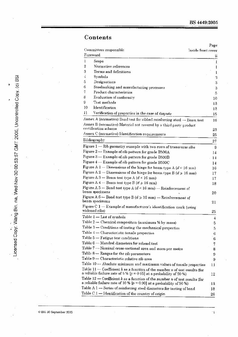
Con tents Page
(lommit,tees responsible Tnside fi-on t cover
Fo~e\vortl ii
1 Scope 1 2 Normative references I 3 Terms and definitions 1 d Symbols 8 5 Designatioiis :3 (i Steelniuking ant1 manufactu~ing processes 3 7 Product characterist.ics 5 8 Evaluation ofconfor~l~i~p 10 9 Test. met.hotls 1.3 10 1clentificaf;ion 13 I1 Verification of properties in the case of rlispute
- 15
Annex A (narnlative) Bond test for ~ihbect reinforcii~p steel - Beanl l as t 16 Annes B (non-native) Material not cuvsretl Ily a third part!. protluct certiticat ion scben~e 23 Annos C (nornia tive) 1tleni.ification re~uirenlents 25
- - -
Bibliography 2 7
Figure 1 -Rib geoinetrp osanlple with trvo rows of transverse ribs 9 Figure 2 - Esample of rib pntt.ern for grade B.500A 14 Figure 3 - Esanlple oP rib pattern for grade BSOOB 1 a Figure 11 - Example of rib pattern for grade BFjOOC 1 e l Figure A. 1 - niiiiansinns of the hinge for beam typo A (d 16 m m ) 16 Figure A.2 - Dili~ensiuns of Ble hinge lor beam t.ype B (ti g 16 mm) l 7 Figure A.3 - Beam test t.,vpe A (d < 16 111111) 15 Figure A.4 - Benm test type B {d 3 16 tn~ii) 18 Figure A.5 - Band test. I>l,e A (d 16 mm) - ~einforcenlsnb of bean q~ecimens 20 Figure A.G -- Bond test type B (d 3 16 nlm) - Reinfnrcemeni of beam specimens 2 1 Figure C 1 - Esample of manufasturcr's itlentihcation mark (using rviclenerl ribs) 2.5
Tohle 1 - List of gvmbols Table 2 - Chemical coniposition ( ~ ~ i a s i m u u ~ % hy mass) Table 3 - Contlitions of testing the mechanical proper1:it.s Table :I - Chmactcrisbic tensile properties
Table 5 - Fatigue test contlil;ions Table G - hIanch-el rlialnete~s for rebenrl teat Table 7 - Nominal cross-sectional area and inass per metre Talde 8 - Ranges for the rib parameters Tnllle 9 - Characteristic rclative rib mren Table 10 - Absolute ~i l in i i~~unl and maximuin values of tensile properties Table 11 - C.oefficient K as a function of the number 11 of test results (for n ~beliablc failure rate of 5 % [p = 0.951 at a probability of 90 %) Table 12 -Coefficient It as a function of the number a of lest resu1t.s (for a reliable failure rate of 10 % Ip = 0.801 at a probability of 90 %) Table A. 1 - Series of reinforcing steel tlianleters for besting of [mnd Table C.1- Idenliiicabion - of rhe country of origin -
Q BS130 September 2006 . i

Foreword
*J?his British Standa~rl has been prepareti by Sul,com~nit.tee ISEI911. anrl is a revision oEBS 4419: 1997. which will be mithrhn~vn on 1 January 2006. This edition incorporates a full revision of the sl-anrlarcl. The charuct,eristic yield strength has beon increa~eil to 500 MPa. and a t.hbrl ductilit.~. clnss has been aclded. ~01n113red t.0 BS 4449 19%.
This st,nndnrd no longer covers plain ruuncl bar. For sizes up t.o and including 12 nit11 in coil. plain round wire id grade 250 MPa has beer1 incorporntetl iuto BS 4482. For larger sixes. ibr tiowel bur applica&ons. reference shoultl be 111acle to BS EN 10025-1. For tlowel bars k c use in coticreie pavement.^. refcrunue should bo n~ade to BS EN 15877-3.
This st:mrlnrtl has been rvritl.en so that i t can be usecl in corijunctiori with BS EN XO080:2005. Dditiitions. symbols, steelmaking and manufacturing processes. ruutizre inspection alld test.il~g. test methods. irlentificat.ion of the manufacturer anrl technical class anil verificat.ion of i~~ecbanicnl properties in the
, case of rlispute are n i l taken horn BS: EN f0080:2005.
BS EN 10080:2005 does not ctefine st.eel grades or technical clnsees. and requires that kchnical classes should be defined in rlccortlanoe with BS EN 10080.2005. 11y sl~ecdiorl values uf R,. R,,IA,. AgL, Re,8ctlRe.,,uun (where appropriate), fatigue strength, bend performance, welclebility, borlcl strength, t.olerances and rlimensions. The three sl.eel grades in this standartl confor111 to a l l of t.he requhementa WEBS EN 10080:2005.
The three grades it1 this stanclartl also conform to tche three 1-emmmenrlorl tluctility classes of BS EN 1992- 1-1:2001. althoueh the fat.igue requirements anrl the fa tiguc test conclitions are retained from the previous version of this standarrl. The only escel~t.lon to this is for pracle B.TOD.4 in sizes helow 8 nrm, where the ductility requirements sl~ecrfied are below those of BS EN f 992-1-1:2004.
RS EN 10080.2005 contains an infornlatlve Annes ZX. which rlescribes how that stantlard can be used for the purposes of CE marlting of reinforcing steels. Annex Z.4 and 8.2,8.3 and 8.4 of BS EN 10080:2005 relate to the role of the notified bocly in assessing products for an E c certificate of conformity, ant1 as such are not. ii~clurletl in this standard. It is not a require~uent of Ohis Brit.ish Standarcl that. ~i~ater ials protluceil to it shoulrl meet the requhenients for CE marking.
Where CE marlung is required for the purposes of complying with the EU C.onstruct.ion Products Directive. BS E N 100RO:2005 al3pljes.
11: is reco~nnientlerl t,hat purc.hasers specify reinforcing steel thal: has bee11 ~ ~ ~ a t ~ u h c t . u r e d ancl supplied to n recognized t h c l party 1)roduct certification scheme. 8.2 specifies the clet~ri~~ination of the long tern1 quality Ievel uncler such a schcme. As an nlte~nntive. Annes I3 provides a batch testing u~ethotl for ~ilaterial which has not been ~,rnrlucetl under such a scheme.
In BS EN 10080. the ternis "rotl" and "wke'? are used to clesabibe reinforcing steel in coil. In this stanclarcl. these tcrnls have not. been includetl to avoid t.he ~lot,ential for confusion, particularly wish wirc producetl to BS 4.182
This standartl comes into effect on 1 January 2006.
This publication does not. purport. t:r> irlclucle all the necessary provisions of a contract. Users are .ereqonsible for i t s correct npplication.
Compliance wit11 a British Standard does not a£ itself confer immunity &om legal obligations.
Summary of pages
This cloculnent cony~rises a fxont cover, an inside front cover. pages i and ii. pages 1 to 27 anrl a bacli cover.
Tho BSI copyright notice rlisplayed in this rlocuir~ent irlclicates rvhen the clocutnent nras last issued.
ii C; GSI 30 September 2005
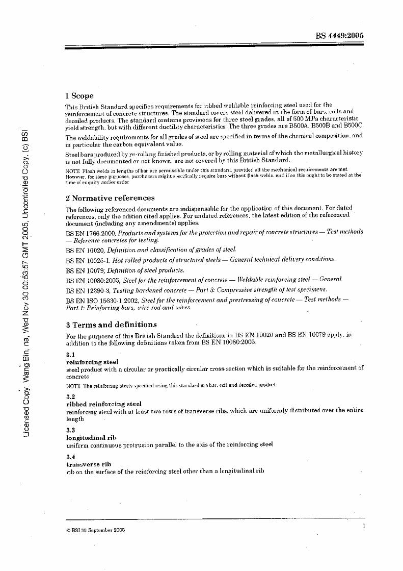
1 Scope This B~ritisl~ Sbandard specifies requirements for r~bl~erl n~elilsble reinforcing steel usecl for the reinforcement of concrete structures. 'he st-nntlard covers steel clelivererl in the form of bnrs. cods and rlecoiled [~rotlucts. The stantlarcl contnins plulvisions for three steel grades, all of 500 IaPa characteristic ~rielcl sbrengtll. but with tlifferent duct-ilit.y chnracteristics. The t.hree grades are BSOOA. B5OOB and BSOOC.
The weldnbility requirenlents for all grades of steel are speci€ied in terms of the chen~icnl co1npo5ition. nnd in particutnr the carbon equivalent value.
Steel Imrs producerl by re-rolling finished pror1uct.s. 0.1' by rolling. mnterinl of which thc mctnllurgicol history is not fillly clocuu~enfetl or: not known. are not covered Ijg this British Stnndmtl. .
NCnE Plash rveIcls in lengths 0 1 . 6 ~ are ~~errnissibte lmrler. this stm~rlard. provirlerl.111 the mechanical rerlt~iierneols are met. Holvever. for some pul-poses. purchasers might specifically reqltire bnrs withotit ff nsh welds. m ~ d ilso this ought to bo stntcd nt the time of enqttin nndlor ortlec
Z Normative rererences The following refesencecl docu~~ients are intliq~ensable for the npplication of this rlocument. For dated references, only Ihe eclition ciherl applies. For unrlatetl references. the latest edition of the referenced rlbcument: (including any a mentlmen t s) applies.
BS EN 1786:2000, Prdrrcls and sysfe?ns for ~hepro /~r t i~~l . imrd i-ep~~.ir TI^ C O I I C J . ~ ~ ~ S ~ . ~ I I C / . T ~ ~ P S - Tesr rrtelltods - Hcfcrcltcc concreies for trsring.
BS EN 10025-1, Piof rolled prod~rcls ~/s!ruc~rrral steels - Ger~cml /ech~lical delir:ery ronditiorrs.
BS EN 10079; &finifion ofst.eel prodllcls.
U S EN 10080:2005, Sicel for /.Ire rein/orcerncn~ of co~lcrere - I~T'eIdable reinforcing step/ - General.
BS EN IS0 15630- 1: 2002, Steel for the rei~rforcenlrn! ond prestressing of C O H C I P ~ E - Tes6 rv~ethods - Prrrl: i: Rei~rforcl~rg brrrs, rr!r'rr. rod rrnd ri!irr.s.
3 Terms and definitions For the purposes of this Rrit,ish Stantlard the rle6nit.ions in US EN 10020 and US EN 10079 apply. in arltlilion to the following dofinikionu token froill BS EN 10080:2005.
3.1 reinfoking steel steel protluct with n cjrcular or practically ckculnr cross-section which i s suitable for t.he reinforceulent of concrete NOTE The reinibrciu~ steels speciGetl~~si~tg this stantlard me bar. coil and tlecailerl p~.ocluol.
3.2 ribbed reinforcing steel reinforcing steel with at least two rows of transverse ribs. wlljch are unifornlly rlistributecl ovet the entire length
3.3 longitudinal rib uniforin continuous prot:rusion parallel to t,he axis of the rejnForcing sl.eel
3.4 transverse rib r1B on t.he surfa'clce of the reinforcing steel other than n longit,udinal rib
O BSJ 30 Seytember 5005 1

3.6 rib height h. clistance 'oil1 the highest point of the rib (t.ransverse or lonpitutlit~al) (.o che surface of the core. to be ~neasured noriilal to she axis of the rJnforcing steel
3.6 .- rib spacing 0 V C
distance be(,ween the centres ol rwo consecutive tratlsverse ribs tuensuretl parallel to the asis ofthe o reinforcing she1
. O -Q 3.7 61 = angle of transverse rib inclination
P CI
angle bet.wek I.he axis nf the transverse rib end he longitutlinal nxis o l the reinforcing st;eol
2 3.8 transverse rib flank inclination . g a
0 angle of the rib flnnk ~tteasured l~erl~entliculnr to the longitutlinnl axis of the rib N I- NOlF See Pipure 1
3.9 A relative rib area 2 f i t m area of the projection of all ribs on a plai~e perpenrlicular to Ihs longitu~linal nlcls of (.he reinforcing steel ri divided bp t.he rib spat!ing :inil the no~ninal chcumference 0 8 3.10
bar ribbed reinforcing steel monuloctured in straight lengths z
$ 3.11 coil single length of reinforcing st:eel wounrl in conmntric rings a
L 3.12 c- ,a decoiled product
- reinforcing steel mnnu~act;ured in coils and subsequently straightened for further processing
3.13 nominal cross-sectional area - 3. An
'3- o crosu~sect.iona1 area equiva1en.t to the area ol'a cixcular plain bar afthe same noininal cliamc;ter, d (i e
nd" 0 7) $ 3.14
characteristic value c value of a material or procluct property having a p~escribed probability of not. being attained in a hyl~othetical unlimited tcst series NOTE 1 This value generally mrrespands to a specific hc t i l e of the nss~m;erl statisticnl ctistributio~~ af the pnrt:c~dar~ropel.t~~ d t h e ~nnterial or ])rorluct.
3.15 minimum value value below which no test result shall fall
2 BSl 30 September 2005
3.16 rriaximum value value \vhich no test result, slinll ssoeed
3.17 batch quantity of bars. coils. or decoiletl prot1uct.s of one nominal tlian~eter and orte cast grotlucerl by one tlianufacturer and presented for examination at: an>- one tilne
3.18 standard property property which is part ol' the routine inspection and lest ~equirement-s for eveyy tesk unit
3.19 special property property which is not del:ei-mi.tled ns pnrt of the rolltine inspedion ant1 besl: requirements for every test unit (e.g. fatigue ~wrformsnce)
3.20 technical class type of reinforcing steel definetl by its ~)erformance charac~.eristics. ident.ifietl by n unique protluci. nun~ber
4 Symbols A list oEsymbols used in this stanrlarcl. reproduoctl hoix BS EN 10080:2005. is given in Tollre 1
5 Designations The proclucks covered by this standard shalt be desipnatecl with the followitzg informaiio~~:
n) ilescril,tion of the product form (i.e. bhr, coil. rlccoilerl pracluch): b) the noniinol clii~~ensions of the product: C) reference to this stnndnrd. ant1 the gracle.
For.esompb. the rlesignat.ion for 40 ~ n ~ n clianieter bar in 12 111 lengths of grade B500B rvoulcl Be: "Bar 40 x 12000 BS 114.19 Grade BSOOB.
Where p~oducts that, conforill to th i s stantlarcl are also required to meet all of the rejuirsnlents of BS EN 10080:2005. for e~naple for the purposes cf CE marking. then reference to this st,andaril shoultl also be 111nde in the designation. For e?iample, the tiesignation of' the 40 n m bay clescribed above woultl he. "Bar BS EN 10080 40 X 12000 BS 4449 Grncle BSOOR"
6 Steelmaking and manufacturing processes The'nelting process end tyle of deosiclation of the steel shall be nt the discretion of the steel p~uducer.
The manufacturing p~ocess for the production of coils and bars shall be at the rliscretion of the ~nanufncturer. It shall be ~:eportetl to the purchaser.
Decoding of coil mnterinl shnll be clone by a niachinc made for this purpose.
(3 BSI 30 September 2005

Table 1 - List of symbols
Percent.nge I.otnl elongation at m a d m u m force Trn~~sverse rib spacirig
Carbon equivalent value (CEi,? Specifiecl chara ct.eriskic value
Nominal rlisnlete~ of the reinforcing steel
Gap between rib rows Relative rib hren Rib heigll t Coefficient. a s a funcbion of the number of test results Average value of test resu1t.a Yield stro1xt.h IJpper ~<eltI strengrh
Tensile atrength Ratio tensile strengt,hifield strength
0.2 % roof strength, non proportional cstension Estimate of the standard rlevinlion Transverse rib flank indinot.ion Angle uf transverse rib indina t io~l
Stress range in t.he asial load fatigue test
I S~mbnl Descriptiot~ - -
Nominal cross-sect.iona1 area
Incretne~lt for calculation ol bcllch release criteria
2 z
4 m- C
Width of the bean1 @cnm t:esi:)
Manibel iliameter (beam test) Total force oppliecI &can1 test)
Force in hinge BntI bar or wire @oam test) Stress in i;he bar or wire (beam test)
flm
amin
&,-t
R,,I:OII, Re,BcdR,.,,3,,, '
Boncl stress (I3ea1n test)
Specifietl n ~ a ~ i m u m stress in the fatigue test
Specified minimunl sl.ress in t.he fatigue i.est Actual value of j5elrl strength Specifiecl value of yield strength Ratio actual value of yield strengt.hlsbecfied value of yield strength
Boncl st.ress at ~nasii~iuill forcc fieam test)
Bond stress at 0.01 mm. 0.1 ~ n n i ant1 1 nim slip fieam test)
s on the property. 9
Unit
In ill
%
n> in i % by mass j 11 i
- ! B
MPa" MPab L~1IIPah - M P ~ " 8
degrees
4 8 BSI 30 Septenlber 2006

7 Product characteristics
7.1 Cbemical cornpnsition
The values ol'in(livic1ual elements n~icl the carl~on equivalent shall not esceeil bhe limits given in Table 2 . The carbon equivalent value C,,, shall be cnlculuted using t.he following formula:
A h is the percentage inanganese conten!: Cr is the 1,ercentoge chromium content;
\ / i s the percentage vnnacliu~i~ content: Mo i s thc pcrccntoge t l io~~*bi l ent i~~~ content.
f i r is the percentage copper cont.enl.: Mi is the percent,sge nickel content.
Table 2 - Chemical composition (maximum 4a by mass)
During 13roduct analysis, any bar that falls outsicle Ihe masimum speciiied limits in Table 2 shall be cleerled not to conform t o this I3ritiah Stantlard.
Cast anaIysis Prurluct analysis
-....
In cases of clispute, where a procluct analysis fnlIs outside the masinium lin~its specified in Table 2. the ~)raedure rlefinecl in 11.2 shall be applied to rletermine whether the material confornis to this standard.
7.2 Meclianical properties
'' I t is permitted I;o e~ceer l the mnsim~w~ values oI'r:srl>on by D 09 "i by mass, provider1 tket the carbon eqd~.a:ent value is rlmreased by 0 01 90 by mass Higher ~litroge~loo~ltents are permissible iEsitfEcient quant.ities of ~litrogcn billrling clcme~~ts we present.
Cnrbot~'
0.22 0.24
NOTE All bnrs shordrl bof~*ee !~'OIII defects. e g. seams. porosity. segregalion. non-mstdlic iaclusions. ~ h ~ c h cm be shown to ;~tlversely i~r~ct the rttechnriicul ]>ropertir?s.
7.2.1 General
~ u l p l ~ u r
0.05 0,055
The charact.eristic value is (unless othel.ivise inclicatacl) the Iorver or upper liniit O F the statistical tolerance interval at which'there is a 90 D/b probability (1-u = 0.90) that 95 % (r, = 0.98) or 90 % (p = 0.90) of t.he values are at or al~ove the lower limit or at or below the upper liiilit respectiveIv. This quality level refers to the lona-term quality level of l~rocluction
7.2.2 Conditions of testing
The conclitions of tcst-ing shall conform to Tnble 3. Table 3 - Conditions of testing the mechanical properties
~ h o s p l ~ o r ~ s
0.05 0.055 .-
O BSI 30 Sept,srnbe~. 200s 5
~ i t ~ ~ ~ ~ ~ b
0.012
Manufacttiring and delivery condition
Producecl in straight lengths by hot; rolling Producecl in straight lengths by colcI working
P1.orlucerl as coil and delivered decoiled Produced nntl delivered as coil
Condition of testing
As ~Ieliverecl" or agedb
&erlb
Agcdb ~ ~ e i l "
Capper
0.80
a ~ : e ( l in the case of clisgute. Aging methorl: heat the lest yier.e to 100 OC, m:lintain s t this toml1erattu.s (*lo ' C ) for a periorl olIjO*_f min.. nnd then cool in
still iur t o room tenpcrature The method of heating is left to the rliwretiuu 01 the m~~mfactnrer. i
Carbon aqu ivnlent
0.50 .
0 . O f 4 10.85 0..52

7.2.3 Tensile properties
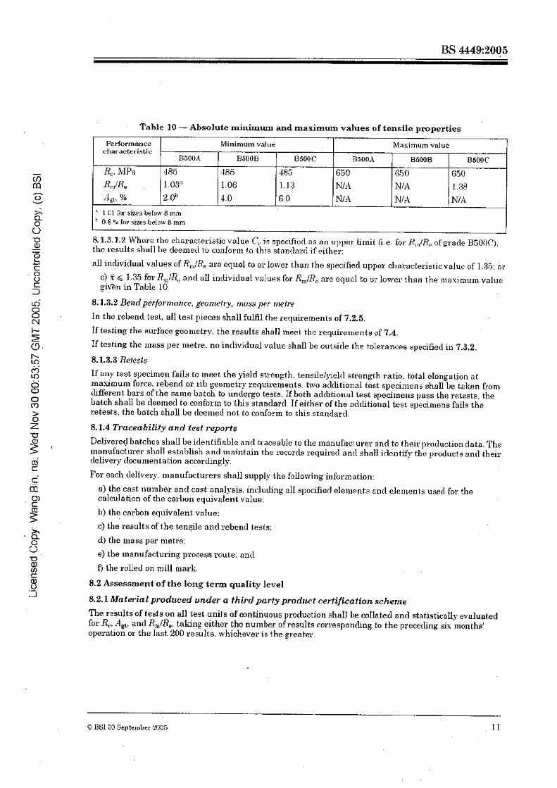
1 % ~ specifier1 charrrcteristic values for the tensile propertics are given in Table 4
U " 14m/R,cbaracterist.ir: i s 1 02 for sizes below 8 m m
4 chara~tet~istic is 1 II ' b For sizes belot$ 8 mm
Vnlr~es of K. specified are i:l~nrnste~ istir with p = 0.05
8 %'altles of I?,,,&!, :md .*I, sl~ecified n1.e charactenstic with p = 0.90.
Calcrllnte rhe val~~es nE R, and R. using the nomind cross sectiolid nren 3 : L$ The absolute rnasimtun ~~rmissiible value of ~ielrl strength is 650 MPa
Table 4 - Cl~aracteristic tensile properties
U FOY yield sl:ren$h (I?,). the upper yield strength (RPn) shall apply. Deternline rhe jleltl sl.reng1.h (1<,) fruli~ t.he 0.2 % 1)~onf sbrcngth (RL,o ?) if n )+Id phcnon~enon is not prcsent.
22 7.2.4 Fatigue strength.
Total elongntiorr at maximum force. A,,
go
2.5" 5.0 ,- - I .o
Tensilelyield strengtll ratio, R,,,lf?.
1.05" 1 08 31.15. 4.35
- m m n 0 V
S Q 0 0 '
Decoded proclucts, from each production site, shall$e subject, to fatigue l;est.ing. Initially. samples shall be talien h-om each production site from one clecoMng ll~achine type fro111 the largest diameter produced.. At a frequency of at least once per year. sa~ l~p les of one rliarneter shall be seIecf.erl fox test from each p~oduction
- site. froa~ one decoiling machine. Srtlnpling shall be carried out in sucll a way that the coinbination of illaterial 1iianufactu1:ing route. type of rlecoilcl: and irdivirlual machines nre covered over a five-yoar periorl.
7.2.4.1 G e n c d m Reinforring bars, coils nncl decoiled llrotlucts shall be subject to fatigue t,esting. CVhell sub~nibtecl lo asial
force ~ntral ler l ratigua testing. using o stress ratio (0 in^ of 0.2, and stress range as given in 0 Table 5. test samples shall suivive five ~tlillion stress cycles. 0 PI Table 5 - Fatigue test conditions
6: !D BSI 30 September 20Dt
R500A B5OOB
- B500C
6 ' z a.
L? m c c f a
- m t
Yield st renab, Re
M Pn
500 500 -500
2 7.2.4.2 Bars 0n.d roils . . 2 Reinforcing bars &otn each proc1ucl;ion si1.e shall be subject t.o fatigue testing. to dei:ermjne the fn~ipue 0 characteristics of a particular geon~et~icol shape ant1 process route. The Latigue groperbies for each steel
ginile and processroute sheU 178 establishetl a t an applicable testing laboratory. initially hy testing samples selectetl6*om thc upper. middle and bottonl of the prorluct rlian~eler range. At lenst. once n year, samples shall be tcsteclfkolli different bars or coils of one cliarneter from each process route. Test. samples shall be solect.ed so that. all cliomet,ers for each process route shull be t,est.etl over o five-year periocI. .-
-' 7.2.4.3BcoikdprodarZ
Bnr size
mm
f16 >16. ~ 2 0 r20. s26 >25. c82 >.32
170
1GO
150
Each test unit shall mmprise ten teat fipecin~ens. For each iliameter. froin each test unit, five Bars shall be selectecl for test. Tho test specimens shnll not eshibit isolated defects that are not charnct.eristic of the p1:oduct from which they are aelect,ecl.
The prorluct,~ shall be tleenlecl to conjhrm (a f.his standard if all Eive test. pieces enrlure five ~ l l ihon stress cycles.
If one of the five test pieces produces a valid failure. a furbher five sam[)les 1i.otn the test, unit shnU I)e testetl. If one of these further salnples fails the test, then the rl~aterial shall be rleemetl not to conform t.u this si:andarcl, ant1 an investigation shnll be carried out ontl appro1;ritrf.e act.ions shd1 be talron. Xf all five further test, pieces endure five million skess c.vcles. then the illat.eria1 shall be cleemed to com[,ly wibh this stanrlarrl.
In the case of any failure, the test. shall be considered invalid if it is initiated ho~n a defect unique to Ehe . test piece or in the aren within 2d of the testing ii~achine grips (~vhere dis the nominal bar cliameter); in this case a fu~ther single tes t shall be carried out (see BS E N IS0 15650-1:2002).
7.2.5 Bend performance
lknd pcrformancc shall be tlemonst.rated by means of the following rebenti test
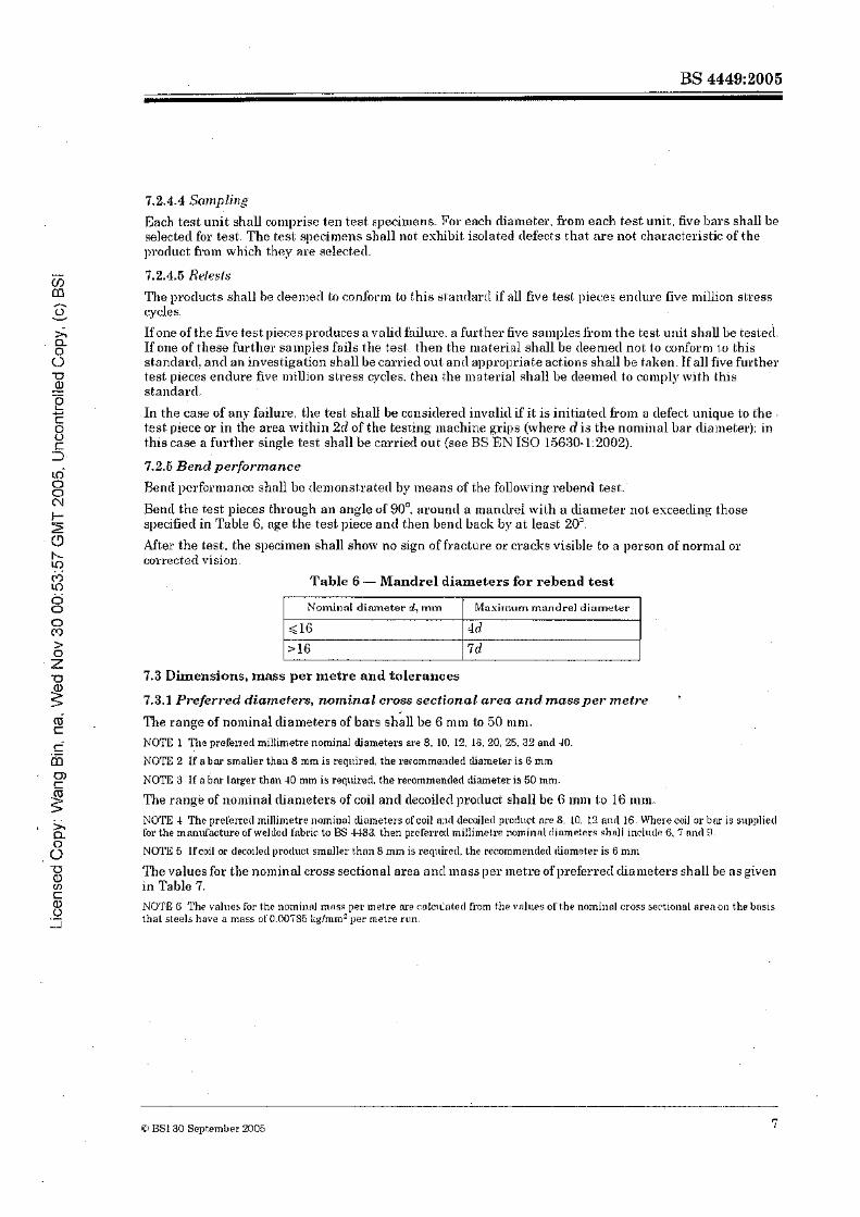
Bend the test pieces through an angle 01 90'. around a manilref with a cliamel.er not esceeiling those specified in Table 6, nge the test piece nntl then bend back by at least 20'.
After the test. the specinlen shall show no sign o.f fracture or crodis visible to a llerson of' nornlal or correct.ecl vision.
Table 6 - Mandrel diameters far rebend test
7.3 Dimensions, mass per metre and tolerances
7.3.1 Preferred diamefers, norninal cross sectional area and mass per metre '
--.- Nominal diameter d , mtn
<lG >l6
The range of nolllinal chalnebers af bars shall be 6 nltll tn 50 nlm.
Mnuirnum mandrel diameter
dd 7d
NOTE 1 The grebl~erl millimetre nominal Jjameters are 8. 10. 12. 16.30, 25. 33 and 40.
NOTE 2 If n b a s smaller than 8 mm is reqrtirerl, the re~ornme~~clerl rlinmeter is G mm
NOTE 3 If n Gnr larger than 40 mm is reqrri~*eci. the rerommended rliameter is 50 mm.
The rang& of nominal clinnleters of coil ancl decoded prorluct tho11 be 6 in111 t o 16 mm. NOTE 4 Thc prel'errctl millimetre iiorninol rliameters af coil n:ld decoilerl prorl~~ct are 8. 10. 12 nilrl 16. MIrere coil or bw is snppliecl for the man~facture ofrveldctl lnbric ta B3 448;1, then pretkrrerl miliimetrc! nomilink dinmeters nhnll inclurle 8. T nnd 9.
NOTE 5 Ifcoil or tlecoiletl prorluct smaller thai18 mm is reqnired, the recomme~~rlecl rliamater is 6 mm
The values for the nominal cross sectional aren and mass per metre of preferred cliameters shnll be ns given in Table 7. NO'l'.E G The values for the ilorni~~nl mass per metre me cslc~Cnterl from the vslaes of the norninnl cross sactio~ral area 011 the basis thnl steels have n mass of0.00785 liglmm? per metre run.
m CI BS130 September 2005

Table 7 - Nomirlal crass-sectional area and mass per metre
7.3.2 Tolerances The pertllissd~le clevintio~~ 6,om nolninnl niass per met.re shall be not 111are than f 4.5 O/o 011 nonlinal cka~ueters greater than H mal. ant1 t6.O % on nolninal dinmeters less than or equal to 8 mm.
Mass per metre
Ii
0.222
0. :302 0.395 0.499 0.617 0.888
1.58
2.d7
3.86 6 31 9.86
15.4
Nominal diameter
mm
6" "0
8 9"
10 12 16
20
25 :3 2 40
50
7.3.3 Length
The nominal length of bars shall be agreerl at t.he time of enquiry and orcler.
The permissible clcviation &om the nominal length sliall be +1001-0 mtn: other t,olwances may be agreerl a t the time of enquiry and order
" Preferred diameters for the rnn~~uflxtwe of welder1 fabric to I3S ,1483 ody.
Cross sectio~m\ area
mm'
28.3 a#. 5 50.8
63.6 78.5
1 1 J'3
20 1
314
39 1 801
1267 1963
7.3.4 Coil ma&
The noniinal coil moss shall be agreed at the t,iine of ~ n q u i r v and ortler
7.4 Bond strength and surface geometry
7.4.1 General
Ril~I~ed bars are characterizetl by their surface geometry, by ~iienna of which bond with the concrete is achieved.
Bontl property ~cquircn~ents of ril~becl reinforcing steels nccorrling to this standard shall be basetl on suiuface geometry. or by nieans of the bond test provitled in Annes A: boncl property require~~~ent .~ basetl on surface geometry arc preferred. The assessment criteria for the boncl tests shall be as given in the appropriate clesign ilo~unients. A suitable means of factory procluction control bassi1 on the control o f sulfate geome1.r~ shall: be derived Boni the bond test rosu1t.s. .
NOTE Required levels of bo~lcl strength. as l n c ~ ~ l l r b d ill the bond t e s t in AIIII~Y A. are pivsn in 135 EN 1992-1.1:200~1, An~ies C
7.4.2 Sttrfacegeornetty
7.4.2.1 General
Ribbed steels are choract:erizecl by the clinlensions. number and conIjpuration of transverse and longituilinnl ribs. Bms. coils nnd decoilerl proclucts shnll have two or nrore rows of transverse ribs uniformly clistributecl nrountl t.he perimeter. Within each row the ribs shall bc u n ~ f o ~ m l y qaced. Ixmg~tu~linal ribs can be present or not..
-411 esa~tq~le of a ribbed steel is given in Figure I
8 aJ HS1 30 September 2005
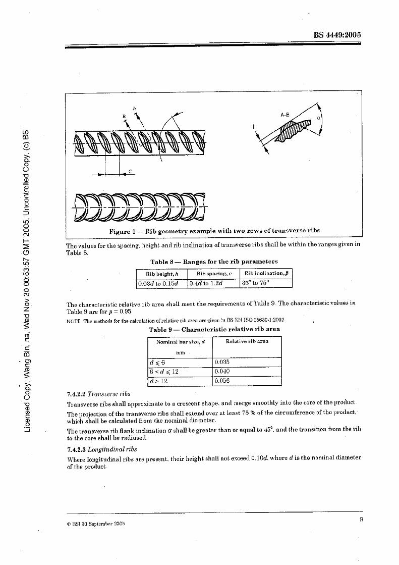
L_ Figure 1 - Rib geometry example with two rows of transverse ribs
Tho values for the sl~scing, height and rib inclination of transverse ribs shall be within the ranges given in Table 8.
Table 8 - Ranges for the rib parameters
The chal:aut,erist.ic relative rib area shall niest the ~:equiremcnts olrPalle 9. The characteristic values in Table 9 are for p = 0.95. NCJTE The methorls for the calculation of relative rib area are given in BS EN IS0 15630-1:2002.
7
Table 9 - Characteristic relative rib area
Rib inclination,B
35" tu 'is" - Rib I~eight, h
0.03d to 0.1513 --.
Transverse ribs shall approsi~liate t o a crescent shape, onrl merge smoothly in to the core of the product
Rih spncing, c
0 . M to 1.2d
Nominal bar size, d
mm
d s G G < d $ 1 2 d > 12
The projection of the transverse ribs shaIl esterrrl over at least 75 % of the cir.cumference of thc prorluct, which shall be talculatetl front the no~ninal diameter.
Relative rib area
0.035 0.040
0.056
R e trnhsverse rib ftanl< inclination a shall Be greater than or equnl to 45'. and the transition frdm the.~ib to the core shall be rocbliuserl.
7.4.2.3 Lorlgilrrdil?crl ribs Where langitucbnel ribs are present,, their height shall nol. exceed 0. lOd, where d is the.nomiua1 diameter of the prorluct.

8 Evaluation of conformity
8.1 Routine it~spectian and testing
8.1.1 General
Reinforcing sl.eels shall be p~orluced untlar a pernlonent s y s t c ~ ~ ~ of routine inspectioh and testing. which shaU inolurle evaluation of specified pro1,erties. as bscrjbetl in 8.1.2 and 8.1.3.
2 8.1.2 Sampling and testing of finished prodrrcts
2 8.1 -2.1 1-'er.i(ica/ion o,fsi~l~~cJcrr-d propcrtie.5 0 C) Fur the verificar.ion of stul~rlard prol>e~:tins, sa~l~pling ant1 liesting shall he as speciiietl in 8.1.2.2 nnil8.1.2.3
8.1.2.2 Bars find coils - - Tho test unit shall bo the cast or part quantity of the cast..
c.
The rute of ~esting shall be ns follorvs. 8 . C a) For che~iiical composition. one analysis per teest unit. The chemical composition (cast. analysis) of the
steel shnll havc been deterniined by the steel producer.
b) For rebend tests. nominal innas per metre and surface gcooletry. one test 11ieoo I I ~ I ~ test unit and nominal diameter.
,C- c) For tensile tests, one test piece per 30 t with at least three test pieces per tcst uriit oiltl no~i~innl rliumeter. Were bars and coils are produced for the manufac.ture of rv~ltletl fabric only. one tensile test piece shall be taken per 30 t protlucsd r. 2 Test results shall be evaluated in accordance with 8.3.3
8.1.2.3 Dpmiled prodnrls
Tho processor of protlucts in coil shall ensure that the rlecoilerl prncIuc~:s continue to meet the specdiecl prol~erty requirement,^ of tho nppropriate grade. Inspection nnrl testing of rhcoilecl reinforcing bars shall
3 include as e minimum:
a) visual inspection for surface gooi~ietry damage of every mil procasserl. - b) surface geometry ~usaauran~ent on at least one sample per day ant1 lpmtlucetl size:
c) tensile testing at n frequency of at least one sninple per machine type (roller or spinnsr) per weel; &om each of two processed sizes. The sampling shall be sudl that all 111achine.s nn4 sizes are coverer1 in a six-
- month periorl. Only one sample shall be taken horn each coil. F Se
' Testing mag be carrieti out either by the processor using its own resoul+ces (internal or esternal) or by lahe , processor in co-operntion with the coil manufacturer. The tests shall not be seen as release tests. but ns the
hasis for the assosemenb of the long-term quality level (LTQL) as described in 8.2. >
8.1.3 Euahmtion of test results . .
$ 8.1.8.1 Tensile propcri.ies
8.1.5.1.1 Where the charncte~irtir voluo C is specified ss n lower limit, the results shall be deemed to
g conform to this at.anilerd if either. -. a) nll indivitlud vnlues are greater t,han or equnl t.o the specfieil chal-acterisbic value cv, or
0 .- _r b ) . t - 3 C , + U l
where
al i s 10 h1Pa for. Re, zero fop R,,!R, ant lo % for >kt. and all inclivitlual values are greater than or equal to thc mini,num valuea given in Table 10.
BSI SU Sept.emher 2005
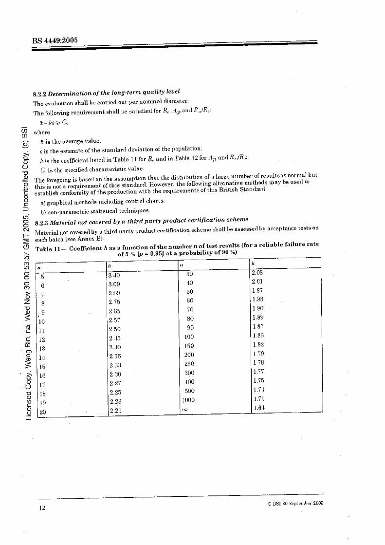
8.2.2 Determfnafwn of the long-term qrcality level n c evaluatio~l shall br! ca~~jcrl out. per noininal diameter.
The follo~virig requirement shall be sal.isiiec1 for Re. ;I,,, and R,,,IR,: .v -- I($ 2 c\. -
where a .T is the abernge value: V
s is t.he esti1nat.e of the st.endarrl ilevjntion of the population:
8 I? i s the coefficient listcrl in TobIe 1 1 for 8, and in Table 12 for .Jbt and H,llfB,; 0
. .
C,; is thc specifietl chnract.e~ist.iv value.
2 The forgoing is baser1 on the assu~npfion that the clistribution of e large number of results is normal but this is not a I-equiremont of bhis standard. Elowever, the folloning aiternative lnethotls may be user1 co establish conformity of the production svith the requirements of this British Standard:
0 a) graphical n~ethorls indutling control charts: - 11) non-parametric statistical techniques.
8.2.3 Materia 1 not colrered by a th.ird party prodlr~cf cartificafion scheme &laterial not coveretl by a third party j~roduct certification schc~i~e shall be assessetl by acceptance tests on emch batch (see ..lnncs 3). Tahle 11 - Coefficient k as a function of the number n of test results (for a reliable failare rate
of 5 '.b = 0.951 a t a probability of 90 q ~ )
m * 8 0 CT)
12 :C: BSI 30 Sell teniber 2005

Table 12 - Coefficient Ir as a function of the number n of test results (for a reliable failure rate of 10 Fb Ip = 0.901 at a probability of 90 9.i)
9 Test methods The tensile test. for the deter~llination of Re. R,,IRe ontl A,,. (,he rebend lest.. the axial loat1 fatigue test. the i~~eosurement of t,he surface goonlotry and the deterolinnt-ion of the relative rib areafR. the delerininat.ion of clevintion frorn.nornina1 inass per mctre ant\ the itlethods for chemical analysis shall be in accordance wit,h BS EN IS0 15630-1:2002. See also Table 3. N W E For the rebent1 test. it is recommeuderl that the I~cnding rate is nppmsimntely three revol l~t im~s per minute.
$0 Identification
10.1 General Each reinforcing steel shall have identification 111arl;s to iilentify the manufacturer, accoriling LO the requirements of Annex C.
Where CE n~nrliing is required. prorluct marking shall be in accorclance with BY EN 10080:2005.
-. - -
0 BSI 30 September 2005
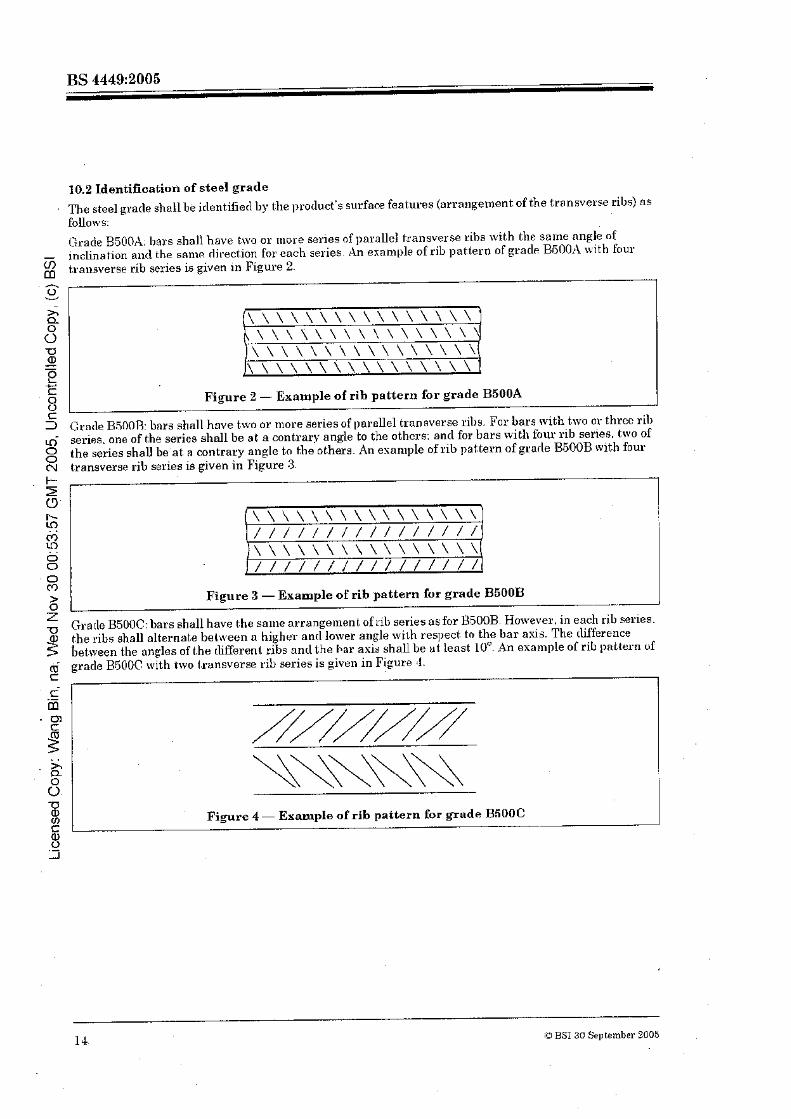
10.2 Identificatiori of steel grade The steel grnile shall be itlentiGed by the l~rotluct's surfam features (arrangement of the transvetse ribs) ns follort~s:
('iraile 3500A, bars shall have two or more series fif parallel tmnsverse ribs with the same nngIe of - inclination aixl the seiiw rlirect,ion for each aeries. An exohlpls of rib pattern of gracla B5OOA with four 2 transverse rib series is given in Figure 2.
I Figure I - Example of rib pattern for grade B500A I Grade R51)OR: bnrs s h ~ l l have t.wo or more series of parnllel transverse rills. For bars with two or threc rilt series, one of the series nhnll be at n contrary angle to the othcrs; anil for bars wit11 four rib series, two of the series shall be'at n mntrary angIe to the ot.herfi. An elinniple ofrib pattern of grade 3.5003 with four transverse rib series is given in Figure 3.
Figure 3 - Example of rih pattern fur grade BSOOB - A*.,
Gratle B.5006: bars shall have the saliie arrangement of rib series as for B500B. However. in each rib series. the ~ i b s shall a1ternet.e hekrveen n higher ant1 lower ailgle with respect to the bar usis. The [Wference between the a n ~ l e s of t.he rliEerenl. ribs and the Par asis shall be u t least 1OU. An exa~i~ple of rib pnttern uf grade BSOOC with two t.~:unsverse rib wries is given in Figure 4.
. A\\\\\\\\ ' 0 I
0- -a m rn Figure 4 - ExampIe of rib pattern for grade R500C C= 0, < >
14 i!3 BSI 30 September M05

11 Verification of properties in the case of dispute
11.1 Mechanical properties
11.1.1 GVhenever the detertuinalioi-I of n property specifietl in this stnnrlartl os a chnl-act.eriaticva1uecreat.es a'rlispute. the value shall be verifierl by selecting ant1 testing three test, pieces &on1 V W ~ O U E pieces fi-0111 the batch under examination.
If one test sesul!. is less thnn the q~ecifiecl characterist,ic value b0t.h the test piece anrl the test method shall 11s carefully esamined. If there is o local fault in the test: piece or reason to believe that an e r r o ~ has occurrecl in the test,. .the test result shall be ignored. Lh this case a further single test shaU be carried out.
If' the three valjrl test results are equal to or greater than the specified characteristicvalue. . . the batch shall I,e ileemerl to conform to i:his stanclarcl. If not, the requirements of 11.1.2 apply.
11.1.2 If 12.1.1 is not.fuUiIlei1. 10 oclrlitional test pieces shall be selectcdi~oi~~ different bars. coils or ctecoilecl prorl~uc~s in the batch. The batch shall I-re deenlerl to confor111 to this stanrlanl ~f the over.nEe test result of t,he 10 test pieces is higher than the characteristic value nnrl the inihvidual values are higher than the n~inimuin ant1 lower then the masi~nui~i values given in Table 10
If not the batch ia rejecled.
11.1.3 Whenever the cIeterminnt.ion of rebend characteristics is a cause for clispubc. they shall be veriEierl by selecting and t,esting three specimens fjco~n different bars, coils or ilecoilerl prorlucts in the Latch. If all three sl~ecimens pass the tests. the batch shall he rleemerl to conforni. ot.herwise the batch shall be cleemetl not to conform to this British Standard.
11.2 Product analysis
If during product analysis. a single sample falls outside the masimun~ deviation limits hr t.he coniposition range of a specified element, give11 ill Table 2. further samples shall be selected from t.he remnincl~lor ofthe bn tch a3 follows:
a) at least t w o sanlples fro111 the fialno cast for ilehvcrecl masses up to 5 t:
b) at least five samples frotn the snnle cast, for clelivered masses up to 20 t:
c) nr. least e~ght snmploa for rleliverecl niosses over 20 t .
If any of the further salnples analysecl fall outside the mnsimu~n procluct analysis bvels given in Taiile 2 for any element, the Latch shall be tlee~necl not to conforni to this stanclarcl.
CI BSI 30 September 2005 1 -5

Annex A (normative) Rond test for ribbed reinforcing steel - Ream test
A.1 Introduction
This annex cleacrihes n nlebhotl for testing the bond characteristics for ~ i b b e d bars ant1 decoileil protlucts to $ be used as reinforcing steel in concrete strocturos.
The bealn test is intenclecl to cletemnline the bond of reinforcing steel and is to serve as a basis for the V . . oon~parison of reinforcing bars ant1 rlecoilerl proilucts nf al~prnsimrrt.ely I he some bar or rlecoilocl pmduct: 2 chsnieter but with clifferent surface configurntions. 0 0 lie test method is applicable for reinforcing steel in cliameters <32 mm.
NOTE Thernelhotl is based on the RlLEM.Recurnmenrl;~tiun RC5. B w ~ d test for reinfurcement steel [I]. - - 2 A.2 Principle of tbe test u
4 test bean1 is loaded by slniple flexure until complete bond failure of the reinforcing steel occurs in both 8 half-beams or until $.he reinforcing steel itself fails. During loading, the siip of the two ends of the K --J reinforcing steeI is measured.
The bean1 usecl for the test consists mf two parallelepipedal reinforced concrete 1110cli~ interconnec1:ed at. the bott.oin bp the reinfo~cing steel of which t.he bond is to be testerl, ant1 at the top by n steel hinge. The climensions of the hvo blocks and the hinges are cletertnined by the cliameter of the reillforcing steel to be tested. The test i s illustrated in Figure A.I. FigureA.2. Figure A 3 and Figure A.4.
The climensions of the test beams clepencl on the nominal cliamet,er of the reinforcing steel for which the bond is to be rleterminecl. For nominal rliailieters less than 16 mm. a beam specinien of type X is used anti for nominal cLia~neters equal to or larger t.han 16 mm, a beoln specimen of t>l,e B is used (see Figure A.3 ancl Figure A . 4 . NOTE Experience of tasting bars with di,mctsrs larger thrill 32 mm is limited To use the test method of this a~u lex foi srtch large rliameters, r type testing ?cogram shoultl be petformed to evaluate the npplico bilitg of the test method.
:G BS130 September PO06
Dimeilsio~ls in mrn
I
z
t
lie y
1 width = I00 mm
Figure A1 - Dimensions of the binge for beam type A (d < 16 rmn)
20 20 I
$0
1

1 Slip meawlring device
2 Steel hinge
20 20
13 Plpstic sleeves
1
0 m
Figure A.3 - Beam test type A (d < 16 m)
,-
9 RST 30 September 500:; l'i
. 'LUL1. liey
1 width = 160 mnl
Figure A.2 - Dimensions of the hinge for beam type B (d 3 16 mm)
Dirneusio~?~ in mm
P/2
-.. ' .
--
L5'
A "
0 N
t t
Dimensions 111 mm
? /2 P/2
1 100 - - fiey
1 S l ~ p measwing devlee
2 Steel hinge
I 3 Elastic sleeves
4 hlovnble sllpport
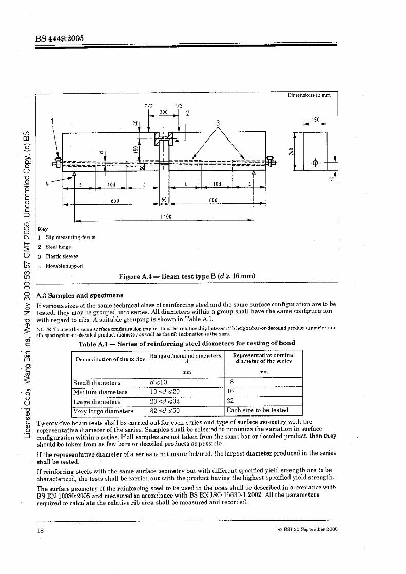
Figure A.4 - Beam test type li B (d 3 16 mm)
A.8 Samples and ~pecimens
$ If various sizes of the vine technical class of reinforcinp steel and the same surface configuration are to be 2' tested. they lnny be grouped into series Allclian~eters within a proup shall have the same configul:ot.ion
with regard to ribs. A suitable grouping is shown in Table A.1. NOT3 Tohave the same ri~r~sacomlSgnmlo~~ implies L e t therelotionahip beheen rib hoighthnrm-decoiled ]aodt~ct~nrne&r nod rib spncinglbnr-or-decoiletl product diameter as \\,ell as the rib illclination is the same.
6 t Table A.3 - Series of reinforcing steel diameters for testing of bond c- fi m - t
2
m
& 'l'yenty-five beam tests shall t ~ e carried out for each series and type of surface georne1:l.y ~vith the 0 representative rliaineter of the series. Samples shall be sclec~ed to lninilnizc the variation in surface .- -I configurar:ion within s series. If all samples are not talien h m the same bar or clecoilerl procluct, t,hen they
should be tnken Dom as few bars or decoiled products as possible.
If the representative clia~ileter of a series is not manufactured. the largest diameter ~~rorlucecl in the series shall be tested.
If reinforcing steels with the saine sur-face geolnetry but with different q~ecifiecl yiettl strength are to be characterized, the tests shall be carried out with the product having the highest specifiecl yield strength.
Representative llorninal diameter of tile series
mm
8 16 32 Each size to be teatecl
Derlorninntion of scrics
Small rlia alutel-s ] Mediu 111 cliamet.e~.s Large clinmeters Very large dinmeters
The surface geometry of the reinforcing steel to be used in the tests shall be clescribetl in accordance with BS EN 100802005 nncl lnensurecl in accordance with BS EN IS0 15G30.1:2002. A l l the parameters required to calculate the relative rib area shall be measured ant1 recorcled.
Rn11ge of nominal. diameters, d
mm
d ~ 1 0 10 -=d ,<20
. . . 20 <d ~ 3 2 32 <d 450

A.4 Test equipment
A.4.1 illot~lds for ihe lesf hertins. mncle of steel. cast. iron or any other non-absorbent mafe~ial which does not yeact with t.he coi~l l lo~~ents of the csncrete. Warertight.ness nncl (Liinensions should be maintained after US<?.
A.4.2 S ~ c c l Iringrs, forlnccl from two pieces of steel in a T shape. as shown in Fiigmw .A 1 ancl Figure A.2. which interconnect t,he tmnsverstll interior faces of t.he t.wo bloc1;s. The widt.h o f the hinge is the same as the width. 6. of rhe benln.
A.4.3 Syskm for ~.c.grr/alingjbrres. Bttctl to the mechanism for npl~lq-ing forces, rvhich cnables them to he increased continuously, within the lirnits rlesa-ibetl in A.6
A.S.1 Force c~pplicalion sysicwl. for applying forms ~~et~pencficular to the face of the beail1 specimen.
The nlechanis~n for applying forces shall consist of steel int.nting knife-edges o~ roller bearings; t.wo to support the beam specin~en ancl another two for loading.
A.4.6 Inslrtn~~e~rls for mecrsuri~l.g/orces, with nn accuracy of at least 1 % of the test result
The reatling device shell give an iniiicat.ior~ of the masinluni force reachcd (luring the test.
A.4.6 I~tsirram~nls for nreoslrr.i~~.gslip. accurate lo hO.01 mui.
A.6 Preparation of samples
A.5.1 Reinforcing steel to be tested
The test bar shall be in the ''as nrnnufactured" condition wilhout loose millscale, preferably enthely bee Cri~n rust ontl, if necessary, carefully clegreased with carbon tetrachloride (CC1.J or ethylene tricliloricle (C2HCls). The test bar shall be without any machining. If the test bar is corroded. t . 1 ~ conditions of the bar shall be clescribed in the test report: and possibly supporbetl by photographs of the surface.
Tho bar shall nol. be cleaner1 in any rvny that. might change its roughness
Test pieces talien h o n ~ coil shall be st.raightenec1 ncmrcling to BS EN IS0 I.ijGBO-l:20(32. Clause 4, prior to test.ing.
A.6.2 A~r.xiliary reinforcement
Ausiliwy reinforcenlent should have the same strength and surface characteristics as 1 he reinforcing steel to be testecl. Figure A.5 anil Figure A.6 detail the cotnl~onents for the auxiliary reinforcement.
A.5.3 Plastic sleeves
Slocves used t.o avoid Ehe aclherence of the conaete to the reinforcing steel to bc tested shall be of plastic. These slesvcs shall be rigid so as not to bekine deformecl during the t,est.
A.5.4 Concrete
A.S.4.l General
The concrot:e-for the beam specimen ns well as the cylinrlricnl test pieces shnU be produced. p l n ~ ~ r l and storecl according to BS EN l766:2000 with the qualifications given in A.6.4.2.
lCr BSI 31) September 2005 19
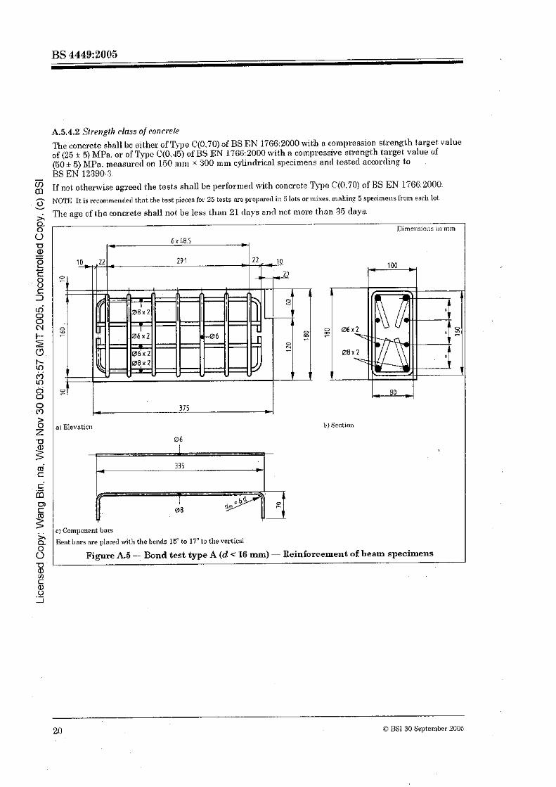
A.5.4.2 Streng.I.11 rims of ronrl-elr
The concrete shall be either: of Tyg~e C(0.70) of BS EN l'i66:2000 with n con~pression strength target value of (25 * 5) MPa. or of Type (1(0,-1.5) of BS EN 1766:2000 with a compressive strength target value of {SO + 5) hlPa, measuretl on 150 nim x :300 mill cylindrical specimens anrl tester1 acmrtlinp la
d
BS EN 12990.3.
If not; othenuise agreed the t.est.s shall be perfo~metl with concrcte Type C(O.'iO) of BS EN l766:2000. 7
NOTE It is rccommenrletl that tbe test pieces for 26 tests are prepnretl in 5 lots or mixes. rnnking 5 specimens hum each lot c;.
The nge of !:he concrete shsll not be less Ihati 21 (lays a n d not inore than 95 clays. a ." . . .-- o r IIirnensin~~s ~n mm
> FJI Elevatici~ b) $ectinn
-0 0 6 I
I -- I
20 6 BSI 30 September 2008
8 Rent bars are placed rvith tho bcnrls 15" to lig to tlievermticd
Figure A.5 - Bond test type A (d < 16 mm) - Reinforcement of beam specimens -a % . . r m U .- A

a) Elevation b) Section
' 1
CJ Component bars . . Bent bars are placerl with the bends 15- to 15" to the vertical
Figure A.6 - Bond test type B (d 3 1G mm) - Reinforcement of beam specimens
A.6 Execution of the tests
Resting tho test beam on trjfu roLtlling linifc-edges 01. rolling bearings. Ioail with two forces of equal magniturlo. clisposecl symmetrically with regard t.o mid-span and lilie.rvise appliecl through movable knZe- edges or rollera. , , 1 he I;ut.al Svrcu. I ; , applied to the test piece is given by one of the following espressionu:.
A,o* $',= --
1.25 ' hr d 16 ini?i
A p 9 ,pa= 1.50 , for d 2 16 111111
where
i l , is the nominal cross-sectional area of the reinforcing steel.
Apply loatling in one of three wfays:
a) in coi~secutive increii~ettts mrrespontling to stresses. 0, in the reinforcing steel of 0 MPa. 80 MPa. 160 RIPa. 240 MPa. etc.: . . b) in smaller increments, or c) continuously, by logging with electronic devices.
Fo'or a) or b), increase the force. a t each stage, gratlually and contjnuously. Reach each increment in half a minute nntl ~iiaintnin the load long enough to stabilize the slip, or. nf; the mosl. for two minutes. For c). use a loatling speed not e~ceecbng a corresponcling stressing rate of 1 MPals in the reinforcing steel.
Measure the slil) at the beginning ant1 a t the end of each increment in loading
BSI 30 Scptemb~r 2005 2 1

C,ont.inue the test until conit,lete bond failure of (.he reinforcing steel occurs in both half-beams or until the reinforcing steel itself fails Bonrl fnilure generally does not. take place simultaneously in t.he two half- beams. For i:his reason. when the half of bhe reillforcing steel ivhase bonil has failed attains a slil) of 3 mm. hold this half-bar in a gripping device which will bear against the concrete nnrl prevent any furt,her slip.
Force-slip curves may be eit,her remrderl automatically. ru. pIottetl point b,y point fioln clial gauge peaclings
A.7 Test results
A.7.1 Calclrlatbn of the bond stress
If the Eotnl force nl~plierl to the Lea111 test is Fo. for a given slip. the bond stress. ~ b . is given by:
where
u* is the stress of the bar, given by one of the €ollotving formulae:
1.5OFa gs = - . for d >, l(j min.
>4
A.7.2 Values of bond stress
Calculate lhe bond stress ibr four lnsasured slip values:
a) roul = Bond stress at 0.01 11i1n ~ l i ~ :
b) TO = Bonil stress at 0.1 mnl slip: c) rl =Bond S(.YRRB a t I 111111 slip: and
rl) rb,, = BoncI stress at ~nasilnum force.
Other values may bc ngrcccl between the parties.
To obtain the four values of slip. record force-slip curves, These shall be n~acle nvadable on request.
A,S Test report . .
The laboratory shall issue a report which sllnll contain the follorving information:
a) identification of the laboratory: b) identification of the manufact.u~e~ of the product tested. c) product nu~iiber; (1) technical class of the reinforcing steel with reference t.o the prorluct specification: e) number of this stantlard (i..e. BS -1449:2005) onrl type of test methoil: f) nonlinal cliameters tested and the' series they represent; g) surface geonaetry of the jpecimen, i.e. ribfintlentntion heights. riblindentation spacing. riblintlentation inclinations ancl relative ribJintlentatio11 area: h) strength class of the concrete. i.e. l'ype C(0.70) or Type C,(0.115) accurtling to BS EN lliGG:2000: i) conlpressive streagth uf the cont:rete at t,he dabe of testing; 1) dates of the t.osts;
k) a11 single test results: 1) description of the failure mode: 111) force.dip curves.
22 Q BST 30 September 2005

Annex B (normative) Material not covered by a third party product certification scheme
B.1 General
PvIaterirtl not ~vvererl by n third party product. certification s c h e ~ i ~ e shall be assessed by acceptance tests on each batch. Sampling ancl testing shall be carried out by nn indepentlent organization at the p~ot1uce~'s ivorks or in t.he s t~ l iho lder '~ yard
B.2 Extent of sampling and testing
For testing purpor;laa. t.he Imtch shnU be clivi[lerl into test units with a masimum mass of 100 t . Each test unit shnll colnprise prorlucts oftthe sanle steel grade and noirtinnl diameter from the same cast The mnnufnct.ure~ shall cert,ify that all proclucts in the test unit 0riginui.e from the saine cast.
Tcst specinlens shall be talien fi-om each test unit as follows:
a) fifceen speciinens fi.0111 cMerent bars. for testing in acoarr\nnce with B.30) ant1 B.3b); b) t.wo test slleciunens, horn [Werent bars. for testing in nmorclance with B.3c).
Preparation of the test specimens shall be ca~ded out as cleacribed in 7.2.2-
B.3 Propeeties to be tested
Specinlens selected in accordance rvit.h B.2 shall bc tester1 f o ~ the follow in^. a) Jnspec~iorr by lymricrbl~s:
1) yielcl strength Re: 2) ten siIe/yielcl ratio R,,,IRe: 3) total elongation at: nlasin~u tn force &-Ig:..
b) Insperlion by crttribrr t ~ s :
1) behaviour in the rebend test; 2) deviations froill the nominal illass per met.re: 3) buncl strength and surface geometry ,
c) Chernical conrposr'lio~r arrordi~~g lo !Ire product ancriysis. All eiernents listecl in 7.1 and the carbon equivalent shall be detertnined.
{I) Fnl i~re p roperfies:
The fatigue properties of rcir~forcing st.eels shnll be determined for each size anrl defined bar shape in-the batch. Sainl~ling and t.est.ing shall be cn~ried out in a m ~ t l a n c e with 7.2.4.
The test procetlure shnll be as clescribeci in Clause 9.
Q BSI 30 timber PO05 2 3

B.4 Evaluation of results
13.4.1 Inspection by varia bks lnsl~ection by variables shall be cnwiecl out a s follows:
- a) The following shall be i1et;enninecl for t,he performance characteri3t.i~~ lister! in B.3a):
V, a 1) all intlividunl values for each of the performance chmncteristics. - 0 Y
2) the ~nenn value m16 of each ofbhe performance characteristics: and
3) the stantlard deviation SI5 Eor each performnnce characteristic
The test unit shall be clee~l~etl to confor~n to this British Stanclarcl if the following contlitions eve met:
nl15 - 2.33 x S,, 2 cv for R,. ant1
In,,- 1 87 x 5;: 2 c*t!for R,,,/R, and .get. 5 ) If the conclit.ions in a) are not. fulljlled. a seconclarg calculnt~ion (the acceptibi1it.y intles I<) shall be rleterminetl. !\!here:
If12 3 2 for Re. and I: 3 1.G for R,,/R, and Aglf testing shall continue. Forty.Eive further t,est sl~edmens shall be taken and tested frola cliflerent barsin the test unit. so that o total of GO rest results are available (r1 = GO).
The test unit shall be cleen~ed to conform to this British Stnndnrtl if the following t~nrlitions are fulfilled:
- 1.93 x!iijO 3 rc. for Be. and
- 1.53 xSI:, 3 c, for R,,,IR, and .;I,,.
B.4.2 Inspection by attribrrfes
Inspection by nttributesshall be carried out a s follows. \&'hen 1:est.ing the properties list;erl in B.3b), either:
a) nU the refiulls cletermined on the 15 test specimens shall conforni to this stnntlaril: or
b) if a maximum of two of the 15 results [lo not co~l'orm to this British Stantlar(1. 45 further test specinlens shall be talcen and testecl from clitr~renl bars in the test unit, nlaliing 60 tost results available: the unit shoII be deenlecl to conform 1.0 this British St.anclarr1 if no more than two of the 60 tesr specjmens fail the tests.
.s B.4.3 Fatigue properties m a, The botch shall be dce~netl to conform to this British Standnrcl if i t confornls to 7.2.4
' C B.5 Test report 5
, s A test report shall be producecl containing the foltowing data:
a) the place of manufacture of the reinforcing steels: 11) the rnll~inal diameter of the steel:
% the p a d e of the steel: UY C cl) the luarliing on the steel; a, -2 e) the cast number; J
f ) the date of testing; g) the Inass of the t e s t unit; nnrl h) the inrlividual test results for all the properties specifiecl in 3.3.
2.1 O BSI 30 September 2005

Annex C (normative) Identification requirements C.1 Bar - Zdentificatian of the manufacturer
C. l . l Ench reinforcing steel shall hear on one rib row. n nlnrlc identifying the ts9r.o~l<s This nwrk shall be repeated at an int;ewal of no(. more than 1.5 la.
G.1.2 The mark shall consist of the following; a) a sq-1114ol denoting the beginning of the ma~k;
b) J) nui~me~lcal syst.em identifying t.he manufacturer. consisting of l:he cvunbry of origin ant1 t.he works number.
(2.1.3 The nu~nericsl system identilying the manufacturer, consisting of n c0un t . r~ number oforigin ant1 n worlis number shall use one of the fallocving methorla:
a) a number of nor11101 ribs between ~viclenecI ribs (for esa~nplo, see Figure C. 1): b) a number of'11ormal ribs between missing ribs: 6)-numbers on the surfaco of Lhe bar:
4) roUec1 or indented marks with a number of norl~ial ribs in bet.~veen them
1 - t --. Y
2 3 4 lies 1 Directiou bfrenrG11~
2 Start
3 Co~mtrj.~ittmber(-t)
I Worlrs n~unbor (16)
Figure C.1- Example of manufacturer's identification mark (using widened ribs)
C.1.4 The syr~lbol indicating the start of the 111ark shall be one of the ~ololl~~ving. a) Where the mnrlcing method uses wictencd ribs. the symbol identifying the start of the mnrli shall consivt of two consecutive wirlenecl ribs (for examp1e see Figure Cf I).
I>) Where the merliing 111ethod uses nlisaing ribs, thc sy~nllol identifying the start of the mnrk shall consist of two consecutive ~nissing ribs.
c) GVhere nunhers are r o h d ~ n t o the surface of the bar. the symb01 indicating the start ofthe mark shall be nn X or 0. (I) Where 31~r l i s are rolled or indenter1 onto the surface. the start of the nznrk shall consist of n clenrIy identi6nble starting aymLol or two nlarlis between one l>ah of normal ribs.
CI BSI 30 Sel,tcmber 2005 25

C.1.5 1%e country of origin shall be inclicated by a number hetween 1 and 9. nccorcling to Table CI 1 (for .
example see Figure C. 1).
C, 1.6 The worlis number shall consist of a one or t-vo digit. nunher between 1 ancl99. escept for mult.iples o l 10 (for esamljle, scc Figure (2.1).
5 Table C. 1 - Identification of the country of origin m n 0 u
C.Z.1 Coil shall be itlentifieil in the same manner as clescribed in C.1 for hnr. 0 C.2.2 For coil. the manufactureis iilentification refers to the works applying the final mechanical u,
ij properties to the mil procluct. In
C.3 Decoiled product Q 0 C.3.1 In adtlition to the ~nonufacturer's itlentification placei1ont.o the procluct? nn iclentificntion riinrlt of the
rlecoiler shall be either ~iincle on #:he prorluct or printed on an attached label. > Q z u
2 m' r c-. 65 m (5
2
Country
Austria. Czech Republic, Gernlany, Poland. Slovalda Reigium, Netherlantls. T,usemhu~:g. Switzerlanrl F~ance. Hungary Italy, Malta. Slovenia
UTi, Irelantl. Iceland enm mark. Estonin. Finl~ni t . 1,ntvia. Lithuania. Norrvay. Swetlen Portugal. Spain Cyprus. Greece Other countries
26 &* BSI 30 September 2005
Country number
1 2
3 1
5 6
7
8 . .
9

Bibliography
Standards puhlicatio~ts
BS EN 1992-1-1:2004 Eurocod~ 2 Desigri ofcorrcrete slr .~~ctr~r~?s - G~~nerirl rlrles [or buildings (fogrlter trrifir 1.111 Ki~tirlgdont Nrrriorlcrl ;ipplicabion Doc~rmen!).
Other publications
[I] RILEM Publications SARI,. Recornnrenrkriio~r RClj*, Bond ipsf for r . e i ~ ~ . f ~ r n r n c ~ n t S I P P I - - Bcrrm~ &st. 2nd Etl. 1982. (~tlro~cl.rillrm,org)
(Cl.BSI 30 September '.'ODE 27
RSI 389 ChisrvicL High Road
London
W4 4AL
. . . . . . . . . . . . . . . . . . . . . . . . . . . . . . . . . . . . . . . . . . . . . . . . . . . . . . . . . . . . . . . . . . . . . . . . . .._*_._ ......, . . . . . . . . . . . . . . . . . . . . . . . . . ........ : ..... . . . . . . . . . . . . . . . . . . . . . . . . . . . . .
BSI - British Standards Institution BSI is t,he indepenilent national body responsibla for 1n:al)ntring British Standards. It presents the Uli view 011 stonclarde in Europe ancl a1: the international level. It is incorpor~tetl by Royal C,hareer.
Revisions
British Standards are updatetl by amendment or revision Users of British Standortls should tnnke sure that they possess the latest alnenrlments or cilit.ions-
If; is khs constant aim of BSI to impruve the quality of our products and services W e woulcl be grateful if anyone lintling nn inaccuracy or ainbiguity while using this Brltish S(.anclarcl would inform the Secretary of the technical cornmi tt ee responsible. t.he identilv of which can be found on the inside front cover. Tel: +44 (0)20 8996 9000. Fas: +411(0)20 8996 7400.
BSI offers menlbers an inrl~v~dual updating service called PI,US which ensures that. slrbscri!jers auto~na trcally receive 1 ho latest editions of sianclarcls.
Buying standards
Ortlers for all BSI. internat:ional ant1 foreign stnnclarcls publications shoultl be arlclressed to Customer Services. Tel: +-I4 (0)20 8996 9001. Fax: +34 (0)20 8996 7001 Email: ~rder~bs i -dobnl . co in . Standarcls are also availabIe from the BSI website at htb~:llwrvw.bsi-~1obal.cam.
In response to orclers far international stanclaxcls, it is BSI policy to supldy the RSI inq~lon~entation of those that have been publishecl as British St.andarrls, unleas otherrvise requested.
Information on standards
BSI provitles a wide range of infor~uatiun on nat,ianal. European and international standards through its Library and its Technical Help to Exporters Service. Varioua BSI electronic in10nnation services are also available which give details on all its proclucts ancl selvices. Cuntact the Infonnot.ion Centre. Tel; t.11 ((920 8996 "i tl. Fas; +44 (0)20 8996 7048. Email: inf&bsi-g1obol.com.
Subscribing nienlbers of BSI are Iiept up ta date with standards developnlents ant1 receive substantial discounts ott the purchase 11ric:e of standarcls. For cletails of these and other benefits contad: RIen~bershi~~ Administrntion Tel: t.44 (0120 8996 7002. Pax: + 4:1. (0520 8996 7001. Ernail: [email protected].
Information regartling online access to British Standards via British Stnntlarcla Online can be found at: httt~://wwrv.bsi-rlobal.conihsonline
Further infortnation allout BSI is available on the BSI website a t htt~~:/lrvrv\v.bui-g1obal.com.
Copyriglit
Copyright subsists in all BSI publications. BSI also halrls tthe c~py~ight. in the TJli of !:he publications of the international standertlization boclies. Except as permittetl under the Copyright. Designs and Patents Act 1988 nu cstract nlny be reproducecl. storecl in a retrieval system or transmitted in any forin or by any means - electronic. photocopying. recording or otherwise -without prior writtcn permission Eron~ BSI.
This does not preclutle the free use, in the course of implementing the stanrlard. of necevsnry details such as symbols. and size. type or grade deGgnations. If these details are to be used fur any other purpose than i~nplement.ntion then the prior written permission of BSI niust be obtained.
Details i~ntl advice can be obtained horn the Copyright. & Licensing Manager Tel; +44 (0120 8996 7070. Fas: +&id (1320 8996 7553. Email: ml,yrichi;@bsi-global.con1.