Licensed Copy: Sheffield University, University of ... 4449-1997_1320141574.pdf · BS 4449:1997...
25
Licensed Copy: Sheffield University, University of Sheffield, 25 March 2003, Uncontrolled Copy, (c) BSI
Transcript of Licensed Copy: Sheffield University, University of ... 4449-1997_1320141574.pdf · BS 4449:1997...

Lice
nsed
Cop
y: S
heffi
eld
Uni
vers
ity, U
nive
rsity
of S
heffi
eld,
25
Mar
ch 2
003,
Unc
ontr
olle
d C
opy,
(c)
BS
I

BRITISH STANDARD BS 4449:1997Incorporating Amendment No. 1
Specification for
Carbon steel bars for the reinforcement of concrete
ICS 77.140.15; 91.080.40
NO COPYING WITHOUT BSI PERMISSION EXCEPT AS PERMITTED BY COPYRIGHT LAW
Lice
nsed
Cop
y: S
heffi
eld
Uni
vers
ity, U
nive
rsity
of S
heffi
eld,
25
Mar
ch 2
003,
Unc
ontr
olle
d C
opy,
(c)
BS
I

BS 4449:1997
This British Standard, having been prepared under thedirection of the EngineeringSector Board, was publishedunder the authority of the Standards Board and comes into effect on15 May 1997
© BSI 07-2001
First published: BS 4449: April 1969 BS 4461: March 1969First revision: BS 4449: May 1978BS 4461: May 1978Second combinedversion as:BS 4449: May 1988
The following BSI referencesrelate to the work on this standard:Committee reference ISE/9/1
ISBN 0 580 27346 6
Committees responsible for this British Standard
The preparation of this British Standard was entrusted by Technical Committee ISE/9, Reinforcing steels, to Subcommittee ISE/9/1, Bar, wire and fabric for concrete reinforcement, upon which the following bodies were represented:
British Cement Association
British Coatings Federation
British Iron and Steel Producers’ Association
British Precast Concrete Federation
Concrete Society
Dept. of Environment – Building Research Establishment
Dept. of Transport – Highways Agency
Electricity Association
Institution of Structural Engineers
UK Certification Authority for Reinforcing Steels
Amendments issued since publication
Amd. No. Date Comments
12032 September 2001 Indicated by a sideline
Lice
nsed
Cop
y: S
heffi
eld
Uni
vers
ity, U
nive
rsity
of S
heffi
eld,
25
Mar
ch 2
003,
Unc
ontr
olle
d C
opy,
(c)
BS
I

BS 4449:1997
© BSI 07-2001 i
Contents
PageCommittees responsible Inside front coverForeword ii
1 Scope 12 References 13 Definitions 14 Sizes 25 Cross sectional area and mass 36 Length 37 Steelmaking process 38 Chemical composition 49 Bond classification of deformed bars 510 Routine inspection and testing 511 Mechanical properties 512 Fatigue properties of deformed bars 613 Retests 614 Verification of mechanical properties 615 Product identification 7
Annex A (informative) Information to be supplied by the purchaser 8Annex B (normative) Determination of the effective cross sectional area of deformed bars 8Annex C (informative) Recommended formulae for calculating projected rib area 9Annex D (normative) Bond classification of deformed bars (bond test) 9Annex E (normative) Inspection, testing and certification 12Annex F (normative) Method of test for fatigue properties of deformed bars 17Annex G (normative) Multiplying factors for tensile tests 18
Figure 1 — Example of rib pattern of grade 460A with four transverserib series 7Figure 2 — Example of rib pattern of grade 460B with four transverserib series 7Figure D.1 — Typical mould for bond performance testing 11
Table 1 — Preferred nominal sizes 2Table 2 — Cross sectional area and mass 3Table 3 — Tolerance on mass 3Table 4 — Chemical composition of steel grades: cast analysis 4Table 5 — Maximum carbon equivalent values: cast analysis 4Table 6 — Maximum deviations in chemical composition on product analysis 4Table 7 — Tensile properties 6Table E.1 — Percentage total strain 12Table E.2 — Rebend test formers 13Table E.3 — Acceptability index k as a function of the number of test results n [for a reliable failure rate of 5 % (pass = 0.95) at a probabilityof 90 % (1 – a = 0.90)] 14Table F.1 — Test stress ranges for nominal bar sizes 17
List of references Inside back cover
Lice
nsed
Cop
y: S
heffi
eld
Uni
vers
ity, U
nive
rsity
of S
heffi
eld,
25
Mar
ch 2
003,
Unc
ontr
olle
d C
opy,
(c)
BS
I

BS 4449:1997
ii © BSI 07-2001
Foreword
This British Standard has been prepared by Technical Committee ISE/9/1, and is a revision of BS 4449:1988, which is withdrawn.
This edition introduces technical changes but it does not reflect a full review or revision of the standard, which will be undertaken in due course. This edition contains some of the requirements that are contained in DD ENV 10080, and aims to prepare the UK market for the eventual publication of EN 10080.
A British Standard does not purport to include all the necessary provisions of a contract. Users of British Standards are responsible for their correct application.
Compliance with a British Standard does not of itself confer immunity from legal obligations.
Summary of pagesThis document comprises a front cover, an inside front cover, pages i and ii, pages 1 to 18, an inside back cover and a back cover.
The BSI copyright notice displayed in this document indicates when the document was last issued.
Sidelining in this document indicates the most recent changes by amendment.
Lice
nsed
Cop
y: S
heffi
eld
Uni
vers
ity, U
nive
rsity
of S
heffi
eld,
25
Mar
ch 2
003,
Unc
ontr
olle
d C
opy,
(c)
BS
I

BS 4449:1997
© BSI 07-2001 1
1 Scope
This British Standard specifies requirements for weldable steel bars for reinforcement of concrete. It covers plain round steel bars in grade 250, and deformed (type 1 and type 2) high yield steel bars in grade 460, the latter in two ductility categories, 460A and 460B.
The weldability requirements for both grades of steel are specified in terms of the carbon equivalent value.
A testing facility for material covered by a third party product certification scheme, and a testing facility for material not covered by such a scheme, are provided.
Steel bars for use as lifting hooks are not included in this British Standard.
Steel bars produced by re-rolling finished products, or by rolling material of which the metallurgical history is not fully documented or not known, are not covered by this British Standard.NOTE 1 Flash welds in lengths of bar are permissible. However, for some purposes, purchasers may specifically require bars without flash welds. For this reason, the manufacturer should enquire whether flash welds are acceptable for the purposes of the purchaser at the time of enquiry and/or order (see Annex A).
NOTE 2 All steels conforming to this British Standard are of weldable quality. Appropriate welding procedures and consumables, to each particular grade and quality, should be used (see BS 7123).
2 References2.1 Normative references
This British Standard incorporates, by dated or undated reference, provisions from other publications. These normative references are made at the appropriate places in the text and the cited publications are listed on the inside back cover. For dated references, only the edition cited applies; any subsequent amendments to or revisions of the cited publication apply to this British Standard only when incorporated in the reference by amendment or revision. For undated references, the latest edition of the cited publication applies, together with any amendments.
2.2 Informative references
This British Standard refers to other publications that provide information or guidance. Editions of these publications current at the time of issue of this standard are listed on the inside back cover, but reference should be made to the latest editions.
3 DefinitionsFor the purposes of this British Standard the following definitions apply.
3.1 bara steel product of plain round or deformed cross section
3.2 hot rolled deformed bara bar that has been so shaped during hot rolling that it conforms to either the geometrical or the performance test classification given in clause 9
3.3 cold worked deformed bara bar that has been cold worked to conform to the property requirements of this British Standard and that conforms to either the geometrical or the performance test classification given in clause 9
3.4 nominal sizethe diameter of a circle with an area equal to the effective cross sectional area of the barNOTE See clause 4 and Annex B.
3.5 coila continuous as-rolled bar in the form of a coil
Lice
nsed
Cop
y: S
heffi
eld
Uni
vers
ity, U
nive
rsity
of S
heffi
eld,
25
Mar
ch 2
003,
Unc
ontr
olle
d C
opy,
(c)
BS
I

BS 4449:1997
2 © BSI 07-2001
3.6 lengtha piece of nominally straight bar cut to a specified length
3.7 bundletwo or more coils or a number of lengths properly bound together
3.8 batchany quantity of bars of one size and grade, whether in coils or bundles, produced by one manufacturer or supplier, presented for examination at any one time
3.9 longitudinal riba uniform continuous protrusion parallel to the axis of the bar, before twisting in the case of cold twisted bars
3.10 transverse ribany rib on the surface of the bar other than a longitudinal rib
3.11 flash weldresistance butt weld, in which the components are progressively advanced towards each other, while the electric current, confined to localized points of contact, causes molten metal to be expelled. When welding temperature is reached, upset force is applied
3.12 manufactureran organization that produces reinforcing steel. This includes steelmakers, re-rollers and cold workers
3.13 supplierany organization supplying reinforcing steel to an end userNOTE Reinforcing steel may be supplied in lengths or coil, or fabricated in accordance with BS 4466.
3.14 characteristic strengththe value of yield strength having a prescribed probability of not being attained in a hypothetical unlimited test series. The characteristic value is the lower limit of the one sided statistical tolerance interval at which there is a 90 % probability (i.e. l – a = 0.90) that 95 % (p = 0.95) of the values are at or above this lower limit. This definition refers to the long-term quality level of production
4 Sizes
4.1 Range
The range of nominal sizes of bars in grades 250 and 460 shall be from 6 mm to 50 mm.NOTE The preferred nominal sizes of bars are given in Table 1.
Table 1 — Preferred nominal sizes
Grade Nominal sizemm
250 8, 10, 12, 16
460 8, 10, 12, 16, 20, 25, 32, 40NOTE 1 If a bar smaller than 8 mm is required, the recommended size is 6 mm.
NOTE 2 If a bar larger than 40 mm is required, the recommended size is 50 mm.
Lice
nsed
Cop
y: S
heffi
eld
Uni
vers
ity, U
nive
rsity
of S
heffi
eld,
25
Mar
ch 2
003,
Unc
ontr
olle
d C
opy,
(c)
BS
I
BS 4449:1997
© BSI 07-2001 3
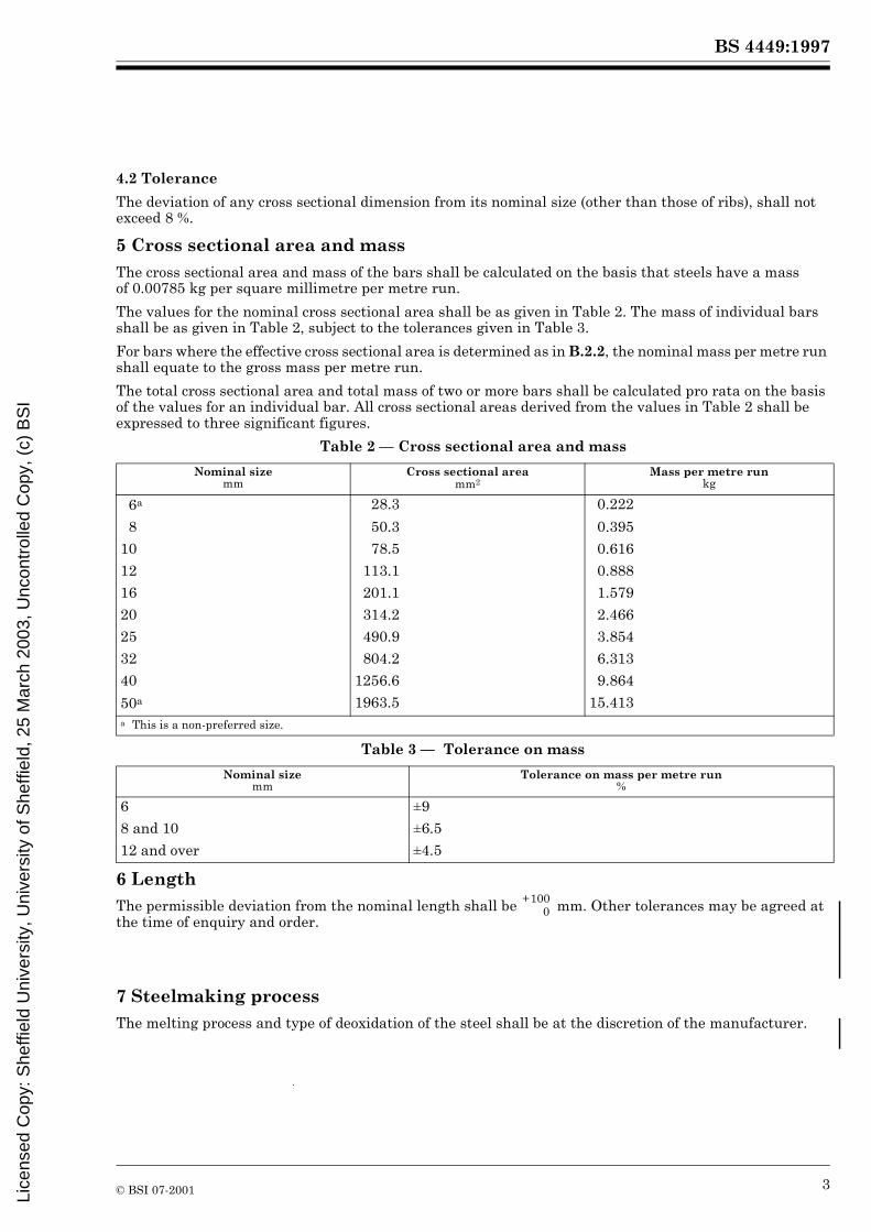
4.2 Tolerance
The deviation of any cross sectional dimension from its nominal size (other than those of ribs), shall not exceed 8 %.
5 Cross sectional area and mass
The cross sectional area and mass of the bars shall be calculated on the basis that steels have a mass of 0.00785 kg per square millimetre per metre run.
The values for the nominal cross sectional area shall be as given in Table 2. The mass of individual bars shall be as given in Table 2, subject to the tolerances given in Table 3.
For bars where the effective cross sectional area is determined as in B.2.2, the nominal mass per metre run shall equate to the gross mass per metre run.
The total cross sectional area and total mass of two or more bars shall be calculated pro rata on the basis of the values for an individual bar. All cross sectional areas derived from the values in Table 2 shall be expressed to three significant figures.
Table 2 — Cross sectional area and mass
Table 3 — Tolerance on mass
6 LengthThe permissible deviation from the nominal length shall be mm. Other tolerances may be agreed at the time of enquiry and order.
7 Steelmaking processThe melting process and type of deoxidation of the steel shall be at the discretion of the manufacturer.
Nominal sizemm
Cross sectional area mm2
Mass per metre run kg
6a 28.3 0.222
8 50.3 0.395
10 78.5 0.616
12 113.1 0.888
16 201.1 1.579
20 314.2 2.466
25 490.9 3.854
32 804.2 6.313
40 1256.6 9.864
50a 1963.5 15.413a This is a non-preferred size.
Nominal size mm
Tolerance on mass per metre run %
6 ±9
8 and 10 ±6.5
12 and over ±4.5
+1000
Lice
nsed
Cop
y: S
heffi
eld
Uni
vers
ity, U
nive
rsity
of S
heffi
eld,
25
Mar
ch 2
003,
Unc
ontr
olle
d C
opy,
(c)
BS
I

BS 4449:1997
4 © BSI 07-2001
8 Chemical composition
8.1 Cast analysis
The chemical composition of the steel, based on cast analysis, shall be in accordance with Table 4.
Bars of both grades shall have a carbon equivalent value, based on cast analysis, not exceeding the maximum values given in Table 5.
The following formula shall be used to calculate the carbon equivalent value, where the chemical symbols represent the percentages of each element:
In cases of dispute, the appropriate methods of test given in BS 6200-3 shall be used.
Table 4 — Chemical composition of steel grades: cast analysis
Table 5 — Maximum carbon equivalent values: cast analysis
8.2 Product analysis and permitted deviations
8.2.1 The maximum deviations on product analysis from the values specified for cast analysis (see Table 4 and Table 5) shall be as given in Table 6.NOTE The product analysis may vary from the cast analysis due to chemical heterogeneity arising during the casting and solidification processes.
Table 6 — Maximum deviations in chemical composition on product analysis
8.2.2 Samples for product analysis shall be taken in accordance with the appropriate method ofBS 6200-3.
8.2.3 During product analysis, any bar that falls outside the maximum deviation limits for the composition range of a specified element, given in Table 6, shall be deemed not to conform to this British Standard.
Element Grade 250% (max.)
Grade 460 % (max.)
Carbon 0.25 0.25
Sulfur 0.060 0.050
Phosphorus 0.060 0.050
Nitrogen 0.012 0.012NOTE 1 The maximum value for nitrogen does not apply if the chemical composition shows a minimum aluminium content of 0.020 %, or if sufficient other nitrogen binding elements are present.
NOTE 2 Nitrogen content is not normally given on a release certificate.
Grade Maximum carbon equivalent value%
250 0.42
460 0.51
Element Deviation above the specified maximum given in Table 4 and Table 5
%
Carbon 0.02
Sulfur 0.005
Phosphorus 0.005
Total nitrogen 0.001
Carbon equivalent value 0.03
carbon equivalent value = C Mn6
--------- Cr Mo V+ +5
--------------------------------- Ni Cu+15
---------------------+ + +
Lice
nsed
Cop
y: S
heffi
eld
Uni
vers
ity, U
nive
rsity
of S
heffi
eld,
25
Mar
ch 2
003,
Unc
ontr
olle
d C
opy,
(c)
BS
I
BS 4449:1997
© BSI 07-2001 5
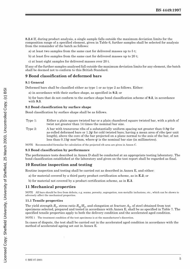
8.2.4 If, during product analysis, a single sample falls outside the maximum deviation limits for the composition range of a specified element, given in Table 6, further samples shall be selected for analysis from the remainder of the batch as follows:
a) at least two samples from the same cast for delivered masses up to 5 t;
b) at least five samples from the same cast for delivered masses up to 20 t;
c) at least eight samples for delivered masses over 20 t.
If any of the further samples analysed fall outside the maximum deviation limits for any element, the batch shall be deemed not to conform to this British Standard.
9 Bond classification of deformed bars
9.1 General
Deformed bars shall be classified either as type 1 or as type 2 as follows. Either:
a) in accordance with their surface shape, as specified in 9.2; or
b) for bars that do not conform to the surface shape bond classification scheme of 9.2, in accordance with 9.3.
9.2 Bond classification by surface shape
Bond classification by surface shape shall be as follows.
NOTE Recommended formulae for calculation of the projected rib area are given in Annex C.
9.3 Bond classification by performance
The performance tests described in Annex D shall be conducted at an appropriate testing laboratory. The bond classification established at the laboratory and given on the test report shall be regarded as final.
10 Routine inspection and testing
Routine inspection and testing shall be carried out as described in Annex E, and either:
a) for material covered by a third party product certification scheme, as in E.2; or
b) for material not covered by a product certification scheme, as in E.3.
11 Mechanical propertiesNOTE All bars should be free from defects, e.g. seams, porosity, segregation, non-metallic inclusions, etc., which can be shown to adversely affect the mechanical properties.
11.1 Tensile properties
The yield strength Re, stress ratio Rm/Re, and elongation at fracture A5, of steel obtained from test specimens selected, prepared and tested in accordance with Annex E, shall be as specified in Table 7. The specified tensile properties apply to both the delivery condition and the accelerated aged condition.NOTE 1 The treatment condition of the test specimens is at the manufacturer’s discretion.
In cases of dispute, the test shall be carried out in the accelerated aged condition in accordance with the method of accelerated ageing set out in Annex E.
Type 1: Either a plain square twisted bar or a plain chamfered square twisted bar, with a pitch of twist not greater than 14 times the nominal bar size.
Type 2: A bar with transverse ribs of a substantially uniform spacing not greater than 0.8��for as-rolled deformed bars or 1.2� for cold twisted bars; having a mean area of ribs (per unit length), above the core of the bar projected on a plane normal to the axis of the bar, of not less than 0.15� mm2/mm, where � is the nominal bar size (in millimetres).
Lice
nsed
Cop
y: S
heffi
eld
Uni
vers
ity, U
nive
rsity
of S
heffi
eld,
25
Mar
ch 2
003,
Unc
ontr
olle
d C
opy,
(c)
BS
I

BS 4449:1997
6 © BSI 07-2001
Table 7 — Tensile properties
11.2 Total elongation at maximum force Agt
The total elongation at maximum force Agt shall be determined in accordance with ISO 10606. Measurements shall be made and recorded and available for inspection, but if the total elongation is below the minimum value specified in Table 7, this shall not be a cause for non-conformity with this British Standard.
11.3 Rebend test
Specimens selected to undergo the rebend test (E.1.6) shall show no sign of fracture or irregular bending deformation.
12 Fatigue properties of deformed barsDeformed bars shall be subjected to type testing, as described in Annex F, to determine the fatigue characteristics of a particular geometrical shape. The fatigue characteristics shall be confirmed by periodic testing on the basis of a three year cycle.
For both type and periodic testing, deformed bars shall endure 5 � 106 cycles of stress.
13 RetestsIf any test specimen fails to meet the yield strength, stress ratio, elongation at fracture, or rebend test requirements, two additional test specimens shall be taken from different bars of the same batch to undergo retests. If both additional test specimens pass the retests, the batch shall be deemed to conform to this British Standard. If either of the additional test specimens fail the retests, the batch shall be deemed not to conform to this British Standard.
14 Verification of mechanical properties
14.1 Where the mechanical properties of a material are in dispute, they shall be verified by selecting and testing three specimens from different bars in the batch. If any of the test specimens fails to conform to 11.1 or 11.3, subclause 14.2 shall apply. If all three specimens pass the tests, the batch shall be deemed to conform to this British Standard.
14.2 If one or more specimens fail the tests in 14.1, ten more specimens shall be selected, from different bars in the batch, for testing.
If, for characteristic strength tests, any one test result from the ten specimens is less than 95 % of the value specified in Table 7, or if any one of the ten specimens fails the tests for the other properties, then both the test specimen and the test method shall be carefully examined. If there is a local fault in the specimen, or if there is reason to believe that an error has occurred in the test, the bar from which the test specimen was taken shall be disregarded and the test result shall be ignored.
If test failures as described above occur, and no local faults are found in test specimens and no errors are found in the tests, then the batch shall be deemed not to conform to this British Standard.
Grade Yield strength Rea Stress ratio Rm/Re
b (min.)
Elongation at fracture A5 (min.)
Total elongation at maximum force Agt
c (min.)
N/mm2 % %
250 250 1.15 22 —
460Ad 460 1.05 12 2.5
460Bd 460 1.08 14 5a For routine testing the yield strength shall be considered a minimum value. For determination of the long term quality level, the
values given shall be for the characteristic strength (see 3.14).b Rm is the tensile strength.c The total elongation at maximum force shall be measured and recorded and available for inspection, but values obtained below
the minimum values specified shall not be a cause for non-conformity with this British Standard.d Ductility classes A and B are designated ductility classes N and H respectively in DD ENV 1992-1-1:1992.
Lice
nsed
Cop
y: S
heffi
eld
Uni
vers
ity, U
nive
rsity
of S
heffi
eld,
25
Mar
ch 2
003,
Unc
ontr
olle
d C
opy,
(c)
BS
I
BS 4449:1997
© BSI 07-2001 7
15 Product identification
15.1 Identification of steel grade 460 — type 2 (ribbed) bars
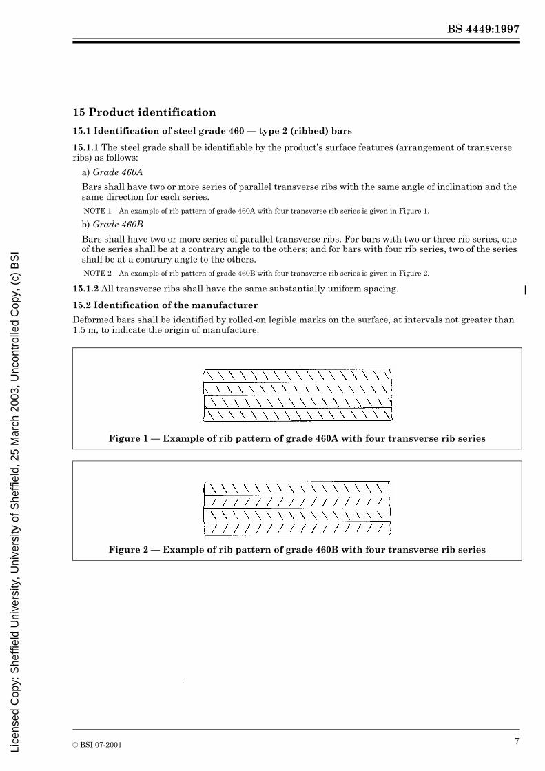
15.1.1 The steel grade shall be identifiable by the product’s surface features (arrangement of transverse ribs) as follows:
a) Grade 460A
Bars shall have two or more series of parallel transverse ribs with the same angle of inclination and the same direction for each series. NOTE 1 An example of rib pattern of grade 460A with four transverse rib series is given in Figure 1.
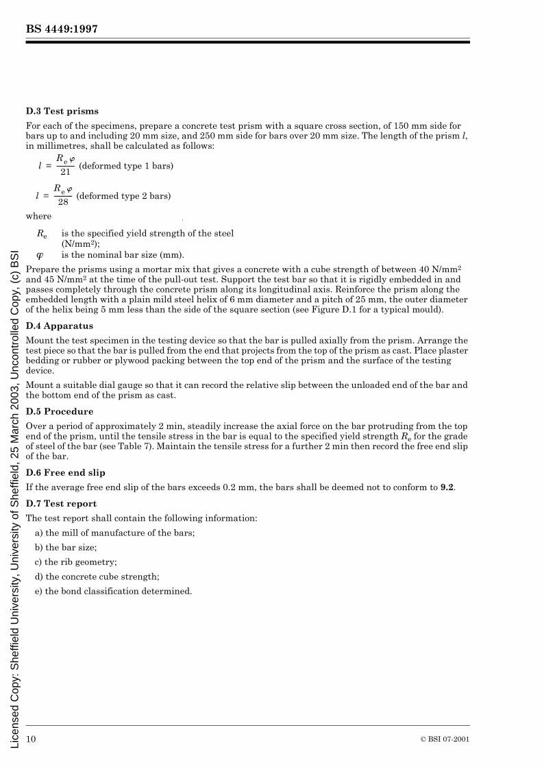
b) Grade 460B
Bars shall have two or more series of parallel transverse ribs. For bars with two or three rib series, one of the series shall be at a contrary angle to the others; and for bars with four rib series, two of the series shall be at a contrary angle to the others. NOTE 2 An example of rib pattern of grade 460B with four transverse rib series is given in Figure 2.
15.1.2 All transverse ribs shall have the same substantially uniform spacing.
15.2 Identification of the manufacturer
Deformed bars shall be identified by rolled-on legible marks on the surface, at intervals not greater than 1.5 m, to indicate the origin of manufacture.
Figure 1 — Example of rib pattern of grade 460A with four transverse rib series
Figure 2 — Example of rib pattern of grade 460B with four transverse rib series
Lice
nsed
Cop
y: S
heffi
eld
Uni
vers
ity, U
nive
rsity
of S
heffi
eld,
25
Mar
ch 2
003,
Unc
ontr
olle
d C
opy,
(c)
BS
I

BS 4449:1997
8 © BSI 07-2001
Annex A (informative)Information to be supplied by the purchaser
The manufacturer should obtain the following basic information from the purchaser at the time of enquiry and/or order:
a) the nominal size of the bars;b) the length of the bars;c) the steel grade;d) the bond classification;e) whether or not flash welds are acceptable;f) any additional requirements.
Annex B (normative)Determination of the effective cross sectional area of deformed bars
B.1 Uniform cross sectional area
For bars where the configuration is such that, by visual inspection, the cross sectional area is substantially uniform along the length of the bar, the effective cross sectional area A shall be the gross cross sectional area, in millimetres squared, determined by weighing and measuring, to a precision of ±0.5 %, a length of not less than 0.5 m, and calculating as follows:
where
B.2 Variable cross sectional area
B.2.1 For a bar of which the cross sectional area varies along its length, a sample of not less than 0.5 m shall be weighed and measured, to a precision of ±0.5 %, first in the as-manufactured condition, and then again after removing the transverse ribs.
B.2.2 Where the difference between the mass of the as-manufactured bar (M) and the mass of the bar with the ribs removed (M�) is less than 3 % of M�, the effective cross sectional area shall be determined as in B.2.
B.2.3 Where the difference between the two masses (M – M�) is 3 % of M� or above, the effective cross sectional area A, in millimetres squared, shall be calculated as follows:
where
For routine test purposes, a nominal ratio of effective to gross cross sectional area shall be stated and used by the manufacturer.
M is the mass of the bar (kg);
L is the length of the bar (m).
M is the mass of the bar with the transverse ribs removed (kg);L is the length of the bar (m).
A M0.00785L--------------------------=
A 1.03M�0.00785L--------------------------=
Lice
nsed
Cop
y: S
heffi
eld
Uni
vers
ity, U
nive
rsity
of S
heffi
eld,
25
Mar
ch 2
003,
Unc
ontr
olle
d C
opy,
(c)
BS
I

BS 4449:1997
© BSI 07-2001 9
Annex C (informative)Recommended formulae for calculating projected rib area
The projected rib area R, in millimetres squared per millimetre length of bar, should be calculated for ribbed bars using one of the following equations:
a) for as-rolled deformed bars:
b) for cold twisted bars:
where
NOTE 1 If more than one pattern of transverse ribs exists, e.g. alternate ribs are set at different angles, or there are different rib patterns in each row, the term containing n should be calculated for each different set of ribs, and the summation of the values obtained.
NOTE 2 The length of the transverse rib is measured at the rib to core interface. The length should be determined as the average of three measurements on each row or set of transverse ribs.
NOTE 3 The height of the transverse rib is measured perpendicular to the core of the bar. The height should be determined as the average of three measurements on each row or set of transverse ribs. (Using Simpson’s rule for approximation under a curve, with rib height measurements at the mid and quarter points, the rib height for each rib profile may be established as a proportion of its mid point height. For transverse ribs of parobolic profile, the rib height should be taken as two thirds of the mid point height.)
NOTE 4 The centre to centre spacing between transverse ribs is determined by dividing the distance, measured parallel to the axis of the bar, between the mid points of two ribs, of about ten ribs apart, by the number of rib spaces in between. For twisted bars, the rib spaces should be counted in a helical fashion.
NOTE 5 The height of the longitudinal rib is determined as the average of three measurements on each rib.
NOTE 6 The pitch of twist measured parallel to the bar axis is determined as the average of three measurements.
Annex D (normative)Bond classification of deformed bars (bond test)
D.1 Principle
The principle of the test is to show that deformed bars, that have been claimed to conform to 9.2, can hold, for a given time, the specified yield strength (see Table 7) in a pull-out test with a free end slip not greater than 0.2 mm.
D.2 Selection of test specimens
For a range of sizes of bar that are geometrically similar in shape, tests shall be carried out on two sizes.NOTE Tests should preferably be carried out on bars of 20 mm and the largest available size.
The surface shape of the bars to be tested shall conform to the manufacturer’s published specification, and shall be as near as possible to the minimum deformation. Six specimens of each size shall be tested.
n is the number of rows of transverse ribs (see note 1);l is the length of the transverse rib (mm) (see note 2);ht is the height of the transverse rib (mm) (see note 3);
� is the angle between the centre line of the transverse rib and the bar axis (�);c is the centre to centre spacing between transverse ribs (mm) (see note 4);N is the number of longitudinal ribs;h1 is the height of the longitudinal rib (mm) (see note 5);
p is the pitch of twist measured parallel to the bar axis (mm) (see note 6);� is the nominal bar size.
R n lh t sin �
c------------------------� �� �=
R n lh t sin �
c------------------------� �� �=
Nh1��
p--------------------� �� �+
Lice
nsed
Cop
y: S
heffi
eld
Uni
vers
ity, U
nive
rsity
of S
heffi
eld,
25
Mar
ch 2
003,
Unc
ontr
olle
d C
opy,
(c)
BS
I
BS 4449:1997
10 © BSI 07-2001
D.3 Test prisms
For each of the specimens, prepare a concrete test prism with a square cross section, of 150 mm side for bars up to and including 20 mm size, and 250 mm side for bars over 20 mm size. The length of the prism l, in millimetres, shall be calculated as follows:
where
Prepare the prisms using a mortar mix that gives a concrete with a cube strength of between 40 N/mm2 and 45 N/mm2 at the time of the pull-out test. Support the test bar so that it is rigidly embedded in and passes completely through the concrete prism along its longitudinal axis. Reinforce the prism along the embedded length with a plain mild steel helix of 6 mm diameter and a pitch of 25 mm, the outer diameter of the helix being 5 mm less than the side of the square section (see Figure D.1 for a typical mould).
D.4 Apparatus
Mount the test specimen in the testing device so that the bar is pulled axially from the prism. Arrange the test piece so that the bar is pulled from the end that projects from the top of the prism as cast. Place plaster bedding or rubber or plywood packing between the top end of the prism and the surface of the testing device.
Mount a suitable dial gauge so that it can record the relative slip between the unloaded end of the bar and the bottom end of the prism as cast.
D.5 Procedure
Over a period of approximately 2 min, steadily increase the axial force on the bar protruding from the top end of the prism, until the tensile stress in the bar is equal to the specified yield strength Re for the grade of steel of the bar (see Table 7). Maintain the tensile stress for a further 2 min then record the free end slip of the bar.
D.6 Free end slip
If the average free end slip of the bars exceeds 0.2 mm, the bars shall be deemed not to conform to 9.2.
D.7 Test report
The test report shall contain the following information:
a) the mill of manufacture of the bars;
b) the bar size;
c) the rib geometry;
d) the concrete cube strength;
e) the bond classification determined.
Re is the specified yield strength of the steel (N/mm2);
� is the nominal bar size (mm).
lR e �
21------------ (deformed type 1 bars)=
lR e �
28------------ (deformed type 2 bars)=
Lice
nsed
Cop
y: S
heffi
eld
Uni
vers
ity, U
nive
rsity
of S
heffi
eld,
25
Mar
ch 2
003,
Unc
ontr
olle
d C
opy,
(c)
BS
I

BS 4449:1997
© BSI 07-2001 11
Figure D.1 — Typical mould for bond performance testing
Lice
nsed
Cop
y: S
heffi
eld
Uni
vers
ity, U
nive
rsity
of S
heffi
eld,
25
Mar
ch 2
003,
Unc
ontr
olle
d C
opy,
(c)
BS
I

BS 4449:1997
12 © BSI 07-2001
Annex E (normative)Inspection, testing and certification
E.1 Manufacturer’s inspection
E.1.1 General
All units of continuous production shall be tested in accordance with E.1.2, E.1.3, E.1.4, E.1.5, E.1.6, E.1.7 and E.1.8.
E.1.2 Selection of test specimens
The unit of production from which test specimens are selected shall be the cast.
Test specimens shall be either at least 600 mm long or 20 times the nominal size, whichever is the greater. The rate of testing shall be:
a) for casts of 100 t or less: three tensile tests and one rebend test;
b) for casts greater than 100 t: three tensile tests and one rebend test for the first 100 t, and an additional tensile test and rebend test for each full (or part over) 30 t remaining.
E.1.3 Condition of test specimens
The tensile and rebend tests shall be carried out on straight bars in the delivery or accelerated aged condition. Bars with a nominal diameter of 40 mm or less shall not be machined.NOTE 1 At the option of the manufacturer or supplier, and in order to simulate natural ageing, test specimens may be subjected to a temperature of 100 �C for a period of not more than 2 h, provided that both the tensile and rebend test samples are treated in the same way, and that this is recorded on the test certificates.
NOTE 2 In the case of 50 mm hot rolled grade 460 bars, where a tensile testing machine of adequate capacity is not available, the bars may be machined to 40 mm diameter prior to tensile testing, provided that there are known multiplying factors determined by testing similar specimens of the bars as-rolled and machined (see Annex G).
E.1.4 Tensile test
The tensile strength, yield strength and elongation at fracture A5 shall be determined by the methods described in BS EN 10002-1. The upper yield strength ReH shall be determined for steels showing a defined yield point. If this is not applicable, or at the discretion of the manufacturer, the 0.2 % proof stress Rp0.2 shall be determined, using an extensometer calibrated to class 2 of BS EN 10002-4, using a strain rate corresponding to a rate of loading not exceeding 10 N/mm2 per second approaching the yield strength.NOTE 1 At the option of the manufacturer, for routine testing, the percentage total strain may be determined as an alternative to the 0.2 % proof stress. This is the stress on the specimen, derived from the load, corresponding to an increase in percentage total strain as specified in Table E.1. The strain may be measured by the extensometer in any convenient gauge length.
The 0.2 % proof stress shall be used in cases of dispute.
Table E.1 — Percentage total strain
NOTE 2 It is recommended that test pieces are lightly scribed at one diameter d or 10 mm centres (whichever is more convenient) throughout their length, and that a gauge length clear of the machine grips and as nearly symmetrical about the fracture as possible is selected.
For elongation values, the test results shall be regarded as valid, irrespective of the position of the fracture, provided that the minimum elongation specified in Table 7 has been obtained.
Where the minimum elongation is not obtained, the sample shall be deemed not to conform to this British Standard, except if the relevant end of the gauge length used for measuring the elongation is 2d or less from the face of the machine grips. In this case the test shall be considered invalid.
Calculate the stresses using the effective cross sectional area of the bar determined as described in Annex B.
Steel grade Total strain%
250 0.33
460 0.43
Lice
nsed
Cop
y: S
heffi
eld
Uni
vers
ity, U
nive
rsity
of S
heffi
eld,
25
Mar
ch 2
003,
Unc
ontr
olle
d C
opy,
(c)
BS
I

BS 4449:1997
© BSI 07-2001 13
E.1.5 Evaluation of tensile test results
All tensile test results shall conform to 11.1 and Table 7.
E.1.6 Rebend test
E.1.6.1 Sequence of operations
The rebend test specimens shall be subjected to the following.
a) The specimen shall be bent through an angle of 45�, using a former of diameter specified inTable E.2, and at a temperature of between 5 �C and 30 �C� so as to produce a continuous and uniform bending deformation (curvature) at every section of the bend. The test shall be conducted either:
1) on a bending machine in which the test specimen is supported by plain smooth surfaces or rolls that do not resist longitudinal movement of the test piece; or
2) on a three-point hydraulic bending machine.
The test machine shall be serviceable and able to impart a constant load to the specimen, and shall be without impact effect. The maximum bending rate shall be 3 r/min or equivalent.
b) The test specimen shall be heated to 100 �C and maintained at this temperature for at least 30 min.NOTE The method of heating is at the discretion of the manufacturer.
c) The test specimen shall be allowed to cool to a temperature of between 5 �C and 30 �C, and partially re-straightened by a steadily applied force, through at least 23�, on a bending machine used in a)�
Table E.2 — Rebend test formers
E.1.6.2 Failure in relation to rib damage
In the event of a specimen failing the rebend test, if there is any damage to the ribs caused by carrying out the initial bending, the test shall be considered invalid, and shall be repeated on another specimen.NOTE Damage to the ribs may be avoided by inserting an aluminium sheet between the specimen and the former. The aluminium sheet should have a maximum thickness of 6 mm.
E.1.7 Cross sectional area and mass
The cross sectional area and mass shall conform to clause 5.
E.1.8 Chemistry
The cast analysis shall conform to 8.1.
E.1.9 Test records
The manufacturer shall maintain a record of the test results for ten years from the date of testing. The records shall be available for inspection, on request, by the purchaser or purchaser’s representative.
E.2 Material covered by a third party product certification scheme
E.2.1 Consistency of production
To determine the production consistency of the manufacturer, the long term quality level shall be regularly assessed. However, no conclusion regarding product conformity to this British Standard shall be made on the basis of this assessment.
Grade Nominal sizemm
Diameter of former
250 all sizes 2d460 d � 16
d > 165d7d
Lice
nsed
Cop
y: S
heffi
eld
Uni
vers
ity, U
nive
rsity
of S
heffi
eld,
25
Mar
ch 2
003,
Unc
ontr
olle
d C
opy,
(c)
BS
I

BS 4449:1997
14 © BSI 07-2001
E.2.2 Determination of the long term quality level
E.2.2.1 Extent of testing
The yield strength results obtained on all casts for each size shall be collated either every three months or after at least 200 results have been obtained. The results shall be used to determine the long term quality level.
E.2.2.2 Evaluation
The average yield strength m shall satisfy the following:
m � cv + k�where
Table E.3 — Acceptability index k as a function of the number of test results n [for a reliable failure rate of 5 % (pass = 0.95) at a probability of 90 % (1 – a = 0.90)]
cv is the characteristic strength (N/mm2);k is the acceptability index (see Table E.3);� is the standard deviation of the population.
n k
5 3.406 3.097 2.899 2.658 2.75
10 2.5711 2.5012 2.4513 2.4014 2.3615 2.3316 2.3017 2.2718 2.2519 2.2320 2.2130 2.0840 2.0150 1.9760 1.9370 1.9080 1.8990 1.87
100 1.86150 1.82200 1.79250 1.78300 1.77400 1.75500 1.74
1000 1.71� 1.64
Lice
nsed
Cop
y: S
heffi
eld
Uni
vers
ity, U
nive
rsity
of S
heffi
eld,
25
Mar
ch 2
003,
Unc
ontr
olle
d C
opy,
(c)
BS
I
BS 4449:1997
© BSI 07-2001 15
E.2.3 Test certificates
E.2.3.1 Certificate of conformity
A certificate of product conformity to this British Standard shall be issued when requested by the purchaser.
The certificate shall state:
a) that the product materials conform to this British Standard, and have undergone the tests specified in this British Standard, at the specified frequency;
b) the address at which the records of the tests are available for inspection.
The certificate shall include the approval number issued by the certifying authority.
E.2.3.2 Manufacturer’s statement of results
In the case of products delivered to a supplier, the manufacturer shall provide the following information:
a) the cast number and cast analysis, including all specified elements and elements used for the calcula-tion of the carbon equivalent value;
b) the carbon equivalent value;
c) the results of the tensile and rebend tests, including the effective cross sectional area;
d) for deformed bars, the rolled on mill mark.
The information shall include the approval number issued by the certifying authority.
E.3 Material not covered by a third party product certification scheme
E.3.1 General
Material not covered by a third party product certification scheme shall be assessed by acceptance tests on each batch. Sampling and testing shall be carried out by an independent organization at the producer’s works or in the stockholder’s yard.
E.3.2 Extent of sampling and testing
For testing purposes, the batch shall be divided into test units each with a maximum mass of 100 t. Each test unit shall comprise products of the same steel grade and nominal diameter from the same cast. The manufacturer shall certify that all products in the test unit originate from the same cast.
Test specimens shall be taken from each test unit as follows:
a) fifteen specimens (or if appropriate, 60 specimens [see E.3.4.1b)], from different bars, for testing in accordance with E.3.3a) and E.3.3b);
b) two test specimens, from different bars, for testing in accordance with E.3.3c).
Preparation of the test specimens shall be carried out as described in E.1.
E.3.3 Properties to be tested
Specimens selected in accordance with E.3.2 shall be tested for the following:
a) Inspection by variables
1) tensile strength Rm;
2) yield strength Re;
3) elongation after fracture A5;
4) total elongation at maximum force Agt (for grade 460A and 460B).
b) Inspection by attributes
1) behaviour in the rebend test;
2) deviations from the nominal cross section;
3) bond test.
Lice
nsed
Cop
y: S
heffi
eld
Uni
vers
ity, U
nive
rsity
of S
heffi
eld,
25
Mar
ch 2
003,
Unc
ontr
olle
d C
opy,
(c)
BS
I
BS 4449:1997
16 © BSI 07-2001
c) Chemical composition according to the product analysis
d) Fatigue properties: grade 460
The fatigue properties of grade 460 steels shall be determined for each size and defined bar shape in the batch. Sampling and testing shall be carried out in accordance with Annex F.
All elements listed in clause 8 and the carbon equivalent shall be determined.
The test procedures shall be as described in E.1.
E.3.4 Evaluation of results
E.3.4.1 Inspection by variables
Inspection by variables shall be carried out as follows:
a) The following shall be determined for the characteristic strength when testing for the properties listed in E.3.3a):
1) all individual values for characteristic strength cv for the 15 test specimens;
2) the mean value for the characteristic strength m15 (for n = 15);
3) the standard deviation S15 (for n = 15).
The test unit shall be deemed to conform to this British Standard if all individual values of Rm/Re and the elongation at fracture A5 exceed the values specified in Table 7, and the following condition is fulfilled by the characteristic strength [but see also b)]:
m15 – 2.33 � S15 � cv
b) If the condition for the characteristic strength stated in a) is not fulfilled, a secondary calculation (the acceptability index k) shall be determined, where:
If k � 2, testing shall continue. Forty-five further test specimens shall be taken and tested from different bars in the test unit, so that a total of 60 test results are available (n = 60).The test unit shall be deemed to conform to this British Standard if all individual values of Rm/Re and the elongation at fracture A5 exceed the values specified in Table 7, and the following condition is ful-filled by the characteristic strength (1.93 is the value for the acceptability index k for n = 60, in accord-ance with Table E.3):
m60 – 1.93 × S60 � cv
E.3.4.2 Inspection by attributes
Inspection by attributes shall be carried out as follows. When testing the properties listed in C.3.3b), either:
a) all the results determined on the 15 test specimens shall conform to this British Standard; or
b) if a maximum of two of the 15 results do not conform to this British Standard, 45 further test speci-mens shall be taken and tested from different bars in the test unit, making 60 test results available. The unit shall be deemed to conform to this British Standard if no more than two of the 60 test specimens fail the tests.
E.3.4.3 Fatigue properties
The batch shall be deemed to conform to this British Standard if it conforms to Annex F.
km15 cv–
S15-----------------------=
Lice
nsed
Cop
y: S
heffi
eld
Uni
vers
ity, U
nive
rsity
of S
heffi
eld,
25
Mar
ch 2
003,
Unc
ontr
olle
d C
opy,
(c)
BS
I

BS 4449:1997
© BSI 07-2001 17
E.3.5 Test report
A test report shall be produced containing the following data:
a) the place of manufacture of the reinforcing steels;
b) the nominal diameter of the steel;
c) the grade of the steel;
d) the marking on the steel;
e) the cast number;
f) the date of testing;
g) the mass of the test unit;
h) the individual test results for all the properties specified in E.3.3.
Annex F (normative) Method of test for fatigue properties of deformed bars
F.1 Fatigue testing
The fatigue properties for each defined bar shape and process route shall be established at an applicable testing laboratory, initially by testing three sizes selected from the top, middle and bottom of the product size range. Products representing the full size range shall be tested on the basis of a three year cycle.
Testing shall be carried out on bars in the commercially straight condition. The bars shall endure 5 � 106 cycles of stress at the applicable stress range for the size of the bar, given in Table F.1.
Table F.1 — Test stress ranges for nominal bar sizes
F.2 Sampling
Bars shall be grouped into batches of 50, all manufactured at the same time, and of the same size and type. The bars shall not exhibit isolated defects that are not characteristic of the product. Test specimens shall be cut from the bars selected at random, and shall have a minimum length of 30d and a minimum free length of 10d, where d is the nominal diameter of the specimen. Each test unit shall comprise five test specimens.
F.3 Test procedure
Specimens shall be tested in air under axial tensile loading, using tapered grips and a suitable gripping medium. The stress ratio shall be 0.2 and the frequency shall not exceed 120 Hz. A sine wave form shall be used. Testing shall be carried out under load control and stresses shall be calculated on the nominal area.
The tests shall be considered invalid if a specimen fails the test due to a defect unique to the specimen, or occurs in an area adjacent to the testing machine grips.
F.4 Retests
F.4.1 The batch shall be deemed to conform to this British Standard if all five test specimensendure 5 � 106 cycles of stress.
F.4.2 If two or more specimens fail to endure 5 � 106 cycles, and the test is valid (see F.3), the batch shall be deemed not to conform to this British Standard.
F.4.3 If one specimen fails the test, a further five test specimens shall be selected from the same batch. If one or more of these specimens fails, the batch shall be deemed not to conform to this British Standard.
Bar sizemm
Stress range N/mm2
Up to and including 16 200
Over 16 up to and including 20 185
Over 20 up to and including 25 170
Over 25 up to and including 32 160
Over 32 up to and including 40 150
Lice
nsed
Cop
y: S
heffi
eld
Uni
vers
ity, U
nive
rsity
of S
heffi
eld,
25
Mar
ch 2
003,
Unc
ontr
olle
d C
opy,
(c)
BS
I
BS 4449:1997
18 © BSI 07-2001
Annex G (normative)Multiplying factors for tensile tests
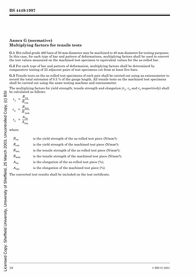
G.1 Hot rolled grade 460 bars of 50 mm diameter may be machined to 40 mm diameter for testing purposes. In this case, for each type of bar and pattern of deformations, multiplying factors shall be used to convert the test values measured on the machined test specimen to equivalent values for the as-rolled bar.
G.2 For each type of bar and pattern of deformation, multiplying factors shall be determined by comparative testing of 25 adjacent pairs of test specimens cut from at least five bars.
G.3 Tensile tests on the as-rolled test specimens of each pair shall be carried out using an extensometer to record the total extension of 0.5 % of the gauge length. All tensile tests on the machined test specimens shall be carried out using the same testing machine and extensometer.
The multiplying factors for yield strength, tensile strength and elongation (ry, ru and re respectively) shall be calculated as follows:
where
The converted test results shall be included on the test certificate.
Rea is the yield strength of the as-rolled test piece (N/mm2);
Rem is the yield strength of the machined test piece (N/mm2);
Rma is the tensile strength of the as-rolled test piece (N/mm2);
Rmm is the tensile strength of the machined test piece (N/mm2);
A5a is the elongation of the as-rolled test piece (%);
A5m is the elongation of the machined test piece (%).
r yR eaR em------------=
r uR maR mm--------------=
r eA5aA5m-----------=
Lice
nsed
Cop
y: S
heffi
eld
Uni
vers
ity, U
nive
rsity
of S
heffi
eld,
25
Mar
ch 2
003,
Unc
ontr
olle
d C
opy,
(c)
BS
I
BS 4449:1997
© BSI 07-2001
List of references (see clause 2)
Normative referencesBSI publicationsBRITISH STANDARDS INSTITUTION, London
BS 6200, Sampling and analysis of iron, steel and other ferrous metals.
BS 6200-3, Methods of analysis.
BS EN 10002, Tensile testing of metallic materials.
BS EN 10002-1:1990, Method of test at ambient temperature.
BS EN 10002-4:1995, Verification of extensometers used in uniaxial testing.
ISO publications (etc.)ISO 10606:1995, Steel for the reinforcement of concrete — Determination of percentage total elongation at maximum force.
Informative referencesBSI publicationsBRITISH STANDARDS INSTITUTION, London
BS 4466:1989, Specification for scheduling, dimensioning, bending and cutting of steel reinforcement for concrete.
BS 7123:1989, Specification for metal arc welding of steel for concrete reinforcement.
DD ENV 1992, Eurocode 2: Design of concrete structures.
DD ENV 1992-1-1:1992, General rules for buildings (together with United Kingdom National Application Document).
DD ENV 10080, Reinforcement bar B500, bars, coils and welded fabric.
Lice
nsed
Cop
y: S
heffi
eld
Uni
vers
ity, U
nive
rsity
of S
heffi
eld,
25
Mar
ch 2
003,
Unc
ontr
olle
d C
opy,
(c)
BS
I

BS 4449:1997
BSI
389 Chiswick High Road
London
W4 4AL
BSI — British Standards InstitutionBSI is the independent national body responsible for preparing British Standards. It presents the UK view on standards in Europe and at the international level. It is incorporated by Royal Charter.
Revisions
British Standards are updated by amendment or revision. Users of British Standards should make sure that they possess the latest amendments or editions.
It is the constant aim of BSI to improve the quality of our products and services. We would be grateful if anyone finding an inaccuracy or ambiguity while using this British Standard would inform the Secretary of the technical committee responsible, the identity of which can be found on the inside front cover. Tel: 020 8996 9000. Fax: 020 8996 7400.
BSI offers members an individual updating service called PLUS which ensures that subscribers automatically receive the latest editions of standards.
Buying standards
Orders for all BSI, international and foreign standards publications should be addressed to Customer Services. Tel: 020 8996 9001. Fax: 020 8996 7001. Standards are also available from the BSI website at http://www.bsi-global.com.
In response to orders for international standards, it is BSI policy to supply the BSI implementation of those that have been published as British Standards, unless otherwise requested.
Information on standards
BSI provides a wide range of information on national, European and international standards through its Library and its Technical Help to Exporters Service. Various BSI electronic information services are also available which give details on all its products and services. Contact the Information Centre. Tel: 020 8996 7111. Fax: 020 8996 7048.
Subscribing members of BSI are kept up to date with standards developments and receive substantial discounts on the purchase price of standards. For details of these and other benefits contact Membership Administration. Tel: 020 8996 7002. Fax: 020 8996 7001. Further information about BSI is available on the BSI website at http://www.bsi-global.com.
Copyright
Copyright subsists in all BSI publications. BSI also holds the copyright, in the UK, of the publications of the international standardization bodies. Except as permitted under the Copyright, Designs and Patents Act 1988 no extract may be reproduced, stored in a retrieval system or transmitted in any form or by any means – electronic, photocopying, recording or otherwise – without prior written permission from BSI.
This does not preclude the free use, in the course of implementing the standard, of necessary details such as symbols, and size, type or grade designations. If these details are to be used for any other purpose than implementation then the prior written permission of BSI must be obtained.
If permission is granted, the terms may include royalty payments or a licensing agreement. Details and advice can be obtained from the Copyright Manager. Tel: 020 8996 7070.
Lice
nsed
Cop
y: S
heffi
eld
Uni
vers
ity, U
nive
rsity
of S
heffi
eld,
25
Mar
ch 2
003,
Unc
ontr
olle
d C
opy,
(c)
BS
I