Product datasheet ASSA ABLOY DL6030C en
24
Product datasheet Dock leveler ASSA ABLOY DL6030C
Transcript of Product datasheet ASSA ABLOY DL6030C en

Product datasheetDock levelerASSA ABLOY DL6030C

Product datasheetDock levelerASSA ABLOY DL6030C
Copyright and Disclaimer NoticeAlthough the contents of this publication have been compiled with the greatest possible care, ASSA ABLOY Entrance Systemscannot accept liability for any damage that might arise from errors or omissions in this publication. We also reserve the right tomake appropriate technical modifications/replacements without prior notice.
No rights can be derived from the contents of this document.
Color guides: Color differences may occur due to different printing and publication methods.
No part of this publication may be copied or published by means of scanning, printing, photocopying, microfilm or any otherprocess whatsoever without prior permission in writing by ASSA ABLOY Entrance Systems.
Copyright © ASSA ABLOY Entrance Systems AB 2006-2021.
All rights reserved.
ASSA ABLOY, Besam, Crawford, Albany and Megadoor as words and logo are trademarks belonging to the ASSA ABLOY Group.
2

Product datasheetDock levelerASSA ABLOY DL6030C
Technical factsFeatures
* Other sizes are available on request
Performance
Sizes - leveler height 800, 900, 930 mm
Sizes - nominal length* 3000, 3500, 4000 mm
Sizes - nominal width 2000 mm
Vertical working range Above dock: Below dock:
0 - 660 mm0 - 650 mm
Platform tear plate 8 mm (8/10)
Surface treatment Standard:Option:
RAL 5010RAL 3002RAL 6005RAL 9005Hot dip galvanised
Control unit Leveler controlDoor controlShelter controlFault & service indicator
Load capacity 6 tonnes (60kN) / 2 tonnes (20kN)
Max. point load 6,5 N / mm² (8 mm tear plate)
Motor hydraulic unit 1,5kW
Mains supply 400V 3-phase, 230V 3-phase
Control unit protection class IP55
Allowable oil types ASSA ABLOY standard hydraulic oil (-20°C - +60°C)ASSA ABLOY low temperature hydraulic oil (-30°C - +60°C)ASSA ABLOY bio hydraulic oil (-20°C - +60°C)
Magnetic valves 24V/DC 18W S1
Surface treatment paint class 1 80μm Corrosive Category C2 M acc. DIN EN ISO 12944-2
Surface treatment paint class 3 160μm Corrosive Category C3 M acc. DIN EN ISO 12944-2
Surface treatment galvanised Hot dip galvanised 80μm Corrosive category C4 & C5-I M acc. DIN EN ISO 12944-2
3

Product datasheetDock levelerASSA ABLOY DL6030C
Contents
Copyright and Disclaimer Notice ..................................................................................................................................2Technical facts ......................................................................................................................................................................3
Contents .................................................................................................................................................................................4
1. Description .................................................................................................................................................................6
1.1 General ........................................................................................................................................................................................................................ 61.1.1 Application.................................................................................................................................................................................................. 61.1.2 Mode of operation ................................................................................................................................................................................... 61.1.3 Overview...................................................................................................................................................................................................... 61.1.4 Standard....................................................................................................................................................................................................... 61.1.5 Options......................................................................................................................................................................................................... 6
1.2 Mini-combidock lip................................................................................................................................................................................................. 71.2.1 Big truck ....................................................................................................................................................................................................... 71.2.2 City van......................................................................................................................................................................................................... 7
1.3 Platform ...................................................................................................................................................................................................................... 81.3.1 Platform tear-plate thickness............................................................................................................................................................... 81.3.2 EPDM seal .................................................................................................................................................................................................... 81.3.3 Slip protection / noise reduction........................................................................................................................................................ 8
1.4 Surface......................................................................................................................................................................................................................... 81.4.1 Painting ........................................................................................................................................................................................................ 81.4.2 Hot galvanising.......................................................................................................................................................................................... 8
1.5 Frames - connection to building........................................................................................................................................................................ 91.5.1 T - leveler frame for embedding in concrete .................................................................................................................................. 91.5.2 W - leveler frame for welding............................................................................................................................................................... 9
1.6 Docking control systems .................................................................................................................................................................................... 101.6.1 950 Docking LA CD ................................................................................................................................................................................ 101.6.2 950 Docking LA CD ................................................................................................................................................................................ 101.6.3 950 Docking DLA CD............................................................................................................................................................................. 101.6.4 950 Docking LSA CD.............................................................................................................................................................................. 101.6.5 950 Docking DLSA CD........................................................................................................................................................................... 101.6.6 950 Docking power cable.................................................................................................................................................................... 10
1.7 Equipment................................................................................................................................................................................................................ 111.7.1 Buffers......................................................................................................................................................................................................... 111.7.2 ASSA ABLOY DE6090E Eye................................................................................................................................................................... 121.7.3 ASSA ABLOY DE6190WC Wheel chock .......................................................................................................................................... 121.7.4 ASSA ABLOY DE6090TLS Traffic light system ............................................................................................................................... 121.7.5 ASSA ABLOY DE6090DL Dock light Heavy Duty LED ................................................................................................................. 121.7.6 ASSA ABLOY DE6090FL Fan light....................................................................................................................................................... 121.7.7 Parking guides.......................................................................................................................................................................................... 12
4

Product datasheetDock levelerASSA ABLOY DL6030C
2. Selection guide ...................................................................................................................................................... 13
2.1 Load capacity according to EN 1398 .............................................................................................................................................................. 132.1.1 Rated load ................................................................................................................................................................................................. 132.1.2 Axle load .................................................................................................................................................................................................... 132.1.3 Dynamic load ........................................................................................................................................................................................... 13
2.2 Select the load capacity ...................................................................................................................................................................................... 132.2.1 Example for lorries ................................................................................................................................................................................. 132.2.2 Example for vans ..................................................................................................................................................................................... 13
2.3 Select the leveler length ..................................................................................................................................................................................... 132.3.1 The calculation ........................................................................................................................................................................................ 132.3.2 Example...................................................................................................................................................................................................... 13
2.4 Nominal width........................................................................................................................................................................................................ 14
3. Specifications ......................................................................................................................................................... 15
3.1 Dimensions.............................................................................................................................................................................................................. 153.2 Platform thickness................................................................................................................................................................................................. 153.3 Control unit ............................................................................................................................................................................................................. 16
3.3.1 Dimensions............................................................................................................................................................................................... 163.3.2 Functions ................................................................................................................................................................................................... 16
4. CEN Performance .................................................................................................................................................. 17
4.1 Safety according to the European Standard EN 1398 .............................................................................................................................. 17
5. Building and space requirements ................................................................................................................... 18
5.1 Electrical preparations......................................................................................................................................................................................... 185.2 Pit preparations...................................................................................................................................................................................................... 19
5.2.1 T - frame ..................................................................................................................................................................................................... 195.2.2 W - frame ................................................................................................................................................................................................... 19
6. Service you can rely on ....................................................................................................................................... 20
Index ..................................................................................................................................................................................... 21
5

Product datasheetDock levelerASSA ABLOY DL6030C
1. Description1.1 General1.1.1 ApplicationThe ASSA ABLOY DL6030C combidock is the optimal solution for docking bays where vehicles of various sizes are loading and unloading. For smaller vehicles only the 1000 mm wide middle section of the lip is extended. For loading and unloading large vehicles, the full 2000 mm wide lip can be extended.The ASSA ABLOY DL6030C combidock system meets the standard demands of most loading operations and fully complies with rules and regulations of the European Standard EN 1398.
1.1.2 Mode of operationThe operation of the ASSA ABLOY DL6030C combidock is based on an electro-hydraulic telescopic lip, controlled by a semi-automatic control unit.When the dock leveler is raised, the lip extends and the leveler lowers gently onto the lorry bed. After loading or unloading, the leveler is raised again, the lip retracts and the platform returns to its parking position, i.e. to ramp level.
1.1.3 Overview
1) Leveler platform2) Telescopic lip3) Leveler frame4) Side plates5) Warning stripes6) Hydraulic unit7) Lift cylinders8) Telescopic lip cylinder9) Buffers (optional)10) Tail lift recess11) Control nut
1.1.4 Standard
1.1.5 Options
* The lip length of 1000 mm is suitable for ISO loading bays with the leveler completely behind the door, or for loading bays with a safety zone in front of the dock leveler having a buffer construction of at least 500 mm deep.
Frames - connection to building:
T-frame
Surface Painting RAL 5010 or RAL 9005
Hydraulic Equipment
Low noise hydraulic unitTwo hydraulic lift cylindersOne hydraulic lip cylinder
Lip Lip length 500 mmAluminium lip
Frames - connection to building
W-frame [frame for welding]
Surface Painting RAL 3002 or RAL 6005Hot dip galvanised
Hydraulic equipment
Low temperature oilBio oil
Energy & Ergonomics
EPDM sealSlip protection/noise reduction
Lip option Lip length 1000 mm*
Description 6
Product datasheetDock levelerASSA ABLOY DL6030C
Description 7
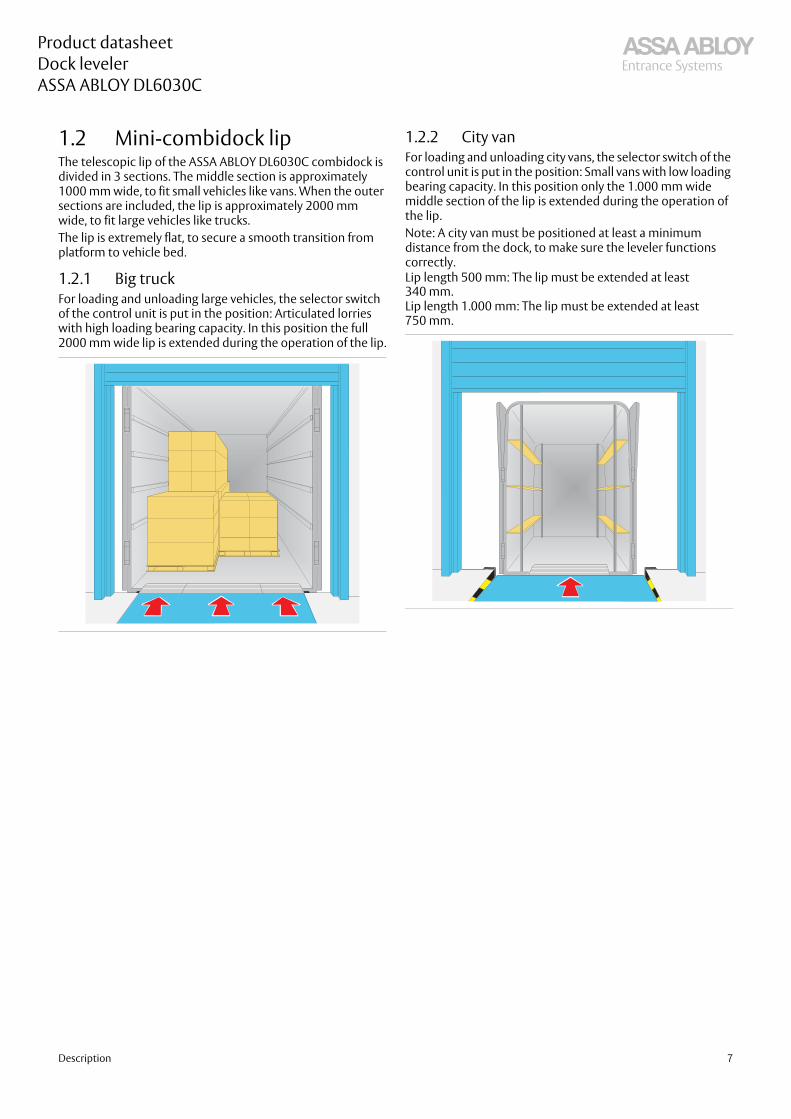
1.2 Mini-combidock lipThe telescopic lip of the ASSA ABLOY DL6030C combidock is divided in 3 sections. The middle section is approximately 1000 mm wide, to fit small vehicles like vans. When the outer sections are included, the lip is approximately 2000 mm wide, to fit large vehicles like trucks.The lip is extremely flat, to secure a smooth transition from platform to vehicle bed.
1.2.1 Big truckFor loading and unloading large vehicles, the selector switch of the control unit is put in the position: Articulated lorries with high loading bearing capacity. In this position the full 2000 mm wide lip is extended during the operation of the lip.
1.2.2 City vanFor loading and unloading city vans, the selector switch of the control unit is put in the position: Small vans with low loading bearing capacity. In this position only the 1.000 mm wide middle section of the lip is extended during the operation of the lip. Note: A city van must be positioned at least a minimum distance from the dock, to make sure the leveler functions correctly.Lip length 500 mm: The lip must be extended at least 340 mm.Lip length 1.000 mm: The lip must be extended at least 750 mm.
Product datasheetDock levelerASSA ABLOY DL6030C
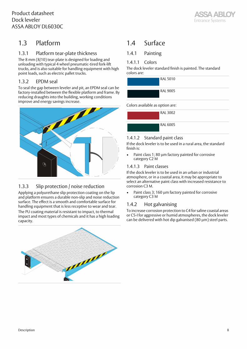
1.3 Platform1.3.1 Platform tear-plate thicknessThe 8 mm (8/10) tear-plate is designed for loading and unloading with typical 4 wheel pneumatic-tired fork-lift trucks, and is also suitable for handling equipment with high point loads, such as electric pallet trucks.
1.3.2 EPDM sealTo seal the gap between leveler and pit, an EPDM seal can be factory-installed between the flexible platform and frame. By reducing draughts into the building, working conditions improve and energy savings increase.
1.3.3 Slip protection / noise reductionApplying a polyurethane slip protection coating on the lip and platform ensures a durable non-slip and noise reduction surface. The effect is a smooth and comfortable surface for handling equipment that is less receptive to wear and tear.The PU coating material is resistant to impact, to thermal impact and most types of chemicals and it has a high loading capacity.
1.4 Surface1.4.1 Painting
1.4.1.1 ColorsThe dock leveler standard finish is painted. The standard colors are:
Colors available as option are:
1.4.1.2 Standard paint classIf the dock leveler is to be used in a rural area, the standard finish is:• Paint class 1; 80 μm factory painted for corrosive
category C2 M
1.4.1.3 Paint classesIf the dock leveler is to be used in an urban or industrial atmosphere, or in a coastal area, it may be appropriate to select an alternative paint class with increased resistance to corrosion C3 M.• Paint class 3; 160 μm factory painted for corrosive
category C3 M
1.4.2 Hot galvanisingTo increase corrosion protection to C4 for saline coastal areas or C5-I for aggressive or humid atmospheres, the dock leveler can be delivered with hot dip galvanised (80 μm) steel parts.
RAL 5010
RAL 9005
RAL 3002
RAL 6005
Description 8

Product datasheetDock levelerASSA ABLOY DL6030C
1.5 Frames - connection to building
The frame is the leveler's connection point to the building and a rigid support for the leveler. The ASSA ABLOY DL6030C combidock is available with different frame types. The frame can be embedded in concrete or installed via screws or welding. All frames are illustrated with the tail lift recess. The levelers are also available without tail lift recess.
1.5.1 T - leveler frame for embedding in concrete
The T-frame is installed in one step. The leveler is directly embedded in concrete.
1.5.2 W - leveler frame for weldingThe W-frame is designed to weld the leveler directly to the floor slab. In case of future replacement, the welding points can be ground away.
Description 9
Product datasheetDock levelerASSA ABLOY DL6030C
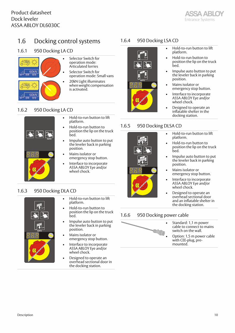
1.6 Docking control systems1.6.1 950 Docking LA CD
1.6.2 950 Docking LA CD
1.6.3 950 Docking DLA CD
1.6.4 950 Docking LSA CD
1.6.5 950 Docking DLSA CD
1.6.6 950 Docking power cable
• Selector Switch foroperation mode: Articulated lorries
• Selector Switch foroperation mode: Small vans
• 20kN Light illuminates when weight compensation is activated.
• Hold-to-run button to lift platform.
• Hold-to-run button to position the lip on the truckbed.
• Impulse auto button to putthe leveler back in parkingposition.
• Mains isolator oremergency stop button.
• Interface to incorporate ASSA ABLOY Eye and/or wheel chock.
• Hold-to-run button to lift platform.
• Hold-to-run button to position the lip on the truckbed.
• Impulse auto button to putthe leveler back in parkingposition.
• Mains isolator oremergency stop button.
• Interface to incorporate ASSA ABLOY Eye and/or wheel chock.
• Designed to operate an overhead sectional door in the docking station.
• Hold-to-run button to liftplatform.
• Hold-to-run button to position the lip on the truck bed.
• Impulse auto button to put the leveler back in parking position.
• Mains isolator or emergency stop button.
• Interface to incorporate ASSA ABLOY Eye and/or wheel chock.
• Designed to operate an inflatable shelter in the docking station.
• Hold-to-run button to liftplatform.
• Hold-to-run button to position the lip on the truck bed.
• Impulse auto button to put the leveler back in parking position.
• Mains isolator or emergency stop button.
• Interface to incorporate ASSA ABLOY Eye and/or wheel chock.
• Designed to operate an overhead sectional door and an inflatable shelter in the docking station.
• Standard: 1,1 m power cable to connect to mains switch on the wall.
• Option: 1,5 m power cablewith CEE-plug, pre-mounted.
Description 10

Product datasheetDock levelerASSA ABLOY DL6030C
1.7 Equipment1.7.1 BuffersBuffers placed in front of the dock leveler absorb the energy of a vehicle that accidentally or intentionally hits the building. Buffers are available in various sizes, in fixed or moving models, and with rubber finishing or steel plate and spring function.
1.7.1.1 RS
1.7.1.2 RB
1.7.1.3 RB with steel front plate
1.7.1.4 RB with steel front and top plate
1.7.1.5 EBH
1.7.1.6 EBF
1.7.1.7 Steel spring buffer 800
ApplicationThe RS buffer is the economical solution for docking stations where vehicles of equal sizes load and unload.We recommend to use 2 RS buffers installed in a row on both sides of the DL6030C.
ApplicationThe RB buffer is a large fixed rubber. It is the universal building and vehicle protection solution.Available depths:• 90 mm• 140 mm
ApplicationThe RB buffer with steel protection front plate increases the building protection and the buffer service life.Available depths:• 90 mm• 140 mm
400
500
ApplicationThe RB buffer with steel protection front and top plate is designed for vehicles with high lorry beds like interchangeable open bodies and containers.Available depths:• 90 mm• 140 mm
ApplicationThe EBH buffer is the ideal solution for docking stations where vehicles of notable height differences load and unload.This buffer can be vertically adjusted by a 'release device'.Available depths:• 90 mm• 140 mm
ApplicationThe EBF buffer is the ideal solution for docking stations where vehicles are expected to make notable vertical suspension changes when loading or unloading.This buffer follows vertical movements of the vehicle.Available depths:• 90 mm• 140 mm
ApplicationThe 800 mm steel spring buffer is designed for applications where vehicles generally are higher than ramp level.
Description 11
Product datasheetDock levelerASSA ABLOY DL6030C
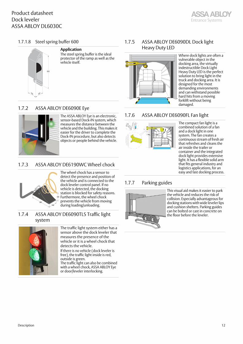
1.7.1.8 Steel spring buffer 600
1.7.2 ASSA ABLOY DE6090E Eye
1.7.3 ASSA ABLOY DE6190WC Wheel chock
1.7.4 ASSA ABLOY DE6090TLS Traffic light system
1.7.5 ASSA ABLOY DE6090DL Dock light Heavy Duty LED
1.7.6 ASSA ABLOY DE6090FL Fan light
1.7.7 Parking guides
ApplicationThe steel spring buffer is the ideal protector of the ramp as well as the vehicle itself.
The ASSA ABLOY Eye is an electronic, sensor-based Dock-IN system, which measures the distance between the vehicle and the building. This makes it easier for the driver to complete the Dock-IN procedure, but also detects objects or people behind the vehicle.
The wheel chock has a sensor to detect the presence and position of the vehicle and is connected to the dock leveler control panel. If no vehicle is detected, the docking station is blocked for safety reasons. Furthermore, the wheel chock prevents the vehicle from moving during loading/unloading.
The traffic light system either has a sensor above the dock leveler that measures the presence of the vehicle or it is a wheel chock that detects the vehicle. If there is no vehicle (dock leveler is free), the traffic light inside is red, outside is green.The traffic light can also be combined with a wheel chock, ASSA ABLOY Eye or door/leveler interlocking.
Where dock lights are often a vulnerable object in the docking area, the virtually indestructible Dock Light Heavy Duty LED is the perfect solution to bring light in the truck and docking area. It is designed for the most demanding environments and can withstand possible hard hits from a moving forklift without being damaged.
The compact fan light is a combined solution of a fan and a dock light in one system. The fan creates a continuous stream of fresh air that refreshes and cleans the air inside the trailer or container and the integrated dock light provides extensive light. It has a flexible solid arm that fits general industry and logistics applications, for an easy and fast docking process.
This visual aid makes it easier to park the vehicle and reduces the risk of collision. Especially advantageous for docking stations with wide leveler lips and cushion shelters. Parking guides can be bolted or cast in concrete on the floor before the leveler.
Description 12
Product datasheetDock levelerASSA ABLOY DL6030C
2. Selection guide2.1 Load capacity according to
EN 1398The EN 1398 describes 3 key definitions about loads.
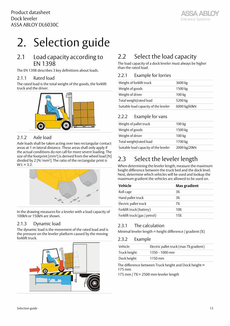
2.1.1 Rated loadThe rated load is the total weight of the goods, the forklift truck and the driver.
2.1.2 Axle loadAxle loads shall be taken acting over two rectangular contact areas at 1 m lateral distance. These areas shall only apply if the actual conditions do not call for more severe loading. The size of the footprint [mm²] is derived from the wheel load [N] divided by 2 [N⁄mm²]. The ratio of the rectangular print is W:L = 3:2.
In the drawing measures for a leveler with a load capacity of 100kN or 150kN are shown.
2.1.3 Dynamic loadThe dynamic load is the movement of the rated load and is the pressure on the leveler platform caused by the moving forklift truck.
2.2 Select the load capacityThe load capacity of a dock leveler must always be higher than the rated load.
2.2.1 Example for lorries
2.2.2 Example for vans
2.3 Select the leveler lengthWhen determining the leveler length, measure the maximum height difference between the truck bed and the dock level. Next, determine which vehicles will be used and lookup the maximum gradient the vehicles are allowed to be used on.
2.3.1 The calculationMinimal leveler length = height difference / gradient (%)
2.3.2 Example
The difference between Truck height and Dock height = 175 mm175 mm / 7% = 2500 mm leveler length
Weight of forklift truck 3600 kg
Weight of goods 1500 kg
Weight of driver 100 kg
Total weight/rated load 5200 kg
Suitable load capacity of the leveler 6000 kg/60kN
Weight of pallet truck 100 kg
Weight of goods 1500 kg
Weight of driver 100 kg
Total weight/rated load 1700 kg
Suitable load capacity of the leveler 2000 kg/20kN
Vehicle Max gradientRoll cage 3%
Hand pallet truck 3%
Electric pallet truck 7%
Forklift truck (battery) 10%
Forklift truck (gas / petrol) 15%
Vehicle: Electric pallet truck (max 7% gradient)
Truck height: 1350 – 1000 mm
Dock height: 1150 mm
Selection guide 13

Product datasheetDock levelerASSA ABLOY DL6030C
2.4 Nominal widthThe correct nominal width must exceed the widest loading vehicle by at least 700 mm. The ASSA ABLOY DL6030C combidock is available with a nominal width of 2000 mm.
Selection guide 14

Product datasheetDock levelerASSA ABLOY DL6030C
3. Specifications3.1 Dimensions Dimensions 500 mm lip
Dimensions 1000 mm lip
* When tail lift is in use** In accordance with the EN 1398 standard, the leveler must not be used beyond the permissible gradient range of ±12.5% (around ± 7°). The limits may only be exceeded if the operator ensures that the danger of slipping has been eliminated (e.g. due to dry and clean surfaces).
3.2 Platform thickness
Abb. DimensionNL Nominal length
OL Overall length (NL +500 mm)
GL Gradient length (NL + 360 mm)
NW Nominal width (= 2000 mm)
LE Leveler extension
LH Leveler height
A Working range above dock level
B Working range below dock level
PD Pit depth
LP Lowest Position
TL Tail lift area
3 Leveler frame
Vertical Working range 60kN mode**
NL LH LP A B - inside LH*
B - down to LP
3000 800 950 450 375 550
3500 900 1150 560 360 650
4000 930 1150 590 390 650
Vertical Working range 20kN mode**
NL LH LP A B - inside LH*
B - down to LP
3000 800 950 100 375 550
3500 900 1150 100 360 650
4000 930 1150 100 390 650
Vertical Working range 60kN mode**
NL LH LP A B - inside LH*
B - down to LP
3000 800 950 520 415 620
3500 900 1150 635 400 650
4000 930 1150 660 430 650
Vertical Working range 20kN mode**
NL LH LP A B - inside LH*
B - down to LP
3000 800 950 100 415 620
3500 900 1150 100 400 650
4000 930 1150 100 430 650
Thickness Max. point load8 mm (8/10) 6,5 N / mm2
Specifications 15
Product datasheetDock levelerASSA ABLOY DL6030C
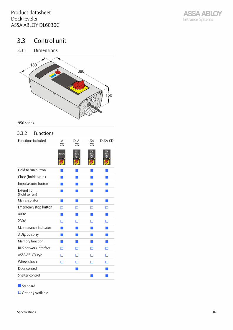
3.3 Control unit3.3.1 Dimensions
3.3.2 Functions
950 series
Functions included LA-CD
DLA-CD
LSA-CD
DLSA-CD
Hold to run button
Close (hold to run)
Impulse auto button
Extend lip (hold to run)
Mains isolator
Emergency stop button
400V
230V
Maintenance indicator
3 Digit display
Memory function
BUS network interface
ASSA ABLOY eye
Wheel chock
Door control
Shelter control
Standard
Option / Available
Specifications 16

Product datasheetDock levelerASSA ABLOY DL6030C
4. CEN Performance4.1 Safety according to the European Standard EN 1398• Emergency Stop Function.
• Safety valves block lowering movement after max. 6% of the nominal length of the leveler.• Two lift cylinders make sure the leveler stops in a horizontal position.
• Free floating position.• Platform torsion. Lateral deflection of at least 3% of nominal width.• Toe guards cover gap between platform and pit in leveler´s highest position.• Working range gradient max. 12,5% (~7°).• Warning stripes on side plates and on frame (black/yellow).
CEN Performance 17

Product datasheetDock levelerASSA ABLOY DL6030C
5. Building and space requirements5.1 Electrical preparations
*Non standard
1 Control unit (included in the delivery)
2 Conduit for wiring internal diameter 50, angles <45° (by others)
3 Mains supply:Mains fuse:Motor power:
3/N/PE AC 50 Hz400V 3-phase, 230V 3-phaseD0 10 A gL1,5 kW
4 Control cable: 18 x 0,75 mm²
5 Main connection 230V: 4 x 1,5 mm²
6 Optional safety switch on sectional door to disable leveler when door is closed*
Building and space requirements 18

Product datasheetDock levelerASSA ABLOY DL6030C
5.2 Pit preparationsThis section illustrates the required pit preparations for each frame type for the ASSA ABLOY DL6030C combidock.
5.2.1 T - frame
5.2.2 W - frame
With tail lift recess Without tail lift recess
Pit drawing 5143.0125 Pit drawing 5143.0237
With tail lift recess Without tail lift recess
Pit drawing 5143.0238 Pit drawing 5143.0239
Building and space requirements 19

Product datasheetDock levelerASSA ABLOY DL6030C
6. Service you can rely on
Expert service you can rely on A healthy business enjoys a steady flow of goods, services and people through its entrances every day. But heavy traffic puts entrances under pressure as every component works to keep them running.
Pro-active care packages
ASSA ABLOY Entrance Systems offer the industry’s most complete, flexible service solutions. Because even something as robust and well-engineered as an ASSA ABLOY door or docking system needs to be serviced to stay in great working order.
ASSA ABLOY e-maintenance™ (optional add-on)
An ASSA ABLOY service agreement gives you service you can rely on. We have specialized local service technicians on call to take care of your service needs. Equipped with a wide range of spare parts and expertise, to keep your industrial doors and docking systems running.
•
With an ASSA ABLOY service agreement you can ensure reliable, safe and sustainable operations at every entrance under your agreement, including doors and docking systems, independent of brand.
For an online overview of your entrance systems and history, add ASSA ABLOY e-maintenance™ to your service package for:
•Easy access to real-time data on all your doors
•Planning, order and service information
Gold Silver BronzeThe ultimate protection
Overview that helps you control lifecycle costs
Added advantages Scheduled Service
••
Spare parts for emergency calls
With full coverage, Gold Service enables you to plan and budget your expenses annually.
emergency calls•
Labor and travel costs for
Replacement of components
•emergency calls
•
Labor and travel costs for
With cover for all service calls during business hours, Silver Service offers you peace of mind.
according to preventive maintenance schedule and to fulfill legislative and safety requirements
Preventive maintenance• Preventive maintenance
With scheduled on site visits, Bronze Service means you know that your doors and docking systems will be regularly serviced and inspected.
Included in all packages24/7 priority service hotline and fast response
1-4 scheduled maintenance visits per year
Documentation reports provided on site
Safety, compliance and quality control checks
Service you can rely on 20

21
Product datasheetDock levelerASSA ABLOY DL6030C
Numerics
950 Docking DLA CD ........................... 10950 Docking DLSA CD ......................... 10950 Docking LA CD .............................. 10950 Docking LSA CD ............................ 10950 Docking power cable .................. 10
A
Application .................................................6ASSA ABLOY DE6090DL Dock light Heavy Duty LED ...................................... 12ASSA ABLOY DE6090E Eye ................. 12ASSA ABLOY DE6090FL Fan light ..... 12ASSA ABLOY DE6090TLS Traffic light system ....................................................... 12ASSA ABLOY DE6190WC Wheel chock12Axle load ................................................... 13
B
Big truck ......................................................7Buffers ....................................................... 11Building and space requirements ... 18
C
CEN Performance .................................. 17City van ........................................................7Colors ...........................................................8Control unit ............................................. 16Copyright and Disclaimer Notice .......2
D
Description .................................................6Dimensions ..................................... 15, 16Docking control systems .................... 10Dynamic load .......................................... 13
E
EBF .............................................................. 11EBH ............................................................. 11Electrical preparations ........................ 18EPDM seal ....................................................8Equipment ............................................... 11Example .................................................... 13Example for lorries ................................ 13Example for vans .................................... 13
F
Features .......................................................3Frames - connection to building ........9Functions .................................................. 16
G
General ........................................................6
H
Hot galvanising .........................................8
L
Load capacity according to EN 1398 13
M
Mini-combidock lip .................................7Mode of operation ...................................6
N
Nominal width ....................................... 14
O
Options ........................................................6Overview .....................................................6
P
Paint classes ...............................................8Painting ........................................................8Parking guides ........................................ 12Performance ..............................................3Pit preparations ..................................... 19Platform .......................................................8Platform tear-plate thickness ..............8Platform thickness ................................ 15
R
Rated load ................................................ 13RB ................................................................ 11RB with steel front and top plate .... 11RB with steel front plate ..................... 11RS ................................................................ 11
SSafety according to the European Standard EN 1398 ................................. 17Select the leveler length ..................... 13Select the load capacity ...................... 13Selection guide ...................................... 13Service you can rely on ....................... 20Slip protection / noise reduction .......8Specifications ......................................... 15Standard ......................................................6Standard paint class ................................8Steel spring buffer 600 ........................ 12Steel spring buffer 800 ........................ 11Surface .........................................................8
T
T - frame ................................................... 19T - leveler frame for embedding in concrete ......................................................9Technical facts ...........................................3The calculation ....................................... 13
W
W - frame ................................................. 19W - leveler frame for welding ..............9
Index

22
Product datasheetDock levelerASSA ABLOY DL6030C

23
Product datasheetDock levelerASSA ABLOY DL6030C

Follow us:
Please enter ASSA ABLOY Entrance in the channel’s search field.assaabloyentrance.com
© A
SSA
ABLO
Y |
PD
.DL6
030C
/en-
ORG
/202
1-03
Tech
nica
l dat
a su
bjec
t to
chan
ge w
ithou
t not
ice
The ASSA ABLOY Group is the global leader in access solutions. Every day, we help billions of people to experience a more open world.
ASSA ABLOY Entrance Systems provides solutions for efficient and safe flow of goods and people. Our offering includes a wide range of automated pedestrian, industrial and residential doors, loading dock equipment, perimeter fencing and service.