PowerCube 1000 V300 Solution Description - Astana...
146
PowerCube 1000 V300 Solution Description Issue 01 Date 2013-11-25 HUAWEI TECHNOLOGIES CO., LTD.
Transcript of PowerCube 1000 V300 Solution Description - Astana...

PowerCube 1000 V300
Solution Description
Issue 01
Date 2013-11-25
HUAWEI TECHNOLOGIES CO., LTD.

Issue 01 (2013-11-25) Huawei Proprietary and Confidential
Copyright © Huawei Technologies Co., Ltd. i
Copyright © Huawei Technologies Co., Ltd. 2013. All rights reserved.
No part of this document may be reproduced or transmitted in any form or by any means without prior
written consent of Huawei Technologies Co., Ltd.
Trademarks and Permissions
and other Huawei trademarks are trademarks of Huawei Technologies Co., Ltd.
All other trademarks and trade names mentioned in this document are the property of their respective
holders.
Notice
The purchased products, services and features are stipulated by the contract made between Huawei and
the customer. All or part of the products, services and features described in this document may not be
within the purchase scope or the usage scope. Unless otherwise specified in the contract, all statements,
information, and recommendations in this document are provided "AS IS" without warranties, guarantees or
representations of any kind, either express or implied.
The information in this document is subject to change without notice. Every effort has been made in the
preparation of this document to ensure accuracy of the contents, but all statements, information, and
recommendations in this document do not constitute a warranty of any kind, express or implied.
Huawei Technologies Co., Ltd.
Address: Huawei Industrial Base
Bantian, Longgang
Shenzhen 518129
People's Republic of China
Website: http://www.huawei.com
Email: [email protected]

PowerCube 1000
Solution Description About This Document
Issue 01 (2013-11-25) Huawei Proprietary and Confidential
Copyright © Huawei Technologies Co., Ltd.
ii
About This Document
Purpose
PowerCube 1000 V300 (PowerCube 1000 for short) is a hybrid power supply solution that
uses solar energy, fuel, and mains as power sources. This document describes the PowerCube
1000 in terms of its position, features, architecture, and system description.
This document covers the features of PowerCube 1000 V300R002C00, PowerCube 1000
V300R002C01, PowerCube 1000 V300R002C03, PowerCube 1000 V300R005C02, and
PowerCube 1000 V300R005C03.
The figures provided in this document are for reference only.
Intended Audience
This document is intended for:
System engineers
Network planning engineers
Sales engineers
Symbol Conventions
The symbols that may be found in this document are defined as follows.
Symbol Description
Indicates an imminently hazardous situation which, if
not avoided, will result in death or serious injury.
Indicates a potentially hazardous situation which, if not
avoided, could result in death or serious injury.
Indicates a potentially hazardous situation which, if not
avoided, may result in minor or moderate injury.
Indicates a potentially hazardous situation which, if not
avoided, could result in equipment damage, data loss,
performance deterioration, or unanticipated results.

PowerCube 1000
Solution Description About This Document
Issue 01 (2013-11-25) Huawei Proprietary and Confidential
Copyright © Huawei Technologies Co., Ltd.
iii
Symbol Description
NOTICE is used to address practices not related to
personal injury.
Calls attention to important information, best practices
and tips.
NOTE is used to address information not related to
personal injury, equipment damage, and environment
deterioration.
Change History
Changes between document issues are cumulative. The latest document issue contains all the
changes made in earlier issues.
Issue 01 (2013-12-17)
Add PowerCube 1000 V300R005C03 features
2.4.4 Grid Hybrid Solution (Mini)
3.2.12 ICC330-HD3-C3
3.3.5 DCDU-200B5
3.4.8 AGM Battery
Issue Draft A (2013-11-15)
This issue is used for first office application (FOA).

PowerCube 1000
Solution Description Contents
Issue 01 (2013-11-25) Huawei Proprietary and Confidential
Copyright © Huawei Technologies Co., Ltd.
iv
Contents
About This Document .................................................................................................................... ii
1 Overview ......................................................................................................................................... 1
1.1 Positioning .................................................................................................................................................................... 1
1.2 Features ......................................................................................................................................................................... 3
2 Architecture .................................................................................................................................... 5
2.1 Overview ...................................................................................................................................................................... 5
2.2 Solar Hybrid Solution ................................................................................................................................................... 6
2.2.1 Solar Hybrid Power Supply Solution ......................................................................................................................... 6
2.2.2 Solar-Diesel Hybrid Power Supply Solution ............................................................................................................. 7
2.2.3 Solar-Grid Hybrid Power Supply Solution ................................................................................................................ 9
2.2.4 Solar-Grid-Diesel Hybrid Power Supply Solution ................................................................................................... 11
2.3 Diesel Hybrid Solution ............................................................................................................................................... 13
2.3.1 Single-DG Hybrid Power Supply Solution .............................................................................................................. 13
2.3.2 DG-Grid (Dual-DG) Hybrid Power Supply Solution .............................................................................................. 15
2.4 Grid Hybrid Solution .................................................................................................................................................. 18
2.4.1 Grid Hybrid Solution (ESU-A) ................................................................................................................................ 18
2.4.2 Grid Hybrid Solution (ESU-H) ................................................................................................................................ 20
2.4.3 Grid Hybrid Solution (FCB) .................................................................................................................................... 21
2.4.4 Grid Hybrid Solution (Mini) .................................................................................................................................... 23
3 System Description ..................................................................................................................... 25
3.1 EPS ............................................................................................................................................................................. 25
3.1.1 Composition ............................................................................................................................................................. 25
3.1.2 PV Module ............................................................................................................................................................... 26
3.1.3 PV Module Support ................................................................................................................................................. 26
3.1.4 PV Antitheft Kit ....................................................................................................................................................... 29
3.1.5 SJB ........................................................................................................................................................................... 29
3.1.6 IDG .......................................................................................................................................................................... 31
3.1.7 FCMS....................................................................................................................................................................... 34
3.1.8 Reused DG ............................................................................................................................................................... 35
3.1.9 Mains ....................................................................................................................................................................... 35
3.2 CCS ............................................................................................................................................................................. 35
3.2.1 Composition ............................................................................................................................................................. 35

PowerCube 1000
Solution Description Contents
Issue 01 (2013-11-25) Huawei Proprietary and Confidential
Copyright © Huawei Technologies Co., Ltd.
v
3.2.2 Open Rack ............................................................................................................................................................... 38
3.2.3 ICC100-N5 .............................................................................................................................................................. 39
3.2.4 ICC200-N1H-C1 ...................................................................................................................................................... 40
3.2.5 ICC200-N2-C1 ........................................................................................................................................................ 42
3.2.6 ICC200-N2-C4 ........................................................................................................................................................ 44
3.2.7 ICC300-H1-A .......................................................................................................................................................... 45
3.2.8 ICC300-H1-B .......................................................................................................................................................... 47
3.2.9 ICC310-H1-A1 ........................................................................................................................................................ 48
3.2.10 ICC310-H1-B1 ...................................................................................................................................................... 50
3.2.11 ICC310-H1-D1 ...................................................................................................................................................... 52
3.2.12 ICC330-HD3-C3 .................................................................................................................................................... 54
3.2.13 ICC500-HA1.......................................................................................................................................................... 58
3.2.14 ICC500-HA1H-C1/ICC500-HA1H-C2 ................................................................................................................. 59
3.2.15 ICC500-HA1H-C3 ................................................................................................................................................. 61
3.2.16 ICC500-HA2-C1/ICC500-HA2-C2 ....................................................................................................................... 62
3.2.17 ICC701-HA1H-C1 ................................................................................................................................................. 64
3.2.18 ICC701-HA2-C1 .................................................................................................................................................... 65
3.2.19 ICC900-DD2, ICC900-HD2, or ICC900-HA2 ...................................................................................................... 67
3.2.20 ICC900-HA1H-C1 ................................................................................................................................................. 68
3.2.21 ICC900-HA2-C1 .................................................................................................................................................... 70
3.2.22 ICC900-HA2-D3 ................................................................................................................................................... 71
3.2.23 ESC200-N1 ............................................................................................................................................................ 73
3.2.24 Indoor FCB Rack ................................................................................................................................................... 77
3.2.25 Indoor DCB Rack .................................................................................................................................................. 78
3.2.26 Outdoor Battery Cabinet ........................................................................................................................................ 79
3.2.27 Flooded Battery Cabinet ........................................................................................................................................ 80
3.2.28 EcoCool ................................................................................................................................................................. 81
3.2.29 Split-Type DC Variable Frequency Air Conditioner .............................................................................................. 81
3.3 ICC ............................................................................................................................................................................. 84
3.3.1 Composition ............................................................................................................................................................. 84
3.3.2 ECC500 ................................................................................................................................................................... 86
3.3.3 ATS-63A1/ATS-63A2 .............................................................................................................................................. 88
3.3.4 ACDU-63A1/ACDU-63A2 ..................................................................................................................................... 90
3.3.5 DCDU-200B5 .......................................................................................................................................................... 91
3.3.6 DCDU-300A1 .......................................................................................................................................................... 93
3.3.7 DCDU-300B1 .......................................................................................................................................................... 95
3.3.8 DCDU-400A1 .......................................................................................................................................................... 97
3.3.9 DCDU-400B1 .......................................................................................................................................................... 99
3.3.10 DCDB-01A .......................................................................................................................................................... 101
3.3.11 DCDU-400AD ..................................................................................................................................................... 102
3.3.12 DCDB-01B .......................................................................................................................................................... 104
3.3.13 IDU-300A1 .......................................................................................................................................................... 105

PowerCube 1000
Solution Description Contents
Issue 01 (2013-11-25) Huawei Proprietary and Confidential
Copyright © Huawei Technologies Co., Ltd.
vi
3.3.14 IDU-300D1 .......................................................................................................................................................... 107
3.3.15 PVDU-60A1 ........................................................................................................................................................ 109
3.3.16 S4850G1 .............................................................................................................................................................. 110
3.3.17 R4850G2 .............................................................................................................................................................. 111
3.3.18 R4850G1, R4850N1, and R4850N3 .................................................................................................................... 112
3.3.19 DTS-200A1.......................................................................................................................................................... 113
3.3.20 BC1203 ................................................................................................................................................................ 115
3.3.21 DJN1000-S/GYN1000-S ..................................................................................................................................... 116
3.3.22 ETP24160A3 ....................................................................................................................................................... 118
3.4 ESS ........................................................................................................................................................................... 119
3.4.1 Composition ........................................................................................................................................................... 119
3.4.2 Flooded Battery ..................................................................................................................................................... 120
3.4.3 DCB-A ................................................................................................................................................................... 122
3.4.4 ESU-D/A1 ............................................................................................................................................................. 123
3.4.5 SCB-A ................................................................................................................................................................... 124
3.4.6 SCB-A1 ................................................................................................................................................................. 125
3.4.7 FCB ........................................................................................................................................................................ 126
3.4.8 AGM Battery ......................................................................................................................................................... 127
3.4.9 ESU Monitor .......................................................................................................................................................... 128
3.4.10 ESM-A01 ............................................................................................................................................................. 129
3.4.11 ESU-A600Wh/C .................................................................................................................................................. 130
3.4.12 ESU-A2400Wh/D ................................................................................................................................................ 131
3.4.13 ESU-A2400Wh/N ................................................................................................................................................ 132
3.4.14 ESMU-01A/ESMU-02A/ESMU-03A ................................................................................................................. 133
3.5 OSS ........................................................................................................................................................................... 135
3.5.1 NetEco ................................................................................................................................................................... 135
3.5.2 M2000 .................................................................................................................................................................... 136
A Acronyms and Abbreviations ................................................................................................ 137

PowerCube 1000
Solution Description 1 Overview
Issue 01 (2013-11-25) Huawei Proprietary and Confidential
Copyright © Huawei Technologies Co., Ltd.
1
1 Overview
1.1 Positioning
Over 600,000 communications sites in the world are supplied with unstable mains or even no
mains at all. How to supply stable power for sites has become a major concern for operators,
especially those in developing countries and rural areas.
To address this problem, Huawei launched the PowerCube 1000, a series of site power supply
solutions that integrate solar energy, fuel, electricity, and batteries. This series features low
total cost of ownership (TCO) to help customers significantly increase power supply
efficiency, decrease expenditures, and maximize return on investment (ROI).
PowerCube 1000 series solutions include the following:
PowerCube-Solar Hybrid: using solar energy as the active power source
PowerCube-Diesel Hybrid: using fuel as the active power source
PowerCube-Grid Hybrid: using the mains as the active power source
The PowerCube 1000 series hybrid power supply solutions apply to areas with poor, unstable,
or no mains.
Figure 1-1 shows the PowerCube 1000 products and application scenarios.

PowerCube 1000
Solution Description 1 Overview
Issue 01 (2013-11-25) Huawei Proprietary and Confidential
Copyright © Huawei Technologies Co., Ltd.
2
Figure 1-1 PowerCube 1000 products and application scenarios
Figure 1-2 shows power grid classification and application scenarios.
Figure 1-2 Power grid classification and application scenarios
Class 1 power grid: You are advised to use the combination of advanced power module 30H
(APM30H) or Telecom Power (TP) power systems.
Class 2 power grid: If the number of monthly outages is less than or equal to 12, you are advised to
use TP power systems. If the number of monthly outages is greater than 12, you are advised to use
grid hybrid solutions.
Class 3 and 4 power grids (including no mains): Use grid hybrid, diesel hybrid, or solar hybrid
solutions.
For Huawei wireless equipment, power grids are classified as follows:
Class 1 power grid: The average AC input power failure duration for communications
equipment is less than 10 hours per month.
Class 2 power grid: The average AC input power failure duration for communications
equipment is less than 10 hours per week.
Class 3 power grid: The average AC input power failure duration for communications
equipment is less than 8 hours and greater than or equal to 2 hours per day.
Class 4 power grid: The average AC input power failure duration for communications
equipment is greater than 8 hours per day or no mains is supplied in the whole day.
PowerCube 1000
Solution Description 1 Overview
Issue 01 (2013-11-25) Huawei Proprietary and Confidential
Copyright © Huawei Technologies Co., Ltd.
3
1.2 Features
Reduced Cost High integration
− With integrated components, the PowerCube 1000 occupies 60% to 80% less floor
area than traditional mains+DG solutions.
− Maximizes the continued use of current devices, including the AC transfer switch
(ATS), energy plant system (EPS), batteries, and power system. This reduces capital
expenditure (CAPEX) for customers while retaining the power supply to
communications equipment during modernization.
Flexible design of energy storage space
− The flexible design applies to various modernized indoor sites and decreases the
number of outdoor cabinets.
Intelligent power hybrid
− Diesel hybrid: Compared with the traditional DG+DG solution, this mode consumes
275 g/kWh fuel, reducing fuel consumption by 50% on average.
− Solar hybrid: Compared with a traditional solar solution, this mode helps to reduce
the CAPEX by 10% to 30%.
− Grid hybrid: Compared with the traditional mains+DG solution, this mode reduces
the fuel expense or may require no DGs.
Various temperature control modernization solutions
− The intelligent management of the EcoCool, split-type DC variable frequency air
conditioner, and reused AC air conditioner help to effectively reduce the EPS
operating duration and fuel consumption.
Standard Platform Standard energy control platform
− The PowerCube 1000 uses a modular energy control center 500 (ECC500) controller
platform to manage the energy plant module (EPM), mains, solar energy, modular
solar supply unit (SSU) and PSU, and optional components such as the inverter, DG
battery charger, and 48 V-24 V converter to facilitate future equipment upgrades and
solution changes.
Standard energy storage platform
− The ESU-As, deep cycle battery-A series (DCB-As), ESU-D/A1s, and flooded
batteries adapt to various scenarios, optimizing solution application and
competitiveness.
Standard element management platform
− Standard element management system, namely, the NetEco or M2000 is available.
Flexible combination
− The total cost of ownership (TCO) is minimized by flexibly combining the DG, mains,
solar energy, and batteries and using the DG, solar energy, or mains as the active
power source to meet site requirements.
− Smooth capacity expansion and evolution are supported.
PowerCube 1000
Solution Description 1 Overview
Issue 01 (2013-11-25) Huawei Proprietary and Confidential
Copyright © Huawei Technologies Co., Ltd.
4
Intelligent Management The PowerCube1000 analyzes the configuration and expenses of the site energy network
and puts forward suggestions for optimization.
The EPS, energy storage system (ESS), environment, and integrated controller and
converter (ICC) are all managed.
The NetEco supports the following aspects of operation: Records equipment running
information and prompts for component maintenance; plans the optimal path for adding
fuel; ensures electrical safety and security; uses a theft prevention design and alarm
generation function for fuel tanks and photovoltaic (PV) modules.
Diagnose the status of health (SOH) and raise appropriate suggestions.

PowerCube 1000
Solution Description 2 Architecture
Issue 01 (2013-11-25) Huawei Proprietary and Confidential
Copyright © Huawei Technologies Co., Ltd.
5
2 Architecture
2.1 Overview
The PowerCube 1000 contains the following functional systems:
Energy plant system (EPS)
Cabinet with cooling system (CCS)
Integrated controller and converter (ICC)
Energy storage system (ESS)
Operations support system (OSS)
Table 2-1 describes the system functions.
Table 2-1 System function description
System Function
EPS Supplies power to the ICC for power conversion and distribution.
CCS Houses and protects the EPS, ICC, and ESS, and ensures that they work
at appropriate temperatures.
ICC Functions as the core of the PowerCube 1000 to logically schedule
energy, monitor the operating status of other systems, and report the
operating status to the NetEco.
ESS Stores power.
OSS Serves as a logical system that consists of the EPS, ESS, ICC, CCS, and
a NetEco. The NetEco displays site data including operating status and
allows you to remotely manage sites.

PowerCube 1000
Solution Description 2 Architecture
Issue 01 (2013-11-25) Huawei Proprietary and Confidential
Copyright © Huawei Technologies Co., Ltd.
6
2.2 Solar Hybrid Solution
2.2.1 Solar Hybrid Power Supply Solution
Networking
Figure 2-1 shows the network diagram for the solar hybrid power supply solution.
Figure 2-1 Network diagram for the solar hybrid power supply solution
The solar hybrid power supply solution works circularly as follows. The power source
preference sequence is PV module > battery.
1. If sun exposure is sufficient, PV modules supply power for loads and batteries.
2. If sun exposure is insufficient, PV modules and batteries supply power for loads.
3. If there is no sun exposure, batteries supply power for loads.
Configurations
Table 2-2 describes the configurations for the solar hybrid power supply solution.

PowerCube 1000
Solution Description 2 Architecture
Issue 01 (2013-11-25) Huawei Proprietary and Confidential
Copyright © Huawei Technologies Co., Ltd.
7
Table 2-2 Configurations for the solar hybrid power supply solution
Scenario EPS ICC Cabinet Battery Cabinet ICC ESS
Indoor PV system Open rack Indoor battery
rack or outdoor
battery cabinet
Direct current
distribution unit
(DCDU),
photovoltaic
distribution unit
(PVDU), and
solar supply unit
(SSU)
Solar cycle
battery (SCB)
Outdoor ICC300-H1-A or
ICC310-H1-A1
Outdoor
battery cabinet
or flooded
battery cabinet
SCB or flooded
battery
ICC100-N5 Outdoor
battery cabinet
OMU-B
(optional)
SCB or deep
cycle battery
(DCB)
Note: Optional components include the PV antitheft kit, GPRS board+antenna, inverter, and DC-DC converter
(-48 V to 24 V). In indoor scenarios, the EcoCool or split-type DC variable frequency air conditioner (SP4D)
can be selected.
2.2.2 Solar-Diesel Hybrid Power Supply Solution
Networking
Figure 2-2 shows the network diagram for the solar-diesel hybrid power supply solution.

PowerCube 1000
Solution Description 2 Architecture
Issue 01 (2013-11-25) Huawei Proprietary and Confidential
Copyright © Huawei Technologies Co., Ltd.
8
Figure 2-2 Network diagram for the solar-diesel hybrid power supply solution
DG: diesel generator
IDG: integrated diesel generator
The solar-diesel hybrid power supply solution works circularly as follows. The power source
preference sequence is PV module > battery > DG.
1. If sun exposure is sufficient, PV modules supply power for loads and batteries.
2. If sun exposure is insufficient, PV modules and batteries supply power for loads.
3. If there is no sun exposure, batteries supply power for loads.
4. If there is no sun exposure and batteries discharge to the specified depth of discharge
(DOD), the DG starts to supply power for loads and batteries.
5. After batteries are fully charged or the sun exposure becomes sufficient, the DG shuts
down, and batteries supply power for loads or PV modules supply power for loads and
batteries.
Configurations
Table 2-3 describes the configurations for the solar-diesel hybrid power supply solution.

PowerCube 1000
Solution Description 2 Architecture
Issue 01 (2013-11-25) Huawei Proprietary and Confidential
Copyright © Huawei Technologies Co., Ltd.
9
Table 2-3 Configurations for the solar-diesel hybrid power supply solution
Scenario EPS ICC Cabinet Battery Cabinet ICC ESS
Indoor PV system
and DG
Open rack Indoor battery rack or
outdoor battery
cabinet
DCDU, PVDU,
SSU, power
supply unit
(PSU), DG
battery charger,
and DG IO
board
SCB or DCB
Outdoor ICC300-H1-A or
ICC310-H1-A1
Outdoor battery
cabinet or flooded
battery cabinet
SCB or flooded
battery
Note: Optional components include the PV antitheft kit, fuel consumption measuring system, GPRS
board+antenna, inverter, and DC-DC converter (-48 V to 24 V). In indoor scenarios, the EcoCool or split-type
DC variable frequency air conditioner (SP4D) can be selected.
2.2.3 Solar-Grid Hybrid Power Supply Solution
Networking
Figure 2-3 shows the network diagram for the solar-grid hybrid power supply solution.

PowerCube 1000
Solution Description 2 Architecture
Issue 01 (2013-11-25) Huawei Proprietary and Confidential
Copyright © Huawei Technologies Co., Ltd.
10
Figure 2-3 Network diagram for the solar-grid hybrid power supply solution
The solar-grid hybrid power supply solution works circularly as follows. If Schedule En in
Mains Ctrl Para is set to Disable (initial state) on the ECC500 LCD, the power source
preference sequence is PV module > mains > battery.
1. If sun exposure is sufficient, PV modules supply power for loads and batteries.
2. If sun exposure is insufficient, PV modules and mains supply power for loads and
batteries.
3. If there is no sun exposure, the mains supplies power for loads and batteries.
4. If there is no sun exposure and no mains, batteries supply power for loads.
If Schedule En in Mains Ctrl Para is set to Enable on the ECC500 LCD, the power source
preference sequence is PV module > battery > mains.
Configurations
Table 2-4 describes the configurations for the solar-grid hybrid power supply solution.
PowerCube 1000
Solution Description 2 Architecture
Issue 01 (2013-11-25) Huawei Proprietary and Confidential
Copyright © Huawei Technologies Co., Ltd.
11
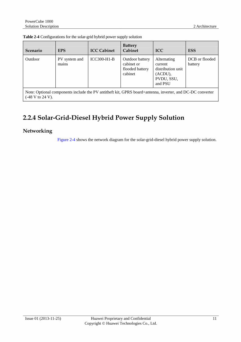
Table 2-4 Configurations for the solar-grid hybrid power supply solution
Scenario EPS ICC Cabinet Battery Cabinet ICC ESS
Outdoor PV system and
mains
ICC300-H1-B Outdoor battery
cabinet or
flooded battery
cabinet
Alternating
current
distribution unit
(ACDU),
PVDU, SSU,
and PSU
DCB or flooded
battery
Note: Optional components include the PV antitheft kit, GPRS board+antenna, inverter, and DC-DC converter
(-48 V to 24 V).
2.2.4 Solar-Grid-Diesel Hybrid Power Supply Solution
Networking
Figure 2-4 shows the network diagram for the solar-grid-diesel hybrid power supply solution.

PowerCube 1000
Solution Description 2 Architecture
Issue 01 (2013-11-25) Huawei Proprietary and Confidential
Copyright © Huawei Technologies Co., Ltd.
12
Figure 2-4 Network diagram for the solar-grid-diesel hybrid power supply solution
The solar-grid-diesel hybrid power supply solution works circularly as follows. If Schedule
En in Mains Ctrl Para is set to Disable (initial state) on the ECC500 LCD, the power source
preference sequence is PV module > mains > battery > DG.
The solar-grid-diesel hybrid power supply solution employs the similar working principles as
the solar-grid hybrid power supply solution. The DG supplies power for loads and batteries
only when there is no sun exposure, no mains, and batteries discharge to the specified DOD.
If Schedule En in Mains Ctrl Para is set to Enable on the ECC500 LCD, the power source
preference sequence is PV module > battery > mains > DG.
Configurations
Table 2-5 describes the configurations for the solar-grid-diesel hybrid power supply solution.
Table 2-5 Configurations for the solar-grid-diesel hybrid power supply solution
Scenario EPS ICC Cabinet Battery Cabinet ICC ESS
Indoor PV system, Open rack Indoor battery
rack or outdoor
DCDU, PVDU,
SSU, PSU, DG
SCB or DCB

PowerCube 1000
Solution Description 2 Architecture
Issue 01 (2013-11-25) Huawei Proprietary and Confidential
Copyright © Huawei Technologies Co., Ltd.
13
Scenario EPS ICC Cabinet Battery Cabinet ICC ESS
DG, and mains battery cabinet battery charger,
and DG IO
board Outdoor ICC300-H1-A or
ICC310-H1-A1
Outdoor battery
cabinet or
flooded battery
cabinet
SCB or flooded
battery
Note: Optional components include the PV antitheft kit, fuel consumption measuring system, GPRS
board+antenna, inverter, and DC-DC converter (-48 V to 24 V). In indoor scenarios, the EcoCool or split-type
DC variable frequency air conditioner (SP4D) can be selected.
2.3 Diesel Hybrid Solution
2.3.1 Single-DG Hybrid Power Supply Solution
Networking
Figure 2-5 shows the single-DG hybrid power supply solution network diagram.

PowerCube 1000
Solution Description 2 Architecture
Issue 01 (2013-11-25) Huawei Proprietary and Confidential
Copyright © Huawei Technologies Co., Ltd.
14
Figure 2-5 Single-DG hybrid power supply solution network diagram
The single-DG hybrid power supply solution works circularly as follows. The power source
preference sequence is battery > DG.
1. Batteries supply power for loads until they discharge to the specified DOD.
2. The DG starts to supply power for loads and batteries.
3. After batteries are fully charged, the DG shuts down.
Configurations
Table 2-6 describes the configurations for the single-DG hybrid power supply solution.
Table 2-6 Configurations for the single-DG hybrid power supply solution
Scenario EPS ICC Cabinet Battery Cabinet ICC ESS
Indoor DG Open rack or
ICC200-N2-C4
Indoor battery
rack or outdoor
battery cabinet
DCDU, PSU,
DG battery
charger, and
DCB

PowerCube 1000
Solution Description 2 Architecture
Issue 01 (2013-11-25) Huawei Proprietary and Confidential
Copyright © Huawei Technologies Co., Ltd.
15
Scenario EPS ICC Cabinet Battery Cabinet ICC ESS
Outdoor ICC701-HA2-C1 DG IO board
ICC900-DD2, ICC900-HA2,
ICC900-HD2 or ICC900-HA2-D3
IDU, PSU, DG
battery charger,
and DG IO
board
Note: Optional components include the fuel consumption measuring system, GPRS board+antenna, inverter,
and DC-DC converter (-48 V to 24 V). In indoor scenarios, the EcoCool or split-type DC variable frequency air
conditioner (SP4D) can be selected.
2.3.2 DG-Grid (Dual-DG) Hybrid Power Supply Solution
Networking
Figure 2-6 shows the DG-grid hybrid power supply solution network diagram. Figure 2-7
shows the dual-DG hybrid power supply solution network diagram.

PowerCube 1000
Solution Description 2 Architecture
Issue 01 (2013-11-25) Huawei Proprietary and Confidential
Copyright © Huawei Technologies Co., Ltd.
16
Figure 2-6 DG-grid hybrid power supply solution network diagram
The DG-grid hybrid power supply solution works circularly as follows. The power source
preference sequence is mains > battery > DG.
1. If the mains is normal, it supplies power for loads and batteries.
2. If the mains is off, batteries supply power for loads until they discharge to the specified
DOD.
3. The DG starts to supply power for loads and batteries.
4. After batteries are fully charged or the mains recovers, the DG shuts down, and batteries
supply power for loads or the mains supplies power for loads and batteries.

PowerCube 1000
Solution Description 2 Architecture
Issue 01 (2013-11-25) Huawei Proprietary and Confidential
Copyright © Huawei Technologies Co., Ltd.
17
Figure 2-7 Dual-DG hybrid power supply solution network diagram
The dual-DG hybrid power supply solution works circularly as follows, with the DGs
working in active/standby mode. The power source preference sequence is battery > DG 1 >
DG 2.
1. Batteries supply power for loads until they discharge to the specified DOD.
2. DG 1 starts to supply power for loads and batteries.
If DG 1 is faulty, DG 2 starts to supply power for loads and batteries and an alarm is generated.
3. After batteries are fully charged, DG 1 or DG 2 shuts down.
The dual-DG hybrid power supply solution works circularly as follows, with the DGs
working alternately. The power source preference sequence is battery > DG 1 (DG 2).
1. Batteries supply power for loads until they discharge to the specified DOD.
2. DG 1 starts to supply power for loads and batteries.
3. After batteries are fully charged, DG 1 shuts down and batteries supply power for loads
until they discharge to the specified DOD.
4. DG 2 starts to supply power for loads and batteries.
5. After batteries are fully charged, DG 2 shuts down.

PowerCube 1000
Solution Description 2 Architecture
Issue 01 (2013-11-25) Huawei Proprietary and Confidential
Copyright © Huawei Technologies Co., Ltd.
18
If DG 1 or DG 2 is faulty, the other DG starts to supply power for loads and batteries and an alarm is
generated.
Configurations
Table 2-7 describes the configurations for the DG-grid (dual-DG) hybrid power supply
solution.
Table 2-7 Configurations for the DG-grid (dual-DG) hybrid power supply solution
Scenario EPS ICC Cabinet Battery Cabinet ICC ESS
Indoor Mains+DG or
dual-DG
Open rack or
ICC200-N2-C4
Indoor battery
rack or outdoor
battery cabinet
ATS, DCDU,
PSU, DG
battery charger,
and DG IO
board
DCB
Outdoor ICC310-H1-D1 Outdoor battery
cabinet
ICC701-HA2-C1
ICC900-DD2, ICC900-HA2,
ICC900-HD2 or ICC900-HA2-D3
IDU, PSU, DG
battery charger,
and DG IO
board
Note: Optional components include the fuel consumption measuring system, GPRS board+antenna, inverter,
and DC-DC converter (-48 V to 24 V). In indoor scenarios, the EcoCool or split-type DC variable frequency air
conditioner (SP4D) can be selected.
2.4 Grid Hybrid Solution
2.4.1 Grid Hybrid Solution (ESU-A)
Networking
Figure 2-8 shows the grid hybrid solution (ESU-A) network diagram.

PowerCube 1000
Solution Description 2 Architecture
Issue 01 (2013-11-25) Huawei Proprietary and Confidential
Copyright © Huawei Technologies Co., Ltd.
19
Figure 2-8 Grid hybrid solution (ESU-A) network diagram
The grid hybrid solution (ESU-A) works circularly as follows. The power source preference
sequence is mains > battery.
1. If the mains is normal, it supplies power for loads and batteries.
2. If the mains is abnormal, batteries supply power for loads.
Configurations
Table 2-8 describes the grid hybrid solution (ESU-A) configurations.
Table 2-8 Grid hybrid solution (ESU-A) configurations
Scenario EPS ICC Cabinet Battery Cabinet ICC ESS
Indoor Mains and DG
(optional) ICC200-N2-C4 ESC200-N1 ACDU,
DCDU, and
PSU
ESU-A600Wh/C and
ESMU-01A
ESU-A2400Wh/D and
ESMU-02A
ESU-A2400Wh/N and
Outdoor ICC500-HA1, ICC500-HA2-C1,
or ICC900-HA2-C1

PowerCube 1000
Solution Description 2 Architecture
Issue 01 (2013-11-25) Huawei Proprietary and Confidential
Copyright © Huawei Technologies Co., Ltd.
20
Scenario EPS ICC Cabinet Battery Cabinet ICC ESS
ESMU-03A
Note: Optional components include the GPRS board+antenna, ATS, DG battery charger, DG IO board,
inverter, and DC-DC converter (-48 V to 24 V). In indoor scenarios, the EcoCool or split-type DC variable
frequency air conditioner (SP4D) can be selected.
2.4.2 Grid Hybrid Solution (ESU-H)
The ESS of the grid hybrid solution (ESU-H) contains ESU-As and FCBs.
Networking
Figure 2-9 shows the grid hybrid solution (ESU-H) network diagram.
Figure 2-9 Grid hybrid solution (ESU-H) network diagram
The grid hybrid solution (ESU-H) works circularly as follows. The power source preference sequence is mains > battery.

PowerCube 1000
Solution Description 2 Architecture
Issue 01 (2013-11-25) Huawei Proprietary and Confidential
Copyright © Huawei Technologies Co., Ltd.
21
1. If the mains is normal, it supplies power for loads and batteries.
2. If the mains is abnormal, batteries supply power for loads.
Configurations
Table 2-9 describes the grid hybrid solution (ESU-H) configurations.
Table 2-9 Grid hybrid solution (ESU-H) configurations
Scenario EPS ICC Cabinet Battery Cabinet ICC ESS
Indoor Mains and DG
(optional)
ICC200-N1H-C1 ESC200-N1 ACDU, DCDU,
direct current
distribution box
(DCDB), DC
transfer switch
(DTS), and PSU
ESU-A600Wh/C
and ESMU-01A
ESU-A2400Wh/
D and
ESMU-02A
ESU-A2400Wh/
N and
ESMU-03A
FCB
Outdoor ICC200-N1H-C1,
ICC500-HA1H-C3,
ICC500-HA1H-C1,
ICC701-HA1H-C1, or
ICC900-HA1H-C1
Note: Optional components include the GPRS board+antenna, ATS, DG battery charger, DG IO board, ESU
monitor, and DC-DC converter (-48 V to 24 V). In indoor scenarios, the EcoCool or split-type DC variable
frequency air conditioner (SP4D) can be selected.
2.4.3 Grid Hybrid Solution (FCB)
Networking
Figure 2-10 shows the grid hybrid solution (FCB) network diagram.

PowerCube 1000
Solution Description 2 Architecture
Issue 01 (2013-11-25) Huawei Proprietary and Confidential
Copyright © Huawei Technologies Co., Ltd.
22
Figure 2-10 Grid hybrid solution (FCB) network diagram
The grid hybrid solution (FCB) works circularly as follows. The power source preference
sequence is mains > battery.
1. If the mains is normal, it supplies power for loads and batteries.
2. If the mains is abnormal, batteries supply power for loads.
Configurations
Table 2-10 describes the grid hybrid solution (FCB) configurations.
Table 2-10 Grid hybrid solution (FCB) configurations
Scenario EPS ICC Cabinet Battery Cabinet ICC ESS
Indoor Mains and DG
(optional)
ICC200-N2-C4 ESC200-N1 ACDU, DCDU,
and PSU
FCB
Outdoor ICC500-HA1, ICC500-HA2-C1, or
ICC900-HA2-C1
Note: Optional components include the GPRS board+antenna, ATS, DG battery charger, DG IO board, ESU
monitor, and DC-DC converter (-48 V to 24 V). In indoor scenarios, the EcoCool or split-type DC variable

PowerCube 1000
Solution Description 2 Architecture
Issue 01 (2013-11-25) Huawei Proprietary and Confidential
Copyright © Huawei Technologies Co., Ltd.
23
Scenario EPS ICC Cabinet Battery Cabinet ICC ESS
frequency air conditioner (SP4D) can be selected.
2.4.4 Grid Hybrid Solution (Mini)
Networking
Figure 2-11 shows the grid hybrid solution (mini) network diagram.
Figure 2-11 Grid hybrid solution (mini) network diagram
The grid hybrid solution (mini) works circularly as follows. The power source preference
sequence is mains > battery.
1. If the mains is normal, it supplies power for loads and batteries.
2. If the mains is abnormal, batteries supply power for loads.

PowerCube 1000
Solution Description 2 Architecture
Issue 01 (2013-11-25) Huawei Proprietary and Confidential
Copyright © Huawei Technologies Co., Ltd.
24
Configurations
Table 2-11 describes the grid hybrid solution (mini) configurations.
Table 2-11 Grid hybrid solution (mini) configurations
Scenario EPS ICC Cabinet Battery Cabinet ICC ESS
Outdoor Mains ICC330-HD3-C3 DCDU and PSU AGM
battery
Note: Optional components include the GPRS board+antenna and heater.

PowerCube 1000
Solution Description 3 System Description
Issue 01 (2013-11-25) Huawei Proprietary and Confidential
Copyright © Huawei Technologies Co., Ltd.
25
3 System Description
3.1 EPS
3.1.1 Composition
The EPS supplies power to the ICC for power conversion and distribution.
Table 3-1 describes the EPS component functions.
Table 3-1 EPS component functions
Subsystem Component Function
PV system PV module Converts solar energy into electric energy.
PV module support Supports PV modules and uses a theft
prevention design.
Solar junction box
(SJB)
Allows multiple PV module strings to be
connected in parallel and supplies solar
power to the ICC.
PV antitheft kit
(optional)
Prevents PV modules from being stolen.
Integrated diesel
generator (IDG)
Energy Plant Module
(EPM)
Supplies AC power by converting chemical
energy into electric energy.
Fuel consumption
measuring system
(FCMS, optional)
Accumulates fuel consumption of the engine
in real time according to the constant volume
method to provide accurate fuel
consumption data for the ICC. It is installed
on the fuel supply pipe of the engine.
Diesel generator
(DG)
Reused DG Supplies AC power by converting chemical
energy into electric energy.
Mains N/A Supplies AC power.

PowerCube 1000
Solution Description 3 System Description
Issue 01 (2013-11-25) Huawei Proprietary and Confidential
Copyright © Huawei Technologies Co., Ltd.
26
3.1.2 PV Module
Appearance
Figure 3-1 shows a PV module.
Figure 3-1 PV module
Functions
A PV module, as an important component for light-to-electricity conversion in a solar power
system, supplies power to loads. It is resistant to corrosion, wind, and rain. PV modules are
connected in a parallel series to meet load voltage and current requirements.
Features Good light transmission
Double-layer solar cell, with high circuit reliability
Long service life of 25 years
Multi-layer polyolefin compressed circuit, which is moisture-proof, well-insulated, and
stable under undervoltage conditions
Certified by the Technical Watch-Over Association (TUV), Underwriters Laboratory
(UL), International Organization for Standardization (ISO), European Conformity (CE),
and International Electrotechnical Commission (IEC).
3.1.3 PV Module Support
Appearance
PV module supports are classified into scalable low supports and scalable high supports.
Figure 3-2 shows a scalable low support, and Figure 3-3 a scalable high support.

PowerCube 1000
Solution Description 3 System Description
Issue 01 (2013-11-25) Huawei Proprietary and Confidential
Copyright © Huawei Technologies Co., Ltd.
27
Figure 3-2 Scalable low support

PowerCube 1000
Solution Description 3 System Description
Issue 01 (2013-11-25) Huawei Proprietary and Confidential
Copyright © Huawei Technologies Co., Ltd.
28
Figure 3-3 Scalable high support
Functions
A PV module support holds one or more PV modules in position.
Features
A PV module support has the following features:
Is designed to prevent thefts and secured by dedicated antitheft bolts.
Can be adjusted to 15, 25, 35, or 45 degrees.
Can be extended flexibly.
Reduces the floor area and allows battery cabinets and communications equipment to be
installed under it.
Is safe and reliable, withstanding wind speeds of 144 km/h.
Can be adjusted flexibly to meet various installation requirements.
Is easy to install and remove.
PowerCube 1000
Solution Description 3 System Description
Issue 01 (2013-11-25) Huawei Proprietary and Confidential
Copyright © Huawei Technologies Co., Ltd.
29
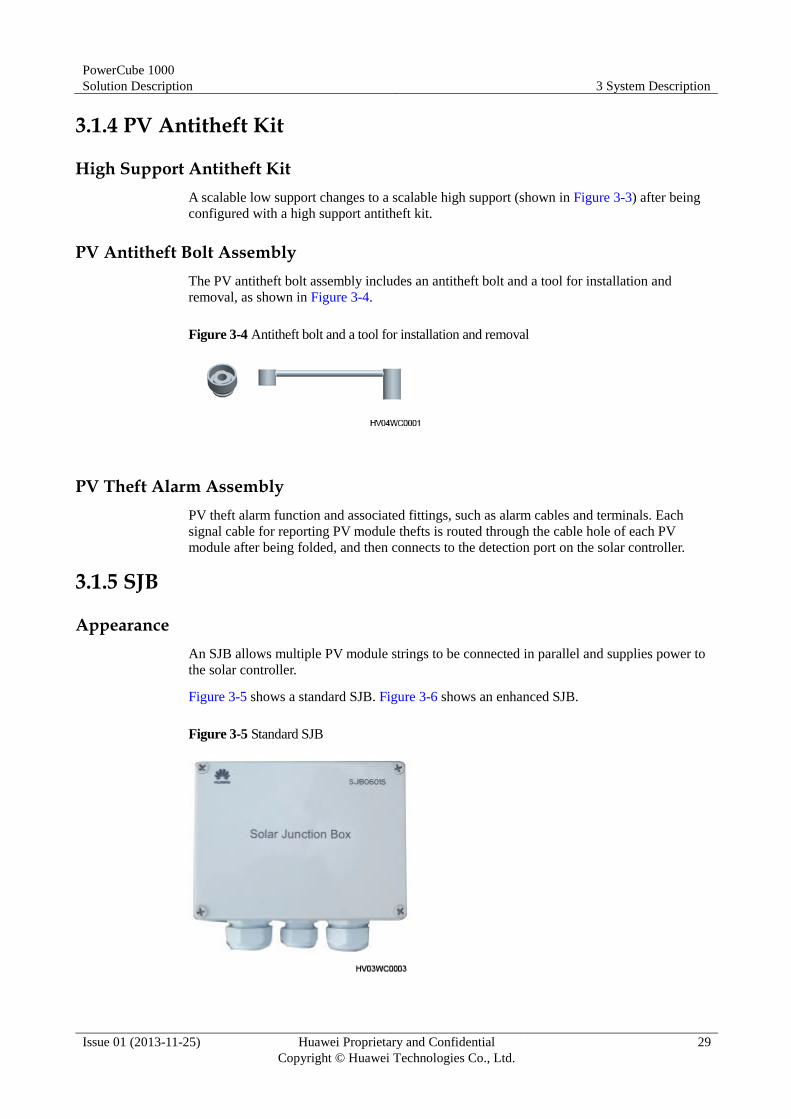
3.1.4 PV Antitheft Kit
High Support Antitheft Kit
A scalable low support changes to a scalable high support (shown in Figure 3-3) after being
configured with a high support antitheft kit.
PV Antitheft Bolt Assembly
The PV antitheft bolt assembly includes an antitheft bolt and a tool for installation and
removal, as shown in Figure 3-4.
Figure 3-4 Antitheft bolt and a tool for installation and removal
PV Theft Alarm Assembly
PV theft alarm function and associated fittings, such as alarm cables and terminals. Each
signal cable for reporting PV module thefts is routed through the cable hole of each PV
module after being folded, and then connects to the detection port on the solar controller.
3.1.5 SJB
Appearance
An SJB allows multiple PV module strings to be connected in parallel and supplies power to
the solar controller.
Figure 3-5 shows a standard SJB. Figure 3-6 shows an enhanced SJB.
Figure 3-5 Standard SJB

PowerCube 1000
Solution Description 3 System Description
Issue 01 (2013-11-25) Huawei Proprietary and Confidential
Copyright © Huawei Technologies Co., Ltd.
30
Figure 3-6 Enhanced SJB
Functions
An SJB, as an electrical box in a solar power system, connects PV module strings in parallel
and houses input and output wiring terminals. To decrease cable voltage drop and facilitate
installation, multiple SJBs are used based on system capacity.
Technical Specifications
Table 3-2 lists the SJB technical specifications.
Table 3-2 SJB technical specifications
Item Specifications
Standard SJB Six inputs converge into one output.
Is protected to IP55.
Is mounted on a pole or wall.
Enhanced SJB Six inputs converge into one output.
Is protected to IP55.
Is mounted on a pole or wall.
Is embedded with reverse connection protection circuits.
Is embedded with surge protection circuits.

PowerCube 1000
Solution Description 3 System Description
Issue 01 (2013-11-25) Huawei Proprietary and Confidential
Copyright © Huawei Technologies Co., Ltd.
31
3.1.6 IDG
Appearance
Figure 3-7 shows the DG model EPM100-M1A, EPM100-M1B, EPM100-M2A, or
EPM100-M2B. Figure 3-8 shows the DG model EPM120-A1A. Figure 3-9 shows the DG
model EPM42-B1B.
Figure 3-7 EPM100-M1A/EPM100-M1B/EPM100-M2A/EPM100-M2B

PowerCube 1000
Solution Description 3 System Description
Issue 01 (2013-11-25) Huawei Proprietary and Confidential
Copyright © Huawei Technologies Co., Ltd.
32
Figure 3-8 EPM120-A1A
Figure 3-9 EPM42-B1B

PowerCube 1000
Solution Description 3 System Description
Issue 01 (2013-11-25) Huawei Proprietary and Confidential
Copyright © Huawei Technologies Co., Ltd.
33
Functions
The IDG converts chemical energy into electricity. In an IDG, the engine converts thermal
energy into mechanical energy, and then the generator converts mechanical energy into
electricity.
Technical Specifications
Table 3-3 lists the technical specifications for the EPM100-M1A, EPM100-M1B,
EPM100-M2A, and EPM100-M2B.
Table 3-3 Technical specifications for the EPM100-M1A, EPM100-M1B, EPM100-M2A, and
EPM100-M2B
Item EPM100-M1A/EPM100-M1B
EPM100-M2A/EPM100-M2B
Replacement interval of
engine oil and oil filter
250 working hours or 1
year, whichever comes first.
1000 working hours or 1
year, whichever comes first.
Basic power 10 kW
Fuel tank 800 L
Dimensions (H x W x D) 1825 mm x 1800 mm x 950 mm (including the base)
Weight About 850 kg
Output 50 Hz, 230 V/400 V, three-phase, four-wire
Table 3-4 lists the technical specifications for the EPM120-A1A, EPM120-A1B, and
EPM120-M2A.
Table 3-4 Technical specifications for the EPM120-A1A, EPM120-A1B, and EPM120-M2A
Item EPM120-A1A EPM120-A1B EPM120-M2A
Replacement interval
of engine oil and oil
filter
250 working hours
or 1 year, whichever
comes first.
250 working hours
or 1 year, whichever
comes first.
500 working hours
or 1 year, whichever
comes first.
Basic power 12 kW
Fuel tank 200 L 800 L 800 L
Dimensions (H x W
x D)
1500 mm x 1800
mm x 950 mm
(including the base)
1825 mm x 1800
mm x 950 mm
(including the base)
1825 mm x 1800
mm x 950 mm
(including the base)
Weight About 850 kg
Output 50 Hz, 230 V/400 V, three-phase, four-wire
Table 3-5 lists the EPM42-B1B technical specifications.

PowerCube 1000
Solution Description 3 System Description
Issue 01 (2013-11-25) Huawei Proprietary and Confidential
Copyright © Huawei Technologies Co., Ltd.
34
Table 3-5 EPM42-B1B technical specifications
Item EPM42-B1B
Replacement interval of engine oil and oil
filter
125 working hours or 1 year, whichever
comes first.
Basic power 4.2 kW
Fuel tank 200 L
Dimensions (H x W x D) 1825 mm x 600 mm x 950 mm (including
the base)
Weight About 400 kg
Output 50 Hz, 230 V, single-phase
3.1.7 FCMS
Appearance
Figure 3-10 shows an FCMS.
Figure 3-10 FCMS

PowerCube 1000
Solution Description 3 System Description
Issue 01 (2013-11-25) Huawei Proprietary and Confidential
Copyright © Huawei Technologies Co., Ltd.
35
Functions
An FCMS is installed on the fuel supply pipe of the engine and accumulates fuel consumption
of the engine in real time to provide accurate fuel consumption data as an important basis for
fuel management.
Technical Specifications
Table 3-6 lists the FCMS technical specifications.
Table 3-6 FCMS technical specifications
Item Specifications
Dimensions (H x W x
D)
900 mm x 600 mm x 140 mm
Weight 19 kg
Protection level IP21
Detection precision Total fuel consumption: 0-200 L; measurement precision: ≤
0.5% FS
Total fuel consumption: > 200 L; measurement precision: ≤
0.5%
3.1.8 Reused DG
A DG supplies AC power. For details, see the related DG user manual.
3.1.9 Mains
The mains supplies AC power and serves as the active power source.
3.2 CCS
3.2.1 Composition
The CCS houses and protects the EPS, ICC, and ESS, and ensures that they work at
appropriate temperatures. In indoor scenarios, the EcoCool and split-type DC variable
frequency air conditioner can be selected as a temperature control system.
Table 3-7 lists the cabinets used by the ICC and ESS. H, A, D, and N represent the
temperature control mode of the cabinet. H indicates heat exchange, A indicates air
conditioner, D indicates free cooling, and N indicates natural cooling. The ESU-H consists of
the ESU-A and FCB.

PowerCube 1000
Solution Description 3 System Description
Issue 01 (2013-11-25) Huawei Proprietary and Confidential
Copyright © Huawei Technologies Co., Ltd.
36
Table 3-7 CCS components
CCS Model Configuration Supported Battery
Temperature Control Mode for the Energy Control Compartment
Temperature Control Mode for the Battery Compartment
Open
rack
None None None Natural
cooling
N/A
ICC100
series
ICC100-N5 OMU-B (optional) None Natural
cooling
Natural
cooling
ICC200
series
ICC200-N1H
-C1
ACDU-63A1,
DCDU-400B1,
DTS-200A1, and
DCDB-01A
ESU-A Natural
cooling
Natural
cooling
ICC200-N2-
C1
ACDU-63A1 and
DCDU-300B1
None Natural
cooling
N/A
ICC200-N2-
C4
DCDU-300A1 None
ICC300
series
ICC300-H1-
A
DCDU-400A1 and
PVDU-60A1
None Heat
exchange
N/A
ICC300-H1-
B
ACDU-63A1,
DCDU-400A1, and
PVDU-60A1
Heat
exchange
N/A
ICC310
series
ICC310-H1-
A1
DCDU-400A1 and
PVDU-60A1
None Heat
exchange
N/A
ICC310-H1-
B1
ATS-63A1,
DCDU-400A1, and
PVDU-60A1
ICC310-H1-
D1
ATS-63A1 and
DCDU-400A1
ICC500
series
ICC500-HA1 ACDU-63A1 and
DCDU-400A1
FCB Heat
exchange
DC air
conditioner
ICC500-HA1
H-C1 and
ICC500-HA1
H-C2
ACDU-63A1,
DCDU-400B1,
DTS-200A1, and
DCDB-01A
ESU-H
ICC500-HA1
H-C3
ACDU-63A2,
DCDU-400AD,
DTS-200A1, and
DCDB-01B
ESU-H
ICC500-HA2
-C1/ICC500-
ACDU-63A1 and
DCDU-300B1 ESU-A or FCB

PowerCube 1000
Solution Description 3 System Description
Issue 01 (2013-11-25) Huawei Proprietary and Confidential
Copyright © Huawei Technologies Co., Ltd.
37
CCS Model Configuration Supported Battery
Temperature Control Mode for the Energy Control Compartment
Temperature Control Mode for the Battery Compartment
HA2-C2
ICC701
series
ICC701-HA1
H-C1
ACDU-63A2,
DCDU-400AD,
DTS-200A1, and
DCDB-01B
ESU-H Heat
exchange
DC air
conditioner
ICC701-HA2
-C1
DCDU-300A1 DCB-A or
ESU-D/A1
ICC900
series
ICC900-DD2 IDU-300A1 DCB-A or
ESU-D/A1
Free cooling Free cooling
ICC900-HD2 IDU-300A1 DCB-A or
ESU-D/A1
Heat
exchange
Free cooling
ICC900-HA2 IDU-300A1 DCB-A or
ESU-D/A1
Heat
exchange
DC air
conditioner
ICC900-HA2
-C1
ACDU-63A1 and
DCDU-300B1 ESU-A
ICC900-HA2
-D3
IDU-300D1 DCB-A or
ESU-D/A1
ICC900-HA1
H-C1
ACDU-63A1,
DCDU-400B1,
DTS-200A1, and
DCDB-01A
ESU-H
Battery
cabinet
ESC200-N1 N/A ESU-A N/A Natural
cooling
Indoor FCB
rack
N/A FCB N/A Natural
cooling
Indoor DCB
rack
N/A DCB-A or
ESU-D/A1
N/A Natural
cooling
Outdoor
battery
cabinet
N/A SCB-A, SCB-A1,
DCB-A, or
ESU-D/A1
N/A Natural
cooling
Flooded
battery
cabinet
N/A Flooded battery N/A Natural
cooling
Figure 3-11 shows ICC series cabinets.

PowerCube 1000
Solution Description 3 System Description
Issue 01 (2013-11-25) Huawei Proprietary and Confidential
Copyright © Huawei Technologies Co., Ltd.
38
Figure 3-11 ICC series cabinets
3.2.2 Open Rack
Appearance
Figure 3-12 shows an open rack.

PowerCube 1000
Solution Description 3 System Description
Issue 01 (2013-11-25) Huawei Proprietary and Confidential
Copyright © Huawei Technologies Co., Ltd.
39
Figure 3-12 Open rack
Technical Specifications
Table 3-8 lists the open rack technical specifications.
Table 3-8 Open rack technical specifications
Item Specifications
Dimensions (H x W x D) 2200 mm x 600 mm x 600 mm
Available height 45 U
3.2.3 ICC100-N5
Interior
Figure 3-13 shows the ICC100-N5 interior.
PowerCube 1000
Solution Description 3 System Description
Issue 01 (2013-11-25) Huawei Proprietary and Confidential
Copyright © Huawei Technologies Co., Ltd.
40
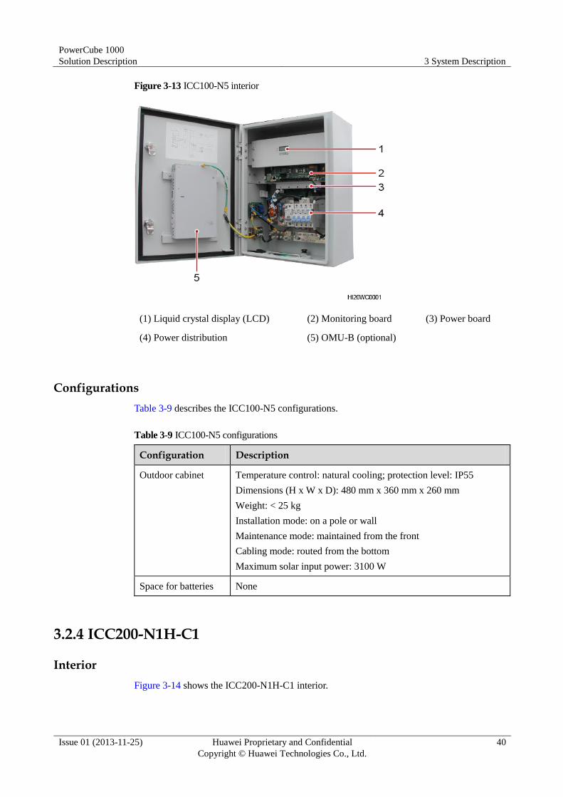
Figure 3-13 ICC100-N5 interior
(1) Liquid crystal display (LCD) (2) Monitoring board (3) Power board
(4) Power distribution (5) OMU-B (optional)
Configurations
Table 3-9 describes the ICC100-N5 configurations.
Table 3-9 ICC100-N5 configurations
Configuration Description
Outdoor cabinet Temperature control: natural cooling; protection level: IP55
Dimensions (H x W x D): 480 mm x 360 mm x 260 mm
Weight: < 25 kg
Installation mode: on a pole or wall
Maintenance mode: maintained from the front
Cabling mode: routed from the bottom
Maximum solar input power: 3100 W
Space for batteries None
3.2.4 ICC200-N1H-C1
Interior
Figure 3-14 shows the ICC200-N1H-C1 interior.

PowerCube 1000
Solution Description 3 System Description
Issue 01 (2013-11-25) Huawei Proprietary and Confidential
Copyright © Huawei Technologies Co., Ltd.
41
Figure 3-14 ICC200-N1H-C1 interior
(1) ACDU-63A1 (2) DCDU-400B1 (3) DTS-200A1
(4) DCDB-01A (5) Remaining space (6) Busbar
(7) Space for batteries
Configurations
Table 3-10 describes the ICC200-N1H-C1 configurations.
Table 3-10 ICC200-N1H-C1 configurations
Configuration Description
Indoor cabinet Temperature control: natural cooling; protection level: IP20
Dimensions (H x W x D): 2000 mm x 600 mm x 600 mm
Weight: 120 kg
Installation mode: on a floor
Maintenance mode: maintained from the front and rear
Cabling mode: routed from the top
DCDU-400B1 and DCDU-400B1 height: 7 U, including the ECC500

PowerCube 1000
Solution Description 3 System Description
Issue 01 (2013-11-25) Huawei Proprietary and Confidential
Copyright © Huawei Technologies Co., Ltd.
42
Configuration Description
DCDB-01A DCDB-01A height: 4 U
Slot: eight 2 U high slots
AC input: one AC input
DC output:
BLVD: one 10 A circuit breaker, two 16 A circuit breakers, and
four 32 A circuit breakers
LLVD: three 63 A circuit breakers and one 125 A circuit breaker
ACDU-63A1 4 U high, one AC input (3P+N), Level C surge protection
DTS-200A1 2 U high, switching between two DC routes
PSU A maximum of eight R4850N1s, R4850N3s, or R4850G1s
Remaining space 10 U, total equipment depth of 310 mm (inserted depth ≤ 265 mm)
Space for batteries ESU-A (150 Ah)
3.2.5 ICC200-N2-C1
Interior
Figure 3-15 shows the ICC200-N2-C1 interior.

PowerCube 1000
Solution Description 3 System Description
Issue 01 (2013-11-25) Huawei Proprietary and Confidential
Copyright © Huawei Technologies Co., Ltd.
43
Figure 3-15 ICC200-N2-C1 interior
(1) ACDU-63A1 (2) DCDU-300B1 (3) Remaining space
Configurations
Table 3-11 describes the ICC200-N2-C1 configurations.
Table 3-11 ICC200-N2-C1 configurations
Configuration Description
Indoor cabinet Temperature control: natural cooling; protection level: IP20
Dimensions (H x W x D): 2000 mm x 600 mm x 600 mm
Weight: 120 kg
Installation mode: on a floor
Maintenance mode: maintained from the front and rear
Cabling mode: routed from the top
DCDU-300B1 Height: 9 U, including the ECC500
Slot: eight 2 U high slots
AC input: one AC input

PowerCube 1000
Solution Description 3 System Description
Issue 01 (2013-11-25) Huawei Proprietary and Confidential
Copyright © Huawei Technologies Co., Ltd.
44
Configuration Description
DC output:
BLVD: one 10 A circuit breaker, two 16 A circuit breakers, and
four 32 A circuit breakers
LLVD: two 63 A circuit breakers and two 125 A circuit breakers
ACDU-63A1 4 U high, one AC input (3P+N), Level C surge protection
PSU A maximum of six R4850N1s, R4850N3s, or R4850G1s
Remaining space 29 U, total equipment depth of 310 mm (inserted depth ≤ 265 mm)
Space for batteries None
3.2.6 ICC200-N2-C4
Interior
Figure 3-16 shows the ICC200-N2-C4 interior.
Figure 3-16 ICC200-N2-C4 interior
(1) Space reserved for the ACDU or ATS (2) DCDU-300A1 (3) Remaining space

PowerCube 1000
Solution Description 3 System Description
Issue 01 (2013-11-25) Huawei Proprietary and Confidential
Copyright © Huawei Technologies Co., Ltd.
45
Configurations
Table 3-12 describes the ICC200-N2-C4 configurations.
Table 3-12 ICC200-N2-C4 configurations
Configuration Description
Indoor cabinet Temperature control: natural cooling; protection level: IP20
Dimensions (H x W x D): 2000 mm x 600 mm x 600 mm
Weight: 120 kg
Installation mode: on a floor
Maintenance mode: maintained from the front and rear
Cabling mode: routed from the top
DCDU-300A1 Height: 7 U, including the ECC500
Slot: eight 1 U high slots
AC input: one AC input
DC output:
BLVD: four 16 A circuit breakers, two 32 A circuit breakers, and
one 63 A circuit breaker
LLVD: two 63 A circuit breakers and two 125 A circuit breakers
ACDU/ATS Optional. Height: 4 U, Level B or Level C surge protection
PSU A maximum of six R4850G2s
Remaining space 14 U, total equipment depth of 310 mm (inserted depth ≤ 265 mm)
Space for batteries 13 U
3.2.7 ICC300-H1-A
Interior
Figure 3-17 shows the ICC300-H1-A interior.

PowerCube 1000
Solution Description 3 System Description
Issue 01 (2013-11-25) Huawei Proprietary and Confidential
Copyright © Huawei Technologies Co., Ltd.
46
Figure 3-17 ICC300-H1-A interior
(1) DCDU-400A1 (2) PVDU-60A1 (3) Remaining space
Configurations
Table 3-13 describes the ICC300-H1-A configurations.
Table 3-13 ICC300-H1-A configurations
Configuration Description
Outdoor cabinet Temperature control: heat exchange; heat dissipation capability:
900 W; protection level: IP55
Dimensions (H x W x D): 900 mm x 600 mm x 480 mm (including
a 200 mm high base)
Weight: 110 kg
Installation mode: on a floor
Maintenance mode: maintained from the front
Cabling mode: routed from the bottom
DCDU-400A1 Height: 6 U, including the ECC500
Slot: eight 1 U high slots
AC input: one AC input
DC output:

PowerCube 1000
Solution Description 3 System Description
Issue 01 (2013-11-25) Huawei Proprietary and Confidential
Copyright © Huawei Technologies Co., Ltd.
47
Configuration Description
Primary load: one 16 A circuit breaker and two 32 A circuit
breakers
Secondary load: two 63 A circuit breakers and one 125 A
circuit breaker
PVDU-60A1 1 U high, four inputs and four outputs
Remaining space 5 U, total equipment depth of 325 mm (inserted depth ≤ 280 mm)
PSU A maximum of four R4850G2s
SSU A maximum of four S4850G1s
Space for batteries N/A
3.2.8 ICC300-H1-B
Interior
Figure 3-18 shows the ICC300-H1-B interior.
Figure 3-18 ICC300-H1-B interior
(1) DCDU-400A1 (2) PVDU-60A1 (3) ACDU-63A1
PowerCube 1000
Solution Description 3 System Description
Issue 01 (2013-11-25) Huawei Proprietary and Confidential
Copyright © Huawei Technologies Co., Ltd.
48
Configurations
Table 3-14 describes the ICC300-H1-B configurations.
Table 3-14 ICC300-H1-B configurations
Configuration Description
Outdoor cabinet Temperature control: heat exchange; heat dissipation capability:
900 W; protection level: IP55
Dimensions (H x W x D): 900 mm x 600 mm x 480 mm (including
a 200 mm high base)
Weight: 110 kg
Installation mode: on a floor
Maintenance mode: maintained from the front
Cabling mode: routed from the bottom
DCDU-400A1 Height: 6 U, including the ECC500
Slot: eight 1 U high slots
AC input: one AC input
DC output:
Primary load: one 16 A circuit breaker and two 32 A circuit
breakers
Secondary load: two 63 A circuit breakers and one 125 A
circuit breaker
ACDU-63A1 4 U high, one AC input (3P+N), Level C surge protection
PVDU-60A1 1 U high, four inputs and four outputs
Remaining space None
PSU A maximum of four R4850G2s
SSU A maximum of four S4850G1s
Space for batteries None
3.2.9 ICC310-H1-A1
Interior
Figure 3-19 shows the ICC310-H1-A1 interior.

PowerCube 1000
Solution Description 3 System Description
Issue 01 (2013-11-25) Huawei Proprietary and Confidential
Copyright © Huawei Technologies Co., Ltd.
49
Figure 3-19 ICC310-H1-A1 interior
(1) DCDU-400A1 (2) PVDU-60A1 (3) Remaining space
Configurations
Table 3-15 describes the ICC310-H1-A1 configurations.
Table 3-15 ICC310-H1-A1 configurations
Configuration Description
Outdoor cabinet Temperature control: heat exchange; heat dissipation capability: 1500
W; protection level: IP55
Dimensions (H x W x D): 1825 mm x 700 mm x 700 mm (including
a 100 mm high base)
Weight: 300 kg
Installation mode: on a floor
Maintenance mode: maintained from the front
Cabling mode: routed from the bottom
DCDU-400A1 Height: 6 U, including the ECC500

PowerCube 1000
Solution Description 3 System Description
Issue 01 (2013-11-25) Huawei Proprietary and Confidential
Copyright © Huawei Technologies Co., Ltd.
50
Configuration Description
Slot: eight 1 U high slots
AC input: one AC input
DC output:
Primary load: one 16 A circuit breaker and two 32 A circuit
breakers
Secondary load: two 63 A circuit breakers and one 125 A circuit
breaker
PVDU-60A1 1 U high, four inputs and four outputs
PSU A maximum of four R4850G2s
SSU A maximum of four S4850G1s
Remaining space 26 U, total equipment depth of 427 mm (inserted depth ≤ 380 mm)
Space for batteries N/A
3.2.10 ICC310-H1-B1
Interior
Figure 3-20 shows the ICC310-H1-B1 interior.

PowerCube 1000
Solution Description 3 System Description
Issue 01 (2013-11-25) Huawei Proprietary and Confidential
Copyright © Huawei Technologies Co., Ltd.
51
Figure 3-20 ICC310-H1-B1 interior
(1) DCDU-400A1 (2) PVDU-60A1 (3) ATS-63A1
(4) Remaining space
Configurations
Table 3-16 describes the ICC310-H1-B1 configurations.
Table 3-16 ICC310-H1-B1 configurations
Configuration Description
Outdoor cabinet Temperature control: heat exchange; heat dissipation capability: 1500
W; protection level: IP55
Dimensions (H x W x D): 1825 mm x 700 mm x 700 mm (including
a 100 mm high base)
Weight: 300 kg
Installation mode: on a floor
Maintenance mode: maintained from the front
Cabling mode: routed from the bottom

PowerCube 1000
Solution Description 3 System Description
Issue 01 (2013-11-25) Huawei Proprietary and Confidential
Copyright © Huawei Technologies Co., Ltd.
52
Configuration Description
DCDU-400A1 Height: 6 U, including the ECC500
Slot: eight 1 U high slots
AC input: one AC input
DC output:
Primary load: one 16 A circuit breaker and two 32 A circuit
breakers
Secondary load: two 63 A circuit breakers and one 125 A circuit
breaker
PVDU-60A1 1 U high, four inputs and four outputs
ATS-63A1 4 U high, two AC inputs (3P+N), Level C surge protection
PSU A maximum of four R4850G2s
SSU A maximum of four S4850G1s
Remaining space 22 U, total equipment depth of 427 mm (inserted depth ≤ 380 mm)
Space for batteries None
3.2.11 ICC310-H1-D1
Interior
Figure 3-21 shows the ICC310-H1-D1 interior.

PowerCube 1000
Solution Description 3 System Description
Issue 01 (2013-11-25) Huawei Proprietary and Confidential
Copyright © Huawei Technologies Co., Ltd.
53
Figure 3-21 ICC310-H1-D1 interior
(1) DCDU-400A1 (2) ATS-63A1 (3) Remaining space
Configurations
Table 3-17 describes the ICC310-H1-D1 configurations.
Table 3-17 ICC310-H1-D1 configurations
Configuration Description
Outdoor cabinet Temperature control: heat exchange; heat dissipation capability: 1500
W; protection level: IP55
Dimensions (H x W x D): 1825 mm x 700 mm x 700 mm (including
a 100 mm high base)
Weight: 300 kg
Installation mode: on a floor
Maintenance mode: maintained from the front
Cabling mode: routed from the bottom
DCDU-400A1 Height: 6 U, including the ECC500

PowerCube 1000
Solution Description 3 System Description
Issue 01 (2013-11-25) Huawei Proprietary and Confidential
Copyright © Huawei Technologies Co., Ltd.
54
Configuration Description
Slot: eight 1 U high slots
AC input: one AC input
DC output:
Primary load: one 16 A circuit breaker and two 32 A circuit
breakers
Secondary load: two 63 A circuit breakers and one 125 A circuit
breaker
ATS-63A1 4 U high, two AC inputs (3P+N), Level C surge protection
PSU A maximum of eight R4850G2s
Remaining space 23 U, total equipment depth of 427 mm (inserted depth ≤ 380 mm)
Space for batteries None
3.2.12 ICC330-HD3-C3
Interior
Figure 3-22 shows the ICC330-HD3-C3 interior.

PowerCube 1000
Solution Description 3 System Description
Issue 01 (2013-11-25) Huawei Proprietary and Confidential
Copyright © Huawei Technologies Co., Ltd.
55
Figure 3-22 ICC330-HD3-C3 interior
(1) DCDU-200B5 (2) Remaining space (3) Heater
(4) Space for batteries (5) Heater
Configurations
Table 3-18 shows the ICC330-HD3-C3 configurations.
Table 3-18 ICC330-HD3-C3 configurations
Configuration Description
Outdoor cabinet Temperature control, heat dissipation capability, and protection level
Energy control compartment: heat exchange; heat dissipation
capability: 1125 W; protection level: IP55
Battery compartment: free cooling; protection level: IP34
Dimensions (H x W x D): 1600 mm x 650 mm x 650 mm (including
a temperature control system and base)
Weight: 200 kg
Installation mode: on a floor
Maintenance mode: maintained from the front
Cabling mode: routed from the bottom
DCDU-200B5 Height: 7 U, including the ECC500

PowerCube 1000
Solution Description 3 System Description
Issue 01 (2013-11-25) Huawei Proprietary and Confidential
Copyright © Huawei Technologies Co., Ltd.
56
Configuration Description
Slot: four 2 U high slots
AC input: one AC input
DC output:
BLVD: two 10 A circuit breakers, two 20 A circuit breakers, and
two 32 A circuit breakers
LLVD: three 32 A circuit breakers and one 63 A circuit breaker
Heater 1 U high, supplied with AC power, used for heating
PSU A maximum of four R4850G1s or R4850G5s
Remaining space 7 U
Space for batteries A maximum of two 12 V AGM battery strings, each being 150 Ah
HAU03A-01 (Optional)
A heater assembly unit (HAU) is adopted to ensure a proper operating temperature for the
equipment inside the cabinet.
Figure 3-23 shows an HAU03A-01.
Figure 3-23 HAU03A-01
Figure 3-24 shows an HAU03A-01 panel.

PowerCube 1000
Solution Description 3 System Description
Issue 01 (2013-11-25) Huawei Proprietary and Confidential
Copyright © Huawei Technologies Co., Ltd.
57
Figure 3-24 HAU03A-01 panel
(1) AC input port (2) Indicator (3) Alarm dry contact
(4) Control dry contact
Table 3-19 shows the HAU03A-01 technical specifications.
Table 3-19 HAU03A-01 technical specifications
Item Specifications
Operating voltage range 90–290 V AC
Voltage frequency 45–65 Hz
Heating capacity 90–132 V AC: 400–600 W
176–290 V AC: 500–750 W
Lamp (Optional)
The cabinet is embedded with a lamp that works at 48 V DC and with less than or equal to 1
W.
Figure 3-25 shows a lamp.

PowerCube 1000
Solution Description 3 System Description
Issue 01 (2013-11-25) Huawei Proprietary and Confidential
Copyright © Huawei Technologies Co., Ltd.
58
Figure 3-25 Lamp
3.2.13 ICC500-HA1
Interior
Figure 3-26 shows the ICC500-HA1 interior.
Figure 3-26 ICC500-HA1 interior (front and rear views)
(1) DCDU-400A1 (2) Remaining space (3) Space for batteries
(4) Space for batteries (5) Remaining space (6) ACDU-63A1
Configurations
Table 3-20 describes the ICC500-HA1 configurations.

PowerCube 1000
Solution Description 3 System Description
Issue 01 (2013-11-25) Huawei Proprietary and Confidential
Copyright © Huawei Technologies Co., Ltd.
59
Table 3-20 ICC500-HA1 configurations
Configuration Description
Outdoor cabinet Temperature control, heat dissipation capability, and protection level
Energy control compartment: heat exchange; heat dissipation
capability: 1300 W; protection level: IP55
Battery compartment: 1000 W DC air conditioner; protection
level: IP55
Dimensions (H x W x D): 1825 mm x 770 mm x 1250 mm (including
a 100 mm high base)
Weight: 315 kg
Installation mode: on a floor
Maintenance mode: maintained from the front and rear
Cabling mode: routed from the bottom
DCDU-400A1 Height: 6 U, including the ECC500
Slot: eight 1 U high slots
AC input: one AC input
DC output:
Primary load: one 16 A circuit breaker and two 32 A circuit
breakers
Secondary load: two 63 A circuit breakers and one 125 A circuit
breaker
ACDU-63A1 4 U high, one AC input (3P+N), Level C surge protection
PSU A maximum of six R4850G2s
Remaining space Front: 3 U; rear: 8 U; supporting total equipment depth of 310 mm
(inserted depth ≤ 265 mm)
Space for batteries A maximum of one 650 Ah FCB string
3.2.14 ICC500-HA1H-C1/ICC500-HA1H-C2
Interior
Figure 3-27 shows the ICC500-HA1H-C1 and ICC500-HA1H-C2 interiors.

PowerCube 1000
Solution Description 3 System Description
Issue 01 (2013-11-25) Huawei Proprietary and Confidential
Copyright © Huawei Technologies Co., Ltd.
60
Figure 3-27 ICC500-HA1H-C1 and ICC500-HA1H-C2 interiors (front and rear views)
(1) DCDU-400B1 (2) Space for ESU-As (3) Space for FCBs
(4) Space for FCBs (5) DCDB-01A (6) ACDU-63A1
(7) DTS-200A1 (8) Remaining space
Configurations
Table 3-21 describes the ICC500-HA1H-C1 and ICC500-HA1H-C2 configurations.
Table 3-21 ICC500-HA1H-C1 and ICC500-HA1H-C2 configurations
Configuration Description
Outdoor cabinet Temperature control, heat dissipation capability, and protection level
Energy control compartment: heat exchange; heat dissipation
capability: 1500 W; protection level: IP55
Battery compartment: 1000 W DC air conditioner for the
ICC500-HA1H-C1; 700 W DC air conditioner for the
ICC500-HA1H-C2; protection level: IP55
Dimensions (H x W x D): 1825 mm x 770 mm x 1250 mm (including
a 100 mm high base)
Weight: 315 kg
Installation mode: on a floor
Maintenance mode: maintained from the front and rear
Cabling mode: routed from the bottom
DCDU-400B1 and
DCDB-01A
DCDU-400B1 height: 7 U, including the ECC500
DCDB-01A height: 4 U
Slot: eight 2 U high slots

PowerCube 1000
Solution Description 3 System Description
Issue 01 (2013-11-25) Huawei Proprietary and Confidential
Copyright © Huawei Technologies Co., Ltd.
61
Configuration Description
AC input: one AC input
DC output:
BLVD: one 10 A circuit breaker, two 16 A circuit breakers, and
four 32 A circuit breakers
LLVD: three 63 A circuit breakers and one 125 A circuit breaker
ACDU-63A1 4 U high, one AC input (3P+N), Level C surge protection
DTS-200A1 2 U high, switching between two DC routes
PSU A maximum of eight R4850N1s, R4850N3s, or R4850G1s
Remaining space Rear: 8 U, total equipment depth of 310 mm (inserted depth ≤ 265
mm)
Space for batteries One ESU-H string: ESU-A (100 Ah) + FCB (400 Ah)
3.2.15 ICC500-HA1H-C3
Interior
Figure 3-28 shows the ICC500-HA1H-C3 interior.
Figure 3-28 ICC500-HA1H-C3 interior (front and rear views)
(1) DCDU-400AD (2) DTS-200A1 (3) Space for ESU-As
(4) Space for FCBs (5) Space for FCBs (6) DCDB-01B
(7) ACDU-63A2 (8) Remaining space

PowerCube 1000
Solution Description 3 System Description
Issue 01 (2013-11-25) Huawei Proprietary and Confidential
Copyright © Huawei Technologies Co., Ltd.
62
Configurations
Table 3-22 describes the ICC500-HA1H-C3 configurations.
Table 3-22 ICC500-HA1H-C3 configurations
Configuration Description
Outdoor cabinet Temperature control, heat dissipation capability, and protection level
Energy control compartment: heat exchange; heat dissipation
capability: 1500 W; protection level: IP55
ESU compartment: 700 W DC air conditioner; protection level:
IP55
Dimensions (H x W x D): 1825 mm x 770 mm x 1250 mm (including
a 100 mm high base)
Weight: 315 kg
Installation mode: on a floor
Maintenance mode: maintained from the front and rear
Cabling mode: routed from the bottom
DCDU-400AD
and DCDB-01B
DCDU-400AD height: 5 U, including the ECC500
DCDB-01B height: 4 U
Slot: eight 1 U high slots
AC input: one AC input
DC output:
BLVD: one 10 A circuit breaker, two 16 A circuit breakers, and
four 32 A circuit breakers
LLVD: two 63 A circuit breakers and two 80 A circuit breakers
ACDU-63A2 4 U high, one AC input (3P+N), Level B surge protection
DTS-200A1 2 U high, switching between two DC routes
PSU A maximum of eight R4850G2s
Remaining space 10 U, total equipment depth of 310 mm (inserted depth ≤ 265 mm)
Space for batteries One ESU-H string: ESU-A (100 Ah) + FCB (400 Ah)
3.2.16 ICC500-HA2-C1/ICC500-HA2-C2
Interior
Figure 3-29 shows the ICC500-HA2-C1 and ICC500-HA2-C2 interiors.

PowerCube 1000
Solution Description 3 System Description
Issue 01 (2013-11-25) Huawei Proprietary and Confidential
Copyright © Huawei Technologies Co., Ltd.
63
Figure 3-29 ICC500-HA2-C1 and ICC500-HA2-C2 interiors (front and rear views)
(1) DCDU-300B1 (2) Space for batteries (3) Space for batteries
(4) Remaining space (5) ACDU-63A1
Both the ESU-A rack and FCB rack can be used as space for batteries inside the ICC500-HA2-C1 and
ICC500-HA2-C2. The preceding figure shows an FCB rack.
Configurations
Table 3-23 describes the ICC500-HA2-C1 and ICC500-HA2-C2 configurations.
Table 3-23 ICC500-HA2-C1 and ICC500-HA2-C2 configurations
Configuration Description
Outdoor cabinet Temperature control, heat dissipation capability, and protection level
Energy control compartment: heat exchange; heat dissipation
capability: 1500 W; protection level: IP55
Battery compartment: 1000 W DC air conditioner for the
ICC500-HA2-C1; 700 W DC air conditioner for the
ICC500-HA2-C2; protection level: IP55
Dimensions (H x W x D): 1825 mm x 770 mm x 1250 mm (including
a 100 mm high base)
Weight: 315 kg
Installation mode: on a floor
Maintenance mode: maintained from the front and rear
Cabling mode: routed from the bottom
DCDU-300B1 Height: 9 U, including the ECC500

PowerCube 1000
Solution Description 3 System Description
Issue 01 (2013-11-25) Huawei Proprietary and Confidential
Copyright © Huawei Technologies Co., Ltd.
64
Configuration Description
Slot: eight 2 U high slots
AC input: one AC input
DC output:
BLVD: one 10 A circuit breaker, two 16 A circuit breakers, and
four 32 A circuit breakers
LLVD: two 63 A circuit breakers and two 125 A circuit breakers
ACDU-63A1 4 U high, one AC input (3P+N), Level C surge protection
PSU A maximum of six R4850N1s, R4850N3s, or R4850G1s
Remaining space Rear: 8 U, total equipment depth of 310 mm (inserted depth ≤ 265
mm)
Space for batteries A maximum of 400 Ah ESU-A or one 650 Ah FCB string
3.2.17 ICC701-HA1H-C1
Interior
Figure 3-30 shows the ICC701-HA1H-C1 interior.
Figure 3-30 ICC701-HA1H-C1 interior (front and rear views)
(1) ACDU-63A2 (2) DCDU-400AD (3) DTS-200A1
(4) Remaining space (5) DCDB-01B (6) Space for ESU-As
(7) Space for FCBs

PowerCube 1000
Solution Description 3 System Description
Issue 01 (2013-11-25) Huawei Proprietary and Confidential
Copyright © Huawei Technologies Co., Ltd.
65
Configurations
Table 3-24 describes the ICC701-HA1H-C1 configurations.
Table 3-24 ICC701-HA1H-C1 configurations
Configuration Description
Outdoor cabinet Temperature control, heat dissipation capability, and protection level
Energy control compartment: heat exchange; heat dissipation
capability: 2000 W@72 dBA, 1400 W@65 dBA; protection level:
IP55
Battery compartment: 700 W DC air conditioner; protection level:
IP55
Dimensions (H x W x D): 2050 mm x 900 mm x 1560 mm (including
a temperature control system and base)
Weight: 400 kg
Installation mode: on a floor
Maintenance mode: maintained from the front and rear
Cabling mode: routed from the bottom
DCDU-400AD
and DCDB-01B
DCDU-400AD height: 5 U, including the ECC500
DCDB-01B height: 4 U
Slot: eight 1 U high slots
AC input: one AC input
DC output:
BLVD: one 10 A circuit breaker, two 16 A circuit breakers, and
four 32 A circuit breakers
LLVD: two 63 A circuit breakers and two 80 A circuit breakers
ACDU-63A2 4 U high, one AC input (3P+N), Level B surge protection
DTS-200A1 2 U high, switching between two DC routes
PSU A maximum of eight R4850G2s
Remaining space Front: 10 U
Space for batteries One ESU-H string: ESU-A (150 Ah) + FCB (650 Ah)
3.2.18 ICC701-HA2-C1
Interior
Figure 3-31 shows the ICC701-HA2-C1 interior.

PowerCube 1000
Solution Description 3 System Description
Issue 01 (2013-11-25) Huawei Proprietary and Confidential
Copyright © Huawei Technologies Co., Ltd.
66
Figure 3-31 ICC701-HA2-C1 interior (front and rear views)
(1) DCDU-300A1 (2) Remaining space (3) Space for batteries
(4) Space for batteries
Configurations
Table 3-25 describes the ICC701-HA2-C1 configurations.
Table 3-25 ICC701-HA2-C1 configurations
Configuration Description
Outdoor cabinet Temperature control, heat dissipation capability, and protection level
Energy control compartment: heat exchange; heat dissipation
capability: 1500 W; protection level: IP55
ESU compartment: 700 W DC air conditioner; protection level:
IP55
Dimensions (H x W x D): 2050 mm x 900 mm x 1560 mm (including
a temperature control system and base)
Weight: 350 kg
Installation mode: on a floor
Maintenance mode: maintained from the front and rear
Cabling mode: routed from the bottom
DCDU-300A1 Height: 7 U, including the ECC500
Slot: eight 1 U high slots
AC input: one AC input
DC output:

PowerCube 1000
Solution Description 3 System Description
Issue 01 (2013-11-25) Huawei Proprietary and Confidential
Copyright © Huawei Technologies Co., Ltd.
67
Configuration Description
BLVD: four 16 A circuit breakers, two 32 A circuit breakers, and
one 63 A circuit breaker
LLVD: two 63 A circuit breakers and two 125 A circuit breakers
ATS Optional, 4 U high, Level B or Level C surge protection
PSU A maximum of six R4850G2s
Remaining space Front: 10 U
Space for batteries A maximum of
DCB-A: two 420 Ah DCB-A strings or one 490 Ah DCB-A string
ESU-D/A1: two 500 Ah ESU-D/A1 strings or one 600 Ah
ESU-D/A1 string
3.2.19 ICC900-DD2, ICC900-HD2, or ICC900-HA2
Interior
Figure 3-32 shows the ICC900-DD2, ICC900-HD2, or ICC900-HA2 interior.
Figure 3-32 ICC900-DD2, ICC900-HD2, or ICC900-HA2 interior
(1) Space for batteries (2) Space for batteries (3) IDU-300A1
Configurations
Table 3-26 shows the ICC900-DD2, ICC900-HD2, and ICC900-HA2 configurations.
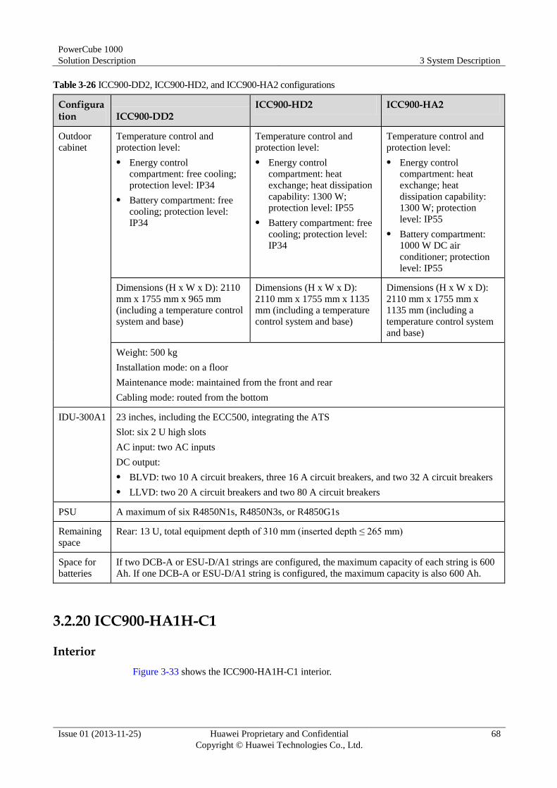
PowerCube 1000
Solution Description 3 System Description
Issue 01 (2013-11-25) Huawei Proprietary and Confidential
Copyright © Huawei Technologies Co., Ltd.
68
Table 3-26 ICC900-DD2, ICC900-HD2, and ICC900-HA2 configurations
Configuration ICC900-DD2
ICC900-HD2 ICC900-HA2
Outdoor
cabinet
Temperature control and
protection level:
Energy control
compartment: free cooling;
protection level: IP34
Battery compartment: free
cooling; protection level:
IP34
Temperature control and
protection level:
Energy control
compartment: heat
exchange; heat dissipation
capability: 1300 W;
protection level: IP55
Battery compartment: free
cooling; protection level:
IP34
Temperature control and
protection level:
Energy control
compartment: heat
exchange; heat
dissipation capability:
1300 W; protection
level: IP55
Battery compartment:
1000 W DC air
conditioner; protection
level: IP55
Dimensions (H x W x D): 2110
mm x 1755 mm x 965 mm
(including a temperature control
system and base)
Dimensions (H x W x D):
2110 mm x 1755 mm x 1135
mm (including a temperature
control system and base)
Dimensions (H x W x D):
2110 mm x 1755 mm x
1135 mm (including a
temperature control system
and base)
Weight: 500 kg
Installation mode: on a floor
Maintenance mode: maintained from the front and rear
Cabling mode: routed from the bottom
IDU-300A1 23 inches, including the ECC500, integrating the ATS
Slot: six 2 U high slots
AC input: two AC inputs
DC output:
BLVD: two 10 A circuit breakers, three 16 A circuit breakers, and two 32 A circuit breakers
LLVD: two 20 A circuit breakers and two 80 A circuit breakers
PSU A maximum of six R4850N1s, R4850N3s, or R4850G1s
Remaining
space
Rear: 13 U, total equipment depth of 310 mm (inserted depth ≤ 265 mm)
Space for
batteries
If two DCB-A or ESU-D/A1 strings are configured, the maximum capacity of each string is 600
Ah. If one DCB-A or ESU-D/A1 string is configured, the maximum capacity is also 600 Ah.
3.2.20 ICC900-HA1H-C1
Interior
Figure 3-33 shows the ICC900-HA1H-C1 interior.
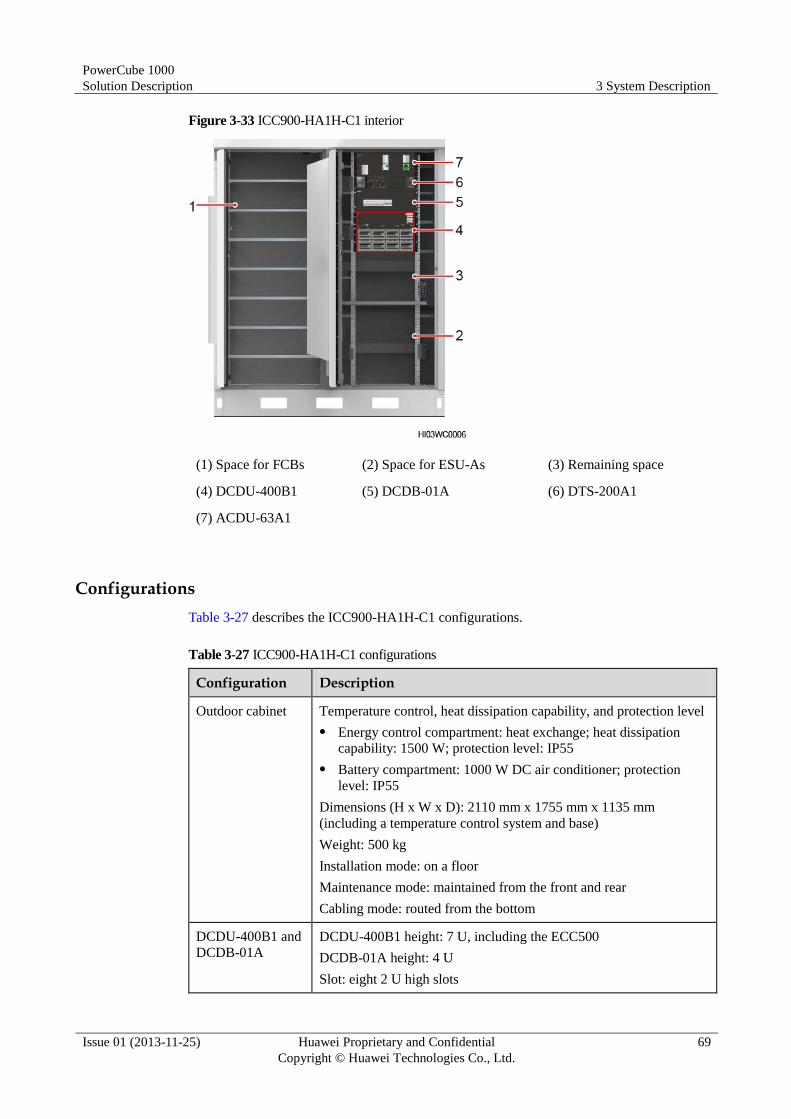
PowerCube 1000
Solution Description 3 System Description
Issue 01 (2013-11-25) Huawei Proprietary and Confidential
Copyright © Huawei Technologies Co., Ltd.
69
Figure 3-33 ICC900-HA1H-C1 interior
(1) Space for FCBs (2) Space for ESU-As (3) Remaining space
(4) DCDU-400B1 (5) DCDB-01A (6) DTS-200A1
(7) ACDU-63A1
Configurations
Table 3-27 describes the ICC900-HA1H-C1 configurations.
Table 3-27 ICC900-HA1H-C1 configurations
Configuration Description
Outdoor cabinet Temperature control, heat dissipation capability, and protection level
Energy control compartment: heat exchange; heat dissipation
capability: 1500 W; protection level: IP55
Battery compartment: 1000 W DC air conditioner; protection
level: IP55
Dimensions (H x W x D): 2110 mm x 1755 mm x 1135 mm
(including a temperature control system and base)
Weight: 500 kg
Installation mode: on a floor
Maintenance mode: maintained from the front and rear
Cabling mode: routed from the bottom
DCDU-400B1 and
DCDB-01A
DCDU-400B1 height: 7 U, including the ECC500
DCDB-01A height: 4 U
Slot: eight 2 U high slots

PowerCube 1000
Solution Description 3 System Description
Issue 01 (2013-11-25) Huawei Proprietary and Confidential
Copyright © Huawei Technologies Co., Ltd.
70
Configuration Description
AC input: one AC input
DC output:
BLVD: one 10 A circuit breaker, two 16 A circuit breakers, and
four 32 A circuit breakers
LLVD: three 63 A circuit breakers and one 125 A circuit breaker
ACDU-63A1 4 U high, one AC input (3P+N), Level C surge protection
DTS-200A1 2 U high, switching between two DC routes
PSU A maximum of eight R4850N1s, R4850N3s, or R4850G1s
Remaining space 8 U, total equipment depth of 310 mm (inserted depth ≤ 265 mm)
Space for batteries One ESU-H string: ESU-A (150 Ah) + FCB (500 Ah)
3.2.21 ICC900-HA2-C1
Interior
Figure 3-34 shows the ICC900-HA2-C1 interior.
Figure 3-34 ICC900-HA2-C1 interior
(1) Space for batteries (2) Space for batteries (3) Remaining space
(4) DCDU-300B1 (5) ACDU-63A1
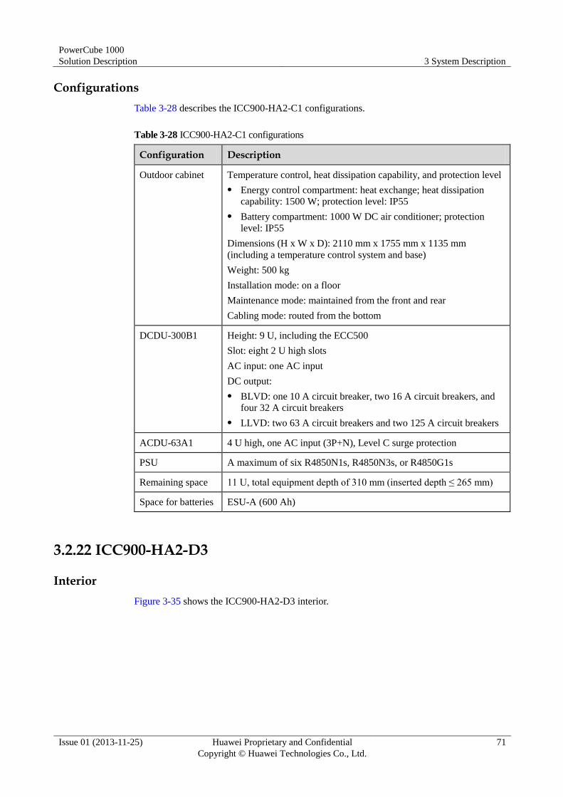
PowerCube 1000
Solution Description 3 System Description
Issue 01 (2013-11-25) Huawei Proprietary and Confidential
Copyright © Huawei Technologies Co., Ltd.
71
Configurations
Table 3-28 describes the ICC900-HA2-C1 configurations.
Table 3-28 ICC900-HA2-C1 configurations
Configuration Description
Outdoor cabinet Temperature control, heat dissipation capability, and protection level
Energy control compartment: heat exchange; heat dissipation
capability: 1500 W; protection level: IP55
Battery compartment: 1000 W DC air conditioner; protection
level: IP55
Dimensions (H x W x D): 2110 mm x 1755 mm x 1135 mm
(including a temperature control system and base)
Weight: 500 kg
Installation mode: on a floor
Maintenance mode: maintained from the front and rear
Cabling mode: routed from the bottom
DCDU-300B1 Height: 9 U, including the ECC500
Slot: eight 2 U high slots
AC input: one AC input
DC output:
BLVD: one 10 A circuit breaker, two 16 A circuit breakers, and
four 32 A circuit breakers
LLVD: two 63 A circuit breakers and two 125 A circuit breakers
ACDU-63A1 4 U high, one AC input (3P+N), Level C surge protection
PSU A maximum of six R4850N1s, R4850N3s, or R4850G1s
Remaining space 11 U, total equipment depth of 310 mm (inserted depth ≤ 265 mm)
Space for batteries ESU-A (600 Ah)
3.2.22 ICC900-HA2-D3
Interior
Figure 3-35 shows the ICC900-HA2-D3 interior.

PowerCube 1000
Solution Description 3 System Description
Issue 01 (2013-11-25) Huawei Proprietary and Confidential
Copyright © Huawei Technologies Co., Ltd.
72
Figure 3-35 ICC900-HA2-D3 interior
(1) Space for batteries (2) Space for batteries (3) IDU-300D1
Configurations
Table 3-29 describes the ICC900-HA2-D3 configurations.
Table 3-29 ICC900-HA2-D3 configurations
Configuration Description
Outdoor cabinet Temperature control, heat dissipation capability, and protection level
Energy control compartment: heat exchange; heat dissipation
capability: 1500 W; protection level: IP55
Battery compartment: 1000 W DC air conditioner; protection
level: IP55
Dimensions (H x W x D): 2110 mm x 1755 mm x 1135 mm
(including a temperature control system and base)
Weight: 500 kg
Installation mode: on a floor
Maintenance mode: maintained from the front and rear
Cabling mode: routed from the bottom
IDU-300D1 23 inches, including the ECC500, integrating the ATS
Slot: six 2 U high slots
AC input: two AC inputs
DC output:
Common load: two 16 A circuit breakers and one 32 A circuit
breaker
PowerCube 1000
Solution Description 3 System Description
Issue 01 (2013-11-25) Huawei Proprietary and Confidential
Copyright © Huawei Technologies Co., Ltd.
73
Configuration Description
Shared by four user loads and providing four circuit breakers for
each user load, one 32 A BLVD circuit breaker, one 32 A LLVD
circuit breaker, and two 80 A LLVD circuit breakers
PSU A maximum of six R4850N1s, R4850N3s, or R4850G1s
Remaining space 13 U, total equipment depth of 310 mm (inserted depth ≤ 265 mm)
Space for batteries If two DCB-A or ESU-D/A1 strings are configured, the maximum
capacity of each string is 600 Ah. If one DCB-A or ESU-D/A1 string
is configured, the maximum capacity is also 600 Ah.
3.2.23 ESC200-N1
Appearance
There are many ESC200-N1 interiors. Figure 3-36,Figure 3-37, and Figure 3-38 shows
ESC200-N1 interiors.

PowerCube 1000
Solution Description 3 System Description
Issue 01 (2013-11-25) Huawei Proprietary and Confidential
Copyright © Huawei Technologies Co., Ltd.
74
Figure 3-36 ESC200-N1 (code:01071466) interior
(1) Busbar (2) Space for batteries

PowerCube 1000
Solution Description 3 System Description
Issue 01 (2013-11-25) Huawei Proprietary and Confidential
Copyright © Huawei Technologies Co., Ltd.
75
Figure 3-37 ESC200-N1 (code:01071821) interior
(1) Busbar (2) Remaining space (3) ESMU-02A
(4) Space for ESU-A2400Wh/D (5) ESMU-03A (6) Space for ESU-A2400Wh/N

PowerCube 1000
Solution Description 3 System Description
Issue 01 (2013-11-25) Huawei Proprietary and Confidential
Copyright © Huawei Technologies Co., Ltd.
76
Figure 3-38 ESC200-N1 (code:01071822) interior
(1) Busbar (2) Remaining space (3) ESMU-03A
(4) Space for ESU-A2400Wh/N
Configurations
Table 3-30 shows the ESC200-N1 configurations.
Table 3-30 ESC200-N1 configurations
Configuration Description
Indoor cabinet Temperature control: natural cooling; protection level: IP20
Dimensions (H x W x D): 2000 mm x 600 mm x 600 mm
Weight: 120 kg
Installation mode: on a floor
Maintenance mode: maintained from the front
Cabling mode: routed from the top
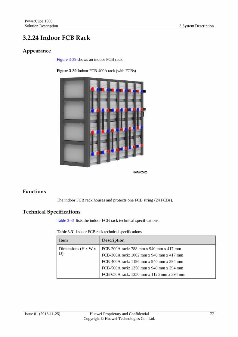
PowerCube 1000
Solution Description 3 System Description
Issue 01 (2013-11-25) Huawei Proprietary and Confidential
Copyright © Huawei Technologies Co., Ltd.
77
3.2.24 Indoor FCB Rack
Appearance
Figure 3-39 shows an indoor FCB rack.
Figure 3-39 Indoor FCB-400A rack (with FCBs)
Functions
The indoor FCB rack houses and protects one FCB string (24 FCBs).
Technical Specifications
Table 3-31 lists the indoor FCB rack technical specifications.
Table 3-31 Indoor FCB rack technical specifications
Item Description
Dimensions (H x W x
D)
FCB-200A rack: 788 mm x 940 mm x 417 mm
FCB-300A rack: 1002 mm x 940 mm x 417 mm
FCB-400A rack: 1196 mm x 940 mm x 394 mm
FCB-500A rack: 1350 mm x 940 mm x 394 mm
FCB-650A rack: 1350 mm x 1126 mm x 394 mm

PowerCube 1000
Solution Description 3 System Description
Issue 01 (2013-11-25) Huawei Proprietary and Confidential
Copyright © Huawei Technologies Co., Ltd.
78
3.2.25 Indoor DCB Rack
Appearance
Figure 3-40 shows an indoor DCB rack.
Figure 3-40 Indoor DCB-490A rack (with DCBs)
Functions
The indoor DCB rack houses one DCB-A or ESU-D/A1 string (24 DCBs).
Technical Specifications
Table 3-32 lists the indoor DCB rack technical specifications.
Table 3-32 Indoor DCB rack technical specifications
Item Description
Dimensions (H x W x
D)
DCB-300A/DCB-420A/DCB-600A rack: 1597 mm x 729 mm x
826 mm
DCB-490A rack: 1422 mm x 813 mm x 826 mm
DCB-800A rack: 1627 mm x 1635 mm x 477 mm
ESU-D600Wh/A1 rack: 1016 mm x 1005 mm x 593 mm
ESU-D800Wh/A1 rack: 1242 mm x 1005 mm x 593 mm
ESU-D1000Wh/A1 rack: 1597 mm x 729 mm x 826 mm
ESU-D1200Wh/A1 rack: 1422 mm x 813 mm x 826 mm

PowerCube 1000
Solution Description 3 System Description
Issue 01 (2013-11-25) Huawei Proprietary and Confidential
Copyright © Huawei Technologies Co., Ltd.
79
Item Description
ESU-D1600Wh/A1 rack: 1627 mm x 1635 mm x 477 mm
3.2.26 Outdoor Battery Cabinet
Appearance
Figure 3-41 shows an outdoor battery cabinet.
Figure 3-41 Outdoor battery cabinet
Functions
The outdoor battery cabinet houses and protects one SCB-A, SCB-A1, DCB-A, or ESU-D/A1
string (24 SCBs or DCBs) and ensures that the SCBs or DCBs work at an appropriate
temperature.
Technical Specifications
Table 3-33 lists the outdoor battery cabinet technical specifications.
Table 3-33 Outdoor battery cabinet technical specifications
Item Specifications
Shape Rectangular cuboid
Dimensions (L x W x H) SCB-A or SCB-A1 cabinet: 1650 mm x 990 mm x 1060
mm
DCB-A or ESU-D/A1 cabinet: 1500 mm x 950 mm x 1000
mm

PowerCube 1000
Solution Description 3 System Description
Issue 01 (2013-11-25) Huawei Proprietary and Confidential
Copyright © Huawei Technologies Co., Ltd.
80
Item Specifications
Weight < 160 kg
3.2.27 Flooded Battery Cabinet
Appearance
Figure 3-42 shows flooded battery cabinets.
Figure 3-42 Flooded battery cabinets
Functions
The flooded battery cabinet houses and protects one flooded battery string (24 flooded
batteries) and ensures that the flooded batteries work at an appropriate temperature.
Technical Specifications
Table 3-34 lists the flooded battery cabinet technical specifications.
Table 3-34 Flooded battery cabinet technical specifications
Item Specifications
Weight 600 Ah flooded battery cabinet: 120 kg
800 Ah flooded battery cabinet: 170 kg
Dimensions (H x W x D) 600 Ah flooded battery cabinet: 1180 mm x 2700 mm x 1000
mm
800 Ah flooded battery cabinet: 1180 mm x 3600 mm x 1000
mm
Temperature control
mode
Natural cooling
Protection level IP34
Installation mode Components are connected by bolts or clamps.

PowerCube 1000
Solution Description 3 System Description
Issue 01 (2013-11-25) Huawei Proprietary and Confidential
Copyright © Huawei Technologies Co., Ltd.
81
3.2.28 EcoCool
The EcoCool is an environment monitoring system. Figure 3-43 shows its network diagram.
The EcoCool applies to new indoor temperature control sites or modernized temperature
control sites.
The EcoCool employs an environment and power automatic controller (EPAC) as the
monitoring part and employs a DC ventilation unit and an AC air conditioner as the execution
part. The ECC500 communicates with the EPAC over southbound communications ports but
does not perform scheduling. The NetEco allows you to configure parameters for the EPAC
and to query alarms, real-time data, and performance data.
Figure 3-43 EcoCool network diagram
The EcoCool works to monitor reused AC air conditioners and DC ventilation unit in real
time and to generate alarms.
3.2.29 Split-Type DC Variable Frequency Air Conditioner
A split-type DC variable frequency air conditioner, specially designed for communications
equipment and similar industrial equipment, is a high-performance DC type air conditioner.
The air conditioner controls the temperature inside the equipment room within 20°C to 40°C
to ensure that all electronic components in the equipment room work properly at their optimal
performance.
The air conditioner applies to new indoor temperature control sites or modernized temperature
control sites. You can choose one or two split-type DC variable frequency air conditioners
based on the load and heat dissipation requirements for the site. The air conditioner consists
of an outdoor unit and indoor unit.

PowerCube 1000
Solution Description 3 System Description
Issue 01 (2013-11-25) Huawei Proprietary and Confidential
Copyright © Huawei Technologies Co., Ltd.
82
Appearance
The split-type DC variable frequency air conditioner is model SP4D.
Figure 3-44 shows an installed split-type DC variable frequency air conditioner.
Figure 3-44 Installed split-type DC variable frequency air conditioner
(1) Indoor unit (2) Outdoor unit
The air conditioner control box is ACC-01.
Figure 3-45 shows an air conditioner control box.
Figure 3-45 Air conditioner control box
Configurations and Networking
A split-type DC variable frequency air conditioner can be configured and networked as
follows:
Configuration mode 1: one split-type DC variable frequency air conditioner
Configuration mode 2: one split-type DC variable frequency air conditioner+ECC500,
networked as shown in Figure 3-46
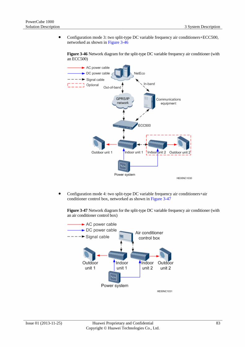
PowerCube 1000
Solution Description 3 System Description
Issue 01 (2013-11-25) Huawei Proprietary and Confidential
Copyright © Huawei Technologies Co., Ltd.
83
Configuration mode 3: two split-type DC variable frequency air conditioners+ECC500,
networked as shown in Figure 3-46
Figure 3-46 Network diagram for the split-type DC variable frequency air conditioner (with
an ECC500)
Configuration mode 4: two split-type DC variable frequency air conditioners+air
conditioner control box, networked as shown in Figure 3-47
Figure 3-47 Network diagram for the split-type DC variable frequency air conditioner (with
an air conditioner control box)

PowerCube 1000
Solution Description 3 System Description
Issue 01 (2013-11-25) Huawei Proprietary and Confidential
Copyright © Huawei Technologies Co., Ltd.
84
Technical Specifications
Table 3-35 lists the technical specifications for the split-type DC variable frequency air
conditioner.
Table 3-35 Technical specifications for the split-type DC variable frequency air conditioner
Item Specifications
Rated or operating voltage range –48 V DC (–10% to +20%)
Total refrigeration capacity 4000 W (indoor temperature: 35°C; outdoor
temperature: 35°C)
3000 W (indoor temperature: 35°C; outdoor
temperature: 55°C)
Dimensions (L×W×H) Indoor unit: 1045 mm x 210 mm x 320 mm
Outdoor unit: 766 mm x 278 mm x 528 mm
Refrigerant R134a
Weight Indoor unit: 21 kg
Outdoor unit: 35 kg
Table 3-36 lists the Air conditioner control box technical specifications.
Table 3-36 Air conditioner control box technical specifications
Item Specifications
Rated input voltage –48 V
Protection Input low voltage protection and input
reverse-connection prevention
Operating temperature –20°C to +55°C
Humidity 5%–95% RH (non-condensing)
Dimensions (H x W x D) 43.6 mm x 316 mm x 186 mm
Heat dissipation mode Natural cooling
3.3 ICC
3.3.1 Composition
The ICC, as the core of the PowerCube 1000, schedules energy logically, monitors the
operating status of other systems, and reports information to the NetEco.
Table 3-37 describes ICC component functions.

PowerCube 1000
Solution Description 3 System Description
Issue 01 (2013-11-25) Huawei Proprietary and Confidential
Copyright © Huawei Technologies Co., Ltd.
85
Table 3-37 ICC component functions
Component Function
ECC500 Implements logical control such as hybrid power scheduling,
ESS management, and ESS on/off control.
Provides a liquid crystal display (LCD) for querying system
information and setting system control parameters.
Performs remote management in in-band or out-of-band mode.
Provides ports for connecting to internal and external signal
cables.
ATS Switches between AC power supplies.
ACDU Distributes AC power.
DCDU and DCDB Distributes DC power.
If there are multiple loads, configure both the DCDU and the
DCDB.
PVDU Provides ports for receiving the currents from PV modules.
SSU Regulates the voltage of PV modules with MPPT technology and
converts DC input into DC output.
PSU Converts AC input into –48 V DC output.
DTS Switches between DC power supplies.
Inverter Converts DC input into AC output.
BC Converts –48 V DC input into 12 V DC output to charge the DG
battery.
DC-DC converter
(–48 V to 24 V)
Converts –48 V DC input into 24 V DC output. The model is the
Embedded Telecom Power 24160A3 (ETP24160A3).
GPRS board and
antenna
Implements GPRS networking.
DG IO board Controls the DG.
Figure 3-48 describes the ICC electrical conceptual diagram (not for ESU-H scenario).

PowerCube 1000
Solution Description 3 System Description
Issue 01 (2013-11-25) Huawei Proprietary and Confidential
Copyright © Huawei Technologies Co., Ltd.
86
Figure 3-48 ICC electrical conceptual diagram (not for ESU-H scenario)
Figure 3-49 describes the ICC electrical conceptual diagram (ESU-H scenario).
Figure 3-49 ICC electrical conceptual diagram (ESU-H scenario)
3.3.2 ECC500
Appearance
Figure 3-50 shows an ECC500 panel.
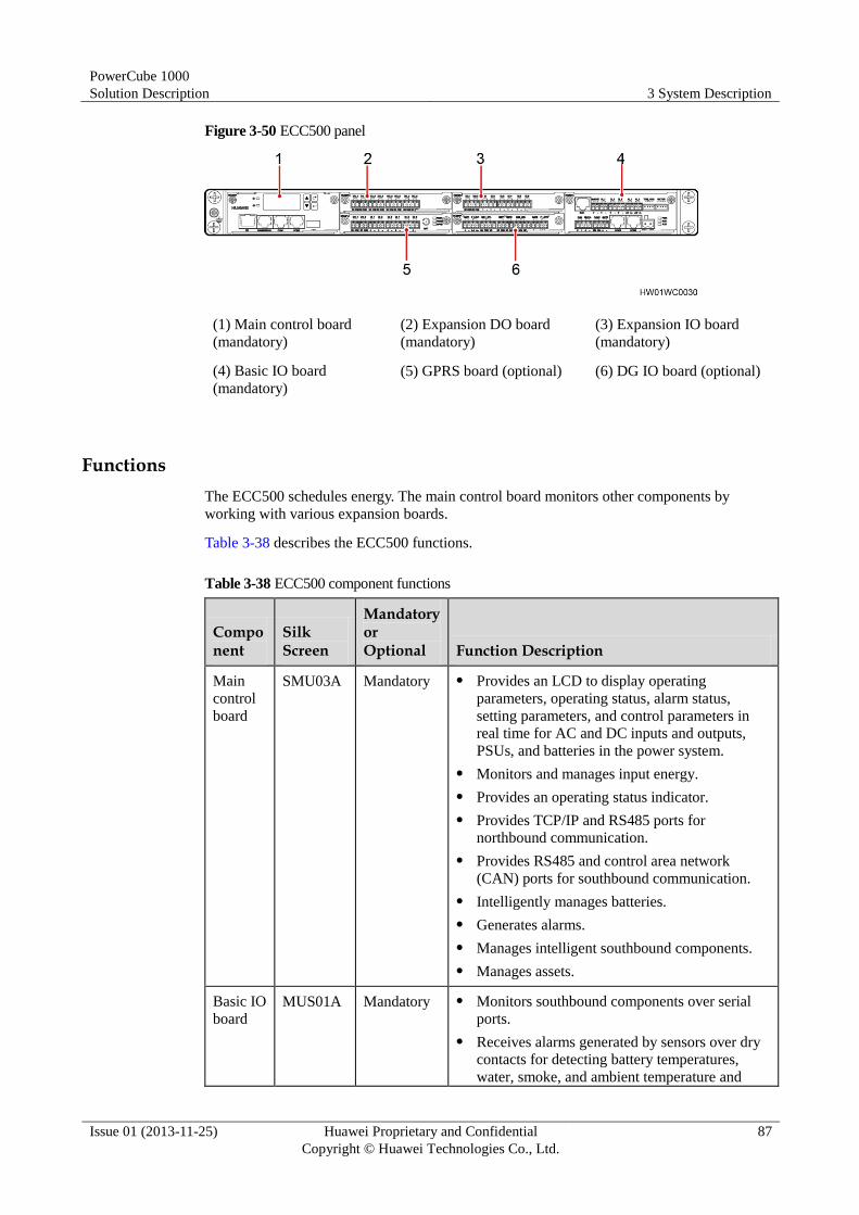
PowerCube 1000
Solution Description 3 System Description
Issue 01 (2013-11-25) Huawei Proprietary and Confidential
Copyright © Huawei Technologies Co., Ltd.
87
Figure 3-50 ECC500 panel
(1) Main control board
(mandatory)
(2) Expansion DO board
(mandatory)
(3) Expansion IO board
(mandatory)
(4) Basic IO board
(mandatory)
(5) GPRS board (optional) (6) DG IO board (optional)
Functions
The ECC500 schedules energy. The main control board monitors other components by
working with various expansion boards.
Table 3-38 describes the ECC500 functions.
Table 3-38 ECC500 component functions
Component
Silk Screen
Mandatory or Optional Function Description
Main
control
board
SMU03A Mandatory Provides an LCD to display operating
parameters, operating status, alarm status,
setting parameters, and control parameters in
real time for AC and DC inputs and outputs,
PSUs, and batteries in the power system.
Monitors and manages input energy.
Provides an operating status indicator.
Provides TCP/IP and RS485 ports for
northbound communication.
Provides RS485 and control area network
(CAN) ports for southbound communication.
Intelligently manages batteries.
Generates alarms.
Manages intelligent southbound components.
Manages assets.
Basic IO
board
MUS01A Mandatory Monitors southbound components over serial
ports.
Receives alarms generated by sensors over dry
contacts for detecting battery temperatures,
water, smoke, and ambient temperature and

PowerCube 1000
Solution Description 3 System Description
Issue 01 (2013-11-25) Huawei Proprietary and Confidential
Copyright © Huawei Technologies Co., Ltd.
88
Component
Silk Screen
Mandatory or Optional Function Description
humidity.
Provides RS485 ports for southbound
communication.
Expansi
on DO
board
MUE04A Mandatory Provides eight dry contact outputs for alarms.
Expansi
on IO
board
MUE05A Mandatory Provides six digital parameter input ports and two
dry contact outputs.
GPRS
board
MUC01A Optional Enables the ECC500 to communicate with the
NetEco in out-of-band mode (by GPRS).
Provides six digital parameter input ports and
two dry contact outputs.
NOTE
You can define alarms for specific digital parameter
input ports on the NetEco.
Dry contact outputs are reserved.
DG IO
board
MUE03A Optional Controls the DG by connecting to a control module
over a dry contact. It can also control the DG by
connecting to the DG directly.
Technical Specifications
Table 3-39 lists the ECC500 technical specifications.
Table 3-39 ECC500 technical specifications
Item Specifications
Dimensions (H x W x
D)
≤ 44.5 mm x 482.6 mm x 220 mm (including mounting ears)
Weight ≤ 5 kg
Operating voltage –40 V DC to –60 V DC
Rated voltage: –48 V DC
3.3.3 ATS-63A1/ATS-63A2
Appearance
Figure 3-51 shows an ATS panel.

PowerCube 1000
Solution Description 3 System Description
Issue 01 (2013-11-25) Huawei Proprietary and Confidential
Copyright © Huawei Technologies Co., Ltd.
89
Figure 3-51 ATS panel
(1) Residual current device
(optional)
(2) 10 A AC output circuit
breaker
(3) ATS main control
box
(4) Bypass switch (5) Maintenance socket
(optional)
(6) DG 1 input circuit
breaker
(7) Mains/DG 2 input circuit
breaker
(8) Surge protective device
(SPD)
Functions
The ATS is an automatic switch system integrating control and power distribution. It supports
and detects the inputs from two power sources (DG 1 and mains or DG 1 and DG 2) and
switches between the two power inputs. The power source can switch to DG 1 by turning the
bypass switch. Table 3-40 describes the ATS functions.
Table 3-40 IATS function description
Function Description
AC power distribution Provides one three-phase AC output, one 10 A AC output, and
one maintenance socket output (optional).
Power source switching Provides a bypass switch that allows the power source to
switch to DG 1.
Monitoring Monitors the voltage, current, frequency, and power factor of
three-phase outputs.
Protection Protects against mains overvoltage, mains undervoltage, DG
overvoltage, and DG undervoltage.
Alarm generation Generates alarms for mains open phase and DG open phase.
Surge protection ATS-63A1: AC surge protection (nominal discharge current:
20 kA, maximum discharge current: 40 kA)
ATS-63A2: AC surge protection (nominal discharge current:
30 kA, maximum discharge current: 60 kA)

PowerCube 1000
Solution Description 3 System Description
Issue 01 (2013-11-25) Huawei Proprietary and Confidential
Copyright © Huawei Technologies Co., Ltd.
90
Function Description
For alarm ports: differential mode: 3 kA (nominal), common
mode: 5 kA (nominal); for interior CAN ports: 250 A
Technical Specifications
Table 3-41 lists the ATS technical specifications.
Table 3-41 ATS technical specifications
Item Specifications
Dimensions (H x W x
D)
175 mm x 482.6 mm x 310 mm (including mounting ears)
Weight 20 kg
Working Modes
The ATS can be operated automatically (AUTO) or manually (BYPASS).
3.3.4 ACDU-63A1/ACDU-63A2
Appearance
Figure 3-52 shows an ACDU panel.
Figure 3-52 ACDU panel
(1) Three-phase AC output
circuit breaker
(2) Residual current
operated circuit breaker (3) Maintenance socket
(4) Three-phase AC input
circuit breaker
(5) AC SPD (6) Single-phase AC output
circuit breaker

PowerCube 1000
Solution Description 3 System Description
Issue 01 (2013-11-25) Huawei Proprietary and Confidential
Copyright © Huawei Technologies Co., Ltd.
91
Functions
Table 3-42 shows the ACDU functions.
Table 3-42 ACDU function description
Function Description
Input One three-phase 380 V AC input port and one 3-pole 63 A AC
circuit breaker
Output (Optional) One 10 A European-standard maintenance socket
with a residual current operated circuit breaker
One three-phase 380 V AC output port and one 3-pole 63 A AC
circuit breaker
One three-phase 380 V AC output to the DCDU and four UT16
wiring terminals
One single-phase 220 V AC output port and one 1-pole 16 A
AC circuit breaker
Surge protection ACDU-63A1: AC surge protection (In = 20 kA; Imax = 40 kA,
supporting alarm generation over dry contacts)
ACDU-63A2: AC surge protection (In = 30 kA; Imax = 60 kA,
supporting alarm generation over dry contacts)
Technical Specifications
Table 3-43 lists the ACDU technical specifications.
Table 3-43 ACDU technical specifications
Item Specifications
Dimensions (H x W x
D)
177.8 mm x 482.6 mm x 82 mm (including mounting ears)
Weight 5 kg
3.3.5 DCDU-200B5
Appearance
The DCDU, consisting of PSU subrack, the ECC500, and DC power distribution, collects AC
and DC inputs from different power sources and converts inputs into DC outputs to power
loads.
Figure 3-53 shows a DCDU-200B5 panel.

PowerCube 1000
Solution Description 3 System Description
Issue 01 (2013-11-25) Huawei Proprietary and Confidential
Copyright © Huawei Technologies Co., Ltd.
92
Figure 3-53 DCDU-200B5 panel
(1) DCDU (2) ECC500 (3) PSU subrack
Functions
Table 3-44 describes the DCDU-200B5 functions.
Table 3-44 DCDU-200B5 functions
Function Description
–48 V DC power
supply
Integrates hot-swap PSUs to convert from AC power to DC
power.
Provides multiple DC outputs (that can be disconnected) for
communications and transmission equipment.
Signal collection
and detection
Collects battery current signals, load current signals, and the input
current signals from –48 V DC power sources by using an internal
signal interface board.
Collects BLVD and LLVD signals and detects battery loop
disconnection and load loop disconnection signals.
Protection Integrates an SPD to provide reliable protection for AC and DC
power ports, monitoring ports, and communications ports.
Communication,
control, and alarm
reporting
The ECC500 supports remote management and online upgrade,
monitors and controls the operating status of the power system
through communication, and reports alarms in a timely manner.
Forcible power-on Allows you to flip on the battery switch to power on the
DCDU-200B5 if only batteries can supply power.
Battery
management
The ECC500 manages batteries effectively to ensure their proper
operation.
Electronic label Stores labels in the DCDU as electronic data.

PowerCube 1000
Solution Description 3 System Description
Issue 01 (2013-11-25) Huawei Proprietary and Confidential
Copyright © Huawei Technologies Co., Ltd.
93
Function Description
Hot swap The PSUs and ECC500 in the DCDU-200B5 are hot-swappable.
Technical Specifications
Table 3-45 lists theDCDU-200B5 technical specifications.
Table 3-45 DCDU-200B5 technical specifications
Item Specifications
Dimensions (H x W x D) 308 mm x 482 mm x 310 mm (including mounting ears)
Weight 25 kg (excluding PSUs)
ECC500 configuration Main control board, basic IO board, expansion IO board, and
expansion DO board
Input Maximum AC input current: 37 A (three-phase)
Maximum DC input current: 200 A
Output DC output:
BLVD: two 10 A circuit breakers, two 20 A circuit
breakers, and two 32 A circuit breakers
LLVD: three 32 A circuit breakers and one 63 A circuit
breaker
Battery circuit breaker Two 125 A circuit breakers
Installation mode Installed in a standard 19-inch rack
Cable routing Left in and right out, or right in and left out
Maintenance mode Maintained from the front
3.3.6 DCDU-300A1
Appearance
The DCDU, consisting of PSU slots, the ECC500, and DC power distribution, collects AC
and DC inputs from different power sources and converts inputs into DC outputs to power
loads.
Figure 3-54 shows a DCDU-300A1 panel.

PowerCube 1000
Solution Description 3 System Description
Issue 01 (2013-11-25) Huawei Proprietary and Confidential
Copyright © Huawei Technologies Co., Ltd.
94
Figure 3-54 DCDU-300A1 panel
(1) ECC500 (2) DCDU (3) PSU slots
Functions
Table 3-46 describes the DCDU-300A1 functions.
Table 3-46 DCDU-300A1 function description
Function Description
–48 V DC power
supply
Integrates hot-swap PSUs to convert from AC power to DC
power.
Provides multiple DC outputs (that can be disconnected) for
communications and transmission equipment.
Signal collection
and detection
Collects battery current signals, load current signals, and the input
current signals from –48 V DC power sources by using an internal
signal interface board.
Collects BLVD and LLVD signals and detects battery loop
disconnection and load loop disconnection signals.
Protection Integrates an SPD to provide reliable protection for DC power ports,
monitoring ports, and communications ports.
Communication,
control, and alarm
reporting
The ECC500 supports remote management and online upgrade,
monitors and controls the operating status of the power system
through communication, and reports alarms in a timely manner.
Forcible power-on Allows you to flip on the battery switch to power on the
DCDU-300A1 if only batteries can supply power.
Battery
management
The ECC500 manages batteries effectively to ensure their proper
operation.
Electronic label Stores labels in the DCDU as electronic data.

PowerCube 1000
Solution Description 3 System Description
Issue 01 (2013-11-25) Huawei Proprietary and Confidential
Copyright © Huawei Technologies Co., Ltd.
95
Function Description
Hot swap The PSUs and ECC500 in the DCDU are hot-swappable.
Technical Specifications
Table 3-47 lists the DCDU-300A1 technical specifications.
Table 3-47 DCDU-300A1 technical specifications
Item Specifications
Dimensions (H x W x D) 310 mm x 482.6 mm x 310 mm
Weight ≤ 25 kg (without PSUs)
ECC500 configuration Main control board, basic IO board, expansion IO board, and
expansion DO board
Input Maximum AC input current: 36 A (three-phase)
Maximum DC input current: 300 A
Output DC output:
BLVD: four 16 A circuit breakers, two 32 A circuit
breakers, and one 63 A circuit breaker
LLVD: two 63 A circuit breakers and two 125 A circuit
breakers
Fuse Two 160 A fuses
Installation mode Installed in a standard 19-inch rack
Cable routing Left in and right out, or right in and left out
Maintenance mode Maintained from the front
3.3.7 DCDU-300B1
Appearance
The DCDU, consisting of PSU slots, the ECC500, and DC power distribution, collects AC
and DC inputs from different power sources and converts inputs into DC outputs to power
loads.
Figure 3-55 shows a DCDU-300B1 panel.

PowerCube 1000
Solution Description 3 System Description
Issue 01 (2013-11-25) Huawei Proprietary and Confidential
Copyright © Huawei Technologies Co., Ltd.
96
Figure 3-55 DCDU-300B1 panel
(1) ECC500 (2) DCDU (3) PSU slots
Functions
Table 3-48 describes the DCDU-300B1 functions.
Table 3-48 DCDU-300B1 function description
Function Description
–48 V DC power
supply
Integrates hot-swap PSUs to convert from AC power to DC
power.
Provides multiple DC outputs (that can be disconnected) for
communications and transmission equipment.
Signal collection
and detection
Collects battery current signals, load current signals, and the input
current signals from –48 V DC power sources by using an internal
signal interface board.
Collects BLVD and LLVD signals and detects battery loop
disconnection and load loop disconnection signals.
Protection Integrates an SPD to provide reliable protection for DC power ports,
monitoring ports, and communications ports.
Communication,
control, and alarm
reporting
The ECC500 supports remote management and online upgrade,
monitors and controls the operating status of the power system
through communication, and reports alarms in a timely manner.
Forcible power-on Allows you to flip on the battery switch to power on the DCDU if
only batteries can supply power.

PowerCube 1000
Solution Description 3 System Description
Issue 01 (2013-11-25) Huawei Proprietary and Confidential
Copyright © Huawei Technologies Co., Ltd.
97
Function Description
Battery
management
The ECC500 manages batteries effectively to ensure their proper
operation.
Electronic label Stores labels in the DCDU as electronic data.
Hot swap The PSUs and ECC500 in the DCDU are hot-swappable.
Technical Specifications
Table 3-49 lists the DCDU-300B1 technical specifications.
Table 3-49 DCDU-300B1 technical specifications
Item Technical Specifications
Dimensions (H x W x D) 9 U x 482.6 mm x 310 mm (including mounting ears)
Weight ≤ 23 kg (without PSUs)
ECC500 configuration Main control board, basic IO board, expansion IO board, and
expansion DO board
Input Maximum AC input current: 37 A (three-phase); 72 A
(single-phase)
Maximum DC input current: 300 A
Output DC output:
BLVD: one 10 A circuit breaker, two 16 A circuit
breakers, and four 32 A circuit breakers
LLVD: two 63 A circuit breakers and two 125 A circuit
breakers
Fuse Two 160 A fuses
Installation mode Installed in a 19-inch rack
Cable routing Left in and right out, or right in and left out
Maintenance mode Maintained from the front
3.3.8 DCDU-400A1
Appearance
The DCDU, consisting of PSU or SSU slots, the ECC500, and DC power distribution, collects
AC and DC inputs from different power sources and converts inputs into DC outputs to power
loads.
Figure 3-56 shows a DCDU-400A1 panel.

PowerCube 1000
Solution Description 3 System Description
Issue 01 (2013-11-25) Huawei Proprietary and Confidential
Copyright © Huawei Technologies Co., Ltd.
98
Figure 3-56 DCDU-400A1 panel
(1) DCDU (2) ECC500 (3) PSU or SSU slots
Functions
Table 3-50 describes the DCDU-400A1 functions.
Table 3-50 DCDU-400A1 function description
Function Description
–48 V DC power
supply
Integrates hot-swap PSUs to convert from AC power to DC
power.
Provides multiple DC outputs (that can be disconnected) for
communications and transmission equipment.
Signal collection
and detection
Collects battery current signals, load current signals, and the input
current signals from –48 V DC power sources by using an internal
signal interface board.
Collects low voltage disconnection signals and detects battery
loop disconnection and load loop disconnection signals.
Protection Integrates an SPD to provide reliable protection for DC power ports,
monitoring ports, and communications ports.
Communication,
control, and alarm
reporting
The ECC500 supports remote management and online upgrade,
monitors and controls the operating status of the power system
through communication, and reports alarms in a timely manner.
Forcible power-on Allows you to flip on the battery switch to power on the
DCDU-400A1 if only batteries can supply power.
Battery
management
The ECC500 manages batteries effectively to ensure their proper
operation.
Electronic label Stores labels in the DCDU as electronic data.
Hot swap The PSUs and ECC500 in the DCDU-400A1 are hot-swappable.

PowerCube 1000
Solution Description 3 System Description
Issue 01 (2013-11-25) Huawei Proprietary and Confidential
Copyright © Huawei Technologies Co., Ltd.
99
Technical Specifications
Table 3-51 lists the DCDU-400A1 technical specifications.
Table 3-51 DCDU-400A1 technical specifications
Item Specifications
Dimensions (H x W x
D)
6 U x 482.6 mm x 310 mm (including mounting ears)
Weight ≤ 25 kg (without PSUs and SSUs)
ECC500 configuration Main control board, basic IO board, expansion IO board, and
expansion DO board
Input Maximum AC input current: 54 A (three-phase); 72 A
(single-phase)
Maximum DC input current: 300 A
Output DC output:
Primary load: one 16 A circuit breaker and two 32 A circuit
breakers
Secondary load: two 63 A circuit breakers and one 125 A
circuit breaker
Fuse Two 250 A fuses
Installation mode Installed in a 19-inch rack
Cable routing Left in and right out, or right in and left out
Maintenance mode Maintained from the front
3.3.9 DCDU-400B1
Appearance
The DCDU, consisting of PSU slots, the ECC500, and DC power distribution, collects AC
and DC inputs from different power sources and converts inputs into DC outputs to power
loads.
Figure 3-57 shows a DCDU-400B1 panel.

PowerCube 1000
Solution Description 3 System Description
Issue 01 (2013-11-25) Huawei Proprietary and Confidential
Copyright © Huawei Technologies Co., Ltd.
100
Figure 3-57 DCDU-400B1 panel
(1) DCDU (2) ECC500 (3) PSU slots
Functions
Table 3-52 describes the DCDU-400B1 functions.
Table 3-52 DCDU-400B1 function description
Function Description
Signal collection
and detection
Collects battery current signals, load current signals, and the input
current signals from –48 V DC power sources by using an internal
signal interface board.
Collects BLVD and LLVD signals and detects battery loop
disconnection and load loop disconnection signals.
Protection Integrates an SPD to provide reliable protection for DC power ports,
monitoring ports, and communications ports.
Communication,
control, and alarm
reporting
The ECC500 supports remote management and online upgrade,
monitors and controls the operating status of the power system
through communication, and reports alarms in a timely manner.
Forcible power-on Allows you to flip on the battery switch to power on the
DCDU-400B1 if only batteries can supply power.
Battery
management
The ECC500 manages batteries effectively to ensure their proper
operation.
Electronic label Stores labels in the DCDU as electronic data.
Hot swap The PSUs and ECC500 in the DCDU-400B1 are hot-swappable.

PowerCube 1000
Solution Description 3 System Description
Issue 01 (2013-11-25) Huawei Proprietary and Confidential
Copyright © Huawei Technologies Co., Ltd.
101
Technical Specifications
Table 3-53 lists the DCDU-400B1 technical specifications.
Table 3-53 DCDU-400B1 technical specifications
Item Specifications
Dimensions (H x W x
D)
7 U x 482 mm x 310 mm (including mounting ears)
Weight ≤ 20 kg (without PSUs)
ECC500 configuration Main control board, basic IO board, expansion IO board, and
expansion DO board
Input Maximum AC input current: 54 A (three-phase); 72 A
(single-phase)
Output The DCDU-400B1 provides no circuit breakers and needs to
work with the DCDB.
Fuse Two 250 A fuses
Installation mode Installed in a 19-inch rack
Cable routing Left in and right out, or right in and left out
Maintenance mode Maintained from the front
3.3.10 DCDB-01A
Appearance
Figure 3-58 shows a DCDB-01A panel.
Figure 3-58 DCDB-01A panel
(1) BLVD output circuit breakers (1) LLVD output circuit breakers

PowerCube 1000
Solution Description 3 System Description
Issue 01 (2013-11-25) Huawei Proprietary and Confidential
Copyright © Huawei Technologies Co., Ltd.
102
Functions Distributes the output from the DCDU to multiple loads, facilitating cable connection.
Performs surge protection on load circuit breakers for DC outputs.
Technical Specifications
Table 3-54 lists the DCDB-01A technical specifications.
Table 3-54 DCDB-01A technical specifications.
Item Specifications
Dimensions (H x W x D) 177.8 mm x 482.6 mm x 182 mm (including mounting ears)
Weight 10 kg
Output DC output:
BLVD: one 10 A circuit breaker, two 16 A circuit
breakers, and four 32 A circuit breakers
LLVD: three 63 A circuit breakers and one 125 A circuit
breaker
Cable routing Connected from the front, routed from the left and right parts
in the front
3.3.11 DCDU-400AD
Appearance
The DCDU, consisting of PSU slots, the ECC500, and DC power distribution, collects AC
and DC inputs from different power sources and converts inputs into DC outputs to power
loads.
Figure 3-59 shows a DCDU-400AD panel.
Figure 3-59 DCDU-400AD panel
(1) DCDU (2) ECC500 (3) PSU slots

PowerCube 1000
Solution Description 3 System Description
Issue 01 (2013-11-25) Huawei Proprietary and Confidential
Copyright © Huawei Technologies Co., Ltd.
103
Functions
Table 3-55 describes the DCDU-400AD functions.
Table 3-55 DCDU-400AD function description
Function Description
Signal collection
and detection
Collects battery current signals, load current signals, and the input
current signals from –48 V DC power sources by using an internal
signal interface board.
Collects BLVD and LLVD signals and detects battery loop
disconnection and load loop disconnection signals.
Protection Integrates an SPD to provide reliable protection for DC power ports,
monitoring ports, and communications ports.
Communication,
control, and alarm
reporting
The ECC500 supports remote management and online upgrade,
monitors and controls the operating status of the power system
through communication, and reports alarms in a timely manner.
Battery
management
The ECC500 manages batteries effectively to ensure their proper
operation.
Electronic label Stores labels in the DCDU as electronic data.
Hot swap The PSUs and ECC500 in the DCDU-400AD are hot-swappable.
Technical Specifications
Table 3-56 lists the DCDU-400AD technical specifications.
Table 3-56 DCDU-400AD technical specifications
Item Specifications
Dimensions (H x W x
D)
5 U x 482.6 mm x 310 mm (including mounting ears)
Weight ≤ 25 kg (without PSUs)
ECC500 configuration Main control board, basic IO board, expansion IO board, and
expansion DO board
Input Maximum AC input current: 54 A (three-phase)
Output The DCDU-400AD provides no circuit breakers and needs to
work with the DCDB.
Fuse Two 250 A fuses
Installation mode Installed in a standard 19-inch rack
Cable routing Left in and right out, or right in and left out

PowerCube 1000
Solution Description 3 System Description
Issue 01 (2013-11-25) Huawei Proprietary and Confidential
Copyright © Huawei Technologies Co., Ltd.
104
Item Specifications
Maintenance mode Maintained from the front
3.3.12 DCDB-01B
Appearance
Figure 3-60 shows a DCDB-01B panel.
Figure 3-60 DCDB-01B panel
(1) BLVD output circuit breakers (1) LLVD output circuit breakers
Functions Distributes the output from the DCDU to multiple loads, facilitating cable connection.
Performs surge protection on load circuit breakers for DC outputs.
Technical Specifications
Table 3-57 lists the DCDB-01B technical specifications.
Table 3-57 DCDB-01B technical specifications.
Item Specifications
Dimensions (H x W x D) 177.8 mm x 482.6 mm x 182 mm (including mounting ears)
Weight 10 kg
Output DC output:
BLVD: one 10 A circuit breaker, two 16 A circuit
breakers, and four 32 A circuit breakers
LLVD: two 63 A circuit breakers and two 80 A circuit
breakers
Cable routing Connected from the front, routed from the left and right parts

PowerCube 1000
Solution Description 3 System Description
Issue 01 (2013-11-25) Huawei Proprietary and Confidential
Copyright © Huawei Technologies Co., Ltd.
105
Item Specifications
in the front
3.3.13 IDU-300A1
Appearance
The IDU, consisting of PSU slots, the ECC500, and DC power distribution, collects AC and
DC inputs from different power sources and converts inputs into DC outputs to power loads.
Figure 3-61 shows an IDU-300A1 panel.
Figure 3-61 IDU-300A1 panel
(1) DC output LLVD (load–) (2) DC output positive busbar
(load+)
(3) DC output BLVD
(load–)
(4) –48 V DC input port (DC
input–)
(5) Fuses (6) AC contactors
(7) Reserved PV input ports (8) ECC500 (9) Battery switch
(10) ATS main control box (11) Reserved SSU slot (12) PSU slots
(13) Filler panel (14) Mains input circuit
breaker
(15) DG input circuit
breaker

PowerCube 1000
Solution Description 3 System Description
Issue 01 (2013-11-25) Huawei Proprietary and Confidential
Copyright © Huawei Technologies Co., Ltd.
106
Functions
Table 3-58 describes the IDU-300A1 functions.
Table 3-58 IDU-300A1 function description
Function Description
AC automatic
switchover
Switches between the DG and the mains by using a controller and
detects inputs from the two power sources.
Input of multiple
types of energy
Receives power from the DG, mains, solar energy, and other power
sources such as a reused DC power system.
Protection Integrates an SPD to provide reliable protection for DC power ports,
monitoring ports, and communications ports.
Communication,
control, and alarm
reporting
The ECC500 supports remote management and online upgrade,
monitors and controls the operating status of the power system
through communication, and reports alarms in a timely manner.
Forcible power-on You can flip on the battery switch to power on the IDU-300A1 if
only batteries can supply power.
Battery
management
The ECC500 manages batteries effectively to ensure their proper
operation.
Battery power
backup
Provides electrical ports for connecting to batteries and ports for
connecting to a battery temperature sensor and detecting signals.
Electronic label Stores labels in the IDU as electronic data.
Hot swap The PSUs and ECC500 in the IDU-300A1 are hot-swappable.
Technical Specifications
Table 3-59 lists the IDU-300A1 technical specifications.
Table 3-59 IDU-300A1 technical specifications
Item Specifications
Dimensions (H x W x D) 660 mm x 682 mm x 390 mm (including mounting ears)
Weight ≤ 50 kg (without PSUs)
ECC500 configuration Main control board, basic IO board, expansion IO board, and
expansion DO board
Input Two maximum AC input currents: 37 A (three-phase, for
the mains); 37 A (three-phase, for the DG)
Maximum DC input current: 200 A
Maximum PV input current (optional): 200 A
Output DC output:
BLVD: two 10 A circuit breakers, three 16 A circuit

PowerCube 1000
Solution Description 3 System Description
Issue 01 (2013-11-25) Huawei Proprietary and Confidential
Copyright © Huawei Technologies Co., Ltd.
107
Item Specifications
breakers, and two 32 A circuit breakers
LLVD: two 20 A circuit breakers and two 80 A circuit
breakers
Fuse Two 160 A fuses
Installation mode Installed in a cabinet
Cable routing Routed from the front
Maintenance mode Maintained from the front
3.3.14 IDU-300D1
Appearance
The DCDU, consisting of PSU slots, the ECC500, and DC power distribution, collects AC
and DC inputs from different power sources and converts inputs into DC outputs to power
loads.
Figure 3-62 shows an IDU-300D1 panel.
Figure 3-62 IDU-300D1 panel
(1) Circuit breakers for four
user loads (load–)
(2) DC output positive
busbar (load+)
(3) –48 V DC input port
(DC input–)

PowerCube 1000
Solution Description 3 System Description
Issue 01 (2013-11-25) Huawei Proprietary and Confidential
Copyright © Huawei Technologies Co., Ltd.
108
(4) Fuses (5) Common load (6) AC contactors
(7) Reserved PV input ports (8) ECC500 (9) ATS main control box
(10) Reserved SSU slots (11) PSU slots (12) Battery switch
(13) Mains input circuit
breakers
(14) DG input circuit
breakers
Functions
Table 3-60 describes the IDU-300D1 functions.
Table 3-60 IDU-300D1 function description
Function Description
AC automatic
switchover
Switches between the DG and the mains by using a controller and
detects inputs from the two power sources.
Input of multiple
types of energy
Receives power from the DG, mains, and other power sources such
as a reused DC power system.
–48 V DC power
supply
Integrates hot-swap PSUs to convert from AC power to DC power.
Provides multiple DC outputs (that can be disconnected) for
communications and transmission equipment.
Protection Integrates an SPD to provide reliable protection for DC power ports,
monitoring ports, and communications ports.
Communication,
control, and alarm
reporting
The ECC500 supports remote management and online upgrade,
monitors and controls the operating status of the power system
through communication, and reports alarms in a timely manner.
Forcible power-on You can flip on the battery switch to power on the IDU-300D1 if
only batteries can supply power.
Battery
management
The ECC500 manages batteries effectively to ensure their proper
operation.
Electronic label Configurations of the ECC500, PSUs, SSUs, power distribution port
board, and ATS main control box are displayed on electronic labels.
Hot swap The PSUs and ECC500 in the IDU-300D1 are hot-swappable.
Technical Specifications
Table 3-61 lists the IDU-300D1 technical specifications.

PowerCube 1000
Solution Description 3 System Description
Issue 01 (2013-11-25) Huawei Proprietary and Confidential
Copyright © Huawei Technologies Co., Ltd.
109
Table 3-61 IDU-300D1 technical specifications
Item Specifications
Dimensions (H x W x D) 677 mm x 682 mm x 390 mm (including mounting ears)
Weight ≤ 60 kg (without PSUs)
ECC500 configuration ECC main control board, basic IO board, expansion IO board,
and expansion DO board
Input Two maximum AC input currents: 37 A (three-phase, for
the mains); 37 A (three-phase, for the DG); 60 A
(single-phase, for the DG)
Maximum DC input current: 300 A
Output DC output:
Common load: two 16 A circuit breakers and one 32 A
circuit breaker
Shared by four user loads and providing four circuit
breakers for each user load, one 32 A BLVD circuit
breaker, one 32 A LLVD circuit breaker, and two 80 A
LLVD circuit breakers
Fuse Two 160 A fuses
Installation mode Installed in a cabinet
Cable routing Routed from the front
Maintenance mode Maintained from the front
3.3.15 PVDU-60A1
Appearance
Figure 3-63 shows a PVDU-60A1 panel.
Figure 3-63 PVDU-60A1 panel
(1) Cable outlets (2) Positive DC input protection circuit breaker

PowerCube 1000
Solution Description 3 System Description
Issue 01 (2013-11-25) Huawei Proprietary and Confidential
Copyright © Huawei Technologies Co., Ltd.
110
Functions Collects power from PV modules and supplies power to SSUs.
Provides four wiring terminals to connect to the negative input terminals of PV modules
and provides four input circuit breakers to connect to the positive input terminals of PV
modules.
Technical Specifications
Table 3-62 describes the technical specifications for the PVDU.
Table 3-62 PVDU technical specifications
Item Specifications
Dimensions (H x W x
D)
44.45 mm x 482.6 mm x 122 mm (including mounting ears)
Weight 3 kg
3.3.16 S4850G1
Appearance
Figure 3-64 shows a S4850G1.
Figure 3-64 S4850G1
(1) Power indicator (2) Alarm indicator (3) Fault indicator
(4) PV positive input port (5) PV negative input port (6) Air exhaust vents
(7) Handle

PowerCube 1000
Solution Description 3 System Description
Issue 01 (2013-11-25) Huawei Proprietary and Confidential
Copyright © Huawei Technologies Co., Ltd.
111
Functions
The S4850G1 is a DC-DC converter that uses maximum power point track (MPPT)
technology. It tracks the highest solar power point based on the output features of PV modules
to maximize the use of solar energy.
Technical Specifications
Table 3-63 describes the technical specifications for the S4850G1.
Table 3-63 S4850G1 technical specifications
Item Specifications
Dimensions (H x W x
D)
41.5 mm x 106.5 mm x 281 mm
Weight 1.8 kg
Input operating
voltage
58–150 V DC
Output voltage 43.2–58 V DC
Rated voltage: 53.5 V DC
Maximum output
power
3000 W
Maximum efficiency 98.5%
3.3.17 R4850G2
Appearance
The R4850G2 is 1 U high. Figure 3-65 shows an R4850G2 panel.
Figure 3-65 R4850G2 panel
(1) Power indicator (2) Alarm indicator (3) Fault indicator
(4) Air exhaust vents (5) Handle

PowerCube 1000
Solution Description 3 System Description
Issue 01 (2013-11-25) Huawei Proprietary and Confidential
Copyright © Huawei Technologies Co., Ltd.
112
Functions
Converts AC power into –48 V DC power.
The R4850G2 runs steadily at high efficiency. Table 3-64 shows the R4850G2 technical
specifications.
Table 3-64 R4850G2 technical specifications
Item Specifications
hot swap Hot-swappable.
Input protection Input overvoltage and undervoltage protection
Input overcurrent protection
Output protection Output overvoltage protection
Output short-circuit protection
Output current limiting protection
Overtemperature
protection Overtemperature protection
Technical Specifications
Table 3-65 shows the R4850G2 technical specifications.
Table 3-65 R4850G2 technical specifications
Item Specifications
Dimensions (H x W x
D)
40.8 mm x 105 mm x 281 mm
Weight 2 kg
3.3.18 R4850G1, R4850N1, and R4850N3
Appearance
Figure 3-66 shows a PSU.
The R4850G1 is a high-efficiency PSU.
The R4850N1 is a standard-efficiency PSU.
The R4850N3 is a standard-efficiency, high-voltage-resistant PSU that can tolerate power
input as high as 500 V AC.

PowerCube 1000
Solution Description 3 System Description
Issue 01 (2013-11-25) Huawei Proprietary and Confidential
Copyright © Huawei Technologies Co., Ltd.
113
Figure 3-66 PSU
Functions Converts AC power into –48 V DC power.
Works reliably with high efficiency.
Allows hot swapping.
Protects against input overvoltage, input undervoltage, input overcurrent, output
overvoltage, output short circuits, output current limiting, and overtemperature.
Technical Specifications
Table 3-66 lists the PSU technical specifications.
Table 3-66 PSU technical specifications
Item Specifications
Dimensions (H x W x
D)
88.9 mm x 103 mm x 243 mm
Weight ≤ 2.8 kg
Input operating
voltage
85–300 V AC
Output voltage 43.2–58 V DC
Rated voltage: 53.5 V DC
Maximum output
power
2900 W
Highest efficiency R4850G1: ≥ 96%
R4850N1: ≥ 92%
R4850N3: ≥ 92%
3.3.19 DTS-200A1
Appearance
Figure 3-67 shows a DTS-200A1 panel.

PowerCube 1000
Solution Description 3 System Description
Issue 01 (2013-11-25) Huawei Proprietary and Confidential
Copyright © Huawei Technologies Co., Ltd.
114
Figure 3-67 DTS-200A1 panel
(1) Output wiring
terminal
(2) –48 V1 fuse (250
V, 2 A)
(3) –48 V2 fuse
(250 V, 2 A)
(4) Automatic
switching status
indicator
(5) Working mode
switching button
(6) Manual switching
status indicator
(7) Active battery
status indicator
(8) Current load
battery switching
button
(9) Reserved battery
status indicator
(10) Active and spare
battery input wiring
terminal
(11) Power, RUN,
and ALM
indicators
(12) CAN&RS485
input port
(13) CAN&RS485
output port
(14) Dual in-line
package (DIP) switch
(15) RS232 port (16) Dry contacts
(17) Output
terminals
(18) Output port (19) Ground
terminal
Functions
Switches between DC power supplies.
Technical Specifications
Table 3-67 lists the DTS-200A1 technical specifications.
Table 3-67 DTS-200A1 technical specifications
Item Specifications
Dimensions (H x W x D) 86.1 mm x 482.6 mm x 310 mm (including mounting ears)
Weight < 20 kg
Input DC 1 and 2 input voltage: 40–60 V DC
Input current: 0–200 A
Output Output voltage: 0–60 V DC
Output current: 0–200 A, maximum load current ≤ 100 A
Protection level IP20
Installation mode Installed in a standard 19-inch rack

PowerCube 1000
Solution Description 3 System Description
Issue 01 (2013-11-25) Huawei Proprietary and Confidential
Copyright © Huawei Technologies Co., Ltd.
115
Item Specifications
Cable routing Left in and right out, or right in and left out
Maintenance mode All external ports and connected cables can be maintained
from the front.
Working Modes
The DTS-200A1 can be operated automatically or manually. It provides the following
buttons:
Working Model: automatic/manual switch
Current Load Battery: manually switch to active batteries or spare batteries
3.3.20 BC1203
Appearance
Figure 3-68 shows a BC1203.
Figure 3-68 BC1203
(1) Protective
earth
(2) DC input (3) Power
switch
(4) Normal operation
indicator
(5) Alarm
indicator
(6) Battery reverse alarm
indicator
(7) DC output (8) Mounting ear
Functions
Table 3-68 describes the BC1203 functions.
Table 3-68 BC1203 function description
Function Description
DC-DC
conversion
Converts –48 V DC input into +12 V DC output to charge the DG
battery.
Input protection Protects against input undervoltage.
Protects against input reverse connection.
Output protection Protects against output current limiting.

PowerCube 1000
Solution Description 3 System Description
Issue 01 (2013-11-25) Huawei Proprietary and Confidential
Copyright © Huawei Technologies Co., Ltd.
116
Function Description
Protects against output short circuits.
Protects against output reverse connection.
Alarm protection Indicates alarms by indicators.
Technical Specifications
Table 3-69 describes the technical specifications for the BC1203.
Table 3-69 BC1203 technical specifications
Item Specifications
Dimensions (H x W x D) 41.6 mm x 482.6 mm x 140 mm (including mounting ears)
Weight ≤ 5 kg
Input operating voltage -36 V DC to -72 V DC
Output voltage Rated voltage: 13.8 V DC
Maximum output power 41.4 W
3.3.21 DJN1000-S/GYN1000-S
Two models of inverters are available: DJN1000-S and GYN1000-S.
Appearance
Figure 3-69 shows a DJN1000-S panel.
Figure 3-69 DJN1000-S panel
(1) DC input port (2) Switch (3) Air exhaust vents
(4) SPD (5) Multi-purpose output socket (6) Indicator
(7) Dry contact (8) AC input and output terminals
Figure 3-70 shows a GYN1000-S panel.

PowerCube 1000
Solution Description 3 System Description
Issue 01 (2013-11-25) Huawei Proprietary and Confidential
Copyright © Huawei Technologies Co., Ltd.
117
Figure 3-70 GYN1000-S panel
(1) DC input port (2) Switch (3) Air exhaust vents
(4) AC Input indicator (5) DC Input indicator (6) Inverter indicator
(7) Alarm indicator (8) Alarm dry contact (9) AC input socket
(10) AC output connector (11) AC output socket (12) SPD
(13) Ground screw
Functions
The inverter converts DC input into AC output.
Technical Specifications
Table 3-70 lists the inverter technical specifications.
Table 3-70 Inverter technical specifications
Item Specifications
Dimensions (H x W x D) 43.5 mm x 482.6 mm x 286 mm (including
mounting ears)
Rated output capacity 1000 VA/700 W
DC input Rated voltage 48 V DC
Rated current 20 A
AC input Rated voltage 230 V AC
Rated frequency 55–65 Hz
AC output Output voltage 220 V AC (tolerance ±3%)
Output frequency 55–65 Hz
Output mode One AC output wiring terminal and one
multi-purpose output socket

PowerCube 1000
Solution Description 3 System Description
Issue 01 (2013-11-25) Huawei Proprietary and Confidential
Copyright © Huawei Technologies Co., Ltd.
118
3.3.22 ETP24160A3
Appearance
The ETP24160A3 consists of power distribution, a backplane, DC-DC converters, and
monitoring ports. Figure 3-71 shows an ETP24160A3 panel.
Figure 3-71 ETP24160A3 panel
(1) Load circuit
breaker F1
(2) Load circuit
breaker F2
(3) Load circuit
breaker F3
(4) DC-DC
converter slot
(5) Load circuit
breaker F6
(6) Load circuit
breaker F5
(7) Load circuit
breaker F4
Figure 3-72 shows a DC-DC converter panel
Figure 3-72 DC-DC converter panel
(1) Run indicator (2) Alarm indicator (3) Fault indicator
(4) –48 V DC input port (5) Air exhaust vents (6) Handle
Functions
The ETP24160A3 performs the following functions:
Converts –48 V DC input into stable +24 V DC output for +24 V communications
equipment.

PowerCube 1000
Solution Description 3 System Description
Issue 01 (2013-11-25) Huawei Proprietary and Confidential
Copyright © Huawei Technologies Co., Ltd.
119
Provides two dry contacts for reporting alarms.
Uploads operating information such as the voltage, current, and DC-DC converter fault
alarms to the main control unit (MCU) over the CAN. The output voltage range of the
ETP24160A3 is set on the MCU.
Allows you to query component information recorded on electronic labels.
The DC-DC converter is hot-swappable and protects against input reverse connection,
input undervoltage, output overvoltage, output short circuits, output current limiting, and
overtemperature.
Technical Specifications
Table 3-71 lists the ETP24160A3 technical specifications.
Table 3-71 ETP24160A3 technical specifications
Item Specifications
Dimensions (H x W x D) 133.5 mm x 482 mm x 310 mm (including mounting ears)
Weight ≤ 10 kg (excluding DC-DC converters)
DC input voltage –40 V DC to –60 V DC (typical value: –53.5 V DC)
DC input current Maximum current: 125 A
DC output voltage 24–30V DC (typical value: 27 V DC)
Maximum output power 4400 W
Output Provides four 100 A and two 32 A power supplies for loads.
Maintenance mode Maintained from the front
Highest efficiency 92%
3.4 ESS
3.4.1 Composition
The ESS stores power in the PowerCube 1000. Table 3-72 describes ESS component
functions.
Table 3-72 ESS component functions
System Composition
Component Function
Flooded
battery
Flooded battery Converts between electric energy and
chemical energy.
SCB SCB-A

PowerCube 1000
Solution Description 3 System Description
Issue 01 (2013-11-25) Huawei Proprietary and Confidential
Copyright © Huawei Technologies Co., Ltd.
120
System Composition
Component Function
SCB-A1
DCB DCB-A
ESU-D/A1
FCB FCB
ESU monitor (optional) Performs preventive maintenance
inspection (PMI) on battery strings and
reports data to the host, improving the
reliability of the DC power system.
Energy storage
module (ESM)
ESU-A600Wh/C,
ESU-A2400Wh/D, and
ESU-A2400Wh/N
Converts between electric energy and
chemical energy.
ESMU-01A, ESMU-02A,
and ESMU-03A
Monitors and protects each ESU-A.
Reports the operating status and alarm
information for each ESU-A over alarm
ports or communications ports.
3.4.2 Flooded Battery
Appearance
Figure 3-73 shows flooded batteries 600Ah and 800Ah.

PowerCube 1000
Solution Description 3 System Description
Issue 01 (2013-11-25) Huawei Proprietary and Confidential
Copyright © Huawei Technologies Co., Ltd.
121
Figure 3-73 600Ah and 800Ah
Functions
Flooded batteries are designed for unstable power grids due to their consistent cycle features.
Technical Specifications
Table 3-73 lists the 600Ah and 800Ah technical specifications.
Table 3-73 600Ah and 800Ah technical specifications
Item 600Ah 800Ah
Dimensions
(H x W x D)
145 mm x 206 mm x 700 mm 191 mm x 210 mm x 700 mm
Weight 34 kg (excluding electrolytes); 46
kg (including electrolytes)
48 kg (excluding electrolytes); 64
kg (including electrolytes)
Capacity
(25°C)
600 Ah 800 Ah
Rated
voltage
2 V DC 2 V DC
Self-dischar
ge < 10%, 90 days (25°C) < 10%, 90 days (25°C)

PowerCube 1000
Solution Description 3 System Description
Issue 01 (2013-11-25) Huawei Proprietary and Confidential
Copyright © Huawei Technologies Co., Ltd.
122
Item 600Ah 800Ah
Maximum
charge
current
90 A 120 A
Charge
voltage
(25°C)
Float voltage: 2.23 V; equalized charging voltage: 2.35 V
Temperature compensation coefficient: –3.3 mV/°C
3.4.3 DCB-A
Appearance
Figure 3-74 shows DCB-A series.
Figure 3-74 DCB-A series
Features Can be charged in a large current.
The low self discharge ratio enables DCB-As to be used for two years at 25°C and
restores the rated capacity by 100%.
Can be charged and discharged 2500 times at 25°C when the DOD is 60%.
Technical Specifications
Table 3-74 lists the DCB-A series technical specifications.
Table 3-74 DCB-A series technical specifications
Item Specifications
Dimensions (L x W x H) DCB-300A: 206 mm x 145 mm x 386 mm
DCB-420A: 206 mm x 145 mm x 502 mm
DCB-490A: 206 mm x 166 mm x 502 mm
DCB-600A: 206 mm x 145 mm x 677 mm
DCB-800A: 206 mm x 191 mm x 677 mm
Weight DCB-300A: about 27 kg

PowerCube 1000
Solution Description 3 System Description
Issue 01 (2013-11-25) Huawei Proprietary and Confidential
Copyright © Huawei Technologies Co., Ltd.
123
Item Specifications
DCB-420A: about 34.5 kg
DCB-490A: about 39.5 kg
DCB-600A: about 48 kg
DCB-800A: about 64.5 kg
Rated voltage 2 V
3.4.4 ESU-D/A1
Appearance
Figure 3-75 shows ESU-D/A1 series.
Figure 3-75 ESU-D/A1
Features The low self discharge ratio enables ESU-D/A1s to be used for two years at 25°C and
restores the rated capacity by 100%.
Can be charged in a large current.
ESU-D/A1s can be charged and discharged 2000 times at 25°C when the DOD is 60%.
Technical Specifications
Table 3-75 lists the ESU-D/A1 series technical specifications.
Table 3-75 ESU-D/A1 series technical specifications
Item Specifications
Dimensions (L x W x H) ESU-D600Wh/A1: 206 mm x 124 mm x 386 mm
ESU-D800Wh/A1: 206 mm x 124 mm x 502 mm
ESU-D1000Wh/A1: 206 mm x 145 mm x 502 mm
ESU-D1200Wh/A1: 206 mm x 166 mm x 502 mm
ESU-D1600Wh/A1: 210 mm x 191 mm x 677 mm
Weight ESU-D600Wh/A1: about 19 kg

PowerCube 1000
Solution Description 3 System Description
Issue 01 (2013-11-25) Huawei Proprietary and Confidential
Copyright © Huawei Technologies Co., Ltd.
124
Item Specifications
ESU-D800Wh/A1: about 27 kg
ESU-D1000Wh/A1: about 33.5 kg
ESU-D1200Wh/A1: about 38 kg
ESU-D1600Wh/A1: about 53 kg
Rated voltage 2 V
3.4.5 SCB-A
Appearance
The SCB-A series is designed for renewable energy, such as solar and wind, and provides
good circulation. Figure 3-76 shows the SCB-A series.
Figure 3-76 SCB-A series
Features Can be charged in a large current and capacity can be restored.
Adapts to high temperatures.
Can be charged and discharged 4000 times at 35°C when the DOD is 30%.
Technical Specifications
Table 3-76 lists the SCB-A series technical specifications.
Table 3-76 SCB-A series technical specifications
Item Specifications
Dimensions (L x W x H) SCB-200A: 227 mm x 96 mm x 291 mm
SCB-300A: 227 mm x 133 mm x 291 mm
SCB-500A: 230.5 mm x 155 mm x 394.5 mm
SCB-600A: 230.5 mm x 179.5 mm x 395.5 mm
SCB-800A: 230.5 mm x 230.5 mm x 395.5 mm
Weight SCB-200A: about 18 kg
SCB-300A: about 25 kg
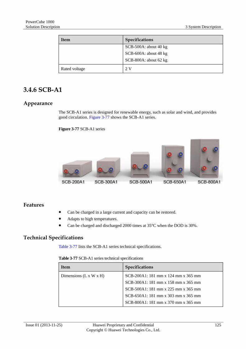
PowerCube 1000
Solution Description 3 System Description
Issue 01 (2013-11-25) Huawei Proprietary and Confidential
Copyright © Huawei Technologies Co., Ltd.
125
Item Specifications
SCB-500A: about 40 kg
SCB-600A: about 48 kg
SCB-800A: about 62 kg
Rated voltage 2 V
3.4.6 SCB-A1
Appearance
The SCB-A1 series is designed for renewable energy, such as solar and wind, and provides
good circulation. Figure 3-77 shows the SCB-A1 series.
Figure 3-77 SCB-A1 series
Features Can be charged in a large current and capacity can be restored.
Adapts to high temperatures.
Can be charged and discharged 2000 times at 35°C when the DOD is 30%.
Technical Specifications
Table 3-77 lists the SCB-A1 series technical specifications.
Table 3-77 SCB-A1 series technical specifications
Item Specifications
Dimensions (L x W x H) SCB-200A1: 181 mm x 124 mm x 365 mm
SCB-300A1: 181 mm x 158 mm x 365 mm
SCB-500A1: 181 mm x 225 mm x 365 mm
SCB-650A1: 181 mm x 303 mm x 365 mm
SCB-800A1: 181 mm x 370 mm x 365 mm

PowerCube 1000
Solution Description 3 System Description
Issue 01 (2013-11-25) Huawei Proprietary and Confidential
Copyright © Huawei Technologies Co., Ltd.
126
Item Specifications
Weight SCB-200A1: about 18.2 kg
SCB-300A1: about 23.5 kg
SCB-500A1: about 33.2 kg
SCB-650A1: about 45.8 kg
SCB-800A1: about 56.4 kg
Rated voltage 2 V
3.4.7 FCB
Appearance
Figure 3-78 shows the FCB series.
Figure 3-78 FCB series
Functions
An FCB applies to an unstable power grid. If mains is available, an FCB allows a high charge
current. If mains is unavailable, an FCB supplies power to communications equipment by
relying on its consistent cycle performance (charged and discharged 1500 times at 25°C when
the DOD is 50%).
Technical Specifications
Table 3-78 lists the FCB series technical specifications.
Table 3-78 FCB series technical specifications
Item Specifications
Dimensions (L x W x H) FCB-200A: 181 mm x 90 mm x 365 mm
FCB-300A: 181 mm x 124 mm x 365 mm
FCB-400A: 181 mm x 158 mm x 365 mm
FCB-500A: 181 mm x 191 mm x 365 mm
FCB-650A: 181 mm x 225 mm x 365 mm

PowerCube 1000
Solution Description 3 System Description
Issue 01 (2013-11-25) Huawei Proprietary and Confidential
Copyright © Huawei Technologies Co., Ltd.
127
Item Specifications
Weight FCB-200A: 13 kg
FCB-300A: 18.5 kg
FCB-400A: 24 kg
FCB-500A: 30 kg
FCB-650A: 35 kg
Rated voltage 2 V
3.4.8 AGM Battery
Appearance
Figure 3-79 shows AGM battery series.
Figure 3-79 AGM battery series
Functions
AGM batteries supply backup power in the areas with good mains quality.
Technical Specifications
Table 3-79 lists the AGM battery technical specifications.
Table 3-79 AGM battery technical specifications
Item 6-FMX-100B 6-FMX-150B 6-GFM-100XB 6-GFM-150X/E
Dimensions
(L x W x H)
395 mm x 110 mm
x 286 mm
549 mm x 110
mm x 310 mm
393 mm x 108
mm x 287 mm
528 mm x 125
mm x 310 mm

PowerCube 1000
Solution Description 3 System Description
Issue 01 (2013-11-25) Huawei Proprietary and Confidential
Copyright © Huawei Technologies Co., Ltd.
128
Item 6-FMX-100B 6-FMX-150B 6-GFM-100XB 6-GFM-150X/E
Weight 30.8 kg 48 kg 35 kg 50 kg
Rated
voltage
12 V DC 12 V DC 12 V DC 12 V DC
Capacity 100 Ah 150 Ah 100 Ah 150 Ah
3.4.9 ESU Monitor
Appearance
Figure 3-80 shows an ESU monitor.
Figure 3-80 ESU monitor
Functions
Table 3-80 describes the ESU monitor functions.
Table 3-80 ESU monitor function description
Function Description
Remote management Performs preventive maintenance inspection (PMI) on battery
strings and reports data to the host, improving the reliability of
the DC power system.
Monitoring Monitors the voltages, charge currents, discharge currents, and
temperatures of 24 batteries. You can configure two ESU
monitors based on site requirements.
Technical Specifications
Table 3-81 lists the technical specifications for the ESU monitor.

PowerCube 1000
Solution Description 3 System Description
Issue 01 (2013-11-25) Huawei Proprietary and Confidential
Copyright © Huawei Technologies Co., Ltd.
129
Table 3-81 Technical specifications for an ESU monitor
Item Specifications
Monitoring Monitors 24 batteries. Multiple ESU monitors can be combined.
Voltage monitoring
range
0–3 V (typical value: 2 V)
0–10 V (typical value: 6 V)
0–15 V (typical value: 12 V)
Power supply 40–300 V DC or 36–250 V AC
Communication mode RS485 bus; baud rate: 9600 bit/s
Cable connection Cable connectors are pluggable.
3.4.10 ESM-A01
Appearance
Figure 3-81 shows an ESM-A01 front panel. The ESM-A01 consists of one ESMU-01A and
four ESU-A600Wh/Cs.
Figure 3-81 ESM-A01 front panel
Functions
The ESM-A01 controls and manages ESUs over the ESMU-01A to ensure that all ESUs have
the same float voltage and charge level and depth. This helps to increase the security and
lifespan of ESUs.
Technical Specifications
Table 3-82 describes the technical specifications for the ESM-A01.

PowerCube 1000
Solution Description 3 System Description
Issue 01 (2013-11-25) Huawei Proprietary and Confidential
Copyright © Huawei Technologies Co., Ltd.
130
Table 3-82 ESM-A01 technical specifications
Item Specifications
Dimensions (H x W x D) 175 mm x 482.6 mm x 437 mm (including mounting
ears)
Weight 50 kg
3.4.11 ESU-A600Wh/C
Appearance
Figure 3-82 shows an ESU-A600Wh/C panel.
Figure 3-82 ESU-A600Wh/C panel
(1) Positive wiring terminal (2) Sampling wiring terminal (3) Negative wiring terminal
(4) Handle (5) COM_ELU OUT port (6) COM_ELU IN port
Features
An ESU-A600Wh/C is made of a new type of material and features safety, long lifespan,
small size, light weight, and has good performance at high temperatures. It can be charged or discharged with large power and does not pollute the environment.

PowerCube 1000
Solution Description 3 System Description
Issue 01 (2013-11-25) Huawei Proprietary and Confidential
Copyright © Huawei Technologies Co., Ltd.
131
Technical Specifications
Table 3-83 lists the ESU-A600Wh/C technical specifications.
Table 3-83 ESU-A600Wh/C technical specifications
Item Specifications
Dimensions (H x W x
D)
125 mm x 105 mm x 420 mm
Weight About 12 kg
Voltage 12 V DC
Capacity 600 Wh
Cycle life Can be charged and discharged 4500 times in 0.3C at 35°C
when the depth of discharge (DOD) is 85%.
3.4.12 ESU-A2400Wh/D
Appearance
Figure 3-83 shows an ESU-A2400Wh/D panel.
Figure 3-83 ESU-A2400Wh/D panel
(1) Positive wiring terminal (2) COM_ELU IN port (3) COM_ELU OUT port
(4) ESU-A4 sampling port (5) ESU-A3 sampling port (6) ESU-A2 sampling port
(7) ESU-A1 sampling port (8) Negative wiring terminal (9) Handle
Features
An ESU-A2400Wh/D is made of a new type of material and features safety, long lifespan,
small size, light weight, and has good performance at high temperatures. It can be charged or
discharged with large power and does not pollute the environment.

PowerCube 1000
Solution Description 3 System Description
Issue 01 (2013-11-25) Huawei Proprietary and Confidential
Copyright © Huawei Technologies Co., Ltd.
132
Technical Specifications
Table 3-84 lists the ESU-A2400Wh/D technical specifications.
Table 3-84 ESU-A2400Wh/D technical specifications
Item Specifications
Dimensions (H x W x D) 125 mm x 435 mm x 420 mm
Weight 37.5 kg
Voltage 48 V DC
Capacity 2400 Wh
Cycle life Can be charged and discharged 3500 times in 0.3C at
35°C when the depth of discharge (DOD) is 85%.
3.4.13 ESU-A2400Wh/N
Appearance
Figure 3-84 shows an ESU-A2400Wh/N panel.
Figure 3-84 ESU-A2400Wh/N panel
(1) COM_ELU IN port (2) COM_ELU OUT port (3) Sampling wiring terminal
(4) Positive wiring terminal (5) Negative wiring terminal (6) Handle
Features
An ESU-A2400Wh/N is made of a new type of material and features safety, long lifespan,
small size, light weight, and has good performance at high temperatures. It can be charged or
discharged with large power and does not pollute the environment.

PowerCube 1000
Solution Description 3 System Description
Issue 01 (2013-11-25) Huawei Proprietary and Confidential
Copyright © Huawei Technologies Co., Ltd.
133
Technical Specifications
Table 3-85 lists the ESU-A2400Wh/N technical specifications.
Table 3-85 ESU-A2400Wh/N technical specifications
Item Specifications
Dimensions (H x W x
D)
125 mm x 440 mm x 500 mm
Weight 30 kg
Voltage 12 V DC
Capacity 2400 Wh
Cycle life Can be charged and discharged 3500 times in 0.3C at 35°C
when the depth of discharge (DOD) is 85%.
3.4.14 ESMU-01A/ESMU-02A/ESMU-03A
Appearance
Figure 3-85 shows an ESMU panel.
Figure 3-85 ESMU panel
(1) COM_OUT port (2) COM_ELU
port
(3) Resistance DIP switch
corresponding to the CAN
port
(4) Resistance DIP
switch (reserved)
(5) Address DIP
switch (ADDRESS)
(6) ESU-A
sampling port
(7) Power switch (8) Power port
(9) Battery– port (10) –48V BUS
port
(11) Status indicator (13) CONSOLE
port
(13) COM_IN port
Functions
Table 3-86 describes the ESMU functions.

PowerCube 1000
Solution Description 3 System Description
Issue 01 (2013-11-25) Huawei Proprietary and Confidential
Copyright © Huawei Technologies Co., Ltd.
134
Table 3-86 ESMU function description
Function Description
Status monitoring Monitors the voltage and temperature of each electrochemical
cell, and voltage and current of the ESU string.
Alarm detection and
reporting
Detects alarms for hardware faults, overvoltage, undervoltage,
overcurrent, high temperatures, and low temperatures, and
reports alarms to the host over a CAN port.
ESU connection control Disconnects ESUs when an alarm is generated and connects
ESUs after exceptions are eliminated.
Cascading A maximum of 12 ESMUs can be cascaded.
Equalization Supports real-time equalization and adaptive equalization:
Real-time equalization: Equalizes cell capacities to delay
electrochemical cell deterioration and prolong the service
life of cells. Such cell capacity imbalance is caused by the
increase of charge/discharge cycles.
Adaptive equalization: Equalizes cell capacities to facilitate
ESU maintenance and replacement in the mixture of
different electrochemical cells, which improves ESU
adaptability. Such cell capacity imbalance is caused by
ESU maintenance and replacement.
The controller identifies the electrochemical cell with the
lowest voltage and adjusts its output current.
SOH Monitors the ESU health status and reports the information to
the host over a CAN port.
Electronic label Identifies ESUs by displaying their models, bar codes, and
production dates.
Technical Specifications
Table 3-87 describes the ESMU technical specifications.
Table 3-87 ESMU technical specifications
Item Specifications
Dimensions (H x W x
D)
44.5 mm x 444 mm x 310 mm
Weight ≤ 5 kg
Disconnection
protection voltage
44–46 V (typical value: 45 V; forcible disconnection voltage: 44
V)
Busbar activation
voltage 46–48 V (typical value: 47 V; forcible activation voltage: 48 V)
Maximum ESMU-01A: 40 A

PowerCube 1000
Solution Description 3 System Description
Issue 01 (2013-11-25) Huawei Proprietary and Confidential
Copyright © Huawei Technologies Co., Ltd.
135
Item Specifications
charge/discharge
current
ESMU-02A: 100 A
ESMU-03A: 100 A
Operating conditions Ambient temperature: –20°C to +55°C
Humidity: 5%–95% RH
Atmospheric pressure: 70–106 kPa
Altitude: ≤ 4 km
Reliability Mean time between failures (MTBF) ≥ 30,000 hours; annual
repair ratio < 1%
3.5 OSS
3.5.1 NetEco
The iManager NetEco monitors and manages key performance indicators (KPIs) and alarms
for power and environment related devices in real time, effectively improving the remote
operation and maintenance of such devices, reducing the number of site visits, and decreasing
operation and maintenance costs. The NetEco can also collect and analyze site power
consumption data and raise energy saving optimization suggestions.
Figure 3-86 shows the NetEco monitoring system.
Figure 3-86 NetEco monitoring system
The NetEco centrally manages site energy and environment over the ECC500 and can be
networked in in-band or out-of-band mode.
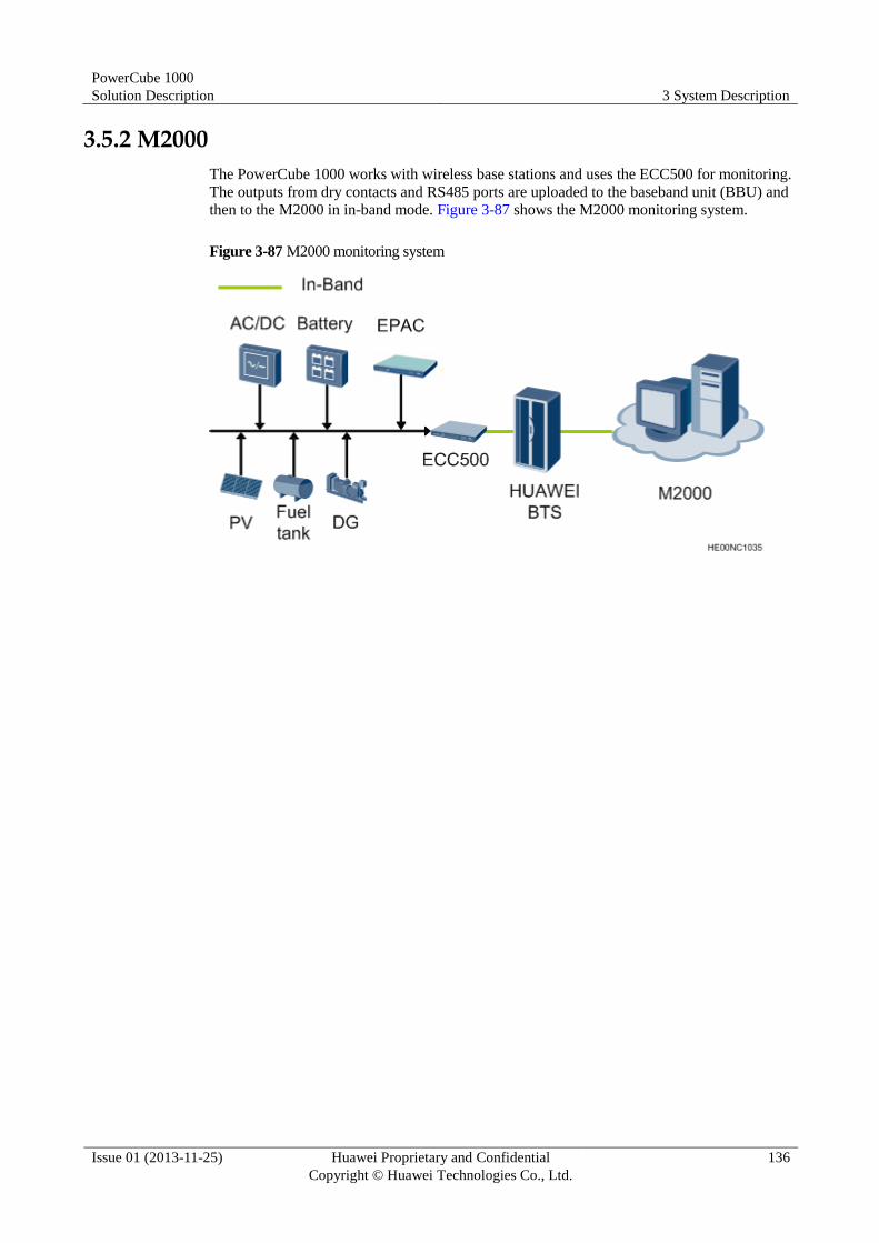
PowerCube 1000
Solution Description 3 System Description
Issue 01 (2013-11-25) Huawei Proprietary and Confidential
Copyright © Huawei Technologies Co., Ltd.
136
3.5.2 M2000
The PowerCube 1000 works with wireless base stations and uses the ECC500 for monitoring.
The outputs from dry contacts and RS485 ports are uploaded to the baseband unit (BBU) and
then to the M2000 in in-band mode. Figure 3-87 shows the M2000 monitoring system.
Figure 3-87 M2000 monitoring system
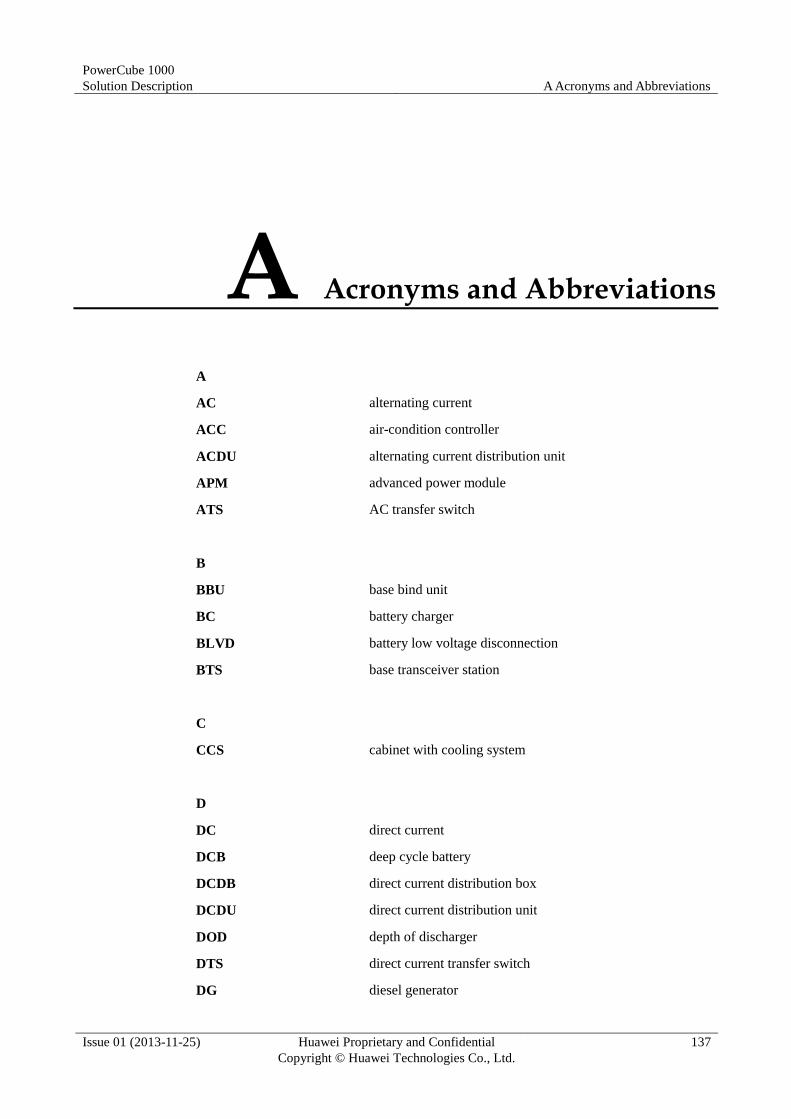
PowerCube 1000
Solution Description A Acronyms and Abbreviations
Issue 01 (2013-11-25) Huawei Proprietary and Confidential
Copyright © Huawei Technologies Co., Ltd.
137
A Acronyms and Abbreviations
A
AC alternating current
ACC air-condition controller
ACDU alternating current distribution unit
APM advanced power module
ATS AC transfer switch
B
BBU base bind unit
BC battery charger
BLVD battery low voltage disconnection
BTS base transceiver station
C
CCS cabinet with cooling system
D
DC direct current
DCB deep cycle battery
DCDB direct current distribution box
DCDU direct current distribution unit
DOD depth of discharger
DTS direct current transfer switch
DG diesel generator

PowerCube 1000
Solution Description A Acronyms and Abbreviations
Issue 01 (2013-11-25) Huawei Proprietary and Confidential
Copyright © Huawei Technologies Co., Ltd.
138
E
ECC energy control center
EPAC environment and power equipment alarm controller
EPS energy plant system
ESC energy storage cabinet
ESM energy storage module
ESMU energy storage management unit
ESS energy storage system
ESU energy storage unit
ETP embedded telecom power
F
FCB fast charge battery
FCMS fuel consumption measuring system
G
GPRS general packet radio service
I
ICC integrated controller and converter
IDG integrated diesel generator
IDU integrated distribution unit
L
LLVD load low voltage disconnection
M
MPPT maximum power point track
MTBF mean time between failure
N
NetEco Network Ecosystem

PowerCube 1000
Solution Description A Acronyms and Abbreviations
Issue 01 (2013-11-25) Huawei Proprietary and Confidential
Copyright © Huawei Technologies Co., Ltd.
139
O
OMU-B box type operation manage unit
OSS operations support system
P
PSU power supply unit
PV photovoltaic
PVDU photovoltaic distribution unit
R
ROI return on investment
S
SCB solar cycle battery
SMU site monitoring unit
SOH status of health
SPD surge protection device
SSU solar supply unit
T
TCO total cost of ownership
TP telecom power