CA Powercube Pbf(en)b 1vcp000253 1201a
20
Medium voltage products PB/F type PowerCube Fixed parts for medium voltage circuit-breakers and contactors
-
Upload
prashanth-chandrashekar -
Category
Documents
-
view
258 -
download
0
description
ABB cubicle sizing
Transcript of CA Powercube Pbf(en)b 1vcp000253 1201a

Medium voltage products
PB/F type PowerCubeFixed parts for medium voltage circuit-breakers and contactors

2

3
Index
4 1. General characteristics
8 2. Main components
12 3. Types available and apparatus
18 4. Electric circuit diagram
4
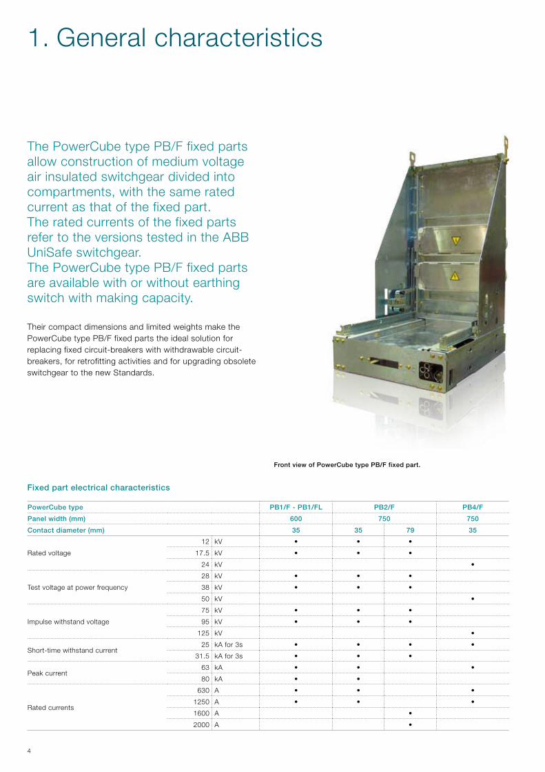
The PowerCube type PB/F fixed parts allow construction of medium voltage air insulated switchgear divided into compartments, with the same rated current as that of the fixed part.The rated currents of the fixed parts refer to the versions tested in the ABB UniSafe switchgear.The PowerCube type PB/F fixed parts are available with or without earthing switch with making capacity.
Their compact dimensions and limited weights make the PowerCube type PB/F fixed parts the ideal solution for replacing fixed circuit-breakers with withdrawable circuit-breakers, for retrofitting activities and for upgrading obsolete switchgear to the new Standards.
FrontviewofPowerCubetypePB/Ffixedpart.
PowerCubetype PB1/F-PB1/FL PB2/F PB4/F
Panelwidth(mm) 600 750 750
Contactdiameter(mm) 35 35 79 35
Rated voltage
12 kV • • •
17.5 kV • • •
24 kV •
Test voltage at power frequency
28 kV • • •
38 kV • • •
50 kV •
Impulse withstand voltage
75 kV • • •
95 kV • • •
125 kV •
Short-time withstand current25 kA for 3s • • • •
31.5 kA for 3s • • •
Peak current63 kA • • •
80 kA • •
Rated currents
630 A • • •
1250 A • • •
1600 A •
2000 A •
Fixedpartelectricalcharacteristics
1. General characteristics
5
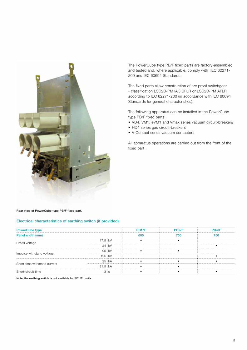
The PowerCube type PB/F fixed parts are factory-assembled and tested and, where applicable, comply with IEC 62271-200 and IEC 60694 Standards.
The fixed parts allow construction of arc proof switchgear - classification LSC2B-PM IAC BFLR or LSC2B-PM AFLR according to IEC 62271-200 (in accordance with IEC 60694 Standards for general characteristics).
The following apparatus can be installed in the PowerCube type PB/F fixed parts:• VD4, VM1, eVM1 and Vmax series vacuum circuit-breakers• HD4 series gas circuit-breakers• V-Contact series vacuum contactors
All apparatus operations are carried out from the front of the fixed part .
RearviewofPowerCubetypePB/Ffixedpart.
PowerCubetype PB1/F PB2/F PB4/F
Panelwidth(mm) 600 750 750
Rated voltage17.5 kV • •
24 kV •
Impulse withstand voltage95 kV • •
125 kV •
Short-time withstand current25 kA • • •
31.5 kA • •
Short-circuit time 3 s • • •
Note:theearthingswitchisnotavailableforPB1/FLunits.
Electricalcharacteristicsofearthingswitch(ifprovided)
6
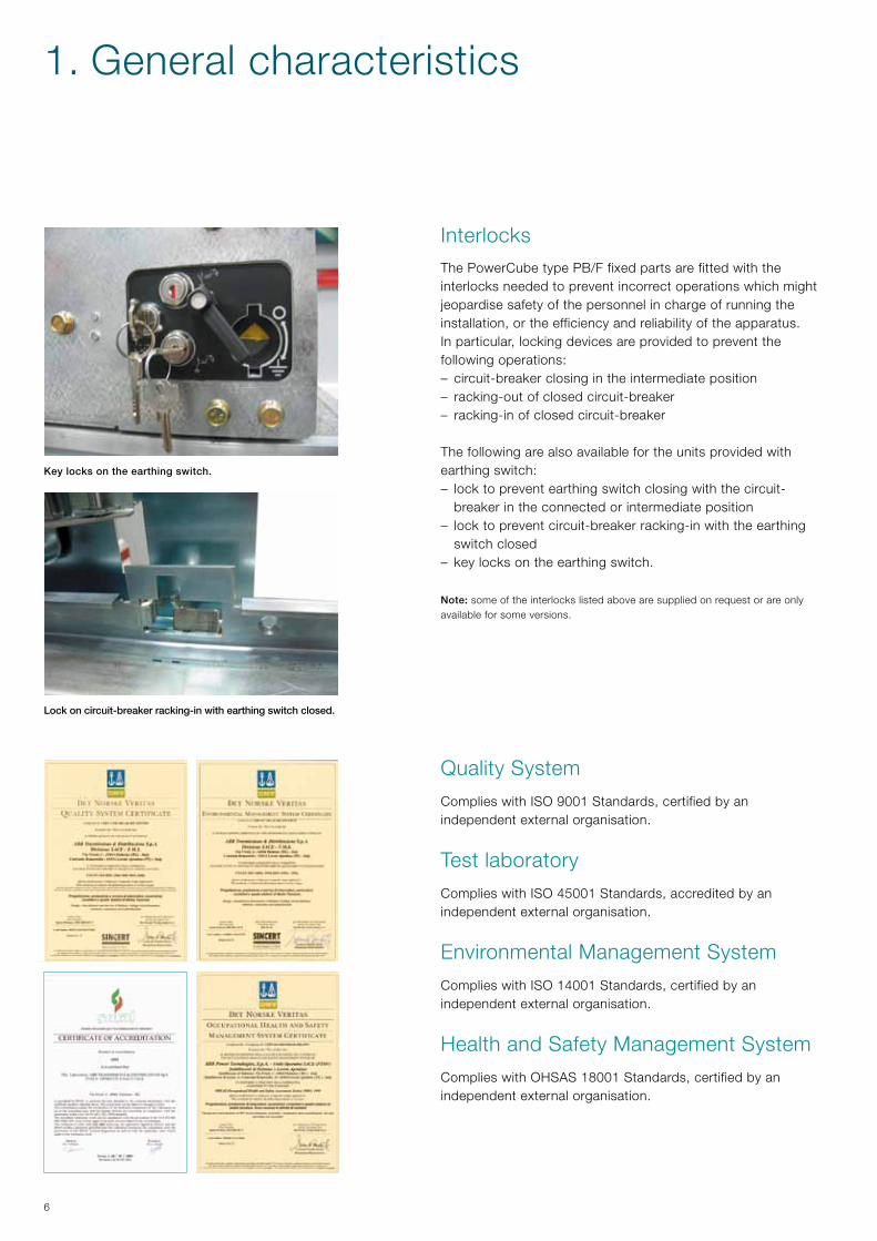
Lockoncircuit-breakerracking-inwithearthingswitchclosed.
Keylocksontheearthingswitch.
Interlocks The PowerCube type PB/F fixed parts are fitted with the interlocks needed to prevent incorrect operations which might jeopardise safety of the personnel in charge of running the installation, or the efficiency and reliability of the apparatus.In particular, locking devices are provided to prevent the following operations:– circuit-breaker closing in the intermediate position– racking-out of closed circuit-breaker– racking-in of closed circuit-breaker
The following are also available for the units provided with earthing switch:– lock to prevent earthing switch closing with the circuit-
breaker in the connected or intermediate position – lock to prevent circuit-breaker racking-in with the earthing
switch closed – key locks on the earthing switch.
Note:some of the interlocks listed above are supplied on request or are only available for some versions.
Quality System
Complies with ISO 9001 Standards, certified by an independent external organisation.
Test laboratory
Complies with ISO 45001 Standards, accredited by an independent external organisation.
Environmental Management System
Complies with ISO 14001 Standards, certified by an independent external organisation.
Health and Safety Management System
Complies with OHSAS 18001 Standards, certified by an independent external organisation.
1. General characteristics

7
A
C
B
Overall dimensions
ModuleRated
voltageRated
currentIscIcw
Tableofdimensions A B C Weight
[kV] [A] [kV] [mm] [mm] [mm] [kg]
PB1/F12 630 - 1250 31.5
1VCD003382
596 1061 900 (*)
17.5 630 - 1250
PB1/FL12 630 - 1250
31.5 1VCD003614 596 1015 787 (*) 17.5 630 - 1250
PB2/F12 630...2000
31.5 1VCD003383 746 1061 1106 (*) 17.5 1250...2000
PB4/F 24 630 - 1250 31.5 1VCD003384 746 1338 1236 (*)
(*) Ask ABB.
PowerCubefixedpart PB1/F PB1/FL PB2/F PB4/F
Width (mm) 600 600 750 750
Rated voltage
12kV • • •
17.5kV • • •
24kV •
Standard fittings 1Plug socket with anti-racking-in lock for circuit- breakers with lower rated current than that of the unit or for apparatus not foreseen l for the unit itself
• • •
Accessories to be specifiedat the time of ordering (assembly by ABB)
2 Circuit-breaker anti-racking-in lock • • •
3 Earthing switch • • •
4Key lock in open or closed position or in open and closed position, for earthing switch
• • •
5Electromechanical lock for earthing switch (24-30-48-60-110-125-220-250 Vdc; 110-220 Vac 50Hz)
• • •
6 Earthing switch auxiliary contacts (5 or 10) • • • •
7 Safety device for metal shutters (Fail Safe) • • •
Accessories on request(assembly by customer)
8 Anti-condensation heater (110-220 Vac 50 Hz) • • • •
9 Padlock for metal shutters (top or bottom or top and bottom) • • • •
10 Earthing switch operating lever, extra in relation to normal supply (*) • • •
11 Apparatus transport and racking-in truck • • • •
(*) The normal supply consists of one operating lever for every 10 fixed parts.
8
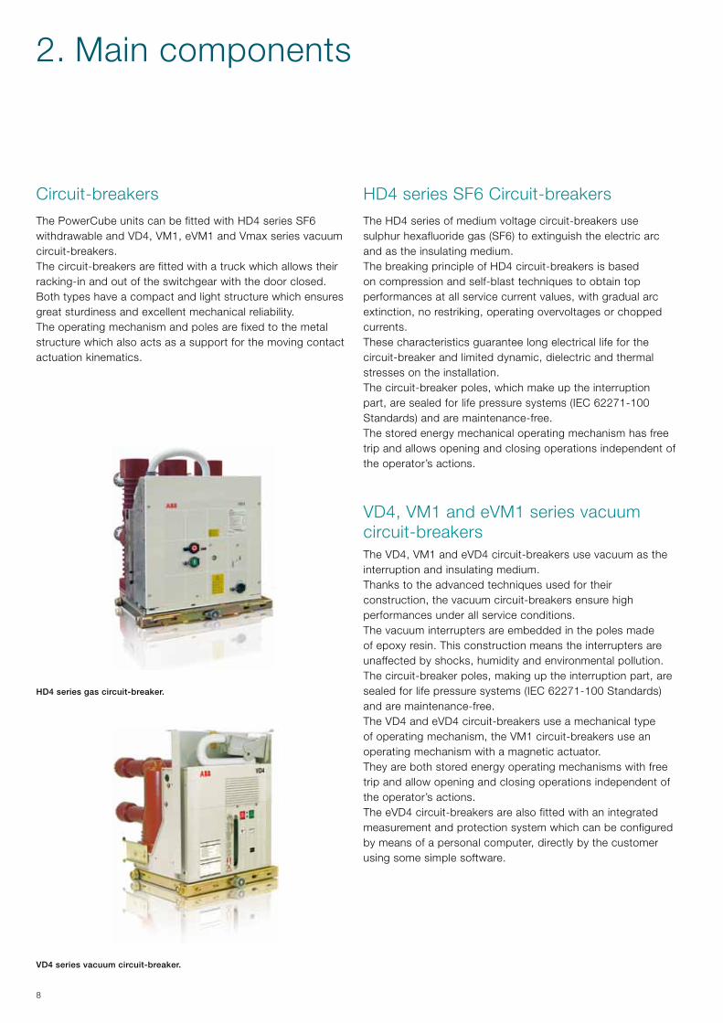
HD4 series SF6 Circuit-breakersThe HD4 series of medium voltage circuit-breakers use sulphur hexafluoride gas (SF6) to extinguish the electric arc and as the insulating medium.The breaking principle of HD4 circuit-breakers is based on compression and self-blast techniques to obtain top performances at all service current values, with gradual arc extinction, no restriking, operating overvoltages or chopped currents.These characteristics guarantee long electrical life for the circuit-breaker and limited dynamic, dielectric and thermal stresses on the installation.The circuit-breaker poles, which make up the interruption part, are sealed for life pressure systems (IEC 62271-100 Standards) and are maintenance-free.The stored energy mechanical operating mechanism has free trip and allows opening and closing operations independent of the operator’s actions.
VD4, VM1 and eVM1 series vacuum circuit-breakersThe VD4, VM1 and eVD4 circuit-breakers use vacuum as the interruption and insulating medium.Thanks to the advanced techniques used for their construction, the vacuum circuit-breakers ensure high performances under all service conditions.The vacuum interrupters are embedded in the poles made of epoxy resin. This construction means the interrupters are unaffected by shocks, humidity and environmental pollution.The circuit-breaker poles, making up the interruption part, are sealed for life pressure systems (IEC 62271-100 Standards) and are maintenance-free.The VD4 and eVD4 circuit-breakers use a mechanical type of operating mechanism, the VM1 circuit-breakers use an operating mechanism with a magnetic actuator.They are both stored energy operating mechanisms with free trip and allow opening and closing operations independent of the operator’s actions.The eVD4 circuit-breakers are also fitted with an integrated measurement and protection system which can be configured by means of a personal computer, directly by the customer using some simple software.
Circuit-breakersThe PowerCube units can be fitted with HD4 series SF6 withdrawable and VD4, VM1, eVM1 and Vmax series vacuum circuit-breakers.The circuit-breakers are fitted with a truck which allows their racking-in and out of the switchgear with the door closed.Both types have a compact and light structure which ensures great sturdiness and excellent mechanical reliability.The operating mechanism and poles are fixed to the metal structure which also acts as a support for the moving contact actuation kinematics.
HD4seriesgascircuit-breaker.
VD4seriesvacuumcircuit-breaker.
2. Main components

9
Vmax/W series vacuum circuit-breakersVmax circuit-breakers are made up of an insulating monobloc in which three vacuum interrupters are fixed. The monobloc and the operating mechanism are fixed to a frame.The vacuum interrupters house the contacts and make up the interruption chambers of the circuit-breaker.Vmax circuit-breakers use a mechanical stored energy operating mechanism with free trip which allows opening and closing operations independent of the operator’s actions. The mechanical operating mechanism is of simple concept and use and can be personalised with a wide range of easily and rapidly installed accessories.This simplicity characterised the apparatus for its reliability, duration and limited maintenance.Vmax circuit-breakers are used in power distribution for control and protection of cables, overhead lines, transformer and distribution substations, motors, transformers, generators and capacitor banks.The circuit-breaker vacuum interrupters, which make up the interruption part, are sealed for life pressure systems (IEC 62271-100 Standards) and are maintenance-free.
V-Contact VSC/P series vacuum contactorsUse of V-Contact series withdrawable contactors is foreseen in the PB1 PowerCube units up to 12 kV.The contactors are suitable for controlling alternating current users which require a high number of operations.They consist of a resin monobloc where the vacuum interrupters, moving equipment, operating mechanism, multivoltage feeder and auxiliary accessories are housed.The monobloc is also the support for installation of the fuses.Fuses according to DIN or BS Standards of different dimensions can be used thanks to special adapters.The type of fuseholder (BS or DIN) must be specified when ordering.Contactor closing is prevented when even a single fuse is missing. Opening is automatic when one of the three fuses blows.They are of compact and sturdy construction and guarantee very long electrical and mechanical life.
eVD4seriesvacuumcircuit-breaker.
Vmax/Wseriesvacuumcircuit-breaker.
V-ContactseriesvacuumcontactorsVSC/P
10
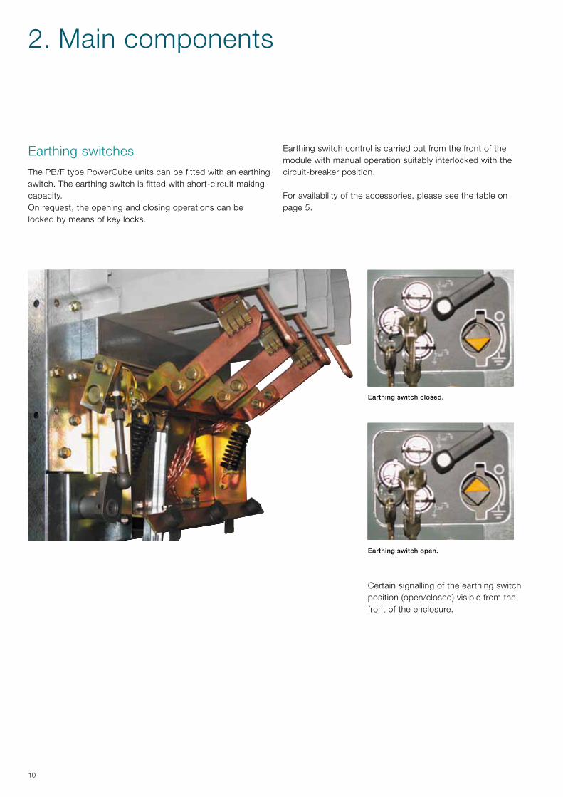
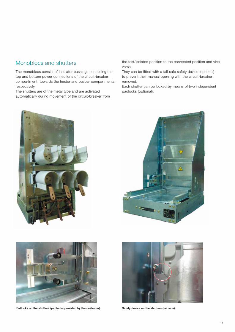
Earthing switchesThe PB/F type PowerCube units can be fitted with an earthing switch. The earthing switch is fitted with short-circuit making capacity.On request, the opening and closing operations can be locked by means of key locks.
Certain signalling of the earthing switchposition (open/closed) visible from thefront of the enclosure.
Earthingswitchopen.
Earthingswitchclosed.
Earthing switch control is carried out from the front of the module with manual operation suitably interlocked with the circuit-breaker position.
For availability of the accessories, please see the table on page 5.
2. Main components
11
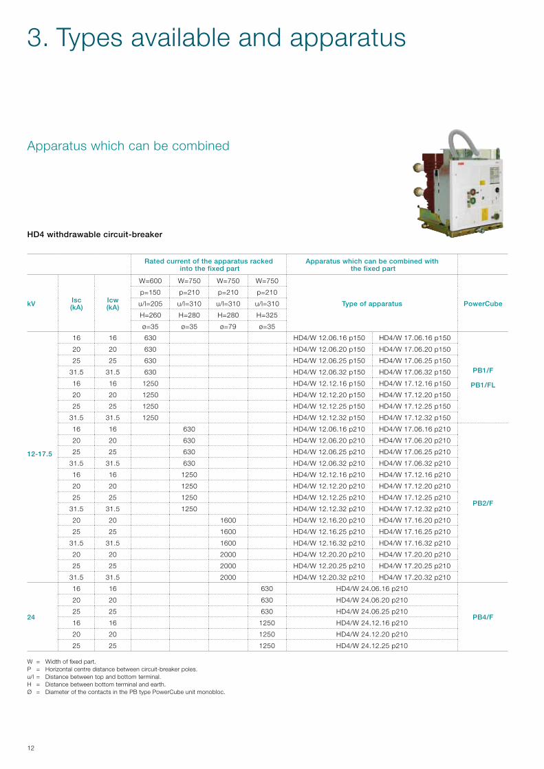
Monoblocs and shuttersThe monoblocs consist of insulator bushings containing the top and bottom power connections of the circuit-breaker compartment, towards the feeder and busbar compartments respectively.The shutters are of the metal type and are activated automatically during movement of the circuit-breaker from
Safetydeviceontheshutters(failsafe).Padlocksontheshutters(padlocksprovidedbythecustomer).
the test/isolated position to the connected position and vice versa.They can be fitted with a fail-safe safety device (optional) to prevent their manual opening with the circuit-breaker removed.Each shutter can be locked by means of two independent padlocks (optional).
12
Apparatus which can be combined
HD4withdrawablecircuit-breaker
W = Width of fixed part.P = Horizontal centre distance between circuit-breaker poles.u/l = Distance between top and bottom terminal.H = Distance between bottom terminal and earth.Ø = Diameter of the contacts in the PB type PowerCube unit monobloc.
3. Types available and apparatus
Ratedcurrentoftheapparatusrackedintothefixedpart
Apparatuswhichcanbecombinedwiththefixedpart
kV Isc(kA)
Icw(kA)
W=600 W=750 W=750 W=750
Typeofapparatus PowerCube
p=150 p=210 p=210 p=210
u/l=205 u/l=310 u/l=310 u/l=310
H=260 H=280 H=280 H=325
ø=35 ø=35 ø=79 ø=35
12-17.5
16 16 630 HD4/W 12.06.16 p150 HD4/W 17.06.16 p150
PB1/F
PB1/FL
20 20 630 HD4/W 12.06.20 p150 HD4/W 17.06.20 p150
25 25 630 HD4/W 12.06.25 p150 HD4/W 17.06.25 p150
31.5 31.5 630 HD4/W 12.06.32 p150 HD4/W 17.06.32 p150
16 16 1250 HD4/W 12.12.16 p150 HD4/W 17.12.16 p150
20 20 1250 HD4/W 12.12.20 p150 HD4/W 17.12.20 p150
25 25 1250 HD4/W 12.12.25 p150 HD4/W 17.12.25 p150
31.5 31.5 1250 HD4/W 12.12.32 p150 HD4/W 17.12.32 p150
16 16 630 HD4/W 12.06.16 p210 HD4/W 17.06.16 p210
PB2/F
20 20 630 HD4/W 12.06.20 p210 HD4/W 17.06.20 p210
25 25 630 HD4/W 12.06.25 p210 HD4/W 17.06.25 p210
31.5 31.5 630 HD4/W 12.06.32 p210 HD4/W 17.06.32 p210
16 16 1250 HD4/W 12.12.16 p210 HD4/W 17.12.16 p210
20 20 1250 HD4/W 12.12.20 p210 HD4/W 17.12.20 p210
25 25 1250 HD4/W 12.12.25 p210 HD4/W 17.12.25 p210
31.5 31.5 1250 HD4/W 12.12.32 p210 HD4/W 17.12.32 p210
20 20 1600 HD4/W 12.16.20 p210 HD4/W 17.16.20 p210
25 25 1600 HD4/W 12.16.25 p210 HD4/W 17.16.25 p210
31.5 31.5 1600 HD4/W 12.16.32 p210 HD4/W 17.16.32 p210
20 20 2000 HD4/W 12.20.20 p210 HD4/W 17.20.20 p210
25 25 2000 HD4/W 12.20.25 p210 HD4/W 17.20.25 p210
31.5 31.5 2000 HD4/W 12.20.32 p210 HD4/W 17.20.32 p210
24
16 16 630 HD4/W 24.06.16 p210
PB4/F
20 20 630 HD4/W 24.06.20 p210
25 25 630 HD4/W 24.06.25 p210
16 16 1250 HD4/W 24.12.16 p210
20 20 1250 HD4/W 24.12.20 p210
25 25 1250 HD4/W 24.12.25 p210
13
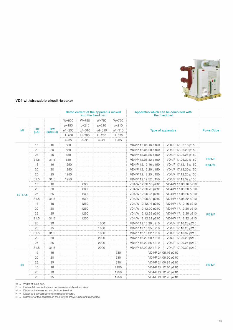
VD4withdrawablecircuit-breaker
W = Width of fixed part.P = Horizontal centre distance between circuit-breaker poles.u/l = Distance between top and bottom terminal.H = Distance between bottom terminal and earth.Ø = Diameter of the contacts in the PB type PowerCube unit monobloc.
Ratedcurrentoftheapparatusrackedintothefixedpart
Apparatuswhichcanbecombinedwiththefixedpart
kV Isc(kA)
Icw(kAx3s)
W=600 W=750 W=750 W=750
Typeofapparatus PowerCube
p=150 p=210 p=210 p=210
u/l=205 u/l=310 u/l=310 u/l=310
H=260 H=280 H=280 H=325
ø=35 ø=35 ø=79 ø=35
12-17.5
16 16 630 VD4/P 12.06.16 p150 VD4/P 17.06.16 p150
PB1/F
PB1/FL
20 20 630 VD4/P 12.06.20 p150 VD4/P 17.06.20 p150
25 25 630 VD4/P 12.06.25 p150 VD4/P 17.06.25 p150
31.5 31.5 630 VD4/P 12.06.32 p150 VD4/P 17.06.32 p150
16 16 1250 VD4/P 12.12.16 p150 VD4/P 17.12.16 p150
20 20 1250 VD4/P 12.12.20 p150 VD4/P 17.12.20 p150
25 25 1250 VD4/P 12.12.25 p150 VD4/P 17.12.25 p150
31.5 31.5 1250 VD4/P 12.12.32 p150 VD4/P 17.12.32 p150
16 16 630 VD4/W 12.06.16 p210 VD4/W 17.06.16 p210
PB2/F
20 20 630 VD4/W 12.06.20 p210 VD4/W 17.06.20 p210
25 25 630 VD4/W 12.06.25 p210 VD4/W 17.06.25 p210
31.5 31.5 630 VD4/W 12.06.32 p210 VD4/W 17.06.32 p210
16 16 1250 VD4/W 12.12.16 p210 VD4/W 17.12.16 p210
20 20 1250 VD4/W 12.12.20 p210 VD4/W 17.12.20 p210
25 25 1250 VD4/W 12.12.25 p210 VD4/W 17.12.25 p210
31.5 31.5 1250 VD4/W 12.12.32 p210 VD4/W 17.12.32 p210
20 20 1600 VD4/P 12.16.20 p210 VD4/P 17.16.20 p210
25 25 1600 VD4/P 12.16.25 p210 VD4/P 17.16.25 p210
31.5 31.5 1600 VD4/P 12.16.32 p210 VD4/P 17.16.32 p210
20 20 2000 VD4/P 12.20.20 p210 VD4/P 17.20.20 p210
25 25 2000 VD4/P 12.20.25 p210 VD4/P 17.20.25 p210
31.5 31.5 2000 VD4/P 12.20.32 p210 VD4/P 17.20.32 p210
24
16 16 630 VD4/P 24.06.16 p210
PB4/F
20 20 630 VD4/P 24.06.20 p210
25 25 630 VD4/P 24.06.25 p210
16 16 1250 VD4/P 24.12.16 p210
20 20 1250 VD4/P 24.12.20 p210
25 25 1250 VD4/P 24.12.25 p210
14
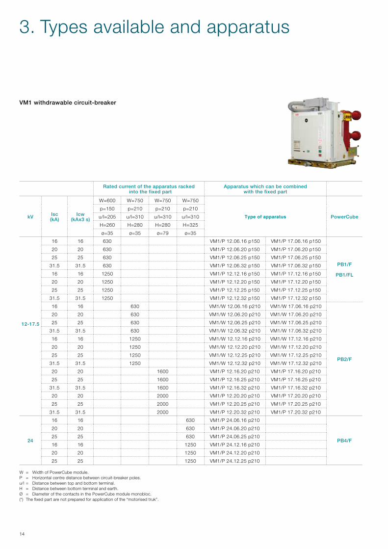
VM1withdrawablecircuit-breaker
W = Width of PowerCube module.P = Horizontal centre distance between circuit-breaker poles.u/l = Distance between top and bottom terminal.H = Distance between bottom terminal and earth.Ø = Diameter of the contacts in the PowerCube module monobloc.(*) The fixed part are not prepared for application of the “motorised truk”.
Ratedcurrentoftheapparatusrackedintothefixedpart
Apparatuswhichcanbecombinedwiththefixedpart
kV Isc(kA)
Icw(kAx3s)
W=600 W=750 W=750 W=750
Type of apparatus PowerCube
p=150 p=210 p=210 p=210
u/l=205 u/l=310 u/l=310 u/l=310
H=260 H=280 H=280 H=325
ø=35 ø=35 ø=79 ø=35
12-17.5
16 16 630 VM1/P 12.06.16 p150 VM1/P 17.06.16 p150
PB1/F
PB1/FL
20 20 630 VM1/P 12.06.20 p150 VM1/P 17.06.20 p150
25 25 630 VM1/P 12.06.25 p150 VM1/P 17.06.25 p150
31.5 31.5 630 VM1/P 12.06.32 p150 VM1/P 17.06.32 p150
16 16 1250 VM1/P 12.12.16 p150 VM1/P 17.12.16 p150
20 20 1250 VM1/P 12.12.20 p150 VM1/P 17.12.20 p150
25 25 1250 VM1/P 12.12.25 p150 VM1/P 17.12.25 p150
31.5 31.5 1250 VM1/P 12.12.32 p150 VM1/P 17.12.32 p150
16 16 630 VM1/W 12.06.16 p210 VM1/W 17.06.16 p210
PB2/F
20 20 630 VM1/W 12.06.20 p210 VM1/W 17.06.20 p210
25 25 630 VM1/W 12.06.25 p210 VM1/W 17.06.25 p210
31.5 31.5 630 VM1/W 12.06.32 p210 VM1/W 17.06.32 p210
16 16 1250 VM1/W 12.12.16 p210 VM1/W 17.12.16 p210
20 20 1250 VM1/W 12.12.20 p210 VM1/W 17.12.20 p210
25 25 1250 VM1/W 12.12.25 p210 VM1/W 17.12.25 p210
31.5 31.5 1250 VM1/W 12.12.32 p210 VM1/W 17.12.32 p210
20 20 1600 VM1/P 12.16.20 p210 VM1/P 17.16.20 p210
25 25 1600 VM1/P 12.16.25 p210 VM1/P 17.16.25 p210
31.5 31.5 1600 VM1/P 12.16.32 p210 VM1/P 17.16.32 p210
20 20 2000 VM1/P 12.20.20 p210 VM1/P 17.20.20 p210
25 25 2000 VM1/P 12.20.25 p210 VM1/P 17.20.25 p210
31.5 31.5 2000 VM1/P 12.20.32 p210 VM1/P 17.20.32 p210
24
16 16 630 VM1/P 24.06.16 p210
PB4/F
20 20 630 VM1/P 24.06.20 p210
25 25 630 VM1/P 24.06.25 p210
16 16 1250 VM1/P 24.12.16 p210
20 20 1250 VM1/P 24.12.20 p210
25 25 1250 VM1/P 24.12.25 p210
3. Types available and apparatus
15
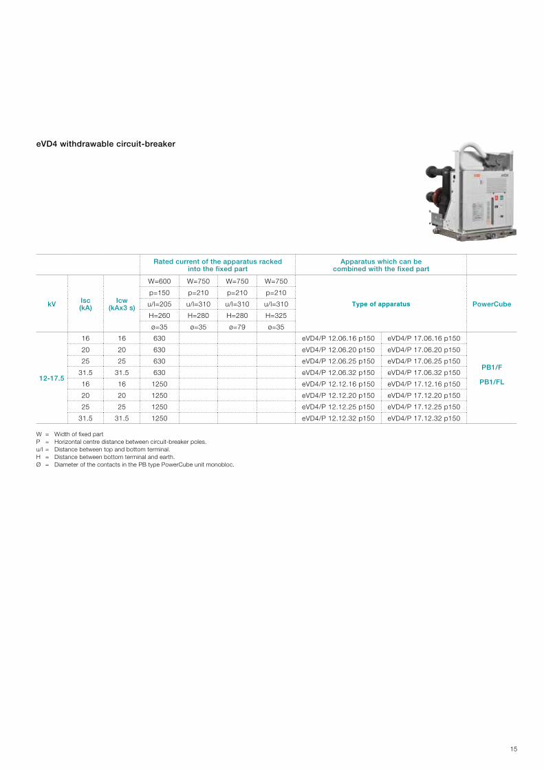
eVD4withdrawablecircuit-breaker
W = Width of fixed partP = Horizontal centre distance between circuit-breaker poles.u/l = Distance between top and bottom terminal.H = Distance between bottom terminal and earth.Ø = Diameter of the contacts in the PB type PowerCube unit monobloc.
Ratedcurrentoftheapparatusrackedintothefixedpart
Apparatuswhichcanbecombinedwiththefixedpart
kV Isc(kA)
Icw(kAx3s)
W=600 W=750 W=750 W=750
Type of apparatus PowerCube
p=150 p=210 p=210 p=210
u/l=205 u/l=310 u/l=310 u/l=310
H=260 H=280 H=280 H=325
ø=35 ø=35 ø=79 ø=35
12-17.5
16 16 630 eVD4/P 12.06.16 p150 eVD4/P 17.06.16 p150
PB1/F
PB1/FL
20 20 630 eVD4/P 12.06.20 p150 eVD4/P 17.06.20 p150
25 25 630 eVD4/P 12.06.25 p150 eVD4/P 17.06.25 p150
31.5 31.5 630 eVD4/P 12.06.32 p150 eVD4/P 17.06.32 p150
16 16 1250 eVD4/P 12.12.16 p150 eVD4/P 17.12.16 p150
20 20 1250 eVD4/P 12.12.20 p150 eVD4/P 17.12.20 p150
25 25 1250 eVD4/P 12.12.25 p150 eVD4/P 17.12.25 p150
31.5 31.5 1250 eVD4/P 12.12.32 p150 eVD4/P 17.12.32 p150
16
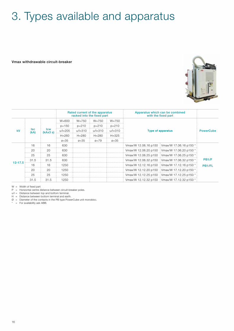
Vmaxwithdrawablecircuit-breaker
W = Width of fixed partP = Horizontal centre distance between circuit-breaker poles.u/l = Distance between top and bottom terminal.H = Distance between bottom terminal and earth.Ø = Diameter of the contacts in the PB type PowerCube unit monobloc.* = For availability ask ABB.
Ratedcurrentoftheapparatusrackedintothefixedpart
Apparatuswhichcanbecombinedwiththefixedpart
kV Isc(kA)
Icw(kAx3s)
W=600 W=750 W=750 W=750
Type of apparatus PowerCube
p=150 p=210 p=210 p=210
u/l=205 u/l=310 u/l=310 u/l=310
H=260 H=280 H=280 H=325
ø=35 ø=35 ø=79 ø=35
12-17.5
16 16 630 Vmax/W 12.06.16 p150 Vmax/W 17.06.16 p150 *
PB1/F
PB1/FL
20 20 630 Vmax/W 12.06.20 p150 Vmax/W 17.06.20 p150 *
25 25 630 Vmax/W 12.06.25 p150 Vmax/W 17.06.25 p150 *
31.5 31.5 630 Vmax/W 12.06.32 p150 Vmax/W 17.06.32 p150 *
16 16 1250 Vmax/W 12.12.16 p150 Vmax/W 17.12.16 p150 *
20 20 1250 Vmax/W 12.12.20 p150 Vmax/W 17.12.20 p150 *
25 25 1250 Vmax/W 12.12.25 p150 Vmax/W 17.12.25 p150 *
31.5 31.5 1250 Vmax/W 12.12.32 p150 Vmax/W 17.12.32 p150 *
3. Types available and apparatus
17
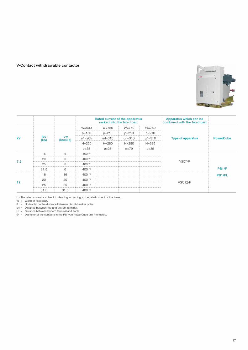
V-Contactwithdrawablecontactor
(1) The rated current is subject to derating according to the rated current of the fuses.W = Width of fixed part.P = Horizontal centre distance between circuit-breaker poles.u/l = Distance between top and bottom terminal.H = Distance between bottom terminal and earth.Ø = Diameter of the contacts in the PB type PowerCube unit monobloc.
Ratedcurrentoftheapparatusrackedintothefixedpart
Apparatuswhichcanbecombinedwiththefixedpart
kV Isc(kA)
Icw(kAx3s)
W=600 W=750 W=750 W=750
Type of apparatus PowerCube
p=150 p=210 p=210 p=210
u/l=205 u/l=310 u/l=310 u/l=310
H=260 H=280 H=280 H=325
ø=35 ø=35 ø=79 ø=35
7.2
16 6 400 (1)
VSC7/P
PB1/F
PB1/FL
20 6 400 (1)
25 6 400 (1)
31.5 6 400 (1)
12
16 16 400 (1)
VSC12/P20 20 400 (1)
25 25 400 (1)
31.5 31.5 400 (1)
18
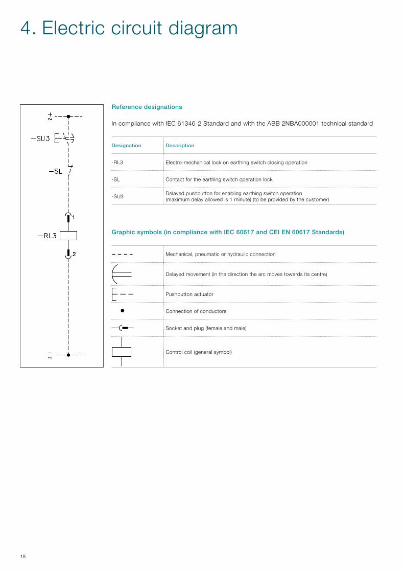
Graphicsymbols(incompliancewithIEC60617andCEIEN60617Standards)
Mechanical, pneumatic or hydraulic connection
Delayed movement (in the direction the arc moves towards its centre)
Pushbutton actuator
Connection of conductors
Socket and plug (female and male)
Control coil (general symbol)
4. Electric circuit diagram
Referencedesignations
In compliance with IEC 61346-2 Standard and with the ABB 2NBA000001 technical standard
Designation Description
-RL3 Electro-mechanical lock on earthing switch closing operation
-SL Contact for the earthing switch operation lock
-SU3Delayed pushbutton for enabling earthing switch operation (maximum delay allowed is 1 minute) (to be provided by the customer)

19

ABBS.p.A.PowerProductsDivisionUnitàOperativaSace-MVVia Friuli, 4I-24044 DalmineTel.: +39 035 6952 111Fax: +39 035 6952 874E-mail: [email protected]
ABBAGCalorEmagMediumVoltageProductsOberhausener Strasse 33 Petzower Strasse 8 D-40472 Ratingen D-14542 Glindow Phone: +49(0)2102/12-1230, Fax: +49(0)2102/12-1916 E-mail: [email protected]
www.abb.com
Contact us
The data and illustrations are not binding. We reserve the right to make changes without notice in the course of technical development of the product.
© Copyright 2012 ABB. All rights reserved.
1VC
P00
0253
- R
ev. B
, en
- T
echn
ical
Cat
alog
ue -
201
2.01
(P
ower
Cub
e P
B/F
) gs