POWER POINT PRESENTATION ON ELECTRICAL … - II PPT_0.pdf · •Group 1 :zero phase displacement...
138
POWER POINT PRESENTATION ON ELECTRICAL MACHINES - II 2016 - 2017 II B. Tech II semester (JNTUH-R15) Mr. K DEVENDER REDDY, Assistant Professor ELECTRICAL AND ELECTRONICS ENGINEERING INSTITUTE OF AERONAUTICAL ENGINEERING DUNDIGAL, HYDERABAD - 500 043
Transcript of POWER POINT PRESENTATION ON ELECTRICAL … - II PPT_0.pdf · •Group 1 :zero phase displacement...
POWER POINT PRESENTATION
ON
ELECTRICAL MACHINES - II
2016 - 2017
II B. Tech II semester (JNTUH-R15)
Mr. K DEVENDER REDDY, Assistant Professor
ELECTRICAL AND ELECTRONICS ENGINEERING
INSTITUTE OF AERONAUTICAL ENGINEERING
DUNDIGAL, HYDERABAD - 500 043

UNIT -I Single-Phase Transformers

Single-Phase Transformers
Objectives:
• Discuss the different types of transformers.
• List transformer symbols and formulas.
• Discuss polarity markings.
Single-Phase Transformers
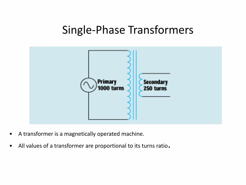
• A transformer is a magnetically operated machine.
• All values of a transformer are proportional to its turns ratio.

Single-Phase Transformers
• The primary winding is connected to the incoming power supply. • The secondary winding is connected to the driven load.

Single-Phase Transformers
• This is an isolation transformer. The secondary winding is physically and electrically isolated from the primary winding.

Single-Phase Transformers
• The two windings of an isolation transformer are linked together by the magnetic field.

Single-Phase Transformers
• The isolation transformer greatly reduces voltage spikes.

Single-Phase Transformers
• Basic construction of an isolation transformer.
Single-Phase Transformers
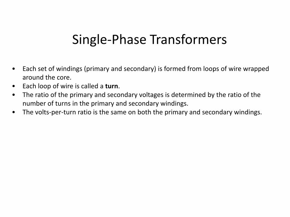
• Each set of windings (primary and secondary) is formed from loops of wire wrapped around the core.
• Each loop of wire is called a turn. • The ratio of the primary and secondary voltages is determined by the ratio of the
number of turns in the primary and secondary windings. • The volts-per-turn ratio is the same on both the primary and secondary windings.

Single-Phase Transformers
Transformer Symbols
NP = number of turns in the primary NS = number of turns in the secondary EP = voltage of the primary ES = voltage of the secondary IP = current in the primary IS = current in the secondary

Single-Phase Transformers
Transformer Formulas
EP / ES = NP / NS
EP x NS = ES x NP
EP x IP = ES x IS
NP x IP = NS x IS
Single-Phase Transformers
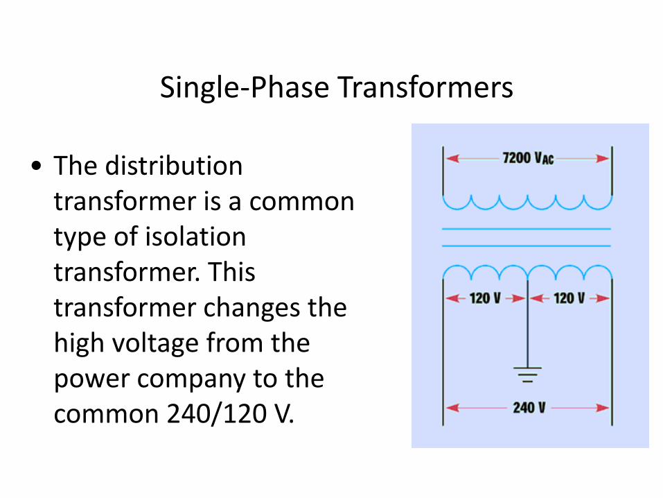
• The distribution transformer is a common type of isolation transformer. This transformer changes the high voltage from the power company to the common 240/120 V.
• The control transformer is another common type of isolation transformer. This transformer reduces high voltage to the value needed by control circuits.
Single-Phase Transformers

Single-Phase Transformers
• Polarity dots are placed on transformer schematics to indicate points that have the same polarity at the same time.

Single-Phase Transformers
Review:
1. All values of voltage, current, and impedance in a transformer are proportional to the turns ratio.
2. The primary winding of a transformer is connected to the source voltage.
3. The secondary winding is connected to the load.

Single-Phase Transformers
Review:
4. An isolation transformer has its primary and secondary voltage electrically and mechanically separated.
5. Isolation transformers help filter voltage and current spikes.
6. Polarity dots are often added to schematic diagrams to indicate transformer polarity.

Transformer Regulation
• Loading changes the output voltage of a transformer.
Definition of % Regulation
100*|V|
|V||V|
load
loadloadno
Vno-load =RMS voltage across the load terminals without load V load = RMS voltage across the load terminals with a specified load
1212
1
011
02
'2
0'21
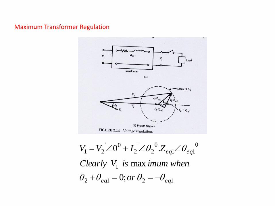
;0
max
.0
eqeq
eqeq
or
whenimumisVClearly
ZIVV
Maximum Transformer Regulation

Transformer 20
Transformer Losses and Efficiency •Transformer Losses
•Core/Iron Loss =V12 / Rc1
•Copper Loss = I12 R1+ I2
2 R2
Definition of % efficiency
100*222
222
CosIVLosses
CosIV
100*/ 2222
221
211
21
222
CosIVRIRIRV
CosIV
c
2Cos = load power factor
100*/ 2222
221
21
222
CosIVRIRV
CosIV
eqc

Transformer 21
Maximum Transformer Efficiency
The efficiency varies as with respect to 2 independent quantities namely, current and power factor
•Thus at any particular power factor, the efficiency is maximum if core loss = copper loss .This can be obtained by differentiating the expression of efficiency with respect to I2 assuming power factor, and all the voltages constant. •At any particular I2 maximum efficiency happens at unity power factor. This can be obtained by differentiating the expression of efficiency with respect to power factor, and assuming I2 and all the voltages constant. •Maximum efficiency happens when both these conditions are satisfied.

Transformer 22
100
0
% full load current
pf=1
pf= 0.8
pf= 0.6
At this load current core loss = copper loss
Maximum efficiency point

Transformer 23
Transformer Equivalent circuit (1)
I1 I2
INL
E1 E2

Transformer 24
Transformer Equivalent circuit (2)
I1
I2
INL

Transformer 25
Transformer Equivalent circuit (3)
I1 I2
INL

Transformer 26
Transformer Equivalent circuit (4)
I2' INL
I1

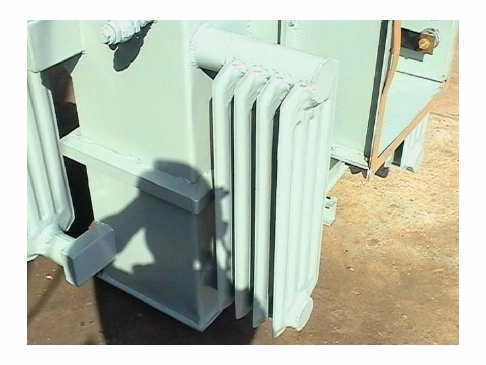
PARTS OF TRANSFORMER
• MAIN TANK • RADIATORS • CONSERVATOR • EXPLOSION VENT • LIFTING LUGS • AIR RELEASE PLUG • OIL LEVEL INDICATOR • TAP CHANGER • WHEELS • HV/LV BUSHINGS • FILTER VALVES • OIL FILLING PLUG • DRAIN PLUG • CABLE BOX


UNIT 2 TESTING OF TRANSFORMERS

TESTING OF TRANSFORMER
• Testing of single phase Transformers OC Test SC test Sumpner’s Test or Back to Back Test
Transformer 40
Open circuit Test
•It is used to determine Lm1 (Xm1)and Rc1
•Usually performed on the low voltage side
•The test is performed at rated voltage and frequency under no load • This test gives the values of core losses in a transformer


Woc= Core loss of the transformer
From the data
Cosø= Woc/(Voc*Ioc)
Iw=IocCosø
Ių = Ioc Sinø
Rcl=Voc/Iw
Xml=Voc/I ų

Transformer 43
Short circuit Test
•It is used to determine Llp (Xeq) and Rp(Req)
•Usually performed on the high voltage side
•This test is performed at reduced voltage and rated frequency with the output of the low voltage winding short circuited such that rated current flows on the high voltage side. • This test gives copper loss of the transformer.


Wsc= copper losses of the
transformer.
Zeq=Vsc/Isc
Req=Wsc/Isc²
Xeq=sqrt(Zeq²-Req²)

Efficiency of the transformer
Ŋ = output Power/ Input power
Ŋ = XVICosø/(XVICosø + Pc +x²Pcu)

Sumpner’s test or back to back test on set of transformers
From this test Losses and Efficiency of the two transformers can be determined

Transformer 48
Parallel operation of transformers
Wrong connections give circulating between the windings that can destroy transformers.

To connect the transformers in parallel the following
conditions must be satisfied
i. Transformers must be of same rating.
ii. Transformers should have the same phase sequence.
iii. voltage ratio must be same.
iv. Per unit impedence of the transformers must be same.
UNIT-III
AUTO AND POLY PHASE TRANSFORMERS

Transformer 51
Autotransformer
•Primary and secondary on the same winding. Therefore there is no
galvanic isolation.

Transformer 52
Features of Autotransformer
Lower leakage
Lower losses
Lower magnetizing current
Increase kVA rating
No galvanic Isolation

Transformer 53
Review of balanced three phase circuits
• Two possible configurations: Star (Y) and delta ()
•Star has neutral, delta does not

Transformer 54
Star (Y) connection
•Line current is same as phase current
•Line-Line voltage is 3 phase-neutral voltage
•Power is given by 3 VL-LI Lcos or 3VphIphcos
Transformer 55
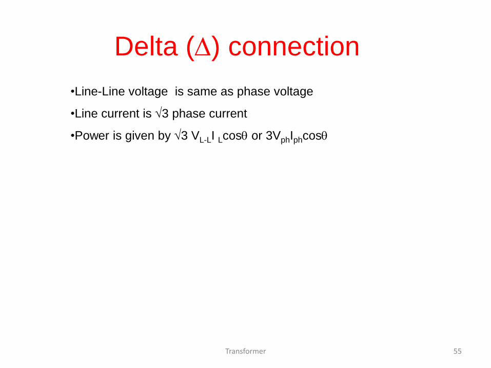
Delta () connection
•Line-Line voltage is same as phase voltage
•Line current is 3 phase current
•Power is given by 3 VL-LI Lcos or 3VphIphcos

Transformer 56
Typical three phase transformer
connections

Transformer 57
Other possible three phase
transformer Connections
• Y- zigzag
•- zigzag
•Open Delta or V
•Scott or T

Transformer 58
How are three phase transformers
made?
• Either by having three single phase transformers connected as three
phase banks.
•Or by having coils mounted on a single core with multiple limbs
•The bank configuration is better from repair perspective, whereas the
single three phase unit will cost less ,occupy less space, weighs less and
is more efficient

Transformer 59
Phase-shift between line-line voltages
in transformers

Transformer 60
Vector grouping of transformers
• Depending upon the phase shift of line-neutral voltages between primary
and secondary; transformers are grouped. This is done for ease of paralleling.
Usually transformers between two different groups should not be paralleled.
•Group 1 :zero phase displacement (Yy0, Dd0,Dz0)
•Group 2 :1800 phase displacement (Yy6, Dd6,Dz6)
•Group 3 : 300 lag phase displacement (Dy1, Yd1,Yz1)
•Group 4 : 300 lead phase displacement (Dy11, Yd11,Yz11)
(Y=Y; D= ; z=zigzag)

Transformer 61
Calculation involving 3-ph transformers

Transformer 62
An example involving 3-ph transformers

Transformer 63
Open –delta or V connection

Transformer 64
Open –delta or V connection
Power from winding ‘ab’
is Pab=VabIacos(300+)
Power from winding ‘bc’
is Pcb=VcbIccos(300-)
Therefore total power is
=2VL-LILcos300cos or 57.7% of total power from 3
phases
Transformer 65
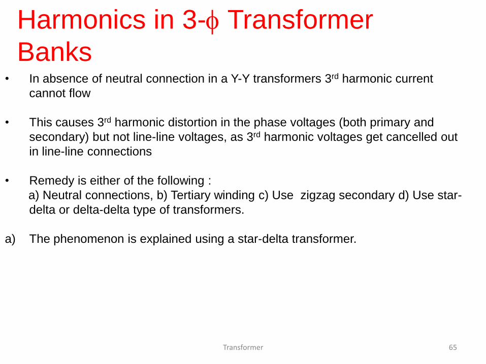
Harmonics in 3- Transformer
Banks
• In absence of neutral connection in a Y-Y transformers 3rd harmonic current
cannot flow
• This causes 3rd harmonic distortion in the phase voltages (both primary and
secondary) but not line-line voltages, as 3rd harmonic voltages get cancelled out
in line-line connections
• Remedy is either of the following :
a) Neutral connections, b) Tertiary winding c) Use zigzag secondary d) Use star-
delta or delta-delta type of transformers.
a) The phenomenon is explained using a star-delta transformer.

Transformer 66
Harmonics in 3- Transformer
Banks(2)

Transformer 67
Harmonics in 3- Transformer
Banks(3)

Three-Phase Transformers
Sine wave distortion caused by harmonics.

UNIT-4
POLY-PHASE INDUCTION MOTORS

Introduction • Three-phase induction motors are the most common and
frequently encountered machines in industry
– simple design, rugged, low-price, easy maintenance
– wide range of power ratings: fractional horsepower to 10 MW
– run essentially as constant speed from no-load to full load
– Its speed depends on the frequency of the power source
• not easy to have variable speed control
• requires a variable-frequency power-electronic drive for optimal speed control

Construction • An induction motor has two main parts
– a stationary stator
• consisting of a steel frame that supports a hollow, cylindrical core
• core, constructed from stacked laminations (why?), having a number of evenly spaced slots, providing the space for the stator winding
Stator of IM

Construction – a revolving rotor
• composed of punched laminations, stacked to create a series of rotor slots, providing space for the rotor winding
• one of two types of rotor windings
• conventional 3-phase windings made of insulated wire (wound-rotor) » similar to the winding on the stator
• aluminum bus bars shorted together at the ends by two aluminum rings, forming a squirrel-cage shaped circuit (squirrel-cage)
• Two basic design types depending on the rotor design – squirrel-cage: conducting bars laid into slots and shorted at both
ends by shorting rings.
– wound-rotor: complete set of three-phase windings exactly as the stator. Usually Y-connected, the ends of the three rotor wires are connected to 3 slip rings on the rotor shaft. In this way, the rotor circuit is accessible.
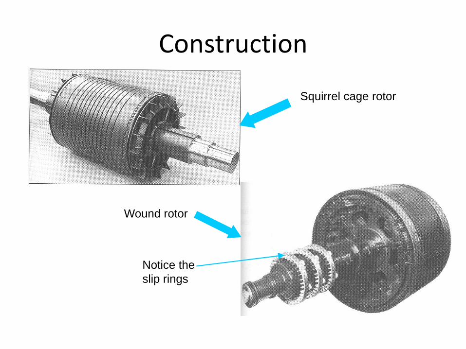
Construction
Squirrel cage rotor
Wound rotor
Notice the
slip rings

Construction
Cutaway in a
typical wound-
rotor IM.
Notice the
brushes and
the slip rings
Brushe
s
Slip rings

Rotating Magnetic Field • Balanced three phase windings, i.e.
mechanically displaced 120 degrees form each other, fed by balanced three phase source
• A rotating magnetic field with constant magnitude is produced, rotating with a speed
Where fe is the supply frequency and
P is the no. of poles and nsync is called the synchronous speed in rpm (revolutions per minute)
120 esync
fn rpm
P

Synchronous speed
P 50 Hz 60 Hz
2 3000 3600
4 1500 1800
6 1000 1200
8 750 900
10 600 720
12 500 600

Rotating Magnetic Field

Rotating Magnetic Field

Rotating Magnetic Field ( ) ( ) ( ) ( )net a b cB t B t B t B t
sin( ) 0 sin( 120 ) 120 sin( 240) 240M M MB t B t B t
ˆsin( )
3ˆ ˆ[0.5 sin( 120 )] [ sin( 120 )]
2
3ˆ ˆ[0.5 sin( 240 )] [ sin( 240 )]
2
M
M M
M M
B t
B t B t
B t B t
x
x y
x y

Rotating Magnetic Field 1 3 1 3
ˆ( ) [ sin( ) sin( ) cos( ) sin( ) cos( )]4 4 4 4
3 3 3 3ˆ[ sin( ) cos( ) sin( ) cos( )]
4 4 4 4
net M M M M M
M M M M
B t B t B t B t B t B t
B t B t B t B t
x
y
ˆ ˆ[1.5 sin( )] [1.5 cos( )]M MB t B t x y

Rotating Magnetic Field

Principle of operation • This rotating magnetic field cuts the rotor windings and
produces an induced voltage in the rotor windings
• Due to the fact that the rotor windings are short circuited, for both squirrel cage and wound-rotor, and induced current flows in the rotor windings
• The rotor current produces another magnetic field
• A torque is produced as a result of the interaction of those two magnetic fields
Where ind is the induced torque and BR and BS are the magnetic flux densities of the rotor and the stator respectively
ind R skB B
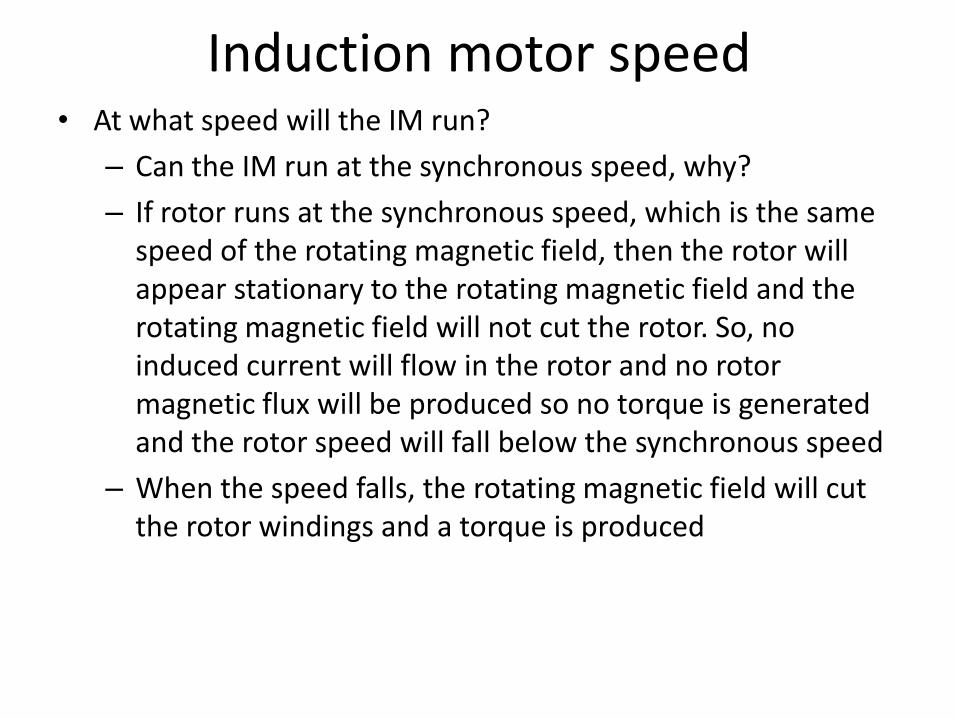
Induction motor speed • At what speed will the IM run?
– Can the IM run at the synchronous speed, why?
– If rotor runs at the synchronous speed, which is the same speed of the rotating magnetic field, then the rotor will appear stationary to the rotating magnetic field and the rotating magnetic field will not cut the rotor. So, no induced current will flow in the rotor and no rotor magnetic flux will be produced so no torque is generated and the rotor speed will fall below the synchronous speed
– When the speed falls, the rotating magnetic field will cut the rotor windings and a torque is produced

Induction motor speed
• So, the IM will always run at a speed lower than the synchronous speed
• The difference between the motor speed and the synchronous speed is called the Slip
Where nslip= slip speed
nsync= speed of the magnetic field
nm = mechanical shaft speed of the motor
slip sync mn n n
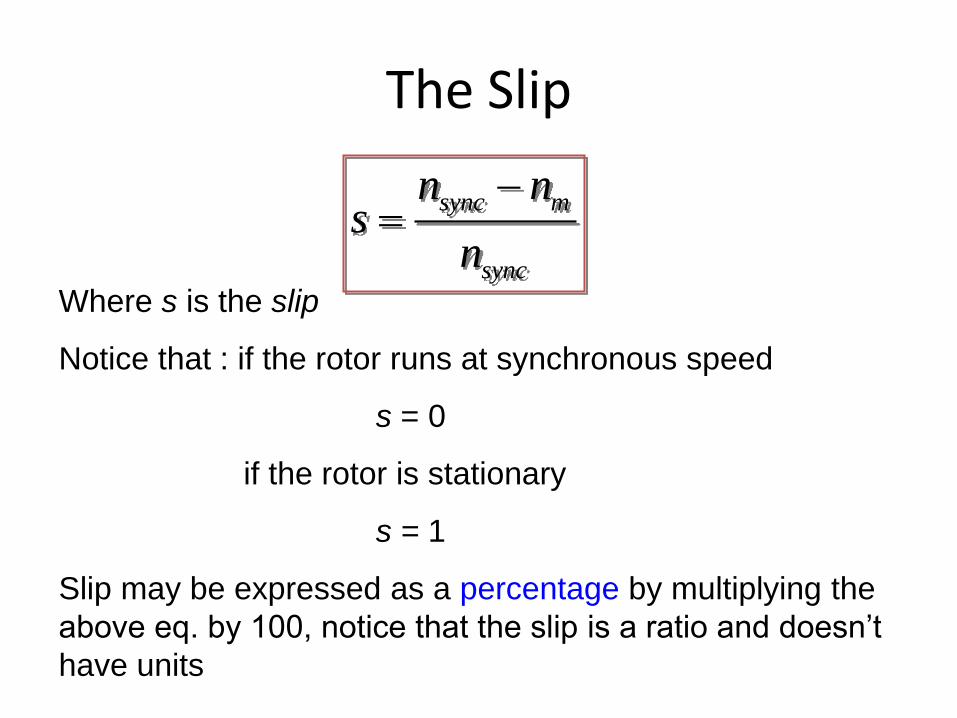
The Slip
sync m
sync
n ns
n
Where s is the slip
Notice that : if the rotor runs at synchronous speed
s = 0
if the rotor is stationary
s = 1
Slip may be expressed as a percentage by multiplying the
above eq. by 100, notice that the slip is a ratio and doesn’t
have units

Frequency • The frequency of the voltage induced in the
rotor is given by
Where fr = the rotor frequency (Hz)
P = number of stator poles
n = slip speed (rpm)
120r
P nf
( )
120
120
s mr
se
P n nf
P snsf

Frequency
• What would be the frequency of the rotor’s induced voltage at any speed nm?
• When the rotor is blocked (s=1) , the frequency of the induced voltage is equal to the supply frequency
• On the other hand, if the rotor runs at synchronous speed (s = 0), the frequency will be zero
r ef s f

Torque
• While the input to the induction motor is electrical power, its output is mechanical power and for that we should know some terms and quantities related to mechanical power
• Any mechanical load applied to the motor shaft will introduce a Torque on the motor shaft. This torque is related to the motor output power and the rotor speed
and
.outload
m
PN m
2
/60
mm
nrad s

Horse power
• Another unit used to measure mechanical power is the horse power
• It is used to refer to the mechanical output power of the motor
• Since we, as an electrical engineers, deal with watts as a unit to measure electrical power, there is a relation between horse power and watts 746hp watts

Equivalent Circuit • The induction motor is similar to the transformer
with the exception that its secondary windings are free to rotate
As we noticed in the transformer, it is easier if we can combine these two circuits in one circuit but there are some difficulties

Equivalent Circuit
• When the rotor is locked (or blocked), i.e. s =1, the largest voltage and rotor frequency are induced in the rotor, Why?
• On the other side, if the rotor rotates at synchronous speed, i.e. s = 0, the induced voltage and frequency in the rotor will be equal to zero, Why?
Where ER0 is the largest value of the rotor’s induced voltage obtained at s = 1(loacked rotor)
0R RE sE

Equivalent Circuit
• The same is true for the frequency, i.e.
• It is known that
• So, as the frequency of the induced voltage in the rotor changes, the reactance of the rotor circuit also changes
Where Xr0 is the rotor reactance
at the supply frequency
(at blocked rotor)
r ef s f
2X L f L
0
2
2
r r r r r
e r
r
X L f L
sf L
sX
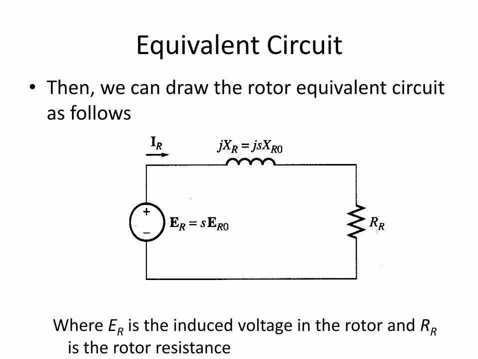
Equivalent Circuit
• Then, we can draw the rotor equivalent circuit as follows
Where ER is the induced voltage in the rotor and RR is the rotor resistance

Equivalent Circuit • Now we can calculate the rotor current as
• Dividing both the numerator and denominator by s so nothing changes we get
Where ER0 is the induced voltage and XR0 is the rotor reactance at blocked rotor condition (s = 1)
0
0
( )
( )
RR
R R
R
R R
EI
R jX
sE
R jsX
0
0( )
RR
RR
EI
RjX
s

Equivalent Circuit
• Now we can have the rotor equivalent circuit

Equivalent Circuit
• Now as we managed to solve the induced voltage and different frequency problems, we can combine the stator and rotor circuits in one equivalent circuit
Where 2
2 0
2
2
2
1 0
eff R
eff R
R
eff
eff R
Seff
R
X a X
R a R
II
a
E a E
Na
N

Power losses in Induction machines
• Copper losses
– Copper loss in the stator (PSCL) = I12R1
– Copper loss in the rotor (PRCL) = I22R2
• Core loss (Pcore)
• Mechanical power loss due to friction and windage
• How this power flow in the motor?

Power flow in induction motor

Power relations
3 cos 3 cosin L L ph phP V I V I
2
1 13SCLP I R
( )AG in SCL coreP P P P
2
2 23RCLP I R
conv AG RCLP P P
( )out conv f w strayP P P P conv
ind
m
P

Equivalent Circuit
• We can rearrange the equivalent circuit as follows
Actual rotor
resistance
Resistance
equivalent to
mechanical load

Power relations
3 cos 3 cosin L L ph phP V I V I
2
1 13SCLP I R
( )AG in SCL coreP P P P
2
2 23RCLP I R
conv AG RCLP P P
( )out conv f w strayP P P P
conv RCLP P 2 223
RI
s
2 22
(1 )3
R sI
s
RCLP
s
(1 )RCLP s
s
(1 )conv AGP s P
convind
m
P
(1 )
(1 )
AG
s
s P
s

Power relations
AGP
RCLP
convP
1
s
1-
s
: :
1 : : 1-
AG RCL convP P P
s s
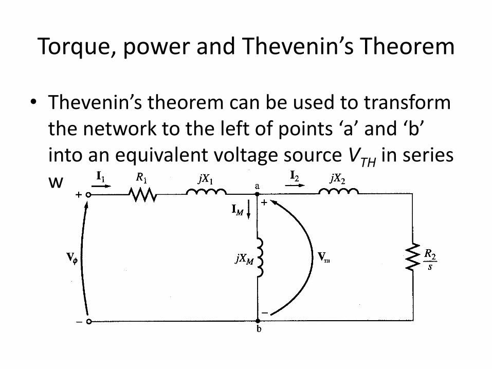
Torque, power and Thevenin’s Theorem
• Thevenin’s theorem can be used to transform the network to the left of points ‘a’ and ‘b’ into an equivalent voltage source VTH in series with equivalent impedance RTH+jXTH

Torque, power and Thevenin’s Theorem
1 1( )
MTH
M
jXV V
R j X X
1 1( ) //TH TH MR jX R jX jX
2 2
1 1
| | | |( )
MTH
M
XV V
R X X

Torque, power and Thevenin’s Theorem
• Since XM>>X1 and XM>>R1
• Because XM>>X1 and XM+X1>>R1
1
MTH
M
XV V
X X
2
1
1
1
MTH
M
TH
XR R
X X
X X

Torque, power and Thevenin’s Theorem
Then the power converted to mechanical (Pconv)
22
222( )
TH TH
T
TH TH
V VI
Z RR X X
s
2 22
(1 )3conv
R sP I
s
And the internal mechanical torque (Tconv)
convind
m
P
(1 )
conv
s
P
s
2 223
AG
s s
RI
Ps

Torque, power and Thevenin’s Theorem 2
2
2
222
3
( )
THind
s
TH TH
V R
sRR X X
s
2 2
2
222
31
( )
TH
ind
s
TH TH
RV
s
RR X X
s

Torque-speed characteristics
Typical torque-speed characteristics of induction motor

Comments 1. The induced torque is zero at synchronous
speed. Discussed earlier.
2. The curve is nearly linear between no-load and full load. In this range, the rotor resistance is much greater than the reactance, so the rotor current, torque increase linearly with the slip.
3. There is a maximum possible torque that can’t be exceeded. This torque is called pullout torque and is 2 to 3 times the rated full-load torque.

Comments
4. The starting torque of the motor is slightly higher than its full-load torque, so the motor will start carrying any load it can supply at full load.
5. The torque of the motor for a given slip varies as the square of the applied voltage.
6. If the rotor is driven faster than synchronous speed it will run as a generator, converting mechanical power to electric power.

Complete Speed-torque c/c

Maximum torque
• Maximum torque occurs when the power transferred to R2/s is maximum.
• This condition occurs when R2/s equals the magnitude of the impedance RTH + j (XTH + X2)
max
2 222( )TH TH
T
RR X X
s
max
2
2 2
2( )T
TH TH
Rs
R X X

Maximum torque
• The corresponding maximum torque of an induction motor equals
The slip at maximum torque is directly proportional to the rotor resistance R2
The maximum torque is independent of R2
2
max2 2
2
31
2 ( )
TH
s TH TH TH
V
R R X X

Maximum torque
• Rotor resistance can be increased by inserting external resistance in the rotor of a wound-rotor induction motor.
The
value of the maximum torque remains unaffected
but
the speed at which it occurs can be controlled.

Maximum torque
Effect of rotor resistance on torque-speed
characteristic
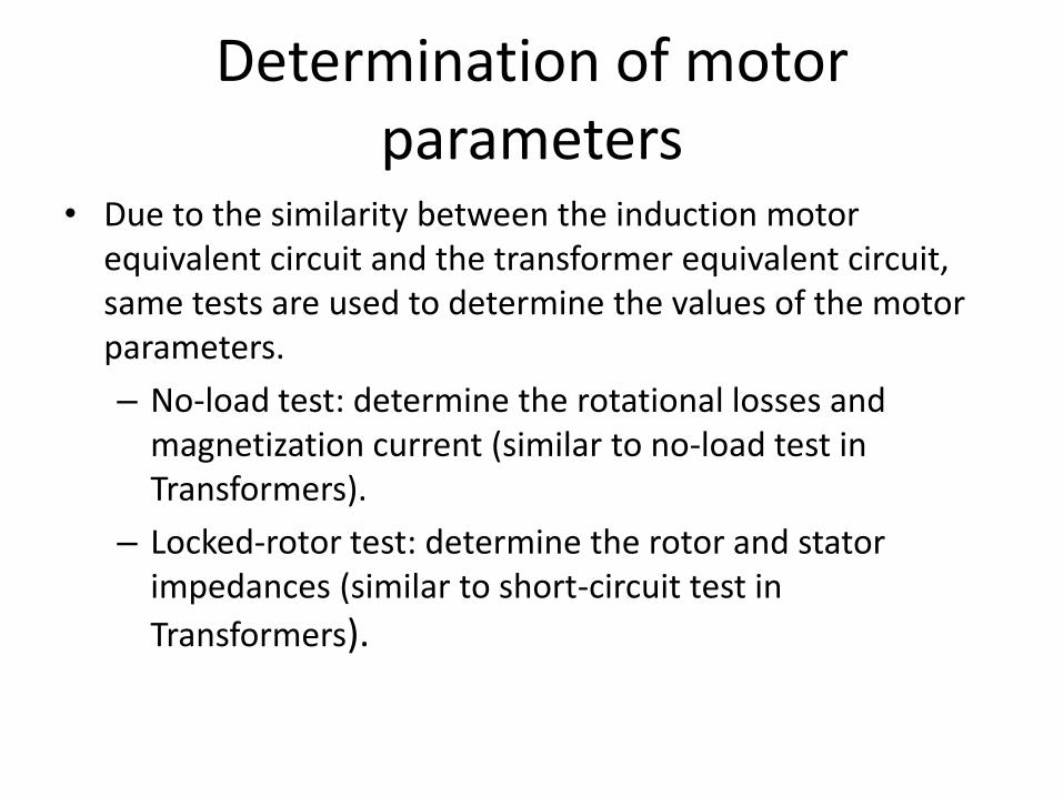
Determination of motor parameters
• Due to the similarity between the induction motor equivalent circuit and the transformer equivalent circuit, same tests are used to determine the values of the motor parameters.
– No-load test: determine the rotational losses and magnetization current (similar to no-load test in Transformers).
– Locked-rotor test: determine the rotor and stator impedances (similar to short-circuit test in
Transformers).

UNIT-5
CIRCLE DIAGRAM AND SPEED CONTROL OF INDUCTION MOTORS

No-load test
1. The motor is allowed to spin freely
2. The only load on the motor is the friction and windage losses, so all Pconv is consumed by mechanical losses
3. The slip is very small

No-load test
4. At this small slip
The equivalent circuit reduces to…
2 22 2
(1 ) R (1 ) &
R s sR X
s s
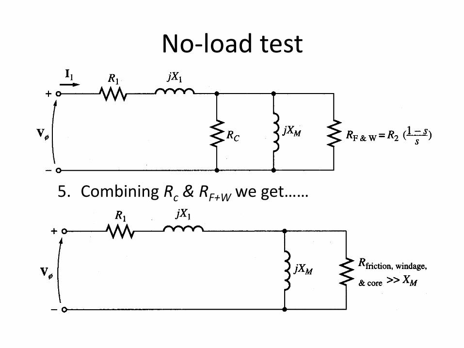
No-load test
5. Combining Rc & RF+W we get……

No-load test
6. At the no-load conditions, the input power measured by meters must equal the losses in the motor.
7. The PRCL is negligible because I2 is extremely small because R2(1-s)/s is very large.
8. The input power equals
Where
&
2
1 13
in SCL core F W
rot
P P P P
I R P
&rot core F WP P P

No-load test
9. The equivalent input impedance is thus approximately
If X1 can be found, in some other fashion, the magnetizing impedance XM will be known
1
1,
eq M
nl
VZ X X
I
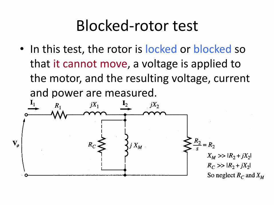
Blocked-rotor test
• In this test, the rotor is locked or blocked so that it cannot move, a voltage is applied to the motor, and the resulting voltage, current and power are measured.

Blocked-rotor test
• The AC voltage applied to the stator is adjusted so that the current flow is approximately full-load value.
• The locked-rotor power factor can be found as
• The magnitude of the total impedance
cos3
in
l l
PPF
V I
LR
VZ
I

Blocked-rotor test
Where X’1 and X’2 are the stator and rotor reactances at the test frequency respectively
'
cos sin
LR LR LR
LR LR
Z R jX
Z j Z
1 2
' ' '
1 2
LR
LR
R R R
X X X
2 1LRR R R
'
1 2rated
LR LR
test
fX X X X
f

Blocked-rotor test
X1 and X2 as function of XLR
Rotor Design X1 X2
Wound rotor 0.5 XLR 0.5 XLR
Design A 0.5 XLR 0.5 XLR
Design B 0.4 XLR 0.6 XLR
Design C 0.3 XLR 0.7 XLR
Design D 0.5 XLR 0.5 XLR

Speed Control of Induction Motor
1- Variable Terminal Voltage Control
2- Variable Frequency Control
3- Rotor Resistance Control
4- Injecting Voltage in Rotor Circuit

1- Variable Terminal Voltage Control
ms
m
LT
T
V decreasing
variable frequency control variable terminal voltage control
Wide speed range Low speed range
Lower & higher rated speed Lower rated speed
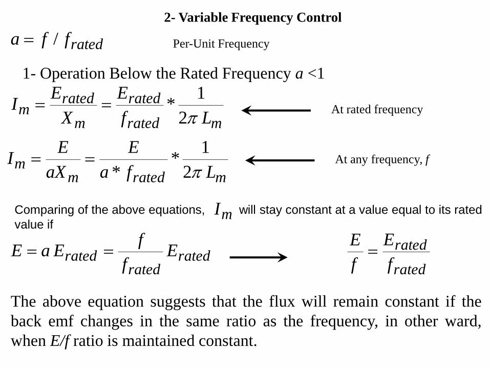
2- Variable Frequency Control
ratedffa / Per-Unit Frequency
1- Operation Below the Rated Frequency a <1
mrated
rated
m
ratedm
Lf
E
X
EI
2
1* At rated frequency
mratedmm
Lfa
E
aX
EI
2
1*
* At any frequency, f
Comparing of the above equations, will stay constant at a value equal to its rated
value if mI
ratedrated
rated Ef
fEaE
rated
rated
f
E
f
E
The above equation suggests that the flux will remain constant if the
back emf changes in the same ratio as the frequency, in other ward,
when E/f ratio is maintained constant.

The rotor current at any frequency f can be obtained from the following equation:
22
22
rr
rated
rr
ratedr
Xas
R
E
Xas
R
aEI
ms
sl
ms
mms
aa
as
ms
m Angular Speed at frequency f
Synchronous Speed at rated frequency ratedf
2
2
22 /*33
rr
rrated
ms
rr
msX
as
R
asRE
s
RI
aT
Torque at frequency f
At a given f and E
r
rm
Xa
Rs
mmssl a ms
sl
ms
mmsasa
r
rated
ms X
ET
2
max2
3

slrms
rated ntconstaasR
ET
23
rr X
as
R
(6-51)
2
2
22 /*33
rr
rrated
ms
rr
msX
as
R
asRE
s
RI
aT

ms
m
msa
T
Braking Motoring

sX
mX
sR
mIsI
E
rX sRr /
rI
V
V/f Control
sXsR
sI
E
rX sRr /
rI
V
mI
mX

V/f Control
22
22
/
/*33
rsrs
rrated
ms
rr
ms XXsRR
sRV
s
RIT
22
2
max2
3
rsss
rated
ms XXRR
VT
At rated frequency
22
2
//
/*3
rsrs
rrated
ms XXasRaR
asRVT
22
2
max//2
3
rsss
rated
ms XXaRaR
VT
At any frequency, f, 1a

V/f Control
ms
m
msa
T

Operation above the rated frequency a>1
The terminal voltage has to be constant = Rated Volatge=
ntconstaV
ratedV
awhenFlux
22
2
max2
3
rsss
rated
ms XXaRR
V
aT
At any frequency, f, 1a
222
2
/
/*3
rsrs
rrated
ms XXasRR
asRVT
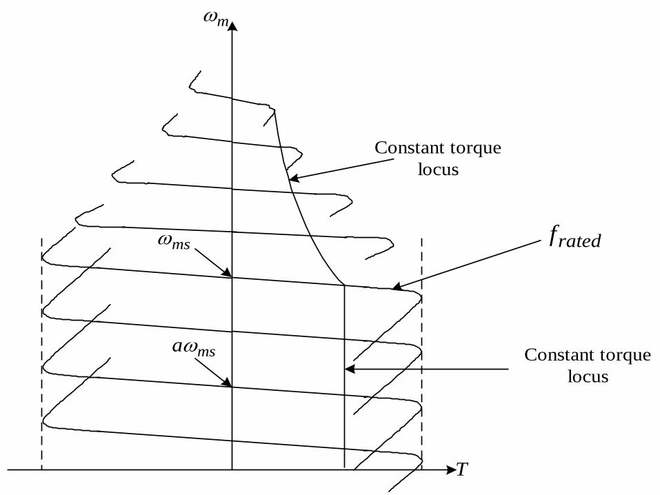
ms
m
msa
T
Constant torque
locus
Constant torque
locus
ratedf

THANK U….