Post Hole Digger - Daken · Post Hole Diggers - Owners Manual & Parts List - 6 - Operation Before...
13
Post Hole Diggers - Owners Manual & Parts List - 1 - POST HOLE DIGGERS Series 503, Series 753 Series 253 “Little Rippa 25 H.P.” Owner’s Manual and Parts List NSW Office - Head Office QLD Office VIC Office 30 Salisbury Rd., Hornsby 2077 89 Colebard St West, 2 Price St., PO Box 70 PO Box 70 Asquith 2077 Acacia Ridge, QLD, 4110 Oakleigh South Vic 3167 Telephone: (02) 9477 2599 Telephone: (07) 3274 5899 Telephone: (03) 9544 1188 Facsimile: (02) 9477 7027 Facsimile: (07) 3274 5952 Facsimile: (03) 9562 7889 Web Site: www.Daken.com.au Toll Free Number: 1800 636 451 Email:[email protected] Toll Free Fax: 1800 809 862 DAKEN PTY LTD ABN 53 004 476 484
Transcript of Post Hole Digger - Daken · Post Hole Diggers - Owners Manual & Parts List - 6 - Operation Before...

Post Hole Diggers - Owners Manual & Parts List - 1 -
POST HOLE DIGGERS
Series 503, Series 753 Series 253 “Little Rippa 25 H.P.”
Owner’s Manual and Parts List
NSW Office - Head Office QLD Office VIC Office 30 Salisbury Rd., Hornsby 2077 89 Colebard St West, 2 Price St., PO Box 70 PO Box 70 Asquith 2077 Acacia Ridge, QLD, 4110 Oakleigh South Vic 3167 Telephone: (02) 9477 2599 Telephone: (07) 3274 5899 Telephone: (03) 9544 1188 Facsimile: (02) 9477 7027 Facsimile: (07) 3274 5952 Facsimile: (03) 9562 7889
Web Site: www.Daken.com.au Toll Free Number: 1800 636 451
Email:[email protected] Toll Free Fax: 1800 809 862
DAKEN PTY LTD ABN 53 004 476 484

Post Hole Diggers - Owners Manual & Parts List - 2 -
POST HOLE DIGGERS Series 503, Series 753
Series 253 “Little Rippa 25 H.P.”
Owner’s Manual & Parts List
INDEX
Contents Page Safety Instructions 3
Safety Decals 4
Getting to Know Your Post Hole Digger 5
Assembly 5
Operating & Transportation of Post Hole Digger 6
Service & Maintenance 7
Spare Parts & Components List 7
Augers, Cutting Teeth and Pilot Bits 8
Procedure for installation of teeth 9
25 H.P. Gearbox 10
50 H.P. Gearbox 11
75 H.P. Gearbox 12
Warranty 13

Post Hole Diggers - Owners Manual & Parts List - 3 -
WARNING: Read the Owner’s Manual before using the Post Hole Digger.
����������� �����Your post hole digger operates with a rotating auger at high speeds - the following safety precautions should be observed at all times. Stand clear of equipment whilst in operation or in a raised position. Keep body and clothing clear of moving parts at all times. Do not operate damaged or faulty equipment. Ensure protective shields and covers are in place before use. Do not remove any guards or covers whilst the post hole digger is in operation. All safety guards should be inspected prior to use, to ensure maximum safety. Do not perform service or maintenance on this equipment whilst the PTO is engaged, or the tractor engine is on. This implement is NOT free standing when dismantled from tractor. Store in a secure manner to avoid injury. Take care when leaving the tractor. Ensure that the PTO is disengaged, the tractor parking brake is on, the tractor’s engine is off and the key removed. Do not allow passengers on the tractor or post hole digger when operating. Onlookers should maintain a safe minimum distance from the post hole digger when in use of 10 meters. Never touch the auger, gearbox, drive shaft, or output shaft, when the tractor engine is running. Turn the engine off first and disengage the PTO. If performing maintenance on the post hole digger whilst it is held on the tractor’s 3 point linkage, ensure that the post hole digger is properly supported by blocks or stands under the jib. Never force the digger into the ground with extra weights or levers, as this may result in gearbox or structural damage, which may result in injury to the operator.

Post Hole Diggers - Owners Manual & Parts List - 4 -
Post Hole Diggers Series 503, Series 753, Series 253
“Little Rippa 25 HP” Safety Decals

Post Hole Diggers - Owners Manual & Parts List - 5 -
General Information
Your Dakenag Post Hole Digger is supplied in eight separate components:
1. Main support beam (jib) 2. “A” Frame for the 3 point linkage attachment to your tractor 3. Gear Box 4. Auger 5. Drive shaft 6. Slip Clutch 7. Input shaft safety cover 8. Output shaft safety cover
Model PHD503 post hole digger is equipped with a 50 hp. gearbox, slip clutch & PTO drive shaft. Model PHD753 post hole digger is equipped with a 75hp. Gearbox, slip clutch & PTO drive shaft. Model 253 “Little Rippa” post hole digger is equipped with a 25 hp. gearbox, slip clutch & PTO drive shaft.
ASSEMBLY
1. Attach the main support beam (jib) to the top link of the 3 point linkage of the tractor. 2. Connect the “A” frame to the two lower link arms of the tractor. 3. Position and connect the top part of the “A” frame to the hole CLOSEST TO THE AUGER (i.e.
FARTHEST FROM THE TRACTOR). The series of holes control height & depth of auger 4. Test the hydraulic linkage of the tractor by raising and lowering the jib. 5. Position the jib at a convenient height and attach the gearbox (without the auger attached) to the
jib by aligning the holes and inserting the pin. A small amount of lubricating grease, and correct alignment, will enable the pin to be fitted without difficulty. NOTE: During this stage, the auger should remain unconnected to the gearbox.
6. Fit the Slip clutch to the input shaft of the gear box. Tighten bolts to the tension specified by
manufacturers’ specifications. Check the length of the drive shaft by separating the 2 sections of the telescopic drive shaft. Attach each section onto the tractor PTO output and gearbox.
Hold both sections in the middle - parallel and together. Lower the jib to maximum operating depth, and mark the overlap of the inner and outer tube of the drive shaft. Repeat the process to measure maximum lifting height. The drive shaft may, need to be cut to length if there is insufficient distance between the yokes when the drive shaft is fully closed. Similarly, the drive shaft cover may also need to be shortened, by cutting to the suitable length with a hacksaw. This operation will determine the correct length of the drive shaft before operation.
7. Connect the auger to the output shaft of the gearbox with bolts provided. Tighten nuts securely. Again, a small amount of lubricating grease will assist in fitting the bolts through the holes.
8. Connect the drive shaft to the gearbox and lock. Fit the other end to the tractor’s PTO output and
lock. In all cases, use a small amount of lubricating grease to protect the output spines. 9. Carefully raise and lower the linkage to be sure that the correct ground clearance can be
obtained. NOTE: The “A” frame must be set so that the boom does not raise itself unnecessarily high on the linkage, or else the drive shaft may become disconnected, the angle of the universal may be excessive resulting in damage to the drive shaft, or the drive shaft may come into contact with the A frame.

Post Hole Diggers - Owners Manual & Parts List - 6 -
Operation Before commencing to use the post hole digger, ensure that you have read and understood the safety instructions contained in this manual. In addition, follow the steps for “Initial Service”, as detailed in the service and maintenance guide below. Lower the gearbox and auger on the jib, with the PTO in a stationary position, over the point where the hole is to be dug. Ensure that the auger is completely vertical to the ground. Lower the jib until the auger comes into contact with the ground. Adjust the perpendicular of the auger by slowly reversing, or going forward, with the tractor. The digging depth of the auger is controlled by the series of holes on the jib. It may be necessary to remove grass, from the area to be dug, to avoid a build up of grass on the cutting teeth. Engage the PTO shaft with low engine revs. Slowly increase the revs, to no more than a fast idle. The post hole digger will dig most effectively if kept at low revs. Excessive revving is unnecessary and may cause damage to the post hole digger and cutting teeth. When raising the auger from the hole, the PTO revs should be reduced to a slow idle speed, to prevent excessive vibration and strain to the post hole digger. If the machine is not digging, raise the auger from the hole to check cutting teeth for obstructions. E.g. a build up of grass or tree roots. Teeth must be clear of all obstructions at all times to maintain digging operation. During the inspection and maintenance of the auger, ensure that you follow the safety instructions outlined in this manual.
Transporting the Post Hole Digger With the post hole digger in a raised position, disconnect the drive shaft from the Tractor PTO. Secure the drive shaft in a parallel position to the jib, by using the chain provided. In doing so, ensure that the yoke of the drive shaft, at the point that it connects to the gearbox, is at right angles (90 deg.) to the drive shaft. In this way, the drive shaft will locate directly under, and parallel to, the jib. Lower the jib carefully until the auger rests on the ground, Slowly reverse the tractor, with the linkage in the down position, until the linkage is fully lowered and the auger and jib are in a parallel position. Secure the auger to the jib. The post hole digger may then be transported.

Post Hole Diggers - Owners Manual & Parts List - 7 -
Servicing & Maintenance The gearbox is pre-filled with Shell Alvania EP(LF) grease 00 (or equivalent). The manufacturer states that this high quality oil has a working life of at least 250 hours of operation. Providing no leaks are detected, no additional oil should be required until the 250 hour service. All bearings in the gearbox are pre-lubricated for life. Where grease nipples are provided on the drive shaft, these should be lubricated regularly before use. Initial Service (prior to use). Ensure that all nuts, bolts and pins are fully tightened. Inspect gearbox and drive shaft, and lubricate if necessary. 100 hour Service (after every 100 hrs of use): Repeat “initial service”. Check level of oil in gearbox. Inspect drive shaft and auger for wear. 250 hour service (after every 250 hrs of use): Repeat “100 hour service” Replace gearbox oil with Shell Alvania EP(LF) Grease 00 (or equivalent) POST HOLE DIGGERS - SPARE PARTS & COMPONENTS LISTING DESCRIPTION QTY 25HP / 253 QTY 50HP / 503 QTY 75HP / 753 JIB WELD ASSEMBLY 1 PHD2501 1 PHD5701 1 PHD5701 A FRAME 1 PHD2503 1 PHD5703 1 PHD5703 LOWER LINKAGE PIN 1 DKB200 1 DKB215 1 DKB215 BUSH 2 DKB351 2 DKB351 2 DKB351 LINKAGE PIN 1 DKB75 N/A N/A LINKAGE PIN 1 DKB404 1 DKB404 LYNCH PIN, LARGE 3 DKB6 2 DKB6 2 DKB6 GEARBOX 1 DKB1666 1 DKB4666 1 DKB5666 PIVOT PIN, G/BOX FOR DKB1666
1 PHD2008 1 PHD5008 1 PHD5008
LYNCH PIN, SMALL 2 DKB4 3 DKB4 3 DKB4 SLIP CLUTCH 1 DKB4164 1 DKB4164 1 DKB3605 PTO DRIVESHAFT 1 DKAB2150 1 DKAB41 1 DKAB6150 SAFETY COVER GUARD
1 DKAS8209 1 DKAS8209 1 DKAS8209
1 DKAS8409 MOUNT KIT FOR S/COVER
1 DK3834WZ 1 DK3834WZ 1 DK3834WZ
set screw, bsw, zinc, 3/8"x 3/4"
2 DK3834WZ 2 DK3834W 2 DK3834WZ
washer, spring, zinc, 3/8" 2 DK38SWZ 2 DK38SWZ 2 DK38SWZ washer, flat, zinc, 3/8" 2 DK38FWZ 2 DK38FWZ 2 DK38FWZ

Post Hole Diggers - Owners Manual & Parts List - 8 -
AUGERS & CUTTING TEETH Augers for Models PHD503 and PHD753 Augers range in size from 6” through to 18”, and are manufactured with heavy duty 5mm flighting and are a standard clockwise direction. All augers are supplied with 2 shear bolts and are equipped with Pengo cutting teeth and fish tail pilot bit, as follows:
Auger Size Product Code
Outside Teeth Inside Teeth Fishtail Pilot Bit
6” Single Cut 82306 1 x (35) 0 1 x (SB-25) 9” Double Cut 82309 1 x (35) 1 x (5T30) 1 x (SB-25) 12” Double Cut 82312 2 x (35) 1 x (5T30) 1 x (SB-30) 15” Double Cut 82315 3 x (35) 1 x (5T30) 1 x (SB-35) 18” Double Cut 82318 4 x (35) 1 x (5T30) 1 x (SB-45)
Augers for “Little Rippa” post hole digger Augers range from 6” to 12”, the 9” & 12” and are made from 3mm flighting, single piping shaft, and are a standard clockwise direction ( for 6” augers please use product code 82306, as detailed above). All augers are supplied with 2 shear bolts and are equipped with Pengo cutting teeth as follows: Auger Size Product Code Outside Teeth Inside Teeth Fishtail Pilot Bit 9” Single Cut 81309 1 x (35) 1 x (5T30) 1 x (SB-25) 12” Single Cut 81312 1 x (35) 1 x (5T30) 1 x (SB-30) Cutting Teeth and Pilot Bits Description Standard Hard Faced Tungsten / Carbide
tipped Outside tooth 82321 82322 82324 (dirt tooth) (35) (35-HF) (35-C) Inside tooth 82323 82360 82325 (chisel point) (5T30) (5T30-HF) (5T30-C) Pilot bit (2.5”) 82366 82366H 82363 (SB-25) (SB-25HF) (SB-25C) Pilot bit (3.0”) 82330 82330H 82335 (SB-30) (SB-30HF) (SB-30C) Pilot bit (3.5”) 82367 82367H 82362 (SB-35) (SB-35HF) (SB-35C) Pilot bit (4.5”) 82364 82364H 82361 (SB-45) (SB-45HF) (SB-45C)

Post Hole Diggers - Owners Manual & Parts List - 9 -
Installation Instructions Quick Change Teeth with Rubber Lock
1. Cut Ribd Rubr-Lok as long as the tooth is wide at the tangs.
2. Insert evenly in holder. Note. Water may be used as a lubricant to install Ribd Rubr-Lok but NEVER use grease or oil.
3. Drive tooth fully in until seated in holder, using Pengo’s SH-85 soft steel hammer. Compression of Ribd Rubr-Lok holds tooth firmly in pocket. For tungsten Carbide teeth: cushion carbides with softwood board before driving fully in.
4, Remove worn teeth with drift punch Replace Rib Rubr-Lok only if damaged. CAUTION. Always wear eye protection when installing and removing teeth.
WARNING: Always wear eye protection when installing and removing teeth.
The manufacturer recommends the use of the following grades of teeth and pilot bits: Standard: Ordinary digging in normal soil conditions, including some loose rock Hard Faced: Abrasive soil conditions, high impact, loose rock Tungsten/Carbide Tipped: Compacted rock, abrasive soil, no impact.
Post Hole Diggers - Owners Manual & Parts List - 10 -
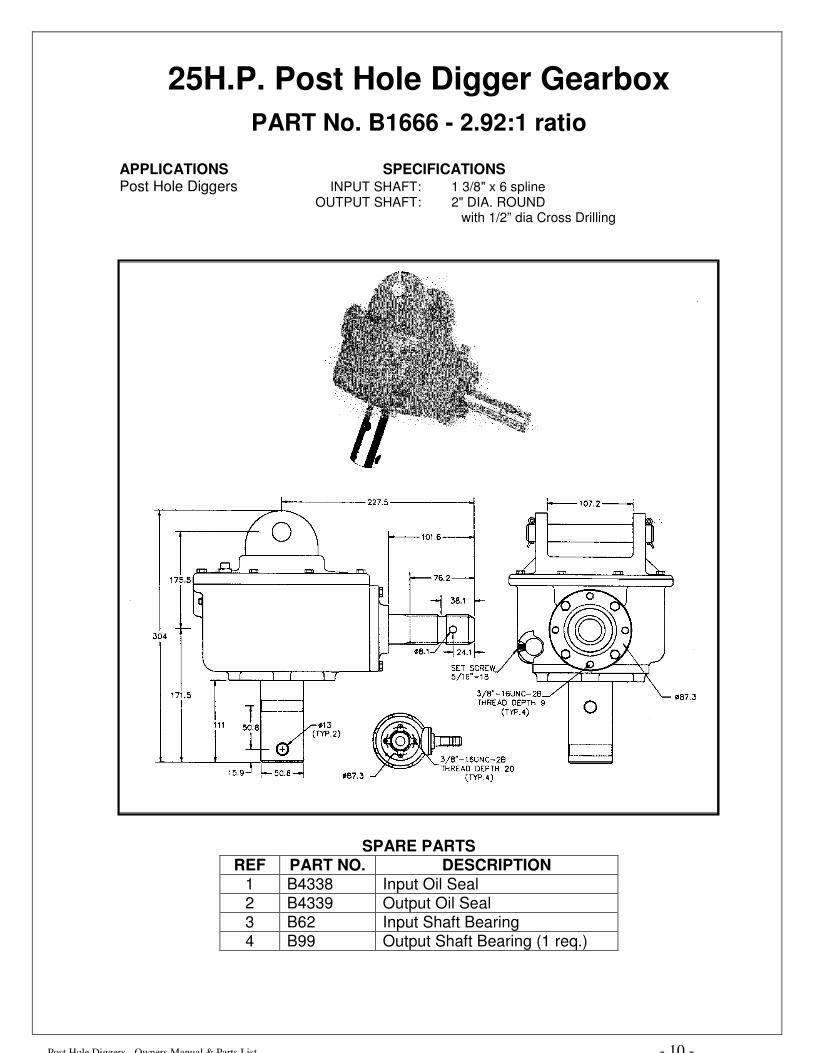
25H.P. Post Hole Digger Gearbox
PART No. B1666 - 2.92:1 ratio
APPLICATIONS SPECIFICATIONS Post Hole Diggers INPUT SHAFT: 1 3/8" x 6 spline OUTPUT SHAFT: 2" DIA. ROUND
with 1/2” dia Cross Drilling
SPARE PARTS REF PART NO. DESCRIPTION
1 B4338 Input Oil Seal 2 B4339 Output Oil Seal 3 B62 Input Shaft Bearing 4 B99 Output Shaft Bearing (1 req.)
Post Hole Diggers - Owners Manual & Parts List - 11 -
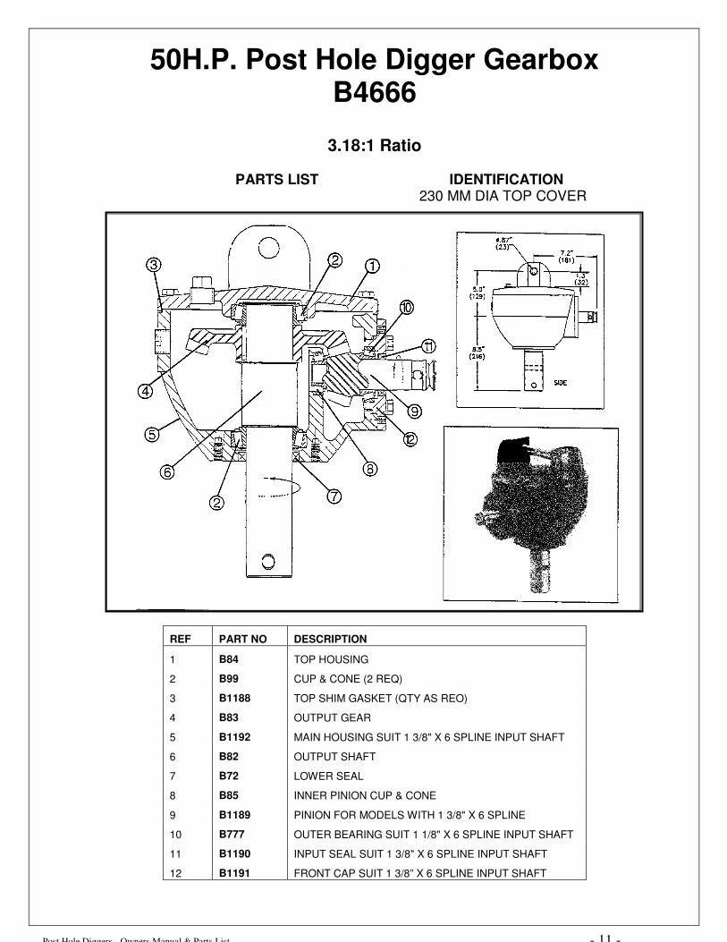
50H.P. Post Hole Digger Gearbox B4666
3.18:1 Ratio
PARTS LIST IDENTIFICATION
230 MM DIA TOP COVER
REF PART NO DESCRIPTION
1 B84 TOP HOUSING
2 B99 CUP & CONE (2 REQ)
3 B1188 TOP SHIM GASKET (QTY AS REO)
4 B83 OUTPUT GEAR
5 B1192 MAIN HOUSING SUIT 1 3/8" X 6 SPLINE INPUT SHAFT
6 B82 OUTPUT SHAFT
7 B72 LOWER SEAL
8 B85 INNER PINION CUP & CONE
9 B1189 PINION FOR MODELS WITH 1 3/8" X 6 SPLINE
10 B777 OUTER BEARING SUIT 1 1/8" X 6 SPLINE INPUT SHAFT
11 B1190 INPUT SEAL SUIT 1 3/8" X 6 SPLINE INPUT SHAFT
12 B1191 FRONT CAP SUIT 1 3/8” X 6 SPLINE INPUT SHAFT

Post Hole Diggers - Owners Manual & Parts List - 12 -
75H.P. Post Hole Digger Gearbox
PART No. B5666 - 4:1 ratio APPLICATIONS SPECIFICATIONS Post Hole Diggers HOUSING: 60-45-10 Nodular SHAFTS: UNS G10450 GEARS: UNS G51200 SEALS: Triple Lipped, Spring Loaded BEARINGS: Tapered Roller OIL: EP-90, 86oz, 2.54L WEIGHT: 111 lbs, 50.5kg INPUT SHAFT: 1 3/8" x 6 spline OUTPUT SHAFT: 2" OD - 1/2" cross drilled
SPARE PARTS
REF PART NO. DESCRIPTION
1 B1184 Input Shaft - 1 3/8" x 6 spline
2 B1185 Outer Cap
3 B773 Pinion Support Housing
4 B2953 Input Seal
5 B777 Outer Pinion Cup & Cone
6 B85 Inner Pinion Cup & Cone
7 B6951 Shim Gaskets (qty as req)
8 B6945 Top Cover
9 B99 Cup & Cone (2 req)
10 B6943 Output Gear
11 B6942 Output Shaft
12 B6941 Main Housing
13 6944 Top Shim Gasket (qty as req)
14 B72 Output Seal
Post Hole Digger, Operators & Parts List Manual. - 13 -
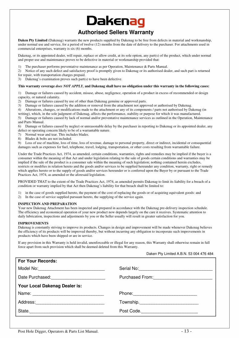
Authorised Sellers Warranty
Daken Pty Limited (Dakenag) warrants the new products supplied by Dakenag to be free from defects in material and workmanship, under normal use and service, for a period of twelve (12) months from the date of delivery to the purchaser. For attachments used in commercial enterprises, warranty is six (6) months.
Dakenag, or its appointed dealer, will repair, replace or allow credit, at its sole option, any part(s) of the product, which under normal and proper use and maintenance proves to be defective in material or workmanship provided that:
1) The purchaser performs preventative maintenance as per Operation, Maintenance & Parts Manual. 2) Notice of any such defect and satisfactory proof is promptly given to Dakenag or its authorised dealer, and such part is returned for repair, with transportation charges prepaid. 3) Dakenag’s examination proves such part(s) to have been defective.
This warranty coverage does NOT APPLY, and Dakenag shall have no obligation under this warranty in the following cases:
1) Damage or failures caused by accident, misuse, abuse, negligence, operation of a product in excess of recommended or design capacity, or natural calamity. 2) Damage or failures caused by use of other than Dakenag genuine or approved parts. 3) Damage or failures caused by the addition or removal from the attachment not approved or authorised by Dakenag. 4) Alterations, changes, or modifications made to the attachment or any of its components / parts not authorised by Dakenag (in writing), which, in the sole judgment of Dakenag, affects the performance, stability or purpose for which it was manufactured. 5) Damage or failures caused by lack of normal and/or preventative maintenance services as outlined in the Operation, Maintenance and Parts Manual. 6) Damage or failures caused by neglect or unreasonable delay by the purchaser in reporting to Dakenag or its appointed dealer, any defect or operating concern likely to be of a warrantable nature. 7) Normal wear and tear. This includes blades. 8) Blades & bolts are not included. 9) Loss of use of machine, loss of time, loss of revenue, damage to personal property, direct or indirect, incidental or consequential damages such as expenses for fuel, telephone, travel, lodging, transportation, or other costs resulting from warrantable failure.
Under the Trade Practices Act, 1974, as amended, certain conditions, warranties, rights and remedies may be implied if the buyer is a consumer within the meaning of that Act and under legislation relating to the sale of goods certain conditions and warranties may be implied if the sale of the product is a consumer sale within the meaning of such legislation; nothing contained herein excludes, restricts or modifies in relation hereto and the goods and/or services to be supplied hereunder any condition, warranty, right or remedy which applies hereto or to the supply of goods and/or services hereunder or is conferred upon the Buyer by or pursuant to the Trade Practices Act, 1974, as amended or the aforesaid legislation. PROVIDED THAT to the extent of the Trade Practices Act, 1974, as amended permits Dakenag to limit its liability for a breach of a condition or warranty implied by that Act then Dakenag’s liability for that breach shall be limited to:
1) in the case of goods supplied hereto, the payment of the cost of replacing the goods or of acquiring equivalent goods: and 2) In the case of service supplied pursuant hereto, the supplying of the service again. INSPECTION AND PREPARATION Your new Dakenag Attachment has been inspected and prepared in accordance with the Dakenag pre-delivery inspection schedule. The efficiency and economical operation of your new product now depends largely on the care it receives. Systematic attention to daily lubrication, inspections and adjustments by you or the Seller usually will result in greater satisfaction for you.
IMPROVEMENTS Dakenag is constantly striving to improve its products. Changes in design and improvement will be made whenever Dakenag believes the efficiency of its products will be improved thereby, but without incurring any obligation to incorporate such improvements in products which have been shipped or are in service.
If any provision in this Warranty is held invalid, unenforceable or illegal for any reason, this Warranty shall otherwise remain in full force apart from such provision which shall be deemed deleted from this Warranty.
Daken Pty Limited A.B.N. 53 004 476 484
For Your Records:
Model No:___________________________ Serial No:______________________________ Date Purchased:______________________ Purchased From:________________________ Your Local Dakenag Dealer is:
Name: _____________________________ Phone:__________________________ Address:____________________________ Township.________________________ State.______________________________ Post Code._______________________