Model PHD2401 Post Hole Digger Operator’s Manual operating and maintenance instructions for...
32
BUSH HOG ® ASSEMBLY • OPERATION • MAINTENANCE CAUTION For Safe Operation Read Rules And Instructions Carefully SINO LEEINGLES, PIDA AYUDA A AIGUIEN QUE SI LO LEA PARA QUE LE TRADUZCA LAS MEDIDAS DE SEGURIDAD. Model PHD2401 Post Hole Digger Operator’s Manual 0113 50072225
Transcript of Model PHD2401 Post Hole Digger Operator’s Manual operating and maintenance instructions for...

BUSH HOG®
ASSEMBLY • OPERATION • MAINTENANCE
CAUTIONFor Safe Operation
Read Rules AndInstructions Carefully
SINO LEEINGLES, PIDA AYUDAA AIGUIEN QUE SI LO LEAPARA QUE LE TRADUZCA LASMEDIDAS DE SEGURIDAD.
Model PHD2401Post Hole DiggerOperator’s Manual
0113 50072225

CONGRATULATIONS!

1
PHD2401 Post Hole DiggerOperator’s Manual
TABLE OF CONTENTS
WARRANTY INFORMATION . . . . . . . . . . . . . . . . . . . . . . . . . . . . . . . . . 2-3
DEALER CHECKLIST . . . . . . . . . . . . . . . . . . . . . . . . . . . . . . . . . . . . . . 4
FEDERAL LAWS AND REGULATIONS. . . . . . . . . . . . . . . . . . . . . . . . . 5
IMPORTANT SAFETY INFORMATION . . . . . . . . . . . . . . . . . . . . . . . . . 6-14
GENERAL SAFETY AND PREPARATION. . . . . . . . . . . . . . . . . 6-7
PERSONAL PROTECTIVE EQUIPMENT . . . . . . . . . . . . . . . . . 7
OPERATING SAFETY . . . . . . . . . . . . . . . . . . . . . . . . . . . . . . . . 8-10
REPAIR AND MAINTENANCE SAFETY . . . . . . . . . . . . . . . . . . 10-11
SAFETY DECALS . . . . . . . . . . . . . . . . . . . . . . . . . . . . . . . . . . . 13-14
INTENDED USE. . . . . . . . . . . . . . . . . . . . . . . . . . . . . . . . . . . . . 15
ASSEMBLY INSTRUCTIONS . . . . . . . . . . . . . . . . . . . . . . . . . . . . . . . . . 15-17
OPERATING INSTRUCTIONS . . . . . . . . . . . . . . . . . . . . . . . . . . . . . . . . 17-20
GENERAL MAINTENANCE . . . . . . . . . . . . . . . . . . . . . . . . . . . . . . . . . . 21
TROUBLE-SHOOTING GUIDE . . . . . . . . . . . . . . . . . . . . . . . . . . . . . . . 22-23
PARTS BREAKDOWN ILLUSTRATION . . . . . . . . . . . . . . . . . . . . . . . . . 24
AUGER BREAKDOWN ILLUSTRATION . . . . . . . . . . . . . . . . . . . . . . . . 25
HYDRAULIC DOWN FORCE KIT . . . . . . . . . . . . . . . . . . . . . . . . . . . . . 26
OPTIONAL PARKING STAND . . . . . . . . . . . . . . . . . . . . . . . . . . . . . . . . 27
TORQUE SPECIFICATIONS . . . . . . . . . . . . . . . . . . . . . . . . . . . . . . . . . 28
SPECIFICATIONS . . . . . . . . . . . . . . . . . . . . . . . . . . . . . . . . . . . . . . . . . 29
NOTES . . . . . . . . . . . . . . . . . . . . . . . . . . . . . . . . . . . . . . . . . . . . . . . . . . 29
2
RETAIL CUSTOMER’S RESPONSIBILITYUNDER THE
BUSH HOG WARRANTYIt is the Retail Customer and/or Operator’s responsibility to read the Operator’s Manual, to operate,
lubricate, maintain, and store the product in accordance with all instructions and safety procedures.Failure of the operator to read the Operator’s Manual is a misuse of this equipment.
It is the Retail Customer and/or Operator’s responsibility to inspect the product and to have anypart(s) repaired or replaced when continued operation would cause damage or excessive wear toother parts or cause a safety hazard.
It is the Retail Customer’s responsibility to deliver the product to the authorized Bush Hog Dealer,from whom he purchased it, for service or replacement of defective parts which are covered by war-ranty. Repairs to be submitted for warranty consideration must be made within forty-five (45) days offailure.
It is the Retail Customer’s responsibility for any cost incurred by the Dealer for traveling to or haulingof the product for the purpose of performing a warranty obligation or inspection.
TO THE OWNER:Read this manual before using your Post Hole Digger. This manual is provided to give you the
necessary operating and maintenance instructions for keeping your Post Hole Digger in top operatingcondition. Please read this manual thoroughly. Understand what each control is for and how to use it.Observe all safety signs on the machine and noted throughout the manual for safe operation of imple-ment. Keep this manual handy for ready reference.
Like all mechanical products, it will require cleaning and upkeep.
Use only genuine Bush Hog service parts. Substitute parts will void the warranty and may not meetstandards required for safe and satisfactory operation. Record the model and serial number of yourAttachment here:
Model:___________________________________________________________________________
Serial Number:____________________________________________________________________

3
LIMITED WARRANTYBush Hog warrants to the original purchaser of any new Bush Hog equipment, purchased from an author-
ized Bush Hog dealer, that the equipment be free from defects in material and workmanship for a period of two(2) years for non-commercial, state, and municipalities’ use and ninety (90) days for commercial use from dateof retail sale. The obligation of Bush Hog to the purchaser under this warranty is limited to the repair or replace-ment of defective parts.
Replacement or repair parts installed in the equipment covered by this limited warranty are warranted forninety (90) days from the date of purchase of such part or to the expiration of the applicable new equipmentwarranty period, whichever occurs later. Warranted parts shall be provided at no cost to the user at an author-ized Bush Hog dealer during regular working hours. Bush Hog reserves the right to inspect any equipment orparts which are claimed to have been defective in material or workmanship.
NOTICE: Bush Hog is NOT responsible for damage to augers caused by hitting underground objects(rocks, roots, etc.) or for bent augers caused by moving the tractor with the auger in the ground.
DISCLAIMER OF IMPLIED WARRANTIES & CONSEQUENTIAL DAMAGES
Bush Hog’s obligation under this warranty, to the extent allowed by law, is in lieu of all warranties, implied orexpressed, INCLUDING IMPLIED WARRANTIES OF MERCHANTABILITY AND FITNESS FOR A PARTIC-ULAR PURPOSE and any liability for incidental and consequential damages with respect to the sale or use ofthe items warranted. Such incidental and consequential damages shall include but not be limited to: transporta-tion charges other than normal freight charges; cost of installation other than cost approved by Bush Hog; duty;taxes; charges for normal service or adjustments; loss of crops or any other loss of income; rental of substituteequipment, expenses due to loss, damage, detention or delay in the delivery of equipment or parts resultingfrom acts beyond the control of Bush Hog.
THIS WARRANTY SHALL NOT APPLY:
1. To vendor items which carry their own warranties, such as hydraulic cylinders, tires, and tubes.
2. If the unit has been subjected to misapplication, abuse, misuse, negligence, fire or other accident.
3. If parts not made or supplied by Bush Hog have been used in connection with the unit, if, in sole judge-ment of Bush Hog such use affects its performance, stability, or reliability.
4. If the unit has been altered or repaired outside of an authorized Bush Hog dealership in a manner which,in the sole judgement of Bush Hog affects its performance, stability or reliability.
5. To normal maintenance service and normal replacement items such as gearbox lubricant, hydraulic fluid,worn blades, or to normal deterioration of such things as belts, seals, and exterior finish, due to use orexposure.
6. To expendable or wear items such as teeth, chains, center points, belts, springs and other items that in thecompany’s sole judgement is a wear item.
NO EMPLOYEE OR REPRESENTATIVE OF BUSH HOG IS AUTHORIZED TO CHANGE THIS WARRAN-TY IN ANY WAY OR GRANT ANY OTHER WARRANTY UNLESS SUCH CHANGE IS MADE IN WRITINGAND SIGNED BY BUSH HOG’S SERVICE MANAGER, 2501 GRIFFIN AVE., SELMA, ALABAMA 36703.
Record the model number, serial number and date purchased. This information will be helpful to your deal-er if parts or service are required.

4
DEALER PREPARATION CHECK LIST
Post Hole Diggers
BEFORE DELIVERING MACHINE – The following check list should be completed.Use the Operator’s Manual as a guide.
❑ Assembly completed
❑ Gearbox filled to proper level with oil
❑ Driveline shields are in place with no damage
❑ Gearbox and auger shields are in place
❑ SMV Sign and bracket installed
❑ All safety decals readable (see decal page)
❑ All bolts tight to torque specifications given on torque chart
❑ Operator’s manual has been delivered to owner and he has been instructed on the safe and proper use of the post hole digger.
Dealer’sSignature ___________________________________________________________
THIS CHECK LIST TO REMAIN IN OPERATOR’S MANUALIt is the responsibility of the dealer to complete the procedure
above before delivery of this implement to the customer.

5
SAFETY
PHD 01/13 Safety Section

6
To the Owner/Operator/DealerAll implements with moving parts are potentially hazardous. There is no substitute for a cautious, safe-minded opera-tor who recognizes the potential hazards and follows reasonable safety practices. The manufacturer has designed thisimplement to be used with all its safety equipment properly attached to minimize the chance of accidents.
BEFORE YOU START!!Read the safety messages on the implement and shown in your manual.
Observe the rules of safety and common sense!
THIS SAFETY ALERT SYMBOL IDENTIFIES IMPORTANTSAFETY WARNING MESSAGES. CAREFULLY READ EACHWARNING MESSAGE THAT FOLLOWS. FAILURE TOUNDERSTAND AND OBEY A SAFETY WARNING, ORRECOGNIZE A SAFETY HAZARD, COULD RESULT IN ANINJURY OR DEATH TO YOU OR OTHERS AROUND YOU.THE OPERATOR IS ULTIMATELY RESPONSIBLE FOR THESAFETY OF HIMSELF, AS WELL AS OTHERS, IN THEOPERATING AREA OF THE TRACTOR AND ATTACHEDEQUIPMENT.
IMPORTANT SAFETY INFORMATION!Working with equipment can lead to injuries. Read this manual, and the manual for your tractor, before assembly oroperating, to acquaint yourself with the machines. It is the implement owner’s responsibility, if this machine is used byany person other than yourself, is loaned or rented, to make certain that the operator, prior to operating:
1. Reads and understands the operator’s manuals.2. Is instructed in safe and proper use.
The use of this equipment is subject to certain hazards which cannot be protected against by mechanicalmeans or product design. All operators of this equipment must read and understand this entire manual, pay-ing particular attention to safety and operating instructions, prior to using. If there is something in this manu-al you do not understand, ask your supervisor, or your dealer, to explain it to you.
THIS SYMBOL MEANS
– ATTENTION!
– BECOME ALERT!
– YOUR SAFETY IS INVOLVED!
UNDERSTAND SIGNAL WORDS
Indicates an imminently hazardous situation that, if not avoided, WILL result inDEATH OR VERY SERIOUS INJURY.
Indicates a imminently hazardous situation that, if not avoided, COULD result inDEATH OR SERIOUS INJURY.
Indicates a imminently hazardous situation that, if not avoided, MAY result inMINOR INJURY.
Identifies special instructions or procedures that, if not strictly observed, couldresult in damage to, or destruction of the machine, attachments or the environment.
NOTE: Identifies points of particular interest for more efficient and convenient operation or repair.
If you have questions not answered in this manual or require additional copies or the manual is damaged, pleasecontact your dealer or the manufacturer directly.
WARNING
DANGER
CAUTION
IMPORTANT

7
SAFETY INSTRUCTIONS (continued)
Safety of the operator is one of the main concerns in designing and developing a new piece of equipment.Designers and manufacturers build in as many safety features as possible. However, every year manyaccidents occur which could have been avoided by a few seconds of thought and a more careful approach tohandling equipment.You, the operator, can avoid many accidents by observing the following precautions in thissection. To avoid personal injury, study the following precautions and insist those working with you, or for you,follow them.
In order to provide a better view, certain photographs or illustrations in this manual may show an assembly witha safety shield removed. However, equipment should never be operated in this condition. Keep all shields inplace. If shield removal becomes necessary for repairs, replace the shield prior to use.
To prevent injury or death, use a tractor equipped with a Roll-Over Protective System (ROPS). Keep foldableROPS systems in “locked up” position at all times.
Never exceed the limits of a piece of machinery. If its ability to do a job, or to do so safely, is in question –DON’T TRY IT.
Do not modify the equipment in any way. Unauthorized modification may impair the function and/or safety andcould affect the life of the equipment.
In addition to the design and configuration of this implement, including Safety Signs and Safety Equipment,hazard control and accident prevention are dependent upon the awareness, concern, prudence, and propertraining of personnel involved in the operation, transport, maintenance, and storage of the machine. Refer alsoto Safety Messages and Operation Instructions in each of the appropriate sections of the Tractor andImplement Manuals. Pay close attention to the Safety Signs affixed to the Tractor and the Implement.
Replace any CAUTION, WARNING, DANGER or instruction safety sign that is not readable or is missing. Donot paint over, remove or deface any safety signs or warning signs on your equipment. Observe all safety signsand practice the instruction on them. Review the safety instructions with all users annually.
Never use alcoholic beverages or drugs which can hinder alertness or coordination while operating thisequipment. Consult your doctor about operating this machine while taking prescription or over the countermedications.
This equipment is dangerous to children and persons unfamiliar with its operation. The operator should be aresponsible adult familiar with farm machinery and trained in this equipment’s operations. Do not allow per-sons to operate or assemble this unit until they have read this manual and have developed a thoroughunderstanding of the safety precautions and of how it works.
EQUIPMENT SAFETY GUIDELINES
Personal protection equipment including hard hat, safety glasses, safety shoes, and gloves are recommendedduring assembly, installation, operation, adjustment, maintaining, repairing, removal, or moving the implement.Do not allow long hair, loose fitting clothing or jewelry to be around moving parts.

8
Know your controls and how to stop tractor, engine, and implement quickly in an emergency. Read this manu-al and the one provided with your tractor.
Never leave the tractor and implement unattended while the implement is in the lifted position. Accidental oper-ation of lifting lever or a hydraulic failure may cause sudden drop of unit with injury or death by crushing.
Never allow children to play on or around tractor or implement. Children can slip or fall off the equipment andbe injured or killed. Inadvertent contact with controls can cause the implement to shift or fall crushing them-selves or others.
Do not allow children or others to ride on the tractor with an operator. Riders are subject to injury such as beingstruck by foreign objects or being thrown off. Riders obstruct the operator’s view resulting in unsafe operation.Never allow anyone to ride on the implement!
This Post Hole Digger was designed for one-man operation from the tractor seat. It is the responsibility of theoperator to see that no one is within twenty-five feet (25’) of the digger when it is started. Do not operate thedigger with another person near, or in contact with, any part of the digger, PTO driveline, or auger. Seriouspersonal injury or death may result if any attempt is made to assist digger operation by hand.
Start tractor only when properly seated in the tractor seat. Starting a tractor in gear can result in injury or death.Do not mount or dismount the tractor while the tractor is moving. Mount or dismount the tractor only when thetractor and all moving parts are completely stopped.
Operate the tractor and/or implement controls only while properly seated in the tractor seat with the seat beltsecurely fastened around you. Inadvertent movement of the tractor or implement may cause serious injury ordeath.
Keep all helpers and bystanders twenty-five feet (25’) from an operating digger. Only properly trained peopleshould operate this machine. It is recommended the tractor be equipped with a Rollover Protection System(ROPS) and a seat belt that is used. Always stop the PTO, set brake, shut off the tractor engine, remove thetractor key, and allow auger to come to a complete stop before dismounting tractor. Never leave equipmentunattended with the tractor running.
Ensure that all safety shielding and safety signs are properly installed and in good condition. If a safety shieldor guard is removed for any reason, it must be replaced before the machine is again operated. Always use,and maintain in place, all power take off guards furnished with the tractor as well as the power take off guardsand shields furnished with the digger.
Clear area of stones, branches or other debris that might be thrown or entangled, causing injury or damage.
Operate only in daylight or good artificial light.
Make sure driveline spring-activated locking pin or balls operate freely and are seated firmly in tractor PTOstub shaft groove.
OPERATIONAL SAFETY
SAFETY INSTRUCTIONS (continued)

9
SAFETY INSTRUCTIONS (continued)
OPERATIONAL SAFETY (continued)
This digger is designed for use only on tractors with 540 RPM power take off.
Do not operate the post hole digger near existing fence wire. Fencing wire, loose wire, cable, landscapewebbing or other similar debris can become entangled in the auger and be rapidly pulled into the auger alongwith bystanders in contact with the material. This can result in serious injury or death. Inspect the area beforedigging and remove any fencing material, wire, cable, chain, rope, landscaping webbing or other similar debristhat could become entangled in the auger. Keep all bystanders 25 feet away from the auger and any wire offencing material near the auger.
Never place yourself or allow anyone between or near the tractor and digger while implement is in operation.
Do not walk or work under a raised digger or attachment unless it is securely blocked or held in position. Donot depend on the tractor hydraulic system to hold the digger or attachment in place.
A heavy load can cause instability of the tractor. Use extreme care during travel. Slow down on turns and watchout for bumps. The tractor may need front counter-weights to counter-balance the weight of the digger.
Do not allow riders on the digger or tractor at any time. There is no safe place for any riders.
Know where the utilities are: Before operating, call your local utilities (call 811 or 1-800-258-0808) for locationof buried utility lines, gas, water, sewer, and telephone, as well as any other hazard you may encounter.
Never allow children to operate or be around this digger.
Do not allow anyone who is not familiar with the safety rules and operation instructions to use this Post HoleDigger.
Do not operate digger on steep hillsides. When digging on uneven or hilly terrain, position the tractor with thePost Hole Digger uphill. With the Post Hole Digger downhill, the tractor could tip when attempting to pull theauger from its hole.
Never replace the shear bolt OR auger retaining bolt with any length other than what is specified in this man-ual. A longer, or protruding fastener is more likely to grab loose clothing or gloves which can result in seriousinjury or death.
Use stabilizer bars, adjustable sway chains, or sway blocks on your tractor lift arms to keep the Post HoleDigger from swinging side to side. Adjust as tightly as practical for best performance.
NEVER put hands on the post hole digger auger, gearbox, or boom to locate the auger when there is any signof rotation of the driveline or auger. Post hole diggers are operated by one person from the tractor seat. Keepall bystanders and/or coworkers away from the post hole digger.

10
SAFETY INSTRUCTIONS (continued)
OPERATIONAL SAFETY (continued)
Inspect the entire machine periodically as indicated in the Maintenance Section of this manual. Look for loosefasteners, worn or broken parts, pinched hydraulic hoses, and leaky or loose fittings. Make sure all pins havecotter pins and washers. Serious injury may occur from not maintaining this machine in good working order.
Relieve hydraulic pressure prior to doing any maintenance or repair work on the implement. Place the imple-ment on the ground or securely blocked up, disengage the PTO, and turn off the tractor engine. Push and pullthe remote hydraulic lever in and out several times prior to starting any maintenance or repair work.
Take all possible precautions when leaving unit unattended: Disengage PTO, lower 3 pt., set parking brake,stop engine and remove key from ignition. Park in level area.
To prevent rapid wear of U-Joints and possible failure of drivelines, never lift auger point more than 8” off theground with PTO operating.
To prevent possible instantaneous driveline failure, never move digger from hole-to-hole or transport whileauger is rotating. This could lead to injury from flying pieces of the failed driveline.
To prevent entanglement and possible serious injury or death, never use body weight to try to push auger intothe ground.
Worn cutting edges or a slightly rounded center point can seriously effect auger penetration. Check for wearbefore each use, replace as necessary.
Do not shovel dirt away from a rotating auger as the shovel can be caught and thrown by the auger.
Do not operate the Post Hole Digger without all safety shields and guards in place.
Before operating equipment: if you have any questions regarding the proper assembly or operation, contactyour dealer or representative.
Before working on this machine, drive to a level area, disengage the PTO, lower implement (or if workingunderneath, raise and block securely), shut off the engine, set the brakes, and remove the ignition keys.Disconnect the PTO shaft from the tractor PTO before servicing the implement.
MAINTENANCE SAFETY
Good maintenance is your responsibility. Poor maintenance is an invitation to trouble.
Never work under equipment unless it is blocked securely. Never depend on hydraulic system to keep imple-ment in raised position.
Always use two people to handle heavy, unwieldy components during assembly, installation, removal, ormoving the digger.

11
Safety is a primary concern in the design, manufacture, sale, and use of Post Hole Diggers. As manufacturers of PostHole Diggers, we want to confirm to you, our customers, our concern for safety.
Our current production machines include, as standard equipment, guards or shields for auger adapters, drivelines,input shafts, and safety signs. Older machines can be retrofitted to add these new guards or shields and, or course,safety signs. If you have an older machine which does not have current standard safety equipment, please contactyour dealer about bringing your machine up to the current level of safety.
Where replacement parts are necessary for periodic maintenance and servicing, genuine factory replacement partsmust be used to restore your equipment to original specifications. The manufacturer will not claim responsibility for useof unapproved parts and/or accessories and other damages as a result of their use.
If equipment has been altered in any way from original design, the manufacturer does not accept any liability for injuryor warranty.
SAFETY INSTRUCTIONS (continued)
MAINTENANCE SAFETY (continued)
Keep all persons away from operator control area while performing adjustments, service, or maintenance.
Periodically tighten all bolts, nuts and screws and check that all cotter pins are properly installed to ensure unitis in a safe condition.
When completing a maintenance or service function, make sure all safety shields and devices are installedbefore placing unit in service.
Never use your hands to locate a hydraulic leak on attachments. Use a small piece of cardboard or wood.Hydraulic fluid escaping under pressure can penetrate the skin. Openings in the skin and minor cuts aresusceptible to infection from hydraulic fluid. If injured by escaping hydraulic fluid, see a doctor at once.Gangrene and death can result. Without immediate medical treatment, serious infection and reactions canoccur.
Comply with state and local laws governing highway safety and movement of farm machinery on public roads.
When driving the tractor and equipment on the road or highway under 20 mph (32 kph) at night or during theday, use flashing amber warning lights and a slow moving vehicle (SMV) identification emblem.
Reduce speed when transporting mounted implements to avoid bouncing and momentary loss of steeringcontrol.
TRANSPORT SAFETY
Make sure post hole digger transported on tractor rear 3 pt. hitch does not obstruct visibility of tractor’s flash-ing lights or SMV sign.

12
SAFETY INSTRUCTIONS (continued)
Always be sure the implement is in the proper raised position and the PTO is turned off for transport.
Turn curves or go up or down hills only at a low speed and at a gradual steering angle. Make certain that atleast 20% of the tractor’s weight is on the front wheels to maintain safe steerage. Slow down on rough oruneven surfaces, and loose gravel.
Be aware of the operating conditions. Do not operate the tractor with weak or faulty brakes. When operatingdown a hill or on wet or rain slick roads, the braking distance increases; use extreme care and reduce yourspeed in these conditions. When operating in traffic, always use the tractor’s flashing warning lights and reduceyour speed. Be aware of traffic around you and watch out for the other guy.
Use extreme care and maintain minimum ground speed when transporting on hillside, over rough ground andwhen operating close to ditches or fences. Be careful when turning sharp corners.
Never allow riders on either tractor or implement. Falling off can kill.
Following operation, or when unhooking, stop the tractor, set the brakes, disengage the PTO, shut off theengine and remove the ignition keys.
STORAGE SAFETY
Do not park equipment where it will be exposed to livestock for long periods of time. Damage and livestockinjury could result.
TRANSPORT SAFETY (continued)
Store the unit in an area away from human activity. Do not permit children to play on or around the stored unit.
Make sure all parked machines are on a hard, level surface and engage all safety devices. Storage locationshould be level and solid to make connecting and unconnecting to power unit easy.
NOTE: The optional parking stand may be used when post hole digger is not in operation. It will help prolong digger’slife by keeping the unit off the ground where moisture and debris are more likely to collect causing undue damage tothe digger. Also, the parking stand aids in mounting and dismounting the post hole digger to and from the tractor.
Use extreme care to keep feet and hands from under the unit and clear of any pinch points. Never stand orallow another person to stand between a running tractor and the unit when disconnecting the implement fromthe tractor 3-point hitch.
13
SAFETY SIGNS AND DECALS
SAFETY INSTRUCTIONS (continued)
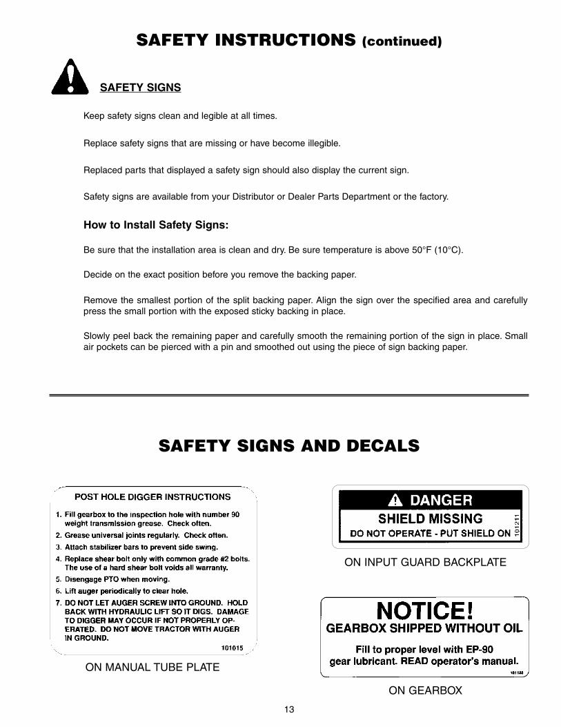
Keep safety signs clean and legible at all times.
Replace safety signs that are missing or have become illegible.
Replaced parts that displayed a safety sign should also display the current sign.
Safety signs are available from your Distributor or Dealer Parts Department or the factory.
Be sure that the installation area is clean and dry. Be sure temperature is above 50°F (10°C).
Decide on the exact position before you remove the backing paper.
Remove the smallest portion of the split backing paper. Align the sign over the specified area and carefullypress the small portion with the exposed sticky backing in place.
Slowly peel back the remaining paper and carefully smooth the remaining portion of the sign in place. Smallair pockets can be pierced with a pin and smoothed out using the piece of sign backing paper.
How to Install Safety Signs:
SAFETY SIGNS
ON MANUAL TUBE PLATE
ON GEARBOX
ON INPUT GUARD BACKPLATE
14
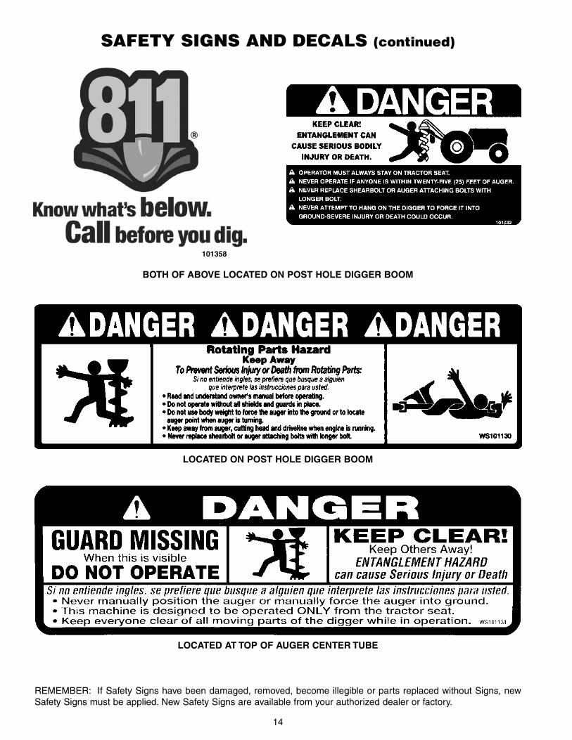
LOCATED ON POST HOLE DIGGER BOOM
SAFETY SIGNS AND DECALS (continued)
LOCATED AT TOP OF AUGER CENTER TUBE
BOTH OF ABOVE LOCATED ON POST HOLE DIGGER BOOM
REMEMBER: If Safety Signs have been damaged, removed, become illegible or parts replaced without Signs, newSafety Signs must be applied. New Safety Signs are available from your authorized dealer or factory.
101358

15
Power unit must be equipped with ROPS or ROPScab and seat belt. Keep seat belt securely fastened.Falling off power unit can result in death from beingrun over or crushed. Keep foldable ROPS systems in“locked up” position at all times.
INSTRUCTIONS
TRACTOR REQUIREMENTS AND PREPARATION
Check the shield over the PTO stub shaft. Make sure itis in good condition and bolted securely to the tractor.Purchase a new shield if old shield is damaged ormissing.
Tractor must be equipped with stabilizer bars, adjustablesway chains, or sway blocks to keep the post hole diggerfrom swinging side to side.
This product is designed to dig holes in the soil whenattached to the 3-point hitch and power-take-off of atractor. It is not intended for any other use. Using theproduct for anything other than digging holes could resultin serious injury or death.
Refer to the “exploded view” of the post hole digger onpage 24 of this manual. Become familiar with the relation-ship of the various components and parts shown.
Unpack all the bundles and lay out various parts. Startwith the yoke (Ref. #2). Place the pull pins (Ref. #14)through the holes in the legs of the yoke and secure withnuts and lock washers.
NOTE: For Category I and II tractors, place the pull pinson the outside of the yoke legs as shown in the diagram.For smaller tractors, it may work better to place the pullpins on the inner side of the yoke legs.
The pins are Category I (7/8” dia.). If your tractor isCategory II, then lift arm bushings are required toproperly fit the 11/8” dia. Cat. II lift arm balls. (Bushings notsupplied.) Place the lift arms of your tractor over the pullpins in the yoke and secure with linchpins (not supplied).
NOTE: Always use adapter bushings when usingCategory I pins on a Category II hitch. Trying to use Cat.I pins in a Cat. II hitch without bushings will result in avery loose fit and the post hole digger will be unstable.
Pin end of digger boom (Ref. #1) to tractor toplinkbracket. Raise boom by hand – check that it doesn’t hitany part of toplink bracket (some tractors only). Ifproblem exists, change hole location and re-check.Failure to check can result in damage to tractor orboom. Cat. I tractors need toplink bushing. Connect yoketo boom with pin (Ref. #14) and cotter pins.
NOTE: When attaching the yoke to the boom, use thehole in the adjustment channel best suited for yourtractor. If you don’t know the best hole location, start withthe middle hole.
Install the plastic manual holder on the bottom of theflat plate welded to the yoke. Locate the manual holderwith the cap facing away from the post hole digger. Usethe two 1/4” x 1” bolts to mount the manual holder.
It is recommended that the pair of gearbox outputguards, and the gearbox input guard be assembled onthe gearbox before the gearbox is fastened to the boom.Place the gearbox upside down on the floor.
Install the formed metal gearbox output shields (Ref.#7) on the gearbox. A socket with a long extensionmakes this an easy installation. Use the M8 x 12mm boltsand 1/4” flat washers to fasten the guards.
ASSEMBLY AND MOUNTING
The Model 2401 3-pt. mounted post hole digger will fitmost Category I, Category II and some larger Category0 tractors equipped with a standard 3-pt. hitch. TheModel 2401 Digger will handle up to 12 inch diameteraugers.
The Model 2401 post hole digger is designed for usewith tractors up to 35 hp. The tractor must have a PowerTake Off (PTO) rated for 540 rpm and with a 6-spline,13/8” diameter output shaft.
An optional hydraulic down-pressure kit is available toprovide an additional 350-450 lbs. of down-pressure intough digging conditions.
NOTE: Low profile tractors generally can only use 30”long augers instead of standard 42” long augers. SomeCategory 0 tractors have very short lift arms or 5/8”diameter (Cat. 0) lift arm ball ends. These tractors are notusually suitable for post hole digging operation.
Check the tractor’s 3-pt. hydraulic lift system. It shouldoperate up and down smoothly and have enough powerto lift the dirt-loaded auger out of the hole. Refer to yourtractor operator’s manual or dealer for any adjustmentsnecessary to put the 3-pt. hydraulic lift system in goodworking order.
WARNING
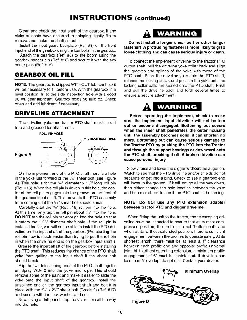
DRIVELINE ATTACHMENTThe driveline yoke and tractor PTO shaft must be dirt
free and greased for attachment.
16
WARNING
On the implement end of the PTO shaft there is a holein the yoke just forward of the 5/16” shear bolt (see FigureA). This hole is for the 3/16” diameter x 11/4” long roll pin(Ref. #16). When this roll pin is driven in this hole, the cen-ter of the roll pin engages into the groove on the front ofthe gearbox input shaft. This prevents the PTO assemblyfrom coming off if the 5/16” shear bolt should shear.
Carefully start the 3/16” (Ref. #16) roll pin into the hole.At this time, only tap the roll pin about 3/16” into the hole.DO NOT tap the roll pin far enough into the hole so thatit enters the 1.25” diameter shaft hole. If the roll pin isinstalled too far, you will not be able to install the PTO dri-veline on the input shaft of the gearbox. (Pre-starting theroll pin now is much easier than trying to put the roll pinin when the driveline end is on the gearbox input shaft.)
Grease the input shaft of the gearbox before installingthe PTO shaft. This reduces the chance of the PTO shaftyoke from galling to the input shaft if the shear boltshould break.
Slip the two telescoping ends of the PTO shaft togeth-er. Spray WD-40 into the yoke and wipe. This shouldremove some of the paint and make it easier to slide theyoke onto the input shaft of the gearbox. Install theunsplined end on the gearbox input shaft and bolt it inplace with the 5/16” x 21/2” shear bolt (Grade 2) (Ref. #17)and secure with the lock washer and nut.
Now, using a drift punch, tap the 3/16” roll pin all the wayinto the hole.
To connect the implement driveline to the tractor PTOoutput shaft, pull the driveline yoke collar back and alignthe grooves and splines of the yoke with those of thePTO shaft. Push. the driveline yoke onto the PTO shaft,release the locking collar, and position the yoke until thelocking collar balls are seated onto the PTO shaft. Pushand pull the driveline back and forth several times toensure a secure attachment.
Figure B
Figure A
INSTRUCTIONS (continued)
Do not install a longer shear bolt or other longerfastener! A protruding fastener is more likely to grabloose clothing and can cause serious injury or death.
WARNINGBefore operating the Implement, check to make
sure the Implement input driveline will not bottomout or become disengaged. Bottoming out occurswhen the inner shaft penetrates the outer housinguntil the assembly becomes solid, it can shorten nomore. Bottoming out can cause serious damage tothe Tractor PTO by pushing the PTO into the Tractorand through the support bearings or downward ontothe PTO shaft, breaking it off. A broken driveline cancause personal injury.
Minimum Overlap
Slowly raise and lower the digger without the auger on.Watch to see that the PTO driveline and/or shields do notseparate or get into a bind. Check to see if gearbox endwill lower to the ground. If it will not go all the way down,then either change the hole location between the yokeand boom or check to see if the PTO shaft is bottoming.
NOTE: Do NOT use any PTO extension adapterbetween tractor PTO and digger driveline.
When fitting the unit to the tractor, the telescoping dri-veline must be inspected to ensure that at its most com-pressed position, the profiles do not “bottom out”, andwhen at its farthest extended position, there is sufficientengagement between the profiles to operate safely. At itsshortest length, there must be at least a 1” clearancebetween each profile end and opposite profile universaljoint. At it farthest operating extension, a minimum profileengagement of 6” must be maintained. If driveline hasless than 6” overlap, do not use. Contact your dealer.
GEARBOX OIL FILL
NOTE: The gearbox is shipped WITHOUT lubricant, so itwill be necessary to fill before use. With the gearbox in alevel position, fill to the side inspection hole with a good90 wt. gear lubricant. Gearbox holds 56 fluid oz. Checkoften and add lubricant if necessary.
Clean and check the input shaft of the gearbox. If anynicks or dents have occurred in shipping, lightly file toremove and make the shaft smooth.
Install the input guard backplate (Ref. #8) on the frontinput end of the gearbox using the four bolts in the gearbox.
Attach the gearbox (Ref. #6) to the boom using thegearbox hanger pin (Ref. #13) and secure it with the twocotter pins (Ref. #15).

17
INSTRUCTIONS (continued)
Operate the post hole digger only on a tractor with540 RPM PTO shaft. The tractor’s engine speedshould not exceed 1200 RPM while digging.
NOTE: On some tractors it may be necessary toremove the drawbar or slide it to one side. This willprevent the PTO driveline shaft from coming in con-tact with the drawbar.
Do not operate the post hole digger near existing fencewire. Fencing wire, loose wire, cable, landscape webbingor other similar debris can become entangled in theauger and be rapidly pulled into the auger along withbystanders in contact with the material. This can result inserious injury or death. Inspect the area before diggingand remove any items that could become entangled inthe auger. Keep all bystanders 25 feet away from theauger and any wire of fencing material near the auger.
If you have ANY questions, regarding the properoperation of this digger, contact your dealer or themanufacturer.
With the PTO driveline installed, place the input guard(Ref. #9) on the input guard back plate (Ref. #8) and fas-ten with the two threaded knobs (Ref. #10).
NOTE: The input guard back and input guard arechained together. This will keep the input guard frombeing mis-placed and make it more likely to be properlyinstalled.
Install the Slow Moving Vehicle (SMV) bracket on theright side of the gearbox. There are two threaded holesthat the bracket will match up with. Fasten with the two 3/8”x 3/4” bolts and 3/8” lockwashers. Place the SMV sign onthe rear of the bracket and fasten with the two #10 - 24 x½” screws and nuts (Ref. #41 and #42).
Attach the handle to the right side of the gearbox byinserting the handle into the hole in gearbox. Install the5/16” x 3/4” bolt and tighten. The handle is to adjust theauger position as you lower the auger to the ground. Youshould be able to easily reach the handle while seatedand as you operate the 3 pt. hitch raise/lower control.
NOTE: It may be necessary to bend the handle to put itin the best position for you to reach. If the handle is toolong for your tractor, remove the plastic grip and cut thehandle as required. If the handle is too short for your trac-tor’s configuration, take the handle to a welding shop andhave it lengthened as required.
NOTE: Use stabilizer bars, adjustable sway chains,or sway blocks on your tractor lift arms to keep thepost hole digger from swinging side to side. Adjustas tightly as practical for best performance.
Slide the auger over the 2” output shaft of the gearboxand secure it with the two bolts. Use a socket wrench withan extension to tighten the auger retaining bolts. Theholes at the edge of the two piece output shaft guard arealigned with the auger bolts.
NOTE: Please refer to the drawings (page 25, Figures Bthrough D) as to the proper mounting pattern for the cut-ting edges. Correct mounting of the cutting edges willassure a complete cut of earth by the auger.
When attaching PTO yoke to tractor PTO shaft, it isimportant that spring-activated locking pin or ballsoperate freely and are seated in groove on PTO shaft.A loose shaft could slip off and result in personalinjury or damage to equipment.
• Thoroughly read and understand your Operator’sManuals.
• Before beginning operation, clear area of objects thatwrap around the auger or might be thrown. Contactlocal utility company (call 811) to make certain thereare no buried gas lines, electrical cables, etc., in thework area. Check for ditches, stumps, holes, or otherobstacles that could cause the tractor to roll over.
• Layout and mark where you want to dig your holes.
• ALL persons should be at least twenty-five (25’) away.Clear the area of helpers, bystanders, especiallychildren. Do not allow anyone to stand behind, or tothe side of a rotating auger.
• To dig properly, your digger must be able to raise orlower through the highest and lowest points of your liftarm travel without binding against the tractor frame.Check carefully BEFORE attaching the auger. If itdoes bind, adjust the tractor 3 pt. linkage so that allmovement is free.
PREPARATION PROCEDURE
CAUTION
WARNING

18
OPERATING INSTRUCTIONS
PRE-OPERATION CHECKLIST
This Post Hole Digger was designed for one-manoperation from the tractor seat. It is the responsibility ofthe operator to see that no one else is within twenty-five feet (25’) of the digger when it is operating.
• Set tractor brakes. Take tractor out of gear. Shift to“Park” (if applicable).
• Do not allow anyone to stand behind, or to the side ofa rotating auger.
• Lower auger point slowly to the ground with the PTOdisengaged.
• With the auger point lowered to the ground, set theengine speed to idle, then engage the PTO. Makesure the auger point is on the ground before engag-ing the PTO.
• Increase the speed as required so dirt is conveyedfrom the hole. Most hole digging is generally best withthe tractor at no more than half throttle speed (PTOspeed @ approx. 300 rpm).
• Under no circumstances should the PTO be run inexcess of 540 rpm.
OPERATION
• In some types of soil, it may be necessary to hold backagainst the auger screw action by moving thehydraulic control lever to “HOLD” or “RAISE” positionto keep the auger from screwing into the ground.
• NEVER use body weight to help the augerpenetrate the ground. When the ground is tootough to penetrate with your cutting edges and point,sharpen or replace them and try again. These arereplaceable parts and must be in good condition topenetrate. (Optional Hydraulic Downpressure Kit isavailable – order #50072109.)
• If you have difficulty penetrating hard ground, refer toOwner’s Manual Trouble-shooting section forsuggestions.
• When the auger has been lowered about a foot or sointo the ground, raise the auger almost out of the holeto clear the dirt, then drill deeper and raise the augeragain. Repeat this procedure until the desired holedepth is reached.
• NEVER allow anyone to shovel dirt away from a rotat-ing auger as the shovel can be caught and thrown bythe auger.
• Disengage the power-take-off when traveling betweenholes.
IT IS ESSENTIAL THAT EVERYONE INVOLVED INTHE ASSEMBLY, OPERATION, TRANSPORT, MAIN-TENANCE, AND STORAGE OF THIS EQUIPMENT BEAWARE, CONCERNED, PRUDENT, AND PROPERLYTRAINED IN SAFETY.
DIGGING A HOLE: Position the tractor so that theauger point is placed where the hole is to be. Lower theauger so that the point touches the ground. The point ofthe auger should be approximately 3” back of center ofthe gearbox. As the auger works into the ground, thisslight angle will straighten, due to the pivoting action ofthe boom downward. If the auger has a side tilt, correctwith the lift arm adjustment on the tractor hitch.
If the auger tilts too far forward or to the rear, it may benecessary to move the tractor slightly. Be careful not tobend the auger.
The post hole digger auger is free-swinging, and careshould be taken while transporting the machine. DO NOTtransport the post hole digger while the PTO is engagedas this could cause the universal joints of the PTO drive-line into a sharp operating angle and cause failure of thedriveline.
(OPERATOR RESPONSIBILITY)
____ Review and follow safety rules and safety signs onpages 5 through 14.
____ Check that post hole digger is properly andsecurely attached to tractor.
____ Make sure driveline spring-activated locking pin orlocking balls operate freely and are seated firmly intractor PTO spline groove.
____ Lubricate all grease fitting locations. Make surePTO driveline slip joint is lubricated.
____ Check to be sure gear lube runs out the smallcheck plug on side of gearbox.
____ Check that all hardware is properly installed.
____ Check to ensure cutting edges are sharp, secureand positioned correctly.
____ Check that all shields and guards are properlyinstalled and in good condition.
____ Set tractor PTO gear select lever for 540 rpmoperation.
____ DO NOT operate the unit if the pre-operationinspection reveals any condition affecting safeoperation.

19
OPERATION INSTRUCTIONS (continued)
■ Never locate auger by putting hands on auger,gearbox, or boom when there is any sign of rotationon the driveline or auger or if the tractor is running.
■ Remain on the tractor seat while operating thepost hole digger. Assisting the machine by hand canresult in possible injury or death.
■ Never use body weight to help the auger penetratethe ground.
Do not shovel dirt away from a turning auger, as theshovel can be caught by the auger and thrown. Donot allow anyone to stand behind or to the side of anoperating auger. ALL persons should be at least 25feet away.
Engage the tractor PTO with the engine at idle (or below1000 engine RPM). As the auger penetrates the ground,lower the unit slowly with the 3 pt. hydraulic system. DONOT LET THE AUGER SCREW ITSELF INTO THEGROUND! Auger must dig with the dirt breaking up andbeing carried to the top by the auger flighting.
Once the hole is dug to the desired depth raise theauger while rotating to bring the dirt out of the hole.To geta clean hole, it is sometimes best to lower the auger intothe hole with the auger turning and then, when at the bot-tom, stop the rotation and raise the auger while not turn-ing. This brings the dirt up with little left in the hole.
For best results, allow the digger to dig about half therequired depth, then lift it partially out of the hole toremove dirt and then re-enter hole and finish to thedesired depth.
DO NOT LET THE DIGGER DIG SO DEEP THAT THEPTO SHAFT IS RUNNING IN THE DIRT. If hole needsto be deeper, use an auger extension. (Part #50072107)
Once the hole is completed, disengage PTO, raiseauger to a safe height, release park brake and pull aheadto the next hole location with tractor.
Never raise point of the auger over 8” off the groundwith PTO operating.
Once the auger is digging a hole, the tractor cannot bemoved. Make sure brake is set securely. If the tractordoes move while the auger is in a hole, damage to thegearbox or auger can result (not covered bywarranty).
Cutting edges and fishtail type center points arereplaceable. They should be sharpened or replacedwhen worn. In hard digging conditions, a fishtail typecenter point is more aggressive.
NOTE: Be sure auger is completely retracted fromthe hole before attempting to move the tractor.
NOTE: If you have a rocky or large root soil condition, itis recommended that a heavy duty auger by used.
If you encounter rocks or roots that catch the auger andcause shear bolts to break, then remove the auger fromthe hole and use a large, heavy pry bar to break up theobstructing rock. A large root may have to be chopped toremove.
If auger becomes lodged below ground, DO NOTattempt to lift auger out of ground by hydraulic lift poweralone. Turn tractor off and disconnect PTO driveline fromthe tractor. Reverse the rotation of the auger by severalturns. This can be accomplished by using a large pipewrench and turning the auger backwards until it clears.Extreme rocking or lifting loads while trying to clear stuckaugers can cause auger, gearbox, or boom failure.
Do not attempt to free the auger by hand while thePTO is connected. Disconnect the PTO driveline fromthe tractor before attempting to free the auger.
WARNING
CAUTION
DANGER
Underground utilities – Contact appropriateagencies to determine if hazardous items are buriedunder the digging site BEFORE DIGGING! Be certainunderground utilities have been called to locateunderground electric, gas, telephone, and otherlines. Call 811 or 1-800-258-0808. Be sure post holedigger operator is properly informed. WHEN INDOUBT, DO NOT DIG!
Before dismounting tractor, you must always set parkbrake, lower the three-point attachment to the ground,turn off tractor and remove ignition key.

20
When traveling on public roads, whether at night orduring the day, use accessory light and devices foradequate warnings to operators of other vehicles.Comply with all federal, state and local laws.
NOTE: Never exceed the recommended augercapacity of the post hole digger. The Model 2401standard duty digger is designed for use with augersup to 12-inch diameter. Use of an incorrect auger orauger extension can cause equipment damage, lossof operator control and personal injury.
TRANSPORTINGPay particular close attention to the Safety Messages
regarding transport. Avoid unnecessary injuries andequipment damage by exercising cautious, conscientioustravel procedures.
Read all safety warnings in the front of the manual.
Attaching the implement to the tractor increases theoverall length of the working unit. Allow additionalclearance for the implement to swing when turning.
Transport to and from your digging site at a safe speedand in such a manner that faster moving vehicles maypass safely. A slow moving vehicle sign should always beproperly displayed when using a public road or right-ofway.
DO NOT OPERATE PTO DURING TRANSPORT.
Raise the post hole digger as high as possible fortransporting.
NOTE: Be careful when raising the auger as highas your tractor’s 3 pt. hitch can go. This can putthe PTO shaft universal joints at an extremeangle and cause damage to the PTO shaft! It isbest to raise the auger just enough to clear thehole when the PTO is engaged.
It is recommended NOT to raise the auger whilePTO is running more than eight (8) inches abovethe ground. REMOVING DIGGER FROM TRACTOR
Post hole diggers when off the tractor, can be anawkward piece of equipment to handle.
Always shut the tractor completely down, place thetransmission in park, disengage the PTO and set theparking brake before you or anyone else attempts to con-nect or disconnect the implement.
Storage location should be level and solid to make con-necting and disconnecting easy. Store in a clean, drylocation away from children and livestock. Keep the driv-eline yoke from sitting in dirt or water.
Use extreme care to keep feet and hands from underthe unit and clear of any pinch points. Never stand orallow another person to stand between a running tractorand the unit when disconnecting the implement from the3-point hitch.
The optional parking stand may be used when PostHole Digger is not in operation. The parking stand aids inmounting and dismounting the Post Hole Digger to andfrom the tractor.
1. Heavy Duty Augers: For rocky or tough soil condi-tions. Check with dealer for availability.
2. 12” Auger Extension: Available for situations wheredeeper holes are required. NOTE: Smaller tractorsmay not raise auger high enough to clear hole when12” auger extension is used. Order part #50072107.
3. Hydraulic Down Force Kit: For tough, hard soil con-ditions. This will allow operator to put 300-400 lbs. ofdown force on the auger for tough or hard ground.Tractor must have auxiliary hydraulic outlet. Orderpart #50072109 for Model 2401 Post Hole Diggers.(See page 26).
4. Parking Stand Kit: Kit allows the post hole digger tobe stored in an upright position. Makes connectingand disconnecting from tractor an easy one manoperation. Order part #50072108. (See page 27).
POST HOLE DIGGER OPTIONS
CAUTION
OPERATION INSTRUCTIONS (continued)
Be aware of the operating conditions. Do not oper-ate the tractor with weak or faulty brakes.When oper-ating down a hill or on wet or rain slick roads, thebraking distance increases; use extreme care andreduce your speed in these conditions. When operat-ing in traffic, always use the tractor’s flashing warn-ing lights and reduce your speed.
WARNING

21
OWNER SERVICE
The information in this section is written for operatorswho possess basic mechanical skills. Should you needhelp, your dealer has trained service techniciansavailable. For your protection, read and follow all safetyinformation in this manual.
▲▲ Lower post hole digger to ground or blocksecurely, turn tractor engine off, remove key anddisconnect PTO driveline from tractor PTO beforeperforming any service or maintenance.
▲▲ Before working underneath, raise 3 pt. hitch todesired position and block securely. Hydraulicsystem leakdown and failure of mechanical orhydraulic system can cause equipment to drop.
▲▲ Keep all persons away from operator control areawhile performing adjustments, service ormaintenance.
LUBRICATION CHARTREF NO. DESCRIPTION FREQUENCY
1 Front U-Joint 8 Hrs.2 Rear U-Joint 8 Hrs.3 Rear PTO yoke on gearbox
input shaft 8 Hrs.4 Gearbox – Fill to proper level Check Daily
(Gearbox holds 56 fluid oz.)
NOTE: Grease the rear PTO driveline yoke on the inputshaft of the gearbox. This reduces the chance of the PTOyoke galling to the input shaft if the shear bolt shouldbreak. If digging conditions are breaking a number ofshear bolts, then grease this location more often.
BEFORE EACH USE:
A. Driveline Universal Joints – Apply multi-purposegrease to fittings.
B. Driveline Guard – Apply 2-3 shots of multi-purposegrease to plastic fittings.
C. Driveline Shaft – Disconnect PTO driveline, pull twosections apart, and apply thin coat of multi-purposegrease to inside of outer (female) section.Reassemble sections and install. Pull each section tobe sure driveline and shields are securely connected.Make certain PTO shielding is in good condition.
ROUTINE MAINTENANCE
LUBRICATION INFORMATIONThe accompanying chart gives the frequency of lubrica-
tion in operating hours, based on normal conditions.Severe or unusual conditions may require more frequentlubrication.
Do not let excess grease collect on or around parts,particularly when operating in sandy areas.
Use an SAE 90W gear lube in gearbox.Use a lithium grease of NO. 2 consistency with a MOLY
(molybdenum disulfide) additive for all locations. Be sureto clean fittings thoroughly before attaching grease gun.When applied according to the lubrication chart, onegood pump of most guns is sufficient. Do not over grease.
AT THE END OF THE SEASON:
1. Drain and change the oil in your gearbox.
2. Check and replace, where necessary, blades, bolts,nuts on the machine.
3. Clean machine and touch up any rust spots that mayhave appeared.
4. Replace any safety signs if damaged or painted over.
5. Make sure PTO driveline yoke and gearbox input shaftare clean and free of burrs. Keep well lubricated toprevent galling of yoke and input shaft when shearbolt becomes sheared.
6. Keep all shields in place. Order new shields if dam-aged or missing.
7. Keep cutting edges sharp. Sharp cutting edges digeasier and better. Outer cutting edges on largeraugers wear faster than inner cutting edges; switchingteeth will even wear.
8. Store implement in clean, dry location, away fromchildren, animals, or traffic area.
DAILY CHECKS:
1. Check that all bolts, nuts, and screws are tight.Checking the bolts and nuts on the cutting blades isparticularly important in rocky soil.
2. Check daily the level of the gearbox oil and top up tothe correct level. Check for gearbox oil leaks. It shouldbe noted that no warranty claim can be submitted ona gearbox that has run dry. It is essential that thegearbox is kept correctly filled with gearbox oil.
3. Grease the PTO shaft daily.
4. Check the wear on the cutting blades. Sharpen themroutinely with an angle grinder or replace when worndown too far. Keep at least two sets of cutting blades,bolts, and nuts as spares.
WARNING

22
TROUBLE-SHOOTING GUIDE
PROBLEM POSSIBLE CAUSE POSSIBLE REMEDY
Auger will not dig. 1. Shear bolt sheared.
2. Teeth dull.
3. Ground too dry and hard.
4. Auger turning too fast and bouncing.
5. Tall grass has wrapped around auger teeth.
6. Auger encountering rocks, roots, or otherobstruction.
7. Auger teeth improperly positioned.
Install new Grade 2 shear bolt.
Sharpen or replace teeth.
Order optional down force kit, or wait until it rains.(May have to replace center point.)
Reduce speed.
Remove grass.
Lift auger from hole and remove obstruction orchange location.
See operator’s manual for proper tooth pattern.(Page 25)
Auger digs so far,but will not digdeeper.
1. PTO driveline assembly “bottoms out” and doesnot allow auger to lower any further.
2. Soil could have hardpan layer below surface.
3. PTO driveline interferes with swinging drawbar.
Remove auger from digger and lower digger forinspection. Gearbox should lower to the ground; if not,PTO driveline assembly may need to be shortened.Maintain minimum 6” overlap of driveline tubes.
Use optional Down Pressure Kit to assist pushingauger into the ground.
Swing drawbar out of the way or remove.
Post hole diggersways side to side.
1. No sway bars or sway blocks on tractor.
2. Lift arms not adjusted evenly.
3. Post hole digger is mounted with excessivelooseness in the hitch connecting points.
Add stabilizers to lower 3-point lift arms.
Adjust lift arms to be level with each other.
Use proper size pins or bushings.
Auger is bentand/or auger flight-ing is bent.
1. Tractor moved on its own while auger was turn-ing in the hole.
2. Operator moved tractor excessively with augerin hole to try to straighten hole being dug at anangle.
3. Auger is encountering rocks, roots or otherobstructions.
4. Shear bolt has been replaced with a harder bolt.
Always make sure gear selector is in neutral or parkand brakes are set.
Be careful not to damage gearbox or auger whenmoving tractor. While digging, move tractor in verysmall increments to keep the hole straight.
Lift auger from hole and remove obstruction orchange location. Use H.D. Auger.
Replace with Grade 2 bolt per instructions.
Auger screws itselfinto the ground.
1. Operator did not lower 3-point hitch to theground slowly.
2. Faulty tractor hydraulics for the 3-point hitch.
3. Tractor is too small to handle the post hole digger.
Lower 3-point hitch slowly to ground.
Repair hydraulic for the 3-point hitch.
Mount post hole digger on a larger tractor.
Driveline comes offinput shaft of gearbox.
1. Shear bolt is broken and roll pin is missing indriveline yoke at the gearbox input shaft.
Replace shear bolt and roll pin.

23
TROUBLE-SHOOTING GUIDE (continued)
PROBLEM POSSIBLE CAUSE POSSIBLE REMEDY
Driveline is dam-aged.
1. Raising auger too high with PTO engaged caus-ing excessive joint operating angle.
2. Auger swings while moving from hole to holewith PTO engaged causing excessive PTO jointoperating angle.
3. Having to raise the auger with an extension toohigh in order to remove it from the hole causingexcessive joint operating angle.
4. Shear bolt has been replaced with a harder bolt.
5. Driveline has not been properly lubricated.
6. PTO was engaged while tractor engine was run-ning at high RPM.
7. Driveline contacts ground before hole is com-pletely dug.
8. Operating PTO at high RPM.
9. Tractor is a “low profile model” (one that is lowto the ground). Due to the low height of the trac-tor, the digger must be raised higher to have thebottom of the auger clear the ground.
Stop driveline rotation before raising auger too high.
Always disengage PTO before moving tractor.
Stop driveline rotation while auger is still in the holeand before the Post Hole Digger is high enough tocause drive line damage.
Use Grade 2 bolt per instructions.
Lubricate driveline per instructions.
Slow engine down to an idle before engaging PTO.
Pin boom to yoke per "Depth Adjustment"instructions. May Need to use an auger extension.
Never Run PTO above 300 RPM.
Generally, low profile model tractors can only use 30inch long augers (standard auger length is 42”). Use adifferent tractor or purchase 30” long augers.
Tractor stalls. 1. Auger is encountering rocks or roots or otherforeign object.
2. Tractor idle is not set correctly.
Remove object or change hole location.
Tune tractor engine.
Gearbox failure. 1. No oil in gearbox.
2. Oil not changed per instructions.
3. Shear bolt has been replaced with a harder bolt .
4. Bent output shaft is due to operator movingtractor when auger is in hole.
Add oil and check per instructions.
Change oil.
Replace with Grade 2 bolt per instructions.
Retrain operator.
Gearbox overheat-ing.
1. Low on lubricant.
2. Improper type lubricant.
Fill to proper level.
Replace with proper lubricant.
Excessive vibration. 1. PTO driveline bearing cross is worn. Replace bearing cross assembly.
Auger bolt shear ongearbox output shaft.
1. Shear bolt on input shaft has been replacedwith a harder bolt
Replace with Grade 2 bolt as per instructions.
PTO driveline“galls” or “frictionwelds” to inputshaft of gearbox.
1. No lubrication on input shaft of gearbox toallow yoke of PTO driveline to turn freely oninput shaft when shear bolt is sheared.
Always keep input shaft greased.
Implement end yoke and gearbox input pinion mayhave to be replaced.
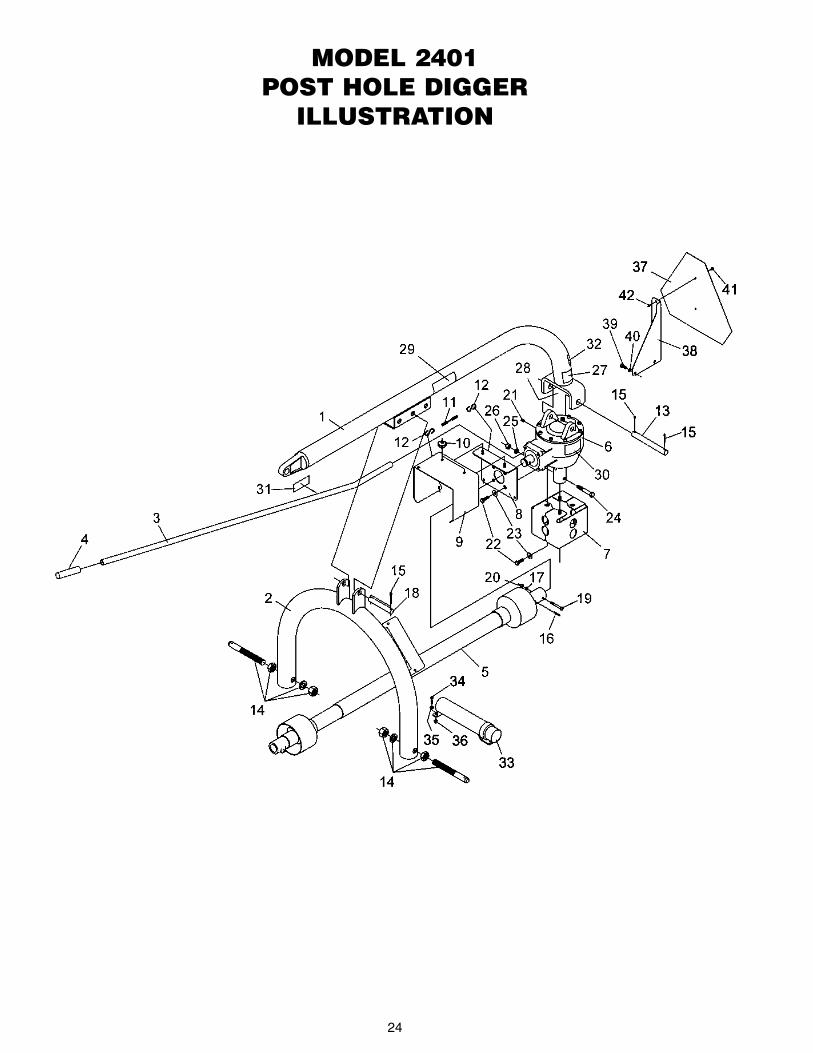
24
MODEL 2401POST HOLE DIGGER
ILLUSTRATION

25
AUGER PARTS ILLUSTRATION
AUGER TEETH MOUNTING PATTERNS(Regular Duty Augers)

DOWN FORCE KIT INSTRUCTIONSKIT #50072109 (FOR MODEL 2401 POST HOLE DIGGER)
INSTALLATION OPERATION
26
1. Refer to the parts illustration and install the DownForce Kit parts as shown. The pin attaching the boomto the yoke is replaced by a ¾ - 10 NC x 6” lg. hexhead bolt and lock nut.
NOTE: Use a good grade hydraulic thread sealant andinstall the hydraulic components. Do not use Teflontape!
2. Place the pivot plates (1) outside of yoke and installthe ¾” x 6” bolt (2). DO NOT TIGHTEN the bolt andnut completely as the plates need to pivot freely.
3. Install second ¾” x 6” bolt (2) spacer (4) and lock nut(3) in middle hole.
4. Install third ¾” bolt (2), two spacers (5) base end ofcylinder (11) and lock nut (3) in top hole.
5. Install the hydraulic cylinder (11) and boom clamp (6& 7). The cylinder rod should be retracted and theboom clamp installed loosely so that it can slip on theboom. Raise the Post Hole Digger to its full up posi-tion. Now tighten the boom clamp bolts to 300 ft. lbs.torque. It may be necessary to retighten the clampbolts after initial use to keep the clamp from slipping.
6. Attach adapter (17) and relief valve (14) to the cylin-der. Attach male quick coupler (not supplied) to pres-sure hose (15). Attach hose to top part of relief valve.Connect pressure hose (15) to one of the tractorremote outlets.
7. Connect the return hose (item # 16) directly to thetractor hydraulic reservoir fill opening. NOTE: DO NOTCONNECT THE RETURN HOSE TO A REMOTEOUTLET. The remote outlet valve ports are blocked inthe neutral position and will damage the hydrauliccylinder or other parts when the boom is raised.
Lower the Post Hole Digger in the usual manner andallow the auger to dig. As down force is needed, apply itcarefully and in small amounts by using the control leveron the tractor remote outlet. It will be necessary to con-tinue lowering the lift arms as the auger digs. Applyingtoo much down force at one time can stall the auger andpossibly cause the shear bolt on the post hole diggerinput shaft to shear. NOTE: REPLACE THE SHEARBOLT WITH A GRADE #2 (SOFT) BOLT ONLY. Usinga (HARD) bolt can damage the auger, PTO driveline orgearbox and void the warranty.
The boom can be raised in the normal manner with-out relieving the down force cylinder pressure. Hydrauliccylinder will retract.
NOTE: DAMAGE CAN OCCUR IF HOSES ARENOT CONNECTED CORRECTLY. If the returnhydraulic hose is connected to the other tractor remoteoutlet instead of directly to the tractor hydraulic reser-voir, severe damage will possibly occur to the hydrauliccylinder and post hole digger when the boom is raised.Make sure hydraulic hoses are connected correctly.

27
OPTIONAL PARKING STAND
KIT #50072108 (FOR MODEL 2401 POST HOLE DIGGER)
The Parking Stand Kit has a plate that bolts to the bottom of the gearbox. Two removable legs go into sockets weld-ed on the plate. The legs are pinned in place. The two legs and the auger form a tripod which supports the post holedigger in a vertical position. A formed hook keeps the PTO driveline end off the ground.
This makes connecting or removing the post hole digger from the tractor a one man job.
Make sure the post hole digger will be located on a solid surface and in a location away from children, animals, ortraffic areas.
1. Remove auger from digger.
2. Remove hardware (5 & 6) and output shield (7) frombottom of gearbox.
3. Place parking stand base plate (4) and output shield(7) over the output shaft. Secure to the bottom of thegearbox using four bolts (5) and flat washers (6) pre-viously removed.
4. Install auger to output shaft using two bolts previous-ly removed.
5. Raise digger to the transport position.
6. Insert the two stand legs (2) into the socket on thefront of the parking stand base plate. Secure with twolocking pins (3).
7. Lower digger until the two legs and the auger form atripod. This will support the post hole digger in a ver-tical position.
8. Remove 3 point arms and driveline from the tractor.Then disconnect the boom from tractor.
9. Attach the PTO hook (1) to the boom of the digger.
10. Hang the driveline from the hook to help prevent dirtand debris from accumulating in the locking collar onthe driveline PTO yoke.
Ref. # Description Qty.1 PTO Hook 1
2 Leg Stand 2
3 Lock Pin 2
4 Parking Stand Base Plate 1
5 M8 x 12mm Hex Head Cap Screw CL8.8 4
6 5/16” Flat Washer 4
7 Output Shield (2 Piece) 2
PARKING STAND PARTS

28
PROPER TORQUE FOR FASTENERS

29
SPECIFICATIONS
Tractor Category Compact, Category 1 and Category 2
Gearbox Special alloy pinion gears and tapered roller bearings – 3:1 ration.
Gears Heat-treated to Rockwell C30-40 to a depth of .030-.040
Driveline Equipped with quick-tach yoke to fit standard 6-spine PTO (completely shielded)
Cutting Edges Sold separately.
Center Point Sold separately. Fishtail Type.
Auger 6”, 9” and 12” sizes available – Regular Duty and Heavy Duty.
Boom 2-7/8” O.D. high strength tubing with multiple holes for height adjustment.
A-frame 2-7/8” high strength tubing.
Safety Shields On driveline, gearbox “U” joint and gearbox output shaft.
Shear Bolt Replaceable. On input shaft to protect driveline, auger and gears.
Options Hydraulic down force kit, 12” auger extension, and parking stand.
NOTES:
MODEL 2401

TO THE OWNER/OPERATOR/DEALER
2501 Griffin Avenue • Selma, AL 36703(334) 874-2700
www.bushhog.com