
POST HOLE DIGGER - Gearmore · POST HOLE DIGGER Operation, Service & Parts Manual For Models D20 &...
17
POST HOLE DIGGER Operation, Service & Parts Manual For Models D20 & D40 September 2006 Revised August 2009 FORM: D20_40DigRev.QXD
Transcript of POST HOLE DIGGER - Gearmore · POST HOLE DIGGER Operation, Service & Parts Manual For Models D20 &...

POST HOLE
DIGGER
Operation, Service
& Parts Manual For
Models D20 & D40
September 2006
Revised August 2009
FORM: D20_40DigRev.QXD
Introduction . . . . . . . . . . . . . . . . . . . . . . . . . . . . .1
Preparation . . . . . . . . . . . . . . . . . . . . . . . . . . . . . .2
Safety Information . . . . . . . . . . . . . . . . . . . . . . . .3
Assembly Instructions . . . . . . . . . . . . . . . . . . . . .4
3-Point Hitch Adjustments . . . . . . . . . . . . . . . . .5
Operating Digger . . . . . . . . . . . . . . . . . . . . . . . . .6
Lubrication & General Maintenance . . . . . . . . .7
Components D20 . . . . . . . . . . . . . . . . . . . . . . . .8-9
Components D40 . . . . . . . . . . . . . . . . . . . . . .10-11
Gearbox Breakdown 682100 . . . . . . . . . . . . . . .12
Driveline Breakdown Eurocardan . . . . . . . . . .13
Driveline Breakdown ITG . . . . . . . . . . . . . . . . .14
Limited Warranty . . . . . . . . . . . . . . . . . . . . . . .15
TABLE OF CONTENTS

Thank you for purchasing a Gearmore Digger.
In order to be able to safely and properly operate this digger, it will benecessary for you to familiarize yourself with the contents of the entiremanual before you attempt to assemble and operate your digger.
Please read all safety and assembly instructions before attempting to operate digger.
INTRODUCTION
Page 1
Date of Purchase: ________________________________
Model Number: __________________________________
Serial Number __________________________________

WARNING
To prevent possible personal injury or death during assembly, installation, operation, adjustment, or removal of implement: DO NOT wear loose clothing, always wear gloves and safety glasses or face shield. Keep other persons a minimum of twenty-five feet (25') away from any unit under power.
READ THIS BEFORE OPERATING DIGGER
TRAINING:
Know your controls. Read this operator's manual and the manual providedwith your tractor.
Learn how to stop the tractor, engine and digger quickly, in case of anemergency.
DO NOT allow children to operate machine, or adults to operate it withoutproper instructions.
PREPARATION:
� Clear area of debris.
� Never permit any person other than the operator to ride on boardthe tractor at any time.
� DO NOT allow riders on digger at any time.
� Operate only in daylight or good artificial light.
� Ensure all safety shielding is properly installed.
� Always wear relatively tight and belted clothing when operating digger.Loose clothing should not be worn, as it could get caught in the movingparts or controls.
PREPARATION
Page 2

OPERATIONAL SAFETY:Guards and safety shields are for your protection. DO NOT operate equipment unless they are in place.
Always operate tractor PTO (power take-off) at recommended RPM (revolutions per minute).
Disengage tractor PTO and shift into neutral before attempting to start engine.
Read and observe all safety decals on the tractor and digger.
NEVER allow anyone within 25' of machine while it is in operation.
Do not stop or start suddenly when going uphill or downhill. Avoid operation on steep slopes.
Be alert for holes in terrain and other hidden hazards. Always drive slowly over rough ground.
Reduce speed on slopes and in sharp turns to prevent tipping or loss of control. Be careful when changing direction on slopes.
Stop digger and tractor immediately upon striking an obstruction. Turn off engine, inspect digger, and repair any damage before resuming operation.
Disengage power to digger and stop engine before dismounting from tractor, making any repairs or adjustments, transporting, or unclogging digger.
Take all possible precautions when leaving tractor unattended. Disengage PTO,lower digger, shift into neutral, set parking brake, stop engine, and remove keyfrom ignition.
Front tractor weights or front tire ballast should be used to enhance front end stability on small tractors.
Check to make sure PTO is properly connected and that the driveline is correct to prevent bottoming out or pulling apart during the full lift range of the hitch.
This implement is designed for a one-man operation. It is the responsibility of the tractor operator to see that no one is in the proximity of the implement when it is started. DO NOT operate the implement with another person within25' of the implement, PTO drive, or auger.
SAFETY INFORMATION
Page 3

The Gearmore Diggers are shipped disassembled in four (4) pieces.
1. Gearbox and auger assembly.
2. Driveshaft assembly with pins and operating instructions packet.
3. The yoke assembly.
4. The boom assembly.
Please assemble in the following manner:
1. Attach end of boom to upper 3-point link bracket of the tractor.
2. Attach yoke lift pins into bottom lift arms of tractor. Attach with lynch pins (not supplied).
3. Bolt yoke to boom with 5/8" x 2 1/2" grade 5 bolt (supplied).
4. Raise gearbox assembly up and attach it to the boom with the supplied pin, fasten into place with two cotter pins.
5. Slide driveshaft onto input shaft of gearbox and secure with 3/8" x 2 1/4" grade 2 shear bolt.
6. Install safety roll pin on implement yoke. This will prevent driveshaft from coming off input shaft if shear bolt shears.
7. Install input shaft shield onto gearbox.
8. Install other end of driveshaft to tractor PTO. Raise and lower digger assembly to verify driveshaft is not bottoming out or pulling apart during the full lift range of the hitch.
9. Slide auger adapter shield onto auger to be used.
10. Attach auger to output shaft using 1/2" x 3" grade 2 bolt.
11. Make sure all bolts and pins are in place and secure before operating digger.
ASSEMBLY INSTRUCTIONS
Page 4

The average operating range of the digger should be between 5" and 65" above the ground level. It is recommended that the 3-point hitch be adjusted toward the minimum required operating range, due to the fact that the greater the operating range, the less force there is available for raising the auger in difficult soil conditions.
CAUTION
Any time an adjustment is made to the 3-point hitch, reference should be made to the 3-point hitch section of the tractor operator's manual. After any adjustments, the digger should be carefully raised and lowered through its operating range and checked for interference.
To change vertical limits of the digger (transport height and digging depth).
1. Attach front end of boom to a hole in the upper link bracket. Upper holes will lower the digger; lower holes will raise the digger.
2. Attach yoke to one of the other existing holes on the boom. Front holes usually increase range; rear holes decrease range.
3. Check tractor hydraulic system to be sure it is raising and lowering to its maximum and minimum recommended heights. Transport height and digging depth can be limited by adjusting lift control handle limit stops.
4. If the front end of the boom strikes some part of the tractor when digger is raised or lowered:
a. Make adjustments under Ref. #1.
b. If at all possible, relocate or adjust the part of the tractor that iscausing the interference.
5. If the tractor has difficulty raising the digger, decrease the lift range.
6. If the tractor hitch raises or lowers rapidly during hydraulic functions, refer to hydraulic adjustment section of the tractor manual.
3-POINT HITCH ADJUSTMENTS
Page 5

WARNING
Never operate digger without gloves and eye protection. Keep other persons a minimum of twenty-five feet (25') away from the digger operation.
TO OPERATE DIGGER:
1. With your digger correctly assembled and attached to the tractor, engagethe tractor PTO at idling speed to give the digger a test run. Then disengage tractor PTO.
2. Place the auger at a vertical position at the desired location of the first hole.
3. Set tractor brake to hold the tractor at the correct position and to prevent damage to the digger.
4. Make sure gloves are on, eye protection is in place, and that nobody is within twenty-five feet (25') of the operation. Engage PTO with the engine at a little more than idle (this speed will depend on soil conditions and experience will help determine proper speed).
5. Slowly lower digger to the ground. After the auger goes a foot or so intothe ground, raise auger almost out of the hole, this allows the auger to clean itself of loose soil. Then drill deeper and raise the auger again. Repeat this procedure until the desired hole depth is reached.
6. When desired hole depth is reached, disengage PTO and raise auger from the hole. For tractors that require PTO engagement to produce lifting power,allow auger to turn at idle while raising it from the hole.
7. If shear bolt breaks:
a. Shut off tractor engine and allow PTO shaft to come to a complete stop.b. Remove broken shear bolt.c. Install new shear bolt (part #600518), then tighten the shear bolt nut
securely.
8. If auger becomes lodged on an obstruction under ground, shut off PTO and tractor engine. Turn the auger several revolutions in reverse. Never attempt to use hydraulic lift of tractor to dislodge auger.
OPERATING DIGGER
Page 6

GEARBOX -
Fill gearbox with gear oil. Use SAE #140 multigear lubricant or equivalent. Gear oil should be changed after 500 hours of use.
DRIVESHAFT -
Grease both cross & bearing and shear pin yoke. After that grease every8 hours of use. It is also necessary, from time to time, to untelescope the driveshaft to clean and re-grease tubing.
GENERAL MAINTENANCE
Carefully follow all instructions as stated in this operator's manual, this includes safety, assembly, 3-point hitch adjustments, operation, lubrication, and maintenance of the digger.
1. Check bolts, nuts, cotter pins, etc. for tightness.
2. Check auger daily for loose, worn or broken teeth or points.
3. Replace, immediately, any damaged or worn parts.
4. Check lubrication - see lubrication section.
IMPORTANT NOTICE:
Due to the exceptionally long travel of the hitch arms on some tractors, extreme caution should be taken that you do not lift and operate the digger at too high of an angle. Also, do not have PTO engaged when moving from hole to hole. Failure to follow these procedures can damage the digger and/or tractor.
LUBRICATION
Page 7

COMPONENTS FOR D20 DIGGER
Page 8
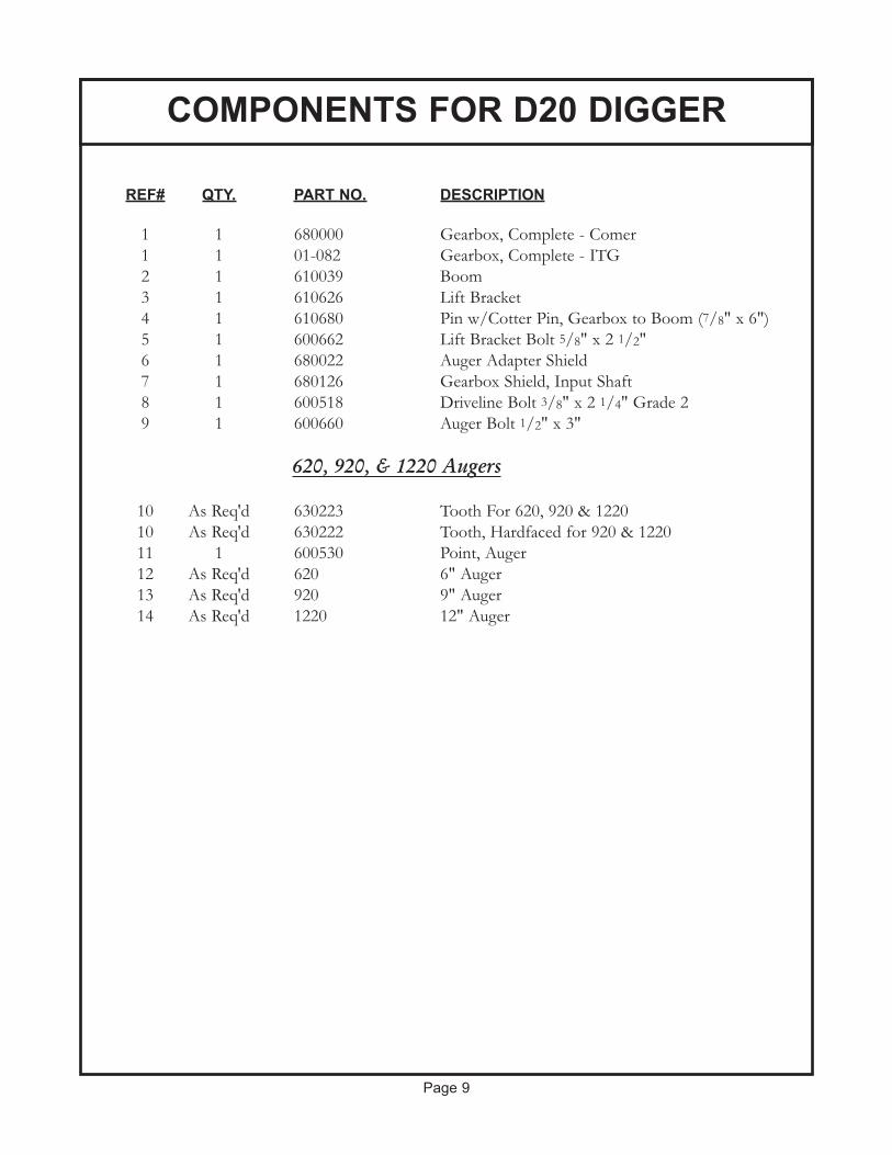
REF# QTY. PART NO. DESCRIPTION
1 1 680000 Gearbox, Complete - Comer1 1 01-082 Gearbox, Complete - ITG2 1 610039 Boom3 1 610626 Lift Bracket4 1 610680 Pin w/Cotter Pin, Gearbox to Boom (7/8" x 6")5 1 600662 Lift Bracket Bolt 5/8" x 2 1/2"6 1 680022 Auger Adapter Shield7 1 680126 Gearbox Shield, Input Shaft8 1 600518 Driveline Bolt 3/8" x 2 1/4" Grade 29 1 600660 Auger Bolt 1/2" x 3"
620, 920, & 1220 Augers
10 As Req'd 630223 Tooth For 620, 920 & 122010 As Req'd 630222 Tooth, Hardfaced for 920 & 122011 1 600530 Point, Auger12 As Req'd 620 6" Auger13 As Req'd 920 9" Auger14 As Req'd 1220 12" Auger
COMPONENTS FOR D20 DIGGER
Page 9

COMPONENTS FOR D40 DIGGER
Page 10

REF# QTY. PART NO. DESCRIPTION
1 1 680000 Gearbox, Complete - Comer1 1 01-082 Gearbox, Complete - ITG2 1 680039 Boom3 1 600625 Lift Bracket4 1 682105 Pin w/Cotter Pin, Gearbox to Boom (7/8" x 7")5 1 600662 Lift Bracket Bolt 5/8" x 2 1/2"6 1 680024 Auger Adapter Shield7 1 680022 Gearbox Shield, Input Shaft8 1 600518 3/8" x 2 1/4" Grade 2 Bolt9 1 600660 Auger Bolt 1/2" x 3"
640, 940, & 1240 Augers
10 As Req'd 630223 Tooth For 640, 940 & 124010 As Req'd 630222 Tooth, Hardfaced for 940 & 124011 1 600530 Point, Auger12 As Req'd 640 6" Auger13 As Req'd 940 9" Auger14 As Req'd 1240 12" Auger
640P, 940P, & 1240P Augers
15 1 135088 Point, Auger16 As Req'd 35 Tooth, Dirt
16A As Req'd 40/50 Tooth, Dirt (2012)17 As Req'd 37 Tooth, Gage18 As Req'd 640P 6" Pengo Auger19 As Req'd 940P 9" Pengo Auger20 As Req'd 1240P 12" Pengo Auger
COMPONENTS FOR D40 DIGGER
Page 11

REF # QTY. PART NUMBER DESCRIPTION1 1 682-101 Housing (18-013)2 8 682-102 Lockwasher (07-001)3 8 682-103 Cap Screw M10 x 30 x 1.75 (06-003)4 2 682-104 Pipe Plug 1/2" (09-002)5 1 682-105 Pin, Hinge 7/8" x 8"6 2 682-106 Cotter Pin7 1 682-107 Top Cap (20-014)8 As Req'd 682-108 Top Gasket .30 (08-021)9 As Req'd 682-109 Top Gasket .25 (08-022)10 As Req'd 682-110 Top Gasket .40 (08-023)11 1 682-111 Bearing Spacer (10-008)12 1 682-112 Retaining Ring (21-004)13 1 682-113 Input Seal (05-010)14 1 682-114 Pinion 11T w/Shaft (03-033)15 2 682-115 Bearing 207 (04-004)16 1 682-116 Retaining Ring (21-006)17 1 682-117 Output Seal 50 x 70 x 10 (05-008)18 1 682-118 Output Shaft (02-029)19 2 682-119 Taper Bearing Assembly 7210 (04-011)20 1 682-120 Outer Bearing Spacer (10-011)21 1 682-121 Retaining Ring (21-001)22 As Req'd 682-122 Gear Adj. Shim .30 (17-002)23 As Req'd 682-123 Gear Adj. Shim .50 (17-003)24 1 682-124 Ring Gear 33T (03-032)
1 682-126 Set Collar 7/8"
GEARBOX BREAKDOWN - 682100
Page 12

REF # QTY. PART NO. DESCRIPTION
1 36718 Driveline Complete (Eurocardan)1 1 31372 Yoke Assembly 1 3/8" x 6 Sp Tractor End2 2 31369 Repair Kit #4 Metric3 1 1140003 Decal, Warning4 1 32204 Yoke 1 1/4" Rnd Implement End5 1 35064 Tube Bearing Lock6 1 35070 Outer Tube Rigid Cone7 1 33994 Cone, Standard8 4 35072 Stop Rotation Pin9 2 33994 Anti-Rotation Chain10 1 35075 Soft Cone11 1 35071 Inner Tube Rigid Cone12 1 35067 Tube Bearing13 1 36726 Complete Shield
DRIVELINE BREAKDOWN - (EUROCARDAN)
Page 13
(Yellow Shield)

REF # QTY. PART NO. DESCRIPTION
1 682200 Driveline Complete (ITG) - 35-1811 1 612165 Yoke Assembly 1 3/8" x 6 Sp Tractor End - 26-0152 1 09-017 Grease Zerk M6 x 13 1 612155 Yoke 1 1/4" Round Bore Imp. End - 23-0054 2 612157 Cross Kit - 26-0215 1 682204 Inner Tube & Yoke - 28-0456 1 612163 Collar Kit - 26-0217 1 13-001 Warning Label8 1 682206 Outer Tube & Yoke - 28-0909 1 682207 Complete Shield - 27-06210 1 633154 Shear Bolt 2 1/4" (not shown)11 1 1/4-20x1/2 Set Screw (not shown)12 1 612180 Outer Tube Bearing Lock - 04-04313 1 612174 Outer Tube Rigid Cone - 24-01414 1 612178 Cone, Standard - 24-01515 6 612175 Locking Pin - 12-01416 2 33994 Anti-Rotation Chain17 1 612174 Soft Cone - 24-01218 1 612173 Inner Tube Rigid Cone - 24-01119 1 612172 Inner Tube Bearing Lock - 04-042
DRIVELINE BREAKDOWN - (ITG)
Page 14
(Black Shield)

GEARMORE, INC., warrants each new Gearmore product to be free from defects in materi-
al and workmanship for a period of twelve (12) months from date of purchase to the original
purchaser. This warranty shall not apply to implements or parts that have been subject to
misuse, negligence, accident, or that have been altered in any way.
Our obligation shall be limited to repairing or replacement of any part, provided that such
part is returned within thirty (30) days from date of failure to Gearmore through the dealer
from whom the purchase was made, transportation charges prepaid.
This warranty shall not be interpreted to render us liable for injury or damages of any kind or
nature, direct, consequential or contingent, to person or property. This warranty does not
extend to loss of crops, loss because of delay in harvesting or any other expenses, for any
other reasons.
Gearmore in no way warranties engines, tires, or other trade accessories, since these items
are warranted separately by these respective manufacturers.
Gearmore reserves the right to make improvements in design or changes in specification at
any time, without incurring any obligations to owners or units previously sold.
GEARMORE, INC.
13477 Benson Ave.
Chino, CA 91710
Always refer to and heed machine operating warning decals on machine.
LIMITED WARRANTY
Page 15
The serial number of this product is stored in our computer database, thus
submitting a warranty registration card is not required.


