POLLING BOARD POL-1 - Notifier · POLLING BOARD POL-1 PRELIMINARY COPY User Manual NOTIFIER...
7
POLLING BOARD POL-1 PRELIMINARY COPY User Manual User Manual NOTIFIER ESPAÑA, S.A. Central: Avda. Conflent 84, Nave 23 Pol. Ind. Pomar de Dalt 08916 BADALONA (BARCELONA) Tel.: 93 497 39 60 Fax: 93 465 86 35 MN-DT-960I 13 OCTOBER 2000 All specifications are subject to change without notice
Transcript of POLLING BOARD POL-1 - Notifier · POLLING BOARD POL-1 PRELIMINARY COPY User Manual NOTIFIER...

POLLING BOARD
POL-1
PRELIMINARY COPY
User ManualUser Manual
NOTIFIER ESPAÑA, S.A.Central: Avda. Conflent 84, Nave 23Pol. Ind. Pomar de Dalt08916 BADALONA (BARCELONA)Tel.: 93 497 39 60 Fax: 93 465 86 35
MN-DT-960I13 OCTOBER 2000
All specifications are subject to change without notice

2
POL-1 Instructions Manual
Configuration Screen
The POL-1 software can be run in different serial RS232ports: COM1, COM2, COM3 and COM4
The baud rate depends on the values selected on the POL-1hardware (19200 bauds by default). In some old computersthis value can be reduced in case of communication faults.This baud rate should have the same value as the POL-1hardware board.
Main Screen
Selecting the “Autoprogramming” option in the main menu the software looks for all the devices installed in the loopA new screen reporting the analogue detectors and modules connected to the loop will appear in 15 sec.
In this example the POL-1 software has found 6 heat detectors, reports the devices found in this address, the colour showsthe type ID

3
DETECTORSHeat = Blue Notifier detectors FDX-551E / FDX-551REIon = Red Notifier detectors CPX-551E / CPX-751EPhoto/Optical = Dark green Notifier detectors SDX-551E / SDX-751EOmni / Multisensor = Magenta Notifier detector IPX-751ELaser VIEW sensor = Light green Notifier detector LPX-751E
MODULES Monitor Modules = Blue MMX-1, MMX-2, MMX-10, MMX-102 Monitor Conventional Detector= Green IZM-1 o ZMX-1 Control Module = Red CMX-2, CMX-10R
The hardware does not recognise two detectors with the same address (dual current) but, usually, if two devices have the sameaddress, PW1 becomes bigger (above 315), and a warning message appears during the autoprogramming process.
Click on the “OK” button to continue the autoprogramming process . Click on “Cancel” to abort it.
The initial value appears on the bottom right-hand corner of the screen (default setting at325µsec)
If there is a short-circuit on the loop or a defective detector, the PW1 value becomes lower than 100 sec. and the software willreport a warning message.
Selecting devicesUp to 20 devices can be monitored in the selected sequence by clicking on the check button
In this case the sequence is:Detector 1, D 26, D 27, D 29, D 31, D02, D 03, D 04, again D 01, D 42,D 41, D 50, D 08, M05, M06, M07, again D 02, again D 01, D 16 and M 08
The sequence will start again after two seconds of delay. This delay between sequences can be set between 0 seconds (almost0.25 seconds) and 60 seconds (1 minute) in the scroll bar.
4
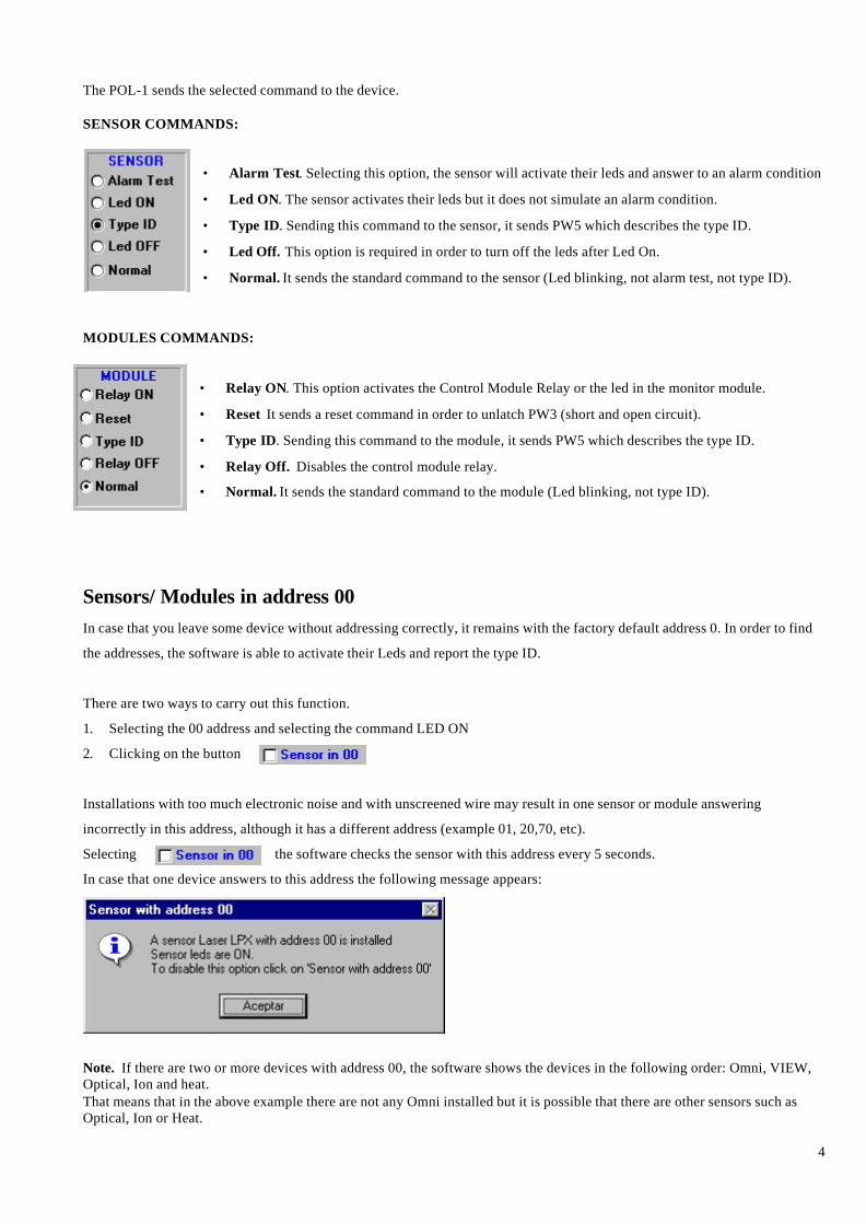
The POL-1 sends the selected command to the device.
SENSOR COMMANDS:
• Alarm Test. Selecting this option, the sensor will activate their leds and answer to an alarm condition
• Led ON. The sensor activates their leds but it does not simulate an alarm condition.
• Type ID. Sending this command to the sensor, it sends PW5 which describes the type ID.
• Led Off. This option is required in order to turn off the leds after Led On.
• Normal. It sends the standard command to the sensor (Led blinking, not alarm test, not type ID).
MODULES COMMANDS:
• Relay ON. This option activates the Control Module Relay or the led in the monitor module.
• Reset It sends a reset command in order to unlatch PW3 (short and open circuit).
• Type ID. Sending this command to the module, it sends PW5 which describes the type ID.
• Relay Off. Disables the control module relay.
• Normal. It sends the standard command to the module (Led blinking, not type ID).
Sensors/ Modules in address 00In case that you leave some device without addressing correctly, it remains with the factory default address 0. In order to find
the addresses, the software is able to activate their Leds and report the type ID.
There are two ways to carry out this function.
1. Selecting the 00 address and selecting the command LED ON
2. Clicking on the button
Installations with too much electronic noise and with unscreened wire may result in one sensor or module answering
incorrectly in this address, although it has a different address (example 01, 20,70, etc).
Selecting the software checks the sensor with this address every 5 seconds.
In case that one device answers to this address the following message appears:
Note. If there are two or more devices with address 00, the software shows the devices in the following order: Omni, VIEW,Optical, Ion and heat.That means that in the above example there are not any Omni installed but it is possible that there are other sensors such asOptical, Ion or Heat.
5
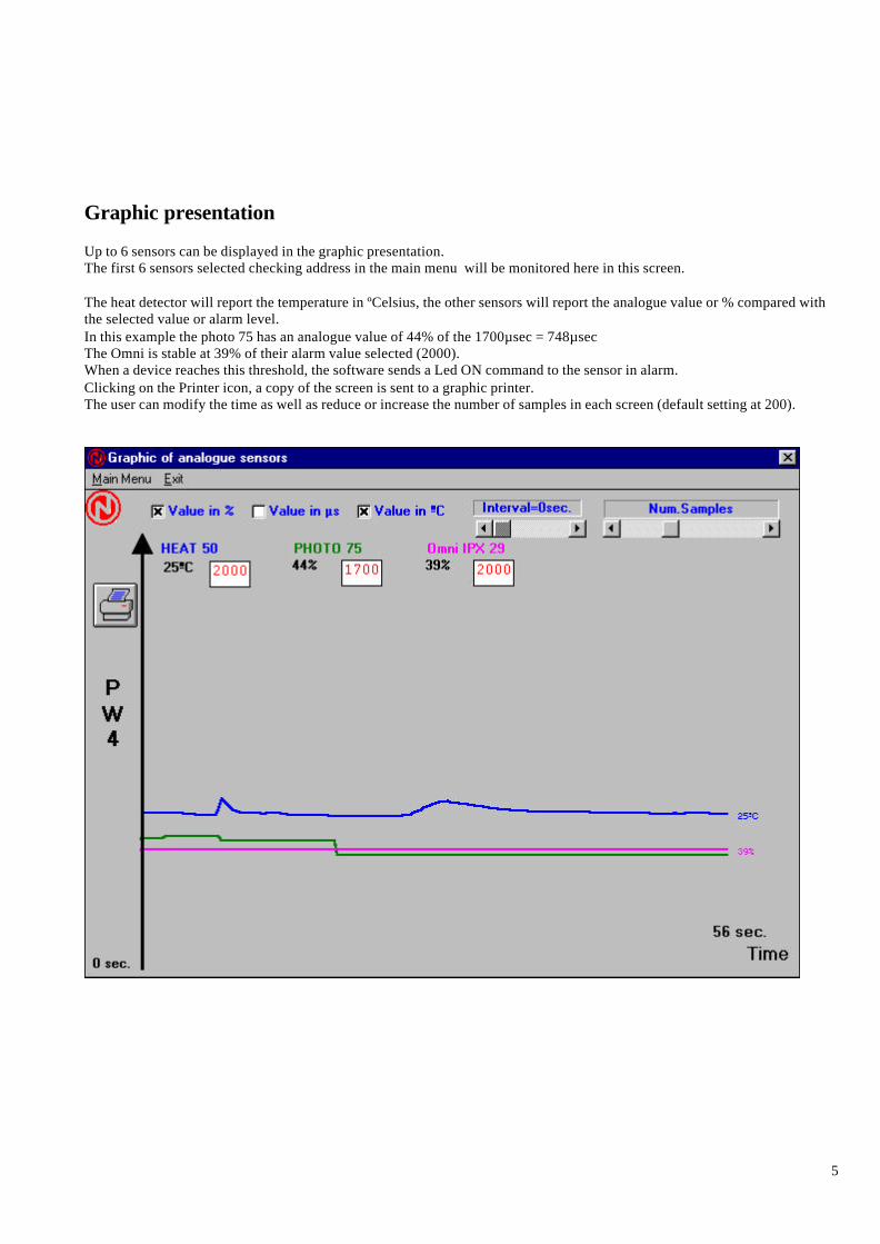
Graphic presentation
Up to 6 sensors can be displayed in the graphic presentation.The first 6 sensors selected checking address in the main menu will be monitored here in this screen.
The heat detector will report the temperature in ºCelsius, the other sensors will report the analogue value or % compared withthe selected value or alarm level.In this example the photo 75 has an analogue value of 44% of the 1700µsec = 748µsecThe Omni is stable at 39% of their alarm value selected (2000).When a device reaches this threshold, the software sends a Led ON command to the sensor in alarm.Clicking on the Printer icon, a copy of the screen is sent to a graphic printer.The user can modify the time as well as reduce or increase the number of samples in each screen (default setting at 200).
6
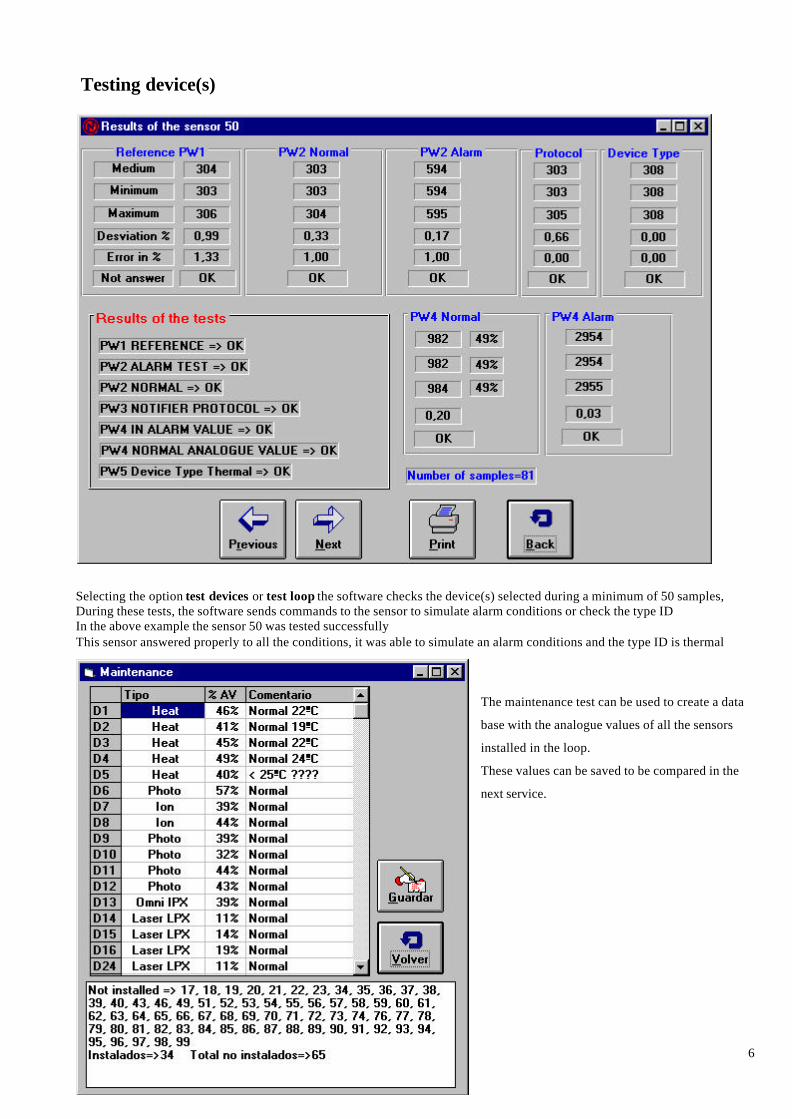
Testing device(s)
Selecting the option test devices or test loop the software checks the device(s) selected during a minimum of 50 samples,During these tests, the software sends commands to the sensor to simulate alarm conditions or check the type IDIn the above example the sensor 50 was tested successfullyThis sensor answered properly to all the conditions, it was able to simulate an alarm conditions and the type ID is thermal
The maintenance test can be used to create a data
base with the analogue values of all the sensors
installed in the loop.
These values can be saved to be compared in the
next service.

7
Activate/Disable sensor ledsThis option allows to the end user to activate or switch off the two sensor leds selecting the device address.
Activate / Disable Control Relay or Monitor Module Led