PLASMA ARC CUTTING TORCHES equipment/plasma...8 section 1 safety precautions 5. AWS C5.5 -...
32
PT-32EH PLASMA ARC CUTTING TORCHES F15-747 02 / 2006 Instruction Manual
Transcript of PLASMA ARC CUTTING TORCHES equipment/plasma...8 section 1 safety precautions 5. AWS C5.5 -...

PT-32EH PLASMA ARC CUTTING TORCHES
F15-747 02/2006
InstructionManual

�
TheseINSTRUCTIONSareforexperiencedoperators.Ifyouarenotfullyfamiliarwiththeprinciplesofopera-tionandsafepracticesforarcweldingandcuttingequipment,weurgeyoutoreadourbooklet,"PrecautionsandSafePracticesforArcWelding,Cutting,andGouging,"Form52-529.DoNOTpermituntrainedpersonstoinstall,operate,ormaintainthisequipment.DoNOTattempttoinstalloroperatethisequipmentuntilyouhavereadandfullyunderstandtheseinstructions.Ifyoudonotfullyunderstandtheseinstructions,contactyoursupplierforfurtherinformation.BesuretoreadtheSafetyPrecautionsbeforeinstallingoroperatingthisequipment.
Be sure this information reaches the operator.You can get extra copies through Your supplier.
USERRESPONSIBILITY
This equipment will perform in conformity with the description thereof contained in this manual and accompanying labels and/or inserts when installed, operated, maintained and repaired in accordance with the instructions provided. This equipment must be checked periodically. Malfunctioning or poorly maintained equipment should not be used. Parts that are broken, missing, worn, distorted or contaminated should be replaced immediately. Should such repair or replacement become necessary, the manufacturer recommends that a telephone or written request for service advice be made to the Authorized Distributor from whom it was purchased.
This equipment or any of its parts should not be altered without the prior written approval of the manufacturer. The user of this equipment shall have the sole responsibility for any malfunction which results from improper use, faulty maintenance, damage, improper repair or alteration by anyone other than the manufacturer or a service facility designated by the manufacturer.

�
TABLEOFCONTENTS
SECTION TITLE PAGE PARAGRAPH
SECTION1 SAFETY........................................................................................................................ 5 English ........................................................................................................................................................ 5 Spanish ....................................................................................................................................................... 9 French ......................................................................................................................................................... 1�
SECTION2 DESCRIPTION .......................................................................................................................................... 17 �.1 General ....................................................................................................................................................... �0 �.� Scope .......................................................................................................................................................... �0 SECTION3 INSTALLATION........................................................................................................................................ �1 �.1 Fitting the PT-��EH Torch .................................................................................................................... �1 �.� General ....................................................................................................................................................... �� �.� Assembly ................................................................................................................................................... ��
SECTION4 OPERATION ............................................................................................................................................. �� 4.1 Steel Heat Shield Guards ...................................................................................................................... �� SECTION5 MAINTENANCE ...................................................................................................................................... �5 5.1 General ....................................................................................................................................................... �5 5.� Inspection and Cleaning of Consumables ..................................................................................... �5 5.� Removing/Replacing Torch Head and Switch from Service Line .......................................... �6 SECTION6 REPLACEMENTPARTS ........................................................................................................................ �7 6.1 General ....................................................................................................................................................... �7 6.� Parts ............................................................................................................................................................. �7

4
TABLEOFCONTENTS

5
section 1 safety precautions
1.0 SafetyPrecautions 1.1 Safety-English
WARNING: These Safety Precautions are for your protection. They summarize pre-cautionary information from the references listed in Additional Safety Information sec-
tion. Before performing any installation or operating procedures, be sure to read and follow the safety precautions listed below as well as all other manuals, material safety data sheets, labels, etc. Failure to observe Safety Precautions can result in injury or death.
PROTECTYOURSELFANDOTHERS--Somewelding,cutting,andgougingprocessesarenoisyandrequireearprotection.Thearc,likethesun,emitsultraviolet(UV)andotherradiation
andcaninjureskinandeyes.Hotmetalcancauseburns.Trainingintheproperuseoftheprocessesandequipmentisessentialtopreventaccidents.Therefore:
1. Always wear safety glasses with side shields in any work area, even if welding helmets, face shields, and goggles are also required.
�. Use a face shield fitted with the correct filter and cover plates to protect your eyes, face, neck, and ears from sparks and rays of the arc when operat-ing or observing operations. Warn bystanders not to watch the arc and not to expose themselves to the rays of the electric-arc or hot metal.
�. Wear flameproof gauntlet type gloves, heavy long-sleeve shirt, cuffless trousers, high-topped shoes, and a welding helmet or cap for hair protection, to protect against arc rays and hot sparks or hot metal. A flameproof apron may also be desirable as protec-tion against radiated heat and sparks.
4. Hot sparks or metal can lodge in rolled up sleeves, trouser cuffs, or pockets. Sleeves and collars should be kept buttoned, and open pockets eliminated from the front of clothing.
5. Protect other personnel from arc rays and hot sparks with a suitable non-flammable partition or curtains.
6. Use goggles over safety glasses when chipping slag or grinding. Chipped slag may be hot and can fly far. Bystanders should also wear goggles over safety glasses.
FIRESANDEXPLOSIONS-- Heatfromflames and arcs can start fires. Hotslagorsparkscanalsocausefiresandexplosions.Therefore:
1. Remove all combustible materials well away from the work area or cover the materials with a protec-tive non-flammable covering. Combustible materials include wood, cloth, sawdust, liquid and gas fuels, solvents, paints and coatings, paper, etc.
�. Hot sparks or hot metal can fall through cracks or crevices in floors or wall openings and cause a hid-den smoldering fire or fires on the floor below. Make certain that such openings are protected from hot sparks and metal.“
�. Do not weld, cut or perform other hot work until the workpiece has been completely cleaned so that there are no substances on the workpiece which might produce flammable or toxic vapors. Do not do hot work on closed containers. They may explode.
4. Have fire extinguishing equipment handy for instant use, such as a garden hose, water pail, sand bucket, or portable fire extinguisher. Be sure you are trained in its use.
5. Do not use equipment beyond its ratings. For ex-ample, overloaded welding cable can overheat and create a fire hazard.
6. After completing operations, inspect the work area to make certain there are no hot sparks or hot metal which could cause a later fire. Use fire watchers when necessary.
7. For additional information, refer to NFPA Standard 51B, "Fire Prevention in Use of Cutting and Welding Processes", available from the National Fire Protec-tion Association, Batterymarch Park, Quincy, MA 0��69.
ELECTRICAL SHOCK -- Contact withliveelectricalpartsandgroundcancausesevereinjuryordeath.DONOTuseACweldingcurrentindampareas,ifmovementisconfined,orifthereisdangeroffalling.

6
section 1 safety precautions
1. Be sure the power source frame (chassis) is con-nected to the ground system of the input power.
�. Connect the workpiece to a good electrical ground.
�. Connect the work cable to the workpiece. A poor or missing connection can expose you or others to a fatal shock.
4. Use well-maintained equipment. Replace worn or damaged cables.
5. Keep everything dry, including clothing, work
area, cables, torch/electrode holder, and power source.
6. Make sure that all parts of your body are insulated from work and from ground.
7. Do not stand directly on metal or the earth while working in tight quarters or a damp area; stand on dry boards or an insulating platform and wear rubber-soled shoes.
8. Put on dry, hole-free gloves before turning on the power.
9. Turn off the power before removing your gloves.
10. Refer to ANSI/ASC Standard Z49.1 (listed on next page) for specific grounding recommenda-tions. Do not mistake the work lead for a ground cable.
ELECTRIC AND MAGNETIC FIELDS— May be dangerous. Electric cur-rent flowing through any conduc-tor causes localized Electric andMagneticFields(EMF).Weldingand
cuttingcurrentcreatesEMFaroundweldingcablesandweldingmachines.Therefore:
1. Welders having pacemakers should consult their physician before welding. EMF may interfere with some pacemakers.
�. Exposure to EMF may have other health effects which are unknown.
�. Welders should use the following procedures to minimize exposure to EMF:
A. Route the electrode and work cables together. Secure them with tape when possible.
B. Never coil the torch or work cable around your body.
C. Do not place your body between the torch and work cables. Route cables on the same side of your body.
D. Connect the work cable to the workpiece as close as possible to the area being welded.
E. Keep welding power source and cables as far away from your body as possible.
FUMES AND GASES -- Fumes andgases,cancausediscomfortorharm,particularly in confined spaces. Donotbreathefumesandgases.Shield-ing gases can cause asphyxiation.
Therefore:
1. Always provide adequate ventilation in the work area by natural or mechanical means. Do not weld, cut, or gouge on materials such as galvanized steel, stain-less steel, copper, zinc, lead, beryllium, or cadmium unless positive mechanical ventilation is provided. Do not breathe fumes from these materials.
�. Do not operate near degreasing and spraying opera-tions. The heat or arc rays can react with chlorinated hydrocarbon vapors to form phosgene, a highly toxic gas, and other irritant gases.
�. If you develop momentary eye, nose, or throat ir-ritation while operating, this is an indication that ventilation is not adequate. Stop work and take necessary steps to improve ventilation in the work area. Do not continue to operate if physical discom-fort persists.
4. Refer to ANSI/ASC Standard Z49.1 (see listing below) for specific ventilation recommendations.

7
section 1 safety precautions
5.WARNING: Thisproduct,whenusedforweldingorcutting,producesfumesorgaseswhich contain chemicals known totheStateofCaliforniatocausebirthdefects and, in some cases, cancer.(California Health & Safety Code§25249.5etseq.)
CYLINDER HANDLING -- Cylinders,ifmishandled,canruptureandvio-lently release gas. Sudden ruptureofcylinder,valve,orreliefdevicecaninjureorkill.Therefore:
1. Use the proper gas for the process and use the proper pressure reducing regulator designed to operate from the compressed gas cylinder. Do not use adaptors. Maintain hoses and fittings in good condition. Follow manufacturer's operating instruc-tions for mounting regulator to a compressed gas cylinder.
�. Always secure cylinders in an upright position by chain or strap to suitable hand trucks, undercar-riages, benches, walls, post, or racks. Never secure cylinders to work tables or fixtures where they may become part of an electrical circuit.
�. When not in use, keep cylinder valves closed. Have valve protection cap in place if regulator is not con-nected. Secure and move cylinders by using suitable hand trucks. Avoid rough handling of cylinders.
4. Locate cylinders away from heat, sparks, and flames. Never strike an arc on a cylinder.
5. For additional information, refer to CGA Standard P-1, "Precautions for Safe Handling of Compressed Gases in Cylinders", which is available from Compressed Gas Association, 1��5 Jefferson Davis Highway, Arlington, VA ���0�.
EQUIPMENTMAINTENANCE--Faultyorimproperlymaintainedequipmentcancauseinjuryordeath.Therefore:
1. Always have qualified personnel perform the instal-lation, troubleshooting, and maintenance work. Do not perform any electrical work unless you are qualified to perform such work.
�. Before performing any maintenance work inside a power source, disconnect the power source from the incoming electrical power.
�. Maintain cables, grounding wire, connections, power cord, and power supply in safe working order. Do not operate any equipment in faulty condition.
4. Do not abuse any equipment or accessories. Keep equipment away from heat sources such as furnaces, wet conditions such as water puddles, oil or grease, corrosive atmospheres and inclement weather.
5. Keep all safety devices and cabinet covers in position and in good repair.
6. Use equipment only for its intended purpose. Do not modify it in any manner.
ADDITIONALSAFETYINFORMATION--Formore information on safe practices forelectric arc welding and cutting equip-ment, ask your supplier for a copy of"Precautions and Safe Practices for ArcWelding, Cutting and Gouging", Form52-529.
The following publications, which are available from the American Welding Society, 550 N.W. LeJuene Road, Miami, FL ��1�6, are recommended to you:
1. ANSI/ASC Z49.1 - "Safety in Welding and Cutting"
�. AWS C5.1 - "Recommended Practices for Plasma Arc Welding"
�. AWS C5.� - "Recommended Practices for Plasma Arc Cutting"
4. AWS C5.� - "Recommended Practices for Air Carbon Arc Gouging and Cutting"

8
section 1 safety precautions
5. AWS C5.5 - "Recommended Practices for Gas Tung-sten Arc Welding“
6. AWS C5.6 - "Recommended Practices for Gas Metal Arc Welding"“
7. AWS SP - "Safe Practices" - Reprint, Welding Hand-book.
8. ANSI/AWS F4.1, "Recommended Safe Practices for Welding and Cutting of Containers That Have Held Hazardous Substances."
MEANING OF SYMBOLS - As usedthroughoutthismanual:MeansAtten-tion!BeAlert!Yoursafetyisinvolved.
Meansimmediatehazardswhich,if not avoided, will result in im-mediate,seriouspersonalinjuryorlossoflife.
Means potential hazards whichcouldresultinpersonalinjuryorlossoflife.
Meanshazardswhichcouldresultinminorpersonalinjury.

9
seccion 1 seGuriDaD
1.2 Safety-Spanish
ADVERTENCIA: Estas Precauciones de Se-guridad son para su protección. Ellas hacen resumen de información proveniente de las
referencias listadas en la sección "Información Adi-cional Sobre La Seguridad". Antes de hacer cualquier instalación o procedimiento de operación , asegúrese de leer y seguir las precauciones de seguridad listadas a continuación así como también todo manual, hoja de datos de seguridad del material, calcomanias, etc. El no observar las Precauciones de Seguridad puede resultar en daño a la persona o muerte.
PROTEJASEUSTEDYALOSDEMAS--Algunosprocesosdesoldadura,corteyranuradosonruidososyrequirenprotección para los oídos. El arco,comoelsol,emiterayosultravioleta
(UV)yotrasradiacionesquepuedendañarlapielylosojos.Elmetalcalientecausaquemaduras.ELentrenamientoenelusopropiodelosequiposysusprocesosesesencialparapreveniraccidentes.Porlotanto:
1. Utilice gafas de seguridad con protección a los lados siempre que esté en el área de trabajo, aún cuando esté usando careta de soldar, protector para su cara u otro tipo de protección.
�. Use una careta que tenga el filtro correcto y lente para proteger sus ojos, cara, cuello, y oídos de las chispas y rayos del arco cuando se esté operando y observando las operaciones. Alerte a todas las per-sonas cercanas de no mirar el arco y no exponerse a los rayos del arco eléctrico o el metal fundido.
�. Use guantes de cuero a prueba de fuego, camisa pesada de mangas largas, pantalón de ruedo liso, zapato alto al tobillo, y careta de soldar con capucha para el pelo, para proteger el cuerpo de los rayos y chispas calientes provenientes del metal fundido. En ocaciones un delantal a prueba de fuego es necesario para protegerse del calor radiado y las chispas.
4. Chispas y partículas de metal caliente puede alojarse en las mangas enrolladas de la camisa , el ruedo del pantalón o los bolsillos. Mangas y cuellos deberán mantenerse abotonados, bolsillos al frente de la camisa deberán ser cerrados o eliminados.
5. Proteja a otras personas de los rayos del arco y chis-pas calientes con una cortina adecuada no-flamable como división.
6. Use careta protectora además de sus gafas de segu-ridad cuando esté removiendo escoria o puliendo.
La escoria puede estar caliente y desprenderse con velocidad. Personas cercanas deberán usar gafas de seguridad y careta protectora.
FUEGOYEXPLOSIONES-- Elcalordelasflamasyelarcopuedenocacionarfuegos.Escoriacalienteylaschispaspuedencausarfuegosyexplosiones.Porlotanto:
1. Remueva todo material combustible lejos del área de trabajo o cubra los materiales con una cobija a prueba de fuego. Materiales combustibles incluyen madera, ropa, líquidos y gases flamables, solventes, pinturas, papel, etc.
�. Chispas y partículas de metal pueden introducirse en las grietas y agujeros de pisos y paredes causando fuegos escondidos en otros niveles o espacios. Asegúrese de que toda grieta y agujero esté cubierto para proteger lugares adyacentes contra fuegos.
�. No corte, suelde o haga cualquier otro trabajo relacionado hasta que la pieza de trabajo esté to-talmente limpia y libre de substancias que puedan producir gases inflamables o vapores tóxicos. No trabaje dentro o fuera de contenedores o tanques cerrados. Estos pueden explotar si contienen vapores inflamables.
4. Tenga siempre a la mano equipo extintor de fuego para uso instantáneo, como por ejemplo una manguera con agua, cubeta con agua, cubeta con arena, o extintor portátil. Asegúrese que usted esta entrenado para su uso.
5. No use el equipo fuera de su rango de operación. Por ejemplo, el calor causado por cable sobrecarga en los cables de soldar pueden ocasionar un fuego.
6. Después de termirar la operación del equipo, inspec-cione el área de trabajo para cerciorarse de que las chispas o metal caliente ocasionen un fuego más tarde. Tenga personal asignado para vigilar si es necesario.
7. Para información adicional , haga referencia a la publicación NFPA Standard 51B, "Fire Prevention in Use of Cutting and Welding Processes", disponible a través de la National Fire Protection Association, Batterymarch Park, Quincy, MA 0��69.
CHOQUE ELECTRICO -- El contactoconlasparteseléctricasenergizadasytierrapuedecausardañoseveroomuerte. NO use soldadura de corri-entealterna(AC)enáreashúmedas,
demovimientoconfinadoenlugaresestrechososihayposibilidaddecaeralsuelo.

10
seccion 1 seGuriDaD
1. Asegúrese de que el chasis de la fuente de poder esté conectado a tierra através del sistema de electricidad primario.
�. Conecte la pieza de trabajo a un buen sistema de tierra física.
�. Conecte el cable de retorno a la pieza de trabajo. Cables y conductores expuestos o con malas conexiones pueden exponer al operador u otras personas a un choque eléctrico fatal.
4. Use el equipo solamente si está en buenas condi-ciones. Reemplaze cables rotos, dañados o con conductores expuestos.
5. Mantenga todo seco, incluyendo su ropa, el área de trabajo, los cables, antorchas, pinza del electrodo, y la fuente de poder.
6. Asegúrese que todas las partes de su cuerpo están insuladas de ambos, la pieza de trabajo y tierra.
7. No se pare directamente sobre metal o tierra mien-tras trabaja en lugares estrechos o áreas húmedas; trabaje sobre un pedazo de madera seco o una plataforma insulada y use zapatos con suela de goma.
8. Use guantes secos y sin agujeros antes de energizar el equipo.
9. Apage el equipo antes de quitarse sus guantes. 10. Use como referencia la publicación ANSI/ASC
Standard Z49.1 (listado en la próxima página) para recomendaciones específicas de como conectar el equipo a tierra. No confunda el cable de soldar a la pieza de trabajo con el cable a tierra.
CAMPOSELECTRICOSYMAGNETI-COS - Son peligrosos. La corrienteeléctricafluyeatravésdecualquierconductor causando a nivel localCampos Eléctricos y Magnéticos
(EMF).Lascorrienteseneláreadecorteysoldadura,creanEMFalrrededordeloscablesdesoldarylasmaquinas.Porlotanto:1. Soldadores u Operadores que use marca-pasos para
el corazón deberán consultar a su médico antes de soldar. El Campo Electromagnético (EMF) puede interferir con algunos marca-pasos.
�. Exponerse a campos electromagnéticos (EMF) puede causar otros efectos de salud aún desconocidos.
�. Los soldadores deberán usar los siguientes proced-imientos para minimizar exponerse al EMF:
A. Mantenga el electrodo y el cable a la pieza de trabajo juntos, hasta llegar a la pieza que usted quiere soldar. Asegúrelos uno junto al otro con cinta adhesiva cuando sea posible.
B. Nunca envuelva los cables de soldar alrededor de su cuerpo.
C. Nunca ubique su cuerpo entre la antorcha y el cable, a la pieza de trabajo. Mantega los cables a un sólo lado de su cuerpo.
D. Conecte el cable de trabajo a la pieza de trabajo lo más cercano posible al área de la soldadura.
E. Mantenga la fuente de poder y los cables de soldar lo más lejos posible de su cuerpo.
HUMO Y GASES -- El humo y losgases, pueden causar malestar odaño, particularmente en espaciossin ventilación. No inhale el humoogases.Elgasdeprotecciónpuede
causarfaltadeoxígeno. Porlotanto:
1. Siempre provea ventilación adecuada en el área de trabajo por medio natural o mecánico. No solde, corte, o ranure materiales con hierro galvanizado, acero inoxidable, cobre, zinc, plomo, berílio, o cad-mio a menos que provea ventilación mecánica positiva . No respire los gases producidos por estos materiales.
�. No opere cerca de lugares donde se aplique sub-stancias químicas en aerosol. El calor de los rayos del arco pueden reaccionar con los vapores de hidrocarburo clorinado para formar un fosfógeno, o gas tóxico, y otros irritant es.
�. Si momentáneamente desarrolla inrritación de ojos, nariz o garganta mientras est á operando, es indicación de que la ventilación no es apropiada. Pare de trabajar y tome las medidas necesarias para mejorar la ventilación en el área de trabajo. No continúe operando si el malestar físico per-siste.
4. Haga referencia a la publicación ANSI/ASC Standard Z49.1 (Vea la lista a continuación) para recomen-daciones específicas en la ventilación.

11
seccion 1 seGuriDaD
5. ADVERTENCIA-- Este producto cuando se uti-lizaparasoldadurasocortes,produce humos o gases, loscualescontienenquímicosconocidosporelEstadodeCali-forniadecausardefectosenelnacimiento,oenalgunoscasos,Cancer. (California Health &SafetyCode§25249.5etseq.)
MANEJO DE CILINDROS-- Loscilindros,sinosonmanejadoscorrectamente, pueden romp-erse y liberar violentamentegases. Rotura repentina delcilindro,válvula,o válvuladeescape puede causar daño omuerte.Porlotanto:
1. Utilize el gas apropiado para el proceso y utilize un regulador diseñado para operar y reducir la presión del cilindro de gas . No utilice adapta-dores. Mantenga las mangueras y las conexiones en buenas condiciones. Observe las instrucciones de operación del manufacturero para montar el regulador en el cilindro de gas comprimido.
�. Asegure siempre los cilindros en posición vertical y amárrelos con una correa o cadena adecuada para asegurar el cilindro al carro, transportes, tab-lilleros, paredes, postes, o armazón. Nunca asegure los cilindros a la mesa de trabajo o las piezas que son parte del circuito de soldadura . Este puede ser parte del circuito elélectrico.
�. Cuando el cilindro no está en uso, mantenga la válvula del cilindro cerrada. Ponga el capote de protección sobre la válvula si el regulador no está conectado. Asegure y mueva los cilindros utilizando un carro o transporte adecuado. Evite el manejo brusco de los
MANTENIMIENTODELEQUIPO--Equipodefectuosoomalmantenidopuedecau-sardañoomuerte.Porlotanto:
1. Siempre tenga personal cualificado para efec-tuar l a instalación, diagnóstico, y mantenimiento del equipo. No ejecute ningún trabajo eléctrico a menos que usted esté cualificado para hacer el trabajo.
�. Antes de dar mantenimiento en el interior de la fuente de poder, desconecte la fuente de poder del suministro de electricidad primaria.
�. Mantenga los cables, cable a tierra, conexciones, cable primario, y cualquier otra fuente de poder en buen estado operacional. No opere ningún equipo en malas condiciones.
4. No abuse del equipo y sus accesorios. Mantenga el equipo lejos de cosas que generen calor como hornos, también lugares húmedos como charcos de agua , aceite o grasa, atmósferas corrosivas y las inclemencias del tiempo.
5. Mantenga todos los artículos de seguridad y coverturas del equipo en su posición y en buenas condiciones.
6. Use el equipo sólo para el propósito que fue diseñado. No modifique el equipo en ninguna manera.
INFORMACION ADICIONAL DE SEGU-RIDAD--Paramásinformaciónsobrelasprácticasdeseguridaddelosequiposdearcoeléctricoparasoldarycortar,pregunteasusuplidorporunacopiade"PrecautionsandSafePracticesforArcWelding,CuttingandGouging-Form52-529.
Las siguientes publicaciones, disponibles através de la American Welding Society, 550 N.W. LeJuene Road, Miami, FL ��1�6, son recomendadas para usted:
1. ANSI/ASC Z49.1 - "Safety in Welding and Cutting"
�. AWS C5.1 - "Recommended Practices for Plasma Arc Welding"
�. AWS C5.� - "Recommended Practices for Plasma Arc Cutting"
4. AWS C5.� - "Recommended Practices for Air Carbon Arc Gouging and Cutting"

1�
seccion 1 seGuriDaD
SIGNIFICADODELOSSIMBOLOS--Segúnustedavanzaenlalecturadeestefolleto:LosSímbolosSig-nifican¡Atención!¡EstéAlerta!Setratadesuseguridad.
Significa riesgo inmediato que,denoserevadido,puederesultarinmediatamente en serio dañopersonalolamuerte.
Significa el riesgo de un peligropotencial quepuederesultarenseriodañopersonalolamuerte.
Significa el posible riesgo quepuederesultarenmenoresdañosalapersona.

1�
section 1 sÉcuritÉ
1.3 Safety-French INCENDIES ET EXPLOSIONS -- Lachaleurprovenantdesflammesoudel'arcpeutprovoquerunincendie.Lelaitierincandescentoulesétincellespeuvent également provoquer un
incendieouuneexplosion.Parconséquent:
1. Éloignez suffisamment tous les matériaux combus-tibles de l'aire de travail et recouvrez les matériaux avec un revêtement protecteur ininflammable. Les matériaux combustibles incluent le bois, les vête-ments, la sciure, le gaz et les liquides combustibles, les solvants, les peintures et les revêtements, le papier, etc.
�. Les étincelles et les projections de métal incan-descent peuvent tomber dans les fissures dans les planchers ou dans les ouvertures des murs et déclencher un incendie couvant à l'étage inférieur Assurez-vous que ces ouvertures sont bien protégées des étincelles et du métal incandescent.
�. N'exécutez pas de soudure, de coupe ou autre tra-vail à chaud avant d'avoir complètement nettoyé la surface de la pièce à traiter de façon à ce qu'il n'ait aucune substance présente qui pourrait produire des vapeurs inflammables ou toxiques. N'exécutez pas de travail à chaud sur des contenants fermés car ces derniers pourraient exploser.
4. Assurez-vous qu'un équipement d'extinction d'incendie est disponible et prêt à servir, tel qu'un tuyau d'arrosage, un seau d'eau, un seau de sable ou un extincteur portatif. Assurez-vous d'être bien instruit par rapport à l'usage de cet équipement.
5. Assurez-vous de ne pas excéder la capacité de l'équipement. Par exemple, un câble de soudage surchargé peut surchauffer et provoquer un in-cendie.
6. Une fois les opérations terminées, inspectez l'aire de travail pour assurer qu'aucune étincelle ou projec-tion de métal incandescent ne risque de provoquer un incendie ultérieurement. Employez des guetteurs d'incendie au besoin.
7. Pour obtenir des informations supplémentaires, consultez le NFPA Standard 51B, "Fire Prevention in Use of Cutting and Welding Processes", disponible au National Fire Protection Association, Batterymarch Park, Quincy, MA 0��69.
CHOCÉLECTRIQUE--Lecontactavecdespiècesélectriquesou lespiècesdemiseàlaterresoustensionpeutcauserdesblessuresgravesoumor-telles.NEPASutiliseruncourantde
soudage c.a. dans un endroit humide, en espacerestreintousiundangerdechutesepose.
AVERTISSEMENT : Ces règles de sécurité ont pour but d'assurer votre protection. Ils récapitulent les informations de précaution provenant des références dans la section
des Informations de sécurité supplémentaires. Avant de procéder à l'installation ou d'utiliser l'unité, assurez-vous de lire et de suivre les précautions de sécurité ci-des-sous, dans les manuels, les fiches d'information sur la sécurité du matériel et sur les étiquettes, etc. Tout défaut d'observer ces précautions de sécurité peut entraîner des blessures graves ou mortelles.
PROTÉGEZ-VOUS--Lesprocessusdesoudage,decoupageetdegougeageproduisentunniveaudebruitélevéet
exigel'emploid'uneprotectionauditive.L'arc,toutcommelesoleil,émetdesrayonsultravioletsenplusd'autrerayonsquipeuventcauserdesblessuresàlapeauetlesyeux.Lemétalincandescentpeutcauserdes brûlures. Une formation reliée à l'usage desprocessusetdel'équipementestessentiellepourprévenirlesaccidents.Parconséquent: 1. Portez des lunettes protectrices munies d'écrans la-
téraux lorsque vous êtes dans l'aire de travail, même si vous devez porter un casque de soudeur, un écran facial ou des lunettes étanches.
�. Portez un écran facial muni de verres filtrants et de plaques protectrices appropriées afin de protéger vos yeux, votre visage, votre cou et vos oreilles des étincelles et des rayons de l'arc lors d'une opération ou lorsque vous observez une opération. Avertissez les personnes se trouvant à proximité de ne pas re-garder l'arc et de ne pas s'exposer aux rayons de l'arc électrique ou le métal incandescent.
�. Portez des gants ignifugiés à crispin, une chemise épaisse à manches longues, des pantalons sans rebord et des chaussures montantes afin de vous protéger des rayons de l'arc, des étincelles et du métal incandescent, en plus d'un casque de soudeur ou casquette pour protéger vos cheveux. Il est également recommandé de porter un tablier ininflammable afin de vous protéger des étincelles et de la chaleur par rayonnement.
4. Les étincelles et les projections de métal incandescent risquent de se loger dans les manches retroussées, les rebords de pantalons ou les poches. Il est recom-mandé de garder boutonnés le col et les manches et de porter des vêtements sans poches en avant.
5. Protégez toute personne se trouvant à proximité des étincelles et des rayons de l'arc à l'aide d'un rideau ou d'une cloison ininflammable.
6. Portez des lunettes étanches par dessus vos lunettes de sécurité lors des opérations d'écaillage ou de meulage du laitier. Les écailles de laitier incandescent peuvent être projetées à des distances considérables. Les personnes se trouvant à proximité doivent égale-ment porter des lunettes étanches par dessus leur lunettes de sécurité.
14
section 1 sÉcuritÉ
�. Les soudeurs doivent suivre les procédures suivantes pour minimiser l'exposition aux champs électriques et magnétiques :
A. Acheminez l'électrode et les câbles de masse ensemble. Fixez-les à l'aide d'une bande adhésive lorsque possible.
B. Ne jamais enrouler la torche ou le câble de masse autour de votre corps.
C. Ne jamais vous placer entre la torche et les câbles de masse. Acheminez tous les câbles sur le même côté de votre corps.
D. Branchez le câble de masse à la pièce à traiter le plus près possible de la section à souder.
E. Veillez à garder la source d'alimentation pour le soudage et les câbles à une distance appropriée de votre corps.
LESVAPEURSETLESGAZ--peuventcauserunmalaiseoudesdommagescorporels, plus particulièrementdans les espaces restreints. Ne re-spirezpaslesvapeursetlesgaz.Legaz de protection risque de causerl'asphyxie.Parconséquent:
1. Assurez en permanence une ventilation adéquate dans l'aire de travail en maintenant une ventila-tion naturelle ou à l'aide de moyens mécanique. N'effectuez jamais de travaux de soudage, de coup-age ou de gougeage sur des matériaux tels que l'acier galvanisé, l'acier inoxydable, le cuivre, le zinc, le plomb, le berylliym ou le cadmium en l'absence de moyens mécaniques de ventilation efficaces. Ne respirez pas les vapeurs de ces matériaux.
�. N'effectuez jamais de travaux à proximité d'une opération de dégraissage ou de pulvérisation. Lorsque la chaleur
ou le rayonnement de l'arc entre en contact avec les vapeurs d'hydrocarbure chloré, ceci peut déclencher la formation de phosgène ou d'autres gaz irritants, tous extrêmement toxiques.
�. Une irritation momentanée des yeux, du nez ou de la gorge au cours d'une opération indique que la ven-tilation n'est pas adéquate. Cessez votre travail afin de prendre les mesures nécessaires pour améliorer la ventilation dans l'aire de travail. Ne poursuivez pas l'opération si le malaise persiste.
4. Consultez ANSI/ASC Standard Z49.1 (à la page suivante) pour des recommandations spécifiques concernant la ventilation.
1. Assurez-vous que le châssis de la source d'alimentation est branché au système de mise à la terre de l'alimentation d'entrée.
�. Branchez la pièce à traiter à une bonne mise de terre électrique.
�. Branchez le câble de masse à la pièce à traiter et assurez une bonne connexion afin d'éviter le risque de choc électrique mortel.
4. Utilisez toujours un équipement correctement entretenu. Remplacez les câbles usés ou endom-magés.
5. Veillez à garder votre environnement sec, incluant les vêtements, l'aire de travail, les câbles, le porte-électrode/torche et la source d'alimentation.
6. Assurez-vous que tout votre corps est bien isolé de la pièce à traiter et des pièces de la mise à la terre.
7. Si vous devez effectuer votre travail dans un espace restreint ou humide, ne tenez vous pas directe-ment sur le métal ou sur la terre; tenez-vous sur des planches sèches ou une plate-forme isolée et portez des chaussures à semelles de caoutchouc.
8. Avant de mettre l'équipement sous tension, isolez vos mains avec des gants secs et sans trous.
9. Mettez l'équipement hors tension avant d'enlever vos gants.
10. Consultez ANSI/ASC Standard Z49.1 (listé à la page suivante) pour des recommandations spécifiques concernant les procédures de mise à la terre. Ne pas confondre le câble de masse avec le câble de mise à la terre.
CHAMPS ÉLECTRIQUES ET MAGNÉ-TIQUES — comportent un risquede danger. Le courant électriquequipassedansn'importequelcon-ducteur produit des champs élec-
triquesetmagnétiqueslocalisés.Lesoudageetlecourantdecoupagecréentdeschampsélectriquesetmagnétiquesautourdescâblesdesoudageetl'équipement.Parconséquent:
1. Un soudeur ayant un stimulateur cardiaque doit consulter son médecin avant d'entreprendre une opération de soudage. Les champs électriques et magnétiques peuvent causer des ennuis pour cer-tains stimulateurs cardiaques.
�. L'exposition à des champs électriques et magné-tiques peut avoir des effets néfastes inconnus pour la santé.

15
section 1 sÉcuritÉ
1. Efforcez-vous de toujours confier les tâches d'installation, de dépannage et d'entretien à un personnel qualifié. N'effectuez aucune réparation électrique à moins d'être qualifié à cet effet.
�. Avant de procéder à une tâche d'entretien à l'intérieur de la source d'alimentation, débranchez l'alimentation électrique.
�. Maintenez les câbles, les fils de mise à la terre, les branchements, le cordon d'alimentation et la source d'alimentation en bon état. N'utilisez jamais un équipement s'il présente une défectuosité quel-conque.
4. N'utilisez pas l'équipement de façon abusive. Gardez l'équipement à l'écart de toute source de chaleur, notamment des fours, de l'humidité, des flaques d'eau, de l'huile ou de la graisse, des atmosphères corrosives et des intempéries.
5. Laissez en place tous les dispositifs de sécurité et tous les panneaux de la console et maintenez-les en bon état.
6. Utilisez l'équipement conformément à son usage prévu et n'effectuez aucune modification.
INFORMATIONSSUPPLÉMENTAIRESRELA-TIVES À LA SÉCURITÉ -- Pour obtenir del'informationsupplémentairesurlesrèglesdesécuritéàobserverpourl'équipementdesoudageàl'arcélectriqueetlecoupage,demandezunexemplairedulivret"Precau-tionsandSafePracticesforArcWelding,CuttingandGouging",Form52-529.
Les publications suivantes sont également recomman-dées et mises à votre disposition par l'American Welding Society, 550 N.W. LeJuene Road, Miami, FL ��1�6 :1. ANSI/ASC Z49.1 - "Safety in Welding and Cutting"�. AWS C5.1 - "Recommended Practices for Plasma Arc
Welding"�. AWS C5.� - "Recommended Practices for Plasma Arc
Cutting"4. AWS C5.� - "Recommended Practices for Air Carbon
Arc Gouging and Cutting"
5.AVERTISSEMENT:Ceproduit,lorsqu'ilestutilisédansuneopérationdesoudageoudecoupage,dégagedesvapeursoudesgaz contenant des chimiques consi-déresparl'étatdelaCaliforniecommeétant une cause des malformationscongénitalesetdanscertainscas,ducancer. (California Health & SafetyCode§25249.5etseq.)
MANIPULATION DES CYLINDRES --Lamanipulationd'uncylindre,sansobserverlesprécautionsnécessaires,peut produire des fissures et unéchappement dangereux des gaz.
Unebrisuresoudaineducylindre,delasoupapeoududispositifdesurpressionpeutcauserdesbles-suresgravesoumortelles.Parconséquent:
1. Utilisez toujours le gaz prévu pour une opération et le détendeur approprié conçu pour utilisation sur les cylindres de gaz comprimé. N'utilisez jamais d'adaptateur. Maintenez en bon état les tuyaux et les raccords. Observez les instructions d'opération du fabricant pour assembler le détendeur sur un cylindre de gaz comprimé.
�. Fixez les cylindres dans une position verticale, à l'aide d'une chaîne ou une sangle, sur un chariot manuel, un châssis de roulement, un banc, un mur, une colonne ou un support convenable. Ne fixez jamais un cylindre à un poste de travail ou toute autre dispositif faisant partie d'un circuit électrique.
�. Lorsque les cylindres ne servent pas, gardez les soupapes fermées. Si le détendeur n'est pas bran-ché, assurez-vous que le bouchon de protection de la soupape est bien en place. Fixez et déplacez les cylindres à l'aide d'un chariot manuel approprié. Toujours manipuler les cylindres avec soin.
4. Placez les cylindres à une distance appropriée de toute source de chaleur, des étincelles et des flammes. Ne jamais amorcer l'arc sur un cylindre.
5. Pour de l'information supplémentaire, consultez CGA Standard P-1, "Precautions for Safe Handling of Compressed Gases in Cylinders", mis à votre dis-position par le Compressed Gas Association, 1��5 Jefferson Davis Highway, Arlington, VA ���0�.
ENTRETIENDEL'ÉQUIPEMENT--Unéquipe-ment entretenudefaçondéfectueuseouinadéquate peut causer des blessuresgravesoumortelles.Parconséquent:

16
section 1 sÉcuritÉ
SIGNIFICATIONDESSYMBOLESCesymbole,utilisépartoutdanscemanuel,signifie"Attention"!Soyezvigilant!Votresécuritéestenjeu.
Signifie un danger immédiat. La situation peutentraînerdesblessuresgravesoumortelles.
Signifieundangerpotentielquipeutentraînerdesblessuresgravesoumortelles.
Signifieundangerquipeutentraînerdesblessurescorporellesmineures.
DANGER
AVERTISSEMENT
ATTENTION

17
SECTION2 DESCRIPTION
PT-32EH TorchDesigned for superior cutting performance and ease of han-dling, the PT-��EH produces clean, exceptionally high quality cuts.
■Most compact 90 amp torch on the market■Excellent cutting capacity - cuts up to 1-1/� in. (�8mm)■Uses shop air, cylinder air or nitrogen for superior versatility■Pilot arc starting - even starts through paint■Choice of �5 ft (7.6m). or 50ft. (15.�m) line length■Excellent consumable life■ Parts in place design■Patented torch and safety circuit■ Exclusive 40 amp Drag Nozzle
■ One-year warranty
SpecificationsCuts up to 1-1/� in. (�8mm)Current Capacity ................................................... 90 amps @ 100% duty cycleAir Supply ................................�50cfh @ 75-80psig (165 l/min @5.�-5.5bar))Length of Service Lines ............................................�5 (7.6m) or 50 ft.(15.�m)Dimensions Overall Length .......................................................................8.� in. (�08 mm) Length of Head ....................................................................... �.0 in. (76 mm)
Compatible ESAB ConsolesPowerCut-875,PowerCut-1125,PowerCut-1250PowerCut-1500
Ordering InformationPT-��EH, 90°, �5 ft. (7.6m) line ..................................................... 055800�548PT-��EH, 90°, 50 ft. (15.�) line ....................................................... 055800�549
Torches and torch body assemblies are supplied without electrode, nozzle, heat shield and valve pin. Order complete spare parts kits or individual components shown with PT-��EH parts breakdown on next page.
PT-32EH Cut Data For Carbon Steel All cut data performed using standard production consumables and 75psi AirCarbon Steel
40 A 60 A 70 A 90 AThickness Cut Cut Cut Cut
Speed (ipm) Speed (ipm) Speed (ipm) Speed (ipm)0.0625 2000.125 980.250 36 98 125 1530.500 11 35 53 580.750 17 23 281.000 10 14 181.250 5 7 121.500 5 8
All cut data performed using standard production consumables and 75psi Air
PT-32EH Cut Speeds - Carbon Steel
0
20
40
60
80
100
120
140
160
180
200
0.000 0.125 0.250 0.375 0.500 0.625 0.750 0.875 1.000 1.125 1.250 1.375 1.500
Material Thickness (in.)
Cut
Spe
ed (I
PM)
40A60A70A90A

18
PT-32EH Cut Data For Aluminum All cut data performed using standard production consumables and 75psi AirAluminum
40 A 60 A 70 A 90 AThickness Cut Cut Cut Cut
Speed (ipm) Speed (ipm) Speed (ipm) Speed (ipm)0.0625 2000.125 1100.250 48 130 148 1880.500 14 44 65 760.750 33 39 411.000 18 25 301.250 5 16 211.500 10 15
All cut data performed using standard production consumables and 75psi Air
PT-32EH Cut Speeds - Aluminum
0
20
40
60
80
100
120
140
160
180
200
0.000 0.125 0.250 0.375 0.500 0.625 0.750 0.875 1.000 1.125 1.250 1.375 1.500
Material Thickness (in.)
Cu
t S
pee
d (
IPM
)
40A
60A
70A
90A
PT-32EH Cut Data For Stainless Steel All cut data performed using standard production consumables and 75psi AirStainless Steel
40 A 60 A 70 A 90 AThickness Cut Cut Cut Cut
Speed (ipm) Speed (ipm) Speed (ipm) Speed (ipm)0.0625 1380.125 580.250 18 71 96 1190.500 6 25 33 440.750 14 16 211.000 8 12 141.250 5 81.500 5
All cut data performed using standard production consumables and 75psi Air
PT-32EH Cut Speeds - Stainless Steel
0
20
40
60
80
100
120
140
160
180
200
0.000 0.125 0.250 0.375 0.500 0.625 0.750 0.875 1.000 1.125 1.250 1.375 1.500
Material Thickness (in.)
Cut
Spe
ed (I
PM)
40A60A70A90A
SECTION2 DESCRIPTION

19
SECTION2 DESCRIPTION
Optional Accessories:50/70ampSparePartsKit(PC-875/1125) ........................... 055800�8��70ampSparePartsKit(PC-1250) ............................................. 055800�50890ampSparePartsKit(PC-1500) ........................................... 055800�06�PlasmaFlowMeasuringKit: This valuable troubleshooting tool allows measurement of the actual plasma gas flow through the torch .................... 05580007�9TorchGuideKit: This complete kit, in a rugged plastic carrying case, includes attachments for circle and straight line cutting on ferrous and non-ferrous metals. Deluxe, 1-�/4" - 4�" (44.5mm-106cm) Radius, .................... 055800��58 Basic, 1-�/4” - �8” (44.5mm-71cm) Radius ........................... 055800�675Stand-offGuide For proper stand-off distance when drag cutting ............. 055800��9�40ampDragNozzle ....................................................................... 055800�908GougingNozzle ............................................................................... 055800�089HeatShieldGouging ..................................................................... 055800�090HeatShieldLong(LHS) ................................................................. 055800�110DragHeatShield(Standard) ....................................................... 055800��74DragHeatShield(Heavy-Duty) ................................................. 0558004�06
Heat Shield0558001957
Long Heat Shield055800�110
Valve Pin0558001959
O-Ring - 85W51(Supplied with head)
Electrode0558001969
Nozzle40 AMP - 055800�908 (Drag Cutting)*50/70 AMP - 055800�618 (PC-875, PC-11�5, & PC-1�50)90 AMP - 055800�8�7 (PC-1500 Only)*PC-875, PC-11�5, 1�50, & PC-1500
PT-��EH Torch Head055800�41�
DragHeatShield(Standard) Maintains a constant stand-off, Good life in most applications ............ .............................................................................................................. 055800��74
DragHeatShield(HeavyDuty) Maintains a constant stand-off, Long life, Suitable for piercing ............ .............................................................................................................. 0558004�06
Contents of PT-32EH Spare Parts KitsPC-875 / 1125 PC-1250 PC-1500P/N 0558002822 P/N 0558003508 P/N 0558003062
50/70 Amp 70 Amp 90 AmpDescription P/N Quantity Quantity Quantity
Heat Shield 0558001957 2 2 2
Heat Shield 0558003110 - - -
50/70 amp Nozzle 0558002618 4 4 -
90 amp Nozzle 0558002837 - - 4
40 amp drag Nozzle 0558002908 1 1 1
Electrode 0558001969 3 3 3
Valve Pin 0558001959 1 1 1
Fuse 2amp, 600vdc 0558001379 - 1 1
Stand-off Guide 0558002393 1 1 1
Wrench 19129 1 1 1
Lubricant 17672 1 1 1

�0
2.1GENERAL
The patent pending PT-��EH is a manual torch with a 90° head designed for use with several Plasma Arc Cutting Pack-ages using clean, dry air as the plasma gas. The service line lengths available with the PT-��EH torch are �5 feet (7.6 m) and 50 feet (15.� m). The PT-��EH torch is rated to operate at a maximum of 90 amperes at 100% duty cycle.
2.2SCOPE
This manual is intended to provide the operator with all the information required to assemble, operate, and repair the PT-��EH Plasma Arc Cutting Torch. For additional safety precautions, process instructions, and system troubleshoot-ing; refer to the appropriate instruction manual for your Plasma Arc Cutting Package.
Theplasmaarccuttingprocessemployshighvoltages.Contactwith"live"partsofthetorchandmachinemustbeavoided.Also,theimproperuseofanyofthegasesemployedcanpresentasafetyhazard.BeforebeginningoperationwiththePT-32EHtorch,refertotheSafetyPrecautionsandoperat-inginstructionsintheappropriatepowersourceinstructionmanual.
Using the torch on any unit not equipped with a mating safety interlockcircuitmayexposeoperatortounexpectedhighvoltage.
SECTION2 DESCRIPTION

�1
SECTION3 INSTALLATION
3.1 FITTINGTHEPT-32EHTORCH
1. For operator safety, the torch connections are located on the output terminal board behind the lower portion of the front panel.
�. Thread the power cable, pilot arc cable and switch leads of the PT-��EH through the Strain Relief on the Access Cover.
4. Connect power cable to the torch fitting (left-hand threads) and tighten securely.
5. Connect the Pilot Arc Leads. Make sure the power cable connection is wrench-tight.
6. Plug in the switch leads to the torch switch receptacle on the output terminal board.
7. Reassemble the access door to the power source. Retighten Strain Relief to secure power cable, but do not overtighten.
POWERCABLE
PILOTARCLEAD
(2)WHITELEADS
POWERCABLE
CONNECTION
PILOTARCCONNECTION
TORCHTRIGGERLEADSCONNECTION
Figure3-1.TypicalConnectionAssembly
FORCOMPLETESAFETYANDINSTALLATIONPROCEDU-REES,CONSULTTHEINSTRUCTIONLITERATURESPECIFICTOTHECONSOLEBEINGUSED.
NOTE:This Illustration depicts connections for Powercut 1�50 and 1500. Other Powercut models; i.e., 875 and 11�5 have identical fittings but the connection points are configured in different locations on the front panel. Consult the specific console literature for complete information.
Beforeanymaintenanceisattemptedonthistorch,makesurethepowerswitchontheconsole is inthe"OFF"positionandtheprimaryinputisdeenergized.

��
3.2GENERAL
Makesurepowerswitchonconsoleisinthe"OFF"posi-tionandprimaryinputpowerisdeenergized.
3.3ASSEMBLY
Install PT-��EH front end parts as shown in Figure �-�.
Thetorchheadcontainsagasflowcheckvalveandanozzlebackpressuretapthatactinconjunctionwithcircuitrywithinthepowersource. Thissystempreventsthetorchfrombeingenergizedwithhighvoltageifthetorchswitchisaccidentallyclosedwhentheshieldisremoved.ALWAYSREPLACETORCHWITHTHEPROPERTORCHMANUFACTUREDBYESABSINCEITALONECONTAINSESAB'SPATENTEDSAFETYINTERLOCK.
SECTION3 INSTALLATION
* The valve pin is a crucial member of the system. Its function is to open the gas flow check valve that is permanently assembled within the torch head. If the pin is not correctly placed in the electrode, the valve will not open and the system will not function. The valve pin also improves electrode cooling by increasing the velocity of air over the inner surface of the electrode.
�. PLACE NOZZLE INTO HEAT SHIELD AND THREAD THIS ASSEMBLY TO THE TORCH BODY AND HAND TIGHTEN.
1. PLACE THE VALVE PIN INTO THE ELECTRODE AND SCREW THE ELECTRODE INTO THE TORCH HEAD AND TIGHTEN SECURELY WITH WRENCH #191�0.
Figure3-2.AssemblyofPT-32EHTorchFrontEndParts
SHIELD
VALVE PIN*ELECTRODE
NOZZLE
3.IMPORTANT!MAKESHIELDVERYTIGHT!

��
4.1 STEELHEATSHIELDGUARDS (RefertoFigure4-1)
ADJUST GUIDE BY TURNING IN A CLOCKWISE DIRECTION ONLY. THIS WILL PREVENT AC-CIDENTAL LOOSENING OF SHIELD.
STEEL GUARDSTAND OFF GUIDEP/N 055800��9�
IF GUIDE IS TOO TIGHT ON SHIELD, OPEN SLOT WITH SCREWDRIVER.
IF TOO LOOSE, CLOSESLOT WITH VISE ORLARGE PLIERS.
�/16" (4.7 mm) TORCH-TO-WORK
GUIDE AGAINSTSTRAIGHT EDGEOR FREE-HANDCUT
Figure4-1.InstallationandOperationofSteelHeatShieldGuards
Dragcutting,evenwithlowercurrentlevelsmaysignificantlyreduce the life of torch consumables. Attempting to DragCut with higher currents (70 amps) may cause immediatecatastrophicconsumabledamage.
DragCuttingwiththePT-32EHTorch
If drag cutting is desired, attach ESAB's standoff guide (P/N 055800��9�). For thin material, under �/8" (9mm), remove 50-70 amp or 90 amp nozzle from torch head, insert ESAB's 40 amp nozzle (P/N 055800�908). Lower current level to 40 amps or lower.
SECTION4 OPERATION
NOTICE
�4
SECTION4 OPERATION
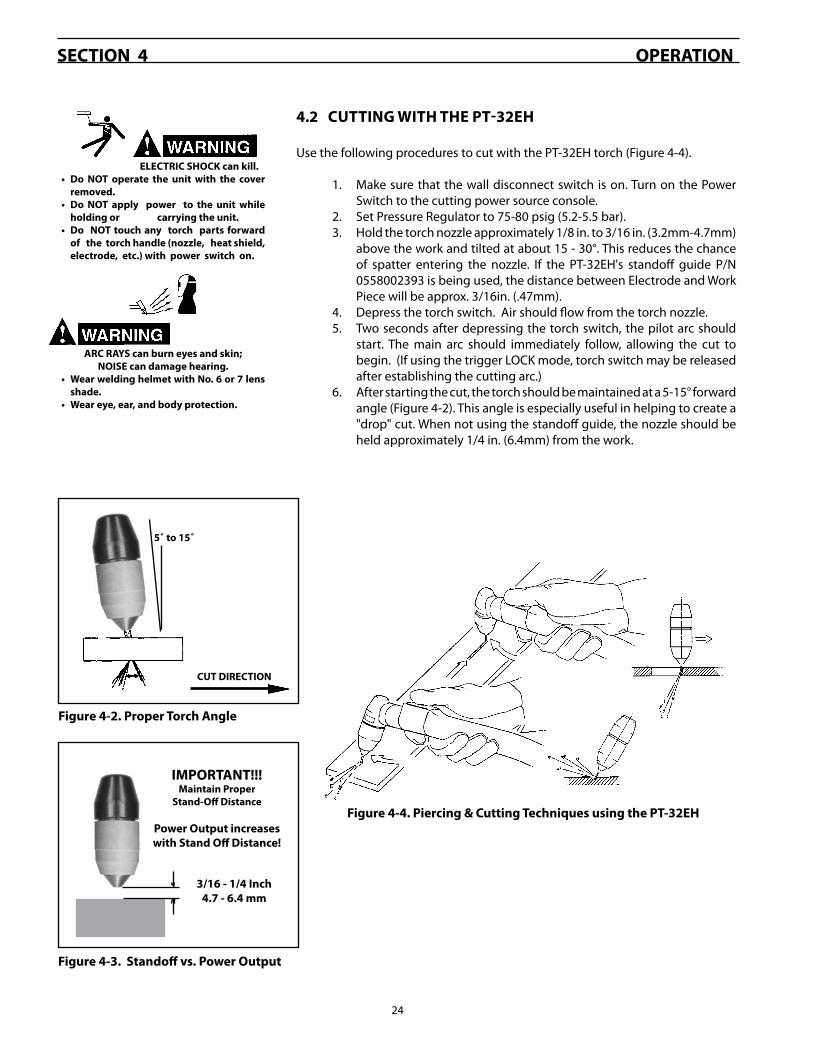
4.2CUTTINGWITHTHEPT-32EH
Use the following procedures to cut with the PT-��EH torch (Figure 4-4).
1. Make sure that the wall disconnect switch is on. Turn on the Power Switch to the cutting power source console.
�. Set Pressure Regulator to 75-80 psig (5.�-5.5 bar).�. Hold the torch nozzle approximately 1/8 in. to �/16 in. (�.�mm-4.7mm)
above the work and tilted at about 15 - �0°. This reduces the chance of spatter entering the nozzle. If the PT-��EH's standoff guide P/N 055800��9� is being used, the distance between Electrode and Work Piece will be approx. �/16in. (.47mm).
4. Depress the torch switch. Air should flow from the torch nozzle.5. Two seconds after depressing the torch switch, the pilot arc should
start. The main arc should immediately follow, allowing the cut to begin. (If using the trigger LOCK mode, torch switch may be released after establishing the cutting arc.)
6. After starting the cut, the torch should be maintained at a 5-15° forward angle (Figure 4-�). This angle is especially useful in helping to create a "drop" cut. When not using the standoff guide, the nozzle should be held approximately 1/4 in. (6.4mm) from the work.
ELECTRICSHOCKcankill.• Do NOT operate the unit with the cover
removed.• Do NOT apply power to the unit while
holdingor carryingtheunit.• Do NOTtouchany torch parts forward
ofthetorchhandle(nozzle,heatshield,electrode,etc.)withpowerswitchon.
ARCRAYScanburneyesandskin;NOISEcandamagehearing.
• WearweldinghelmetwithNo.6or7lensshade.
• Weareye,ear,andbodyprotection.
Figure4-2.ProperTorchAngle
Figure4-3.Standoffvs.PowerOutput
IMPORTANT!!!MaintainProper
Stand-OffDistance
PowerOutputincreaseswithStandOffDistance!
3/16-1/4Inch4.7-6.4mm
Figure4-4.Piercing&CuttingTechniquesusingthePT-32EH
CUTDIRECTION
5˚to15˚

�5
5.1 GENERAL
Beforeanymaintenanceisattemptedonthistorch,makesurethepowerswitchontheconsole is inthe"OFF"positionandtheprimaryinputisdeenergized.
5.2 INSPECTIONANDCLEANINGOFCONSUMABLES
1. Disassemble the front end of the PT-��EH as follows:
a. Position torch head in a downward direction (refer to Figure �-�) and remove the shield. The nozzle will drop from the head and remain in the shield. Unscrew the electrode to remove it and the valve pin. Remove these components and inspect for wear. The nozzle and electrode will generally wear at the same rate. For best performance, replace together.
b. Nozzle: Replace if the orifice is clogged, nicked, or out-of-round.
c. Electrode: When replacing the nozzle, always inspect the electrode for wear. If more than .06" (1.5mm) of electrode Hafnium has eroded, replace the electrode. If the electrode is used beyond this recommended wear limit, dam-age to the torch and power source may occur. Nozzle life is also greatly reduced when using the electrode below the recommended limit. Refer to Figure 5-1.
d. Shield: The face of the shield will gradually erode from the heat and molten metal spray. Replace the shield if more than 1/8 inch (�.� mm) has eroded from the face. Refer to Figure �-�.
e. O-ring: Lubricate as per Figure 5-1. Replace if cut or worn. Air leaking past this seal will reduce cutting performance.
�. To replace the above front end components, refer to Figure �-�.
HEAT SHIELD
Figure5-1.O-ring,Electrode,andShieldMaintenance
LUBRICANT (P/N 1767�) CAN BE APPLIED TO O-RING OR HEAT SHIELD.
THE HEAT SHIELD FACE WILL GRADUAL-LY ERODE WITH USE. SEE PARAGRAPH 5.�-1.d
O-RING
REPLACE ELECTRODE BEFORE PITTING BE-COMESDEEPERTHAN.06INCH(1.5MM)
NEW Replace when eroded beyond.06"(1.5mm) Depth.
WORN
SECTION5 MAINTENANCE

�6
5.3 REMOVING/REPLACINGTORCHHEADANDSWITCHESFROMSERVICELINE
5. Next, remove the Pilot Arc connection from the Torch Head using two wrenches to prevent twisting stainless steel tube.
POWER CABLE
PILOT ARC CONNECTION
4. If the torch head is to be replaced, remove the power cable from the Torch Head by using two wrenches to prevent twisting brass tube.
SECTION5 MAINTENANCE
�. Carefully remove the torch body and switches from the assembly. Pull the insulating sleeves back to ex-pose the hose and cable connections. If the switch is to be replaced, remove switch and snip leads (�) at the spliced connections. (Replacement switches are supplied with new splices and extra long leads)
�. Replace insulation as shown. Replace switches in as-sembly. Proceed to step 6.
1. Remove six screws from handle. Separate the two halves of the handle
6. Place the torch head into the assembly and guide the cables and tubes into the housing. Fold the wiring into the cavity, being careful not to overlap any mat-ing surfaces of the housing. Replace the other half of the housing and tighten the six screws. Tighten screws until there is no gap between the two halves
Beforeanymaintenanceisattemptedonthistorch,makesurethepowerswitchontheconsole is inthe"OFF"positionandtheprimaryinputisdeenergized.

�7
tributor or from:
ESABWelding&CuttingProducts Attn.:CustomerServiceDept. POBox100545,EbenezerRoad Florence,SC,29501-0545
Refer to the Communication Guide located on the last page of this manual for a list of customer service phone numbers.
6.1General
Replacement parts are illustrated on the following figures. When ordering replacement parts, order by part number and part name, as listed. Always provide the series or serial number of the unit on which the parts will be used. The serial number is stamped on the unit nameplate.
Replacement parts may be ordered from your ESAB dis-
SECTION6 REPLACEMENTPARTS
6.2Parts
TORCH BODY/HEAD -055800�41�
SWITCH18��4
HANDLE-055800����
SPLICE - 6745�0
SWITCH18��4
TERMINAL FASTENER- 950011
(�) WHITE LEADS
PILOT ARC LEAD
POWER CABLE
CABLE ASSEMBLY�5FT. (7.6m) - 055800�84150FT. (15.�m) - 055800�84�
Torchesandtorchbodyassembliespurchasedindividuallyaresup-pliedwithoutelectrode,nozzle,heatshieldandvalvepin.Ordercompletesparepartskitsorindividualcomponentsasrequired(seeSection2).

NOTES

NOTES

NOTES

RevisionHistory
04 / �005 - added updated torch cut data for Aluminum, Carbon Steel and Stainless Steel.
0� / �006 - Corrected Spare Parts Kits table on Page 1�

F15-747 02/2006
A. CUSTOMER SERVICE QUESTIONS: Telephone: (800)�6�-7080 / Fax: (800) 6�4-7548 Hours: 8:00 AM to 7:00 PM EST Order Entry Product Availability Pricing Order Information Returns
B. ENGINEERING SERVICE: Telephone: (84�) 664-4416 / Fax : (800) 446-569� Hours: 7:�0 AM to 5:00 PM EST Warranty Returns Authorized Repair Stations Welding Equipment Troubleshooting
C. TECHNICAL SERVICE: Telephone: (800) ESAB-1��/ Fax: (84�) 664-445� Hours: 8:00 AM to 5:00 PM EST Part Numbers Technical Applications Specifications Equipment Recommendations
D. LITERATURE REQUESTS: Telephone: (84�) 664-556� / Fax: (84�) 664-5548 Hours: 7:�0 AM to 4:00 PM EST
E. WELDING EQUIPMENT REPAIRS: Telephone: (84�) 664-4487 / Fax: (84�) 664-5557 Hours: 7:�0 AM to �:�0 PM EST Repair Estimates Repair Status
F. WELDING EQUIPMENT TRAINING Telephone: (84�)664-44�8 / Fax: (84�) 679-5864 Hours: 7:�0 AM to 4:00 PM EST Training School Information and Registrations
G. WELDING PROCESS ASSISTANCE: Telephone: (800) ESAB-1�� Hours: 7:�0 AM to 4:00 PM EST
H. TECHNICAL ASST. CONSUMABLES:
Telephone : (800) 9��-7070 Hours: 7:�0 AM to 5:00 PM EST
IFYOUDONOTKNOWWHOMTOCALL
Telephone: (800) ESAB-1�� Fax: (84�) 664-446�
Hours: 7:�0 AM to 5:00 PM ESTor
visit us on the web at http://www.esabna.comThe ESAB web site offers
Comprehensive Product InformationMaterial Safety Data Sheets
Warranty RegistrationInstruction Literature Download Library
Distributor LocatorGlobal Company Information
Press ReleasesCustomer Feedback & Support
ESABWelding&CuttingProducts,Florence,SCWeldingEquipmentCOMMUNICATIONGUIDE-CUSTOMERSERVICES