
piping1 2 manual routing of pipe - CAD Schroer
17
MPDS4 – PIPING 1 Manual Routing of a Pipe This exercise is the continuation of the previous exercise “Placing Equipment”. In this part of the “Piping” course we will learn to: • use connection points • route a simple pipe and • insert elbows and flanges We will start with our design consisting of 4 tanks placed on the graphics area. Initial Design The grid is still left from the previous exercise. Since we don’t need it now we can turn it off. Remember, you can switch off the display of a grid in the Coordinates Dialog.
Transcript of piping1 2 manual routing of pipe - CAD Schroer
MPDS4 – PIPING 1
Manual Routing of a Pipe
This exercise is the continuation of the previous exercise “Placing Equipment”.
In this part of the “Piping” course we will learn to:
• use connection points
• route a simple pipe and
• insert elbows and flanges
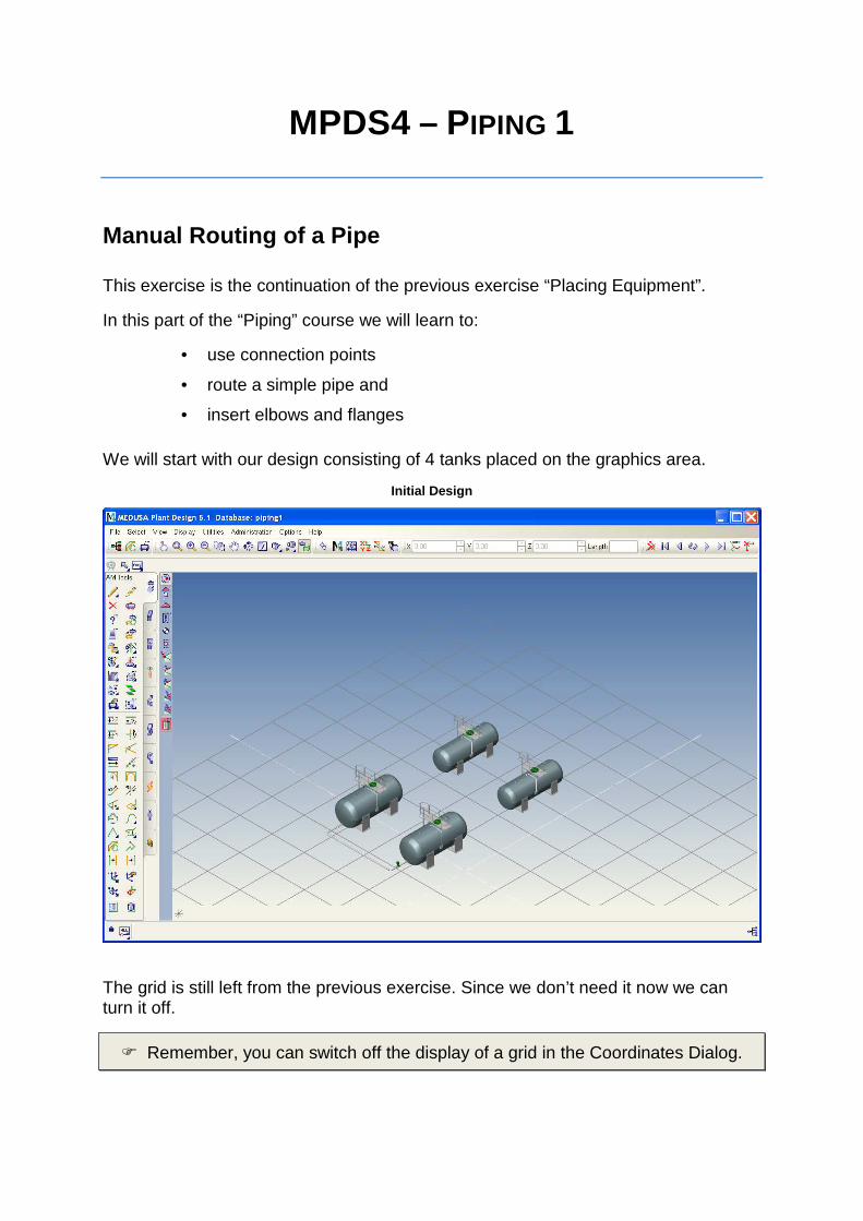
We will start with our design consisting of 4 tanks placed on the graphics area.
Initial Design
The grid is still left from the previous exercise. Since we don’t need it now we can turn it off.
� Remember, you can switch off the display of a grid in the Coordinates Dialog.

� Open the XYZ dialog by selecting the appropriate tool in the toolbar.
Opens the Coordinates Dialog
� Uncheck the Snap and Grid checkbox and close the dialog.
Uncheck Snap and Grid in the Coordinates Dialog
The grid is removed from the graphics area.
Now we want to connect the two tanks with a pipe.
� Pan to find the suitable position for the connection and zoom in to make the nozzles on the two tanks visible.
Pan and Zoom tool

� Remember To pan hold down the left mouse button and move the mouse,
to zoom in and out scroll the middle mouse wheel.
When position and size of the two tanks are satisfying, you have to quit the Pan and/or Zoom tool.
� Click the RMB anywhere in the graphics area.
The Exit Current Tool option appears.
Exit Tool Option
� Click the LMB to exit Pan and/or Zoom, which is our current tool at this time.
� To exit from any tool click the RMB in the graphics area to open a popup menu and select Exit Current Tool.
Preparing to route a pipe
Pipes are routed between predefined connection points .
Connection points are the means by which instances - such as equipment and piping components - are connected together. For example, if a flange is bolted to the nozzle of a tank, the representation of where the flange is connected to the nozzle is a connection point .

An instance can have several connection points. Typically, these are named P1, P2, P3, and so on. Connection points have embedded information stored in the system:
• Name of the connection
• Name of the instance to which it belongs
• Position and orientation of the connection point to the assembly
• Size
• Connection type
The Drag tail points and segments tool is a general purpose tool for routing and modifying pipe lines.
Drag tail points and segments tool
� Select the Drag tail points and segments tool.
Identifying Connection Points
How can you find the predefined connection points?
� Move the mouse cursor over the tank.
Arrows are displayed indicating the predefined connection points of the tank.
� Move the cursor over the nozzles.
The arrow at the currently selected nozzle becomes red.

Moving the cursor over an equipment indicates conne ction points
We want to use the connection point at the lower front side of the tank.
� Move the cursor to the desired nozzle.
The arrow appears red and the name P3 of the selected connection point is displayed in the status area at the bottom left of the screen.
Status area displaying the connection name: P3
Starting a pipe line with Edit Link
First we have to set the start point of the pipe. This should be the connection point at the nozzle of the tank. Proceed as follows.
� After positioning your view as shown, click the RMB in the graphics area.
A popup menu opens.
� Select the Edit Link option.

Starting a pipe by Edit link
� Then select a nozzle by using the LMB.
A yellow asterisk the tail point appears on the nozzle marking the current point. A rubber band is attached to the cursor.
� Important hint, when you are in the edit tail mode:
� Once you click in the graphics area, a new tail point will be created. If you created a new tail point unintentionally, you can delete it by using the
option Delete Point from the RMB popup menu. You can delete the complete tail by using the option Delete Tail from the
RMB popup menu.

Starting point of the pipe
The dashboard displays some information about the selected connection point.
Connection point information
Starting from this first point we want to route a pipeline by a series of points ending at the second tank. We proceed as follows:
• In a first step we create a rough route of the pipeline.
• Then we align the pipe at right angles.
• Finally we insert elbows and flanges.
Routing the pipe and insert Piping Components
� In order to create a second point set the cursor to an approximate position and click the MMB.

First pipe segment
A pipe segment is displayed showing a yellow axis, known as a tail, and a yellow asterisk which marks the current point.
� Enter 2000 in the input field on the dashboard to set the first pipe segment to 2m and confirm with the Enter key.
Setting Length of the pipe segment
The length of the pipe segment switches to the desired size.
� In order to create the next pipe segment position the cursor to the approximate position and click the MMB.
� Finally complete the routing of the pipe by placing the cursor on the nozzle of the second tank and click the LMB.
The asterisk appears at the nozzle of the tank indicating the connection point as the current point.
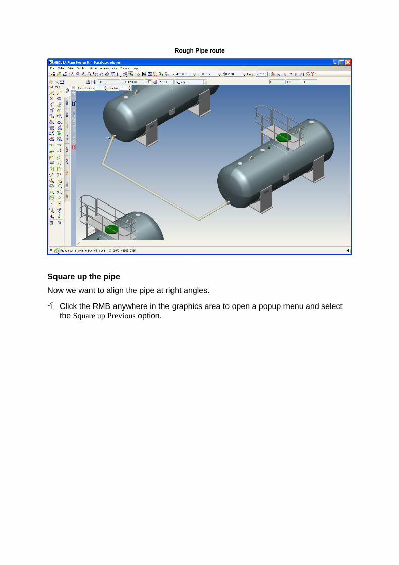
Rough Pipe route
Square up the pipe
Now we want to align the pipe at right angles.
� Click the RMB anywhere in the graphics area to open a popup menu and select the Square up Previous option.

Square up Previous to create orthogonal pipeline
The pipeline is automatically aligned. All angles are right-angled and the length of the pipe segments is justified.
Squared Pipeline

Defaults for Inserting Elbows
In order to round the edges of the pipeline we have to insert elbows. You can do this automatically for both angles at one time. At this time we will set some defaults, so that later the pipeline will be created automatically with elbows.
� The Drag tail points and segments tool is still the current tool! The current tool is always indicated in the status area bottom left side of the
screen.
� Switch into the Piping tooltray.
� Select the Piping Options tool.
Piping tooltray with the Piping Options tool

The Options dialog opens.
Piping Options dialog
� Turn Auto Elbow on.
� Select 90LR from the Type list.
� Save and close the dialog.
The yellow tail is still displayed and the asterisk at the connection point marks the current tail point.
Select flange from catalog and create pipeline
Now we want to add flanges at the two connection points of the pipeline.
In a first step we will add it to the current connection point.
� Choose the Select the Weld-neck flange tool from the Piping tooltray.

Select the Weld-neck-flange tool
The Select Piping Component dialog appears.
Select Piping Component Dialog-1
Since MPDS4 already knows the size and specification - Current Spec - of the flange, the choices are immediately narrowed down to a few choices.
� To narrow the selection further, uncheck BS and DIN Dimensions body standards and click the Search button.
Select Piping Component Dialog-2
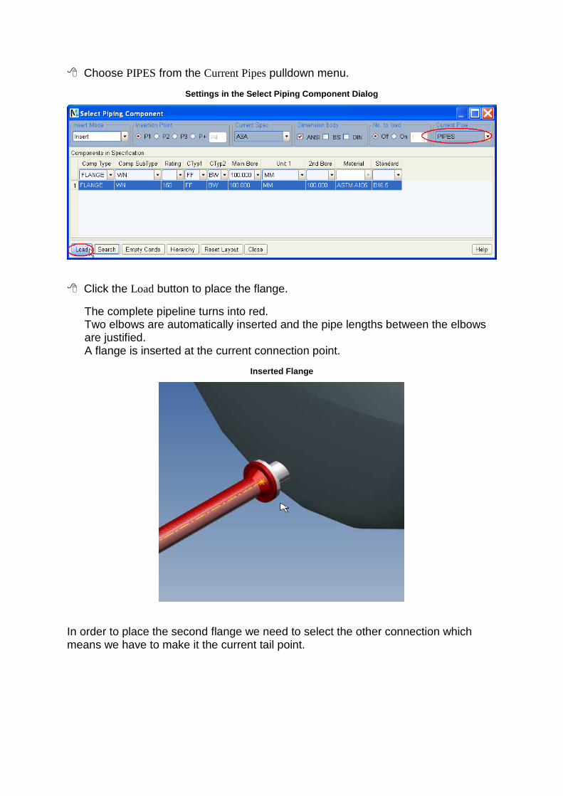
� Choose PIPES from the Current Pipes pulldown menu.
Settings in the Select Piping Component Dialog
� Click the Load button to place the flange.
The complete pipeline turns into red. Two elbows are automatically inserted and the pipe lengths between the elbows are justified. A flange is inserted at the current connection point.
Inserted Flange
In order to place the second flange we need to select the other connection which means we have to make it the current tail point.

� Select the Pan and/or Zoom tool from the toolbar. Center your view on the second connection point and zoom in.
Pan and/or Zoom tool
� At this time the Pan and/or Zoom tool is the current tool. Current tools are displayed in the status area at the bottom left side of the screen.
� Click the RMB anywhere in the graphics area to display the Exit current tool option.
� Select Exit current Tool.
The current tool is the Select Weld Neck Flange again, visible in the status area.
� Click the RMB anywhere in the graphics area to open the popup menu and choose Edit Link.
� Select the appropriate nozzle.
The selected connection point is marked with an asterisk which indicates the current tail point.
Insert point for the second flange

� Click the Load button in the Select Piping Component dialog.
The flange is promptly inserted.
Second inserted flange
� Close the Select Piping Component dialog.
The pipeline with two elbows and two flanges has been successfully created.
Completing the piping creation
We want to complete the creation process and view the complete design.
� Click the RMB in the graphics area to display Exit Current Tool and quit the tool.
� Select the Fit View option from the View pulldown menu to fit the design to the current window.
Fit View option

� Choose Deselect All from the Select options.
Select options with Deselect All
The pipe which was displayed red till now is deselected.
� Select the Delete Tail tool in the toolbar.
Delete Tail
The tail, displayed as yellow dashed line, is removed.
The finally displayed design should be similar to that shown below.
Final display
� End of exercise