Physical measurements and subjective characterization of...
78
THESIS FOR THE DEGREE OF LICENCIATE OF ENGINEERING Physical measurements and subjective characterization of pipe organ mechanical key actions ERKIN ASUTAY Department of Civil and Environmental Engineering Division of Applied Acoustics Chalmers Room Acoustics Group Multi Sensory Applications CHALMERS UNIVERSITY OF TECHNOLOGY Gothenburg, Sweden, 2013
Transcript of Physical measurements and subjective characterization of...
THESIS FOR THE DEGREE OF LICENCIATE OF ENGINEERING
Physical measurements and subjective characterization of pipe organ mechanical key actions
ERKIN ASUTAY
Department of Civil and Environmental Engineering Division of Applied Acoustics
Chalmers Room Acoustics Group � Multi Sensory Applications CHALMERS UNIVERSITY OF TECHNOLOGY
Gothenburg, Sweden, 2013

Physical measurements and subjective characterization of pipe organ mechanical key actions
Erkin Asutay © Erkin Asutay, 2013 Lic. / Department of Civil and Environmental Engineering, Chalmers University of Technology Technical report no: lic 2013:4 ISSN 1652-9146 Department of Civil and Environmental Engineering Division of Applied Acoustics Chalmers Room Acoustic Group � Multi Sensory Applications Chalmers University of Technology SE-412 96 Gothenburg Sweden Telephone: +46 (0) 31-772 2200 Printed by Chalmers Reproservice Gothenburg, Sweden, 2013

Physical measurements and subjective characterization of pipe organ mechanical key actions Erkin Asutay Department of Civil and Environmental Engineering Division of Applied Acoustics Chalmers Room Acoustic Group � Multi Sensory Applications Chalmers University of Technology
Abstract
Musical instruments do not only provide auditory or visual information but they also convey haptic feedback to the performer. One might consider that the auditory feedback is the only crucial information that the musician requires. However, as perception of most objects and events are multisensory, sensation and perception of playing a musical instrument is also multisensory.
The present thesis sets out to develop a methodology to measure and characterize the properties of the organ key mechanics that determine haptic sensation of pipe organ playing. A framework is proposed here with the purpose to develop the methodology to objectively measure and subjectively characterize mechanical key action properties. The methods for the objective characterization will be explained using results of detailed measurements and a framework for subjective characterization of the haptic properties is proposed.
There are a number of components in the mechanical key action that contributes to the overall force feedback to the organist. It is a complex mechanical system and no two key has identical construction. This makes it difficult to model the key action mathematically, since one needs a different form of a model for each key. Therefore, force feedback at the console as a function of key-fall and velocity was chosen to be measured to reveal the dynamic behavior of the key action. To have objective measurements and to be able to control for the key velocity, a controllable linear actuator was used to press the keys. From the results of these measurements a number of parameters were extracted to characterize dynamic system behavior. These parameters can be used for comparison of different keys within an instrument as well as overall comparison of different instruments.
The study of the role of haptic sensation of organ playing requires subjective characterization of the key action. Since this part is ongoing work,

only the methodology is described here. Based on an online survey among expert as well as novice organists on haptic sensation of organ playing, a set of semantic differential scales were devised. These semantic differential scales will be used in subjective experiments, with the aim to reveal the underlying dimensions of the haptic perception of the particular organs. Once the subjective characters of the key actions are revealed, they will be linked to the physical system and the objective characteristics to study the salient key action properties.
Keywords: Pipe organ, Mechanical key action, Instrument � player interaction

Acknowledgements
The Licenciate thesis presented here is a part of a research project, The Organ as Memory Bank, at Göteborg Organ Art Center (GOArt), University of Gothenburg. The project is funded by the Swedish Research Council (Vetenskapsrådet) and is carried out in collaboration with the Division of Applied Acoustics.
First I would like to express my gratitude towards my supervisors Mendel Kleiner and Daniel Västfjäll for their guidance, advice and invaluable feedback. I would like to thank Johan Norrback and Carl Johan Bergsten at GOArt, for interesting ideas, good advice and help with the technical matters. Many thanks goes to all who are employed at GOArt for their help.
I would also like to thank people of Applied Acoustics, students and colleagues, for creating such a pleasant environment.
Last but not least a big thanks to friends and family who supported me through thick and thin!


Contents
1. Introduction ........................................................................... 1
1.1. Multimodality of Instrument Playing ................................... 3
1.2. Human Haptic Perception .................................................... 5
2. Pipe Organ ............................................................................. 9
2.1. Mechanical Organ Actions .................................................. 10
2.2. Pluck ....................................................................................... 15
2.3. Equivalent Dynamic Mass ................................................... 15
3. Methodology Review ............................................................ 19
3.1. Piano ...................................................................................... 20
3.2. Related work ......................................................................... 23
4. Objective Characterization of Organ Actions ..................... 27
4.1. Measurement Apparatus ...................................................... 27
4.2. Force profile during key-fall ................................................ 29
4.3. Pluck and related parameters .............................................. 31
4.4. Stiffness in the system .......................................................... 33
4.5. Characterization of the friction in the system ................... 34
4.6. Effect of inertia ..................................................................... 34
4.7. Energy related measures ...................................................... 36

5. Analysis of the Objective Measures ..................................... 39
5.1. Objective key characters within a single manual ...............39
5.2. Comparison of Different Instruments ...............................48
6. Conclusions and Future Work ............................................. 53
6.1. Subjective Characterization ..................................................54
6.1.1. Semantic measurement scales .........................................54
6.1.2. Subjective measurements ................................................57
A. Specifications of the Organs ................................................ 59
A1. The North German Baroque Organ ...................................59
A2. The Brombaugh Organ ........................................................60
A3. Hammarberg Organ ..............................................................62
A4. Verschueren Organ ...............................................................62
A5. Craighead-Saunders Organ ..................................................63
A6. Cornell Baroque Organ ........................................................63
B. Developed Semantic Measurement Scales .......................... 65
References .................................................................................... 67

1. Introduction
Musical instruments do not only provide auditory or visual information but they also convey haptic feedback to the performer. The present thesis sets out to develop a methodology to measure and characterize the properties of the organ key mechanics that determine haptic sensation of pipe organ playing. A framework is proposed here with the purpose to develop the methodology to objectively measure and subjectively characterize key action properties. There are different types of key actions within different organ building periods and traditions. In this thesis the focus will be on mechanical tracker actions; thus the pipe organs with electric or pneumatic actions will not be discussed. The methods for the objective characterization will be explained using results of detailed measurements and a framework for subjective characterization of the haptic properties is proposed.
Objective characterization of these properties focuses on the physical feedback that the instrument provides. There are a number of components in the mechanical key action that contributes to the overall force feedback that the organ player receives, such as the force due to the pressurized wind chest acting on the pallet, the force from the spring to keep the pallet closed, the forces needed to overcome friction in the key components, and the force needed to accelerate the key itself. Figure 1.1 shows the construction of a simple suspended action. Since, the aim of the present work is to define the haptic feedback to the organist, force feedback at the console as a function of key-fall and velocity was chosen to be measured to reveal the dynamic behavior of the key action. To have objective measurements and to be able to control for the key velocity, a controllable linear actuator was used to actuate the keys. During the movement of the key, the position of the key and the force at the key tip were measured simultaneously. Using the results of these measurements the objective parameters were extracted to characterize dynamic system behavior. Moreover, these parameters could be used for comparison of different keys within an instrument as well as overall comparison of different instruments. The main purpose of this procedure is to provide a �key action signature�.

2 1. Introduction
Figure 1.1 Construction of a simple suspended key action (Pykett, 2001). When the
player presses the key that is hinged at the back the key pulls a tracker that opens a valve (pallet). Once the pallet is open, the pressurized air in the wind chest flows through the wind ways into the pipes.
The study of the role of haptic sensation of organ playing requires subjective characterization of the key action. Based on an online survey among expert as well as novice organists on haptic sensation of organ playing, a set of semantic differential scales were devised. These semantic differential scales will be used in subjective experiments, with the aim to reveal the underlying dimensions of the haptic perception of the particular organs. Finally, the objective and subjective characteristics are linked to reveal sensory-salient key action properties.
The rest of Chapter 1 points to the multisensory nature of the relationship between the performer and the instrument. Further, it stresses the importance of the energetic coupling between the two via the haptic channel on forming of such a relationship.
Chapter 2 introduces pipe organs with mechanical key actions, and explains the main construction of mechanical key actions and describes its components. It will be shown that the mechanical system is complex and no two key has identical construction. This makes it difficult to model the key action mathematically, since one needs a different form of a model for each key. Moreover, Chapter 2 describes the main design parameters for key actions and how these are related to the physical feedback that the organ player receives during the musical performance.

1. Introduction 3
Since the aim of this work is to propose and test a methodology for the characterization of key actions from the perspective of the organ player (i.e. feedback that the instrument provides) it is imperative to review the relevant literature and such a review is presented in Chapter 3. Up to date, there are few studies on the properties of pipe organs. However, Chapter 3 presents similar studies performed on pianos and other keyboard instruments. Further, Chapter 3 also reviews relevant studies within the music performance research with similar methodology.
Chapter 4 describes the proposed measurement methodology, and the parameters that could be extracted from these measurements for objective characterization of key action properties. The extracted parameters were later used for both analyzing key action properties of an instrument and for comparing the characteristics of different instruments using statistical methods. These analyses and statistical methods are explained in Chapter 5. These statistical analyses reveal that the extracted parameters are able to show clear differences between instruments. Nevertheless, it is not obvious that these differences are apparent to the organ players during their interaction with the instruments, so subjective characterization is needed. Finally, a methodological framework is proposed in Chapter 6 to investigate the subjective characteristics of mechanical key action.
1.1. Multimodality of Instrument Playing
Playing music is a complex task that requires both cognitive and motor skills. Research on music performance has argued the role of attention, memory, imagery and visuospatial functions on musical abilities (Jäncke, 2006). Further, musicians should have the skill of transformation of the internal representation of musical structures into appropriate motor actions (Palmer, 1997; Gabrielsson, 2003). Since playing music is such a complex task, it is no surprise that a particular type of relationship is developed between the musician and the instrument.
During the performance, musical instruments provide sensory feedback to the musician. The uninitiated person might assume that the auditory feedback is the only crucial information that the musician requires. However, as perception of most objects and events are multisensory, sensation and perception of playing a musical instrument is also multisensory. For example, string instruments convey information through performer�s fingers, wind instruments through fingers and lips. Further, vibrations in the instrument body can be felt through contact. If one considers a pipe organ,

4 1. Introduction
during performance organist hears the pipes sounding as well as the contribution of the room acoustics, sees the console, and feels the instruments physical reactions through her fingers and feet. Figure 1.2 shows a simple model that depicts the multimodal nature of instrument playing. According to this model there is an energetic coupling between the instrument and the performer that underlines the role of the bodily involvement in music performance that transcends the auditory aspect. Through this coupling they both act on each other and react to the other�s actions. Evidently, musician receives input from the instrument via other sensory modalities, i.e. auditory and visual.
The energetic coupling between the instrument and the performer is intriguing. There have been philosophical attempts to characterize the performer � instrument relationship. Pedro Rebelo (2006) defines the abovementioned energetic coupling as a haptic engagement and the relationship between the instrument and the performer as a participatory one rather than one of control. Rebelo also defines the instrument not as an extension of the performer�s body but as an entity that comprises its own dynamics, expression and culture, and underlines the importance of haptic sensation in musical performance. In the following section haptic sensation and perception will be described in detail. Rebelo�s concept of haptic was borrowed from Deleuze and Guattari�s (1987) notion of Smooth Space, which is described as a space that is �navigated by constantly acting on a feedback from an immediate environment�. In practice this would mean that the performer constantly acts on the feedback from the instrument, adapts her/his playing style and configures even her/his posture and limbs depending on the physical resistance from the instrument. Similar to above, Schroeder (2006) focuses her analysis on the discontinuity between the performer and the instrument rather than on the notion of seamless merging of the two which assumes the instrument as an extension of the performer�s body (i.e. instrumental prosthesis; for a similar view, see Cumming, 2000) through which he experiences the world (see also; Schroeder & Rebelo, 2009; Newland, 2012).
It seems that independent of how one assumes the nature of the instrument/performer relationship, as seamless merging into one body or the interplay between two separate entities, the bodily involvement is essential (Davidson & Correia, 2001). This means that apart from the auditory modality the haptic modality assumes a key role in playing a musical instrument. The following section presents an overview of human haptic perception before introducing the construction of a pipe organ and mechanical key actions.

1. Introduction 5
Figure 1.2 Simple model that shows the multimodal nature of instrument playing
1.2. Human Haptic Perception
Human haptic perception is a sensory modality that involves most common everyday activities. Various aspects of human haptic perception are presented briefly in this section (for more detailed accounts, see Klatzky & Lederman, 2002; Hatwell, Streri & Gentaz, 2003; Jones & Lederman, 2006; Bracewell, Wimperis & Wing, 2008; Bresciani, Drewing & Ernst, 2008; Gardner, 2010). Sense of touch is -from the developmental perspective- the oldest sense; it starts developing in the womb and is the most developed sense at birth. Studies also show that the sense of touch is the main channel of information about the environment in early life and has a crucial communicative function between infant and caregiver. Further, it is involved in most everyday activities: walking, picking up objects, and even maintaining one�s posture.
The modality of touch comprises a number of submodalities. Depending on the underlying neural inputs three systems have been distinguished: cutaneous, proprioceptive and haptic. Cutaneous system is related to skin and its mechanoreceptors. It receives input from these receptors that are embedded in skin. In the glabrous (hairless) skin, such as the palmar portion of the human hand, there are four different types of cutaneous mechanoreceptors. They have different adaptation capabilities to stimulation and receptive field size. There are two fast adapting (FA) units that rapidly respond to the onset and offset of skin deformation, while slow adapting (SA) units produce response to sustained skin deformation. Within each classification (FA or SA) there are two different types of mechanoreceptors depending on their respective field size. The first types, FA1 and SA1, have small and well defined receptive fields, whereas the second types, SA2 and FA2 units, have large and diffuse receptive fields with

6 1. Introduction
somewhat ambiguous boundaries. The cutaneous system mainly receives input from these mechanoreceptors about the temporal properties of the skin deformation (the onset and offset and the rate of change of skin deformation) and it spatial location.
Proprioception is defined as the sense of the position of the body parts, relative to other parts of the body. Proprioceptive system receives its input from the mechanoreceptors located in muscles, tendons and joints. These receptors contribute to the formation of the sense of one�s own body, as well as the position and movement of the limbs. The receptors located in the muscle spindles respond to the vibration, dynamic stretch, rate of change of muscle fiber length. Further, the Golgi tendon organ, which is located between the muscle fibers and the tendon, primarily responds to the forces that develop in the muscle fibers. In short it codes the muscle tension. The angle of the joints is thought to be coded primarily through muscle length.
Figure 1.3 Somatosensory pathways to cortex that shows how the information from
the mechanoreceptors is transferred to the cortex (from http://www.rci.rutgers.edu/~uzwiak/NBSpring12/NBSpringLect6.html)
1. Introduction 7
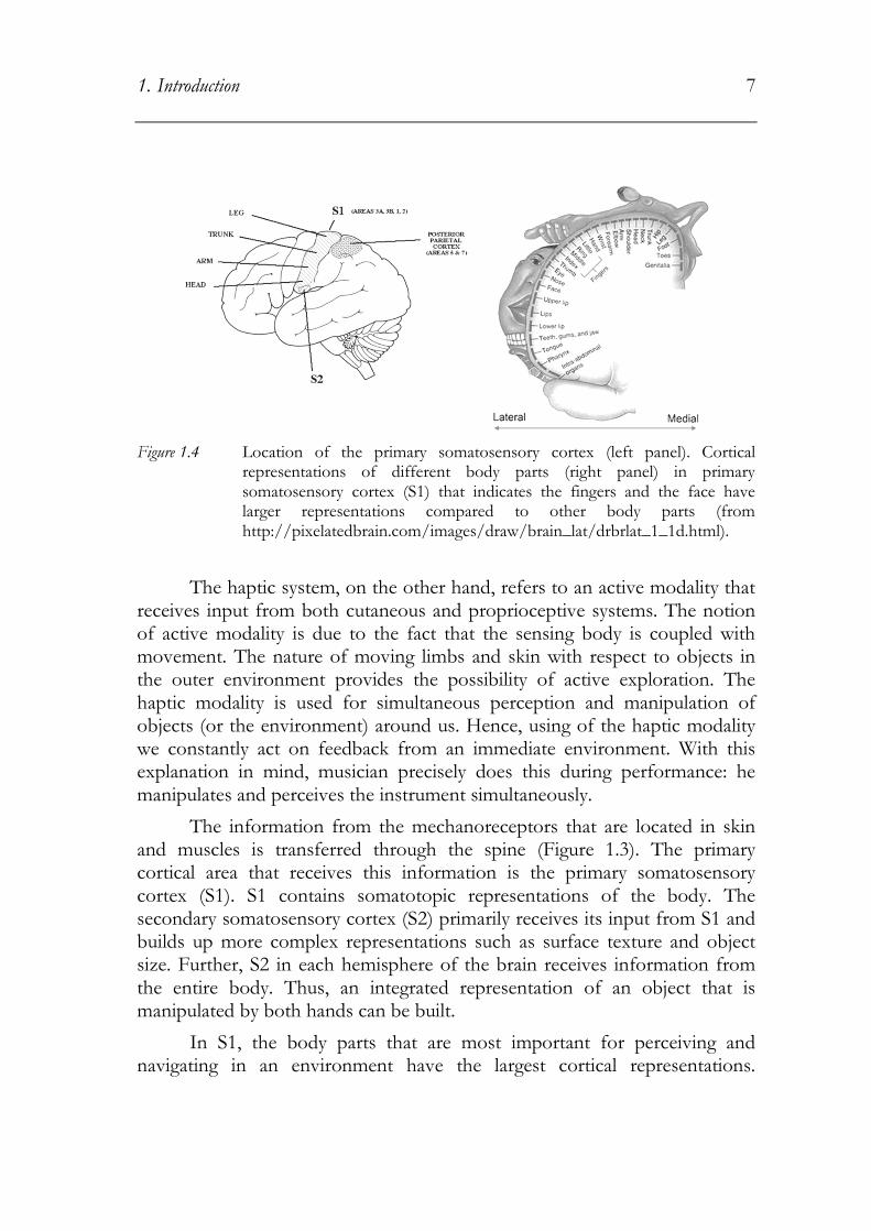
Figure 1.4 Location of the primary somatosensory cortex (left panel). Cortical
representations of different body parts (right panel) in primary somatosensory cortex (S1) that indicates the fingers and the face have larger representations compared to other body parts (from http://pixelatedbrain.com/images/draw/brain_lat/drbrlat_1_1d.html).
The haptic system, on the other hand, refers to an active modality that receives input from both cutaneous and proprioceptive systems. The notion of active modality is due to the fact that the sensing body is coupled with movement. The nature of moving limbs and skin with respect to objects in the outer environment provides the possibility of active exploration. The haptic modality is used for simultaneous perception and manipulation of objects (or the environment) around us. Hence, using of the haptic modality we constantly act on feedback from an immediate environment. With this explanation in mind, musician precisely does this during performance: he manipulates and perceives the instrument simultaneously.
The information from the mechanoreceptors that are located in skin and muscles is transferred through the spine (Figure 1.3). The primary cortical area that receives this information is the primary somatosensory cortex (S1). S1 contains somatotopic representations of the body. The secondary somatosensory cortex (S2) primarily receives its input from S1 and builds up more complex representations such as surface texture and object size. Further, S2 in each hemisphere of the brain receives information from the entire body. Thus, an integrated representation of an object that is manipulated by both hands can be built.
In S1, the body parts that are most important for perceiving and navigating in an environment have the largest cortical representations.

8 1. Introduction
Accordingly fingers, lips and tongue have larger cortical representations in primary somatosensory cortex compared to other body parts (Figure 1.4). The skin on the hands and around the mouth is more sensitive compared to other parts. Hence, it is to be expected that most musical instruments are designed to be manipulated by our hands, fingers, lips and tongue. Evidently, this is also due to the dynamical dexterity of these manipulators. The following section introduces the construction of a pipe organ and mechanical key action, which is followed by a review of studies that are relevant to the current aims from a methodological perspective in Chapter 3.

2. Pipe Organ
The pipe organ has existed for more than a thousand years. Its modern form began to develop in the middle ages. The artistic and technical peak of organ building was reached in Germany already in the seventeenth century (Fletcher & Rossing, 1998). Some of the greatest organ music was created in the Baroque period. Many remarkable pipe organs were built for cathedrals, despite an artistic decline during the Classical and Romantic periods. Many current organ builders have adopted the principles of the master organ builders of the seventeenth and eighteenth centuries.
Pipes in an organ are to a large extent arranged in a matrix form, where columns and rows represent notes and individual ranks, respectively. Usually, columns are set out in symmetrical appearance, that is, odd numbered columns (C, D, E�) are placed in order from the left, while the rest (C#, D#, F�) are put in order from the right side (Figure 2.1). The pipes stand on holes on top of a windchest that form one column. Stop knobs are used to admit and block the air to individual ranks, by the use of a slider in the form of a wooden lath with holes at the positions of each pipe of a rank.
The stop knob and key actions of early instruments were entirely mechanical. The first pneumatic levers that reduce the force required to move the keys were introduced in the nineteenth century. This construction enabled larger and less rigidly laid out organs. In such a pneumatic action the only force needed is to open a small valve and allow a bellows to collapse. Also, with the advent of electricity, electromagnets were introduced in the key actions either as a direct valve actuator for each pipe or in combination with pneumatic levers. During the Organ Reform Movement in 1920s, a return to the principles and values of the earlier organs was started. It was argued that the key action should be mechanical, since the connection between the player and the pallet was considered to be crucial (e.g. Bonavia-Hunt, 1939). Some advocates of mechanical key action claimed that with the pneumatic and electric actions the player lost the intimate, personal relationship with the instrument (e.g Baker, 1993). Further, it was considered that since the mechanical action provides a �close contact� between the player and the

10 2. Pipe Organ
instrument, a good player can apply a more sensitive touch and even articulate the sound of the pipes. Most of the work on key actions in pipe organs, to some extent, is subjective in nature, and the authors have not provided experimental evidence to back up their opinions (for a review, see Woolley, 2006).
Figure 2.1 An example of symmetrical pipe placement on a windchest. Bass notes are placed in the middle and higher pitches on the sides. Different pipes in one line towards the wall on the left side are different ranks of the same note (Photo by Erkin Asutay).
2.1. Mechanical Organ Actions
This section introduces the physical design of the mechanical key action and discusses the influence of its individual components on the resulting touch. Since the purpose of this thesis is to study the nature of the physical force feedback that the organist receives at the keyboard, it is worthwhile to study the construction of the key action and its components. Two types of key action will be discussed: suspended action where the key is

2. Pipe Organ 11
Figure 2.2 Illustration of suspended and balanced actions. In a suspended action (top) the key is pivoted at the rear; and tracker is connected to the key. In a balanced action (bottom), the key is balanced in the middle, and is connected to a sticker and a balanced; which is connected to the tracker.
pivoted at the rear and balanced (backfall) action in which the key is balanced close to its center as shown in Figure 2.2. In a suspended action the key is pivoted at the rear end. One can consider the key as suspended from the pallet at the end of a tracker. Thus, when the organ player strikes a key, trackers attached to it will pull the pallet to open. In the backfall action the

12 2. Pipe Organ
Figure 2.3 Illustration of the windchest including the groove, pallet box and pallet.
The pipes are seated on top of the groove (adapted from Audsley, 1965).
key is balanced in the middle. Therefore, there is a need of transforming the upward movement at the end of the key to downward movement at the pallet. This is achieved by stickers and backfalls, also shown in Figure 2.2.
In mechanical key action the aim is to transfer the movement at the key tip to the pallet that lets the pressurized air to flow into the pipes. The pallet, at its rest position, keeps the two sections of the windchest separated, i.e. pallet box that contains pressurized air, and groove that is connected to the pipes (Figure 2.3). All the pipes for one particular note sit on top of one groove, so that when the pallet opens the pressurized air is admitted to the pipes via the groove. The pallet is kept closed by a spring when the key is not pressed. Hence, in order to open the pallet the organist needs to overcome the forces due to the spring and the pressurized air acting on the pallet. The latter is one of the main design parameters and it is called the pluck. The pluck will be discussed in detail below.
The transfer of motion from the key to the pallet is over a number of components: trackers, stickers, backfalls, squares and rollers. A tracker is a wooden or metal strip used for transferring the movement in a straight line by pulling. The most critical factor for trackers is their mass. Since the distance between the console and the windchest might be large in big instruments, tracker mass becomes an important parameter that defines the inertia of the action. The organ player should not have to move a large amount of mass to play a note because this requires a large force. Trackers are usually made of wood, bronze or aluminum. A sticker, on the other hand, is a similar structure that transfers the motion by pushing. It is used in backfall

2. Pipe Organ 13
Figure 2.4 Illustration of a square that is hinged at point C. The arrows show the
direction of the movement. When a key is pressed the tracker connected to the horizontal arm of the square makes it rotate around its hinge and pulls the horizontal tracker that is connected to its vertical arm (adapted from Audsley, 1965).
actions in combination with a lever (i.e. a backfall) pivoted at the middle in order to reverse the direction of movement, i.e. from pushing to pulling. Since they work under compression stickers are more susceptible to buckling. To avoid buckling stickers need to have a larger cross section than trackers. Thus, they are usually short so that their contribution to the total mass of the action is limited. A square is a bent lever that is used in order to change the orientation of the motion from vertical to horizontal or vice versa (Figure 2.4). When a tracker pulls the horizontal arm of the square in Figure 2.4, it rotates around its hinge and pulls a horizontal tracker that is attached on its vertical arm.
Since the windchest is larger than the keyboard, and pipes seldom are arranged in a chromatic order, the movement needs to be transferred in horizontal direction as shown in Figure 2.5. This is achieved by rollers, circular rods pivoted around their axis, with arms at both ends to which the rest of the action is attached as shown in Figure 2.6. When a tracker pulls a roller arm, the roller rotates around its axis and pulls the tracker attached on its other end, thus transferring the motion in horizontal direction. Since rollers rotate around their axes, their contribution to the overall equivalent dynamic mass (EDM, is discussed below) is small compared to their actual mass. However, they should not twist, since twisting of the roller will result in extra stiffness in the system. The key will start moving before the pallet moves, and later the pallet opening will be uncontrollable.

14 2. Pipe Organ
Figure 2.5 Illustration of the use of the rollers in order to transfer the movement in
horizontal directions. The bottom of the figure shows the width of the manual, one tracker for each key; while the top shows the width of the windchest on top which the pipes are seated (adapted from Audsley, 1965).
Figure 2.6 Illustration of rollers, the tracker on the right side is pulled down when the key is pressed and rotates the roller in turn pulls down the tracker attached to its left end (adapted from Audsley, 1965)

2. Pipe Organ 15
2.2. Pluck
The most important haptic characteristic of a mechanical key action is pluck. Pluck is caused by the pressure difference between pallet box and the groove, which are separated by the pallet. The force acting on the pallet due to the pressurized air inside the pallet box needs to be overcome by the organ player before the pallet opens and the air is admitted to the pipes. After the pallet opens pressure on either side equalizes, and the force necessary to keep the pallet open drops rapidly. In the author�s experience, most players seem to like a certain amount of pluck, so that they feel the response of the instrument and so that they can control the pallet opening to some extent. However, too much pluck is undesirable since it may cause fatigue. Moreover, it will result in a hard-to-control and somewhat cumbersome action due to the substantial and sudden drop in needed force after the pallet opens. Evidently, the spring characteristics affect how the force feedback will appear after the pallet opening and the force required to keep the note sounding. In fact some organ builders design key action so that there is a balance between pluck force and spring force.
Pluck mainly depends on the design of pallets and pallet openings. When the pallet is closed the force acting on it will depend on the pressure inside the pallet box and the size of the pallet opening. Further, the pallet opening is determined by the air flow needed by the pipes. Thus, pallets and pallet-openings may need to be larger towards the base notes which would result in larger pluck.
2.3. Equivalent Dynamic Mass
Inertia in the key components affects the nature of the force feedback that the organ player receives. First, the larger the mass in the key action, the greater the force required to start the components moving. Further, release time of a key action depends on the mass in the system; and release time is critical for the repetition rate of the action. Here, repetition rate is the maximum rate at which a single note could be played in one second. Release time is the time that takes for a key to come up after it is released from its bottom position. According to these definitions it is no surprise that release time will define the repetition rate of an organ. Once the key is released from the bottom, the spring will pull all the action to its rest position. Hence, excess amount of mass in the action will result in a longer release time, which in turn will limit the repetition rate. Release time could be defined as,

16 2. Pipe Organ
����� = 2����
where, trel is the release time, d is the key travel depth (i.e. the distance between the key top to bottom positions), M is the total mass in the system, and Fs is the spring force that restores the action to its in initial position (Woolley, 2006; Pykett, 2011). This expression is simplified in many ways. First, it assumes the spring force to be constant. Some organ builders use pre-tensed springs in order to limit the changes in spring force over the course of the pallet opening. Nevertheless, the force is rarely constant. If one assumes a linearly decreasing force (i.e. linear spring character) the above expression becomes,
����� = 3����,���
where, Fs,max is the maximum spring force when the key is fully pressed. Linear spring assumption does not apply in all cases. Further, these expressions do not take the friction and gravity into account that would make the model even more complicated. Despite the simplifications these expressions provide a relationship between the release time and the mass of the action. Hence, to have a high repetition rate the action should have as little mass as possible compared to spring force.
Here, the effective mass of the action is not equal to the total mass of all the components in the action. Since, components like trackers and stickers make translational movements and others like keys and rollers make rotational movements, their net contribution to the equivalent dynamic mass (EDM) will be different. The dimension of EDM is mass; however, it varies depending on the construction of the key action. The exact form of EDM is different for each action, which makes it difficult to provide a mathematical model of the key action due to the need of a different form of a model for each key.
When calculating the contribution of different components of the key action to EDM, one needs to specify the construction of the particular component. Trackers and stickers (i.e. components that make translational movements) contribute to the EDM with their actual masses. However, for

2. Pipe Organ 17
the components that are pivoted or hinged and make rotational movements one needs to consider moments of inertia. The EDM of rotating components can be computed by equating the required kinetic energy for moving their point of contact to energy required for moving a mass the same distance.
��� = �����
where I is the moment of inertia of the component, ω the angular velocity, meq the EDM of the component and v the translational velocity at the point of contact. Thus, in order to predict the EDM of a rotating component one needs to specify how it is pivoted, since this will define the moment of inertia (Olson, 1958).
Rollers are the components that make the smallest contribution to the total EDM compared to their actual masses, since they rotate around their axes. Woolley (2006) provided some examples of EDM calculation for different types of rollers (see Table 2.1). As can be seen in Table 2.1, the larger the diameter of the roller the larger the EDM. However, still only a small fraction of its actual weight act as EDM. Components that are pivoted or hinged like keys and pallets contribute larger compared to rollers. EDM of these components are around one third of their actual masses, although the exact ratio depends of the pivot point. For instance, an oak construction key that has 12mm by 25mm cross section and 60cm length would weigh about 120 gram (approximate density of oak: 700kg/m3). Therefore, its EDM would be around 40 gram. Finally, EDM of trackers are equal to their actual masses, since they make only translational movements. A tracker with 8mm by 2mm cross section will have a mass of 12grams per meter length. Thus, the total distance between the console and the windchest defines the actual tracker mass in a key action.

18 2. Pipe Organ
Table 2.1 Comparison of actual mass and EDM for various materials of rollers (adapted from Woolley, 2006).
Material Cross section [mm]
Mass per meter [g/m]
EDM per meter [g/m]
EDM [% of total mass]
Aluminum rod 10 212 1.06 0.5
Aluminum tube 10x6 59 0.92 0.6
Steel rod 8 396 1.27 0.3
Steel tube 8x6 174 0.87 0.5
Wood 20 220 4.4 2

3. Methodology Review
In earlier sections it is argued that the energetic coupling via the haptic perception between the performer and the instrument has a key role on forming the relationship between the two which is multisensory in nature. One aim of this study is to develop a methodology to study the role of haptic perception in pipe organ playing; and to use it to characterize different key actions. As was discussed in the introduction, the research focuses on objective and subjective characterization of key action properties. Before going into the details of the suggested methods, it is necessary to review other studies relevant to the current aims from a methodological perspective.
In 2006, Woolley investigated the physical characteristics of pipe organ mechanical key actions. The main objective of the study was to investigate to what extent the player can control the pallet movement, and hence the initial transient of a note. Woolley performed measurements of key movement of several instruments using a position sensor while an organist played a piece of music under different conditions. He asked the players to accentuate a note during performance and/or to play a key faster or slower. In addition to the key movement Woolley measured pallet movement and pressure inside the groove, and recorded the sound of the note when this was possible. However, he did not measure the force that the organ players work against. In his work, Woolley (2006) concluded that even though the feedback from the instrument seemed to be important, organists could not produce an audible demonstration of what they think they were doing. Apart from Woolley�s work, no other studies has been done on pipe organ key actions. Therefore, the rest of the section reviews relevant work mainly on piano and some other keyboards instruments. Even though the construction of piano action and thus the force feedback to the player is very different from the organ, the research methodology is relevant to the present study.

20 3. Methodology Review
Figure 3.1 Working principles of a typical grand piano action (Fletcher&Rossing,
p.357-8)
3.1. Piano
The piano is one of the most versatile and popular musical instrument in Western music, which makes it the most-studied one. A piano consists of a keyboard, action, strings, frame and soundboard (for a simplified drawing, see Figure 3.1).
When the player presses a key, the damper is raised and the hammer is thrown against the string causing it to vibrate. These vibrations are transmitted, via the bridge, to the soundboard. Figure 3.1 shows a typical grand piano action. In a grand piano, pressing a key causes the whippen to rotate, which makes the jack to push the hammer and set it in motion. At the same time, the other end of the key lifts the damper off the string. As the key continues to be pressed, the jack rotates away from the hammer knuckle causing the hammer to rotate freely until it strikes the string and bounces back. The upright piano action is different from the grand piano action mainly due to the fact that the hammer and the damper move horizontally (for more detailed accounts, see Fletcher & Rossing, 1998).
The timing and motion patterns of the key and hammer were studied extensively in order to define the behavior of grand piano actions (Askenfelt & Jansson, 1990; 1991; Goebl, Bresin & Galembo, 2005). Askenfelt and

3. Methodology Review 21
Jansson (1990, 1991) provided the timing patterns of the key and hammer for a few sample of keystrokes. They reported the travel time of the key from the top to bottom in different dynamical keystrokes (e.g. about 25ms at a forte and about 160ms at piano). The temporal shifts between hammer-string contact and key bottom contact in piano and forte attack were also measured. More recently, Goebl and colleagues (Goebl, Bresin & Galembo, 2005) made an attempt to investigate the temporal behavior of grand piano actions in different touch conditions. They measured key and hammer velocities and recorded the sound of three different pianos under pressed and struck touch conditions for a variety of dynamical levels. Pressed touch refers to when the finger rests on the surface of the key before pressing it; and struck touch refers to when the finger strikes the resting key. Their aim was to provide measurement data that could help determine and provide functions that may be useful in performance research and piano pedagogy. Constant temporal behavior over the type of touch and low compression properties of the parts of the action were hypothesized to be indicators of instrumental quality. Although useful in understanding the dynamic behavior of the instrument the abovementioned methodology does not provide much information on the forces, against which pianists act.
There have been several other attempts to model the piano action. Hayashi and colleagues (Hayashi, Yamane & Mori, 1999) developed a grand piano action model to simulate the hammer motion. An action model was built to help develop a self-playing piano. Gillespie, using rigid planar bodies modeled the grand piano action behavior starting from the key rest to hammer/string contact (Gillespie, 1992). Later, this model was extended to include all the bodies in the grand piano action (Gillespie, 1994; 1996). The modeling algorithm accommodated dynamical systems with changing kinematic constraints, which describe the bodies in contact at a given time. Depending on a set of indicator functions model detected when the bodies should be in contact and changed the kinematic constraints accordingly by shifting the state of the model into a different set of equations. Recently, Gillespie and colleagues (Gillespie, Yu, Grijalva & Awtar, 2011) built a grand piano action model using an empirical technique, frequency-domain system-identification. For experiments they linearized the system by removing breaking/making contact points and drove the system with finite input impedance (an armature was built to match the one of the human finger). Another simplification was to remove the escapement completely. They presented the frequency domain representations for different configurations of the system: (1) Armature itself, (2) armature coupled to the key, (3) armature coupled to the key and whippen, and (4) armature coupled to the

22 3. Methodology Review
key, whippen and hammer. A hybrid model was built based on the frequency-domain representations. In this model, which had four different modes and was similar to the earlier models (e.g. Gillespie, 1996), transitions between the modes were governed by indicator functions that were used to detect which bodies should be in contact. The hybrid model was tested with respect to the measurements and they obtained good agreement. In 2006, Hirschkorn and colleagues (Hirschkorn, McPhee & Birkett, 2006) proposed a multi-body dynamic model of a grand piano action. Their model includes a combination of dynamic equations generated by MAPLE and ordinary differential equation (ODE) solvers. Their novel addition was the use of the custom contact models in MATLAB in order to model the contact between different bodies of the action. Unlike the parameters in the abovementioned models, in Hirshkorn and colleagues� model all parameters were directly measured from the physical properties of the action. The piano action models provide a better understanding piano�s manufacture and performance research. Further, they could support improved designs of realistic force-feedback electronic musical instruments.
From a methodological perspective, I argue that performance research provide tools for the aims of the current volume. Research in music performance is a domain of study of both cognitive and motor skills (Palmer, 1997; Gabrielsson, 1999; 2003). Within the field researchers study, measure, analyze, and model music performance. In order to measure performance a variety of technologies have been employed (for an overview, see Goebl, Dixon, De Poli, Friberg, Bresin, & Widmer, 2008). In a recent review, Jabusch (2006) stated that visualization and analysis of movements associated with piano practice were based on two principles: (1) detection and analysis of motion of upper extremity of pianists or (2) detection and investigation of processes that take place inside the instrument (i.e. keyboard related parameters such as hammer and key velocities and expended force) as an indicator of performer�s movements. The methodology employed in the latter could also be used to study instrumental characteristics. For example, dynamic finger forces of expert and amateur pianists were measured using pressure sensitive foil placed under the keys during piano playing exercises (Parlitz, Peschel & Altenmüller, 1998). The aim of the study was to delineate characteristic differences of force-economy between expert and amateur players. However, with this technique the force could only be measured after the key reached to the bottom; and the resolution of force detection was insufficient. Therefore, Drescher and colleagues (Drescher, Parlitz, Tiedemann & Altenmüller, 1999) proposed a new technique to assess the finger forces during piano performance. They constructed the keys as double

3. Methodology Review 23
transverse beams and used four strain-gage foils to detect the forces acting on the key continuously. They developed the system as a tool for piano pedagogy, where pianists could receive feedback on their force-expenditure during performance practice. Borrowing from the abovementioned methodology of the movement analysis, one can collect keyboard related parameters to characterize the key action of the instrument. Further, by the use of a standardized touch these parameters would be comparable between instruments.
Apart from the investigation of instrument related parameters such as velocities of different components, performance research also developed methodologies in order to extract performance related parameters from the sound of the notes (for a review, see Goebl et al., 2008). Therefore, one can extract information from the sound of the notes to assist the characterization of the key action of the instruments.
3.2. Related work
The piano is not the only instrument that has been studied from the viewpoint of haptics. Below are listed a limited review of the work on other keyboard related instruments. The dynamics of the clavichord have not been widely investigated compared to the piano (Thwaites & Fletcher, 1981; Fletcher & Rossing, 1998; d�Alessandro, 2010). A typical clavichord is a rectangular box, with pairs of strings for each note running along the long side of the box (Fletcher & Rossing, 1998). Strings run over a curved bridge attached to a soundboard close to one end; and they are anchored to tuning pins at one end and to hitch pins at the other (Figure 3.2). Keys of the clavichord are constructed as simple levers. When a key is pressed, an upright brass tangent that is mounted at the other end of the key strikes a pair of strings. The tangent remains in touch with the strings as long as the key is pressed. The strike of the tangent causes the strings to vibrate; and it also defines the effective vibrating length of the strings between the bridge and the tangent. In order to damp the vibrations at the other end of the strings felt is applied to them close to the hitch pins.
Thwaites and Fletcher (1981) analyzed the design and the performance of the instrument. Their analysis consisted of a string excitation model, as well as a model for and measurements of soundboard vibration modes. Recently, the dynamics of the clavichord was investigated with the focus on the tangent motion and the variations in the sound of clavichord notes (d�Alessandro, 2010). In this study, tangent velocity, radiated sound and two

24 3. Methodology Review
Figure 3.2 Construction of a clavichord. The strings run from the tuning pins on one
end to hitch pins on the other (http://www.hpschd.nu/).
tangent-string contact signals were recorded. Tangent velocity investigated both in the temporal and spectral domains; and a tangent-string contact velocity model was proposed. Moreover, a linear relationship was found between the logarithm of the peak tangent velocity and the sound pressure level of the sounding note. Since the tangent velocity seemed to be the key parameter, d�Alessandro concluded that the player was challenged to control for her finger velocity, which could explain the high dependence of the sound quality of the clavichord on the player�s ability. Although this study provides understanding of the clavichord, it does not provide any information on the force feedback that the performer receives from the instrument.
There have also been several attempts to design interfaces for digital musical instruments that have a realistic force feedback based on models of physical instrument. Grand piano action is, by far, the most studied system for such implementation (Cadoz, Lisowski & Florens, 1990; Gillespie, 1996; Oboe & De Poli, 2002; Oboe, 2006; Lozada, Hafez & Boutillon, 2007). Most of these active systems employed electromagnetic actuators to reproduce force. For instance, in MIKEY project (Oboe, 2006), voice coil motors were used to generate the force that was calculated in real time by a dynamic simulator that runs a model. With this system it was possible to implement grand piano action, harpsichord and Hammond organ.
Recently, Havryliv and colleagues attempted to design and implement a haptic carillon clavier (Havryliv, Naghdy & Schiemer, 2007; Havryliv, Geiger, Guertler, Naghdy & Schiemer, 2009). They modeled the dynamics of a carillon mechanism (Figure 3.3), and validated the model with measurements that are designed to show the dynamics of the system without the player influence and the response of the system to an applied force. Based on the model a single-baton haptic carillon prototype was built.

3. Methodology Review 25
Figure 3.3 Illustration of a carillon mechanism (Havryliv, 2007)


4. Objective Characterization of Organ Actions
The main purpose of this research project is to study the role of haptic sensation in pipe organ playing. Hence, the focus is on the physical force feedback that the organ player receives during performance. We have seen in Chapter 2 that this force feedback depends on many different parameters. The organ player has to accelerate the key components and overcome the pluck in order to make the instrument sound. Further, the impedance contribution of the return spring and friction in the system cannot be overlooked. Since each key action is designed in a different way it is difficult to propose a model that would work for every instrument.
Given the complexity of building a model, the author decided to measure the force at the key tip, while the key is being pressed in different settings. The purpose of these measurements is to reveal the dynamic behavior of a key action. Objective parameters were then extracted from the measurements to characterize a particular action. Since these measurements can be done in a standardized manner, they provide the possibility of comparing different instruments. The measurement procedure and the extracted parameters are explained in detail below.
4.1. Measurement Apparatus
The force at the key tip was measured as a function of key fall. In order to control the key fall, a linear actuator was used that was equipped with an encoder. A typical measurement setup can be seen in Figure 4.1. A piezo-resistive force transducer (Kistler 9131A21) was used to measure the force and a laser displacement sensor (Omron Z4M-S40) to measure the key position.
The linear actuator � encoder assembly was a commercial unit manufactured by Nanotec. The maximum speed (250 mm/s), range (25 mm) and maximum thrust (150N) of the actuator were sufficient for the purpose here. The resolution of the actuator (L4118M1804-T5x5) was 0.025 mm/step

28
and the encoder (WEDS5546loop positioning controller (Nanotec SMCI33) was used to control the actuator (Figure 4.2).
Figure 4.1 Photo showing a typical measurement setup. A linear actuator is used to press the key with controlled speed. The force at the key tip and the key displacement were measured using a piezolaser displacement sensor, respectively (photo by Erkin Asutay).
Figure 4.2 Controller unit for the linear actuator (photo by Erkin Asutay).
4. Objective Characterization of Organ
and the encoder (WEDS5546-A10) had 500 counts per revolution. A closed loop positioning controller (Nanotec SMCI33) was used to control the
Photo showing a typical measurement setup. A linear actuator is used to press the key with controlled speed. The force at the key tip and the key displacement were measured using a piezo-resistive force transducer and a
displacement sensor, respectively (photo by Erkin Asutay).
Controller unit for the linear actuator (photo by Erkin Asutay).
Objective Characterization of Organ Actions
A10) had 500 counts per revolution. A closed loop positioning controller (Nanotec SMCI33) was used to control the
Photo showing a typical measurement setup. A linear actuator is used to press the key with controlled speed. The force at the key tip and the key
resistive force transducer and a displacement sensor, respectively (photo by Erkin Asutay).
Controller unit for the linear actuator (photo by Erkin Asutay).

4. Objective Characterization of Organ Actions 29
Figure 4.3 Force displacement curves measured at c of the main division at the North
German Baroque Organ, Gothenburg, Sweden. Measurements were done both when the blowers were off (top plot) and when they were on with Principal 16� registration (bottom plot). The key was pressed by the actuator with a slow jerk-free acceleration in all cases. In both plots red and black lines represent the force during attack and release of the key, respectively.
A National Instruments CompactDAQ (NI cDAQ-9178) system and LabVIEW Signal Express software were used to collect data. The minimum sampling frequency was set to 2 kHz for both force and displacement signals.
4.2. Force profile during key-fall
A typical force-displacement curve can be seen in Figure 4.3. Displayed data in Figure 4.3 was measured at tenor c in the main division (HauptWerk) of the North German Baroque Organ in Örgryte Nya Kyrka, Gothenburg, Sweden (see Appendix A). The top plot of Figure 4.3 shows the force profile when the blowers were off, whereas data plotted in the bottom figure was measured while the blowers were on, with Principal 16� registration. In the plots red and black lines display force profile while pressing and releasing the key, respectively. During both measurements the key was pressed and released with slow, jerk-free acceleration and deceleration. Movement of the

30 4. Objective Characterization of Organ Actions
Figure 4.4 Movement of the linear actuator for the two different key-press conditions. The left plot shows the slow jerk-free acceleration condition, while the rapid acceleration condition is depicted in right plot.
Figure 4.5 Force displacement curves measured at c of the main division at the North
German Baroque Organ, Gothenburg, Sweden. The top plot shows the force profile when the blowers were off, while bottom plot depicts the situation when the blowers were on.
key tip for this setting can be seen in Figure 4.4 (left plot). This setting was to avoid the effects of inertia of the key components, and to study the effect of pluck and the return spring. When the blowers were off the response is similar to that of a simple spring, that is, force increases as the key is pressed further. The bottom plot of Figure 4.3 shows the effect of pluck. The force

4. Objective Characterization of Organ Actions 31
builds up until the force acting on the pallet due to pressurized air inside the wind chest is overcome. After this point pallet opens and pressure on its both sides is equalized quickly; hence the rapid drop in required force to move the key further.
To investigate the effect of inertia in the system, keys were also pressed faster with rapid acceleration. Figure 4.4 (right plot) indicates the key movement in such a setting. In this setting the linear actuator rapidly accelerates the key tip (ca. 500 mm/s2) until it reaches a certain speed (100 mm/s) then keeps constant speed until the key reaches bottom position. The influence of the inertia in the key action can be studied when the key is pressed in this manner (Figure 4.5). The oscillations in the force profile when the blowers were off (top plot in Figure 4.5) are due to the inertia of key components. These oscillations are also visible when the blowers were on (bottom plot in Figure 4.5). Further, the maximum force required to open the pallet seems to be higher in comparison to Figure 4.3 (bottom plot).
A number of parameters were extracted to describe the characteristics of key action using the results of these measurements. These parameters will be used to compare different keys in an instrument as well as different instruments with mechanical key actions. The rest of the chapter defines these selected parameters in detail. A summary of all the extracted measures that are explained in this section are shown in Table 4.2 at the end of the chapter.
4.3. Pluck and related parameters
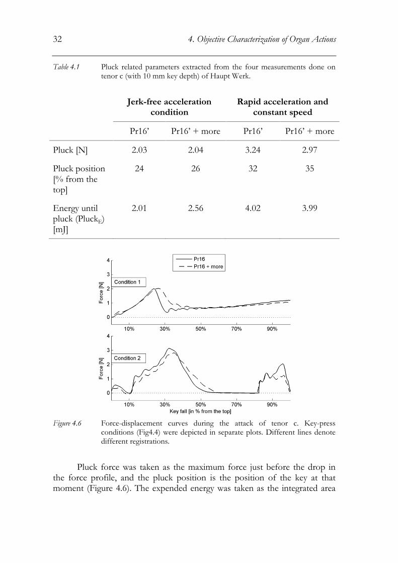
First, pluck related parameters were investigated and extracted. Naturally, the force needed to overcome the pressure in the wind chest was extracted as pluck. Figure 4.6 shows the results of four different measurements done on tenor c of Haupt Werk, when the blowers were on. During the attack, force at the key tip and key position were measured for two different registrations in two different playing settings (see Figure 4.4). First registration setting was only Principal 16�, while the second setting was selected in order to see the effect of increased wind consumption on the appearance of pluck. Therefore, more stops were added to Principal 16� (Octav 8�, Octav 4�, SuperOctav 2�, and Mixture). In these settings the parameters extracted were: (1) maximum force before the pallet opens, (2) the position of the key when the pallet opens, and (3) expended energy until the pallet opens (see Table 4.1).
32 4. Objective Characterization of Organ Actions
Table 4.1 Pluck related parameters extracted from the four measurements done on tenor c (with 10 mm key depth) of Haupt Werk.
Jerk-free acceleration condition
Rapid acceleration and constant speed
Pr16� Pr16� + more Pr16� Pr16� + more
Pluck [N] 2.03 2.04 3.24 2.97
Pluck position [% from the top]
24 26 32 35
Energy until pluck (PluckE) [mJ]
2.01 2.56 4.02 3.99
Figure 4.6 Force-displacement curves during the attack of tenor c. Key-press
conditions (Fig4.4) were depicted in separate plots. Different lines denote different registrations.
Pluck force was taken as the maximum force just before the drop in the force profile, and the pluck position is the position of the key at that moment (Figure 4.6). The expended energy was taken as the integrated area

4. Objective Characterization of Organ Actions 33
under the force profile from the start of the key travel until the pluck occurs. Instead of percentage of key fall the position was measured in millimeters. The key depth for the tenor c of HauptWerk was 10 mm. After studying Figure 4.6 and Table 4.1, one can say that required force and energy to open the pallet were higher, and the pluck position was further down when the key was pressed faster.
Further, increasing the wind consumption did not increase the pluck force. Since the pluck force is the force to overcome the pressurized air in wind chest to open the pallet, the air consumption should not affect the pluck force substantially. Therefore, the decrease in the pluck force for increased air consumption during fast playing condition (see Table 4.1) was an unexpected reslut. Nevertheless, this is not a consistent condition for the keys that were measured. Moreover, the increased air consumption caused the appearance of the peak force to be broader (see Figure 4.6); and the pluck position to happen just slightly further down (about 2 %; or 0.2 mm). This figure is well within the measurement resolution of the laser displacement sensor (about 0.04 mm).
4.4. Stiffness in the system
The characterization of the equivalent stiffness in the key action is an important task. The force at the key tip and position of the key were measured while the blowers were off and the keys were pressed with slow jerk-free acceleration (left panel in Figure 4.4). These measurement conditions are ideal to investigate the stiffness in the system. By measurement with the blowers switched off one eliminates the effect of pluck; and by pressing the keys with jerk-free acceleration one removes the influence of inertia. The equivalent stiffness in the key action in this case was defined as the average slope of the mid-section of the force-displacement curve during the attack, measured while the blowers were off and the key was pressed with jerk-free acceleration. The mid-section of the curve is defined as the portion that falls in between 20% and 80% of the key-fall (Figure 4.7). Figure 4.7 shows the stiffness curves plotted for three different keys (c, c1, and c2) in HauptWerk in the North German Baroque Organ in Örgryte Nya Kyrka in Gothenburg, Sweden. The equivalent stiffness in the system depends on the stiffness of the spring, the flexibility of trackers, and rigidity of the rollers.
It is organ building practice to pre-tense the springs. To capture the effect of the amount of pretension in the springs, the average force in the mid-section of the force profile was computed (see Fspring in Figure 4.7).

34 4. Objective Characterization of Organ Actions
Figure 4.7 Extraction of the equivalent stiffness and Fspring parameters from the force
profiles.
4.5. Characterization of the friction in the system
It is difficult to accurately measure how much friction there is in the action because of the complexity of the key action system. In order to characterize the friction in the system, the author chose to measure force at the key tip and key position while pressing and releasing the key with jerk-free acceleration when the blowers were off (Figure 4.8). Figure 4.8 shows the force profile during attack and release of three different keys (c, c1, and c2) in Haupt Werk in the North German Baroque Organ in Örgryte Nya Kyrka in Gothenburg, Sweden.
Since the manner of pressing the keys removes the inertia effects, the offset between attack and release profiles is due to the friction in the key action. In this study the friction is characterized by the area between the attack and release curves, which correlates with the energy lost to friction. After studying Figure 4.8, one can conclude that in c there was substantially less friction compared to both c1 and c2.
4.6. Effect of inertia
In addition to the parameters mentioned above, the inertia of key components also contributes to the physical feedback to the organ player. However, it is complicated to come up with a model that includes the effect of inertia (see Chapter 2.3). From the measurements done here, one can see

4. Objective Characterization of Organ Actions 35
Figure 4.8 Force profiles for the attack and release of three keys (in respective plots).
The area that lies in between the two curves in each plot is taken as a measure of how much energy is lost to friction.
the effect of inertia in rapid acceleration condition (right panel in Figure 4.4). For this condition, oscillations in the force � displacement curve could be detected (top plot in Figure 4.5). These are due to the mass and stiffness of the key components. Here, the key action was assumed to be similar to a simple one-degree-of-freedom mass-spring system. Therefore, the oscillation frequency was detected from the measurements; and it was used with the extracted stiffness parameter (see Chapter 4.4) in order to characterize the inertia-effect.
���� = ���(2��0)�
where keq is the equivalent stiffness and f0 is the oscillation frequency. Note that the effective mass parameter (Meff) extracted in this manner is not the

36 4. Objective Characterization of Organ Actions
same as the equivalent dynamic mass (EDM) introduced in Chapter 2.3. The drawback of this approach is that in some measurements it is difficult to detect the oscillation frequency correctly.
4.7. Energy related measures
Borrowing from the performance research methodology, the author chose to extract energy related parameters. These are based on energy expenditure during pressing the key under different conditions. The expended energy was computed by integrating force over the key fall at 9 different percentiles from 10% of the total key depth to 90%. A typical result can be seen in Figure 4.9, where energy expenditure is plotted against key fall for all the above-mentioned measurement conditions for tenor c in HauptWerk at the North German Baroque Organ in Örgryte Nya Kyrka. Conditions 1 (Left plot in Figure 4.9) and 2 (Right plot in Figure 4.9) depict jerk-free acceleration (Left panel in Figure 4.4) and rapid acceleration (Right panel in Figure 4.4) conditions, respectively. These energy profiles can be used to characterize the key action properties. They can also be used to compare the different keys and instruments provided that the keys are pressed in the same manner.
A number of other parameters were extracted in addition to these energy profiles. When the blowers are switched on, the required energy to press the key increases due to the pluck. The maximum increase in energy required due to pluck, in relation to the condition when the blowers are off is taken as an indicator of pluck called Pluck Ratio. For instance, for Principal 16� registration under condition 1 maximum increase in relation to the wind-off setting occurs at 30% of the key fall (3.4 times as much). Therefore, the Pluck Ratio for this particular registration is 3.4.
Further, one can see the influence of inertia of the key components on the expended energy when the two conditions are compared. The energy expenditure for the two conditions when the blowers were off is plotted in Figure 4.10 for such a comparison. The difference between the two curves is the energy required to start the movement of the components of the key action. The largest difference in expended energy between these two conditions is taken as an indicator of inertia of the components in the key action and is called Einertia (see Figure 4.10).

4. Objective Characterization of Organ Actions 37
Figure 4.9 Expended energy to press the key (energy profiles) taken from c at the
main division. Right and left plots depict the energy profiles for the two key-press conditions (jerk-free and rapid acceleration; see Figure 4.4). Different curves indicate different registrations.
Figure 4.10 Energy profiles for the two key-press conditions when the blowers were off. The difference between the curves is due to the inertia of the key components. The figure also shows how the Einertia parameter is extracted.
A summary of all the extracted parameters is shown in Table 4.2. These parameters can be used to compare different keys within an instrument as well as keys in different instruments. Since they are extracted from the measurements done at the console, they are directly related to the organ player�s perspective. The console is also the most accessible measurement location in an instrument, which makes measurements non-invasive and easily done on different instruments.

38 4. Objective Characterization of Organ Actions
The parameters listed in Table 4.2 (apart from Meff) are used in the following chapter for comparison between different instruments. As mentioned above, detection of the oscillation frequency is difficult for some cases, so Meff was excluded from further analyses and comparisons that are presented in Chapter 5.
Table 4.2 Summary of all the extracted parameters in order to characterize the key action
Parameter Name
Description Unit Reference
D Key depth [mm]
Pluck Pluck Force [N] Chapter 4.3
Pluck position Position of the key from the top when the pluck occurs
[%] Chapter 4.3
PluckE Expended energy until the pluck [mJ] Chapter 4.3
keq Equivalent stiffness [N/m] Chapter 4.4
Fspring Effect of the pretension in the spring
[N] Chapter 4.4
Efriction Energy lost to friction [mJ] Chapter 4.5
Meff Effective mass [g] Chapter 4.6
Energy Profile Expended energy profiles with respect to key position
[mJ] Chapter 4.7
Pluck Ratio Increase in required energy due to pluck with respect to wind-off setting
[-] Chapter 4.7
Einertia Extra energy that is needed to start moving the key components when the blowers are off
[mJ] Chapter 4.7

5. Analysis of the Objective Measures
The previous chapter explained the measurement methodology. The proposed objective parameters can be used to characterize the physical feedback to the organ player from the key action. They can also be used to characterize and compare different instruments.
The purpose of this chapter is to demonstrate the statistical methods to characterize different instruments using the proposed objective parameters. Initially the chapter is focused on the keys within one manual of a particular instrument, and on how the statistical methods can be applied to characterize the key action properties of an instrument. In the second part of the chapter, parameters extracted from a selection of keys are used for comparison of different instruments. All measurements were done following the methodology described in Chapter 4.
5.1. Objective key characters within a single manual
This section demonstrates how the proposed parameters could be used to characterize an instrument using measurements done on HauptWerk (Main Division) of the Cornell Baroque Organ, at Cornell University, Ithaca, NY (Figure 5.1). This organ was based on the tonal architecture of the Charlottenburg organ in Berlin that was built by Arp Schnitger in 1706. It was built as a collaborative effort by Cornell�s College of Arts and Sciences and the Göteborg Organ Art Center (GOArt) at the University of Gothenburg (for details; see Appendix A). The organ has two manuals and a pedal keyboard, 30 stops and 42 individual ranks of pipes (1847 pipes in total).
The measurements were carried out on select keys within each manual. Here, the focus will be on the keys at the main division of the organ. At each key the force on the key tip and the key position were measured simultaneously using the controllable linear actuator to press and release the keys. Four different measurement conditions (two blower settings and two key-press settings) were used (see Table 5.1); and for each measurement

40 5. Analysis of the Objective Parameters
condition the force and key position were measured 3 times, and then averaged.
Figure 5.1 Cornell Baroque Organ located in the Anabel Taylor Chapel in Cornell
University, Ithaca, NY (photo taken by Erkin Asutay).

5. Analysis of the Objective Parameters 41
Table 5.1 Description of the measurement settings
Blower settings Key-press settings
Wind off Slow jerk-free acceleration (see left panel in Figure 4.4)
Wind on (Principal 8� registration) Rapid acceleration (ca 500 mm/s2) then constant speed (100 mm/s) until key bottom (see right panel in Figure 4.4)
The previously proposed objective parameters were the extracted from the measurements (see Table 4.2). As mentioned prerviously, effective mass parameter (Meff) was excluded from further analyses, since it was difficult to detect the oscillation frequency for every key.
The overall appearance of the main parameters for each key can be seen in Table 5.2. The values in Table 5.2 do not only provide information about individual keys, but they also can be used to study how different parameters change over the range of an instrument.
In order to see how parameters change across the compass of the manual one can group the keys into separate octaves and run one-way analysis of variance (ANOVA) to search for statistical differences between the octaves. Here, the keys were grouped into 5 different octaves: Oct1 (D, E, F#, and G), Oct2 (c, c#, e, f#, and g), Oct3 (c1, c#1, e1, f#1, and g1), Oct4, (c2, c#2, e2, f#2, and g2), and Oct5 (c3 and c#3). A series of one-way ANOVAs were done in order to investigate the possible differences between different groups of keys. All the parameters listed in Table 5.2 were used as dependent variables. There were no statistically significant differences between different groups of keys for parameters keq, Fspring, Einertia, and Efriction (Figure 5.2).
Key depth was found to be statistically different across the compass between different octaves (F(4,16)=3.26, p<.05). Contrast analysis of the effect revealed a significant linear trend (F(1,16)=12.11, p<.01) which indicated that key depth decreased slightly with increasing octave (Figure 5.3). Even though the actual differences were within 1 mm, the linear trend could be seen in Figure 5.3. Finally, post-hoc least square differences (LSD) tests showed that key depths within Oct1 was significantly larger compared to both Oct4 and Oct5 (both at p<.05 level). There were no differences between any other groups.

42 5. Analysis of the Objective Parameters
Table 5.2 Main descriptive parameters for all the measured keys in the main division of the Cornell Baroque Organ. The listed pluck parameters were taken from the jerk-free acceleration setting.
Key d [mm]
Pluck [N]
Pluck pos. [%]
PluckE [mJ]
Keq [N/m]
Fspring [N]
Efriction [mJ]
Einertia [mJ]
D 8.5 2.17 20 1.74 186 1.23 4.59 1.05
E 7.9 2.59 28 2.82 213 1.32 3.85 1.62
F# 9.5 1.42 22 1.34 113 1.32 3.60 3.02
G 9.0 2.79 21 2.74 143 1.45 5.19 1.52
c 8.9 1.99 21 1.89 211 1.43 6.36 1.51
c# 8.5 1.03 20 0.98 107 1.18 3.60 2.18
e 8.5 1.97 21 1.78 205 1.13 4.75 1.58
f# 8.4 0.95 18 0.77 91 1.24 2.98 1.99
g 7.9 1.88 22 1.58 167 1.24 3.96 0.94
c1 7.8 1.87 26 1.86 207 1.17 3.38 0.84
c#1 8.5 0.96 18 0.70 93 1.21 2.88 1.88
e1 7.9 1.94 22 1.72 149 1.15 3.19 1.47
f#1 8.1 0.96 23 0.94 115 1.37 1.64 2.29
g1 8.7 1.74 18 1.47 350 1.10 4.81 1.40
c2 7.9 1.57 18 1.11 168 1.27 3.75 1.25
c#2 8.0 0.77 18 0.61 74 1.16 2.94 1.81
e2 7.5 1.72 17 1.20 146 1.23 3.02 1.77
f#2 7.8 1.09 21 0.83 132 1.61 3.32 2.00
g2 8.4 1.77 18 1.40 102 1.17 2.56 1.32
c3 7.4 2.05 19 1.52 162 1.53 3.71 1.81
c#3 7.7 0.75 20 0.62 155 1.46 5.78 1.61
Mean ± SE
8.2 ± .12
1.62 ± .13
20 ± .61
1.41 ± .13
156 ± 13.4
1.28 ± .03
3.8 ± .24
1.66 ± .11

5. Analysis of the Objective Parameters 43
Figure 5.2 Equivalent stiffness (keq), Fspring, Einertia, and Efriction for different keys in
Cornell Baroque organ. Keys are ordered in rising pitch.
Pluck force and position did not yield significant differences over the range of the manual. Nevertheless, a significant linear trend in pluck force (F(1,16)=4.63, p<.05) indicated that as the pitch increased pluck force tended to decrease (Figure 5.4). Post-hoc LSD tests indicated that pluck force in Oct1 tended to be higher compared to all other octaves (at p<.08 level). This is mainly due to the need of larger pallet openings and larger pallets for bass notes.

44 5. Analysis of the Objective Parameters
Figure 5.3 Key depth of the measured keys that are ordered in rising pitch. The circles and the error bars indicate the average key depth within each octave and the standard error of the mean, respectively.
Figure 5.4 Pluck force for the measured keys that are ordered in rising pitch. The
circles and the error bars indicate the average pluck force within each octave and the standard error of the mean, respectively.
The pluck position did not differ between different groups of keys (Figure 5.4) in this instrument. Further, the results on expended energy until pluck (PluckE) were similar to pluck force. A statistically significant linear trend (F(1,16)=9.29, p<.01) showed that required energy to overcome the pluck decreased as the pitch increased (Figure 5.4). Post-hoc LSD tests revealed that PluckE for Oct1 was significantly higher compared to other octaves (at p<.05 level).

5. Analysis of the Objective Parameters 45
Figure 5.5 Average effect of wind settings (top plot) and key-press settings (bottom
plot) on the energy profiles over all the keys.
Further, possible differences between white (E, G, c, e, g, c1, e1, g1, c2, e2, g2, and c3) and black (D, F#, c#, f#, c#1, f#1, c#2, f#2, and c#3) keys were investigated. The parameters listed in Table 5.2 were submitted to one-way ANOVAs to search for differences between black and white keys. According to the results no significant differences could be found in key depth, pluck position, Fspring, and Efriction. Pluck force was found to be significantly higher (F(1,19)=25.17, p<.01) for white keys (1.99±0.11 N) compared to black keys (1.12±0.15 N). Similar results were found for the expended energy until pluck (F(1,19)=14.95, p<.01), that is, required energy to overcome the pluck was higher for white keys (1.76±0.15 mJ) compared to black keys (0.95±0.12 mJ). Moreover, equivalent stiffness was higher for white keys compared to black keys (F(1,19)=8.39, p<.01).
Finally, energy profiles (expended energy with respect to the key position while pressing the key) were submitted into repeated-measures ANOVA with three factors: wind setting (off vs. on), key-press setting (jerk-

46 5. Analysis of the Objective Parameters
free vs. rapid acceleration), and key position (from 10% to 90% from the top). It was found that rapid acceleration required significantly more energy to press the key compared to jerk-free acceleration (F(1,20)=479.5, p<.001, η2=.96). This effect is due to the influence of inertia, since one would expend more energy to accelerate the key components. The two way wind-setting*key-position (F(8,160)=18.04, p<.001, η2=.47) and key-press-setting*key-position (F(8,160)=66.67, p<.001, η2=.77) interactions were statistically significant (Figure 5.5). In the top plot of Figure 5.5, one can see the average effect of wind-setting (i.e. pluck) on energy profiles, whereas the average effect of key-press setting (i.e. inertia) is depicted in the bottom plot of Figure 5.5. The three-way interaction was also statistically significant (F(8,160)=47.5, p<.001, η2=.70). One can see the average energy profiles for the four different settings in Figure 5.6.
Figure 5.6 Average effect of wind setting for different key-press conditions, i.e. jerk-
free acceleration (top plot) and rapid acceleration (bottom plot).

5. Analysis of the Objective Parameters 47
Table 5.3 The list of instruments and keys, on which the measurements were carried out.
ID Instruments Manuals Registration for wind-on
setting
Keys
Organ no.1
North German Baroque Organ,
Gothenburg, Sweden
Werck Principal 16� c, c1, c2
Oberpositiv Principal 8� c, c#, c1, c#1, c2, c#2
Organ no.2
Brombaugh Organ, Gothenburg, Sweden
Werck Principal 8� c, c#, c1, c#1, c2, c#2
Brustpostitiv Gedakt 8� c, c#, c1, c#1, c2, c#2
Organ no.3
Hammarberg Organ, Gothenburg, Sweden
Manual I Gedakt 8� c, c#, c1, c#1, c2, c#2
Manual II Rorflojt 8� c, c#, c1, c#1, c2, c#2
Organ no.4
Verschueren Organ, Gothenburg, Sweden
Manual I Bourdon 8� c, c#, c1, c#1, c2, c#2
Manual II Bourdon 8� c, c1, c#1, c2, c#2
Organ no.5
Craighead-Saunders Organ, Rochester,
NY
Manual I Principal 8� c, c#, c1, c#1, c2, c#2
Manual II Principal 4� c, c#, c1, c#1, c2, c#2
Organ no.6
Cornell Baroque Organ, Ithaca, NY
Hauptwerk Principal 8� c, c#, c1, c#1, c2, c#2
Ruckpositiv Principal 8� c, c# c1, c#1, c2, c#2

48 5. Analysis of the Objective Parameters
Figure 5.7 Average key depths for different instruments (SE of the means are
indicated). Asterisk shows significant differences.
5.2. Comparison of Different Instruments
The key action characteristics of different instruments can be compared using the proposed parameters. Measurements were done on different instruments and the proposed parameters were extracted for several keys within each instrument. These were then submitted to statistical analyses (for the list of the instruments and keys, see Table 5.3 and Appendix A).
All the extracted parameters except the energy profiles were submitted to a series of one-way ANOVAs in order to investigate the differences between instruments. First, key depth was significantly different between these instruments (F(5,62)=9.68, p<.001). Organs 2 and 4 had significantly smaller key depths compared to the rest (at p<.01 level). Organ no 3 had the largest key depth of all the instruments (Figure 5.7).
All the extracted parameters except the energy profiles were submitted to a series of one-way ANOVAs in order to investigate the differences between instruments. First, key depth was significantly different between these instruments (F(5,62)=9.68, p<.001). Organs 2 and 4 had significantly smaller key depths compared to the rest (at p<.01 level). Organ no 3 had the largest key depth of all the instruments (Figure 5.7).
All three pluck parameters (expended energy until pluck, pluck force, and position) yielded significant results in ANOVA (at p<.001 level). Post-hoc LSD analysis revealed that the organs could be divided into three different groups. Organs 2, 3, and 4 belonged to the first group and had

5. Analysis of the Objective Parameters 49
Figure 5.8 Average pluck force for different instruments (SE of the means are
indicated). Asterisk shows significant differences.
significantly lower pluck than the rest; also the pluck occurred earlier during the key fall. The group that had the highest pluck and latest pluck position were organs 1 and 5. Pluck values for organ no. 6 were in between these two groups of instruments (see Figure 5.8). All the other parameters yielded significant differences between instruments (at p<.001 level). The mean values and standard errors of the means for these parameters could be seen in Table 5.4.
Similar to the analysis in the previous section, energy profiles were submitted to repeated-measures ANOVA with wind setting (off vs. on), key-press setting (jerk-free vs. rapid acceleration), and key position (from 10% to 90% from the top) as within-subject factors. Instrument was added as a between-subjects factor to the analysis. All the effects that were reported in Chapter 5.1 were replicated. Here, only the effects involving the instrument parameter are reported. First, instrument had a significant main effect (F(5,62)=15.36, p<.001, η2=.55) indicating that the required energy to press the keys was different for different instruments. Further pair-wise comparisons revealed that organ no.2 required significantly less energy compared to the others; and that organs no. 1, 5, and 6 required significantly more energy compared to organs no. 3 and 4 (all differences p<.05 level). Other significant interactions were instrument*key-position (F(40,496)=11.99, p<.001, η2=.49), instrument*wind-setting*key-position (F(40,496)=7.71, p<.001, η2=.38), and instrument*key-press-setting*key-position (F(40,496)=9.65, p<.001, η2=.44). All these interactions showed that

50 5. Analysis of the Objective Parameters
Figure 5.9 The average effect of wind setting (i.e. pluck) on the energy profiles for
different instruments.
the energy profiles were significantly different for different instruments (see Figure 5.9).
The analyses presented in this chapter revealed that the extracted parameters and the energy profiles are indeed different for different types of instruments; and that the statistical methods could be employed in order to investigate these differences. Note that even though only a small number of keys were selected within each instrument, statistical analyses revealed significant differences between the instruments. At this point the important questions are: (1) if these differences are apparent to organ players who

5. Analysis of the Objective Parameters 51
Table 5.4 Mean values of extracted parameters for different instruments (standard errors of the means are indicated in parentheses).
Organ no.1
Organ no.2
Organ no.3
Organ no.4
Organ no.5
Organ no.6
d [mm] 8.0(.8) 6.1(.2) 9.2 (.4) 6.9 (.2) 8.5(.3) 8.3 (.1)
Pluck [N] 1.8(.2) 0.6(.04) 0.7 (.1) 0.8 (.05) 1.6 (.2) 1.2 (.1)
Pluck position [%] 26(1.5) 7(1.3) 11 (1.2) 7 (1.1) 26 (2.5) 16 (1.4)
PluckE [mJ] 2.1(.37) 0.2(.04) 0.5 (.11) 0.3 (.06) 2.1 (.44) 0.9 (.15)
Keq [N/mm] 113(15) 83(8) 93 (24) 49 (6) 57 (10) 117 (15)
Fspring [N] 0.9(.11) 0.3(.05) 0.6 (.04) 0.6 (.07) 0.8 (.09) 1.2 (.06)
Efriction [mJ] 4.3(.55) 1.5(.20) 2.1 (.36) 2.4 (.27) 2.9 (.50) 3.9 (.32)
Einertia [mJ] 0.8(.06) 0.3(.03) 0.7 (.15) 0.5 (.08) 1.0 (.11) 1.7 (.17)
interact with the instruments; and (2) which of these parameters are sensorially salient. In the following chapter, a framework is proposed on how to study subjective characteristics of the mechanical key actions; and how to combine objective and subjective characteristics.


6. Conclusions and Future Work
The present thesis is a part of a research project that sets out to characterize mechanical pipe organ key actions. Since the nature of the key action affects the organ player and how the instrument is being perceived, one needs to do both objective and subjective characterization of key action properties. The present thesis explains the measurement methodology that was developed to objectively characterize the key action properties. The methodology described here could be used to extract parameters that are related to physical construction of the instrument. Further, in the previous chapter it was shown that these parameters could be used to characterize instruments and compare them with each other. The measurement methodology developed in this thesis can be used to document physical characteristics of mechanical key actions in a way that makes sense to the organ players, since it deals with the mechanical and physiological properties that they can relate to. However, at this point it is not clear if the organ players can perceive differences between instruments along the parameters proposed here. Hence, apart from physical measurements and parameterization of the force at the key tip while pressing the keys, subjective characterization is needed. The main purpose of subjective measurements is to reveal perceptual dimensions along which one can characterize a particular instrument and compare different instruments. One can employ different psychophysical methods for this purpose. The author chose to start with generating a list of words that are used to describe key action characteristics of pipe organs among the organ players and builders. Once this descriptive list is ready, one can devise subjective measurement scales from it; and use those scales in experiments with organ players in order to characterize key actions of different instruments subjectively. Evidently, after the subjective experiments one should combine objective and subjective characteristics of mechanical key actions in order to study if the differences in objective parameters could explain differences in subjective parameters (the relationship between physical and perceptual characters). The outcome of this process is expected to show the parameters that are salient to organ players and thus correlate to their perception of the instrument and the musical

54 6. Conclusions and Future Work
performance. The subjective characterization is ongoing work. Therefore, this section only provides an overview of what has been done and what is expected to be done for subjective characterization. It provides detailed information on all the steps that are described above (i.e. generation of descriptive words, devising subjective measurement scales, and subjective experiments). Further, it introduces statistical methods for linking objective and subjective characters.
6.1. Subjective Characterization
In order to measure haptic sensation, the first task is to devise semantic measurement scales. These scales are based on words or phrases that describe a perceptual aspect of the subjective experience of the mechanical key actions. For instance, a semantic differential scale that is aimed to measure the subjective sensation of the pluck could look like the one in Figure 6.1. Here, the organ player is asked to rate how much pluck he experiences for one particular instrument; and the scale ranges from not at all to extremely in nine intervals. Hence, the scale in Figure 6.1 is a nine point unipolar scale. However, since an organ has different sections that differ mechanically one would expect that it is not possible to characterize the sensation of pluck with just one scale. The scale in Figure 6.1 will most likely be inadequate for measuring the pluck sensation. Many scales are likely to be necessary to describe the perceptual aspects of organ playing. Hence, one needs to put more effort in order to devise relevant measurement scales for the purpose.
Figure 6.1 A subjective measurement scale devised to measure how much pluck force
the organist feels. Nine-point scale ranges from not at all to extremely much
6.1.1. Semantic measurement scales
Since the aim is to tap into the perceptual aspects of the mechanical key actions, the measurement scales should be relevant to organ players. Therefore, an online survey was carried out with the purpose of compiling a

6. Conclusions and Future Work 55
list of words or phrases that are used by organ players describing the haptic sensation of organ playing. In the survey, participants were asked to describe the physical experience of playing a pipe organ with good (desirable) and bad (undesirable) key action according to their preferences and experience. They were encouraged to give examples from the existing pipe organs, and were free to describe their experience in a way they see fit. Employing this procedure, one can learn how the organ players describe their interaction with an instrument.
10 participants (4 females) took part in the survey (average age: 42.4, std.dev: 12.3). They had at least 5 years of experience in organ playing and were organists and/or organ students at the Academy of Music and Drama in Gothenburg, Sweden. A list of descriptive words was generated using their responses. The phrases the participants used to describe their experiences could be divided into a number of central topics or categories (Table 6.1): (1) controllability of the instrument (e.g. feeling of being in control, fast response from the instrument), (2) mechanical or physical aspects (e.g. heaviness of the action, balance between the keys, viscous feeling), (3) connectedness (e.g. feeling in contact with the wind, feeling disconnected from the instrument), and (4) ergonomics. These four perceptual aspects could be found in each of the participants� responses.
In order to measure haptic sensation of pipe organ playing semantic measurement scales can be developed based on the list of words that were generated from the responses to the online survey. The semantic differential scales should cover all the perceptual aspects in Table 6.1 (controllability of the instrument, influence of physical aspects, connectedness, and ergonomics). For instance, the phrase �heavy action� was used by all the participants in the survey. According to the participated organ players a key action should not be �too heavy�. At this point one can only speculate what organ players mean by heavy action, or in other words what physical aspects contribute to the sensation of �heaviness�. Most probably they mean that it takes more energy than necessary to press the keys, which could be due to a large pluck force and/or too high spring force, but not necessarily related to the mass of the action itself. Therefore, one can devise a unipolar or a bipolar scale based on this particular word (Figure 6.2), and design experiments to measure how heavy a particular key action is (see the developed semantic measurement scales to be used in subjective tests in Appendix B).
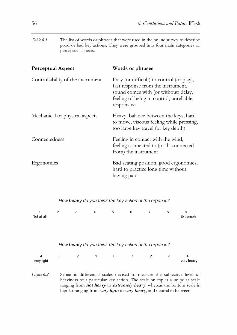
56 6. Conclusions and Future Work
Table 6.1 The list of words or phrases that were used in the online survey to describe good or bad key actions. They were grouped into four main categories or perceptual aspects.
Perceptual Aspect Words or phrases
Controllability of the instrument Easy (or difficult) to control (or play), fast response from the instrument, sound comes with (or without) delay, feeling of being in control, unreliable, responsive
Mechanical or physical aspects Heavy, balance between the keys, hard to move, viscous feeling while pressing, too large key travel (or key depth)
Connectedness Feeling in contact with the wind, feeling connected to (or disconnected from) the instrument
Ergonomics Bad seating position, good ergonomics, hard to practice long time without having pain
Figure 6.2 Semantic differential scales devised to measure the subjective level of heaviness of a particular key action. The scale on top is a unipolar scale ranging from not heavy to extremely heavy; whereas the bottom scale is bipolar ranging from very light to very heavy, and neutral in between.

6. Conclusions and Future Work 57
6.1.2. Subjective measurements
First experiment will concern the instruments, whose objective parameters were already collected (see Tables 5.3 and 5.4). Organ players will rate, using the semantic scales that are provided (see Appendix B), the instruments based on their previous encounters with them. With this sort of data collection one relies on the memory of the participants. Further, since participants might not be familiar with every instrument, one cannot have a repeated-measures design (i.e. each participant rates every instrument), which could reduce statistical power. In that case one might need larger number of participants. However, even with these drawbacks, data collection in this manner can be rather fast, and this pilot experiment could serve as initial testing of the semantic scales to see if they could capture differences between instruments that were shown to be different in many aspects in the previous chapter. Moreover, one would be able to investigate the relationship between objective parameters and subjective measures.
Depending on the results of the first experiment, a new experiment will be designed. In the second experiment a number of organ players will rate the key action of different pipe organs while they are interacting with the instruments. Evidently, after the pilot experiment some of the semantic scales may need to be altered or even removed, and some new scales could be added. The second experiment is planned to be a controlled experiment, where participants will take time to interact with the instruments, rate them and report their impressions. Obviously, data collection will take more time compared to the first experiment. Nevertheless, with this experimental design the familiarity with the instrument is not needed, and one can use a repeated-measures design, where every participant could play each instrument and rate them on semantic differential scales that are provided. The outcome of the subjective experiments will be to reveal perceptual characteristics of key actions of different instruments. Hence, this will conclude the subjective characterization of mechanical key actions.
Finally, one needs to form a link between the objective and subjective characteristics of key actions, which could be done using statistical methods. This should be done in order to reveal sensorially salient key action parameters. One can then find which objective parameters that are correlated to each subjective characteristic. Further, one can also investigate how the changes in the physical parameters would influence the perceptual outcome.
In conclusion, a methodology to characterize pipe organ mechanical key actions with objective measurements is presented and discussed in this

58 6. Conclusions and Future Work
thesis. Objective characterization was done from the performer�s perspective, i.e. characterization of the physical feedback that the performer receives from the instrument. The measurement methodology and extraction of objective measures was discussed in detail. Moreover, it was shown how these measures or parameters could be used to characterize a particular instrument as well as in comparison of different instruments. As shown in Chapter 5, it was found that the proposed parameters ca indeed capture differences between instruments. During the continuation of the research project considerable effort will be spent on subjective characterization of pipe organ key actions. Further, the objective parameters presented in the current thesis will be connected to the subjective characteristics in order to reveal salient properties of mechanical key actions. The outcome of this research project will help improve the current knowledge in the field of organ building. It will provide new technologies and methods for organ documentation. Also, it will reveal more about the interaction between the instrument and the performer.

A. Specifications of Pipe Organs
In this section, one can find the specifications of the instruments that were mentioned in Chapters 4 and 5.
A1. The North German Baroque Organ, Örgryte New Church, Gothenburg, Sweden
The North German Baroque Organ was built within a research project with the aim of reconstructing a 17th century North German organ in Arp Schnitger�s (1648-1714) style on a scientific basis. It was modeled after Arp Schnitger�s organ in the Hamburg Jakobikirche. The facade is a copy of the 1699 Schnitger organ facade in the Lübeck Cathedral which was destroyed during World War II. It has four manuals, pedal and 54 stops (Table A.1).
Figure A.1 Measurement session at the North German Baroque Organ (photo taken
by Erkin Asutay)

60 A. Specifications of Pipe Organs
Table A. 1 Manual, pedal and stop specifications of the North German Baroque Organ (wind pressure: 76mm water column). For more info on the North German Baroque Organ: http://www.goart.gu.se/research/instruments/north-german-baroque-organ/)
Werck (II) CDEFGA-c3
RuckPositiv (I) CDE-c3
OberPositiv (III) CDEFGA-c3
BrustPositiv (IV) CDEFGA-c3
Pedal
CD-d1
Principal 16�
Quintaden 16�
Octav 8�
Spitzfloit 8�
Octav 4�
SuperOctav 2�
Rauschpfeiff 2�
Mixtur 6.7.8f
Trommet 16�
Principal 8�
Quintaden 8�
Gedact 8�
Octav 4�
Blockfloit 4�
Octav 2�
Quer Floit 2�
Sieffloit 11/2
Scharff 6.7.8f
Dulcian 16�
Bahrpfeiff 8�
Principal 8�
Hollfloit 8�
Rohrfloit 8�
Octav 4�
Spitzfloit 4�
Nassat 3�
Octav 2�
Gemshorn 2�
Scharff 6f
Cimbel 3f
Trommet 8�
VoxHumana 8�
Zincke (from f) 8�
Principal 8�
Octav 4�
Hollfloit 4�
Waltfloit 2�
Sexquialter 2f
Scharff 4.5.6f
Dulcian 8�
Trechter Regal 8�
Principal 16�
SubBass 16�
Octav 8�
Octav 4�
Rauschpfeiff 3f
Mixtur 6.7.8f
Posaunen 32�
Posaunen 16�
Dulcian 16�
Trommet 8�
Trommet 4�
Cornet 2�
A2. The Brombaugh Organ, Haga Church, Gothenburg, Sweden
The organ was built by John Brombaugh and installed in Haga Church in 1991. The instrument was inspired by the early 17th century North German pipe organs. The planning and building of the instrument was done in collaboration between the Haga Parish and the Academy of Music and Drama at the University of Gothenburg.

A. Speifications of Pipe Organs
Table A.2 Manual, pedal and stop specifications of the Brombaugh Organ (wind pressure: 78mm water column).
Werk (I) CDE-c3
Praestant 8�
Gedack 8�
Holzprincipal 8�
Octava 4�
Spitzpipe 4�
Octava 2�
Qvinta 3�
Sesquialtera (treble) II
Mixtura IV-VI
Trommet 8�
Figure A.2 Measurement session at the Brombaugh Organ (photo taken by Erkin Asutay).
Speifications of Pipe Organs
Manual, pedal and stop specifications of the Brombaugh Organ (wind pressure: 78mm water column).
Brustpositiv (II) CDEFGA-c3 Pedal CDE
Holzgedackt 8�
Floit 4�
Hohlquinta (treble) 3�
Hohlfloitlein 2�
Regal 8�
Subbass 16�
Praestant 8�
Octava 4�
Bawrfloitlein 1�
Posaunen 16�
Trommet 8�
Dulcian 8�
Cornett 2�
Measurement session at the Brombaugh Organ (photo taken by Erkin
61
Manual, pedal and stop specifications of the Brombaugh Organ (wind
Pedal CDE-d1
Subbass 16�
Praestant 8�
Octava 4�
Bawrfloitlein 1�
Posaunen 16�
Trommet 8�
Dulcian 8�
Cornett 2�
Measurement session at the Brombaugh Organ (photo taken by Erkin

62 A. Specifications of Pipe Organs
A3. Hammarberg Organ
The organ was built by Nils Hammarberg in 1965 and is located at the Academy of Music and Drama, University of Gothenburg, Sweden. It has two manuals, pedal and 13 stops.
Table A.3 Manual, pedal and stop specifications of the Hammarberg Organ.
Manual I � C-g3 Manual II � C-g3 Pedal � C-f1
Gedakt 8
Principal 4
Valdflöjt 2
Sesquialtera 2 ch
Mixtur 3 ch
Rörflöjt 8
Koppelföjt 4
Principal 2
Nasat 11/3
Regal 8
Gedacktbas 16
Borduna 8
Flöjt 4
A4. Verschueren Organ
The organ was built by Verschueren Orgalbouw in 1987 and bought by the Academy of Music and Drama, University of Gothenburg in 1992. Today it is used as a practice instrument by the students in the Academy of Music and Drama.
Table A.4 Manual, pedal and stop specifications of the Verschueren Organ.
Manual I � C-g3 Manual II � C-g3 Pedal � C-f1
Bourdon 8
Fluit 4 bas & discant
Bourdon 8
Nasard 11/3 bas & 22/3
discant
Octaaf 2
pull down to I

A. Speifications of Pipe Organs 63
A5. Craighead-Saunders Organ
The organ is built within a research project at Göteborg Organ Art Research Center (GOArt) at the University of Gothenburg. GOArt research workshop that worked on a reconstruction of the 1776 organ by Adam Gottlob Casparini in the Holy Ghost Church in Vilnius, Lithuania began in 2004. The completed organ was inaugurated in 2008 at Christ Church in Rochester, NY.
Table A.5 Manual, pedal and stop specifications of the Craighead-Saunders Organ (wind pressure: 74mm water column). For more information on the instrument: http://www.goart.gu.se/research/instruments/craighead-saunders-organ/
Claviatura Prima Claviatura Secunda Pedal
Principal 8�
Borduna 16�
Hohlflaut 8�
Quintathon 8�
Flaut Travers 4�
Octava Principal 4�
Qvinta 3�
Super Octava 2�
Flasch Flot 2�
Tertia 1 3/5�
Mixtura IV-V
Trompet 8�
Principal 4�
Iula 8�
Principal Amalel 8�
Unda Maris 8�
Flaut Major 8�
Spiel Flot 4�
Flaut Minor 4�
Octava 2�
Wald Flot 2�
Mixture III-IV
Dulcian 16�
Vox Humana 8�
Principal Bass 16�
Violon Bass 16�
Octava Bass 8�
Flaut & Quint Bass 8�
Full Bass 12�
Super Octava Bass 4�
Posaun Bass 16�
Trompet Bass 8�
A6. Cornell Baroque Organ
The organ is a reconstruction of an instrument built by Arp Schnitger for Charlottenbourg Court in Berlin in 1706. Reconstructed instrument was built for Cornell University in Ithaca, NY.

64 A. Specifications of Pipe Organs
Table A.6 Manual, pedal and stop specifications of the Cornell Baroque Organ (wind pressure: 74mm water column). For more information: http://www.goart.gu.se/research/instruments/anabel-taylor-chapel-organ/
Hauptwerk I Ruckpositiv II Pedal
Principal 8�
Quintadena 16�
Floite Dues 8�
Gedact 8�
Octav 4�
Violdegamb 4�
Nassat 3�
SuperOctav 2�
Mixtur IV
Trompete 8�
Vox Humana 8�
Principal 8�
Gedact Lieblich 8�
Octav 4�
Floite Dues 4�
Octav 2�
Waltfloit 2�
Sesquialt II
Scharf III
Hoboy 8�
Principal 16�
Octav 8�
Octav 4�
Nachthorn 2�
Rauschpfeife II
Mixtur IV
Posaunen 16�
Trommet 8�
Trommet 4�
Cornet 2�

B. Developed Semantic Measurement Scales
In this section a list of semantic differential scales that were devised based on the results of the online survey described in Chapter 6. Subjects will be asked to rate the instruments they are familiar with according to these scales. As described in Chapter 6, data collection of this manner is time saving, and it could serve as an initial testing of the devised semantic scales.
Instructions of the survey will appear as:
The survey you are about to participate in is a part of the GOArt research project: The Organ as Memory Bank. Within this research project, our aim is to develop new methodologies for documenting historical organs that are both technical and artistically relevant. By participating in this survey you are taking part in this important process.
In addition to the sound of the organ, the dynamic behavior of key actions is also very important. The performer receives feedback from the instrument through the way the key action behaves and adapts to this feedback. Thus, the characteristics of the key action will affect the interaction between the organist and the organ and influence the musical performance itself. Therefore, the specific aim of this survey is to study perceptual characteristics of the key action. The survey you are about to take will help us explore the subjective impressions you get about an organ through physically interacting with its key action.
In this survey you will be asked to rate the key action of a number of pipe organs that are listed on the next page. Please pick the instruments that you are familiar with and rate them based on your previous experiences with it.
You are asked to rate the instruments on a number of scales (see the example below). You will respond by selecting a number on each scale that suits you the best.

66 B. Devloped Semantic Measurement Scales
Table B.1 Devised semantic measurement scales. All the scales are 9-point unipolar scales that range from �not at all� at one end to �very much� at the other.
Questions in the subjective experiment
How heavy do you think the key action of the organ is?
How precise do you think the key action is?
How precise do you think the key action is?
How controllable do you think the key action of the organ is?
How controllable do you think the key action of the organ is?
How even do you think the keys are?
How even do you think the keys are?
How fast do you think the instrument responds to your input?
How deep do you think the key depth is?
To what extent do you feel connected to the instrument while you play?
How fluent does it feel when you perform on the instrument?
How good do you think the design of the instrument from the perspective of ergonomics?
How good do you think the key action of the instrument?

References
Audsley, G. A. (1965). The Art of Organ Building. Minneola, NY: Dover Publications Inc.
Askenfelt, A. & Jansson, E. V. (1990). From touch to string vibrations. I. Timing in the grand piano action. Journal of the Acoustical Society of America, 88, 52-63.
Askenfelt, A. & Jansson, E. V. (1991). From touch to string vibrations. II. The motion of the key and hammer. Journal of the Acoustical Society of America, 90, 2383-2393.
Baker, D. (1993). The Organ. Shire: Princes Risborough.
Bonavia-Hunt, N. (1939). The Modern British Organ. London: Weekes.
Bracewell, R. M., Wimperis, A. S., & Wing, A. M. (2008). Brain mechanisms of haptic perception. In A. Bicchi, M. Buss, M. O. Ernst, & A. Peer (Eds.), The Sense of Touch and Its Rendering (pp. 25-38). Berlin: Springer-Verlag.
Bresciani, J., Drewing, K., & Ernst, M. O. (2008). Human haptic perception and the design of haptic-enhanced virtual environments. In A. Bicchi, M. Buss, M. O. Ernst, & A. Peer (Eds.), The Sense of Touch and Its Rendering (pp. 39-60). Berlin: Springer-Verlag.
Cadoz, C., Lisowski, L., & Florens, J. L. (1990). A modular feedback keyboard design. Computer Music Journal, 14(2), 47-51.
Cumming, N. (2000). The sonic self: Musical subjectivity and signification. Bloomington, IN: Indiana University Press.
Davidson, J. W., & Correia, J. S. (2001). Meaningful musical performance: A bodily experience. Research Studies in Music Education, 17, 70-83.

68 References
d�Alessandro, C. (2010). On the dynamics of the clavichord: From tangent motion to sound. Journal of the Acoustical Society of America, 128(4), 2173-2181.
Deleuze, G., & Guattari, F. (1987). Anti-Oedipus: Capitalism and schizophrenia. Minneapolis, MN: University of Minneapolis Press.
Drescher, D., Parlitz, D., Tiedemann, J., & Altenmüller, E. (1999). A new measuring instrument for determining and depicting the forces of the fingers applied to the piano keys. Europiano, 39(2), 23-42.
Fletcher, N. H., & Rossing, T. D. (1998). The Physics of Musical Instruments, 2nd Ed. New York: Springer Science & Business Media, Inc.
Gabrielsson, A. (1999). The performance of music. In D. Deutsch (Ed.), The psychology of Music, 2nd ed. (pp.501-602). San Diego: Academic Press.
Gabrielsson, A. (2003). Music performance research at the millennium. Psychology of Music, 31(3), 221-272.
Gardner, E. P. (2010). Touch. In Encyclopedia of Life Sciences (ELS). Chichester: John Wiley & Sons, Ltd. DOI: 10.1002/9780470015902.a0000219.pub2
Gillespie, R. B. (1992). Dynamical modeling of the grand piano action. In Proc. of International Computer Music Conference, San Jose, CA, 1992, pp.77-80.
Gillespie, R. B. (1994). The virtual piano action: Design and implementation. In Proc. of International Computer Music Conference, Arhus, Denmark, 1994, pp.167-170.
Gillespie, R. B. (1996). Haptic display of systems with changing kinematic constraints: The virtual piano action. PhD thesis, Stanford University.
Gillespie, R. B., Yu, B., Grijalva, R., & Awtar, S. (2011). Characterizing the feel of the piano action. Computer Music Journal, 35(1), 43-57.
Goebl, W., Bresin, R., & Galembo, A. (2005). Touch and temporal behavior of grand piano actions. Journal of the Acoustical Society of America, 118(2), 1154-1165.
Goebl, W., Dixon, S., De Poli, G., Friberg, A., Bresin, R., & Widmer, G. (2008). Sense in expressive music performance: Data acquisition,

References 69
computational studies, and models. In P. Polotti & D. Rocchesso (Eds.), Sound to Sense, Sense to Sound: A State of the Art in Sound and Music Computing (pp. 195-242). Berlin: Logos Verlag.
Hatwell, Y., Streri, A., & Gentaz, E. (Eds.). (2003). Touching for Knowing. Amsterdam, The Netherlands: John Benjamins Publishing Co.
Havryliv, M., Naghdy, F., & Schiemer, G. (2007). Synthesizing touch: Haptic-rendered practice carillon. In Proc. Australasian Computer Music Conference, Canberra, 2007, pp. 66-73.
Havryliv, M., Geiger, F., Guertler, M., Naghdy, F., & Schiemer, G. (2009). The Carillon and its haptic signature: Modeling the changing force-feedback constraints of a musical instrument for haptic display. In M. E. Altinsoy, U. Jekosch & S. Brewster (Eds.) HAID 2009, LNCS 5763 (pp. 91-99). Berlin: Springer-Verlag.
Hayashi, E., Yamane, M., & Mori, H. (1999). Behavior of piano-action in a grand piano. I. Analysis of the motion of the hammer prior to string contact. Journal of the Acoustical Society of America, 105(6), 3534-3544.
Hirschkorn, M., McPhee, J., & Birkett, S. (2006). Dynamic modeling and experimental testing of a piano action mechanism. Journal of Computational and Nonlinear Dynamics, 1, 47-55.
Jabusch, H. C. (2006). Movement analysis in pianists. In E. Altenmüller, M. Wiesendanger, & J. Kesselring (Eds.), Music, Motor Control and the Brain (pp. 91-108). New York: Oxford University Press.
Jäncke, L. (2006). From cognition to action. In E. Altenmüller, M. Wiesendanger, & J. Kesselring (Eds.), Music, Motor Control and the Brain (pp. 25-38). New York: Oxford University Press.
Jones, L. A., & Lederman, S. J. (2006). Human Hand Function. New York: Oxford University Press.
Klatzky, R. L., & Lederman, S. J. (2002). Touch. In A. F. Healy & R. W. Proctor (Eds.), Experimental Psychology (pp. 147-176). Volume 4 in I. B. Weiner (Editor-in-Chief), Handbook of Psychology. New York: Wiley.
Lozada, J., Hafez, M., & Boutillon, X. (2007). A novel haptic interface for musical keyboards. In Proc. IEEE/ASME International Conference of Advanced Intelligent Mechatronics, Zurich, Sep 4-7, 2007, pp. 1-6.
70 References
Newland, I. (2012). Performing touch: Intersensoriality as creative practice in the body/instrument relationship. Activate, 2(1).
Oboe, R. (2006). A multi-instrument force feedback keyboard. Computer Music Journal, 30(3), 38-52.
Oboe, R., & De Poli, G. (2002). Multi-instrument virtual keyboard � The MIKEY project. In Proc. Conference on New Instruments for Musical Expression, Dublin, May 24-26, 2002.
Olson, H. F. (1958). Solutions of Engineering Problems by Dynamical Analogies. Princeton, NJ: D. Van Nostrand Company, Inc.
Palmer, C. (1997). Music performance. Annual Review of Psychology, 48, 115-138.
Parlitz, D., Peschel, T., & Altenmüller, E. (1998). Assessment of dynamic finger forces in pianists: Effects of training and expertise. Journal of Biomechanics, 31, 1063-1067.
Pykett, C. (2011). The Physics of Organ Actions. http://www.pykett.org.uk/the_physics_of_organ_actions.htm (accessed 19th November 2012).
Rebelo, P. (2006). Haptic sensation and instrumental transgression. Contemporary Music Review, 25(1/2), 27-35.
Schroeder, F. (2006). The voice as transcursive inscriber: The relation of body and instrument understood through the workings of a machine. Contemporary Music Review, 25(1/2), 131-138.
Schroeder, F., & Rebelo, P. (2009). The Pontydian performance: the performative layer. Organized Sound, 14(2), 134-141.
Thwaites, S., & Fletcher, N. H. (1981). Some notes on the clavichord. Journal of the Acoustical Society of America, 69(5), 1476-1483.
Woolley, A. (2006). The Physical Characteristics of Mechanical Pipe Organ Actions and How They Affect Musical Performance. PhD thesis, Edinburgh University.