
AN 521: Cyclone III Active Parallel Remote System August 2009 Altera Corporation AN 521: Cyclone...
38
© August 2009 Altera Corporation AN 521: Cyclone III Active Parallel Remote System Upgrade Reference Design AN-521-1.1 © August 2009 AN 521: Cyclone III Active Parallel Remote System Upgrade Reference Design Introduction Among the difficult challenges that system designers face are shortened design cycles, evolving standards, and system deployments in remote locations. Cyclone ® III devices help overcome these challenges with their inherent reprogrammability and dedicated circuitry to perform remote system upgrade. Cyclone III devices support the remote system upgrade feature in active parallel (AP) and active serial (AS) mode. The objective of this reference design is to educate you on the Cyclone III remote system upgrade feature. With remote system upgrade, Cyclone III devices are able to receive a new configuration data from a remote source, update the flash memory content and reconfigure themselves with the new configuration data. In this reference design example, the ALTREMOTE_UPDATE megafunction is instantiated along with a user logic to initiate the reconfiguration cycle. This reference design is targeted for the Cyclone III Starter Kit Board and is useful for system designers to get started with the remote system upgrade feature. You may modify this reference design to suit your system usage. f For more information about the remote system upgrade feature for Cyclone III devices, refer to the Configuration, Design Security, and Remote System Upgrades in Cyclone III Devices chapter in volume 1 of the Cyclone III Device Handbook. f For more information about the AP scheme for Cyclone III devices, refer to the Configuration, Design Security, and Remote System Upgrades in Cyclone III Devices chapter in volume 1 of the Cyclone III Device Handbook. f For more information about the Cyclone III Starter Kit, refer to the Cyclone III FPGA Starter Kit. This application note contains the following information: ■ “Overview on Remote Update Mode” on page 2 ■ “Reference Design Functional Description” on page 3 ■ “Reference Design Signals” on page 7 ■ “Factory Image User Logic State Machine” on page 10 ■ “Application Image User Logic State Machine” on page 12 ■ “Factory Image and Application Image Addressing” on page 13 ■ “System Requirements” on page 14 ■ “Cyclone III AP Remote System Upgrade Testing Procedure” on page 14 ■ “Triggering System Reconfiguration” on page 24 ■ “Monitoring System Parameters Using SignalTap Logic Analyzer” on page 31
-
Upload
truongkhue -
Category
Documents
-
view
219 -
download
2
Transcript of AN 521: Cyclone III Active Parallel Remote System August 2009 Altera Corporation AN 521: Cyclone...

© August 2009 Altera Corporation
© August 2009
AN 521: Cyclone III Active ParallelRemote System Upgrade Reference
Design
AN-521-1.1IntroductionAmong the difficult challenges that system designers face are shortened design cycles, evolving standards, and system deployments in remote locations. Cyclone® III devices help overcome these challenges with their inherent reprogrammability and dedicated circuitry to perform remote system upgrade. Cyclone III devices support the remote system upgrade feature in active parallel (AP) and active serial (AS) mode.
The objective of this reference design is to educate you on the Cyclone III remote system upgrade feature. With remote system upgrade, Cyclone III devices are able to receive a new configuration data from a remote source, update the flash memory content and reconfigure themselves with the new configuration data. In this reference design example, the ALTREMOTE_UPDATE megafunction is instantiated along with a user logic to initiate the reconfiguration cycle. This reference design is targeted for the Cyclone III Starter Kit Board and is useful for system designers to get started with the remote system upgrade feature. You may modify this reference design to suit your system usage.
f For more information about the remote system upgrade feature for Cyclone III devices, refer to the Configuration, Design Security, and Remote System Upgrades in Cyclone III Devices chapter in volume 1 of the Cyclone III Device Handbook.
f For more information about the AP scheme for Cyclone III devices, refer to the Configuration, Design Security, and Remote System Upgrades in Cyclone III Devices chapter in volume 1 of the Cyclone III Device Handbook.
f For more information about the Cyclone III Starter Kit, refer to the Cyclone III FPGA Starter Kit.
This application note contains the following information:
■ “Overview on Remote Update Mode” on page 2
■ “Reference Design Functional Description” on page 3
■ “Reference Design Signals” on page 7
■ “Factory Image User Logic State Machine” on page 10
■ “Application Image User Logic State Machine” on page 12
■ “Factory Image and Application Image Addressing” on page 13
■ “System Requirements” on page 14
■ “Cyclone III AP Remote System Upgrade Testing Procedure” on page 14
■ “Triggering System Reconfiguration” on page 24
■ “Monitoring System Parameters Using SignalTap Logic Analyzer” on page 31
AN 521: Cyclone III Active Parallel Remote System Upgrade Reference Design

Page 2 Overview on Remote Update Mode
Overview on Remote Update ModeCyclone III devices offer the remote system upgrade feature in remote update mode. In remote update mode, Cyclone III devices load the factory image at the 24'h10000 word address upon device power-up. The factory image is user-defined and contains soft logic to:
■ Process any error based on status information from the dedicated remote system upgrade circuitry.
■ Communicate with the remote host, receive a new application image and store this new configuration data in a local non-volatile memory device.
■ Determine the application image to load into Cyclone III devices.
■ Enable or disable the user watchdog timer and load its time-out value (optional).
■ Instruct the remote system upgrade circuitry to initiate a reconfiguration cycle.
Figure 1 shows the transition between the factory and application image in remote update mode.
The remote upgrade circuitry in the Cyclone III devices updates the remote system status register with the cause of reconfiguration if there is an error occured during application image loading. The following actions cause the remote system upgrade status register to be written:
■ nSTATUS driven low externally.
■ Internal configuration cyclic redundancy code (CRC) error.
■ User watchdog timer time-out.
■ A configuration reset from logic array (core nCONFIG).
■ External nCONFIG assertion.
Figure 1. Transition Between Configurations in Remote Update Mode
Factory Configuration
Application 1 Configuration
Power Up
Set Control Registerand Reconfigure
Reload a Different Application
Reload a Different Application
Configuration Error
Application n Configuration
Configuration Error
Configuration Error
Set Control Registerand Reconfigure
AN 521: Cyclone III Active Parallel Remote System Upgrade Reference Design © August 2009 Altera Corporation

Reference Design Functional Description Page 3
Upon error, the system reverts back to the factory image. In the factory image, the remote upgrade status register is read to determine the reconfiguration source to help you to determine the next course of action.
When Cyclone III devices successfully load the application image, the soft logic in the application image determines the arrival of remote system update. When a remote system update arrives, the soft logic receives the incoming data, writes it to the memory configuration memory devices, and triggers the system to load the factory reconfiguration. The factory image reads the remote system upgrade status register, determines the valid application image to load, writes the remote system upgrade control register accordingly, and initiates system reconfiguration.
Reference Design Functional DescriptionFigure 2 shows the remote system upgrade reference design block diagram.
User Logic Control BlockIn the remote system upgrade application, the user logic is user-defined. In this reference design, the user logic in the factory image is designed to:
■ Determine the next boot address and write the next boot address to the ALTREMOTE_UPDATE megafunction.
■ Write to the ALTREMOTE_UPDATE megafunction to enable the early conf_done checking in the application image.
■ Write to the ALTREMOTE_UPDATE megafunction to enable the watchdog timer feature in the application image.
■ Write to the ALTREMOTE_UPDATE megafunction to set the watchdog timer value for the application image.
Figure 2. Cyclone III Active Parallel Remote System Upgrade Reference Design Block Diagram
User Logic Control Block
User Logic Reconfiguration Delay Circuitry
Watchdog Timer Reset
Circuitry
Parallel Flash Loader
Status Indicator
ALTREMOTE_UPGRADE Megafunction
(Remote System Upgrade Circuitry)
Active Parallel Remote Update Configuration
Page_0 – Factory ImageStarting address:0x010000 (Word Address)0x020000 (Byte Address)
Page_1 – Application Image 1Starting address:0x070000 (Word Address)0x0E0000 (Byte Address)
Page_2 – Application Image 2Starting address:0x0D0000 (Word Address)0x1A0000 (Byte Address)
Intel P30128Mb flashEP3C25F324C8
© August 2009 Altera Corporation AN 521: Cyclone III Active Parallel Remote System Upgrade Reference Design

Page 4 Reference Design Functional Description
■ Read from the ALTREMOTE_UPDATE megafunction to determine the source of reconfiguration and reports the status accordingly. The factory image user logic in this reference design is designed to report the error induced by watchdog timer, nSTATUS, external nCONFIG assertion or configuration CRC.
■ Trigger the ALTREMOTE_UPDATE megafunction to initiate the reconfiguration.
The user logic in the application image is designed to:
■ Read from the ALTREMOTE_UPDATE megafunction to determine the current application image boot address.
■ Read from the ALTREMOTE_UPDATE megafunction to determine the current status of the watchdog timer feature.
■ Read from the ALTREMOTE_UPDATE megafunction to determine the value of the watchdog timer time out.
■ Trigger the ALTREMOTE_UPDATE megafunction to initiate the reconfiguration.
User Logic Reconfiguration Delay CircuitryThis reconfiguration delay circuitry introduces the 33554431 clock cycles of a 50 MHz clock in between the time when the user logic control block triggers the reconfiguration on its output pin and the time when the signal is received on the reconfig input port of the ALTREMOTE_UPDATE megafunction. This allows the SignalTap® Logic Analyzer to update the Quartus® II software with the logic cell’s information before the Cyclone III device is updated with the new configuration image. This enables you to monitor the system parameters with the SignalTap Logic Analyzer when the reconfiguration is triggered. You are not required to add any delay on the reconfiguration signal path in an application in which you are not required to monitor the system parameters using the SignalTap Logic Analyzer.
Watchdog Timer Reset CircuitryThe watchdog timer feature in the remote system upgrade ensures that the application image is valid and functional. In this reference design, the watchdog timer reset circuitry resets the timer periodically during user-mode operation of an application image. This indicates that the system is running an error-free operation. If the application image detects a functional problem or if the system hangs, the watchdog timer reset circuitry ceases to function and the timer ceases to reset. The watchdog timer times out and the dedicated circuitry updates the remote system upgrade status register, triggering the device to load the factory image.
Using the ALTREMOTE_UPDATE megafunction, the time-out value for the watchdog timer feature is set to 40894472 clock cycles. This is based on the 10 MHz internal clock which is supplied internally within the remote system upgrade circuitry. The time-out value is set during the factory image. To reset the watchdog timer before it expires, the watchdog timer reset circuitry in the application image is designed to reset the timer for every 33554432 clock cycles based on the onboard 50 MHz clock. The watchdog timer feature is only supported in the application image.
1 To comply with the specification as outlined in the handbook, the watchdog timer reset circuitry is designed to pulse the reset_timer input of the ALTREMOTE_UPDATE megafunction high for a minimum of 250 ns.
AN 521: Cyclone III Active Parallel Remote System Upgrade Reference Design © August 2009 Altera Corporation
Reference Design Functional Description Page 5
ALTREMOTE_UPDATE MegafunctionIncluded in the Quartus II software, the ALTREMOTE_UPDATE megafunction enables you to take advantage of the remote system upgrade circuitry in Cyclone III FPGAs. The ALTREMOTE_UPDATE megafunction simplifies the user interface to the dedicated remote upgrade circuitry, allowing you to implement the remote system upgrade with the following additional features:
■ Factory configuration
■ Application configuration
■ Watchdog timer
■ Remote configuration registers
f For more information about the ALTREMOTE_UPDATE megafunction, refer to the Remote Update Circuitry (ALTREMOTE_UPDATE) Megafunction User Guide.
Parallel Flash LoaderThe FPGA-based parallel flash loader (PFL) megafunction provides a simple and efficient way to program flash devices through the JTAG interface of the Cyclone III device. With these tools, a special I/O scan chain is defined to program and verify the flash device using custom commands. This implementation uses the JTAG state machine to access the programmable logic of the Cyclone III device to implement the flash memory driver and address decoder functions. The programming instruction is loaded directly into the flash device through the connecting I/O pins.
In a real remote system upgrade application, new configuration data is received from remote location and user logic loads the new configuration data into flash and perform system reconfiguration. The connection to the remote source is a communication protocol, such as TCP/IP, PCI, user datagram protocol (UDP), UART, or a proprietary interface. For simplification in this reference design, PFL is instantiated in the factory image and the application image design to allow for updates to the factory or the application image while the device is in user mode. Regardless of whether the device is configured with the factory image or application image design, you can load a new image to the P30 flash through the Quartus II programming window interface.
1 For more information about how to perform the factory and application image update, refer to “Updating the New Image into P30 Flash” on page 22.
f For more information about FPGA based Parallel Flash Loader, refer to AN 478: Using FPGA-Based Parallel Flash Loader with the Quartus II Software.
Status IndicatorBesides the factory image design as the safe image in this reference design, the two application image designs are application image 1 and application image 2. The factory image is designed to report the error induced by the watchdog timer, nSTATUS error, external nCONFIG assertion, and configuration CRC. There are four LEDs available on the board and they are arranged in the design to be turned on or off in the different combinations to indicate the system status.
© August 2009 Altera Corporation AN 521: Cyclone III Active Parallel Remote System Upgrade Reference Design

Page 6 Reference Design Functional Description
Table 1 shows the system status information for the different combinations of LED[4..1] status.
Table 1. Status Indicator Description
LED[4..1] (1) Status Information
4'b1111 The factory image is loaded upon power-up or during core nCONFIG assertion in the application image.
4'b1010 The factory image is loaded upon watchdog timer time-out error in the application image 1.
4'b0011 The factory image is loaded upon watchdog timer time-out error in the application image 2.
4'b1001 The factory image is loaded upon nSTATUS error assertion in the application image 1.
4'b0100 The factory image is loaded upon nSTATUS error assertion in the application image 2.
4'b0101 The factory image is loaded upon CRC error during the application image 1 configuration.
4'b0110 The factory image is loaded upon CRC error during the application image 2 configuration.
4'b1110 The factory image is loaded upon external nCONFIG assertion in the application image 1.
4'b0001 The factory image is loaded upon external nCONFIG assertion in the application image 2.
4'b110X Indicates that the Cyclone III device is configured with the application image 1. LED[1] blinks to indicate the watchdog timer reset circuitry is running.
4'b11X0 Indicates that the Cyclone III device is configured with the application image 2. LED[2] blinks to indicate the watchdog timer reset circuitry is running.
Note to Table 1:
(1) '1' indicates the LED is turned on, while '0' indicates the LED is turned off. 'X’ indicates the LED is blinking.
AN 521: Cyclone III Active Parallel Remote System Upgrade Reference Design © August 2009 Altera Corporation

Reference Design Signals Page 7
Reference Design SignalsTable 2 describes the signals incorporated into the design.
Table 2. Reference Design Signals Description (Part 1 of 4)
Signal Name Description Associated Functional Block
clk_in Clock source to the design. This clock is an input to the user logic, ALTREMOTE_UPDATE megafunction, and watchdog timer reset circuitry. The source of this input clock is from an onboard clock source that runs at 50 MHz (3).
User logic control block, watchdog timer reset circuitry, and
ALTREMOTE_UPDATE megafunction (1)
start_write Input to the user logic control block. This input triggers the user logic to start writing or reading parameters from the ALTREMOTE_UPDATE megafunction before initiating the reconfiguration.
User logic control block
© August 2009 Altera Corporation AN 521: Cyclone III Active Parallel Remote System Upgrade Reference Design

Page 8 Reference Design Signals
CS_monitor[7..0] Output signal from the user logic control block. It indicates the current state machine of the user logic. The MSB of the CS_monitor[7] signal is used to initiate reconfiguration on reconfig input port of ALTREMOTE_UPDATE megafunction.
User logic control block and ALTREMOTE_UPDATE megafunction
(1)
busy_node Output signal from ALTREMOTE_UPDATE megafunction and input to the user logic control block. If this signal is high, it indicates the remote system upgrade circuitry is busy either reading or writing parameter.
data_out_node[28..0] Output from the ALTREMOTE_UPDATE megafunction and input to the user logic control block. This bus holds the read parameter from the remote system upgrade circuitry.
param_node[1..0] Output from the ALTREMOTE_UPDATE megafunction and input to the user logic control block. This bus specifies which parameter in the remote system upgrade circuitry must be read or updated.
data_in_node[21..0] Output from the ALTREMOTE_UPDATE megafunction and input to the user logic control block. These are data input for writing parameter data into the remote system upgrade circuitry. The parameter read or written is defined by param_node[1..0].
read_source_node[1..0] Output from the ALTREMOTE_UPDATE megafunction and input to the user logic control block. Specifies whether a parameter value is read from the current or previous state.
read_param_node Signal indicating the parameter specified on the param[] port of the ALTREMOTE_UPDATE megafunction must be read.
Table 2. Reference Design Signals Description (Part 2 of 4)
Signal Name Description Associated Functional Block
AN 521: Cyclone III Active Parallel Remote System Upgrade Reference Design © August 2009 Altera Corporation

Reference Design Signals Page 9
reset Asynchronous reset input to the ALTREMOTE_UPDATE megafunction.
ALTREMOTE_UPDATE megafunction (1)
op_leds[3..0] Output from the user logic control block. This bus determines the logic state of status indicator LEDs.
User logic control block
trigger_wd_error Input to the watchdog timer reset circuitry. If this signal is high, it disables the watchdog timer reset circuitry.
Watchdog timer reset circuitryreset_timer_value[25..0] Output from the watchdog timer reset
circuitry. The MSB of the reset_timer_value[25] signal is used to trigger the timer_reset input port of ALTREMOTE_UPDATE megafunction.
flash_reset_n Active-low reset output from the FPGA to the #RST pin of the flash. This pin is tied high to enable the parallel flash. Driving the nRESET pin low resets the parallel flash.
PFL (2)
flash_clk DCLK output from the FPGA to the CLK input of the parallel flash. This pin is driven low in user mode to prevent contention during PFL access.
flash_adv_n Active-low address valid output from the FPGA to the #AVD pin of parallel flash. This pin is driven low in user mode to indicate to the parallel flash that valid address is present on the PADD[23..0] address bus during read or write operation.
pfl_nreset Input to the PFL. Asynchronous reset for the PFL. This pin is pulled high to enable the FPGA configuration.
Table 2. Reference Design Signals Description (Part 3 of 4)
Signal Name Description Associated Functional Block
© August 2009 Altera Corporation AN 521: Cyclone III Active Parallel Remote System Upgrade Reference Design

Page 10 Factory Image User Logic State Machine
Factory Image User Logic State MachineThe factory image is a safe image in the remote system upgrade application. By default, the Cyclone III device loads the factory image at a 0x10000h word address equivalent to a 0x20000h byte address. Upon power-up and error, the Cyclone III device loads the factory image.
pfl_flash_access_granted Input to the PFL. This pin is pulled high to allow the PFL as the flash master. Pulling it low prevents JTAG access to the flash and FPGA configuration.
PFL (2)
pfl_flash_access_request Output from the PFL. The PFL drives this pin high when JTAG accesses the flash or PFL configures the FPGA. Used for system-level synchronization. This pin can be connected to a processor or arbitrator, if required. In this reference design, this pin is left unconnected.
flash_addr[22..0] Output from the PFL. This bus controls the address inputs to the flash for memory addresses.
flash_data[15..0] Bidirectional pin to the PFL. Data bus to transmit or receive 16-bit data to or from the flash memory in parallel.
flash_cs_n Output from the PFL. Connects to the CE pin of the flash device. A low signal enables the flash device.
flash_wr_n Output from the PFL. Connects to the WE pin of the flash device. A low signal enables write operation to the flash device.
flash_oe_n Output from the PFL. Connects to the OE pin of the flash device. A low signal enables the outputs of the flash device during a read operation.
Notes to Table 2:
(1) For more information about the ALTREMOTE_UPDATE megafunction port description, refer to the Remote Update Circuitry (ALTREMOTE_UPDATE) Megafunction User Guide.
(2) For more information about the PFL port descriptions, refer to the AN 478: Using FPGA-Based Parallel Flash Loader with the Quartus II Software.(3) To drive the ALTREMOTE_UPDATE megafunction, this clock is divided by two from 50 MHz to 25 MHz to meet the maximum remote update
clock frequency specification for Cyclone III devices at 40 MHz. For more information about the maximum clock frequency specification for Cyclone IIII devices, refer to the Remote Update Circuitry (ALTREMOTE_UPDATE) Megafunction User Guide.
Table 2. Reference Design Signals Description (Part 4 of 4)
Signal Name Description Associated Functional Block
AN 521: Cyclone III Active Parallel Remote System Upgrade Reference Design © August 2009 Altera Corporation

Factory Image User Logic State Machine Page 11
Figure 3 describes the user logic state machine for the factory image.
Figure 3. Factory Image User Logic State Machine
Notes to Figure 3:
(1) CS_monitor is an output from the user logic control block to indicate the current state machine. The value can be monitored using the SignalTap Logic Analyzer. This is explained in “Monitoring System Parameters Using SignalTap Logic Analyzer” on page 31.
(2) If the factory image is loaded upon power-up, the reconfiguration source returns 0x00000h to indicate the system enters the factory image for the first time.
(3) Return 0x00000h if the system enters the factory image upon power-up.(4) User logic in the factory image determines any error occurs in the previous application image configuration. User logic in the factory image can
determine if the watchdog timer, nSTATUS error, external nCONFIG assertion, or configuration CRC error has occurred.(5) User logic in the factory image writes the upper 12 bits of the 29 bits of the watchdog timer value. The remote system upgrade circuitry appends
17'b1000 to the upper 12 bits value to complete the 29-bit watchdog timer value. (6) User logic in the factory image writes the upper 22 bits of the 24 bits of the next application boot address to the ALTREMOTE_UPDATE
megafunction. The remote system upgrade circuitry appends 2'b00 to the upper 22 bits value to complete the 22 bits of the next application boot address.
(7) Reconfiguration is triggered by asserting the core nCONFIG to the remote system upgrade circuitry. This is equivalent to pulsing the reconfig input of the ALTREMOTE_UPDATE megafunction high for a minimum of 250 ns.
Power Up / Reconfiguration
Read reconfiguration trigger conditions
source (2)
Read previous application boot
address (3)
Determine the source of reconfiguration and reports status
accordingly (4)
Enable the early confdone error checking in application
image
Set the watchdog timer value in application image (5)
Enable the watchdog timer in application image
Trigger Reconfiguration
(7)
Start_write asserted
Related CS_monitor signal value = 01h, 02h, 03h (1)
Related CS_monitor signal value = 04h, 05h, 06h
Related CS_monitor signal value = 07h
Related CS_monitor signal value = 09h, 0Ah, 0Bh (1)
Related CS_monitor signal value = 0Ch, 0Dh, 0Eh (1)
Related CS_monitor signal value = 0Fh, 10h, 11h (1)
Write next application image boot address (6)
Related CS_monitor signal value = 12h, 13h, 14h (1)
Wait for start_write to be asserted
Related CS_monitor signal value = 08h (1)
© August 2009 Altera Corporation AN 521: Cyclone III Active Parallel Remote System Upgrade Reference Design

Page 12 Application Image User Logic State Machine
Application Image User Logic State MachineThe two application images used in the reference design are application image 1 and application image 2. Application image 1 is assigned at the memory address of the 0x70000h word address, which is equivalent to the 0xE0000h byte address. Application image 2 is assigned at the memory address of the 0xD0000h word address, which is equivalent to the 0x1A0000h byte address. Both of the user logic application images use the same state machine.
Figure 4 describes the user logic state machine for both application images.
Figure 4. Application Image User Logic State Machine
Notes to Figure 4:
(1) CS_monitor is an output from the user logic control block to indicate the current state machine. The value can be monitored using the SignalTap Logic Analyzer. This is explained in “Monitoring System Parameters Using SignalTap Logic Analyzer” on page 31.
(2) The 24-bit current application image boot address is read from the remote system upgrade circuitry. The user can verify the current application image boot address the the SignalTap Logic Analyzer. This is explained in “Monitoring System Parameters Using SignalTap Logic Analyzer” on page 31.
(3) The user can verify the current setting for the watchdog timer enable status the with SignalTap Logic Analyzer. This is explained in “Monitoring System Parameters Using SignalTap Logic Analyzer” on page 31.
(4) The 29 bits watchdog timer value is read from the remote system upgrade circuitry. The user can verify the watchdog timer value with the SignalTap Logic Analyzer. This is explained in “Monitoring System Parameters Using SignalTap Logic Analyzer” on page 31.
(5) Reconfiguration is triggered by asserting the core nCONFIG to the remote system upgrade circuitry. This is equivalent to pulsing the reconfig input of the ALTREMOTE_UPDATE megafunction high for a minimum of 250 ns.
Reconfiguration
Wait for start_write to be asserted
Read watchdog timer enable status (3)
Read watchdog timer value (4)
Read current application boot
address (2)
Trigger Reconfiguration
(5)
Start_write asserted
CS_monitor signal value = 01h (1)
CS_monitor signal value = 02h, 03h, 04h (1)
CS_monitor signal value = 05h, 06h, 07h (1)
CS_monitor signal value = 08h, 09h, 0Ah (1)
CS_monitor signal value = 80h (1)
AN 521: Cyclone III Active Parallel Remote System Upgrade Reference Design © August 2009 Altera Corporation

Factory Image and Application Image Addressing Page 13
Factory Image and Application Image Addressing In remote system upgrade applications, assign the correct start address for the application configuration image during factory application operation before reconfiguration to the application image is triggered.
Figure 5 describes the page addressing relationship between the setting in the Quartus II convert programming file window, the factory image user logic state machine, and the remote system upgrade circuitry.
Figure 5. Application Image Page Addressing Relationship Between the Quartus II Convert Programming File Settings, Factory Image User Logic Control Block, and Remote System Upgrade Circuitry Settings
Notes to Figure 5:
(1) The start address in the Quartus II software page settings must be specified as byte address.(2) By default, the remote system upgrade circuitry loads the factory image at the 0x20000h byte address or equivalent to 0x10000h word
address.(3) When the remote system upgrade feature is used in AP mode, reading and writing to the ALTREMOTE_UPDATE megafunction is based on word
addressing.(4) The start address for application image 1 and application image 2 is user defined and may vary by design and device density.
Factory Image : 0x20000 h (Byte Address) (2) 0x10000 h (Word Address)
Application Image 1: 0xE0000h (Byte Address) (4) 0x70000h (Word Address)
Application Image 2: 0x1A0000h (Byte Address) (4) 0xD0000h (Word Address)
Factory Image User Logic (3)
Factory Image : 0x4000h (Word Address)
Application Image 1: 0x1C000h (Word Address)
Application Image 2: 0x34000h (Word Address)
During read operation, the 24 bits addresses are read from the ALTREMOTE_UPDATE megafunction
ALTREMOTE_UPDATE megafunction (Remote System Upgrade Circuitry)
Factory Image : 0x10000h (Word Address)
Application Image 1: 0x70000h (Word Address)
Application Image 2: 0xD0000h (Word Address)
Address to be written to the ALTREMOTE_UPDATE megafunction is obtained by truncating 2 LSB bits from the word address of the start address. The example below shows truncating 2 LSB bits from 0x70000h which results in 0x1C000h.
Quartus II Convert Programming File Window Page Settings (1)
0111 0000 0000 0000 0000
0001 1100 0000 0000 0000 Truncate 2 LSB bits
During writeoperation, 22bits of the 24 bitsaddress arewritten to theALTREMOTE_UPDATE megafunction
© August 2009 Altera Corporation AN 521: Cyclone III Active Parallel Remote System Upgrade Reference Design
Page 14 Design Walkthrough
Design WalkthroughThis section describes the system requirements and testing procedure for the Cyclone III AP remote system upgrade reference design application.
System RequirementsThe reference design requires the following:
■ Cyclone III Starter Kit board
■ Computer installed with the Quartus II software version 7.2 and above
■ Altera USB-Blaster™ cable or other Altera download cable
Cyclone III AP Remote System Upgrade Testing ProcedureThe following sections describe the step by step procedure to test the Cyclone III AP remote system upgrade using the Cyclone III Starter Kit board.
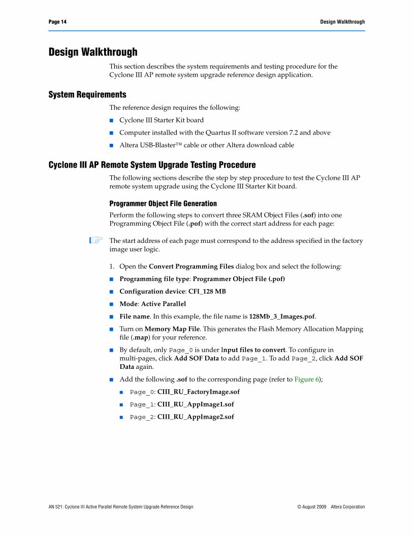
Programmer Object File GenerationPerform the following steps to convert three SRAM Object Files (.sof) into one Programming Object File (.pof) with the correct start address for each page:
1 The start address of each page must correspond to the address specified in the factory image user logic.
1. Open the Convert Programming Files dialog box and select the following:
■ Programming file type: Programmer Object File (.pof)
■ Configuration device: CFI_128 MB
■ Mode: Active Parallel
■ File name. In this example, the file name is 128Mb_3_Images.pof.
■ Turn on Memory Map File. This generates the Flash Memory Allocation Mapping file (.map) for your reference.
■ By default, only Page_0 is under Input files to convert. To configure in multi-pages, click Add SOF Data to add Page_1. To add Page_2, click Add SOF Data again.
■ Add the following .sof to the corresponding page (refer to Figure 6);
■ Page_0: CIII_RU_FactoryImage.sof
■ Page_1: CIII_RU_AppImage1.sof
■ Page_2: CIII_RU_AppImage2.sof
AN 521: Cyclone III Active Parallel Remote System Upgrade Reference Design © August 2009 Altera Corporation

Design Walkthrough Page 15
2. To assign the Start Address of each page, click and highlight SOF Data, and click Properties to assign the start address for each page.
1 The Quartus II software convert programming file uses byte addressing. The setting of each page is shown in Figure 7, Figure 8, and Figure 9.
Figure 6. Converting Three .sof into one .pof for AP Programming
Figure 7. Factory Image Page Setting
© August 2009 Altera Corporation AN 521: Cyclone III Active Parallel Remote System Upgrade Reference Design

Page 16 Design Walkthrough
3. Click Generate to generate the .pof . A .map is generated with the .pof.
1 In this reference design, the conversion file setup (.cof) in Figure 6 is included in the /POF/ directory. In the same directory, you can find the generated 128MB_3_Images.pof.
4. Verify that the correct start address is assigned for each page by examining the .map that is generated.
1 You can open the .map with any text editor application available in your computer. Figure 10 shows .map that is generated.
Figure 8. Application Image 1 Page Setting
Figure 9. Application Image 2 Page Setting
AN 521: Cyclone III Active Parallel Remote System Upgrade Reference Design © August 2009 Altera Corporation

Design Walkthrough Page 17
1 The generated .pof named 128Mb_3_Images.pof is available in the /POF/ directory. This .pof contains the configuration data of the factory image, application image 1, and application image 2.
Programming the .pof into P30 FlashPerform the following steps to program the flash device in the Quartus II programmer:
1. Connect the USB-Blaster cable to the USB-Blaster port on J3.
2. Power-up the Cyclone III Starter Kit board by connecting the laptop power to J2.
3. On the Tools menu in the Quartus II software, click Programmer.
4. In the Programmer window, click Add Device. The Select Devices dialog box appears (Figure 11).
Figure 10. Screen Shot of .map (1)
Note to Figure 10:
(1) The end address varies by design and device density.
© August 2009 Altera Corporation AN 521: Cyclone III Active Parallel Remote System Upgrade Reference Design

Page 18 Design Walkthrough
5. Under Device name, select EP3C25.
6. Click OK. The device name appears in the Programmer window.
7. Right-click the device name you added and click Attach Flash Device, as shown in Figure 12. The Select Flash Device dialog box appears (Figure 13).
Figure 11. Selecting Device Family and Density
AN 521: Cyclone III Active Parallel Remote System Upgrade Reference Design © August 2009 Altera Corporation

Design Walkthrough Page 19
8. Under Device family, turn on Flash Memory.
9. Under Device name, select CFI_128MB which is the density of the flash device.
Figure 12. Attaching the Flash Device
Figure 13. Selecting the Flash Device
© August 2009 Altera Corporation AN 521: Cyclone III Active Parallel Remote System Upgrade Reference Design

Page 20 Design Walkthrough
10. Click OK.
11. Right-click the flash device name and click Change File. The Select New Programming File dialog box appears (Figure 14).
12. Select the .pof of the flash device and click Open.
13. Under the Program/Configure column, turn on the check box for Page_0, Pages_1 and Pages_2 of the .pof you added. The Quartus II Programmer automatically enables a factory default PFL image, as shown in Figure 15.
Figure 14. Adding .pof for Flash Programming Device
AN 521: Cyclone III Active Parallel Remote System Upgrade Reference Design © August 2009 Altera Corporation

Design Walkthrough Page 21
1 To erase or program the entire flash device, turn on the check box associated with the .pof . To erase or program a particular page of the flash device, turn on the check box associated with the page.
14. Click Start to configure the PFL and program the flash device. With the Quartus II Programmer, you can program, verify, erase, or blank-check the configuration data pages and user data page separately, provided the FPGA contains the PFL. You can bypass the PFL configuration step if the FPGA already contains the PFL configuration.
f For more information on the Cyclone III Parallel Flash Loader, refer to AN 478: Using FPGA-Based Parallel Flash Loader with the Quartus II Software.
Configuring Cyclone III Devices in Remote Update ModeAfter the flash is programmed, power-down and power-up the board to allow the Cyclone III device to configure in remote update mode.
Figure 15. Enabling the Factory Default PFL Image for Flash Device Programming
© August 2009 Altera Corporation AN 521: Cyclone III Active Parallel Remote System Upgrade Reference Design

Page 22 Design Walkthrough
Figure 16 shows the transition between configuration images based on the user logic state machine that is defined in the factory image user logic.
Updating the New Image into P30 FlashThe PFL is instantiated in the factory and application images. After the device is in user mode, you can update the new image to replace the current factory configuration image or application image. This is done while the device is configured with the factory image or application image. The following are the steps to update the new image in the P30 flash:
1. Regenerate the .pof with the new .sof that contains the new factory and/or application image. You can follow steps 1 through 4 in “Programmer Object File Generation” on page 14.
2. In the Programmer window, click Auto Detect. The Quartus II software detects the EP3C25 device and the 128 MB flash, as shown in Figure 17.
Figure 16. Transition Between Configuration Images in Remote Update Mode
Notes to Figure 16:
(1) Asserting the start_write signal on the Cyclone III Started Kit board is equivalent to pushing the Button1 push button on the board. This initiates a reconfiguration on the Cyclone III remote system upgrade circuitry.
(2) After the start_write signal is asserted, the user can monitor the output with the SignalTap to verify the interface of the user logic control block to ALTREMOTE_UPDATE megafunction. This is explained in “Monitoring System Parameters Using SignalTap Logic Analyzer”.
(3) '1' indicates the LED is turned on, while '0' indicates the LED is turned off. 'X' indicates the LED is blinking.(4) By default, when the device loads the factory image during power-up or during core nCONFIG assertion from the
application image, LED[4..1] is equal to 4'b1111. For more information about system status based on the LED[4..1] status, refer Table 1 on page 6.
(5) Upon error, the device loads the factory image. The actions that trigger the system to reload the factory image are the watchdog timer time out error, the nSTATUS is driven low, the external nCONFIG assertion, the configuration CRC error, and core nCONFIG reconfiguration. In this reference design, the user can induce the watchdog timer error, nSTATUS error, external nCONFIG assertion, and configuration CRC error. This is explained in “Triggering System Reconfiguration” on page 24.
FPGA is configured with Factory Image .
LED[4..1] = 1111 (3) (4)
(Page_0)
FPGA is configured with Application Image 1.
LED[4..1] = 110X (3)
FPGA is configured with Application Image 2.
LED[4..1] = 11X0 (3)
Assert start_write signal on user logic control block (1) (2)
Error during configuration or user mode (5)
Assert start_write signal on user logic control block (1) (2)
Assert start_write signal on user logic control block (1) (2)
Assert start_write signal on user logic control block (1) (2)
Error during configuration or user mode (5)
Power Up
AN 521: Cyclone III Active Parallel Remote System Upgrade Reference Design © August 2009 Altera Corporation

Design Walkthrough Page 23
3. Right-click the flash device name and click Change File. The Select New Programming File dialog box appears (Figure 18).
4. Select the .pof of the flash device that you generated and click Open.
5. Turn on the check box associated with the page that you want to update. Figure 19 shows an example on how to replace the application image 1 (Page_1).
Figure 17. Auto-Detect From the Quartus II Programmer Window While Device is in User Mode
Figure 18. Selecting New Generated .pof
© August 2009 Altera Corporation AN 521: Cyclone III Active Parallel Remote System Upgrade Reference Design

Page 24 Design Walkthrough
6. Click Start. The Quartus II Programmer starts sending the configuration bits to the memory flash through the PFL that is instantiated in the factory or application image design.
7. Power-down and power-up the board to allow the device to reconfigure with the new image.
Triggering System ReconfigurationUpon error, the remote system upgrade circuitry updates the remote system upgrade status register and the trigger device to reload the factory configuration image. User logic in the factory image can determine the source of reconfiguration by reading the remote system upgrade status register bit [30..26].
Figure 19. Selecting Page_1 for New Image Update
AN 521: Cyclone III Active Parallel Remote System Upgrade Reference Design © August 2009 Altera Corporation

Design Walkthrough Page 25
Table 3 describes the remote system upgrade status register bit [30..26] reconfiguration source status information.
1 The ALTREMOTE_UPDATE megafunction simplifies the operation of reading the remote system upgrade status register bit [30..26] by allowing you to read back the parameter defined by 'Read Past Status 1 reconfiguration trigger conditions source'. For more information, refer to “Cyclone III ALTREMOTE_UPDATE Operations (Note 1)” on page 33.
In this reference design, you can induce the watchdog timer time out error, the external nCONFIG assertion, the nSTATUS error, and the configuration CRC error to verify the remote system upgrade circuitry behavior when these events occur. The following sections describe the procedures to trigger the system reconfiguration.
Inducing the Watchdog Timer ErrorThe time out value for the watchdog timer feature is set to 40894472 clock cycles, based on the internal 10 MHz clock. This is set in the factory application image. The watchdog timer reset circuitry instantiated in the design is running on the onboard 50 MHz clock. The watchdog timer reset circuitry is set to reset the reset_timer input of the ALTRREMOTE_UPDATE megafunction for every 33554432 clock cycles of the 50 MHz clock before the timer expires. To induce the watchdog timer in application images 1 and 2, perform the following steps:
1. Power-down and power-up the board.
2. Verify the LED[4..1] is equal to 1111 to indicate the factory image.
3. Push the Button1 push button to initiate reconfiguration from the factory image to application image 1.
4. Verify that LED[4] and LED[3] are turned on, LED[2] is turned off, and LED[1] is blinking. LED[1] blinks to indicate the watchdog timer reset circuitry is resetting the timer periodically in application image 1.
Table 3. Remote System Upgrade Status Register Bit [30..26] Reconfiguration Source Status Information
Remote System Upgrade Status
Register Bit[30..26]Reconfiguration Source Status Information
5'b00000 System loads factory configuration image upon device power-up
5'b00001 System reloads factory configuration image upon core nCONFIG assertion
5'b00010 System reloads factory configuration image upon watchdog timer time out in application configuration image
5'b00100 System reloads factory configuration image upon nSTATUS assertion in application configuration image
5'b01000 System reloads factory configuration image upon configuration CRC error during application configuration
5'b10000 System reloads factory configuration image upon external nCONFIG assertion in application configuration image
© August 2009 Altera Corporation AN 521: Cyclone III Active Parallel Remote System Upgrade Reference Design

Page 26 Design Walkthrough
5. On the board, push the Button4 push button once. The LED[1] stops blinking. This indicates that the watchdog timer reset circuitry is disabled and no longer resetting the watchdog timer. After approximately four seconds, the watchdog timer in the application image 1 times out. This triggers the remote system upgrade circuitry to update the remote system upgrade circuitry status register bit [30..26] to 5'b0010 and reverts back to the factory image. Status indicator LED[4..1] equals to 4'b1010. This indicates that system has reverted back to the factory image as the result of the watchdog timer time out error in the application image 1.
6. On the board, push the Button1 push button again. This time, the application image 2 loads into the device.
7. Verify that LED[4] and LED[3] are turned on, LED[2] is blinking, and LED[1] is turned off. LED[2] blinks to indicate the watchdog timer reset circuitry is resetting the timer periodically in the application image 2.
8. On the board, push the Button4 push button once. The LED[2] stops blinking. This indicates that the watchdog timer reset circuitry is disabled and no longer resetting the watchdog timer. After approximately four seconds, the watchdog timer in the application image 2 times out. This triggers the remote system upgrade circuitry to update the remote system upgrade circuitry status register bit [30..26] to 5'b0010 and reverts back to the factory image. Status indicator LED[4..1] equals to 4'b0011. This indicates that the system has reverted back to the factory image as the result of the watchdog timer time out error in the application image 2.
Inducing External nCONFIG AssertionTo induce the external nCONFIG assertion error, perform the following steps:
1. Power-down and power-up the board.
2. Verify the LED[4..1] is equal to 1111 to indicate the factory image. On the board, push the Button1 push button to initiate reconfiguration from the factory image to application image 1.
3. Verify that LED[4] and LED[3] is turned on, LED[2] is turned off, and LED[1] is blinking. LED[1] blinks to indicate the watchdog timer reset circuitry is resetting the timer periodically in the application image 1.
4. Push the Reconfigure push button on the board. This pulses the nCONFIG low and trigger the remote system upgrade circuitry to revert back to the factory image. The remote system upgrade circuitry status register bit [30..26] is updated to 5'b10000. Status indicator LED[4..1] is equal to 4'b1110. This indicates that the system has reverted back to the factory image as the result of external nCONFIG assertion on the application image 1.
5. On the board, push the Button1 push button to initiate reconfiguration from the factory image to application image 2.
6. Verify that LED[4] and LED[3] is turned on, LED[2] is blinking, and LED[1] is turned off. LED[2] blinks to indicate the watchdog timer reset circuitry is resetting the timer periodically in the application image 2.
AN 521: Cyclone III Active Parallel Remote System Upgrade Reference Design © August 2009 Altera Corporation

Design Walkthrough Page 27
7. Push the Reconfigure push button on the board. This pulses the nCONFIG low and trigger the remote system upgrade circuitry to revert back to the factory image. The remote system upgrade circuitry status register bit [30..26] is updated to 5'b10000. Status indicator LED[4..1] is equal to 4'b0001. This indicates that system has reverted back to the factory image as the result of external nCONFIG assertion on application image 2.
Inducing nSTATUS ErrorTo induce the nSTATUS error, perform the following steps:
1. Power down and power up the board.
2. Verify the LED[4..1] is equal to 4'b 1111 to indicate the factory image.
3. Open the Quartus II Programming window and turn on the check box under the Erase column associated with Page_1, as shown in Figure 20.
4. Click Start to begin erasing the application image 1.
5. On the board, push the Button1 push button to initiate reconfiguration from the factory image to the application image 1.
6. Because the application image 1 is erased, the reconfiguration from the factory image to the application image 1 fails. The Cyclone III device pulls the nSTATUS signal low to indicate the failure. This triggers the remote system upgrade circuitry to update the remote system upgrade circuitry status register bit [30..26] to 5'b00100 and reverts back to the factory image. Status indicator LED[4..1] is equal to 4'b1001. This indicates that the system has reverted back to the factory image as a result of the nSTATUS error during the application image 1 configuration.
Figure 20. Erasing Application Image 1 from Flash
© August 2009 Altera Corporation AN 521: Cyclone III Active Parallel Remote System Upgrade Reference Design

Page 28 Design Walkthrough
7. If the Button1 push button is pushed again, this causes the device to load the application image 2. To induce the nSTATUS error in the application image 2, in the Quartus II Programming window, turn on the check box under the Erase column associated with Page_2, as shown in Figure 21.
8. Click Start to begin erasing the application image 2.
9. On the board, push the Button1 push button to initiate reconfiguration from the factory image to application image 2.
10. Because the application image 2 is erased, the configuration from the factory image to application image 2 fails. The Cyclone II device pulls the nSTATUS signal low to indicate the failure. This triggers the remote system upgrade circuitry to update the remote system upgrade circuitry status register bit [30..26] to 5'b00100 and reverts back to the factory image. Status indicator LED[4..1] is equal to 4'b0100. This indicates that the system has reverted back to the factory image as a result of the nSTATUS error during the application image 2 configuration.
11. To recover from this error, update the valid image for the application image 1 and application image 2 with 128Mb_3_Images.pof in the /POF/ directory.
Inducing Configuration CRC ErrorIn the following procedure, you must store the invalid image generated in a design that targets an EP3C16 device instead of an EP3C25 device into flash memory before the device is triggered to load the invalid image. This induces the CRC error during the application image configuration. The following steps describe the procedure to induce the configuration CRC error:
Figure 21. Erasing Application Image 1 from Flash
AN 521: Cyclone III Active Parallel Remote System Upgrade Reference Design © August 2009 Altera Corporation

Design Walkthrough Page 29
1. Use the steps in “Updating the New Image into P30 Flash” on page 22, regenerate a new .pof with the invalid invalid_SOF.sof in the /POF/invalid_SOF_POF/ directory. Altera recommends that you use the same .sof to replace Page_1 and Page_2 which corresponds to the application image 1 and application image 2, respectively. This is shown in (Figure 22).
1 Invalid_AppImage1_2.pof is available in the /POF/invalid_SOF_POF/ directory. This .pof contains an invalid image for both the application image 1 and application image 2.
Figure 22. Attaching Two Invalid .sof at Page_1 and Page_2 for .pof Conversion
© August 2009 Altera Corporation AN 521: Cyclone III Active Parallel Remote System Upgrade Reference Design

Page 30 Design Walkthrough
2. Program the .pof that contains the invalid images into flash by updating application image 1 and application image 2, as shown in Figure 23.
3. Power-down and power-up the board.
4. Verify that the LED[4..1] is equal to 4'b1111 to indicate the factory image.
5. On the board, push the Button1 push button to initiate reconfiguration from the factory image to the application image 1.
6. This triggers the device to configure from the flash page that contains the invalid image for the application image 1. The Cyclone III device flags the CRC error during configuration and reverts back to the factory image. The remote system upgrade circuitry status register bit [30..26] is updated to 5'b01000. Status indicator LED[4..1] is equal to 4'b0101 to indicate the configuration CRC error during the application image 1 configuration.
7. On the board, push the Button1 push button again. This initiates reconfiguration from the factory image to the application image 2.
8. Because the application image 2 also contains an invalid image, the device flags the CRC error during configuration and reverts back to the factory image. The remote system upgrade circuitry status register bit [30..26] is updated to 5'b01000. Status indicator LED[4..1] is equal to 4'b0110 to indicate the configuration CRC error during the application image 2 configuration.
9. To recover from this error, update the valid image for the application image 1 and the application image 2 using 128Mb_3_Images.pof in the /POF/ directory.
Figure 23. Updating Application Image 1 and Application Image 2 with Invalid Image
AN 521: Cyclone III Active Parallel Remote System Upgrade Reference Design © August 2009 Altera Corporation

Design Walkthrough Page 31
Monitoring System Parameters Using SignalTap Logic AnalyzerFor information about the state machine of the factory image user logic, application image user logic, and the interfacing signals between the user logic and the ALTREMOTE_UPDATE megafunction, which help you observe the system parameters with the SignalTap II Logic Analyzer, refer to the following:
■ “Reference Design Functional Description” on page 3
■ “Reference Design Signals” on page 7
■ “Factory Image User Logic State Machine” on page 10
■ “Application Image User Logic State Machine” on page 12
The SignalTap Logic Analyzer associated for each design is included in each design directory. To enable and execute the SignalTap Logic Analyzer for each design file, perform the following steps:
1. Open the targeted project design file. You can start with the factory image project design file (CIII_RU_AP_FactoryImage.qpf).
2. Turn on the SignalTap II Logic Analyzer by performing the following steps:
a. On the Assignments menu, click Settings. The Settings dialog box appears.
b. In the Category list, click the + icon to expand Timing Analysis Settings and select SignalTap II Logic Analyzer.
c. Turn on Enable SignalTap II Logic Analyzer.
d. In the SignalTap II File name, specify ciii_ru_ap.stp.
3. Recompile the design.
4. Repeat steps 1 to 3 for the application image 1 project design file (CIII_RU_AP_AppImage1.qpf) and the application image 2 (CIII_RU_AP_AppImage2.qpf).
5. Regenerate the .pof using the .sof from each page that the SignalTap Logic Analyzer file instantiates. To do this, refer to “Programmer Object File Generation” on page 14.
6. Program the .pof that you have generated into flash. To do this, refer to “Programming the .pof into P30 Flash” on page 17.
1 The .sof in each design directory and the .pof located in the /POF/ directory has the SignalTap enabled. You can skip steps 1 through 5 by programming the P30 flash with the generated 128Mb_3_Images.pof in /POF/ directory.
7. Power-down and power-up the board.
8. On the board, verify that the LED[4..1] is equal to 4'b1111 to indicate the factory image.
9. Ensure that the targeted project file is open. Open the file CIII_AP_RU_FactoryImage.qpf.
10. In the same Quartus II software window in which the targeted project file is opened, from the File menu, browse to the ciii_ru_ap.stp that has been added to design file and click Open.
© August 2009 Altera Corporation AN 521: Cyclone III Active Parallel Remote System Upgrade Reference Design

Page 32 Design Walkthrough
11. In the SignalTap window, click Run Analysis. This triggers the SignalTap II Logic Analyzer to run until the trigger event occurs. In the ciii_ru_ap.stp in the factory image design directory, the trigger condition is defined at the CS_monitor output signal equal to 0x09h. In the application image 1 and application image 2 design directories, the trigger condition is defined at the CS_monitor output signal equal to 0x02h.
12. On the board, push the Button1 push button to assert the start_write signal to the user logic control block and initiate configuration. A change in the state machine meets the SignalTap trigger condition and the SignalTap captures the data.
13. After the SignalTap acquisition buffer is full, the SignalTap ceases to run and nodes analysis results display.
14. To monitor system parameters in the application image 1 and application image 2, repeat steps 10 trough 13 using the SignalTap file that resides in the respective design directory.
AN 521: Cyclone III Active Parallel Remote System Upgrade Reference Design © August 2009 Altera Corporation

Design Walkthrough Page 33
The following section explains the nodes analysis results as captured in the SignalTap window. All the parameters are based on the Cyclone III ALTREMOTE_UPDATE operations, as shown in Table 4.
Table 4. Cyclone III ALTREMOTE_UPDATE Operations (Note 1)
Ports
read
(2)
wrr
ite (3
)
read
_sou
rce
(4)
para
m (5
)
data_in width (bits) (6)
Cyclone IIII Remote Update Operations da
ta_o
ut w
idth
(bits
) (7)
Data Type MSM Mode
1 0 [01] [010] — Read current Application mode Watchdog Time-Out Value
29 Timer Value Application
1 0 [01] [011] — Read current Application mode Watchdog Enable
1 Flag Application
1 0 [01] [111] — Read Past Status 1 reconfiguration trigger condition source
5 Reconfiguration Trigger Cause
Factory
1 0 [10] [100] — Read current Application mode boot address
24 Address Application
0 1 [00] [001] 1 Write the early Confdone check bit
— Flag Factory
0 1 [00] [010] 12 (Upper 12 bits of 29-bit
watchdog timeout value)
Write Watchdog Time-Out value
— Timer Set Value Factory
0 1 [00] [011] 1 Write Watchdog Timer enable
— Flag Factory
0 1 [00] [100] 22 (Upper 22 bits of 24-bit
address value)
Write application boot address
— Address Factory
Notes to Table 4:
(1) This table includes only the operations used in the factory and application user logic in this reference design. For more information about the Cyclone III ALTREMOTE_UPDATE operations, refer to the Remote Update Circuitry (ALTREMOTE_UPDATE) Megafunction User Guide.
(2) In this reference design, the read port in the ALTREMOTE_UPDATE megafunction is wired to read_param_node.(3) In this reference design, the write port in the ALTREMOTE_UPDATE megafunction is wired to write_param_node.(4) In this reference design, the param port in the ALTREMOTE_UPDATE megafunction is wired to param_node.(5) In this reference design, the read_source port in the ALTREMOTE_UPDATE megafunction is wired to read_source_node.(6) In this reference design, the data_in port in the ALTREMOTE_UPDATE megafunction is wired to data_in_node.(7) In this reference design, the data_out port in the ALTREMOTE_UPDATE megafunction is wired to data_out_node.
© August 2009 Altera Corporation AN 521: Cyclone III Active Parallel Remote System Upgrade Reference Design

Page 34 Design Walkthrough
Reconfiguration from the Factory Image to Application Image 1 or Application Image 2Figure 24 through Figure 27 show SignalTap output examples when the device is transitioning from the factory image to the application image 1 or 2.
Figure 24 shows the parameters when the factory image user logic is writing to the ALTREMOTE_UPDATE megafunction to enable the watchdog timer feature in application configuration image. After the busy_node is low, the factory image user logic sets param_node = 3'b011, write_param = 1'b1, and data_in_node = 22'h000001.
Figure 25 shows the parameters when the factory image user logic is writing to the ALTREMOTE_UPDATE megafunction to set the watchdog timer value in the application configuration image. After the busy_node is low, the factory image user logic sets param_node = 3'b010, write_param = 1'b1, and data_in_node = 22'h000138. This sets the upper 12 bits of the 29 bits watchdog timer value. The remote system upgrade circuitry appends 17'b1000 to the upper 12 bits, which results in the watchdog timer value to be equivalent to 40894472.
Figure 24. Factory Image State Machine as Observed Using SignalTap: Enabling the Watchdog Timer Feature in the Application Image
Figure 25. Factory Image State Machine as Observed Using SignalTap: Setting the Watchdog Timer Value in the Application Image
AN 521: Cyclone III Active Parallel Remote System Upgrade Reference Design © August 2009 Altera Corporation

Design Walkthrough Page 35
Figure 26 shows the parameters when the factory image user logic is writing to the ALTREMOTE_UPDATE megafunction to set the next application configuration image boot address. After the busy_node is low, the factory image user logic sets param_node = 3'b100, write_param = 1'b1, and data_in_node = 22'h01C000. This sets the upper 22 bits of the 24 bits of the application boot address. The remote system upgrade circuitry appends 2'b00 to the upper 22 bits, which results in the 24'h70000 word address to be equivalent to the 24'hE0000 byte address for the application image 1.
Figure 27 shows the parameters when the factory image user logic is writing to the ALTREMOTE_UPDATE megafunction to set the next application configuration image boot address. After the busy_node is low, the factory image user logic sets param_node = 3'b100, write_param = 1'b1, and data_in_node = 22'b034000. This sets the upper 22 bits of the 24 bits of the application boot address. The remote system upgrade circuitry appends 2'b00 to the upper 22 bits, which results in the 24'hD0000 word address to be equivalent to the 24'h1A0000 byte address for the application image 2.
Reconfiguration from Application Image 1 or Application Image 2 Back to Factory ImageFigure 28 through Figure 30 show the SignalTap output examples when the device is transitioning from the application image to the factory image.
Figure 26. Factory Image State Machine as Observed Using SignalTap: Writing the Next Application Boot Address (Transitioning from Factory Image to Application Image 1)
Figure 27. Factory Image State Machine as Observed Using SignalTap: Writing the Next Application Boot Address (Transitioning from Factory Image to Application Image 2)
© August 2009 Altera Corporation AN 521: Cyclone III Active Parallel Remote System Upgrade Reference Design
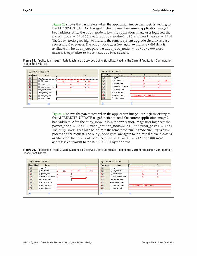
Page 36 Design Walkthrough
Figure 28 shows the parameters when the application image user logic is writing to the ALTREMOTE_UPDATE megafunction to read the current application image 1 boot address. After the busy_node is low, the application image user logic sets the param_node = 3'b100, read_source_node=2'b10, and read_param = 1'b1. The busy_node goes high to indicate the remote system upgrade circuitry is busy processing the request. The busy_node goes low again to indicate valid data is available on the data_out port, the data_out_node = 24'h070000 word address is equivalent to the 24'hE0000 byte address.
Figure 29 shows the parameters when the application image user logic is writing to the ALTREMOTE_UPDATE megafunction to read the current application image 2 boot address. After the busy_node is low, the application image user logic sets the param_node = 3'b100, read_source_node=2'b10, and read_param = 1'b1. The busy_node goes high to indicate the remote system upgrade circuitry is busy processing the request. The busy_node goes low again to indicate that valid data is available on the data_out port, the data_out_node = 24'h0D0000 word address is equivalent to the 24'h1A0000 byte address.
Figure 28. Application Image 1 State Machine as Observed Using SignalTap: Reading the Current Application Configuration Image Boot Address
Figure 29. Application Image 2 State Machine as Observed Using SignalTap: Reading the Current Application Configuration Image Boot Address
AN 521: Cyclone III Active Parallel Remote System Upgrade Reference Design © August 2009 Altera Corporation

Conclusion Page 37
Figure 30 shows the parameters when the user logic is writing to the ALTREMOTE_UPDATE megafunction to read the current watchdog timer value setting. After the busy_node is low, the application image user logic sets the param_node = 3'b010, read_source_node=2'b01, and read_param = 1'b1. The busy_node goes high to indicate the remote system upgrade circuitry is busy processing the request. The busy_node signal goes low again to indicate that valid data is available on the data_out port, data_out_node = 29'h02700008 is equivalent to 40894472. This matches the watchdog timer value setting of the factory image user logic.
f For more information about the SignalTap Logic Analyzer, refer to the Design Debugging Using the Signal Tap II Embedded Logic Analyzer chapter in volume 3 of the Quartus II Handbook.
ConclusionCyclone III devices offer remote system upgrade capability to help with upgrading a system in real-time through any network. Remote system upgrade helps to deliver feature enhancements and bug fixes without costly recalls, reduces time to market, and extends product life cycles. The remote system upgrade circuitry in the Cyclone III devices provides error detection, recovery, and status information to ensure reliable reconfiguration.
Figure 30. Application Image 1 and Application Image 2 State Machine as Observed Using SignalTap: Reading Current Watchdog Timer Value Setting
© August 2009 Altera Corporation AN 521: Cyclone III Active Parallel Remote System Upgrade Reference Design

Page 38 Document Revision History
101 Innovation DriveSan Jose, CA 95134www.altera.comTechnical Supportwww.altera.com/support
Copyright © 2009 Altera Corporation. All rights reserved. Altera, The Programmable Solutions Company, the stylized Altera logo, specific device designations, and all other words and logos that are identified as trademarks and/or service marks are, unless noted otherwise, the trademarks and service marks of Altera Corporation in the U.S. and other countries. All other product or service names are the property of their respective holders. Altera products are protected under numerous U.S. and foreign patents and pending applications, maskwork rights, and copyrights. Altera warrants performance of its semiconductor products to current specifications in accordance with Altera's standard warranty, but reserves the right to make changes to any products and services at any time without notice. Altera assumes no responsibility or liability arising out of the application or use of any information, product, or service described herein except as expressly agreed to in writing by Altera Corporation. Altera customers are advised to obtain the latest version of device specifications before relying on any published information and before placing orders for products or services.
Document Revision HistoryTable 5 shows the revision history for this application note.
Table 5. Document Revision History
Date and Document Version Changes Made Summary of Changes
August 2009 v1.1 ■ Updated “Introduction” on page 1
■ Updated “Overview on Remote Update Mode” on page 2
■ Updated “Watchdog Timer Reset Circuitry” on page 4
■ Updated “Status Indicator” on page 5
■ Updated Table 2 on page 7
■ Updated (Note 3) of Table 2 on page 7
■ Updated “Application Image User Logic State Machine” on page 12
■ Updated (Note 3) of Figure 5 on page 13
■ Updated “Programmer Object File Generation” on page 14
■ Updated “Triggering System Reconfiguration” on page 24
■ Updated “Inducing the Watchdog Timer Error” on page 25
■ Updated “Inducing External nCONFIG Assertion” on page 26
■ Updated “Inducing Configuration CRC Error” on page 28
■ Updated “Monitoring System Parameters Using SignalTap Logic Analyzer” on page 31
■ Updated “Reconfiguration from the Factory Image to Application Image 1 or Application Image 2” on page 34
■ Updated “Reconfiguration from Application Image 1 or Application Image 2 Back to Factory Image” on page 35
—
June 2008 v1.0 Initial release. —
AN 521: Cyclone III Active Parallel Remote System Upgrade Reference Design © August 2009 Altera Corporation