Patents Pending TPO/PVC Attachment Installation Guide
19
Patents Pending TPO/PVC Attachment Installation Guide www.solarstrap.com SSIM Rev.110619
Transcript of Patents Pending TPO/PVC Attachment Installation Guide

Patents Pending
TPO/PVC Attachment Installation Guide
www.solarstrap.comSSIM Rev.110619

2
Copy
right
© 2
017
by P
erm
aCity
. All
right
s res
erve
d.
SSIM Rev.110619
SolarStrap™ Installation ManualCopyright© 2017 by PermaCity. All rights reserved.
www.solarstrap.com
The SolarStrap™ is made in the U.S.A. with quality assurance. The unique features of this product and design are patent pending and copying of PermaCity intellectual property without its written consent is prohibited and subject to strict enforcement.
The information contained herein is subject to change without notice.
Invented, Designed, and Manufactured by:
PermaCity Solar525 S. Hewitt St.Los Angeles, CA 90013(323) 692-9264www.permacity.com
Installer must read this manual before attempting installation. Failure to correctly establish the requirements of the proposed installation site is dangerous and can void the framing or roofing warranty.
UL1703 20150519 §48.1.b)1): The system achieves a Class A fire rating when installed in the manner specified in these instructions.UL2703 First Edition 20150128 §26.1: The system has achieved a Class A fire rating when installed with Type 1 and Type 2 modules.UL 2703 Certificate No. US 82160016
Wind Tunnel Tested per ASCE Standard 7, 91.1609 LAMCApproval No. 00303
www.akstamping.com
ul.comFile No. E356152UL467 Report: QIMS2.E356152UL467 Intertek Report: 101005952LAX-001UL1703: Class A Pending or currently exempt as a roof mount only system (subject to module fire class rating)UL2703 Certificate of Compliance: 20140820 – E356152
CAUTION

3
Copy
right
© 2
017
by P
erm
aCity
. All
right
s res
erve
d.
SSIM Rev.110619
Contents
Before You StartHandling & Installing
FeaturesSystem Overview
Exploded DiagramPreparing to Build
ComponentsRequired Tools and Safety Equipment
Planning and Layout
InstallationLay Down StrapsAdd BracketsPlace Modules
Wire Management and GroundingGrounding the Array Example
Seismic Engineering
Roof Connection
NotesParts List
TÜV UL2703 - ConformanceTÜV UL2703 - Approved Modules
WarrantySolarStrap™ Limited Warranty Statement
4444556678899
1011121213141516171718181919192020
Certi�cation and Approved Modules

4
Copy
right
© 2
017
by P
erm
aCity
. All
right
s res
erve
d.
SSIM Rev.110619
Handling & InstallingIt is critically important to observe standard safety practices when installing SolarStrap™:• Follow all OSHA safety guidelines for construction safety.• Stop work during stormy weather. Solar modules, SolarStraps, and other components can be blown
off the roof in high winds.• Always secure solar modules, SolarStraps, and other components from unexpected high winds while
under construction. Wind blown construction materials are a safety hazard.• Never step or sit on the glass surface of a solar module. The glass may break, resulting in shock or
bodily injury.• Do not throw or roughly handle any SolarStrap™ components.• Do not bring SolarStrap™ into contact with sharp or heavy objects.• Do not modify SolarStrap™ components in any way. The exchange of bolts, drilling of holes, bending
and any other physical changes not intended in standard installation procedure will void the warranty.• Products should be installed and maintained by qualified personnel. Keep unauthorized personnel
away from solar modules.• It is the installer’s responsibility to verify the integrity of the structure to which SolarStrap™ is used.
Roofs or structures with rotten/rusted bearers, undersized bearers, excessively spaced bearers or anyother unsuitable substructure cannot be used with SolarStrap™. Installation on such structures couldresult in death or serious injury.
Features
Roof loading calculation are based on code approved stress equations and allowable margins of safety. Roof loading calculations must be conservatively performed under wind loads, snow, and dead loads. Components have had full envelope forces applied to each component from engineered data sets approved by the engineer of record. The engineer of record will review PermaCity wind data tables and choose the appropriate wind uplift values by boundary roof zones. The engineer of record will choose and compute the quantity and method of positive seismic attachments required based on roof type, roof substructure and seismic locations. This data is either provided as part of the project engineering or from a SolarStrap code compliant data set.
• Aluminum 5052 - 6061• Suitable for most buildings• Suitable for roof slope range 0°< 9.5°• Panel array weight under (3) Lbs/sf• High strength-to-weight ratio• Spacing efficiency with integrated setback adjustments• High corrosion resistant materials resulting in low lifetime maintenance and an extended product life• Complies with SEAOC 7-05 guidance for wind load design• Complies with SEAOC PV-2 and ASCE 7-10• Complies with SEAOC PV-1 guidance for wind tunnel tested arrays• Ballast only option under (5) Lbs/sf in most Western U.S. locations• Tested to 120 MPH wind zones, calibrated to 150 MPH
BEFORE YOU START
Roof Loading Resistance, and Seismic Attachments

Copy
right
© 2
017
by P
erm
aCity
. All
right
s res
erve
d.
SSIM Rev.110619
Diagram
The SolarStrap™ is fast and easy to install with minor field measurements required. The PanStrap option is available when used in conjunction with PermaCity’s wind tunnel test data in compliance with SEAOC PV-2 Guidelines.
Note: The SSSS4 or SSOP3 will need to be in every installation for that installation to retain Fire Rating. (UL2703 First Edition 20150128 §26.1)
SYSTEM OVERVIEW
SolarStrap™ A�achment Plate/Heavy Duty
SSAP/SSAPHD
SolarStrap™ Inverter Mount Rack**SSIMR
SolarStrap™ One PieceSSOP3
SolarStrap™ Low Bracket(5˚, 10˚, 15˚)
SSLB
Grounding LugSGB-5
Grounding LugSGB-4
Serrated Hex Flange NutSSHWSFN
SolarStrap™ High Bracket(5˚, 10˚, 15˚)
SSHB
*
Full Threaded Hex Bolt SSHWHB
Lock Washer SSHWLW
Conductive Mid Clamp A3004
Conductive End Clamp A3003
Components

7
Copy
right
© 2
017
by P
erm
aCity
. All
right
s res
erve
d.
SSIM Rev.091917
PREPARING TO BUILD
RequiredToolsandSafetyEquipment
ChalkLineReel
Footwear
SafetyHarness
DrillwithImpactDriver
Gloves
SafetyVest
MeasuringTape
HardHat
TorqueScrewDriver
SafetyGlasses

8
Copy
right
© 2
017
by P
erm
aCity
. All
right
s res
erve
d.
SSIM Rev.110619
• Identify interlock set point on SolarStrap™ (y2). Verify plan set to check correct slot to inter-lock.x = Length center to center or end to center, including end and mid clampsx¹ = Length of the center of the module to the center of strapx² = Length of the strap to the center of the strapx3 = Space in-between modules 3/4” minimumy¹ = Inter-lock set point on SolarStrap™y² = Distance for inter row shading
PLANNING AND LAYOUT
• AHJ may request seismic attachment for certain zones. Verify with your local department of building and safety.• Be careful to follow final design layout.• Installer must verify that PV Module manufacturer’s attachment points for clamps are met to avoid damage,
injuries and module warranty being voided.• Installers must verify that all building requirements specific to installation site are met, including city, fire department,
and other jurisdictions responsible for Residential/Commercial roof inspections.• Installer must follow all OSHA CFR1926 rules and regulations regarding Job-site safety, fall protection and PPE. For
more info visit: www.osha.gov
CAUTION
FRAMED MODULE LAYOUT
Roof Layout
[X][X]
[y1]
[y2]
[X]
[y1]
6'-512"
[77.500]
6'-512"
[77.500]
6'-512"
[77.500]
3'-314"
[39.335]
1'-1"
[12.966]
3'-314"
[39.335]
ANGLE VARIES (__°) ANGLE VARIES (__°)
INTER-ROW SPACING IS DETERMINED BASED ON THE TILT ANGLE OF THE PV SYSTEM AND INTER-LOCK SETTING OF THE SOLARSTRAP RACKING SYSTEM.

9SSIM Rev.110619
PLANNING AND LAYOUT
FRAMED MODULE LAYOUT
CHALKLINE
ELEL
EL
EL
EL
EL
EL = EDGE LINE AS MARKED ON THE ROOF TO GUIDE INSTALLATION.
ELEL
EL
EL
EL
EL
FA = FRONT ATTACHMENT (POSITVE ATTACHMENT OR NON PENETRATING METHOD)
PLACE SSLB - LOW BRACKET AND SSHB - HIGH BRACKET OVER INTEGRATED PEMSTUDS STICKING UP THE SSOP3 - SOLARSTRAP.TO SECURE THE BRACKETS USESSHWSFN - 1/4" SERRATED FLANGE NUT AND FASTENED TO 55 IN-LBS.
SSAP - ATTACHMENT PLATE
MA = MID ATTACHMENT (POSITVE ATTACHMENT OR NON PENETRATING METHOD)
EA = END ATTACHMENT (POSITVE ATTACHMENT OR NON PENETRATING METHOD)
FA
MA
EAFA
FA
MA
MAEA
EA
SSPTD - PLY TIE DOWNSSPC - PLY CAP
USE PERMACITYS SSAP - ATTACHMENT PLATE FOR THEFOLLOWING ROOF APPLICATIONS UNLESS OTHERWISESPECIFIED; BUR (BUILT UP ROOFS, ASPHALT,
PLYWOOD, OSB, METAL DECKS, CONCRETE
ROOFS, METAL CORRUGATED)
POSITIVE ATTAHCMENT METHOD:
POSITIVE ATTACHMENT NON PENETRATING METHOD
USE PERMACITYS NON PENETRATING FOR THEFOLLOWING ROOF APPLICATIONS UNLESS OTHERWISESPECIFIED; TPO,PVC,EPDM OR HYBRID SYSTEM
(SSAP - ATTACHMENT PLATE WITH TPO,PVC OR
EPDM SOLUTION.)
NON PENETRATING METHOD:
EL
EL
EL
EL
Roof Layout
EA
MA
FA
EA
MA
4'-4"
[52.000]
FA
EA
MA
= END ATTACHMENT (POSITVE ATTACHMENT)
= MID ATTACHMENT (POSITVE ATTACHMENT)
= FRONT ATTACHMENT (POSITVE ATTACHMENT)
= END ATTACHMENT (POSITVE ATTACHMENT)
= MID ATTACHMENT (POSITVE ATTACHMENT)
= FRONT ATTACHMENT (POSITVE ATTACHMENT)
= END ATTACHMENT (POSITVE ATTACHMENT)
FA
= MID ATTACHMENT (POSITVE ATTACHMENT)
= FRONT ATTACHMENT (POSITVE ATTACHMENT)
6'-212"
[74.500]
6'-212"
[74.500]
ONCE THE CORRECT INTERLOCK SETTING HAS BEING ESTABLISHED BY PERMACITY AND/OR APPROVED PLANS BY AHJ/BUILDING DEPARTMENT.INTERLOCK ALL SSOP3 - SOLARSTRAP TO THE ESTABLISHED SETTING. THIS WILL MAKE THE INSTALLATION AND MOUNTING OF SOLARSTRAP COMPONENTS AND SOLAR EQUIPMENT FAST AND EASY.
NOTE:
INTERLOCK SETTING.INTERLOCK SETTING.INTERLOCK SETTING.
TO MAKE THIS INSTALLATION FAST,EASY,AND ACCURATE. YOU CAN DO THE FOLLOWING TO LOCATE AND PLACE THE SSOP3 - SOLARSTRAP AND SSAP - ATTACHMENT PLATES. [ USE A JIG ( 2 x 4 WOOD/STUD OR ALUMINUM BAR, CUT TO THE CORRECT SIZE. THIS CAN BE PROVIDED BY PERMACITY OR CAN BE ACQUIRED ONCE YOU MARK THE ROOF.
NOTE:
[VARIES]
JIG [WOOD OR ALUMINUM SQUARE]CUT TO CORRECT MEASUREMENT.
JIG [WOOD OR ALUMINUM SQUARE]CUT TO CORRECT MEASUREMENT.
USE FOR THE FOLLOWING ROOF(S); ASPHALT, PLYWOOD, OSB, CONCRETE, METAL DECK, RAFTERS. PLEASE ENSURE CORRECT FASTENER IS USE FOR SPECIFIC ROOF. CONSULT YOUR ENGINEER AND/OR USE FASTENERS ON APPROVED PLAN SET.
POSITIVE ATTACHMENT:
USE FOR THE FOLLOWING ROOF(S); TPO,PVC,ASPHALT, PLYWOOD, OSB, CONCRETE, METAL DECK, RAFTERS. PLEASE ENSURE CORRECT FASTENER IS USE FOR SPECIFIC ROOF. CONSULT YOUR ENGINEER AND/OR USE FASTENERS ON APPROVED PLAN SET.
TPO/PVC ATTACHMENT:

/
/
/
I
I I
I
I
\ \
\
""'
-------
---/
/
'
'
\
I
/
\
\
10SSIM Rev.110619
Add Brackets
INSTALLATION
After SolarStraps are laid down, simply place brackets with top flanges facing inwards. The low bracket is for the sun-facing side and the high bracket for the shade-facing side. Fasten the Serrated Hex Flange Nuts to secure brackets to a torque of 55 in.-Lbs. See Mid and End Clamp instruction on page 12.
PLACE SSLB - LOW BRACKET AND SSHB - HIGH BRACKET OVER INTEGRATED PEM STUDS STICKING UP THE SSOP3 - SOLARSTRAP.TO SECURE THE BRACKETS USE SSHWSFN - 1/4" SERRATED FLANGE NUT AND FASTENED TO 55 IN-LBS.
NOTE:

11
Copy
right
© 2
017
by P
erm
aCity
. All
right
s res
erve
d.
SSIM Rev.110619
Place Modules
INSTALLATION
After brackets are secured, simply place modules on brackets. Install mid and end clamps and torque to 55 in.-Lbs. See Mid and End Clamp instruction on page 12.
SolarStraps must be secured by using "Conductive Mid Clap and End Clamp" for framed modules and "Frameless End Clamps" for Framless Modules.
Never leave unsecured modules on the roof unattended.
CAUTION

12
Copy
right
© 2
017
by P
erm
aCity
. All
right
s res
erve
d.
SSIM Rev.110619
INSTALLATION
Over torquing could result in module damage and voiding of warranty. Never torque more than 55 in.-Lbs. Clamps must be in proper location with the bolt center at the least 2.5” from the frame edge.
CAUTION
Note: For frameless modules, use Module Manufactures installation manual for torque spec or as specified in Appendix.
Mid Clamp with Integrated Ground Installation
End Clamp with Integrated Ground Installation
13
Copy
right
© 2
017
by P
erm
aCity
. All
right
s res
erve
d.
SSIM Rev.110619
Wire Management and Grounding
INSTALLATION
Simply attach ground wire to the provided Grounding Lug (SGB-4 or SGB-5) fastened to the wing of the low or high bracket and connect the ground wire to the pull box that is mounted on the back of the high bracket. From the pull box run ground wire all the way to the inverter or combiner box per the electrical engineering drawing.
PVC Schedule 80, EMT, IMT, or Rigid conduit may be secured to any part of the brackets and should be six inches or more above the roof to minimize heat gain and wire heat losses. Conduit may pass under the array to take the most direct path to inverters or combiner boxes. For wire management use EMT or Schedule 80 PVC conduit supported by a one-hole strap and one self tapping screw to attach your conduit to the side of the wing. Use plastic end protection if using EMT. EMT should be avoided for inter row crossings if the local AHJ requires bonding of EMT at these locations.
Note: A SSBB is only required on frameless modules, to bond the rows to columns. One per bonded 40 modules.
The SolarStap™ is certified by UL2703 to be used for integrated grounding in two directions. (1) primary from module to module bonded by the Conductive Mid Clamp A3003 and (2)Through the SolarStrap connected to Mid Clamp A3004 or End Clamp A3003. For frameless modules the SolarStrap Bond Bar (SSBB) is used to connect SolarStraps together to maintain a continuos bond. The Maximum number of adjacent bonded PV modules or Straps from the “Grounding Lug” (SGB-4 or SGB-5) attached to the first supporting bracket is limited by the inverter DC ground conductor size or 360 modules, no more than 40 modules across from the SolarStrap connected to the grounding lug. For installations where some of the modules cannot be installed adjacent to each other the following methods may apply.
a. A solid #6 AWG copper conductor or A #6 AWG stranded wire with a maximum length of 30feet bonded using approved grounding lug (SGB-4 or SGB-5)
b. Use of SSBB to bond gaps; including walkways
Keep copper away from aluminium and galvanized steel.
CAUTION

14
Copy
right
© 2
017
by P
erm
aCity
. All
right
s res
erve
d.
SSIM Rev.110619
Up to 360 modules in an array requires a grounding lug (SGB-4 or SGB-5/Torque to 55 in. Lbs) secured to one bracket. A #6 AWG copper or stranded wire equipment ground bonds each grounding lug (SGB-4 or SGB-5/Torques to 55 in. Lbs) to the Earth Ground. The array may be up to 200 feet in each. The grounding lug must be placed on a continuous strap. Stranded rows of modules may ground through straps to the adjoining row. For islands of modules a #6 AWG copper or stranded wire jumper ground wire connects islands of modules together through grounding lugs (SGB-4 or SGB-5/Torque to 55 in.Lbs) secured to one bracket per section. A SolarStrap™ Bond Bar (SSBB) can also be used.
a. A solid #6 AWG copper conductor or A #6 AWG stranded wire with a maximum length of 30feet bonded using approved grounding lug (SGB-4 or SGB-5)
b. Use of SSBB to bond Frameless module straps together since bonding is not available througha module frame
c. Use of SSBB to bond gaps; including walkways
Grounding the Array Example
INSTALLATION
360 PV Modules Max 360 PV Modules Max
15
Copy
right
© 2
017
by P
erm
aCity
. All
right
s res
erve
d.
SSIM Rev.110619
PermaCity SolarStrap™ is uniquely suited for installation of rooftop mounted PV solar systems in seismically active areas and on buildings with limited roof structural capacity. Due to its light weight and flexible mounting options, the PermaCity SolarStrap™ is a viable option for a wide range of rooftops. Our design allows the PermaCity SolarStrap™ to be mounted to the roof using one of three mounting options: structurally attached; ballasted; and a hybrid option that uses both ballasted and structural attachments. Calculations have been performed in accordance with the 2013 California Building Code (CBC), the governing building code in California, which references the 2012 International Building Code (IBC). The 2012 IBC references the 2010 Minimum Design Loads for Buildings and Other Structures, including Supplement No. 1, No. 2, and Errata, by the American Society of Civil Engineers (ASCE), referred to as ASCE 7-10. The anchorage designs have been designed to withstand code-prescribed seismic forces due to the self-weight of the racking system, the self-weight of the solar panels and the system’s ballast, if present.
Our structural analysis and design of the PermaCity SolarStrap™ and it’s method of attachment (ballasted, structurally attached and the hybrid ballasted with structural attachment) complies with Section 13.4 of ASCE 7-10, which states that all components shall be positively fastened to the structure without considerationof frictional resistance. The intent of our design is to provide a solution for various design parameters forseismic anchorage in a variety of site-specific conditions. Since there are many different possible seismicconditions, we can provide a site-specific seismic anchorage configuration with calculations to assure asafe installation and to obtain building permits. The seismic forces used in our calculations assume SiteClass D and utilize short- period spectral accelerations as provided in ASCE 7-10. The design parametersmay also be customized by roof material type.
Limita��For certain projects, site specific engineering may be recommended to help determine a very efficient custom installation cost. These various building-specific issues must be evaluated by the appropriate registered professional(s) prior to the addition of the photovoltaic and racking systems. A licensed structural engineer shall be consulted for building-specific structural evaluation.
SEISMIC ENGINEERING
ApplicationofSeismicBuildingCodes
16
Copy
right
© 2
017
by P
erm
aCity
. All
right
s res
erve
d.
SSIM Rev.110619
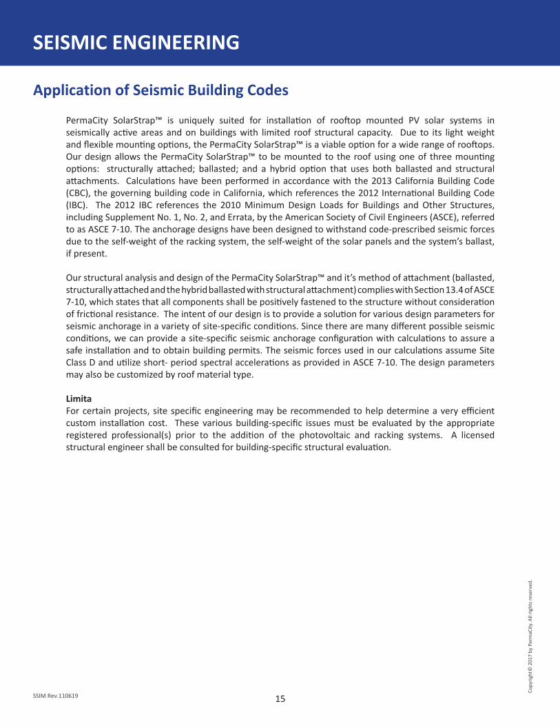
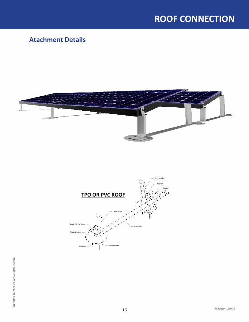
ROOF CONNECTION
Atachment Details
High Bracket
Kep Nut
SolarStrap
Fastener
Single Ply Cap
Low Bracket
Single Ply Tie Down
Washer
Piranha Plate
TPO OR PVC ROOF

17
Copy
right
© 2
017
by P
erm
aCity
. All
right
s res
erve
d.
SSIM Rev.110619
Parts List
NOTES
Product Product Number Number Note
SolarStrap™ One Piece SSOP3
SolarStrap™ Bond Bar SSBB
SolarStrap™ SolarStrap SSSS4
SolarStrap™ Universal Connect Strap SSUCS4
SolarStrap™ Pan Strap SSPS4
SolarStrap™ Inverter Mount Rack SSIMR
SolarStrap™ Attachment Plate SSAP
SolarStrap™ Attachment Plate Heavy Duty SSAPHD
SolarStrap™ High Bracket 5˚ SSHB5
SolarStrap™ High Bracket 10˚ SSHB10
SolarStrap™ High Bracket 15˚ SSHB15
SolarStrap™ Double High Bracket 5˚ SSHBEW5
SolarStrap™ Double High Bracket 10˚ SSHBEW10
SolarStrap™ Double High Bracket 15˚ SSHBEW15
SolarStrap™ Low Bracket 5˚ SSLB5
SolarStrap™ Low Bracket 10˚ SSLB10
SolarStrap™ Low Bracket 15˚ SSLB15
SolarStrap™ Double Low Bracket 5˚ SSLBEW5
SolarStrap™ Double Low Bracket 10˚ SSLBEW10
SolarStrap™ Double Low Bracket 15˚ SSLBEW15
Conductive Mid Clamp A3004
Conductive End Clamp A3003
Grounding Lug SGB-4
Grounding Lug SGB-5
Serrated Hex Flange Nut SSHWSFN
Thin Film End Clamp with Star Washer SSPS4

•
eco nc.
18
Copy
right
© 2
017
by P
erm
aCity
. All
right
s res
erve
d.
SSIM Rev.110619
TÜV UL2703 - Conformance
TÜV UL2703 - Approved Modules
CERTIFICATIONS AND APPROVED MODULES
Fire ConformanceTÜV Rheinland Reference File: R1-PMC150609
Mechanical Conformance
Testing Approval
Manufacture Model Electrical Bonding Fire Type
SunEdison 270W X 2
X 1
SunPower 327W X 2
Sunpreme GX-Series X 3
SolarWorld 285W X 1
Manufacture Model Surface Area(SQFT)
Downward Design Load
(PSF)
Upward Design Load
(PSF)
Down-Slope Design Load
(PSF)
20 30 5 5
L2-PMC150609
TÜV Rheinland Reference File: L1-PMC151112 L4-PMC150609
Electrical ConformanceTÜV Rheinland Reference File: L1-PMC161026
L1-PMC170505L1-PMC170615L3-PMC150609
LG 280W X 1
ecoSolargy 300W X 1
Design Load Rating
SunPower 395W X 2
casey
Text Box
MI-Series, HIx-xxxHI
casey
Text Box
MI-Series, HIx-xxxHI

19
Copy
right
© 2
017
by P
erm
aCity
. All
right
s res
erve
d.
SSIM Rev.110619
SolarStrap™ Limited Warranty Statement
WARRANTY
A. Extent of Limited Warranty1. PermaCity warrants to the end-user customer that the PermaCity products specified above will be free from defects
in materials and workmanship for the duration specified above, which duration begins on the date of purchase by the customer.
2. PermaCity’s limited warranty covers only those defects that arise as a result of normal use of the product, and does not cover any other problems, including those that arise as a result of:a. Improper maintenance or modification;b. Parts or supplies not provided or supported by PermaCity;c. Operation outside the design specifications or engineering;d. Unauthorized modification or misuse.
3. If PermaCity receives, during the applicable warranty period, notice of a defect in any product which is covered by PermaCity’s warranty, PermaCity shall either repair or replace the product, at PermaCity’s option.
4. If PermaCity is unable to repair or replace, as applicable, a defective product which is covered by PermaCity’s warranty, PermaCity shall, within a reasonable time after being notified of the defect, refund the purchase price for the product.
5. PermaCity shall have no obligation to repair, replace, or refund until the customer returns the defective product to PermaCity.
6. Any replacement product may be either new or like-new, provided that it has functionality at least equal to that of the product being replaced.
7. PermaCity products may contain remanufactured parts, components, or materials equivalent to new in performance.8. PermaCity’s Limited Warranty Statement is valid in any country where the covered PermaCity product is distributed by PermaCity.
Contracts for additional warranty services, such as on-site service, may be available from any authorized PermaCity service company in countries where the product is distributed by PermaCity or by an authorized importer.
B. Limitations of WarrantyTo the extent allowed by local law, neither PermaCity nor its third party suppliers makes any other warranty or condition of any kind, whether express or implied warranties or conditions of merchantability, satisfactory quality, and fitness for a particular purpose.
C. Limitations of Liability1. To the extent allowed by local law, the remedies provided in this Warranty Statement are the customer’s sole and exclusive remedies.2. To the extent allowed by local law, except for the obligations specifically set forth in this warranty statement, in no
event shall PermaCity or its third party suppliers be liable for direct, indirect, special, incidental, or consequential damages, whether based on contract, tort, or any other legal theory and whether advised of the possibility of such damages.
D. Projects located within 2.5 miles of the ocean must use marine grade option, using either coated stainless steel serrated hex flange nut, pem studs, and pem nuts or these items mare in aluminium.
The only warranties for PermaCity products and services are set forth in the express warranty statements accompanying such products and services. Nothing herein should be construed as constituting an additional warranty. PermaCity shall not be liable for technical or editorial errors or omissions contained herein. In order to keep full warranty, please design and build per installation manual guidelines.
PermaCity requires periodic re-inspection of the installation for loose components, loose fasteners and any corrosion, such that if found, the affected components are to be immediately replaced.
Product Product NumberSolarStrap™ One Piece SSOP3 20 YearsSolarStrap™ SolarStrap SSSS4 20 YearsSolarStrap™ Universal Connect Strap SSUCS4 20 YearsSolarStrap™ Attachment Plate SSAP 20 YearsSolarStrap™ Attachment Plate Heavy Duty SSAPHD 20 YearsSolarStrap™ Pan Strap SSPS4 20 YearsSolarStrap™ High Bracket (5˚, 10˚, 15˚) SSHB 20 YearsSolarStrap™ Double High Bracket (5˚, 10˚, 15˚) SSHBEW 20 YearsSolarStrap™ Low Bracket (5˚, 10˚, 15˚) SSLB 20 YearsSolarStrap™ Double Low Bracket (5˚, 10˚, 15˚) SSLBEW 20 YearsConductive Mid Clamp A3004 20 YearsConductive End Clamp A3003 20 Years
Duration of Limited Warranty

SolarStrap™ Installation ManualCopyright© 2017 by PermaCity. All rights reserved.
www.solarstrap.com
SSIM Rev.110619