
InnoSys Tensioning Process Presented to: Ford Motor Co 29Feb08 Patented and Patents pending.
27
InnoSys Tensioning InnoSys Tensioning Process Process Presented to: Ford Motor Co 29Feb08 Patented and Patents pending
-
Upload
clinton-bryan-scott -
Category
Documents
-
view
216 -
download
0
Transcript of InnoSys Tensioning Process Presented to: Ford Motor Co 29Feb08 Patented and Patents pending.

InnoSys Tensioning ProcessInnoSys Tensioning Process
Presented to:
Ford Motor Co
29Feb08
Patented andPatents pending

Reduces CostReduces Cost
►Eliminates self adjust mechanismsEliminates self adjust mechanisms►Reduces standard processing time Reduces standard processing time
and cost by combining pre-stretch and cost by combining pre-stretch and adjustment in one processand adjustment in one process

Reduces Warranty CostReduces Warranty Cost
►Accurate & repeatable tensioning Accurate & repeatable tensioning process eliminates tension related process eliminates tension related warranty warranty

Simplifies Plant ProcessingSimplifies Plant Processing
►Pre-stretch and adjustment are Pre-stretch and adjustment are combined into one operation.combined into one operation.
►Operator installs the tool onto the Operator installs the tool onto the adjuster nut and is then free to adjuster nut and is then free to perform other operations while the perform other operations while the system is tensionedsystem is tensioned

InnoSys Tensioning InnoSys Tensioning SystemSystem
Process ExplanationProcess Explanation

Typical Tension Controlled Process Typical Tension Controlled Process
0
20
40
60
80
100
120
140
160
180
0 20 40 60 80 100 120 140Cable Travel
Cab
le T
ensi
on

Typical Tension Controlled Process Typical Tension Controlled Process
0
20
40
60
80
100
120
140
160
180
0 20 40 60 80 100 120 140Cable Travel
Cab
le T
ensi
on Flat part of curve
where the slack is being removed
Transition area where the brakes are starting to drag
Steep part of curve, brakes are fully engaged and building clamp load

Typical Tension Controlled Process Typical Tension Controlled Process
0
20
40
60
80
100
120
140
160
180
0 20 40 60 80 100 120 140Cable Travel
Cab
le T
ensi
on Flat part of curve
where the slack is being removed
Transition area where the brakes are starting to drag
Here is the ideal tension for a properly adjusted park brake. The slack is removed and the brakes do not drag

Typical Tension Controlled Process Typical Tension Controlled Process
0
20
40
60
80
100
120
140
160
180
0 20 40 60 80 100 120 140Cable Travel
Cab
le T
ensi
on
Target Tension

Typical Tension Controlled Process Typical Tension Controlled Process
0
20
40
60
80
100
120
140
160
180
0 20 40 60 80 100 120 140Cable Travel
Cab
le T
ensi
on
Target Tension
Normal Measurement Variation

Typical Tension Controlled Process Typical Tension Controlled Process
0
20
40
60
80
100
120
140
160
180
0 20 40 60 80 100 120 140Cable Travel
Cab
le T
ensi
on
Target Tension
Normal Measurement Variation
Results in large travel variation

InnoSys Tensioning Process InnoSys Tensioning Process
0
20
40
60
80
100
120
140
160
180
0 20 40 60 80 100 120 140Cable Travel
Ca
ble
Te
ns
ion
Smaller Travel Variation
The Innosys method targets high loads in the steep part of the travel – tension curve.
Tensioning in the steep part of the curve reduces travel variation and effectively pre-stretches the cable system.
Ideally this target should set to the normal max operating force.
Measurement variation

InnoSys Tensioning Process InnoSys Tensioning Process
0
20
40
60
80
100
120
140
160
180
0 20 40 60 80 100 120 140Cable Travel
Cab
le T
ensi
on
Direct Tension Measurement Results in Low Measurement Variation
Accurate Tension Measurement Translates into
Small Travel Variation
The InnoSys process holds the nut away from the equalizer transfering the cable force to a load cell that is located directly inline with the cable.
This results in very accurate tension measurements which translates into low travel variation

InnoSys Self Tensioning Process InnoSys Self Tensioning Process
0
20
40
60
80
100
120
140
160
180
0 20 40 60 80 100 120 140Cable Travel
Cab
le T
ensi
on
Normal Tension Variation
Small travel variation is maintained
The InnoSys tool temporarily shortens the system allowing the target tension to be in the steep part of the travel - tension curve thus minimizing adjustment variation and effectively pre-stretching the cable system.
The tool then releases the cable a specific distance back to the "ideal" point on the curve.

InnoSys End Effector InnoSys End Effector OperationOperation

InnoSys End Effector OperationInnoSys End Effector OperationTool ReleasedTool Released

InnoSys End Effector OperationInnoSys End Effector OperationTool ReleasedTool Released
Locking balls are in released position so the nut can be installed or removed from the tool

InnoSys End Effector OperationInnoSys End Effector OperationTool ReleasedTool Released
Locking balls in the released position

InnoSys End Effector OperationInnoSys End Effector OperationTool CockedTool Cocked
Once the shaft is pushed back far enough the release ring pushes the locking balls inward and locks the piston in the retracted position
When the shaft is pushed back float sleeve will push the locking balls inward and lock the nut in the nose of the tool holding the nut away from the equalizer
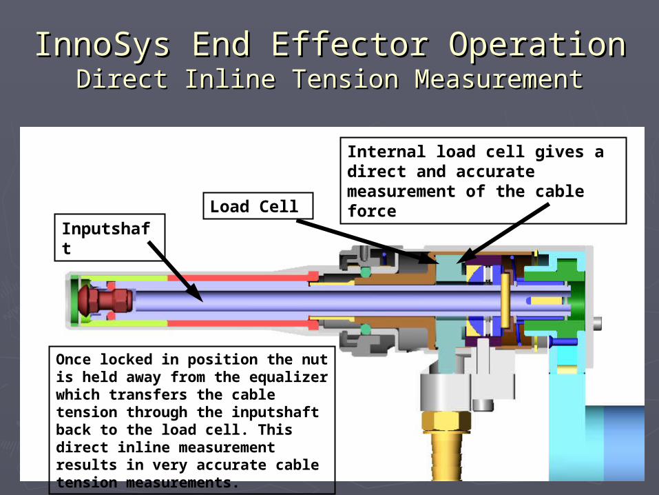
InnoSys End Effector OperationInnoSys End Effector OperationDirect Inline Tension MeasurementDirect Inline Tension Measurement
LoadInternal load cell gives a direct and accurate measurement of the cable force
Once locked in position the nut is held away from the equalizer which transfers the cable tension through the inputshaft back to the load cell. This direct inline measurement results in very accurate cable tension measurements.
Inputshaft
Load Cell

InnoSys End EffectorInnoSys End EffectorMeasurement AccuracyMeasurement Accuracy
% Error Between Internal Load Cell and Actual Cable Force% Error Between Internal Load Cell and Actual Cable Force
1.20.80.40.0-0.4-0.8-1.2
140
120
100
80
60
40
20
0
error %
Frequency
Mean 0.07334StDev 0.4844N 1593
Histogram of error %Normal
This graph demonstrates the ability of the Innosys tool to measure the cable force with exceptional accuracy

InnoSys Tensioning SystemInnoSys Tensioning SystemSequence of OperationsSequence of Operations
1. Operator loads nut into nose of tool and cocks tool locking the nut in the tool which holds the nut away from the equalizer.
2. Operator installs anti-rotation device onto threaded rod
3. Operator presses start trigger and is then free to perform other tasks
4. PLC commands nut runner to run fast forward until the run fast target is achieved.
5. PLC then commands nut runner to run slow until target tension is achieved
6. PLC watches force in load cell and restarts nut runner if system relaxes
7. PLC continues to retension system until tension stabilizes
8. Once the cable force stabilizes the PLC commands the nut runner to back off a specified distance.
9. Operator releases tool by pulling release ring.

InnoSys Tension Controlled InnoSys Tension Controlled Process SummaryProcess Summary
► Action 1 – End effecter is placed on the nutAction 1 – End effecter is placed on the nut► Action 2 – Operator cocks the end effecter. In doing so the nut is Action 2 – Operator cocks the end effecter. In doing so the nut is
securely captured and positioned away from the equalizer. This securely captured and positioned away from the equalizer. This allows the allows the
► Action 3 – Operator presses start trigger and the nut is run up Action 3 – Operator presses start trigger and the nut is run up the threaded rod until the target tension is achieved. Setting the the threaded rod until the target tension is achieved. Setting the target tension to a force that is close to the max system target tension to a force that is close to the max system operating tension accurately measured directly in line with the operating tension accurately measured directly in line with the cable axis because the nut is held away from the equalizer and cable axis because the nut is held away from the equalizer and the tool’s internal load cell is located in line with the cable axis.the tool’s internal load cell is located in line with the cable axis.
► Action 3 – Once pre-stretch tension is achieved and stable, a Action 3 – Once pre-stretch tension is achieved and stable, a specific amount of tension is removed from the cable system specific amount of tension is removed from the cable system through a combination of running reverse revolutions and through a combination of running reverse revolutions and returning the nut to the equalizer. The operator un-cocks the returning the nut to the equalizer. The operator un-cocks the tool to release the nut and return it to the equalizer. Process is tool to release the nut and return it to the equalizer. Process is now complete.now complete.

InnoSys Self Tensioning InnoSys Self Tensioning ProcessProcess
1361281201121049688
LSL USL
LSL 85Target *USL 135Sample Mean 111.048Sample N 58StDev(Within) 2.2062StDev(Overall) 2.5684
Process Data
Cp 3.78CPL 3.94CPU 3.62Cpk 3.62
Pp 3.24PPL 3.38PPU 3.11Ppk 3.11Cpm *
Overall Capability
Potential (Within) Capability
PPM < LSL 0.00PPM > USL 0.00PPM Total 0.00
Observed PerformancePPM < LSL 0.00PPM > USL 0.00PPM Total 0.00
Exp. Within PerformancePPM < LSL 0.00PPM > USL 0.00PPM Total 0.00
Exp. Overall Performance
WithinOverall
Process Capability Using 400 lb Target

InnoSys Self Tensioning InnoSys Self Tensioning ProcessProcess
1361281201121049688
LSL USL
LSL 85Target *USL 135Sample Mean 109.883Sample N 237StDev(Within) 4.57312StDev(Overall) 6.04218
Process Data
Cp 1.82CPL 1.81CPU 1.83Cpk 1.81
Pp 1.38PPL 1.37PPU 1.39Ppk 1.37Cpm *
Overall Capability
Potential (Within) Capability
PPM < LSL 0.00PPM > USL 0.00PPM Total 0.00
Observed PerformancePPM < LSL 0.03PPM > USL 0.02PPM Total 0.05
Exp. Within PerformancePPM < LSL 19.09PPM > USL 16.12PPM Total 35.22
Exp. Overall Performance
WithinOverall
Process Capability Using 300 lb Target

InnoSys Tensioning SystemInnoSys Tensioning SystemPlant Capability DataPlant Capability Data
Setting target force to the max normal operating force reduces variation

InnoSys Self Tensioning InnoSys Self Tensioning ProcessProcess
► Plants Currently in ProductionPlants Currently in Production Shreveport - October 2003Shreveport - October 2003 Flint - November 2003Flint - November 2003 Doraville - June 2004Doraville - June 2004 Wilmington - September 2005Wilmington - September 2005 LDT – August 2006LDT – August 2006
► Plants Being Tooled for ProductionPlants Being Tooled for Production Cami – Spring 2008Cami – Spring 2008 Spring Hill – Spring 2008Spring Hill – Spring 2008 7 GMT900 Truck Plants – Spring 20097 GMT900 Truck Plants – Spring 2009


![Post Tensioning[1]](https://static.fdocuments.net/doc/165x107/543ffc0bafaf9fff098b4bcd/post-tensioning1.jpg)

