P132 TechnicalDataSheet EN 12 b - Schneider...
42
MICOM P132 Feeder Management and Bay Control Version P132 -306 -415/416/417/418/419 -612 ff Technical Data Sheet This document does not replace the Technical Manual.
Transcript of P132 TechnicalDataSheet EN 12 b - Schneider...

MICOM P132 Feeder Management
and Bay Control
Version P132 -306 -415/416/417/418/419 -612 ff
Technical Data Sheet
This document does not replace the Technical Manual.

P132_TechnicalDataSheet_EN_12_b 2 P132-306-415/416/417/418/419-612 ff
Application and Scope The unit's protection functions provide selective short-circuit protection, ground fault protection and overload protection in medium- and highvoltage systems. The systems can be operated as solidly-grounded, low-impedance-grounded, resonant-grounded or isolated-neutral systems. The multitude of protection functions incorporated into the unit enable the user to cover a wide range of applications in the protection of cable and line sections, transformers and motors. For easy adaptation to varying system operation conditions four independent parameter subsets are provided. Alternatively to the variants with CT inputs or CT and VT inputs the MiCOM P132 is optionally deliverable with VT inputs only to be applied as over-/under frequency/voltage protection unit only. The optional control functions are designed for the control of up to three electrically operated switchgear units equipped with electrical check-back signaling located in the bay of a medium-voltage substation or a non-complex high-voltage
station. For the selection of the bay type the MiCOM P132 is provided with over 80 predefined bay types and allows download of customized bay type. External auxiliary devices are largely obviated through the integration of binary inputs and power outputs that are independent of auxiliary voltages, by the direct connection option for current and voltage transformers and by the comprehensive interlocking capability. This simplifies handling of the protection and control technology for a switchbay from planning to commissioning. The MiCOM P132 provides an extensive number of functions which can select individually for inclusion in the unit's configuration or cancel them as desired. By means of a straight-forward configuration procedure, the user can adapt the device flexibly to the scope of protection required in each particular application. Due to the powerful, freely configurable logic of the device, special applications can be accommodated.
P132with VTs
P132with CTs
P132with VTs and CTs
50 / 51 P,Q,N DTOC Definite-time o/c protection, three stages, phase-selective51 P,Q,N IDMT_1 Inverse-time o/c protection, single-stage, phase-selective
51 P,Q,N IDMT_2 Inverse-time o/c protection, single-stage, phase-selective
67 P,N SCDD Short-circuit direction determination
50 SOTF Switch onto fault protection
85 PSIG Protective signaling
79 ARC Auto-reclosure control (3-pole)
25 ASC Automatic synchronism check ( )
67W/YN GFDSS Ground fault direction determination (wattmetric/neutral admittance)
TGFD Transient ground fault direction determination ( ) 1)
37/48/49/49LR/50S/66 MP Motor protection
49 THERM Thermal overload protection
46 I2> Unbalance protection
27/59/47 V<> Over/Undervoltage protection
81 f<> Over/Underfrequency protection
32 P<> Directional power protection
50BF CBF Circuit breaker failure protection
CBM Circuit breaker failure monitoring
MCMOM Measuring circuit monitoring
LIMIT Limit value monitoring
LOGIC Programmable logic
PSS Parameter subset selection
DEV Control and monitoring of up to 3 switchgear units ( ) 1) ( ) 1) ( ) 1)
CMD_1 Single-pole commands ( ) 1) ( ) 1) ( ) 1)
SIG_1 Single-pole signals ( ) 1) ( ) 1) ( ) 1)
ILOCK Interlocking logic ( ) 1) ( ) 1) ( ) 1)
COMMx 2 comm. interfaces, IRIG-B, protection comm. interface InterMiCOM1) ( ) ( ) ( )
IRIGB Time synchronisation IRIG-B ( ) ( ) ( )
IEC IEC-61850-interface ( ) ( ) ( )MEASI / MEASO 2x 20 mA outputs, 20 mA input, 1 RTD input ( ) 1) ( ) 1) ( ) 1)
MEASI 9 RTD inputs ( ) 1) ( ) 1)
F_KEY Function keys 6 1) 6 1) 6 1)
Functional overview
= standard; ( ) = order option1) not available for P132 in 24T case
Figure 1: Functional overview

P132-306-415/416/417/418/419-612 ff 3 P132_TechnicalDataSheet_EN_12_b
In addition to the functions listed in figure 1, as well as comprehensive selfmonitoring, the following global functions are available in the MiCOM P132: > Parameter subset selection
(4 independent parameter subsets) > Measured operating data to support the user
during commissioning, testing and operation > Operating data recording
(time-tagged signal logging)
> Overload data acquisition 1)
> Overload recording 1) (time-tagged signal logging)
> Ground fault data acquisition 2)
> Ground fault recording 2) (time-tagged signal logging)
> Measured fault data
> Fault data acquisition > Fault recording
(time-tagged signal logging together with fault value recording of the three phase currents 1), the residual current 1), the three phase-to-ground voltages 3) and the neutral displacement voltage 3)).
The MiCOM P132 is of modular design. The pluggable modules are housed in a robust aluminum case and electrically connected via an analog and a digital bus printed circuit board. The nominal currents or the nominal voltages, respectively, of the measuring inputs can be set with the help of function parameters. The nominal voltage range of the standard optical coupler inputs is 24 to 250 V DC without internal switching. Optional there are also other ranges with higher pick-up thresholds possible. The auxiliary voltage input for the power supply is a wide-range design as well. The nominal voltage ranges are 48 to 250 V DC and 100 to 230 V AC. An additional version is available for the lower nominal voltage range of 24 V DC. All output relays are suitable for both signals and commands.
1) available if MiCOM P132 is provided at least with CTs 2) available if MiCOM P132 is provided with CTs and VTs 3) available if MiCOM P132 is provided at least with VTs
Figure 2: Function diagram

P132_TechnicalDataSheet_EN_12_b 4 P132-306-415/416/417/418/419-612 ff
The optional resistance temperature detector (RTD) inputs are lead compensated and balanced. The optional 0 to 20 mA input provides open-circuit and overload monitoring, zero suppression defined by a setting, plus the option of linearizing the input variable via 20 adjustable interpolation points. Two freely selected measured signals (cyclically updated measured operating data and stored measured fault data) can be output as a load-independent direct current via the two optional 0 to 20 mA outputs. The characteristics are defined via 3 adjustable interpolation points allowing a minimum output current (4 mA, for example) for receiver-side open-circuit monitoring, knee-point definition for fine scaling and a limitation to lower nominal currents (10 mA, for example). Where sufficient output relays are available, a freely selected measured variable can be output in BCD-coded form via contacts.
Figure 3: MiCOM P132 in 24T, 40T and 84T cases
Control and display
> Local control panel with LC-display
> 6 function keys (available in the 40T and 84T case)
> 23 LED indicators, 18 of which allow freely configurable function assignment for red, green or yellow visualization. (in the 24T case there are 10 unicoloured LED indicators available for this functions).
> PC interface > Communication interfaces (optional)
> IRIG-B signal input (optional)
> Protection communication interface InterMiCOM (optional)
Function keys (available in 40T and 84T case)
The MiCOM P132 has six freely configurable function keys. A single function can be assigned to each function key. So circuit breakers and functions can be switched on or off and recorded information can be reseted directly via function key. Instead of a single function, a menu jump lists with up to 16 elements can be assigned. Setting parameters, event counters and/or event records can be selected into a menu list. Repeated pressing of the relevant function key will then sequentially trigger the element of the selected menu jump list. For each function key, the user can define an operating mode suitable to the assigned functionality. To guard against inadvertent or unauthorized use each function key is protected with a password.

P132-306-415/416/417/418/419-612 ff 5 P132_TechnicalDataSheet_EN_12_b
Detachable HMI (available in 40T and 84T case)
For remote mounting in switch gears the MiCOM P132 can be equipped with a detachable HMI. This design has the advantage of a comfortable device handling even in switch gears with protection arrangements difficult to access.
Figure 4: Detachable HMI in a medium voltage
switchgear
The design of the protection device MiCOM P132 allows a connection or disconnection to the detachable HMI at any time. The HMI hardware module will be completely and automatically recognized. The visualisation of the device status is done via the display of the HMI and via 4 LED`s at the basic device. Even if the detachable HMI is lacking all device functions are completely warranted. With a connected HMI the PC-interface of the device cannot be enabled. To connect the basic device and the detachable HMI standardised cable (Ethernet cable, max. length 10 m) can be used. One connection cable of three meter length is included in the MiCOM P132 scope of delivery.
Figure 5: Basic device with detachable HMI
Information interfaces (optional)
Information exchange is done via the local control panel, the PC interface and 2 optional communication interfaces. The first communication interface has settable protocols conforming to IEC 60870-5-103, IEC 60870-5-101, DNP 3.0, Modbus and Courier (COMM1) or provides alternatively protocol conforming to IEC 61850 (IEC). It’s intended for integration in substation control systems. The 2nd communication interface (COMM2) conforms to IEC 60870-5-103 and is intended for remote setting access only. Clock synchronization can be achieved using one of the protocols or using the IRIG-B signal input. Additionally, the optional InterMiCOM interface (COMM 3) allows a direct transfer of any digital status information between two devices.

P132_TechnicalDataSheet_EN_12_b 6 P132-306-415/416/417/418/419-612 ff
Main Functions Main functions are autonomous function groups and can be individually configured or disabled to suit a particular application. Function groups that are not required and have been disabled by the user are masked completely (except for the configuration parameter) and functional support is withdrawn from such groups. This concept permits an extensive scope of functions and universal application of the device in a single design version, while at the same time providing for a clear and straight-forward setting procedure and adaptation to the protection and control task under consideration.
Definite-Time Overcurrent Protection
Definite-time overcurrent protection is provided for the three phase currents and the negative-sequence current with three timer stages and for the residual current with four timer stages. For the first three residual current stages the use of the residual current measured directly or calculated from the three phase currents is offered for selection. For the fourth residual current stage - with extended setting range - the calculated residual current is always used. The residual and negative-sequence currents stages affect the general starting signal. This effect can be suppressed if desired. Starting of the phase current stage I> and the negative-sequence current stage Ineg> can be stabilized under inrush conditions if desired. The ratio of the second harmonic component of the phase currents to the fundamental wave serves as the criterion. This stabilization is either phase-selective or effective across all three phases depending on the chosen setting. The negative-sequence current stage Ineg> is subject to all phase current stabilizations. The phase current stages I>> and I>>> and the negative-sequence current stages Ineg>> and Ineg>>> are never affected by this stabilization procedure. Intermittent startings of the residual current stage IN> can be accumulated over time by means of a settable hold time. If the accumulated starting times reach the trip limit value (which is also adjustable by setting) then a trip with selective signaling ensues. Additionally, the operate values of all overcurrent stages can be set as dynamic parameters. For a settable hold time, switching to the dynamic operate values can be done via an external signal. Once the hold time has elapsed, the static operate values are reinstated.
Inverse-Time Overcurrent Protection
For the inverse-time overcurrent protection the three phase currents, residual current and negative-sequence current determined from the filtered fundamental wave of the three phase currents are evaluated in separate, single stage measuring systems. For the residual current stage the use of the residual current measured directly or calculated from the three phase currents is offered for selection. The effect on the general starting signal of the stages measuring in the residual path and in the negative-sequence system, respectively, can be suppressed if desired. For the individual measuring systems, the user can select from a multitude of tripping characteristics (see figure 6).
No. Tripping time chraracteristic Constants and formulae (t in s)(k= 0.05 … 10.00) A B C R
0 Definite Time
per IEC 255-3
1 Normally inverse 0.14000 0.02000
2 Very inverse 13.50000 1.00000
3 Extremely inverse 80.00000 2.00000
4 Long time inverse 120.00000 1.00000
per ANSI / IEEE C37.112 Trip Release
5 Moderately inverse 0.05150 0.02000 0.11400 4.85000
6 Very inverse 19.61000 2.00000 0.49100 21.60000
7 Extremly inverse 28.20000 2.00000 0.12170 29.10000
per ANSI Trip Release
8 Normally inverse 8.93410 2.09380 0.17966 9.00000
9 Short time inverse 0.26630 1.29690 0.03393 0.50000
10 Long time inverse 5.61430 1.00000 2.18592 15.75000
not per standard
11 RI-type inverse
not per standard
12 RXIDG-type inverse
kt =
1II
Akt B
B
−⎟⎟⎠
⎞⎜⎜⎝
⎛⋅=
⎟⎟⎟⎟⎟
⎠
⎞
⎜⎜⎜⎜⎜
⎝
⎛
−
−⎟⎟⎠
⎞⎜⎜⎝
⎛⋅= C
1II
Akt B
ref
⎟⎟⎠
⎞⎜⎜⎝
⎛−
⋅=
refII
236.0339.0
1kt
⎟⎟⎠
⎞⎜⎜⎝
⎛⋅−⋅=
refIIln35.18.5kt
1I
I
Rkt B
ref
r
−⎟⎟⎠
⎞⎜⎜⎝
⎛⋅=
Figure 6: Tripping time characteristics of Inverse-Time
Overcurrent Protection

P132-306-415/416/417/418/419-612 ff 7 P132_TechnicalDataSheet_EN_12_b
Starting of the phase current stage and the negative-sequence current stage can be stabilized under inrush conditions if desired. The ratio of the second harmonic component of the phase currents to the fundamental wave serves as the criterion. This stabilization is either phase-selective or effective across all three phases depending on the chosen setting. The negative-sequence current stage is subject to all phase current stabilizations. Intermittent startings of the phase, negative-sequence or residual current stage can be accumulated on the basis of the set tripping characteristic by means of a settable hold time. Tripping is also performed in accordance with the relevant tripping characteristic. Additionally, the operate values of all overcurrent stages can be set as dynamic parameters. For a settable hold time, switching to the dynamic operate values can be done via an external signal. Once the hold time has elapsed, the static operate values are reinstated.
Short-Circuit Direction Determination
Due to the short-circuit direction determination function, the MiCOM P132 can be used as a directional time-overcurrent protection device. For the individual overcurrent timer stages the user may select whether the stage shall be forward-directional, backward-directional or non-directional. Direction determination is performed in separate measuring systems for the phase current and residual current timer stages, respectively. In the direction-measuring system for the phase current timer stages, the phase-to-phase voltage opposite to the selected phase current is used for direction determination as a function of the type of fault, and an optimum characteristic angle is employed (see figure 7).
Meas.
system
Starting Variables selected for measurement Characteristic
angle αP or αN
P A IA VBC = V BN - V CN +45°
B IB VCA = VCN - VAN +45°
C IC V AB = VAN - V BN +45°
A-B IA V BC = V BN - V CN +60°
B-C IC V AB = V AN - V BN +30°
C-A IC V AB = VAN - V BN +60°
A-B-C IC V AB = VAN - V BN +45°
I meas
G GF IN V NG = -90°...+90°(adjustable)
(reference var.)
Imeas
V meas
Backward decision
Forward decision
Vmeas
1/3 · (VAN+VBN+VCN)
Figure 7: Directional charakteristics in Short-Circuit
Direction Determination
A voltage memory is integrated to provide the required voltage data for direction determination in the event of 3-pole faults with a large 3-phase voltage drop. In the direction measuring system for the residual current timer stages, direction is determined using the internally computed neutral displacement voltage; the characteristic angle is adjustable taking account of the various neutral-point treatments in the system. The direction measuring system for the residual current timer stages is not enabled until a set value for neutral displacement voltage is exceeded. The user may select whether the triggering pre-orientation for a non-enabled direction measuring system for residual current timer stages shall be blocked in the event of phase current starting.

P132_TechnicalDataSheet_EN_12_b 8 P132-306-415/416/417/418/419-612 ff
Protective Signaling
Protective signaling can be used in conjunction with short-circuit direction determination. For this purpose the protection devices must be suitably connected by pilot wires or the optional protection interface InterMiCOM on both ends of the line section to be protected. The user may select whether teleprotection will be controlled by the direction measuring system of the phase current timer stages only, by the direction measuring system of the residual current timer stages only, or by the direction measuring systems of the phase current and residual current timer stages. For protection devices on the infeed side of radial networks, teleprotection can also be controlled without the short-circuit direction determination function.
Protection Interface InterMiCOM (optional)
InterMiCOM allows high performance permissive and blocking type unit protection to be configured, plus transfer of any digital status information between line ends. Intertripping is supported too, with channel health monitoring and cyclic redundancy checks (CRC) on the received data for maximum message security. InterMiCOM provides eight end-end signal bits, assignable to any function within a MiCOM relay’s programmable logic. Default failsafe states can be set in case of channel outage. Switch on to Fault Protection
Closing of a circuit breaker might inadvertently lead to a short-circuit fault due to a feeder grounding connection not yet removed, for example. The function ‘switch on to fault protection’ provides for an undelayed protective tripping during a settable time after a manual close command has been issued. Depending on the operating mode, either a trip command with initialization of the general starting or a phase overcurrent stage results.
Auto-Reclosing Control
The auto-reclosing control operates in three-phase mode. ARC cycles with one high-speed reclosing (HSR) and multiple (up to nine) subsequent time-delay reclosing (TDR) may be configured by the user. Reclosing cycles without prior HSR are possible. For special applications, tripping prior to an HSR or TDR can be delayed. HSR and TDR reclosings are counted and signaled separately. A test HSR can be triggered via any of the unit's interfaces.
Automatic Synchronism Check (optional)
This function can be used in conjunction with automatic or manual (re)closure or close command of the optional control functions. In non-radial networks this ensures that reclosure or close command will proceed only if the synchronism conditions are met. For the control functions a second mode with a decoupled operation of the automatic synchronism check and close command is available.
Over-/Underfrequency Protection
Over-/underfrequency protection has four stages. Each of these can be operated in one of the following modes: > Over-/underfrequency monitoring
> Over-/underfrequency monitoring combined with differential frequency gradient monitoring (df/dt) for system decoupling applications
> Over-/underfrequency monitoring combined with medium frequency gradient monitoring (Δf/Δt) for load shedding applications

P132-306-415/416/417/418/419-612 ff 9 P132_TechnicalDataSheet_EN_12_b
Over-/Undervoltage Protection
The over-/undervoltage-time protection function evaluates the fundamental wave of the phase voltages and of the neutral displacement voltage as well as the positive-sequence voltage and negative-sequence voltage obtained from the fundamental wave of the three phase-to-ground voltages. Two definite-time-delay overvoltage stages each are provided for evaluation of the neutral displacement voltage and negative-sequence voltage. Two additional definite-time-delay undervoltage stages each are provided for evaluation of the phase voltages and the positive-sequence voltage. As an option, a minimum current level can be specified to enable the undervoltage stages. Evaluation of the phase voltages can be performed using either the phase-to-phase voltages or the phase-to-ground voltages as desired. For evaluating the neutral displacement voltage, the user may choose between the neutral displacement voltage formed internally from the three phase-to-ground voltages and the neutral displacement voltage formed externally (from the open delta winding of the voltage transformer, for example) via the fourth voltage measuring input.
Directional Power Protection
The directional power protection monitors exceeding the active and reactive power limit, a power drop and the reversal of direction at unsymmetrically operated lines. Evaluation of the power is performed using the fundamental wave of the phase currents and of the phase-to-ground voltages.
Circuit Breaker Failure Protection
With either the internal or an external trip command, two timer stages are started for the monitoring of the circuit breaker action. If the first timer elapses while the fundamental of the current stays above a settable threshold, a 'circuit breaker failure' condition is determined and a re-trip command (e.g. to the 2nd breaker trip coil) can be issued. Upon elapsing of the 2nd timer stage, a back-trip command can be issued to trip the upstream breaker. The input of a 'circuit breaker failure' signal via an appropriately configured binary input while the general starting persists, effects an undelayed trip command.
Circuit Breaker Monitoring
This function provides the user with several criteria for the assessment of circuit breaker wear: > Calculated number of remaining operations
based on the CB wear curve (see figure 8)
> Mechanical operations count
> Accumulation of the Interrupted currents sum (linear and squared)
> Accumulated current-time integrals of trips
For each of these criteria, a signaling threshold can be set by the user.
Num
ber o
f per
mis
sibl
e C
B op
erat
ions
Figure 8: Circuit breaker wear curve
This function can be blocked for testing purposes. The measuring values of the last circuit breaker operations are resettable. Also the measurands and the counters of the circuit breaker monitoring can be resetted if the concerned circuit breaker was changed.

P132_TechnicalDataSheet_EN_12_b 10 P132-306-415/416/417/418/419-612 ff
Motor Protection
For the protection of directly switched h.v. induction motors with thermally critical rotor, the following specially matched protection functions are provided: > Recognition of operating mode
> Rotor overload protection using a thermal motor replica
> Choice of reciprocally quadratic or logarithmic tripping characteristic
> Inclusion of heat dispersion processes in the rotor after several startups
> Separate cooling periods for rotating and stopped motors
> Startup repetition monitoring with reclosure blocking (see figure 9)
> Control logic for heavy starting and protection of locked rotor
> Loss of load protection
Using the optional resistance temperature detector inputs direct monitoring of the temperature of the stator windings and the bearings can be realized (see figure 10).
���
��
��
��
��
�
���
�������������
��
�
��
��������������������������
����������������������
����
������
���������������
Figure 9: Overload memory and start-up counter
Thermal Overload Protection Using this function, thermal overload protection for lines, transformers and stator windings of h.v. motors can be realized. The highest of the three phase currents serves to track a first-order thermal replica according to IEC 255-8. The tripping time is determined by the set thermal time constant τ of the protected object and the set tripping level Δϑtrip and depends on the accumulated thermal load Δϑ0:
The temperature of the cooling medium can be taken into account in the thermical replica using the optional resistance temperature inputs or the 0 to 20 mA input. Additionally a second input could be defined as a back-up in case of failure of the main 0 to 20 mA input. The user has a choice of using a thermal replica on the basis of either relative or absolute temperature. A warning signal can be issued in accordance with the set warning level Δϑwarning. As an alternative method of generating a warning, the cyclically updated measured operating value of the predicted time remaining before tripping is monitored to check whether it is falling below a set threshold.
Unbalance Protection
The negative-sequence current is determined from the filtered fundamental wave of the three phase currents. The evaluation of the negative-sequence current is performed in two time-overcurrent stages with definite-time delay.

P132-306-415/416/417/418/419-612 ff 11 P132_TechnicalDataSheet_EN_12_b
Ground-Fault Direction Determination
For the determination of the ground-fault direction in isolated or Peterson-coil compensated power systems several proven methods are provided: > Steady-state power or admittance evaluation
methods - complemented by signaling schemes and tripping logic
> Transient signal method (optional)
Ground Fault Direction Determination Using Steady-State Values
The ground fault direction is determined by evaluating the neutral displacement voltage and the residual current (from a core balance or window-type current transformer). The directional characteristic (cos ϕ or sin ϕ circuit) can be set to suit the neutral-point treatment (resonant-grounded or isolated-neutral). In the cos ϕ mode (for a resonant-grounded network), the adjustable sector angle also has an effect so that faulty direction decisions (resulting, for instance, from the phase angle error of the CT and VT) can be suppressed effectively. Operate sensitivity and sector angle can be set separately for the forward and backward direction, respectively. Either steady-state power or steady-state admittance can be selected for evaluation. Alternatively, an evaluation based on current only can be performed. In this case, only the magnitude of the filtered neutral current is used as ground fault criterion. Both procedures operate with either the filtered fundamental wave or the fifth harmonic component in accordance with the chosen setting.
Transient Ground Fault Direction Determination (optional)
The ground fault direction is determined by evaluating the neutral displacement voltage calculated from the three phase-to-ground voltages and the neutral current on the basis of the transient ground fault measuring procedure. The direction decision is latched. The user may select either manual or automatic resetting after a set time delay.
Measuring-Circuit Monitoring
Measuring-circuit monitoring includes the monitoring of the phase currents and phase-to-phase voltages. Phase current monitoring is based on the principle of maximum allowable magnitude unbalance, whereby the arithmetic difference between the maximum and minimum phase currents - as referred to the maximum phase current - is compared to the set operate value. Even with an economy-type CT connection (CTs in only two phases) it is possible to monitor the phase currents given appropriate settings. Phase-to-phase voltage monitoring is based on a plausibility check involving the phase currents. If a low current threshold setting is exceeded by at least one phase current, the three phase-to-phase voltages are monitored for a set minimum level. In addition to magnitude monitoring, phase sequence monitoring of the phase-to-phase voltages may be activated.

P132_TechnicalDataSheet_EN_12_b 12 P132-306-415/416/417/418/419-612 ff
Limit Monitoring
The phase currents, the phase-to-ground voltages and the phase-to-phase voltages are monitored. For 3-phase sets, the highest and the lowest value is determined.
Also the neutral displacement and the reference voltage, the temperatures of the resistance temperature detectors and the value of the linearised 0 to 20 mA input are monitored. The evaluations uses an operate value and time delay set by the user. Thereby, all values can be monitored for exceeding an upper limit or falling below a lower limit. Limit value monitoring is not a fast protection function and is intended to be used for monitoring and signaling purposes e.g. limit temperature monitoring.
RTD
RTD
RTD
RTD
RTD
RTD
RTD
RTD
RTD PhaseA B C
RTD anbient temperature / coolant temperature
RTD
RTD
stator
rotorbearingbearing
RTD
RTDPrime sensor
Backup sensor
Figure 10: Temperature detection of a motor for Limit Monitoring and Thermal Overload Protection

P132-306-415/416/417/418/419-612 ff 13 P132_TechnicalDataSheet_EN_12_b
Measured Data Input (optional)
The optional analog I/O module provides a 0 to 20 mA input for the acquisition of externally measured variables such as transducer outputs. The external input characteristics can be linearized via adjustable interpolation points. This feature also provides for an adaptation of the range to, for example, 4 to 20 mA or 0 to 10 mA. The optional RTD module offers the possibility of connecting up to 9 resistance temperature detectors for direct temperature acquisition. Depending on the set operating mode, all the RTD's operate in parallel or the RTD's can be subdivided into regular inputs and reserve inputs which take over when the corresponding regular inputs fail. The measured variables acquired by the analog measured data input function are monitored for exceeding or falling below set limits. Furthermore, they are used by thermal overload protection function for the acquisition of the coolant temperature.
Measured Data Output
The protection device provides the options of operating data output and fault data output. The user can select an output in BCD-coded form through relay contacts or an output in analog form as load-independent current (0 to 20 mA). For the current output, a special analog I/O module is required. For an output in BCD-coded form, an appropriate number of free output relays need to be available.
Programmable Logic
User-configurable logic enables the user to set up logic operations on binary signals within a framework of Boolean equations. By means of a straightforward configuration procedure, any of the signals of the protection device can be linked by logic 'OR' or 'AND' operations with the possibility of additional negation operations. The output signal of an equation can be fed into a further, higher-order equation as an input signal thus leading to a set of interlinked Boolean equations. The output signal of each equation is fed to a separate timer stage with two timer elements each and a choice of operating modes. Thus the output signal of each equation can be assigned a freely configurable time characteristic. The two output signals of each equation can be configured to each available input signal. The user-configurable logic function is then able to influence the individual functions without external wiring (block, reset, trigger, for example). Via non-storable continuous signals, monostable trigger signals and bistable stored setting/resetting signals, the Boolean equations can be controlled externally via any of the device's interfaces.

P132_TechnicalDataSheet_EN_12_b 14 P132-306-415/416/417/418/419-612 ff
Control Functions (optional)
The optional control functions of the MiCOM P132 are designed for the control of up to three electrically operated switchgear units equipped with electrical check-back signaling. For this task, the MiCOM P132 is fitted with the optional binary I/O module X (6I/6O) for the control of switchgear units. This module provides binary inputs for the acquisition of switching positions and output relays for switching commands. For the control of switchgear units either the binary inputs or the optional communication interface or the function keys of the local control panel can be used. Up to 12 single-pole operating signals can be acquired and processed in accordance with their significance for the substation (circuit breaker readiness, for example). For the setting of the debounce and chattering times, three independent setting groups are available. These can be assigned to the switching position signaling inputs and single-pole operating signals. The MICOM P132 issues switching command outputs with the integration of switching readiness and permissibility tests; subsequently the MiCOM P132 monitors the intermediate position times of the switchgear units. If a switchgear malfunction is detected, this fact will be indicated (e.g. by an appropriately configured LED indicator). Before a switching command output is executed, the interlocking logic of the MiCOM P132 will check whether the new switchgear unit state corresponds to a permissible bay or substation topology. The interlocking logic is set out for each bay in the default setting as bay interlock with and without station interlock. By means of a straight-forward parameter setting procedure, the interlocking equations can be adapted to the prevailing bay and substation topology. The presentation and functioning of the interlocking system correspond to those of the programmable logic.
For integration of the MiCOM P132 into an integrated control systems, the equations for the bay interlock with station interlock form the basis of interlock checking. Without integration into the substation control system or with integration using IEC 61850, the bay interlock without station interlock is used in interlock checking; external ring feeders or signals received via IEC 61850 may be included in the interlocking logic. If the bay or station topology (as applicable) is permissible then the switching command is issued. If a non-permissible state would result from the switching operation then the switching command is rejected and a signal to this effect is issued. If the bay type does not require all binary outputs then the remaining outputs are available for free configuration. In addition to the switching command output, a triggering of binary outputs by continuous commands is possible.
Figure 11: Control panel of the MiCOM P132

P132-306-415/416/417/418/419-612 ff 15 P132_TechnicalDataSheet_EN_12_b
Global Functions Functions operating globally allow the adaptation of the unit's interfaces to the protected power system, offer support during commissioning and testing and provide continuously updated information on the operation, as well as valuable analysis results following events in the protected system.
Clock Synchronization
The device incorporates an internal clock with a resolution of 1ms. All events are time-tagged based on this clock, entered in the recording memory appropriate to their significance and signaled via the communication interface. Alternatively two external synchronisation signals can be used according to the selected communication protocol: using one of the protocols Modbus, DNP3, IEC 60870-5-103, IEC 60870-5-101 or IEC 61850 the device will be synchronized by a time telegram from a higher-level substation control system. With IEC 61850 communication time synchronisations can be done using SNTP services. In any other case it will be synchronized using the IRIG-B signal input. The internal clock will then be adjusted accordingly and operate with an accuracy of ±10 ms if synchronized via protocol and ±1ms if synchronized via IRIG-B signal.
Parameter Subset Selection
The function parameters for setting the protection functions are, to a large extent, stored in four independent parameter subsets. Switching between these subsets is readily achieved via any of the device's interfaces.
Operating Data Recording
For the continuous recording of processes in system operation or of events, a non-volatile ring memory for up to 128 entries is provided. The relevant signals, each fully tagged with date and time at signal start and signal end, are entered in chronological sequence. Included are control actions such as the enabling or disabling of functions as well as local control triggering for testing and resetting. The onset and end of events in the network, as far as these represent a deviation from normal operation (overload or short-circuit, for example) are recorded.
Overload Data Acquisition
Overload situations in the network represent a deviation from normal system operation and can be permitted for a brief period only. The overload protection functions enabled in the device recognize overload situations in the system and provide for acquisition of overload data such as the magnitude of the overload current, the relative heating during the overload situation and its duration.
Overload Recording
While an overload condition persists in the network, the relevant signals, each fully tagged with date and time at signal start and signal end, are entered into a non-volatile memory in chronological sequence. The measured overload data, fully tagged with the date and time of acquisition, are also entered. Up to eight overload situations can be recorded. If more than eight overload situations occur without interim memory clearance then the oldest overload recording is overwritten.
Ground Fault Data Acquisition
While a ground fault in a network with isolated neutral or resonant grounding represents a system fault, it is usually nevertheless possible, in the first instance, to continue system operation without restrictions. The ground fault determination functions enabled in the protection device recognize ground faults in the system and provide for the acquisition of the associated ground fault data such as the magnitude of the neutral displacement voltage and the ground fault duration.
Ground Fault Recording
While a ground fault condition persists in the power system, the relevant signals, each fully tagged with date and time at signal start and signal end, are entered into a non-volatile memory in chronological sequence. The measured ground fault data, fully tagged with the date and time of acquisition, are also entered. Up to eight ground faults can be recorded. If more than eight ground faults occur without interim memory clearance then the oldest ground fault recording is overwritten.
P132_TechnicalDataSheet_EN_12_b 16 P132-306-415/416/417/418/419-612 ff
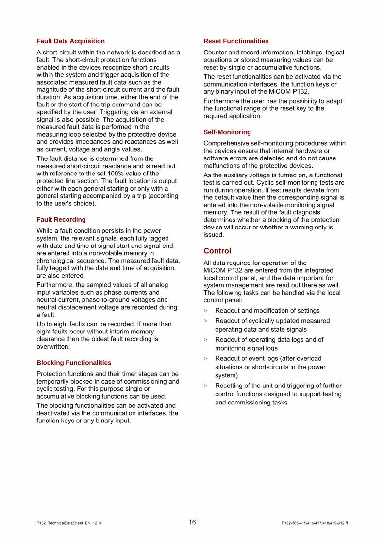
Fault Data Acquisition
A short-circuit within the network is described as a fault. The short-circuit protection functions enabled in the devices recognize short-circuits within the system and trigger acquisition of the associated measured fault data such as the magnitude of the short-circuit current and the fault duration. As acquisition time, either the end of the fault or the start of the trip command can be specified by the user. Triggering via an external signal is also possible. The acquisition of the measured fault data is performed in the measuring loop selected by the protective device and provides impedances and reactances as well as current, voltage and angle values. The fault distance is determined from the measured short-circuit reactance and is read out with reference to the set 100% value of the protected line section. The fault location is output either with each general starting or only with a general starting accompanied by a trip (according to the user's choice).
Fault Recording
While a fault condition persists in the power system, the relevant signals, each fully tagged with date and time at signal start and signal end, are entered into a non-volatile memory in chronological sequence. The measured fault data, fully tagged with the date and time of acquisition, are also entered. Furthermore, the sampled values of all analog input variables such as phase currents and neutral current, phase-to-ground voltages and neutral displacement voltage are recorded during a fault. Up to eight faults can be recorded. If more than eight faults occur without interim memory clearance then the oldest fault recording is overwritten.
Blocking Functionalities
Protection functions and their timer stages can be temporarily blocked in case of commissioning and cyclic testing. For this purpose single or accumulative blocking functions can be used. The blocking functionalities can be activated and deactivated via the communication interfaces, the function keys or any binary input.
Reset Functionalities
Counter and record information, latchings, logical equations or stored measuring values can be reset by single or accumulative functions. The reset functionalities can be activated via the communication interfaces, the function keys or any binary input of the MiCOM P132. Furthermore the user has the possibility to adapt the functional range of the reset key to the required application.
Self-Monitoring
Comprehensive self-monitoring procedures within the devices ensure that internal hardware or software errors are detected and do not cause malfunctions of the protective devices. As the auxiliary voltage is turned on, a functional test is carried out. Cyclic self-monitoring tests are run during operation. If test results deviate from the default value then the corresponding signal is entered into the non-volatile monitoring signal memory. The result of the fault diagnosis determines whether a blocking of the protection device will occur or whether a warning only is issued.
Control All data required for operation of the MiCOM P132 are entered from the integrated local control panel, and the data important for system management are read out there as well. The following tasks can be handled via the local control panel: > Readout and modification of settings > Readout of cyclically updated measured
operating data and state signals > Readout of operating data logs and of
monitoring signal logs > Readout of event logs (after overload
situations or short-circuits in the power system)
> Resetting of the unit and triggering of further control functions designed to support testing and commissioning tasks

P132-306-415/416/417/418/419-612 ff 17 P132_TechnicalDataSheet_EN_12_b
The local control panel shown in figure 12 comprises the local control elements and functions described below.
Operation
(1) The integrated local control panel has an graphical back-lit LCD Display with 4 x 20 alphanumeric characters.
23(resp. 10 in the 24T case) LED indicators are provided for signal display (2) 5 LED indicators are permanently assigned to
signals. (3) The remaining 18 LED indicators are
available for free assignment by the user and can be configured for the colours red, green or yellow. Furthermore different operation and flashing modes are available. In the 24T case 5 unicoloured LED indicators are available for this functions.
A separate adhesive label is provided for user-defined labeling of these LED indicators according to the chosen configuration.
Menu Tree
(4) By pressing the cursor keys
, , G and guided by the LCD display, the user moves within a plain text menu. All setting parameters and measured variables as well as all local control functions are arranged in this menu which is standardized for all devices of the system. Changes to the settings can be prepared and confirmed by means of the Enter Key G which also serves to trigger local control functions. In the event of erroneous entries, exit from the enter mode with rejection of the entries is possible at any time by means of the Clear Key C When the edit mode is not activated, pressing the Clear Key has the effect of resetting the indications. Pressing the Read Key provides direct access to a preselected point in the menu.
Password Protection Access barriers protect the enter mode or the function keys in order to guard against inadvertent or unauthorized changing of parameter settings or triggering of control functions.
Mi COM P132Par amet er s
P132
7 8 4
3
2
6 1
3
5
Figure 12: Local control panel
Function Keys (available in 40T and 84T case)
(5) 6 Function Keys (F1…F6) are available for free assignment to any logical binary input or control function. This facilitates control, e.g. of manual trip and close commands.
Type Label and PC- Interface
(6) An upper cover identifying the product name. The cover may be raised to provide access to the product model number and ratings.
(7) A lower cover concealing the RS232 serial interface to connect a personal computer.
(8) To guard the lower cover against unauthorized opening it is provided a facility for fitting a security lead seal.
Display Panels The configuration of the local control panel allows the installation of measured value `Panels`on the LCD display. The Panels are automatically displayed for certain operation conditions of the system. Priority increases from normal operation to operation under overload conditions and finally operation following a short-circuit in the system. The protection device thus provides the measured value data relevant for the prevailing conditions. Devices with the optional control functions have additionally a control panel display to show the active switchgear status and for local control via function keys.
P132_TechnicalDataSheet_EN_12_b 18 P132-306-415/416/417/418/419-612 ff
Mechanical Design The devices are supplied in four case designs. > Surface-mounted case
> Surface-mounted case with detachable HMI
> Flush-mounted case
> Flush-mounted case with detachable HMI
With all case designs, connection is via threaded terminal ends with the option of either pin-terminal or ring-terminal connection. Two 40T respective three 24T flush-mounted cases can be combined to form a complete 19" mounting rack. Figure 13 shows the modular hardware structure of the devices. The plug-in modules can be combined to suit individual requirements. The device itself can identify the fitted modules. During each startup, the number and type of fitted modules are identified and checked for compliance with the permissible configurations. As function of the components actually fitted, the corresponding configuration parameters are then enabled for application.
Transformer Module T
The transformer module converts the measured current and voltage variables to the internal processing levels and provides for electrical isolation.
Power Supply Module V
The power supply module ensures the electrical isolation of the device as well as providing the power supply. Depending on the chosen design version, optical coupler inputs and output relays are provided in addition.
Processor Module P
The processor module performs the analog/digital conversion of the measured variables as well as all digital processing tasks.
Local Control Module L
The local control module encompasses all control and display elements as well as a PC interface. The local control module is located behind the front panel and connected to the processor module via a ribbon cable.
The detachable HMI gets connected to the processor module via interfacing module (cover plate) and connection cable.
Bus Modules B
Bus modules are printed circuit boards (PCBs). They provide the electrical connection between the other modules. Two types of bus modules are used, namely the analog- and the digital-bus PCB.

P132-306-415/416/417/418/419-612 ff 19 P132_TechnicalDataSheet_EN_12_b
Communication Module A (optional)
The optional communication module provides one or two serial information interfaces for the integration of the protection device into a substation control system and for remote access respectively a protection communication interface for the transfer of digital information between two protective devices. The communication module with serial communication interface(s) is plugged into the processor module.
Protection Interface A (InterMiCOM) (optional)
The optional protection interface provides point to point digital communication between two MiCOM protection devices.
Binary I/O Modules X (optional)
The binary I/O modules are equipped with optical couplers for binary signal input as well as output relays for the output of signals and commands or combinations of these.
Transient Ground Fault Evaluation Module N (optional)
The optional transient ground fault module evaluates the measured variables according to the transient ground fault evaluation scheme.
Analog Modules Y (optional)
Der optional RTD module is fitted with 9 resistance temperature detector inputs. The optional analog module is fitted with a resistance temperature detector input, a 20 mA input and two 20 mA outputs. One output relay each is assigned to the two 20 mA outputs. Additionally four optical coupler inputs are available.
GGC
GG
G
G
G
MiCOM
TRIP
ALARM
OUT OF SERVICE
HEALTHY
EDIT MODE
F1
F2
F3
F4
F5
F6
Y VXT
Binary signals / Measured data / Commands Power supplyCurrents / Voltages
PP
B
PC Interface
L
Communication Interfaces
A A
Protection Interface InterMiCOM
A
NC
Figure 13: System structure

P132_TechnicalDataSheet_EN_12_b 20 P132-306-415/416/417/418/419-612 ff
Technical Data General Data
Design Surface-mounted case suitable for wall installation or flush-mounted case for 19" cabinets and for control panels
Installation position Vertical ±30°
Degree of Protection Per DIN VDE 0470 and EN 60529 or IEC 529. IP 52; IP 20 for the rear connection area of the flush-mounted case
Weight Case 24T: max. 5 kg Case 40T: max. 7 kg Case 84T: max. 11 kg
Dimensions See “Dimensions”
Terminal Connection Diagrams See “Connections”
Terminals PC Interface (X6) DIN 41652 connector , type D-Sub, 9-pin
Communication Interfaces COMM1, COMM2, COMM3 Optical fibers (X7, X8 and X31, X32): F-SMA-interface per IEC 60874-2 per plastic fiber or BFOC-(ST®)-interface 2.5 per IEC 60874-10-1 per glass fiber or Leads (X9, X10, X33): Threaded terminal ends M2 for wire cross sections up to 1.5 mm2
or (only for COMM3 (InterMiCOM)) RS232 (X34): DIN 41652 connector, Type D-Sub, 9 pin.
Communication Interface IEC 61850 Optical fibers (X7, X8): BFOC-(ST®)-interface 2.5 per IEC 60874-10-1 per glass fiber or optical fibers (X13): SC-interface per IEC60874-14-4 per glass fiber and Leads (X12): RJ45 connector per ISO/IEC 8877
IRIG-B Interface (X11) BNC plug
Current-Measuring Inputs Threaded terminals for pin-terminal connection: Threaded terminal ends M5, self-centering with wire protection for conductor cross sections of ≤ 4 mm2 or Threaded terminals M4 for ring-terminal connection
Other Inputs and Outputs Threaded terminals for pin-terminal connection: Threaded terminal ends M3, self-centering with wire protection for conductor cross sections of 0.2 to 2.5 mm2 or Threaded terminals M4 for ring-terminal connection
Creepage Distance and Clearance Per EN 61010-1 and IEC 664-1, pollution degree 3, working voltage 250 V, overvoltage category III, impulse test voltage 5 kV

P132-306-415/416/417/418/419-612 ff 21 P132_TechnicalDataSheet_EN_12_b
Tests
Type Test Tests according to EN 60255-6, IEC 255-6 or EN 50121-5
EMC Interference Suppression Per EN 55022 or IEC CISPR 22, Class A
1 MHz Burst Disturbance Test Per IEC 255 Part 22-1 or IEC 60255-22-1, Class III, Common-mode test voltage: 2.5 kV, Differential test voltage: 1.0 kV, Test duration: > 2 s, Source impedance: 200 Ω
Immunity to Electrostatic Discharge Per EN 60255-22-2 or IEC 60255-22-2, Level 3, Contact discharge, single discharges : > 10, Holding time: > 5 s, Test voltage: 6 kV, Test generator: 50...100 MΩ, 150 pF / 330 Ω
Immunity to Radiated Electromagnetic Energy Per EN 61000-4-3 and ENV 50204, Level 3, Antenna distance to tested device: > 1 m on all sides, Test field strength, frequ. band 80...1000 MHz: 10 V / m, Test using AM: 1 kHz / 80 %, Single test at 900 MHz: AM 200 Hz / 100 %
Electrical Fast Transient or Burst Requirements Per IEC 60255-22-4, Class B: Power supply: Amplitude: 2 kV, Burst frequency: 5 kHz Inputs / Outputs: Amplitude: 2 kV, Burst frequency: 5 kHz Communication: Amplitude: 1 kV, Burst frequency: 5 kHz Per DIN EN 61000-4-4, severity level 4: Power supply: Amplitude: 4 kV, Burst frequency: 2,5 kHz and 5 kHz Inputs / Outputs: Amplitude: 2 kV, Burst frequency: 5 kHz Communication: Amplitude: 2 kV, Burst frequency: 5 kHz Rise time of one pulse: 5 ns, Impulse duration (50% value): 50 ns, Burst duration: 15 ms, Burst cycle: 300 ms, Source impedance: 50 Ω
Conducted Disturbance Induced by Radiofrequency Fields Per IEC 60255-22-7, Class A: Phase-to-Phase: Voltage 150 V r.m.s,. Coupling resistor 100 Ω, Coupling capacitor 0.1 μF, for 10 s. Phase-to-Ground: Voltage 300 V r.m.s., Coupling resistor 220 Ω, Coupling capacitor 0.47 μF, for 10 s.
Surge Immunity Per EN 61000-4-5 or IEC 61000-4-5, Level 4, Testing of power supply circuits, unsymmetrically / symmetrically operated lines, Open-circt. voltg. front time/time to half-value: 1.2 / 50 µs, Short-circuit current front time/time to half-value: 8 / 20 µs, Amplitude: 4 / 2 kV, Pulse frequency: > 5 / min, Source impedance: 12 / 42 Ω
Immunity to Conducted Disturbances Induced by Radio Frequency Fields Per EN 61000-4-6 or IEC 61000-4-6, Level 3, Disturbing test voltage: 10 V
Power Frequency Magnetic Field Immunity Per EN 61000-4-8 or IEC 61000-4-8, Level 4, Frequency: 50 Hz, Test field strength: 30 A / m, 100 A / m
Alternating Component (Ripple) in DC Auxiliary Energizing Quantity Per IEC 255-11, 12 %
Insulation Voltage Test Per IEC 255-5 or DIN EN 61010, 2 kV~, 60 s For the voltage test of the power supply inputs, direct voltage (2.8 kVDC) must be used. The PC Interface must not be subjected to the voltage test.
Impulse Voltage Withstand Test Per IEC 255-5, Front time: 1.2 µs, Time to half-value: 50 µs, Peak value: 5 kV, Source impedance: 500 Ω
Mechanical Robustness Vibration Test Per DIN EN 60255-21-1 or IEC 255-21-1, test severity class 1: frequency range in operation: 10...60 Hz, 0.035 mm, 60...150 Hz, 0.5 g, frequency range during transport: 10...150 Hz, 1 g
Shock Response and Withstand Test, Bump Test Per DIN EN 60255-21-2 or. IEC 255-21-2, acceleration and pulse duration: Shock Response test to verify full operability (during operation): test severity class 1, 5 g for 11 ms, Shock Response test to verify endurance (during transport): test severity class 1, 15 g for 11 ms
Seismic Test Per DIN EN 60255-21-3 or IEC 255-21-3, test procedure A, Class 1: frequency range: 5...8 Hz, 3.5 mm / 1.5 mm, 8...35 Hz, 10 / 5 m/s2
3 × 1 cycle
Vibration Test 1) Per DIN EN 60255-21-1 or IEC 255-21-1, test severity class 2: frequency range in operation: 10...60 Hz, 0.075 mm, 60...150 Hz, 1.0 g, frequency range during transport: 10...150 Hz, 2 g
Shock Response and Withstand Test, Bump Test 1) Per DIN EN 60255-21-2 or IEC 255-21-2, acceleration and pulse duration: Shock Response test to verify full operability (during operation): test severity class 2, 10 g für 11 ms, Shock Response test to verify endurance (during transport): test severity class 1, 15 g für 11 ms Shock bump test to verify permanent shock (during transport): test severity class 1, 10 g für 16 ms
Seismic Test 1) Per DIN EN 60255-21-3 or IEC 255-21-3, test procedure A, Class 2 frequency range: 5...8 Hz, 7.5 mm / 3.5 mm, 8...35 Hz, 20 / 10 m/s2
3 × 1 cycle
1) Enhanced mechanical robustness for the following case variants:
Flush mounted case, version 2 (with angle brackets and frame) Surface mounted case

P132_TechnicalDataSheet_EN_12_b 22 P132-306-415/416/417/418/419-612 ff
Routine Test Test per EN 60255-6 or IEC 255-6
Voltage Test Per IEC 255-5: 2.2 kVAC, 1 s For the voltage test of the power supply inputs, direct voltage (2.8 kVDC) must be used. The PC Interface must not be subjected to the voltage test.
Additional Thermal Test 100 % controlled thermal endurance test, inputs loaded.
Environmental Conditions
Ambient Temperature Range Recommended temperature range: –5 °C...+55 °C, or +23 °F...+131 °F Limit temperature range: –25 °C...+70 °C, or -13 °F...+158 °F
Ambient Humidity Range ≤ 75 % relative humidity (annual mean), up to 56 days at ≤ 95 % relative humidity and 40 °C, condensation not permissible
Solar Radiation Avoid exposure of the front panel to direct solar radiation.
Ratings
Measurement Inputs Nominal frequency fnom: 50 Hz and 60 Hz (settable) Operating range: 0.95...1.05 fnom Frequency protection: 40…70 Hz
Current Nominal current Inom: 1 A and 5 A (settable) Nominal consumption per phase: < 0.1 VA at Inom Load rating: continuous: 4 Inom for 10 s: 30 Inom
for 1 s: 100 Inom Nominal surge current: 250 Inom
Voltage Nominal voltage Vnom: 50...130 VAC (settable) Nominal consumption per phase: < 0.3 VA at Vnom=130 VAC Load rating: continuous 150 VAC
Binary Signal Inputs Max. permissible voltage: 300 VDC
Switching threshold (as per order option) order option: Standard variant: 18V (VA,nom: 24 ... 250 VDC): Switching threshold range 14 V ... 19 VDC Special variant with switching thresholds from 58 ... 72 % of the nominal supply voltage (VA,nom) (definitively "low" at VA < 58 % of the nominal supply voltage, definitively "high" at VA > 72 % of the nominal supply voltage): "Special variant 73 V": nom. supply voltage 110 VDC "Special variant 90 V": nom. supply voltage 127 VDC "Special variant 146 V": nom. supply voltage 220 VDC "Special variant 155 V": nom. supply voltage 250 VDC
Power Consumption (as per order option): Standard variant: VA = 19...110VDC : 0.5 W +/-30% VA > 110VDC : VA ∗ 5 mA +/- 30 % Special variants: VA > switching threshold: VA ∗ 5mA +/-30 %
Note: The standard variant of binary signal inputs (opto-couplers) is recommended in most applications, as these inputs operate with any voltage from 19V. Special versions with higher pick-up/drop-off thresholds are provided for applications where a higher switching threshold is expressly required.
Analog Inputs and Outputs Direct Current Input Input current: 0...26 mA Value range 0.00...1.20 IDC,nom (IDC,nom = 20 mA) Maximum permissible continuous current: 50 mA Maximum permissible input voltage: 17 V Input load: 100 Ω Open-circiut monitoring: 0...10 mA (adjustable) Overload monitoring: > 24.8 mA Zero suppression: 0.000...0.200 IDC,nom (adjustable)
Resistance Temperature Detector For analog module only PT100 permitted, For RTD module PT100, Ni100, Ni120 permitted Value range: -40...+215 °C 3-wire configuration: max. 20 Ω per conductor open and short-circuit input permitted Open circuit monitoring: Θ > +215 °C (or Θ > +419 °F) and Θ < -40 °C (or Θ < -40 °F)
Direct Current Output Output current: 0 … 20 mA Maximum permissible load: 500 Ω Maximum output voltage: 15 V

P132-306-415/416/417/418/419-612 ff 23 P132_TechnicalDataSheet_EN_12_b
Output Relays Binary module X (4H) with High-break contacts applicable to DC circuits only Rated voltage: 250 VDC Continuous current: 10 A Short-duration current: 250 A for 0.03 s 30 A for 3 s Making capacity: 30 A Breaking capacity: 7500 W resistive or 30 A at 250 VDC maximum values: 30 A and 300 VDC 2500 W inductive (L/R = 40 ms) or 10 A at 250 VDC maximum values: 10 A and 300 VDC
Binary module X (6I/6O) for control of switchgear units Rated voltage: 250 VDC, 250 VAC Continuous current: 8 A Short-duration current: 30 A for 0.5 s Making capacity: 1000 W (VA) at L/R = 40 ms Breaking capacity: 0.2 A at 220 VDC and L/R = 40 ms, 4 A at 230 VAC and cos ϕ = 0.4
Other modules Rated voltage: 250 VDC, 250 VAC Continuous current: 5 A Short-duration current: 30 A for 0.5 s Making capacity: 1000 W (VA) at L/R = 40 ms Breaking capacity: 0.2 A at 220 VDC and L/R = 40 ms, 4 A at 230 VAC and cos ϕ = 0.4
IRIG-B Interface Min./max. input voltage level (peak-peak): 100 mVpp / 20 Vpp Input impedance: 33 kΩ at 1 kHz Galvanic isolation: 2 kV
Power Supply Nominal Auxiliary Voltage VA,nom: 48…250 VDC and 100...230 VAC or VA,nom: 24 VDC (depends on ordering)
Operating Range for direct voltage: 0.8…1.1 VA,nom with a residual of up to 12 % of VA,nom for alternating current: 0.9…1.1 VA,nom
Nominal Consumption at VA = 220 VDC and maximum number of modules fitted in case24T: Inital position approx.: 11 W Active position approx.: 20 W in case 40T: Inital position approx.: 11 W Active position approx.: 25 W in case 84T: Inital position approx.: 11 W Active position approx.: 44 W
Start-Up Peak Current < 3 A, duration 0.25 ms
Stored-Energy Time ≥ 50 ms for interruption of VA ≥ 220 VDC
PC-Interface Transmission rate: 300...115200 Baud (settable)
Communication Interfaces COMM1, COMM2, COMM3 Communication Interface COMM1: Protocol switchable between IEC 60870-5-103, IEC 870-5-101, Modbus, DNP 3.0, Courier Transmission speed: 300...64000 bit/s (settable)
Communication Interface COMM2: Protocol per IEC 60870-5-103 Transmission speed: 300...57600 bit/s (settable)
Protection Interface COMM3: InterMiCOM, asynchronous, full duplex Transmission speed: 600...19200 bit/s (settable)
Wire Leads Per RS 485 or RS 422, 2 kV-isolation Distance to be bridged: peer to peer link: max. 1200 m multi-endpoint link: max. 100 m
Plastic Fiber Connection Optical wavelength : typ. 660 nm Optical output: min. – 7.5 dBm Optical sensivity: min. – 20 dBm Optical input: max. – 5 dBm Distance to be bridged: max. 45 m 1)
Class Fiber Connection G 50/125 Optical wavelength : typ. 820 nm Optical output: min. – 19.8 dBm Optical sensivity: min. – 24 dBm Optical input: max. – 10 dBm Distance to be bridged: max. 400 m 1)
Class Fiber Connection G 62,5/125 Optical wavelength : typ. 820 nm Optical output: min. – 16 dBm Optical sensivity: min. – 24 dBm Optical input: max. – 10 dBm Distance to be bridged: max. 1400 m 1)
1) Distance to be bridged for optical outputs and inputs that are
equal on both ends, taking into account a system reserve of 3 dB and typical fiber attenuation.

P132_TechnicalDataSheet_EN_12_b 24 P132-306-415/416/417/418/419-612 ff
Communication Interface IEC Wire Leads Ethernet based communication per IEC 61850 Transmission rate: 10 resp. 100 Mbit/s RJ45, 1.5kV-isolation, Distance to be bridged: max. 100 m
Optical Fiber (100 Mbit/s) Ethernet based communication per IEC 61850 SC- or ST-interface Optical wavelength: typ. 1300 nm For glass fiber G50/125 Optical output: min. –23.5 dBm Optical sensitivity: min. -31 dBm Optical input: max. -14 dBm For glass fiber G62.5/125 Optical output: min. -20 dBm Optical sensitivity: min. -31 dBm Optical input: max. -14 dBm
IRIG-B Interface Format B122, Amplitude modulated, 1 kHz carrier signal, BCD time-of-year code
Typical Characteristic Data
Main Function Minimum output pulse for a trip command: 0.1 … 10 s (settable) Output pulse for a close command: 0.1 to 10 s (settable)
Definite-Time and Inverse-Time Overcurrent Protection Shortest tripping time: time delayed stage: directional operation: approx. 0.7 cycles nondirectional operation: approx. 1.2 cycles Earth current stage: < 10ms (at tIN> = 0 ms) Starting reset time (from twice the set threshold to zero) approx. 1.5 cycles Starting and measurement resetting ratio: 0.95
Short-Circuit Direction Determination Nominal acceptance angle for forward decision: ±90 ° Resetting ratio forward/backward recognition: ≤ 7 ° Base point release for phase currents: 0.1 Inom Base point release for phase-to-phase voltages: 0.002 Vnom at Vnom = 100 V Base point release for residual current: 0.01 Inom Base point release for neutral displacement voltage: 0.015 to 0.6 Vnom /√3 (adjustable)
Over-/Undervoltage Protection Operate time inclusive of output relay (measured variable from nominal value to 1.2-fold operate value or measured variable from nominal value to 0.8-fold operate value): ≤ 40 ms, approx. 30 ms Reset time (measured variable from 1.2-fold operate value to nominal value or measured variable from 0.8-fold operate value to nominal value): ≤ 45 ms, approx. 30 ms Starting resetting ratio: settable hysteresis 1...10%
Directional Power Protection Operate time inclusive of output relay (measured variable from nominal value to 1.2-fold operate value or measured variable from nominal value to 0.8-fold operate value): ≤ 60 ms, approx. 50 ms Reset time (measured variable from 1.2-fold operate value to nominal value or measured variable from 0.8-fold operate value to nominal value): ≤ 40 ms, approx. 30 ms Resetting ratio for P>, Q>: settable hysteresis 0.05...0.95 P<, Q<: settable hysteresis 1.05...20
Deviations of the Operate Values
Deviation relative to the set value of sinusoidal signals with nominal frequency fnom, total harmonic distortion ≤ 2 %, ambient temperature 20°C and nominal auxiliary voltage VA,nom.
Measuring-circuit monitoring Operate values Ineg , Vneg: ± 3 %
Overcurrent-Time Protection Operate values I>, IN>: ± 5 %
Short-circuit direction determination Operate values: ± 10 °
Motor and Thermal Overload Protection Reaction time: ± 7.5 % at I/Iref =6
Over-/Underfrequency Protection Operate values f<>: +/- 30 mHz (fnom = 50 Hz) +/- 40 mHz (fnom = 60 Hz) Operate values df/dt: +/- 0.1 Hz/s (fnom = 50 or 60 Hz)
Over-/Undervoltage Protection Operate values V<>, Vpos<>: ± 1 % (setting 0.6…1.4 Vnom) Operate values VNG>, Vneg>: ± 1 % (setting > 0.3 Vnom)
Unbalance Protection Operate values: ± 5 %
Directional Power Protection Operate values P<>, Q<>: ± 5 %
GF Direction Determination Operate values: VNG>, IN,act , IN,reac, IN> ± 3 % Sector Angle: 1 °
Deviations of the Timer Stages
Deviation relative to the set value of sinusoidal signals with nominal frequency fnom, total harmonic distortion ≤ 2 %, ambient temperature 20°C and nominal auxiliary voltage VA,nom.
Definite-Time Stages ± 1% + 20...40 ms Neutral current: ≤ 3 ms (at tIN> = 0 ms)
Inverse-Time Stages ± 5 % + 10...25 ms (measured variable greater than 2 Iref) or for IEC characteristic‚ extremely inverse‘ and for thermal overload protection: ± 7,5 % + 10...20 ms
Deviations in Measured Data Aquisiton
Deviation relative to the nominal value of sinusoidal signals with nominal frequency fnom, total harmonic distortion ≤ 2 %, ambient temperature 20°C and nominal auxiliary voltage VA,nom.

P132-306-415/416/417/418/419-612 ff 25 P132_TechnicalDataSheet_EN_12_b
Operating Data Currents / measuring inputs: ±1% Voltages / measuring inputs: ± 0,5 % Currents / internally calculated: ± 2 % Voltages / internally calculated: ± 2 % Active and reactive power / energy: approx. ± 2 % of meas. value for cos ϕ = ± 0.7 approx. ± 5 % of meas. value for cos ϕ = ± 0.3 Load angle: ± 1 ° Frequency: ± 10 mHz
Fault Data Currents and voltages: ± 3 % Short circuit impedance: ± 5 % Fault location: ± 5 %
Internal Clock With free running internal clock: < 1 min. / month With external synchronization via protocol, synch. interval ≤ 1 min: < 10 ms via IRIG-B signal input: ± 1 ms
Resolution in Fault Data Aquisition
Time Resolution Fault Data Aquisition: 1 ms
Currents Dynamic range: 100 Inom resp 25 Inom Amplitude resolution at Inom = 1 A: 6.1 mAr.m.s resp 1.5 mAr.m.s at Inom = 5 A: 30.5 mAr.m.s resp 7.6 mAr.m.s
Residual Current Dynamic range: 16 Inom resp. 2 Inom Amplitude resolution at Inom = 1 A: 0.98 mA r.m.s. resp. 0.12 mA r.m.s. at Inom = 5 A: 4.9 mA r.m.s. resp. 0.61 mA r.m.s.
Voltage Dynamic range: 150 V Amplitude resolution: 9.2 mVr.m.s
Adress List Function Parameters
Global Functions PC Link (PC): Command blocking: No / Yes Sig./meas.val.block.: No / Yes
Communication Link 1 (COMM1): Command block. USER: No / Yes Sig./meas.block.USER: No / Yes
Communication Link 2 (COMM2): Command block. USER: No / Yes Sig./meas.block.USER: No / Yes
Binary Output (OUTP): Outp.rel.block USER: No / Yes
Main function (MAIN): Device on-line: No (= off) / Yes (= on) Test mode USER: No / Yes Nominal frequ. fnom: 50 Hz / 60 Hz Phase sequence: A – B – C / A – C – B Time tag: 1stEgde.,OpMem sorted 1stEgde.,OpMem unsort after debounce time Inom C.T. prim.: 1..10000 A IN,nom C.T. prim.: 1..10000 A Vnom V.T. prim.: 0.1....1000.0 kV VNG,nom V.T. prim.: 0.1....1000.0 kV Vref,nom V.T. prim.: 0.1...1000.0 kV Inom prim. NCIT: 50…4000 A IN,nom prim. NCIT: 10…800 A Vnom prim. NCIT: 0.1...1000.0 kV Ph. err. VAG,1 NCIT: -5.0…5.0° Ph. err. VBG,1 NCIT: -5.0…5.0° Ph. err. VCG,1 NCIT: -5.0…5.0° Ph. err. VAG,2 NCIT: -5.0…5.0° Ph. e. VBG/Vref,2 NCIT: -5.0…5.0° Ph. err. VCG,2 NCIT: -5.0…5.0° Channel select NCIT: No channel Channel 1 on Channel 2 on Inom device: 1 A / 5 A IN,nom device: 1 A / 5 A Vnom V.T. sec.: 50...130 V VNG,nom V.T. sec.: 50...130 V Vref,nom V.T. sec.: 30...130 V Conn. meas. circ. IP: Standard / Opposite Conn. meas. circ. IN: Standard / Opposite Meas. direction P,Q: Standard / Opposite Meas. value rel. IP: 0.000...0.200 Inom Meas. value rel. IN: 0.000...0.200 IN,nom Meas. value rel. V: 0.000...0.200 Vnom Meas. val. rel. VNG: 0.000...0.200 VNG,nom Meas. val. rel. Vref: 0.000...0.200 Vref,nom Op. mode energy cnt.: Procedure 1 / Procedure 2 Settl. t. IP,max,del: 0.1...60.0 min Fct.assign. reset 1: see selection table Fct.assign. reset 2: see selection table Fct.assign. block. 1: see selection table Fct.assign. block. 2: see selection table Trip cmd.block. USER: No / Yes Fct.assig.trip cmd.1: see selection table Fct.assig.trip cmd.2: see selection table Min.dur. trip cmd. 1: 0.10...10.00 s

P132_TechnicalDataSheet_EN_12_b 26 P132-306-415/416/417/418/419-612 ff
Min.dur. trip cmd. 2: 0.10...10.00 s Latching trip cmd. 1: No / Yes Latching trip cmd. 2: No / Yes Close cmd.pulse time 0.10...10.00 s Sig. asg. CB open: see selection table Inp.asg. ctrl.enabl.: see selection table valid for y = ‚1‘ to ‚3‘ Debounce time gr. y: 0.00...2.54 s Chatt.mon. time gr. y: 0.0...25.4 s Change of state gr. y: 0...254 Cmd. dur.long cmd.: 1...254 s Cmd. dur. short cmd.: 1...254 s Inp.asg.interl.deact: see selection table Inp.asg. L/R key sw.: see selection table Auto-assignment I/O: No / Yes Electrial control: Remote / Local Delay Man.Op.Superv.: 0...255 s W. ext. cmd. termin.: No / Yes Inp.assign. tripping: see selection table Prot.trip>CB tripped: Without function Gen. trip command 1 Gen. trip command 2 Gen. trip command 1/2 Inp. asg. CB trip: see selection table Sig. asg. CB closed: see selection table Inp.asg.CB tr.en.ext: see selection table Inp.asg. CB trip ext: see selection table Inp.asg. mult.sig. 1: see selection table Inp.asg. mult.sig. 2: see selection table Fct. assign. fault: see selection table
Parameter Subset Selection (PSS): Control via USER: No / Yes Param.subs.sel. USER: Parameter subset 1 Parameter subset 2 Parameter subset 3 Parameter subset 4 Keep time: 0.000...65.000 s / Blocked
Self-Monitoring (SFMON): Fct. assign. warning: see selection table Mon.sig. retention: 0...240 h / Blocked
Fault data acquisition (FT_DA): Line length: 0.01...500.00 km Line reactance: 0.10...200.00 Ω for Inom = 1.0 A 0.02...40.00 Ω for Inom = 5.0 A Angle kG: -180...180 ° Abs. value kG: 0.00...8.00 Start data acquisit.: End of fault / Trigg., trip, GS end Output fault locat.: On general starting On gen.start.w.trip
Fault Recording (FT_RC): Fct. assign. trigger: see selection table I>: 0.01...40.00 Inom / Blocked Pre-fault time: 1...50 Periods Post-fault time: 1...50 Periods Max. recording time: 5...750 Periods
General Functions Main function (MAIN): Syst.IN enabled USER: No / Yes
Definite-time overcurrent protection (DTOC): General enable USER: No / Yes
Inverse-time overcurrent protection (IDMT1 resp. IDMT2): General enable USER: No / Yes
Shortcircuit direction determination (SCDD): General enable USER: No / Yes
Switch on to fault protection (SOTF): General enable USER: No / Yes Operating mode: Trip by I> Trip by I>> Trip b< I>>> Trip by gen. start. Manual close timer: 0.00...10.00 s
Protective signaling (PSIG): General enable USER: No / Yes
Autoreclosing control (ARC): General enable USER: No / Yes Sig.asg.trip t.GFDSS: Starting LS Starting Y(N)> Starting LS / Y(N)> Fct.assign. tLOGIC: see selection table
Automatic synchronism check (ASC): General enabled USER: No / Yes Transm.cycle,meas.v.: 0...10 s
Ground fault direction determination using steady-state values (GFDSS): General enable USER: No / Yes Operating mode: Steady-state power Steady-state current Steady-state admitt.
Transient ground fault direction determination (TGFD): General enable USER: No / Yes
Motor protection (MP): General enable USER: No / Yes Hours_Run >: 1…65000 h
Thermal overload protection (THERM): General enable USER: No / Yes Operating mode: Relative replica Absolute replica
Unbalance protection (I2>): General enable USER: No / Yes
Over-/undervoltage protection (V<>): General enable USER: No / Yes
Over-/ underfrequency protection (f<>): General enable USER: No / Yes Selection meas. volt: Voltage A-G Voltage B-G Voltage C-G Voltage A-B Voltage B-C Voltage C-A Evaluation time: 3...5 Periods Undervolt. block. V<: 0.20...1.00 Vnom(/√3)
Directional power protection (P<>): General enable USER: No / Yes

P132-306-415/416/417/418/419-612 ff 27 P132_TechnicalDataSheet_EN_12_b
Circuit Breaker Failure Protection (CBF) General enable USER: No / Yes Start with man. trip: No / Yes Fct.assignm. CBAux.: see selection table I>: 0.05…20.00 Inom t1 3p: 0,00…100,00 s / Blocked t2: 0.00…100.00 s / Blocked Min.dur. trip cmd. t1: 0.10…10.00 s Min.dur. trip cmd. t2: 0.10…10.00 s Latching trip cmd. t1: No / Yes Latching trip cmd. t2: No / Yes Delay/starting trig.: 0.00…100.00 s / Blocked Delay/fault beh. CB: 0.00…100.00 s / Blocked Delay/CB sync.superv.: 0.00…100.00 s / Blocked
Circuit Breaker Monitoring (CBM) General enable USER: No / Yes Blocking USER: No / Yes Sig. asg. trip cmd: see selection table Operating mode: see selection table Inom, CB: 1…65000 A Perm. CB op. Inom,CB: 1…65000 Med. curr. Itrip,CB: 1…65000 A / Blocked Perm. CB op. Imed,CB: 1…65000 / Blocked Max. curr. Itrip,CB: 1…65000 A Perm. CB op. Imax,CB: 1…65000 No. CB operations>: 1…65000 Remain No. CB op. <: 1…65000 ΣItrip>: 1...65000 Inom,CB ΣItrip**2>: 1...65000 Inom,CB** ΣI*t>: 1.0...4000.0 kAs Corr. acquis. time: -0.200...0.200 s
Measuring circuit monitoring (MCMON): General enable USER: No / Yes Op. mode Idiff>: Without IA,IC IA, IB, IC Idiff>: 0.25...0.50 IP,max Op. mode Vmin< monit: Vmin< Vmin< with I enable Vmin< w. CB cont. enab. Vmin<: 0.40…0.90 Vnom / Blocked Operate delay: 0.50...10.00 s / Blocked Phase sequ. monitor.: No / Yes FF,Vref enabled USER: No / Yes Oper. delay FF, Vref: 00.00...10.00 s
Limit Value Monitoring (LIMIT): General enable USER: No / Yes I>: 0.10... 2.40 Inom / Blocked I>>: 0.10... 2.40 Inom / Blocked tI>: 1...1000 s / Blocked tI>>: 1...1000 s / Blocked I<: 0.10... 2.40 Inom / Blocked I<<: 0.10... 2.40 Inom / Blocked tI<: 1...1000 s / Blocked tI<<: 1...1000 s / Blocked VPG>: 0.10... 2.50 Vnom/√3 / Blocked VPG>>: 0.10... 2.50 Vnom/√3 / Blocked tVPG>: 1...1000 s / Blocked tVPG>>: 1...1000 s / Blocked VPG<: 0.10... 2.50 Vnom/√3 / Blocked VPG<<: 0.10... 2.50 Vnom/√3 / Blocked tVPG<: 1...1000 s / Blocked tVPG<<: 1...1000 s / Blocked VPP>: 0.10... 1.50 Vnom / Blocked VPP>>: 0.10... 1.50 Vnom / Blocked tVPP>: 1...1000 s / Blocked tVPP>>: 1...1000 s / Blocked VPP<: 0.10... 1.50 Vnom / Blocked VPP<<: 0.10... 1.50 Vnom / Blocked tVPP<: 1...1000 s / Blocked
tVPP<<: 1...1000 s / Blocked VNG>: 0.010... 1.000 Vnom / Blocked VNG>>: 0.010... 1.000 Vnom / Blocked tVNG>: 1...1000 s / Blocked tVNG>>: 1...1000 s / Blocked Vref>: 0.10...2.50 Vnom / Blocked Vref>>: 0.10...2.50 Vnom / Blocked tVref>: 1...1000 s / Blocked tVref>>: 1...1000 s / Blocked Vref<: 0.10...2.50 Vnom / Blocked Vref<<: 0.10...2.50 Vnom / Blocked tVref<: 1...1000 s / Blocked tVref<<: 1...1000 s / Blocked IDC,lin>: 0.100...1.100 IDC,nom / Blocked IDC,lin>>: 0.100...1.100 IDC,nom / Blocked tIDC,lin>: 0.00...20.00 s / Blocked tIDC,lin>>: 0.00...20.00 s / Blocked IDC,lin<: 0.100...1.100 IDC,nom / Blocked IDC,lin<<: 0.100...1.100 IDC,nom / Blocked tIDC,lin<: 0.00...20.00 s / Blocked tIDC,lin<<: 0.00...20.00 s / Blocked T>: -20...200°C T>>: -20...200°C tT>: 0...1000 s / Blocked tT>>: 0...1000 s / Blocked T<: -20...200°C T<<: -20...200°C tT<: 0...1000 s / Blocked tT<<: 0...1000 s / Blocked Valid for y = ‚1‘ to ‚9‘ Ty>: -20...200°C Ty>>: -20...200°C tTy>: 0...1000 s / Blocked tTy>>: 0...1000 s / Blocked Ty<: -20...200°C Ty<<: -20...200°C tTy<: 0...1000 s / Blocked tTy<<: 0...1000 s / Blocked
Programmable Logic (LOGIC): General enable USER: No / Yes Valid for y = ‚1‘ to ‚8‘: Set y USER: No / Yes Valid for y = ‚1‘ to ‚32‘: Fct.assignm. outp. y: see selection table Op. mode t output y: Without timer stage Oper./release.delay Oper.del./puls.dur Op./rel.delay,retrig Op.del./puls.dur.,rt Minimum time Time t1 output y: 0.00...600.00 s Time t2 output y: 0.00...600.00 s Sig.assig. outp. y: see selection table Sig.assig. outp. y(t): see selection table
Commands (CMD_1): Valid for y = ‚C001‘ to ‚C012‘ Design. command y: see selection table Oper. mode cmd. y: Long command Short command Persistent command
Signaling (SIG_1): Valid for y = ‚S001‘ to ‚S012‘ Designat. signal y: see selection table Oper. mode sig. y: Without function Start/end signal Transient signal Gr.asg. debounc. y: Group 1 ... Group 3 Min. sig. dur. y: 0...254 s

P132_TechnicalDataSheet_EN_12_b 28 P132-306-415/416/417/418/419-612 ff
Parameter Subset (valid for parameter subsets x = = ‚1‘ to ‚4‘:
Measured Data Input (MEASI): BackupTempSensor PSx: None Group 1 – 2 Group 1 - 2/3
Main function (MAIN): Neutrl-pt threat. PSx: Low-imped. Grounding Isolated/res.ground. Hld time dyn.par. PSx: 0.00...100.00 s / Blocked Bl.tim.st. IN,neg PSx: Without For single-ph. start For multi-ph. start Gen. start. mode PSx: W/o start. IN, Ineg/With start. IN, Ineg Op. rush restr. PSx: Without Not phase-selective Phase-selective Rush I(2*fn)/I(fn) PSx: 10...35 % / Blocked I> lift rush restr. PSx: 5.0...20.0 Inom / Blocked Suppr.start. sig. PSx: 0.00...100.00 s tGS PSx: 0.00...100.00 s / Blocked
Definite-time overcurrent protection (DTOC): Enable PSx: No / Yes I> PSx: 0.10...40.00 Inom / Blocked I> dynamic PSx: 0.10...40.00 Inom / Blocked I>> PSx: 0.10...40.00 Inom / Blocked I>> dynamic PSx: 0.10...40.00 Inom / Blocked I>>> PSx: 0.10...40.00 Inom / Blocked I>>> dynamic PSx: 0.10...40.00 Inom / Blocked tI> Psx: 0.00...100.00 s / Blocked tI>> PSx: 0.00...100.00 s / Blocked tI>>> PSx: 0.00...100.00 s / Blocked Ineg> PSx: 0.10...25.00 Inom / Blocked Ineg> dynamic PSx: 0.10...25.00 Inom / Blockedt Ineg>> PSx: 0.10...25.00 Inom / Blocked Ineg>> dynamic PSx: 0.10...25.00 Inom / Blocked Ineg>>> PSx: 0.10...25.00 Inom / Blocked Ineg>>> dynamic PSx: 0.10...25.00 Inom / Blocked tIneg> PSx: 0.00...100.00 s / Blocked tIneg>> PSx: 0.00...100.00 s / Blocked tIneg>>> PSx: 0.00...100.00 s / Blocked Eval. IN>,>>,>>> PSx: Calculated / Measured IN> PSx: 0.002...8.000 Inom / Blocked IN> dynamic PSx: 0.020...8.000 Inom / Blocked IN>> PSx: 0.002...8.000 Inom / Blocked IN>> dynamic PSx: 0.020...8.000 Inom / Blocked IN>>> PSx: 0.002...8.000 Inom / Blocked IN>>> dynamic PSx: 0.020...8.000 Inom / Blocked IN>>>> PSx: 0.10...40.00 Inom / Blocked IN>>>> dynamic PSx: 0.10...40.00 Inom / Blocked tIN> PSx: 0.00...100.00 s / Blocked tIN>> PSx: 0.00...100.00 s / Blocked tIN>>> PSx: 0.00...100.00 s / Blocked tIN>>>> PSx: 0.00...100.00 s / Blocked Puls.prol.IN>,int PSx: 0.00...10.00 s tIN>,interm. PSx: 0.00...100.00 s / Blocked Hold-time tIN>,intm. PSx: 0.0...600.0 s
Inverse-time overcurrent protection (IDMT1 resp. IDMT2): Enable PSx: No / Yes Iref,P PSx: 0.10...4.00 Inom / Blocked Iref,P dynamic PSx: 0.10...4.00 Inom / Blocked Characteristic P PSx: Definite Time IEC Standard Inverse IEC Very Inverse IEC Extr. Inverse IEC Long Time Inv. IEEE Moderately Inv. IEEE Very Inverse IEEE Extremely Inv. ANSI Normally Inv. ANSI Short Time Inv. ANSI Long Time Inv. RI-Type Inverse RXIDG-Type Inverse Factor kt,P PSx: 0.05...10.00 Min. trip t. P PSx: 0.00...10.00 s Hold time P PSx: 0.00...600.00 s Release P PSx: Without delay / Delayed as per char. Evaluation IN PSx: calculated / Measured Valid for y = ‚neg‘ or ‚N‘: Iref,y PSx: 0.01...4.00 Inom / Blocked Iref,y dynamic PSx: 0.01...4.00 Inom / Blocked Characteristic y PSx: Definite Time IEC Standard Inverse IEC Very Inverse IEC Extr. Inverse IEC Long Time Inv. IEEE Moderately Inv. IEEE Very Inverse IEEE Extremely Inv. ANSI Normally Inv. ANSI Short Time Inv. ANSI Long Time Inv. RI-Type Inverse RXIDG-Type Inverse Factor kt,y PSx: 0.05...10.00 Min. trip t. y PSx: 0.00...10.00 s Hold time y PSx: 0.00...600.00 s Release y PSx: Without delay / Delayed as per char.
Short-circuit direction determination (SCDD): Enable PSx: No / Yes Trip bias PSx: No / Yes valid values for: Direction tI> PSx: Direction tI>> PSx: Direction tIref,P> PSx: Direction tIN> PSx: Direction tIN>> PSx: Direction tIref,N> PSx: Forward directional Backward directional Non-directional Charact. angle G PSx: -90... -45...90 ° VNG> PSx: 0.015... 0.100...0.600 Vnom/√3 Block. bias G PSx: No / Yes Oper.val. Vmemory PSx: 0.01...1.00 Vnom
Protective signaling (PSIG): Enable PSx: No / Yes Tripping time PSx: 0.00...10.00 s Release t. send PSx: 0.00...10.00 s DC loop op. mode PSx: Transm.rel.break con / Transm.rel.make con. Direc. Dependence PSx: Without Phase curr. System Residual curr.system Phase/resid.c.system

P132-306-415/416/417/418/419-612 ff 29 P132_TechnicalDataSheet_EN_12_b
Autoreclosing control (ARC): Enable PSx: No / Yes CB clos.pos.sig. PSx: Without / With Operating mode PSx: HSR/TDR permitted TDR only permitted Test HSR only permit Operative time PSx: 0.00...10.00 s HSR trip.time GS PSx: 0.00...10.00 s / Blocked HSR trip.time I> PSx: 0.00...10.00 s / Blocked HSR trip.time I>> PSx: 0.00...10.00 s / Blocked HSRtrip.time I>>> PSx: 0.00...10.00 s / Blocked HSR trip.time IN> PSx: 0.00...10.00 s / Blocked HSRtrip.time IN>> PSx: 0.00...10.00 s / Blocked HSRtrip.t. IN>>> PSx: 0.00...10.00 s / Blocked HSRtrip.t. Iref,P PSx: 0.00...10.00 s / Blocked HSRtrip.t.Iref,N PSx: 0.00...10.00 s / Blocked HSRtr.t. Iref,neg PSx: 0.00...10.00 s / Blocked HSR trip t.GFDSS PSx: 0.00...10.00 s / Blocked HSRtrip.t. LOGIC PSx: 0.00...10.00 s / Blocked HSR block.f. I>>> PSx: No / Yes HSR dead time PSx: 0.15...600.00 s No. permit. TDR PSx: 0...9 TDR trip.time GS PSx: 0.00...10.00 s / Blocked TDR trip.time I> PSx: 0.00...10.00 s / Blocked TDR trip.time I>> PSx: 0.00...10.00 s / Blocked TDRtrip.time I>>> PSx: 0.00...10.00 s / Blocked TDR trip.time IN> PSx: 0.00...10.00 s / Blocked TDRtrip.time IN>> PSx: 0.00...10.00 s / Blocked TDRtrip.t. IN>>> PSx: 0.00...10.00 s / Blocked TDRtrip.t. Iref,P PSx: 0.00...10.00 s / Blocked TDRtrip.t.Iref,N PSx: 0.00...10.00 s / Blocked TDRtr..t. Iref,neg PSx: 0.00...10.00 s / Blocked TDR trip t.GFDSS PSx: 0.00...10.00 s / Blocked TDRtrip.t. LOGIC PSx: 0.00...10.00 s / Blocked TDR dead time PSx: 0.15...600.00 s TDR block.f. I>>> PSx: No / Yes Reclaim time PSx: 1...600 s Blocking time PSx: 0...600 s
Automatic synchonism check (ASC): Enable PSx: No / Yes CB assignment PSx: see selection table System integrat. PSx: Autom.synchron.check Autom.synchron.control Active for HSR PSx: No / Yes Active for TDR PSx: No / Yes Clos.rej.w.block PSx: No / Yes Operative time PSx: 0.0...6000.0 s Operating mode PSx: Voltage-checked Sync.-checked Volt./sync.-checked Op.mode volt.chk. PSx: Vref but not V V but not Vref Not V and not Vref Not V or not Vref V> volt.check PSx: 0.10...0.80 Vnom(/√3) V< volt. check PSx: 0.10...0.80 Vnom(/√3) tmin volt. check PSx: 0.00...10.00 s Measurement loop PSx: Loop A-G/ B-G/ C-G/ A-B/ B-C/ C-A V> sync. check PSx: 0.40...1.20 Vnom(/√3) Delta Vmax PSx: 0.02...0.40 Vnom Delta f max PSx: 0.03...1.00 Hz Delta phi max PSx: 5...100 ° Phi offset PSx: -180...180 ° tmin sync. check PSx: 0.00...10.00 s
Ground fault direction determination using steady-state values (GFDSS): Enable PSx: No / Yes Op.m.GF pow./adm PSx: cos phi circuit / sin phi circuit Evaluation VNG PSx: Calculated / Measured Meas. direction PSx: Standard / Opposite VNG> PSx: 0.02...1.00 Vnom(/√3) tVNG> PSx: 0.02...10.00 s f/fnom (P meas.) PSx: 1 / 5 f/fnom (I meas.) PSx: 1 / 5 IN,act>/reac> LS PSx: 0.003...1.000 IN,nom Sector angle LS PSx: 80...89 ° Operate delay LS PSx: 0.00...100.00 s / Blocked Release delay LS PSx: 0.00...10.00 s IN,act>/reac> BS PSx: 0.003...1.000 IN,nom Sector angle BS PSx: 80...89 ° Operate delay BS PSx: 0.00...100.00 s / Blocked Release delay BS PSx: 0.00...10.00 s IN> PSx: 0.003...1.000 IN,nom Operate delay IN PSx: 0.00...100.00 s / Blocked Release delay IN PSx: 0.00...10.00 s G(N)> / B(N)> LS PSx: 0.01...1.00 YN,nom G(N)> / B(N)> BS PSx: 0.01...1.00 YN,nom Y(N)> PSx: 0.01...2.00 YN,nom Correction angle PSx: -30...+30° Oper. delay Y(N)> PSx: 0.00...100.00 s / Blocked Rel. delay Y(N)> PSx: 0.00...10.00 s
Transient ground fault direction determination (TGFD): Enable PSx: No / Yes Evaluation VNG PSx: Sum (VA-B-C-G) / Measured Measurem. direc PSx: Standard / Opposite VNG> PSx: 0.15...0.50 Vnom(/√3) Operate delay PSx: 0.05...1.60 s IN,p> PSx: 0.03...0.50 Inom Buffer time PSx: 0...1200 s / Blocked
Motor protection (MP): Enable PSx: No / Yes Iref PSx: 0.10...4.00 Inom Factor kP PSx: 1.05...1.50 IStUp> PSx: 1.8...3.0 Iref tIStUp> PSx: 0.1...1.9 s Character. type P PSx: Reciprocal squared / logarithmic t6Iref PSx: 1.0...100.0 s Tau after st-up PSx: 1...60 s Tau mach. running PSx: 1...1000 min Tau mach. stopped PSx: 1...1000 min Permiss.No.st-ups PSx: 2/1 (cold/warm) / 3/2 (cold/warm) RC permitted, Θ< PSx: 22...60 % / Blocked Operating mode PSx: Without THERM / With THERM St-up time t,StUp PSx: 2.0...100.0 s Blocking time tE PSx: 2.0...100.0 s I< PSx: 0.2...0.9 Iref / Blocked tI< PSx: 0.1...20.0 s
Thermal overload protection (THERM): Enable PSx: No / Yes Sel. backup th. PSx: see selection table Iref PSx: 0.10...4.00 Inom Start.fact OL_RC PSx: 1.05...1.50 Tim.const.1,>Ibl PSx: 1.0...1000.0 min Tim.const.2,<Ibl PSx: 1.0...1000.0 min Max.perm.obj.tmp. PSx: 0...300 °C Max. perm.cool.temp. PSx: 0...70 °C Select.meas.input PSx: see selection table Default CTA PSx: -40...70 °C Bl. f. CTA fault PSx: No / Yes Rel. O/T warning PSx: 50...200 % Rel. O/T trip PSx: 50...200 % Hysteres.is trip PSx: 2...30 % Warning pre-trip PSx: 0.0...1000.0 min / Blocked

P132_TechnicalDataSheet_EN_12_b 30 P132-306-415/416/417/418/419-612 ff
Unbalance protection (I2>): Enable PSx: No / Yes Ineg> PSx: 0.10...0.80 Inom / Blocked Ineg>> PSx: 0.10...0.80 Inom / Blocked tIneg> PSx: 0.00...100.00 s / Blocked tIneg>> PSx: 0.00...100.00 s / Blocked
Over-/undervoltage protection (V<>): Enable PSx: No / Yes Operating mode PSx: Delta / Star I enable V< PSx: 0.04...1.00 Inom Op.mode V< mon. PSx: Without / With Evaluation VNG PSx: Calculated / Measured V> PSx: 0.20...1.50 Vnom(/√3) / Blocked V>> PSx: 0.20...1.50 Vnom(/√3) / Blocked tV> PSx: 0.00...100.00 s / Blocked tV> 3-pole PSx: 0.00...100.00 s / Blocked tV>> PSx: 0.00...100.00 s / Blocked V< PSx: 0.20...1.50 Vnom(/√3) / Blocked V<< PSx: 0.20...1.50 Vnom(/√3) / Blocked tV< PSx: 0.00...100.00 s / Blocked tV< 3-pole PSx: 0.00...100.00 s / Blocked tV<< PSx: 0.00...100.00 s / Blocked Vpos> PSx: 0.20...1.50 Vnom/√3 / Blocked Vpos>> PSx: 0.20...1.50 Vnom/√3 / Blocked tVpos> PSx: 0.00...100.00 s / Blocked tVpos>> PSx: 0.00...100.00 s / Blocked Vpos< PSx: 0.20...1.50 Vnom/√3 / Blocked Vpos<< PSx: 0.20...1.50 Vnom/√3 / Blocked tVpos< PSx: 0.00...100.00 s / Blocked tVpos<< PSx: 0.00...100.00 s / Blocked Vneg> PSx: 0.20...1.50 Vnom/√3 / Blocked Vneg>> PSx: 0.20...1.50 Vnom/√3 / Blocked tVneg> PSx: 0.00...100.00 s / Blocked tVneg>> PSx: 0.00...100.00 s / Blocked VNG> PSx: 0.02...1.00 Vnom(/√3) / Blocked VNG>> PSx: 0.02...1.00 Vnom(/√3) / Blocked tVNG> PSx: 0.00...100.00 s / Blocked tVNG>> PSx: 0.00...100.00 s / Blocked tTransient PSx: 0.00...100.00 s / Blocked Hyst. V<> meas. PSx: 1...10 % Hyst. V<> deduc. PSx: 1...10 %
Over-/ underfrequency protection (f<>): Enable PSx: No / Yes Valid for y = ‚1‘ to ‚4‘ Oper. mode fy PSx: f f with df/dt f w. Delta f/Delta t fy PSx: 40.00...70.00 Hz / Blocked tfy PSx: 0.00...10.00 s / Blocked dfy/dt PSx: 0.1...10.0 Hz/s / Blocked Delta fy PSx: 0.01...5.00 Hz / Blocked Delta ty PSx: 0.04...3.00 s
Directional power protection (P<>): Enabled PSx: No / Yes Valid for y = ‚>‘ and ‚>>‘: Py PSx: 0.010...1.500 Snom / Blocked Qy PSx: 0.010...1.500 Snom / Blocked Diseng. ratio Py PSx: 0.05...0.95 Diseng. ratio Qy> PSx: 0.05...0.95 Valid for y = ‚<‘ and ‚<<‘: Py PSx: 0.010...0.500 Snom / Blocked Qy PSx: 0.010...0.500 Snom / Blocked Diseng. ratio Py PSx: 1.05...20.00 Diseng. ratio Qy PSx: 1.05...20.00 Valid for y = ‚>‘ and ‚>>‘ and ‚<‘ and ‚<<‘: Operate delay Py PSx: 0.00...100.00 s / Blocked Release delay Py P Sx: 0.00...100.00 s Direction Py PSx: Forward directional Backward directional Non-directional Operate delay Qy PSx: 0.00...100.00 s / Blocked Release delay Qy PSx: 0.00...10.00 s Direction Qy PSx: Forward directional Backward directional Non-directional tTransient pulse PSx: 0.00...100.00 s
Control Main function (MAIN): BI active USER: No / Yes SI active USER: No / Yes Inp.asg. fct.block.1: see selection table Inp.asg. fct.block.2: see selection table Op. delay fct. block: 0...60 s CB1 max. oper. cap.: 1...99 CB1 ready fct.assign: see selection table
External device (DEV01 to DEV03): Designat. ext. dev.: see selection table Op.time switch. dev.: 0...254 s Latching time: 0.00...5.00 s Gr. assign.debounce: Group 1 ... Group 3 Interm. pos. suppr.: No / Yes Stat.ind.interm.pos.: No / Yes Oper.mode cmd: Long command / Short command / Time control Inp.asg. sw.tr. plug: see selection table With gen.trip cmd.1: No / Yes With gen.trip cmd.2: No / Yes With close cmd./prot: No / Yes Inp.asg.el.ctrl.open: see selection table Inp.asg.el.ctr.close: see selection table Inp. asg. end Open: see selection table Inp. asg. end Close: see selection table Open w/o stat.interl: No / Yes Close w/o stat. int.: No / Yes Fct.assig.BIwSI open: see selection table Fct.assig.BIwSI clos: see selection table Fct.asg.BI w/o SI op: see selection table Fct.asg.BI w/o SI cl: see selection table
Interlocking logic (ILOCK): Valid for y = ‚1‘ to ‚32‘ Fct.assignm. outp. y: see selection table

P132-306-415/416/417/418/419-612 ff 31 P132_TechnicalDataSheet_EN_12_b
Measured Operating Data Logical Communication interface InterMiCOM (COMM3): No. tel.errors p.u.: 0.0...100.0 % No.t.err. max,stored: 0.0...100.0 % Loopback result: Not measured Passed Failed Loopback receive: 0...255
Measured Data Input (MEASI): Valid for y = ‚1‘ to ‚9 ‘ Temperature Ty: -40.0...215.0 °C Temp. Ty max.: -40.0...215.0 °C Temperature p.u. Ty: -0.40...2.15 100°C Current IDC: 0.00...24.00 mA Current IDC p.u.: 0.00...1.20 IDC,nom Curr. IDC,lin. p.u.: 0.00...1.20 IDC,nom Scaled value IDC,lin: -32000...32000 Temperature T: -40.0...215.0 °C Temperature Tmax : -40.0...215.0 °C Temperature p.u. T: -0.40...2.15 100 °C
Measured Data Output (MEASO): Current A-1: 0.00...20.00 mA Current A-2: 0.00...20.00 mA
Main Function (MAIN): Date: 01.01.1997...31.12.2096 dd.mm.yy Time: 00:00:00...23:59:59 hh:mm:ss Time switching: Standard time / Daylight saving time Frequency f: 40.00...70.00 Hz Curr. IP,min prim.: 0...25000 A IP,max prim.,delay: 0...25000 A IP,max prim.,stored: 0...25000 A Curr. IP,min prim.: 0...25000 A Current A prim.: 0...25000 A Current B prim.: 0...25000 A Current C prim.: 0...25000 A Current Σ (IP) prim.: 0...25000 A Current IN prim.: 0...25000 A Volt. VPG,max prim.: 0.0...2500.0 kV Volt. VPG,min prim.: 0.0...2500.0 kV Voltage A-G prim.: 0.0...2500.0 kV Voltage B-G prim.: 0.0...2500.0 kV Voltage C-G prim.: 0.0...2500.0 kV Volt. Σ(VPG)/3 prim.: 0.0...2500.0 kV Voltage VNG prim.: 0.0...2500.0 kV Voltage Vref prim.: 0.0...3000.0 kV Volt. VPP,max prim.: 0.0...2500.0 kV Volt. VPP,min prim.: 0.0...2500.0 kV Voltage A-B prim.: 0.0...2500.0 kV Voltage B-C prim.: 0.0...2500.0 kV Voltage C-A prim.: 0.0... 2500.0 kV Volt. VPG, min prim: 0.0…2500.0 kV Appar.power S prim.: -1399.9...1400.0 MVA Active power P prim.: -999.9...1000.0 MW Reac. power Q prim.: -999.9...1000.0 Mvar Act.energy outp.prim: 0.00...655.35 MWh Act.energy inp. prim: 0.00...655.35 MWh React.en. outp. prim: 0.00...655.35 Mvar h React. en. inp. prim: 0.000...655.35 Mvar h Frequency f p.u.: 0.200...4.000 fnom Current IP,max p.u.: 0.000...25.000 Inom IP,max p.u.,delay: 0.000...25.000 Inom IP,max p.u.,stored: 0.000...25.000 Inom Current IP,min p.u.: 0.000...25.000 Inom Current A p.u.: 0.000...25.000 Inom Current B p.u.: 0.000...25.000 Inom Current C p.u.: 0.000...25.000 Inom Current Σ (IP) p.u.: 0.000...25.000 Inom Current IN p.u.: 0.000...16.000 IN,nom Current Ipos p.u.: 0.000...25.000 Inom Current Ineg p.u.: 0.000...25.000 Inom Voltage VPG,max p.u.: 0.000...25.000 Vnom Voltage VPG,min p.u.: 0.000...25.000 Vnom
Voltage A-G p.u.: 0.000...25.000 Vnom Voltage B-G p.u.: 0.000...25.000 Vnom Voltage C-G p.u.: 0.000...25.000 Vnom Volt. Σ(VPG)/√3 p.u.: 0.000...12.000 Vnom Voltage VNG p.u.: 0.000...25.000 VNG,nom Voltage Vref p.u.: 0.000...3.000 Vnom Voltage VPP,max p.u.: 0.000...25.000 Vnom Voltage VPP,min p.u.: 0.000...25.000 Vnom Voltage A-B p.u.: 0.000...25.000 Vnom Voltage B-C p.u.: 0.000...25.000 Vnom Voltage C-A p.u.: 0.000...25.000 Vnom Voltage Vpos p.u.: 0.000...25.000 Vnom Voltage Vneg p.u.: 0.000...25.000 Vnom Appar. power S p.u.: -10.700...10.700 Snom Active power P p.u.: -7.500...7.500 Snom Reac. power Q p.u.: -7.500...7.500 Snom Active power factor: -1.000...1.000 Load angle phi A: -180...180 ° Load angle phi B: -180...180 ° Load angle phi C: -180...180 ° Angle phi N: -180...180 ° Load angle phi A p.u.: -1.80...1.80 phi.ref Load angle phi B p.u.: -1.80...1.80 phi.ref Load angle phi C p.u.: -1.80...1.80 phi.ref Angle phi N p.u.: -1.80...1.80 phi.ref Angle ΣVPG vs. IN: -180...180 ° Angle ΣVPG/IN p.u.: -1.80...1.80 phi.ref Phase rel.,IN vs ΣIP: Equal phase / Reverse phase Current ΣI unfilt. 0.000...25.000 Inom
Ground fault direction determination using steady-state values (GFDSS): Current IN,act p.u.: 0.000...30.000 IN,nom Curr. IN,reac p.u.: 0.000...30.000 IN,nom Curr. IN filt. p.u.: 0.000...30.000 IN,nom Admitt. Y(N) p.u.: 0.000... 5.000 YN,nom Conduct. G(N) p.u.: -5.000... 5.000 YN,nom Suscept. B(N) p.u.: -5.000... 5.000 YN,nom
Motor Protection (MP): Therm.repl.buffer MP: 0...100 % St-ups still permitt: 0...3 Therm. repl. MP p.u.:0.00...1.00 100% St-ups st. perm.p.u.: 0.00...0.30 factor 10
Thermal overload protection (THERM): Status THERM replica: -25000...25000 % Object temperature: -40...300 °C Coolant temperature: -40...200 °C Pre-trip time left: 0.0...1000.0 min Therm. replica p.u.: -2.50...2.50 100 % Object temp. p.u.: -0.40...3.00 100 °C Coolant temp.p.u.: -0.40...0.20 100 °C Temp. offset replica: -25000...25000 %

P132_TechnicalDataSheet_EN_12_b 32 P132-306-415/416/417/418/419-612 ff
Dimensions Surface-mounted case 24T
139.6
168.8
186.4
257.1
147.
5
177.
5
184.
5
TRIP
ALARM
OUT OF SERVICE
HEALTHY
EDIT MODE
MiPa
COr a
Mme
P1t e
3 2r s
Surface-mounted case 40 T
213.4
242.6
260.2
257.1
147.
5
177.
5
184.
5
TRIP
ALARM
OUT OF SERVICE
HEALTHY
EDIT MODE
MiPa
COr a
Mme
P1t e
3 2r s
Figure 14: Dimensional drawings for surface-mounted case, part 1

P132-306-415/416/417/418/419-612 ff 33 P132_TechnicalDataSheet_EN_12_b
Surface-mounted case 84T
147.
5
177.
5
184.
5
434.8
464.0
481.6
257.1
TRIP
ALARM
OUT OF SERVICE
HEALTHY
EDIT MODE
MiPa
COr a
Mme
P1t e
3 2r s
Figure 15: Dimensional drawings for surface-mounted case, part 2
Flush-mounted case 24T with panel cutout, version 1 (without angle brackets)
227.9
253.6
177.
5
129.2
77.5
5.0
5.0
103.8
159.
0
168.
0
139.6
TRIP
ALARM
OUT OF SERVICE
HEALTHY
EDIT MODE
MiPa
COr a
Mme
P1t e
3 2r s
Figure 16: Dimensional drawings for flush-mounted case version 1 (without angle brackets), part 1

P132_TechnicalDataSheet_EN_12_b 34 P132-306-415/416/417/418/419-612 ff
Flush-mounted case 40T with panel cutout, version 1 (without angle brackets)
227.9
253.6
177.
5
213.4
203.0
155.4
5.0
5.0
181.3
159.
0
168.
0
TRIP
ALARM
OUT OF SERVICE
HEALTHY
EDIT MODE
MiPa
COr a
Mme
P1t e
3 2r s
Flush-mounted case 84T with panel cutout, version 1 (without angle brackets)
227.9
253.6
177.
5
434.8
284.9259.0
5.0
159.
0
168.
0
5.0
25.9
410.0
TRIP
ALARM
OUT OF SERVICE
HEALTHY
EDIT MODE
MiPa
COr a
Mme
P1t e
3 2r s
Figure 17: Dimensional drawings for flush-mounted case version 1 (without angle brackets), part 2

P132-306-415/416/417/418/419-612 ff 35 P132_TechnicalDataSheet_EN_12_b
Flush-mounted case 24T with panel cutout, Version 2 (with angle brackets and frame)
227.9
253.6
177.
5
139.6
168.8
186.4
101.
6
6.4
101.
6
186.
5
150.7
168.8
TRIP
ALARM
OUT OF SERVICE
HEALTHY
EDIT MODE
MiPa
COr a
Mme
P1t e
3 2r s
Flush-mounted case 40T with panel cutout, Version 2 (with angle brackets and frame)
227.9
253.6
177.
5
101.
6
6.4
224.5
242.6
101.
6
186.
5
213.4
242.6
260.2
TRIP
ALARM
OUT OF SERVICE
HEALTHY
EDIT MODE
MiPa
COr a
Mme
P1t e
3 2r s
Figure 18: Dimensional drawings for flush-mounted case version 2 (with angle brackets and frame), part 1

P132_TechnicalDataSheet_EN_12_b 36 P132-306-415/416/417/418/419-612 ff
Flush-mounted case 84T with panel cutout, Version 2 (with angle brackets and frame)
227.9
253.6
177.
5
101.
6
6.4
445.9
464.0
101.
6
186.
5
434.8
464.0
481.6
TRIP
ALARM
OUT OF SERVICE
HEALTHY
EDIT MODE
MiPa
COr a
Mme
P1t e
3 2r s
Figure 19: Dimensional drawings for flush-mounted case version 2 (with angle brackets and frame), part 2

P132-306-415/416/417/418/419-612 ff 37 P132_TechnicalDataSheet_EN_12_b
Front view 40T case for connection of a detachable HMI
WARNING:Connection for remotecontrol panel only.Not for networkconnection!
Front view 84T case for connection of a detachable HMI
WARNING:Connection for remotecontrol panel only.Not for networkconnection!
Detachable HMI with panel cutout
213,4 20,7
46,3
177,
5
197,5
3,0
181,3
148,
0
168,
0
107,
3
192,5
Aus-Kommando
Warnung
Block./Störung
Betrieb
Änderungsmod.
MiPa
COr a
Mme
P1t e
32r s
Figure 20: Dimensional drawings for detachable HMI

P132_TechnicalDataSheet_EN_12_b 38 P132-306-415/416/417/418/419-612 ff
Location of the modules MiCOM P132 in cases 24T and 40T - Pin-terminal connection (24T: diagram P132 -415, 40T: diagram P132 -417) - Transformer board ring-, other boards pin terminal connection (24T: diagram P132 -416, 40T: diagram P132 -418)
01
01
02
02
03
03
04
04
05
05
06
06
07
07
08
08
09
09
10
10
V4I8O
X
6O
Y4I
X6I6O
X6I6O
X24I
alt.
AP Nalt.
Y9T
alt.
A
alt. alt.
X6I8O
X6I8O
alt.
A
alt.
X
4H
T
ETHCH2 CH3
CH1CH2
-/4I-/4V/5V
MiCOM P132 in case 84T - Ring-terminal connection (diagram P132 -419)
01
01
02
02
03
03
04
04
05
05
06
06
07
07
08
08
09
09
10
10
AP
11
11
12
12
13
13
14
14
15
15
16
16
X6I6O
17
17
18
18
X
6O
19
19
20
20
V4I8O
21
21
X6I6O
N X24I
alt.
alt.
Y9T
alt.
A
alt. alt.
X6I8O
X6I8O
alt.
Aalt.
X
4H
Y4I
T-/4I
-/4V/5V
ETHCH2 CH3
CH1CH2
Figure 21: Location diagrams
X041
1314
15161718
1112
12345
678
Ring
Type T
Pin
X04212345
678
IA
IB
IC
IN
T1
T2
T3
T4
-/4J -/4/5V
Option:
Option:
T5T6T7
T90
T15
X041
123456
7
8
UVWNN(e)E(n)
1U2U
Transformer module
Voltage measuring inputs
Current measuring inputsOption:
X_11234
56789
X_11234
56789
1011
121314151617
18
19202122
2324
252627
Ring
K_01
K_02
K_03
K_04K_05K_06K_07
K_08
Power supply
Type V
U100
Power supply module
Signal inputs
U_01
U_02
U_03
U_04
Output relaysPin
X_31234
56
789
X_212
345678
9 Vin
Vin
Vin
Vin
PE
Vaux
4I / 8O
+-
‘_‘is used as a wildcard for the location
Figure 22 Terminal connection diagrams of the modules, part 1

P132-306-415/416/417/418/419-612 ff 39 P132_TechnicalDataSheet_EN_12_b
X_1123456
789
X_1123456
789
10111213141516
1718
19
202122
232425
2627
Output relays
X_31
234
567
89
X_21234567
89
K_01
K_02
K_03
K_04
K_05
K_06
Signal inputs
U_01
U_02
U_03
U_04
U_05
U_06
Ring Pin
Vin
Vin
Vin
Vin
Vin
Vin
Binary module
Type X6I / 6O
X_11234
56789
X_11234
56789
1011
121314151617
18
19202122
2324
25
2627
Ring
K_01
K_02
K_03
K_04K_05K_06K_07
K_08
Binary module
U_01
U_02
U_03
U_04
U_05
U_06
Output relaysPin
X_31234
56
7
89
X_212
345678
9
Type X6I / 8O
Signal inputs
Vin
Vin
Vin
Vin
Vin
Vin
X_1123
456789
X_1123
456789
101112131415161718
192021222324
252627
Ring
Binary module
Signal inputsPin
X_3123456
789
X_2
123456789
Type X24I
U_17U_18U_19U_20U_21U_22U_23U_24
U_01U_02U_03U_04U_05U_06U_07U_08
U_09U_10U_11U_12U_13U_14U_15U_16
Vin
Vin
Vin
X_3
123456
X_2
123
4
5678
9
X_1123
456
789
X_1123
456
789
101112
13
14151617
18
19
2021222324
Ring
Analogmodule
U_01
U_02
U_03
U_04
Pin
Type Y4I
Signal and measuring inputs
Measuring outputs
K_01
U_080..20 mA
valid
K_02
U_090..20 mA
valid
U
#U
#
U_05
U_06
U
#
U
#
0..20 mA
PT100
Vin
Vin
Vin
Vin
X_11234
56789
Pin
X_3
123456789
X_212
3456789
Type Y9T
RTD module
Meas. inputs
U81
U82
U83
U84
U85
U86
U87
U88
U89
U
#
U
#
U
#
U
#
U
#
U
#
U
#
U
#
U
#
X111
X81
Type A
Channel 1optical fiber link
Per order
##
IRIG-B time synchronization
Channel 2 wire link only
or wire link
X//Y
RS 485
D2[R]
X1012345 D1[T]
U20
X//Y
RS 485
D2[R]
X9123
45 D1[T]
U19
U17X//Y
U18X//Y
X71
U21
Communication module CH1 / CH2
X8TX
Type A
IEC 61850optical fiber link ST
Per order
COMM2 wire link
oroptical fiber link SC
X//Y
RS 485
D2[R]
X1012
345 D1[T]
U20
U17X/Y
U18X/Y
X7RX
Communicationmodule ETH / CH2
X121
U26X/Y
U25X//Y
X13RX
TX
and wire link
RJ45
X321
Type A
COMM3 optical fiber link
Per order
or wire link
or wire link
X//Y
RS 485
D2[R]
X33123
45 D1[T]
U24
U22X//Y
U23X//Y
X311
Communicationmodule (InterMiCOM) CH3
U27
D1[T]D2[R]
RS 232
E2[G]
X//Y
M5[DCD]
+UB
X3412345
7
E
X_11234
56789
X_11234
56789
1011
12131415161718
192021222324252627
RingOutput relays
Pin
X_3
123456789
X_212
3456789
K_01
K_02
K_03
K_04
K_05
K_06
1)
1)
1)
1)
Type X 6O
Binary module
X_1123
456789
X_1123
456789
101112131415
161718
1920
21222324252627
Ring
Type X
High-break contacts
Pin
X_312
3456789
X_2123456
789
K_01
4H
K_02
K_04
K_03
+
+
+
+
Binary module
‘_‘ is used as a wildcard fort he location 1) Binary module X (6O) optional with 4 static outputs, in parallel with closer contact K_02.2, K_03.1, K_04, K_05
Figure 23: Terminal connection diagrams of the modules, part 2

P132_TechnicalDataSheet_EN_12_b 40 P132-306-415/416/417/418/419-612 ff
Connection Examples
Figure 24: Connection example currents and voltages
Power supply
P132 (Detail)
Circuitbreaker Q0
Vin
Vin
Vin
Vin
Vin
Vin
OPEN
X061: X061: X061: X061:
5 6 3 4
1 2
CLOSE
DisconnectorQ1
EarthingswitchQ8
X063:
X063: X063: X063:
X063: X063: X063:
X063: X063:
1
2
765
43
89
Figure 25: Connection example optional control

P132-306-415/416/417/418/419-612 ff 41 P132_TechnicalDataSheet_EN_12_b
Ordering Information MiCOM P132Feeder Management and Bay Control P132 P 1 3 2 - 9 0 -306 -4xx -612 -7xx -46x -9x x -9x x -8xxBasic device:Basic device 24TE, pin-terminal connection, 1 -415Basic device 24TE, CT/VT ring-, I/O pin-terminal connection, 2 -416Basic device 40TE, pin-terminal connection, 3 -417Basic device 40TE, CT/VT ring-, I/O pin-terminal connection, 5 -418Basic device 84TE, ring-terminal connection, 8 -419 basic complement with 4 binary inputs and 8 output relays; 6 function keys (40TE and 84TE only)Mounting option and display:Surface-mounted, local control panel with text display 3Flush-mounted, local control panel with text display 4Surface-mounted, with detachable HMI 16) 7Flush-mounted, with detachable HMI 16) 9
Current transformer:Without 11) 0
Inom = 1 A / 5 A (T1...T4) 2) 9
Voltage transformer:Without 11) 0Vnom = 50 ... 130 V (4-pole) 4Vnom = 50 ... 130 V (5-pole) f. Automatic Synchronism Check 12) 5
Additional binary I/O options: 16)
Without 0With 1 binary module (add. 6 binary inputs and 8 output relays) 1With 2 binary modules (add. 12 binary inputs and 16 output relays) 2With 1 binary module (add. 6 binary inputs and 6 output relays) 5 for the control of up to 3 switchgear unitsWith 1 binary module (add. 6 binary inputs and 6 output relays) 6 and 1 binary module (add. 6 binary inputs and 6 output relays) for the control of up to 3 switchgear unitsWith 1 binary module (add. 6 binary inputs and 8 output relays) 8 and 1 binary module (add. 6 binary inputs and 6 output relays) for the control of up to 3 switchgear unitsPower supply and additional outputs:VA,nom = 24 VDC 3VA,nom = 48 ... 250 VDC / 100 ... 230 VAC 4VA,nom = 24 VDC and 6 output relays, 4 with thyristor 6VA,nom = 48 ... 250 VDC / 100 ... 230 VAC 7 and 6 output relays, 4 with thyristorVA,nom = 24 VDC and 6 output relays 8VA,nom = 48 ... 250 VDC / 100 ... 230 VAC and 6 output relays 9VA,nom = 24 VDC and 4 high break contacts CVA,nom = 48 ... 250 VDC / 100 ... 230 VAC and 4 high break contacts D
Further add. options: 16)
Without 0With TGF (transient ground fault direction determination) module 3) 10) 1With analogue module 2With TGF and analogue module 3) 10) 3With binary module (add. 24 binary inputs) 4With TGF and binary module (add. 24 binary inputs) 3) 10) 5With RTD module 3) 12) 7With RTD and analogue module 3) 12) 8With RTD module and binary module (add. 24 binary inputs) 3) 12) 9
Switching threshold on binary inputs:>18 V (standard variant) Without order extension no. >90 V (60...70% of VA,nom = 125...150 V) 8) -461>155 V (60...70% of VA,nom = 220...250 V) 8) -462>73 V (67% of VA,nom = 110 V) 8) -463>146 V (67% of VA,nom = 220 V) 8) -464
With communication / information interface: Only IRIG-B input for clock synchronization -90 0Protocol can be switched between: -92 IEC 60870-5-101/-103, Modbus, DNP3, Courier and IRIG-B input for clock synchronization and 2nd interface (RS485, IEC 60870-5-103)For connection to wire, RS485, isolated 1For connection to plastic fibre, FSMA connector 2For connection to glass fibre, ST connector 4Protocol IEC61850: -94For connection to 100 Mbit/s Ethernet, glass fibre SC and wire RJ45 6 and 2nd interface (RS485, IEC 60870-5-103)For connection to 100 Mbit/s Ethernet, glass fibre ST and wire RJ45 7 and 2nd interface (RS485, IEC 60870-5-103)
With guidance / protection interface: 16)
Protocol InterMiCOM -95For connection to wire, RS485, isolated 1For connection to plastic fibre, FSMA connector 2For connection to glass fibre, ST connector 4For connection to wire, RS232, isolated 5Language:English (German) 4) Without order extension no. Px40 English (English) 4) on request -800German (English) 4) -801French (English) 4) on request -802Spanish (English) 4) on request -803Polish (English) 4) on request -804Russian (English) 4) 7) on request -805
2) Switching via parameter, default setting is underlined!3) This option is excluded if the InterMiCOM (-95x) is ordered4) Second included language in brackets7) Hardware option, supports cyrillic letters instead of special West. Europe characters8) Standard variant recommended, if higher pickup threshold not explicitly required by the application10) Transient ground fault option for variants with current and voltage transformers only11) Option without current transformers and without voltage transformers not possible 12) Option without current transformer not possible16) Options for basic device 24 TE not possible

T&D Worldwide Contact Centre Available 24h a day: +44 (0) 1785 25 00 70 [email protected] www.areva-td.com