ORLAN 96 SUPER ORLAN 130 SUPER - Cranp-Kovo en.pdf · 2 3 1. Boiler application Cranp-Kovo's...
28
ORLAN 96 SUPER INSTRUCTION MANUAL & SERVICE MANUAL ORLAN 130 SUPER
Transcript of ORLAN 96 SUPER ORLAN 130 SUPER - Cranp-Kovo en.pdf · 2 3 1. Boiler application Cranp-Kovo's...

ORLAN 96 SUPER
INSTRUCTION MANUAL& SERVICE MANUAL
ORLAN 130 SUPER
INSTRUCTION MANUALContent
1. Boiler application. . . . . . . . . . . . . . . . . . . . . . . . . . . . . . . . . . . . . . . . . . . . . . . . . . . . . . . . . . . . . . . . . . . . . . . . . . . . . . . . . . . . . . . . . . . .3
2. Principle of work. . . . . . . . . . . . . . . . . . . . . . . . . . . . . . . . . . . . . . . . . . . . . . . . . . . . . . . . . . . . . . . . . . . . . . . . . . . . . . . . . . . . . . . . . . . . .3
3. Description of the controller . . . . . . . . . . . . . . . . . . . . . . . . . . . . . . . . . . . . . . . . . . . . . . . . . . . . . . . . . . . . . . . . . . . . . . . . . . . . . . . .4
3.1. Front panel of EKOSTER 2 . . . . . . . . . . . . . . . . . . . . . . . . . . . . . . . . . . . . . . . . . . . . . . . . . . . . . . . . . . . . . . . . . . . . . .4
3.2. Main functions of EKOSTER 2 . . . . . . . . . . . . . . . . . . . . . . . . . . . . . . . . . . . . . . . . . . . . . . . . . . . . . . . . . . . . . . . . . .4
4. Gasification process . . . . . . . . . . . . . . . . . . . . . . . . . . . . . . . . . . . . . . . . . . . . . . . . . . . . . . . . . . . . . . . . . . . . . . . . . . . . . . . . . . . . . . . . .7
5. Boiler start-up . . . . . . . . . . . . . . . . . . . . . . . . . . . . . . . . . . . . . . . . . . . . . . . . . . . . . . . . . . . . . . . . . . . . . . . . . . . . . . . . . . . . . . . . . . . . . . .8
5.1. Lightning up. . . . . . . . . . . . . . . . . . . . . . . . . . . . . . . . . . . . . . . . . . . . . . . . . . . . . . . . . . . . . . . . . . . . . . . . . . . . . . . . . . . .8
5.2. Fuel stoking . . . . . . . . . . . . . . . . . . . . . . . . . . . . . . . . . . . . . . . . . . . . . . . . . . . . . . . . . . . . . . . . . . . . . . . . . . . . . . . . . . . .8
5.3. Boiler turning off. . . . . . . . . . . . . . . . . . . . . . . . . . . . . . . . . . . . . . . . . . . . . . . . . . . . . . . . . . . . . . . . . . . . . . . . . . . . . . .9
5.4. Optimal boiler’s temperature. . . . . . . . . . . . . . . . . . . . . . . . . . . . . . . . . . . . . . . . . . . . . . . . . . . . . . . . . . . . . . . . . .9
5.5. Power outage and pump failure. . . . . . . . . . . . . . . . . . . . . . . . . . . . . . . . . . . . . . . . . . . . . . . . . . . . . . . . . . . . . . .9
6. Maintenance . . . . . . . . . . . . . . . . . . . . . . . . . . . . . . . . . . . . . . . . . . . . . . . . . . . . . . . . . . . . . . . . . . . . . . . . . . . . . . . . . . . . . . . . . . . . . . .10
6.1. Boiler maintenance. . . . . . . . . . . . . . . . . . . . . . . . . . . . . . . . . . . . . . . . . . . . . . . . . . . . . . . . . . . . . . . . . . . . . . . . . . . .10
6.2. Boiler cleaning . . . . . . . . . . . . . . . . . . . . . . . . . . . . . . . . . . . . . . . . . . . . . . . . . . . . . . . . . . . . . . . . . . . . . . . . . . . . . . . .10
6.3. Boiler tightness. . . . . . . . . . . . . . . . . . . . . . . . . . . . . . . . . . . . . . . . . . . . . . . . . . . . . . . . . . . . . . . . . . . . . . . . . . . . . . . .11
6.4. Fan maintenance . . . . . . . . . . . . . . . . . . . . . . . . . . . . . . . . . . . . . . . . . . . . . . . . . . . . . . . . . . . . . . . . . . . . . . . . . . . . .12
2 3
2 3
1. Boiler applicationCranp-Kovo's gasification boiler ORLAN SUPER is designed to burn wood. As a main fuel it is recommended to use wood logs with moisture content 15-25% and max. length 5 cm shorter than loading chamber depth depending on boiler size; wood log diameter: 15-25 cm.
ATTENTION! Using fuel different than the recommended not guarantees optimum boiler operation and achieving parameters featured in technical data. It can also affect durability of the boiler and its components.
ATTENTION! Using fuel different than the recommended is treated as wrong boiler operation and resultant performance irregularities cannot be reason for complaint.
ATTENTION! Boiler is equipped with controller that enables to operate in right temperature’s range and protects the boiler against overheating by fan activation.
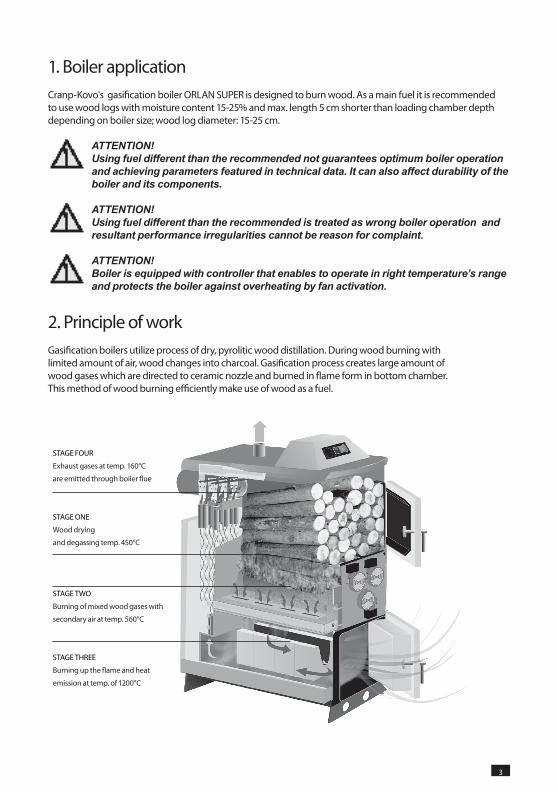
2. Principle of workGasification boilers utilize process of dry, pyrolitic wood distillation. During wood burning with limited amount of air, wood changes into charcoal. Gasification process creates large amount of wood gases which are directed to ceramic nozzle and burned in flame form in bottom chamber. This method of wood burning efficiently make use of wood as a fuel.
STAGE FOUR
Exhaust gases at temp. 160°C
are emitted through boiler flue
STAGE ONE
Wood drying
and degassing temp. 450°C
STAGE TWO
Burning of mixed wood gases with
secondary air at temp. 560°C
STAGE ThREE
Burning up the flame and heat
emission at temp. of 1200°C
4 5
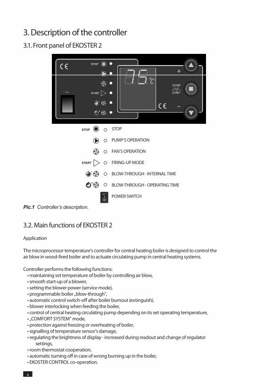
STOP
PUMP’S OPERATION
FAN’S OPERATION
FIRING-UP MODE
BLOW-ThROUGh - INTERNAL TIME
BLOW-ThROUGh - OPERATING TIME
POWER SWITCh
Pic.1 Controller’s description.
3.1. Front panel of EKOSTER 2
3. Description of the controller
3.2. Main functions of EKOSTER 2
Application
The microprocessor temperature’s controller for central heating boiler is designed to control the air blow in wood-fired boiler and to actuate circulating pump in central heating systems.
Controller performs the following functions:• maintaining set temperature of boiler by controlling air blow,• smooth start-up of a blower,• setting the blower power (service mode),• programmable boiler „blow-through”,• automatic control switch-off after boiler burnout (extinguish),• blower interlocking when feeding the boiler,• control of central heating circulating pump depending on its set operating temperature,• „COMFORT SYSTEM” mode,• protection against freezing or overheating of boiler,• signalling of temperature sensor’s damage,• regulating the brightness of display - increased during readout and change of regulator
settings,• room thermostat cooperation,• automatic turning off in case of wrong burning up in the boiler,• EKOSTER CONTROL co-operation.
STOP
START

4 5
Operation description
After switching on, controller is in , which is signaled by adequate diode. Operation starts after pressing or automatically, when boiler’s temperature increases above operating threshold – temperature difference between set temperature and DT parameter set in the service menu. Status is automatically activated after 30 minutes since temperature decrease below operating threshold. CONTROL socket which is located at the back panel of the controller is for connection of remote control EKOSTER CONTROL.
Buttons and are for setting's changes. During boiler operation, pressing or causes possibility to change desired boiler’s temperature. Pressing and withholding button causes increase of speed of temperature changing.
Pressing button causes:• temperature below operating threshold:turning on/off of the controller signaled with diodes
or ,• at temperature above operating threshold:fan operation blockade signaled by blinking
, diode, which makes possible to stoke the boiler. Return to automatic operation after pressing button.
ATTENTION! Displaying „Er” on the controller informs about temperature increase above 99 °C, below -9 °C or boiler sensor damage. To secure the boiler till sensor replacement, pump will be automatically activated.
COMFORT SYSTEM
COMFORT SYSTEM function in controller prevents pump’s rotor from stone deposition. Controller automatically activates pump after heating season for 30 seconds every 14 days.
Pump operation in this mode is signaled with flashing PUMP diode. Function activates after 1 minute since controller’s activation. Pump activation in this mode causes that 14 days period is counted from the beginning.
Freezing and overheating function
Controller enables to turn on circulation pump In case if temperature drops to 4 °C or lower. Exceeding 97°C causes fan to turn off and circulation pump activation. Boiler overheating is signaled with flashing diode. In such a case it is recommended to determine cause of overheating, eliminate and turn on the boiler pressing button. Pump is activated permanently In case of boiler sensor damage.
Blow-through
• Press and hold for 3 s till diode starts blinking,• Buttons , are for blow-through time setting in seconds,• Press dtill diode starts blinking,• With buttons , set blow- through pause in minutes,• Press .
From now on controller at temperatures higher than set one will activate blow-through.

6 7
ATTENTION! - Setting blow-through on „0” will deactivate blow-through,, - Above 98 °C blow-through is turned off not to overheat the boiler.
Remote control
Controller is adjusted to install remote control „EKOSTER CONTROL” that enables to control and change the boiler’s temperature, displays of pump condition and mode START-STOP, at the same time remote control can activate alarm in case of temperature sudden increase to alarming level.
Remote control with 10 or 15 meters cable is an accessory appliance.
Service mode
Service mode is for settings changes. To enter service mode:• turn off controller,• turn on and during controller’s software displaying (ex. 3.4) press and hold button until
parameter “HI” will display.
Controller displays in turn symbol and its value. , buttons enables to change current parameter value and button is for moving on to next parameter:
Parameter order:• „HI” temperature’s hysteresis (setting range: 2 – 9 °C) how much temperature must fall from
set temperature to turn the fan on.• „Po” temperature of pump activation - pre-set 65°C (setting range: 65-90°C), after room
thermostat connection, change temperature below 65°C, till „rP” parameter appears on display– Ekoster based on signal from room thermostat will automatically control pump’s operation.
• „DT” temperature’s difference from operation threshold: at what temperature’s difference controller will enter or status (setting range: 10-30°C) for example DT=20, set temperature = 70°C, after falling below 50°C
( temperature decreased below DT parameter) controller will wait 30 minutes and will turn off fan signaling it with diode.
• „┌ ┌”: fan power in percentages (3: 30% - 10:100%)
ATTENTION! It is recommended to set DT=20 HI=2°C and boiler’s temperature 90°C for connection with accumulation tank.
6 7
4. Gasification processGasification boiler ORLAN SUPER must operate in specified conditions.
Optimal boiler’s temperature is 85 - 90 °C. At lower temperatures gasification process is not running correctly – boiler cannot reach nominal power and fuel usage is relatively higher. Wood drying in loading chamber is crucial stage in gasification process – at lower temperatures boiler cannot reach right temperature and gasification process is disturbed. Main source of heat in ORLAN SUPER boiler is gas flame created during gasification process, if main conditions won’t be met for proper gasification process, amount and quality of flame will be inadequate.
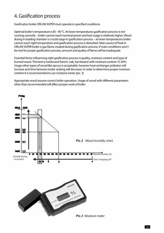
Essential factor influencing right gasification process is quality, moisture content and type of burned wood. The best is hardwood (beech, oak, harnbeam) with moisture content 15-20%. Usage other types of wood like spruce is acceptable, however heat exchanger pollution will increase and time between boiler stoking will decrease. In order to determine proper moisture content it is recommended to use moisture meter (pic. 3)
Appropriate wood assures correct boiler operation. Usage of wood with different parameters other than recommended will affect proper work of boiler.
Tree’s chopping off
Opt
imum
hum
idity
Outside drying - in months
Wood humidity [%]
Pic.2 Wood humidity chart.
Pic.3 Moisture meter
8 9
5. Boiler start-upBefore boiler start-up it is advisable to check tightness of screw connections (leakages), level of water in installation and properly set controller’s parameters.
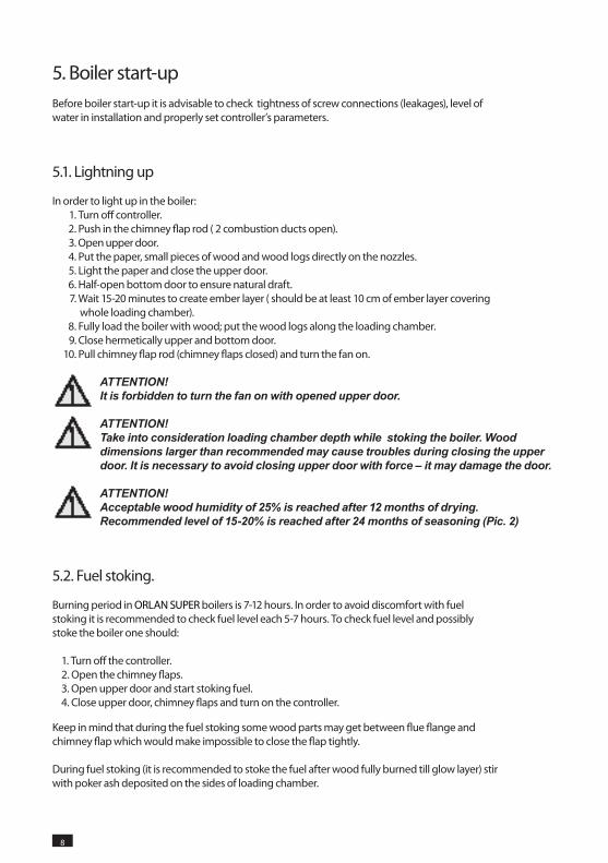
5.1. Lightning up
In order to light up in the boiler: 1. Turn off controller. 2. Push in the chimney flap rod ( 2 combustion ducts open). 3. Open upper door. 4. Put the paper, small pieces of wood and wood logs directly on the nozzles. 5. Light the paper and close the upper door. 6. half-open bottom door to ensure natural draft. 7. Wait 15-20 minutes to create ember layer ( should be at least 10 cm of ember layer covering
whole loading chamber). 8. Fully load the boiler with wood; put the wood logs along the loading chamber. 9. Close hermetically upper and bottom door. 10. Pull chimney flap rod (chimney flaps closed) and turn the fan on.
ATTENTION! It is forbidden to turn the fan on with opened upper door.
ATTENTION! Take into consideration loading chamber depth while stoking the boiler. Wood dimensions larger than recommended may cause troubles during closing the upper door. It is necessary to avoid closing upper door with force – it may damage the door.
ATTENTION! Acceptable wood humidity of 25% is reached after 12 months of drying. Recommended level of 15-20% is reached after 24 months of seasoning (Pic. 2)
5.2. Fuel stoking.
Burning period in ORLAN SUPER boilers is 7-12 hours. In order to avoid discomfort with fuel stoking it is recommended to check fuel level each 5-7 hours. To check fuel level and possibly stoke the boiler one should:
1. Turn off the controller.2. Open the chimney flaps.3. Open upper door and start stoking fuel.4. Close upper door, chimney flaps and turn on the controller.
Keep in mind that during the fuel stoking some wood parts may get between flue flange and chimney flap which would make impossible to close the flap tightly.
During fuel stoking (it is recommended to stoke the fuel after wood fully burned till glow layer) stir with poker ash deposited on the sides of loading chamber.
8 9
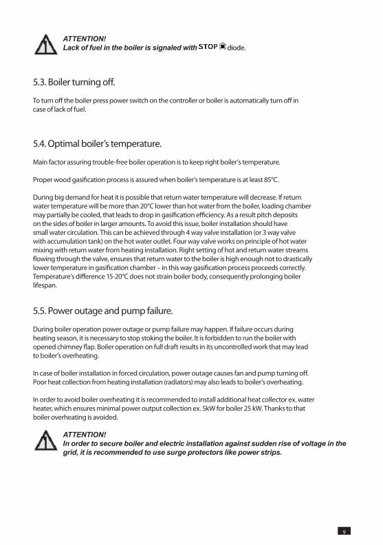
ATTENTION! Lack of fuel in the boiler is signaled with diode.
5.3. Boiler turning off.
To turn off the boiler press power switch on the controller or boiler is automatically turn off in case of lack of fuel.
5.4. Optimal boiler’s temperature.
Main factor assuring trouble-free boiler operation is to keep right boiler’s temperature.
Proper wood gasification process is assured when boiler’s temperature is at least 85°C.
During big demand for heat it is possible that return water temperature will decrease. If return water temperature will be more than 20°C lower than hot water from the boiler, loading chamber may partially be cooled, that leads to drop in gasification efficiency. As a result pitch deposits on the sides of boiler in larger amounts. To avoid this issue, boiler installation should have small water circulation. This can be achieved through 4 way valve installation (or 3 way valve with accumulation tank) on the hot water outlet. Four way valve works on principle of hot water mixing with return water from heating installation. Right setting of hot and return water streams flowing through the valve, ensures that return water to the boiler is high enough not to drastically lower temperature in gasification chamber – in this way gasification process proceeds correctly. Temperature’s difference 15-20°C does not strain boiler body, consequently prolonging boiler lifespan.
5.5. Power outage and pump failure.
During boiler operation power outage or pump failure may happen. If failure occurs during heating season, it is necessary to stop stoking the boiler. It is forbidden to run the boiler with opened chimney flap. Boiler operation on full draft results in its uncontrolled work that may lead to boiler’s overheating.
In case of boiler installation in forced circulation, power outage causes fan and pump turning off. Poor heat collection from heating installation (radiators) may also leads to boiler’s overheating.
In order to avoid boiler overheating it is recommended to install additional heat collector ex. water heater, which ensures minimal power output collection ex. 5kW for boiler 25 kW. Thanks to that boiler overheating is avoided.
ATTENTION! In order to secure boiler and electric installation against sudden rise of voltage in the grid, it is recommended to use surge protectors like power strips.
10 11
6. Maintenance6.1. Boiler maintenance.
Boiler needs to be serviced for idle time ( summer season, absence of user).
Sides of loading, ash chamber, chimney flap and heat exchanger needs to be cleaned regularly (it is advisable to burn softwood like spruce to remove pitch before summer season). After burning softwood leave the boiler open – in this way damp is not condensing on the sides of boiler.
ATTENTION! It is advisable to control the boiler annually in order to prepare it well for the next heating season.
6.2. Boiler cleaning
Ash created during wood burning falls down through the nozzle to ash chamber, that’s why it is advisable to remove the ash from bottom chamber. Each time before lightning up the boiler it is recommended to clean loading chamber. Ash needs to be removed through the nozzle. Use the tools supplied with the boiler.
Pitch is created during gasification process. Amount of created pitch depends on wood type, humidity and water temperature coming out and into the boiler. It is recommended to clean loading chamber at least once a month.
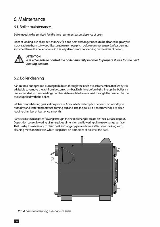
Particles in exhaust gases flowing through the heat exchanger create on their surface deposit. Deposition causes lowering of inner pipes dimension and lowering of heat exchange surface. That is why it is necessary to clean heat exchanger pipes each time after boiler stoking with cleaning mechanism levers which are placed on both sides of boiler at the back.
Pic.4 View on cleaning mechanism lever.
10 11
ATTENTION! It is necessary to use cleaning mechanism levers that are positioned on both sides of boiler each time after stoking the boiler, otherwise pitch may clogged turbulators that affects boiler efficiency and boiler lifespan.
ATTENTION! To avoid accumulation of ash in bottom chamber especially at the back side below heat exchanger pipes, it is necessary to remove the ash with boiler tools.
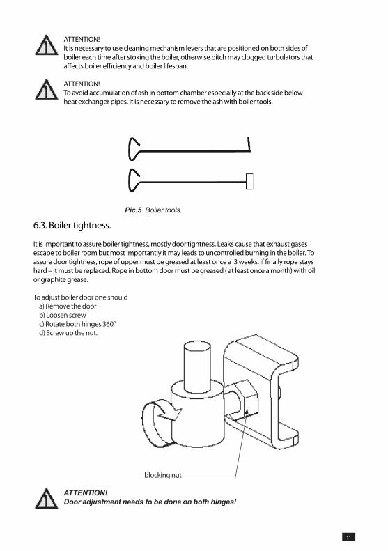
Pic.5 Boiler tools.
6.3. Boiler tightness.
It is important to assure boiler tightness, mostly door tightness. Leaks cause that exhaust gases escape to boiler room but most importantly it may leads to uncontrolled burning in the boiler. To assure door tightness, rope of upper must be greased at least once a 3 weeks, if finally rope stays hard – it must be replaced. Rope in bottom door must be greased ( at least once a month) with oil or graphite grease.
To adjust boiler door one shoulda) Remove the doorb) Loosen screwc) Rotate both hinges 360° d) Screw up the nut.
ATTENTION! Door adjustment needs to be done on both hinges!
blocking nut
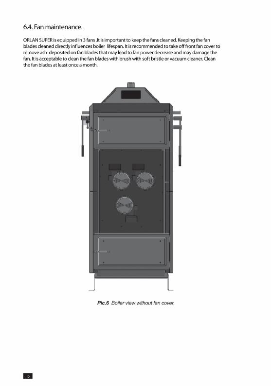
6.4. Fan maintenance.
ORLAN SUPER is equipped in 3 fans .It is important to keep the fans cleaned. Keeping the fan blades cleaned directly influences boiler lifespan. It is recommended to take off front fan cover to remove ash deposited on fan blades that may lead to fan power decrease and may damage the fan. It is acceptable to clean the fan blades with brush with soft bristle or vacuum cleaner. Clean the fan blades at least once a month.
Pic.6 Boiler view without fan cover.
12 13
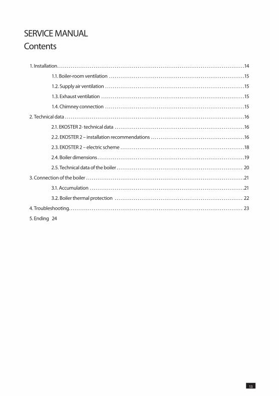
SERVICE MANUALContents
1. Installation. . . . . . . . . . . . . . . . . . . . . . . . . . . . . . . . . . . . . . . . . . . . . . . . . . . . . . . . . . . . . . . . . . . . . . . . . . . . . . . . . . . . . . . . . . . . . . . . . .14
1.1. Boiler-room ventilation . . . . . . . . . . . . . . . . . . . . . . . . . . . . . . . . . . . . . . . . . . . . . . . . . . . . . . . . . . . . . . . . . . . . . . .15
1.2. Supply air ventilation . . . . . . . . . . . . . . . . . . . . . . . . . . . . . . . . . . . . . . . . . . . . . . . . . . . . . . . . . . . . . . . . . . . . . . . . .15
1.3. Exhaust ventilation . . . . . . . . . . . . . . . . . . . . . . . . . . . . . . . . . . . . . . . . . . . . . . . . . . . . . . . . . . . . . . . . . . . . . . . . . . .15
1.4. Chimney connection . . . . . . . . . . . . . . . . . . . . . . . . . . . . . . . . . . . . . . . . . . . . . . . . . . . . . . . . . . . . . . . . . . . . . . . . .15
2. Technical data . . . . . . . . . . . . . . . . . . . . . . . . . . . . . . . . . . . . . . . . . . . . . . . . . . . . . . . . . . . . . . . . . . . . . . . . . . . . . . . . . . . . . . . . . . . . . .16
2.1. EKOSTER 2- technical data . . . . . . . . . . . . . . . . . . . . . . . . . . . . . . . . . . . . . . . . . . . . . . . . . . . . . . . . . . . . . . . . . . . .16
2.2. EKOSTER 2 – installation recommendations . . . . . . . . . . . . . . . . . . . . . . . . . . . . . . . . . . . . . . . . . . . . . . . . .16
2.3. EKOSTER 2 – electric scheme . . . . . . . . . . . . . . . . . . . . . . . . . . . . . . . . . . . . . . . . . . . . . . . . . . . . . . . . . . . . . . . . .18
2.4. Boiler dimensions . . . . . . . . . . . . . . . . . . . . . . . . . . . . . . . . . . . . . . . . . . . . . . . . . . . . . . . . . . . . . . . . . . . . . . . . . . . . .19
2.5. Technical data of the boiler . . . . . . . . . . . . . . . . . . . . . . . . . . . . . . . . . . . . . . . . . . . . . . . . . . . . . . . . . . . . . . . . . . 20
3. Connection of the boiler . . . . . . . . . . . . . . . . . . . . . . . . . . . . . . . . . . . . . . . . . . . . . . . . . . . . . . . . . . . . . . . . . . . . . . . . . . . . . . . . . . .21
3.1. Accumulation . . . . . . . . . . . . . . . . . . . . . . . . . . . . . . . . . . . . . . . . . . . . . . . . . . . . . . . . . . . . . . . . . . . . . . . . . . . . . . . . .21
3.2. Boiler thermal protection . . . . . . . . . . . . . . . . . . . . . . . . . . . . . . . . . . . . . . . . . . . . . . . . . . . . . . . . . . . . . . . . . . . 22
4. Troubleshooting. . . . . . . . . . . . . . . . . . . . . . . . . . . . . . . . . . . . . . . . . . . . . . . . . . . . . . . . . . . . . . . . . . . . . . . . . . . . . . . . . . . . . . . . . . . 23
5. Ending 24
12 13
14 15
1. InstallationBoiler should be installed according to binding rules and norms. The requirements of norm PN 87/B 02411 according building of solid fuel boiler room, norm PN 91/B 02413 according open system boilers’ production and norm PN-B-02414:1999 according to safety appliances in pressurized systems should be taken into account.
These norms and rules should be followed, however, caution is required as national rules in countries to which the product is sold may replace above mentioned norms.
In case of boiler assembly outside the producer's country, rules and norms should be followed according to solid fuel boiler assembly in countries in which the boiler is sold.
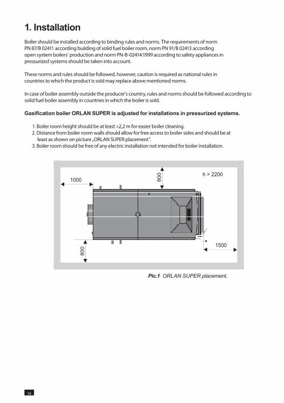
Gasification boiler ORLAN SUPER is adjusted for installations in pressurized systems.
1. Boiler room height should be at least >2,2 m for easier boiler cleaning. 2. Distance from boiler room walls should allow for free access to boiler sides and should be at
least as shown on picture „ORLAN SUPER placement”. 3. Boiler room should be free of any electric installation not intended for boiler installation.
Pic.1 ORLAN SUPER placement.
14 15
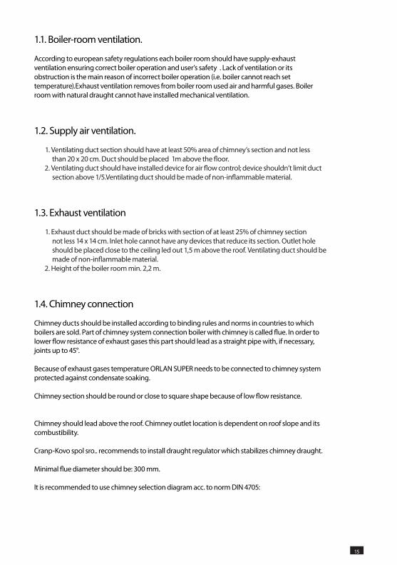
1.1. Boiler-room ventilation.
According to european safety regulations each boiler room should have supply-exhaust ventilation ensuring correct boiler operation and user’s safety . Lack of ventilation or its obstruction is the main reason of incorrect boiler operation (i.e. boiler cannot reach set temperature).Exhaust ventilation removes from boiler room used air and harmful gases. Boiler room with natural draught cannot have installed mechanical ventilation.
1.2. Supply air ventilation.
1. Ventilating duct section should have at least 50% area of chimney’s section and not less than 20 x 20 cm. Duct should be placed 1m above the floor.
2. Ventilating duct should have installed device for air flow control; device shouldn’t limit duct section above 1/5.Ventilating duct should be made of non-inflammable material.
1.3. Exhaust ventilation
1. Exhaust duct should be made of bricks with section of at least 25% of chimney section not less 14 x 14 cm. Inlet hole cannot have any devices that reduce its section. Outlet hole should be placed close to the ceiling led out 1,5 m above the roof. Ventilating duct should be made of non-inflammable material.
2. height of the boiler room min. 2,2 m.
1.4. Chimney connection
Chimney ducts should be installed according to binding rules and norms in countries to which boilers are sold. Part of chimney system connection boiler with chimney is called flue. In order to lower flow resistance of exhaust gases this part should lead as a straight pipe with, if necessary, joints up to 45°.
Because of exhaust gases temperature ORLAN SUPER needs to be connected to chimney system protected against condensate soaking.
Chimney section should be round or close to square shape because of low flow resistance.
Chimney should lead above the roof. Chimney outlet location is dependent on roof slope and its combustibility.
Cranp-Kovo spol sro.. recommends to install draught regulator which stabilizes chimney draught.
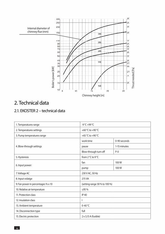
Minimal flue diameter should be: 300 mm.
It is recommended to use chimney selection diagram acc. to norm DIN 4705:
1. Temperatures range -9 °C +99 °C
2. Temperatures settings +60 °C to +90 °C
3. Pump temperatures range +65 °C to +90 °C
4. Blow-through settings
work time 0-90 seconds
pause 1-15 minutes
Blow-through turn off P-0
5. hysteresis from 2 °C to 9 °C
6. Input power:fan 100 W
pump 100 W
7. Voltage AC 230 V AC, 50 hz
8. Input volatge 275 VA
9. Fan power in percentages % x 10 (setting range 30 % to 100 %)
10. Relative air temperature ≤95 %
11. Protection class IP 40
12. Insulation class I
13. Ambient temperature 0-40 °C
14. Disconnection type full
15. Electric protection 2 x 3,15 A (fusible)
2. Technical data2.1. EKOSTER 2 – technical data
16 17
Boile
r’s p
ower
[kW
]
Internal diameter of chimney flue (mm)
Thru
st n
eede
d [P
a]
Chimney height [m]
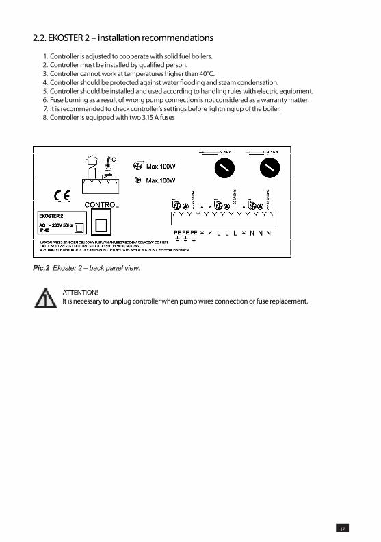
2.2. EKOSTER 2 – installation recommendations
1. Controller is adjusted to cooperate with solid fuel boilers. 2. Controller must be installed by qualified person. 3. Controller cannot work at temperatures higher than 40°C. 4. Controller should be protected against water flooding and steam condensation. 5. Controller should be installed and used according to handling rules with electric equipment. 6. Fuse burning as a result of wrong pump connection is not considered as a warranty matter. 7. It is recommended to check controller’s settings before lightning up of the boiler. 8. Controller is equipped with two 3,15 A fuses
16 17
Pic.2 Ekoster 2 – back panel view.
ATTENTION! It is necessary to unplug controller when pump wires connection or fuse replacement.
18 19
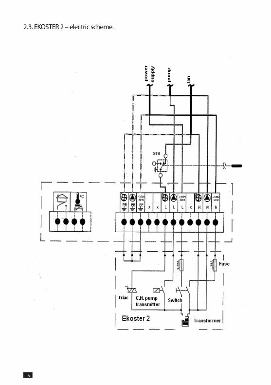
2.3. EKOSTER 2 – electric scheme.
18 19
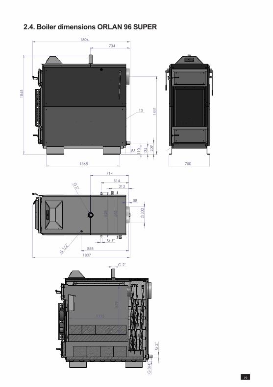
2.4. Boiler dimensions ORLAN 96 SUPER
G2"
G 2"
G3/
4"
1115
879
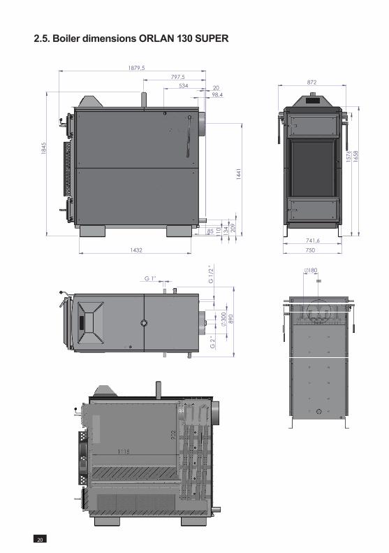
2.5. Boiler dimensions ORLAN 130 SUPER
20 21
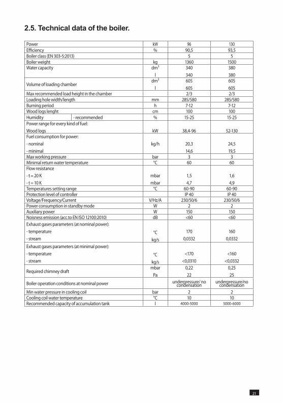
Power kW 96 130Efficiency % 90,5 93,5Boiler class (EN 303-5:2013) 5 5Boiler weight kg 1360 1500Water capacity dm3
l340340
380380
Volume of loading chamberdm3
l605605
605605
Max recommended load height in the chamber 2/3 2/3Loading hole width/length mm 285/580 285/580Burning period h 7-12 7-12Wood logs lenght cm 100 100humidity - recommended % 15-25 15-25Power range for every kind of fuel:Wood logs kW 38,4-96 52-130Fuel consumption for power:- nominal- minimal
kg/h 20,314,6
24,519,5
Max working pressure bar 3 3Minimal return water temperature °C 60 60Flow resistance- t = 20 K- t = 10 K
mbarmbar
1,54,7
1,64,9
Temperatures setting range °C 60-90 60-90Protection level of controller IP 40 IP 40Voltage/Frequency/Current V/Hz/A 230/50/6 230/50/6Power consumption in standby mode W 2 2Auxiliary power W 150 150Noisness emission (acc.to EN ISO 12100:2010) dB <60 <60Exhaust gases parameters (at nominal power):- temperature- stream
°Ckg/s
1700,0332
1600,0332
Exhaust gases parameters (at minimal power):- temperature- stream
°Ckg/s
<170<0,0310
<160<0,0332
Required chimney draftmbar
Pa0,2222
0,2525
Boiler operation conditions at nominal power underpressure/ no condensation
underpressure/no condensation
Min water pressure in cooling coil bar 2 2Cooling coil water temperature °C 10 10Recommended capacity of accumulation tank l 4000-5000 5000-6000
2.5. Technical data of the boiler.
20 21
22 23
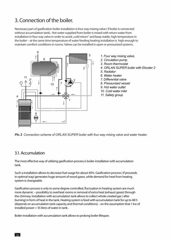
3. Connection of the boiler.Necessary part of gasification boiler installation is four way mixing valve ( if boiler is connected without accumulation tank). Hot water supplied from boiler is mixed with return water from installation in four way valve in order to avoid „cold return” and keep stable, high temperature in the boiler – at the same time temperature of water feeding heating installation is high enough to maintain comfort conditions in rooms. Valves can be installed in open or pressurized systems.
1. Four way mixing valve,2. Circulation pump3. Room thermostat 4. ORLAN SUPER boiler with Ekoster 25. Radiator6. Water heater7. Differential valve8. Pressurized vessel9. Hot water outlet10. Cold water inlet11. Safety group
Pic.3 Connection scheme of ORLAN SUPER boiler with four way mixing valve and water heater.
3.1. Accumulation
The most effective way of utilizing gasification process is boiler installation with accumulation tank.
Such a installation allows to decrease fuel usage for about 40%. Gasification process ( if proceeds in optimal way) generates huge amount of wood gases, while demand for heat from heating system is changeable.
Gasification process is only to some degree controlled, fluctuation in heating system are much more dynamic – possibility to overheat rooms or removal of extra heat (exhaust gases) through the chimney. Installation with accumulation tank allows to collect whole created gas ( after burning) in form of heat in the tank. Heating system is feed with accumulation tank for up to 48 h (depends on accumulation tank capacity and thermal conditions) – on the assumption that 1 kw of installed power = 55 litres of water in tank .
Boiler installation with accumulation tank allows to prolong boiler lifespan.
22 23
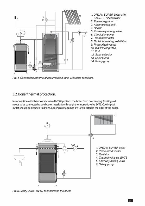
Pic.5 Safety valve - BVTS connection to the boiler.
1. ORLAN SUPER boiler2. Pressurized vessel3. Radiator4. Thermal valve ex. BVTS5. Four way mixing valve6. Safety group
1. ORLAN SUPER boiler with EKOSTER 2 controller
2. Thermoregulator3. Accumulation tank4. Heater5. Three-way mixing valve6. Circulation pump7. Room thermostat8. Outlet for heating installation9. Pressurized vessel10. h.d.w mixing valve11. Coil12. Solar collector13. Solar pump14. Safety group
Pic.4 Connection scheme of accumulation tank with solar collectors.
3.2. Boiler thermal protection.
In connection with thermostatic valve BVTS it protects the boiler from overheating. Cooling coil needs to be connected to cold water installation through thermostatic valve BVTS. Cooling coil outlet should be directed to drains. Cooling coil tappings 3/4'' are located at the sides of the boiler.
24 25
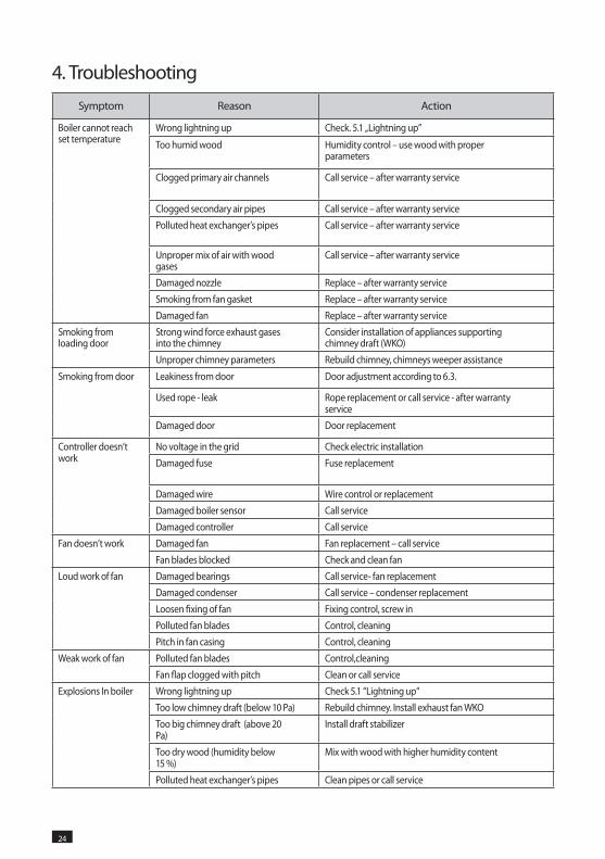
4. Troubleshooting
Symptom Reason Action
Boiler cannot reach set temperature
Wrong lightning up Check. 5.1 „Lightning up”
Too humid wood humidity control – use wood with proper parameters
Clogged primary air channels Call service – after warranty service
Clogged secondary air pipes Call service – after warranty service
Polluted heat exchanger’s pipes Call service – after warranty service
Unproper mix of air with wood gases
Call service – after warranty service
Damaged nozzle Replace – after warranty service
Smoking from fan gasket Replace – after warranty service
Damaged fan Replace – after warranty service
Smoking from loading door
Strong wind force exhaust gases into the chimney
Consider installation of appliances supporting chimney draft (WKO)
Unproper chimney parameters Rebuild chimney, chimneys weeper assistance
Smoking from door Leakiness from door Door adjustment according to 6.3.
Used rope - leak Rope replacement or call service - after warranty service
Damaged door Door replacement
Controller doesn’t work
No voltage in the grid Check electric installation
Damaged fuse Fuse replacement
Damaged wire Wire control or replacement
Damaged boiler sensor Call service
Damaged controller Call service
Fan doesn’t work Damaged fan Fan replacement – call service
Fan blades blocked Check and clean fan
Loud work of fan Damaged bearings Call service- fan replacement
Damaged condenser Call service – condenser replacement
Loosen fixing of fan Fixing control, screw in
Polluted fan blades Control, cleaning
Pitch in fan casing Control, cleaning
Weak work of fan Polluted fan blades Control,cleaning
Fan flap clogged with pitch Clean or call service
Explosions In boiler Wrong lightning up Check 5.1 “Lightning up“
Too low chimney draft (below 10 Pa) Rebuild chimney. Install exhaust fan WKO
Too big chimney draft (above 20 Pa)
Install draft stabilizer
Too dry wood (humidity below 15 %)
Mix with wood with higher humidity content
Polluted heat exchanger’s pipes Clean pipes or call service
24 25
5. Ending
Present appliance is marked according to European Directive 2002/96/EC on waste electrical and electronic equipment.
Symbol placed on the components or attached documents means that appliance is not classified as a household waste.
Scrapping should take place in special collection point in order to reuse electrical and electronic components.

26 27

26 27

CRANP-KOVO s.r.o.
790 70 Javornik, Miru 371CZECh REPUBLICT +420 584 492 808 F +420 584 492 888
www.cranp-kovo.cz