Table of Contents - New Horizon Corp3 Boiler Application Orlan Pellet Boilers are designed to heat...
20
Transcript of Table of Contents - New Horizon Corp3 Boiler Application Orlan Pellet Boilers are designed to heat...


2
Table of Contents
Boiler Application ................................................................................................3Installation ............................................................................................................3Understanding the Controller .............................................................................4Operating the Boiler for the First Time ..............................................................4Controller Menu Hierarchy .................................................................................6Controller Power Connections ...........................................................................7Controller Error Codes ........................................................................................8Wiring Diagram ....................................................................................................8Boiler Dimensions ...............................................................................................9Technical Specifications ...................................................................................10Controller Electrical Data .................................................................................11Motor Electrical Data .........................................................................................11Gear Motor Technical Data ...............................................................................12Ceramic Burner Specifications ........................................................................12Boiler Piping Diagram .......................................................................................13Important Piping Connections .........................................................................13Emergency Overheat Protection ......................................................................14How the Boiler Works .......................................................................................14Preventing Burnback ........................................................................................15Boiler Maintenance ...........................................................................................15Ventilating the Boiler Room ..............................................................................16Chimney Requirements ....................................................................................17Troubleshooting ................................................................................................18Boiler Components Disposal and Recycling ..................................................19
!Warning !There are a number of these Warning Alerts throughout this manual. Be sure that you read, understand and follow each of them.

3
Boiler ApplicationOrlan Pellet Boilers are designed to heat water for pressurized hot water (hydron-ic) heating systems. The boiler must be installed according to all local and national codes and must be equipped with a pressure relief valve and associated piping that complies with current codes. The boiler has a number of safety features built in, including a controller that keeps it operating at the correct temperature by regu-lating the burner with a blower.
The Orlan Pellet Boiler is designed to burn dry wood pellets 1/4 to 1/3 inches in di-ameter and 1/2 to 2 inches in length. The pellet hopper should be filled completely. It is designed to operate automatically and provide long times between burns. Bear in mind that the time between fillings will depend upon the outside tempera-ture and nature of the space being heated.
InstallationYour Orlan Pellet Boiler should be installed by a qualified professional (i.e., heat-ing contractor, plumber or other licensed professional familiar with solid fuel appli-ances). It must be connected to a Class A chimney (stainless steel or ceramic tile) and must not be connected to a chimney serving any other appliance.
Funnel Casing -- ZENON, I’M NOT SURE WHAT THIS IS. I CAN DELETE REF-ERENCE TO IT OR PROVIDE SOME DETAIL IF YOU CAN HELP ME UNDER-STAND IT.
For ease of installation, the chimney flue connector can be removed by unscrew-ing eight nuts on the flue block and removing it from the flange. Be sure to reinstall the gasket on the flange when reassembling it, to maintain a tight seal.
The boiler is shipped with three pieces of firebrick shinkwrapped together in the bottom of the combustion chamber. They should be unwrapped and placed around and over the burner as shown in the diagram below. Specifically, the two long bricks should be placed alongside the burner so that the edges of the bricks touch the walls of the combustion chamber. The remaining brick should be set on top of the other two, directly over the burner.
1. Boiler’s use
Low-temperature pellet boilers produced by Eko-Vimar Orlański company are for water heating in central heating and for combustion of pellet at sizes: diameter- 6 up to 8 mm; length 10 up to 50 mm. Pellet’s container allows for long lasting burning process with no extra loading necessity. The container is to be filled up when adding pellet.
Pellet boiler is to be installed in open pressure vessel system assuring boiler’s working in nominal working pressure.
The boiler is equipped with a controller enabling boiler’s working at right temperature’s range and it secures the boiler against its overheating thanks to burner’s exhaust fan switching on.
2. Instalation
Boilers should be installed accordingly to current norms and regulations by suitably qualified staff. First burning up can be made by Fabrical Service or Authorized Service only.
The PN/87/B 02411 Norm according solid fuel boilers look and the PN 91/B 02413 Norm telling about open-system solid fuel boilers’ assembling should be taken into account. The EKO-VIMAR ORLAŃSKI prescribes use of funnel casing which secures against wood tar permeating via the chimney walls; the company do not take responsibility for its disregarding and what follows for harms that it may cause.
In case of difficulties when boiler relocating, there is an option of chimney flue block disassembly. In the case unscrew nuts (8xM8) and take it out of flue block’s flange. When reassembly remember of a sealing rope on the flue block’s flange which secures against fumes getting out.
At the bottom of Orlan Pellet combustion chamber there are three chamotte bricks wrapped in “stretch” wrapping which after boiler installation are to be placed in a burner as it follows: two oblong bricks are to be placed along the burner edges, they should touch combustion chamber walls; the third-larger brick should be placed on the top of the two ones
Palnik
3
Burner
Bricks
bricks’ placement in a burner

4
Understanding the Controller3.2. Description of a regulator
1 - fan2 - feeder no13 - feeder no24 - circulating pump5 - domestic water pump6 - heater7,8 - distress diode ( fuel shortage, damage of a sensor, set parameters exceeding)
Buttons
Buttons are for menu issues and setting changes. Diodes 1-6 are to inform about some ap-pliances’ connecting ( feeders, heaters and pumps).Diodes 7 and 8 give alarms ( fuel shortage, damage of a sensor, established parameters’ exceeding).
ORLAN PELLET regulator controls with a boiler by fuel automatic loadingand burning up system. The controller’s functions are:
- burning up- keeping the temperature needed in a boiler- boiler overheating protection- protection against the self-burning-up of a fuel in the container- controlling with a circulation pump- controlling with a domestic water pump- fi re keeping- protection against to high fumes’ temperature
3.1. Burning up
1. Fill In the container with pellet and close the cover tight. 2. Connect the plug with a connector at 230V/50Hz , then connect the controller with a network switch.
WARNING!Connection socket should be secured with the 4A fuseand anti-shock switch (max power 20 mA )
Buttonsand setting changes.
, +,-, Buttonsand setting changes.
4
Guide to the Controls
1. Fan2. Auger #13. Auger #24. Circulator pump5. Domestic water
pump6. Burner7. & 8. Warnings
(fuel shortage, sensor damage, overheating, etc.
3.2. Description of a regulator
1 - fan2 - feeder no13 - feeder no24 - circulating pump5 - domestic water pump6 - heater7,8 - distress diode ( fuel shortage, damage of a sensor, set parameters exceeding)
Buttons
Buttons are for menu issues and setting changes. Diodes 1-6 are to inform about some ap-pliances’ connecting ( feeders, heaters and pumps).Diodes 7 and 8 give alarms ( fuel shortage, damage of a sensor, established parameters’ exceeding).
ORLAN PELLET regulator controls with a boiler by fuel automatic loadingand burning up system. The controller’s functions are:
- burning up- keeping the temperature needed in a boiler- boiler overheating protection- protection against the self-burning-up of a fuel in the container- controlling with a circulation pump- controlling with a domestic water pump- fi re keeping- protection against to high fumes’ temperature
3.1. Burning up
1. Fill In the container with pellet and close the cover tight. 2. Connect the plug with a connector at 230V/50Hz , then connect the controller with a network switch.
WARNING!Connection socket should be secured with the 4A fuseand anti-shock switch (max power 20 mA )
Buttonsand setting changes.
, +,-, Buttonsand setting changes.
4
The push-button controls depicted in the diagram above and reproduced below allow you to access the controller menu and for making adjustments or changes to the settings.
The light-emitting diode lights (numbers 1-8) are the system status indicators, as described in the box to the left.
!Warning !The controller should be protected with a 4A fuse and circuit breaker (max voltage of 20 mA).
The controller regulates the automatic fuel loading and combustion systems. Its functions are as follows:• Combustion• Maintaining boiler temperature• Overheat protection• Fuel burn-back protection• Circulator pump control• Domestic water pump control• Exhaust temperature control
Operating the Boiler for the First Time1. Fill the hopper with pellets and close the cover tightly.
2. Connect the controller to a 120V/60Hz circuit either by plugging it into a dedi-cated outlet or wiring it directly into the circuit.

5
!Warning !The controller must be connected to a dedicated circuit with no other appliances connected to it.
When the controller is powered up, the display panel will show the following information:
12:23Mon
Temp: 25Start
CURRENT TIME
DAY
BOILER WATER TEMP
TEMP SETTING
3. After loading the fuel and turning on the controller, push the button for five seconds or more. The display will show the START function, which indicates that the augers are delivering fuel to the starter. This process can take any-where from 1 to 20 minutes. When the boiler is ready to begin burning the fuel, the display will show the letters “GRZ,” indicating that the fuel has been ignited.
4. When the flue exhaust temperature reaches the setpoint, the controller will be-gin circulating water through the heating system and maintain the set tempera-ture as long as there is fuel in the hopper.
5. If it becomes necessar to shut the boiler down, press the button again and hold it for at least five secones. The display will indicate that the boiler is shutting down and no more fuel will be augered into the burner.
3.2. Description of a regulator
1 - fan2 - feeder no13 - feeder no24 - circulating pump5 - domestic water pump6 - heater7,8 - distress diode ( fuel shortage, damage of a sensor, set parameters exceeding)
Buttons
Buttons are for menu issues and setting changes. Diodes 1-6 are to inform about some ap-pliances’ connecting ( feeders, heaters and pumps).Diodes 7 and 8 give alarms ( fuel shortage, damage of a sensor, established parameters’ exceeding).
ORLAN PELLET regulator controls with a boiler by fuel automatic loadingand burning up system. The controller’s functions are:
- burning up- keeping the temperature needed in a boiler- boiler overheating protection- protection against the self-burning-up of a fuel in the container- controlling with a circulation pump- controlling with a domestic water pump- fi re keeping- protection against to high fumes’ temperature
3.1. Burning up
1. Fill In the container with pellet and close the cover tight. 2. Connect the plug with a connector at 230V/50Hz , then connect the controller with a network switch.
WARNING!Connection socket should be secured with the 4A fuseand anti-shock switch (max power 20 mA )
Buttonsand setting changes.
, +,-, Buttonsand setting changes.
4
!Warning !The controller will shut the burner down if the water temperature in the boiler exceeds 90 degrees centigrade (194 degrees fahr-enheit). When this happens, you must determine the cause and fix the problem. To restart the controller, it must be reset. Do this by switching the controller off, then turn it on while depressing all four function buttons at the same time.
Use the button to access the controller menu.
Press the button to turn the fan on and off.
The button turns the feed augers on and off.
Menu levels are navigated by pressing the button.
3.2. Description of a regulator
1 - fan2 - feeder no13 - feeder no24 - circulating pump5 - domestic water pump6 - heater7,8 - distress diode ( fuel shortage, damage of a sensor, set parameters exceeding)
Buttons
Buttons are for menu issues and setting changes. Diodes 1-6 are to inform about some ap-pliances’ connecting ( feeders, heaters and pumps).Diodes 7 and 8 give alarms ( fuel shortage, damage of a sensor, established parameters’ exceeding).
ORLAN PELLET regulator controls with a boiler by fuel automatic loadingand burning up system. The controller’s functions are:
- burning up- keeping the temperature needed in a boiler- boiler overheating protection- protection against the self-burning-up of a fuel in the container- controlling with a circulation pump- controlling with a domestic water pump- fi re keeping- protection against to high fumes’ temperature
3.1. Burning up
1. Fill In the container with pellet and close the cover tight. 2. Connect the plug with a connector at 230V/50Hz , then connect the controller with a network switch.
WARNING!Connection socket should be secured with the 4A fuseand anti-shock switch (max power 20 mA )
Buttonsand setting changes.
, +,-, Buttonsand setting changes.
4
6
Once the menu is accessed, choices can be made, depending on what you are trying to accomplish. The options are explained below. Their hierarchical position on the menu structure is shown in the diagram below.
<service menu> For service personnel only.<digital clock> Sets the hour and date.<language> Use to select “English” as the default language.<warm water> Sets the domestic hot water parameters (when installed).<fan> Sets the fan parameters.<sustaining parameters> Sets operational defaults, including fan.<feeding time> Auger control settings.<temperatures> Sets temperature sensors.
If you make a change that you don’t want to keep, simply do nothing further for one minute and the controller will return to the previous setting.
When setting the boiler temperature settings, use the and buttons to make the change.
3.2. Description of a regulator
1 - fan2 - feeder no13 - feeder no24 - circulating pump5 - domestic water pump6 - heater7,8 - distress diode ( fuel shortage, damage of a sensor, set parameters exceeding)
Buttons
Buttons are for menu issues and setting changes. Diodes 1-6 are to inform about some ap-pliances’ connecting ( feeders, heaters and pumps).Diodes 7 and 8 give alarms ( fuel shortage, damage of a sensor, established parameters’ exceeding).
ORLAN PELLET regulator controls with a boiler by fuel automatic loadingand burning up system. The controller’s functions are:
- burning up- keeping the temperature needed in a boiler- boiler overheating protection- protection against the self-burning-up of a fuel in the container- controlling with a circulation pump- controlling with a domestic water pump- fi re keeping- protection against to high fumes’ temperature
3.1. Burning up
1. Fill In the container with pellet and close the cover tight. 2. Connect the plug with a connector at 230V/50Hz , then connect the controller with a network switch.
WARNING!Connection socket should be secured with the 4A fuseand anti-shock switch (max power 20 mA )
Buttonsand setting changes.
, +,-, Buttonsand setting changes.
4
<service m
enu> only for a trade service!
<digital clock>
this function enables for hour and a week day setting
<language>
enables for language choosing<
warm
water>
function possible when H
UW
module purchasing
<fan>
it possibles controlling of the fan’s power
<sustaining param
eters> w
orking time and stopover setting in sustaining m
ode and hysterezis of a fan.
<feeding tim
e>w
orking time and stopover of feeders w
hen heating<
temperatures>
it possibles previews of tem
peratures on sensors
If we put changes that w
e do nit want to keep- w
e should just do nothing for another 1 m
inute and previous settings will rem
ain.Boiler’s tem
perature changes:W
hen working w
ith the buttons “+” and “-“ w
e change the temperature settings.
4. Controller’s m
enu description
6
Hold Up ParamHysteresis: 05 o
BlowerWork < min >:02
LoaderPause < min >:10
LoaderWork < min >:10< Hold Up Param. >
< Blower >
< Heat water >
< Language >
< Clock >
< Service MENU >
Mon 13:44
Polish
Heat WaterTurn On: No
Heat WaterTemperat. : 50 o
BlowerModulation : No
BlowerMax. power: 100 %
<Load time >Load TimePause < sek >:10
Load timePause< sek >:10
< Temperatures >HW: 38 LD: 46Flumes : 80
o o
o
< Manual > < - >Blower<+> Loader
12:45 Temp: 25 Mon STOP
o
Controller Menu Hierarchy

7
Controller Power Connections
There are 34 electrical connections located at the back of the controller that power various boiler components, as indicated in the table below:
1 power PE2 power N3 power L4 auger 2 PE5 auger 2 N6 auger 2 L7 auger 1 PE8 auger 1 N9 auger 1 L10 DHW pump PE11 DHW pump N12 DHW pump L13 system pump PE
14 system pump N15 system pump L16 burner PE17 burner N18 burner L19 fan PE20 fan N21 fan L24-25 cramp25-26 cramp27-28 exhaust temp sensor31-32 DHW temp sensor33-34 boiler temp sensor
5. Description of a regulator connection
Connection description:Looking from the backside:
1 - power2 - power3 - power4 - feeder 25 - feeder 26 - feeder 27 - feeder 18 - feeder 19 - feeder 110 - HUW pump11 - HUW pump12 - HUW pump
13 - pump14 - pump15 - pump16 - heater17 - heater18 - heater19 - fan20 - fan21 - fan
23-24 - cramp25-26 - cramp27-28 - fumes’ temperature sensor (Pt 1000)29-30 - fedder temerature sensor (KTY-81-210)31-32 - HUW temperature sensor (KTY 81-210)33-34 - boiler temperature sensor (KTY 81-210)
PENLPENLPENLPENL
PENLPENLPENL
Error: 01 - boiler’s temperature sensor breakdownError: 02 - feeder’s temperature sensor breakdownError: 03 - fumes’ temperature sensor breakdownError: 04 - domestic water temperature sensor breakdownError: 05 - outlet breakdown( shorting of the transmitter’s controller)Error: 06 - outlet breakdown ( no po-wer behind the transmitter’s controller)Error: 07 - power shortage at thefan’s outletError: 08 - power shortage at thepump’ s outletError: 09 - power shortage at the domestic water pump’s outletError: 10 - power shortage atthe feeder no 1 outletError: 11 - power shortage atthe feeder no 2 outletError: 12 - power shortage at the heater outletError: 13 - boiler’s permissive temperature exceedError: 14 - feeder’s permissive temperature exceedError: 15 - fumes’ permissible temperature exceed
Kody błędów
The controller is set with two 10 A fuses.Fuses’ sockets are at theright back side of a controller under the main switch ( look the picture)
fi g. 12x10A
7
5.1. Connection of a regulator:
8
Power supply
Feeder nr 2
Feeder nr 1
Central Heating Pump
Heater
Blower fan
pt 1000 fumes temperature sensorFeeder temperaturesensor
Hot water sensor
Boiler temperaturesensor
Cramp
Cramp
Room thermostat
Domestic Water Pumppower switch
2-10A fuses
120V Power Supply
Auger #2
Auger #1
Domestic Water (DHW)PumpMain System Pump
Burner
Blower Fan
CrampCrampExhaust Temp SensorAuger Temp SensorDHW SensorBoiler Temp Sensor
Room Thermostat

8
Controller Error CodesThe Orlan Pellet Boiler controller has a total of 15 error codes that display when a problem is detected. They are explained in the following list:
Error: 01 Boiler temp sensor failureError: 02 Auger temp sensor failureError: 03 Exhaust temp sensor failureError: 04 Domestic hot water (DHW) temp sensor failureError: 05 Controller short circuitError: 06 No power to controllerError: 07 No power to blower fanError: 08 No power to main system pumpError: 09 No power to DHW pumpError: 10 No power to auger #1Error: 11 No power to auger #2Error: 12 No power to burnerError: 13 Boiler overheatingError: 14 Auger overheatingError: 15 Exhaust maximum temp exceeded
7. .Electric scheme of O
rlan Pellet boiler
13
Wiring Diagram
120 V
MainPump
Blower
DHWPump
Burner
Auger #1
Auger #2
boilertemp
sensor
DHWtemp
sensor
augertemp
sensor
exhausttemp
sensor

9
Boiler Dimensions
6. Technical data.
6.1. Boiler dimension
9
44.09”
44.69”
11.81”
12.60”
28.11”35.83”
22.83”
7.09
”50
.00”
56.4
6”
13.58”
6.30
”
40.3
5”9.
06”
10
Technical Specifications
No Description Units Value
1. Power kW/KBtu-hr 30/100
2. Power range kW/KBtu-hr 8-30/ 27.3-100
3. Boiler classwg. EN303-5
3
4. Boiler efficiency % 925. Fuel type: pellet
Length diameter moisture content
in.in.%
.39-2.00.24-.31
8-126. Fuel consumption at power:
nominal minimal
Lb/hr 7.52.5
7. Space to be heated Sq. ft. 3,200
8. Max working pressure psi 30
9. Max water temperature °F 195
10. Min return temperature °F 140
11. Smoke exhaust diameter in 6.3
12. Chimney flue size in. of H2O .04-.0813. Exhaust temp under normal operation
nominal minimal
°F 320265
14. Chimney draft under normal operation nominal minimal
kg/s 0.020.01
15. Boiler weight lbs 660
16. Boiler water capacity gallons 15.85
17. Hopper capacity gallons 35.5
18. Combustion slot size; width/length In. 10.25/17.0
19. Cold water temperature heat exchanger °F 50
20. Normal operating pressure psi 30
21. Cooling water minimal pressure psi 30
22. Voltage/Frequency V/Hz 120/60
23. Additional power W 250
24. Recommended size of hot water storage tank gallons 40025. Hydraulic resistance of a boiler mbar �T=20K
mbar �T=10K 4
17

11
Controller Technical DataNo Description Units Value
1. Temperature regulation range °F 140-350
2. Water temperature measurement range °F 16-250
3. Exhaust temperature measurement range °F 32-430
4. Information Display Large, readable, alfa-numeric LCD readout
5. Burner regulator duration min. 1-60
6. Demister regulation Smooth (possibility of service mode turning off)
7. Fumes’ temperature control Exhaust temp control sensor allows for more economic and safer operation.
8. Room temp operating range °F 32-120
9. Power outage protection
During a power outage, the controller will retain the clock and memory settings for 50 minutes.
Motor Electrical DataDescription Value
1. Type Commutator motor with a gear 2. Voltage 120VAC 60 Hz 3. Number of fields 2P
4.No charge engine characteristics
CurrentInitial power Rotation velocity Voltage
0.65 A +/- 15% 72W +/- 15% 5.4 rotation/min +- 10% 161V MAX
5.1. Limit load 33 Nm MIN.
5.
Loading characteristic - 1 min after the motor starts working
5.2. Acceptable load 25 Nm MlN.
5.3. Start loading 20 Nm MIN.
6. Max power 1.2 A MAX.
7. Dialectic stamina A motor takes 1500V RMS voltage in 1 minute time (1800V RMS by 1 sec) measured between motor’s coil and its core. (trial current 3 mA)
8. Insulation constant 100 M� min at 500V constant equivalent measured between a coil and casing.
9. Thermal protection Thermally protected motor ( up to 250 degrees F.)
10. Insulation category Category “E”

12
Gear Motor Mechanical DataDescription Value
1. Lubrication Mineral oil and grease
2. Volume 25 dB MAX.
3. Weight 4.85 lb.
4. Driveshaft orientation horizontal
5. Ratio 1:532
6. Bearings ball bearings
Ceramic Burner SpecificationsDescription Value
1. Type GLO 120 - 400
2. Input voltage range Compatible with 230/120 A adapter
3. Current 3.3-4.2 A 120 VAC
4. Power 400-500W for one burner. 800W serial combination of two burners.
6. Burner temp 2,200°F
9. Heating time >12s up to 2,200°F
10. Burner construction recrystallizary ceramic Si3N4
11. Safety rules CSA
13
8. Boiler’s hydraulic connections8.1. Connection scheme
Return from installation– DN 50
Installation’s power – DN 50 Cooling coil terminal – 2× DN 20
Ferrule – DN 15
1. Boiler with a pellet container 2. Boiler pump3. Feeder distributor4. Three-way mixing valve5. Circulating pump6. Differential valve7. Return distributor8. Heater9. H.U.W loading pump10.H.U.W container11.H.U.W outlet12. Cold water inlet
Connection scheme
14
8.2. Description of hydraulic elements connecting
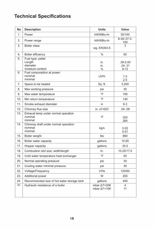
Boiler Piping Diagram
1. Boiler with hopper2. Main system pump3. Supply water distributor4. Three-way mixing valve5. Circulating pump6. Differential valve
7. Return water distributor8. Burner9. DHW loading pump10. DHW tank11. DHW outlet12. Cold water inlet
Important Piping Connections
8. Boiler’s hydraulic connections8.1. Connection scheme
Return from installation– DN 50
Installation’s power – DN 50 Cooling coil terminal – 2× DN 20
Ferrule – DN 15
1. Boiler with a pellet container 2. Boiler pump3. Feeder distributor4. Three-way mixing valve5. Circulating pump6. Differential valve7. Return distributor8. Heater9. H.U.W loading pump10.H.U.W container11.H.U.W outlet12. Cold water inlet
Connection scheme
14
8.2. Description of hydraulic elements connecting

14
Emergency Overheat Protection8.3. Securing coil
In connection with thermostatic cooling valve its function is thermal- overheating protection of a boiler. We connect the coil to cold water installation through thermostatic valve (ex. STS 2WATTS ). Outlet of a coil is to be directed to a drain.
1. Pellet container2. Motoreducer of a feeder no13. Motoreducer of a feeder no24. Feeder no15. Feeder no26. Exhaust fan7. Burner8. Heater
9. Loading system
Loading scheme
1
2
3
4
6 7
5 8
15
STS 20
8.3. Securing coil
In connection with thermostatic cooling valve its function is thermal- overheating protection of a boiler. We connect the coil to cold water installation through thermostatic valve (ex. STS 2WATTS ). Outlet of a coil is to be directed to a drain.
1. Pellet container2. Motoreducer of a feeder no13. Motoreducer of a feeder no24. Feeder no15. Feeder no26. Exhaust fan7. Burner8. Heater
9. Loading system
Loading scheme
1
2
3
4
6 7
5 8
15
STS 20
How the Boiler Works
A cooling coil inside the pressure vessel may be connected to a domestic water supply to provide cooling action in the event that the boiler overheats. The water in the coil never mixes with regular boiler water. After passing through the coil, the water exits into a common drain.
1. Pellet hopper2. Auger #1 motor reducer3. Auger #2 motor reducer4. Auger #15. Auger #26. Exhaust fan7. Burner8. Heater

15
Preventing BurnbackWithout adequate protection, it may be possible under certain circumstances for the fire to burn back from the burner and into the pellet hopper. This is prevented in the Orlan Pellet Boiler by a thermostat in the auger pipe which turns the boiler off when the temperature exceeds 200 degrees F. The controller also sounds an alarm when that temperature is detected.
!Warning !The controller must be reset after an overheat condition is detected and the alarm sounds. It is critical that the cause of the problem be identified and fixed before restarting the boiler.
The Orlan Pellet Boiler’s dual-auger feeding system is also designed to prevent fire from entering the pellet hopper by burning back up through the auger tube. This is accomplished by connecting both augers to a chute pipe in such a way that burnback is prevented. Essentially, the vertical chute is always empty, thus preventing a path for the fire to follow.
Boiler MaintenanceAshes produced by burning the pellets fall down into the bottom of the combus-tion chamber and should be cleaned out once a month. Use the tools provided with the boiler. They include a scraping device and a cleaning shield. At the same time (once monthly) it is also a good idea to clean out the heat exchanger tubes with the cleaning shield.
To clean the heat exchanger tubes:
1. Open the top door of the boiler.2. Unscrew the two nuts with a 13 mm wrench. These nuts hold the plate that
seals the heat exchanger tubes.3. Pull the turbulators out of the heat exchange tubes and scrape the tubes clean
with the cleaning shield, allowing the soot, ash and other debris to fall down into the bottom of the combustion chamber.
4. Scrub the turbulators clean with a wire brush.5. Put the turbulators back into the tubes and bolt the plate back into place.
10. Protection against flame getting into the container
10.1. Acceptable fuel temperature excees in the feeder.Controller is equipped with safety thermostat which turns the boiler off when it excees the fuel’s acceptable temperature. It measures the feeder’s pipe. The controller alarms and in the same time turns off the boiler when the temperature excees 95°C.
10.2. Fuel loading outage Pellet feeding system is constructed in the way as to let the flames to get into container. Two feeders joined with a chute pipe ensure safe pellet’s feeding.
Boiler regulator ensures right operating of the both feeders. The feeders co-operate together in the way that the vertical spilling pipe sector is always empty and that assures stopping of pellet’s feeding continuity
NOTICE!!!Standby resetting is manual by pressing the button at safety thermostat.Before standby resetting it’s necessary to find the overheating reason andto get rid of it.
11. Maintenence of a boiler
Ash coming from pellet burning goes down the combustion chamber. What follows it should be taken out once a month. For this adequate cleaning devices should be used – they go together with boiler’s accessory; these are scraping device and cleaning shield. It’s also advisable to clean heat exchanger pipes with a ceaning shield once a month.
To clean the heat exchanger you should:
1. Open top door of a boiler2. Unscrew two nuts with M13 wrench ( they secure heat exchanger’s flap behind of which there are heat exchanger’s pipes together with economizers). 3. After the economizers’ taking out every of the smoke tubes should be cleaned with a clearing shield, economizers should be cleaned with a scrubbing brush.4. Place the economizers back in the smoke tubes.
16
EkonomizerTurbulator
The turbulators help increase boiler efficiency by slowing down the gasses exiting from the combustion chamber as they pass through the heat exchanger tubes. One sure sign that the tubes need cleaning is if the exhaust temperatures begin to read higher than normal. Accumulated soot and ash work to insulate the tubes from the water in the boiler, and the unabsotbed heat is exhausted to the chim-ney rather than heating the water in the system.

16
Blocking Nut
!Warning !The bottom and top doors should be adjusted at the same time. Be sure to adequately lubricate the door hinges and rope seal.
Ventilating the Boiler Room
It is very important to maintain tight seals on the doors of your Orlan Pellet Boiler. Poor seals can result in smoke and gases leaking out of the boiler and lead to uncontrolled burning which may cause the boiler to overheat. The fiberglass rope used to seal the doors should be inspected regularly and treated with graphite or some other lubricant (i.e. motor oil or WD-40) as needed, to keep them flexible.
Over time (typically after one heating season) the rope seals on the doors can become flattened through normal use. When this occurs, the door hinges can be adjusted to compensate for the new shape of the sealing rope, as follows:
1. Remove the door.2. Loosen the cap.3. Turn the hinge 360 degrees.4. Tighten the blocking nut to block the hinge retaining screw.
The room that the boiler is installed in should have a ceiling at least 7 feet above the floor and have adequate ventilation built in, for the sake of both safety and proper boiler performance. Poor ventilation can cause smoky operation and prob-lems reaching and maintaining the desired water temperature. Your Orlan Pellet Boiler requires both supply and exhaust ventilation, as described here:
The supply ventilation vent should consist of a pipe allowing outside air into the boiler room. It should be equal to 50 percent of the cross section diameter of the chimney. The duct should be located about 3 feet above the floor. The intake side of the ventilation pipe should be fitted with an appliance air flow control device. The vent should be made of a non-flammable material, such as aluminum.
The exhaust ventilation vent should be equal to 25 percent of the cross section diameter of the chimney. It should be located under the ceiling and extend at least 5 feet above the roof.

17
Your Orlan Pellet Boiler requires a 6-inch diameter Class A chimney, which can have either a stainless steel or ceramic tile liner. The chimney must be in good condition and installed in compliance with all applicable codes. A new chimney should be installed by a professional. An existing chimney should be inspected by a qualified professional, such as a chimney sweep. No other appliances may be connected to the chimney being used by the boiler.
It is important for the chimney to be as straight as possible, i.e., with few bends and turns that might restrict the draft. It is always better to use two 45-degree turns rather than one 90-degree turn.The chimney should be fitted with a clea-nout located at the boiler chimney vent or exhaust. The installation of a baromet-ric damper is also recommended.
Chimney Requirements

18
TroubleshootingProblem Cause Action to be takenSTOP indicator ON, tone
fuel shortage Fill the hopper with pellets.
Insufficient fuel Fill the hopper with pellets. Boiler doesn’t reach the desired temperature
pellets too moist Replace wet pellets with dry fuel.
primary air vent blocked Call service – out of warranty
secondary air vent blocked Call service – out of warranty
heat exchanger tubes clogged
Clean the heat exchanger or call service-out of warranty
Damaged fan plate gasket Replace it – out of warranty
fan damaged Replace it – out of warranty strong wind causing backdraft.
Consider installing a chimney cap designed to prevent backdraft.
Smoke coming into the room when the door is opened (a small amount of smoke is normal).
Inadequate chimney or blocked chimney.
Consult chimney sweep.
Leaky door gasket Replace the gasket – out of warranty.
Smoke and fumes escaping into the boiler room during normal operation.
Damaged or misadjusted door.
Inspect door and adjust tension.
No power Check the fuse, circuit breaker and wiring.
Regulator doesn’t work
Fuse blown Replace the fuse Damaged wiring Inspect and repair Regulator damaged call service Bearings damaged call service – out of warranty Loud fan operation condensator damaged call service – out of warranty Loose fan mounting Inspect and tighten Dirty fan blades Inspect and clean
fault 01 Boiler temp sensor failure
call service/replace sensor
fault 02 Auger temp sensor failure
call service/replace sensor
fault 03 Exhaust temp sensor failure
call service/replace sensor
fault 04 Domestic hot water (DHW) temp sensor failure
call service/replace sensor
fault 05 Controller short circuit call service

19
Fault Cause Action to be takenfault 06 No power to the controller Call service
fault 07 No power to the pump Call service
fault 08 No power to the pump Call service
fault 09 No power to the pump Call service
fault 10 No power to auger #1 Call service
fault 11 No power to auger #2 Call service
fault 12 No power to the burner Call service
fault 13, tone Boiler overheating Determine the reason and fix the problem, then reset the controller.
fault 14 Auger overheating Determine the reason and fix the problem, then reset the controller.
fault 15 Excess flue gas temp Determine the reason (such as dirty heat exchanger tubes) and fix the problem, then reset the controller.
Boiler Components Disposal and Recycling
temperature sensor damaged call service
regulator damaged call service
thermal protection engages investigate reasons for boiler overheating
no power in regulator check fuse and wiring
fan damaged call service - fan’s replacement
regulator damaged call service
fan not working
fan blocked inspect and clean the fan
bearings damaged call service - fan’s replacement
condenser damaged call service - condenser’s replacement
fan making noise fan clips loosened check, turn the clips tight
fan’s blades unclean check and clean
debris in fans cover check and clean
dirty fan blades check and clean fan working poorly pitch on the fan cover check and clean
problems with startup refer to Section 6.5 chimney draught to low (below 10 Pa)
rebuild chimney. Consider use of WKO exhaust fan
chimney draught to intensive (over 20 Pa) use exhaust regulator
wood too small or too dry mix with larger humidity fuel as to increase humidity level (in about 15-35%)
Explosion or “puffing” in the firebox
clogged heat exchanger tubes
clean the exchanger or call service – not covered by warranty
9. Disposal and Recycling of Boiler Components EKO boilers contain steel, electronic components, insulation and other materials that may be subject to local, state or federal regulations as to their proper disposal. When retiring an EKO boiler from service, make sure that all applicable laws, rules and regulations are observed. When in doubt, check with your local regulating authority for scrapping and disposal guidelines.
17
Orlan Pellet Boilers contain steel, electronic components, insulation and other materials that may be subject to lo-cal, state or federal regulations as to their proper dis-posal. When retiring an Orlan Pellet Boiler from service, make sure that all applicable laws, rules and regulations are observed. When in doubt, check with your local regu-lating authority for scrapping and disposal guidelines.

18
Distributed in North America by:
New Horizon Corporation, Inc. 151 McGregor Drive Sutton, WV 26601
(304) 765-7171 [email protected]