
Signaling Router Oracle® Communications Diameter Release ...
Oracle® CommunicationsHLR RouterGetting Started
E72250 Revision 01
April 2016

Oracle Communications HLR Router Getting StartedCopyright © 2014, 2016, Oracle and/or its affiliates. All rights reserved.
This software and related documentation are provided under a license agreement containing restrictionson use and disclosure and are protected by intellectual property laws. Except as expressly permitted in yourlicense agreement or allowed by law, you may not use, copy, reproduce, translate, broadcast, modify, license,transmit, distribute, exhibit, perform, publish, or display any part, in any form, or by any means. Reverseengineering, disassembly, or decompilation of this software, unless required by law for interoperability, isprohibited.
The information contained herein is subject to change without notice and is not warranted to be error-free.If you find any errors, please report them to us in writing.
If this is software or related documentation that is delivered to the U.S. Government or anyone licensing iton behalf of the U.S. Government, then the following notice is applicable:
U.S. GOVERNMENT END USERS: Oracle programs, including any operating system, integrated software,any programs installed on the hardware, and/or documentation, delivered to U.S. Government end usersare "commercial computer software" pursuant to the applicable Federal Acquisition Regulation andagency-specific supplemental regulations. As such, use, duplication, disclosure, modification, and adaptationof the programs, including any operating system, integrated software, any programs installed on thehardware, and/or documentation, shall be subject to license terms and license restrictions applicable to theprograms. No other rights are granted to the U.S. Government.
This software or hardware is developed for general use in a variety of information management applications.It is not developed or intended for use in any inherently dangerous applications, including applicationsthat may create a risk of personal injury. If you use this software or hardware in dangerous applications,then you shall be responsible to take all appropriate fail-safe, backup, redundancy, and other measures toensure its safe use. Oracle Corporation and its affiliates disclaim any liability for any damages caused byuse of this software or hardware in dangerous applications.
Oracle and Java are registered trademarks of Oracle and/or its affiliates. Other names may be trademarksof their respective owners.
Intel and Intel Xeon are trademarks or registered trademarks of Intel Corporation. All SPARC trademarksare used under license and are trademarks or registered trademarks of SPARC International, Inc. AMD,Opteron, the AMD logo, and the AMD Opteron logo are trademarks or registered trademarks of AdvancedMicro Devices. UNIX is a registered trademark of The Open Group.
This software or hardware and documentation may provide access to or information about content, products,and services from third parties. Oracle Corporation and its affiliates are not responsible for and expresslydisclaim all warranties of any kind with respect to third-party content, products, and services unless otherwiseset forth in an applicable agreement between you and Oracle. Oracle Corporation and its affiliates will notbe responsible for any loss, costs, or damages incurred due to your access to or use of third-party content,products, or services, except as set forth in an applicable agreement between you and Oracle.
Table of Contents
Chapter 1: About the Help...........................................................................7The Online Help System.......................................................................................................................8Help Organization.................................................................................................................................8Documentation Admonishments.........................................................................................................9Related Publications............................................................................................................................10Locate Product Documentation on the Oracle Help Center Site...................................................10Customer Training...............................................................................................................................11My Oracle Support (MOS)..................................................................................................................11Emergency Response...........................................................................................................................12
Chapter 2: About HLR Router...................................................................13Introduction to HLR Router...............................................................................................................14
HLR Router functionality........................................................................................................14System Architecture.............................................................................................................................15
HLR Router Components ......................................................................................................15Distributed configuration...................................................................................................................17
Centralized configuration.......................................................................................................17Decentralized configuration...................................................................................................20
Chapter 3: User Interface Introduction....................................................23User interface organization.................................................................................................................24
User Interface Elements...........................................................................................................24Main menu options..................................................................................................................25
Missing Main Menu options...............................................................................................................26Common Graphical User Interface Widgets....................................................................................27
System Login Page...................................................................................................................27Main Menu Icons......................................................................................................................28Work Area Displays.................................................................................................................29Customizing the Splash Page Welcome Message...............................................................32Column headers (sorting).......................................................................................................32Page Controls............................................................................................................................33Optional Layout Element Toolbar.........................................................................................34Filters..........................................................................................................................................35
iiiE72250 Revision 01, April 2016

Auto refresh controls...............................................................................................................37Pause Updates..........................................................................................................................37Max Records Per Page Controls.............................................................................................37
Glossary...............................................................................................................................39
ivE72250 Revision 01, April 2016
List of Figures
Figure 1: HLR Router System Diagram........................................................................................................15
Figure 2: Oracle System Login.......................................................................................................................28
Figure 3: Paginated Table................................................................................................................................30
Figure 4: Scrollable Table................................................................................................................................30
Figure 5: Form Page.........................................................................................................................................31
Figure 6: Tabbed Pages....................................................................................................................................31
Figure 7: Tabbed Pages....................................................................................................................................31
Figure 8: Report Output..................................................................................................................................32
Figure 9: Sortable and Non-sortable Column Headers..............................................................................33
Figure 10: Optional Layout Element Toolbar...............................................................................................34
Figure 11: Automatic Error Notification.......................................................................................................34
Figure 12: Examples of Filter Styles...............................................................................................................35
vE72250 Revision 01, April 2016
List of Tables
Table 1: Admonishments..................................................................................................................................9
Table 2: NOAM Main Menu Options............................................................................................................18
Table 3: SOAM Main Menu Options.............................................................................................................20
Table 4: User Interface Elements....................................................................................................................24
Table 5: Main Menu Icons...............................................................................................................................29
Table 6: Example Action Buttons...................................................................................................................33
Table 7: Submit Buttons...................................................................................................................................33
Table 8: Filter Control Elements.....................................................................................................................35
viE72250 Revision 01, April 2016
Chapter
1About the Help
The online help describes the functions of the HLRRouter and provides procedures and explanations
Topics:
• The Online Help System.....8 of the GUI that is used to configure the application• Help Organization.....8 components. The online help is updated with each
major release of the software.• Documentation Admonishments.....9• Related Publications.....10• Locate Product Documentation on the Oracle Help
Center Site.....10• Customer Training.....11• My Oracle Support (MOS).....11• Emergency Response.....12
7E72250 Revision 01, April 2016
The Online Help System
The online help system:
• Gives a conceptual overview of the application's purpose, architecture, and functionality• Describes the pages and fields on the application GUI (Graphical User Interface)• Provides procedures for using the application interface• Explains the organization of, and how to use, the documentation
The Getting Started section of the Help provides an overview of the application and a description ofhow to use the Help. In this section, you can find information about the application, including a productoverview, the system architecture, and functions. Additionally, the Getting Started section familiarizesyou with common GUI features, including user interface elements, main menu options, supportedbrowsers, and common user interface widgets.
Help Organization
The online help is organized into multiple sections, each covering a different aspect of the application.
Getting Started
The Getting Started section of the documentation provides an overview of the HLR Router applicationand documentation. In this section you can find information about the HLR Router including a productoverview, the system architecture, and functionality. Additionally, this section familiarizes you withcommon HLR Router GUI features including user interface elements, main menu options, supportedbrowsers, and common user interface widgets.
OAM
The OAM section of the documentation describes HLR Router's Operation, Administration, andMaintenance, and the GUI pages nested under the Administration, Configuration, Alarms & Events,Log Files, Status & Manage, and Measurements Menu options. The OAM section of the documentationexplains how to use these GUI pages to view and manage the basic operation, administration, andmaintenance for the HLR Router.
SS7/Sigtran
The SS7/Sigtran section of the documentation describes HLR Router's Signaling Network Interface,and how to use the GUI pages nested under the SS7/Sigtran Menu option. The Signaling NetworkInterface provides standard SCCP functionality, traditional MTP3 routing capabilities, and a standardM3UA interface to the external network. The SS7/Sigtran section of the documentation explains howto use the SS7/Sigtran GUI pages to perform configuration and maintenance tasks related to adjacentservers, SS7 signaling points, link sets, associations, routes, and SS7 Sigtran options.
HLR Router Online Help
The HLR Router Online Help section of the documentation describes GUI pages nested under theEAGLE XG Database and the Tekelec HLR Router Menu options. These GUI Menu options allow you
8E72250 Revision 01, April 2016
About the Help
to manage Network Entity, DN, IMSI, Signaling, and PDBI configurations as well as Audit, Queryand PDBI maintenance. The HLR Router Online Help section of the documentation explains how toperform configuration and maintenance tasks using these GUI pages.
HLR Router Administration
The HLR Router Administration section provides system configuration information; Query Serverinformation; general, provisioning, and file formatting information.
HLR Router Alarms, KPIs, and Measurements
The HLR Router Alarms, KPIs, and Measurements section provides information relevant tounderstanding alarms and events that may occur in the HLR Router; recovery procedures for addressingalarms and events, as necessary; tasks for viewing alarms and events, generating alarms reports, andviewing and exporting alarms and events history; and SS7/Sigtran measurement information, includingany relevant customer actions for addressing unusual measurement values.
Transport Manager
The Transport Manager section provides information relevant to the configuration of Transports (STOPassociations and UDP connections with remote hosts over an underlying IP network). It provides theinterface to the Adapter Layer and manages the connections and data transmission from STOP/UDPsockets.
Documentation Admonishments
Admonishments are icons and text throughout this manual that alert the reader to assure personalsafety, to minimize possible service interruptions, and to warn of the potential for equipment damage.
Table 1: Admonishments
DescriptionIcon
Danger:
(This icon and text indicate the possibility ofpersonal injury.)
Warning:
(This icon and text indicate the possibility ofequipment damage.)
Caution:
(This icon and text indicate the possibility ofservice interruption.)
9E72250 Revision 01, April 2016
About the Help
DescriptionIcon
Topple:
(This icon and text indicate the possibility ofpersonal injury and equipment damage.)
Related Publications
The HLR Router documentation set includes these publications, which provide information for theconfiguration and use of HLR Router and related applications.
Some documents are available only through the Oracle Technical Network (OTN).
The current releases of all documents are available through the Oracle Technical Network
Getting Started includes a product overview, system architecture, and functions. It also explains theHLR Router GUI features including user interface elements, main menu options, supported browsers,and common user interface widgets.
Operation, Administration, and Maintenance (OAM) Guide provides information on system-levelconfiguration and administration tasks for the advanced functions of the HLR Router, both for initialsetup and maintenance.
HLR Router Online Help explains how to use the HLR Router GUI pages to manage the configurationand maintenance of the EAGLE XG Database and the Tekelec HLR Router.
HLR Router Administration Guide describes HLR Router architecture, functions, system and PDBIconfiguration; Signaling and Transport configuration; the Query Server; and PDE CSV file formats.
HLR Router Alarms, KPIs, and Measurements Reference Guide provides detailed descriptions of alarms,events, Key Performance Indicators (KPIs), and measurements; indicates actions to take to resolve analarm, event, or unusual measurement value; and explains how to generate reports containing currentalarm, event, KPI, and measurement information.
SS7/Sigtran User Guide describes HLR Router's Signaling Network Interface, which provides standardSCCP functionality, traditional MTP3 routing capabilities, and a standardM3UA interface to theexternal network. The SS7/Sigtran section of the documentation explains how to use the SS7/SigtranGUI pages to perform configuration and maintenance tasks related to adjacent servers, SS7 signalingpoints, link sets, associations, routes, and SS7/Sigtran options.
Transport Manager User Guide describes the configuration of Transports (SCTP associations and UDPconnections with remote hosts over an underlying IP network).
Locate Product Documentation on the Oracle Help Center Site
Oracle Communications customer documentation is available on the web at the Oracle Help Center(OHC) site, http://docs.oracle.com. You do not have to register to access these documents. Viewing thesefiles requires Adobe Acrobat Reader, which can be downloaded at http://www.adobe.com.
1. Access the Oracle Help Center site at http://docs.oracle.com.
10E72250 Revision 01, April 2016
About the Help
2. Click Industries.3. Under the Oracle Communications subheading, click the Oracle Communications
documentation link.The Communications Documentation page appears. Most products covered by these documentationsets will appear under the headings “Network Session Delivery and Control Infrastructure” or“Platforms.”
4. Click on your Product and then the Release Number.A list of the entire documentation set for the selected product and release appears.
5. To download a file to your location, right-click the PDF link, select Save target as (or similarcommand based on your browser), and save to a local folder.
Customer Training
Oracle University offers training for service providers and enterprises. Visit our web site to view, andregister for, Oracle Communications training:
http://education.oracle.com/communication
To obtain contact phone numbers for countries or regions, visit the Oracle University Education website:
www.oracle.com/education/contacts
My Oracle Support (MOS)
MOS (https://support.oracle.com) is your initial point of contact for all product support and trainingneeds. A representative at Customer Access Support (CAS) can assist you with MOS registration.
Call the CAS main number at 1-800-223-1711 (toll-free in the US), or call the Oracle Support hotlinefor your local country from the list at http://www.oracle.com/us/support/contact/index.html. When calling,make the selections in the sequence shown below on the Support telephone menu:
1. Select 2 for New Service Request2. Select 3 for Hardware, Networking and Solaris Operating System Support3. Select one of the following options:
• For Technical issues such as creating a new Service Request (SR), Select 1• For Non-technical issues such as registration or assistance with MOS, Select 2
You will be connected to a live agent who can assist you with MOS registration and opening a supportticket.
MOS is available 24 hours a day, 7 days a week, 365 days a year.
11E72250 Revision 01, April 2016
About the Help

Emergency Response
In the event of a critical service situation, emergency response is offered by the Customer AccessSupport (CAS) main number at 1-800-223-1711 (toll-free in the US), or by calling the Oracle Supporthotline for your local country from the list at http://www.oracle.com/us/support/contact/index.html. Theemergency response provides immediate coverage, automatic escalation, and other features to ensurethat the critical situation is resolved as rapidly as possible.
A critical situation is defined as a problem with the installed equipment that severely affects service,traffic, or maintenance capabilities, and requires immediate corrective action. Critical situations affectservice and/or system operation resulting in one or several of these situations:
• A total system failure that results in loss of all transaction processing capability• Significant reduction in system capacity or traffic handling capability• Loss of the system’s ability to perform automatic system reconfiguration• Inability to restart a processor or the system• Corruption of system databases that requires service affecting corrective actions• Loss of access for maintenance or recovery operations• Loss of the system ability to provide any required critical or major trouble notification
Any other problem severely affecting service, capacity/traffic, billing, and maintenance capabilitiesmay be defined as critical by prior discussion and agreement with Oracle.
12E72250 Revision 01, April 2016
About the Help
Chapter
2About HLR Router
This section describes the HLR Router, its GUI, thesystem architecture, and decentralizedconfiguration.
Topics:
• Introduction to HLR Router.....14• System Architecture.....15• Distributed configuration.....17
13E72250 Revision 01, April 2016
Introduction to HLR Router
The HLR Router aids the optimization of HLR workloads over mobile networks by providing acentralized database of subscriber to HLR mappings. This allows mobile network operators to optimizethe workloads of HLRs by pairing subscribers with HLRs based on their signaling activity patterns.It also optimizes capacity for each HLR by allowing subscriber ranges to be split over different HLRsand allows individual subscribers to be assigned to any HLR.
Additionally, the HLR eliminates the need to maintain subscriber routing information at every MSCin the network. When an HLR record is needed, the MSC routes the request to the HLR. The HLR usesglobal title translation to determine the correct HLR for the subscriber and sends the MSC request tothat HLR. The HLR also provides the ability to route to mated HLRs based on SS7 network status,and to route to a default HLR if no translations exist for a given subscriber via exception routing. Notonly does this eliminate the need to maintain subscriber routing information at every MSC in thenetwork, this also allows great flexibility in distributing or redistributing subscribers across availableHLRs.
This introduction will familiarize you with the basic operation, features, and components of the HLRRouter.
HLR Router functionality
The HLR Router provides these functionalities:
• SCCP message relay functions for HLR Routing• PDBI provisioning allowing independent information systems to add, delete, change or retrieve
information about any IMSI, DN, or Network Entity association• The ability to add an NPA to a region using NPA Splits• Automatic provisioning of blacklist entries for new Network Entities• Efficient and flexible MTP3-style routing of SS7 signaling between MSCs and HLRs• A Mate Network Entities table that contains preferred and mate relationships that allows rerouting
to a Mate Network Entity if the primary is not available• Ability to throttle the amount of any GSM messages destined to the HLR• Exception routing of messages that do not find a successful translation in the provisioning database• The ability for a remote client to run adhoc, read-only queries on a provisioned database using
Query Server• Geographically independent Disaster Recovery NOAM servers that can, upon activation, take over
the responsibilities of the main NOAM• Enhanced application security via the ability to manage the administration of accounts, logins, and
passwords• Real-time alarms and alarm history availability• The ability to capture and preserve vital collections of configured data using manual and/or
automatic backups• Automatic file-based bulk import of provisioning data on the NOAM• Map Layer Routing (MLR) to activate or deactivate the map layer routing feature• On-demand ability to collect performance data on HLR Router• Access to the Secure Active Network Environment (SANE)
14E72250 Revision 01, April 2016
About HLR Router
System Architecture
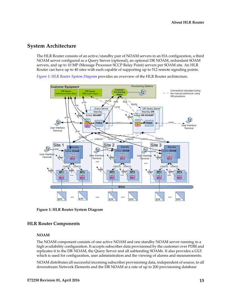
The HLR Router consists of an active/standby pair of NOAM servers in an HA configuration, a thirdNOAM server configured as a Query Server (optional), an optional DR NOAM, redundant SOAMservers, and up to 10 MP (Message Processor SCCP Relay Point) servers per SOAM site. An HLRRouter can have up to 40 sites with each capable of supporting up to 512 remote signaling points.
Figure 1: HLR Router System Diagram provides an overview of the HLR Router architecture.
Figure 1: HLR Router System Diagram
HLR Router Components
NOAM
The NOAM component consists of one active NOAM and one standby NOAM server running in ahigh availability configuration. It accepts subscriber data provisioned by the customer over PDBI andreplicates it to the DR NOAM, the Query Server and all subtending SOAMs. It also provides a GUIwhich is used for configuration, user administration and the viewing of alarms and measurements.
NOAM distributes all successful incoming subscriber provisioning data, independent of source, to alldownstream Network Elements and the DR NOAM at a rate of up to 200 provisioning database
15E72250 Revision 01, April 2016
About HLR Router
updates per second. In order to ensure the database levels of the Network Elements are less than thedatabase levels of the NOAM and DR NOAM, the active provisioning site NOAM provisions the DRNOAM prior to updating the Network Elements.
DR NOAM (Optional)
The DR NOAM is a geographically independent NOAM component. The DR NOAM has the samehardware configuration and network accessibility as the NOAM.
The DR NOAM's databases are kept up to date through real-time replication of subscriber andapplication data from the Active NOAM. Under normal operating conditions, the DR NOAM doesnot provision any downstream systems but if made Active, it will take over all the functions of theActive NOAM including the PDBI and database replication to subtending SOAMs.
SOAM
The SOAM component consists of one active SOAM and a standby SOAM server running in a highavailability configuration. It accepts subscriber data replicated from the Active NOAM and in turnreplicates it to all subtending MPs located in the same physical frame. SOAM also provides a GUIused for local Signaling configuration and viewing alarms and measurements details specific tocomponents located within the frame (SOAM, MP).
The SOAM supports up to 10 MPs.
Query Server (Optional)
The Query Server is an independent application server containing a replicated version of the PDBIdatabase. It accepts replicated subscriber data from the NOAM and stores it in a customer accessibleMySQL database. A Query Server is located in the same physical frame as each NOAM component(NOAM / DR NOAM).
Network Element
Network Elements are containers that group and create relationships between servers in the network.There are two types of Network Elements:
• NOAM: such as the NOAM and the DR NOAM• Signaling: contains a pair of SOAM servers and one or more MP servers
The system can support two NOAM Network Elements and up to 40 Signaling Network Elements.
MPs
The MPs are servers with the HLR Router application installed that are configured for MP functionality.They accept replicated subscriber data from the local SOAM and store it in a subscriber database.
The MP is accessed as a Service Relay Point and is connected to the Eagle STPs via Sigtran M3UAinterfaces. Each MP is capable of relaying real-time SCCP messages at a maximum sustained rate of25,000 transactions per second for HLR routing lookups. Multiple MP servers may be deployed in asingle frame in order to scale query capacity. Each site can support up to 10 MPs, but the HLR RouterSystem can support up to a total of 96 MPs in the system.
16E72250 Revision 01, April 2016
About HLR Router
Distributed configuration
The HLR Router supports centralized and decentralized configurations:
• Centralized configuration:
• All subscriber data configuration and maintenance occurs at the NOAM level• Application management, such as configuring servers, occurs at the NOAM level
• Decentralized:
• All signaling network configuration and maintenance occurs on the SOAM level
Due to distributed configuration:
• Most OAM Administration, Configuration, and Status & Manage tasks can only be performedwhen you are logged into an active NOAM
• EAGLE XG Database and Tekelec HLR Router tasks related to the subscriber database are onlyavailable when logged into an active NOAM, with the exception of querying the database
• EAGLE XG Database and Tekelec HLR Router tasks related to signaling are only available whenlogged into an active SOAM
• All SS7/Sigtran Main Menu options are only available when you are logged into an SOAM• The available Alarms, KPIs, Measurements, and Events vary depending on whether you are logged
into an NOAM or SOAM
Centralized configuration
Subscriber provisioning data is provisioned at the active server of the Primary NOAM cluster andreplicated to all servers on the network. System configuration and subscriber data is provisioned atthe active server of the Primary NOAM cluster, replicated to all other NOAMs, and then replicatedto the active SOAM of each Network Element (NE).
PDBI
The main method of subscriber data provisioning is PDBI (Provisioning Database Interface). PDBIallows one or several independent information systems supplied and maintained by the networkoperator to be used for provisioning databases and for configuring systems. Through the PDBI,independent information systems may add, delete, change or retrieve information about any IMSI,DN, or Network Entity association.
GUI Provisioning
Local provisioning can be done using the HLR Router GUI. The GUI can be used to manage PDBIsetup, to make direct changes to the subscriber database entries, and to perform application operations,management, and provisioning.
Table 2: NOAM Main Menu Options shows the GUI options available when logged into an NOAM.
17E72250 Revision 01, April 2016
About HLR Router
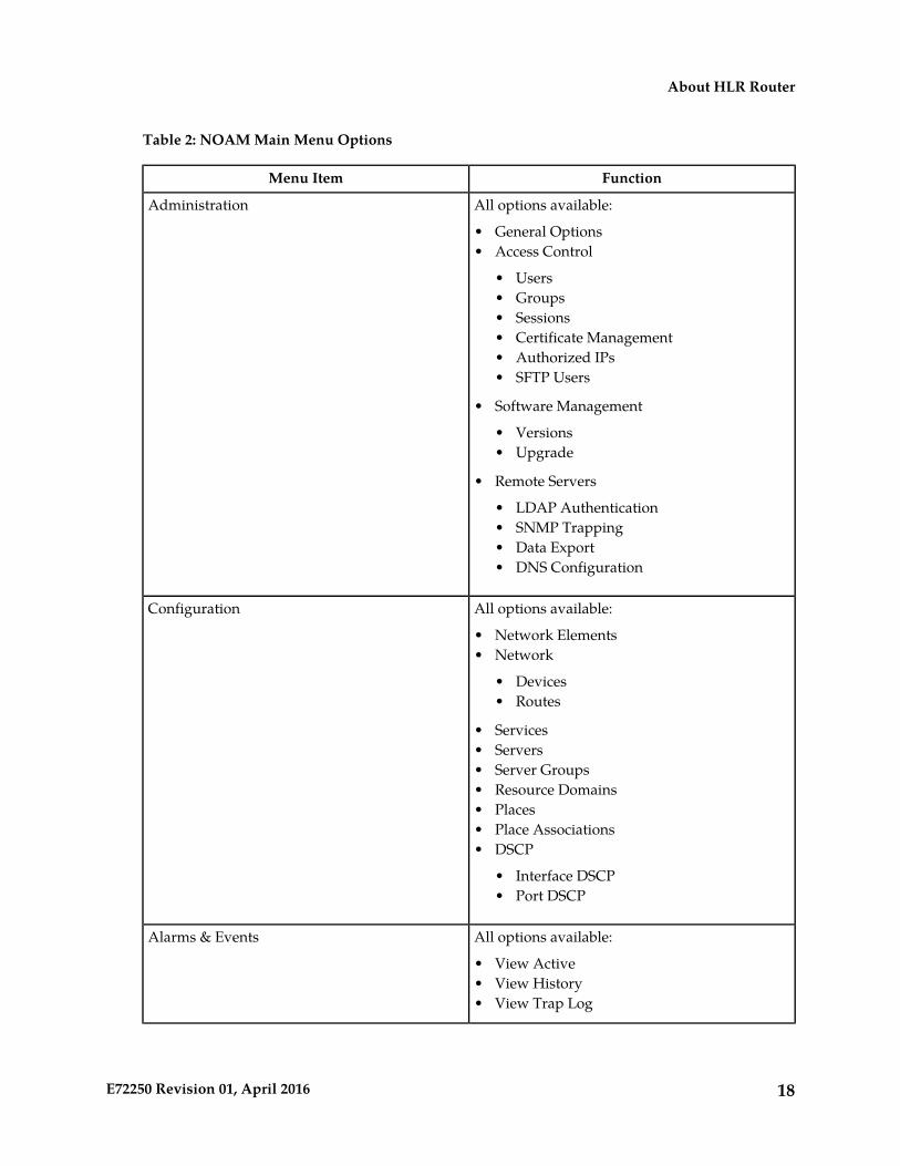
Table 2: NOAM Main Menu Options
FunctionMenu Item
All options available:Administration
• General Options• Access Control
• Users• Groups• Sessions• Certificate Management• Authorized IPs• SFTP Users
• Software Management
• Versions• Upgrade
• Remote Servers
• LDAP Authentication• SNMP Trapping• Data Export• DNS Configuration
All options available:Configuration
• Network Elements• Network
• Devices• Routes
• Services• Servers• Server Groups• Resource Domains• Places• Place Associations• DSCP
• Interface DSCP• Port DSCP
All options available:Alarms & Events
• View Active• View History• View Trap Log
18E72250 Revision 01, April 2016
About HLR Router
FunctionMenu Item
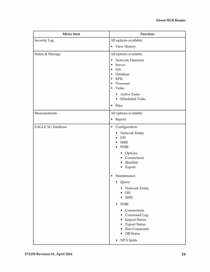
All options available:Security Log
• View History
All options available:Status & Manage
• Network Elements• Server• HA• Database• KPIs• Processes• Tasks
• Active Tasks• Scheduled Tasks
• Files
All options available:Measurements
• Report
EAGLE XG Database • Configuration:
• Network Entity• DN• IMSI• PDBI
• Options• Connections• Blacklist• Export
• Maintenance:
• Query
• Network Entity• DN• IMSI
• PDBI
• Connections• Command Log• Import Status• Export Status• Run Command• DB Status
• NPA Splits
19E72250 Revision 01, April 2016
About HLR Router
FunctionMenu Item
Configuration:Tekelec HLR Router
• Options• Service Config• Substitutions• Mated Entities• Throttling
• DN Whitelist• IMSI Whitelist• MP Groups• Opcodes• Rules• Rule Test
• PDE
• Options
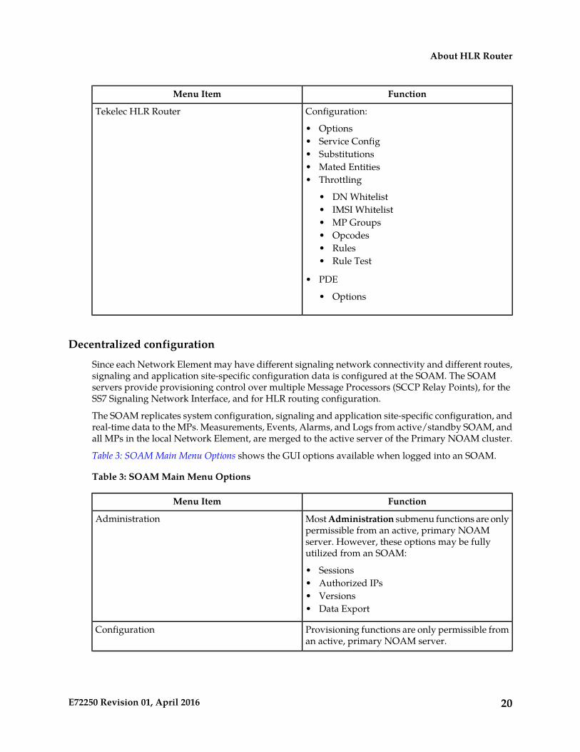
Decentralized configuration
Since each Network Element may have different signaling network connectivity and different routes,signaling and application site-specific configuration data is configured at the SOAM. The SOAMservers provide provisioning control over multiple Message Processors (SCCP Relay Points), for theSS7 Signaling Network Interface, and for HLR routing configuration.
The SOAM replicates system configuration, signaling and application site-specific configuration, andreal-time data to the MPs. Measurements, Events, Alarms, and Logs from active/standby SOAM, andall MPs in the local Network Element, are merged to the active server of the Primary NOAM cluster.
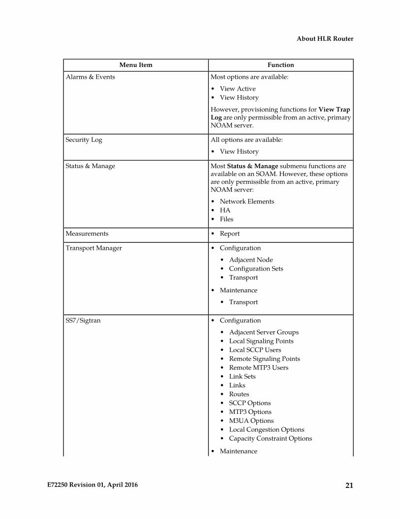
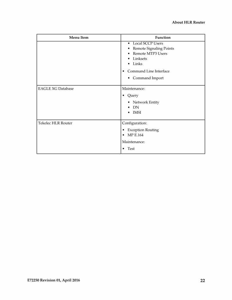
Table 3: SOAM Main Menu Options shows the GUI options available when logged into an SOAM.
Table 3: SOAM Main Menu Options
FunctionMenu Item
Most Administration submenu functions are onlypermissible from an active, primary NOAM
Administration
server. However, these options may be fullyutilized from an SOAM:
• Sessions• Authorized IPs• Versions• Data Export
Provisioning functions are only permissible froman active, primary NOAM server.
Configuration
20E72250 Revision 01, April 2016
About HLR Router
FunctionMenu Item
Most options are available:Alarms & Events
• View Active• View History
However, provisioning functions for View TrapLog are only permissible from an active, primaryNOAM server.
All options are available:Security Log
• View History
Most Status & Manage submenu functions areavailable on an SOAM. However, these options
Status & Manage
are only permissible from an active, primaryNOAM server:
• Network Elements• HA• Files
Measurements • Report
Transport Manager • Configuration
• Adjacent Node• Configuration Sets• Transport
• Maintenance
• Transport
SS7/Sigtran • Configuration
• Adjacent Server Groups• Local Signaling Points• Local SCCP Users• Remote Signaling Points• Remote MTP3 Users• Link Sets• Links• Routes• SCCP Options• MTP3 Options• M3UA Options• Local Congestion Options• Capacity Constraint Options
• Maintenance
21E72250 Revision 01, April 2016
About HLR Router
FunctionMenu ItemLocal SCCP Users•
• Remote Signaling Points• Remote MTP3 Users• Linksets• Links
• Command Line Interface
• Command Import
Maintenance:EAGLE XG Database
• Query
• Network Entity• DN• IMSI
Configuration:Tekelec HLR Router
• Exception Routing• MP E.164
Maintenance:
• Test
22E72250 Revision 01, April 2016
About HLR Router
Chapter
3User Interface Introduction
This section describes the organization and usageof the application's user interface. In it you can find
Topics:
• User interface organization.....24 information about how the interface options are• Missing Main Menu options.....26 organized, how to use widgets and buttons, and
how filtering and other page display options work.• Common Graphical User Interface Widgets.....27
23E72250 Revision 01, April 2016
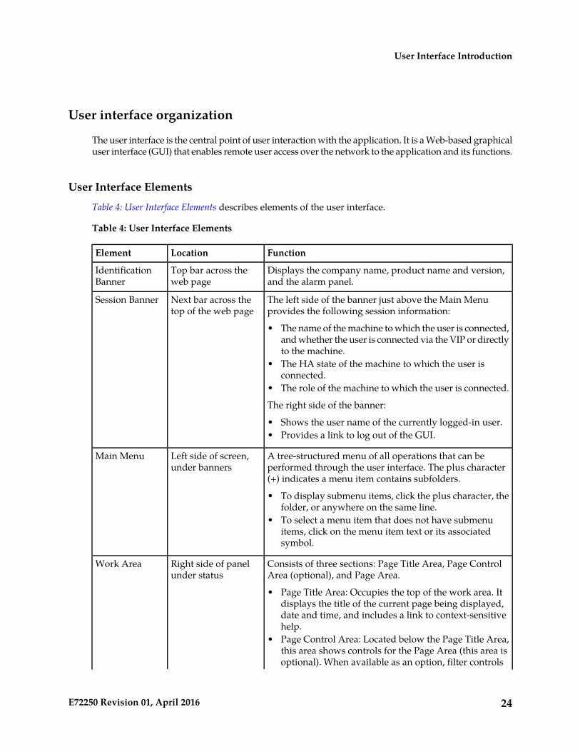
User interface organization
The user interface is the central point of user interaction with the application. It is a Web-based graphicaluser interface (GUI) that enables remote user access over the network to the application and its functions.
User Interface Elements
Table 4: User Interface Elements describes elements of the user interface.
Table 4: User Interface Elements
FunctionLocationElement
Displays the company name, product name and version,and the alarm panel.
Top bar across theweb page
IdentificationBanner
The left side of the banner just above the Main Menuprovides the following session information:
Next bar across thetop of the web page
Session Banner
• The name of the machine to which the user is connected,and whether the user is connected via the VIP or directlyto the machine.
• The HA state of the machine to which the user isconnected.
• The role of the machine to which the user is connected.
The right side of the banner:
• Shows the user name of the currently logged-in user.• Provides a link to log out of the GUI.
A tree-structured menu of all operations that can beperformed through the user interface. The plus character(+) indicates a menu item contains subfolders.
Left side of screen,under banners
Main Menu
• To display submenu items, click the plus character, thefolder, or anywhere on the same line.
• To select a menu item that does not have submenuitems, click on the menu item text or its associatedsymbol.
Consists of three sections: Page Title Area, Page ControlArea (optional), and Page Area.
Right side of panelunder status
Work Area
• Page Title Area: Occupies the top of the work area. Itdisplays the title of the current page being displayed,date and time, and includes a link to context-sensitivehelp.
• Page Control Area: Located below the Page Title Area,this area shows controls for the Page Area (this area isoptional). When available as an option, filter controls
24E72250 Revision 01, April 2016
User Interface Introduction

FunctionLocationElementdisplay in this area. The Page Control Area contains theoptional layout element toolbar, which displays differentelements depending on which GUI page is selected. Formore information, see Optional Layout Element Toolbar.
• Page Area: Occupies the bottom of the work area. Thisarea is used for all types of operations. It displays alloptions, status, data, file, and query screens. Informationor error messages are displayed in a message box at thetop of this section. A horizontal and/or vertical scrollbar is provided when the displayed information exceedsthe page area of the screen. When a user first logs in,this area displays the application user interface page.The page displays a user-defined welcome message. Tocustomize the message, see Customizing the LoginMessage.
Main menu options
The menu options that appear on the screen differ according to whether you are logged into an NOAMor SOAM. This table describes all main menu user interface options. For a list of NOAM menu options,please see Centralized configuration. For a list of SOAM menu options, please see Decentralizedconfiguration.
Note: The menu options can differ according to the permissions assigned to a user's log-in account.For example, the Administration menu options would not appear on the screen of a user who doesnot have administrative privileges.
FunctionMenu Item
The Administration menu allows you to:Administration
• Set up and manage user accounts• Configure group permissions• View session information• Authorize IP addresses to access the user
interface• Configure options including, but not limited
to, password history and expiration, loginmessage, welcome message, and the numberof failed login attempts before an account isdisabled
• Configure SNMP services• Validate and transfer ISO files• Prepare, initiate, monitor, and complete
upgrades• View the software versions report
Provides access to configuring network elements,servers, server groups, and systems.
Configuration
25E72250 Revision 01, April 2016
User Interface Introduction
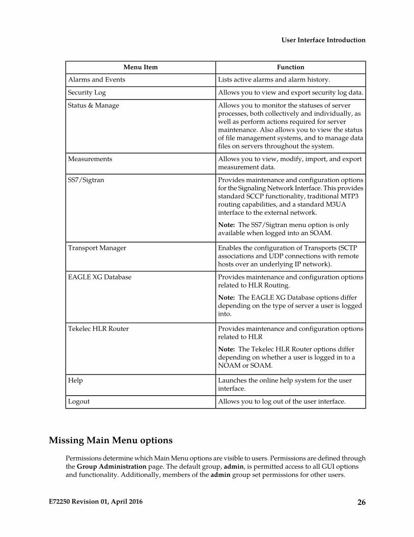
FunctionMenu Item
Lists active alarms and alarm history.Alarms and Events
Allows you to view and export security log data.Security Log
Allows you to monitor the statuses of serverprocesses, both collectively and individually, as
Status & Manage
well as perform actions required for servermaintenance. Also allows you to view the statusof file management systems, and to manage datafiles on servers throughout the system.
Allows you to view, modify, import, and exportmeasurement data.
Measurements
Provides maintenance and configuration optionsfor the Signaling Network Interface. This provides
SS7/Sigtran
standard SCCP functionality, traditional MTP3routing capabilities, and a standard M3UAinterface to the external network.
Note: The SS7/Sigtran menu option is onlyavailable when logged into an SOAM.
Enables the configuration of Transports (SCTPassociations and UDP connections with remotehosts over an underlying IP network).
Transport Manager
Provides maintenance and configuration optionsrelated to HLR Routing.
Note: The EAGLE XG Database options differdepending on the type of server a user is loggedinto.
EAGLE XG Database
Provides maintenance and configuration optionsrelated to HLR
Note: The Tekelec HLR Router options differdepending on whether a user is logged in to aNOAM or SOAM.
Tekelec HLR Router
Launches the online help system for the userinterface.
Help
Allows you to log out of the user interface.Logout
Missing Main Menu options
Permissions determine which Main Menu options are visible to users. Permissions are defined throughthe Group Administration page. The default group, admin, is permitted access to all GUI optionsand functionality. Additionally, members of the admin group set permissions for other users.
26E72250 Revision 01, April 2016
User Interface Introduction
Main Menu options vary according to the group permissions assigned to a user's account. Dependingon your user permissions, some menu options may be missing from the Main Menu. For example,Administration menu options do not appear on your screen if you do not have administrativepermissions. For more information about user permissions, see Group Administration in the OAMsection of the online help, or contact your system administrator.
Common Graphical User Interface Widgets
Common controls allow you to easily navigate through the system. The location of the controls remainsstatic for all pages that use the controls. For example, after you become familiar with the location ofthe display filter, you no longer need to search for the control on subsequent pages because the locationis static.
System Login Page
Access to the user interface begins at the System Login page. The System Login page allows users tolog in with a username and password and provides the option of changing the password upon login.The System Login page also features a date and time stamp reflecting the time the page was lastrefreshed. Additionally, a customizable login message appears just below the Log In button.
The user interface is accessed via HTTPS, a secure form of the HTTP protocol. When accessing a serverfor the first time, HTTPS examines a web certificate to verify the identity of the server. The configurationof the user interface uses a self-signed web certificate to verify the identity of the server. When theserver is first accessed, the supported browser warns the user that the server is using a self-signedcertificate. The browser requests confirmation that the server can be trusted. The user is required toconfirm the browser request to gain access.
Customizing the Login MessageBefore logging in, the System Login page appears. You can create a login message that appears justbelow the Log In button on the System Login page.
27E72250 Revision 01, April 2016
User Interface Introduction
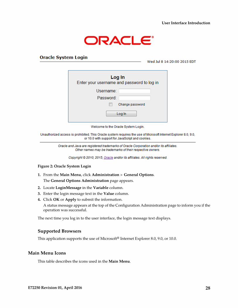
Figure 2: Oracle System Login
1. From the Main Menu, click Administration > General Options.The General Options Administration page appears.
2. Locate LoginMessage in the Variable column.3. Enter the login message text in the Value column.4. Click OK or Apply to submit the information.
A status message appears at the top of the Configuration Administration page to inform you if theoperation was successful.
The next time you log in to the user interface, the login message text displays.
Supported BrowsersThis application supports the use of Microsoft® Internet Explorer 8.0, 9.0, or 10.0.
Main Menu Icons
This table describes the icons used in the Main Menu.
28E72250 Revision 01, April 2016
User Interface Introduction
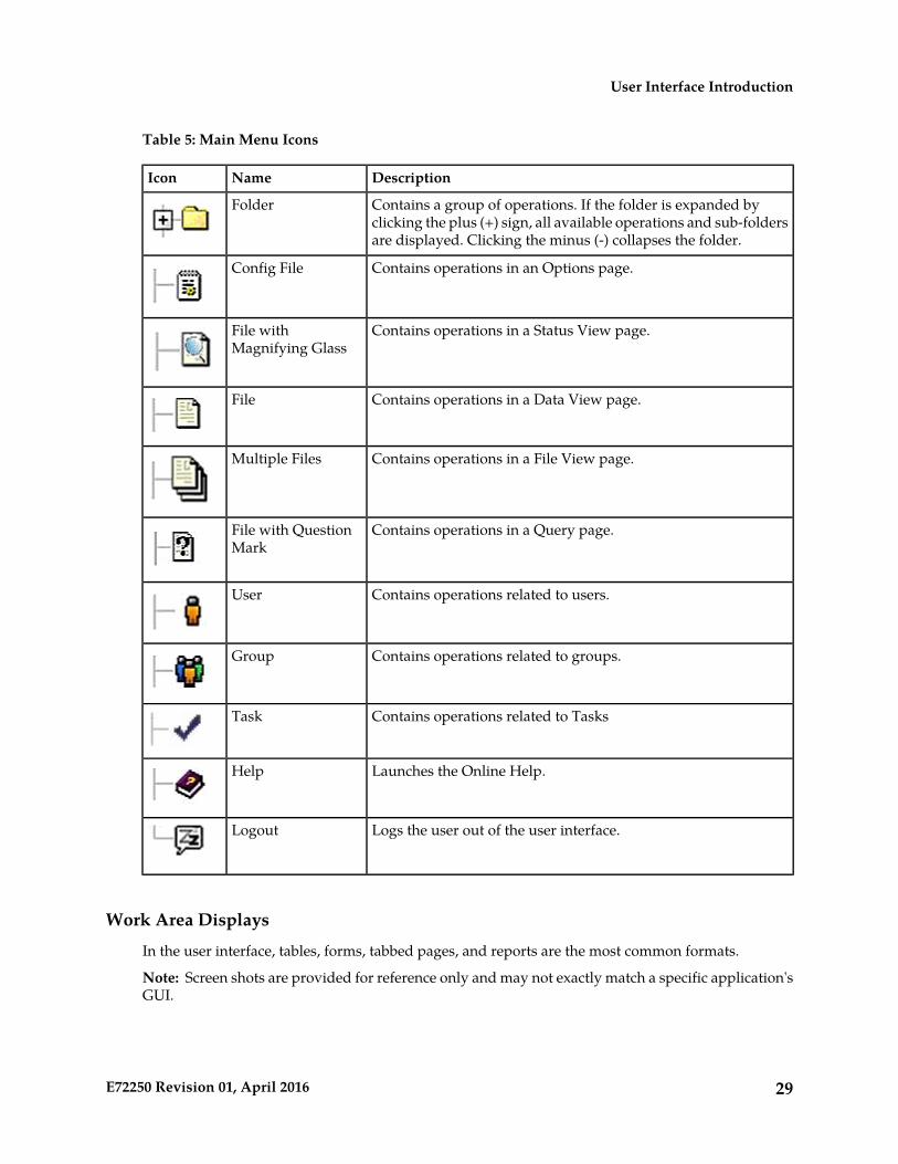
Table 5: Main Menu Icons
DescriptionNameIcon
Contains a group of operations. If the folder is expanded byclicking the plus (+) sign, all available operations and sub-foldersare displayed. Clicking the minus (-) collapses the folder.
Folder
Contains operations in an Options page.Config File
Contains operations in a Status View page.File withMagnifying Glass
Contains operations in a Data View page.File
Contains operations in a File View page.Multiple Files
Contains operations in a Query page.File with QuestionMark
Contains operations related to users.User
Contains operations related to groups.Group
Contains operations related to TasksTask
Launches the Online Help.Help
Logs the user out of the user interface.Logout
Work Area Displays
In the user interface, tables, forms, tabbed pages, and reports are the most common formats.
Note: Screen shots are provided for reference only and may not exactly match a specific application'sGUI.
29E72250 Revision 01, April 2016
User Interface Introduction
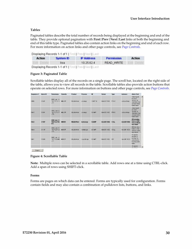
Tables
Paginated tables describe the total number of records being displayed at the beginning and end of thetable. They provide optional pagination with First|Prev|Next|Last links at both the beginning andend of this table type. Paginated tables also contain action links on the beginning and end of each row.For more information on action links and other page controls, see Page Controls.
Figure 3: Paginated Table
Scrollable tables display all of the records on a single page. The scroll bar, located on the right side ofthe table, allows you to view all records in the table. Scrollable tables also provide action buttons thatoperate on selected rows. For more information on buttons and other page controls, see Page Controls.
Figure 4: Scrollable Table
Note: Multiple rows can be selected in a scrollable table. Add rows one at a time using CTRL-click.Add a span of rows using SHIFT-click.
Forms
Forms are pages on which data can be entered. Forms are typically used for configuration. Formscontain fields and may also contain a combination of pulldown lists, buttons, and links.
30E72250 Revision 01, April 2016
User Interface Introduction
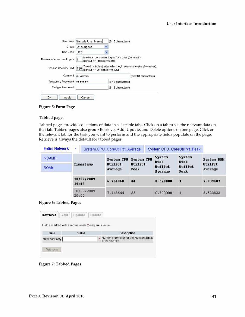
Figure 5: Form Page
Tabbed pages
Tabbed pages provide collections of data in selectable tabs. Click on a tab to see the relevant data onthat tab. Tabbed pages also group Retrieve, Add, Update, and Delete options on one page. Click onthe relevant tab for the task you want to perform and the appropriate fields populate on the page.Retrieve is always the default for tabbed pages.
Figure 6: Tabbed Pages
Figure 7: Tabbed Pages
31E72250 Revision 01, April 2016
User Interface Introduction
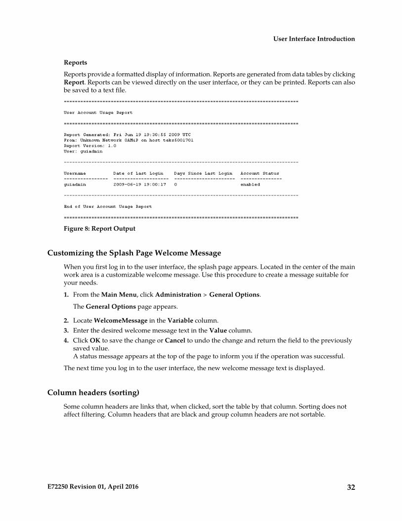
Reports
Reports provide a formatted display of information. Reports are generated from data tables by clickingReport. Reports can be viewed directly on the user interface, or they can be printed. Reports can alsobe saved to a text file.
Figure 8: Report Output
Customizing the Splash Page Welcome Message
When you first log in to the user interface, the splash page appears. Located in the center of the mainwork area is a customizable welcome message. Use this procedure to create a message suitable foryour needs.
1. From the Main Menu, click Administration > General Options.
The General Options page appears.
2. Locate WelcomeMessage in the Variable column.3. Enter the desired welcome message text in the Value column.4. Click OK to save the change or Cancel to undo the change and return the field to the previously
saved value.A status message appears at the top of the page to inform you if the operation was successful.
The next time you log in to the user interface, the new welcome message text is displayed.
Column headers (sorting)
Some column headers are links that, when clicked, sort the table by that column. Sorting does notaffect filtering. Column headers that are black and group column headers are not sortable.
32E72250 Revision 01, April 2016
User Interface Introduction

Figure 9: Sortable and Non-sortable Column Headers
Page Controls
User interface pages contain controls, such as buttons and links, that perform specified functions. Thefunctions are described by the text of the links and buttons.
Note: Disabled buttons are grayed out. Buttons that are irrelevant to the selection or current systemstate, or which represent unauthorized actions as defined in Group Administration, are disabled. Forexample, Delete is disabled for users without Global Data Delete permission. Buttons are also disabledif, for example, multiple servers are selected for an action that can only be performed on a single serverat a time.
Table 6: Example Action Buttons contains examples of Action buttons.
Table 6: Example Action Buttons
FunctionAction Button
Inserts data into a table.Insert
Edits data within a table.Edit
Deletes data from table.Delete
Changes the status of a managed object.Change
Some Action buttons take you to another page.
Submit buttons, described in Table 7: Submit Buttons, are used to submit information to the server. Thebuttons are located in the page area and accompanied by a table in which you can enter information.The Submit buttons, except for Cancel, are disabled until you enter some data or select a value for allmandatory fields.
Table 7: Submit Buttons
FunctionSubmit Button
Submits the information to the server, and if successful, returns to the Viewpage for that table.
OK
Submits the information to the server, and if successful, remains on the currentpage so that you can enter additional data.
Apply
Returns to the View page for the table without submitting any informationto the server.
Cancel
33E72250 Revision 01, April 2016
User Interface Introduction
Optional Layout Element Toolbar
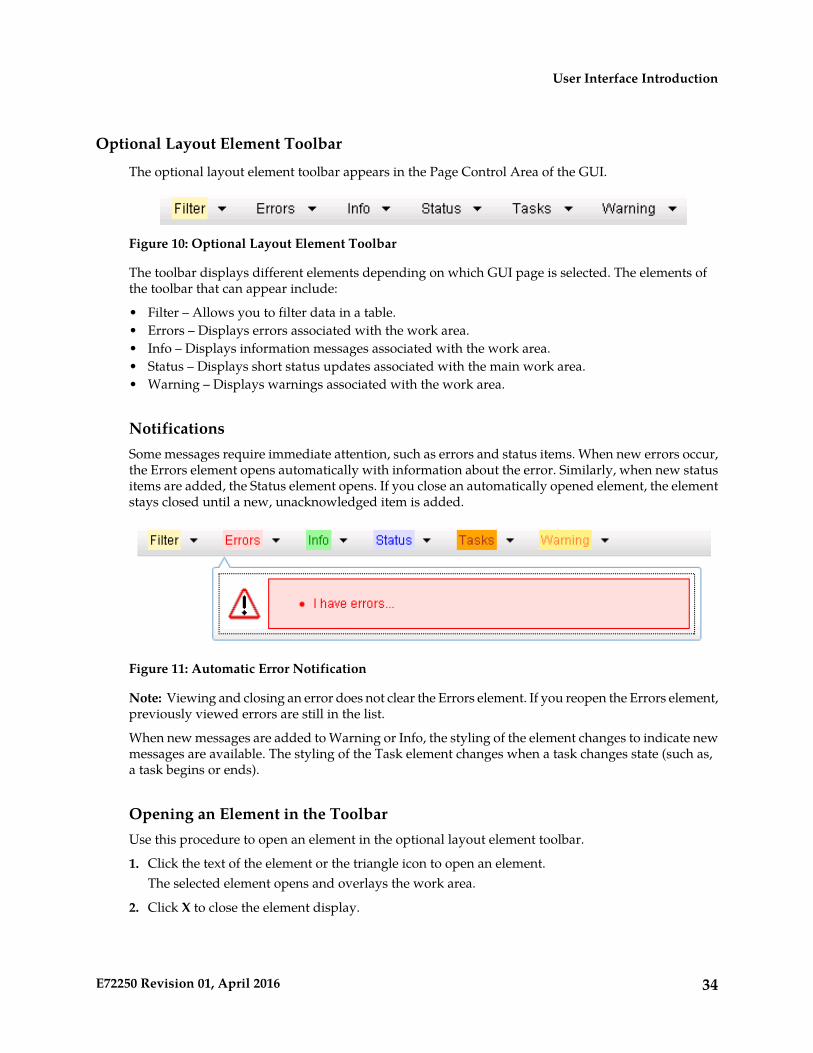
The optional layout element toolbar appears in the Page Control Area of the GUI.
Figure 10: Optional Layout Element Toolbar
The toolbar displays different elements depending on which GUI page is selected. The elements ofthe toolbar that can appear include:
• Filter – Allows you to filter data in a table.• Errors – Displays errors associated with the work area.• Info – Displays information messages associated with the work area.• Status – Displays short status updates associated with the main work area.• Warning – Displays warnings associated with the work area.
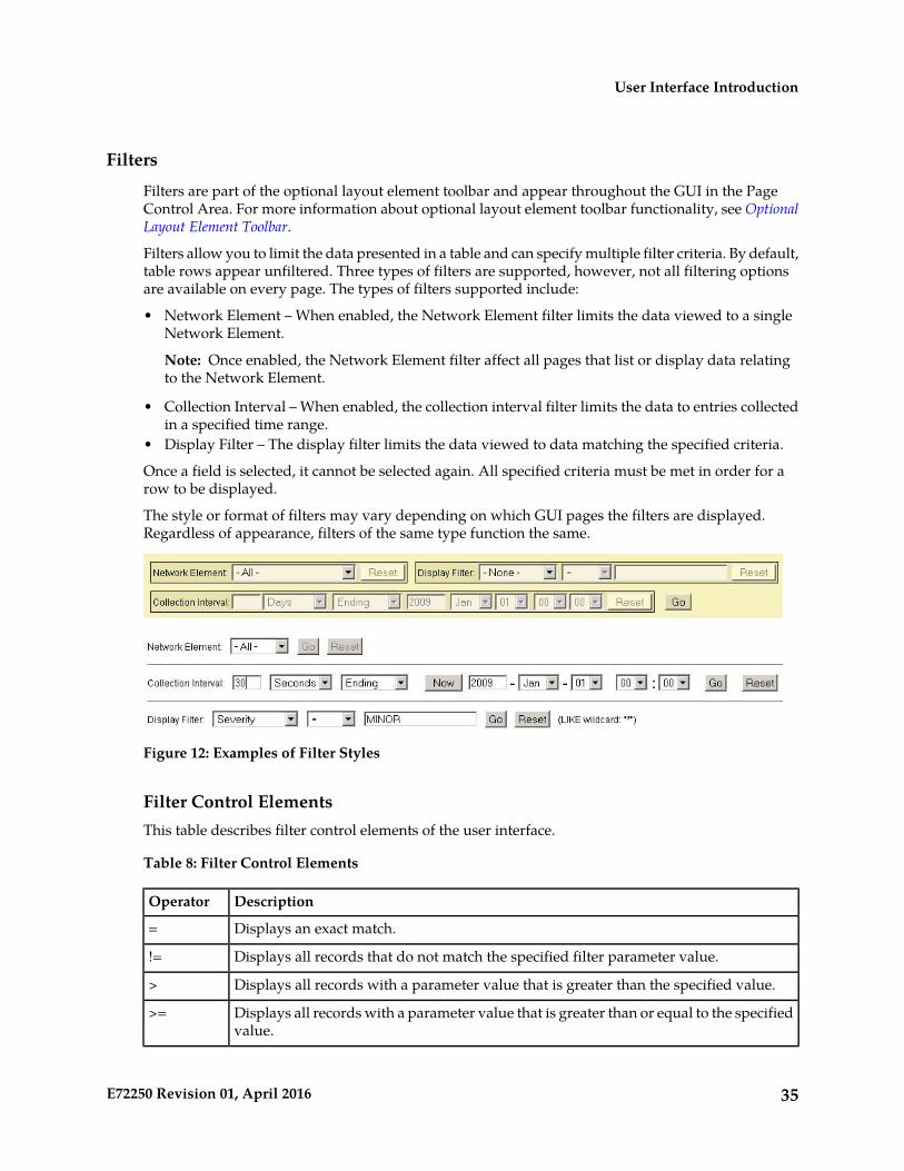
NotificationsSome messages require immediate attention, such as errors and status items. When new errors occur,the Errors element opens automatically with information about the error. Similarly, when new statusitems are added, the Status element opens. If you close an automatically opened element, the elementstays closed until a new, unacknowledged item is added.
Figure 11: Automatic Error Notification
Note: Viewing and closing an error does not clear the Errors element. If you reopen the Errors element,previously viewed errors are still in the list.
When new messages are added to Warning or Info, the styling of the element changes to indicate newmessages are available. The styling of the Task element changes when a task changes state (such as,a task begins or ends).
Opening an Element in the ToolbarUse this procedure to open an element in the optional layout element toolbar.
1. Click the text of the element or the triangle icon to open an element.The selected element opens and overlays the work area.
2. Click X to close the element display.
34E72250 Revision 01, April 2016
User Interface Introduction
Filters
Filters are part of the optional layout element toolbar and appear throughout the GUI in the PageControl Area. For more information about optional layout element toolbar functionality, see OptionalLayout Element Toolbar.
Filters allow you to limit the data presented in a table and can specify multiple filter criteria. By default,table rows appear unfiltered. Three types of filters are supported, however, not all filtering optionsare available on every page. The types of filters supported include:
• Network Element – When enabled, the Network Element filter limits the data viewed to a singleNetwork Element.
Note: Once enabled, the Network Element filter affect all pages that list or display data relatingto the Network Element.
• Collection Interval – When enabled, the collection interval filter limits the data to entries collectedin a specified time range.
• Display Filter – The display filter limits the data viewed to data matching the specified criteria.
Once a field is selected, it cannot be selected again. All specified criteria must be met in order for arow to be displayed.
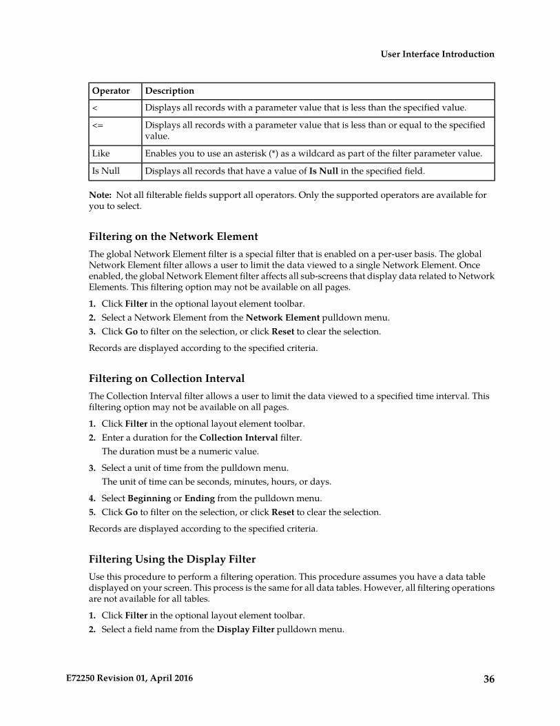
The style or format of filters may vary depending on which GUI pages the filters are displayed.Regardless of appearance, filters of the same type function the same.
Figure 12: Examples of Filter Styles
Filter Control ElementsThis table describes filter control elements of the user interface.
Table 8: Filter Control Elements
DescriptionOperator
Displays an exact match.=
Displays all records that do not match the specified filter parameter value.!=
Displays all records with a parameter value that is greater than the specified value.>
Displays all records with a parameter value that is greater than or equal to the specifiedvalue.
>=
35E72250 Revision 01, April 2016
User Interface Introduction
DescriptionOperator
Displays all records with a parameter value that is less than the specified value.<
Displays all records with a parameter value that is less than or equal to the specifiedvalue.
<=
Enables you to use an asterisk (*) as a wildcard as part of the filter parameter value.Like
Displays all records that have a value of Is Null in the specified field.Is Null
Note: Not all filterable fields support all operators. Only the supported operators are available foryou to select.
Filtering on the Network ElementThe global Network Element filter is a special filter that is enabled on a per-user basis. The globalNetwork Element filter allows a user to limit the data viewed to a single Network Element. Onceenabled, the global Network Element filter affects all sub-screens that display data related to NetworkElements. This filtering option may not be available on all pages.
1. Click Filter in the optional layout element toolbar.2. Select a Network Element from the Network Element pulldown menu.3. Click Go to filter on the selection, or click Reset to clear the selection.
Records are displayed according to the specified criteria.
Filtering on Collection IntervalThe Collection Interval filter allows a user to limit the data viewed to a specified time interval. Thisfiltering option may not be available on all pages.
1. Click Filter in the optional layout element toolbar.2. Enter a duration for the Collection Interval filter.
The duration must be a numeric value.
3. Select a unit of time from the pulldown menu.The unit of time can be seconds, minutes, hours, or days.
4. Select Beginning or Ending from the pulldown menu.5. Click Go to filter on the selection, or click Reset to clear the selection.
Records are displayed according to the specified criteria.
Filtering Using the Display FilterUse this procedure to perform a filtering operation. This procedure assumes you have a data tabledisplayed on your screen. This process is the same for all data tables. However, all filtering operationsare not available for all tables.
1. Click Filter in the optional layout element toolbar.2. Select a field name from the Display Filter pulldown menu.
36E72250 Revision 01, April 2016
User Interface Introduction
This selection specifies the field in the table that you want to filter on. The default is None, whichindicates that you want all available data displayed.
The selected field name displays in the Display Filter field.
3. Select an operator from the operation selector pulldown menu.4. Enter a value in the value field.
This value specifies the data that you want to filter on. For example, if you specify Filter=Severitywith the equals (=) operator and a value of MINOR, the table would show only records whereSeverity=MINOR.
5. For data tables that support compound filtering, click Add to add another filter condition. Thenrepeat steps 2 through 4.Multiple filter conditions are joined by an AND operator.
6. Click Go to filter on the selection, or click Reset to clear the selection.
Records are displayed according to the specified criteria.
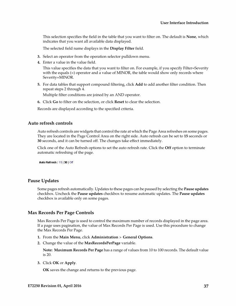
Auto refresh controls
Auto refresh controls are widgets that control the rate at which the Page Area refreshes on some pages.They are located in the Page Control Area on the right side. Auto refresh can be set to 15 seconds or30 seconds, and it can be turned off. The changes take effect immediately.
Click one of the Auto Refresh options to set the auto refresh rate. Click the Off option to terminateautomatic refreshing of the page.
Pause Updates
Some pages refresh automatically. Updates to these pages can be paused by selecting the Pause updatescheckbox. Uncheck the Pause updates checkbox to resume automatic updates. The Pause updatescheckbox is available only on some pages.
Max Records Per Page Controls
Max Records Per Page is used to control the maximum number of records displayed in the page area.If a page uses pagination, the value of Max Records Per Page is used. Use this procedure to changethe Max Records Per Page.
1. From the Main Menu, click Administration > General Options.2. Change the value of the MaxRecordsPerPage variable.
Note: Maximum Records Per Page has a range of values from 10 to 100 records. The default valueis 20.
3. Click OK or Apply.
OK saves the change and returns to the previous page.
37E72250 Revision 01, April 2016
User Interface Introduction

Apply saves the change and remains on the same page.
The maximum number of records displayed is changed.
38E72250 Revision 01, April 2016
User Interface Introduction
Glossary
C
Comma-Separated ValuesCSV
The comma-separated value fileformat is a delimited data formatthat has fields separated by thecomma character and recordsseparated by newlines (a newlineis a special character or sequenceof characters signifying the end ofa line of text).
D
Directory numberDN
A DN can refer to any mobile orwireline subscriber number, andcan include MSISDN, MDN, MIN,or the wireline Dialed Number.
G
Graphical User InterfaceGUI
The term given to that set of itemsand facilities which provides youwith a graphic means formanipulating screen data ratherthan being limited to characterbased commands.
H
Home Location RegisterHLR
A component within the SwitchingSubsystem of a GSM network. TheHLR database is the centraldatabase within the GSMarchitecture. This is whereinformation about the mobilecommunications subscribers whoare assigned to a specific locationarea is stored. The subscriber data
39E72250 Revision 01, April 2016
H
is used to establish connections andcontrol services. Depending on thenetwork size, the number ofsubscribers and the networkorganization, a number of HLRscan exist within a GSM network.
I
International Mobile StationIdentity
IMSI
A unique internal network IDidentifying a mobile subscriber.
M
Message Processor - The role of theMessage Processor is to provide the
MP
application messaging protocolinterfaces and processing.However, these servers also haveOAM components. All MessageProcessors replicate from theirSignaling OAM's database andgenerate faults to a FaultManagement System.
Mobile Switching CenterMSC
An intelligent switching system inGSM networks. This systemestablishes connections betweenmobile communicationssubscribers.The primary service delivery nodefor GSM/CDMA, responsible forrouting voice calls and SMS as wellas other services (such asconference calls, FAX and circuitswitched data).
N
Network ElementNE
An independent and identifiablepiece of equipment closelyassociated with at least one
40E72250 Revision 01, April 2016
Glossary
N
processor, and within a singlelocation.
In a 2-Tiered DSR OAM system,this includes the NOAM and allMPs underneath it. In a 3-TieredDSR OAM system, this includes theNOAM, the SOAM, and all MPsassociated with the SOAM.
The devices, servers, or functionswithin a wireless network withwhich Policy Management systemsinteract.
See NENetwork Element
Network Operations,Administration, and Maintenance
NOAM
P
Provisioning Database InterfacePDBI
The interface consists of thedefinition of provisioning messagesonly. The customer must write aclient application that uses thePDBI request/response messagesto communicate with the PDBA.
S
Signaling Connection Control PartSCCP
The signaling connection controlpart with additional functions forthe Message Transfer Part (MTP)in SS7 signaling. Messages can betransmitted between arbitrarynodes in the signaling networkusing a connection-oriented orconnectionless approach.
Signaling TransportSigtran
41E72250 Revision 01, April 2016
Glossary
S
System Operations,Administration, and Maintenance
SOAM
Site Operations, Administration,and Maintenance
Signaling System #7SS7
A communications protocol thatallows signaling points in anetwork to send messages to eachother so that voice and dataconnections can be set up betweenthese signaling points. Thesemessages are sent over its ownnetwork and not over the revenueproducing voice and data paths.The EAGLE is an STP, which is adevice that routes these messagesthrough the network.
42E72250 Revision 01, April 2016
Glossary