Optical-Interference Mitigation in Visible Light ...
15
energies Article Optical-Interference Mitigation in Visible Light Communication for Intelligent Transport Systems Applications Muhammad Irfan 1, * , Usman Habib 2 , Fazal Muhammad 3, * , Farman Ali 4 , Abdullah S Alwadie 1 , Shakir Ullah 5 , Adam Glowacz 6, * and Witold Glowacz 6 1 Electrical Engineering Department, College of Engineering, Najran University Saudia Arabia, Najran 61441, Saudia Arabia; [email protected] 2 School of Electrical Engineering, Korea Advanced Institute of Science and Technology, Daejeon 34141, Korea; [email protected] 3 Department of Electrical Engineering, City University of Science and Information Technology, Peshawar 25000, Pakistan 4 Department of Electrical Engineering, Qurtuba University of Science and IT, DI Khan 25000, Pakistan; [email protected] 5 Department of Telecommucation Engineering, University of Engineering and Technology, Peshawar 25120, Pakistan; [email protected] 6 Department of Automatic, Control and Robotics, AGH University of Science and Technology, 30-059 Krakow, Poland; [email protected] * Correspondence: [email protected] (M.I.); [email protected] (F.M.); [email protected] (A.G.) Received: 26 August 2020; Accepted: 25 September 2020; Published: 27 September 2020 Abstract: Intelligent Transport Systems (ITS) are anticipated to be one of the key technologies for the next decade and their deployment can benefit from the recent developments in the domain of Visible Light Communication (VLC). Light Emitting Diode (LED)-based low-cost VLC is considered in this work to provide a practical approach towards the implementation of an ITS by addressing the major issues of channel noise, free-space optical multipath reflections and interference from light sources. An analytical model is presented for the proposed Multiple-Input–Single-Output (MISO)-based VLC, and simulations are performed to analyze the performance of the system for various transmission distances. Results show that the proposed optimal receiver for 4 × 1 MISO can provide considerable improvement in the bit error rate for the forward error correction (FEC) threshold of 3.8 × 10 -3 in the presence of optical interference, and is suitable to support an ITS with an inter-vehicle transmission approach. The comparison of achieved performance with existing solutions for VLC-based ITS depicts that the proposed framework provides much higher data rates, three times longer transmission distance and improved receiver sensitivity. Keywords: intelligent transport systems (ITS); visible light communication (VLC); light emitting diode (LED); bit error rate (BER) 1. Introduction The research interest in Visible Light Communication (VLC) has been boosted since its acceptance by the IEEE 802.15.7 standard to utilize VLC for the Physical (PHY) and Medium Access Control (MAC) layers [1] of the free-space optics systems. The increasing amount of unmanned vehicles is reshaping the major fields of life including business, rescue operations and everyday commutes. The significant development of smart societies has created new opportunities in the ever changing world Energies 2020, 13, 5064; doi:10.3390/en13195064 www.mdpi.com/journal/energies
Transcript of Optical-Interference Mitigation in Visible Light ...
energies
Article
Optical-Interference Mitigation in Visible LightCommunication for Intelligent TransportSystems Applications
Muhammad Irfan 1,* , Usman Habib 2 , Fazal Muhammad 3,* , Farman Ali 4 ,Abdullah S Alwadie 1 , Shakir Ullah 5 , Adam Glowacz 6,* and Witold Glowacz 6
1 Electrical Engineering Department, College of Engineering, Najran University Saudia Arabia, Najran 61441,Saudia Arabia; [email protected]
2 School of Electrical Engineering, Korea Advanced Institute of Science and Technology, Daejeon 34141, Korea;[email protected]
3 Department of Electrical Engineering, City University of Science and Information Technology,Peshawar 25000, Pakistan
4 Department of Electrical Engineering, Qurtuba University of Science and IT, DI Khan 25000, Pakistan;[email protected]
5 Department of Telecommucation Engineering, University of Engineering and Technology, Peshawar 25120,Pakistan; [email protected]
6 Department of Automatic, Control and Robotics, AGH University of Science and Technology, 30-059 Krakow,Poland; [email protected]
* Correspondence: [email protected] (M.I.); [email protected] (F.M.);[email protected] (A.G.)
Received: 26 August 2020; Accepted: 25 September 2020; Published: 27 September 2020�����������������
Abstract: Intelligent Transport Systems (ITS) are anticipated to be one of the key technologies forthe next decade and their deployment can benefit from the recent developments in the domain ofVisible Light Communication (VLC). Light Emitting Diode (LED)-based low-cost VLC is consideredin this work to provide a practical approach towards the implementation of an ITS by addressingthe major issues of channel noise, free-space optical multipath reflections and interference fromlight sources. An analytical model is presented for the proposed Multiple-Input–Single-Output(MISO)-based VLC, and simulations are performed to analyze the performance of the system forvarious transmission distances. Results show that the proposed optimal receiver for 4 × 1 MISOcan provide considerable improvement in the bit error rate for the forward error correction (FEC)threshold of 3.8 × 10⁻³ in the presence of optical interference, and is suitable to support an ITS withan inter-vehicle transmission approach. The comparison of achieved performance with existingsolutions for VLC-based ITS depicts that the proposed framework provides much higher data rates,three times longer transmission distance and improved receiver sensitivity.
Keywords: intelligent transport systems (ITS); visible light communication (VLC); light emittingdiode (LED); bit error rate (BER)
1. Introduction
The research interest in Visible Light Communication (VLC) has been boosted since its acceptanceby the IEEE 802.15.7 standard to utilize VLC for the Physical (PHY) and Medium Access Control(MAC) layers [1] of the free-space optics systems. The increasing amount of unmanned vehiclesis reshaping the major fields of life including business, rescue operations and everyday commutes.The significant development of smart societies has created new opportunities in the ever changing world
Energies 2020, 13, 5064; doi:10.3390/en13195064 www.mdpi.com/journal/energies
Energies 2020, 13, 5064 2 of 15
of communication systems. The humanitarian sector is still in search of a feasible framework for smarttransportation to provide logistical and health care services [2], on an everywhere-and-anywhere basis.The need to provide a high level of service, while considering smart transportation’s environmentalimpact and government policy measures [3], has led to the use of innovative solutions of devices andoptimization algorithms [4] in the past decade. VLC systems based on the Light Emitting Diode (LED)provide a suitable projection towards the realization of such systems on a large-scale, as they canmake use of the existing lightening frameworks to offer considerably high data rate communication.The associated advantages include low cost, immunity from Electro-Magnetic (EM) interference,unlicensed band operation and several special applications where EM waves can not be used (such asunderwater communications) [5]. VLC-based Light-Fidelity (LiFi) systems [6] are another examplewhere the existing facilities of visible light can be utilized to provide broadband services at bus stops,train stations, waiting areas at hospitals, etc. For instance, LED operated billboards on a high street canprovide network access without the need for a separate Wireless-Fidelity (wifi) network. Due to itsease of implementation, VLC is equally useful for inter and intra vehicle communication, as manysafety features such as cruise control can be activated in a rear vehicle by transmitting the informationfrom a front one [7]. The importance of research on VLC-based systems has upsurged in the pastdecade due to the saturation of the radio frequency (RF) spectrum, drastic demand in the number ofconnected devices, increasing interference levels and environmental constraints of wireless powerlevels. However, the industrial development of VLC-based systems has not been impressive so fardue to the insufficient work on system modeling and analysis, while considering the practical impactsand factors affecting the system performance. Most of the study on VLC so far has been performedfor indoor environments [8–10] and the real challenge for such systems is the change in intensity oflight in the case of outdoor transmission deteriorating the system’s performance to a large extent [11].State-of-the-art technologies such as intelligent transportation systems (ITS) require both indoor andoutdoor communication access [12], and the issues related to the development of such systems onthe required scale needs to be addressed. LEDs are commonly found in the form of arrays due totheir low cost, high energy efficiency and long lifetime. Although LED supports bandwidths of upto a few Megahertz (MHz), their existence in the form of vehicular lights, lamp posts, traffic lightsand billboards makes them a potential candidate to be used for ITS [13], as compared to other opticalsources. The current road situation, possible queues, and information about the pedestrians or cyclistsmoving towards the road from a street, can be transmitted to the vehicles using existing infrastructure,supported by the conventional optical networks for mobile networks [14]. As the Line-of-Sight (LoS)and visible nature of LED-based communication are considered as distinguished advantages of thistechnology over RF counterparts [15–17], the provision of reliable transmission even for small data ratesis still in question. ITS based on vehicle-to-vehicle (V2V) communication is subjected to several typesof disruption such as interference from the side-roadway [18], vehicle-to-infrastructure communicationsystems such as LiFi transmission from a lamp post along the road [19], and natural light sources,which limit the accuracy of the channel estimation [20].
Multiple-Input–Single-Output (MISO) has been used in several IEEE RF standards to increase thereliability and data rates in a multipath-affected environment [21–23]. The use of several transmittingunits makes it possible to make use of the spatial diversity and to receive multiple copies of thesame signal at the receiver, each experiencing a distinct and de-correlated channel response [24].The major difference between a Single-Input–Single-Output (SISO)-based transmission and MISO isthe number of transmitting units. Using approximation theory, a MISO system can be divided in toseveral SISO linear systems [25]. Studies have shown that despite the difference in multiple numbersof transmitting LEDs in MISO as compared to SISO [23], the complexity of MISO transmission can besignificantly reduced by using maximum ratio combiner receiver [26,27]. The use of MISO in VLC canaddress the challenges associated with the ITS such as different weather conditions (fog, rain, smoke,etc.), light intensity variations due to the moving objects and imperfect alignment of the transceivers.The need is the systematic characterization of the MISO in VLC for different parameters, based on the
Energies 2020, 13, 5064 3 of 15
commercially available vehicle LEDs. This paper presents a VLC-based MISO transmission model forITS applications, which will provide significant guidelines for the practical implementation of suchsystems regarding future technologies. By using the head and back lights of the vehicles, as well asstreet lights and traffic signals as an interferer signal, the potential of MISO in VLC is demonstratedby using an array of four LED units to improve the reliability and performance. The main researchquestion is to find a solution to the performance degradation of a VLC-based ITS due to the reflectionsand strong interference signal. Such performance-limiting factors have shown previously to limitthe data rate, transmission distance and receiver sensitivity. This work focuses on the proposal of asolution based on analytical modeling and simulation analysis using real-time parametric values.
2. Related Works and Contribution
Recent field trials on VLC-based ITS have demonstrated a lot of advantages of using illuminationpurposed LEDs for road safety and traffic control [28–30]. Aside from the proven advantages (suchas high levels of integration with existing infrastructure, transmission up to 50 m distance, etc.) inreal-world environments, several connected challenges are experienced. These include saturation ofthe receiver due to strong sunlight, diffusion of traffic lights in bad weather conditions and degradationin performance due to the multiple reflections from the road surface. The use of MISO for performanceimprovement based on VLC has been presented previously using Vertical-Cavity Surface-EmittingLaser (VCSEL) [31] and LED [32] as the source. As a low-cost solution for the practical implementationof VLC on a large scale, LED is a more preferable choice as presented in [33], but the propagationchannel has only been considered for indoor transmission and for very low data rates (in KBps).The multiple LED units-based transmission in [34,35] provides a comprehensive study for suchsystems but does not include the effect of interference from neighboring optical sources. This workpresents the characterization of VLC due to the outdoor environment such as sunlight interferenceand background/artificial light as noise effects. For the first time, a complete model with link budgetanalysis is presented for VLC-based ITS. The main contributions of this work are as follows:
• A 4 × 1 MISO-based VLC system for ITS is considered in this work, to enhance the reliability ofthe LED-based transmission system.
• The effect of link range and interference signal is analyzed in terms of bit error rate (BER) toquantify the performance improvement due to the proposed optimal receiver.
• Another variant of MISO is used with encoding performed at the transmitter side to comparethe performance of the system in the presence of channel effects (multipath reflection and opticalinterference signal) using practical set of parameters for the VLC.
• An optimal design of the MISO receiver is proposed for the VLC transmission and analyzed fordifferent transmission distances and received optical powers for practical channel conditions.The results shows the superiority of the proposed approach over conventional MISO.
The rest of the paper is organized as follows: Section 2 presents the analytical model for theVLC-based MIMO processing and the use of spatial diversity to enhance the reliability of the system.The simulation model based on the mathematical analysis is presented in Section 3 and results arediscussed in the following Section 4. The work is concluded in Section 5.
3. Analytical Model
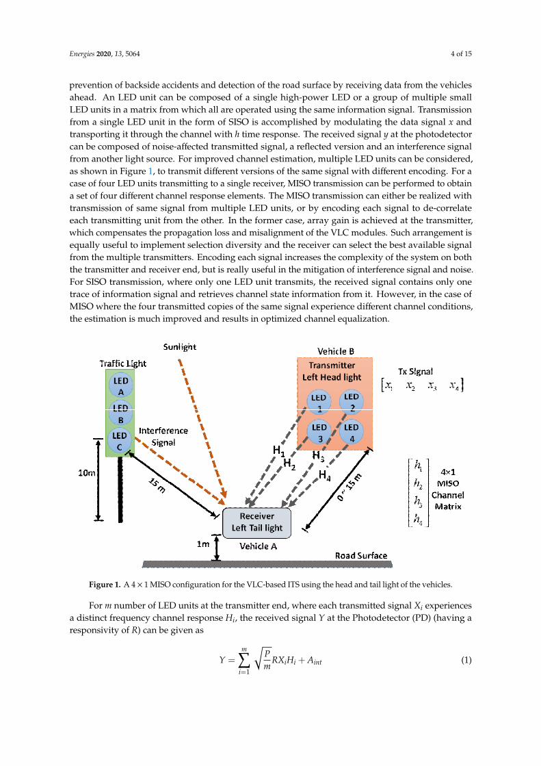
The considered VLC system in this work is based on commercially available LEDs which can beused in the vehicles as head lights. The typical bandwidth of 20 MHz from an LED is continuouslyimproving with the development of new techniques in LED manufacturing and advancements infabrication processes. Figure 1 shows a typical application of VLC in an ITS where the head light of arear vehicle is used to transmit information towards the tail light of a vehicle in front. Such a scenariois considered here to make a realistic model for the ITS because the concept of vehicle lights-basedVLC for road safety is already in place for commercial implementation. The associated benefits include
Energies 2020, 13, 5064 4 of 15
prevention of backside accidents and detection of the road surface by receiving data from the vehiclesahead. An LED unit can be composed of a single high-power LED or a group of multiple smallLED units in a matrix from which all are operated using the same information signal. Transmissionfrom a single LED unit in the form of SISO is accomplished by modulating the data signal x andtransporting it through the channel with h time response. The received signal y at the photodetectorcan be composed of noise-affected transmitted signal, a reflected version and an interference signalfrom another light source. For improved channel estimation, multiple LED units can be considered,as shown in Figure 1, to transmit different versions of the same signal with different encoding. For acase of four LED units transmitting to a single receiver, MISO transmission can be performed to obtaina set of four different channel response elements. The MISO transmission can either be realized withtransmission of same signal from multiple LED units, or by encoding each signal to de-correlateeach transmitting unit from the other. In the former case, array gain is achieved at the transmitter,which compensates the propagation loss and misalignment of the VLC modules. Such arrangement isequally useful to implement selection diversity and the receiver can select the best available signalfrom the multiple transmitters. Encoding each signal increases the complexity of the system on boththe transmitter and receiver end, but is really useful in the mitigation of interference signal and noise.For SISO transmission, where only one LED unit transmits, the received signal contains only onetrace of information signal and retrieves channel state information from it. However, in the case ofMISO where the four transmitted copies of the same signal experience different channel conditions,the estimation is much improved and results in optimized channel equalization.
Energies 2020, 13, x FOR PEER REVIEW 4 of 16
The considered VLC system in this work is based on commercially available LEDs which can be used in the vehicles as head lights. The typical bandwidth of 20 MHz from an LED is continuously improving with the development of new techniques in LED manufacturing and advancements in fabrication processes. Figure 1 shows a typical application of VLC in an ITS where the head light of a rear vehicle is used to transmit information towards the tail light of a vehicle in front. Such a scenario is considered here to make a realistic model for the ITS because the concept of vehicle lights-based VLC for road safety is already in place for commercial implementation. The associated benefits include prevention of backside accidents and detection of the road surface by receiving data from the vehicles ahead. An LED unit can be composed of a single high-power LED or a group of multiple small LED units in a matrix from which all are operated using the same information signal. Transmission from a single LED unit in the form of SISO is accomplished by modulating the data signal x and transporting it through the channel with h time response. The received signal y at the photodetector can be composed of noise-affected transmitted signal, a reflected version and an interference signal from another light source. For improved channel estimation, multiple LED units can be considered, as shown in Figure 1, to transmit different versions of the same signal with different encoding. For a case of four LED units transmitting to a single receiver, MISO transmission can be performed to obtain a set of four different channel response elements. The MISO transmission can either be realized with transmission of same signal from multiple LED units, or by encoding each signal to de-correlate each transmitting unit from the other. In the former case, array gain is achieved at the transmitter, which compensates the propagation loss and misalignment of the VLC modules. Such arrangement is equally useful to implement selection diversity and the receiver can select the best available signal from the multiple transmitters. Encoding each signal increases the complexity of the system on both the transmitter and receiver end, but is really useful in the mitigation of interference signal and noise. For SISO transmission, where only one LED unit transmits, the received signal contains only one trace of information signal and retrieves channel state information from it. However, in the case of MISO where the four transmitted copies of the same signal experience different channel conditions, the estimation is much improved and results in optimized channel equalization.
Figure 1. A 4 × 1 MISO configuration for the VLC-based ITS using the head and tail light of the vehicles. Figure 1. A 4 × 1 MISO configuration for the VLC-based ITS using the head and tail light of the vehicles.
For m number of LED units at the transmitter end, where each transmitted signal Xi experiencesa distinct frequency channel response Hi, the received signal Y at the Photodetector (PD) (having aresponsivity of R) can be given as
Y =m∑
i=1
√Pm
RXiHi + Aint (1)

Energies 2020, 13, 5064 5 of 15
where P represents the total power drawn from the vehicle for the transmitter, Aint represents theinterference signal and N denotes background noise. For a separation of D between the transmitterand receiver, the channel response (H) for the ith LED will have a strong LoS component given by
Hi = cosuθcos ϕu + 12πD2 (2)
where θ represents the angle for irradiance which depends on the orientation of the LED and ϕ denotesthe angle of incident between the axes of transmitter and receiver. The value of ϕ remains between 0and the receiver’s semi-angle. The index u, in terms of ϕ can be elaborated as
u = −ln(2)/ln(cos(ϕ)) (3)
Even for signal with no interference, the effect of atmospheric attenuation coefficient (α) and fieldof view (FOV) θFOV on the received power (Pr) has to be considered. The general equation for thePr becomes
Pr =e−αDP
(DθFOV/2π)2 (4)
where several factors still need to be considered for VLC transmission. The accuracy in the estimationof received power can be increased by a detailed model [36] for the LOS signal, given by
Pr, e f f = PrG(ϕ)
(Ae f f cosϕ
)D22π
∫ π0 G(ϕ)sinϕdϕ
(5)
In Equation (5), G(ϕ) denotes beam pattern for transmitter and Aeff is the effective area of thephotodetector. The Pr,eff is the improved version of the estimated power and will be used in thesimulation analysis. The signal-to-noise ratio (SNR) for the SISO transmission, for a noise spectraldensity of σ2
N, can be estimated as
SNR =Pm R2
∣∣∣∑mi=1 Hi
∣∣∣σ2
N
2
(6)
Given the condition in Equation (6), the data rate (Υ) is directly related to the bandwidth of thetransmitter (B) for the case of on-off-keying (OOK). To increase the data rate by using an advancedmodulation scheme such as Pulse Amplitude Modulation (PAM), in which the intensity of the carrierpulses can be changed with high speed, the tradeoff exists between the PAM level (L) and the powerpenalty caused due to the increase in intensity-modulated levels. For using L-PAM, which encodesbsym number of bits to a symbol, the penalty in terms of power (Pp) can be given as
Pp =L− 1√
bsym(7)
This shows that increasing the spectral efficiency by a factor of two, by using a higher level PAMscheme, will require approximately 6.5 dB more power. This does not include the power penaltycaused by the non-linearities due to the higher order PAM. Due to this reason, only OOK has beenused in this work to present a low-complex and highly linear system for ITS. To consider a reflectedversion of the signal which exists due to the reflection from the road surface, street pole or a sign-board,a diffused signal with a modified road surface reflection profile [37] can be used to model the reflected(non-LOS) signal as
Xre f = Xcos(Φ)µ
π(8)
In Equation (8), Φ denotes the angle of diffused reflection and µ denotes the amount of reflectivity.The H represents a 4 × 4 channel matrix which is evaluated using a training sequence (TS) before the
Energies 2020, 13, 5064 6 of 15
actual transmission. The received signal Y and the pre-known TS can be used at the receiver end toestimate the channel using a simple zero-forcing equalizer performing the Yi/TS operation (wherei represents the number of transmitting units). The inverse of the estimated channel matrix can betherefore used to recover the data from the channel effects. The channel matrix is estimated using atraining sequence before the actual transmission. To achieve 4 × 1 MISO, the diversity is implementedon the transmitter side by coding the information signal into four different versions. Each versionis transmitted through an individual LED unit. Even if the complexity of the system is reduced bytransmitting same signal through each LED unit, array gain [38] can be achieved using the channeltime response h(t) (which can be estimated from Equation (2) for individual units) for all m units as
Gain =1√
m∑m
i=1
∣∣∣∣∣∣hi(t)∣∣∣∣∣∣2 (9)
With MISO processing, the Equation (6) can be modified as
SNR = max
E∣∣∣∣hT wt|wt |
X∣∣∣∣
E[n2]
2 =m∑
i=1
|hi|2 PT
σ2 (10)
where W represents the coding matrix which is applied to the information signal at the transmitter side.Equation (10) represents the estimated SNR after MISO transmission, which takes into account thechannel response of multiple transmitted signals and, hence, enhancement in the overall performance.Then finally the capacity (SNR dependent) of the MISO system can be given as
CMIMO = log2
1 +m∑
i=1
|hi|2 PT
σ2
(11)
Finally, in the presence of interference signal, the optimum receiver configuration can be obtainedby first estimating the decision static (x*) of the information signal using the waveform-spreadingcorrelator. Here, the cost function (Γ) represents the quality measurements of the system as a sum ofthe Mean Square Error (MSE) of all MISO channels that are required to be determined for the encodedsequence (c) used for the transmitting signal, given by
Y = x∗m∑
i=1
ci
∫ T
0r(t + Ti)Γ
∗(t)dt (12)
where r represents the cross-correlation function and T is the time delay with respect to the direct pathsignal. Thus, by using the correlation function (K) of the composite signal consisting of the informationsignal, noise and interference signal, the SNR for the optimized receiver becomes
SNR =(E0/Enoise)
∑mi=1
∣∣∣∣∫ T0 ((xi(t) × hi(t))Γ∗(t)dt
∣∣∣∣2∫ T0
∫ T0 K(t0, τ)Γ∗(t0)Γ∗(τ)dt0dτ
(13)
Considering the vertical and horizontal movements of the vehicles due to road surface and trafficconditions [39], a set of four LEDs is arranged in a square shape to ensure the availability of adequateamounts of illumination in different conditions. A lower number of units will cause an insufficientlevel of received power [40]. On the other hand, increasing the number of LED units will result inhigh cost and complexity. The next section will present the simulations performed on the basis of theproposed system and an optimized receiver for MISO transmission.
Energies 2020, 13, 5064 7 of 15
4. Simulation Model
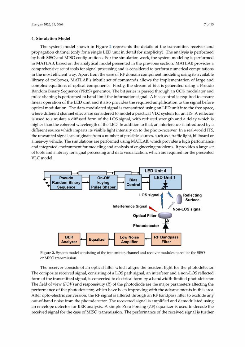
The system model shown in Figure 2 represents the details of the transmitter, receiver andpropagation channel (only for a single LED unit in detail for simplicity). The analysis is performedby both SISO and MISO configurations. For the simulation work, the system modeling is performedin MATLAB, based on the analytical model presented in the previous section. MATLAB provides acomprehensive set of tools for signal processing and is considered to perform numerical computationsin the most efficient way. Apart from the ease of RF domain component modeling using its availablelibrary of toolboxes, MATLAB’s inbuilt set of commands allows the implementation of large andcomplex equations of optical components. Firstly, the stream of bits is generated using a PseudoRandom Binary Sequence (PRBS) generator. The bit series is passed through an OOK modulator andpulse shaping is performed to band limit the information signal. A bias control is required to ensurelinear operation of the LED unit and it also provides the required amplification to the signal beforeoptical modulation. The data-modulated signal is transmitted using an LED unit into the free space,where different channel effects are considered to model a practical VLC system for an ITS. A reflectoris used to simulate a diffused form of the LOS signal, with reduced strength and a delay which ishigher than the coherent wavelength of the LED. In addition to that, an interference is introduced by adifferent source which imparts its visible light intensity on to the photo-receiver. In a real-world ITS,the unwanted signal can originate from a number of possible sources, such as a traffic light, billboard ora near-by vehicle. The simulations are performed using MATLAB, which provides a high performanceand integrated environment for modeling and analysis of engineering problems. It provides a large setof tools and a library for signal processing and data visualization, which are required for the presentedVLC model.
Energies 2020, 13, x FOR PEER REVIEW 7 of 16
4. Simulation Model
The system model shown in Figure 2 represents the details of the transmitter, receiver and propagation channel (only for a single LED unit in detail for simplicity). The analysis is performed by both SISO and MISO configurations. For the simulation work, the system modeling is performed in MATLAB, based on the analytical model presented in the previous section. MATLAB provides a comprehensive set of tools for signal processing and is considered to perform numerical computations in the most efficient way. Apart from the ease of RF domain component modeling using its available library of toolboxes, MATLAB’s inbuilt set of commands allows the implementation of large and complex equations of optical components. Firstly, the stream of bits is generated using a Pseudo Random Binary Sequence (PRBS) generator. The bit series is passed through an OOK modulator and pulse shaping is performed to band limit the information signal. A bias control is required to ensure linear operation of the LED unit and it also provides the required amplification to the signal before optical modulation. The data-modulated signal is transmitted using an LED unit into the free space, where different channel effects are considered to model a practical VLC system for an ITS. A reflector is used to simulate a diffused form of the LOS signal, with reduced strength and a delay which is higher than the coherent wavelength of the LED. In addition to that, an interference is introduced by a different source which imparts its visible light intensity on to the photo-receiver. In a real-world ITS, the unwanted signal can originate from a number of possible sources, such as a traffic light, billboard or a near-by vehicle. The simulations are performed using MATLAB, which provides a high performance and integrated environment for modeling and analysis of engineering problems. It provides a large set of tools and a library for signal processing and data visualization, which are required for the presented VLC model.
LED Unit 4LED Unit 1Pseudo
Random Binary Sequence
On-Off keying
Pulse Shaper
BiasControl
Optical Filter
RF Bandpass Filter
Photodetector
Low NoiseAmplifierEqualizerBER
Analyzer
Interference Signal
LOS signal
Non-LOS signal
ReflectingSurface
Figure 2. System model consisting of the transmitter, channel and receiver modules to realize the SISO or MISO transmission.
The receiver consists of an optical filter which aligns the incident light for the photodetector. The composite received signal, consisting of a LOS path signal, an interferer and a non-LOS reflected form of the transmitted signal, is converted to electrical form by a bandwidth-limited photodetector. The field of view (FOV) and responsivity (R) of the photodiode are the major parameters affecting the performance of the photodetector, which have been improving with the advancements in this area. After opto-electric conversion, the RF signal is filtered through an RF bandpass filter to exclude any out-of-band noise from the photodetector. The recovered signal is amplified and demodulated using an envelope detector for BER analysis. A simple Zero Forcing (ZF) equalizer is used to decode the received signal for the case of MISO transmission. The performance of the received signal is further improved using a blind-adaptive time domain equalizer, as presented in [41]. The set of parameters used for the simulation work is shown briefly in Table 1. For a realistic approach, the experimental
Figure 2. System model consisting of the transmitter, channel and receiver modules to realize the SISOor MISO transmission.
The receiver consists of an optical filter which aligns the incident light for the photodetector.The composite received signal, consisting of a LOS path signal, an interferer and a non-LOS reflectedform of the transmitted signal, is converted to electrical form by a bandwidth-limited photodetector.The field of view (FOV) and responsivity (R) of the photodiode are the major parameters affecting theperformance of the photodetector, which have been improving with the advancements in this area.After opto-electric conversion, the RF signal is filtered through an RF bandpass filter to exclude anyout-of-band noise from the photodetector. The recovered signal is amplified and demodulated usingan envelope detector for BER analysis. A simple Zero Forcing (ZF) equalizer is used to decode thereceived signal for the case of MISO transmission. The performance of the received signal is further

Energies 2020, 13, 5064 8 of 15
improved using a blind-adaptive time domain equalizer, as presented in [41]. The set of parametersused for the simulation work is shown briefly in Table 1. For a realistic approach, the experimental setof values for the optical components [12,28] and 4 × 1 MISO channel [41] are used. A training sequenceof 10 k length is used to optimize the equalizer weights at the start of the transmission. Afterwards,the channel state information from the MISO processing is used to change the equalizer weights.For practical V2V communication where channel conditions are constantly changing, the frequenttransmission of the training sequence will considerably reduce the effective data rate. Therefore, the useof MISO processing at the receiver becomes more useful in such scenarios.
Table 1. Set of parameters used for the analytical model and their values for the simulation analysis.
Module Parameter Symbol Value
Transmitter
Semi-angle of LED ψ 50◦
Number of LED units for MISO m 4Angle of irradiance θ 35◦
Angle of incidence ϕ 25◦
LED Bandwidth B 20 MHzNoise bandwidth factor I 0.5
Channel
Diffused reflectivity µ 0.4Angle of diffused reflection Φ 70◦
Distance between transmitterand receiver D 0–15 m
Receiver
Responsivity R 0.6 A/WFOV of the PD ∆ 20◦
PD aperture diameter A 10 cmRF Bessel filter order n 4
5. Results and Discussion
This section presents the simulation results considering the system model presented in theSection 4. Figure 3 shows the 3D representation of the received power from a group of four LED unitsat the transmitter end. As it can be seen, the transmitted energy from each LED is directed towards thecentral axis of the LED. The respective SNR is shown in Figure 4 where the area between the LED unitsexperiences low SNR, as detected by the photo-receiver.
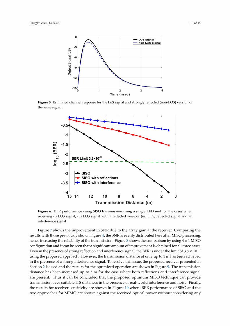
The channel response in the time domain is shown in Figure 5 for the LOS and a strong non-LOSsignal that degrades the performance of the actual transmission. Receiver diversity or the use of anappropriate MISO algorithm at the receiver can benefit from the multipath reflected signal at the cost ofsome complexity. The BER results are shown in Figure 6 for three cases using SISO transmission fromsingle LED unit. The results are shown for (i) a LOS signal which is only affected by the atmosphericattenuation, (ii) a LOS signal with a reflected version from a shiny surface (like a junction safetyconvex mirror along the road) with strong impact, and (iii) when the LOS signal and reflected signalare received along with an interference signal from a neighboring optical source (such as a trafficlight). The results for SISO shows that the threshold of 3.8 × 10⁻³ has only been achieved for theideal case, when no interference signal is present. The transmission is limited to approximately 7 mfor such case and the system is unable to provide an appropriate performance with the reflections orinterference signal.

Energies 2020, 13, 5064 9 of 15
Energies 2020, 13, x FOR PEER REVIEW 9 of 16
Figure 3. Received power (represented in the form of a 3D mesh) for the set of four LED units within the head light area of 4×4 cm2.
Figure 4. Estimated SNR for the four LED units.
The channel response in the time domain is shown in Figure 5 for the LOS and a strong non-LOS signal that degrades the performance of the actual transmission. Receiver diversity or the use of an appropriate MISO algorithm at the receiver can benefit from the multipath reflected signal at the cost of some complexity. The BER results are shown in Figure 6 for three cases using SISO transmission from single LED unit. The results are shown for (i) a LOS signal which is only affected by the atmospheric attenuation, (ii) a LOS signal with a reflected version from a shiny surface (like a junction safety convex mirror along the road) with strong impact, and (iii) when the LOS signal and reflected signal are received along with an interference signal from a neighboring optical source (such as a traffic light). The results for SISO shows that the threshold of 3.8 × 10⁻³ has only been achieved for the
Figure 3. Received power (represented in the form of a 3D mesh) for the set of four LED units withinthe head light area of 4 × 4 cm2.
Energies 2020, 13, x FOR PEER REVIEW 9 of 16
Figure 3. Received power (represented in the form of a 3D mesh) for the set of four LED units within the head light area of 4×4 cm2.
Figure 4. Estimated SNR for the four LED units.
The channel response in the time domain is shown in Figure 5 for the LOS and a strong non-LOS signal that degrades the performance of the actual transmission. Receiver diversity or the use of an appropriate MISO algorithm at the receiver can benefit from the multipath reflected signal at the cost of some complexity. The BER results are shown in Figure 6 for three cases using SISO transmission from single LED unit. The results are shown for (i) a LOS signal which is only affected by the atmospheric attenuation, (ii) a LOS signal with a reflected version from a shiny surface (like a junction safety convex mirror along the road) with strong impact, and (iii) when the LOS signal and reflected signal are received along with an interference signal from a neighboring optical source (such as a traffic light). The results for SISO shows that the threshold of 3.8 × 10⁻³ has only been achieved for the
Figure 4. Estimated SNR for the four LED units.
Energies 2020, 13, 5064 10 of 15
Energies 2020, 13, x FOR PEER REVIEW 10 of 16
ideal case, when no interference signal is present. The transmission is limited to approximately 7m for such case and the system is unable to provide an appropriate performance with the reflections or interference signal.
Figure 5. Estimated channel response for the LoS signal and strongly reflected (non-LOS) version of the same signal.
Figure 6. BER performance using SISO transmission using a single LED unit for the cases when receiving (i) LOS signal; (ii) LOS signal with a reflected version; (iii) LOS, reflected signal and an interference signal.
Figure 7 shows the improvement in SNR due to the array gain at the receiver. Comparing the results with those previously shown Figure 4, the SNR is evenly distributed here after MISO processing, hence increasing the reliability of the transmission. Figure 8 shows the comparison by using 4 × 1 MISO configuration and it can be seen that a significant amount of improvement is obtained for all three cases. Even in the presence of strong reflection and interference signal, the BER is under the limit of 3.8 × 10⁻³ using the proposed approach. However, the transmission distance of only up to 1 m has been achieved in the presence of a strong interference signal. To resolve this issue, the proposed receiver presented in Section 2 is used and the results for the optimized operation are shown in Figure 9. The transmission distance has been increased up to 5 m for the case where both reflections and interference signal are present. Thus it can be concluded that the proposed optimum MISO technique can provide transmission over suitable ITS distances in the presence of real-world interference and noise. Finally, the results for receiver sensitivity are shown in Figure 10 where BER
Figure 5. Estimated channel response for the LoS signal and strongly reflected (non-LOS) version ofthe same signal.
Energies 2020, 13, x FOR PEER REVIEW 10 of 16
ideal case, when no interference signal is present. The transmission is limited to approximately 7m for such case and the system is unable to provide an appropriate performance with the reflections or interference signal.
Figure 5. Estimated channel response for the LoS signal and strongly reflected (non-LOS) version of the same signal.
Figure 6. BER performance using SISO transmission using a single LED unit for the cases when receiving (i) LOS signal; (ii) LOS signal with a reflected version; (iii) LOS, reflected signal and an interference signal.
Figure 7 shows the improvement in SNR due to the array gain at the receiver. Comparing the results with those previously shown Figure 4, the SNR is evenly distributed here after MISO processing, hence increasing the reliability of the transmission. Figure 8 shows the comparison by using 4 × 1 MISO configuration and it can be seen that a significant amount of improvement is obtained for all three cases. Even in the presence of strong reflection and interference signal, the BER is under the limit of 3.8 × 10⁻³ using the proposed approach. However, the transmission distance of only up to 1 m has been achieved in the presence of a strong interference signal. To resolve this issue, the proposed receiver presented in Section 2 is used and the results for the optimized operation are shown in Figure 9. The transmission distance has been increased up to 5 m for the case where both reflections and interference signal are present. Thus it can be concluded that the proposed optimum MISO technique can provide transmission over suitable ITS distances in the presence of real-world interference and noise. Finally, the results for receiver sensitivity are shown in Figure 10 where BER
Figure 6. BER performance using SISO transmission using a single LED unit for the cases whenreceiving (i) LOS signal; (ii) LOS signal with a reflected version; (iii) LOS, reflected signal and aninterference signal.
Figure 7 shows the improvement in SNR due to the array gain at the receiver. Comparing theresults with those previously shown Figure 4, the SNR is evenly distributed here after MISO processing,hence increasing the reliability of the transmission. Figure 8 shows the comparison by using 4 × 1 MISOconfiguration and it can be seen that a significant amount of improvement is obtained for all three cases.Even in the presence of strong reflection and interference signal, the BER is under the limit of 3.8 × 10⁻³
using the proposed approach. However, the transmission distance of only up to 1 m has been achievedin the presence of a strong interference signal. To resolve this issue, the proposed receiver presented inSection 2 is used and the results for the optimized operation are shown in Figure 9. The transmissiondistance has been increased up to 5 m for the case where both reflections and interference signalare present. Thus it can be concluded that the proposed optimum MISO technique can providetransmission over suitable ITS distances in the presence of real-world interference and noise. Finally,the results for receiver sensitivity are shown in Figure 10 where BER performance of SISO and thetwo approaches for MIMO are shown against the received optical power without considering any

Energies 2020, 13, 5064 11 of 15
reflection or interference signal for simplicity. The transmission distance is fixed to 6 m, and the effectsof atmospheric attenuation and FOV are included to compare the performance of each case in terms ofreceived power. The proposed MISO processing results in improved receiver sensitivity due to theenhancement in SNR and thus improves the power efficiency of the overall system as the photodetectorrequires a reduced amount of power to provide the same BER performance, as in the case of MISO witha conventional receiver. Even in the presence of strong interference signal, the proposed frameworkshows successful transmission of much higher data rates as compared to [27], and three times longertransmission distance as compared to the previously reported MIMO-based VLC transmission [30].This shows the superiority of the proposed MISO receiver in the VLC-based ITS, which is evident fromthe provision of higher data rates, longer transmission distances and improved receiver sensitivitythan recently proposed solutions [31].
Energies 2020, 13, x FOR PEER REVIEW 11 of 16
performance of SISO and the two approaches for MIMO are shown against the received optical power without considering any reflection or interference signal for simplicity. The transmission distance is fixed to 6 m, and the effects of atmospheric attenuation and FOV are included to compare the performance of each case in terms of received power. The proposed MISO processing results in improved receiver sensitivity due to the enhancement in SNR and thus improves the power efficiency of the overall system as the photodetector requires a reduced amount of power to provide the same BER performance, as in the case of MISO with a conventional receiver. Even in the presence of strong interference signal, the proposed framework shows successful transmission of much higher data rates as compared to [27], and three times longer transmission distance as compared to the previously reported MIMO-based VLC transmission [30]. This shows the superiority of the proposed MISO receiver in the VLC-based ITS, which is evident from the provision of higher data rates, longer transmission distances and improved receiver sensitivity than recently proposed solutions [31].
Figure 7. Improved SNR for the LED array using array gain from MISO transmission.
Figure 7. Improved SNR for the LED array using array gain from MISO transmission.
Energies 2020, 13, x FOR PEER REVIEW 11 of 16
performance of SISO and the two approaches for MIMO are shown against the received optical power without considering any reflection or interference signal for simplicity. The transmission distance is fixed to 6 m, and the effects of atmospheric attenuation and FOV are included to compare the performance of each case in terms of received power. The proposed MISO processing results in improved receiver sensitivity due to the enhancement in SNR and thus improves the power efficiency of the overall system as the photodetector requires a reduced amount of power to provide the same BER performance, as in the case of MISO with a conventional receiver. Even in the presence of strong interference signal, the proposed framework shows successful transmission of much higher data rates as compared to [27], and three times longer transmission distance as compared to the previously reported MIMO-based VLC transmission [30]. This shows the superiority of the proposed MISO receiver in the VLC-based ITS, which is evident from the provision of higher data rates, longer transmission distances and improved receiver sensitivity than recently proposed solutions [31].
Figure 7. Improved SNR for the LED array using array gain from MISO transmission.
Figure 8. BER performance using 4 × 1 MISO processing for the cases when the receiver detectsMIMO-encoded (i) LOS signal; (ii) LOS signal with a reflected version; (iii) LOS, reflected signal and aninterference signal.

Energies 2020, 13, 5064 12 of 15
Energies 2020, 13, x FOR PEER REVIEW 12 of 16
Figure 8. BER performance using 4 × 1 MISO processing for the cases when the receiver detects MIMO-encoded (i) LOS signal; (ii) LOS signal with a reflected version; (iii) LOS, reflected signal and an interference signal.
Figure 9. BER performance using 4 × 1 MISO processing with the proposed optimum receiver for the cases when the receiver detects MIMO-encoded (i) LOS signal; (ii) LOS signal with a reflected version; (iii) LOS, reflected signal and an interference signal.
Figure 10. BER performance using SISO and 4 × 1 MISO processing with the conventional and proposed optimum receiver against the received optical power for a fixed transmission distance of 6 m.
6. Conclusions
This paper presents an LED-based VLC system for ITS applications where the head and tail lights of vehicles are used as transmitter and receiver, respectively. The proposed VLC system is presented using analytical modeling and analysis is performed using simulations for SISO and MISO-
Figure 9. BER performance using 4 × 1 MISO processing with the proposed optimum receiver for thecases when the receiver detects MIMO-encoded (i) LOS signal; (ii) LOS signal with a reflected version;(iii) LOS, reflected signal and an interference signal.
Energies 2020, 13, x FOR PEER REVIEW 12 of 16
Figure 8. BER performance using 4 × 1 MISO processing for the cases when the receiver detects MIMO-encoded (i) LOS signal; (ii) LOS signal with a reflected version; (iii) LOS, reflected signal and an interference signal.
Figure 9. BER performance using 4 × 1 MISO processing with the proposed optimum receiver for the cases when the receiver detects MIMO-encoded (i) LOS signal; (ii) LOS signal with a reflected version; (iii) LOS, reflected signal and an interference signal.
Figure 10. BER performance using SISO and 4 × 1 MISO processing with the conventional and proposed optimum receiver against the received optical power for a fixed transmission distance of 6 m.
6. Conclusions
This paper presents an LED-based VLC system for ITS applications where the head and tail lights of vehicles are used as transmitter and receiver, respectively. The proposed VLC system is presented using analytical modeling and analysis is performed using simulations for SISO and MISO-
Figure 10. BER performance using SISO and 4× 1 MISO processing with the conventional and proposedoptimum receiver against the received optical power for a fixed transmission distance of 6 m.
6. Conclusions
This paper presents an LED-based VLC system for ITS applications where the head and tail lightsof vehicles are used as transmitter and receiver, respectively. The proposed VLC system is presentedusing analytical modeling and analysis is performed using simulations for SISO and MISO-basedtransmission. Different cases are considered to explore the system model in the presence of strongreflections and interference signal for transmission distances of up to 15 m. It is concluded thatmultipath reflections have negligible effect due to their small amplitude and comparatively large area
Energies 2020, 13, 5064 13 of 15
of the photodetector, but strong sunlight or interference from a neighboring vehicle severely affects theperformance. Simulation results show that forward error correction (FEC) threshold of BER 3.8 × 10⁻³
can be achieved using the proposed MISO receiver model at much longer distances, as compared toconventional SISO and MISO operation. The optimized receiver design also shows improvements inthe sensitivity of the receiver, and hence can be used as a promising solution for future VLC-basedITS applications.
Future work includes additional signal processing to discriminate between a vehicle in closeproximity or strong sunlight, in case of a sudden increase in illumination. The formation of a VLC-basedvehicular network can also be considered for improved coordination and road safety.
7. Research Limitations and Implications
VLC-based ITS is an emerging concept which will have its associated challenges and socio-economiceffects. The integration of the VLC components with existing transportation networks, and compatibilitywith the legacy communication networks, is a rising challenge for the standardization bodies.Apart from V2V communication, the telematics of transport [42] can play an important role inthe development of smart-societies and lead to an increase in socio-economic benefits [43] throughtraffic management, upgrading of emergency services, administration of traffic enforcement andsupport to the logistics industry. Future work on the VLC-based ITS may include the environmentalimpact assessment and cost–benefit analysis to attract the automotive industry in the developmentand use of VLC components in the head and tail lights, as presented in the proposed framework.
The research limitations related to VLC-based ITS include limited bandwidth of the LED devices,maintaining LOS connectivity on a bumpy road and flickering of LEDs due to continuous streamsof ones and zeros. The implications of such a system can be anticipated, such as the provision of RFspectrum for other applications, provision of dual technology in parallel to existing RF communicationsystems, more efficient usage of the existing lighting infrastructure, and automobile lights and newopportunities in the area of photonics and transportation.
Author Contributions: Conceptualization, U.H., and F.M.; methodology, M.I., F.A., U.H. and A.SA.; software,F.A., U.H. and F.M.; validation, F.A. and U.H.; formal analysis, F.A. and U.H.; investigation, F.A., U.H., F.M., andW.G.; data curation, U.H.; writing—original draft preparation, U.H.; writing—review and editing, M.I., F.M.,A.SA., M.I., A.G., and S.U.; visualization, U.H.; resources, W.G.; supervision, U.H. and M.I.; project administration,F.M., M.I., A.SA., A.G., S.U.; and W.G.; funding acquisition, M.I. and A.G. All authors have read and agreed to thepublished version of the manuscript.
Funding: This research was funded by the AGH University of Science and Technology, grant No. 16.16.120.773 topay the open access article processing charges of the journal.
Acknowledgments: This work was supported by the Ministry of Education and the Deanship of ScientificResearch, Najran University, Kingdom of Saudi Arabia, under code number NU/ESCI/17/0114.
Conflicts of Interest: The authors declare no conflict of interest. The funders had no role in the design of thestudy; in the collection, analyses, or interpretation of data; in the writing of the manuscript, or in the decision topublish the results.
References
1. Nawaz, T.; Seminara, M.; Caputo, S.; Mucchi, L.; Cataliotti, F.S.; Catani, J. IEEE 802.15. 7-compliant ultra-lowlatency relaying VLC system for safety-critical ITS. IEEE Trans. Veh. Technol. 2019, 68, 12040–12051. [CrossRef]
2. Azmat, M.; Kummer, S. Potential applications of unmanned ground and aerial vehicles to mitigate challengesof transport and logistics-related critical success factors in the humanitarian supply chain. Asian J. Sustain.Soc. Responsib. 2020, 5, 1–22. [CrossRef]
3. Pojani, D.; Stead, D. Policy design for sustainable urban transport in the global south. Policy Des. Pract. 2018,1, 90–102. [CrossRef]
4. Muñoz-Villamizar, A.; Montoya-Torres, J.R.; Faulin, J. Impact of the use of electric vehicles in collaborativeurban transport networks: A case study. Transp. Res. Part D 2017, 50, 40–54. [CrossRef]

Energies 2020, 13, 5064 14 of 15
5. Matheus, L.E.M.; Vieira, A.B.; Vieira, L.F.M.; Vieira, M.A.M.; Gnawali, O. Visible Light Communication:Concepts, Applications and Challenges. IEEE Commun. Surv. Tutor. 2019, 21, 3204–3237. [CrossRef]
6. Lorriere, N.; Simon, J.-J.; Betrancourt, N.; Pasquinelli, M.; Chabriel, G.; Barrere, J.; Escoubas, L.; Wu, J.-L.;Bermudez, V.; Ruiz, C. Photovoltaic Solar Cells for Outdoor LiFi Communications. J. Light. Technol. 2020,38, 1. [CrossRef]
7. Turan, B.; Narmanlioglu, O.; Ergen, S.C.; Uysal, M. On the Performance of MIMO OFDM-Based Intra-VehicularVLC Networks. In Proceedings of the 2016 IEEE 84th Vehicular Technology Conference (VTC-Fall), Instituteof Electrical and Electronics Engineers (IEEE), Montréal, QC, Canada, 18–21 September 2016; pp. 1–5.
8. Lv, H.; Feng, L.F.L.; Yang, A.; Guo, P.; Huang, H.; Chen, S.-F. High accuracy VLC Indoor Positioning systemwith differential detection. IEEE Photonics J. 2017, 9, 1. [CrossRef]
9. Feng, L.; Yang, H.; Hu, R.Q.; Wang, J. MmWave and VLC-Based Indoor Channel Models in 5G WirelessNetworks. IEEE Wirel. Commun. 2018, 25, 70–77. [CrossRef]
10. Lourenço, N.; Siegel, M.; Gabriel, C.; Pessoa, L.; Silva, B.; Ghassemlooy, Z.; Alves, L.M.L.M.; Zvánovec, S.;Khalighi, M.-A. VLC for indoor positioning: An industrial view on applications. In Visible LightCommunications: Theory and Applications; CRC Press: Boca Raton, FL, USA, 2017; pp. 373–404.
11. Ndjiongue, A.R.; Ferreira, H.C. An overview of outdoor visible light communications. Trans. Emerg.Telecommun. Technol. 2018, 29, e3448. [CrossRef]
12. Dahri, F.A.; Mangrio, H.B.; Baqai, A.; Umrani, F.A. Experimental Evaluation of Intelligent Transport Systemwith VLC Vehicle-to-Vehicle Communication. Wirel. Pers. Commun. 2018, 106, 1885–1896. [CrossRef]
13. Tebruegge, C.; Memedi, A.; Dressler, F. Reduced Multiuser-Interference for Vehicular VLC Using SDMA andMatrix Headlights. In Proceedings of the 2019 IEEE Global Communications Conference (GLOBECOM),Institute of Electrical and Electronics Engineers (IEEE), Taipei, Taiwan, 7–11 December 2019; pp. 1–6.
14. Habib, U.; Steeg, M.; Stohr, A.; Gomes, N.J. Radio-over-fiber-supported 60GHz multiuser transmission usingleaky wave antenna. In Proceedings of the 2017 International Topical Meeting on Microwave Photonics(MWP), Institute of Electrical and Electronics Engineers (IEEE), Beijing, China, 23–26 October 2017; pp. 1–4.
15. Ali, F.; Ahmad, S.; Muhammad, F.; Abbas, Z.H.; Habib, U.; Kim, S. Adaptive Equalization for DispersionMitigation in Multi-Channel Optical Communication Networks. Electronics 2019, 8, 1364. [CrossRef]
16. Sushanth, K.S.; Chockalingam, A. Multiple-LED Complex Modulation Schemes for Indoor MIMO VLCSystems. In Proceedings of the IEEE International Conference on Communications (ICC), Shanghai, China,20–24 May 2019; pp. 1–6.
17. Cha, J.; Vinayagam, M. LED-ID Technology for IEEE802. 15.7 m OWC. IEEE COMSOC MMTC E-Lett. 2018,13, 29–33.
18. Cuba-Zúñiga, D.J.; Mafra, S.B.; Mejía-Salazar, J.R. Cooperative Full-Duplex V2V-VLC in Rectilinear andCurved Roadway Scenarios. Sensors 2020, 20, 3734. [CrossRef]
19. Ivascu, C.O.; Ursutiu, D.; Samoila, C. Improve VLC LiFi Performance for V2V Communication.In Cyber-Physical Systems and Digital Twins (Lecture Notes in Networks and Systems); Springer: Basel, Switzerland,2019; Volume 80, pp. 315–329. [CrossRef]
20. Karbalayghareh, M.; Miramirkhani, F.; Eldeeb, H.B.; Kizilirmak, R.C.; Sait, S.M.; Uysal, M. Channel Modellingand Performance Limits of Vehicular Visible Light Communication Systems. IEEE Trans. Veh. Technol. 2020,69, 1. [CrossRef]
21. Wu, L.; Zhang, Z.; Dang, J.; Liu, H. Blind Interference Alignment for Multiuser MISO Indoor Visible LightCommunications. IEEE Commun. Lett. 2017, 21, 1039–1042. [CrossRef]
22. Habib, U.; Aighobahi, A.E.; Wang, C.; Gomes, N.J. Radio over fiber transport of mm-Wave 2 × 2 MIMO forspatial diversity and multiplexing. In Proceedings of the IEEE International Topical Meeting on MicrowavePhotonics (MWP), Long Beach, CA, USA, 31 October–3 November 2016; pp. 39–42.
23. Ma, S.; Zhang, T.; Lu, S.; Li, H.; Wu, Z.; Li, S. Energy Efficiency of SISO and MISO in Visible LightCommunication Systems. J. Light. Technol. 2018, 36, 2499–2509. [CrossRef]
24. Yang, H.; Chen, C.; Zhong, W.-D.; Alphones, A.; Xie, X. Joint Precoder and Equalizer Design for Multi-UserMulti-Cell MIMO VLC Systems. IEEE Trans. Veh. Technol. 2018, 67, 11354–11364. [CrossRef]
25. Malti, R.; Ekongolo, S.; Ragot, J. Dynamic SISO and MISO system approximations based on optimal Laguerremodels. IEEE Trans. Autom. Control. 1998, 43, 1318–1323. [CrossRef]
Energies 2020, 13, 5064 15 of 15
26. Battikh, D.B.C.; Kelif, J.M.; Coupechoux, M.; Godlewski, P. Dynamic system performance of SISO, MISOand MIMO Alamouti schemes. In Proceedings of the 34th IEEE Sarnoff Symposium, Princeton, NJ, USA,2–4 May 2011; pp. 1–5.
27. Alian, E.H.M.; Saffar, H.E.; Mitran, P. Cross-Band Interference Reduction Trade-Offs in SISO and MISOOFDM-Based Cognitive Radios. IEEE Trans. Wirel. Commun. 2012, 11, 2436–2445. [CrossRef]
28. Marabissi, D.; Mucchi, L.; Caputo, S.; Nizzi, F.; Pecorella, T.; Fantacci, R.; Nawaz, T.; Seminara, M.; Catani, J.Experimental Measurements of a Joint 5G-VLC Communication for Future Vehicular Networks. J. Sens.Actuator Netw. 2020, 9, 32. [CrossRef]
29. Avătămănit,ei, S.-A.; Căilean, A.-M.; Done, A.; Dimian, M.; Prelipceanu, M. Noise Resilient Outdoor TrafficLight Visible Light Communications System Based on Logarithmic Transimpedance Circuit: ExperimentalDemonstration of a 50 m Reliable Link in Direct Sun Exposure. Sensors 2020, 20, 909. [CrossRef]
30. Raddo, T.R.; Cimoli, B.; Sirbu, B.; Rommel, S.; Tekin, T.; Monroy, I.T. An end-to-end 5G automotiveecosystem for autonomous driving vehicles. In Proceedings of the SPIE Conference of Broadband AccessCommunication Technologies XIV by International Society for Optics and Photonics, Princeton, NJ, USA,2–4 May 2020; Volume 11307, p. 1130705.
31. Yeh, C.-H.; Wei, L.-Y.; Chow, C.-W. Using a Single VCSEL Source Employing OFDM Downstream Signaland Remodulated OOK Upstream Signal for Bi-directional Visible Light Communications. Sci. Rep. 2017,7, 15846. [CrossRef] [PubMed]
32. Li, B.; Wang, J.; Zhang, R.; Shen, H.; Zhao, C.; Hanzo, L. Multiuser MISO Transceiver Design for IndoorDownlink Visible Light Communication Under Per-LED Optical Power Constraints. IEEE Photonics J. 2015,7, 1–15. [CrossRef]
33. Jeong, J.U.; Lee, K.S.; Seo, H.D.; Han, D.H.; Lee, K.J. Parallel Coding Scheme for Flicker Mitigation inMIMO-VLC. J. Korea Inst. Intell. Transp. Syst. 2016, 15, 146–154. [CrossRef]
34. Petrariu, A.I.; Lavric, A.; Coca, E. VLC for vehicular communications: A multiple input multiple output(MIMO) approach. In Proceedings of the 2018 International Conference on Development and ApplicationSystems (DAS), Institute of Electrical and Electronics Engineers (IEEE), Suceava, Romania, 24–26 May 2018;pp. 134–137.
35. Kowalczyk, M. 2 × 2 MIMO VLC Optical Transmission System Based on LEDs in a Double Role. Acta Phys.Pol. A 2016, 130, 41–44. [CrossRef]
36. Cui, K.; Chen, G.; Xu, Z.; Roberts, R.D. Line-of-sight visible light communication system design anddemonstration. In Proceedings of the IEEE 7th International Symposium on Communication SystemsNetworks and Digital Signal Processing, Newcastle, UK, 21–23 July 2010; pp. 621–625.
37. Luo, P.; Ghassemlooy, Z.; le Minh, H.; Bentley, E.; Burton, A.; Tang, X. Bit-error-rate performance of acar-to-car VLC system using 2 × 2 MIMO. Mediterr. J. Comput. Netw. 2015, 11, 400–407.
38. Zhou, C.; Guo, N.; Qiu, R.C. Experimental Results on Multiple-Input Single-Output (MISO) Time Reversal forUWB Systems in an Office Environment. In Proceedings of the IEEE Military Communications Conference,Washington, DC, USA, 23–25 October 2006; pp. 1–6.
39. Eroglu, Y.S.; Güvenç, I.; Sahin, A.; Yapıcı, Y.; Pala, N.; Yüksel, M. Multi-element VLC networks: LEDassignment, power control, and optimum combining. IEEE J. Sel. Areas Commun. 2017, 36, 121–135.[CrossRef]
40. Vegni, A.M.; Biagi, M. Optimal LED placement in indoor VLC networks. Opt. Express 2019, 27, 8504–8519.[CrossRef]
41. Muhammad, F.; Ali, F.; Habib, U.; Usman, M.; Khan, I.; Kim, S. Time Domain Equalization and DigitalBack-Propagation Method-Based Receiver for Fiber Optic Communication Systems. Int. J. Opt. 2020,2020, 3146374. [CrossRef]
42. Stawiarska, E.; Sobczak, P. The Impact of Intelligent Transportation System Implementations on theSustainable Growth of Passenger Transport in EU Regions. Sustainability 2018, 10, 1318. [CrossRef]
43. Juan, Z.; Wu, J.; McDonald, M. Socio-economic impact assessment of intelligent transport systems.Tsinghua Sci. Technol. 2006, 11, 339–350. [CrossRef]
© 2020 by the authors. Licensee MDPI, Basel, Switzerland. This article is an open accessarticle distributed under the terms and conditions of the Creative Commons Attribution(CC BY) license (http://creativecommons.org/licenses/by/4.0/).