
Optical Fiber Technology - Engineering Papers PDFs/Optical OFDM... · Invited Papers Optical...
18
Invited Papers Optical orthogonal division multiplexing for long haul optical communications: A review of the first five years Arthur James Lowery ⇑ , Liang B. Du Department of Electrical and Computer Systems Engineering, Monash University, Wellington Road, Clayton, VIC 3800, Australia article info Article history: Available online 19 August 2011 Keywords: Optical communications Optical orthogonal frequency division multiplexing Coherent Direct detection Fiber nonlinearity Nonlinearity compensation Electronic dispersion compensation abstract Optical OFDM was proposed for dispersion compensation in long-haul optical communications systems in 2006 in two forms, one using direct-detection and the other using coherent detection. Since then there has been extensive innovation towards developing intermediate forms of optical OFDM that are more suited to specific applications. This review paper presents our view on the developments in optical OFDM for long-haul optical transmission applications. It covers the basic elements of radio OFDM before con- centrating on direct detection optical OFDM and its development, followed by coherent optical OFDM. All-optical OFDM is then considered, together with optical methods of generating and separating the OFDM subcarriers. The paper then discusses the critical issue of nonlinear degradation due to the Kerr effect in optical fibers and reviews recent innovations to mitigate the effects of fiber nonlinearity. Finally some future research directions are discussed. Ó 2011 Elsevier Inc. All rights reserved. 1. Introduction Optical fiber communications is tremendously successful because of the near-perfect characteristics of optical fibers when compared with copper cables and metallic waveguides. The sin- gle-mode fiber allowed gigabit-rate non-return to zero (NRZ) pulses to be transmitted at gigabit rates with around a hundred kilometers between regenerators. The invention of the Erbium- doped fiber amplifiers (EDFAs) removed the issue of fiber loss, allowing transcontinental communications without electronic regeneration, and made wavelength-division multiplexing (WDM) cost-effective, multiplying the capacity of a single fiber by a factor of more than a hundred. Negative-dispersion fiber, used in Dispersion-Compensating Modules (DCMs) [1], removed the limitation on bit rate per wavelength-channel due to fiber chro- matic dispersion (CD). Polarization-mode dispersion (PMD) im- posed a higher limitation on rate [2], but spun optical fibers had sufficiently-low PMD for most system lengths. Fiber nonlinearity, which results in a phase-modulation of signals proportional to the instantaneous combined intensity of all signals in the Fiber (the Kerr effect), has become the current limit to the total (data) capacity–length–product of a fiber, resulting in the ‘‘nonlinear Shannon limit’’ [3,4]. There has been and continues to be a vibrant research commu- nity working on optical methods of improving fiber capacity and transmission distance using optical technologies. However, a major shift in thinking occurred throughout the engineering community after the introduction of commercial electronic pre-compensation of CD [5], followed by electronic postcompensation [6]. Such prod- ucts used electronic digital processing to compensate for optical dispersion [7]; before this electronics was seen as the bottleneck in optical communications systems. An advantage of the electronic approach is that it greatly simplified the design and installation of a link, because the DCMs were removed [1]. This simplified the de- sign process, decreased the cost of the initial roll-out of the link and reduced maintenance of the ‘outside plant’. Another electronic approach to compensate dispersion at the receiver involved Maxi- mum-Likelihood Sequence Estimation (MLSE). These early Elec- tronic Dispersion Compensation (EDC) techniques operated at 10.7 Gbit/s [8]. Soon after, dispersion unmanaged 40 Gbit/s per wavelength, and more recently 100 Gbit/s, systems were demon- strated using coherent receivers and digital compensation [9–12]. These systems used polarization-multiplexed transmission [13]. The challenge of increasing bit rates per wavelength beyond 100 Gbit/s has led to a flurry of research and development activity across the world, with a goal in providing computationally efficient equalization techniques [14,15]. In 2006 two groups reported dispersion-compensation tech- niques based on digital-processing implementations of Orthogonal Frequency Division Multiplexing (OFDM) [16]. Lowery and Armstrong first proposed a direct detection solution in a postdead- line paper at OFC 2006 [17]. This was soon followed by an Electron- ics Letter from by Shieh and Athaudage [18]. Meanwhile, Djordjevic and Vasic were working on a direct-detection optical OFDM [19]. All groups included experts in OFDM applied to radio systems, 1068-5200/$ - see front matter Ó 2011 Elsevier Inc. All rights reserved. doi:10.1016/j.yofte.2011.07.009 ⇑ Corresponding author. E-mail address: [email protected] (A.J. Lowery). Optical Fiber Technology 17 (2011) 421–438 Contents lists available at ScienceDirect Optical Fiber Technology www.elsevier.com/locate/yofte
Transcript of Optical Fiber Technology - Engineering Papers PDFs/Optical OFDM... · Invited Papers Optical...
Optical Fiber Technology 17 (2011) 421–438
Contents lists available at ScienceDirect
Optical Fiber Technology
www.elsevier .com/locate /yof te
Invited Papers
Optical orthogonal division multiplexing for long haul optical communications:A review of the first five years
Arthur James Lowery ⇑, Liang B. DuDepartment of Electrical and Computer Systems Engineering, Monash University, Wellington Road, Clayton, VIC 3800, Australia
a r t i c l e i n f o
Article history:Available online 19 August 2011
Keywords:Optical communicationsOptical orthogonal frequency divisionmultiplexingCoherentDirect detectionFiber nonlinearityNonlinearity compensationElectronic dispersion compensation
1068-5200/$ - see front matter � 2011 Elsevier Inc. Adoi:10.1016/j.yofte.2011.07.009
⇑ Corresponding author.E-mail address: [email protected] (A.J. L
a b s t r a c t
Optical OFDM was proposed for dispersion compensation in long-haul optical communications systemsin 2006 in two forms, one using direct-detection and the other using coherent detection. Since then therehas been extensive innovation towards developing intermediate forms of optical OFDM that are moresuited to specific applications. This review paper presents our view on the developments in optical OFDMfor long-haul optical transmission applications. It covers the basic elements of radio OFDM before con-centrating on direct detection optical OFDM and its development, followed by coherent optical OFDM.All-optical OFDM is then considered, together with optical methods of generating and separating theOFDM subcarriers. The paper then discusses the critical issue of nonlinear degradation due to the Kerreffect in optical fibers and reviews recent innovations to mitigate the effects of fiber nonlinearity. Finallysome future research directions are discussed.
� 2011 Elsevier Inc. All rights reserved.
1. Introduction
Optical fiber communications is tremendously successfulbecause of the near-perfect characteristics of optical fibers whencompared with copper cables and metallic waveguides. The sin-gle-mode fiber allowed gigabit-rate non-return to zero (NRZ)pulses to be transmitted at gigabit rates with around a hundredkilometers between regenerators. The invention of the Erbium-doped fiber amplifiers (EDFAs) removed the issue of fiber loss,allowing transcontinental communications without electronicregeneration, and made wavelength-division multiplexing(WDM) cost-effective, multiplying the capacity of a single fiberby a factor of more than a hundred. Negative-dispersion fiber, usedin Dispersion-Compensating Modules (DCMs) [1], removed thelimitation on bit rate per wavelength-channel due to fiber chro-matic dispersion (CD). Polarization-mode dispersion (PMD) im-posed a higher limitation on rate [2], but spun optical fibers hadsufficiently-low PMD for most system lengths. Fiber nonlinearity,which results in a phase-modulation of signals proportional tothe instantaneous combined intensity of all signals in the Fiber(the Kerr effect), has become the current limit to the total (data)capacity–length–product of a fiber, resulting in the ‘‘nonlinearShannon limit’’ [3,4].
There has been and continues to be a vibrant research commu-nity working on optical methods of improving fiber capacity andtransmission distance using optical technologies. However, a major
ll rights reserved.
owery).
shift in thinking occurred throughout the engineering communityafter the introduction of commercial electronic pre-compensationof CD [5], followed by electronic postcompensation [6]. Such prod-ucts used electronic digital processing to compensate for opticaldispersion [7]; before this electronics was seen as the bottleneckin optical communications systems. An advantage of the electronicapproach is that it greatly simplified the design and installation ofa link, because the DCMs were removed [1]. This simplified the de-sign process, decreased the cost of the initial roll-out of the linkand reduced maintenance of the ‘outside plant’. Another electronicapproach to compensate dispersion at the receiver involved Maxi-mum-Likelihood Sequence Estimation (MLSE). These early Elec-tronic Dispersion Compensation (EDC) techniques operated at10.7 Gbit/s [8]. Soon after, dispersion unmanaged 40 Gbit/s perwavelength, and more recently 100 Gbit/s, systems were demon-strated using coherent receivers and digital compensation [9–12].These systems used polarization-multiplexed transmission [13].The challenge of increasing bit rates per wavelength beyond100 Gbit/s has led to a flurry of research and development activityacross the world, with a goal in providing computationally efficientequalization techniques [14,15].
In 2006 two groups reported dispersion-compensation tech-niques based on digital-processing implementations of OrthogonalFrequency Division Multiplexing (OFDM) [16]. Lowery andArmstrong first proposed a direct detection solution in a postdead-line paper at OFC 2006 [17]. This was soon followed by an Electron-ics Letter from by Shieh and Athaudage [18]. Meanwhile, Djordjevicand Vasic were working on a direct-detection optical OFDM [19].All groups included experts in OFDM applied to radio systems,
422 A.J. Lowery, L.B. Du / Optical Fiber Technology 17 (2011) 421–438
and this seeded the question: ‘‘Why not use OFDM to compensatedispersion in optical systems?’’ An optical implementation ofOFDM had been reported in 2002 [20], but had dismissed the useof electronics at high speeds. In some ways, OFDM was an exten-sion to using multiple subcarriers to carry a high speed channel[21]; however, these earlier systems did not use the orthogonalityproperty of OFDM, required bulky microwave components to gen-erate and separate the subcarriers, and did not use digital equaliza-tion of optical subcarriers.
Lowery and Armstrong had earlier proposed power efficientmethods using OFDM for multimode-fiber [22] and free-space sys-tems [23,24], and the main challenge was to overcome the problemof mapping a bipolar OFDM system, with its strong negative-peaks,onto a positive-going optical intensity waveform. The traditionalsolution was to use a high bias, to ensure that all negative peaksmapped to a positive intensity [25–27]. Lowery and Armstrongproposed clipping the waveform at the zero voltage level, mappingall negative voltage values to zero optical power, which ensuredthe distortion falls into unwanted regions of the baseband spec-trum. Multimode optical OFDM systems [28] will not be coveredin this paper. However, Tang et al. have proposed considerable ad-vances including adaptive modulation [29] and impressive real-time demonstrations using FPGAs for signal processing which havebeen recently extended to single-mode links [30,31].
A solution of making optical OFDM suitable for long-haul sys-tems required further innovation as it must compensate for chro-matic dispersion rather than multipath (or modal) dispersion[32]. Lowery and Armstrong proposed a system which only re-quired a simple direct-detection receiver, together with single-sideband modulation [33,34] and a frequency gap between theoptical carrier and OFDM sideband for intermodulation productsto fall into. This technique is commonly referred to as direct detec-tion optical OFDM (DDO-OFDM). Shieh and Athaudage proposedthe use of a coherent receiver [18], which mapped the traditionalOFDM voltage signal onto an optical field waveform. This is mostcommonly referred to as coherent optical OFDM (CO-OFDM). Soonafter, Jansen et al. produced an experimental demonstration ofcoherent optical OFDM with an innovative solution to overcome la-ser phase noise [35].
It was very difficult to publish these early papers: the argumentagainst Optical OFDM was sometimes that there would be hugeproblems with optical nonlinearity, due to the systems using hun-dreds of subcarriers which would all mix, giving millions of inter-ference tones due to the Kerr effect. The early papers usedsimulation to show this concern to be overblown [36], becauseeach subcarrier has a small power [37] and later that high-datarates in standard dispersion fibers offer significantly better perfor-mance over theoretical predictions for lower rates in low-disper-sion fibers [38,39]. These first publications showed that OFDMcould be used to transmit data over long-haul distances, leadingto an acceptance of Optical OFDM followed by an intense interestfrom the research and development communities, and spurningmultiple technical sessions at major conferences. OFDM is nowconsidered a contender for >100 Gbit/s transmission with manyoff-line demonstrations of extremely high spectrally-efficient sys-tems using concatenated bands to reach Tbit/s transmission rateswith digital subcarrier generation [40,41] and multi-Tbit/s rateswith optical-band multiplexing techniques [42,43].
This paper maps the developments in optical OFDM from theseearly years focusing mainly on long-haul systems. There have beenmany technical innovations, particularly in methods of generatingoptical OFDM signals, in compensating polarization-mode disper-sion, in improving spectral efficiency, in increasing receiver sensi-tivity, and in compensating for Kerr nonlinearity. Many of thesedevelopments have led to new analytical theories to ascertain per-formance limits. Although this paper cannot cover each aspect in
detail, a large number of references will be given to aid furtherexploration of each topic. There are a number of other excellent re-views concentrating on different aspects of optical OFDM [40,44–47] and high-speed long-haul optical transmission in general[3,12,13,47–51].
2. Theory of OFDM
2.1. Radio Frequency OFDM systems
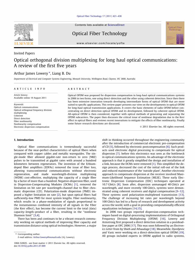
OFDM is a multi-carrier modulation technique, where a datastream is encoded onto many subcarriers that are then transmittedtogether on a common path [52]. Fig. 1 illustrates the overlappingspectra of the subcarriers, together with the transmitted wave-form, which comprises a sequence of OFDM symbols. An advantageof OFDM is that each subcarrier has a narrow bandwidth comparedwith the total data rate, so is relatively unaffected by multipathinterference or phase distortion. Strictly, the subcarriers have amuch wider bandwidth than their frequency spacing because thetransitions between data symbols are fast compared with the sym-bol duration; each subcarrier is a sinc-function (sin(x)/x) in the fre-quency domain upon modulation. Spectral efficiency is gained byoverlapping the sinc functions so that the centre frequencies ofall subcarriers other than the one of interest lie on the nulls ofthe subcarrier of interest. OFDM signals can either be transmittedat baseband (such as over ADSL networks) or up-converted ontoa carrier with a mixer as shown in Fig. 2. To maximize power effi-ciency, no carrier is transmitted and a local oscillator is used at thereceiver.
The received data is recovered using a matched filter for eachsubcarrier, which perfectly rejects interference from neighborsand also causes no distortion of the wanted channel. The matchedfilter usually has a rectangular impulse response; that is, it com-bines the samples of the received signal with equal-magnitudeweights. The phase of the weights increases monotonically; therate of increase of phase is a frequency offset and determines thesubcarrier being received. In practice, the bank of matched filtersreceiving a number of subcarriers can be replaced by a discreteFourier transform (DFT) [53], which can be implemented efficientlyusing the Fast Fourier Transform (FFT) algorithm [54].
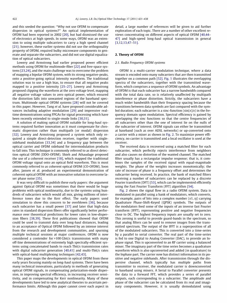
Fig. 2 shows the signal flow in a radio OFDM system. Data ismodulated in parallel using a bank of modulators, which converts,for example, pairs of bits into a complex number (±1, ±j) carryingQuadrature Phase-Shift-Keyed (QPSK) symbols. The outputs ofthe modulators feed some of the inputs of an inverse fast Fouriertransform (IFFT), representing positive and negative frequenciesclose to DC. The highest frequency inputs are usually set to zero.This zeroing is useful to provide guard-bands in the spectrum, sothat analog filters can be used to remove images from the trans-mitted spectrum. The output of the IFFT is a superposition of allof the modulated subcarriers. This is converted into a time-seriesby a parallel to serial converter. The real part of the time-seriesis fed to one Digital to Analog Converter (DAC), to provide an In-phase signal. This is upconverted to an RF carrier using a balancedmixer. The imaginary part of the time series becomes a quadraturewaveform which is also upconverted and added (in quadrature) tothe Inphase part. The carrier now has distinct information in its po-sitive and negative sidebands. After transmission through the dis-persive channel, which typically has multiple paths fromtransmitter to receiver, the modulated carrier is downconvertedto baseband using mixers. A Serial to Parallel converter presentsthe data to a forward FFT, which provides a series of paralleloutputs, each corresponding to a subcarrier. The amplitude andphase of the subcarrier can be calculated from its real and imagi-nary components. However, it is usually demodulated using
Time
Frequency
Waveforms are a sum of phase-modulated sinewaves
OFDM symbol
Fig. 1. OFDM spectrum (left) and time-waveform (right). The spectrum comprising overlapping subcarriers (sinc functions): the waveform in each OFDM symbol is asummation of phase- and amplitude-modulated subcarriers.
Fig. 2. Simplified radio-OFDM system implemented using Fourier Transforms. Using zeros at the inputs of the FFT gives a spectral guard-band around the OFDM band, whichis critical in radio applications to avoid interference with neighboring channels.
A.J. Lowery, L.B. Du / Optical Fiber Technology 17 (2011) 421–438 423
thresholding about the x and y axis. Because the channel is disper-sive, equalizers are required to adjust the amplitude and phase ofeach subcarrier before thresholding. They can also compensatefor amplitude errors in a channel with fading. Since the equaliza-tion is a single multiplication, these are known as 1-tap equalizers.In contrast, most single-carrier systems require equalizers consist-ing of a weighted sum of delayed versions of the input signal, using‘multiple taps’ of a delay line. This simplification is possible be-cause the subcarriers are so narrow that each, within itself, is prac-tically unaffected by dispersion.
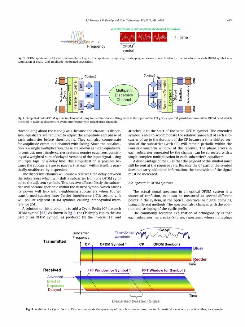
The dispersive channel will cause a relative time delay betweenthe subcarriers which will shift a subcarrier from one OFDM sym-bol to the adjacent symbols. This has two effects: firstly the subcar-rier will become aperiodic within the desired symbol which causesits power will leak into neighboring subcarriers when Fouriertransformed causing Inter-Carrier Interference (ICI); secondly, itwill pollute adjacent OFDM symbols, causing Inter-Symbol Inter-ference (ISI).
A solution to this problem is to add a Cyclic Prefix (CP) to eachOFDM symbol [55]. As shown in Fig. 3, the CP simply copies the lastpart of an OFDM symbol, as produced by the inverse FFT, and
Subcarrier Frequency
Transmitted
FFT Window for Symbol
Advanced
Delayed
Received
Effect of Dispersion
OFDM Symbol 1CP
Discarde
Time-dowaveform
Fig. 3. Addition of a Cyclic Prefix (CP) to accommodate the spreading of the subc
attaches it to the start of the same OFDM symbol. The extendedsymbol is able to accommodate the relative time-shift of each sub-carrier of up to the duration of the CP because a time-shifted ver-sion of the subcarrier (with CP) will remain periodic within theFourier-Transform window of the receiver. The phase errors ineach subcarrier generated by the channel can be corrected with asingle complex multiplication in each subcarrier’s equalizers.
A disadvantage of the CP is that the payload of the symbol muststill be sent at the required rate. Because the CP part of the symboldoes not carry additional information, the bandwidth of the signalmust be increased.
2.2. Spectra in OFDM systems
The actual signal spectrum in an optical OFDM system is asource of confusion, as it can be measured at several differentpoints in the system, in the optical, electrical or digital domains,using different methods. The spectrum also changes with the addi-tion and stripping of the cyclic prefix.
The commonly accepted explanation of orthogonality is thateach subcarrier has a sin(x)/x (a sinc) spectrum, whose nulls align
Time
Bluer
Redder
1
CP OFDM Symbol 2
FFT Window for Symbol 2
d (wasted) SignalTime
main “Copy”
arriers in time, due to chromatic dispersion in an optical fiber, for example.
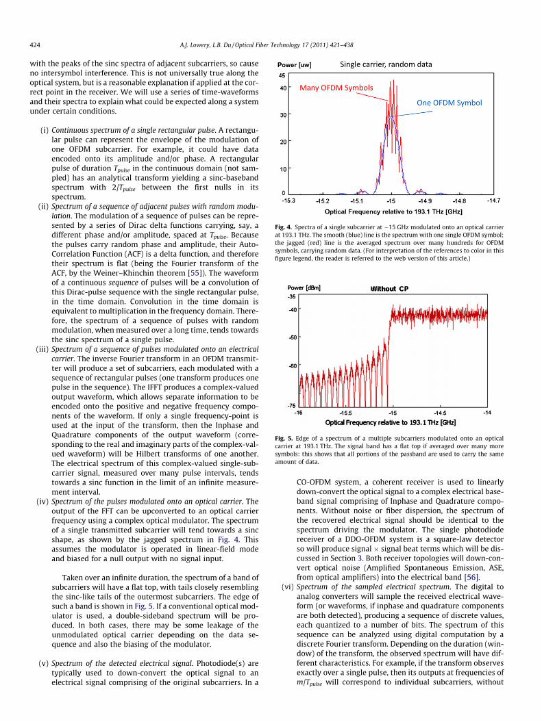
Fig. 4. Spectra of a single subcarrier at �15 GHz modulated onto an optical carrierat 193.1 THz. The smooth (blue) line is the spectrum with one single OFDM symbol;the jagged (red) line is the averaged spectrum over many hundreds for OFDMsymbols, carrying random data. (For interpretation of the references to color in thisfigure legend, the reader is referred to the web version of this article.)
Fig. 5. Edge of a spectrum of a multiple subcarriers modulated onto an opticalcarrier at 193.1 THz. The signal band has a flat top if averaged over many moresymbols: this shows that all portions of the passband are used to carry the sameamount of data.
424 A.J. Lowery, L.B. Du / Optical Fiber Technology 17 (2011) 421–438
with the peaks of the sinc spectra of adjacent subcarriers, so causeno intersymbol interference. This is not universally true along theoptical system, but is a reasonable explanation if applied at the cor-rect point in the receiver. We will use a series of time-waveformsand their spectra to explain what could be expected along a systemunder certain conditions.
(i) Continuous spectrum of a single rectangular pulse. A rectangu-lar pulse can represent the envelope of the modulation ofone OFDM subcarrier. For example, it could have dataencoded onto its amplitude and/or phase. A rectangularpulse of duration Tpulse in the continuous domain (not sam-pled) has an analytical transform yielding a sinc-basebandspectrum with 2/Tpulse between the first nulls in itsspectrum.
(ii) Spectrum of a sequence of adjacent pulses with random modu-lation. The modulation of a sequence of pulses can be repre-sented by a series of Dirac delta functions carrying, say, adifferent phase and/or amplitude, spaced at Tpulse. Becausethe pulses carry random phase and amplitude, their Auto-Correlation Function (ACF) is a delta function, and thereforetheir spectrum is flat (being the Fourier transform of theACF, by the Weiner–Khinchin theorem [55]). The waveformof a continuous sequence of pulses will be a convolution ofthis Dirac-pulse sequence with the single rectangular pulse,in the time domain. Convolution in the time domain isequivalent to multiplication in the frequency domain. There-fore, the spectrum of a sequence of pulses with randommodulation, when measured over a long time, tends towardsthe sinc spectrum of a single pulse.
(iii) Spectrum of a sequence of pulses modulated onto an electricalcarrier. The inverse Fourier transform in an OFDM transmit-ter will produce a set of subcarriers, each modulated with asequence of rectangular pulses (one transform produces onepulse in the sequence). The IFFT produces a complex-valuedoutput waveform, which allows separate information to beencoded onto the positive and negative frequency compo-nents of the waveform. If only a single frequency-point isused at the input of the transform, then the Inphase andQuadrature components of the output waveform (corre-sponding to the real and imaginary parts of the complex-val-ued waveform) will be Hilbert transforms of one another.The electrical spectrum of this complex-valued single-sub-carrier signal, measured over many pulse intervals, tendstowards a sinc function in the limit of an infinite measure-ment interval.
(iv) Spectrum of the pulses modulated onto an optical carrier. Theoutput of the FFT can be upconverted to an optical carrierfrequency using a complex optical modulator. The spectrumof a single transmitted subcarrier will tend towards a sincshape, as shown by the jagged spectrum in Fig. 4. Thisassumes the modulator is operated in linear-field modeand biased for a null output with no signal input.
Taken over an infinite duration, the spectrum of a band ofsubcarriers will have a flat top, with tails closely resemblingthe sinc-like tails of the outermost subcarriers. The edge ofsuch a band is shown in Fig. 5. If a conventional optical mod-ulator is used, a double-sideband spectrum will be pro-duced. In both cases, there may be some leakage of theunmodulated optical carrier depending on the data se-quence and also the biasing of the modulator.
(v) Spectrum of the detected electrical signal. Photodiode(s) aretypically used to down-convert the optical signal to anelectrical signal comprising of the original subcarriers. In a
CO-OFDM system, a coherent receiver is used to linearlydown-convert the optical signal to a complex electrical base-band signal comprising of Inphase and Quadrature compo-nents. Without noise or fiber dispersion, the spectrum ofthe recovered electrical signal should be identical to thespectrum driving the modulator. The single photodiodereceiver of a DDO-OFDM system is a square-law detectorso will produce signal � signal beat terms which will be dis-cussed in Section 3. Both receiver topologies will down-con-vert optical noise (Amplified Spontaneous Emission, ASE,from optical amplifiers) into the electrical band [56].
(vi) Spectrum of the sampled electrical spectrum. The digital toanalog converters will sample the received electrical wave-form (or waveforms, if inphase and quadrature componentsare both detected), producing a sequence of discrete values,each quantized to a number of bits. The spectrum of thissequence can be analyzed using digital computation by adiscrete Fourier transform. Depending on the duration (win-dow) of the transform, the observed spectrum will have dif-ferent characteristics. For example, if the transform observesexactly over a single pulse, then its outputs at frequencies ofm/Tpulse will correspond to individual subcarriers, without
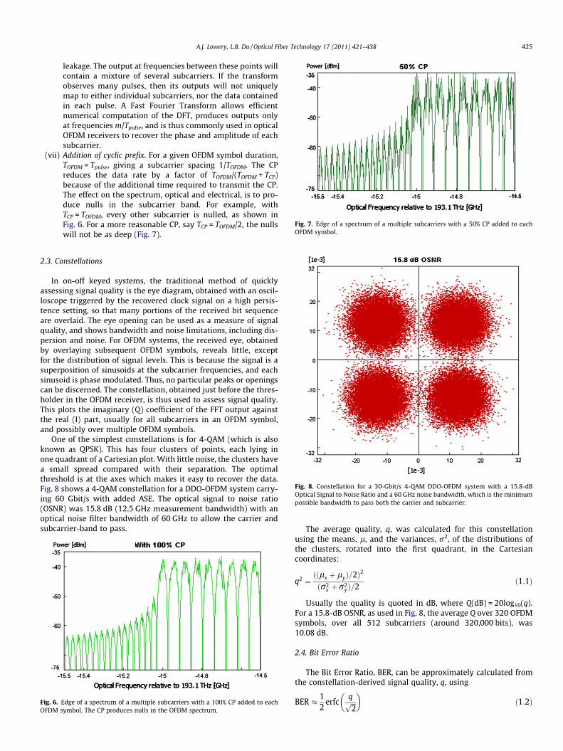
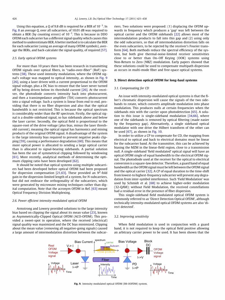
Fig. 7. Edge of a spectrum of a multiple subcarriers with a 50% CP added to eachOFDM symbol.
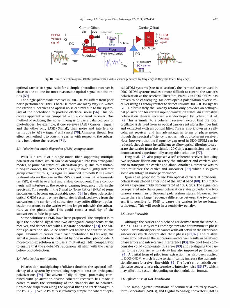
Fig. 8. Constellation for a 30-Gbit/s 4-QAM DDO-OFDM system with a 15.8-dBOptical Signal to Noise Ratio and a 60 GHz noise bandwidth, which is the minimumpossible bandwidth to pass both the carrier and subcarrier.
A.J. Lowery, L.B. Du / Optical Fiber Technology 17 (2011) 421–438 425
leakage. The output at frequencies between these points willcontain a mixture of several subcarriers. If the transformobserves many pulses, then its outputs will not uniquelymap to either individual subcarriers, nor the data containedin each pulse. A Fast Fourier Transform allows efficientnumerical computation of the DFT, produces outputs onlyat frequencies m/Tpulse, and is thus commonly used in opticalOFDM receivers to recover the phase and amplitude of eachsubcarrier.
(vii) Addition of cyclic prefix. For a given OFDM symbol duration,TOFDM = Tpulse, giving a subcarrier spacing 1/TOFDM. The CPreduces the data rate by a factor of TOFDM/(TOFDM + TCP)because of the additional time required to transmit the CP.The effect on the spectrum, optical and electrical, is to pro-duce nulls in the subcarrier band. For example, withTCP = TOFDM, every other subcarrier is nulled, as shown inFig. 6. For a more reasonable CP, say TCP = TOFDM/2, the nullswill not be as deep (Fig. 7).
2.3. Constellations
In on-off keyed systems, the traditional method of quicklyassessing signal quality is the eye diagram, obtained with an oscil-loscope triggered by the recovered clock signal on a high persis-tence setting, so that many portions of the received bit sequenceare overlaid. The eye opening can be used as a measure of signalquality, and shows bandwidth and noise limitations, including dis-persion and noise. For OFDM systems, the received eye, obtainedby overlaying subsequent OFDM symbols, reveals little, exceptfor the distribution of signal levels. This is because the signal is asuperposition of sinusoids at the subcarrier frequencies, and eachsinusoid is phase modulated. Thus, no particular peaks or openingscan be discerned. The constellation, obtained just before the thres-holder in the OFDM receiver, is thus used to assess signal quality.This plots the imaginary (Q) coefficient of the FFT output againstthe real (I) part, usually for all subcarriers in an OFDM symbol,and possibly over multiple OFDM symbols.
One of the simplest constellations is for 4-QAM (which is alsoknown as QPSK). This has four clusters of points, each lying inone quadrant of a Cartesian plot. With little noise, the clusters havea small spread compared with their separation. The optimalthreshold is at the axes which makes it easy to recover the data.Fig. 8 shows a 4-QAM constellation for a DDO-OFDM system carry-ing 60 Gbit/s with added ASE. The optical signal to noise ratio(OSNR) was 15.8 dB (12.5 GHz measurement bandwidth) with anoptical noise filter bandwidth of 60 GHz to allow the carrier andsubcarrier-band to pass.
Fig. 6. Edge of a spectrum of a multiple subcarriers with a 100% CP added to eachOFDM symbol. The CP produces nulls in the OFDM spectrum.
The average quality, q, was calculated for this constellationusing the means, l, and the variances, r2, of the distributions ofthe clusters, rotated into the first quadrant, in the Cartesiancoordinates:
q2 ¼ððlx þ lyÞ=2Þ2
ðr2x þ r2
yÞ=2ð1:1Þ
Usually the quality is quoted in dB, where Q(dB) = 20log10(q).For a 15.8-dB OSNR, as used in Fig. 8, the average Q over 320 OFDMsymbols, over all 512 subcarriers (around 320,000 bits), was10.08 dB.
2.4. Bit Error Ratio
The Bit Error Ratio, BER, can be approximately calculated fromthe constellation-derived signal quality, q, using
BER � 12
erfcqffiffiffi2p� �
ð1:2Þ
426 A.J. Lowery, L.B. Du / Optical Fiber Technology 17 (2011) 421–438
Using this equation, a Q of 9.8 dB is required for a BER of 10�3. InFig. 8 an average Q, over all subcarriers, of 10.01 dB was required toobtain a BER (by counting errors) of 10�3. This is because in DDOOFDM each subcarrier has a different signal quality which causes thismethod to underestimate BER. A better method is to calculate the BERfor each subcarrier (using an average of many OFDM symbols), aver-age the BERs, and back-calculate the signal quality, of required [57].
2.5. Early optical OFDM systems
For more than 10 years there has been research in transmittingOFDM signals over optical fibers, in ‘‘radio-over-fiber’’ (RoF) sys-tems [58]. These used intensity modulation, where the OFDM sig-nal’s voltage was mapped to optical intensity, as shown in Fig. 9[26], using a laser driven with a current proportional to the OFDMsignal voltage, plus a DC bias to ensure that the laser never turnedoff by being driven below its threshold current [26]. At the recei-ver, the photodiode converts intensity back into photocurrent,and then a transimpedance amplifier (TIA) converts photocurrentinto a signal voltage. Such a system is linear from end to end, pro-viding that there is no fiber dispersion and also that the opticalbandwidth is not restricted. This is because the optical spectrumis considerably wider than the RF spectrum. Firstly, the optical sig-nal is a double-sideband signal, so has sidebands above and belowthe laser carrier. Secondly, the optical field is proportional to thesquare-root of the drive voltage (plus bias, minus the laser thresh-old current), meaning the optical signal has harmonics and mixingproducts of the original OFDM signal. A disadvantage of the systemis the large intensity bias required to prevent negative peaks clip-ping [59], causing a performance degradation [60]. This means thatmore optical power is allocated to sending a large optical carrierthan is allocated to signal-bearing sidebands. A partial solutionhas been the use of symmetrical clipping followed by windowing[61]. More recently, analytical methods of determining the opti-mum clipping ratio have been developed [62].
It should be noted that optical systems using multiple subcarri-ers had been developed before optical OFDM had been proposedfor dispersion compensation [21,63]. These provided an N2-foldgain in the dispersion-limited length of a system, for N-subcarriers,but did not embrace the orthogonality of the subcarriers, whichwere generated by microwave mixing techniques rather than dig-ital computation. Note that the acronym OFDM in Ref. [63] meantOptical Frequency Division Multiplexing.
2.6. Power efficient intensity-modulated optical OFDM
Armstrong and Lowery provided solutions to the large intensitybias based on clipping the signal about its mean value [23], knownas Asymmetrically-Clipped Optical OFDM (ACO-OFDM). This pro-vided a sweet-spot in operation, where the received (electrical)signal quality was maximized and the DC bias minimized. Clippingabout the mean value (removing all negative-going signals) causeda large amount of intermodulation distortion between the subcar-
RealOFDM Voltagesignal
+
Bias CurrentV-> I
LaserI->P
Fiber
Tim
Intensity
Time
Voltage
Subcarrier
spectrum
Cross-product
Fig. 9. Intensity modulated optica
riers. Two solutions were proposed: (1) displacing the OFDM up-wards in frequency which produces a ‘gap’ was left between theoptical carrier and the OFDM sidebands [22] allows most of theintermodulation products to fall into this gap and (2) using onlythe odd subcarriers, so that all intermodulation distortion falls onthe even subcarriers, to be rejected by the receiver’s Fourier trans-form [64]. Both methods reduce the spectral efficiency of the sys-tem, but both give thermal-noise-limited receiver sensitivitiesclose to or better than On–Off Keying (OOK) systems usingNon-Return to Zero (NRZ) modulation. Early papers showed thatthese solutions could be used to compensate multipath dispersionas occurs in multi-mode fiber and free-space optical systems.
3. Direct detection optical OFDM for long-haul systems
3.1. Compensating for CD
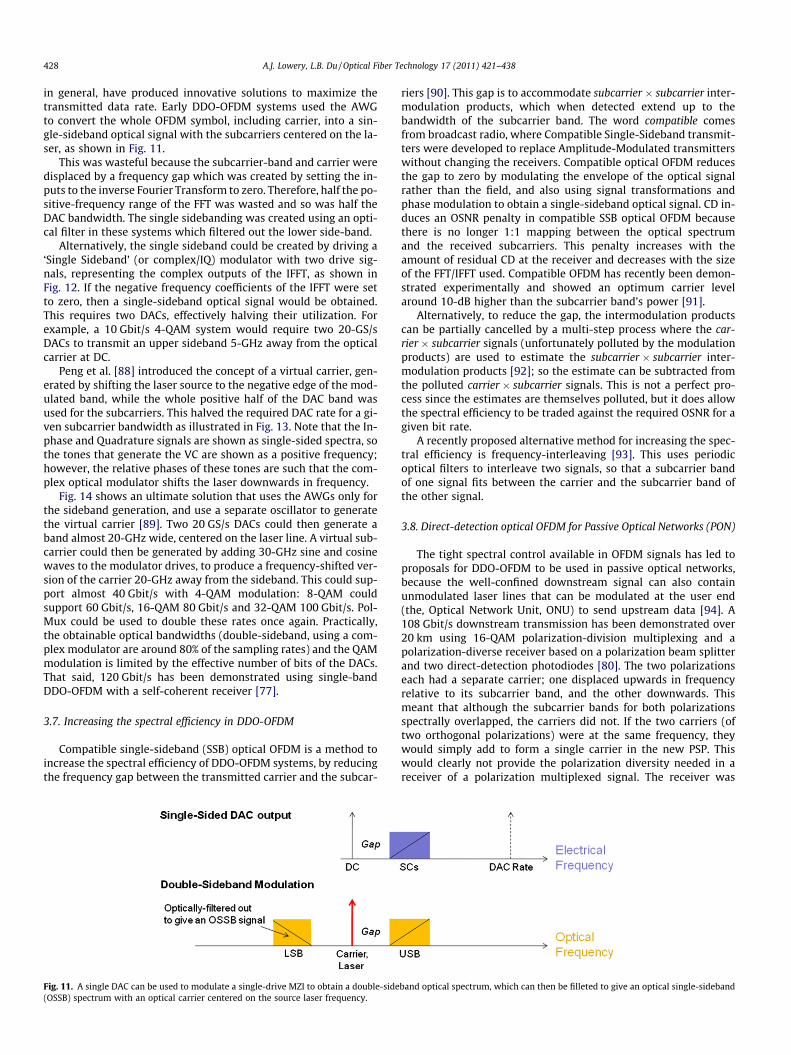
An issue with intensity-modulated optical systems is that the fi-ber’s chromatic dispersion will cause the signals of the two side-bands to rotate, which converts amplitude modulation into phasemodulation. This produces nulls at certain frequencies when thesidebands mix with the carrier upon photodetection [65]. A solu-tion to this issue is single-sideband modulation [34,66], whereone of the sidebands is removed by optical filtering (made easierby the frequency gap). Alternatively, a single sideband opticalmodulator with one drive the Hilbert transform of the other canbe used [67], as shown in Fig. 10.
In order to utilize a CP to compensate for CD, the mapping fromelectrical to optical and back to electrical domains must be linearfor the subcarrier band. At the transmitter, this can be achieved bybiasing the MZM in the linear-field region, close to a transmissionnull. A single-sideband ‘field modulated’ optical signal will have anoptical OFDM single of equal bandwidth to the electrical OFDM sig-nal. The photodiode used at the receiver for the optical to electricalconversion is a square-law detector. Therefore, a guard band of equalbandwidth as the OFDM signal must be left between the OFDM signaland the optical carrier [32]. A CP of equal duration to the time-shiftfrom lowest-to highest-frequency subcarrier will prevent any degra-dation from inter-symbol interference. Such ‘Field Modulation’ wasused by Schmidt et al. [68] to achieve higher-order modulation(32-QAM); without Field Modulation, the received constellationshad a residual error in the presence of fiber dispersion.
This single-sideband field modulated optical OFDM system iscommonly referred to as ‘Direct Detection Optical OFDM’, althoughtechnically intensity-modulated optical OFDM systems are also ‘di-rect detected’.
3.2. Improving sensitivity
When field modulation is used in conjunction with a guardband, it is not required to keep the optical field positive allowingan arbitrary carrier power to be used. It has been shown that the
+
Bias Voltage
I->V
PDI->P
OFDM Voltagesignal
BlockDC
eTime
Voltage
carr.
s
l OFDM (IM-OOFDM) system.
OFDM Voltagesignal
add
DC
+
RF MixerPD
OFDM Voltagesignal
Fiber
Time
Field (excl.Carrier)
Time
Voltage
Time
VoltageCmplx
Carrier Offset
IQ
Modulator
+
cossin
Q I
RFmix Q
I
Carrier Offset
Time
Subcarr.carrier
laser
spectrum
SC x carrierRF spectrum
Fig. 10. Direct-detection optical OFDM system with a virtual carrier generated by frequency-shifting the laser’s frequency.
A.J. Lowery, L.B. Du / Optical Fiber Technology 17 (2011) 421–438 427
optimal carrier-to-signal ratio for a simple photodiode receiver isclose to one-to-one for most reasonable optical signal to noise ra-tios [69].
The single-photodiode receiver in DDO-OFDM suffers from poornoise performance. This is because there are many ways in whichthe carrier, subcarrier and optical noise can mix due to the square-law of the photodiode to produce electrical noise [56]. This be-comes apparent when compared with a coherent receiver. Onemethod of reducing the noise mixing is to use a balanced pair ofphotodiodes; for example, if one receives (ASE + Carrier + Signal)and the other only (ASE + Signal), then noise and interferenceterms due to (ASE + Signal)2 will cancel [70]. A simpler, though lesseffective, method is to boost the carrier with respect to the subcar-riers just before the receiver [71].
3.3. Polarization-mode dispersion (PMD) compensation
PMD is a result of a single-mode fiber supporting multiplepolarization states, which can be decomposed into two orthogonalmodes, or principal states of Polarization (PSPs). Due to manufac-turing tolerances, the two PSPs are likely to have slightly differentgroup velocities; thus, if a signal is launched into both PSPs (whichis almost always the case, as the PSPs are unknown to the transmit-ter PSP), it will have a fast and a slow component. These compo-nents will interfere at the receiver causing frequency nulls in thespectrum. This results in the Signal to Noise Ratios (SNRs) of somesubcarriers to become unacceptably poor [72]. In a direct-detectionoptical OFDM system, where the carrier is displaced away from thesubcarriers, the carrier and subcarriers may suffer different polar-ization rotations, so the carrier will no longer mix with the subcar-riers at the photodiode. This could cause a majority of thesubcarriers to fade in power.
Some solutions to PMD have been proposed. The simplest is tosplit the sideband signal into two orthogonal components at thereceiver, and detect each with a separate photodiode [73]. The car-rier’s polarization should be controlled before the splitter, so thatequal amounts of carrier reach each photodiode. In this way, thesignal is guaranteed to be detected by one or other photodiode. Amore-complex solution is to use a multi-stage PMD compensatorto ensure that the sideband’s subcarriers all align with the carrierbefore photodetection.
3.4. Polarization multiplexing
Polarization multiplexing (PolMux) doubles the spectral effi-ciency of a system by transmitting separate data on orthogonalpolarizations [74]. The advent of digital signal processing com-bined with polarization-diverse coherent receivers has made iteasier to undo the scrambling of the channels due to polariza-tion-mode dispersion along the optical fiber and track changes inthe PSPs [75]. While PolMux is relatively simple for coherent opti-
cal OFDM systems (see next section), the ‘remote’ carrier used inDDO-OFDM systems makes it more difficult to control the carrier’spolarization at the receiver. Therefore, PolMux in DDO-OFDM hasproven to be challenging. Xie developed a polarization diverse re-ceiver using a Faraday rotator to detect PolMux DDO-OFDM signals[76]. Unfortunately the Faraday rotator only provides an orthogo-nal polarization for certain input polarization states. An alternativepolarization diverse receiver was developed by Schmidt et al.[72].This is similar to a coherent receiver, except that the localoscillator is derived from an optical carrier sent along the fiber linkand extracted with an optical filter. This is also known as a self-coherent receiver, and has advantages in terms of phase noise,though the spectral efficiency is not as high as a coherent receiver.Note, however, that the frequency gap used in DDO-OFDM can bereduced, though must be sufficient to allow optical filtering to sep-arate the carrier from the signal. 120 Gbit/s transmission has beendemonstrated experimentally using this technique [77].
Feng et al. [78] also proposed a self-coherent receiver, but usingtwo separate fibers: one to carry the subcarrier and carriers, andone to transport the carrier and alone. Another alternative was totime-multiplex the carrier and subcarrier [79] which also givessome advantage in noise performance.
Qian et al. proposed to use two optical carriers at orthogonalpolarizations placed either side of the signal band [80]. This meth-od was experimentally demonstrated at 108 Gbit/s. The signal canbe separated into the original polarization states provided the twocarriers remain in orthogonal polarization states. However, be-cause there is a large frequency difference between the two carri-ers, it is possible for PMD to cause the carriers to be no longerorthogonal. This will result in a sensitivity penalty.
3.5. Laser linewidth
Although the carrier and sideband are derived from the same la-ser in DDO-OFDM systems, these systems are not immune to phasenoise. Chromatic dispersion causes walk-off between the carrier andsubcarriers which decorrelates their phases [81,82]. The relativephase error between the subcarriers and carrier results in basebandphase errors and intra-carrier interference [83]. The pilot tone com-pensator could compensate this error [83] and re-aligning the car-rier to the subcarrier with a delay line also improved performance[84]. A digital form of pilot tone extraction has also been appliedto DDO-OFDM, which is able to significantly increase the transmis-sion distance for a given linewidth [85]. The fiber’s chromatic disper-sion also converts laser phase noise to intensity noise [86,87], whichmay affect the system depending on the modulation format.
3.6. Efficient use of DAC bandwidth
The sampling-rate limitations of commercial Arbitrary Wave-form Generators (AWGs), and Digital to Analog Converters (DACs)
428 A.J. Lowery, L.B. Du / Optical Fiber Technology 17 (2011) 421–438
in general, have produced innovative solutions to maximize thetransmitted data rate. Early DDO-OFDM systems used the AWGto convert the whole OFDM symbol, including carrier, into a sin-gle-sideband optical signal with the subcarriers centered on the la-ser, as shown in Fig. 11.
This was wasteful because the subcarrier-band and carrier weredisplaced by a frequency gap which was created by setting the in-puts to the inverse Fourier Transform to zero. Therefore, half the po-sitive-frequency range of the FFT was wasted and so was half theDAC bandwidth. The single sidebanding was created using an opti-cal filter in these systems which filtered out the lower side-band.
Alternatively, the single sideband could be created by driving a‘Single Sideband’ (or complex/IQ) modulator with two drive sig-nals, representing the complex outputs of the IFFT, as shown inFig. 12. If the negative frequency coefficients of the IFFT were setto zero, then a single-sideband optical signal would be obtained.This requires two DACs, effectively halving their utilization. Forexample, a 10 Gbit/s 4-QAM system would require two 20-GS/sDACs to transmit an upper sideband 5-GHz away from the opticalcarrier at DC.
Peng et al. [88] introduced the concept of a virtual carrier, gen-erated by shifting the laser source to the negative edge of the mod-ulated band, while the whole positive half of the DAC band wasused for the subcarriers. This halved the required DAC rate for a gi-ven subcarrier bandwidth as illustrated in Fig. 13. Note that the In-phase and Quadrature signals are shown as single-sided spectra, sothe tones that generate the VC are shown as a positive frequency;however, the relative phases of these tones are such that the com-plex optical modulator shifts the laser downwards in frequency.
Fig. 14 shows an ultimate solution that uses the AWGs only forthe sideband generation, and use a separate oscillator to generatethe virtual carrier [89]. Two 20 GS/s DACs could then generate aband almost 20-GHz wide, centered on the laser line. A virtual sub-carrier could then be generated by adding 30-GHz sine and cosinewaves to the modulator drives, to produce a frequency-shifted ver-sion of the carrier 20-GHz away from the sideband. This could sup-port almost 40 Gbit/s with 4-QAM modulation: 8-QAM couldsupport 60 Gbit/s, 16-QAM 80 Gbit/s and 32-QAM 100 Gbit/s. Pol-Mux could be used to double these rates once again. Practically,the obtainable optical bandwidths (double-sideband, using a com-plex modulator are around 80% of the sampling rates) and the QAMmodulation is limited by the effective number of bits of the DACs.That said, 120 Gbit/s has been demonstrated using single-bandDDO-OFDM with a self-coherent receiver [77].
3.7. Increasing the spectral efficiency in DDO-OFDM
Compatible single-sideband (SSB) optical OFDM is a method toincrease the spectral efficiency of DDO-OFDM systems, by reducingthe frequency gap between the transmitted carrier and the subcar-
Fig. 11. A single DAC can be used to modulate a single-drive MZI to obtain a double-side(OSSB) spectrum with an optical carrier centered on the source laser frequency.
riers [90]. This gap is to accommodate subcarrier � subcarrier inter-modulation products, which when detected extend up to thebandwidth of the subcarrier band. The word compatible comesfrom broadcast radio, where Compatible Single-Sideband transmit-ters were developed to replace Amplitude-Modulated transmitterswithout changing the receivers. Compatible optical OFDM reducesthe gap to zero by modulating the envelope of the optical signalrather than the field, and also using signal transformations andphase modulation to obtain a single-sideband optical signal. CD in-duces an OSNR penalty in compatible SSB optical OFDM becausethere is no longer 1:1 mapping between the optical spectrumand the received subcarriers. This penalty increases with theamount of residual CD at the receiver and decreases with the sizeof the FFT/IFFT used. Compatible OFDM has recently been demon-strated experimentally and showed an optimum carrier levelaround 10-dB higher than the subcarrier band’s power [91].
Alternatively, to reduce the gap, the intermodulation productscan be partially cancelled by a multi-step process where the car-rier � subcarrier signals (unfortunately polluted by the modulationproducts) are used to estimate the subcarrier � subcarrier inter-modulation products [92]; so the estimate can be subtracted fromthe polluted carrier � subcarrier signals. This is not a perfect pro-cess since the estimates are themselves polluted, but it does allowthe spectral efficiency to be traded against the required OSNR for agiven bit rate.
A recently proposed alternative method for increasing the spec-tral efficiency is frequency-interleaving [93]. This uses periodicoptical filters to interleave two signals, so that a subcarrier bandof one signal fits between the carrier and the subcarrier band ofthe other signal.
3.8. Direct-detection optical OFDM for Passive Optical Networks (PON)
The tight spectral control available in OFDM signals has led toproposals for DDO-OFDM to be used in passive optical networks,because the well-confined downstream signal can also containunmodulated laser lines that can be modulated at the user end(the, Optical Network Unit, ONU) to send upstream data [94]. A108 Gbit/s downstream transmission has been demonstrated over20 km using 16-QAM polarization-division multiplexing and apolarization-diverse receiver based on a polarization beam splitterand two direct-detection photodiodes [80]. The two polarizationseach had a separate carrier; one displaced upwards in frequencyrelative to its subcarrier band, and the other downwards. Thismeant that although the subcarrier bands for both polarizationsspectrally overlapped, the carriers did not. If the two carriers (oftwo orthogonal polarizations) were at the same frequency, theywould simply add to form a single carrier in the new PSP. Thiswould clearly not provide the polarization diversity needed in areceiver of a polarization multiplexed signal. The receiver was
band optical spectrum, which can then be filleted to give an optical single-sideband
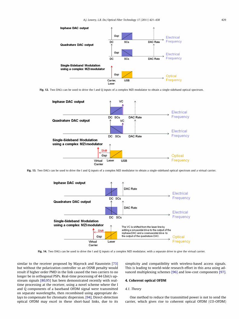
Fig. 12. Two DACs can be used to drive the I and Q inputs of a complex MZI modulator to obtain a single-sideband optical spectrum.
Fig. 13. Two DACs can be used to drive the I and Q inputs of a complex MZI modulator to obtain a single-sideband optical spectrum and a virtual carrier.
Fig. 14. Two DACs can be used to drive the I and Q inputs of a complex MZI modulator, with a separate drive to give the virtual carrier.
A.J. Lowery, L.B. Du / Optical Fiber Technology 17 (2011) 421–438 429
similar to the receiver proposed by Mayrock and Haunstein [73]but without the polarization controller so an OSNR penalty wouldresult if higher order PMD in the link caused the two carriers to nolonger be in orthogonal PSPs. Real-time processing of 44 Gbit/s up-stream signals [80,95] has been demonstrated recently with real-time processing at the receiver, using a novel scheme where the Iand Q components of a baseband OFDM signal were transmittedon separate wavelengths, then recombined using appropriate de-lays to compensate for chromatic dispersion. [94]. Direct-detectionoptical OFDM may excel in these short-haul links, due to its
simplicity and compatibility with wireless-based access signals.This is leading to world-wide research effort in this area using ad-vanced multiplexing schemes [96] and low-cost components [97].
4. Coherent optical OFDM
4.1. Theory
One method to reduce the transmitted power is not to send thecarrier, which gives rise to coherent optical OFDM (CO-OFDM)
430 A.J. Lowery, L.B. Du / Optical Fiber Technology 17 (2011) 421–438
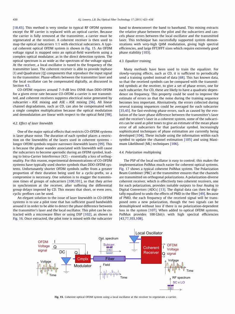
[18,45]. This method is very similar to typical RF OFDM systemsexcept the RF carrier is replaced with an optical carrier. Becausethe carrier is fully removed at the transmitter, a carrier must beregenerated at the receiver. A coherent receiver is then used tomap the optical subcarriers 1:1 with electrical subcarriers. A typi-cal coherent optical OFDM system is shown in Fig. 15. An OFDMvoltage signal is mapped onto an optical-field waveform using acomplex optical modulator, as in the direct detection system. Theoptical spectrum is as wide as the spectrum of the voltage signal.At the receiver, a local oscillator is tuned to the frequency of thetransmitter laser. The coherent receiver is able to provide Inphase(I) and Quadrature (Q) components that reproduce the input signalto the transmitter. Phase-offsets between the transmitter laser andthe local oscillator can be compensated digitally, as discussed inSection 4.3.
CO-OFDM requires around 7–9 dB less OSNR than DDO-OFDMfor a given error rate because CO-OFDM a carrier is not transmit-ted, and coherent receivers suppress electrical noise generated bysubcarrier � ASE mixing and ASE � ASE mixing [56]. All linearchannel degradations, such as CD, can also be compensated witha single complex multiplication because the optical modulationand demodulation are linear with respect to the optical field [98].
4.2. Effect of laser linewidth
One of the major optical effects that restricts CO-OFDM systemsis laser phase noise. The duration of each symbol places a restric-tion on the linewidths of the lasers used in coherent systems –longer OFDM symbols require narrower-linewidth lasers [99]. Thisis because the phase wander associated with linewidth will causethe subcarriers to become aperiodic during an OFDM symbol, lead-ing to Intra-Carrier Interference (ICI) – essentially a loss of orthog-onality. For this reason, experimental demonstrations of CO-OFDMsystems have typically used shorter symbols than DDO-OFDM sys-tems. Unfortunately shorter OFDM symbols suffer from a greaterproportion of their duration being used for a cyclic-prefix, so acompromise is necessary. One solution is to stagger the transmis-sion times of groups of subcarriers [100,101], so that they arrivein synchronism at the receiver, after suffering the differentialgroup delays imposed by CD. This means that short, or even zero,cyclic prefixes can be used.
An elegant solution to the issue of laser linewidth in CO-OFDMsystems is to use a pilot tone that has sufficient guard bandwidtharound it in order to be able to detect the phase difference betweenthe transmitter’s laser and the local oscillator. This pilot can be ex-tracted with a microwave filter or using DSP [102], as shown inFig. 16. Once extracted, the pilot tone is mixed with the subcarrier
OFDM Voltagesignal DC
FiberField
Time
VoltageCmplx
IQ
Modulator
Q I
Subcarr.
laser
Opt. spectrum
Fig. 15. Coherent optical OFDM system using a local
band to downconvert the band to baseband. This mixing extractsthe relative phase between the pilot and the subcarriers and can-cels phase errors between the local oscillator and the transmittedlaser. This technique has successfully supported system demon-strations with very-high QAM modulation, giving high spectralefficiencies, and large FFT/IFFT sizes which require extremely goodphase stability [103].
4.3. Equalizer training
Many methods have been used to train the equalizer. Forslowly-varying effects, such as CD, it is sufficient to periodicallysend a training symbol instead of data [68]. This has known data,so that the received symbols can be compared with the transmit-ted symbols at the receiver, to give a set of phase errors, one foreach subcarrier. For CD, these are likely to have a quadratic depen-dence on frequency. This property could be used to improve theestimate of errors so that the noise during the training sequencebecomes less important. Alternatively, the errors collected duringseveral training sequences could be averaged for each subcarrier[35,45]. For fast-evolving phase errors, such as caused by the evo-lution of the laser phase difference between the transmitter’s laserand the receiver’s laser in a coherent system, some of the subcarri-ers can be used as pilot tones to give an estimate of the mean phaseerror of all subcarriers for that particular symbol. Increasinglysophisticated techniques of phase estimation are currently beingdeveloped [104]. These include using the information within eachsymbol to update the channel estimation [105] and using Maxi-mum Likelihood (ML) techniques [106].
4.4. Polarization multiplexing
The PSP of the local oscillator is easy to control; this makes theimplementation PolMux much easier for coherent optical systems.Fig. 17 shows a typical coherent PolMux system. The PolarizationBeam Combiner (PBC) at the transmitter ensures that the channelsare transmitted on orthogonal polarizations. A polarization-diversecoherent receiver, which is effectively two coherent receivers, onefor each polarization, provides suitable outputs to four Analog toDigital Convertors (ADCs) [13]. The digital data can then be digi-tally equalized to undo the effects of PMD in the fiber [49]. Becauseof PMD, the each frequency of the received signal will be trans-posed onto a new polarization, though the two signals can bedemultiplexed without loss if there is no polarization-dependentloss in the system [107]. When added to optical OFDM systems,PolMux provides 100 Gbit/s with high spectral efficiencies[43,77,103,108].
OFDM Voltagesignal
Time
Time
Voltage
Coherent Receiver Q
I
Local Oscillator
SC x LORF spectrum
oscillator at the receiver to regenerate a carrier.
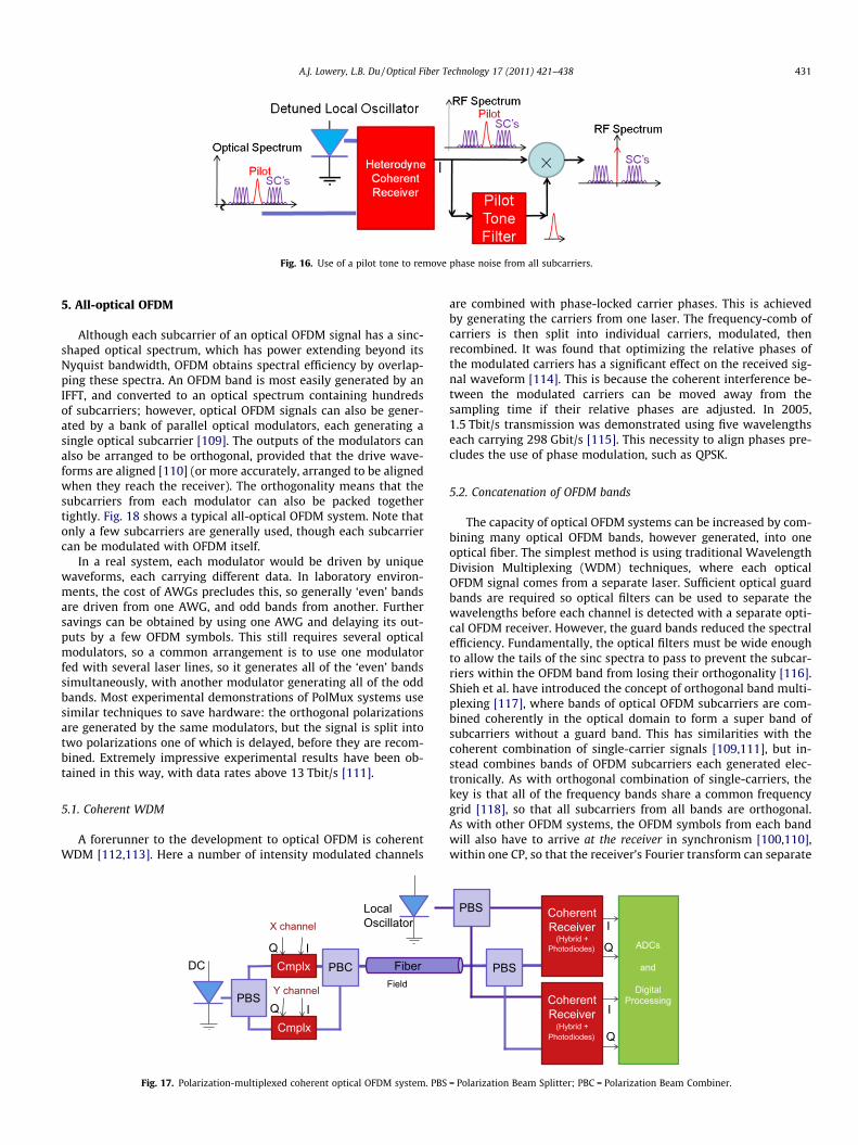
Fig. 16. Use of a pilot tone to remove phase noise from all subcarriers.
A.J. Lowery, L.B. Du / Optical Fiber Technology 17 (2011) 421–438 431
5. All-optical OFDM
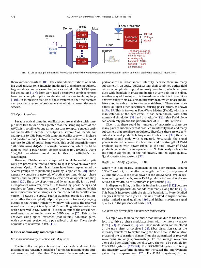
Although each subcarrier of an optical OFDM signal has a sinc-shaped optical spectrum, which has power extending beyond itsNyquist bandwidth, OFDM obtains spectral efficiency by overlap-ping these spectra. An OFDM band is most easily generated by anIFFT, and converted to an optical spectrum containing hundredsof subcarriers; however, optical OFDM signals can also be gener-ated by a bank of parallel optical modulators, each generating asingle optical subcarrier [109]. The outputs of the modulators canalso be arranged to be orthogonal, provided that the drive wave-forms are aligned [110] (or more accurately, arranged to be alignedwhen they reach the receiver). The orthogonality means that thesubcarriers from each modulator can also be packed togethertightly. Fig. 18 shows a typical all-optical OFDM system. Note thatonly a few subcarriers are generally used, though each subcarriercan be modulated with OFDM itself.
In a real system, each modulator would be driven by uniquewaveforms, each carrying different data. In laboratory environ-ments, the cost of AWGs precludes this, so generally ‘even’ bandsare driven from one AWG, and odd bands from another. Furthersavings can be obtained by using one AWG and delaying its out-puts by a few OFDM symbols. This still requires several opticalmodulators, so a common arrangement is to use one modulatorfed with several laser lines, so it generates all of the ‘even’ bandssimultaneously, with another modulator generating all of the oddbands. Most experimental demonstrations of PolMux systems usesimilar techniques to save hardware: the orthogonal polarizationsare generated by the same modulators, but the signal is split intotwo polarizations one of which is delayed, before they are recom-bined. Extremely impressive experimental results have been ob-tained in this way, with data rates above 13 Tbit/s [111].
5.1. Coherent WDM
A forerunner to the development to optical OFDM is coherentWDM [112,113]. Here a number of intensity modulated channels
X channel
DC FiberField
CmplxQ I
Local Oscillator
CmplxQ I
PBC
PBSY channel
Fig. 17. Polarization-multiplexed coherent optical OFDM system. PBS
are combined with phase-locked carrier phases. This is achievedby generating the carriers from one laser. The frequency-comb ofcarriers is then split into individual carriers, modulated, thenrecombined. It was found that optimizing the relative phases ofthe modulated carriers has a significant effect on the received sig-nal waveform [114]. This is because the coherent interference be-tween the modulated carriers can be moved away from thesampling time if their relative phases are adjusted. In 2005,1.5 Tbit/s transmission was demonstrated using five wavelengthseach carrying 298 Gbit/s [115]. This necessity to align phases pre-cludes the use of phase modulation, such as QPSK.
5.2. Concatenation of OFDM bands
The capacity of optical OFDM systems can be increased by com-bining many optical OFDM bands, however generated, into oneoptical fiber. The simplest method is using traditional WavelengthDivision Multiplexing (WDM) techniques, where each opticalOFDM signal comes from a separate laser. Sufficient optical guardbands are required so optical filters can be used to separate thewavelengths before each channel is detected with a separate opti-cal OFDM receiver. However, the guard bands reduced the spectralefficiency. Fundamentally, the optical filters must be wide enoughto allow the tails of the sinc spectra to pass to prevent the subcar-riers within the OFDM band from losing their orthogonality [116].Shieh et al. have introduced the concept of orthogonal band multi-plexing [117], where bands of optical OFDM subcarriers are com-bined coherently in the optical domain to form a super band ofsubcarriers without a guard band. This has similarities with thecoherent combination of single-carrier signals [109,111], but in-stead combines bands of OFDM subcarriers each generated elec-tronically. As with orthogonal combination of single-carriers, thekey is that all of the frequency bands share a common frequencygrid [118], so that all subcarriers from all bands are orthogonal.As with other OFDM systems, the OFDM symbols from each bandwill also have to arrive at the receiver in synchronism [100,110],within one CP, so that the receiver’s Fourier transform can separate
Q
I
Q
I
PBS
PBS
Coherent Receiver
(Hybrid +Photodiodes)
Coherent Receiver
(Hybrid +Photodiodes)
ADCs
and
DigitalProcessing
= Polarization Beam Splitter; PBC = Polarization Beam Combiner.
Fiber
spectrum
Cmplx
QPSK
Modulator
Q I
CmplxQ I
CmplxQ I
OFDM Voltagesignal
Coherent Receiver Q
I
Local Oscillator
Opticalcomb
spectrum
Demux Mux
The channels can be separated electrically, but this requires extremely-high bandwidth ADCs.Optical FFTs arean alternative.
Fig. 18. Use of multiple modulators to construct a wide-bandwidth OFDM signal by modulating lines of an optical comb with individual modulators.
432 A.J. Lowery, L.B. Du / Optical Fiber Technology 17 (2011) 421–438
them without crosstalk [100]. The earlier demonstrations of band-ing used an laser tone, intensity modulated then phase modulated,to generate a comb of carrier frequencies locked to the OFDM sym-bol generators [117]; later work used a serrodyne comb generatorbased on a complex optical modulator within a recirculating loop[119]. An interesting feature of these systems is that the receivercan pick out any set of subcarriers to obtain a lower data-rateservice.
5.3. Optical receivers
Because optical sampling oscilloscopes are available with sam-ple rates two to four times greater than the sampling rates of theAWGs, it is possible for one sampling scope to capture enough opti-cal bandwidth to decode the outputs of several AWG bands. Forexample, a 30-GHz bandwidth sampling oscilloscope with inphaseand quadrature outputs from a homodyne coherent receiver couldcapture 60-GHz of optical bandwidth. This could potentially carry120 Gbit/s using 4-QAM in a single polarization, which could bedoubled with a polarization-diverse receiver to 240 Gbit/s. Using16-QAM modulation could double this to 480 Gbit/s perwavelength.
However, if higher rates are required, it would be useful to opti-cally pre-process the received signal to split it between lower-ratereceivers. Optical Fourier Transforms have been implemented byseveral groups, with pioneering work by Sanjoh et al. [20]. Thesegenerally comprise a network of optical splitters, delays, phaseshifters and couplers, followed by electrical or optical samplinggates [120]. The array of splitters and delays generally form a seri-al-to-parallel converter, which is followed by phase delays andcouplers to form a weighted sum of the parallel samples (whichwere time-consecutive samples, before the serial to parallel con-version). Because the optical Fourier transform provides a continu-ous (rather than sampled) output, it gives a continuously-varyingoutput as the Fourier transform window rolls across the receivedwaveform. Its output is only valid if the rolling window coincideswith a received OFDM symbol. Thus the output of the optical net-work needs to be sampled once per OFDM symbol [20]. This can beachieved using optical switches (modulators), nonlinear gates,with a coherent receiver with a pulsed local oscillator. These devel-opments are reviewed in Ref. [116].
6. Fiber nonlinearity and compensation
6.1. Fiber nonlinearity in optical OFDM systems
The Kerr effect in optical fibers describes the dependence of theinstantaneous refractive index of a fiber on the instantaneous opti-cal power carried in the fiber. This causes phase retardation pro-
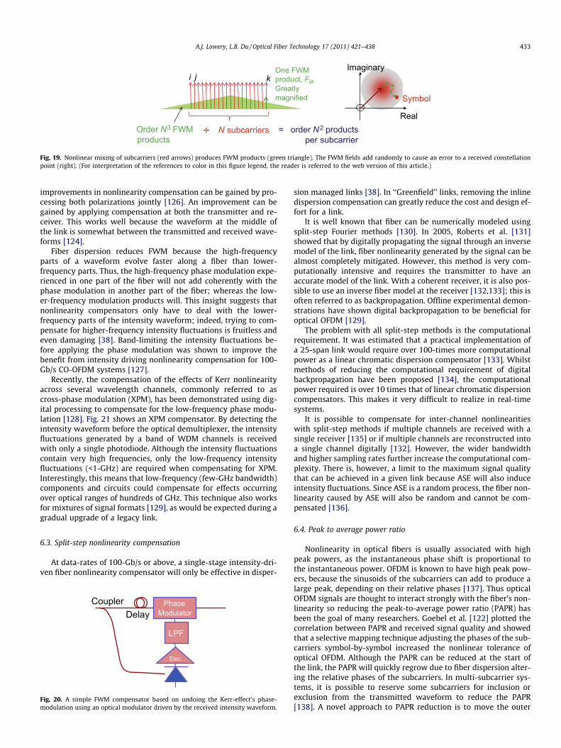
portional to the instantaneous intensity. Because there are manysubcarriers in an optical OFDM system, their combined optical fieldcauses a complicated optical intensity waveform, which can pro-duce wide-bandwidth phase modulation at any point in the Fiber.Another way of looking at this time-domain effect is to treat it asany two subcarriers causing an intensity beat, which phase modu-lates another subcarrier to give new sidebands. These new side-bands fall upon other subcarriers, causing phase errors, as shownin Fig. 19. This is known as Four-Wave Mixing (FWM), which is amanifestation of the Kerr effect. It has been shown, with bothnumerical simulation [38] and analytically [121], that FWM alonecan accurately predict the performance of CO-OFDM systems.
Given that there could be hundreds of subcarriers, there aremany pairs of subcarriers that produce an intensity beat, and manysubcarriers that are phase modulated. Therefore, there are order N-cubed sideband products falling upon N subcarriers [37], thus theproblem should scale with N-squared. Fortunately the signalpower is shared between N subcarriers, and the strength of FWMproducts scales with power-cubed, so the total power of FWMproducts generated is independent of N. This analysis leads tothe simple expression for the nonlinearity-limited signal quality,Qnl, dispersion-free systems [37]:
QnlðdBÞ � �20log10ðcLePtotalÞ � 3:01 ð1:2Þ
where c is nonlinearity coefficient of the fiber (usually around1.3 W�1 km�1), Le is the effective length the fiber (usually around20 km) and Ptotal is the total power in the OFDM band (W). In sys-tems with guard bands, some FWM products fall outside the re-ceived bandwidth, so this estimate is pessimistic [37].
In dispersive links, this limit is further increased [122] becausethe nonlinear products do not add coherently along the link [38].This benefit increases with the signal’s bandwidth. More detailedanalyses showed that higher CD values resulted in higher nonlin-earity limited signal qualities [39] and higher maximum signalqualities in the presence of noise [121].
6.2. Intensity-driven fiber nonlinearity compensator
A simple way to undo the phase modulation due to the Kerr ef-fect is to drive a phase modulator from with the intensity wave-form [123], as shown in Fig. 20. Phase modulation can be placedat the transmitter or receiver [124]. Fiber dispersion causes theintensity waveform to evolve along the fiber because the relativephases of the subcarriers change. Thus the transmitted or receivedwaveforms are only approximately like the average waveformalong the fiber. Significant benefits were shown to be possible forCO-OFDM systems [123,124]. For DDO-OFDM systems, filteringthe intensity waveform significantly increased the improvementgained by compensation [125]. For PolMux systems, further
i j kOne FWM product, FijkGreatly magnified
Order N3 FWM products
N subcarriers = order N2 products per subcarrier
Imaginary
Real
Symbol
÷
Fig. 19. Nonlinear mixing of subcarriers (red arrows) produces FWM products (green triangle). The FWM fields add randomly to cause an error to a received constellationpoint (right). (For interpretation of the references to color in this figure legend, the reader is referred to the web version of this article.)
A.J. Lowery, L.B. Du / Optical Fiber Technology 17 (2011) 421–438 433
improvements in nonlinearity compensation can be gained by pro-cessing both polarizations jointly [126]. An improvement can begained by applying compensation at both the transmitter and re-ceiver. This works well because the waveform at the middle ofthe link is somewhat between the transmitted and received wave-forms [124].
Fiber dispersion reduces FWM because the high-frequencyparts of a waveform evolve faster along a fiber than lower-frequency parts. Thus, the high-frequency phase modulation expe-rienced in one part of the fiber will not add coherently with thephase modulation in another part of the fiber; whereas the low-er-frequency modulation products will. This insight suggests thatnonlinearity compensators only have to deal with the lower-frequency parts of the intensity waveform; indeed, trying to com-pensate for higher-frequency intensity fluctuations is fruitless andeven damaging [38]. Band-limiting the intensity fluctuations be-fore applying the phase modulation was shown to improve thebenefit from intensity driving nonlinearity compensation for 100-Gb/s CO-OFDM systems [127].
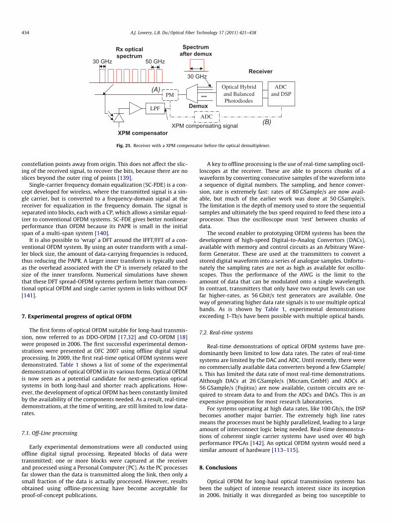
Recently, the compensation of the effects of Kerr nonlinearityacross several wavelength channels, commonly referred to ascross-phase modulation (XPM), has been demonstrated using dig-ital processing to compensate for the low-frequency phase modu-lation [128]. Fig. 21 shows an XPM compensator. By detecting theintensity waveform before the optical demultiplexer, the intensityfluctuations generated by a band of WDM channels is receivedwith only a single photodiode. Although the intensity fluctuationscontain very high frequencies, only the low-frequency intensityfluctuations (<1-GHz) are required when compensating for XPM.Interestingly, this means that low-frequency (few-GHz bandwidth)components and circuits could compensate for effects occurringover optical ranges of hundreds of GHz. This technique also worksfor mixtures of signal formats [129], as would be expected during agradual upgrade of a legacy link.
6.3. Split-step nonlinearity compensation
At data-rates of 100-Gb/s or above, a single-stage intensity-dri-ven fiber nonlinearity compensator will only be effective in disper-
Elec.
DelayCoupler Phase
Modulator
LPF
Fig. 20. A simple FWM compensator based on undoing the Kerr-effect’s phase-modulation using an optical modulator driven by the received intensity waveform.
sion managed links [38]. In ‘‘Greenfield’’ links, removing the inlinedispersion compensation can greatly reduce the cost and design ef-fort for a link.
It is well known that fiber can be numerically modeled usingsplit-step Fourier methods [130]. In 2005, Roberts et al. [131]showed that by digitally propagating the signal through an inversemodel of the link, fiber nonlinearity generated by the signal can bealmost completely mitigated. However, this method is very com-putationally intensive and requires the transmitter to have anaccurate model of the link. With a coherent receiver, it is also pos-sible to use an inverse fiber model at the receiver [132,133]; this isoften referred to as backpropagation. Offline experimental demon-strations have shown digital backpropagation to be beneficial foroptical OFDM [129].
The problem with all split-step methods is the computationalrequirement. It was estimated that a practical implementation ofa 25-span link would require over 100-times more computationalpower as a linear chromatic dispersion compensator [133]. Whilstmethods of reducing the computational requirement of digitalbackpropagation have been proposed [134], the computationalpower required is over 10 times that of linear chromatic dispersioncompensators. This makes it very difficult to realize in real-timesystems.
It is possible to compensate for inter-channel nonlinearitieswith split-step methods if multiple channels are received with asingle receiver [135] or if multiple channels are reconstructed intoa single channel digitally [132]. However, the wider bandwidthand higher sampling rates further increase the computational com-plexity. There is, however, a limit to the maximum signal qualitythat can be achieved in a given link because ASE will also induceintensity fluctuations. Since ASE is a random process, the fiber non-linearity caused by ASE will also be random and cannot be com-pensated [136].
6.4. Peak to average power ratio
Nonlinearity in optical fibers is usually associated with highpeak powers, as the instantaneous phase shift is proportional tothe instantaneous power. OFDM is known to have high peak pow-ers, because the sinusoids of the subcarriers can add to produce alarge peak, depending on their relative phases [137]. Thus opticalOFDM signals are thought to interact strongly with the fiber’s non-linearity so reducing the peak-to-average power ratio (PAPR) hasbeen the goal of many researchers. Goebel et al. [122] plotted thecorrelation between PAPR and received signal quality and showedthat a selective mapping technique adjusting the phases of the sub-carriers symbol-by-symbol increased the nonlinear tolerance ofoptical OFDM. Although the PAPR can be reduced at the start ofthe link, the PAPR will quickly regrow due to fiber dispersion alter-ing the relative phases of the subcarriers. In multi-subcarrier sys-tems, it is possible to reserve some subcarriers for inclusion orexclusion from the transmitted waveform to reduce the PAPR[138]. A novel approach to PAPR reduction is to move the outer
30 GHz 50 GHz
Rx optical spectrum
30 GHz
Spectrum after demux
Receiver
LPF
PM
XPM compensating signalXPM compensator
Demux
(A)
ADC(B)
···Optical Hybrid and Balanced Photodiodes
ADC and DSP
Fig. 21. Receiver with a XPM compensator before the optical demultiplexer.
434 A.J. Lowery, L.B. Du / Optical Fiber Technology 17 (2011) 421–438
constellation points away from origin. This does not affect the slic-ing of the received signal, to recover the bits, because there are noslices beyond the outer ring of points [139].
Single-carrier frequency domain equalization (SC-FDE) is a con-cept developed for wireless, where the transmitted signal is a sin-gle carrier, but is converted to a frequency-domain signal at thereceiver for equalization in the frequency domain. The signal isseparated into blocks, each with a CP, which allows a similar equal-izer to conventional OFDM systems. SC-FDE gives better nonlinearperformance than OFDM because its PAPR is small in the initialspan of a multi-span system [140].
It is also possible to ‘wrap’ a DFT around the IFFT/FFT of a con-ventional OFDM system. By using an outer transform with a smal-ler block size, the amount of data-carrying frequencies is reduced,thus reducing the PAPR. A larger inner transform is typically usedas the overhead associated with the CP is inversely related to thesize of the inner transform. Numerical simulations have shownthat these DFT spread-OFDM systems perform better than conven-tional optical OFDM and single carrier system in links without DCF[141].
7. Experimental progress of optical OFDM
The first forms of optical OFDM suitable for long-haul transmis-sion, now referred to as DDO-OFDM [17,32] and CO-OFDM [18]were proposed in 2006. The first successful experimental demon-strations were presented at OFC 2007 using offline digital signalprocessing. In 2009, the first real-time optical OFDM systems weredemonstrated. Table 1 shows a list of some of the experimentaldemonstrations of optical OFDM in its various forms. Optical OFDMis now seen as a potential candidate for next-generation opticalsystems in both long-haul and shorter reach applications. How-ever, the development of optical OFDM has been constantly limitedby the availability of the components needed. As a result, real-timedemonstrations, at the time of writing, are still limited to low data-rates.
7.1. Off-Line processing
Early experimental demonstrations were all conducted usingoffline digital signal processing. Repeated blocks of data weretransmitted; one or more blocks were captured at the receiverand processed using a Personal Computer (PC). As the PC processesfar slower than the data is transmitted along the link, then only asmall fraction of the data is actually processed. However, resultsobtained using offline-processing have become acceptable forproof-of-concept publications.
A key to offline processing is the use of real-time sampling oscil-loscopes at the receiver. These are able to process chunks of awaveform by converting consecutive samples of the waveform intoa sequence of digital numbers. The sampling, and hence conver-sion, rate is extremely fast: rates of 80 GSample/s are now avail-able, but much of the earlier work was done at 50 GSample/s.The limitation is the depth of memory used to store the sequentialsamples and ultimately the bus speed required to feed these into aprocessor. Thus the oscilloscope must ‘rest’ between chunks ofdata.
The second enabler to prototyping OFDM systems has been thedevelopment of high-speed Digital-to-Analog Convertors (DACs),available with memory and control circuits as an Arbitrary Wave-form Generator. These are used at the transmitters to convert astored digital waveform into a series of analogue samples. Unfortu-nately the sampling rates are not as high as available for oscillo-scopes. Thus the performance of the AWG is the limit to theamount of data that can be modulated onto a single wavelength.In contrast, transmitters that only have two output levels can usefar higher-rates, as 56 Gbit/s test generators are available. Oneway of generating higher data rate signals is to use multiple opticalbands. As is shown by Table 1, experimental demonstrationsexceeding 1-Tb/s have been possible with multiple optical bands.
7.2. Real-time systems
Real-time demonstrations of optical OFDM systems have pre-dominantly been limited to low data rates. The rates of real-timesystems are limited by the DAC and ADC. Until recently, there wereno commercially available data converters beyond a few GSample/s. This has limited the data rate of most real-time demonstrations.Although DACs at 26 GSample/s (Micram, GmbH) and ADCs at56 GSample/s (Fujitsu) are now available, custom circuits are re-quired to stream data to and from the ADCs and DACs. This is anexpensive proposition for most research laboratories.
For systems operating at high data rates, like 100 Gb/s, the DSPbecomes another major barrier. The extremely high line ratesmeans the processes must be highly parallelized, leading to a largeamount of interconnect logic being needed. Real-time demonstra-tions of coherent single carrier systems have used over 40 highperformance FPGAs [142]. An optical OFDM system would need asimilar amount of hardware [113–115].
8. Conclusions
Optical OFDM for long-haul optical transmission systems hasbeen the subject of intense research interest since its inceptionin 2006. Initially it was disregarded as being too susceptible to
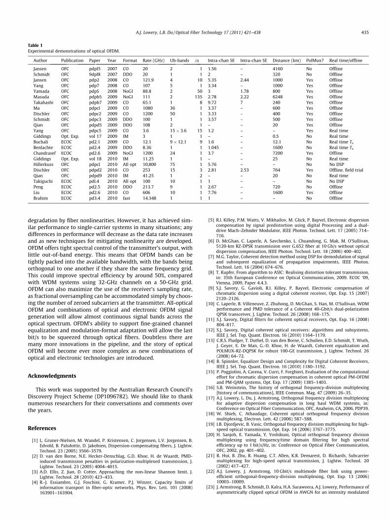
Table 1Experimental demonstrations of optical OFDM.
Author Publication Paper Year Format Rate (GHz) Ub-bands ks Intra-chan SE Intra-chan SE Distance (km) PolMux? Real time/offline
Jansen OFC pdpl5 2007 CO 20 2 1 1.56 – 4160 No OfflineSchmidt OFC 9dpl8 2007 DDO 20 1 1 2 – 320 No OfflineJansen OFC pdp2 2008 CO 121.9 4 10 5.35 2.44 1000 Yes OfflineYang OFC pdp7 2008 CO 107 5 1 3.34 – 1000 Yes OfflineYamada OFC pdpS 2008 NoGI 88.8 2 50 3 1.78 800 Yes OfflineMasuda OFC pdpb5 2009 NoGI 111 2 135 2.78 2.22 6248 Yes OfflineTakahashi OFC pdpb7 2009 CO 65.1 1 8 9.72 7 240 Yes OfflineMa OFC pdpcl 2009 CO 1080 36 1 3.37 – 600 Yes OfflineDischler OFC pdpc2 2009 CO 1200 50 1 3.33 – 400 Yes OfflineSchmidt OFC pdpc3 2009 DDO 100 1 1 3.57 – 500 Yes OfflineQian OFC pdpd5 2009 DDO 108 2 1 – – 20 Yes OfflineYang OFC pdpc5 2009 CO 3.6 15 � 3.6 15 1.2 – – Yes Real timeGiddings Opt. Exp. vol 17 2009 IM 3 1 1 – – 0.5 No Real timeBuchali ECOC pd2.1 2009 CO 12.1 9 � 12.1 9 1.6 – 12.1 No Real time Tx
Benlachte ECOC pd2.4 2009 DDO 8.36 1 1 1.045 – 1600 No Real time Tx
Chandrasef ECOC pd2.6 2009 NoGI 1200 24 1 3.7 – 7200 Yes OfflineGiddings Opt. Exp. vol 18 2010 IM 11.25 1 1 – – 25 No Real timeHillerkuss OFC pdpcl 2010 All opt 10,800 75 1 5.76 – – No No DSPDischler OFC pdpd2 2010 CO 253 15 3 2.81 2.53 764 Yes Offline, field trialQian OFC pdpd9 2010 IM 41.25 1 2 – – 20 No Real timeTakiguchi ECOC pdl.4 2010 All opt 100 10 1 1 – – No No DSPPeng ECOC pd2.5 2010 DDO 213.7 9 1 2.67 – 720 No OfflineLiu ECOC pd2.6 2010 CO 606 10 1 7.76 – 1600 Yes OfflineBrahim ECOC pd3.4 2010 fast 14.348 1 1 1 – – No Offline
A.J. Lowery, L.B. Du / Optical Fiber Technology 17 (2011) 421–438 435
degradation by fiber nonlinearities. However, it has achieved sim-ilar performance to single-carrier systems in many situations; anydifferences in performance will decrease as the data rate increasesand as new techniques for mitigating nonlinearity are developed.OFDM offers tight spectral control of the transmitter’s output, withlittle out-of-band energy. This means that OFDM bands can betightly packed into the available bandwidth, with the bands beingorthogonal to one another if they share the same frequency grid.This could improve spectral efficiency by around 50%, comparedwith WDM systems using 32-GHz channels on a 50-GHz grid.OFDM can also maximize the use of the receiver’s sampling rate,as fractional oversampling can be accommodated simply by choos-ing the number of zeroed subcarriers at the transmitter. All-opticalOFDM and combinations of optical and electronic OFDM signalgeneration will allow almost continuous signal bands across theoptical spectrum. OFDM’s ability to support fine-grained channelequalization and modulation-format adaptation will allow the lastbit/s to be squeezed through optical fibers. Doubtless there aremany more innovations in the pipeline, and the story of opticalOFDM will become ever more complex as new combinations ofoptical and electronic technologies are introduced.
Acknowledgments
This work was supported by the Australian Research Council’sDiscovery Project Scheme (DP1096782). We should like to thanknumerous researchers for their conversations and comments overthe years.
References
[1] L. Gruner-Nielsen, M. Wandel, P. Kristensen, C. Jorgensen, L.V. Jorgensen, B.Edvold, B. Palsdottir, D. Jakobsen, Dispersion-compensating fibers, J. Lightw.Technol. 23 (2005) 3566–3579.
[2] D. van den Borne, N.E. Hecker-Denschlag, G.D. Khoe, H. de Waardt, PMD-induced transmission penalties in polarization-multiplexed transmission, J.Lightw. Technol. 23 (2005) 4004–4015.
[3] A.D. Ellis, Z. Jian, D. Cotter, Approaching the non-linear Shannon limit, J.Lightw. Technol. 28 (2010) 423–433.
[4] R.-J. Essiambre, G.J. Foschini, G. Kramer, P.J. Winzer, Capacity limits ofinformation transport in fiber-optic networks, Phys. Rev. Lett. 101 (2008)163901–163904.
[5] R.I. Killey, P.M. Watts, V. Mikhailov, M. Glick, P. Bayvel, Electronic dispersioncompensation by signal predistortion using digital Processing and a dual-drive Mach–Zehnder Modulator, IEEE Photon. Technol. Lett. 17 (2005) 714–716.
[6] D. McGhan, C. Laperle, A. Savchenko, L. Chuandong, G. Mak, M. O’Sullivan,5120-km RZ-DPSK transmission over G.652 fiber at 10 Gb/s without opticaldispersion compensation, IEEE Photon. Technol. Lett. 18 (2006) 400–402.
[7] M.G. Taylor, Coherent detection method using DSP for demodulation of signaland subsequent equalization of propagation impairments, IEEE Photon.Technol. Lett. 16 (2004) 674–676.
[8] T. Kupfer, From algorithm to ASIC: Realising distortion tolerant transmission,in: 35th European Conference on Optical Communication, 2009. ECOC ’09,Vienna, 2009, Paper 4.4.3.
[9] S.J. Savory, G. Gavioli, R.I. Killey, P. Bayvel, Electronic compensation ofchromatic dispersion using a digital coherent receiver, Opt. Exp. 15 (2007)2120–2126.
[10] C. Laperle, B. Villeneuve, Z. Zhuhong, D. McGhan, S. Han, M. O’Sullivan, WDMperformance and PMD tolerance of a Coherent 40-Gbit/s dual-polarizationQPSK transceiver, J. Lightw. Technol. 26 (2008) 168–175.
[11] S.J. Savory, Digital filters for coherent optical receivers, Opt. Exp. 16 (2008)804–817.
[12] S.J. Savory, Digital coherent optical receivers: algorithms and subsystems,IEEE J. Sel. Top. Quant. Electron. 16 (2010) 1164–1179.
[13] C.R.S. Fludger, T. Duthel, D. van den Borne, C. Schulien, E.D. Schmidt, T. Wuth,J. Geyer, E. De Man, G.-D. Khoe, H. de Waardt, Coherent equalization andPOLMUX-RZ-DQPSK for robust 100-GE transmission, J. Lightw. Technol. 26(2008) 64–72.
[14] B. Spinnler, Equalizer Design and Complexity for Digital Coherent Receivers,IEEE J. Sel. Top. Quant. Electron. 16 (2010) 1180–1192.
[15] P. Poggiolini, A. Carena, V. Curri, F. Forghieri, Evaluation of the computationaleffort for chromatic dispersion compensation in coherent optical PM-OFDMand PM-QAM systems, Opt. Exp. 17 (2009) 1385–1403.
[16] S.B. Weinstein, The history of orthogonal frequency-division multiplexing[history of communications], IEEE Commun. Mag. 47 (2009) 26–35.
[17] A.J. Lowery, L. Du, J. Armstrong, Orthogonal frequency division multiplexingfor adaptive dispersion compensation in long haul WDM systems, in:Conference on Optical Fiber Communication, OFC, Anaheim, CA, 2006, PDP39.
[18] W. Shieh, C. Athaudage, Coherent optical orthogonal frequency divisionmultiplexing, Electron. Lett. 42 (2006) 587–588.
[19] I.B. Djordjevic, B. Vasic, Orthogonal frequency division multiplexing for high-speed optical transmission, Opt. Exp. 14 (2006) 3767–3775.
[20] H. Sanjoh, E. Yamada, Y. Yoshikuni, Optical orthogonal frequency divisionmultiplexing using frequency/time domain filtering for high spectralefficiency up to 1 bit/s/Hz, in: Conference on Optical Fiber Communication,OFC, 2002, pp. 401–402.
[21] R. Hui, B. Zhu, R. Huang, C.T. Allen, K.R. Demarest, D. Richards, Subcarriermultiplexing for high-speed optical transmission, J. Lightw. Technol. 20(2002) 417–427.
[22] A.J. Lowery, J. Armstrong, 10 Gbit/s multimode fiber link using power-efficient orthogonal-frequency-division multiplexing, Opt. Exp. 13 (2006)10003–10009.
[23] J. Armstrong, B. Schmidt, D. Kalra, H.A. Suraweera, A.J. Lowery, Performance ofasymmetrically clipped optical OFDM in AWGN for an intensity modulated
436 A.J. Lowery, L.B. Du / Optical Fiber Technology 17 (2011) 421–438
direct detection system, in: Proc. IEEE Global Communications Conference(GLOBECOM 2006), San Francisco, USA, 2006.
[24] J.B. Carruthers, J.M. Kahn, Multiple-subcarrier modulation for nondirectedwireless infrared communication, IEEE J. Sel. Areas Commun. 14 (1996) 538–546.
[25] B.J. Dixon, R.D. Pollard, S. Iezekiel, Orthogonal frequency-divisionmultiplexing in wireless communication systems with multimode fibrefeeds, IEEE Trans. Microwave Theory and Techniques 49 (2001) 1404–1409.
[26] N.E. Jolley, H. Kee, P. Pickard, J. Tang, K. Cordina, Generation and propagationof a 1550 nm 10 Gbit/s optical orthogonal frequency division multiplexedsignal over 1000 m of multimode fibre using a directly modulated DFB, in:Optical Fiber Communication Conference, OFC/NFOEC, 2005, pp. 319–321.
[27] O. Gonzalez, R. Perez-Jimenez, S. Rodriguez, J. Rabadan, A. Ayala, OFDM overindoor wireless optical channel, IEE Proc. Optoelectron. 152 (2005) 199–204.
[28] B.J. Dixon, R.D. Pollard, S. Iezekiel, Orthogonal frequency-divisionmultiplexing in wireless communication systems with multimode fiberfeeds, IEEE Trans. Microw. Theory Tech. 49 (2001) 1404–1409.
[29] J.M. Tang, P.M. Lane, K.A. Shore, Transmission performance of adaptivelymodulated optical OFDM signals in multimode fiber links, IEEE Photon.Technol. Lett. 18 (2006) 205–207.
[30] X.Q. Jin, R.P. Giddings, J.M. Tang, Real-time transmission of 3 Gb/s 16-QAMencoded optical OFDM signals over 75 km SMFs with negative powerpenalties, Opt. Exp. 17 (2009) 14574–14585.
[31] R.P. Giddings, X.Q. Jin, E. Hugues-Salas, E. Giacoumidis, J.L. Wei, J.M. Tang,Experimental demonstration of a record high 11.25 Gb/s real-time opticalOFDM transceiver supporting 25 km SMF end-to-end transmission in simpleIMDD systems, Opt. Exp. 18 (2010) 5541–5555.
[32] A.J. Lowery, J. Armstrong, Orthogonal frequency division multiplexing fordispersion compensation of long-haul optical systems, Opt. Exp. 14 (2006)2079–2084.
[33] D. Fonseca, A.V.T. Cartaxo, P. Monteiro, Optical single-sideband transmitterfor various electrical signaling formats, J. Lightw. Technol. 24 (2006) 2059–2069.
[34] M. Sieben, J. Conradi, D. Dodds, B. Davies, S. Walklin, 10 Gbit/s optical singlesideband system, Electron. Lett. 33 (1997) 971–973.
[35] S.L. Jansen, I. Morita, N. Tadeka, H. Tanaka, 20-Gb/s OFDM transmission over4160-km SSMF enabled by RF-pilot tone phase noise compensation, in:Conference on Optical Fiber Communication, OFC, Anaheim, CA, 2007, PDP15.
[36] A.J. Lowery, L.B. Du, J. Armstrong, Performance of optical OFDM in ultralong-haul WDM lightwave systems, J. Lightw. Technol. 25 (2007) 131–138.
[37] A.J. Lowery, S. Wang, M. Premaratne, Calculation of power limit due to fibernonlinearity in optical OFDM systems, Opt. Exp. 15 (2007) 13282–13287.
[38] L.B.Y. Du, A.J. Lowery, Improved nonlinearity precompensation for long-haulhigh-data-rate transmission using coherent optical OFDM, Opt. Exp. 16(2008) 19920–19925.
[39] M. Nazarathy, J. Khurgin, R. Weidenfeld, Y. Meiman, P. Cho, R. Noe, I.Shpantzer, V. Karagodsky, Phased-array cancellation of nonlinear FWM incoherent OFDM dispersive multi-span links, Opt. Exp. 16 (2008) 15777–15810.
[40] W. Shieh, High spectral efficiency coherent optical OFDM for 1 Tb/s Ethernettransport, in: Conference on Optical Fiber Communication, OFC, San Diego,2009, OWW1.
[41] S.L. Jansen, I. Morita, H. Tanaka, 10 � 121.9-Gb/s PDM-OFDM transmissionwith 2-b/s/Hz spectral efficiency over 1000 km of SSMF, in: Conference onOptical Fiber Communication, OFC, San Diego, 2008, PDP2.
[42] A. Sano, E. Yamada, H. Masuda, E. Yamazaki, T. Kobayashi, E. Yoshida, Y.Miyamoto, S. Matsuoka, R. Kudo, K. Ishihara, Y. Takatori, M. Mizoguchi, K.Okada, K. Hagimoto, H. Yamazaki, S. Kamei, H. Ishii, 13.4-Tb/s (134 � 111-Gb/s/ch) no-guard-interval coherent OFDM transmission over 3600 km of SMFwith 19-ps average PMD, in: 34th European Conference on OpticalCommunication (ECOC), Brussels, 2008, Th.3.E.1.
[43] E. Yamada, A. Sano, H. Masuda, E. Yamazaki, T. Kobayashi, E. Yoshida, K.Yonenaga, Y. Miyamoto, K. Ishihara, Y. Takatori, T. Yamada, H. Yamazaki,1 Tbit/s (111 Gbit/s/ch � 10 ch) no-guard-interval CO-OFDM transmissionover 2100 km DSF, Electron. Lett. 44 (2008) 1417–1418.
[44] J. Armstrong, OFDM for optical communications, J. Lightw. Technol. 27 (2009)189–204.
[45] W. Shieh, H. Bao, Y. Tang, Coherent optical OFDM: theory and design, Opt.Exp. 16 (2008) 841–859.
[46] S.L. Jansen, I. Morita, T.C.W. Schenk, D. van den Borne, H. Tanaka, OpticalOFDM – a candidate for future long-haul optical transmission systems, in:Conference on Optical Fiber Communication, OFC, San Diego, 2008, pp. 1–3.
[47] A. Barbieri, G. Colavolpe, T. Foggi, E. Forestieri, G. Prati, OFDM versus single-carrier transmission for 100 Gbps optical communication, J. Lightw. Technol.28 (2010) 2537–2551.
[48] H. Bulow, F. Buchali, A. Klekamp, Electronic dispersion compensation, J.Lightw. Technol. 26 (2008) 158–167.
[49] D. van den Borne, T. Duthel, C.R.S. Fludger, E.D. Schmidt, T. Wuth, C. Schulien,E. Gottwald, G.D. Khoe, H. de Waardt, Coherent equalization versus directdetection for 111-Gb/s Ethernet transport, in: Digest of the IEEE/LEOSSummer Topical Meetings, 2007, pp. 11–12.
[50] J.M. Kahn, H. Keang-Po, Spectral efficiency limits and modulation/detectiontechniques for DWDM systems, IEEE J. Sel. Top. Quant. Electron. 10 (2004)259–272.
[51] P.J. Winzer, R.J. Essiambre, Advanced optical modulation formats, Proc. IEEE94 (2006) 952–985.
[52] R.W. Chang, High-speed multichannel data transmission with bandlimitedorthogonal signals, Bell Sys. Tech. J. 45 (1966) 1775–1796.
[53] S.B. Weinstein, P.M. Ebert, Data transmission frequency-division multiplexingusing the discrete Fourier transform, IEEE Trans. Commun. Technol. 19 (1971)628–634.
[54] J.W. Cooley, J.W. Tukey, An algorithm for the machine calculation of complexFourier series, Math. Comput. 19 (1965) 297–301.
[55] J.G. Proakis, M. Salehi, Essentials of Communications Systems Engineering,Prentice Hall, New Jersey, 2005.
[56] A.J. Lowery, Amplified-spontaneous noise limit of optical OFDM lightwavesystems, Opt. Exp. 16 (2008) 860–865.
[57] W.-R. Peng, K.-M. Feng, A.E. Willner, S. Chi, Estimation of the bit error rate fordirect-detected OFDM signals with optically preamplified receivers, J. Lightw.Technol. 27 (2009) 1340–1346.
[58] M.R.D. Rodrigues, J.J. O’Reilly, Assessment of the performance of radio overfibre based wireless networks employing OFDM signalling, in: LondonCommunications Symposium, 1999, pp. 47–50.
[59] A.A.M. Saleh, Fundamental limit on number of channels in subcarrier-multiplexed lightwave CATV system, Electron. Lett. 25 (1989) 776–777.
[60] K. Panta, J. Armstrong, Effects of clipping on the error performance of OFDMin frequency selective channels, IEEE Trans. Commun. 3 (2004)668–671.
[61] D. Chanda, A. Sesay, B. Davies, Performance of clipped OFDM signal in fiber,in: Proc. IEEE Canadian Conference on Electrical and Computer Engineering,Niagara Falls, 2004, pp. 2401–2404.
[62] E. Vanin, Performance evaluation of intensity modulated optical OFDMsystem with digital baseband distortion, Opt. Exp. 19 (2011) 4280–4293.
[63] R. Hui, Multitributary OFDM optical transmitter using carrier-suppressedoptical single-sideband modulation, vol. 1, 2003, pp. 92–93.
[64] J. Armstrong, A.J. Lowery, Power efficient optical OFDM, Electron. Lett. 42(2006) 370–371.
[65] G. Meslener, Chromatic dispersion induced distortion of modulatedmonochromatic light employing direct detection, IEEE J. Quant. Electron. 20(1984) 1208–1216.
[66] R. Hui, B. Zhu, R. Huang, C. Allen, K. Demarest, D. Richards, 10-Gb/s SCM fibersystem using optical SSB modulation, IEEE Photon. Technol. Lett. 13 (2001)896–898.
[67] G.H. Smith, D. Novak, Z. Ahmed, Novel technique for generation of optical SSBwith carrier using a single MZM to overcome fiber chromatic dispersion, in:Technical Digest 1996 International Topical Meeting on MicrowavePhotonics, 1996, MWP ’96, 1996, pp. 5–8 suppl.
[68] B.J.C. Schmidt, A.J. Lowery, J. Armstrong, Experimental demonstrations of20 Gbit/s direct-detection optical OFDM and 12 Gbit/s with a colorlesstransmitter, in: Conference on Optical Fiber Communication, OFC, Anaheim,CA, 2007, PDP18.
[69] S.L. Jansen, I. Morita, H. Tanaka, Carrier-to-signal power in fiber-optic SSB-OFDM transmission systems, in: IEICE General Conference, Nagoya, 2007, pp.B-10-24, 363.
[70] W.-R. Peng, I. Morita, H. Tanaka, Enabling high capacity direct-detectionoptical OFDM transmissions using beat interference cancellation receiver, in:36th European Conference and Exhibition on Optical Communication (ECOC),2010, paper Mo.3.E.6.
[71] A.J. Lowery, Improving sensitivity and spectral efficiency in direct-detectionoptical OFDM systems, in: Conference on Optical Fiber Communication, OFC,San Diego, 2008, OMM4.
[72] B.J.C. Schmidt, A.J. Lowery, J. Armstrong, Impact of PMD in single-receiver andpolarization-diverse direct-detection optical OFDM, J. Lightw. Technol. 27(2009) 2792–2799.
[73] M. Mayrock, H. Haunstein, PMD tolerent direct-detection optical OFDMsystem, in: European Conference on Optical Communications, ECOC, Berlin,2007, pp. 5.2.5.
[74] A.R. Chraplyvy, A.H. Gnauck, R.W. Tkach, J.L. Zyskind, J.W. Sulhoff, A.J. Lucero,Y. Sun, R.M. Jopson, F. Forghieri, R.M. Derosier, C. Wolf, A.R. McCormick, 1-Tb/s transmission experiment, IEEE Photon. Technol. Lett. 8 (1996)1264–1266.
[75] Y. Han, G. Li, Coherent optical communication using polarization multiple-input–multiple-output, Opt. Exp. 13 (2005) 7527–7534.
[76] C. Xie, PMD insensitive direct-detection optical OFDM systems using self-polarization diversity, in: Optical Fiber Communication Conference, 2008, pp.1–3.
[77] B.J.C. Schmidt, Z. Zan, L.B. Du, A.J. Lowery, 120 Gbit/s over 500-km usingsingle-band polarization-multiplexed self-coherent optical OFDM, J. Lightw.Technol. 28 (2010) 328–335.
[78] K.-M. Feng, R.-T. Shui, Y.-W. Huang, W.-R. Peng, Sensitivity improvementusing amplified optical self-coherent detection in an optical OFDM system,in: LEOS Annual Meeting Conference Proceedings, 2009. LEOS ’09. IEEE, 2009,pp. 42–43.
[79] W.-R. Peng, Spectrally efficient direct-detected optical OFDM transmissionusing carrier-data timely multiplexing technique, in: 35th EuropeanConference on Optical Communication, 2009, ECOC ’09, 2009, pp. 1–2.
[80] D. Qian, N. Cvijetic, J. Hu, T. Wang, 108 Gb/s OFDMA-PON with polarizationmultiplexing and direct-detection, in: Conference on Optical FiberCommunication, OFC, San Diego, CA, 2009, PDPD5.
[81] Z. Zan, M. Premaratne, A.J. Lowery, Laser RIN and linewidth requirements fordirect detection optical OFDM, in: Conference on Lasers and Electro-Optics,CLEO 2008, 2008, Paper CWN2.
A.J. Lowery, L.B. Du / Optical Fiber Technology 17 (2011) 421–438 437
[82] L. Richter, H. Mandelberg, M. Kruger, P. McGrath, Linewidth determinationfrom self-heterodyne measurements with subcoherence delay times, IEEE J.Quant. Electron. 22 (1986) 2070–2074.
[83] W.-R. Peng, J. Chen, S. Chi, On the phase noise impact in direct-detectionoptical OFDM transmission, IEEE Photon. Technol. Lett. 22 (2010)649–651.
[84] Z. Zan, L.B.Y. Du, A.J. Lowery, Experimental demonstration on the reduction oflinewidth impact in a self-heterodyne optical OFDM system, in: Conferenceon Optical Fiber Communication (OFC), Collocated National Fiber OpticEngineers Conference (OFC/NFOEC), 2010, pp. 1–3.
[85] W.-R. Peng, I. Morita, H. Tanaka, Digital phase noise estimation andmitigation approach for direct-detection optical OFDM transmissions, in:36th European Conference and Exhibition on Optical Communication (ECOC),2010, pp. 1–3.
[86] S. Yamamoto, N. Edagawa, H. Taga, Y. Yoshida, H. Wakabayashi, Analysis oflaser phase noise to intensity noise conversion by chromatic dispersion inintensity modulation and direct detection optical-fiber transmission, J.Lightw. Technol. 8 (1990) 1716–1722.
[87] K. Petermann, FM-AM noise conversion in dispersive single-mode fibretransmission lines, Electron. Lett. 26 (1990) 2097–2098.
[88] W.-R. Peng, X. Wu, V.R. Arbab, B. Shamee, L.C. Christen, J.-Y. Yang, K.-M. Feng,A.E. Willner, S. Chi, Experimental demonstration of a coherently modulatedand directly detected optical OFDM system using an RF-tone insertion, in:Conference on Optical Fiber Communication/National Fiber Optic EngineersConference, 2008, OFC/NFOEC 2008, 2008, pp. 1–3.
[89] B.J.C. Schmidt, A.J. Lowery, L.B. Du, Low sample rate transmitter for direct-detection optical OFDM, in: Optical Fiber Telecommunications (OFC 2009),San Diego, CA, 2009, OWM4.
[90] M. Schuster, S. Randel, C.A. Bunge, S.C.J. Lee, F. Breyer, B. Spinnler, K.Petermann, Spectrally efficient compatible single-sideband modulation forOFDM transmission with direct detection, IEEE Photon. Technol. Lett. 20(2008) 670–672.
[91] Z. Xu, M. O’Sullivan, R. Hui, OFDM system implementation using compatibleSSB modulation with a dual-electrode MZM, Opt. Lett. 35 (2010)1221–1223.
[92] W.-R. Peng, X. Wu, K.-M. Feng, V.R. Arbab, B. Shamee, J.-Y. Yang, L.C. Christen,A.E. Willner, S. Chi, Spectrally efficient direct-detected OFDM transmissionemploying an iterative estimation and cancellation technique, Opt. Exp. 17(2009) 9099–9111.
[93] L. Mehedy, M. Bakaul, A. Nirmalathas, Frequency interleaving towardsspectrally efficient directly detected optical OFDM for next-generationoptical access networks, Opt. Exp. 18 (2010) 23161–23172.
[94] N. Cvijetic, Q. Dayou, H. Junqiang, W. Ting, 44-Gb/s/lambda upstreamOFDMA-PON transmission with polarization-insensitive source-free ONUs,in: Conference on Optical Fiber Communication (OFC), Collocated NationalFiber Optic Engineers Conference (OFC/NFOEC), 2010, OTuO2.
[95] D. Qian, T.T.O. Kwok, N. Cvijetic, J. Hu, T. Wang, 41.25 Gb/s real-time OFDMreceiver for variable rate WDM-OFDMA-PON transmission, in: Conference onOptical Fiber Communication (OFC), Collocated National Fiber OpticEngineers Conference (OFC/NFOEC), San Diego, CA, 2010, PDPD9.
[96] L. Zhang, X. Xin, B. Liu, J. Yu, Q. Zhang, A novel ECDM-OFDM-PON architecturefor next-generation optical access network, Opt. Exp. 18 (2010) 18347–18353.
[97] E. Hugues-Salas, R.P. Giddings, X.Q. Jin, J.L. Wei, X. Zheng, Y. Hong, C. Shu, J.M.Tang, Real-time experimental demonstration of low-cost VCSEL intensity-modulated 11.25 Gb/s optical OFDM signal transmission over 25 km PONsystems, Opt. Exp. 19 (2011) 2979–2988.
[98] S.L. Jansen, I. Morita, T.C. Schenk, H. Tanaka, Long-haul transmission of16 � 52.5 Gbits/s polarization-division-multiplexed OFDM enabled by MIMOprocessing (Invited), J. Opt. Netw. 7 (2008) 173–182.
[99] X. Yi, W. Shieh, Y. Ma, Phase noise effects on high spectral efficiency coherentoptical OFDM transmission, J. Lightw. Technol. 6 (2008) 1309–1316.
[100] A.J. Lowery, Reducing cyclic prefix overhead in optical OFDM systems, in:European Conference on Optical Communications (ECOC), Vienna, Austria,2009, pp. 1.3.4.
[101] L.B. Du, A.J. Lowery, Mitigation of dispersion penalty for short-cyclic-prefixcoherent optical OFDM systems, in: 36th European Conference andExhibition on Optical Communication (ECOC), 2010, pp. 1–3.
[102] S.L. Jansen, I. Morita, T.C.W. Schenk, N. Takeda, H. Tanaka, Coherent optical25.8-Gb/s OFDM transmission over 4160-km SSMF, J. Lightw. Technol. 26(2008) 6–15.
[103] S.L. Jansen, I. Morita, H. Tanaka, 16 � 52.5-Gb/s, 50-GHz spaced, POLMUX-CO-OFDM transmission over 4160 km of SSMF enabled by MIMO processing,in: ECOC 2007, Berlin, 2007, PD 1.3.
[104] M.E. Mousa-Pasandi, D.V. Plant, Zero-overhead phase noise compensation viadecision-directed phase equalizer for coherent optical OFDM, Opt. Exp. 18(2010) 20651–20660.
[105] X. Liu, F. Buchali, Intra-symbol frequency-domain averaging based channelestimation for coherent optical OFDM, Opt. Exp. 16 (2008) 21944–21957.
[106] W. Shieh, Maximum-likelihood phase and channel estimation for coherentoptical OFDM, IEEE Photon. Technol. Lett. 20 (2008) 605–607.
[107] O. Vassilieva, T. Hoshida, X. Wang, J. Rasmussen, H. Miyata, T. Naito, Impact ofpolarization dependent loss and cross-phase modulation on polarizationmultiplexed DQPSK signals, in: Conference on Optical Fiber Communication/National Fiber Optic Engineers Conference, 2008, OFC/NFOEC 2008, 2008,Paper OThU6.
[108] N. Cvijetic, D. Qian, J. Yu, Y.-K. Huang, T. Wang, Polarization-multiplexedoptical wireless transmission with coherent detection, J. Lightw. Technol. 28(2010) 1218–1227.
[109] A. Sano, E. Yoshida, H. Masuda, T. Kobayashi, E. Yamada, Y. Miyamoto, F.Inuzuka, Y. Hibino, Y. Takatori, K. Hagimoto, T. Yamada, Y. Sakamaki,30 � 100-Gb/s all-optical OFDM transmission over 1300 km SMF with 10ROADM nodes, in: European Conference on Optical Communication, Berlin,Germany, 2007, Paper PD 1.7.
[110] S. Chandrasekhar, X. Liu, Experimental investigation on the performance ofclosely spaced multi-carrier PDM-QPSK with digital coherent detection, Opt.Exp. 17 (2009) 21350–21361.
[111] A. Sano, E. Yamada, H. Masuda, E. Yamazaki, T. Kobayashi, E. Yoshida, Y.Miyamoto, S. Matsuoka, R. Kudo, K. Ishihara, Y. Takatori, M. Mizoguchi, K.Okada, K. Hagimoto, H. Yamazaki, S. Kamei, and H. Ishii, 13.4-Tb/s(134 � 111-Gb/s/ch) no-guard-interval coherent OFDM transmission over3600 km of SMF with 19-ps average PMD, in: 34th European Conference onOptical Communication, 2008, ECOC 2008, 2008, pp. 1–2.
[112] A.D. Ellis, F.C. Garcia Gunning, Spectral density enhancement using coherentWDM, IEEE Photon. Technol. Lett. 17 (2005) 504–506.
[113] F.C. Garcia Gunning, T. Healy, A.D. Ellis, 298 Gbit/s coherent WDMtransmission over 80 km of SMF at 1 bit/s/Hz spectral efficiency, in: 31stEuropean Conference on Optical Communication, 2005, ECOC 2005, vol. 3,2005, pp. 445–446.
[114] F.C. Garcia Gunning, T. Healy, A.D. Ellis, Dispersion tolerance of coherentWDM, IEEE Photon. Technol. Lett. 18 (2006) 1338–1340.
[115] F.C. Garcia Gunning, T. Healy, R.J. Manning, A.D. Ellis, Multi-banded coherentWDM transmission, in: 31st European Conference on OpticalCommunication, 2005, ECOC 2005, vol. 6, 2005, pp. 23–24.
[116] A.J. Lowery, Design of arrayed-waveguide grating routers for use as opticalOFDM demultiplexers, Opt. Exp. 18 (2010) 14129–14143.
[117] W. Shieh, Q. Yang, Y. Ma, 107 Gb/s coherent optical OFDM transmission over1000-km SSMF fiber using orthogonal band multiplexing, Opt. Exp. 16 (2008)6378–6386.
[118] Q. Yang, W. Shieh, Y. Ma, Guard-band influence on orthogonal-band-multiplexed coherent optical OFDM, Opt. Lett. 33 (2008) 2239–2241.
[119] Y. Ma, Q. Yang, Y. Tang, S. Chen, W. Shieh, 1-Tb/s single-channel coherentoptical OFDM transmission over 600-km SSMF fiber with subwavelengthbandwidth access, Opt. Exp. 17 (2009) 9421–9427.
[120] K. Lee, C.T.D. Thai, J.-K.K. Rhee, All optical discrete Fourier transformprocessor for 100 Gbps OFDM transmission, Opt. Exp. 16 (2008) 4023–4028.
[121] X. Chen, W. Shieh, Closed-form expressions for nonlinear transmissionperformance of densely spaced coherent optical OFDM systems, Opt. Exp. 18(2010) 19039–19054.
[122] B. Goebel, B. Fesl, L.D. Coelho, N. Hanik, On the effect of FWM in coherentoptical OFDM systems, in: Conference on Optical Fiber Communication, OFC,2008, pp. 1–3.
[123] A.J. Lowery, Fiber nonlinearity mitigation in optical links that use OFDM fordispersion compensation, IEEE Photon. Technol. Lett. 19 (2007) 1556–1558.
[124] A.J. Lowery, Fiber nonlinearity pre- and post-compensation for long-hauloptical links using OFDM, Opt. Exp. 15 (2007) 12965–12970.
[125] L.B.Y. Du, A.J. Lowery, Fiber nonlinearity precompensation for long-haul linksusing direct-detection optical OFDM, Opt. Exp. 16 (2008) (2008) 6209–6215.
[126] X. Liu, F. Buchali, R.W. Tkach, Improving the nonlinear tolerance ofpolarization-division-multiplexed CO-OFDM in long-haul fibertransmission, J. Lightw. Technol. 27 (2009) 3632–3640.
[127] L.B.Y. Du, A.J. Lowery, Fiber nonlinearity compensation for CO-OFDM systemswith periodic dispersion maps, in: Optical Fiber Telecommunications (OFC),San Diego, CA, 2009, OTuO1.
[128] L.B.Y. Du, A.J. Lowery, Practical XPM compensation method for coherentoptical OFDM systems, IEEE Photon. Technol. Lett. 22 (2009) 320–322.
[129] L.B.Y. Du, A.J. Lowery, Compensating XPM for 100 Gbit/s coherent channelswith 10 Gbit/s direct-detection NRZ neighbors, in: Optical FiberTelecommunications, San Diego, CA, 2010, Paper OTuE7.
[130] M.D. Feit, J.A. Fleck Jr., A. Steiger, Solution of the Schrödinger equation by aspectral method, J. Comput. Phys. 47 (1982) 412–433.
[131] K. Roberts, C. Li, L. Strawczynski, M. O’Sullivan, I. Hardcastle, Electronicprecompensation of optical nonlinearity, IEEE Photon. Technol. Lett. 18(2006) 403–405.
[132] X. Li, X. Chen, G. Goldfarb, E. Mateo, I. Kim, F. Yaman, G. Li, Electronic post-compensation of WDM transmission impairments using coherent detectionand digital signal processing, Opt. Exp. 16 (2008) 880–888.
[133] E. Ip, J.M. Kahn, Compensation of dispersion and nonlinear impairmentsusing digital backpropagation, J. Lightw. Technol. 26 (2008) 3416–3425.
[134] L.B. Du, A.J. Lowery, Improved single channel backpropagation for intra-channel fiber nonlinearity compensation in long-haul optical communicationsystems, Opt. Exp. 18 (2010) 17075–17088.
[135] F. Yaman, G. Li, Nonlinear impairment compensation for polarization-division multiplexed WDM transmission using digital backwardpropagation, Photon. J. IEEE 1 (2009) 144–152.
[136] D. Rafique, A.D. Ellis, Impact of signal-ASE four-wave mixing on theeffectiveness of digital back-propagation in 112 Gb/s PM-QPSK systems,Opt. Exp. 19 (2011) 3449–3454.
[137] M. Nolle, R. Freund, Comparison of 30 Gbit/s coherent 8PSK single carrier andOFDM multi carrier systems with respect to transmission reach, in:Conference on Optical Fiber Communication – Incudes Post DeadlinePapers, 2009, OFC 2009, 2009, pp. 1–3.

438 A.J. Lowery, L.B. Du / Optical Fiber Technology 17 (2011) 421–438
[138] M. Sharif, B. Hassibi, On the achievable average power reduction of MSMoptical signals, IEEE Commun. Lett. 8 (2004) 84–86.
[139] B.S. Krongold, T. Yan, W. Shieh, Fiber nonlinearity mitigation by PAPRreduction in coherent optical OFDM systems via active constellationextension, in: 34th European Conference on Optical Communication, 2008,ECOC 2008, 2008, pp. 1–2.
[140] J. Li, S. Zhang, F. Zang, Z. Chen, Comparison of transmission performances forCO-SCFDE and CO-OFDM systems, IEEE Photon. Technol. Lett. 22 (2010)1054–1056.
[141] Y. Tang, W. Shieh, B.S. Krongold, DFT-spread OFDM for fiber nonlinearitymitigation, IEEE Photon. Technol. Lett. 22 (2010) 1250–1252.
[142] M. Birk, P. Gerard, R. Curto, L. Nelson, X. Zhou, P. Magill, T.J. Schmidt, C.Malouin, B. Zhang, E. Ibragimov, S. Khatana, M. Glavanovic, R. Lofland, R.Marcoccia, G. Nicholl, M. Nowell, F. Forghieri, Field trial of a real-time, singlewavelength, coherent 100 Gbit/s PM-QPSK channel upgrade of an installed1800 km link, in: Optical Fiber Communications, Optical Society of America,San Diego, CA, 2010, PDPD1.