Optical Fiber Connections joints and couplers. Fiber Joints Optical fiber links with any line...
25
Optical Fiber Connections joints and couplers
-
Upload
estella-webster -
Category
Documents
-
view
250 -
download
3
Transcript of Optical Fiber Connections joints and couplers. Fiber Joints Optical fiber links with any line...
Optical Fiber Connections joints and couplers
Fiber Joints
• Optical fiber links with any line communication system have a requirement for both jointing and termination.
• A single mode fiber has continuous preform length of around 200Km but such fiber spans cannot be installed
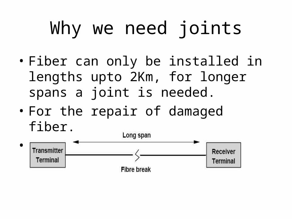
Why we need joints
• Fiber can only be installed in lengths upto 2Km, for longer spans a joint is needed.
• For the repair of damaged fiber.
• For test purpose at terminal equipment.
• All of the fiber cable in a building cannot be installed as one continues cable run.
• joints are needed to complete network cabling.
• Temporary access is needed for test purposes.
• Fiber optic transmitter and receivers are terminated to a fiber optic Pigtail.
• A fiber pigtail is a short length of optical fiber (usually 1 meter or less) permanently fixed to the optical source or detector.
• Manufacturers supply transmitters and receivers with pigtails and connectors
• Reduced coupling loss results when source-to-fiber and fiber-to-detector coupling is done in a controlled manufacturing environment
Fiber Pigtail
Fiber joint loss
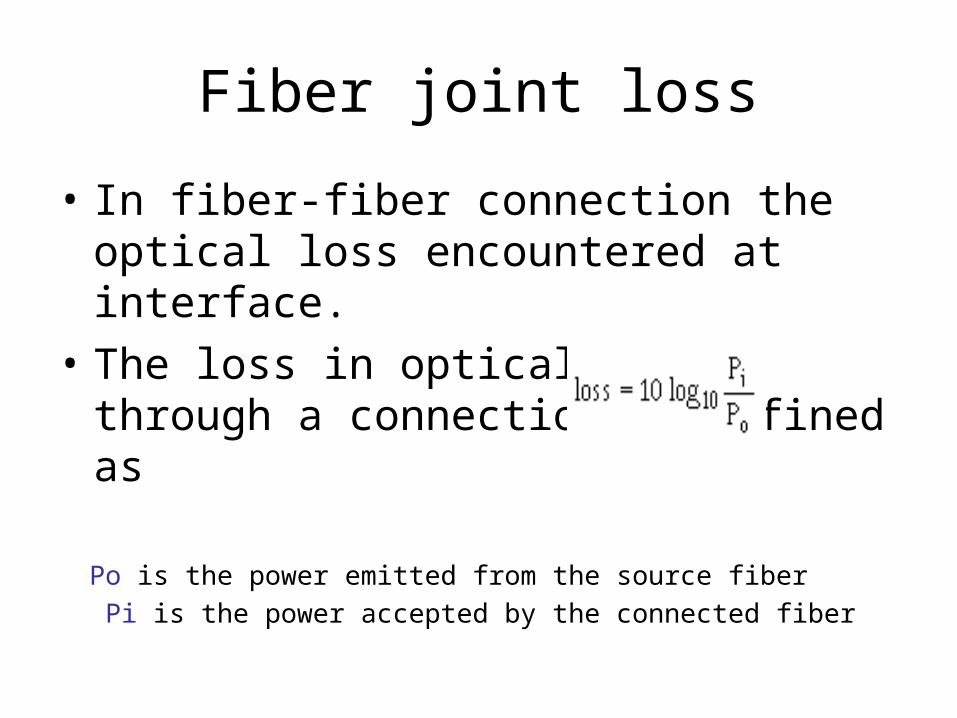
• In fiber-fiber connection the optical loss encountered at interface.
• The loss in optical power through a connection is defined as
Po is the power emitted from the source fiber
Pi is the power accepted by the connected fiber
Fiber joint loss (cont…)
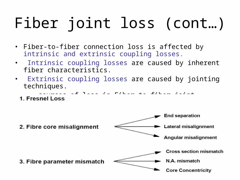
• Fiber-to-fiber connection loss is affected by intrinsic and extrinsic coupling losses.
• Intrinsic coupling losses are caused by inherent fiber characteristics.
• Extrinsic coupling losses are caused by jointing techniques. sources of loss in Fiber-to-fiber joint
Fiber joint loss (cont…)
• Intrinsic coupling losses are limited by reducing fiber mismatches between the connected fibers.
• This is done by procuring only fibers that meet stringent geometrical and optical specifications
• Extrinsic coupling losses are limited by proper connection procedures.
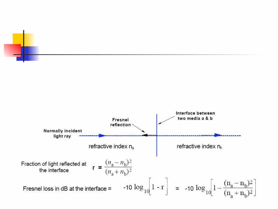
Fresnel Loss (Return Loss)
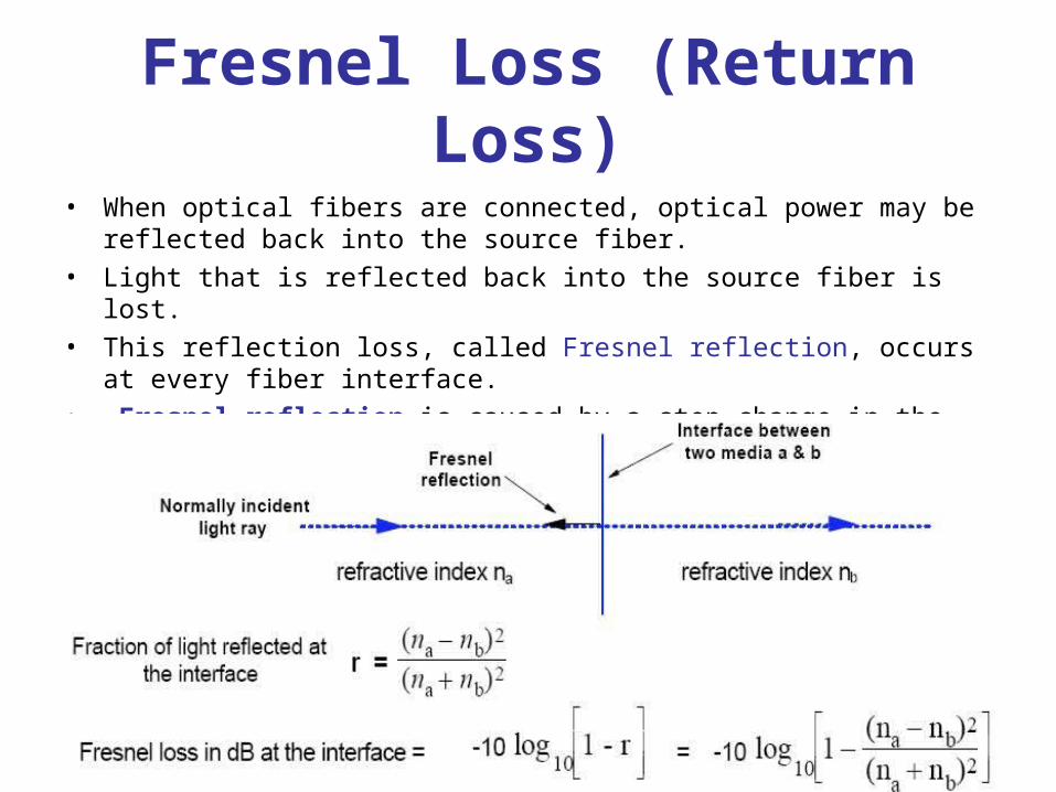
• When optical fibers are connected, optical power may be reflected back into the source fiber.
• Light that is reflected back into the source fiber is lost.
• This reflection loss, called Fresnel reflection, occurs at every fiber interface.
• Fresnel reflection is caused by a step change in the refractive index that occurs at the fiber joint.
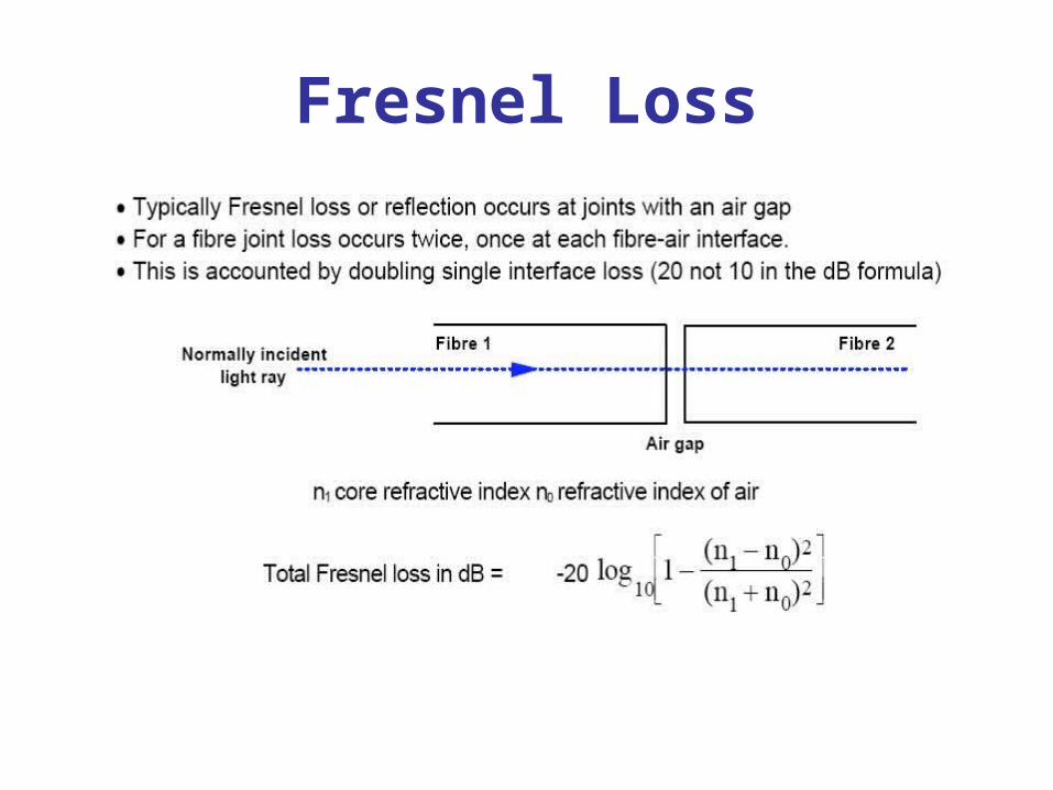
Fresnel Loss
Reducing Fresnel Loss
• To reduce the amount of loss from Fresnel reflection, the air gap can be filled with an index matching gel.
• The refractive index of the index matching gel should match the refractive index of the fiber core.
• Index matching gel reduces the step change in the refractive index at the fiber interface.
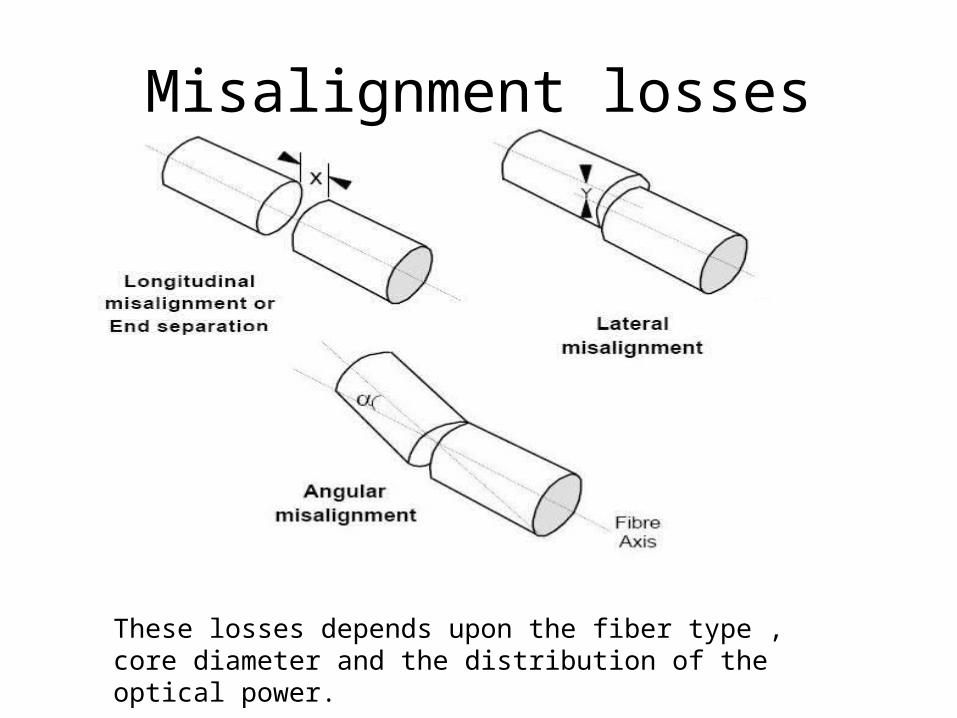
Misalignment losses
These losses depends upon the fiber type , core diameter and the distribution of the optical power.
End separation Loss

Fiber Splice
A permanent joint formed between two individual optical fibers in the field or factory is known as a FIBER SPLICE.
Used to establish long haul optical fiber links
Two types of splicing:
1. Fusion splicing2. Mechanical splicing
Prior to splicing both fibers must be prepared:
Remove plastic buffer coatings on both fibres
Cleave fibre end and clean with isopropyl alcohol
Good fibre end preparation is vital if a low loss splice is to be achieved.
Fusion Splice
Melts the fibers together to form a continuous fiber
The source of heat is usually an electric arc, but can also be a laser, or a gas flame, or a tungsten filament through which current is passed.
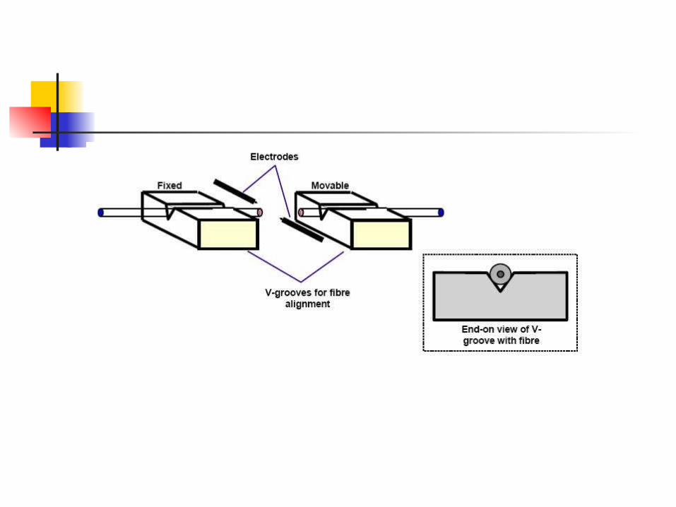
Fusion Splice Principles
Cleaved fiber ends are fused permanently together using an electric arc
During splicing fibers area held in V-grooves for alignment
A variety of splices have developed to cater for multimode and singlemode fiber
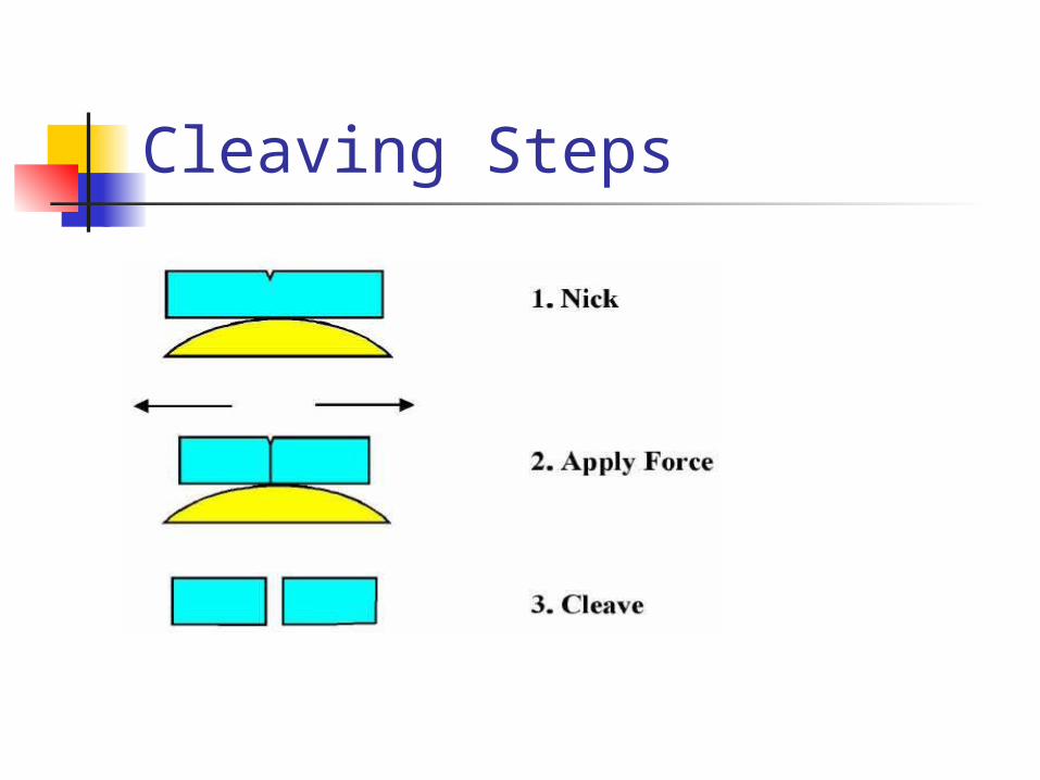
Cleaving Steps
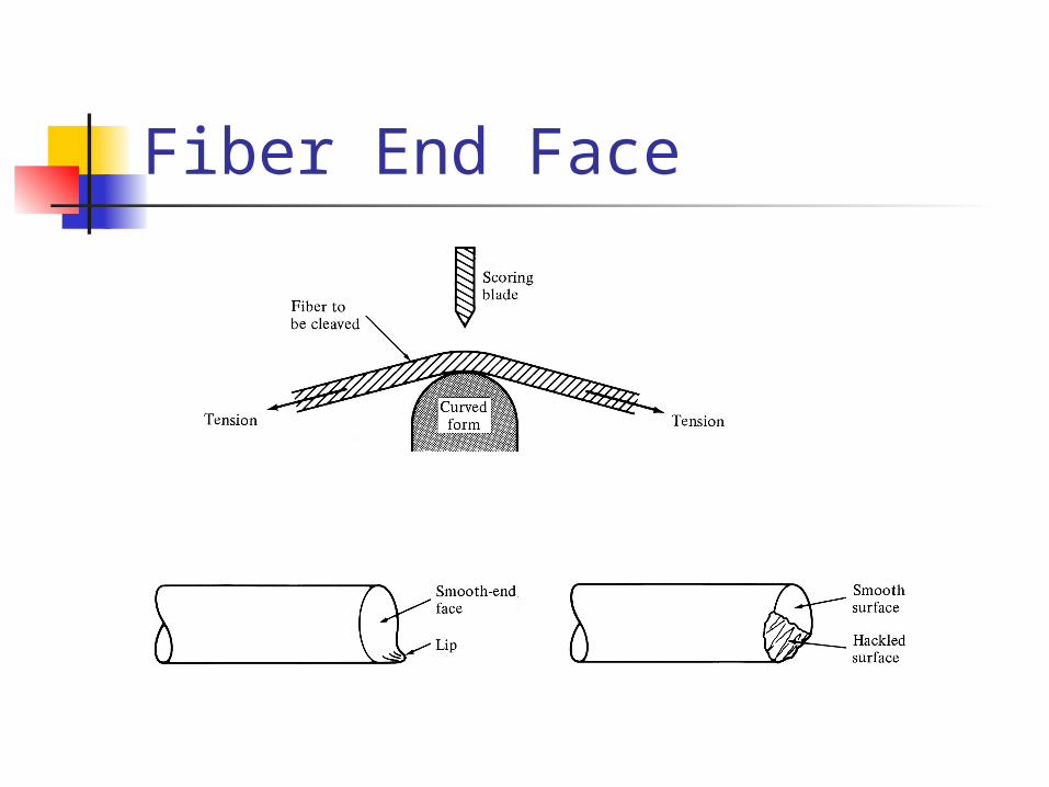
Fiber End Face
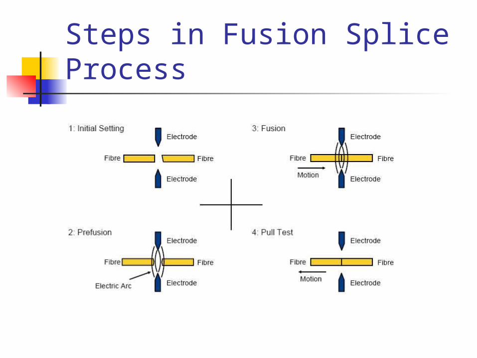
Steps in Fusion Splice Process
Fusion Splice loss
Which Splice?
If cost is the issue, we've given you the clues to make a choice: fusion is expensive equipment and cheap splices, while mechanical is cheap equipment and expensive splices. So if you make a lot of splices (like thousands in an big telco or CATV network) use fusion splices. If you need just a few, use mechanical splices. Fusion splices give very low back reflections and are preferred for singlemode high speed digital or CATV networks. However, they don't work too well on multimode splices, so mechanical splices are preferred for MM, unless it is an underwater or aerial application, where the greater reliability of the fusion splice is preferred.