Optical Fiber Communication - Study...
16
www.studymafia.org A Seminar report On Optical Fiber Communication Submitted in partial fulfillment of the requirement for the award of degree Of Mechanical SUBMITTED TO: SUBMITTED BY: www.studymafia.org www.studymafia.org
-
Upload
truongkhanh -
Category
Documents
-
view
221 -
download
0
Transcript of Optical Fiber Communication - Study...
www.studymafia.org
A
Seminar report
On
Optical Fiber Communication
Submitted in partial fulfillment of the requirement for the award of degree
Of Mechanical
SUBMITTED TO: SUBMITTED BY: www.studymafia.org www.studymafia.org
www.studymafia.org
Preface
I have made this report file on the topic Optical Fiber Communication; I have tried my best to
elucidate all the relevant detail to the topic to be included in the report. While in the beginning I
have tried to give a general view about this topic.
My efforts and wholehearted co-corporation of each and everyone has ended on a successful
note. I express my sincere gratitude to …………..who assisting me throughout the preparation of
this topic. I thank him for providing me the reinforcement, confidence and most importantly the
track for the topic whenever I needed it.
www.studymafia.org
Content
Introduction
Fundamentals of Fibers
Construction of Fibers
Classification of Optical Fibers
Modes and Propagation of Light in Fibers
Advantages over Conventional Cables
Areas of Application
Conclusion
References
www.studymafia.org
Introduction
Optical fibers are arguably one of the world’s most influential scientific developments from the
latter half of the 20th century. Why has the development of fibers been given so much attention
by the scientific community when we have alternatives? The main reason is bandwidth – fibers
can carry an extremely large amount of information. More indirectly, many of the systems that
we either rely on or enjoy in everyday life such as banks, television and newspapers as (to name
only a very limited selection) are themselves dependent on communication systems that are
dependent on optical fibers.
www.studymafia.org
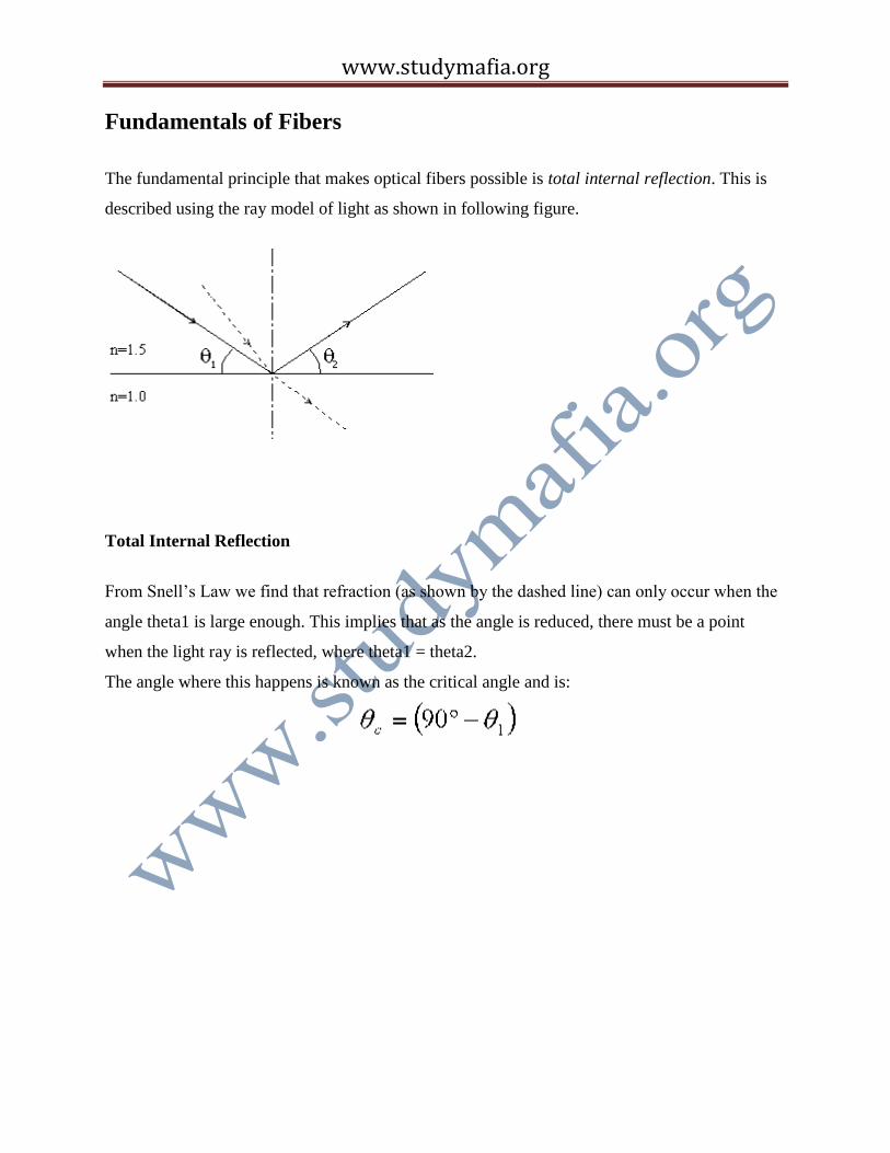
Fundamentals of Fibers
The fundamental principle that makes optical fibers possible is total internal reflection. This is
described using the ray model of light as shown in following figure.
Total Internal Reflection
From Snell’s Law we find that refraction (as shown by the dashed line) can only occur when the
angle theta1 is large enough. This implies that as the angle is reduced, there must be a point
when the light ray is reflected, where theta1 = theta2.
The angle where this happens is known as the critical angle and is:
www.studymafia.org
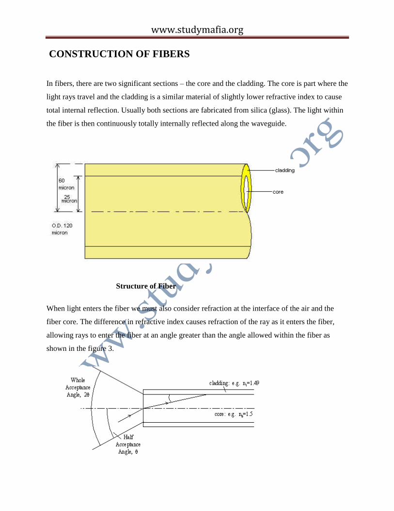
CONSTRUCTION OF FIBERS
In fibers, there are two significant sections – the core and the cladding. The core is part where the
light rays travel and the cladding is a similar material of slightly lower refractive index to cause
total internal reflection. Usually both sections are fabricated from silica (glass). The light within
the fiber is then continuously totally internally reflected along the waveguide.
Structure of Fiber
When light enters the fiber we must also consider refraction at the interface of the air and the
fiber core. The difference in refractive index causes refraction of the ray as it enters the fiber,
allowing rays to enter the fiber at an angle greater than the angle allowed within the fiber as
shown in the figure 3.
www.studymafia.org
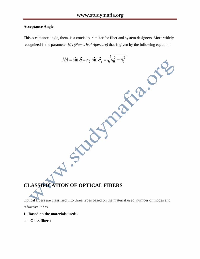
Acceptance Angle
This acceptance angle, theta, is a crucial parameter for fiber and system designers. More widely
recognized is the parameter NA (Numerical Aperture) that is given by the following equation:
CLASSIFICATION OF OPTICAL FIBERS
Optical fibers are classified into three types based on the material used, number of modes and
refractive index.
1. Based on the materials used:-
a. Glass fibers:
www.studymafia.org
They have a glass core and glass cladding. The glass used in the fiber is ultra pure, ultra
transparent silicon dioxide (SiO2) or fused quartz. Impurities are purposely added to pure glass
to achieve the desired refractive index.
b. Plastic clad silica:
This fiber has a glass core and plastic cladding. This performance though not as good as all glass
fibers, is quite respectable.
c. Plastic fibers:
They have a plastic core and plastic cladding. These fibers are attractive in applications where
high bandwidth and low loss are not a concern.
2. Based on the number of modes:-
a. Single Mode fiber:
When a fiber wave-guide can support only the HE11 mode, it is referred to as a single mode
wave-guide. In a step index structure this occurs w3hen the wave-guide is operating at v<2.4
where v is dimensionless number which relates the propagating in the cladding. These single
mode fibers have small size and low dopant level (typically 0.3% to 0.4% index elevation over
the lading index.)
In high silica fibers the wave-guide and the material dispersion are often of opposite signs. This
fact can be used conveniently to achieve a single mode fiber of extremely large bandwidth.
Reduced dopant level results in lower attenuation than in multimode fibres. A single mode wave
guide with its large and fully definable bandwidth characteristics is an obvious candidate for long
distance, high capacity transmission applications.
b. Multimode fiber:
It is a fiber in which more than one mode is propagating at the system operating wavelength.
Multimode fiber system does not have the information carrying capacity of single mode fibers.
However they offer several advantages for specific systems. The larger core diameters result in
easier splicing of fibers. Given the larger cores, higher numerical apertures, and typically shorter
link distances, multimode systems can use less expensive light sources such as LED s .
Multimode fibers have numerical apertures that typically range from 0.2 to 0.29 and have core
size that range from 35 to100 micro-meters.
www.studymafia.org
3. Based on refractive index:-
a. Step index fiber:
The step index (SI) fiber consists of a central core whose refractive index is n1, surrounded by a
lading whose refractive index is n2, lower than that of core. Because of an abrupt index change
at the core cladding interface such fibers are called step index fibers.
b. Graded index fibers:
The refractive index of the core in graded index fiber is not constant, but decreases gradually
from its maximum value n1 to its minimum value n2 at the core-cladding interface. The ray
velocity changes along the path because of variations in the refractive index. The ray propagating
along the fiber axis takes the shortest path but travels most slowly, as the index is largest along
this path in medium of lower refractive index where they travel faster. It is therefore possible for
all rays to arrive together at the fiber output by a suitable choice of refractive index profile.
MODES AND PROPAGATION OF LIGHT IN FIBERS
Also crucial to understanding fibers is the principle of modes. A more in-depth analysis of the
propagation of light along an optical fiber requires the light to be treated as an electromagnetic
wave (rather that as a ray).
www.studymafia.org
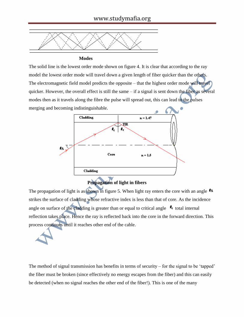
Modes
The solid line is the lowest order mode shown on figure 4. It is clear that according to the ray
model the lowest order mode will travel down a given length of fiber quicker than the others.
The electromagnetic field model predicts the opposite – that the highest order mode will travel
quicker. However, the overall effect is still the same – if a signal is sent down the fiber as several
modes then as it travels along the fibre the pulse will spread out, this can lead to the pulses
merging and becoming indistinguishable.
Propagation of light in fibers
The propagation of light is as shown in figure 5. When light ray enters the core with an angle
strikes the surface of cladding whose refractive index is less than that of core. As the incidence
angle on surface of the cladding is greater than or equal to critical angle total internal
reflection takes place. Hence the ray is reflected back into the core in the forward direction. This
process continues until it reaches other end of the cable.
The method of signal transmission has benefits in terms of security – for the signal to be ‘tapped’
the fiber must be broken (since effectively no energy escapes from the fiber) and this can easily
be detected (when no signal reaches the other end of the fiber!). This is one of the many
www.studymafia.org
advantages of the medium. But mainly two factors, attenuation and dispersion of light, have to be
considered while transmitting the light over large distances. We use repeaters and regenerators to
reduce the attenuation and dispersion.
REPEATERS AND REGENERATORS:-
Optical repeaters are purely optical devices that are used simply to combat attenuation in the
fiber; typically spans of 80km upwards are now possible. The recent introduction of soliton
transmission methods has increased the allowed distance between repeaters and systems
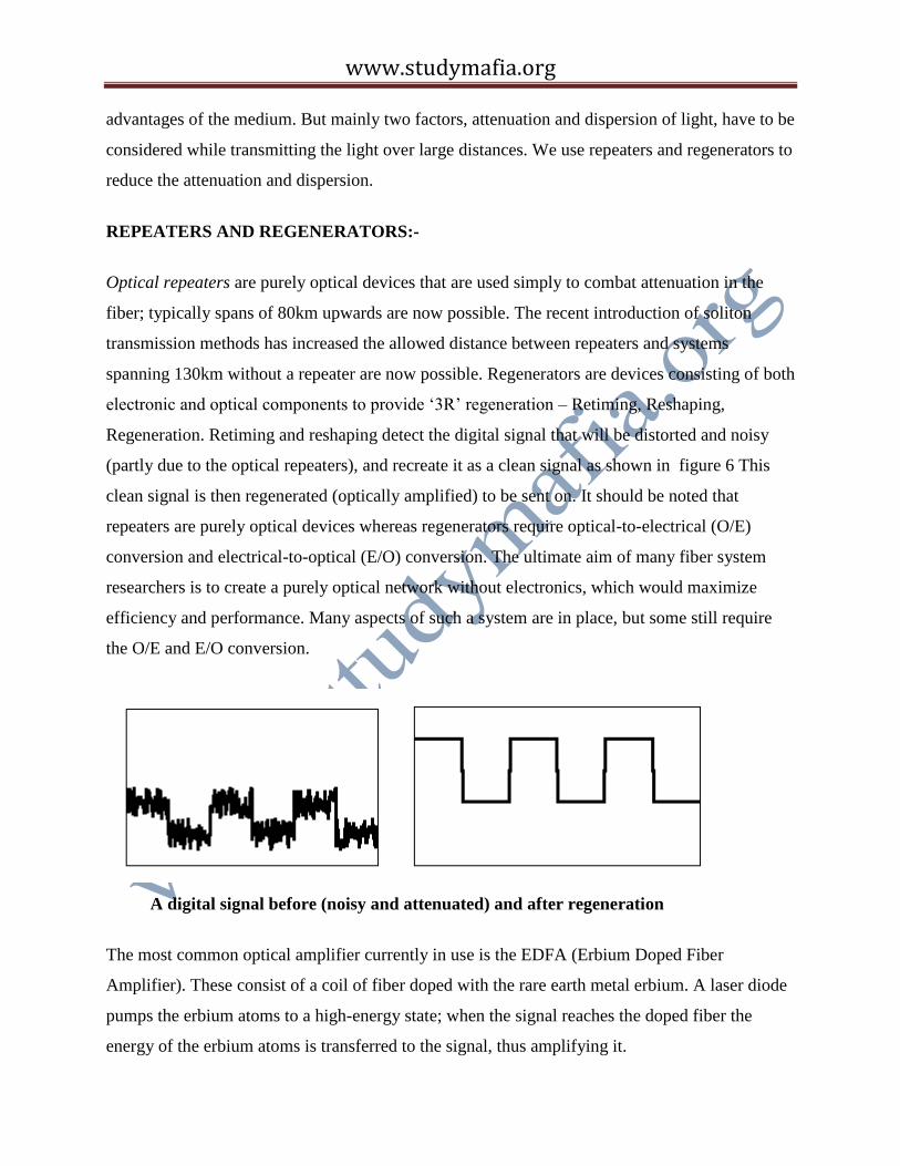
spanning 130km without a repeater are now possible. Regenerators are devices consisting of both
electronic and optical components to provide ‘3R’ regeneration – Retiming, Reshaping,
Regeneration. Retiming and reshaping detect the digital signal that will be distorted and noisy
(partly due to the optical repeaters), and recreate it as a clean signal as shown in figure 6 This
clean signal is then regenerated (optically amplified) to be sent on. It should be noted that
repeaters are purely optical devices whereas regenerators require optical-to-electrical (O/E)
conversion and electrical-to-optical (E/O) conversion. The ultimate aim of many fiber system
researchers is to create a purely optical network without electronics, which would maximize
efficiency and performance. Many aspects of such a system are in place, but some still require
the O/E and E/O conversion.
A digital signal before (noisy and attenuated) and after regeneration
The most common optical amplifier currently in use is the EDFA (Erbium Doped Fiber
Amplifier). These consist of a coil of fiber doped with the rare earth metal erbium. A laser diode
pumps the erbium atoms to a high-energy state; when the signal reaches the doped fiber the
energy of the erbium atoms is transferred to the signal, thus amplifying it.
www.studymafia.org
Light Sources
Two types of light source are used with fibers, LEDs and Laser Diodes. LEDs can operate in the
near infrared (the main wavelengths used in fibers are 1300nm and 1550nm, along with 850nm
for some applications); they can emit light at 850nm and 1300nm. They also have the advantages
of long lifetimes and being cheap. Unfortunately they are large compared to the cross-section of
a fiber and so a large amount of light is lost in the coupling of an LED with a fiber. This also
reduces the amount of modal control designers have over incident light. Laser diodes can be
made to emit light at either 1300nm or 1550 nm, and also over a small spectral width (unlike
LEDs), which reduces chromatic dispersion. Their emitting areas are extremely small and so the
angle of incidence of light on a fiber can be accurately controlled such that <5% of the possible
modes within a multimode fiber will be initially used. They are more efficient than LEDs in
terms of coupling of light into the fiber, although they have shorter lifetimes than and are more
expensive than LEDs. One crucial advantage of lasers over LEDs in today’s world of digital
communications is their high switching speed and small rise times, leading to increased
bandwidth.
Detecting the Signal
The most efficient detectors are reverse-bias photo detectors. They essentially cause a current to
flow when light is incident on them. The choice of semiconductor that is used to fabricate the
detector is dependent on the wavelength sensitivity and the responsivity that are required.
Bandwidth considerations are also important (determined by the rise time and fall time of a
detector); in detectors the fall time is often appreciably greater than the rise time and so this must
be used to calculate the bandwidth of a detector. There are many further complications in
detectors, including noise equivalent power that indicates how ‘clean’ a signal from a detector is.
www.studymafia.org
ADVANTAGES OVER CONVENTIONAL CABLES
Wide Bandwidth: Optical fibers offer greater bandwidth due to the use of light as carrier. The
frequency range used for glass fiber communication extends from 2*e14Hz to 4*e14Hz. Hence
optical fibers are suitable for high speed, large capacity telecommunication lines.
Low Loss: In a coaxial cable attenuation increases with frequency. The higher the frequency of
information signals the greater the loss, whereas in an optical fiber the attenuation is independent
of frequency. They offer a loss of0.2 dBm/km, allowing repeater separation upto 50Km or more.
Freedom from electromagnetic interference: Optical fibers are not affected by interference
originating from power cables, railways and radio waves. They do not limit unwanted radiation
and no cross talk between fibers exists. These fibers make an ideal transmission medium when
EMI (Electro Magnetic Immunity) is increased.
Non conductivity: Optical fibers are non-conductive and are not effective by strong
electromagnetic interference such as lighting. These are usable in explosive environment.
Small diameters and less weight: Even multi fiber optical cables have a small diameter and are
light weight, and flexible optical fiber cables permit effective utilization of speech and can also
be applicable to long distance use are easier to handle and install than conventional cables.
Security: Fiber optic is a highly source transmission medium. It does not radiate energy that can
be received by a nearby antenna, and it is extremely difficult to tap a fiber and virtually
impossible to make the tap undetected.
Safety: Fibre is a dielectric and does not carry electricity. It presents no sparks or fire hazards. It
does not cause explosions, which occur due to faulty copper cable.
www.studymafia.org
Areas of Application
Telecommunications: Optical fibers are now the standard point to point cable link between
telephone substations.
Local Area Networks (LAN's): Multimode fiber is commonly used as the "backbone" to carry
signals between the hubs of LAN's from where copper coaxial cable takes the data to the
desktop. Fiber links to the desktop, however, are also common.
Cable TV: As mentioned before domestic cable TV networks use optical fiber because of its
very low power consumption.
CCTV: Closed circuit television security systems use optical fiber because of its inherent
security, as well as the other advantages mentioned above
www.studymafia.org
Conclusions
We are currently in the middle of a rapid increase in the demand for data bandwidth across the
Earth. For most applications optical fibers are the primary solution to this problem. They have
potentially a very high bandwidth, with many of the bandwidth limitations now being at the
transceivers rather than being an intrinsic property of the fiber allowing easy upgrading of
systems without relaying cable.
This is creating a surge in the deployment of fiber both in backbones of networks and in
topologically horizontal cabling, which inturn is supporting and propelling the industry into
further research. With the adoption of new techniques such as DWDM, soliton transmission, and
ultimately the purely optical network, we have a medium that will satisfy our communication
needs for the foreseeable future.

www.studymafia.org
References
www.google.com
www.wikipedia.com
www.studymafia.org