Operator's Manual - Barbeques Galore this Operator's Manual for convenient referral and for part...
20
NOTE TO ASSEMBLER / INSTALLER: Leave this manual with the consumer. NOTE TO CONSUMER: Keep this manual for future reference. RECORD YOUR SERIAL # __________________ (see silver CSA label on main body of side burner lid) IMPORTANT: Failure to comply with these instructions could result in a fire or explosion that could cause serious bodily injury, death or property damage. Whether this side burner was assembled by you or someone else, you must read this entire manual before using your side burner to ensure the side burner is properly assembled, installed and main- tained. Use your side burner at least 3 feet away from any wall or surface. Use your side burner at least 3 feet away from combustible objects that can melt or catch fire such as vinyl or wood siding, fences and overhangs or sources of ignition including pilot lights on water heaters and live electrical appliances. THIS GAS APPLIANCE IS DESIGNED FOR OUT- DOOR USE ONLY. Never use this gas appliance on a balcony, deck, or patio above the ground floor of your home. Never use your gas side burner in a garage, porch, shed, breezeway or any other enclosed area. Never obstruct the flow of ventilation air around your gas side burner housing. Never disconnect the gas regulator or any gas fitting while your side burner is lit. A lit side burner can ignite leaking gas and cause a fire or explosion which could result in property damage, personal injury or death. WARNING ! ! Manual # P80151113A - Date:2010/04/13 Liquid Propane Gas (LPG) Side Burner Model TSB10ALP Natural Gas (NG ) Side Burner Model TSB10ANG Models TSB10ALP/NG Operator's Manual FREE HELP FROM THE GRILL EXPERTS Grand Hall is the expert on this product and trained to help you with: visit www.grandhall.com or call: 1-877-934-7455 Monday - Friday 8:00am-4:30pm CST Assembly Questions Side Burner Operation Replacement of Damaged or Missing parts
Transcript of Operator's Manual - Barbeques Galore this Operator's Manual for convenient referral and for part...

NOTE TO ASSEMBLER / INSTALLER:Leave this manual with the consumer.
NOTE TO CONSUMER:Keep this manual for future reference.
RECORD YOUR SERIAL # __________________(see silver CSA label on main body of side burner lid)
ü
ü
IMPORTANT:
ü
Failure to comply with these instructions couldresult in a fire or explosion that could cause seriousbodily injury, death or property damage.Whether this side burner was assembled by you orsomeone else, you must read this entire manualbefore using your side burner to ensure the sideburner is properly assembled, installed and main-tained.Use your side burner at least 3 feet away fromany wall or surface. Use your side burner at least3 feet away from combustible objects that can meltor catch fire such as vinyl or wood siding, fences andoverhangs or sources of ignition including pilot lightson water heaters and live electrical appliances.THIS GAS APPLIANCE IS DESIGNED FOR OUT-DOOR USE ONLY.Never use this gas appliance on a balcony, deck, orpatio above the ground floor of your home.Never use your gas side burner in a garage, porch,shed, breezeway or any other enclosed area.Never obstruct the flow of ventilation airaround your gas side burner housing.Never disconnect the gas regulator or any gasfitting while your side burner is lit. A lit side burnercan ignite leaking gas and cause a fire or explosionwhich could result in property damage, personalinjury or death.
ü
ü
ü
ü
ü
ü
WARNING! !
ü
Manual # P80151113A - Date:2010/04/13
Liquid Propane Gas (LPG) Side BurnerModel TSB10ALPNatural Gas (NG ) Side BurnerModel TSB10ANG
Models TSB10ALP/NG
Operator's Manual
FREE HELPFROM THE GRILL EXPERTS
Grand Hall is the expert on this product andtrained to help you with:
visit www.grandhall.com or call:
1-877-934-7455Monday - Friday 8:00am-4:30pm CST
Assembly QuestionsSide Burner OperationReplacement of Damaged or Missing parts
üüü
ü

2
Table of Contents WARNING! !
• LPG models must be used with Liquid PropaneGas and the regulator assembly supplied. Natu-ral Gas models must be used with Natural Gasonly. Any attempt to convert the side burner fromone fuel type to another is extremely hazardousand will void the warranty.
Keep gas regulator hose away from hot sideburner surfaces and dripping grease. Avoid unnec-essary twisting of hose. Visually inspect hoseprior to each use for cuts, cracks, excessive wearor other damage. If the hose appears damageddo not use the gas side burner. Call 1-877-934-7455 for a certified replacement hose.
California Proposition 65Combustion byproducts produced when using thisproduct contain chemicals known to the State ofCalifornia to cause cancer, birth defects, or otherreproductive harm.
Brass components on the side burner, such ashose fittings, propane cylinder valves (sold sepa-rately) and burner valve stems, contain lead whichis known to the State of California to cause cancer,birth defects, or other reproductive harm.
Never use charcoal or lighter fluid in this gas sideburner. Failure to comply with these instructionscould result in a grease fire or explosion that couldcause serious bodily injury, death or property dam-age.
The Grease Tray must be visually inspected beforeeach side burner use. Remove any grease andwash Grease Tray with a mild soap and warm watersolution. Failure to comply with these instructionscould result in a grease fire or explosion that couldcause serious bodily injury, death or propertydamage.
•
•
•
•
Primary Safety Warnings ........................... 1-3Pre-Assembly Instructions .............................. 3Part Diagrams and Lists .......................... 4-6Assembly Instructions................................7-9LP Gas Tank Installation ...................... 10-12Natural Gas Connection..............................13Use & Care Instructions:• Lighting Instructions.................................14• Troubleshooting.........................................15Cleaning and Maintenance......................16-17Frequently Asked Questions ................ A1-A2Warranty Terms.............................Back Cover
DANGER! !1.2.3.4.
If you smell gas:Shut off gas to the appliance.Extinguish any open flame.Open lid.If odor continues, keep away fromthe appliance and immediately callyour gas supplier or your fire depart-ment.
Do not store or use gasoline or otherflammable liquids or vapors in the vi-cinity of this or any other appliances.
An LP cylinder not connected for useshall not be stored in the vicinity ofthis or any other appliance.
1.
2.
WARNING! !
Failure to remove Side Burner Lidduring the lighting procedures couldresult in a fire or explosion that couldcause serious bodily injury, death, orproperty damage.
WARNING! !
Your appliance will get very hot. Never lean over thecooking area while using your side burner. Do nottouch cooking surfaces or any other side burner partswhile the side burner is in operation, or until the sideburner has cooled down after use. Failure to complywith these instructions may result in serious bodilyinjury.
WARNING! !

3
Pre-Assembly Instructions For Your Safety
Side Burner Installation CodesThe installation must conform with local codes or, in theabsence of local codes, with either the National Fuel GasCode, ANSI Z223.1/NFPA 54, Natural Gas and Propane.Installation Code, CSA B149.1, or Propane Storage andHandling Code, B149.2.
•••
PRE-ASSEMBLYRead and perform the following pre-assembly instruc-tions:
Tools Required for Assembly:protective work glovesprotective eyewear
For your safety, obtain assistance from anotherperson when assembling this product.
Open Lid of shipping carton and remove top sheet ofcardboard and packing materials. Lay cardboardsheet on floor and use as a work surface to protectfloor and side burner parts from scratches.
You may slice the carton front corners with a utilityknife to lay open the carton front panel. This allowsyou to remove the components packed inside beforelifting the side burner out of the packaging.
Use the Hardware and Part Diagrams to ensure allitems are included and free of damage.
Do not assemble or operate the side burner if it ap-pears damaged. If there are damaged or missing partswhen you unpack the shipping box or you have ques-tions during the assembly process call: 1-877-934-7455 Monday - Friday 8:00am-4:30pm CST
Phillips head screwdriver
CSA Label locatedinside the lid
CAUTION! !Failure to comply with these instructions may resultin a hazardous situation which, if not avoided, mayresult in injury.
For safe operation ensure the Gas Valve Assem-bly Orifice is inside the Burner Tube before usingyour side burner. See figure. If the Orifice is notinside the Burner Tube, lighting the Burner maycause explosion and/or fire resulting in seriousbodily injury and/or property damage.
METHOD 1: Bend a stiff wire or wire coat hangerinto a small hook as shown and run the hookthrough the Burner Tube and inside the Burnerseveral times to remove debris.
METHOD 2: Use a bottle brush with a flexiblehandle and run the brush through the BurnerTube and inside the Burner several times toremove any debris.
METHOD 3: Use an air hose to force air througheach Burner Tube. The forced air should passdebris or obstructions through the Burner and outthe Ports.
TO CLEAN BURNER TUBE,INSERT HOOK HERE
Burner Tube9
Burner Port
1.
2.
3.
4. Refer to the figure below and perform one of these3 cleaning methods:
Carefully lift each Burner up and away from the GasValve Orifice.
Check and clean Burner/Venturi Tubes for insectsand insect nests. A clogged tube can lead to a firebeneath the side burner.
Spiders and small insects can spin webs and nestin the Burner Tubes during transit and warehousingwhich can lead to a gas flow obstruction resultingin a fire in and around the Burner Tubes. This typeof "FLASHBACK FIRE" can cause serious sideburner damage and create an unsafe operatingcondition for the user.
To reduce the chance of FLASHBACK FIREyou must clean the Burner Tubes as followsbefore initial use. Also do this at least once amonth in summer and fall or whenever spiders areactive in your area, and if your side burner has notbeen used for an extended period of time.
Remove the screws from the side burner body and therear of each Burner using a Phillips Head Screwdriver.
Orifice Burner TubeGas Valve Assembly
4
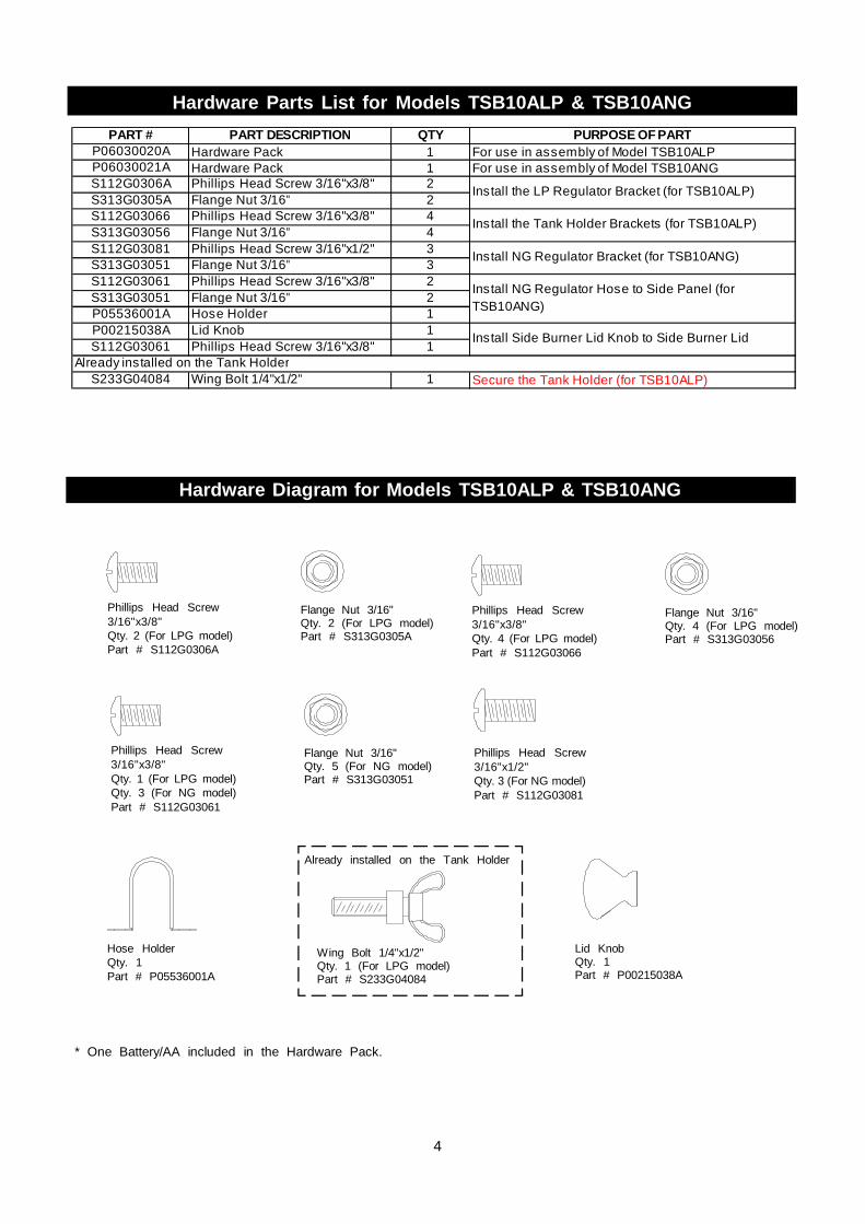
Hardware Parts List for Models TSB10ALP & TSB10ANG
* One Battery/AA included in the Hardware Pack.
Phillips Head Screw3/16"x3/8"Qty. 2 (For LPG model)Part # S112G0306A
Flange Nut 3/16"Qty. 2 (For LPG model)Part # S313G0305A
Phillips Head Screw3/16"x1/2"Qty. 3 (For NG model)Part # S112G03081
Hose HolderQty. 1Part # P05536001A
Hardware Diagram for Models TSB10ALP & TSB10ANG
Wing Bolt 1/4"x1/2"Qty. 1 (For LPG model)Part # S233G04084
Already installed on the Tank Holder
Lid KnobQty. 1Part # P00215038A
PART # PART DESCRIPTION QTY PURPOSE OF PARTP06030020A Hardware Pack 1 For use in assembly of Model TSB10ALPP06030021A Hardware Pack 1 For use in assembly of Model TSB10ANGS112G0306A Phillips Head Screw 3/16"x3/8" 2S313G0305A Flange Nut 3/16" 2S112G03066 Phillips Head Screw 3/16"x3/8" 4S313G03056 Flange Nut 3/16" 4S112G03081 Phillips Head Screw 3/16"x1/2" 3S313G03051 Flange Nut 3/16" 3S112G03061 Phillips Head Screw 3/16"x3/8" 2S313G03051 Flange Nut 3/16" 2P05536001A Hose Holder 1P00215038A Lid Knob 1S112G03061 Phillips Head Screw 3/16"x3/8" 1
S233G04084 Wing Bolt 1/4"x1/2" 1 Secure the Tank Holder (for TSB10ALP)Already installed on the Tank Holder
Install Side Burner Lid Knob to Side Burner Lid
Install the LP Regulator Bracket (for TSB10ALP)
Install the Tank Holder Brackets (for TSB10ALP)
Install NG Regulator Bracket (for TSB10ANG)
Install NG Regulator Hose to Side Panel (forTSB10ANG)
Phillips Head Screw3/16"x3/8"Qty. 1 (For LPG model)Qty. 3 (For NG model)Part # S112G03061
Flange Nut 3/16"Qty. 5 (For NG model)Part # S313G03051
Phillips Head Screw3/16"x3/8"Qty. 4 (For LPG model)Part # S112G03066
Flange Nut 3/16"Qty. 4 (For LPG model)Part # S313G03056

Parts Diagram for Models TSB10ALP & TSB10ANG
5
1
2
3
4
5
6
9
9
11
1219
20
14
13
181516
17
8
2224
23
18
29
217
25
26
2827
2a
10
23a
6a 6b

Parts List for Models TSB10ALP & TSB10ANG
6
Important: Use only Grand Hall replacement parts. The use of any part that is not a Grand Hall replace-ment part can be dangerous and will also void your product warranty. Keep this Operator's Manual forconvenient referral and for part replacement.
To obtain the correct replacement parts for your gas side burner, please refer to the part numbers in thisparts list. The following information is required to ensure you receive the correct parts:1. Model and Serial Number (see CSA label on side burner)2. Part Number3. Part Description4. Quantity of parts needed
For the repair or replacement parts you need:Call 1-877-934-7455 M-F 8AM-4:30PM CST
KEY DESCRIPTION PART # QTY1 Knob/Side Burner Lid P00215038A 12 Lid P0011554AA 12a Lid Chain P05522002A 13 Pot Support P016040476 14 Side Burner Body P0073958FC 15 Side Burner Frame P0073961F4 16 Gas Valve/Manifold Assembly Y0060735 16a Connection Hose/Gas Manifold P03715018A 16b Gas Manifold P03715019B 17 Bracket for NG Regulator (NG) P033040544 18 Grease Tray P02718064B 19 Trim Plate Left/Right P03304064C 210 Side Burner Frame Support Bracket P03304059C 211 Control Panel P0290448IX 112 Panel, Rear P0075804FC 113 Side Burner P02004041A 214 Side Burner Cap P02013058E 2
Side Burner Orifice (LPG) P06539034A 2Side Burner Orifice (NG) P06539035A 2
16 Connection Hose, Short P03701033A 117 Connection Hose, Long P03701034A 118 Orifice Bracket P03328075C 219 Side Burner Electrode with Wire, Front P02618054A 120 Side Burner Electrode with Wire, Rear P02618055A 121 Regulator with Hose Assembly (NG) P03614007A 122 Electronic Ignitor - 2 Ports P02502252C 123 Control Knob P03411503L 2
23a Control Knob Spring P05504021A 224 Control Knob Seat P03415014S 225 Lighting Stick P05313026B 126 Regulator with Hose and Connector (LPG) P03601043A 127 Tank Holder Assembly (LPG) P05358003T 128 Tank Holder Bracket, Left (LPG) P03304055F 129 Tank Holder Bracket, Right (LPG) P03304056F 1
Hardware Pack (LPG) P06030020A 1Hardware Pack (NG) P06030021A 1Operator Manual P80151113A 1
15
Phillips Head Screw3/16"x3/8"Qty. 2 (For NG model)Part # S112G03061
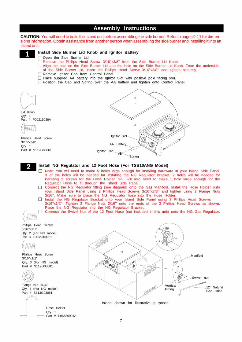
Assembly InstructionsCAUTION: You will need to build the island unit before assembling the side burner. Refer to pages 9-11 for dimen-sions information. Obtain assistance from another person when assembling the side burner and installing it into anisland unit.
7
2
Phillips Head Screw3/16"x1/2"Qty. 3 (For NG model)Part # S112G03081
Flange Nut 3/16"Qty. 5 (For NG model)Part # S313G03051
Install NG Regulator and 12 Foot Hose (For TSB10ANG Model)Note: You will need to make 5 holes large enough for installing hardware in your Island Side Panel.3 of the holes will be needed for installing the NG Regulator Bracket. 2 holes will be needed forinstalling 2 screws for the Hose Holder. You will also need to make 1 hole large enough for theRegulator Hose to fit through the Island Side Panel.Connect the NG Regulator fitting (see diagram) onto the Gas Manifold. Install the Hose Holder ontoyour Island Side Panel using 2 Phillips Head Screws 3/16’’x3/8’’ and tighten using 2 Flange Nuts3/16’’. Make sure to place the NG Regulator hose into the Hose Holder.Install the NG Regulator Bracket onto your Island Side Panel using 3 Phillips Head Screws3/16’’x1/2’’. Tighten 3 Flange Nuts 3/16’’ onto the ends of the 3 Phillips Head Screws as shown.Place the NG Regulator into the NG Regulator Bracket.Connect the Swivel Nut of the 12 Foot Hose (not included in this unit) onto the NG Gas Regulator.
Install Side Burner Lid Knob and Ignitor BatteryOpen the Side Burner Lid.Remove the Phillips Head Screw 3/16’’x3/8’’ from the Side Burner Lid Knob.Align the hole on the Side Burner Lid and the hole on the Side Burner Lid Knob. From the undersideof the Side Burner Lid, insert the Phillips Head Screw 3/16’’x3/8’’ and tighten securely.Remove Ignitor Cap from Control Panel.Place supplied AA battery into the Ignitor Slot with positive pole facing you.Position the Cap and Spring over the AA battery and tighten onto Control Panel.
1
Hose HolderQty. 1Part # P05536001A
Phillips Head Screw3/16"x3/8"Qty. 1Part # S112G03061 Ignitor Cap
Ignitor Slot
AA Battery
Spring
+-
Manifold
Swivel nut
12' NaturalGas Hose
Island shown for illustrative purposes.
VerticalFitting
Lid KnobQty. 1Part # P00215038A

8
Install Tank Holder Brackets and LP Regulator (For TSB10ALP Model)
CAUTION: Build your island before installing the LP Gas Tank and Partition Panel (not included in this unit).Refer to the heights listed in Fig. 4 on page 9 for constructing your grill island. An island unit is not includedwith the purchase of your Side Burner.
3-1Note: You will need to make 4 holes on your Island Bottom Panel before installing the Tank Holder Brackets.You will also need to make a hole in your Island Bottom Panel to accommodate your LP Gas Tank. Makesure the diameter of the hole is at least 9 inches. Make sure the depth of the hole is greater than theheight of the gas tank seat.Install the Bracket with Regulator onto the Island Side Panel using 2 Phillips Head Screws 3/16"x3/8"and 2 Flange Nuts 3/16".Install the Stainless Steel Tube (not included in this unit) onto the Manifold. Next, insert the other endof the Stainless Steel Tube through the hole on the Island's Side Panel. Install the Stainless Steel Tubeonto the male fitting on the Bracket.Install the Tank Holder Brackets onto the Island Bottom Panel using 4 Phillips Head Screws 3/16"x3/8".Tighten 4 Flange Nuts 3/16" onto the ends of the 4 Phillips Head Screws as shown. Be sure that theflat surfaces of the Tank Holder Brackets are positioned onto the Island Bottom Panel as shown below.
One wing bolt is used to secure thetank holder.
3-2
Wing Bolt 1/4"x1/2"Qty. 1 (For LPG model)Part # S233G04084(Already installed on the Tank Holder)
Fig. 3
Island BottomPanel
B Ring of theTank Holder
A Ring of theTank Holder
Install the LP Gas Tank (For TSB10ALP Model)Turn your LP Gas Tank Valve clockwise to the closed or OFF position.Remove the Wing Bolt from the Right Bracket of the Tank Holder Assembly. Reserve it for later step.Place the LP Gas Tank into the Tank Holder. Be sure that the bottom of the tank fully rests in thecutout of the Island Bottom Panel.Place the reserved Wing Bolt into the Right Bracket of the Tank Holder Assembly to secure the LPGas Tank.Attach the LP Regulator with Hose onto the LP Gas Tank.
Black
Phillips Head Screw 3/16"x3/8"Qty. 2 (For LPG model)Part # S112G0306A
Flange Nut 3/16"Qty. 2 (For LPG model)Part # S313G0305A
Phillips Head Screw 3/16"x3/8"Qty. 4 (For LPG model)Part # S112G03066
Flange Nut 3/16"Qty. 4 (For LPG model)Part # S313G03056
Black Black

9
Final Side Burner AssemblyStepWhen you have finished assembling your side
burner, be sure that all screws are tightenedfor safe operation of your side burner.
Before each use of the side burner, make surethe Grease Tray is fully seated under the sideburner Bowl.
CAUTION: The Grease Tray should be inspectedbefore each side burner use to be sure thereis no excessive grease buildup. Clean theGrease Tray frequently to eliminate greasebuild-up and to prevent grease fires.
Failure to remove Side Burner Lid during the lightingprocedures could result in a fire or explosion thatcould cause serious bodily injury, death, or propertydamage.
WARNING! !
Install Cooking Components6 Position the Pot Support over the Burners.Place the Side Burner Lid over the PotSupport.
Be sure that both Control Knobs are set to"OFF" and open the Side Burner Lid.Press the Ignitor Cap. You should hear a"clicking" sound. Your assistant should seea blue spark within each Spark ElectrodeTip . If a spark is present the Electrode Tipsare properly positioned.If no spark is seen, the Spark Gap needsto be adjusted as follows:
Side Burner Electrode Check5This test will ensure that the Spark ElectrodeTips are properly positioned so your SideBurner lights easily and properly.
Install the Partition Panel (not included in this unit) onto the left island.Make sure there is 22-24'' of clearance between the partition panel and the Tank HolderAssembly.
4 Install Partition Panel (for TSB10ALP Model)
AA Battery may be installed backwards.Electric wires may be loose. Remove the AABattery and inspect the Ignitor Junction Boxfound behind the Control Panel and recon-nect any loose wires.
--
•
•
If the gap between the Spark Electrode Tipand Burner Port is more than 3/16" wideuse needle nose pliers to gently squeezethe Spark Electrode Tip to narrow gap.Recheck the Electrode again, if no "clicking"sound is heard:
Spark Electrode Tip
Burner Port
Spark Gap3/16"
Partition Panel(above the Gas Tank)
Fig. 4
5"
22-24"21"
1"
17-19"
5"Vent Openings mustbe at least 1/8" wide.
Lid
Pot Support
2"

LP Gas Tank Installation
10
!Do not store a spare LP-Gas tank under or nearthis appliance.Never fill the tank beyond 80 percent full; andIf the information in "(a)" and "(b)" is not followedexactly, a fire causing death or serious injury mayoccur.
A.
B.C.
WARNING !
CORRECT LP GAS TANK USE
Never connect an unregulated LP gas tank to your sideburner. The gas regulator assembly supplied with yourgas grill is adjusted to have an outlet pressure of 11"water column (W.C.) for connection to an LP gas tank.Only use the regulator and hose assembly supplied withyour side burner. Replacement regulators and hoseassemblies must be those specified by Grand Hall.
Have your LP Gas dealer check the release valve afterevery filling to ensure it remains free of defects.
Always keep LP Gas tank in upright position.
Do not subject the LP Gas tank to excessive heat.
Never store an LP Gas tank indoors. If you store yourside burner unit indoors, always disconnect the LPGas Tank first and store it safely outside.
LP Gas tanks must be stored outdoors in a well-ventilated area and out of the reach of children.
Disconnected LP Gas tanks must not be stored in abuilding, garage or any other enclosed area.
The regulator and hose assembly can be seen afteropening the island's door and must be inspectedbefore each use of the side burner. If your regulatorand hose are damaged in any way, they must bereplaced prior to using the side burner again.
Any attempt to convert your side burner from one fuel typeto another is extremely hazardous and will void thewarranty.
Never light your gas side burner with the lid closedor before checking to ensure the burners are fullyseated over the gas valve orifices.
The LP Gas tank must be constructed and markedin accordance with the Specifications for LP-GasCylinders of the U.S. Department of Transportation(D.O.T.) or the National Standard of Canada, CAN/CSA-B339, Cylinders, Spheres and Tubes for Trans-portation of Dangerous Goods; and Commission, asapplicable.
The LP Gas tank must have a shutoff valve, termi-nating in an LP Gas supply tank valve outlet, that iscompatible with a Type 1 tank connection device. TheLP Gas tank must also have a safety relief devicethat has a direct connection with the vapor space ofthe tank.
The tank supply system must be arranged for vaporwithdrawal.
The LP Gas tank must have a collar to protect thetank valve.
! WARNING !Refer to this table when designing the island unit for theTSB10ALP/NG Model. Side* and Rear* show the mini-mum amount of distance the unit must be from com-bustibles (ex. Vinyl or wood siding, fences and over-hangs) or sources of ignition (ex. Pilot lights on waterheaters and live electrical appliances). Height* shows theminimum height the island unit must be starting fromthe ground up.
Model Height Width Depth Side* Rear* Height*TSB10ALP/NG
9" 14" 19-1/2" 36" 36" 29"
Never allow children to operate your side burner. Do notallow children or pets to play near your side burner. Alwayssupervise children and pets if they are in the vicinity of theunit.Use of alcohol, prescription or non-prescription drugs canimpair your ability to properly assemble and safely operateyour side burner.Keep fire extinguisher readily accessible. In the event of aoil/grease fire, do not attempt to extinguish with water. Usetype B extinguisher or smother with dirt, sand or baking soda.In the event of rain, turn off the burners and gas supply. Waitfor the side burner to cool, and then place a cover on it.Use your side burner on a level, stable surface in an areaclear of combustible materials.Do not leave side burner unattended when in use.Do not move the appliance when in use.Allow the side burner to cool before moving or storing.Do not use your side burner as a heater.This side burner is not intended to be installed in or onrecreational vehicles and/or boats.The side burner is not intended for commercial use.Never use charcoal or lighter fluid in this gas side burner.
LP Gas side burner models are designed for use with astandard 20 lb. Liquid Propane Gas (LP Gas) tank, notincluded with side burner. Never connect your side burnerto an LP Gas tank that exceeds this capacity. A tank ofapproximately 12 inches in diameter by 18-1/2 inches highis the maximum size LP Gas tank to use. You must usean "OPD" gas tank which offers a listed Overfill PreventionDevice. This safety feature prevents the tank from beingoverfilled which can cause a malfunction of the LP Gas Tank,regulator, and/or side burner.
Non-combustibleConstruction
6" minimum clearancefrom cutout (for lid)
Rear*
Side*
Height*Height
Depth
Wide

USE AND CARE INSTRUCTIONS
11
If growing bubbles appear do not use or movethe LP Gas tank. Contact an LP Gas Supplieror your fire department!
WARNING! !
Secure a 20lb LP Gas Tank to Gas Side BurnerNote: You can only use 20lb LP Gas Tank with thisSide Burner.
NOTE: When using Propane (LP), EXTREME CAU-TION should be used to provide ample ventilation ofvapor from the enclosure. LP Gas vapor is heavierthan air and SERIOUS INJURY from a DANGEROUSEXPLOSION could occur if LP Gas is allowed toaccumulate in an enclosure and then ignited. Both theBarbeque enclosure and LP cylinder enclosure re-quire venting that must be provided at the floor levelof the enclosure to allow any leaking LP Gas vaporto escape (see Fig. 6).NOTE: When installing a barbeque equipped for liquidpropane (LP) in an island, the LP tank must be ina separate enclosure that is completely isolated fromthe barbeque. It must be cross-ventilated in accor-dance with local codes. The LP tank MUST NEVERbe installed directly under the barbeque.NOTE: The total of the upper ventilation openingsmust be a minimum of 20 sq. inches. The total ofthe lower ventilation openings must be a minimumof 10 sq. inches. Upper and lower ventilation open-ings MUST BE PROVIDED on both sides of built-inconstruction. The top of the upper ventilations open-ings must be located within 5" from the top of theisland. The bottom of the lower ventilation openingsmust be at least 1" or less from the floor of the island.The top of the lower ventilation openings cannot bemore than 5" from the floor of the island. Everyventilation opening must have a minimum of 1/8" (SeeFig. 4 on page 9). Contact a Grand Hall associatefor more details.
Note: The built-in appliance for use with a remote self-contained LP Gas supply system must use rigid pipe,semi-rigid tubing or a connector complying with theStandard for Connections for Gas Appliance, ANSIZ21.24/CSA 6.10
NOTE about LP Gas Tank Exchange Programs
How to Leak Test your LP Gas Tank
All leak tests must be repeated each time your LP Gastank is exchanged or refilled.
When checking for gas leaks do not smoke.
Do not use an open flame to check for gas leaks.
Your side burner must be leak tested outdoors in a well-ventilated area, away from ignition sources such as gasfired or electrical appliances. During the leak test, keepyour side burner away from open flames or sparks.
Do not use household cleaning agents. Damage to gasassembly components can result.
For your safety:
Leak test new and exchanged LP Gas tanks BEFOREconnecting one to your side burner.
Always keep new and exchanged LP Gas tanks in an up-right position during use, transit or storage.
Use a clean paintbrush and a 50/50 mild soap andwater solution.Brush soapy solution onto LP Gas tank in the areasindicated by the arrows. See diagram.If growing bubbles appear do not use or move theLP Gas tank. Call an LP Gas Supplier or your FireDepartment.
Many retailers that sell gas appliances offer you the op-tion of replacing your empty LP Gas tank through an ex-change service. Use only those reputable exchange com-panies that inspect, precision fill, test, and certify theirtanks. Exchange your tank only for an OPD safety feature-equipped tank as described in the LP Gas tank section ofthis Guide.
ü
ü
ü
Fig. 6
Non-CombustibleConstruction, such asstone, marble, cement
Air Vents
Partition Panel
Stainless Steel Tube(Refer to the Notebelow).
5/8" UNFThread

12
WARNING!If you have a gas leak that cannot be repaired bytightening, turn off the gas at the source, disconnectfuel line from your side burner and call 1-877-934-7455 or your gas supplier for repair assistance.
LP Gas Model only:Connect Regulator with Hose to your LP Gas Tank
USE AND CARE INSTRUCTIONS
1.
WARNING!Do not store spare LP cylinder within10 feet (3m) of this appliance.Do not store or use gasoline or otherflammable liquids and vapors within 25feet (8m) of this appliance.When cooking with oil/grease, do notallow the oil/grease to get hotter 350°F(177°C)Do not leave oil/grease unattended.4.
2.
3.
CAUTION: When the appliance is not in use the gas mustbe turned off at the tank. Place dust cap on cylinder valveoutlet whenever the cylinder is not in use. Only install thetype of dust cap on the cylinder valve outlet that is providedwith the cylinder valve. Other types of caps or plugs mayresult in leakage of propane.
!
Disconnecting A Liquid Propane Gas (LPG)Tank From Your Side Burner
Make sure the Burner Valves and LP Gas tank valveare off. (Turn clockwise to close.)
Detach the hose and regulator assembly from theLP Gas tank valve by turning the Quick CouplingNut counterclockwise. Do not use a wrench or anytools when turning the Quick Coupling Nut.
!
WARNING !Failure to read and follow the Use and CareInstructions could result in a fire or explosion thatcould cause serious bodily injury, death or prop-erty damage.
!
Check all connections for LP Gas LeaksNever test for leaks with an open flame. Prior to firstuse, at the beginning of each season, or every timeyour LP Gas tank is changed, you must check for gasleaks. Follow these three steps:
Make a soap solution by mixing one part liquiddetergent and one part water.
Turn the side burner Control Knobs to the full OFFposition, then turn the gas ON at source.
Apply the soap solution to all gas connectionsindicated by the arrows. See diagram. If bubblesappear in the soap solution the connections arenot properly sealed. Check each fitting and tightenor repair as necessary.
Quick CouplingNut
Turn all Burner Valves to the OFF position.Inspect the valve connection port and regulatorassembly for damage or debris. Remove any debris.Never use damaged or plugged equipment.Connect the regulator assembly to the tank valveand HAND TIGHTEN nut clockwise to a full stop.DO NOT use a wrench to tighten because it coulddamage the Quick Coupling Nut and result in a gasleak/fire hazard.Open the tank valve (counterclockwise) 1/4 to 1/2of a full turn, and use a soapy water solution tocheck all connections for leaks before attemptingto light your side burner. See "Check all connec-tions for LP Gas Leaks". If a leak is found, turnthe tank valve off and do not use your side burneruntil the leak is repaired.
Type 1 connection per ANSIZ21.58A-2008/CSA 1.6A-2008
Gas Valve / ManifoldAssembly
LP Gas Tank
Regulator withHose (LPG)
(Not includedin this unit)

13
Natural Gas ConnectionNatural Gas Model only:Connecting Natural Gas To Your Side Burner
Your natural side burner is designed for use withnatural gas (NG) only. The gas pressure Regulatorsupplied with this appliance must be installed andused on your side burner. The unit and Regulatorare set to operate with an outlet pressure of 4" W.C.Install a Shutoff Valve at the gas supply source out-doors at a point after the gas pipe exits the outside walland before the quick-disconnect hose. Or install it atthe point before the gas line piping enters the ground.See Fig. 2.Pipe sealing compound or pipe thread tape resistantto the action of natural gas must be used on all malepipe thread connections.Disconnect your side burner from fuel source whenthe gas supply is being tested at high pressures. Thisside burner and its individual shutoff valve must bedisconnected from the gas supply pipe system duringany pressure testing of that system at pressure inexcess of 1/2 psi (3.5kpa).Turn off your side burner when the gas supply is beingtested at low pressures. The side burner must beisolated from the gas supply pipe system by closingits individual manual shutoff valve during any pres-sure testing of the gas supply pipe system at pres-sures equal to or less than 1/2 psi (3.5kpa).The Quick Disconnect connects to a 3/8 inch NPTthread from the gas source. The Quick Disconnectfitting is a hand operated device that automaticallyshuts off the flow of gas from the source when it isdisconnected.The Quick Disconnect fitting can be installed horizon-tally or pinpointing downward. DO NOT install thefitting with the opening pointing upward because thefitting could collect water and debris.The Dust Covers (plastic plugs) provided with theQuick Disconnect Hose help keep the open endsclean while disconnected.WARNING: Do not route the 12 Foot Quick DisconnectHose under a deck. The hose must be visible andinspected prior to each side burner use.
Natural Gas Safety Instructions
Connect the Swivel nut of the 12' Natural GasHose to the horizontal fitting of NG Regulator asshown in Fig.1. Connect the other hose end (maleplug) to the gas supply line from your home. Readand follow the "Natural Gas Safety Instructions"below.
Gas Supply
Inside Wall
Outside Wall
Male Fitting
To SideBurner
LockingShut Off
Shut Off
QuickDisconnect
Fig.2
Check all connections for Natural Gas LeaksNever test for leaks with an open flame. Prior to first useand at the beginning of each season, you must checkfor gas leaks. Follow these three steps:
Make a soap solution by mixing one part liquiddetergent and one part water.
Turn the side burner Control Knobs to their full OFFpositions. Next, turn the gas ON at the source.
Apply the soap solution to all gas connectionsindicated by the arrows. See Fig.3. If bubblesappear in the soap solution the connections arenot properly sealed. Check each fitting and tightenor repair as necessary.
Fig.3
Gas Valve / ManifoldAssembly
Fig.1
Swivel nut
Hose, 12 ft./ NG
Vertical Fitting
Hose, 12 ft./ NG
NG Regulator
If the length of line required does not exceed 50 feet,use a 5/8" O.D. tube. One size larger should be usedfor lengths greater than 50 feet.Gas piping must be copper tubing, type K or L; poly-ethylene plastic tube, with a minimum wall thickness of0.62 inch; or standard weight (schedule 40) steel orwrought iron pipe.Copper tubing must be tin-lined if the gas contains morethan 0.3 grams of hydrogen sulfide per 100 cubic feetof gas.Plastic tubing is suitable only for outdoor, undergrounduse.Gas piping in contact with earth, or any other materialwhich may corrode the piping, must be protected againstcorrosion in an approved manner.Underground piping must have a minimum of 18" cover.
Gas Line Piping:

14
USE AND CARE INSTRUCTIONSSide Burner Lighting Instructions
Failure to replace a faulty hose, secure gas supplyconnections or to open the Lid before proceeding tothe Lighting Procedures could result in a fire orexplosion that could cause serious bodily injury, death,or property damage.
WARNING! !
Set Control Knobs to OFF and open the LP Gas tankvalve SLOWLY 1/4 of a full turn. For Natural Gas openthe Shut Off Valve at the source.
Push and turn the control knob to HI/ and press theelectric ignitor 3 to 4 seconds to light the burner.
5.
6.
8.
7. If ignition does not occur in 5 seconds, turn gas off atsource and turn Control Knobs OFF. Wait at least 5minutes for gas to clear, then retry. If your side burnerstill fails to light turn the burner Control Knob(s) and gassource OFF and conduct a leak test of ALL gas connec-tions and gas sources as explained in the Use andCare section of this guide. If no leaks are detected, wait5 minutes for any gas to clear and repeat the lightingprocedure.
After one Burner is lit, turn the tank valve SLOWLY onemore 1/4 of a turn.
Before each use, check all hoses for cracks, nicks, cuts,burns, or abrasions. If a hose is damaged in any way,do not use your side burner before replacing the hosewith an authorized part from the Parts List. Also makesure all gas supply connections are securely tightened.Familiarize yourself with the Safety and Use and Careinstructions in this Guide. Do not smoke while lightingside burner or checking gas supply connections.Be sure the LP Gas tank is filled.Open the Side Burner Lid.
1.
4.3.
2.
Manually Lighting Your Side Burner By PaperMatch
Rear Burner Front Burner
Note: Island is shown for illustrative purposes only.Island is not included with Side Burner unit.
To light your gas side burner by match, insert a match intothe Lighting Stick and follow steps 1 through 5 of the SideBurner Lighting Instructions. Then, light the match andplace Lighting Stick through the Pot Support on the sideburner as shown below. Turn the nearest Control Knob tothe HI/ setting to release gas. The Burner should lightimmediately.
Open LP Gas tankOFF
HI/
OFF
LOW
HI/
LOW

15
USE AND CARE INSTRUCTIONS
GRILL INFORMATION CENTERCall 1-877-934-7455 Monday - Friday 8:00am-4:30pm CST
Troubleshooting
Turn gas off at source and turn Control Knobs toOFF. Wait at least 5 minutes for gas to clear, thenretry.
If your side burner still fails to light, check gassupply and connections.
Repeat lighting procedure. If your side burnerstill fails to operate, turn the gas off at source,turn the Control Knobs to OFF, then check thefollowing:
If the side burner fails to light :1.
2.
3.
Never lean over your side burner while lighting orduring cooking. Keep your face and body a safedistance (at least 18 inches) from the side burnerwhen lighting your side burner by match.
WARNING! !
To purge air from your gas line and/or resetthe regulator excess gas flow device:
Turn Control Knobs to the OFF position.
Turn off the gas at the source.
Disconnect regulator from LP Gas tank.For Natural Gas disconnect regulator from12 ft. Natural Gas Hose.
Let unit stand 5 minutes to allow air to purgefrom gas line.
Reconnect regulator to the LP Gas tank.For Natural Gas reconnect regulator to12 ft. Natural Gas Hose.
Turn tank valve on SLOWLY 1/4 of a turn.For Natural Gas open Shut Off valve.
Open the side burner Lid.
Push and turn the Control Knob to HI/ andpress the electric ignitor 3 to 4 seconds tolight the burner.
WARNING !Should a FLASHBACK fire occur in or around theBurners, follow the instructions below. Failure tocomply with these instructions could result in a fireor explosion that could cause serious bodily injury,death, or property damage.
!
Shut off gas supply to the gas side burner.Turn the Control Knobs to OFF position.Put out any flame with a Class B fireextinguisher.
üüü
Obstruction in gas lineCorrection: Remove regulator hose from side burner.Do not smoke! Open gas supply for one second toclear any obstruction from fuel line. Close off gassupply at source and reconnect fuel line to side burner.
Disconnected Electric WiresCorrection: Inspect the Electric Ignitor (see Parts List)found in the Control Box. Connect loose Electric wiresto Junction Box and try to light the side burner.
Weak AA BatteryCorrection: Remove the Ignitor Cap and replace thebattery.
If the side burner still does not light you may needto purge air from the gas line or reset the regulatorexcess gas flow device. Note: This procedureshould be done every time a new LP Gas tankis connected to your side burner.

CLEANING AND MAINTENANCE
16
Proper care and maintenance will keep your side burner in topoperating condition and prolong its life. Follow these cleaningprocedures on a timely basis and your side burner will stayclean and operate with minimum effort.CAUTION: Be sure your side burner is OFF and cool beforecleaning.
Cleaning Exterior Stainless Steel Surfaces:Routine care and maintenance is required to preservethe appearance and corrosion resistance of stainlesssteel. The fact is stainless steel can corrode, rust anddiscolor under certain conditions. Rust is caused whenregular steel particles in the atmosphere become at-tached to the stainless steel surface. Steel particles canalso become attached to your side burner if you use steelwool or stiff wire brushes to clean the side burner insteadof non-abrasive cloth, sponge or nylon cleaning tools. Incoastal areas rust pits can develop on stainless surfacesthat cannot be fully removed. Bleach and other chlorinebased solutions used for household and pool cleaningcan also cause corrosion to stainless steel. Weathering,extreme heat, smoke from cooking and machine oils usedin the manufacturing process of stainless steel can causestainless steel to turn tan in color. Although there are manyfactors which can affect the surface appearance of stain-less steel, they do not affect the integrity of the steel or theperformance of the side burner.
To help maintain the finish of stainless steel follow thesecleaning tips for the best results:
After every use (after your side burner has cooled down),wipe stainless surfaces with a soft, soapy cloth or spongethen rinse with water. Be sure to remove all food par-ticles, sauces or marinades from stainless steel becausethese can be highly acidic and damaging to stainlesssurfaces.Never use abrasive cleaners, scrubbers or stiff wirebrushes of any type on your side burner.Use a heat resistant Stainless Steel Cleaner and rub orwipe in the direction of the stainless steel grain or polishlines. Do not polish against the grain.
1.
3.
2.
Failure to comply with these instructions couldresult in a fire or explosion that could cause seriousbodily injury, death or property damage.
Keep side burner area clear and free from combus-tible materials, gasoline and other flammable vaporsand liquids.
Do not obstruct the flow of air for combustion andventilation.
Keep the ventilation openings of the tank enclosurecabinet free and clear of debris.
Visually check burner flames occasionally to ensureproper flame pattern as shown below.
MAGNIFIED VIEW OF SIDE BURNER FLAME THROUGHOPEN LID.
WARNING! !
Cleaning The Grease TrayTo reduce the chance of fire, the Grease Tray should bevisually inspected before each side burner use. Re-move any grease and wash Grease Tray with a mildsoap and warm water solution.
Cleaning the Inside of the Side Burner LidVisually inspect the inside of the Side Burner Lid beforeeach side burner use. Remove any grease and washwith a mild soap and warm water solution.
Routine Cleaning of The Side Burner InteriorAt least every 3 months, you must give your entire sideburner a thorough cleaning to minimize your risk ofgrease fire and keep the side burner in top shape.
Turn all Burner Knobs to the full OFF position.
Turn the gas off at the source.
Disconnect the Regulator from the source. Inspect thehose with regulator assembly for cracking, cuts or anyother damage, and replace as neccessary. Refer to theParts List in this Operator's Manual.
Remove and clean the Pot Support.
Brush the inside and bottom of the side burner with afiber pad or nylon brush and wash with a mild soap andwarm water solution. Rinse thoroughly and let dry.
Check each Spark Electrode, adjusting as needed. Thespace between the Spark Electrode Tip and Burnershould be approximately 3/16".
1.
2.
3.
4.
5.
6.
Cleaning The Pot SupportBefore initial use, and periodically thereafter, washyour Pot Support in a mild soap and warm watersolution. You can use a wash cloth or vegetable brushto clean your Pot Support.
Replace the Pot Support.
Reconnect the gas source and observe the Burnerflame for correct operation.
7.
8.
To reduce the chance of FLASHBACK FIRE you must cleanthe Burner Tubes as follows at least once a month insummer and fall or whenever spiders are active in yourarea, and if your side burner has not been used for anextended period of time.
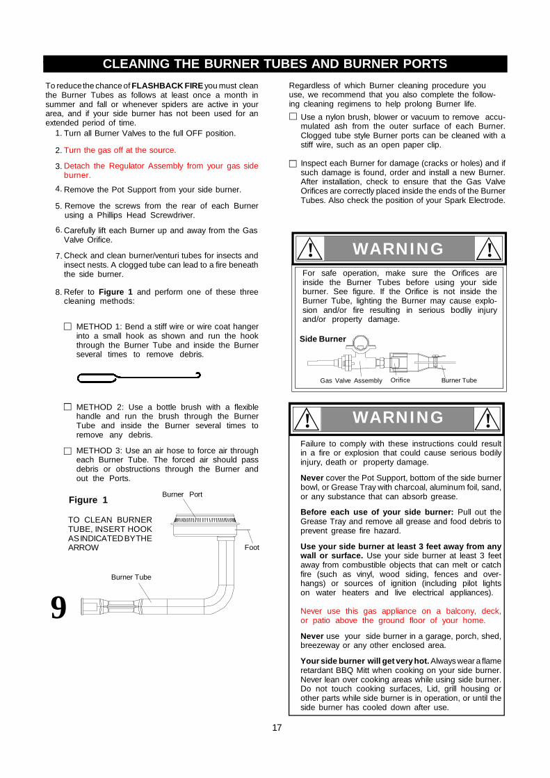
Regardless of which Burner cleaning procedure youuse, we recommend that you also complete the follow-ing cleaning regimens to help prolong Burner life.
1.
2.
3.
4.
Turn all Burner Valves to the full OFF position.
Turn the gas off at the source.
Remove the Pot Support from your side burner.
Detach the Regulator Assembly from your gas sideburner.
CLEANING THE BURNER TUBES AND BURNER PORTS2.2.
METHOD 1: Bend a stiff wire or wire coat hangerinto a small hook as shown and run the hookthrough the Burner Tube and inside the Burnerseveral times to remove debris.
METHOD 2: Use a bottle brush with a flexiblehandle and run the brush through the BurnerTube and inside the Burner several times toremove any debris.
METHOD 3: Use an air hose to force air througheach Burner Tube. The forced air should passdebris or obstructions through the Burner andout the Ports.
Use a nylon brush, blower or vacuum to remove accu-mulated ash from the outer surface of each Burner.Clogged tube style Burner ports can be cleaned with astiff wire, such as an open paper clip.
Inspect each Burner for damage (cracks or holes) and ifsuch damage is found, order and install a new Burner.After installation, check to ensure that the Gas ValveOrifices are correctly placed inside the ends of the BurnerTubes. Also check the position of your Spark Electrode.
Figure 1
TO CLEAN BURNERTUBE, INSERT HOOKAS INDICATED BY THEARROW
9Burner Tube
Foot
Burner Port
17
5.
6.
7.
8. Refer to Figure 1 and perform one of these threecleaning methods:
Remove the screws from the rear of each Burnerusing a Phillips Head Screwdriver.
Carefully lift each Burner up and away from the GasValve Orifice.
Check and clean burner/venturi tubes for insects andinsect nests. A clogged tube can lead to a fire beneaththe side burner. For safe operation, make sure the Orifices are
inside the Burner Tubes before using your sideburner. See figure. If the Orifice is not inside theBurner Tube, lighting the Burner may cause explo-sion and/or fire resulting in serious bodliy injuryand/or property damage.
WARNING! !
Side Burner
Orifice Burner TubeGas Valve Assembly
WARNING! !Failure to comply with these instructions could resultin a fire or explosion that could cause serious bodilyinjury, death or property damage.
Never cover the Pot Support, bottom of the side burnerbowl, or Grease Tray with charcoal, aluminum foil, sand,or any substance that can absorb grease.
Before each use of your side burner: Pull out theGrease Tray and remove all grease and food debris toprevent grease fire hazard.
Use your side burner at least 3 feet away from anywall or surface. Use your side burner at least 3 feetaway from combustible objects that can melt or catchfire (such as vinyl, wood siding, fences and over-hangs) or sources of ignition (including pilot lightson water heaters and live electrical appliances).
Never use this gas appliance on a balcony, deck,or patio above the ground floor of your home.
Never use your side burner in a garage, porch, shed,breezeway or any other enclosed area.
Your side burner will get very hot. Always wear a flameretardant BBQ Mitt when cooking on your side burner.Never lean over cooking areas while using side burner.Do not touch cooking surfaces, Lid, grill housing orother parts while side burner is in operation, or until theside burner has cooled down after use.
ü
ü
ü
ü
ü
ü
ü

A-1
FREQ
UEN
TLY
ASK
ED
QU
ESTI
ON
S (F
AQ
'S)
No, your side burner is manufactured to exact specificationsand is certified for LPG (Liquid Propane Gas) or NG (NaturalGas) use only. For your safety, conversion kits are notavailable, nor will we sell or otherwise provide parts orinformation to be used to convert your side burner. Anyattempt to convert your side burner is dangerous and willvoid your warranty.
Answer:
Can I convert my side burner from one fuel type toanother in other words from LPG to NG or viceversa?
Question:
Never lean over your side burner while lighting orduring cooking. Keep your face and body a safedistance (at least 18 inches) from the side burnerwhen lighting your side burner by match.
WARNING !!
Question:Sometimes I hear a humming sound coming from myregulator. What causes this? And - My side burnerhas a low flame and sometimes will not light. Why?
Where do I use my side burner for safer operationand better performance?
Question:
Answer:Strong winds and low temperatures can affect theheating and performance of your side burner sofactor in these elements when positioning your sideburner outdoors for cooking.In windy conditions, always position the front ofside burner to face oncoming wind to reduce smokeand heat blowing in your face and prevent potentialhazards to yourself and side burner.Use your side burner at least 3 feet away fromany wall or surface.Use your side burner at least 3 feet away fromcombustible objects that can melt or catch fire (suchas vinyl or wood siding, fences, and overhangs), orsources of ignition (including pilot lights on waterheaters and live electrical appliances).Never use this gas appliance on a balcony, deck,or patio above the ground floor of your home.Never use your side burner in a garage, porch,shed, breezeway or any other enclosed area.Never obstruct the flow of ventilation air aroundyour side burner housing.
Do not turn tank valve more than ½ of one turn onLPG models.
Turn all Control Knobs to the OFF position.
Turn off the LP Gas tank at the tank valve.For Natural Gas shut off NG valve.
Disconnect regulator from LP Gas tank.For Natural Gas disconnect regulator from 12 ft.Natural Gas Hose.Let unit stand for 5 minutes.
Reconnect regulator to the LP Gas tank.For Natural Gas reconnect regulator to 12 ft. NaturalGas Hose.
Open side burner Lid (if you have closed it).
Turn the tank valve slowly ¼ of one turn.For Natural Gas open Shut Off valve.
Light Burner.
Turn the tank valve slowly one more ¼ of one turnfor ½ of one complete turn.
Continue to light Burners moving towards the fuelsource.
Answer:The humming sound is gas flowing through theregulator. A low volume of sound is normal and will notinterfere with the operation of your side burner. Loud orexcessive regulator humming and/or low flow andintermittent lighting may be caused by the regulator'sexcess gas flow device. Opening the tank valve all theway or too quickly is what triggers the regulator's safetydevice to restrict gas flow, preventing excess gas flow toyour side burner. Lighting the Burner farthest from thefuel source every time will help eliminate air pockets inthe manifold. Note: This procedure should be done everytime a new LP Gas tank is connected to your side burner.
Question:
If my ignitor or battery is not working how can I light myside burner manually? And - Why would I need thesilver lighting stick that hangs from the side of my sideburner?
Answer:
If your ignition fails to work or your battery needsreplacing you can light your side burner using the ManualLighting Stick. The Lighting Stick is designed to hold apaper match and allows you to safely insert a matchthrough the Pot Support without getting close to theBurner. To light your side burner manually, insert a papermatch into the Manual Lighting Stick and follow steps 1through 5 of the Basic Lighting Procedures. Then, lightthe match and place the Lighting Stick through the PotSupport. Turn the nearest Burner Control Knob to theHI/ setting to release gas. The Burner should lightimmediately.
Answer:The serial and model numbers are listed on a silver CSAlabel placed on the side burner. The CSA label is locatedon the inside of the side burner lid.
Are the serial and model numbers of my side burnerlisted somewhere for my reference?
Question:

A-2
FREQ
UEN
TLY A
SKED
Q
UESTIO
NS
(FAQ
'S)
After every use (after your side burner has cooled down),wipe stainless surfaces with a soft, soapy cloth or spongethen rinse with water. Be sure to remove all food par-ticles, sauces or marinades from stainless steel becausethese can be highly acidic and damaging to stainlesssurfaces.
Never use abrasive cleaners, scrubbers or stiff wirebrushes of any type on your side burner.
Use a heat resistant Stainless Steel Cleaner and rub orwipe in the direction of the stainless steel grain or polishlines. Do not polish against the grain.
Rusting is a natural oxidation process and will not affectthe short term performance of your side burner.
The Regulator and Hose supplied with my gas sideburner does not fit the older LP Gas tank I’ve used foryears. Why not?
The U.S. Government regulates gas appliances and LPGas tanks. When regulations are changed the LP Gastank fittings are altered to insure compliance. If your LPGas tank does not fit the Regulator and Hose suppliedwith your new grill, the tank is outdated and must bereplaced. Note: Effective April 1, 2002 all LP Gas tankssold must include an “OPD” Overfill Prevention Device.The OPD tanks are identified by their triangular-shapedvalve wheel. This internal device prevents the LP Gastank from being overfilled. Tanks without an OPD valvecan not be refilled.
Question:What causes side burner parts to rust and what effect
does it have on my side burner?
Answer:
Routine care and maintenance is required to preserve theappearance and corrosion resistance of stainless steel.The fact is stainless steel can corrode, rust and discolorunder certain conditions. Rust is caused when regular steelparticles in the atmosphere become attached to the stain-less steel surface. Steel particles can also become attachedto your side burner if you use steel wool or stiff wire brushesto clean the side burner instead of non-abrasive cloth,sponge or nylon cleaning tools. In coastal areas rust pitscan develop on stainless surfaces that cannot be fully re-moved. Bleach and other chlorine based solutions usedfor household and pool cleaning can also cause corrosionto stainless steel.
Weathering, extreme heat, smoke from cooking and ma-chine oils used in the manufacturing process of stainlesssteel can cause stainless steel to turn tan in color. Althoughthere are many factors which can affect the surface appear-ance of stainless steel, they do not affect the integrity of thesteel or the performance of the side burner. To help main-tain the finish of stainless steel follow these cleaning tipsfor the best results:
To slow the rusting process on Pot Support werecommend greasing the grids before and after eachcookout. Use a brush to apply a thin layer of cooking oil orvegetable shortening onto each Pot Support. We do notsuggest spray type oils unless they are specified for high-temperature cooking.
Question:
Answer:

Grand Hall will warrant to the ORIGINAL PURCHASER of this gas side burner that it will be free of defectsin material and workmanship for set periods below from the date of purchase when used under normaloutdoor use and correct assembly.
- Burners, Pot Support (when applicable) - 5 year Limited Warranty (No rust or burn through)- Flame Tamers, Electrical Components, Ignition Systems, Valves, and Plastic Components - 2 year Limited Warranty- All other stainless steel parts - 2 year Limited Warranty
Grand Hall will require reasonable proof of your date of purchase. Therefore, you should send in the ownerregistration card and save your receipt in case it is required as proof of purchase.
This Limited warranty is limited to replacement of parts at Grand Hall's option that proved to be defectiveunder normal use and service. You will be charged for shipping and handling of the replacement parts.
Grand Hall may require the return of defective parts for examination before issuing replacement parts. Ifyou are required to return defective parts, shipping charges must be prepaid by the customer.
Upon examination and to Grand Hall's determination, if the original part is proven defective, Grand Hallmay approve your claim and elect to replace such parts without charge. In any instance, customer isresponsible for shipping and handling of the replacement parts.
This Warranty does not cover any failures or operating difficulties due to accidents, abuse, misuse, alteration,misapplication, vandalism, improper installation, maintenance or service, damages caused by flashback fireor grease fires, as set out in the Operator's Manual.
This warranty does not cover scratches, dents, corrosion or discoloration caused by weather, heat, abrasiveand chemical cleaners, pool or spa chemicals, and/or any tools used in the assembly or installation ofthis unit. This warranty does not cover paint loss, surface rust, corrosion or stainless steel discolorationwhich is considered normal wear and tear. This warranty does not cover the cost of any inconvenience,personal injury or property damage due to improper use or product failure.
Deterioration or damage due to severe weather conditions such as hail, hurricanes, earthquakes, tsunamis,tornadoes, terrorism, discoloration due to exposure to chemicals either directly or in the atmosphere, Actsof God/Forces of Nature are not covered by this Limited Warranty.
No part returns will be accepted without prior authorization from Grand Hall. Authorization for parts and/or the return of parts may be requested by calling 1-877-934-7455,8am-4:30pm CST, Monday-Friday.
For technical troubleshooting and/or service inquiries, please call 1-800-752-3085, 8am-4:30pm CST,Monday-Friday.
Warranty Restrictions
This warranty gives you specific legal rights, and you may also have other rights which vary from state to state.
This product is certified for safe use only in the country where purchased; Modification for use in any other location is a safety hazard and immediately voids the warranty.
This warranty is not transferable.
This warranty is void if the product is used for commercial or rental purposes.
Manufacturer:Grand Hall Enterprise Co., Ltd.9th Fl., No. 298, Rueiguang Rd., Neihu,Taipei, Taiwan (114)
•
•
Grand Hall Limited Warranty
•
•