O&M Manual for SKR - environmental-expert.com · SKR-6150 15kW (20HP) three phase SKR-6220 22kW...
22
STANCOR PUMPS Instruction Manual MODEL SKR Heavy Duty Slurry Pumps Introduction Thank you for selecting the Stancor SKR heavy-duty submersible slurry pump. This instruction manual explains the product operations and gives important precautions regarding its safe use. In order to use the product to maximum benefit, be sure to read the instructions thoroughly and follow them carefully. To avoid accidents, do not use the pump in any way other than as described in this instruction manual particularly on ! WARNING . .After reading this instruction manual, keep it nearby as a reference in case questions arise during use. If this instruction manual should become lost or damaged, ask your nearest dealer or representative for another copy. INDEX Introduction………………..PAGE. 1 Prior to Operation………..PAGE. 2 Installation………………….PAGE. 3 Electrical Wiring…………..PAGE. 4 Operation…………………….PAGE. 5 Maintenance………………..PAGE. 5 Construction………………..PAGE. 6 Troubleshooting……………PAGE.20 Disassembly and Assembly………..PAGE. 21
Transcript of O&M Manual for SKR - environmental-expert.com · SKR-6150 15kW (20HP) three phase SKR-6220 22kW...
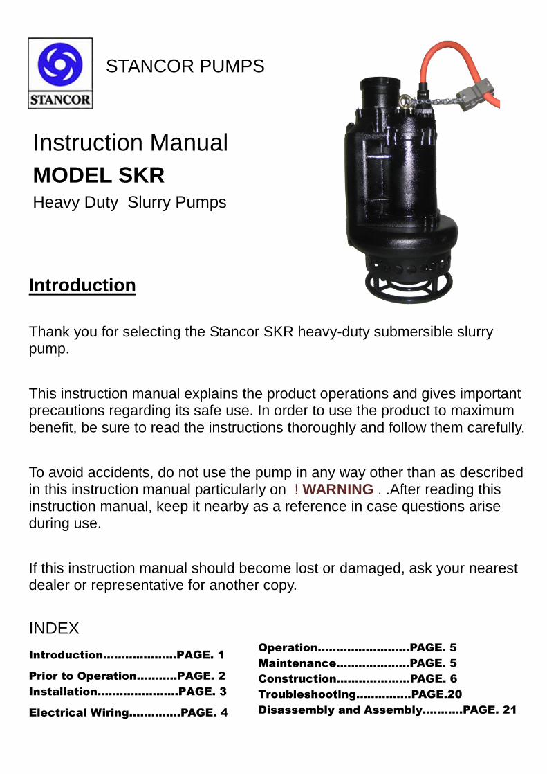
STANCOR PUMPS
Instruction Manual
MODEL SKRHeavy Duty Slurry Pumps
Introduction
Thank you for selecting the Stancor SKR heavy-duty submersible slurrypump.
This instruction manual explains the product operations and gives importantprecautions regarding its safe use. In order to use the product to maximumbenefit, be sure to read the instructions thoroughly and follow them carefully.
To avoid accidents, do not use the pump in any way other than as describedin this instruction manual particularly on ! WARNING . .After reading thisinstruction manual, keep it nearby as a reference in case questions ariseduring use.
If this instruction manual should become lost or damaged, ask your nearestdealer or representative for another copy.
INDEX
Introduction………………..PAGE. 1
Prior to Operation………..PAGE. 2
Installation………………….PAGE. 3
Electrical Wiring…………..PAGE. 4
Operation…………………….PAGE. 5
Maintenance………………..PAGE. 5
Construction………………..PAGE. 6
Troubleshooting……………PAGE.20
Disassembly and Assembly………..PAGE. 21
2
Prior to Operation
Check the following points upon receipt of your pump:
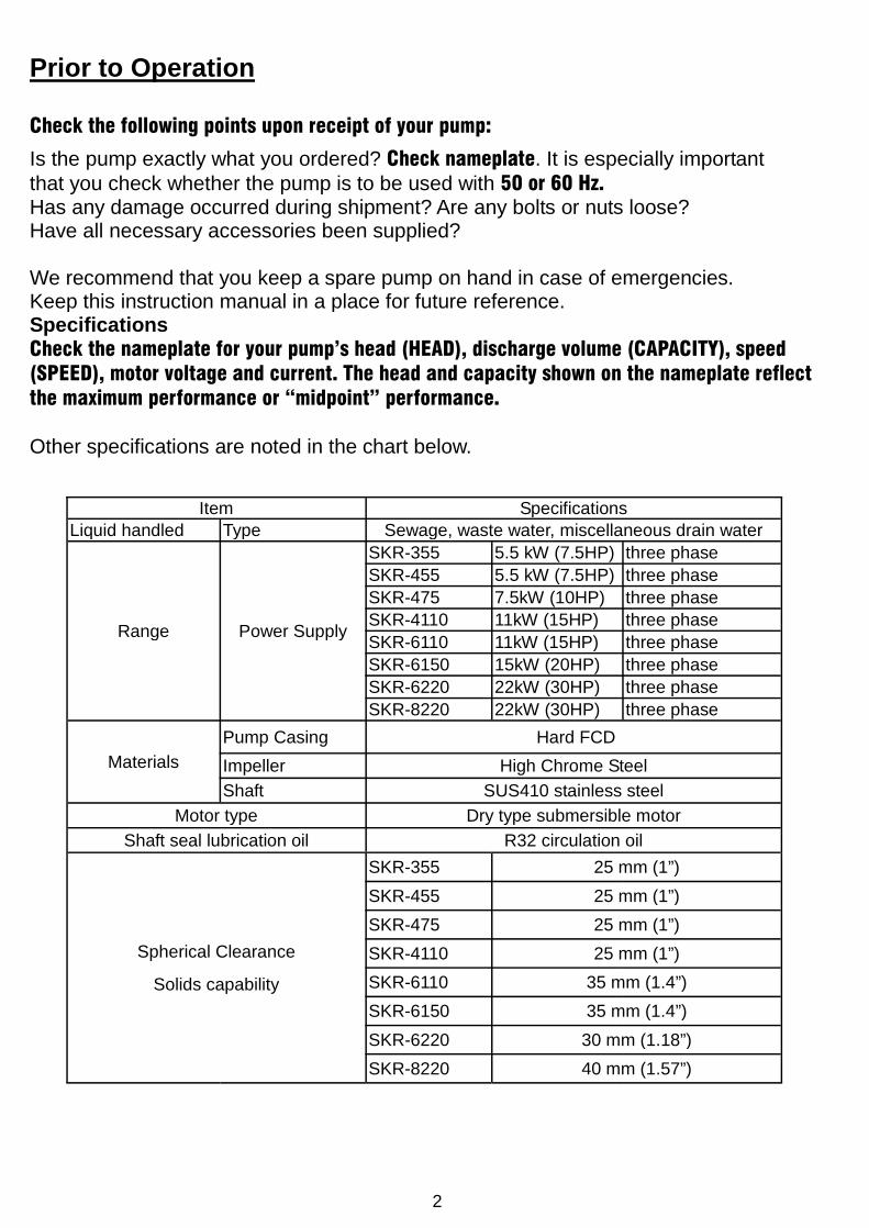
Is the pump exactly what you ordered? Check nameplate. It is especially importantthat you check whether the pump is to be used with 50 or 60 Hz.Has any damage occurred during shipment? Are any bolts or nuts loose?Have all necessary accessories been supplied?
We recommend that you keep a spare pump on hand in case of emergencies.Keep this instruction manual in a place for future reference.SpecificationsCheck the nameplate for your pump’s head (HEAD), discharge volume (CAPACITY), speed(SPEED), motor voltage and current. The head and capacity shown on the nameplate reflectthe maximum performance or “midpoint” performance.
Other specifications are noted in the chart below.
Item SpecificationsLiquid handled Type Sewage, waste water, miscellaneous drain water
Range Power Supply
SKR-355 5.5 kW (7.5HP) three phase
SKR-455 5.5 kW (7.5HP) three phase
SKR-475 7.5kW (10HP) three phase
SKR-4110 11kW (15HP) three phase
SKR-6110 11kW (15HP) three phase
SKR-6150 15kW (20HP) three phase
SKR-6220 22kW (30HP) three phase
SKR-8220 22kW (30HP) three phase
Materials
Pump Casing Hard FCD
Impeller High Chrome Steel
Shaft SUS410 stainless steel
Motor type Dry type submersible motor
Shaft seal lubrication oil R32 circulation oil
Spherical Clearance
Solids capability
SKR-355 25 mm (1”)
SKR-455 25 mm (1”)
SKR-475 25 mm (1”)
SKR-4110 25 mm (1”)
SKR-6110 35 mm (1.4”)
SKR-6150 35 mm (1.4”)
SKR-6220 30 mm (1.18”)
SKR-8220 40 mm (1.57”)
3
Installation
1. Check the following before beginning installation.Insulation resistance measurement:With the motor and cable (excluding the power supply cable) immersed in water, use a Megger to measure theinsulation resistance between ground and each phase of the motor, and again between each phase of the motor. The
Megger should indicate an insulation resistance of not less than 20mega ohms. While making the measurement, keepthe power supply cable off the ground.
We recommend that an auxiliary pump be kept on hand in case of emergency.
2. Installation-Under no circumstances should cable be pulled while the pump is being transported or installed.
Attach a chain or rope to the grip and install the pump.
This pump must not be installed on its side or operated in a dry condition. Ensure that it is installed upright on a securebase.
Install the pump at a location in the tank where there is the least turbulence.
If there is a flow of liquid inside the tank, support the piping where appropriate. Install piping so that air will not beentrapped. If piping must be installed in such a way that air pockets are unavoidable, install an air release valve wher-ever such air pockets are most likely to develop.
Do not permit end of discharge piping to be submerged, as backflow will result when the pump is shut down.
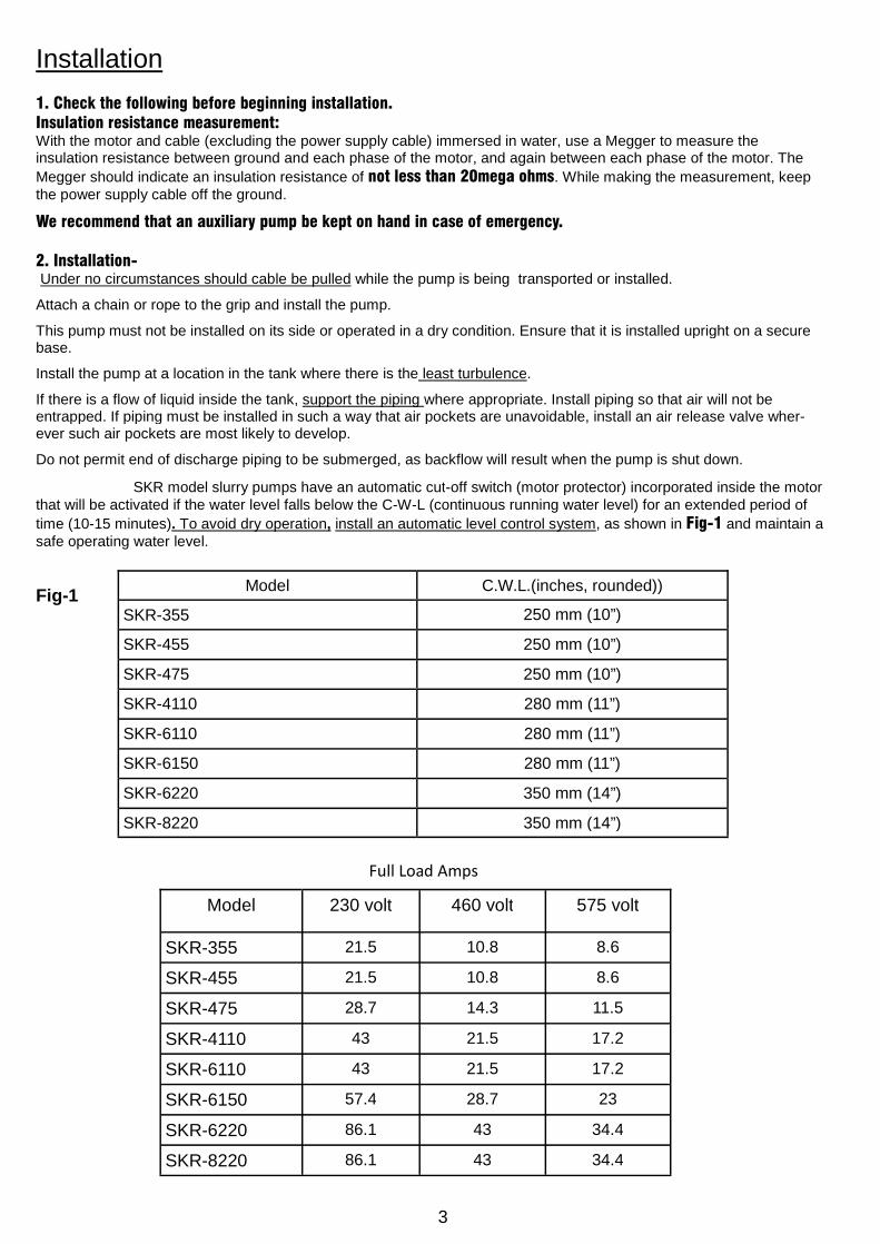
! WARNING : SKR model slurry pumps have an automatic cut-off switch (motor protector) incorporated inside the motorthat will be activated if the water level falls below the C-W-L (continuous running water level) for an extended period of
time (10-15 minutes). To avoid dry operation, install an automatic level control system, as shown in Fig-1 and maintain asafe operating water level.
Fig-1Model C.W.L.(inches, rounded))
SKR-355 250 mm (10”)
SKR-455 250 mm (10”)
SKR-475 250 mm (10”)
SKR-4110 280 mm (11”)
SKR-6110 280 mm (11”)
SKR-6150 280 mm (11”)
SKR-6220 350 mm (14”)
SKR-8220 350 mm (14”)
Model 230 volt 460 volt 575 volt
SKR-355 21.5 10.8 8.6
SKR-455 21.5 10.8 8.6
SKR-475 28.7 14.3 11.5
SKR-4110 43 21.5 17.2
SKR-6110 43 21.5 17.2
SKR-6150 57.4 28.7 23
SKR-6220 86.1 43 34.4
SKR-8220 86.1 43 34.4
Full Load Amps
4
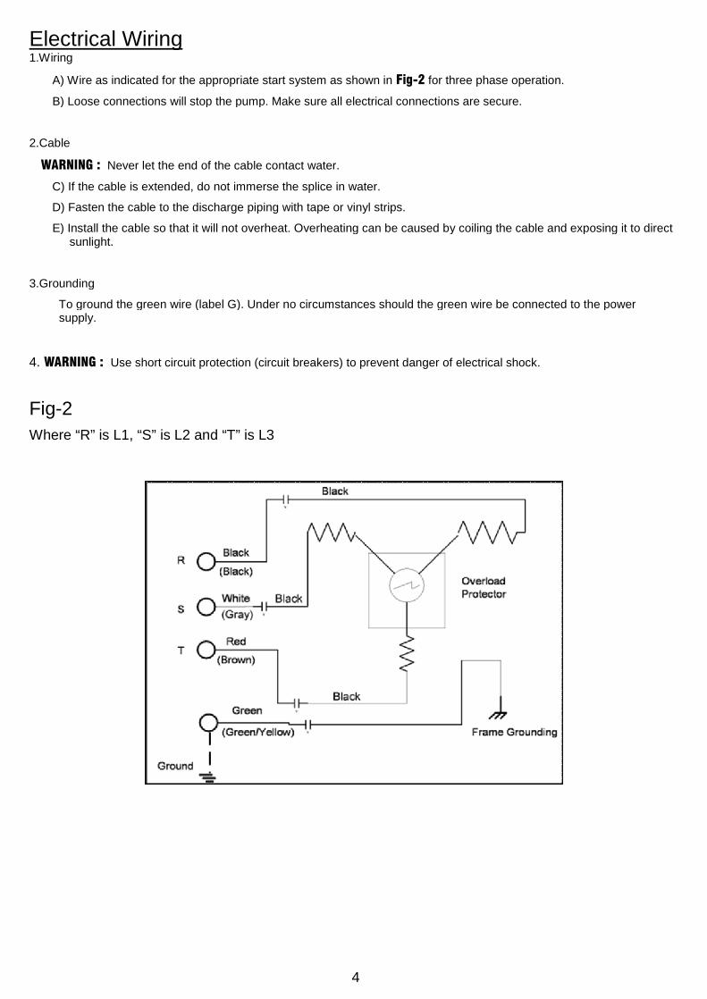
Electrical Wiring1.Wiring
A) Wire as indicated for the appropriate start system as shown in Fig-2 for three phase operation.
B) Loose connections will stop the pump. Make sure all electrical connections are secure.
2.Cable
! WARNING : Never let the end of the cable contact water.
C) If the cable is extended, do not immerse the splice in water.
D) Fasten the cable to the discharge piping with tape or vinyl strips.
E) Install the cable so that it will not overheat. Overheating can be caused by coiling the cable and exposing it to directsunlight.
3.Grounding
To ground the green wire (label G). Under no circumstances should the green wire be connected to the powersupply.
4. WARNING : Use short circuit protection (circuit breakers) to prevent danger of electrical shock.
Fig-2
Where “R” is L1, “S” is L2 and “T” is L3
5
Operation
1. Before starting the pump1. After completing installation, measure the insulation resistance again as described in on page 3.
2. Check water level.
If the pump is operated continuously for an extended period of time in a dry condition or at the lowest waterlevel, the motor protector will be activated. Constant repetition of this action will shorten pump service life. Donot start the pump again in such a situation until after the motor has completely cooled.
2. Test operation….
Non-automatic pump (SKR)
1. Turn the operating switch on and off a couple of times to check for normal pump start.
2. Next, check direction of rotation. The pump will “kick” counterclockwise (when viewed from the top). If dis-charge volume is low or unusual sounds are heard when the pump is operating, rotation has been reversed.When this happens, reverse two of the wires and recheck rotation.
Maintenance
Check pressure, output, voltage, current and other specifications. Unusual readings may indicate that correctiveaction is required. Refer to Troubleshooting and correct as soon as possible.
1. Daily inspections
Check current with ammeter for fluctuation every few days. If ammeter fluctuation is significant, even though within thelimits of pump rating, foreign matter may be clogging the pump. If the quantity of liquid discharged falls suddenly,foreign matter may be blocking the suction inlet.
2. Regular inspectionsMonthly inspections
Measure the insulation resistance. The value should be more than 1M ohm. If resistance starts to fall rapidlyeven with an initial indication of over 1M ohm, this nay be an indication of trouble and repair work is required.
Annual inspectionsTo prolong the service life of the mechanical seal by replacing the oil in the mechanical seal chamber once ayear. Water mixed with the oil or cloudy mixtures are indications of a defective mechanical seal requiringreplacement. When replacing the oil, lay the pump on its side with filler plug on top. Install suitable amount tur-bine oil No.32 (ISO VG-32).Inspections at 3-5year intervalsConduct an overhaul of the pump. These intervals will preclude the possibility of future trouble.
3. Parts that will need to be replaced
Replace the appropriate part when the following conditions are apparent.
Note: above replacement schedule is based on normal operating conditions.
SEVERE DUTY CONDITIONS OR APPLICATION MAY REQUIRE MORE FREQUENT INSPECTIONS AND
REPLACEMENTS, PARTICULARLY OF THE MECHANICAL SEAL AND SEAL CHAMBER OIL.
Replaceable part Mechanical seal Oil filler plug gasket Lubricating oil O-ring
Replacement guideWhenever oil in me-chanical seal cham-
ber is clouded
Whenever oil is re-placed or inspected
Whenever cloudedor dirty
Whenever pump isoverhauled
Frequency Annually Half yearly Half yearly Annually
6
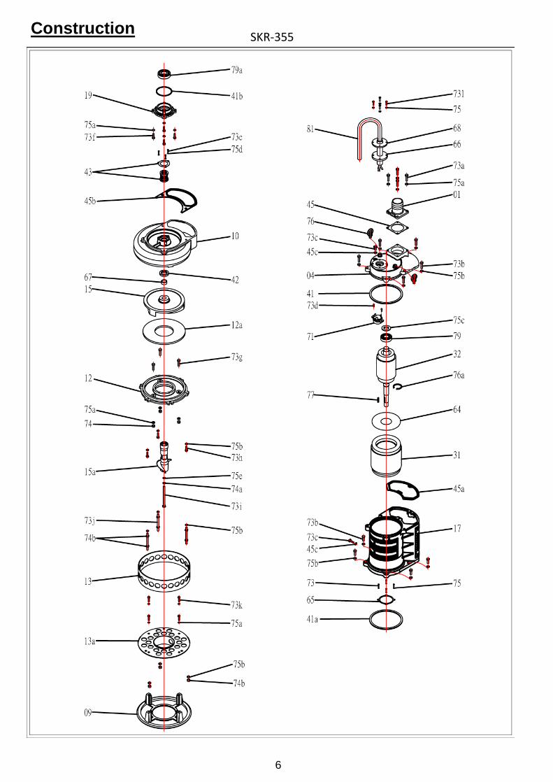
ConstructionSKR-355
7
NO Name Material NO Name Material
01 Discharge head FC-20 45 Gasket N-70
04 Upper cover FC-20 45a Gasket N-70
09 Base plate FCD-45 45b Gasket N-70
10 Pump casing FCD-45 45c Gasket N-70
12 Inlet plate FC-20 64Insulating
sheet
12
aWear plate
High
chrome
steel
65 Shim SC
13 Strainer SC 66 Cable gland NBR
13
aStrainer Center FCD-45 67 Shaft sleeve
SUS-410
Heat
Treat
15 Impeller
High
Chrome
Steel
68 Gland Holder SUS-304
15
aAgitator
High
Chrome
Steel
71Thermal pro-
tector
17 Motor frame FC-10 73 Screw SUS-304
19 Bearing bracket FC-20 73a Screw SUS-304
31 Stator 73b Screw SUS-304
32 Shaft/Rotor 73c Screw SUS-304
41 O’ring N-70 73d Screw SUS-304
41
aO’ring N-70 73e Screw SUS-304
41
bO’ring N-70 73f Screw SUS-304
42 Oil seal 73g Screw SUS-304
NO Name Material
73i Screw SUS-304
73j Screw SUS-304
73k Screw SUS-304
73l Screw SUS-304
74 Nut SUS-304
74a Nut SUS-304
74
bNut SUS-304
75 Spring washer SUS-304
75a Spring washer SUS-304
75
bSpring washer SUS-304
75c Wave washer SC
75
dSpring washer SUS-304
75
eSpring washer SUS-304
76 Ring fastener SC
76a C’ing SC
77 Key SUS-304
79 Bearing
79a Bearing
43 Mech.seal 73h Screw SUS-304 81 Cable
8
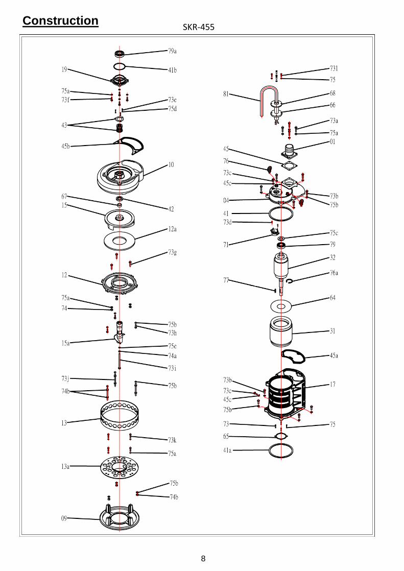
ConstructionSKR-455

9
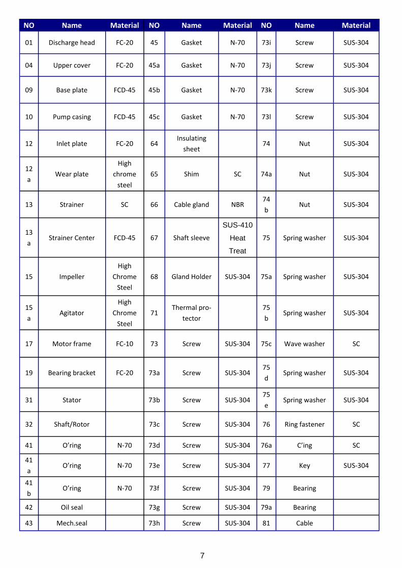
NO Name Material NO Name Material
01 Discharge head FC-20 45 Gasket N-70
04 Upper cover FC-20 45a Gasket N-70
09 Base plate FCD-45 45b Gasket N-70
10 Pump casing FCD-45 45c Gasket N-70
12 Inlet plate FC-20 64Insulating
sheet
12
aWear plate
High
chrome
steel
65 Shim SC
13 Strainer SC 66 Cable gland NBR
13
aStrainer Center FCD-45 67 Shaft sleeve
SUS-410
Heat
Treat
15 Impeller
High
Chrome
Steel
68 Gland Holder SUS-304
15
aAgitator
High
Chrome
Steel
71Thermal pro-
tector
17 Motor frame FC-10 73 Screw SUS-304
19 Bearing bracket FC-20 73a Screw SUS-304
31 Stator 73b Screw SUS-304
32 Shaft/Rotor 73c Screw SUS-304
41 O’ring N-70 73d Screw SUS-304
41
aO’ring N-70 73e Screw SUS-304
41 O’ring N-70 73f Screw SUS-304
42 Oil seal 73g Screw SUS-304
NO Name Material
73i Screw SUS-304
73j Screw SUS-304
73k Screw SUS-304
73l Screw SUS-304
74 Nut SUS-304
74a Nut SUS-304
74
bNut SUS-304
75 Spring washer SUS-304
75a Spring washer SUS-304
75
bSpring washer SUS-304
75c Wave washer SC
75
dSpring washer SUS-304
75
eSpring washer SUS-304
76 Ring fastener SC
76a C’ing SC
77 Key SUS-304
79 Bearing
79a Bearing
43 Mech.seal 73h Screw SUS-304 81 Cable
10
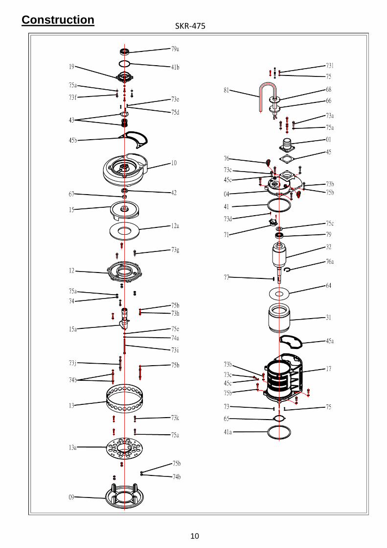
ConstructionSKR-475
11
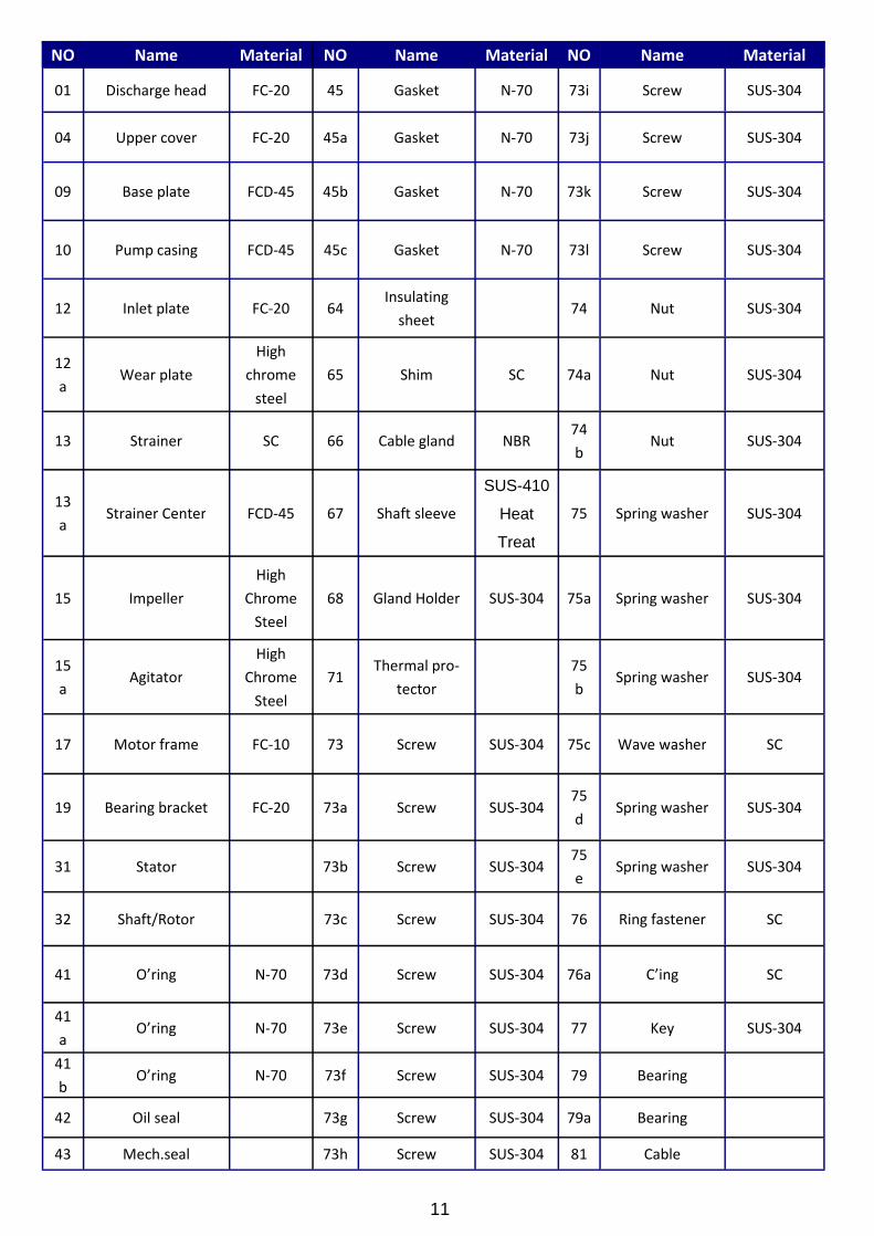
NO Name Material NO Name Material
01 Discharge head FC-20 45 Gasket N-70
04 Upper cover FC-20 45a Gasket N-70
09 Base plate FCD-45 45b Gasket N-70
10 Pump casing FCD-45 45c Gasket N-70
12 Inlet plate FC-20 64Insulating
sheet
12
aWear plate
High
chrome
steel
65 Shim SC
13 Strainer SC 66 Cable gland NBR
13
aStrainer Center FCD-45 67 Shaft sleeve
SUS-410
Heat
Treat
15 Impeller
High
Chrome
Steel
68 Gland Holder SUS-304
15
aAgitator
High
Chrome
Steel
71Thermal pro-
tector
17 Motor frame FC-10 73 Screw SUS-304
19 Bearing bracket FC-20 73a Screw SUS-304
31 Stator 73b Screw SUS-304
32 Shaft/Rotor 73c Screw SUS-304
41 O’ring N-70 73d Screw SUS-304
41
aO’ring N-70 73e Screw SUS-304
41
bO’ring N-70 73f Screw SUS-304
42 Oil seal 73g Screw SUS-304
NO Name Material
73i Screw SUS-304
73j Screw SUS-304
73k Screw SUS-304
73l Screw SUS-304
74 Nut SUS-304
74a Nut SUS-304
74
bNut SUS-304
75 Spring washer SUS-304
75a Spring washer SUS-304
75
bSpring washer SUS-304
75c Wave washer SC
75
dSpring washer SUS-304
75
eSpring washer SUS-304
76 Ring fastener SC
76a C’ing SC
77 Key SUS-304
79 Bearing
79a Bearing
43 Mech.seal 73h Screw SUS-304 81 Cable
12
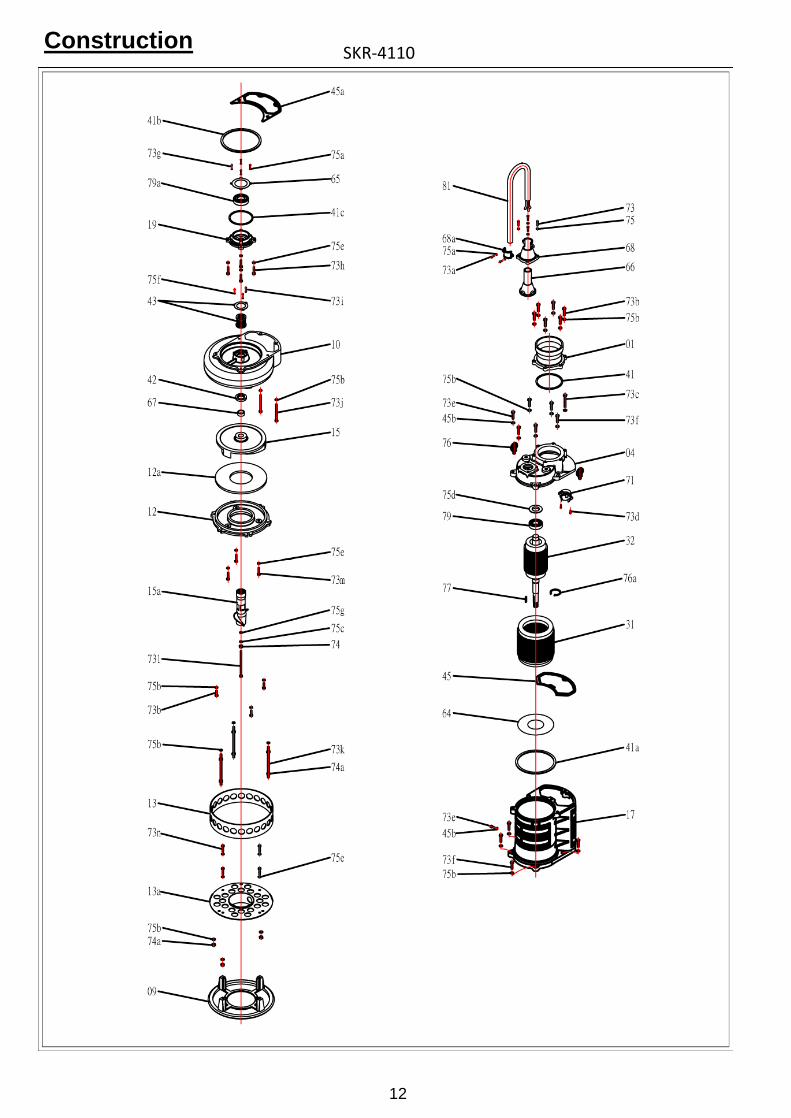
ConstructionSKR-4110
13
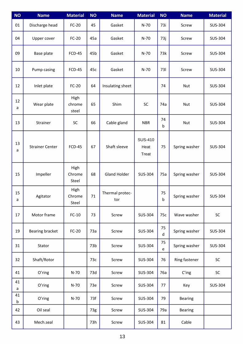
NO Name Material NO Name Material
01 Discharge head FC-20 45 Gasket N-70
04 Upper cover FC-20 45a Gasket N-70
09 Base plate FCD-45 45b Gasket N-70
10 Pump casing FCD-45 45c Gasket N-70
12 Inlet plate FC-20 64 Insulating sheet
12
aWear plate
High
chrome
steel
65 Shim SC
13 Strainer SC 66 Cable gland NBR
13
aStrainer Center FCD-45 67 Shaft sleeve
SUS-410
Heat
Treat
15 Impeller
High
Chrome
Steel
68 Gland Holder SUS-304
15
aAgitator
High
Chrome
Steel
71Thermal protec-
tor
17 Motor frame FC-10 73 Screw SUS-304
19 Bearing bracket FC-20 73a Screw SUS-304
31 Stator 73b Screw SUS-304
32 Shaft/Rotor 73c Screw SUS-304
41 O’ring N-70 73d Screw SUS-304
41
aO’ring N-70 73e Screw SUS-304
41
bO’ring N-70 73f Screw SUS-304
42 Oil seal 73g Screw SUS-304
NO Name Material
73i Screw SUS-304
73j Screw SUS-304
73k Screw SUS-304
73l Screw SUS-304
74 Nut SUS-304
74a Nut SUS-304
74
bNut SUS-304
75 Spring washer SUS-304
75a Spring washer SUS-304
75
bSpring washer SUS-304
75c Wave washer SC
75
dSpring washer SUS-304
75
eSpring washer SUS-304
76 Ring fastener SC
76a C’ing SC
77 Key SUS-304
79 Bearing
79a Bearing
43 Mech.seal 73h Screw SUS-304 81 Cable

14
ConstructionSKR-6110

15
NO Name Material NO Name Material
01 Discharge head FC-20 45 Gasket N-70
04 Upper cover FC-20 45a Gasket N-70
09 Base plate FCD-45 45b Gasket N-70
10 Pump casing FCD-45 45c Gasket N-70
12 Inlet plate FC-20 64Insulating
sheet
12
aWear plate
High
chrome
steel
65 Shim SC
13 Strainer SC 66 Cable gland NBR
13
aStrainer Center FCD-45 67 Shaft sleeve
SUS-410
Heat
Treat
15 Impeller
High
Chrome
Steel
68 Gland Holder SUS-304
15
aAgitator
High
Chrome
Steel
71Thermal pro-
tector
17 Motor frame FC-10 73 Screw SUS-304
19 Bearing bracket FC-20 73a Screw SUS-304
31 Stator 73b Screw SUS-304
32 Shaft/Rotor 73c Screw SUS-304
41 O’ring N-70 73d Screw SUS-304
41
aO’ring N-70 73e Screw SUS-304
41
bO’ring N-70 73f Screw SUS-304
42 Oil seal 73g Screw SUS-304
NO Name Material
73i Screw SUS-304
73j Screw SUS-304
73k Screw SUS-304
73l Screw SUS-304
74 Nut SUS-304
74a Nut SUS-304
74
bNut SUS-304
75 Spring washer SUS-304
75a Spring washer SUS-304
75
bSpring washer SUS-304
75c Wave washer SC
75
dSpring washer SUS-304
75
eSpring washer SUS-304
76 Ring fastener SC
76a C’ing SC
77 Key SUS-304
79 Bearing
79a Bearing
43 Mech.seal 73h Screw SUS-304 81 Cable
16
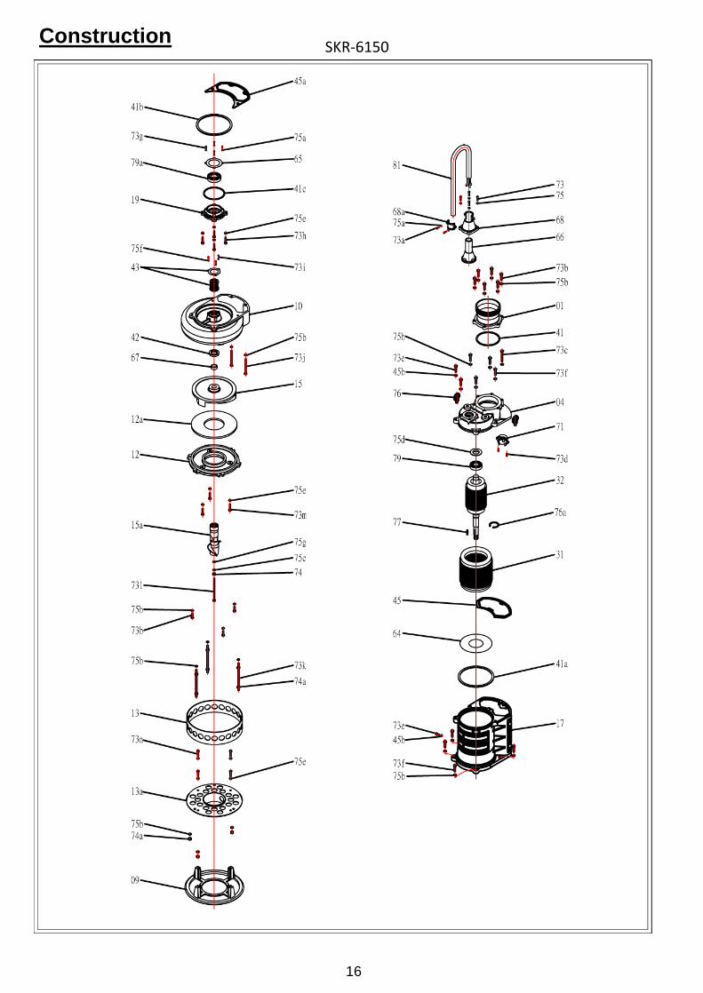
ConstructionSKR-6150
17
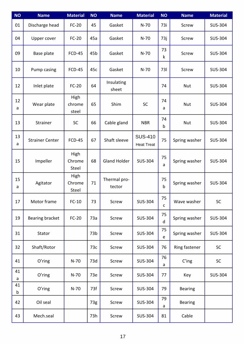
NO Name Material NO Name Material
01 Discharge head FC-20 45 Gasket N-70
04 Upper cover FC-20 45a Gasket N-70
09 Base plate FCD-45 45b Gasket N-70
10 Pump casing FCD-45 45c Gasket N-70
12 Inlet plate FC-20 64Insulating
sheet
12
aWear plate
High
chrome
steel
65 Shim SC
13 Strainer SC 66 Cable gland NBR
13
aStrainer Center FCD-45 67 Shaft sleeve
SUS-410
Heat Treat
15 Impeller
High
Chrome
Steel
68 Gland Holder SUS-304
15
aAgitator
High
Chrome
Steel
71Thermal pro-
tector
17 Motor frame FC-10 73 Screw SUS-304
19 Bearing bracket FC-20 73a Screw SUS-304
31 Stator 73b Screw SUS-304
32 Shaft/Rotor 73c Screw SUS-304
41 O’ring N-70 73d Screw SUS-304
41
aO’ring N-70 73e Screw SUS-304
41
bO’ring N-70 73f Screw SUS-304
42 Oil seal 73g Screw SUS-304
NO Name Material
73i Screw SUS-304
73j Screw SUS-304
73
kScrew SUS-304
73l Screw SUS-304
74 Nut SUS-304
74
aNut SUS-304
74
bNut SUS-304
75 Spring washer SUS-304
75
aSpring washer SUS-304
75
bSpring washer SUS-304
75
cWave washer SC
75
dSpring washer SUS-304
75
eSpring washer SUS-304
76 Ring fastener SC
76
aC’ing SC
77 Key SUS-304
79 Bearing
79
aBearing
43 Mech.seal 73h Screw SUS-304 81 Cable
18
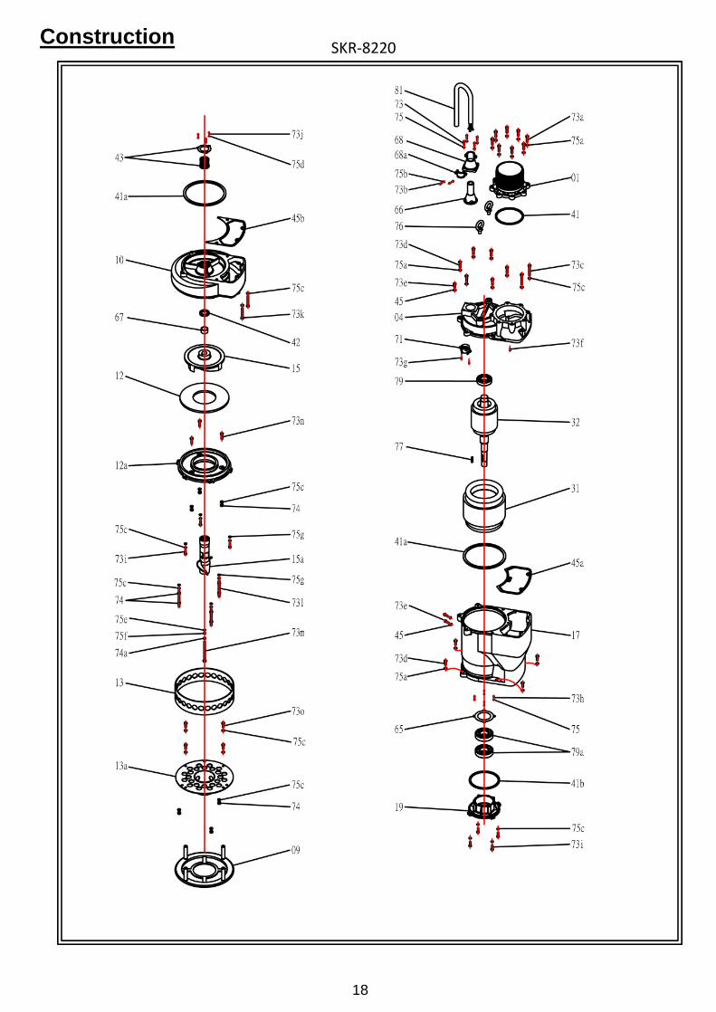
ConstructionSKR-8220
19
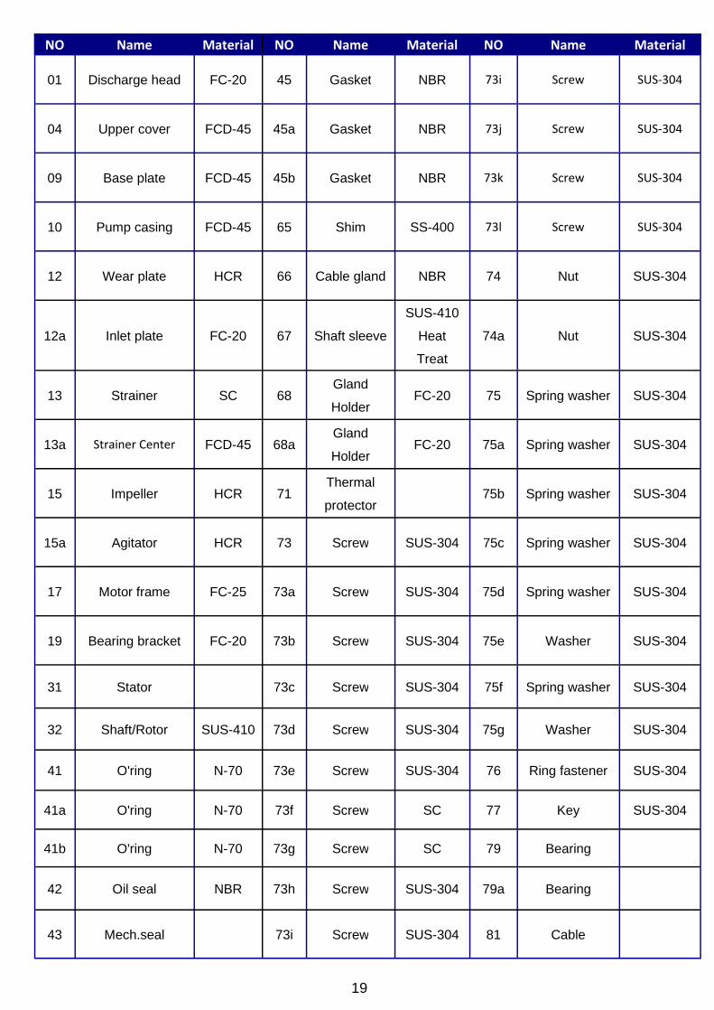
NO Name Material NO Name Material
01 Discharge head FC-20 45 Gasket NBR
04 Upper cover FCD-45 45a Gasket NBR
09 Base plate FCD-45 45b Gasket NBR
10 Pump casing FCD-45 65 Shim SS-400
12 Wear plate HCR 66 Cable gland NBR
12a Inlet plate FC-20 67 Shaft sleeve
SUS-410
Heat
Treat
13 Strainer SC 68Gland
HolderFC-20
13a Strainer Center FCD-45 68aGland
HolderFC-20
15 Impeller HCR 71Thermal
protector
15a Agitator HCR 73 Screw SUS-304
17 Motor frame FC-25 73a Screw SUS-304
19 Bearing bracket FC-20 73b Screw SUS-304
31 Stator 73c Screw SUS-304
32 Shaft/Rotor SUS-410 73d Screw SUS-304
41 O'ring N-70 73e Screw SUS-304
41a O'ring N-70 73f Screw SC
41b O'ring N-70 73g Screw SC
42 Oil seal NBR 73h Screw SUS-304
NO Name Material
73i Screw SUS-304
73j Screw SUS-304
73k Screw SUS-304
73l Screw SUS-304
74 Nut SUS-304
74a Nut SUS-304
75 Spring washer SUS-304
75a Spring washer SUS-304
75b Spring washer SUS-304
75c Spring washer SUS-304
75d Spring washer SUS-304
75e Washer SUS-304
75f Spring washer SUS-304
75g Washer SUS-304
76 Ring fastener SUS-304
77 Key SUS-304
79 Bearing
79a Bearing
43 Mech.seal 73i Screw SUS-304 81 Cable
20
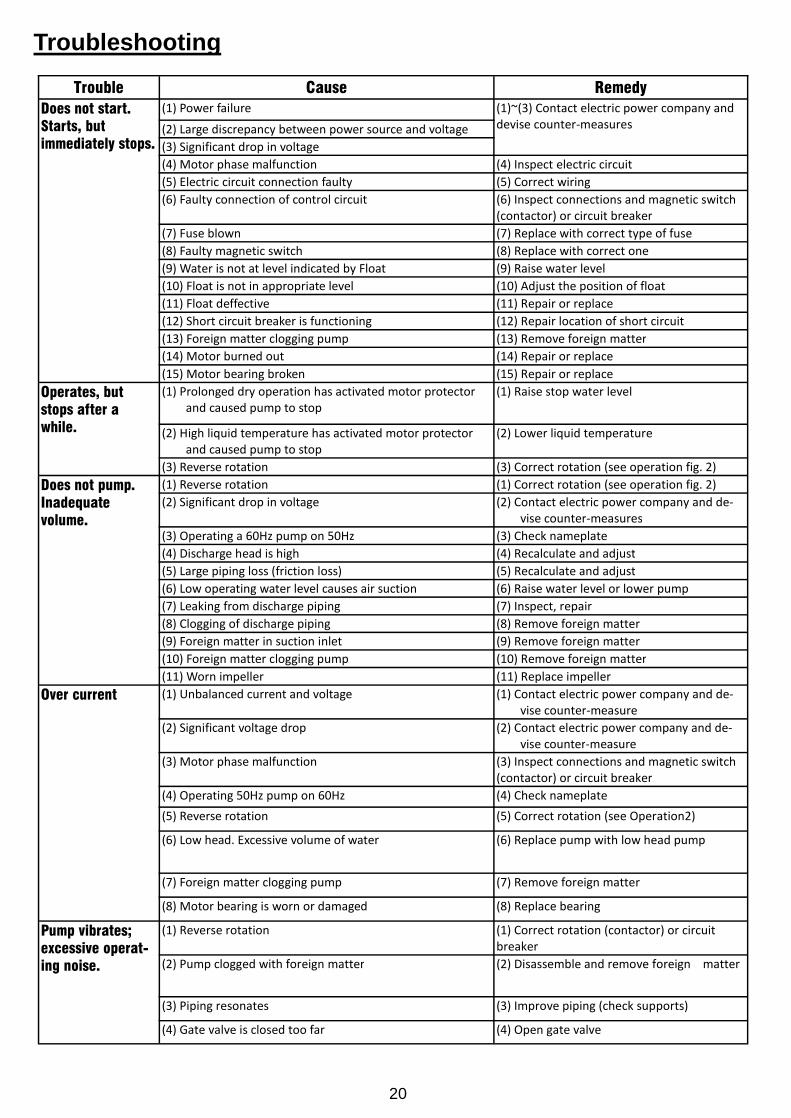
Troubleshooting
Trouble Cause Remedy
Does not start.Starts, butimmediately stops.
(1) Power failure (1)~(3) Contact electric power company anddevise counter-measures(2) Large discrepancy between power source and voltage
(3) Significant drop in voltage
(4) Motor phase malfunction (4) Inspect electric circuit
(5) Electric circuit connection faulty (5) Correct wiring
(6) Faulty connection of control circuit (6) Inspect connections and magnetic switch(contactor) or circuit breaker
(7) Fuse blown (7) Replace with correct type of fuse
(8) Faulty magnetic switch (8) Replace with correct one
(9) Water is not at level indicated by Float (9) Raise water level
(10) Float is not in appropriate level (10) Adjust the position of float
(11) Float deffective (11) Repair or replace
(12) Short circuit breaker is functioning (12) Repair location of short circuit
(13) Foreign matter clogging pump (13) Remove foreign matter
(14) Motor burned out (14) Repair or replace
(15) Motor bearing broken (15) Repair or replace
Operates, butstops after awhile.
(1) Prolonged dry operation has activated motor protectorand caused pump to stop
(1) Raise stop water level
(2) High liquid temperature has activated motor protectorand caused pump to stop
(2) Lower liquid temperature
(3) Reverse rotation ! WARNING : (3) Correct rotation (see operation fig. 2)
Does not pump.Inadequatevolume.
(1) Reverse rotation (1) Correct rotation (see operation fig. 2)
(2) Significant drop in voltage (2) Contact electric power company and de-vise counter-measures
(3) Operating a 60Hz pump on 50Hz (3) Check nameplate
(4) Discharge head is high (4) Recalculate and adjust
(5) Large piping loss (friction loss) (5) Recalculate and adjust
(6) Low operating water level causes air suction (6) Raise water level or lower pump
(7) Leaking from discharge piping (7) Inspect, repair
(8) Clogging of discharge piping (8) Remove foreign matter
(9) Foreign matter in suction inlet (9) Remove foreign matter
(10) Foreign matter clogging pump (10) Remove foreign matter
(11) Worn impeller (11) Replace impeller
Over current (1) Unbalanced current and voltage (1) Contact electric power company and de-vise counter-measure
(2) Significant voltage drop (2) Contact electric power company and de-vise counter-measure
(3) Motor phase malfunction (3) Inspect connections and magnetic switch(contactor) or circuit breaker
(4) Operating 50Hz pump on 60Hz (4) Check nameplate
(5) Reverse rotation ! WARNING : (5) Correct rotation (see Operation2)
(6) Low head. Excessive volume of water (6) Replace pump with low head pump
(7) Foreign matter clogging pump (7) Remove foreign matter
(8) Motor bearing is worn or damaged (8) Replace bearing
Pump vibrates;excessive operat-ing noise.
(1) Reverse rotation (1) Correct rotation (contactor) or circuitbreaker
(2) Pump clogged with foreign matter (2) Disassemble and remove foreign matter
(3) Piping resonates (3) Improve piping (check supports)
(4) Gate valve is closed too far (4) Open gate valve
21
Disassembly and Assembly
1. Disassembly-When disassembling pump, have a piece of cardboard or wooden board ready
to place the different parts on as you work. Do not pile parts on top of each other.They should be laid out neatly in rows. The “O” ring and gasket cannot be usedagain once they are removed. Have replacement parts ready. Disassemble in thefollowing order, referring to the sectional view.
! ! WARNING : Be sure to cut off power source beginning disassembly.(1) Remove pump casing bolts, raise the motor section and remove pump casing.(2) Remove shaft head bolt and impeller.(3) Remove oil filler plug and drain lubricating oil.(4) Remove intermediate casing bolts and intermediate oil chamber.
(Remember that any lubricating oil remaining in the mechanical seal chamberwill flow out.)(5) Carefully remove mechanical seal, taking care not to scratch sliding surface or
motor shaft.
2. Assembly-Re-assemble in reverse order of disassembly.
Be careful of the following points.(1) During re-assembly, rotate the impeller by hand and check for smooth rotation.
If rotation is not smooth, perform steps-(3) through -(5) again.
(2) Upon completion of re-assembly step -(1) rotate the impeller by hand from thesuction the suction inlet and check that it rotates smoothly without touching thesuction cover before operating the pump.
Please obtain “O” rings, gaskets, shaft seals and other parts from your authorizedStancor pump dealer or call Stancor directly at 203-268-7513 for assistance.
22
Stancor, Inc.
515 Fan Hill Road Monroe, CT 06468
203-268-7513 Fax 203-268-7958
www.stancorpumps.com