O P E R 4-Post Lift
64
4-Post Lift AR43-5MB, SM40, SM40-47BMW,SM40LT, SM55-M51VAS, SM60 O P E R A T I N G A N D M A I N T E N A N C E M A N U A L © Rotary Lift, 03/2013 CO6941.3 LP20100 OM20121 Rev.D 03/2013
Transcript of O P E R 4-Post Lift

4-Post Lift AR43-5MB,
SM40, SM40-47BMW,SM40LT,
SM55-M51VAS, SM60
O P E R A T I N G
A N D
M A I N T E N A N C E
M A N U A
L
© Rotary Lift, 03/2013 CO6941.3 LP20100 OM20121 Rev.D 03/2013


EC Declaration of Conformity Pursuant to EC Directive 2006/42/EC on Machinery (Annex II A)
Name and address of manufacturer BlitzRotary GmbH
Hüfinger Str.55
78199 Bräunlingen,
Deutschland
This declaration relates solely to the machine as configured when launched onto the commercial market;
parts which have been added by the end user and/or modifications made following purchase remain unaf-
fected. Unauthorised modifications or changes to this machine invalidate this Declaration.
We hereby declare that the machine described below,
Product designation: 4-post lift
Series/type designation: Load capacity 4000 kg SM40-47, SM40-51, SM40AT-47, SM40AT-51, AR43-5MB, SM40-47BMW Load capacity 5500 kg SM55-M51 VAS Load capacity 6000 kg SM60-51, SM60-55, SM60AT-51, SM60AT-55 Load capacity 4000/3000 kg SM40LT-47, SM40LT-51 SM40LT-AT-47, SM40LT-AT-51 Machine/serial number: ...................................................
Year of manufacture: 20…
complies with all key provisions of Machinery Directive 2006/42/EC.
Furthermore, the machine complies with the provisions of the Electromagnetic Compatibility Directive
2004/108/EC and the Low Voltage Directive 2006/95/EC
(safety standards have been met pursuant to Annex I, No. 1.5.1 of the Machinery Directive 2006/42/EC).
Related harmonised standards:
EN 1493: 2010 Vehicle lifts
EN ISO 12100-1: 2003 Safety of machinery – basic concepts
EN ISO 12100-2: 2003 Safety of machinery – basic concepts
EN 60204-1:2006+7/2007 Electrical equipment of machines
EN 349:1993+A1:2008 Safety of machinery –Minimum distances
EN ISO 13850:2008 Safety of machinery – emergency stops
EN ISO 14121-1:2007 Safety of machinery – risk assessment
Related miscellaneous technical standards and specifications:
BGG 945 Inspection of lifts
BGR 500 Use of work equipment
BGV A3 Accident Prevention Regulation relating to Electrical installations
and Equipment
Name of person authorized to compile the technical documentation:
Mr. Pohl, Hüfinger Str. 55, 78199 Bräunlingen
Place, date:
Bräunlingen, 19.03.2013 ___________________________
Frank Scherer / Managing Director


1.
i Rev.D 2013_03_en
Table of Contents
1. Introduction .................................................. 1
1.1 About this operating manual ................. 1
1.2 Warning and information symbols ......... 1
1.3 Intended use .......................................... 2
1.4 Incorrect use, incorrect behavior ........... 2
1.5 Internal accident, health and safety, and
environmental information ..................... 2
2. Safety ............................................................ 3
2.1 Operators .............................................. 3
2.2 Basic safety requirements ..................... 3
2.3 Permitted axle loads and weight
distribution ............................................. 4
2.4 Ban on unauthorized modifications or
alterations .............................................. 5
2.5 Experts, competent persons ................. 5
2.6 Maintenance contractors,
installation staff ...................................... 5
2.7 Safety inspections by
competent persons ................................ 6
3. The 4-Post Lift .............................................. 7
3.1 Overview of parts .................................. 7
3.2 General workflow ................................... 7
3.3 Work area, danger zones ...................... 8
3.4 Safety mechanisms ............................... 8
3.5 Control unit .......................................... 12
4. Operation .................................................... 13
4.1 Emergency stop .................................. 13
4.2 Switch the machine on ........................ 13
4.3 Determine the vehicle data ................. 13
4.4 Driving on ............................................ 14
4.5 Lifting/lowering .................................... 14
4.6 Drive off ............................................... 15
4.7 Switch the machine off ........................ 15
5. Problems, causes, actions ....................... 16
5.1 Troubleshooting by the operator ......... 16
5.2 Troubleshooting by authorized
maintenance contractors ..................... 18
6. Authorized lowering .................................. 21
6.1 Manually lowering the lift when there is a
height difference of > 50 mm ............... 21
6.2 Leveling the rolling jacks ...................... 22
6.3 Emergency manual function ................ 22
7. Technical data ............................................ 24
8. Cleaning ...................................................... 25
9. Maintenance and repair ............................. 26
9.1 Qualification of maintenance and repair
staff ...................................................... 26
9.2 Maintenance and repair
safety regulations ................................. 26
9.3 Maintenance work ................................ 27
9.4 Approved hydraulic oils ........................ 30
9.5 Check, refill, change the hydraulic oil .. 31
9.6 Repair work (Repairs) ......................... 32
10. Transport, Storage ..................................... 35
10.1 Transport .............................................. 35
10.2 Offloading ............................................. 36
10.3 Storage ................................................ 36
11. Assembly .................................................... 37
11.1 Assembly safety instructions ............... 37
11.2 Quick assembly instructions ................ 37
11.3 Site specifications ................................ 38
11.4 Installation preparations ....................... 38
11.5 Prepare the runways ............................ 39
11.6 Prepare the cross beams ..................... 39
11.7 Set up the cables ................................. 41
11.8 Fasten the runways to the cross beams41
11.9 Insert the latch bars ............................. 42
11.10 Assemble the lift column .............. 42
11.11 Attach the latch bars and cables .. 44
11.12 Attach the flexible hose ................ 45
11.13 Assemble the hydraulics module.. 45
12. Electrical connections ............................... 47
12.1 Safety instructions for connecting power
cables ................................................... 47
12.2 Connect the lift power supply ............... 47
13. Commissioning .......................................... 49
13.1 Test the pneumatic and hydraulic system
..........................................................49

Introduction
ii Rev. D 2013_03_en
13.2 Test the safety mechanism ................. 49
13.3 Align the rolling jacks........................... 50
13.4 Leveling the main lift............................ 50
14. Wheel alignment kit AK... (optional) ........ 52
14.1 Supplied parts ..................................... 52
14.2 Assembly ............................................. 52
14.3 Adjustment work .................................. 53
15. Disassembly ............................................... 55
16. Disposal ...................................................... 55
16.1 Environmental procedures for disposal55
16.2 Packaging ............................................ 55
16.3 Oils, grease, and other chemical
substances .......................................... 55
16.4 Metals / Electronic waste .................... 55
ANNEX
SM40-47, SM40-47BMW und SM40-51:
Pneumatic circuit diagram, wiring diagrams,
hydraulic circuit diagram, spare parts lists
SM55-M51 VAS, AR43-5MB, SM60-51 and
SM60-55:
Pneumatic circuit diagram, wiring diagrams,
hydraulic circuit diagram, spare parts lists
SM40LT-47and SM40LT-51:
Pneumatic circuit diagram, wiring diagrams,
hydraulic circuit diagram, spare parts lists
Maintenance schedule: Instructions for conduct-
ing visual inspections and function testing
Inspection log

1. Introduction
1 Rev.D 2013_03_en
1. Introduction
1.1 About this operating manual
The post lift conforms to state of the art technology
and complies with the applicable occupational
health & safety and accident prevention regulations.
Notwithstanding, improper use or use other than
that which is intended may result in a risk of fatal or
physical injury to the user or third parties and may
also result in damage to property.
It is therefore imperative that the relevant people
carefully read and understand this operating manu-
al. Read the instructions carefully to prevent incor-
rect use, potential hazards and damage. The post
lift should always be operated according to regula-
tions.
Please note the following:
The operating manual must be kept near the lift
and be easily accessible for all users.
This operating manual provides information on
the post lifts SM40, SM55M51 VAS, SM60,
AR43-5MB and the SM40LT variant with rolling
jacks.
Make sure that you have read and under-
stood Chapter 2, Safety and also the operat-
ing instructions supplied with the machine.
We assume no liability for damage and opera-
tional breakdowns which may occur as a result of
non-compliance with the instructions contained
within this operating manual.
Installation and commissioning of the lifts is de-
scribed in detail in Chapters 11 to 13. Installation
may only be carried out by authorized installation
specialists and qualified electricians.
If you should run into difficulties please contact a
specialist, our customer service or spare parts
department or one of our representatives.
Illustrations may differ from the supplied version
of the machine. Functions or processes to be car-
ried out remain the same.
1.2 Warning and information symbols
Warnings are identified by the following symbols,
depending on the hazard classification.
Be especially aware of safety and hazards when
working in situations identified by warning symbols.
Comply with the occupational health & safety and
accident prevention regulations which are applicable
in your country.
Risk of death or injury
Direct threat to life and health of
people. Non-compliance may lead to
death or serious injury.
Risk of death or injury
Potential risk to life and health of
people. Non-compliance may lead to
serious or critical injury.
Risk of injury
Potentially hazardous situation.
Non-compliance may lead to minor
or moderate injury.
Damage to property
Potentially hazardous situation.
Non-compliance may lead to dam-
age to property.
Other Symbols
INFO symbol
Useful information and Tips.
Bullet point:
For lists with key information on the respec-
tive subject.
1. Handling instructions: Carry out the detailed steps in sequence.
Handling instructions, warning
Carry out the detailed steps in se-
quence.
DANGER
CAUTION
ATTENTION
i
WARNING
Disclaimer: We assume no responsibility for printing errors, mistakes and technical changes. The brands and trademarks mentioned in this document refer to their owners or the products thereof.
1. Introduction
2 Rev. D 2013_03_en
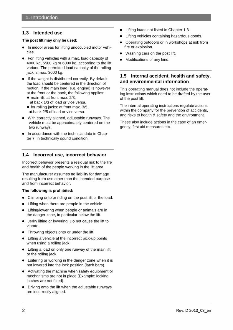
1.3 Intended use
The post lift may only be used:
In indoor areas for lifting unoccupied motor vehi-
cles.
For lifting vehicles with a max. load capacity of
4000 kg, 5500 kg or 6000 kg, according to the lift
variant. The permitted load capacity of the rolling
jack is max. 3000 kg.
If the weight is distributed correctly. By default,
the load should be centered in the direction of
motion. If the main load (e.g. engine) is however
at the front or the back, the following applies:
● main lift: at front max. 2/3,
at back 1/3 of load or vice versa.
● for rolling jacks: at front max. 3/5,
at back 2/5 of load or vice versa.
With correctly aligned, adjustable runways. The
vehicle must be approximately centered on the
two runways.
In accordance with the technical data in Chap-
ter 7, in technically sound condition.
1.4 Incorrect use, incorrect behavior
Incorrect behavior presents a residual risk to the life
and health of the people working in the lift area.
The manufacturer assumes no liability for damage
resulting from use other than the intended purpose
and from incorrect behavior.
The following is prohibited:
Climbing onto or riding on the post lift or the load.
Lifting when there are people in the vehicle.
Lifting/lowering when people or animals are in
the danger zone, in particular below the lift.
Jerky lifting or lowering. Do not cause the lift to
vibrate.
Throwing objects onto or under the lift.
Lifting a vehicle at the incorrect pick-up points
when using a rolling jack.
Lifting a load on only one runway of the main lift
or the rolling jack.
Loitering or working in the danger zone when it is
not lowered into the lock position (latch bars).
Activating the machine when safety equipment or
mechanisms are not in place (Example: locking
latches are not fitted).
Driving onto the lift when the adjustable runways
are incorrectly aligned.
Lifting loads not listed in Chapter 1.3.
Lifting vehicles containing hazardous goods.
Operating outdoors or in workshops at risk from
fire or explosion.
Washing cars on the post lift.
Modifications of any kind.
1.5 Internal accident, health and safety,
and environmental information
This operating manual does not include the operat-
ing instructions which need to be drafted by the user
of the post lift.
The internal operating instructions regulate actions
within the company for the prevention of accidents,
and risks to health & safety and the environment.
These also include actions in the case of an emer-
gency, first aid measures etc.
2. Safety
3 Rev.D 2013_03_en
2. Safety
2.1 Operators
The post lift may only be operated without supervi-
sion by persons who:
Are 18 years old and above.
Are familiar with the basic regulations on health
& safety and accident prevention.
Have been trained to handle and operate the
post lift.
Have proven their ability to do so to the compa-
ny.
Have been expressly appointed in writing to op-
erate the lift.
Have read and understood the operating manual.
2.2 Basic safety requirements
Only operate the post lift after a specialist has
certified in the inspection log that it has been cor-
rectly set up.
Always follow the operating instructions (labels
on the post lift).
If several people work on the post lift, a supervi-
sor must be appointed by the company.
The post lift may only be operated in technically
sound condition with regard to safety and with all
safety mechanisms in place.
The control box or control unit may only be
opened by a qualified electrician.
Safety inspections must be conducted regularly,
at least once annually.
If signs of a defect appear, immediately shut
down the post lift, inform a supervisor and contact
the customer service if necessary.
Keep the work area clean and free of oil, grease,
and contamination.
Before lifting/lowering, check that the acoustic
alarm (buzzer) works.
Before standing or working in the danger zone
underneath the main lift/rolling jack, lower it into
the lock position (latch bars) using the "Down“
button.
There must be no obstacles in the path of the
main lift or the rolling jack.
Always monitor the load carefully when lifting
and lowering.
Always stop the vehicles safely, centered on the
runways. Secure the vehicle against rolling with
wheel chocks.
For lifts with rolling jacks:
Always lift the vehicle with the rolling jack on the
pick-up points approved by the vehicle manufac-
turer. Lift it for a short distance and check that the
pick-up points are secure. Only then can the ve-
hicle be moved to the required height.
Take steps against traffic in the area of the post
lift. Do not park other vehicles in the danger zone.
Do not load main lifts and rolling jacks beyond
the permitted capacity, comply with the permitted
axle loads and load distribution in accordance
with Chapter 2.3.
When disassembling or fitting heavy vehicle
parts, watch out for dangerous shifts in the weight
balance, in particular when the vehicle is sup-
ported by rolling jacks. Secure the vehicle be-
forehand.
Always fully lower, switch off and secure main
lifts and rolling jacks to prevent unauthorized use
after completion of work (turn main switch to
"OFF“ and lock).
Follow the maintenance and service schedule,
record performance of maintenance and servicing
(Chapter 9).
Installation, maintenance and servicing may only
be carried out by authorized specialists (mainte-
nance contractors) (Chapter 9).
Only qualified electricians may work on the elec-
trics.
Only trained people with knowledge of hydrau-
lics/pneumatics may work on hydraulic or pneu-
matic equipment.
Appropriate personal protective equipment must
be worn when working in the area of the lift in ac-
cordance with the applicable health & safety and
accident prevention regulations. For example,
protective gloves, protective goggles, safety
shoes.
Only original spare parts from the manufacturer
may be used.
The lift must be inspected by a specialist after
repairing any supporting parts.

2. Safety
4 Rev. D 2013_03_en
2.3 Permitted axle loads and weight
distribution
Before lifting the vehicle, you must ensure that the
weight distribution is correct.
When the weight distribution is correct (default posi-
tion in direction of motion) the main load is located
at the front (e. g. engine).
WARNING
Risk of injury through toppling of
the vehicle when incorrectly load-
ed.
Comply with the permitted load capacity as in
Fig. 1 and 2.
Comply with the permitted weight distribution
as in Fig. 1 and 2.
Comply with the approved distances between
pick-up points as in Fig. 3.
Figure 1: SM40LT (with rolling jack)
Load capacity
● Main lift 4000 kg
● Rolling jack 3000 kg
Permitted weight distribution
● Main lift front max. 2/3:
F1 = max. 2670 kg
back max.1/3:
F2 = max. 1330 kg
● Rolling jack front max. 3/5:
F1: 1800 kg
back max.2/5:
F2: 1200 kg
Figure 2: SM40, AR43-5MB, SM55M51 VAS or
SM60
Load capacity
● AR43-5MB 4000 kg
● SM40, SM40-47 BMW 4000 kg
● SM55M51 VAS 5500 kg
● SM60 6000 kg
Permitted weight distribution
● SM40 front max. 2/3:
FA1 = max. 2670 kg
back max.1/3:
FA2 = max. 1330 kg
● SM60 front max. 2/3:
FA1 = max. 4000 kg
back max.1/3:
FA2 = max. 2000 kg
Figure 3: Approved distance between pick-up
points on rolling jacks
● Length max. 1.7 m ● Width min. 1.2 m
1
2
3
● SM60 front max. 2/3:
FA1 = max. 3667 kg back max.1/3: FA2 = max. 1833 kg
2. Safety
5 Rev.D 2013_03_en
2.4 Ban on unauthorized modifications
or alterations
Unauthorized modifications and alterations to the
post lift are not permitted for safety reasons.
The operating permit shall also be deemed null
and void.
The Declaration of Conformity also becomes null
and void.
2.5 Experts, competent persons
The post lift must be inspected after commissioning
and at regular intervals (after max. one year), as
well as after design modifications or repair of sup-
porting parts. Inspections may be carried out by
the following people:
Certified expert
These are people who have specialist knowledge
in the field of lifts based on their professional train-
ing and experience.
Experts should be able to inspect lifts and make an
expert assessment thereof.
TÜV experts, specialist engineers from the manu-
facturer or self-employed specialist engineers can
be used for inspections.
Competent persons
These are people who have adequate knowledge
in the field of lifts based on their professional train-
ing and experience.
They are sufficiently familiar with health & safety
and accident prevention regulations as well as with
lift technology in order to be able to assess the oc-
cupational health & safety compliance of lifts.
2.6 Maintenance contractors, installa-
tion staff
Maintenance, servicing and installation work may
only be done by companies or specialists authorized
by the manufacturer.
These people trained in the field of lifts are compe-
tent persons, who are trained for maintenance as
well as repair work.
A competent person is a person who has adequate
knowledge based on his professional training and
experience and is also familiar with key regulations
so that he:
Can assess the work assigned to him,
Can recognize potential risks,
Can take actions required to eliminate the risk,
And has the required knowledge of repair and
fitment.
The specialist knowledge of a competent person
must enable him to be in a position to
Read and fully understand circuit diagrams,
Fully understand the context with particular re-
gard to any installed safety equipment.
Possess knowledge of the function and design of
system components.
Simple faults on the post lift may be rectified by
operating staff.
In the event of a more serious fault, contact an au-
thorized maintenance contractor.

2. Safety
6 Rev. D 2013_03_en
2.7 Safety inspections by competent
persons
Safety inspections must be carried out to guarantee
the safety of lifts.
Safety inspections should be carried out in the fol-
lowing cases:
Before initial operation, after initial installation.
Use the form "Initial safety inspection before in-
stallation“.
After initial operation at regular intervals, but at
least once a year. Use the form "Regular Safety
Inspection“.
After any design modification to parts of the lift.
Use the form "Unscheduled Safety Inspection“.
The initial safety inspection as well as the
safety inspections must be carried out by a
competent person. We recommend that you
also perform maintenance in the course of the
inspection.
Unscheduled safety inspections and special
maintenance work are required in the event of
design modifications to the lift (fitting addi-
tional parts). The safety inspection must be
carried out by a competent person.
Use the form supplied in the Annex
containing lists for carrying out safety
inspections. Please use the relevant form and
staple it to the manual after completion.
i
i
i

3. The 4-Post Lift
7 Rev.D 2013_03_en
3. The 4-Post Lift
3.1 Overview of parts
Figure 4: Example of a 4-post lift
with rolling jack
1 Standard lift column
2 Lift column with control unit
3 Automatic ramp chock
4 Cross beams
5 Control unit
6 Compressed air unit with lubricator (Option)
7 Hydraulic unit with engine and tank (11 liters)
8 Base plate
9 Fixed runway
10 Drive-on ramp
11 Latch bar locking latch
12 Latch bar
13 Slip plate
14 Rolling jacks (SM40LT only)
15 Filler plate
16 Adjustable runway
17 Adjustable filler plate
T Nameplate
3.2 General workflow
After determining the vehicle data and aligning
the runways, the vehicle is driven onto the main
lift and secured against rolling.
The vehicle is raised to the desired height with
the main lift.
With optional rolling jack:
If a rolling jack is used, the manufacturer-
approved pick-up points on the vehicle are se-
lected and the matching supports are placed un-
derneath. After adjusting the selector on the con-
trol unit and checking that the weight distribution
is correct, the vehicle is lifted by the rolling jack,
and the locking latch then locks. Only then can
work continue in the danger zone.
Main lifts and rolling jacks are fitted with a pneu-
matic locking mechanism.
If the lift lowers even slightly, for safety reasons it
automatically moves into the latch bar (locking
latch).
After completion of the work, the vehicle is low-
ered again to the ground and driven off.
4

3. The 4-Post Lift
8 Rev. D 2013_03_en
3.3 Work area, danger zones
Figure 5: Work area, danger zones
1 Control area
2 Work area and danger zone
3 Vehicle overhang
WARNING
Risk of injury in the danger zone of
the post lift in the event of incorrect
behavior.
Only remain in the danger area if you have
been trained and briefed and assigned to the
area.
Keep the work area clean.
Keep escape routes clear so that you can
leave the danger zone quickly and safely in
the event of an emergency.
3.4 Safety mechanisms
See figures 6 ... 15
WARNING
Safety mechanisms protect both
people and lift. They must not be
disabled!
Post lift danger zones are protected by safety
mechanisms.
Function and condition of the safety mecha-
nisms must be checked daily!
If safety mechanisms are triggered, the post
lift stops immediately.
If safety mechanisms are defective, the post
lift must be taken out of use immediately and
the main switch locked with a padlock. Any
further use must be prevented until the ma-
chine is fully repaired!
If the post lift is moved or taken out of use for
long periods, check the safety mechanisms
before re-commissioning and repair if neces-
sary.
5

3. The 4-Post Lift
9 Rev.D 2013_03_en
1 Buzzer
Acoustic alarm. Sounds:
● When lowering the main lift < 120 mm
(foot protection).
● When lowering the rolling jacks (hand and
finger protection).
● When troubleshooting (lifting/lowering using
the override switch, for height equalizing or
during emergency manual lowering).
2 Lockable main switch
"ON“ setting: Post lift ready for use.
"OFF“ setting: Post lift out of use. The mains
voltage is still present inside the control box.
Switching off (OFF) immediately stops any
movement of the post lift (= emergency stop).
3 Locking latch on each lift column
The locking mechanism consists of a latch bar
and roller with cam shaft. Latch bar with 100
mm locking latch notches.
If a fault occurs in the hydraulic system or if the
cable breaks or becomes slack, the brake
mechanism is activated. The cam is pressed
against the latch bar through a powerful spring
action. In addition a lock cam latches (via an
air piston) into the latch bar. All up or down
movements stop immediately. Any further low-
ering is prevented.
4 Locking latch on both rolling jacks
The locking mechanism consists of toothed
lock bars. On releasing the lift or lower button,
the upper bracket swings down. The lock bars
engage (ratchets).
5 Foot protection switch on the lift column
with control unit
Deactivates the lowering process at a lift height
of 120 mm (foot protection,
otherwise a crushing or shearing hazard ex-
ists).
You can only lower from this height by pressing
the "Down“ button and the
"Lower in danger zone“ button
(2-button safety switch).
6
7
8
9
Buzzer

3. The 4-Post Lift
10 Rev. D 2013_03_en
6 Pressure control valve
The pressure control valve (arrow) is factory
set to ca. 210 bar.
Prevents a sudden lowering of the lift in the
event of a leak in the hydraulic hose (lowering
speed = max. 1.5 x default speed).
7 Lowering valve (emergency release) and
emergency manual valves
● Pos. 7.1 Lowering valve for emergency re-
lease of the main lift or the rolling jack (Fig. 12 = default configuration).
● Pos. 7.2 and 7.3: Emergency manual valve
for main lift and rolling jack. Fitted differently ac-
cording to variant. Before use check assignment
to main lift and rolling jack.
During a power failure the valves close and
stop any movement.
8 Broken cable and slack cable switch
● Pos. 8.1: Broken cable switch:
This switch is activated if the cable is broken. All
movement of the post lift stops immediately. The
control buttons will not function. Consult a com-
petent person for repair.
● Pos. 8.2: Slack cable switch:
This switch is activated when the cable is too
slack. All movement of the post lift stops imme-
diately. The Down button will not function. The
Up button will however function in order that the
cable can be pulled tight again by raising the lift
slightly.
10
11
12
13
i

3. The 4-Post Lift
11 Rev.D 2013_03_en
9 Photo sensor for rolling jack runways:
Guards against height differences of >
50 mm between the runways
Stops the lowering or lifting process if the dif-
ference in height between the two runways is
greater than 50 mm.
10 Rolling jack warning stripes (yellow-black)
Warning stripes on the rolling jack scissors.
Hand and finger protection warning, otherwise
a crushing and shearing hazard may exist dur-
ing the lifting or lowering process.
14
15

3. The 4-Post Lift
12 Rev. D 2013_03_en
3.5 Control unit
All movement of the lift stops immediately
when you release a pressed button.
Figure 16: Control unit in the lift column
1 Selector, only for SM40LT variant with rolling
jack:
● Left setting: Main lift active ● Right setting: Rolling jack active
2 UP button
For main lifts or rolling jacks.
Functions only if the button is pressed.
Post lift /rolling jack runways move up.
3 On/off switch for optional lighting.
4 DOWN button
●For main lifts or rolling jacks.
Functions only if the button is pressed.
The main lift or rolling jack runways move up
for around 2 seconds to release themselves
from the locking latches.
Runways move down until the automatic shut-off
is activated 120 mm above the ground
(foot protection, otherwise this may present a
crushing and shearing hazard). The lowering
process stops.
5 LOCK button
●For main lifts or rolling jacks.
Functions only if the button is pressed.
● Main lift: Locks the cross beams in the latch
bars of the four lift columns. Keep button
pressed until all cross beams lock securely into
the latch bars. ● Rolling jack: Lowers both runways onto the
toothed lock bars (ratchets).
Keep button pressed until both runways lock
securely into the latch bars.
6 DOWN button in the danger zone below 120
mm
● For main lifts or rolling jacks.
Only functions after the 120 mm automatic
shut-off has reacted to DOWN (4). The run-
ways can then be lowered completely if both
buttons (5) and (6) are pressed at the same
time. A buzzer sounds throughout the entire
lowering process.
16
7 Buzzer
Acoustic alarm. Sounds:
● When the main lift is being lowered < 120
mm (Foot protection)
● When the rolling jack is being lowered (hand
and finger protection).
● When troubleshooting (lifting/lowering using
the override switch, for height equalizing or
during emergency manual lowering).
8 Lockable main switch
"ON“ setting: Post lift ready for use.
"OFF“ setting: Post lift out of use. The mains
voltage is still present inside the control box.
Switching off (OFF) immediately stops any
movement of the post lift (= emergency stop)..
i
i

4. Operation
13 Rev.D 2013_03_en
4. Operation
DANGER
Risk of injury when lowering the
load onto objects below the lift or
the vehicle. Vehicle may topple
over.
Before lowering, you must remove all objects
from underneath the lift. This applies in partic-
ular to chassis stands and auxiliary jacks.
Always monitor the lift and vehicle carefully
when lifting or lowering.
DANGER
Risk of fatal injury if load is incor-
rectly distributed on both rolling
jacks. Vehicle may topple over.
Check that axle loads and weight distribution
are correct in accordance with Chapter 1.3.
Secure the load with adequately sized chassis
stands.
DANGER
Risk of fatal injury in the event of
malfunction or damaged parts.
Shut down post lift. To do so, set the main
switch to "OFF“and lock it with a padlock.
Consult a competent person.
When working with the post lift, make sure
you follow the instructions listed in Chap-
ter 2. Safety.
4.1 Emergency stop
1. To perform an emergency stop, set the main
switch to OFF ("OFF“setting). The main lift or
the rolling jack stops immediately.
4.2 Switch the machine on
1. Switch on the power supply with the main switch
("ON“setting).
2. Check the operational status of the main lift and
the rolling jack.
3. Check the functionality of the control buttons.
4. Check the functionality of the buzzer. To do so
raise the runways slightly from the bottom posi-
tion and lower again. A buzzer must sound
when lowering.
5. Lower the main lift (including drive-on ramps)
rolling jack completely.
6. Keep work area and runways clean (no objects
lying around, no grease, no oil).
4.3 Determine the vehicle data
1. Determine the weight details and the vehicle
height (see vehicle license).
Check the vehicle center of gravity, check the
load and body. Check the permitted weight
distribution on the lift.
2. Compare details with the nominal data of the lift.
3. Determine the approved pick-up points accord-
ing to the manufacturers specifications.
4. If the vehicle data is not available, ask the su-
pervisor.
i i

4. Operation
14 Rev. D 2013_03_en
4.4 Driving on
17
1. If required, set the adjustable runways (Fig. 17,
Pos R) according to the width of the vehicle. To
move them, loosen 2 runway bolts on each of
the two cross beams, move the runways in par-
allel, then tighten the bolts again.
2. Drive the vehicle onto the runways centered on
both sides (have someone guide you on). Make
sure that the wheels do not hang over the edges
of the runways.
3. Apply the vehicle handbrake, get out, and close
all vehicle doors.
4. Secure the vehicle with chocks against rolling.
5. Place supports or pads at the 4 approved pick-
up points. Only use supports or pads approved
by the manufacturer. These must be correctly
and stably positioned.
6. Take safety measures to ensure that neither
people nor loads can collapse or fall and loads
cannot slip. Make sure the weight distribution is
correct.
4.5 Lifting/lowering
DANGER
Risk of injury in the post lift zone.
Do not put people at risk when the lift or rolling
jack moves.
Always monitor the danger zones when lifting
or lowering.
No-one must stand in the traffic zone of the lift.
WARNING
Danger of crushing and shearing of
limbs (foot, toe, finger etc.). Possi-
ble uncontrolled movement when
lowering in the danger zone (below
the runways, cross beams) or when
moving the rolling jack scissors.
No parts of the body below the runways,cross
beams, or in the rolling jack scissors zone.
A buzzer sounds during the lowering process
in the danger zone < 120 mm.
Do not place objects below the lift or the rolling
jack.
ATTENTION Damage to high vehicles when
LIFTING and LOWERING. Vehicles
which are too high may collide with
the ceiling.
Even when LOWERING, the main lift or rolling
jack briefly moves up (out of the latches).
Monitor the process constantly.
Make sure that the vehicle does not collide
with the ceiling.
The lifting or lowering process must be
carried out uniformly so that the load does not
change position.
If the vehicle does not remain stable, end all
movement immediately.
Then turn the main switch to "OFF“ and lock
it. The vehicle must now be lowered by an au-
thorized competent person.
i
i

4. Operation
15 Rev.D 2013_03_en
Raising the lift
1. Set the selector to the left (main lift).
2. Lift the main lift slightly with the UP button.
3. Check the steadiness and pick-up stability of the
vehicle.
4. Only start to lift smoothly and to the required
height if the vehicle is stable.
ATTENTION Destruction of the hydraulic pump.
Operating error, when the main lift
is moved for long periods to its full
rise.
Only move the lift to just below its full rise.
Then release the button.
5. Lower the main lift with the "Lock“ button to the
lock position.
Comply with occupational health & safety and
accident prevention regulations. Use safety
stands when disassembling heavy parts.
Check that weight distribution is correct.
Raise the rolling jack
6 Set the selector to the right (rolling jack).
7 Check the position of the supports or pads and
correct if necessary.
8 Lift the vehicle slightly with the Up button.
9 Proceed as described above (Pos. 3 to 5).
Lifting with a slack cable
If the main lift is on the skew, the slack cable
switch activates a stop. Only the lift function is
still active. The buzzer sounds continuously
throughout the lifting.
The lift function is also locked if the cable
breaks.
If the cable is slack, press the Up button.
Raise the lift so that all 4 cables are ten-
sioned.
Lowering the main lift or rolling jack
1. Remove all objects in the lift and rolling jack
zone, in particular under the lift and rolling jacks.
2. Set the selector to the desired position.
3. Using the Down button, steadily lower the lift or
the rolling jack until the automatic shut-off (120
mm) is activated.
To do so, first move the runways up for around
2 seconds to release them from the ratchets.
Only then move the runways down until the au-
tomatic shut-off is activated. The lowering pro-
cess stops.
When lowering, make sure that the main lift
lowers smoothly. If not then stop the process.
If the main lift is skew, move it upwards slight-
ly so that the cables pull tight. Then continue
the lowering process.
If this does not work, consult a competent
person.
4 To completely lower the lift press "Lock“ and
"Lower in the danger zone“ together.
Move the main lift or rolling jack right to the bot-
tom position. Make sure that the drive-on ramps
are fully lowered.
4.6 Drive off
1. Remove chocks.
2. Carefully drive the vehicle off the lift and away
from the lift area (have someone to guide you).
In doing so, make sure that the wheels never
run over the edge of the runways or alongside
them.
4.7 Switch the machine off
1. Disconnect the power supply with the main
switch ("OFF“setting) and lock the switch with a
padlock.
i i
i
i

5. Problems, causes, actions
16 Rev. D 2013_03_en
5. Problems, causes, actions
The following lists contain information on
potential problems, their causes, and
actions to rectify the fault.
Repairs to safety mechanisms on the lift may
richtungen only be carried out by authorized
maintenance contractors (component persons).
During a breakdown (power failure), the lift remains
automatically in safe mode. This means that all movement
is halted.
5.1 Troubleshooting by the operator
The following troubleshooting measures may only be carried out by
an authorized operator.
Before doing so, make sure that power supply is connected, dass die Netz-
the main switch is in the "ON“position
and an air supply of 6...8 bar is connected.
Problem Possible cause Actions
The motor is not running. Mains fuse is faulty. Reset or change the mains fuse.
The runways lower unevenly
during the lowering processLift
or rolling jack runways tilted.
Main lift
Slack cable switch or broken
cable switch activated.
Can lift when cable is slack.
If cable is broken the whole lift
is locked.
Lowering locked.
Rolling jack
Photosensor disconnected.
Height difference > 50 mm.
Whole lift is locked.
An object is blocking the
downward motion. The lower-
ing process is aborted.
Load unevenly distributed.
Settling function still active:
main lift and rolling jack partly
still in the lock position (Lock
bar/ratchets).
Slack or broken cable on one
of the lift columns.
Main lift
1. Move lift up slightly. Make
sure that all cables are ten-
sioned.
2. Remove objects from under
the lift.
3. Carry out adjustments. To do
so, lower the lift completely.
4. Check that lift is being cor-
rectly operated.
5. If this cannot be done:
(Chapter 6. Authorized low-
ering) or (Chapter 9.
Maintenance/repair).
Rolling jack
1. Consult a competent person
(Chapter 6. Authorized low-
ering).
i
If the problem is not rectified by the listed
measures, you must seek advice from a com-
petent person.
The troubleshooting measures listed in 5.2
may only be carried out by maintenance con-
tractors.
If the lift is out of order for long periods, carry
out the following steps:
1. Lower the lift to the lowest position.
2. Switch the main switch to Off and lock with a
padlock.
3. Disconnect the power supply and air supply.
i
i
i

5. Problems, causes, actions
17 Rev.D 2013_03_en
Problem Possible cause Actions
Control unit does not work. A
buzzer sounds. Runways misaligned. Misa-
lignment protection activated.
Consult maintenance contractors
(Chapter 6. Authorized lowering).
Lowering process stops abrupt-
ly.
A buzzer sounds, control unit is
out of order.
Cable too slack.
Cable broken.
1. Switch main switch to "OFF“ and
lock it.
2. Consult maintenance contrac-
tors. Change the cable.
The main lift does not react
when being lowered.
Only rolling jack can be low-
ered.
A buzzer sounds.
Cable too slack or damaged.
Slack cable switch activated.
1. Switch main switch to "OFF“ and
lock it.
2. Consult maintenance contrac-
tors. Tighten and adjust cable
(Chapters 11.11 und 13.4).
Restart.
The process stops after a few
centimeters when lowering into
the lock position.
Pneumatic solenoid valve not
supplied with compressed air.
Check compressor connection.
Lift button does not work.
Main lift or rolling jack:
Runways do not move up.
Hydraulic oil level too low. 1. Refill hydraulics up to gauge
mark (Chapter 9.4).
2. Check with dipstick.
Attention: Using rapeseed based oil
destroys the seal.
Use only biodegradable oils (HEES-
oils based on synthetic esters).
The water content of the oil may not
exceed 2 %.
Do not mix bio-oils with mineral oils.
Runways do not lift with a load.
They do however rise without a
load.
The lift is overloaded.
Rated load capacity exceeded,
maybe on one runway.
Hydraulic pressure incorrect-
ly set on pressure control
valve.
1. Check vehicle weight.
If necessary re-position the ve-
hicle (Chapter 2.3.
rated weight distribution).
2. Correct setting on pressure con-
trol valve.
Power failure on main lift which
is locked in the latch bars. No mains supply. Can only be lowered with manual
pump and optional hydraulic power
unit.

5. Problems, causes, actions
18 Rev. D 2013_03_en
5.2 Troubleshooting by authorized maintenance contractors
Problem Possible cause Actions
Control unit does not work.
A buzzer sounds.
Runways misaligned. Misa-
lignment protection activated. Lower the lift or rolling jack,
Chapter 6. Authorized lowering.
The main lift does not react
when being lowered.
Only rolling jack can be lowered.
A buzzer sounds.
Cable too slack or damaged.
Slack cable switch activated.
1. Tighten and adjust cable
(Chapter 11.11 und 13.4),
Change if necessary.
2. Lower lift completely (chap-
ter 6).
3. Carry out function test.
Lift does not work.
A buzzer sounds
Fuses damaged.
Thermal protection discon-
nected.
Transformer damaged.
Depending on cause:
● Reset or replace fuses.
● Connect thermal protection.
● Replace transformer.
The motor is not running. Incorrect supply voltage to the
motor.
Wiring loose.
Faulty motor.
Faulty limit switch.
Depending on cause:
● Supply the correct voltage to
the motor.
● Check all wiring connections
and repair or insulate if neces-
sary.
● Test function of the Up switch.
Replace if necessary.
● Check function of overhead
limit switch. Replace if necessary.
● Change hydraulic power unit for
motor.
Up button does not work.
Runways do not move up(main
lift or rolling jack).
Lowering valve is open.
Pump is sucking air.
Suction pipe disconnected
from pump.
Depending on cause:
● Clean or replace lowering
valve.
● Tighten fittings on suction pipe.
● Replace suction pipe.
Runways do not lift with a load.
Runways rise however without a
load.
Insufficient voltage supplied to
motor hydraulic power unit.
Lowering valve is dirty.
Release valve incorrectly set.
Depending on cause:
● Supply the correct voltage to
the motor.
● Clean the lowering valve.
● Adjust release valve.
Runways lowering slowly. Check valve is dirty.
Lowering valve dirty.
External oil leaks on pipes
and hoses.
Dirty installation space (Check
valve and lowering valve).
Depending on cause:
● Clean check valve.
● Clean lowering valve.
● Eliminate leaks.

5. Problems, causes, actions
19 Rev.D 2013_03_en
Problem Possible cause Actions
Lift speed
too low.
Air has mixed with oil
or is being sucked in.
Hydraulic hose is loose.
Depending on cause:
● Change oil ( Chapter 9.4).
● Tighten fittings on suction pipe.
● Secure the oil return tube.
Leak in hydraulic power unit Hydraulic pump is faulty. Repair hydraulic pump.
Fault on hydraulic pump. Pressure control valve set
incorrectly.
Overloading (vehicle too
heavy).
Depending on cause:
● Correct the pressure control
valve.
● Replace hydraulic pump. Do
not put excessively heavy vehi-
cles onto the lift.
Hydraulic oil leaking from the
filler/breather cap. Air has mixed with the oil or is
being sucked in.
Oil return line is loose.
Hydraulic hose is damaged.
Depending on cause:
●
● Tighten fittings on suction pipe.
● Attach return line.
● Replace hydraulic hoses.
Runways lift unevenly
(Height difference in runways). Cables are out of adjustment
Lift not leveled.
Floor is uneven.
Depending on cause:
● Correct the cable tension
(Chapter 11.11 and 13.4).
● Reset and accurately level the
lift.
● Place spacers/shims under-
neath (Chapter 13. Commis-
sioning).
Anchor is loose. Assembly fault,
for example drill holes are too
big or load capacity of concrete
floor is inadequate.
Depending on cause:
● Repair the lift.
● Re-install
(Chapters 11 to 13). Follow
installation requirements.
Runways either do not lift to full
rise or they chatter during lifting. Hydraulic oil level too low. Check oil level. If required bleed
the hydraulic cylinder (Assem-
bly manual).
Runways do not lower. Inadequate air supply.
Locking latches are offset.
Depending on cause:
● Check air pressure and adjust
of necessary (6 ... 8 bar).
● Check whether air lines are
leaking or crushed.
● Check locking mechanism,
repair if necessary.

5. Problems, causes, actions
20 Rev. D 2013_03_en
Problem Possible cause Actions
Locking latches not latching or
cannot be released. Compressed air supply inter-
rupted.
Faulty control valve for air
supply.
Locking mechanism is
jammed.
Air cylinder for locking mech-
anism is dirty.
Check locking mechanism, repair
if necessary.
Lowering process stops abruptly.
A buzzer sounds, the control unit
is out of order.
Cable is too slack.
Cable broken.
Depending on cause:
● turn main switch to "OFF“
and lock it.
● Check all cables.
Replace faulty or warped cables
(Chapter 9.6).

6. Authorized lowering
21 Rev.D 2013_03_en
6. Authorized lowering
Only by authorized competent per-sons
WARNING
Risk of injury in the case of incor-
rect behavior. Only authorized
competent persons may lower lifts
as described below.
Cordon off the danger zone, prevent access
by all persons.
Constantly monitor the danger zones when
lifting or lowering.
No-one may remain in the lift traffic zone.
Only qualified electricians may carry out work
on the electrics.
Figure 18
1 Electronic alignment control button:
Functions only when the photosensor is discon-
nected
2 Rolling jack leveling button
6.1 Manually lowering the lift when
there is a height difference of > 50 mm
After the photosensor has been activated when the
height difference between the runways is above 50
mm, the rolling jacks are locked completely. The
main lift can also no longer be lowered.
To correct this, proceed as follows. A buzzer sounds
throughout the entire lifting/lowering process.
1. Secure the danger zone, see above.
2. Remove the safety cover on the side of the con-
trol unit.
3. Set the selector on the main lift or rolling jack as
required.
4. Push the electronic alignment control button (1)
together with the UP or DOWN button. In doing
so, the main lift or rolling jack move up to full
rise and then down to the bottom position.
5. If both runways are lowered completely onto the
floor, turn the main switch to the "OFF“ position,
wait a short while, then turn the main switch to
the "ON“ position.
18
6 Conduct a function test. The lift is now ready
for operation again.
7 Attach the side safety cover and screw back
into place.

6. Authorized lowering
22 Rev. D 2013_03_en
6.2 Leveling the rolling jacks
DANGER
Risk of injury due to height differ-
ence in the runways when the lift is
loaded. Vehicle may topple over.
Adjust the height of the runways slightly.
Avoid large differences in height between the
runways.
Consult a competent person if lift is too
skewed.
The height level of the left or right runways
can be manually adjusted by pressing the red
button (2). This is done by equalizing the hy-
draulic fluid within the hydraulic system.
1. Push the red leveling button (Fig. 18, Pos. 2)
together with the UP button until both runways
are at the same height.
An adjustment process is carried out when the
buttons are pressed.
2. If necessary, release the buttons and repeat the
process again until the runways are at the same
height.
3. Push in the leveling button together with the
DOWN button until both runways are completely
lowered onto the floor.
4. Turn the main switch to the "OFF“ position, wait
a short while, then turn the main switch to the
"ON“ position.
5. Carry out a function test. The lift is now ready
again for operation.
6. Attach the side safety cover and screw back into
place.
6.3 Emergency manual function
Even if the post lift fails totally, the vehicle can be
lowered, for example by disconnecting the power
supply.
The main lift rolling jacks can be lowered from one
locking latch to the next, albeit step by step.
Example: Lowering the main lift:
Depending on the assembly situation it may be that the emergency manual valves are fit-ted the wrong way round. Always check using the cable routing and colour as a guide and using a function test, check the assignment of the valves to the rolling jacks and main lift.
1. Secure the danger zone, see Warnings.
2. Remove the metal cap from the valve.
19
3. Remove the valve from the threaded rod and
screw on the metal cap completely
(Emergency Manual = active).
20
4. Remove the plastic cap from the lowering
valve.
i
i

6. Authorized lowering
23 Rev.D 2013_03_en
5. Release the air cylinders on all 4 lift columns
with the release pins. Then turn the brass
screw again to the left. The lift drops back into
the next lock position.
21
6 Turn the brass screw to the left to lower the
main lift to the next lock position.
22
7 Repeat the process until the main lift has been
lowered completely to the floor.
8 Turn the brass screw to the right as far as it will
go to close the pressure control valve,
otherwise the lifting function will not work.
9 Screw on the plastic cap.
10 Refit the emergency manual valve. Make sure
that the metal cap is screwed on completely,
otherwise the lifting function will not work.

7. Technical data
24 Rev. D 2013_03_en
7. Technical data
SM40-47 SM40-51 SM40LT-47 SM40LT-51
SM40-47 BMW
SM55-M51 VAS
AR43-5MB
SM60-51 SM60-55
A Load capacity
Lift Rolling jack
4000 kg 3000 kg
6000 kg
B Stroke SM55-M51/ AR43-5MB
SM40-47BMW
SM40-47 / SM60-51 SM40-51 / SM60-55 SM40LT-47 SM40LT-51 LT-47 rolling jack LT-51 rolling jack
1943 mm 1943 mm 1750 mm 1750 mm 390 mm 390 mm
1890 mm 1890 mm
C Overall length with
drive-on ramps SM40-47 / SM55-M51 VAS/AR43-5MB/ SM60-51 SM40-51 / SM60-55 SM40LT-47 SM40LT-51
SM40-47BMW
5788 mm 6188 mm 5788 mm 6188 mm
5396 mm 6796 mm
D Overall width 3320 mm 3403 mm
E
F
Drive-on height
Lift
SM40-47BMW
Rolling jack
175 mm 66 mm
190 mm
G H
Runway length
SM40-47 / SM60-51 SM40-51 / SM60-55 SM40LT-47 SM40LT-51 Rolling jack
4700 mm 5100 mm 4700 mm 5100 mm 1490 to 2000 mm
5100 mm 5500 mm
I J
Runway width Rolling jack
560 mm 560 mm
560 mm
K Inner distance be-tween runways, 3 positions
800 mm 950 mm 1100 mm
800 mm 950 mm 1100 mm
Motor power rating 3 kW 3 kW
Electrical connection 400 v, 50 Hz (3+N+PE)
400 v, 50 Hz (3+N+PE)
Compressor connec-tion
8...10 bar 8...10 bar
Lift time lift Lift time rolling jack
45 Sec. 10 Sec.
45 Sec.
Hydraulic system operating pressure
190 bar 190 bar
Hydraulic oil tank ca-pacity
11 liters 11 liters
Noise level 70 dB(A) 70 dB(A)
Ambient temperature range
0...50 °C 0...50 °C
Relative humidity range (without condensation, at 20 °C)
30...95 % 30...95 %
23
Nameplate with details of lift model, serial
number, year of manufacture etc. For the po-
sition of the nameplate see Fig. 1.
i

8. Cleaning
25 Rev.D 2013_03_en
8. Cleaning
Only clean the lift when not loaded (without vehi-
cle).
Clean main lift, rolling jack and all work areas
daily. In doing so, always keep all post lift com-
ponents clean.
If the lift is in a particularly dirty environ-
ment, clean accordingly more frequently.
Do not use abrasive cleaning materials on lift
parts and covers. Use lint-free cloth.
Do not use compressors or high pressure clean-
ers for cleaning work.
Always consult a maintenance contractor if you
identify a hazard.
Prior to maintenance make sure that fittings and
fixtures are free of oil, lubricants, and cleaning
materials.
Cables (running steel cable) must be regular-
ly lubricated with a suitable lubricant, from ex-
ample from Duotac,
CRC or Mobil (Mobilarma 798).
This can significantly increase the service life of
the cable. Lubricant can be applied by spraying,
dipping, or brushing.
Do not clean cable with water.
Make sure that steel cable is properly lu-
bricated.
i
i
24

9. Maintenance and repair
26 Rev. D 2013_03_en
9. Maintenance and repair
9.1 Qualification of maintenance and
repair staff
Maintenance and repair work may only be carried
out by an authorized maintenance contractor
(Chapter 2.6).
9.2 Maintenance and repair safety reg-
ulations
Only qualified electricians may work on electrical
equipment on the machine.
Only qualified staff with specialist knowledge and
experience with hydraulics or pneumatics may
work on hydraulic or pneumatic equipment.
Ensure that you follow the instructions listed in
2, Safety.
When working on the hydraulics or on pneumatic
equipment, ensure that you follow the safety
regulations listed in the supplied power unit oper-
ating instructions annexed to this manual.
Only perform maintenance on unloaded lifts and
rolling jacks.
Main lifts and rolling jacks must be lowered com-
pletely or latched into the lock positions (locking
latches).
Prevent environmental hazards:
● Mineral-oil-based hydraulic oil is combustible
and a water pollutant. It must only be used in
conjunction with the relevant safety data sheet
and if all specified measures contained therein
are implemented.
● Provide suitable oil drain pans and oil absor-
bents.
● Ensure that no hydraulic oils, lubricants or
cleaning materials contaminate the soil or leak
into the drainage system.
● Comply with local regulations for handling wa-
ter pollutants, for example for absorbing leaking
fluids or fluids from oil separators.
Avoid contact with or inhalation of toxic sub-
stances such as hydraulic fluid.
Wear protective clothing, for example protective
goggles, protective gloves etc.
Before all maintenance and repair work:
● secure the post lift zone with a red-white chain
and warning notices.
● turn the main switch to OFF ("OFF“ Position).
● disconnect the air supply (manometer on the
compressor unit to 0 bar).
● inform all persons in the area about the
maintenance and repair work.
Only use original spare parts from the manufac-
turer.
Tighten all fittings after maintenance work ac-
cording to the specified torque figures.
The default setting for safety valves must be a
maximum of 10 % or a minimum of 20 bar above
the operating pressure of the machine. The safety
valve settings may not be adjusted.
Remove all used materials, tools and other ob-
jects from the danger zone after cleaning,
maintenance, and repair work.
Dispose of hydraulic oils, lubricants, cleaning
materials, and replaced parts in accordance with
environmental regulations.
DANGER
Inadequate maintenance and repair
work may cause serious injury and
also lead to damage to property. A
safety risk as well as a risk of fatal
injury exists during operation.
Follow the maintenance and repair instructions
below carefully.
Regularly clean the post lift ( Chapter 8).
Comply with maintenance intervals (Chapter
9.3). This will keep the post lift in perfect work-
ing condition and guarantee safe operation.
Maintenance and repair work must be docu-
mented (annex, maintenance schedule,
regular maintenance reports, and repair re-
ports).
9. Maintenance and repair
27 Rev.D 2013_03_en
9.3 Maintenance work
WARNING
Potential crushing and shearing
hazard to limbs caused by uncon-
trolled lowering motion.
In particularly dirty environments, maintain the
post lifts accordingly more frequently.
Only perform maintenance on unloaded lifts,
i.e. without vehicle.
Before maintenance work lower the main lift
completely or lower and latch into the lock
(locking latches).
Turn the main switch to OFF ("OFF“ setting)
and lock with a padlock.
Cordon off the maintenance area to unauthor-
ized persons (red-white chain, warning notic-
es).
Disconnect the air supply (Compressor unit
manometer to 0 bar).
Inform all persons in the area about the
maintenance work.
WARNING
Risk to people and the environment
caused by toxic substances when
emptying or filling the hydraulic oil
tank or lubricator (Compressor
unit).
Avoid contact with or inhalation of hydraulic oil
or Vaseline oil.
Provide a suitable oil drain pan and oil absor-
bent.
Ensure that used oil does not contaminate the
soil or wash away into the drainage system.
Comply with local regulations for handling wa-
ter pollutants.
Dispose of used oil in an environmentally
friendly manner.
Hydraulic oil is highly inflammable, combus-
tible.
DANGER
Risk of fatal injury if anchor bolts
are loose. Post lift may slip, the
load may collapse.
Stop operating the post lift.
Secure the post lift. If this cannot be done,
provide an approved foundation then anchor
and secure the post lift properly.
Daily inspection
1. Check whether the automatic wheel chocks,
drive-on ramps, or the chocks and drive-on
chocks are damaged or show signs of wear.
Replace damaged or worn parts.
2. Check the function of the locking latches on the
main lift (visual inspection). To do so, lock the
main lift in the locking latches then raise and
tension the cable.
3. Check horizontal alignment of runways. Run-
ways must be horizontally aligned and at the
same height. If not, correct the alignment
(Chapter 13. Commissioning).
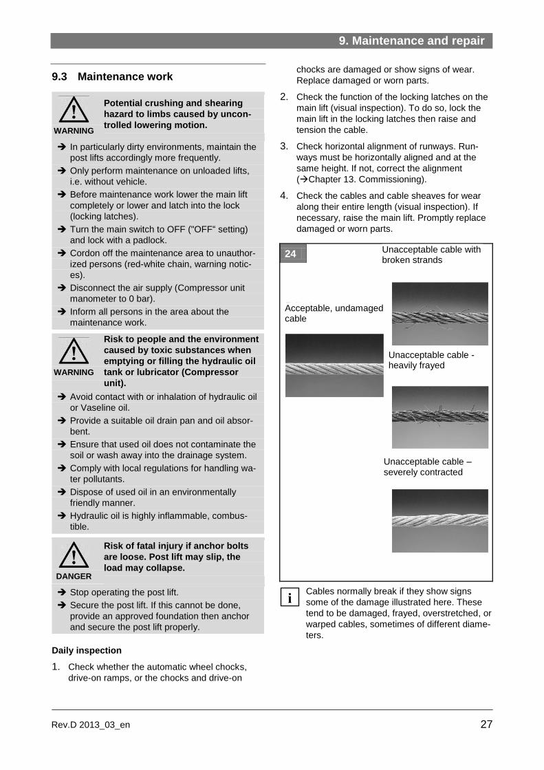
4. Check the cables and cable sheaves for wear
along their entire length (visual inspection). If
necessary, raise the main lift. Promptly replace
damaged or worn parts.
24
Cables normally break if they show signs
some of the damage illustrated here. These
tend to be damaged, frayed, overstretched, or
warped cables, sometimes of different diame-
ters.
i
Acceptable, undamaged cable
Unacceptable cable with broken strands
Unacceptable cable -heavily frayed
Unacceptable cable – severely contracted

9. Maintenance and repair
28 Rev. D 2013_03_en
5. Test the buzzer ( Chapter 3.4, Pos. 1).
A buzzer must also sound when lowering in the
foot protection zone.
If the buzzer is faulty the post lift must not be
operated.i

9. Maintenance and repair
29 Rev.D 2013_03_en
Monthly maintenance
1. Turn the main switch to OFF ("OFF“ setting) and
lock with a padlock.
2. Check whether the runways and rolling jacks
are horizontally aligned during lifting and lower-
ing and move up and down. Re-adjust stretched
cables (Chapter 13. Commissioning).
3. Check whether screw fittings have come loose.
This applies in particular to screw fittings be-
tween drive-on surfaces and cross beams.
4. Check the hydraulic oil level (Hydraulic tank). If
necessary, refill with approved hydraulic oil
(Chapter 9.4) ("max“ mark. Empty tank capac-
ity 11 liters).
5. Inspect the tank cover of the hydraulic tank. The
vent cap must be clean so that no vacuum can
form.
Clean if necessary.
6. Check hydraulic component seals (visual in-
spection).
7. Turn main switch to ON ("ON“ setting).
8. Check that control buttons and switches func-
tion properly.
9. Carry out a function test with and without load.
10. Complete a maintenance report ( Annex).
Six month maintenance
1. Raise lift and rolling jacks.
2. Turn main switch to OFF ("OFF“ setting) and
lock with a padlock.
3. Lubricate post lift with approved lubricant
(Chapter 9.4).
● Fig. 25: 4x Cross beam grease fitting with
grease press
● Fig. 26: 8x Runways grease fitting for main lift
with grease press
● Fig. 27: 2x Rolling jack grease fitting with
grease press
● Fig. 28: 2x Rolling jack grease fitting with
grease press
● Lightly grease the rolling jack slides running
surfaces.
4. Turn the main switch on ("ON“ setting).
5. Conduct function test. Lower lift and rolling jack
completely.
6. Complete a maintenance report ( Attach-
ment).
25
26
27
28

9. Maintenance and repair
30 Rev. D 2013_03_en
Annual maintenance
1. Turn the main switch off (Position "OFF“) and
lock with padlock.
2. Lubricate cross beam cable sheaves with
grease (Consistency classification II).
3. Check Hydraulic cylinder and Hydraulic hoses
for leaks (visual inspection).
4. Inspect electrical cables for damage
(visual inspection).
5. Turn the main switch on again (Position "ON“).
6. Check that control buttons and switches func-
tion properly.
7. Replace illegible or missing labels on the post
lift. Re-order from the manufacturer.
8. Conduct safety inspections
(Chapter 2.7).
9. Complete maintenance report and inspection
report from safety inspection ( Annex).
Depending on the level to which it has degraded
1. Change the hydraulic oil (Chapter 9.5).
9.4 Approved hydraulic oils
Important information
Only use hydraulic oils in accordance with DIN
51524 for the hydraulic system.
Only use biodegradable oils
(HEES-based on synthetic esters).
Use PTFE seals or foam elastomers if the water
content is high.
ATTENTION Seals may be destroyed if the in-
correct hydraulic oil is used.
Do not use rapeseed based oils.
The water content of the hydraulic oil must not
exceed 2 %.
Do not mix bio-oils with mineral oils. Mixing
leads to foaming problems and corrosion
damage.
Make sure that the oil is not contaminated by
any other oil or water.
Use a proportionally lower viscosity bio-oil as
a replacement for mineral oil. This improves
the lubrication properties, reduces energy
consumption and generates less heat.
HEES32-bio-oils can, for example, be used as a
replacement for mineral oil HLP46:
PLANTOSYN 3268
BECHEM HYDROSTAR HEES 46 longlife
BP Biohyd 32
Mobil EAL Hydraulic Oil 32 and 46
Oils and grease
Only use consistency classification II oils and
grease.
Water pollutants
Oils and grease are water pollutants in terms
of the Water Management Act (WGH).
Always dispose of these in an environmental-
ly friendly manner in compliance with the ap-
plicable regulations in your country (Chap-
ter 16. Disposal).
i
i
i

9. Maintenance and repair
31 Rev.D 2013_03_en
9.5 Check, refill, change the hydraulic
oil
WARNING
Risk to people and the environment
from toxic substances when filling
the hydraulic oil tank.
Avoid contact with and inhalation of hydraulic
oil.
Wear protective clothing (protective goggles,
protective gloves).
Provide suitable oil drain pans and oil absor-
bents.
Ensure that no hydraulic oils, lubricants, or
cleaning materials contaminate the soil or leak
into the drainage system.
Comply with local regulations for handling wa-
ter pollutants, for example for absorbing leak-
ing fluids or fluids from oil separators.
Hydraulic oil is highly inflammable, combus-
tible.
1. Check hydraulic oil level on the hydraulic oil
tank.
The oil level must not exceed the minimum
value ("min“).
2. Place the oil drain pan under the tank, remove
tank cap and refill hydraulic oil to the
"max“mark.
3. Ensure that the vents work and that no vacuum
is generated.
4. Screw on the tank cap so that the tank is
properly sealed.
5. Remove oil residues on the floor or on the lift
with an approved detergent. Dispose of used
cleaning cloths in the correct manner.
6. Complete a maintenance report ( Annex).
An oil change is carried out depending on the extent to which the hydraulic oil has degraded. To do so, proceed as follows:
1. Lower all runways (main lift and rolling jack)
completely, turn main switch off ("OFF“ position)
and lock it.
2. Place the oil drain pan under the hydraulic oil
tank, completely disassemble the tank and emp-
ty out the remaining oil into the drain pan.
29
3. Replace the hydraulic oil tank in the correct
manner.
4. Fill approved hydraulic oil up to the "max“-mark.
Maximum capacity of empty tank is 11 liters.
5. On the , AR43-5MB, SM55-M51VAS or SM60,
bleed the main cylinder. On the SM40LT vari-
ant, bleed all 3 hydraulic cylinders.
6. Remove oil residues on the floor or on the lift
with an approved detergent. Dispose of used
cleaning cloth in the correct manner.
7. Turn main switch back on ("ON“ setting).
8. Check that control buttons and switches func-
tion properly.
9. Carry out function tests with and without load.
10. Complete maintenance report ( Annex).
i

9. Maintenance and repair
32 Rev. D 2013_03_en
9.6 Repair work
(Repairs)
Always refer to the information received
during the manufacturer‘s training.
Changing the cylinder
1. Lower the post lift into a suitable position until all
4 latches are completely latched in the latch
bars.
2. Check the latching (visual inspection).
All 4 latches must be 100 % latched and the ca-
bles unloaded.
3. Turn the main switch off ("OFF“setting) and lock
with a padlock.
4. Disconnect the mains fuse and attach a warning
notice preventing unauthorized reconnection.
5. Loosen the cable retainers.
6. Activate the hydraulic system without pressure.
7. Disconnect the air supply / remove fitting.
8. Change cylinder.
9. Reassemble in reverse order.
Worn ratchets
1. Proceed as above under Change cylinders,
Pos. 1 to 4.
2. To safeguard against unforeseen lowering, also
place suitable supports under the post lift at the
lift columns.
3. Loosen the ratchet mounting screws.
4. Activate the hydraulic system without pressure.
5. Disconnect the air supply at the air cylinder
fitting.
6. Disassemble the ratchet.
DANGER
If repairs are carried out incorrect-
ly, they may cause serious injury
and also lead to damage to proper-
ty. A safety risk as well as a risk of
fatal injury exists during operation.
Repairs may only be carried out by trained
customer service staff.
Follow all safety regulations and warnings in
this chapter.
Always follow the repair instructions below.
Repair work must be documented ( Annex,
inspection logbook).
i
9. Maintenance and repair
33 Rev.D 2013_03_en
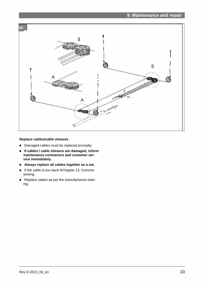
Replace cables/cable sheaves
Damaged cables must be replaced promptly.
If cables / cable sheaves are damaged, inform
maintenance contractors and customer ser-
vice immediately.
Always replace all cables together as a set.
If the cable is too slackChapter 13. Commis-
sioning.
Replace cables as per the manufacturers train-
ing.
30


10. Transport, Storage
35 Rev.D 2013_03_en
10. Transport, Storage
DANGER
Crushing and shearing hazard for
limbs when unloading.
Caused by collapsing or slipping of
the load.
Only unload the packing unit and transport to
the installation site with a forklift truck or pallet
jack with a sufficient load capacity.
Only use hoists approved for the total weight
(straps, chains etc.).
Attach these so that the load cannot slip
(check the centre of gravity of the load).
Only secure individual components to load-
bearing parts. Always lift vertically, steadily
and without jerking.
Carry out a visual inspection before offloading.
Do not stand close to or underneath swinging
loads.
Constantly monitor the danger zone when lift-
ing or lowering.
Always transport hydraulic components empty
of oil.
ATTENTION Lift components may be damaged
if offloaded incorrectly.
Do not damage plates on the underside of the
lift when lifting.
Several parts are inserted into the compo-
nents, for example into the runways. Offload
these carefully to prevent damage.
When offloading, proceed from top to bottom.
10.1 Transport
The lift is supplied in a packing unit (base unit) plus
a separate hydraulic power unit. The optional wheel
alignment kit is also supplied in a packing unit. The
respective packing unit comes with the following
documentation:
Transport description giving suitable suspension
points, total weight, centre of gravity, required
cable lengths, transport locks, etc.
List of all individual components included in de-
livery.
31
Base unit Centre of gravity in the middle
1 Lift column
2 Drive-on ramp
3 Cross beams
4 Lift column with control unit
5 Tracks
Arrows Fittings
(Transport locks)

10. Transport, Storage
36 Rev. D 2013_03_en
10.2 Offloading
7. Inspect the shipment for any shipping or
transport damage. Immediately report any dam-
age to your supervisor and to the transport firm.
8. If there is any transport damage, contact the
transport firm.
9. Transport the packing unit to the installation
site. This must conform to the approved envi-
ronmental conditions (Chapter 7.
Technical data).
10. Unfasten the transport locks for the large parts
on the front of the packing unit.
11. Offload the runways and cross beams and set
down carefully.
Recommended: Raise the runways and cross
beams slightly, for example set down onto
stable wood beams. This will also enable you
to better route the pneumatic lines and elec-
trical cables later.
12. Remove all other components from the pallet
and set down carefully.
13. Inspect the supplied parts according to the
packing list provided.
14. Dispose of packaging in an environmentally
friendly manner, in compliance with the regula-
tions applicable in your country (Chapter 16.
Disposal).
10.3 Storage
Lift components must always be stored in a dry
place (no corrosion protection).
Recommended Storage Conditions
Ambient temperature: -5 ... +50
Relative humidity, 30 % ... 95 %
with condensation, at 20 °C
The manufacturer provides no warranty for
corrosion damage caused by incorrect stor-
age.
i
i

11. Assembly
37 Rev.D 2013_03_en
11. Assembly
11.1 Assembly safety instructions
Verify that the foundation is suitable before as-
sembling.
Think about and prevent potential sources of
danger before assembly (Chapter 1. Intended
use, improper use, incorrect behavior, and inter-
nal incident, health & safety, and environmental
information).
Operators must be able to view the post lift and
the danger zone in full from the control unit
(Chapter 3.3. Work area, danger zone).
Refer to the technical data in chapter 7.
Route and protect on-site power cables accord-
ing to manufacturers specifications.
Only qualified electricians may carry out electri-
cal work on the electrical equipment of the ma-
chine.
Only qualified staff with specialist knowledge and
experience with hydraulics or pneumatics may
work on hydraulic or pneumatic equipment.
When working on the hydraulics or on pneumatic
equipment, ensure that you follow the safety
regulations listed in the supplied power unit oper-
ating instructions annexed to this manual.
Ensure that you also follow the instructions
listed in 2. Safety.
11.2 Quick assembly instructions
The lift components are already pre-
assembled ex works. When assembling these
must simply be joined together, electric,
pneumatic, and hydraulic lines must be
properly connected.
1. Determine the installation site of the post lift.
Check the foundation. If necessary, reinforce
the foundations at the point where the lift col-
umns will be positioned.
2. Make preparations for installation. Prepare elec-
trical and pneumatic connections.
Check the foundation for unevenness and level
it out. Use spacers and shims.
3. Set down both runways and prepare them for
assembly.
4. Set down both cross beams and prepare them
for assembly. Disassemble the cable sheaves.
5. Set up the cables. To do so, pull out the cables
from the cross beams and tension them.
6. Fasten the runways to the cross beams.
7. Insert the latch bars into the latch bar brackets.
8. Stand the lift columns upright, anchor and se-
cure to the floor.
9. Secure the latch bars and cables.
10. Attach flexible hoses.
11. Assemble the hydraulics module. Fill the hy-
draulics tank.
12. Connect the electrics.
13. Power up the post lift and connect the pneumat-
ic lines (when it stops, it will automatically lock
in the latch bars).
14. Carry out initial commissioning.
Make minor adjustments to the post lift.
15. Fit the automatic wheel chocks, drive-on ramps
and other additional components.
GEFAHR
Incorrect installation work may
lead to serious injury and material
damage. A safety risk as well as a
risk of fatal injury exists during
operation.
Follow the instructions below carefully.
Only customer service staff authorized by the
manufacturer may assemble and commission
the post lift.
Correct installation and commissioning must
be documented in the inspection logbook.
To do so, use the form "Initial safety inspec-
tion before installation“.
i

11. Assembly
38 Rev. D 2013_03_en
11.3 Site specifications
The post lift may only be installed above ground
and indoors.
Refer to the building plans when selecting a site.
When anchoring to the floor, take into account
any pipes, cables, and supply lines lying there.
Ensure that the load capacity of the foundation is
adequate.
● Support surface for lift columns:
Reinforced concrete, concrete quality
C20/C25
● Floor load capacity for each lift column (34 x
23 cm): Min. 2000 kg.
● Floor must be designed for a floor anchor.
Do not fit post lifts onto asphalt or a similar
unstable surface, since the anchor may come
loose in the floor.
Comply with the specified minimum distances
and clearances (Chapter 3.3. Work place,
danger zone): ● Min. work area for loading and movement:
8.58 m x 4.86 m.
● Min. distance around sides:
0.8 m, without through traffic 0.6 m
● Min. ceiling height / lamp height:
2.032 m + overhead clearance of largest
vehicle.
Take account of the max. required hall
height/room height. For variants with rolling
jack, also factor in the max. extension height
of the rolling jack.
For wheel alignment lifts, take into account
the vehicle or alignment system
manufacturer’s specifications.
32
Runways must be fitted straight and level. Height
tolerance ± 5 mm, max. difference between di-
agonals 6 mm.
Tighter tolerances are defined for the optional
wheel alignment kit, according to manufactur-
er’s specifications.
Factor in sufficient space for the approach and
drive-off. Take drive-on ramps into account.
Take note of the maximum bearing pressure
under the lift column. Take into account the
weight distribution and the dead load of the lift
parts.
11.4 Installation preparations
1. Provide an electrical and pneumatic outlet close
to the lift column with the control unit:
● Electrical, according to the lift variant :
230 V AC or 400 V (3xL+N+PE),
5 x 2.5 mm²
● Pneumatic: 6...8 bar. When using a
pneumatic axle jack (Optional)
8...10 bar.
2. Level out any uneven floor areas around the lift
columns. If required, fill bearing surfaces for lift
columns with reinforced concrete (concrete
quality C20/C25).
3. Equalize slight differences in height between lift
columns using spacers or shims (optional ac-
cessories).
The permitted height tolerance between the
lift columns is ± 5 mm. The 4 lift columns
must be leveled exactly to the same height so
that the runways are horizontal. This is also
important when settling the lift onto the latch
bars.
Use only original spacers or shims (optional
accessories).
i
i
i i
i
Difference in diagonals < 6 mm

11. Assembly
39 Rev.D 2013_03_en
11.5 Prepare the runways
Cables and sheaves are prefitted in the run-
ways and secured by transport locks.
The runways can be fitted with the approach
area on the left or right.
Always attach the fixed runway to the lift col-
umn with the control unit.
1. Set down both runways onto stable wood
beams at the installation site with a distance of
around. 0.9 m between them.
Use the A to D markings. Label "A“of the fixed
runway to the power supply.
2. Pull out the cables and pneumatic lines on the
front ends of the runways. These must be rolled
in under the runways and secured).
33
3. Insert the cables into the cable sheaves of the
runways. Make sure they are correctly positioned
in the cable sheaves.
4. Lubricate the cable sheave grooves on both
front ends of the fixed runways (for grease
seeChapter 9.4).
34
5. Insert the fitting (metal guard) for flexible hoses
from inside and outside into the fixed runway
and tighten.
11.6 Prepare the cross beams
1. Position both cross beams under the runway
beams at the ends of the runways. Make sure
that markings A to D match up.
2. Pull out the cable sheaves on the right and left
of the two cross beams.
35
3. On each cross beam, remove the M8 screws
and (1) and the outer guides (2)
(Guide = twist lock).
i
i
i
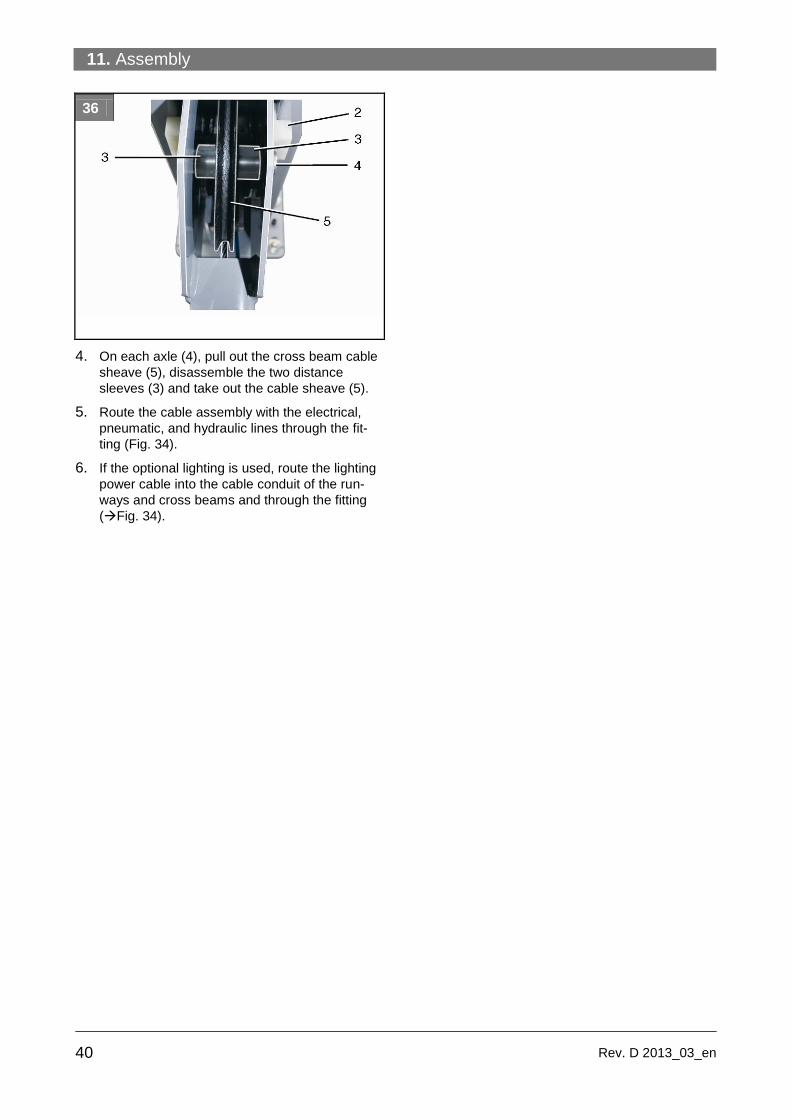
11. Assembly
40 Rev. D 2013_03_en
36
4. On each axle (4), pull out the cross beam cable
sheave (5), disassemble the two distance
sleeves (3) and take out the cable sheave (5).
5. Route the cable assembly with the electrical,
pneumatic, and hydraulic lines through the fit-
ting (Fig. 34).
6. If the optional lighting is used, route the lighting
power cable into the cable conduit of the run-
ways and cross beams and through the fitting
(Fig. 34).

11. Assembly
41 Rev.D 2013_03_en
37
6. Connect the pneumatic lines of the adjustable
runway to the two T-connectors ( Pneumatic
circuit diagram).
7. For variants with rolling jacks:
Route the hydraulic line of the adjustable run-
way in the cross beams and through the fitting
(Fig. 34).
11.7 Set up the cables
38
1. Pull out the 4 cables according to the cable
diagram through the cross beam and route them
out of the cross beams. They must protrude
from the cross beam by about the same dis-
tance.
ATTENTION Malfunction if cables are crossed
or slack.
Ensure that the cables are pulled tight within
the cross beam and are not crossed.
2. Fit the cross beam cable sheaves ( Fig. 30
and 33). To do so, insert the cable sheave and
the two distance sleeves into the cross beam for
each cross beam. Slide the greased axle into
the side and secure the guide.
11.8 Fasten the runways to the cross
beams
39
1. Align the fixed and adjustable runways with the
cross beam mounting holes (S) at the front and
back. In doing so, make sure that the cables
and lines are in the correct position. Cables
must not fall out of the grooves of the sheaves.
For alternative mounting positions for the ad-
justable runways, see Pos. (L) and (R).
40
2. Check the difference in length between the two
lift diagonals (between the corner points of the
cross beams). Maximum allowed difference be-
tween the two diagonals = 6 mm.
Difference in diagonals < 6 mm

11. Assembly
42 Rev. D 2013_03_en
3. Fit the two runways to the cross beams with the
supplied M10 bolts ( Fig. 39).
Tightening torque table in Nm where = 0,12
Thread Property class
5.6 8.8 10.9 12.9
M 4 1.3 3 4.6 5.1
M 5 2.7 5.9 8.6 10
M 6 4.7 10.1 14.9 17.4
M 8 11.3 24.6 36.1 42.2
M 10 22.9 48 71 83
M 12 39 84 123 144
M 14 62 133 195 229
M 16 96 206 302 354
M 18 133 295 421 492
M 20 187 415 592 692
4. Check diagonal length. Correct the alignment if
necessary.
11.9 Insert the latch bars
41
Insert the 4 latch bars into the safety locks. To do
so:
1. Push the roller with the cam shaft to the back
(arrow), so that there is a small gap.
2. Insert latch bar and slide almost to the floor
(leave a small gap for the lift column base
plate).
11.10 Assemble the lift column
Proceed as follows on all 4 lift columns. Make sure the lift column with the control unit is
correctly positioned.
1. Set down the lift column onto the assembly po-
sition with a forklift truck.
2. Slide the lift column from the back onto the latch
bar and align approximately with a plumb line.
42
3. Equalize any slight differences in height with the
screws (S). Place spacers underneath in each
case.
Equalize greater differences in height with
shims (optional accessories). Make sure there
is no differences in height between the lift col-
umns (max. height difference between the
4 lift columns = 5 mm).
43
4. SM 40 series and SM 40 LT series only:
Slide the lift columns onto the two guides of the

11. Assembly
43 Rev.D 2013_03_en
cross beams leaving a 1 mm gap and align pre-
cisely using a spirit level.

11. Assembly
44 Rev. D 2013_03_en
44
SM60 series only:
fasten the right and left slider blocks G to the lift
column each with 3 bolts. Then slide the latch
bar into the slider blocks.
Slide on the lift column onto the two cross beam
guides leaving a gap of 1 mm and align precise-
ly with a spirit level (see Fig.43).
5. Mark the 4 anchoring holes on the floor and for
each lift column and drill (Ø 16 mm,
130 mm deep). Clean the drill holes.
6. Insert all 16 anchor bolts into the holes. Use a
rubber mallet if necessary.
Approved anchor bolts
Manufacturer Type Thread
MKT Anchor bolt BZ plus M16
MKT Anchor bolt BZ plus A4 or HCR
M16
MKT Injection system VMZ (chem.)
105/M16 125/M16 145/M16
HILTI HVZ (chem.) M16x105
HILTI Through bolt anchor HST, HST-R and HST-HCR
M16
Fischer Anchor bolt FAZ II M16
Fischer High-bond anchor FHB II (chem.)
M16x95
Würth FAZ M20 M16
Anchor bolt clamping zone
The clamping zone for these anchor bolts is
the sum of the non-bearing flooring plus the
thickness of the column base plateof 12 mm.
7. Fit the 4 lift columns onto the shims with ap-
proved nuts and bolt locking devices. Select the
tightening torque according to the bolt manufac-
turer’s specifications. Also consider the on-site
conditions.
DANGER
Risk of fatal injury if lift columns
are not secured properly. Lift or
load could topple or collapse.
Comply with the specified torque on each bolt.
If this is not possible, repair the floor according
to specifications (Chapter 11.3), otherwise
commissioning cannot be carried out.
11.11 Attach the latch bars and cables
Proceed as follows on all 4 lift columns.
Series SM40 and SM40 LT:
45
Series SM60
46
i

11. Assembly
45 Rev.D 2013_03_en
1. Insert the supplied threaded pins (2) from above
through the top plate of the lift column and at-
tach using 2 lock nuts (1) with washers for each
pin ( Fig. 45 and 46).
2. Insert the threaded pin (2) from above into the
latch bar.
3. Adjust the latch bar (3) using the hex nuts (1) in
such a way that it lies in a circular recess on the
floor but does not make contact with the floor.
4. Tighten the hex nuts at top and bottom slightly,
but do not yet tighten them fully.
5. Lock at the top using the M20 lock nut.
6. Screw the threaded sleeve (4) for the cable (5)
into the top plate from below so that the cable is
lightly tensioned. Do not yet secure the cable.
7. Secure the threaded sleeve at the top with an
M20 lock nut and then with a jam nut.
11.12 Attach the flexible hose
47
8. Route the cable assembly with the electrical,
pneumatic and hydraulic cables through the
flexible hose into the control box.
9. Make sure that the flexible hose sits securely in
the metal fitting of the fixed runway.
10. Then tighten the 2nd metal fitting on the control
box.
11.13 Assemble the hydraulics module
Only qualified staff with specialist knowledge and
experience of hydraulics may work on hydraulic
equipment.
Always follow the safety regulations in the hy-
draulic power unit instructions in the annex to
this manual.
The hydraulic power unit with motor and tank is
supplied separately and is assembled as follows:
1. Screw the 4 threaded pins with rubber pads (2)
into the lift columns.
CAUTION
Risk of injury from heavy hydraulic
power units.
If possible, assemble the complete unit in
pairs.
2. Attach the complete hydraulic power unit to the
4 threaded pins with the mounting plate (3), fit
spacers and secure with self-locking nuts.
48

11. Assembly
46 Rev. D 2013_03_en
3. Connect the supply lines (Fig. 49, arrow) to the
hydraulic block.
● SM40LT with 2 emergency manual valves
metallic fittings for main lift
black fittings for rolling jacks
● SM40, AR43-5MB, SM55-M51VAS and SM60
with 1 emergency manual
valve
4. Open the tank cap and fill the tank with 11 liters
of hydraulic oil. For approved hydraulic oil types,
seeChapter 9.4.
49
50

12. Electrical connections
47 Rev.D 2013_03_en
12. Electrical connections
12.1 Safety instructions for connecting
power cables
Electrical connection work may only be carried
out by qualified electricians.
Before commissioning, check the mains voltage
of the building wiring. This must match the spec-
ified post lift voltage (see Annex or wiring dia-
gram in the control box).
The connection to the mains supply must be
hard-wired!
The mains supply cable from the fuse box to the
control box of the post lift must be hard-wired
according to the wiring diagram. No plug outlets
must be used.
The motor is designed for clockwise phase rota-
tion. The direction of rotation must be checked
during connection (if necessary, reverse the po-
larity!).
A motor protection switch designed for rated
current and rated voltage must be fitted as over-
load protection. This must be provided by the lift
user (not supplied).
All leads/cables/hoses must be routed in cable
conduits. Trip hazards must be avoided in the
traffic and work zone.
All main switches must be switched to “O” when
working on the electrics of this machine. The
mains power supply must be disconnected at
the fuse box (disconnect the mains fuse) and
isolated to prevent accidental reconnection. A
clearly visible warning sign must be attached
accordingly.
12.2 Connect the lift power supply
51
1. Disconnect the mains fuse and attach a sign
warning against reconnection.
2. Connect the cable assembly terminals to the
corresponding connectors. The connectors are
coded so that only matching terminals can be
connected.
Connect 4 terminals to main lift, one terminal for
rolling jack.
3. Feed the hydraulic supply lines and power ca-
bles from below through the lower knock-out in
the control box and connect to the hydraulic
power unit ( Annex, Power unit operating in-
structions, hydraulics diagram).
4. Check the voltage, current and power ratings on
the information plate. Make sure the approved
structural conditions for connecting the power
cables are in place.
DANGER
Risk of electrocution. Faulty elec-
trical work may lead to critical inju-
ry and also to damage to property.
Always follow the instructions below.
Proper installation and commissioning must be
documented in the inspection logbook.
Use the form "Initial safety inspection before
installation“.

12. Electrical connections
48 Rev. D 2013_03_en
5. Remove the motor connection box cover and
route a 5-core power cable through the cable
gland into the connection box accordingly.
52
6. Route 2-core thermal contact switch power ca-
bles (Fig. 52) accordingly through the cable
gland into the connection box and connect them
(circuit diagram in annex).
7. Establish a mains connection (Fig. 52 and 53)
● Standard configuration with 400 V connection
(3+N+PE): W2 – U2 – V2 bridge.
● Alternatively 3 x 230 V- connection:
Change the wiring on the transformer (arrow,
Fig. 54) to 230 V.
Remove the six M5 nuts in the motor connection
box, bridge U1–W2, V1–U2, W1–V2 according
to the diagram and tighten the nuts again.
8. Make sure that the equipment is properly
earthed. Do not connect the earth conductor to
gas, water, or telecommunications installations.
9. Attach the motor connection box cover.
10. Check the direction of rotation of the motor (see
also direction of the arrow on the motor). To do
so, close the control box, connect the mains
fuse, turn the main switch to "ON“ and push the
Up button. Reverse the polarity if the direction of
rotation is incorrect.
53
54

13. Commissioning
49 Rev.D 2013_03_en
13. Commissioning
13.1 Test the pneumatic and hydraulic
system
The pneumatic connections must be established
on-site by the user.
1. Only connect the pneumatic line to the pneu-
matic female coupler.
2. Set the air pressure on the manometer to 6 ... 8
bar.
3. Set the main switch to ON.
4. Move the unloaded lift to full rise and the bottom
position several times using the Up and Down
buttons. This will completely remove any air
pockets in the hydraulic system.
5. For variants with rolling jacks, move the unload-
ed rolling jacks up and down several times.
6. Carry out a visual inspection of the hydraulic
and pneumatic system. In doing so, check all
lines, especially the couplings. No leaks must
be found.
7. Lower the lift and rolling jack completely and
check the hydraulic oil level. This must also
correspond to the maximum level.
8. Finally check that the hydraulic and pneumatic
hoses and components are fitted securely.
13.2 Test the safety mechanism
Test the “Lower in the danger zone” Function
1. Raise the main lift around ½ m with the Up but-
ton.
2. Push the Down button. The lowering process
must stop at a height of around 120 mm (foot
protection).
3. Push the Down button and Lock button together
until the main lift has been lowered completely.
A buzzer sounds constantly during the lowering
process.
4. Test the safety shut-off for the rolling jack in the
same way.
Test the "Anti-Misalignment“ on the rolling jacks
5. Raise the rolling jacks with the Up button.
6. Mask the photosensors between the runways.
7. Push the Down button (whilst turning the selec-
tor to main lift and rolling jack respectively).
The Down function must be deactivated. Neither
the main lift nor the rolling jacks may be low-
ered.
8. Remove the adhesive strips on the photosen-
sor.
Test the "Slack cable” function
9. Lock the main lift to the latch bars with the Lock
button. Press the button until the cables are
completely slack.
10. Push the Electronic Alignment Control button
(Chapter 6) together with the Up button until
the cables are tensioned and the buzzer switch-
es off.
Test the “broken cable” function
1. Ensure that no vehicle is on the lift or the rolling
jacks (lift unloaded).
2. Raise the main lift by around 1 m with the Up
button.
3. Place a wood block under a cross beam directly
next to a lift column and lower the main lift with
the Down button.
4. Lower the main lift onto the wood block, until the
lift column cable is slack.
The lowering process must now automatically
stop and the locking latch (lock cams into the
latch bar) must engage.
An alarm sounds. All functions on the control
unit, with the exception of the Rolling Jack
Down function must now be out of order.
5. Push the Electronic Alignment Control button
(Chapter 6) together with the Up button until
the cable is tensioned again and the buzzer
switches off.
6. Now carry out the test (steps 2 to 5) on the oth-
er lift columns.
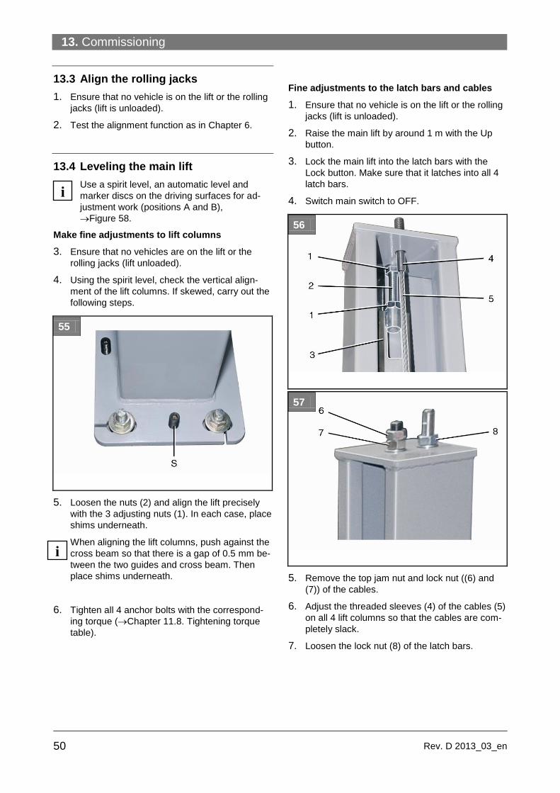
13. Commissioning
50 Rev. D 2013_03_en
13.3 Align the rolling jacks
1. Ensure that no vehicle is on the lift or the rolling
jacks (lift is unloaded).
2. Test the alignment function as in Chapter 6.
13.4 Leveling the main lift
Use a spirit level, an automatic level and
marker discs on the driving surfaces for ad-
justment work (positions A and B),
Figure 58.
Make fine adjustments to lift columns
3. Ensure that no vehicles are on the lift or the
rolling jacks (lift unloaded).
4. Using the spirit level, check the vertical align-
ment of the lift columns. If skewed, carry out the
following steps.
55
5. Loosen the nuts (2) and align the lift precisely
with the 3 adjusting nuts (1). In each case, place
shims underneath.
When aligning the lift columns, push against the
cross beam so that there is a gap of 0.5 mm be-
tween the two guides and cross beam. Then
place shims underneath.
6. Tighten all 4 anchor bolts with the correspond-
ing torque (Chapter 11.8. Tightening torque
table).
Fine adjustments to the latch bars and cables
1. Ensure that no vehicle is on the lift or the rolling
jacks (lift is unloaded).
2. Raise the main lift by around 1 m with the Up
button.
3. Lock the main lift into the latch bars with the
Lock button. Make sure that it latches into all 4
latch bars.
4. Switch main switch to OFF.
56
57
5. Remove the top jam nut and lock nut ((6) and
(7)) of the cables.
6. Adjust the threaded sleeves (4) of the cables (5)
on all 4 lift columns so that the cables are com-
pletely slack.
7. Loosen the lock nut (8) of the latch bars.
i
i

13. Commissioning
51 Rev.D 2013_03_en
58
8. Place markers A and B on the driving surfaces.
9. Using the automatic level, measure the distanc-
es between markers A and B for each lift col-
umn.
59
10. Using the adjusting nuts (1) adjust all 4 latch
bars so that the two driving surfaces are aligned
with a crosswise height tolerance of
± 1 mm and diagonal tolerances of
± 2 mm.
11. Tighten the adjusting nuts (1) of the 4 lift col-
umns (lock them).
12. Then secure the lock nut at the top (Fig. 57,
Pos. 8.)
13. Tension the threaded sleeves (4) of the cables
(5) on the 4 lift columns slightly.
14. Turn the main switch to ON and lower the main
lift to the floor.
The rolling jacks are already height adjusted
ex works and do not need to be leveled.
Adjust the cables
1. Drive a vehicle with a total weight of 2000 kg
centered onto the main lift. Make sure that the
vehicle is also centered laterally on both run-
ways.
2. Push the Up button until all cables are ten-
sioned and the acoustic alarm switches off.
3. Raise the main lift by around 1 m with the Up
button.
4. Use the threaded sleeves (4) to adjust the ca-
bles (5) on all 4 lift columns so that they are
evenly tensioned.
5. Secure the 4 threaded sleeves at the top with
an M20 lock nut and jam nut (Fig. 57, Pos. 6
and 7).
i

14. Wheel alignment kit AK... (optional)
52 Rev. D 2013_03_en
14. Wheel alignment kit AK... (op-
tional)
14.1 Supplied parts
Wheel alignment Kit for post lift types SM40, ,
AR43-5MB, SM55-M51VAS SM40LT, and SM60,
consisting of
(2 parts of each):
Adjustable filler plate
Fixed filler plate
Slip plate
Optional: Turning radius gauge for the relevant
wheel alignment system
14.2 Assembly
These post lifts can be combined with wheel align-
ment systems from different manufacturers.
The post lifts must be converted for use. Thus, on
each runway the base plate at the front and back
must be replaced by filler plates and slip plates from
the wheel alignment kit.
On each side:
1. Remove the base plate on the approach side
(drive-on ramp side).
2. Insert the slip plate so that both bolts protrude
from the underside of the runway.
60
3. Secure the slip plate (use the corresponding
thread locker and nuts).
4. Insert the two locking pins ("B“).
5. Remove the base plate on the drive-off side
(automatic ramp chock end).
61
6 Insert the filler plate in such a way that all bolts
protrude from the underside of the runway.
If an optional turntable is used, use the adjusta-
ble filler plate, the turning radius gauge and the
small filler plate.
Depending on the wheel base, insert the adjust-
able filler plate before or behind the turning ra-
dius gauge.
62
7 Then adjust the gap with the adjustment screw
"S“so that all components lie one behind the
other with small gaps in between.
8 Secure the slip plate (use the corresponding
thread locker and nuts).
9 Insert the turntable locking pins.

14. Wheel alignment kit AK... (optional)
53 Rev.D 2013_03_en
14.3 Adjustment work
63
1. To begin making adjustments, first roughly level
the runways.
2. To do so, adjust the 4 cables in such a way that
the loaded runways of the lift are horizontal both
lengthwise and diagonally.
To do this, place a spirit level onto the surface
of the runway first lengthwise and then onto the
cross beam.
64
3. Lock the lift into the latch bar.
4. Adjust the cables with the nuts on the cable
end. Then lock the nuts. Make sure that all
latches are at the same height.
Adjust the runways according to the requirements of
the vehicle manufacturer. To do so, the following
measuring equipment is required:
● Automatic level
● Measuring stand with scale in mm.
5. Drive the vehicle onto the lift so that the front
wheels stand on the turning radius gauge and
the rear wheels on the slip plate.
The vehicle must come to a halt virtually cen-
tered on the lift in the direction of motion.
6. Loosen the lock pins on the turning radius
gauge and slip plates. Make sure that the vehi-
cle can now slip easily on the plates and that
no tension exists so that the adjustment work
can be carried out precisely.
7. Now lower the lift into the bottom position.
65
8 Position the automatic level so that the meas-
uring stands can be seen positioned one be-
hind the other on the wheel footprints.
9 For each wheel footprint, note the measure-
ments according to the scale on the measuring
stand.
10 Using the 4 cross beam adjustment screws in
the "bottom position“, (Fig. 25) adjust the
height so that the readings from all 4 measur-
ing points are the same after they have been
checked again.
66
11. This concludes the initial adjustment work (initial
measurement).
14. Wheel alignment kit AK... (optional)
54 Rev. D 2013_03_en
12. Then lift the runways when loaded with the ve-
hicle to the desired working height and lower in-
to the four latch bars with the Lock button.
13. Make a note of the 4 measurements of the
wheel footprint at this height.
14. Adjust the latch bars. To do so, loosen the jam
nuts on the threaded rods and raise or lower the
latch bar with the adjusting nut. Make sure that
all 4 wheel footprints have the same height
reading.
15. Then tighten the jam nuts of the threaded rods
again.
16. Archive the measurement report with the updat-
ed measurements.
For your safety, lock the post lift in the 4
latch bars during wheel alignment (locking
latch). Only then may work be carried out
in the danger zone and only then can
wheel alignment be carried out precisely.
i
15. Disassembly
55 Rev.D 2013_03_en
15. Disassembly
Disassembly work may only be carried out by
authorized qualified staff.
Only qualified electricians may work on the elec-
trics.
Only trained persons with specialist knowledge
of hydraulics/pneumatics may work on the hy-
draulic or pneumatic equipment.
1. To carry out disassembly work, switch off the
equipment at the main switch (position OFF).
2. Disconnect the mains fuse and attach a warning
sign to prevent reconnection.
3. Switch off the compressor unit (compressor unit
manometer to 0 bar) and disconnect the line to
the post lift.
4. Disconnect the electricity supply.
WARNING
Risk of fatal injury through incor-
rect disassembly of hydraulic
components. These are pressur-
ized (up to
200 bar).
Never disassemble hydraulic components (lift
cylinders). These should always be detached
as a single component.
The lift cylinder should only be properly dis-
posed of by a certified company.
5. Empty the hydraulic oil tank, drain the hydrau-
lic oil from the hydraulic hoses. Dispose of the
hydraulic oil as described in Chapter 16.
6. Remove grease and other chemical sub-
stances. Dispose of as described in Chapter
16.
7. Disassemble lift columns, cross beams and
runways (Chapter 10 and 11).
16. Disposal
16.1 Environmental procedures for dis-
posal
Prevent environmental hazards.
Avoid contact with or inhalation of toxic sub-
stances such as hydraulic fluid.
Oils and lubricants are water pollutants under the
terms of the Water Management Act WGH. Al-
ways dispose of these in an environmentally
friendly manner in compliance with the regula-
tions which apply in your country
Hydraulic oil-based on mineral oil is a water pol-
lutant and is combustible. Refer to the relevant
safety data sheet for disposal.
Provide suitable oil drain pans and oil absorbents
to drain the oil.
Ensure that no hydraulic oil, lubricants, or clean-
ing materials contaminate the soil or wash away
into the drainage system.
16.2 Packaging
Do not dispose of with domestic waste! The packag-
ing contains some recyclable material which must
not disposed of with domestic waste.
1. Dispose of packaging materials in compliance
with local regulations.
16.3 Oils, grease, and other chemical
substances
1. When working with oil, grease and other chemi-
cal substances, comply with the environmental
regulations which apply to the relevant product.
2. Dispose of oil, grease and other chemical sub-
stances in compliance with the environmental
regulations which apply in your country.
16.4 Metals / Electronic waste
This must always be properly disposed of by a certi-
fied company.

56 Rev. D 2013_03_en


16.
58
BlitzRotary GmbH Tel +49.771.9233.0 USA: +1.812.273.1622 (Headquarter)
Hüfinger Straße 55 Fax +49.771.9233.99 Canada: +1.905.812.9920
D-78199 Bräunlingen [email protected] United Kingdom: +44.178.747.7711
www.blitzrotary.com Australasia: +60.3.7660.0285