ELECTRO-HYDRAULIC OVERHEAD TWO-POST LIFT
22
1 Aston® Overhead Two Post Lift AL-100RH User’s Manual Version: V3.0 Serial No.: Production Date: ELECTRO-HYDRAULIC OVERHEAD TWO-POST LIFT For Models: AL-100RH (10,000 lbs./4.5T) Aston Technologies, Inc. www.astontechusa.com
Transcript of ELECTRO-HYDRAULIC OVERHEAD TWO-POST LIFT
1 Aston® Overhead Two Post Lift AL-100RH User’s Manual
Version: V3.0
Serial No.:
Production Date:
ELECTRO-HYDRAULIC
OVERHEAD TWO-POST LIFT
For Models: AL-100RH (10,000 lbs./4.5T)
Aston Technologies, Inc.
www.astontechusa.com

2 Aston® Overhead Two Post Lift AL-100RH User’s Manual
This instruction manual is an essential integral part of this product. Please read all instructions.
• Properly keep this manual for use during the maintenance.
• This equipment is only used for its clearly designed purpose, and never use it for other purposes.
• The manufacturer is not responsible for any damage caused by improper use or other purposes of use.
PRECAUTION
• Only the qualified personnel having undergone special training can operate this machine. Without the
permission of the manufacturer or not following the requirement of the manual, any changes in the
machine part and in the usage of scope may cause direct or indirect damage to the machine.
• Don’t keep the lift in the extreme temperature and humidity environment. Avoid installation beside the
heating equipment, water tap, air humidifier or stove.
• Prevent the lift from contacting large amount of dust, ammonia, alcohol, thinner or spray adhesive, and
prevent it from rain shower.
• During the machine operation, non-operators should be kept away from the machine.
• Inspect machine daily, do not use lift with damaged parts or being damaged. Use original components to replace
damaged parts.
• The lift can’t be overloaded. The rated load of the lift is already marked on the nameplate.
• Please don’t raise the lift when there are people in the vehicle. During the operation, the customer and
spectators shouldn’t stand in the lifting area.
• Keep the lifting area free from obstacle, grease, machine oil, garbage and other impurities.
• Position the swing arm of the lift, making it contact the lifting point as recommended by the manufacturer. Raise the
carriage and confirm the lifting pad and vehicle are closely contacted. Raise the carriage to the appropriate working
height.
• For some vehicles, the parts dismantling (or installation) will cause severe deviation of the center of gravity, leading to
unstable vehicle. The support is needed to keep the balance of the vehicle.
• Before moving the vehicle away from the lifting area, please position the swing arm and lifting pad back away to avoid
blockage during the movement.
• Use appropriate equipment and tools as well as safety protection facilities, e.g. working uniform, safety boot etc.
• Pay special attention to various safety marks attached to the machine body.
• Keep hair, loose clothing, fingers, and all parts of body away from moving parts.
• Pay special attention not to dismantling the safety unit of the machine or making it not functioning.
• The hydraulic oil used for this lift is N32 or N46.
• Let components cool down before storage, loosen component cables completely in storage.
• Do not install lift in the open air or expose to rain.
OWNER / EMPLOYER OBLIGATIONS
1. The Owner/Employer shall ensure that lift operators are qualified and that they are trained in the safe use and
operation of the lift using the manufacturer’s operating instructions.
2. The Owner/Employer shall establish procedures to periodically inspect the lift in accordance with the lift
manufacturer’s instructions, American National Standard for Automotive Lifts - Safety Requirements for
Operation, Inspection and Maintenance; and the Employer shall ensure that the lift inspectors are qualified and that

3 Aston® Overhead Two Post Lift AL-100RH User’s Manual
they are adequately trained in the inspection of the lift.
3. The Owner/Employer shall maintain the periodic inspection and maintenance records recommended by the lift
manufacturer’s instructions, American National Standard for Automotive Lifts - Safety Requirements for
Operation, Inspection and Maintenance.
4. The Owner/Employer shall display the lift manufacturer’s operating instructions; American National Standard for
Automotive Lifts - Safety Requirements for Operation, Inspection and Maintenance; and in the case of frame
engaging lifts, Vehicle Lifting Points/Quick Reference Guide for Frame Engaging Lifts in a conspicuous location
in the lift area convenient to the operator.
5. The Owner/Operator shall provide necessary lockout/tagout means for energy sources, Safety Requirements for the
Lockout/Tagout of Energy Sources, before beginning any lift repairs and maintenance.
6. The Owner/Employer shall not modify the lift in any manner without the prior written consent of the manufacturer.
IMPORTANT SAFETY INSTRUCTIONS
When using this lift, basic safety precautions should always be followed, including the following:
1. Read all instructions in this manual and on the lift thoroughly before installing, operating, servicing or maintaining the
lift.
2. Care must be taken as burns can occur from touching hot parts.
3. Do not operate equipment with a damaged cord or if the equipment has been dropped or damaged – until it has been
examined by a qualified service person.
4. Do not let a cord hang over the edge of the table, bench, or counter or come in contact with hot manifolds or moving fan
blades.
5. If an extension cord is necessary, a cord with a current rating equal to or more than that of the equipment should be used.
Cords rated for less current than the equipment may overheat. Care should be taken to arrange the cord so that it will not
be tripped over or pulled.
6. Always unplug equipment from electrical outlet when not in use. Never use the cord to pull the plug from the outlet.
Grasp plug and pull to disconnect.
7. Let equipment cool completely before putting away. Loop cord loosely around equipment when storing.
8. To reduce the risk of fire, do not operate equipment in the vicinity of open containers of flammable liquids (gasoline).
9. Adequate ventilation should be provided when working on operating internal combustion engines.
10. Keep hair, loose clothing, fingers, and all parts of body away from moving parts.
11. To reduce the risk of electric shock, do not use on wet surfaces or expose to rain.
12. Use only as described in this manual. Use only manufacturer’s recommended attachments.
13. ALWAYS WEAR SAFETY GLASSES. Everyday eyeglasses only have impact resistant lenses, they are not safety
glasses.
14. Inspect lift daily. Do not operate if it malfunctions or problems have been encountered.
15. Never attempt to overload the lift. The manufacturer’s rated capacity is shown on the identification label on the power
side column. Do not override the operating controls or the warranty will be void.
16. Before driving vehicle between the towers, position the arms to the drive through position to ensure unobstructed
clearance. Do not hit or run over arms as this could damage the lift and/or vehicle.
17. Only trained and authorized personnel should operate the lift. Do not allow customers or bystanders to operate the lift or
be in the lift area.

4 Aston® Overhead Two Post Lift AL-100RH User’s Manual
18. Position the lift support pads to contact the vehicle manufacturers recommended lifting points. Raise the lift until the
pads contact the vehicle. Check pads for secure contact with the vehicle. Check all arm restraints and insure they are
properly engaged. Raise the lift to the desired working height.
19. Some pickup trucks may require an optional truck adapter to clear running boards or other accessories.
20. NOTE: Always use all 4 arms to raise and support vehicle.
21. Caution! Never work under the lift unless the mechanical safety locks are engaged.
22. Note that the removal or installation of some vehicle parts may cause a critical load shift in the center of gravity and may
cause the vehicle to become unstable. Refer to the vehicle manufacturer’s service manual for recommended procedures.
23. Always keep the lift area free of obstruction and debris. Grease and oil spills should always be cleaned up immediately.
24. Never raise vehicle with passengers inside.
25. Before lowering check area for any obstructions.
26. Before removing the vehicle from the lift area, position the arms to the drive-thru position to prevent damage to the lift
and /or vehicle.
27. Do not remove hydraulic fittings while under pressure.
WARNING! Failure by purchaser to provide the recommended mounting surface could result in unsatisfactory lift performance,
property damage, or personal injury.
LOCATION This lift has been evaluated for indoor use only with an operating ambient temp. range of 41- 104°F (5 - 40°C). It is
prohibited to install this product outdoors. Failure to adhere will result in decertification, loss of warranty, and possible
damage to the equipment.
For additional safety instructions regarding lifting, lift types, warning labels, preparing to lift, vehicle spotting, vehicle lifting,
maintaining load stability, emergency procedures, vehicle lowering, lift limitations, lift maintenance, good shop practices,
installation, operator training and owner/employer responsibilities,please refer to “Lifting It Right” (ALI/SM) and “Safety Tips”
(ALI/ST) and vehicle lift points for service garage lifting SAE J2184.
For additional instruction on general requirements for lift operation, please refer to “Automotive Lift-Safety Requirements for
Operation, Inspection and Maintenance” (ANSI/ALI ALOIM). Installation shall be performed in accordance with ANSO/ALI
ALIS, Safety Requirements for Installation and Service of Automotive Lifts.

5 Aston® Overhead Two Post Lift AL-100RH User’s Manual
TABLE OF CONTENTS
1.Safety…………………………………………….………………………………………………………...7
1.1 Introduction…………………………………………………………………………………………….. ...7
1.2 Symbols……………...……..…………………………………………………………………………..…7
1.3 Intended Use……………...……………………………………………………………………………….7
1.4 Safety Instruction for Commissioning…………………………………………………………………….7
1.5 Safety Instruction for Operation…………………………………………………………………………..7
1.6 Safety Instruction for Servicing…………………….……………………………………………………..8
1.7 Safety Features……………………………………………………………………………………………8
1.7.1 Dead Man's Type Control…………………….…………………………………………………………8
1.7.2 Equalizing System………………………………………………………………………………………8
1.7.3 Collision Prevention Switch…………………………………………………………………………….8
1.7.4 Pinch Point Protection…………………………………………………………………………………..8
1.7.5 Automatic Arm Restraint…………………............…………………………………………………...8
1.7.6 Pipe Break Valve………………………………………………………………………………………..8
1.7.7 Pressure Relief Valve…………………………………………………………………………………8
2. Specifications…………………………………………………………………………………………….8
3. Installation…………………………………………………………………………….. …………….....10
3.1 Important Concrete and Anchoring Information………………….……………………………………..10
3.2 Anchoring Tip Sheet………………………….………………………………………………………….10
3.3 Installation Procedure……………………...…….………………………………………………………11
4. Operation……………………………………………………………………………………………….12
4.1 Preparations……………………………………………………………………………………………13
4.2 Raising………………………...…………………………………………………………………………13
4.3 Locking ………………………………………………………………………………………………..14

6 Aston® Overhead Two Post Lift AL-100RH User’s Manual
4.4 Lowering…………………………………………………………………………………………………14
5. Maintenance…………………………………………………………………………………………….14
5.1 Daily Pre-Operation Check………………………...…………………………………………………... 14
5.2 Weekly Maintenance………………………...…………………………………………………………..15
5.3 Yearly Maintenance……………………………………………………………………………………...15
6. Troubleshooting………………………………………………………………………………………...15
Appendix………………………...…………………………………………………………………………..17
Parts List…………………………………………………………………………………………………...19
Warranty……………………….………….…………..…………………….…………………………….22

7 Aston® Overhead Two Post Lift AL-100RH User’s Manual
1. SAFETY
1.1 Introduction
Thoroughly read this manual before operating the lift and
comply with the instructions. Always display the manual in
a conspicuous location.
Personal injury and property damage incurred due to non-
compliance with these safety instructions are not covered
by the product liability regulations.
1.2 Symbols
Failure to comply with instructions could result
in personal injury.
Failure to comply with instructions could result
in property damage.
Important information
1.3 Intended Use
The lift is designed for the safe lifting of automotive
vehicles. Observe the rated load capacity and load
distribution of the lift.
Load Distribution Front
Model No. Load Capacity
Minimum Maximum
AL-100RH 10,000 lb. 2: 3 3: 2
● The lift may be installed and commissioned by
authorized service personnel only.
● The standard lift version may not be installed and
commissioned in the vicinity of explosives or
flammable liquids, outdoors or in moist rooms (e.g.
car wash).
1.5 Safety Instructions for Operation
● Read the operating manual.
● Lift operation by authorized personnel over 18 years
only.
● Always keep the lift and lift area clean and free of
tools, parts, debris etc.
● Once the disk adapters contact the lift points, check
arm restraints for engagement.
● After raising the vehicle briefly, stop and check the
disk adapters for secure contact.
● Always lift the vehicle using all four adapters.
● Make sure the vehicle doors are closed during raising
and lowering cycles.
● Closely watch the vehicle and the lift during raising
and lowering cycles.
● Do not allow anyone to stay in lift area during raising
and lowering cycles.
● Do not allow anyone on lift or inside raised vehicle.
● Only use the lift for its intended purpose.
● Comply with the applicable accident prevention
regulations.
In principle, the lift is
designed for both approach
directions.
For a long service life, we
recommend using the short
support arms for engaging
the engine side of the
vehicle.
1.4 Safety Instructions
for Commissioning
● Do not overload the lift. The rated load capacity is
indicated on the lift nameplate.
● Only use the vehicle manufacturer’s recommended lift
points.
● After positioning the vehicle apply the parking brake.
● Use caution when removing or installing heavy
components (center-of-gravity displacement).
● The main switch serves as emergency switch. In case
of emergency turn to position 0.

8 Aston® Overhead Two Post Lift AL-100RH User’s Manual
● Protect all parts of the electrical equipment from
humidity and moisture.
● Protect the lift against unauthorized usage by
padlocking the main switch.
1.6 Safety Instructions for Servicing
● Maintenance or repair work by authorized service
personnel only.
● Turn off and padlock the main switch before doing
any maintenance, or repair work.
● Work on pulse generators or proximity switches by
authorized service personnel only.
● Work on the electrical equipment by certified
electricians only.
Once the lift is raised, the arm restraints are locked
automatically to avoid any swivel under load.
1.7.6 Pipe Break Valve
The hydraulic cylinders are equipped with pipe break
valves. They respond in case of rapid pressure drop (line
break) to prevent sudden lowering movements.
1.7.7 Pressure Relief Valve
A pressure relief valve is used to limit the hydraulic
working pressure to a maximum of 150 bar.
2. SPECIFICATIONS
See following pages.
● Ensure that ecologically harmful substances are
disposed of only in accordance with the appropriate
regulations.
● Do not use high pressure/steam jet cleaners or caustic
cleaning agents. Risk of damage!
● Do not replace or override the safety devices.
1.7 Safety Features
1.7.1 Dead Man's Type Control
The operator is required to hold the controls in the engaged
position to raise or lower the lift.
1.7.2 Equalizing System
The lift is provided with equalizing cables to ensure level
movement of both carriages.
1.7.3 Collision Prevention Switch
A rope-operated limit switch prevents collisions between
vehicle roof and cross member.
1.7.4 Pinch Point Protection
During lowering cycles, the support arms automatically
stop at a height of 120 mm above bottom position.
To lower the arms completely, release the "Lower" button
and press the "Lower to bottom position" button. Lift travel
to the lower limit stop is accompanied by an audible signal.
1.7.5 Automatic Arm Restraint
The properties indicated apply to lifts running at
operating temperature.
9 Aston® Overhead Two Post Lift AL-100RH User’s Manual
-3-

10 Aston® Overhead Two Post Lift AL-100RH User’s Manual
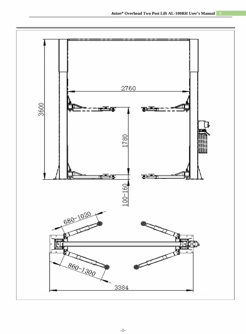
Model No. AL-100RH
Capacity 10,000 lbs./4.5T
Min. Height 100 mm
Max. Lifting Height 1900 mm
Overall Height 3600 mm
Overall Width 3384 mm
Width between Columns 2760 mm
Short Arm Length 680 mm~1020 mm
Long Arm Length 860 mm~1300 mm
Lifting Time Approx. 50 Sec.
Lowering Time Approx. 30 Sec.
Anchoring M18
Concrete grade min. C20/25(DIN 1045:2001-07)
Motor power 2.2KW
Rated current 14.6A
Fuse protection 16 A time delay
Power supply 3~400V+N+PE
Sound pressure level ≤75dB(A)
Specifications are subject to change without notice.
3.1 IMPORTANT CONCRETE AND
ANCHORING INFORMATION
● Concrete shall have compression strength of at least
3,000 PSI and a minimum thickness of 4" in order to
achieve a minimum anchor embedment of 3 1/4”.
When using the standard supplied 3/4” x 5 1/2” long
anchors, if the top of the anchor exceeds 2 1/4” above
the floor grade, you DO NOT have enough
embedment.
● Use the existing holes in column base plate as a guide
for drilling the 3/4” diameter holes into the concrete.
Maintain a 6” minimum distance from any slab edge
or seam. Hole to hole spacing should be a minimum 6
1/2” in any direction. Concrete thickness or hole depth
should be a minimum of 4”.
CAUTION: DO NOT Install on asphalt or other
similar unstable surface. Columns are supported only by
anchoring in floor.
● Using the horseshoe shims provided, shim each
column base as required until each column is plumb.
If one column has to be elevated to match the plane of
the other column, full size base shim plates should be
used (Reference Shim Kit). Torque anchors to 120 ft-
lbs. Shim thickness MUST NOT exceed 1/2” when
using the 5 1/2” long anchors provided with the lift.
Adjust the column extensions plumb.
● If anchors do not tighten to 150 ft-lbs. Installation
torque, replace concrete under each column base with
a 4' x 4' x 6" thick 3,000 PSI minimum concrete pad
keyed under and flush with the top of existing floor.
Let concrete cure before installing lifts and anchors.
3.2 ANCHORING TIP SHEET

11 Aston® Overhead Two Post Lift AL-100RH User’s Manual
● Anchors must be at least 6” from the edge of the slab
or any seam.
● Use a concrete hammer drill with a carbide tip, solid
drill bit the same diameter as the anchor, 3/4”. (.775
to .787 inches diameter). Do not use excessively worn
bits or bits which have been incorrectly sharpened.
● Keep the drill in a perpendicular line while drilling.
● Let the drill do the work. Do not apply excessive
pressure. Lift the drill up and down occasionally to
remove residue to reduce binding.
● Drill the hole to depth equal to the length of anchor.
● For better holding power blow dust from the hole.
● Place a flat washer and hex nut over threaded end of
anchor, leaving approximately 1/2 inch of thread
exposed carefully tap anchor. Do not damage threads.
Tap anchor into the concrete until nut and flat washer
are against base plate. Do not use an impact wrench to
tighten. Tighten the nut, two or three turns on average
concrete (28-day cure). If the concrete is very hard
only one or two turns may be required. Check each
anchor bolt with torque wrench set to 120-foot pounds.
3.3 INSTALLATION PRECEDURE
PLEASE READ THIS INSTRUCTION
BEFORE STARTING TO OPERATE THE LIFT.
Check for ceiling clearance first to confirm the
lift can be set up in your bay.
STEP 1: After unloading the lift, place it near the intended
installation location.
STEP 2: Remove the shipping bands and packing
materials from the unit.
STEP 3: Open the wrapping from the upper column and
carefully remove the parts from inside. Remove the
packing brackets and bolts holding the two columns
together (do not discard bolts, they are used in the assembly
of the lift)
STEP 4: Position the columns facing each other 107-1/4”
inside base plates Square the columns by measuring
diagonally from corner points on base plates (within 1/4”).
STEP 5: Using a 3/4" concrete drill, drill the anchor holes
in the main side column, installing anchors as you go. Use
a block of wood or rubber mallet to drive anchor bolts in.
Drill to a minimum depth of 4" to insure maximum holding
power. Drilling thru concrete (recommended) will allow
the anchor to be driven thru the bottom if the anchor needs
to be replaced later.
STEP 6: Using a level, check column for side-to-side
plumb and front-to-back plumb. If needed, use horseshoe
shims provided by placing shims underneath the base plate
and around the anchor bolt. This will prevent bending the
column bottom plates (Shim thickness should not exceed
1/2”). Tighten anchor bolts to 120 ft-lbs.
STEP 7: Install the overhead cross beam. Be sur e to bolt
them together by installing the bolts from inside the cross
beam out. This is to avoid interference with the cable when
operating the lift. Next, install the cross beam between two
columns.
STEP 8: After fastening the cross beam, check and
confirm that the remaining column is plumb.
STEP 9: Secure the remaining column by duplicating
STEP 6 and STEP 7.
STEP 10: Install the safety latch on both side columns. Connect the safety release cable between two latches.

12 Aston® Overhead Two Post Lift AL-100RH User’s Manual
Check that the tension of the cable is tight. Pull the single
point release handle several times and check the tension
again by making sure both latches release at the same time
when the handle is pulled.
STEP 11: Mount the power unit on the main side leg to the
power unit bracket using the four 5/16” bolts and nuts.
Connect the power unit to the fitting in- stalled on the back
of the main leg by using a short hose supplied.
STEP 12: Connect the equalizing cables. Do not tighten at
this stage of assembly.
NOTE: The cable stud that connects to the front
right corner of the carriage should be connected first by
pulling the stud through the carriage hole and up where
it is easy to be held by locking pliers. Pull the stud back
into place after threading at least 1/2” of the stud past the
locknut. Connect the other ends to the rear right corners
of the carriage with at least 1/2” of thread showing past
the lock nut (cables run on the inside of the carriage). It
may be necessary to manually raise both carriages above
the cylinder to provide enough space to use the locking
pliers. Make sure the carriage is set in the LOCK position.
STEP 17: Locate each hole in the center of the up-rights,
approximately 6” below the top edge, on the same side of
the columns as the power unit. Install the two eye-bolts to
the outside of each up-right with the hardware provided.
STEP 18: Insert the cable through the eye-bolt in the slave
column side and secure with crimp fitting. Run cable across
to the motor column side through the eye-bolt and down to
the motor. Insert cable through the pull-pin on top of the
motor and temporarily secure with locking pliers or small
clamp.
Operate lift and apply pressure to the safety cable to insure
motor shuts off prior to any part of vehicle coming in
contact with cross rail.
Adjust cable if necessary and secure with crimp fitting. Remove any excess cable with wire cutters.
STEP 19: Do not place any vehicle on the lift at this time.
Cycle the lift up and down several times to insure latches
engage properly and all air is re- moved from the system.
To lower the lift, first raised the lift to clear the latches and
then pull down the safety release handle to lower lift. lf
latches function out of sync, tighten the cable on the latch
that engages first.
STEP 13: Adjust the carriage cable tension. This is 4. OPERATION
accomplished by tightening the carriage adjustment nut on top of each carriage. The rear carriage adjustment nut
adjusts the opposite post carriage height. The left post
carriage nut adjusts the right column carriage, and the right
column carriage nut adjusts the left column carriage.
Adjust each cable to approximately 1/2” side-to-side play.
Check the latch releases to insure the carriage is still
engaged in the appropriate latch.
STEP 14: Install all four swing arms, readjust the arm lock
preinstalled to make sure that gear racks are engaging the
moon gear on the arm properly.
STEP 15: Remove the vent plug from the power unit and
fill the reservoir. Use a Ten Weight (SAE-10) non-foaming,
non-detergent hydraulic fluid (Texaco HD46 or equal). The
unit will hold twelve quarts of fluid.
STEP 16: Make the Electrical hookup to the power unit.
Warning: the wiring must comply with local
code. Have a certified electrician make the electrical hook
-up to the power unit.
Lift operation by authorized personnel over 18
years only.
Apply the parking brake after positioning the vehicle on
the lift.
Do not allow anyone to stay in lift area during raising
and lowering cycles. Closely watch the vehicle and the lift
during raising and lowering cycles.
Observe the rated load capacity and load distribution Do
not allow anyone to climb on lift or stay inside vehicle.
After raising the vehicle briefly, stop and check adapters
for secure contact.
Once the disk adapters contact the lift points, check arm
restraints for engagement. Make sure the vehicle doors
are closed during raising and lowering cycles.
In case of defects or malfunctions such as jerky lift
movement or deformation of the superstructure, support

13 Aston® Overhead Two Post Lift AL-100RH User’s Manual
or lower the lift immediately. Turn off and padlock the
main switch. Contact qualified service personnel.
4.1 Preparations
Each support arm is provided with an automatic arm
restraint which unlatches automatically when the lift is in
bottom position.
When the carriages are in a raised position, the arm
restraint can be disengaged by pulling the release pin.
● Fully lower the lift and swing the arms to full drive-
through position.
● Turn the disk adapters that they evenly contact all four
lift points.
Once the disk adapters contact the lift points,
check arm restraints for engagement. If necessary,
slightly move the arms until the gear segments mesh.
Never unlatch the arm restraints when the lift is under
load.
● Leave vehicle and remain clear of lift.
Always lift the vehicle using all four adapters.
4.2 Raising
During raising and lowering cycles: Closely
watch the vehicle and the lift, do not allow anyone to stay
in lift area and make sure the vehicle doors are closed.
Once the disk adapters contact the lift points, check arm
restraints for engagement. After raising the vehicle
briefly, stop and check adapters for secure contact.
● Press button on power unit.
Lift stops once button is released or upward travel limit is
reached.
When vehicle is in raised position:
● Observe all accident prevention regulations.
● Do not allow unauthorized persons to stay under the
raised vehicle.
● Avoid rocking of vehicle.
● Keep lift free of tools, parts, etc.
● Fasten the vehicle to the support arms using lashing
straps when removing or installing heavy components.
● Slowly position vehicle midway between adapters.
Apply the parking brake.
● Swing and telescope arms as required to position
adapters under vehicle manufacturer's recommended
lift points.

14 Aston® Overhead Two Post Lift AL-100RH User’s Manual
4.3 Locking
● The latch mechanism will 'trip over' when the lift
raises and drop into each latch stop. But, to lock the
lift you must press the lowering lever to relieve the
hydraulic pressure and let the latch set tight in a lock
position.
5. MAINTENANCE SCHEDULE
The following periodic maintenance is the suggested
minimum requirements and minimum intervals;
accumulated hours or monthly period, which ever comes
sooner. If you hear a noise or see any indication of
impending failure-cease operation immediately-inspect,
correct and/or replace parts as required.
WARNING-USERS SHOULD ALWAYS
INSPECT LIFTING EQUIPMENT AT THE START OF
EVERY SHIFT. THESE AND OTHER PERIODIC
INSPECTIONS ARE THE RESPONSIBILITY OF THE
USER.
5.1 DAILY PRE-OPERATION CHECK (8
HOURS)
Always lock the lift before going under the
vehicle. Never allow anyone to go under the lift when
raising or lowering. Read the safety procedures in the
manual.
The user should perform daily check.
ATTENTION! LOOK OUT! Daily check of safety latch
system is very important - the discovery of device failure
before needed could save you from expensive property
damage, lost production time, serious personal" injury
and even death.
Note: It is normal for an empty lift to lower
slowly. It may be necessary to add weight.
4.4 Lowering
During raising and lowering cycles: Closely
watch the vehicle and the lift, do not allow anyone to stay
in lift area and make sure the vehicle doors are closed.
● Raise the lift until the latches clear the safety racks in
both sides.
● Pull down and hold the safety release handle.
Warning: Always make sure safety latches on
both sides clear the rack at same time when pulling down
the release handle by adjusting the cable.
● Press the lever at the power unit to lower the lift.
● Check safety lock audibly and visually while in
operation.
● Check safety latches for free movement and full
engagement with rack.
● Check hydraulic connections, and hoses for leakage.
● Check chain connections - bends, cracks-and
looseness.
● Check cables connections- bends, cracks-and
looseness.
● Check for frayed cables in both raised and lowered
position.
● Check snap rings at all rollers and sheaves.
● Check bolts, nuts, and screws and tighten.
● Check wiring & switches for damage.
● Keep base plate free of dirt, grease or any other
corrosive substances.
● Check floor for stress cracks near anchor bolts.

15 Aston® Overhead Two Post Lift AL-100RH User’s Manual
● Check swing arm restraints.
5.2 WEEKLY MAINTENANCE (40 HOURS)
● Check anchor bolts torque to 150 ft-lbs for the 3/4''
anchor bolts.
Do not use impact wrench.
● Check floor for stress cracks near anchor bolts.
● Check hydraulic oil level.
● Check cylinder mount for looseness and damage.
Relocating or changing components may cause problems.
Each component in the system must be compatible; an
undersized or restricted line will cause a drop-in pressure.
All valve, pump, and hose connections should be sealed
and/or capped until just prior to use. Air hoses can be used
to clean fittings and other components. However, the air
supply must be filtered and dry to prevent contamination.
Most important - cleanliness - contamination is the most
frequent cause of malfunction or failure of hydraulic
equipment.
● Check and tighten bolts and nuts, and screws.
● Check cylinder puller assembly for free movement or
excessive ware on cylinder yoke or pulley pin.
● Check cable pulley for free movement and excessive
ware.
5.3 YEARLY MAINTENANCE
● Lubricate chain.
● Grease rub blocks and column surface contacting rub
blocks.
● Change the hydraulic fluid, good maintenance
procedure makes it mandatory to keep hydraulic fluid
clean. No hard-fast rules can be established, operating
temperature, type of service, contamination levels,
filtration, and chemical composition of fluid should be
considered. If operating in dusty environment shorter
interval may be required.
The following items should only be performed
by a trained maintenance expert. ● Replace hydraulic hoses.
● Replace chains and rollers.
● Replace cables and sheaves.
● Replace or rebuild air and hydraulic cylinders as
required.
● Replace or rebuild pumps / motors as required.
● Check hydraulic and air cylinder rod and rod end
(threads) for deformation or damage.
6. TROUBLE SHOOTING
See the following page.

16 Aston® Overhead Two Post Lift AL-100RH User’s Manual
Issue Reason Action to take
Breaker or fuse blown Call electrician.
Motor does not run. Motor thermal overload tripped Wait for overload to cool.
Faulty wiring connections Call electrician.
Defective up button Call electrician for checking.
Push handle down and push the up button at the A piece of trash is under check valve same time. Hold for 10-15 seconds. This should flush the system.
The clearance between the plunger Check the clearance between the plunger valve of Motor runs but does not valve of the lowering handle is too the lowering handle. There should be 1/16". rise. small.
Dirty on the ball and seat of check Remove the check valve cover and clean ball and valve. seat.
Oil level too low.
Oil level should be just under the vent cap port when the lift is down!!
Oil blows out breather of Lift lowered too quickly while under a Remove excessive weight from lift. heavy load.
power unit:
Oil reservoir overfilled. Reduce the oil to the oil level.
Impeller fan cover is dented. Take off and straighten.
Faulty wiring Call electrician.
Motor hums and does not
Bad capacitor Call electrician. run.
Low voltage Call electrician.
Lift overloaded Remove excessive weight from lift.
Lift jerks going up and Raise lift all the way to top and return to floor; Air in hydraulic system Repeat 4-6 times. Do not let this overheat power
down. unit.
Oil leaks around the tank-mounting Check the oil level in the tank. The level should be
flange. Oil reservoir overfilled. two inches below the flange of the tank. Check
with a screwdriver.
Oil leaks Oil leaks around the rod end of the cylinder. The rod seal of the cylinder is Rebuild or replace the cylinder.
out.
Oil leaks around the breather end of the cylinder. The piston seal of the cylinder Rebuild or replace the cylinder. is out.
Leg of the lift is dry and requires grease. Grease the legs.
Lift makes excessive noise. Cylinder pulley assembly or cable Grease the pulley assembly. pulley assembly is not moving freely.
May have excessive wear on pins or Replace the pins or cylinder yoke. cylinder yoke.

17 Aston® Overhead Two Post Lift AL-100RH User’s Manual
APPENDIX
18 Aston® Overhead Two Post Lift AL-100RH User’s Manual
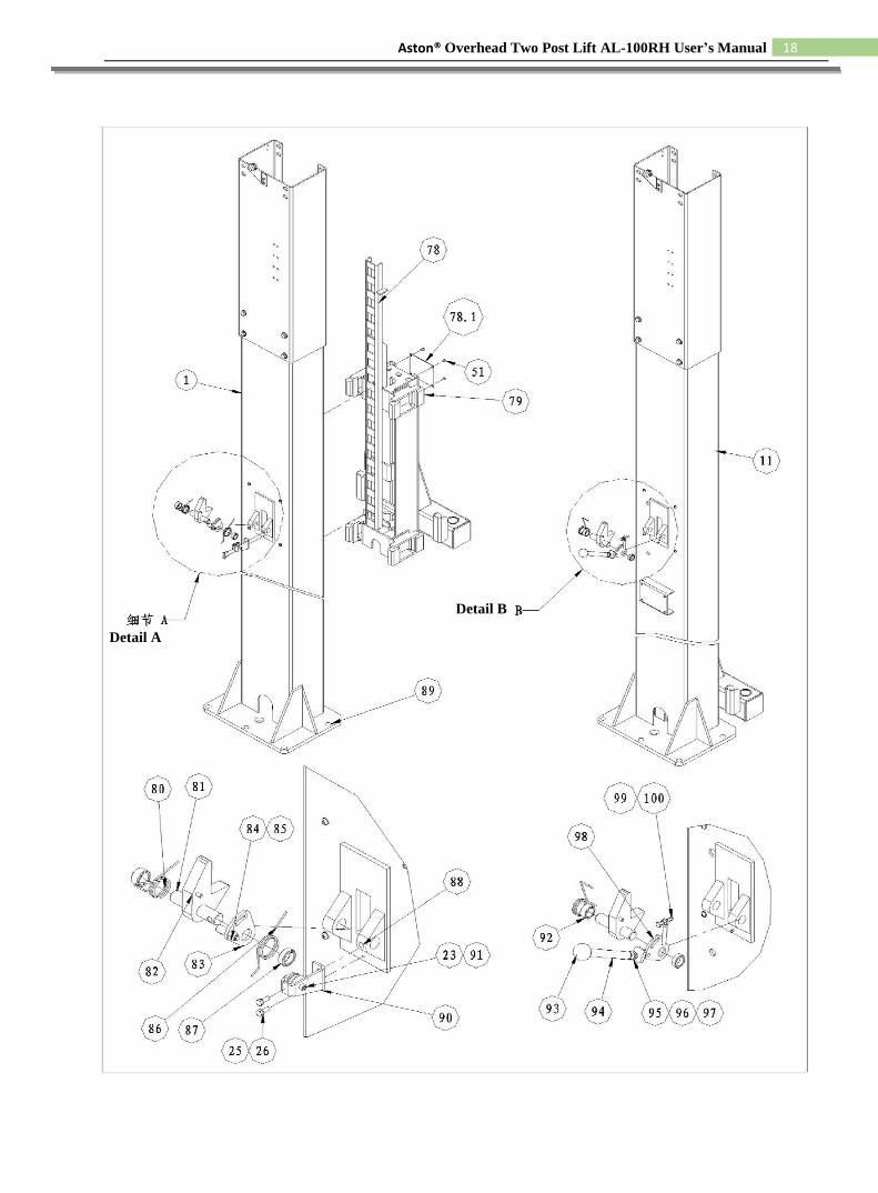
Detail A
Detail B

19 Aston® Overhead Two Post Lift AL-100RH User’s Manual
PARTS LIST
No. Symbol Name Quantity Remark
1 TT9D-100-01B-00 Assistant column 1 Weld assembly
2 TT9D-100-02-00 Extension 2 Weld assembly
3 TT9D-300-01-00 Arm 2 Weld assembly
4 TT9D-300K-01-00 Arm 2 Weld assembly
4.1 TPF4-400-04-00 Pad support weld assembly 2 Weld assembly
4.2 TPF4-400-01A Rubber pad 2
4.3 GB819-85 cross recessed countersunk head
4 M8X16 screw
5 GB70-85 hexagon socket head cap head
4 M6X20 screw
6 DL38G-F100A Rubber pad 4
7 TT9D-300-03-00 Pad support 4 Weld assembly
8 GB894.1-86 Spindle circlip 4 d25
9 TT9D-300-02 Move swivel nut 4 Black
10 GB894.1-86 Spindle spring circlip 8 d45
11 TT9D-100-01A-00 Main column 1 Weld assembly
12 Hydraulic pump 1
13 GB5781-86 hexagon bolt 4 M8X25
14 GB97.2-85 Flat washer 4 d8
15 GB93-87 Spring washer 4 d8
16 GB6170-86 hexagon nut 4 M8
17 DPF4-3.2-200-03 Block 4
17.1 DPF4-3.2-200-10 Compound bush 4
18 GB894.1-86 Spindle spring circlip 4 d19
19 TT9D-400-01-05 Short spacer bush 4
20 TT9D-400-01-03 Long spacer bush 2
21 TT9D-400-01-04 Axle 2
22 GB70-85 Bolt 2 M6X25
23 GB/T889-1968 Locknut 3 M6
24 XG4.5A05-01-01 Trolley 3
25 GB5781-86 Hexangular bolt 10 M6X16
26 GB93-87 Spring washer 10 d6
27 XG4.5A05-01-02 Bracket A 2
28 TT9D-400-01-01-00 Connecting socket 1 1 Weld assembly
29 GB41-86 Hexangular nut 33 M12
30 GB95-85 Flat Washer 30 d12
31 GB5781-86 Hexangular bolt 5 M12X25
32 GB93-87 Spring washer 34 d20
33 GB5781-86 Hexangular bolt 4 M12X30
34 TT9D-400-01-02-00 Connecting socket 2 1 Weld assembly
35 Rubber sponge washer 1
36 DL38G-L103A spindle 2
37 DL38G-L102A Rod 1
38 DL38G-L101A Rod seat 2
39 GB896-86 Open spindle circlip 2 d15
40 TT9D-600-09-00 Vitta support 2 Weld assembly

20 Aston® Overhead Two Post Lift AL-100RH User’s Manual
No. Symbol Name Quantity Remark
42 GB5781-86 Hexangular bolt 24 M12X40
43 GB96-85 Flat washer 32 d12
44 Journey switch 1 TZ-8104
45 TPF4-400-06-00 Spindle weld 4 Weld assembly
46 Ball handle 4 Black Bakelite ball
47 TPF4-200-11-01 Rack shaft 4
48 GB97.2-85 Flat washer 8 d10
49 GB93-87 Spring washer 4 d10
49.1 GB6170-86 Nut 4 M10
50 TPF4-200-11-04 Gear rack 4
51 TPF4-200-11-05 Baffle 4
52 TPF4-200-11-02 Spring 4
53 GB91-86 Open pin 4 d2x25
54 TT9D-500-07-00 Assistant cover 1 Weld assembly
55 TT9D-500-01-00 Main cover 1 Weld assembly
56 GB95-85 Flat washer 8 d6
57 GB818-85 Cross Recess Head Screw 16 M6X8
58 TPF4-500-05 Direct outside fitting 1
59 TPF4-500-07 Hydraulic fitting 1
60 TPF4-500-08 Washer 1
61 TPF4-500-09 Nut 2
62 TT9D-600-02 Hydraulic hose 1 L=320
64 TT9D-600-06 Three-way connection 1
65 TT9D-500-08-00 Safety thin steel cable 1 subassembly
66 TT9D-600-04 Hydraulic hose 1 L=1580
67 TT9D-600-03 Hydraulic hose 1 L=8520
68 TPF4-500-06 Direct inside and outside fitting 2
69 TT9D-600-05-00 Straight joint 2 subassembly
70 GB819-85 crow recessed countersunk head
2 M6X10 screw
71 TT9D-100-03-00 Rope sheave root spindle 2 Weld assembly
72 XG4.5A01-03 Trolley 2
73 Compound bush 2
74 Hydraulic cylinder 2 subassembly
75 TT9D-600-01 Steel cable 2 L=10M
76 GB95-85 Flat washer 4 D20
77 Hexangular nut 4 3/4"-16
78 TT9D-200-01-00 Carriage 2 Weld assembly
78.1 TT9D-200-03 Cover 2
79 TPF4A-200-12 Nylon block 16
80 XG4.5A05-07 Main torsional spring 2
81 XG45A05-11 spindle 2
82 TT9D-500-04-00 Cliver 2
83 TT9D-500-02-03B sector 1
84 TT9D-500-06 nut 1
85 TT9D-500-05 spindle 1

21 Aston® Overhead Two Post Lift AL-100RH User’s Manual
No. Symbol Name Quantity Remark
86 XG45A05-08 Assistant torsional spring 1
87 XG45A05-10 Cover 2
88 GB70-85 Sockets bolt 2 M10X16
89 Expand bolt 10 φ19
90 XG4.5A05-02-02 Bracket B 1
91 GB5781-86 Hexangular bolt 1 M6X35
92 XG4.5A05-09 Cover 2
93 JN/T7271.1-94 Ball handle 1
94 TT9D-500-03 Handle 1
95 GB6170-86 Hexangular nut 1 M10
96 GB95-85 Flat washer C 1 D10
97 GB93-87 Spring washer 1 D10
98 TT9D-500-02-00 Sector 1 Weld assembly
99 GB5781-86 Hexangular bolt 1 M6X35
100 GB6170-86 Hexangular nut 1 M6

22 Aston® Overhead Two Post Lift AL-100RH User’s Manual
LIMITED WARRANTY
Structural Warranty:
The following parts and structural components carry a three-year warranty: Arms, Columns, Carriages, Legs,
Overhead Beam, Tracks Cross Rails, Top Rail Beam, Swivel Pins, Uprights
Limited One-Year Warranty:
Aston® offers a limited one-year warranty to the original purchaser of Lifts in the United States, Canada and
Mexico. Aston® will replace, without charge, any part found defective in materials or workmanship under
normal use, for a period of one year after purchase. The purchaser is responsible for all shipping charges. This
warranty does not apply to equipment that has been improperly installed or altered or that has not been operated
or maintained according to specifications.
Other Limitations:
This warranty does not cover: 1. Parts needed for normal maintenance. 2. Wear parts, including but not limited
to cables, slider blocks, chains, rubber pads and pulleys. 3. Replacement of lift after the first 30 days. A seal kit
and installation instructions will be sent for repairs thereafter. 4. On-site labor: Upon receipt, the customer must
visually inspect the equipment for any potential freight damage before signing clear on the shipping receipt.
Freight damage is not considered a warranty issue and therefore must be noted for any potential recovery with
the shipping company.
The customer is required to notify Aston® of any missing parts within 72 hours. Timely notification must be
received to be covered under warranty. Aston® will replace any defective part under warranty at no charge as
soon as such parts become available from the manufacturer. No guarantee is given as to the immediate
availability of replacement parts.
Aston® reserves the right to make improvements and/or design changes to its lifts without any obligation to
previously sold, assembled or fabricated equipment.
There is no other express warranty on the Aston® lifts and this warranty is exclusive of and in lieu of all other
warranties, expressed or implied, including all warranties of merchantability and fitness for a purpose.
To the fullest extent allowed by law, Aston® shall not be liable for loss of use, cost of cover, lost profits,
inconvenience, lost time, commercial loss or other incidental or consequential damages.
This Limited Warranty is granted to the original purchaser only and is not transferable or assignable. Some
states do not allow exclusion or limitation of consequential damages or how long an implied warranty lasts, so
the above limitations and exclusions may not apply. This warranty gives you specific legal rights and you may
have other rights, which may vary from state to state.