
2-Post Lift Instruction Manual
56
0 2-Post Lift Instruction Manual Model No.:QJ-Y-2-35
Transcript of 2-Post Lift Instruction Manual

0
2-Post Lift
Instruction Manual Model No.:QJ-Y-2-35

1
Statement
All rights reserved! Without the written consent of Yantai Haide Science and
Technology Co., Ltd. , no copy or replicate is allowed by any company or individual in
any format(like electronics, mechanical, copy, record and other format). Please read
this manual carefully before usage,do carefully operation,maintenance and repair by
rules.No obligation is taken by our company if operate not by rules.This manual is
designed for Yantai Haide Science and Technology Co., Ltd. usage, no obligation is
taken if use this manual for other machine.
Manufacturer
Yantai Haide Science and Technology Co., Ltd.
Address: No 14, Wuxi Road, Developed District, Yantai, China
Tel: 86-535-6853129
Fax: 86-535-6853815
Website: www.ythaide.com
Service
Yantai Haide Science and Technology Co., Ltd.
No 14, Wuxi Road, Developed District, Yantai, China
Tel: 86-535-6853129
Fax: 86-535-6853815
Email: [email protected]

2
ATTENTION
The damage during the transportation is due to carrier.
The safety performance is considered during design and
manufacture. Sufficient training and skillful operation can
only make the product safety guaranteed.
All the specifications requested on the machine label must be
obeyed for installation. Only a qualified electrician is allowed
operation.
Read this manual Carefully before usage, any usage or repair
is prohibited before reading this manual.
The company has the right to improve partial structure, no
obligation for update about products sold before.
Make sure lifting arm lock gears are fastened well before
lifting vehicles.
The damage due to overload weight, the user is responsible for
the responsibility.

3
Contents
Chapter I Introduction....................................................................4-6
Chapter II Safety instructions........................................................7-10
Chapter III Method of Packaging and Handling.........................11-12
Chapter IV Installation and Testing.............................................12-24
Chapter V Maintenance...........................................................25-26
Chapter VI Electric Safety...........................................................26-27
Chapter VII Hydraulic System....................................................28-29
Annex:
1. Products Quality Certificate
2. Products Inspectation Report
3. Product Warranty Card
4. Packing List
5. Exploded Diagram

4
Chapter I Introduction
1.1 Overview
Two post hydraulic car lift uses hydraulic power as the power source and with
mechanical security insurance. The lift has the advantages of simple structure, superior
performance, advanced technology, easy operation and safe usage. It is suitable for
vehicle repairing industry such as auto repair shop and auto repair retail-department
and other etc.
1.2 Structural performance
1.2.1 The lift is the Floorplate 2-Post Hydraulic Car Lift which takes the use conditions
of most users into full consideration in structure.The users can install the lift in the
appropriate place according to their own situation.
1.2.2 The hydraulic system uses hydraulic power unit,compact, safe, reliable, easy to
adjust, easy to maintain and has low failure rate. The hydraulic system is with manual
voltage regulator, revolving the overflow valve and screw to adjust systematic pressure
is ok.
Note: The system pressure has been adjusted prior to shipment,the users can
not adjust by themselves.
1.2.3 The lift is with mechanical security lock, simple and reliable in structure.
1.3 Operating system:
1.3.1 When the power is on, press the rise button to achieve the required high, release
the button, the device can be stopped.
1.3.2 Confirm the mechanical lock can lock the slider, if there is no safe locked, press
the down handle to make the slider down so that the mechanical lock can lock the slider.
1.3.3 During working pay attention to the mechanical lock, if the mechanical lock
doesn’t lock the slider effectively, should adjust to make it in the best condition.
5
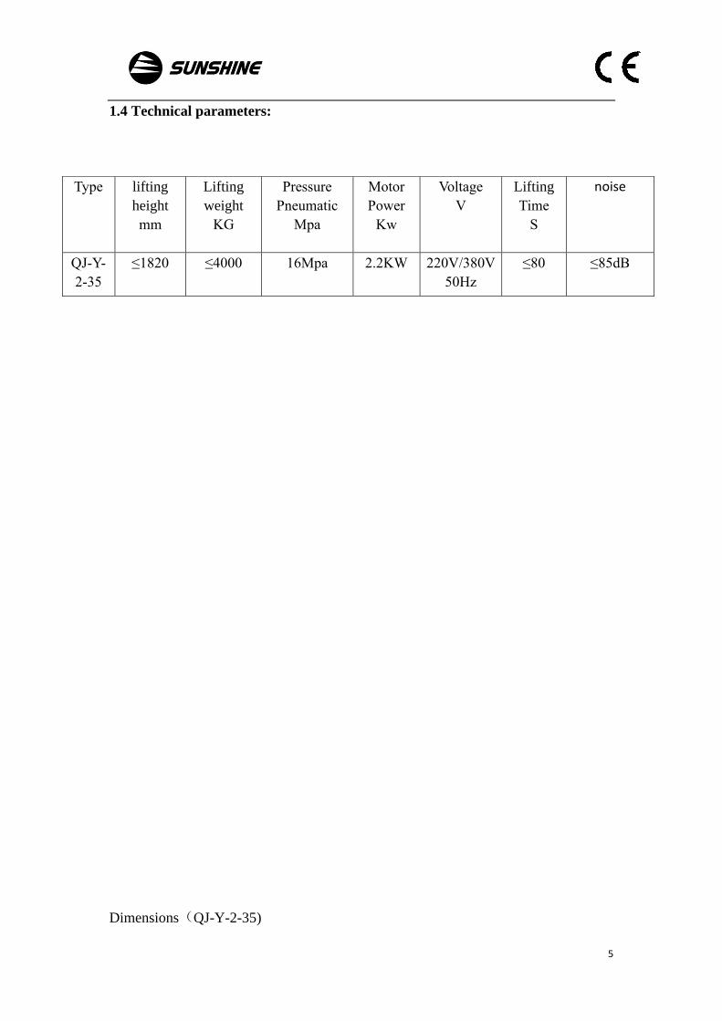
1.4 Technical parameters:
Dimensions(QJ-Y-2-35)
Type lifting
height
mm
Lifting
weight
KG
Pressure
Pneumatic
Mpa
Motor
Power
Kw
Voltage
V
Lifting
Time
S
noise
QJ-Y-
2-35
≤1820 ≤4000 16Mpa 2.2KW 220V/380V
50Hz
≤80 ≤85dB

6
Chapter II, Safety instructions

7
2.1 Safety specification
在 Do not operate the equipment until you carefully read and fully understand the
instructions which the rules contain. Negligence may result in major accidents,
electrical shock or serious personal and property damage.
1. Know your machine
For your personal safety, please carefully read this manual, know applications and
limitations of the machine, and the potential risks associated with the machine.
2. Keep work area clean
Messy area and components can cause accidents.
3. Do not use the machine in dangerous environment
Do not use the machine in wet atmosphere or rain, or exposed to rain, keep work
area in good lighting.
4. Non-professional staff do not close
All visitors must remain a safe distance from the work area.
5. Do not operate the machine by force
Keep the speed of the machine in its design, operate with security implementation
6. Wear appropriate clothing
Avoid wearing loose clothing, gloves, necklaces or jewelry that can be involved
by moving parts, we recommend wearing non-slip shoes, wear the cap long hair can be
wrapped in.
7.Do not maintain the machine in working condition
The machine should be properly maintained on a regular basis, such as lubrication,
adjustment, but certainly don’t maintain it in working condition.
8. You must cut off the power before maintenance and replacing parts.
9. Do not run the machine without people’s charge.
10.machine label

8
2.2 The warning signs

9

10
2.3 Security design description
2.3.1 Hydraulic system adopts hydraulic cylinder to lift. Explosion-proof valve is
used to hydraulic cylinder. Once hydraulic oil pipe explode, damage will not
happen because of lift suddenly goes down.
2.3.2 Steel rope is adopted to the balancing installation to ensure synchronous
lifting.
2.3.3 Lift mechanical lock is unlock and does not work when goes down. But it
works in rest state. So it is safe even when the oil pipe burst or steel wire rope
broken.

11
Chapter III Method of Packaging and Handling
3.1 Packing way:
The lift is packed to be several parts as below:
1 The lift body is wrapped in steel frame, completely covered by unbreakable material,
include all body parts.
2 Power unit and electrical control box (some models without electronic control box)
is packed in cardboard box.
3 We will provide some optional accessories for some client's special requirement.
3.2 lifting and loading、transport:
1 When lifting and loading, must use woven nylon tape with loading-bear strength no
less than 2 tons, and to the center of gravity, to avoid the tape placed in mechanical lock
position. See the Fig. As below.
2. Right equipment and methods must be chose when loading and unloading. Also
ensure the parts is no missing and consider package size、 weight、center of gravity
and breakable parts.
3. Lift must be placed flat and avoid direct sunlight in the warehouse.moisture-proof.
Temperature is -10°C to +40°C.

12
4. After delivery, to check the damage may occur on the way of transport and storage.
And to verify the promise of manufacturer. If the damage occurred during
transportation, the customer should immediately inform the transport company.
5. Be careful when opening the package, to maintain a certain distance. Do not lose
small parts when opening package.
Chapter IV Installation and Testing

13
4.1 Installing tools:
1、 Φ18 churn drill bit
2、 churn drill
3、 12-14、17-19 spanner
4、 adjustable spanner
5、 cross screw driver,flat screw driver
6、 hammer
7、 band tape(5m)
8、 squareness gauge
9、 chalk
4.2 Installation warning
4.3 Choose installation place.
1、 Lift is designed to be installed inside the house, space is no obstacle, well-ventilated.
Shall not be installed near the wash area, paint, paint corrosive solvents stacking area.
if the installation place close to bedroom, may explode, very dangerous. We must avoid
here to install. There are other state regulations on health and safety. Such as minimum
distance from walls or other equipment. Emergency access and other requirements.
2、 Must keep fire far away from lift installation place, the surrounding environment
must be good.
4.4 Installation requirement on ground
Only manufacturers or distributors authorized professional technical personnel may install
the equipment. The installer must have the qualifications. Non-professional installation
may cause serious injury to person or equipment.
Installation according to the chart.

14
1、 Lift must be installed on a minimum thickness of 250 mm, a minimum strength of
300PSI concrete ground.
Specifications of concrete must be strictly enforced, otherwise it will cause
a serious accident.
Installation ground should be level. Should supplement the small uneven
ground level. If the concrete level tolerance is big, should consider re-pouring
concrete.
4.5 Installation
1、According to the instructions in the packing list, to check if is missing parts or
damage parts.
2、 According to foundation chart (Fig.2) to install lift. Using chalk to draw the
installation range of column lift.

15
3、 After marking proper position for lift column, to draw with a rough outline of
column position with chalk, column base as a template.
4、Re-check all the dimensions to ensure that each column of the base shape and
position consistent with the chalk line.
5、 Firstly, place cylinder in the positioning hole in the column bottom, then after fixing
slider to slide, push the slide to bottom of the column from top. Two columns distance
is 2800mm.
6、Base on column bottom hole for position, to drill a hole about 150 mm deep with
churn drill on concrete. To ensure the expansion bolts' fixed-strength, do not get churn
drill shaking when drilling hole. After drilling, with a vacuum cleaner or wire brush to
clean the dust of each hole. Ensure the column in the process to prevent the dumping
or shifting.
7、The nuts should be reserved 3-5mm thread after assembling expansion bolts. Inserted
into the drilled hole, tapping with a hammer until the bolt to the column bottom of the
spring washer parts, then taping pivot bolt until it can not move. Measured vertical
degree of vertical column with squareness gauge .If column vertical degree is large, use
pad to adjust. After vertical adjustment, tighten the nut bolt. nut tightening torque is
about 80N.M.
Anchor bolt installation drawings:

16
The column vertical degree must be guaranteed, otherwise it will
cause lift can not rise or damage to person.
8、Install lift pump station、oil pipe(Fig.3.2),mechanical lock, steel wire rope , limit
switch parts and so on. Fix the balancing steel wire rope (Fig.3.), The slide should be
at bottom when adjusting the balancing steel wire rope. Two steel wire rope keep in
same tightness.
Steel wire rope installation drawings:

17

18
1 Hex nuts M20 8
2 Wire rope 2
Pump station connection diagram:

19
No Name Spec Qty
1 Pump 1
2 Flange nut M8 4
3 Flange hexagonal bolt M8×30 4
Top cover installation drawing:
No Name Spec Qty
1 Top cover 2
2 Top pulley-bottom plate 2
3 Bimetallic bearing 302519 2
4 Pulley side cushion 2
5 Shaft elastic ring φ25 2
6 hex nut M12 8
7 Elastic washer φ12 8
8 Flat washer φ12 8
9 Hexagon headed bolt M12×30 8
Height adaptor installation diagram:

20
No Name Spec Qty
1 Height adaptor bracket 2
2 Elastic washer φ8 4
3 Hexagon head screw M8×12 4
Bottom pulley installation diagram:
No Name Spec Qty
1 Bottom pulley-bottom plate 4
2 Bimetallic bearing 302516 4
3 Pulley side cushion 8
4 Shaft ring φ25 4
Oil pipe connection diagram:

21
No Name Spec Qty
1 Pump station 1
2 Oil pipe 1300 1
3 Barrel connector NPT3/8-M16×1.5-115 2
4 Oil pipe 2830 1
5 Right angle joint NPT3/8-M16×1.5 2
6 Oil cylinder 2
Main oil cylinder installation diagram:
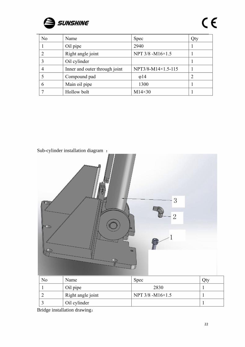
22
No Name Spec Qty
1 Oil pipe 2940 1
2 Right angle joint NPT 3/8 -M16×1.5 1
3 Oil cylinder 1
4 Inner and outer through joint NPT3/8-M14×1.5-115 1
5 Compound pad φ14 2
6 Main oil pipe 1300 1
7 Hollow bolt M14×30 1
Sub-cylinder installation diagram :
No Name Spec Qty
1 Oil pipe 2830 1
2 Right angle joint NPT 3/8 -M16×1.5 1
3 Oil cylinder 1
Bridge installation drawing:

23
No Name Spec Qty
1 Gap bridge 1
2 Flat pad φ12 4
3 Hexagon headed bolt M12×20 4
8、Installation method of unlocking wire:
When install the unlocking wire, please put the circle at one end of the wire around the
small roller’s bushing of the main column’s active rotating board lock, install φ8 flat
washer, and then fasten with M8*20 screw and M8 nut at a point. (Parts at Point a, b,
c, d, e and f will be illustrated in the following pictures). Then make the other end of
the wire (without circle) go upward to circle the nylon roller at b point and then
downward to circle the nylon roller at c point, then keep the wire parallel to the ground
and circle the nylon roller of sub column at c point, make the wire go upward to go
through the fixing board at d point, and go through the dragline bushing. One end of
the dragline bushing is fixed on the dragline fixing board with M8 screw. After the
unlocking wire goes through the dragline bushing, fix the other end of the dragline
bushing at the dragline frame at e point. Then make the unlocking wire go through the
small roller bushing of passive board of sub column at f point. After adjusting the
tightness of unlocking wire, use the wire clip fix the unlocking wire which goes through
the passive rotating board of sub column. Take care that when adjusting the tightness
of unlocking wire, do not make it too loose. When the unlocking wire between the
main and sub columns does not fall naturally, its tightness is OK.

24

25

26
Above is the drawing of parts of point a and b

27
Above is the drawing of parts at point c. The structure of parts at point c of the main
column and the sub column is same.

28
Above is the drawing of parts at point c.

29
Above is the drawing of parts at point e and f.

30
Below please find the parts listed in the above drawings.
Item No. Parts name Specifications Quantity
1 Hex. screw M6*45 1
2 Small nylon roller 3
3 hex nut M6 3
4 hex. screw M8*20 2
5 large pad φ8 3
6 small roller bushing 2
7 hex nut M8 6
8 Hex. screw M6*30 2
9 small roller frame 2
10 Hex. screw M6*10 6
11 dragline fixing board 1
12 Hex. screw M6*25 2
13 dragline bushing 1
14 dragline frame 1
15
9、When the installation position of the lift is confirmed, fix the protective base plate
with 4 plastic expansion bolts on the ground as illustration below.
Then place the gaps on the base plates of the main and sub columns at the extended
parts of the base plate as illustration below.

31
Finally install the oil tube between the main and sub columns, and fix the oil tube with
nylon ribbons which go through the holes in the welded iron part on the base plate. See
illustration below.

32
10、Connect power supply and terminal according to circuit diagram. And make sure
the phase of the connection is correct and the grounding is reliable.
The wiring of the circuit must be connected by a professional electrician
Ensure that the power supply voltage is same with the lift requirements
Make sure the phase connection is correct and that the wrong connection will burn out the motor
and not be covered by the warranty
Pump stations must be kept dry
11、Installation of the arm. Insert the arm into the transverse slot of the carriage,aim
the holes in the carriage’s horizontal tube and the holes of the arm shaft and insert the
arm shaft and then put the circlips on the end of the arm shaft. Then install tray,
auxiliary tray, etc.
4.6 Test and adjustment
1、Please confirm before starting:
Make sure the column is vertical and the arm is horizontal.
Make sure the expansion bolt is fastened.
To ensure that the power supply voltage and motor nameplate requirements are
consistent.

33
Make sure the electrical system is connected correctly and has good grounding.
Make sure the hydraulic pipe is connected correctly.
Ensure adequate space for people and goods in the work area。
2、The tank capacity is 10 L,fill N46 (SY1227-84) hydraulic oil into the tank of the
pumping station and the oil quantity should be between the top and bottom of the fuel
tank scale.
As low winter temperatures, hydraulic oil is more viscous, if necessary, you can choose
more than 32 # 40 # The following high-pressure anti-wear hydraulic oil. filling
lithium grease (GB7324-87) in the internal slider of slider touches , requires top-down
uniform filling
3、First click up button and check whether there is oil on the oil outset within
5seconds.If there's no oil proves the motor reverses, Any two-phase adjustment of the
power steering motor is ok. Press the up button and slider can be increased and repeated
lifting several times, the highest and lowest position, measuring if the height of the two

34
slider are the same, or should be adjusted two ends of the curtain rope slider height until
they are the same; two sliding Height Maximum tolerance is 5 mm.
4、In the trial run of the process, should observe the vibration, noise of lift , whether
the oil leak, pump motor functioning, the implementation of electrical components etc..
5、Do 2-3 times the full load test, simultaneous detection of item 3,4,if there's no problem, just do
repair work
1、Operate strictly in accordance with operating procedures, don't operate lift casually
2、Make sure center of gravity as close as possible to the panel made by two poles. because
center of gravity is different from cars during lifting.
3、The motor reverse is prohibited to avoid damage to the pump during initial installation
4、A comprehensive inspection is needed every half month especially whether three
expansion bolts behind pole panel is loose
5、Hydraulic oil must be a regular manufacturers of high pressure anti-wear hydraulic oil.
6、Observe the oil level frequently to avoid starvation and damage caused by oil pump idle.
7、Always check the working status of mechanical safety lock to make it safe and reliable.
8、Hydraulic valve, system pressure has been adjusted at the factory, the user can not adjust
is casually and should be responsible for the consequences.
9、Repair work, the mechanical safety lock must be effective working state.
Chapter V Maintenance
5.1 Maintenance
Car lift maintenance should pay attention to the following points
1、 Should ensure the cleanliness of lift, There's no obstacles around to avoid crash or
fall during the lifting process, damages to people and equipment
2, Maintain the hydraulic hoses, electrical lines are clean to avoid aging and damaged
Of lines.

35
3、Replace the hydraulic oil every 9-10 months. When empty the oil, used oil should
be put clean out. oil level could be in the middle of the oil gauge when filling the oil.
4, Usually should check the oil level, if below the oil gauge should promptly fill oil to
the mid-line.
5,Obstacles is forbidden in oil tank to avoid damages to oil pump.
6、 Clean up the oil filter every 3 months using Kerosene, hair brush to clean obstacles
on the surface. Be careful not to damage the oil filter, if damaged, should be replaced
immediately
7、 Steel rope and pulley should be painted lubricant frequently and observe if there's
fracture on the rope, if there should be immediately replaced.
8、Check if the column is vertical every 6 months , if vertical change, need to re-adjust,
and tighten the nut, tightening torque of about 80N.M.
5.2 Common faults and solution
No.
faults
solution
1
Two sliding table are not
synchronized
Adjust the nuts on the rope (should be regularly
adjusted after usage)
2
Motor doesn't work check whether the power is on
Check whether the power supply is good
and electricity connection is loosen the wiring to fall
off
3
Motor doesn't work The power is not enough

36
4
motor rotates but lift doesn't
work well
check whether motor connected well, motor reverse
Check whether fuel tank is adequate, inlet tube is off
and the filter is blocked
5
Lift falls automatically after
lifting up
clean one-way valve, shuttle valve, relief valve of
pump station
6
Safety lock doesn't work Check whether safety lock plate is in the right position
check offsetting spring of safety lock plate is off
7
Motors, electrical component
failures
cut off the power timely, check, repair, replacement it
by a professional electrician
8
etc find any other abnormal, please contact us asap.
Chapter VI Electrical safety
6.1Electrical system safety rules
1、 Only person through formal training and have professional knowledge could do
electrical maintenance and troubleshooting.
2、 Do not modify or omit the protective chain devices.
3、 Before starting, read and pay attention to warning signs.
4、When trouble exclusion have been determined, cut off the power, the main switch
must be locked.
5、 Note that the lift is used safely in humid areas to avoid the occurrence of electric
shock
6、 Before the electricity sent to the lift, must stay away from the lift.
7、 Do not open the electrical box, unless the need for inspection for electrical
equipment .
8、 Do not modify the circuit, unless authorized by the manufacturer qualified.

37
9、 When replacing electrical parts, need to determine whether they meet specifications,
including color-coded wires
10、 When operating electrical equipment, do not wear metallic glasses, necklace, etc.
In addition, do not wear rings, watches, bracelets
6.2Electrical schematic diagram:

38
Chapter VII Hydraulic system
7.1 Safety rules for hydraulic systems
1、 Non-professional personnel not allowed to remove gear pumps, control valves,
etc.。
2、 System pressure must not be adjusted at will, exceeding the rated pressure of
pump station will cause damage to gear pump or personal injury。
3、 Hydraulic oil pipe shall not be in contact with sharp object。
4、 Hydraulic oil pipes not to be in contact with corrosive substances.
5、 Hydraulic oil pipe must change if damage or rubber layer aging .
6、 When replacing hydraulic oil pipe, the nominal pressure of the pipe shall not be
less than twice the pressure of the system。
7.2 Hydraulic principle diagram

39
7.3 Hydraulic principle diagram、Interface schematic:
7.4Pump station decomposition diagram:

40
Two post hydraulic auto lift
Quality certification
The product meets requirements of
Q/0601KHD002-2013 standard,is qualified to be out
of factory after check
Serial no:
Legal representative: Inspection charger:
D a te :
Ya n t a i H a i d e S c i e n c e a n d Te c h n o l o g y C o . , L t d .
A d d r e s s : 2 1 . To n g r u n R o a d , A P E C I n d u s t r i a l Z o n e , Z h i f u
D i s t r i c t , Ya n t a i , C h i n a
Te l : 8 6 - 5 3 5 - 6 8 5 3 8 1 2 , 6 8 5 3 8 1 6 ;
S e r v i c e h o t l i n e : 8 6 - 5 3 5 - 6 8 5 3 1 2 9

41
Inspection Report
Product Name:Two post hydraulic car lift
Model :
This product implements Q/0601KHD002-2013 standard. Before
the product leaves the factory, the inspection items and results are as
follows:
No. Inspection item Unit Standard
data
Measured
value
1 Lifting height mm ≤1815
2 Lifting capacity Kg ≤4000
3 Minimum hight mm ≤100
4 System pressure Mpa ≤16
5 Lifting time s ≤80
Inspector:
Date:

42
Product warranty card
User’s company / name
Address and Phone
Description and Model Two Post Hydraulic Car Lift
Ex-work No.
Date acquisition
Dealer’s name
Dear Customer,
Thanks for choosing our lift. With this warranty card and invoice, we will provide our best after service for you according to
relative regulations of the Law of the PRC on the Protection of the Rights and Interests of Consumers. Please read and fill out
the card carefully, and give it to the dealer and our company for the records.
User‘s
obligation
Please fill out this card and affix the official seal when purchasing the device, in triplicates, one for the dealer,
one for our company, and the third one is for you.
This card should be kept well. Should the device fail to operate, this card will be one of the proofs to determine
whether free charge service is available for the device.
This card can only be effective with our company’s official seal.
Warranty
conditions
Should the product fail to operate within one year from the date of purchasing and is confirmed by our company
that it was used in normal conditions and according to the requirements of User’s Manual, we will provide
limited repairing for free.
If the product need to be repaired under warranty, the user should take the warranty card, invoice, and the User’s
Service Sheets filled out by himself to obtain free service. The old components will be possessed by our
company.
Items not in contract maintenance range: Damages due to improper transportation, misapplication, insufficient
ground strength, power disagree with specifications, or operation not according to the User’s Manual. If the
warranty is overdue, and our company is requested to provide service, we will charge based on our company’s
cost price.
※Customer saved

43
Product warranty card
User’s company / name
Address and Phone
Description and Model Two Post Hydraulic Car Lift
Ex-work No.
Date acquisition
Dealer’s name
Dear Customer,
Thanks for choosing our lift. With this warranty card and invoice, we will provide our best after service
for you according to relative regulations of the Law of the PRC on the Protection of the Rights and Interests
of Consumers. Please read and fill out the card carefully, and give it to the dealer and our company for the
records.
User‘s
obligation
Please fill out this card and affix the official seal when purchasing the device, in triplicates,
one for the dealer, one for our company, and the third one is for you.
This card should be kept well. Should the device fail to operate, this card will be one of the
proofs to determine whether free charge service is available for the device.
This card can only be effective with our company’s official seal.
Warranty
conditions
Should the product fail to operate within one year from the date of purchasing and is confirmed
by our company that it was used in normal conditions and according to the requirements of
User’s Manual, we will provide limited repairing for free.
If the product need to be repaired under warranty, the user should take the warranty card,
invoice, and the User’s Service Sheets filled out by himself to obtain free service. The old
components will be possessed by our company.
Items not in contract maintenance range: Damages due to improper transportation,
misapplication, insufficient ground strength, power disagree with specifications, or operation
not according to the User’s Manual. If the warranty is overdue, and our company is requested
to provide service, we will charge based on our company’s cost price.

44
※Distributor saved
Product warranty card
User’s company / name
Address and Phone
Description and Model Two Post\ Hydraulic Car Lift
Ex-work No.
Date acquisition
Dealer’s name
Dear Customer,
Thanks for choosing our lift. With this warranty card and invoice, we will provide our best after
service for you according to relative regulations of the Law of the PRC on the Protection of the Rights
and Interests of Consumers. Please read and fill out the card carefully, and give it to the dealer and
our company for the records.
User‘s
obligation
Please fill out this card and affix the official seal when purchasing the device, in triplicates, one
for the dealer, one for our company, and the third one is for you.
This card should be kept well. Should the device fail to operate, this card will be one of the proofs
to determine whether free charge service is available for the device.
This card can only be effective with our company’s official seal.
Warranty
conditions
Should the product fail to operate within one year from the date of purchasing and is confirmed by
our company that it was used in normal conditions and according to the requirements of User’s
Manual, we will provide limited repairing for free.
If the product need to be repaired under warranty, the user should take the warranty card, invoice,
and the User’s Service Sheets filled out by himself to obtain free service. The old components will be
possessed by our company.
Items not in contract maintenance range: Damages due to improper transportation, misapplication,
insufficient ground strength, power disagree with specifications, or operation not according to the
User’s Manual. If the warranty is overdue, and our company is requested to provide service, we will
charge based on our company’s cost price.

45
※Company saved

46

47

48

49

50

51
No. Code Name Spec Qty Note
1 91012110100 Column welding parta -
main-40
1
2 14020406001 Oil cylinder
2
3 13010100078 Bimetal bearing 302547 2
4 91011110800 Pulley
2
5 14020100001 Oil nipple φ8 2
6 15030100025 Internal and external
straight joint
NPT 3-8 to M14×1.5-
115
1
7 15030200003 Right angle joint NPT 3-8 to M16×1.5 2
8 15030100013 Hollow bolt M14×30 2

52
9 12130100001 Composite mat φ14 2
10 14020208092 Oil pipe L=1300 1
11 91011110400 Buttom pulley-base plate
4
12 13010100015 Bimetal bearing 302516 4
13 91011110700 Pulley side pad
10
14 12090100003 Shaft circlip φ25 6
15 15010000003 Chain LH-125 2
16 21010100056 Column chain pin With the chain 2
17 12080100010 Cotter pin φ2.5×16 8
18 91012110300 Column top cover 4T
2
19 91011110600 Top pulley-base plate
2
20 13010100016 Bimetal bearing 302519 2
21 12030100020 Hex head bolt M12×30 8
22 12050201009 Flat washer φ12 12
23 12050203007 Elastic washer φ12 12
24 12010101005 Hex nuts M12 8
25 91011111100 Curtain bracket-base plate
2
26 12020301028 inner hex screw M6×12 14
27 16030401038 cylinder curtain L=2700 2
28 12010500001 hex nut M6 7
29 14020502065 hydraulic pump
1
30 12030400005 hex bolt M8×30 6
31 12010103002 hex nut M8 6
32 11110300004 limited switch ME8108 1
33 12030400007 hex bolt M5×10 2
34 91030161305 oil pipe clip
2
35 91011111000 adaptor bracket
2
36 12050203005 elastic washer φ8 4
37 12020301013 inner hex screw M8×12 12
38 91013110300 lock pin
2
39 12020400007 inner hex screw M10×12 2

53
40 91013110500 lock bush 10
2
41 91013112500 spring
1
42 12020301032 inner hex screw M6×10 17
43 21013110400 turning plate-3.5A
1
44 21013111300 lock plate
2
45 21011110800 lock plate washer
2
46 91013110400 lock bush 14
2
47 91013112000 spring
2
48 12030400001 hex bolt M6×16 1
49 12020400015 inner hex screw M6×10 1
50 12010101004 hex nut M10 1
51 12100100001 Handle ball M10-φ40 1
52 21013100002 Mechanical lock cover-
main-4.0A
1
53 21013110500 Pulley bracket
1
54 21010300007 Nylon small pulley φ6-φ32-10 3
55 12020301101 Hexagon socket head cap
screw
M6×45 1
56 21011110700 Small pulley bracket
2
57 12030100017 Outer hexagonal bolt M6×30 2
58 21023111500 Unlocking handle
1
59 21013000900 Active wire rope fixing
bolt
1
60 91012110200 Column welding-sub-40
1
61 21013111100 Rotary plate return spring
1
62 91011110900 Passive transfer plate
1
63 91013200002 Electromagnet cover
1
64 21013110600 Cable fixing plate
1
65 12020301007 Hexagon socket head cap
screw
M6×25 2
66 91011111200
91011111000
Cable bracket
1
67 12050202006 Large washer φ8 2
68 21010200021 Small pulley spacer
1

54
69 91012120100 4.0T carriage
2
70 91011120700 Slider
16
71 91011120110 Press plate
8
72 12050203003 Elastic washer φ10 16
73 12020202007 Hexagon socket head cap
screw
M10×25 16
74 91011120600 Pin
4
75 12090100026 Shaft circlip φ38 4
76 91011121300 carriage lock pin
4
77 12020301048 Inner hexagon bolt M8×12 4
78 91013121200 carriage spring
4
79 21010100055 carriage chain pin with the chain 2
80 21013120300 carriage rubber block
2
81 12090100019 shaft circlip φ22 4
82 21013121100 Inner gear A
2
83 21013121200 Inner gear B
2
84 12020301025 inner hexagon bolt M12×20 4
85 91012130100 4T arm R705-1055
2
86 91012130200 extension arm R728-1080
2
87 21010300069 out gear
4
88 12020301042 Inner hexagon bolt M10×20 12
89 12020301017 Inner hexagon bolt M8×25 4
90 12010101003 hexagon screw M8 4
91 21010200020 3 step tray
4
92 12020201013 cross bolt M8×12 8
93 16060400021 rubber pad
4
94 91012130300 4T arm R860-1365
2
95 91012130400 extension arm R883-1390
2
96 12020301025 Hexagon socket head cap
screw
M12×20 4
97 91011140900 floor plate
1
98 14020208091 oil pipe 8-II-2940 1

55
99 15040000006 steel rope φ8-8665 2
100 91011140920 Channel-section steel
1