NuTiny-SDK-NUC029FAE User Manual...NuTiny-SDK-NUC029FAE User Manual Dec. 24, 2014 5 of 21 Rev. 1.01...
21
NuTiny-SDK-NUC029FAE User Manual Dec. 24, 2014 Rev. 1.01 NuTiny-SDK-NUC029FAE User Manual for NuMicro™ NUC029FAE Series The information described in this document is the exclusive intellectual property of Nuvoton Technology Corporation and shall not be reproduced without permission from Nuvoton. Nuvoton is providing this document only for reference purposes of NuMicro ™ microcontroller based system design. Nuvoton assumes no responsibility for errors or omissions. All data and specifications are subject to change without notice. For additional information or questions, please contact: Nuvoton Technology Corporation.
Transcript of NuTiny-SDK-NUC029FAE User Manual...NuTiny-SDK-NUC029FAE User Manual Dec. 24, 2014 5 of 21 Rev. 1.01...

NuTiny-SDK-NUC029FAE User Manual
Dec. 24, 2014 Rev. 1.01
NuTiny-SDK-NUC029FAE User Manual for NuMicro™ NUC029FAE Series
The information described in this document is the exclusive intellectual property of
Nuvoton Technology Corporation and shall not be reproduced without permission from Nuvoton.
Nuvoton is providing this document only for reference purposes of NuMicro™
microcontroller based system design.
Nuvoton assumes no responsibility for errors or omissions.
All data and specifications are subject to change without notice.
For additional information or questions, please contact: Nuvoton Technology Corporation.
NuTiny-SDK-NUC029FAE User Manual
Dec. 24, 2014 2 of 21 Rev. 1.01
Table of Contents
1 Overview ........................................................................................... 3
2 Introduction to NuTiny-SDK-NUC029FAE ............................................... 3
2.1 NuTiny-SDK-NUC029FAE Jumper Description ................................................ 4 2.2 Pin Assignment for Extended Connectors ...................................................... 5 2.3 NuTiny-SDK-NUC029FAE PCB Placement....................................................... 6
3 Starting to Use NuTiny-SDK-NUC029FAE on the Keil μVision® IDE ............ 7
3.1 Downloading and Installing Keil μVision® IDE Software ................................... 7 3.2 Downloading and Installing Nuvoton Nu-Link Driver ....................................... 7 3.3 Hardware Setup ......................................................................................... 7 3.4 Example Program ....................................................................................... 8
4 Starting to Use NuTiny-SDK-NUC029FAE on the IAR Embedded Workbench 9
4.1 Downloading and Installing IAR Embedded Workbench Software ...................... 9 4.2 Downloading and Installing Nuvoton Nu-Link Driver ....................................... 9 4.3 Hardware Setup ......................................................................................... 9 4.4 Example Program ..................................................................................... 10
5 NuTiny-SDK-NUC029FAE Schematics .................................................. 11
5.1 NuTiny-EVB-NUC029FAE Schematic ........................................................... 11 5.2 Nu-Link-Me Schematic .............................................................................. 12
6 Downloading NuMicro™ Related Files from Nuvoton Website .................. 13
6.1 Downloading NuMicro™ Keil μVision® IDE Driver .......................................... 13 6.2 Downloading NuMicro™ IAR EWARM Driver ................................................. 16 6.3 Downloading NuMicro™ NUC029FAE Series BSP Software Library ................... 19
7 Revision History ............................................................................... 21

NuTiny-SDK-NUC029FAE User Manual
Dec. 24, 2014 3 of 21 Rev. 1.01
1 Overview The NuTiny-SDK-NUC029FAE is a specific development tool for NuMicro™ NUC029FAE series-NUC029FAE by which users can develop and verify the application program easily. The NuTiny-SDK-NUC029FAE includes two portions: NuTiny-EVB-NUC029FAE (an evaluation board) and Nu-Link-Me (Debug Adaptor). With the NuTiny-SDK-NUC029FAE, users do not need additional ICE or debug equipment.
2 Introduction to NuTiny-SDK-NUC029FAE The following figure shows the NuTiny-SDK-NUC029FAE for NUC029xAE series, in which the left portion is called NuTiny-EVB-NUC029FAE and the right portion is Debug Adaptor called Nu-Link-Me. The NuTiny-EVB-NUC029FAE is similar to other development board. Users can use it to develop and verify applications to emulate the real behavior. In fact, the real chip NUC029FAE is mounted on the board. The NuTiny-EVB-NUC029FAE can be a real system controller to design user target system. The Nu-Link-Me is a Debug Adaptor which connects the USB port of your PC to your target system (via Serial Wired Debug Port) and allows you to program and debug embedded programs on the target hardware. To use the Nu-Link-Me Debug adaptor with Keil or IAR, please refer to “Nuvoton NuMicro™ IAR ICE Driver User Manual” or Nuvoton NuMicro™ Keil ICE Driver User Manual” for details.
Target Chip ICE Controller
VCC:3.3V or 5V
(JP8)
ICE Controller
USB Connector
(ICEJ2)
GND
(JP3)
VCC
(JP1)
Reset Key
(SW1)
TSSOP-20 pin
Extended Connector
(J4)
TSSOP-20 pin
Extended Connector
(J3)
I/O LED
Power LED
VCC
(JP5)
GND
(JP6)
Figure 2-1 NuTiny-SDK-NUC029FAE (Green PCB Board)
NuTiny-SDK-NUC029FAE User Manual
Dec. 24, 2014 4 of 21 Rev. 1.01
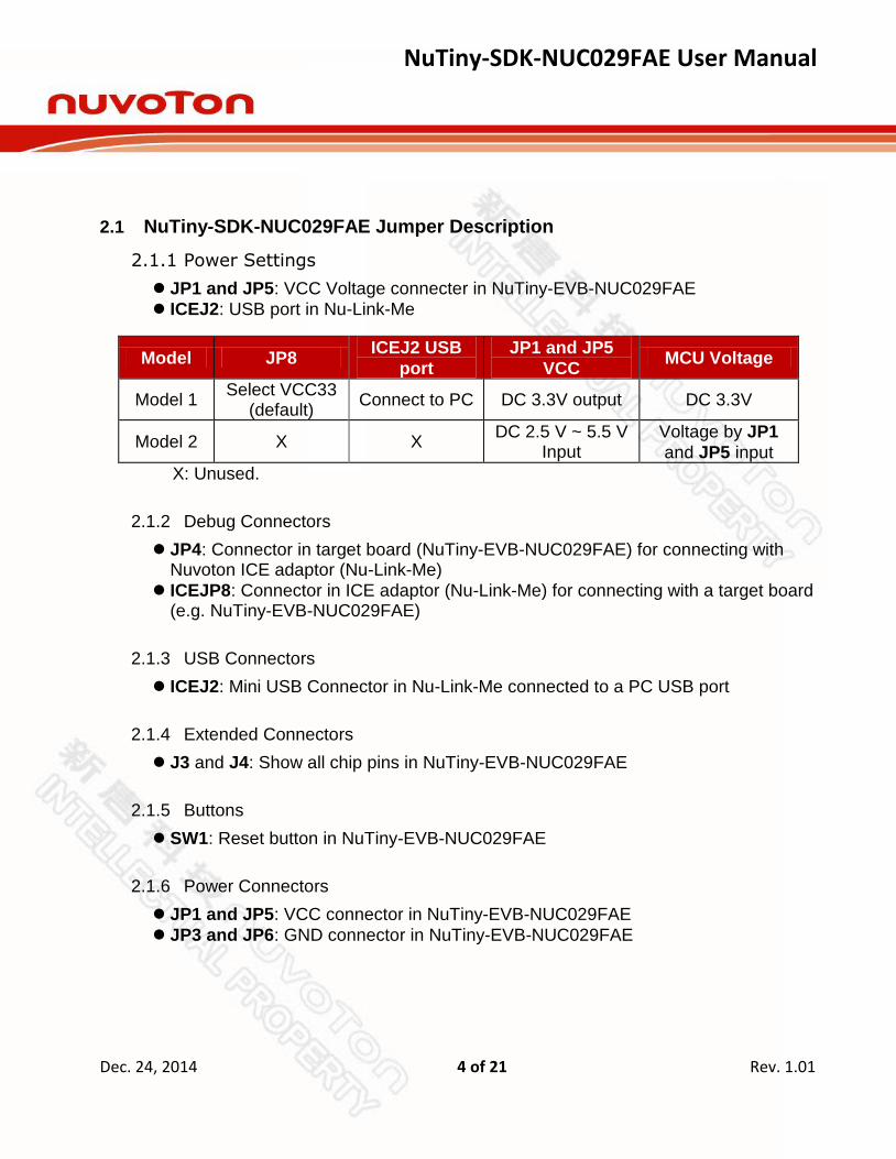
2.1 NuTiny-SDK-NUC029FAE Jumper Description
2.1.1 Power Settings
JP1 and JP5: VCC Voltage connecter in NuTiny-EVB-NUC029FAE
ICEJ2: USB port in Nu-Link-Me
Model JP8 ICEJ2 USB
port
JP1 and JP5
VCC MCU Voltage
Model 1 Select VCC33
(default) Connect to PC DC 3.3V output DC 3.3V
Model 2 X X DC 2.5 V ~ 5.5 V
Input Voltage by JP1
and JP5 input
X: Unused.
2.1.2 Debug Connectors
JP4: Connector in target board (NuTiny-EVB-NUC029FAE) for connecting with Nuvoton ICE adaptor (Nu-Link-Me)
ICEJP8: Connector in ICE adaptor (Nu-Link-Me) for connecting with a target board (e.g. NuTiny-EVB-NUC029FAE)
2.1.3 USB Connectors
ICEJ2: Mini USB Connector in Nu-Link-Me connected to a PC USB port
2.1.4 Extended Connectors
J3 and J4: Show all chip pins in NuTiny-EVB-NUC029FAE
2.1.5 Buttons
SW1: Reset button in NuTiny-EVB-NUC029FAE
2.1.6 Power Connectors
JP1 and JP5: VCC connector in NuTiny-EVB-NUC029FAE
JP3 and JP6: GND connector in NuTiny-EVB-NUC029FAE

NuTiny-SDK-NUC029FAE User Manual
Dec. 24, 2014 5 of 21 Rev. 1.01
2.2 Pin Assignment for Extended Connectors
The NuTiny-EVB-NUC029FAE provides the NUC029FAE target chip on board and
the extended connectors (J3 and J4) for TSSOP20-pin. The following table is the pin assignment for NUC029FAE.
Pin No Pin Name Pin No Pin Name
01 P1.2,RXD,AIN2,ACMP0_P 11 VSS
02 P1.3,TXD,AIN3,ACMP0_P 12 P2.4,PWM2
03 P1.4,AIN4,ACMP0_N 13 P2.5,PWM3
04 P1.5,AIN5,ACMP0_P 14 P4.6,ICE_CLK
05 nRST 15 P4.7,ICE_DAT
06 P3.2,nINT0,STADC,T0EX,ACMP1_P
16 P0.7,SPICLK0
07 P3.4,T0,SDA0,ACMP1_P 17 P0.6,MISO_0
08 P3.5,T1,SCL0,ACMP1_P 18 P0.5,MOSI_0
09 P5.1,XTAL2 19 P0.4,SPISS0,PWM5
10 P5.0,XTAL1 20 VDD
Table 2-1 Pin Assignment for NUC029FAE
NuTiny-SDK-NUC029FAE User Manual
Dec. 24, 2014 6 of 21 Rev. 1.01
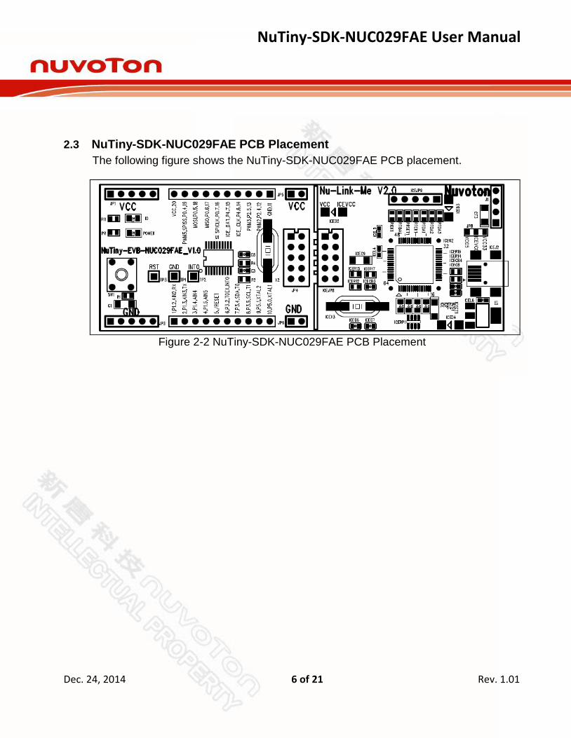
2.3 NuTiny-SDK-NUC029FAE PCB Placement
The following figure shows the NuTiny-SDK-NUC029FAE PCB placement.
Figure 2-2 NuTiny-SDK-NUC029FAE PCB Placement

NuTiny-SDK-NUC029FAE User Manual
Dec. 24, 2014 7 of 21 Rev. 1.01
3 Starting to Use NuTiny-SDK-NUC029FAE on the Keil μVision® IDE
3.1 Downloading and Installing Keil μVision® IDE Software
Please connect to the Keil company website (http://www.keil.com) to download the Keil μVision
® IDE and install the RVMDK.
3.2 Downloading and Installing Nuvoton Nu-Link Driver
Please connect to Nuvoton NuMicro™ website (http://www.nuvoton.com/NuMicro) to download the “NuMicro™ Keil μVision
® IDE driver” file. Please refer to section 6.1 for
the detailed download flow. After the Nu-Link driver is downloaded, please unzip the file and execute the “Nu-Link_Keil_Driver.exe” to install the driver.
3.3 Hardware Setup
The hardware setup is shown in the following figure.
Figure 3-1 NuTiny-SDK-NUC029FAE Hardware Setup

NuTiny-SDK-NUC029FAE User Manual
Dec. 24, 2014 8 of 21 Rev. 1.01
3.4 Example Program
This example demonstrates how to download and debug an application on a NuTiny-SDK-NUC029FAE board. The example file can be found in the directory list shown in the following figure.
Directory
Figure 3-2 Example Directory
To use this example: The I/O LED on the NuTiny-EVB-NUC029FAE board will be toggled on.
Start μVision®
Project – Open Open the led.uvproj project file
Project – Build Compile and link the LED application
Flash – Download Program the application code into on-chip Flash ROM
Start Debug mode When using the debugger commands, you may:
Review variables in the watch window
Single step through code
Reset the device
Run the application

NuTiny-SDK-NUC029FAE User Manual
Dec. 24, 2014 9 of 21 Rev. 1.01
4 Starting to Use NuTiny-SDK-NUC029FAE on the IAR Embedded
Workbench
4.1 Downloading and Installing IAR Embedded Workbench Software
Please connect to IAR company website (http://www.iar.com) to download the IAR Embedded Workbench and install the EWARM.
4.2 Downloading and Installing Nuvoton Nu-Link Driver
Please connect to Nuvoton Company NuMicro™
website (http://www.nuvoton.com/NuMicro) to download “NuMicro™ IAR EWARM Driver” file. Please refer to section 6.2 for the detail download flow. After the Nu-Link driver is downloaded, please unzip the file and execute the “Nu-Link_IAR_Driver.exe” to install the driver.
4.3 Hardware Setup
The hardware setup is shown in the following figure.
Figure 4-1 NuTiny-SDK-NUC029FAE Hardware Setup
NuTiny-SDK-NUC029FAE User Manual
Dec. 24, 2014 10 of 21 Rev. 1.01
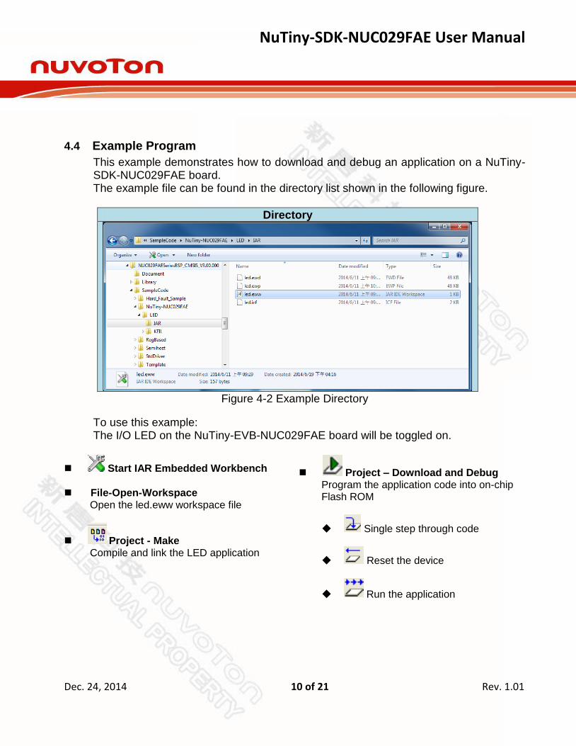
4.4 Example Program
This example demonstrates how to download and debug an application on a NuTiny-SDK-NUC029FAE board. The example file can be found in the directory list shown in the following figure.
Directory
Figure 4-2 Example Directory
To use this example: The I/O LED on the NuTiny-EVB-NUC029FAE board will be toggled on.
Start IAR Embedded Workbench
File-Open-Workspace Open the led.eww workspace file
Project - Make Compile and link the LED application
Project – Download and Debug Program the application code into on-chip Flash ROM
Single step through code
Reset the device
Run the application
NuTiny-SDK-NUC029FAE User Manual
Dec. 24, 2014 11 of 21 Rev. 1.01
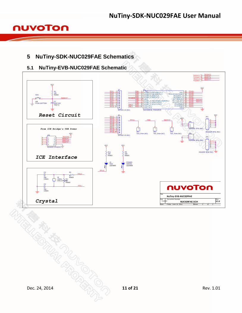
5 NuTiny-SDK-NUC029FAE Schematics
5.1 NuTiny-EVB-NUC029FAE Schematic
J3
SIPSOC-10 (NC)
123456789
10
Reset Circuit
VCC
VCC
VCC VCC
VCC
J4
SIPSOC-10 (NC)
123456789
10
TICERST
JP1
HEADER 5PX1 (NC)
12345
JP3
HEADER 5PX1 (NC)
12345
JP5
HEADER 2PX1 (NC)
12
JP6
HEADER 2PX1 (NC)
12
PIN1
R11330R0603
12
IOREDLED0805
PIN12
PIN2PIN3PIN4PIN5PIN6PIN7
Title
Size Document Number Rev
Date: Sheet of
NUC029FAE.SCH V1.0
NuTiny-EVB-NUC029FAE
Custom
2 2Friday , June 13, 2014
PIN8
12
POWERGREENLED0805
PR330R0603
XTAL1
PIN9PIN10
VCCPIN11PIN12
PIN14PIN13
From ICE Bridge's USB Power
VCC
PIN15
ICE Interface
TICEDAT
TICERST
TICEVCCJP4
HEADER 5PX2(NC)
1 23 45 67 89 10
TICECLK
C110uF/10VTANT-A
R110KR0603SW1
PUSH BOTTOMSW
PIN16
C5
20pC0603
X212MHzXTAL\LP\SMD
R41MR0603
XTAL2C3
20pC0603
R2
33R0603
TP1Test_Point (NC)
1
PIN17
PIN1
PIN11
PIN2
PIN19
PIN3
PIN20
PIN4
PIN18
TICERSTPIN5PIN6
TP2Test_Point (NC)
1
PIN6
U1
NUC029FAE_TOSSOP20
ACMP0_P,RXD,AIN2,P1.21
ACMP0_P,TXD,AIN3,P1.32
ACMP0_N,AIN4,P1.43
ACMP0_N,AIN5,P1.54
nRST5
ACMP1_P,T0EX,STADC,nINT0,P3.26
ACMP1_P,SDA0,T0,P3.47
ACMP1_P,SCL0,T1,P3.58
XTAL2,P5.19
XTA1, P5.010
VDD20
P0.4,SPISS0,PWM519
P0.5,MOSI_018
P0.6,MISO_017
P0.7,SPICLK016
P4.7,ICE_DAT15
P4.6,ICE_CLK14
P2.5,PWM313
P2.4,PWM212
VSS11
PIN7PIN8
PIN20
TICERST
TP3Test_Point (NC)
1
PIN19PIN18PIN17PIN16
TICEDATPIN15
PIN13
XTAL1 PIN10PIN12PIN11
XTAL2 PIN9
Crystal
TICECLKPIN14
TICECLKTICEDAT
TICERSTTICERST
TICEDATTICECLK
TICEVCCTICEVCC
NuTiny-SDK-NUC029FAE User Manual
Dec. 24, 2014 12 of 21 Rev. 1.01
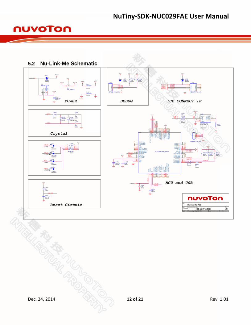
5.2 Nu-Link-Me Schematic
VCC33
USB_D+USB_D-
VCC
12
IDLE
REDLED0805
RED
ICPLED 12
ICP
YELLOWLED0805
12
ICE
REDLED0805
ICELEDiceRP1
8P4R-3308P4RA
12345678
12
BUSY
GREENLED0805
VCC
GREEN
iceL5
L0603
iceC7
20pC0603
iceR12
33R0603 iceX3
12MHz
XTAL\LP\SMD
iceR13
1M/DNE
R0603
iceL4
L0603
iceC6
20pC0603
ADAVSS
AVDD
DEBUG
J1
HEADER 4PX1 (NC)
1234
DMDP
VCC
TICEVCCTICEVCC
iceR17
10K
R0603
12 iceD3
SS24ARB060L
1 2
iceD4
SS24ARB060L
iceC910uF/10VTANT-A
VCC5
USBVBUS
VCC
VCC
TICECLKTICEDAT
TICERST
ICE_RST
VCC
iceJP8
HEADER 5PX2 (NC)
1 23 45 67 89 10
TICERST
TICEDATTICECLK
VCC
Reset Circuit
iceJP9
HEADER 5PX1 (NC)
12345
(YELLOW)
(RED)
(GREEN)
(RED)
ICE_CLKICE_DAT
ICE_RST
12M_I
MCU and USB
12M_O
CrystaliceU2
NUC12SRE3AN_LQFP64
PA0/ADC044PA1/ADC145PA2/ADC246PA3/ADC347PA4/ADC448INT0/PB14
1
CPO1/PB132
CPO0/PB123
VB
US
17
VD
D33
18
D-
19
D+
20
PB
0/R
X0
21
PB
1/T
X0
22
PB
2/R
TS
023
PB
3/C
TS
024
PC
2/S
DI0
026
PC
1/S
PC
LK
027
PC
0/S
S00
28
PC11/SDO1033PC10/SDI1034PC9/SPCLK135PC8/SS1036PA15/PWM337PA14/PWM238PA13/PWM139
X32I4
X32O5
I2C1SCL/PA116
I2C0SDA/PA89
I2C1SDA/PA107
I2C0SCL/PA98
RX1/PB410
TX1/PB511
RTS1/PB612
CTS1/PB713
PC
3/S
DO
00
25
AVSS43
ICE_CK42
ICE_DAT41
PA12/PWM040
LDO14
VSS16 VDD15
AD
C/P
A5
49
AD
C6/P
A6
50
AD
C7/P
A7
51
AV
DD
52
CP
N0/P
C7
53
CP
P0/P
C6
54
CP
N1/P
C15
55
CP
P1/P
C14
56
INT
1/P
B15
57
XT
1_O
ut
58
XT
1_In
59
/RE
SE
T60
VS
S1
61
VD
D1
62
PV
SS
63
ST
AD
C/T
M0/P
B8
64
PE
529
PB
11/T
M3
30
PB
10/S
S01/T
M2
31
PB
9/S
S11/T
M1
32
iceL6L0603
iceR1633R0603
iceR1433R0603
iceJ2
mini USB 5pinUSB_MINI_B
GND5 NC4 DP3 DM2 VCC1
SHIELD6
SHIELD7
SHIELD8
SHIELD9
ICE CONNECT IF
USBVBUS
USB_D+ DPDMUSB_D-
VCC
RTIDA1100KR0603
RICK1100KR0603
VCC
ICE
_R
ST
U3AMS1117-3.3V
IN3
GN
D1
OU
T2
OU
T4
VCC33
12
iceD2SS24ARB060L
12M
_I
VCC
AVDD
12M
_O
REDICPLED
GREEN
iceCB30.1uFC0603
ICELED
USBVBUS
VB
US
iceCB40.1uC0603
iceC81uFC0603
RTDA20R0603
TICERST
RTDA333R0603
RTCK1100KR0603
TICECLK
RTDA1100KR0603
RRSET1100KR0603
ADAVSS
TICEDAT
VCC
ICE_DATICE_CLK
JP83-W JUMPER
1 32
USBVBUS
CT310uF/10VTANT-A
iceCT110uF/10VTANT-A
Title
Size Document Number Rev
Date: Sheet of
ICE_LQFP64.SCH V2.0
Nu-Link-Me V2.0
Custom
1 2Wednesday , May 21, 2014
POWER
VCC5
NuTiny-SDK-NUC029FAE User Manual
Dec. 24, 2014 13 of 21 Rev. 1.01
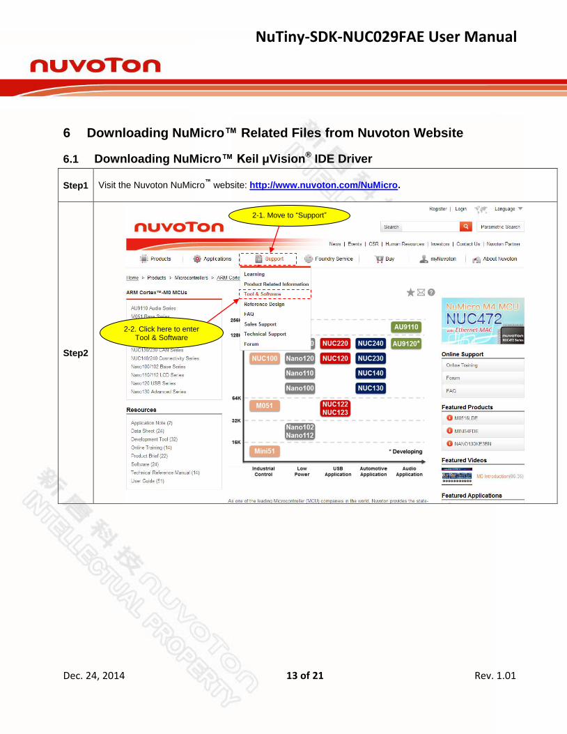
6 Downloading NuMicro™ Related Files from Nuvoton Website
6.1 Downloading NuMicro™ Keil μVision® IDE Driver
Step1
Visit the Nuvoton NuMicro™
website: http://www.nuvoton.com/NuMicro.
Step2
2-1. Move to “Support”
2-2. Click here to enter Tool & Software

NuTiny-SDK-NUC029FAE User Manual
Dec. 24, 2014 14 of 21 Rev. 1.01
Step3
Click here to enter Software
download page

NuTiny-SDK-NUC029FAE User Manual
Dec. 24, 2014 15 of 21 Rev. 1.01
Step4
Step5
Download the NuMicro
™ Keil μVision
® IDE driver.
Click here to download the file.

NuTiny-SDK-NUC029FAE User Manual
Dec. 24, 2014 16 of 21 Rev. 1.01
6.2 Downloading NuMicro™ IAR EWARM Driver
Step1
Visit the Nuvoton NuMicro™
website: http://www.nuvoton.com/NuMicro.
Step2
2-1. Move to “Support”
2-2. Click here to enter Tool & Software

NuTiny-SDK-NUC029FAE User Manual
Dec. 24, 2014 17 of 21 Rev. 1.01
Step3
Click here to enter Software
download page

NuTiny-SDK-NUC029FAE User Manual
Dec. 24, 2014 18 of 21 Rev. 1.01
Step4
Step5
Download the NuMicro™
IAR EWARM driver.
Click here to download the file.

NuTiny-SDK-NUC029FAE User Manual
Dec. 24, 2014 19 of 21 Rev. 1.01
6.3 Downloading NuMicro™ NUC029FAE Series BSP Software Library
Step1
Visit the Nuvoton NuMicro™
website: http://www.nuvoton.com/NuMicro.
Step2
2-1. Move to “Support”
2-2. Click here to enter Tool & Software
NuTiny-SDK-NUC029FAE User Manual
Dec. 24, 2014 20 of 21 Rev. 1.01
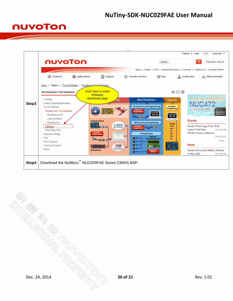
Step3
Step4
Download the NuMicro™
NUC029FAE Series CMSIS BSP.
Click here to enter Software
download page

NuTiny-SDK-NUC029FAE User Manual
Dec. 24, 2014 21 of 21 Rev. 1.01
7 Revision History
Revision Date Description
1.00 Jun. 19, 2014 First version.
1.01 Dec. 24, 2014 Fix the typo on 6.3 Downloading NuMicro™ NUC029FAE Series BSP Software Library Step4.
Important Notice
Nuvoton Products are neither intended nor warranted for usage in systems or equipment, any
malfunction or failure of which may cause loss of human life, bodily injury or severe property damage.
Such applications are deemed, “Insecure Usage”.
Insecure usage includes, but is not limited to: equipment for surgical implementation, atomic energy
control instruments, airplane or spaceship instruments, the control or operation of dynamic, brake or
safety systems designed for vehicular use, traffic signal instruments, all types of safety devices, and
other applications intended to support or sustain life.
All Insecure Usage shall be made at customer’s risk, and in the event that third parties lay claims to
Nuvoton as a result of customer’s Insecure Usage, customer shall indemnify the damages and
liabilities thus incurred by Nuvoton.