Numatics Vacuum Products Catalog
172
Vacuum Products www.numatics.com
-
Upload
mangesh-rasote -
Category
Documents
-
view
51 -
download
2
description
Numatics Vacuum Products Catalog
Transcript of Numatics Vacuum Products Catalog
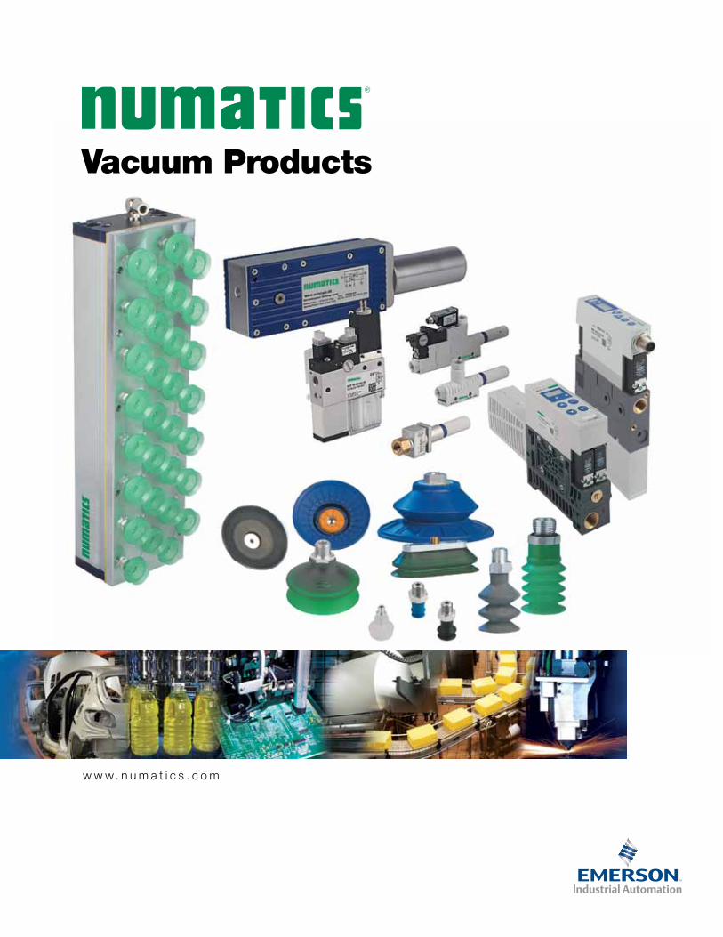
Vacuum Products
w w w . n u m a t i c s . c o m

Information subject to change without notice. For ordering information or regarding your local sales office visit www.numatics.com.1
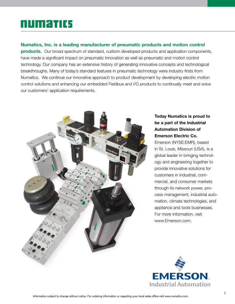
Numatics, Inc. is a leading manufacturer of pneumatic products and motion control products. Our broad spectrum of standard, custom developed products and application components, have made a significant impact on pneumatic innovation as well as pneumatic and motion control technology. Our company has an extensive history of generating innovative concepts and technological breakthroughs. Many of today’s standard features in pneumatic technology were industry firsts from Numatics. We continue our innovative approach to product development by developing electric motion control solutions and enhancing our embedded Fieldbus and I/O products to continually meet and solve our customers' application requirements.
Today Numatics is proud to be a part of the Industrial Automation Division of Emerson Electric Co. Emerson (NYSE:EMR), based in St. Louis, Missouri (USA), is a global leader in bringing technol-ogy and engineering together to provide innovative solutions for customers in industrial, com-mercial, and consumer markets through its network power, pro-cess management, industrial auto-mation, climate technologies, and appliance and tools businesses. For more information, visit www.Emerson.com.
i
Information subject to change without notice. For ordering information or regarding your local sales office visit www.numatics.com.
Vacuum Products
Intro to Vacuum Products PAGES 1-40
Vacuum Generators (Ejectors, Electric Pumps) PAGES 41-80
Mounting Elements PAGES 132-140
Specialty Grippers PAGES 141-147
Vacuum Sensors/Switches and Regulators PAGES 148-163
Accessories PAGES 164-168
Suction Cups PAGES 81-131
Introduction to Vacuum Products . . . . . . . . . . . . . . . . . . . . . . . . 1-6
Engineering Information . . . . . . . . . . . . . . . . . . . . . . . . . . . . 7-40- Vacuum system and its components - Vacuum Knowledge and Terminology - System Design – Calculation Example - Symbols in Vacuum Technology - Units and Conversion Tables - Vacuum Glossary
Basic Ejectors . . . . . . . . . . . . . . . . . . . . . . . . . . . . . . . . . . 42-52- NSBPX Series - NSBPC Series - NSEGX Series
Multi-stage Ejectors . . . . . . . . . . . . . . . . . . . . . . . . . . . . . . 53-55- NSEMX Series
Flexible Mounting . . . . . . . . . . . . . . . . . . . . . . . . . . . . . . .132-140- NFSTE Series - NFLK Series - NKGL Series - NHTR Series
Large Area Grippers . . . . . . . . . . . . . . . . . . . . . . . . . . . . .141-143- NFX Series
Magnetic Grippers . . . . . . . . . . . . . . . . . . . . . . . . . . . . . .144-145- NSGMX Series
Vacuum Switch . . . . . . . . . . . . . . . . . . . . . . . . . . . . . . . .148-160- NVS-V-SA / SD - NVS-V-AH / AV-T - NVS-V - NVS-V-D - NVS-V-PM-NO / NC
Pressure Switch . . . . . . . . . . . . . . . . . . . . . . . . . . . . . . . .161-162- NVS-P10-AH / AV-T - NVS-P10-D
Vacuum Filters. . . . . . . . . . . . . . . . . . . . . . . . . . . . . . . . .164-166- NVFTX Series - NVFIX Series (In-line style)
Check Valves . . . . . . . . . . . . . . . . . . . . . . . . . . . . . . . . . . . 167- NSVK Series - NSVKG Series
Flat Round Suction Cups and Plates . . . . . . . . . . .82-89, 108-109, 115-121- NPFYN Series - NPFGX Replacement Cup - NSAFX Series Automotive Cup - NSPUX Series (Suction Plate) - NSGPN Series - NSGPX Replacement Cup
Flat Oval Suction Cups . . . . . . . . . . . . . . . . . . . . . . . . 90-93, 110-111- NSGON Series - NSGOX Replacement Cup - NSAOF Automotive Cup
ii

Information subject to change without notice. For ordering information or regarding your local sales office visit www.numatics.com.
Vacuum Products
Acc
esso
ries
Acc
esso
ries
Vacu
um P
rodu
cts
Suc
tion
Cup
sM
ount
ing
Ele
men
tsS
peci
alty
Grip
pers
Sen
sors
/Sw
itche
s an
d R
egul
ator
s
Intro to Vacuum Products PAGES 1-40
Vacuum Generators (Ejectors, Electric Pumps) PAGES 41-80
Mounting Elements PAGES 132-140
Specialty Grippers PAGES 141-147
Vacuum Sensors/Switches and Regulators PAGES 148-163
Accessories PAGES 164-168
In-Line Ejectors . . . . . . . . . . . . . . . . . . . . . . . . . 72-77- NSLPX Series - NVRXX Series
Electric Pumps . . . . . . . . . . . . . . . . . . . . . . . . . 78-80- NEVE-TR Series
Suction Cups PAGES 81-131
Sizing Requirements for Vacuum Products . . . . . . . . . . .
#-#
Feed Ejectors . . . . . . . . . . . . . . . . . . . . . . . . 56-57- NSECX Series
Compact Ejectors . . . . . . . . . . . . . . . . . . . . . . 58-68- NSCPI Series - NSCPM Series - NSXMP Series
Ejectors . . . . . . . . . . . . . . . . . . . . . . . . . . . 69-71- NSEAC-RP Series
Floating Grippers . . . . . . . . . . . . . . . . . . . . .146-147- NSBSX Series
Vacuum and Pressure Switch . . . . . . . . . . . . . .159-160- NVS-P
Regulators . . . . . . . . . . . . . . . . . . . . . . . . . . . 163- NVRG
Round Bellows . . . . . . . . . . . . . . . . . 94-107, 112-114- NFSGA Series (1.5 B) - NFGA Replacement Cup - NFSGX Series (2.5 B) - NFGX Replacement Cup - NSABX Series (1.5 B) Automotive Cup
Holders - Mountings . . . . . . . . . . . . . . . . . . . . . 168
Misc. Accessories. . . . . . . . . . . . . . . . . . . . . . . 168
Specialty Cups for Packaging . . . . . . . . . . . . . . . 122-128- NSPFX Series - NSPB4 Series - NSPB1 Series - NSPOB Series
Specialty Cups for Eggs & Candy . . . . . . . . . . . . . 129-131- NEFG Series (1.5B - 2.5B - 3.5B): Egg Cups - NSPGX Series: Candy Cup
iii
Vacu
um G
ener
ator
s
Cable Connectors . . . . . . . . . . . . . . . . . . . . . . . 168
Silencers . . . . . . . . . . . . . . . . . . . . . . . . . . . . 168- NSDX Series

Information subject to change without notice. For ordering information or regarding your local sales office visit www.numatics.com.4
Vacuum Products Introduction to Vacuum Products
Vacuum Components and Gripping Systems
Vacuum components and vacuum gripping systems from Numatics permit decisive productivity improvements in
automated processes. Be it in mechanical engineering or in the robot industry – Numatics customers in all areas of
automation technology profit from our qualified system consultancy services and our innovative solutions. The range
of workpieces which can be handled with vacuum extends from easily damaged, small parts such as electronic chips
or CDs to furniture elements or heavy sheets of steel.
Our specialists’ expertise guarantees efficient and economical solutions for the automation of a process; from the
individual components, to the complex gripping system, all the way through to the particular customer-specific
application.
Vacuum Components
Vacuum suction cups
Special grippers
Mounting elements
Vacuum generators
Numatics valve technology
Switches and system monitoring
Filters and connections
Vacuum Gripping Systems
Fully configured systems for industrial robots and portals,
delivered ready for connection

Information subject to change without notice. For ordering information or regarding your local sales office visit www.numatics.com.5
Vacuum ProductsIntroduction to Vacuum Products
Industry and Market Specific Solutions
In all areas of automation technology, Numatics customers benefit from expert systems consulting and innovative
solutions. Numatics vacuum components include everything they need to develop a fully operational vacuum system.
The extensive range of vacuum products corresponds to the specific requirements in a wide variety of industry
sectors. The primary focus is on the industries described below.
Metal sheets /automotive
Fast cycle times and high operational
reliability
Special suction cups for highly dynamic metal sheet
handling, even with oiled metal sheets or fragile
components
Vacuum generator with integrated system
monitoring, condition monitoring and IO-Link
technology for increasing process reliability and
improving energy efficiency
Optimized mounting elements for the requirements
of the automotive industry
Wood
Handling of workpieces with a variety
of surfaces under difficult operating
conditions
Comprehensive range of filters for protecting
vacuum systems from contamination
Large area vacuum gripping systems for moving
wooden sheets, furniture parts, pallets or entire
layers of boards
Information subject to change without notice. For ordering information or regarding your local sales office visit www.numatics.com.6
Vacuum Products Introduction to Vacuum Products
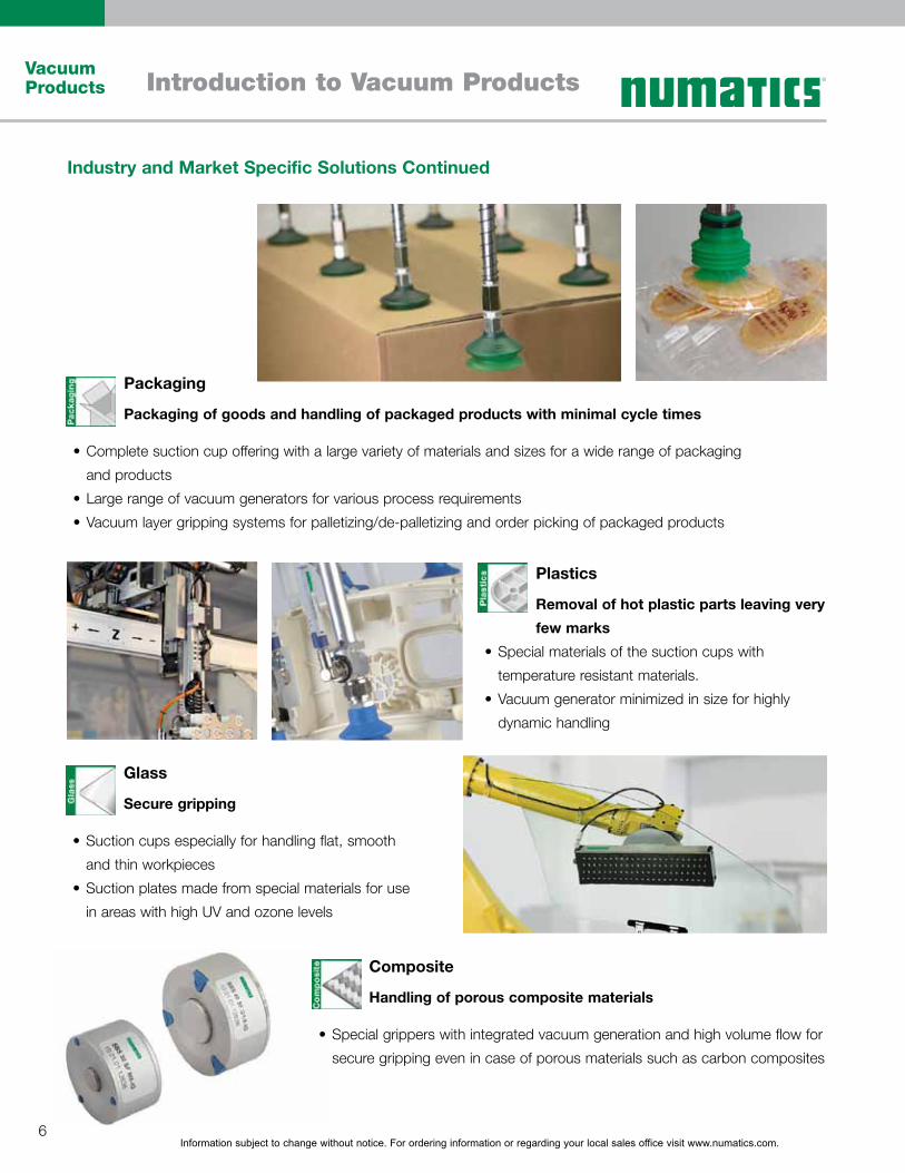
Industry and Market Specific Solutions Continued
Packaging
Packaging of goods and handling of packaged products with minimal cycle times
Complete suction cup offering with a large variety of materials and sizes for a wide range of packaging
and products
Large range of vacuum generators for various process requirements
Vacuum layer gripping systems for palletizing/de-palletizing and order picking of packaged products
Plastics
Removal of hot plastic parts leaving very
few marks
Special materials of the suction cups with
temperature resistant materials.
Vacuum generator minimized in size for highly
dynamic handling
Composite
Handling of porous composite materials
Special grippers with integrated vacuum generation and high volume flow for
secure gripping even in case of porous materials such as carbon composites
Glass
Secure gripping
Suction cups especially for handling flat, smooth
and thin workpieces
Suction plates made from special materials for use
in areas with high UV and ozone levels
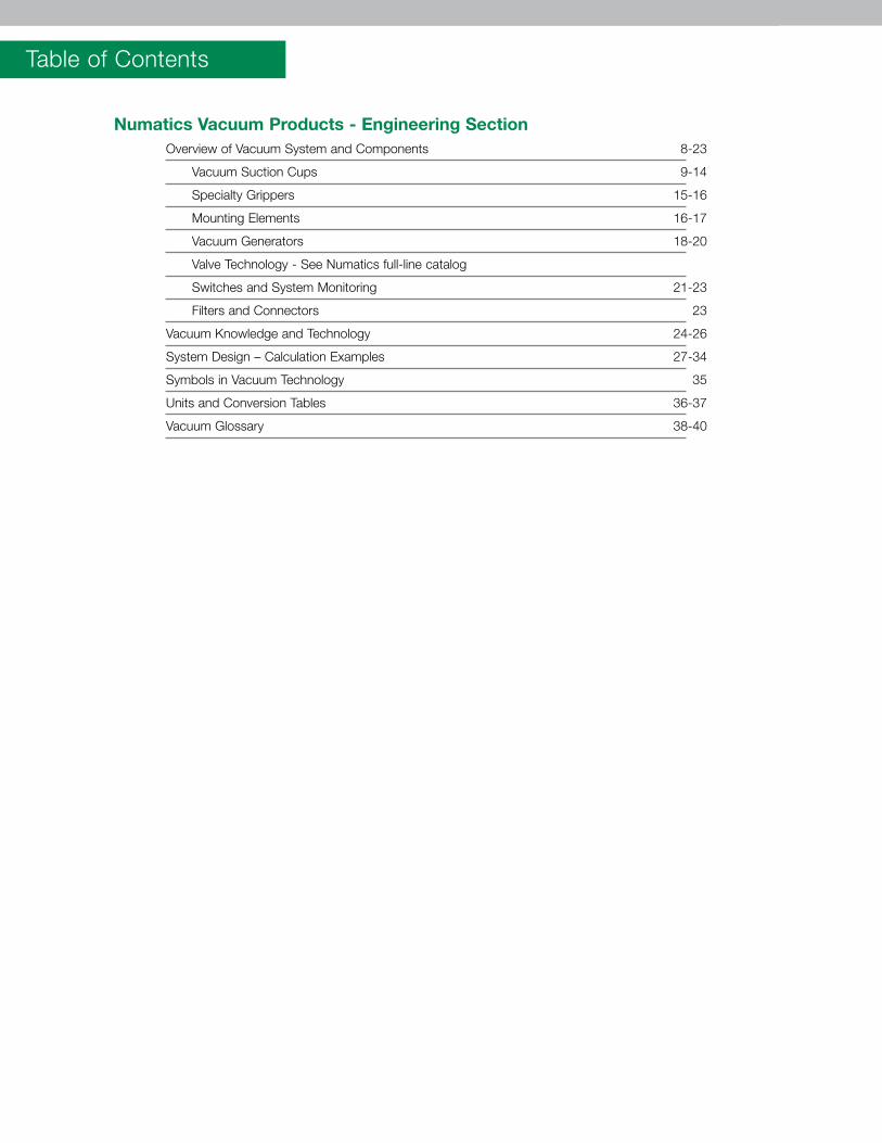
Table of Contents
Numatics Vacuum Products - Engineering Section Overview of Vacuum System and Components 8-23
Vacuum Suction Cups 9-14
Specialty Grippers 15-16
Mounting Elements 16-17
Vacuum Generators 18-20
Valve Technology - See Numatics full-line catalog
Switches and System Monitoring 21-23
Filters and Connectors 23
Vacuum Knowledge and Technology 24-26
System Design – Calculation Examples 27-34
Symbols in Vacuum Technology 35
Units and Conversion Tables 36-37
Vacuum Glossary 38-40
Information subject to change without notice. For ordering information or regarding your local sales office visit www.numatics.com.8
Vacuum Products
Numatics Vacuum ProductsEngineering Section
Vacu
um P
rodu
cts
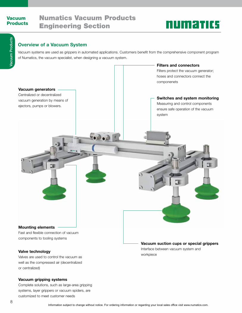
Overview of a Vacuum SystemVacuum systems are used as grippers in automated applications. Customers benefit from the comprehensive component program of Numatics, the vacuum specialist, when designing a vacuum system.
Vacuum generators
Mounting elements
Valve technology
Vacuum gripping systems
Filters and connectors
Switches and system monitoring
Vacuum suction cups or special grippers
Centralized or decentralized vacuum generation by means of ejectors, pumps or blowers.
Fast and flexible connection of vacuum components to tooling systems
Valves are used to control the vacuum as well as the compressed air (decentralized or centralized)
Complete solutions, such as large-area gripping systems, layer grippers or vacuum spiders, are customized to meet customer needs
Filters protect the vacuum generator; hoses and connectors connect the componenets
Measuring and control components ensure safe operation of the vacuum system
Interface between vacuum system and workpiece
Information subject to change without notice. For ordering information or regarding your local sales office visit www.numatics.com.9
Vacuum Products
Numatics Vacuum ProductsEngineering Section
Vacu
um P
rodu
cts
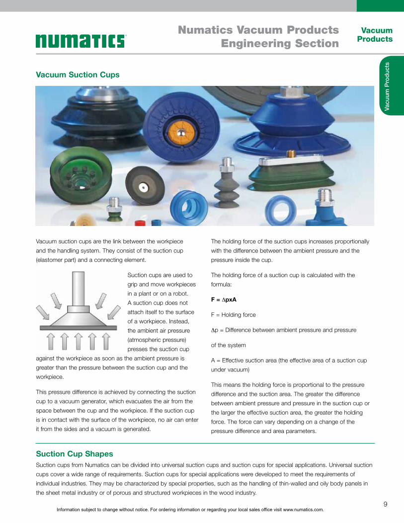
Vacuum Suction Cups
Suction Cup Shapes
Vacuum suction cups are the link between the workpiece and the handling system. They consist of the suction cup (elastomer part) and a connecting element.
Suction cups are used to grip and move workpieces in a plant or on a robot. A suction cup does not attach itself to the surface of a workpiece. Instead, the ambient air pressure (atmospheric pressure) presses the suction cup
against the workpiece as soon as the ambient pressure is greater than the pressure between the suction cup and the workpiece.
This pressure difference is achieved by connecting the suction cup to a vacuum generator, which evacuates the air from the space between the cup and the workpiece. If the suction cup is in contact with the surface of the workpiece, no air can enter it from the sides and a vacuum is generated.
The holding force of the suction cups increases proportionally with the difference between the ambient pressure and the pressure inside the cup.
The holding force of a suction cup is calculated with the formula:
F = 6pxA
F = Holding force
6p = Difference between ambient pressure and pressure
of the system
A = Effective suction area (the effective area of a suction cup under vacuum)
This means the holding force is proportional to the pressure difference and the suction area. The greater the difference between ambient pressure and pressure in the suction cup or the larger the effective suction area, the greater the holding force. The force can vary depending on a change of the pressure difference and area parameters.
Suction cups from Numatics can be divided into universal suction cups and suction cups for special applications. Universal suction cups cover a wide range of requirements. Suction cups for special applications were developed to meet the requirements of individual industries. They may be characterized by special properties, such as the handling of thin-walled and oily body panels in the sheet metal industry or of porous and structured workpieces in the wood industry.
Information subject to change without notice. For ordering information or regarding your local sales office visit www.numatics.com.10
Vacuum Products
Numatics Vacuum ProductsEngineering Section
Vacu
um P
rodu
cts
Vacuum Suction Cups Continued
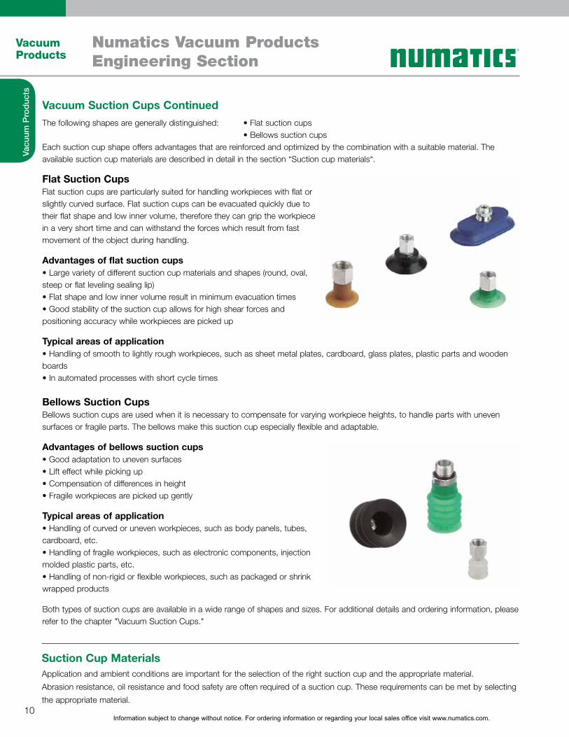
Each suction cup shape offers advantages that are reinforced and optimized by the combination with a suitable material. The available suction cup materials are described in detail in the section “Suction cup materials“.
Flat Suction CupsFlat suction cups are particularly suited for handling workpieces with flat or slightly curved surface. Flat suction cups can be evacuated quickly due to their flat shape and low inner volume, therefore they can grip the workpiece in a very short time and can withstand the forces which result from fast movement of the object during handling.
Advantages of flat suction cups
steep or flat leveling sealing lip)
positioning accuracy while workpieces are picked up
Typical areas of application
boards
Bellows Suction CupsBellows suction cups are used when it is necessary to compensate for varying workpiece heights, to handle parts with uneven surfaces or fragile parts. The bellows make this suction cup especially flexible and adaptable.
Advantages of bellows suction cups
Typical areas of application
cardboard, etc.
molded plastic parts, etc.
wrapped products
Both types of suction cups are available in a wide range of shapes and sizes. For additional details and ordering information, please refer to the chapter "Vacuum Suction Cups."
Suction Cup MaterialsApplication and ambient conditions are important for the selection of the right suction cup and the appropriate material. Abrasion resistance, oil resistance and food safety are often required of a suction cup. These requirements can be met by selecting the appropriate material.
Information subject to change without notice. For ordering information or regarding your local sales office visit www.numatics.com.11
Vacuum Products
Numatics Vacuum ProductsEngineering Section
Vacu
um P
rodu
cts
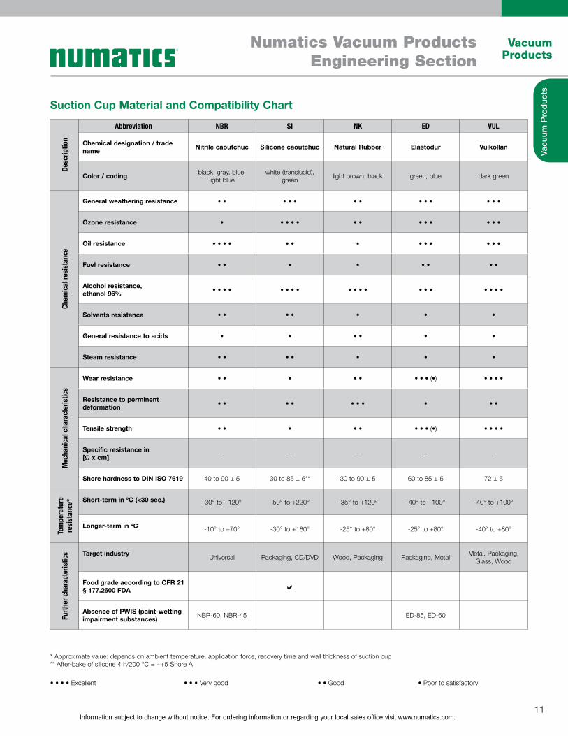
Suction Cup Material and Compatibility Chart
Desc
riptio
n
Abbreviation NBR SI NK ED VUL
Chemical designation / trade name Nitrile caoutchuc Silicone caoutchuc Natural Rubber Elastodur Vulkollan
Color / coding black, gray, blue, light blue
white (translucid), green light brown, black green, blue dark green
Chem
ical
resi
stan
ce
General weathering resistance
Ozone resistance
Oil resistance
Fuel resistance
Alcohol resistance,ethanol 96%
Solvents resistance
General resistance to acids
Steam resistance
Mec
hani
cal c
hara
cter
istic
s
Wear resistance
Resistance to perminent deformation
Tensile strength
Specific resistance in [1 x cm] – – – – –
Shore hardness to DIN ISO 7619 40 to 90 ± 5 30 to 85 ± 5** 30 to 90 ± 5 60 to 85 ± 5 72 ± 5
Tem
pera
ture
re
sist
ance
* Short-term in ºC (<30 sec.) -30° to +120° -50° to +220° -35° to +120º -40° to +100° -40° to +100°
Longer-term in ºC -10° to +70° -30° to +180° -25° to +80° -25° to +80° -40° to +80°
Furt
her c
hara
cter
istic
s Target industry Universal Packaging, CD/DVD Wood, Packaging Packaging, Metal Metal, Packaging, Glass, Wood
Food grade according to CFR 21 § 177.2600 FDA D
Absence of PWIS (paint-wetting impairment substances) NBR-60, NBR-45 ED-85, ED-60
* Approximate value: depends on ambient temperature, application force, recovery time and wall thickness of suction cup ** After-bake of silicone 4 h/200 °C = ~+5 Shore A
Information subject to change without notice. For ordering information or regarding your local sales office visit www.numatics.com.12
Vacuum Products
Numatics Vacuum ProductsEngineering Section
Vacu
um P
rodu
cts
Storage and Cleaning of Suction Cups
Technical Data of Suction Cups
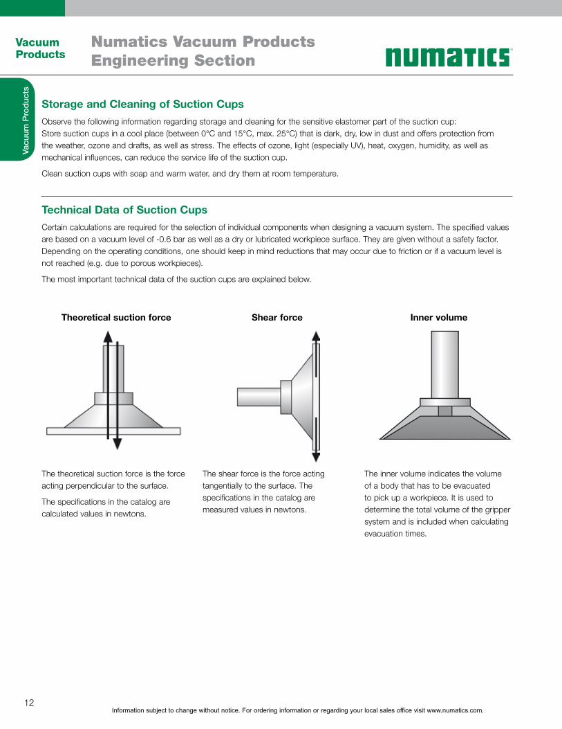
Theoretical suction force Shear force Inner volume
Observe the following information regarding storage and cleaning for the sensitive elastomer part of the suction cup:Store suction cups in a cool place (between 0°C and 15°C, max. 25°C) that is dark, dry, low in dust and offers protection from the weather, ozone and drafts, as well as stress. The effects of ozone, light (especially UV), heat, oxygen, humidity, as well as mechanical influences, can reduce the service life of the suction cup.
Clean suction cups with soap and warm water, and dry them at room temperature.
Certain calculations are required for the selection of individual components when designing a vacuum system. The specified values are based on a vacuum level of -0.6 bar as well as a dry or lubricated workpiece surface. They are given without a safety factor. Depending on the operating conditions, one should keep in mind reductions that may occur due to friction or if a vacuum level is not reached (e.g. due to porous workpieces).
The most important technical data of the suction cups are explained below.
The theoretical suction force is the force acting perpendicular to the surface.
The specifications in the catalog are calculated values in newtons.
The shear force is the force acting tangentially to the surface. The specifications in the catalog are measured values in newtons.
The inner volume indicates the volume of a body that has to be evacuated to pick up a workpiece. It is used to determine the total volume of the gripper system and is included when calculating evacuation times.
Information subject to change without notice. For ordering information or regarding your local sales office visit www.numatics.com.13
Vacuum Products
Numatics Vacuum ProductsEngineering Section
Vacu
um P
rodu
cts
The Vacuum System and its Components
Design of the Suction CupThe design of the suction cup always depends on the actual application. For this reason, various physical values must be calculated and determined before the correct suction cup can be selected.
Later in this chapter, the design of a vacuum system is described in more detail based on a calculation example.
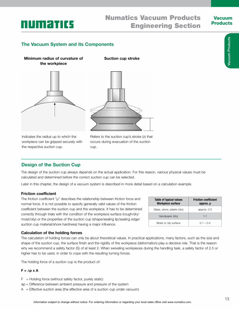
Minimum radius of curvature of the workpiece
Suction cup stroke
Indicates the radius up to which the workpiece can be gripped securely with the respective suction cup.
Refers to the suction cup’s stroke (z) that occurs during evacuation of the suction cup.
Friction coefficientThe friction coefficient “µ” describes the relationship between friction force and normal force. It is not possible to specify generally valid values of the friction coefficient between the suction cup and the workpiece. It has to be determined correctly through trials with the condition of the workpiece surface (rough/dry/moist/oily) or the properties of the suction cup (shape/sealing lip/sealing edge/suction cup material/shore hardness) having a major influence.
Calculation of the holding forcesThe calculation of holding forces can only be about theoretical values. In practical applications, many factors, such as the size and shape of the suction cup, the surface finish and the rigidity of the workpiece (deformation) play a decisive role. That is the reason why we recommend a safety factor (S) of at least 2. When swiveling workpieces during the handling task, a safety factor of 2.5 or higher has to be used, in order to cope with the resulting turning forces.
The holding force of a suction cup is the product of:
F = 6p x A
F = Holding force (without safety factor, purely static) 6p = Difference between ambient pressure and pressure of the system A = Effective suction area (the effective area of a suction cup under vacuum)
Table of typical values Workpiece surface
Friction coefficient approx. µ
Glass, stone, plastic (dry) approx. 0.5
Sandpaper (dry) 1.1
Moist or oily surface 0.1 – 0.4
Information subject to change without notice. For ordering information or regarding your local sales office visit www.numatics.com.14
Vacuum Products
Numatics Vacuum ProductsEngineering Section
Vacu
um P
rodu
cts
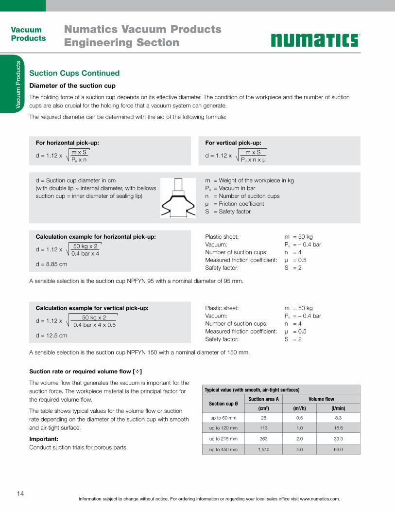
Suction Cups ContinuedDiameter of the suction cup
The holding force of a suction cup depends on its effective diameter. The condition of the workpiece and the number of suction cups are also crucial for the holding force that a vacuum system can generate.
The required diameter can be determined with the aid of the following formula:
A sensible selection is the suction cup NPFYN 95 with a nominal diameter of 95 mm.
A sensible selection is the suction cup NPFYN 150 with a nominal diameter of 150 mm.
For horizontal pick-up:
Calculation example for horizontal pick-up:
Calculation example for vertical pick-up:
For vertical pick-up:
d = 1.12 x
d = 1.12 x
d = 1.12 x
d = 8.85 cm
d = 12.5 cm
m = Weight of the workpiece in kgPu = Vacuum in barn = Number of suciton cupsµ = Friction coefficientS = Safety factor
Plastic sheet:Vacuum:Number of suction cups:Measured friction coefficient:Safety factor:
Plastic sheet:Vacuum:Number of suction cups:Measured friction coefficient:Safety factor:
m = 50 kgPu = – 0.4 barn = 4µ = 0.5S = 2
m = 50 kgPu = – 0.4 barn = 4µ = 0.5S = 2
d = 1.12 x m x S
50 kg x 2
50 kg x 2
m x SPu x n
0.4 bar x 4
0.4 bar x 4 x 0.5
Pu x n x µ
~d = Suction cup diameter in cm (with double lip ~ internal diameter, with bellows suction cup = inner diameter of sealing lip)
Typical value (with smooth, air-tight surfaces)
Suction cup ØSuction area A Volume flow
(cm2) (m3/h) (l/min)
up to 60 mm 28 0.5 8.3
up to 120 mm 113 1.0 16.6
up to 215 mm 363 2.0 33.3
up to 450 mm 1,540 4.0 66.6
Suction rate or required volume flow [ ]
The volume flow that generates the vacuum is important for the suction force. The workpiece material is the principal factor for the required volume flow.
The table shows typical values for the volume flow or suction rate depending on the diameter of the suction cup with smooth and air-tight surface.
Important:Conduct suction trials for porous parts.
Information subject to change without notice. For ordering information or regarding your local sales office visit www.numatics.com.15
Vacuum Products
Numatics Vacuum ProductsEngineering Section
Vacu
um P
rodu
cts
Specialty Grippers
Large Area Grippers
Special grippers are used in applications in which regular suction cups cannot be used. Special grippers are used to handle wafers, films, paper, fragile workpieces or textile fiber composites. They serve as a connection element between the workpiece and the handling system just like the suction cup.
Numatics separates special grippers into the following series:Floating suction grippersMagnetic grippers
The NFX Series large area gripper is designed to handle work-pieces with a wide range of dimensions and/or undefined positions. It provides customers with a reliable means of handling work-pieces that have several gaps.Applications include palletizing/depalletizing, in addition to order picking and sorting of a wide range of work-pieces with a single gripper. Typical work-piece materials include cardboard, wood, metal or plastic.
Floating Suction GripperFloating suction grippers are pneumatically operated special grippers with integrated vacuum generation. They operate on the Bernoulli principle and work as a low-contact system. The workpiece “floats” on an air cushion at the gripper surface. This makes the floating suction gripper ideally suited for the handling of very sensitive products. The high volume flow can compensate for leakage, when handling porous workpieces.
Advantages of floating suction grippers:Low-contact handlingHigh volume flowSafe separation of thin, porous workpieces Integrated vacuum generation
Typical areas of application:Handling of fiber composites, paper, film, wood veneer, printed circuit boards, wafers and solar cellsSeparation of thin, porous workpieces
Information subject to change without notice. For ordering information or regarding your local sales office visit www.numatics.com.16
Vacuum Products
Numatics Vacuum ProductsEngineering Section
Vacu
um P
rodu
cts
Magnetic GripperMagnetic grippers provide safe gripping of ferromagnetic workpieces by using the magnetic field of an integrated permanent magnet. The magnet is moved with compressed air to activate and deactivate gripping. Magnetic grippers are operated with pneumatic valves. The gripper does not require a voltage source for this purpose.
Advantages of magnetic grippers:Safe gripping with a permanent magnet is possible without voltage sourceControl of permanent magnet with compressed air or vacuum
Typical areas of application:Handling of ferromagnetic workpiecesHandling of blanks and perforated plates as well as sheet metal parts with drilled holes/breakouts or complex shapesSupport of vacuum gripping system in highly dynamic handling of sheet metal parts
Mounting Elements
Numatics offers a broad product range of mounting elements to integrate grippers (suction cups or special grippers) into gripping systems.
The following mounting elements can basically be distinguished:Holders and adaptersSpring plungerJointed mountings
For additional information and ordering details, refer to the chapter "Mounting Elements."
Information subject to change without notice. For ordering information or regarding your local sales office visit www.numatics.com.17
Vacuum Products
Numatics Vacuum ProductsEngineering Section
Vacu
um P
rodu
cts
Mounting Elements Continued
Holders and adaptersThe suction cups are attached to the basic structure or the traverse with holders and adapters. Different types of aluminum sections or square and round tubes are available.
Spring plungersSpring plungers are used to compensate height differences of workpieces. They also cushion the impact of the suction cup and allow handling of fragile workpieces.
Jointed mountingsJointed mountings provide a better adaption of the suction cup to the workpiece due to the design of Flexolink NFLK and ball joint NKGL that can be swiveled in all directions.
Suction cups(chapter “Vacuum Suction Cups” or “Special Grippers”)
Information subject to change without notice. For ordering information or regarding your local sales office visit www.numatics.com.18
Vacuum Products
Numatics Vacuum ProductsEngineering Section
Vacu
um P
rodu
cts
Vacuum Generators
Vacuum generators provide the vacuum level that is required for the handling task. The vacuum is created either pneumatically or electrically.
Pneumatic vacuum generators implement short cycle times and can be integrated directly into the system due to their compact and lightweight design.
Electrical vacuum generators are used in applications when compressed air is not available or when very high suction capacities are required.
Pneumatic vacuum generatorsEjectors
Electrical vacuum generatorsPumps
ImportantThe nominal suction rate of all vacuum generators is given in l/min or m3/h. The values are based on an ambient pressure of 1,013 mbar (sea level) and an ambient temperature of 20 °C.The maximum suction rate therefore indicates the volume flow that the vacuum generator evacuates from the environment (free flow).
Free pick flow Additional suction while workpiece is picked up
Information subject to change without notice. For ordering information or regarding your local sales office visit www.numatics.com.19
Vacuum Products
Numatics Vacuum ProductsEngineering Section
Vacu
um P
rodu
cts
Vacuum Generators Continued
Principle of operation of a single-stage ejector
Principle of operation of a multi-stage ejector
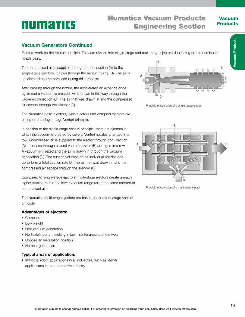
Ejectors work on the Venturi principle. They are divided into single-stage and multi-stage ejectors depending on the number of nozzle pairs.
The compressed air is supplied through the connection (A) to the single-stage ejectors. It flows through the Venturi nozzle (B). The air is accelerated and compressed during this process.
After passing through the nozzle, the accelerated air expands once again and a vacuum is created. Air is drawn in this way through the vacuum connection (D). The air that was drawn in and the compressed air escape through the silencer (C).
The Numatics basic ejectors, inline ejectors and compact ejectors are based on the single-stage Venturi principle.
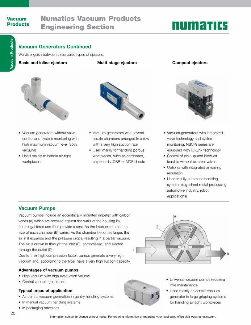
In addition to the single-stage Venturi principle, there are ejectors in which the vacuum is created by several Venturi nozzles arranged in a row. Compressed air is supplied to the ejector through con- nection (A). It passes through several Venturi nozzles (B) arranged in a row. A vacuum is created and the air is drawn in through the vacuum connection (D). The suction volumes of the individual nozzles add up to form a total suction rate D. The air that was drawn in and the compressed air escape through the silencer (C).
Compared to single-stage ejectors, multi-stage ejectors create a much higher suction rate in the lower vacuum range using the same amount of compressed air.
The Numatics multi-stage ejectors are based on the multi-stage Venturi principle.
Advantages of ejectors:CompactLow weightFast vacuum generationNo flexible parts, resulting in low maintenance and low wear Choose an installation positionNo heat generation
Typical areas of application:Industrial robot applications in all industries, such as feeder applications in the automotive industry
Information subject to change without notice. For ordering information or regarding your local sales office visit www.numatics.com.20
Vacuum Products
Numatics Vacuum ProductsEngineering Section
Vacu
um P
rodu
cts
Vacuum Generators ContinuedWe distinguish between three basic types of ejectors:
Basic and inline ejectors Multi-stage ejectors Compact ejectors
Vacuum Pumps
Vacuum generators without valve control and system monitoring with high maximum vacuum level (85% vacuum)Used mainly to handle air-tight workpieces
Vacuum generators with several nozzle chambers arranged in a row with a very high suction rate.Used mainly for handling porous workpieces, such as cardboard, chipboards, OSB or MDF sheets
Vacuum generators with integrated valve technology and system monitoring, NSCPI series are equipped with IO-Link technologyControl of pick-up and blow-off feasible without external valvesOptional with integrated air-saving regulationUsed in fully automatic handling systems (e.g. sheet metal processing, automotive industry, robot applications)
Vacuum pumps include an eccentrically mounted impeller with carbon vanes (A) which are pressed against the walls of the housing by centrifugal force and thus provide a seal. As the impeller rotates, the size of each chamber (B) varies. As the chamber becomes larger, the air in it expands and the pressure drops, resulting in a partial vacuum. The air is drawn in through the inlet (C), compressed, and ejected through the outlet (D).Due to their high compression factor, pumps generate a very high vacuum and, according to the type, have a very high suction capacity.
Advantages of vacuum pumpsHigh vacuum with high evacuation volume Central vacuum generation
Typical areas of applicationAs central vacuum generation in gantry handling systemsIn manual vacuum handling systemsIn packaging machines
Universal vacuum pumps requiring little maintenanceUsed mainly as central vacuum generator in large gripping systems for handling air-tight workpieces
Information subject to change without notice. For ordering information or regarding your local sales office visit www.numatics.com.21
Vacuum Products
Numatics Vacuum ProductsEngineering Section
Vacu
um P
rodu
cts
Switches and System Monitoring
Vacuum SwitchesVacuum switches are available in mechanical and electronic types. In the mechanical versions, the existing vacuum is measured by using a membrane, or a valve (pneumatic design) is activated. In the electronic version, the vacuum is measured by a piezoresistive sensor and a switching signal (analog or digital) is output.
Devices for system monitoring are important for the safe operation of a vacuum system. Numatics offers measuring as well as control components for this purpose.
We distinguish between the following components for system monitoring and control:Vacuum switchesPressure switchesCombined vacuum/pressure switchesConnection cable and adapter for vacuum switches Measuring and control components
Components for system monitoring are used in all areas of automated handling applications, for example, in feeder systems in the automotive industry, in the plastics industry, as well as in other applications in order to increase process safety.

Information subject to change without notice. For ordering information or regarding your local sales office visit www.numatics.com.22
Vacuum Products
Numatics Vacuum ProductsEngineering Section
Vacu
um P
rodu
cts
Vacuum Switches ContinuedVacuum switches are used in the measuring range from -1 to 0 bar. There are the following types of vacuum switches:
Mechanical vacuum switchesMechanical vacuum switches are characterized by their sturdy design and their universal operating principle. The pneumatic design (PM), does not require electrical connections. It works purely with pneumatics. You can set the switching points (with fixed hysteresis) to adapt these switches individually to the process parameters.
Electronic vacuum switchesElectronic vacuum switches have a high switching accuracy and repeatability with a very compact design. Vacuum switches with digital display offer a high level of convenience, because the switching points and hysteresis are fully programmable using a foil keypad. To program the switching point in a process rather quickly and simply, use vacuum switches with teach button. You can program the switching points with this version using a key in a matter of seconds. Vacuum switches with analog and digital output and vacuum switches in miniature form round off the program.
Pressure Switches
Combined Vacuum/Pressure Switches
Electronic pressure switches are used in the measuring range from 0 to 10 bar. Pressure switches with digital display are easy to operate. The switching points and hysteresis are fully programmable using a foil keypad. They are used when there are high requirements for switching accuracy and repeatability as well as implementation of short switching times. Pressure switches with teach button are particularly suited to program switching points quickly and easily. Pressure switches with analog and digital output can also be used as pressure sensors due to their two outputs.
Combined vacuum/pressure switches are used in the measuring range from -1 to 10 bar. The switching accuracy is reduced by the large measuring range. They are available with two switching outputs (digital and analog) and can also be used as a vacuum sensor or a pressure sensor for this reason.
Information subject to change without notice. For ordering information or regarding your local sales office visit www.numatics.com.23
Vacuum Products
Numatics Vacuum ProductsEngineering Section
Vacu
um P
rodu
cts
Connections and Adapters for Vacuum SwitchesMatching connection cables and adapters are available for the different types of switches. The cables and connectors are adapted to meet the customer-specific requirements and local standards.
Measuring and Control Components
Filters and Connectors
Vacuum regulators can be adjusted mechanically. They provide a precise setting with high repeatability. Vacuum regulators compensate for pressure differences of vacuum generators caused by their design.
Vacuum systems are protected by the use of filters. The filters protect the vacuum generator from contamination. Suction cups and vacuum generator are connected with each other by hoses and connectors.
Vacuum Filters Filters are used to protect the vacuum generator or the valve in dusty environments. The filters are installed in the system between the suction cup and the vacuum
generator or the valve.
Vacuum filters are often installed as central filter in the system. The vacuum filters have a degree of separation of almost 100%.
Vacuum cup filters are installed as decentralized filters directly in the vacuum line at the suction cup. Vacuum cup filters are used with light to medium contamination.
Inline filters are installed as decentralized filters directly in the vacuum line at the suction cup. Inline filters are used with small flows and light contamination.
Check valves interrupt the flow as soon as a certain volume flow has been reached. This will turn off any suction cups in the gripper system that may not be covered completely. The system vacuum will remain intact.

Information subject to change without notice. For ordering information or regarding your local sales office visit www.numatics.com.24
Vacuum Products
Numatics Vacuum ProductsEngineering Section
Vacu
um P
rodu
cts
Definition of VacuumVacuum is the term for air pressures which lie below normal atmospheric pressure. The ambient pressure is 1,013 mbar (14.7 PSI) at sea level and decreases with elevation.
The form of the vacuum depends on the application in vacuum technology. A relatively small vacuum, the low vacuum, is sufficient for vacuum handling.
The pressure of the low vacuum ranges from 1 mbar (0.015 PSI) to 1,013 mbar (14.7 PSI); at sea level (ambient pressure)
Specification as relative valueIn vacuum technology, the vacuum is specified as a relative value which means the vacuum is specified in relation to the ambient pressure. Such vacuum values always have a negative sign, because the ambient pressure is used as the reference point, which is defined as 0 mbar.
Specification as absolute valueIn science, a vacuum is specified as an absolute value. The reference point is absolute zero, which means space void of air (e.g. outer space). This means the vacuum value is always positive.
The following table shows the comparison values between absolute and relative pressure.
Underpressure/Vacuum Overpressure
-1,000 -500 0 +500 +1,000 mbar
Ambient pressure
0 +500 +1,000 mbar
Absolute value
Vacuum/pressure conversion table
Absolute pressure (mbar) Relative Vacuum Bar N/cm2 kPa atm, kp/cm2 mm H2O Torr; mm Hg in Hg
8.00 6.62 5.64 4.74 3.81 3.01 2.28 1.42 0.40
16.10 13.60 11.37 9.03 7.25 5.63 3.97 2.65 1.10
37.70 33.20 30.10 26.70 23.00 18.60 14.90 9.80 5.20
71.00 65.00 60.10 52.00 44.00 36.50 29.00 20.50 11.40
127.00 117.80 106.00 94.20 79.10 65.30 49.87 35.99 23.00
215.00 172.00 156.10 138.70 118.50 99.10 79.36 58.90 37.24
At the end of this chapter you will find additional conversion and unit tables.

Information subject to change without notice. For ordering information or regarding your local sales office visit www.numatics.com.25
Vacuum Products
Numatics Vacuum ProductsEngineering Section
Vacu
um P
rodu
cts
Measurement Units for Vacuum DataThe units pascal [Pa], kilopascal [kPa], bar [bar] and millibar [mbar] are most widely used in vacuum technology as units for pressure. The units are converted as follows:
0.001 bar = 0.1 kPa = 1 mbar = 100 Pa
In this catalog, all absolute pressure values are given in bar or mbar, all relative values in %. The % value is typical for a relative indi- cation of the efficiency of a vacuum generator. Other units are used internationally. Some of them are included in the following table.
Vacuum/pressure conversion table
Bar N/cm2 kPa atm, kp/cm2 mm H2O Torr; mm Hg in Hg
Bar 1.00000 10.00000 100.0000 1.01970 10,197.00 750.0600 29.5400
N/cm2 0.10000 1.00000 10.0000 0.10190 1,019.70 75.0060 2.9540
kPa 0.01000 0.10000 1.0000 0.01020 101.97 7.5006 0.2954
atm, kp/cm2 0.98070 9.80700 98.0700 1.00000 10,332.00 735.5600 28.9700
mm H2O 0.00010 0.00100 0.0100 0.00000 1.00 0.0740 0.0030
Torr; mm Hg 0.00133 0.01333 0.1333 0.00136 13.60 1.0000 0.0394
in Hg 0.03380 0.33850 3.8850 0.03446 345.40 25.2500 1.0000
At the end of this chapter you will find additional conversion and unit tables.
Energy Required for Vacuum GenerationThe energy required for vacuum generation increases dispropor- tionately to the attained vacuum. Increasing the vacuum from -600 mbar to -900 mbar, for example, increases the holding force by a factor of 1.5, but the evacuation time and the energy needed to achieve this vacuum value increases by a factor of 3.
This means that only the vacuum required should be generated in the working area to keep the energy expenditure and the operating costs at a minimum.
Common working areasfor air-tight surface (e.g. metal, plastics, etc.): -600 to -800 mbar vacuumfor porous materials (e.g. cardboard boxes, particle boards, MDF sheets, etc.): -200 to -400 mbar vacuum; in this range the necessary holding force is generated by increasing the suction rate and the suction area.
Important:In this catalog, the holding forces of the suction cups are always specified at an efficient vacuum level of -600 mbar.
Force
Vacuum (mbar)
Energy
0 -100 -200 -300 -400 -500 -600 -700 -800 -900 -1000
Information subject to change without notice. For ordering information or regarding your local sales office visit www.numatics.com.26
Vacuum Products
Numatics Vacuum ProductsEngineering Section
Vacu
um P
rodu
cts
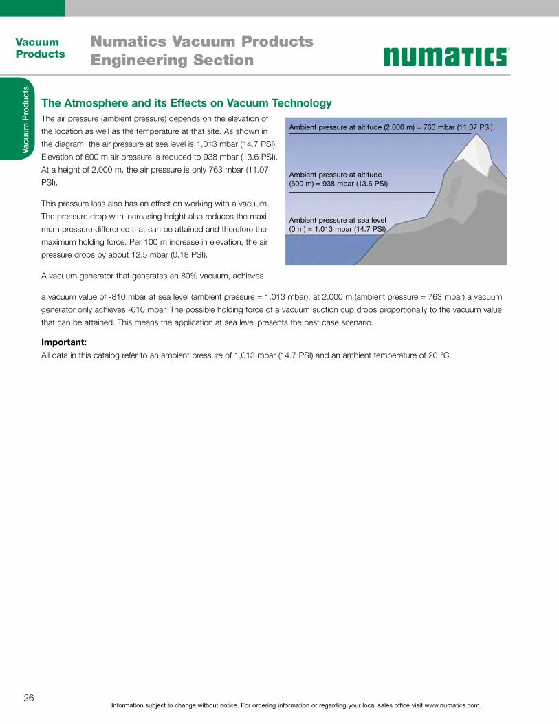
The Atmosphere and its Effects on Vacuum TechnologyThe air pressure (ambient pressure) depends on the elevation of the location as well as the temperature at that site. As shown in the diagram, the air pressure at sea level is 1,013 mbar (14.7 PSI). Elevation of 600 m air pressure is reduced to 938 mbar (13.6 PSI). At a height of 2,000 m, the air pressure is only 763 mbar (11.07 PSI).
This pressure loss also has an effect on working with a vacuum. The pressure drop with increasing height also reduces the maxi- mum pressure difference that can be attained and therefore the maximum holding force. Per 100 m increase in elevation, the air pressure drops by about 12.5 mbar (0.18 PSI).
A vacuum generator that generates an 80% vacuum, achieves
a vacuum value of -810 mbar at sea level (ambient pressure = 1,013 mbar); at 2,000 m (ambient pressure = 763 mbar) a vacuum generator only achieves -610 mbar. The possible holding force of a vacuum suction cup drops proportionally to the vacuum value that can be attained. This means the application at sea level presents the best case scenario.
Important:All data in this catalog refer to an ambient pressure of 1,013 mbar (14.7 PSI) and an ambient temperature of 20 °C.
Ambient pressure at altitude (2,000 m) = 763 mbar (11.07 PSI)
Ambient pressure at altitude (600 m) = 938 mbar (13.6 PSI)
Ambient pressure at sea level (0 m) = 1.013 mbar (14.7 PSI)
Information subject to change without notice. For ordering information or regarding your local sales office visit www.numatics.com.27
Vacuum Products
Numatics Vacuum ProductsEngineering Section
Vacu
um P
rodu
cts
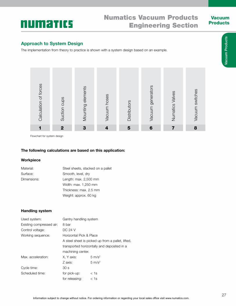
Approach to System DesignThe implementation from theory to practice is shown with a system design based on an example.
1 2 3 4 5 6 7 8
Cal
cula
tion
of fo
rces
Suc
tion
cups
Mou
ntin
g el
emen
ts
Vacu
um h
oses
Dis
tribu
tors
Vacu
um g
ener
ator
s
Num
atic
s Va
lves
Vacu
um s
witc
hes
Flowchart for system design
The following calculations are based on this application:
Workpiece
Handling system
Material: Surface: Dimensions:
Used system:Existing compressed air: Control voltage: Working sequence:
Max. acceleration:
Cycle time: Scheduled time:
Steel sheets, stacked on a pallet Smooth, level, dryLength: max. 2,500 mm Width: max. 1,250 mm Thickness: max. 2.5 mm Weight: approx. 60 kg
Gantry handling system8 barDC 24 VHorizontal Pick & PlaceA steel sheet is picked up from a pallet, lifted, transported horizontally and deposited in a machining center.X, Y axis: 5 m/s2
Z axis: 5 m/s2
30 sfor pick-up: < 1sfor releasing: < 1s
Information subject to change without notice. For ordering information or regarding your local sales office visit www.numatics.com.28
Vacuum Products
Numatics Vacuum ProductsEngineering Section
Vacu
um P
rodu
cts
Weight Calculation of a WorkpieceIt is important to determine the weight (m) of the workpiece to continue with additional calculations. It is calculated based on the following formula:
m = L x B x H x l
m = Weight (kg)
L = Length (m)
B =Width (m)
H = Height (m)
l = Density (kg/m3)
FTH = m x (g + a) x S
FTH = theoretical holding force (N)
m = Weight (kg)
g = Gravity (9.81 m/s2)
a = Acceleration (m/s2) of the system
S = Safety factor (minimum value 1.5 times safety;
for critical, diverse or varied or porous materials or rough surfaces 2.0
or even higher)
Our example:
m = 2.5mx1.25mx0.0025mx7,850kg/m3
m = 61.33kg
Our example:
FTH = 61.33 kg x (9.81 m/s2+ 5 m/s2) x 1.5
FTH = 1,363 N
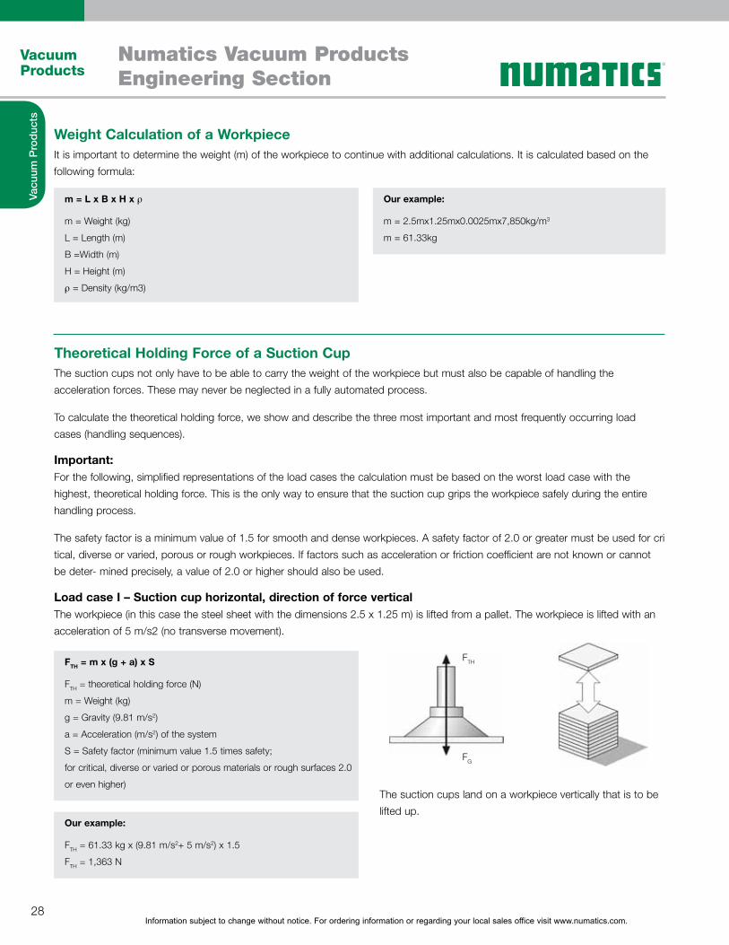
Theoretical Holding Force of a Suction CupThe suction cups not only have to be able to carry the weight of the workpiece but must also be capable of handling the acceleration forces. These may never be neglected in a fully automated process.
To calculate the theoretical holding force, we show and describe the three most important and most frequently occurring load cases (handling sequences).
Important:For the following, simplified representations of the load cases the calculation must be based on the worst load case with the highest, theoretical holding force. This is the only way to ensure that the suction cup grips the workpiece safely during the entire handling process.
The safety factor is a minimum value of 1.5 for smooth and dense workpieces. A safety factor of 2.0 or greater must be used for cri tical, diverse or varied, porous or rough workpieces. If factors such as acceleration or friction coefficient are not known or cannot be deter- mined precisely, a value of 2.0 or higher should also be used.
Load case I – Suction cup horizontal, direction of force verticalThe workpiece (in this case the steel sheet with the dimensions 2.5 x 1.25 m) is lifted from a pallet. The workpiece is lifted with an acceleration of 5 m/s2 (no transverse movement).
The suction cups land on a workpiece vertically that is to be lifted up.
FTH
FG
Information subject to change without notice. For ordering information or regarding your local sales office visit www.numatics.com.29
Vacuum Products
Numatics Vacuum ProductsEngineering Section
Vacu
um P
rodu
cts
FTH = m x (g + a/µ) x S
FTH = theoretical holding force (N)Fa = Acceleration force = m · am = Weight (kg)g = Gravity (9.81 m/s2)a = Acceleration (m/s2) of the system (keep in mind Emergency Stop situations!)µ = Friction coefficient = 0.1 for oily surfaces = 0.2 to 0.3 for wet surfaces = 0.5 for wood, metal, glass, stone etc. = 0.6 for rough surfacesCaution! The specified values for friction coefficient are averagedand must be checked for the individual workpiece!
S = Safety (minimum value 1.5 times safety, for critical, diverse or varied or porous materials or rough surfaces 2.0 or even higher)
FTH = (m/µ) x (g + a) x S
FTH = theoretical holding force (N)m = Weight (kg)g = Gravity (9.81 m/s2)a = Acceleration (m/s2) of the plant (keep in mind Emergency Stop situations!)µ = Friction coefficient = 0.1 for oily surfaces = 0.2 to 0.3 for wet surfaces = 0.5 for wood, metal, glass, stone etc. = 0.6 for rough surfacesS = Safety (minimum value 2.0 times safety, forcritical, diverse or varied or porous materials or rough surfaces even higher)
Our example:
FTH = 61.33 kg x (9.81 m/s2+ 5 m/s2) x 1.5 FTH = 1,822 N
Our example:
FTH = 61.33 kg x (9.81 m/s2+ 5 m/s2) x 1.5 FTH = 1,822 N
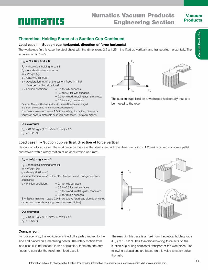
Theoretical Holding Force of a Suction Cup ContinuedLoad case II – Suction cup horizontal, direction of force horizontalThe workpiece (in this case the steel sheet with the dimensions 2.5 x 1.25 m) is lifted up vertically and transported horizontally. The acceleration is 5 m/s2.
Load case III – Suction cup vertical, direction of force verticalDescription of load case: The workpiece (in this case the steel sheet with the dimensions 2.5 x 1.25 m) is picked up from a pallet and moved with a rotary motion at an acceleration of 5 m/s2.
Comparison:For our scenario, the workpiece is lifted off a pallet, moved to the side and placed on a machining center. The rotary motion from load case III is not needed in this application, therefore one only needs to consider the result from load case II.
The suction cups land on a workpiece horizontally that is to be moved to the side.
The result in this case is a maximum theoretical holding force (FTH ) of 1,822 N. This theoretical holding force acts on the suction cup during horizontal transport of the workpiece. The following calculations are based on this value to safely solve the task.
FTH
FaFG
FTH
FG
Information subject to change without notice. For ordering information or regarding your local sales office visit www.numatics.com.30
Vacuum Products
Numatics Vacuum ProductsEngineering Section
Vacu
um P
rodu
cts
Calculation of suction force FS [N] for individual suction cup
FS = FTH/n
FS = Suction force
FTH = Theoretical holding force
n = Number of suction cups
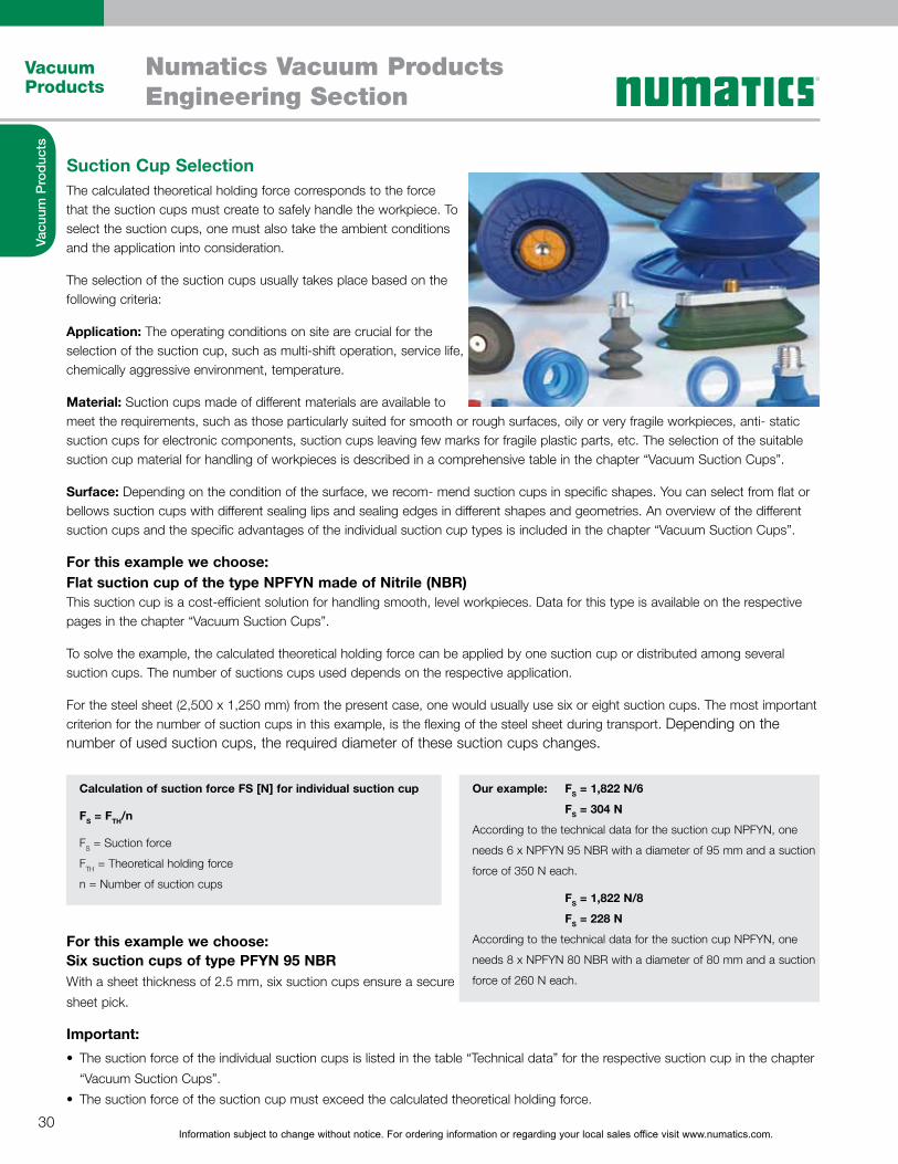
Suction Cup SelectionThe calculated theoretical holding force corresponds to the force that the suction cups must create to safely handle the workpiece. To select the suction cups, one must also take the ambient conditions and the application into consideration.
The selection of the suction cups usually takes place based on the following criteria:
Application: The operating conditions on site are crucial for the selection of the suction cup, such as multi-shift operation, service life, chemically aggressive environment, temperature.
Material: Suction cups made of different materials are available to meet the requirements, such as those particularly suited for smooth or rough surfaces, oily or very fragile workpieces, anti- static suction cups for electronic components, suction cups leaving few marks for fragile plastic parts, etc. The selection of the suitable suction cup material for handling of workpieces is described in a comprehensive table in the chapter “Vacuum Suction Cups”.
Surface: Depending on the condition of the surface, we recom- mend suction cups in specific shapes. You can select from flat or bellows suction cups with different sealing lips and sealing edges in different shapes and geometries. An overview of the different suction cups and the specific advantages of the individual suction cup types is included in the chapter “Vacuum Suction Cups”.
For this example we choose: Flat suction cup of the type NPFYN made of Nitrile (NBR)This suction cup is a cost-efficient solution for handling smooth, level workpieces. Data for this type is available on the respective pages in the chapter “Vacuum Suction Cups”.
To solve the example, the calculated theoretical holding force can be applied by one suction cup or distributed among several suction cups. The number of suctions cups used depends on the respective application.
For the steel sheet (2,500 x 1,250 mm) from the present case, one would usually use six or eight suction cups. The most important criterion for the number of suction cups in this example, is the flexing of the steel sheet during transport. Depending on the number of used suction cups, the required diameter of these suction cups changes.
For this example we choose:Six suction cups of type PFYN 95 NBRWith a sheet thickness of 2.5 mm, six suction cups ensure a secure sheet pick.
Important:
The suction force of the individual suction cups is listed in the table “Technical data” for the respective suction cup in the chapter “Vacuum Suction Cups”.The suction force of the suction cup must exceed the calculated theoretical holding force.
Our example: FS = 1,822 N/6
FS = 304 N
According to the technical data for the suction cup NPFYN, one
needs 6 x NPFYN 95 NBR with a diameter of 95 mm and a suction
force of 350 N each.
FS = 1,822 N/8
FS = 228 N
According to the technical data for the suction cup NPFYN, one
needs 8 x NPFYN 80 NBR with a diameter of 80 mm and a suction
force of 260 N each.
Information subject to change without notice. For ordering information or regarding your local sales office visit www.numatics.com.31
Vacuum Products
Numatics Vacuum ProductsEngineering Section
Vacu
um P
rodu
cts
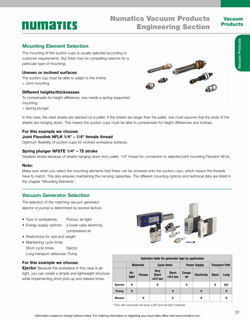
Mounting Element Selection
Vacuum Generator Selection
The mounting of the suction cups is usually selected according to customer requirements. But there may be compelling reasons for a particular type of mounting:
Uneven or inclined surfacesThe suction cup must be able to adapt to the incline: > Joint mounting
Different heights/thicknessesTo compensate for height difference, one needs a spring-supported mounting:> Spring plunger
In this case, the steel sheets are stacked on a pallet. If the sheets are larger than the pallet, one must assume that the ends of the sheets are hanging down. This means the suction cups must be able to compensate for height differences and inclines.
For this example we choose: Joint Flexolink NFLK 1/4" – 1/4" female threadOptimum flexibility of suction cups for inclined workpiece surfaces.
Spring plunger NFSTE 1/4" – 75 strokeGreatest stroke because of sheets hanging down from pallet, 1/4" thread for connection to selected joint mounting Flexolink NFLK.
Note:Make sure when you select the mounting elements that these can be screwed onto the suction cups, which means the threads have to match. This also ensures maintaining the carrying capacities. The different mounting options and technical data are listed in the chapter “Mounting Elements”.
The selection of the matching vacuum generator (ejector or pump) is determined by several factors:
Type of workpieces: Porous, air-tightEnergy supply options: a lower case electricity, compressed airRestrictions for size and weightMaintaining cycle times Short cycle times: Ejector Long transport distances: Pump
For this example we choose: Ejector Because the workpiece in this case is air-tight, you can create a simple and lightweight structure while implementing short pick-up and release times.
Selection table for generator type by application
Materials Cycle times Power Supply Transport Path
Air-tight Porous
Very Short
<0.5 sec
Short >0.5 sec
Compr. air Electricity Short Long
Ejector X X X X (X)*
Pump X X X X
Blower X X X X
* Only with automatic air-saver (LSP) and air-tight materials
Information subject to change without notice. For ordering information or regarding your local sales office visit www.numatics.com.32
Vacuum Products
Numatics Vacuum ProductsEngineering Section
Vacu
um P
rodu
cts
Vacuum Generator Selection ContinuedSuction rate of vacuum generator The diameter of the suction cup determines the suction rate that a vacuum generator has to apply to evacuate the suction cup. The suitable suction rate is described in the table “Technical data” of the respective vacuum generator.
Based on experience and measurements with system designs, we recommend a selection based on the following table:
Note: The specified values apply regardless of the type of vacuum generation. The recommended suction ratio applies per suction cup and only for smooth, air-tight surfaces. For porous, permeable workpieces we recommend conducting a corresponding suction trial with the original workpiece.
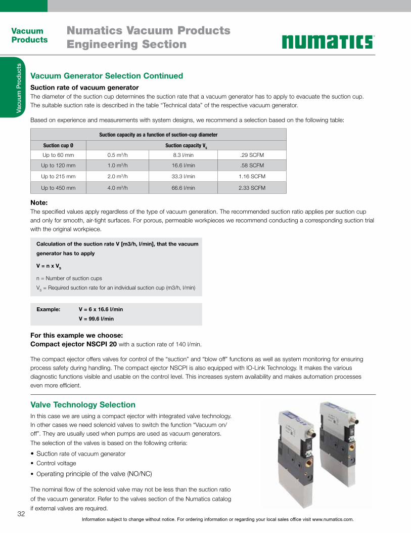
For this example we choose:Compact ejector NSCPI 20 with a suction rate of 140 l/min.
The compact ejector offers valves for control of the “suction” and “blow off” functions as well as system monitoring for ensuring process safety during handling. The compact ejector NSCPI is also equipped with IO-Link Technology. It makes the various diagnostic functions visible and usable on the control level. This increases system availability and makes automation processes even more efficient.
Suction capacity as a function of suction-cup diameter
Suction cup Ø Suction capacity VS
Up to 60 mm 0.5 m3/h 8.3 l/min .29 SCFM
Up to 120 mm 1.0 m3/h 16.6 l/min .58 SCFM
Up to 215 mm 2.0 m3/h 33.3 l/min 1.16 SCFM
Up to 450 mm 4.0 m3/h 66.6 l/min 2.33 SCFM
Calculation of the suction rate V [m3/h, l/min], that the vacuum
generator has to apply
V = n x VS
n = Number of suction cups
VS = Required suction rate for an individual suction cup (m3/h, l/min)
Example: V = 6 x 16.6 l/min
V = 99.6 l/min
Valve Technology SelectionIn this case we are using a compact ejector with integrated valve technology. In other cases we need solenoid valves to switch the function “Vacuum on/off”. They are usually used when pumps are used as vacuum generators.The selection of the valves is based on the following criteria:
Suction rate of vacuum generatorControl voltage
Operating principle of the valve (NO/NC)
The nominal flow of the solenoid valve may not be less than the suction ratio of the vacuum generator. Refer to the valves section of the Numatics catalog if external valves are required.
Information subject to change without notice. For ordering information or regarding your local sales office visit www.numatics.com.33
Vacuum Products
Numatics Vacuum ProductsEngineering Section
Vacu
um P
rodu
cts
The nominal flow is listed in the “Technical data” of the respective valve and the suction rate is listed in the “Technical data” of the respective vacuum generator.
Calculation of the suction rate V [m3/h, l/min], that the vacuum
generator has to apply
V = n x VS
n = Number of suction cups
VS = Required suction rate for an individual suction cup (m3/h, l/min)
Example: VV = 116 l/min = 7 m3/h
For this example we choose: The used compact ejector of type SCPI 20 is equipped with solenoid valves which eliminates the need for separate valves.
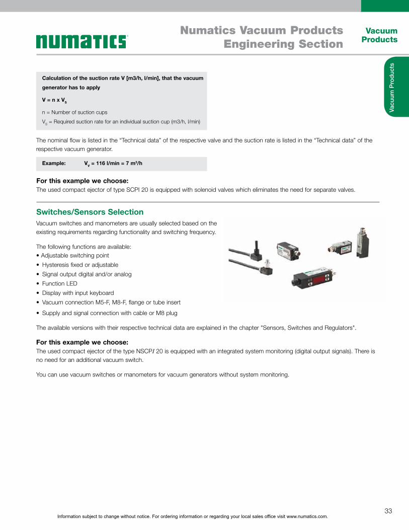
Switches/Sensors SelectionVacuum switches and manometers are usually selected based on the existing requirements regarding functionality and switching frequency.
The following functions are available:
Hysteresis fixed or adjustableSignal output digital and/or analog Function LEDDisplay with input keyboardVacuum connection M5-F, M8-F, flange or tube insert
Supply and signal connection with cable or M8 plug
The available versions with their respective technical data are explained in the chapter "Sensors, Switches and Regulators".
For this example we choose:The used compact ejector of the type NSCPI 20 is equipped with an integrated system monitoring (digital output signals). There is no need for an additional vacuum switch.
You can use vacuum switches or manometers for vacuum generators without system monitoring.

Information subject to change without notice. For ordering information or regarding your local sales office visit www.numatics.com.34
Vacuum Products
Numatics Vacuum ProductsEngineering Section
Vacu
um P
rodu
cts
Calculation of Evacuation Times
The evacuation time of the entire system is 0.34 seconds. The system is cost-optimized and efficient, shorter cycle times are possible.
The entire volume that has to be evacuated is required to calculate
the efficiency of the vacuum system.
VG = V1 + V2 + V3 + V4 + V5 + ...
VG = Volume to be evacuated (m3)
V1 = Volume of suction cups (m3)
V2 = Volume of mounting elements (m3)
V3 = Volume of vacuum hoses (m3)
V4 = Volume of distributor (m3)
V5 = Volume of prefilter (if necessary) (m3)
V6 = Volume of solenoid valve (if necessary) (m3)
...
Calculation of evacuation time t (h)
t = (VG x In (Pa/Pe) x 1.3)/V
VG = Volume to be evacuated (m3)
In = Natural logarithm
Pa = Absolute start pressure (1,013 mbar)
Pe = Absolute final pressure (mbar)
V = Suction rate of vacuum generator (m3/h)
Example:
VG = 6 x 32 cm3 + 6 x 9.5 cm3 + 6 x 43 cm3 +1 x 38.5 cm3
VG = 546 cm3 = 0.000546 m3
Example:
t = (0.000546 m3 x In (1,013 mbar / 400 mbar) x 1.3) / 6.95 m3
t = 0.0000949 h = 0.34 sec
60% = 400 mbar absolute
Test with Original PartsThe example listed above provides a recommendation ratio on a theoretical system design. It is recommended to perform testing using actual work pieces. If required, we will assist and and provicde test analysis
Information subject to change without notice. For ordering information or regarding your local sales office visit www.numatics.com.35
Vacuum Products
Numatics Vacuum ProductsEngineering Section
Vacu
um P
rodu
cts
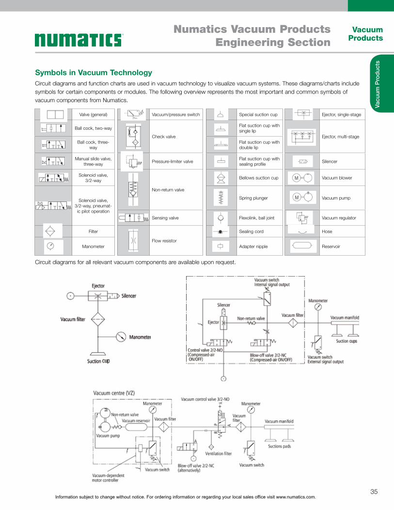
Symbols in Vacuum TechnologyCircuit diagrams and function charts are used in vacuum technology to visualize vacuum systems. These diagrams/charts include symbols for certain components or modules. The following overview represents the most important and common symbols of vacuum components from Numatics.
Circuit diagrams for all relevant vacuum components are available upon request.
Valve (general) Vacuum/pressure switch Special suction cup Ejector, single-stage
Ball cock, two-way
Check valve
Flat suction cup with single lip
Ejector, multi-stageBall cock, three-
wayFlat suction cup with double lip
Manual slide valve, three-way Pressure-limiter valve Flat suction cup with
sealing profile Silencer
Solenoid valve, 3/2-way
Non-return valve
Bellows suction cup Vacuum blower
Solenoid valve, 3/2-way, pneumat-ic pilot operation
Spring plunger Vacuum pump
Sensing valve Flexolink, ball joint Vacuum regulator
Filter
Flow resistor
Sealing cord Hose
Manometer Adapter nipple Reservoir
Information subject to change without notice. For ordering information or regarding your local sales office visit www.numatics.com.36
Vacuum Products
Numatics Vacuum ProductsEngineering Section
Vacu
um P
rodu
cts
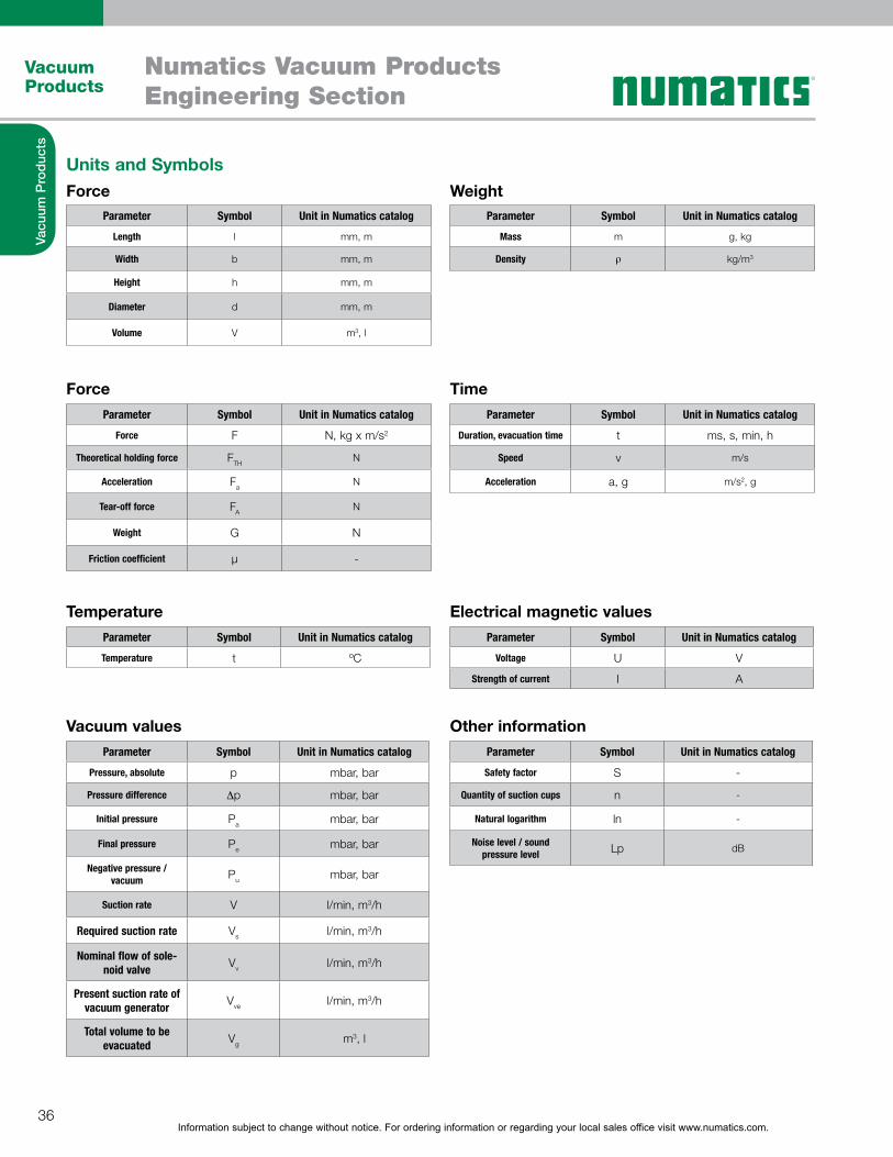
Units and Symbols
Force Time
Force Weight
Vacuum values Other information
Temperature Electrical magnetic values
Parameter Symbol Unit in Numatics catalog
Length l mm, m
Width b mm, m
Height h mm, m
Diameter d mm, m
Volume V m3, l
Parameter Symbol Unit in Numatics catalog
Mass m g, kg
Density l kg/m3
Parameter Symbol Unit in Numatics catalog
Force F N, kg x m/s2
Theoretical holding force FTHN
Acceleration FaN
Tear-off force FAN
Weight G N
Friction coefficient µ -
Parameter Symbol Unit in Numatics catalog
Duration, evacuation time t ms, s, min, h
Speed v m/s
Acceleration a, g m/s2, g
Parameter Symbol Unit in Numatics catalog
Pressure, absolute p mbar, bar
Pressure difference 6p mbar, bar
Initial pressure Pa mbar, bar
Final pressure Pe mbar, bar
Negative pressure / vacuum Pu mbar, bar
Suction rate V l/min, m3/h
Required suction rate Vs l/min, m3/h
Nominal flow of sole-noid valve Vv l/min, m3/h
Present suction rate of vacuum generator Vve l/min, m3/h
Total volume to be evacuated Vg m3, l
Parameter Symbol Unit in Numatics catalog
Safety factor S -
Quantity of suction cups n -
Natural logarithm ln -
Noise level / sound pressure level Lp dB
Parameter Symbol Unit in Numatics catalog
Temperature t ºC
Parameter Symbol Unit in Numatics catalog
Voltage U V
Strength of current I A
Information subject to change without notice. For ordering information or regarding your local sales office visit www.numatics.com.37
Vacuum Products
Numatics Vacuum ProductsEngineering Section
Vacu
um P
rodu
cts
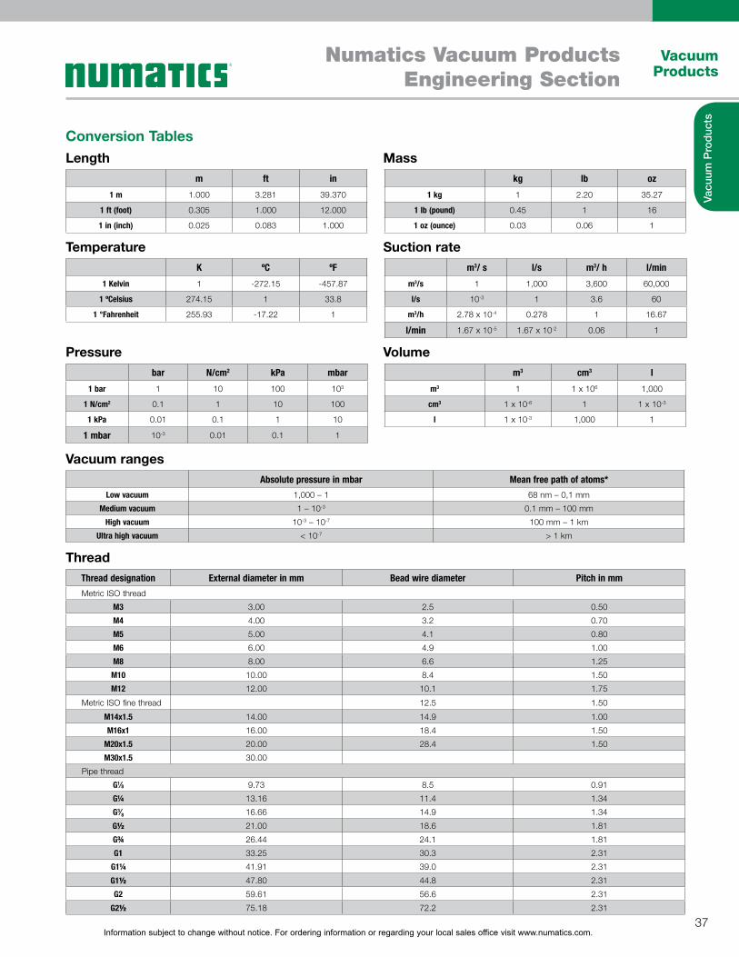
Conversion TablesLength
Temperature
Pressure
Vacuum ranges
Thread
Mass
Suction rate
Volume
m ft in
1 m 1.000 3.281 39.370
1 ft (foot) 0.305 1.000 12.000
1 in (inch) 0.025 0.083 1.000
K ºC ºF
1 Kelvin 1 -272.15 -457.87
1 ºCelsius 274.15 1 33.8
1 °Fahrenheit 255.93 -17.22 1
kg lb oz
1 kg 1 2.20 35.27
1 lb (pound) 0.45 1 16
1 oz (ounce) 0.03 0.06 1
m3 cm3 l
m3 1 1 x 10⁶ 1,000
cm3 1 x 10⁻⁶ 1 1 x 10⁻³
l 1 x 10⁻³ 1,000 1
m3/ s l/s m3/ h l/min
m3/s 1 1,000 3,600 60,000
l/s 10-3 1 3.6 60
m3/h 2.78 x 10⁻⁴ 0.278 1 16.67
l/min 1.67 x 10⁻⁵ 1.67 x 10⁻² 0.06 1
bar N/cm2 kPa mbar
1 bar 1 10 100 103
1 N/cm2 0.1 1 10 100
1 kPa 0.01 0.1 1 10
1 mbar 10-3 0.01 0.1 1
Absolute pressure in mbar Mean free path of atoms*Low vacuum 1,000 – 1 68 nm – 0,1 mm
Medium vacuum 1 – 10-3 0.1 mm – 100 mm
High vacuum 10-3 – 10-7 100 mm – 1 km
Ultra high vacuum < 10-7 > 1 km
Thread designation External diameter in mm Bead wire diameter Pitch in mmMetric ISO thread
M3 3.00 2.5 0.50
M4 4.00 3.2 0.70
M5 5.00 4.1 0.80
M6 6.00 4.9 1.00
M8 8.00 6.6 1.25
M10 10.00 8.4 1.50
M12 12.00 10.1 1.75
Metric ISO fine thread 12.5 1.50
M14x1.5 14.00 14.9 1.00
M16x1 16.00 18.4 1.50
M20x1.5 20.00 28.4 1.50
M30x1.5 30.00
Pipe thread
G1⁄8 9.73 8.5 0.91
G! 13.16 11.4 1.34
G3⁄8 16.66 14.9 1.34
G! 21.00 18.6 1.81
G" 26.44 24.1 1.81
G1 33.25 30.3 2.31
G1! 41.91 39.0 2.31
G1! 47.80 44.8 2.31
G2 59.61 56.6 2.31
G2! 75.18 72.2 2.31

Information subject to change without notice. For ordering information or regarding your local sales office visit www.numatics.com.38
Vacuum Products
Numatics Vacuum ProductsEngineering Section
Vacu
um P
rodu
cts
Vacuum GlossaryAbrasion resistanceThe abrasion resistance refers to the resistance of suction cups (elastomer part) against mechanical stress, especially friction. It is determined by the material properties of the suction cup as well as its shape.
Absolute pressureThe absolute pressure refers to the absolute zero point, or a space completely empty of molecules. In an absolute vacuum there is a pressure of 0 bar. A relative vacuum of -600 mbar corresponds to an absolute pressure of 400 mbar.
Air-saving functionAir-saving function refers to the ejector's air-saving function dur-ing the handling procedure. Once the ejector reaches a parti- cular vacuum value, the evacuation process is interrupted. If the vacuum drops below a defined value, the ejector starts evacu-ating again. The air-saving function can therefore increase the energy and economic efficiency of a vacuum system.
Ambient pressure (atmospheric pressure)Ambient pressure refers to the hydrostatic pressure that exists at any given point. Ambient pressure is also known as atmo-spheric pressure. The standard atmospheric pressure at sea level is 1,013 mbar. The ambient pressure drops with increas-ing altitude. The ambient pressure has a direct influence on the maximum vacuum value that can be reached.
Bernoulli's principleBernoulli's principle describes the drop in pressure of a fluid when it passes from a narrow section to a much wider section. In practice, this happens in the form of a direct transition into an open space. To prevent the vacuum collapsing, the fluid is diverted to the side.
Centralized vacuum systemIn a centralized vacuum system, the vacuum is generated with a central vacuum source for more than one suction cups.
Check valveThe check valve is the valve that automatically monitors vol-ume flow. If the volume flow exceeds a defined value, the valve closes automatically; for example, when suction cups are not being used.
Control pressure rangeThe control pressure range is the range between the lowest and highest permissible control pressures.
Cycle timeThe cycle time refers to the time taken for a repetitive process to complete one cycle.
Decentralized vacuum systemIn a decentralized vacuum system, a vacuum is generated directly at each individual vacuum suction cup. Positioning vacuum gene- ration directly at the suction cup allows for short pick-up and depositing times.
Evacuation timeThe evacuation time refers to the time it takes to evacuate a certain volume to reach a required vacuum value.
Flow resistanceFlow resistance refers to a reduced flow cross-section in a vacuum line. The resistance reduces the volume flow that can pass through a line.
Friction coefficientThe friction coefficient [µ] refers to the relationship between friction force and normal force (contact force between suction cup and workpiece). The friction coefficient is not specified by an unit.
High vacuumA high vacuum describes any vacuum in which there is an abso- lute pressure of 10-7 to 10-3 mbar. High vacuums are used, for example, in electron tubes and particle accelerators.
Holding forceHolding force refers to the force that can be exerted by a suc-tion cup to grip a workpiece. It is calculated by multiplying the pres- sure difference by the effective suction area of the suc-tion cup (F = 6p x A). The holding force of a suction cup is thus influenced by underpressure and the suction area. It is a theoretical value, specified without safety factors. It is usual to state the holding force of a suction cup with a relative vacuum of 60%.
HysteresisHysteresis refers to a pressure difference between two switch-ing points, and thus defines the state of the output signal. The res- pective output signal changes when either the upper or lower limit value of the hysteresis is reached. Using the example of a vacuum switch: when the vacuum reaches a specified value, the signal changes to “ON”. If the vacuum drops below a defined value, the signal switches to “OFF”. Hysteresis is mainly used to control the air-saving function of ejectors.
Idle position of NC valveThe idle position of an NC valve refers to the position of the valve when it is not actuated, i.e. “closed” (normally closed).
Idle position of NO valveThe idle position of an NO valve refers to the position of the valve when it is not actuated, i.e. “open” (normally open).
Information subject to change without notice. For ordering information or regarding your local sales office visit www.numatics.com.39
Vacuum Products
Numatics Vacuum ProductsEngineering Section
Vacu
um P
rodu
cts
Vacuum Glossary ContinuedInner volumeThe inner volume indicates the volume of the body that has to be evacuated during a suction procedure. For example, the inner volume of a suction cup has an effect on the evacuation time.
LeakageLeakage refers to a leak within the vacuum system. This can be caused by missing or faulty sealing elements, or by the porosity of the workpiece being processed.
Load caseLoad case refers to the handling task, or the process of han-dling a workpiece.Load case I – Suction cup horizontal, direction of force vertical Load case II – Suction cup horizontal, direction of force horizon-tal Load case III – Suction cup vertical, direction of force vertical
Low vacuumA low vacuum describes any vacuum in which there is an absolute pressure of 1 mbar up to atmospheric pressure (1,013 mbar). Examples of applications for a low vacuum include light bulbs and vacuum cleaners. Vacuum handling technology also uses values in the low vacuum range because these can be generated economically to create high suction power and short cycle times.
Medium vacuumA medium vacuum describes any vacuum in which there is an absolute pressure between 0.001 mbar and 1 mbar. Medium vacuums are used, for example, in low-pressure gas-filled lights.
Nominal flowNominal flow refers to the maximum flow through a certain dia- meter (nominal diameter). The nominal flow is given in l/min or m3/h.
Normal forceNormal force is the force component acting perpendicular to a surface. Every force acting on a surface can be divided into normal force and shear force (see “Shear force”). Based on the normal force, the friction force can be calculated using the friction coefficient for a material pairing. The result indicates the friction force between two surfaces, for example between a suction cup and a workpiece. Normal force is measured in Newton [N].
NPN – Switching outputNPN switching output refers to the configuration of a switch-ing output in cases where the load is connected to the positive pole of the operating voltage source. The output transistor of the vacuum switch connects the active device through to the opera- ting voltage, allowing current to flow through the con-suming device.
Minimum radius of curvatureThe minimum radius of curvature refers to the smallest radius that a suction cup can securely grip. For round suction cups, this refers to a sphere, while for oval suction cups it refers to a cylinder.
Operating temperatureThe operating temperature is the temperature range in which a product can be deployed or run.
Overpressure resistanceOverpressure resistance refers to the maximum pressure that a body (for example, a reservoir or vacuum filter) can resist.
PNP Switching outputPNP switching output refers to the configuration of a switching output in cases where the load has a permanent connection to the operating voltage source. The output transistor of the vacuum switch connects the active device to the positive pole, allowing current to flow through the consuming device.
Recovery timeThe recovery time is the period in which the product is not being used or is not subject to significant work loads. The prod-uct can recover during this time.
Reference pressureReference pressure is the pressure referred to by a sensor. Vacuum switches, for example, have a connection for reference air.
Relative pressureRelative pressure refers to the value of pressure in relation to the prevalent ambient pressure. The vacuum is given using negative values. Relative pressure has a pressure of 0 mbar as a refer-ence point. An absolute pressure of 400 mbar corresponds to a relative pressure of -600 mbar. In the field of vacuum handling, it is also common to state the values in percentages:-600 mbar corresponds to a vacuum of 60%.
Reversing valveA reversing valve is a type of changeover valve used in a blower. The valve supplies the system alternately with overpressure and underpressure. The valve thus controls the suction, blow-off and neutral setting in the vacuum system.
Shear forceShear force is the force acting tangentially to a surface and indi- cates how much friction can be transferred between the suction cup and workpiece. Shear force is given in Newton [N].

Information subject to change without notice. For ordering information or regarding your local sales office visit www.numatics.com.40
Vacuum Products
Numatics Vacuum ProductsEngineering Section
Vacu
um P
rodu
cts
Vacuum Glossary ContinuedVenturi principleThe Venturi principle describes the correlation between dynamic and static air pressure when air flows through a tube. At the narrowest section, the dynamic pressure is at a maximum, while the static pressure is at a minimum. Since the same volume is flowing through the tube, the velocity increases in proportion to the cross sections. Because of this differential pressure, a vac-uum can be created and air can be drawn in by using Venturi nozzles with a side inlet port. Vacuum generators based on this principle are called ejectors.
Volume flowVolume flow refers to the volume of a medium that flows through a cross section within a certain amount of time.
Workpiece temperatureThe workpiece temperature is the temperature of a processed workpiece. This temperature can influence the selection of a suitable suction cup material.
Standard literA standard liter is the measurement of a gas occupying a liter at 20 °C and 1,013 mbar (standard state).
Standard pressureStandard pressure is the pressure in the atmosphere under stan- dard conditions. In both technology and the natural sci-ences, this is 1,013 mbar at 0°C. The values in the Numatics catalog refer to a temperature of 20 °C
Standard temperatureStandard temperature is the temperature under standard condi- tions. The values in the Numatics catalog refer to a temperature of 20 °C.
Suction forceSee “Holding force”
Suction cup strokeThe suction cup stroke refers to the stroke effect that is created by the suction cup when picking up a workpiece. The stroke value indicates the maximum contraction of the suction cup.
Suction powerSee “Suction rate”
Suction rateSuction rate refers to the suction power of a vacuum genera-tor. This value indicates the volume that can be evacuated by a vacuum generator in a certain time. The suction rate is given in l/min or m3/h.
Switching pointThe switching point refers to a point at which a switch changes the state of the output signal. If, for example, a programmed vacuum value is reached on a vacuum switch, the output signal switches to “ON” and there is voltage at the switch output.The initial position of the signal can be set to either NC (opener) or NO (closer).
VacuumA vacuum is a pressure range lower than that of the ambient pressure. The vacuum value is divided into various classes; refer to "High Vacuum", “Medium Vacuum” and “Low Vacuum”.
Ventilation timeThe ventilation time refers to the time it takes to dissipate vacuum in a system. This defines the time it takes to release a workpiece. The ventilation of a suction cup can take place either atmospheri- cally or actively by a compressed air pulse (active blow off).
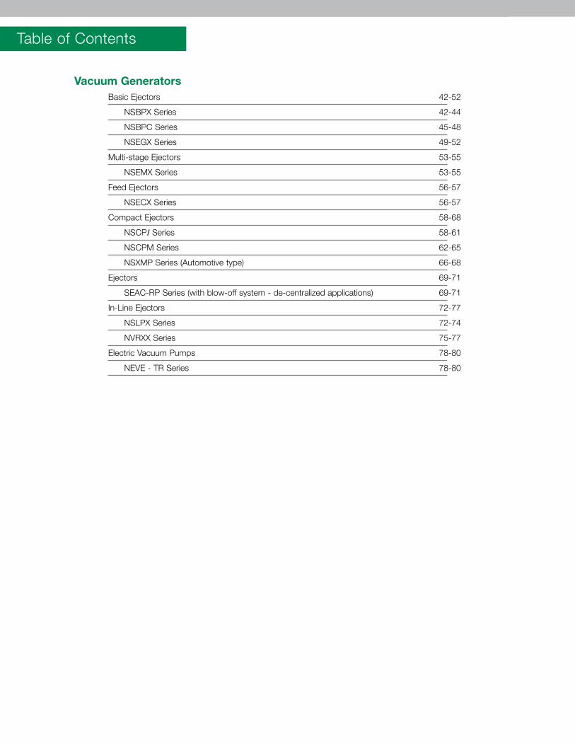
Table of Contents
Vacuum Generators Basic Ejectors 42-52
NSBPX Series 42-44
NSBPC Series 45-48
NSEGX Series 49-52
Multi-stage Ejectors 53-55
NSEMX Series 53-55
Feed Ejectors 56-57
NSECX Series 56-57
Compact Ejectors 58-68
NSCPI Series 58-61
NSCPM Series 62-65
NSXMP Series (Automotive type) 66-68
Ejectors 69-71
SEAC-RP Series (with blow-off system - de-centralized applications) 69-71
In-Line Ejectors 72-77
NSLPX Series 72-74
NVRXX Series 75-77
Electric Vacuum Pumps 78-80
NEVE - TR Series 78-80
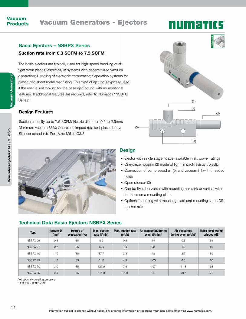
Information subject to change without notice. For ordering information or regarding your local sales office visit www.numatics.com.42
Vacuum Products Vacuum Generators - Ejectors
Vacu
um G
ener
ator
s
Design
Ejector with single stage nozzle: available in six power ratings
One-piece housing (2) made of light, impact-resistant plastic
Connection of compressed air (5) and vacuum (1) with threaded
holes
Open silencer (3)
Can be fixed horizontal with mounting holes (4) or vertical with
the base on a mounting plate
Optional mounting with mounting plate and mounting kit on DIN
top-hat rails
Suction capacity up to 7.5 SCFM; Nozzle diameter: 0.5 to 2.5mm;
Maximum vacuum 85%; One-piece impact resistant plastic body;
Silencer (standard). Port Size: M5 to G3/8
Design Features
Basic Ejectors – NSBPX SeriesSuction rate from 0.3 SCFM to 7.5 SCFM
The basic ejectors are typically used for high-speed handling of air-
tight work pieces, especially in systems with decentralized vacuum
generation; Handling of electronic component; Separation systems for
plastic and sheet metal machining. This type of ejector is typically used
if the user is just looking for the base ejector unit with no additional
features. If additional features are required, refer to Numatics “NSBPC
Series”.
Gen
erat
ors-
Eje
ctor
s: N
SB
PX
Ser
ies
Type Nozzle-Ø (mm)
Degree of evacuation (%)
Max. suction rate (l/min)
Max. suction rate (m3/h)
Air consumpt. during evac. (l/min)*
Air consumpt. during evac. (m3/h)*
Noise level workp. gripped (dB)
NSBPX 05 0.5 85 8.0 0.5 14 0.8 53
NSBPX 07 0.7 85 16.0 1.0 22 1.3 59
NSBPX 10 1.0 85 37.7 2.3 48 2.9 59
NSBPX 15 1.5 85 71.0 4.3 105 6.3 65
NSBPX 20 2.0 85 127.0 7.6 197 11.8 68
NSBPX 25 2.5 85 215.0 12.9 311 18.7 70
Technical Data Basic Ejectors NSBPX Series
*At optimal operating pressure **For max. length 2 m
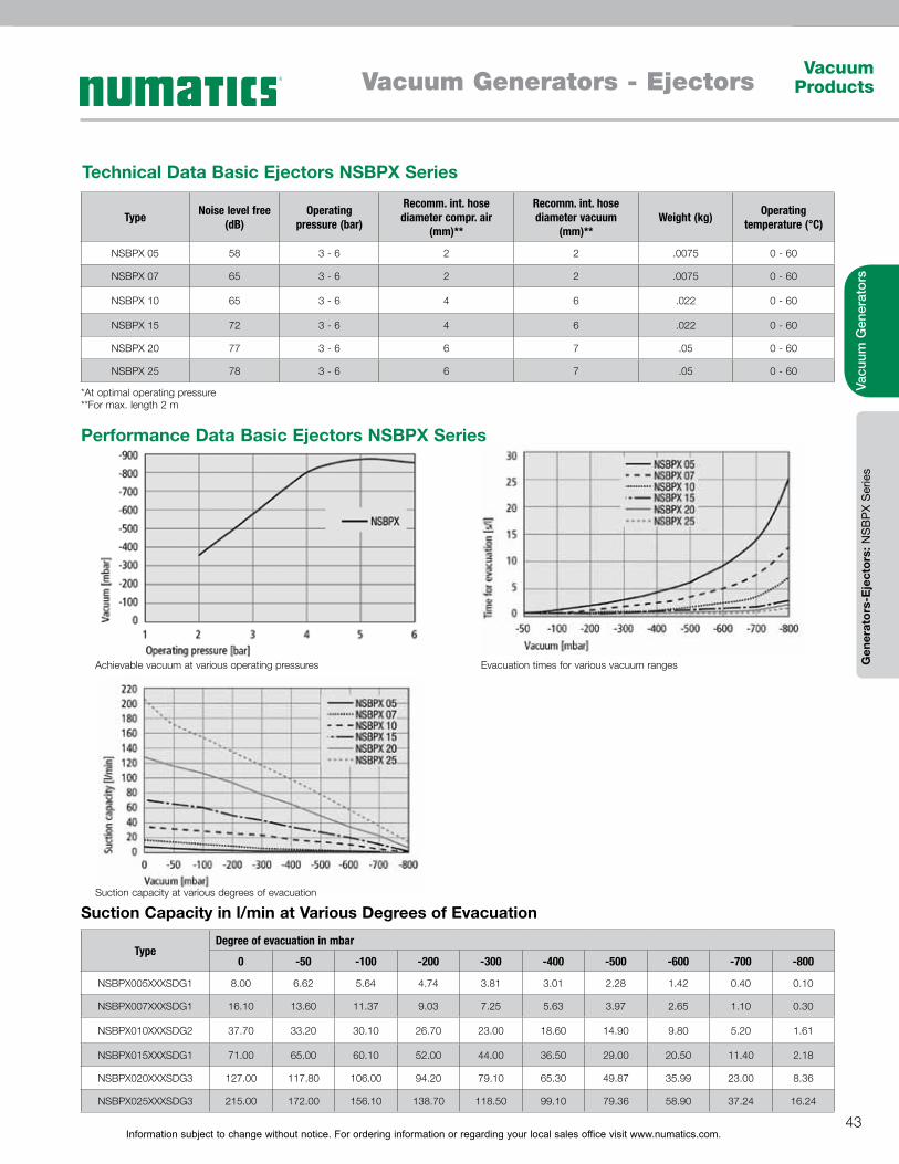
Information subject to change without notice. For ordering information or regarding your local sales office visit www.numatics.com.43
Vacuum ProductsVacuum Generators - Ejectors
Vacu
um G
ener
ator
sG
ener
ator
s-E
ject
ors:
NS
BP
X S
erie
s
TypeDegree of evacuation in mbar
0 -50 -100 -200 -300 -400 -500 -600 -700 -800
NSBPX005XXXSDG1 8.00 6.62 5.64 4.74 3.81 3.01 2.28 1.42 0.40 0.10
NSBPX007XXXSDG1 16.10 13.60 11.37 9.03 7.25 5.63 3.97 2.65 1.10 0.30
NSBPX010XXXSDG2 37.70 33.20 30.10 26.70 23.00 18.60 14.90 9.80 5.20 1.61
NSBPX015XXXSDG1 71.00 65.00 60.10 52.00 44.00 36.50 29.00 20.50 11.40 2.18
NSBPX020XXXSDG3 127.00 117.80 106.00 94.20 79.10 65.30 49.87 35.99 23.00 8.36
NSBPX025XXXSDG3 215.00 172.00 156.10 138.70 118.50 99.10 79.36 58.90 37.24 16.24
Type Noise level free (dB)
Operating pressure (bar)
Recomm. int. hose diameter compr. air
(mm)**
Recomm. int. hose diameter vacuum
(mm)**Weight (kg) Operating
temperature (°C)
NSBPX 05 58 3 - 6 2 2 .0075 0 - 60
NSBPX 07 65 3 - 6 2 2 .0075 0 - 60
NSBPX 10 65 3 - 6 4 6 .022 0 - 60
NSBPX 15 72 3 - 6 4 6 .022 0 - 60
NSBPX 20 77 3 - 6 6 7 .05 0 - 60
NSBPX 25 78 3 - 6 6 7 .05 0 - 60
Technical Data Basic Ejectors NSBPX Series
Performance Data Basic Ejectors NSBPX Series
Suction Capacity in l/min at Various Degrees of Evacuation
*At optimal operating pressure **For max. length 2 m
Achievable vacuum at various operating pressures
Suction capacity at various degrees of evacuation
Evacuation times for various vacuum ranges
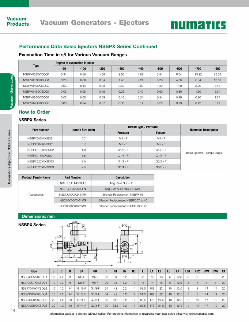
Information subject to change without notice. For ordering information or regarding your local sales office visit www.numatics.com.44
Vacuum Products Vacuum Generators - Ejectors
Vacu
um G
ener
ator
sG
ener
ator
s-E
ject
ors:
NS
BP
X S
erie
s
NSBPX Series
Dimensions: mm
How to OrderNSBPX Series
Part Number Nozzle Size (mm)Thread Type / Port Size
Numatics DescriptionPressure Vacuum
NSBPX005XXXSDG1 0.7 M5 - F M5 - F
Basic Ejectors - Single Stage
NSBPX007XXXSDG1 0.7 M5 - F M5 - F
NSBPX010XXXSDG2 1.0 G1/8 - F G1/8 - F
NSBPX015XXXSDG1 1.5 G1/8 - F G1/8 - F
NSBPX020XXXSDG3 2.0 G1/4 - F G3/8 - F
NSBPX025XXXSDG3 2.5 G1/4 - F G3/8 - F
Type B d D GA GB H H1 H2 H3 L L1 L2 L3 L4 LG1 LG2 SW1 SW2 X1
NSBPX005XXXSDG1 10 4.2 9 M5-F M5-F 26 31 5.2 12 45 74 18 5 12.5 5 5 8 8 20
NSBPX007XXXSDG1 10 4.2 9 M5-F M5-F 26 31 5.2 12 45 74 18 5 12.5 5 5 8 8 20
NSBPX010XXXSDG2 15 4.2 14 G1/8-F G1/8-F 34 42 5.2 14 51.5 102 22 10 12.5 8 8 14 14 20
NSBPX015XXXSDG1 15 4.2 14 G1/8-F G1/8-F 34 42 5.2 14 51.5 102 22 10 12.5 8 8 14 14 20
NSBPX020XXXSDG3 20 4.2 20 G1/4-F G3/8-F 39 53.5 5.2 17 86.5 176 24.5 13 12.5 9 10 17 19 20
NSBPX025XXXSDG3 20 4.2 20 G1/4-F G3/8-F 39 53.5 5.2 17 86.5 176 24.5 13 12.5 9 10 17 19 20
Product Family Name Part Number Description
Accessories
NBEPL1111453SBP Mtg Plate NSBP EJT
NSETSBPX0056CFN Mtg. Set NSBP/NSBPC M4F
NSDXXXXXXX24BMM Silencer Replacement NSBPX 05
NSDXXXXXXX401MG Silencer Replacement NSBPX 07 to 10
NSDXXXXXXX763MG Silencer Replacement NSBPX 20 to 25
TypeDegree of evacuation in mbar
-50 -100 -200 -300 -400 -500 -600 -700 -800
NSBPX005XXXSDG1 0.34 0.68 1.56 2.66 4.02 5.84 8.54 13.22 25.54
NSBPX007XXXSDG1 0.20 0.38 0.84 1.46 2.24 3.26 4.66 6.84 12.56
NSBPX010XXXSDG2 0.06 0.14 0.30 0.52 0.82 1.30 1.98 3.26 6.56
NSBPX015XXXSDG1 0.05 0.08 0.16 0.26 0.40 0.60 0.86 1.30 2.54
NSBPX020XXXSDG3 0.03 0.05 0.09 0.16 0.24 0.34 0.49 0.80 1.74
NSBPX025XXXSDG3 0.03 0.04 0.07 0.09 0.14 0.20 0.28 0.42 0.99
Evacuation Time in s/l for Various Vacuum Ranges
Performance Data Basic Ejectors NSBPX Series Continued
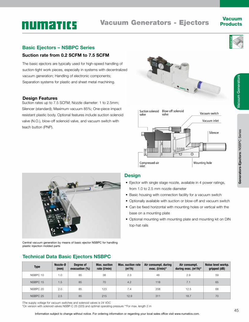
Information subject to change without notice. For ordering information or regarding your local sales office visit www.numatics.com.45
Vacuum ProductsVacuum Generators - Ejectors
Vacu
um G
ener
ator
sG
ener
ator
s-E
ject
ors:
NS
BP
C S
erie
s
The basic ejectors are typically used for high-speed handling of
suction-tight work pieces, especially in systems with decentralized
vacuum generation; Handling of electronic components;
Separation systems for plastic and sheet metal machining.
Design Features
Basic Ejectors – NSBPC SeriesSuction rate from 0.2 SCFM to 7.5 SCFM
Suction rates up to 7.5 SCFM; Nozzle diameter: 1 to 2.5mm;
Silencer (standard); Maximum vacuum 85%; One-piece impact
resistant plastic body. Optional features include suction solenoid
valve (N.O.), blow-off solenoid valve, and vacuum switch with
teach button (PNP).
DesignEjector with single stage nozzle, available in 4 power ratings,
from 1.0 to 2.5 mm nozzle diameter
Basic housing with connection facility for a vacuum switch
Optionally available with suction or blow-off and vacuum switch
Can be fixed horizontal with mounting holes or vertical with the
base on a mounting plate
Optional mounting with mounting plate and mounting kit on DIN
top-hat rails
Central vacuum generation by means of basic ejector NSBPC for handling plastic injection molded parts
Type Nozzle-Ø (mm)
Degree of evacuation (%)
Max. suction rate (l/min)
Max. suction rate (m3/h)
Air consumpt. during evac. (l/min)*
Air consumpt. during evac. (m3/h)*
Noise level workp. gripped (dB)
NSBPC 10 1.0 85 38 2.3 48 2.9 59
NSBPC 15 1.5 85 70 4.2 118 7.1 65
NSBPC 20 2.0 85 123 7.4 208 12.5 68
NSBPC 25 2.5 85 215 12.9 311 18.7 70
Technical Data Basic Ejectors NSBPC
!The supply voltage for vacuum switches and solenoid valves is 24 VDC*On version with solenoid valves NSBP-C 25 (320) and optimal operating pressure **For max. length 2 m
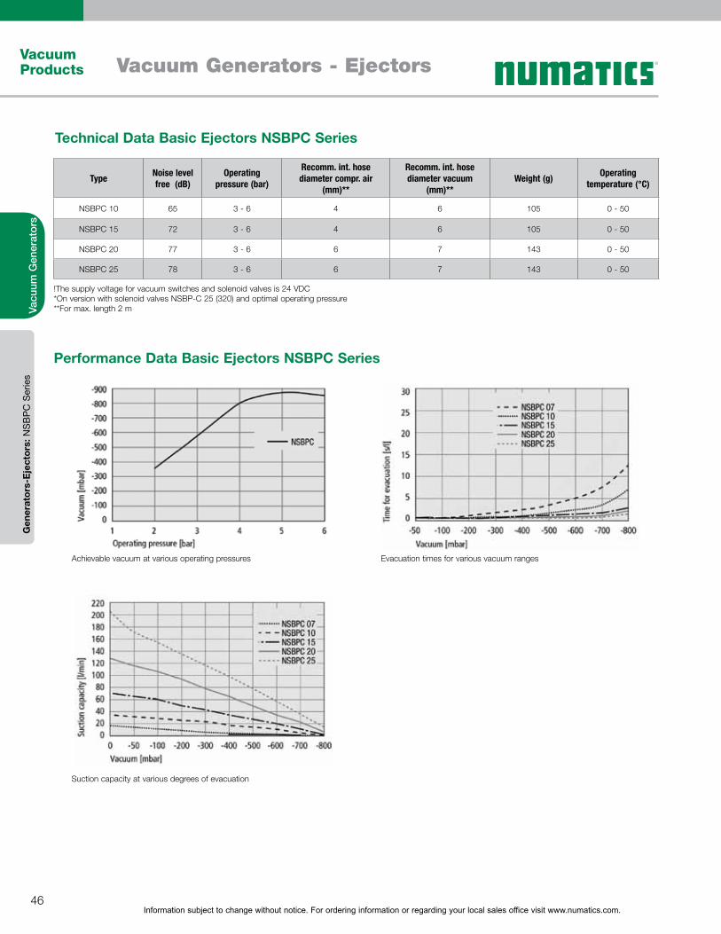
Information subject to change without notice. For ordering information or regarding your local sales office visit www.numatics.com.46
Vacuum Products Vacuum Generators - Ejectors
Vacu
um G
ener
ator
sG
ener
ator
s-E
ject
ors:
NS
BP
C S
erie
s
Type Noise level free (dB)
Operating pressure (bar)
Recomm. int. hose diameter compr. air
(mm)**
Recomm. int. hose diameter vacuum
(mm)**Weight (g) Operating
temperature (°C)
NSBPC 10 65 3 - 6 4 6 105 0 - 50
NSBPC 15 72 3 - 6 4 6 105 0 - 50
NSBPC 20 77 3 - 6 6 7 143 0 - 50
NSBPC 25 78 3 - 6 6 7 143 0 - 50
Technical Data Basic Ejectors NSBPC Series
!The supply voltage for vacuum switches and solenoid valves is 24 VDC*On version with solenoid valves NSBP-C 25 (320) and optimal operating pressure **For max. length 2 m
Performance Data Basic Ejectors NSBPC Series
Achievable vacuum at various operating pressures
Suction capacity at various degrees of evacuation
Evacuation times for various vacuum ranges
Information subject to change without notice. For ordering information or regarding your local sales office visit www.numatics.com.47
Vacuum ProductsVacuum Generators - Ejectors
Vacu
um G
ener
ator
sG
ener
ator
s-E
ject
ors:
NS
BP
C S
erie
s
TypeDegree of evacuation in mbar
0 -50 -100 -200 -300 -400 -500 -600 -700 -800
NSBPC 10 38.00 33.20 30.10 26.70 23.00 18.60 14.90 9.80 5.20 1.61
NSBPC 15 70.00 65.00 60.10 52.00 44.00 36.50 29.00 20.50 11.40 2.18
NSBPC 20 123.00 115.00 104.00 93.00 78.00 64.00 49.00 35.50 23.00 8.00
NSBPC 25 215.00 175.00 157.50 139.50 119.00 99.50 79.60 59.00 37.30 16.30
TypeDegree of evacuation in mbar
-50 -100 -200 -300 -400 -500 -600 -700 -800
NSBPC 10 0.06 0.14 0.30 0.52 0.82 1.30 1.98 3.26 6.56
NSBPC 15 0.05 0.08 0.16 0.26 0.40 0.60 0.86 1.30 2.54
NSBPC 20 0.03 0.05 0.09 0.16 0.24 0.34 0.49 0.80 1.74
NSBPC 25 0.02 0.03 0.06 0.09 0.14 0.20 0.28 0.42 0.99
Evacuation Time in s/l for Various Vacuum Ranges
Suction Capacity in l/min at Various Degrees of Evacuation
How to OrderNSBPC Series
Product Family Name Part number Nozzle Size (mm)Thread Type / Port Size
Description - FeaturesPressure Vacuum
Basic ejectors - single stage with additional features
NSBPC010XXXVTG2 1.0 G1/8 - F G1/8 - F Basic ejector; vacuum switch (PNP)
NSBPC010ANOXXG2 1.0 G1/8 - F G1/8 - F Basic ejector; suction valve; blow off valve
NSBPC010ANOVTG2 1.0 G1/8 - F G1/8 - F Basic ejector; suction valve; blow off valve; vacuum switch (PNP)
NSBPC015XXXVTG2 1.5 G1/8 - F G1/8 - F Basic ejector; vacuum switch (PNP)
NSBPC015ANOXXG2 1.5 G1/8 - F G1/8 - F Basic ejector; suction valve; blow off valve
NSBPC015ANOVTG2 1.5 G1/8 - F G1/8 - F Basic ejector; suction valve; blow off valve; vacuum switch (PNP)
NSBPC020XXXVTG3 2.0 G1/4 - F G3/8 - F Basic ejector; vacuum switch (PNP)
NSBPC020ANOXXG3 2.0 G1/4 - F G3/8 - F Basic ejector; suction valve; blow off valve;
NSBPC020ANOVTG3 2.0 G1/4 - F G3/8 - F Basic ejector; suction valve; blow off valve; vacuum switch (PNP)
NSBPC025XXXVTG3 2.5 G1/4 - F G3/8 - F Basic ejector; vacuum switch (PNP)
NSBPC025ANOXXG3 2.5 G1/4 - F G3/8 - F Basic ejector; suction valve; blow off valve
NSBPC025ANOVTG3 2.5 G1/4 - F G3/8 - F Basic ejector; suction valve; blow off valve; vacuum switch (PNP)
Product Family Name Part Number Description
Accessories
NBEPL1111453SBP Mtg Plate NSBP EJT
NSETSBPX0056CFN Mtg. Set NSBP/NSBPC M4F
NSDXXXXXXX401MG Silencer Replacement NSBPC 07 to 10
NSDXXXXXXX763MG Silencer Replacement NSBPC 20 to 25
NASKMIC1030PUGE 3 meter connection cable for solenoid valve
NASKBM8450PURGE Cable M8 4 5M PUR GE - Straight Connection
NASKBM8450PURWX Cable M8 4 5M PUR W - Right-angle connection
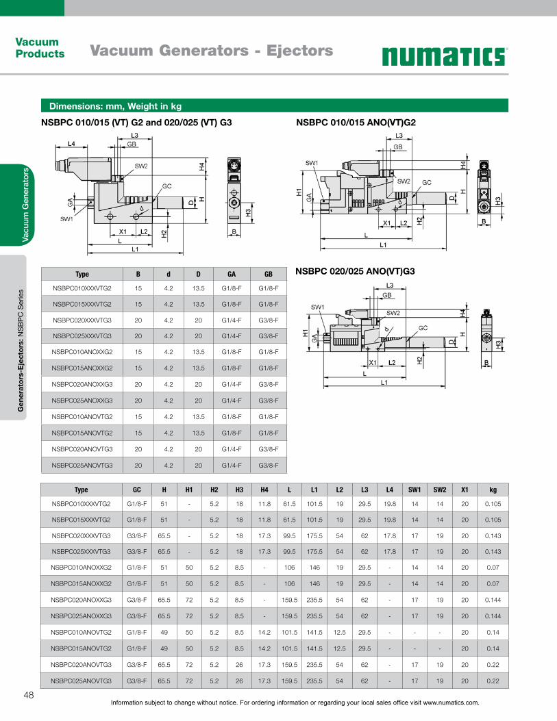
Information subject to change without notice. For ordering information or regarding your local sales office visit www.numatics.com.48
Vacuum Products Vacuum Generators - Ejectors
Vacu
um G
ener
ator
sG
ener
ator
s-E
ject
ors:
NS
BP
C S
erie
s
NSBPC 020/025 ANO(VT)G3
NSBPC 010/015 (VT) G2 and 020/025 (VT) G3 NSBPC 010/015 ANO(VT)G2
Dimensions: mm, Weight in kg
Type GC H H1 H2 H3 H4 L L1 L2 L3 L4 SW1 SW2 X1 kg
NSBPC010XXXVTG2 G1/8-F 51 - 5.2 18 11.8 61.5 101.5 19 29.5 19.8 14 14 20 0.105
NSBPC015XXXVTG2 G1/8-F 51 - 5.2 18 11.8 61.5 101.5 19 29.5 19.8 14 14 20 0.105
NSBPC020XXXVTG3 G3/8-F 65.5 - 5.2 18 17.3 99.5 175.5 54 62 17.8 17 19 20 0.143
NSBPC025XXXVTG3 G3/8-F 65.5 - 5.2 18 17.3 99.5 175.5 54 62 17.8 17 19 20 0.143
NSBPC010ANOXXG2 G1/8-F 51 50 5.2 8.5 - 106 146 19 29.5 - 14 14 20 0.07
NSBPC015ANOXXG2 G1/8-F 51 50 5.2 8.5 - 106 146 19 29.5 - 14 14 20 0.07
NSBPC020ANOXXG3 G3/8-F 65.5 72 5.2 8.5 - 159.5 235.5 54 62 - 17 19 20 0.144
NSBPC025ANOXXG3 G3/8-F 65.5 72 5.2 8.5 - 159.5 235.5 54 62 - 17 19 20 0.144
NSBPC010ANOVTG2 G1/8-F 49 50 5.2 8.5 14.2 101.5 141.5 12.5 29.5 - - - 20 0.14
NSBPC015ANOVTG2 G1/8-F 49 50 5.2 8.5 14.2 101.5 141.5 12.5 29.5 - - - 20 0.14
NSBPC020ANOVTG3 G3/8-F 65.5 72 5.2 26 17.3 159.5 235.5 54 62 - 17 19 20 0.22
NSBPC025ANOVTG3 G3/8-F 65.5 72 5.2 26 17.3 159.5 235.5 54 62 - 17 19 20 0.22
Type B d D GA GB
NSBPC010XXXVTG2 15 4.2 13.5 G1/8-F G1/8-F
NSBPC015XXXVTG2 15 4.2 13.5 G1/8-F G1/8-F
NSBPC020XXXVTG3 20 4.2 20 G1/4-F G3/8-F
NSBPC025XXXVTG3 20 4.2 20 G1/4-F G3/8-F
NSBPC010ANOXXG2 15 4.2 13.5 G1/8-F G1/8-F
NSBPC015ANOXXG2 15 4.2 13.5 G1/8-F G1/8-F
NSBPC020ANOXXG3 20 4.2 20 G1/4-F G3/8-F
NSBPC025ANOXXG3 20 4.2 20 G1/4-F G3/8-F
NSBPC010ANOVTG2 15 4.2 13.5 G1/8-F G1/8-F
NSBPC015ANOVTG2 15 4.2 13.5 G1/8-F G1/8-F
NSBPC020ANOVTG3 20 4.2 20 G1/4-F G3/8-F
NSBPC025ANOVTG3 20 4.2 20 G1/4-F G3/8-F
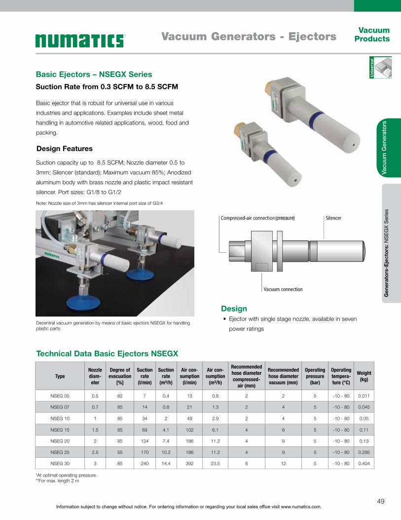
Information subject to change without notice. For ordering information or regarding your local sales office visit www.numatics.com.49
Vacuum ProductsVacuum Generators - Ejectors
Vacu
um G
ener
ator
sG
ener
ator
s-E
ject
ors:
NS
EGX
Ser
ies
Basic ejector that is robust for universal use in various
industries and applications. Examples include sheet metal
handling in automotive related applications, wood, food and
packing.
Suction capacity up to 8.5 SCFM; Nozzle diameter 0.5 to
3mm; Silencer (standard); Maximum vacuum 85%; Anodized
aluminum body with brass nozzle and plastic impact resistant
silencer. Port sizes: G1/8 to G1/2
Basic Ejectors – NSEGX SeriesSuction Rate from 0.3 SCFM to 8.5 SCFM
Design Features
Decentral vacuum generation by means of basic ejectors NSEGX for handling plastic parts
Note: Nozzle size of 3mm has silencer internal port size of G3/4
DesignEjector with single stage nozzle, available in seven
power ratings
TypeNozzle diam-eter
Degree of evacuation
[%]
Suction rate
(l/min)
Suction rate
(m#/h)
Air con-sumption
(l/min)
Air con-sumption
(m#/h)
Recommended hose diameter compressed-
air (mm)
Recommended hose diameter vacuum (mm)
Operating pressure
(bar)
Operating tempera-ture (°C)
Weight (kg)
NSEG 05 0.5 82 7 0.4 13 0.8 2 2 5 -10 - 80 0.011
NSEG 07 0.7 85 14 0.8 21 1.3 2 4 5 -10 - 80 0.045
NSEG 10 1 85 34 2 49 2.9 2 4 5 -10 - 80 0.05
NSEG 15 1.5 85 69 4.1 102 6.1 4 6 5 -10 - 80 0.11
NSEG 20 2 85 124 7.4 186 11.2 4 9 5 -10 - 80 0.13
NSEG 25 2.5 55 170 10.2 186 11.2 4 9 5 -10 - 80 0.295
NSEG 30 3 85 240 14.4 392 23.5 6 12 5 -10 - 80 0.404
Technical Data Basic Ejectors NSEGX
*At optimal operating pressure **For max. length 2 m
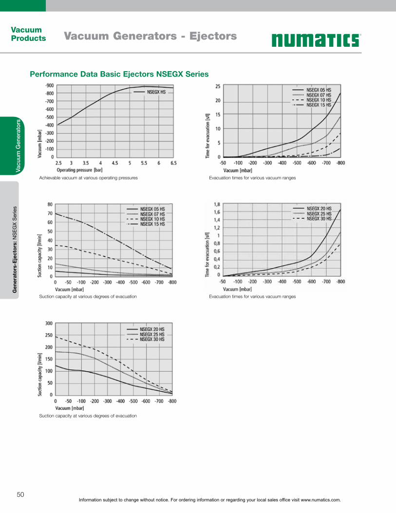
Information subject to change without notice. For ordering information or regarding your local sales office visit www.numatics.com.50
Vacuum Products Vacuum Generators - Ejectors
Vacu
um G
ener
ator
sG
ener
ator
s-E
ject
ors:
NS
EGX
Ser
ies
Performance Data Basic Ejectors NSEGX Series
Achievable vacuum at various operating pressures
Suction capacity at various degrees of evacuation
Suction capacity at various degrees of evacuation
Evacuation times for various vacuum ranges
Evacuation times for various vacuum ranges
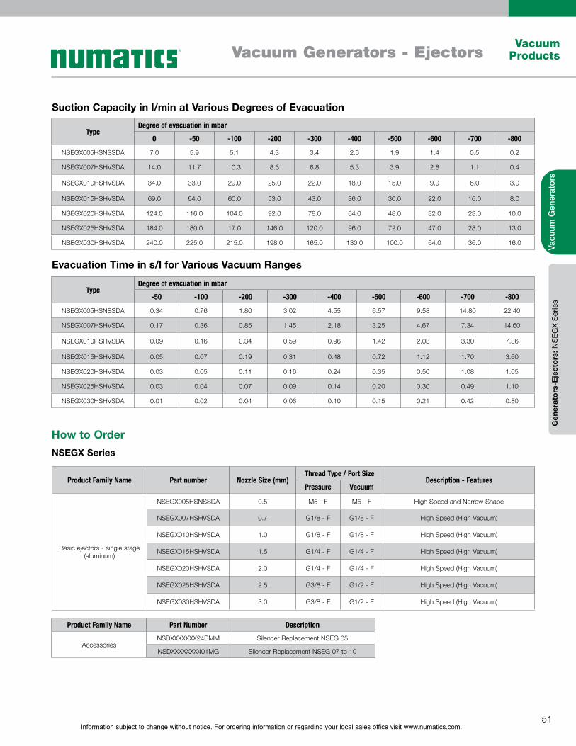
Information subject to change without notice. For ordering information or regarding your local sales office visit www.numatics.com.51
Vacuum ProductsVacuum Generators - Ejectors
Vacu
um G
ener
ator
sG
ener
ator
s-E
ject
ors:
NS
EGX
Ser
ies
TypeDegree of evacuation in mbar
0 -50 -100 -200 -300 -400 -500 -600 -700 -800
NSEGX005HSNSSDA 7.0 5.9 5.1 4.3 3.4 2.6 1.9 1.4 0.5 0.2
NSEGX007HSHVSDA 14.0 11.7 10.3 8.6 6.8 5.3 3.9 2.8 1.1 0.4
NSEGX010HSHVSDA 34.0 33.0 29.0 25.0 22.0 18.0 15.0 9.0 6.0 3.0
NSEGX015HSHVSDA 69.0 64.0 60.0 53.0 43.0 36.0 30.0 22.0 16.0 8.0
NSEGX020HSHVSDA 124.0 116.0 104.0 92.0 78.0 64.0 48.0 32.0 23.0 10.0
NSEGX025HSHVSDA 184.0 180.0 17.0 146.0 120.0 96.0 72.0 47.0 28.0 13.0
NSEGX030HSHVSDA 240.0 225.0 215.0 198.0 165.0 130.0 100.0 64.0 36.0 16.0
TypeDegree of evacuation in mbar
-50 -100 -200 -300 -400 -500 -600 -700 -800
NSEGX005HSNSSDA 0.34 0.76 1.80 3.02 4.55 6.57 9.58 14.80 22.40
NSEGX007HSHVSDA 0.17 0.36 0.85 1.45 2.18 3.25 4.67 7.34 14.60
NSEGX010HSHVSDA 0.09 0.16 0.34 0.59 0.96 1.42 2.03 3.30 7.36
NSEGX015HSHVSDA 0.05 0.07 0.19 0.31 0.48 0.72 1.12 1.70 3.60
NSEGX020HSHVSDA 0.03 0.05 0.11 0.16 0.24 0.35 0.50 1.08 1.65
NSEGX025HSHVSDA 0.03 0.04 0.07 0.09 0.14 0.20 0.30 0.49 1.10
NSEGX030HSHVSDA 0.01 0.02 0.04 0.06 0.10 0.15 0.21 0.42 0.80
Evacuation Time in s/l for Various Vacuum Ranges
Suction Capacity in l/min at Various Degrees of Evacuation
How to OrderNSEGX Series
Product Family Name Part number Nozzle Size (mm)Thread Type / Port Size
Description - FeaturesPressure Vacuum
Basic ejectors - single stage (aluminum)
NSEGX005HSNSSDA 0.5 M5 - F M5 - F High Speed and Narrow Shape
NSEGX007HSHVSDA 0.7 G1/8 - F G1/8 - F High Speed (High Vacuum)
NSEGX010HSHVSDA 1.0 G1/8 - F G1/8 - F High Speed (High Vacuum)
NSEGX015HSHVSDA 1.5 G1/4 - F G1/4 - F High Speed (High Vacuum)
NSEGX020HSHVSDA 2.0 G1/4 - F G1/4 - F High Speed (High Vacuum)
NSEGX025HSHVSDA 2.5 G3/8 - F G1/2 - F High Speed (High Vacuum)
NSEGX030HSHVSDA 3.0 G3/8 - F G1/2 - F High Speed (High Vacuum)
Product Family Name Part Number Description
AccessoriesNSDXXXXXXX24BMM Silencer Replacement NSEG 05
NSDXXXXXXX401MG Silencer Replacement NSEG 07 to 10
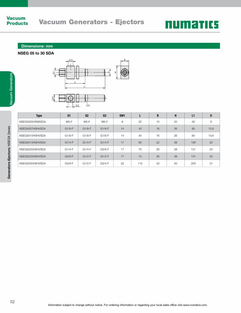
Information subject to change without notice. For ordering information or regarding your local sales office visit www.numatics.com.52
Vacuum Products Vacuum Generators - Ejectors
Vacu
um G
ener
ator
sG
ener
ator
s-E
ject
ors:
NS
EGX
Ser
ies
NSEG 05 to 30 SDA
Dimensions: mm
Type G1 G2 G3 SW1 L B H L1 D
NSEGX005HSNSSDA M5-F M5-F M5-F 8 32 10 20 56 9
NSEGX007HSHVSDA G1/8-F G1/8-F G1/8-F 14 40 16 26 80 13.6
NSEGX010HSHVSDA G1/8-F G1/8-F G1/8-F 14 45 16 26 85 13.6
NSEGX015HSHVSDA G1/4-F G1/4-F G1/4-F 17 60 22 38 106 20
NSEGX020HSHVSDA G1/4-F G1/4-F G3/8-F 17 75 26 38 131 20
NSEGX025HSHVSDA G3/8-F G1/2-F G1/2-F 17 75 26 38 131 20
NSEGX030HSHVSDA G3/8-F G1/2-F G3/4-F 22 110 42 50 200 31
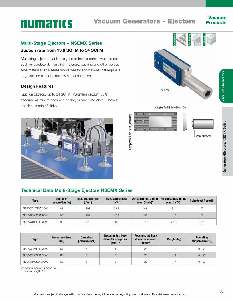
Information subject to change without notice. For ordering information or regarding your local sales office visit www.numatics.com.53
Vacuum ProductsVacuum Generators - Ejectors
Vacu
um G
ener
ator
sG
ener
ator
s-E
ject
ors:
NS
EMX
Ser
ies
Multi-stage ejector that is designed to handle porous work-pieces,
such as cardboard, insulating materials, packing and other porous
type materials. This series works well for applications that require a
large suction capacity, but low air consumption.
Multi-Stage Ejectors – NSEMX SeriesSuction rate from 13.6 SCFM to 34 SCFM
Design Features
Suction capacity up to 34 SCFM; maximum vacuum 85%;
anodized aluminum body and nozzle; Silencer (standard); Gaskets
and flaps made of nitrile.
Type Degree of evacuation (%)
Max. suction rate (l/min)
Max. suction rate (m3/h)
Air consumpt. during evac. (l/min)*
Air consumpt. during evac. (m3/h)* Noise level free (dB)
NSEMX025SDAXXXX 85 393 23.6 101 6.1 77
NSEMX050SDAXXXX 85 704 42.2 197 11.8 80
NSEMX100SDAXXXX 85 976 58.6 376 22.6 81
Type Noise level free (dB)
Operating pressure (bar)
Recomm. int. hose diameter compr. air
(mm)**
Recomm. int. hose diameter vacuum
(mm)**Weight (kg) Operating
temperature (°C)
NSEMX025SDAXXXX 64 5 4 20 1.1 0 - 50
NSEMX050SDAXXXX 66 5 6 25 1.4 0 - 50
NSEMX100SDAXXXX 60 5 6 32 1.7 0 - 50
Technical Data Multi-Stage Ejectors NSEMX Series
*At optimal operating pressure **For max. length 2 m
NSEMX
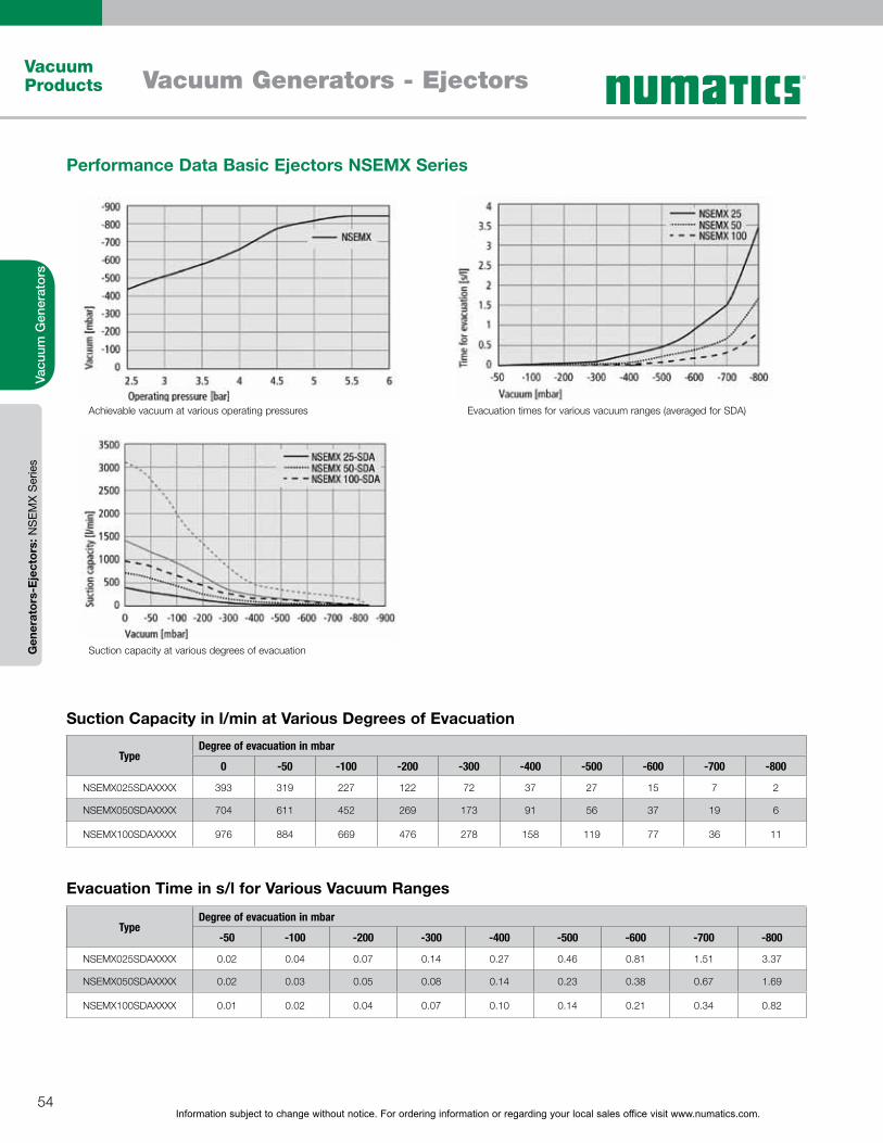
Information subject to change without notice. For ordering information or regarding your local sales office visit www.numatics.com.54
Vacuum Products Vacuum Generators - Ejectors
Vacu
um G
ener
ator
sG
ener
ator
s-E
ject
ors:
NS
EMX
Ser
ies
TypeDegree of evacuation in mbar
0 -50 -100 -200 -300 -400 -500 -600 -700 -800
NSEMX025SDAXXXX 393 319 227 122 72 37 27 15 7 2
NSEMX050SDAXXXX 704 611 452 269 173 91 56 37 19 6
NSEMX100SDAXXXX 976 884 669 476 278 158 119 77 36 11
TypeDegree of evacuation in mbar
-50 -100 -200 -300 -400 -500 -600 -700 -800
NSEMX025SDAXXXX 0.02 0.04 0.07 0.14 0.27 0.46 0.81 1.51 3.37
NSEMX050SDAXXXX 0.02 0.03 0.05 0.08 0.14 0.23 0.38 0.67 1.69
NSEMX100SDAXXXX 0.01 0.02 0.04 0.07 0.10 0.14 0.21 0.34 0.82
Performance Data Basic Ejectors NSEMX Series
Evacuation Time in s/l for Various Vacuum Ranges
Suction Capacity in l/min at Various Degrees of Evacuation
Achievable vacuum at various operating pressures
Suction capacity at various degrees of evacuation
Evacuation times for various vacuum ranges (averaged for SDA)

Information subject to change without notice. For ordering information or regarding your local sales office visit www.numatics.com.55
Vacuum ProductsVacuum Generators - Ejectors
Vacu
um G
ener
ator
sG
ener
ator
s-E
ject
ors:
NS
EMX
Ser
ies
How to OrderNSEMX Series
NSEMX 25 to 100 SDA
Dimensions: mm
Type B B1 d D1 G1 G2 G3 H L L1 L2 X1 Y1
NSEMX025SDAXXXX 85 - 5.5 40 G1/4"-F G1/2"-F G1/2"-F 48 195 275 6 183 55
NSEMX050SDAXXXX 85 - 5.5 50 G1/4"-F G3/4"-F G3/4"-F 58 215 335 6 183 55
NSEMX100SDAXXXX 85 - 5.5 50 G1/4"-F G1"-F G3/4"-F 68 215 335 6 183 55
Product Family Name Part number Nozzle Size (mm)Thread Type / Port Size
Description - FeaturesPressure Vacuum
Multi-stage ejectors
NSEMX025SDAXXXX 25 G1/4 - F G1/2 - F Multi-stage ejector nozzle - High suction capacity
NSEMX050SDAXXXX 50 G1/4 - F G3/4 - F Multi-stage ejector nozzle - High suction capacity
NSEMX100SDAXXXX 100 G1/4 - F G 1 - F Multi-stage ejector nozzle - High suction capacity
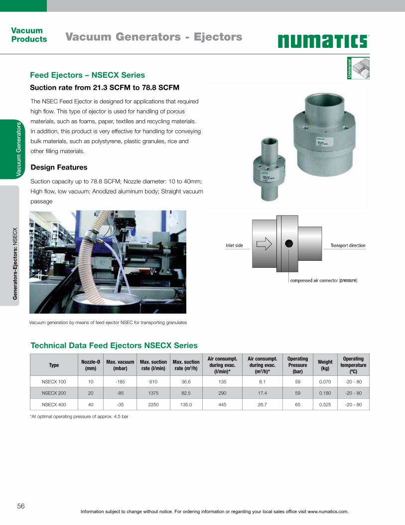
Information subject to change without notice. For ordering information or regarding your local sales office visit www.numatics.com.56
Vacuum Products Vacuum Generators - Ejectors
Vacu
um G
ener
ator
sG
ener
ator
s-E
ject
ors:
NS
ECX
Feed Ejectors – NSECX SeriesSuction rate from 21.3 SCFM to 78.8 SCFM
Design Features
Technical Data Feed Ejectors NSECX Series
Suction capacity up to 78.8 SCFM; Nozzle diameter: 10 to 40mm;
High flow, low vacuum; Anodized aluminum body; Straight vacuum
passage
The NSEC Feed Ejector is designed for applications that required
high flow. This type of ejector is used for handling of porous
materials, such as foams, paper, textiles and recycling materials.
In addition, this product is very effective for handling for conveying
bulk materials, such as polystyrene, plastic granules, rice and
other filling materials.
Type Nozzle-Ø (mm)
Max. vacuum (mbar)
Max. suction rate (l/min)
Max. suction rate (m3/h)
Air consumpt. during evac.
(l/min)*
Air consumpt. during evac.
(m3/h)*
Operating Pressure
(bar)
Weight (kg)
Operating temperature
(ºC)
NSECX 100 10 -185 610 36.6 135 8.1 59 0.070 -20 - 80
NSECX 200 20 -85 1375 82.5 290 17.4 59 0.180 -20 - 80
NSECX 400 40 -35 2250 135.0 445 26.7 65 0.525 -20 - 80
*At optimal operating pressure of approx. 4.5 bar
Vacuum generation by means of feed ejector NSEC for transporting granulates
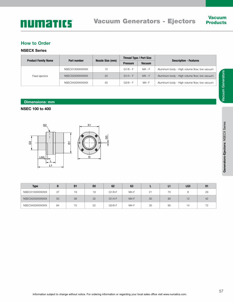
Information subject to change without notice. For ordering information or regarding your local sales office visit www.numatics.com.57
Vacuum ProductsVacuum Generators - Ejectors
Vacu
um G
ener
ator
sG
ener
ator
s-E
ject
ors:
NS
ECX
Ser
ies
NSEC 100 to 400
Dimensions: mm
Type D D1 D2 G2 G3 L L1 LG3 X1
NSECX100XXXXXXX 37 19 19 G1/8-F M4-F 21 70 8 29
NSECX200XXXXXXX 50 38 32 G1/4-F M4-F 30 90 12 42
NSECX400XXXXXXX 84 75 52 G3/8-F M4-F 35 95 14 72
How to OrderNSECX Series
Product Family Name Part number Nozzle Size (mm)Thread Type / Port Size
Description - FeaturesPressure Vacuum
Feed ejectors
NSECX100XXXXXXX 10 G1/8 - F M4 - F Aluminum body - High volume flow; low vacuum
NSECX200XXXXXXX 20 G1/4 - F M4 - F Aluminum body - High volume flow; low vacuum
NSECX400XXXXXXX 40 G3/8 - F M4 -F Aluminum body - High volume flow; low vacuum
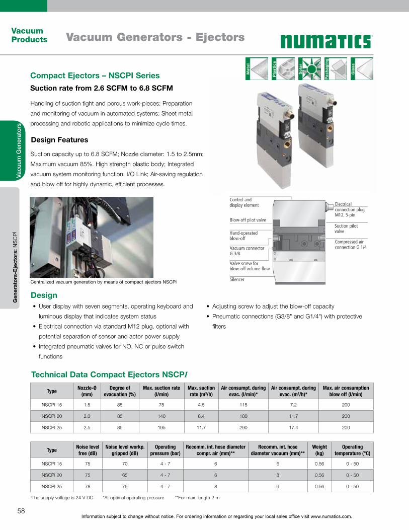
Information subject to change without notice. For ordering information or regarding your local sales office visit www.numatics.com.58
Vacuum Products Vacuum Generators - Ejectors
Vacu
um G
ener
ator
s
Handling of suction tight and porous work-pieces; Preparation
and monitoring of vacuum in automated systems; Sheet metal
processing and robotic applications to minimize cycle times.
Suction capacity up to 6.8 SCFM; Nozzle diameter: 1.5 to 2.5mm;
Maximum vacuum 85%. High strength plastic body; Integrated
vacuum system monitoring function; I/O Link; Air-saving regulation
and blow off for highly dynamic, efficient processes.
Compact Ejectors – NSCPI SeriesSuction rate from 2.6 SCFM to 6.8 SCFM
Design Features
Centralized vacuum generation by means of compact ejectors NSCPi
Type Nozzle-Ø (mm)
Degree of evacuation (%)
Max. suction rate (l/min)
Max. suction rate (m3/h)
Air consumpt. during evac. (l/min)*
Air consumpt. during evac. (m3/h)*
Max. air consumption blow off (l/min)
NSCPI 15 1.5 85 75 4.5 115 7.2 200
NSCPI 20 2.0 85 140 8.4 180 11.7 200
NSCPI 25 2.5 85 195 11.7 290 17.4 200
Type Noise level free (dB)
Noise level workp. gripped (dB)
Operating pressure (bar)
Recomm. int. hose diameter compr. air (mm)**
Recomm. int. hose diameter vacuum (mm)**
Weight (kg)
Operating temperature (°C)
NSCPI 15 75 70 4 - 7 6 6 0.56 0 - 50
NSCPI 20 75 65 4 - 7 6 8 0.56 0 - 50
NSCPI 25 78 75 4 - 7 8 9 0.56 0 - 50
Technical Data Compact Ejectors NSCPI
!The supply voltage is 24 V DC *At optimal operating pressure **For max. length 2 m
DesignUser display with seven segments, operating keyboard and
luminous display that indicates system status
Electrical connection via standard M12 plug, optional with
potential separation of sensor and actor power supply
Integrated pneumatic valves for NO, NC or pulse switch
functions
Adjusting screw to adjust the blow-off capacity
Pneumatic connections (G3/8" and G1/4") with protective
filters
Gen
erat
ors-
Eje
ctor
s: N
SC
PI

Information subject to change without notice. For ordering information or regarding your local sales office visit www.numatics.com.59
Vacuum ProductsVacuum Generators - Ejectors
Vacu
um G
ener
ator
sG
ener
ator
s-E
ject
ors:
NS
CP
I Ser
ies
TypeDegree of evacuation in mbar
0 -50 -100 -200 -300 -400 -500 -600 -700 -800
NSCPI 15 75.0 70.3 65.4 55.2 46.3 38.3 31.2 23.9 13.5 3.4
NSCPI 20 139.0 131.3 123.1 106.8 92.5 79.3 65.2 51.9 32.1 8.5
NSCPI 25 195.0 188.2 176.8 153.6 133.6 11.0 89.3 67.4 39.7 11.7
TypeDegree of evacuation in mbar
-50 -100 -200 -300 -400 -500 -600 -700 -800
NSCPI 15 0.03 0.07 0.16 0.27 0.42 0.63 0.91 1.37 2.60
NSCPI 20 0.02 0.04 0.08 0.14 0.22 0.31 0.44 0.66 1.54
NSCPI 25 0.01 0.02 0.05 0.09 0.14 0.20 0.28 0.42 0.86
Performance Data Basic Ejectors NSCPI Series
Evacuation Time in s/l for Various Vacuum Ranges
Suction Capacity in l/min at Various Degrees of Evacuation
Achievable vacuum at various operating pressures
Suction capacity at various degrees of evacuation
Evacuation times for various vacuum ranges (averaged for NSDA)
Information subject to change without notice. For ordering information or regarding your local sales office visit www.numatics.com.60
Vacuum Products Vacuum Generators - Ejectors
Vacu
um G
ener
ator
sG
ener
ator
s-E
ject
ors:
NS
CP
I Ser
ies
How to OrderNSCPI Series
Product Family Name Part Number Description
AccessoriesNASKBM1250PURGE Cable Connnector - M12 5-Pole
NWARSETSCPISMPI Maintenance Kit - NSCPI
Product Family Name Part number Nozzle Size
(mm)
Thread Type / Port SizeDescription - Features
Digital Switch/Integrated Air
Savings FunctionPressure Vacuum
Compact intelligent single-stage ejectors
NSCPI015ANOVDM1 1.5 G1/4 - F G3/8 - F Digital vacuum switch; suction valve normally open; blow-off valve; M12 - 5 Pin Connector
NSCPI015ANCVDM1 1.5 G1/4 - F G3/8 - F Digital vacuum switch; suction valve normally closed; blow-off valve; M12 - 5 Pin Connector
NSCPI015ANORDM1 1.5 G1/4 - F G3/8 - FDigital vacuum switch with integrated air saving function; suction valve normally open; blow-off
valve; M12 - 5 Pin ConnectorD
NSCPI015ANCRDM1 1.5 G1/4 - F G3/8 - FDigital vacuum switch with integrated air saving function; suction valve normally closed; blow-off
valve; M12 - 5 Pin ConnectorD
NSCPI020ANOVDM1 2.0 G1/4 - F G3/8 - F Digital vacuum switch; suction valve normally open; blow-off valve; M12 - 5 Pin Connector
NSCPI020ANCVDM1 2.0 G1/4 - F G3/8 - F Digital vacuum switch ; suction valve normally closed; blow-off valve; M12 - 5 Pin Connector
NSCPI020ANORDM1 2.0 G1/4 - F G3/8 - FDigital vacuum switch with integrated air saving function; suction valve normally open; blow-off
valve; M12 - 5 Pin ConnectorD
NSCPI020ANCRDM1 2.0 G1/4 - F G3/8 - FDigital vacuum switch with integrated air saving function; suction valve normally closed; blow-off
valve; M12 - 5 Pin ConnectorD
NSCPI025ANOVDM1 2.5 G1/4 - F G3/8 - F Digital vacuum switch; suction valve normally open; blow-off valve; M12 - 5 Pin Connector
NSCPI025ANCVDM1 2.5 G1/4 - F G3/8 - F Digital vacuum switch ; suction valve normally closed; blow-off valve; M12 - 5 Pin Connector
NSCPI025ANORDM1 2.5 G1/4 - F G3/8 - FDigital vacuum switch with integrated air saving function; suction valve normally open; blow-off
valve; M12 - 5 Pin ConnectorD
NSCPI025ANCRDM1 2.5 G1/4 - F G3/8 - FDigital vacuum switch with integrated air saving function; suction valve normally closed; blow-off
valve; M12 - 5 Pin ConnectorD
NSCPI Compact Ejectors are delivered ready to connect (without connection cables).
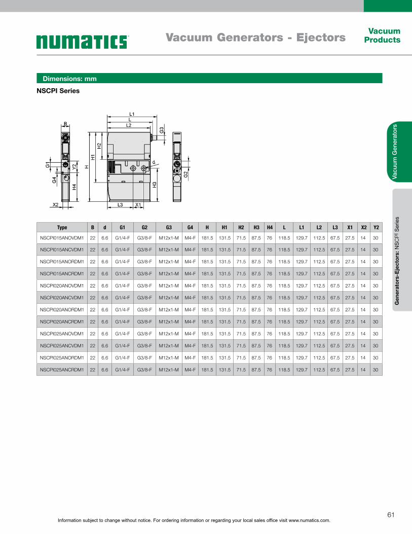
Information subject to change without notice. For ordering information or regarding your local sales office visit www.numatics.com.61
Vacuum ProductsVacuum Generators - Ejectors
Vacu
um G
ener
ator
sG
ener
ator
s-E
ject
ors:
NS
CP
I Ser
ies
NSCPI Series
Dimensions: mm
Type B d G1 G2 G3 G4 H H1 H2 H3 H4 L L1 L2 L3 X1 X2 Y2
NSCPI015ANOVDM1 22 6.6 G1/4-F G3/8-F M12x1-M M4-F 181.5 131.5 71.5 87.5 76 118.5 129.7 112.5 67.5 27.5 14 30
NSCPI015ANCVDM1 22 6.6 G1/4-F G3/8-F M12x1-M M4-F 181.5 131.5 71.5 87.5 76 118.5 129.7 112.5 67.5 27.5 14 30
NSCPI015ANORDM1 22 6.6 G1/4-F G3/8-F M12x1-M M4-F 181.5 131.5 71.5 87.5 76 118.5 129.7 112.5 67.5 27.5 14 30
NSCPI015ANCRDM1 22 6.6 G1/4-F G3/8-F M12x1-M M4-F 181.5 131.5 71.5 87.5 76 118.5 129.7 112.5 67.5 27.5 14 30
NSCPI020ANOVDM1 22 6.6 G1/4-F G3/8-F M12x1-M M4-F 181.5 131.5 71.5 87.5 76 118.5 129.7 112.5 67.5 27.5 14 30
NSCPI020ANCVDM1 22 6.6 G1/4-F G3/8-F M12x1-M M4-F 181.5 131.5 71.5 87.5 76 118.5 129.7 112.5 67.5 27.5 14 30
NSCPI020ANORDM1 22 6.6 G1/4-F G3/8-F M12x1-M M4-F 181.5 131.5 71.5 87.5 76 118.5 129.7 112.5 67.5 27.5 14 30
NSCPI020ANCRDM1 22 6.6 G1/4-F G3/8-F M12x1-M M4-F 181.5 131.5 71.5 87.5 76 118.5 129.7 112.5 67.5 27.5 14 30
NSCPI025ANOVDM1 22 6.6 G1/4-F G3/8-F M12x1-M M4-F 181.5 131.5 71.5 87.5 76 118.5 129.7 112.5 67.5 27.5 14 30
NSCPI025ANCVDM1 22 6.6 G1/4-F G3/8-F M12x1-M M4-F 181.5 131.5 71.5 87.5 76 118.5 129.7 112.5 67.5 27.5 14 30
NSCPI025ANORDM1 22 6.6 G1/4-F G3/8-F M12x1-M M4-F 181.5 131.5 71.5 87.5 76 118.5 129.7 112.5 67.5 27.5 14 30
NSCPI025ANCRDM1 22 6.6 G1/4-F G3/8-F M12x1-M M4-F 181.5 131.5 71.5 87.5 76 118.5 129.7 112.5 67.5 27.5 14 30
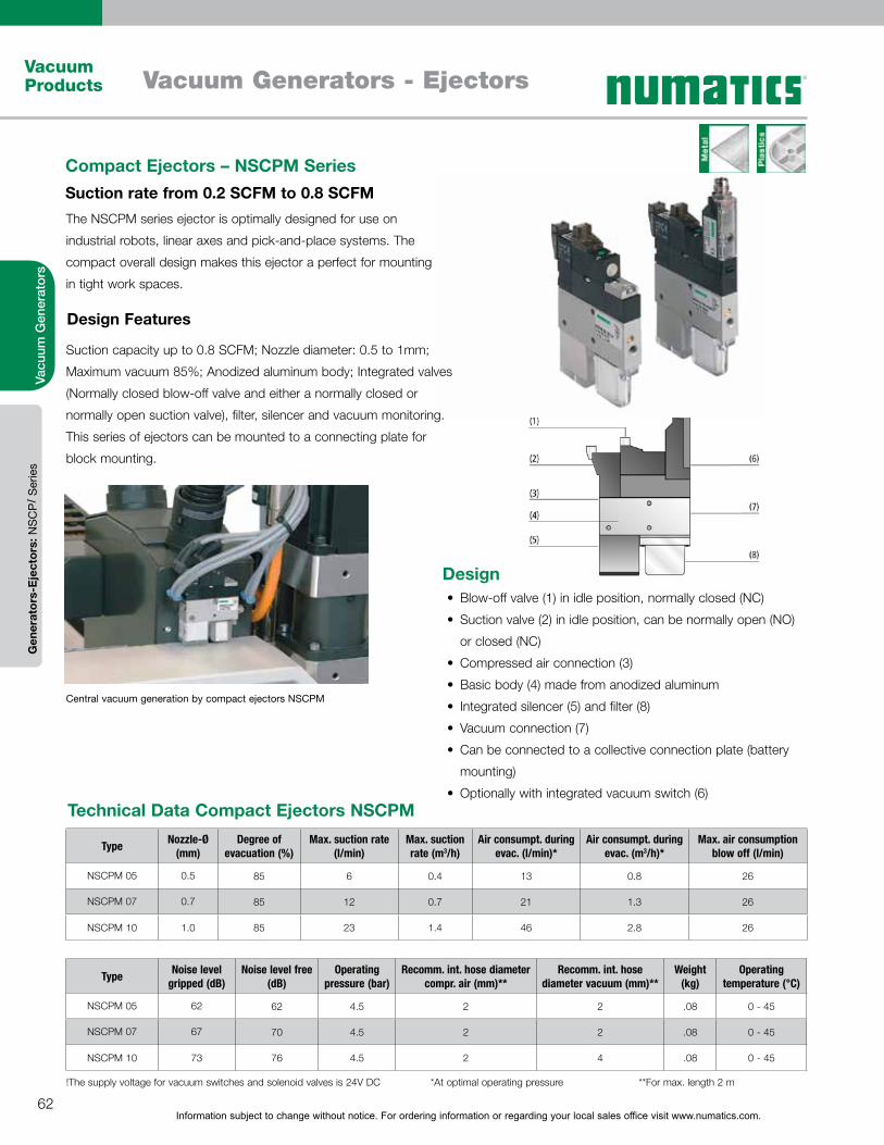
Information subject to change without notice. For ordering information or regarding your local sales office visit www.numatics.com.62
Vacuum Products Vacuum Generators - Ejectors
Vacu
um G
ener
ator
sG
ener
ator
s-E
ject
ors:
NS
CPI S
erie
s
The NSCPM series ejector is optimally designed for use on
industrial robots, linear axes and pick-and-place systems. The
compact overall design makes this ejector a perfect for mounting
in tight work spaces.
Suction capacity up to 0.8 SCFM; Nozzle diameter: 0.5 to 1mm;
Maximum vacuum 85%; Anodized aluminum body; Integrated valves
(Normally closed blow-off valve and either a normally closed or
normally open suction valve), filter, silencer and vacuum monitoring.
This series of ejectors can be mounted to a connecting plate for
block mounting.
Compact Ejectors – NSCPM SeriesSuction rate from 0.2 SCFM to 0.8 SCFM
Design Features
Central vacuum generation by compact ejectors NSCPM
Type Nozzle-Ø (mm)
Degree of evacuation (%)
Max. suction rate (l/min)
Max. suction rate (m3/h)
Air consumpt. during evac. (l/min)*
Air consumpt. during evac. (m3/h)*
Max. air consumption blow off (l/min)
NSCPM 05 0.5 85 6 0.4 13 0.8 26
NSCPM 07 0.7 85 12 0.7 21 1.3 26
NSCPM 10 1.0 85 23 1.4 46 2.8 26
Type Noise level gripped (dB)
Noise level free (dB)
Operating pressure (bar)
Recomm. int. hose diameter compr. air (mm)**
Recomm. int. hose diameter vacuum (mm)**
Weight (kg)
Operating temperature (°C)
NSCPM 05 62 62 4.5 2 2 .08 0 - 45
NSCPM 07 67 70 4.5 2 2 .08 0 - 45
NSCPM 10 73 76 4.5 2 4 .08 0 - 45
Technical Data Compact Ejectors NSCPM
!The supply voltage for vacuum switches and solenoid valves is 24V DC *At optimal operating pressure **For max. length 2 m
DesignBlow-off valve (1) in idle position, normally closed (NC)
Suction valve (2) in idle position, can be normally open (NO)
or closed (NC)
Compressed air connection (3)
Basic body (4) made from anodized aluminum
Integrated silencer (5) and filter (8)
Vacuum connection (7)
Can be connected to a collective connection plate (battery
mounting)
Optionally with integrated vacuum switch (6)
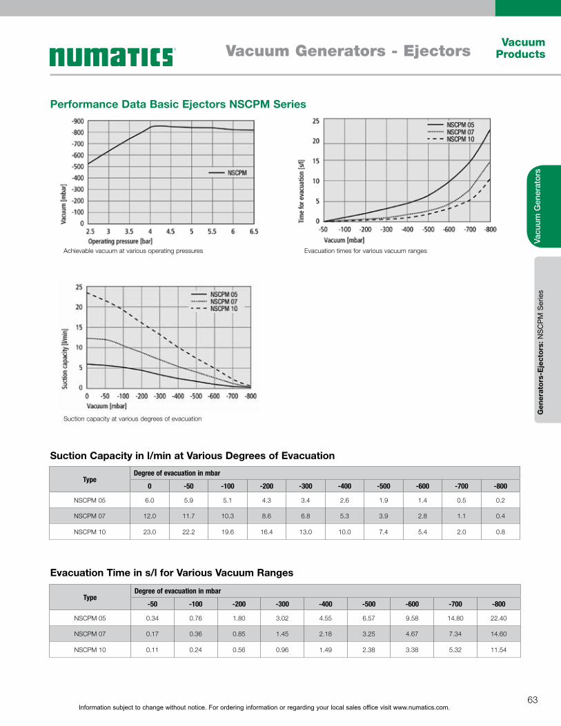
Information subject to change without notice. For ordering information or regarding your local sales office visit www.numatics.com.63
Vacuum ProductsVacuum Generators - Ejectors
Vacu
um G
ener
ator
sG
ener
ator
s-E
ject
ors:
NS
CP
M S
erie
s
TypeDegree of evacuation in mbar
0 -50 -100 -200 -300 -400 -500 -600 -700 -800
NSCPM 05 6.0 5.9 5.1 4.3 3.4 2.6 1.9 1.4 0.5 0.2
NSCPM 07 12.0 11.7 10.3 8.6 6.8 5.3 3.9 2.8 1.1 0.4
NSCPM 10 23.0 22.2 19.6 16.4 13.0 10.0 7.4 5.4 2.0 0.8
TypeDegree of evacuation in mbar
-50 -100 -200 -300 -400 -500 -600 -700 -800
NSCPM 05 0.34 0.76 1.80 3.02 4.55 6.57 9.58 14.80 22.40
NSCPM 07 0.17 0.36 0.85 1.45 2.18 3.25 4.67 7.34 14.60
NSCPM 10 0.11 0.24 0.56 0.96 1.49 2.38 3.38 5.32 11.54
Performance Data Basic Ejectors NSCPM Series
Evacuation Time in s/l for Various Vacuum Ranges
Suction Capacity in l/min at Various Degrees of Evacuation
Achievable vacuum at various operating pressures
Suction capacity at various degrees of evacuation
Evacuation times for various vacuum ranges
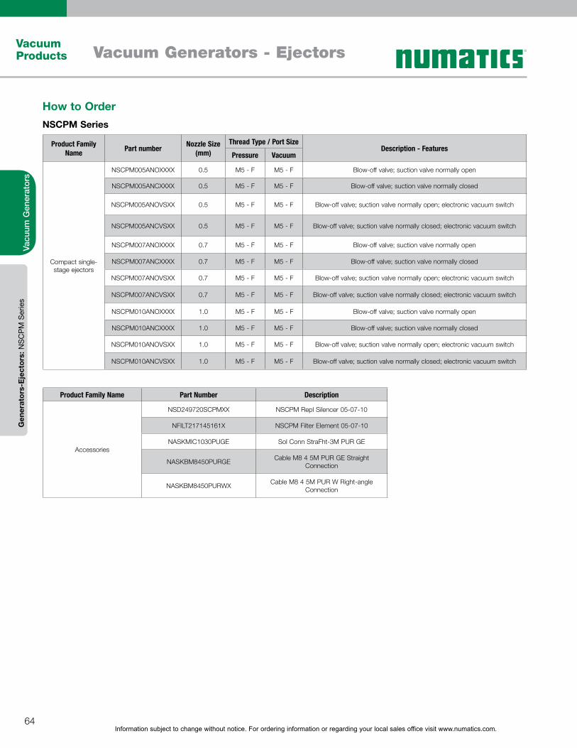
Information subject to change without notice. For ordering information or regarding your local sales office visit www.numatics.com.64
Vacuum Products Vacuum Generators - Ejectors
Vacu
um G
ener
ator
sG
ener
ator
s-E
ject
ors:
NS
CP
M S
erie
s
How to OrderNSCPM Series
Product Family Name Part number Nozzle Size
(mm)Thread Type / Port Size
Description - FeaturesPressure Vacuum
Compact single-stage ejectors
NSCPM005ANOXXXX 0.5 M5 - F M5 - F Blow-off valve; suction valve normally open
NSCPM005ANCXXXX 0.5 M5 - F M5 - F Blow-off valve; suction valve normally closed
NSCPM005ANOVSXX 0.5 M5 - F M5 - F Blow-off valve; suction valve normally open; electronic vacuum switch
NSCPM005ANCVSXX 0.5 M5 - F M5 - F Blow-off valve; suction valve normally closed; electronic vacuum switch
NSCPM007ANOXXXX 0.7 M5 - F M5 - F Blow-off valve; suction valve normally open
NSCPM007ANCXXXX 0.7 M5 - F M5 - F Blow-off valve; suction valve normally closed
NSCPM007ANOVSXX 0.7 M5 - F M5 - F Blow-off valve; suction valve normally open; electronic vacuum switch
NSCPM007ANCVSXX 0.7 M5 - F M5 - F Blow-off valve; suction valve normally closed; electronic vacuum switch
NSCPM010ANOXXXX 1.0 M5 - F M5 - F Blow-off valve; suction valve normally open
NSCPM010ANCXXXX 1.0 M5 - F M5 - F Blow-off valve; suction valve normally closed
NSCPM010ANOVSXX 1.0 M5 - F M5 - F Blow-off valve; suction valve normally open; electronic vacuum switch
NSCPM010ANCVSXX 1.0 M5 - F M5 - F Blow-off valve; suction valve normally closed; electronic vacuum switch
Product Family Name Part Number Description
Accessories
NSD249720SCPMXX NSCPM Repl Silencer 05-07-10
NFILT217145161X NSCPM Filter Element 05-07-10
NASKMIC1030PUGE Sol Conn StraFht-3M PUR GE
NASKBM8450PURGE Cable M8 4 5M PUR GE Straight Connection
NASKBM8450PURWX Cable M8 4 5M PUR W Right-angle Connection
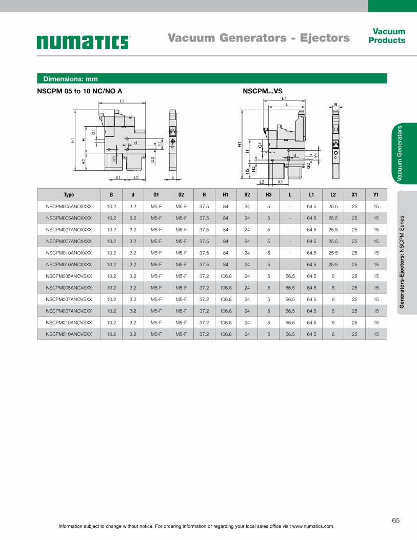
Information subject to change without notice. For ordering information or regarding your local sales office visit www.numatics.com.65
Vacuum ProductsVacuum Generators - Ejectors
Vacu
um G
ener
ator
sG
ener
ator
s-E
ject
ors:
NS
CP
M S
erie
s
Type B d G1 G2 H H1 H2 H3 L L1 L2 X1 Y1
NSCPM005ANOXXXX 10.2 3.2 M5-F M5-F 37.5 84 24 5 - 64.5 25.5 25 15
NSCPM005ANCXXXX 10.2 3.2 M5-F M5-F 37.5 84 24 5 - 64.5 25.5 25 15
NSCPM007ANOXXXX 10.2 3.2 M5-F M5-F 37.5 84 24 5 - 64.5 25.5 25 15
NSCPM007ANCXXXX 10.2 3.2 M5-F M5-F 37.5 84 24 5 - 64.5 25.5 25 15
NSCPM010ANOXXXX 10.2 3.2 M5-F M5-F 37.5 84 24 5 - 64.5 25.5 25 15
NSCPM010ANCXXXX 10.2 3.2 M5-F M5-F 37.5 84 24 5 - 64.5 25.5 25 15
NSCPM005ANOVSXX 10.2 3.2 M5-F M5-F 37.2 106.8 24 5 56.5 64.5 6 25 15
NSCPM005ANCVSXX 10.2 3.2 M5-F M5-F 37.2 106.8 24 5 56.5 64.5 6 25 15
NSCPM007ANOVSXX 10.2 3.2 M5-F M5-F 37.2 106.8 24 5 56.5 64.5 6 25 15
NSCPM007ANCVSXX 10.2 3.2 M5-F M5-F 37.2 106.8 24 5 56.5 64.5 6 25 15
NSCPM010ANOVSXX 10.2 3.2 M5-F M5-F 37.2 106.8 24 5 56.5 64.5 6 25 15
NSCPM010ANCVSXX 10.2 3.2 M5-F M5-F 37.2 106.8 24 5 56.5 64.5 6 25 15
NSCPM 05 to 10 NC/NO A NSCPM...VS
Dimensions: mm
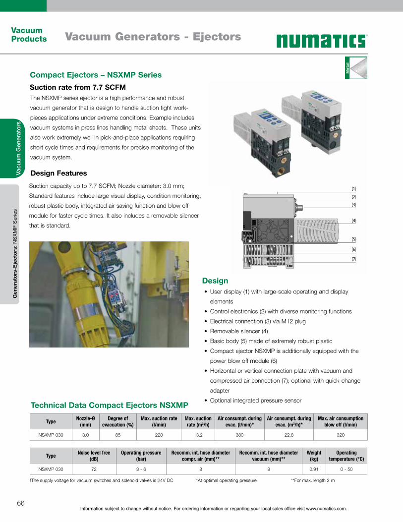
Information subject to change without notice. For ordering information or regarding your local sales office visit www.numatics.com.66
Vacuum Products Vacuum Generators - Ejectors
Vacu
um G
ener
ator
sG
ener
ator
s-E
ject
ors:
NS
XMP
Ser
ies
Compact Ejectors – NSXMP SeriesSuction rate from 7.7 SCFM
Design Features
The NSXMP series ejector is a high performance and robust
vacuum generator that is design to handle suction tight work-
pieces applications under extreme conditions. Example includes
vacuum systems in press lines handling metal sheets. These units
also work extremely well in pick-and-place applications requiring
short cycle times and requirements for precise monitoring of the
vacuum system.
Suction capacity up to 7.7 SCFM; Nozzle diameter: 3.0 mm;
Standard features include large visual display, condition monitoring,
robust plastic body, integrated air saving function and blow off
module for faster cycle times. It also includes a removable silencer
that is standard.
Type Nozzle-Ø (mm)
Degree of evacuation (%)
Max. suction rate (l/min)
Max. suction rate (m3/h)
Air consumpt. during evac. (l/min)*
Air consumpt. during evac. (m3/h)*
Max. air consumption blow off (l/min)
NSXMP 030 3.0 85 220 13.2 380 22.8 320
Technical Data Compact Ejectors NSXMP
!The supply voltage for vacuum switches and solenoid valves is 24V DC *At optimal operating pressure **For max. length 2 m
Type Noise level free (dB)
Operating pressure (bar)
Recomm. int. hose diameter compr. air (mm)**
Recomm. int. hose diameter vacuum (mm)**
Weight (kg)
Operating temperature (°C)
NSXMP 030 72 3 - 6 8 9 0.91 0 - 50
DesignUser display (1) with large-scale operating and display
elements
Control electronics (2) with diverse monitoring functions
Electrical connection (3) via M12 plug
Removable silencer (4)
Basic body (5) made of extremely robust plastic
Compact ejector NSXMP is additionally equipped with the
power blow off module (6)
Horizontal or vertical connection plate with vacuum and
compressed air connection (7); optional with quick-change
adapter
Optional integrated pressure sensor
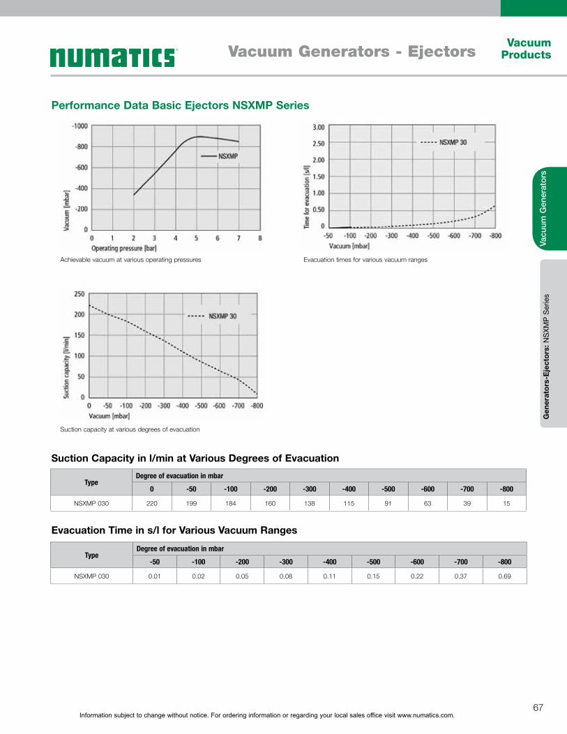
Information subject to change without notice. For ordering information or regarding your local sales office visit www.numatics.com.67
Vacuum ProductsVacuum Generators - Ejectors
Vacu
um G
ener
ator
sG
ener
ator
s-E
ject
ors:
NS
XMP
Ser
ies
TypeDegree of evacuation in mbar
0 -50 -100 -200 -300 -400 -500 -600 -700 -800
NSXMP 030 220 199 184 160 138 115 91 63 39 15
TypeDegree of evacuation in mbar
-50 -100 -200 -300 -400 -500 -600 -700 -800
NSXMP 030 0.01 0.02 0.05 0.08 0.11 0.15 0.22 0.37 0.69
Performance Data Basic Ejectors NSXMP Series
Evacuation Time in s/l for Various Vacuum Ranges
Suction Capacity in l/min at Various Degrees of Evacuation
Achievable vacuum at various operating pressures
Suction capacity at various degrees of evacuation
Evacuation times for various vacuum ranges

Information subject to change without notice. For ordering information or regarding your local sales office visit www.numatics.com.68
Vacuum Products Vacuum Generators - Ejectors
Vacu
um G
ener
ator
sG
ener
ator
s-E
ject
ors:
NS
XMP
Ser
ies
NSXMP Series
Dimensions: mm
Type B D G1 G2 H H1 H2 H3 H4 L L2 L3 X1 Y1
NSXMP030NC0HM12 38 5.5 G3/8-F M12-M 108 160 54 6 26 209 5 97 89 10
NSXMP030NC0VM12 38 5.5 G3/8-F M12-M 108 158 54 6 26 209 5 97 89 10
NSXMP030NC0QM12 38 5.5 - M12-M 108 146 54 6 26 209 5 97 89 10
NSXMP030IMPHM12 38 5.5 G3/8-F M12-M 108 160 54 6 26 209 5 97 89 10
NSXMP030IMPVM12 38 5.5 G3/8-F M12-M 108 158 54 6 26 209 5 97 89 10
NSXMP030IMPQM12 38 5.5 - M12-M 108 146 54 6 26 209 5 97 89 10
How to OrderNSXMP Series
Product Family Name Part number Numatics Description
Accessories
NASKBM1285000XX Cable M12 8 Pole 5M
NGPQ1122461STNB NSXMP Ind plate with quick change
NGPQ2122872STNB NSXMP Dbl plate with quick change
Product Family Name Part number Nozzle Size (mm)Thread Type / Port Size
Description - FeaturesPressure Vacuum
Compact single-stage ejectors
NSXMP030IMPHM12 3 G3/8-F G3/8-F Suction valve - Bistable switched with pulse; Horizontal port configuration.
NSXMP030IMPQM12 3 G3/8-F G3/8-FSuction valve - Bistable switched with pulse;
Quick connect version - must be ordered with single or double base plate.
NSXMP030IMPVM12 3 G3/8-F G3/8-F Suction valve - Bistable switched with pulse; verti-cal port configuration.
NSXMP030NC0HM12 3 G3/8-F G3/8-F Suction valve - NC; Horizontal port configuration.
NSXMP030NC0QM12 3 G3/8-F G3/8-F Suction valve - NC; Quick connect version - must be ordered with single or double base plate.
NSXMP030NC0VM12 3 G3/8-F G3/8-F Suction valve - NC; vertical port configuration.

Information subject to change without notice. For ordering information or regarding your local sales office visit www.numatics.com.69
Vacuum ProductsVacuum Generators - Ejectors
Vacu
um G
ener
ator
sG
ener
ator
s-E
ject
ors:
NS
EAC
-RP
Ser
ies
The NSEAC RP series is designed to handle applications that
require short cycle times; examples include tooling systems,
sheet metal fabrication, automotive, packaging machines and
applications on robots.
Note:
When ordering the vacuum switch option, a connector cable is
required:
NASKBM8450PURGE - Cable/Straight Connection
NASKBM8450PURWX - Cable/Right-angle Connection
Suction rates up to 1.26 SCFM; Nozzle diameter 1mm; Anodized
aluminum body; Integrated blow-off function; integrated air savings
function with adjusting screw; silencer.
Design Features
Ejectors with Blow-Off System - NSEAC-RP SeriesSuction rate 1.26 SCFM
Decentralized vacuum generation by means of ejector NSEAC-RP with blow off system right on suction cup
DesignBody made of anodized aluminium
Integrated blow off function
Optional vacuum switch NVSV00AHTPNPSXX with
adjustable switching point (connection cable not included
in delivery)
Two mounting screws included in delivery
Type Nozzle-Ø (mm)
Degree of evacuation
(%)
Max. suction rate (l/min)
Max. suction rate (m3/h)
Air consumpt. during evac.
(l/min)*
Air consumpt. during evac.
(m3/h)*
Max. air consumption blow
off (l/min)
Operating pressure (bar)
Weight (kg)
NSEAC-RP 1.0 85 36 2.1 65 3.9 92 4 - 6 0.18
Technical Data Compact Ejectors NSEAC-RP
*At optimal operating pressure

Information subject to change without notice. For ordering information or regarding your local sales office visit www.numatics.com.70
Vacuum Products Vacuum Generators - Ejectors
Vacu
um G
ener
ator
sG
ener
ator
s-E
ject
ors:
NS
EAC
-RP
Ser
ies
TypeDegree of evacuation in mbar
0 -50 -100 -200 -300 -400 -500 -600 -700 -800
NSEAC-RP 36.0 34.0 32.0 27.5 24.0 19.5 12.0 8.0 5.0 3.0
TypeDegree of evacuation in mbar
-50 -100 -200 -300 -400 -500 -600 -700 -800
NSEAC-RP 0.12 0.20 0.39 0.62 0.93 1.35 1.98 3.26 6.50
Performance Data Basic Ejectors NSEAC-RP Series
Evacuation Time in s/l for Various Vacuum Ranges
Suction Capacity in l/min at Various Degrees of Evacuation
Achievable vacuum at various operating pressures
Suction capacity at various degrees of evacuation
Evacuation times for various vacuum ranges
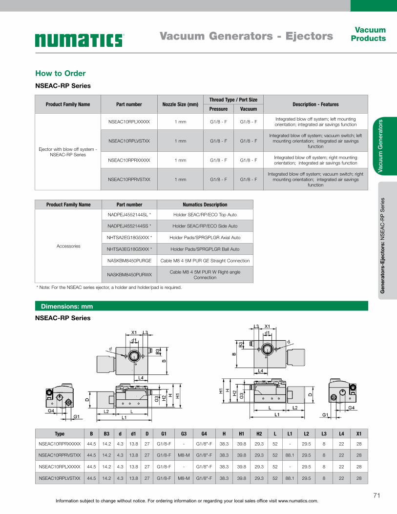
Information subject to change without notice. For ordering information or regarding your local sales office visit www.numatics.com.71
Vacuum ProductsVacuum Generators - Ejectors
Vacu
um G
ener
ator
sG
ener
ator
s-E
ject
ors:
NS
EAC
-RP
Ser
ies
How to OrderNSEAC-RP Series
NSEAC-RP Series
Dimensions: mm
Type B B3 d d1 D G1 G3 G4 H H1 H2 L L1 L2 L3 L4 X1
NSEAC10RPRXXXXX 44.5 14.2 4.3 13.8 27 G1/8-F - G1/8"-F 38.3 39.8 29.3 52 - 29.5 8 22 28
NSEAC10RPRVSTXX 44.5 14.2 4.3 13.8 27 G1/8-F M8-M G1/8"-F 38.3 39.8 29.3 52 88.1 29.5 8 22 28
NSEAC10RPLXXXXX 44.5 14.2 4.3 13.8 27 G1/8-F - G1/8"-F 38.3 39.8 29.3 52 - 29.5 8 22 28
NSEAC10RPLVSTXX 44.5 14.2 4.3 13.8 27 G1/8-F M8-M G1/8"-F 38.3 39.8 29.3 52 88.1 29.5 8 22 28
Product Family Name Part number Numatics Description
Accessories
NADPEJ4552144SL * Holder SEAC/RP/ECO Top Auto
NADPEJ4552144SS * Holder SEAC/RP/ECO Side Auto
NHTSA2EG18G5XXX * Holder Pads/SPRGPLGR Axial Auto
NHTSA3EG18G5XXX * Holder Pads/SPRGPLGR Ball Auto
NASKBM8450PURGE Cable M8 4 5M PUR GE Straight Connection
NASKBM8450PURWX Cable M8 4 5M PUR W Right-angle Connection
Product Family Name Part number Nozzle Size (mm)Thread Type / Port Size
Description - FeaturesPressure Vacuum
Ejector with blow off system - NSEAC-RP Series
NSEAC10RPLXXXXX 1 mm G1/8 - F G1/8 - F Integrated blow off system; left mounting orientation; integrated air savings function
NSEAC10RPLVSTXX 1 mm G1/8 - F G1/8 - FIntegrated blow off system; vacuum switch; left
mounting orientation; integrated air savings function
NSEAC10RPRXXXXX 1 mm G1/8 - F G1/8 - F Integrated blow off system; right mounting orientation; integrated air savings function
NSEAC10RPRVSTXX 1 mm G1/8 - F G1/8 - FIntegrated blow off system; vacuum switch; right
mounting orientation; integrated air savings function
* Note: For the NSEAC series ejector, a holder and holder/pad is required.
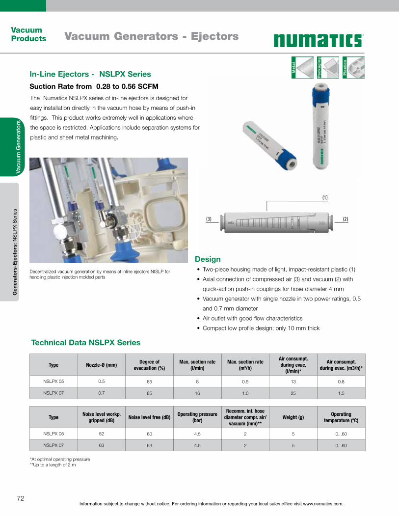
Information subject to change without notice. For ordering information or regarding your local sales office visit www.numatics.com.72
Vacuum Products Vacuum Generators - Ejectors
Vacu
um G
ener
ator
sG
ener
ator
s-E
ject
ors:
NS
LPX
Ser
ies
The Numatics NSLPX series of in-line ejectors is designed for
easy installation directly in the vacuum hose by means of push-in
fittings. This product works extremely well in applications where
the space is restricted. Applications include separation systems for
plastic and sheet metal machining.
In-Line Ejectors - NSLPX Series Suction Rate from 0.28 to 0.56 SCFM
Technical Data NSLPX Series
DesignTwo-piece housing made of light, impact-resistant plastic (1)
Axial connection of compressed air (3) and vacuum (2) with
quick-action push-in couplings for hose diameter 4 mm
Vacuum generator with single nozzle in two power ratings, 0.5
and 0.7 mm diameter
Air outlet with good flow characteristics
Compact low profile design; only 10 mm thick
Decentralized vacuum generation by means of inline ejectors NtSLP for handling plastic injection molded parts
Type Nozzle-Ø (mm) Degree of evacuation (%)
Max. suction rate (l/min)
Max. suction rate (m3/h)
Air consumpt. during evac.
(l/min)*
Air consumpt. during evac. (m3/h)*
NSLPX 05 0.5 85 8 0.5 13 0.8
NSLPX 07 0.7 85 16 1.0 25 1.5
Type Noise level workp. gripped (dB) Noise level free (dB) Operating pressure
(bar)
Recomm. int. hose diameter compr. air/
vacuum (mm)**Weight (g) Operating
temperature (ºC)
NSLPX 05 52 60 4.5 2 5 0...60
NSLPX 07 63 63 4.5 2 5 0...60
*At optimal operating pressure**Up to a length of 2 m

Information subject to change without notice. For ordering information or regarding your local sales office visit www.numatics.com.73
Vacuum ProductsVacuum Generators - Ejectors
Vacu
um G
ener
ator
sG
ener
ator
s-E
ject
ors:
NS
LPX
Ser
ies
Performance Data Basic Ejectors NSLPX Series
TypeDegree of evacuation in mbar
0 -50 -100 -200 -300 -400 -500 -600 -700 -800
NSLPX005XXXXXS1 8.00 6.42 4.97 3.76 2.65 1.79 1.06 0.32 0.10 0.05
NSLPX007XXXXXS1 15.90 13.30 10.89 8.70 6.67 4.65 2.88 1.29 0.55 0.06
TypeDegree of evacuation in mbar
-50 -100 -200 -300 -400 -500 -600 -700 -800
NSLPX005XXXXXS1 0.4 0.7 1.6 2.7 4.0 5.8 8.5 13.1 24.5
NSLPX007XXXXXS1 0.2 0.4 0.8 1.4 2.2 3.2 4.6 6.7 12.7
Evacuation Time in s/l for Various Vacuum Ranges
Suction Capacity in l/min at Various Degrees of Evacuation
Achievable vacuum at various operating pressures
Suction capacity at various degrees of evacuation
Evacuation times for various vacuum ranges
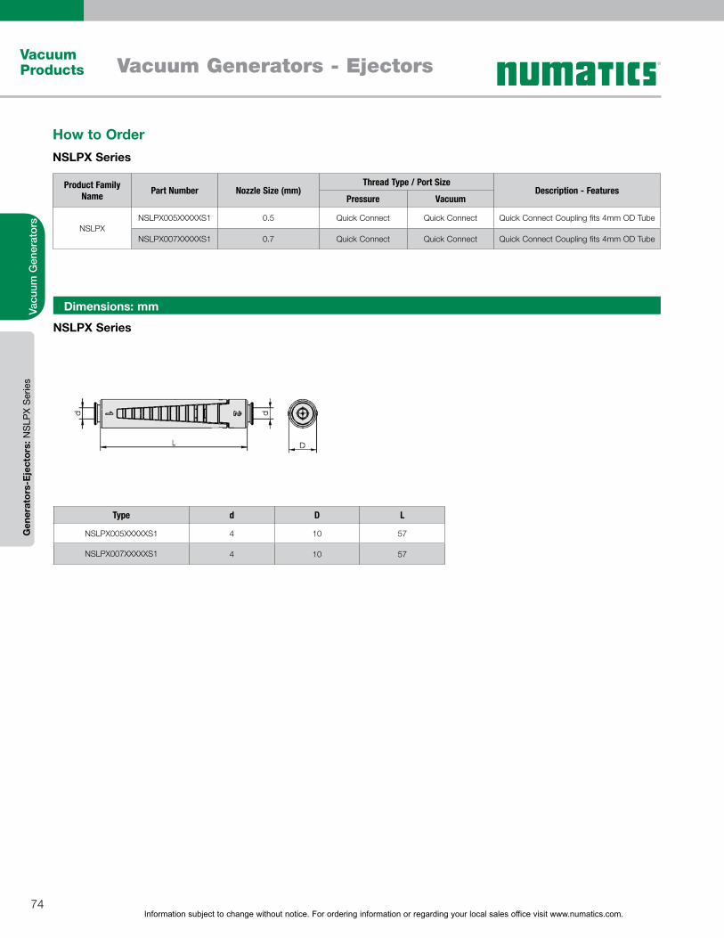
Information subject to change without notice. For ordering information or regarding your local sales office visit www.numatics.com.74
Vacuum Products Vacuum Generators - Ejectors
Vacu
um G
ener
ator
sG
ener
ator
s-E
ject
ors:
NS
LPX
Ser
ies
Product Family Name Part Number Nozzle Size (mm)
Thread Type / Port SizeDescription - Features
Pressure Vacuum
NSLPX NSLPX005XXXXXS1 0.5 Quick Connect Quick Connect Quick Connect Coupling fits 4mm OD Tube
NSLPX007XXXXXS1 0.7 Quick Connect Quick Connect Quick Connect Coupling fits 4mm OD Tube
How to OrderNSLPX Series
NSLPX Series
Dimensions: mm
Type d D L
NSLPX005XXXXXS1 4 10 57
NSLPX007XXXXXS1 4 10 57
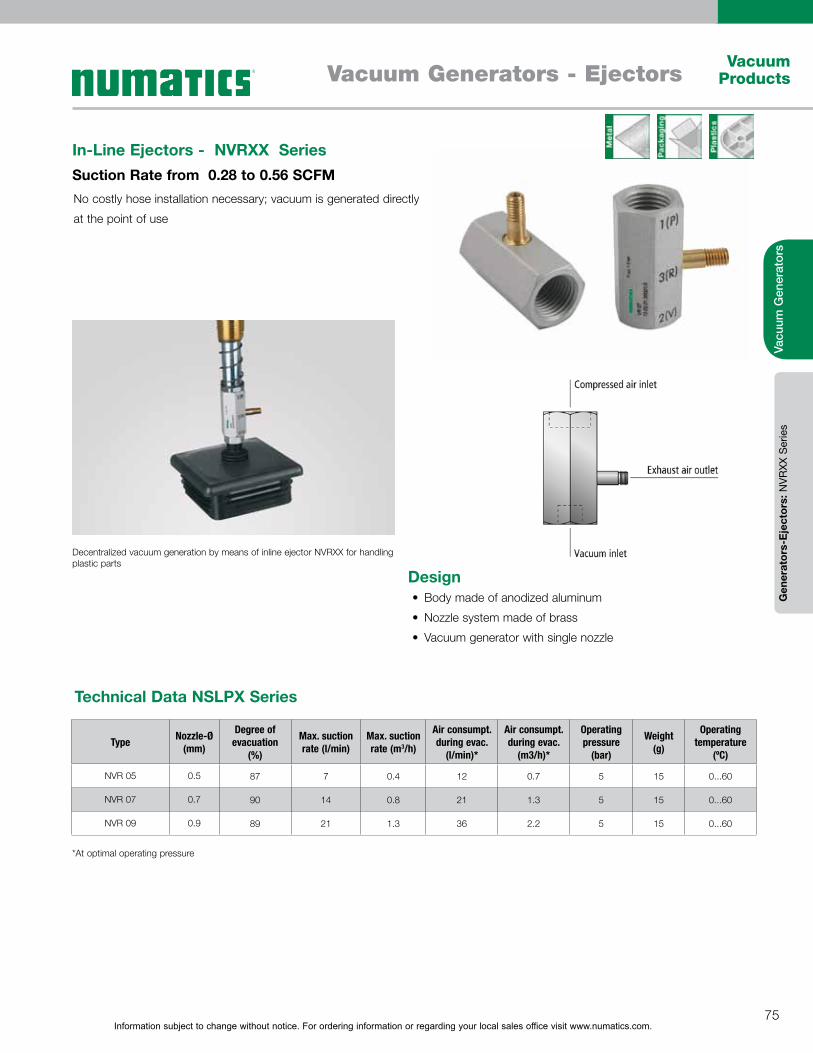
Information subject to change without notice. For ordering information or regarding your local sales office visit www.numatics.com.75
Vacuum ProductsVacuum Generators - Ejectors
Vacu
um G
ener
ator
sG
ener
ator
s-E
ject
ors:
NVR
XX S
erie
s
No costly hose installation necessary; vacuum is generated directly
at the point of use
In-Line Ejectors - NVRXX Series Suction Rate from 0.28 to 0.56 SCFM
Technical Data NSLPX Series
Decentralized vacuum generation by means of inline ejector NVRXX for handling plastic parts
Type Nozzle-Ø (mm)
Degree of evacuation
(%)
Max. suction rate (l/min)
Max. suction rate (m3/h)
Air consumpt. during evac.
(l/min)*
Air consumpt. during evac.
(m3/h)*
Operating pressure
(bar)
Weight (g)
Operating temperature
(ºC)
NVR 05 0.5 87 7 0.4 12 0.7 5 15 0...60
NVR 07 0.7 90 14 0.8 21 1.3 5 15 0...60
NVR 09 0.9 89 21 1.3 36 2.2 5 15 0...60
*At optimal operating pressure
DesignBody made of anodized aluminum
Nozzle system made of brass
Vacuum generator with single nozzle
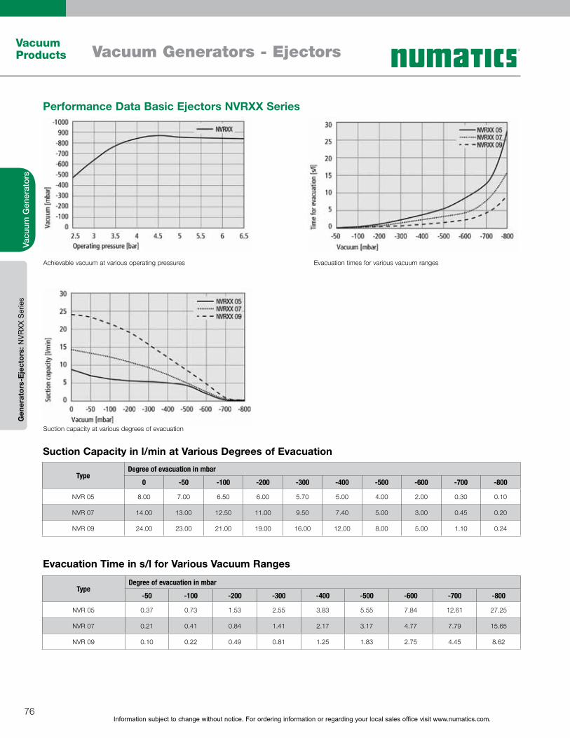
Information subject to change without notice. For ordering information or regarding your local sales office visit www.numatics.com.76
Vacuum Products Vacuum Generators - Ejectors
Vacu
um G
ener
ator
sG
ener
ator
s-E
ject
ors:
NVR
XX S
erie
s
Performance Data Basic Ejectors NVRXX Series
TypeDegree of evacuation in mbar
0 -50 -100 -200 -300 -400 -500 -600 -700 -800
NVR 05 8.00 7.00 6.50 6.00 5.70 5.00 4.00 2.00 0.30 0.10
NVR 07 14.00 13.00 12.50 11.00 9.50 7.40 5.00 3.00 0.45 0.20
NVR 09 24.00 23.00 21.00 19.00 16.00 12.00 8.00 5.00 1.10 0.24
TypeDegree of evacuation in mbar
-50 -100 -200 -300 -400 -500 -600 -700 -800
NVR 05 0.37 0.73 1.53 2.55 3.83 5.55 7.84 12.61 27.25
NVR 07 0.21 0.41 0.84 1.41 2.17 3.17 4.77 7.79 15.65
NVR 09 0.10 0.22 0.49 0.81 1.25 1.83 2.75 4.45 8.62
Evacuation Time in s/l for Various Vacuum Ranges
Suction Capacity in l/min at Various Degrees of Evacuation
Achievable vacuum at various operating pressures
Suction capacity at various degrees of evacuation
Evacuation times for various vacuum ranges
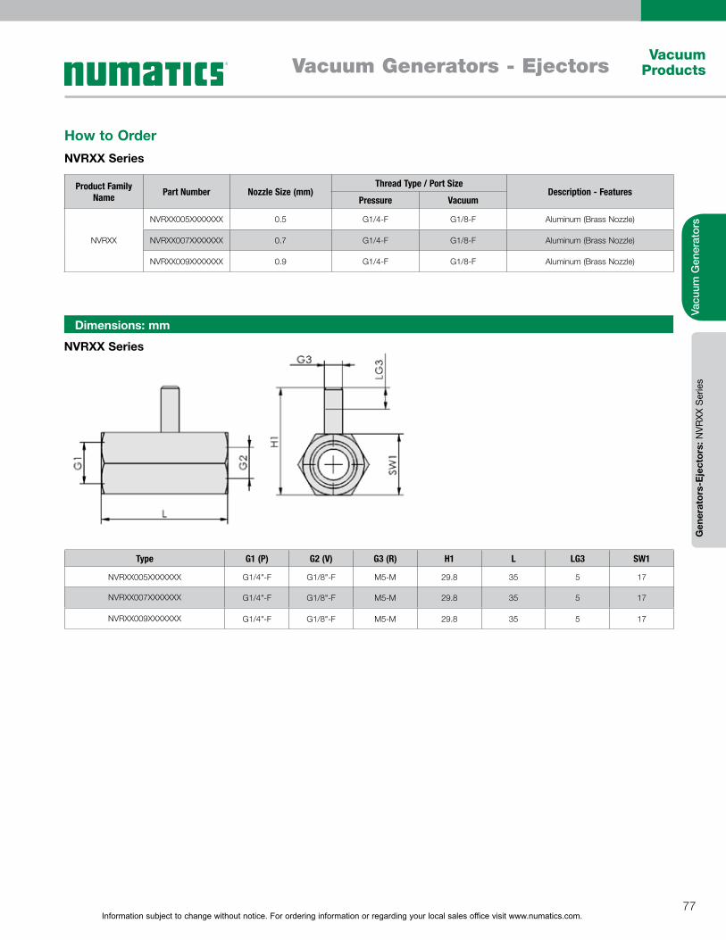
Information subject to change without notice. For ordering information or regarding your local sales office visit www.numatics.com.77
Vacuum ProductsVacuum Generators - Ejectors
Vacu
um G
ener
ator
sG
ener
ator
s-E
ject
ors:
NVR
XX S
erie
s
NVRXX Series
Dimensions: mm
Type G1 (P) G2 (V) G3 (R) H1 L LG3 SW1
NVRXX005XXXXXXX G1/4"-F G1/8"-F M5-M 29.8 35 5 17
NVRXX007XXXXXXX G1/4"-F G1/8"-F M5-M 29.8 35 5 17
NVRXX009XXXXXXX G1/4"-F G1/8"-F M5-M 29.8 35 5 17
How to OrderNVRXX Series
Product Family Name Part Number Nozzle Size (mm)
Thread Type / Port SizeDescription - Features
Pressure Vacuum
NVRXX
NVRXX005XXXXXXX 0.5 G1/4-F G1/8-F Aluminum (Brass Nozzle)
NVRXX007XXXXXXX 0.7 G1/4-F G1/8-F Aluminum (Brass Nozzle)
NVRXX009XXXXXXX 0.9 G1/4-F G1/8-F Aluminum (Brass Nozzle)
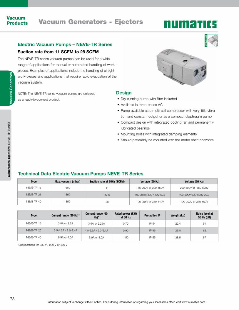
Information subject to change without notice. For ordering information or regarding your local sales office visit www.numatics.com.78
Vacuum Products Vacuum Generators - Ejectors
Vacu
um G
ener
ator
sG
ener
ator
s-E
ject
ors:
NEV
E-TR
Ser
ies
The NEVE-TR series vacuum pumps can be used for a wide
range of applications for manual or automated handling of work-
pieces. Examples of applications include the handling of airtight
work-pieces and applications that require rapid evacuation of the
vacuum system.
NOTE: The NEVE-TR series vacuum pumps are delivered
as a ready-to-connect product.
Electric Vacuum Pumps – NEVE-TR SeriesSuction rate from 11 SCFM to 28 SCFM
Type Max. vacuum (mbar) Suction rate at 60Hz (SCFM) Voltage (50 Hz) Voltage (60 Hz)
NEVE-TR 16 -850 11 175-260V or 300-450V 200-300V or 350-520V
NEVE-TR 25 -850 17.5 190-255V/330-440V AC3 190-290V/330-500V AC3
NEVE-TR 40 -850 28 190-255V or 330-440V 190-290V or 330-500V
Type Current range (50 Hz)* Current range (60 Hz)*
Rated power (kW) at 60 Hz Protection IP Weight (kg) Noise level at
50 Hz (dB)
NEVE-TR 16 3.8A or 2.2A 3.9A or 2.25A 0.70 IP 54 22.4 61
NEVE-TR 25 3.5-4.2A / 2.0-2.4A 4.0-3.6A / 2.3-2.1A 0.90 IP 55 26.0 62
NEVE-TR 40 6.9A or 4.0A 6.9A or 4.0A 1.50 IP 55 38.5 67
Technical Data Electric Vacuum Pumps NEVE-TR Series
*Specifications for 230 V / 230 V or 400 V
DesignDry-running pump with filter included
Available in three-phase AC
Pump available as a multi-cell compressor with very little vibra-
tion and constant output or as a compact diaphragm pump
Compact design with integrated cooling fan and permanently
lubricated bearings
Mounting holes with integrated damping elements
Should preferably be mounted with the motor shaft horizontal
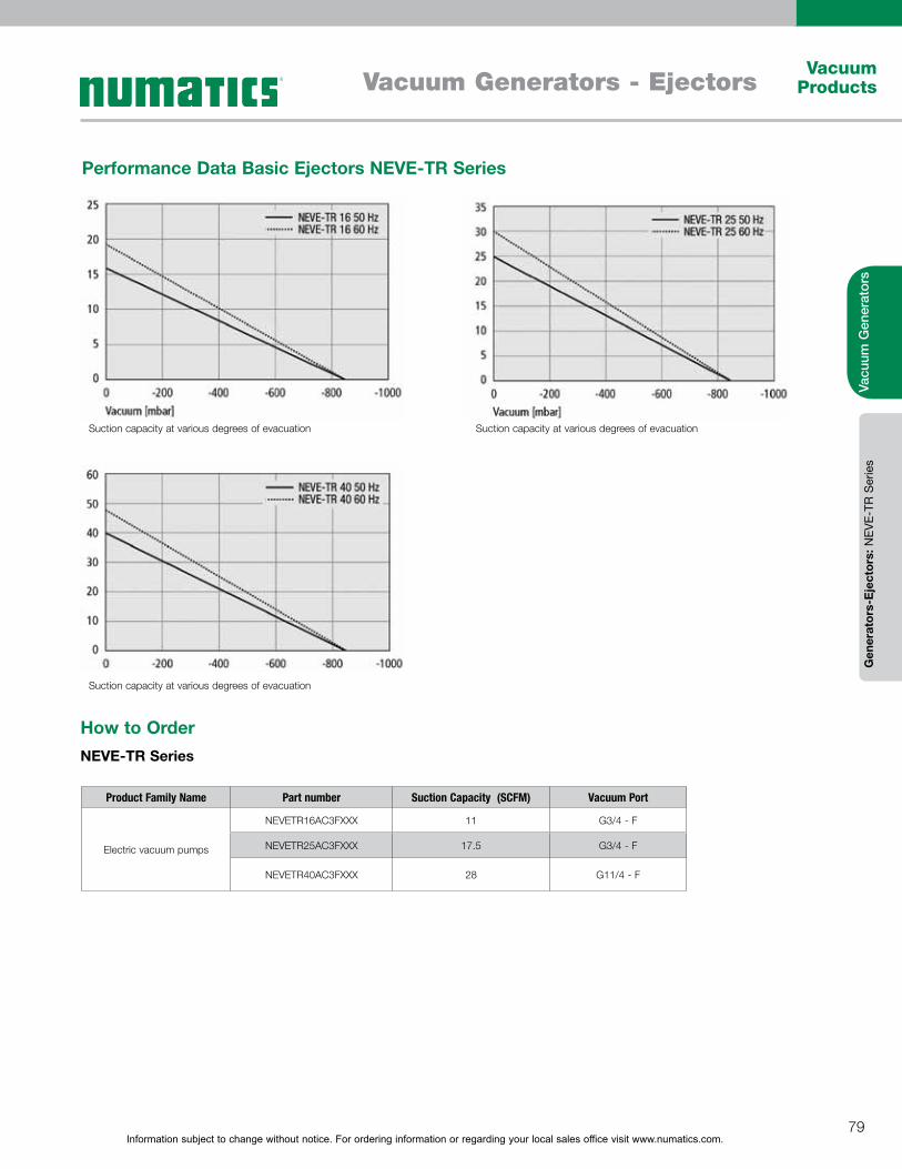
Information subject to change without notice. For ordering information or regarding your local sales office visit www.numatics.com.79
Vacuum ProductsVacuum Generators - Ejectors
Vacu
um G
ener
ator
sG
ener
ator
s-E
ject
ors:
NEV
E-TR
Ser
ies
Performance Data Basic Ejectors NEVE-TR Series
Product Family Name Part number Suction Capacity (SCFM) Vacuum Port
Electric vacuum pumps
NEVETR16AC3FXXX 11 G3/4 - F
NEVETR25AC3FXXX 17.5 G3/4 - F
NEVETR40AC3FXXX 28 G11/4 - F
How to OrderNEVE-TR Series
Suction capacity at various degrees of evacuation
Suction capacity at various degrees of evacuation
Suction capacity at various degrees of evacuation
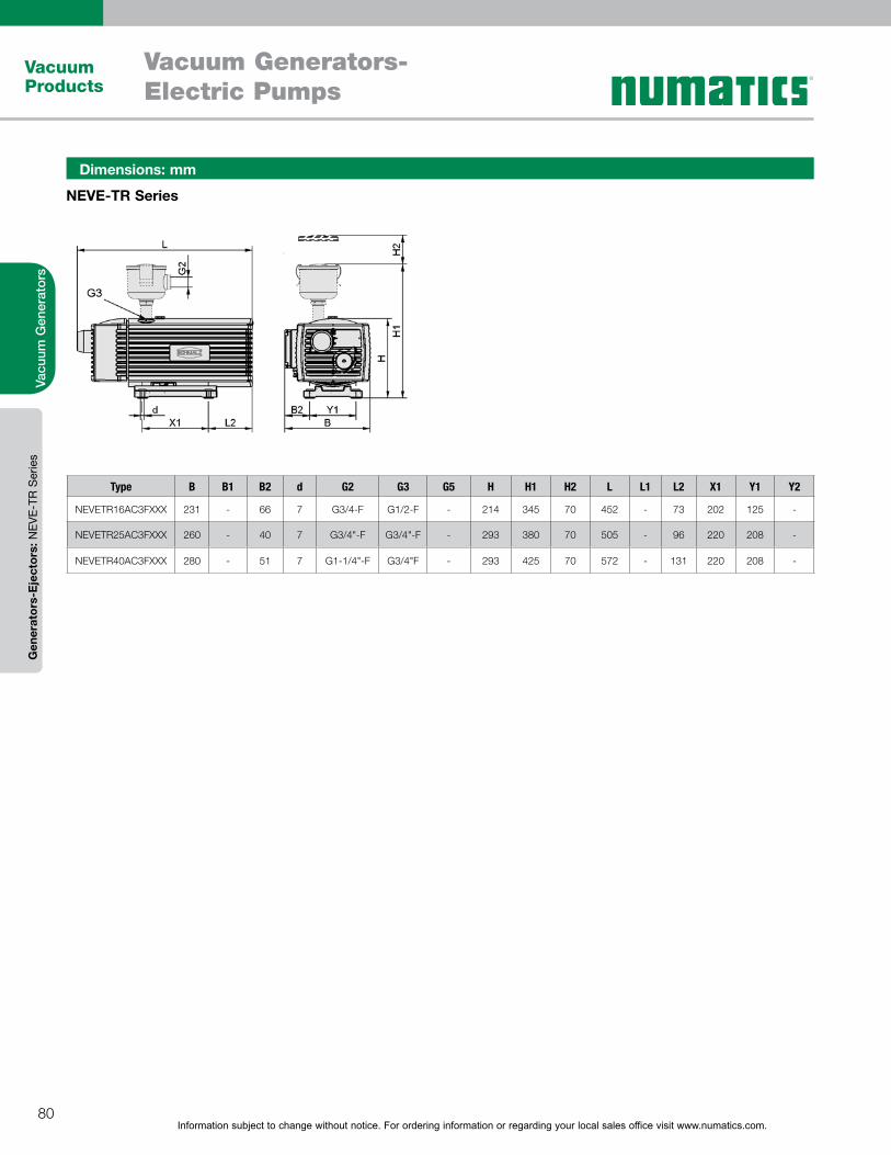
Information subject to change without notice. For ordering information or regarding your local sales office visit www.numatics.com.80
Vacuum Products
Vacu
um G
ener
ator
sG
ener
ator
s-E
ject
ors:
NEV
E-TR
Ser
ies
Vacuum Generators-Electric Pumps
NEVE-TR Series
Dimensions: mm
Type B B1 B2 d G2 G3 G5 H H1 H2 L L1 L2 X1 Y1 Y2
NEVETR16AC3FXXX 231 - 66 7 G3/4-F G1/2-F - 214 345 70 452 - 73 202 125 -
NEVETR25AC3FXXX 260 - 40 7 G3/4"-F G3/4"-F - 293 380 70 505 - 96 220 208 -
NEVETR40AC3FXXX 280 - 51 7 G1-1/4"-F G3/4"F - 293 425 70 572 - 131 220 208 -
81
Table of Contents
Vacuum Suction Cups Flat Round Suction Cups – NPFYN Series 82-87
NPFGX Series (replacement suction cup) 82-87
Flat Round Suction Plates – NSPUX Series 88-89
Flat Oval Suction Cups – NSGON Series 90-93
NSGOX Series (replacement suction cup) 90-93
Round Bellows (round 1.5 bellows) Suction Cups – NFSGA Series 94-101
NFGAX Series (replacement suction cup) 94-101
Round Bellows (round 2.5 bellows) Suction Cups – NFSGX Series 102-107
NFGX Series (replacement suction cups) 102-107
NSAFX Series – Flat Round Suction Cups (automotive) 108-109
NSAOF Series – Flat Oval Suction Cups (automotive) 110-111
NSABX Series – Round 1.5 Bellows Suction Cups (automotive) 112-114
NSGPN Series – Round Flat Suction Cups (specialty cups – plastic film and paper) 115-118
NSGPX Series (replacement suction cup) 115-118
Specialty Cups for Packaging 119-128
NSPFX Series - Flat Round Suction Cups 119-121
NSPB4 Series - Round 4.5 Bellows Suction Cups 122-123
NSPB1 Series - Round 1.5 Bellows Suction Cups 124-126
NSPOB Series - Oval 1.5 Bellows Suction Cups 127-128
Specialty Cups for Eggs & Candy 129-131
NEFGX (egg suction cups) - Round 1.5, 2.5 & 3.5 Bellows 129-131
NSPGX (candy suction cups) - Round Bell Shaped Suction Cup 129-131
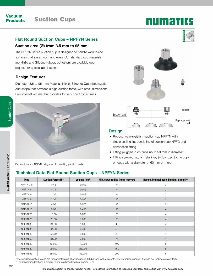
Information subject to change without notice. For ordering information or regarding your local sales office visit www.numatics.com.82
Vacuum Products Suction Cups
Suc
tion
Cup
sS
uctio
n C
ups:
NP
FYN
Ser
ies
The NPFYN series suction cup is designed to handle work-piece
surfaces that are smooth and even. Our standard cup materials
are Nitrile and Silicone rubber, but others are available upon
request for special applications.
Diameter: 3.5 to 95 mm; Material: Nitrile, Silicone; Optimized suction
cup shape that provides a high suction force, with small dimensions;
Low internal volume that provides for very short cycle times.
Flat Round Suction Cups – NPFYN SeriesSuction area (Ø) from 3.5 mm to 95 mm
Design Features
Flat suction cups NPFYN being used for handling plastic boards
DesignRobust, wear-resistant suction cup NPFYN with
single sealing lip, consisting of suction cup NPFG and
connection fitting
Fitting plugged in on cups up to 50 mm in diameter
Fitting screwed into a metal inlay (vulcanized to the cup)
on cups with a diameter of 60 mm or more
Type Suction Force (N)* Volume (cm3) Min. curve radius (mm) (convex) Recom. internal hose diameter d (mm)**
NPFYN 3.5 0.42 0.002 8 2
NPFYN 5 0.75 0.005 8 2
NPFYN 6 1.20 0.008 8 2
NPFYN 8 2.30 0.030 10 2
NPFYN 10 4.00 0.070 13 2
NPFYN 15 9.00 0.400 13 4
NPFYN 20 15.50 0.800 20 4
NPFYN 25 26.50 1.300 25 4
NPFYN 30 34.00 1.300 40 4
NPFYN 35 44.00 2.700 50 4
NPFYN 40 57.70 3.800 50 4
NPFYN 50 91.00 7.000 75 4
NPFYN 60 125.00 10.000 100 6
NPFYN 80 260.00 25.000 150 6
NPFYN 95 350.00 35.000 200 6
Technical Data Flat Round Suction Cups – NPFYN Series
*The specified suction forces are theoretical values at a vacuum of -0.6 bar and with a smooth, dry workpiece surface - they do not include a safety factor **The recommended hose diameter refers to a hose length of approx. 2 m

Information subject to change without notice. For ordering information or regarding your local sales office visit www.numatics.com.83
Vacuum ProductsSuction Cups
Suc
tion
Cup
sS
uctio
n C
ups:
NP
FYN
Ser
ies
How to OrderNPFYN Series and NPFGX Replacement Cups - Flat Round Suction Cups
Suction Cup Assembly Replacement Cups
Series / Cup Diameter(mm) Thread Type / Port Size
Material Type Material Type
Nitrile(55 Hardness)
Silicone(55 Hardness)
Nitrile(55 Hardness)
Silicone(55 Hardness)
NPFYN 3.5 M3-M NPFYN003XXB5AMM NPFYN003XXS5AMM NPFGX003XXB5XXX NPFGX003XXS5XXX
NPFYN 5 M5-M NPFYN005XXB5BMM NPFYN005XXS5BMM NPFGX005XXB5XXX NPFGX005XXS5XXX
NPFYN 8 M5-M NPFYN008XXB5BMM NPFYN008XXS5BMM NPFGX008XXB5XXX NPFGX008XXS5XXX
NPFYN 10
G1/8-F NPFYN010XXB51FG NPFYN010XXS51FG
NPFGX010XXB5XXX NPFGX010XXS5XXXG1/8-M NPFYN010XXB51MG NPFYN010XXS51MG
M5-M NPFYN010XXB5BMM NPFYN010XXS5BMM
NPFYN 15G1/8-F NPFYN015XXB51FG NPFYN015XXS51FG
NPFGX015XXB5XXX NPFGX015XXS5XXXG1/8-M NPFYN015XXB51MG NPFYN015XXS51MG
NPFYN 20G1/8-F NPFYN020XXB51FG NPFYN020XXS51FG
NPFGX020XXB5XXX NPFGX020XXS5XXXG1/8-M NPFYN020XXB51MG NPFYN020XXS51MG
NPFYN 25
G1/8-F NPFYN025XXB51FG NPFYN025XXS51FG
NPFGX025XXB5XXX NPFGX025XXS5XXXG1/8-M NPFYN025XXB51MG NPFYN025XXS51MG
NPT1/8-M NPFYN025XXB51MN NPFYN025XXS51MN
NPFYN 30
G1/8-F NPFYN030XXB51FG NPFYN030XXS51FG
NPFGX030XXB5XXX NPFGX030XXS5XXXG1/8-M NPFYN030XXB51MG NPFYN030XXS51MG
NPT1/8-M NPFYN030XXB51MN NPFYN030XXS51MN
NPFYN 35
G1/8-F NPFYN035XXB51FG NPFYN035XXS51FG
NPFGX035XXB5XXX NPFGX035XXS5XXXG1/8-M NPFYN035XXB51MG NPFYN035XXS51MG
NPT1/8-M NPFYN035XXB51MN NPFYN035XXS51MN
NPFYN 40
G1/8-F NPFYN040XXB51FG NPFYN040XXS51FG
NPFGX040XXB5XXX NPFGX040XXS5XXXG1/8-M NPFYN040XXB51MG NPFYN040XXS51MG
NPT1/8-M NPFYN040XXB51MN NPFYN040XXS51MN
NPFYN 50G1/8-F NPFYN050XXB51FG NPFYN050XXS51FG
NPFGX050XXB5XXX NPFGX050XXS5XXXG1/8-M NPFYN050XXB51MG NPFYN050XXS51MG
NPFYN 60G1/4-F NPFYN060XXB52FG NPFYN060XXS52FG
NPFGX060XXB5XXX NPFGX060XXS5XXXG1/4-M NPFYN060XXB52MG NPFYN060XXS52MG
NPFYN 80G1/4-F NPFYN080XXB52FG NPFYN080XXS52FG
NPFGX080XXB5XXX NPFGX080XXS5XXXG1/4-M NPFYN080XXB52MG NPFYN080XXS52MG
NPFYN 95G1/4-F NPFYN095XXB52FG NPFYN095XXS52FG
NPFGX095XXB5XXX NPFGX095XXS5XXXG1/4-M NPFYN095XXB52MG NPFYN095XXS52MG
Information subject to change without notice. For ordering information or regarding your local sales office visit www.numatics.com.84
Vacuum Products Suction Cups
Suc
tion
Cup
sS
uctio
n C
ups:
NP
FYN
Ser
ies
Dimensions: mm
NPFYN 3.5 to 10 Male
NPFYN 15 to 50 Male
NPFYN 60 to 95 FemaleNPFYN 60 to 95 Male
NPFYN 5 to 10 Female
NPFYN 15 to 50 Female
Information subject to change without notice. For ordering information or regarding your local sales office visit www.numatics.com.85
Vacuum ProductsSuction Cups
Suc
tion
Cup
sS
uctio
n C
ups:
NP
FYN
Ser
ies
Dimensions: mm
Type dn Ds G1 H LG1 SW1 Z (stroke)
NPFYN003XXB5AMM 1 3.5 M3-M 6 3 5 0.5
NPFYN003XXS5AMM 1 3.5 M3-M 6 3 5 0.5
NPFYN005XXB5BMM 2 5 M5-M 11.5 4.5 8 0.9
NPFYN005XXS5BMM 2 5 M5-M 11.5 4.5 8 0.9
NPFYN008XXB5BMM 2 8 M5-M 12 4.5 8 1.4
NPFYN008XXS5BMM 2 8 M5-M 12 4.5 8 1.4
NPFYN010XXB51MG 2 10 M5-M 12.5 4.5 8 1.3
NPFYN010XXB51FG 2 10 G1/8-M 12.5 8 14 1.3
NPFYN010XXB5BMM 2 10 G1/8-F 23.5 9 14 1.3
NPFYN010XXS51MG 2 10 M5-M 12.5 4.5 8 1.3
NPFYN010XXS51FG 2 10 G1/8-M 12.5 8 14 1.3
NPFYN010XXS5BMM 2 10 G1/8-F 23.5 9 14 1.3
NPFYN015XXB51MG 2 15 G1/8-M 13 8 14 1.9
NPFYN015XXB51FG 2 15 G1/8-F 24 9 14 1.9
NPFYN015XXS51MG 2 15 G1/8-M 13 8 14 1.9
NPFYN015XXS51FG 2 15 G1/8-F 24 9 14 1.9
NPFYN020XXB51MG 2 20 G1/8-M 15 8 14 2.3
NPFYN020XXB51FG 2 20 G1/8-F 26 9 14 2.3
NPFYN020XXS51MG 2 20 G1/8-M 15 8 14 2.3
NPFYN020XXS51FG 2 20 G1/8-F 26 9 14 2.3
NPFYN025XXB51MG 2.4 25 G1/8-M 19 8 14 3
NPFYN025XXB51FG 2.4 25 G1/8-F 30 9 14 3
NPFYN025XXB51MN 2.4 25 NPTG1/8-F 30 9 14 3
NPFYN025XXS51MG 2.4 25 G1/8-M 19 8 14 3
NPFYN025XXS51FG 2.4 25 G1/8-F 30 9 14 3
NPFYN025XXS51MN 2.4 25 NPTG1/8-F 30 9 14 3
NPFYN030XXB51MG 2.4 30 G1/8-M 17 8 14 2
NPFYN030XXB51FG 2.4 30 G1/8-F 28 9 14 2
NPFYN030XXB51MN 2.4 30 NPTG1/8-F 28 9 14 2
NPFYN030XXS51MG 2.4 30 G1/8-M 17 8 14 2
NPFYN030XXS51FG 2.4 30 G1/8-F 28 9 14 2
NPFYN030XXS51MN 2.4 30 NPTG1/8-F 28 9 14 2
NPFYN035XXB51MG 2.4 35 G1/8-M 19 8 14 3
NPFYN035XXB51FG 2.4 35 G1/8-F 30 9 14 3
NPFYN035XXB51MN 2.4 35 NPTG1/8-F 30 9 14 3
NPFYN035XXS51MG 2.4 35 G1/8-M 19 8 14 3
NPFYN035XXS51FG 2.4 35 G1/8-F 30 9 14 3
NPFYN035XXS51MN 2.4 35 NPTG1/8-F 30 9 14 3
NPFYN040XXB51MG 2.4 40 G1/8-M 19 8 14 3.5
NPFYN040XXB51FG 2.4 40 G1/8-F 30 9 14 3.5
NPFYN040XXB51MN 2.4 40 NPTG1/8-F 30 9 14 3.5
NPFYN040XXS51MG 2.4 40 G1/8-M 19 8 14 3.5
Information subject to change without notice. For ordering information or regarding your local sales office visit www.numatics.com.86
Vacuum Products Suction Cups
Suc
tion
Cup
sS
uctio
n C
ups:
NP
FYN
Ser
ies
Type dn Ds G1 H LG1 SW1 Z (stroke)
NPFYN040XXS51FG 2.4 40 G1/8-F 30 9 14 3.5
NPFYN040XXS51MN 2.4 40 NPT1/8-F 30 9 14 3.5
NPFYN050XXB51MG 2.4 50 G1/8-M 20 8 14 4
NPFYN050XXB51FG 2.4 50 G1/8-F 31 9 14 4
NPFYN050XXS51MG 2.4 50 G1/8-M 20 8 14 4
NPFYN050XXS51FG 2.4 50 G1/8-F 31 9 14 4
NPFYN060XXB52MG 5.5 60 G1/4-M 23 10 17 5
NPFYN060XXB52FG 5.5 60 G1/4-F 39 11 17 5
NPFYN060XXS52MG 5.5 60 G1/4-M 23 10 17 5
NPFYN060XXS52FG 5.5 60 G1/4-F 39 11 17 5
NPFYN080XXB52MG 5.5 80 G1/4-M 25 10 17 6
NPFYN080XXB52FG 5.5 80 G1/4-F 41 11 17 6
NPFYN080XXS52MG 5.5 80 G1/4-M 25 10 17 6
NPFYN080XXS52FG 5.5 80 G1/4-F 41 11 17 6
NPFYN095XXB52MG 5.5 95 G1/4-M 25.5 10 17 6
NPFYN095XXB52FG 5.5 95 G1/4-F 41.5 11 17 6
NPFYN095XXS52MG 5.5 95 G1/4-M 25.5 10 17 6
NPFYN095XXS52FG 5.5 95 G1/4-F 41.5 11 17 6
Dimensions: mm
Information subject to change without notice. For ordering information or regarding your local sales office visit www.numatics.com.87
Vacuum ProductsSuction Cups
Suc
tion
Cup
sS
uctio
n C
ups:
NP
FYN
Ser
ies
Dimensions: mm
NPFGX 3 to 10
Replacement Cups for the NPFYN Series
NPFGX 60 to 95
NPFGX 15 to 50
Type Ds G1 H Z (stroke) d1 d Dk H2 H3 d2
NPFYN 3.5 3.5 - 4 0.5 3 2 4 1.5 2.5 1
NPFYN 5 5 - 6.5 0.9 6 4 7.5 2 4 1.5
NPFYN 8 8 - 7 1.4 6 4 8 2 4 2
NPFYN 10 10 - 7.5 1.3 6 4 8.5 2 4 2
NPFYN 15 15 - 8 1.9 7.8 4.5 12 2.6 - -
NPFYN 20 20 - 10 2.3 11 4.5 15 4.5 - -
NPFYN 25 25 - 14 3 11 6 16 7 - -
NPFYN 30 30 - 12 2 11 6 14.5 7 - -
NPFYN 35 35 - 14 3 11 6 20.5 7 - -
NPFYN 40 40 - 14 3.5 11 6 24 7 - -
NPFYN 50 50 15 4 20 8 28.5 7.2 - -
NPFYN 60 60 M10x1.25-F 18 5 - - 38.5 - - -
NPFYN 80 80 M10x1.25-F 18 6 - - 52 - - -
NPFYN 95 95 M10x1.25-F 19 6 - - 68 - - -
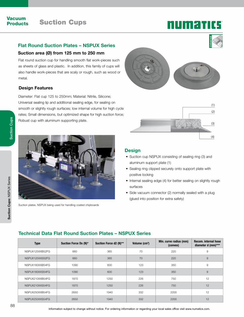
Information subject to change without notice. For ordering information or regarding your local sales office visit www.numatics.com.88
Vacuum Products Suction Cups
Suc
tion
Cup
sS
uctio
n C
ups:
NS
PU
X S
erie
s
Flat round suction cup for handling smooth flat work-pieces such
as sheets of glass and plastic. In addition, this family of cups will
also handle work-pieces that are scaly or rough, such as wood or
metal.
Diameter: Flat cup 125 to 250mm; Material: Nitrile, Silicone;
Universal sealing lip and additional sealing edge, for sealing on
smooth or slightly rough surfaces; low internal volume for high cycle
rates; Small dimensions, but optimized shape for high suction force;
Robust cup with aluminum supporting plate.
Flat Round Suction Plates – NSPUX SeriesSuction area (Ø) from 125 mm to 250 mm
Design Features
Suction plates. NSPUX being used for handling coated chipboards
DesignSuction cup NSPUX consisting of sealing ring (3) and
aluminum support plate (1)
Sealing ring clipped securely onto support plate with
positive locking
Internal sealing edge (4) for better sealing on slightly rough
surfaces
Side vacuum connector (2) normally sealed with a plug
(glued into position for extra safety)
Type Suction Force Ds (N)* Suction Force d2 (N)** Volume (cm3) Min. curve radius (mm) (convex)
Recom. internal hose diameter d (mm)***
NSPUX125XXB52FG 660 365 70 220 9
NSPUX125XXS52FG 660 365 70 220 9
NSPUX160XXB54FG 1090 600 123 350 9
NSPUX160XXS54FG 1090 600 123 350 9
NSPUX210XXB54FG 1870 1250 226 750 12
NSPUX210XXS54FG 1870 1250 226 750 12
NSPUX250XXB54FG 2650 1940 332 2200 12
NSPUX250XXS54FG 2650 1940 332 2200 12
Technical Data Flat Round Suction Plates – NSPUX Series

Information subject to change without notice. For ordering information or regarding your local sales office visit www.numatics.com.89
Vacuum ProductsSuction Cups
Suc
tion
Cup
sS
uctio
n C
ups:
NS
PU
X S
erie
s
Suction plate NSPUX (sealing ring + support plate) is delivered assembled. The assembly consists of:
Sealing ring – elastomer part, available in various diameters
Aluminium support plate, available with various threads
Dimensions: mm
NSPUX 125 to 250
Type Ds G1 H LG1 Z (stroke) d d2 H1 L1 G2 LG2
NSPUX 125 125 G1/4-F 25 13 7 22 83 26 22 G1/4-F 14
NSPUX 16 160 G1/2-F 25 13.5 7 34 113 26.5 36.5 G1/4-F 15
NSPUX 210 210 G1/2-F 25 13.5 5 34 163 26.5 36.5 G1/4-F 15
NSPUX 250 250 G1/2-F 25 13.5 7 34 203 26.5 76 G1/2-F 15
How to Order ContinuedNSPUX Series - Flat Round Suction Plates
Suction Cup Assembly
Series / Cup Diameter(mm)
Thread Type / Port Size
Material Type
Nitrile(55 Hardness)
Silicone(55 Hardness)
NSPUX 125 G1/4-F NSPUX125XXB52FG NSPUX125XXS52FG
NSPUX 160 G1/2-F NSPUX160XXB54FG NSPUX160XXS54FG
NSPUX 210 G1/2-F NSPUX210XXB54FG NSPUX210XXS54FG
NSPUX 250 G1/2-F NSPUX250XXB54FG NSPUX250XXS54FG

Information subject to change without notice. For ordering information or regarding your local sales office visit www.numatics.com.90
Vacuum Products Suction Cups
Suc
tion
Cup
sS
uctio
n C
ups:
NS
GO
N S
erie
s
Flat oval suction cup with maximum suction force particularly
on narrow, elongated work-pieces, such as sections and pipes;
Handling of objects with frame type elements, such as windows
and doors.
Dimensions: Oval Cup 4 x 2 to 90 x 30 mm; Material: Nitrile,
Silicone; High suction forces with reduced space requirement; Works
better than round cups when handling narrow work-pieces where
flat surface areas are too small for a round cup. Suction cups of size
24 x 8 and larger are additionally secured with a two-ear clamp to
prevent rotation.
Flat Oval Suction Cups – NSGON SeriesSuction area (LxW) from 4 x 2 mm to 90 x 30 mm
Design Features
Flat suction cups NSGON being used for handling blister packaging
Type Suction Force (N)* Volume (cm3) Min. curve radius (mm) (convex)
Recom. internal hose diameter d (mm)**
NSGON 4x2 0.42 0.004 1 2
NSGON 7x3.5 1.00 0.019 3 2
NSGON 12x4 1.80 0.048 3 2
NSGON 15x5 3.10 0.036 4 2
NSGON 18x6 4.50 0.058 4 2
NSGON 24x8 8.00 0.138 8 4
NSGON 30x10 12.20 0.280 8 4
NSGON 45x15 28.20 0.980 10 6
NSGON 60x20 50.10 2.300 20 6
NSGON 75x25 78.30 4.700 30 6
NSGON 90x30 112.60 8.500 35 6
Technical Data Flat Oval Suction Cups – NSGON Series
*The specified suction forces are theoretical values at a vacuum of -0.6 bar and with a smooth, dry workpiece surface - they do not include a safety factor**The recommended hose diameter refers to a hose length of approx. 2 m
DesignRobust, wear-resistant suction cup NSGON with
single sealing lip, consisting of suction cup NSGO and
connection fitting
Fitting plugged into cup
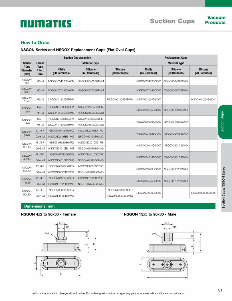
Information subject to change without notice. For ordering information or regarding your local sales office visit www.numatics.com.91
Vacuum ProductsSuction Cups
Suc
tion
Cup
sS
uctio
n C
ups:
NS
GO
N S
erie
s
Dimensions: mm
NSGON 4x2 to 90x30 - Female NSGON 15x5 to 90x30 - Male
How to OrderNSGON Series and NSGOX Replacement Cups (Flat Oval Cups)
Suction Cup Assembly Replacement Cups
Series / Cup
Diameter(mm)
Thread Type / Port Size
Material Type Material Type
Nitrile(60 Hardness)
Silicone(60 Hardness)
Silicone(70 Hardness)
Nitrile(60 Hardness)
Silicone(60 Hardness)
Silicone(70 Hardness)
NSGON 4x2 M3-M NSGON00402B6AMM NSGON00402S6AMM NSGOX00402B6XXX NSGOX00402S6XXX
NSGON 7x3.5 M3-M NSGON00703B6AMM NSGON00703S6AMM NSGOX00703B6XXX NSGOX00703S6XXX
NSGON 12x4 M5-M NSGON01204B6BMM NSGON01204S8BMM NSGOX01204B6XXX NSGOX01204S8XXX
NSGON 15x5
M5-F NSGON01505B6BFM NSGON01505S6BFMNSGOX01505B6XXX NSGOX01505S6XXX
M5-M NSGON01505B6BMM NSGON01505S6BMM
NSGON 18x6
M5-F NSGON01806B6BFM NSGON01806S6BFMNSGOX01806B6XXX NSGOX01806S6XXX
M5-M NSGON01806B6BMM NSGON01806S6BMM
NSGON 24x8
G1/8-F NSGON02408B61FG NSGON02408S61FGNSGOX02408B6XXX NSGOX02408S6XXX
G1/8-M NSGON02408B61MG NSGON02408S61MG
NSGON 30x10
G1/8-F NSGON03010B61FG NSGON03010S61FGNSGOX03010B6XXX NSGOX03010S6XXX
G1/8-M NSGON03010B61MG NSGON03010S61MG
NSGON 45x15
G1/4-F NSGON04515B62FG NSGON04515S62FGNSGOX04515B6XXX NSGOX04515S6XXX
G1/4-M NSGON04515B62MG NSGON04515S62MG
NSGON 60x20
G1/4-F NSGON06020B62FG NSGON06020S62FGNSGOX06020B6XXX NSGOX06020S6XXX
G1/4-M NSGON06020B62MG NSGON06020S62MG
NSGON 75x25
G1/4-F NSGON07525B62FG NSGON07525S62FGNSGOX07525B6XXX NSGOX07525S6XXX
G1/4-M NSGON07525B62MG NSGON07525S62MG
NSGON 90x30
G1/4-F NSGON09030B62FG NSGON09030S82FGNSGOX09030B6XXX NSGOX09030S8XXX
G1/4-M NSGON09030B62MG NSGON09030S82MG
Information subject to change without notice. For ordering information or regarding your local sales office visit www.numatics.com.92
Vacuum Products Suction Cups
Suc
tion
Cup
sS
uctio
n C
ups:
NS
GO
N S
erie
s
Dimensions: mm
Type B dn G1 H L LG1 SW1 Z (stroke)
NSGON00402B6AMM 2 1 M3-M 8 4 3 5 0.5
NSGON00402S6AMM 2 1 M3-M 8 4 3 5 0.5
NSGON00703B6AMM 3.5 1 M3-M 8 7 3 5 0.8
NSGON00703S6AMM 3.5 1 M3-M 8 7 3 5 0.8
NSGON01204B6BMM 4 1.8 M5-M 18 12 4.5 8 0.5
NSGON01204S8BMM 4 1.8 M5-M 18 12 4.5 8 0.5
NSGON01505B6BMM 5 2 M5-M 17 15 5 8 0.7
NSGON01505B6BFM 5 2 M5-F 22 15 5.5 8 0.7
NSGON01505S6BMM 5 2 M5-M 17 15 5 8 0.7
NSGON01505S6BFM 5 2 M5-F 22 15 5.5 8 0.7
NSGON01806B6BMM 6 2 M5-M 17 18 5 8 0.8
NSGON01806B6BFM 6 2 M5-F 22 18 5.5 8 0.8
NSGON01806S6BMM 6 2 M5-M 17 18 5 8 0.8
NSGON01806S6BFM 6 2 M5-F 22 18 5.5 8 0.8
NSGON02408B61MG 8 3.5 G1/8"-M 17 24 8 14 1
NSGON02408B61FG 8 3.5 G1/8"-F 25 24 9 14 1
NSGON02408S61MG 8 3.5 G1/8"-M 17 24 8 14 1
NSGON02408S61FG 8 3.5 G1/8"-F 25 24 9 14 1
NSGON03010B61MG 10 3.5 G1/8"-M 17 30 8 14 1.5
NSGON03010B61FG 10 3.5 G1/8"-F 25 30 9 14 1.5
NSGON03010S61MG 10 3.5 G1/8"-M 17 30 8 14 1.5
NSGON03010S61FG 10 3.5 G1/8"-F 25 30 9 14 1.5
NSGON04515B62MG 15 3.5 G1/4"-M 26 45 10 17 2
NSGON04515B62FG 15 3.5 G1/4"-F 36 45 12 17 2
NSGON04515S62MG 15 3.5 G1/4"-M 26 45 10 17 2
NSGON04515S62FG 15 3.5 G1/4"-F 36 45 12 17 2
NSGON06020B62MG 20 3.5 G1/4"-M 26 60 10 17 2.5
NSGON06020B62FG 20 3.5 G1/4"-F 36 60 12 17 2.5
NSGON06020S62MG 20 3.5 G1/4"-M 26 60 10 17 2.5
NSGON06020S62FG 20 3.5 G1/4"-F 36 60 12 17 2.5
NSGON07525B62MG 25 3.5 G1/4"-M 26 75 10 17 2.8
NSGON07525B62FG 25 3.5 G1/4"-F 36 75 12 17 2.8
NSGON07525S62MG 25 3.5 G1/4"-M 26 75 10 17 2.8
NSGON07525S62FG 25 3.5 G1/4"-F 36 75 12 17 2.8
NSGON09030B62MG 30 3.5 G1/4"-M 26 90 10 17 3.5
NSGON09030B62FG 30 3.5 G1/4"-F 36 90 12 17 3.5
NSGON09030S82MG 30 3.5 G1/4"-M 26 90 10 17 3.5
NSGON09030S82FG 30 3.5 G1/4"-F 36 90 12 17 3.5
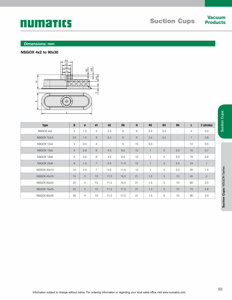
Information subject to change without notice. For ordering information or regarding your local sales office visit www.numatics.com.93
Vacuum ProductsSuction Cups
Suc
tion
Cup
sS
uctio
n C
ups:
NS
GO
N S
erie
s
Dimensions: mm
NSGOX 4x2 to 90x30
Type B d d1 d2 Dk H H2 H3 H4 L Z (stroke)
NSGOX 4x2 2 1.2 3 2.4 6 6 2.4 3.4 - 4 0.5
NSGOX 7x3.5 3.5 1.5 3 2.4 6 6 2.4 3.4 - 7 0.8
NSGOX 12x4 4 3.5 4 - 8 15 9.5 - - 12 0.5
NSGOX 15x5 5 2.8 6 4.5 8.5 12 1 3 5.5 15 0.7
NSGOX 18x6 6 3.2 6 4.5 8.5 12 1 3 5.5 18 0.8
NSGOX 24x8 8 1.5 7 5.5 11.5 12 1 3 5.5 24 1
NSGOX 30x10 10 2.5 7 5.5 11.5 12 1 3 5.5 30 1.5
NSGOX 45x15 15 3 13 11.5 15.5 21 1.5 3 10 45 2
NSGOX 60x20 20 4 13 11.5 15.5 21 1.5 3 10 60 2.5
NSGOX 75x25 25 4 13 11.5 17.5 21 1.5 3 10 75 2.8
NSGOX 90x30 30 4 13 11.5 17.5 21 1.5 3 10 90 3.5

Information subject to change without notice. For ordering information or regarding your local sales office visit www.numatics.com.94
Vacuum Products Suction Cups
Suc
tion
Cup
sS
uctio
n C
ups:
NFS
GA
Ser
ies
Round 1.5 bellows suction cup that is designed to handle sensitive
and/or uneven work-pieces; Examples include work-pieces such
as pipes where the surface is curved. The bellows type cup
helps to provide a reliable seal. Special design of the suction cup
bellows allows for use in systems with quick cycle times.
Diameter: 11 to 150 mm; Round 1.5 bellows cup; Material:
Nitrile, Silicone, Vulkollan; Robust and hard wearing suction cups
with soft tapered sealing lip; High suction force with optimum
dampening effect during placement of suction cup on work-piece;
Very stiff top fold, providing good resistance to horizontal forces
during high acceleration applications.
Round 1.5 Bellows Suction Cups – NFSGA SeriesSuction area (Ø) from 11 mm to 150 mm
Design Features
Bellows suction cups NFSGA VU1 being used for handling cardboard boxes
DesignSuction cup connected positively to fitting; no turning even
when handling heavy loads
Suction cup with supports on the bottom
All fittings plugged in
Suction cup with a diameter of 25 mm or more with
supports on the bottom
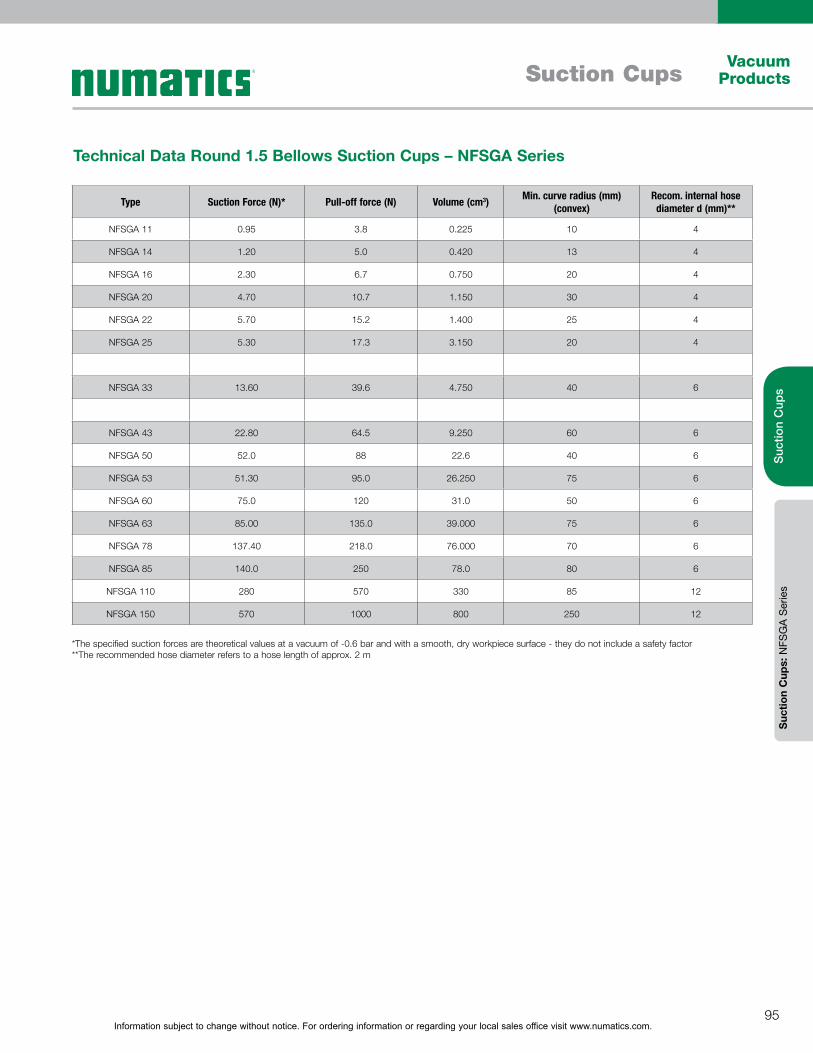
Information subject to change without notice. For ordering information or regarding your local sales office visit www.numatics.com.95
Vacuum ProductsSuction Cups
Suc
tion
Cup
sS
uctio
n C
ups:
NFS
GA
Ser
ies
Type Suction Force (N)* Pull-off force (N) Volume (cm3) Min. curve radius (mm) (convex)
Recom. internal hose diameter d (mm)**
NFSGA 11 0.95 3.8 0.225 10 4
NFSGA 14 1.20 5.0 0.420 13 4
NFSGA 16 2.30 6.7 0.750 20 4
NFSGA 20 4.70 10.7 1.150 30 4
NFSGA 22 5.70 15.2 1.400 25 4
NFSGA 25 5.30 17.3 3.150 20 4
NFSGA 33 13.60 39.6 4.750 40 6
NFSGA 43 22.80 64.5 9.250 60 6
NFSGA 50 52.0 88 22.6 40 6
NFSGA 53 51.30 95.0 26.250 75 6
NFSGA 60 75.0 120 31.0 50 6
NFSGA 63 85.00 135.0 39.000 75 6
NFSGA 78 137.40 218.0 76.000 70 6
NFSGA 85 140.0 250 78.0 80 6
NFSGA 110 280 570 330 85 12
NFSGA 150 570 1000 800 250 12
Technical Data Round 1.5 Bellows Suction Cups – NFSGA Series
*The specified suction forces are theoretical values at a vacuum of -0.6 bar and with a smooth, dry workpiece surface - they do not include a safety factor**The recommended hose diameter refers to a hose length of approx. 2 m
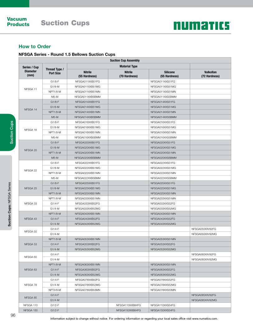
Information subject to change without notice. For ordering information or regarding your local sales office visit www.numatics.com.96
Vacuum Products Suction Cups
Suc
tion
Cup
sS
uctio
n C
ups:
NFS
GA
Ser
ies
How to OrderNFSGA Series - Round 1.5 Bellows Suction Cups
Suction Cup Assembly
Series / Cup Diameter
(mm)
Thread Type / Port Size
Material Type
Nitrile(55 Hardness)
Nitrile(70 Hardness)
Silicone(55 Hardness)
Vulkollan(72 Hardness)
NFSGA 11
G1/8-F NFSGA011XXB51FG NFSGA011XXS51FG
G1/8-M NFSGA011XXB51MG NFSGA011XXS51MG
NPT1/8-M NFSGA011XXB51MN NFSGA011XXS51MN
M5-M NFSGA011XXB5BMM NFSGA011XXS5BMM
NFSGA 14
G1/8-F NFSGA014XXB51FG NFSGA014XXS51FG
G1/8-M NFSGA014XXB51MG NFSGA014XXS51MG
NPT1/8-M NFSGA014XXB51MN NFSGA014XXS51MN
M5-M NFSGA014XXB5BMM NFSGA014XXS5BMM
NFSGA 16
G1/8-F NFSGA016XXB51FG NFSGA016XXS51FG
G1/8-M NFSGA016XXB51MG NFSGA016XXS51MG
NPT1/8-M NFSGA016XXB51MN NFSGA016XXS51MN
M5-M NFSGA016XXB5BMM NFSGA016XXS5BMM
NFSGA 20
G1/8-F NFSGA020XXB51FG NFSGA020XXS51FG
G1/8-M NFSGA020XXB51MG NFSGA020XXS51MG
NPT1/8-M NFSGA020XXB51MN NFSGA020XXS51MN
M5-M NFSGA020XXB5BMM NFSGA020XXS5BMM
NFSGA 22
G1/8-F NFSGA022XXB51FG NFSGA022XXS51FG
G1/8-M NFSGA022XXB51MG NFSGA022XXS51MG
NPT1/8-M NFSGA022XXB51MN NFSGA022XXS51MN
M5-M NFSGA022XXB5BMM NFSGA022XXS5BMM
NFSGA 25
G1/8-F NFSGA025XXB51FG NFSGA025XXS51FG
G1/8-M NFSGA025XXB51MG NFSGA025XXS51MG
NPT1/8-M NFSGA025XXB51MN NFSGA025XXS51MN
NFSGA 33
NPT1/8-M NFSGA033XXB51MN NFSGA033XXS51MN
G1/4-F NFSGA033XXB52FG NFSGA033XXS52FG
G1/4-M NFSGA033XXB52MG NFSGA033XXS52MG
NFSGA 43
NPT1/8-M NFSGA043XXB51MN NFSGA043XXS51MN
G1/4-F NFSGA043XXB52FG NFSGA043XXS52FG
G1/4-M NFSGA043XXB52MG NFSGA043XXS52MG
NFSGA 50G1/4-F NFSGA050XXV92FG
G1/4-M NFSGA050XXV92MG
NFSGA 53
NPT1/8-M NFSGA053XXB51MN NFSGA053XXS51MN
G1/4-F NFSGA053XXB52FG NFSGA053XXS52FG
G1/4-M NFSGA053XXB52MG NFSGA053XXS52MG
NFSGA 60G1/4-F NFSGA060XXV92FG
G1/4-M NFSGA060XXV92MG
NFSGA 63
NPT1/8-M NFSGA063XXB51MN NFSGA063XXS51MN
G1/4-F NFSGA063XXB52FG NFSGA063XXS52FG
G1/4-M NFSGA063XXB52MG NFSGA063XXS52MG
NFSGA 78
G1/4-F NFSGA078XXB52FG NFSGA078XXS52FG
G1/4-M NFSGA078XXB52MG NFSGA078XXS52MG
NPT3/8-M NFSGA078XXB53MN NFSGA078XXS53MN
NFSGA 85G1/4-F NFSGA085XXV92FG
G1/4-M NFSGA085XXV92MG
NFSGA 110 G1/2-F NFSGA110XXB84FG NFSGA110XXS54FG
NFSGA 150 G1/2-F NFSGA150XXB84FG NFSGA150XXS54FG
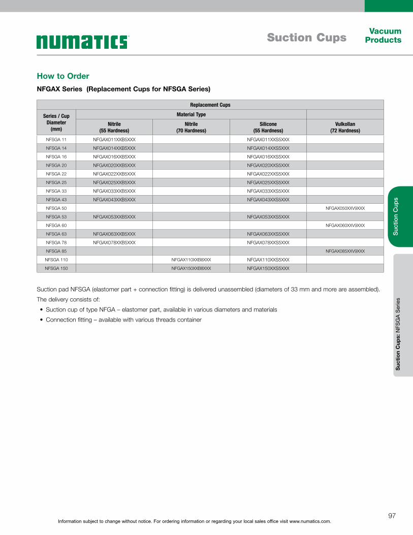
Information subject to change without notice. For ordering information or regarding your local sales office visit www.numatics.com.97
Vacuum ProductsSuction Cups
Suc
tion
Cup
sS
uctio
n C
ups:
NFS
GA
Ser
ies
How to OrderNFGAX Series (Replacement Cups for NFSGA Series)
Replacement Cups
Series / Cup Diameter
(mm)
Material Type
Nitrile(55 Hardness)
Nitrile(70 Hardness)
Silicone(55 Hardness)
Vulkollan(72 Hardness)
NFSGA 11 NFGAX011XXB5XXX NFGAX011XXS5XXX
NFSGA 14 NFGAX014XXB5XXX NFGAX014XXS5XXX
NFSGA 16 NFGAX016XXB5XXX NFGAX016XXS5XXX
NFSGA 20 NFGAX020XXB5XXX NFGAX020XXS5XXX
NFSGA 22 NFGAX022XXB5XXX NFGAX022XXS5XXX
NFSGA 25 NFGAX025XXB5XXX NFGAX025XXS5XXX
NFSGA 33 NFGAX033XXB5XXX NFGAX033XXS5XXX
NFSGA 43 NFGAX043XXB5XXX NFGAX043XXS5XXX
NFSGA 50 NFGAX050XXV9XXX
NFSGA 53 NFGAX053XXB5XXX NFGAX053XXS5XXX
NFSGA 60 NFGAX060XXV9XXX
NFSGA 63 NFGAX063XXB5XXX NFGAX063XXS5XXX
NFSGA 78 NFGAX078XXB5XXX NFGAX078XXS5XXX
NFSGA 85 NFGAX085XXV9XXX
NFSGA 110 NFGAX110XXB8XXX NFGAX110XXS5XXX
NFSGA 150 NFGAX150XXB8XXX NFGAX150XXS5XXX
Suction pad NFSGA (elastomer part + connection fitting) is delivered unassembled (diameters of 33 mm and more are assembled).
The delivery consists of:
Suction cup of type NFGA – elastomer part, available in various diameters and materials
Connection fitting – available with various threads container
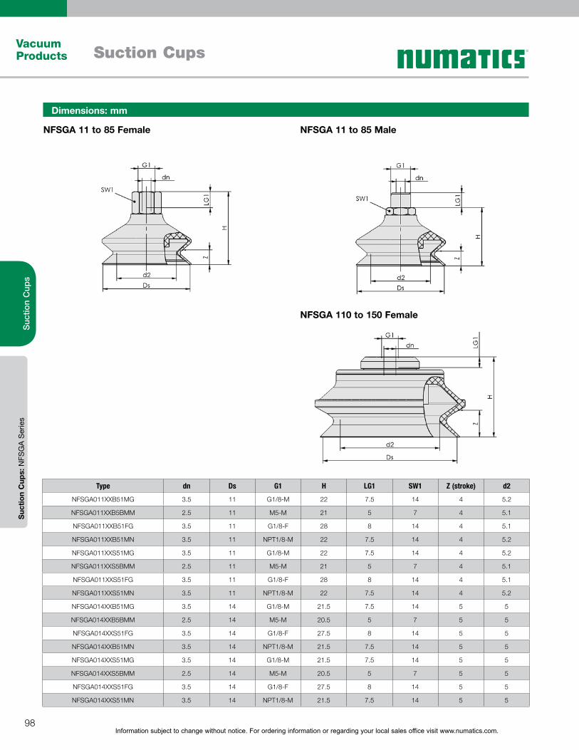
Information subject to change without notice. For ordering information or regarding your local sales office visit www.numatics.com.98
Vacuum Products Suction Cups
Suc
tion
Cup
sS
uctio
n C
ups:
NFS
GA
Ser
ies
Dimensions: mm
NFSGA 11 to 85 Female
NFSGA 110 to 150 Female
NFSGA 11 to 85 Male
Type dn Ds G1 H LG1 SW1 Z (stroke) d2
NFSGA011XXB51MG 3.5 11 G1/8-M 22 7.5 14 4 5.2
NFSGA011XXB5BMM 2.5 11 M5-M 21 5 7 4 5.1
NFSGA011XXB51FG 3.5 11 G1/8-F 28 8 14 4 5.1
NFSGA011XXB51MN 3.5 11 NPT1/8-M 22 7.5 14 4 5.2
NFSGA011XXS51MG 3.5 11 G1/8-M 22 7.5 14 4 5.2
NFSGA011XXS5BMM 2.5 11 M5-M 21 5 7 4 5.1
NFSGA011XXS51FG 3.5 11 G1/8-F 28 8 14 4 5.1
NFSGA011XXS51MN 3.5 11 NPT1/8-M 22 7.5 14 4 5.2
NFSGA014XXB51MG 3.5 14 G1/8-M 21.5 7.5 14 5 5
NFSGA014XXB5BMM 2.5 14 M5-M 20.5 5 7 5 5
NFSGA014XXS51FG 3.5 14 G1/8-F 27.5 8 14 5 5
NFSGA014XXB51MN 3.5 14 NPT1/8-M 21.5 7.5 14 5 5
NFSGA014XXS51MG 3.5 14 G1/8-M 21.5 7.5 14 5 5
NFSGA014XXS5BMM 2.5 14 M5-M 20.5 5 7 5 5
NFSGA014XXS51FG 3.5 14 G1/8-F 27.5 8 14 5 5
NFSGA014XXS51MN 3.5 14 NPT1/8-M 21.5 7.5 14 5 5
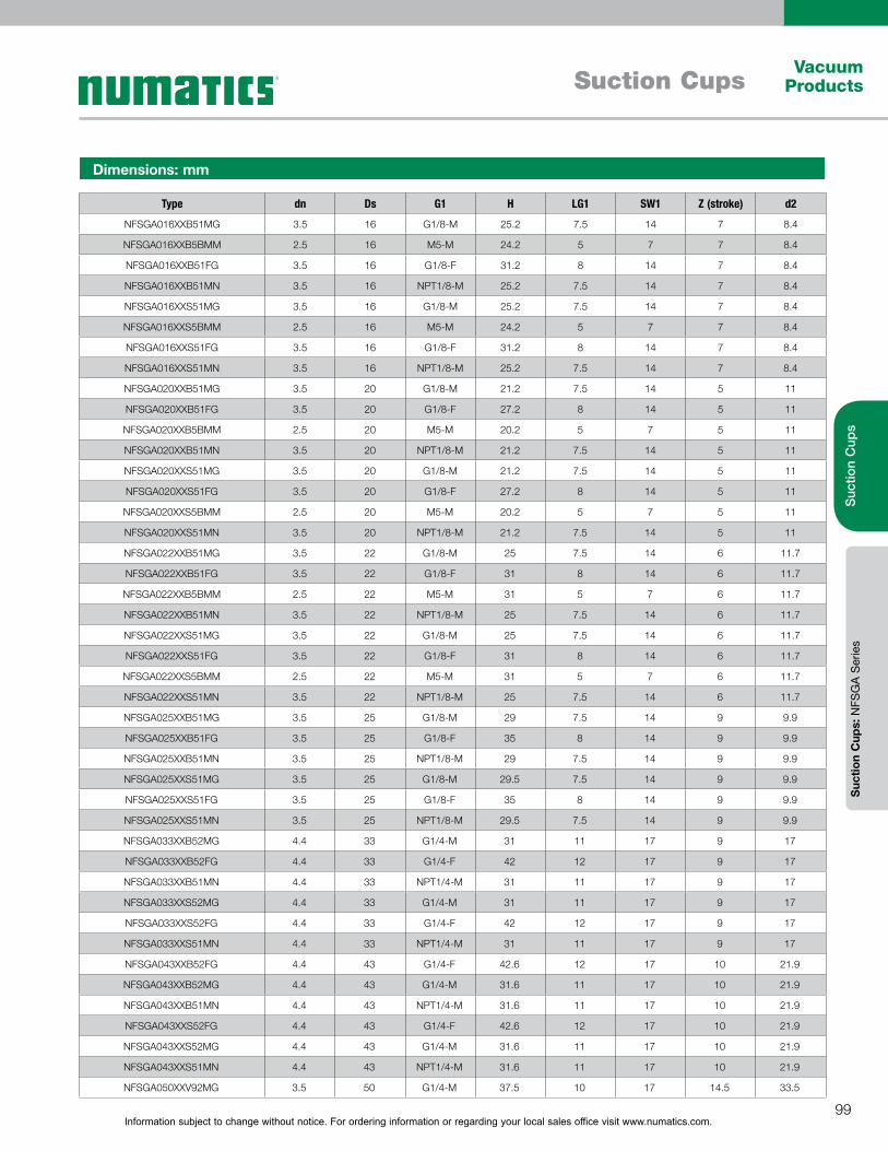
Information subject to change without notice. For ordering information or regarding your local sales office visit www.numatics.com.99
Vacuum ProductsSuction Cups
Suc
tion
Cup
sS
uctio
n C
ups:
NFS
GA
Ser
ies
Type dn Ds G1 H LG1 SW1 Z (stroke) d2
NFSGA016XXB51MG 3.5 16 G1/8-M 25.2 7.5 14 7 8.4
NFSGA016XXB5BMM 2.5 16 M5-M 24.2 5 7 7 8.4
NFSGA016XXB51FG 3.5 16 G1/8-F 31.2 8 14 7 8.4
NFSGA016XXB51MN 3.5 16 NPT1/8-M 25.2 7.5 14 7 8.4
NFSGA016XXS51MG 3.5 16 G1/8-M 25.2 7.5 14 7 8.4
NFSGA016XXS5BMM 2.5 16 M5-M 24.2 5 7 7 8.4
NFSGA016XXS51FG 3.5 16 G1/8-F 31.2 8 14 7 8.4
NFSGA016XXS51MN 3.5 16 NPT1/8-M 25.2 7.5 14 7 8.4
NFSGA020XXB51MG 3.5 20 G1/8-M 21.2 7.5 14 5 11
NFSGA020XXB51FG 3.5 20 G1/8-F 27.2 8 14 5 11
NFSGA020XXB5BMM 2.5 20 M5-M 20.2 5 7 5 11
NFSGA020XXB51MN 3.5 20 NPT1/8-M 21.2 7.5 14 5 11
NFSGA020XXS51MG 3.5 20 G1/8-M 21.2 7.5 14 5 11
NFSGA020XXS51FG 3.5 20 G1/8-F 27.2 8 14 5 11
NFSGA020XXS5BMM 2.5 20 M5-M 20.2 5 7 5 11
NFSGA020XXS51MN 3.5 20 NPT1/8-M 21.2 7.5 14 5 11
NFSGA022XXB51MG 3.5 22 G1/8-M 25 7.5 14 6 11.7
NFSGA022XXB51FG 3.5 22 G1/8-F 31 8 14 6 11.7
NFSGA022XXB5BMM 2.5 22 M5-M 31 5 7 6 11.7
NFSGA022XXB51MN 3.5 22 NPT1/8-M 25 7.5 14 6 11.7
NFSGA022XXS51MG 3.5 22 G1/8-M 25 7.5 14 6 11.7
NFSGA022XXS51FG 3.5 22 G1/8-F 31 8 14 6 11.7
NFSGA022XXS5BMM 2.5 22 M5-M 31 5 7 6 11.7
NFSGA022XXS51MN 3.5 22 NPT1/8-M 25 7.5 14 6 11.7
NFSGA025XXB51MG 3.5 25 G1/8-M 29 7.5 14 9 9.9
NFSGA025XXB51FG 3.5 25 G1/8-F 35 8 14 9 9.9
NFSGA025XXB51MN 3.5 25 NPT1/8-M 29 7.5 14 9 9.9
NFSGA025XXS51MG 3.5 25 G1/8-M 29.5 7.5 14 9 9.9
NFSGA025XXS51FG 3.5 25 G1/8-F 35 8 14 9 9.9
NFSGA025XXS51MN 3.5 25 NPT1/8-M 29.5 7.5 14 9 9.9
NFSGA033XXB52MG 4.4 33 G1/4-M 31 11 17 9 17
NFSGA033XXB52FG 4.4 33 G1/4-F 42 12 17 9 17
NFSGA033XXB51MN 4.4 33 NPT1/4-M 31 11 17 9 17
NFSGA033XXS52MG 4.4 33 G1/4-M 31 11 17 9 17
NFSGA033XXS52FG 4.4 33 G1/4-F 42 12 17 9 17
NFSGA033XXS51MN 4.4 33 NPT1/4-M 31 11 17 9 17
NFSGA043XXB52FG 4.4 43 G1/4-F 42.6 12 17 10 21.9
NFSGA043XXB52MG 4.4 43 G1/4-M 31.6 11 17 10 21.9
NFSGA043XXB51MN 4.4 43 NPT1/4-M 31.6 11 17 10 21.9
NFSGA043XXS52FG 4.4 43 G1/4-F 42.6 12 17 10 21.9
NFSGA043XXS52MG 4.4 43 G1/4-M 31.6 11 17 10 21.9
NFSGA043XXS51MN 4.4 43 NPT1/4-M 31.6 11 17 10 21.9
NFSGA050XXV92MG 3.5 50 G1/4-M 37.5 10 17 14.5 33.5
Dimensions: mm
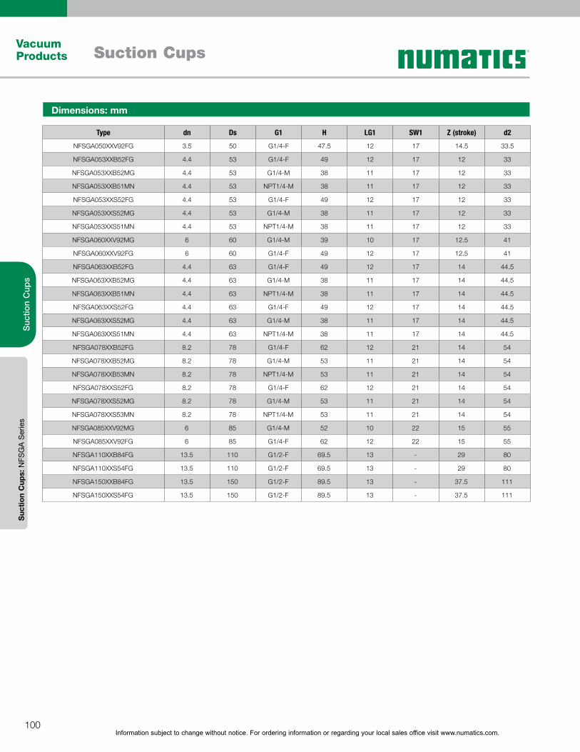
Information subject to change without notice. For ordering information or regarding your local sales office visit www.numatics.com.100
Vacuum Products Suction Cups
Suc
tion
Cup
sS
uctio
n C
ups:
NFS
GA
Ser
ies
Type dn Ds G1 H LG1 SW1 Z (stroke) d2
NFSGA050XXV92FG 3.5 50 G1/4-F 47.5 12 17 14.5 33.5
NFSGA053XXB52FG 4.4 53 G1/4-F 49 12 17 12 33
NFSGA053XXB52MG 4.4 53 G1/4-M 38 11 17 12 33
NFSGA053XXB51MN 4.4 53 NPT1/4-M 38 11 17 12 33
NFSGA053XXS52FG 4.4 53 G1/4-F 49 12 17 12 33
NFSGA053XXS52MG 4.4 53 G1/4-M 38 11 17 12 33
NFSGA053XXS51MN 4.4 53 NPT1/4-M 38 11 17 12 33
NFSGA060XXV92MG 6 60 G1/4-M 39 10 17 12.5 41
NFSGA060XXV92FG 6 60 G1/4-F 49 12 17 12.5 41
NFSGA063XXB52FG 4.4 63 G1/4-F 49 12 17 14 44.5
NFSGA063XXB52MG 4.4 63 G1/4-M 38 11 17 14 44.5
NFSGA063XXB51MN 4.4 63 NPT1/4-M 38 11 17 14 44.5
NFSGA063XXS52FG 4.4 63 G1/4-F 49 12 17 14 44.5
NFSGA063XXS52MG 4.4 63 G1/4-M 38 11 17 14 44.5
NFSGA063XXS51MN 4.4 63 NPT1/4-M 38 11 17 14 44.5
NFSGA078XXB52FG 8.2 78 G1/4-F 62 12 21 14 54
NFSGA078XXB52MG 8.2 78 G1/4-M 53 11 21 14 54
NFSGA078XXB53MN 8.2 78 NPT1/4-M 53 11 21 14 54
NFSGA078XXS52FG 8.2 78 G1/4-F 62 12 21 14 54
NFSGA078XXS52MG 8.2 78 G1/4-M 53 11 21 14 54
NFSGA078XXS53MN 8.2 78 NPT1/4-M 53 11 21 14 54
NFSGA085XXV92MG 6 85 G1/4-M 52 10 22 15 55
NFSGA085XXV92FG 6 85 G1/4-F 62 12 22 15 55
NFSGA110XXB84FG 13.5 110 G1/2-F 69.5 13 - 29 80
NFSGA110XXS54FG 13.5 110 G1/2-F 69.5 13 - 29 80
NFSGA150XXB84FG 13.5 150 G1/2-F 89.5 13 - 37.5 111
NFSGA150XXS54FG 13.5 150 G1/2-F 89.5 13 - 37.5 111
Dimensions: mm

Information subject to change without notice. For ordering information or regarding your local sales office visit www.numatics.com.101
Vacuum ProductsSuction Cups
Suc
tion
Cup
sS
uctio
n C
ups:
NFS
GA
Ser
ies
Dimensions: mm
NFGAX 50 to 85 (VUL)NFGAX 11 to 25 NFGAX 33 to 78
NFGAX 110 to 150 Female
Type Ds H Z (stroke) d1 d Dk H2 H3 d2 D1
NFGAX 11 11 16 4 - 4.5 10 6.9 9.3 5.1 12
NFGAX 14 14 15.5 5 - 4.5 10 6.9 8.5 5 13.7
NFGAX 16 16 19.2 7 - 4.5 10 6.9 9.3 8.4 17
NFGAX 20 20 15.2 5 - 4.5 10 6.9 8.7 11 19.9
NFGAX 22 22 19 6 4.5 10 6.9 9.1 11.7 24.2
NFGAX 25 25 23 9 4.5 10 6.9 8.9 9.9 25
NFGAX 33 33 27 9 16 8 18 13 14 17 36
NFGAX 43 43 27.6 10 14.5 8 18 13 17.1 21.9 45.9
NFGAX 50 8 13.6 33.5 50 17.5 47 32.5 8 18 14.5
NFGAX 53 53 34 12 14.5 8 18 13 19 33 58.6
NFGAX 60 12 20 41 60 21 59 34 12 22 12.5
NFGAX 63 63 34 14 14.5 8 18 13 18.8 44.5 67
NFGAX 78 78 47 14 21.8 11.8 24.7 19.7 31.4 54 83
NFGAX 85 12 25 55 85 25 84 47 20 32 15
NFGAX 110 110 55 29 7 13.5 86 8 10 80 123
NFGAX 150 150 74 37.5 7 13.5 120 6 - 111 168
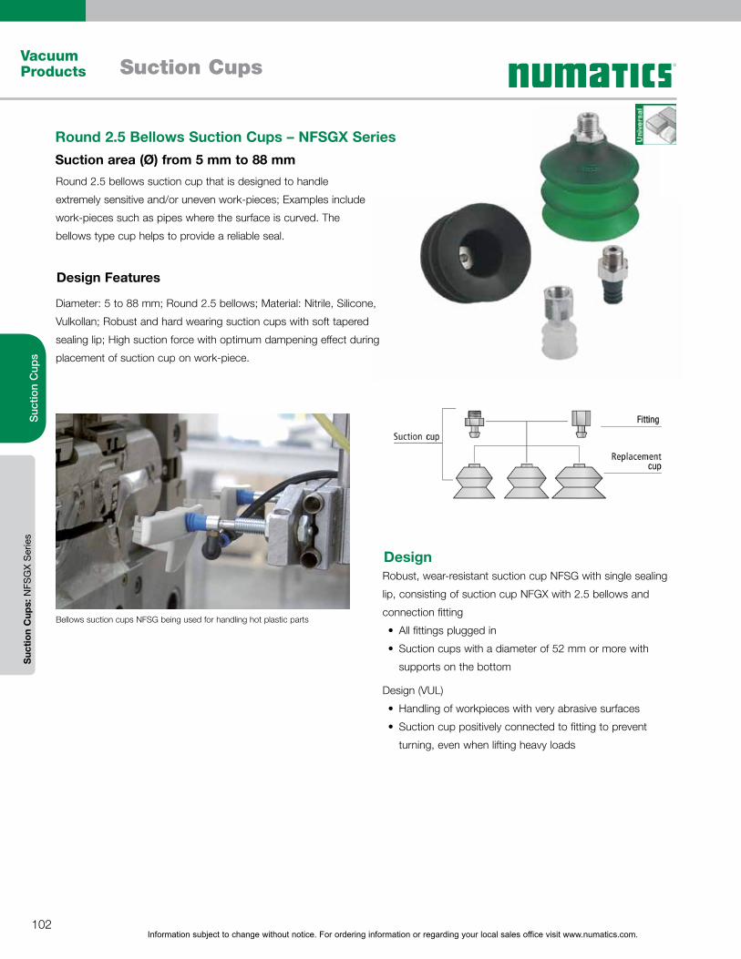
Information subject to change without notice. For ordering information or regarding your local sales office visit www.numatics.com.102
Vacuum Products Suction Cups
Suc
tion
Cup
sS
uctio
n C
ups:
NFS
GX
Ser
ies
Round 2.5 bellows suction cup that is designed to handle
extremely sensitive and/or uneven work-pieces; Examples include
work-pieces such as pipes where the surface is curved. The
bellows type cup helps to provide a reliable seal.
Diameter: 5 to 88 mm; Round 2.5 bellows; Material: Nitrile, Silicone,
Vulkollan; Robust and hard wearing suction cups with soft tapered
sealing lip; High suction force with optimum dampening effect during
placement of suction cup on work-piece.
Round 2.5 Bellows Suction Cups – NFSGX SeriesSuction area (Ø) from 5 mm to 88 mm
Design Features
Bellows suction cups NFSG being used for handling hot plastic parts
DesignRobust, wear-resistant suction cup NFSG with single sealing
lip, consisting of suction cup NFGX with 2.5 bellows and
connection fitting
All fittings plugged in
Suction cups with a diameter of 52 mm or more with
supports on the bottom
Design (VUL)
Handling of workpieces with very abrasive surfaces
Suction cup positively connected to fitting to prevent
turning, even when lifting heavy loads
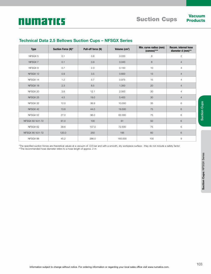
Information subject to change without notice. For ordering information or regarding your local sales office visit www.numatics.com.103
Vacuum ProductsSuction Cups
Suc
tion
Cup
sS
uctio
n C
ups:
NFS
GX
Ser
ies
Type Suction Force (N)* Pull-off force (N) Volume (cm3) Min. curve radius (mm) (convex)***
Recom. internal hose diameter d (mm)**
NFSGX 5 0.1 0.8 0.033 8 2
NFSGX 7 0.1 0.9 0.043 8 4
NFSGX 9 0.7 2.3 0.150 10 4
NFSGX 12 0.9 3.5 0.600 13 4
NFSGX 14 1.2 5.7 0.975 15 4
NFSGX 18 2.3 8.5 1.350 20 4
NFSGX 20 3.8 12.1 2.000 30 4
NFSGX 25 4.5 19.0 5.400 30 4
NFSGX 32 12.0 36.9 10.000 35 6
NFSGX 42 13.6 44.0 19.500 75 6
NFSGX 52 27.0 96.0 62.000 75 6
NFSGX 60 VU1-72 61.0 100 61 50 6
NFSGX 62 39.6 137.0 72.500 75 6
NFSGX 85 VU1-72 120.0 250 195 60 6
NFSGX 88 45.2 286.0 165.000 100 9
Technical Data 2.5 Bellows Suction Cups – NFSGX Series
*The specified suction forces are theoretical values at a vacuum of -0.6 bar and with a smooth, dry workpiece surface - they do not include a safety factor**The recommended hose diameter refers to a hose length of approx. 2 m
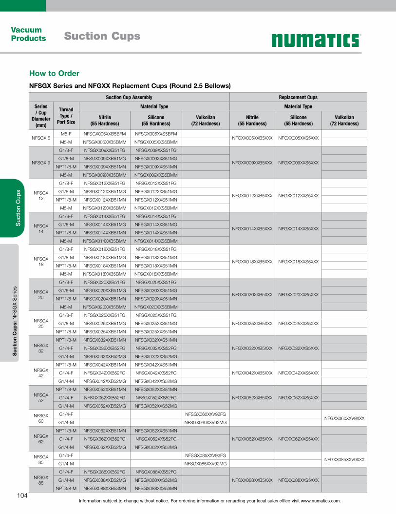
Information subject to change without notice. For ordering information or regarding your local sales office visit www.numatics.com.104
Vacuum Products Suction Cups
Suc
tion
Cup
sS
uctio
n C
ups:
NFS
GX
Ser
ies
Suction Cup Assembly Replacement Cups
Series / Cup
Diameter(mm)
Thread Type /
Port Size
Material Type Material Type
Nitrile(55 Hardness)
Silicone(55 Hardness)
Vulkollan(72 Hardness)
Nitrile(55 Hardness)
Silicone(55 Hardness)
Vulkollan(72 Hardness)
NFSGX 5M5-F NFSGX005XXB5BFM NFSGX005XXS5BFM
NFGXX005XXB5XXX NFGXX005XXS5XXXM5-M NFSGX005XXB5BMM NFSGX005XXS5BMM
NFSGX 9
G1/8-F NFSGX009XXB51FG NFSGX009XXS51FG
NFGXX009XXB5XXX NFGXX009XXS5XXXG1/8-M NFSGX009XXB51MG NFSGX009XXS51MG
NPT1/8-M NFSGX009XXB51MN NFSGX009XXS51MN
M5-M NFSGX009XXB5BMM NFSGX009XXS5BMM
NFSGX 12
G1/8-F NFSGX012XXB51FG NFSGX012XXS51FG
NFGXX012XXB5XXX NFGXX012XXS5XXXG1/8-M NFSGX012XXB51MG NFSGX012XXS51MG
NPT1/8-M NFSGX012XXB51MN NFSGX012XXS51MN
M5-M NFSGX012XXB5BMM NFSGX012XXS5BMM
NFSGX 14
G1/8-F NFSGX014XXB51FG NFSGX014XXS51FG
NFGXX014XXB5XXX NFGXX014XXS5XXXG1/8-M NFSGX014XXB51MG NFSGX014XXS51MG
NPT1/8-M NFSGX014XXB51MN NFSGX014XXS51MN
M5-M NFSGX014XXB5BMM NFSGX014XXS5BMM
NFSGX 18
G1/8-F NFSGX018XXB51FG NFSGX018XXS51FG
NFGXX018XXB5XXX NFGXX018XXS5XXXG1/8-M NFSGX018XXB51MG NFSGX018XXS51MG
NPT1/8-M NFSGX018XXB51MN NFSGX018XXS51MN
M5-M NFSGX018XXB5BMM NFSGX018XXS5BMM
NFSGX 20
G1/8-F NFSGX020XXB51FG NFSGX020XXS51FG
NFGXX020XXB5XXX NFGXX020XXS5XXXG1/8-M NFSGX020XXB51MG NFSGX020XXS51MG
NPT1/8-M NFSGX020XXB51MN NFSGX020XXS51MN
M5-M NFSGX020XXB5BMM NFSGX020XXS5BMM
NFSGX 25
G1/8-F NFSGX025XXB51FG NFSGX025XXS51FG
NFGXX025XXB5XXX NFGXX025XXS5XXXG1/8-M NFSGX025XXB51MG NFSGX025XXS51MG
NPT1/8-M NFSGX025XXB51MN NFSGX025XXS51MN
NFSGX 32
NPT1/8-M NFSGX032XXB51MN NFSGX032XXS51MN
NFGXX032XXB5XXX NFGXX032XXS5XXXG1/4-F NFSGX032XXB52FG NFSGX032XXS52FG
G1/4-M NFSGX032XXB52MG NFSGX032XXS52MG
NFSGX 42
NPT1/8-M NFSGX042XXB51MN NFSGX042XXS51MN
NFGXX042XXB5XXX NFGXX042XXS5XXXG1/4-F NFSGX042XXB52FG NFSGX042XXS52FG
G1/4-M NFSGX042XXB52MG NFSGX042XXS52MG
NFSGX 52
NPT1/8-M NFSGX052XXB51MN NFSGX052XXS51MN
NFGXX052XXB5XXX NFGXX052XXS5XXXG1/4-F NFSGX052XXB52FG NFSGX052XXS52FG
G1/4-M NFSGX052XXB52MG NFSGX052XXS52MG
NFSGX 60
G1/4-F NFSGX060XXV92FGNFGXX060XXV9XXX
G1/4-M NFSGX060XXV92MG
NFSGX 62
NPT1/8-M NFSGX062XXB51MN NFSGX062XXS51MN
NFGXX062XXB5XXX NFGXX062XXS5XXXG1/4-F NFSGX062XXB52FG NFSGX062XXS52FG
G1/4-M NFSGX062XXB52MG NFSGX062XXS52MG
NFSGX 85
G1/4-F NFSGX085XXV92FGNFGXX085XXV9XXX
G1/4-M NFSGX085XXV92MG
NFSGX 88
G1/4-F NFSGX088XXB52FG NFSGX088XXS52FG
NFGXX088XXB5XXX NFGXX088XXS5XXXG1/4-M NFSGX088XXB52MG NFSGX088XXS52MG
NPT3/8-M NFSGX088XXB53MN NFSGX088XXS53MN
How to OrderNFSGX Series and NFGXX Replacment Cups (Round 2.5 Bellows)
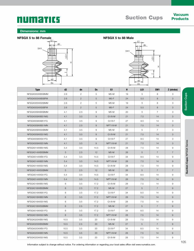
Information subject to change without notice. For ordering information or regarding your local sales office visit www.numatics.com.105
Vacuum ProductsSuction Cups
Suc
tion
Cup
sS
uctio
n C
ups:
NFS
GX
Ser
ies
Dimensions: mm
NFSGX 5 to 88 Female NFSGX 5 to 88 Male
Type d2 dn Ds G1 H LG1 SW1 Z (stroke)
NFSGX005XXB5BMM 2.6 2 5 M5-M 19 5 8 3
NFSGX005XXB5BFM 2.6 2 5 M5-F 24 5.5 8 3
NFSGX005XXS5BMM 2.6 2 5 M5-M 19 5 8 3
NFSGX005XXS5BFM 2.6 2 5 M5-F 24 5.5 8 3
NFSGX009XXB5BMM 4.1 2.5 9 M5-M 20 5 7 3
NFSGX009XXB51MG 4.1 3.5 9 G1/8-M 21 7.5 14 3
NFSGX009XXB51FG 4.1 3.5 9 G1/8-F 27 8.5 14 3
NFSGX009XXB51MN 4.1 2.5 9 NPT1/8-M 21 7.5 14 3
NFSGX009XXS5BMM 4.1 3.5 9 M5-M 20 5 7 3
NFSGX009XXS51MG 4.1 3.5 9 G1/8-M 21 7.5 14 3
NFSGX009XXS51FG 4.1 3.5 9 G1/8-F 27 8.5 14 3
NFSGX009XXS51MN 4.1 3.5 9 NPT1/8-M 21 7.5 14 3
NFSGX014XXB51MG 5.4 3.5 14.5 G1/8-M 28 7.5 14 9
NFSGX014XXB5BMM 5 2.5 12 M5-M 26 5 7 7
NFSGX014XXB51FG 5.4 3.5 14.5 G1/8-F 34 8.5 14 9
NFSGX014XXB51MN 5.4 3.5 14.5 NPT1/8-M 28 7.5 14 9
NFSGX014XXS51MG 5.4 3.5 14.5 G1/8-M 28 7.5 14 9
NFSGX014XXS5BMM 5 2.5 12 M5-M 26 5 7 7
NFSGX014XXS51FG 5.4 3.5 14.5 G1/8-F 34 8.5 14 9
NFSGX014XXS51MN 5.4 3.5 14.5 NPT1/8-M 28 7.5 14 9
NFSGX018XXB51MG 8 3.5 17.2 G1/8-M 28 7.5 14 9
NFSGX018XXB5BMM 8 2.5 17.2 M5-M 27 5 7 9
NFSGX018XXB51FG 8 3.5 17.2 G1/8-F 34 8.5 14 9
NFSGX018XXB51MN 8 3.5 17.2 NPT1/8-M 28 7.5 14 9
NFSGX018XXS51MG 8 3.5 17.2 G1/8-M 28 7.5 14 9
NFSGX018XXS5BMM 8 2.5 17.2 M5-M 27 5 7 9
NFSGX018XXS51FG 8 3.5 17.2 G1/8-F 34 8.5 14 9
NFSGX018XXS51MN 8 3.5 17.2 NPT1/8-M 28 7.5 14 9
NFSGX020XXB51MG 10.5 3.5 20 G1/8-M 28 7.5 14 9
NFSGX020XXB5BMM 10.5 2.5 20 M5-M 27 5 7 9
NFSGX020XXB51FG 10.5 3.5 20 G1/8-F 34 8.5 14 9
NFSGX020XXB51MN 10.5 3.5 20 NPT1/8-M 28 7.5 14 9
NFSGX020XXS51MG 10.5 3.5 20 G1/8-M 28 7.5 14 9
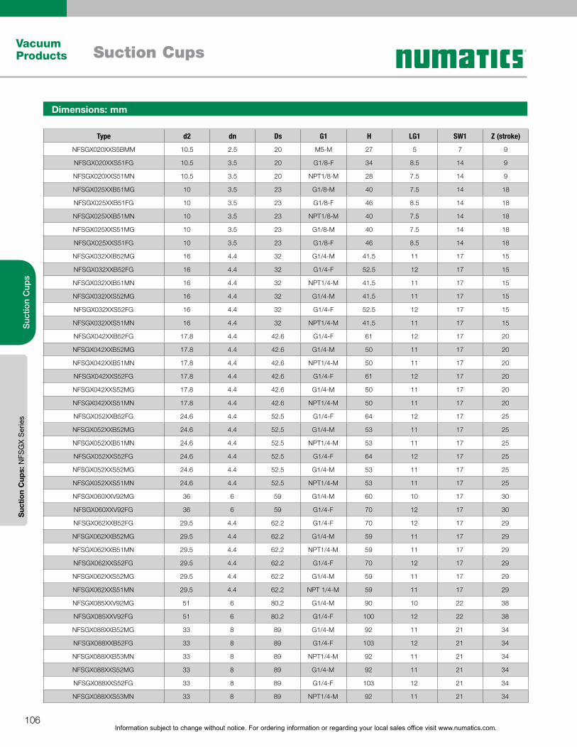
Information subject to change without notice. For ordering information or regarding your local sales office visit www.numatics.com.106
Vacuum Products Suction Cups
Suc
tion
Cup
sS
uctio
n C
ups:
NFS
GX
Ser
ies
Type d2 dn Ds G1 H LG1 SW1 Z (stroke)
NFSGX020XXS5BMM 10.5 2.5 20 M5-M 27 5 7 9
NFSGX020XXS51FG 10.5 3.5 20 G1/8-F 34 8.5 14 9
NFSGX020XXS51MN 10.5 3.5 20 NPT1/8-M 28 7.5 14 9
NFSGX025XXB51MG 10 3.5 23 G1/8-M 40 7.5 14 18
NFSGX025XXB51FG 10 3.5 23 G1/8-F 46 8.5 14 18
NFSGX025XXB51MN 10 3.5 23 NPT1/8-M 40 7.5 14 18
NFSGX025XXS51MG 10 3.5 23 G1/8-M 40 7.5 14 18
NFSGX025XXS51FG 10 3.5 23 G1/8-F 46 8.5 14 18
NFSGX032XXB52MG 16 4.4 32 G1/4-M 41.5 11 17 15
NFSGX032XXB52FG 16 4.4 32 G1/4-F 52.5 12 17 15
NFSGX032XXB51MN 16 4.4 32 NPT1/4-M 41.5 11 17 15
NFSGX032XXS52MG 16 4.4 32 G1/4-M 41.5 11 17 15
NFSGX032XXS52FG 16 4.4 32 G1/4-F 52.5 12 17 15
NFSGX032XXS51MN 16 4.4 32 NPT1/4-M 41.5 11 17 15
NFSGX042XXB52FG 17.8 4.4 42.6 G1/4-F 61 12 17 20
NFSGX042XXB52MG 17.8 4.4 42.6 G1/4-M 50 11 17 20
NFSGX042XXB51MN 17.8 4.4 42.6 NPT1/4-M 50 11 17 20
NFSGX042XXS52FG 17.8 4.4 42.6 G1/4-F 61 12 17 20
NFSGX042XXS52MG 17.8 4.4 42.6 G1/4-M 50 11 17 20
NFSGX042XXS51MN 17.8 4.4 42.6 NPT1/4-M 50 11 17 20
NFSGX052XXB52FG 24.6 4.4 52.5 G1/4-F 64 12 17 25
NFSGX052XXB52MG 24.6 4.4 52.5 G1/4-M 53 11 17 25
NFSGX052XXB51MN 24.6 4.4 52.5 NPT1/4-M 53 11 17 25
NFSGX052XXS52FG 24.6 4.4 52.5 G1/4-F 64 12 17 25
NFSGX052XXS52MG 24.6 4.4 52.5 G1/4-M 53 11 17 25
NFSGX052XXS51MN 24.6 4.4 52.5 NPT1/4-M 53 11 17 25
NFSGX060XXV92MG 36 6 59 G1/4-M 60 10 17 30
NFSGX060XXV92FG 36 6 59 G1/4-F 70 12 17 30
NFSGX062XXB52FG 29.5 4.4 62.2 G1/4-F 70 12 17 29
NFSGX062XXB52MG 29.5 4.4 62.2 G1/4-M 59 11 17 29
NFSGX062XXB51MN 29.5 4.4 62.2 NPT1/4-M 59 11 17 29
NFSGX062XXS52FG 29.5 4.4 62.2 G1/4-F 70 12 17 29
NFSGX062XXS52MG 29.5 4.4 62.2 G1/4-M 59 11 17 29
NFSGX062XXS51MN 29.5 4.4 62.2 NPT 1/4-M 59 11 17 29
NFSGX085XXV92MG 51 6 80.2 G1/4-M 90 10 22 38
NFSGX085XXV92FG 51 6 80.2 G1/4-F 100 12 22 38
NFSGX088XXB52MG 33 8 89 G1/4-M 92 11 21 34
NFSGX088XXB52FG 33 8 89 G1/4-F 103 12 21 34
NFSGX088XXB53MN 33 8 89 NPT1/4-M 92 11 21 34
NFSGX088XXS52MG 33 8 89 G1/4-M 92 11 21 34
NFSGX088XXS52FG 33 8 89 G1/4-F 103 12 21 34
NFSGX088XXS53MN 33 8 89 NPT1/4-M 92 11 21 34
Dimensions: mm
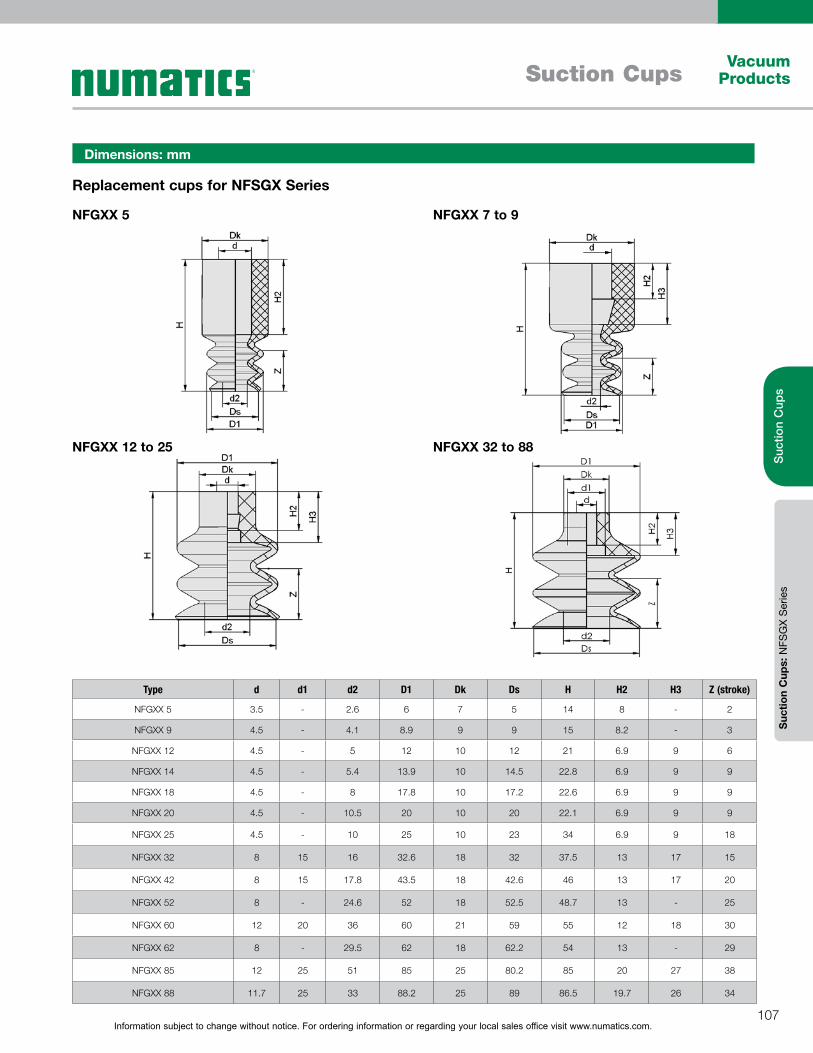
Information subject to change without notice. For ordering information or regarding your local sales office visit www.numatics.com.107
Vacuum ProductsSuction Cups
Suc
tion
Cup
sS
uctio
n C
ups:
NFS
GX
Ser
ies
Dimensions: mm
NFGXX 5
Replacement cups for NFSGX Series
NFGXX 12 to 25
NFGXX 7 to 9
NFGXX 32 to 88
Type d d1 d2 D1 Dk Ds H H2 H3 Z (stroke)
NFGXX 5 3.5 - 2.6 6 7 5 14 8 - 2
NFGXX 9 4.5 - 4.1 8.9 9 9 15 8.2 - 3
NFGXX 12 4.5 - 5 12 10 12 21 6.9 9 6
NFGXX 14 4.5 - 5.4 13.9 10 14.5 22.8 6.9 9 9
NFGXX 18 4.5 - 8 17.8 10 17.2 22.6 6.9 9 9
NFGXX 20 4.5 - 10.5 20 10 20 22.1 6.9 9 9
NFGXX 25 4.5 - 10 25 10 23 34 6.9 9 18
NFGXX 32 8 15 16 32.6 18 32 37.5 13 17 15
NFGXX 42 8 15 17.8 43.5 18 42.6 46 13 17 20
NFGXX 52 8 - 24.6 52 18 52.5 48.7 13 - 25
NFGXX 60 12 20 36 60 21 59 55 12 18 30
NFGXX 62 8 - 29.5 62 18 62.2 54 13 - 29
NFGXX 85 12 25 51 85 25 80.2 85 20 27 38
NFGXX 88 11.7 25 33 88.2 25 89 86.5 19.7 26 34

Information subject to change without notice. For ordering information or regarding your local sales office visit www.numatics.com.108
Vacuum Products Suction Cups
Suc
tion
Cup
sS
uctio
n C
ups:
NS
AFX
Ser
ies
This flat round cup is designed to handle a wide range of sheet
metal applications, especially thin walled sheets of metal and
other sensitive work-pieces; Examples include the handling of thin
metal body sheets used in the automotive industry, such as feeder
systems for press room lines.
Diameter: 50 to 125 mm; Flat round cup; Material: Nitrile;
Connection fitting vulcanized to suction cup; Designed to handle
high vertical or horizontal holding forces; large area internal
structured support; Soft and flexible sealing lip that provides reliable
sealing on flat or slightly curved surfaces.
Flat Round Suction Cups (Automotive) – NSAFX SeriesSuction area (Ø) from 50 mm to 125 mm
Design Features
Flat suction cups NSAFX being used for handling sheet metal parts
Type Suction Force (N)* Lateral force (N)** Lateral force oily surface (N)** Volume (cm3) Min. curve radius
(mm) (convex)***Recom. internal hose diameter d (mm)***
NSAFX 50 100 80 76 7.0 65 4
NSAFX 60 150 105 85 13.0 75 6
NSAFX 80 272 205 180 36.0 100 6
NSAFX 100 430 310 300 58.0 135 6
NSAFX 125 660 475 400 115.0 165 9
Technical Data – NSAFX Series
*The specified suction forces are theoretical values at a vacuum of -0.6 bar and with a smooth, dry workpiece surface - they do not include a safety factor**The specified lateral forces are values measured at a vacuum of -0.6 bar with a dry or oily, smooth, flat workpiece surface. Depending on the workpiece surface and its quality, the actual values may deviate from these values.***The recommended hose diameter refers to a hose length of approx. 2 m
DesignLarge structured inner support
Robust and wear resistant, with single sealing lip and
special slot
Nitrile - 45 shore hardness
Slots in bottom of cup prevents oily metal sheets from
slipping

Information subject to change without notice. For ordering information or regarding your local sales office visit www.numatics.com.109
Vacuum ProductsSuction Cups
Suc
tion
Cup
sS
uctio
n C
ups:
NS
AFX
Ser
ies
The connection fitting is vulcanized to the suction cup
How to OrderNSAFX Series (Flat Round Cups - Automotive Style)
Suction Cup Assembly
Series / Cup Diameter (mm) Thread Type / Port Size
Material Type
Nitrile(45 Hardness)
NSAFX 50 G3/8-F NSAFX050XXB33FG
NSAFX 50 NPT3/8-F NSAFX050XXB33FN
NSAFX 60 G3/8-F NSAFX060XXB33FG
NSAFX 60 NPT3/8-F NSAFX060XXB33FN
NSAFX 80 G3/8-F NSAFX080XXB33FG
NSAFX 80 NPT3/8-F NSAFX080XXB33FN
NSAFX 100 G3/8-F NSAFX100XXB33FG
NSAFX 100 NPT3/8-F NSAFX100XXB33FN
NSAFX 125 G3/8-F NSAFX125XXB33FG
NSAFX 125 NPT3/8-F NSAFX125XXB33FN
Dimensions: mm
NSAFX 50 to 125 Female
Type D1* dn Ds G1 H LG1 SW1 Z (stroke)
NSAFX050XXB33FG 56 6 52 G3/8-F 28 15 22 5.0
NSAFX050XXB33FN 56 6 52 NPT3/8-F 28 15 22 5.0
NSAFX060XXB33FG 67 6 63 G3/8-F 31 15 22 6.0
NSAFX060XXB33FN 67 6 63 NPT3/8-F 31 15 22 6.0
NSAFX080XXB33FG 89 6 83 G3/8-F 35 15 22 7.6
NSAFX080XXB33FN 89 6 83 NPT3/8-F 35 15 22 7.6
NSAFX100XXB33FG 110 6 103 G3/8-F 36 15 22 9.5
NSAFX100XXB33FN 110 6 103 NPT3/8-F 36 15 22 9.5
NSAFX125XXB33FG 135 9 128 G3/8-F 43 15 22 12.5
NSAFX125XXB33FN 135 9 128 NPT3/8-F 43 15 22 12.5
* D1 is the external dimension of the suction cup when it is pressed against the workpiece by the vacuum
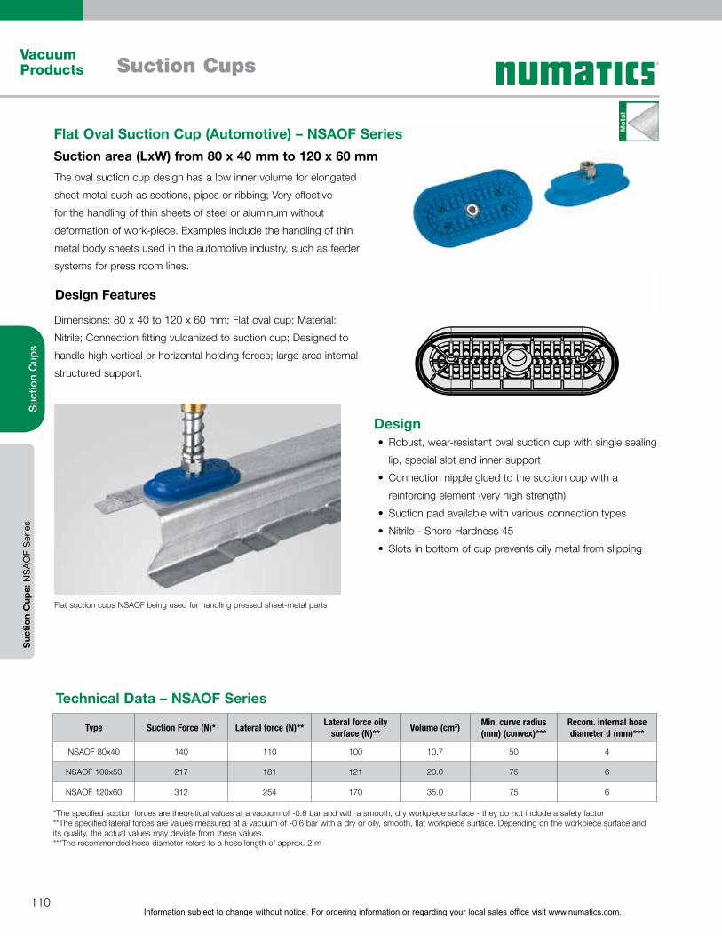
Information subject to change without notice. For ordering information or regarding your local sales office visit www.numatics.com.110
Vacuum Products Suction Cups
Suc
tion
Cup
sS
uctio
n C
ups:
NS
AO
F S
erie
s
The oval suction cup design has a low inner volume for elongated
sheet metal such as sections, pipes or ribbing; Very effective
for the handling of thin sheets of steel or aluminum without
deformation of work-piece. Examples include the handling of thin
metal body sheets used in the automotive industry, such as feeder
systems for press room lines.
Dimensions: 80 x 40 to 120 x 60 mm; Flat oval cup; Material:
Nitrile; Connection fitting vulcanized to suction cup; Designed to
handle high vertical or horizontal holding forces; large area internal
structured support.
Flat Oval Suction Cup (Automotive) – NSAOF SeriesSuction area (LxW) from 80 x 40 mm to 120 x 60 mm
Design Features
Flat suction cups NSAOF being used for handling pressed sheet-metal parts
Type Suction Force (N)* Lateral force (N)** Lateral force oily surface (N)** Volume (cm3) Min. curve radius
(mm) (convex)***Recom. internal hose diameter d (mm)***
NSAOF 80x40 140 110 100 10.7 50 4
NSAOF 100x50 217 181 121 20.0 75 6
NSAOF 120x60 312 254 170 35.0 75 6
Technical Data – NSAOF Series
*The specified suction forces are theoretical values at a vacuum of -0.6 bar and with a smooth, dry workpiece surface - they do not include a safety factor**The specified lateral forces are values measured at a vacuum of -0.6 bar with a dry or oily, smooth, flat workpiece surface. Depending on the workpiece surface and its quality, the actual values may deviate from these values.***The recommended hose diameter refers to a hose length of approx. 2 m
DesignRobust, wear-resistant oval suction cup with single sealing
lip, special slot and inner support
Connection nipple glued to the suction cup with a
reinforcing element (very high strength)
Suction pad available with various connection types
Nitrile - Shore Hardness 45
Slots in bottom of cup prevents oily metal from slipping
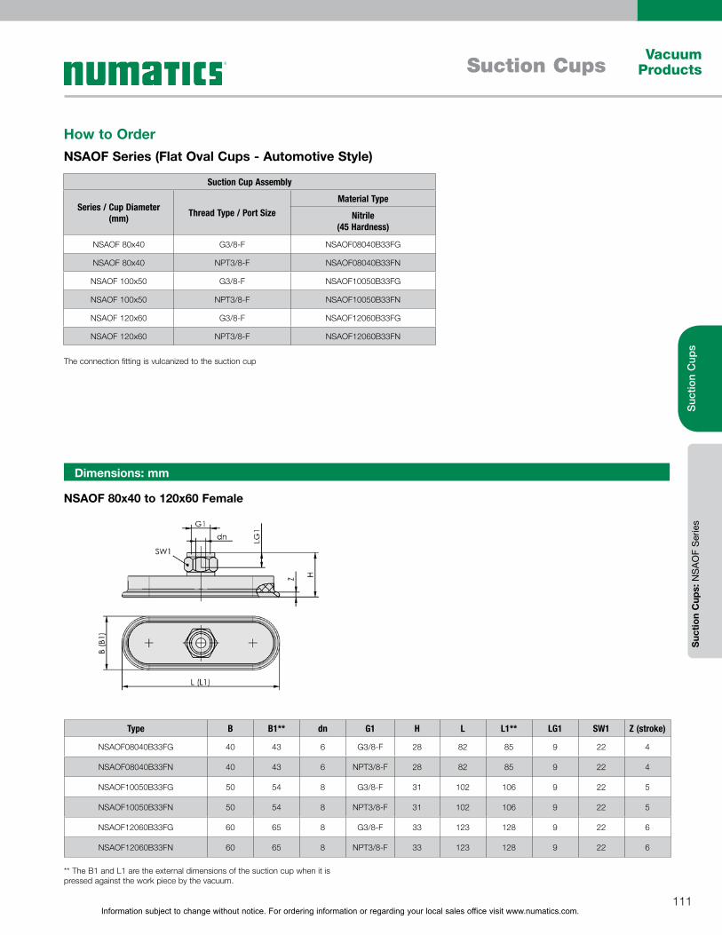
Information subject to change without notice. For ordering information or regarding your local sales office visit www.numatics.com.111
Vacuum ProductsSuction Cups
Suc
tion
Cup
sS
uctio
n C
ups:
NS
AO
F S
erie
s
How to OrderNSAOF Series (Flat Oval Cups - Automotive Style)
Dimensions: mm
NSAOF 80x40 to 120x60 Female
Type B B1** dn G1 H L L1** LG1 SW1 Z (stroke)
NSAOF08040B33FG 40 43 6 G3/8-F 28 82 85 9 22 4
NSAOF08040B33FN 40 43 6 NPT3/8-F 28 82 85 9 22 4
NSAOF10050B33FG 50 54 8 G3/8-F 31 102 106 9 22 5
NSAOF10050B33FN 50 54 8 NPT3/8-F 31 102 106 9 22 5
NSAOF12060B33FG 60 65 8 G3/8-F 33 123 128 9 22 6
NSAOF12060B33FN 60 65 8 NPT3/8-F 33 123 128 9 22 6
The connection fitting is vulcanized to the suction cup
** The B1 and L1 are the external dimensions of the suction cup when it is pressed against the work piece by the vacuum.
Suction Cup Assembly
Series / Cup Diameter (mm) Thread Type / Port Size
Material Type
Nitrile(45 Hardness)
NSAOF 80x40 G3/8-F NSAOF08040B33FG
NSAOF 80x40 NPT3/8-F NSAOF08040B33FN
NSAOF 100x50 G3/8-F NSAOF10050B33FG
NSAOF 100x50 NPT3/8-F NSAOF10050B33FN
NSAOF 120x60 G3/8-F NSAOF12060B33FG
NSAOF 120x60 NPT3/8-F NSAOF12060B33FN
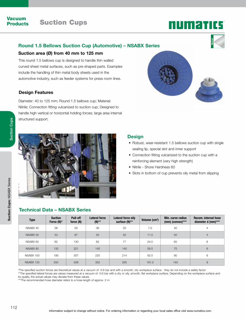
Information subject to change without notice. For ordering information or regarding your local sales office visit www.numatics.com.112
Vacuum Products Suction Cups
Suc
tion
Cup
sS
uctio
n C
ups:
NS
AB
X S
erie
s
This round 1.5 bellows cup is designed to handle thin walled
curved sheet metal surfaces, such as pre-shaped parts. Examples
include the handling of thin metal body sheets used in the
automotive industry, such as feeder systems for press room lines.
Diameter: 40 to 125 mm; Round 1.5 bellows cup; Material:
Nitrile; Connection fitting vulcanized to suction cup; Designed to
handle high vertical or horizontal holding forces; large area internal
structured support.
Round 1.5 Bellows Suction Cup (Automotive) – NSABX SeriesSuction area (Ø) from 40 mm to 125 mm
Design Features
Type Suction Force (N)*
Pull-off force (N)
Lateral force (N)**
Lateral force oily surface (N)** Volume (cm3) Min. curve radius
(mm) (convex)***Recom. internal hose diameter d (mm)***
NSABX 40 38 59 36 33 7.0 40 4
NSABX 50 53 87 55 52 11.5 50 4
NSABX 60 82 130 82 77 24.0 65 6
NSABX 80 135 221 145 140 56.5 75 6
NSABX 100 190 357 220 214 92.5 90 6
NSABX 125 250 558 352 335 191.0 140 9
Technical Data – NSABX Series
*The specified suction forces are theoretical values at a vacuum of -0.6 bar and with a smooth, dry workpiece surface - they do not include a safety factor**The specified lateral forces are values measured at a vacuum of -0.6 bar with a dry or oily, smooth, flat workpiece surface. Depending on the workpiece surface and its quality, the actual values may deviate from these values.***The recommended hose diameter refers to a hose length of approx. 2 m
DesignRobust, wear-resistant 1.5 bellows suction cup with single
sealing lip, special slot and inner support
Connection fitting vulcanized to the suction cup with a
reinforcing element (very high strength)
Nitrile - Shore Hardness 60
Slots in bottom of cup prevents oily metal from slipping

Information subject to change without notice. For ordering information or regarding your local sales office visit www.numatics.com.113
Vacuum ProductsSuction Cups
Suc
tion
Cup
sS
uctio
n C
ups:
NS
AB
X S
erie
s
How to OrderNSABX Series (Round 1.5 Bellows Cups - Automotive Style)
Suction Cup Assembly
Series / Cup Diameter (mm) Thread Type / Port Size
Material Type
Nitrile(60 Hardness)
NSABX 40 G3/8-F NSABX040XXB63FG
NSABX 40 NPT3/8-F NSABX040XXB63FN
NSABX 50 G3/8-F NSABX050XXB63FG
NSABX 50 NPT3/8-F NSABX050XXB63FN
NSABX 60 G3/8-F NSABX060XXB63FG
NSABX 60 NPT3/8-F NSABX060XXB63FN
NSABX 80 G3/8-F NSABX080XXB63FG
NSABX 80 NPT3/8-F NSABX080XXB63FN
NSABX 100 G3/8-F NSABX100XXB63FG
NSABX 100 NPT3/8-F NSABX100XXB63FN
NSABX 125 G3/8-F NSABX125XXB63FG
NSABX 125 NPT3/8-F NSABX125XXB63FN
Information subject to change without notice. For ordering information or regarding your local sales office visit www.numatics.com.114
Vacuum Products Suction Cups
Suc
tion
Cup
sS
uctio
n C
ups:
NS
AB
X S
erie
s
Dimensions: mm
NSABX 40 to 125 Female
Type D1* dn Ds G1 H LG1 SW1 Z (stroke)
NSABX040XXB63FG 45 4 42 G3/8-F 44 9.5 22 10
NSABX040XXB63FN 45 4 42 NPT3/8-F 44 9.5 22 10
NSABX050XXB63FG 56 6 52 G3/8-F 37 15 22 11.5
NSABX050XXB63FN 56 6 52 NPT3/8-F 37 15 22 11.5
NSABX060XXB63FG 67 6 63 G3/8-F 41.5 15 22 14.5
NSABX060XXB63FN 67 6 63 NPT3/8-F 41.5 15 22 14.5
NSABX080XXB63FG 89 6 83 G3/8-F 50 15 22 22
NSABX080XXB63FN 89 6 83 NPT3/8-F 50 15 22 22
NSABX100XXB63FG 110 6 103 G3/8-F 57 15 22 26
NSABX100XXB63FN 110 6 103 NPT3/8-F 57 15 22 26
NSABX125XXB63FG 135 9 128 G3/8-F 68 15 22 32
NSABX125XXB63FN 135 9 128 NPT3/8-F 68 15 22 32
* D1 is the external dimension of the suction cup when it is pressed against the workpiece by the vacuum

Information subject to change without notice. For ordering information or regarding your local sales office visit www.numatics.com.115
Vacuum ProductsSuction Cups
Suc
tion
Cup
sS
uctio
n C
ups:
NS
GP
N S
erie
s
Special flat round suction cups for handling paper, wood veneers,
wafers, blister packs, and films; this series of cups are standard
with an elongated sealing lip and inner support for handling of
sensitive work-pieces.
Diameter: 15 to 40 mm; Round flat cup; Material: Natural Rubber
and Silicone; Connection fitting plugged into suction cup; Special flat
long tapered sealing lip and inner support.
Flat Round Suction Cups (Plastic Film & Paper) - NSGPN SeriesSuction area (Ø) from 15 mm to 40 mm
Design Features
Flat suction cups NSGPN being used for handling blister packagings
Type Suction Force (N)* Volume (cm3) Recom. internal hose diameter d (mm)**
NSGPN 15 5.5 0.12 2
NSGPN 20 8.5 0.31 2
NSGPN 24 11.0 0.70 4
NSGPN 30 19.0 1.50 4
NSGPN 34 25.0 2.10 4
NSGPN 40 33.0 2.90 4
Technical Data – NSGPN Series
*The specified suction forces are theoretical values at a vacuum of -0.6 bar and with a smooth, dry workpiece surface - they do not include a safety factor**The recommended hose diameter refers to a hose length of approx. 2 m
DesignRobust and wear-resistant with single sealing lip
Fitting plugged into cup
Natural Rubber - Shore Hardness 40 A
Silicone - Shore Hardness 50 A
Information subject to change without notice. For ordering information or regarding your local sales office visit www.numatics.com.116
Vacuum Products Suction Cups
Suc
tion
Cup
sS
uctio
n C
ups:
NS
GP
N S
erie
s
How to OrderNSGPN Series (Flat Round Cups - for Plastic Film and Paper)
Suction Cup Assembly Replacement Cups
Series / Cup Diameter
(mm)
Thread Type / Port Size
Material Type Material Type
Natural Rubber(40 Hardness)
Silicone(50 Hardness)
Natural Rubber(40 Hardness)
Silicone(50 Hardness)
NSGPN 15
G1/8-F NSGPN015XXN21FG NSGPN015XXS41FG
NSGPX015XXN2XXX NSGPX015XXS4XXXG1/8-M NSGPN015XXN21MG NSGPN015XXS41MG
M5-M NSGPN015XXN2BMM NSGPN015XXS4BMM
NSGPN 20
G1/8-F NSGPN020XXN21FG NSGPN020XXS41FG
NSGPX020XXN2XXX NSGPX020XXS4XXXG1/8-M NSGPN020XXN21MG NSGPN020XXS41MG
M5-M NSGPN020XXN2BMM NSGPN020XXS4BMM
NSGPN 24
G1/8-F NSGPN024XXN21FG NSGPN024XXS41FG
NSGPX024XXN2XXX NSGPX024XXS4XXXG1/8-M NSGPN024XXN21MG NSGPN024XXS41MG
M5-M NSGPN024XXN2BMM NSGPN024XXS4BMM
NSGPN 30G1/4-F NSGPN030XXN22FG NSGPN030XXS42FG
NSGPX030XXN2XXX NSGPX030XXS4XXXG1/4-M NSGPN030XXN22MG NSGPN030XXS42MG
NSGPN 34G1/4-F NSGPN034XXN22FG
NSGPX034XXN2XXXG1/4-M NSGPN034XXN22MG
NSGPN 40G1/4-F NSGPN040XXN22FG
NSGPX040XXN2XXXG1/4-M NSGPN040XXN22MG
Information subject to change without notice. For ordering information or regarding your local sales office visit www.numatics.com.117
Vacuum ProductsSuction Cups
Suc
tion
Cup
sS
uctio
n C
ups:
NS
GP
N S
erie
s
Dimensions: mm
NSGPN 15 to 40 Female NSGPN 15 to 40 Male
Type dn Ds G1 H LG1 SW1 Z (stroke)
NSGPN015XXN2BMM 2.5 14.5 M5-M 15 5 7 0.9
NSGPN015XXN21MG 3.5 14.5 G1/8-M 16 7.5 14 0.9
NSGPN015XXN21FG 3.5 14.5 G1/8-F 22 8 14 0.9
NSGPN015XXS4BMM 2.5 14.5 M5-M 15 5 7 0.9
NSGPN015XXS41MG 3.5 14.5 G1/8-M 16 7.5 14 0.9
NSGPN015XXS41FG 3.5 14.5 G1/8-F 22 8 14 0.9
NSGPN020XXN2BMM 2.5 20.9 M5-M 15.4 5 7 1.5
NSGPN020XXN21MG 3.5 20.9 G1/8-M 16.4 7.5 14 1.5
NSGPN020XXN21FG 3.5 20.9 G1/8-F 22.4 8 14 1.5
NSGPN020XXS4BMM 2.5 20.9 M5-M 15.4 5 7 1.5
NSGPN020XXS41MG 3.5 20.9 G1/8-M 16.4 7.5 14 1.5
NSGPN020XXS41FG 3.5 20.9 G1/8-F 22.4 8 14 1.5
NSGPN024XXN2BMG 2.5 24.4 M5-M 15.8 5 7 1.7
NSGPN024XXN21MG 3.5 24.4 G1/8-M 16.8 7.5 14 1.7
NSGPN024XXN21FG 3.5 24.4 G1/8-F 22.8 8 14 1.7
NSGPN024XXS4BMM 2.5 24.4 M5-M 15.8 5 7 1.7
NSGPN024XXS41MG 3.5 24.4 G1/8-M 16.8 7.5 14 1.7
NSGPN024XXS41FG 3.5 24.4 G1/8-F 22.8 8 14 1.7
NSGPN030XXN22MG 5.5 30.6 G1/4-M 27.2 10 17 2
NSGPN030XXN22FG 5.5 30.6 G1/4-F 37.2 12 17 2
NSGPN030XXS42FG 5.5 30.6 G1/4-F 37.2 12 17 2
NSGPN030XXS42MG 5.5 30.6 G1/4-M 27.2 10 17 2
NSGPN034XXN22MG 5.5 34.5 G1/4-M 28 10 17 1.4
NSGPN034XXN22FG 5.5 34.5 G1/4-F 38 12 17 1.4
NSGPN040XXN22MG 5.5 40.5 G1/4-M 25.6 10 17 2.3
NSGPN040XXN22FG 5.5 40.5 G1/4-F 35.6 12 17 2.3
Information subject to change without notice. For ordering information or regarding your local sales office visit www.numatics.com.118
Vacuum Products Suction Cups
Suc
tion
Cup
sS
uctio
n C
ups:
NS
GP
N S
erie
s
NSGPX 15 to 40
Replacement cups for NSGPN Series
Dimensions: mm
Type d d2 Dk Ds H H2 Z (stroke)
NSGPX 15 4.5 3.5 9.0 14.5 10.0 7.2 0.9
NSGPX 20 4.5 3.5 10.5 20.9 10.4 7.1 1.5
NSGPX 24 4.5 3.5 10.0 24.4 10.8 7.3 1.7
NSGPX 30 11.2 6.6 15.6 30.6 22.2 15.7 2.0
NSGPX 34 11.2 5.8 14.8 34.5 23.0 16.8 1.4
NSGPX 40 8.0 5.0 16.0 40.5 20.6 14.5 2.3
Information subject to change without notice. For ordering information or regarding your local sales office visit www.numatics.com.119
Vacuum ProductsSuction Cups
Suc
tion
Cup
sS
uctio
n C
ups:
NS
PFX
Ser
ies
NSPFX Series (Flat Round Suction Cups)Suction area (Ø) from 20 mm to 50 mm
Technical Data – NSPFX Series
NSPF
Flat suction cups NSPFX being used in packaging machines
Type Suction Force (N)*
Pull-off force (N)
Lateral force (N)
Volume (cm3)
Min. curve radius [mm] (convex)
Recom. internal hose diameter d (mm)**
Type Connection element SC...
NSPF-20 ED-65 16.0 19.2 10.5 1.0 25 4 040
NSPF-25 ED-65 22.7 27.1 17.0 1.5 40 4 040
NSPF-30 ED-65 29.5 35.3 22.5 2.3 45 6 040
NSPF-40 ED-65 49.5 62.5 25.0 5.1 75 6 050
NSPF-50 ED-65 74.2 87.4 44.0 7.9 100 6 060
Flat round suction cups specially designed for the packaging
industry. This particular cup is typically used for heavy duty
packaging applications that require extended life with a reliable
seal. Examples of applications include high speed palletizing,
de-palletizing processes, cardboard box/tray effectors, and rigid
packaging in top/side loading machines.
Diameter: 20 to 50mm; Flat round suction cup; Material: Elastodur;
flexible, adaptable sealing lip; robust, reinforced main body
Design Features
DesignRound flat suction cup NSPF (1) with soft, flexible sealing
lip and supporting ribs on the suction surface
Made of wear-proof material Elastodur ED-65
Models with diameter up to 30 mm feature plug-in
connection element for quick change of suction cup
Starting at 40 mm diameter with a 2-piece connection
fitting: consisting of machine-side fitting (2) and suction-
side fitting (3)
Clip-in filter screen (4) as pre-filter (filter pore size 250 µm)
All connection elements with male thread are equipped
with integrated sealing
Elastodur - Shore hardness 65 (wear proof - extended life)
*The specified suction forces are theoretical values at a vacuum of -0.6 bar and with a smooth, dry workpiece surface - they do not include a safety factor**The recommended hose diameter refers to a hose length of approx. 2 m
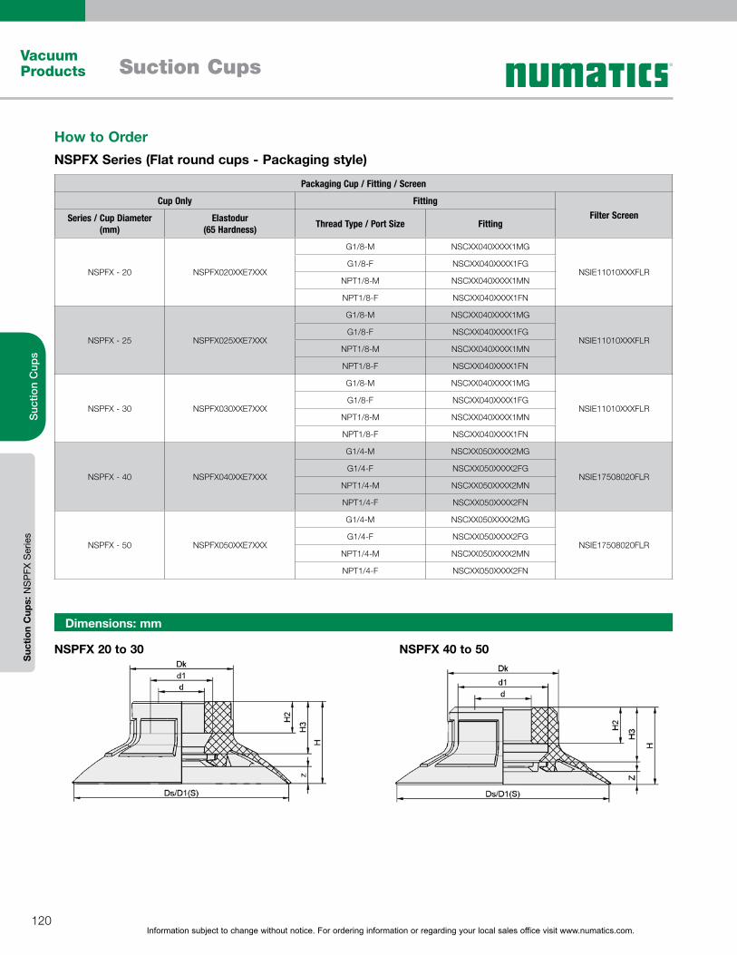
Information subject to change without notice. For ordering information or regarding your local sales office visit www.numatics.com.120
Vacuum Products Suction Cups
Suc
tion
Cup
sS
uctio
n C
ups:
NS
PFX
Ser
ies
Dimensions: mm
NSPFX 20 to 30 NSPFX 40 to 50
How to OrderNSPFX Series (Flat round cups - Packaging style)
Packaging Cup / Fitting / Screen
Cup Only FittingFilter ScreenSeries / Cup Diameter
(mm)Elastodur
(65 Hardness) Thread Type / Port Size Fitting
NSPFX - 20 NSPFX020XXE7XXX
G1/8-M NSCXX040XXXX1MG
NSIE11010XXXFLRG1/8-F NSCXX040XXXX1FG
NPT1/8-M NSCXX040XXXX1MN
NPT1/8-F NSCXX040XXXX1FN
NSPFX - 25 NSPFX025XXE7XXX
G1/8-M NSCXX040XXXX1MG
NSIE11010XXXFLRG1/8-F NSCXX040XXXX1FG
NPT1/8-M NSCXX040XXXX1MN
NPT1/8-F NSCXX040XXXX1FN
NSPFX - 30 NSPFX030XXE7XXX
G1/8-M NSCXX040XXXX1MG
NSIE11010XXXFLRG1/8-F NSCXX040XXXX1FG
NPT1/8-M NSCXX040XXXX1MN
NPT1/8-F NSCXX040XXXX1FN
NSPFX - 40 NSPFX040XXE7XXX
G1/4-M NSCXX050XXXX2MG
NSIE17508020FLRG1/4-F NSCXX050XXXX2FG
NPT1/4-M NSCXX050XXXX2MN
NPT1/4-F NSCXX050XXXX2FN
NSPFX - 50 NSPFX050XXE7XXX
G1/4-M NSCXX050XXXX2MG
NSIE17508020FLRG1/4-F NSCXX050XXXX2FG
NPT1/4-M NSCXX050XXXX2MN
NPT1/4-F NSCXX050XXXX2FN
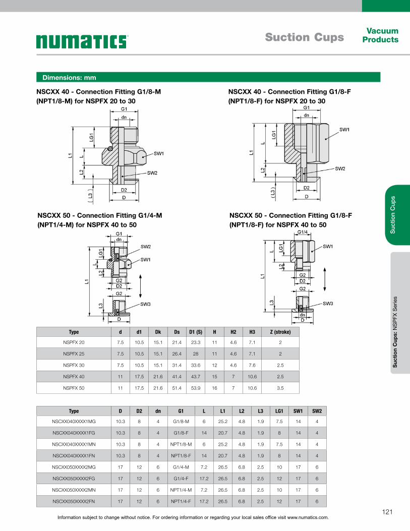
Information subject to change without notice. For ordering information or regarding your local sales office visit www.numatics.com.121
Vacuum ProductsSuction Cups
Suc
tion
Cup
sS
uctio
n C
ups:
NS
PFX
Ser
ies
NSCXX 40 - Connection Fitting G1/8-M (NPT1/8-M) for NSPFX 20 to 30
Dimensions: mm
NSCXX 40 - Connection Fitting G1/8-F (NPT1/8-F) for NSPFX 20 to 30
NSCXX 50 - Connection Fitting G1/4-M (NPT1/4-M) for NSPFX 40 to 50
Type d d1 Dk Ds D1 (S) H H2 H3 Z (stroke)
NSPFX 20 7.5 10.5 15.1 21.4 23.3 11 4.6 7.1 2
NSPFX 25 7.5 10.5 15.1 26.4 28 11 4.6 7.1 2
NSPFX 30 7.5 10.5 15.1 31.4 33.6 12 4.6 7.6 2.5
NSPFX 40 11 17.5 21.6 41.4 43.7 15 7 10.6 2.5
NSPFX 50 11 17.5 21.6 51.4 53.9 16 7 10.6 3.5
Type D D2 dn G1 L L1 L2 L3 LG1 SW1 SW2
NSCXX040XXXX1MG 10.3 8 4 G1/8-M 6 25.2 4.8 1.9 7.5 14 4
NSCXX040XXXX1FG 10.3 8 4 G1/8-F 14 20.7 4.8 1.9 8 14 4
NSCXX040XXXX1MN 10.3 8 4 NPT1/8-M 6 25.2 4.8 1.9 7.5 14 4
NSCXX040XXXX1FN 10.3 8 4 NPT1/8-F 14 20.7 4.8 1.9 8 14 4
NSCXX050XXXX2MG 17 12 6 G1/4-M 7.2 26.5 6.8 2.5 10 17 6
NSCXX050XXXX2FG 17 12 6 G1/4-F 17.2 26.5 6.8 2.5 12 17 6
NSCXX050XXXX2MN 17 12 6 NPT1/4-M 7.2 26.5 6.8 2.5 10 17 6
NSCXX050XXXX2FN 17 12 6 NPT1/4-F 17.2 26.5 6.8 2.5 12 17 6
NSCXX 50 - Connection Fitting G1/8-F (NPT1/8-F) for NSPFX 40 to 50

Information subject to change without notice. For ordering information or regarding your local sales office visit www.numatics.com.122
Vacuum Products Suction Cups
Suc
tion
Cup
sS
uctio
n C
ups:
NS
PB
4 S
erie
s
NSPB4 Series (Round 4.5 Bellows Suction Cups)Suction area (Ø) from 20 mm to 40 mm
NSPB4-195
TypeSuction force
[N] at -200 mbar*
Suction force [N] at -400
mbar*
Suction force [N] at -600
mbar*
Pull-off force [N] at -200 mbar
Pull-off force [N] at -400 mbar Volume (cm3) Type Connection
element SC...
NSPB4 20 2.6 5.3 8 4.9 7 7.9 080
NSPB4 30 5.3 10.6 16 9.9 13 15.6 080
NSPB4 40 8.3 16.6 25 14.1 23 35.7 090
Technical Data – NSPB4 Series
*The specified suction forces are theoretical values at a vacuum of -0.6 bar and with a smooth, dry workpiece surface - they do not include a safety factor**The recommended hose diameter refers to a hose length of approx. 2 m
DesignBellows suction cup NSPB4 (1) with 4.5 bellows and soft,
flexible sealing lip
Special reinforced bellows for additional stability
Mounting via Connector SC (3). Alternatively direct
attachment on 3/8”- or 1/2”-pipe via hose clamp (4)
Clip-in filter screen (4) as pre-filter (filter pore size 250 µm)
Mounting elements with male thread include integrated
sealing ring
Silicone - Shore hardness 55 (food grade)
Round 4.5 bellows suction cups specially designed for the
packaging industry. This particular cup is typically used for
handling flexible products, such as pouches and various types
of plastic film packaged products. This type of cup provides a
reliable means of gripping and handling of solid, powder and liquid
filled pouches, and can be used in high speed applications in
conjunction with robots.
Diameter: 20 to 40mm; Round 4.5 bellows cup; Material: Silicone
(food grade); thin steep sealing lip with low fins.
Design Features
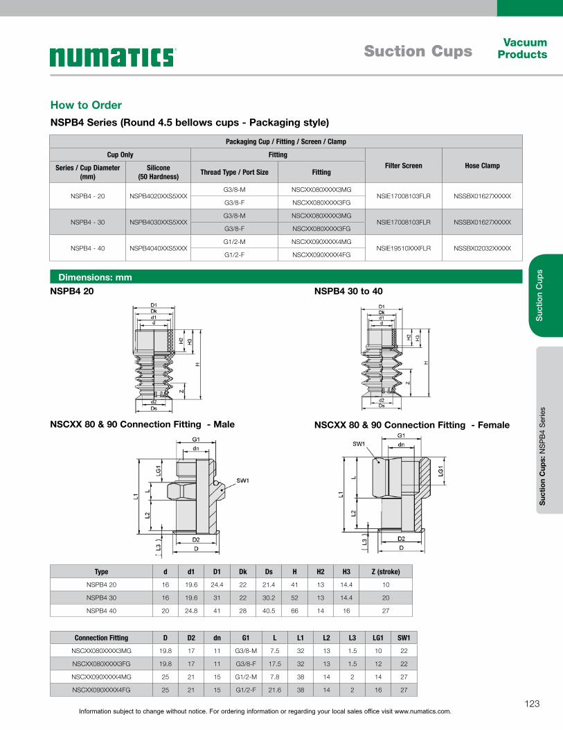
Information subject to change without notice. For ordering information or regarding your local sales office visit www.numatics.com.123
Vacuum ProductsSuction Cups
Suc
tion
Cup
sS
uctio
n C
ups:
NS
PB
4 S
erie
s
NSPB4 20
NSCXX 80 & 90 Connection Fitting - Female
NSPB4 30 to 40Dimensions: mm
Connection Fitting D D2 dn G1 L L1 L2 L3 LG1 SW1
NSCXX080XXXX3MG 19.8 17 11 G3/8-M 7.5 32 13 1.5 10 22
NSCXX080XXXX3FG 19.8 17 11 G3/8-F 17.5 32 13 1.5 12 22
NSCXX090XXXX4MG 25 21 15 G1/2-M 7.8 38 14 2 14 27
NSCXX090XXXX4FG 25 21 15 G1/2-F 21.6 38 14 2 16 27
NSCXX 80 & 90 Connection Fitting - Male
Type d d1 D1 Dk Ds H H2 H3 Z (stroke)
NSPB4 20 16 19.6 24.4 22 21.4 41 13 14.4 10
NSPB4 30 16 19.6 31 22 30.2 52 13 14.4 20
NSPB4 40 20 24.8 41 28 40.5 66 14 16 27
How to OrderNSPB4 Series (Round 4.5 bellows cups - Packaging style)
Packaging Cup / Fitting / Screen / Clamp
Cup Only FittingFilter Screen Hose ClampSeries / Cup Diameter
(mm)Silicone
(50 Hardness) Thread Type / Port Size Fitting
NSPB4 - 20 NSPB4020XXS5XXXG3/8-M NSCXX080XXXX3MG
NSIE17008103FLR NSSBX01627XXXXXG3/8-F NSCXX080XXXX3FG
NSPB4 - 30 NSPB4030XXS5XXXG3/8-M NSCXX080XXXX3MG
NSIE17008103FLR NSSBX01627XXXXXG3/8-F NSCXX080XXXX3FG
NSPB4 - 40 NSPB4040XXS5XXXG1/2-M NSCXX090XXXX4MG
NSIE19510XXXFLR NSSBX02032XXXXXG1/2-F NSCXX090XXXX4FG

Information subject to change without notice. For ordering information or regarding your local sales office visit www.numatics.com.124
Vacuum Products Suction Cups
Suc
tion
Cup
sS
uctio
n C
ups:
NS
PB
1 S
erie
s
NSPB1 Series (Round 1.5 Bellows Suction Cups)Suction area (Ø) from 20 mm to 60 mm
Technical Data – NSPB1 Series
NSPB1
Type Suction Force (N)*
Pull-off force (N)
Lateral force (N)
Volume (cm3)
Min. curve radius [mm] (convex)
Recom. internal hose diameter d (mm)**
Type Connection element SC...
NSPB1 20 9.9 16.2 9.8 2.9 20 4 040
NSPB1 25 14.9 23.4 13.0 5.1 20 4 040
NSPB1 30 20.7 30.6 15.5 7.8 35 6 040
NSPB1 40 35.9 46.8 24.8 18.4 70 6 050
NSPB1 50 54.7 72.7 31.2 30.3 100 6 050
NSPB1 60 78.0 100.9 49.4 49.5 200 6 050
Bellows suction cups NSPB1 being used in top-loading machines
*The specified suction forces are theoretical values at a vacuum of -0.6 bar and with a smooth, dry workpiece surface - they do not include a safety factor**The recommended hose diameter refers to a hose length of approx. 2 m
Round 1.5 bellows suction cups specially designed for the
packaging industry. This particular cup is typically used for similar
applications as the round flat packaging cups (NSPFX), but 1.5
bellows allows for the handling of work pieces that require more
flexibility. Examples of applications include high speed palletizing,
de-palletizing processes, cardboard box/tray effectors, and rigid
packaging in top/side loading machines.
Diameter: 20 to 60mm; Round 1.5 bellows suction cup; Material:
Elastodur; flexible, adaptable sealing lip; robust, reinforced main
body.
Design Features
DesignRound, 1.5 bellows suction cup (1) with soft, flexible
sealing lip
Made of wear-proof material Elastodur ED-65
Models with diameter up to 30 mm feature plug-in fitting
Starting at 40 mm diameter with a 2-piece fitting;
consisting of machine-side fitting(2) and suction-side
fitting (3)
Clip-in filter screen (4) as pre-filter
All connection fittings with male thread are equipped with
integrated sealing
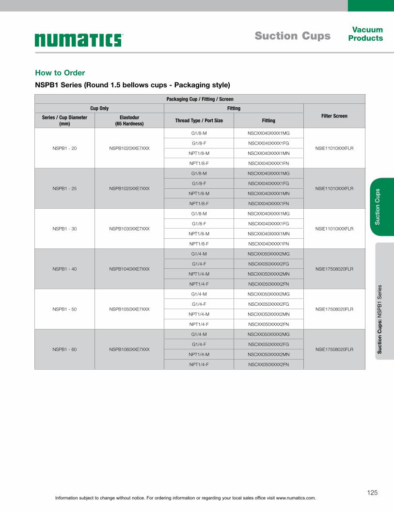
Information subject to change without notice. For ordering information or regarding your local sales office visit www.numatics.com.125
Vacuum ProductsSuction Cups
Suc
tion
Cup
sS
uctio
n C
ups:
NS
PB
1 S
erie
s
How to OrderNSPB1 Series (Round 1.5 bellows cups - Packaging style)
Packaging Cup / Fitting / Screen
Cup Only FittingFilter ScreenSeries / Cup Diameter
(mm)Elastodur
(65 Hardness) Thread Type / Port Size Fitting
NSPB1 - 20 NSPB1020XXE7XXX
G1/8-M NSCXX040XXXX1MG
NSIE11010XXXFLRG1/8-F NSCXX040XXXX1FG
NPT1/8-M NSCXX040XXXX1MN
NPT1/8-F NSCXX040XXXX1FN
NSPB1 - 25 NSPB1025XXE7XXX
G1/8-M NSCXX040XXXX1MG
NSIE11010XXXFLRG1/8-F NSCXX040XXXX1FG
NPT1/8-M NSCXX040XXXX1MN
NPT1/8-F NSCXX040XXXX1FN
NSPB1 - 30 NSPB1030XXE7XXX
G1/8-M NSCXX040XXXX1MG
NSIE11010XXXFLRG1/8-F NSCXX040XXXX1FG
NPT1/8-M NSCXX040XXXX1MN
NPT1/8-F NSCXX040XXXX1FN
NSPB1 - 40 NSPB1040XXE7XXX
G1/4-M NSCXX050XXXX2MG
NSIE17508020FLRG1/4-F NSCXX050XXXX2FG
NPT1/4-M NSCXX050XXXX2MN
NPT1/4-F NSCXX050XXXX2FN
NSPB1 - 50 NSPB1050XXE7XXX
G1/4-M NSCXX050XXXX2MG
NSIE17508020FLRG1/4-F NSCXX050XXXX2FG
NPT1/4-M NSCXX050XXXX2MN
NPT1/4-F NSCXX050XXXX2FN
NSPB1 - 60 NSPB1060XXE7XXX
G1/4-M NSCXX050XXXX2MG
NSIE17508020FLRG1/4-F NSCXX050XXXX2FG
NPT1/4-M NSCXX050XXXX2MN
NPT1/4-F NSCXX050XXXX2FN

Information subject to change without notice. For ordering information or regarding your local sales office visit www.numatics.com.126
Vacuum Products Suction Cups
Suc
tion
Cup
sS
uctio
n C
ups:
NS
PB
1 S
erie
s
Dimensions: mm
NSCXX 40 - Connection Fitting G1/8-F (NPT1/8-F) for NSPB1 20 to 30
NSCXX 50 - Connection Fitting G1/8-M (NPT1/8-M) for NSPB1 40 to 60
Type D D2 dn G1 L L1 L2 L3 LG1 SW1 SW2
NSCXX040XXXX1MG 10.3 8 4 G1/8-M 6 25.2 4.8 1.9 7.5 14 4
NSCXX040XXXX1FG 10.3 8 4 G1/8-F 14 20.7 4.8 1.9 8 14 4
NSCXX040XXXX1MN 10.3 8 4 NPT1/8-M 6 25.2 4.8 1.9 7.5 14 4
NSCXX040XXXX1FN 10.3 8 4 NPT1/8-F 14 20.7 4.8 1.9 8 14 4
NSCXX050XXXX2MG 17 12 6 G1/4-M 7.2 26.5 6.8 2.5 10 17 6
NSCXX050XXXX2FG 17 12 6 G1/4-F 17.2 26.5 6.8 2.5 12 17 6
NSCXX050XXXX2MN 17 12 6 NPT1/4-M 7.2 26.5 6.8 2.5 10 17 6
NSCXX050XXXX2FN 17 12 6 NPT1/4-F 17.2 26.5 6.8 2.5 12 17 6
Type d d1 D1 Dk d2 Ds D1 (S) H H2 H3 Z
NSPB1 20 7.5 10.5 24.6 15.1 13.8 21.4 26.3 18 4.6 7.6 8
NSPB1 25 7.5 10.5 29 15.1 16.9 26.4 31.3 21 4.6 7.6 11
NSPB1 30 7.5 10.5 34.2 15.1 20 31.4 36.7 23 4.6 7.6 13
NSPB1 40 11 17.5 44.6 21.6 26.1 41.4 48 30 7 11.1 16
NSPB1 50 11 17.5 55.2 21.6 32.3 51.4 58.4 32 7 11.1 18
NSPB1 60 11 17.5 65.7 21.6 38.6 61.4 69.6 36 7 11.1 22
NSPB1 20 to 30
NSCXX 50 - Connection Fitting G1/8-F (NPT1/8-F) for NSPB1 40 to 60
NSCXX 40 - Connection Fitting G1/8-M (NPT1/8-M) for NSPB1 20 to 30
NSPB1 40 to 60
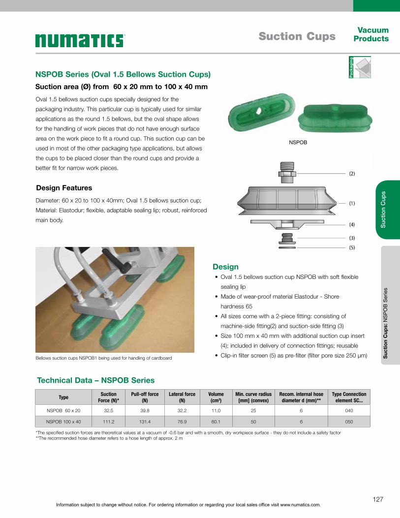
Information subject to change without notice. For ordering information or regarding your local sales office visit www.numatics.com.127
Vacuum ProductsSuction Cups
Suc
tion
Cup
sS
uctio
n C
ups:
NS
PO
B S
erie
s
NSPOB Series (Oval 1.5 Bellows Suction Cups)Suction area (Ø) from 60 x 20 mm to 100 x 40 mm
Technical Data – NSPOB Series
NSPOB
Bellows suction cups NSPOB1 being used for handling of cardboard
Type Suction Force (N)*
Pull-off force (N)
Lateral force (N)
Volume (cm3)
Min. curve radius [mm] (convex)
Recom. internal hose diameter d (mm)**
Type Connection element SC...
NSPOB 60 x 20 32.5 39.8 32.2 11.0 25 6 040
NSPOB 100 x 40 111.2 131.4 76.9 60.1 50 6 050
*The specified suction forces are theoretical values at a vacuum of -0.6 bar and with a smooth, dry workpiece surface - they do not include a safety factor**The recommended hose diameter refers to a hose length of approx. 2 m
Oval 1.5 bellows suction cups specially designed for the
packaging industry. This particular cup is typically used for similar
applications as the round 1.5 bellows, but the oval shape allows
for the handling of work pieces that do not have enough surface
area on the work piece to fit a round cup. This suction cup can be
used in most of the other packaging type applications, but allows
the cups to be placed closer than the round cups and provide a
better fit for narrow work pieces.
Diameter: 60 x 20 to 100 x 40mm; Oval 1.5 bellows suction cup;
Material: Elastodur; flexible, adaptable sealing lip; robust, reinforced
main body.
Design Features
DesignOval 1.5 bellows suction cup NSPOB with soft flexible
sealing lip
Made of wear-proof material Elastodur - Shore
hardness 65
All sizes come with a 2-piece fitting: consisting of
machine-side fitting(2) and suction-side fitting (3)
Size 100 mm x 40 mm with additional suction cup insert
(4); included in delivery of connection fittings; reusable
Clip-in filter screen (5) as pre-filter (filter pore size 250 µm)
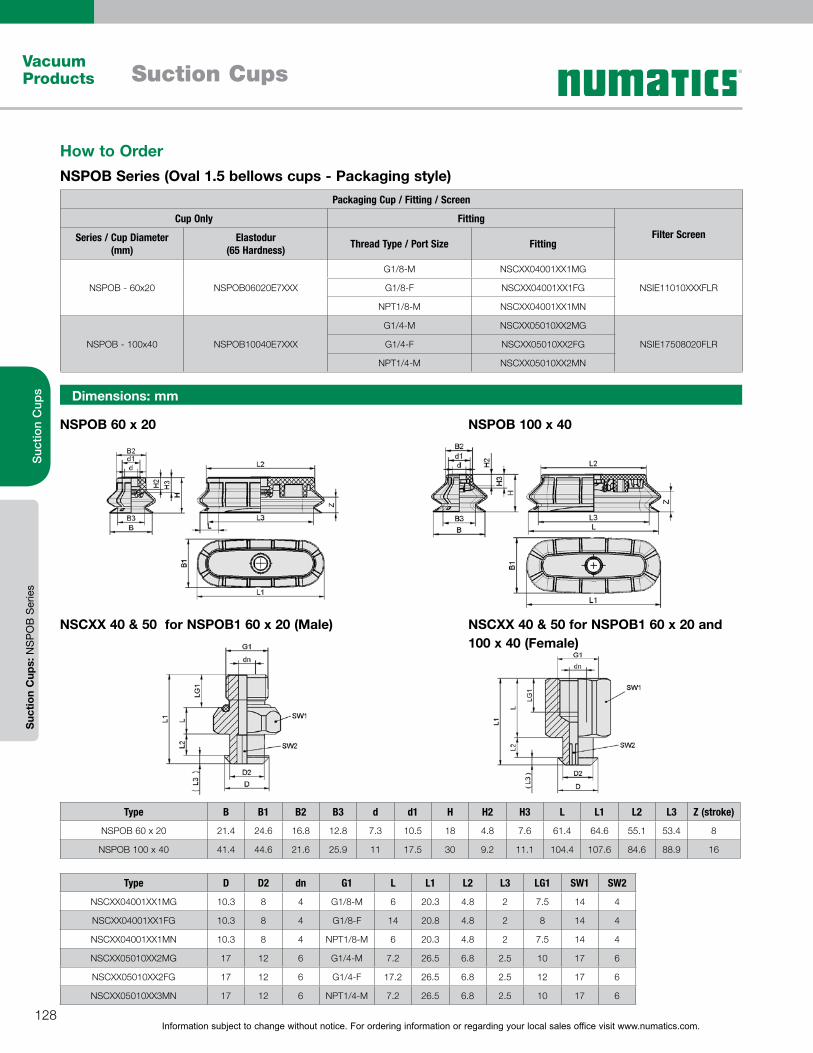
Information subject to change without notice. For ordering information or regarding your local sales office visit www.numatics.com.128
Vacuum Products Suction Cups
Suc
tion
Cup
sS
uctio
n C
ups:
NS
PO
B S
erie
s
Dimensions: mm
NSPOB 60 x 20
NSCXX 40 & 50 for NSPOB1 60 x 20 (Male)
NSPOB 100 x 40
NSCXX 40 & 50 for NSPOB1 60 x 20 and 100 x 40 (Female)
Type B B1 B2 B3 d d1 H H2 H3 L L1 L2 L3 Z (stroke)
NSPOB 60 x 20 21.4 24.6 16.8 12.8 7.3 10.5 18 4.8 7.6 61.4 64.6 55.1 53.4 8
NSPOB 100 x 40 41.4 44.6 21.6 25.9 11 17.5 30 9.2 11.1 104.4 107.6 84.6 88.9 16
Type D D2 dn G1 L L1 L2 L3 LG1 SW1 SW2
NSCXX04001XX1MG 10.3 8 4 G1/8-M 6 20.3 4.8 2 7.5 14 4
NSCXX04001XX1FG 10.3 8 4 G1/8-F 14 20.8 4.8 2 8 14 4
NSCXX04001XX1MN 10.3 8 4 NPT1/8-M 6 20.3 4.8 2 7.5 14 4
NSCXX05010XX2MG 17 12 6 G1/4-M 7.2 26.5 6.8 2.5 10 17 6
NSCXX05010XX2FG 17 12 6 G1/4-F 17.2 26.5 6.8 2.5 12 17 6
NSCXX05010XX3MN 17 12 6 NPT1/4-M 7.2 26.5 6.8 2.5 10 17 6
How to OrderNSPOB Series (Oval 1.5 bellows cups - Packaging style)
Packaging Cup / Fitting / Screen
Cup Only FittingFilter ScreenSeries / Cup Diameter
(mm)Elastodur
(65 Hardness) Thread Type / Port Size Fitting
NSPOB - 60x20 NSPOB06020E7XXX
G1/8-M NSCXX04001XX1MG
NSIE11010XXXFLRG1/8-F NSCXX04001XX1FG
NPT1/8-M NSCXX04001XX1MN
NSPOB - 100x40 NSPOB10040E7XXX
G1/4-M NSCXX05010XX2MG
NSIE17508020FLRG1/4-F NSCXX05010XX2FG
NPT1/4-M NSCXX05010XX2MN
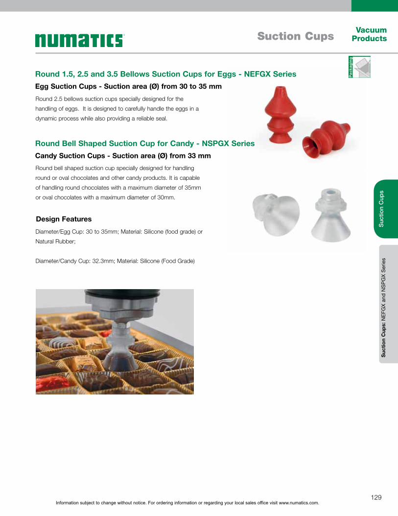
Information subject to change without notice. For ordering information or regarding your local sales office visit www.numatics.com.129
Vacuum ProductsSuction Cups
Suc
tion
Cup
sS
uctio
n C
ups:
NEF
GX
and
NS
PG
X S
erie
s
Round 1.5, 2.5 and 3.5 Bellows Suction Cups for Eggs - NEFGX SeriesEgg Suction Cups - Suction area (Ø) from 30 to 35 mm
Round Bell Shaped Suction Cup for Candy - NSPGX SeriesCandy Suction Cups - Suction area (Ø) from 33 mm
Round 2.5 bellows suction cups specially designed for the
handling of eggs. It is designed to carefully handle the eggs in a
dynamic process while also providing a reliable seal.
Round bell shaped suction cup specially designed for handling
round or oval chocolates and other candy products. It is capable
of handling round chocolates with a maximum diameter of 35mm
or oval chocolates with a maximum diameter of 30mm.
Diameter/Egg Cup: 30 to 35mm; Material: Silicone (food grade) or
Natural Rubber;
Diameter/Candy Cup: 32.3mm; Material: Silicone (Food Grade)
Design Features
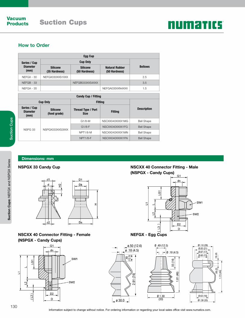
Information subject to change without notice. For ordering information or regarding your local sales office visit www.numatics.com.130
Vacuum Products Suction Cups
Suc
tion
Cup
sS
uctio
n C
ups:
NEF
GX
and
NS
PG
X S
erie
s Dimensions: mm
ø.50 (12.6)ø .18 (4.5)
.49
(12.
5)
ø 30.0
2.91
(74)
Ø .18 (4.5)
Ø .49 (12.5)
1.81
(46)
Ø 1.30(33)
.55
(14)
Ø1.38 (35)
Ø.63 (16)
Ø.67 (17)
.16
(4)
Ø.83 (21)
Ø.60 (15)
Ø1.10 (28)
.08
(2)
1.73
(44)
NSPGX 33 Candy Cup
NSCXX 40 Connector Fitting - Female (NSPGX - Candy Cups)
NEFGX - Egg Cups
NSCXX 40 Connector Fitting - Male (NSPGX - Candy Cups)
How to Order
Egg Cup
Series / Cup Diameter
(mm)
Cup OnlyBellowsSilicone
(35 Hardness)Silicone
(50 Hardness)Natural Rubber(50 Hardness)
NEFGX - 30 NEFGX030XXS1XXX 2.5
NEFGB - 33 NEFGB033XXS4XXX 3.5
NEFGA - 35 NEFGA035XXN4XXX 1.5
Candy Cup / Fitting
Cup Only Fitting
DescriptionSeries / Cup Diameter
(mm)
Silicone (food grade)
Thread Type / Port Size Fitting
NSPG 33 NSPGX033XXS3XXX
G1/8-M NSCXX040XXXX1MG Bell Shape
G1/8-F NSCXX040XXXX1FG Bell Shape
NPT1/8-M NSCXX040XXXX1MN Bell Shape
NPT1/8-F NSCXX040XXXX1FN Bell Shape

Information subject to change without notice. For ordering information or regarding your local sales office visit www.numatics.com.131
Vacuum ProductsSuction Cups
Suc
tion
Cup
sS
uctio
n C
ups:
NEF
GX
and
NS
PG
X S
erie
s
Type Ds H d d2
NEFGX030XXS1XXX 30 74 4.03 12.6
NEFGB033XXS4XXX 33 46 4.5 12.5
NEFGA035XXN4XXX 35 44 15 28
Type d d1 d2 Dk Ds D1 H H2
NSPGX033XXS3XXX 7.3 11 7.8 15.5 32.3 21.5 38 4.8
Type dn D D2 G1 L L1 L2 L3 LG1 SW1 SW2
NSCXX040XXXX1MG 4 10.3 8 G1/8"-M 6 25.2 4.8 1.9 7.5 14 4
NSCXX040XXXX1FG 4 10.3 8 G1/8"-F 14 20.7 4.8 1.9 8 14 4
NSCXX040XXXX1MN 4 10.3 8 NPT-M 6 25.2 4.8 1.9 7.5 14 4
NSCXX040XXXX1FN 4 10.3 8 NPT-F 14 20.7 4.8 1.9 8 14 4
Dimensions: mm
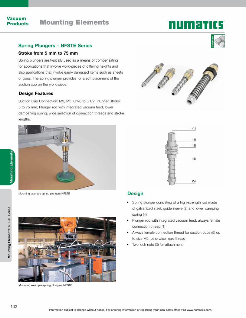
Information subject to change without notice. For ordering information or regarding your local sales office visit www.numatics.com.132
Mounting ElementsVacuum Products
Mou
ntin
g E
lem
ents
Mou
ntin
g E
lem
ents
: NFS
TE S
erie
s
Spring plungers are typically used as a means of compensating
for applications that involve work-pieces of differing heights and
also applications that involve easily damaged items such as sheets
of glass. The spring plunger provides for a soft placement of the
suction cup on the work-piece.
Spring plunger consisting of a high-strength rod made
of galvanized steel, guide sleeve (2) and lower damping
spring (4)
Plunger rod with integrated vacuum feed, always female
connection thread (1)
Always female connection thread for suction cups (5) up
to size M5, otherwise male thread
Two lock nuts (3) for attachment
Suction Cup Connection: M3, M5, G1/8 to G1/2; Plunger Stroke:
5 to 75 mm; Plunger rod with integrated vacuum feed; lower
dampening spring; wide selection of connection threads and stroke
lengths.
Spring Plungers – NFSTE SeriesStroke from 5 mm to 75 mm
Design Features
Mounting example spring plungers NFSTE
Mounting example spring plungers NFSTE
Design
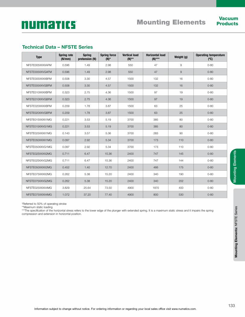
Information subject to change without notice. For ordering information or regarding your local sales office visit www.numatics.com.133
Mounting ElementsVacuum
Products
Mou
ntin
g E
lem
ents
Mou
ntin
g E
lem
ents
: NFS
TE S
erie
s
Type Spring rate (N/mm)
Spring pretension (N)
Spring force (N)*
Vertical load (N)**
Horizontal load (N)*** Weight (g) Operating temperature
(ºC)
NFSTE005XXXXAFM 0.596 1.49 2.98 550 47 9 0-80
NFSTE005XXVGAFM 0.596 1.49 2.98 550 47 9 0-80
NFSTE005XXXXBFM 0.508 3.30 4.57 1500 132 16 0-80
NFSTE005XXVGBFM 0.508 3.30 4.57 1500 132 16 0-80
NFSTE010XXXXBFM 0.323 2.75 4.36 1500 97 19 0-80
NFSTE010XXVGBFM 0.323 2.75 4.36 1500 97 19 0-80
NFSTE020XXXXBFM 0.209 1.78 3.87 1500 63 25 0-80
NFSTE020XXVGBFM 0.209 1.78 3.87 1500 63 25 0-80
NFSTE015XXXX1MG 0.221 3.53 5.19 3700 385 80 0-80
NFSTE015XXVG1MG 0.221 3.53 5.19 3700 385 80 0-80
NFSTE025XXXX1MG 0.143 3.57 5.36 3700 283 90 0-80
NFSTE050XXXX1MG 0.097 2.92 5.34 3700 173 110 0-80
NFSTE050XXVG1MG 0.097 2.92 5.34 3700 173 110 0-80
NFSTE025XXXX2MG 0.711 6.47 15.36 2400 747 145 0-80
NFSTE025XXVG2MG 0.711 6.47 15.36 2400 747 144 0-80
NFSTE050XXXX2MG 0.452 1.40 12.70 2400 466 175 0-80
NFSTE075XXXX2MG 0.262 5.38 15.20 2400 340 190 0-80
NFSTE075XXVG2MG 0.262 5.38 15.20 2400 340 202 0-80
NFSTE025XXXX4MG 3.829 25.64 73.50 4900 1870 400 0-80
NFSTE075XXXX4MG 1.072 37.20 77.40 4900 800 530 0-80
Technical Data – NFSTE Series
*Referred to 50% of operating stroke**Maximum static loading***The specification of the horizontal stress refers to the lower edge of the plunger with extended spring. It is a maximum static stress and it impairs the spring compression and extension in horizontal position.

Information subject to change without notice. For ordering information or regarding your local sales office visit www.numatics.com.134
Mounting ElementsVacuum Products
Mou
ntin
g E
lem
ents
Mou
ntin
g E
lem
ents
: NFS
TE S
erie
s
How to OrderNFSTE Series - Spring Plungers
Series / Plunger Stroke
(mm)
Spring Plunger Part Number Thread Type / Port Size Additional Features
NFSTE 5
NFSTE005XXVGAFM M3-F Anti-Rotation Guard
NFSTE005XXVGBFM M5-F Anti-Rotation Guard
NFSTE005XXXXAFM M3-F
NFSTE005XXXXBFM M5-F
NFSTE 10NFSTE010XXVGBFM M5-F Anti-Rotation Guard
NFSTE010XXXXBFM M5-F
NFSTE 15NFSTE015XXVG1MG G1/8-M Anti-Rotation Guard
NFSTE015XXXX1MG G1/8-M
NFSTE 20NFSTE020XXVGBFM M5-F Anti-Rotation Guard
NFSTE020XXXXBFM M5-F
NFSTE 25
NFSTE025XXVG2MG G1/4-M Anti-Rotation Guard
NFSTE025XXXX1MG G1/8-M
NFSTE025XXXX2MG G1/4-M
NFSTE025XXXX4MG G1/2 -M
NFSTE 50
NFSTE050XXVG1MG G1/8-M Anti-Rotation Guard
NFSTE050XXXX1MG G1/8-M
NFSTE050XXXX2MG G1/4-M
NFSTE 75
NFSTE075XXVG2MG G1/4-M Anti-Rotation Guard
NFSTE075XXXX2MG G1/4-M
NFSTE075XXXX4MG G1/2 -M
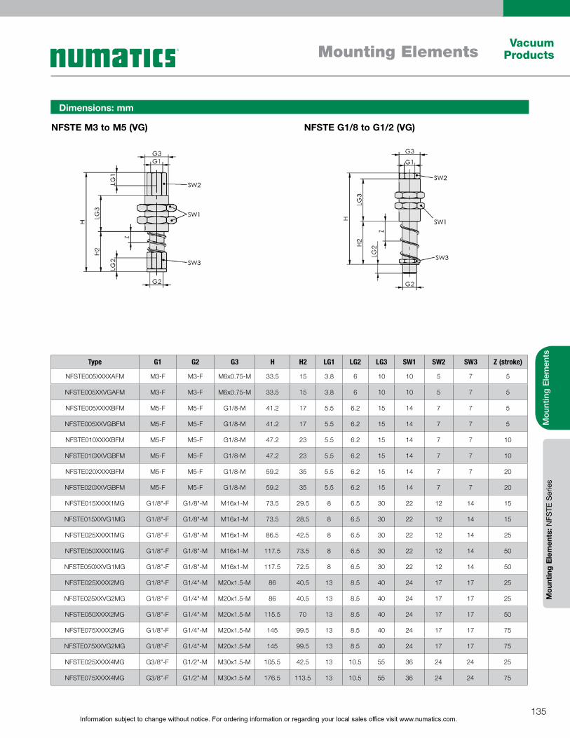
Information subject to change without notice. For ordering information or regarding your local sales office visit www.numatics.com.135
Mounting ElementsVacuum
Products
Mou
ntin
g E
lem
ents
Mou
ntin
g E
lem
ents
: NFS
TE S
erie
s
Type G1 G2 G3 H H2 LG1 LG2 LG3 SW1 SW2 SW3 Z (stroke)
NFSTE005XXXXAFM M3-F M3-F M6x0.75-M 33.5 15 3.8 6 10 10 5 7 5
NFSTE005XXVGAFM M3-F M3-F M6x0.75-M 33.5 15 3.8 6 10 10 5 7 5
NFSTE005XXXXBFM M5-F M5-F G1/8-M 41.2 17 5.5 6.2 15 14 7 7 5
NFSTE005XXVGBFM M5-F M5-F G1/8-M 41.2 17 5.5 6.2 15 14 7 7 5
NFSTE010XXXXBFM M5-F M5-F G1/8-M 47.2 23 5.5 6.2 15 14 7 7 10
NFSTE010XXVGBFM M5-F M5-F G1/8-M 47.2 23 5.5 6.2 15 14 7 7 10
NFSTE020XXXXBFM M5-F M5-F G1/8-M 59.2 35 5.5 6.2 15 14 7 7 20
NFSTE020XXVGBFM M5-F M5-F G1/8-M 59.2 35 5.5 6.2 15 14 7 7 20
NFSTE015XXXX1MG G1/8"-F G1/8"-M M16x1-M 73.5 29.5 8 6.5 30 22 12 14 15
NFSTE015XXVG1MG G1/8"-F G1/8"-M M16x1-M 73.5 28.5 8 6.5 30 22 12 14 15
NFSTE025XXXX1MG G1/8"-F G1/8"-M M16x1-M 86.5 42.5 8 6.5 30 22 12 14 25
NFSTE050XXXX1MG G1/8"-F G1/8"-M M16x1-M 117.5 73.5 8 6.5 30 22 12 14 50
NFSTE050XXVG1MG G1/8"-F G1/8"-M M16x1-M 117.5 72.5 8 6.5 30 22 12 14 50
NFSTE025XXXX2MG G1/8"-F G1/4"-M M20x1.5-M 86 40.5 13 8.5 40 24 17 17 25
NFSTE025XXVG2MG G1/8"-F G1/4"-M M20x1.5-M 86 40.5 13 8.5 40 24 17 17 25
NFSTE050XXXX2MG G1/8"-F G1/4"-M M20x1.5-M 115.5 70 13 8.5 40 24 17 17 50
NFSTE075XXXX2MG G1/8"-F G1/4"-M M20x1.5-M 145 99.5 13 8.5 40 24 17 17 75
NFSTE075XXVG2MG G1/8"-F G1/4"-M M20x1.5-M 145 99.5 13 8.5 40 24 17 17 75
NFSTE025XXXX4MG G3/8"-F G1/2"-M M30x1.5-M 105.5 42.5 13 10.5 55 36 24 24 25
NFSTE075XXXX4MG G3/8"-F G1/2"-M M30x1.5-M 176.5 113.5 13 10.5 55 36 24 24 75
Dimensions: mm
NFSTE G1/8 to G1/2 (VG)NFSTE M3 to M5 (VG)
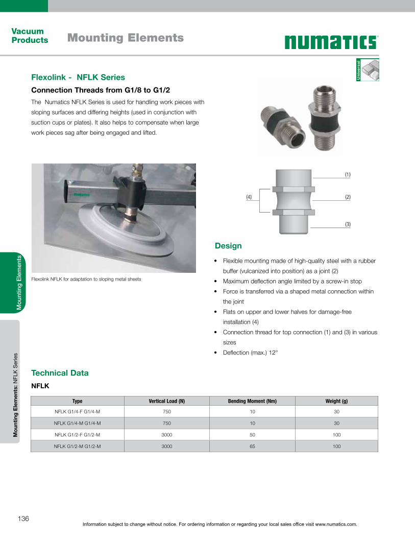
Information subject to change without notice. For ordering information or regarding your local sales office visit www.numatics.com.136
Mounting ElementsVacuum Products
Mou
ntin
g E
lem
ents
Mou
ntin
g E
lem
ents
: NFL
K S
erie
s
Flexolink - NFLK Series Connection Threads from G1/8 to G1/2
Flexolink NFLK for adaptation to sloping metal sheets
Type Vertical Load (N) Bending Moment (Nm) Weight (g)
NFLK G1/4-F G1/4-M 750 10 30
NFLK G1/4-M G1/4-M 750 10 30
NFLK G1/2-F G1/2-M 3000 50 100
NFLK G1/2-M G1/2-M 3000 65 100
Technical DataNFLK
The Numatics NFLK Series is used for handling work pieces with
sloping surfaces and differing heights (used in conjunction with
suction cups or plates). It also helps to compensate when large
work pieces sag after being engaged and lifted.
Flexible mounting made of high-quality steel with a rubber
buffer (vulcanized into position) as a joint (2)
Maximum deflection angle limited by a screw-in stop
Force is transferred via a shaped metal connection within
the joint
Flats on upper and lower halves for damage-free
installation (4)
Connection thread for top connection (1) and (3) in various
sizes
Deflection (max.) 12°
Design
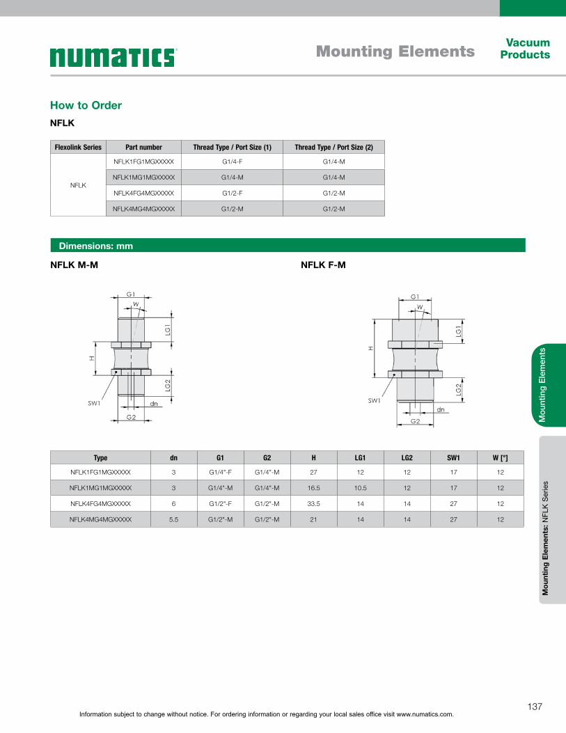
Information subject to change without notice. For ordering information or regarding your local sales office visit www.numatics.com.137
Mounting ElementsVacuum
Products
Mou
ntin
g E
lem
ents
Mou
ntin
g E
lem
ents
: NFL
K S
erie
s
Flexolink Series Part number Thread Type / Port Size (1) Thread Type / Port Size (2)
NFLK
NFLK1FG1MGXXXXX G1/4-F G1/4-M
NFLK1MG1MGXXXXX G1/4-M G1/4-M
NFLK4FG4MGXXXXX G1/2-F G1/2-M
NFLK4MG4MGXXXXX G1/2-M G1/2-M
How to OrderNFLK
Dimensions: mm
NFLK M-M NFLK F-M
Type dn G1 G2 H LG1 LG2 SW1 W [°]
NFLK1FG1MGXXXXX 3 G1/4"-F G1/4"-M 27 12 12 17 12
NFLK1MG1MGXXXXX 3 G1/4"-M G1/4"-M 16.5 10.5 12 17 12
NFLK4FG4MGXXXXX 6 G1/2"-F G1/2"-M 33.5 14 14 27 12
NFLK4MG4MGXXXXX 5.5 G1/2"-M G1/2"-M 21 14 14 27 12
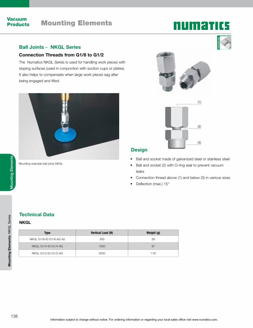
Information subject to change without notice. For ordering information or regarding your local sales office visit www.numatics.com.138
Mounting ElementsVacuum Products
Mou
ntin
g E
lem
ents
Mou
ntin
g E
lem
ents
: NK
GL
Ser
ies
Ball Joints - NKGL Series Connection Threads from G1/8 to G1/2The Numatics NKGL Series is used for handling work pieces with
sloping surfaces (used in conjunction with suction cups or plates).
It also helps to compensate when large work pieces sag after
being engaged and lifted.
Ball and socket made of galvanized steel or stainless steel
Ball and socket (2) with O-ring seal to prevent vacuum
leaks
Connection thread above (1) and below (3) in various sizes
Deflection (max.) 15°
Design
Type Vertical Load (N) Weight (g)
NKGL G1/8-IG G1/8-AG A2 300 26
NKGL G1/4-IG G1/4-AG 1500 67
NKGL G1/2-IG G1/2-AG 2500 116
Technical DataNKGL
Mounting example ball joints NKGL

Information subject to change without notice. For ordering information or regarding your local sales office visit www.numatics.com.139
Mounting ElementsVacuum
Products
Mou
ntin
g E
lem
ents
Mou
ntin
g E
lem
ents
: NK
GL
Ser
ies
Ball Joint Series Part number Thread Type / Port Size (1) Thread Type / Port Size (2) Material
NKGL
NKGL1FG1MGA2XXX G1/8-F G1/8-M Stainless Steel
NKGL2FG2MGXXXXX G1/4-F G1/4-M Galvanized Steel
NKGL4FG4MGXXXXX G1/2-F G1/2-M Galvanized Steel
How to OrderNKGL
NKGL G1/8 to G1/2
Type dn G1 G2 H LG1 LG2 SW1 W [°]
NKGL1FG1MGA2XXX 2.0 G1/8-F G1/8-M 26.5 8.5 7 14 15
NKGL2FG2MGXXXXX 3.5 G1/4-F G1/4-M 37.5 12 10 19 15
NKGL4FG4MGXXXXX 4 G1/2"-F G1/2"-M 40 14 12 24 15
Dimensions: mm
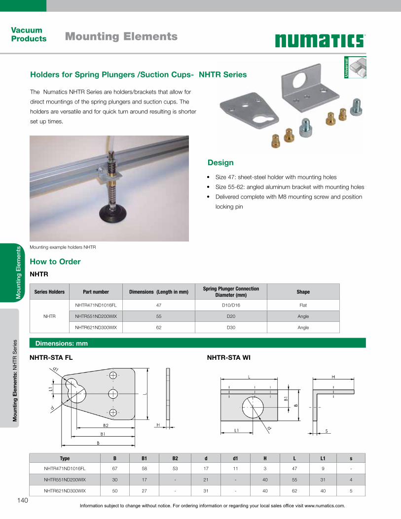
Information subject to change without notice. For ordering information or regarding your local sales office visit www.numatics.com.140
Mounting ElementsVacuum Products
Mou
ntin
g E
lem
ents
Mou
ntin
g E
lem
ents
: NH
TR S
erie
s
NHTR-STA FL NHTR-STA WI
Type B B1 B2 d d1 H L L1 s
NHTR471ND1016FL 67 58 53 17 11 3 47 9 -
NHTR551ND200WIX 30 17 - 21 - 40 55 31 4
NHTR621ND300WIX 50 27 - 31 - 40 62 40 5
Dimensions: mm
Mounting example holders NHTR
Series Holders Part number Dimensions (Length in mm) Spring Plunger Connection Diameter (mm) Shape
NHTR
NHTR471ND1016FL 47 D10/D16 Flat
NHTR551ND200WIX 55 D20 Angle
NHTR621ND300WIX 62 D30 Angle
How to OrderNHTR
Holders for Spring Plungers /Suction Cups- NHTR Series
The Numatics NHTR Series are holders/brackets that allow for
direct mountings of the spring plungers and suction cups. The
holders are versatile and for quick turn around resulting is shorter
set up times.
Size 47: sheet-steel holder with mounting holes
Size 55-62: angled aluminum bracket with mounting holes
Delivered complete with M8 mounting screw and position
locking pin
Design
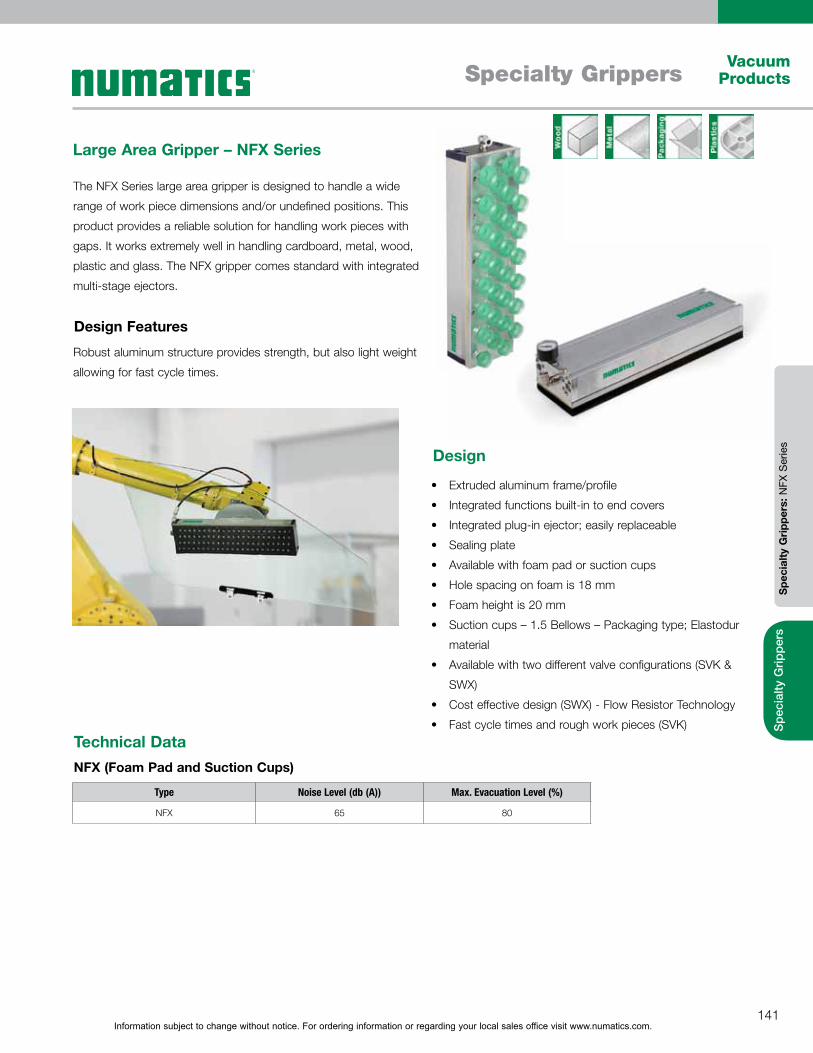
Information subject to change without notice. For ordering information or regarding your local sales office visit www.numatics.com.141
Specialty GrippersVacuum
Products
Spe
cial
ty G
rippe
rsS
peci
alty
Gri
pper
s: N
FX S
erie
s
Large Area Gripper – NFX Series
The NFX Series large area gripper is designed to handle a wide
range of work piece dimensions and/or undefined positions. This
product provides a reliable solution for handling work pieces with
gaps. It works extremely well in handling cardboard, metal, wood,
plastic and glass. The NFX gripper comes standard with integrated
multi-stage ejectors.
Extruded aluminum frame/profile
Integrated functions built-in to end covers
Integrated plug-in ejector; easily replaceable
Sealing plate
Available with foam pad or suction cups
Hole spacing on foam is 18 mm
Foam height is 20 mm
Suction cups – 1.5 Bellows – Packaging type; Elastodur
material
Available with two different valve configurations (SVK &
SWX)
Cost effective design (SWX) - Flow Resistor Technology
Fast cycle times and rough work pieces (SVK)
Robust aluminum structure provides strength, but also light weight
allowing for fast cycle times.
Design Features
Design
Technical DataNFX (Foam Pad and Suction Cups)
Type Noise Level (db (A)) Max. Evacuation Level (%)
NFX 65 80
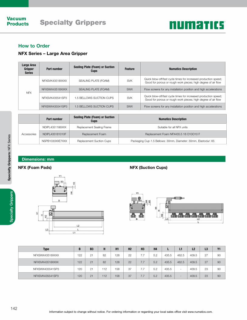
Information subject to change without notice. For ordering information or regarding your local sales office visit www.numatics.com.142
Specialty GrippersVacuum Products
Spe
cial
ty G
rippe
rsS
peci
alty
Gri
pper
s: N
FX S
erie
s
Large Area Gripper Series
Part number Sealing Plate (Foam) or Suction Cups Feature Numatics Description
NFX
NFXSVK43518XXXX SEALING PLATE (FOAM) SVK Quick blow-off/fast cycle times for increased production speed; Good for porous or rough work pieces; high degree of air flow
NFXSWX43518XXXX SEALING PLATE (FOAM) SWX Flow screens for any installation position and high accelerations
NFXSVK435541SP3 1.5 BELLOWS SUCTION CUPS SVK Quick blow-off/fast cycle times for increased production speed; Good for porous or rough work pieces; high degree of air flow
NFXSWX435541SP3 1.5 BELLOWS SUCTION CUPS SWX Flow screens for any installation position and high accelerations
Part number Sealing Plate (Foam) or Suction Cups Numatics Description
Accessories
NDIPL4351186XXX Replacement Sealing Frame Suitable for all NFX units
NDIPL435181010F Replacement Foam Replacement Foam NFX435.5 18 O10O10 F
NSPB1030XXE7XXX Replacement Suction Cups Packaging Cup-1.5 Bellows: 30mm, Diameter: 30mm, Elastodur: 65
How to OrderNFX Series – Large Area Gripper
Dimensions: mm
NFX (Foam Pads) NFX (Suction Cups)
Type B B3 H H1 H2 H3 H4 L L1 L2 L3 Y1
NFXSWX43518XXXX 122 21 82 128 22 7.7 5.2 435.5 462.5 409.5 27 90
NFXSVK43518XXXX 122 21 82 128 22 7.7 5.2 435.5 462.5 409.5 27 90
NFXSWX435541SP3 120 21 112 158 37 7.7 5.2 435.5 - 409.5 23 90
NFXSVK435541SP3 120 21 112 158 37 7.7 5.2 435.5 - 409.5 23 90

Information subject to change without notice. For ordering information or regarding your local sales office visit www.numatics.com.143
Specialty GrippersVacuum
Products
Spe
cial
ty G
rippe
rsS
peci
alty
Gri
pper
s: N
FX S
erie
s
NFX with Integrated Vacuum Generation
Valve Component
Sealing plate
Suction pads
Example:Large-area vacuum gripping system NFX with sealing plate
Example:Large-area vacuum gripping system NFX with suction pads
Vacuum generatorPlug-in ejector with lightweight designQuickly replaceableAlternatively with up to 4 multi-stage ejectors for optimum performance adjustment
Valve type SVKQuick blow-off and fast cycle times for increased production speedHigh degree of air passage for handling porous and rough workpieces
Sealing plate (foam)Flexible and highly resistantDifferent grids according to the width of the work pieceQuickly replaceableOptional: sealing plate with integrated filter screen to protect against contamination
Valve type SWXFlow screens for any installation position and high accelerations
Suction pads (elastomer)Soft, adaptable sealing lipQuickly replaceable
Main bodyMade from extruded aluminium sectionVariable in width by combining unitsVariable in length
T-slotFor flexible mechanical attachment of the gripper
End cover with function modulesFor the “sensor”, “blow-off” and “separation” connections
Vacuum display using vacuum manometer
+
+
=
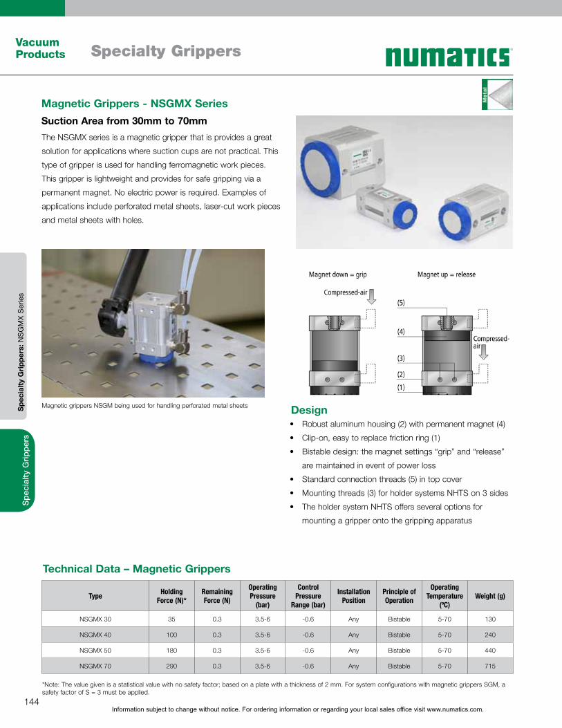
Information subject to change without notice. For ordering information or regarding your local sales office visit www.numatics.com.144
Specialty GrippersVacuum Products
Spe
cial
ty G
rippe
rsS
peci
alty
Gri
pper
s: N
SG
MX
Ser
ies
The NSGMX series is a magnetic gripper that is provides a great
solution for applications where suction cups are not practical. This
type of gripper is used for handling ferromagnetic work pieces.
This gripper is lightweight and provides for safe gripping via a
permanent magnet. No electric power is required. Examples of
applications include perforated metal sheets, laser-cut work pieces
and metal sheets with holes.
Magnetic Grippers - NSGMX Series Suction Area from 30mm to 70mm
Magnetic grippers NSGM being used for handling perforated metal sheets
Type Holding Force (N)*
Remaining Force (N)
Operating Pressure
(bar)
Control Pressure
Range (bar)
Installation Position
Principle of Operation
Operating Temperature
(ºC)Weight (g)
NSGMX 30 35 0.3 3.5-6 -0.6 Any Bistable 5-70 130
NSGMX 40 100 0.3 3.5-6 -0.6 Any Bistable 5-70 240
NSGMX 50 180 0.3 3.5-6 -0.6 Any Bistable 5-70 440
NSGMX 70 290 0.3 3.5-6 -0.6 Any Bistable 5-70 715
Technical Data – Magnetic Grippers
*Note: The value given is a statistical value with no safety factor; based on a plate with a thickness of 2 mm. For system configurations with magnetic grippers SGM, a safety factor of S = 3 must be applied.
Robust aluminum housing (2) with permanent magnet (4)
Clip-on, easy to replace friction ring (1)
Bistable design: the magnet settings “grip” and “release”
are maintained in event of power loss
Standard connection threads (5) in top cover
Mounting threads (3) for holder systems NHTS on 3 sides
The holder system NHTS offers several options for
mounting a gripper onto the gripping apparatus
Design
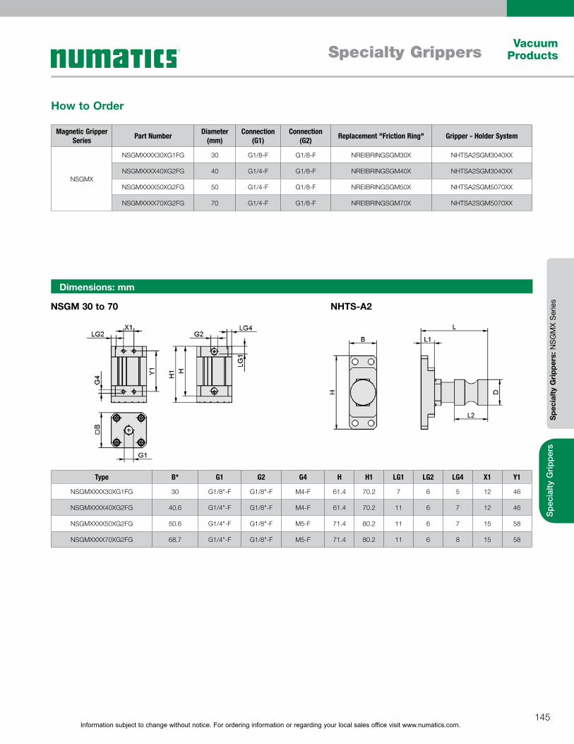
Information subject to change without notice. For ordering information or regarding your local sales office visit www.numatics.com.145
Specialty GrippersVacuum
Products
Spe
cial
ty G
rippe
rsS
peci
alty
Gri
pper
s: N
SG
MX
Ser
ies
Magnetic Gripper Series Part Number Diameter
(mm)Connection
(G1)Connection
(G2) Replacement "Friction Ring" Gripper - Holder System
NSGMX
NSGMXXXX30XG1FG 30 G1/8-F G1/8-F NREIBRINGSGM30X NHTSA2SGM3040XX
NSGMXXXX40XG2FG 40 G1/4-F G1/8-F NREIBRINGSGM40X NHTSA2SGM3040XX
NSGMXXXX50XG2FG 50 G1/4-F G1/8-F NREIBRINGSGM50X NHTSA2SGM5070XX
NSGMXXXX70XG2FG 70 G1/4-F G1/8-F NREIBRINGSGM70X NHTSA2SGM5070XX
How to Order
Dimensions: mm
NSGM 30 to 70 NHTS-A2
Type B* G1 G2 G4 H H1 LG1 LG2 LG4 X1 Y1
NSGMXXXX30XG1FG 30 G1/8"-F G1/8"-F M4-F 61.4 70.2 7 6 5 12 46
NSGMXXXX40XG2FG 40.6 G1/4"-F G1/8"-F M4-F 61.4 70.2 11 6 7 12 46
NSGMXXXX50XG2FG 50.6 G1/4"-F G1/8"-F M5-F 71.4 80.2 11 6 7 15 58
NSGMXXXX70XG2FG 68.7 G1/4"-F G1/8"-F M5-F 71.4 80.2 11 6 8 15 58
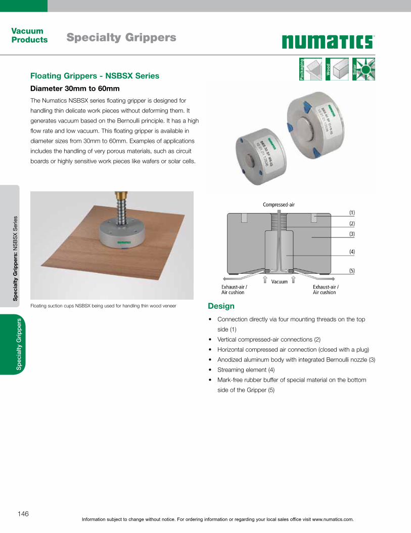
Information subject to change without notice. For ordering information or regarding your local sales office visit www.numatics.com.146
Specialty GrippersVacuum Products
Spe
cial
ty G
rippe
rsS
peci
alty
Gri
pper
s: N
SB
SX
Ser
ies
The Numatics NSBSX series floating gripper is designed for
handling thin delicate work pieces without deforming them. It
generates vacuum based on the Bernoulli principle. It has a high
flow rate and low vacuum. This floating gripper is available in
diameter sizes from 30mm to 60mm. Examples of applications
includes the handling of very porous materials, such as circuit
boards or highly sensitive work pieces like wafers or solar cells.
Floating Grippers - NSBSX Series Diameter 30mm to 60mm
Floating suction cups NSBSX being used for handling thin wood veneer
Connection directly via four mounting threads on the top
side (1)
Vertical compressed-air connections (2)
Horizontal compressed air connection (closed with a plug)
Anodized aluminum body with integrated Bernoulli nozzle (3)
Streaming element (4)
Mark-free rubber buffer of special material on the bottom
side of the Gripper (5)
Design
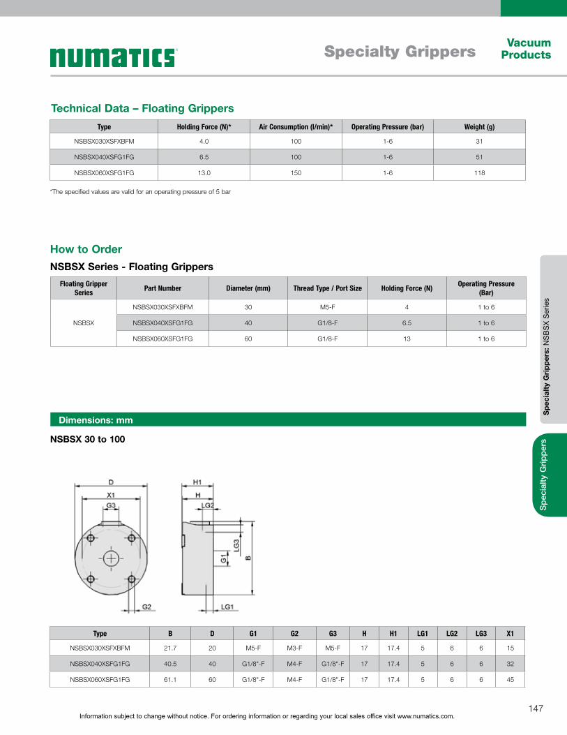
Information subject to change without notice. For ordering information or regarding your local sales office visit www.numatics.com.147
Specialty GrippersVacuum
Products
Spe
cial
ty G
rippe
rsS
peci
alty
Gri
pper
s: N
SB
SX
Ser
ies
Type Holding Force (N)* Air Consumption (l/min)* Operating Pressure (bar) Weight (g)
NSBSX030XSFXBFM 4.0 100 1-6 31
NSBSX040XSFG1FG 6.5 100 1-6 51
NSBSX060XSFG1FG 13.0 150 1-6 118
Technical Data – Floating Grippers
*The specified values are valid for an operating pressure of 5 bar
Dimensions: mm
Type B D G1 G2 G3 H H1 LG1 LG2 LG3 X1
NSBSX030XSFXBFM 21.7 20 M5-F M3-F M5-F 17 17.4 5 6 6 15
NSBSX040XSFG1FG 40.5 40 G1/8"-F M4-F G1/8"-F 17 17.4 5 6 6 32
NSBSX060XSFG1FG 61.1 60 G1/8"-F M4-F G1/8"-F 17 17.4 5 6 6 45
Floating Gripper Series Part Number Diameter (mm) Thread Type / Port Size Holding Force (N) Operating Pressure
(Bar)
NSBSX
NSBSX030XSFXBFM 30 M5-F 4 1 to 6
NSBSX040XSFG1FG 40 G1/8-F 6.5 1 to 6
NSBSX060XSFG1FG 60 G1/8-F 13 1 to 6
How to OrderNSBSX Series - Floating Grippers
NSBSX 30 to 100

Information subject to change without notice. For ordering information or regarding your local sales office visit www.numatics.com.148
Vacuum Sensors/Switches and Regulators
Vacuum Products
Vacu
um S
enso
rs/S
witc
hes
and
Reg
ulat
ors
Sen
sors
/Sw
itche
s an
d R
egul
ator
s
Miniature Vacuum Switches/Sensors - NVS-V-SA/SD Series
NVSV SA / SD
Type NVSVSA00M5XXXXX NVSVSA00D4XXXXX NVSVSD60M5XXXXX NVSVSD60D4XXXXX
Measured medium Non-aggressive gases; dry, oil-free air
Non-aggressive gases; dry, oil-free air
Non-aggressive gases; dry, oil-free air
Non-aggressive gases; dry, oil-free air
Measuring range -1-0 bar -1-0 bar -1-0 bar -1-0 bar
Max. overpressure resistance (bar) 5 5 5 5
Repeatability ± 1% of full-scale value ± 1% of full-scale value ± 1% of full-scale value ± 1% of full-scale value
Hysteresis - - Fixed: approx. 20 mbar Fixed: approx. 20 mbar
Output signal Analog: 1-5 V Analog: 1-5 V 1 digital 1 digital
Switching capacity (mA) - - 60 60
Point attitude - - - 600 mbar - 600 mbar
Indication - - LED LED
Electrical connection Cable Cable Cable Cable
Voltage 10-24V DC 10-24V DC 10-24V DC 10-24V DC
Protection IP IP 40 IP 40 IP 40 IP 40
Temperature influence ± 3% of full-scale value ± 3% of full-scale value ± 3% of full-scale value ± 3% of full-scale value
Operating temperature (°C) 0-50 °C 0-50 °C 0-50 °C 0-50 °C
Length of cable (m) 3 3 3 3
Weight (g) 5 5 5 5
Technical DataNVS-V-SA/SD
The Numatics NVS-V-SA/SD series is a mini sensor with housing
and connector cable. Examples of applications include the
measurement of vacuum values close to the suction cup, remote
evaluation of signals, in addition to being used in most other areas
of automated handling.
Electronic vacuum switch for measurement of vacuum
values close to the suction cup
Remote evaluation of the signals
Processing of output signals in, for example, a stored-
program controller
Ideal for outputting part-presence signals
For use in all areas of automated handling
Design

Information subject to change without notice. For ordering information or regarding your local sales office visit www.numatics.com.149
Vacuum Sensors/Switches and Regulators
Vacuum Products
Vacu
um S
enso
rs/S
witc
hes
and
Reg
ulat
ors
Sen
sors
/Sw
itche
s an
d R
egul
ator
s
Vacuum Switches / Sensors Part Number Measuring Range (Bar) Principle of Function Switching Point (mBar) Vacuum Connection
NVS-V-SA/SD
NVSVSA00M5XXXXX -1 to 0 Analog M5-M
NVSVSA00D4XXXXX -1 to 0 Analog 4mm Plug-in Tube
NVSVSD60M5XXXXX -1 to 0 Digital -600 M5-M
NVSVSD60D4XXXXX -1 to 0 Digital -600 4mm Plug-in Tube
How to OrderNVS-V-SA/SD Series - Miniature Vacuum Switches/Sensors
Dimensions: mm
NVS-V-SA/SD - M5 NVS-V-SA/SD - D4
Type B D G1 H H1 L LG1 SW1
NVSVSA00M5XXXXX 9.5 - M5-M 16.9 - 21 5 8
NVSVSA00D4XXXXX 9.5 4 - 17.2 32.2 21 - -
NVSVSD60M5XXXXX 9.5 - M5-M 16.9 - 21 5 8
NVSVSD60D4XXXXX 9.5 4 - 17.2 32.2 21 - -
Information subject to change without notice. For ordering information or regarding your local sales office visit www.numatics.com.150
Vacuum Sensors/Switches and Regulators
Vacuum Products
Vacu
um S
enso
rs/S
witc
hes
and
Reg
ulat
ors
Sen
sors
/Sw
itche
s an
d R
egul
ator
s
NVS-V-AH / AV-T
How to OrderNVS-V-AH / AV-T Switches/Sensors
Type NVSV00AHTPNPSXX NVSV00AVTPNPSXX
Measured medium Non-aggressive gases; dry, oil-free air
Non-aggressive gases; dry, oil-free air
Measuring range -1-0 bar -1-0 bar
Max. overpressure resistance (bar) 5 5
Repeatability ± 1% of full-scale value ± 1% of full-scale value
Hysteresis Fixed: approx. 20 mbar Fixed: approx. 20 mbar
Output signal 2 digital 2 digital
Switching capacity (mA) 200 200
Indication LED LED
Electrical connection Male connect M8, 4 pole Male connect M8, 4 pole
Voltage 10-30V DC 10-30V DC
Current consumption (mA) 20 20
Protection IP IP 40 IP 40
Temperature influence ± 3% of full-scale value ± 3% of full-scale value
Operating temperature (ºC) 0-60 °C 0-60 °C
Weight (g) 6 6
Technical DataNVS-V-AH / AV-T
Vacuum Switches / Sensors Part Number Measuring Range
(Bar) Connection Switching Point Adjustment Switching Function Standard Feature
NVS-V-AH/AV-TNVSV00AHTPNPSXX 0 to 10 Horizontal Teach button PNP Fixed hysteresis
NVSV00AVTPNPSXX 0 to 10 Vertical Teach button PNP Fixed hysteresis
Product Family Name Part Number Description Comments
Accessories
NASKBM8450PURGE Cable M8 4 5M PUR GE Straight Connection
NASKBM8450PURWX Cable M8 4 5M PUR W Right Angle Connection
NADAPVS61316XXX 6mm Plug-in tube Connection Adapter
NADAPVSX1316BMM M5-M Connection Adapter
Vacuum Switches - NVS-V-AH / AV-T Series
The NVS-V-AH / AV-T vacuum switch/sensor works very well in
dynamic handling systems and can be used as a measuring or
switching element. This product offers two digital switch outputs
and a switching capacity of 200mA.
Plastic housing in 10 mm design
Adapter plate for quick mounting, either
vertically or horizontally
Teach button integrated into the cover
Transparent cover over the LED indicator
Power and control connections via 4-pin M8
connector
Optionally available with M5 vacuum
connection or 6 mm plug-in tube
Design

Information subject to change without notice. For ordering information or regarding your local sales office visit www.numatics.com.151
Vacuum Sensors/Switches and Regulators
Vacuum Products
Vacu
um S
enso
rs/S
witc
hes
and
Reg
ulat
ors
Sen
sors
/Sw
itche
s an
d R
egul
ator
s
Dimensions: mm
NVS-V-AH/AV-T
NADAP-VS 6-1.3x16 NADAP-VS M5-AG-1.3x16
Type D G1 H H2 LG1 SW1
NADAP-VS 6-1.3x16 6 - 27.3 20.0 - -
NADAP-VS M5-AG-1.3x16 - M5-M 12.0 - 5.0 8
Type B G1 H L L1
NVS-V-AH-T-PNP-S 10 M8-M 17.5 36.2 43
NVS-V-AV-T-PNP-S 10 M8-M 16.4 41.2 48
Information subject to change without notice. For ordering information or regarding your local sales office visit www.numatics.com.152
Vacuum Sensors/Switches and Regulators
Vacuum Products
Vacu
um S
enso
rs/S
witc
hes
and
Reg
ulat
ors
Sen
sors
/Sw
itche
s an
d R
egul
ator
s
How to OrderNVS-V Switches/Sensors
Type NVS-V
Measured medium Non-aggressive gases; dry, oil-free air
Measuring range -1-0 bar
Max. overpressure resistance (bar) 5
Repeatability ± 1% of full-scale value
Hysteresis Adjustable: 3 to 25% of set value
Output signal 1 anal./1 dig 1-5V
Switching capacity (mA) 125
On time (ms) 5
Indication LED
Electrical connection Male connect M8, 4 pole
Measured medium connection G1/8" male + M5 fem.
Voltage 10.8-30V DC
Current consumption (mA) 30
Protection IP IP 40/65 (with hose)
Temperature influence ± 3% of full-scale value
Operating temperature (ºC) 0-50 °C
Weight (g) 18
Vacuum Switches - NVS-V Series
NVS-V
The NVS-V electronic vacuum switch provides precise
measurement comes with analog and digital outputs. This series
can easily adapt to customer applications with the adjustable
hysteresis and switching points. Its small size and low weight
permit use directly on the suction cup.
Technical DataNVS-V
Electronic vacuum switch in robust polycarbonate housing
Vacuum connection with flange or G1/8" male thread;
both versions with additional M5 female thread
Switching point and hysteresis adjustable with screws
Supply voltage via 4-pin M8 screw connector
Integrated LED for indication of the switching state
Venting plug (reference air, IP 65) for screwing into switch
housing
Design
Vacuum Switches / Sensors Part Number Measuring Range
(Bar)Vacuum
Connection Switching Function
NVS-V NVSVPNPXXXXXXXX -1 to 0 G1/8-M PNP
Product Family Name Part Number Description Comments
AccessoriesNASKBM8450PURGE Cable M8 4 5M PUR GE Straight Connection
NASKBM8450PURWX Cable M8 4 5M PUR W Right Angle Connection
Information subject to change without notice. For ordering information or regarding your local sales office visit www.numatics.com.153
Vacuum Sensors/Switches and Regulators
Vacuum Products
Vacu
um S
enso
rs/S
witc
hes
and
Reg
ulat
ors
Sen
sors
/Sw
itche
s an
d R
egul
ator
s
NVS-V
Type B G1 G2 G3 H L L1 L3 LG1
NVS-V-PNP 15.7 G1/8"-M M5-F M8x1-M 19.7 44 62 - 8
Dimensions: mm

Information subject to change without notice. For ordering information or regarding your local sales office visit www.numatics.com.154
Vacuum Sensors/Switches and Regulators
Vacuum Products
Vacu
um S
enso
rs/S
witc
hes
and
Reg
ulat
ors
Sen
sors
/Sw
itche
s an
d R
egul
ator
s
Type NVSV00DPNPXXXXX
Measured medium Non-aggressive gases; dry, oil-free air
Measuring range -1-0 bar
Max. overpressure resistance (bar) 5
Repeatability ± 1% of full-scale value
Hysteresis Adjustable: 0 to 100% of set value or comparator mode
Output signal 2 digital
Switching capacity (mA) 180
Indication 2xLED
Display resolution 0 bar, 5 mmHg, 0.2 inHg, 1 kPa
Display units bar, mmHg, inHg, kPa
Measured-value display 3-digit 7-segment LED
Electrical connection Male connect M8, 4 pole
Measured medium connection G1/8" male + M5 fem.
Voltage 10.8-30V DC
Current consumption (mA) 30
Protection IP IP 40/65 (with hose)
Temperature influence ± 3% of full-scale value in the range 0 to 50°C
Operating temperature (ºC) 0-50 °C
Weight (g) 25
Technical DataNVS-V-D
NVS-V-D
Vacuum Switches - NVS-V-D Series
The NVS-V-D electronic vacuum switch with digital display
provides precise measurement. Switching point and hysteresis
is programmable with foil keypad, in addition to offering two
separately programmable outputs. This series can easily adapt to
customer applications with the adjustable hysteresis and switching
points. Its small size and low weight permit use directly on the
suction cup.
Electronic vacuum switch in a robust polycarbonate
housing
Vacuum connection with G1/8" male thread; additional M5
female thread
3-digit display and foil keypad on the front for adjustment
of the settings
Integrated LED for indication of the switching state
Supply voltage via 4-pin M8 screw connector
Compact construction and low weight
Design

Information subject to change without notice. For ordering information or regarding your local sales office visit www.numatics.com.155
Vacuum Sensors/Switches and Regulators
Vacuum Products
Vacu
um S
enso
rs/S
witc
hes
and
Reg
ulat
ors
Sen
sors
/Sw
itche
s an
d R
egul
ator
s
How to OrderNVS-V-D Switches/Sensors
Dimensions: mm
NVS-V-D
Type B D G1 G2 G3 H L L1 LG1
NVS-V-D 16 3.4 G1/8"-M M5-F M8x1-M 24.7 58.5 75.5 8
Vacuum Switches / Sensors Part Number Measuring Range
(Bar)Vacuum
Connection Switching Function Standard Feature
NVS-V-D NVSV00DPNPXXXXX -1 to 0 G1/8-M & M5-F PNP Digital Display
Product Family Name Part Number Description Comments
AccessoriesNASKBM8450PURGE Cable M8 4 5M PUR GE Straight Connection
NASKBM8450PURWX Cable M8 4 5M PUR W Right Angle Connection

Information subject to change without notice. For ordering information or regarding your local sales office visit www.numatics.com.156
Vacuum Sensors/Switches and Regulators
Vacuum Products
Vacu
um S
enso
rs/S
witc
hes
and
Reg
ulat
ors
Sen
sors
/Sw
itche
s an
d R
egul
ator
s
NVS-P10-D
Type NVSP10DPNPXXXXX
Measured medium Non-aggressive gases; dry, oil-free air
Measuring range 0-10 bar
Max. overpressure resistance (bar) 16
Repeatability ± 1% of full-scale value
Hysteresis Adjustable: 0 to 100% of set value or comparator mode
Output signal 2 digital
Switching capacity (mA) 180
Indication 2xLED
Display resolution 0 bar, 1 psi, 0.05 kgf/cm2, 0.01 Mpa
Display units bar, psi, kgf/cm2, Mpa
Measured-value display 3-digit 7-segment LED
Electrical connection Male connect M8, 4 pole
Measured medium connection G1/8" male + M5 fem.
Voltage 10.8-30V DC
Current consumption (mA) 55
Protection IP IP 40/65 (with hose)
Temperature influence ± 3% of full-scale value in the range 0 to 50°C
Operating temperature (ºC) 0-50 °C
Weight (g) 25
Technical DataNVS-P10-D
Pressure Switches - NVS-P10-D Series
The NVS-P10-D electronic pressure switch with digital display
provides precise measurement. Switching point and hysteresis
is programmable with foil keypad, in addition to offering two
separately programmable outputs. This series can easily adapt to
customer applications with the adjustable hysteresis and switching
points. Compact construction and low weight permit use directly
on suction cup.
Electronic pressure switch in robust polycarbonate
housing
Pressure connection via G1/8" male thread, additional M5
female thread
Display with three digits and foil keypad on front for
setting the values
Integrated LED for indication of the switching state
Electrical connections via 4-pin M8 screw connector
Design
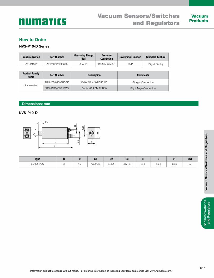
Information subject to change without notice. For ordering information or regarding your local sales office visit www.numatics.com.157
Vacuum Sensors/Switches and Regulators
Vacuum Products
Vacu
um S
enso
rs/S
witc
hes
and
Reg
ulat
ors
Sen
sors
/Sw
itche
s an
d R
egul
ator
s
Dimensions: mm
NVS-P10-D
Type B D G1 G2 G3 H L L1 LG1
NVS-P10-D 16 3.4 G1/8"-M M5-F M8x1-M 24.7 58.5 75.5 8
How to OrderNVS-P10-D Series
Pressure Switch Part Number Measuring Range (Bar)
Pressure Connection Switching Function Standard Feature
NVS-P10-D NVSP10DPNPXXXXX 0 to 10 G1/8-M & M5-F PNP Digital Display
Product Family Name Part Number Description Comments
AccessoriesNASKBM8450PURGE Cable M8 4 5M PUR GE Straight Connection
NASKBM8450PURWX Cable M8 4 5M PUR W Right Angle Connection
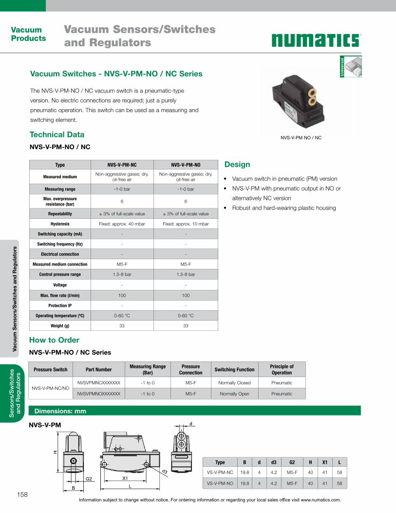
Information subject to change without notice. For ordering information or regarding your local sales office visit www.numatics.com.158
Vacuum Sensors/Switches and Regulators
Vacuum Products
Vacu
um S
enso
rs/S
witc
hes
and
Reg
ulat
ors
Sen
sors
/Sw
itche
s an
d R
egul
ator
s
Type B d d3 G2 H X1 L
VS-V-PM-NC 19.8 4 4.2 M5-F 40 41 58
VS-V-PM-NO 19.8 4 4.2 M5-F 40 41 58
How to OrderNVS-V-PM-NO / NC Series
Technical DataNVS-V-PM-NO / NC
Dimensions: mm
NVS-V-PM
Type NVS-V-PM-NC NVS-V-PM-NO
Measured medium Non-aggressive gases; dry, oil-free air
Non-aggressive gases; dry, oil-free air
Measuring range -1-0 bar -1-0 bar
Max. overpressure resistance (bar) 6 6
Repeatability ± 3% of full-scale value ± 3% of full-scale value
Hysteresis Fixed: approx. 40 mbar Fixed: approx. 10 mbar
Switching capacity (mA) - -
Switching frequency (Hz) - -
Electrical connection - -
Measured medium connection M5-F M5-F
Control pressure range 1.5-8 bar 1.5-8 bar
Voltage - -
Max. flow rate (l/min) 100 100
Protection IP - -
Operating temperature (ºC) 0-60 °C 0-60 °C
Weight (g) 33 33
NVS-V-PM NO / NC
Vacuum Switches - NVS-V-PM-NO / NC Series
The NVS-V-PM-NO / NC vacuum switch is a pneumatic-type
version. No electric connections are required; just a purely
pneumatic operation. This switch can be used as a measuring and
switching element.
Vacuum switch in pneumatic (PM) version
NVS-V-PM with pneumatic output in NO or
alternatively NC version
Robust and hard-wearing plastic housing
Design
Pressure Switch Part Number Measuring Range (Bar)
Pressure Connection Switching Function Principle of
Operation
NVS-V-PM-NC/NONVSVPMNCXXXXXXX -1 to 0 M5-F Normally Closed Pneumatic
NVSVPMNOXXXXXXX -1 to 0 M5-F Normally Open Pneumatic
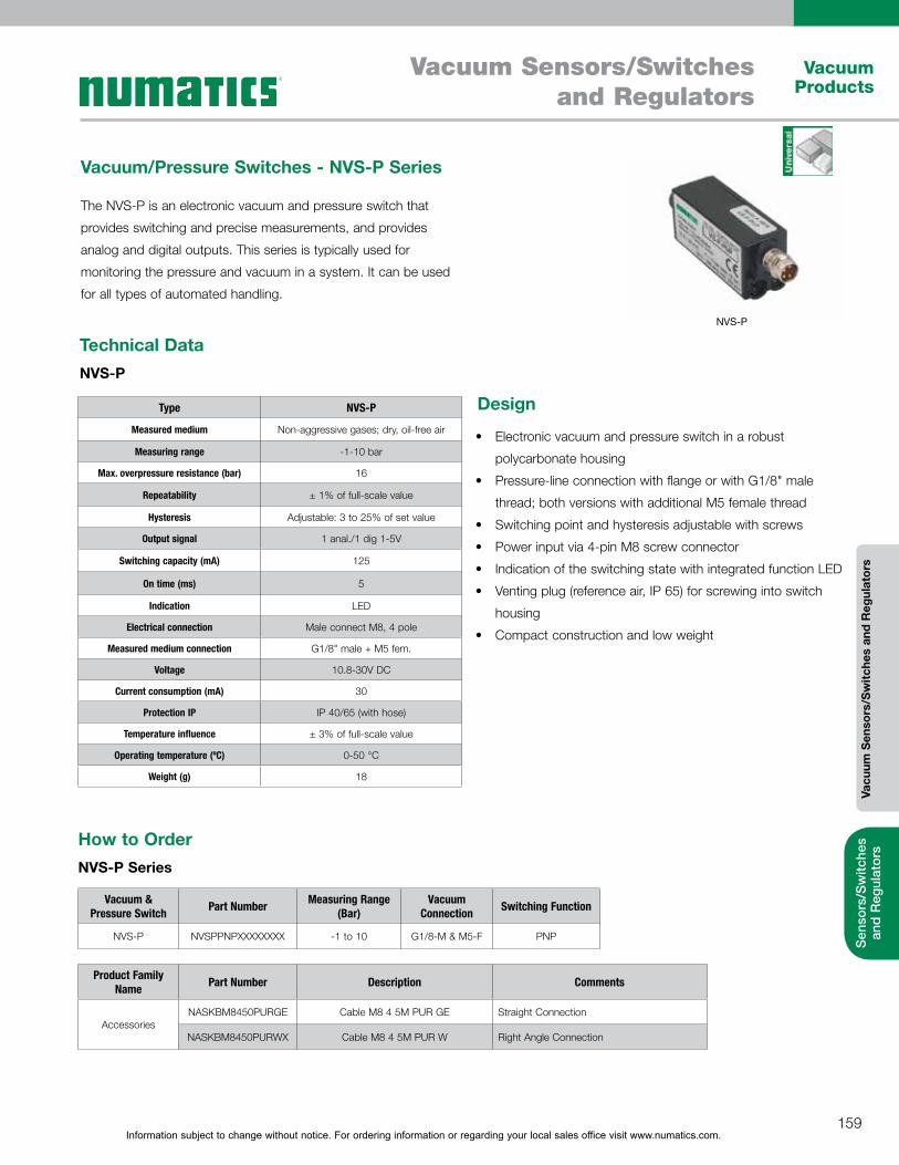
Information subject to change without notice. For ordering information or regarding your local sales office visit www.numatics.com.159
Vacuum Sensors/Switches and Regulators
Vacuum Products
Vacu
um S
enso
rs/S
witc
hes
and
Reg
ulat
ors
Sen
sors
/Sw
itche
s an
d R
egul
ator
s
Type NVS-P
Measured medium Non-aggressive gases; dry, oil-free air
Measuring range -1-10 bar
Max. overpressure resistance (bar) 16
Repeatability ± 1% of full-scale value
Hysteresis Adjustable: 3 to 25% of set value
Output signal 1 anal./1 dig 1-5V
Switching capacity (mA) 125
On time (ms) 5
Indication LED
Electrical connection Male connect M8, 4 pole
Measured medium connection G1/8" male + M5 fem.
Voltage 10.8-30V DC
Current consumption (mA) 30
Protection IP IP 40/65 (with hose)
Temperature influence ± 3% of full-scale value
Operating temperature (ºC) 0-50 °C
Weight (g) 18
How to OrderNVS-P Series
NVS-P
Technical DataNVS-P
Vacuum/Pressure Switches - NVS-P Series
The NVS-P is an electronic vacuum and pressure switch that
provides switching and precise measurements, and provides
analog and digital outputs. This series is typically used for
monitoring the pressure and vacuum in a system. It can be used
for all types of automated handling.
Electronic vacuum and pressure switch in a robust
polycarbonate housing
Pressure-line connection with flange or with G1/8" male
thread; both versions with additional M5 female thread
Switching point and hysteresis adjustable with screws
Power input via 4-pin M8 screw connector
Indication of the switching state with integrated function LED
Venting plug (reference air, IP 65) for screwing into switch
housing
Compact construction and low weight
Design
Vacuum & Pressure Switch Part Number Measuring Range
(Bar)Vacuum
Connection Switching Function
NVS-P NVSPPNPXXXXXXXX -1 to 10 G1/8-M & M5-F PNP
Product Family Name Part Number Description Comments
AccessoriesNASKBM8450PURGE Cable M8 4 5M PUR GE Straight Connection
NASKBM8450PURWX Cable M8 4 5M PUR W Right Angle Connection
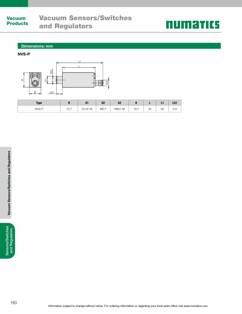
Information subject to change without notice. For ordering information or regarding your local sales office visit www.numatics.com.160
Vacuum Sensors/Switches and Regulators
Vacuum Products
Vacu
um S
enso
rs/S
witc
hes
and
Reg
ulat
ors
Sen
sors
/Sw
itche
s an
d R
egul
ator
s
Dimensions: mm
NVS-P
Type B G1 G2 G3 H L L1 LG1
NVS-P 15.7 G1/8"-M M5-F M8x1-M 19.7 44 62 8.0
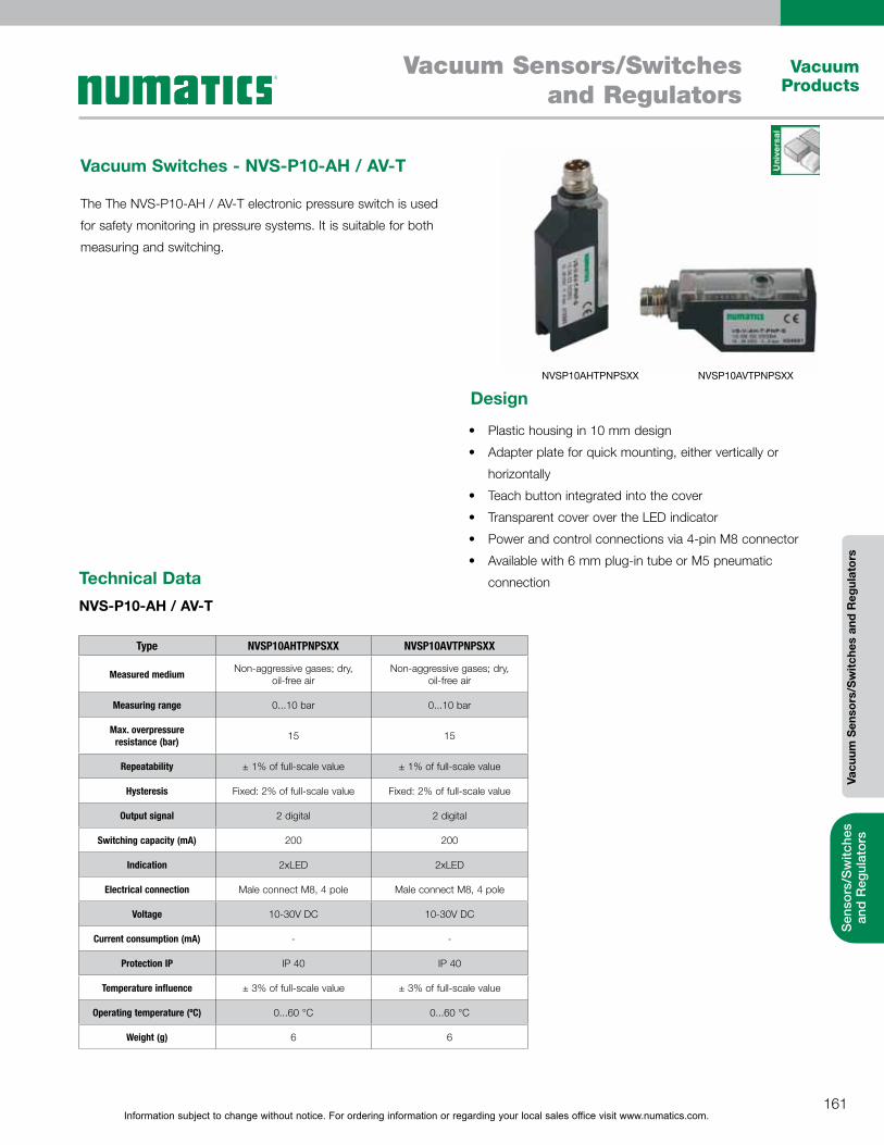
Information subject to change without notice. For ordering information or regarding your local sales office visit www.numatics.com.161
Vacuum Sensors/Switches and Regulators
Vacuum Products
Vacu
um S
enso
rs/S
witc
hes
and
Reg
ulat
ors
Sen
sors
/Sw
itche
s an
d R
egul
ator
s
Vacuum Switches - NVS-P10-AH / AV-T
The The NVS-P10-AH / AV-T electronic pressure switch is used
for safety monitoring in pressure systems. It is suitable for both
measuring and switching.
NVSP10AHTPNPSXX NVSP10AVTPNPSXX
Plastic housing in 10 mm design
Adapter plate for quick mounting, either vertically or
horizontally
Teach button integrated into the cover
Transparent cover over the LED indicator
Power and control connections via 4-pin M8 connector
Available with 6 mm plug-in tube or M5 pneumatic
connection
Design
Technical DataNVS-P10-AH / AV-T
Type NVSP10AHTPNPSXX NVSP10AVTPNPSXX
Measured medium Non-aggressive gases; dry, oil-free air
Non-aggressive gases; dry, oil-free air
Measuring range 0...10 bar 0...10 bar
Max. overpressure resistance (bar) 15 15
Repeatability ± 1% of full-scale value ± 1% of full-scale value
Hysteresis Fixed: 2% of full-scale value Fixed: 2% of full-scale value
Output signal 2 digital 2 digital
Switching capacity (mA) 200 200
Indication 2xLED 2xLED
Electrical connection Male connect M8, 4 pole Male connect M8, 4 pole
Voltage 10-30V DC 10-30V DC
Current consumption (mA) - -
Protection IP IP 40 IP 40
Temperature influence ± 3% of full-scale value ± 3% of full-scale value
Operating temperature (ºC) 0...60 °C 0...60 °C
Weight (g) 6 6
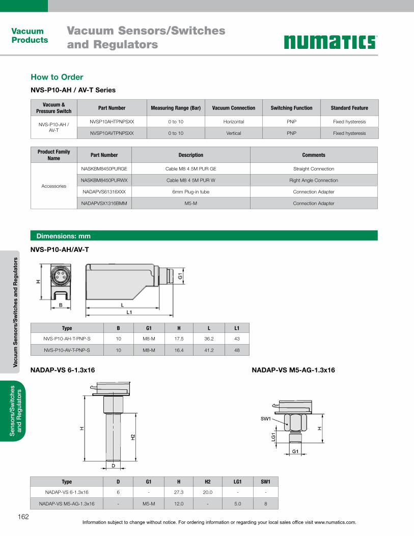
Information subject to change without notice. For ordering information or regarding your local sales office visit www.numatics.com.162
Vacuum Sensors/Switches and Regulators
Vacuum Products
Vacu
um S
enso
rs/S
witc
hes
and
Reg
ulat
ors
Sen
sors
/Sw
itche
s an
d R
egul
ator
s
How to OrderNVS-P10-AH / AV-T Series
Vacuum & Pressure Switch Part Number Measuring Range (Bar) Vacuum Connection Switching Function Standard Feature
NVS-P10-AH / AV-T
NVSP10AHTPNPSXX 0 to 10 Horizontal PNP Fixed hysteresis
NVSP10AVTPNPSXX 0 to 10 Vertical PNP Fixed hysteresis
Type B G1 H L L1
NVS-P10-AH-T-PNP-S 10 M8-M 17.5 36.2 43
NVS-P10-AV-T-PNP-S 10 M8-M 16.4 41.2 48
Product Family Name Part Number Description Comments
Accessories
NASKBM8450PURGE Cable M8 4 5M PUR GE Straight Connection
NASKBM8450PURWX Cable M8 4 5M PUR W Right Angle Connection
NADAPVS61316XXX 6mm Plug-in tube Connection Adapter
NADAPVSX1316BMM M5-M Connection Adapter
Dimensions: mm
NVS-P10-AH/AV-T
NADAP-VS 6-1.3x16 NADAP-VS M5-AG-1.3x16
Type D G1 H H2 LG1 SW1
NADAP-VS 6-1.3x16 6 - 27.3 20.0 - -
NADAP-VS M5-AG-1.3x16 - M5-M 12.0 - 5.0 8
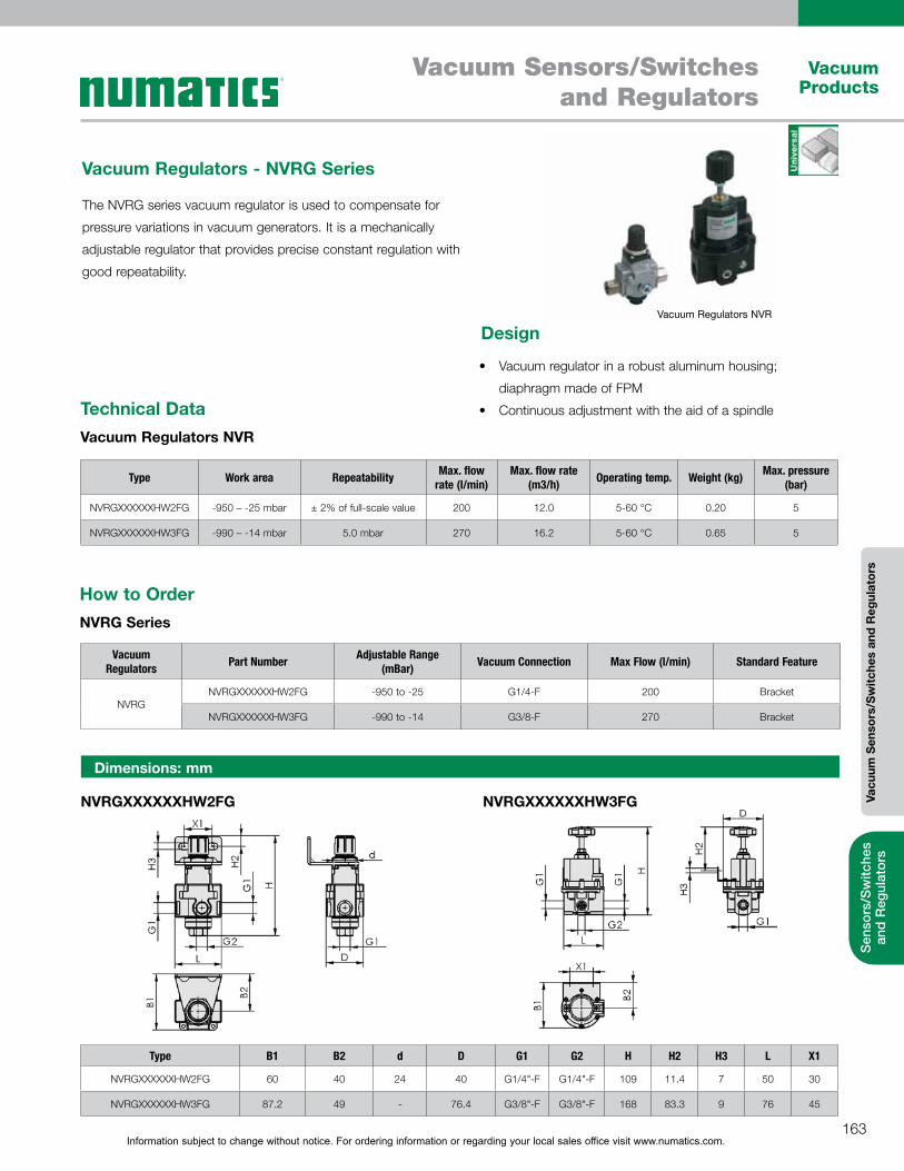
Information subject to change without notice. For ordering information or regarding your local sales office visit www.numatics.com.163
Vacuum Sensors/Switches and Regulators
Vacuum Products
Vacu
um S
enso
rs/S
witc
hes
and
Reg
ulat
ors
Sen
sors
/Sw
itche
s an
d R
egul
ator
s
Technical DataVacuum Regulators NVR
Vacuum Regulators - NVRG Series
Type Work area Repeatability Max. flow rate (l/min)
Max. flow rate (m3/h) Operating temp. Weight (kg) Max. pressure
(bar)
NVRGXXXXXXHW2FG -950 – -25 mbar ± 2% of full-scale value 200 12.0 5-60 °C 0.20 5
NVRGXXXXXXHW3FG -990 – -14 mbar 5.0 mbar 270 16.2 5-60 °C 0.65 5
Vacuum Regulators NVR
Dimensions: mm
NVRGXXXXXXHW2FG NVRGXXXXXXHW3FG
Type B1 B2 d D G1 G2 H H2 H3 L X1
NVRGXXXXXXHW2FG 60 40 24 40 G1/4"-F G1/4"-F 109 11.4 7 50 30
NVRGXXXXXXHW3FG 87.2 49 - 76.4 G3/8"-F G3/8"-F 168 83.3 9 76 45
The NVRG series vacuum regulator is used to compensate for
pressure variations in vacuum generators. It is a mechanically
adjustable regulator that provides precise constant regulation with
good repeatability.
Vacuum regulator in a robust aluminum housing;
diaphragm made of FPM
Continuous adjustment with the aid of a spindle
Design
How to OrderNVRG Series
Vacuum Regulators Part Number Adjustable Range
(mBar) Vacuum Connection Max Flow (l/min) Standard Feature
NVRG NVRGXXXXXXHW2FG -950 to -25 G1/4-F 200 Bracket
NVRGXXXXXXHW3FG -990 to -14 G3/8-F 270 Bracket
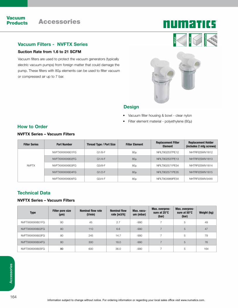
Information subject to change without notice. For ordering information or regarding your local sales office visit www.numatics.com.164
AccessoriesVacuum Products
Acc
esso
ries
Vacuum filter housing & bowl - clear nylon
Filter element material - polyethylene (80µ)
Design
How to OrderNVFTX Series – Vacuum Filters
Technical DataNVFTX Series – Vacuum Filters
Filter Series Part Number Thread Type / Port Size Filter Element Replacement Filter Element
Replacement Holder (includes 2 mtg screws)
NVFTX
NVFTXXXXXX801FG G1/8-F 80µ NFILT802537PE12 NHTRFI2SWIV1812
NVFTXXXXXX802FG G1/4-F 80µ NFILT802537PE13 NHTRFI2SWIV1813
NVFTXXXXXX803FG G3/8-F 80µ NFILT802571PE34 NHTRFI2SWIV1814
NVFTXXXXXX804FG G1/2-F 80µ NFILT802571PE35 NHTRFI2SWIV1815
NVFTXXXXXX805FG G3/4-F 80µ NFILT803989PE5X NHTRFI2SWIV34XX
Vacuum Filters - NVFTX SeriesSuction Rate from 1.6 to 21 SCFM
Vacuum filters are used to protect the vacuum generators (typically
electric vacuum pumps) from foreign matter that could damage the
pump. These filters with 80µ elements can be used to filter vacuum
or compressed air up to 7 bar.
Type Filter pore size (µm)
Nominal flow rate (l/min)
Nominal flow rate [m3/h]
Max. vacu-um (mbar)
Max. overpres-sure at 25°C
(bar)
Max. overpres-sure at 50°C
(bar)Weight (kg)
NVFTXXXXXX801FG 80 45 2.7 -990 7 5 49
NVFTXXXXXX802FG 80 110 6.6 -990 7 5 47
NVFTXXXXXX803FG 80 245 14.7 -990 7 5 79
NVFTXXXXXX804FG 80 300 18.0 -990 7 5 76
NVFTXXXXXX805FG 80 600 36.0 -990 7 5 164
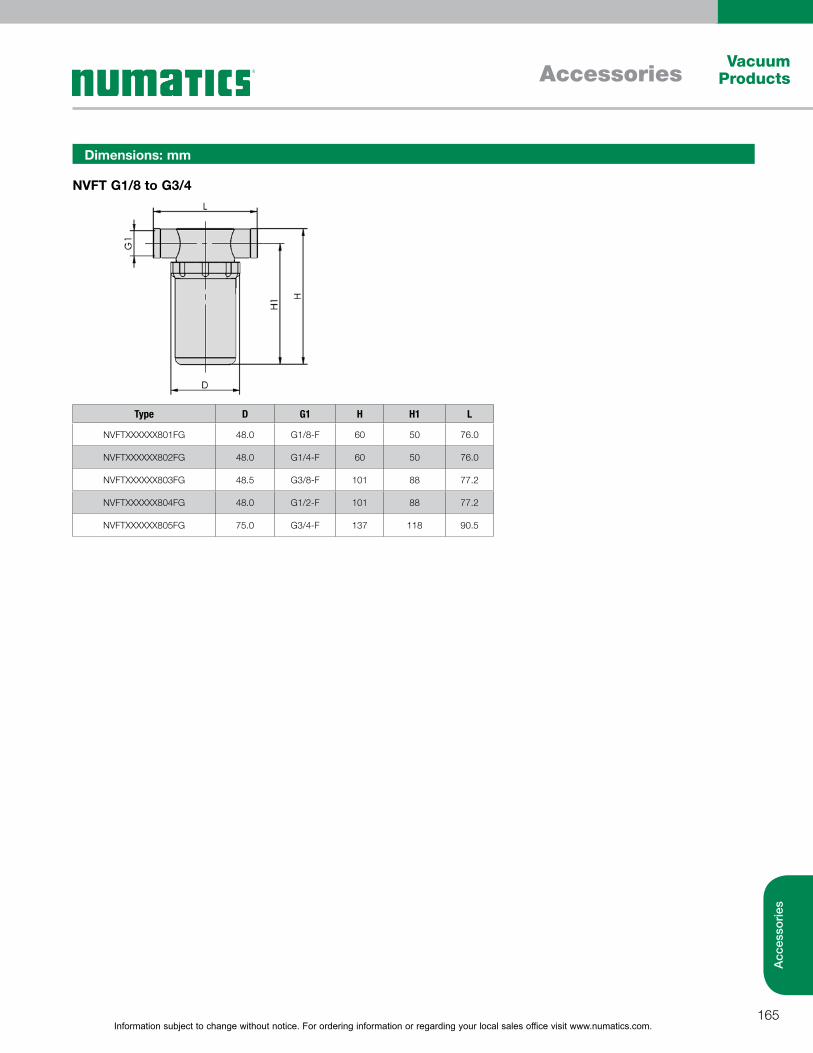
Information subject to change without notice. For ordering information or regarding your local sales office visit www.numatics.com.165
AccessoriesVacuum
Products
Acc
esso
ries
Dimensions: mm
NVFT G1/8 to G3/4
Type D G1 H H1 L
NVFTXXXXXX801FG 48.0 G1/8-F 60 50 76.0
NVFTXXXXXX802FG 48.0 G1/4-F 60 50 76.0
NVFTXXXXXX803FG 48.5 G3/8-F 101 88 77.2
NVFTXXXXXX804FG 48.0 G1/2-F 101 88 77.2
NVFTXXXXXX805FG 75.0 G3/4-F 137 118 90.5
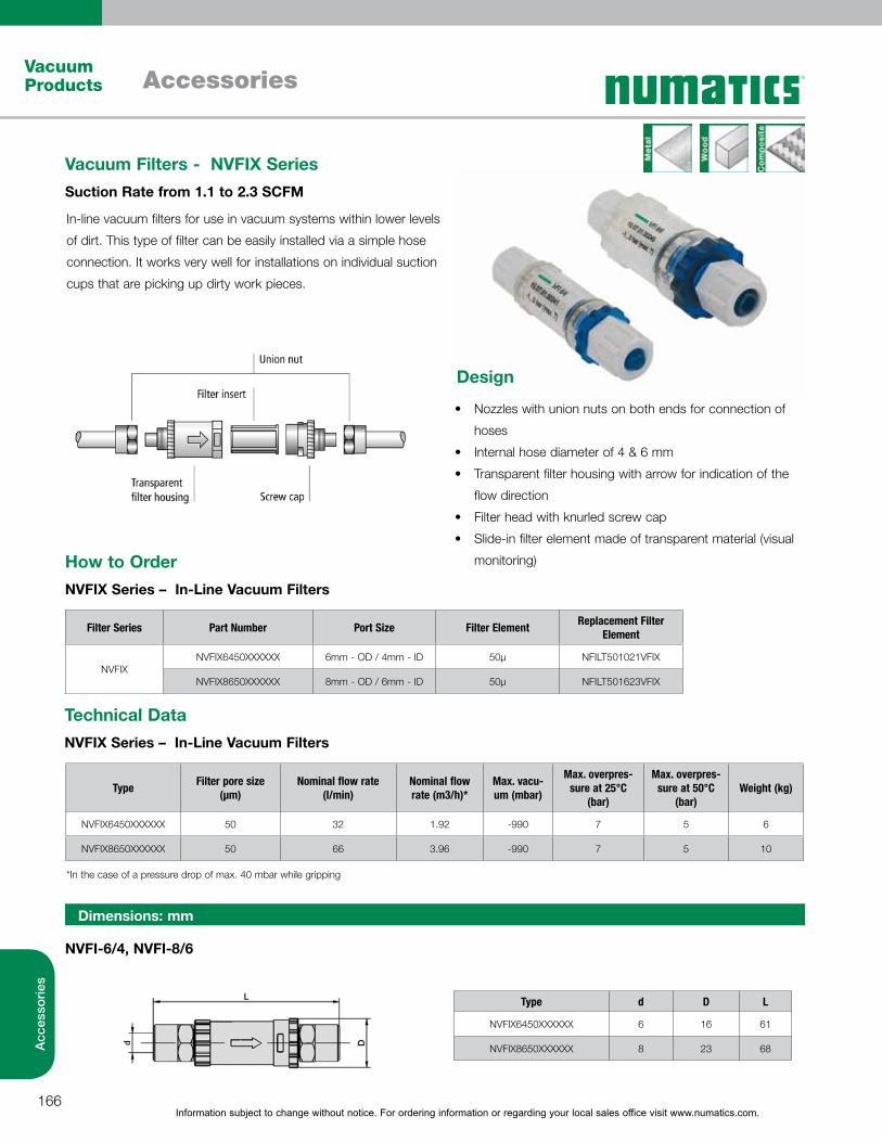
Information subject to change without notice. For ordering information or regarding your local sales office visit www.numatics.com.166
AccessoriesVacuum Products
Acc
esso
ries
Nozzles with union nuts on both ends for connection of
hoses
Internal hose diameter of 4 & 6 mm
Transparent filter housing with arrow for indication of the
flow direction
Filter head with knurled screw cap
Slide-in filter element made of transparent material (visual
monitoring)
Design
How to OrderNVFIX Series – In-Line Vacuum Filters
Filter Series Part Number Port Size Filter Element Replacement Filter Element
NVFIXNVFIX6450XXXXXX 6mm - OD / 4mm - ID 50µ NFILT501021VFIX
NVFIX8650XXXXXX 8mm - OD / 6mm - ID 50µ NFILT501623VFIX
Technical DataNVFIX Series – In-Line Vacuum Filters
Type Filter pore size (µm)
Nominal flow rate (l/min)
Nominal flow rate (m3/h)*
Max. vacu-um (mbar)
Max. overpres-sure at 25°C
(bar)
Max. overpres-sure at 50°C
(bar)Weight (kg)
NVFIX6450XXXXXX 50 32 1.92 -990 7 5 6
NVFIX8650XXXXXX 50 66 3.96 -990 7 5 10
*In the case of a pressure drop of max. 40 mbar while gripping
Vacuum Filters - NVFIX SeriesSuction Rate from 1.1 to 2.3 SCFM
In-line vacuum filters for use in vacuum systems within lower levels
of dirt. This type of filter can be easily installed via a simple hose
connection. It works very well for installations on individual suction
cups that are picking up dirty work pieces.
Dimensions: mm
NVFI-6/4, NVFI-8/6
Type d D L
NVFIX6450XXXXXX 6 16 61
NVFIX8650XXXXXX 8 23 68
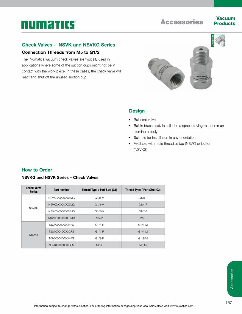
Information subject to change without notice. For ordering information or regarding your local sales office visit www.numatics.com.167
AccessoriesVacuum
Products
Acc
esso
ries
Check Valves - NSVK and NSVKG Series Connection Threads from M5 to G1/2
Check Valve Series Part number Thread Type / Port Size (G1) Thread Type / Port Size (G2)
NSVKG
NSVKGXXXXXXX1MG G1/8-M G1/8-F
NSVKGXXXXXXX2MG G1/4-M G1/4-F
NSVKGXXXXXXX4MG G1/2-M G1/2-F
NSVKGXXXXXXXBMM M5-M M5-F
NSVKX
NSVKXXXXXXXX1FG G1/8-F G1/8-M
NSVKXXXXXXXX2FG G1/4-F G1/4-M
NSVKXXXXXXXX4FG G1/2-F G1/2-M
NSVKXXXXXXXXBFM M5-F M5-M
How to OrderNSVKG and NSVK Series – Check Valves
The Numatics vacuum check valves are typically used in
applications where some of the suction cups might not be in
contact with the work piece. In these cases, the check valve will
react and shut off the unused suction cup.
Ball seat valve
Ball in brass seat, installed in a space-saving manner in an
aluminum body
Suitable for installation in any orientation
Available with male thread at top (NSVK) or bottom
(NSVKG)
Design
Information subject to change without notice. For ordering information or regarding your local sales office visit www.numatics.com.168
AccessoriesVacuum Products
Acc
esso
ries
Holders - Mountings
Misc. Accessories
Accessories - How to OrderCable Connectors
Silencers
Accessories Part Number Description Accessory/Series
Cable Connectors
NASKBM8450PURGE Cable M8 4 5M PUR GE NSBPC, NSCPM, NSEAC, Switches-Sensors - Straight Connection
NASKBM8450PURWX Cable M8 4 5M PUR W NSBPC, NSCPM, NSEAC, Switches-Sensors -Right Angle Connection
NASKMIC1030PUGE Sol Conn StraFht-3M PUR GE NSBPC, NSCPM - Cable for solenoid valves
NASKBM1250PURGE Cable Connector - M12 5-Pole NSCPI
NASKBM1285000XX Cable M12 8 Pole 5M NSXMP
Accessories Part Number Description Accessory/Series
Silencers
NSDXXXXXXX24BMM Repl. Silencer NSBP EJT 05 NSBP, NSBPC, NSEG
NSDXXXXXXX401MG Repl. Silencer NSBP EJT 07/10 NSBP, NSBPC, NSEG
NSDXXXXXXX763MG Repl. Silencer NSBP EJT 20/25 NSBP, NSBPC,
NSD249720SCPMXX SCPM Repl Silencer 05-07-10 NSCPM
NFILT217145161X SCPM Filter Element 05-07-10 NSCPM
Accessories Part Number Description Accessory/Series
Misc. Ejector Accessories
NFILT217145161X Filter Element NSCPM 05-07-10 NSCPM
NWARSETSCPISMPI Maintenance Kit - NSCPI NSCPI
Accessories Part Number Description Accessory/Series
Vacuum Switches-Sensors
NADAPVS61316XXX 6mm Plug-in tube Connection Adapter
NADAPVSX1316BMM M5-M Connection Adapter
Accessories Part Number Description Accessory/Series
Holders - Mountings
NBEPL1111453SBP Mtg Plate NSBP EJT NSBP, NSBPC,
NSETSBPX0056CFN Mtg. Set NSBP/NSBPC M4F NSBP, NSBPC,
NADPEJ4552144SL Holder SEAC/RP/ECO Top Auto NSEAC
NADPEJ4552144SS Holder SEAC/RP/ECO Side Auto NSEAC
NHTSA2EG18G5XXX Holder Pads/SPRGPLGR Axial Auto NSEAC
NHTSA3EG18G5XXX Holder Pads/SPRGPLGR Ball Auto NSEAC
NHTRFI2SWIV1812 Replacements Holder for Filter NVFT
NHTRFI2SWIV1813 Replacements Holder for Filter NVFT
NHTRFI2SWIV1814 Replacements Holder for Filter NVFT
NHTRFI2SWIV1815 Replacements Holder for Filter NVFT
NHTRFI2SWIV34XX Replacements Holder for Filter NVFT
NHTSA2SGM3040XX Holder systems for NSGM Series NSGMXXXX30XG1FG, NSGMXXXX40XG2FG
NHTSA2SGM5070XX Holder systems for NSGM Series NSGMXXXX50XG2FG, NSGMXXXX70XG2FG
NGPQ1122461STNB Single base plate-quick change NSXMP
NGPQ2122872STNB Double base plate-quick change NSXMP

World Class Supplier of Pneumatic Components
World Headquarters
Numatics, Inc. | Tel (248) 596.3200 | www.numatics.com | email: [email protected] Rev 04/13 10M-IPC/Walsworth-3/12© Numatics Inc. 2012-2013 Numatics® is registered in the United States and elsewhere
USA Numatics, Incorporated46280 Dylan DriveNovi, Michigan 48377
P: 248-596-3200 F: 248-596-3201
Canada Numatics, LtdP: 519-758-2700 F: 519-758-5540
Brazil Ascoval Ind.e Comercio LtdaP: (55) 11-4208-1700 F: (55) 11-4195-3970
México - Ascomatica SA de CVP: 52 55 58 09 56 40 (DF y Area metropolitana)P: 01 800 000 ASCO (2726) (Interior de la República) F: 52 55 58 09 56 60