Vacuum Control Catalog 2009 - MSH T · PDF fileVacuum Control Catalog 2009 - i Contents Vacuum...
219
Vacuum Control Catalog 2005 - 2006 VACUUM GAUGES, VALVES, FITTINGS AND FEEDTHROUGHS
Transcript of Vacuum Control Catalog 2009 - MSH T · PDF fileVacuum Control Catalog 2009 - i Contents Vacuum...

Vacuum ControlCatalog 2005 - 2006
Vacuum GauGes, ValVes, FittinGs and FeedthrouGhs

Vacuum Control Catalog 2009 - i
Vacuum Control CatalogContents
Table of Contents
VACUUM GAUGESSKY® Capacitance Diaphragm Gauge
CDG025D, CDG025D-S . . . . . . . . . . . . . . . . . . . . . . . . . . . . . . . . . . . . . . . . . . . . A1
CDG045 . . . . . . . . . . . . . . . . . . . . . . . . . . . . . . . . . . . . . . . . . . . . . . . . . . . . . . . . A5
CDG100D . . . . . . . . . . . . . . . . . . . . . . . . . . . . . . . . . . . . . . . . . . . . . . . . . . . . . A10
CDG160D, CDG200D . . . . . . . . . . . . . . . . . . . . . . . . . . . . . . . . . . . . . . . . . . . . A15
AllCeramic™ CDG025-C . . . . . . . . . . . . . . . . . . . . . . . . . . . . . . . . . . . . . . . . . . A20
AllCeramic™ CDG160A-C / CDG160A-CS . . . . . . . . . . . . . . . . . . . . . . . . . . . . A22
Bayard-Alpert Pirani Gauge
BPG400 . . . . . . . . . . . . . . . . . . . . . . . . . . . . . . . . . . . . . . . . . . . . . . . . . . . . . . . A25
BPG402-S . . . . . . . . . . . . . . . . . . . . . . . . . . . . . . . . . . . . . . . . . . . . . . . . . . . . . A29
High Pressure Hot Ionization Pirani Gauge
HPG400 . . . . . . . . . . . . . . . . . . . . . . . . . . . . . . . . . . . . . . . . . . . . . . . . . . . . . . . A33
Bayard-Alpert Pirani Capacitance Diaphragm Gauge
TripleGauge® BCG450 . . . . . . . . . . . . . . . . . . . . . . . . . . . . . . . . . . . . . . . . . . . . A37
Pirani Standard Gauge
PSG050 / PSG051 . . . . . . . . . . . . . . . . . . . . . . . . . . . . . . . . . . . . . . . . . . . . . . . A42
PSG100-S, PSG101-S . . . . . . . . . . . . . . . . . . . . . . . . . . . . . . . . . . . . . . . . . . . . A44
PSG500/-S, PSG502-S, PSG510-S, PSG512-S . . . . . . . . . . . . . . . . . . . . . . . . A47
Pirani Capacitance Diaphragm Gauge
PCG400, PCG410 . . . . . . . . . . . . . . . . . . . . . . . . . . . . . . . . . . . . . . . . . . . . . . . A51
Penning Gauge
PEG100 . . . . . . . . . . . . . . . . . . . . . . . . . . . . . . . . . . . . . . . . . . . . . . . . . . . . . . . A54
Inverted Magnetron Pirani Gauge
MPG400/401 . . . . . . . . . . . . . . . . . . . . . . . . . . . . . . . . . . . . . . . . . . . . . . . . . . . A57
Vacuum Gauge Controllers
VGC401, VGC402, VGC403 . . . . . . . . . . . . . . . . . . . . . . . . . . . . . . . . . . . . . . . . A60
Vacuum Switch
VSA100A . . . . . . . . . . . . . . . . . . . . . . . . . . . . . . . . . . . . . . . . . . . . . . . . . . . . . . . A62
VSC150A . . . . . . . . . . . . . . . . . . . . . . . . . . . . . . . . . . . . . . . . . . . . . . . . . . . . . . A64
Calibration Service
Vacuum Gauges . . . . . . . . . . . . . . . . . . . . . . . . . . . . . . . . . . . . . . . . . . . . . . . . . A68

Vacuum Control Catalog Contents
Vacuum Control Catalog 2009 - ii
VACUUM FEEdthroUGhSRotary Feedthroughs ISO-KF / ISO-K
FRH DN 16 - DN 63 . . . . . . . . . . . . . . . . . . . . . . . . . . . . . . . . . . . . . . . . . . . . . . . B1
Rotary Feedthroughs CF
FRU DN 16 - DN 40 . . . . . . . . . . . . . . . . . . . . . . . . . . . . . . . . . . . . . . . . . . . . . . . B3
Rotary/Linear Motion Feedthroughs ISO-KF
FCH DN 16 - DN 40 . . . . . . . . . . . . . . . . . . . . . . . . . . . . . . . . . . . . . . . . . . . . . . . B5
Linear Motion Feedthroughs CF
FPU DN 16 - DN 40 . . . . . . . . . . . . . . . . . . . . . . . . . . . . . . . . . . . . . . . . . . . . . . . B7
Electrical Feedthroughs
DN 16 ISO-KF . . . . . . . . . . . . . . . . . . . . . . . . . . . . . . . . . . . . . . . . . . . . . . . . . . . . B9
DN 40 ISO KF . . . . . . . . . . . . . . . . . . . . . . . . . . . . . . . . . . . . . . . . . . . . . . . . . . . B11
DN 16 CF . . . . . . . . . . . . . . . . . . . . . . . . . . . . . . . . . . . . . . . . . . . . . . . . . . . . . . B13
DN 40 CF . . . . . . . . . . . . . . . . . . . . . . . . . . . . . . . . . . . . . . . . . . . . . . . . . . . . . . B15
DN 40 ISO KF . . . . . . . . . . . . . . . . . . . . . . . . . . . . . . . . . . . . . . . . . . . . . . . . . . . B17
Coaxial Feedthroughs ISO-KF / CF-F
BNC / MHV DN 16 - 40 . . . . . . . . . . . . . . . . . . . . . . . . . . . . . . . . . . . . . . . . . . . B19
Vacuum Feedthroughs
METAL-CERAMIC CONNECTIONS . . . . . . . . . . . . . . . . . . . . . . . . . . . . . . . . . . B21
Liquid Feedthroughs ISO-KF / CF-F
DN 40 . . . . . . . . . . . . . . . . . . . . . . . . . . . . . . . . . . . . . . . . . . . . . . . . . . . . . . . . . B23
Viewports
DN 25 - DN 50 ISO-KF . . . . . . . . . . . . . . . . . . . . . . . . . . . . . . . . . . . . . . . . . . . . B25
DN 63 - DN 160 ISO-K . . . . . . . . . . . . . . . . . . . . . . . . . . . . . . . . . . . . . . . . . . . . B27
DN 16 - DN 160 CF . . . . . . . . . . . . . . . . . . . . . . . . . . . . . . . . . . . . . . . . . . . . . . B29
DN 63 - DN 160 ISO-F . . . . . . . . . . . . . . . . . . . . . . . . . . . . . . . . . . . . . . . . . . . . B31
Vacuum Feedthroughs
VACUUM BALL BEARINGS . . . . . . . . . . . . . . . . . . . . . . . . . . . . . . . . . . . . . . . . B33
LUBRICANTS AND SEALING MATERIALS . . . . . . . . . . . . . . . . . . . . . . . . . . . . B35

Vacuum Control Catalog 2009 - iii
Vacuum Control CatalogContents
VACUUM VALVESAngle and Inline Valves ( VAH, VAP, VAM, VIM)
ISO-KF DN 5 manually, pneumatically, solenoid . . . . . . . . . . . . . . . . . . . . . . . . . C1
Angle and Inline Valves ( VAH, VIH, VAP, VIP)
ISO-KF DN16 - 40 manually . . . . . . . . . . . . . . . . . . . . . . . . . . . . . . . . . . . . . . . . . C4
ISO-KF DN16 - 40 manually (Diaphragm Valves) . . . . . . . . . . . . . . . . . . . . . . . . . C8
ISO-KF DN16 - 40 pneumatically . . . . . . . . . . . . . . . . . . . . . . . . . . . . . . . . . . . C10
ISO-KF DN16 - 40 solenoid (VAP, VIP) . . . . . . . . . . . . . . . . . . . . . . . . . . . . . . . C14
ISO-KF DN16 - 40 solenoid (VAM) . . . . . . . . . . . . . . . . . . . . . . . . . . . . . . . . . . . C18
ISO-KF DN63 manually, pneumatically . . . . . . . . . . . . . . . . . . . . . . . . . . . . . . . C21
ISO-KF DN100 manually, pneumatically . . . . . . . . . . . . . . . . . . . . . . . . . . . . . . C24
ISO-KF DN160 pneumatically . . . . . . . . . . . . . . . . . . . . . . . . . . . . . . . . . . . . . . C27
Butterfly Valves (VBH, VBP)
ISO-KF DN63 - 160 manually . . . . . . . . . . . . . . . . . . . . . . . . . . . . . . . . . . . . . . C29
ISO-KF DN63 - 250 pneumatically . . . . . . . . . . . . . . . . . . . . . . . . . . . . . . . . . . C31
Dosing Valves (VDH)
ISO-KF DN10 manually (coarse gas dosing) . . . . . . . . . . . . . . . . . . . . . . . . . . C37
ISO-KF DN16 manually (fine gas dosing / shut-off) . . . . . . . . . . . . . . . . . . . . . C38
Dosing Systems (VDM, VDE, VCE, VCC, VCA)
All-Metal Dosing Valves and System . . . . . . . . . . . . . . . . . . . . . . . . . . . . . . . . . C40
Gas Dosing Systems . . . . . . . . . . . . . . . . . . . . . . . . . . . . . . . . . . . . . . . . . . . . . C43
Solenoid Control Valves . . . . . . . . . . . . . . . . . . . . . . . . . . . . . . . . . . . . . . . . . . . C44
All-Metal Angle Valves (VAH)
CF-R DN16 - 63 manually . . . . . . . . . . . . . . . . . . . . . . . . . . . . . . . . . . . . . . . . . C50
Venting Valves (VVH, VVM, VIN)
ISO-KF DN10 manually . . . . . . . . . . . . . . . . . . . . . . . . . . . . . . . . . . . . . . . . . . . C52
ISO-KF DN10 solenoid . . . . . . . . . . . . . . . . . . . . . . . . . . . . . . . . . . . . . . . . . . . . C53
ISO-KF DN10 solenoid (power failure) . . . . . . . . . . . . . . . . . . . . . . . . . . . . . . . . C55
Safety Valves (VSM)
ISO-KF DN16 - 40 . . . . . . . . . . . . . . . . . . . . . . . . . . . . . . . . . . . . . . . . . . . . . . . C56
ISO-KF DN63 - 100 . . . . . . . . . . . . . . . . . . . . . . . . . . . . . . . . . . . . . . . . . . . . . . C56
Pressure Relief Valve (VSA)
ISO-KF DN16 . . . . . . . . . . . . . . . . . . . . . . . . . . . . . . . . . . . . . . . . . . . . . . . . . . . C58
Ball Valves
ISO-KF DN10 - 40 . . . . . . . . . . . . . . . . . . . . . . . . . . . . . . . . . . . . . . . . . . . . . . . C59

Vacuum Control Catalog Contents
Vacuum Control Catalog 2009 - iv
VACUUM FIttINGSISO-KF Small Flange Components
CONNECTION ELEMENTS . . . . . . . . . . . . . . . . . . . . . . . . . . . . . . . . . . . . . . . . . D1
SEALS . . . . . . . . . . . . . . . . . . . . . . . . . . . . . . . . . . . . . . . . . . . . . . . . . . . . . . . . . . D3
FLANGES . . . . . . . . . . . . . . . . . . . . . . . . . . . . . . . . . . . . . . . . . . . . . . . . . . . . . . . D6
PIPE FITTINGS . . . . . . . . . . . . . . . . . . . . . . . . . . . . . . . . . . . . . . . . . . . . . . . . . . . D7
BELLOWS/HOSE WITH FLANGES . . . . . . . . . . . . . . . . . . . . . . . . . . . . . . . . . . . D9
TRANSITION PIECES . . . . . . . . . . . . . . . . . . . . . . . . . . . . . . . . . . . . . . . . . . . . . D11
HOSE, HOSE CONNECTION . . . . . . . . . . . . . . . . . . . . . . . . . . . . . . . . . . . . . . . D14
ISO-K Clamp Flange Components
CONNECTION ELEMENTS . . . . . . . . . . . . . . . . . . . . . . . . . . . . . . . . . . . . . . . . D16
SEALS . . . . . . . . . . . . . . . . . . . . . . . . . . . . . . . . . . . . . . . . . . . . . . . . . . . . . . . . . D17
FLANGES . . . . . . . . . . . . . . . . . . . . . . . . . . . . . . . . . . . . . . . . . . . . . . . . . . . . . . D20
PIPE FITTINGS . . . . . . . . . . . . . . . . . . . . . . . . . . . . . . . . . . . . . . . . . . . . . . . . . . D22
BELLOWS / HOSE WITH FLANGES . . . . . . . . . . . . . . . . . . . . . . . . . . . . . . . . . D24
TRANSITION PIECES . . . . . . . . . . . . . . . . . . . . . . . . . . . . . . . . . . . . . . . . . . . . . D25
PROTECTIVE LIDS . . . . . . . . . . . . . . . . . . . . . . . . . . . . . . . . . . . . . . . . . . . . . . . D26
ISO-F Fixed Flange Components
FLANGE COMPONENTS . . . . . . . . . . . . . . . . . . . . . . . . . . . . . . . . . . . . . . . . . . D27
UHV CF Components
CONNECTION ELEMENTS . . . . . . . . . . . . . . . . . . . . . . . . . . . . . . . . . . . . . . . . D29
SEALS . . . . . . . . . . . . . . . . . . . . . . . . . . . . . . . . . . . . . . . . . . . . . . . . . . . . . . . . . D30
FLANGES . . . . . . . . . . . . . . . . . . . . . . . . . . . . . . . . . . . . . . . . . . . . . . . . . . . . . . D32
PIPE FITTINGS . . . . . . . . . . . . . . . . . . . . . . . . . . . . . . . . . . . . . . . . . . . . . . . . . . D36
BELLOWS / HOSE WITH FLANGES, COMPENSATOR . . . . . . . . . . . . . . . . . . . D38
TRANSITION PIECES . . . . . . . . . . . . . . . . . . . . . . . . . . . . . . . . . . . . . . . . . . . . . D39
PROTECTIVE LIDS . . . . . . . . . . . . . . . . . . . . . . . . . . . . . . . . . . . . . . . . . . . . . . . D40
Website

Vacuum Gauges

Vacuum Feedthroughs Contents
Vacuum Control Catalog 2009 - Aii
VACUUM GAUGES
SKY® Capacitance Diaphragm Gauge
CDG025D, CDG025D-S . . . . . . . . . . . . . . . . . . . . . . . . . . . . . . . . . . . . . . . . . . . . A1
CDG045 . . . . . . . . . . . . . . . . . . . . . . . . . . . . . . . . . . . . . . . . . . . . . . . . . . . . . . . . A5
CDG100D . . . . . . . . . . . . . . . . . . . . . . . . . . . . . . . . . . . . . . . . . . . . . . . . . . . . . A10
CDG160D, CDG200D . . . . . . . . . . . . . . . . . . . . . . . . . . . . . . . . . . . . . . . . . . . . A15
AllCeramic™ CDG025-C . . . . . . . . . . . . . . . . . . . . . . . . . . . . . . . . . . . . . . . . . . A20
AllCeramic™ CDG160A-C / CDG160A-CS . . . . . . . . . . . . . . . . . . . . . . . . . . . . A22
Bayard-Alpert Pirani Gauge
BPG400 . . . . . . . . . . . . . . . . . . . . . . . . . . . . . . . . . . . . . . . . . . . . . . . . . . . . . . . A25
BPG402-S . . . . . . . . . . . . . . . . . . . . . . . . . . . . . . . . . . . . . . . . . . . . . . . . . . . . . A29
High Pressure Hot Ionization Pirani Gauge
HPG400 . . . . . . . . . . . . . . . . . . . . . . . . . . . . . . . . . . . . . . . . . . . . . . . . . . . . . . . A33
Bayard-Alpert Pirani Capacitance Diaphragm Gauge
TripleGauge® BCG450 . . . . . . . . . . . . . . . . . . . . . . . . . . . . . . . . . . . . . . . . . . . . A37
Pirani Standard Gauge
PSG050 / PSG051 . . . . . . . . . . . . . . . . . . . . . . . . . . . . . . . . . . . . . . . . . . . . . . . A42
PSG100-S, PSG101-S . . . . . . . . . . . . . . . . . . . . . . . . . . . . . . . . . . . . . . . . . . . . A44
PSG500/-S, PSG502-S, PSG510-S, PSG512-S . . . . . . . . . . . . . . . . . . . . . . . . A47
Pirani Capacitance Diaphragm Gauge
PCG400, PCG410 . . . . . . . . . . . . . . . . . . . . . . . . . . . . . . . . . . . . . . . . . . . . . . . A51
Penning Gauge
PEG100 . . . . . . . . . . . . . . . . . . . . . . . . . . . . . . . . . . . . . . . . . . . . . . . . . . . . . . . A54
Inverted Magnetron Pirani Gauge
MPG400/401 . . . . . . . . . . . . . . . . . . . . . . . . . . . . . . . . . . . . . . . . . . . . . . . . . . . A57
Vacuum Gauge Controllers
VGC401, VGC402, VGC403 . . . . . . . . . . . . . . . . . . . . . . . . . . . . . . . . . . . . . . . . A60
Vacuum Switch
VSA100A . . . . . . . . . . . . . . . . . . . . . . . . . . . . . . . . . . . . . . . . . . . . . . . . . . . . . . . A62
VSC150A . . . . . . . . . . . . . . . . . . . . . . . . . . . . . . . . . . . . . . . . . . . . . . . . . . . . . . A64
Calibration Service
Vacuum Gauges . . . . . . . . . . . . . . . . . . . . . . . . . . . . . . . . . . . . . . . . . . . . . . . . . A68

Vacuum GaugesSKY® Capacitance Diaphragm Gauge
Vacuum Gauges Catalog 2009 - A1
■ Semiconductor manufacturing equipment for Etch, CVD, PVD, ALD
■ Data storage and display manufacturing equipment
■ Industrial vacuum equipment
■ General high accuracy pressure measurement
Applications
The INFICON SKY CDG025D Capacitance Diaphragm Gauge line of highly accurate temperature compensated manometers is designed for stable performance in harsh manufacturing tool environments. Advanced digital electronics improve gauge performance and offer easy handling features such as one pushbutton zero function and setpoint adjustment. The corrosion resistant ultra pure ceramic sensor provides excellent zero stability with a long life expectancy of several million pressure cycles, including atmospheric bursts. A unique sensor shielding (patent pending) protects the gauge from process contamination. A robust mechanical design and digital electronics improve EMC compatibility, long term stability and temperature compensation. The CDG025D sets new standards for fast stability after power on and fast recovery from atmospheric pressure exposure.
Advantages
CDG025D, CDG025D-S
SKY® Capacitance diaphragm Gauge
■ Full scale ranges from 100 mTorr … 1000 Torr
■ Fast stability after power on
■ Fast recovery from atmospheric pressure
■ Corrosion resistant ceramic sensor
■ Excellent long term signal stability
■ Temperature compensated
■ Sensor protected from contamination
■ One pushbutton zero function
■ Wide range power supply
■ 2 setpoints (optional)
■ RS232 interface (optional)

Vacuum Gauges SKY® Capacitance Diaphragm Gauge
Vacuum Gauges Catalog 2009 - A2
Ordering Information
CDG025D, CDG025D-S (continued)
CDG025D, temperature compensated Full Scale Range Flange type Torr Pascal mbar 1/2” tube DN 16 ISO-KF DN 16 CF-R 8 VCR®
1000 133,322 1333 375-000 375-001 375-002 375-003
100 13,332 133 376-000 376-001 376-002 376-003
10 1,333 13.3 377-000 377-001 377-002 377-003
1 133 1.3 378-000 378-001 378-002 378-003
0.1 13.3 0.13 379-000 379-001 379-002 379-003
Other flange types and full scale ranges on request.
CDG025D, with 2 setpoints and RS232 interface, temperature compensated Full Scale Range Flange type Torr Pascal mbar 1/2” tube DN 16 ISO-KF DN 16 CF-R 8 VCR®
1000 133,322 1333 375-300 375-301 375-302 375-303
– 110,000 1,100 375-500 375-501 375-502 375-503
200 26,664 267 382-300 382-301 382-302 382-303
100 13,332 133 376-300 376-301 376-302 376-303
– 10,000 100 376-500 376-501 376-502 376-503
20 2,666 26.7 383-300 383-301 383-302 383-303
10 1,333 13.3 377-300 377-301 377-302 377-303
– 1,000 10 377-500 377-501 377-502 377-503
1 133 1.3 378-300 378-301 378-302 378-303
– 100 1 378-500 378-501 378-502 378-503
0.25 33.3 0.33 385-300 385-301 385-302 385-303
0.1 13.3 0.13 379-300 379-301 379-302 379-303
– 10 0.1 379-500 379-501 379-502 379-503
bold = standard products

Vacuum GaugesSKY® Capacitance Diaphragm Gauge
Vacuum Gauges Catalog 2009 - A3
Specifications (other ranges)
Specifications (standard products)
CDG025D, CDG025D-S (continued)
Measurement Range Torr 1000 100 10 1 0.1 F.S. (Full Scale) Pa 133,322 13,332 1,333 133 13 mbar 1333 133 13.3 1.3 0.13Accuracy1) % of reading 0.2 0.2 0.2 0.2 0.5
Temperature effect on zero % F.S./°C 0.005 0.005 0.005 0.015 0.02 on span % of reading/°C 0.01 0.01 0.01 0.01 0.03
Resolution % F.S. 0.003 0.003 0.003 0.003 0.003
Pressure, max. kPa (absolute) 400 260 260 260 130
Lowest reading % F.S. 0.01
Lowest suggested reading % F.S. 0.05
Lowest suggested control pressure % F.S. 0.5
Temperature Operation (ambient) °C +5 ... +50 Bakeout (at flange)2) °C ≤110 Storage °C –40 ... +65
Supply voltage VDC 14 ... 30
Power consumption W ≤1
Output signal (analog) VDC 0 ... +10
Response time ms 30 130
Degree of protection IP 30
Standards EN 61000-6-2, EN 61000-6-3, EN 61010, UL 61010-1, CSA 22.2 No.61010-1, RoHS
Electrical connection D-sub, 15 pole, male
Setpoint3) two setpoints (SP1, SP2) Relay contact VDC / ADC 30 / ≤0.5 Hysteresis % F.S. 1
Materials exposed to vacuum Aluminum oxide ceramic (AI2O3), Vacon 704), stainless steel (AISI 316L5)), AgCuTi hard solder, sealing glass
1) Non-linearity, hysteresis, repeatability at 25°C ambient operating temperature without temperature effects after 2 hours operation. 2) Non-Operation. 3) CDG025D-S only. 4) 28% Ni, 23% Co, 49% Fe 5) 18% Cr, 10% Ni, 3% Mo, 69% Fe
Measurement Range Torr – 200 – 20 – – 0.25 – F.S. (Full Scale) Pa 110,000 26,664 10,000 2,666 1,000 100 33.3 10 mbar 1000 267 100 26.7 10 1 0.33 0.1Accuracy1) % of reading 0.2 0.2 0.2 0.2 0.2 0.2 0.25 0.5
Temperature effect on zero % F.S./°C 0.005 0.005 0.005 0.005 0.005 0.015 0.02 0.02 on span % of reading/°C 0.01 0.01 0.01 0.01 0.01 0.01 0.03 0.03
Resolution % F.S. 0.003 0.003 0.003 0.003 0.003 0.003 0.003 0.003
Pressure, max. kPa (absolute) 400 260 260 260 260 260 130 130
For further specifications, see table above.

Vacuum Gauges SKY® Capacitance Diaphragm Gauge
Vacuum Gauges Catalog 2009 - A4
Dimensions, Internal Volume, Weight
CDG025D, CDG025D-S (continued)
8 VCR�
DN 16 ISO-KF�
55 �(2.17)�
116.
8�(4
.60)
�
DN 16 CF-R�OD ½" tube�
RUN� ZERO�
1� 2� SP�
�
69�
(2.7
2)�
18�
(0.7
1)�
26�
(1.0
2)�
3.8�
(0.1
5)�
33.8
�(1
.33)
�
113�
(4.4
5)�
mm (inch)
1/2” tube DN 16 ISO KF DN 16 CF-R 8 VCR®
Internal volume cm3 (inch3) 3.6 ( 0.22) 3.6 ( 0.22) 3.6 ( 0.22) 3.6 ( 0.22)
Weight g 260 270 280 290
TIBA33E1-D

Vacuum GaugesSKY® Capacitance Diaphragm Gauge
Vacuum Control Catalog 2009 - A5
CDG045D
SKY® Capacitance diaphragm Gauge
INFICON SKY CDG045D manometers are your best choice for highly accurate total pressure measurement and control. CDG045D gauges are temperature controlled at 45°C for superior signal stability and repeatability. They are available for full scale ranges from 100 mTorr to 1000 Torr, with all common flange types and fieldbus interfaces and provide a linear 0 to 10 V, gas type independent, pressure signal. INFICON capacitance manometers use a corrosion proof ultra pure alumina ceramic diaphragm. The advantages of the ceramic sensor are better signal stability, faster recovery from atmosphere, short warm up time and an extraordinary lifetime. INFICON CDG are high quality, cost effective pressure sensors for demanding vacuum applications.
Advantages
■ Lower CoO (cost of ownership), 50% faster warm up, energy efficient low power consumption
■ Easy integration, wide variety of full scales, flanges and interfaces, standard with two set points
■ Easy one push button or remote signal zero command, zero offset adjustable
■ Diagnostic port for quick service and maintenance
■ Two year warranty, longer lifetime with advanced heating concept and gauge protection
■ No long term recalibration due to excellent signal stability and repeatability, even in harsh plasma applications
■ Compliance & standards: CE, EN, UL, SEMI, RoHS
Applications
■ Etch, CVD, PVD and other semiconductor production processes
■ Chemical and corrosive vacuum processes
■ General thin film and vacuum processes
■ Reference sensor for monitoring of test instruments according to international standards
■ Transfer standard for traceability measurements

Vacuum Gauges SKY® Capacitance Diaphragm Gauge
Vacuum Control Catalog 2009 - A6
Other flange types and full scale ranges (F.S.) on request.
Full Scale (F.S.)
Fieldbus interface
bold = standard products
3 C C 1 – 6 5 1 – 2 3 0 0
0 None 1 DeviceNet 2 Profibus
0.1 3 0.25 4 0.5 5 1 6 2 7 5 8 10 9 20 A 50 B 100 C 200 D 500 E (Torr only) 1000 F (mbar only) 1100 G
Flange
1 DN 16 ISO-KF 3 DN 16 CF-R 9 OD 1/2” tube E 8 VCR female
Unit
5 Torr (x 1.33 mbar; x 133 Pa) 6 mbar (x 100 Pa)
Ordering Information
CDG045 (continued)
Accessories
DiagnosticCommunication adapter (2 m) for PC RS232 serial port 303-333
Software to run the diagnostic functions on Windows NT, XP can be downloaded from our website.

Vacuum GaugesSKY® Capacitance Diaphragm Gauge
Vacuum Control Catalog 2009 - A7
Specifications (Torr based standard products)
CDG045 (continued)
Measurement Range Torr 1000 100 10 1 0.1 F.S. (Full Scale) Pa 133,322 13,332 1,333 133 13 mbar 1333 133 13.3 1.3 0.13Accuracy1) % of reading 0.15
Temperature effect on zero % F.S./°C 0.0025 0.005
on span % of reading/°C 0.01
Pressure, max. kPa (absolute) 400 260 130
Resolution % F.S. 0.003
Lowest reading % F.S. 0.01
Lowest suggested reading % F.S. 0.05
Lowest suggested control pressure % F.S. 0.5
Temperature Operation (ambient) °C +10 ... +40 Bakeout at flange °C ≤110 Storage °C –40 ... +65
Supply voltage +14 ... +30 VDC or ±15 V (±5%)
Power consumption During Heat up W ≤12 At operating temperature W ≤8
Output signal (analog) VDC 0 ... +10
Response time ms 30 130
Degree of protection IP 40
Standards EN 61000-6-2, EN 61010, UL 61010-1, CSA 22.2 No.61010-1, SEMI S-2
Electrical connection D-sub, 15 pole, male
Setpoint two setpoints (SP1, SP2) Relay contact VDC / ADC ≤30 / ≤0.5 Hysteresis % F.S. 1
Diagnostic port Protocol RS232-C Read pressure, status, ID, Set set points, filter, zero adjust, factory reset, DC offset
Materials exposed to vacuum Aluminum oxide ceramic (AI2O3), stainless steel (AISI 316L2)), Nickel, sealing glass
1) Non-linearity, hysteresis, repeatability at 25°C ambient operating temperature without temperature effects after 2 hours operation. 2) 18% Cr, 10% Ni, 3% Mo, 69% Fe

Vacuum Gauges SKY® Capacitance Diaphragm Gauge
Vacuum Control Catalog 2009 - A8
CDG045 (continued)
Specifications (Torr based other ranges)
Measurement Range Torr 500 200 50 20 5 2 0.5 0.25 F.S. (Full Scale) Pa 66,661 26,664 6,666.1 2,666 666.61 266.66 66.66 33.3 mbar 666.61 267 66.67 26.7 6.6661 2.67 0.67 0.33Accuracy1) % of reading 0.15
Temperature effect on zero % F.S./°C 0.0025 0.005
on span % of reading/°C 0.01
Pressure, max. kPa (absolute) 400 260 130
Resolution % F.S. 0.003
Further specifications see table above.
CDG045D DeviceNet™Protocol DeviceNet™, group 2 slave only
Data rate kBaud 125, 250, 500 by switch or network programmableCable length 125 kbps m (ft) 500 (1650) 250 kbps m (ft) 250 (825) 500 kbps m (ft) 100 (330)
MAC ID address 00 - 63 by switch or network programmable
Digital functions read pressure, status, ID set set points, filter, zero adjust, factory reset, DC offset
Specification DeviceNet™ ”Vacuum Gauge Device Profile” (ODVA)
Device type “VG” vacuum gauge
I / O slave messaging polling only
Supply voltage for gauge at D-sub connector +14 … +30 VDC or ±15 V / ≤12 WSupply voltage for DeviceNet transceiver at microstyle connector 24 V nom / <2 W (11 … 25 V)
Connector for DeviceNet™ microstyle, 5 pinConnector for CDG (analog output, supply voltage CDG, setpoints) D-sub, 15 pin, male
Specifications (DeviceNet™)
Specifications (mbar based products)
Measurement Range mbar 1100 100 10 1 0.1 F.S. (Full Scale) Pa 110,000 10,000 1,000 100 10Accuracy1) % of reading 0.15
Temperature effect on zero % F.S./°C 0.0025 0.005
on span % of reading/°C 0.01
Pressure, max. kPa (absolute) 400 260 130
Resolution % F.S. 0.003
Further specifications see tables «SPECIFICATIONS (Torr based standard products)» and «SPECIFICATIONS (Torr based other products)».

Vacuum GaugesSKY® Capacitance Diaphragm Gauge
Vacuum Control Catalog 2009 - A9
Dimensions
TIBA34E1
CDG045D Profibus DPBaud rates kBaud 9.6 / 19.2 / 93.75 / 187.5 / 500 MBaud 1.5 / 12Address address 00 - 125 by switch or network programmableDigital functions read pressure, status, ID set set points, filter, zero adjust, factory reset, DC offsetConnector for Profibus DP D-sub, 9 pin, femaleConnector for CDG (analog output, supply voltage, setpoints) D-sub, 15 pin, male
Specifications (Profibus DP)
SP1�
SP2�
STAT
US�
SP� ZERO�
DIAG�
NET�
SP1�
SP2�
STAT
US�
SP� ZERO�
DIAG�
5� P�2�1�
2� 4�6�P�
0�2� 4�
6�8�0�
8 VCR�
DN 16 ISO-KF�
82�(3.23)�
145.
7�(5
.74)
�
DN 16 CF-R�OD ½" tube�
SP1�
SP2�
STAT
US�
SP� ZERO�
DIAG�
43.2
�(1
.70)
�11
0.4�
(4.3
5)�
3.8�
(0.1
5)�
141.
9�(5
.59)
�
Profibus�DeviceNet�standard�
10.8
�(0
.41)
�16
.5�
(0.6
5)�
17.9
�(0
.70)
�3.
8�(0
.15)
�
13�
(0.5
1)�
31.5
�(1
.24)
�
mm (inch)
CDG045 (continued)
1/2” tube DN 16 ISO KF DN 16 CF-R 8 VCR®
Internal volume cm3 (inch3) 4.2 ( 0.26) 4.2 ( 0.26) 4.2 ( 0.26) 4.2 ( 0.26)
Weight g 837 852 875 897

Vacuum Gauges SKY® Capacitance Diaphragm Gauge
Vacuum Control Catalog 2009 - A10
CDG100D
SKY® Capacitance diaphragm Gauges
Applications
■ Etch, PVD, CVD and other semiconductor production processes
■ Chemical and corrosive high temperature processes
■ General thin film and vacuum processes requiring gauge protection
Advantages
INFICON SKY CDG100D manometers are your best choice for accurate total pressure measurement and control. CDG100D gauges are temperature controlled at 100°C for superior performance in demanding semiconductor and plasma processes. They are available for full scale ranges from 100 mTorr to 1000 Torr, with all common flange types and fieldbus interfaces and provide a linear 0 to 10 V, gas type independent, pressure signal. INFICON capacitance manometers use an ultra pure alumina ceramic diaphragm which is corrosion proof. The advantages of the ceramic sensor are better signal stability, faster recovery from atmosphere, short warm up time and an extraordinary lifetime. INFICON CDG are high quality, cost effective pressure sensors for demanding semiconductor, plasma and vacuum applications.
■ Lower CoO (cost of ownership), 50% faster warm up, energy efficient low power consumption
■ Easy integration, wide variety of full scales, flanges and interfaces, standard with two set points
■ Easy one push button or remote signal zero command, zero offset adjustable
■ Diagnostic port for quick service and maintenance
■ Two year warranty, longer lifetime with advanced heating concept and gauge protection
■ No long term recalibration due to excellent signal stability and repeatability, even in harsh plasma applications
■ Compliance & standards: CE, EN, UL, SEMI, RoHS

Vacuum GaugesSKY® Capacitance Diaphragm Gauge
Vacuum Control Catalog 2009 - A11
Accessories
Ordering Information
CDG100D (continued)
Other flange types and full scale ranges (F.S.) on request.
Full Scale (F.S.)
Fieldbus interface
bold = standard products
3 C D 1 – 6 5 1 – 2 3 0 0
0 None 1 DeviceNet 2 Profibus
0.1 3 0.25 4 0.5 5 1 6 2 7 5 8 10 9 20 A 50 B 100 C 200 D 500 E (Torr only) 1000 F (mbar only) 1100 G
Flange
1 DN 16 ISO-KF 3 DN 16 CF-R 9 OD 1/2” tube E 8 VCR female
Unit
5 Torr (x 1.33 mbar; x 133 Pa) 6 mbar (x 100 Pa)
DiagnosticCommunication adapter (2 m) for PC RS232 serial port 303-333
Software to run the diagnostic functions on Windows NT, XP can be downloaded from our website.

Vacuum Gauges SKY® Capacitance Diaphragm Gauge
Vacuum Control Catalog 2009 - A12
Specifications (Torr based standard products)
CDG100D (continued)
Measurement Range Torr 1000 100 10 1 0.1 F.S. (Full Scale) Pa 133,322 13,332 1,333 133 13 mbar 1333 133 13.3 1.3 0.13Accuracy1) % of reading 0.2 0.4
Temperature effect on zero % F.S./°C 0.0025 0.005
on span % of reading/°C 0.02
Pressure, max. kPa (absolute) 400 260 130
Resolution % F.S. 0.003
Lowest reading % F.S. 0.01
Lowest suggested reading % F.S. 0.05
Lowest suggested control pressure % F.S. 0.5
Temperature Operation (ambient) °C +10 ... +50 Bakeout at flange °C ≤110 Storage °C –40 ... +65
Supply voltage +14 ... +30 VDC or ±15 V (±5%)
Power consumption During Heat up W ≤15 At operating temperature W ≤10
Output signal (analog) VDC 0 ... +10
Response time ms 30 130
Degree of protection IP 40
Standards EN 61000-6-2, EN 61010, UL 61010-1, CSA 22.2 No.61010-1, SEMI S-2
Electrical connection D-sub, 15 pole, male
Setpoint two setpoints (SP1, SP2) Relay contact VDC / ADC ≤30 / ≤0.5 Hysteresis % F.S. 1
Diagnostic port Protocol RS232-C Read pressure, status, ID, Set set points, filter, zero adjust, factory reset, DC offset
Materials exposed to vacuum Aluminum oxide ceramic (AI2O3), stainless steel (AISI 316L2)), Nickel, sealing glass
1) Non-linearity, hysteresis, repeatability at 25°C ambient operating temperature without temperature effects after 2 hours operation. 2) 18% Cr, 10% Ni, 3% Mo, 69% Fe
Measurement Range Torr 500 200 50 20 5 2 0.5 0.25 F.S. (Full Scale) Pa 66,661 26,664 6,666.1 2,666 666.61 266.66 66.66 33.3 mbar 666.61 267 66.67 26.7 6.6661 2.67 0.67 0.33Accuracy1) % of reading 0.2 0.4
Temperature effect on zero % F.S./°C 0.0025 0.005
on span % of reading/°C 0.02
Pressure, max. kPa (absolute) 400 260 130
Resolution % F.S. 0.003
Further specifications see table above.
Specifications (Torr based other ranges)

Vacuum GaugesSKY® Capacitance Diaphragm Gauge
Vacuum Control Catalog 2009 - A13
Specifications (Profibus DP)
Specifications (DeviceNet™)
Specifications (mbar based products)
CDG100D (continued)
CDG100D Profibus DPBaud rates kBaud 9.6 / 19.2 / 93.75 / 187.5 / 500 MBaud 1.5 / 12Address address 00 - 125 by switch or network programmableDigital functions read pressure, status, ID set set points, filter, zero adjust, factory reset, DC offsetConnector for Profibus DP D-sub, 9 pin, femaleConnector for CDG (analog output, supply voltage, setpoints) D-sub, 15 pin, male
CDG100D DeviceNet™Protocol DeviceNet™, group 2 slave only
Data rate kBaud 125, 250, 500 by switch or network programmableCable length 125 kbps m (ft) 500 (1650) 250 kbps m (ft) 250 (825) 500 kbps m (ft) 100 (330)
MAC ID address 00 - 63 by switch or network programmable
Digital functions read pressure, status, ID set set points, filter, zero adjust, factory reset, DC offset
Specification DeviceNet™ ”Vacuum Gauge Device Profile” (ODVA)
Device type “VG” vacuum gauge
I / O slave messaging polling only
Supply voltage for gauge at D-sub connector +14 … +30 VDC or ±15 V / ≤12 WSupply voltage for DeviceNet transceiver at microstyle connector 24 V nom / <2 W (11 … 25 V)
Connector for DeviceNet™ microstyle, 5 pinConnector for CDG (analog output, supply voltage CDG, setpoints) D-sub, 15 pin, male
Measurement Range mbar 1100 100 10 1 0.1 F.S. (Full Scale) Pa 110,000 10,000 1,000 100 10Accuracy1) % of reading 0.2 0.4
Temperature effect on zero % F.S./°C 0.0025 0.005
on span % of reading/°C 0.02
Pressure, max. kPa (absolute) 400 260 130
Resolution % F.S. 0.003
Further specifications see table «SPECIFICATIONS (Torr based standard products)».

Vacuum Gauges SKY® Capacitance Diaphragm Gauge
Vacuum Control Catalog 2009 - A14
Dimensions
CDG100D (continued)
SP1�
SP2�
STAT
US�
SP� ZERO�
DIAG�
NET�
SP1�
SP2�
STAT
US�
SP� ZERO�
DIAG�
5� P�2�1�
2� 4�6�P�
0�2� 4�
6�8�0�
8 VCR�
DN 16 ISO-KF�
82�(3.23)�
145.
7�(5
.74)
�
DN 16 CF-R�OD ½" tube�
SP1�
SP2�
STAT
US�
SP� ZERO�
DIAG�
43.2
�(1
.70)
�11
0.4�
(4.3
5)�
3.8�
(0.1
5)�
141.
9�(5
.59)
�
Profibus�DeviceNet�standard�
10.8
�(0
.41)
�16
.5�
(0.6
5)�
17.9
�(0
.70)
�3.
8�(0
.15)
�
13�
(0.5
1)�
31.5
�(1
.24)
�
mm (inch)
1/2” tube DN 16 ISO KF DN 16 CF-R 8 VCR®
Internal volume cm3 (inch3) 4.2 ( 0.26) 4.2 ( 0.26) 4.2 ( 0.26) 4.2 ( 0.26)
Weight g 837 852 875 897
TIBA35E1

Vacuum GaugesSKY® Capacitance Diaphragm Gauge
Vacuum Control Catalog 2009 - A15
CDG160D, CDG200D
SKY® Capacitance diaphragm Gauges
Applications
■ Etch, PVD, CVD, LPCVD and other semiconductor production processes
■ Chemical and corrosive high temperature processes
■ General thin film and vacuum processes requiring gauge protection
Advantages
INFICON SKY CDG160D and CDG200D high temperature manometers are your best choice for accurate total pressure measurement and control. CDG160D and CDG200D gauges are temperature controlled at 160°C respectivly 200°C for superior performance in demanding semiconductor and plasma processes. They are available for full scale ranges from 1 Torr to 1000 Torr, with all common flange types and fieldbus interfaces and provide a linear 0 to 10V, gas type independent, pressure signal. INFICON capacitance manometers use an ultra pure alumina ceramic diaphragm which is corrosion proof. The advantages of the ceramic sensor are better signal stability, faster recovery from atmosphere, short warm up time and an extraordinary lifetime. INFICON CDG are high quality, cost effective pressure sensors for demanding semiconductor, plasma and vacuum applications.
■ Lower CoO (cost of ownership), 50% faster warm up, energy efficient low power consumption
■ Easy integration, wide variety of full scales, flanges and interfaces, standard with two set points
■ Easy one push button or remote signal zero command, zero offset adjustable
■ Diagnostic port for quick service and maintenance
■ Two year warranty, longer lifetime with heating concept and gauge protection
■ No long term recalibration due to excellent signal stability and repeatability, even in harsh plasma applications
■ Compliance & standards: CE, EN, UL, SEMI, RoHS
New! 200°C sensor

Vacuum Gauges SKY® Capacitance Diaphragm Gauge
Vacuum Control Catalog 2009 - A16
Accessories
Ordering Information
CDG160D, CDG200D (continued)
Other flange types and full scale ranges (F.S.) on request.
Full Scale (F.S.)
Fieldbus interface
bold = standard products
3 C E 1 – 6 5 E – 2 3 0 0
0 None 1 DeviceNet 2 Profibus
0.1 3 0.25 4 0.5 5 1 6 2 7 5 8 10 9 20 A 50 B 100 C 200 D 500 E (Torr only) 1000 F (mbar only) 1100 G
Flange
1 DN 16 ISO-KF 3 DN 16 CF-R 9 OD 1/2” tube E 8 VCR female
Unit
5 Torr (x 1.33 mbar; x 133 Pa) 6 mbar (x 100 Pa)
Sensor temperature °C
160 E 200 F
DiagnosticCommunication adapter (2 m) for PC RS232 serial port 303-333
Software to run the diagnostic functions on Windows NT, XP can be downloaded from our website.

Vacuum GaugesSKY® Capacitance Diaphragm Gauge
Vacuum Control Catalog 2009 - A17
Specifications (Torr based standard products)
CDG160D, CDG200D (continued)
Measurement Range Torr 1000 100 10 1 F.S. (Full Scale) Pa 133,322 13,332 1,333 133 mbar 1333 133 13.3 1.3Accuracy1) % of reading 0.4
Temperature effect on zero % F.S./°C 0.005 on span % of reading/°C 0.02
Pressure, max. kPa (absolute) 400 260
Resolution % F.S. 0.003
Lowest reading % F.S. 0.01
Lowest suggested reading % F.S. 0.05
Lowest suggested control pressure % F.S. 0.5
Temperature Operation (ambient) °C +10 ... +50 Bakeout at flange °C ≤200 Storage °C –40 ... +65
Supply voltage +21 ... +30 VDC or ±15 V (±5%)
Power consumption during heat up CDG160D W ≤18 CDG200D W ≤25
Power consumption at operating temperature CDG160D W ≤12 CDG200D W ≤18
Output signal (analog) VDC 0 ... +10
Response time ms 30
Degree of protection IP 40
Standards EN 61000-6-2, EN 61010, UL 61010-1, CSA 22.2 No.61010-1, SEMI S-2
Electrical connection D-sub, 15 pole, male
Setpoint two setpoints (SP1, SP2) Relay contact VDC / ADC ≤30 / ≤0.5 Hysteresis % F.S. 1
Diagnostic port Protocol RS232-C Read pressure, status, ID, Set set points, filter, zero adjust, factory reset, DC offset
Materials exposed to vacuum Aluminum oxide ceramic (AI2O3), stainless steel (AISI 316L2)), Nickel, sealing glass
1) Non-linearity, hysteresis, repeatability at 25°C ambient operating temperature without temperature effects after 2 hours operation. 2) 18% Cr, 10% Ni, 3% Mo, 69% Fe

Vacuum Gauges SKY® Capacitance Diaphragm Gauge
Vacuum Control Catalog 2009 - A18
Specifications (DeviceNet™)
Specifications (mbar based products)
Specifications (Torr based other ranges)
CDG160D, CDG200D (continued)
Measurement Range Torr 500 200 50 20 5 2 F.S. (Full Scale) Pa 66,661 26,664 6,666.1 2,666 666.61 266.66 mbar 666.61 267 66.67 26.7 6.6661 2.67Accuracy1) % of reading 0.4
Temperature effect on zero % F.S./°C 0.005 on span % of reading/°C 0.02
Pressure, max. kPa (absolute) 400 260
Resolution % F.S. 0.003
Further specifications see table above.
Measurement Range mbar 1100 100 10 1 F.S. (Full Scale) Pa 110,000 10,000 1,000 100Accuracy1) % of reading 0.4
Temperature effect on zero % F.S./°C 0.005 on span % of reading/°C 0.02
Pressure, max. kPa (absolute) 400 260
Resolution % F.S. 0.003
Further specifications see table «SPECIFICATIONS (Torr based standard products)».
CDG160D, CDG200D DeviceNet™Protocol DeviceNet™, group 2 slave only
Data rate kBaud 125, 250, 500 by switch or network programmableCable length 125 kbps m (ft) 500 (1650) 250 kbps m (ft) 250 (825) 500 kbps m (ft) 100 (330)
MAC ID address 00 - 63 by switch or network programmable
Digital functions read pressure, status, ID set set points, filter, zero adjust, factory reset, DC offset
Specification DeviceNet™ ”Vacuum Gauge Device Profile” (ODVA)
Device type “VG” vacuum gauge
I / O slave messaging polling only
Supply voltage for gauge at D-sub connector +14 … +30 VDC or ±15 V / ≤12 WSupply voltage for DeviceNet transceiver at microstyle connector 24 V nom / <2 W (11 … 25 V)
Connector for DeviceNet™ microstyle, 5 pinConnector for CDG (analog output, supply voltage CDG, setpoints) D-sub, 15 pin, male

Vacuum Gauges SKY® Capacitance Diaphragm Gauge
Vacuum Control Catalog 2009 - A19
Specifications (Profibus DP)
Dimensions, Internal Volume, Weight
CDG160D, CDG200D (continued)
mm (inch)
TIBA36E1
CDG160D, CDG200D Profibus DPBaud rates kBaud 9.6 / 19.2 / 93.75 / 187.5 / 500 MBaud 1.5 / 12Address address 00 - 125 by switch or network programmableDigital functions read pressure, status, ID set set points, filter, zero adjust, factory reset, DC offsetConnector for Profibus DP D-sub, 9 pin, femaleConnector for CDG (analog output, supply voltage, setpoints) D-sub, 15 pin, male
SP1�
SP2�
STAT
US�
SP� ZERO�
DIAG�
NET�
SP1�
SP2�
STAT
US�
SP� ZERO�
DIAG�
5� P�2�1�
2� 4�6�P�
0�2� 4�
6�8�0�
8 VCR�
DN 16 ISO-KF�
82�(3.23)�
145.
7�(5
.74)
�
DN 16 CF-R�OD ½" tube�
SP1�
SP2�
STAT
US�
SP� ZERO�
DIAG�
43.2
�(1
.70)
�11
0.4�
(4.3
5)�
3.8�
(0.1
5)�
141.
9�(5
.59)
�
Profibus�DeviceNet�standard�
10.8
�(0
.41)
�16
.5�
(0.6
5)�
17.9
�(0
.70)
�3.
8�(0
.15)
�
13�
(0.5
1)�
31.5
�(1
.24)
�
1/2” tube DN 16 ISO KF DN 16 CF-R 8 VCR®
Internal volume cm3 (inch3) 4.2 ( 0.26) 4.2 ( 0.26) 4.2 ( 0.26) 4.2 ( 0.26)
Weight g 837 852 875 897

Vacuum Gauges SKY® Capacitance Diaphragm Gauge
Vacuum Control Catalog 2009 - A20
Ordering Information
AllCeramic™ CDG025-C
SKY® Capacitance diaphragm Gauges
Applications
All vacuum exposed surfaces of the Sky AllCeramic CDG are constructed of
ultra-pure aluminum oxide ceramic, replacing the stainless steel tubing of
our traditional CDG. This product is preferred in applications where metal
contamination must be avoided.
Advantages
■ No metal contamination
■ Marginal zero drift
■ Virtually corrosion proof – long sensor life results in reduced downtime thus reducing cost of ownership
■ Superior accuracy and repeatability over long period of operation
■ Better long term and temperature stability
■ Less sensitive to frequent pressure cycles to atmosphere, may eliminate isolation valve (depending on operation mode)
■ Less susceptible to particles and process by-products due to protection shield (Suprashield)
■ Etch, CVD and PVD processes
■ Doping silicon using implantation or diffusion processes
■ Oxidation
■ Creation of gate oxide layer in the range of 100 Å
■ Creation of barrier layers (Ti, TiN, Ta and TaN as a protection layer between Silicon and Aluminum or Copper)
Full scale (Pa1))Type Flange 133322 13332.2 1333.22 133.322 ATM±13332.2 2)
CDG025-C 1/2” tube 371-250 371-251 371-252 371-253 371-200
1) Other pressure units on request 2) Pressure difference between atmospheric and gauge pressure

Vacuum GaugesSKY® Capacitance Diaphragm Gauge
Vacuum Control Catalog 2009 - A21
Specifications
AllCeramic CDG025-C (continued)
Measurement Range Pa 133322 13332.2 1333.22 133.322 ATM±13332.2F.S. (full scale)Lowest suggested control pressure Pa 6.66 x 10+2 6.66 x 10+1 6.66 x 10+0 6.66 x 10⁻¹ –
Lowest suggested reading Pa 6.66 x 10+1 6.66 x 10+0 6.66 x 10⁻¹ 6.66 x 10⁻² –
Lowest reading Pa 1.33 x 10+1 1.33 x 10+0 1.33 x 10⁻¹ 1.33 x 10⁻² –
Accuracy1) % of reading 0.2 0.2 0.2 0.2 0.2
Temperature effect on zero % F.S./°C 0.005 0.005 0.005 0.015 0.05 on span % of reading/°C 0.01 0.01 0.01 0.01 0.04
Resolution % F.S. 0.0015 0.0015 0.0015 0.0025 0.01
Temperature Operation (ambient) °C +5 ... +50 +5 ... +50 +5 ... +50 +5 ... +50 +5 ... +50 At flange °C ≤110 ≤110 ≤110 ≤110 ≤110 Storage °C –40 ... +65 –40 ... +65 –40 ... +65 –40 ... +65 –40 ... +65
Pressure max. (absolute) kPa 400 267 267 267 267
Power supply Voltage 1 or VDC ±15 ±5% ±15 ±5% ±15 ±5% ±15 ±5% ±15 ±5% Voltage 2 VDC +18 ... +26.4 +18 ... +26.4 +18 ... +26.4 +18 ... +26.4 +18 ... +26.4 Power consumption2) W ≤1.6 ≤1.6 ≤1.6 ≤1.6 ≤1.6
Output signal (analog) Measuring range V 0 ... +10 0 ... +10 0 ... +10 0 ... +10 +5±5 Voltage range V –11 ... +11 –11 ... +11 –11 ... +11 –11 ... +11 –11 ... +11 Relation voltage vs. pressure linear linear linear linear linear
Response time ms 30 30 30 100 30
Internal volume cm3 (inch3) 4.5 (0.275) 4.5 (0.275) 4.5 (0.275) 4.5 (0.275) 4.5 (0.275)
Weight g 250 250 250 250 250
Protective type IP 30 IP 30 IP 30 IP 30 IP 30
Electrical connection D-sub, 15 pole, D-sub, 15 pole, D-sub, 15 pole, D-sub, 15 pole, D-sub, 15 pole, male male male male male
Materials exposed to vacuum Aluminum oxide ceramic (AI2O3), sealing glass
1) Non-linearity, hysteresis, repeatability at 25°C ambient operating temperature without temperature effects after 2 hours operation. 2) Typical value at 25°C ambient temperature after reaching operating temperature.
Dimensions
57 (2.24")�
63 (2
.48"
)�30
(1.1
8")�
55 (2
.17"
�)�
mm (inch)�
1/2 " tube�
57 (2.24")�
63 (2
.48"
)�30
(1.1
8")�
55 (2
.17"
�)�
mm (inch)�
1/2 " tube�
TIBA07E1-A

Vacuum Gauges SKY® Capacitance Diaphragm Gauge
Vacuum Control Catalog 2009 - A22
Ordering Information
AllCeramic™ CDG160A-C / CDG160A-CS
SKY® Capacitance diaphragm Gauges
Applications
The INFICON SKY AllCeramic CDG160A-C is the only completely metal-free 160°C temperature controlled capacitance diaphragm gauge designed for demanding applications, such as oxidation, diffusion and LPCVD. All surfaces exposed to the vacuum such as tubing, plasma shield and contamination protection shield are composed of corrosion-resistant ultra pure aluminum oxide ceramic, eliminating potential metal contamination from the gauge.
The INFICON SKY AllCeramic CDG160A-C integrates the proven sensor technology of the INFICON CDG160A series of gauges for reliable and repeatable performance in LPCVD and other harsh semiconductor manufacturing applications.
Advantages
■ Metal-free ultra pure ceramic design prevents metal contaminations
■ Temperature controlled to 160°C prevents condensation of process products and by-products
■ Compact design saves valuable space and simplifies tool integration
■ High ambient temperature compatibility
■ Enhanced particle protection chamber with an additional protection shield (Suprashield) reduces the probability of gauge contamination
■ Unique ceramic sensor design provides repeatability and accurate measurements with excellent long-term stability
■ Optional set point and status indication provides additional control and safety functions
■ Oxidation, diffusion and LPCVD processes
■ Other metal-free vacuum measurement requirements
Full scale (Pa1))Type Set point Flange 133322 13332.2 1333.22 133.322
CDG160A-C none 1/2” tube 371-260 371-261 371-262 371-263
CDG160A-CS 2 1/2” tube 371-270 371-271 371-272 371-2731) Other pressure units on request
Vacuum GaugesSKY® Capacitance Diaphragm Gauge
Vacuum Control Catalog 2009 - A23
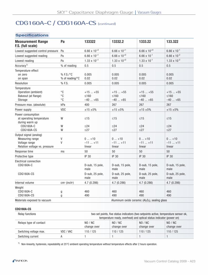
Specifications
CDG160A-C / CDG160A-CS (continued)
Measurement Range Pa 133322 13332.2 1333.22 133.322F.S. (full scale)Lowest suggested control pressure Pa 6.66 x 10+2 6.66 x 10+1 6.66 x 10+0 6.66 x 10⁻¹
Lowest suggested reading Pa 6.66 x 10+1 6.66 x 10+0 6.66 x 10⁻¹ 6.66 x 10⁻²
Lowest reading Pa 1.33 x 10+1 1.33 x 10+0 1.33 x 10⁻¹ 1.33 x 10⁻²
Accuracy1) % of reading 0.5 0.5 0.5 0.5
Temperature effect on zero % F.S./°C 0.005 0.005 0.005 0.005 on span % of reading/°C 0.02 0.02 0.02 0.02
Resolution % F.S. 0.005 0.005 0.005 0.005
Temperature Operation (ambient) °C +15 ... +55 +15 ... +55 +15 ... +55 +15 ... +55 Bakeout (at flange) °C ≤160 ≤160 ≤160 ≤160 Storage °C –40 ... +65 –40 ... +65 –40 ... +65 –40 ... +65
Pressure max. (absolute) kPa 400 267 267 267
Power supply VDC ±15 ±5% ±15 ±5% ±15 ±5% ±15 ±5%
Power consumption at operating temperature W ≤15 ≤15 ≤15 ≤15 during warm up CDG160A-C W ≤24 ≤24 ≤24 ≤24 CDG160A-CS W ≤27 ≤27 ≤27 ≤27
Output signal (analog) Measuring range V 0 ... +10 0 ... +10 0 ... +10 0 ... +10 Voltage range V –11 ... +11 –11 ... +11 –11 ... +11 –11 ... +11 Relation voltage vs. pressure linear linear linear linear
Response time ms 50 50 50 50
Protective type IP 30 IP 30 IP 30 IP 30
Electrical connection CDG160A-C D-sub, 15 pole, D-sub, 15 pole, D-sub, 15 pole, D-sub, 15 pole, male male male male
CDG160A-CS D-sub, 25 pole, D-sub, 25 pole, D-sub, 25 pole, D-sub, 25 pole, male male male male
Internal volume cm3 (inch3) 4.7 (0.286) 4.7 (0.286) 4.7 (0.286) 4.7 (0.286)
Weight CDG160A-C g 460 460 460 460 CDG160A-CS g 490 490 490 490
Materials exposed to vacuum Aluminum oxide ceramic (AI2O3), sealing glass
CDG160A-CS
Relay functions two set points, five status indicators (two setpoints active, temperature sensor ok, temperature ready, overheat) and optical status indicator (power on)
Relays type of contact NO / NC NO / NC NO / NC NO / NC change over change over change over change over
Switching voltage max. VDC / VAC 110 / 125 110 / 125 110 / 125 110 / 125
Switching current A 1 1 1 1
1) Non-linearity, hysteresis, repeatability at 25°C ambient operating temperature without temperature effects after 2 hours operation.

Vacuum Gauges SKY® Capacitance Diaphragm Gauge
Vacuum Control Catalog 2009 - A24
CDG160A-C / CDG160A-CS (continued)
Dimensions
TIBA13E1-A
2.5 (0.098") 5.0 (0.197")ø78.5 (3.09")
105
(4.1
3")
149.
5 (5
.88"
)
Ceramic tube 1/2”CDG160A-C and CDG160A-CS
CDG160A-C CDG160A-CS
Vacuum GaugesBayard-Alpert Pirani Gauge
Vacuum Control Catalog 2009 - A25
Ordering Information
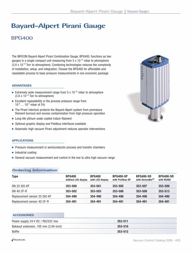
BPG400
Bayard-Alpert Pirani Gauge
The INFICON Bayard-Alpert Pirani Combination Gauge, BPG400, functions as two gauges in a single compact unit measuring from 5 x 10⁻¹⁰ mbar to atmosphere (3.8 x 10⁻¹⁰ Torr to atmosphere). Combining technologies reduces the complexity of installation, setup, and integration. Choose the BPG400 for affordable and repeatable process to base pressure measurements in one economic package.
APPLICATIONS
■ Pressure measurement in semiconductor process and transfer chambers
■ Industrial coating
■ General vacuum measurement and control in the low to ultra high vacuum range
ADVANTAGES
■ Extremely wide measurement range from 5 x 10⁻¹⁰ mbar to atmosphere (3.8 x 10⁻¹⁰ Torr to atmosphere)
■ Excellent repeatability in the process pressure range from 10-8 … 10-2 mbar of 5%
■ The Pirani interlock protects the Bayard-Alpert system from premature filament burnout and excess contamination from high pressure operation
■ Long-life yttrium oxide coated iridum filament
■ Optional graphic display and Fieldbus interfaces available
■ Automatic high vacuum Pirani adjustment reduces operator interventions
ACCESSORIES
Power supply 24 V DC / RS232C line 353-511
Bakeout extension, 100 mm (3.94 inch) 353-510
Baffle 353-512
Type BPG400 BPG400 BPG400-SP BPG400-SD BPG400-SR without LCD display with LCD display with Profibus DP with DeviceNetTM with RS485
DN 25 ISO-KF 353-500 353-501 353-505 353-507 353-509
DN 40 CF-R 353-502 353-503 353-506 353-508 353-513
Replacement sensor 25 ISO-KF 354-490 354-490 354-490 354-490 354-490
Replacement sensor 40 CF-R 354-491 354-491 354-491 354-491 354-491

Vacuum Gauges Bayard-Alpert Pirani Gauge
Vacuum Control Catalog 2009 - A26
Specifications
Specifications
BPG400 (continued)
BPG400 Standard BPG400 DisplayMeasurement range (air, O2, CO, N2) mbar (Torr) 5 x 10⁻¹⁰ … 1000 (3.8 x 10⁻¹⁰ … 750)Accuracy 10-8 … 10-2 mbar % of reading ±15Repeatability 10-8 … 10-2 mbar % of reading 5Degas 1) p < 7.2 x 10⁻⁶ mbar electron bombardment, max. 3 minPressure, max. bar (absolute) 2Temperature Operation (ambient) °C 0 … +50 Storage °C -20 … +70 Bakeout At flange with extension °C 150 At flange without extension °C 80 Electronics removed °C 150Supply voltage V / A DC 20 … 28 / 0.8Output signal analog V 0 … +10 Measurement range V 0.774 … 10 Voltage vs. pressure V / Decade 0.75 Error signal V 0.3 / 0.5 Load impedance, min. kΩ 10Interface (digital) 2) RS232CElectrical connection D-sub, 15 pin, maleCable length, max.3) m (ft) 100 (330)Materials exposed to vacuum Yt2O3, Ir, Pt, Mo, Cu, W, NiFe, NiCr, stainless steel, glassInternal volume KF / CF cm3 (inch)3 24 (1.46) / 34 (2.1)Weight KF / CF g 285 / 550Protection type IP301) Reduced accuracy during degas2) Simultaneous use of RS232C or VGC400 series controllers and Fieldbus is not allowed3) For RS232C operation <30 m
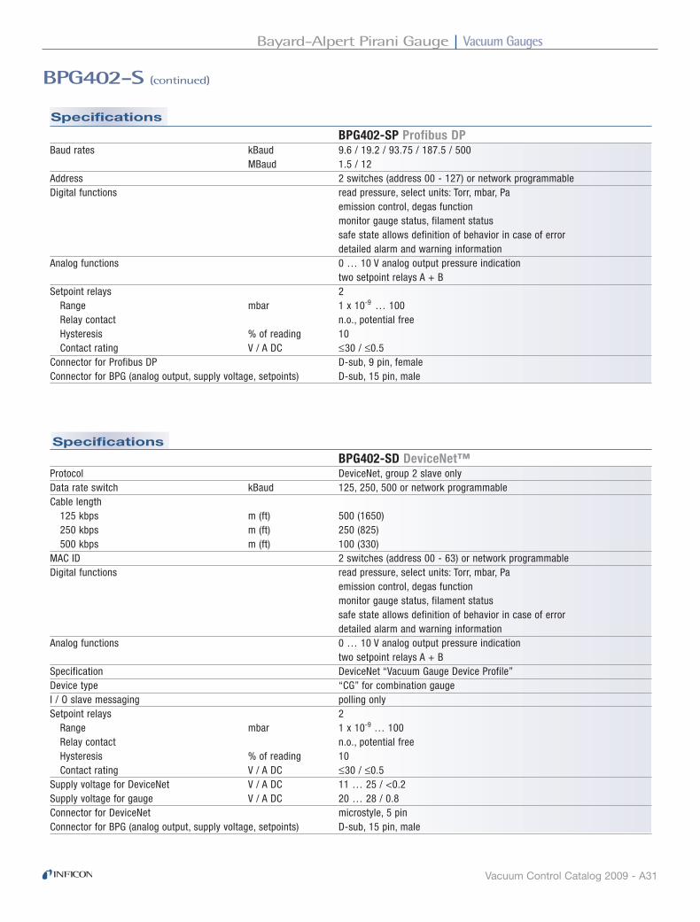
BPG400-SP Profibus DPBaud rates kBaud 9.6 / 19.2 / 93.75 / 187.5 / 500 MBaud 1.5 / 12Address 2 switches (address 00 - 127) or network programmableDigital functions read pressure, select units: Torr, mbar, Pa degas function, Pirani full scale adjust monitor gauge status safe state allows definition of behavior in case of error detailed alarm and warning informationAnalog functions 0 … 10 V analog output pressure indication two setpoint relays A + BSetpoint relays 2 Range mbar 1 x 10⁻⁹ … 100 Relay contact n.o., potential free Hysteresis % of reading 10 Contact rating V / A DC 60 / 0.5Connector for Profibus DP D-sub, 9 pin, femaleConnector for BPG (analog output, supply voltage, setpoints) D-sub, 15 pin, male

Vacuum GaugesBayard-Alpert Pirani Gauge
Vacuum Control Catalog 2009 - A27
Specifications
BPG400 (continued)
BPG400-SD DeviceNet™Protocol DeviceNet™, group 2 slave onlyData rate switch kBaud 125, 250, 500 or network programmableCable length 125 kbps m (ft) 500 (1650) 250 kbps m (ft) 250 (825) 500 kbps m (ft) 100 (330)MAC ID 2 switches (address 00 - 63) or network programmableDigital functions read pressure, select units: Torr, mbar, Pa degas function, Pirani full scale adjust monitor gauge status safe state allows definition of behavior in case of error detailed alarm and warning informationAnalog functions 0 … 10 V analog output pressure indication two setpoint relays A + BSpecification DeviceNet™ ”Vacuum Gauge Device Profile”Device type “CG” for combination gaugeI / O slave messaging polling onlySetpoint relays 2 Range mbar 1 x 10⁻⁹ … 100 Relay contact n.o., potential free Hysteresis % of reading 10 Contact rating V / A DC 60 / 0.5Supply voltage for DeviceNet™ V / A DC 11 … 25 / 0.5Supply voltage for gauge V / A DC 20 … 28 / 0.8Connector for DeviceNet™ microstyle, 5 pinConnector for BPG (analog output, supply voltage, setpoints) D-sub, 15 pin, male
BPG400-SR RS485Baud rates kBaud 0.3 / 1.2 / 2.4 / 4.8 / 9.6 / 19.2 / 28.8Address 2 switches (address 00 - 127) or network programmableDigital functions read pressure, select units: Torr, mbar, Pa degas function, Pirani full scale adjust monitor gauge status detailed alarm and warning informationAnalog functions 0 … 10 V analog output pressure indication two setpoint relays A + BSetpoint relays 2 Range mbar 1 x 10⁻⁹ … 100 Relay contact n.o., potential free Hysteresis % of reading 10 Contact rating V / A DC 60 / 0.5Connector for RS485 D-sub, 9 pin, maleConnector for BPG (analog output, supply voltage, setpoints) D-sub, 15 pin, male
Specifications

Vacuum Gauges Bayard-Alpert Pirani Gauge
Vacuum Control Catalog 2009 - A28
Accessories Dimensions
Power supply 24 V DC / RS232C line
D-Sub, 15 pin, femaleRS232 to PC / PLCD-Sub, 9 pin, female,
90 … 250 V AC supply
24 V DC supply
1.8 m
5 m
5 m
Bakeout extension: Allows measurement at flange temperatures up to 150°C. Fast and easy installation.
Baffle: Prevents contamination of the sensor. Easy installation into the vacuum connection - no tools required.
Standard Baffle
BPG400 (continued)
TIBA15E1-A

Vacuum GaugesBayard-Alpert Pirani Gauge
Vacuum Control Catalog 2009 - A29
Ordering Information
BPG402-S
Bayard-Alpert Pirani Gauge
The INFICON Bayard-Alpert Pirani Combination Gauge, BPG402-S, functions as two gauges in a single compact unit measuring from 5 x 10⁻¹⁰ mbar to atmosphere (3.8 x 10⁻¹⁰ Torr to atmosphere). Combining technologies reduces the complexity of installation, setup, and integration. Choose the BPG402-S with dual yttrium oxide coated iridium filaments for affordable and repeatable process to base pressure measurements in one economical package. Sensing elements with on-board calibration data guarantees high reproducibility when exchanging sensors.
Applications
■ Pressure measurement in semiconductor process and transfer chambers
■ Industrial coating
■ General vacuum measurement and control in the low to ultra high vacuum range
Advantages
■ Extremely wide measurement range from 5 x 10⁻¹⁰ mbar to atmosphere (3.8 x 10⁻¹⁰ Torr to atmosphere)
■ Excellent repeatability in the process pressure range from 10-8 … 10-2 mbar of 5%
■ Pirani interlock protects the filament from premature burnout
■ Dual long-life yttrium oxide coated iridium filament
■ Optional graphic display and Fieldbus interfaces available
■ Automatic high vacuum Pirani adjustment reduces operator interventions
■ Easy to exchange sensing element with on-board calibration data guarantees high reproducibility
Power supply 24 V DC / RS232C line 353-511
Baffle 353-512
Type BPG402-S BPG402-S BPG402-SP BPG402-SD without display with display with Profibus DP with DeviceNetTM
DN 25 ISO-KF 353-570 353-572 353-574 353-576
DN 40 CF-R 353-571 353-573 353-575 353-577
Replacement sensor 25 ISO-KF 354-494
Replacement sensor 40 CF-R 354-495
Accessories

Vacuum Gauges Bayard-Alpert Pirani Gauge
Vacuum Control Catalog 2009 - A30
Specifications
BPG402-S (continued)
BPG402-S Standard BPG402-S DisplayMeasurement range (air, O2, CO, N2) mbar (Torr) 5 x 10⁻¹⁰ … 1000 (3.8 x 10⁻¹⁰ … 750)Accuracy 10-8 … 10-2 mbar % of reading ±15Repeatability 10-8 … 10-2 mbar % of reading 5Degas 1) p < 7.2 x 10⁻⁶ mbar electron bombardment, max. 3 minPressure, max. bar (absolute) 2Temperature Operation (ambient) °C 0 … +50 Storage °C -20 … +70 Bakeout at flange without electronics °C 80Supply voltage V / A DC 20 … 28 / 0.8Output signal analog V 0 … +10 Measurement range V 0.774 … 10 Voltage vs. pressure V / Decade 0.75 Error signal V 0.3 / 0.5 Load impedance, min. kΩ 10Set point relay 1 Range mbar 1 x 10⁻⁹ … 100 Relay contact n.o., potential free Hysteresis % of reading 10 Contact rating V / A DC ≤30 / ≤0.5Digital functions degasInterface (digital) 2) RS232CEmission control automatic / manual via interfaceFilament dual Yt2O2 coated IrFilament status LED / digital outputElectrical connection D-sub, 15 pin, maleCable length, max.3) m (ft) 100 (330)Materials exposed to vacuum Yt2O3, Ir, Pt, Mo, Cu, W, NiFe, NiCr, stainless steel, glassInternal volume KF / CF cm3 (inch)3 24 (1.46) / 34 (2.1)Weight KF / CF g 285 / 550Protection type IP30
1) Reduced accuracy during degas2) Simultaneous use of RS232C or VGC400 series controllers and Fieldbus is not allowed3) For RS232C operation <30 m
Vacuum GaugesBayard-Alpert Pirani Gauge
Vacuum Control Catalog 2009 - A31
Specifications
Specifications
BPG402-S (continued)
BPG402-SD DeviceNet™Protocol DeviceNet, group 2 slave onlyData rate switch kBaud 125, 250, 500 or network programmableCable length 125 kbps m (ft) 500 (1650) 250 kbps m (ft) 250 (825) 500 kbps m (ft) 100 (330)MAC ID 2 switches (address 00 - 63) or network programmableDigital functions read pressure, select units: Torr, mbar, Pa emission control, degas function monitor gauge status, filament status safe state allows definition of behavior in case of error detailed alarm and warning informationAnalog functions 0 … 10 V analog output pressure indication two setpoint relays A + BSpecification DeviceNet “Vacuum Gauge Device Profile”Device type “CG” for combination gaugeI / O slave messaging polling onlySetpoint relays 2 Range mbar 1 x 10⁻⁹ … 100 Relay contact n.o., potential free Hysteresis % of reading 10 Contact rating V / A DC ≤30 / ≤0.5Supply voltage for DeviceNet V / A DC 11 … 25 / <0.2Supply voltage for gauge V / A DC 20 … 28 / 0.8Connector for DeviceNet microstyle, 5 pinConnector for BPG (analog output, supply voltage, setpoints) D-sub, 15 pin, male
BPG402-SP Profibus DPBaud rates kBaud 9.6 / 19.2 / 93.75 / 187.5 / 500 MBaud 1.5 / 12Address 2 switches (address 00 - 127) or network programmableDigital functions read pressure, select units: Torr, mbar, Pa emission control, degas function monitor gauge status, filament status safe state allows definition of behavior in case of error detailed alarm and warning informationAnalog functions 0 … 10 V analog output pressure indication two setpoint relays A + BSetpoint relays 2 Range mbar 1 x 10⁻⁹ … 100 Relay contact n.o., potential free Hysteresis % of reading 10 Contact rating V / A DC ≤30 / ≤0.5Connector for Profibus DP D-sub, 9 pin, femaleConnector for BPG (analog output, supply voltage, setpoints) D-sub, 15 pin, male

Vacuum Gauges Bayard-Alpert Pirani Gauge
Vacuum Control Catalog 2009 - A32
Dimensions Accessories
DN 25 ISO-KF� DN 40CF-R�
mm (inch)
67 (2.64)
48 (1
.89)
42 (1
.65)
153
(6.0
3)
58 (2
.29)
Power supply 24 V DC / RS232C line
D-Sub, 15 pin, femaleRS232 to PC / PLCD-Sub, 9 pin, female,
90 … 250 V AC supply
24 V DC supply
1.8 m
5 m
5 m
Baffle: Prevents contamination of the sensor. Easy installation into the vacuum connection - no tools required.
Standard Baffle
BPG402-S (continued)
TIBA31E1

Vacuum GaugesHigh Pressure Hot Ionization Pirani Gauge
Vacuum Control Catalog 2009 - A33
Accessories
Ordering Information
HPG400
high Pressure hot Ionization Pirani Gauge
The INFICON High Pressure Hot Ionization Pirani Gauge, HPG400, combines High Pressure Hot Ionization and Pirani sensors in a single, compact, economical package to measure pressure from 2 x 10⁻⁶ mbar to atmosphere (1.5 x 10⁻⁶ Torr to atmosphere). The HPG400 provides highly repeatable and reproducible pressure measurement for accurate sputter process pressure control.
Type HPG400 HPG400 HPG400-SP HPG400-SD without LCD display with LCD display with Profibus DP1) with DeviceNet1)
DN 25 ISO-KF 353-520 353-521 353-525 353-527
DN 40 CF-F 353-522 353-523 353-526 353-528
Replacement sensor 25 ISO-KF 354-487 354-487 354-487 354-487
Replacement sensor 40 CF-F 354-488 354-488 354-488 354-4881) not available with LCD display
Applications
■ Sputter applications in semiconductor manufacturing, electronics and media industry
■ Industrial coating
■ General vacuum measurement and control in the low to high vacuum range
Advantages
■ HPG400 saves cost and tool space and reduces the complexity of vacuum system installation and setup
■ The high pressure hot ion gauge delivers accurate, reliable pressure measurements from 1 x 10⁻⁵ … 1 mbar for improved process control
■ User selectable hot ion emission activation between 5 x 10⁻² and 1 mbar
■ Pirani interlock protects the hot filament from premature burnout
■ Optional graphic display and Fieldbus interfaces available
■ Automatic high vacuum Pirani adjustment reduces operator interventions
Power supply 24 V DC / RS232C line 353-511

Vacuum Gauges High Pressure Hot Ionization Pirani Gauge
Vacuum Control Catalog 2009 - A34
Specifications
HPG400 (continued)
HPG400 Standard HPG400 DisplayMeasurement range (air, N2) mbar (Torr) 2 x 10⁻⁶ … 1000 (1.5 x 10⁻⁶ … 750)Accuracy 10-5 … 1 mbar % of reading ±15 1)
Repeatability 10-5 … 10-1 mbar % of reading 2 10-1 … 100 mbar % of reading 30Hot ion emission on, selectable mbar 1 mbar 5 x 10⁻¹
mbar 2 x 10⁻¹
mbar 1 x 10⁻¹
mbar 5 x 10⁻²
Pressure, max. bar (absolute) 5Temperature Operation (ambient) °C 0 … +50 Storage °C -20 … +70 Bakeout At flange °C 80 Electronics removed °C 150Supply voltage V / A DC 20 … 28 / 0.8Output signal analog V 0 … +10.2 Measurement range Hot cathode V 1.5 … 7.5 Pirani V 8.5 … 9.75 Voltage vs. pressure Hot cathode V / Decade 1 Pirani V / Decade 0.25 Error signal Hot cathode V 0.3 Pirani V 0.5 Load impedance , min. kΩ 10Interface (digital) 2) RS232CElectrical connection D-sub, 15 pin, maleCable length, max.3) m (ft) 100 (330)Materials exposed to vacuum Yt2O3, Ir, Pt, Mo, Cu, W, NiFe, NiCr, stainless steel, glassInternal volume KF / CF cm3 (inch)3 20 (1.2) / 30 (1.8)Weight KF / CF g 430 / 695Protection type IP301) Accuracy from 10-5 mbar to the selected hot ion emission on value2) Simultaneous use of RS232C or VGC400 series controllers and Fieldbus is not allowed3) For RS232C operation <30 m

Vacuum GaugesHigh Pressure Hot Ionization Pirani Gauge
Vacuum Control Catalog 2009 - A35
Specifications
Specifications
HPG400-SD DeviceNet™Protocol DeviceNet, group 2 slave onlyData rate switch kBaud 125, 250, 500 or network programmableCable length 125 kbps m (ft) 500 (1650) 250 kbps m (ft) 250 (825) 500 kbps m (ft) 100 (330)MAC ID 2 switches (address 00 - 63) or network programmableNetwork size up to 64 nodes per segmentDigital functions read pressure, select units: Torr, mbar, Pa Pirani full scale adjust monitor gauge status safe state allows definition of behavior in case of error detailed alarm and warning informationAnalog functions 0 … 10 V analog output pressure indication two setpoint relays A + BVisual communication indicators LED network status (green / red) LED module status (green / red)Specification DeviceNet “Vacuum Gauge Device Profile”Device type “CG” for combination gaugeI / O slave messaging polling onlySetpoint relays 2 Range mbar 2 x 10⁻⁶ … 100 Relay contact n.o., potential free Hysteresis % of reading 10 Contact rating V DC / A 60 / 0.5Supply voltage for DeviceNet V DC / A 11 … 25 / 0.5Supply voltage for gauge V DC 20 … 28Connector for DeviceNet microstyle, 5 pinConnector for HPG (analog output, supply voltage, setpoints) D-sub, 15 pin, male
HPG400-SP Profibus DPBaud rates kBaud 9.6 / 19.2 / 93.75 / 187.5 / 500 MBaud 1.5 / 12Address 2 switches (address 00 - 127) or network programmableDigital functions read pressure, select units: Torr, mbar, Pa Pirani full scale adjust monitor gauge status safe state allows definition of behavior in case of error detailed alarm and warning informationAnalog functions 0 … 10 V analog output pressure indication two setpoint relays A + BSetpoint relays 2 Range mbar 1 x 10⁻⁶ … 100 Relay contact n.o., potential free Hysteresis % of reading 10 Contact rating V DC / A 60 / 0.5Connector for Profibus DP D-sub, 9 pin, femaleConnector for HPG (analog output, supply voltage, setpoints) D-sub, 15 pin, male
HPG400 (continued)

Vacuum Gauges High Pressure Hot Ionization Pirani Gauge
Vacuum Control Catalog 2009 - A36
Dimensions
Accessories
HPG400 (continued)
HPG400D-Sub, 15 pin, female
RS232 to PC / PLCD-Sub,9 pin, female
90 to 250 V AC supply
24 V DC supply
1.8 m
5 m
5 m
Power supply 24 V DC / RS232C line
TIBA14E1-A
Vacuum GaugesBayard-Alpert Pirani Capacitance Diaphragm Gauge
Vacuum Gauges Catalog 2009 - A37
Ordering Information
Accessories
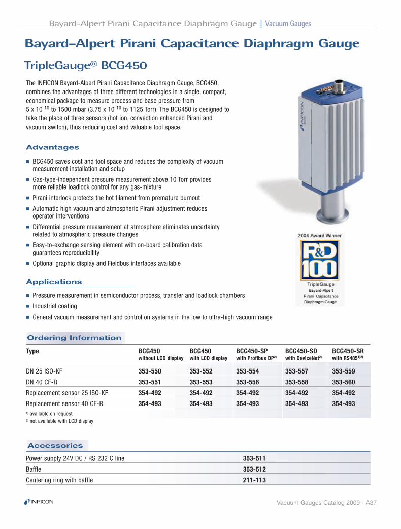
TripleGauge® BCG450
Bayard-Alpert Pirani Capacitance diaphragm Gauge
Advantages
The INFICON Bayard-Alpert Pirani Capacitance Diaphragm Gauge, BCG450, combines the advantages of three different technologies in a single, compact, economical package to measure process and base pressure from 5 x 10⁻¹⁰ to 1500 mbar (3.75 x 10⁻¹⁰ to 1125 Torr). The BCG450 is designed to take the place of three sensors (hot ion, convection enhanced Pirani and vacuum switch), thus reducing cost and valuable tool space.
Type BCG450 BCG450 BCG450-SP BCG450-SD BCG450-SR without LCD display with LCD display with Profibus DP2) with DeviceNet2) with RS4851)2)
DN 25 ISO-KF 353-550 353-552 353-554 353-557 353-559
DN 40 CF-R 353-551 353-553 353-556 353-558 353-560
Replacement sensor 25 ISO-KF 354-492 354-492 354-492 354-492 354-492
Replacement sensor 40 CF-R 354-493 354-493 354-493 354-493 354-4931) available on request2) not available with LCD display
Applications
■ Pressure measurement in semiconductor process, transfer and loadlock chambers
■ Industrial coating
■ General vacuum measurement and control on systems in the low to ultra-high vacuum range
■ BCG450 saves cost and tool space and reduces the complexity of vacuum measurement installation and setup
■ Gas-type-independent pressure measurement above 10 Torr provides more reliable loadlock control for any gas-mixture
■ Pirani interlock protects the hot filament from premature burnout
■ Automatic high vacuum and atmospheric Pirani adjustment reduces operator interventions
■ Differential pressure measurement at atmosphere eliminates uncertainty related to atmospheric pressure changes
■ Easy-to-exchange sensing element with on-board calibration data guarantees reproducibility
■ Optional graphic display and Fieldbus interfaces available
Power supply 24V DC / RS 232 C line 353-511
Baffle 353-512
Centering ring with baffle 211-113

Vacuum Gauges Bayard-Alpert Pirani Capacitance Diaphragm Gauge
Vacuum Gauges Catalog 2009 - A38
Specifications
TripleGauge® BCG450 (continued)
BCG450 Standard BCG450 DisplayMeasurement range mbar (Torr) 5 x 10⁻¹⁰ to 1500 (3.75 x 10⁻¹⁰ to 1125)Accuracy 10-8 to 10-2 mbar % of reading ±15 10-2 to 50 mbar % of reading ±15 50 to 950 mbar % of reading ±5 950 to 1050 mbar % of reading ±2.5Repeatability 10-8 … 10-2 mbar % of reading 5Hot ion emission on mbar 2 x 10⁻²
(high)(selectable high / low, via RS232 / Fieldbus) mbar 8 x 10⁻³
(low)Degas1) p < 7.2 x 10⁻⁶ mbar Electron bombardment, max. 3 minPressure, max. bar (absolute) 5Temperature Operation (ambient) °C 0 to +50 Storage °C -20 to +70 Bakeout At flange °C 80 Electronics removed °C 150Supply V / A DC 20 to 28 / 0.8Output signal analog V 0 to 10.3 Measurement range V 0.774 to 10.3 Relation voltage / pressure V / Decade 0.75 Error signal V 0.3 / 0.5 Minimum load kΩ 10Interface (digital)2) RS232CConnector D-sub, 15 pin, maleCable length, max.3) m (ft) 100 (330)Materials exposed to vacuum Yt2O3, Ir, Mo, Cu, W, NiFe, NiCr, AI2O3, SnAg, stainless steel, glass Internal volume KF / CF cm3 (inch)3 24 (1.46) / 34 (2.1)Weight KF / CF g 285 / 550Protection type IP301) Reduced accuracy during degas2) Simultaneous use of RS232C or VGC400 series controllers and Fieldbus is not allowed3) For RS232C operation <30m

Vacuum GaugesBayard-Alpert Pirani Capacitance Diaphragm Gauge
Vacuum Gauges Catalog 2009 - A39
Specifications
TripleGauge® BCG450 (continued)
BCG450-SD DeviceNet™Protocol DeviceNet, group 2 slave onlyData rate switch kBaud 125, 250, 500 or network programmableCable length 125 kbps m (ft) 500 (1650) 250 kbps m (ft) 250 (825) 500 kbps m (ft) 100 (330)MAC ID 2 switches (address 00 - 63) or network programmableNetwork size Up to 64 nodes per segmentDigital functions Read pressure, select units: Torr, mbar, Pa Degas function Monitor gauge status Safe state allows definition of behavior in case of error Detailed alarm and warning informationAnalog functions 0 to 10 V analog output pressure indication Two setpoint relays A + BVisual communication indicators LED network status (green / red) LED module status (green / red)Specification DeviceNet ”Vacuum Gauge Device Profile”Device type “CG” for combination gaugeI / O peer to peer messaging polling onlyConfiguration consistency value noFaulted node recovery noBaud rates kBaud 125 / 250 / 500Master / Scanner noI / 0 slave messaging polling onlySetpoint relays 2 Range mbar 1 x 10⁻⁹ to 1400 Relay contact n.o., potential free Hysteresis % of reading 10 Contact rating V / A DC 60 / 0.5 Connector D-sub, 15 pin, maleSupply for DeviceNet V / A DC 11 to 25 / 0.5Supply for gauge V DC 20 to 28Connector for DeviceNet Microstyle, 5 pinConnector for BCG (analog output, supply voltage, setpoints) D-sub, 15 pin, male

Vacuum Gauges Bayard-Alpert Pirani Capacitance Diaphragm Gauge
Vacuum Gauges Catalog 2009 - A40
BCG450-SR RS485Baud rates kBaud 0.3 / 1.2 / 2.4 / 4.8 / 9.6 / 19.2 / 28.8Address 2 switches (address 00 - 127) or network programmableDigital functions Read pressure, select units: Torr, mbar, Pa Degas function, Pirani full scale adjust Monitor gauge status Detailed alarm and warning informationAnalog functions 0 to 10 V analog output pressure indication Two adjustable setpoint relays A + BSetpoint relays 2 Range mbar 1 x 10⁻⁹ to 100 Relay contact n.o., potential free Hysteresis % of reading 10 Contact rating V / A DC 60 / 0.5Connector for RS485 D-sub, 9 pin, male for gauge (analog output, supply voltage, setpoints) D-sub, 15 pin, male
Specifications
TripleGauge® BCG450 (continued)
BCG450-SP Profibus DPBaud rates kBaud 9.6 / 19.2 / 93.75 / 187.5 / 500 MBaud 1.5 / 12Address 2 switches (address 00 - 127) or network programmableDigital functions Read pressure, select units: Torr, mbar, Pa Degas function Monitor gauge status Safe state allows definition of behavior in case of error Detailed alarm and warning informationAnalog functions 0 to 10 V analog output pressure indication Two setpoint relays A + BSetpoint relays 2 Range mbar 1 x 10⁻⁹ to 1400 Relay contact n.o., potential free Hysteresis % of reading 10 Contact rating V / A DC 60 / 0.5 Connector for Profibus DP D-sub, 9 pin, female for BCG (analog output, supply voltage, setpoints) D-sub, 15 pin, male
Specifications

Vacuum GaugesBayard-Alpert Pirani Capacitance Diaphragm Gauge
Vacuum Gauges Catalog 2009 - A41
Accessories
Power supply 24 V DC / RS 232 C line
D-Sub, 15 pin, femaleRS232 to PC / PLCD-Sub, 9 pin, female,
90 to 250 V AC supply
24 V DC supply
1.8 m
5 m
5 m
Baffle Prevents contamination of the sensor. Easy installation into the vacuum connection - no tools required.
Standard Baffle
Dimensions
TripleGauge® BCG450 (continued)
TIBA12E1-B
Vacuum Gauges Pirani Standard Gauge
Vacuum Control Catalog 2009 - A42
Ordering Information
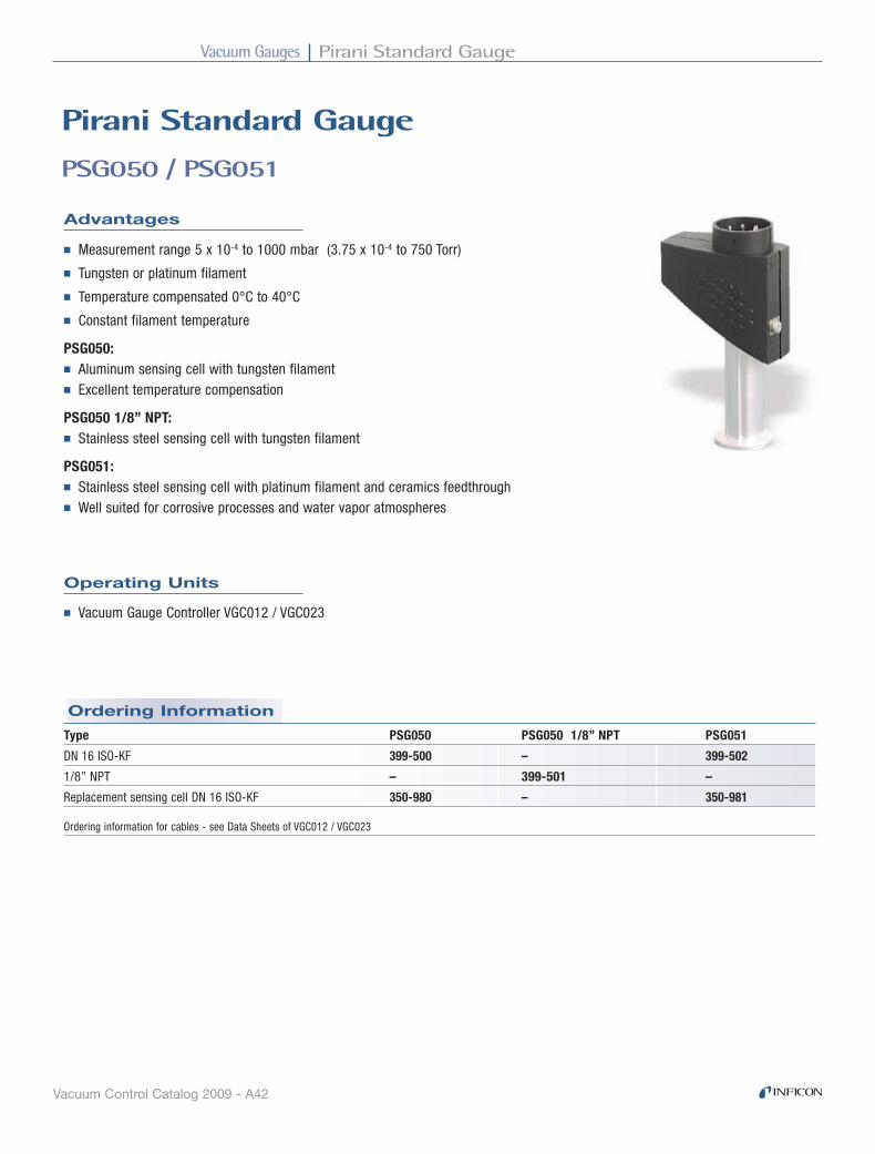
PSG050 / PSG051
Pirani Standard Gauge
Operating Units
■ Vacuum Gauge Controller VGC012 / VGC023
Advantages
■ Measurement range 5 x 10⁻⁴ to 1000 mbar (3.75 x 10⁻⁴ to 750 Torr)
■ Tungsten or platinum filament
■ Temperature compensated 0°C to 40°C
■ Constant filament temperature
PSG050:■ Aluminum sensing cell with tungsten filament■ Excellent temperature compensation
PSG050 1/8” NPT:■ Stainless steel sensing cell with tungsten filament
PSG051:■ Stainless steel sensing cell with platinum filament and ceramics feedthrough■ Well suited for corrosive processes and water vapor atmospheres
Type PSG050 PSG050 1/8” NPT PSG051
DN 16 ISO-KF 399-500 – 399-502
1/8” NPT – 399-501 –
Replacement sensing cell DN 16 ISO-KF 350-980 – 350-981
Ordering information for cables - see Data Sheets of VGC012 / VGC023

Vacuum GaugesPirani Standard Gauge
Vacuum Control Catalog 2009 - A43
Dimensions
Specifications
PSG050 PSG050 1/8" NPT PSG051Measurement range mbar (Torr) 5 x 10⁻⁴ to 1000 (3.75 x 10⁻⁴ to 750)
Temperature
Operation (ambient) °C 0 to +40 0 to +40 0 to +40
Storage °C 80 80 80
Filament Tungsten Tungsten Platinum
Filament temperature °C 110 110 110
Pressure, max. absolute bar 3 3 10
Volume of the sensing cell, approx. cm3 11 11 10
Vacuum connection DN 16 ISO-KF 1/8” NPT DN 16 ISO-KF
Materials exposed to vacuum Tungsten, aluminum, Tungsten, Platinum, stainless steel, nickel-plated steel, stainless steel, NiFe, CrNi, AL2O3, NiFe stainless steel, NiFe, glass glass, CrNi, CrNi, epoxy cement epoxy cement
Additional specifications - see Data Sheets and Operating Manuals VGC012 / VGC023
144
(5.7
)�
135
(5.3
)�
122
(4.8
)�
40 (1.6)�20�(0.8)�
5 (0.2)�
35 (1.4)�
DN 16 ISO-KF�1/8" NPT�
133
(5.2
)�
mm (inch)
TIBA20E1

Vacuum Gauges Pirani Standard Gauge
Vacuum Control Catalog 2009 - A44
Ordering Information
PSG100-S, PSG101-S
Pirani Standard Gauge
The INFICON Pirani Standard Gauges PSG100-S and PSG101-S are especially designed or easy integration into vacuum systems using Profibus DP or DeviceNetTM fieldbus protocols. The gauges are equipped with a setpoint and for corrosive applications, a platinum filament version is available.
Applications
■ Processes with corrosive gases (PSG101-S)
■ Fore vacuum pressure monitoring
■ Control of high vacuum ionization gauges
■ Safety circuits in vacuum systems
■ General vacuum measurement and control in the fine and rough vacuum range
Advantages
■ Fieldbus interface (Profibus DB, DeviceNetTM) for easy integration into vacuum systems using network communications
■ For corrosive applications or high levels of water vapors the PSG101-S uses a platinum filament and a Al2O3 ceramic feedthrough
■ Setpoint with adjustable threshold over a wide range
■ Mounts in any orientation
■ Logarithmic analog output signal
■ Sensor cell is easily replaced
Type PSG100-S PSG101-S DN 16 ISO-KF, Tungsten DN 16 ISO-KF, Platinum
With setpoint 350-020 350-030
With DeviceNetTM (PSG100-SD, PSG101-SD) 350-021 350-031
With Profibus DP (PSG100-SP, PSG101-SP) 350-022 350-032
Replacement sensor (DN16 ISO KF) 350-980 350-981

Vacuum GaugesPirani Standard Gauge
Vacuum Control Catalog 2009 - A45
Specifications
Specifications
PSG100-SP Profibus DP, PSG101-SP Profibus DPSupported baud rates (for auto detection) kBaud 9.6 / 19.2 / 93.75 / 187.5 / 500 / 1500Expanded user parameter data Bytes 5Configuring Number of input and output data 2Sync-Mode and Freeze-Mode YesConnector D sub, 9 pin
PSG100-S PSG101-S Tungsten PlatinumMeasurement range (air, O2, CO, N2) mbar 5 x 10⁻⁴ … 1000 Torr 3.8 x 10⁻⁴ … 750Filament material tungsten platinumMounting orientation anyFeldbus protocol DeviceNetTM or Profibus DPSetpoint 1 Range mbar 1 x 10⁻³ … 500 Relay contact n.o. / potential free Hysteresis ≈30% of adjusted pressure Contact rating VDC / A 60 / 0.5 Relay status LED, greenPressure, max. (absolute) bar 3 10 1)
Temperature Operation (ambient) °C +10 … +50 Storage °C -20 … +70 Bakeout at flange °C 80Power supply Voltage V DC 14.5 … 36 Consumption, max. W <2Output signal analog V 0 … 10.6 Measurement range V 0.66 … 10 Relation voltage / pressure V / Decade 1.333Connector FCC 68, female, 8 pin (shielded)Cable length, max. (analog) m (ft) 100 (330)Materials exposed to vacuum tungsten, Al, nickel-plated steel, platinum, stainless steel, CrNi, stainless steel, NiFe, glass, AI2O3 ceramics, NiFe, Mo, Ni CrNi8020, epoxy cementFlange DN 16 ISO-KFInternal volume DN 16 ISO-KF cm3 (inch)3 11 (0.67)Weight, approx. DN 16 ISO-KF g 290Protection type IP401)
Threaded connections only
PSG100-S, PSG101-S (continued)

Vacuum Gauges Pirani Standard Gauge
Vacuum Control Catalog 2009 - A46
Specifications
Dimensions
mm (inches)
PSG100-SD DeviceNet™, PSG101-SD DeviceNetDevice type genericExplicit peer to peer messaging noI / O peer to peer messaging noConfiguration consistency value noFaulted node recovery noBaud rates kBaud 125 / 250 / 500Master / Scanner noI / O slave messaging Bit Strobe yes Polling yes Cyclic yes Change of State (COS) yesSupply for DeviceNet V DC 11 to 25Connector for DeviceNet Phoenix Combicon, 5 pin
TIBA21E1-A
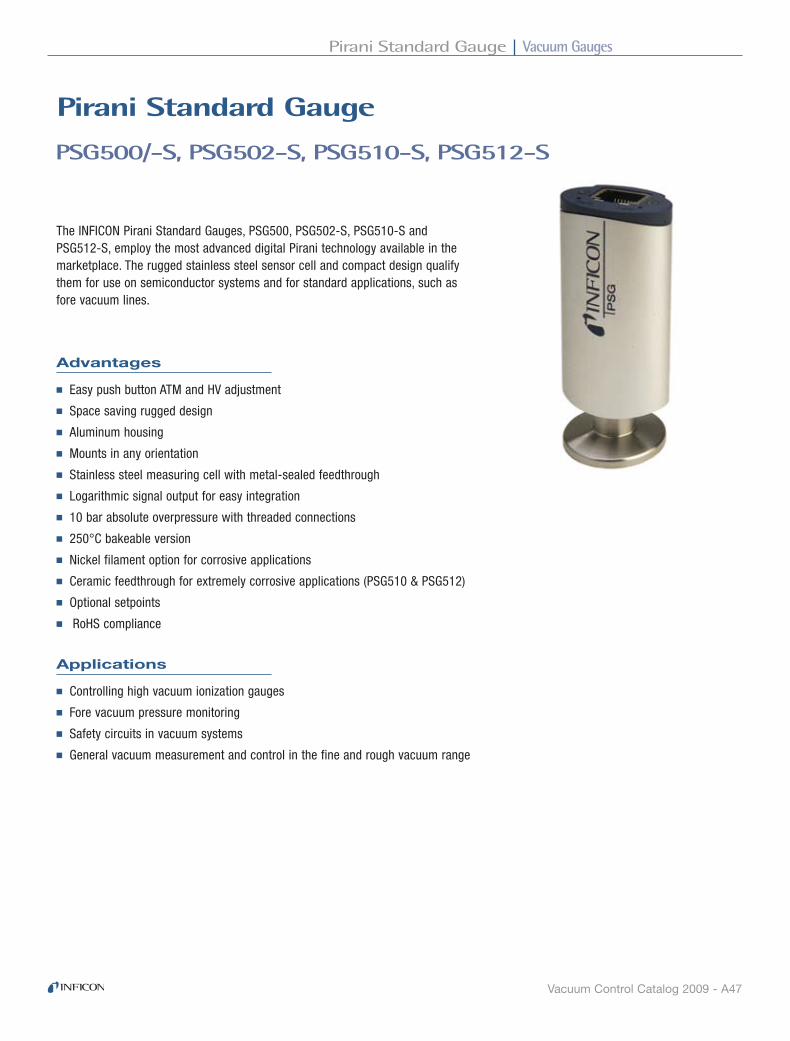
Vacuum GaugesPirani Standard Gauge
Vacuum Control Catalog 2009 - A47
PSG500/-S, PSG502-S, PSG510-S, PSG512-S
Pirani Standard Gauge
The INFICON Pirani Standard Gauges, PSG500, PSG502-S, PSG510-S and PSG512-S, employ the most advanced digital Pirani technology available in the marketplace. The rugged stainless steel sensor cell and compact design qualify them for use on semiconductor systems and for standard applications, such as fore vacuum lines.
Applications
■ Controlling high vacuum ionization gauges
■ Fore vacuum pressure monitoring
■ Safety circuits in vacuum systems
■ General vacuum measurement and control in the fine and rough vacuum range
Advantages
■ Easy push button ATM and HV adjustment
■ Space saving rugged design
■ Aluminum housing
■ Mounts in any orientation
■ Stainless steel measuring cell with metal-sealed feedthrough
■ Logarithmic signal output for easy integration
■ 10 bar absolute overpressure with threaded connections
■ 250°C bakeable version
■ Nickel filament option for corrosive applications
■ Ceramic feedthrough for extremely corrosive applications (PSG510 & PSG512)
■ Optional setpoints
■ RoHS compliance

Vacuum Gauges Pirani Standard Gauge
Vacuum Control Catalog 2009 - A48
Ordering Information
PSG500/-S, PSG502-S, PSG510-S, PSG512-S (continued)
Type PSG500 PSG500-S PSG502-S PSG510-S PSG512-S Setpoints none two setpoints two setpoints two setpoints two setpoints Filament tungsten tungsten nickel tungsten nickel
DN 16 ISO-KF 350-060 350-080 350-140 350-200 350-300
DN 16 CF-R 350-062 350-082 350-142
1/8” NPT 350-061 350-081 350-141
8 VCR® 350-064 350-084 350-144
4 VCR® 350-065 350-085 350-145
1/2” tube 350-063 350-083 350-143
7/16-20 UNF 350-066 350-086 350-146
DN 16 ISO-KF long tube 350-067 350-087 350-147
DN 16 CF-R long tube 350-068 350-088 350-148
Replacement sensor Filament tungsten nickel tungsten nickel
DN 16 ISO-KF 350-920 350-900 350-930 350-940
DN 16 CF-R 350-922 350-902
1/8” NPT 350-921 350-901
8 VCR® 350-924 350-904
4 VCR® 350-926 350-906
1/2” tube 350-923 350-903
7/16-20 UNF 350-925 350-905
DN 16 ISO-KF long tube 350-927 350-907
DN 16 CF-R long tube 350-928 350-908
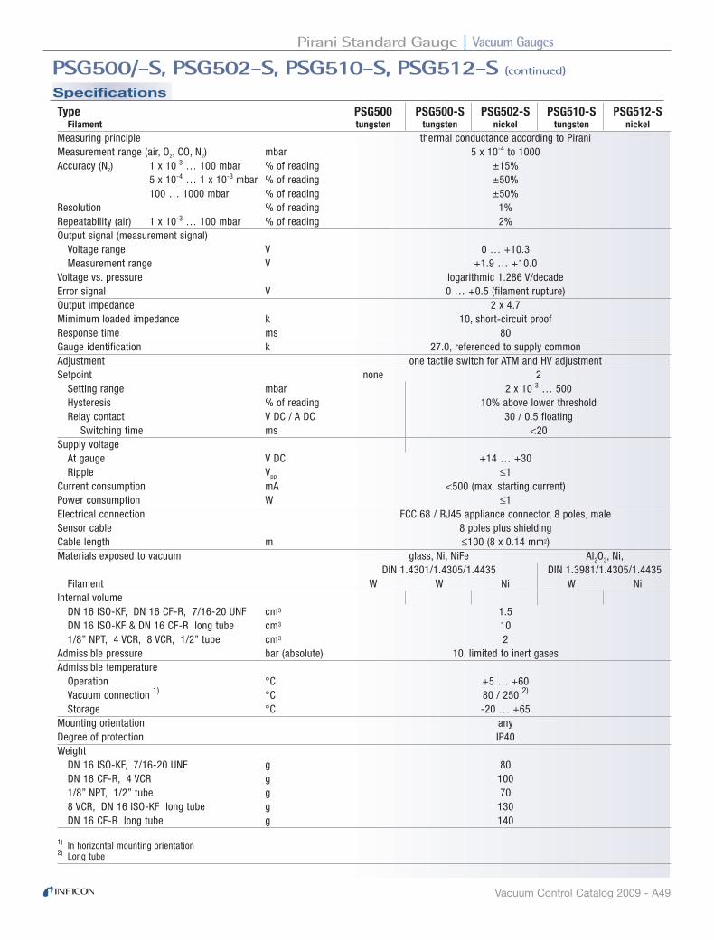
Vacuum GaugesPirani Standard Gauge
Vacuum Control Catalog 2009 - A49
Specifications
PSG500/-S, PSG502-S, PSG510-S, PSG512-S (continued)
Type PSG500 PSG500-S PSG502-S PSG510-S PSG512-S Filament tungsten tungsten nickel tungsten nickelMeasuring principle thermal conductance according to PiraniMeasurement range (air, O2, CO, N2) mbar 5 x 10⁻⁴ to 1000Accuracy (N2) 1 x 10⁻³ … 100 mbar % of reading ±15% 5 x 10⁻⁴ … 1 x 10⁻³ mbar % of reading ±50% 100 … 1000 mbar % of reading ±50%Resolution % of reading 1%Repeatability (air) 1 x 10⁻³ … 100 mbar % of reading 2%Output signal (measurement signal) Voltage range V 0 … +10.3 Measurement range V +1.9 … +10.0Voltage vs. pressure logarithmic 1.286 V/decadeError signal V 0 … +0.5 (filament rupture)Output impedance Ω 2 x 4.7Mimimum loaded impedance kΩ 10, short-circuit proofResponse time ms 80Gauge identification kΩ 27.0, referenced to supply commonAdjustment one tactile switch for ATM and HV adjustmentSetpoint none 2 Setting range mbar 2 x 10⁻³ … 500 Hysteresis % of reading 10% above lower threshold Relay contact V DC / A DC 30 / 0.5 floating Switching time ms <20Supply voltage At gauge V DC +14 … +30 Ripple Vpp ≤1Current consumption mA <500 (max. starting current)Power consumption W ≤1Electrical connection FCC 68 / RJ45 appliance connector, 8 poles, maleSensor cable 8 poles plus shieldingCable length m ≤100 (8 x 0.14 mm2)Materials exposed to vacuum glass, Ni, NiFe Al2O3, Ni, DIN 1.4301/1.4305/1.4435 DIN 1.3981/1.4305/1.4435 Filament W W Ni W NiInternal volume DN 16 ISO-KF, DN 16 CF-R, 7/16-20 UNF cm3 1.5 DN 16 ISO-KF & DN 16 CF-R long tube cm3 10 1/8” NPT, 4 VCR, 8 VCR, 1/2” tube cm3 2Admissible pressure bar (absolute) 10, limited to inert gasesAdmissible temperature Operation °C +5 … +60 Vacuum connection 1) °C 80 / 250 2)
Storage °C -20 … +65Mounting orientation anyDegree of protection IP40Weight DN 16 ISO-KF, 7/16-20 UNF g 80 DN 16 CF-R, 4 VCR g 100 1/8” NPT, 1/2” tube g 70 8 VCR, DN 16 ISO-KF long tube g 130 DN 16 CF-R long tube g 140
1) In horizontal mounting orientation 2) Long tube

Vacuum Gauges Pirani Standard Gauge
Vacuum Control Catalog 2009 - A50
Dimensions
PSG500/-S, PSG502-S, PSG510-S, PSG512-S (continued)
TIBA29E1-B
19 (0
.75)
�
1/2" tube�7/16-20 UNF�
24 (0
.95)
�
8 VC
R�
31.5
(1.2
4)�
41.5
(1.6
3)�
4 VC
R�
1/8" N�PT�
29 (1
.14)
�
DN
16
ISO
-KF�
DN
16
CF-
R�
115
(4.5
3)�
116
(4.5
7)�
14 (5
.5)�15
(0.5
9) *�
)�
DN
16
ISO
-KF�
DN
16
CF-
R�
*�)� PSG51x-S: 20 (0.78)�
70.3
(2.7
7)�
20.9 (0.82)�
50 (1
.97)
�65
(2.5
6)�
32.8 (1.29)�
mm (inch)

Vacuum GaugesPirani Capacitance Diaphragm Gauge
Vacuum Control Catalog 2009 - A51
Ordering Information
PCG400, PCG410
Pirani Capacitance diaphragm Gauge
Advantages
■ General measurement and control in the medium and rough vacuum range
■ Control of high vacuum ionization gauges
Applications
■ Loadlock control
■ Forevacuum pressure monitoring
■ Safety circuits in vacuum systemss
■ Gas-type-independent above 100 mbar (75 Torr) - enables safe venting with any gas mixture
■ Higher accuracy and reproducibility at atmosphere - for reliable detection of atmospheric pressure, no frequent readjustment at atmospheric pressure anymore
■ Independence of mounting position - provides engineering freedom in tool design
■ Faster atmosphere detection - eliminates waiting time and thus shortens process cycle time
■ Compact design - saves valuable space on the tool
■ One log/linear output signal over the entire range - for easy tool integration
The INFICON PCG Pirani Capacitance Diaphragm Gauge is the first vacuum gauge to combine the advantages of a ceramic capacitance diaphragm gauge and the cost effectiveness of a Pirani in one compact package. In the measurement range between 100 mbar (75 Torr) and atmosphere, where Pirani sensors lose sensitivity, the capacitance diaphragm technology supplies accurate, gas-type and flow independent measurement values up to 1500 mbar (1125 Torr). Available with up to two integrated relays, the PCG can eliminate the need for 1/2 atm or other expensive switches. To simplify tool integration, the Pirani and CDG signals are combined into a single log/linear analog output spanning the full range of the gauge.
Type PCG400 PCG400-S PCG410 PCG410-S Setpoint none with 2 setpoints none with 1 setpoint Connector FCC 68 FCC 68 9 D-Sub 9 D-Sub
DN 16 ISO-KF 355-000 355-010 355-020 355-030
1/8” NPT 355-001 355-011 355-021 355-031
DN 16 CF-F 355-002 355-012 355-022 355-032
8 VCR®, female 355-004 355-014 355-024 355-034
4 VCR®, female 355-005 355-015 355-025 355-035
4 VCR® 90°, female 355-026

Vacuum Gauges Pirani Capacitance Diaphragm Gauge
Vacuum Control Catalog 2009 - A52
Specifications
PCG400, PCG410 (continued)
PCG400 PCG400-S PCG410 PCG410-S FCC 68 FCC 68 9 D-Sub 9 D-Sub
for INFICON VGC40x vacuum gauge controllers for direct connection to PC / PLC
Electrical connection FCC 68, 8 pin D-Sup, 9 pin, maleMeasurement range mbar 5 x 10⁻⁴ to 1500 Torr 3.8 x 10⁻⁴ to 1125Accuracy (N2) 1 x 10⁻³ … 50 mbar % of reading ±15% 50 … 950 mbar % of reading ±5% ATM (950 … 1050 mbar) % of reading ±2.5%Repeatability (N2) 1 x 10⁻³ to 1100 mbar % of reading ±2%Mounting orientation anySetpoint none 2 none 1 Range (N2) mbar 1.5 x 10⁻³ … 1400 1.5 x 10⁻³ … 1400 Relay contact n.o. / potential free n.o. / potential free Hysteresis 10% of threshold 10% of threshold Contact rating V DC / A 30 / 1 30 / 1 Relay status LED, green LED, greenPressure, max. (absolute) bar 5Temperature Operation (ambient) °C +10 … +50 Storage °C -20 … +65 Bakeout at flange °C +80 Filament °C <160Power supply Voltage V DC 15 … 30 (Ripple ≤ 1 Vpp) Consumption, max. W 2.5Output signal analog V 0 … +10.3 0 … +9.0 Measurement range, logarithmic V +1.9 … +10.23 +2.2 … +8.68 Relation voltage / pressure V / Decade 1.286 1 Response time ms 10 10Connector FCC 68, female, 8 pin (shielded)Cable length, max. m (ft) 100 (330)Materials exposed to vacuum Al2O3 (>99.5%), tungsten, stainless steel, Cu, glass, NiFe, Ni SnAg, AgPdInternal volume KF / CF cm3 6 / 8Weight KF / CF g 90 / 120Protection type IP 40
SP1 SP2SP1
SP1 SP2
SP1 SP2SP1
SP1 SP2
SP1 SP2SP1
SP1 SP2
SP1 SP2SP1
SP1 SP2

Vacuum GaugesPirani Capacitance Diaphragm Gauge
Vacuum Control Catalog 2009 - A53
Dimensions
PCG400, PCG410 (continued)
TIBA10E1-B
8 VCR � female�
52.7
(2.0
7")�
1/8" NPT�
45 (1
.78"
)�
4 VCR � female�53
.3 (2
.22"
)�
26.3
(1.0
3")�
DN 16 ISO-KF�DN 16 CF-F�
39 (1
.54"
)�
68.3
(2.6
9")�
28 (1.1")�45 (1.77")�
� �
4 VCR 90 �̊female�
23.4�(1.03")�
mm (inch)

Vacuum Gauges Penning Gauge
Vacuum Control Catalog 2009 - A54
Ordering Information
Type PEG100 PEG100-D PEG100-P with DeviceNetTM with Profibus DPTM
DN 25 ISO-KF 351-000 351-003 351-005
DN 40 CF-R 351-002 351-004 —
Replacement cathode plates, titanium 351-490 351-490 351-490Set of 5 pieces
PEG100
Penning Gauge
The INFICON Penning Gauge PEG100 provides reliable high vacuum measurements. The rugged Penning cold cathode sensor has no filament to burn out. Due to titanium cathode plates and the reduced high voltage after plasma ignition, the gauge can be operated also in sputtering applications. The fieldbus options, in addition to the logarithmic analog output signal, allow easy integration into vacuum systems using Profibus DP or DeviceNet protocols.
APPLICATIONS
■ High vacuum pressure monitoring
■ Evaporation and sputtering systems
■ General vacuum measurement and control in the fine and high vacuum range
ADVANTAGES
■ Wide measurement range from 5 x 10⁻⁹ to 1 x 10⁻² mbar (7.5 x 10⁻¹⁰ to 7.5 x 10⁻³ Torr)
■ All-metal cold cathode sensor (Penning) with ceramic feedthrough
■ Innovative electrode geometry provides excellent ignition properties
■ Decreased high voltage after plasma ignition and titanium cathode plates reduce risk of contamination, even during sputtering operations with argon
■ The anode ring and the titanium cathode can be cleaned or replaced easily
■ Minimal magnetic field intensity adjacent to gauge
■ LED indicator for power on and plasma ignited
■ Logarithmic analog output signal
■ Fieldbus interface (Profibus DB, DeviceNet) for easy integration into vacuum systems using network communications

Vacuum GaugesPenning Gauge
Vacuum Control Catalog 2009 - A55
Specifications
Specifications
Specifications
PEG100Measurement range mbar 1 x 10⁻⁹ to 1 x 10⁻² Torr 7.5 x 10⁻¹⁰ to 7.5 x 10⁻³
Accuracy 10-8 to 10-4 mbar % of reading ±30Pressure, max. absolute bar 10Temperature Operation (ambient) °C +10 to +50 Storage °C -20 to +75 Bakeout without electronics °C 350 with electronics, at flange °C 70Supply Voltage V DC 14.5 to 36 Consumption, max. W <2Output signal analog V 0 to 10.6 Measurement range V 0.66 to 10 Relation voltage / pressure V / Decade 1.333Connector FCC 68, female, 8 pin (shielded)Cable length, max. (analog) m (ft) 100 (330)Materials exposed to vacuum Stainless steel, CrNi, AI2O3, NiFe, Mo, Cu, Ni, TiInternal volume cm3 (inch)3 21 (1.28)Weight, approx. g 500Protection type IP40
PEG100-D DeviceNet™Device type genericExplicit peer to peer messaging noI / O peer to peer messaging noConfiguration consistency value noFaulted node recovery noBaud rates kBaud 125 / 250 / 500Master / Scanner noI / O slave messaging Bit Strobe yes Polling yes Cyclic yes Change of State (COS) yesSupply for DeviceNet V DC 11 to 25Connector for DeviceNet Phoenix Combicon, 5 pin
PEG100-P Profibus DP™Supported baud rates (auto detection) kBaud 9.6 / 19.2 / 93.75 / 187.5 / 500 / 1500Expanded user parameter data Bytes 5Configuring Number of input and output data 2Sync-Mode and Freeze-Mode YesConnector D-sub, 9 pin
PEG100 (continued)

Vacuum Gauges Penning Gauge
Vacuum Control Catalog 2009 - A56
Dimensions
PEG100 (continued)
TIBA22E1-A

Vacuum GaugesInverted Magnetron Pirani Gauge
Vacuum Control Catalog 2009 - A57
Accessories
Ordering Information
Inverted Magnetron Pirani Gauge
MPG400/401
APPLICATIONS
■ High vacuum pressure monitoring
■ Base pressure for evaporation and sputtering systems
■ General vacuum measurement and control in the medium and high vacuum range
ADVANTAGES
■ Combination gauge – Inverted Magnetron & Pirani
■ Wide measurement range from 5 x 10⁻⁹ mbar to atmosphere
■ No filament to burn out
■ Excellent ignition properties
■ Easy to clean
■ FPM or metal-sealed feedthrough
■ LED indicator for high voltage on
■ Logarithmic analog output signal
The INFICON Inverted Magnetron Pirani Gauges, MPG400 and MPG401, measure from 5 x 10⁻⁹ mbar to atmosphere (3.8 x 10⁻⁹ Torr to atmosphere). Combining technologies into one single compact unit with one logarithmic analog out put signal significantly reduces the complexity of installation, setup and integration.
Type MPG400 MPG401 FPM sealed metal-sealed
DN 25 ISO-KF 351-010 351-020
DN 40 ISO-KF 351-011 351-021
DN 40 CF-F 351-012 351-022
Type MPG400 MPG401 FPM sealed metal-sealed
Magnetic shield 351-023 351-023

Vacuum Gauges Inverted Magnetron Pirani Gauge
Vacuum Control Catalog 2009 - A58
Specifications
MPG400/401 - continued
MPG400 MPG401 FPM sealed metal-sealed
Measurement range (air, N2) mbar (Torr) 5 x 10⁻⁹ … 1000 (3.8 x 10⁻⁹ … 760)Accuracy (N2) 1 x 10⁻⁸ … 100 mbar % of reading ≈±30%Repeatability 1 x 10⁻⁸ … 100 mbar % of reading ≈±5%Mounting orientation anyAdmissible pressure bar (absolute) ≤10 (limited to inert gases)Admissible temperature Operation (ambient) °C +5 … +55 Storage °C –40 … +65 Bake-out 1) °C 150Filament temperature (Pirani) °C 120Supply voltage At gauge V DC +15 … +30 At supply unit with max. cable length 2) V DC +16 … +30 Ripple Vpp ≤1Power consumption W ≤2Fuse to be connected AT ≤1Output signal (measurement signal) Voltage range V 0 … +10.5 Measurement range V +1.82 … +8.6Voltage vs. pressure logarithmic, 0.6 V/decadeError signal V <0.5 (no supply) V >9.5 (Pirani sensor, filament rupture)Output impedance Ω 2 x 10Minimum loaded impedance kΩ 10, short-circuit proofResponse time p > 10-6 mbar ms <10 p = 10-8 mbar ms ≈1000Identification gauge kΩ 85, referenced to supply commonStatus Pirani-only mode V 0 (low) Combined Pirani / cold cathode mode V 15 … 30 (high) LED LED green high voltage onElectrical connection FCC 68 appliance connector, 8 poles, female Sensor cable 8 poles plus shielding Cable length m ≤50 (8 x 0.14 mm2)Operating voltage kV ≤3.3Operating current µA ≤500Materials exposed to vacuum stainless steel, Al2O3, FPM75, stainless steel, Al2O3, Ag, Cu, Sn Mo, Ni, Au, W Mo, Ni, Au, WInternal volume cm3 ≈20Weight DN 25 ISO-KF g ≈700 ≈730 DN 40 ISO-KF g ≈720 ≈750 DN 40 CF-F g ≈980 ≈1010Protection category IP 40Standards EN 61000-6-2, EN 61000-6-3, EN 61010-1
1) Without electronics and magnetic shielding.2) The minimum voltage of the supply unit must be increased proportionally to the length of the sensor cable.

Vacuum GaugesInverted Magnetron Pirani Gauge
Vacuum Control Catalog 2009 - A59
Spare PartsDimensions
18
DN 25 ISO-KF
18.5
DN 40 ISO-KF
DN 40 CF-F
24
92
ø 63.5
2855
60
75
105
3255
60
75
15.5
ø 63.5
[mm]
MPG400
MPG401
Type MPG400 MPG401 FPM sealed metal-sealed
Maintenance kit includes: 351-999 351-997 support/centering ring seals ignition aid
Repair kit includes: 351-998 351-996 Pirani element anode anode extension 1)
Cu seal 1)
screw fitting 1)
support/centering ring seals ignition aid
Ignition aid kit includes: 351-995 351-995 ignition aid
Mounting tool for ignition aid 351-994 351-9941) MPG401 only
TIBA30E1
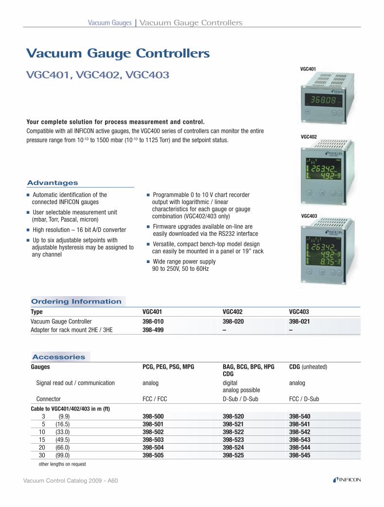
Vacuum Gauges Vacuum Gauge Controllers
Vacuum Control Catalog 2009 - A60
Gauges PCG, PEG, PSG, MPG BAG, BCG, BPG, HPG CDG (unheated) CDG Signal read out / communication analog digital analog analog possible Connector FCC / FCC D-Sub / D-Sub FCC / D-Sub
Cable to VGC401/402/403 in m (ft) 3 (9.9) 398-500 398-520 398-540 5 (16.5) 398-501 398-521 398-541 10 (33.0) 398-502 398-522 398-542 15 (49.5) 398-503 398-523 398-543 20 (66.0) 398-504 398-524 398-544 30 (99.0) 398-505 398-525 398-545 other lengths on request
Accessories
Your complete solution for process measurement and control.Compatible with all INFICON active gauges, the VGC400 series of controllers can monitor the entire pressure range from 10-10 to 1500 mbar (10-10 to 1125 Torr) and the setpoint status.
■ Automatic identification of the connected INFICON gauges
■ User selectable measurement unit (mbar, Torr, Pascal, micron)
■ High resolution – 16 bit A/D converter
■ Up to six adjustable setpoints with adjustable hysteresis may be assigned to any channel
■ Programmable 0 to 10 V chart recorder out put with logarithmic / linear characteristics for each gauge or gauge combination (VGC402/403 only)
■ Firmware upgrades available on-line are easily downloaded via the RS232 interface
■ Versatile, compact bench-top model design can easily be mounted in a panel or 19” rack
■ Wide range power supply 90 to 250V, 50 to 60Hz
Ordering Information
VGC401, VGC402, VGC403
Vacuum Gauge Controllers
Advantages
VGC401
VGC402
VGC403
Type VGC401 VGC402 VGC403
Vacuum Gauge Controller 398-010 398-020 398-021Adapter for rack mount 2HE / 3HE 398-499 – –
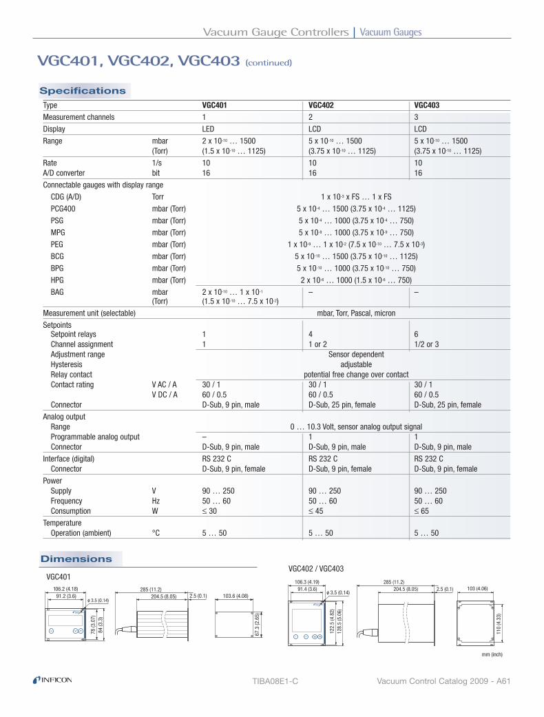
Vacuum GaugesVacuum Gauge Controllers
Vacuum Control Catalog 2009 - A61
Dimensions
Specifications
VGC401, VGC402, VGC403 (continued)
TIBA08E1-C
Type VGC401 VGC402 VGC403Measurement channels 1 2 3
Display LED LCD LCD
Range mbar 2 x 10⁻¹⁰ … 1500 5 x 10⁻¹⁰ … 1500 5 x 10⁻¹⁰ … 1500 (Torr) (1.5 x 10⁻¹⁰ … 1125) (3.75 x 10⁻¹⁰ … 1125) (3.75 x 10⁻¹⁰ … 1125)
Rate 1/s 10 10 10A/D converter bit 16 16 16
Connectable gauges with display range
CDG (A/D) Torr 1 x 10⁻³ x FS … 1 x FS
PCG400 mbar (Torr) 5 x 10⁻⁴ … 1500 (3.75 x 10⁻⁴ … 1125)
PSG mbar (Torr) 5 x 10⁻⁴ … 1000 (3.75 x 10⁻⁴ … 750)
MPG mbar (Torr) 5 x 10⁻⁹ … 1000 (3.75 x 10⁻⁹ … 750)
PEG mbar (Torr) 1 x 10⁻⁹ … 1 x 10⁻² (7.5 x 10⁻¹⁰ … 7.5 x 10⁻³)
BCG mbar (Torr) 5 x 10⁻¹⁰ … 1500 (3.75 x 10⁻¹⁰ … 1125)
BPG mbar (Torr) 5 x 10⁻¹⁰ … 1000 (3.75 x 10⁻¹⁰ … 750)
HPG mbar (Torr) 2 x 10⁻⁶ … 1000 (1.5 x 10⁻⁶ … 750)
BAG mbar 2 x 10⁻¹⁰ … 1 x 10⁻¹ – – (Torr) (1.5 x 10⁻¹⁰ … 7.5 x 10⁻²)
Measurement unit (selectable) mbar, Torr, Pascal, micron
Setpoints Setpoint relays 1 4 6 Channel assignment 1 1 or 2 1/2 or 3 Adjustment range Sensor dependent Hysteresis adjustable Relay contact potential free change over contact Contact rating V AC / A 30 / 1 30 / 1 30 / 1 V DC / A 60 / 0.5 60 / 0.5 60 / 0.5 Connector D-Sub, 9 pin, male D-Sub, 25 pin, female D-Sub, 25 pin, female
Analog output Range 0 … 10.3 Volt, sensor analog output signal Programmable analog output – 1 1 Connector D-Sub, 9 pin, male D-Sub, 9 pin, male D-Sub, 9 pin, male
Interface (digital) RS 232 C RS 232 C RS 232 C Connector D-Sub, 9 pin, female D-Sub, 9 pin, female D-Sub, 9 pin, female
Power Supply V 90 … 250 90 … 250 90 … 250 Frequency Hz 50 … 60 50 … 60 50 … 60 Consumption W ≤ 30 ≤ 45 ≤ 65
Temperature Operation (ambient) °C 5 … 50 5 … 50 5 … 50
para
106.2 (4.18)91.2 (3.6)
78 (3
.07)
84 (3
.3)
285 (11.2)103.6 (4.08)
67.3
(2.6
5)
2.5 (0.1)204.5 (8.05)ø 3.5 (0.14)
ch para
106.3 (4.19)91.4 (3.6)
ø 3.5 (0.14)
122.
5 (4
.82)
128.
5 (5
.06)
285 (11.2)2.5 (0.1)204.5 (8.05) 103 (4.06)
110
(4.3
3)
mm (inch)
VGC401VGC402 / VGC403

Vacuum Gauges Vacuum Switch
Vacuum Control Catalog 2009 - A62
Ordering Information
VSA100A
Vacuum Switch
Applications
■ Control of load lock chambers
■ Safety shutdown of vacuum systems
The pressure switch VSA100A is used as a safety switch in vacuum systems. For example, to automatically interrupt the gas supply when venting vacuum systems with a purge gas at a pressure of 6 mbar below atmospheric pressure.
At a differential pressure of 6 mbar resp. return switching pressure of 3 mbar below atmospheric pressure, an elastic diaphragm actuates a changeover contact which in turn may be used to switch directly any ancillary equipment.
The electrical connections are protected by a plastic cover.
Advantages
■ Reliable and budget-priced vacuum switch
■ Long service life
■ Rugged design
■ Easy to integrate
■ IP 44 protection
■ Can be connected to a programmable control
Type VSA100-ADN 16 ISO-KF, complete with 3 m (9.9 ft) cable 399-001

Vacuum GaugesVacuum Switch
Vacuum Control Catalog 2009 - A63
Dimensions
Specifications
Switching pressure mbar 6 ±2 (below atmosphere)Back switching mbar 3 ±2 (below atmosphere)
Operating pressure (absolute) bar <2
Helium permeation mbar l/s <10-6
Leak rate mbar l/s <5 x 10⁻⁸
Temperature Operation °C 0 ... +85 Storage °C -20 ... +85
Switching contacts (gold plated) Change over contact Voltage max. VDC/VAC 24/24 Current max. mA 30 (24 VDC) / 100 (24 VAC) Load min. mA 1
Electrical connector Cable, bare wire
Cable length, standard m (ft) 3 (9.9)
Vacuum connection DN 16 ISO-KF
Protective type IP 44
Mounting orientation vertical (standing)
Internal volume cm3 (inch3) 2 (0.122)
Materials exposed to vacuum Stainless steel 1.4305, EPDM, PTFE (Teflon)
Weight g 315
Technical Note: Due to the diaphragm material used (EPDM), the Vacuum Switch VSA100A is not suited for applications in which the process gas contains large quantities of helium. The leak rate of the diaphragm for helium is >10-6 mbar l/s.
72 (2
.83)
50 (1
.97)
ø48.5 (ø1.9) mm (inch)
DN16 KF
VSA100A - continued
TIBA27E1-A

Vacuum Gauges Vacuum Switch
Vacuum Control Catalog 2009 - A64
Accessories
Ordering Information
VSC150A
Vacuum Switch
Applications
The pressure switch VSA100A is used as a safety switch in vacuum systems. For example, to automatically interrupt the gas supply when venting vacuum systems with a purge gas at a pressure of 6 mbar below atmospheric pressure.
At a differential pressure of 6 mbar, and a return switching pressure of 3 mbar below atmospheric pressure, an elastic diaphragm actuates a changeover contact which in turn may be used to switch directly any ancillary equipment.
The electrical connections are protected by a plastic cover.
Advantages
■ High switching accuracy (± 0.1 mbar)
■ Stable long term operating characteristics
■ Rugged, corrosion protected design
■ Increased switching capability when using switching amplifier
■ Switching contacts (normally closed) in the reference chamber and thus protected against process media
■ Adapter available for differential pressure measurement
■ Pressure switch or differential pressure switch to control valves, pumps, power supplies
■ Load lock chambers
■ Process chambers
Type VSC150
DN 16 ISO-KF 399-005
SV Switching Amplifier 399-008
Pressure Switch Adjustment 399-006
Differential Pressure Adapter 399-007

Vacuum GaugesVacuum Switch
Vacuum Control Catalog 2009 - A65
Specifications
VSC150A - continued
VSC150 Vacuum SwitchSwitching range mbar 0.5 … 2000Response sensivity mbar 0.1Overload limit mbar 3000Switching hysteresis mbar 0.5Temperature Operation (ambient) °C 5 … 90 Storage °C -20 … 70 Bakeout (max. 8 h) °C 120 Coefficient of switch point %/K of switching value 0.4Vacuum connection DN 16 ISO-KFElectrical connection Protected plug (DIN 43650)Switch n.c. Switching voltage V 24Switching current mA 10Contact resistance Ω 1Protection category IP 65Materials in contact with the medium Sensing volume Stainless steel 1.4301, 1.4401, 1.4310, 1.3541, FPM75 Reference volume Stainless steel 1.4301, 1.4401, 1.3541, glass, goldSensing volume 1) cm3 ≈4Reference volume cm3 ≈20Weight kg 1.3
1) Including connection port.
Specifications
SV Switching AmplifierMains supply (selectable) V 110 … 130, 220 … 240
Mains frequency Hz 50 / 60Power consumption VA 3Output relay Change over contact Switching voltage V 250 Switching current A 5 Switching capacity VA 500Response time ms 30Release time ms 7Control circuit V / mA 24 / 10Operation temperature °C 5 … 50Weight kg 0.36

Vacuum Gauges Vacuum Switch
Vacuum Control Catalog 2009 - A66
Dimensions
TIBA32E1
VSC150A - continued
VSC150 Vacuum Switch SV Switching Amplifier
51
DN 16 KF
Option:Differential pressureadapter DN 16 KF
8518
14
105
21
19
133
21,5�
80�
4,2�
15� 109�
121�55,5�
Pg �9�
Pg �9�
21�50,5�
163�
mm mm


Vacuum Gauges Calibration Service
Vacuum Control Catalog 2009 - A68
Ordering Information
Vacuum Gauges
Calibration Service
Applications
INFICON offers calibration services for vacuum gauges. A DKD calibration certificate or a factory calibration certificate can be issued. Calibration to other standards (e.g. NIST) is available upon request.
Advantages
■ Known deviation to calibration standards
■ Controlled quality over time
■ Reference to standard is required
■ Reference for customer in-house calibration service of
vacuum gauges
DKD CALIBRATION
The German Calibration Service (DKD) ensures traceability of industrial measurements and testing to national calibration standards. It is run jointly by the Federal Institution for Physics and Technology (PTB), the Industry, the Federal Minister for Economics and the Western European Metrology Club (WEMC).
The transfer standards employed in the DKD calibration facility are checked regularly (recalibrated) by the PTB.
FACTORY CALIBRATION
Factory calibrations are run with standards which have not been calibrated directly at the PTB; instead the transfer standards of the DKD calibration service are used. Thus traceability to national standards is ensured in both cases.
OTHER CALIBRATIONS
NIST Calibration available upon request. Call for pricing and availability.
TIBA37E1
Calibration Service DKD Calibration Factory Calibration
Calibration range
to 10-3 mbar / Torr 398-900 398-910
to 10-5 mbar / Torr 398-901 398-911
to 10-7 mbar / Torr 398-902 398-912

Vacuum Feedthroughs
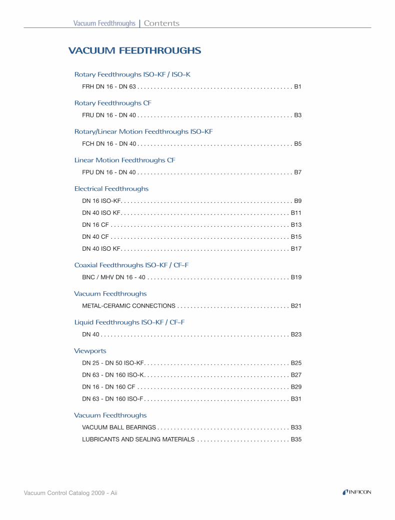
Vacuum Feedthroughs Contents
Vacuum Control Catalog 2009 - Aii
VACUUM FEEdthroUGhS
Rotary Feedthroughs ISO-KF / ISO-K
FRH DN 16 - DN 63 . . . . . . . . . . . . . . . . . . . . . . . . . . . . . . . . . . . . . . . . . . . . . . . B1
Rotary Feedthroughs CF
FRU DN 16 - DN 40 . . . . . . . . . . . . . . . . . . . . . . . . . . . . . . . . . . . . . . . . . . . . . . . B3
Rotary/Linear Motion Feedthroughs ISO-KF
FCH DN 16 - DN 40 . . . . . . . . . . . . . . . . . . . . . . . . . . . . . . . . . . . . . . . . . . . . . . . B5
Linear Motion Feedthroughs CF
FPU DN 16 - DN 40 . . . . . . . . . . . . . . . . . . . . . . . . . . . . . . . . . . . . . . . . . . . . . . . B7
Electrical Feedthroughs
DN 16 ISO-KF . . . . . . . . . . . . . . . . . . . . . . . . . . . . . . . . . . . . . . . . . . . . . . . . . . . . B9
DN 40 ISO KF . . . . . . . . . . . . . . . . . . . . . . . . . . . . . . . . . . . . . . . . . . . . . . . . . . . B11
DN 16 CF . . . . . . . . . . . . . . . . . . . . . . . . . . . . . . . . . . . . . . . . . . . . . . . . . . . . . . B13
DN 40 CF . . . . . . . . . . . . . . . . . . . . . . . . . . . . . . . . . . . . . . . . . . . . . . . . . . . . . . B15
DN 40 ISO KF . . . . . . . . . . . . . . . . . . . . . . . . . . . . . . . . . . . . . . . . . . . . . . . . . . . B17
Coaxial Feedthroughs ISO-KF / CF-F
BNC / MHV DN 16 - 40 . . . . . . . . . . . . . . . . . . . . . . . . . . . . . . . . . . . . . . . . . . . B19
Vacuum Feedthroughs
METAL-CERAMIC CONNECTIONS . . . . . . . . . . . . . . . . . . . . . . . . . . . . . . . . . . B21
Liquid Feedthroughs ISO-KF / CF-F
DN 40 . . . . . . . . . . . . . . . . . . . . . . . . . . . . . . . . . . . . . . . . . . . . . . . . . . . . . . . . . B23
Viewports
DN 25 - DN 50 ISO-KF . . . . . . . . . . . . . . . . . . . . . . . . . . . . . . . . . . . . . . . . . . . . B25
DN 63 - DN 160 ISO-K . . . . . . . . . . . . . . . . . . . . . . . . . . . . . . . . . . . . . . . . . . . . B27
DN 16 - DN 160 CF . . . . . . . . . . . . . . . . . . . . . . . . . . . . . . . . . . . . . . . . . . . . . . B29
DN 63 - DN 160 ISO-F . . . . . . . . . . . . . . . . . . . . . . . . . . . . . . . . . . . . . . . . . . . . B31
Vacuum Feedthroughs
VACUUM BALL BEARINGS . . . . . . . . . . . . . . . . . . . . . . . . . . . . . . . . . . . . . . . . B33
LUBRICANTS AND SEALING MATERIALS . . . . . . . . . . . . . . . . . . . . . . . . . . . . B35
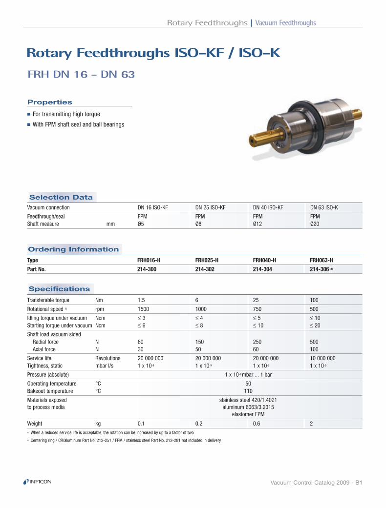
Vacuum FeedthroughsRotary Feedthroughs
Vacuum Control Catalog 2009 - B1
Specifications
Ordering Information
Selection Data
Properties
FRH DN 16 - DN 63
rotary Feedthroughs ISo-KF / ISo-K
■For transmitting high torque
■With FPM shaft seal and ball bearings
Type FRH016-H FRH025-H FRH040-H FRH063-H
Part No. 214-300 214-302 214-304 214-306 2)
Vacuum connection DN 16 ISO-KF DN 25 ISO-KF DN 40 ISO-KF DN 63 ISO-K
Feedthrough/seal FPM FPM FPM FPM Shaft measure mm Ø5 Ø8 Ø12 Ø20
1) When a reduced service life is acceptable, the rotation can be increased by up to a factor of two
2) Centering ring / CR/aluminum Part No. 212-251 / FPM / stainless steel Part No. 212-281 not included in delivery
Transferable torque Nm 1.5 6 25 100
Rotational speed 1) rpm 1500 1000 750 500
Idling torque under vacuum Ncm ≤ 3 ≤ 4 ≤ 5 ≤ 10 Starting torque under vacuum Ncm ≤ 6 ≤ 8 ≤ 10 ≤ 20
Shaft load vacuum sided Radial force N 60 150 250 500 Axial force N 30 50 60 100
Service life Revolutions 20 000 000 20 000 000 20 000 000 10 000 000 Tightness, static mbar l/s 1 x 10⁻⁹ 1 x 10⁻⁹ 1 x 10⁻⁹ 1 x 10⁻⁹
Pressure (absolute) 1 x 10⁻⁹ mbar ... 1 bar
Operating temperature °C 50 Bakeout temperature °C 110
Materials exposed stainless steel 420/1.4021to process media aluminum 6063/3.2315 elastomer FPM
Weight kg 0.1 0.2 0.6 2

Vacuum Feedthroughs Rotary Feedthroughs
Vacuum Control Catalog 2009 - B2
FRH016-H FRH025-H FRH040-H FRH063-H
FRH DN 16 - DN 63 - continued
Dimensions
RIBA01E1

Vacuum FeedthroughsRotary Feedthroughs
Vacuum Control Catalog 2009 - B3
Specifications
Ordering Information
Selection Data
Properties
rotary Feedthroughs CF
■Bellow sealed
■All-metal version
■For very demanding vacuum requirements
Type FRU016-H FRU040-N FRU040-L
Part No. 214-310 214-312 214-314
Vacuum connection DN 16 CF-F DN 40 CF-F DN 40 CF-F
Feedthrough / seal bellow bellow bellow Shaft connection mm 4 8 12
Transferable torque Dynamic Nm 0.4 4 10 Dynamic, at 300°C Nm 0.2 2 2 Static Nm 0.2 3 5
Rotational speed rpm 200 1000 500 At max. torque rpm 500 300
Shaft load vacuum sided Radial force N 10 60 100 Axial force N 5 20 30
Service life Revolutions 1 000 000 2 000 000 1 000 000 Scale division Degree 10 – –
Tightness mbar l/s 5 x 10-11
Pressure (absolute) 1 x 10⁻¹⁰ mbar ... 2 bar
Operating temperature °C 300Bakeout temperature °C 300
Materials exposed 304L/1.4306 304L/1.4306 304L/1.4306to process media 304/1.4301 304/1.4301 304/1.4301 –/2.4360 –/2.4360 303/1.4305
Weight kg 0.3 1.5 3.0
FRU DN 16 - DN 40
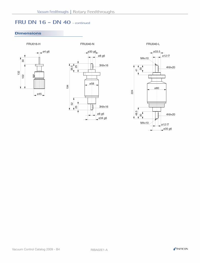
Vacuum Feedthroughs Rotary Feedthroughs
Vacuum Control Catalog 2009 - B4
FRU DN 16 - DN 40 - continued
Dimensions
RIBA02E1-A
30�
ø12 f7�ø33.5�
ø80�
48.5
�
ø12 f7�ø35 g6�
224�
4h9×20�
4h9×20�
M4×10�
M4×10�
41�
30�
52�
194�
36.5
�25
�25
�
ø58�
ø8 g6�ø30 g6�
3h9×16�
3h9×16�
ø8 g6�ø34 g6�
FRU040-N� FRU040-L�FRU016-H�
102�13
2�30
�
ø4 g6�
ø45�

Vacuum FeedthroughsRotary/Linear Motion Feedthroughs
Vacuum Control Catalog 2009 - B5
Ordering Information
Selection Data
Specifications
Properties
FCH DN 16 - DN 40
rotary/Linear Motion Feedthroughs ISo-KF
■Two FPM shaft seals
■Direct push/pull and rotary actuation
■With locking ring and optional anti-rotation device
Type FCH016-H FCH025-H FCH040-H
Rotary/linear feedthrough Part No. 214-320 214-322 214-324 Anti-rotation device Part No. 214-072 214-073 214-074
Shaft load Radial force at max.travel N 10 15 30 Torsion torque Nm 2 8 20
Tightness, static mbar l/s 1 x 10⁻⁹
Pressure (absolute) 1 x 10⁻⁸ mbar ... 1bar
Operating temperature °C 50 Bakeout temperature °C 110
Materials exposed stainless steel 304/1.4301
to process media aluminum 6063/3.2315
Weight kg 0.1 0.2 0.3
Vacuum connection DN 16 ISO-KF DN 25 ISO-KF DN 40 ISO-KF
Feedthrough/seal FPM FPM FPM Shaft connection M 3 / Ø 5mm M 4 / Ø 8mm M 6 / Ø 12mm
Travel mm 50 100 150

Vacuum Feedthroughs Rotary/Linear Motion Feedthroughs
Vacuum Control Catalog 2009 - B6
FCH DN 16 - DN 40 - continued
Dimensions
Feedthrough
Anti-rotation device
FCH016-H FCH025-H FCH040-H
Feedthrough Feedthrough
Anti-rotation device Anti-rotation device
RIBA03E1
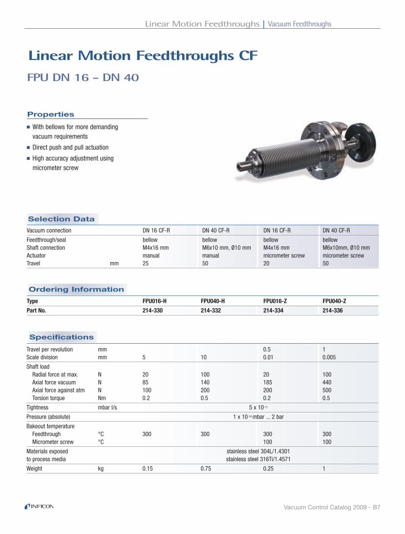
Vacuum FeedthroughsLinear Motion Feedthroughs
Vacuum Control Catalog 2009 - B7
Specifications
Ordering Information
Selection Data
Properties
FPU DN 16 - DN 40
Linear Motion Feedthroughs CF
■With bellows for more demanding vacuum requirements
■Direct push and pull actuation
■High accuracy adjustment using micrometer screw
Type FPU016-H FPU040-H FPU016-Z FPU040-Z
Part No. 214-330 214-332 214-334 214-336
Vacuum connection DN 16 CF-R DN 40 CF-R DN 16 CF-R DN 40 CF-R
Feedthrough/seal bellow bellow bellow bellow Shaft connection M4x16 mm M6x10 mm, Ø10 mm M4x16 mm M6x10mm, Ø10 mm Actuator manual manual micrometer screw micrometer screw Travel mm 25 50 20 50
Travel per revolution mm 0.5 1 Scale division mm 5 10 0.01 0.005
Shaft load Radial force at max. N 20 100 20 100 Axial force vacuum N 85 140 185 440 Axial force against atm N 100 200 200 500 Torsion torque Nm 0.2 0.5 0.2 0.5
Tightness mbar l/s 5 x 10-11
Pressure (absolute) 1 x 10⁻¹⁰ mbar ... 2 bar
Bakeout temperature Feedthrough °C 300 300 300 300 Micrometer screw °C 100 100
Materials exposed stainless steel 304L/1.4301 to process media stainless steel 316Ti/1.4571
Weight kg 0.15 0.75 0.25 1

Vacuum Feedthroughs Linear Motion Feedthroughs
Vacuum Control Catalog 2009 - B8
FPU DN 16 - DN 40 - continued
Dimensions
FPU016-H FPU040-H FPU016-Z FPU040-Z
RIBA04E1

Vacuum FeedthroughsElectrical Feedthroughs
Vacuum Control Catalog 2009 - B9
Specifications
Ordering Information
Selection Data
DN 16 ISO-KF
Electrical Feedthroughs
Feedthrough 214-111 214-112 214-113 Connector: vacuum side – – 214-191 Connector: atmospheric side 214-171 214-172 214-172
Connection Vacuum side solder connection solder connection connector Atmospheric side connector connector connector
Diameter of connecting wire mm 0.6 1.2 1.2
Tightness mbar l/s 1 x 10⁻⁹
Pressure (absolute) 1 x 10⁻⁸ mbar ... 2.5 bar Bakeout temperature (feedthrough and connector) °C 130
Housing stainless steel 303/1.4305 Insulator PEEK / Araldite Seal FPM Contacts (feedthrough and connector) gold-plated bronze
Vacuum connection DN 16 ISO-KF DN 16 ISO-KF DN 16 ISO-KF
Number of feedthroughs 4 9 9 Voltage per pole V 50 50 50 Current per pole A 1 2 2

Vacuum Feedthroughs Electrical Feedthroughs
Vacuum Control Catalog 2009 - B10
DN 16 ISO-KF - continued
Dimensions
Feedthrough
Connector: air side
214-111
Connector: vacuum side
214-191
214-171 214-172 214-172
214-112
Feedthrough
214-113
Feedthrough
RIBA09E1
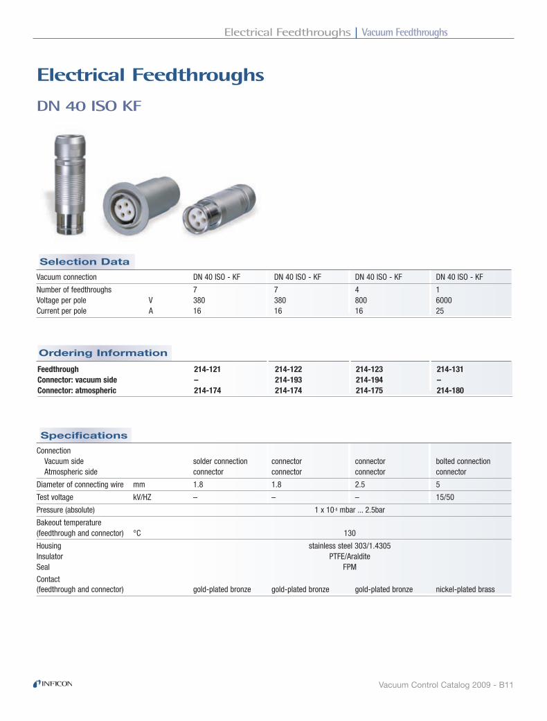
Vacuum FeedthroughsElectrical Feedthroughs
Vacuum Control Catalog 2009 - B11
Connection Vacuum side solder connection connector connector bolted connection Atmospheric side connector connector connector connector
Diameter of connecting wire mm 1.8 1.8 2.5 5
Test voltage kV/HZ – – – 15/50
Pressure (absolute) 1 x 10⁻⁸ mbar ... 2.5bar
Bakeout temperature (feedthrough and connector) °C 130
Housing stainless steel 303/1.4305 Insulator PTFE/Araldite Seal FPM
Contact (feedthrough and connector) gold-plated bronze gold-plated bronze gold-plated bronze nickel-plated brass
Vacuum connection DN 40 ISO - KF DN 40 ISO - KF DN 40 ISO - KF DN 40 ISO - KF
Number of feedthroughs 7 7 4 1 Voltage per pole V 380 380 800 6000 Current per pole A 16 16 16 25
Specifications
Ordering Information
Selection Data
DN 40 ISO KF
Electrical Feedthroughs
Feedthrough 214-121 214-122 214-123 214-131 Connector: vacuum side – 214-193 214-194 – Connector: atmospheric 214-174 214-174 214-175 214-180
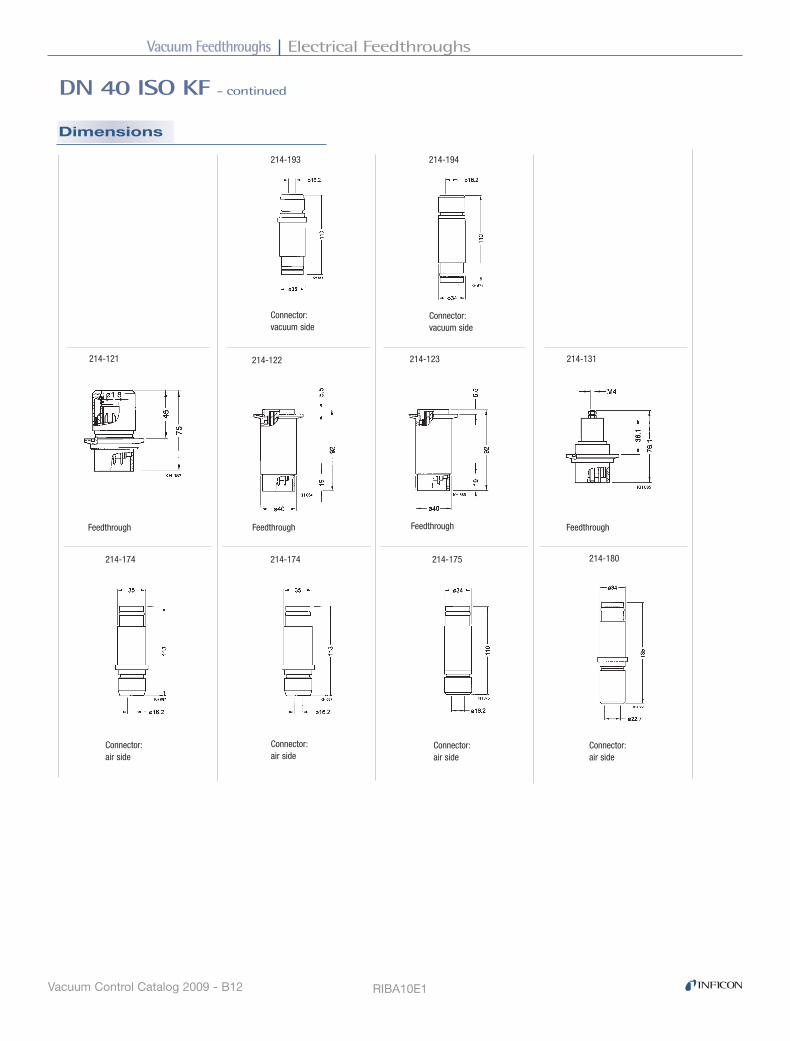
Vacuum Feedthroughs Electrical Feedthroughs
Vacuum Control Catalog 2009 - B12
DN 40 ISO KF - continued
Dimensions
RIBA10E1
Connector: vacuum side
Feedthrough
Connector: air side
214-121 214-122 214-123 214-131
214-193 214-194
214-174 214-174 214-175 214-180
Feedthrough Feedthrough Feedthrough
Connector: vacuum side
Connector: air side
Connector: air side
Connector: air side
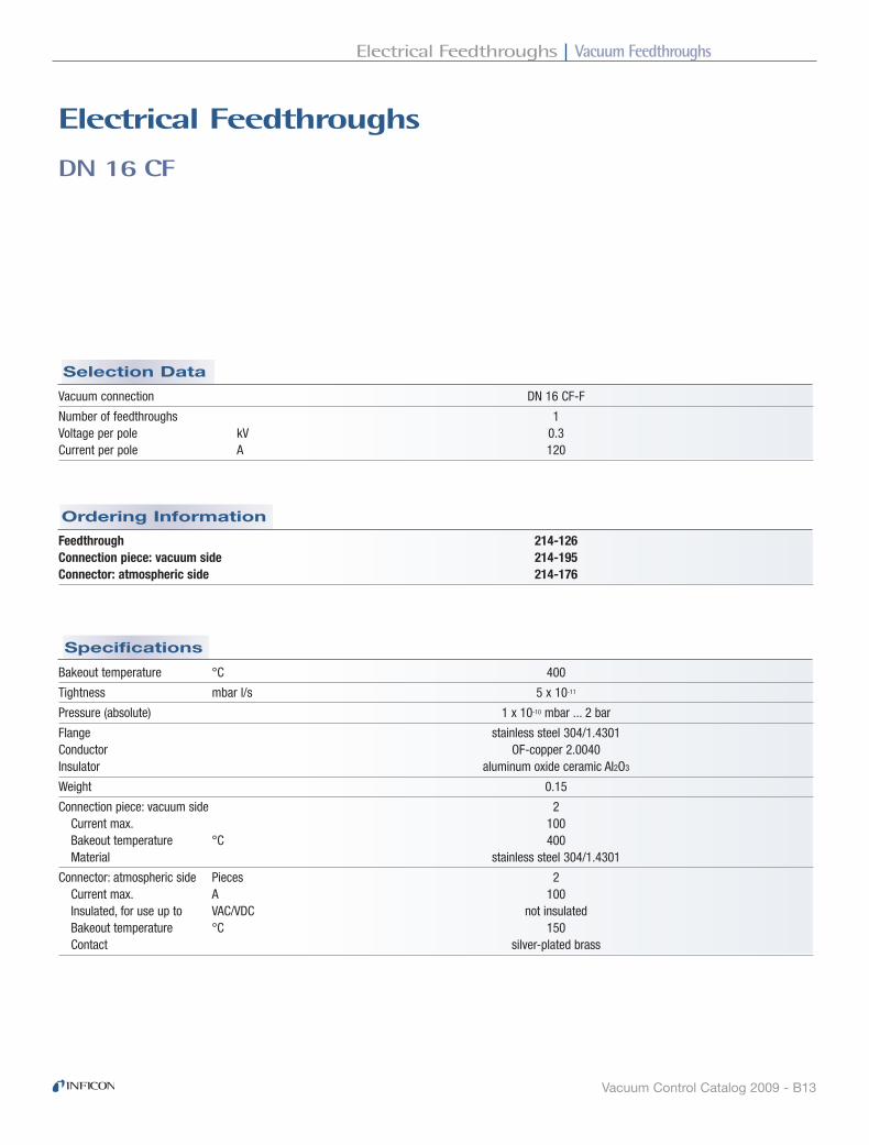
Vacuum FeedthroughsElectrical Feedthroughs
Vacuum Control Catalog 2009 - B13
Bakeout temperature °C 400
Tightness mbar l/s 5 x 10-11
Pressure (absolute) 1 x 10⁻¹⁰ mbar ... 2 bar
Flange stainless steel 304/1.4301 Conductor OF-copper 2.0040 Insulator aluminum oxide ceramic Al2O3
Weight 0.15
Connection piece: vacuum side 2 Current max. 100 Bakeout temperature °C 400 Material stainless steel 304/1.4301
Connector: atmospheric side Pieces 2 Current max. A 100 Insulated, for use up to VAC/VDC not insulated Bakeout temperature °C 150 Contact silver-plated brass
Feedthrough 214-126 Connection piece: vacuum side 214-195 Connector: atmospheric side 214-176
Vacuum connection DN 16 CF-F
Number of feedthroughs 1 Voltage per pole kV 0.3 Current per pole A 120
Specifications
Ordering Information
Selection Data
DN 16 CF
Electrical Feedthroughs

Vacuum Feedthroughs Electrical Feedthroughs
Vacuum Control Catalog 2009 - B14
DN 16 CF - continued
Dimensions
RIBA11E1
SW 8�
53�
25�
19.5
�
M6�
ø10�
KU 077
214-126 214-195 214-176

Vacuum FeedthroughsElectrical Feedthroughs
Vacuum Control Catalog 2009 - B15
Bakeout temperature °C 400
Tightness mbar l/s 5 x 10-11
Pressure (absolute) 1 x 10⁻¹⁰ mbar ... 2 bar
Flange 304/1.4301 304/1.4301 304/1.4301 304/1.4301 304/1.4301 Conductor OFC 2.0040 OFC 2.0040 OFC 2.0040 304/1.4301 304/1.4301 Insulator Al2O3 Al2O3 Al2O3 Al2O3 Al2O3
Weight 0.15 0.5 0.45 0.3 0.5
Connection piece: vacuum side 2 1 2 5 10 Current A 20 10001) 100 12 12 Bakeout temperature °C 400 400 400 400 400 Material 304/1.4301 2.0061 304/1.4301 304/1.4301 304/1.4301
Connector: atmospheric side Pieces 2 1 2 5 10 Current max. A 100 250 100 25 25 Insulated, for use up to VAC/VDC not insulated 30/60 30/60 30/60 30/60 Bakeout temperature °C 150 150 50 50 50 Contact silver-plated brass silver-plated brass silver-plated brass gold-plated brass gold-plated brass
Feedthrough 214-136 214-127 214-128 214-116 214-117 Connection piece: vacuum side 214-195 214-196 214-195 214-192 214-198 Connector: atmospheric side 214-176 214-177 214-176 214-173 214-181 Connector: atm. side, H2O cooled – 214-178 – – –
Vacuum connection DN 40 CF-F DN 40 CF-F DN 40 CF-F DN 40 CF-F DN 40 CF-FNumber of feedthroughs 1 1 2 4 9 Voltage per pole kV 0.3 1 0.3 1 1 Current per pole A 70 200/1000 1) 70 8 8
1) With water-cooling
Specifications
Ordering Information
Selection Data
DN 40 CF
Electrical Feedthroughs
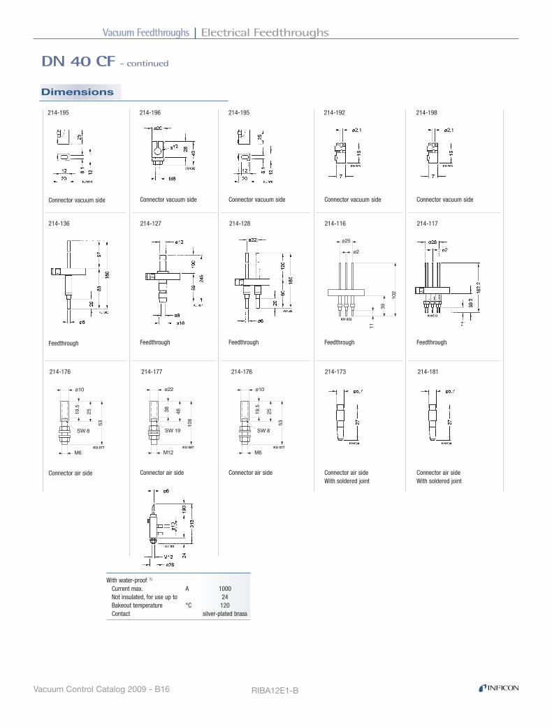
Vacuum Feedthroughs Electrical Feedthroughs
Vacuum Control Catalog 2009 - B16
DN 40 CF - continued
Dimensions
RIBA12E1-B
102�
39�
11�KH 652
ø2�
ø25�
SW 8�
53�
25�
19.5
�
M6�
ø10�
KU 077
SW 19�
106�
48�38�
M12�
ø22�
KU 087
214-195214-196 214-192 214-198
214-127 214-116
214-176214-177 214-173 214-181
214-128 214-117
214-195
Connector vacuum side
214-136
Feedthrough
214-176
With water-proof 1)
Current max. A 1000 Not insulated, for use up to 24 Bakeout temperature °C 120 Contact silver-plated brass
Connector air side
SW 8�
53�
25�
19.5
�
M6�
ø10�
KU 077
Connector vacuum side Connector vacuum side Connector vacuum side Connector vacuum side
Feedthrough Feedthrough Feedthrough Feedthrough
Connector air side Connector air side Connector air side With soldered joint
Connector air side With soldered joint

Vacuum FeedthroughsHigh Current Feedthroughs
Vacuum Control Catalog 2009 - B17
Tightness mbar l/s 1 x 10⁻⁹
Pressure (absolute) 1 x 10⁻⁸ mbar ... 2.5 bar (max. 10 bar with external centering ring)
Bakeout temperature °C 110
Housing aluminum 6063/3.2315 Insulator thermoplast and thermoset Seal FPM
Feedthrough with O-ring KF40 214-141 Current connection with water cooling 2) 214-145 Straight electrode 214-142 Angle electrode 214-1432) Not insulated
Vacuum connection DN 40 ISO-KF
Number of feedthroughs 1
Voltage V 100 Current A 250/1500 1)
1) With water cooling
Specifications
Ordering Information
Selection Data
DN 40 ISO KF
high Current Feedthrough
♦ Selection of three electrodes ♦ Slide into mounted feedthrough ♦ Current connection with water cooling
Properties

Vacuum Feedthroughs High Current Feedthroughs
Vacuum Control Catalog 2009 - B18
DN 40 ISO KF - continued
Dimensions
RIBA13E1
Current connection with water cooling copper/brass
Feedthrough
Electrodes copper/brass
214-141
214-145
214-142 214-143
Electrodes copper/brass

Vacuum FeedthroughsCoaxial Feedthroughs
Vacuum Control Catalog 2009 - B19
Specifications
Ordering Information
Selection Data
BNC / MHV DN 16 - 40
Coaxial Feedthroughs ISo-KF / CF-F
Properties
■Based on MIL-C-39012A
■Voltage up to 5 kV DC
■With atmospheric connector
Vacuum connection DN 16 ISO-KF DN 16 ISO-KF DN 16 CF-F DN 16 CF-F DN 40 CF-F
Number of feedthroughs 1 1 1 1 3
Voltage AC, 50 Hz kV 0.35 3.5 0.35 3.5 3.5 DC kV 0.5 5 0.5 5 5 Current A 3 3 3 3 3
Frequency MHz 150 150 Impedance Ω 50-60 50-60 Insulation resistance at 20°C Ω 1010 1010 1010 1010 1010
Tightness mbar l/s 1 x 10⁻⁹ 1 x 10⁻⁹ 1 x 10⁻¹⁰ 1 x 10⁻¹⁰ 1 x 10⁻¹⁰
Pressure (absolute) 1) 1 x 10⁻⁸ mbar to 1 x 10⁻⁸ mbar to 1 x 10⁻¹⁰ mbar to 1 x 10⁻¹⁰ mbar to 1 x 10⁻¹⁰ mbar to 2.5 bar 2.5 bar 10 bar 10 bar 10 bar
Housing, flange, conductor stainless steel stainless steel stainless steel stainless steel stainless steel Feedthrough, seal Al2O3 Al2O3 Al2O3 Al2O3 Al2O3
Bakeout temperature With connector °C 50 50 50 50 50 Without connector °C 200 200 400 400 400
Standart connection Atmospheric connector UG 88/U UG 932/U UG 88/U UG 932/U UG 932/U Cable RG 58/U RG 59/U RB 58/U RG 59/U RG 59/U
Weight kg 0.1 0.1 0.14 0.14 0.5
Type BNC MHV BNC MHV MHV
Part No. 214-151 214-152 214-155 214-156 214-157
1) Pressure at 400ºC : 2 bar

Vacuum Feedthroughs Coaxial Feedthroughs
Vacuum Control Catalog 2009 - B20
BNC / MHV DN 16 - 40 - continued
Dimensions
214-151 214-152 214-155 214-156 214-157
RIBA14E1-A

Vacuum FeedthroughsVacuum Feedthroughs
Vacuum Control Catalog 2009 - B21
Specifications
Ordering Information
Selection Data
METAL-CERAMIC CONNECTIONS
Vacuum Feedthroughs
Properties
■High grade materials allow repeated bakings up to 400°C
Part No. 214-161 214-162 214-163 214-164
Insulator Al2O3 Al2O3 Al2O3 Al2O3 Connection a Fe-Ni Fe-Ni Fe-Ni Fe-Ni b Fe-Ni stainless steel stainless steel stainless steel 304/1.4301 304/1.4301 304/1.4301
Bakeout temperature °C 400 400 400 400 Tightness mbar l/s 5 x 10-11 5 x 10-11 5 x 10-11 5 x 10-11
Weight g 5 12 25 90
Voltage 1) 3 kV 2 kV 5 kV 10 kV
1) Based on VDE 0110 for air and surface-leakage in atmosphere on both sides.
Higher values up to factor two are admissible in pressures <10-4 mbar.

Vacuum Feedthroughs Vacuum Feedthroughs
Vacuum Control Catalog 2009 - B22
214-161�
15.5
�40
�12
�7�
ø2.1�ø3.5�
ø7.2�ø6.2�
12�
39�
8�8�
ø10�ø9.2�
ø6�ø8�
ø13.5�
35�
8�
ø10�ø9.2�
ø13.5�62�
8�
ø6�ø8�
214-162� 214-163� 214-164�
62�
9�
95�
10�
ø23�
ø20�ø19�
ø12�ø16�
METAL-CERAMIC CONNECTIONS - continued
Dimensions
RIBA15E1-A

Vacuum FeedthroughsLiquid Feedthroughs
Vacuum Control Catalog 2009 - B23
Specifications
Ordering Information
Selection Data
Properties
DN 40
Liquid Feedthroughs ISo-KF / CF-F
■For H2O and LN2
■Thermically insulated
■Specially suited for very hot and very cold applications
Vacuum connection DN 40 ISO-KF DN 40 CF-F
Feedthrough/seal welded welded Tube dimensions mm Ø 8 x 1 Ø 8 x 1 Number of tubes 2 2
Part No. 214-101 214-102
Tightness mbar l/s 1 x 10⁻⁹ 1 x 10⁻¹⁰
Pressure 10-8 mbar ... 10 bar 10-9 mbar ... 10 bar
Temperature range °C -200 ... +150 -200 ... +400
Material stainless steel 304/1.4301 stainless steel 304/1.4301
Weight kg 0.3 0.4

Vacuum Feedthroughs Liquid Feedthroughs
Vacuum Control Catalog 2009 - B24
DN 40 - continued
Dimensions
214-101 214-102
RIBA16E1

Vacuum FeedthroughsViewports
Vacuum Control Catalog 2009 - B25
Specifications
Selection Data
Average transmittance curve
Sapphire
Kodial
Borosilicate
DN 25 - DN 50 ISO-KF
Viewports
Part No. 214-003 214-004 214-005
Vacuum connection DN 25 ISO-KF DN 40 ISO-KF DN 50 ISO-KF
Window borosilicate glass Seal FPM Flange aluminum 6082/3.2315 Bakeout temperature °C 150
Properties
■Wide viewing angle
Tightness mbar l/s 1 x 10⁻⁹
Pressure (absolute) 1 x 10⁻⁸ mbar ... 4 bar Max. at 150°C bar 3
Window thickness mm 3.8
Weight g 20 30 40
Ordering Information

Vacuum Feedthroughs Viewports
Vacuum Control Catalog 2009 - B26
DN 25 - DN 50 ISO-KF - continued
Dimensions
214-004 214-005
Mounting
214-003
Claws, screws and clamping ring not included
RIBA05E1

Vacuum FeedthroughsViewports
Vacuum Control Catalog 2009 - B27
Specifications
Ordering Information
Selection Data
DN 63 - DN 160 ISO-K
Viewports
Part No. 214-006 214-007 214-008
Vacuum connection DN 63 ISO-K DN 100 ISO-K DN 160 ISO-K
Window borosilicate glass Seal FPM Flange aluminum 6082/3.2315 Bakeout temperature °C 150
Tightness mbar l/s 1 x 10⁻⁹
Pressure (absolute) 1 x 10⁻⁸ mbar ... 2 bar Max. at 150°C bar 1
Window thickness mm 6 8 10
Weight kg 0.2 0.3 0.4
1) Claws not included
Properties
■Wide viewing angle
Average transmittance curve
Sapphire
Kodial
Borosilicate

Vacuum Feedthroughs Viewports
Vacuum Control Catalog 2009 - B28
DN 63 - DN 160 ISO-K - continued
Dimensions
214-006 214-007 214-008
Mounting
RIBA06E1

Vacuum FeedthroughsViewports
Vacuum Control Catalog 2009 - B29
Specifications
Ordering Information
Selection Data
DN 16 - DN 160 CF
Viewports
Properties
■Protection window
■With Fe-Ni alloy as transition material
Vacuum connection DN 16 CF-F DN 40 CF-F DN 40 CF-F DN 63 CF-F DN 100 CF-F DN 160 CF-F
Window kodial glass kodial glass sapphire glass kodial glass kodial glass kodial glass
Seal iron/nickel Flange stainless steel 304/1.4301 Bakeout temperature °C 400
Tightness mbar l/s 5 x 10-11
Pressure (absolute) Min. mbar 1 x 10⁻¹⁰
Max. bar 2 Max. at 400°C bar 1
Window thickness mm 1.5 3 3 3.5 6 8 Weight kg 0.04 0.24 0.35 0.85 1.4 2.8
Viewport 214-021 214-022 214-032 214-023 214-024 214-025 Bolt set 213-416 standard standard standard standard standard
Average transmittance curve
Sapphire
Kodial
Borosilicate

Vacuum Feedthroughs Viewports
Vacuum Control Catalog 2009 - B30
DN 16 - DN 160 CF - continued
Dimensions
214-006 214-007 214-008
Mounting
RIBA08E1

Vacuum FeedthroughsViewports
Vacuum Control Catalog 2009 - B31
Specifications
Ordering Information
Selection Data
DN 63 - DN 160 ISO-F
Viewports
Properties
■Wide viewing angle
Viewport 1) 214-016 214-017 214-018 Protective glass, 5 pcs. 214-046 214-047 214-0481) Claws, bolts, nuts and washer included
Tightness mbar l/s 1 x 10⁻⁹
Pressure (absolute) 1 x 10⁻⁸ mbar ... 2 bar Max. at 150°C bar 1
Window thickness mm 7.5 11 15 Protective glass thickness mm 2.5 2.5 2.5
Weight kg 0.8 1.4 3
Vacuum connection DN 63 ISO-F DN 100 ISO-F DN 160 ISO-F
Window borosilicate glass Seal FPM Flange black anodized aluminum 6063/3.2315 Centering ring aluminum 6063/3.2315 Snap ring stainless steel 304/1.4301 Bakeout temperature °C 150
Average transmittance curve
Sapphire
Kodial
Borosilicate

Vacuum Feedthroughs Viewports
Vacuum Control Catalog 2009 - B32
DN 63 - DN 160 ISO-F - continued
Dimensions
214-006 214-007 214-008
Mounting
RIBA07E1

Vacuum FeedthroughsVacuum Ball Bearings
Vacuum Control Catalog 2009 - B33
Rotational speed at 20°C rpm 5000 4000 3000 2500 2000 1500 300°C rpm 1500 1500 1000 800 500 300
Load capacity 3) Static CO N 400 400 800 1000 1500 2000
Dynamic C N 50 50 100 150 200 250 Axial load <<C <<C <<C <<C <<C <<C
Fit according to ISO G6 / f6 G6 / f6 G6 / f6 G6 / f6 G6 / f6 G6 / f6
Weight g 3 4 8 13 20 251) At half load and > 1000/min
2) At -200°C reduction of tenacity
3) At 20°C; half value at 300°C
Type 624 605 626 608 6000 6001 Part No. 214-211 214-212 214-213 214-214 214-215 214-216
Service life 1) (revolutions) > 20 Mio.
Pressure (absolute) mbar 1 x 10-12 ... 1 x 10⁻² Operating temperature 2) °C -200 ... +300 Material stainless steel 440C/1.3543, 304/1.4301
Specifications
Ordering Information
Selection Data
Properties
VACUUM BALL BEARINGS
Vacuum Feedthroughs
■Specially suited for clean vacuum applications and extreme residual gas requirements
■With shields (non-rubbing seals)
■With dry lubrication
■Bearing clearance
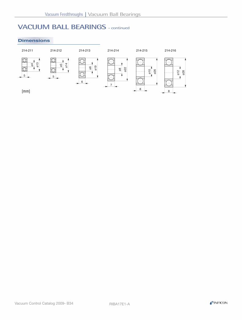
Vacuum Feedthroughs Vacuum Ball Bearings
Vacuum Control Catalog 2009- B34
VACUUM BALL BEARINGS - continued
Dimensions
RIBA17E1-A
ø13�
ø4�
5�
ø14�
ø5�
5�
ø19�
ø6�
6�
ø22�
ø8�
7�8�
ø26�
ø10�
8�
ø28�
ø12�
214-211� 214-212� 214-213� 214-214� 214-215� 214-216�
[mm]

Vacuum FeedthroughsLubricants and Sealing Materials
Vacuum Control Catalog 2009 - B35
Ordering Information
Selection Data
Ordering Information
Selection Data
LUBRICANTS AND SEALING MATERIALS
Vacuum Feedthroughs
High Temperature Lubricant
■Prevents seizing of stainless steel screw connections at atmosphere even at high temperatures
■Remains fully effective for at least 10 bakeout cycles
Type C 100
Part No. 214-231
Temperature resistance 1000°C
In packages of 28 g
Sealing Material
■For sealing small leaks
Temperature resistance °C -40 - 200 350
Version Paste Spray In packages of g 200 170
Type Rhodosil 340 Sprayseal
Part No. 214-233 214-234
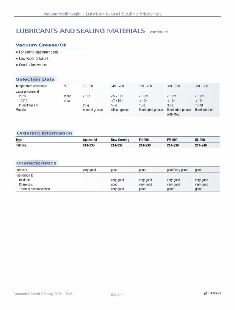
Vacuum Feedthroughs Lubricants and Sealing Materials
Vacuum Control Catalog 2009 - B36
Characteristics
Ordering Information
Selection Data
LUBRICANTS AND SEALING MATERIALS - continued
Lubricity very good good good good/very good good
Resistance to Oxidation very good very good very good very good Chemicals good very good very good very good Thermal decomposition very good good good good
Vacuum Grease/Oil
■For sliding elastomer seals
■Low vapor pressure
■Good adhesiveness
Temperature resistance °C 10 - 30 -40 - 200 -20 - 200 -60 - 300 -60 - 300
Vapor pressure at 20°C mbar <10-8 <5 x 10⁻⁷ < 10-12 < 10-12 < 10-12 100°C mbar <7 x.10-6 < 10-7 < 10-7 < 10-7 In packages of 25 g 50 g 10 g 30 g 10 ml Material mineral grease silicon grease fluorinated grease fluorinated grease fluorinated oil with MoS2
Type Apezon M Dow Corning FU 090 FM 090 OL 090
Part No. 214-236 214-237 214-238 214-239 214-240
RIBA18E1

Vacuum Valves

Vacuum Valves Contents
Vacuum Control Catalog 2009 - Cii
VACUUM VALVES
Angle and Inline Valves ( VAH, VAP, VAM, VIM)
ISO-KF DN 5 manually, pneumatically, solenoid . . . . . . . . . . . . . . . . . . . . . . . . . C1
Angle and Inline Valves ( VAH, VIH, VAP, VIP)
ISO-KF DN16 - 40 manually . . . . . . . . . . . . . . . . . . . . . . . . . . . . . . . . . . . . . . . . . C4
ISO-KF DN16 - 40 manually (Diaphragm Valves) . . . . . . . . . . . . . . . . . . . . . . . . . C8
ISO-KF DN16 - 40 pneumatically . . . . . . . . . . . . . . . . . . . . . . . . . . . . . . . . . . . C10
ISO-KF DN16 - 40 solenoid (VAP, VIP) . . . . . . . . . . . . . . . . . . . . . . . . . . . . . . . C14
ISO-KF DN16 - 40 solenoid (VAM) . . . . . . . . . . . . . . . . . . . . . . . . . . . . . . . . . . . C18
ISO-KF DN63 manually, pneumatically . . . . . . . . . . . . . . . . . . . . . . . . . . . . . . . C21
ISO-KF DN100 manually, pneumatically . . . . . . . . . . . . . . . . . . . . . . . . . . . . . . C24
ISO-KF DN160 pneumatically . . . . . . . . . . . . . . . . . . . . . . . . . . . . . . . . . . . . . . C27
Butterfly Valves (VBH, VBP)
ISO-KF DN63 - 160 manually . . . . . . . . . . . . . . . . . . . . . . . . . . . . . . . . . . . . . . C29
ISO-KF DN63 - 250 pneumatically . . . . . . . . . . . . . . . . . . . . . . . . . . . . . . . . . . C31
Dosing Valves (VDH)
ISO-KF DN10 manually (coarse gas dosing) . . . . . . . . . . . . . . . . . . . . . . . . . . C37
ISO-KF DN16 manually (fine gas dosing / shut-off) . . . . . . . . . . . . . . . . . . . . . C38
Dosing Systems (VDM, VDE, VCE, VCC, VCA)
All-Metal Dosing Valves and System . . . . . . . . . . . . . . . . . . . . . . . . . . . . . . . . . C40
Gas Dosing Systems . . . . . . . . . . . . . . . . . . . . . . . . . . . . . . . . . . . . . . . . . . . . . C43
Solenoid Control Valves . . . . . . . . . . . . . . . . . . . . . . . . . . . . . . . . . . . . . . . . . . . C44
All-Metal Angle Valves (VAH)
CF-R DN16 - 63 manually . . . . . . . . . . . . . . . . . . . . . . . . . . . . . . . . . . . . . . . . . C50
Venting Valves (VVH, VVM, VIN)
ISO-KF DN10 manually . . . . . . . . . . . . . . . . . . . . . . . . . . . . . . . . . . . . . . . . . . . C52
ISO-KF DN10 solenoid . . . . . . . . . . . . . . . . . . . . . . . . . . . . . . . . . . . . . . . . . . . . C53
ISO-KF DN10 solenoid (power failure) . . . . . . . . . . . . . . . . . . . . . . . . . . . . . . . . C55
Vacuum ValvesContents
Vacuum Control Catalog 2009 - Ciii
VACUUM VALVES (continued)
Safety Valves (VSM)
ISO-KF DN16 - 40 . . . . . . . . . . . . . . . . . . . . . . . . . . . . . . . . . . . . . . . . . . . . . . . C56
ISO-KF DN63 - 100 . . . . . . . . . . . . . . . . . . . . . . . . . . . . . . . . . . . . . . . . . . . . . . C56
Pressure Relief Valve (VSA)
ISO-KF DN16 . . . . . . . . . . . . . . . . . . . . . . . . . . . . . . . . . . . . . . . . . . . . . . . . . . . C58
Ball Valves
ISO-KF DN10 - 40 . . . . . . . . . . . . . . . . . . . . . . . . . . . . . . . . . . . . . . . . . . . . . . . C59
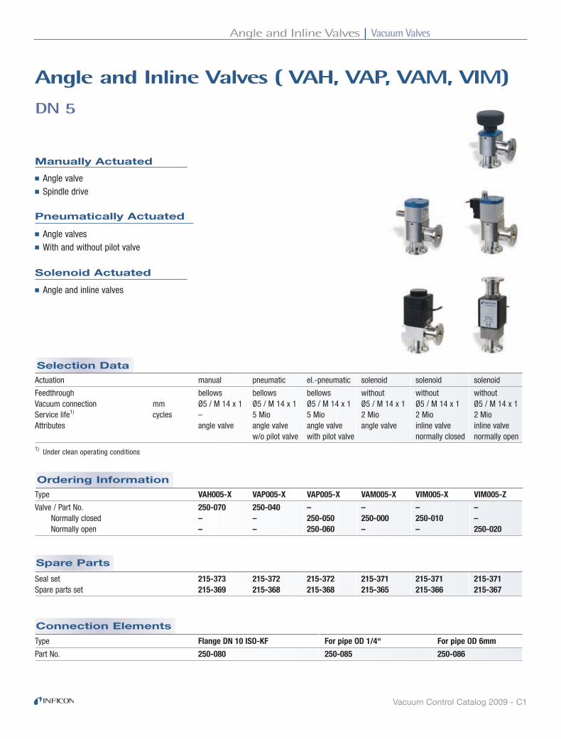
Vacuum ValvesAngle and Inline Valves
Vacuum Control Catalog 2009 - C1
Connection Elements
Spare Parts
Ordering Information
Selection Data
Manually Actuated
DN 5
Angle and Inline Valves ( VAh, VAP, VAM, VIM)
■ Angle valve■ Spindle drive
Pneumatically Actuated
■ Angle valves■ With and without pilot valve
Solenoid Actuated
■ Angle and inline valves
Actuation manual pneumatic el.-pneumatic solenoid solenoid solenoid
Feedthrough bellows bellows bellows without without without Vacuum connection mm Ø5 / M 14 x 1 Ø5 / M 14 x 1 Ø5 / M 14 x 1 Ø5 / M 14 x 1 Ø5 / M 14 x 1 Ø5 / M 14 x 1 Service life1) cycles – 5 Mio 5 Mio 2 Mio 2 Mio 2 Mio Attributes angle valve angle valve angle valve angle valve inline valve inline valve w/o pilot valve with pilot valve normally closed normally open1) Under clean operating conditions
Type VAH005-X VAP005-X VAP005-X VAM005-X VIM005-X VIM005-Z
Valve / Part No. 250-070 250-040 – – – – Normally closed – – 250-050 250-000 250-010 – Normally open – – 250-060 – – 250-020
Type Flange DN 10 ISO-KF For pipe OD 1/4“ For pipe OD 6mm
Part No. 250-080 250-085 250-086
Seal set 215-373 215-372 215-372 215-371 215-371 215-371 Spare parts set 215-369 215-368 215-368 215-365 215-366 215-367
ISO-KF DN 5 manually, pneumatically, solenoid

Vacuum Valves Angle and Inline Valves
Vacuum Control Catalog 2009 - C2
Specifications
DN 5 - continued
Type VAH005-X VAP005-X VAP005-X VAM005-X VIM005-X VIM005-Z Actuation manual pneumatic el.-pneumatic solenoid solenoid solenoid
Tightness mbar l/s 1 x 10⁻⁹ 1 x 10⁻⁹ 1 x 10⁻⁹ 1 x 10⁻⁹ 1 x 10⁻⁹ 1 x 10⁻⁹
Conductance for air Molecular flow l/s 0.4 0.4 0.4 0.3 0.2 0.2 Laminar flow l/s 4 4 4 3 2 2
Pressure range (absolute) mbar … bar 10-8 … 4 10-8 … 4 10-8 … 4 10-8 … 10 10-8 … 10 10-8 … 10
Pressure difference ∆p In closing direction bar 4 3 3 5 5 4 In opening direction bar 4 3 3 1.5 1.5 2 Opens against ∆p1) bar 4 3 3 1 1 4
Temperature Ambient °C 52) … 70 52) … 80 52) … 40 52) … 40 52) … 40 52) … 40
Closing time ms – 35 / 35 35 / 35 7 / 30 7 / 30 30 / 10 Opening time ms – Switching frequency 1/min – 150 150 300 300 300
Degree of protection – IP 65 IP 65 IP 65 IP 65 IP 65
Supply voltage/ V DC – – 24 24 24 24 Power consumption W – – 1 10 10 10
Materials Housing 304/1.4301 304/1.4301 304/1.4301 304/1.4301 304/1.4301 304/1.4301 Actuator Al & plastic anodized Al anodized Al – – – Bellows 304/1.4301 304/1.4301 304/1.4301 – – – Valve plate 304/1.4301 304/1.4301 304/1.4301 – – – Guiding tube – – – 303/1.4105 303/1.4105 303/1.4105 Armature – – – 303/1.4105 303/1.4105 303/1.4105 Seals FPM FPM FPM FPM FPM FPM
Weight kg 0.15 0.20 0.20 0.26 0.28 0.30
1) Compressed air: overpressure 4 bar2) –15°C, if the ambiance is free of condensable gases

Vacuum ValvesAngle and Inline Valves
Vacuum Control Catalog 2009 - C3
Dimensions
VAH005-X VAP005-X VAP005-X VAM005-X
30 (1.18)500 (19.68)
31.5
(1.2
4)
mm (inch)
8 (0
.31)
8 (0
.31)
82 (3
.23)
M14x1
M14x1
30 (1.18)500 (19.68)
31.5
(1.2
4)
mm (inch)
8 (0
.31)
8 (0
.31)
82 (3
.23)
M14x1
M14x1
VIM005-X VIM005-Z
14.5 (0.57)
14.5 (0.57)
18 (0.71)
DN 10 ISO-KF
HOD 6mm
HOD 1/4"
mm (inch)
Compressed air connection
Power connection
SIBA11E1-A

Vacuum Valves Angle and Inline Valves
Vacuum Control Catalog 2009 - C4
Advantages
VAH016 ... 040-A/X
VIH016 ... 040-X
Angle and Inline Valves ( VAh, VIh)
The INFICON ISO-KF valve line, VAH / VIH016 … 040-A/X performs as a gauge isolation, bypass, roughing or venting valve and is well suited for all general high vacuum and semiconductor processes. The improved industrial design results in a rugged, compact, easy to operate valve. The visual position indicator shows the open / close status of the valve for clear understanding of valve status. The extremely long service life and easy to maintain design results in a highly reliable valve with low cost of ownership. The new line is compatible with the current INFICON VAH / VIH016 … 040-A/X valve line.
■ Ergonomically designed knob for secure grip
■ Fast open / close actuation with one 130° turn; or a soft continuously variable actuation for controlled venting / pumping of vacuum systems
■ Low operating force required, even if the valve is opened against vacuum
■ Drive locks into final open / close position
■ Visual position indicator, standard
■ 316L stainless steel bellows
■ Easy maintenance, fast bellows and seal replacement
■ High conductance for fast pump down or venting
■ High differential pressure resistance
■ FPM sealing standard, other sealing materials available upon request
■ High purity aluminum or stainless steel housing
ISO-KF DN16 - 40 manually
Manually Actuated
Angle and Inline Valves ( VAh, VIh, VAP, VIP)

Vacuum ValvesAngle and Inline Valves
Vacuum Control Catalog 2009 - C5
Spare Parts
Cycle life Cycles 10000 10000 10000
Conductance for molecular flow Angle valve l/s 5 14 45 Inline Valve l/s 2.5 7 20
Tightness mbar l/s 1 x 10⁻⁹ 1 x 10⁻⁹ 1 x 10⁻⁹
Operating pressure min. / max. mbar / bar 1 x 10⁻⁸ / 2 1 x 10⁻⁸ / 2 1 x 10⁻⁸ / 1.5
Pressure, max. (absolute) bar 4 4 4
Pressure difference In closing direction bar 4 4 2 In opening direction bar 2 2 1.5
Ambiance temperature °C 0 … +50 0 … +50 0 … +50
Mounting orientation any any any
Seals FPM FPM FPM
Weight Angle valve kg 0.31 0.34 0.42 0.49 0.85 0.96 Inline valve kg 0.71 1.09 1.83
Vacuum connection DN 16 ISO-KF DN 25 ISO-KF DN 40 ISO-KF
Aluminum housing AISI/DIN -/EN AW-6082 -/EN AW-6082 -/EN AW-6082 Stainless steel housing AISI/DIN 304/1.4301 304/1.4301 304/1.4301
VAH016 ... 040-A/X
VIH016 ... 040-X - continued
Selection Data
Ordering Information
Inline ValveType VIH016-A VIH016-X VIH025-A VIH025-X VIH040-A VIH040-X
— 253-265 — 253-365 — 253-465
Angle ValveType VAH016-A VAH016-X VAH025-A VAH025-X VAH040-A VAH040-X
253-200 253-245 253-300 253-345 253-400 253-445
Specifications
Vacuum connection DN 16 ISO-KF DN 25 ISO-KF DN 40 ISO-KF
Seal kit 299-001 299-006 299-011 O-rings for one valve
Bellows cpl. 299-002 299-007 299-012 Bellows & seal kit
Angle and Inline Valves ( VAh, VIh, VAP, VIP)

Vacuum Valves Angle and Inline Valves
Vacuum Control Catalog 2009 - C6
VAH016 ... 040-A/X
VIH016 ... 040-X - continued
Dimensions Angle Valve
DN�
Aluminum housing
DN A B C D E
DN 16 ISO-KF 141.3 149.5 39.6 45 40
DN 25 ISO-KF 145.3 155.7 39.6 54 50
DN 40 ISO-KF 186.2 201.4 50 69 65
Stainless steel housing
DN�
Protective lid
Valve seat site
Flow direction
DN A B C D E
DN 16 ISO-KF 143.9 152.1 39.6 45 40
DN 25 ISO-KF 148.7 159.1 39.6 54 50
DN 40 ISO-KF 189.2 204.4 50 69 65

Vacuum ValvesAngle and Inline Valves
Vacuum Control Catalog 2009 - C7
Dimensions Inline Valve
SIBA40E1-A
DN�
Stainless steel housing
DN A B C D E F
DN 16 ISO-KF 125.4 133.6 39.6 45 80 20
DN 25 ISO-KF 132 142.4 39.6 54 100 31.8
DN 40 ISO-KF 166.5 181.7 50 69 130 40.8
Protective lid
Valve seat site
Flow direction
VAH016 ... 040-A/X
VIH016 ... 040-X - continued

Vacuum Valves Angle and Inline Valves
Vacuum Control Catalog 2009 - C8
Type VIH016-AD VIH025-AD VIH040-AD
253-481 253-482 253-483
Ordering Information Selection Data
Advantages
VIH016 ... 040-AD
diaphragm Valves
The INFICON ISO-KF diaphragm valve line, VIH016 … 040-AD performs as a gauge isolation, roughing or venting valve. The manual spindle drive allows easy gas dosing. The robust and rugged industrial design is well suited for gases and liquids and is resistant to contamination.
■ Spindle drive for controlled venting and easy dosing
■ Low operating force required
■ Visual position indicator
■ FPM diaphragm sealing; other sealing materials on request
■ Aluminum inline housing EN AW-6082
■ Easy maintenance, fast diaphragm seal replacement
■ Small footprint and easy system integration
Diaphragm (1 piece) 299-031 299-032 299-033
Spare Parts
ISO-KF DN16 - 40 manually (Diaphragm Valves)
Manually Actuated

Vacuum ValvesAngle and Inline Valves
Vacuum Control Catalog 2009 - C9
Specifications VIH016-AD VIH025-AD VIH040-AD
Vacuum connection DN 16 ISO-KF DN 25 ISO-KF DN 40 ISO-KF
Cycle life Cycles >10000 >10000 >10000
Conductance for molecular flow l/s 2 5 17
Tightness mbar l/s 1 x 10⁻⁹ 1 x 10⁻⁹ 1 x 10⁻⁹
Operating pressure min. / max. mbar / bar 1 x 10⁻⁷ / 5 1 x 10⁻⁷ / 5 1 x 10⁻⁷ / 5
Pressure, max. (absolute) bar 5 5 5
Ambiance temperature °C 0 … +50 0 … +50 0 … +50
Mounting orientation any any any
Diaphragm FPM FPM FPM
Weight kg 0.16 0.5 1.2
VIH016 ... 040-AD - continued
AVa
lve
open
Valv
e cl
osed
B
DN
DN
E
D
D
C
DN A B C D E F
DN 16 ISO-KF 66 62 52 32.5 29.5 –
DN 25 ISO-KF 111 101 80 54 47 –
DN 40 ISO-KF 148.5 134.5 105 75 69.5 80
Protective lid
Visual position indicator
DN
DN
AV
alv
e o
pen
Valv
e c
lose
dB
C
D
F
E
VIH016-AD, VIH025-AD VIH040-AD
[mm]
Dimensions
SIBA45E1
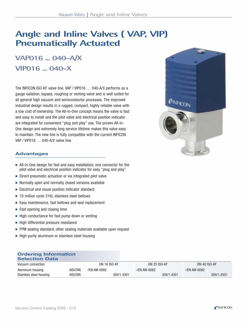
Vacuum Valves Angle and Inline Valves
Vacuum Control Catalog 2009 - C10
Vacuum connection DN 16 ISO-KF DN 25 ISO-KF DN 40 ISO-KF
Aluminum housing AISI/DIN -/EN AW-6082 -/EN AW-6082 -/EN AW-6082 Stainless steel housing AISI/DIN 304/1.4301 304/1.4301 304/1.4301
Ordering Information Selection Data
Advantages
VAP016 ... 040-A/X
VIP016 ... 040-X
Angle and Inline Valves ( VAP, VIP)Pneumatically Actuated
The INFICON ISO-KF valve line, VAP / VIP016 … 040-A/X performs as a gauge isolation, bypass, roughing or venting valve and is well suited for all general high vacuum and semiconductor processes. The improved industrial design results in a rugged, compact, highly reliable valve with a low cost of ownership. The All-in-One concept means the valve is fast and easy to install and the pilot valve and electrical position indicator are integrated for convenient “plug and play” use. The proven All-in-One design and extremely long service lifetime makes this valve easy to maintain. The new line is fully compatible with the current INFICON VAP / VIP016 … 040-A/X valve line.
■ All-in-One design for fast and easy installation; one connector for the pilot valve and electrical position indicator for easy “plug and play”
■ Direct pneumatic actuation or via integrated pilot valve
■ Normally open and normally closed versions available
■ Electrical and visual position indicator standard
■ 10 million cycle 316L stainless steel bellows
■ Easy maintenance, fast bellows and seal replacement
■ Fast opening and closing time
■ High conductance for fast pump down or venting
■ High differential pressure resistance
■ FPM sealing standard, other sealing materials available upon request
■ High purity aluminum or stainless steel housing
ISO-KF DN16 - 40 pneumatically
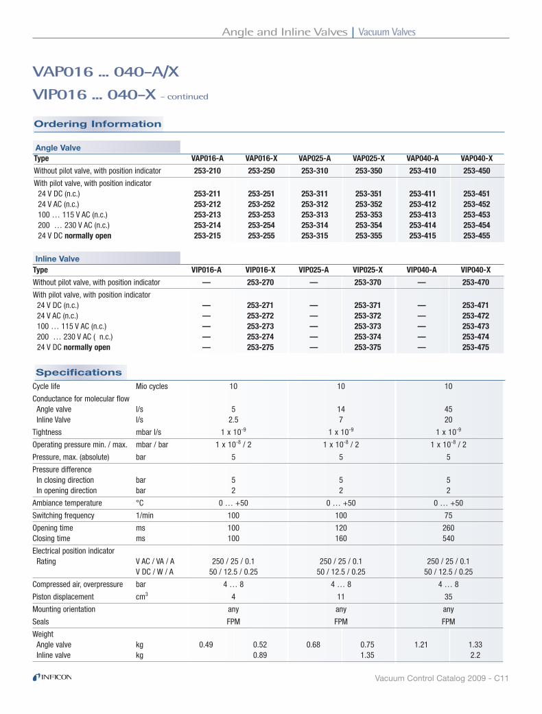
Vacuum ValvesAngle and Inline Valves
Vacuum Control Catalog 2009 - C11
Type VIP016-A VIP016-X VIP025-A VIP025-X VIP040-A VIP040-X
Without pilot valve, with position indicator — 253-270 — 253-370 — 253-470
With pilot valve, with position indicator 24 V DC (n.c.) — 253-271 — 253-371 — 253-471 24 V AC (n.c.) — 253-272 — 253-372 — 253-472 100 … 115 V AC (n.c.) — 253-273 — 253-373 — 253-473 200 … 230 V AC ( n.c.) — 253-274 — 253-374 — 253-474 24 V DC normally open — 253-275 — 253-375 — 253-475
Type VAP016-A VAP016-X VAP025-A VAP025-X VAP040-A VAP040-X
Without pilot valve, with position indicator 253-210 253-250 253-310 253-350 253-410 253-450
With pilot valve, with position indicator 24 V DC (n.c.) 253-211 253-251 253-311 253-351 253-411 253-451 24 V AC (n.c.) 253-212 253-252 253-312 253-352 253-412 253-452 100 … 115 V AC (n.c.) 253-213 253-253 253-313 253-353 253-413 253-453 200 … 230 V AC (n.c.) 253-214 253-254 253-314 253-354 253-414 253-454 24 V DC normally open 253-215 253-255 253-315 253-355 253-415 253-455
VAP016 ... 040-A/X
VIP016 ... 040-X - continued
Ordering Information
Specifications
Angle Valve
Inline Valve
Cycle life Mio cycles 10 10 10
Conductance for molecular flow Angle valve l/s 5 14 45 Inline Valve l/s 2.5 7 20
Tightness mbar l/s 1 x 10⁻⁹ 1 x 10⁻⁹ 1 x 10⁻⁹
Operating pressure min. / max. mbar / bar 1 x 10⁻⁸ / 2 1 x 10⁻⁸ / 2 1 x 10⁻⁸ / 2
Pressure, max. (absolute) bar 5 5 5
Pressure difference In closing direction bar 5 5 5 In opening direction bar 2 2 2
Ambiance temperature °C 0 … +50 0 … +50 0 … +50
Switching frequency 1/min 100 100 75
Opening time ms 100 120 260 Closing time ms 100 160 540
Electrical position indicator Rating V AC / VA / A 250 / 25 / 0.1 250 / 25 / 0.1 250 / 25 / 0.1 V DC / W / A 50 / 12.5 / 0.25 50 / 12.5 / 0.25 50 / 12.5 / 0.25
Compressed air, overpressure bar 4 … 8 4 … 8 4 … 8
Piston displacement cm3 4 11 35
Mounting orientation any any any
Seals FPM FPM FPM
Weight Angle valve kg 0.49 0.52 0.68 0.75 1.21 1.33 Inline valve kg 0.89 1.35 2.2

Vacuum Valves Angle and Inline Valves
Vacuum Control Catalog 2009 - C12
VAP016 ... 040-A/X
VIP016 ... 040-X - continued
Dimensions Angle Valve
Vacuum connection DN 16 ISO-KF DN 25 ISO-KF DN 40 ISO-KF
Seal kit 299-001 299-006 299-011 O-rings for one valve
Bellows cpl. 299-002 299-007 299-012 Bellows & seal kit
Cover cpl. 299-003 299-008 299-013 Receptacle, visual & electrical position indicator already assembled
Spare Parts
Accessories
Vacuum connection DN 16 ISO-KF DN 25 ISO-KF DN 40 ISO-KF
Cable connector right angled 215-165 215-165 215-165
DN�
DN�
ø4�
Aluminum housing
DN A B C D E F G
DN 16 ISO-KF 142 112.9 75.1 55 51.4 93.2 40
DN 25 ISO-KF 146.9 117.8 79 64.3 60.1 97.8 50
DN 40 ISO-KF 188.8 159.7 114.9 81.3 75.7 105.3 65
Compressed air connection
Protective lid
Electrical connection
Flow direction
Position indicator connection
Valve seat site
Visual position indicator
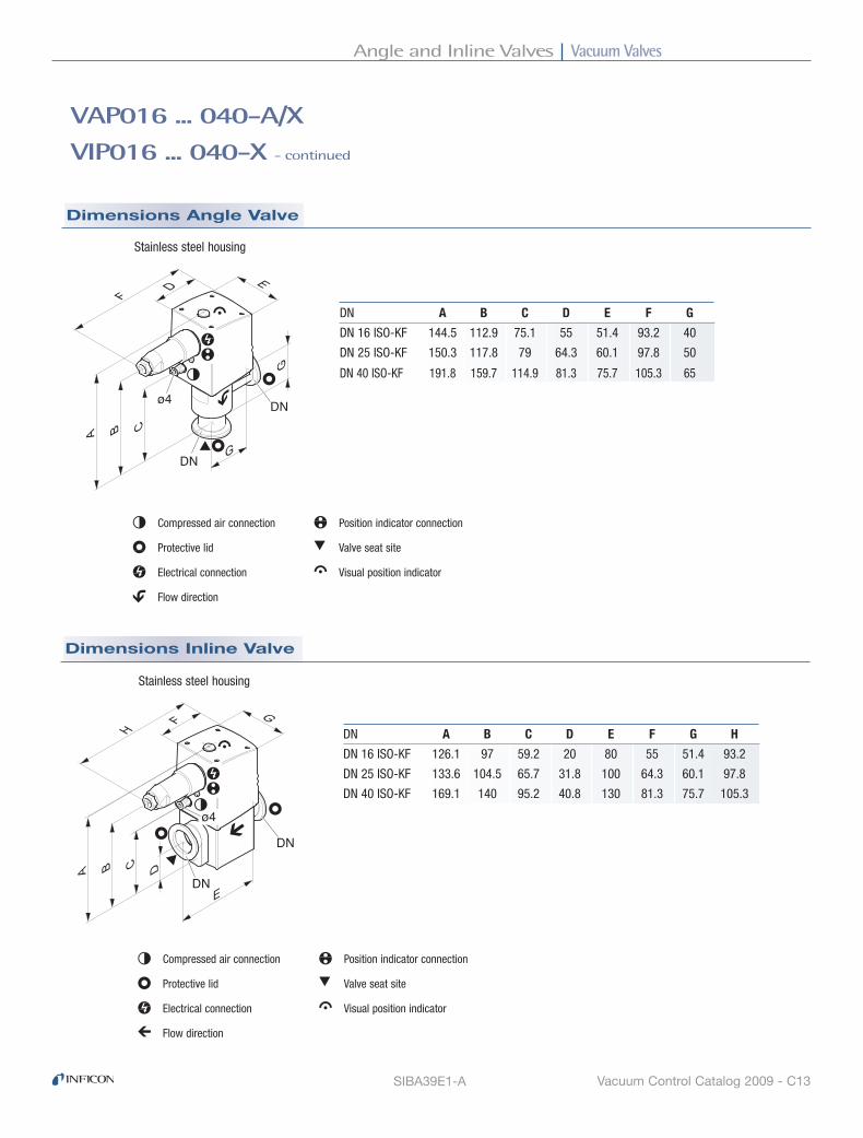
Vacuum ValvesAngle and Inline Valves
Vacuum Control Catalog 2009 - C13
Dimensions Angle Valve
SIBA39E1-A
VAP016 ... 040-A/X
VIP016 ... 040-X - continued
Stainless steel housing
DN�
DN�
ø4�
DN A B C D E F G
DN 16 ISO-KF 144.5 112.9 75.1 55 51.4 93.2 40
DN 25 ISO-KF 150.3 117.8 79 64.3 60.1 97.8 50
DN 40 ISO-KF 191.8 159.7 114.9 81.3 75.7 105.3 65
Compressed air connection
Protective lid
Electrical connection
Flow direction
Position indicator connection
Valve seat site
Visual position indicator
Dimensions Inline Valve
DN�
DN�
ø4�
Stainless steel housing
DN A B C D E F G H
DN 16 ISO-KF 126.1 97 59.2 20 80 55 51.4 93.2
DN 25 ISO-KF 133.6 104.5 65.7 31.8 100 64.3 60.1 97.8
DN 40 ISO-KF 169.1 140 95.2 40.8 130 81.3 75.7 105.3
Compressed air connection
Protective lid
Electrical connection
Flow direction
Position indicator connection
Valve seat site
Visual position indicator

Vacuum Valves Angle and Inline Valves
Vacuum Control Catalog 2009 - C14
Vacuum connection DN 16 ISO-KF DN 25 ISO-KF DN 40 ISO-KF
Aluminum housing AISI/DIN -/EN AW-6060 -/EN AW-6060 -/EN AW-6060 Stainless steel housing AISI/DIN 304/1.4301 304/1.4301 304/1.4301
Order Information Selection Data
Advantages
VAP016 ... 040-A/X
VIP016 ... 040-X
Angle and Inline Valves ( VAP, VIP)Pneumatically Actuated
The new INFICON ISO-KF valve line, VAP / VIP016 … 040-A/X performs as a gauge isolation, bypass, roughing or venting valve and is perfectly suited for all general high vacuum and semiconductor processes. The improved industrial design is very robust, compact and highly reliable with a low cost of ownership. This pneumatic actuated valve is designed for system manufacturers who need a compact and space saving valve unit. This valve comes with an outstanding long service lifetime and is very easy to maintain. It is equipped with the same approved high quality components like INFICON is using for its very successful All-in-One concept valve line.
■ Robust and very compact design
■ Visual position indicator, standard
■ 10 million cycle 316L stainless steel bellows
■ Easy maintenance due to fast bellows and seal replacement
■ Fast opening and closing time
■ High conductance for fast pump down or venting
■ High differential pressure resistance
■ FPM sealing standard. Other sealing materials available upon request
■ High purity aluminum or stainless steel housing

Vacuum ValvesAngle and Inline Valves
Vacuum Control Catalog 2009 - C15
Cycle life Mio cycles 10 10 10
Conductance for molecular flow Angle valve l/s 5 14 45 Inline Valve l/s 2.5 7 20
Tightness mbar l/s 1 x 10⁻⁹ 1 x 10⁻⁹ 1 x 10⁻⁹
Operating pressure min. / max. mbar / bar 1 x 10⁻⁸ / 2 1 x 10⁻⁸ / 2 1 x 10⁻⁸ / 2
Pressure, max. (absolute) bar 5 5 5
Pressure difference In closing direction bar 5 5 5 In opening direction bar 2 2 2
Ambiance temperature °C 0 … +50 0 … +50 0 … +50
Bakeout temperature Housing °C 120 150 120 150 120 150 Actuator °C 120 120 120 120 120 120
Switching frequency 1/min 100 100 75
Opening time ms 100 120 260 Closing time ms 100 160 540
Compressed air, overpressure bar 4 … 8 4 … 8 4 … 8
Piston displacement cm3 4 11 35
Mounting orientation any any any
Seals FPM FPM FPM
Weight Angle valve kg 0.38 0.42 0.57 0.66 1.17 1.28 Inline valve kg 0.83 1.27 2.48
VAP016 ... 040-A/X
VIP016 ... 040-X - continued
Ordering Information
Specifications
Angle Valve
Inline Valve
Type VAP016-A VAP016-X VAP025-A VAP025-X VAP040-A VAP040-X
253-220 253-260 253-320 253-360 253-420 253-460
Type VIP016-A VIP016-X VIP025-A VIP025-X VIP040-A VIP040-X
— 253-280 — 253-380 — 253-480
Vacuum connection DN 16 ISO-KF DN 25 ISO-KF DN 40 ISO-KF
Seal kit 299-001 299-006 299-011 O-rings for one valve
Bellows cpl. 299-002 299-007 299-012 Bellows & seal kit
Spare Parts

Vacuum Valves Angle and Inline Valves
Vacuum Control Catalog 2009 - C16
VAP016 ... 040-A/X
VIP016 ... 040-X - continued
Dimensions Angle Valve
DN�
DN�
ø4�
Aluminum housing
DN A B C D E
DN 16 ISO-KF 100.5 95.7 75.6 40 45
DN 25 ISO-KF 108.5 102.6 80.6 50 54
DN 40 ISO-KF 150.5 144.7 116.6 65 69
Compressed air connection
Protective lid
Flow direction
Valve seat site
Visual position indicator
Stainless steel housing
DN�
DN�
ø4�
DN A B C D E
DN 16 ISO-KF 103 98.2 78.1 40 45
DN 25 ISO-KF 112 106 84 50 54
DN 40 ISO-KF 153.5 147.7 119.6 65 69
Compressed air connection
Protective lid
Flow direction
Valve seat site
Visual position indicator
[mm]
[mm]
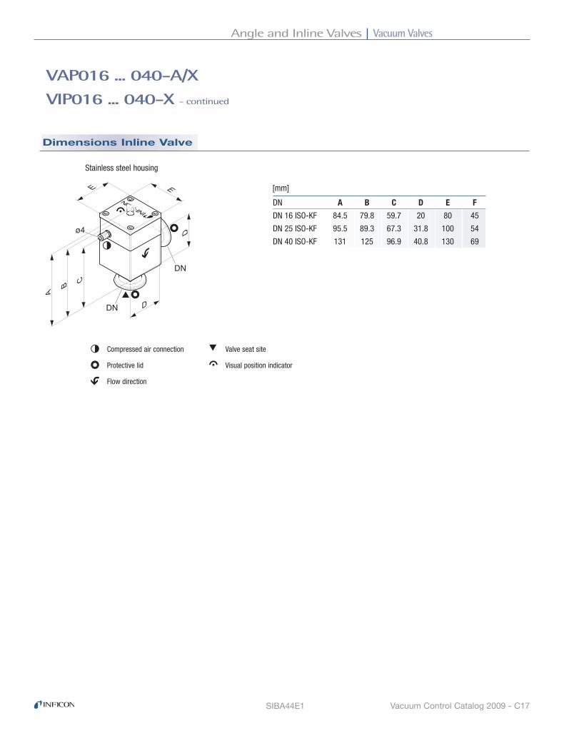
Vacuum ValvesAngle and Inline Valves
Vacuum Control Catalog 2009 - C17SIBA44E1
VAP016 ... 040-A/X
VIP016 ... 040-X - continued
Dimensions Inline Valve
DN�
DN�
ø4�
Stainless steel housing
DN A B C D E F
DN 16 ISO-KF 84.5 79.8 59.7 20 80 45
DN 25 ISO-KF 95.5 89.3 67.3 31.8 100 54
DN 40 ISO-KF 131 125 96.9 40.8 130 69
Compressed air connection
Protective lid
Flow direction
Valve seat site
Visual position indicator
[mm]

Vacuum Valves Solenoid Actuated Angle Valves with ISO-KF Flanges
Vacuum Control Catalog 2009 - C18
Seal kit 299-001 299-006 299-011 O-rings for one valve
Bellows cpl. 299-002 299-007 299-012 Bellows & seal kit
Electronics cpl. 299-016 299-016 299-016
Linear solenoid cpl. 299-017 299-018 299-019
Vacuum connection DN 16 ISO-KF DN 25 ISO-KF DN 40 ISO-KF
Aluminum housing AISI/DIN -/EN AW-6060 -/EN AW-6060 -/EN AW-6060 Stainless steel housing AISI/DIN 304/1.4301 304/1.4301 304/1.4301
Ordering Information
Selection Data
Solenoid Actuated Angle Valves
Advantages
■ Bellows feedthrough, stainless steel 316L■ Compact design■ Electrical and visual (LED) position indication■ Selectable operating mode Remote control via PLC or PC Local operation■ Wide voltage range■ Easy maintenance, fast bellows and seal replacement
■ Fast opening and closing time
■ FPM sealing standard, other sealing materials available upon request
■ Aluminum or stainless steel housing
■ High conductance for fast pump down or venting
Spare Parts
VAM016 ... 040-A/X
Type VAM016-A VAM016-X VAM025-A VAM025-X VAM040-A VAM040-X
Part No. 253-500 253-501 253-502 253-503 253-504 253-505

Vacuum ValvesSolenoid Actuated Angle Valves with ISO-KF Flanges
Vacuum Control Catalog 2009 - C19
Specifications
VAM016 ... 040-A/X - continued
Type VAM016-A VAM016-X VAM025-A VAM025-X VAM040-A VAM040-X
Cycle life Mio cycles 2 2 2 Conductance for molecular flow l/s 4 13 35
Tightness mbar l/s 1 x 10⁻⁹ 1 x 10⁻⁹ 1 x 10⁻⁹
Operating pressure min. / max mbar / bar 10-8 / 1.3 10-8 / 1.3 10-8 / 1.3 Pressure max. bar 3 3 1
Pressure difference In closing direction bar 1.3 1.3 1.3 In opening direction bar 1.3 1.3 1 Opens to a pressure difference of bar 1.3 1.3 1.3
Ambient temperature °C 0 … 50 0 … 50 0 … 50
Bakeout temperature Housing °C 120 120 120 Actuator, idle °C 50 50 50
Supply voltage V 90 … 264 90 … 264 90 … 264 Frequency Hz 47 … 63 47 … 63 47 … 63
Pickup power W 405 416 367 Holding power W 8.1 8.3 7.5 Power consumption W 400 400 400
Closing time ms 100 120 230 Opening time ms 220 220 650 Dead time ms 40 140 450
Switching frequency At 40°C 1/min 30 30 30 At 50°C 1/min 20 20 20
Control voltage V DC 15 … 30 15 … 30 15 … 30 Power consumption mA 1.5 … 5 1.5 … 5 1.5 … 5
Position indicator Switching voltage V DC 15 … 30 15 … 30 15 … 30 Switching current mA 100 100 100
Materials Housing EN-AW 6060 1.4301 EN-AW 6060 1.4301 EN-AW 6060 1.4301 Bellows stainless steel stainless steel stainless steel Seals FPM FPM FPM
Degree of protection IP 54 IP 54 IP 54 Mounting orientation any any any
Weight kg 1.1 1.2 1.9 2.0 4.3 4.4

Vacuum Valves Solenoid Actuated Angle Valves with ISO-KF Flanges
Vacuum Control Catalog 2009 - C20
Dimensions
VAM016 ... 040-A/X - continued
SIBA42E1-A
DN�
DN�
Aluminum housing [mm]
DN A B C D E F G
DN 16 ISO-KF 170.9 51.4 40 96 86 59 10
DN 25 ISO-KF 193 64.9 50 112.7 97.3 70 15.4
DN 40 ISO-KF 246 92.9 65 139 119.5 90 19.5
Leak detection opening
Protective lid
Electrical connection
Flow direction
Position indicator connection
Valve seat site
Visual position indicator
Stainless steel housing [mm]
DN�
DN�
DN A B C D E F G
DN 16 ISO-KF 172.9 53.4 40 96 86 59 10
DN 25 ISO-KF 196.4 68.3 50 112.7 97.3 70 15.4
DN 40 ISO-KF 249 95.9 65 139 119.5 90 19.5
Leak detection opening
Protective lid
Electrical connection
Flow direction
Position indicator connection
Valve seat site
Visual position indicator

Vacuum ValvesAngle Valves
Vacuum Control Catalog 2009 - C21
Ordering Information - Manually Actuated
Selection Data
Specifications - Manually Actuated
Spare Parts
DN 63
Angle Valves ( VAh, VAP )
Seal set 215-251 215-251 Bellows set for manually actuated valves 215-254 215-254
Manually Actuated
■ Spindle drive with hand wheel ■ Smooth opening■ Visual position indicaton
Pneumatically Actuated
■ Visual indication for open and closed position■ Electrical position indicator for open and closed position■ For system manufacturers without pilot valve
Type VAH063-A VAH063-X
Angle valve Part No. 250-470 250-475
Angle valve DN 63 ISO-K DN 63 ISO-K Housing material AISI/DIN aluminum -/3.2373 stainless steel 304/1.4301
Service life Mio cycles 1.5 1.5 Conductance for molecular flow l/s 140 140 Tightness mbar l/s 1 x 10⁻⁹ 1 x 10⁻⁹
Pressure absolute, min. / max. mbar / bar 10-8 / 1,5 10-8 / 1,5 Pressure resistance bar (abs.) 4 4
Differential pressure in closing / opening direction bar 1.5 / 1.5 1.5 / 1.5 Opens to a pressure difference of bar 1.5 1.5
Ambient temperature °C 5 – 60 5 – 60
Mounting orientation any any Seals FPM FPM Weight kg 3.6 6.5
ISO-KF DN63 manually, pneumatically
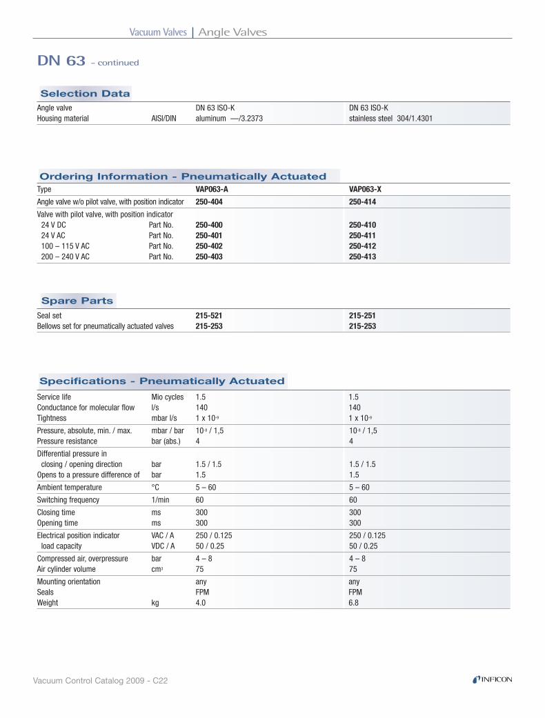
Vacuum Valves Angle Valves
Vacuum Control Catalog 2009 - C22
Selection Data
Spare Parts
Specifications - Pneumatically Actuated
Ordering Information - Pneumatically Actuated
DN 63 - continued
Angle valve DN 63 ISO-K DN 63 ISO-K Housing material AISI/DIN aluminum —/3.2373 stainless steel 304/1.4301
Type VAP063-A VAP063-X
Angle valve w/o pilot valve, with position indicator 250-404 250-414
Valve with pilot valve, with position indicator 24 V DC Part No. 250-400 250-410 24 V AC Part No. 250-401 250-411 100 – 115 V AC Part No. 250-402 250-412 200 – 240 V AC Part No. 250-403 250-413
Seal set 215-521 215-251 Bellows set for pneumatically actuated valves 215-253 215-253
Service life Mio cycles 1.5 1.5 Conductance for molecular flow l/s 140 140 Tightness mbar l/s 1 x 10⁻⁹ 1 x 10⁻⁹
Pressure, absolute, min. / max. mbar / bar 10-8 / 1,5 10-8 / 1,5 Pressure resistance bar (abs.) 4 4
Differential pressure in closing / opening direction bar 1.5 / 1.5 1.5 / 1.5 Opens to a pressure difference of bar 1.5 1.5
Ambient temperature °C 5 – 60 5 – 60
Switching frequency 1/min 60 60
Closing time ms 300 300 Opening time ms 300 300
Electrical position indicator VAC / A 250 / 0.125 250 / 0.125 load capacity VDC / A 50 / 0.25 50 / 0.25
Compressed air, overpressure bar 4 – 8 4 – 8 Air cylinder volume cm3 75 75
Mounting orientation any any Seals FPM FPM Weight kg 4.0 6.8

Vacuum ValvesAngle Valves
Vacuum Control Catalog 2009 - C23
Dimensions - Pneumatically Actuated
Dimensions - Manually Actuated
mm (inch)
DN 63 ISO-K
DN 63 ISO-K
88 (3.64)
88 (3
.64)
150 (5.90)
266
(10.
47)
20 (0
.79)
124
(4.8
8)
mm (inch)
DN 63 ISO-K
DN 63 ISO-K88 (3.46)
88 (3
.46)
14 (0
.55)
250
(9.8
4)
130
(5.1
2)
168 (6.61)
∅ 6
, or ∅
x 1
/4"
VAH063-A / VAH063-X
VAP063-A / VAP063-X
Angle valve with and without pilot valve, with position indicator
SIBA15E1-A

Vacuum Valves Angle Valves
Vacuum Control Catalog 2009 - C24
Specifications - Manually Actuated
Spare Parts
Ordering Information - Manually Actuated
Selection Data
DN 100
Angle Valves ( VAh, VAP )
Seal set 215-271 215-271 Bellows set for manually actuated valves 215-274 215-274
Manually Actuated
■ Bellows feedthrough■ Spindle drive with hand wheel ■ Smooth opening■ Visual position indication
Pneumatically Actuated
■ Bellows feedthrough■ Visual indication of the open and closed position■ Electrical position indicator for open and closed position■ For system manufacturers without pilot valve
Type VAH100-A VAH100-X
Part No. 250-480 250-485
Angle valve DN 100 ISO-K DN 100 ISO-K Housing material AISI(AA)/DIN aluminum - / 3.2373 stainless steel 303 /1.4305
Service life Mio cycles 1.5 1.5 Conductance for molecular flow l/s 330 330 Tightness mbar l/s 1 x 10⁻⁹ 1 x 10⁻⁹
Pressure absolute, min. / max. mbar / bar 10-8 / 1,5 10-8 / 1,5 Pressure resistance bar (abs.) 4 4
Differential pressure in closing / opening direction bar 1.5 / 1.5 1.5 / 1.5 Opens to a pressure difference of bar 1.5 1.5
Ambient temperature °C 5 – 60 5 – 60
Mounting orientation any any Seals FPM FPM Weight kg 6.1 11.1
ISO-KF DN100 manually, pneumatically
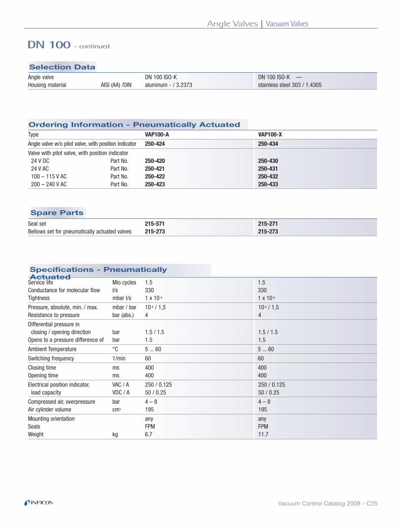
Vacuum ValvesAngle Valves
Vacuum Control Catalog 2009 - C25
Selection Data
Spare Parts
Specifications - Pneumatically Actuated
Ordering Information - Pneumatically Actuated
DN 100 - continued
Angle valve DN 100 ISO-K DN 100 ISO-K — Housing material AISI (AA) /DIN aluminum - / 3.2373 stainless steel 303 / 1.4305
Type VAP100-A VAP100-X
Angle valve w/o pilot valve, with position indicator 250-424 250-434
Valve with pilot valve, with position indicator 24 V DC Part No. 250-420 250-430 24 V AC Part No. 250-421 250-431 100 – 115 V AC Part No. 250-422 250-432 200 – 240 V AC Part No. 250-423 250-433
Seal set 215-571 215-271 Bellows set for pneumatically actuated valves 215-273 215-273
Service life Mio cycles 1.5 1.5 Conductance for molecular flow l/s 330 330 Tightness mbar l/s 1 x 10⁻⁹ 1 x 10⁻⁹
Pressure, absolute, min. / max. mbar / bar 10-8 / 1,5 10-8 / 1,5 Resistance to pressure bar (abs.) 4 4
Differential pressure in closing / opening direction bar 1.5 / 1.5 1.5 / 1.5 Opens to a pressure difference of bar 1.5 1.5
Ambient Temperature °C 5 ... 60 5 ... 60
Switching frequency 1/min 60 60
Closing time ms 400 400 Opening time ms 400 400
Electrical position indicator, VAC / A 250 / 0.125 250 / 0.125 load capacity VDC / A 50 / 0.25 50 / 0.25
Compressed air, overpressure bar 4 – 8 4 – 8 Air cylinder volume cm3 195 195
Mounting orientation any any Seals FPM FPM Weight kg 6.7 11.7

Vacuum Valves Angle Valves
Vacuum Control Catalog 2009 - C26
Dimensions - Pneumatically Actuated
Dimensions - Manually Actuated
DN 100 - continued
mm (inch)
DN 100 ISO-K
DN 100 ISO-K
108 (4.25)
108
(4.2
5)
190 (7.48)
320
(12.
68)
25 (1
.00)
164
(6.4
6)
mm (inch)
DN 100 ISO-K
DN 100 ISO-K108 (4.25)
108
(4.2
5)
14 (0
.55)
282
(11.
10)
170
(6.6
9)
208 (8.19)
∅ 6
, or ∅
x 1
/4"
VAH100-A / VAH100-X
VAP100-A / VAP100-X
Angle valve with and without pilot valve,with position indicator
SIBA16E1-A
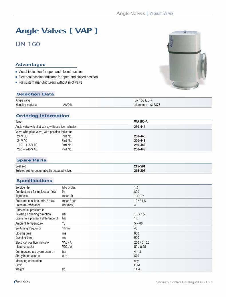
Vacuum ValvesAngle Valves
Vacuum Control Catalog 2009 - C27
Specifications
Ordering Information
Selection Data
Spare Parts
DN 160
Angle Valves ( VAP )
Advantages
■ Visual indication for open and closed position■ Electrical position indicator for open and closed position■ For system manufacturers without pilot valve
Angle valve DN 160 ISO-K Housing material AA/DIN aluminum -/3.2373
Type VAP160-A
Angle valve w/o pilot valve, with position indicator 250-444
Valve with pilot valve, with position indicator 24 V DC Part No. 250-440 24 V AC Part No. 250-441 100 – 115 V AC Part No. 250-442 200 – 240 V AC Part No. 250-443
Seal set 215-591 Bellows set for pneumatically actuated valves 215-293
Service life Mio cycles 1.5 Conductance for molecular flow l/s 800 Tightness mbar l/s 1 x 10⁻⁹
Pressure, absolute, min. / max. mbar / bar 10-8 / 1,5 Pressure resistance bar (abs.) 4
Differential pressure in closing / opening direction bar 1.5 / 1.5 Opens to a pressure difference of bar 1.5
Ambient Temperature °C 5 – 60
Switching frequency 1/min 40
Closing time ms 650 Opening time ms 600
Electrical position indicator, VAC / A 250 / 0.125 load capacity VDC / A 50 / 0.25
Compressed air, overpressure bar 4 – 8 Air cylinder volume cm3 570
Mounting orientation any Seals FPM Weight kg 11.4
ISO-KF DN160 pneumatically

Vacuum Valves Angle Valves
Vacuum Control Catalog 2009 - C28
Dimensions
DN 160 - continued
mm (inch)
DN 160 ISO-K
DN 160 ISO-K138 (5.43)
138
(5.4
3)
14 (0
.55)
366
(14.
41)
221
(8.7
0)
264 (10.39)
∅ 6
, or ∅
x 1
/4"
VAP160-A
SIBA17E1-A

Vacuum ValvesAll-Metal Dosing Valves and System
Vacuum Control Catalog 2009 - C29
Selection Data
Specifications
Ordering Information
VBH063 … 160-X
Butterfly Valves Manually actuated
Advantages
■ Three sizes available: DN 63, 100, 160
■ Robust and compact design with low installation height
■ High conductance all stainless steel housings
■ Lateral gauge/valve flange connections standard
■ FPM sealings
■ Extremely long service lifetime
Vacuum connection DN 63 ISO-F DN 100 ISO-F DN 160 ISO-F
Type VBH063-X VBH100-X VBH160-X
250-560 250-570 250-580
Lateral vacuum connections DN 10 ISO-KF 2 x DN 10 ISO-KF 2 x DN 10 ISO-KF DN 16 ISO-KF DN 25 ISO-KF DN 25 ISO-KF
Cycle life Cycles 100,000 100,000 100,000
Conductance for molecular flow l/s 350 1000 3400
Tightness mbar l/s 1 x 10⁻⁹ 1 x 10⁻⁹ 1 x 10⁻⁹
Pressure in either direction Static min. / max. mbar / bar 1 x 10⁻⁸ / 10 1 x 10⁻⁸ / 10 1 x 10⁻⁸ / 10 Dynamic min. / max mbar / bar 1 x 10⁻⁸ / 4 1 x 10⁻⁸ / 4 1 x 10⁻⁸ / 4
Pressure difference ∆p In either direction bar 4 4 4
Bakeout teperature housing °C 150 150 150
Housing, shaft, valve plate AISI / DIN 304 / 1.4301 304 / 1.4301 304 / 1.4301
Seals FPM FPM FPM
Weight kg 3.1 5.2 9.3
ISO-KF DN63 - 160 manually
Butterfly Valves (VBh, VBP)

Vacuum Valves All-Metal Dosing Valves and System
Vacuum Control Catalog 2009 - C30
Dimensions
Accessories
Spare Parts
VBH063 … 160-X - continued
mm (inch)DN 10 ISO-KF
DN 16 ISO-KF
DN 63 ISO-F
DN 63 ISO-F
40 (1
.57)
16 (0
.63)
130
(5.1
2)16
(0.6
3)
80 (3
.15)
55 (2
.17)
75 (2
.95)
75 (2
.95)
134 (5.28)
VBH063-X
VBH063 VBH100 VBH160
Seal kit X type 215-143 215-145 215-147
DN 100 ISO-F
DN 100 ISO-F
DN 10 ISO-KFDN 10
ISO-K
FDN 25 ISO-KF
mm (inch)
50 (1
.97)
30 (1
.18)
165
(6.5
0)22
(0.8
7)
150 (5.90)
80 (3
.15)
55 (2
.17)
75 (2
.95)
75 (2
.95)
VBH100-X
DN 160 ISO-F
DN 160 ISO-F
DN 10 IS
O-KF DN 25 ISO-KF DN 10 ISO-KF
mm (inch)
50 (1
.97)
54.5
(2.1
5)48
.5 (1
.91)
78 (3
.07)
115
(4.5
3)
100
(3.9
3)10
0 (3
.93)
225
(8.8
6)
202 (7.95)
VBH160-X
VBH063 VBH100 VBH160
Connection elements X type 215-212 215-214 215-216
SIBA43E1

Vacuum ValvesPneumatically Actuated Butterfly Valves
Vacuum Control Catalog 2009 - C31
VBP063 ... 250-X/Z
Pneumatically Actuated Butterfly Valves( VBP )
Advantages
■ Four sizes available: DN 63, 100, 160, 250
■ Robust and compact design with low installation height
■ High conductance all stainless steel housings
■ With or without lateral gauge/valve flange connections
■ FPM sealings
■ Extremely long service lifetime■ Direct pneumatic actuation or via pilot valve■ Electrical and visual position indicator
ISO-KF DN63 - 250 pneumatically

Vacuum Valves Pneumatically Actuated Butterfly Valves
Vacuum Control Catalog 2009 - C32
Specifications
Selection Data
Vacuum connection DN 63 ISO-F DN 100 ISO-F DN 160 ISO-F DN 250 ISO-K
Lateral vacuum connections DN 10 ISO-KF 2 x DN 10 ISO-KF 2 x DN 10 ISO-KF 2 x DN 10 ISO-KF DN 16 ISO-KF DN 25 ISO-KF DN 25 ISO-KF DN 25 ISO-KF DN 40 ISO-KF
With lateral vacuum connections
Type VBP063-X VBP100-X VBP160-X VBP250-X
253-100 253-120 253-140 253-160
Without lateral vacuum connections
Type VBP063-Z VBP100-Z VBP160-Z VBP250-Z
253-110 253-130 253-150 253-170
Cycle life Cycles 1,000,000 1,500,000 1,500,000 1,000,000
Conductance for molecular flow X types l/s 350 1000 3400 8200 Z types l/s 400 1400 4000 8200
Tightness mbar l/s 1 x 10⁻⁹ 1 x 10⁻⁹ 1 x 10⁻⁹ 1 x 10⁻⁹
Pressure in either direction Static min. / max. mbar / bar 1 x 10⁻⁸ / 10 1 x 10⁻⁸ / 10 1 x 10⁻⁸ / 10 1 x 10⁻⁸ / 10 Dynamic min. / max mbar / bar 1 x 10⁻⁸ / 4 1 x 10⁻⁸ / 4 1 x 10⁻⁸ / 4 1 x 10⁻⁸ / 4
Pressure difference ∆p In either direction bar 4 4 4 4
Bakeout temperature housing °C 150 150 150 150
Housing, shaft, valve plate AISI / DIN 304 / 1.4301 304 / 1.4301 304 / 1.4301 304 / 1.4301
Seals FPM FPM FPM FPM
Weight X types kg 3.8 6.5 10 15.7 Z types kg 3.5 5 8 16
VBP063 ... 250-X/Z - continued
Ordering Information

Vacuum ValvesPneumatically Actuated Butterfly Valves
Vacuum Control Catalog 2009 - C33
Dimensions
Accessories
Spare Parts VBP063 VBP100 VBP160 VBP250
Seal kit X type 215-143 215-145 215-147 215-149 Z type 215-144 215-146 215-148 215-149
Actuator 253-181 253-182 253-182 253-183
VBP063 VBP100 VBP160 VBP250
Position indicator 253-180 253-180 253-180 253-180
Pilot valve 230 V AC / 50 Hz 215-131 215-131 215-131 215-131 115 V AC / 60 Hz 215-132 215-132 215-132 215-132 24 V AC / 50 Hz 215-133 215-133 215-133 215-133 24 V DC / 50 Hz 215-134 215-134 215-134 215-134
Connection elements X type 215-212 215-214 215-216 212-225 Z type 215-213 215-215 215-217 212-225
Compressed air connection
Electrical connection
Visual position indicator
Leak detection opening
Position indicator connection
Valve seat site
130�
12.8
�12
.8�
DN 16 ISO-KF�
DN 10 ISO-KF�
121.
3�61
�
195.7�186�
16�
40�
16�
23�
DN 63 ISO-F�
DN 63 ISO-F�
9.5�
53�
59� 10
1.5�
20�
VBP063-X
[mm]
130�
121.
3�61
�
195.7�186�
21�
35�
16�
DN 63 ISO-F�
DN 63 ISO-F�
9.5�
53�
59� 10
1.5�
20�
VBP063-Z
[mm]
VBP063 ... 250-X/Z - continued

Vacuum Valves Pneumatically Actuated Butterfly Valves
Vacuum Control Catalog 2009 - C34
Dimensions
Compressed air connection
Electrical connection
Visual position indicator
Leak detection opening
Position indicator connection
Valve seat site
DN 25 ISO-KF�
165�
11.3�
11.3
�
45 �̊ 45 �̊
DN 10 ISO-KF�DN 10 ISO-KF�
256.7�229�
161�
121.
3�61
�
22�
50�
30�
28�
DN 100 ISO-F�
DN 100 ISO-F�
20.5
�63
�
83� 12
5.5�
21�
VBP100-X
[mm]
165�
256.7�229�
161�
121.
3�61
�
37�
35�
30�
DN 100 ISO-F�
DN 100 ISO-F�
20.5
�63
�
83� 12
5.5�
21�
VBP100-Z
[mm]
VBP063 ... 250-X/Z - continued

Vacuum ValvesPneumatically Actuated Butterfly Valves
Vacuum Control Catalog 2009 - C35
Compressed air connection
Electrical connection
Visual position indicator
Leak detection opening
Position indicator connection
Valve seat site
54.4
�50
�48
.4�
28�
DN 160 ISO-F�
DN 160 ISO-F�
22�
19.5
�
62�
83� 12
5.5�
288�260�
161�
121.
3�
DN 25 ISO-KF�
225�
10.8�
10.8
�
45 �̊ 45 �̊
DN 10 ISO-KF�DN 10 ISO-KF�
61�
VBP160-X
[mm]
54.4
�40
�58
.4�
DN 160 ISO-F�
DN 160 ISO-F�
22�
19.5
�
62�
83� 12
5.5�
288�260�
161�
121.
3�
225�
61�
VBP160-Z
[mm]
Dimensions
VBP063 ... 250-X/Z - continued

Vacuum Valves Pneumatically Actuated Butterfly Valves
Vacuum Control Catalog 2009 - C36
Dimensions
VBP063 ... 250-X/Z - continued
69�
88�
99� DN 250 ISO-K�
29�
31�
57�
42�
120�
DN 250 ISO-K�
146�
30�̊
367.5�339.5�
30 �̊30 �̊
205�
154�
174�
DN 10 ISO-KF�
DN 25 ISO-KF�
154�
290�
DN 10 ISO-KF�
DN 40 ISO-KF�
121.
25�
61�
222�
VBP250-X69
�88
�99
� DN 250 ISO-K�
29�
31�
57.2
�
120�
DN 250 ISO-K�
146.
2�
367.5�339.5�
121.
25�
61�
222�
290�
VBP250-Z
Compressed air connection
Electrical connection
Visual position indicator
Leak detection opening
Position indicator connection
Valve seat site
[mm]
[mm]
SIBA41E1-A

Vacuum ValvesManually Actuated Coarse Gas Dosing Valve
Vacuum Control Catalog 2009 - C37
Dimensions
Spare Parts
Selection Data
Specifications
Ordering Information
VDH010-A
Manually ActuatedCoarse Gas dosing Valve
Advantages
■ For admitting a reproducible flow of gas into a vacuum chamber
Vacuum connection DN 10 ISO-KF
Gas flow, controllable Min. mbar l/s 40 Max. mbar l/s 1700
Type VDH010-A
Part No. 250-520
Tightness mbar l/s 1 x 10⁻⁸ Pressure range mbar to bar 1x 10⁻⁷ to 4 Bakeout temperature °C 100
Housing aluminum Seals FPM
Weight kg 0.2
Seal set 215-207
mm (inch)
DN 10 ISO-KF
DN 10 ISO-KF
30 (1.18)
96 (3
.78)
101
(3.9
8)
30 (1
.18)
∅ 40 (1.57)
SIBA25E1
ISO-KF DN10 manually (coarse gas dosing)
dosing Valves (Vdh)
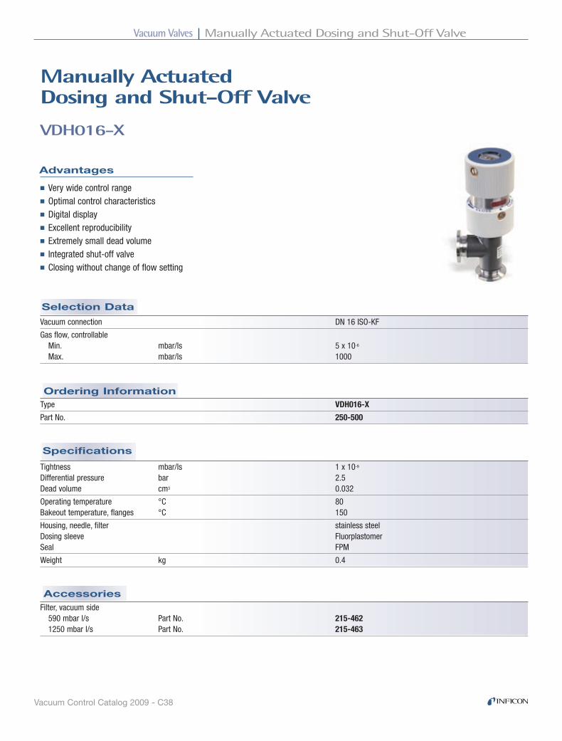
Vacuum Valves Manually Actuated Dosing and Shut-Off Valve
Vacuum Control Catalog 2009 - C38
Accessories
Specifications
Ordering Information
Selection Data
VDH016-X
Manually Actuateddosing and Shut-off Valve
Advantages
■ Very wide control range■ Optimal control characteristics■ Digital display■ Excellent reproducibility■ Extremely small dead volume■ Integrated shut-off valve■ Closing without change of flow setting
Vacuum connection DN 16 ISO-KF
Gas flow, controllable Min. mbar/ls 5 x 10⁻⁶ Max. mbar/ls 1000
Filter, vacuum side 590 mbar l/s Part No. 215-462 1250 mbar l/s Part No. 215-463
Tightness mbar/ls 1 x 10⁻⁹ Differential pressure bar 2.5 Dead volume cm3 0.032
Operating temperature °C 80 Bakeout temperature, flanges °C 150
Housing, needle, filter stainless steel Dosing sleeve Fluorplastomer Seal FPM
Weight kg 0.4
Type VDH016-X
Part No. 250-500
ISO-KF DN16 manually (fine gas dosing / shut-off)

Vacuum ValvesManually Actuated Dosing and Shut-Off Valve
Vacuum Control Catalog 2009 - C39
Dimensions
VDH016-X - continued
mm (inch)DN 16 ISO-KF
DN 10 ISO-KF
30 (1.18)
12.5
(0.4
9)11
7.5
(4.6
3)
30 (1
.18)
∅ 42 (1.65)
∅ 40 (1.57)
∅ 20 (0.79)
SIBA26E1

Vacuum Valves All-Metal Dosing Valves and System
Vacuum Control Catalog 2009 - C40
Connection flange Input DN 16 CF-R DN 16 CF-R Output DN 40 CF-F DN 40 CF-F
Gas flow, controllable Min. mbar/ls 1 x 10⁻¹⁰ 1 x 10⁻¹⁰
Max. mbar/ls 600 100 1)
Tightness mbar/ls 1 x 10-11 1 x 10-11
Pressure min./max. (absolute) mbar 1 x 10-11/30 1 x 10⁻¹⁰/30 Conductance for molecular flow l/s 0.7 0.7
Operating temperature °C 200 200 Bakeout temperature °C 350 350 2)
Valve plate sapphire sapphire Valve seat copper copper Housing stainless steel stainless steel
Weight kg 1.4 1.4
1) Can be regulated with the VCE500 Controller
2) Without cable
Actuator manual manual and thermo-mechanical in conjunction with VCE500
Selection Data
Specifications
Ordering Information VDH040-U / VDE040-U
VDH040-U / VDE040-U / VCE500
All-Metal dosing Valves and System
Advantages
■ Minimal dead volume■ Controlled routing of the gas flow using capillaries■ Operating temperature 200°C■ Control of total pressure or gas flow■ Automatic control in conjunction with VDE40-U and VCE500
Type VDH040-U VDE040-U
Valve 250-700 250-720
dosing Systems (VdM, VdE, VCE, VCC, VCA)
All-Metal Dosing Valves and System

Vacuum ValvesAll-Metal Dosing Valves and System
Vacuum Control Catalog 2009 - C41
VDH040-U / VDE040-U / VCE500
Standard, 80°C 3 m Part No. 202-914 12 m (max. cable length) Part No. 202-916
Extension, 200°C 2 m Part No. 202-924
Power supply V 115 / 230
Frequency Hz 50 … 60 Power consumption VA 20
Regulating characteristic proportional-integral (PI) Reset time s 2 … 30 Proportional gain 2 … 1000
Internal nominal value Scale divisions 0 … 1000 External nominal value VCD/100 kΩ 0 … +10
Protection class IP 20
Controller for VDE040-U VCE500
Part No. 250-920
Valve plate, sapphire 215-715 215-715 Valve seat Standard 215-716 215-716 Gold plated 215-717 215-717
Tool kit 215-707 215-707
Options
Accessories
Cable
Specifications
Ordering Information VCE500
Spare Parts
VDH040-U / VDE040-U / VCE500 - continued
Type VDH040-U VDE040-U
Capillary complete, vacuum side, 1m 215-708 215-708 Heater, 200°C 250-701 250-701 Adapter DN 40/16 CF 213-071 213-071
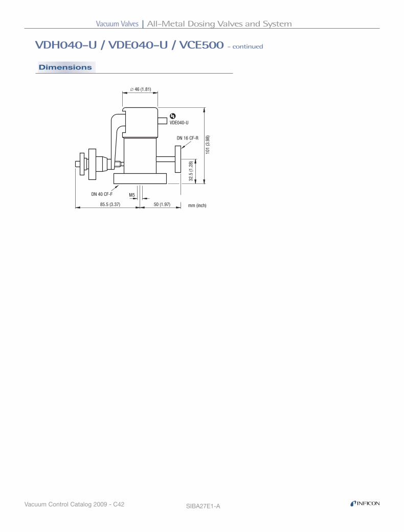
Vacuum Valves All-Metal Dosing Valves and System
Vacuum Control Catalog 2009 - C42
Dimensions
VDH040-U / VDE040-U / VCE500 - continued
SIBA27E1-A
mm (inch)
DN 40 CF-F
DN 16 CF-R
VDE040-U
85.5 (3.37) 50 (1.97)
M5
101
(3.9
8)
32.5
(1.2
8)
∅ 46 (1.81)

Vacuum ValvesGas Dosing Systems
Vacuum Control Catalog 2009 - C43
Gas dosing Systems
User Advantages
■ Higher yield■ Optimized cycle time■ Excellent reproducibility■ Easy system integration
Pro
cess
Cham
ber
Pressure Gauge
Control Valve VDE016-X
Control Valve VDM005-X
ControllerVCC500-Z
Interface ModuleVCA200-Z
e.g. PC, IPC,PLC, MC
GAS DOSING SYSTEMS
e.g. PC, IPC,PLC, MC
Gas Dosing Systems
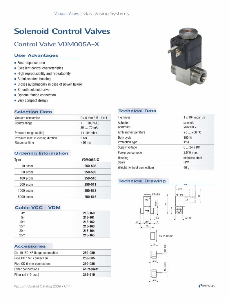
Vacuum Valves Gas Dosing Systems
Vacuum Control Catalog 2009 - C44
Technical Data
Accessories
6.5�(17)�8� 8�33�
M14
×1�
2.8×0.5�
14.5�
OD
1/4"
�
14.5�
OD
6mm
�
DN 10 ISO-KF�
18�
49�
17�
AF 17�
49�
23.5�
35�
Technical Drawing
Cable VCC - VDM
Ordering Information
Control Valve VDM005A-X
User Advantages
Type VDM005A-X
10 sccm 250-508
50 sccm 250-509
100 sccm 250-510
500 sccm 250-511
1000 sccm 250-512
5000 sccm 250-513
■ Fast response time■ Excellent control characteristics■ High reproducibility and repeatability■ Stainless steel housing■ Closes automatically in case of power failure■ Smooth solenoid drive■ Optional flange connection■ Very compact design
DN 10 ISO-KF flange connection 250-080
Pipe OD 1/4" connection 250-085
Pipe OD 6 mm connection 250-086
Other connections on request
Filter set (10 pcs.) 215-519
Solenoid Control Valves
Vacuum connection DN 5 mm / M 14 x 1
Control range 1 … 100 %FS 20 … 70 mA
Pressure range (outlet) 1 x 10⁻⁸ mbar
Pressure max. in closing diretion 2 bar Response time <30 ms
Selection Data
3m 216-160 5m 216-161 10m 216-162 15m 216-163 20m 216-164 25m 216-165
Tightness 1 x 10⁻⁹ mbar l/s
Actuator solenoid Controller VCC500-Z
Ambient temperature +5 ... +50 °C
Duty cycle 100 % Protection type IP51
Supply voltage 0 ... 24 V DC
Power consumption 2.5 W max.
Housing stainless steel Seals FPM
Weight (without connection) 96 g
Solenoid Control Valves

Vacuum ValvesGas Dosing Systems
Vacuum Control Catalog 2009 - C45
Cable VCC - VDE
Selection Data Technical Data
Ordering Information1)
Technical Drawing
Control Valve VDE016-X
User Advantages
■ Broad control range■ Excellent reproducibility■ Status information and commands via digital interface■ Withstands corrosive gases - stainless steel / FPM■ Combined with the VCC500-Z controller, the valve closes
automatically in case of a power failure
Vacuum connection DN 16 ISO-KF
Gas flow, controllable Min. 5 x 10⁻⁶ mbar l/s Max. 1250 mbar l/s
Pressure absolute Min. 1 x 10⁻⁸ mbar Max. 2.5 bar
Closing / opening time 3 / 4 s
3 m Part No. 216-150 5 m Part No. 216-151 10 m Part No. 216-152 15 m Part No. 216-153 20 m Part No. 216-154 25 m Part No. 216-155
Type VDE016-X
Part No. 250-5051) Connector included
Tightness 1 x 10⁻⁹ mbar l/s
Actuator Stepper motor Control Digital VCC500-Z, VCA200-Z Analog 0 ... 10 V DC
Ambient temperature 5 ... 40 °C
Supply 24 V DC / 12 VA
Housing stainless steel Dosing sleeve fluorplastomer Seals FPM
Weight1) 0.5 kg
1) Connector included
DN 16 ISO-KF
30 (1
.18) 90
(3.5
4)
35 (1.38)
152
(5.9
8)
mm (inch)
60 (2
.36)
60 (2.36)

Vacuum Valves Gas Dosing Systems
Vacuum Control Catalog 2009 - C46
Ordering Information1)
Selection Data
Technical Data
Technical Drawing
Controller VCC500-Z
User Advantages
■ Simple operation - user friendly LCD display and function keys■ Analog/digital inputs, outputs and interfaces■ 99 PI pre-programmed control adjustments for quick and easy operation ■ Adjustable PID control algorithm■ Wide variety of pre-programmed pressure gauges
Type VCC500-Z
Part No. 250-900
Analog input 0 ... 10 V DC nominal pressure, gas flow
Analog output 0 ... 10 V DC pressure, valve position
Operating modes Pressure control Gas flow adjustment
8 available digital inputs Flow adjustment, opening/closing the valve, switching between pressure and gas flow control
8 available digital outputs Valve position indication, setpoint status reached, status messages - sensor, valve, pressure control upstream and downstream
Features Switching on after power failure Output “nominal value reached”, adjustable tolerance Units mbar, Pa, Torr, mV Languages English, German Interfaces RS232C, RS485Controller types Auto = PI - selectable control speed steps 1-99 PID = PID - user definable parameters Control accuracy 5 % FS sensors
Display accuracy 0.2 % FS sensor
Supply Voltage 90 ... 250 V AC Consumption 50 VA
Weight 1.65 kg
mm (inch)
106 (4.17)
128
(5.0
4)
122.
5 (4
.82)
91 (3.58) 3 (0.12)208.5 (8.21)∅ 3.5 (0.14)
mm (inch)
106 (4.17)
128
(5.0
4)
122.
5 (4
.82)
91 (3.58) 3 (0.12)208.5 (8.21)∅ 3.5 (0.14)

Vacuum ValvesGas Dosing Systems
Vacuum Control Catalog 2009 - C47
Technical Drawing
Technical Data
Ordering Information
Selection Data
Interface Module VCA200-Z
User Advantages
■ Easy and economic system integration■ Connects an RS232C interface to the digital interface of the Control Valve VDE016-X ■ Inquiry of status and valve position
Interface RS232C Supply 24 VDC / 0.5 A
Type VCA200-Z
Part No. 250-915
Installation DIN mounting rail (symmetric or asymmetric) Connection terminals Ambient temperature 5 ... 50°C
Weight 40 g
18 (0.71) 62 (2.44)
63 (2
.48)
54 (2
.12)
SIBA09E1-B
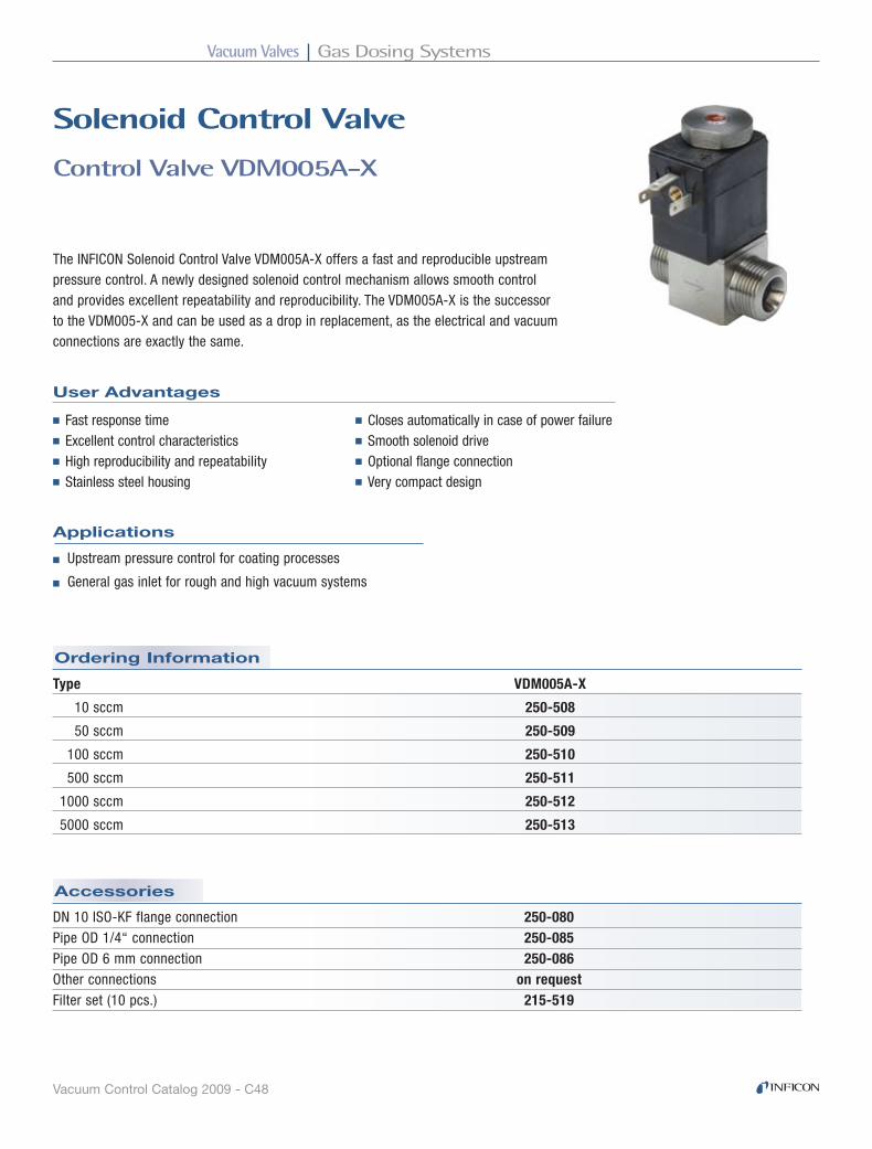
Vacuum Valves Gas Dosing Systems
Vacuum Control Catalog 2009 - C48
Accessories
Ordering Information
Control Valve VDM005A-X
User Advantages
Solenoid Control Valve
The INFICON Solenoid Control Valve VDM005A-X offers a fast and reproducible upstream pressure control. A newly designed solenoid control mechanism allows smooth control and provides excellent repeatability and reproducibility. The VDM005A-X is the successor to the VDM005-X and can be used as a drop in replacement, as the electrical and vacuum connections are exactly the same.
■ Fast response time■ Excellent control characteristics■ High reproducibility and repeatability■ Stainless steel housing
■ Closes automatically in case of power failure■ Smooth solenoid drive■ Optional flange connection■ Very compact design
■ Upstream pressure control for coating processes
■ General gas inlet for rough and high vacuum systems
Applications
Type VDM005A-X
10 sccm 250-508
50 sccm 250-509
100 sccm 250-510
500 sccm 250-511
1000 sccm 250-512
5000 sccm 250-513
DN 10 ISO-KF flange connection 250-080Pipe OD 1/4“ connection 250-085Pipe OD 6 mm connection 250-086Other connections on requestFilter set (10 pcs.) 215-519
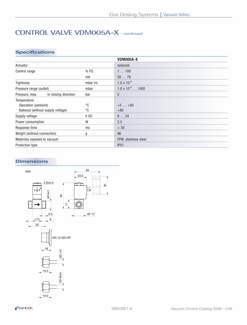
Vacuum ValvesGas Dosing Systems
Vacuum Control Catalog 2009 - C49SIBA38E1-A
Dimensions
Specifications
VDM005A-XActuator solenoid
Control range % FS 1 … 100
mA 20 … 70
Tightness mbar l/s 1.0 x 10⁻⁹
Pressure range (outlet) mbar 1.0 x 10⁻⁸ … 1000
Pressure, max. in closing direction bar 2
Temperature Operation (ambient) °C +5 … +50 Bakeout (without supply voltage) °C +80
Supply voltage V DC 0 … 24
Power consumption W 2.5
Response time ms < 30
Weight (without connection) g 96
Materials exposed to vacuum FPM, stainless steel
Protection type IP51
6.5�(17)�8� 8�33�
M14
×1�
2.8×0.5�
14.5�
OD
1/4"
�
14.5�
OD
6mm
�
DN 10 ISO-KF�
18�
49�
17�
AF 17�
49�
23.5�
35�
mm
CONTROL VALVE VDM005A-X - continued
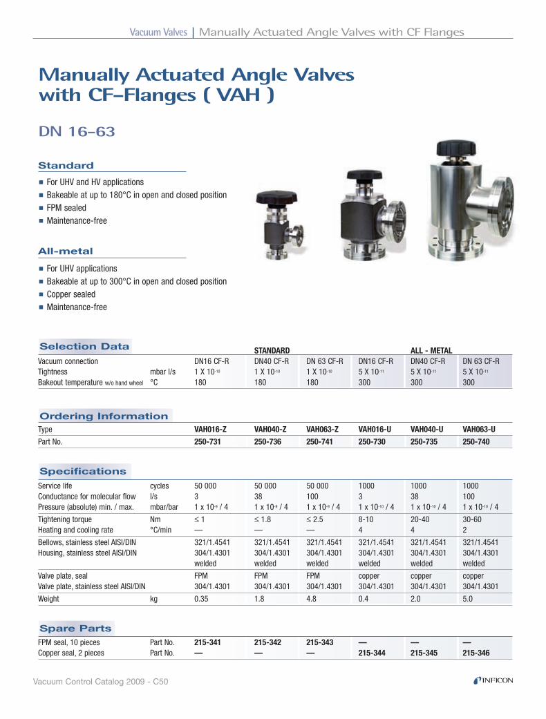
Vacuum Valves Manually Actuated Angle Valves with CF Flanges
Vacuum Control Catalog 2009 - C50
Spare Parts
Specifications
Ordering Information
Selection Data
Standard
DN 16-63
Manually Actuated Angle Valveswith CF-Flanges ( VAh )
■ For UHV and HV applications■ Bakeable at up to 180°C in open and closed position■ FPM sealed■ Maintenance-free
All-metal
■ For UHV applications■ Bakeable at up to 300°C in open and closed position■ Copper sealed■ Maintenance-free
STANDARD ALL - METAL Vacuum connection DN16 CF-R DN40 CF-R DN 63 CF-R DN16 CF-R DN40 CF-R DN 63 CF-R Tightness mbar l/s 1 X 10⁻¹⁰ 1 X 10⁻¹⁰ 1 X 10⁻¹⁰ 5 X 10-11 5 X 10-11 5 X 10-11
Bakeout temperature w/o hand wheel °C 180 180 180 300 300 300
Type VAH016-Z VAH040-Z VAH063-Z VAH016-U VAH040-U VAH063-U
Part No. 250-731 250-736 250-741 250-730 250-735 250-740
FPM seal, 10 pieces Part No. 215-341 215-342 215-343 — — — Copper seal, 2 pieces Part No. — — — 215-344 215-345 215-346
Service life cycles 50 000 50 000 50 000 1000 1000 1000 Conductance for molecular flow l/s 3 38 100 3 38 100 Pressure (absolute) min. / max. mbar/bar 1 x 10⁻⁹ / 4 1 x 10⁻⁹ / 4 1 x 10⁻⁹ / 4 1 x 10⁻¹⁰ / 4 1 x 10⁻¹⁰ / 4 1 x 10⁻¹⁰ / 4
Tightening torque Nm ≤ 1 ≤ 1.8 ≤ 2.5 8-10 20-40 30-60 Heating and cooling rate °C/min — — — 4 4 2
Bellows, stainless steel AISI/DIN 321/1.4541 321/1.4541 321/1.4541 321/1.4541 321/1.4541 321/1.4541 Housing, stainless steel AISI/DIN 304/1.4301 304/1.4301 304/1.4301 304/1.4301 304/1.4301 304/1.4301 welded welded welded welded welded welded
Valve plate, seal FPM FPM FPM copper copper copper Valve plate, stainless steel AISI/DIN 304/1.4301 304/1.4301 304/1.4301 304/1.4301 304/1.4301 304/1.4301
Weight kg 0.35 1.8 4.8 0.4 2.0 5.0
All-Metal Angle Valves (VAh)
CF-R DN16 - 63 manually

Vacuum ValvesManually Actuated Angle Valves with CF Flanges
Vacuum Control Catalog 2009 - C51
Dimensions
DN 16-63 - continued
63�
63�
70�10
7.6�
34.6
�
150.
9�
AF 17�
ø 62�
DN 40 CF-R�(rotatable)�
DN 40 CF-R�(rotatable)�
Spin
dle
lift�
26.6
�
69.6
�
25.6
�
104.
2�
AF 8�
38�
38�
35�
ø 62�
Spin
dle
lift�
15.2
�
DN 16 CF-R�(rotatable)�
DN 16 CF-R�(rotatable)�
105�
105�
182�
ø100�
61�
231.
2�
AF 22�
ø74�
Spin
dle
lift�
36.4
�
DN 63 CF-R�(rotatable)�
DN 63 CF-R�(rotatable)�
69.6
�
25.6
�
88.2
�
AF 8�
38�
38�
35�
ø 62�
DN 16 CF-R�(rotatable)�
DN 16 CF-R�(rotatable)�11
9.4�
Spin
dle
lift�
15�
63�
63�
70�
107.
6�
34.1
�
Spin
dle
lift�
27.5
�14
0�
AF 17�
ø 62�
DN 40 CF-R�(rotatable)�
DN 40 CF-R�(rotatable)�
177.
5�
105�
105�
Spin
dle
lift�
36.4
�21
0.7�
ø100�61
�
267.
6�
AF 22�
ø74�
DN 63 CF-R�(rotatable)�
DN 63 CF-R�(rotatable)�
182�
VAH016-Z VAH040-Z VAH063-Z
VAH016-U VAH040-U VAH063-U
SIBA18E1-B
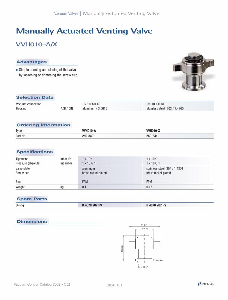
Vacuum Valves Manually Actuated Venting Valve
Vacuum Control Catalog 2009 - C52
Specifications
Selection Data
Dimensions
Ordering Information
Spare Parts
Advantages
VVH010-A/X
Manually Actuated Venting Valve
■ Simple opening and closing of the valve by loosening or tightening the screw cap
Vacuum connection DN 10 ISO-KF DN 10 ISO-KF Housing AISI / DIN aluminum / 3.0615 stainless steel 303 / 1.4305
Type VVH010-A VVH010-X
Part No. 250-840 250-841
Tightness mbar l/s 1 x 10⁻⁹ 1 x 10⁻⁹ Pressure (absolute) mbar/bar 1 x 10⁻⁸ / 1 1 x 10⁻⁸ / 1
Valve plate aluminum stainless steel 304 / 1.4301 Screw cap brass nickel-plated brass nickel-plated Seal FPM FPM
Weight kg 0.1 0.15
O-ring B 4070 207 PV B 4070 207 PV
51 (2.0)
30 (1.18)
42 (1
.77)
DN 10 ISO-KF
mm (inch)
SIBA31E1
Venting Valves (VVh, VVM, VIN)
ISO-KF DN10 manually
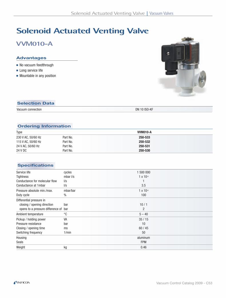
Vacuum ValvesSolenoid Actuated Venting Valve
Vacuum Control Catalog 2009 - C53
Specifications
Ordering Information
Selection Data
VVM010-A
Solenoid Actuated Venting Valve
Advantages
■ No vacuum feedthrough■ Long service life■ Mountable in any position
Vacuum connection DN 10 ISO-KF
Type VVM010-A
230 V AC, 50/60 Hz Part No. 250-533115 V AC, 50/60 Hz Part No. 250-53224 V AC, 50/60 Hz Part No. 250-531 24 V DC Part No. 250-530
Service life cycles 1 500 000 Tightness mbar l/s 1 x 10⁻⁹ Conductance for molecular flow l/s 1 Conductance at 1mbar l/s 3.5
Pressure absolute min./max. mbar/bar 1 x 10⁻⁸ Duty cycle % 100
Differential pressure in closing / opening direction bar 10 / 1 opens to a pressure difference of bar 2
Ambient temperature °C 5 – 40
Pickup / holding power VA 35 / 15 Pressure resistance bar 10 Closing / opening time ms 60 / 45 Switching frequency 1/min 50
Housing aluminum Seals FPM
Weight kg 0.46
ISO-KF DN10 solenoid

Vacuum Valves Solenoid Actuated Venting Valve
Vacuum Control Catalog 2009 - C54
Dimensions
Seal set 215-208 Filter B 4161 210 4F
Filter with port, centering ring and clamping ring 215-152
44 (1.73)
ø14
(0.5
5)
mm (inch)
DN 1
0 IS
O-KF
DN 10 ISO-KF30 (1.18)
30 (1
.18)
60 (2.36)
ø42 (1.89)
105
(4.1
3)
mm (inch)
VVM010-A - continued
Spare Parts
Options
SIBA32E1

Vacuum ValvesPower Failure Venting Valve
Vacuum Control Catalog 2009 - C55
Dimensions
Specifications
Ordering Information
Selection Data
VIM010-A
Power Failure Venting Valve
Advantages
■ For automatic venting of pumps, system or vacuum chambers in case of a power failure
Vacuum connection DN 10 ISO-KF
Venting time for a 50 l vessel 270 s
Type VIM010-A
200 - 230 V, 50/60 Hz 250-851 24 V DC 250-850 115 V, 50/60 Hz 250-852
Part number 250-850 250-851 250-852
Tightness mbar l/s 1 x 10⁻⁷
Ambient temperature °C 0 – 50
Switching frequency 1/min 60 Service life Mio cycles 3
Opening time ms 30Closing time ms 30
Housing aluminum Seal FPM
Nominal power Pickup W / VA 2.5 / – – / 5 – / 5 Holding W / VA 2.5 / – – / 3.7 – / 3.7
Protection class IP 65
Weight kg 0.1
DN 10 ISO-KF
64 (2.52)
30 (1.18)
65.8 (2.60)
27 (1.06)
41 (1.61)
mm (inch)
SIBA34E1
ISO-KF DN10 solenoid (power failure)

Vacuum Valves Vacuum Safety Valves
Vacuum Control Catalog 2009 - C56
Specifications
Ordering Information
Selection Data
VSM DN 16 - DN 100
Vacuum Safety Valves
Advantages
■ Fast-closing high vacuum isolation valve for separating the vacuum chamber from the backing pump■ Venting valve for roughing pumps■ Immediate closing action upon power failure■ Opening action only after the intake line has been evacuated
Vacuum connection DN 16 ISO-KF DN 25 ISO-KF DN 40 ISO-KF DN 63 ISO-K DN 100 ISO-K
Type VSM016-A VSM025-A VSM040-A VSM063-A VSM100-A
200 - 230 V AC 253-004 253-014 253-024 253-034 253-044 100 - 115 V AC 253-002 253-012 253-022 253-032 253-042 24 V DC 253-000 253-010 253-020 253-030 253-040
Nominal power DC 2.5 W AC 5 / 3.7 VA (starting / holding)
Type of protection IP 65 according to DIN 40 050
Conductance 3.8 l/s 11 l/s 30.5 l/s 126 l/s 300 l/s
Installation position any
Tightness body < 1x10⁻⁹ mbar l/s valve plate < 1x10⁻⁵ mbar l/s
Pressure range 1x10⁻⁸ mbar – 1 bar (abs.)
Required pressure difference up for the safety valves to function properly in closing direction > 150 mbar in opening direction < 150 mbar
Temperatures ambiance 5°C – 50°C
Solenoid coil ambiance 20°C < 55°C ambiance 20°C < 80°C
Bakeout housing < 60°C actuator < 50°C
Materials housing, flange aluminum seals FPM
Weight 0.3 kg 0.5 kg 0.9 kg 2.4 kg 5.1 kg
ISO-KF DN16 - 40
Safety Valves (VSM)
ISO-KF DN63 - 100

Vacuum ValvesVacuum Safety Valves
Vacuum Control Catalog 2009 - C57
Dimensions
Spare Parts
VSM DN 16 - DN 100 - continued
Seal set 215-055 215-056 215-057 215-058 215-059
DN A B C D
DN 16 ISO-KF 139 40 49 44
DN 25 ISO-KF 162 50 49 56
DN 40 ISO-KF 178 65 49 82
DN A B D
DN 63 ISO-K 220 88 124
DN 100 ISO-K 264 108 164
SIBA33E1
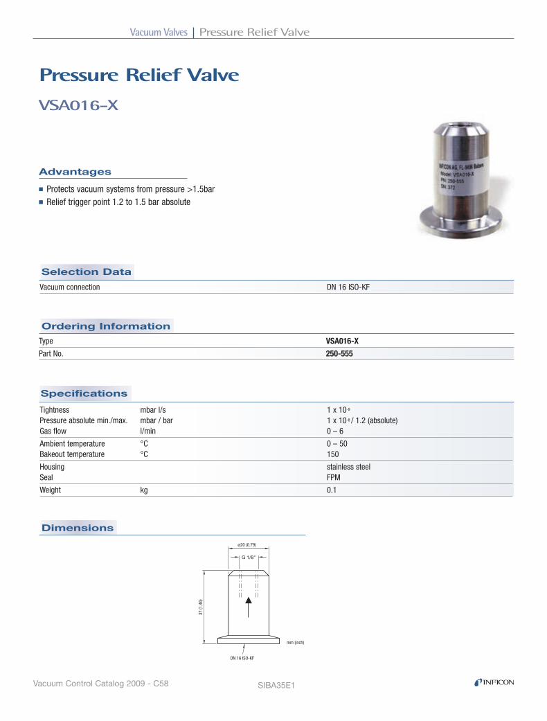
Vacuum Valves Pressure Relief Valve
Vacuum Control Catalog 2009 - C58
Dimensions
Specifications
Ordering Information
Selection Data
VSA016-X
Pressure relief Valve
Advantages
■ Protects vacuum systems from pressure >1.5bar■ Relief trigger point 1.2 to 1.5 bar absolute
Vacuum connection DN 16 ISO-KF
Type VSA016-X
Part No. 250-555
Tightness mbar l/s 1 x 10⁻⁹
Pressure absolute min./max. mbar / bar 1 x 10⁻⁸ / 1.2 (absolute) Gas flow l/min 0 – 6
Ambient temperature °C 0 – 50 Bakeout temperature °C 150
Housing stainless steel Seal FPM
Weight kg 0.1
G 1/8"
DN 16 ISO-KF
37 (1
.46)
ø20 (0.79)
mm (inch)
SIBA35E1
ISO-KF DN16
Pressure relief Valve (VSA)

Vacuum ValvesBall Valves with ISO-KF Flanges
Vacuum Control Catalog 2009 - C59
Dimensions
Specifications
Ordering Information
Selection Data
DN 10-40
Ball Valves with ISo-KF Flanges
Advantages
■ Rugged and cost effective■ Simple opening and closing by lever■ Unobstructed passage
Tightness mbar/ls 1 x 10⁻⁵ 1 x 10⁻⁵ 1 x 10⁻⁵ 1 x 10⁻⁵ Conductance for molecular flow l/s 1.5 3 9 30
Pressure absolute min./max. mbar/bar 10-5 / 5 1) 10-5 / 5 1) 10-5 / 5 1) 10-5 / 5 1)
Bakeout temperature °C 80 80 80 80
Housing brass nickel plated brass nickel plated brass nickel plated brass nickel plated Seals PTFE PTFE PTFE PTFE
Weight kg 0.35 0.35 0.35 0.351) With outer centering ring
Vacuum connection DN 10 ISO-KF DN 16 ISO-KF DN 25 ISO-KF DN 40 ISO-KF
Part No. 215-860 215-861 215-862 215-863
DN
A
B
C
DN
DN A B C
DN 10 ISO-KF 75 83 47
DN 16 ISO-KF 100 95 51
DN 25 ISO-KF 130 110 64
DN 40 ISO-KF 160 160 85
SIBA36E1
Ball Valves
ISO-KF DN10 - 40

Vacuum Valves Ball Valves with ISO-KF Flanges
Vacuum Control Catalog 2009 - C60

Vacuum FittingsFittings and Ultra-High Components

Vacuum Fittings Contents
Vacuum Control Catalog 2009 - Dii
ISO-KF Small Flange Components
CONNECTION ELEMENTS . . . . . . . . . . . . . . . . . . . . . . . . . . . . . . . . . . . . . . . . . D1
SEALS . . . . . . . . . . . . . . . . . . . . . . . . . . . . . . . . . . . . . . . . . . . . . . . . . . . . . . . . . . D3
FLANGES . . . . . . . . . . . . . . . . . . . . . . . . . . . . . . . . . . . . . . . . . . . . . . . . . . . . . . . D6
PIPE FITTINGS . . . . . . . . . . . . . . . . . . . . . . . . . . . . . . . . . . . . . . . . . . . . . . . . . . . D7
BELLOWS/HOSE WITH FLANGES . . . . . . . . . . . . . . . . . . . . . . . . . . . . . . . . . . . D9
TRANSITION PIECES . . . . . . . . . . . . . . . . . . . . . . . . . . . . . . . . . . . . . . . . . . . . . D11
HOSE, HOSE CONNECTION . . . . . . . . . . . . . . . . . . . . . . . . . . . . . . . . . . . . . . . D14
ISO-K Clamp Flange Components
CONNECTION ELEMENTS . . . . . . . . . . . . . . . . . . . . . . . . . . . . . . . . . . . . . . . . D16
SEALS . . . . . . . . . . . . . . . . . . . . . . . . . . . . . . . . . . . . . . . . . . . . . . . . . . . . . . . . . D17
FLANGES . . . . . . . . . . . . . . . . . . . . . . . . . . . . . . . . . . . . . . . . . . . . . . . . . . . . . . D20
PIPE FITTINGS . . . . . . . . . . . . . . . . . . . . . . . . . . . . . . . . . . . . . . . . . . . . . . . . . . D22
BELLOWS / HOSE WITH FLANGES . . . . . . . . . . . . . . . . . . . . . . . . . . . . . . . . . D24
TRANSITION PIECES . . . . . . . . . . . . . . . . . . . . . . . . . . . . . . . . . . . . . . . . . . . . . D25
PROTECTIVE LIDS . . . . . . . . . . . . . . . . . . . . . . . . . . . . . . . . . . . . . . . . . . . . . . . D26
ISO-F Fixed Flange Components
FLANGE COMPONENTS . . . . . . . . . . . . . . . . . . . . . . . . . . . . . . . . . . . . . . . . . . D27
UHV CF Components
CONNECTION ELEMENTS . . . . . . . . . . . . . . . . . . . . . . . . . . . . . . . . . . . . . . . . D29
SEALS . . . . . . . . . . . . . . . . . . . . . . . . . . . . . . . . . . . . . . . . . . . . . . . . . . . . . . . . . D30
FLANGES . . . . . . . . . . . . . . . . . . . . . . . . . . . . . . . . . . . . . . . . . . . . . . . . . . . . . . D32
PIPE FITTINGS . . . . . . . . . . . . . . . . . . . . . . . . . . . . . . . . . . . . . . . . . . . . . . . . . . D36
BELLOWS / HOSE WITH FLANGES, COMPENSATOR . . . . . . . . . . . . . . . . . . . D38
TRANSITION PIECES . . . . . . . . . . . . . . . . . . . . . . . . . . . . . . . . . . . . . . . . . . . . . D39
PROTECTIVE LIDS . . . . . . . . . . . . . . . . . . . . . . . . . . . . . . . . . . . . . . . . . . . . . . . D40
Website
VACUUM FIttINGS
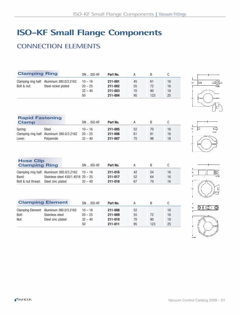
Vacuum FittingsISO-KF Small Flange Components
Vacuum Control Catalog 2009 - D1
Clamping Element
Hose Clip Clamping Ring
Rapid Fastening Clamp
Clamping Ring
CONNECTION ELEMENTS
ISo-KF Small Flange Components
DN ... ISO-KF Part No. A B C
Clamping ring half: Aluminum 380.0/3.2162 10 – 16 211-001 45 61 16Bolt & nut: Steel nickel plated 20 – 25 211-002 55 72 16 32 – 40 211-003 70 90 18 50 211-004 95 123 25
DN ... ISO-KF Part No. A B C
Spring: Steel 10 – 16 211-005 52 70 16Clamping ring half: Aluminum 380.0/3.2162 20 – 25 211-006 61 81 16Lever: Polyamide 32 – 40 211-007 75 98 18
DN ... ISO-KF Part No. A B C
Clamping Element: Aluminum 380.0/3.2162 10 – 16 211-008 52 18Bolt: Stainless steel 20 – 25 211-009 55 72 16Nut: Steel zinc plated 32 – 40 211-010 70 90 18 50 211-011 95 123 25
DN ... ISO-KF Part No. A B C
Clamping ring half: Aluminum 380.0/3.2162 10 – 16 211-016 42 54 16Band: Stainless steel 430/1.4016 20 – 25 211-017 52 64 16Bolt & nut thread: Steel zinc plated 32 – 40 211-018 67 79 16
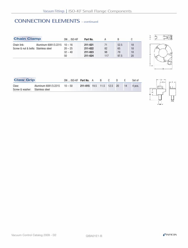
Vacuum Fittings ISO-KF Small Flange Components
Vacuum Control Catalog 2009 - D2
Claw Grip
Chain Clamp
CONNECTION ELEMENTS - continued
DN ... ISO-KF Part No. A B C
Chain link: Aluminum 6081/3.2215 10 – 16 211-021 71 52.5 18Screw & nut & bolts: Stainless steel 20 – 25 211-022 82 65 18 32 – 40 211-023 98 79 18 50 211-024 117 97.5 20
DN ... ISO-KF Part No. A B C D E Set of
Claw: Aluminum 6081/3.2215 10 – 50 211-015 19.5 11.5 12.5 20 14 4 pcs.Screw & washer: Stainless steel
QIBA01E1-B

Vacuum FittingsISO-KF Small Flange Components
Vacuum Control Catalog 2009 - D3
Reducing Centering Ring
External Centering Ring
Centering Ring
ISo-KF Small Flange Components
SEALS
DN ... ISO-KF Part No. A B C D
Ring: Aluminum 6082/– 10 211-051 12 10 8 3.9Seal: Elastomer CR 16 211-052 17 16 8 3.9 20 211-053 22 20 8 3.9 25 211-054 26 25 8 3.9 32 211-055 34 32 8 3.9 40 211-056 41 40 8 3.9 50 211-057 52 50 8 3.9
Ring: Aluminum 6082/– 10 211-058 12 10 8 3.9Seal: Elastomer FPM 16 211-059 17 16 8 3.9 20 211-060 22 20 8 3.9 25 211-061 26 25 8 3.9 32 211-062 34 32 8 3.9 40 211-063 41 40 8 3.9 50 211-064 52 50 8 3.9
Ring: Stainless steel 303/1.4305– 10 211-065 12 10 8 3.9Seal: Elastomer FPM 16 211-066 17 16 8 3.9 20 211-067 22 20 8 3.9 25 211-068 26 25 8 3.9 32 211-069 34 32 8 3.9 40 211-070 41 40 8 3.9 50 211-071 52 50 8 3.9
DN ... ISO-KF Part No. A B C D E
Ring: Aluminum 6082/– 10 / 16 211-072 17 10 12 8 3.9Seal: Elastomer CR 20 / 25 211-073 26 20 22 8 3.9 32 / 40 211-074 41 32 34 8 3.9
Ring: Aluminum 6082/– 10 / 16 211-075 17 10 12 8 3.9Seal: Elastomer FPM 20 / 25 211-076 26 20 22 8 3.9 32 / 40 211-077 41 32 34 8 3.9
Ring: Stainless steel 303/1.4305 10 / 16 211-078 17 10 12 8 3.9Seal: Elastomer FPM 20 / 25 211-079 26 20 22 8 3.9 32 / 40 211-080 41 32 34 8 3.9
DN ... ISO-KF Part No. A B C D
Ring: Aluminum 6082/– 10-16 211-081 32 30.2 7 3.9Seal: Elastomer CR 20-25 211-082 42 40.2 7 3.9 32-40 211-083 57 55.2 7 3.9 50 211-084 77 75.2 7 3.9
Ring: Aluminum 6082/– 10-16 211-085 32 30.2 7 3.9Seal: Elastomer FPM 20-25 211-086 42 40.2 7 3.9 32-40 211-087 57 55.2 7 3.9 50 211-088 77 75.2 7 3.9

Vacuum Fittings ISO-KF Small Flange Components
Vacuum Control Catalog 2009 - D4
Indium Seal
Centering Ring with Fine Filter
Centering Ring with Filter
O-Ring
SEALS - continued
DN ... ISO-KF Part No. A B C D
Inner ring: Stainless steel 303/1.4305 10 211-096 12 9 8 3.9
Snab ring: Stainless steel 304/1.4301 16 211-097 17 13 8 3.9
Seal: Elastomer FPM 25 211-098 26 22 8 3.9
40 211-099 41 35.5 8 3.9
50 211-100 52 45.7 8 3.9
DN ... ISO-KF Part No. A B Set of
Elastomer CR 10 211-146 15 5 10 pcs.
16 211-147 18 5 10 pcs.
20 211-148 25 5 10 pcs.
25 211-149 28 5 10 pcs.
32 211-150 40 5 10 pcs.
40 211-151 42 5 10 pcs.
50 211-152 55 5 10 pcs.
Elastomer FPM 10 211-153 15 5 10 pcs.
16 211-154 18 5 10 pcs.
20 211-155 25 5 10 pcs.
25 211-156 28 5 10 pcs.
32 211-157 40 5 10 pcs.
40 211-158 42 5 10 pcs.
50 211-159 55 5 10 pcs.
DN ... ISO-KF Part No. A B C D E
Inner ring: Stainless steel 304/1.4301 10-16 211-162 32 18 30 3.9 7
Outer ring: Aluminum 5012/– 20-25 211-163 42 28 40 3.9 7
Seal: Indium 32-40 211-164 57 43 55 3.9 7
Working temperature: -196° to +60°C 50 211-165 77 63 75 3.9 7
Filter: Stainless steel 316L/1.4435Pore size 0.004 mm Degree of separation at 0.001 mmup to 98%
DN ... ISO-KF Part No. A B C D E*
Ring: Stainless steel 303/1.4305 10 211-089 12 8 8 3.9 0.5m3/h
Seal: Elastomer FPM 16 211-090 17 14 8 3.9 1.2m3/h
25 211-092 26 23 8 3.9 4.2m3/h
40 211-094 41 38 8 3.9 11.3m3/h
50 211-095 52 48 8 3.9 18.1m3/h
Filter: Stainless steel 316L/1.4435Pore size 0.02 mm* Air at 0°C, 20 mbardifferential pressure
Recommended gas flow direction

Vacuum FittingsISO-KF Small Flange Components
Vacuum Control Catalog 2009 - D5
Aluminum Seal
Support for Aluminum Seal
SEALS - continued
QIBA02E1-B
DN ... ISO-KF Part No. A B For Aluminum Seal
Stainless steel 301/1.4310 10-16 211-171 32 7 211-167
20-25 211-172 42 7 211-168
32-40 211-173 57 7 211-169
Reusable 50 211-174 77 7 211-170
With
DN ... ISO-KF Part No. A B C D Support Ring
Aluminum anneated 6082/3.2315 10-16 211-167 25.6 19.6 4.5 22.6 211-171
20-25 211-168 35.6 29.6 4.5 32.6 211-168
32-40 211-169 50.6 44.6 4.5 47.6 211-173
Set of 3 pieces 50 211-170 65.6 59.6 4.5 62.6 211-174

Vacuum Fittings ISO-KF Small Flange Components
Vacuum Control Catalog 2009 - D6
Flange withTube, Long
Flange withTube, Short
Blank Flange
FLANGES
ISo-KF Small Flange Components
QIBA03E1-A
DN ... ISO-KF Part No. A
Aluminum 6082/– 10 211-176 5
16 211-177 5
25 211-178 5
40 211-179 5
50 211-180 6
Stainless steel 304/1.4301 10 211-181 5
16 211-182 5
25 211-183 5
40 211-184 5
50 211-185 6
DN ... ISO-KF Part No. A B C
Steel –/1.0037 10 211-201 20 12 16
16 211-202 20 16 20
25 211-203 20 26 30
40 211-204 20 41 45
50 211-205 20 51 55
Stainless steel 304/1.4301 10 211-211 20 12 16
16 211-212 20 16 20
25 211-213 20 26 30
40 211-214 20 41 45
50 211-215 20 50 54
DN ... ISO-KF Part No. A B C
Steel –/1.0037 10 211-206 70 12 16
16 211-207 70 16 20
25 211-208 70 26 30
40 211-209 70 41 45
50 211-210 70 51 55
Stainless steel 304/1.4301 10 211-216 70 12 16
16 211-217 70 16 20
25 211-218 70 26 30
40 211-219 70 41 45
50 211-220 70 50 54

Vacuum FittingsISO-KF Small Flange Components
Vacuum Control Catalog 2009 - D7
Reducing Tee
Tee
Elbow 45º
Elbow 90º
ISo-KF Small Flange Components
PIPE FITTINGS
DN ... ISO-KF Part No. A B C
Aluminum 6082/– 10 211-261 30 60 12 16 211-262 40 80 16 25 211-263 50 100 25 40 211-264 65 130 39
Stainless steel 304/1.4301 10 211-291 30 60 12 16 211-292 40 80 16 25 211-293 50 100 25 40 211-294 65 130 40.5 50 211-295 70 140 53
DN ... ISO-KF Part No. A B C
Stainless steel 304/1.4301 16 211-307 26 55 15 25 211-308 32 68.8 25
40 211-309 40 87.7 37
DN ... ISO-KF Part No. A B
Aluminum 6082/– 10 211-251 30 12
16 211-252 40 16
25 211-253 50 25
40 211-254 65 39
Stainless steel 304/1.4301 10 211-286 30 9
16 211-287 40 15
25 211-288 50 25
40 211-289 65 40.5
50 211-290 70 49
DN ... ISO-KF Part No. A B C
Stainless steel 304/1.4301 25/16 211-316 50 100 40
40/16 211-317 65 130 40
40/25 211-318 65 130 50
50/16 211-319 70 140 50
50/25 211-320 70 140 65
50/40 211-321 70 140 65

Vacuum Fittings ISO-KF Small Flange Components
Vacuum Control Catalog 2009 - D8
Reducer
Intermediate Piece
Reducing Cross
Cross
PIPE FITTINGS - continued
QIBA04E1-B
DN ... ISO-KF Part No. A B
Aluminum 6082/– 16 211-227 80 16
25 211-228 100 25
40 211-229 130 40
Stainless steel 304/1.4301 16 211-277 80 16
25 211-278 100 25
40 211-279 130 40.5
50 211-280 140 53
DN ... ISO-KF Part No. A B
Aluminum 6082/– 25/16 211-231 40 16
40/16 211-232 40 16
40/25 211-233 40 25
50/40 211-234 40 40
Stainless steel 303/1.4305 25/16 211-281 40 16
40/16 211-282 40 16
40/25 211-283 40 26
50/40 211-284 40 40
DN ... ISO-KF Part No. A B C
Aluminum 6082/3.2315 10 211-266 30 60 12
16 211-267 40 80 16
25 211-268 50 100 25
40 211-269 65 130 39
Stainless steel 304/1.4301 10 211-296 30 60 12
16 211-297 40 80 16
25 211-298 50 100 25
40 211-299 65 130 40.5
50 211-300 70 140 53
DN ... ISO-KF Part No. A B C D E F
Aluminum 6082/3.2315 25 211-271 35 70 35 70 25 16
40 211-272 40 80 45 90 39 16
Stainless steel 304/1.4301 25 211-301 35 70 35 70 25 17
40 211-302 40 80 45 90 40.5 16
50 211-303 50 100 50 100 53 16

Vacuum FittingsISO-KF Small Flange Components
Vacuum Control Catalog 2009 - D9
Metal Hose
Bellows
Metal Hose, Flexible
ISo-KF Small Flange Components
BELLOWS/HOSE WITH FLANGES
DN ... ISO-KF Part No. A B C D
Flanges: Stainless steel 304/1.4301 10 211-326 70 3.5 3 23°Bellow: Stainless steel 316Ti/– 16 211-327 70 6.4 4.1 21° 25 211-328 80 8 5 17°A = unstressed length 40 211-329 100 11 7 15°D = max. deviation from axis 50 211-330 100 10 6 15°Max. internal pressure: 4 bar
DN ... ISO-KF Part No. A B C
Flanges: Stainless steel 304/1.4301 16 211-515 250 40 25Bellow: Stainless steel 316Ti/– 16 211-516 500 40 25 25 211-519 250 55 36 25 211-520 500 55 36 40 211-523 250 90 60Max. internal pressure: 2 bar 40 211-524 500 90 60B = radius for multiple bending 50 211-527 250 100 65C = radius for single bend 50 211-528 500 100 65
DN ... ISO-KF Part No. A B C
Flanges: Stainless Steel 304/1.4301 10 211-331 250 70 32Bellow: Stainless steel 316Ti/– 10 211-332 500 70 32 10 211-333 750 70 32 10 211-334 1000 70 32 16 211-335 250 70 50 16 211-336 500 70 50 16 211-337 750 70 50 16 211-338 1000 70 50 25 211-339 250 100 60 25 211-340 500 100 60 25 211-341 750 100 60 25 211-342 1000 100 60 40 211-343 250 130 100 40 211-344 500 130 100 40 211-345 750 130 100 40 211-346 1000 130 100 50 211-347 250 200 130Max. internal pressure: 4 bar 50 211-348 500 200 130B = radius for multiple bending 50 211-349 750 200 130C = radius for single bend 50 211-350 1000 200 130

Vacuum Fittings ISO-KF Small Flange Components
Vacuum Control Catalog 2009 - D10
PVC Hose
BELLOWS/HOSE WITH FLANGES - continued
QIBA05E1-A
DN ... ISO-KF Part No. A B C
Hose: PVC with cast in steel spiral 16 211-406 500 130 65Nipple: Aluminum 6082/– 16 211-407 1000 130 65Hose clamp: Stainless steel 430/– 25 211-408 500 200 100 25 211-409 1000 200 100B = radius for multiple bending 40 211-410 500 260 130C = radius for single bend 40 211-411 1000 260 130

Vacuum FittingsISO-KF Small Flange Components
Vacuum Control Catalog 2009 - D11
Adapter ISO-KF/VCR Male
Adapter ISO-KF/VCR Female
Adapter ISO-KF/CF-F
Adapter ISO-KF/ISO-K
ISo-KF Small Flange Components
TRANSITION PIECES
ISO-KF/ISO-K Part No. A
Aluminum 6082/– 40/63 212-171 40
50/63 212-172 45
Stainless steel 303/1.4305 40/63 212-173 40
50/63 212-174 45
40/100 212-175 40
ISO-KF/VCR Part No. A
Flange: Stainless steel 304/1.4301 16/ 1/4” 211-359 35.8
Nut: Stainless steel 316L/1.4435 25/ 1/4” 211-480 35.8
25/ 1/2” 211-360 40.6
Width across flats in inch 40/ 3/4” 211-361 53.3
ISO-KF/CF-F Part No. A B
Stainless steel 304/1.4301 16/16 213-251 35 16
25/16 213-252 35 16
16/40 213-254 30 16
25/40 213-255 30 26
40/40 213-256 50 37
40/63 213-259 35 41
40/100 213-262 50 41
ISO-KF/VCR Part No. A
Flange: Stainless steel 304/1.4301 16/ 1/4” 211-362 35.8
Nut: Stainless steel 316L/1.4435 25/ 1/4” 211-481 35.8
25/ 1/2” 211-363 40.6
Width across flats in inch 40/ 3/4” 211-364 53.3

Vacuum Fittings ISO-KF Small Flange Components
Vacuum Control Catalog 2009 - D12
Screw-in Flange
Screw-on Flange
Glass Tube Connection
Adapter ISO-KF/Swagelok
TRANSITION PIECES - continued
ISO-KF/Swagelok Part No. A B
Flange: Stainless steel 304/1.4301 16/6 mm 211-356 1) 37 15.3
Nut: Stainless steel 316L/1.4435 25/10 mm 211-357 1) 45 17.2
40/16 mm 211-358 1) 53 24.4
16/ 1/8” 211-476 2) 34.5 12.7
25/ 1/4” 211-477 2) 37 15.3
1) Width across flats metric (SI) 40/ 1/4” 211-478 2) 37 15.32) Width across flats in inch 40/ 1/2” 211-479 2) 47.5 22.8
DN ... ISO-KF Part No. A B C D
Flange: Aluminum 6082/– 10 211-351 50 8 10 30
Sealing: Elastomer FPM 40 211-353 65 22 26 45
Tube: Glas Pyrex
ISO-KF/DN Part No. A B C D
Flange: Stainless steel 303/1.4305 10/ G 3/8” 211-366 35 15 G 3/8” 12
Sealing: Elastomer FPM 16/ G 1/2” 211-367 35 15 G 1/2” 16
25/ G 1” 211-368 45 25 G1” 25
Width across flats metric (SI) 40/ G 1 1/2” 211-369 50 30 G 1 1/2” 41
ISO-KF/DN Part No. A B C D
Flange: Stainless steel 303/1.4305 10/ G 3/8” 211-376 35 15 G 3/8” 10
Sealing: Elastomer FPM 16/ G 1/2” 211-377 35 15 G 1/2” 15
25/ G 1” 211-378 45 25 G 1” 24
Width across flats metric (SI) 40/ G 1 1/2” 211-379 50 30 G 1 1/2” 38

Vacuum FittingsISO-KF Small Flange Components
Vacuum Control Catalog 2009 - D13
Adapter ISO-KF/NPT Male
Adapter ISO-KF/NPT Female
TRANSITION PIECES - continued
QIBA06E1-B
ISO-KF/NPT Part No. A B C D
Stainless steel 303 16/ 1/8” 211-566 19 10 12 1/8-27 NPT
16/ 1/4” 211-567 19 13 15 1/4-18 NPT
25/ 1/8” 211-569 19 10 12 1/8-27 NPT
25/ 1/4” 211-570 19 13 15 1/4-18 NPT
25 / 1/2” 211-571 26 18 25 1/2-14 NPT
25 / 1” 211-572 42 24 25 1-11 1/2 NPT
40 / 1/4” 211-574 19 13 15 1/4-18 NPT
40 / 1/2” 211-575 26 18 25 1/2-14 NPT
Width across flats in inch 40 / 1” 211-576 26 23 41 1-11 1/2 NPT
ISO-KF/NPT Part No. A B C D
Stainless steel 303 / 1.4305 16/ 1/8” 211-551 40 17 5 1/8-27 NPT
16/ 1/4” 211-552 40 22 7 1/4-18 NPT
25/ 1/8” 211-554 40 17 5 1/8-27 NPT
25/ 1/4” 211-555 40 22 7 1/4-18 NPT
25 / 1/2” 211-556 50 30 14 1/2-14 NPT
25 / 1” 211-557 60 32 25 1-11 1/2 NPT
40 / 1/4” 211-559 40 21 7 1/4-18 NPT
40 / 1/2” 211-560 50 30 14 1/2-14 NPT
40 / 1” 211-561 60 33 25 1-11 1/2 NPT
40 / 1 1/4” 211-562 50 31.5 32 1 1/4-11 1/2 NPT
40 / 1 1/2” 211-563 50 28 32 1 1/2-11 1/2 NPT
Width across flats in inch 40 / 2” 211-564 50 27 40 2-11 1/2 NPT

Vacuum Fittings ISO-KF Small Flange Components
Vacuum Control Catalog 2009 - D14
Hose Clamp
Sleeve with Hose Clamp
Hose Connection
Hose Adapter for Rubber Hose
Hose Adapter 90º
ISo-KF Small Flange Components
HOSE, HOSE CONNECTION
DN ... ISO-KF Part No. A B C
Aluminum 6082/– 16 211-387 40 7 12
25 211-388 40 7 12 40 211-389 40 7 12
Stainless steel 303/1.4305 16 211-392 40 7 12
25 211-393 40 7 12 40 211-394 40 7 12
DN ... ISO-KF Part No. A B C D E
Hose clamp: Stainless steel 430/– 16 211-417 58 7 14 16 44
Sleeve: Elastomer CR 25 211-418 60 9 16 25 50
Max. internal pressure: 1 bar 40 211-419 64 13 20 40 68
DN ... ISO-KF Part No. A B
Stainless steel 430/– 16 211-461 13 32
25 211-462 19 44
40 211-463 29 76
DN ... ISO-KF Part No. A B C D
Aluminum 6082/– 16 211-257 40 40 16 13
25 211-258 50 50 25 22
40 211-259 65 65 40 37
C = nominal connection for sleeve / hose
DN ... ISO-KF Part No. A B C
Aluminum 6082/– 25 211-401 40 13 16
16 211-402 40 13 16
25 211-403 40 22 25
40 211-404 40 37 40
C = nominal connectionfor sleeve / hose
C = nominal connection for hose

Vacuum FittingsISO-KF Small Flange Components
Vacuum Control Catalog 2009 - D15
Protective Lid
Rubber Hose
PVC Hose
HOSE, HOSE CONNECTION - continued
QIBA07E1-B
DN ... ISO-KF Part No. A B C
Polyethylene 10-16 211-427 32 29 7.5
20-25 211-428 42 39 7.5
32-40 211-429 57 54 7.5
50 211-430 77 74 7.5
DN ... ISO-KF Part No. A B C
With cast in spiral 16 211-442 23 16 130
25 211-443 33 25 200
40 211-444 53 40 260
DN ... ISO-KF Part No. A B
For vacuum applications 10 211-451 17 7
16 211-452 25 10
20 211-453 32 16
Indicate length in meters Hardness: 55 ± 5 Shore A Temperature: -30 to +85 °C
For vacuum applications Indicate length in meters

Vacuum Fittings ISO-K Clamp Flange Components
Vacuum Control Catalog 2009 - D16
Claw
Clamp
CONNECTION ELEMENTS
DN ... ISO-K Part No. A B C Set of
Steel zinc plated 103/– 63-250 212-225 60 17 27 4 pcs.
320-500 212-226 78 27 39 4 pcs.
630 212-227 88 31 49 4 pcs.
Stainless steel 316/– 63-250 212-228 61 18 28 4 pcs.
320-630 212-240 82 29 47 4 pcs.
DN ... ISO-K Part No. A B C Set of
Clamping flange / base plate 63-100 212-231 22.5 35 13.9 4 pcs.
160-250 212-232 23 35 13.9 4 pcs.
320-500 212-233 36.5 50 20.6 4 pcs.
630 212-234 41.5 55 25.6 4 pcs.
Clamping flange/ 63-100 212-235 18.6 30 10 4 pcs.
base plate with groove 160-250 212-236 19 35 10 4 pcs.
320-500 212-237 31 45 15 4 pcs.
630 212-233 36.5 50 20.6 4 pcs.
Clamping flange with 63-100 212-247 20.6 30 12 4 pcs.
groove / base plate 160-250 212-248 21.1 35 12 4 pcs.
320-500 212-249 33.9 45 18 4 pcs.
630 212-233 36.5 50 20.6 4 pcs.
Steel zinc plated 103/–
ISo-K Clamp Flange Components
QIBA08E1

Vacuum FittingsISO-K Clamp Flange Components
Vacuum Control Catalog 2009 - D17
Centering Ring
ISo-K Clamp Flange Components
SEALS
DN ... ISO-K Part No. A B C D
Inner & outer ring: Aluminum 6082/– 63 212-251 96 70 3.9 8
Seal: Elastomer CR 80 212-091 109 83 3.9 8
100 212-252 128 102 3.9 8
160 212-253 179 153 3.9 8
200 212-254 239 213 3.9 8
250 212-255 287 261 3.9 8
320 212-256 358 318 5.6 14
400 212-257 440 400 5.6 14
500 212-258 541 501 5.6 14
630 212-259 691 651 5.6 14
Inner & outer ring: Aluminum 6082/– 63 212-261 96 70 3.9 8
Seal: Elastomer FPM 80 212-092 109 83 3.9 8
100 212-262 128 102 3.9 8
160 212-263 179 153 3.9 8
200 212-264 239 213 3.9 8
250 212-265 287 261 3.9 8
320 212-266 358 318 5.6 14
400 212-267 440 400 5.6 14
500 212-268 541 501 5.6 14
630 212-269 691 651 5.6 14
800 212-270 840 800 5.6 14
1000 212-271 1040 1000 5.6 14
Inner ring: Stainless steel 304/– 63 212-281 96 70 3.9 8
Outer ring: Aluminum 6082/– 80 212-093 109 83 3.9 8
Seal: Elastomer FPM 100 212-282 128 102 3.9 8
160 212-283 179 153 3.9 8
200 212-284 239 213 3.9 8
250 212-285 287 261 3.9 8

Vacuum Fittings ISO-K Clamp Flange Components
Vacuum Control Catalog 2009 - D18
O-Ring
Centering Ring with Fine Filter DN ... ISO-K Part No. A B C D
Inner ring: Stainless steel 304/– 63 212-291 62 69.8 3.9 8
Outer ring: Aluminum 6082/– 100 212-292 94 101.8 3.9 8
Seal: Elastomer FPM
Snap ring: Stainless steel 304/–
Filter grit: Stainless steel 304/–
Filter: Stainless steel 316L/–
Pore size 0.004 mm
Degree of separation at
0.001 mm up to 98%
DN ... ISO-K Part No. A B Set of
Elastomer CR 63 212-386 75.6 5.3 5 pcs.
80 212-387 88.3 5.3 5 pcs.
100 212-388 107.3 5.3 5 pcs.
160 212-389 158.1 5.3 5 pcs.
200 212-390 208.9 5.3 5 pcs.
250 212-391 253.4 5.3 5 pcs.
320 212-356 329.6 7
400 212-357 405.3 7
500 212-358 506.9 7
630 212-359 658.9 7
Elastomer FPM 63 212-392 75.6 5.3 5 pcs.
80 212-393 88.3 5.3 5 pcs.
100 212-394 107.3 5.3 5 pcs.
160 212-395 158.1 5.3 5 pcs.
200 212-396 208.9 5.3 5 pcs.
250 212-397 253.4 5.3 5 pcs.
Elastomer FPM 320 212-366 329.6 7
400 212-367 405.3 7
500 212-368 506.9 7
630 212-369 658.9 7
800 212-370 808 7
1000 212-371 1006 7
SEALS - continued

Vacuum FittingsISO-K Clamp Flange Components
Vacuum Control Catalog 2009 - D19
Aluminum Seal DN ... ISO-K Part No. A B C D E
Aluminum annealed 6082/– 63 212-301 85.6 83 69.8 2.6 4.5
100 212-302 116.6 114 101.8 2.6 4.5
160 212-303 166.6 164 152.8 2.6 4.5
250 212-305 276.6 274 260.8 2.6 4.5
Number of Clamps Claw Grips
DN 63 ISO -K 4
DN 100 ISO-K 6 8
DN 160 ISO-K 8 8
DN 250 ISO-K 12 12
SEALS - continued
QIBA09E1

Vacuum Fittings ISO-K Clamp Flange Components
Vacuum Control Catalog 2009 - D20
Welding Flange
Blank Flange
ISo-K Clamp Flange Components
FLANGES
DN ... ISO-K Part No. A B
Steel nickel plated A570/– 63 212-001 95 12
100 212-002 130 12
160 212-003 180 12
250 212-005 290 12
Stainless steel 304/– 63 212-011 95 12
80 212-076 110 12
100 212-012 130 12
160 212-013 180 12
200 212-014 240 12
250 212-015 290 12
320 212-016 370 17
400 212-017 450 17
500 212-018 550 17
630 212-019 690 22
DN ... ISO-K Part No. A B C D E
Steel –/1.0570 63 212-021 95 76.1 70.3 12 6
100 212-022 130 108 102.2 12 6
Steel A570/– 160 212-023 180 159 153.2 12 6
250 212-025 290 267 261 12 6
Stainless steel 304/– 63 212-031 95 76.1 71.5 12 6
80 212-078 110 88.9 84.9 12 6
100 212-032 130 108 102 12 6
160 212-033 180 159 155 12 6
200 212-034 240 219.1 213.9 12 6
250 212-035 290 267 261 12 6

Vacuum FittingsISO-K Clamp Flange Components
Vacuum Control Catalog 2009 - D21
Flange with Tube DN ... ISO-K Part No. A B C
Flange: Steel –/1.0570 63 212-041 100 76.1 70.3
Tube: Steel –/1.0831 100 212-042 100 108 102.2
160 212-043 100 159 153.2
250 212-045 100 267 261
320 212-046 100 324 318
400 212-047 100 406 400
500 212-048 100 508 500
630 212-049 100 660 650
Stainless steel 304/– 63 212-051 100 76.1 71.5
100 212-052 100 108 104
160 212-053 100 159 155
200 212-054 100 219.1 213.1
250 212-055 100 267 261
320 212-056 100 324 318
400 212-057 100 406 400
500 212-058 100 508 500
630 212-059 100 660 650
FLANGES - continued
QIBA10E1

Vacuum Fittings ISO-K Clamp Flange Components
Vacuum Control Catalog 2009 - D22
Reducer
Reducing Tee
Tee
Elbow 90º
ISo-K Clamp Flange Components
PIPE FITTINGS
DN ... ISO-K Part No. A B
Stainless steel 304/– 63 212-101 88 66
100 212-102 108 100
160* 212-103 138 150
200* 212-104 178 213
250* 212-105 208 250
320* 212-106 250 318
A�
*�
øB�
A�
DN ... ISO-K Part No. A
Stainless steel 303/– 80/63 212-084 50
100/63 212-161 50
160/100 212-163 50
250/200 212-170 50
DN ... ISO-K Part No. A B
Stainless steel 304/– 63 212-111 88 66
100 212-112 108 100
160 212-113 138 150
200 212-114 178 213
250 212-115 208 250
320 212-116 250 318
B�
A�
C�
DN ... ISO-K Part No. A B C
Stainless steel 304/– 160/63 212-196 138 276 130
160/100 212-197 138 276 131
250/200 212-198 190 380 208
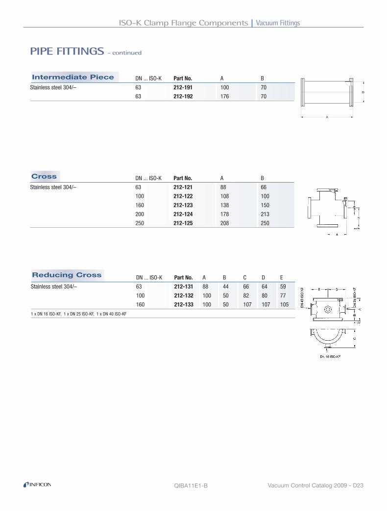
Vacuum FittingsISO-K Clamp Flange Components
Vacuum Control Catalog 2009 - D23
Reducing Cross
Cross
Intermediate Piece
PIPE FITTINGS - continued
QIBA11E1-B
DN ... ISO-K Part No. A B C D E
Stainless steel 304/– 63 212-131 88 44 66 64 59
100 212-132 100 50 82 80 77
160 212-133 100 50 107 107 105
1 x DN 16 ISO-KF, 1 x DN 25 ISO-KF, 1 x DN 40 ISO-KF
DN ... ISO-K Part No. A B
Stainless steel 304/– 63 212-121 88 66
100 212-122 108 100
160 212-123 138 150
200 212-124 178 213
250 212-125 208 250
B�
A�
DN ... ISO-K Part No. A B
Stainless steel 304/– 63 212-191 100 70
63 212-192 176 70

Vacuum Fittings ISO-K Clamp Flange Components
Vacuum Control Catalog 2009 - D24
Metal Hose
Bellows
ISo-K Clamp Flange Components
BELLOWS / HOSE WITH FLANGES
DN ... ISO-K Part No. A B C
Flanges: Stainless steel 304/– 63 212-211 250 250 160
Bellow: Stainless steel 316Ti/– 63 212-212 500 250 160 63 212-213 750 250 160
63 212-214 1000 250 160
100 212-215 250 370 240
100 212-216 500 370 240
100 212-217 750 370 240
Max. internal pressure 1.5 bar 100 212-218 1000 370 240
B = radius for multiple bending
C = radius for single bending
DN ... ISO-K Part No. A B C D E
Flanges: Stainless steel 304/– 63 212-201 132 20 20 66 30°
Bellow: Stainless steel 316Ti/– 100 212-202 132 28 28 95 30°
160 212-203 150 22 22 153 14°
200 212-204 150 20 20 213 12°
E = max. deviation from axis 250 212-205 200 30 30 261 13°
Max. internal pressure 1.5 bar 320 212-206 250 50 50 313 12°
A = unstressed length
QIBA12E1

Vacuum FittingsISO-K Clamp Flange Components
Vacuum Control Catalog 2009 - D25
Sleeve with Hose Clamp
Adapter
Adapter
Adapter
Adapter Flange
ISo-K Clamp Flange Components
TRANSITION PIECES
QIBA13E1-A
ISO-K / ISO-KF Part No. A
Aluminum 6082/– 63/40 212-171 40
63/50 212-172 45
Stainless steel 303/– 63/25 212-176 50
63/40 212-173 40
63/50 212-174 45
100/40 212-175 40
DN ... ISO-K Part No. A B
Aluminum 6082/– 63 212-181 51 76
100 212-182 56 107
160 212-183 56 156
DN ... ISO-KF Part No. A B C D E
Sleeve: Elastomer CR 63 212-186 70 14 24 75 120
Hose clamp: Stainless steel 430/– 100 212-187 72 8 26 106 150
Max. internal pressure: 1 bar 160 212-188 72 8 26 155 200
ISO-K / ISO-F Part No. A
Stainless steel 304/– 160/63 212-152 22
160/100 212-153 25
200/100 212-155 20
200/160 212-156 25
250/160 212-159 22
ISO-CF / ISO-K Part No. A B C
Stainless steel 304/– 63/63 213-271 90 1 1
100/100 213-272 90 1 1
160/160 213-273 90 1.5 1.5

Vacuum Fittings ISO-K Clamp Flange Components
Vacuum Control Catalog 2009 - D26
Protective Lids
ISo-K Clamp Flange Components
PROTECTIVE LIDS
DN ... ISO-K Part No. A B C
Polyethylene 63 212-311 102 95 18
100 212-312 137 130 18
160 212-313 187 180 18
200 212-314 248 240 18.5
250 212-315 297.5 290 18.5
320 212-316 380 370 23.5
400 212-317 461 450 23.5
500 212-318 557 550 24
630 212-319 697 690 29
QIBA14E1

Vacuum FittingsISO-F Fixed Flange Components
Vacuum Control Catalog 2009 - D27
Measurement Flange
Adapter Flange with ISO-K / ISO-F
Collar Flange with Retaining Ring
ISo-F Fixed Flange Components
FLANGE COMPONENTS
DN ... ISO-F Part No. A B C
Flange: Steel nickel plated –/1.0570 63 212-061 12 95.5 130
Retaining Ring: Steel nickel plated 100 212-062 12 130.5 165
160 212-063 16 180.7 225
200 212-064 16 240.7 285
250 212-065 16 290.7 335
320 212-066 20 370.8 425
400 212-067 20 450.8 510
500 212-068 20 550.8 610
630 212-069 24 691 750
DN ... ISO-F Part No. A
Stainless steel 304/1.4301 160/63 212-152 22
160/100 212-153 25
200/100 212-155 20
200/160 212-156 25
250/160 212-159 22
DN ... ISO-F Part No. A B C
Aluminum 6082/3.2315 100 212-142 30 165 M 8
160 212-143 30 225 M 10
Stainless steel 304/1.4301 63 212-146 30 130 M 8
100 212-147 30 165 M 8
160 212-148 30 225 M 10
*Claw grip DN 16 ISO-KF included

Vacuum Fittings ISO-F Fixed Flange Components
Vacuum Control Catalog 2009 - D28
O-Ring
Sealing Disk
Set of Hexagon Bolts DN ... ISO-F Part No. A B Set of
Steel zinc plated 63-100 212-241 40 8 8 pcs.
160-250 212-242 50 10 12 pcs.
320-500 212-243 70 12 16 pcs.
630 212-244 80 12 20 pcs.
DN ... ISO-F Part No. A B C
Disk: Aluminum 6082/3.2315 63 212-321 73 3.9 98
O-ring: Elastomer CR 100 212-322 107 3.9 132
160 212-323 160 3.9 185
250 212-325 270 3.9 295
320 212-326 330 5.6 375
400 212-327 415 5.6 460
500 212-328 515 5.6 560
630 212-329 656 5.6 701
800 212-330 825 5.6 870
1000 212-331 1025 5.6 1070
DN ... ISO-F Part No. A B Set of
Elastomer CR 63 212-345 80 5 5 pcs.
100 212-346 110 5 5 pcs.
160 212-347 165 5 5 pcs.
250 212-349 265 5 5 pcs.
320 212-338 325 8
400 212-339 412 8
500 212-340 510 8
630 212-341 640 8
800 212-342 820 8
1000 212-343 1023 8
FLANGE COMPONENTS - continued
QIBA15E1
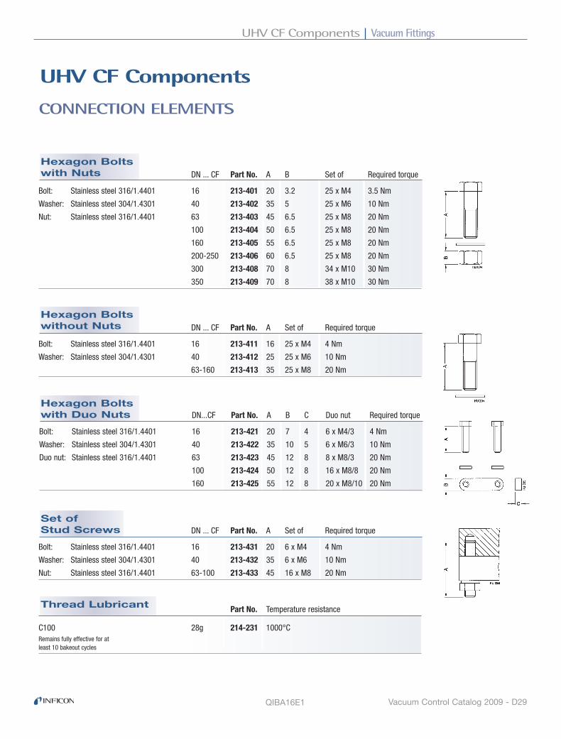
Vacuum FittingsUHV CF Components
Vacuum Control Catalog 2009 - D29
Thread Lubricant
Set of Stud Screws
Hexagon Bolts with Duo Nuts
Hexagon Bolts without Nuts
Hexagon Bolts with Nuts
CONNECTION ELEMENTS
Part No. Temperature resistance
C100 28g 214-231 1000°CRemains fully effective for at least 10 bakeout cycles
DN ... CF Part No. A B Set of Required torque
Bolt: Stainless steel 316/1.4401 16 213-401 20 3.2 25 x M4 3.5 Nm
Washer: Stainless steel 304/1.4301 40 213-402 35 5 25 x M6 10 Nm
Nut: Stainless steel 316/1.4401 63 213-403 45 6.5 25 x M8 20 Nm
100 213-404 50 6.5 25 x M8 20 Nm
160 213-405 55 6.5 25 x M8 20 Nm
200-250 213-406 60 6.5 25 x M8 20 Nm
300 213-408 70 8 34 x M10 30 Nm
350 213-409 70 8 38 x M10 30 Nm
DN ... CF Part No. A Set of Required torque
Bolt: Stainless steel 316/1.4401 16 213-411 16 25 x M4 4 Nm
Washer: Stainless steel 304/1.4301 40 213-412 25 25 x M6 10 Nm
63-160 213-413 35 25 x M8 20 Nm
DN...CF Part No. A B C Duo nut Required torque
Bolt: Stainless steel 316/1.4401 16 213-421 20 7 4 6 x M4/3 4 Nm
Washer: Stainless steel 304/1.4301 40 213-422 35 10 5 6 x M6/3 10 Nm
Duo nut: Stainless steel 316/1.4401 63 213-423 45 12 8 8 x M8/3 20 Nm
100 213-424 50 12 8 16 x M8/8 20 Nm
160 213-425 55 12 8 20 x M8/10 20 Nm
DN ... CF Part No. A Set of Required torque
Bolt: Stainless steel 316/1.4401 16 213-431 20 6 x M4 4 Nm
Washer: Stainless steel 304/1.4301 40 213-432 35 6 x M6 10 Nm
Nut: Stainless steel 316/1.4401 63-100 213-433 45 16 x M8 20 Nm
UhV CF Components
QIBA16E1

Vacuum Fittings UHV CF Components
Vacuum Control Catalog 2009 - D30
DN ... CF Part No. A B C Set of
High quality 16 213-461 2.1 21.3 16.2 10 pcs.
Individually packed 40 213-462 2.1 48.1 39 10 pcs.
Copper OFHC –/2.0040 63 213-463 2.1 82.4 63.6 10 pcs.
Double silver plated 100 213-464 2.1 120.5 101.8 10 pcs.
160 213-465 2.1 171.3 152.6 5 pcs.
200 213-466 2.1 222.1 203.4 5 pcs.
250 213-467 2.1 272.9 254.2 5 pcs.
DN ... CF Part No. A B C Set of
High quality 16 213-451 2.1 21.3 16.2 10 pcs.
Copper OFHC –/2.0040 40 213-452 2.1 48.1 39 10 pcs.
Individually packed 63 213-453 2.1 82.4 63.6 10 pcs.
100 213-454 2.1 120.5 101.8 10 pcs.
160 213-455 2.1 171.3 152.6 10 pcs.
200 213-456 2.1 222.1 203.4 10 pcs.
250 213-457 2.1 272.9 254.2 5 pcs.
300 213-458 2.1 326.2 307 1 pcs.
350 213-459 2.1 376.5 357 1 pcs.
Copper Gasket Silver Plated
Copper Gasket
UhV CF Components
SEALS
Quality copper gaskets and silver plated copper gaskets are strictly designed for use in high-end UHV applications. These gaskets, made of OFHC copper, are inspected, cleaned and individually packed to ensure maximum quality.

Vacuum FittingsUHV CF Components
Vacuum Control Catalog 2009 - D31
DN ... CF Part No. A B C D Set of
Seal: Elastomer FPM 250 213-397 5 266.5 248.3 256.2 1 pcs.
Support ring: Aluminum 6082/–
DN ... CF Part No. A B C D Set of
Elastomer FPM 16 213-391 2 21 16 5 pcs.
40 213-392 2.5 48.2 42 5 pcs.
63 213-393 3.2 82.7 69.7 2.5 2 pcs.
100 213-394 3.2 119.8 107.8 2.5 2 pcs.
160 213-395 3.2 171.1 156 2.5 2 pcs.
200 213-396 3.2 222.5 206 2.5 2 pcs.
FPM Seal with Support Ring
FPM Seal
SEALS - continued
QIBA17E1-A

Vacuum Fittings UHV CF Components
Vacuum Control Catalog 2009 - D32
Blank Flange, Rotatable
Blank Flange
UhV CF Components
FLANGES
DN ... CF-F Part No. A B C
Stainless steel 304/1.4301 16 213-001 7.5 14 1.4 40 213-002 13 38 1.4 63 213-003 17.5 66 1.4 100 213-004 20 104 1.4 160 213-005 22 155 1.4 200 213-006 24.5 205 1.4 250 213-007 2405 256 1.4
Stainless steel 316L/1.4435 300 213-008 28.5 306 1.4 350 213-009 28.5 356 1.4
Stainless steel 316LN/1.4429 16 213-101 7.5 14 1.4 40 213-102 13 38 1.4 63 213-103 17.5 66 1.4 100 213-104 20 104 1.4 160 213-105 22 155 1.4 200 213-106 24.5 205 1.4 250 213-107 24.5 256 1.4
DN ... CF-R Part No. A B C D E
Stainless steel 304/1.4301 16 213-011 7.5 5.8 18.6 14 1.4
40 213-012 13 7.6 41 38 1.4
63 213-013 17.5 12.6 71 66 1.4
100 213-014 20 14.3 109 104 1.4
160 213-015 22 15.8 160 155 1.4
200 213-016 24.5 17.1 206 205 1.4
250 213-017 24.5 18 257 256 1.4
Stainless steel 316LN/1.4429 16 213-111 7.5 5.8 18.6 14 1.4
40 213-112 13 7.6 41 38 1.4
63 213-113 17.5 12.6 71 66 1.4
100 213-114 20 14.3 109 104 1.4
160 213-115 22 15.8 160 155 1.4
200 213-116 24.5 17.1 206 205 1.4
250 213-117 24.5 18 257 256 1.4

Vacuum FittingsUHV CF Components
Vacuum Control Catalog 2009 - D33
Welding Flange, Rotatable
Welding Flange
FLANGES - continued
DN ... CF-F Part No. A B C D E
Stainless steel 304/1.4301 16 213-021 7.5 3.3 17.2 18 1
40 213-022 13 7.5 39.5 40 1.5
63 213-023 17.5 8 66 70 2
100 213-024 20 9 104 108 2
160 213-025 22 10 155 159 2
200 213-026 24.5 12 205 205 2.5
250 213-027 24.5 12 256 256 3
Stainless steel 316L/1.4435 300 213-028 28.5 15.8 306 306 3
350 213-029 28.5 15.8 356 356 3
Stainless steel 316LN/1.4429 16 213-121 7.5 3.3 17.2 18 1
40 213-122 13 7.5 39.5 40 1.5
63 213-123 17.5 8 66 70 2
100 213-124 20 9 104 108 2
160 213-125 22 10 155 159 2
200 213-126 24.5 12 205 205 2.5
250 213-127 24.5 12 256 256 3
DN ... CF-R Part No. A B C D E
Stainless steel 304/1.4301 16 213-041 7.5 3.3 17.2 18 1
40 213-042 13 7.5 39.5 40 1.5
63 213-043 17.5 8 66 70 2
100 213-044 20 9 104 108 2
160 213-045 22 10 155 159 2
200 213-046 24.5 12 205 205 2.5
250 213-047 24.5 12 256 256 3
Stainless steel 316LN/1.4429 16 213-141 7.5 3.3 17.2 18 1
40 213-142 13 7.5 39.5 40 1.5
63 213-143 17.5 8 66 70 2
100 213-144 20 9 104 108 2
160 213-145 22 10 155 159 2
200 213-146 24.5 12 205 205 2.5
250 213-147 24.5 12 256 256 3

Vacuum Fittings UHV CF Components
Vacuum Control Catalog 2009 - D34
Flange with Tube, Rotatable
Flange with Tube
Welding Flange for Gauges
Welding Flange with Tapped Holes
FLANGES - continued
DN ... CF-F Part No. A B C D E
Stainless steel 304/1.4301 16 213-031 7.5 3.3 17.2 18 1 6xM4
40 213-032 13 7.5 39.5 40 1.5 6xM6
63 213-033 17.5 8 66 70 2 8xM8
100 213-034 20 9 104 108 2 16x M8
DN ... CF-F Part No. A B C D
Stainless steel 304/1.4301 16 213-051 38 17.2 18 1
40 213-052 63 39.5 40 1.6
63 213-053 105 66 70 2
100 213-054 135 104 108 2
160 213-055 167 155 159 2
DN ... CF-R Part No. A B C D
Stainless steel 304/1.4301 16 213-061 38 17.2 18 1
40 213-062 63 39.5 40 1.6
63 213-063 105 66 70 2
100 213-064 135 104 108 2
160 213-065 167 155 159 2
DN ... CF-F Part No. A B C D E F G F
Stainless steel 304/1.4301 40 213-092 24 17 38 69.5 1.75 48 10 4

Vacuum FittingsUHV CF Components
Vacuum Control Catalog 2009 - D35
Reducing Flange CF-F/CF-F
FLANGES - continued
QIBA18E1-A
DN ... CF-F Part No. A B C D
Stainless steel 304/1.4301 40/16 213-071 13 16 22 5.5 6xM4 63/40 213-073 17.5 39 50 9 6xM6 100/40 213-075 20 39 55 9 6xM6 100/63 213-076 20 66 85 11 8xM8 160/40 213-078 22 39 60 9 6xM6 160/100 213-080 22 104 120 11 16xM8
Stainless steel 316LN/1.4429 40/16 213-171 13 16 22 5.5 6xM4 63/40 213-173 17.5 39 50 9 6xM6 100/40 213-175 20 39 55 9 6xM6 100/63 213-176 20 66 85 11 8xM8 160/40 213-178 22 39 60 9 6xM6 160/100 213-180 22 104 120 11 16xM8

Vacuum Fittings UHV CF Components
Vacuum Control Catalog 2009 - D36
Elbow 90º
Reducer CF/CF
Intermediate Piece, Insulated
Intermediate Piece
UhV CF Components
PIPE FITTINGS
DN ... CF Part No. A B C D
Stainless steel 304/1.4301 40/16 213-221 45 1 1 16
63/40 213-223 75 1 1 37
100/40 213-225 75 1 1 37
100/63 213-226 95 1 1 66
160/100 213-230 105 1.5 1.5 104
DN ... CF Part No. A B C D
Stainless steel 304/1.4301 16 213-301 38 0.5 0.5 15
40 213-302 63 0.5 0.5 38
63 213-303 105 1 1 66
100 213-304 135 1 1 100
160 213-305 167 1.5 1.5 150
DN ... CF Part No. A B C D
Stainless steel 304/1.4301 16 213-201 76 0.5 0.5 16
40 213-202 126 1 1 37
63 213-203 210 1 1 104
100 213-204 270 1 1 104
160 213-205 334 1.5 1.5 155
DN ... CF Part No. A B C D E F G
Flanges: Stainless steel 304/1.4301 40 213-212 70 1 1 25 30 34.5 44
Insulator: Ceramic Al2O3 63 213-213 90 1 1 53 45 66 65
Transition insulator/flange: FeNi
Bakeout temperature: 350 °C
G = Surface leakage 20 kV at 10-4 mbar

Vacuum FittingsUHV CF Components
Vacuum Control Catalog 2009 - D37
Reducing Cross
Double Cross Piece
Cross
TEE
PIPE FITTINGS - continued
DN ... CF Part No. A B C D
Stainless steel 304/1.4301 16 213-321 38 0.5 0.5 15
40 213-322 63 0.5 0.5 38
63 213-323 105 1 1 66
100 213-324 135 1 1 100
160 213-325 167 1.5 1.5 150
DN ... CF Part No. A B C D
Stainless steel 304/1.4301 40 213-332 63 0.5 0.5 38
3 rotatable flanges 63 213-333 105 1 1 66
3 fix flanges 100 213-334 135 1 1 100
160 213-335 167 1.5 1.5 150
DN ... CF Part No. A B C D E F
Stainless steel 304/1.4301 100 213-342 135 1 1 67.5 106 84
2 x DN 16 CF-F
2 x DN 40 CF-F
DN ... CF Part No. A B C D
Stainless steel 304/1.4301 16 213-311 38 0.5 0.5 15
40 213-312 63 0.5 0.5 38
63 213-313 105 1 1 66
100 213-314 135 1 1 100
160 213-315 167 1.5 1.5 150
QIBA19E1

Vacuum Fittings UHV CF Components
Vacuum Control Catalog 2009 - D38
Flexible Metal DN...CF Part No. A B C D E F G
Flanges: Stainless steel 304/1.4301 16 213-361 250 23 16 15 22.5 70 50
Bellows: Stainless steel 316Ti/1.4571 16 213-362 500 23 16 15 22.5 70 50
16 213-363 750 23 16 15 22.5 70 50
16 213-364 1000 23 16 15 22.5 70 50
40 213-365 250 46 36.8 40.5 53 130 100
40 213-366 500 46 36.8 40.5 53 130 100
40 213-368 1000 46 36.8 40.5 53 130 100
F = radius for multiple bending
G = radius for single bending
Max. internal pressure: 5 bar
Bellows
Compensator
UhV CF Components
BELLOWS / HOSE WITH FLANGES, COMPENSATOR
DN...CF-F Part No. A B C D E F G
Flanges: Stainless steel 304/1.4301 40 213-346 120 10 0 36.8 100 10 10°
Bellows: Stainless steel 316Ti/1.4571 63 213-347 130 20 0 62 154 13 12°
100 213-348 127 30 0 93 192 13 12° Max. internal pressure for DN 40: 4 bar
Max. internal pressure for DN 63/100: 1.5 bar
DN...CF Part No. A B C D E F G
Flanges: Stainless steel 304/1.4301 16 213-351 76 1.5 1.5 15 22 16 21°
Bellows: Stainless steel 316Ti/1.4571 40 213-352 126 2 2 40 55 36.8 7.5°
63 213-353 139 2 2 62 80 66 37°
100 213-354 142 2 2 92 116 102 28°
160 213-355 250 3 3 154 187 153 16°
A = unstressed length
Max. internal pressure DN 40: 4 bar
Max. internal pressure DN 63 ... 160: 1.5 bar
QIBA20E1

Vacuum FittingsUHV CF Components
Vacuum Control Catalog 2009 - D39
Adapter CF-F/ISO-K
Adapter CF-F/ISO-KF
UhV CF Components
TRANSITION PIECES
DN...CF-F Part No. A B
Stainless steel 304/1.4301 16/16 213-251 35 16
16/25 213-252 35 16
40/16 213-254 30 16
40/25 213-255 30 26
40/40 213-256 50 37
63/40 213-259 35 41
100/40 213-262 50 41
DN ... CF-F Part No. A B C D
Stainless steel 304/1.4301 63/63 213-271 90 1 1 66
100/100 213-272 90 1 1 104
160/160 213-273 90 1.5 1.5 153
QIBA21E1

Vacuum Fittings UHV CF Components
Vacuum Control Catalog 2009 - D40
Protective Lids
UhV CF Components
PROTECTIVE LIDS
DN ... CF Part No. A B C
Polyethylene 16 213-441 36 34 9.5
40 213-442 71.5 69.5 17.5
63 213-443 115.5 113.5 22
100 213-444 154 152 24.5
160 213-445 205 202.5 27
200 213-446 263 254 36
250 213-447 315 306 36
QIBA22E1

www.inficon.com [email protected] Due to our continuing program of product improvements, specifications are subject to change without notice.
tilc85e1-c ©2009 INFICON
®
Website