Numatics Vacuum Products Engineering Section
28
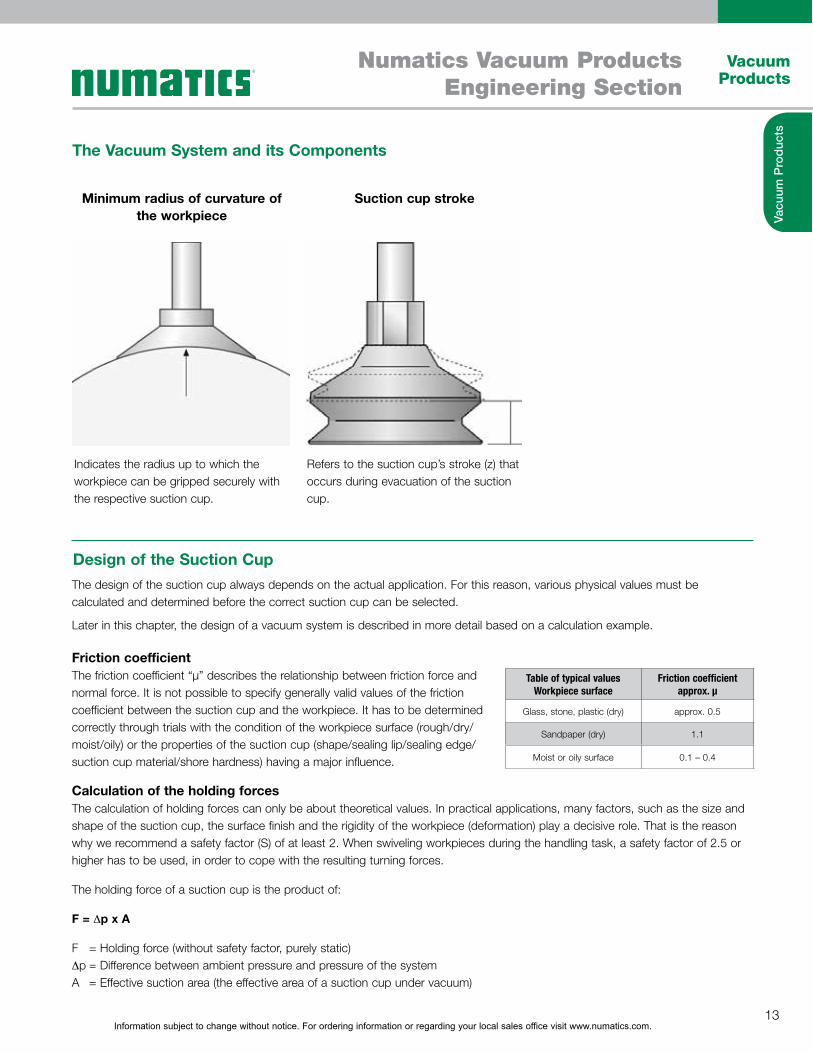
Information subject to change without notice. For ordering information or regarding your local sales office visit www.numatics.com. 13 Vacuum Products Numatics Vacuum Products Engineering Section Vacuum Products The Vacuum System and its Components Design of the Suction Cup The design of the suction cup always depends on the actual application. For this reason, various physical values must be calculated and determined before the correct suction cup can be selected. Later in this chapter, the design of a vacuum system is described in more detail based on a calculation example. Minimum radius of curvature of the workpiece Suction cup stroke Indicates the radius up to which the workpiece can be gripped securely with the respective suction cup. Refers to the suction cup’s stroke (z) that occurs during evacuation of the suction cup. Friction coefficient The friction coefficient “µ” describes the relationship between friction force and normal force. It is not possible to specify generally valid values of the friction coefficient between the suction cup and the workpiece. It has to be determined correctly through trials with the condition of the workpiece surface (rough/dry/ moist/oily) or the properties of the suction cup (shape/sealing lip/sealing edge/ suction cup material/shore hardness) having a major influence. Calculation of the holding forces The calculation of holding forces can only be about theoretical values. In practical applications, many factors, such as the size and shape of the suction cup, the surface finish and the rigidity of the workpiece (deformation) play a decisive role. That is the reason why we recommend a safety factor (S) of at least 2. When swiveling workpieces during the handling task, a safety factor of 2.5 or higher has to be used, in order to cope with the resulting turning forces. The holding force of a suction cup is the product of: F = �p x A F = Holding force (without safety factor, purely static) �p = Difference between ambient pressure and pressure of the system A = Effective suction area (the effective area of a suction cup under vacuum) Table of typical values Workpiece surface Friction coefficient approx. µ Glass, stone, plastic (dry) approx. 0.5 Sandpaper (dry) 1.1 Moist or oily surface 0.1 – 0.4
Transcript of Numatics Vacuum Products Engineering Section
Information subject to change without notice. For ordering information or regarding your local sales office visit www.numatics.com.13
Vacuum Products
Numatics Vacuum ProductsEngineering Section
Vacu
um P
rod
ucts
The Vacuum System and its Components
Design of the Suction Cup
The design of the suction cup always depends on the actual application. For this reason, various physical values must be calculated and determined before the correct suction cup can be selected.
Later in this chapter, the design of a vacuum system is described in more detail based on a calculation example.
Minimum radius of curvature of the workpiece
Suction cup stroke
Indicates the radius up to which the workpiece can be gripped securely with the respective suction cup.
Refers to the suction cup’s stroke (z) that occurs during evacuation of the suction cup.
Friction coefficientThe friction coefficient “µ” describes the relationship between friction force and normal force. It is not possible to specify generally valid values of the friction coefficient between the suction cup and the workpiece. It has to be determined correctly through trials with the condition of the workpiece surface (rough/dry/moist/oily) or the properties of the suction cup (shape/sealing lip/sealing edge/suction cup material/shore hardness) having a major influence.
Calculation of the holding forcesThe calculation of holding forces can only be about theoretical values. In practical applications, many factors, such as the size and shape of the suction cup, the surface finish and the rigidity of the workpiece (deformation) play a decisive role. That is the reason why we recommend a safety factor (S) of at least 2. When swiveling workpieces during the handling task, a safety factor of 2.5 or higher has to be used, in order to cope with the resulting turning forces.
The holding force of a suction cup is the product of:
F = �p x A
F = Holding force (without safety factor, purely static) �p = Difference between ambient pressure and pressure of the system A = Effective suction area (the effective area of a suction cup under vacuum)
Table of typical values Workpiece surface
Friction coefficient approx. µ
Glass, stone, plastic (dry) approx. 0.5
Sandpaper (dry) 1.1
Moist or oily surface 0.1 – 0.4

Information subject to change without notice. For ordering information or regarding your local sales office visit www.numatics.com.14
Vacuum Products
Numatics Vacuum ProductsEngineering Section
Vacu
um P
rod
ucts
Suction Cups Continued
Diameter of the suction cup
The holding force of a suction cup depends on its effective diameter. The condition of the workpiece and the number of suction cups are also crucial for the holding force that a vacuum system can generate.
The required diameter can be determined with the aid of the following formula:
A sensible selection is the suction cup NPFYN 95 with a nominal diameter of 95 mm.
A sensible selection is the suction cup NPFYN 150 with a nominal diameter of 150 mm.
For horizontal pick-up:
Calculation example for horizontal pick-up:
Calculation example for vertical pick-up:
For vertical pick-up:
d = 1.12 x
d = 1.12 x
d = 1.12 x
d = 8.85 cm
d = 12.5 cm
m = Weight of the workpiece in kgPu = Vacuum in barn = Number of suciton cupsµ = Friction coefficientS = Safety factor
Plastic sheet:Vacuum:Number of suction cups:Measured friction coefficient:Safety factor:
Plastic sheet:Vacuum:Number of suction cups:Measured friction coefficient:Safety factor:
m = 50 kgPu = – 0.4 barn = 4µ = 0.5S = 2
m = 50 kgPu = – 0.4 barn = 4µ = 0.5S = 2
d = 1.12 x m x S
50 kg x 2
50 kg x 2
m x SPu x n
0.4 bar x 4
0.4 bar x 4 x 0.5
Pu x n x µ
~d = Suction cup diameter in cm (with double lip ~ internal diameter, with bellows suction cup = inner diameter of sealing lip)
Typical value (with smooth, air-tight surfaces)
Suction cup ØSuction area A Volume flow
(cm2) (m3/h) (l/min)
up to 60 mm 28 0.5 8.3
up to 120 mm 113 1.0 16.6
up to 215 mm 363 2.0 33.3
up to 450 mm 1,540 4.0 66.6
Suction rate or required volume flow [ � ]
The volume flow that generates the vacuum is important for the suction force. The workpiece material is the principal factor for the required volume flow.
The table shows typical values for the volume flow or suction rate depending on the diameter of the suction cup with smooth and air-tight surface.
Important:Conduct suction trials for porous parts.

Information subject to change without notice. For ordering information or regarding your local sales office visit www.numatics.com.15
Vacuum Products
Numatics Vacuum ProductsEngineering Section
Vacu
um P
rod
ucts
Specialty Grippers
Large Area Grippers
Special grippers are used in applications in which regular suction cups cannot be
used. Special grippers are used to handle wafers, films, paper, fragile workpieces or
textile fiber composites. They serve as a connection element between the workpiece
and the handling system just like the suction cup.
� Numatics separates special grippers into the following series:
� Floating suction grippers
� Magnetic grippers
The NFX Series large area gripper is designed to handle work-pieces
with a wide range of dimensions and/or undefined positions. It provides
customers with a reliable means of handling work-pieces that have several
gaps.
Applications include palletizing/depalletizing, in addition to order picking
and sorting of a wide range of work-pieces with a single gripper. Typical
work-piece materials include cardboard, wood, metal or plastic.
Floating Suction GripperFloating suction grippers are pneumatically operated special grippers with integrated vacuum generation. They operate on the
Bernoulli principle and work as a low-contact system. The workpiece “floats” on an air cushion at the gripper surface. This makes
the floating suction gripper ideally suited for the handling of very sensitive products. The high volume flow can compensate for
leakage, when handling porous workpieces.
Advantages of floating suction grippers:� Low-contact handling
� High volume flow
� Safe separation of thin, porous workpieces
� Integrated vacuum generation
Typical areas of application:� Handling of fiber composites, paper, film, wood veneer, printed circuit boards,
wafers and solar cells
� Separation of thin, porous workpieces
Information subject to change without notice. For ordering information or regarding your local sales office visit www.numatics.com.16
Vacuum Products
Numatics Vacuum ProductsEngineering Section
Vacu
um P
rod
ucts
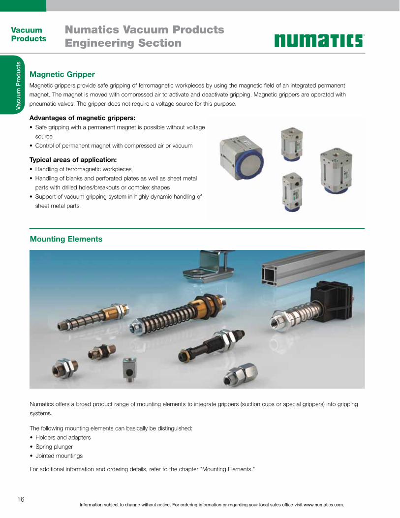
Magnetic GripperMagnetic grippers provide safe gripping of ferromagnetic workpieces by using the magnetic field of an integrated permanent
magnet. The magnet is moved with compressed air to activate and deactivate gripping. Magnetic grippers are operated with
pneumatic valves. The gripper does not require a voltage source for this purpose.
Advantages of magnetic grippers:� Safe gripping with a permanent magnet is possible without voltage
source
� Control of permanent magnet with compressed air or vacuum
Typical areas of application:� Handling of ferromagnetic workpieces
� Handling of blanks and perforated plates as well as sheet metal
parts with drilled holes/breakouts or complex shapes
� Support of vacuum gripping system in highly dynamic handling of
sheet metal parts
Mounting Elements
Numatics offers a broad product range of mounting elements to integrate grippers (suction cups or special grippers) into gripping
systems.
The following mounting elements can basically be distinguished:
� Holders and adapters
� Spring plunger
� Jointed mountings
For additional information and ordering details, refer to the chapter "Mounting Elements."

Information subject to change without notice. For ordering information or regarding your local sales office visit www.numatics.com.17
Vacuum Products
Numatics Vacuum ProductsEngineering Section
Vacu
um P
rod
ucts
Mounting Elements Continued
Holders and adaptersThe suction cups are attached to the basic structure or the traverse with
holders and adapters. Different types of aluminum sections or square and
round tubes are available.
Spring plungersSpring plungers are used to compensate height differences of workpieces.
They also cushion the impact of the suction cup and allow handling of fragile
workpieces.
Jointed mountingsJointed mountings provide a better adaption of the suction cup to the
workpiece due to the design of Flexolink NFLK and ball joint NKGL that can
be swiveled in all directions.
Suction cups(chapter “Vacuum Suction Cups” or “Special Grippers”)

Information subject to change without notice. For ordering information or regarding your local sales office visit www.numatics.com.18
Vacuum Products
Numatics Vacuum ProductsEngineering Section
Vacu
um P
rod
ucts
Vacuum Generators
Vacuum generators provide the vacuum level that is required for the handling task. The vacuum is created either pneumatically or
electrically.
Pneumatic vacuum generators implement short cycle times and can be integrated directly into the system due to their compact
and lightweight design.
Electrical vacuum generators are used in applications when compressed air is not available or when very high suction capacities are
required.
Pneumatic vacuum generators� Ejectors
Electrical vacuum generators� Pumps
ImportantThe nominal suction rate of all vacuum generators is given in
l/min or m3/h. The values are based on an ambient pressure of
1,013 mbar (sea level) and an ambient temperature of 20 °C.
The maximum suction rate therefore indicates the volume flow
that the vacuum generator evacuates from the environment
(free flow).
Free pick flow Additional suction while workpiece is picked up

Information subject to change without notice. For ordering information or regarding your local sales office visit www.numatics.com.19
Vacuum Products
Numatics Vacuum ProductsEngineering Section
Vacu
um P
rod
ucts
Vacuum Generators Continued
Principle of operation of a single-stage ejector
Principle of operation of a multi-stage ejector
Ejectors work on the Venturi principle. They are divided into single-stage and multi-stage ejectors depending on the number of
nozzle pairs.
The compressed air is supplied through the connection (A) to the
single-stage ejectors. It flows through the Venturi nozzle (B). The air is
accelerated and compressed during this process.
After passing through the nozzle, the accelerated air expands once
again and a vacuum is created. Air is drawn in this way through the
vacuum connection (D). The air that was drawn in and the compressed
air escape through the silencer (C).
The Numatics basic ejectors, inline ejectors and compact ejectors are
based on the single-stage Venturi principle.
In addition to the single-stage Venturi principle, there are ejectors in
which the vacuum is created by several Venturi nozzles arranged in a
row. Compressed air is supplied to the ejector through con- nection
(A). It passes through several Venturi nozzles (B) arranged in a row.
A vacuum is created and the air is drawn in through the vacuum
connection (D). The suction volumes of the individual nozzles add
up to form a total suction rate D. The air that was drawn in and the
compressed air escape through the silencer (C).
Compared to single-stage ejectors, multi-stage ejectors create a much
higher suction rate in the lower vacuum range using the same amount of
compressed air.
The Numatics multi-stage ejectors are based on the multi-stage Venturi
principle.
Advantages of ejectors:� Compact
� Low weight
� Fast vacuum generation
� No flexible parts, resulting in low maintenance and low wear
� Choose an installation position
� No heat generation
Typical areas of application:� Industrial robot applications in all industries, such as feeder
applications in the automotive industry

Information subject to change without notice. For ordering information or regarding your local sales office visit www.numatics.com.20
Vacuum Products
Numatics Vacuum ProductsEngineering Section
Vacu
um P
rod
ucts
Vacuum Generators Continued
We distinguish between three basic types of ejectors:
Basic and inline ejectors Multi-stage ejectors Compact ejectors
Vacuum Pumps
� Vacuum generators without valve
control and system monitoring with
high maximum vacuum level (85%
vacuum)
� Used mainly to handle air-tight
workpieces
� Vacuum generators with several
nozzle chambers arranged in a row
with a very high suction rate.
� Used mainly for handling porous
workpieces, such as cardboard,
chipboards, OSB or MDF sheets
� Vacuum generators with integrated
valve technology and system
monitoring, NSCPI series are
equipped with IO-Link technology
� Control of pick-up and blow-off
feasible without external valves
� Optional with integrated air-saving
regulation
� Used in fully automatic handling
systems (e.g. sheet metal processing,
automotive industry, robot
applications)
Vacuum pumps include an eccentrically mounted impeller with carbon
vanes (A) which are pressed against the walls of the housing by
centrifugal force and thus provide a seal. As the impeller rotates, the
size of each chamber (B) varies. As the chamber becomes larger, the
air in it expands and the pressure drops, resulting in a partial vacuum.
The air is drawn in through the inlet (C), compressed, and ejected
through the outlet (D).
Due to their high compression factor, pumps generate a very high
vacuum and, according to the type, have a very high suction capacity.
Advantages of vacuum pumps� High vacuum with high evacuation volume
� Central vacuum generation
Typical areas of application� As central vacuum generation in gantry handling systems
� In manual vacuum handling systems
� In packaging machines
� Universal vacuum pumps requiring
little maintenance
� Used mainly as central vacuum
generator in large gripping systems
for handling air-tight workpieces

Information subject to change without notice. For ordering information or regarding your local sales office visit www.numatics.com.21
Vacuum Products
Numatics Vacuum ProductsEngineering Section
Vacu
um P
rod
ucts
Switches and System Monitoring
Vacuum SwitchesVacuum switches are available in mechanical and electronic types. In
the mechanical versions, the existing vacuum is measured by using a
membrane, or a valve (pneumatic design) is activated. In the electronic
version, the vacuum is measured by a piezoresistive sensor and a
switching signal (analog or digital) is output.
Devices for system monitoring are important for the safe operation of a vacuum system. Numatics offers measuring as well as
control components for this purpose.
We distinguish between the following components for system monitoring and control:
� Vacuum switches
� Pressure switches
� Combined vacuum/pressure switches
� Connection cable and adapter for vacuum switches
� Measuring and control components
Components for system monitoring are used in all areas of automated handling applications, for example, in feeder systems in the
automotive industry, in the plastics industry, as well as in other applications in order to increase process safety.

Information subject to change without notice. For ordering information or regarding your local sales office visit www.numatics.com.22
Vacuum Products
Numatics Vacuum ProductsEngineering Section
Vacu
um P
rod
ucts
Vacuum Switches ContinuedVacuum switches are used in the measuring range from -1 to 0 bar. There are the following types of vacuum switches:
Mechanical vacuum switchesMechanical vacuum switches are characterized by their sturdy design and their universal operating principle. The pneumatic
design (PM), does not require electrical connections. It works purely with pneumatics. You can set the switching points (with fixed
hysteresis) to adapt these switches individually to the process parameters.
Electronic vacuum switchesElectronic vacuum switches have a high switching accuracy and repeatability with a very compact design. Vacuum switches with
digital display offer a high level of convenience, because the switching points and hysteresis are fully programmable using a foil
keypad. To program the switching point in a process rather quickly and simply, use vacuum switches with teach button. You can
program the switching points with this version using a key in a matter of seconds. Vacuum switches with analog and digital output
and vacuum switches in miniature form round off the program.
Pressure Switches
Combined Vacuum/Pressure Switches
Electronic pressure switches are used in the measuring range from 0 to
10 bar. Pressure switches with digital display are easy to operate. The
switching points and hysteresis are fully programmable using a foil keypad.
They are used when there are high requirements for switching accuracy
and repeatability as well as implementation of short switching times.
Pressure switches with teach button are particularly suited to program
switching points quickly and easily. Pressure switches with analog and
digital output can also be used as pressure sensors due to their two
outputs.
Combined vacuum/pressure switches are used in the measuring range
from -1 to 10 bar. The switching accuracy is reduced by the large
measuring range. They are available with two switching outputs (digital and
analog) and can also be used as a vacuum sensor or a pressure sensor for
this reason.

Information subject to change without notice. For ordering information or regarding your local sales office visit www.numatics.com.23
Vacuum Products
Numatics Vacuum ProductsEngineering Section
Vacu
um P
rod
ucts
Connections and Adapters for Vacuum SwitchesMatching connection cables and adapters are available for the different
types of switches. The cables and connectors are adapted to meet the
customer-specific requirements and local standards.
Measuring and Control Components
Filters and Connectors
Vacuum regulators can be adjusted mechanically. They provide a precise
setting with high repeatability. Vacuum regulators compensate for pressure
differences of vacuum generators caused by their design.
Vacuum systems are protected by the use of filters. The filters protect the vacuum
generator from contamination. Suction cups and vacuum generator are connected
with each other by hoses and connectors.
Vacuum Filters
Filters are used to protect the vacuum generator or the valve in dusty environments.
The filters are installed in the system between the suction cup and the vacuum
generator or the valve.
Vacuum filters are often installed as central filter in the system. The vacuum filters
have a degree of separation of almost 100%.
Vacuum cup filters are installed as decentralized filters directly in the vacuum line at
the suction cup. Vacuum cup filters are used with light to medium contamination.
Inline filters are installed as decentralized filters directly in the vacuum line at the
suction cup. Inline filters are used with small flows and light contamination.
Check valves interrupt the flow as soon as a certain volume flow has been
reached. This will turn off any suction cups in the gripper system that may not
be covered completely. The system vacuum will remain intact.

Information subject to change without notice. For ordering information or regarding your local sales office visit www.numatics.com.24
Vacuum Products
Numatics Vacuum ProductsEngineering Section
Vacu
um P
rod
ucts
Definition of VacuumVacuum is the term for air pressures which lie below normal atmospheric pressure. The ambient pressure is 1,013 mbar (14.7 PSI)
at sea level and decreases with elevation.
The form of the vacuum depends on the application in vacuum technology. A relatively small vacuum, the low vacuum, is sufficient
for vacuum handling.
The pressure of the low vacuum ranges from 1 mbar (0.015 PSI) to 1,013 mbar (14.7 PSI); at sea level (ambient pressure)
Specification as relative valueIn vacuum technology, the vacuum is specified as a relative value which means the vacuum is specified in relation to the ambient
pressure. Such vacuum values always have a negative sign, because the ambient pressure is used as the reference point, which is
defined as 0 mbar.
Specification as absolute valueIn science, a vacuum is specified as an absolute value. The reference point is absolute zero, which means space void of air (e.g.
outer space). This means the vacuum value is always positive.
The following table shows the comparison values between absolute and relative pressure.
Underpressure/Vacuum Overpressure
-1,000 -500 0 +500 +1,000 mbar
Ambient pressure
0 +500 +1,000 mbar
Absolute value
Vacuum/pressure conversion table
Absolute pressure (mbar)
Relative Vacuum Bar N/cm2 kPa atm, kp/cm2 mm H2O Torr; mm Hg in Hg
8.00 6.62 5.64 4.74 3.81 3.01 2.28 1.42 0.40
16.10 13.60 11.37 9.03 7.25 5.63 3.97 2.65 1.10
37.70 33.20 30.10 26.70 23.00 18.60 14.90 9.80 5.20
71.00 65.00 60.10 52.00 44.00 36.50 29.00 20.50 11.40
127.00 117.80 106.00 94.20 79.10 65.30 49.87 35.99 23.00
215.00 172.00 156.10 138.70 118.50 99.10 79.36 58.90 37.24
At the end of this chapter you will find additional conversion and unit tables.

Information subject to change without notice. For ordering information or regarding your local sales office visit www.numatics.com.25
Vacuum Products
Numatics Vacuum ProductsEngineering Section
Vacu
um P
rod
ucts
Measurement Units for Vacuum DataThe units pascal [Pa], kilopascal [kPa], bar [bar] and millibar [mbar] are most widely used in vacuum technology as units for
pressure. The units are converted as follows:
0.001 bar = 0.1 kPa = 1 mbar = 100 Pa
In this catalog, all absolute pressure values are given in bar or mbar, all relative values in %. The % value is typical for a relative indi-
cation of the efficiency of a vacuum generator. Other units are used internationally. Some of them are included in the following table.
Vacuum/pressure conversion table
Bar N/cm2 kPa atm, kp/cm2 mm H2O Torr; mm Hg in Hg
Bar 1.00000 10.00000 100.0000 1.01970 10,197.00 750.0600 29.5400
N/cm2 0.10000 1.00000 10.0000 0.10190 1,019.70 75.0060 2.9540
kPa 0.01000 0.10000 1.0000 0.01020 101.97 7.5006 0.2954
atm, kp/cm2 0.98070 9.80700 98.0700 1.00000 10,332.00 735.5600 28.9700
mm H2O 0.00010 0.00100 0.0100 0.00000 1.00 0.0740 0.0030
Torr; mm Hg 0.00133 0.01333 0.1333 0.00136 13.60 1.0000 0.0394
in Hg 0.03380 0.33850 3.8850 0.03446 345.40 25.2500 1.0000
At the end of this chapter you will find additional conversion and unit tables.
Energy Required for Vacuum GenerationThe energy required for vacuum generation increases
dispropor- tionately to the attained vacuum. Increasing
the vacuum from -600 mbar to -900 mbar, for example,
increases the holding force by a factor of 1.5, but the
evacuation time and the energy needed to achieve this
vacuum value increases by a factor of 3.
This means that only the vacuum required should be
generated in the working area to keep the energy
expenditure and the operating costs at a minimum.
Common working areas� for air-tight surface (e.g. metal, plastics, etc.): -600 to -800 mbar vacuum
� for porous materials (e.g. cardboard boxes, particle boards, MDF sheets, etc.): -200 to -400 mbar vacuum; in this range the
necessary holding force is generated by increasing the suction rate and the suction area.
Important:In this catalog, the holding forces of the suction cups are always specified at an efficient vacuum level of -600 mbar.
Force
Vacuum (mbar)
Energy
0 -100 -200 -300 -400 -500 -600 -700 -800 -900 -1000
Information subject to change without notice. For ordering information or regarding your local sales office visit www.numatics.com.26
Vacuum Products
Numatics Vacuum ProductsEngineering Section
Vacu
um P
rod
ucts
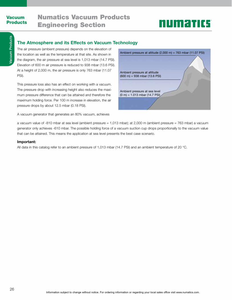
The Atmosphere and its Effects on Vacuum TechnologyThe air pressure (ambient pressure) depends on the elevation of
the location as well as the temperature at that site. As shown in
the diagram, the air pressure at sea level is 1,013 mbar (14.7 PSI).
Elevation of 600 m air pressure is reduced to 938 mbar (13.6 PSI).
At a height of 2,000 m, the air pressure is only 763 mbar (11.07
PSI).
This pressure loss also has an effect on working with a vacuum.
The pressure drop with increasing height also reduces the maxi-
mum pressure difference that can be attained and therefore the
maximum holding force. Per 100 m increase in elevation, the air
pressure drops by about 12.5 mbar (0.18 PSI).
A vacuum generator that generates an 80% vacuum, achieves
a vacuum value of -810 mbar at sea level (ambient pressure = 1,013 mbar); at 2,000 m (ambient pressure = 763 mbar) a vacuum
generator only achieves -610 mbar. The possible holding force of a vacuum suction cup drops proportionally to the vacuum value
that can be attained. This means the application at sea level presents the best case scenario.
Important:All data in this catalog refer to an ambient pressure of 1,013 mbar (14.7 PSI) and an ambient temperature of 20 °C.
Ambient pressure at altitude (2,000 m) = 763 mbar (11.07 PSI)
Ambient pressure at altitude (600 m) = 938 mbar (13.6 PSI)
Ambient pressure at sea level (0 m) = 1.013 mbar (14.7 PSI)
Information subject to change without notice. For ordering information or regarding your local sales office visit www.numatics.com.27
Vacuum Products
Numatics Vacuum ProductsEngineering Section
Vacu
um P
rod
ucts
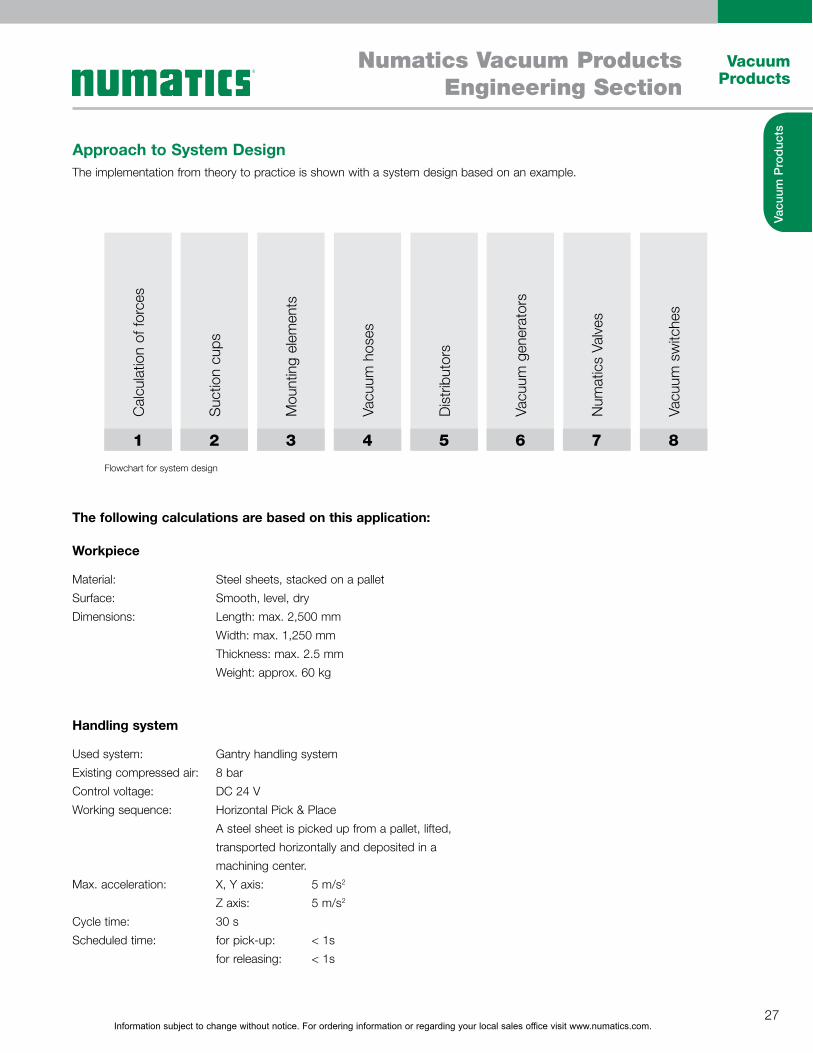
Approach to System DesignThe implementation from theory to practice is shown with a system design based on an example.
1 2 3 4 5 6 7 8
Cal
cula
tion
of fo
rces
Suc
tion
cups
Mou
ntin
g el
emen
ts
Vacu
um h
oses
Dis
trib
utor
s
Vacu
um g
ener
ator
s
Num
atic
s Va
lves
Vacu
um s
witc
hes
Flowchart for system design
The following calculations are based on this application:
Workpiece
Handling system
Material:
Surface:
Dimensions:
Used system:
Existing compressed air:
Control voltage:
Working sequence:
Max. acceleration:
Cycle time:
Scheduled time:
Steel sheets, stacked on a pallet
Smooth, level, dry
Length: max. 2,500 mm
Width: max. 1,250 mm
Thickness: max. 2.5 mm
Weight: approx. 60 kg
Gantry handling system
8 bar
DC 24 V
Horizontal Pick & Place
A steel sheet is picked up from a pallet, lifted,
transported horizontally and deposited in a
machining center.
X, Y axis: 5 m/s2
Z axis: 5 m/s2
30 s
for pick-up: < 1s
for releasing: < 1s
Information subject to change without notice. For ordering information or regarding your local sales office visit www.numatics.com.28
Vacuum Products
Numatics Vacuum ProductsEngineering Section
Vacu
um P
rod
ucts
Weight Calculation of a WorkpieceIt is important to determine the weight (m) of the workpiece to continue with additional calculations. It is calculated based on the
following formula:
m = L x B x H x �
m = Weight (kg)
L = Length (m)
B =Width (m)
H = Height (m)
� = Density (kg/m3)
FTH = m x (g + a) x S
FTH = theoretical holding force (N)
m = Weight (kg)
g = Gravity (9.81 m/s2)
a = Acceleration (m/s2) of the system
S = Safety factor (minimum value 1.5 times safety;
for critical, diverse or varied or porous materials or rough surfaces 2.0
or even higher)
Our example:
m = 2.5mx1.25mx0.0025mx7,850kg/m3
m = 61.33kg
Our example:
FTH = 61.33 kg x (9.81 m/s2+ 5 m/s2) x 1.5
FTH = 1,363 N
Theoretical Holding Force of a Suction CupThe suction cups not only have to be able to carry the weight of the workpiece but must also be capable of handling the
acceleration forces. These may never be neglected in a fully automated process.
To calculate the theoretical holding force, we show and describe the three most important and most frequently occurring load
cases (handling sequences).
Important:For the following, simplified representations of the load cases the calculation must be based on the worst load case with the
highest, theoretical holding force. This is the only way to ensure that the suction cup grips the workpiece safely during the entire
handling process.
The safety factor is a minimum value of 1.5 for smooth and dense workpieces. A safety factor of 2.0 or greater must be used for cri
tical, diverse or varied, porous or rough workpieces. If factors such as acceleration or friction coefficient are not known or cannot
be deter- mined precisely, a value of 2.0 or higher should also be used.
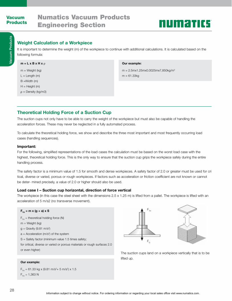
Load case I – Suction cup horizontal, direction of force verticalThe workpiece (in this case the steel sheet with the dimensions 2.5 x 1.25 m) is lifted from a pallet. The workpiece is lifted with an
acceleration of 5 m/s2 (no transverse movement).
The suction cups land on a workpiece vertically that is to be
lifted up.
FTH
FG

Information subject to change without notice. For ordering information or regarding your local sales office visit www.numatics.com.29
Vacuum Products
Numatics Vacuum ProductsEngineering Section
Vacu
um P
rod
ucts
FTH = m x (g + a/µ) x S
FTH = theoretical holding force (N)Fa = Acceleration force = m · am = Weight (kg)g = Gravity (9.81 m/s2)a = Acceleration (m/s2) of the system (keep in mind Emergency Stop situations!)µ = Friction coefficient = 0.1 for oily surfaces = 0.2 to 0.3 for wet surfaces = 0.5 for wood, metal, glass, stone etc. = 0.6 for rough surfacesCaution! The specified values for friction coefficient are averagedand must be checked for the individual workpiece!
S = Safety (minimum value 1.5 times safety, for critical, diverse or varied or porous materials or rough surfaces 2.0 or even higher)
FTH = (m/µ) x (g + a) x S
FTH = theoretical holding force (N)m = Weight (kg)g = Gravity (9.81 m/s2)a = Acceleration (m/s2) of the plant (keep in mind Emergency Stop situations!)µ = Friction coefficient = 0.1 for oily surfaces = 0.2 to 0.3 for wet surfaces = 0.5 for wood, metal, glass, stone etc. = 0.6 for rough surfacesS = Safety (minimum value 2.0 times safety, forcritical, diverse or varied or porous materials or rough surfaces even higher)
Our example:
FTH = 61.33 kg x (9.81 m/s2+ 5 m/s2) x 1.5 FTH = 1,822 N
Our example:
FTH = 61.33 kg x (9.81 m/s2+ 5 m/s2) x 1.5 FTH = 1,822 N
Theoretical Holding Force of a Suction Cup ContinuedLoad case II – Suction cup horizontal, direction of force horizontalThe workpiece (in this case the steel sheet with the dimensions 2.5 x 1.25 m) is lifted up vertically and transported horizontally. The
acceleration is 5 m/s2.
Load case III – Suction cup vertical, direction of force verticalDescription of load case: The workpiece (in this case the steel sheet with the dimensions 2.5 x 1.25 m) is picked up from a pallet
and moved with a rotary motion at an acceleration of 5 m/s2.
Comparison:For our scenario, the workpiece is lifted off a pallet, moved to the
side and placed on a machining center. The rotary motion from
load case III is not needed in this application, therefore one only
needs to consider the result from load case II.
The suction cups land on a workpiece horizontally that is to
be moved to the side.
The result in this case is a maximum theoretical holding force
(FTH ) of 1,822 N. This theoretical holding force acts on the
suction cup during horizontal transport of the workpiece. The
following calculations are based on this value to safely solve
the task.
FTH
FaFG
FTH
FG
Information subject to change without notice. For ordering information or regarding your local sales office visit www.numatics.com.30
Vacuum Products
Numatics Vacuum ProductsEngineering Section
Vacu
um P
rod
ucts
Calculation of suction force FS [N] for individual suction cup
FS = FTH/n
FS = Suction force
FTH = Theoretical holding force
n = Number of suction cups
Suction Cup SelectionThe calculated theoretical holding force corresponds to the force that the suction cups must create to safely handle the workpiece. To select the suction cups, one must also take the ambient conditions and the application into consideration.
The selection of the suction cups usually takes place based on the following criteria:
Application: The operating conditions on site are crucial for the selection of the suction cup, such as multi-shift operation, service life, chemically aggressive environment, temperature.
Material: Suction cups made of different materials are available to meet the requirements, such as those particularly suited for smooth or rough surfaces, oily or very fragile workpieces, anti- static suction cups for electronic components, suction cups leaving few marks for fragile plastic parts, etc. The selection of the suitable suction cup material for handling of workpieces is described in a comprehensive table in the chapter “Vacuum Suction Cups”.
Surface: Depending on the condition of the surface, we recom- mend suction cups in specific shapes. You can select from flat or bellows suction cups with different sealing lips and sealing edges in different shapes and geometries. An overview of the different suction cups and the specific advantages of the individual suction cup types is included in the chapter “Vacuum Suction Cups”.
For this example we choose: Flat suction cup of the type NPFYN made of Nitrile (NBR)This suction cup is a cost-efficient solution for handling smooth, level workpieces. Data for this type is available on the respective pages in the chapter “Vacuum Suction Cups”.
To solve the example, the calculated theoretical holding force can be applied by one suction cup or distributed among several suction cups. The number of suctions cups used depends on the respective application.
For the steel sheet (2,500 x 1,250 mm) from the present case, one would usually use six or eight suction cups. The most important criterion for the number of suction cups in this example, is the flexing of the steel sheet during transport. Depending on the number of used suction cups, the required diameter of these suction cups changes.
For this example we choose:Six suction cups of type PFYN 95 NBRWith a sheet thickness of 2.5 mm, six suction cups ensure a secure
sheet pick.
Important:
� The suction force of the individual suction cups is listed in the table “Technical data” for the respective suction cup in the chapter
“Vacuum Suction Cups”.
� The suction force of the suction cup must exceed the calculated theoretical holding force.
Our example: FS = 1,822 N/6
FS = 304 N
According to the technical data for the suction cup NPFYN, one
needs 6 x NPFYN 95 NBR with a diameter of 95 mm and a suction
force of 350 N each.
FS = 1,822 N/8
FS = 228 N
According to the technical data for the suction cup NPFYN, one
needs 8 x NPFYN 80 NBR with a diameter of 80 mm and a suction
force of 260 N each.
Information subject to change without notice. For ordering information or regarding your local sales office visit www.numatics.com.31
Vacuum Products
Numatics Vacuum ProductsEngineering Section
Vacu
um P
rod
ucts
Mounting Element Selection
Vacuum Generator Selection
The mounting of the suction cups is usually selected according to customer requirements. But there may be compelling reasons for a particular type of mounting:
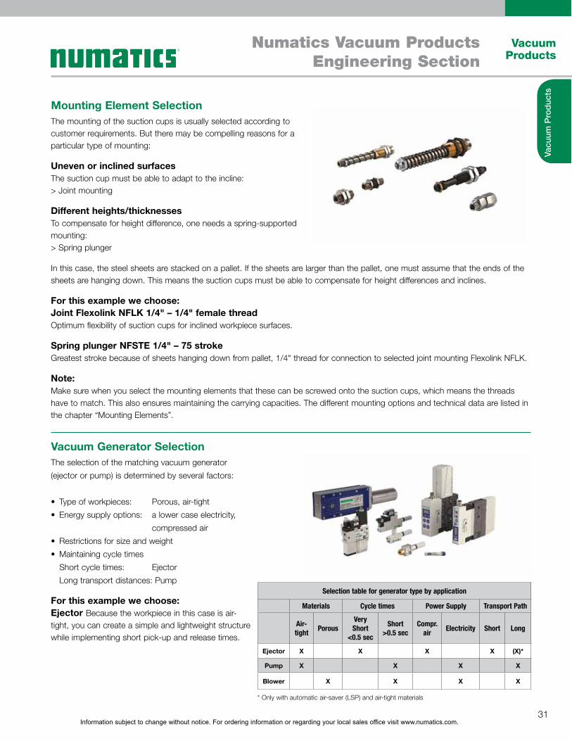
Uneven or inclined surfacesThe suction cup must be able to adapt to the incline: > Joint mounting
Different heights/thicknessesTo compensate for height difference, one needs a spring-supported mounting:> Spring plunger
In this case, the steel sheets are stacked on a pallet. If the sheets are larger than the pallet, one must assume that the ends of the sheets are hanging down. This means the suction cups must be able to compensate for height differences and inclines.
For this example we choose: Joint Flexolink NFLK 1/4" – 1/4" female threadOptimum flexibility of suction cups for inclined workpiece surfaces.
Spring plunger NFSTE 1/4" – 75 strokeGreatest stroke because of sheets hanging down from pallet, 1/4" thread for connection to selected joint mounting Flexolink NFLK.
Note:Make sure when you select the mounting elements that these can be screwed onto the suction cups, which means the threads have to match. This also ensures maintaining the carrying capacities. The different mounting options and technical data are listed in the chapter “Mounting Elements”.
The selection of the matching vacuum generator
(ejector or pump) is determined by several factors:
� Type of workpieces: Porous, air-tight
� Energy supply options: a lower case electricity,
compressed air
� Restrictions for size and weight
� Maintaining cycle times
Short cycle times: Ejector
Long transport distances: Pump
For this example we choose: Ejector Because the workpiece in this case is air-tight, you can create a simple and lightweight structure while implementing short pick-up and release times.
Selection table for generator type by application
Materials Cycle times Power Supply Transport Path
Air-tight
PorousVery Short
<0.5 sec
Short >0.5 sec
Compr. air
Electricity Short Long
Ejector X X X X (X)*
Pump X X X X
Blower X X X X
* Only with automatic air-saver (LSP) and air-tight materials
Information subject to change without notice. For ordering information or regarding your local sales office visit www.numatics.com.32
Vacuum Products
Numatics Vacuum ProductsEngineering Section
Vacu
um P
rod
ucts
Vacuum Generator Selection ContinuedSuction rate of vacuum generator The diameter of the suction cup determines the suction rate that a vacuum generator has to apply to evacuate the suction cup. The suitable suction rate is described in the table “Technical data” of the respective vacuum generator.
Based on experience and measurements with system designs, we recommend a selection based on the following table:
Note: The specified values apply regardless of the type of vacuum generation. The recommended suction ratio applies per suction cup and only for smooth, air-tight surfaces. For porous, permeable workpieces we recommend conducting a corresponding suction trial with the original workpiece.
For this example we choose:Compact ejector NSCPI 20 with a suction rate of 140 l/min.
The compact ejector offers valves for control of the “suction” and “blow off” functions as well as system monitoring for ensuring process safety during handling. The compact ejector NSCPI is also equipped with IO-Link Technology. It makes the various diagnostic functions visible and usable on the control level. This increases system availability and makes automation processes even more efficient.
Suction capacity as a function of suction-cup diameter
Suction cup Ø Suction capacity VS
Up to 60 mm 0.5 m3/h 8.3 l/min .29 SCFM
Up to 120 mm 1.0 m3/h 16.6 l/min .58 SCFM
Up to 215 mm 2.0 m3/h 33.3 l/min 1.16 SCFM
Up to 450 mm 4.0 m3/h 66.6 l/min 2.33 SCFM
Calculation of the suction rate V [m3/h, l/min], that the vacuum
generator has to apply
V = n x VS
n = Number of suction cups
VS = Required suction rate for an individual suction cup (m3/h, l/min)
Example: V = 6 x 16.6 l/min
V = 99.6 l/min
Valve Technology SelectionIn this case we are using a compact ejector with integrated valve technology. In other cases we need solenoid valves to switch the function “Vacuum on/off”. They are usually used when pumps are used as vacuum generators.
The selection of the valves is based on the following criteria:
� Suction rate of vacuum generator
� Control voltage
� Operating principle of the valve (NO/NC)
The nominal flow of the solenoid valve may not be less than the suction ratio
of the vacuum generator. Refer to the valves section of the Numatics catalog
if external valves are required.

Information subject to change without notice. For ordering information or regarding your local sales office visit www.numatics.com.33
Vacuum Products
Numatics Vacuum ProductsEngineering Section
Vacu
um P
rod
ucts
The nominal flow is listed in the “Technical data” of the respective valve and the suction rate is listed in the “Technical data” of the respective vacuum generator.
Calculation of the suction rate V [m3/h, l/min], that the vacuum
generator has to apply
V = n x VS
n = Number of suction cups
VS = Required suction rate for an individual suction cup (m3/h, l/min)
Example: VV = 116 l/min = 7 m3/h
For this example we choose: The used compact ejector of type SCPI 20 is equipped with solenoid valves which eliminates the need for separate valves.
Switches/Sensors SelectionVacuum switches and manometers are usually selected based on the existing requirements regarding functionality and switching frequency.
The following functions are available: � ���������� ��������� �����
� Hysteresis fixed or adjustable
� Signal output digital and/or analog
� Function LED
� Display with input keyboard
� Vacuum connection M5-F, M8-F, flange or tube insert
� Supply and signal connection with cable or M8 plug
The available versions with their respective technical data are explained in the chapter "Sensors, Switches and Regulators".
For this example we choose:The used compact ejector of the type NSCPI 20 is equipped with an integrated system monitoring (digital output signals). There is no need for an additional vacuum switch.
You can use vacuum switches or manometers for vacuum generators without system monitoring.
Information subject to change without notice. For ordering information or regarding your local sales office visit www.numatics.com.34
Vacuum Products
Numatics Vacuum ProductsEngineering Section
Vacu
um P
rod
ucts
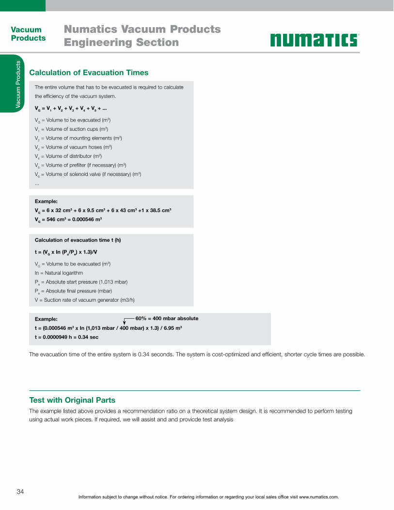
Calculation of Evacuation Times
The evacuation time of the entire system is 0.34 seconds. The system is cost-optimized and efficient, shorter cycle times are possible.
The entire volume that has to be evacuated is required to calculate
the efficiency of the vacuum system.
VG = V1 + V2 + V3 + V4 + V5 + ...
VG = Volume to be evacuated (m3)
V1 = Volume of suction cups (m3)
V2 = Volume of mounting elements (m3)
V3 = Volume of vacuum hoses (m3)
V4 = Volume of distributor (m3)
V5 = Volume of prefilter (if necessary) (m3)
V6 = Volume of solenoid valve (if necessary) (m3)
...
Calculation of evacuation time t (h)
t = (VG x In (Pa/Pe) x 1.3)/V
VG = Volume to be evacuated (m3)
In = Natural logarithm
Pa = Absolute start pressure (1,013 mbar)
Pe = Absolute final pressure (mbar)
V = Suction rate of vacuum generator (m3/h)
Example:
VG = 6 x 32 cm3 + 6 x 9.5 cm3 + 6 x 43 cm3 +1 x 38.5 cm3
VG = 546 cm3 = 0.000546 m3
Example:
t = (0.000546 m3 x In (1,013 mbar / 400 mbar) x 1.3) / 6.95 m3
t = 0.0000949 h = 0.34 sec
60% = 400 mbar absolute
Test with Original PartsThe example listed above provides a recommendation ratio on a theoretical system design. It is recommended to perform testing using actual work pieces. If required, we will assist and and provicde test analysis
Information subject to change without notice. For ordering information or regarding your local sales office visit www.numatics.com.35
Vacuum Products
Numatics Vacuum ProductsEngineering Section
Vacu
um P
rod
ucts
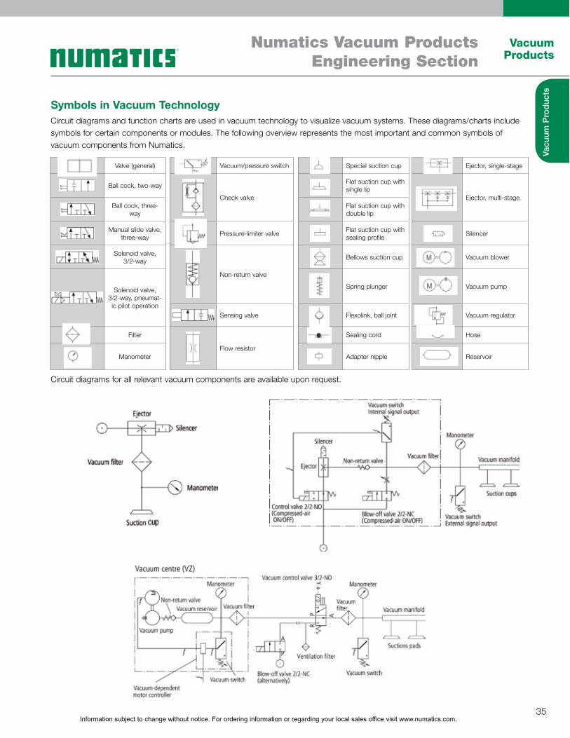
Symbols in Vacuum TechnologyCircuit diagrams and function charts are used in vacuum technology to visualize vacuum systems. These diagrams/charts include symbols for certain components or modules. The following overview represents the most important and common symbols of vacuum components from Numatics.
Circuit diagrams for all relevant vacuum components are available upon request.
Valve (general) Vacuum/pressure switch Special suction cup Ejector, single-stage
Ball cock, two-way
Check valve
Flat suction cup with single lip
Ejector, multi-stageBall cock, three-
wayFlat suction cup with double lip
Manual slide valve, three-way
Pressure-limiter valveFlat suction cup with sealing profile
Silencer
Solenoid valve, 3/2-way
Non-return valve
Bellows suction cup Vacuum blower
Solenoid valve, 3/2-way, pneumat-ic pilot operation
Spring plunger Vacuum pump
Sensing valve Flexolink, ball joint Vacuum regulator
Filter
Flow resistor
Sealing cord Hose
Manometer Adapter nipple Reservoir
Information subject to change without notice. For ordering information or regarding your local sales office visit www.numatics.com.36
Vacuum Products
Numatics Vacuum ProductsEngineering Section
Vacu
um P
rod
ucts
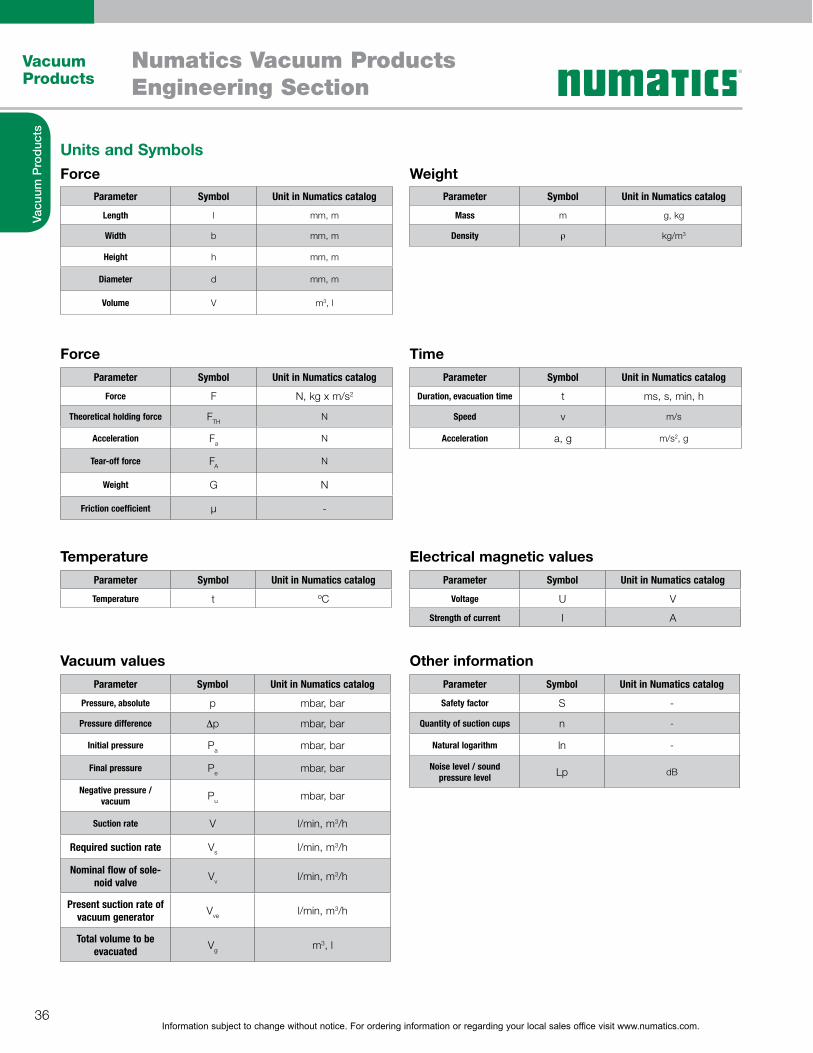
Units and Symbols
Force Time
Force Weight
Vacuum values Other information
Temperature Electrical magnetic values
Parameter Symbol Unit in Numatics catalog
Length l mm, m
Width b mm, m
Height h mm, m
Diameter d mm, m
Volume V m3, l
Parameter Symbol Unit in Numatics catalog
Mass m g, kg
Density � kg/m3
Parameter Symbol Unit in Numatics catalog
Force F N, kg x m/s2
Theoretical holding force FTHN
Acceleration FaN
Tear-off force FAN
Weight G N
Friction coefficient µ -
Parameter Symbol Unit in Numatics catalog
Duration, evacuation time t ms, s, min, h
Speed v m/s
Acceleration a, g m/s2, g
Parameter Symbol Unit in Numatics catalog
Pressure, absolute p mbar, bar
Pressure difference �p mbar, bar
Initial pressure Pa mbar, bar
Final pressure Pe mbar, bar
Negative pressure / vacuum Pu mbar, bar
Suction rate V l/min, m3/h
Required suction rate Vs l/min, m3/h
Nominal flow of sole-noid valve
Vv l/min, m3/h
Present suction rate of vacuum generator
Vve l/min, m3/h
Total volume to be evacuated
Vg m3, l
Parameter Symbol Unit in Numatics catalog
Safety factor S -
Quantity of suction cups n -
Natural logarithm ln -
Noise level / sound pressure level Lp dB
Parameter Symbol Unit in Numatics catalog
Temperature t ºC
Parameter Symbol Unit in Numatics catalog
Voltage U V
Strength of current I A
Information subject to change without notice. For ordering information or regarding your local sales office visit www.numatics.com.37
Vacuum Products
Numatics Vacuum ProductsEngineering Section
Vacu
um P
rod
ucts
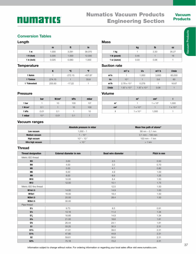
Conversion TablesLength
Temperature
Pressure
Vacuum ranges
Thread
Mass
Suction rate
Volume
m ft in
1 m 1.000 3.281 39.370
1 ft (foot) 0.305 1.000 12.000
1 in (inch) 0.025 0.083 1.000
K ºC ºF
1 Kelvin 1 -272.15 -457.87
1 ºCelsius 274.15 1 33.8
1 °Fahrenheit 255.93 -17.22 1
kg lb oz
1 kg 1 2.20 35.27
1 lb (pound) 0.45 1 16
1 oz (ounce) 0.03 0.06 1
m3 cm3 l
m3 1 1 x 10⁶ 1,000
cm3 1 x 10⁻⁶ 1 1 x 10⁻³
l 1 x 10⁻³ 1,000 1
m3/ s l/s m3/ h l/min
m3/s 1 1,000 3,600 60,000
l/s 10-3 1 3.6 60
m3/h 2.78 x 10⁻⁴ 0.278 1 16.67
l/min 1.67 x 10⁻⁵ 1.67 x 10⁻² 0.06 1
bar N/cm2 kPa mbar
1 bar 1 10 100 103
1 N/cm2 0.1 1 10 100
1 kPa 0.01 0.1 1 10
1 mbar 10-3 0.01 0.1 1
Absolute pressure in mbar Mean free path of atoms*
Low vacuum 1,000 – 1 68 nm – 0,1 mm
Medium vacuum 1 – 10-3 0.1 mm – 100 mm
High vacuum 10-3 – 10-7 100 mm – 1 km
Ultra high vacuum < 10-7 > 1 km
Thread designation External diameter in mm Bead wire diameter Pitch in mm
Metric ISO thread
M3 3.00 2.5 0.50
M4 4.00 3.2 0.70
M5 5.00 4.1 0.80
M6 6.00 4.9 1.00
M8 8.00 6.6 1.25
M10 10.00 8.4 1.50
M12 12.00 10.1 1.75
Metric ISO fine thread 12.5 1.50
M14x1.5 14.00 14.9 1.00
M16x1 16.00 18.4 1.50
M20x1.5 20.00 28.4 1.50
M30x1.5 30.00
Pipe thread
G1⁄8 9.73 8.5 0.91
G¼ 13.16 11.4 1.34
G3⁄8 16.66 14.9 1.34
G½ 21.00 18.6 1.81
G¾ 26.44 24.1 1.81
G1 33.25 30.3 2.31
G1¼ 41.91 39.0 2.31
G1½ 47.80 44.8 2.31
G2 59.61 56.6 2.31
G2½ 75.18 72.2 2.31

Information subject to change without notice. For ordering information or regarding your local sales office visit www.numatics.com.38
Vacuum Products
Numatics Vacuum ProductsEngineering Section
Vacu
um P
rod
ucts
Vacuum GlossaryAbrasion resistanceThe abrasion resistance refers to the resistance of suction cups (elastomer part) against mechanical stress, especially friction. It is determined by the material properties of the suction cup as well as its shape.
Absolute pressureThe absolute pressure refers to the absolute zero point, or a space completely empty of molecules. In an absolute vacuum there is a pressure of 0 bar. A relative vacuum of -600 mbar corresponds to an absolute pressure of 400 mbar.
Air-saving functionAir-saving function refers to the ejector's air-saving function dur-ing the handling procedure. Once the ejector reaches a parti- cular vacuum value, the evacuation process is interrupted. If the vacuum drops below a defined value, the ejector starts evacu-ating again. The air-saving function can therefore increase the energy and economic efficiency of a vacuum system.
Ambient pressure (atmospheric pressure)Ambient pressure refers to the hydrostatic pressure that exists at any given point. Ambient pressure is also known as atmo-spheric pressure. The standard atmospheric pressure at sea level is 1,013 mbar. The ambient pressure drops with increas-ing altitude. The ambient pressure has a direct influence on the maximum vacuum value that can be reached.
Bernoulli's principleBernoulli's principle describes the drop in pressure of a fluid when it passes from a narrow section to a much wider section. In practice, this happens in the form of a direct transition into an open space. To prevent the vacuum collapsing, the fluid is diverted to the side.
Centralized vacuum systemIn a centralized vacuum system, the vacuum is generated with a central vacuum source for more than one suction cups.
Check valveThe check valve is the valve that automatically monitors vol-ume flow. If the volume flow exceeds a defined value, the valve closes automatically; for example, when suction cups are not being used.
Control pressure rangeThe control pressure range is the range between the lowest and highest permissible control pressures.
Cycle timeThe cycle time refers to the time taken for a repetitive process to complete one cycle.
Decentralized vacuum systemIn a decentralized vacuum system, a vacuum is generated directly at each individual vacuum suction cup. Positioning vacuum gene- ration directly at the suction cup allows for short pick-up and depositing times.
Evacuation timeThe evacuation time refers to the time it takes to evacuate a certain volume to reach a required vacuum value.
Flow resistanceFlow resistance refers to a reduced flow cross-section in a vacuum line. The resistance reduces the volume flow that can pass through a line.
Friction coefficientThe friction coefficient [µ] refers to the relationship between friction force and normal force (contact force between suction cup and workpiece). The friction coefficient is not specified by an unit.
High vacuumA high vacuum describes any vacuum in which there is an abso- lute pressure of 10-7 to 10-3 mbar. High vacuums are used, for example, in electron tubes and particle accelerators.
Holding forceHolding force refers to the force that can be exerted by a suc-tion cup to grip a workpiece. It is calculated by multiplying the pres- sure difference by the effective suction area of the suc-tion cup (F = �p x A). The holding force of a suction cup is thus influenced by underpressure and the suction area. It is a theoretical value, specified without safety factors. It is usual to state the holding force of a suction cup with a relative vacuum of 60%.
HysteresisHysteresis refers to a pressure difference between two switch-ing points, and thus defines the state of the output signal. The res- pective output signal changes when either the upper or lower limit value of the hysteresis is reached. Using the example of a vacuum switch: when the vacuum reaches a specified value, the signal changes to “ON”. If the vacuum drops below a defined value, the signal switches to “OFF”. Hysteresis is mainly used to control the air-saving function of ejectors.
Idle position of NC valveThe idle position of an NC valve refers to the position of the valve when it is not actuated, i.e. “closed” (normally closed).
Idle position of NO valveThe idle position of an NO valve refers to the position of the valve when it is not actuated, i.e. “open” (normally open).

Information subject to change without notice. For ordering information or regarding your local sales office visit www.numatics.com.39
Vacuum Products
Numatics Vacuum ProductsEngineering Section
Vacu
um P
rod
ucts
Vacuum Glossary ContinuedInner volumeThe inner volume indicates the volume of the body that has to be evacuated during a suction procedure. For example, the inner volume of a suction cup has an effect on the evacuation time.
LeakageLeakage refers to a leak within the vacuum system. This can be caused by missing or faulty sealing elements, or by the porosity of the workpiece being processed.
Load caseLoad case refers to the handling task, or the process of han-dling a workpiece.Load case I – Suction cup horizontal, direction of force vertical Load case II – Suction cup horizontal, direction of force horizon-tal Load case III – Suction cup vertical, direction of force vertical
Low vacuumA low vacuum describes any vacuum in which there is an absolute pressure of 1 mbar up to atmospheric pressure (1,013 mbar). Examples of applications for a low vacuum include light bulbs and vacuum cleaners. Vacuum handling technology also uses values in the low vacuum range because these can be generated economically to create high suction power and short cycle times.
Medium vacuumA medium vacuum describes any vacuum in which there is an absolute pressure between 0.001 mbar and 1 mbar. Medium vacuums are used, for example, in low-pressure gas-filled lights.
Nominal flowNominal flow refers to the maximum flow through a certain dia- meter (nominal diameter). The nominal flow is given in l/min or m3/h.
Normal forceNormal force is the force component acting perpendicular to a surface. Every force acting on a surface can be divided into normal force and shear force (see “Shear force”). Based on the normal force, the friction force can be calculated using the friction coefficient for a material pairing. The result indicates the friction force between two surfaces, for example between a suction cup and a workpiece. Normal force is measured in Newton [N].
NPN – Switching outputNPN switching output refers to the configuration of a switch-ing output in cases where the load is connected to the positive pole of the operating voltage source. The output transistor of the vacuum switch connects the active device through to the opera- ting voltage, allowing current to flow through the con-suming device.
Minimum radius of curvatureThe minimum radius of curvature refers to the smallest radius that a suction cup can securely grip. For round suction cups, this refers to a sphere, while for oval suction cups it refers to a cylinder.
Operating temperatureThe operating temperature is the temperature range in which a product can be deployed or run.
Overpressure resistanceOverpressure resistance refers to the maximum pressure that a body (for example, a reservoir or vacuum filter) can resist.
PNP Switching outputPNP switching output refers to the configuration of a switching output in cases where the load has a permanent connection to the operating voltage source. The output transistor of the vacuum switch connects the active device to the positive pole, allowing current to flow through the consuming device.
Recovery timeThe recovery time is the period in which the product is not being used or is not subject to significant work loads. The prod-uct can recover during this time.
Reference pressureReference pressure is the pressure referred to by a sensor. Vacuum switches, for example, have a connection for reference air.
Relative pressureRelative pressure refers to the value of pressure in relation to the prevalent ambient pressure. The vacuum is given using negative values. Relative pressure has a pressure of 0 mbar as a refer-ence point. An absolute pressure of 400 mbar corresponds to a relative pressure of -600 mbar. In the field of vacuum handling, it is also common to state the values in percentages:-600 mbar corresponds to a vacuum of 60%.
Reversing valveA reversing valve is a type of changeover valve used in a blower. The valve supplies the system alternately with overpressure and underpressure. The valve thus controls the suction, blow-off and neutral setting in the vacuum system.
Shear forceShear force is the force acting tangentially to a surface and indi- cates how much friction can be transferred between the suction cup and workpiece. Shear force is given in Newton [N].

Information subject to change without notice. For ordering information or regarding your local sales office visit www.numatics.com.40
Vacuum Products
Numatics Vacuum ProductsEngineering Section
Vacu
um P
rod
ucts
Vacuum Glossary ContinuedVenturi principleThe Venturi principle describes the correlation between dynamic and static air pressure when air flows through a tube. At the narrowest section, the dynamic pressure is at a maximum, while the static pressure is at a minimum. Since the same volume is flowing through the tube, the velocity increases in proportion to the cross sections. Because of this differential pressure, a vac-uum can be created and air can be drawn in by using Venturi nozzles with a side inlet port. Vacuum generators based on this principle are called ejectors.
Volume flowVolume flow refers to the volume of a medium that flows through a cross section within a certain amount of time.
Workpiece temperatureThe workpiece temperature is the temperature of a processed workpiece. This temperature can influence the selection of a suitable suction cup material.
Standard literA standard liter is the measurement of a gas occupying a liter at 20 °C and 1,013 mbar (standard state).
Standard pressureStandard pressure is the pressure in the atmosphere under stan- dard conditions. In both technology and the natural sci-ences, this is 1,013 mbar at 0°C. The values in the Numatics catalog refer to a temperature of 20 °C
Standard temperatureStandard temperature is the temperature under standard condi- tions. The values in the Numatics catalog refer to a temperature of 20 °C.
Suction forceSee “Holding force”
Suction cup strokeThe suction cup stroke refers to the stroke effect that is created by the suction cup when picking up a workpiece. The stroke value indicates the maximum contraction of the suction cup.
Suction powerSee “Suction rate”
Suction rateSuction rate refers to the suction power of a vacuum genera-tor. This value indicates the volume that can be evacuated by a vacuum generator in a certain time. The suction rate is given in l/min or m3/h.
Switching pointThe switching point refers to a point at which a switch changes the state of the output signal. If, for example, a programmed vacuum value is reached on a vacuum switch, the output signal switches to “ON” and there is voltage at the switch output.The initial position of the signal can be set to either NC (opener) or NO (closer).
VacuumA vacuum is a pressure range lower than that of the ambient pressure. The vacuum value is divided into various classes; refer to "High Vacuum", “Medium Vacuum” and “Low Vacuum”.
Ventilation timeThe ventilation time refers to the time it takes to dissipate vacuum in a system. This defines the time it takes to release a workpiece. The ventilation of a suction cup can take place either atmospheri- cally or actively by a compressed air pulse (active blow off).