
NSS REPORT
28
GOLDEN STAR (BOGOSO/PRESTEA) LIMITED PLANT MAINTENANCE DEPARTMENT NATIONAL SERVICE INDUSTRIAL TRAININING REPORT (OCTOBER 2013-AUGUST 2014) BY BENJAMIN KOFI YEBOAH – NSP/23/13 28/09/2014
-
Upload
benjamin-kofi-yeboah -
Category
Documents
-
view
59 -
download
0
Transcript of NSS REPORT

GOLDEN STAR (BOGOSO/PRESTEA) LIMITED
PLANT MAINTENANCE DEPARTMENT
NATIONAL SERVICE INDUSTRIAL TRAININING REPORT
(OCTOBER 2013-AUGUST 2014)
BY
BENJAMIN KOFI YEBOAH – NSP/23/13
28/09/2014
ii
ABSTRACT
The report is a technical report on National Service Industrial Training at Golden Star
(Bogoso/Prestea) Limited (GSPBL). I was attached to the Plant Maintenance Department of
GSBPL to learn the various maintenance practices of the process plant.
Plant Maintenance department is made up of 8 sections namely Proactive Reliability
Maintenance (PRM), Planning, CMF, Oxide, Biox, Service, Welding and Fabrication, Electrical
and Instrument sections.
The report captures the maintenance systems used by the sections under Plant maintenance
department. PRM section uses predictive and proactive maintenance systems while the
remaining sections use corrective and preventive maintenance systems in daily works. The report
elaborate on the major predictive maintenance tools used by PRM section namely oil analysis,
thermography and vibration analysis.
The report also illustrates the steps used in executing the various maintenance systems and the
interconnectivity between them in achieving the primary objective of Plant Maintenance
Department.

iii
TABLE OF CONTENT
ABSTRACT …………………………………………………………………………………………………………….……………………….. I
INTRODUCTION …………………………………………………………………………………………………………………….…....... II
PLANT MAINTENANCE (P.M)………………………………………………………………………………………………………….. 1
KEY PERFORMACE INDICATORS (KPIs) OF PLANT MAINTENANCE…………………………………………………… 2
THE STRUCTURE OF MAINTENACE ACTIVITY AT GSBPL PROCESS PLANT………………….……………..........3
PROACTIVE – RELIABILITY MAINTENANCE SECTION (PRM).........................................................….....4
PREDICTIVE MAINTENANCE UNIT…………………………………………………………………………………………………….5
OIL ANALYSIS …………………………………………………………………………………………………………………….…………….5
VIBRATION ANALYSIS……………………………………………………………………………………………………………….……..10
THERMOGRAPHY …………………………………………………………………………………………………………………………….14
PROACTIVE MAINTENACE UNIT……………………………………………………………………………………………………….16
LUBRICATION……………………………………………………………………………………………….………………………………….16
CMF………………………………………………………………………………………………………………….……………………………..17
CORRECTIVE MAINTENANCE AT CMF…………………………………………………………….……………………………….17
PREVENTIVE MANINTENANCE OF CENTRIFUGAL PUMPS AT CMF…………………..……………………………..18
WARMAN RUBBER LINED PUMP PM TASKS FOR 2OOO HOURS OPERATION…………………………………..18
WELDING AND FABRICATION SECTION…………………………………………………………………………………………...20
GENERAL SAFETY RULES AT THE PLANT……………………………………………………………………………………….…..23
CONCLUSION AND RECOMMENDATION…………………………………………………..………….………………………….24

iv
INTRODUCTION
Golden Star Bogoso/Prestea Limited (GSPBL) is a gold mining company situated at Bogoso in
the western region of Ghana owned by Golden Star Resources. The company oversees the
mining and exploration on concessions at both Bogoso and Prestea. The company processes both
refractory and non-refractory ore. The non-refractory ore is processed by the 1.5million tonnes
per year Bogoso oxide process plant utilizing a conventional carbon in leach (CIL) process. The
refractory ore is also processed by the 2.7 million tonnes per year Bogoso sulfide process plant
which utilizes sulfide concentrate flotation circuit, bio-oxidation (BIOX) and CIL.
In about 15 years of operations in Ghana, the company still shares in the following visions;
Deliver superior returns to investors
Value and develop our people
Be committed to international practices and conduct.
Be partner of choice for host communities and governments.
With respect to the above listed visions, GSPBL offers training to students and graduate through
its attachment, national service and graduate training programs. GSBPL continues to produce
quality gold with standard safety and environmental practices.

1
PLANT MAINTENANCE (P.M)
Plant maintenance is an asset management department under GSBPL with the primary objective
of extending life span and reducing down time of plant machinery to maximize plant availability.
The department manages the acquisition, sustainability and disposal of machinery at the plant.
Plant Maintenance department uses proactive-reliability maintenance and corrective maintenance
systems cost effectively to accomplish its aim. The department adheres to safety and
environmental standards in execution of work. Some of the safety procedures are the Lock out
and the Tag out system, Take5 Form, Confined Space Permit, Hot Work Permit, Job Hazard
Analysis, Safe Work Permit etc. The department is divided into sections with individual
objectives bent in the direction of the primary objective of P.M. These are;
Proactive Reliability Maintenance (PRM) Section: The primary aim of the section is to detect
and address failures in plant machinery. The section uses both predictive and proative
maintenance techniques to achieve its primary objective. The section raises work request and
provides technical advice to the Mechanical and Electrical sections. The section basically
ensures the reliability and safety of machinery in the process plant.
Mechanical and Electrical Sections: The sections consist of CMF, Biox, Oxide, Services,
Electricals and Instruments. The sections seek to minimize repair hours to maximize the
availability of the plant. The sections use both corrective and preventive maintenance systems to
react to incipient failures at their sections.

2
Planning Section: The section is concerned with preparing work cost effectively to be done at a
scheduled date. The section oversees the acquisition of equipment, spare parts and the allocation
of materials and labour to offer the appropriate maintenance to equipment. The section uses both
work request and work order system to plan and schedule work for the Mechanical and Electrical
Sections.
KEY PERFORMANCE INDICATORS (KPIs) OF PLANT MAINTENANCE
Plant maintenance uses the following key performance indicators (KPIs) to illustrate its actual
performance against forecasted goals.
Availability of the process plant.
Maintenance cost.
Maintenance downtime
Loss time injury (LTI).
Work completion and outstanding.
The following KPIs are subject to review weekly, monthly, quarterly and yearly.

3
THE STRUCTURE OF MAINTENANCE ACTIVITIES AT GSBPL PLANT
PLANT MAINTENANCE
PROACTIVE–RELIABILITY
MAINTENANCE (PRM) PLANNING
MECH AND ELECT
SECTIONS.
PLANNING AND
SCHEDULING
RAISING OF
WORKREQUEST
INSPECTION
LUBRICATION
RCA/FMECA
ALIGNMENT BALANCING
OIL ANALYSIS
MOTOR CURRENT ANALYSIS
NDT
THERMO-
GRAPHY
VIBRATION ANALYSIS
PREDICTIVE
MAINTENANCE
PROACTIVE
MAINTENANCE
TECHNICAL
ADVICE CMF BIOX OXIDE SERVICE ELEC INST
CORRECTIVE
MAINTENANCE
PREVENTIVE
MAINTENANCE
INSPECTION
S

4
PROACTIVE-RELIABILITY MAINTENANCE SECTION (PRM)
Proactive-Reliability Maintenance Section is the condition monitoring fraternity of Plant
Maintenance. The section monitors and trends machine performance and condition with the
following operations parameters; vibration, temperature, thermography, motor current, ultrasonic
thickness gauging, and lubrication condition. PRM is basically divided into predictive
maintenance and proactive maintenance units to provide the needed technical assistance to
machinery at the plant. Below is the cycle of activities the section undertakes.
1. Data Acquisition.
2. Process data to
information
3. Analyze information and
transforms the information
to technical knowledge.
4. Performs root cause
analysis and diagnostics.
5. Correction of KPIs
6. Apply proactive
measures.

5
PREDICTIVE MAINTENANCE UNIT
The Predictive Maintenance Unit processes operations data to information and transforms the
information to technical knowledge to predict the condition of equipment and detect incipient
failures in plant machinery. The section currently uses 5 main predicting mechanisms. These are;
Oil Analysis
Vibration analysis
Thermography
Motor current analysis
Non Destructive Thickness Test (NDT)
OIL ANALYSIS
Oil analysis is a non-intrusive means of determining whether oil is fit for use. The section takes
oil sample from every lubrication unit in the plant for analysis as part of their lubrication plan.
Oil samples are taken every month from the lubrication unit of equipment such as the gear box,
lube oil reservoir and bearing assembly for analysis at the PRM lab. The section uses Oilview
Analyzer to analyze oil samples based on 5 major parameters. These are;
1. Viscosity: According to the Society of Tribologists and Lubrication Engineers (STLE),
viscosity is one of oil’s most important physical properties. Small changes in viscosity
can render lubrication ineffective which would further impact on the reliability of the
equipment. In view of that viscosity is the first parameter measured at the oil analysis lab.
The lab measures the absolute viscosity of every oil sample to determine its condition.
The lab sets the limit at ±15 percent for caution, and ±20 percent for critical. Viscosity

6
change is normally caused by change in oxidation characteristics, excessive mechanical
stress and contamination.
2. Wear Debris: Wear debris is one of the parameter for detecting failure modes in
mechanical components. The Oilview Analyzer characterizes wear particle size and
concentration of ferrous materials and provides visual inspections on the type of wear.
There are 3 types of wear commonly associated with wear contamination in oil.
I. Abrasive wear is the removal of surface material through the cutting action of
relatively harder particles against a relatively softer surface primarily through
contamination of the oil by solids.
II. Fatigue wear is caused by cyclic loading of metal surfaces. Fatigue wear can be
accelerated through surface corrosion and inadequate lubricant film thickness.
III. Adhesive wear is caused by metal to metal contact in the absence of a lubricant
film. Adhesive wear (sliding wear) particle sizes may decrease over time as
opposing surfaces polish one another. This is normally caused by unbalancing and
misalignment.
3. Contamination: Contaminants are nonferrous particles associated with the operating
environment of equipment. The Oilview Analyzer provides information on particle size
against its concentration in oil. Alarming figures on particle concentration is due to
improper breathers and seals of a lube unit. Contaminant in oil causes abrasive wear and
increase the viscosity of the lubricant.

7
4. Water droplets: Moisture in oil activates oxidation which reduces the effective viscosity
of the lubricant. According to SKF Reliability Maintenance Institute, 0.1 % (1000ppm) of
water will reduce the effective viscosity of lubricant by 50% and reduce bearing life by
90% hence the need to analyze oil sample for moisture. Moisture in lube unit is also
associated with improper breathers and seals of a lube unit.
`
5. Oil Chemistry: The chemistry of a lubricant determines its quality. Oil chemistry is
dependent on the dielectric constant of the oil. Dielectric constant increases with additive
concentration, oxidation and contamination. Viscosity of a lubricant is also based on the
chemistry of the oil.
PROCEDURE FOR OIL SAMPLING AND ANALYSIS BY PRM
The section uses the following accessories to aid in the sampling and analysis of the oil;
A. Fresh and clean sample bottle and tube for taking sample.
B. Hand pump for transferring oil to the sample bottle.
C. Fresh syringe for transferring oil from sample bottle to Oilview Analyzer.
D. Tissue paper for cleaning.
E. Filter for filtering particles from the analyzer for visual inspection on a micrometer.
F. Weighing scale for measuring the mass of a sample.
G. Diluent for diluting sample for easy flow.
Below are the procedures for sampling and analysis of oil.

8
Ensure equipment is running and access the place whether it is safe for sample
collection.
Assemble the hand pump if oil cannot be sampled from a drain valve.
Carefully locate the sampling point and place the suction tube immaculately into the
reservoir.
Pump the oil in to the sample bottle and close the sample point after sampling.
Label the sample bottle with respect to the specific equipment.
Clean any oil droplet around and take oil sample to the lab for analysis
Switch the Oilview Analyzer on for not less than 45minute and answer yes or no on the
following question template.

9
Run the viscosity test with the viscometer to determine the absolute viscosity of the oil.
Begin each test by manually flushing the three tests with clean diluents. Then check the
cleanliness of the Test 1 and 2 sensors using the Clean Check buttons in the software
Place a filter into the filter patch for wear debris analysis.
Run Test 1to measure the oil’s dielectric and chemistry.
Run Test 2 to measure ferrous wear, non-ferrous contamination, and water
Run Test 3 to measure particle size distribution using a laser-based particle counter.
Print the result of the tests and plot a graph with data given for easy interpretation.
Remove the filter into the filter plate and place it onto the micrometer specimen stage for
visual inspection of wear particles.
Clean the Oilview Analyzer of any droplet and switch it off.
Dispose sample bottle, tubes and syringe because they are meant for only one sample.
The section compares the test data given with immediate four samples taken earlier and plot a
graph of wear debris and viscosity against 5 samples for specific equipment. It enables the
section to properly monitor and trend the equipment condition.
10
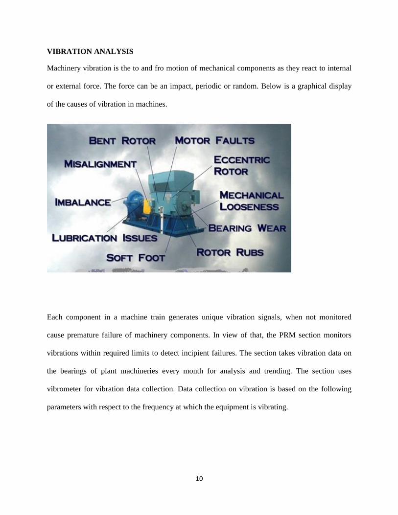
VIBRATION ANALYSIS
Machinery vibration is the to and fro motion of mechanical components as they react to internal
or external force. The force can be an impact, periodic or random. Below is a graphical display
of the causes of vibration in machines.
Each component in a machine train generates unique vibration signals, when not monitored
cause premature failure of machinery components. In view of that, the PRM section monitors
vibrations within required limits to detect incipient failures. The section takes vibration data on
the bearings of plant machineries every month for analysis and trending. The section uses
vibrometer for vibration data collection. Data collection on vibration is based on the following
parameters with respect to the frequency at which the equipment is vibrating.

11
Displacement: Is the change in distance or position of an object relative to its reference point or
neutral position. The magnitude of the displacement is termed as amplitude. In vibration
analysis, the higher the amplitude of the vibration signals, the more severe the vibration.
Displacement is measured in peak to peak units of mils (1 mil = .001”) or mm (1 mm = .0025”).
Displacement measurements are recorded in three directions (axial, horizontal and
vertical).Displacement is used to identify problems in the lower frequency ranges usually less
than 10 hertz.
Velocity: Is the time rate of change of displacement. In vibration analysis, it is defined as the
speed of the vibrating component. Velocity is measured in mm/sec represent the root mean
square (RMS) value. velocity measurement is also measured in the same three directions as
displacement. Velocity is used to identify problems in an intermediate frequency range from
10Hz to around 1500Hz (600 to 90000 CPM).
Acceleration: Is the time rate of change of velocity. Acceleration is measured in units of G’s or
millimeters per second/second (mm/s/s) in RMS .Acceleration is very important fault data in the
high frequency around 5000 Hz (300 000 CPM). Acceleration data are measured in the
rotational axis only.
However the following parameters present a wave in the time domain, which makes it
difficult to interpret hence the need to convert to frequency domain using FFT spectrum.
FFT spectrum identifies the type of vibration with respect to its frequency. FFT spectrum
may show modulated frequencies or sidebands which needs to be demodulated to identify
specific frequencies respectively. This enables the team to determine the root cause of a
vibration.

12
In vibration analysis frequency shows the type of vibration while amplitude or
displacement shows the severity or intensity of vibration.
Below is the graphs used in vibration analysis to determine the root cause of vibration in
machinery.
Time wave graph
Fast Fourier Transform (FFT) spectrum graph.

13
PROCEDURE FOR VIBRATION DATA COLLECTION BY PRM
1. Ensure the machine is running and access whether the place is safe for data collection.
2. Identify data collection point on or as close as possible to the bearings of a rotating
machine.
3. Clean data collection point on the machine component of dust or dirt.
4. Take velocity readings on the bearings in the horizontal, vertical and axial direction.
5. Take acceleration reading on the bearings only in the rotational axis direction.
The figure below shows the directions in which velocity readings are taken on a bearing.
6. Enter values in Microsoft excel for analysis.
Below is the order of defects associated with the direction of vibration data taken.
Vertical Horizontal Axial
1.Mechanical looseness 1.Unbalance 1.Misalignment 2.Worn out journal bearing 2.Bearing defect 2.Bent shaft 3.Resonance 3.Gear defect 3.Cocked bearing 4.Misalignment 4.Eccetrencity 4.Unbalance

14
PREVENTION OF RESONANCE IN CENTRIFUGAL PUMPS WITH VIBRATION
ANALYSIS
Resonance occurs when the frequency of an induced force or impacted force on a body is equal
to the natural frequency of the body. Resonance causes mechanical looseness, misalignment and
subsequently leads to failure in machines. Hence the need to prevent it.
To prevent resonance in centrifugal pumps, measure the natural frequency of the
foundation with the pump installed on it. That is;
√
Where is natural frequency, k = stiffness of the foundation and m= the mass of the
foundation and the pump.
Determine the frequency of induced force from the rotational speed of the shaft of
installed pump.
If the two frequencies are equal, resonance will occur hence either the rotational speed or
the mass or stiffness of the foundation can be altered to accommodate an inequality
between the 2 frequencies to prevent resonance.
THERMOGRAPHY
Thermography is one of the inspection tools used to detect the contact temperature of a body. It
provides the ability to critically inspect the contact temperature of an area or spot on a body.
Thermography is basically the graphical display of heat emitted by a body above absolute zero
temperature in the infra-red range of electromagnetic spectrum.

15
The section uses FLIR thermography camera and its software for imaging and analysis
respectively. The camera detects radiations in the infrared range of the electromagnetic spectrum
and produces images of that radiation called thermograms. The figure below shows a
thermogram of an electric circuit.
The image is subsequently uploaded on to a computer for analysis and reporting. Analysis of the
thermogram would give the maximum and minimum temperature of the area of the image. The
software can also narrow the area to a spot to detect the temperature of that spot on the
thermogram.
The section takes thermographic images of the breaker, contactor and the termination wires of an
electric panel, electrical motor and mechanical barrels monthly. The section compares 4
consecutive images of a component to trend the heat generated by the component. Thermography
enables the section to detect fault in shaft, electrical motors etc.

16
PROACTIVE MAINTENANCE UNIT
The proactive maintenance unit addresses failures and implements measures that prevent the re-
occurrence of failures in plant machineries. Some of the proactive measures used by the PRM
section are;
Lubrication
Inspections
Alignment and Balancing
Root Cause Analysis (RCA) and Failure Mode And Effect Analysis (FMEA)
LUBRICATION
Lubrication is termed as the life blood of every machinery. Lubrication primarily reduces friction
between two mechanical components in contact and relative motion. It also cools and prevents
corrosion in machines. Research has shown that industrial machines can have 40,000hrs (5
years) meantime between failures only when there is a good lubrication plan.
PRM section has a lubrication schedule for machines with respect to manufacturer’s
requirement. Example is the barrel unit of centrifugal pumps. The section also monitors the
automated lubrication of major machinery components such as trunnion bearing and girth gear of
the mills and gearboxes. The section ensures that equipment is lubricated with a lubricant of the
right viscosity and chemistry.

17
C.M.F
CMF is one of the sections within the Plant Maintenance Department. The section uses both
corrective and preventive maintenance systems to maintain machines at the crushing, milling and
floatation process circuit of the plant. The section manages machines such as the SAG and Ball
mills, Mill Discharge Pumps, Conveyers, Neutralization Tails Thickener and Pumps, Regrind
Mill, Floatation Cells, Floatation Tails Thickener and Pumps, Reagent Pumps.
CORRECTIVE MAINTAINANCE AT CMF
Corrective maintenance is the predominant maintenance practice used by the CMF in
maximizing availability of the plant. All repairs done by the section are planned, implemented
and verified before the machine is returned to service. Below is the steps undertaken in
corrective maintenance practice at CMF
1. Accurate identification of incipient failure using root cause analysis.
2. Controlling incipient failure.
3. Raising of work request.
4. Approved work request undergoes planning and scheduling.
5. Release work order.
6. Execution of work.
7. Verification of repair.

18
PREVENTIVE MAINTENANCE OF CENTRIFUGAL PUMPS AT CMF
Inspection is the major preventive maintenance tool used by CMF to minimize breakdowns and
corrective maintenance works. Inspections are done routinely on machines at the plant.
Centrifugal pumps undergo thorough inspections based on the running hours of the pump. Below
are the check lists of activities performed during inspections.
ROUTINE INSPECTION OF CENTRIFUGAL PUMPS AT CMF
1. Check for unusual sounds and signs of equipment failure.
2. Check all mounting fasteners and joints for tightness and security.
3. Inspect inlet and exit flanges and pipes for leakages.
4. Apply 5 to 6 shots of Alvania EP2 grease through nipples.
10/8 WARMAN RUBBER LINED PUMP PREVENTIVE MAINTENANCE FOR 2000
HOURS OPERATION.
1. Ensure the pump is isolated and locked out.
2. Remove gland water line from the pump.
3. Break the suction and discharge lines
4. Remove front cover and inspect the wet end.
5. Turn gland water on and run until water becomes clear.
6. Fit gland water line to pump
7. Remove and replace all packings.
8. Inspect gland follower for wear.
9. Clean and apply anti seize gland follower bolts

19
10. Clean and inspect sleeve for wear.
11. Fit front cover to pump
12. Inspect the holding down bolts clamps and clamp washers.
13. Inspect belts for cracks and replace if required.
14. Inspect belt alignment
15. Tension belt
16. Replace guard
17. Grease pump bearing barrel unit and labrynth.
Tools and accessories to be used:
24 spanner for the guard bolts
Pipe wrench (small) for gland water line
Pipe wrench (large) for turning of the shaft
19 spanner for gland follower separation.
30 spanner for gland follower adjustment bolt, frame and cover plate liner bolt.
Extractor for removal of gland packings.
Screw driver for fixing gland packings.
46 spanner for barrel adjustment bolt.
14mm Allen Key for pulley adjustment.
36 spanner for the suction and discharge lines.
65 spanner or flogger for pump casing bolts and motor adjustment.
5 ton shuckle for lifting of pump casing.
Fibre sling/wire sling for lifting of pump casing.

20
Wire brush for cleaning.
Sledge hammer (4 pound) for fitting the sleeve on the shaft.
Grease for fixing the packings.
Wd40 for assistance in removal of bolts
Anti-seize to prevent seizure of components during assembling.
WELDING AND FABRICATION SECTION
Welding and fabrication is one of the vital sections under plant maintenance department. The
section provides services to the plant by welding of steels of various thicknesses, patching of
leakages on steel pipes, gas cutting of rusted bolts and fabrication of structures. Electric arc
welding and Oxy-acetylene gas cutting are processes used in daily works.
ELECTRIC ARC WELDING
Electric arc welding is a type of fusion welding. In electric arc welding, electrode is set to a
higher voltage than the parts to join. The electrode gets a low voltage and sufficiently high
current so that when it is brought near to the parts, an electric arc is generated. The arc is to heat
the metal locally. The electrode melts and fuses the parts. The electrode is coated with a flux
which forms an inert shield to protect the joint from oxidation.

21
SELECTION OF ELECTRODE
There are different kinds of electrode used in welding. Electrodes vary in sizes and metal
components such as brass, mild steel, stainless steel etc. The section uses 2.5mm and 3.2mm
electrodes of both mild steel and stainless steel mostly in daily works. Selection of electrode type
is dependent on the type of metal and thickness to weld. The selection of the electrode also
influences the selection of current on a welding machine. An electrode must always be free of
dirt and moisture to prevent blow holes in weld beads.
EDGE PREPARATION
Edge preparation is vital in welding of a workpiece. It improves the quality of the weld.it is
basically the gap designed for the weld bead to fill. Edge preparation also includes brushing off
dirt and grinding off rust or paint on the edges of the workpiece.
The edge preparation of a work piece is dependent on the size of electrode, type of joint and the
thickness of the workpiece. Edge preparation is significantly required for metals of 6mm
thickness and above. Butt joint normally requires edge preparation for a groove weld to fit
perfectly. However fillet weld on lap joint or tee joint do not necessarily require edge
preparation.

22
HOW TO WELD A WORKPIECE USING ELECTRIC ARC WELDING MACHINE
Wear the required PPEs ( welding shield, leather gloves, apron, work booth, respirator)
Set the work piece at a place away from an electric source or watery area or flammable
gas and ensure good ventilation and accessibility to fire extinguisher.
Prepare the edge of the workpiece.
Connect the earth clamp to the work piece.
Switch the machine on and choose the required voltage and current.
Put an electrode with required size and metal component in the electrode holder.
Strikes the part to weld lightly with the electrode to generate an arc and sustain the arc by
maintaining a gap between the workpiece and the electrode not greater than the size of
the electrode.
Gently pull the electrode backward to complete a travel.
Chip off the slug on the weld to reveal the welding bead.
PRECAUTIONS
1. Ensure the work piece is free of dirt and moisture to prevent blow holes in weld.
2. Avoid subjecting welded piece to rapid cooling since it distort the grain structure of the
weld and weakens it.
3. Pre heat metals of low thermal conductivity or large thickness to make welding easy by
exciting the metal to it molten temperature.
4. Chip off slug before start of another travel of weld.

23
GENERAL SAFETY RULES AT THE PROCESS PLANT
Wear the required PPEs (helmet, goggles, safety booth) before entering the plant.
Report any incident to your supervisor for appropriate actions and directions.
Fill the appropriate document (take 5 form, safe work permit, hot work permit,
risk assessment form, job hazard analysis form) before working on any machine.
Isolate and tag out electrically driven machine before working on it.
Do not fight at the workplace.
Do not use acohol or drugs for working.
Wear the required PPEs that match a specific job.
Use right tool for the right work.
Clean the work area after work.
Clean all tools and put them at the right place.
General Safety Slogan: if it is not safe, don’t do it but find a way to make it safe.

24
CONCLUSION
My national service at GSPBL has been educative and adventurous for me as a plant
maintenance trainee. The training has taught me the types of maintenance practices used by the
Plant Maintenance department. I have also gained hands on experience on the procedure of work
at GSPBL. Conclusively GSPBL provides a safe and welcoming environment for training and
working.
RECOMMENDATION
Procedure of work must be reviewed and workers must undergo refreshable training from
time to time to eliminate complacency in working.
The PRM section must be furbished with adequate instruments to assist the plant with
accurate predictions on machines condition.
The mechanical and electrical section must invest more time into preventive maintenance
tools such as inspections, alignment, balancing and lubrication to curb down the number
of breakdowns and corrective maintenance works.