Notes for machine operators EVF93xx 9300 vector 15-30kW
46
EDKVF93−02 .MUw Ä.MUwä Information for the operator of the machine 9300 vector 15 ... 30 kW l EVS9327-xV ... EVS9329-xV Frequency inverter Global Drive
Transcript of Notes for machine operators EVF93xx 9300 vector 15-30kW

EDKVF93−02.MUw
Ä.MUwä
Information for the operator of the machine
9300 vector 15 ... 30 kW
�
EVS9327−xV ... EVS9329−xV
Frequency inverter
Global Drive

9300vec155

Key for overview
Position Description
� Controller
� Fixing bracket for standard mounting
� EMC shield sheet with fixing screws for shielded control cables
� Cover with fixing screws
� EMC shield sheet for the motor cable and the feed cable for the motor temperature monitoring with PTC ther-mistor or thermal contact (NC contact)
Interfaces and displays
Position Description
L1, L2, L3, PE Mains connection
+UG, −UG DC supply
U, V, W, PE Motor connection
T1, T2 Connection of PTC thermistor or thermal contact (NC contact) of the motor
X1 AIF interface (automation interface)Slot for communication module (e. g. XT EMZ9371BC keypad)
X3 Jumper for setting analog input signal at X6/1, X6/2
X4 System bus (CAN) connection
X5 Connection of digital inputs and outputs
X6 Connection of analog inputs and outputs
X8 Connection of incremental encoder with TTL level or SinCos encoder and KTY temperature sensor of the motor
X9 Connection of digital frequency input signal
X10 Connection of digital frequency output signal
X11 Connection of KSR relay output for "safe standstill" (for variants V004 and V024 only)
Status displays
Position LED red LED green Operating status
� Off On Controller is enabled
On On Mains is switched on and automatic start is inhibited
Off Blinking slowly Controller is inhibited
Off On Motor data identification is active
Blinking quickly Off Undervoltage or overvoltage
Blinking slowly Off Active fault
0Fig. 0Tab. 0

Contentsi
� 4 EDKVF93−02 EN 3.0
1 About this documentation 5. . . . . . . . . . . . . . . . . . . . . . . . . . . . . . . . . . . . . . . . . . . . . . . . . .
1.1 Document history 5. . . . . . . . . . . . . . . . . . . . . . . . . . . . . . . . . . . . . . . . . . . . . . . . . . . .
1.2 Target group 5. . . . . . . . . . . . . . . . . . . . . . . . . . . . . . . . . . . . . . . . . . . . . . . . . . . . . . . .
1.3 Validity information 6. . . . . . . . . . . . . . . . . . . . . . . . . . . . . . . . . . . . . . . . . . . . . . . . . .
1.4 Conventions used 7. . . . . . . . . . . . . . . . . . . . . . . . . . . . . . . . . . . . . . . . . . . . . . . . . . . .
1.5 Notes used 8. . . . . . . . . . . . . . . . . . . . . . . . . . . . . . . . . . . . . . . . . . . . . . . . . . . . . . . . . .
2 Safety instructions 9. . . . . . . . . . . . . . . . . . . . . . . . . . . . . . . . . . . . . . . . . . . . . . . . . . . . . . . . .
2.1 General safety and application notes for Lenze controllers 9. . . . . . . . . . . . . . . . . .
2.2 Thermal motor monitoring 12. . . . . . . . . . . . . . . . . . . . . . . . . . . . . . . . . . . . . . . . . . . .
2.2.1 Forced ventilated or naturally ventilated motors 13. . . . . . . . . . . . . . . . . . .
2.2.2 Self−ventilated motors 14. . . . . . . . . . . . . . . . . . . . . . . . . . . . . . . . . . . . . . . . .
2.3 Residual hazards 16. . . . . . . . . . . . . . . . . . . . . . . . . . . . . . . . . . . . . . . . . . . . . . . . . . . . .
2.4 Safety instructions for the installation according to UL 18. . . . . . . . . . . . . . . . . . . . .
3 Parameter setting 20. . . . . . . . . . . . . . . . . . . . . . . . . . . . . . . . . . . . . . . . . . . . . . . . . . . . . . . . .
3.1 Parameter setting with the XT EMZ9371BC keypad 20. . . . . . . . . . . . . . . . . . . . . . . .
3.1.1 General data and operating conditions 20. . . . . . . . . . . . . . . . . . . . . . . . . .
3.1.2 Installation and commissioning 21. . . . . . . . . . . . . . . . . . . . . . . . . . . . . . . .
3.1.3 Display elements and function keys 21. . . . . . . . . . . . . . . . . . . . . . . . . . . . .
3.1.4 Changing and saving parameters 23. . . . . . . . . . . . . . . . . . . . . . . . . . . . . . .
3.1.5 Loading a parameter set 25. . . . . . . . . . . . . . . . . . . . . . . . . . . . . . . . . . . . . . .
3.1.6 Transferring parameters to other standard devices 26. . . . . . . . . . . . . . . . .
3.1.7 Activating password protection 28. . . . . . . . . . . . . . . . . . . . . . . . . . . . . . . . .
3.1.8 Diagnostics 29. . . . . . . . . . . . . . . . . . . . . . . . . . . . . . . . . . . . . . . . . . . . . . . . . .
3.1.9 Menu structure 30. . . . . . . . . . . . . . . . . . . . . . . . . . . . . . . . . . . . . . . . . . . . . .
4 Troubleshooting and fault elimination 32. . . . . . . . . . . . . . . . . . . . . . . . . . . . . . . . . . . . . . .
4.1 Display of operating data, diagnostics 32. . . . . . . . . . . . . . . . . . . . . . . . . . . . . . . . . . .
4.1.1 Display of operating data 32. . . . . . . . . . . . . . . . . . . . . . . . . . . . . . . . . . . . . .
4.1.2 Diagnostics 33. . . . . . . . . . . . . . . . . . . . . . . . . . . . . . . . . . . . . . . . . . . . . . . . . .
4.2 Troubleshooting 34. . . . . . . . . . . . . . . . . . . . . . . . . . . . . . . . . . . . . . . . . . . . . . . . . . . . .
4.2.1 Status display via controller LEDs 34. . . . . . . . . . . . . . . . . . . . . . . . . . . . . . . .
4.2.2 Fault analysis with the history buffer 35. . . . . . . . . . . . . . . . . . . . . . . . . . . .
4.3 Drive behaviour in the event of faults 36. . . . . . . . . . . . . . . . . . . . . . . . . . . . . . . . . . . .
4.4 Fault elimination 37. . . . . . . . . . . . . . . . . . . . . . . . . . . . . . . . . . . . . . . . . . . . . . . . . . . . .
4.4.1 Drive errors 37. . . . . . . . . . . . . . . . . . . . . . . . . . . . . . . . . . . . . . . . . . . . . . . . . .
4.4.2 Controller in clamp operation 38. . . . . . . . . . . . . . . . . . . . . . . . . . . . . . . . . . .
4.4.3 Behaviour in case of overvoltage in the DC bus (OU message) 39. . . . . . . .
4.5 System error messages 40. . . . . . . . . . . . . . . . . . . . . . . . . . . . . . . . . . . . . . . . . . . . . . . .
4.5.1 General error messages 40. . . . . . . . . . . . . . . . . . . . . . . . . . . . . . . . . . . . . . . .
4.5.2 Resetting system error messages 45. . . . . . . . . . . . . . . . . . . . . . . . . . . . . . . .

About this documentationDocument history
1
� 5EDKVF93−02 EN 3.0
1 About this documentation
� Note!
This documentation contains all the information required by the machineoperator to run the drive controllers of the 9300 vector series installed in yourmachine/system.
You may make further use of the information contained in this documentationwithout asking Lenze for permission if you do not change the contents.
1.1 Document history
What is new / what has changed?
Material number Version Description
.MUw 3.0 11/2013 TD06 Error corrections
13217737 2.1 03/2010 TD23 Change of the company’s address
13217737 2.0 03/2010 TD14 New edition due to reorganisation of the companyUL−warnings updatedRevision for software version 8x
13217737 1.0 07/2007 TD23 First edition
Tip!
Information and auxiliary devices related to the Lenze products can be foundin the download area at
http://www.Lenze.com
1.2 Target group
This documentation is directed at qualified skilled personnel according to IEC 60364.
Qualified skilled personnel are persons who have the required qualifications to carry outall activities involved in installing, mounting, commissioning, and operating the product.

About this documentationValidity information
1
� 6 EDKVF93−02 EN 3.0
1.3 Validity information
... 9300 vector frequency inverters as of nameplate data:
� � � Nameplate
EVF 93xx ˘ x V Vxxx 1x 8x
Product series
9300vec112
EVF = Frequency inverter
Type no. / rated power
400V 480 V
9327 = 15 kW 18.5 kW
9328 = 22 kW 30 kW
9329 = 30 kW 37 kW
Type
E = Built−in unit
C = Built−in unit in "cold plate" technique
Design
V = Vector−controlled frequency inverter
Variant
˘ Standard
V003 = In "cold plate" technique
V004 = With "safe standstill" function
V024 = With "safe standstill" function and for IT mains
V100 = For IT systems
Hardware version
Software version

About this documentationConventions used
1
� 7EDKVF93−02 EN 3.0
1.4 Conventions used
This documentation uses the following conventions to distinguish between differenttypes of information:
Type of information Identification Examples/notes
Spelling of numbers
Decimal separator language−dependent
In each case, the signs typical for the targetlanguage are used as decimal separators.For example: 1234.56 or 1234,56
Warnings
UL warnings Given in English and French
UR warnings �
Text
Program name » « PC softwareFor example: »Engineer«, »Global DriveControl« (GDC)
Icons
Page reference � Reference to another page with additionalinformationFor instance: � 16 = see page 16
Documentation reference Reference to another documentation withadditional informationFor example: EDKxxx = seedocumentation EDKxxx

About this documentationNotes used
1
� 8 EDKVF93−02 EN 3.0
1.5 Notes used
The following pictographs and signal words are used in this documentation to indicatedangers and important information:
Safety instructions
Structure of safety instructions:
� Danger!
(characterises the type and severity of danger)
Note
(describes the danger and gives information about how to prevent dangeroussituations)
Pictograph and signal word Meaning
� Danger!
Danger of personal injury through dangerous electrical voltage.Reference to an imminent danger that may result in death orserious personal injury if the corresponding measures are nottaken.
� Danger!
Danger of personal injury through a general source of danger.Reference to an imminent danger that may result in death orserious personal injury if the corresponding measures are nottaken.
� Stop!Danger of property damage.Reference to a possible danger that may result in propertydamage if the corresponding measures are not taken.
Application notes
Pictograph and signal word Meaning
� Note! Important note to ensure troublefree operation
Tip! Useful tip for simple handling
Reference to another documentation
Special safety instructions and application notes
Pictograph and signal word Meaning
Warnings! Safety note or application note for the operation according toUL or CSA requirements.The measures are required to meet the requirements accordingto UL or CSA.� Warnings!

Safety instructionsGeneral safety and application notes for Lenze controllers
2
� 9EDKVF93−02 EN 3.0
2 Safety instructions
2.1 General safety and application notes for Lenze controllers
(in accordance with Low−Voltage Directive 2006/95/EC)
For your personal safety
Disregarding the following safety measures can lead to severe injury to persons anddamage to material assets:
ƒ Only use the product as directed.
ƒ Never commission the product in the event of visible damage.
ƒ Never commission the product before assembly has been completed.
ƒ Do not carry out any technical changes on the product.
ƒ Only use the accessories approved for the product.
ƒ Only use original spare parts from Lenze.
ƒ Observe all regulations for the prevention of accidents, directives and lawsapplicable on site.
ƒ Transport, installation, commissioning and maintenance work must only be carriedout by qualified personnel.
– Observe IEC 364 and CENELEC HD 384 or DIN VDE 0100 and IEC report 664 orDIN VDE 0110 and all national regulations for the prevention of accidents.
– According to this basic safety information, qualified, skilled personnel are personswho are familiar with the assembly, installation, commissioning, and operation ofthe product and who have the qualifications necessary for their occupation.
ƒ Observe all specifications in this documentation.
– This is the condition for safe and trouble−free operation and the achievement ofthe specified product features.
– The procedural notes and circuit details described in this documentation are onlyproposals. It is up to the user to check whether they can be transferred to theparticular applications. Lenze Automation GmbH does not accept any liability forthe suitability of the procedures and circuit proposals described.
ƒ Depending on their degree of protection, some parts of the Lenze controllers(frequency inverters, servo inverters, DC speed controllers) and their accessorycomponents can be live, moving and rotating during operation. Surfaces can be hot.
– Non−authorised removal of the required cover, inappropriate use, incorrectinstallation or operation, creates the risk of severe injury to persons or damage tomaterial assets.
– For more information, please see the documentation.
ƒ High amounts of energy are produced in the controller. Therefore it is required towear personal protective equipment (body protection, headgear, eye protection, earprotection, hand guard).

Safety instructionsGeneral safety and application notes for Lenze controllers
2
� 10 EDKVF93−02 EN 3.0
Application as directed
Controllers are components which are designed for installation in electrical systems ormachines. They are not to be used as domestic appliances, but only for industrial purposesaccording to EN 61000−3−2.
When controllers are installed into machines, commissioning (i.e. starting of the operationas directed) is prohibited until it is proven that the machine complies with the regulationsof the EC Directive 2006/42/EC (Machinery Directive); EN 60204 must be observed.
Commissioning (i.e. starting of the operation as directed) is only allowed when there iscompliance with the EMC Directive (2004/108/EC).
The controllers meet the requirements of the Low−Voltage Directive 2006/95/EC. Theharmonised standard EN 61800−5−1 applies to the controllers.
The technical data and supply conditions can be obtained from the nameplate and thedocumentation. They must be strictly observed.
Warning: Controllers are products which can be installed in drive systems of category C2according to EN 61800−3. These products can cause radio interferences in residential areas.In this case, special measures can be necessary.
Transport, storage
Please observe the notes on transport, storage, and appropriate handling.
Observe the climatic conditions according to the technical data.
Installation
The controllers must be installed and cooled according to the instructions given in thecorresponding documentation.
The ambient air must not exceed degree of pollution 2 according to EN 61800−5−1.
Ensure proper handling and avoid excessive mechanical stress. Do not bend anycomponents and do not change any insulation distances during transport or handling. Donot touch any electronic components and contacts.
Controllers contain electrostatic sensitive devices which can easily be damaged byinappropriate handling. Do not damage or destroy any electrical components since thismight endanger your health!

Safety instructionsGeneral safety and application notes for Lenze controllers
2
� 11EDKVF93−02 EN 3.0
Electrical connection
When working on live controllers, observe the applicable national regulations for theprevention of accidents (e.g. VBG 4).
The electrical installation must be carried out according to the appropriate regulations(e.g. cable cross−sections, fuses, PE connection). Additional information can be obtainedfrom the documentation.
This documentation contains information on installation in compliance with EMC(shielding, earthing, filter, and cables). These notes must also be observed for CE−markedcontrollers. The manufacturer of the system is responsible for compliance with the limitvalues demanded by EMC legislation. The controllers must be installed in housings (e.g.control cabinets) to meet the limit values for radio interferences valid at the site ofinstallation. The housings must enable an EMC−compliant installation. Observe inparticular that e.g. the control cabinet doors have a circumferential metal connection tothe housing. Reduce housing openings and cutouts to a minimum.
Lenze controllers may cause a DC current in the PE conductor. If a residual current device(RCD) is used for protection against direct or indirect contact for a controller withthree−phase supply, only a residual current device (RCD) of type B is permissible on thesupply side of the controller. If the controller has a single−phase supply, a residual currentdevice (RCD) of type A is also permissible. Apart from using a residual current device (RCD),other protective measures can be taken as well, e.g. electrical isolation by double orreinforced insulation or isolation from the supply system by means of a transformer.
Operation
If necessary, systems including controllers must be equipped with additional monitoringand protection devices according to the valid safety regulations (e.g. law on technicalequipment, regulations for the prevention of accidents). The controllers can be adapted toyour application. Please observe the corresponding information given in thedocumentation.
After the controller has been disconnected from the supply voltage, all live componentsand power terminals must not be touched immediately because capacitors can still becharged. Please observe the corresponding stickers on the controller.
All protection covers and doors must be shut during operation.
Safety functions
Certain controller versions support safety functions (e.g. "Safe torque off", formerly "Safestandstill") according to the requirements of the EC Directive 2006/42/EC (MachineryDirective). The notes on the integrated safety system provided in this documentation mustbe observed.
Maintenance and servicing
The controllers do not require any maintenance if the prescribed operating conditions areobserved.
Disposal
Recycle metal and plastic materials. Ensure professional disposal of assembled PCBs.
The product−specific safety and application notes given in these instructions must beobserved!

Safety instructionsThermal motor monitoring
2
� 12 EDKVF93−02 EN 3.0
2.2 Thermal motor monitoring
� Note!
From software version 8.1 onwards, the 9300 vector controllers are providedwith an I2xt function for sensorless thermal monitoring of the connectedmotor.
ƒ I2xt monitoring is based on a mathematical model which calculates athermal motor utilisation from the detected motor currents.
ƒ The calculated motor utilisation is saved when the mains is switched off.
ƒ The function is UL−certified, i.e. additional protective measures for the motorare not required in UL−approved systems.
ƒ Nevertheless, I2xt monitoring does not provide full motor protectionbecause other influences on the motor utilisation such as changes in thecooling conditions (e.g. cooling air flow interrupted or too warm) cannot bedetected.
Die I2 x t load of the motor is displayed in C0066.
The thermal loading capacity of the motor is expressed by the thermal motor timeconstant (�, C0128). Find the value in the rated motor data or contact the manufacturer ofthe motor.
The I2 x t monitoring has been designed such that it will be activated after 179 s in theevent of a motor with a thermal motor time constant of 5 minutes (Lenze setting C0128),a motor current of 1.5 x IN and a trigger threshold of 100 %.
Two adjustable trigger thresholds provide for different responses.
ƒ Adjustable response OC8 (TRIP, warning, off).
– The trigger threshold is set in C0127.
– The response is set in C0606.
– The response OC8, for instance, can be used for an advance warning.
ƒ Fixed response OC6−TRIP.
– The trigger threshold is set in C0120.
Behaviour of the I2 x t monitoring Condition
The I2 x t monitoring is deactivated.C0066 is set = 0 % andMCTRL−LOAD−I2XT is set = 0.00 %.
When C0120 = 0 % and C0127 = 0 %, set controllerinhibit.
I2 x t monitoring is stopped.The current value in C0066 and at theMCTRL−LOAD−I2XT output is frozen.
When C0120 = 0 % and C0127 = 0 %, set controllerenable.
I2 x t monitoring is deactivated.The motor load is displayed in C0066.
Set C0606 = 3 (off) and C0127 > 0 %.
� Note!
An error message OC6 or OC8 can only be reset if the I2 x t load falls below theset trigger threshold by 5 %.

Safety instructionsThermal motor monitoring
Forced ventilated or naturally ventilated motors
2
� 13EDKVF93−02 EN 3.0
2.2.1 Forced ventilated or naturally ventilated motors
Parameter setting
The following codes can be set for I2 x t monitoring:
Code Meaning Value range Lenze setting
C0066 Display of the I2 x t load of the motor 0 ... 250 % −
C0120 Threshold: Triggering of error "OC6" 0 ... 120 % 0 %
C0127 Threshold: Triggering of error "OC8" 0 ... 120 % 0 %
C0128 Thermal motor time constant 0.1 ... 50.0 min 5.0 min
C0606 Response to error "OC8" TRIP, warning, off Warning
Calculate release time and I2xt load
Formula for release time Information
t � � (���) � ln����
�1 � z � 1
IMotIN2
�� 100
���
�
IMot Actual motor current (C0054)
Ir Rated motor current (C0088)
� Thermal motor time constant (C0128)
z Threshold value in C0120 (OC6) or C0127 (OC8)
Formulae for I2 x t load Information
L(t) � IMot
IN2
� 100% �1 � e�t�
L(t) Chronological sequence of the I2 x t load of the motor(Display: C0066)
IMot Actual motor current (C0054)
Ir Rated motor current (C0088)
� Thermal motor time constant (C0128)
If the controller is inhibited, the I2 x t load is reduced:
L(t) � LStart� � e��t�
� LStart I2 x t load before controller inhibit
If an error is triggered, the value corresponds to thethreshold value set in C0120 (OC6) or C0127 (OC8).
Read release time in the diagram
Diagram for detecting the release times for a motor with a thermal motor time constantof 5 minutes (Lenze setting C0128):
I = 3 × IMot N
0
50
100
120
0 100 200 300 400 500 600 700 800 900 1000
t [s]
L [%] I = 2 × IMot N I = 1.5 × IMot NI = 1 × IMot N
9300STD105
Fig. 2−1 I2 × t−monitoring: Release times for different motor currents and trigger thresholds
IMot Actual motor current (C0054)Ir Rated motor current (C0088)L I2 x t load of the motor (display: C0066)T Time

Safety instructionsThermal motor monitoringSelf−ventilated motors
2
� 14 EDKVF93−02 EN 3.0
2.2.2 Self−ventilated motors
Due to the construction, self−ventilated standard motors are exposed to an increased heatgeneration in the lower speed range compared to forced ventilated motors.
Warnings!
For complying with the UL 508C standard, you have to set thespeed−dependent evaluation of the permissible torque via code C0129/x.
Parameter setting
The following codes can be set for I2 x t monitoring:
Code Meaning Value range Lenze setting
C0066 Display of the I2 x t load of the motor 0 ... 250 % −
C0120 Threshold: Triggering of error "OC6" 0 ... 120 % 0 %
C0127 Threshold: Triggering of error "OC8" 0 ... 120 % 0 %
C0128 Thermal motor time constant 0.1 ... 50.0 min 5.0 min
C0606 Response to error "OC8" TRIP, warning, off Warning
C0129/1 S1 torque characteristic I1/Irated 10 ... 200 % 100 %
C0129/2 S1 torque characteristics n2/nrated 10 ... 200 % 40 %
Effect of code C0129/x
0
0.9
0 0.1
C0129/2
0.2 0.3 0.4
0.6
0.7
0.8
1.0
1.1
�
�
0.132
�
I / IN
n / nN
C0129/1
�
9300STD350
Fig. 2−2 Working point in the range of characteristic lowering
The lowered speed / torque characteristic (Fig. 2−2) reduces the permissible thermal loadof self−ventilated standard motors. The characteristic is a line the definition of whichrequires two points:
ƒ Point �: Definition with C0129/1
This value also enables an increase of the maximally permissible load.
ƒ Point �: Definition with C0129/2
With increasing speeds, the maximally permissible load remains unchanged(IMot = Irated).
In Fig. 2−2, the motor speed and the corresponding permissible motor torque (�) can beread for each working point (�on the characteristic (�) ... �). � can also be calculatedusing the values in C0129/1and C0129/2 (evaluation coefficient "y", � 15).

Safety instructionsThermal motor monitoring
Self−ventilated motors
2
� 15EDKVF93−02 EN 3.0
Calculate release time and I2xt load
Calculate the release time and the I2 x t load of the motor considering the values inC0129/1 and C0129/2(evaluation coefficient "y").
Formulae for release time Information
y �100% � C0129�1
C0129�2� n
nN� C0129�1
T � � (���) � ln����
�1 � z � 1
IMoty�IN2
�� 100
���
�
T Release time of the I2 x t monitoring
� Thermal motor time constant (C0128)
In Function: Natural logarithm
IMot Actual motor current (C0054)
Ir Rated motor current (C0088)
z Threshold value in C0120 (OC6) or C0127 (OC8)
y Evaluation coefficient
nrated Rated speed (C0087)
Formulae for I2 x t load Information
L(t) � IMot
y � IN2
� 100% �1 � e�t�
L(t) Chronological sequence of the I2 x t load of the motor(Display: C0066)
y Evaluation coefficient
IMot Actual motor current (C0054)
Ir Rated motor current (C0088)
� Thermal motor time constant (C0128)
If the controller is inhibited, the I2 x t load is reduced:
L(t) � LStart� � e��t�
� LStart I2 x t load before controller inhibit
If an error is triggered, the value corresponds to thethreshold value set in C0120 (OC6) or C0127 (OC8).

Safety instructionsResidual hazards
2
� 16 EDKVF93−02 EN 3.0
2.3 Residual hazards
Protection of persons
ƒ Before working on the controller, check that no voltage is applied to the powerterminals:
– Because the power terminals V, W, +UG and −UG remain live for at least 3 minutesafter disconnecting from mains.
– Because the power terminals L1, L2, L3; U, V, W, +UG and −UG remain live when themotor is stopped.
ƒ The leakage current to earth (PE) is >3.5 mA. According to EN 61800−5−1
– a fixed installation is required,
– a double PE connection is required, or, if there is only a single PE connection, the PEconductor must have a cross−section of at least 10 mm2.
ƒ The heat sink of the controller has an operating temperature of > 80 °C:
– Contact with the heatsink results in burns.
ƒ If you use the "flying−restart circuit" function (C0142 = 2, 3) for machines with a lowmoment of inertia and minimum friction:
– After controller enable in standstill, the motor may start or change its direction ofrotation for a short time, because the flying restart process also is carried out at aspeed of 0.
ƒ During parameter set transfer, the control terminals of the controller can haveundefined states!
– Therefore the plugs X5 and X6 must be unplugged, before the transfer is executed.This ensures that the controller is inhibited and all control terminals have thedefined "LOW" state.
Device protection
ƒ Frequent mains switching (e.g. inching mode via mains contactor) can overload anddestroy the input current limitation of the drive controller:
– At least 3 minutes must pass between switching off and restarting the devicesEVS9321−xS and EVS9322−xS.
– At least 3 minutes must pass between two starting procedures of the devicesEVS9323−xS ... EVS9332−xS.
– Use the "safe torque off" safety function (STO) if safety−related mainsdisconnections occur frequently. The drive variants Vxx4 are equipped with thisfunction.
Motor protection
ƒ Certain drive controller settings can overheat the connected motor:
– E. g. long−time operation of the DC injection brake.
– Long−time operation of self−ventilated motors at low speeds.

Safety instructionsResidual hazards
2
� 17EDKVF93−02 EN 3.0
Protection of the machine/system
ƒ Drives can reach dangerous overspeeds (e. g. setting of high output frequencies inconnection with motors and machines not suitable for this purpose):
– The drive controllers do not provide protection against such operating conditions.For this purpose, use additional components.

Safety instructionsSafety instructions for the installation according to UL
2
� 18 EDKVF93−02 EN 3.0
2.4 Safety instructions for the installation according to UL
Original − English
Warnings!
ƒ Motor Overload Protection– For information on the protection level of the internal overload protection
for a motor load, see the corresponding manuals or software helps.– If the integral solid state motor overload protection is not used, external or
remote overload protection must be provided.
ƒ Branch Circuit Protection– The integral solid state protection does not provide branch circuit
protection.– Branch circuit protection has to be provided externally in accordance with
corresponding instructions, the National Electrical Code and anyadditional codes.
ƒ Please observe the specifications for fuses and screw−tightening torques inthese instructions.
ƒ EVS9327 � EVS9329:– Suitable for use on a circuit capable of delivering not more than 5000 rms
symmetrical amperes, 480 V maximum, when protected by fuses.– Suitable for use on a circuit capable of delivering not more than 50000 rms
symmetrical amperes, 480 V maximum, when protected by J, T or R classfuses.
– Maximum surrounding air temperature: 0 ... +50 °C– > +40 °C: reduce the rated output current by 2.5 %/°C– Use 60/75 °C or 75 °C copper wire only.

Safety instructionsSafety instructions for the installation according to UL
2
� 19EDKVF93−02 EN 3.0
Original − French
Warnings!
ƒ Protection du moteur contre les surcharges– Pour obtenir des informations sur le niveau de protection offert par la
protection intégrée contre les surcharges du moteur, se reporter auxmanuels correspondants ou aux systèmes d’aide logiciels.
– Si la protection statique intégrée contre les surcharges du moteur n’estpas utilisée, prévoir impérativement un dispositif de protection externe ouséparé contre les surcharges.
ƒ Protection par disjoncteur– La protection statique intégrée n’offre pas la même protection qu’un
disjoncteur.– Une protection par disjoncteur externe doit être fournie, conformément
aux indications fournies, au National Electrical Code et aux autresdispositions applicables.
ƒ Se conformer aux spécifications relatives aux fusibles et aux couples deserrage contenues dans le présent document.
ƒ EVS9327 � EVS9329 :– Convient aux circuits non susceptibles de délivrer plus de 5000 ampères
symétriques eff., maximum 480 V, avec protection par fusibles.– Convient aux circuits non susceptibles de délivrer plus de 50000 ampères
symétriques eff., maximum 480 V, avec protection par des fusibles decalibre J, T ou R.
– Température ambiante maximale : 0 ... +50 °C– > +40 °C: ramener le courant assigné de sortie à 2,5 %/°C– Utiliser exclusivement des conducteurs en cuivre 60/75 °C ou 75 °C.

Parameter settingParameter setting with the XT EMZ9371BC keypadGeneral data and operating conditions
3
� 20 EDKVF93−02 EN 3.0
3 Parameter setting
3.1 Parameter setting with the XT EMZ9371BC keypad
Description
The keypad is available as an accessory. A full description of the keypad can be obtainedfrom the Instructions included in the keypad delivery.
Plugging in the keypad
It is possible to plug the keypad into the AIF interface or remove it during operation.
As soon as the keypad is supplied with voltage, it carries out a self−test. The keypad is readyfor operation if it is in display mode.
3.1.1 General data and operating conditions
� ��
�
�
� �����SHPRG
Para
Code
Menu
0050 00
50.00_Hz
M C T R L - N O U T
0 b
ca
9371BC011
Feature Values
Dimensions
Width a 60 mm
Height b 73.5 mm
Depth c 15 mm
Environmental conditions
Climate
Storage IEC/EN 60721−3−1 1K3 (−25 ... +60 °C)
Transport IEC/EN 60721−3−2 2K3 (−25 ... +70 °C)
Operation IEC/EN 60721−3−3 3K3 (−10 ... +60 °C)
Enclosure IP 20

Parameter settingParameter setting with the XT EMZ9371BC keypad
Installation and commissioning
3
� 21EDKVF93−02 EN 3.0
3.1.2 Installation and commissioning
�
��
�
�
�
�
��
���
SHPRG Pa
raCode
Menu 00
5000
50.00_Hz
MCTRL-NOUT
E82ZWLxxx
� ��
�
�
� �����SHPRG
Para
Code
Menu
0050 00
50.00_Hz
M C T R L - N O U T
E82ZBBXC
EMZ9371BC
� ��
�
�
� �����SHPRG
Para
Code
Menu
0050 00
G L O B A L D R I V E
I n i t
� ��
�
�
�
0050 00
50.00 Hz
2 0 %
� ��
�
�
�
0050 00
50.00 Hz
2 0 %
�
�
�� ���� �
�
� �
9371BC018
Fig. 3−1 Installation and commissioning of XT EMZ9371BC keypad or E82ZBBXC diagnosis terminal
� Connect keypad to the AIF interface on the front of the standard device.
The keypad can be connected/disconnected during operation.
� As soon as the keypad is supplied with voltage, it carries out a short self−test.
� The operation level indicates when the keypad is ready for operation:
� Current state of the standard device
� Memory location 1 of the user menu (C0517):
Code number, subcode number, and current value
� Active fault message or additional status message
� Actual value in % of the status display defined in C0004
� � must be pressed to leave the operation level
3.1.3 Display elements and function keys
� ��
�
�
� �����SHPRG
Para
Code
Menu
0050 00
50.00_Hz
M C T R L - N O U T
�
�
�
�
�
�
�
�
�
9371BC002
Fig. 3−2 Display elements and function keys of the XT EMZ9371BC keypad

Parameter settingParameter setting with the XT EMZ9371BC keypadDisplay elements and function keys
3
� 22 EDKVF93−02 EN 3.0
Displays
� Status displays of standard device
Display Meaning Explanation
� Ready for operation
� Pulse inhibit is active Power outputs are inhibited
� The set current limit is exceeded in motor orgenerator mode
� Speed controller 1 in the limitation Drive is torque−controlled(Only active for operation with standarddevices of the 9300 series)
� Active fault
� Acceptance of the parameters
Display Meaning Explanation
� Parameter is accepted �immediately � Standard device operates immediately withthe new parameter value
SHPRG � Parameter must be acknowledged with ��� Standard device operates with the newparameter value after being acknowledged
SHPRG Parameter must be acknowledged in case ofcontroller inhibit ���
Standard device operates with the newparameter value after the controller isenabled again
None Display parameter Change is not possible
� Active level
Display Meaning Explanation
Menu Menu level is active Select main menu and submenus
Code Code level is active Select codes and subcodes
Para Parameter level is active Change parameters in the codes orsubcodes
None Operating level is active Display operating parameters
� Short text
Display Meaning Explanation
alphanumerical
Contents of the menus, meaning of the codesand parameters
In the operating level display of C0004 in % andthe active fault
� Number
Active level Meaning Explanation
Menu level Menu number Display is only active for operation withstandard devices of the 8200 vector or 8200motec series
Code level Four−digit code number
� Number
Active level Meaning Explanation
Menu level Submenu number Display is only active for operation withstandard devices of the 8200 vector or 8200motec series
Code level Two−digit subcode number
� Parameter value
Parameter value with unit
� Cursor
In the parameter level, the digit above the cursor can be directly changed
� Function keys
For description see the following table

Parameter settingParameter setting with the XT EMZ9371BC keypad
Changing and saving parameters
3
� 23EDKVF93−02 EN 3.0
Function keys
� Note!Shortcuts with �:
Press and hold �, then press the second key in addition.
Key Function
Menu level Code level Parameter level Operating level
�Change to theparameter level
Change to the operatinglevel
Change to the codelevel
���
Go to the "Short setup"menu and loadpredefinedconfigurations 1)
Accept parameterswhen SHPRG � orSHPRG is displayed
�
!
Change between menuitems
Change of code numberChange of digit viacursor
���
� !
Quick change betweenmenu items
Quick change of codenumber
Quick change of digitvia cursor
" Change between main menu, submenu and codelevel
Cursor to the right
# Cursor to the left
$ Deactivate the function of the key %, the LED in the key goes off
% Inhibit the controller, the LED in the key is lit.
Reset fault (TRIP−Reset): 1. Remove the cause of malfunction2. Press %3. Press $
1) Only active for operation with standard devices of the 8200 vector or 8200 motec series
3.1.4 Changing and saving parameters
� Note!Your settings have an effect on the current parameters in the main memory.You must save your settings in a parameter set so that they are not lost whenthe mains are connected.
If you only need one parameter set, save your settings as parameter set 1,since parameter set 1 is loaded automatically after mains connection.
Step Keysequence
Action
1. Select the menu � ! " # Use the arrow keys to select the desired menu
2. Change to the code level " Display of the first code in the menu
3. Select code or subcode ! � Display of the current parameter value
4. Change to the parameter level �
5. When SHPRG is displayed, inhibit thecontroller
% 1) The drive coasts
6. Change parameter
A " # Move cursor below the digit to be changed
B ! � Change of digit
� !
� �
Quick change of digit

Parameter settingParameter setting with the XT EMZ9371BC keypadChanging and saving parameters
3
� 24 EDKVF93−02 EN 3.0
ActionKeysequence
Step
7. Accept the changed parameter
Display of SHPRG or SHPRG � � � Confirm change to accept the parameterDisplay "OK"
Display � − The parameter has been accepted immediately
8. Enable the controller, if required $ 1) The drive runs again
9. Change to the code level
A � Display of the operating level
B � Display of the code with changed parameter
10. Change further parameters Restart the "loop" with step 1. or 3.
11. Save changed parameters
A � ! " # Select the code C0003 "PAR SAVE" in the menu"Load/Store"
B � Change to the parameter levelDisplay "0" and "READY"
Select the parameter set in whichthe parameters are to be savedpermanently
C � Save as parameter set 1:� Set "1" "Save PS1"
Save as parameter set 2:� Set "2" "Save PS2"
Save as parameter set 3:� Set "3" "Save PS3"
Save as parameter set 4:� Set "4" "Save PS4"
D � � When "OK" is displayed, the settings are permanentlysaved in the selected parameter set.
12. Change to the code level
A � Display of the operating level
B � Display of C0003 "PAR SAVE"
13. Set parameters for another parameterset
Restart the "loop" with step 1. or 3.
1) The function of the % key can be programmed:C0469 = 1: Controller inhibitC0469 = 2: Quick stop (Lenze setting)

Parameter settingParameter setting with the XT EMZ9371BC keypad
Loading a parameter set
3
� 25EDKVF93−02 EN 3.0
3.1.5 Loading a parameter set
The keypad serves to load a saved parameter set into the main memory when the controlleris inhibited. After the controller is enabled, it operates with the new parameters.
� Danger!ƒ When a new parameter set is loaded, the controller is reinitialised and acts
as if it had been connected to the mains:– ��System configurations and terminal assignments can be changed. Make
sure that your wiring and drive configuration comply with the settings ofthe parameter set.
ƒ Only use terminal X5/28 as source for the controller inhibit! Otherwise thedrive may start in an uncontrolled way when switching over to anotherparameter set.
� Note!ƒ After switching on the supply voltage, the controller always loads parameter
set 1 into the main memory.
ƒ It is also possible to load other parameter sets into the main memory via thedigital inputs or bus commands.
Step Keysequence
Action
1. Inhibit controller Terminal X5/28 = LOW
2. Load the saved parameter set into themain memory
A � ! " # Select the code C0002 "PAR LOAD" in the menu"Load/Store"
B � Change to the parameter levelThe active parameter set is displayed, e. g. display "0"and "Load Default"If you want to restore the delivery status, proceed withD
Select the parameter set to beloaded
C � Load parameter set 1:� Set "1" "Load PS1"
Load parameter set 2:� Set "2" "Load PS2"
Load parameter set 3:� Set "3" "Load PS3"
Load parameter set 4:� Set "4" "Load PS4"
D � � "RDY" goes off. The parameter set is loaded completelyinto the main memory if "RDY" is displayed again.
3. Change to the code level
A � Display of the operating level
B � Display of C0002 "PAR LOAD"
4. Enable controller Terminal X5/28 = HIGHThe drive is running with the settings of the loadedparameter set

Parameter settingParameter setting with the XT EMZ9371BC keypadTransferring parameters to other standard devices
3
� 26 EDKVF93−02 EN 3.0
3.1.6 Transferring parameters to other standard devices
Parameter settings can be easily copied from one standard device to another by using thekeypad.
For this purpose use the "Load/Store" menu
� Danger!During the parameter transfer from the keypad to the standard device thecontrol terminals can adopt undefined states!
Therefore the plugs X5 and X6 must be disconnected from the standard devicebefore the transfer takes place. This ensures that the controller is inhibited andall control terminals have the defined state "LOW".
Copying parameter sets from the standard device into the keypad
� Note!After copying the parameter sets into the XT keypad (C0003 = 11), always theparameter set that was loaded last via C0002 is activated.
Like this the current parameters also remain active after copying:
ƒ Save the current parameters in the parameter set before copying and loadthis parameter set in the controller via C0002.
Step Keysequence
Action
1. Connect the keypad to standarddevice 1
2. Inhibit controller Terminal X5/28 = LOWThe drive coasts.
3. Select C0003 in the "Load/Store"menu
��!�"�# Select code C0003 "PAR SAVE" in the "Load/Store"menu using the arrow keys.
4. Change to the parameter level � Display "0" and "READY"
5. Copy all parameter set into thekeypad
The settings saved in the keypad are overwritten.
� Set "11" "Save extern"
6. Start copying ��� The "RDY" status display goes off. As parameter value"BUSY" is displayed.If "BUSY" goes off after approx. one minute, allparameter sets were copied into the keypad. The"RDY" status display is lit.
7. Change to the code level
A � Display of the operating level
B � Display C0003 and "PAR SAVE"
8. Enable controller Terminal X5/28 = HIGH
9. Remove keypad from standard device1

Parameter settingParameter setting with the XT EMZ9371BC keypadTransferring parameters to other standard devices
3
� 27EDKVF93−02 EN 3.0
Copying parameter sets fom keypad into the standard device
Step Keysequence
Action
1. Connect the keypad to standarddevice 2
2. Inhibit controller Terminal X5/28 = LOWThe "IMP" status display is it.The drive coasts
3. Pull the plugs X5 and X6 All control terminals have the defined "LOW" status.
4. Select C0002 in the "Load/Store"menu
��!�"�# Select code C0002 "PAR LOAD" in the "Load/Store"menu using the arrow keys.
5. Change to the parameter level � The active parameter set is shown, e. g. display "0" and"Load Default"
6. Select the correct copy function The settings saved in the standard device areoverwritten.
� Copy all parameter sets available into theEEPROM of the standard device and save thempermanently.
� The parameter set that was active before copying isoverwritten.
� The parameters are not yet active after copying.Select parameter set and load it in the mainmemory. � 25
� Set "20" "ext −> EEPROM"
� Copy individual parameter sets into the mainmemory of the standard device.
� Copy parameter set 1 into the main memory:Set � "11" "Load ext PS1"
Copy parameter set 2 into the main memory:Set � "12" "Load ext PS2"
Copy parameter set 3 into the main memory:Set � "13" "Load ext PS3"
Copy parameter set 4 into the main memory:Set � "14" "Load ext PS4"
7. Start copying ��� The "RDY" status display goes off. As parameter value"BUSY" is displayed.If "BUSY" goes off, the parameter sets selected werecopied into the standard device. The "RDY" statusdisplay is lit.
8. Change to the code level
A � Display of the operating level
B � Display C0002 and "PAR LOAD"
9. � If the function "Copy all parametersets into the EEPROM"(C0002 = 20) is selected, theymight have to be loaded in themain memory manually.
� If the function "Copy individualparameter sets into the mainmemory" (C0002 = 1x) is selected,they might have to be savedpermanently in the EEPROMmanually.
��!�"�# Select code C0003 "PAR SAVE" in the "Load/Store"menu using the arrow keys and store the contents ofthe main memory permanently.
10. Plug in plugs X5 and X6
11. Enable controller Terminal X5/28 = HIGHThe drive is running with the new settings.

Parameter settingParameter setting with the XT EMZ9371BC keypadActivating password protection
3
� 28 EDKVF93−02 EN 3.0
3.1.7 Activating password protection
� Note!ƒ If the password protection is activated (C0094 = 1 ... 9999), you only have
free access to the user menu.
ƒ To access the other menus, you must enter the password. By this, thepassword protection is annulled until you enter a new password.
ƒ Please observe that the password−protected parameters can be overwrittenas well when transferring the parameter sets to other standard devices. Thepassword is not transferred.
ƒ Do not forget your password! If you have forgotten your password, it canonly be reset via a PC or a bus system!
Activate password protection
Step Keysequence
Action
1. Select the "USER menu" � ! " # Change to the user menu using the arrow keys
2. Change to the code level " Display of code C0051 "MCTRL−NACT"
3. Select C0094 � Display of code C0094 "Password"
4. Change to the parameter level � Display "0" = no password protection
5. Set password
A � Select password (1 ... 9999)
B � � Confirm password
6. Change to the code level
A � Display of the operating level
B � Display of C0094 and "Password"
7. Change to the "USER menu" # # !
The password protection is active now.You can only quit the user menu if you re−enter the password and confirm it with ���.
Remove password protection
Step Keysequence
Action
1. Change to the code level in the usermenu
"
2. Select C0094 � Display of code C0094 "Password"
3. Change to the parameter level � Display "9999" = password protection is active
4. Enter password
A ! Set valid password
B � � ConfirmThe password protection is deactivated by entering thepassword once again.
5. Change to the code level
A � Display of the operating level
B � Display of C0094 and "Password"
The password protection is deactivated now. All menus can be freely accessed again.

Parameter settingParameter setting with the XT EMZ9371BC keypad
Diagnostics
3
� 29EDKVF93−02 EN 3.0
3.1.8 Diagnostics
In the "Diagnostic" menu the two submenus "Actual info" and "History" contain all codesfor
ƒ monitoring the drive
ƒ fault/error diagnosis
In the operating level, more status messages are displayed. If several status messages areactive, the message with the highest priority is displayed.
Priority Display Meaning
1 GLOBAL DRIVE INIT Initialisation or communication error betweenkeypad and controller
2 XXX − TRIP Active TRIP (contents of C0168/1)
3 XXX − MESSAGE Active message (contents of C0168/1)
4 Special device states:
Switch−on inhibit
5 Source for controller inhibit (the value of C0004 is displayed simultaneously):
STP1 9300 servo: Terminal X5/28
ECSxS/P/M/A: Terminal X6/SI1
STP3 Operating module or LECOM A/B/LI
STP4 INTERBUS or PROFIBUS−DP
STP5 9300 servo, ECSxA/E: System bus (CAN)
ECSxS/P/M: MotionBus (CAN)
STP6 C0040
6 Source for quick stop (QSP):
QSP−term−Ext The MCTRL−QSP input of the MCTRL function block is on HIGH signal.
QSP−C0135 Operating module or LECOM A/B/LI
QSP−AIF INTERBUS or PROFIBUS−DP
QSP−CAN 9300 servo, ECSxA: System bus (CAN)
ECSxS/P/M: MotionBus (CAN)
7 XXX − WARNING Active warning (contents of C0168/1)
8 xxxx Value below C0004

Parameter settingParameter setting with the XT EMZ9371BC keypadMenu structure
3
� 30 EDKVF93−02 EN 3.0
3.1.9 Menu structure
For simple, user−friendly operation, the codes are clearly arranged in function−relatedmenus:
Main menu Submenus Description
Display Display
User−Menu Codes defined in C0517
Code list All available codes
ALL All available codes listed in ascending order (C0001 ... C7999)
PS 1 Codes in parameter set 1 (C0001 ... C1999)
PS 2 Codes in parameter set 2 (C2001 ... C3999)
PS 3 Codes in parameter set 3 (C4001 ... C5999)
PS 4 Codes in parameter set 4 (C6001 ... C7999)
Load/Store Parameter set managementParameter set transfer, restore delivery status
Diagnostic Diagnostic
Actual info Display codes to monitor the drive
History Fault analysis with history buffer
Short setup Quick configuration of predefined applicationsConfiguration of the user menuThe predefined applications depend on the type of the standard device (frequencyinverter, servo inverter, position controller, ...)
Main FB Configuration of the main function blocks
NSET Setpoint processing
NSET−JOG Fixed setpoints
NSET−RAMP1 Ramp function generator
MCTRL Motor control
DFSET Digital frequency processing
DCTRL Internal control
Terminal I/O Connection of inputs and outputs with internal signals
AIN1 X6.1/2 Analog input 1
AIN2 X6.3/4 Analog input 2
AOUT1 X6.62 Analog output 1
AOUT2 X6.63 Analog output 2
DIGIN Digital inputs
DIGOUT Digital outputs
DFIN Digital frequency input
DFOUT Digital frequency output
State bus State bus (not with 9300 frequency inverter)
Controller Configuration of internal control parameters
Speed Speed controller
Current Current controller or torque controller
Phase Phase controller (not with 9300 frequency inverter)
Motor/Feedb. Input of motor data, configuration of speed feedback
Motor adj Motor data
Feedback Configuration of feedback systems
Monitoring Configuration of monitoring functions

Parameter settingParameter setting with the XT EMZ9371BC keypad
Menu structure
3
� 31EDKVF93−02 EN 3.0
DescriptionSubmenusMain menu Description
DisplayDisplay
LECOM/AIF Configuration of operation with communication modules
LECOM A/B Serial interface
AIF interface Process data
Status word Display of status words
System bus Configuration of system bus (CAN)
Management CAN communication parameters
CAN−IN1CAN object 1
CAN−OUT1
CAN−IN2CAN object 2
CAN−OUT2
CAN−IN3CAN object 3
CAN−OUT3
Status word Display of status words
FDO Free digital outputs
Diagnostic CAN diagnostic
FB config Configuration of function blocks
Func blocks Parameterisation of function blocksThe submenus contain all available function blocks
FCODE Configuration of free codes
Identify Identification
Drive Software version of standard device
Op Keypad Software version of keypad

Troubleshooting and fault eliminationDisplay of operating data, diagnosticsDisplay of operating data
4
� 32 EDKVF93−02 EN 3.0
4 Troubleshooting and fault elimination
4.1 Display of operating data, diagnostics
4.1.1 Display of operating data
Description
Important operating parameters are measured by the controller. They can be displayedwith the keypad or PC.
Some operating data can be calibrated to be displayed or selected directly with the unit ofthe process quantity (e.g. pressure, temperature, speed).
� Note!
The calibration always affects all specified codes simultaneously.
Codes for parameter setting
Code Possible settings IMPORTANT
No. Name Lenze Selection
C0051 MCTRL−NACT −36000 {1 rpm} 36000 Actual speed value, function blockMCTRL� Read only
C0052 MCTRL−Umot 0 {1 V} 800 Motor voltage, function block MCTRL� Read only� MCTRL−VACT = 100 % = C0090
C0053 UG−VOLTAGE 0 {1 V} 900 DC−bus voltage, function block MCTRL� Read only� MCTRL−DCVOLT = 100 % = 1000 V
C0054 IMot 0.0 {0.1 A} 500.0 Current motor current, function blockMCTRL� Read only� MCTRL−IACT = 100 % = C0022
C0061 Heatsink temp 0 {1 °C} 100 Heatsink temperature� Read only� If the temperature of the heatsink
> 85 °C, the controller sets TRIP OH� Early warning is possible via OH4,
temperature is set in C0122
C0063 Mot temp 0 {1 °C} 200 Motor temperature� Read only� Monitoring of the motor
temperature must be activated.� KTY at X8/5, X8/8:
– At 150 °C, TRIP OH3 is set– Early warning is possible via OH7,
temperature is set in C0121� PTC, thermal contact at T1, T2:
– Release sets TRIP or warning OH8

Troubleshooting and fault eliminationDisplay of operating data, diagnostics
Diagnostics
4
� 33EDKVF93−02 EN 3.0
IMPORTANTPossible settingsCode
SelectionLenzeNameNo.
C0064 Utilization 0 {1 %} 150 Device utilisation I×t� Read only� Device utilisation during the last
180 s of operating time� C0064 > 100 % releases warning
OC5
� C0064 > 140 % limits the outputcurrent of the controller to 67 % ofthe maximum current in C0022
C0150 Status word Bit00 — Bit08 Status code Read onlyDecimal status word for networkingvia automation interface (AIF)� Binary interpretation indicates the
bit states
Bit01 IMP Bit09 Status code
Bit02 — Bit10 Status code
Bit03 — Bit11 Status code
Bit04 — Bit12 Warning
Bit05 — Bit13 Message
Bit06 n = 0 Bit14 —
Bit07 CINH Bit15 —
4.1.2 Diagnostics
Description
Display codes for diagnostics
Codes for parameter setting
Code Possible settings IMPORTANT
No. Name Lenze Selection
C0093 DRIVE IDENT Controller identification� Read only
0 invalid Damaged power section
1 none No power section
9321...9333
9321VC...9333VC
Display of the controller used
C0099 S/W version x.y Software version� Read onlyx
yMain versionSubversion

Troubleshooting and fault eliminationTroubleshootingStatus display via controller LEDs
4
� 34 EDKVF93−02 EN 3.0
4.2 Troubleshooting
Detecting breakdowns
A breakdown can be detected quickly via the LEDs at the controller or via the statusinformation at the keypad.
Analysing errors
Analyse the error using the history buffer. The list of fault messages gives you advice howto remove the fault. (� 40)
4.2.1 Status display via controller LEDs
During operation the operating status of the controller is shown by 2 LEDs.
LED Operating status
Red � Green �
Off On Controller is enabled
On On Mains is switched on and automatic start isinhibited
Off Blinking slowly Controller is inhibited
Off On Motor data identification is being performed
Blinking quickly Off Undervoltage
Blinking slowly Off Active fault

Troubleshooting and fault eliminationTroubleshooting
Fault analysis with the history buffer
4
� 35EDKVF93−02 EN 3.0
4.2.2 Fault analysis with the history buffer
Retracing faults
Faults can be retraced via the history buffer. Fault messages are stored in the 8 memorylocations in the order of their appearance.
The memory locations can be retrieved via codes.
Structure of the history buffer
Code Memory location Entry Note
C0168/1 C0169/1 C0170/1 Memory location 1 Active fault If the fault is no longer pending or has beenacknowledged:� The contents of the memory locations
1 ... 7 are shifted "up" to the next memorylocation.
� The content of memory location 8 isdeleted from the history buffer and cannotbe retrieved anymore.
� Memory location 1 is deleted (= no activefault).
C0168/2 C0169/2 C0170/2 Memory location 2 Last fault
C0168/3 C0169/3 C0170/3 Memory location 3 Last but one fault
C0168/4 C0169/4 C0170/4 Memory location 4 Last but two fault
C0168/5 C0169/5 C0170/5 Memory location 5 Last but three fault
C0168/6 C0169/6 C0170/6 Memory location 6 Last but four fault
C0168/7 C0169/7 C0170/7 Memory location 7 Last but five fault
C0168/8 C0169/8 C0170/8 Memory location 8 Last but six fault
Explanations regarding the codes
C0168 Fault indication and response� The entry is effected as a LECOM error number� If several faults with different responses occur at the same time:
– Only the fault with the highest priority response is entered (1. TRIP, 2. message,3. warning).
� If several faults with the same response (e.g. 2 messages) occur at the same time:– Only the fault which occurred first is entered.
C0169 Time of fault occurence� The reference time is provided by the power−on time meter (C0179).� If the same fault occurs several times in succession, only the time of the last occurrence
is stored.
C0170 Fault frequency� Only the time of the last occurrence is stored.
Clear history buffer
Set C0167�=�1 to clear the history buffer.
Troubleshooting and fault eliminationDrive behaviour in the event of faultsFault analysis with the history buffer
4
� 36 EDKVF93−02 EN 3.0
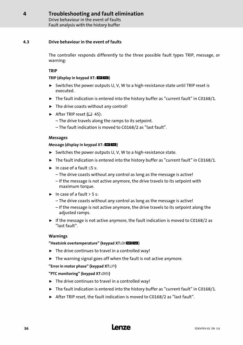
4.3 Drive behaviour in the event of faults
The controller responds differently to the three possible fault types TRIP, message, orwarning:
TRIP
TRIP (display in keypad XT: � �)
ƒ Switches the power outputs U, V, W to a high−resistance state until TRIP reset isexecuted.
ƒ The fault indication is entered into the history buffer as "current fault" in C0168/1.
ƒ The drive coasts without any control!
ƒ After TRIP reset (� 45):
– The drive travels along the ramps to its setpoint.
– The fault indication is moved to C0168/2 as "last fault".
Messages
Message (display in keypad XT: � �)
ƒ Switches the power outputs U, V, W to a high−resistance state.
ƒ The fault indication is entered into the history buffer as "current fault" in C0168/1.
ƒ In case of a fault �5 s:
– The drive coasts without any control as long as the message is active!
– If the message is not active anymore, the drive travels to its setpoint withmaximum torque.
ƒ In case of a fault > 5 s:
– The drive coasts without any control as long as the message is active!
– If the message is not active anymore, the drive travels to its setpoint along theadjusted ramps.
ƒ If the message is not active anymore, the fault indication is moved to C0168/2 as"last fault".
Warnings
"Heatsink overtemperature" (keypad XT:OH � �)
ƒ The drive continues to travel in a controlled way!
ƒ The warning signal goes off when the fault is not active anymore.
"Error in motor phase" (keypad XT:LP1)
"PTC monitoring" (keypad XT:OH51)
ƒ The drive continues to travel in a controlled way!
ƒ The fault indication is entered into the history buffer as "current fault" in C0168/1.
ƒ After TRIP reset, the fault indication is moved to C0168/2 as "last fault".

Troubleshooting and fault eliminationFault elimination
Drive errors
4
� 37EDKVF93−02 EN 3.0
4.4 Fault elimination
4.4.1 Drive errors
Malfunction Cause Remedy
An asynchronous motorwith feedback rotates in anuncontrolled manner andwith low speed
The motor phases are reversed so that the rotating fieldof the motor is not identical with the rotating field ofthe feedback system. The drive shows the followingbehaviour:� V/f characteristic control (C0006 = 5)
– The motor rotates faster than the speed setpoint bythe value set in C0074 (influence of the speedcontroller, Lenze setting 10 % of nmax). After thecontroller is enabled, it does not stop at zero speedsetpoint or quick stop (QSP).
– The final motor current depends, among otherthings, on the set value of the Vmin boost (C0016)and can rise to Imax (C0022). This may activate thefault message OC5.
� Vector control (C0006 = 1)– The motor rotates slowly with maximum slip speed
(depending on motor data and maximum current)and does not react to a speed setpoint. Thedirection of rotation, however, is determined bythe sign of the speed setpoint.
– The motor current rises up to Imax (C0022). Thismay activate the fault message OC5 with a timedelay.
� Check motor cable for correct phaserelation.
� If possible, operate the motor withdeactivated feedback (C0025 = 1) andcheck the direction of rotation of themotor.
Motor does not rotatealthough the controller isenabled (� is off) and aspeed setpoint has beenspecified.
The two terminal strips X5 are reversed. Since X5/A1 andX5/28 face each other, the controller can be enabled ifthe control terminals are internally supplied. All otherconnections, however, are assigned incorrectly so thatthe motor cannot start.
Check the position of the terminal strips:� If you look at the connection unit in
reading direction, the left terminalstrip X5 must be connected with theinput signals and the right terminalstrip X5 must be connected with theoutput signals.
The monitoring of themotor phases (LP1) doesnot respond if a motorphase is interrupted,although C0597 = 0 or 2
The function block MLP1 is not entered into theprocessing table.
Enter the function block MLP1 into theprocessing table. The function block MLP1requires 30 �s of calculating time.
If during high speedsDC−injection braking (GSB)is activated, the fault OC1(TRIP) or OU (TRIP) occurs
During DC−injection braking the controller sets pulseinhibit for a short time (DCTRL−IMP) to reduce themagnetisation in the motor before a DC voltage isinjected into the motor. At high speeds (e. g. in case ofmid−frequency motors) the residual voltage whichdevelops from the residual magnetism and high speedcan generate such a high motor current that OC1 or OUare activated.
Prolong the duration of the pulse inhibit:� Connect the output signal DCTRL−IMP
to the function block TRANSx andadjust the desired switch−off timethere (usually 500 ms). IfDCTRL−CINH1 is set to HIGH, theduration of the pulse inhibit isprolonged by the time adjusted.

Troubleshooting and fault eliminationFault eliminationController in clamp operation
4
� 38 EDKVF93−02 EN 3.0
4.4.2 Controller in clamp operation
The clamp operation is a permissible operating mode. But since, however, pulse inhibit isset again and again, the controller cannot provide the optimum power.
If the output power is optimal, the output current mainly is right below the clampthreshold.
9300vec110
Fig. 4−1 Output current when starting a motor with high load (shown with the oscilloscope in GDC)
� Clamp threshold
� Output current
Function
1. When the output current reaches 2.25 × Ir, a software clamp is activated.
2. The controller sets pulse inhibit for a short time. The motor current decreases as afunction of the inductance in the motor circuit.
– An internal counter is increased by the value one.
3. After max. 250 �s the pulse inhibit is deactivated.
4. If a software clamp reoccurs within 2 s, the internal counter is again increased by thevalue one. Otherwise the counter is set to zero.
– If the counter reaches the value 4300, OC3 (TRIP) is activated.

Troubleshooting and fault eliminationFault elimination
Behaviour in case of overvoltage in the DC bus (OU message)
4
� 39EDKVF93−02 EN 3.0
4.4.3 Behaviour in case of overvoltage in the DC bus (OU message)
Description
If the DC−bus voltage (UDC) exceeds the switch−off threshold OU, the pulse inhibit is set. Atthe same time, an internal timing element starts for a delay time (C0912).
The pulse inhibit is deactivated if the voltage falls below the switch−on threshold OU andthe delay time has elapsed.
Switching thresholds in case of overvoltage in the DC bus (OU):
Mains voltage range C0173 Switch−off threshold OU Switch−on threshold OU
< 400 V Operation with / withoutbrake chopper
0 770 V 755 V
400 V Operation with / withoutbrake chopper
1 * 770 V 755 V
460 V Operation with / withoutbrake chopper
2 770 V 755 V
480 V Operation without brakechopper
3 770 V 755 V
480 V Operation with brakechopper
4 800 V 785 V
* Lenze setting
Codes for parameter setting
Code Possible settings IMPORTANT
No. Name Lenze Selection
C0912 OV delay time � − {1 ms} − Delay time of the pulse enable afteran OU message� Depending on C0082, C0086,
C0087, C0088, C0089, C0090,C0091, C0092A change of one of the codesresets C0912 to the time of theselected motor
� The time is derived from thedouble rotor time constant

Troubleshooting and fault eliminationSystem error messagesGeneral error messages
4
� 40 EDKVF93−02 EN 3.0
Adjustment
UDC
t C0912�
t < C0912
t = C0912
�
�
� �
IMP
9300vec142
Fig. 4−2 Influence of the delay time (C0912)
� Switch−off threshold OU� Switch−on threshold OU� The period of time between exceeding the switch−off threshold OU and undershooting the
switch−on threshold OU equals or is higher than the delay time set in C0912.
After undershooting the switch−on threshold OU, the pulse inhibit is deactivated.
� The period of time between exceeding the switch−off threshold OU and undershooting theswitch−on threshold OU is lower than the delay time set in C0912.
The pulse inhibit is deactivated after the delay time in C0912 has elapsed.
ƒ The delay time in [ms] is set under C0912. The Lenze setting can be changed by thefactor 0.5 ... 2.
4.5 System error messages
4.5.1 General error messages
� Note!
In the case of a query via system bus (CAN), the fault messages arerepresented as numbers (see first column of the table).

Troubleshooting and fault eliminationSystem error messages
General error messages
4
� 41EDKVF93−02 EN 3.0
Fault message Description Cause Remedy
No. Display
−−− −−− No fault − −
0011 OC1 Overcurrent in motor cable(Ia > 2.25 x IN; Hardwaremonitoring)
In the event of a short circuit � Search for the cause of theshort circuit.
� Check the motor cable.
Capacitive charging current of themotor cable is too high
Use motor cable which is shorteror of lower capacitance
Too short acceleration ordeceleration times in proportionto the load (C0012, C0013, C0105)
� Increase the gain (Pcomponent) of the Imaxcontroller (C0075).
� Reduce integral−action time(integral action component) ofthe Imax controller (C0076)
The drive is connected to thecoasting machine. The coasting iscaused by a short−time pulseinhibit, e.g. at� OU (overvoltage in the DC bus)� external or internal controller
inhibit
� Activate flying restart circuit
� Encoder error� Tracks during encoder
feedback of the motor speedare interchanged
Check wiring of the encoder
DC−injection braking at highspeeds
� See � 37
Missing mains phase � Check the connections and thesupply cable of the device
� Check mains voltage
0012 OC2 Motor cable earth fault One of the motor phases hasearth contact.
� Search for cause of shortcircuit.
� Check motor cable.
0013 OC3 Overload during acceleration. Too short acceleration ordeceleration times in proportionto the load (C0012, C0013,C0105).
� Increase the gain (Pcomponent) of the currentcontroller (C0075).
� Reduce the reset time (integralaction component) of the Imaxcontroller (C0076).
� Increase ramp times.� � 38, "controller in clamp
operation (fault OC3)"
0015 OC5 I x t overload � Frequent and too longacceleration with overcurrent
� Continuous overload withImotor > 1.05 x Irx.
Check drive dimensioning.
0016 OC6 I2xt overload � Frequent and too longacceleration processes withmotor overcurrent.
� Permanent motor overloadwith Imotor>Irmotor
Check drive dimensioning.
x018 OC8 I2xt overload advance warning � Frequent and too longacceleration processes withmotor overcurrent.
� Permanent motor overloadwith Imotor>Irmotor
Check drive dimensioning.
2020 OU Overvoltage in the DC bus Braking energy is too high.(DC−bus voltage is higher than setin C0173.)
� Use a braking unit orregenerative module.
� Check dimensioning of thebrake resistor.
1030 LU Undervoltage in the DC bus DC bus voltage is lower thanspecified in C0173.
� Check mains voltage� Check supply cable

Troubleshooting and fault eliminationSystem error messagesGeneral error messages
4
� 42 EDKVF93−02 EN 3.0
RemedyCauseDescriptionFault message RemedyCauseDescription
DisplayNo.
x032 LP1 Motor phase failure A current−carrying motor phasehas failed.
� Check motor.� Check motor cable.� Switch off monitoring
(C0597 = 3).
The current limit value is set toolow.
� Set higher current limit valuevia C0599.
0050 OH Heatsink temperature > +90 C Ambient temperatureTu > +40 C or > +50 C
� Allow module to cool andensure better ventilation.
� Check ambient temperature inthe control cabinet.
Heatsink is very dirty. Clean heatsink.
Wrong mounting position Change mounting position.
x053 OH3 Motor temperature> +150 C threshold(temperature detection viaresolver or incremental valueencoder)
Motor is thermally overloadeddue to:� Impermissible continuous
current� Frequent or too long
acceleration processes
� Check drive dimensioning.� Switch off monitoring
(C0583 = 3).
No PTC/temperature contactconnected.
Correct wiring.
x054 OH4 Heatsink temperature > C0122 Ambient temperature Tu > +40 Cor > +50 C
� Allow module to cool andensure better ventilation.
� Check ambient temperature inthe control cabinet.
� Switch off monitoring(C0582 = 3).
Heatsink is very dirty. Clean heatsink
Wrong mounting position Change mounting position.
The value specified under C0122is set too low.
Enter a higher value under C0122.
x057 OH7 Motor temperature > C0121(temperature detection viaresolver or incremental valueencoder)
Motor is thermally overloadeddue to:� Impermissible continuous
current� Frequent or too long
acceleration processes
� Check drive dimensioning.� Switch off monitoring
(C0584 = 3).
No PTC/temperature contactconnected.
Correct wiring.
The value specified under C0121is set too low.
Enter a higher value in C0121.
x058 OH8 Motor temperature via inputs T1and T2 is too high.
Motor is thermally overloadeddue to:� Impermissible continuous
current� Frequent or too long
acceleration processes
� Check drive dimensioning.� Switch off monitoring
(C0585 = 3).
Terminals T1 and T2 are notconnected
Connect PTC/temperaturecontact.
x061 CE0 Automation interface (AIF)communication error
Faulty transfer of controlcommands via AIF.
� Plug in the communicationmodule/keypad XT firmly,screw down, if necessary.
� Switch off monitoring(C0126 = 3).

Troubleshooting and fault eliminationSystem error messages
General error messages
4
� 43EDKVF93−02 EN 3.0
RemedyCauseDescriptionFault message RemedyCauseDescription
DisplayNo.
x062 CE1 Communication error on theprocess data input objectCAN1_IN
CAN1_IN object receives faultydata or communication isinterrupted.
� Check wiring at X4.� Check sender.� Increase monitoring time
under C0357/1, if necessary.� Switch off monitoring
(C0591 = 3).
x063 CE2 Communication error on theprocess data input objectCAN2_IN
CAN2_IN object receives faultydata or communication isinterrupted.
� Check wiring at X4.� Check sender.� Increase monitoring time
under C0357/2, if necessary.� Switch off monitoring
(C0592 = 3).
x064 CE3 Communication error on theprocess data input objectCAN3_IN
CAN3_IN object receives faultydata or communication isinterrupted.
� Check wiring at X4.� Check sender.� Increase monitoring time
under C0357/3, if necessary.� Switch off monitoring
(C0593 = 3).
x065 CE4 BUS−OFF state of system bus(CAN)
The controller has received toomany faulty telegrams via thesystem bus (CAN) and hasdisconnected from the bus.
� Check wiring at X4: Is the buscorrectly terminated?
� Check shield connection of thecables.
� Check PE connection.� Check bus load, reduce the
baud rate if necessary.(Observe the cable length!)
� Switch off the monitoring(C0595 = 3).
0071 CCr System failure Strong interference injection onthe control cables
Screen control cables
Ground or earth loops in thewiring
� Check wiring� Check PE connection
After troubleshooting: Deenergisethe device completely (disconnect24 V supply, discharge DC bus)!
0072 PR1 Checksum error in parameterset 1CAUTION: The Lenze setting isloaded automatically!
� Fault when loading aparameter set.
� Interruption whiletransmitting the parameter setvia keypad.
� Set the required parametersand store them under C0003 =1.
� As to PLC devices, check theuse of pointers.
The stored parameters areincompatible with the loadedsoftware version.
Store the parameter set underC0003 = 1 first to allow for afaults reset.
0073 PR2 Checksum error in parameterset 2PLEASE NOTE: The Lenze setting isloaded automatically!
� Fault while loading aparameter set.
� Interruption during thetransfer of the parameter setvia keypad.
� Set the required parametersand save them with C0003 = 2.
The parameters saved do notcomply with the software versionloaded.
In order to be able toacknowledge the error, first savethe parameter set with C0003 = 2.

Troubleshooting and fault eliminationSystem error messagesGeneral error messages
4
� 44 EDKVF93−02 EN 3.0
RemedyCauseDescriptionFault message RemedyCauseDescription
DisplayNo.
0074 PEr Program error Error in the program flow Send the parameter set (on floppydisk/CD−ROM) with a detaileddescription of the problem toLenze.After troubleshooting: Deenergisethe device completely (disconnect24 V supply, discharge DC bus)!
0075 PR0 Error in parameter set. The operating system softwarehas been updated.
Storage of the Lenze settingC0003 = 1.
After troubleshooting: Deenergisethe device completely (disconnect24 V supply, discharge DC bus)!
0077 PR3 Checksum error in parameterset 3PLEASE NOTE: The Lenze setting isloaded automatically!
� Fault while loading aparameter set.
� Interruption during thetransfer of the parameter setvia keypad.
� Set the required parametersand save them with C0003 = 3.
The parameters saved do notcomply with the software versionloaded.
In order to be able toacknowledge the error, first savethe parameter set with C0003 = 3.
0078 PR4 Checksum error in parameterset 4PLEASE NOTE: The Lenze setting isloaded automatically!
� Fault while loading aparameter set.
� Interruption during thetransfer of the parameter setvia keypad.
� Set the required parametersand save them with C0003 = 4.
The parameters saved do notcomply with the software versionloaded.
In order to be able toacknowledge the error, first savethe parameter set with C0003 = 4.
0079 PI Fault during parameterinitialisation
� An error has been detectedduring the parameter settransfer between two devices.
� The parameter set does notmatch the controller, e.g. ifdata has been transferred froma higher−power controller to alower−power controller.
� Correct parameter set.� Send parameter set (on floppy
disk/CD−ROM) and a detaileddescription of the problem toLenze.
x083 Sd3 Encoder error at X9 Cable interrupted. Check cable for open circuit.
Pin X9/8 not connected. Apply 5 V to pin X9/8 or switch offmonitoring (C0587 = 3).
x085 Sd5 Encoder error at X6/1 and X6/2(C0034 = 1)
Current signal at X6/1 X6/2 <2mA.
� Check cable for open circuit.� Check current signal encoder.� Switch off monitoring
(C0598 = 3).
x086 Sd6 Motor temperature sensor error(X7 or X8)
Encoder for detecting the motortemperature at X7 or X8 indicatesundefined values.
� Check cable for firmconnection.
� Switch off the monitoring(C0594 = 3).
x091 EEr External monitoring has beentriggered via DCTRL.
A digital signal assigned to theTRIP−SET function has beenactivated.
� Check external encoder.� Switch off the monitoring
(C0581 = 3).
0105 H05 Internal fault (memory) Contact Lenze.
0107 H07 Internal fault (power stage) During initialisation of thecontroller, an incorrect powerstage was detected.
Contact Lenze.
x110 H10 Heatsink temperature sensorerror
Sensor for detecting the heatsinktemperature indicates undefinedvalues.
� Contact Lenze.� Switch off the monitoring
(C0588 = 3).
x111 H11 Temperature sensor error:Temperature inside the controller
Sensor for detecting the internaltemperature indicates undefinedvalues.
� Contact Lenze.� Switch off the monitoring
(C0588 = 3).

Troubleshooting and fault eliminationSystem error messages
Resetting system error messages
4
� 45EDKVF93−02 EN 3.0
RemedyCauseDescriptionFault message RemedyCauseDescription
DisplayNo.
0140 ID1 Error during motor dataidentification.
No motor connected. Check motor connection.
Stator resistance too high. Check entered motor data.
Controller inhibited externally. Enable controller and repeatmotor data identification. Thecontroller enable must bepending continuously until theend of the identification process.
0141 ID2 Error during motor dataidentification.
Motor too small. � Check entered motor data. Forparameterisation with GlobalDrive Control, use the inputassistant for motor data.
� The measurements for theinverter error characteristicand the stator resistance arecorrect (save measured valuesin C0003). For the operatingmode V/f characteristic controlthe motor data identificationcan be completed.
Controller inhibited externally. Enable controller and repeatmotor data identification. Thecontroller enable must bepending continuously until theend of the identification process.
x200 NMAX Maximum system speed (C0596)has been exceeded.
� Active load (e.g. for hoists) istoo high.
� Drive is not speed−controlled,torque is excessively limited.
� Check drive dimensioning.� Increase torque limit, if
necessary.� Switch off monitoring
(C0607 = 3).
Representation of the error number:x 0 = TRIP, 1 = message, 2 = warning
E. g. "2091": An external monitoring function has triggered EEr warning
4.5.2 Resetting system error messages
Response Measures for resetting the fault message
TRIP Note!If a TRIP source is still active, the pending TRIP cannot be reset.
Resetting the TRIP can be effected by:� Pressing the keypad XT EMZ9371 BC � %. Then press $ to re−enable the controller.� Setting code C0043 = 0.� Control word C0135, bit 11� Control word AIF� Control word of system bus (CAN)After resetting the TRIP, the drive remains at standstill.
Message Danger!After elimination of the fault, the fault message is cancelled automatically and the drive restartsautomatically.
Warning After elimination of the fault, the fault message is cancelled automatically.

& '© 11/2013
� Lenze Automation GmbHHans−Lenze−Str. 1D−31855 AerzenGermany
Service Lenze Service GmbHBreslauer Straße 3D−32699 ExtertalGermany
+49�(0)51 54 /�82−0 00�80�00�/ 24�4�68�77 (24 h helpline)
� +49�(0)51 54 /�82 − 28 00 � +49�(0)51�54�/ 82−11 12
� [email protected] � [email protected]
� www.Lenze.com
EDKVF93−02 .MUw EN 3.0 TD06
10 9 8 7 6 5 4 3 2 1