Not all thin-section bearings are created equal KAYDON … · thin-section bearings are created...
21
Not all thin-section bearings are created equal KAYDON new capacity calculations Robert Roos, Scott Hansen A white paper from KAYDON ® Corporation Bearings Division
-
Upload
hoangduong -
Category
Documents
-
view
215 -
download
1
Transcript of Not all thin-section bearings are created equal KAYDON … · thin-section bearings are created...

Not all thin-section bearings are created equal
KAYDON new capacity calculationsRobert Roos, Scott Hansen
A white paper from KAYDON® Corporation Bearings Division

2
Table of Contents
Abstract ....................................................................................................... pg. 3
Introduction.................................................................................................. pg. 4
Objective...................................................................................................... pg. 7
Literature Review......................................................................................... pg. 8
Test ProcedurePreparation............................................................................................. pg. 12Starting Test........................................................................................... pg. 13Stopping Test ......................................................................................... pg. 13
New Kaydon Capacity Equations ................................................................ pg. 16
Derivation of Constants:The Stress Constant............................................................................... pg. 18The Ball Load Distribution Factor ........................................................... pg. 19The Rows Exponent ............................................................................... pg. 19The Stress Factor ( ) ............................................................................ pg. 19
Four Point Contact Bearing Test Results..................................................... pg. 20
Conclusions ................................................................................................. pg. 20
References .................................................................................................. pg. 21

3
Abstract: ABMA standard 9 and ISO 281 give equations for calculating the “BasicDynamic Radial Load Rating” for ball bearings. These equations are based on anumber of assumptions. Many of these assumptions are not valid for “Thin-Section”bearings. (Thin-Section bearings are described in ABMA standard 26.2). Nevertheless,many “Thin-Section” bearing catalogs report load ratings based on these equations.
Kaydon has developed a new method for calculating the Dynamic Radial Load Ratingfor “Thin-Section” ball bearings. The new method uses the contact stress and thenumber of stress cycles per revolution to calculate the capacity. The new numbers arebased on five years of actual test results. These equations can also be used tocalculate the “Dynamic Radial Load Rating” for Four-Point contact ball bearings, whichare not covered in standard 9 or ISO 281.

4
INTRODUCTION
The year was 1944 and the problem that needed to be solved required a new bearing tobe developed. The US Government contacted Kaydon Engineering Corporation toengineer and build a light-weight, thin-section ball bearing for a ball gun turret to beused on an aircraft. This bearing became the inspiration for a catalog line of thin-sectionball bearings known today as REALI-SLIM®.
In many applications, shafts supported by bearings are lightly loaded. Shaft positionwith respect to the housing or other components is critical. These designs do not needbig, heavy bearings and can be supported adequately by thinner bearing racesmanufactured to close tolerances. Kaydon had identified a need for a bearing that wascapable of saving space in designs and reducing overall weight. Thinner bearing racesand cross sections allowed designers to also reduce the size and mass of the shaftsand housings for even greater space and weight savings.
When is a bearing thin-section? Rolling element bearing dimensions have beenstandardized by the ABMA so that for a given bore diameter, bearings aremanufactured with different outside diameters. For a given outside diameter bearingsare made in different widths. Therefore, each bearing belongs to a dimension series thatcan be designated by diameter and width.
For a conventional series of ball bearings, radial cross section and ball diametertypically increase with bore diameter. Therefore, an increase in bearing weight issignificant as bore diameter increases. The graph in Figure 1 compares conventionalbearings with thin-section bearings illustrating this change in radial cross section withbore diameter.
Bearing weight can be reduced with thin-section bearings because for a given series ofbearings, radial cross section and ball size remain constant. Generally, a bearing isconsidered to have a thin-section when:
Radial cross section is less than one fourth the bore diameter. Radial cross section is less than twice the rolling element diameter.

5
Figure 1
Benchmarking and Fatigue Life Testing
As the world’s inventor and largest producer of thin-section ball bearings, KaydonBearings has devised methods for testing the fatigue life of REALI-SLIM® bearings.Daily testing of production product has continued for almost 40 years. The testingmethod is addressed in the section of this paper titled “PROCEDURE FOR TESTINGFATIGUE LIFE OF REALI-SLIM® BALL BEARINGS”. Along with testing of Kaydonproduced REALI-SLIM® bearings we have also benchmarked most major knownproducers of thin-section ball bearings by subjecting their catalog equivalent bearingspurchased through distribution to the same testing procedure.

6
TABLE A
Kaydon REALI-SLIM® ball bearings outperform all thin-section ball bearings life tested todate (see TABLE A). Armed with this information, we set out to prove or disprove theABMA / ISO calculations for life. Our findings are listed in the following report in thesection titled “NEW KAYDON THIN-SECTION BALL BEARING CAPACITYCALCULATIONS”.
It is also important when comparing “catalog” bearings that appear to have the same orsimilar part number that all thin-section bearing are not created equal. There can bemajor differences in things that cannot easily be seen that can cause devastatingreductions in bearing life and performance. Here is a short list of those differences:
Ball grade Race and ball material and microstructure Hardness of balls and races Ball and ball path surface finish Method of manufacture grinding and hone of ball track (some thin-section
bearing manufacturers only hard turn ball paths Curvature, race curvature Runouts: radial, axial Cleaning process Residual magnetism Cold temperature stabilization of races and balls Retained austenite
BASE CATALOG ACTUAL
TEST PART B10 EQUIVALENT CATALOG CAPACITY B10 FATIGUE
REPORT NUMBER MANUFACTURER LIFE CAPACITY CAPACITY COMPARISON PERFORMANCE
(hours) (lbs) (lbs)
RP545 KC040CP0 Kaydon 76.0 1,059 880 +20% +73%
RP487 KC040CP0 Kaydon 71.2 1,036 880 +18% +64%
RP582 KC040CP0 Competitor ( A ) 23.2 713 1290 -45% -83%
RP487 KC040CP0 Competitor ( B ) 12.5 580 884 -34% -72%
RP534 NC040CP0 Kaydon 59.9 978 880 +11% +36%
RP529 NC040CP0 Kaydon 120.4 1234 880 +40% +174%
RP584 NC040CP0 Competitor ( C ) 19.1 668 1290 -48% -87%

7
OBJECTIVE
The purpose of this study is to develop a new set of equations for calculating thedynamic capacity of REALI-SLIM® bearings. The new equations must be supported byboth theory and actual test results.

8
LITERATURE REVIEW
Many thin-section ball bearing competitors calculate capacity using the methods foundin ABMA standard 9, or in ISO-281. These standards define the term “Basic DynamicRadial Load Rating” which is synonymous with Kaydon definition of “Dynamic Capacity”.The Basic Dynamic Radial Load Rating (Cr) is defined as:
“That constant radial load which a bearing could theoretically endure for abasic rating life of one million revolutions.”
These standards also define the L10 bearing fatigue life as:“The basic rating life in millions of revolutions for 90% reliability”
The L10 life is then calculated from the Load Rating (Cr) using equation 1. Please notethat the “Basic Dynamic Radial Load Rating”, as defined in these two standards, is notthe maximum operating load for the bearing. It is simply a constant used in the lifeequation. It is often greater than the “Static” radial load rating (Cor). Loading thebearing beyond the “Static” rating will cause permanent deformation or “Brinelling”.Both standards state:
“The life formula gives satisfactory results for a broad range of bearingloads. However . . . The user should consult the bearing manufacturer toestablish the applicability of the life formula in cases where (the appliedload) Pr exceeds (the static capacity) Cor or (1/2 the dynamic rating) 0.5 Cr,whichever is smaller.”
Eg. 1
3
10=
r
r
P
CL million revolutions ...................... ISO 281 par 5.3.1
These two standards give the following equations for calculating the “Basic DynamicLoad Rating” (Cr):
8.13/27.0)cos( bcmr DZifbC = for ball size (Db) 1 inch.
Eg. 2 ISO 281 par 5.18.13/27.0)cos(647.3 bcmr DZifbC = for ball size (Db) >1 inch
where:L10 = The basic life rating in millions revolutions for 90% reliabilityCr = Basic Dynamic Radial Load Ratingbm = Material factor for contemporary steels (bm = 1.3)fc = Geometry factor from tablesi = Number of rows
a = Contact angle
Z = Number of balls per rowDb = Ball DiameterPr = Applied radial load.
9
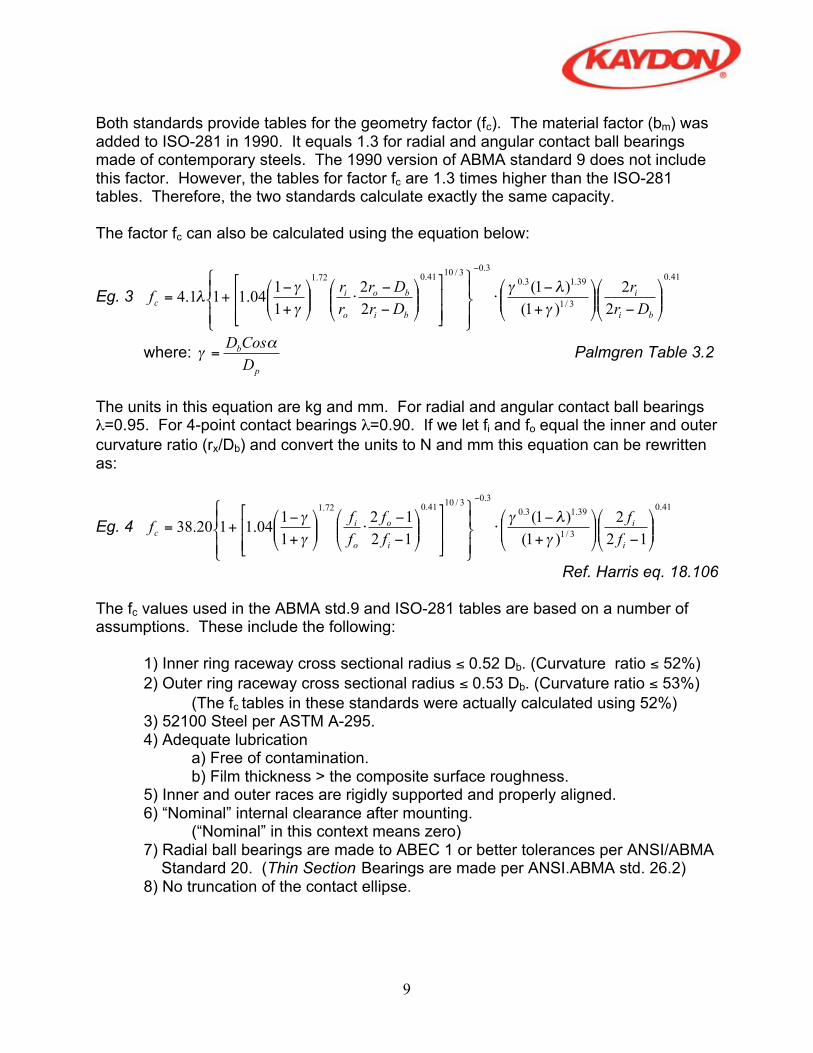
Both standards provide tables for the geometry factor (fc). The material factor (bm) wasadded to ISO-281 in 1990. It equals 1.3 for radial and angular contact ball bearingsmade of contemporary steels. The 1990 version of ABMA standard 9 does not includethis factor. However, the tables for factor fc are 1.3 times higher than the ISO-281tables. Therefore, the two standards calculate exactly the same capacity.
The factor fc can also be calculated using the equation below:
Eg. 3
41.0
3/1
39.13.0
3.03/10
41.072.1
2
2
)1(
)1(
2
2
1
104.111.4
+++=
bi
i
bi
bo
o
ic
Dr
r
Dr
Dr
r
rf
where: p
b
D
CosD= Palmgren Table 3.2
The units in this equation are kg and mm. For radial and angular contact ball bearings=0.95. For 4-point contact bearings =0.90. If we let fi and fo equal the inner and outer
curvature ratio (rx/Db) and convert the units to N and mm this equation can be rewrittenas:
Eg. 4
41.0
3/1
39.13.0
3.03/10
41.072.1
12
2
)1(
)1(
12
12
1
104.1120.38
+++=
i
i
i
o
o
ic
f
f
f
f
f
ff
Ref. Harris eq. 18.106
The fc values used in the ABMA std.9 and ISO-281 tables are based on a number ofassumptions. These include the following:
1) Inner ring raceway cross sectional radius 0.52 Db. (Curvature ratio 52%)
2) Outer ring raceway cross sectional radius 0.53 Db. (Curvature ratio 53%)
(The fc tables in these standards were actually calculated using 52%)
3) 52100 Steel per ASTM A-295.4) Adequate lubrication
a) Free of contamination.b) Film thickness > the composite surface roughness.
5) Inner and outer races are rigidly supported and properly aligned.6) “Nominal” internal clearance after mounting.
(“Nominal” in this context means zero)7) Radial ball bearings are made to ABEC 1 or better tolerances per ANSI/ABMA Standard 20. (Thin Section Bearings are made per ANSI.ABMA std. 26.2)8) No truncation of the contact ellipse.

10
Kaydon does not use these equations to calculate Dynamic Capacity because most ofthese assumptions are not valid for “Thin Section” bearings. They were never intendedfor “Thin Section” bearings. Most importantly, the life calculated using these equationsis not supported by Kaydon testing. Nevertheless, many Kaydon competitors use theseequations anyway. (See table 1.)
Part No. KAA10CL0 KA020CP0 KC040CP0 KF080CP0 KA120CP0 KG120CP0 KG400CP0
Kaydon Catalog 150 320 880 4100 980 8510 18,310
ISO/ABMA 1990 fc Tables: 558 1012 2321 8081 1904 14,133 21,630 1978 fc Tables: 430 778 1785 6216 1465 10,872 16,638
Calculated fc: 1990: 379 701 1656 6363 1319 11,766 18,006 1978: 291 539 1274 4895 1015 9,050 13,851
INA(1)
558 1012 2316 8094 14,164 21,582
NSK(1)
558 1012 2316 8094 14,164
RBC(2)
300 560 1290 5140 1060 10,690 16,230
SKF(1)
555 1009 2338 8049 1915 14,029 21,493
(1) INA, NSK and SKF all use the ABMA/ISO ratings taking fc directly from the tables without adjusting for
the curvature ratio or diametral clearance.(2)
RBC numbers appear to adjust for curvature, but not clearance.Table 1 – Comparative Capacities
According to the old Kaydon capacity equations, the dynamic capacity of a KC040CP0is 884 lbs. Under a radial load of 525 lbs, the predicted L10 life at 1780 RPM is 44.7 hrs.If the capacity is calculated using the 1978 ABMA/ISO equations, with fc calculatedusing equation 4, rather then the using the tables, the capacity should be 1274 lbs. Thisgives a life of 133.8 hours. The actual average L10 life for these bearings over the last 5years has been 80.2 hours. The actual life is almost double the life predicted by the oldKaydon equations, but “apparently” less than predicted by the ABMA/ISO equations.
Figure 1 – Ball load Distribution

11
However, we know that life under a radial load decreases as the clearance increases.This is because fewer balls carry the radial load. (See figure 1) The theoretical L10 lifewas calculated for the KC040CP0 bearing under a 525 lb. load at 1780 RPM wasplotted for various amounts of diametrical clearance. The life calculations use theABMA/ISO capacity, (adjusted for curvature) in the life prediction. As shown in figure 2,the actual measured L10 life falls very close to the predicted values when clearance isconsidered.
KC040XP0Calculated Life vs Diametral Clearance Under 525 lb Radial Load
0
50
100
150
200
250
300
350
400
450
500
-0.0010 -0.0005 0.0000 0.0005 0.0010 0.0015 0.0020 0.0025 0.0030
Diametral Clearance (Inch)
Lif
e (
hrs
.)
KC040CP0
Kaydon Test Data
Catalog 300 Life
KC040XP0
DC Tolerance
Figure 2 – Life vs. Diametral Clearance
In summary, Kaydon life testing does support the use of the ABMA/ISO (1978) capacityvalues, when curvature and clearance are considered. It does not support the modernmaterials factor (bm) that was added in 1990. However, it is important that theassumptions behind these equations are understood.
The purpose of a published capacity is to allow the customer to use a quick (Cr/Pr)3
equation to estimate life. The ABMA/ISO equations are not adequate for this purposebecause they don’t consider the curvature or clearance in the “Basic Dynamic LoadRating.” Therefore, alternate methods must be used to calculate the published ratingsfor these bearings.

12
PROCEDURE FOR TESTING FATIGUE LIFE
OF REALI-SLIM® BALL BEARINGS
PREPARATION
Test Parameters
The test parameters (i.e. load and speed) must first be calculated. These are selected tocause the bearings to fail by fatigue in a reasonable time period (typically less than 100hours), while not subjecting the bearing to excessive loads. Testing speed is 1,780 rpm.
The desired radial load to be applied is found from the formula:
Lh = (16,667/S) x (C / P)3
or
P = C / [ (S x Lh / 16,667 )1/3
]
Where Lh is the L10 life in hours under the test conditionsC is the Dynamic Load Rating for the bearing (from a catalog or calculation)P is the Applied Radial LoadS is the Speed of the bearing under test, in RPM.
Applied test loads are normally selected to be approx 60% or less of the Dynamic RadialLoad Rating.
Bearings to be tested should be randomly selected from the identified lot. At least 20pieces should be used for each test. Each bearing should be identified with a uniquereference number.
Bearings must be cleaned as assemblies prior to test, by mechanical agitation in mineralspirits for at least five (5) minutes.
Each bearing is mounted in suitable housings, making witness marks to indicateorientation in housings, and then mounted on a driven spindle with the axis horizontal.(See Figure 1).

13
A steel load strap is then attached to outer race, then connected to an air cylinderarranged to apply radial load to the bearing. The centerline of the air cylinder, the steelstrap, and the lower tooling should all be in the same plane as the bearing centerline.
The force exerted by the load cylinder is measured by a portable load cell and digitalindicator. The air pressure to the load cylinder is adjusted to produce the desired radialload on the bearing. NOTE: In calculating the total radial load on the bearing, the weightof the tooling must also be considered.
An accelerometer is mounted on top of the stationary housing with radial orientation, andis connected to the automatic monitoring equipment.
The circulating oil system is checked for adequate oil level, and to ensure that filterreplacement is not overdue.
STARTING TEST
Circulating oil to lubricate the test bearing should be connected and turned on. Thecooling water to the oil heat exchangers must also be turned on. Air to the load cylindershould be left “Off.”
The drive motor is “jogged” to ensure that no components are loose and that there is nounwanted interference between the rotating and stationary parts. The motor is thenturned on, and the reading (in hours and tenths) of the elapsed time meter is noted. Alltest notes are recorded on the Test Data Collection Sheet.
Oil flow to the bearing is adjusted to be as high as possible without causing excessivefoaming or leakage from bearing housing. Oil flowing to each bearing should not exceeda temperature of 130 °F. Air to the load cylinder should now be turned “On.”
The baseline radial vibration is measured. The auto shut-off system should then be setfor this baseline vibration level, so that automatic shut-down occurs when vibrationincreases to 150% of baseline level.
STOPPING TEST
When bearing failure is suspected, either due to audible noise or auto shut-off, thebearing rotation is stopped, and the bearing is disassembled and inspected.
If no visible signs of spalling or other failure are found on the balls/rollers or race paths,the bearing is reassembled and remounted in the test housings, noting the orientation ofwitness marks. The testing is then resumed (with the automatic shut-down system,baseline vibration level reset if necessary).

14
If spalling is found, the hour meter reading is noted and the elapsed time is calculated.Also, the location and degree of spalling is noted, and then the bearing components arebagged, identified and saved.
After all bearings in the test have been run to failure, the elapsed times are entered intothe Kaydon Weibull analysis software program. This program establishes the best-fitWeibull line for the data, calculates the slope and scale parameters, and determines theL10 fatigue life for the sample group.
The L10 value obtained from the Weibull program is then compared to the theoretical L10
fatigue life at the tested load and speed. If the observed L10 value does not meet orexceed the theoretical L10 value, an investigation should be conducted into possible rootcauses.
The Weibull slope parameter gives an indication of the degree of scatter of test results.For through-hardened AISI 52100 bearing steel races, a Weibull slope value in the range1.0 – 1.5 is to be expected, with a lower value indicating a greater degree of fatigue lifedispersion, and a higher value indicating less scatter.
At least one failed bearing race should be sectioned and mounted, through a failed area(spall). At a minimum the following metallurgical properties should be evaluated andrecorded:
hardness grain size steel cleanliness carbide networking

15
FIGURE 1

16
RESULTS: NEW KAYDON CAPACITY EQUATIONS
A) Dynamic Radial Capacity (Cr)
The new Kaydon capacity calculations are based on the contact stress and the number ofstress cycles at the highest loaded point in the stationary race. ABMA and ISOcalculations assume that the inner race is rotating and the outer race is stationary.Therefore, the highest loaded point on the outer race is always in the same spot. Theinner race may actually have a higher contact stress, but the load is distributed over theentire circumference. The dynamic capacity is calculated from the basic life equation, asshown in equations 1 and 5 below.
Eg. 16
3
1010=
P
CL
r
(revolutions.)
Eg. 5
3
1
3
1
3
1
3
1
100100
10
/10
10
7.
6
8
6
10 ====fS
CosZiQ
fP
fP
LPC maz
rrrr (lbs.)
where:Cr The basic dynamic load rating (Dynamic Capacity)Pr The radial load for a life of 108 stress cycles.L10 The number of revolutions for 108 stress cycles.f The number of stress cycles per revolution.Qmax The normal ball load on the highest loaded ball for 108 stress cycles.Z The number of balls per row.i The number of rows of contact.
The contact angle.
S The ball load distribution factor.The stress factor: =1 for Angular (A) and Radial (C) contact bearings and
=(.9/.95) for Four Point (X) contact bearings.
The factor Qmax is the normal ball load that gives a mean contact stress of 262,500 psi, inthe outer race. This is the stress value associated with 108 stress cycles. This stressvalue was determined experimentally in Kaydon laboratory testing. The L10 lifein revolutions is then calculated by dividing the number of stress cycles (108) by thenumber of stress cycles per revolution (f) which is calculated using equation 3, below.
Stress Cycles Per Revolution:
Eg. 6 = cos12 P
b
D
DZf .................................. ref. Harris eq. 25.14

17
The relationship between max ball load (Qmax) and applied radial load (Pr) is calculatedusing the “Stribeck” equation, shown in equation 4 below. The constant “S” is the loaddistribution factor. For bearings with zero diametral clearance S equals 4.37. Forbearings with “nominal” clearance, an approximate value of 5 is often used for S.
Eg. 7S
ZQPr
cosmax= .................................... ref. Harris eqs. 6.23/6.24
However, in reality, S varies with both diametral clearance and applied loads. For“REALI-SLIM® bearings, the diametral clearance increases with the nominal diameter.Therefore the factor S also increases with diameter. The value of S, used in the newKaydon capacity equations varies with the pitch diameter. It assumes that a nominalamount of diametral clearance remains in the bearing after installation. It is calculatedusing the equation 5, below.
Equation for ball distribution factor:
Eg. 8 S = .027Dp + 5.260
It takes 4 steps to calculate the new dynamic radial capacity. These are detailed below.
Step 1: The first step in calculating the capacity is to calculate the normal ball load (Qmax)that gives an outer race mean contact stress of 262,500 psi. This is calculated using thestandard stress equations. This gives the ball load capacity for 108 stress cycles.
Step 2: The next step is to calculate the ball distribution factor (S) from equation 8.
Step 3: The number of stress cycles per revolution is then calculated using equation 6.
Step 4: Once the max normal ball load, the distribution factor, and the number of stresscycles per revolution are known, the radial capacity can be calculated using equation 5.

18
DERIVATION OF CONSTANTS
A) The Stress Constant:
The 262,500 PSI contact stress constant used in these equations comes from Kaydonlaboratory life testing of KC040CP0 bearings. The L10 life in hours for a ball bearing isgiven by equation 12 below.
Eg. 12 •=NP
CL
r667,16
3
10 hours
Under a radial load of 525 lbs, at a speed of 1780 RPM, the L10 life of a KC040CP0bearing over the last 5 years has averaged 80.2 hours. By solving the life equation (Eg.12) for Cr, the new dynamic rating for the KC040CP0 becomes 1073 lbs.
Eg. 13 107316667
178080525
16667
3/13/1
10 ===NL
PCr lbs.
Under a radial load of 1073 lbs, and an estimated installed clearance of .0016 inch, themaximum ball load is 164.84 lbs. Solving equation 7 for S gives a load distribution factorof 5.3769. (See attachment 1)
Ref. Eg. 7 3769.51073
)1)(35)(84.164(cosmax ===rP
ZQS
The number of stress cycles per revolution is calculated using equation 6, and equals16.75 for the KC040CP0, as shown below. This means that there are 16.75 millionstress cycles per million revolutions.
Ref. Eg. 6 75.16375.4
1875.1
2
35cos1
2===
P
b
D
DZf
We can then calculate the normal ball load for an L10 life of 100 million (108) stress cyclesusing equation 5. The normal ball load for a fatigue life of 108 stress cycles equals 90.87lbs. as shown below.
Ref. Eg. 5
3
13
1
75.16
100
3769.5
351073
100max===Q
fS
ZCosQC mazr or Qmax = 90.87 lbs.
For a normal ball load of 90.87, the mean contact stress in a KC040CP0 outer race is262,500 PSI.

19
B) The Ball Load Distribution Factor (S):
For the KC040CP0 bearing under an applied load of 1073 lbs, and an assumed clearanceafter installation of .0016 inch, the ball load distribution factor (S) was calculated to be5.3769.
For the KG400CP0, an outer race stress of 262,500 PSI, corresponds to a normal ballload of 801.23 lbs. The stress cycles per revolution (f ) for this bearing equal 60.75. Asshown in equation 5, the capacity is a function of the load distribution factor, which is inturn a function of the diametral clearance and the applied load. Equation 5 was thensolved by trial and error for the capacity (Cr) and the load distribution factor (S). For anassumed clearance of .0072 inch and a radial load of 18,307 lbs, S was calculated usingKaydon program to be 6.3562.
The stress distribution factor (S) varies with the installed clearance, which increases withthe pitch diameter. The equation for S, was derived using the equation of a line.
Eg. 14 y = mx + b where: 02674.375.441
3769.53562.6
21
21 ===pp DD
SSm
b = y – mx = 5.3769 - (.02674) (4.375) = 5.2599
S = .02674Dp + 5.2599
C) Rows of Contact Exponent (i(.7))
The number of rows of contact is raised to the 0.7 power because failure can occur oneither row. This is a statistical factor that considers the possibility of either row failing.It gives the L10 life for the whole bearing, and is lower than the life for the individual rows.This factor is consistent with both the ISO/ABMA calculations as well as the old Kaydonmethod.
D) The Stress Factor ( ))
The tables in both ABMA standard 9 and ISO 281 show multiple columns for factor (fc).The first column is titled “Single Row Radial Contact” and “Single and Double RowAngular Contact”. The second column is titled “Double Row Radial Contact”, and has alower value for (fc). The reason for this is described on page 81 and table 3.3 of Ball andRoller Bearing Engineering by A. Palmgren (1959). Palmgren shows a of .95 for single
row radial bearings, and for single and double row angular contact bearings. He alsoshows a =.90 for double row radial bearings. It is described as a stress factor. This
factor allows for uneven load sharing between the two rows of contact. Therefore,Kaydon has chosen a de-rating factor of ( =.90/.95) for Four-Point Contact (X-Type) ball
bearings. (The 0.95 factor for radial and angular contact bearings is already factored intothe maximum allowable stress level, which was established by testing.)

20
FOUR POINT CONTACT BEARINGS
Using the new capacity calculation (Equation 5), the radial capacity of a KC040XP0(4-Point) bearing is 1,417 lbs. If we plug this number into equation 9, the L10 life under atest load of 525 lbs, at 1780 RPM is 184 hours. In Kaydon testing, the L10 life of astandard KC040XP0 was actually 189.3 hours. Therefore, there is good correlationbetween the calculated and measured capacity.
Ref. Eg. 9 1841780
667,16
525
1417667,1633
10=•=•=
NP
CL
r
(hrs.)
CONCLUSIONS
The new Kaydon capacity equations are based on the maximum contact stress and thenumber of stress cycles per revolution. They consider the actual curvature of the races.They also consider the diametral clearance. The new capacities are supported by actualtest data. The new radial capacity for radial (C-type) bearings ranges from 36% higher inthe KAA10CL0 to no change in the KG400CP0. The radial capacity of four point contact(X-type) bearings increases from 31% to 77% depending on the bearing size. The newcapacities are still lower than the ABMA/ISO numbers, but will give a more accurateestimate of actual bearing life when used in the L10=(Cr/Pr)
3 equation.
These equations apply to Kaydon Catalog 300 bearings with standard clearance only.Preload and clearance have a significant influence on bearing life. The catalog capacityshould be used for an initial bearing selection only. Life can then be calculated usingother Kaydon programs. These programs use the ISO/ABMA capacity, but also take thecurvature and/or clearance/preload into consideration.

21
References:
“Load Ratings and Fatigue Life for Ball Bearings”, ANSI/AFBMA Std 9, (1978)
“Load Ratings and Fatigue Life for Ball Bearings”, ANSI/AFBMA Std 9, (1990)
“Rolling Bearings – Dynamic Load Ratings and Rating Life” ISO 281, (1990)
T. Harris, Rolling Bearing Analysis, 3rd Ed., J Wiley & Sons USA (1991)
A. Palmgren, Ball and Roller Bearing Engineering, 3rd Ed., SKF Industries, Inc.,Philadelphia, PA. (1959)