Ball and Roller Bearings · (RCT bearings), ball screw support bearings, turntable bearings, as...
399
Ball and Roller Bearings For New Technology Network R corporation CAT NO 2202-@/E
Transcript of Ball and Roller Bearings · (RCT bearings), ball screw support bearings, turntable bearings, as...

Ball and Roller Bearings
For New Technology Network
R
corporation
CAT. NO. 2202-@/E

Technical Data A- 5
Deep Groove Ball Bearings B- 5
Miniature and Extra Small Bearings B- 29
Angular Contact Ball Bearings B- 41
Self-Aligning Ball Bearings B- 77
Cylindrical Roller Bearings B- 89
Tapered Roller Bearings B-131
Spherical Roller Bearings B-229
Thrust Bearings B-265
Locknuts, Lockwashers & Lockplates C- 1
Catalog List & Appendix Table D- 1
Warranty
NTN warrants, to the original purchaser only, that the delivered product which is the subject of this sale (a)will conform to drawings and specifications mutually established in writing as applicable to the contract, and (b)be free from defects in material or fabrication. The duration of this warranty is one year from date of delivery.If the buyer discovers within this period a failure of the product to conform to drawings or specifications, or adefect in material or fabrication, it must promptly notify NTN in writing. In no event shall such notification bereceived by NTN later than 13 months from the date of delivery. Within a reasonable time after suchnotification, NTN will, at its option, (a) correct any failure of the product to conform to drawings, specificationsor any defect in material or workmanship, with either replacement or repair of the product, or (b) refund, in partor in whole, the purchase price. Such replacement and repair, excluding charges for labor, is at NTN'sexpense. All warranty service will be performed at service centers designated by NTN. These remedies arethe purchaser's exclusive remedies for breach of warranty.
NTN does not warrant (a) any product, components or parts not manufactured by NTN, (b) defects causedby failure to provide a suitable installation environment for the product, (c) damage caused by use of theproduct for purposes other than those for which it was designed, (d) damage caused by disasters such as fire,flood, wind, and lightning, (e) damage caused by unauthorized attachments or modification, (f) damage duringshipment, or (g) any other abuse or misuse by the purchaser.
THE FOREGOING WARRANTIES ARE IN LIEU OF ALL OTHER WARRANTIES, EXPRESS OR IMPLIED,INCLUDING BUT NOT LIMITED TO THE IMPLIED WARRANTIES OF MERCHANTABILITY AND FITNESSFOR A PARTICULAR PURPOSE.
In no case shall NTN be liable for any special, incidental, or consequential damages based upon breach ofwarranty, breach of contract, negligence, strict tort, or any other legal theory,and in no case shall total liabilityof NTN exceed the purchase price of the part upon which such liability is based. Such damages include, butare not limited to, loss of profits, loss of savings or revenue, loss of use of the product or any associatedequipment, cost of capital, cost of any substitute equipment, facilities or services, downtime, the claims of thirdparties including customers, and injury to property. Some states do not allow limits on warranties, or onremedies for breach in certain transactions. In such states, the limits in this paragraph and in paragraph (2)shall apply to the extent allowable under case law and statutes in such states.
Any action for breach of warranty or any other legal theory must be commenced within 15 months followingdelivery of the goods.
Unless modified in a writing signed by both parties, this agreement is understood to be the complete andexclusive agreement between the parties, superceding all prior agreements, oral or written, and all othercommunications between the parties relating to the subject matter of this agreement. No employee of NTN orany other party is authorized to make any warranty in addition to those made in this agreement.
This agreement allocates the risks of product failure between NTN and the purchaser. This allocation isrecognized by both parties and is reflected in the price of the goods. The purchaser acknowledges that it hasread this agreement, understands it, and is bound by its terms.
© NTN Corporation. 2001Although care has been taken to assure the accuracy of the data compiled in this catalog, NTN does notassume any liability to any company or person for errors or omissions.

Ball and Roller Bearings
NTN

A-2
TECHNICAL DATA CONTENTS
1. Classification and Characteristicsof Rolling Bearings……………………A-5
1.1 Rolling bearing construction………………A-5
1.2 Classification of rolling bearings …………A-5
1.3 Characteristics of rolling bearings ………A-9
2. Bearing Selection ……………………A-10
2.1 Bearing selection flow chart ……………A-10
2.2 Type and character is tics ………………A-12
2.3 Selection of bearing arrangement………A-13
3. Load Rating and Life ………………A-15
3.1 Bearing life…………………………………A-15
3.2 Basic rated life and basic dynamic load rating …………………………………A-15
3.3 Machine applications and requisite life…A-16
3.4 Adjusted life rating factor…………………A-16
3.5 Basic static load rating……………………A-17
3.6 Allowable static equivalent load…………A-18
4. Bearing Load Calculation…………A-19
4.1 Loads acting on shafts……………………A-19
4.2 Bearing load distribution …………………A-21
4.3 Mean load …………………………………A-22
4.4 Equivalent load……………………………A-23
4.5 Allowable axial load for cylindricalroller bearings ……………………………A-25
4.6 Bearing rated life andload calculation examples ………………A-26
5. Boundary Dimensions andBearing Number Codes ……………A-28
5.1 Boundary dimensions ……………………A-28
5.2 Bearing numbers …………………………A-29
6. Bearing Tolerances …………………A-33
6.1 Dimensional accuracy andrunning accuracy …………………………A-33
6.2 Chamfer measurements and toleranceor allowable values of tapered hole ……A-44
6.3 Bearing tolerance measurementmethods……………………………………A-46
7. Bearing Fits ……………………………A-47
7.1 Interference ………………………………A-47
7.2 The necessity of a proper fit ……………A-47
7.3 Fit selection ………………………………A-47
8. Bearing Internal Clearanceand Preload ……………………………A-56
8.1 Bearing internal clearance ………………A-56
8.2 Internal clearance selection ……………A-56
8.3 Preload ……………………………………A-64

A-3
9. Allowable Speed ………………………A-68
10. Friction andTemperature Rise……………………A-69
10.1 Friction……………………………………A-69
10.2 Temperature rise…………………………A-69
11. Lubrication ……………………………A-70
11.1 Lubrication of rolling bearings …………A-70
11.2 Lubrication methods andcharacteristics……………………………A-70
11.3 Grease lubrication ………………………A-70
11.4 Solid grease(For bearings with solid grease) ………A-74
11.5 Oil lubrication ……………………………A-74
12. External bearingsealing devices………………………A-78
13. Bearing Materials……………………A-81
13.1 Raceway androlling element materials ………………A-81
13.2 Cage materials……………………………A-82
14. Shaft and Housing Design………A-83
14.1 Fixing of bearings ………………………A-83
14.2 Bearing fitting dimensions………………A-84
14.3 Shaft and housing accuracy……………A-85
14.4 Allowable bearing misalignment ………A-85
15. Bearing Handling……………………A-86
15.1 Bearing storage …………………………A-86
15.2 Installation ………………………………A-86
15.3 Internal clearance adjustment …………A-88
15.4 Post installation running test……………A-90
15.5 Bearing disassembly……………………A-90
16. Bearing Damage andCorrective Measures………………A-93
17. Technical data ………………………A-95
17.1 Deep groove ball bearing radial internalclearances and axial internal clearances……………………………………………A-95
17.2 Angular contact ball bearing axial load andaxial displacement………………………A-95
17.3 Tapered roller bearing axial load andaxial displacement………………………A-97
17.4 Fitting surface pressure…………………A-98
17.5 Necessary press fit and pullout force …A-99

●Classification and Characteristics of Rolling Bearings
1.1 Rolling bearing constructionMost rolling bearings consist of rings with raceway (an
inner ring and an outer ring), rolling elements (either ballsor rollers) and a rolling element retainer. The retainerseparates the rolling elements at regular intervals holdsthem in place within the inner and outer raceways, andallows them to rotate freely. See Figs. 1.1 - 1.8.
Rolling elements come in two general shapes: ball orrollers. Rollers come in four basic styles: cylindrical,needle, tapered, and spherical.Balls geometrically contact the raceway surfaces of theinner and outer rings at "points", while the contact surfaceof rollers is a "line" contact.
Theoretically, rolling bearings are so constructed as toallow the rolling elements to rotate orbitally while alsorotating on their own axes at the same time.
While the rolling elements and the bearing rings takeany load applied to the bearings (at the contact pointbetween the rolling elements and raceway surfaces), theretainer takes no direct load. It only serves to hold therolling units at equal distances from each other andprevent them from falling out.
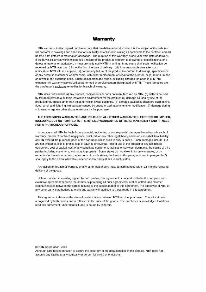
1.2 Classification of rolling bearingsRolling bearings fall into two main classifications: ball
bearings and roller bearings. Ball bearings are classifiedaccording to their bearing ring configurations: deepgroove, angular contact and thrust types. Roller bearingson the other hand are classified according to the shape ofthe rollers: cylindrical, needle, taper and spherical.
Rolling bearings can be further classified according tothe direction in which the load is applied; radial bearingscarry radial loads and thrust bearings carry axial loads.
Other classification methods include: 1) number ofrolling rows (single, multiple, or 4-row), 2) separable andnon-separable, in which either the inner ring or the outerring can be detached, 3) thrust bearings which can carryaxial loads in only one direction, and double directionthrust bearings which can carry loads in both directions.
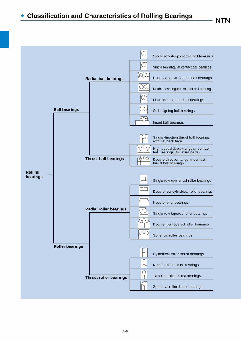
There are also bearings designed for specialapplications, such as: railway car journal roller bearings(RCT bearings), ball screw support bearings, turntablebearings, as well as rectilinear motion bearings (linearball bearings, linear roller bearings and linear flat rollerbearings).
A-5
Outerring
Inner ring
CageBall
Deep groove ball bearingFig 1.1
Ball
Cage
Outerring
Innerring
Angular contact ball bearingFig. 1.2
Inner ring
Outer ring
Cage
Roller
Cylindrical roller bearingFig. 1.3
Outer ring
Roller
Cage
Needle roller bearingFig. 1.4
Outer ring
Roller
Cage
Inner ring
Tapered roller bearingFig. 1.5
Outerring
Innerring
RollerCage
Spherical roller bearingFig. 1.6
Inner ring
Outer ring
Ball
Cage
Thrust ball bearingFig. 1.7
Outer ring
Inner ring
Roller
Cage
Thrust roller bearingFig. 1.8
1. Classification and Characteristics of Rolling Bearings
●Classification and Characteristics of Rolling Bearings
A-6
High-speed duplex angular contactball bearings (for axial loads)
Insert ball bearings
Rolling bearings
Ball bearings
Roller bearings
Radial ball bearings
Thrust ball bearings
Radial roller bearings
Thrust roller bearings
Single row deep groove ball bearings
Single row angular contact ball bearings
Duplex angular contact ball bearings
Double row angular contact ball bearings
Four-point contact ball bearings
Self-aligning ball bearings
Single direction thrust ball bearingswith flat back face
Double direction angular contactthrust ball bearings
Single row cylindrical roller bearings
Double row cylindrical roller bearings
Needle roller bearings
Single row tapered roller bearings
Double row tapered roller bearings
Spherical roller bearings
Cylindrical roller thrust bearings
Needle roller thrust bearings
Tapered roller thrust bearings
Spherical roller thrust bearings
●Classification and Characteristics of Rolling Bearings
A-7
���
�����
�������
�������
�������
������
�����
���
Ultra thin wall type ball bearings
Specialapplicationbearings
Turntable bearings
Clearance adjusting needle rollerbearings
Complex bearings
Ball screw support bearings
Connecting rod cage-equippedneedle rollers
Yoke type track rollers
Stud type track rollers
Railway car journal roller bearings(RCT bearings)
Ultra-clean vacuum bearings
Linearmotionbearings
Linear motion bearings are not listed in this catalog
Rubber molded bearings
SL-type cylindrical roller bearings
Crossed roller thrust bearings
Special application bearings are not listed in this catalog.
Fig. 1.9 Classification of rolling bearings

●Classification and Characteristics of Rolling Bearings
A-8
Snap ring
Cage
Rivet
Ball
Inner ringraceway
Outer ringraceway
Bearing chamfer
Shield
Inner ringside face
Inner ring
Outer ring
Width
Bea
ring
bore
diam
eter
Pitc
h ci
rcle
diam
eter
Bea
ring
outs
ide
diam
eter
Outer ring,front face
Inner ring,back face
Effectiveload center
Inner ring,front face
Outer ring,back face
Contact angle
Fig. 1.10 Diagram of representative bearing parts
Deep groove ball bearing Angular contact ball bearing
Inner ringwith rib
Rol
ler
insc
ribed
ci
rcle
dia
met
er
Outer ring with 2 ribs
L-shaped loose rib
Cylindrical roller
Cone front face rib
Contact angle
Cup small insidediameter (SID)
Cup, back face
Cone, front face
Cup, front face
Cone, back face
Effective load center
Cone back face rib
Tapered roller
Standout
Bearing width
Cylindrical roller bearing Tapered roller bearing
Lock washer
Locknut
SleeveTapered bore of
inner ring
Inner ring
Spherical roller
Outer ring
Shaft washer
Housing washer
Ball
Bearing bore diameter
Bearing outside diameter
Bearingheight
Spherical roller bearing Single-direction thrust ball bearing

●Classification and Characteristics of Rolling Bearings
A-9
1.3 Characteristics of rolling bearings
1.3.1 Characteristics of rolling bearingsRolling bearings come in many shapes and varieties,
each with its own distinctive features.However, when compared with sliding bearings, rolling
bearings all have the following advantages:
(1) The starting friction coefficient is lower and there islittle difference between this and the dynamicfriction coefficient is produced.
(2) They are internationally standardized, interchangeableand readily obtainable.
(3) They are easy to lubricate and consume lesslubricant.
(4) As a general rule, one bearing can carry both radialand axial loads at the same time.
(5) May be used in either high or low temperatureapplications.
(6) Bearing rigidity can be improved by preloading.
Construction, classes, and special features of rollingbearings are fully described in the boundary dimensionsand bearing numbering system section.
1.3.2 Ball bearings and roller bearingsGenerally speaking, when comparing ball and roller
bearings of the same dimensions, ball bearings exhibit alower frictional resistance and lower face run-out inrotation than roller bearings.
This makes them more suitable for use in applications
which require high speed, high precision, low torque andlow vibration. Conversely, roller bearings have a largerload carrying capacity which makes them more suitablefor applications requiring long life and endurance forheavy loads and shock loads.
1.3.3 Radial and thrust bearingsAlmost all types of rolling bearings can carry both radial
and axial loads at the same time.Generally, bearings with a contact angle of less than
45°have a much greater radial load capacity and areclassed as radial bearings; whereas bearings which havea contact angle over 45°have a greater axial loadcapacity and are classed as thrust bearings. There arealso bearings classed as complex bearings whichcombine the loading characteristics of both radial andthrust bearings.
1.3.4 Standard bearings and special bearingsBearings which are internationally standardized as to
shape and size are much more economical to use, asthey are interchangeable and available on a worldwidebasis.
However, depending on the type of machine they are tobe used in, and the expected application and function, anon-standard or specially designed bearing may be bestto use. Bearings that are adapted to specific applications,and "unit bearings" which are integrated (built-in) into amachine's components, and other specially designedbearings are also available.

Selectio
no
fb
earing
type
and
con
figu
ration
(1) Dimensional limitationsThe allowable space for bearings is typically limited.
In most cases, shaft diameter (or the bearing borediameter) has been determined according to themachine’s other design specifications. Therefore, abearing’s type and dimensions are determinedaccording to standard bearing bore diameters. For thisreason all dimension tables are organized according tostandard bore diameters. There is a wide range ofstandardized bearing types and dimensions: the rightone for a particular application can usually be found inthese tables.
(2) Bearing loadThe characteristics, magnitude, and direction of loads
acting upon a bearing are extremely variable. Ingeneral, the basic rated loads shown in bearingdimension tables indicate their load capacity. However,in determining the appropriate bearing type,consideration must also be given to whether the actingload is a radial load only or an axial load only, orcombined radial and axial load, etc. When ball androller bearings within the same dimension series areconsidered, the roller bearings have a larger loadcapacity and are also capable of withstanding greatervibration and shock loads.
(3) Rotational speedThe allowable speed of a bearing will differ
depending upon bearing type, size, tolerances, cagetype, load, lubricating conditions, and coolingconditions.
The allowable speeds listed in the bearing tables forgrease and oil lubrication are for standard NTNbearings. In general, deep groove ball bearings,angular contact ball bearings, and cylindrical rollerbearings are most suitable for high speed applications.
(4) Bearing tolerancesThe dimensional accuracy and operating tolerances
of bearings are regulated by ISO and JIS standards.For equipment requiring high tolerance shaft runout orhigh speed operation, etc., bearings with Class 5tolerance or higher are recommended. Deep grooveball bearings, angular contact ball bearings, andcylindrical roller bearings are recommended for highrotational tolerances.
(5) RigidityElastic deformation occurs along the contact surfaces
of a bearing’s rolling elements and raceway surfaceswhen under load. With certain types of equipment it isnecessary to reduce this deformation as much as
2. Bearing Selection
Rolling element bearings are available in a variety oftypes, configurations, and sizes. When selecting thecorrect bearing for your application, it is important toconsider several factors, such as the calculation ofvarious angles and clearances, which will ensure proper
fit. A comparison of the performance characteristics foreach bearing type is shown in Table 2.1. As a generalguideline, the basic procedure for selecting the mostappropriate bearing is shown in the following flow chart.
A-10
Bearing Selection
2.1 Bearing selection flow chart
●Shaft runout tolerances(refer to page insert …A-33)
●Rotational speed(refer to page insert …A-68)
●Torque fluctuation
●Design life of components to house bearings(refer to page insert …A-17)
●Dynamic/static equivalent load conditions(refer to page insert …A-23)
●Safety factor(refer to page insert …A-17)
●Allowable speed(refer to page insert …A-68)
●Allowable axial load(refer to page insert …A-17, 25)
●Allowable space(refer to page insert …A-28)
●Dimensional limitations(refer to page insert …A-28)
●Bearing load (magnitude, direction, vibration; presence of shock load)(refer to page insert …A-19)
●Rotational speed(refer to page insert …A-68)
●Bearing tolerances(refer to page insert …A-33)
●Rigidity(refer to page insert …A-64)
●Allowable misalignment of inner/outer rings(refer to page insert …A-85)
●Friction torque(refer to page insert …A-69)
●Bearing arrangement (fixed side, floating side)(refer to page insert …A-13)
●Installation and disassembly requirements(refer to page insert …A-86)
●Bearing availability and cost
●Function and construction of components to house bearings
�●Bearing mounting location�●Bearing load (direction and
magnitude)�●Rotational speed�●Vibration and shock load�●Bearing temperature (ambient
and friction-generated)�●Operating environment
(potential for corrosion, degree of contamination, extent of lubrication)
Confirm operatingconditions andoperatingenvironment
Select bearingtype andconfiguration
Select bearingdimensions
Select bearingtolerances
Pro
cedu
reC
on
firmatio
n item
s

Bearing Selection
A-11
Fig. 2.1
possible. Roller bearings exhibit less elasticdeformation than ball bearings, and therefore arerecommended for such equipment. Furthermore, insome cases, bearings are given an initial load(preloaded) to increase their shafting rigidity. Thisprocedure is commonly applied to deep groove ballbearings, angular contact ball bearings, and taperedroller bearings.
(6) Misalignment of inner and outer ringsShaft flexure, variations in shaft or housing accuracy,
and fitting errors, etc. result in a certain degree ofmisalignment between the bearing’s inner and outerrings. In cases where the degree of misalignment islikely to be relatively large, self-aligning ball bearings,spherical roller bearings, or bearing units with self-aligning properties are the most appropriate choices.(Refer to Fig. 2.1)
(7) Noise and torque levelsRolling bearings are manufactured and processed
according to high precision standards, and thereforegenerally produce only slight amounts of noise andtorque. For applications requiring particularly low-noiseor low-torque operation, deep groove ball bearings andcylindrical roller bearings are most appropriate.
(8) Installation and disassemblySome applications require frequent disassembly and
reassembly to enable periodic inspections and repairs.For such applications, bearings with separableinner/outer rings, such as cylindrical roller bearings,needle roller bearings, and tapered roller bearings aremost appropriate. Incorporation of adapter sleevessimplifies the installation and disassembly of self-aligning ball bearings and spherical roller bearings withtapered bores.
●Material and shape of shaft and housing(refer to page insert …A-83)
●Fit(refer to page insert …A-47)
●Temperature differential between inner/outer rings(refer to page insert …A-57)
●Allowable misalignment of inner/outer rings(refer to page insert …A-85)
●Load (magnitude, nature)(refer to page insert …A-19)
●Amount of preload(refer to page insert …A-64)
●Rotational speed(refer to page insert …A-68)
●Rotational speed(refer to page insert …A-68)
●Noise level●Vibration and shock load●Momentary load●Lubrication type and method
(refer to page insert …A-70)
●Operating temperature(refer to page insert …A-70)
●Rotational speed(refer to page insert …A-68)
●Lubrication type and method(refer to page insert …A-70)
●Sealing method(refer to page insert …A-78)
●Maintenance and inspection(refer to page insert …A-86)
●Operating environment (high/low temperature, vacuum, pharmaceutical, etc.)
●Requirement for high reliability
●Installation-related dimensions(refer to page insert …A-84)
●Installation and disassembly procedures(refer to page insert …A-86)
Select bearing’sinternalclearance
Select cagetype andmaterial
Select lubricant,lubrication method, sealing method
Select anyspecial bearingspecifications
Confirmhandlingprocedures
Self-aligning ball bearing Spherical roller bearing
Allowablemisalignmentangle
Allowablemisalignmentangle
A-12
Bearing Selection
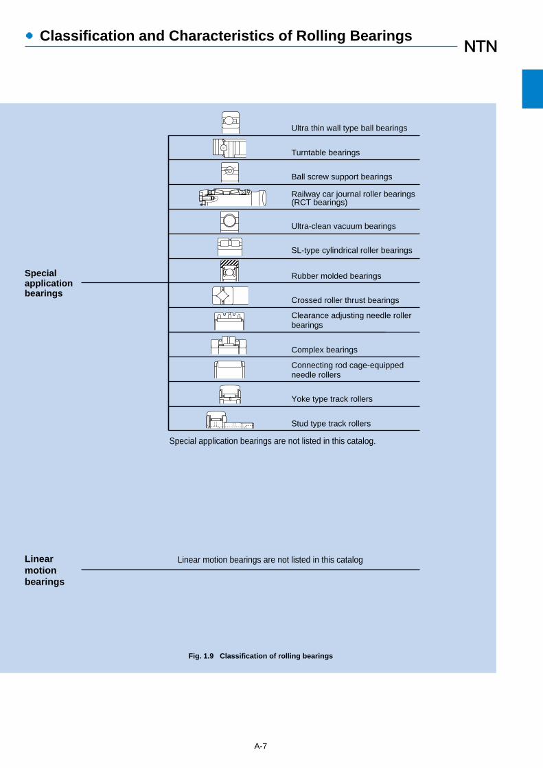
Table 2.1 Types and characteristics of rolling bearings
Deepgroove
ballbearings
Angularcontact
ballbearings
Double row angularcontact
ball bearings
Duplexangularcontact
ball bearings
Self-aligning
ballbearings
Cylindricalroller
bearings
Single-flange
cylindricalroller bearings
Double-flange
cylindricalroller bearings
Double rowcylindrical
roller bearings
Taperedroller
bearings
Multi-row, 4-row tapered roller bearings.
Sphericalroller
bearings
Thrust ball
bearings
Double rowangularcontact
thrust ballbearings
Sphericalrollerthrust
bearings
1 ☆☆☆☆�
☆☆☆�
☆☆☆☆�
☆☆☆☆�
�
�
☆�
◎�
○�
☆☆☆☆�
☆☆☆�
☆☆☆�
☆☆☆�
�
�
�
○�
�
�
�
�
☆☆�
☆☆�
�
�
☆☆�
☆�
�
◎�
○�
☆☆☆�
☆☆☆�
☆�
☆☆�
☆☆�
�
�
◎��○�
☆☆�
�
�
☆�
�
★�
☆☆☆�
◎�
○�
�
○�
☆☆☆☆�
☆☆☆�
☆�
☆�
☆☆�
☆☆�
☆�
�
◎�
○�
○�
�
☆☆☆�
☆☆�
☆�
�
☆☆�
☆☆�
�
○�
�
○�
�
�
☆☆☆�
☆�
☆�
�
☆☆�
☆☆�
�
◎�
�
○�
�
�
☆☆☆�
☆☆☆�
☆�
�
☆☆☆�
☆☆�
�
�
◎�
○�
○�
�
B-5 B-41 B-72 B-41 B-77 B-89 B-89 B-89 B-89
☆☆☆�
☆☆☆�
�
�
☆☆�
☆☆�
☆�
○�
�
○�
�
�
B-131
☆☆�
☆�
�
�
☆☆☆☆�
☆☆☆�
�
◎�
○�
○�
B-131
☆☆�
�
�
�
☆☆☆�
☆☆☆�
☆☆☆�
◎�
○�
�
○�
B-229
☆�
☆�
☆�
�
�
�
�
★�
○�
○�
�
B-265
☆☆☆�
☆☆☆�
�
�
☆☆�
★�
★�
◎�
�
○�
B-265
☆�
�
�
�
☆☆☆�
☆☆☆�
☆☆☆�
○�
�
○�
B-265
A-66
A-31
―
A-67
A-54
A-18
A-79
A-13
A-13
―
A-79
―�
1 ☆ The number of stars in dicate the degree to which that bearing type displays that particular characteristic. ★ Not applicable to that bearing type.
2 ◎ Indicates dual direction. ○ Indicates single direction axial movement only.
3 ◎ Indicates movement at raceway. ○ Indicates movement at mated surface of inner or outer ring.
4 ○ Indicates both inner ring and outer ring are detachable.
5 ○ Indicates inner ring with tapered bore is possible.
Bearing types
Characteristics
Load Carrying Capacity
Radial load
Axial load
High speed
High rotating accuracy
Low noise/vibration
Low friction torque
High rigidity
1
1
1
1
Vibration/shock resistance1
Allowable misalignmentfor inner/outer rings
1
For fixed bearings2
For floating bearings3
Non-separable or separable4
Tapered bore bearings5
Remarks
Reference page
1
High speed
High rotating accuracy
Low noise/vibration
Low friction torque
High rigidity
1
1
1
1
Vibration/shock resistance1
Allowable misalignmentfor inner/outer rings
1
For fixed bearings2
For floating bearings3
Non-separable or separable4
Tapered bore bearings5
Remarks
Reference page
For DB and DFarrangement
For DBarrangement
For duplexarrangement
NU, Ntype
NJ, NFtype
NUP, NP, NHtype
Referencepage
Bearing types
Characteristics
For duplexarrangement
Load Carrying Capacity
Radial load
Axial load
2.2 Type and character is ticsTable 2.1 shows types and characteristics of rolling bearings.

Bearing Selection
A-13
2.3 Selection of bearing arrangementShaft assemblies generally require two bearings to
support and locate the shaft radially and axially, relative tothe stationary housing. These two bearings are called the“fixed-side” and “floating-side” bearings. The fixed-sidebearing “fixes” or controls movement of the shaft axially inrelation to the housing. The floating-side bearing moves or“floats” axially in relation to the housing and is thereforeable to relieve stress caused by the expansion andcontraction of the shaft due to temperature fluctuations,and allow for misalignment caused by fitting errors.
Fixed-side bearings have the capacity to receive bothaxial and radial loads, and therefore a bearing whichcontrols axial movement in both directions should beselected. Floating-side bearings receive only radial loads,and therefore bearings which are mounted to permit freeaxial movement, or bearings with separable inner and
outer rings are most desirable. Cylindrical roller bearingsare generally separable and allow for axial displacementalong their raceway surfaces; deep groove ball bearingsare non-separable, but can be mounted to allow fordisplacement along their fitting surfaces.
In applications with short distances between bearings,shaft expansion and contraction due to temperaturefluctuations is slight, therefore the same type of bearingmay be used for both the fixed-side and floating-sidebearing. In such cases it is common to use a set ofmatching bearings, such as angular contact ball bearings,to guide and support the shaft in one axial direction only.
Table 2.2 (1) shows representative bearingarrangements where the bearing type differs on the fixedside and floating side. Table 2.2 (2) shows somecommon bearing arrangements where no distinction ismade between the fixed side and floating side. Verticalshaft bearing arrangements are shown in Table 2.2 (3).
1. General arrangement for small machinery.
2. For radial loads, but will also accept axial loads.
3. Preloading by springs or shims on outer ring face.
1. Suitable for high speed. Widely used.
2. Even with expansion and contraction of shaft, non-fixing side moves smoothly.
1. Radial loading plus dual direction axial loading possible.
2. In place of duplex angular contact ball bearings, double-row angular contact ball bearings are also used.
1. Heavy loading capable.
2. Shafting rigidity increased by preloading the two back-to-back fixed bearings.
3. Requires high precision shafts and housings, and minimal fitting
1. Allows for shaft deflection and fitting errors.
2. By using an adaptor on long shafts without screws or shoulders, bearing mounting and dismounting can be facilitated.
3. Not suitable for axial load applications.
1. Widely used in general industrial machinery with heavy and shock load demands.
2. Allows for shaft deflection and fitting errors.
3. Accepts radial loads as well as dual direction axial loads.
1. Widely used in general industrial machinery with heavy and shock loading.
2. Radial and dual directional axial loading.
1. Capable of handling large radial and axial loads at high rotational speeds.
2. Maintains clearance between the bearing’s outer diameter and housing inner diameter to prevent deep groove ball bearings from receiving radial loads.
Arrangement
Fixed FloatingComment Application
Wormgear speedreducers, etc.
Small pumps, smallelectric motors,auto-mobiletransmissions, etc.
Medium-sizedelectric motors, ventilators, etc.
Machine toolspindles, etc.
Counter shafts forgeneral industrialequipment, etc.
Industrial machineryreduction gears. etc.
Reduction gears forgeneral industrialequipment, etc.
Diesel locomotives,etc.
Table 2.2 (1) Bearing arrangement (Fixed and Floating)

Bearing Selection
A-14
General arrangement for use in small machines.
1. This type of back-to-back arrangement well suited for moment loads.
2. Preloading increases shaft rigidity.
3. High speed reliable.
1. Withstands heavy and shock loads. Wide range application.
2. Shafting rigidity increased by preloading.
3. Back-to-back arrangement for moment loads, and face-to-face arrangement to alleviate fitting errors.
4. With face-to-face arrangement, inner ring shrink-fit is facilitated.
1. Accepts heavy loading.
2. Suitable if inner and outer ring shrink-fit is required.
3. Care must be taken that axial clearance does not become too small during operation.
When fixing bearing is a duplex angular contact ball bearing, non-fixing bearing is a cylindrical roller bearing.
1. Most suitable arrangement for very heavy axial loads.
2. Depending on the relative alignment of the spherical surface of the rollers in the upper and lower bearings, shaft deflection and fitting errors can be absorbed.
3. Lower self-aligning spherical roller thrust bearing pre-load is possible.
Back to back
Face to face
Arrangement Comment Application
Reduction gears,automotive axles, etc.
Constructionequipment, miningequipment sheaves,agitators, etc.
Spindles of machinetools, etc.
Small electric motors,small reductiongears, etc.
Arrangement Comment Application
Crane center shafts,etc.
Machine tool spindles,vertical mountedelectric motors, etc.
Table 2.2 (2) Bearing arrangement (Placed oppositely)
Table 2.2 (3) Bearing arrangement (Vertical shaft)
3. Load Rating and Life3.1 Bearing life
Even in bearings operating under normal conditions, thesurfaces of the raceway and rolling elements areconstantly being subjected to repeated compressivestresses which causes flaking of these surfaces to occur.This flaking is due to material fatigue and will eventuallycause the bearings to fail. The effective life of a bearingis usually defined in terms of the total number ofrevolutions a bearing can undergo before flaking of eitherthe raceway surface or the rolling element surfacesoccurs.
Other causes of bearing failure are often attributed toproblems such as seizing, abrasions, cracking, chipping,gnawing, rust, etc. However, these so called "causes" ofbearing failure are usually themselves caused byimproper installation, insufficient or improper lubrication,faulty sealing or inaccurate bearing selection. Since theabove mentioned "causes" of bearing failure can beavoided by taking the proper precautions, and are notsimply caused by material fatigue, they are consideredseparately from the flaking aspect.
3.2 Basic rating life and basic dynamic load ratingA group of seemingly identical bearings when subjected
to identical load and operating conditions will exhibit awide diversity in their durability.
This "life" disparity can be accounted for by thedifference in the fatigue of the bearing material itself.This disparity is considered statistically when calculatingbearing life, and the basic rating life is defined as follows.
The basic rating life is based on a 90% statistical modelwhich is expressed as the total number of revolutions90% of the bearings in an identical group of bearingssubjected to identical operating conditions will attain orsurpass before flaking due to material fatigue occurs. Forbearings operating at fixed constant speeds, the basicrating life (90% reliability) is expressed in the total numberof hours of operation.
The basic dynamic load rating is an expression of theload capacity of a bearing based on a constant loadwhich the bearing can sustain for one million revolutions(the basic life rating). For radial bearings this ratingapplies to pure radial loads, and for thrust bearings itrefers to pure axial loads. The basic dynamic load ratingsgiven in the bearing tables of this catalog are for bearingsconstructed of NTN standard bearing materials, usingstandard manufacturing techniques. Please consult NTNEngineering for basic load ratings of bearings constructedof special materials or using special manufacturingtechniques.
The relationship between the basic rating life, the basicdynamic load rating and the bearing load is given informula (3.1).
L10=(C)
p…………(3.1)
P
where,p= 3......................For ball bearingsp= 10/3.................For roller bearings
L10 : Basic rating life 106 revolutionsC : Basic dynamic rating load, N
(Cr: radial bearings, Ca: thrust bearings)P : Equivalent dynamic load, N
(Pr: radial bearings, Pa: thrust bearings)
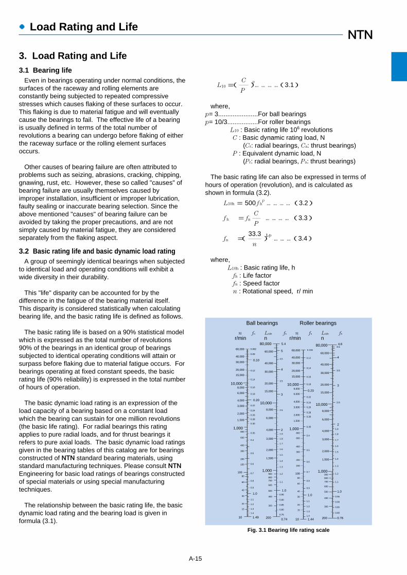
The basic rating life can also be expressed in terms ofhours of operation (revolution), and is calculated asshown in formula (3.2).
L10h = 500 f hp …………(3.2)
f h = fnC …………(3.3)
P
fn =(33.3
)1/p ………(3.4)
n
where,L10h : Basic rating life, h
fh : Life factorfn : Speed factor n : Rotational speed, r/ min
A-15
●Load Rating and Life
40,000
4.6
60,000
80,000
30,000
20,000
15,000
3
10,0002.5
8,000
6,000
4,000
3,000
2,000
1.9
3.5
4.5
2
4
1.8
1.7
1.6
1.5
1.41,500
1.3
1.21,000
1.1
900
800
700
600
500
4000.95
1.0
0.90
300 0.85
0.80
0.76200
100
0.6
60,000
40,000
0.106
30,000
0.12
0.1420,000
0.1615,000
0.1810,000
0.208,000
0.22
0.24
0.26
0.28
6,000
4,000
3,000
2,0000.30
1,500
0.351,000
0.4800
600
0.5
400
300
200
150
0.7
80
600.8
0.940
301.0
1.1
1.3
20
15
1.4
1.2
1.4410
60,000
5.480,000
4.5
5
40,000
430,000
3.520,000
15,0003
2.5
10,000
6,000
24,000
3,000
2,000
1.9
1.8
1.7
1.6
1.5
1,5001.4
1.3
1.21,000
800
900
700 1.1
1.0
600
500
4000.95
0.90
0.85300
0.80
0.75
0.742001.4910
40,000
60,000
30,0000.10
0.082
0.09
0.12
0.14
20,000
15,000
0.16
0.18
10,0008,000
8,000
6,000
4,000
3,000
2,000
1,500
1,000800
600
400
300
200
150
0.20
0.22
0.24
0.26
0.28
0.30
0.35
0.4
0.5
0.6
0.7
0.8
10080
60
40
30
20
0.9
1.0
1.1
1.2
1.3
1.4
15
fnn L10h
r/min nfh n L10hfn
r/min nfh
Ball bearings Roller bearings
Fig. 3.1 Bearing life rating scale
Formula (3.2) can also be expressed as shown informula (3.5).
L10h =106
(C)
p …(3.5)
60 n P
The relation ship between Rotational speed n andspeed factor fn as well as the relation between the basicrating life L10h and the life factor fn is shown in Fig. 3.1.
When several bearings are incorporated in machinesor equipment as complete units, all the bearings in theunit are considered as a whole when computing bearinglife (see formula 3.6). The total bearing life of the unit isa life rating based on the viable lifetime of the unit beforeeven one of the bearings fails due to rolling contactfatigue.
1L =( 1 + 1 + … 1 )
1/e………(3.6)
L1e
L2e
Lne
where,e = 10/9....................For ball bearingse = 9/8......................For roller bearings
L : Total basic rating life of entire unit, hL1 , L2 …Ln: Basic rating life of individual bearings, 1, 2,
…n, h
When the load conditions vary at regular intervals, thelife can be given by formula (3.7).
Lm =(ΣΦ j/Lj)-1…………………(3.7)
where,Φ j : Frequency of individual load conditionsL j : Life under individual conditions
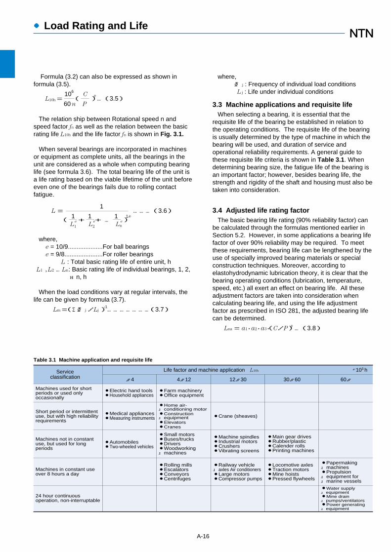
3.3 Machine applications and requisite lifeWhen selecting a bearing, it is essential that the
requisite life of the bearing be established in relation tothe operating conditions. The requisite life of the bearingis usually determined by the type of machine in which thebearing will be used, and duration of service andoperational reliability requirements. A general guide tothese requisite life criteria is shown in Table 3.1. Whendetermining bearing size, the fatigue life of the bearing isan important factor; however, besides bearing life, thestrength and rigidity of the shaft and housing must also betaken into consideration.
3.4 Adjusted life rating factorThe basic bearing life rating (90% reliability factor) can
be calculated through the formulas mentioned earlier inSection 5.2. However, in some applications a bearing lifefactor of over 90% reliability may be required. To meetthese requirements, bearing life can be lengthened by theuse of specially improved bearing materials or specialconstruction techniques. Moreover, according toelastohydrodynamic lubrication theory, it is clear that thebearing operating conditions (lubrication, temperature,speed, etc.) all exert an effect on bearing life. All theseadjustment factors are taken into consideration whencalculating bearing life, and using the life adjustmentfactor as prescribed in ISO 281, the adjusted bearing lifecan be determined.
Lna= a1・a2・a3・(C/P)p…(3.8)
A-16
●Load Rating and Life
Table 3.1 Machine application and requisite life
~4 4~12 12~30 30~60 60~�Life factor and machine application L10h ×103 hService
classification
Machines used for shortperiods or used only �occasionally
Short period or intermittentuse, but with high reliabilityrequirements
Machines not in constantuse, but used for longperiods
Machines in constant useover 8 hours a day
24 hour continuousoperation, non-interruptable
¡Electric hand tools¡Household appliances
¡Medical appliances¡Measuring instruments
¡Automobiles¡Two-wheeled vehicles
¡Farm machinery¡Office equipment
¡Home air- conditioning motor¡Construction equipment¡Elevators¡Cranes
¡Small motors¡Buses/trucks¡Drivers¡Woodworking machines
¡Rolling mills¡Escalators ¡Conveyors¡Centrifuges
¡Crane (sheaves)
¡Machine spindles¡Industrial motors¡Crushers¡Vibrating screens
¡Railway vehicle axles Air conditioners¡Large motors¡Compressor pumps
¡Main gear drives¡Rubber/plastic¡Calender rolls¡Printing machines
¡Locomotive axles¡Traction motors¡Mine hoists¡Pressed flywheels
¡Papermaking machines¡Propulsion equipment for marine vessels
¡Water supply equipment¡Mine drain pumps/ventilators¡Power generating equipment

where,Lna : Adjusted life rating in millions of revolutions
(106)(adjusted for reliability, material andoperating conditions)
a1 : Reliability adjustment factora2 : Material adjustment factora3 : Operating condition adjustment factor
3.4.1 Life adjustment factor for reliability a1
The values for the reliability adjustment factor a1 (for areliability factor higher than 90%) can be found in Table3.2.
3.4.2 Life adjustment factor for material a2
The life of a bearing is affected by the material type andquality as well as the manufacturing process. In thisregard, the life is adjusted by the use of an a2 factor.
The basic dynamic load ratings listed in the catalog arebased on NTN's standard material and process,therefore, the adjustment factor a2 =1. When specialmaterials or processes are used the adjustment factorcan be larger than 1.
NTN bearings can generally be used up to 120˚C. Ifbearings are operated at a higher temperature, thebearing must be specially heat treated (stabilized) so thatinadmissible dimensional change does not occur due tochanges in the micro-structure. This special heattreatment might cause the reduction of bearing lifebecause of a hardness change.
3.4.3 Life adjustment factor a3 for operating conditionsThe operating conditions life adjustment factor a3 is
used to adjust for such conditions as lubrication,operating temperature, and other operation factors whichhave an effect on bearing life.
Generally speaking, when lubricating conditions aresatisfactory, the a3 factor has a value of one; and whenlubricating conditions are exceptionally favorable, and allother operating conditions are normal, a3 can have avalue greater than one.
However, when lubricating conditions are particularlyunfavorable and the oil film formation on the contactsurfaces of the raceway and rolling elements isinsufficient, the value of a3 becomes less than one. This
A-17
●Load Rating and Life
Reliability % Ln Reliability factor a1
90
95
96
97
98
99
L10
L5
L4
L3
L2
L1
1.00
0.62
0.53
0.44
0.33
0.21
Table 3.2 Reliability adjustment factor values a1
Fig. 3.2 Life adjustment value for operating temperature
300250200150100
1.0
0.8
0.6
0.4
0.2Li
fe a
djus
tmen
t val
ue
a3
Operating temperature ˚C
insufficient oil film formation can be caused, for example,by the lubricating oil viscosity being too low for theoperating temperature (below 13 mm2/s for ball bearings;below 20 mm2/s for roller bearings); or by exceptionallylow rotational speed (nr/min x dpmm less than 10,000).For bearings used under special operating conditions,please consult NTN Engineering.
As the operating temperature of the bearing increases,the hardness of the bearing material decreases. Thus, thebearing life correspondingly decreases. The operatingtemperature adjustment values are shown in Fig. 3.2.
3.5 Basic static load ratingWhen stationary rolling bearings are subjected to static
loads, they suffer from partial permanent deformation ofthe contact surfaces at the contact point between therolling elements and the raceway. The amount ofdeformity increases as the load increases, and if thisincrease in load exceeds certain limits, the subsequentsmooth operation of the bearings is impaired.
It has been found through experience that a permanentdeformity of 0.0001 times the diameter of the rollingelement, occurring at the most heavily stressed contactpoint between the raceway and the rolling elements, canbe tolerated without any impairment in running efficiency.
The basic rating static load refers to a fixed static loadlimit at which a specified amount of permanentdeformation occurs. It applies to pure radial loads forradial bearings and to pure axial loads for thrust bearings.The maximum applied load values for contact stressoccurring at the rolling element and raceway contactpoints are given below.
For ball bearings 4,200 Mpa(except self-aligning ball bearings)For self-aligning ball bearings 4,600 MpaFor roller bearings 4,000 Mpa

●Load Rating and Life
Table 3.4 Minimum safety factor values S0
2
1
0.5
3
1.5
1
Operating conditions
High rotational accuracy demand
Ballbearings
Rollerbearings
Normal rotating accuracy demand(Universal application)
Slight rotational accuracydeterioration permitted(Low speed, heavy loading, etc.)
Note 1: For spherical thrust roller bearings, min. S0 value=4.2: For shell needle roller bearings, min. S0 value=3.3: When vibration and/or shock loads are present, a load factor
based on the shock load needs to be included in the P0 max value.
3.6 Allowable static equivalent loadGenerally the static equivalent load which can be
permitted (See Section 4.4.2 page A-23) is limited by thebasic static rating load as stated in Section 5.5.However, depending on requirements regarding frictionand smooth operation, these limits may be greater orlesser than the basic static rating load.
In the following formula (3.9) and Table 3.4 the safetyfactor S0 can be determined considering the maximumstatic equivalent load.
So =Co/Po…(3.9)
where,So : Safety factorCo : Basic static rating load, N
(radial bearings: Cor, thrust bearings: Coa)Po max : Maximum static equivalent load, N
(radial: Por max, thrust: Coa max)
A-18

To compute bearing loads, the forces which act on theshaft being supported by the bearing must bedetermined. These forces include the inherent deadweight of the rotating body (the weight of the shafts andcomponents themselves), loads generated by theworking forces of the machine, and loads arising fromtransmitted power.
It is possible to calculate theoretical values for theseloads; however, there are many instances where theload acting on the bearing is usually determined by thenature of the load acting on the main powertransmission shaft.
4.1 Load acting on shafts4.1.1 Load factor
There are many instances where the actual operationalshaft load is much greater than the theoreticallycalculated load, due to machine vibration and/or shock. This actual shaft load can be found by using formula(4.1).
K= fw・Kc ……………………………(4.1)where,
K :Actual shaft load N{kgf}fw:Load factor (Table 4.1)Kc:Theoretically calculated value N{kgf}
4.1.2 Gear loadThe loads operating on gears can be divided into three
main types according to the direction in which the load isapplied; i.e. tangential (Kt), radial (Ks), and axial (Ka).The magnitude and direction of these loads differaccording to the types of gears involved. The loadcalculation methods given herein are for two general-usegear and shaft arrangements: parallel shaft gears, andcross shaft gears. For load calculation methodsregarding other types of gear and shaft arrangements,please consult NTN Engineering.
(1)Loads acting on parallel shaft gearsThe forces acting on spur and helical parallel shaftgears are depicted in Figs. 4.1, 4.2, and 4.3. The loadmagnitude can be found by using or formulas (4.2),through (4.4).
●Bearing Load Calculation
A-19
Table 4.1 Load factor fw
Amountof shock Application
Heavy shock
Light shock
Very little orno shock
Electric machines, machine tools,measuring instruments.
Railway vehicles, automobiles,rolling mills, metal working machines,paper making machines, rubber mixingmachines, printing machines, aircraft, textile machines, electrical units, officemachines.
Crushers, agricultural equipment,construction equipment, cranes.
1.0~1.2
1.2~1.5
1.5~3.0
fw
Kt=19.1×10⁶・H
NDp・n
=1.95×10⁶・H
{kgf}
……(4.2)
Dp・n
Ks= Kt・tanα(Spur gear)………(4.2a)
= Kt・tanα
(Helical gear)……(4.2b)cosβ
Kr =√Kt2+Ks
2 ………………………(4.3)
Ka = Kt・tanβ(Helical gear) ……(4.4)where,
Kt:Tangential gear load (tangential force), NKs:Radial gear load (separating force), NKr:Right angle shaft load (resultant force of
tangential force and separating force), NKa:Parallel load on shaft, NH:Transmission force , kWn:Rotational speed, r/minDp:Gear pitch circle diameter, mmα:Gear pressure angleβ:Gear helix angle
}
4. Bearing Load Calculation
Fig. 4.1 Spur gear loads
Ks
Kt
Fig. 4.2 Helical gear loads
Ks
Kt
Ka
Fig. 4.3 Radial resultant forces
Kt
Kr Ks
Dp

●Bearing Load Calculation
A-20
Because the actual gear load also contains vibrationsand shock loads as well, the theoretical load obtained bythe above formula should also be adjusted by the gearfactor fz as shown in Table 4.2.
(2)Loads acting on cross shaftsGear loads acting on straight tooth bevel gears and
spiral bevel gears on cross shafts are shown in Figs. 4.4and 4.5. The calculation methods for these gear loads areshown in Table 4.3. Herein, to calculate gear loads forstraight bevel gears, the helix angle β= 0.
The symbols and units used in Table 4.3 are as follows:
Kt :Tangential gear load (tangential force), NKs :Radial gear load (separating force), NKa :Parallel shaft load (axial load), NH :Transmission force, kWn :Rotational speed, r/minDpm :Mean pitch circle diameter, mmα :Gear pressure angleβ :Helix angleδ :Pitch cone angle
In general, the relationship between the gear load andthe pinion gear load, due to the right angle intersection ofthe two shafts, is as follows:
Ksp=Kag…………………(4.5)Kap=Ksg…………………(4.6)
K tp
Kap
Ksg
Kag
Ktg
Ksp
Fig. 4.4 Loads on bevel gears
D pm
2
K a
K s
K t
βδ
Fig. 4.5 Bevel gear diagram
Axial load Ka
Ks=Kt tanα�cosδ�cosβ�
�+ tanβsinδ�
Kt=19.1×10⁶・H
Dpm・n ,1.95×106・H
Dpm・n
Separating force Ks
Tangential load Kt
Pinion
RotationdirectionHelixdirection
Driving side
Driven side
Driving side
Driven side
Ks=Kt tanα�cosδ�cosβ�
�- tanβsinδ�
Ks=Kt tanα�cosδ�cosβ�
�- tanβsinδ� Ks=Kt tanα�cosδ�cosβ�
�+ tanβsinδ�
Ka=Kt tanα�sinδ�cosβ�
�- tanβcosδ� Ka=Kt tanα�sinδ�cosβ�
�+ tanβcosδ�
Ka=Kt tanα�sinδ�cosβ�
�+ tanβcosδ� Ka=Kt tanα�sinδ�cosβ�
�- tanβcosδ�
Clockwise Counter clockwise Clockwise Counter clockwise
Right Left Left Right
Table 4.3 Loads acting on bevel gears Unit N
Gear type
Ordinary machined gears(Pitch and tooth profile errors of less than 0.1 mm)
Precision ground gears(Pitch and tooth profile errors of less than 0.02 mm) 1.05~1.1
1.1~1.3
fz
Table 4.2 Gear factor fz
where,
Ksp,Ksg:Pinion and gear separating force, NKap,Kag:Pinion and gear axial load, N
For spiral bevel gears, the direction of the load variesdepending on the direction of the helix angle, the directionof rotation, and which side is the driving side or the drivenside. The directions for the separating force (Ks) and axialload (Ka) shown in Fig. 4.5 are positive directions. Thedirection of rotation and the helix angle direction aredefined as viewed from the large end of the gear. Thegear rotation direction in Fig. 4.5 is assumed to beclockwise (right).
4.1.2 Chain / belt shaft loadThe tangential loads on sprockets or pulleys when
power (load) is transmitted by means of chains or beltscan be calculated by formula (4.7).
Kt=19.1 ×10⁶・H
NDp・n
……………(4.7)
=1.95×10⁶・H
{kgf}Dp・n
where,
Kt:Sprocket/pulley tangential load, N
H:Transmitted force, kW
Dp:Sprocket/pulley pitch diameter,mm
For belt drives, an initial tension is applied to givesufficient constant operating tension on the belt andpulley. Taking this tension into account, the radial loadsacting on the pulley are expressed by formula (4.8). Forchain drives, the same formula can also be used ifvibrations and shock loads are taken into consideration.
Kr=f b・Kt…(4.8)where,
Kr:Sprocket or pulley radial load, N
f b:Chain or belt factor (Table 4.3)
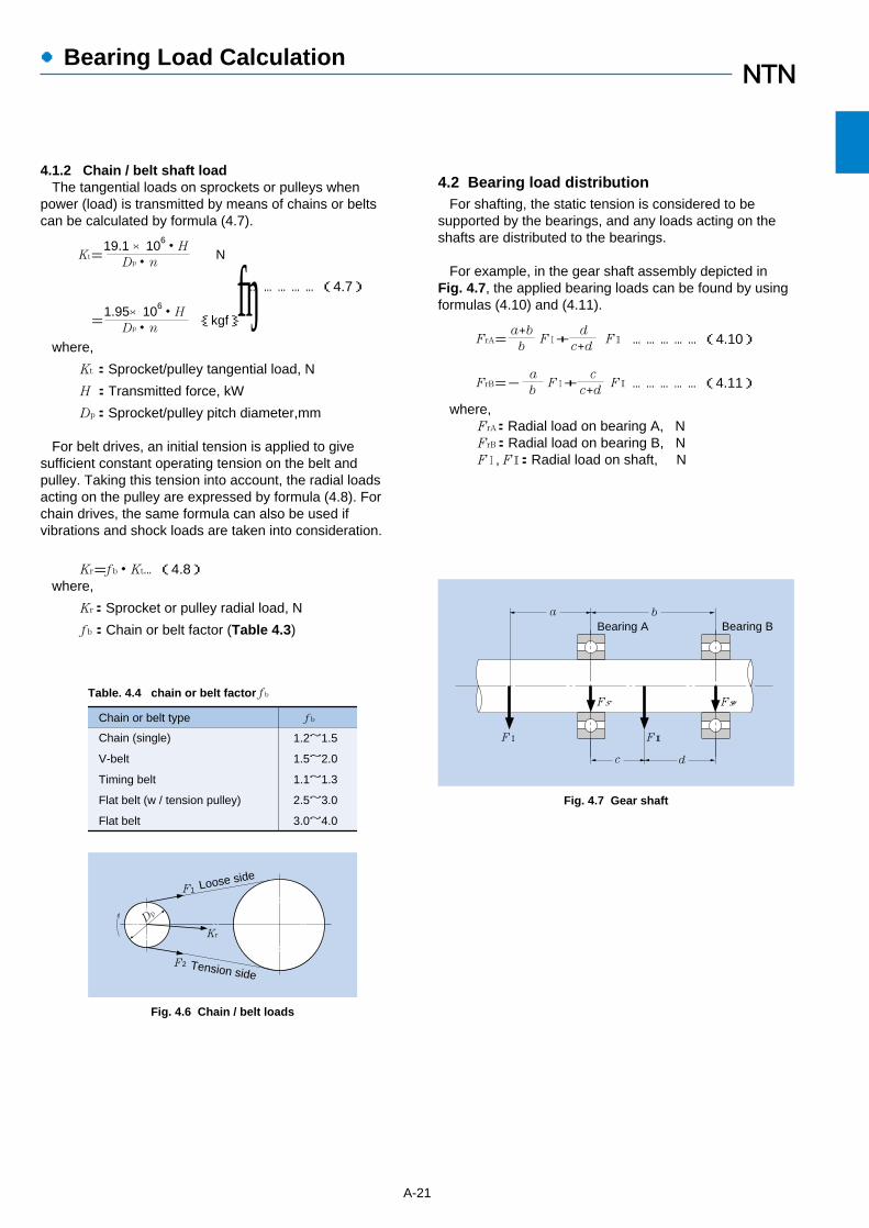
4.2 Bearing load distributionFor shafting, the static tension is considered to be
supported by the bearings, and any loads acting on theshafts are distributed to the bearings.
For example, in the gear shaft assembly depicted inFig. 4.7, the applied bearing loads can be found by usingformulas (4.10) and (4.11).
FrA=a+b
F1+d
F2 ……………(4.10)b c+d
FrB=-a
F1+c
F2 ……………(4.11)b c+d
where,FrA:Radial load on bearing A, NFrB:Radial load on bearing B, NF1, F2:Radial load on shaft, N
A-21
●Bearing Load Calculation
Fig. 4.6 Chain / belt loads
Chain or belt type f b
V-belt
Timing belt
Flat belt (w / tension pulley)
Flat belt
1.2~1.5
1.5~2.0
1.1~1.3
2.5~3.0
3.0~4.0
Chain (single)
Table. 4.4 chain or belt factor f b
F1
Kr
Dp
F2
Loose side
Tension side
c d
a b
FrA
F! F@
FrB
Bearing A Bearing B
Fig. 4.7 Gear shaft
}
●Bearing Load Calculation
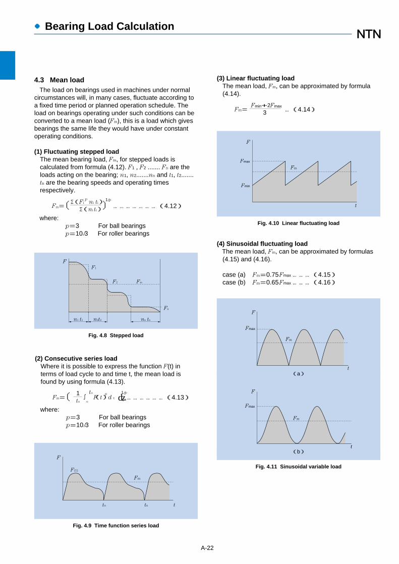
4.3 Mean loadThe load on bearings used in machines under normal
circumstances will, in many cases, fluctuate according toa fixed time period or planned operation schedule. Theload on bearings operating under such conditions can beconverted to a mean load (Fm), this is a load which givesbearings the same life they would have under constantoperating conditions.
(1) Fluctuating stepped load The mean bearing load, Fm, for stepped loads iscalculated from formula (4.12). F1 , F2 ....... Fn are theloads acting on the bearing; n1, n2.......nn and t1, t2.......tn are the bearing speeds and operating timesrespectively.
Fm=〔Σ(Fip
ni ti)〕1/p
…………………(4.12)Σ(ni ti)where:
p=3 For ball bearingsp=10/3 For roller bearings
A-22
(3) Linear fluctuating loadThe mean load, Fm, can be approximated by formula(4.14).
Fm=Fmin+2Fmax
…(4.14)3
F
F1
FmF2
Fn
nn tnn1 t1 n2t2
Fig. 4.8 Stepped load
Fig. 4.11 Sinusoidal variable load
F
Fm
F(t)
2to0 to t
Fig. 4.9 Time function series load
F
Fmax
Fmin
Fm
t
Fig. 4.10 Linear fluctuating load
(2) Consecutive series loadWhere it is possible to express the function F(t) interms of load cycle to and time t, the mean load isfound by using formula (4.13).
Fm=〔 1∫
to
F(t)p
d t 〕1/p………………(4.13)
to o
where:p=3 For ball bearingsp=10/3 For roller bearings
Fmax
Fm
t
F
F
Fmax
Fm
t(a)
(b)
(4) Sinusoidal fluctuating loadThe mean load, Fm, can be approximated by formulas(4.15) and (4.16).
case (a) Fm=0.75Fmax………(4.15)case (b) Fm=0.65Fmax………(4.16)
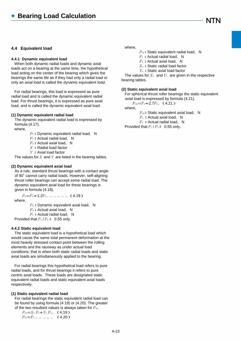
4.4 Equivalent load
4.4.1 Dynamic equivalent loadWhen both dynamic radial loads and dynamic axial
loads act on a bearing at the same time, the hypotheticalload acting on the center of the bearing which gives thebearings the same life as if they had only a radial load oronly an axial load is called the dynamic equivalent load.
For radial bearings, this load is expressed as pureradial load and is called the dynamic equivalent radialload. For thrust bearings, it is expressed as pure axialload, and is called the dynamic equivalent axial load.
(1) Dynamic equivalent radial loadThe dynamic equivalent radial load is expressed byformula (4.17).where,
Pr:Dynamic equivalent radial load, NFr:Actual radial load, NFa:Actual axial load, NX:Radial load factorY:Axial load factor
The values for X and Y are listed in the bearing tables.
(2) Dynamic equivalent axial loadAs a rule, standard thrust bearings with a contact angleof 90˚ cannot carry radial loads. However, self-aligningthrust roller bearings can accept some radial load. Thedynamic equivalent axial load for these bearings isgiven in formula (4.18).
Pa=Fa+1.2Fr………………(4.18)where,
Pa:Dynamic equivalent axial load, NFa:Actual axial load, NFr:Actual radial load, N
Provided that Fr / Fa≦ 0.55 only.
4.4.2 Static equivalent loadThe static equivalent load is a hypothetical load which
would cause the same total permanent deformation at themost heavily stressed contact point between the rollingelements and the raceway as under actual loadconditions; that is when both static radial loads and staticaxial loads are simultaneously applied to the bearing.
For radial bearings this hypothetical load refers to pureradial loads, and for thrust bearings it refers to purecentric axial loads. These loads are designated staticequivalent radial loads and static equivalent axial loadsrespectively.
(1) Static equivalent radial loadFor radial bearings the static equivalent radial load canbe found by using formula (4.19) or (4.20). The greaterof the two resultant values is always taken for Por.
Por=Xo Fr+Yo Fa…(4.19)Por=Fr …………… (4.20)
where,Por:Static equivalent radial load, NFr:Actual radial load, NFa:Actual axial load, NXo:Static radial load factorYo:Static axial load factor
The values for Xo and Yo are given in the respectivebearing tables.
(2) Static equivalent axial loadFor spherical thrust roller bearings the static equivalentaxial load is expressed by formula (4.21).
Poa=Fa+2.7Fr…(4.21)where,
Poa:Static equivalent axial load, NFa:Actual axial load, NFr:Actual radial load, N
Provided that Fr / Fa≦ 0.55 only.
A-23
●Bearing Load Calculation

4.4.3 Load calculation for angular ball bearings andtapered roller bearings
For angular ball bearings and tapered roller bearingsthe pressure cone apex (load center) is located as shownin Fig. 4.12, and their values are listed in the bearingtables.
When radial loads act on these types of bearings thecomponent force is induced in the axial direction. For thisreason, these bearings are used in pairs (either DB or DFarrangements). For load calculation this component forcemust be taken into consideration and is expressed byformula (4.22).
Fa =0.5Fr
…………………(4.22)Y
The equivalent radial loads for these bearing pairs aregiven in Table 4.5.
●Bearing Load Calculation
A-24
Y1
0.5Fr1≦�Y2
0.5Fr2+�Fa
Y1
0.5Fr1>�Y2
0.5Fr2+�Fa
Y2
0.5Fr2≦�Y1
0.5Fr1+�Fa
Y2
0.5Fr2>�Y1
0.5Fr1+�Fa
Fa1=�Y2
0.5Fr2+�Fa
Fa2=�Y2
0.5Fr2
Fa1=�Y1
0.5Fr1
Fa2=�Y1
0.5Fr1-�Fa
Fa1=�Y1
0.5Fr1
Fa2=�Y1
0.5Fr1+�Fa
Fa1=�Y2
0.5Fr2-�Fa
Fa2=�Y2
0.5Fr2
Axial load Equivalent radial loadLoad condition
Y2
0.5Fr2+�FaPr1=XFr1+Y1
Pr2=Fr2
Pr1=Fr1
Y1
0.5Fr1-�FaPr2=XFr2+Y2
Pr1=Fr1
Y1
0.5Fr1+�FaPr2=XFr2+Y2
Y2
0.5Fr2-�FaPr1=XFr1+Y1
Pr2=Fr2
Bearing arrangement
Fa
Fr1
DBarrangement
DFarrangement
DBarrangement
DFarrangement
Fr2
Fa
Fr2 Fr1
Fr1 Fr2
Fa
Fr2 Fr1
Fa
Brg1 Brg2
Brg2 Brg1
Brg1 Brg2
Brg2 Brg1
Note 1: The above are valid when the bearing internal clearance and preload are zero.2: Radial forces in the opposite direction to the arrow in the above illustration are also regarded as positive.
Table 4.5 Bearing arrangement and dynamic equivalent load
Fig. 4.12 Pressure cone apex
a
α�
Load center Load centerFa
Fr
FrFa
a
α�

●Bearing Load Calculation
Table 4 Value of coefficient k and allowable axial (Fa max)
NJ,NUP10NJ,NUP,NF,NH2,NJ,NUP,NH22NJ,NUP,NF,NH3,NJ,NUP,NH23NJ,NUP,NH2E,NJ,NUP,NH22ENJ,NUP,NH3E,NJ,NUP,NH23ENJ,NUP,NH4,�SL01-48SL01-49SL04-50 0.044
0.0340.0220.100
0.080
0.050
0.065
0.040
Bearing type k Fa max
0.2Fr
0.2Fr
0.2Fr
0.4Fr
0.4Fr
0.4Fr
0.4Fr
0.4Fr
Fig. 4.13 Allowable face pressure of rib
4.5 Allowable axial ioad for cylindrical rollerbearings
Cylindrical roller bearings having flanges on both theinner and outer rings can be loaded with a certain axialforce at the same time. Unlike the basic dynamic loadrating with is determined by the development of rollingfatigue, a permissible dynamic axial load of a rollingcylindrical roller bearing is determined by heat generation,seizure, etc., at the sliding contact surfaces of the guideflanges and end faces of the rollers. The allowable axialload is approximated by the formula below which is basedon past experience and experiments.
Pt = k・d2・Pz …………………(4.23)
where,Pt:Allowable axial load during rotation N{kgf}k :Coefficient determined by internal bearing
geometry (Please refer to Table 4.6)d :Bore diameter of the bearings mmPz:Allowable face pressure (bearing stress) of the
collar MPa (Please refer to Fig. 4.13){kgf/mm2}
However, if the ratio axial load/radial load is large,normal rolling motion of the roller cannot be achieved. Therefor, a value exceeding Fa max shown in Table 4.6should not be used.
Moreover, when applying axial loads, the followingguidelines are important;
(1) Be carful to specify proper radial internal clearance.(2) Use a lubricant containing an extreme pressure
additive.(3) The shaft and housing abutment height must be
enough to cover those of the flanges. (4) In case of severe axial loads, increase the mounting
accuracy and perform test running of the bearing.
In cases of axial loads being placed on large cylindricalroller bearings (for example, bearing diameters of 300mmor more), large axial loads being on the bearing under lowspeed consult conditions, or forces bearing applied,please consult with NTN Engineering. For cylindrical rollerbearings subjected to high axial use Type HT, Pleaseconsult NTN Engineering.
200
150
100
50
00 5 10 15 20 25 30
Pz
MP
a �
Greaselubrication oroil lubrication
dp・n
dp:Pitoh circle diameter of rollers mmdp≒(Bearing bore diameter + Bearing outer diameter)/2n:Revolution per minute r/min
Mainly oil lubrication
shows greaselubrication
Intemittent axial load
Instant axial load
Normal axial load
×104 mm・rpm
Allo
wab
le fa
ce p
ress
ure
A-25

●Bearing Load Calculation
4.6 Bearing rated life and load calculationexamples
In the examples given in this section, for the purpose ofcalculation, all hypothetical load factors as well as allcalculated load factors may be presumed to be includedin the resultant load values.
――――――――――――――――――――――――――――――――――――(Example 1)What is the rating life in hours of operation (L10h)for deep groove ball bearing 6208 operating at650 r/min, with a radial load Fr of 3.2 kN ?――――――――――――――――――――――――――――――――――――
From formula (4.17) the dynamic equivalent radial load:
Pr=Fr=3.2kN{326kgf}The basic dynamic rated load for bearing 6208 (from
bearing table) is 29.1 kN, and the speed factor (fn) for ballbearings at 650 r/min (n) from Fig. 4.1 is 0.37. The lifefactor, fh, from formula (3.3) is:
f h=fnCr=0.37×
29.1=3.36
Pr 3.2
Therefore, with fh = 3.36 from Fig. 3.1 the rated life, L10h,is approximately 19,000 hours.
――――――――――――――――――――――――――――――――――――(Example 2)What is the life rating L10h for the same bearing andconditions as in Example 1, but with an additionalaxial load Fa of 1.8 kN ?――――――――――――――――――――――――――――――――――――
To find the dynamic equivalent radial load value for Pr,the radial load factor X and axial load factor Y are used.The basic static load rating, Cor, for bearing 6208 is 17.8kN.
Fa=
1.8=0.10
Cor 17.8
Therefore, from the bearing tables e= 0.29.For the operating radial load and axial load:
Fa=
1.8=0.56>e=0.29
Fr 3.2
From the bearing tables X = 0.56 and Y = 1.48, andfrom formula (4.17) the equivalent radial load, Pr, is:
Pr=XFr+YFa=0.56×3.2+1.48×1.8
=4.46 kN{455kgf}
From Fig. 3.1 and formula (3.3) the life factor, fh, is:
f h=fnCr= 0.37×
29.1 = 2.41
Pr 4.46
Therefore, with life factor fh = 2.41, from Fig. 5.1 therated life, L10h, is approximately 7,000 hours.
A-26
70 100170
150
Bearings2(4T-32205)
Bearings1�(4T-32206)
Fig. 4.14 Spur gear diagram
The gear load from formulas (4.1), (4.2a) and (4.3) is:
Kt=19.1×10⁶・H
=19,100×150
Dp・n 150×2,000
=9.55kN{974kgf}
Ks=Kt・tanα=9.55×tan20˚
=3.48kN{355kgf}
Kr=√Kt2+Ks
2=√9.552+3.482
=10.16kN{1,040kgf}
The radial loads for bearings ! and @ are:
Fr1=100
Kr=100×10.16=5.98kN{610kgf}170 170
――――――――――――――――――――――――――――――――――――(Example 3)Determine the optimum model number for acylindrical roller bearing operating at 450 r/min,with a radial load Fr of 200 kN, and which musthave a life of over 20,000 hours.――――――――――――――――――――――――――――――――――――
From Fig. 3.1 the life factor fh = 3.02 (L10h at 20,000),and the speed factor fn = 0.46 (n = 450 r/min). To find therequired basic dynamic load rating, Cr, formula (3.3) isused.
Cr=f h
Pr=3.02
×200f n 0.46
=1 313kN{134,000kgf}
From the bearing table, the smallest bearing that fulfillsall the requirements is NU2336 (Cr = 1380 kN).
――――――――――――――――――――――――――――――――――――(Example 4)What are the rated lives of the two tapered rollerbearings supporting the shaft shown in Fig. 4.14Bearing @ is an 4T-32206 with a Cr = 54.5 kN, and bearing ! is an 4T-32205 with a Cr = 42.0 kN.The spur gear shaft has a pitch circle diameter Dp of150 mm, and a pressure angle α of 20˚. The geartransmitted force HP = 150 kW at 2,000 r/min(speed factor n).――――――――――――――――――――――――――――――――――――
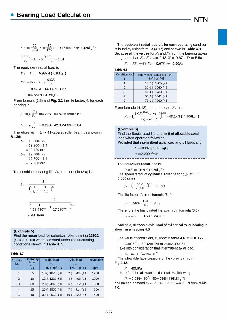
From formula (4.12) the mean load, Fm, is:
Fm =〔Σ(Pri
10/3・ni・φi)
〕3/10
=48.1kN{4,906kgf}Σ(ni・φi)
――――――――――――――――――――――――――――――――――――(Example 6)Find the Basic rated life and limit of allowable axial load when operated following.Provided that intermittent axial load and oil lubricant.
Fr=10kN{1,020kgf}
n=2,000 r/min――――――――――――――――――――――――――――――――――――
The equivalent radial load is:
Pr=Fr=10kN{1,020kgf}The speed factor of cylindrical roller bearing, fn, at n=2,000 r/min
fn=〔 33.3 〕3/10=0.2932,000
The life factor, f h, from formula (3.4)
f h=0.293×124
=3.6310
There fore the basic rated life, L10h ,from formula (3.3)
L10h =500×3.63 ≒24,000
And next, allowable axial load of cylindrical roller bearing isshown in a heading 4.5.
The value of coefficient, k, show in table 4.6. k = 0.065
dp=(60+130)/2=95mm,n=2,000 r/min Take into consideration that intermittent axial load.
dp・n×104=19×104
The allowable face pressure of the collar, Pt , fromFig.4.13.
Pt =40MPaThere fore the allowable axial load, Pz, following
Pz =0.065×602×40=936N{95.5kgf}and meet a demand Fa max<0.4×10,000=4,000N from table4.6.
Fr2=70
Kr=70 ×10.16=4.18kN{426kgf}170 170
0.5Fr1=1.87>
0.5Fr2=1.31
Y1 Y2
The equivalent radial load is:
Pr1=Fr1=5.98kN{610kgf}
Pr2=XFr2+Y20.5Fr1
Y1
=0.4×4.18+1.67×1.87
=4.66kN{475kgf}
From formula (3.3) and Fig. 3.1 the life factor, fh, for eachbearing is:
f h1= fnCr1=0.293×54.5/5.98=2.67
Pr1
f h2= fnCr2=0.293×42.0/4.66=2.64
Pr2
Therefore: a2 = 1.4(4T-tapered roller bearings shown inB-136)
Lh1=13,200×a2
=13,200×1.4=18,480 ore
Lh2=12,700×a2
=12,700×1.4=17,780 ore
The combined bearing life, Lh, from formula (3.6) is:
1Lh=
〔 1 + 1 〕1/e
Lh1e
Lh2e
1=
〔 1 + 1 〕8/9
18,4809/8 17,7809/8
=9,780 hour
――――――――――――――――――――――――――――――――――――(Example 5)Find the mean load for spherical roller bearing 23932(La = 320 kN) when operated under the fluctuatingconditions shown in Table 4.7.――――――――――――――――――――――――――――――――――――
A-27
The equivalent radial load, Pr, for each operating conditionis found by using formula (4.17) and shown in Table 4.8.Because all the values for Fri and Fai from the bearing tablesare greater than Fa / Fr > e= 0.18, X= 0.67 e Y2= 5.50.
Pri = XFri+Y2 Fai= 0.67Fri+ 5.50Fai
ConditionNo.i
Operatingtime
Radial load Axial load Revolution
φiFri
%� kN{ kgf }� rpm
1 5 1200
2 10 1000
3 60 800
4 15 600
5 10 400
Fai ni
2{ 204 }�10{ 1020 }�
12{ 1220 }�
20{ 2040 }�
25{ 2550 }�
30{ 3060 }�
4{ 408 }�
6{ 612 }�
7{ 714 }�
10{ 1020 }�
kN{ kgf }�
Table 4.7
Table 4.8
Condition No.�i
Equivalent radial load. Pri
kN{ kgf }�
12345
17.7{ 1805 }�30.0{ 3060 }�46.4{ 4733 }�55.3{ 5641 }�75.1{ 7660 }�
●Bearing Load Calculation

A-28
●Boundary Dimensions and Bearing Number Codes
5.1 Boundary dimensionsA rolling bearing's major dimensions, known as
"boundary dimensions," are shown in Figs. 5.1 - 5.3. Tofacilitate international bearing interchangeability andeconomical bearing production, bearing boundarydimensions have been standardized by the InternationalStandards Organization (ISO). In Japan, rolling bearingboundary dimensions are regulated by Japanese IndustrialStandards (JIS B 1512).
Those boundary dimensions which have beenstandardized include: bearing bore diameter, outsidediameter, width/height, and chamfer dimensions - allimportant dimensions when considering the compatibility
B
d D
r
r
r r
r
r
r r
T
C
d D
r
r
B
r1 r1
α
E
d1
d
D1
D
rT
r
rr
Fig. 5.1 Radial bearings(excluding tapered roller bearings)
Fig. 5.2 Tapered roller bearings Fig. 5.3 Single direction thrust bearings
Fig. 5.4 Dimension series for radial bearings (excluding tapered roller bearings)
82
8 0 1
83
08 010900
02 03 04
18191011
12 13 2928
202122 23 24
383930
3132 33 48 49 40 41 42 58 59 50 68 69 60
2 3 4 5 6
89012
3
4
Widthseries
Diameterseries
Dimensionseries
Fig. 5.5 Dimension series for tapered roller bearings Fig. 5.6 Dimension series forthrust bearings
Diameterseries
3
Widthseries
2
109
2 2
3
3 0 2 3 0 1 2
Radial bearings(excluding tapered rollerbearings)
Tapered roller bearings
Thrust bearings
number
dimensions
number
number
dimensions
7, 8, 9, 0, 1, 2, 3, 4 8, 0, 1, 2, 3, 4, 5, 6
7, 9, 1, 2
small large small large
small large
9, 0, 1, 2, 3
small large
0, 1, 2, 3, 4
small large
0, 1, 2, 3
Diameter series(outer diameter dimensions)
Width series(width dimensions)
Height series(height dimensions)
Dimension series
Referencediagram
Diagram 5.4
Diagram 5.5
Diagram 5.6
dimensions small large
of shafts, bearings, and housings. However, as a generalrule, bearing internal construction dimensions are notcovered by these dimensions.
For metric rolling bearings there are 90 standardizedbore diameters (d) ranging in size from 0.6mm - 2,500mm.
Outer diameter dimensions (D) for radial bearings withstandardized bore diameter dimensions are covered in the"diameter series;" their corresponding width dimensions(B) are covered in the "width series." For thrust bearingsthere is no width series; instead, these dimensions arecovered in the "height series." The combination of allthese series is known as the "dimension series." All seriesnumbers are shown in Table 5.1.
Although many rolling bearing dimensions are
Table 5.1 Dimension series numbers
7071
7273
74
9091
9293
94
101112
13
14
22
23
24
01 2 3 4
7
9
1
2
Dimensionseries
Diameterseries Height series
5. Boundary Dimensions and Bearing Number Codes

A-29
●Boundary Dimensions and Bearing Number Codes
standardized, and have been listed here for purposes offuture standardization, there are many standard bearingdimensions which are not presently manufactured.
Boundary dimensions for radial bearings (excludingtapered roller bearings) are shown in the attached tables.
5.2 Bearing numbersRolling bearing part numbers indicate bearing type,
dimensions, tolerances, internal construction, and other
(Bearing number examples)
6 2 0 5 Z Z C 3/2 A
Shell Alvania 2 grease
Radial internal clearance C3
shielded (both)
Nominal bore diameter 25mm
Diameter series 2
Deep groove ball bearing
2 4 0/7 5 0 B K 3 0
Type B
Nominal bore diameter 750mm
Dimension series 0
Width series 4
Spherical roller bearing
7 0 1 2 C D B/G M P 4
Tolerances JIS Class 4
Medium preload
Back-to-back duplex arrangement
Contact angle 15° Nominal bore diameter 60mm
Dimension series 0
Angular contact ball bearing
5 1 1 2 0 L 1 P 5
Tolerances JIS Class 5
High strength, machinedbrass cage
Nominal bore diameter 100mm
Diameter series 1
Height series 1
Thrust ball bearing
N U 3 2 0 G 1 C 3
Radial internal clearance C3
High strength machined brass
rivetless cage with square holes
Dimension series 3
Cylindrical roller bearing NU type
4 T-3 0 2 0 8
Nominal bore diameter 40mm
Diameter series 2
Width series 0
Tapered roller bearing
Spec. 4T (top tapered)
2 3 0 3 4 B D 1Lubrication hole/lubrication groove
(when outer diameter is less than 320mm)
Type B
Nominal bore diameter 170mm
Dimension series 0
Width series 3
Spherical roller bearing
Bore diameter: tapered innerring bore, standard taper ratio 1:30
related specifications. Bearing numbers are comprised of a"basic number" followed by "supplementary codes." Themakeup and order of bearing numbers is shown in Table 5.2.
The basic number indicates general information about abearing, such as its fundamental type, boundarydimensions, series number, bore diameter code andcontact angle. The supplementary codes derive fromprefixes and suffixes which indicate a bearing's tolerances,internal clearances, and related specifications.

●Boundary Dimensions and Bearing Number Codes
A-30
Table 5.2 Bearing number composition and arrangement
Bearingseries code
Deep groove ball bearings (type code 6)6869606263
(1)(1)(1)(0)(0)
Width/height series Diameter series
89023
Basic numbersSupplementary prefix code
4T:
ET:
E:
F:
H:
M:
5S:
HL:
TS2:
TS3:
TS4:
4T tapered roller bearings
ET tapered roller bearings
carburized alloy steelbearings
stainless steel bearings
high speed steel bearings
plated bearings
ceramic rolling elementbearings
HL (high lubrication) rollerbearings
dimension stabilizedbearing for hightemperature use(to 160°C)
dimension stabilizedbearing for hightemperature use(to 200°C)
dimension stabilizedbearing for hightemperature use(to 250°C)
Basic number
Dimension series codeSpecial application/material/
heat treatment code
Angular contact ball bearings (type code 7)7879707273
(1)(1)(1)(0)(0)
89023
Self-aligning ball bearings (type code 1,2)12132223
(0)(0)(2)(2)
2323
Cylindrical roller bearings (type code NU, N, NF, NNU, NN, etc.)NU10NU2NU22NU3NU23
NU4NNU49
NN30
1(0)2
(0)2
(0)43
02233490
Tapered roller bearings (type code 3)329X320X302322303303D313X
323
22020012
90223333
Spherical roller bearings (type code 2)239230240231241222232213
223
334342312
900112233
Single direction thrust ball bearings (type code 5)511512513
514
1111
1234
Cylindrical roller thrust bearings (type code 8)811812
893
119
123
Self-aligning thrust roller bearings (type code 2)292293
294
999
234
Bore diameter number Contact angle codebore
diameter mmCode
/0.6/1.5/2.5
1
9
00010203
/22/28/32
040506
889296
/500/530/560
/2,360/2,500
…�
…�
0.6 1.5 2.5
1
9
10121517
222832
202530
440460480
500530560
2,3602,500
…�
…�
…�Code Contact angle
11
(A)BC
(B)CD
Standard contact angle 30˚Standard contact angle 40˚Standard contact angle 15˚
Contact angle over 10˚to/including 17˚Contact angle over 17˚to/including 24˚Contact angle over 24˚to/including 32˚
Angular contact ball bearings
Tapered roller bearings
1 Codes in ( ) are not shown in nominal numbers.Note: Please consult NTN Engineering concerning bearing series codes, and supplementary prefix/suffix codes not listed in the above table.
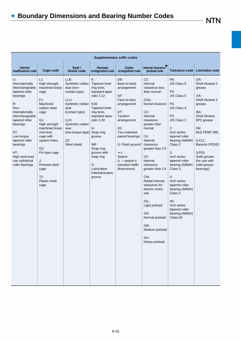
●Boundary Dimensions and Bearing Number Codes
A-31
U:Internationallyinterchangeabletapered rollerbearings
R:Non-internationallyinterchangeabletapered rollerbearings
ST:Low torquetapered rollerbearings
HT: High axial loaduse cylindricalroller bearings
Internalmodifications code Cage code
Seal /Shield code
Racewayconfiguration code
Duplexarrangement code Tolerance code
L1: High strength, machined brasscage
F1:Machinedcarbon steelcage
G1: High strengthmachined brassrivet-lesscage withsquare holes,
G2: Pin type cage
J: Pressed steelcage
T2:Plastic moldcage
LLB:Synthetic rubberseal (non-contact type)
LLU:Synthetic rubberseal(contact type)
LLH:Synthetic rubberseal(low-torque type)
ZZ:Steel shield
K:Tapered innerring bore,standard taperratio 1:12
K30:Tapered innerring bore,standard taperratio 1:30
N:Snap ringgroove
NR:Snap ringgroove withsnap ring
D: Lubricationhole/lubrication groove
DB:Back-to-backarrangement
DF:Face-to-facearrangement
DT:Tandemarrangement
D2:Two matched,paired bearings
G: Flush ground
+α: Spacer(α= spacer’sstandard widthdimensions)
C2:Internalclearance lessthan normal
(CN):Normal clearance
C3:Internalclearancegreater thannormal
C4:Internalclearancegreater than C3
C5:Internalclearancegreater than C4
CM:Radial internalclearance forelectric motoruse
/GL:Light preload
GN:Normal preload
GM:Medium preload
GH:Heavy preload
P6:JIS Class 6
P5:JIS Class 5
P4:JIS Class 4
P2:JIS Class 2
2:Inch seriestapered rollerbearing (ABMA)Class 2
3:Inch seriestapered rollerbearing (ABMA)Class 3
0:Inch seriestapered rollerbearing (ABMA)Class 0
00:Inch seriestapered rollerbearing (ABMA)Class 00
/2A:Shell Alvania 2grease
/3A:Shell Alvania 3grease
/8A:Shell AlvaniaEP2 grease
/5K:MULTEMP SRL
/LX11:Barierta JFE552
/LP03:Solid grease(for use withsolid greasebearings)
Lubrication code
Supplementary suffix codes
Internal clearance /preload code
1

A-30
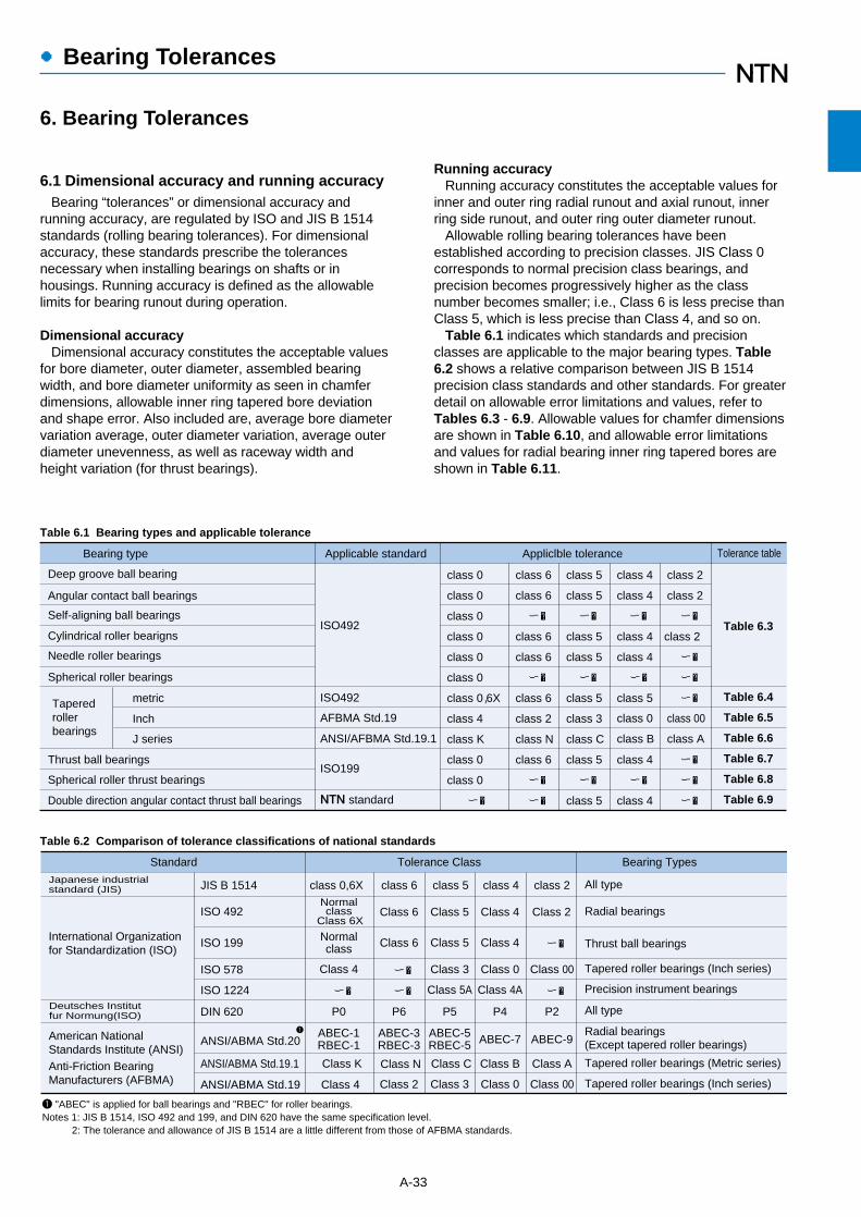
A-33
●Bearing Tolerances
6.1 Dimensional accuracy and running accuracyBearing “tolerances” or dimensional accuracy and
running accuracy, are regulated by ISO and JIS B 1514standards (rolling bearing tolerances). For dimensionalaccuracy, these standards prescribe the tolerancesnecessary when installing bearings on shafts or inhousings. Running accuracy is defined as the allowablelimits for bearing runout during operation.
Dimensional accuracyDimensional accuracy constitutes the acceptable values
for bore diameter, outer diameter, assembled bearingwidth, and bore diameter uniformity as seen in chamferdimensions, allowable inner ring tapered bore deviationand shape error. Also included are, average bore diametervariation average, outer diameter variation, average outerdiameter unevenness, as well as raceway width andheight variation (for thrust bearings).
Running accuracyRunning accuracy constitutes the acceptable values for
inner and outer ring radial runout and axial runout, innerring side runout, and outer ring outer diameter runout.
Allowable rolling bearing tolerances have beenestablished according to precision classes. JIS Class 0corresponds to normal precision class bearings, andprecision becomes progressively higher as the classnumber becomes smaller; i.e., Class 6 is less precise thanClass 5, which is less precise than Class 4, and so on.
Table 6.1 indicates which standards and precisionclasses are applicable to the major bearing types. Table6.2 shows a relative comparison between JIS B 1514precision class standards and other standards. For greaterdetail on allowable error limitations and values, refer toTables 6.3 - 6.9. Allowable values for chamfer dimensionsare shown in Table 6.10, and allowable error limitationsand values for radial bearing inner ring tapered bores areshown in Table 6.11.
Table 6.1 Bearing types and applicable tolerance
Table 6.2 Comparison of tolerance classifications of national standards
Bearing type
Deep groove ball bearing
Spherical roller thrust bearings
Double direction angular contact thrust ball bearings
Thrust ball bearings
Spherical roller bearings
Taperedrollerbearings
Cylindrical roller bearigns
Self-aligning ball bearings
Angular contact ball bearings
Needle roller bearings
Applicable standard Appliclble tolerance Tolerance table
metric
Inch
J series
ISO492
ISO492
AFBMA Std.19
ANSI/AFBMA Std.19.1
ISO199
NTN standard
class 0
class 0
class 0
class 0
class 0
class 0
class 0,6X
class 4
class K
class 0
class 0
ー�
class 6
class 6
class 6
class 6
class 6
class 2
class N
class 6
class 5
class 5
class C
class 3
class 5
class 5
class 5
class 5
class 5 class 4
class 4
class 4
class 4
class 5
class 0
class B
class 4
class 4
class A
class 00
class 2
class 2
class 2
ー�
ー� ー� ー� ー�
ー�
ー�
ー�
ー�
ー�
ー� ー� ー� ー�
ー� ー� ー�
Table 6.3
Table 6.4
Table 6.5
Table 6.6
Table 6.7
Table 6.8
Table 6.9
Standard
Japanese industrial standard (JIS)
Tolerance Class Bearing Types
class 0,6X class 6 class 2
International Organizationfor Standardization (ISO)
Deutsches Institutfur Normung(ISO)
American NationalStandards Institute (ANSI)
class 5 class 4JIS B 1514
ISO 492
ISO 199
ISO 578
ISO 1224
DIN 620
ANSI/ABMA Std.20
ANSI/ABMA Std.19.1
ANSI/ABMA Std.19
Normalclass
Class 6XClass 6
Class 6
Class N
Class 2
Normalclass
Class 4
P0
ABEC-1RBEC-1
Class K
Class 4
Class 5 Class 4 Class 2
Class 5 Class 4
Class 3 Class 0 Class 00
Class 5A Class 4A
Class C Class B Class A
Class 3 Class 0 Class 00
ABEC-3RBEC-3
ABEC-5RBEC-5 ABEC-7 ABEC-9
P6 P5 P4 P2
ー�
ー� ー� ー�
ー�
All type
Radial bearings
Thrust ball bearings
Tapered roller bearings (Inch series)
Precision instrument bearings
All type
Radial bearings (Except tapered roller bearings)
Tapered roller bearings (Metric series)
Tapered roller bearings (Inch series)
Anti-Friction Bearing Manufacturers (AFBMA)
1
1 "ABEC" is applied for ball bearings and "RBEC" for roller bearings.Notes 1: JIS B 1514, ISO 492 and 199, and DIN 620 have the same specification level.
2: The tolerance and allowance of JIS B 1514 are a little different from those of AFBMA standards.
6. Bearing Tolerances

●Bearing Tolerances
A-34
Table 6.3 Tolerance for radial bearings (Except tapered roller bearings)Table 6.3 (1) Inner rings
Table 6.3 (2) Outer rings
Nominal bore diameter
d
mm
over incl.
0.6 2.5
10
183050
80120150
180250315
400500630
8001,0001,250 1,600
2.51018
305080
120150180
250315400
500630800
1,0001,2501,600 2,000
Single plane mean bore diameter deviation�
∆dmp
�
�
000
000
000
000
000
000 0
000
000
000
000
00ー
ーーーー
000
000
000
000
ーーー
ーーー ー
-5-5-5
-6-8-9
-10-13-13
-15-18-23
ーーー
ーーーー
000
000
000
0ーー
ーーー
ーーー ー
-4-4-4
-5-6-7
-8-10-10
-12ーー
ーーー
ーーーー
000
000
000
0ーー
ーーー
ーーーー
-2.5-2.5-2.5
-2.5-2.5-4
-5-7-7
-8ーー
ーーー
ーーーー
-8-8-8
-10-12-15
-20-25-25
-30-35-40
-45-50-75
-100-125-160-200
-7-7-7
-8-10-12
-15-18-18
-22-25-30
-35-40ー
ーーーー
Single radial plane bore diameter variation�
Vdp�
�
�
101010
131519
253131
384450
566394
125155200250
999
101315
192323
283138
4450ー
ーーーー
555
689
101313
151823
ーーー
ーーーー
444
567
81010
12ーー
ーーー
ーーーー
2.52.52.5
2.52.54
577
8ーー
ーーー
ーーーー
888
101219
253131
384450
566394
125155200250
777
81015
192323
283138
4450ー
ーーーー
444
567
81010
121418
ーーー
ーーーー
333
455
688
9ーー
ーーー
ーーーー
2.52.52.5
2.52.54
577
8ーー
ーーー
ーーーー
666
89
11
151919
232630
343855
7594
120150
555
689
111414
171923
2630ー
ーーーー
444
567
81010
121418
ーーー
ーーーー
333
455
688
9ーー
ーーー
ーーーー
2.52.52.5
2.52.54
577
8ーー
ーーー
ーーーー
1 The dimensional difference ∆ds of bore diameter to applied for class 4 and 2 is the same as the tolerance of dimentional difference ∆dmp of average bore diameter. However, the dimensional difference is applied to diameter series 0, 1, 2, 3 and 4 against Class 4, and to all the diameter series against Class 2.
4)
1 1
high low high low high low high low high low
class 0 class 6 class 5 class 4 class 2
diameter series 9 class
0class
6class
5class
4class
2
max
maxdiameter series 0.1 class
0class
6class
5class
4class
2
max
maxdiameter series 2.3.4class
0class
6class
5class
4class
2
max
Nominal outside diameter
D
mm
over incl.
2.5 6 18
30 50 80
120 150 180
250 315 400
500 630 800
1,000 1,250 1,600 2,000
61830
5080
120
150180250
315400500
630800
1,000
1,2501,6002,0002,500
Single plane mean outside diameter deviation
∆Dmp
�
�
�
000
000
000
000
000
000 0
000
000
000
000
000
ーーーー
000
000
000
000
00ー
ーーーー
-5-5-6
-7-9
-10
-11-13-15
-18-20-23
-28-35ー
ーーーー
000
000
000
00ー
ーーー
ーーー ー
-4-4-5
-6-7-8
-9-10-11
-13-15ー
ーーー
ーーーー
000
000
000
00ー
ーーー
ーーーー
-2.5 -2.5 -4
-4 -4 -5
-5 -7 -8
-8-10 ー
ー ー ー
ー ー ー ー
-8-8-9
-11-13-15
-18-25-30
-35-40-45
-50-75
-100
-125-160-200-250
-7-7-8
-9-11-13
-15-18-20
-25-28-33
-38-45-60
ーーーー
Single radial plane outside diameter variation
VDp�
open type
101012
141619
233138
445056
6394
125
155200250310
99
10
111416
192325
313541
485675
ーーーー
556
79
10
111315
182023
2835ー
ーーーー
445
678
91011
1315ー
ーーー
ーーーー
2.52.54
445
578
810ー
ーーー
ーーーー
889
111319
233138
445056
6394
125
155200250310
778
91116
192325
313541
485675
ーーーー
445
578
81011
141517
2126ー
ーーーー
334
556
788
1011ー
ーーー
ーーーー
667
81011
141923
263034
385575
94120150190
556
78
10
111415
192125
293445
ーーーー
445
578
81011
141517
2126ー
ーーーー
334
556
788
1011ー
ーーー
ーーーー
5 The dimensional difference ∆Ds of outer diameter to be applied for classes 4 and 2 is the same as the tolerance of dimensional difference ∆Dmp of average outer diameter. However, the dimensional difference is applied to diameter series 0, 1, 2, 3 and 4 against Class 4, and also to all the diameter series against Class 2.
2.52.54
445
578
810ー
ーーー
ーーーー
2.52.54
445
578
810ー
ーーー
ーーーー
8
5 5
high low high low high low high low high low
class 0 class 6 class 5 class 4 class 2
diameter series 9class
0class
6class
5class
4class
2
max
maxdiameter series 0.1class
0class
6class
5class
4class
2
max
maxdiameter series 2.3.4class
0class
6class
5class
4class
2
max

A-35
●Bearing Tolerances
Mean single planebore diameter variation
Vdmp�
�
�
�
666
89
11
151919
232630
343855
7594
120150
555
689
111414
171923
2630ー
ーーーー
333
345
577
89
12
ーーー
ーーーー
222
2.533.5
455
6ーー
ーーー
ーーーー
1.51.51.5
1.51.52
2.53.53.5
4ーー
ーーー
ーーーー
101010
131520
253030
405060
657080
90100120140
567
81010
131818
202530
3540ー
ーーーー
444
455
688
101315
ーーー
ーーーー
2.52.52.5
344
566
8ーー
ーーー
ーーーー
1.51.51.5
2.52.52.5
2.52.55
5ーー
ーーー
ーーーー
777
888
91010
111315
ーーー
ーーーー
333
445
566
7ーー
ーーー
ーーーー
1.51.51.5
1.51.51.5
2.52.54
5ーー
ーーー
ーーーー
Inner ringradial runout
Kia�
�
�
�
Unitμm
Face runoutwith bore
Sd�
�
�
�
Inner ringaxial runout(with side)
Sia
�
�
777
888
91010
131520
ーーー
ーーーー
333
445
577
8ーー
ーーー
ーーーー
2.52.52.5
2.534
455
6ーー
ーーー
ーーーー
Inner ring width deviation
∆Bs�
�
�
000
000
000
000
000
0000
-40-120-120
-120-120-150
-200-250-250
-300-350-400
-450-500-750
-1,000-1,250-1,600-2,000
000
000
000
000
ーーー
ーーーー
-40-40-80
-120-120-150
-200-250-250
-300-350-400
ーーー
ーーーー
000
000
000
0ーー
ーーー
ーーーー
-40-40-80
-120-120-150
-200-250-250
-300ーー
ーーー
ーーーー
ー-250-250
-250-250-380
-380-500-500
-500-500-630
ーーー
ーーーー
�ー00
000
000
000
ーーー
ーーーー
000
000
000
000
ーーー
ーーーー
-250-250-250
-250-250-250
-380-380-380
-500-500-630
ーーー
ーーーー
Inner ring widthvarietion
VBs�
�
�
�
121520
202025
253030
303540
506070
80100120140
121520
202025
253030
303540
4550ー
ーーーー
555
556
788
101315
ーーー
ーーーー
1.51.51.5
1.51.51.5
2.52.54
5ーー
ーーー
ーーーー
1.51.51.5
2.52.52.5
2.52.55
5ーー
ーーー
ーーーー
2 To be applied for deep groove ball bearing and angular contact ball bearings.3 To be applied for individual raceway rings manufactured for combined bearing use.4 Nominal bore diameter of bearings of 0.6 mm is included in this dimensional division.
23
class 0
class 6
class 5
class 4
class 2
max
class 0
class 6
class 5
class 5
class 4
class 2
class 4
class 2
max max
class 5
class 4
class 2
max high low high lowhigh low
normal
class 0,6 class 5,4
high low high low
class 0,6 class 5,4class 2
modifiedclass
0class
6class
5class
4class
2
max
�
2,3,4 0,1,2,3,4
101012
162026
3038ー
ーーー
ーーー
ーーーー
99
10
131620
2530ー
ーーー
ーーー
ーーーー
667
81011
141923
263034
385575
94120150190
556
78
10
111415
192125
293445
ーーーー
333
455
678
91012
1418ー
ーーーー
222.5
33.54
556
78ー
ーーー
ーーーー
1.51.52
222.5
2.53.54
45ー
ーーー
ーーーー
Mean single planeoutside diameter
variationVDmp����
Unit μm
Outer ring radial runout
Kea�
�
�
2.52.52.5
2.534
557
78ー
ーーー
ーーーー
Outside surfaceinclination
SD�
�
�
�
�
�
class 0,6
555
568
88
10
111315
1820ー
ーーーー
1.51.51.5
1.51.52.5
2.52.54
57ー
ーーー
ーーーー
6 To be applied in case snap rings are not installed on the bearings.7 To be applied for deep groove ball bearings and angular contact ball bearings.8 Nominal outer diameter of bearings of 2.5 mm is included in this dimensional division.
151515
202535
404550
607080
100120140
160190220250
889
101318
202325
303540
506075
ーーーー
556
78
10
111315
182023
2530ー
ーーーー
334
556
78
10
1113ー
ーーー
ーーーー
1.51.52.5
2.545
557
78ー
ーーー
ーーーー
888
889
101011
131315
1820ー
ーーーー
444
445
557
810ー
ーーー
ーーーー
1.51.51.5
1.51.52.5
2.52.54
57ー
ーーー
ーーーー
Outside ringaxial runout
Sea�
�
�
888
81011
131415
182023
2530ー
ーーーー
555
556
78
10
1013ー
ーーー
ーーーー
1.51.52.5
2.545
557
78ー
ーーー
ーーーー
Outer ringwidth
deviation�
∆Cs
�
all type
Identical to ∆Bs of innerring of samebearing
Identical to∆Bs and VBs
of innerring ofsamebearing
6 7
class 0 class 0 class 6
class 6
class 5
class 4
class 2
max
class 0
class 6
class 5
class 4
class 2
max
class 5
class 4
class 2
max
class 5
class 4
class 2
max
class 5
class 4
class 2
maxmax
Single radial planeoutside diameter
variation VDp�capped bearingsdiameter series
Outer ring widthvariation
VCs�
�

●Bearing Tolerances
A-36
Table 6.4 Tolerance of tapered roller bearings (Metric system)
Table 6.4 (1) Inner rings
Table 6.4 (2) Outer rings
Nominal bore diameter
d�
mm
� over incl.
101830
5080
120
180250315
400500630
800
183050
80120180
250315400
500630800
1,000
Single plane mean borediameter deviation
∆dmp�
�
�
000
000
000
000
0
000
000
0ーー
ーーー
ー
000
000
0ーー
ーーー
ー
-5-6-8
-9-10-13
-15ーー
ーーー
ー
-12-12-12
-15-20-25
-30-35-40
-45-50-75
-100
-7-8
-10
-12-15-18
-22ーー
ーーー
ー
1 The dimensional difference ∆ds of bore diameter to be applied for class 4 is the same as the tolerance of dimensional difference ∆dmp of average bore diameter.
Single radial planebore diameter variation
Vdp
121212
152025
303540
455075
100
78
10
121518
22ーー
ーーー
ー
568
91114
17ーー
ーーー
ー
456
78
10
11ーー
ーーー
ー
Mean single planebore diameter variation
Vdmp
999
111519
232630
343856
75
568
91114
16ーー
ーーー
ー
555
689
11ーー
ーーー
ー
445
557
8ーー
ーーー
ー
Inner ring radial runout
Kia
151820
253035
506070
8090
105
120
78
10
101318
20ーー
ーーー
ー
556
78
11
13ーー
ーーー
ー
334
456
8ーー
ーーー
ー
Facerunout
with bore
Sd�
�
�
788
89
10
11ーー
ーーー
ー
344
556
7ーー
ーーー
ー
1class 0,6X class 5,6
max
class 4class0,6X
class6
class5
class4
max
class0,6X
class6
class5
class4
max
class0,6X
class6
class5
class4
class5
class4
max max
Nominal outside diameter
D�
mm
�over incl.
183050
80120150
180250315
400500630
8001,0001,250
305080
120150180
250315400
500630800
1,0001,2501,600
Single plane mean outsidediameter deviation
∆Dmp
�
�
000
000
000
000
000
000
000
000
ーーー
ーーー
000
000
000
ーーー
ーーー
-6-7-9
-10-11-13
-15-18-20
ーーー
ーーー
-12-14-16
-18-20-25
-30-35-40
-45-50-75
-100-125-160
-8-9
-11
-13-15-18
-20-25-28
ーーー
ーーー
2 The dimensional difference ∆Ds of outside diameter to be applied for class 4 is the same as the tolerance of dimensional difference ∆Dmp of average outside diameter.3 The dimensional difference ∆ds of bore diameter to be applied for class 4 is the same as the tolerance of dimensional difference ∆dmp of average bore diameter.
Single radial planeoutside diameter
variation
VDp�
�
�
121416
182025
303540
455075
100125160
89
11
131518
202528
ーーー
ーーー
678
101114
151922
ーーー
ーーー
557
88
10
111415
ーーー
ーーー
Mean single planeoutside diameter
variation
VDmp
�
�
91112
141519
232630
343856
7584
120
678
101114
151921
ーーー
ーーー
556
789
101314
ーーー
ーーー
455
567
89
10
ーーー
ーーー
Outer ring radial runout
Kea
�
�
182025
354045
506070
80100120
140165190
91013
182023
253035
ーーー
ーーー
678
101113
151820
ーーー
ーーー
455
678
101113
ーーー
ーーー
Outsidesurface
inclination
SD�
�
888
91010
111313
ーーー
ーーー
444
555
78
10
ーーー
ーーー
2
3class 0,6X class 5,6
max
class 4class0,6X
class6
class5
class4
max
class0,6X
class6
class5
class4
max
class0,6X
class6
class5
class4
max
class5
class4
max
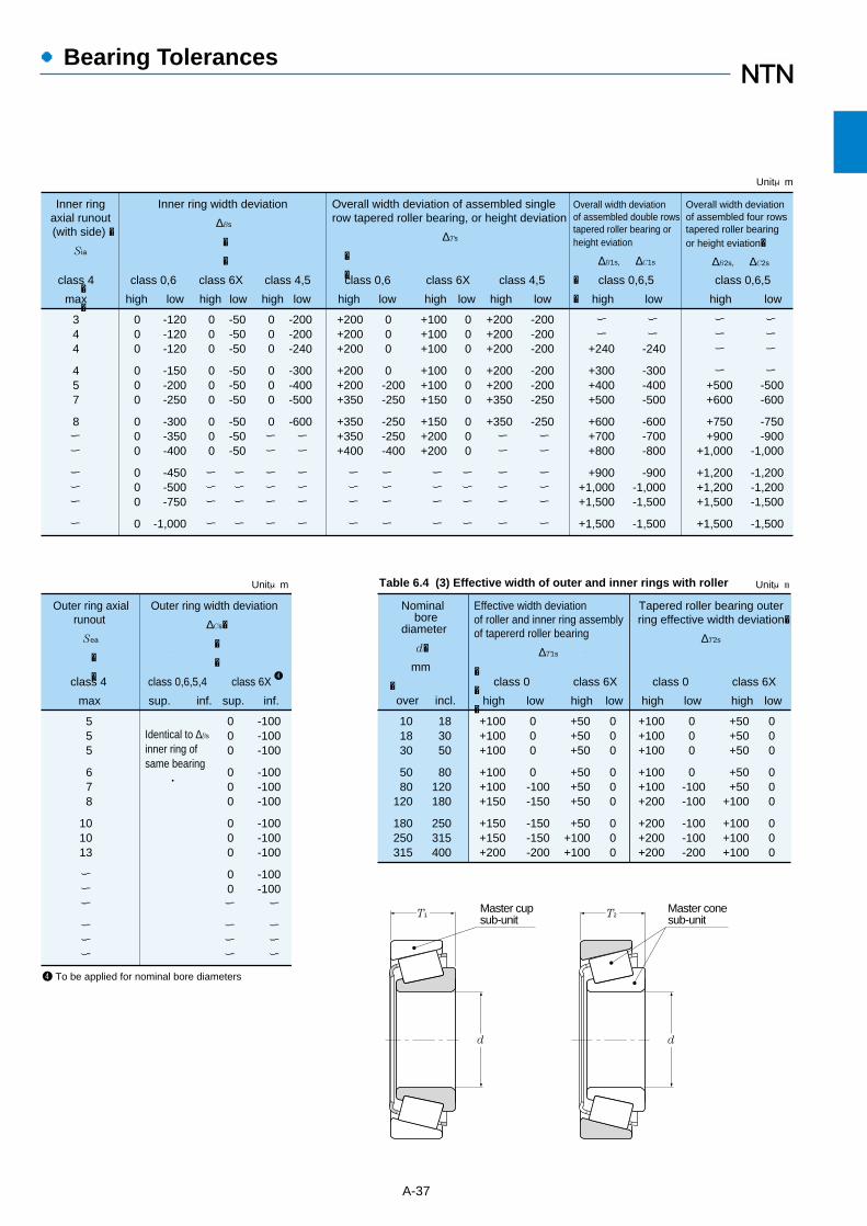
●Bearing Tolerances
A-37
Table 6.4 (3) Effective width of outer and inner rings with roller
Inner ringaxial runout(with side) �
Sia
�
�
Inner ring width deviation
∆Bs
�
�
000
000
000
000
0
000
000
000
ーーー
ー
000
000
0ーー
ーーー
ー
-200-200-240
-300-400-500
-600ー ー
ー ー ー
ー
-120-120-120
-150-200-250
-300-350-400
-450-500-750
-1,000
-50-50-50
-50-50-50
-50-50-50
ーーー
ー
∆Ts
�
�
+200+200+200
+200+200+350
+350+350+400
ー ー ー
ー
0 0 0
0 -200 -250
-250 -250 -400
ー ー ー
ー
ー ー
+240
+300+400+500
+600+700+800
+900+1,000+1,500
+1,500
Overall width deviationof assembled double rowstapered roller bearing orheight eviation
∆B1s, ∆C1s
�
�
Overall width deviationof assembled four rowstapered roller bearingor height eviation�
∆B2s, ∆C2s
344
457
8ーー
ーーー
ー
+100+100+100
+100+100+150
+150+200+200
ー ー ー
ー
000
000
000
ーーー
ー
+200+200+200
+200+200+350
+350ー ー
ー ー ー
ー
-200-200-200
-200-200-250
-250ー ー
ー ー ー
ー
ー ー
-240
-300-400-500
-600-700-800
-900-1,000-1,500
-1,500
ー ー ー
ー +500+600
+750+900
+1,000
+1,200+1,200+1,500
+1,500
ー ー ー
ー -500-600
-750-900
-1,000
-1,200-1,200-1,500
-1,500
Unitμm
class 4
max
class 0,6 class 6X class 4,5
high low high low high low
class 0,6 class 6X class 4,5
high low high low high low
class 0,6,5
high low
class 0,6,5
high low
Overall width deviation of assembled singlerow tapered roller bearing, or height deviation
Outer ring axialrunout
Sea
�
�
Outer ring width deviation
∆Cs�
�
�
000
000
000
00ー
ーーー
-100-100-100
-100-100-100
-100-100-100
-100-100ー
ーーー
555
678
101013
ーーー
ーーー
Identical to ∆Bs
inner ring ofsame bearing
Unitμm
4
4 To be applied for nominal bore diameters
class 0,6,5,4 class 6Xclass 4
max sup. inf. sup. inf.
Nominal bore diameter
d�
mm
� over incl.
Effective width deviationof roller and inner ring assemblyof tapererd roller bearing
∆T1s
�
�
�+100+100+100
+100 +100+150
+150+150+200
101830
5080
120
180250315
Unitμm
183050
80120180
250315400
0 0 0
0 -100 -150
-150 -150 -200
+50+50+50
+50 +50+50
+50+100+100
000
000
000
Tapered roller bearing outerring effective width deviation�
∆T2s
+100+100+100
+100 +100+200
+200+200+200
0 0 0
0-100-100
-100-100-200
+50+50+50
+50 +50
+100
+100+100+100
000
000
000
class 0 class 6X
high low high low
class 0 class 6X
high low high low
Master conesub-unit
Master cupsub-unit
T1 T2
d d
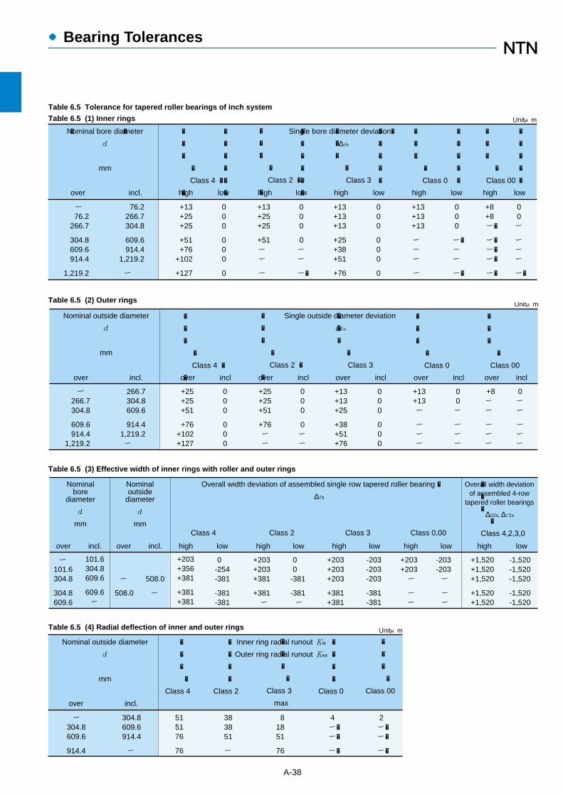
●Bearing Tolerances
A-38
Table 6.5 Tolerance for tapered roller bearings of inch system
Table 6.5 (1) Inner rings
Table 6.5 (2) Outer rings
Table 6.5 (3) Effective width of inner rings with roller and outer rings
Table 6.5 (4) Radial deflection of inner and outer rings
Single bore diameter deviation�
∆ds
�
�
�
�
Class 4 �
�
+13+25+25
+51+76
+102
+127
000
000
0
+13+25+25
+51ー ー
ー
000
0ーー
ー�
+13+13+13
+25+38+51
+76
000
000
0
+13+13+13
ー ー ー
ー
000
ー�ーー
ー�
+8+8ー�
ー�ー�ー�
ー�
00ー
ーーー
ー�
�
�
�
�
Class 2 �
�
�
�
�
�
Class 3
�
�
�
�
Class 0
�
�
�
�
Class 00
�
�
�
�
�
�
�
�
�
�
�
�
�
�
�
�
�
�
�
�
�
�
�
�
�
�
�
Unitμm
Nominal bore diameter
d
mm
ー 76.2
266.7
304.8609.6914.4
1,219.2
76.2266.7304.8
609.6914.4
1,219.2
ー
� �
over incl. high low high low high low high low high low
Nominal outside diameter
d
mm
Single outside diameter deviation
∆Ds
ー 266.7304.8
609.6914.4
1,219.2
266.7304.8609.6
914.41,219.2ー
+25+25+51
+76+102+127
000
000
+25+25+51
+76ー ー
000
0ーー
+13+13+25
+38+51+76
000
000
+13+13ー
ー ー ー
00ー
ーーー
+8ー ー
ー ー ー
0ーー
ーーー
Unitμm
over incl.
�
�
�
�
Class 4 �
�
�
�
�
�
Class 2 �
�
�
�
�
�
Class 3
�
�
�
�
Class 0
�
�
�
�
Class 00
over incl over incl over incl over incl over incl
Nominalbore
diameter
d
mm
Overall width deviation of assembled single row tapered roller bearing �
∆Ts
ー 101.6304.8
304.8609.6
101.6304.8609.6
609.6ー
+203+356+381
+381+381
0-254-381
-381-381
+203+203+381
+381ー
00
-381
-381ー
+203+203+203
+381+381
-203-203-203
-381-381
+203+203ー
ー ー
-203-203ー
ー ー
+1,520+1,520+1,520
+1,520+1,520
-1,520-1,520-1,520
-1,520-1,520
�
�
�
�
Class 4,2,3,0
Nominaloutside
diameter
d
mm
ー
508.0
508.0
ー
Overall width deviationof assembled 4-row
tapered roller bearings
∆B2s, ∆C2s
over incl. over incl. high low
Class 4
high low
Class 2
high low
Class 3
high low high low
Class 0,00
515176
76
383851
ー
81851
76
4ー�ー�
ー�
2ー�ー�
ー�
�
�
�
�
Class 2
�
�
�
�
Class 0
Unitμm
Nominal outside diameter
d
mm
ー 304.8609.6
914.4
304.8609.6914.4
ー
Inner ring radial runout Kia
Outer ring radial runout Kea
�
�
�
�
Class 4
�
�
�
�
Class 3
max
�
�
�
�
Class 00
over incl.
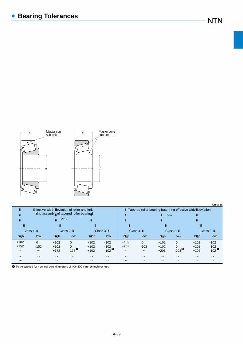
A-39
●Bearing Tolerances
Effective width deviation of roller and innerring assembly of tapered roller bearing�
∆T1s
+102+152ー
ー ー
0-152ー
ー ー
+102+102+178
ー ー
00
-178
ー ー
+102+102+102
ー ー
-102-102-102
ー ー
Unitμm
Tapered roller bearing outer ring effective width deviation
∆T2s
+102+203ー
ー ー
0-102ー
ー ー
+102+102+203
ー ー
00
-203
ー ー
+102+102+102
ー ー
-102-102-102
ー ー
1 To be applied for nominal bore diameters of 406.400 mm (16 inch) or less.
1 1 1 1
�
�
�
�
Class 4 �
�high low
�
�
�
�
Class 2 �
�high low
�
�
�
�
Class 3 �
�high low
�
�
�
�
Class 4 �
�high low
�
�
�
�
Class 2 �
�high low
�
�
�
�
Class 3 �
�high low
Master conesub-unit
Master cupsub-unit
T1 T2
d d
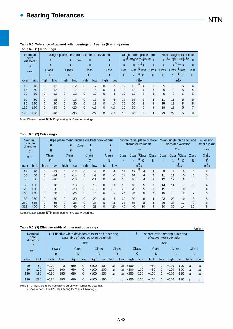
●Bearing Tolerances
A-40
Table 6.6 Tolerance of tapered roller bearings of J series (Metric system)
Table 6.6 (1) Inner rings
Table 6.6 (2) Outer rings
Table 6.6 (3) Effective width of inner and outer rings
101830
5080
120
180
183050
80120180
250
000
000
0
-12-12-12
-15-20-25
-30
000
000
0
-12-12-12
-15-20-25
-30
000
000
0
-7-8
-10
-12-15-18
-22
000
000
0
-5-6-8
-9-10-13
-15
121212
152025
30
121212
152025
30
444
555
6
333
333
4
999
111519
23
999
111519
23
555
555
5
445
557
8
Nominal borediameter
d
mm
Single radial plane borediameter variation
Vdp�
�
�
�
�
Mean single plane borediameter variation
Vdmp
�
�
�
Single plane mean bore diameter deviation�
∆dmp
�
�
�
Class
K
�
�
�
Class
N
�
�
�
Class
C
�
�
�
Class
B
�
�
�
Class
K
�
�
�
Class
N
�
�
�
Class
C
�
�
�
Class
B
�
�
�
Class
K
�
�
�
Class
N
�
�
�
Class
C
�
�
�
Class
B
Note: Please consult NTN Engineering for Class A bearings.
over incl. high low high low high low high low max max
183050
80120150
180250315
305080
120150180
250315400
000
000
000
-12-14-16
-18-20-25
-30-35-40
000
000
000
-12-14-16
-18-20-25
-30-35-40
000
000
000
-8-9
-11
-13-15-18
-20-25-28
000
000
000
-6-7-9
-10-11-13
-15-18-20
121416
182025
303540
121416
182025
303540
444
555
68
10
333
333
455
91112
141519
232630
91112
141519
232630
556
789
101314
455
567
89
10
334
445
666
Nominal outside diameter
D
mm
Single radial plane outsidediameter variation
VDp
�
�
�
�
Mean single plane outsidediameter variation
VDmp
�
�
�
outer ringaxial runout
Sea
�
�
�
Single plane mean outside diameter deviation�
∆Dmp
Class
K
Class
N
Class
C
Class
B
Note: Please consult NTN Engineering for Class A bearings.
�
�
�
Class
K
over incl. high low
�
�
�
Class
N
high low
�
�
�
Class
C
high low
�
�
�
Class
B
high low max
Class
K
Class
N
Class
C
Class
B
Class
B
max max
80120180
250
1080
120
180
0-100-150
-150
+100+100+150
+150
000
0
+50+50+50
+50
-100-100-100
-150
+100+100+100
+100
*�*�*�
*
Note 1: "*" mark are to be manufactured only for combined bearings. 2: Please consult NTN Engineering for Class A bearings.
Unitμm
0-100-100
-100
+100+100+200
+200
000
0
+50+50
+100
+100
-100-100-150
-150
+100+100+100
+100
*�*�*�
*
Nominal borediameter
d
mm
over incl. high low high low high low high low high low high low high low high low
�
Class
K
Class
N
Class
C
Class
B
Class
N
�
Class
K
Class
C
Class
B
*�*�*�
*
*�*�*�
*
Effective width deviation of roller and inner ringassembly of tapered roller bearing�
∆T1s
Tapered roller bearing outer ringeffective width deviation
∆T2s
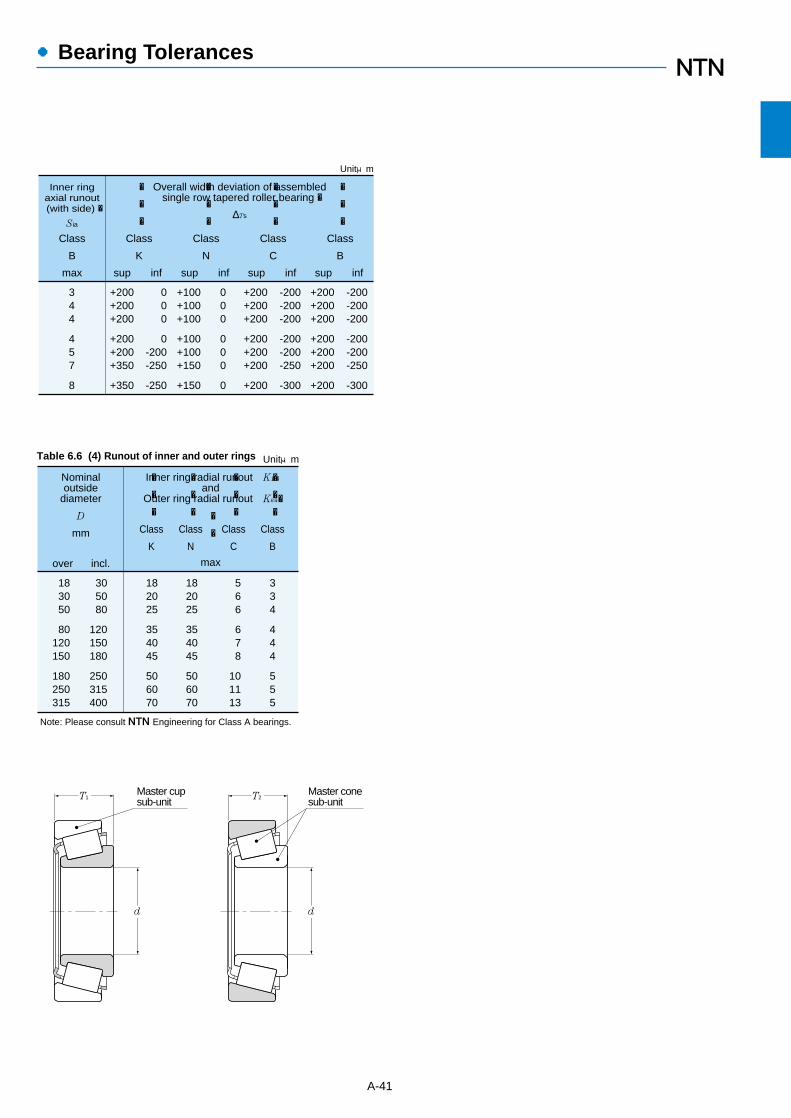
Unitμm
182025
354045
506070
182025
354045
506070
566
678
101113
334
444
555
Inner ring radial runout Kia�and
Outer ring radial runout Kea�
�
�
max
�
�
�
Class
K
�
�
�
Class
N
�
�
�
Class
C
�
�
�
Class
B
183050
80120150
180250315
305080
120150180
250315400
Note: Please consult NTN Engineering for Class A bearings.
Nominaloutside
diameter
D
mm
over incl.
●Bearing Tolerances
A-41
Table 6.6 (4) Runout of inner and outer rings
344
457
8
+200+200+200
+200+200+350
+350
000
0-200-250
-250
+100+100+100
+100+100+150
+150
000
000
0
+200+200+200
+200+200+200
+200
-200-200-200
-200-200-250
-300
+200+200+200
+200+200+200
+200
-200-200-200
-200-200-250
-300
Inner ringaxial runout(with side) �
Sia
Class
B
max sup inf sup inf sup inf sup inf
�
�
�
Class
K
�
�
�
Class
N
�
�
�
Class
C
�
�
�
Class
B
Overall width deviation of assembledsingle row tapered roller bearing �
∆Ts
Unitμm
Master conesub-unit
Master cupsub-unit
T1 T2
d d
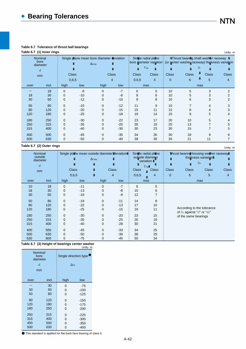
Nominal outsidediameter
d
mm
over incl.
Single plane mean outside diameter deviation�
∆Dmp
�
�
�
000
000
000
000
-11-13-16
-19-22-25
-30-35-40
-45-50-75
Single radial planeoutside diameter
variation �
VDp�
�
�
000
000
000
000
-7-8-9
-11-13-15
-20-25-28
-33-38-45
101830
5080
120
180250315
400500630
183050
80120180
250315400
500630800
81012
141719
232630
343855
567
81011
151921
252934
According to the toleranceof S1 against "d" or "d2"of the same bearings
Thrust bearing housing washer racewaythickness variation�
Se
Unitμm
�
�
�
Class
0,6,5
high low
�
�
�
Class
4
high low
�
�
�
Class
0,6,5
�
�
�
Class
4
max
�
�
�
Class
0
�
�
�
Class
6
�
�
�
Class
5
�
�
�
Class
4
max
Nominal bore diameter
d
mm
over incl.
000
000
000
00
-8-10-12
-15-20-25
-30-35-40
-45-50
Single radial planebore diameter variation
Vdp
000
000
000
00
-7-8
-10
-12-15-18
-22-25-30
-35-40
ー1830
5080
120
180250315
400500
183050
80120180
250315400
500630
689
111519
232630
3438
568
91114
171923
2630
101010
101515
202530
3035
556
789
101315
1821
333
445
577
911
222
334
455
67
Thrust bearing shaft washer raceway(or center washer raceway) thickness variation
Si
�
�
Unitμm
�
�
�
Class
0,6,5
high low
�
�
�
Class
4
high low
�
�
�
Class
0,6,5
�
�
�
Class
4
max
�
�
�
Class
0
�
�
�
Class
6
�
�
�
Class
5
�
�
�
Class
4
max
Single plane mean bore diameter deviation
∆dmp
●Bearing Tolerances
A-42
Table 6.7 (2) Outer rings
Table 6.7 (3) Height of bearings center washer
Table 6.7 Tolerance of thrust ball bearings
Table 6.7 (1) Inner rings
Nominal borediameter
d
mm
over incl. high low
000
000
0000
-75-100-125
-150-175-200
-225-300-350-400
ー3050
80120180
250315400500
305080
120180250
315400500630
Unitμm
Single direction type
∆Ts
1 This standard is applied for flat back face bearing of class 0.
1

●Bearing Tolerances
A-43
Table 6.8 Tolerance of spherical thrust roller bearing
Table 6.8 (1) Inner ringsTable 6.8 (2) Outer ring
Table 6.9 Tolerance of double direction type angular contact thrust ball bearings
Table 6.9 (1) Inner rings and bearing height
Table 6.9 (2) Outer rings
50 80 0 -15 11 25 +150 -150
120 180 0 -25 19 30 +250 -250
180 250 0 -30 23 30 +300 -300250 315 0 -35 26 35 +350 -350315 400 0 -40 30 40 +400 -400
400 500 0 -45 34 45 +450 -450
80 120 0 -20 15 25 +200 -200
Unitμm
Nominalbore diameter
d
mm over incl. high low high lowmax max
Single radialplane borediametervariation
Vdp
� Facerunout
with bore
Sd
Height deviation ofsingle directionthrust bearing
∆Ts
Single plane meanbore diameter deviation
∆dmp
�
120180250
315400500
630800
180250315
400500630
8001,000
000
000
00
-25-30-35
-40-45-50
-75-100
Unitμm
Nominal outside diameter
d
mm
Single plane meanoutside diameter
deviation
∆Dmp��
over incl. high low
183050
80120180
250315
305080
120180250
315400
000
000
00
-6-8-9
-10-13-15
-18-23
000
000
00
-5-6-7
-8-10-12
-15-18
888
91011
1315
445
567
89
556
688
1013
335
566
810
556
78
10
1315
2.534
456
79
000
000
00
-300-400-500
-600-700-800
-900-1,000
Nominal bore diameter
d
mm
over incl. high low
Class 5 Class 4 Class 5 Class 4 Class 5 Class 4
high low max max high low
Class 5 Class 5, Class 4Class 4
max
Single plane mean bore diameterdeviation ∆dmp
Single bore diameter deviation ∆ds
��
Inner ring axialrunout (with side)
Sia
Face runoutwith bore
Sd
�
Inner ringwidth variation
VBs � ��
Height deviation of singledirection thrust bearing
∆Ts
�
Unitμm
Outside surface inclination�
SD
Single plane mean outsidediameter deviation ∆Dmp
Single outside diameterdeviation ∆Ds
�
�
-30-40-50
-60-60-75
-90-110-120
-40-50-60
-75-75-90
-105-125-140
889
101011
131315
445
557
81013
568
88
10
111315
2.53 4
5 5 7
7 8
10
Unitμm
Nominal outside diameter
mm
305080
120150180
250315400
5080
120
150180250
315400500
Outer ring width variation�
VCs
Outer ring axial runout�
Sea
According to tolerance of Sia
against "d" of thesame bearings
over incl. high low max
Class 5 Class 4 Class 5 Class 4
max
Class 5 Class 4
max
Class 5 Class 4
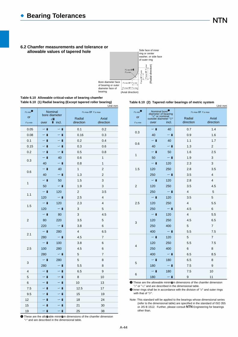
●Bearing Tolerances
A-44
Unit mm
rs min1
or
r1s min
Nominalbore diameter
d��over incl.
rs max or r1s max
Radialdirection
Axialdirection
0.05
0.08
0.1
0.15
0.2
0.3
0.6
1
1.1
1.5
2.1
3
2.5
4
5
6
7.5
9.5
12
15
19
2
ー �
ー �
ー �
ー �
ー �
ー �
40
ー �
40
ー �
50
ー �
120
ー �
120
ー �
80
220
ー �
280
ー �
100
280
ー �
280
ー �
ー �
ー �
ー �
ー �
ー �
ー �
ー �
�
ー �
ー �
ー �
ー �
ー �
40
ー �
40
ー �
50
ー �
120
ー �
120
ー �
80
220
ー �
280
ー �
100
280
ー �
280
ー �
ー �
ー �
ー �
ー �
ー �
ー �
ー �
ー �
�
0.1
0.16
0.2
0.3
0.5
0.6
0.8
1
1.3
1.5
1.9
2
2.5
2.3
3
3
3.5
3.8
4
4.5
3.8
4.5
5
5
5.5
6.5
8
10
12.5
15
18
21
25
0.2
0.3
0.4
0.6
0.8
1
1
2
2
3
3
3.5
4
4
5
4.5
5
6
6.5
7
6
6
7
8
8
9
10
13
17
19
24
30
38
1 These are the allowable minimum dimensions of the chamfer dimension "r" and are described in the dimensional table.
Table 6.10 Allowable critical-value of bearing chamferTable 6.10 (1) Radial bearing (Except tapered roller bearing) Table 6.10 (2) Tapered roller bearings of metric system
Unit mm
rs min2
or
r1s min
rs max or r1s max
0.3
0.6
1
5
3
ー �
40
ー �
40
ー �
50
ー �
120
250
ー �
120
250
ー �
120
250
ー �
120
250
400
ー �
120
250
400
ー �
180
ー �
180
40
ー �
40
ー �
50
ー �
120
250
ー �
120
250
ー �
120
250
ー �
120
250
400
ー �
120
250
400
ー �
180
ー �
180
ー �
�
0.7
0.9
1.1
1.3
1.6
1.9
2.3
2.8
3.5
2.8
3.5
4
3.5
4
4.5
4
4.5
5
5.5
5
5.5
6
6.5
6.5
7.5
7.5
9
1.4
1.6
1.7
2
2.5
3
3
3.5
4
4
4.5
5
5
5.5
6
5.5
6.5
7
7.5
7
7.5
8
8.5
8
9
10
11
2 These are the allowable minimum dimensions of the chamfer dimension "r" or "r1" and are described in the dimensional table.3 Inner rings shall be in accordance with the division of "d" and outer rings with that of "D".
Note: This standard will be applied to the bearings whose dimensional series (refer to the dimensional table) are specified in the standard of ISO 355 or JIS B 1512. Further, please consult NTN Engineering for bearings other than.
1.5
2
2.5
4
6
Radialdirection
Axialdirection
Nominal bore3
diameter of bearing"d" or nominal
outside diameter "D"
over incl.
6.2 Chamfer measurements and tolerance or allowable values of tapered hole Side face of inner
ring or centerwasher, or side faceof outer ring
Bore diameter face of bearing or outer diameter face ofbearing (Axial direction)
rs min or r1s min (Rad
ial d
irect
ion)
rs max or r1s max
rsm
in o
r r
1sm
in
rsm
ax o
r r
1sm
ax
rs min or�r1s min

A-45
●Bearing Tolerances
Table 6.10 (3) Thrust bearings Table 6.11 (1) Tolerance and allowable values (Class 0) oftapered hole of radial bearings
Table 6.11 (2) Allowable variations for radial bearing inner ringtapered bores Standard taper ratio 1:30 (Class 0)
d�mm
over incl. high low high low max
Vdp∆dmp
��
101830
5080
120
180250315
400500630
8001,0001,2501,600
1018
305080
120180250
315400500
630800
1,0001,250
000
222733
+++
000
394654
+++
000
637281
+++
000
8997
110
+++
0000
125140165195
++++
000
151821
+++
000
253035
+++
000
404652
+++
000
576370
+++
0000
8090
105125
++++
91113
161922
404652
576370
ー�ー�ー�ー��
Unitμm1 2-∆d1mp ∆dmp
d�mm
over incl.
��
below
Vdp�
�max
∆dmp��
over below
��
over
80120180
250315400
500630
5080
120
180250315
400500
000
+15+20+25
000
+30+35+40
00
+45+50
000
+30+35+40
000
+46+52+57
00
+63+70
192240
465257
6370
1 Applies to all radial flat planes of inner ring tapered bore. 2 Does not apply to diameter series 7 and 8.Note: Quantifiers
For a standard taper ratio of 1:12 d1=d+ B
�
For a standard taper ratio of 1:30 d1=d+ B
∆dmp :Dimensional difference of the average bore diameter within the flat surface at the theoretical small end of the tapered bore.� ∆d1mp :Dimensional difference of the average bore diameter within the flat surface at the theoretical large end of the tapered bore.� Vdp :Unevenness of the bore diameter with the flat surface� B :Nominal width of inner ring� α :Half of the tapered bore’s nominal taper angle� For a standard taper ratio of 1:12 α=2°23′9.4″� For a standard taper ratio of 1:30 α=0°57′7.4″
Units μm
112
1 2
130
�
-∆d1mp ∆dmp
0.05
0.08
0.1
0.15
0.2
0.3
0.6
1
1.1
1.5
2
2.1
4
3
5
6
7.5
9.5
19
12
15
0.1
0.16
0.2
0.3
0.5
0.8
1.5
2.2
2.7
3.5
4
4.5
5.5
6.5
21
15
25
10
8
12.5
18
4 These are the allowable minimum dimensions of the chamfer dimension "r" or "r1" and are described in the dimensional table.
rs max or r1s max
Radial and axial direcitionrs min or r1 min
4
Unit mm
2α� 2α�∆dmpd+ �
BB
d1+ d1+∆dmp ∆d1mpd1d
Theoretical tapered hole Tapered hole having dimensionaldifference of the average borediameter within the flat surface
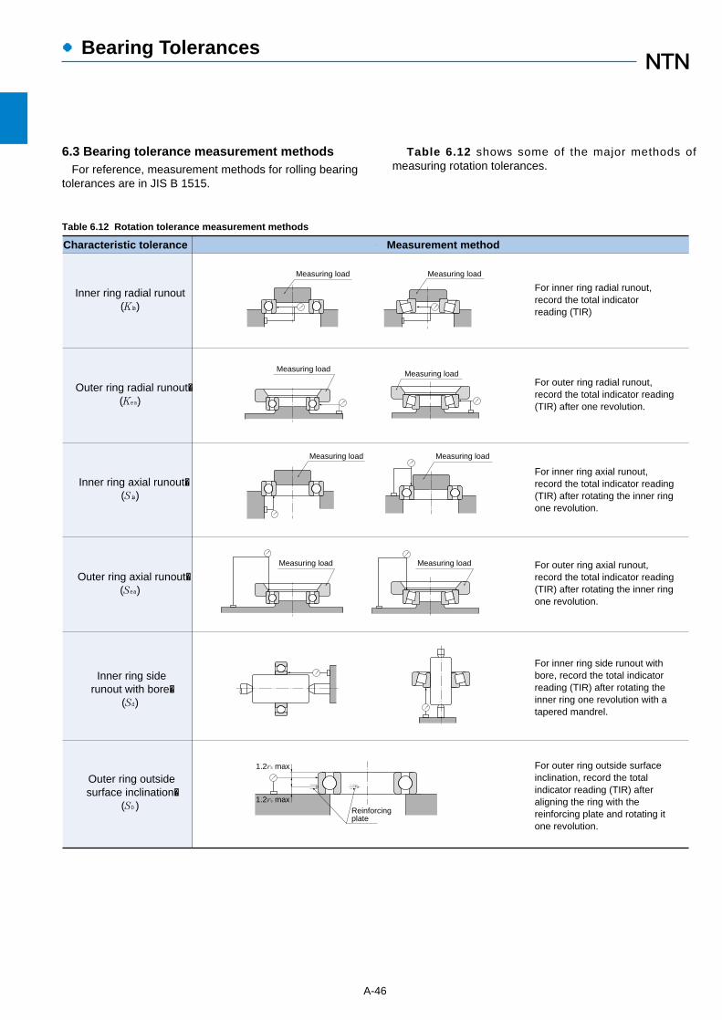
A-46
●Bearing Tolerances
6.3 Bearing tolerance measurement methodsFor reference, measurement methods for rolling bearing
tolerances are in JIS B 1515.
Table 6.12 shows some of the major methods ofmeasuring rotation tolerances.
Table 6.12 Rotation tolerance measurement methods
Inner ring radial runout(Kia)
Outer ring radial runout�(Kea)
Inner ring axial runout�(Sia)
Outer ring axial runout�(Sea)
Inner ring siderunout with bore�
(Sd)
Outer ring outsidesurface inclination�
(SD)
For outer ring outside surfaceinclination, record the totalindicator reading (TIR) afteraligning the ring with thereinforcing plate and rotating itone revolution.
For inner ring side runout withbore, record the total indicatorreading (TIR) after rotating theinner ring one revolution with atapered mandrel.
For outer ring axial runout,record the total indicator reading(TIR) after rotating the inner ringone revolution.
For inner ring axial runout,record the total indicator reading(TIR) after rotating the inner ringone revolution.
For outer ring radial runout,record the total indicator reading(TIR) after one revolution.
For inner ring radial runout,record the total indicatorreading (TIR)
Characteristic tolerance Measurement method
Measuring load Measuring load
Measuring loadMeasuring load
Measuring load Measuring load
Measuring loadMeasuring load
Reinforcingplate
1.2rs max
1.2rs max
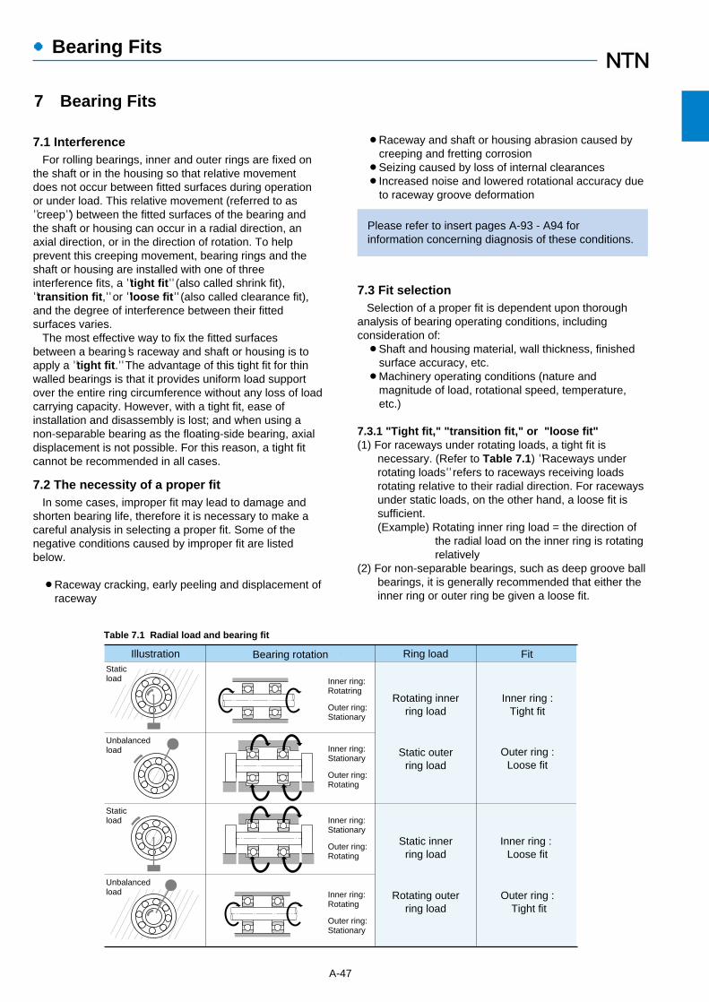
¡Raceway and shaft or housing abrasion caused bycreeping and fretting corrosion
¡Seizing caused by loss of internal clearances¡Increased noise and lowered rotational accuracy due
to raceway groove deformation
Please refer to insert pages A-93 - A94 forinformation concerning diagnosis of these conditions.
7.3 Fit selectionSelection of a proper fit is dependent upon thorough
analysis of bearing operating conditions, includingconsideration of:¡Shaft and housing material, wall thickness, finished
surface accuracy, etc. ¡Machinery operating conditions (nature and
magnitude of load, rotational speed, temperature,etc.)
7.3.1 "Tight fit," "transition fit," or "loose fit"(1) For raceways under rotating loads, a tight fit is
necessary. (Refer to Table 7.1) "Raceways underrotating loads" refers to raceways receiving loadsrotating relative to their radial direction. For racewaysunder static loads, on the other hand, a loose fit issufficient.(Example) Rotating inner ring load = the direction of
the radial load on the inner ring is rotatingrelatively
(2) For non-separable bearings, such as deep groove ballbearings, it is generally recommended that either theinner ring or outer ring be given a loose fit.
7.1 InterferenceFor rolling bearings, inner and outer rings are fixed on
the shaft or in the housing so that relative movementdoes not occur between fitted surfaces during operationor under load. This relative movement (referred to as"creep") between the fitted surfaces of the bearing andthe shaft or housing can occur in a radial direction, anaxial direction, or in the direction of rotation. To helpprevent this creeping movement, bearing rings and theshaft or housing are installed with one of threeinterference fits, a "tight fit" (also called shrink fit),"transition fit," or "loose fit" (also called clearance fit),and the degree of interference between their fittedsurfaces varies.
The most effective way to fix the fitted surfacesbetween a bearing's raceway and shaft or housing is toapply a "tight fit." The advantage of this tight fit for thinwalled bearings is that it provides uniform load supportover the entire ring circumference without any loss of loadcarrying capacity. However, with a tight fit, ease ofinstallation and disassembly is lost; and when using anon-separable bearing as the floating-side bearing, axialdisplacement is not possible. For this reason, a tight fitcannot be recommended in all cases.
7.2 The necessity of a proper fitIn some cases, improper fit may lead to damage and
shorten bearing life, therefore it is necessary to make acareful analysis in selecting a proper fit. Some of thenegative conditions caused by improper fit are listedbelow.
¡Raceway cracking, early peeling and displacement ofraceway
A-47
●Bearing Fits
Table 7.1 Radial load and bearing fit
Illustration Ring load Fit
Rotating innerring load
Static outerring load
Inner ring :Tight fit
Outer ring :Loose fit
Inner ring : Loose fit
Outer ring : Tight fit
Static innerring load
Rotating outerring load
Inner ring:Rotatring
Outer ring:Stationary
Inner ring:Stationary
Outer ring:Rotating
Inner ring:Stationary
Outer ring:Rotating
Inner ring:Rotating
Outer ring:Stationary
Bearing rotationStaticload
Staticload
Unbalancedload
Unbalancedload
7 Bearing Fits

7.3.2 Recommended FitsBearing fit is governed by the selection tolerances for
bearing shaft diameters and housing bore diameters. Widely used fits for 0 Class tolerance bearings and
various shaft and housing bore diameter tolerances areshown in Table 7.1.
Generally-used, standard fits for most types of bearingsand operating conditions are shown in Tables 7.2 - 7.7.
Table 7.2: Fits for radial bearingsTable 7.3: Fits for thrust bearingsTable 7.4: Fits for electric motor bearingsTable 7.6: Fits for inch series tapered roller bearings
(ANSI Class 4)Table 7.7: Fits for inch series tapered roller bearings
(ANSI Class 3 and 0)Table 7.5. shows fits and their numerical values.
For special fits or applications, please consult NTNEngineering.
7.3.3 Interference minimum and maximum valuesThe following points should be considered when it is
necessary to calculate the interference for an application:¡In calculating the minimum required amount of
interference keep in mind that:1) interference is reduced by radial loads2) interference is reduced by differences between
bearing temperature and ambient temperature3) interference is reduced by variation of fitted
surfaces¡Maximum interference should be no more than
1:1000 of the shaft diameter or outer diameter. Required interference calculations are shown below.
(1) Radial loads and required interference Interference between inner rings mounted on solid
shafts is reduced when acted upon by radial loads.Calculation of the minimum required amount ofinterference in such cases is shown in formulae (7.1) and(7.2).
Fr≦ 0.3 Cor
∆ dF = 0.08 (d・Fr / B)1/2 N }………(7.1)= 0.25 (d・Fr / B)1/2 {kgf }Fr> 0.3 Cor
∆ dF = 0.02 (Fr / B) N }………(7.2)= 0.2 (Fr / B) {kgf }Where,
∆ dF : Required effective interference for load μmd : Nominal bore diameter mmB : Inner ring width mm
Fr : Radial load N{kgf}Cor : Basic static rated load N{kgf}
(2) Temperature difference and required interferenceInterference between inner rings and steel shafts is
reduced as a result of temperature increases (differencebetween bearing temperature and ambient temperature,∆T) caused by bearing rotation. Calculation of theminimum required amount of interference in such cases is
shown in formulae (7.1).∆ dT = 0.0015 d ∆T ……………………………………(7.3)
∆ dT : Required effective interference fortemperature difference μm
∆T : Difference between bearing temperatureand ambient temperature ˚C
d : Bearing bore diameter mm
(3) Fitted surface variation and required interferenceInterference between fitted surfaces is reduced by
roughness and other slight variations of these surfaceswhich are flattened in the fitting process. The degree ofreduced interference depends upon the finish treatmentof these surfaces, but in general it is necessary toassume the following interference reductions.
For ground shafts: 1.0~2.5μmFor lathed shafts: 5.0~7.0μm
(4) Maximum interferenceWhen bearing rings are installed with an interference fit,
tension or compression stress may occur along theirraceways. If interference is too great, this may causedamage to the rings and reduce bearing life. For thesereasons, maximum interference should not exceed thepreviously mentioned ratio of 1:1,000 of shaft or outsidediameter.
7.3.4 Other details(1) Tight interference fits are recommended for,
¡Operating conditions with large vibration or shockloads
¡Applications using hollow shafts or housings withthin walls
¡Applications using housings made of light alloys orplastic
(2) Loose interference fits are preferable for,¡Applications requiring high running accuracy¡Applications using small sized bearings or thin
walled bearings
A-48
●Bearing Fits
G6G7
H7H6
H8
M6 M7N6 N7
P6 P7
p6
n6n5m6m5
k6k5
h6h5
g6g5∆dmp
∆Dmp
Loose fit
Types of fits
Tight fit
Tight fit
Housing
Shafts
Class 0 J6 J7
K6 K7
J6J5
Transition fit
Transition fit
Class 0
Fig 7.1
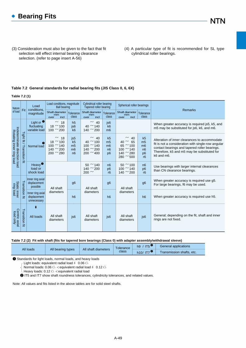
●Bearing Fits
A-49
Table 7.2 (1)
Table 7.2 General standards for radial bearing fits (JIS Class 0, 6, 6X)
Rotating inner ring load
Tight fit / T
ransition fit
Indeterminate direction load
Transition fit
Static innerring load
Transition fit
Centric axialload only
Loadconditions,magnitude
Light orfluctuating
variable load
Normal load
Heavyload or
shock load
Inner ring axialdisplacement
possible
Inner ring axialdisplacementunnecessary
All loads
Load conditions, magnitudeBall bearingNature
of load FitShaft diameter
mm over incl
Toleranceclass
Shaft diametermm
over incl Tolerance
classShaft diameter
mm over incl
Toleranceclass
18100200
~~~
18
100
h5js6k6
4065
100140280500
~~~~~~
4065
100140280
k5m5m6n6p6r6
Spherical roller bearings
40140200
~~~
40
140
js6k6
m6
When greater accuracy is required js5, k5, andm5 may be substituted for js6, k6, and m6.
100140200
~~~
50100140
n6p6r6
140200
~~~
50140200
n6p6r6
40100140200400
~~~~~
40
100140200
k5m5m6n6p6
18100140200280
~~~~~
18
100140200
js5k5
m5m6n6
Use bearings with larger internal clearancesthan CN clearance bearings.
Alteration of inner clearances to accommodatefit is not a consideration with single-row angularcontact bearings and tapered roller bearings.Therefore, k5 and m5 may be substituted fork6 and m6.
When greater accuracy is required use g5.For large bearings, f6 may be used.
When greater accuracy is required use h5.
General; depending on the fit, shaft and innerrings are not fixed.
All shaftdiameters
All shaftdiameters
All shaftdiameters
All shaftdiameters
All shaftdiameters
All shaftdiameters
g6
h6
g6
h6
g6
h6
Remarks
js6
js6
js6
Cylindrical roller bearingTapered roller bearing
1
1
1
�
All loads Toleranceclass
All shaft diametersAll bearing types /
/
h9
h10
IT5
IT7
General applications
Transmission shafts, etc.
1 Standards for light loads, normal loads, and heavy loads Light loads: equivalent radial load ≦ 0.06 Cr Normal loads: 0.06 Cr <equivalent radial load ≦ 0.12 Cr Heavy loads: 0.12 Cr <equivalent radial load 2 IT5 and IT7 show shaft roundness tolerances, cylindricity tolerances, and related values.
Note: All values and fits listed in the above tables are for solid steel shafts.
2
2
Table 7.2 (2) Fit with shaft (fits for tapered bore bearings (Class 0) with adapter assembly/withdrawal sleeve)
(3) Consideration must also be given to the fact that fitselection will effect internal bearing clearanceselection. (refer to page insert A-56)
(4) A particular type of fit is recommended for SL typecylindrical roller bearings.

A-50
●Bearing Fits
Table 7.2 (3) Housing fits
Rotating outer ring load or
static outer ring load
Solid or splithousing
Tight fit
Transition
or loose fitT
ight totransition fit
Inner ring staticload or outer
ring rotating loadCentered axial
load only - Loose fit
Loose fitLoose fit
Solid housing
Dire
ctio
nin
dete
rmin
ate
load
Toleranceclass
Outer ring axialdisplacement
Natureof load Housing Fit Load conditions, magnitude Remarks
All loads
Light to normal load
Shaft and inner ringsreach high temperature
Requires silent operation
High rotation accuracyrequired with light tonormal loads
Light to normal load
Normal to heavy load
Heavy shock load
Light or variable load
Normal to heavy load
Heavy load (thin wall housing)or heavy shock load
H7
G7
H8
G7
F7
H6
Js6
K6
Js7
K7
M7
M7
N7
P7
Displacement possible
Easy displacement
Displacement possible
Easy displacement
Easy displacement
Displacement possible
Displacement not possible(in principle)
Displacement not possible(in principle)
Displacement possible
Displacement not possible(in principle)
Displacement not possible
Displacement not possible
Displacement not possible
Displacement not possible
Select a tolerance class that willprovide clearance between outerring and housing.
G7 also acceptable for large typebearings as well as outer rings andhousings with large temperature differences.
F7 also acceptable for large type bearings aswell as outer rings and housings with largetemperature differences.
Applies primarily to ball bearings
Applies primarily to roller bearings
When greater accuracy is requiredsubstitute Js6 for Js7 and K6 for K7.
Applies primarily to ball bearings
Applies primarily to roller bearings
2
1
1 Standards for light loads, normal loads, and heavy loads Light loads: equivalent radial load ≦ 0.06 Cr Normal loads: 0.06 Cr <equivalent radial load ≦ 0.12 Cr Heavy loads: 0.12 Cr < equivalent radial load 2 Indicates whether or not outer ring axial displacement is possible with non-separable type bearings.
Note 1: All values and fits listed in the above tables are for cast iron or steel housings.2: In cases where only a centered axial load acts on the bearing, select a tolerance class that will provide clearance in the axia
direction for the outer ring.

A-51
●Bearing Fits
Table 7.3 (1) Shaft fits
Table 7.3 Standard fits for thrust bearings (JIS Class 0 and 6)
Table 7.4 Fits for electric motor bearings
Bearing type Load conditions Fit Tolerance class
All thrust bearings
Self-aligning rollerthrust bearings
Centered axial load only
Combined load
Inner ring static load
Transition fit
Transition fit All sizes
js6 or h6
Inner ring rotating loador
direction indeterminate load
Transition fit
Tight fit
~�~�~�
200400
200400
k6 or js6m6 or k6n6 or m6
js6
Shaft diametermm
over incl
All sizes
Bearing type Load conditions Fit Toleranceclass
Remarks
All thrustbearings
Self-aligningroller thrust
bearings
Centered axial load only
Combined load
Outer ring static load
Direction Indeterminateload or outer ringrotating load
Loose fit
Transition fit
Select a tolerance class that will provide clearance between outer ring and housing.
H8
H7
K7
M7
Greater accuracy required with thrust ball bearings
Normal operating conditions
For relatively large radial loads
Note: All values and fits listed in the above tables are for cast iron or steel housings.
Table 7.3 (2) Housing fits
Bearing type
Deep grooveball bearings
Cylindricalroller bearings
Shaft fitsShaft diameter mm
Over incl. Tolerance class
~�~�~�
18100160
18
100
~�~�~�
40160200
40
160
j5k5
m5
k5m5n6
Housing bore diameter
Housing fits Tolerance class
All sizes
All sizes
H6orJ6
H6orJ6

●Bearing Fits
A-52
3
6
10
18
30
50
80
6
10
18
30
50
80
120
0
0
0
0
0
0
0
-8
-8
-8
-10
-12
-15
-20
4T~
3T~
2T~
3T~
3T~
5T~
8T~
9L
11L
14L
16L
20L
23L
27L
4T~
3T~
2T~
3T~
3T~
5T~
8T~
12L
14L
17L
20L
25L
29L
34L
8T~
8T~
8T~
10T~
12T~
15T~
20T~
5L
6L
8L
9L
11L
13L
15L
8T~
8T~
8T~
10T~
12T~
15T~
20T~
8L
9L
11L
13L
16L
19L
22L
11T~
12T~
13T~
15T~
18T~
21T~
26T~
2L
2L
3L
4L
5L
7L
9L
10.5T
11T
12T
14.5T
17.5T
21.5T
27.5T
~ 2.5L
~ 3L
~ 4L
~ 4.5L
~ 5.5L
~ 6.5L
~ 7.5L
14T~
15T~
16T~
19T~
23T~
27T~
33T~
2L
2L
3L
4L
5L
7L
9L
Nominal borediameter of
bearing
d
mm
over incl high low
bearing shaft bearing shaft bearing shaft bearing shaft bearing shaft bearing shaft bearing shaft
Single planemean borediameterdeviation
∆dmp
1g5 h5 h6 j5 js5 j6
1 Above table is not applicable to tapered roller bearings whose bore diameter is 30mm or less.
120140160
140160180
180200225
200225250
250280
280315
315355
355400
400450
450500
0 -25
0 -30
0 -35
0 -40
0 -45
11T~32L
15T~35L
18T~40L
22T~43L
25T~47L
11T~39L
15T~44L
18T~49L
22T~54L
25T~60L
25T~18L
30T~20L
35T~23L
40T~25L
45T~27L
25T~25L
30T~29L
35T~32L
40T~36L
45T~40L
32T~11L
37T~13L
42T~16L
47T~18L
52T~20L
34T ~ 9L
40T ~10L
46.5T~11.5L
52.5T~12.5L
58.5T~13.5L
39T~11L
46T~13L
58T~18L
51T~16L
65T~20L
g6
6
10
18
30
50
80
120
150
180
250
315
400
10
18
30
50
80
120
150
180
250
315
400
500
0
0
0
0
0
0
0
0
0
0
0
0
-8
-8
-9
-11
-13
-15
-18
-25
-30
-35
-40
-45
5L~
6L~
7L~
9L~
10L~
12L~
14L~
14L~
15L~
17L~
18L~
20L~
28L
32L
37L
45L
53L
62L
72L
79L
91L
104L
115L
128L
0~
0~
0~
0~
0~
0~
0~
0~
0~
0~
0~
0~
17L
19L
22L
27L
32L
37L
43L
50L
59L
67L
76L
85L
0~
0~
0~
0~
0~
0~
0~
0~
0~
0~
0~
0~
23L
26L
30L
36L
43L
50L
58L
65L
76L
87L
97L
108L
4T~
5T~
5T~
6T~
6T~
6T~
7T~
7T~
7T~
7T~
7T~
7T~
13L
14L
17L
21L
26L
31L
36L
43L
52L
60L
69L
78L
7T~
8T~
9T~
11T~
12T~
13T~
14T~
14T~
16T~
16T~
18T~
20T~
16L
18L
21L
25L
31L
37L
44L
51L
60L
71L
79L
88L
7.5T
9T
10.5T
12.5T
15T
17.5T
20T
20T
23T
26T
28.5T
31.5T
~15.5L
~17L
~19.5L
~23.5L
~28L
~32.5L
~38L
~45L
~53L
~61L
~68.5L
~76.5L
7T~
9T~
11T~
13T~
15T~
18T~
21T~
21T~
24T~
27T~
29T~
32T~
10L
10L
11L
14L
17L
19L
22L
29L
35L
40L
47L
53L
Nominal outside
diameter ofbearing
d
mm
Single plane mean outside
diameterdeviation
∆Dmp
2G7 H6 H7 J6 J7 Js7 K6
2 Above table is not application to tapered roller bearings whose outside diameter is 150mm or less.Note: T = tight, L = loose
over incl high. low.
housing bearing housing bearing housing bearing housing bearing housing bearing housing bearing housing bearing
Table 7.5 Numeric value table of fitting for radial bearing of 0 class
Table 7.5 (1) Fitting against shaft
Table 7.5 (2) Fitting against housing
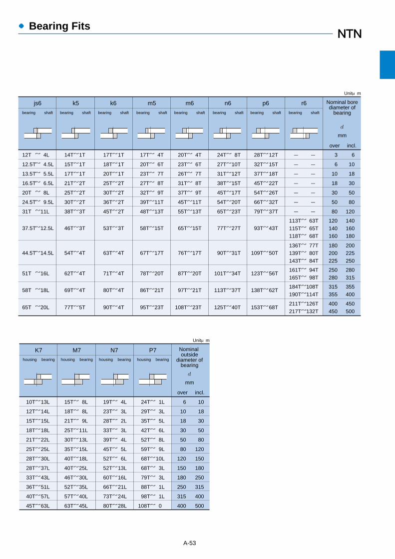
●Bearing Fits
A-53
12T
12.5T
13.5T
16.5T
20T
24.5T
31T
~ 4L
~ 4.5L
~ 5.5L
~ 6.5L
~ 8L
~ 9.5L
~11L
14T~
15T~
17T~
21T~
25T~
30T~
38T~
1T
1T
1T
2T
2T
2T
3T
17T~
18T~
20T~
25T~
30T~
36T~
45T~
1T
1T
1T
2T
2T
2T
2T
17T~
20T~
23T~
27T~
32T~
39T~
48T~
4T
6T
7T
8T
9T
11T
13T
Nominal borediameter of
bearing
d
mm
js6 k5 k6 m5
Unitμm
20T~
23T~
26T~
31T~
37T~
45T~
55T~
4T
6T
7T
8T
9T
11T
13T
m6
24T~
27T~
31T~
38T~
45T~
54T~
65T~
8T
10T
12T
15T
17T
20T
23T
n6
28T~
32T~
37T~
45T~
54T~
66T~
79T~
12T
15T
18T
22T
26T
32T
37T
p6
-
-
-
-
-
-
-
r6
37.5T~12.5L
44.5T~14.5L
51T ~16L
65T ~20L
58T ~18L
46T~3T
54T~4T
62T~4T
69T~4T
77T~5T
53T~3T
63T~4T
80T~4T
90T~4T
71T~4T
58T~15T
67T~17T
78T~20T
86T~21T
95T~23T
65T~15T
76T~17T
87T~20T
97T~21T
108T~23T
77T~27T
90T~31T
101T~34T
113T~37T
125T~40T
93T~43T
109T~50T
123T~56T
138T~62T
153T~68T
113T~115T~118T~
63T65T68T
136T~139T~143T~
77T80T84T
161T~165T~
94T98T
184T~190T~
108T114T
211T~217T~
126T132T
-
-
-
-
-
-
-
3
6
10
18
30
50
80
6
10
18
30
50
80
120
120140160
140160180
180200225
200225250
250280
280315
315355
355400
400450
450500
over incl.
bearing shaft bearing shaft bearing shaft bearing shaft bearing shaft bearing shaft bearing shaft bearing shaft
10T~
12T~
15T~
18T~
21T~
25T~
28T~
28T~
33T~
36T~
40T~
45T~
13L
14L
15L
18L
22L
25L
30L
37L
43L
51L
57L
63L
15T~
18T~
21T~
25T~
30T~
35T~
40T~
40T~
46T~
52T~
57T~
63T~
8L
8L
9L
11L
13L
15L
18L
25L
30L
35L
40L
45L
19T~
23T~
28T~
33T~
39T~
45T~
52T~
52T~
60T~
66T~
73T~
80T~
4L
3L
2L
3L
4L
5L
6L
13L
16L
21L
24L
28L
24T~
29T~
35T~
42T~
52T~
59T~
68T~
68T~
79T~
88T~
98T~
108T~
1L
3L
5L
6L
8L
9L
10L
3L
3L
1L
1L
0
6
10
18
30
50
80
120
150
180
250
315
400
10
18
30
50
80
120
150
180
250
315
400
500
Nominal outside
diameter ofbearing
d
mm
K7 M7 N7 P7
Unitμm
over incl.
housing bearing housing bearing housing bearing housing bearing

●Bearing Fits
A-54
Table 7.6 Fits for inch series tapered roller bearing (ANSI class 4)
Load conditionsShaft diameter
over incl. high low high low max mind mm
Cone bore tolerance
∆ds
Shaft tolerance Extreme fitsRemark
Normal loads,no shock
Heavy loads orshock loads
Cone axialdisplacementon shaftnecessary
Cone axialdisplacementon shaftunnecessary
76.2304.8609.6914.4
76.2
304.8609.6
~~~~
76.2304.8609.6914.4
76.2
304.8609.6
~~~~
76.2304.8609.6914.4
76.2
304.8609.6
~~~~
76.2304.8609.6914.4
76.2
304.8609.6
~~~~
+13+25+51+76
0000
+13+25+51+76
0000
+13+25+51+76
0000
+13+25+51+76
0000
253876
114
++++
38+
0000
13255176
----
3864
127190
++++
64+
13255176
++++
0000
~~~~
~
~~~~
~~~~
12T13T25T38T
38T64T
127T190T
12T38T
13T25T51T76T
13L50L
102L152L
0000
13L25L51L76L
This extreme fitsis applicable tolittle shock loadconditions.
Use average tight cone fit of 0.5μm/mm,(0.0005 inch/inch) of cone bore, use aminimum fit of 25μm, 0.0010 inch tight.
This extreme fitsis not applicableto shock loadconditions.
Unitμm
1
Rotating cone load
Stationary cone load
Table 7.6 (2) Fit with housing
Load conditions
over incl. high low high low max min
Housing bore diameterD mm
Cup O.D.tolerance
Housing boretolerance
Extreme fitsTypes of fit
76.2127.0304.8609.6914.4
76.2
127.0304.8609.6
~~~~~
+25+25+25+51+76
00000
515151
102152
+++++
767676
152229
+++++
~~~~~
76L76L76L
152L229L
26L26L26L51L76L
1 For bearings with negation deviation indicated in bearing tables,same fit applies.Note 1: For bearings higher than class 2, consult NTN Engineering.
2: T= tight, L= loose
Unitμm
Light andnormal loads:cup axiallyadjustable
Heavy loads:cup not axiallydisplaceable
Cup not axiallydisplaceable
76.2127.0304.8609.6914.4
76.2
127.0304.8609.6
~~~~~
+25+25+25+51+76
00000
76.2127.0304.8609.6914.4
76.2
127.0304.8609.6
~~~~~
+25+25+25+51+76
00000
76.2127.0304.8609.6914.4
76.2
127.0304.8609.6
~~~~~
+25+25+25+51+76
00000
000
2651
++
25255176
127
+++++
~~~~~
25L25L51L76L
127L
25T25T25T25T25T
38515176
102
-----
1325252525
-----
~~~~~
13T25T25T25T25T
63T76T76T
127T178T
~~~~~
38515176
102
-----
1325252525
-----
13T25T25T25T25T
63T76T76T
127T178T
1
loose fit
tightinterference fit
tight fit
∆Ds
Light andnormal loads:cup easilyaxiallydisplaceableS
tationary cup loadR
otatingcup load
Table 7.6 (1) Fit with shaft
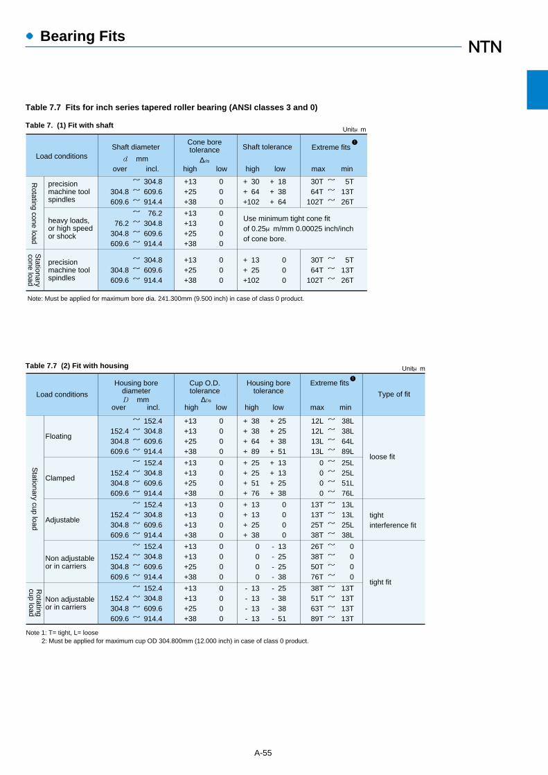
●Bearing Fits
A-55
Table 7.7 Fits for inch series tapered roller bearing (ANSI classes 3 and 0)
304.8609.6914.4
304.8609.6
~~~
76.2304.8609.6914.4
76.2
304.8609.6
~~~~
304.8609.6914.4
304.8609.6
~~~
+13+25+38
000
+13+13+25+38
0000
+13+25+38
000
183864
+++
000
3064
102
+++
1325
102
+++
~~~
~~~
5T
13T26T
30T64T
102T
30T64T
102T
5T
13T26T
Use minimum tight cone fitof 0.25μm/mm 0.00025 inch/inchof cone bore.
Note: Must be applied for maximum bore dia. 241.300mm (9.500 inch) in case of class 0 product.
Unitμm
Load conditionsShaft diameter
over incl. high low high low max mind mm
Cone boretolerance
∆ds
Shaft tolerance Extreme fits1
precisionmachine toolspindles
precisionmachine toolspindles
heavy loads,or high speedor shock
Rotating cone load
Stationary
cone load
Type of fit
152.4304.8609.6914.4
152.4304.8609.6
~~~~
+13+13+25+38
0000
25253851
++++
38386489
++++
~~~~
38L38L64L89L
12L12L13L13L
Note 1: T= tight, L= loose2: Must be applied for maximum cup OD 304.800mm (12.000 inch) in case of class 0 product.
152.4304.8609.6914.4
152.4304.8609.6
~~~~
152.4304.8609.6914.4
152.4304.8609.6
~~~~
152.4304.8609.6914.4
152.4304.8609.6
~~~~
+13+13+25+38
0000
25255176
++++
~~~~
25L25L51L76L
0000
+13+13+13+38
0000
0000
~~~~
13L13L25L38L
13T13T25T38T
+13+13+25+38
0000
13252538
----
~~~~
0000
26T38T50T76T
152.4304.8609.6914.4
152.4304.8609.6
~~~~
+13+13+25+38
0000
25383851
----
13131313
----
~~~~
13T13T13T13T
38T51T63T89T
13132538
++++
0000
13132538
++++
loose fit
tightinterference fit
tight fit
Load conditions
over incl. high low high low max min
Housing borediameterD mm
Cup O.D. tolerance
Housing boretolerance
Extreme fits
Unitμm
1
∆Ds
Floating
Clamped
Adjustable
Non adjustableor in carriers
Non adjustableor in carriers
Stationary cup load
Rotating
cup load
Table 7. (1) Fit with shaft
Table 7.7 (2) Fit with housing

●Bearing Internal Clearance and Preload
8.1 Bearing internal clearanceBearing internal clearance (initial clearance) is the
amount of internal clearance a bearing has before beinginstalled on a shaft or in a housing.
As shown in Fig. 8.1, when either the inner ring or theouter ring is fixed and the other ring is free to move,displacement can take place in either an axial or radialdirection. This amount of displacement (radially or axially)is termed the internal clearance and, depending on thedirection, is called the radial internal clearance or theaxial internal clearance.
When the internal clearance of a bearing is measured, aslight measurement load is applied to the raceway so theinternal clearance may be measured accurately.However, at this time, a slight amount of elasticdeformation of the bearing occurs under the measurementload, and the clearance measurement value (measuredclearance) is slightly larger than the true clearance. Thisdiscrepancy between the true bearing clearance and theincreased amount due to the elastic deformation must becompensated for. These compensation values are given inTable 8.1. For roller bearings the amount of elasticdeformation can be ignored.
The internal clearance values for each bearing class areshown in Tables 8.3 through 8.11.
A-56
δ2
δ1
δ
Fig. 8.1 Internal clearance
Radial clearance =δ Axial clearance =δ1+δ2
Nominal Bore Diameterd mm
over incl.
101850
1850
200
Measuring LoadN{kgf}
24.549
147
{2.5}{5}{15}
Radial Clearance Increase
C2 CN C3 C4 C5
3~44~56~8
458
469
469
469
Unitμm
1
Table 8.1 Adjustment of radial internal clearance based onmeasured load
Table 8.2 Examples of applications where bearing clearancesother than normal clearance are used
Operating conditions Applications Selected clearance
Railway vehicle axles
Vibration screens
Tractors and final speedregulators
Rolling mill table rollers
Paper making machinesand driers
Railway vehicle tractionmotors
Main spindles of lathes (Double-row cylindrical rollerbearings)
Micromotors
C3
C3,C4With heavy or shockload, clearance is great.
Shaft or inner ring isheated.
To reduce noise andvibration when rotating.
To reduce shaft runout,clearance is adjusted.
With directionindeterminate load,both inner and outerrings are tight-fitted.
C4
C4
C3
C2,CM
C9NA,C0NA
C3,C4
8.2 Internal clearance selectionThe internal clearance of a bearing under operating
conditions (effective clearance) is usually smaller thanthe same bearing's initial clearance before being installedand operated. This is due to several factors includingbearing fit, the difference in temperature between theinner and outer rings, etc. As a bearing's operatingclearance has an effect on bearing life, heatgeneration, vibration, noise, etc.; care must be takenin selecting the most suitable operating clearance.
Effective internal clearance:The internal clearance differential between the initial
clearance and the operating (effective) clearance (theamount of clearance reduction caused by interferencefits, or clearance variation due to the temperaturedifference between the inner and outer rings) can becalculated by the following formula:
δeff=δo-(δf+δt)…………………(8.1)
where,δeff : Effective internal clearance, mmδo : Bearing internal clearance, mmδf : Reduced amount of clearance due to
interference, mmδt : Reduced amount of clearance due to
temperature differential of inner and outer r, mm
8. Bearing Internal Clearance and Preload
1 This diameter is included in the group.

●Bearing Internal Clearance and Preload
A-57
Table 8.3 Radial internal clearance of deep groove ball bearings
Nominal bore diameterd mm
over incl. min max min max min max min max min max
ー 2.5 6
2.56
10
10 18 24
18 24 30
30 40 50
40 50 65
65 80
100
80 100 120
120 140 160
140 160 180
180 200 225
200 225 250
250 280 315
280 315 355
355 400 450
400 450 500
500 560
560 630
C2
0 0 0
6 7 7
0 0 1
9 10 11
1 1 1
11 11 15
1 1 2
15 18 20
2 2 2
23 23 25
2 2 2
30 35 40
2 2 3
45 55 60
3 3 3
70 80 90
10 10
100 110
CN
4 2 2
11 13 13
80 90
210 230
55 60 70
145 170 190
35 40 45
105 115 125
25 25 30
71 85 95
3 5 5
18 20 20
6 6 8
20 23 28
10 12 15
30 36 41
18 18 20
48 53 61
C3
10 8 8
20 23 23
11 13 13
25 28 28
15 18 23
33 36 43
25 30 36
51 58 66
41 46 53
81 91
102
63 75 85
117 140 160
90 100 110
170 190 210
130 150 170
240 270 300
190 210
330 360
C4
ー ー 14
ー ー 29
18 20 23
33 36 41
28 30 38
46 51 61
46 53 61
71 84 97
71 81 91
114 130 147
107 125 145
163 195 225
155 175 195
245 270 300
225 250 280
340 380 420
310 340
470 520
C5
ー ー 20
ー ー 37
25 28 30
45 48 53
40 45 55
64 73 90
65 75 90
105 120 140
105 120 135
160 180 200
150 175 205
230 265 300
225 245 275
340 370 410
315 350 390
460 510 570
440 490
630 690
Unitμm
(1) Reduced clearance due to interferenceWhen bearings are installed with interference fits on
shafts and in housings, the inner ring will expand and theouter ring will contract; thus reducing the bearings'internal clearance. The amount of expansion orcontraction varies depending on the shape of thebearing, the shape of the shaft or housing, dimensions ofthe respective parts, and the type of materials used. Thedifferential can range from approximately 70% to 90%of the effective interference.
δf= (0.70~0.90) ∆deff…………………… (8.2)
where,δf : Reduced amount of clearance due to
interference, mm∆deff : Effective interference, mm
(2) Reduced internal clearance due to inner/outer ringtemperature difference.
During operation, normally the outer ring will rangefrom 5 to 10℃ cooler than the inner ring or rotating parts.However, if the cooling effect of the housing is large, theshaft is connected to a heat source, or a heatedsubstance is conducted through the hollow shaft; the
temperature difference between the two rings can beeven greater. The amount of internal clearance is thusfurther reduced by the differential expansion of thetwo rings.
δt=α・∆T・Do………………………… (8.3)
where,δt : Amount of reduced clearance due to heat
differential, mmα : Bearing steel linear expansion coefficient
12.5 × 10⁻⁶/˚C∆T : Inner/outer ring temperature differential, ℃Do : Outer ring raceway diameter, mm
Outer ring raceway diameter, Do, values can beapproximated by using formula (8.4) or (8.5).
For ball bearings and spherical roller bearings,Do= 0.20 (d + 4.0D) ……………………… (8.4)
For roller bearings (except self-aligning),Do= 0.25 (d + 3.0D) ……………………… (8.5)
where,d : Bearing bore diameter, mmD : Bearing outside diameter, mm

101824
304050
6580
100
120140160
180
(incl.) 455
99
12
121818
2424ー
ー
111212
171722
223030
3838ー
ー
ーー15
152025
303535
405060
65
ーー30
303540
455560
658090
100
182430
405065
80100120
140160180
200
Note 1: Suffix CM is added to bearing numbers.2: Non-interchangeable clearance3: This diameter is included in the group.
Unitμm
Radial internal clearance CM Nominal bore diameter d mm
over incl. min max
Deep groove ball bearings
min max
Cylindrical roller bearings
Nominal bore diameter
d mm C1
333
333
3333
88
10
101113
15161820
C2 Normal C3 C4
101830
5080
100
120150180200
121212
141722
30333540
666
81113
15161820
151520
253240
50556065
88
10
141722
30353540
151520
253240
50556065
222432
405060
758090
100
223040
557595
110130150180
304055
7595
120
140170200240
ー1018
305080
100120150180
Unitμm
Note: The clearance group in the table is applied only to contact angles in the table below.
over incl. min max min max min max min max min max
Nominal bore diameter
d mm
Bearing with cylindrical bore
C2
122
345
667
89
10
1015
89
10
121416
181921
242731
3844
Normal C3 C4 C5
2.56
10
14 18 24
30 40 50
65 80
100
120 140
61014
182430
405065
80100120
140
160
151719
212324
293136
404856
6880
566
81011
131416
182225
3035
202526
283035
404450
607083
100120
101213
151719
232530
354250
6070
151921
232529
343745
546475
90110
253335
373946
535769
8396
114
135161
212730
323440
465062
7689
105
125150
334248
505258
667188
108124145
175210
over incl. min max min max min max min max min max
●Bearing Internal Clearance and Preload
A-58
Table 8.4 Radial internal clearance of self-aligning ball bearings
Table 8.5 Radial internal clearance of double row and duplex angular contact ball bearings
Contact anglesymbol
Nominal contactangle
C2,Normal,C3
C
A1
B
15˚
30˚
40˚
Applicable clearance group
C1,C2
Normal,C3,C4
1 Usually not to be indicated
Table 8.6 Radial internal clearance of bearings for electric motor

Nominal bore diameterd mm
― 10 24
10 24 30
30 40 50
40 50 65
65 80
100
80 100 120
120 140 160
140 160 180
180 200 225
200 225 250
250 280 315
280 315 355
355 400 450
400 450 500
C2
0 0 0
25 25 25
5 5
10
30 35 40
10 15 15
45 50 55
15 20 25
60 70 75
35 45 45
90 105 110
55 55 65
125 130 145
100 110 110
190 210 220
Normal
20 20 20
45 45 45
190 210 220
280 310 330
125 130 145
195 205 225
25 30 40
50 60 70
40 50 50
75 85 90
60 70 75
105 120 125
90 105 110
145 165 175
C3
35 35 35
60 60 60
45 50 60
70 80 90
65 75 85
100 110 125
100 115 120
145 165 170
140 160 170
195 220 235
190 200 225
260 275 305
280 310 330
370 410 440
C4
50 50 50
75 75 75
60 70 80
85 100 110
90 105 125
125 140 165
145 165 170
190 215 220
195 220 235
250 280 300
260 275 305
330 350 385
370 410 440
460 510 550
C5
― 65 70
― 90 95
80 95
110
105 125 140
130 155 180
165 190 220
200 225 250
245 275 300
275 305 330
330 365 395
370 410 455
440 485 535
510 565 625
600 665 735
Unitμm
over incl. min max min max min max min max min max
●Bearing Internal Clearance and Preload
A-59
Table 8.7 Radial internal clearance of cylindrical roller bearings, needle roller bearings(Interchangeable, cylindrical bore bearings)
Nominal bore diameter
d mm
Bearing with tapered bore
C2
ーーー
ー1315
192227
354250
6065
ー�ー�ー�
ー�2628
353947
576881
98110
Normal C3 C4 C5
ーーー
ー1720
242732
394756
68
74
ーーー
ー3339
465261
7590
108
130150
ーーー
ー2023
293341
506275
90100
ーーー
ー4250
596580
98116139
165191
ーーー
ー2833
404556
6984
100
120140
ーーー
ー3744
525873
91109130
155180
ーーー
ー5562
727999
123144170
205240
2.56
10
14 18 24
30 40 50
65 80
100
120 140
61014
182430
405065
80100120
140
160
ーーー
ー79
121418
232935
40
45
Unitμm
over incl.min maxmin maxmin maxmin maxmin max

Nominal bore diameter d mm
Bearing with cylindrical bore
C1NA C2NA NA1 C3NA C4NA C5NA
101010
101215
152025
253035
354045
505560
65758595
202020
252530
354045
506065
758090
100110120
135150170190
303030
354045
506070
8090
100
110120135
150165180
200225255285
ー6565
708095
110130155
180200225
250275305
330370410
455510565625
ー7575
8095
110
130150180
205230260
285315350
380420470
520585650720
555
555
51010
101515
152020
252530
30354550
101010
101215
152025
253035
354045
505560
65758595
ー1018
243040
506580
100120140
160180200
225250280
315355400450
101824
304050
6580
100
120140160
180200225
250280315
355400450500
202020
252530
354045
506065
758090
100110120
135150170190
353535
404550
557080
95105115
125140155
170185205
225255285315
454545
505565
7590
105
120135150
165180200
215240265
295330370410
454545
505565
7590
105
120135150
165180200
215240265
295330370410
555555
607080
90110125
145160180
200220240
265295325
360405455505
1 For bearings with normal clearance, only NA is added to bearing numbers. Ex. NU310NA, NN03020KNAP5
over incl. min max min max min max min max min max min max
●Bearing Internal Clearance and Preload
A-60
Table 8.8 Radial internal clearance of cylindrical roller bearings, needle roller bearings (non-interchangeable)
Table 8.9 Axial internal clearance of metric double row and duplex tapered roller bearings(except series 329X, 330, 322C, 323C)
Nominal bore diameter d mm
Contact angleα≦27˚ (e ≦ 0.76)
C2
Note: Radial internal clearance is approximately obtained from:
∆r = 0.667・e・∆a
where, ∆r = radial internal clearance, μm ∆a = axial internal clearance, μm e = constant, see bearing tables
Normal C3 C4
252525
202020
454545
6080
100
120160180
200220260300
757595
8585
110
150175175
200220260
300360400
440480560600
182430
405065
80100120
140160180
200225250
280315355400
243040
506580
100120140
160180200
225250280
315355400500
757595
85110130
150175175
200240260
300360400
440500560620
125125165
150175220
260305305
340380420
480560620
680760860920
125145165
175195240
280350390
400440500
560620700
780860980
1,100
170195235
240260325
390480520
540580660
740820920
1,0201,1201,2801,400
170195210
240280325
390455500
520600660
720820920
1,0201,1201,2801,440
220245280
305350410
500585630
660740820
9001,0201,140
1,2601,3801,5801,740
over incl. min max min max min max min max

●Bearing Internal Clearance and Preload
A-61
Nominal bore diameter
d mm
Contact angleα> 27˚ (e > 0.76)
C2 Normal C3 C4
505070
7080
100
120120120
160ーー
ーーー
ーーーー
182430
405065
80100120
140160180
200225250
280315355400
243040
506580
100120140
160180200
225250280
315355400500
506070
8090
110
130150160
180ーー
ーーー
ーーーー
7080
100
110120150
180200210
240ーー
ーーー
ーーーー
90100120
140160190
230260260
300ーー
ーーー
ーーーー
101010
101010
202020
30ーー
ーーー
ーーーー
303040
404050
707070
100ーー
ーーー
ーーーー
303040
405060
707070
100ーー
ーーー
ーーーー
708090
110130150
180210210
240ーー
ーーー
ーーーー
Unitμm
over incl.min maxmin maxmin maxmin max
Nominal bore diameter d mm
Bearing with tapered bore
C9NA2 C0NA2 C1NA C2NA NA1 C3NA
777
101010
101520
202530
303035
404045
45506070
171717
202020
203035
354045
455055
656575
7590
100115
202020
252530
354045
506065
758090
100110120
135150170190
555
555
51010
101515
152020
252530
30354550
51010
101215
152025
253035
354045
505560
65758595
303030
354045
506070
8090
100
110120135
150165180
200225255285
353535
404550
557080
95105115
125140155
170185205
225255285315
ー1018
243040
506580
100120140
160180200
225250280
315355400450
101824
304050
6580
100
120140160
180200225
250280315
355400450 500
101010
101215
152025
253035
354045
505560
65758595
202020
252530
354045
506065
758090
100110120
135150170190
555555
607080
90110125
145160180
200220240
265295325
360405455505
454545
505565
7590
105
120135150
165180200
215240265
295330370410
454545
505565
7590
105
120135150
165180200
215240265
295330370410
Unitμm
2 C9NA, C0NA and C1NA are applied only to precision bearings of Class 5 and higher.
over incl.min maxmin maxmin maxmin maxmin maxmin max
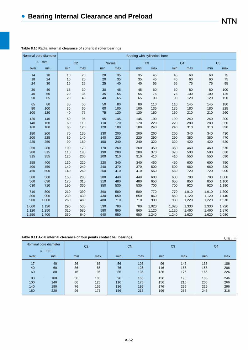
Nominal bore diameter
d mm C2 CN C3 C4
263646
56667696
668696
106126156176
174060
80100140180
406080
100140180220
567686
96116136156
106126136
156176196216
96116126
136156176196
146166176
196216236256
136156166
186206226246
186206226
246266296316
Unit μm
over incl. min max min max min max min max
Nominal bore diameter
d mm
Bearing with cylindrical bore
C2
101015
152020
303540
506065
708090
100110120
130140140
150170190
210230260
290320350
202025
303540
506075
95110120
130140150
170190200
220240260
280310350
390430480
530580640
Normal C3 C4 C5
141824
304050
6580
100
120140160
180200225
250280315
355400450
500560630
710800900
1,0001,1201,250
182430
405065
80100120
140160180
200225250
280315355
400450500
560630710
800900
1,000
1,1201,2501,400
353540
455565
80100120
145170180
200220240
260280310
340370410
440480530
580650710
780860950
202025
303540
506075
95110120
130140150
170190200
220240260
280310350
390430480
530580640
454555
607590
110135160
190220240
260290320
350370410
450500550
600650700
770860930
1,0201,1201,240
353540
455565
80100120
145170180
200220240
260280310
340370410
440480530
580650710
780860950
454555
607590
110135160
190220240
260290320
350370410
450500550
600650700
770860930
1,0201,1201,240
606075
80100120
145180210
240280310
340380420
460500550
600660720
780850920
1,0101,1201,220
1,3301,4601,620
606075
80100120
145180210
240280310
340380420
460500550
600660720
780850920
1,0101,1201,220
1,3301,4601,620
757595
100125150
180225260
300350390
430470520
570630690
750820900
1,0001,1001,190
1,3001,4401,570
1,7201,8702,080
over incl. min max min max min max min max min max
●Bearing Internal Clearance and Preload
A-62
Table 8.10 Radial internal clearance of spherical roller bearings
Table 8.11 Axial internal clearance of four points contact ball bearings.
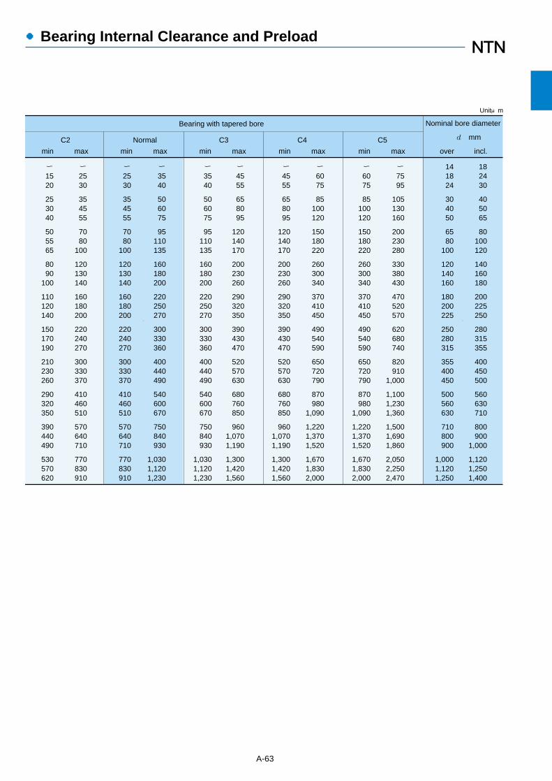
●Bearing Internal Clearance and Preload
A-63
Nominal bore diameter
d mm
Bearing with tapered bore
C2
ー3540
506075
95110135
160180200
220250270
300330360
400440490
540600670
750840930
1,0301,1201,230
Normal C3 C4 C5
141824
304050
6580
100
120140160
180200225
250280315
355400450
500560630
710800900
1,0001,1201,250
182430
405065
80100120
140160180
200225250
280315355
400450500
560630710
800900
1,000
1,1201,2501,400
ー4555
658095
120140170
200230260
290320350
390430470
520570630
680760850
9601,0701,190
1,3001,4201,560
ー6075
85100120
150180220
260300340
370410450
490540590
650720790
870980
1,090
1,2201,3701,520
1,6701,8302,000
ー7595
105130160
200230280
330380430
470520570
620680740
820910
1,000
1,1001,2301,360
1,5001,6901,860
2,0502,2502,470
ー1520
253040
505565
8090
100
110120140
150170190
210230260
290320350
390440490
530570620
ー2530
354555
7080
100
120130140
160180200
220240270
300330370
410460510
570640710
770830910
ー2530
354555
7080
100
120130140
160180200
220240270
300330370
410460510
570640710
770830910
ー3540
506075
95110135
160180200
220250270
300330360
400440490
540600670
750840930
1,0301,1201,230
ー4555
658095
120140170
200230260
290320350
390430470
520570630
680760850
9601,0701,190
1,3001,4201,560
ー6075
85100120
150180220
260300340
370410450
490540590
650720790
870980
1,090
1,2201,3701,520
1,6701,8302,000
Unitμm
over incl.min maxmin maxmin maxmin maxmin max

8.3 PreloadNormally, bearings are used with a slight internal
clearance under operating conditions. However, in someapplications, bearings are given an initial load; this meansthat the bearings' internal clearance is negative beforeoperation. This is called "preload" and is commonlyapplied to angular ball bearings and tapered rollerbearings.
8.3.1 Purpose of preloadGiving preload to a bearing results in the rolling element
and raceway surfaces being under constant elasticcompressive forces at their contact points. This has theeffect of making the bearing extremely rigid so that evenwhen load is applied to the bearing, radial or axial shaft
displacement does not occur. Thus, the naturalfrequency of the shaft is increased, which is suitable forhigh speeds.
Preload is also used to prevent or suppress shaftrunout, vibration, and noise; improve running accuracyand locating accuracy; reduce smearing, and regulaterolling element rotation. Also, for thrust ball and rollerbearings mounted on horizontal shafts, preloading keepsthe rolling elements in proper alignment.
The most common method of preloading is to apply anaxial load to two duplex bearings so that the inner andouter rings are displaced axially in relation to each other.This preloading method is divided into fixed positionpreload and constant pressure preload.
A-64
●Bearing Internal Clearance and Preload
Method Basic pattern
Precisionangular contactball bearings
Fixed position preload
Constant pressure preload
Applicable bearings Characteristics ApplicationsObject
Maintainingaccuracy ofrotating shaft,preventingvibrationincreasingrigidity
Preloading is accomplished bya predetermined offset of therings or by using spacers. Forthe standard preload see Table8.13
Preloading is accomplished byusing coil or belleville springs.Recommended preloads are asfollows:for deep groove ball bearings:4~10 d N0.4~1.0 d {kgf} for angular contact ball bearings: see Table 8.13
Preload is accomplished byusing coil or belleville springs.Recommended preloads are asfollows:for thrust ball bearings:T1=0.42 (nCoa) 1.9×10⁻¹³ N =3.275(nCoa)1.9×10⁻¹³ {kgf}T2=0.00083 Coa
N{kgf}�which ever is greater forspherical roller thrust bearings:� T=0.025 Coa
0.8 N =0.0158 Coa
0.8 {kgf}
Grinding machines,lathes, milling machines,measuring instruments
Tapered rollerbearings, thrustball bearings,angular contactball bearings
Increasingbearing rigidity
Preload is accomplished by adjusting athreaded screw.The amount of preload is set by measuringthe starting torque or axial displacement.Relationship between the starting torqueM and preload T is approximately given bythe following formulas:for duplex angularcontact ball bearings:
for duplex tapered rollerbearings:
Lathes, milling machines,differential gears of automotives,printing machines, wheel axles
Angular contactball bearings,deep grooveball bearings,precisiontapered rollerbearings
Maintainingaccuracy andpreventingvibration andnoise with aconstantamount ofpreload withoutbeing affectedby loads ortemperature
Internal grinding machines,electric motors,high speed shafts in small machines,tension reels
Tapered rollerbearings withsteep angle,spherical rollerthrust bearings,thrust ballbearings
Preventingsmearing onraceway ofnon-loadedside underaxial loads
Rolling mills, extruding machines
Note: In the above formulas dp = pitch diameter of bearing, mm dp = (Bore+Outside dia) / 2 T = preload, N The starting torque M however, is greatly influenced by lubricants and a period of run-in time.
d = bearing bore, mm n = number of revolutions, r/minCoa = basic static axial load rating, N
Δ�Δ�
M= N・mm1)�
330~430dp・T
M= N・mm1)�
57~107dp
0.8・T
Table 8.12 Preloading methods and characteristics

8.3.2 Preloading methods and amountsThe basic pattern, purpose and characteristics of
bearing preloads are shown in Table 8.12. The definiteposition preload is effective for positioning the twobearings and also for increasing the rigidity. Due to theuse of a spring for the constant pressure preload, thepreloading amount can be kept constant, even when thedistance between the two bearings fluctuates under theinfluence of operating heat and load.
Also, the standard preloading amount for the pairedangular contact ball bearings is shown in Table 8.13.Light and normal preload is applied to prevent generalvibration, and medium and heavy preload is appliedespecially when rigidity is required.
A-65
●Bearing Internal Clearance and Preload
8.3.3 Preload and rigidityThe increased rigidity effect preloading has on bearingsis shown in Fig. 8.2. When the offset inner rings of thetwo paired angular contact ball bearings are pressedtogether, each inner ring is displaced axially by theamount δ0 and is thus given a preload, F0, in thedirection. Under this condition, when external axial loadFa is applied, bearing!will have an increaseddisplacement by the amount δa and bearing @
,s
displacement will decrease. At this time the loads appliedto bearing!and @ are FI and FII, respectively.
Under the condition of no preload, bearing I will bedisplaced by the amount δb when axial load Fa isapplied. Since the amount of displacement, δa, is lessthan δb, it indicates a higher rigidity for δa.
Fa �
FoFo
δo δo
Inner ringdisplacement
Fo : Preload��Inner ringdisplacement
F1= F2+ Fa�
Fa: External axial load
(1) Under free from preload
(2) Under preloading
(3) Under preloading and applied load
Fo
Bearing1
Bearing2 Bearing1
Axi
al lo
ad
F1= F2+ Fa
Axial displacement
δo
δ1 δ2δo
Fo
Fa
Fa
F1
F2
δb
δa
�
δoδoδoδo
F2
δa δa
δa
Outer ring
Inner ringSteel ball
Bearing2
Fig. 8.2 Fixed position preload versus axial displacement

A-66
●Bearing Internal Clearance and Preload
Table 8.13 The normal preload of duplex arrangement angular contact ball bearings
Nominalbore diameter�
d mm
Bearing
- 1218
324050
658090
95100105
110120140
150160170
180190
121832
405065
809095
100105110
120140150
160170180
190200
20{ 2}20{ 2}29{ 3}
49{ 5}49{ 5}98{10}
98{10}147{15}147{15}
147{15}196{20}196{20}
196{20}294{30}294{30}
490{50}490{50}490{50}
590{60}590{60}
29{ 3}29{ 3}78{ 8}
147{ 15}147{ 15}196{ 20}
294{ 30}390{ 40}390{ 40}
390{ 40}590{ 60}590{ 60}
590{ 60}785{ 80}785{ 80}
980{100}980{100}980{100}
1,470{150}1,470{150}
196{ 20}
294{ 30}490{ 50}590{ 60}
785{ 80}980{100}980{100}
1,470{150}1,470{150}1,470{150}
1,960{200}2,450{250}2,940{300}
2,940{300}2,940{300}3,900{400}
3,900{400}5,900{600}
--
98{ 10}
196{ 20}245{ 25}294{ 30}
390{ 40}490{ 50}490{ 50}
685{ 70}685{ 70}685{ 70}
880{ 90}980{100}
1,470{150}
1,470{150}1,470{150}1,960{200}
1,960{200}2,940{300}
--
49{ 5}
78{ 8}98{ 10}
118{ 12}
196{ 20}245{ 25}245{ 25}
294{ 30}294{ 30}294{ 30}
390{ 40}490{ 50}685{ 70}
685{ 70}685{ 70}880{ 90}
880{ 90}1,270{130}
--
20{ 2}
29{ 3}39{ 4}49{ 5}
78{ 8}98{10}98{10}
118{12}118{12}118{12}
147{15}196{20}245{25}
245{25}245{25}294{30}
294{30}490{50}
--
147{ 15}
147{ 15}196{ 20}390{ 40}
390{ 40}590{ 60}590{ 60}
590{ 60}590{ 60}980{100}
980{100}1,270{130}1,470{150}
1,470{150}1,960{200}1,960{200}
2,450{250}2,450{250}
--
78{ 8}
78{ 8}98{ 10}
196{ 20}
196{ 20}294{ 30}294{ 30}
294{ 30}294{ 30}490{ 50}
490{ 50}590{ 60}785{ 80}
785{ 80}980{100}980{100}
1,270{130}1,270{130}
--
29{ 3}
29{ 3}49{ 5}98{10}
98{10}147{15}147{15}
147{15}147{15}196{20}
196{20}294{30}390{40}
390{40}490{50}490{50}
590{60}590{60}
--
10{ 1}
10{ 1}20{ 2}29{ 3}
29{ 3}49{ 5}49{ 5}
49{ 5}49{ 5}78{ 8}
78{ 8}98{10}
147{15}
147{15}147{15}147{15}
196{20}196{20}
--
over inch
78C 79C,HSB9C 70C,BNT0,
Low Normal Central Heavy Low Normal Low NormalCentral Heavy
Nominal bore diameter�d mm
Bearing
- 1218
324050
658090
95100105
110120140
150160170
180190
121832
405065
809095
100105110
120140150
160170180
190200
196{ 20}294{ 30}490{ 50}
880{ 90}980{ 100}
1,470{ 150}
1,960{ 200}2,940{ 300}2,940{ 300}
2,940{ 300}3,900{ 400}3,900{ 400}
3,900{ 400}5,900{ 600}5,900{ 600}
8,800{ 900}8,800{ 900}8,800{ 900}
9,800{1,000}9,800{1,000}
147{ 15}147{ 15}294{ 30}
590{ 60}590{ 60}880{ 90}
1,470{150}1,960{200}1,960{200}
1,960{200}2,450{250}2,450{250}
2,450{250}3,450{350}3,450{350}
4,900{500}4,900{500}4,900{500}
6,850{700}6,850{700}
78{ 8}78{ 8}
147{ 15}
294{ 30}294{ 30}490{ 50}
590{ 60}880{ 90}880{ 90}
880{ 90}980{100}980{100}
980{100}1,470{150}1,470{150}
2,450{250}2,450{250}2,450{250}
3,450{350}3,450{350}
29{ 3}29{ 3}49{ 5}
78{ 8}78{ 8}
147{15}
147{15}196{20}196{20}
196{20}294{30}294{30}
294{30}490{50}490{50}
685{70}685{70}685{70}
880{90}880{90}
147{ 15}196{ 20}294{ 30}
590{ 60}635{ 70}785{ 80}
1,180{120}1,470{150}1,470{150}
1,960{200}1,960{200}1,960{200}
2,940{300}3,450{350}4,400{450}
4,400{450}4,400{450}5,900{600}
5,900{600}7,850{800}
78{ 8}147{ 15}196{ 20}
294{ 30}390{ 40}490{ 50}
785{ 80}980{100}980{100}
1,274{130}1,274{130}1,274{130}
1,780{180}1,960{200}2,450{250}
2,450{250}2,450{250}3,450{350}
3,450{350}4,900{500}
39{ 4}49{ 5}98{ 10}
147{ 15}196{ 20}245{ 25}
390{ 40}490{ 50}490{ 50}
685{ 70}685{ 70}685{ 70}
880{ 90}980{100}
1,270{130}
1,270{130}1,270{130}1,780{180}
1,780{180}2,450{250}
over inch
79,HSB9 70,HSB0
Normal Central Heavy Low Normal Central Heavy
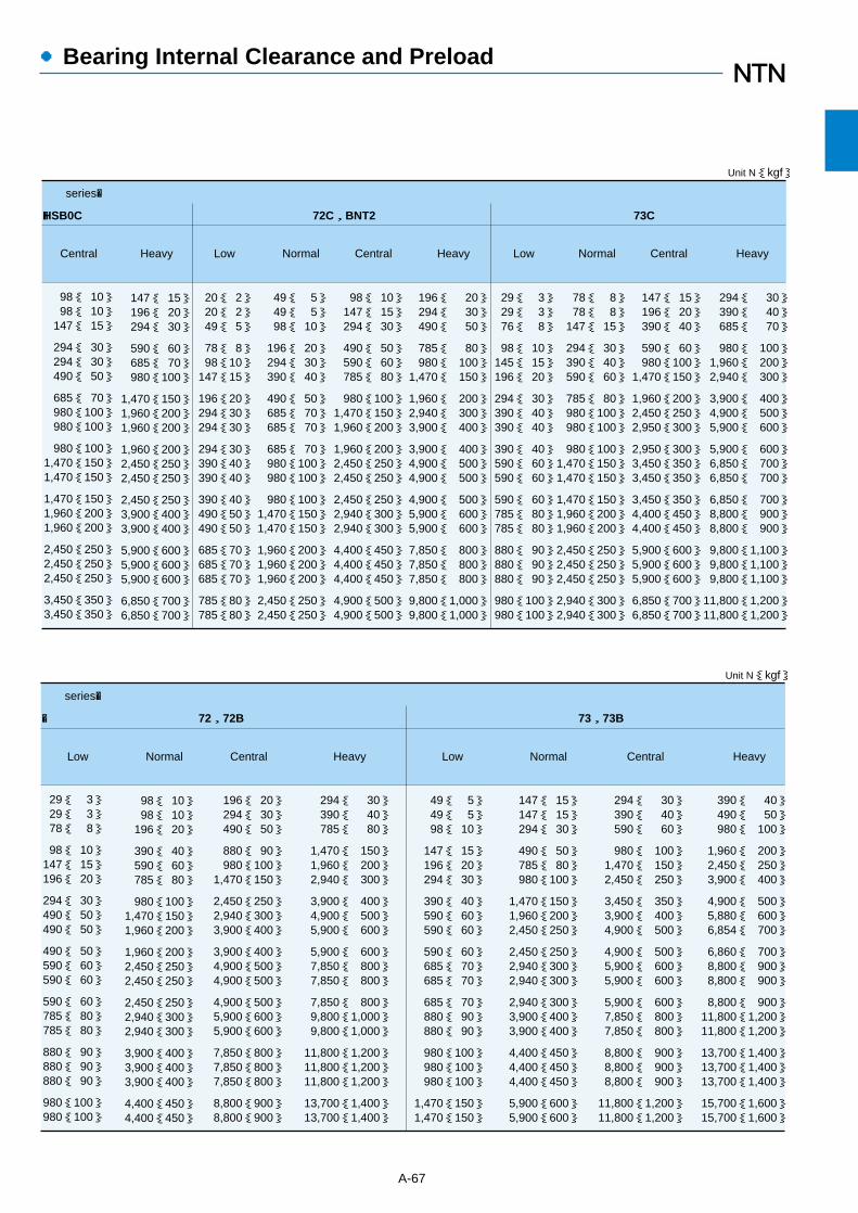
A-67
●Bearing Internal Clearance and Preload
98{ 10}98{ 10}
147{ 15}
294{ 30}294{ 30}490{ 50}
685{ 70}980{100}980{100}
980{100}1,470{150}1,470{150}
1,470{150}1,960{200}1,960{200}
2,450{250}2,450{250}2,450{250}
3,450{350}3,450{350}
147{ 15}196{ 20}294{ 30}
590{ 60}685{ 70}980{100}
1,470{150}1,960{200}1,960{200}
1,960{200}2,450{250}2,450{250}
2,450{250}3,900{400}3,900{400}
5,900{600}5,900{600}5,900{600}
6,850{700}6,850{700}
294{ 30}390{ 40}685{ 70}
980{ 100}1,960{ 200}2,940{ 300}
3,900{ 400}4,900{ 500}5,900{ 600}
5,900{ 600}6,850{ 700}6,850{ 700}
6,850{ 700}8,800{ 900}8,800{ 900}
9,800{1,100}9,800{1,100}9,800{1,100}
11,800{1,200}11,800{1,200}
147{ 15}196{ 20}390{ 40}
590{ 60}980{100}
1,470{150}
1,960{200}2,450{250}2,950{300}
2,950{300}3,450{350}3,450{350}
3,450{350}4,400{450}4,400{450}
5,900{600}5,900{600}5,900{600}
6,850{700}6,850{700}
78{ 8}78{ 8}
147{ 15}
294{ 30}390{ 40}590{ 60}
785{ 80}980{100}980{100}
980{100}1,470{150}1,470{150}
1,470{150}1,960{200}1,960{200}
2,450{250}2,450{250}2,450{250}
2,940{300}2,940{300}
29{ 3}29{ 3}76{ 8}
98{ 10}145{ 15}196{ 20}
294{ 30}390{ 40}390{ 40}
390{ 40}590{ 60}590{ 60}
590{ 60}785{ 80}785{ 80}
880{ 90}880{ 90}880{ 90}
980{100}980{100}
196{ 20}294{ 30}490{ 50}
785{ 80}980{ 100}
1,470{ 150}
1,960{ 200}2,940{ 300}3,900{ 400}
3,900{ 400}4,900{ 500}4,900{ 500}
4,900{ 500}5,900{ 600}5,900{ 600}
7,850{ 800}7,850{ 800}7,850{ 800}
9,800{1,000}9,800{1,000}
98{ 10}147{ 15}294{ 30}
490{ 50}590{ 60}785{ 80}
980{100}1,470{150}1,960{200}
1,960{200}2,450{250}2,450{250}
2,450{250}2,940{300}2,940{300}
4,400{450}4,400{450}4,400{450}
4,900{500}4,900{500}
49{ 5}49{ 5}98{ 10}
196{ 20}294{ 30}390{ 40}
490{ 50}685{ 70}685{ 70}
685{ 70}980{100}980{100}
980{100}1,470{150}1,470{150}
1,960{200}1,960{200}1,960{200}
2,450{250}2,450{250}
20{ 2}20{ 2}49{ 5}
78{ 8}98{10}
147{15}
196{20}294{30}294{30}
294{30}390{40}390{40}
390{40}490{50}490{50}
685{70}685{70}685{70}
785{80}785{80}
series�
� 72C,BNT2 73CHSB0C
Central Heavy Low Normal Central Heavy Low Normal Central Heavy
Unit N{kgf}
29{ 3}29{ 3}78{ 8}
98{ 10}147{ 15}196{ 20}
294{ 30}490{ 50}490{ 50}
490{ 50}590{ 60}590{ 60}
590{ 60}785{ 80}785{ 80}
880{ 90}880{ 90}880{ 90}
980{100}980{100}
98{ 10}98{ 10}
196{ 20}
390{ 40}590{ 60}785{ 80}
980{100}1,470{150}1,960{200}
1,960{200}2,450{250}2,450{250}
2,450{250}2,940{300}2,940{300}
3,900{400}3,900{400}3,900{400}
4,400{450}4,400{450}
390{ 40}490{ 50}980{ 100}
1,960{ 200}2,450{ 250}3,900{ 400}
4,900{ 500}5,880{ 600}6,854{ 700}
6,860{ 700}8,800{ 900}8,800{ 900}
8,800{ 900}11,800{1,200}11,800{1,200}
13,700{1,400}13,700{1,400}13,700{1,400}
15,700{1,600}15,700{1,600}
294{ 30}390{ 40}590{ 60}
980{ 100}1,470{ 150}2,450{ 250}
3,450{ 350}3,900{ 400}4,900{ 500}
4,900{ 500}5,900{ 600}5,900{ 600}
5,900{ 600}7,850{ 800}7,850{ 800}
8,800{ 900}8,800{ 900}8,800{ 900}
11,800{1,200}11,800{1,200}
147{ 15}147{ 15}294{ 30}
490{ 50}785{ 80}980{100}
1,470{150}1,960{200}2,450{250}
2,450{250}2,940{300}2,940{300}
2,940{300}3,900{400}3,900{400}
4,400{450}4,400{450}4,400{450}
5,900{600}5,900{600}
49{ 5}49{ 5}98{ 10}
147{ 15}196{ 20}294{ 30}
390{ 40}590{ 60}590{ 60}
590{ 60}685{ 70}685{ 70}
685{ 70}880{ 90}880{ 90}
980{100}980{100}980{100}
1,470{150}1,470{150}
294{ 30}390{ 40}785{ 80}
1,470{ 150}1,960{ 200}2,940{ 300}
3,900{ 400}4,900{ 500}5,900{ 600}
5,900{ 600}7,850{ 800}7,850{ 800}
7,850{ 800}9,800{1,000}9,800{1,000}
11,800{1,200}11,800{1,200}11,800{1,200}
13,700{1,400}13,700{1,400}
196{ 20}294{ 30}490{ 50}
880{ 90}980{100}
1,470{150}
2,450{250}2,940{300}3,900{400}
3,900{400}4,900{500}4,900{500}
4,900{500}5,900{600}5,900{600}
7,850{800}7,850{800}7,850{800}
8,800{900}8,800{900}
series�
� 72,72B 73,73B
Unit N{kgf}
Low Normal Central Heavy Low Normal Central Heavy
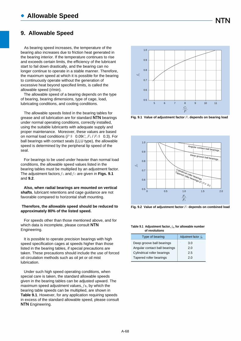
1.0
0.5
0.6
0.7
0.8
0.9
5 6 7 8 9 10 11
Cr
P
f L
A-68
●Allowable Speed
As bearing speed increases, the temperature of thebearing also increases due to friction heat generated inthe bearing interior. If the temperature continues to riseand exceeds certain limits, the efficiency of the lubricantstart to fail down drastically, and the bearing can nolonger continue to operate in a stable manner. Therefore,the maximum speed at which it is possible for the bearingto continuously operate without the generation ofexcessive heat beyond specified limits, is called theallowable speed (r/min).
The allowable speed of a bearing depends on the typeof bearing, bearing dimensions, type of cage, load,lubricating conditions, and cooling conditions.
The allowable speeds listed in the bearing tables forgrease and oil lubrication are for standard NTN bearingsunder normal operating conditions, correctly installed,using the suitable lubricants with adequate supply andproper maintenance. Moreover, these values are basedon normal load conditions (P ≦ 0.09C, Fa / Fr≦ 0.3). Forball bearings with contact seals (LLU type), the allowablespeed is determined by the peripheral lip speed of theseal.
For bearings to be used under heavier than normal loadconditions, the allowable speed values listed in thebearing tables must be multiplied by an adjustment factor.The adjustment factors f L and f C are given in Figs. 9.1and 9.2.
Also, when radial bearings are mounted on verticalshafts, lubricant retentions and cage guidance are notfavorable compared to horizontal shaft mounting.
Therefore, the allowable speed should be reduced toapproximately 80% of the listed speed.
For speeds other than those mentioned above, and forwhich data is incomplete, please consult NTNEngineering.
It is possible to operate precision bearings with highspeed specification cages at speeds higher than thoselisted in the bearing tables, if special precautions aretaken. These precautions should include the use of forcedoil circulation methods such as oil jet or oil mistlubrication.
Under such high speed operating conditions, whenspecial care is taken, the standard allowable speedsgiven in the bearing tables can be adjusted upward. Themaximum speed adjustment values, f B, by which thebearing table speeds can be multiplied, are shown inTable 9.1. However, for any application requiring speedsin excess of the standard allowable speed, please consultNTN Engineering.
Fig. 9.1 Value of adjustment factor FL depends on bearing load
Fig. 9.2 Value of adjustment factor FC depends on combined load
0
1.0
0.9
0.8
0.7
0.6
0.50.5 1.0 1.5 2.0
Fa
Fr
f C
Deep groove ball bearings
Angular contact ball bearings
Cylindrical roller bearings
Tapered roller bearings (Fa/Fr≦2e)
Table 9.1 Adjustment factor, fB, for allowable numberof revolutions
Type of bearing Adjustment factor fB
Deep groove ball bearings
Angular contact ball bearings
Cylindrical roller bearings
Tapered roller bearings
3.0
2.0
2.5
2.0
9. Allowable Speed
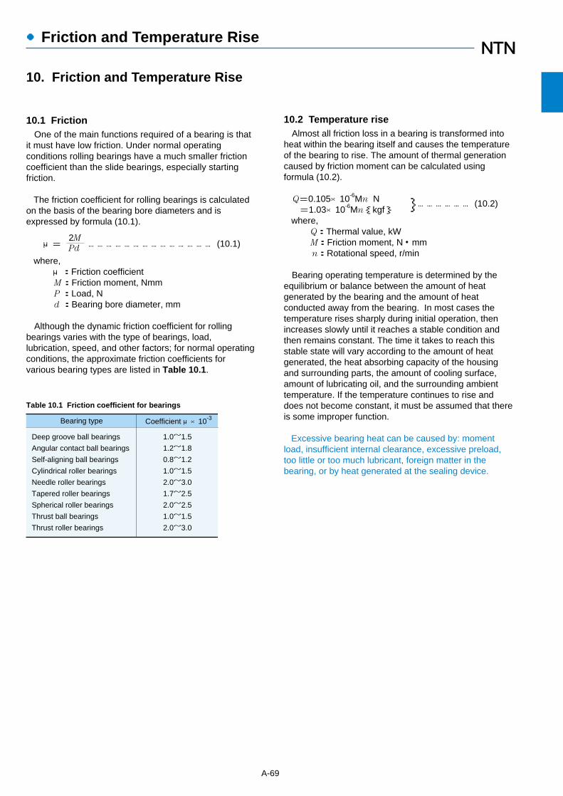
●Friction and Temperature Rise
10.1 FrictionOne of the main functions required of a bearing is that
it must have low friction. Under normal operatingconditions rolling bearings have a much smaller frictioncoefficient than the slide bearings, especially startingfriction.
The friction coefficient for rolling bearings is calculatedon the basis of the bearing bore diameters and isexpressed by formula (10.1).
μ=2M
…………………………………… (10.1)Pd
where,μ:Friction coefficientM:Friction moment, NmmP :Load, Nd :Bearing bore diameter, mm
Although the dynamic friction coefficient for rollingbearings varies with the type of bearings, load,lubrication, speed, and other factors; for normal operatingconditions, the approximate friction coefficients forvarious bearing types are listed in Table 10.1.
10.2 Temperature riseAlmost all friction loss in a bearing is transformed into
heat within the bearing itself and causes the temperatureof the bearing to rise. The amount of thermal generationcaused by friction moment can be calculated usingformula (10.2).
Q=0.105×10⁻⁶Mn N }……………… (10.2)=1.03×10⁻⁶Mn{kgf}
where,Q:Thermal value, kWM:Friction moment, N・mmn:Rotational speed, r/min
Bearing operating temperature is determined by theequilibrium or balance between the amount of heatgenerated by the bearing and the amount of heatconducted away from the bearing. In most cases thetemperature rises sharply during initial operation, thenincreases slowly until it reaches a stable condition andthen remains constant. The time it takes to reach thisstable state will vary according to the amount of heatgenerated, the heat absorbing capacity of the housingand surrounding parts, the amount of cooling surface,amount of lubricating oil, and the surrounding ambienttemperature. If the temperature continues to rise anddoes not become constant, it must be assumed that thereis some improper function.
Excessive bearing heat can be caused by: momentload, insufficient internal clearance, excessive preload,too little or too much lubricant, foreign matter in thebearing, or by heat generated at the sealing device.
A-69
Deep groove ball bearings
Angular contact ball bearings
Self-aligning ball bearings
Cylindrical roller bearings
Needle roller bearings
Tapered roller bearings
Spherical roller bearings
Thrust ball bearings
Thrust roller bearings
Bearing type Coefficient μ×10-3
1.0~1.5
1.2~1.8
0.8~1.2
1.0~1.5
2.0~3.0
1.7~2.5
2.0~2.5
1.0~1.5
2.0~3.0
Table 10.1 Friction coefficient for bearings
10. Friction and Temperature Rise
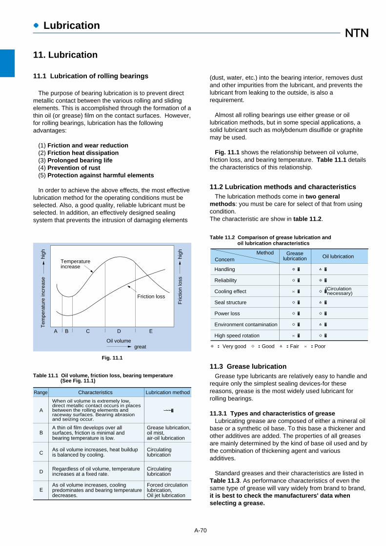
●Lubrication
11. Lubrication
11.1 Lubrication of rolling bearings
The purpose of bearing lubrication is to prevent directmetallic contact between the various rolling and slidingelements. This is accomplished through the formation of athin oil (or grease) film on the contact surfaces. However,for rolling bearings, lubrication has the followingadvantages:
(1) Friction and wear reduction(2) Friction heat dissipation(3) Prolonged bearing life(4) Prevention of rust(5) Protection against harmful elements
In order to achieve the above effects, the most effectivelubrication method for the operating conditions must beselected. Also, a good quality, reliable lubricant must beselected. In addition, an effectively designed sealingsystem that prevents the intrusion of damaging elements
A-70
Friction loss
Fric
tion
loss
Oil volume
EDCBA
Tem
pera
ture
incr
ease
Temperatureincrease
great
high
high
Fig. 11.1
(dust, water, etc.) into the bearing interior, removes dustand other impurities from the lubricant, and prevents thelubricant from leaking to the outside, is also arequirement.
Almost all rolling bearings use either grease or oillubrication methods, but in some special applications, asolid lubricant such as molybdenum disulfide or graphitemay be used.
Fig. 11.1 shows the relationship between oil volume,friction loss, and bearing temperature. Table 11.1 detailsthe characteristics of this relationship.
11.2 Lubrication methods and characteristicsThe lubrication methods come in two general
methods: you must be care for select of that from usingcondition.The characteristic are show in table 11.2.
Table 11.1 Oil volume, friction loss, bearing temperature (See Fig. 11.1)
Range Characteristics Lubrication method
When oil volume is extremely low,direct metallic contact occurs in placesbetween the rolling elements andraceway surfaces. Bearing abrasionand seizing occur.
A thin oil film develops over allsurfaces, friction is minimal andbearing temperature is low.
As oil volume increases, heat buildupis balanced by cooling.
Regardless of oil volume, temperatureincreases at a fixed rate.
As oil volume increases, coolingpredominates and bearing temperaturedecreases.
A
B
C
D
E
ーーー�
Grease lubrication,oil mist,air-oil lubrication
Circulatinglubrication
Circulatinglubrication
Forced circulationlubrication,Oil jet lubrication
MethodConcern
Greaselubrication Oil lubrication
Handling
Reliability
Cooling effect
Seal structure
Power loss
Environment contamination
High speed rotation
◎�
○�
�
○�
○�
○�
�
△�
◎�
○�
△�
○�
△�
○�
(Circulation necessary)
◎: Very good ○:Good △:Fair ×:Poor
Table 11.2 Comparison of grease lubrication andoil lubrication characteristics
11.3 Grease lubricationGrease type lubricants are relatively easy to handle and
require only the simplest sealing devices-for thesereasons, grease is the most widely used lubricant forrolling bearings.
11.3.1 Types and characteristics of greaseLubricating grease are composed of either a mineral oil
base or a synthetic oil base. To this base a thickener andother additives are added. The properties of all greasesare mainly determined by the kind of base oil used and bythe combination of thickening agent and variousadditives.
Standard greases and their characteristics are listed inTable 11.3. As performance characteristics of even thesame type of grease will vary widely from brand to brand,it is best to check the manufacturers' data whenselecting a grease.

A-71
●Lubrication
Lithium grease Sodium grease(Fiber grease)
Calcium compoundbase grease
Thickener
Grease name
Base oil�
Dropping point ˚C�
Mechanical stability�
Pressure resistance�
Water resistance
Applications
Li soap Na soap Ca+Na soapCa+Li soap
Mineral oil
170 ~ 190
-30 ~ +130
Excellent
Good
Good
Diester oil
170 ~ 190
-50 ~ +130
Good
Good
Good
Silicone oil
200 ~ 250
-50 ~ +160
Good
poor
Good
Mineral oil
150 ~ 180
-20 ~ +130
Excellent ~ Good
Good
Good ~ poor
Mineral oil
150 ~ 180
-20 ~ +120
Excellent ~ Good
Excellent ~ Good
Good ~ poor
Widest range ofapplications.
Grease used in alltypes of rollingbearings.
Excellent lowtemperature andwear characteristics.
Suitable for smallsized and miniaturebearings.
Suitable for highand lowtemperatures.
Unsuitable for heavyload applications dueto low oil filmstrength.
Some emulsificationwhen water isintroduced.
Excellentcharacteristics atrelatively hightemperatures.
Excellent pressureresistance andmechanical stability.
Suitable forbearings receivingshock loads.
Aluminum grease Non-soap base greaseThickener
AI soap Bentone, silica gel, urea, carbon black,fluorine compounds, etc.
Mineral oil
70 ~ 90
-10 ~ +80
Good ~ poor
Good
Good
Mineral oil
250 or above
-10 ~ +130
Good
Good
Good
Synthetic oil
250 or above
-50 ~ +200
Good
Good
Good
Excellent viscositycharacteristics.
Suitable forbearings subjectedto vibrations.
Can be used in a wide range of low tohigh temperatures. Shows excellent heatresistance, cold resistance, chemicalresistance, and other characteristicswhen matched with a suitable base oiland thickener.
Grease used in all types of rolling bearings.
Thickener
Grease name
Base oil�
Dropping point ˚C�
Mechanical stability�
Pressure resistance�
Water resistance
Applications
Operatingtemperature range ˚C
Operatingtemperature range ˚C
Table 11.3 Grease varieties and characteristics
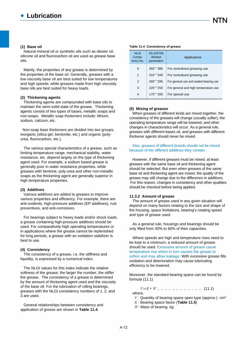
●Lubrication
(5) Mixing of greasesWhen greases of different kinds are mixed together, the
consistency of the greases will change (usually softer), theoperating temperature range will be lowered, and otherchanges in characteristics will occur. As a general rule,greases with different bases oil, and greases with differentthickener agents should never be mixed.
Also, greases of different brands should not be mixedbecause of the different additives they contain.
However, if different greases must be mixed, at leastgreases with the same base oil and thickening agentshould be selected. But even when greases of the samebase oil and thickening agent are mixed, the quality of thegrease may still change due to the difference in additives.For this reason, changes in consistency and other qualitiesshould be checked before being applied.
11.3.2 Amount of greaseThe amount of grease used in any given situation will
depend on many factors relating to the size and shape ofthe housing, space limitations, bearing's rotating speedand type of grease used.
As a general rule, housings and bearings should beonly filled from 30% to 60% of their capacities.
Where speeds are high and temperature rises need tobe kept to a minimum, a reduced amount of greaseshould be used. Excessive amount of grease causetemperature rise which in turn causes the grease tosoften and may allow leakage. With excessive grease fillsoxidation and deterioration may cause lubricatingefficiency to be lowered.
Moreover, the standard bearing space can be found byformula (11.1)
V=K・W ……………………………… (11.1)where, V : Quantity of bearing space open type (approx.) cm3
K : Bearing space factor (Table 11.5)W : Mass of bearing kg
A-72
(1) Base oilNatural mineral oil or synthetic oils such as diester oil,
silicone oil and fluorocarbon oil are used as grease baseoils.
Mainly, the properties of any grease is determined bythe properties of the base oil. Generally, greases with alow viscosity base oil are best suited for low temperaturesand high speeds; while greases made from high viscositybase oils are best suited for heavy loads.
(2) Thickening agentsThickening agents are compounded with base oils to
maintain the semi-solid state of the grease. Thickeningagents consist of two types of bases, metallic soaps andnon-soaps. Metallic soap thickeners include: lithium,sodium, calcium, etc.
Non-soap base thickeners are divided into two groups;inorganic (silica gel, bentonite, etc.) and organic (poly-urea, fluorocarbon, etc.).
The various special characteristics of a grease, such aslimiting temperature range, mechanical stability, waterresistance, etc. depend largely on the type of thickeningagent used. For example, a sodium based grease isgenerally poor in water resistance properties, whilegreases with bentone, poly-urea and other non-metallicsoaps as the thickening agent are generally superior inhigh temperature properties.
(3) AdditivesVarious additives are added to greases to improve
various properties and efficiency. For example, there areanti-oxidents, high-pressure additives (EP additives), rustpreventives, and anti-corrosives.
For bearings subject to heavy loads and/or shock loads,a grease containing high-pressure additives should beused. For comparatively high operating temperatures orin applications where the grease cannot be replenishedfor long periods, a grease with an oxidation stabilizer isbest to use.
(4) ConsistencyThe consistency of a grease, i.e. the stiffness and
liquidity, is expressed by a numerical index.
The NLGI values for this index indicate the relativesoftness of the grease; the larger the number, the stifferthe grease. The consistency of a grease is determinedby the amount of thickening agent used and the viscosityof the base oil. For the lubrication of rolling bearings,greases with the NLGI consistency numbers of 1, 2, and3 are used.
General relationships between consistency andapplication of grease are shown in Table 11.4.
Table 11.4 Consistency of grease
NLGIConsis-
tency No.
JIS (ASTM)Worked
penetrationApplications
0
1
2
3
4
For centralized greasing use
For centralized greasing use
For general use and sealed bearing use
For general and high temperature use
For special use
355~385
310~340
265~295
220~250
175~205

supply interval should be shortened accordingly.
Generally, for every 10˚C increase in bearingtemperature above 80˚C, the relubrication period isreduced by exponent "1/1.5".
――――――――――――――――――――――――――――――――――――(Example)Find the grease relubrication time limit for deepgroove ball bearing 6206, with a radial load of2.0 kN operating at 3,600 r/min.――――――――――――――――――――――――――――――――――――
Cr / Pr= 19.5/2.0 kN = 9.8, from Fig. 9.1 the adjustedload, fL, is 0.96.
From the bearing tables, the allowable speed forbearing 6206 is 11,000 r/min and the numbers ofrevolutions permissible at a radial load of 2.0 kN are
no= 0.96×11,000= 10,560 r/min
therefore, no=
10,560=2.93
n 3,600
Using the chart in Fig. 11.2, find the point correspondingto bore diameter d = 30 (from bearing table) on thevertical line for radial ball bearings. Draw a straighthorizontal line to vertical line !. Then, draw a straight linefrom that point (A in example) to the point on line@ whichcorresponds to the no / n value (2.93 in example). Thepoint, C, where this line intersects vertical line# indicatesthe relubrication interval h. In this case the life of thegrease is approximately 5,500 hours.
11.3.3 ReplenishmentAs the lubricating efficiency of grease declines with the
passage of time, fresh grease must be re-supplied atproper intervals. The replenishment time interval dependson the type of bearing, dimensions, bearing's rotatingspeed, bearing temperature, and type of grease.
An easy reference chart for calculating greasereplenishment intervals is shown in Fig. 11.2.
This chart indicates the replenishment interval forstandard rolling bearing grease when used under normaloperating conditions.
As operating temperatures increase, the grease re-
A-73
●Lubrication
Table 11.5 Bearings space ratio K
Bearing type Retainer type K�
Ball bearings �
NU-type cylindrical roller bearings� �
N-type cylindrical roller bearings
� �
Tapered roller bearings �
Spherical roller bearings
2
3
1
1 Remove 160 series2 Remove NU4 series3 Remove N4 series
Pressed retainer�
Pressed retainer�Machined retainer�
Pressed retainer�Machined retainer�
Pressed retainer�
Pressed retainer�Machined retainer
61
5036
5537
46
3528
400300200
10050403020107
200
100
50
30
2010
500300200
100
503020
500
300200
100
50
3020
Bearing bore d, mm
!
30,000
20,000
10,000
5,0004,000
3,000
2,000
1,000
500400
300
20.0
15.0
10.09.08.07.06.0
5.0
4.0
3.0
2.0
1.5
1.0
0.9
0.8
0.7
B
A
no /n
@
no:factor fL×limiting speed for grease see Fig. 9.1 and bearing tables�n :actual rotational speed, r/min
#
C
Relubrication interval, h
Radial ballbearings
Thrust ball bearings
Cylindrical rollerbearings
Tapered roller bearingsSpherical roller bearings
Fig. 11.2 Diagram for relubrication interval of greasing

●Lubrication
11.4 Solid grease (For bearings with solid grease)"Solid grease" is a lubricant composed mainly of
lubricating grease and ultra-high polymer polyethylene.Solid grease has the same viscosity as grease at normaltemperature, but by applying a special heat treatmentprocess, this special grease solidifies retaining a largeproportion of the lubricant within the bearing. The result ofthis solidification is that the grease does not easily leakfrom the bearing, even when the bearing is subjected tostrong vibrations or centrifugal force.
Bearings with solid grease are available in two types:the spot-pack type in which solid grease is injected intothe retainer, and the full-pack type in which all emptyspace around the rolling elements is filled with solidgrease.
Spot-pack solid grease is standard for deep groove ballbearings, small diameter ball bearings, and bearing units.Full-pack solid grease is standard for self-aligning ballbearings, spherical roller bearings, and needle rollerbearings.
Primary advantages:(1) Clean working environment with minimal grease
leakage(2) Low bearing torque with spot-pack type solid grease
For more details, please refer to NTN special catalogof Solid grease bearings.
A-74
11.5 Oil lubricationOil lubrication is suitable for applications requiring that
bearing-generated heat or heat applied to the bearingfrom other sources be carried away from the bearing anddissipated to the outside.Table 11.6 shows the mainmethods of oil lubrication.
11.5.1 Selection of lubricating oilUnder normal operating conditions, spindle oil, machine
oil, turbine oil, and other mineral oils are widely used forthe lubrication of rolling bearings. However, fortemperatures above 150˚C or below -30˚C, synthetic oilssuch as diester oil, silicone oil, and fluorocarbon oil areused.
For lubricating oils, viscosity is one of the mostimportant properties and determines an oil’s lubricatingefficiency. If viscosity is too low, formation of the oil filmwill be insufficient, and damage will occur to the loadcarrying surfaces of the bearing. If viscosity is too high,viscous resistance will also be great and result intemperature increases and friction loss. In general, forhigher speed applications a lower viscosity oil should beused; for heavier load applications, a higher viscosity oilshould be used.
In regard to operating temperature and lubrication,Table 11.7 lists the required oil viscosity for differenttypes of rolling bearings. Fig. 11.5 is an oil viscosity -operating temperature comparison chart for the purposeof selecting a lubrication oil with viscosity characteristicsappropriate to an application.
Table 11.8 lists the selection standards for lubricating oilviscosity with reference to bearing operating conditions.
Fig. 11.3 Deep groove ball bearing with spot-pack solid grease (Z shield)(Standard for deep groove ball bearings)
Fig. 11.4 Spherical roller bearing with full-pack solid grease(Standard for spherical roller bearings)
Solid grease
Solid grease
Ball bearings, Cylindrical roller bearings,Needle roller bearings
Spherical roller bearings, Tapered rollerbearings, Needle roller thrust bearings
Self-aligning roller thrust bearings
Bearing type Dynamic viscosity mm2 /s
13
20
30
Table 11.7 Required lubricating oil viscosity for bearings
3,0002,000
1,000
500
300200
100
50
30
2015
10
8
6
5
4
3
- 30 - 20 0- 10 10 20 30 40 50 60 70 80 90 100 110 120 130 140 150 160
1 : ISO VG 320
7 : ISO VG 15
2 : ISO VG 1503 : ISO VG 684 : ISO VG 465 : ISO VG 326 : ISO VG 22
Temperature °C�
Vis
cosi
ty m
m2 /s
1
2
34
56
7
FIg. 11.5 Relation between lubricating oil viscosity andtemperature

A-75
●Lubrication
Lubrication method Example
¡In this method, the required minimum amount of lubricating oil is measured and fed to each bearing at ideal intervals using compressed air.
¡With fresh lubricating oil constantly being fed to the bearing, and with the cooling effect of the compressed air, bearing temperature rise can be minimized.
¡Because the required oil quantity is infinitesimal, the working environment can be kept clean. Air-oil lubrication units
are available from NTN.
Lubrication method Example
(Air-oil lubrication)
¡This method lubricates by injecting oil under high pressure directly into the side of the bearing. This is a reliable system for high speed, high temperature or otherwise severe conditions.
¡Used for lubricating the bearings in jet engines, gas turbines, and other high speed equipment.
¡Under-race lubrication for machine tools is one example of this type of lubrication.
(Oil jet lubrication)
¡Using pressurized air, lubricating oil is atomized before passing through the bearing.
¡Due to the low lubricant resistance, this method is well suited to high speed applications.
(Oil mist lubrication)
¡In this method, a partially submerged disc rotates and pulls oil up into a reservoir from which it then drains down through the bearing, lubricating it.
(Disc lubrication)
¡In this method, oil is collected above the bearing and allowed to drip down into the housing where it becomes a lubricating mist as it strikes the rolling elements. Another version allows only slight amounts of oil to pass through the bearing.
¡Used at relatively high speeds for light to moderate load applications.
¡In most cases, oil volume is a few drops per minute.
(Drip lubrication)
¡Used for bearing cooling applications or for automatic oil supply systems in which the oil supply is centrally located.
¡One of the advantages of this method is that oil cooling devices and filters to maintain oil purity can be installed within the system.
¡In order for oil to thoroughly lubricate the bearing, oil inlets and outlets must be provided on opposite sides of the bearing.
(Circulating lubrication)
¡In this method, an impeller or similar device mounted on the shaft draws up oil and sprays it onto the bearing. This method can be used at considerably high speeds.
(Oil spray lubrication)
¡Oil bath lubrication is the most generally used method of lubrication and is widely used for low to moderate rotation speed applications.
¡For horizontal shaft applications, oil level should be maintained at approximately the center of the lowest rolling element, according to the oil gauge, when the bearing is at rest. For vertical shafts at low speeds, oil level should be maintained at 50 - 80% submergence of the rolling elements.
(Oil bath lubrication)
������������������
Mistseparator
Air
Air filter
Reservoir (level switch)
Air oil line
Pressure switch
Air Nozzle
TimerSolenoid valveT
Oil
�
Table 11.6 Oil lubrication methods

●Lubrication
A-76
KExpelled oil temp minussupplied oil temp ˚C
10 1.5
15 1
20 0.75
25 0.6
11.5.2 Oil quantityIn forced oil lubrication systems, the heat radiated away
by the housing and surrounding parts plus the heatcarried away by the lubricating oil is approximately equalto the amount of heat generated by the bearing and othersources.
For standard housing applications, the quantity of oilrequired can be found by formula (11.2).
Q=K・q ……………………………… (11.2)where,
Q: Quantity of oil for one bearing cm3/min.K: Allowable oil temperature rise factor (Table 11.9)q : Minimum oil quantity cm3/min. (Fig. 11.6)
Because the amount of heat radiated will varyaccording to the type of housing, for actual operation it isadvisable that the quantity of oil calculated by formula(11.2) be multiplied by a factor or 1.5 or 2.0. Then, theamount of oil can be adjusted to correspond to actualoperating conditions.
Furthermore, if it is assumed for calculation purposesthat no heat is radiated by the housing, and that allbearing heat is removed by the oil, then the value in Fig.11.3 for shaft diameter, d = 0, regardless of actual shaftdiameter.
――――――――――――――――――――――――――――――――――――(Example) For tapered roller bearing 30220Umounted on a flywheel shaft with a radial load of 9.5kN{969 kgf}, operating at 1,800 r/min, what is theamount of lubricating oil required to keep the bearingtemperature rise below 15˚C.――――――――――――――――――――――――――――――――――――
d = 100 mm,dn = 100×1,800=18×104
From Fig. 11.6 q = 180cm3 / min
11.5.3 Relubrication intervalsThe intervals at which lubricating oil should be changed
varies depending upon operating conditions, oil quantity,and type of oil used. In general, for oil bath lubricationwhere the operating temperature is 50˚C or less, oilshould be replaced once a year. When the operatingtemperature is between 80˚C – 100˚C, oil should bereplaced at least every three months. For importantequipment, it is advisable that lubricating efficiency andoil purity deterioration be checked regularly to determinewhen oil replacement is necessary.
Bearing operatingtemperature
˚C
Up to allowable revolutions
dn-valueLubricating oil ISO viscosity grade (VG)
Normal load Heavy load or shock loadSuitable bearing
-30~ 0 22,32 46 All types
0~ 60
60~100
100 ~150
0~ 60
60~100
15,000 Up to
15,000 ~80,000
80,000 ~150,000
150,000~500,000
15,000 Up to
15,000 ~80,000
80,000 ~150,000
150,000~500,000
Up to allowable revolutions
Up to allowable revolutions
Up to allowable revolutions
46,68
32,46
22,32
100
68
32
22,32
220
150
100,150
68
10
150
100
68
32
All types
All types
All types but thrust ball bearings
Single row radial ball bearings, cylindrical roller bearings
All types
All types
All types but thrust ball bearings
Single row radial ball bearings, cylindrical roller bearings
All types
Self-aligning roller bearings
320
46,68
150
Note 1: Applied when lubrication method is either oil bath or circulating lubrication.2: Please consult NTN Engineering in cases where operating conditions fall outside the range covered by this table.
Table 11.8 Selection standards for lubricating oils (Reference)
Table 11.9 Factor K
Assume the bearing temperature is approximatelyequal to the expelled oil temperature,from Table 11.9, since K= 1
Q=1×180=180cm3 / min
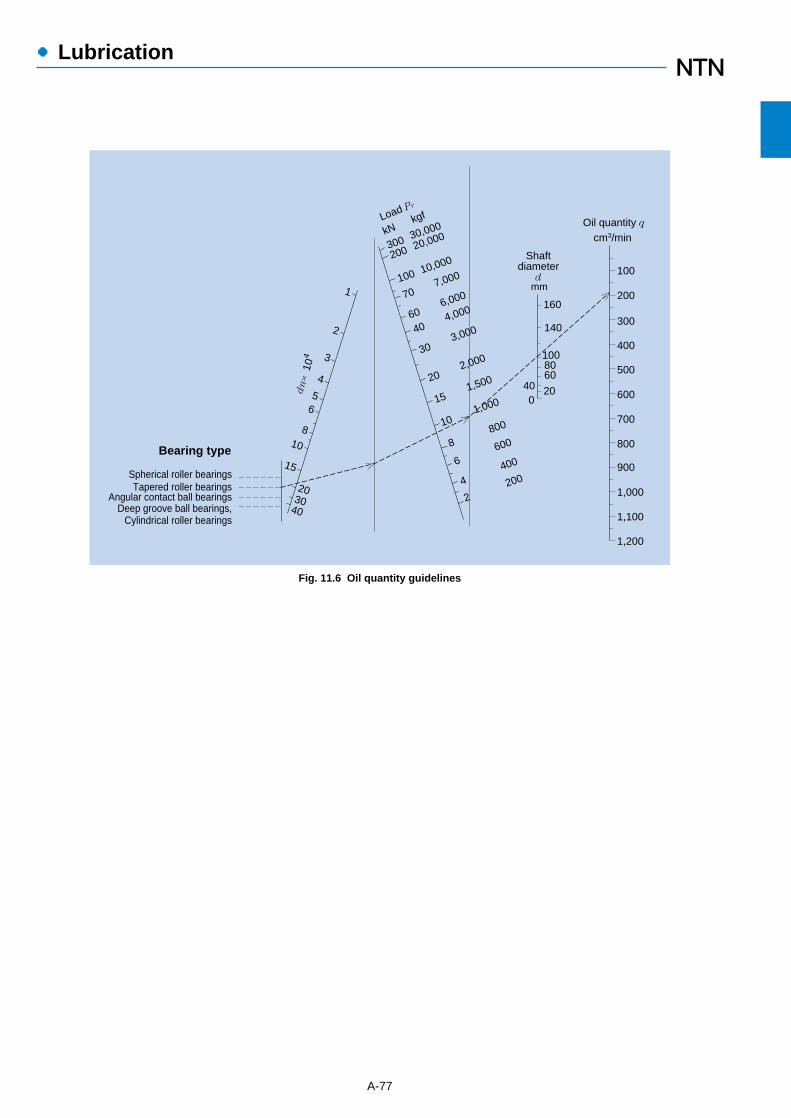
A-77
●Lubrication
Fig. 11.6 Oil quantity guidelines
140
160
1008060
200
40
300200
30,000
20,000
100 10,000
70 7,000
60 6,000
40 4,000
30 3,000
20 2,000
15 1,500
10 1,000
8 8
00
6 6
00
4 4
00
2 2
00
1
2
3
4
56
810
15
2030
40
100
200
300
400
500
600
700
800
900
1,000
1,100
1,200
Shaftdiameter
dmm
Oil quantity qcm3/min
kN kgfLoad Pr
dn×
104
Spherical roller bearingsTapered roller bearings
Angular contact ball bearingsDeep groove ball bearings,
Cylindrical roller bearings
Bearing type

External seals have two main functions: to preventlubricating oil from leaking out, and, to prevent dust, water,and other contaminants from entering the bearing. Whenselecting a seal, the following factors need to be taken intoconsideration: the type of lubricant (oil or grease), sealperipheral speed, shaft fitting errors, space limitations,seal friction and resultant heat increase, and cost.
Sealing devices for rolling bearings fall into two mainclassifications: non-contact seals and contact seals.
¡Non-contact seals: Non-contact seals utilize a smallclearance between the shaft and the housing cover.Therefore friction is negligible, making them suitable forhigh speed applications.
In order to improve sealing capability, clearancespaces are often filled with lubricant.
¡Contact seals: Contact seals accomplish their sealing
action through the contact pressure of a resilient part ofthe seal (the lip is often made of synthetic rubber) andthe sealing surface. Contact seals are generally farsuperior to non-contact seals in sealing efficiency,although their friction torque and temperature risecoefficients are higher. Furthermore, because the lipportion of a contact seal rotates while in contact withthe shaft, the allowable seal peripheral speed variesdepending on seal type.
Lubrication is necessary at the contact surfacebetween the lip portion of the contact seal and theshaft. Ordinary bearing lubricant can also be used forthis purpose.
The following chart lists the special characteristics ofseals and other points to be considered when choosingan appropriate seal.
A-78
Type Seal construction Name Seal characteristics and selection considerations
No
n-co
ntact seals
Cautionary points regarding selectionClearance seal�����Oil groove seal (oil grooves on housing side)�����Oil groove seal (oil grooves on shaft and housing side)
This is an extremely simple seal design with a small radial clearance.����Several concentric oil grooves are provided on the housing inner diameter to greatly improve the sealing effect. When the grooves are filled with lubricant, the intrusion of contaminants from the outside is prevented.��Oil grooves are provided on both the shaft outer diameter and housing inner diameter for a seal with even greater sealing efficiency.
・In order to improve sealing efficiency, clearances between the shaft and housing should be minimized. However, care should be taken to confirm shaft/bearing rigidity and other factors to avoid direct shaft-housing contact during operation.
・Oil groove width, depth (reference)width : 2~5 mm depth : 4~5 mm
・Three or more oil grooves should be provided.・Sealing efficiency can be further
improved by filling the oil groove portion with grease of which the viscosity grade is 150 to 200.・Grease is generally used as the
lubricant for labyrinth seals, and, except in low speed applications, is commonly used together with other sealing devices.
Oil groove clearance (reference)
50 Up to 0.2~0.450 or above 0.5~1.0
Shaft diameter mm Clearance mm
Axial labyrinth seal������Radial labyrinth seal�������Aligning labyrinth seal
This seal has a labyrinth passageway on the axial side of the housing.�����A labyrinth passageway is affixed to the radial side of the housing. For use with split housings. This offers better sealing efficiency than axial labyrinth seals. ���The seal's labyrinth passageway is slanted and has sufficient clearance to prevent contact between the housing projections and the shaft even as the shaft realigns.
Cautionary points regarding selection
・In order to improve sealing efficiency, labyrinth passageway clearances should be minimized. However, care should be taken to confirm shaft/bearing rigidity, fit, internal clearances and other factors to avoid direct contact between labyrinth projections during operation.
・Sealing efficiency can be further improved by filling the labyrinth passageway with grease of which the viscosity grade is 150 to 200.・Labyrinth seals are suitable for
high speed applications.
Labyrinth clearance (reference)
Shaftdiameter
mm
Clearance mm
ー~ 50 0.2~0.4 1.0~2.050~200 0.5~1.0 3.0~5.0
Radial direction Axial direction
12. External bearing sealing devices
●External bearing sealing devices

A-79
●External bearing sealing devices
Type Seal construction Name Seal characteristics and selection considerations
No
n-co
ntact seals
Co
ntact seals
Cautionary points regarding selectionOil comb sleeve��������Internal slinger�������External slinger
In this design, lubricating oil that makes its way out of the housing along the shaft is thrown off by projections on the oil comb sleeve and recirculated.����By providing a slinger inside the housing, centrifugal force guides the lubricant flow back on the bearing and helps prevent it from dirtying the work environment. ���By mounting a slinger on the outside of the housing, centrifugal force helps to prevent dust and other solid contaminants from entering.
・By installation on the revolving shaft, these seal types make use of centrifugal force to aid lubrication, seal in lubricant, and prevent the entrance of contaminants. �・Installation of a slinger inside the
housing further enhances the sealing in of lubricants. �・Installation of a slinger on the
outside of the housing will provide greater protection against dust and other bearing contaminants. �・These seal types are commonly
employed together with other sealing devices.
Oil combsleeve
Oilsurface
Oil flow
Slinger
Air flow
Slinger
In cross section resembling the letter "Z," this seal's empty spaces are filled with grease. The seal is commonly used with a plummer block (bearing housing).�����This design enhances sealing efficiency with a lip that seals from the axial direction. With the aid of centrifugal force, this seal also offers effective protection against dust, water, and other contaminants entering the bearing. Grease can be used on both sides of the seal. At seal peripheral speeds in excess of 12 m/s, seal ring fit is lost due to centrifugal force, and a clamping band is necessary to hold it in place.
Nitrile rubberAcrylic rubber Fluorinated rubberNitrile rubberNitrile rubber
Seal type/material Allowable temp ˚C Allowableperipheral speed
Z grease seal��������V-ring seal��
Z grease seal
V-ring seal
Cautionary points regarding selectionOil seal Oil seals are widely used, and their shapes and dimensions are standardized under JIS B 2402. In this design, a ring-shaped spring is installed in the lip section. As a result, optimal contact pressure is exerted between the lip edge and shaft surface, and sealing efficiency is good.
When the oil seal and the bearing are in very close proximity, internal bearing clearances are sometimes too small to accommodate the additional heat generated by friction between the seal and shaft. In addition to considering the heat generated by contact seals at various peripheral speeds, internal bearing clearances must also be selected with caution.
Depending upon the direction in which the lip faces (in toward the bearing or away from the bearing) contact oil seals are very effective at preventing lubricant leakage from the housing or contaminants from infiltrating the bearing.
Shaft surface roughness (reference)�������Shaft material (reference) ��
MaterialMachine structuralcarbon steel Low carbonalloy steel Stainless steel
Surfacehardness
HRC 40 or higher necessaryHRC 55 or higher advisable
Processingmethod
Final grinding withoutrepeat (moving), or buffedafter hard chrome plating
Surface roughnessPeripheralspeed m/s Ra Rmax
~ 5 0.8a 3.2s 5~10 0.4a 1.6s10~ 0.2a 0.8s
Metal conduit
Spring
Seal lip
Lip edge
Allowable speed/temperature according to seal type/material (reference)
-25 ~+120-15 ~+150-30 ~+200-25 ~+120-25 ~+120
16 or less26 or less32 or less 6 or less40 or less
Oil seals
Z-sealV-ring
60,000m/s(V(m/s)=―――――――――― )�π×d(mm)×n(r/min)
For dust proof For preventinglubricant leakage

●External bearing sealing devices
A-80
Type Seal construction Name Seal characteristics and selection considerations
Co
mb
inatio
n seals
Z-seal + Labyrinth seal
This is an example of an axial labyrinth seal which has been combined with a Z-seal to increase its sealing efficiency. The axial labyrinth seal is affixed to the shaft with a setting bolt or other method. In the diagram on the left, both the direction of the Z-seal and the labyrinth seal are oriented to keep dust and other contaminants out of the bearing.Because a Z-seal has been incorporated, the allowable peripheral speed should not exceed 6 m/s.
�
Labyrinth seal+ Oil groove seal + Slinger �������Oil groove seal + Slinger+ Z-seal��
This is an example of a combination of three different non-contact seals. It has the advantage of preventing both lubricant leakage from inside the bearing and infiltration of dust and other contaminants from the outside. It is widely used on mining equipment and as a sealing system with plummer blocks in extremely dusty application conditions.�����This is an example where an oil groove seal and slinger have been combined with a Z-seal to increase its sealing efficiency. In the diagram on the left, all three seals have been oriented to keep dust and other contaminants out of the bearing. The combination is widely used on mining equipment and as a sealing system with plummer blocks in extremely dusty application conditions.
13.1 Raceway and rolling element materialsWhile the contact surfaces of a bearing's raceways and
rolling elements are subjected to repeated heavy stress,they still must maintain high precision and rotationalaccuracy. To accomplish this, the raceways and rollingelements must be made of a material that has highhardness, is resistant to rolling fatigue, is wear resistant,and has good dimensional stability. The most commoncause of fatigue cracking in bearings is the inclusion ofnon-metallic impurities in the steel. By using purematerials low in these non-metallic impurities, the rollingfatigue life of the bearing is lengthened.
For all NTN bearings, steel low in oxygen content andnon-metallic impurities, then refined by a vacuumdegassing process as well as outside hearth smelting, isused. For bearings requiring especially high reliability andlong life, steels of even higher in purity, such as vacuumsmelted steel (VIM, VAR, CEVM) and electro-slag meltedsteel (ESR), are used.
1) High/mid carbon alloy steelIn general, steel varieties which can be hardened not
just on the surface but also deep hardened by the so-called "through hardening method" are used for theraceways and rolling elements of bearings. Foremostamong these is high carbon chromium bearing steel,which is widely used. For large type bearings andbearings with large cross sectional dimensions, inductionhardened bearing steel incorporating manganese ormolybdenum is used. Also in use is mid-carbon chromiumsteel incorporating silicone and manganese, which givesit hardening properties comparable to high carbonchromium steel.
2) Case hardened (carburized) steelBecause of its combination of a hard surface layer
which has been carburized and hardened to anappropriate depth, and a relatively pliable inner core,case hardened steel has excellent efficiency againstshock loads. NTN uses case hardened steel for almost allof its tapered roller bearings. In terms of case hardenedsteel for NTN's other bearings, chromium steel andchrome molybdenum steel are used for small to mediumsized bearings, and nickel chrome molybdenum steel isused for large sized bearings.
3) Heat resistant bearing steelWhen bearings made of ordinary high carbon chromium
steel which have undergone standard heat treatment areused at temperatures above 120˚C for long durations,unacceptably large dimensional changes can occur. Forthis reason, a dimension stabilizing treatment (TStreatment) has been devised for very high temperatureapplications. Through application of this dimensionstabilizing treatment, shortening of rolling fatigue life dueto decreases in bearing hardness at high temperaturescan be avoided. (refer to page insert A-17 3.4.2)
For standard high temperature bearings used attemperatures from 150˚C – 200˚C, the addition of siliconeto the steel improves heat resistance and results in abearing with excellent rolling fatigue life with minimaldimensional change or softening at high temperatures.
A variety of heat resistant steels are also incorporated inbearings to minimize softening and dimensional changeswhen used at high temperatures. Two of these are highspeed molybdenum steel and high speed tungsten steel.For bearings requiring heat resistance in high speedapplications, there is also heat resistant case hardeningmolybdenum steel.
4) Corrosion resistant bearing steelFor applications requiring high corrosion resistance,
stainless steel is used. To achieve this corrosionresistance a large proportion of the alloying elementchrome is added to martensite stainless steel.
5) Induction hardened steelBesides the use of surface hardening steel, induction
hardening is also utilized for bearing raceway surfaces,and for this purpose mid-carbon steel is used for its lowercarbon content instead of through hardened steel. Forinduction hardening of the deep layers required for largerbearings and bearings with large surface dimensions,mid-carbon steel is fortified with chrome and molybdenum.
6) Other bearing materialsFor ultra high speed applications and applications
requiring very high level corrosion resistance, ceramicbearing materials such as Si3N4 are also available.
A-81
●Bearing Materials
13. Bearing Materials
A-82
●Bearing Materials
13.2 Cage materialsBearing cage materials must have the strength to
withstand rotational vibrations and shock loads. Thesematerials must also have a low friction coefficient, be lightweight, and be able to withstand bearing operationtemperatures.
For small and medium sized bearings, pressed cages ofcold or hot rolled steel with a low carbon content ofapprox. 0.1% are used. However, depending on theapplication, austenitic stainless steel is also used.
For large bearings, machined cages of machinestructural carbon steel or high tensile cast brass arewidely used, although aluminum alloy and other materialcages are also available.
For aircraft engine bearings, high tensile brass, mid-carbon nickel, chrome, or molybdenum steel is used afterundergoing various heat treatments and hightemperature tempering. The sliding properties of thesematerials may also be enhanced when silver plated.
Injection molded plastic cages are now widely used:most are made from fiber glass reinforced heat resistantpolyimide resin. Plastic cages are light weight, corrosionresistant and have excellent damping and slidingproperties. Heat resistant polyimide resins nowenable the production of cages that perform well inapplications ranging between -40˚C – 120˚C. However,they are not recommended for use at temperaturesexceeding 120˚C.
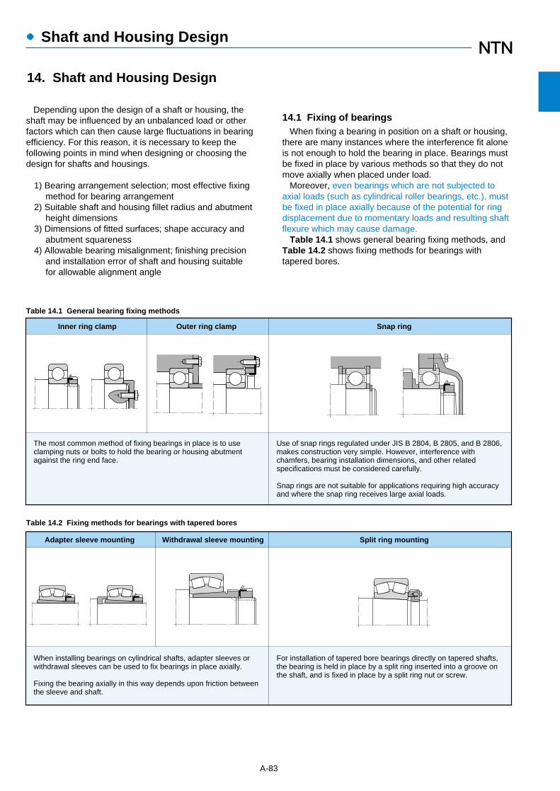
Depending upon the design of a shaft or housing, theshaft may be influenced by an unbalanced load or otherfactors which can then cause large fluctuations in bearingefficiency. For this reason, it is necessary to keep thefollowing points in mind when designing or choosing thedesign for shafts and housings.
1) Bearing arrangement selection; most effective fixingmethod for bearing arrangement
2) Suitable shaft and housing fillet radius and abutmentheight dimensions
3) Dimensions of fitted surfaces; shape accuracy andabutment squareness
4) Allowable bearing misalignment; finishing precisionand installation error of shaft and housing suitablefor allowable alignment angle
A-83
●Shaft and Housing Design
Inner ring clamp Outer ring clamp Snap ring
The most common method of fixing bearings in place is to use clamping nuts or bolts to hold the bearing or housing abutment against the ring end face.
Use of snap rings regulated under JIS B 2804, B 2805, and B 2806, makes construction very simple. However, interference with chamfers, bearing installation dimensions, and other related specifications must be considered carefully.
Snap rings are not suitable for applications requiring high accuracy and where the snap ring receives large axial loads.
Adapter sleeve mounting Withdrawal sleeve mounting Split ring mounting
When installing bearings on cylindrical shafts, adapter sleeves or withdrawal sleeves can be used to fix bearings in place axially.
Fixing the bearing axially in this way depends upon friction between the sleeve and shaft.
For installation of tapered bore bearings directly on tapered shafts, the bearing is held in place by a split ring inserted into a groove on the shaft, and is fixed in place by a split ring nut or screw.
Table 14.2 Fixing methods for bearings with tapered bores
Table 14.1 General bearing fixing methods
14.1 Fixing of bearingsWhen fixing a bearing in position on a shaft or housing,
there are many instances where the interference fit aloneis not enough to hold the bearing in place. Bearings mustbe fixed in place by various methods so that they do notmove axially when placed under load.
Moreover, even bearings which are not subjected toaxial loads (such as cylindrical roller bearings, etc.), mustbe fixed in place axially because of the potential for ringdisplacement due to momentary loads and resulting shaftflexure which may cause damage.
Table 14.1 shows general bearing fixing methods, andTable 14.2 shows fixing methods for bearings withtapered bores.
14. Shaft and Housing Design

rs min ras max
Normal use1 Special use2
h(min)�
0.050.080.1 0.150.2 0.3 0.6 1 1 1.5 2 2 2 2.5 3 4 5 6 8
10 12 15
0.050.080.1 0.150.2 0.3 0.6 1 1.1 1.5 2 2.1 2.5 3 4 5 6 7.5 9.5
12 15 19
0.3 0.3 0.4 0.6 0.8
1.252.252.753.5 4.255 6 6 7 9
11 14 18 22 27 32 42
1 2 2.5 3.254 4.5 5.5 5.5 6.5 8
10 12 16 20 24 29 38
Unit mm
1 It is necessary to be larger abutment height than the above value under larger thrust load.2 The values in this "Special Case" column should be adopted in cases where the thrust load is extremely small except for tapered roller bearings angular contact bearings, spherical roller bearings.
Note: ras max maximum allowable fillet radius.
14.2 Bearing fitting dimensions14.2.1 Abutment height and fillet radius
The shaft and housing abutment height (h) should belarger than the bearings' maximum allowable chamferdimensions (rs max), and the abutment should bedesigned so that it directly contacts the flat part of thebearing end face. The fillet radius must be smaller thanthe bearing's minimum allowable chamfer dimension (rs
min) so that it does not interfere with bearing seating.Table 14.3 lists abutment height (h) and fillet radius (ra).
For bearings to be applied to very large axial loads aswell, shaft abutments (h) should be higher than the valuesin the table.
14.2.2 For spacer and ground undercutIn cases where a fillet radius (ra) larger than the bearing
chamfer dimension is required to strengthen the shaft orto relieve stress concentration (Fig. 14.1a), or where theshaft abutment height is too low to afford adequatecontact surface with the bearing (Fig. 14.1b), spacersmay be used effectively.
Relief dimensions for ground shaft and housing fittingsurfaces are given in Table 14.4.
A-84
●Shaft and Housing Design
Table 14.3 Fillet radius and abutment height
Table 14.4 Relief dimensions for ground shaft
rs min
rs min
rs min
rs min
ra h
hra
rs min
rs min
rc
rc
b
b
t
t
Fig. 14.1 Bearing mounting with spacer
(a) (b)
rs min
ra max
rs min
1
1.1
1.5
2
2.1
2.5
3
4
5
6
7.5
2
2.4
3.2
4
4
4
4.7
5.9
7.4
8.6
10
rs min
0.2
0.3
0.4
0.5
0.5
0.5
0.5
0.5
0.6
0.6
0.6
1.3
1.5
2
2.5
2.5
2.5
3
4
5
6
7
b t rcRelief dimensions
Unit mm
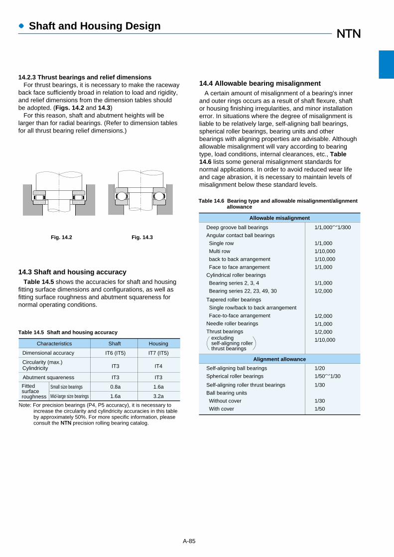
14.2.3 Thrust bearings and relief dimensionsFor thrust bearings, it is necessary to make the raceway
back face sufficiently broad in relation to load and rigidity,and relief dimensions from the dimension tables shouldbe adopted. (Figs. 14.2 and 14.3)
For this reason, shaft and abutment heights will belarger than for radial bearings. (Refer to dimension tablesfor all thrust bearing relief dimensions.)
14.3 Shaft and housing accuracyTable 14.5 shows the accuracies for shaft and housing
fitting surface dimensions and configurations, as well asfitting surface roughness and abutment squareness fornormal operating conditions.
A-85
●Shaft and Housing Design
Fig. 14.2 Fig. 14.3
Deep groove ball bearings
Angular contact ball bearings
Single row
Multi row
back to back arrangement
Face to face arrangement
Cylindrical roller bearings
Bearing series 2, 3, 4
Bearing series 22, 23, 49, 30
1/1,000~1/300
1/1,000
1/10,000
1/10,000
1/1,000
1/1,000
1/2,000
Tapered roller bearings
Single row/back to back arrangement
Face-to-face arrangement
Needle roller bearings
Thrust bearingsexcludingself-aligning rollerthrust bearings
1/2,000
1/1,000
1/2,000
1/10,000
Self-aligning ball bearings
Spherical roller bearings
1/20
1/50~1/30
Self-aligning roller thrust bearings
Ball bearing units
Without cover
With cover
1/30
1/30
1/50
Allowable misalignment
Alignment allowance
Table 14.6 Bearing type and allowable misalignment/alignmentallowance
Characteristics
Dimensional accuracy
Circularity (max.)Cylindricity
Abutment squareness
Small size bearings
Mid-large size bearings
Fittedsurfaceroughness
Shaft Housing
IT6 (IT5) IT7 (IT5)
IT3 IT4
IT3 IT3
0.8a 1.6a
1.6a 3.2a
Note: For precision bearings (P4, P5 accuracy), it is necessary to increase the circularity and cylindricity accuracies in this table by approximately 50%. For more specific information, please consult the NTN precision rolling bearing catalog.
Table 14.5 Shaft and housing accuracy
14.4 Allowable bearing misalignmentA certain amount of misalignment of a bearing's inner
and outer rings occurs as a result of shaft flexure, shaftor housing finishing irregularities, and minor installationerror. In situations where the degree of misalignment isliable to be relatively large, self-aligning ball bearings,spherical roller bearings, bearing units and otherbearings with aligning properties are advisable. Althoughallowable misalignment will vary according to bearingtype, load conditions, internal clearances, etc., Table14.6 lists some general misalignment standards fornormal applications. In order to avoid reduced wear lifeand cage abrasion, it is necessary to maintain levels ofmisalignment below these standard levels.
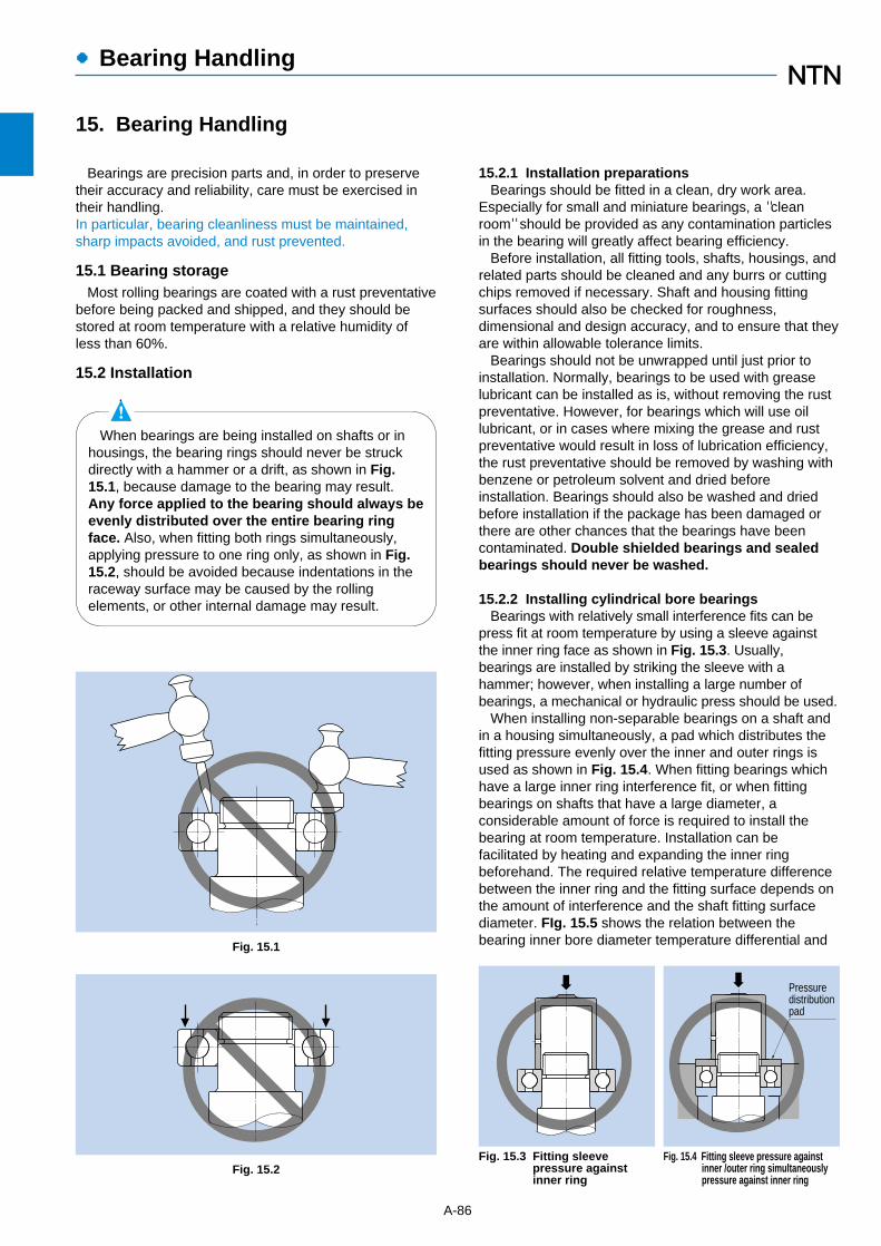
●Bearing Handling
15.2.1 Installation preparationsBearings should be fitted in a clean, dry work area.
Especially for small and miniature bearings, a "cleanroom" should be provided as any contamination particlesin the bearing will greatly affect bearing efficiency.
Before installation, all fitting tools, shafts, housings, andrelated parts should be cleaned and any burrs or cuttingchips removed if necessary. Shaft and housing fittingsurfaces should also be checked for roughness,dimensional and design accuracy, and to ensure that theyare within allowable tolerance limits.
Bearings should not be unwrapped until just prior toinstallation. Normally, bearings to be used with greaselubricant can be installed as is, without removing the rustpreventative. However, for bearings which will use oillubricant, or in cases where mixing the grease and rustpreventative would result in loss of lubrication efficiency,the rust preventative should be removed by washing withbenzene or petroleum solvent and dried beforeinstallation. Bearings should also be washed and driedbefore installation if the package has been damaged orthere are other chances that the bearings have beencontaminated. Double shielded bearings and sealedbearings should never be washed.
15.2.2 Installing cylindrical bore bearingsBearings with relatively small interference fits can be
press fit at room temperature by using a sleeve againstthe inner ring face as shown in Fig. 15.3. Usually,bearings are installed by striking the sleeve with ahammer; however, when installing a large number ofbearings, a mechanical or hydraulic press should be used.
When installing non-separable bearings on a shaft andin a housing simultaneously, a pad which distributes thefitting pressure evenly over the inner and outer rings isused as shown in Fig. 15.4. When fitting bearings whichhave a large inner ring interference fit, or when fittingbearings on shafts that have a large diameter, aconsiderable amount of force is required to install thebearing at room temperature. Installation can befacilitated by heating and expanding the inner ringbeforehand. The required relative temperature differencebetween the inner ring and the fitting surface depends onthe amount of interference and the shaft fitting surfacediameter. FIg. 15.5 shows the relation between thebearing inner bore diameter temperature differential and
15. Bearing Handling
Bearings are precision parts and, in order to preservetheir accuracy and reliability, care must be exercised intheir handling.In particular, bearing cleanliness must be maintained,sharp impacts avoided, and rust prevented.
15.1 Bearing storageMost rolling bearings are coated with a rust preventative
before being packed and shipped, and they should bestored at room temperature with a relative humidity ofless than 60%.
15.2 Installation
A-86
Pressuredistributionpad
Fig. 15.3 Fitting sleeve pressure against inner ring
Fig. 15.1
Fig. 15.2Fig. 15.4 Fitting sleeve pressure against
inner /outer ring simultaneouslypressure against inner ring
When bearings are being installed on shafts or inhousings, the bearing rings should never be struckdirectly with a hammer or a drift, as shown in Fig.15.1, because damage to the bearing may result.Any force applied to the bearing should always beevenly distributed over the entire bearing ringface. Also, when fitting both rings simultaneously,applying pressure to one ring only, as shown in Fig.15.2, should be avoided because indentations in theraceway surface may be caused by the rollingelements, or other internal damage may result.

●Bearing Handling
A-87
Fig. 15.5 Temperature differential required for shrinkage fitof inner ring
280
260
240
220
200
180
160
140
120
100
80
60
40
20
50 100 150 200 250 300 350 400 450 500 550 600
280
260
240
220
200
180
160
140
120
100
80
60
40
20
r6
Dia
met
ric e
xpan
sion
of i
nner
rin
g bo
re μ
m
j5
30℃
k5
m6
n6
p6
40℃
50℃60℃70℃80℃
Ris
e in
tem
p.di
ffere
nce
befo
re/a
fter
heat
ing
bear
ing
90℃�
Bearing bore diameter mm
the amount of thermal expansion. In any event, bearingsshould never be heated above 120˚C.
The most commonly used method of heating bearings isto immerse them in hot oil. However, this method shouldnot be used for prelubricated shielded and sealed bearings.
To avoid overheating parts of the bearings they shouldnever be brought into direct contact with the heat source,but instead should be suspended inside the heating tankor placed on a wire grid.
If bearings are dry-heated with a heating cabinet or hotplate, they can be mounted without drying.
For heating the inner rings of Nu, NJ or NUP cylindricaland similar type bearings without any ribs or with only asingle rib, an induction heater can be used to quickly heatbearings in a dry state (always demagnetize).
When heated bearings are installed on shafts, theinner rings must be held against the shaft abutmentuntil the bearing has been cooled in order to preventgaps from occurring between the ring and theabutment face.
As shown in Fig. 15.6, a removal pawl, or tool, can alsobe used to dismount the inner ring when using theinduction heating method described above.
15.2.3 Installation of tapered bore bearingsSmall type bearings with tapered bores are installed
over a tapered shaft, withdrawal sleeves, or adaptersleeves by driving the bearing into place using a locknut.The locknut is tightened using a hammer or impactwrench. (Fig. 15.7)
Large size bearings require considerable fitting forceand must be installed hydraulically.
In Fig. 15.8 the fitting surface friction and nut tightening
Fig. 15.6 Removal of inner ring using an induction heater
Fig. 15.7 Installation methods using locknuts
a) Installation on tapered bore b) Installation with adapter sleeve
c) Installation using withdrawal sleeve
Fig. 15.8 Installation utilizing oil injection
Removal pawl
inner ring
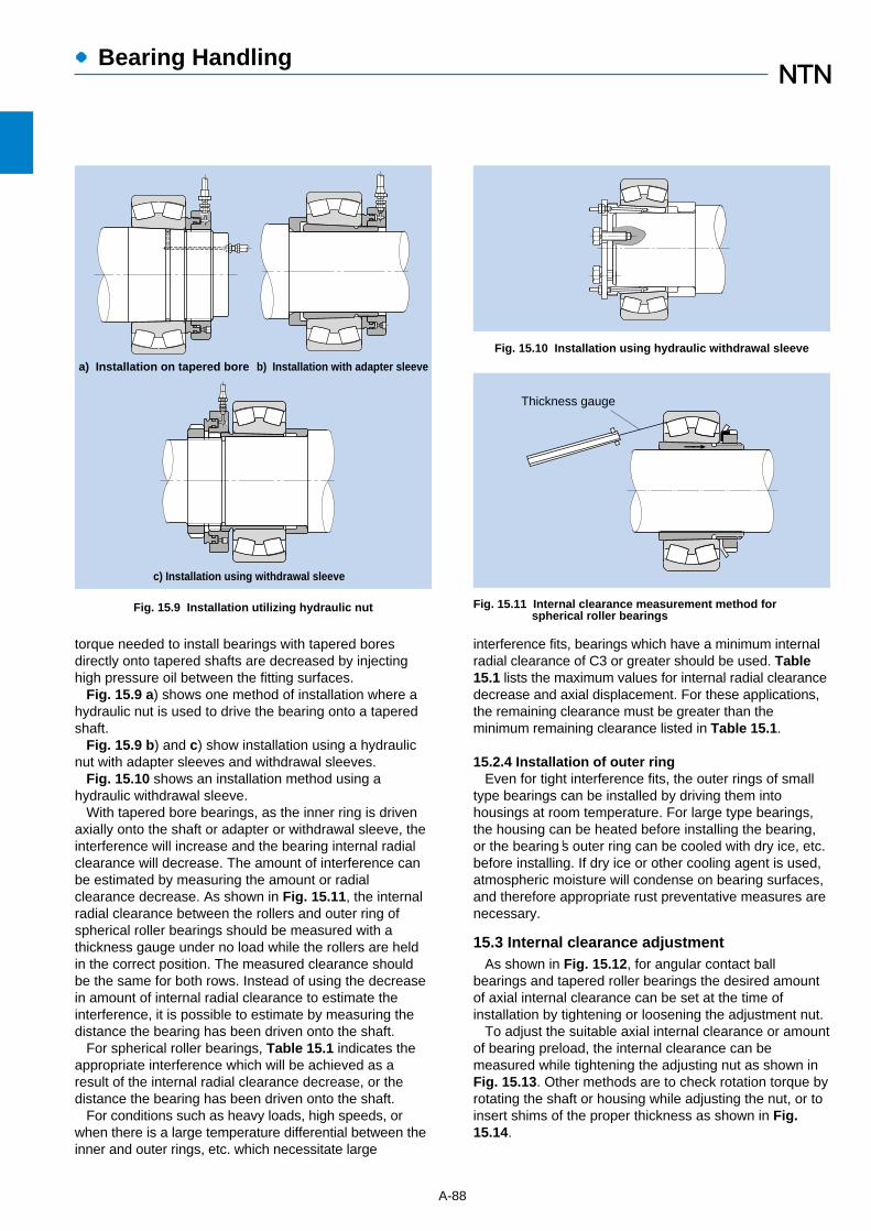
torque needed to install bearings with tapered boresdirectly onto tapered shafts are decreased by injectinghigh pressure oil between the fitting surfaces.
Fig. 15.9 a) shows one method of installation where ahydraulic nut is used to drive the bearing onto a taperedshaft.
Fig. 15.9 b) and c) show installation using a hydraulicnut with adapter sleeves and withdrawal sleeves.
Fig. 15.10 shows an installation method using ahydraulic withdrawal sleeve.
With tapered bore bearings, as the inner ring is drivenaxially onto the shaft or adapter or withdrawal sleeve, theinterference will increase and the bearing internal radialclearance will decrease. The amount of interference canbe estimated by measuring the amount or radialclearance decrease. As shown in Fig. 15.11, the internalradial clearance between the rollers and outer ring ofspherical roller bearings should be measured with athickness gauge under no load while the rollers are heldin the correct position. The measured clearance shouldbe the same for both rows. Instead of using the decreasein amount of internal radial clearance to estimate theinterference, it is possible to estimate by measuring thedistance the bearing has been driven onto the shaft.
For spherical roller bearings, Table 15.1 indicates theappropriate interference which will be achieved as aresult of the internal radial clearance decrease, or thedistance the bearing has been driven onto the shaft.
For conditions such as heavy loads, high speeds, orwhen there is a large temperature differential between theinner and outer rings, etc. which necessitate large
A-88
●Bearing Handling
Fig. 15.10 Installation using hydraulic withdrawal sleeve
Fig. 15.11 Internal clearance measurement method forspherical roller bearings
a) Installation on tapered bore b) Installation with adapter sleeve
c) Installation using withdrawal sleeve
Fig. 15.9 Installation utilizing hydraulic nut
Thickness gauge
interference fits, bearings which have a minimum internalradial clearance of C3 or greater should be used. Table15.1 lists the maximum values for internal radial clearancedecrease and axial displacement. For these applications,the remaining clearance must be greater than theminimum remaining clearance listed in Table 15.1.
15.2.4 Installation of outer ringEven for tight interference fits, the outer rings of small
type bearings can be installed by driving them intohousings at room temperature. For large type bearings,the housing can be heated before installing the bearing,or the bearing's outer ring can be cooled with dry ice, etc.before installing. If dry ice or other cooling agent is used,atmospheric moisture will condense on bearing surfaces,and therefore appropriate rust preventative measures arenecessary.
15.3 Internal clearance adjustmentAs shown in Fig. 15.12, for angular contact ball
bearings and tapered roller bearings the desired amountof axial internal clearance can be set at the time ofinstallation by tightening or loosening the adjustment nut.
To adjust the suitable axial internal clearance or amountof bearing preload, the internal clearance can bemeasured while tightening the adjusting nut as shown inFig. 15.13. Other methods are to check rotation torque byrotating the shaft or housing while adjusting the nut, or toinsert shims of the proper thickness as shown in Fig.15.14.
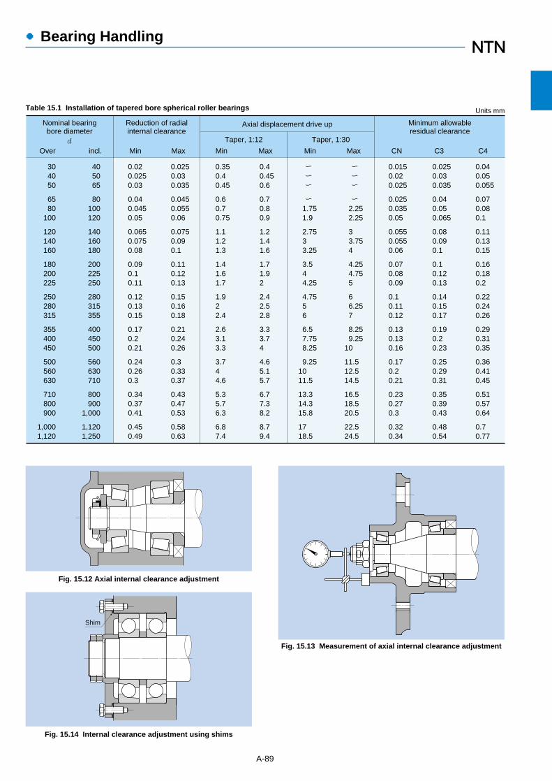
●Bearing Handling
A-89
Nominal bearingbore diameter
304050
6580
100
120140160
180200225
250280315
355400450
500560630
710800900
1,0001,120
Units mm
d
Reduction of radialinternal clearance
Min Max
Axial displacement drive up
Taper, 1:12
MaxMin
Taper, 1:30
Min Max
Minimum allowableresidual clearance
CN C4C3
405065
80100120
140160180
200225250
280315355
400450500
560630710
800900
1,000
1,1201,250
0.02 0.0250.03
0.04 0.0450.05
0.0650.0750.08
0.09 0.1 0.11
0.12 0.13 0.15
0.17 0.2 0.21
0.24 0.26 0.3
0.34 0.37 0.41
0.45 0.49
0.0250.03 0.035
0.0450.0550.06
0.0750.09 0.1
0.11 0.12 0.13
0.15 0.16 0.18
0.21 0.24 0.26
0.3 0.33 0.37
0.43 0.47 0.53
0.58 0.63
0.350.40.45
0.60.70.75
1.11.21.3
1.41.61.7
1.92 2.4
2.63.13.3
3.74 4.6
5.35.76.3
6.87.4
0.40.450.6
0.7 0.80.9
1.21.41.6
1.71.92
2.42.52.8
3.33.74
4.65.15.7
6.77.38.2
8.79.4
ー ー ー
ー 1.751.9
2.753 3.25
3.5 4 4.25
4.755 6
6.5 7.758.25
9.2510 11.5
13.3 14.3 15.8
17 18.5
ー ー ー
ー 2.252.25
3 3.754
4.254.755
6 6.257
8.259.25
10
11.5 12.5 14.5
16.5 18.5 20.5
22.5 24.5
0.0150.02 0.025
0.0250.0350.05
0.0550.0550.06
0.07 0.08 0.09
0.1 0.11 0.12
0.13 0.13 0.16
0.17 0.2 0.21
0.23 0.27 0.3
0.32 0.34
0.0250.03 0.035
0.04 0.05 0.065
0.08 0.09 0.1
0.1 0.12 0.13
0.14 0.15 0.17
0.19 0.2 0.23
0.25 0.29 0.31
0.35 0.39 0.43
0.48 0.54
0.04 0.05 0.055
0.07 0.08 0.1
0.11 0.13 0.15
0.16 0.18 0.2
0.22 0.24 0.26
0.29 0.31 0.35
0.36 0.41 0.45
0.51 0.57 0.64
0.7 0.77
Over incl.
Table 15.1 Installation of tapered bore spherical roller bearings
Fig. 15.12 Axial internal clearance adjustment
Fig. 15.13 Measurement of axial internal clearance adjustment
Fig. 15.14 Internal clearance adjustment using shims
Shim
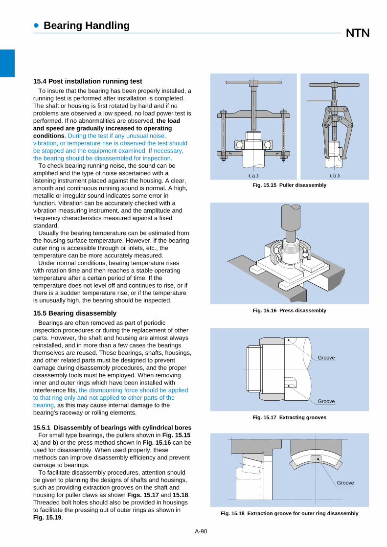
●Bearing Handling
15.4 Post installation running testTo insure that the bearing has been properly installed, a
running test is performed after installation is completed.The shaft or housing is first rotated by hand and if noproblems are observed a low speed, no load power test isperformed. If no abnormalities are observed, the loadand speed are gradually increased to operatingconditions. During the test if any unusual noise,vibration, or temperature rise is observed the test shouldbe stopped and the equipment examined. If necessary,the bearing should be disassembled for inspection.
To check bearing running noise, the sound can beamplified and the type of noise ascertained with alistening instrument placed against the housing. A clear,smooth and continuous running sound is normal. A high,metallic or irregular sound indicates some error infunction. Vibration can be accurately checked with avibration measuring instrument, and the amplitude andfrequency characteristics measured against a fixedstandard.
Usually the bearing temperature can be estimated fromthe housing surface temperature. However, if the bearingouter ring is accessible through oil inlets, etc., thetemperature can be more accurately measured.
Under normal conditions, bearing temperature riseswith rotation time and then reaches a stable operatingtemperature after a certain period of time. If thetemperature does not level off and continues to rise, or ifthere is a sudden temperature rise, or if the temperatureis unusually high, the bearing should be inspected.
15.5 Bearing disassemblyBearings are often removed as part of periodic
inspection procedures or during the replacement of otherparts. However, the shaft and housing are almost alwaysreinstalled, and in more than a few cases the bearingsthemselves are reused. These bearings, shafts, housings,and other related parts must be designed to preventdamage during disassembly procedures, and the properdisassembly tools must be employed. When removinginner and outer rings which have been installed withinterference fits, the dismounting force should be appliedto that ring only and not applied to other parts of thebearing, as this may cause internal damage to thebearing's raceway or rolling elements.
15.5.1 Disassembly of bearings with cylindrical boresFor small type bearings, the pullers shown in Fig. 15.15
a) and b) or the press method shown in Fig. 15.16 can beused for disassembly. When used properly, thesemethods can improve disassembly efficiency and preventdamage to bearings.
To facilitate disassembly procedures, attention shouldbe given to planning the designs of shafts and housings,such as providing extraction grooves on the shaft andhousing for puller claws as shown Figs. 15.17 and 15.18.Threaded bolt holes should also be provided in housingsto facilitate the pressing out of outer rings as shown inFig. 15.19.
A-90
Fig. 15.15 Puller disassembly
(a) (b)
Fig. 15.16 Press disassembly
Fig. 15.17 Extracting grooves
Groove
Groove
Fig. 15.18 Extraction groove for outer ring disassembly
Groove
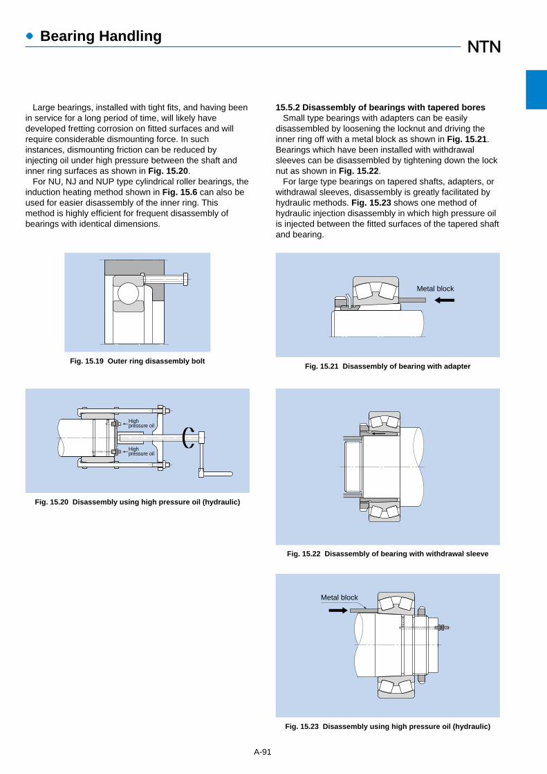
●Bearing Handling
A-91
Fig. 15.19 Outer ring disassembly bolt
Fig. 15.23 Disassembly using high pressure oil (hydraulic)
Metal block
Fig. 15.22 Disassembly of bearing with withdrawal sleeve
Fig. 15.20 Disassembly using high pressure oil (hydraulic)
Highpressure oil
Highpressure oil
Fig. 15.21 Disassembly of bearing with adapter
Metal block
Large bearings, installed with tight fits, and having beenin service for a long period of time, will likely havedeveloped fretting corrosion on fitted surfaces and willrequire considerable dismounting force. In suchinstances, dismounting friction can be reduced byinjecting oil under high pressure between the shaft andinner ring surfaces as shown in Fig. 15.20.
For NU, NJ and NUP type cylindrical roller bearings, theinduction heating method shown in Fig. 15.6 can also beused for easier disassembly of the inner ring. Thismethod is highly efficient for frequent disassembly ofbearings with identical dimensions.
15.5.2 Disassembly of bearings with tapered boresSmall type bearings with adapters can be easily
disassembled by loosening the locknut and driving theinner ring off with a metal block as shown in Fig. 15.21.Bearings which have been installed with withdrawalsleeves can be disassembled by tightening down the locknut as shown in Fig. 15.22.
For large type bearings on tapered shafts, adapters, orwithdrawal sleeves, disassembly is greatly facilitated byhydraulic methods. Fig. 15.23 shows one method ofhydraulic injection disassembly in which high pressure oilis injected between the fitted surfaces of the tapered shaftand bearing.
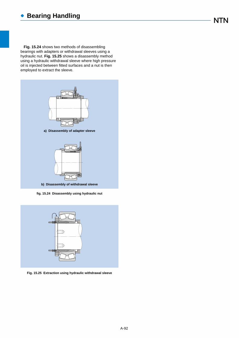
A-92
●Bearing Handling
a) Disassembly of adapter sleeve
b) Disassembly of withdrawal sleeve
fig. 15.24 Disassembly using hydraulic nut
Fig. 15.25 Extraction using hydraulic withdrawal sleeve
Fig. 15.24 shows two methods of disassemblingbearings with adapters or withdrawal sleeves using ahydraulic nut. Fig. 15.25 shows a disassembly methodusing a hydraulic withdrawal sleeve where high pressureoil is injected between fitted surfaces and a nut is thenemployed to extract the sleeve.

While it is of course impossible to directly observe
bearings in operation, one can get a good idea of how they
are operating by monitoring noise, vibration, temperature
and lubricant condition. Types of damage typically
encountered are presented in Table 16.1.
A-93
●Bearing Damage and Corrective Measures
Description Causes Correction
FlakingThe surface of the raceway wearing away.
Conspicuoushills and valleysform soonafterward.
Seizure
Cracking andnotching
Retainer damageRivets break or becomeloose resulting in retainer damage.
Meandering wearpatterns
Abrasion or an irregular, meanderingwear pattern left by rolling elements
along racewaysurfaces.
¡Shaft or housing of insufficient accuracy.¡Improper installation - Insufficient shaft or housing rigidity.¡Shaft whirling caused by excessive internal bearing clearances.
¡Reinspect bearing’s internal clearances.¡Review accuracy of shaft and housing finish.¡Review rigidity of shaft and housing.
Smearing andscuffing
The surface becomes rough andsome small deposits form.
Scuffing generally refers toroughness on therace collar and theends of the rollers.
Rust and corrosionThe surface becomes either partiallyor fully rusted, and occasionally
rust evenoccurs alongthe rollingelement pitchlines.
¡Excessive loads or improper handling.¡Improper mounting.¡Improper precision in the shaft or housing.¡Insufficient clearance.¡Contamination.¡Rust.¡Drop in hardness due to abnormally high temperatures.
¡Review application conditions.¡Select a different type of bearing.¡Reevaluate the clearance.¡Improve the precision of the shaft and housing.¡Reevaluate the layout (design) of the area around the bearing.¡Review assembly procedures.¡Review lubricant type and lubrication methods.
The bearing heats up and becomesdiscolored.Eventually the bearing will seize up.
¡Insufficient clearance (including clearances made smaller by local deformation).¡Insufficient lubrication or improper lubricant.¡Excessive loads (excessive pressure).¡Skewed rollers.
¡Check for proper clearance. (Increase clearances.)¡Riview lubricant type and quantity.¡Review application conditions.¡Take steps to prevent misalignment.¡Reevaluate the design of the area around the bearing (including fitting of the bearing).¡Improve assembly procedures.
Localized flaking occurs.Little cracks or notches appear.
¡Excessive shock loads.¡Excessive interference.¡Large flaking.¡Friction cracking.¡Inadequate abutment or chamfer.¡Improper handling. (gouges from large foreign objects.)
¡Review application conditions.¡Select proper interference and review materials.¡Improve assembly procedures and take more care in handling.¡Take measures to prevent friction cracking. (Review lubricant type.)¡Reevaluate the design of the area around the bearing.
¡Excessive moment loading.¡High speed or excessive speed fluctuations.¡Inadequate lubrication.¡Impact with foreign objects.¡Excessive vibration.¡Improper mounting. (Mounted misaligned)¡Abnormal temperature rise. (Plastic retainers)
¡Review of application conditions.¡Reevaluation of lubrication conditions.¡Review of retainer type selection.¡Take more care in handling.¡Investigate shaft and housing rigidity.
¡Inadequate lubrication.¡Entrapped foreign particles.¡Roller skewing due to a misaligned bearing.¡Bare spots in the collar oil film due to large axial loading.¡Surface roughness.¡Excessive slippage of the rolling elements.
¡Reevaluation of the lubricant type and lubrication method.¡Review of operating conditions.¡Setting of a suitable pre-load.¡Improve sealing performance.¡Take care to handle the bearing properly.
¡Poor storage conditions.¡Poor packaging.¡Insufficient rust inhibitor.¡Penetration by water, acid, etc.¡Handling with bare hands.
¡Take measures to prevent rusting while in storage.¡Improve sealing performance.¡Periodically inspect the lubricating oil.¡Take care when handling the bearing.
16. Bearing Damage and Corrective Measures
Table 16.1 Bearing damage and corrective measures

●Bearing Damage and Corrective Measures
A-94
FrettingThere are two types of fretting.In one, a rusty wear powder formson the mating surfaces.
In the other,brinellingindentationsform on theraceway at therollingelement pitch.
¡Insufficient interference.¡Small bearing oscillation angle.¡Insufficient lubrication.¡Fluctuating loads.¡Vibration during transport.
WearThe surfaces wear and dimensionaldeformation results. Wear is oftenaccompanied by roughness andscratches.
Electrolyticcorrosion
Pits form on the raceway.The pits gradually grow into ripples.
Dents and scratches
Scoring during assembly, gougesdue to hard foreign objects, and
surface dentingdue tomechanical
shock.
Slipping or creeping
Surface mattingLuster of raceway surfaces is gone;surface is matted, rough, and / or
evenly dimpled.Surfacecovered withminute dents.
¡Infiltration of bearing by foreign matter.¡Insufficient lubrication.
¡Reevaluation of lubricant type and lubrication method.¡Review sealing mechanisms.¡Examine lubrication oil purity. (filter may be excessively dirty, etc.)
PeelingPatches of minute flaking or peeling(size, approx. 10μm).Innumerable hair-line cracks visiblethough not yet peeling.(This type of damage frequentlyseen on roller bearings.)��
¡Infiltration of bearing by foreign matter.¡Insufficient lubrication.
¡Reevaluation of lubricant type and lubrication method.¡Improve sealing performance. (to prevent infiltration of foreign matter)¡Take care to operate smoothly.
Description Causes Correction
¡Review the interference and apply a coat of lubricant.¡Pack the inner and outer rings separately for transport.¡When the two cannot be separated, apply a pre-load.¡Select a different kind of lubricant.¡Select a different type of bearing.
¡Entrapment of foreign particles in the lubricant.¡Inadequate lubrication.¡Skewed rollers.
¡Review lubricant type and lubrication methods.¡Improve sealing performance.¡Take steps to prevent misalignment.
¡Electric current flowing through the rollers. ¡Create a bypass circuit for the current.¡Insulate the bearing so that current does not pass through it.
¡Entrapment of foreign objects.¡Bite-in on the flaked-off side.¡Dropping or other mechanical shocks due to careless handling.¡Assembled misaligned.
¡Improve handling and assembly methods.¡Take measures to prevent the entrapment of foreign objects.¡Should the damage have been caused by little pieces of metal, thoroughly check all other locations.
Slipping is accompanied bymirrorlike or discolored surfaces on
the ID and OD.Scuffing mayalso occur.
¡Insufficient interference in the mating section.¡Sleeve not fastened down properly.¡Abnormal temperature rise.¡Excessive loads.
¡Reevaluate the interference.¡Reevaluate usage conditions.¡Review the precision of the shaft and housing.
Table 16.1 Bearing damage and corrective measures

●Technical Data
17.2 Angular contact ball bearing axial load and axial displacement
A-95
fig. 17.1.1 Series 68 radial internal/axial internal clearances
Fig. 17.1.2 Series 69 radial internal/axial internal clearances Fig. 17.1.4 Series 62 radial internal/axial internal clearances
0.40
0.30
0.20
0.10
0.050.003 0.005 0.01 0.02 0.03 0.05
Radial internal clearance mm
Axi
al in
tern
al c
lear
ance
m
m
0.50
0.08
0.06
6805
6810681568206830
6800
0.40
0.30
0.20
0.10
0.050.003 0.005 0.01 0.02 0.03 0.05
Radial internal clearance mm
Axi
al in
tern
al c
lear
ance
m
m
0.50
0.08
0.06
6930
6900691069156920
6905
0.40
0.30
0.20
0.10
0.050.003 0.005 0.01 0.02 0.03 0.05
Radial internal clearance mm
Axi
al in
tern
al c
lear
ance
m
m
0.50
0.08
0.06
6230
6205621062156220
6200
Fig. 17.1.3 Series 60 radial internal/axial internal clearances
0.40
0.30
0.20
0.10
0.050.003 0.005 0.01 0.02 0.03 0.05
Radial internal clearance mmA
xial
inte
rnal
cle
aran
ce
mm
0.50
0.08
0.06
600060056020
6015
6010
6030
Fig. 17.2.1 Series 79 C axial load and axial displacement
0.04
0.03
0.02
0.01
00 1.0 1.5 2.5×10
3N
Axial load
Axi
al d
ispl
acem
ent
mm
0.5 2.0
7930C7905
C
7910
C7915C
7920C
Fig. 17.2.2 Series 79 axial load and axial displacement
0.04
0.03
0.02
0.01
00 1.0 1.5 2.5×10
3N
Axial load
Axi
al d
ispl
acem
ent
mm
0.5 2.0
7920
7930
7910
7915
7905
17. Technical data
※This data is based on typical dimensions. NTN do not guarantee at this data.
17.1 Deep groove ball bearing radial internal clearances and axial internal clearances

●Technical Data
A-96
Fig. 17.2.3 Series 70 C axial load and axial displacement
0.04
0.03
0.02
0.01
00 0.5 1.0 1.5 2.0 2.5×10³N
Axial load
Axi
al d
ispl
acem
ent
mm 70
00C
7005
C
7010C7015C
7020C
7030C
Fig. 17.2.4 Series 70 axial load and axial displacement
0.04
0.03
0.02
0.01
00 0.5 1.0 1.5 2.0 2.5×10³N
Axial load
Axi
al d
ispl
acem
ent
mm
7000
7030
702070157010
7005
Fig. 17.2.5 Series 70 B axial load and axial displacement
0.04
0.03
0.02
0.01
00 0.5 1.0 1.5 2.0 2.5×10³N
Axial load
Axi
al d
ispl
acem
ent
mm
7020B7015B
7000B
7030B
7010B7005B
Fig. 17.2.6 Series 72 C axial load and axial displacement
0.04
0.03
0.02
0.01
00 0.5 1.0 1.5 2.0 2.5×10³N
Axial load
Axi
al d
ispl
acem
ent
mm 7200
C72
05C
7210
C
7215
C
7220C
7230C
Fig. 17.2.7 Series 72 axial load and axial displacement
0.04
0.03
0.02
0.01
00 0.5 1.0 1.5 2.0 2.5×10³N
7200
7230
72207215
Axial load
Axi
al d
ispl
acem
ent
mm
72107205
Fig. 17.2.8 Series 72 B axial load and axial displacement
0.04
0.03
0.02
0.01
00 0.5 1.0 1.5 2.0 2.5×10³N
Axial load
Axi
al d
ispl
acem
ent
mm
7200B
7230B
7210B7205B
7215B 7220B
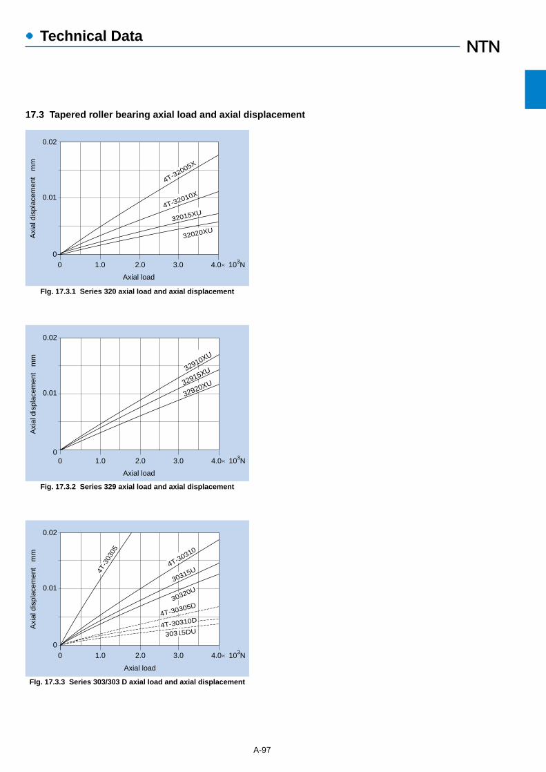
●Technical Data
17.3 Tapered roller bearing axial load and axial displacement
A-97
FIg. 17.3.1 Series 320 axial load and axial displacement
0.02
0.01
00 2.0 3.0 4.0×10³N
Axial load
Axi
al d
ispl
acem
ent
mm
1.0
4T-32005X
32015XU
32020XU
4T-32010X
Fig. 17.3.2 Series 329 axial load and axial displacement
0.02
0.01
00 2.0 3.0 4.0×10³N
Axial load
Axi
al d
ispl
acem
ent
mm
1.0
32910XU
32915XU
32920XU
FIg. 17.3.3 Series 303/303 D axial load and axial displacement
0.02
0.01
00 2.0 3.0 4.0×10³N
Axial load
Axi
al d
ispl
acem
ent
mm
30315DU
1.0
4T-3
0305
4T-30310
30315U
30320U
4T-30305D
4T-30310D

●Technical Data
A-98
Table 17.4.1 Fitted surface pressure and maximum allowable stress
Fit conditions
Solid steel shaft/inner ring fit
MPa{kgf / mm2}�
Hollow steel shaft/inner ring fit
Steel housing/outer ring fit
Shaft / inner ring fit
Housing/outer ring fit
Maximumallowablestress
MPa{kgf / mm2}
Equation
P =2
E
d
∆deff1- (
Di
d)2
P =2
E
∆d
∆deff [1- (d / Di)2 ][1- (do / d)
2 ]
[1 - (do / Di)2 ]
P =2
E
D
∆Deff [1 - (Do / D)2 ][1 - (D / Dh)
2 ]
[1 - (Do /Dh)2 ]
σt max = P 1 + (d / Di)
2
1 – (d / Di)2
σt max = P2
1 – (Do / D)2
Codes (units: N{kgf}, mm)
d : Shaft diameter, inner ringbore diameter
do : Hollow shaft innerdiameter�
Di : Inner ring average groovediameter�
∆deff : Effective interference�E : Elasticity factor�
= 208,000 MPa{ 21,200 kgf / mm2 }
D : Housing inner diameter,bearing outer diameter
Do : Outer ring average groove diameter�
Dh : Housing outer diameter �∆Deff : Effective interference
Inner ring bore diameter face maximumallowable stress
Outer ring inner diameter face maximumallowable stress
do d Di
Do
Dh
D
Fittedsurfacepressure
Table 17.4.2 Average groove diameter
Bearing typeAverage groove diameter
Inner ring ( Di ) Outer ring ( Do )
Deep grooveball bearings
Cylindricalroller bearings1
Sphericalroller bearings
All types
All types
All types
1.055
4d + D
1.054
3d + D
3
2d + D
0.955
d + 4D
0.984
d + 3D
0.975
d + 4D
d: Inner ring bore diameter mm D: Outer ring outer diameter mm1 Average groove diameter values shown for double rib type.
17.4 Fitting surface pressureTable 17.4.1 lists equations for calculating the pressure
and maximum allowable stress between fitting surfaces. Table 17.4.2 can be used to determine the approximate
average groove diameter for bearing inner and outerrings.
The effective interference, in other words the actualinterference after fitting, is smaller than the apparent
interference derived from the measured valued for thebearing bore diameter and shaft. This difference is due tothe roughness or variations of the finished surfaces to befitted, and therefore it is necessary to assume thefollowing reductions in effective interference:
For ground shafts: 1.0 ~ 2.5μmFor lathed shafts : 5.0 ~ 7.0μm

●Technical Data
A-99
17.5 Necessary press fit and pullout forceEquations (7.1) and (7.2) below can be used to
calculate the necessary pullout force for press fit for innerrings and shafts or outer rings and housings.
For shaft and inner rings:Kd = μ・P・π・d・B …………………………(7.1)KD = μ・P・π・D・B …………………………(7.2)
Where,Kd : Inner ring press fit or pullout force N{kgf}KD : Outer ring press fit or pullout force N{kgf}P : Fitted surface pressure MPa{kgf/mm2}
(Refer to Table 17.4.1)d : Shaft diameter, inner ring bore diameter mmD : Housing inner diameter, outer ring outer
diameter mmB : Inner or outer ring widthμ : Sliding friction coefficient (Refer to Table 17.5.1)
Table 17.5.1 Press fit and pullout sliding friction coefficient
0.120.180.170.140.300.33
Type
Inner (outer) ring press fit onto cylindrical shaft (bore)Inner (outer) ring pullout from cylindrical shaft (bore)Inner ring press fit onto tapered shaft or sleeveInner ring pullout from tapered shaftSleeve press fit onto shaft/bearingSleeve pullout from shaft/bearing
μ�
Fig. 17.4.1 Average fit interference as it relates to surfacepressure and max. allowable stress
2
1
3
45
10
20
30
4050
100
250200
150
5040
30
20
5
4
3
2
1
0.50.4
0.3
0.2
0.120 30 50 70 100 200 300 500
Nominal bearing bore diameter (Class 0) mm
25
20
15
10
54
3
2
110
0.55
kgf/mm2 kgf/mm2
Fitt
ed s
urfa
ce p
ress
ure
Pm
MPa
Max
imum
allo
wab
le s
tres
sσt max
k5
MPa
js5
n6m5
p6
Fig. 17.4.2 Maximum fit interference as it relates to surfacepressure and max. allowable stress
4
2
5
10
20
40
50
100
200
400
300
50
30
10
3
2
1
0.5
0.220 30 50 70 100 200 300 500
40
2520
10
4
220
110
30
45
30.3
0.4
40
100
150
250
3
5
15
30
kgf/mm2
kgf/mm2MPa MPa
m5k5
js5
p6
n6
Nominal bearing bore diameter (Class 0) mm
Fitt
ed s
urfa
ce p
ress
ure
Pm Max
imum
allo
wab
le s
tres
s
σt max

A-100
Ball and Roller Bearings

B-2
INDEX OF BEARING TABLES
Deep Groove Ball Bearings………………………………………………………………… B-5
Deep groove ball bearings 67,68,69,160,60,62,63,64 …………………………………………… B-8
Expansion compensating bearings EC-60,EC-62,EC-63………………………………………… B-26
Miniature and Extra Small Ball Bearings…………………………………………… B-29
Metric system sizes 67,68,69,60,62,63,BC ……………………………………………………… B-32
Inch system sizes R,RA……………………………………………………………………………… B-36
With ring grooves, snap rings SC…………………………………………………………………… B-38
Angular Contact Ball Bearings…………………………………………………………… B-41
Single and duplex arrangements 79,70,72,72B,73,73B ………………………………………… B-44
High speed single and duplex arrangements 78C,79C,70C,72C,73C ………………………… B-56
Ultra-high speed angular contact ball bearings BNT0,BNT2,HSB9C,HSB0C ………………… B-64
Ceramic ball angular contact ball bearings 5S-BNT,5S-HSB …………………………………… B-68
Four-point contact ball bearings QJ2,QJ3 ………………………………………………………… B-70
Double row angular contact ball bearings 52,53 ………………………………………………… B-72
Self-Aligning Ball Bearings………………………………………………………………… B-77
12(K), 22(K), 13(K), 23(K) …………………………………………………………………………… B-78
Adapters for self-aligning ball bearings ……………………………………………………………… B-84
Cylindrical Roller Bearings ………………………………………………………………… B-89
NU,NJ,NUP,N,NF10,2,22,3,23,4……………………………………………………………………… B-92
L type loose rib HJ2,22,3,23,4 ……………………………………………………………………… B-110
Multi-row cylindrical roller bearings NN49(K),NNU49(K),NN30(K),NNU30(K)………………… B-114
Four-row cylindrical roller bearings 4R …………………………………………………………… B-120

B-3
Tapered Roller Bearings …………………………………………………… B-131
Metric system sizes
329X,320X,330,331,302,322,322C,332,303,303D,313X,323,323C …………… B-138
Inch system sizes ……………………………………………………………………………………… B-156
Multi-row tapered roller bearings (outward facing type)
4130,4230,4131,4231,4302,4322,4303,4303D,4323 …………………………… B-194
Multi-row tapered roller bearings (inward facing type) 3230,3231………………………………… B-208
Four-row tapered roller bearings CR0……………………………………………………………… B-212
Spherical Roller Bearings…………………………………………………………………… B-229
239(K),230(K),240(K30),231(K),241(K30),222(K),232(K),213(K),223(K) ……………………… B-232
Adapters for spherical roller bearings………………………………………………………………… B-252
Withdrawal sleeves for spherical roller bearings …………………………………………………… B-257
Thrust Bearings…………………………………………………………………………………… B-265
Single direction type 511,512,513,514 …………………………………………………………… B-270
Double row angular contact thrust ball bearings 5629(M),5620(M) …………………………… B-274
High speed duplex angular contact thrust ball bearings HTA9DB,HTA0DB …………………… B-278
Self-aligning roller thrust bearings 292,293,294 ………………………………………………… B-282

●Deep Groove Ball Bearings
1. Design features and special characteristics
Deep groove ball bearings are very widely used. A deepgroove is formed on each inner and outer ring of the bearingenabling them to sustain radial and axial loads in eitherdirection as well as well as the complex loads which resultfrom the combination of these forces. Deep groove ballbearings are suitable for high speed applications.
B-5
In addition to the open type, deep groove ball bearingscome in a number of varieties, including prelubricatedbearings, bearings with one or both sides sealed or shielded,bearings with snap rings and high capacity specification, etc.
Table 1 shows the construction and special characteristicsof various sealed deep groove ball bearings.
Shielded type Sealed typeType, code no.
Non-contact type ZZ Non-contact type LLB Low torque type LLHContact type LLU
Construction
¡Metal shield plate is affixed to outside ring; inner ring incorporates a V-groove and labyrinth clearance.
¡Outer ring incorporates synthetic rubber molded to a steel plate; seal edge is aligned with V-groove along inner ring surface with labyrinth clearance.
¡Basic construction the same as LU type, but specially designed lip on edge of seal prevents penetration by foreign matter; low torque construction.
¡Outer ring incorporates synthetic rubber molded to a steel plate; seal edge contacts V-groove along inner ring surface.
1 Please consult NTN Engineering about applications which exceed the allowable temperature range of products listed on this table.Note : This chart lists double shielded and double sealed bearings, but single shielded (Z) and single sealed (LB, LU, LH) are also available.
Grease lubrication should be used with single shielded and single sealed bearings.
-25 ℃~120 ℃ -25 ℃~120 ℃-25 ℃~110 ℃Depends on lubricant
Same as open type Much better than LLU-typeLimited by contact sealsSame as open type
Poor Very goodVery goodPoor
Better than ZZ-type Much better than LLB-typeExcellentVery good
Low Low MediumTorque Rather high
Dust proofing
Water proofing
High speed capacity
Allowable temp.range 1
Performance com
parison
Table 1 Sealed ball bearings: construction and characteristics
Open type Shielded type Sealed type (non-contact) Expansion Compensating Bearing

●Deep Groove Ball Bearings
B-6
2. Standard cage types
As shown in Table 2, pressed cages are generally used indeep groove ball bearings. However, machined cages arealso used in larger sized bearings designed for high speedapplications.
3. Other bearing types
3. 1 Bearings with snap rings
Some bearings accommodate a snap ring which isattached along the outer diameter of the outer ring. By usingsnap rings, positioning in the axial direction is possible andhousing installation is simplified. In addition to open type,shielded and sealed types are also manufactured. ConsultNTN Engineering.
3. 2 Expansion compensating bearings
Expansion compensating bearings have the same boundarydimensions as standard bearings, except that a high polymermaterial with a large coefficient of thermal expansion hasbeen inserted along the outer circumference of the outerring.
Due to the extremely small difference of thermal expansionattained between the fitted surfaces of the high polymer
equipped outer ring and the light alloy bearing housing, agood interference fit can be achieved with stableperformance across a wide temperature range. Anotheradvantage is a large reduction in the occurrence of outer ringcreeping.
(1) Allowable loadMaximum allowable load Cp (refer to the table of boundary
dimensions) has been determined in accordance with outerring strength; therefore, it is necessary to select a bearingwith a maximum allowable load greater than the largestanticipated bearing load.
(2) Housing and bearing fitTable 3 shows the recommended fits for bearings with
light metal alloy housings.In cases where the bearing is going to be interference fit
with the housing, it is very important not to damage the highpolymer material. Therefore it is essential that the lip of thehousing diameter be given a 10˚–15˚ chamfer as shown inDiagram 2.
Furthermore, as shown in Diagram 2, it is also advisable toapply the interference fit using a press in order not force the
Bearing series Pressed cage
676869
16060626364
6700~ 67066800~ 68346900~ 6934
16001~160526000~ 60526200~ 62446300~ 63446403~ 6416
― 6836~ 68/6006936~ 69/500
16056~ 160726056~ 6084
― ― ―
Machined cage
Table 2 Standard cages for deep groove ball bearings
Table 3 Recommended fits for outer ring and housing bore
Diagram 1. Expansion compensating bearings Diagram 2. Fitting method and housing inner diameter chamfer
High polymer material 0.5mmover
10°~15°
Conditions Housing boretolerance class
SuitablebearingHousing materialLoad type, etc.
Rotating outer ring loadRotating inner ring load;
light loadDirection indeterminate load;
ordinary load
Rotating outer ring load;heavy load
Direction indeterminate load;shock load
Al alloyMg alloyOther light alloys
Al alloyMg alloyOther light alloys
Deep grooveball bearing
Cylindricalroller bearing
Thick-walled typedeep grooveball bearing
H6
N6

●Deep Groove Ball Bearings
B-7
bearing into the housing in a misaligned position. (Diagram 2)(3) Radial internal clearance
Regulations for radial internal clearance are the same asthose for standard deep groove ball bearings. For standardfit and application conditions, a C3 clearance is used withthis bearing.
For more detailed information concerning this bearing andthe availability of roller bearings contact NTN Engineering.
3.3 TMB ball bearings
TMB ball bearings have the same boundary dimensions asstandard deep groove ball bearings, but have undergone aspecial heat treatment that considerably extends wear life.
These bearings are especially effective in counteringreduced wear life due to the effects of infiltration by dust andother foreign matter.¡TMB ball bearings' special characteristics are identical to
standard bearings at rated loads, but with a bearingcharacterization factor of a2 = 2.2
¡TMB 62 series bearings can be used in place ofstandard 63 series bearings enabling lighter weight,more compact designs
¡Greater resistance to reduced wear life due to infiltrationby dust and other foreign matter
For dimensional specifications and other detailedinformation about TMB ball bearings, contact NTNEngineering.
Diagram 3. AC bearing
3.4 AC bearings (creep prevention bearings)
AC bearings have the same boundary dimensions asstandard bearings with the addition of two O-rings imbeddedin the outside circumference of the outer ring. (Diagram 3)
This bearing has a steel housing, can withstand rotatingouter ring loads, and is suitable for applications where a"tight fit" is not possible but the fear of creeping exists. Withits capacity for axial load displacement, an AC bearing canalso be installed as a floating side bearing to accommodateshaft fluctuations. Before installing the bearing into thehousing, high viscosity oil (base oil viscosity, 100 mm2/s ormore) or grease should be applied to the space between thetwo O-rings. This lubricant forms a thin oil layer inside thebearing which prevents contact between the outer ring andhousing, lowers the coefficient of friction, and is still able toprevent creeping by utilizing the friction force of the O-rings.
For dimensional specifications, handling procedures, andother detailed information concerning AC bearings, contactNTN Engineering.
O-rings

●Deep Groove Ball Bearings
B-8
Boundary dimensions Basic load ratings Limiting speeds Bearing numbers
dynamic static dynamic static rpmmm kN kgf grease oil non- low
rNS open type open type open sealed contact torque contactd D B rs min
1min Cr Cor Cr Cor ZZ LLB Z LB LLH LLU type type type type type
10
12
15
17
20
1 Smallest allowable dimension for chamfer dimension r.
d 10~20mm
Shielded type(ZZ)
Non-contactsealed type(LLB, LLF)
Contactsealed type
(LLU)
Low torquesealed type
(LLH)
B
r
r
D d
Open type
15 3 0.1 ― 0.855 0.435 87 44 10,000 12,000 ― ― 6700 ― ― ― ―19 5 0.3 ― 1.83 0.925 187 94 32,000 38,000 ― 24,000 6800 ZZ LLB ― LLU22 6 0.3 0.3 2.7 1.27 275 129 30,000 36,000 ― 21,000 6900 ZZ LLB ― LLU26 8 0.3 ― 4.55 1.96 465 200 29,000 34,000 25,000 21,000 6000 ZZ LLB LLH LLU30 9 0.6 0.5 5.10 2.39 520 244 25,000 30,000 21,000 18,000 6200 ZZ LLB LLH LLU35 11 0.6 0.5 8.20 3.50 835 355 23,000 27,000 20,000 16,000 6300 ZZ LLB LLH LLU
18 4 0.2 ― 0.930 0.530 95 54 8,300 9,500 ― ― 6701 ― LLF ― ―21 5 0.3 ― 1.92 1.04 195 106 29,000 35,000 ― 20,000 6801 ZZ LLB ― LLU24 6 0.3 0.3 2.89 1.46 295 149 27,000 32,000 ― 19,000 6901 ZZ LLB ― LLU28 7 0.3 ― 5.10 2.39 520 244 26,000 30,000 ― ― 16001 ― ― ― ―28 8 0.3 ― 5.10 2.39 520 244 26,000 30,000 21,000 18,000 6001 ZZ LLB LLH LLU32 10 0.6 0.5 6.10 2.75 620 280 22,000 26,000 20,000 16,000 6201 ZZ LLB LLH LLU37 12 1 0.5 9.70 4.20 990 425 20,000 24,000 19,000 15,000 6301 ZZ LLB LLH LLU
21 4 0.2 ― 0.940 0.585 96 59 6,600 7,600 ― ― 6702 ― LLF ― ―24 5 0.3 ― 2.08 1.26 212 128 26,000 31,000 ― 17,000 6802 ZZ LLB ― LLU28 7 0.3 0.3 3.65 2.00 375 204 24,000 28,000 ― 16,000 6902 ZZ LLB ― LLU32 8 0.3 ― 5.60 2.83 570 289 22,000 26,000 ― ― 16002 ― ― ― ―32 9 0.3 0.3 5.60 2.83 570 289 22,000 26,000 18,000 15,000 6002 ZZ LLB LLH LLU35 11 0.6 0.5 7.75 3.60 790 365 19,000 23,000 18,000 15,000 6202 ZZ LLB LLH LLU42 13 1 0.5 11.4 5.45 1,170 555 17,000 21,000 15,000 12,000 6302 ZZ LLB LLH LLU
23 4 0.2 ― 1.00 0.660 102 67 5,000 6,700 ― ― 6703 ― LLF ― ―26 5 0.3 ― 2.23 1.46 227 149 24,000 28,000 ― 15,000 6803 ZZ LLB ― LLU30 7 0.3 0.3 4.65 2.58 475 263 22,000 26,000 ― 14,000 6903 ZZ LLB ― LLU35 8 0.3 ― 6.80 3.35 695 345 20,000 24,000 ― ― 16003 ― ― ― ―35 10 0.3 0.3 6.80 3.35 695 345 20,000 24,000 16,000 14,000 6003 ZZ LLB LLH LLU40 12 0.6 0.5 9.60 4.60 980 465 18,000 21,000 15,000 12,000 6203 ZZ LLB LLH LLU47 14 1 0.5 13.5 6.55 1,380 665 16,000 19,000 14,000 11,000 6303 ZZ LLB LLH LLU62 17 1.1 ― 22.7 10.8 2,320 1,100 14,000 16,000 ― ― 6403 ― ― ― ―
27 4 0.2 ― 1.04 0.730 106 74 5,000 5,700 ― ― 6704 ― LLF ― ―32 7 0.3 0.3 4.00 2.47 410 252 21,000 25,000 ― 13,000 6804 ZZ LLB ― LLU37 9 0.3 0.3 6.40 3.70 650 375 19,000 23,000 ― 12,000 6904 ZZ LLB ― LLU42 8 0.3 ― 7.90 4.50 810 455 18,000 21,000 ― ― 16004 ― ― ― ―42 12 0.6 0.5 9.40 5.05 955 515 18,000 21,000 13,000 11,000 6004 ZZ LLB LLH LLU47 14 1 0.5 12.8 6.65 1,310 680 16,000 18,000 12,000 10,000 6204 ZZ LLB LLH LLU52 15 1.1 0.5 15.9 7.90 1,620 805 14,000 17,000 12,000 10,000 6304 ZZ LLB LLH LLU

Bearing Snap ring groove Snap ring Abutment and fillet dimensions Mass4
numbers dimensions dimensionsmm mm mm kg
snap2
snap2
ring ring D1 a b ro D2 f da Da DX CY CZ ras r Nas
groove max max min max max max min max3
max (approx.) max min max max (approx.)
B-92 Sealed and shielded bearings are also available. 3 This dimension applies to sealed and shielded bearings. 4 Does not include bearings with snap rings. 5 See page B-38.
●Deep Groove Ball Bearings
0.0100.0200.0400.0700.100.150.200.300.400.50
0.180.200.240.270.290.320.350.380.410.44
1 0 0.56
2.462.141.831.611.481.351.251.131.051.00
Fa
FreX Y X Y
≦eFa
Cor
Fa
Fr>e
Equivalent bearing loaddynamicPr=XFr+YFa
staticPor=0.6Fr+0.5Fa
When Por<Fr use Por=Fr
a
b
ro ro
f
D2
With snap ring
rNa
CY
ra
daDaDXdD1 D
B
rrN
r
With snap ring groove
CZ
― ― ― ― ― ― ― ― 10.8 ― 14.2 ― ― ― 0.1 ― 0.0015― ― ― ― ― ― ― ― 12 12.5 17 ― ― ― 0.3 ― 0.005N NR 20.8 1.05 0.8 0.2 24.8 0.7 12 13 20 25.5 1.5 0.7 0.3 0.3 0.009―5 ―5 ― ― ― ― ― ― 12 13.5 24 ― ― ― 0.3 ― 0.019N NR 28.17 2.06 1.35 0.4 34.7 1.12 14 16 26 35.5 2.9 1.2 0.6 0.5 0.032N NR 33.17 2.06 1.35 0.4 39.7 1.12 14 17 31 40.5 2.9 1.2 0.6 0.5 0.053
― ― ― ― ― ― ― ― 13.6 13.8 16.4 ― ― ― 0.2 ― 0.002― ― ― ― ― ― ― ― 14 14.5 19 ― ― ― 0.3 ― 0.006N NR 22.8 1.05 0.8 0.2 26.8 0.7 14 15 22 27.5 1.5 0.7 0.3 0.3 0.011― ― ― ― ― ― ― ― 14 ― 26 ― ― ― 0.3 ― 0.019―5 ―5 ― ― ― ― ― ― 14 16 26 ― ― ― 0.3 ― 0.021N NR 30.15 2.06 1.35 0.4 36.7 1.12 16 17 28 37.5 2.9 1.2 0.6 0.5 0.037N NR 34.77 2.06 1.35 0.4 41.3 1.12 17 18.5 32 42 2.9 1.2 1 0.5 0.06
― ― ― ― ― ― ― ― 16.6 16.8 19.4 ― ― ― 0.2 ― 0.0025― ― ― ― ― ― ― ― 17 17.5 22 ― ― ― 0.3 ― 0.007N NR 26.7 1.3 0.95 0.25 30.8 0.85 17 17.5 26 31.5 1.9 0.9 0.3 0.3 0.016― ― ― ― ― ― ― ― 17 ― 30 ― ― ― 0.3 ― 0.025N NR 30.15 2.06 1.35 0.4 36.7 1.12 17 19 30 37.5 2.9 1.2 0.3 0.3 0.03N NR 33.17 2.06 1.35 0.4 39.7 1.12 19 20 31 40.5 2.9 1.2 0.6 0.5 0.045N NR 39.75 2.06 1.35 0.4 46.3 1.12 20 23 37 47 2.9 1.2 1 0.5 0.082
― ― ― ― ― ― ― ― 18.6 18.8 21.4 ― ― ― 0.2 ― 0.0025― ― ― ― ― ― ― ― 19 19.5 24 ― ― ― 0.3 ― 0.008N NR 28.7 1.3 0.95 0.25 32.8 0.85 19 20 28 33.5 1.9 0.9 0.3 0.3 0.018― ― ― ― ― ― ― ― 19 ― 33 ― ― ― 0.3 ― 0.032N NR 33.17 2.06 1.35 0.4 39.7 1.12 19 21 33 40.5 2.9 1.2 0.3 0.3 0.039N NR 38.1 2.06 1.35 0.4 44.6 1.12 21 23 36 45.5 2.9 1.2 0.6 0.5 0.066N NR 44.6 2.46 1.35 0.4 52.7 1.12 22 25 42 53.5 3.3 1.2 1 0.5 0.115― ― ― ― ― ― ― ― 23.5 ― 55.5 ― ― ― 1 ― 0.27
― ― ― ― ― ― ― ― 21.6 22.3 25.4 ― ― ― 0.2 ― 0.0045N NR 30.7 1.3 0.95 0.25 34.8 0.85 22 22.5 30 35.5 1.9 0.9 0.3 0.3 0.019N NR 35.7 1.7 0.95 0.25 39.8 0.85 22 24 35 40.5 2.3 0.9 0.3 0.3 0.036― ― ― ― ― ― ― ― 22 ― 40 ― ― ― 0.3 ― 0.051N NR 39.75 2.06 1.35 0.4 46.3 1.12 24 26 38 47 2.9 1.2 0.6 0.5 0.069N NR 44.6 2.46 1.35 0.4 52.7 1.12 25 28 42 53.5 3.3 1.2 1 0.5 0.106N NR 49.73 2.46 1.35 0.4 57.9 1.12 26.5 28.5 45.5 58.5 3.3 1.2 1 0.5 0.144

Shielded type(ZZ)
Non-contactsealed type(LLB, LLF)
Contactsealed type
(LLU)
Low torquesealed type
(LLH)
B
r
r
D d
Open type
●Deep Groove Ball Bearings
B-10
Boundary dimensions Basic load ratings Limiting speeds Bearing numbers
dynamic static dynamic static rpmmm kN kgf grease oil non- low
rNS open type open type open sealed contact torque contactd D B rs min
1min Cr Cor Cr Cor ZZ LLB Z LB LLH LLU type type type type type
20
22
25
28
30
32
35
d 20~35mm
1 Smallest allowable dimension for chamfer dimension r.
72 19 1.1 ― 28.5 13.9 2,900 1,420 12,000 14,000 ― ― 6404 ― ― ― ―
44 12 0.6 0.5 9.40 5.05 955 515 17,000 20,000 13,000 10,000 60/22 ZZ LLB LLH LLU50 14 1 0.5 12.9 6.80 1,320 690 14,000 17,000 12,000 9,700 62/22 ZZ LLB LLH LLU56 16 1.1 0.5 18.4 9.25 1,880 945 13,000 15,000 11,000 9,200 63/22 ZZ LLB LLH LLU
32 4 0.2 ― 1.10 0.840 112 86 4,000 4,600 ― ― 6705 ― LLF ― ―37 7 0.3 0.3 4.30 2.95 435 300 18,000 21,000 ― 10,000 6805 ZZ LLB ― LLU42 9 0.3 0.3 7.05 4.55 715 460 16,000 19,000 ― 9,800 6905 ZZ LLB ― LLU47 8 0.3 ― 8.35 5.10 855 520 15,000 18,000 ― ― 16005 ― ― ― ―47 12 0.6 0.5 10.1 5.85 1,030 595 15,000 18,000 11,000 9,400 6005 ZZ LLB LLH LLU52 15 1 0.5 14.0 7.85 1,430 800 13,000 15,000 11,000 8,900 6205 ZZ LLB LLH LLU62 17 1.1 0.5 21.2 10.9 2,160 1,110 12,000 14,000 9,700 8,100 6305 ZZ LLB LLH LLU80 21 1.5 ― 34.5 17.5 3,550 1,780 10,000 12,000 ― ― 6405 ― ― ― ―
52 12 0.6 0.5 12.5 7.40 1,270 755 14,000 16,000 10,000 8,400 60/28 ZZ LLB LLH LLU58 16 1 0.5 17.9 9.75 1,830 995 12,000 14,000 9,700 8,100 62/28 ZZ LLB LLH LLU68 18 1.1 0.5 26.7 14.0 2,730 1,430 11,000 13,000 8,900 7,400 63/28 ZZ LLB LLH LLU
37 4 0.2 ― 1.14 0.950 117 97 3,300 3,800 ― ― 6706 ― LLF ― ―42 7 0.3 0.3 4.70 3.65 480 370 15,000 18,000 ― 8.800 6806 ZZ LLB ― LLU47 9 0.3 0.3 7.25 5.00 740 510 14,000 17,000 ― 8,400 6906 ZZ LLB ― LLU55 9 0.3 ― 11.2 7.35 1,150 750 13,000 15,000 ― ― 16006 ― ― ― ―55 13 1 0.5 13.2 8.3 1,350 845 13,000 15,000 9,200 7,700 6006 ZZ LLB LLH LLU62 16 1 0.5 19.5 11.3 1,980 1,150 11,000 13,000 8,800 7,300 6206 ZZ LLB LLH LLU72 19 1.1 0.5 26.7 15.0 2,720 1,530 10,000 12,000 7,900 6,600 6306 ZZ LLB LLH LLU90 23 1.5 ― 43.5 23.9 4,400 2,440 8,800 10,000 ― ― 6406 ― ― ― ―
58 13 1 0.5 11.8 8.05 1,200 820 12,000 15,000 8,700 7,200 60/32 ZZ LLB LLH LLU65 17 1 0.5 20.7 11.6 2,110 1,190 11,000 12,000 8,400 7,100 62/32 ZZ LLB LLH LLU75 20 1.1 0.5 29.8 16.9 3,050 1,730 9,500 11,000 7,700 6,500 63/32 ZZ LLB LLH LLU
47 7 0.3 0.3 4.90 4.05 500 410 13,000 16,000 ― 7,600 6807 ZZ LLB ― LLU55 10 0.6 0.5 9.55 6.85 975 695 12,000 15,000 ― 7,100 6907 ZZ LLB ― LLU62 9 0.3 ― 11.7 8.20 1,190 835 12,000 14,000 ― ― 16007 ― ― ― ―62 14 1 0.5 16.0 10.3 1,630 1,050 12,000 14,000 8,200 6,800 6007 ZZ LLB LLH LLU72 17 1.1 0.5 25.7 15.3 2,620 1,560 9,800 11,000 7,600 6,300 6207 ZZ LLB LLH LLU80 21 1.5 0.5 33.5 19.1 3,400 1,950 8,800 10,000 7,300 6,000 6307 ZZ LLB LLH LLU
100 25 1.5 ― 55.0 31.0 5,600 3,150 7,800 9,100 ― ― 6407 ― ― ― ―

B-11
●Deep Groove Ball Bearings
0.0100.0200.0400.0700.100.150.200.300.400.50
0.180.200.240.270.290.320.350.380.410.44
1 0 0.56
2.462.141.831.611.481.351.251.131.051.00
Fa
FreX Y X Y
≦eFa
Cor
Fa
Fr>e
Equivalent bearing loaddynamicPr=XFr+YFa
staticPor=0.6Fr+0.5Fa
When Por<Fr use Por=Fr
a
b
ro ro
f
D2
With snap ring
rNa
CY
ra
daDaDXdD1 D
B
rrN
r
With snap ring groove
CZ
Bearing Snap ring groove Snap ring Abutment and fillet dimensions Mass4
numbers dimensions dimensionsmm mm mm kg
snap2
snap2
ring ring D1 a b ro D2 f da Da DX CY CZ ras r Nas
groove max max min max max max min max3
max (approx.) max min max max (approx.)
2 Sealed and shielded bearings are also available. 3 This dimension applies to sealed and shielded bearings. 4 Does not include bearings with snap rings.
― ― ― ― ― ― ― ― 26.5 ― 65.5 ― ― ― 1 ― 0.4
N NR 41.75 2.06 1.35 0.4 48.3 1.12 26 26.5 40 49 2.9 1.2 0.6 0.5 0.074N NR 47.6 2.46 1.35 0.4 55.7 1.12 27 29.5 45 56.5 3.3 1.2 1 0.5 0.117N NR 53.6 2.46 1.35 0.4 61.7 1.12 28.5 31 49.5 62.5 3.3 1.2 1 0.5 0.176
― ― ― ― ― ― ― ― 26.6 27.3 30.4 ― ― ― 0.2 ― 0.005N NR 35.7 1.3 0.95 0.25 39.8 0.85 27 28 35 40.5 1.9 0.9 0.3 0.3 0.022N NR 40.7 1.7 0.95 0.25 44.8 0.85 27 29 40 45.5 2.3 0.9 0.3 0.3 0.042― ― ― ― ― ― ― ― 27 ― 45.0 ― ― ― 0.3 ― 0.06N NR 44.6 2.06 1.35 0.4 52.7 1.12 29 30.5 43 53.5 2.9 1.2 0.6 0.5 0.08N NR 49.73 2.46 1.35 0.4 57.9 1.12 30 32 47 58.5 3.3 1.2 1 0.5 0.128N NR 59.61 3.28 1.9 0.6 67.7 1.7 31.5 35 55.5 68.5 4.6 1.7 1 0.5 0.232― ― ― ― ― ― ― ― 33 ― 72 ― ― ― 1.5 ― 0.53
N NR 49.73 2.06 1.35 0.4 57.9 1.12 32 34 48 58.5 2.9 1.2 0.6 0.5 0.098N NR 55.6 2.46 1.35 0.4 63.7 1.12 33 35.5 53 64.5 3.3 1.2 1 0.5 0.171N NR 64.82 3.28 1.9 0.6 74.6 1.7 34.5 38.5 61.5 76 4.6 1.7 1 0.5 0.284
― ― ― ― ― ― ― ― 31.6 32.3 35.4 ― ― ― 0.2 ― 0.006N NR 40.7 1.3 0.95 0.25 44.8 0.85 32 33 40 45.5 1.9 0.9 0.3 0.3 0.026N NR 45.7 1.7 0.95 0.25 49.8 0.85 32 34 45 50.5 2.3 0.9 0.3 0.3 0.048― ― ― ― ― ― ― ― 32 ― 53 ― ― ― 0.3 ― 0.091N NR 52.6 2.08 1.35 0.4 60.7 1.12 35 37 50 61.5 2.9 1.2 1 0.5 0.116N NR 59.61 3.28 1.9 0.6 67.7 1.7 35 39 57 68.5 4.6 1.7 1 0.5 0.199N NR 68.81 3.28 1.9 0.6 78.6 1.7 36.5 43 65.5 80 4.6 1.7 1 0.5 0.36― ― ― ― ― ― ― ― 38 ― 82 ― ― ― 1.5 ― 0.735
N NR 55.6 2.08 1.35 0.4 63.7 1.12 37 39 53 64.5 2.9 1.2 1 0.5 0.129N NR 62.6 3.28 1.9 0.6 70.7 1.7 37 40 60 71.5 4.6 1.7 1 0.5 0.226N NR 71.83 3.28 1.9 0.6 81.6 1.7 38.5 43.5 68.5 83 4.6 1.7 1 0.5 0.382
N NR 45.7 1.3 0.95 0.25 49.8 0.85 37 38 45 50.5 1.9 0.9 0.3 0.3 0.029N NR 53.7 1.7 0.95 0.25 57.8 0.85 39 40 51 58.5 2.3 0.9 0.6 0.5 0.074― ― ― ― ― ― ― ― 37 ― 60 ― ― ― 0.3 ― 0.11N NR 59.61 2.08 1.9 0.6 67.7 1.7 40 42 57 68.5 3.4 1.7 1 0.5 0.155N NR 68.81 3.28 1.9 0.6 78.6 1.7 41.5 45 65.5 80 4.6 1.7 1 0.5 0.288N NR 76.81 3.28 1.9 0.6 86.6 1.7 43 47 72 88 4.6 1.7 1.5 0.5 0.457
― ― ― ― ― ― ― 43 ― 92 ― ― ― 1.5 ― 0.952

Shielded type(ZZ)
Non-contactsealed type
(LLB)
Contactsealed type(LLU)�
B
r
r
D d
Open type Low torquesealed type
(LLH)
●Deep Groove Ball Bearings
B-12
Boundary dimensions Basic load ratings Limiting speeds Bearing numbers
dynamic static dynamic static rpmmm kN kgf grease oil non- low
rNS open type open type open sealed contact torque contactd D B rs min
1min Cr Cor Cr Cor ZZ LLB Z LB LLH LLU type type type type type
40
45
50
55
60
d 40~60mm
1 Smallest allowable dimension for chamfer dimension r.
52 7 0.3 0.3 5.10 4.40 520 445 12,000 14,000 ― 6,700 6808 ZZ LLB ― LLU62 12 0.6 0.5 12.2 8.90 1,240 910 11,000 13,000 ― 6,300 6908 ZZ LLB ― LLU68 9 0.3 ― 12.6 9.65 1,290 985 10,000 12,000 ― ― 16008 ― ― ― ―68 15 1 0.5 16.8 11.5 1,710 1,170 10,000 12,000 7,300 6,100 6008 ZZ LLB LLH LLU80 18 1.1 0.5 29.1 17.8 2,970 1,820 8,700 10,000 6,700 5,600 6208 ZZ LLB LLH LLU90 23 1.5 0.5 40.5 24.0 4,150 2,450 7,800 9,200 6,400 5,300 6308 ZZ LLB LLH LLU
110 27 2 ― 63.5 36.5 6,500 3,750 7,000 8,200 ― ― 6408 ― ― ― ―
58 7 0.3 0.3 5.35 4.95 550 500 11,000 12,000 ― 5,900 6809 ZZ LLB ― LLU68 12 0.6 0.5 13.1 10.4 1,330 1,060 9,800 12,000 ― 5,600 6909 ZZ LLB ― LLU75 10 0.6 ― 12.9 10.5 1,320 1,070 9,200 11,000 ― ― 16009 ― ― ― ―75 16 1 0.5 21.0 15.1 2,140 1,540 9,200 11,000 6,500 5,400 6009 ZZ LLB LLH LLU85 19 1.1 0.5 32.5 20.4 3,350 2,080 7,800 9,200 6,200 5,200 6209 ZZ LLB LLH LLU
100 25 1.5 0.5 53.0 32.0 5,400 3,250 7,000 8,200 5,600 4,700 6309 ZZ LLB LLH LLU120 29 2 ― 77.0 45.0 7,850 4,600 6,300 7,400 ― ― 6409 ― ― ― ―
65 7 0.3 0.3 6.60 6.10 670 620 9,600 11,000 ― 5,300 6810 ZZ LLB ― LLU72 12 0.6 0.5 13.4 11.2 1,370 1,140 8,900 11,000 ― 5,100 6910 ZZ LLB ― LLU80 10 0.6 ― 13.2 11.3 1,350 1,150 8,400 9,800 ― ― 16010 ― ― ― ―80 16 1 0.5 21.8 16.6 2,230 1,690 8,400 9,800 6,000 5,000 6010 ZZ LLB LLH LLU90 20 1.1 0.5 35.0 23.2 3,600 2,370 7,100 8,300 5,700 4,700 6210 ZZ LLB LLH LLU
110 27 2 0.5 62.0 38.5 6,300 3,900 6,400 7,500 5,000 4,200 6310 ZZ LLB LLH LLU130 31 2.1 ― 83.0 49.5 8,450 5,050 5,700 6,700 ― ― 6410 ― ― ― ―
72 9 0.3 0.3 8.80 8.10 900 825 8,700 10,000 ― 4,800 6811 ZZ LLB ― LLU80 13 1 0.5 16.0 13.3 1,630 1,350 8,200 9,600 ― 4,600 6911 ZZ LLB ― LLU90 11 0.6 ― 18.6 15.3 1,900 1,560 7,700 9,000 ― ― 16011 ― ― ― ―90 18 1.1 0.5 28.3 21.2 2,880 2,170 7,700 9,000 ― 4,500 6011 ZZ LLB ― LLU
100 21 1.5 0.5 43.5 29.2 4,450 2,980 6,400 7,600 ― 4,300 6211 ZZ LLB ― LLU120 29 2 0.5 71.5 45.0 7,300 4,600 5,800 6,800 ― 3,900 6311 ZZ LLB ― LLU140 33 2.1 ― 89.0 54.0 9,050 5,500 5,200 6,100 ― ― 6411 ― ― ― ―
78 10 0.3 0.3 11.5 10.6 1,170 1,080 8,000 9,400 ― 4,400 6812 ZZ LLB ― LLU85 13 1 0.5 16.4 14.3 1,670 1,450 7,600 8,900 ― 4,300 6912 ZZ LLB ― LLU95 11 0.6 ― 20.0 17.5 2,040 1,780 7,000 8,300 ― ― 16012 ― ― ― ―95 18 1.1 0.5 29.5 23.2 3,000 2,370 7,000 8,300 ― 4,100 6012 ZZ LLB ― LLU
110 22 1.5 0.5 52.5 36.0 5,350 3,700 6,000 7,000 ― 3,800 6212 ZZ LLB ― LLU130 31 2.1 0.5 82.0 52.0 8,350 5,300 5,400 6,300 ― 3,600 6312 ZZ LLB ― LLU150 35 2.1 ― 102 64.5 10,400 6,550 4,800 5,700 ― ― 6412 ― ― ― ―
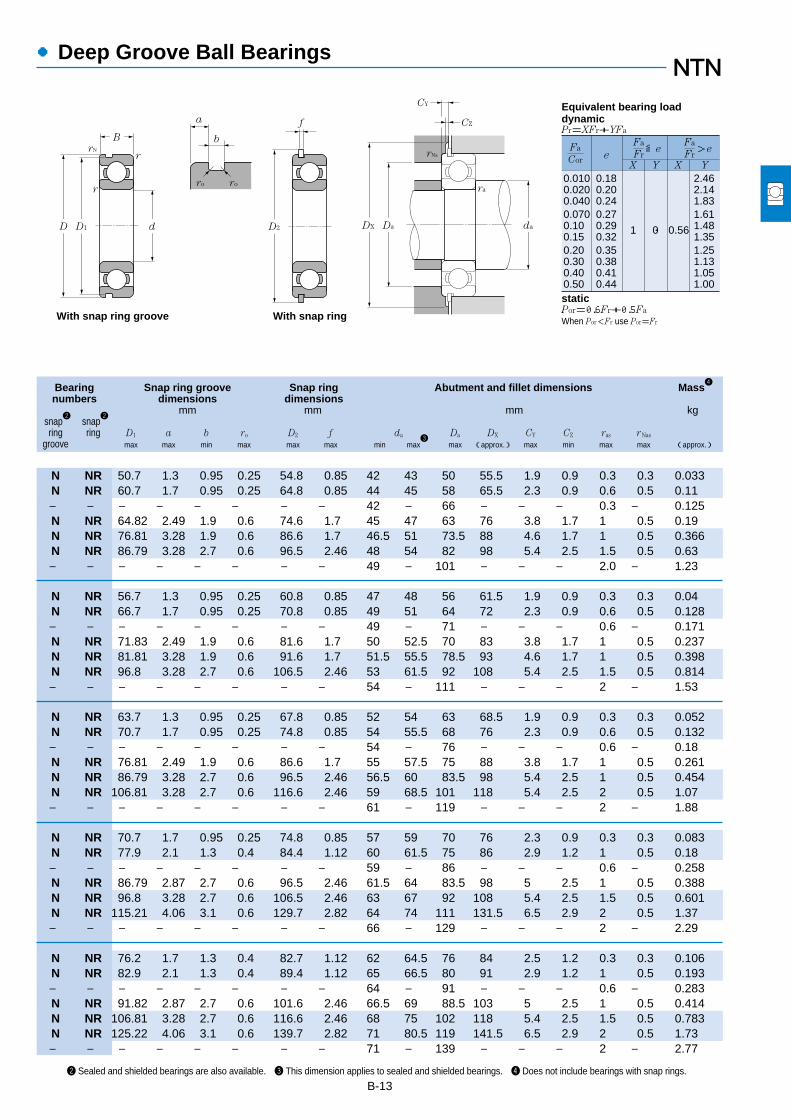
B-13
●Deep Groove Ball Bearings
0.0100.0200.0400.0700.100.150.200.300.400.50
0.180.200.240.270.290.320.350.380.410.44
1 0 0.56
2.462.141.831.611.481.351.251.131.051.00
Fa
FreX Y X Y
≦eFa
Cor
Fa
Fr>e
Equivalent bearing loaddynamicPr=XFr+YFa
staticPor=0.6Fr+0.5Fa
When Por<Fr use Por=Fr
a
b
ro ro
f
D2
With snap ring
rNa
CY
ra
daDaDXdD1 D
B
rrN
r
With snap ring groove
CZ
2 Sealed and shielded bearings are also available. 3 This dimension applies to sealed and shielded bearings. 4 Does not include bearings with snap rings.
Bearing Snap ring groove Snap ring Abutment and fillet dimensions Mass4
numbers dimensions dimensionsmm mm mm kg
snap2
snap2
ring ring D1 a b ro D2 f da Da DX CY CZ ras r Nas
groove max max min max max max min max3
max (approx.) max min max max (approx.)
N NR 50.7 1.3 0.95 0.25 54.8 0.85 42 43 50 55.5 1.9 0.9 0.3 0.3 0.033N NR 60.7 1.7 0.95 0.25 64.8 0.85 44 45 58 65.5 2.3 0.9 0.6 0.5 0.11― ― ― ― ― ― ― ― 42 ― 66 ― ― ― 0.3 ― 0.125N NR 64.82 2.49 1.9 0.6 74.6 1.7 45 47 63 76 3.8 1.7 1 0.5 0.19N NR 76.81 3.28 1.9 0.6 86.6 1.7 46.5 51 73.5 88 4.6 1.7 1 0.5 0.366N NR 86.79 3.28 2.7 0.6 96.5 2.46 48 54 82 98 5.4 2.5 1.5 0.5 0.63― ― ― ― ― ― ― ― 49 ― 101 ― ― ― 2.0 ― 1.23
N NR 56.7 1.3 0.95 0.25 60.8 0.85 47 48 56 61.5 1.9 0.9 0.3 0.3 0.04N NR 66.7 1.7 0.95 0.25 70.8 0.85 49 51 64 72 2.3 0.9 0.6 0.5 0.128― ― ― ― ― ― ― ― 49 ― 71 ― ― ― 0.6 ― 0.171N NR 71.83 2.49 1.9 0.6 81.6 1.7 50 52.5 70 83 3.8 1.7 1 0.5 0.237N NR 81.81 3.28 1.9 0.6 91.6 1.7 51.5 55.5 78.5 93 4.6 1.7 1 0.5 0.398N NR 96.8 3.28 2.7 0.6 106.5 2.46 53 61.5 92 108 5.4 2.5 1.5 0.5 0.814― ― ― ― ― ― ― ― 54 ― 111 ― ― ― 2 ― 1.53
N NR 63.7 1.3 0.95 0.25 67.8 0.85 52 54 63 68.5 1.9 0.9 0.3 0.3 0.052N NR 70.7 1.7 0.95 0.25 74.8 0.85 54 55.5 68 76 2.3 0.9 0.6 0.5 0.132― ― ― ― ― ― ― ― 54 ― 76 ― ― ― 0.6 ― 0.18N NR 76.81 2.49 1.9 0.6 86.6 1.7 55 57.5 75 88 3.8 1.7 1 0.5 0.261N NR 86.79 3.28 2.7 0.6 96.5 2.46 56.5 60 83.5 98 5.4 2.5 1 0.5 0.454N NR 106.81 3.28 2.7 0.6 116.6 2.46 59 68.5 101 118 5.4 2.5 2 0.5 1.07― ― ― ― ― ― ― ― 61 ― 119 ― ― ― 2 ― 1.88
N NR 70.7 1.7 0.95 0.25 74.8 0.85 57 59 70 76 2.3 0.9 0.3 0.3 0.083N NR 77.9 2.1 1.3 0.4 84.4 1.12 60 61.5 75 86 2.9 1.2 1 0.5 0.18― ― ― ― ― ― ― ― 59 ― 86 ― ― ― 0.6 ― 0.258N NR 86.79 2.87 2.7 0.6 96.5 2.46 61.5 64 83.5 98 5 2.5 1 0.5 0.388N NR 96.8 3.28 2.7 0.6 106.5 2.46 63 67 92 108 5.4 2.5 1.5 0.5 0.601N NR 115.21 4.06 3.1 0.6 129.7 2.82 64 74 111 131.5 6.5 2.9 2 0.5 1.37― ― ― ― ― ― ― ― 66 ― 129 ― ― ― 2 ― 2.29
N NR 76.2 1.7 1.3 0.4 82.7 1.12 62 64.5 76 84 2.5 1.2 0.3 0.3 0.106N NR 82.9 2.1 1.3 0.4 89.4 1.12 65 66.5 80 91 2.9 1.2 1 0.5 0.193― ― ― ― ― ― ― ― 64 ― 91 ― ― ― 0.6 ― 0.283N NR 91.82 2.87 2.7 0.6 101.6 2.46 66.5 69 88.5 103 5 2.5 1 0.5 0.414N NR 106.81 3.28 2.7 0.6 116.6 2.46 68 75 102 118 5.4 2.5 1.5 0.5 0.783N NR 125.22 4.06 3.1 0.6 139.7 2.82 71 80.5 119 141.5 6.5 2.9 2 0.5 1.73― ― ― ― ― ― ― ― 71 ― 139 ― ― ― 2 ― 2.77

Shielded type(ZZ)
Non-contactsealed type
(LLB)
Contactsealed type(LLU)�
B
r
r
D d
Open type��
●Deep Groove Ball Bearings
B-14
Boundary dimensions Basic load ratings Limiting speeds Bearing numbers
dynamic static dynamic static rpmmm kN kgf grease oil non-
rNS open type open type open sealed contact contactd D B rs min
1min Cr Cor Cr Cor ZZ LLB Z LB LLU type type type type
65
70
75
80
85
d 65~85mm
1 Smallest allowable dimension for chamfer dimension r.
85 10 0.6 0.5 11.6 11.0 1,180 1,120 7,400 8,700 4,100 6813 ZZ LLB LLU90 13 1 0.5 17.4 16.1 1,770 1,640 7,000 8,200 4,000 6913 ZZ LLB LLU
100 11 0.6 ― 20.5 18.7 2,090 1,910 6,500 7,700 ― 16013 ― ― ―100 18 1.1 0.5 30.5 25.2 3,100 2,570 6,500 7,700 3,900 6013 ZZ LLB LLU120 23 1.5 0.5 57.5 40.0 5,850 4,100 5,500 6,500 3,600 6213 ZZ LLB LLU140 33 2.1 0.5 92.5 60.0 9,450 6,100 4,900 5,800 3,300 6313 ZZ LLB LLU160 37 2.1 ― 111 72.5 11,300 7,400 4,400 5,200 ― 6413 ― ― ―
90 10 0.6 0.5 12.1 11.9 1,230 1,220 6,900 8,100 3,800 6814 ZZ LLB LLU100 16 1 0.5 23.7 21.2 2,420 2,160 6,500 7,700 3,700 6914 ZZ LLB LLU110 13 0.6 ― 24.4 22.6 2,480 2,300 6,100 7,100 ― 16014 ― ― ―110 20 1.1 0.5 38.0 31.0 3,900 3,150 6,100 7,100 3,600 6014 ZZ LLB LLU125 24 1.5 0.5 62.0 44.0 6,350 4,500 5,100 6,000 3,400 6214 ZZ LLB LLU150 35 2.1 0.5 104 68.0 10,600 6,950 4,600 5,400 3,100 6314 ZZ LLB LLU180 42 3 ― 128 89.5 13,100 9,100 4,100 4,800 ― 6414 ― ― ―
95 10 0.6 0.5 12.5 12.9 1,280 1,310 6,400 7,600 3,600 6815 ZZ LLB LLU105 16 1 0.5 24.4 22.6 2,480 2,300 6,100 7,200 3,500 6915 ZZ LLB LLU115 13 0.6 ― 25.0 24.0 2,540 2,450 5,700 6,700 ― 16015 ― ― ―115 20 1.1 0.5 39.5 33.5 4,050 3,400 5,700 6,700 3,300 6015 ZZ LLB LLU130 25 1.5 0.5 66.0 49.5 6,750 5,050 4,800 5,600 3,200 6215 ZZ LLB LLU160 37 2.1 0.5 113 77.0 11,600 7,850 4,300 5,000 2,900 6315 ZZ LLB LLU190 45 3 ― 138 99.0 14,000 10,100 3,800 4,500 ― 6415 ― ― ―
100 10 0.6 0.5 12.7 13.3 1,290 1,360 6,000 7,100 3,400 6816 ZZ LLB LLU110 16 1 0.5 24.9 24.0 2,540 2,450 5,700 6,700 3,200 6916 ZZ LLB LLU125 14 0.6 ― 25.4 25.1 2,590 2,560 5,300 6,200 ― 16016 ― ― ―125 22 1.1 0.5 47.5 40.0 4,850 4,050 5,300 6,200 3,100 6016 ZZ LLB LLU140 26 2 0.5 72.5 53.0 7,400 5,400 4,500 5,300 3,000 6216 ZZ LLB LLU170 39 2.1 0.5 123 86.5 12,500 8,850 4,000 4,700 2,700 6316 ZZ LLB LLU200 48 3 ― 164 125 16,700 12,800 3,600 4,200 ― 6416 ― ― ―
110 13 1 0.5 18.7 19.0 1,910 1,940 5,700 6,700 3,100 6817 ZZ LLB LLU120 18 1.1 0.5 32.0 29.6 3,250 3,000 5,400 6,300 3,000 6917 ZZ LLB LLU130 14 0.6 ― 25.9 26.2 2,640 2,670 5,000 5,900 ― 16017 ― ― ―130 22 1.1 0.5 49.5 43.0 5,050 4,400 5,000 5,900 2,900 6017 ZZ LLB LLU150 28 2 0.5 83.5 64.0 8,500 6,500 4,200 5,000 2,800 6217 ZZ LLB LLU180 41 3 0.5 133 97.0 13,500 9,850 3,800 4,500 2,600 6317 ZZ LLB LLU
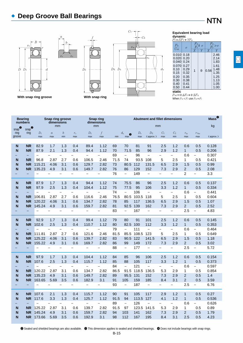
B-15
●Deep Groove Ball Bearings
0.0100.0200.0400.0700.100.150.200.300.400.50
0.180.200.240.270.290.320.350.380.410.44
1 0 0.56
2.462.141.831.611.481.351.251.131.051.00
Fa
FreX Y X Y
≦eFa
Cor
Fa
Fr>e
Equivalent bearing loaddynamicPr=XFr+YFa
staticPor=0.6Fr+0.5Fa
When Por<Fr use Por=Fr
a
b
ro ro
f
D2
With snap ring
rNa
CY
ra
daDaDXdD1 D
B
rrN
r
With snap ring groove
CZ
Bearing Snap ring groove Snap ring Abutment and fillet dimensions Mass4
numbers dimensions dimensionsmm mm mm kg
snap2
snap2
ring ring D1 a b ro D2 f da Da DX CY CZ ras r Nas
groove max max min max max max min max3
max (approx.) max min max max (approx.)
2 Sealed and shielded bearings are also available. 3 This dimension applies to sealed and shielded bearings. 4 Does not include bearings with snap rings.
N NR 82.9 1.7 1.3 0.4 89.4 1.12 69 70 81 91 2.5 1.2 0.6 0.5 0.128N NR 87.9 2.1 1.3 0.4 94.4 1.12 70 71.5 85 96 2.9 1.2 1 0.5 0.206― ― ― ― ― ― ― ― 69 ― 96 ― ― ― 0.6 ― 0.307N NR 96.8 2.87 2.7 0.6 106.5 2.46 71.5 74 93.5 108 5 2.5 1 0.5 0.421N NR 115.21 4.06 3.1 0.6 129.7 2.82 73 80.5 112 131.5 6.5 2.9 1.5 0.5 0.99N NR 135.23 4.9 3.1 0.6 149.7 2.82 76 86 129 152 7.3 2.9 2 0.5 2.08― ― ― ― ― ― ― ― 76 ― 149 ― ― ― 2 ― 3.3
N NR 87.9 1.7 1.3 0.4 94.4 1.12 74 75.5 86 96 2.5 1.2 0.6 0.5 0.137N NR 97.9 2.5 1.3 0.4 104.4 1.12 75 77.5 95 106 3.3 1.2 1 0.5 0.334― ― ― ― ― ― ― ― 74 ― 106 ― ― ― 0.6 ― 0.441N NR 106.81 2.87 2.7 0.6 116.6 2.46 76.5 80.5 103.5 118 5 2.5 1 0.5 0.604N NR 120.22 4.06 3.1 0.6 134.7 2.82 78 85 117 136.5 6.5 2.9 1.5 0.5 1.07N NR 145.24 4.9 3.1 0.6 159.7 2.82 81 92.5 139 162 7.3 2.9 2 0.5 2.52― ― ― ― ― ― ― ― 83 ― 167 ― ― ― 2.5 ― 4.83
N NR 92.9 1.7 1.3 0.4 99.4 1.12 79 80 91 101 2.5 1.2 0.6 0.5 0.145N NR 102.6 2.5 1.3 0.4 110.7 1.12 80 82.5 100 112 3.3 1.2 1 0.5 0.353― ― ― ― ― ― ― ― 79 ― 111 ― ― ― 0.6 ― 0.464N NR 111.81 2.87 2.7 0.6 121.6 2.46 81.5 85.5 108.5 123 5 2.5 1 0.5 0.649N NR 125.22 4.06 3.1 0.6 139.7 2.82 83 90.5 122 141.5 6.5 2.9 1.5 0.5 1.18N NR 155.22 4.9 3.1 0.6 169.7 2.82 86 99 149 172 7.3 2.9 2 0.5 3.02― ― ― ― ― ― ― ― 88 ― 177 ― ― ― 2.5 ― 5.72
N NR 97.9 1.7 1.3 0.4 104.4 1.12 84 85 96 106 2.5 1.2 0.6 0.5 0.154N NR 107.6 2.5 1.3 0.4 115.7 1.12 85 88 105 117 3.3 1.2 1 0.5 0.373― ― ― ― ― ― ― ― 84 ― 121 ― ― ― 0.6 ― 0.597N NR 120.22 2.87 3.1 0.6 134.7 2.82 86.5 91.5 118.5 136.5 5.3 2.9 1 0.5 0.854N NR 135.23 4.9 3.1 0.6 149.7 2.82 89 95.5 131 152 7.3 2.9 2 0.5 1.4N NR 163.65 5.69 3.5 0.6 182.9 3.1 91 105 159 185 8.4 3.1 2 0.5 3.59― ― ― ― ― ― ― ― 93 ― 187 ― ― ― 2.5 ― 6.76
N NR 107.6 2.1 1.3 0.4 115.7 1.12 90 91 105 117 2.9 1.2 1 0.5 0.27N NR 117.6 3.3 1.3 0.4 125.7 1.12 91.5 94 113.5 127 4.1 1.2 1 0.5 0.536― ― ― ― ― ― ― ― 89 ― 126 ― ― ― 0.6 ― 0.626N NR 125.22 2.87 3.1 0.6 139.7 2.82 91.5 97 123.5 141.5 5.3 2.9 1 0.5 0.89N NR 145.24 4.9 3.1 0.6 159.7 2.82 94 103 141 162 7.3 2.9 2 0.5 1.79N NR 173.66 5.69 3.5 0.6 192.9 3.1 98 112 167 195 8.4 3.1 2.5 0.5 4.23

Shielded type(ZZ)
Non-contactsealed type
(LLB)
Contactsealed type(LLU)�
B
r
r
D d
Open type��
●Deep Groove Ball Bearings
B-16
Boundary dimensions Basic load ratings Limiting speeds Bearing numbers
dynamic static dynamic static rpmmm kN kgf grease oil non-
rNS open type open type open sealed contact contactd D B rs min
1min Cr Cor Cr Cor ZZ LLB Z LB LLU type type type type
d 90~120mm
1 Smallest allowable dimension for chamfer dimension r.
90
95
100
105
110
120
115 13 1 0.5 19.0 19.7 1,940 2,010 5,400 6,300 3,000 6818 ZZ LLB LLU125 18 1.1 0.5 33.0 31.5 3,350 3,200 5,100 6,000 2,900 6918 ZZ LLB LLU140 16 1 ― 33.5 33.5 3,400 3,400 4,700 5,600 ― 16018 ― ― ―140 24 1.5 0.5 58.0 49.5 5,950 5,050 4,700 5,600 2,800 6018 ZZ LLB LLU160 30 2 0.5 96.0 71.5 9,800 7,300 4,000 4,700 2,600 6218 ZZ LLB LLU190 43 3 0.5 143 107 14,500 10,900 3,600 4,200 2,400 6318 ZZ LLB LLU
120 13 1 0.5 19.3 20.5 1,970 2,090 5,000 5,900 2,800 6819 ZZ LLB LLU130 18 1.1 0.5 33.5 33.5 3,450 3,400 4,800 5,700 2,800 6919 ZZ LLB LLU145 16 1 ― 34.5 35.0 3,500 3,550 4,500 5,300 ― 16019 ― ― ―145 24 1.5 0.5 60.5 54.0 6,150 5,500 4,500 5,300 2,600 6019 ZZ LLB LLU170 32 2.1 0.5 109 82.0 11,100 8,350 3,700 4,400 2,500 6219 ZZ LLB LLU200 45 3 0.5 153 119 15,600 12,100 3,300 3,900 2,300 6319 ZZ ― LLU
125 13 1 0.5 19.6 21.2 2,000 2,160 4,800 5,600 2,700 6820 ZZ LLB LLU140 20 1.1 0.5 41.0 39.5 4,200 4,050 4,500 5,300 2,600 6920 ZZ LLB LLU150 16 1 ― 35.0 36.5 3,600 3,750 4,200 5,000 ― 16020 ― ― ―150 24 1.5 0.5 60.0 54.0 6,150 5,500 4,200 5,000 2,600 6020 ZZ LLB LLU180 34 2.1 0.5 122 93.0 12,500 9,450 3,500 4,200 2,300 6220 ZZ LLB LLU215 47 3 ― 173 141 17,600 14,400 3,200 3,700 2,200 6320 ZZ ― LLU
130 13 1 0.5 19.8 22.0 2,020 2,240 4,600 5,400 ― 6821 ― ― ―145 20 1.1 0.5 42.5 42.0 4,300 4,300 4,300 5,100 2,500 6921 ZZ LLB LLU160 18 1 ― 52.0 50.5 5,300 5,150 4,000 4,700 ― 16021 ― ― ―160 26 2 0.5 72.5 65.5 7,400 6,700 4,000 4,700 2,400 6021 ZZ LLB LLU190 36 2.1 0.5 133 105 13,600 10,700 3,400 4,000 2,300 6221 ZZ ― LLU225 49 3 ― 184 153 18,700 15,700 3,000 3,600 2,100 6321 ZZ ― LLU
140 16 1 0.5 24.9 28.2 2,540 2,880 4,300 5,100 ― 6822 ― ― ―150 20 1.1 0.5 43.5 44.5 4,450 4,550 4,100 4,800 2,400 6922 ZZ LLB LLU170 19 1 ― 57.5 56.5 5,850 5,800 3,800 4,500 ― 16022 ― ― ―170 28 2 0.5 82.0 73.0 8,350 7,450 3,800 4,500 2,300 6022 ZZ LLB LLU200 38 2.1 0.5 144 117 14,700 11,900 3,200 3,800 2,200 6222 ZZ ― LLU240 50 3 ― 205 179 20,900 18,300 2,900 3,400 1,900 6322 ZZ ― LLU
150 16 1 0.5 28.9 33.0 2,950 3,350 4,000 4,700 ― 6824 ― ― ―165 22 1.1 0.5 53.0 54.0 5,400 5,500 3,800 4,400 ― 6924 ― ― ―180 19 1 ― 63.0 63.5 6,450 6,450 3,500 4,100 ― 16024 ― ― ―180 28 2 0.5 85.0 79.5 8,650 8,100 3,500 4,100 2,100 6024 ZZ LLB LLU

B-17
●Deep Groove Ball Bearings
0.0100.0200.0400.0700.100.150.200.300.400.50
0.180.200.240.270.290.320.350.380.410.44
1 0 0.56
2.462.141.831.611.481.351.251.131.051.00
Fa
FreX Y X Y
≦eFa
Cor
Fa
Fr>e
Equivalent bearing loaddynamicPr=XFr+YFa
staticPor=0.6Fr+0.5Fa
When Por<Fr use Por=Fr
a
b
ro ro
f
D2
With snap ring
rNa
CY
ra
daDaDXdD1 D
B
rrN
r
With snap ring groove
CZ
Bearing Snap ring groove Snap ring Abutment and fillet dimensions Mass4
numbers dimensions dimensionsmm mm mm kg
snap2
snap2
ring ring D1 a b ro D2 f da Da DX CY CZ ras r Nas
groove max max min max max max min max3
max (approx.) max min max max (approx.)
2 Sealed and shielded bearings are also available. 3 This dimension applies to sealed and shielded bearings. 4 Does not include bearings with snap rings.
N NR 112.6 2.1 1.3 0.4 120.7 1.12 95 96 110 122 2.9 1.2 1 0.5 0.285N NR 122.6 3.3 1.3 0.4 130.7 1.12 96.5 99 118.5 132 4.1 1.2 1 0.5 0.554― ― ― ― ― ― ― ― 95 ― 135 ― ― ― 1 ― 0.848N NR 135.23 3.71 3.1 0.6 149.7 2.82 98 102 132 152 6.1 2.9 1.5 0.5 1.02N NR 155.22 4.9 3.1 0.6 169.7 2.82 99 109 151 172 7.3 2.9 2 0.5 2.15N NR 183.64 5.69 3.5 0.6 202.9 3.1 103 118 177 205 8.4 3.1 2.5 0.5 4.91
N NR 117.6 2.1 1.3 0.4 125.7 1.12 100 101 115 127 2.9 1.2 1 0.5 0.3N NR 127.6 3.3 1.3 0.4 135.7 1.12 101.5 104 123.5 137 4.1 1.2 1 0.5 0.579― ― ― ― ― ― ― ― 100 ― 140 ― ― ― 1 ― 0.885N NR 140.23 3.71 3.1 0.6 154.7 2.82 103 109 137 157 6.1 2.9 1.5 0.5 1.08N NR 163.65 5.69 3.5 0.6 182.9 3.1 106 116 159 185 8.4 3.1 2 0.5 2.62N NR 193.65 5.69 3.5 0.6 212.9 3.1 108 125 187 215 8.4 3.1 2.5 0.5 5.67
N NR 122.6 2.1 1.3 0.4 130.7 1.12 105 106 120 132 2.9 1.2 1 0.5 0.313N NR 137.6 3.3 1.9 0.6 145.7 1.7 106.5 110 133.5 147 4.7 1.7 1 0.5 0.785― ― ― ― ― ― ― ― 105 ― 145 ― ― ― 1 ― 0.91N NR 145.24 3.71 3.1 0.6 159.7 2.82 108 110 142 162 6.1 2.9 1.5 0.5 1.15N NR 173.66 5.69 3.5 0.6 192.9 3.1 111 122 169 195 8.4 3.1 2 0.5 3.14― ― ― ― ― ― ― ― 113 133 202 ― ― ― 2.5 ― 7
N NR 127.6 2.1 1.3 0.4 135.7 1.12 110 ― 125 137 2.9 1.2 1 0.5 0.33N NR 142.6 3.3 1.9 0.6 150.7 1.7 111.5 115 138.5 152 4.7 1.7 1 0.5 0.816― ― ― ― ― ― ― ― 110 ― 155 ― ― ― 1 ― 1.2N NR 155.22 3.71 3.1 0.6 169.7 2.82 114 119 151 172 6.1 2.9 2 0.5 1.59N NR 183.64 5.69 3.5 0.6 202.9 3.1 116 125 179 205 8.4 3.1 2 0.5 3.7― ― ― ― ― ― ― ― 118 134 212 ― ― ― 2.5 ― 8.05
N NR 137.6 2.5 1.9 0.6 145.7 1.7 115 ― 135 147 3.9 1.7 1 0.5 0.515N NR 147.6 3.3 1.9 0.6 155.7 1.7 116.5 120 143.5 157 4.7 1.7 1 0.5 0.849― ― ― ― ― ― ― ― 115 ― 165 ― ― ― 1 ― 1.46N NR 163.65 3.71 3.5 0.6 182.9 3.1 119 126 161 185 6.4 3.1 2 0.5 1.96N NR 193.65 5.69 3.5 0.6 212.9 3.1 121 132 189 215 8.4 3.1 2 0.5 4.36― ― ― ― ― ― ― ― 123 149 227 ― ― ― 2.5 ― 9.54
N NR 147.6 2.5 1.9 0.6 155.7 1.7 125 ― 145 157 3.9 1.7 1 0.5 0.555N NR 161.8 3.7 1.9 0.6 171.5 1.7 126.5 ― 158.5 173 5.1 1.7 1 0.5 1.15― ― ― ― ― ― ― ― 125 ― 175 ― ― ― 1 ― 1.56N NR 173.66 3.71 3.5 0.6 192.9 3.1 129 136 171 195 6.4 3.1 2 0.5 2.07

Shielded type(ZZ)
Contactsealed type(LLU)�
B
r
r
D d
Open type
●Deep Groove Ball Bearings
B-18
Boundary dimensions Basic load ratings Limiting speeds Bearing numbers
dynamic static dynamic static rpmmm kN kgf grease oil
rNS open type open type open sealed contactd D B rs min
1min Cr Cor Cr Cor ZZ Z LLU type type type
d 120~170mm
1 Smallest allowable dimension for chamfer dimension r.
120
130
140
150
160
170
215 40 2.1 ― 155 131 15,900 13,400 2,900 3,400 2,000 6224 ZZ LLU260 55 3 ― 207 185 21,100 18,800 2,600 3,100 ― 6324 ― ―
165 18 1.1 0.5 37.0 41.0 3,750 4,200 3,700 4,300 ― 6826 ― ―180 24 1.5 0.5 65.0 67.5 6,650 6,850 3,500 4,100 ― 6926 ― ―200 22 1.1 ― 80.0 79.5 8,150 8,100 3,200 3,800 ― 16026 ― ―200 33 2 0.5 106 101 10,800 10,300 3,200 3,800 1,900 6026 ZZ LLU230 40 3 ― 167 146 17,000 14,900 2,700 3,100 ― 6226 ― ―280 58 4 ― 229 214 23,400 21,800 2,400 2,800 ― 6326 ― ―
175 18 1.1 0.5 38.5 44.5 3,900 4,550 3,400 4,000 ― 6828 ― ―190 24 1.5 0.5 66.5 71.5 6,800 7,300 3,200 3,800 ― 6928 ― ―210 22 1.1 ― 82.0 85.0 8,350 8,650 3,000 3,500 ― 16028 ― ―210 33 2 ― 110 109 11,200 11,100 3,000 3,500 1,800 6028 ZZ LLU250 42 3 ― 166 150 17,000 15,300 2,500 2,900 ― 6228 ― ―300 62 4 ― 253 246 25,800 25,100 2,200 2,600 ― 6328 ― ―
190 20 1.1 0.5 47.5 55.0 4,850 5,600 3,100 3,700 ― 6830 ― ―210 28 2 ― 85.0 90.5 8,650 9,200 3,000 3,500 ― 6930 ― ―225 24 1.1 ― 96.5 101 9,850 10,300 2,800 3,200 ― 16030 ― ―225 35 2.1 ― 126 126 12,800 12,800 2,800 3,200 1,700 6030 ZZ LLU270 45 3 ― 176 168 18,000 17,100 2,300 2,700 ― 6230 ― ―320 65 4 ― 274 284 28,000 28,900 2,100 2,400 ― 6330 ― ―
200 20 1.1 0.5 48.5 57.0 4,950 5,800 2,900 3,400 ― 6832 ― ―220 28 2 ― 87.0 96.0 8,850 9,800 2,800 3,300 ― 6932 ― ―240 25 1.5 ― 99.0 108 10,100 11,000 2,600 3,000 ― 16032 ― ―240 38 2.1 ― 143 144 14,500 14,700 2,600 3,000 1,600 6032 ZZ LLU290 48 3 ― 185 186 18,900 19,000 2,100 2,500 ― 6232 ― ―340 68 4 ― 278 286 28,300 29,200 1,900 2,300 ― 6332 ― ―
215 22 1.1 ― 60.0 70.5 6,100 7,200 2,700 3,200 ― 6834 ― ―230 28 2 ― 86.0 95.5 8,750 9,750 2,600 3,100 ― 6934 ― ―260 28 1.5 ― 119 128 12,100 13,100 2,400 2,800 ― 16034 ― ―260 42 2.1 ― 168 172 17,200 17,600 2,400 2,800 ― 6034 ― ―310 52 4 ― 212 223 21,700 22,800 2,000 2,400 ― 6234 ― ―360 72 4 ― 325 355 33,500 36,000 1,800 2,100 ― 6334 ― ―

B-19
●Deep Groove Ball Bearings
0.0100.0200.0400.0700.100.150.200.300.400.50
0.180.200.240.270.290.320.350.380.410.44
1 0 0.56
2.462.141.831.611.481.351.251.131.051.00
Fa
FreX Y X Y
≦eFa
Cor
Fa
Fr>e
Equivalent bearing loaddynamicPr=XFr+YFa
staticPor=0.6Fr+0.5Fa
When Por<Fr use Por=Fr
a
b
ro ro
f
D2
With snap ring
rNa
CY
ra
daDaDXdD1 D
B
rrN
r
With snap ring groove
CZ
Bearing Snap ring groove Snap ring Abutment and fillet dimensions Mass4
numbers dimensions dimensionsmm mm mm kg
snap2
snap2
ring ring D1 a b ro D2 f da Da DX CY CZ ras r Nas
groove max max min max max max min max3
max (approx.) max min max max (approx.)
2 Sealed and shielded bearings are also available. 3 This dimension applies to sealed and shielded bearings. 4 Does not include bearings with snap rings.
― ― ― ― ― ― ― ― 131 143 204 ― ― ― 2 ― 5.15― ― ― ― ― ― ― ― 133 ― 247 ― ― ― 2.5 ― 12.4
N NR 161.8 3.3 1.9 0.6 171.5 1.7 136.5 ― 158.5 173 4.7 1.7 1 0.5 0.8N NR 176.8 3.7 1.9 0.6 186.5 1.7 138 ― 172 188 5.1 1.7 1.5 0.5 1.52― ― ― ― ― ― 136.5 ― 193.5 ― ― ― 1 ― 2.31N NR 193.65 5.69 3.5 0.6 212.9 3.1 139 148 191 215 8.4 3.1 2 0.5 3.16― ― ― ― ― ― ― ― 143 ― 217 ― ― ― 2.5 ― 5.82― ― ― ― ― ― ― ― 146 ― 264 ― ― ― 3 ― 15.3
N NR 171.8 3.3 1.9 0.6 181.5 1.7 146.5 ― 168.5 183 4.7 1.7 1 0.5 0.85N NR 186.8 3.7 1.9 0.6 196.5 1.7 148 ― 182 198 5.1 1.7 1.5 0.5 1.62― ― ― ― ― ― ― ― 146.5 ― 203.5 ― ― ― 1 ― 2.45― ― ― ― ― ― ― ― 149 158 201 ― ― ― 2 ― 3.35― ― ― ― ― ― ― ― 153 ― 237 ― ― ― 2.5 ― 7.57― ― ― ― ― ― ― ― 156 ― 284 ― ― ― 3 ― 18.5
N NR 186.8 3.3 1.9 0.6 196.5 1.7 156.5 ― 183.5 198 4.7 1.7 1 0.5 1.16― ― ― ― ― ― ― ― 159 ― 201 ― ― ― 2 ― 2.47― ― ― ― ― ― ― ― 156.5 ― 218.5 ― ― ― 1 ― 3.07― ― ― ― ― ― ― ― 161 169 214 ― ― ― 2 ― 4.08― ― ― ― ― ― ― ― 163 ― 257 ― ― ― 2.5 ― 9.41― ― ― ― ― ― ― ― 166 ― 304 ― ― ― 3 ― 22
N NR 196.8 3.3 1.9 0.6 206.5 1.7 166.5 ― 193.5 208 4.7 1.7 1 0.5 1.23― ― ― ― ― ― ― ― 169 ― 211 ― ― ― 2 ― 2.61― ― ― ― ― ― ― ― 168 ― 232 ― ― ― 1.5 ― 3.64― ― ― ― ― ― ― ― 171 183 229 ― ― ― 2 ― 5.05― ― ― ― ― ― ― ― 173 ― 277 ― ― ― 2.5 ― 11.7― ― ― ― ― ― ― ― 176 ― 324 ― ― ― 3 ― 26
― ― ― ― ― ― ― ― 176.5 ― 208.5 ― ― ― 1 ― 1.63― ― ― ― ― ― ― ― 179 ― 221 ― ― ― 2 ― 2.74― ― ― ― ― ― ― ― 178 ― 252 ― ― ― 1.5 ― 4.93― ― ― ― ― ― ― ― 181 ― 249 ― ― ― 2 ― 6.76― ― ― ― ― ― ― ― 186 ― 294 ― ― ― 3 ― 14.5― ― ― ― ― ― ― ― 186 ― 344 ― ― ― 3 ― 30.7

B
r
r
D d
Open Type
ra
daDa
ra
●Deep Groove Ball Bearings
B-20
Boundary dimensions Basic load ratings Limiting speeds Bearing
dynamic static dynamic staticnumbers
mm kN kgf rpmgrease oil open
d D B rs min1
Cr Cor Cr Cor open type open type type
d 180~260mm
1 Smallest allowable dimension for chamfer dimension r.
180
190
200
220
240
260
225 22 1.1 60.5 73.0 6,200 7,450 2,600 3,000 6836250 33 2 110 119 11,200 12,200 2,400 2,900 6936280 31 2 117 134 11,900 13,600 2,300 2,700 16036280 46 2.1 189 199 19,300 20,300 2,300 2,700 6036320 52 4 227 241 23,200 24,600 1,900 2,200 6236380 75 4 355 405 36,000 41,500 1,700 2,000 6336
240 24 1.5 73.0 88.0 7,450 9,000 2,400 2,900 6838260 33 2 113 127 11,500 13,000 2,300 2,700 6938290 31 2 134 156 13,700 15,900 2,100 2,500 16038290 46 2.1 197 215 20,100 21,900 2,100 2,500 6038340 55 4 255 281 26,000 28,700 1,800 2,100 6238400 78 5 355 415 36,000 42,500 1,600 1,900 6338
250 24 1.5 74.0 91.5 7,550 9,300 2,300 2,700 6840280 38 2.1 157 168 16,000 17,100 2,200 2,600 6940310 34 2 142 160 14,400 16,300 2,000 2,400 16040310 51 2.1 218 243 22,200 24,800 2,000 2,400 6040360 58 4 269 310 27,400 31,500 1,700 2,000 6240420 80 5 410 500 42,000 51,000 1,500 1,800 6340
270 24 1.5 76.5 98.0 7,800 10,000 2,100 2,400 6844300 38 2.1 160 180 16,400 18,400 2,000 2,300 6944340 37 2.1 181 216 18,500 22,000 1,800 2,200 16044340 56 3 241 289 24,600 29,400 1,800 2,200 6044400 65 4 297 365 30,500 37,000 1,500 1,800 6244460 88 5 410 520 42,000 53,000 1,400 1,600 6344
300 28 2 85.0 112 8,650 11,400 1,900 2,200 6848320 38 2.1 170 203 17,300 20,700 1,800 2,100 6948360 37 2.1 178 217 18,200 22,100 1,700 2,000 16048360 56 3 249 310 25,400 32,000 1,700 2,000 6048
320 28 2 87.0 120 8,900 12,200 1,700 2,000 6852360 46 2.1 222 280 22,600 28,500 1,600 1,900 6952400 44 3 227 299 23,200 30,500 1,500 1,800 16052400 65 4 291 375 29,700 38,500 1,500 1,800 6052
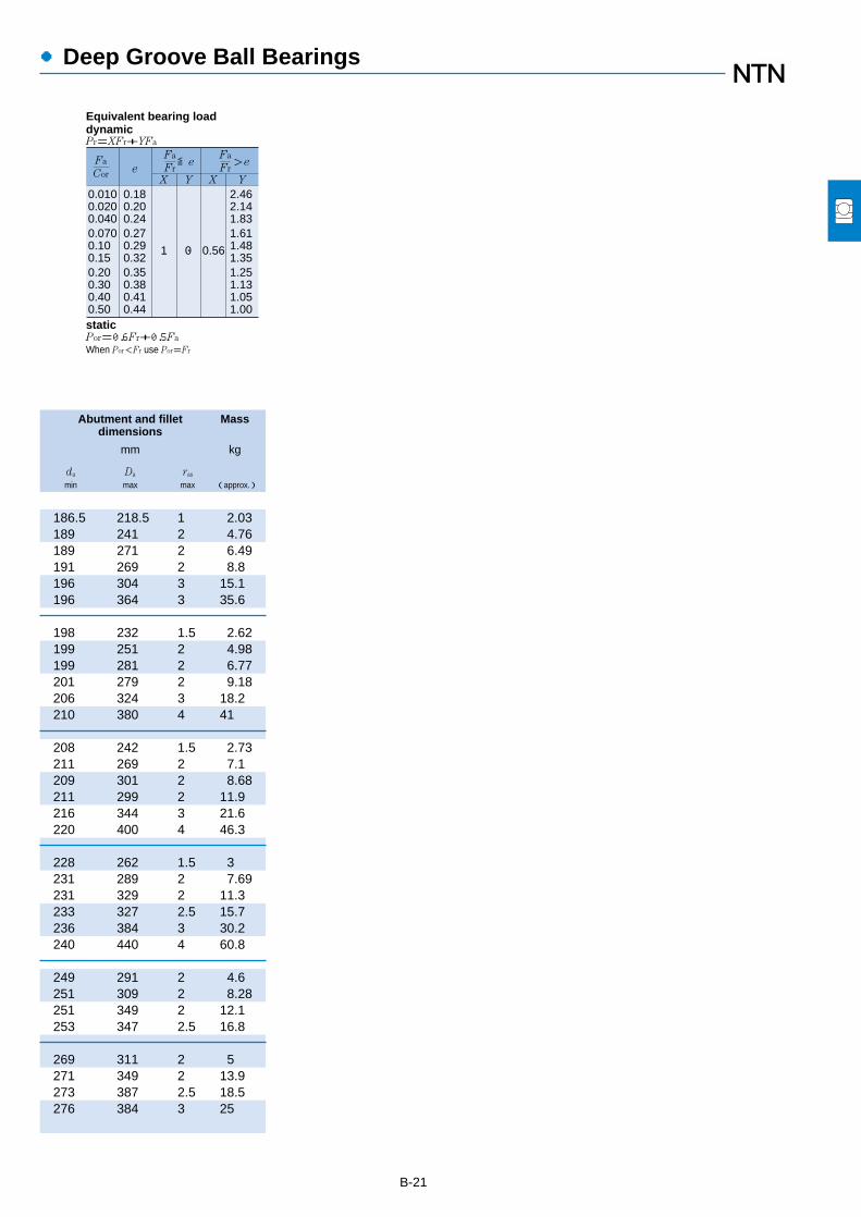
B-21
●Deep Groove Ball Bearings
0.0100.0200.0400.0700.100.150.200.300.400.50
0.180.200.240.270.290.320.350.380.410.44
1 0 0.56
2.462.141.831.611.481.351.251.131.051.00
Fa
FreX Y X Y
≦eFa
Cor
Fa
Fr>e
Equivalent bearing loaddynamicPr=XFr+YFa
staticPor=0.6Fr+0.5Fa
When Por<Fr use Por=Fr
Abutment and fillet Massdimensions
mm kg
da Da ras
min max max (approx.)
186.5 218.5 1 2.03189 241 2 4.76189 271 2 6.49191 269 2 8.8196 304 3 15.1196 364 3 35.6
198 232 1.5 2.62199 251 2 4.98199 281 2 6.77201 279 2 9.18206 324 3 18.2210 380 4 41
208 242 1.5 2.73211 269 2 7.1209 301 2 8.68211 299 2 11.9216 344 3 21.6220 400 4 46.3
228 262 1.5 3231 289 2 7.69231 329 2 11.3233 327 2.5 15.7236 384 3 30.2240 440 4 60.8
249 291 2 4.6251 309 2 8.28251 349 2 12.1253 347 2.5 16.8
269 311 2 5271 349 2 13.9273 387 2.5 18.5276 384 3 25

●Deep Groove Ball Bearings
B-22
Boundary dimensions Basic load ratings Limiting speeds Bearing
dynamic static dynamic staticnumbers
mm kN kgf rpmgrease oil open
d D B rs min1
Cr Cor Cr Cor open type open type type
d 280~440mm
1 Smallest allowable dimension for chamfer dimension r.
B
r
r
D d
Open Type
ra
daDa
ra
440
280
300
320
340
360
380
400
420
350 33 2 137 177 13,900 18,100 1,600 1,900 6856380 46 2.1 227 299 23,200 30,500 1,500 1,800 6956420 44 3 232 315 23,700 32,500 1,400 1,600 16056420 65 4 325 420 33,000 43,000 1,400 1,600 6056
380 38 2.1 162 210 16,500 21,500 1,500 1,700 6860420 56 3 276 375 28,200 38,500 1,400 1,600 6960460 50 4 292 410 29,800 42,000 1,300 1,500 16060460 74 4 355 480 36,000 49,000 1,300 1,500 6060
400 38 2.1 168 228 17,200 23,200 1,400 1,600 6864440 56 3 285 405 29,000 41,000 1,300 1,500 6964480 50 4 300 440 30,500 45,000 1,200 1,400 16064480 74 4 370 530 38,000 54,000 1,200 1,400 6064
420 38 2.1 170 236 17,400 24,000 1,300 1,500 6868460 56 3 293 430 29,800 44,000 1,200 1,400 6968520 57 4 340 515 35,000 52,500 1,100 1,300 16068520 82 5 420 610 42,500 62,500 1,100 1,300 6068
440 38 2.1 187 258 19,100 26,300 1,200 1,400 6872480 56 3 300 455 30,500 46,500 1,100 1,300 6972540 57 4 350 550 36,000 56,000 1,100 1,200 16072540 82 5 440 670 44,500 68,000 1,100 1,200 6072
480 46 2.1 231 340 23,600 34,500 1,100 1,300 6876520 65 4 325 510 33,000 52,000 1,100 1,200 6976560 82 5 455 725 46,500 74,000 990 1,200 6076
500 46 2.1 226 340 23,100 34,500 1,100 1,200 6880540 65 4 335 535 34,000 54,500 990 1,200 6980600 90 5 510 825 52,000 84,000 930 1,100 6080
520 46 2.1 260 405 26,500 41,500 1,000 1,200 6884560 65 4 340 560 35,000 57,000 940 1,100 6984620 90 5 530 895 54,000 91,000 880 1,000 6084
540 46 2.1 264 420 26,900 43,000 950 1,100 6888600 74 4 365 615 37,500 63,000 890 1,000 6988

B-23
●Deep Groove Ball Bearings
0.0100.0200.0400.0700.100.150.200.300.400.50
0.180.200.240.270.290.320.350.380.410.44
1 0 0.56
2.462.141.831.611.481.351.251.131.051.00
Fa
FreX Y X Y
≦eFa
Cor
Fa
Fr>e
Equivalent bearing loaddynamicPr=XFr+YFa
staticPor=0.6Fr+0.5Fa
When Por<Fr use Por=Fr
289 341 2 7.4291 369 2 14.8293 407 2.5 23296 404 3 31
311 369 2 10.5313 407 2.5 23.5316 444 3 32.5316 444 3 43.8
331 389 2 10.9333 427 2.5 24.8336 464 3 34.2336 464 3 46.1
351 409 2 11.5353 447 2.5 26.2356 504 3 47.1360 500 4 61.8
371 429 2 12.3373 467 2.5 27.5376 524 3 49.3380 520 4 64.7
391 469 2 19.7396 504 3 39.8400 540 4 67.5
411 489 2 20.6416 524 3 41.6420 580 4 87.6
431 509 2 21.6436 544 3 43.4440 600 4 91.1
451 529 2 22.5456 584 3 60
Abutment and fillet Massdimensions
mm kg
da Da ras
min max max (approx.)

●Deep Groove Ball Bearings
B-24
Boundary dimensions Basic load ratings Limiting speeds Bearing
dynamic static dynamic staticnumbers
mm kN kgf rpmgrease oil open
d D B rs min1
Cr Cor Cr Cor open type open type type
d 460~600mm
1 Smallest allowable dimension for chamfer dimension r.
B
r
r
D d
Open Type
ra
daDa
ra
580 56 3 315 515 32,000 52,500 900 1,100 6892620 74 4 375 645 38,500 66,000 850 1,000 6992
600 56 3 320 540 32,500 55,000 860 1,000 6896650 78 5 430 770 44,000 78,500 810 950 6996
620 56 3 325 560 33,500 57,000 820 970 68/500670 78 5 445 805 45,500 82,500 770 910 69/500
650 56 3 330 580 34,000 59,500 770 900 68/530
680 56 3 335 600 34,000 61,500 710 840 68/560
730 60 3 375 705 38,500 72,000 660 780 68/600
530
560
600
460
480
500
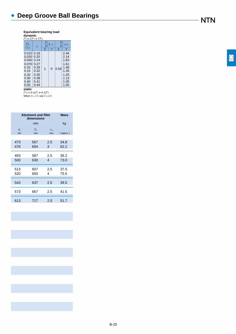
B-25
●Deep Groove Ball Bearings
0.0100.0200.0400.0700.100.150.200.300.400.50
0.180.200.240.270.290.320.350.380.410.44
1 0 0.56
2.462.141.831.611.481.351.251.131.051.00
Fa
FreX Y X Y
≦eFa
Cor
Fa
Fr>e
Equivalent bearing loaddynamicPr=XFr+YFa
staticPor=0.6Fr+0.5Fa
When Por<Fr use Por=Fr
473 567 2.5 34.8476 604 3 62.2
493 587 2.5 36.2500 630 4 73.0
513 607 2.5 37.5520 650 4 75.5
543 637 2.5 39.5
573 667 2.5 41.5
613 717 2.5 51.7
Abutment and fillet Massdimensions
mm kg
da Da ras
min max max (approx.)

Expansion Compensating Bearings
B-26
Boundary dimensions Basic load ratings Allowable Limiting speeds Bearing numbers
dynamic static dynamic staticload
rpmmm kN kgf kN kgf grease oil non-
1
open type open type open sealed1
contact contact1
d D B rs min2
Cr Cor Cr Cor Cp Cp ZZ,LLB Z,LB LU,LLU type type type type
10
12
15
17
20
25
30
35
40
45
50
1 This bearing number is for double sealed and double shielded type bearings, but single sealed and single shielded type are also available. 2 Smallest allowable dimension for chamfer dimension r.
d 10 ‘50mm
dD
B
r
r
Open type Shielded type(ZZ)
Non-contactsealed type
(LLB)
Contactsealed type(LLU)�
26 8 0.3 4.55 1.96 465 200 1.65 168 29,000 34,000 21,000 EC-6000 ZZ LLB LLU30 9 0.6 5.10 2.39 520 244 2.39 244 25,000 30,000 18,000 EC-6200 ZZ LLB LLU35 11 0.6 8.20 3.50 835 355 3.45 355 23,000 27,000 16,000 EC-6300 ZZ LLB LLU
28 8 0.3 5.10 2.39 520 244 1.78 181 26,000 30,000 18,000 EC-6001 ZZ LLB LLU32 10 0.6 6.10 2.75 620 280 2.29 233 22,000 26,000 16,000 EC-6201 ZZ LLB LLU37 12 1 9.70 4.20 990 425 3.65 375 20,000 24,000 15,000 EC-6301 ZZ LLB LLU
32 9 0.3 5.60 2.83 570 289 2.83 289 22,000 26,000 15,000 EC-6002 ZZ LLB LLU35 11 0.6 7.75 3.60 790 365 2.78 284 19,000 23,000 15,000 EC-6202 ZZ LLB LLU42 13 1 11.4 5.45 1,170 555 4.40 450 17,000 21,000 12,000 EC-6302 ZZ LLB LLU
35 10 0.3 6.80 3.35 695 345 2.88 294 20,000 24,000 14,000 EC-6003 ZZ LLB LLU40 12 0.6 9.60 4.60 980 465 3.45 350 18,000 21,000 12,000 EC-6203 ZZ LLB LLU47 14 1 13.5 6.55 1,380 665 6.55 665 16,000 19,000 11,000 EC-6303 ZZ LLB LLU
42 12 0.6 9.40 5.05 955 515 5.05 515 18,000 21,000 11,000 EC-6004 ZZ LLB LLU47 14 1 12.8 6.65 1,310 680 6.55 515 16,000 18,000 10,000 EC-6204 ZZ LLB LLU52 15 1.1 15.9 7.90 1,620 805 7.90 805 14,000 17,000 10,000 EC-6304 ZZ LLB LLU
47 12 0.6 10.1 5.85 1,030 595 5.85 595 15,000 18,000 9,400 EC-6005 ZZ LLB LLU52 15 1 14.0 7.85 1,430 800 6.55 665 13,000 15,000 8,900 EC-6205 ZZ LLB LLU62 17 1.1 21.2 10.9 2,160 1,110 10.9 1,110 12,000 14,000 8,100 EC-6305 ZZ LLB LLU
55 13 1 13.2 8.30 1,350 845 8.30 845 13,000 15,000 7,700 EC-6006 ZZ LLB LLU62 16 1 19.5 11.3 1,980 1,150 9.85 1,000 11,000 13,000 7,300 EC-6206 ZZ LLB LLU72 19 1.1 26.7 15.0 2,720 1,530 15.0 1,530 10,000 12,000 6,600 EC-6306 ZZ LLB LLU
62 14 1 16.0 10.3 1,630 1,050 10.3 1,050 12,000 14,000 6,800 EC-6007 ZZ LLB LLU72 17 1.1 25.7 15.3 2,620 1,560 14.5 1,480 9,800 11,000 6,300 EC-6207 ZZ LLB LLU80 21 1.5 33.5 19.1 3,400 1,950 18.5 1,890 8,800 10,000 6,000 EC-6307 ZZ LLB LLU
68 15 1 16.8 11.5 1,710 1,170 11.5 1,170 10,000 12,000 6,100 EC-6008 ZZ LLB LLU80 18 1.1 29.1 17.8 2,970 1,820 17.5 1,780 8,700 10,000 5,600 EC-6208 ZZ LLB LLU90 23 1.5 40.5 24.0 4,150 2,450 23.4 2,380 7,800 9,200 5,300 EC-6308 ZZ LLB LLU
75 16 1 21.0 15.1 2,140 1,540 15.1 1,540 9,200 11,000 5,400 EC-6009 ZZ LLB LLU85 19 1.1 32.5 20.4 3,350 2,080 16.2 1,660 7,800 9,200 5,200 EC-6209 ZZ LLB LLU
100 25 1.5 53.0 32.0 5,400 3,250 27.4 2,790 7,000 8,200 4,700 EC-6309 ZZ LLB LLU
80 16 1 21.8 16.6 2,230 1,690 16.6 1,690 8,400 9,800 5,000 EC-6010 ZZ LLB LLU90 20 1.1 35.0 23.2 3,600 2,370 22.2 2,270 7,100 8,300 4,700 EC-6210 ZZ LLB LLU
110 27 2 62.0 38.5 6,300 3,900 33.0 3,350 6,400 7,500 4,200 EC-6310 ZZ LLB LLU

Abutment and fillet Massdimensions
mm kg
da Da ras open typemin max
3max max iapprox. j
B-27
3 This dimension applies to sealed and shielded bearings.
Expansion Compensating Bearings
0.0100.0200.0400.0700.100.150.200.300.400.50
0.180.200.240.270.290.320.350.380.410.44
1 0 0.56
2.462.141.831.611.481.351.251.131.051.00
Fa
FreX Y X Y
≦eFa
Cor
Fa
Fr>e
Equivalent bearing loaddynamicPr=XFr+YFa
staticPor=0.6Fr+0.5Fa
When Por<Fr use Por=Fr
Da
ra
da
ra
12 13.5 24 0.3 0.01914 16 26 0.6 0.03114 17 31 0.6 0.051
14 16 26 0.3 0.02116 17.5 28 0.6 0.03617 18.5 32 1 0.058
17 19 30 0.3 0.02919 20.5 31 0.6 0.04320 23 37 1 0.079
19 21 33 0.3 0.03721 23 36 0.6 0.06222 25 42 1 0.11
24 26 38 0.6 0.06625 28 42 1 0.10126.5 28.5 45.5 1 0.139
29 30.5 43 0.6 0.07530 32 47 1 0.12231.5 35 55.5 1 0.223
35 37 50 1 0.1135 39 57 1 0.19136.5 43 65.5 1 0.334
40 42 57 1 0.14841.5 45 65.5 1 0.27743 47 72 1.5 0.44
45 47 63 1 0.18346.5 51 73.5 1 0.35248 54 82 1.5 0.609
50 52.5 70 1 0.23351.5 55.5 78.5 1 0.39153 61.5 92 1.5 0.80
55 57.5 75 1 0.24656.5 60 83.5 1 0.44459 68.5 101 2 1.03
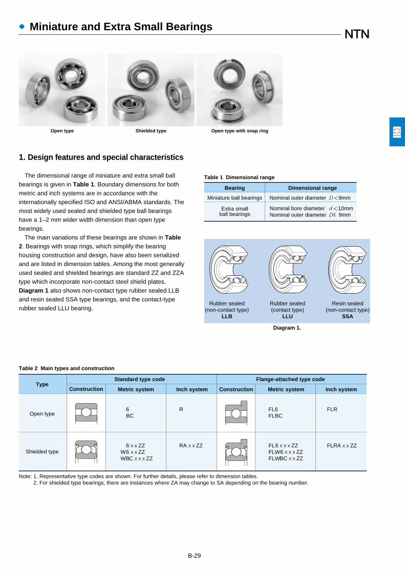
●Miniature and Extra Small Bearings
1. Design features and special characteristics
The dimensional range of miniature and extra small ballbearings is given in Table 1. Boundary dimensions for bothmetric and inch systems are in accordance with theinternationally specified ISO and ANSI/ABMA standards. Themost widely used sealed and shielded type ball bearingshave a 1–2 mm wider width dimension than open typebearings.
The main variations of these bearings are shown in Table2. Bearings with snap rings, which simplify the bearinghousing construction and design, have also been serializedand are listed in dimension tables. Among the most generallyused sealed and shielded bearings are standard ZZ and ZZAtype which incorporate non-contact steel shield plates.Diagram 1 also shows non-contact type rubber sealed LLBand resin sealed SSA type bearings, and the contact-typerubber sealed LLU bearing.
B-29
Bearing Dimensional range
Miniature ball bearings Nominal outer diameter D<9mm
Extra smallball bearings
Nominal bore diameter d<10mmNominal outer diameter D≧9mm
Table 1 Dimensional range
Table 2 Main types and construction
Rubber sealed(non-contact type)
LLB
Rubber sealed(contact type)
LLU
Resin sealed(non-contact type)
SSA
Standard type code Flange-attached type codeType
Construction Construction
Open type
Shielded type
Metric system Inch system Metric system Inch system
6BC
6 X X ZZ6 X X ZZ C X X X ZZ
WWB
R
RA X X ZZ
FL6FLBC
6 X X X ZZ 6 X X X ZZ BC X X ZZ
FLR
FLRA X X ZZFLFLWFLW
Note: 1. Representative type codes are shown. For further details, please refer to dimension tables. 2. For shielded type bearings, there are instances where ZA may change to SA depending on the bearing number.
Diagram 1.
Open type Shielded type Open type with snap ring

Units μm
Outer diameterdimensional
tolerance∆D1S or ∆D2S�
Above Below
Outside cylindricalsurface runout
relative to back faceSD1�
Max.
Back faceaxial runout
Sea1�
Max.
Width dimensiontolerance
∆C1S or ∆C2S�
Above Below
Widthunevenness
VC1S or VC2S�
Max.
ISO standard
Class 0
Class 6
Class 5
Class 4
Class 2
*�(see table below)
―
―
8
4
1.5
―
―
11
7
3 1
4
Identical to samebearing's innerring VBS
5
2.5
1.5
Identical to samebearing's inner ringVBS
1 Nominal outer diameter, 18 mm or less.
Flange nominalouter diameter
D1 or D2�mm
over up to incl.
Outer diameterdimensional tolerance
∆D1S or ∆D2S
Above Below
―
10
18
30
10
18
30
50
+220
+270
+330
+390
-36
-43
-52
-62
Units μm*�
Accuracy class
Table 3 Accuracy of outer ring flanges
●Miniature and Extra Small Bearings
B-30
2. Standard cage types
Pressed cages are standard for these bearings. However,molded resin cages are used for some bearings dependingon the application.
3. Dimensional and rotational accuracy
The accuracy of miniature and small ball bearingscomplies with JIS standards. Accuracy standards are listedin the Bearings Accuracy clause on page A-31. Flangeaccuracies are listed in Table 3.

●Miniature and Extra Small Bearings
B-31
4. Radial internal clearance
Radial internal clearance values should be applied aslisted in the table regarding the Bearing Internal Clearanceand Preload clause on page A-54.
However, for miniature and extra small bearings, the radialclearance values for high precision bearings given in Table 4
MIL Standard Tight Standard Loose Extra Loose
Code C2S
Internalclearance
Min. Max.
0 5
CNS CNM CNL C3S C3M C3L
Min. Max. Min. Max. Min. Max. Min. Max. Min. Max. Min. Max.
3 8 5 10 8 13 10 15 13 20 20 28
Units μm
Note: 1. These standards are specified in accordance with MIL 23063. However, NTN codes are shown. 2. Clearance values do not include compensation for measuring load.
are applied in many cases.For more specific selection information, please refer to the
NTN Miniature and Extra Small Ball Bearings Catalog, orcontact NTN Engineering.
Table 4 Radial internal clearance for high precision bearings

●Miniature and Extra Small Ball Bearings
B-32
Boundary dimensions Basic load ratings Limiting speeds
dynamic static dynamic static
mm N kgf rpm
d D B B1 D1 D2 C1 C2 rs min1
Cr Cor Cr Cor grease oil
1.5
2
2.5
3
4
5
1 Smallest allowable dimension for chamfer dimension r.
d 1.5~5mm
B1
r
B1
D d D1dD
B
B1
C1 C2
D2
B
r
r
r
With flanged outer ringand single shield
(FL…Z)
With flangedouter ring
(FL)
With double shield(ZZ)
With single shield(Z)
Open type
Metric system sizes
4 1.2 2 5 5 0.4 0.6 0.15 102 29.0 10.0 3.00 88,000 100,0005 2 2.6 6.5 6.5 0.6 0.8 0.15 171 51.0 17.0 5.00 79,000 93,0006 2.5 3 7.5 7.5 0.6 0.8 0.15 274 86.0 28.0 9.00 71,000 84,000
4 1.2 2 ― ― ― ― 0.05 104 37.0 11.0 4.00 83,000 98,0005 1.5 2.3 6.1 6.1 0.5 0.6 0.08 171 51.0 17.0 5.00 74,000 87,0005 2 2.5 ― ― ― ― 0.1 171 51.0 17.0 5.00 74,000 87,0006 2.3 3 7.5 7.5 0.6 0.8 0.15 279 89.0 28.0 9.00 67,000 79,0006 2.5 ― 7.2 ― 0.6 ― 0.15 279 89.0 28.0 9.00 67,000 79,0007 2.5 ― ― ― ― ― 0.15 390 120 40.0 12.0 59,000 70,0007 2.8 3.5 8.5 8.5 0.7 0.9 0.15 380 125 39.0 13.0 62,000 73,000
5 1.5 2.3 ― ― ― ― 0.08 153 59.0 16.0 6.00 70,000 82,0006 1.8 2.6 7.1 7.1 0.5 0.8 0.08 209 73.0 21.0 7.50 65,000 76,0007 3 3 ― 8.2 ― 0.6 0.15 284 96.0 29.0 10.0 59,000 70,0007 2.5 3.5 8.5 8.5 0.7 0.9 0.15 284 96.0 29.0 10.0 59,000 70,0008 2.5 2.8 9.2 ― 0.6 ― 0.15 430 152 44.0 16.0 56,000 66,0008 2.8 4 9.5 9.5 0.7 0.9 0.15 550 174 56.0 18.0 56,000 66,000
6 2 2.5 7.2 7.2 0.6 0.6 0.08 242 94.0 25.0 9.50 60,000 71,0007 2 3 8.1 8.1 0.5 0.8 0.1 390 130 40.0 13.0 58,000 68,0008 2.5 ― 9.2 ― 0.6 ― 0.15 560 180 57.0 18.0 54,000 63,0008 3 4 9.5 9.5 0.7 0.9 0.15 560 180 57.0 18.0 54,000 63,0009 2.5 4 10.2 10.6 0.6 0.8 0.15 635 219 65.0 22.0 50,000 59,0009 3 5 10.5 10.5 0.7 1 0.15 635 219 65.0 22.0 50,000 59,000
10 4 4 11.5 11.5 1 1 0.15 640 224 65.0 23.0 50,000 58,000
7 2 2.5 8.2 8.2 0.6 0.6 0.08 222 88.0 23.0 9.00 54,000 63,0008 2 3 9.2 9.2 0.6 0.6 0.08 395 140 40.0 14.0 52,000 61,0009 2.5 4 10.3 10.3 0.6 1 0.15 640 224 65.0 23.0 49,000 57,000
10 3 4 11.2 11.6 0.6 0.8 0.15 650 235 66.0 24.0 46,000 55,00011 4 4 12.5 12.5 1 1 0.15 715 276 73.0 28.0 45,000 52,00012 4 4 13.5 13.5 1 1 0.2 970 360 99.0 36.0 43,000 51,00013 5 5 15 15 1 1 0.2 1,310 490 134 50.0 42,000 49,00016 5 5 ― ― ― ― 0.3 1,760 680 179 69.0 37,000 44,000
8 2 2.5 9.2 9.2 0.6 0.6 0.08 217 91.0 22.0 9.50 49,000 57,0009 2.5 3 10.2 10.2 0.6 0.6 0.15 500 211 51.0 21.0 46,000 55,000
10 3 4 11.2 11.6 0.6 0.8 0.15 715 276 73.0 28.0 45,000 52,000
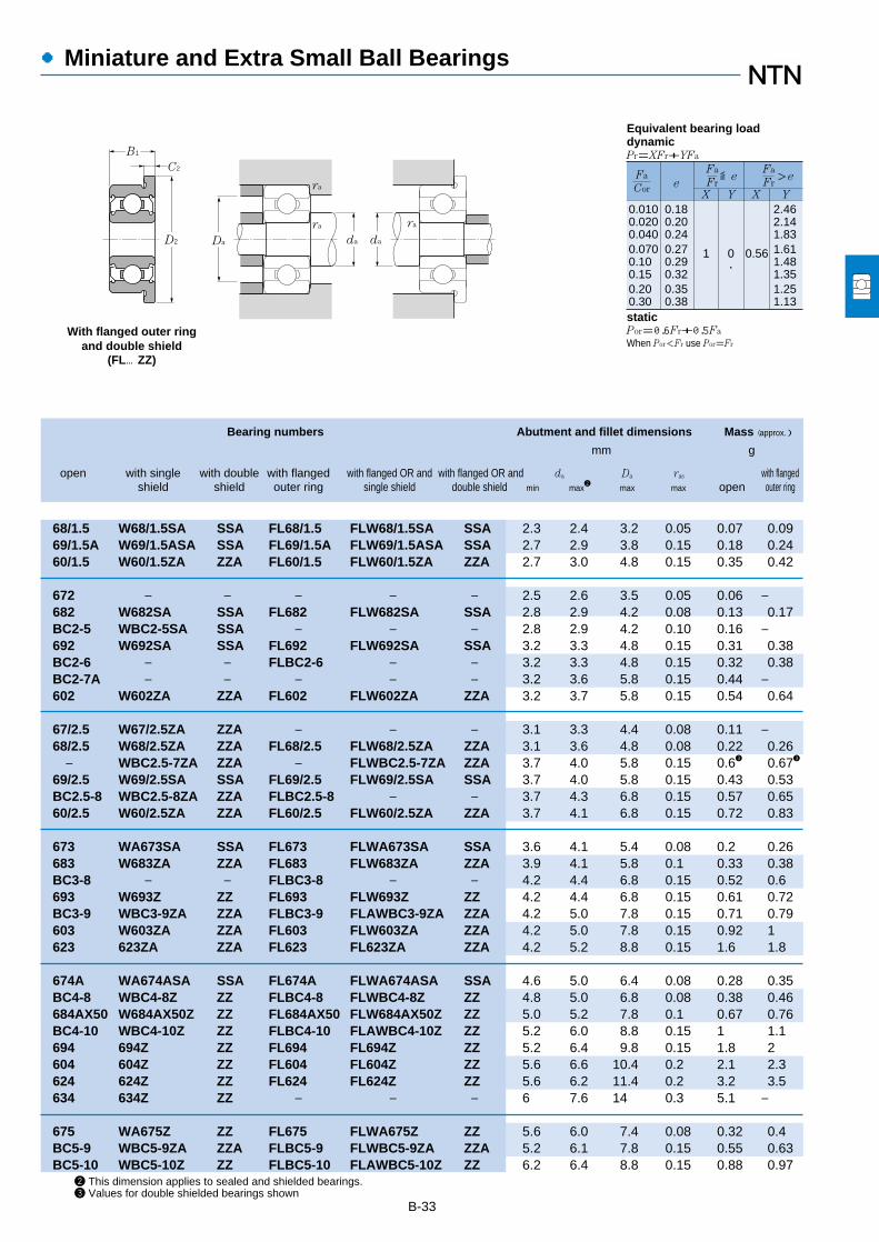
B-33
2 This dimension applies to sealed and shielded bearings.3 Values for double shielded bearings shown
Bearing numbers Abutment and fillet dimensions Mass (approx.)
mm g
open with single with double with flanged with flanged OR and with flanged OR and da Da ras with flangedshield shield outer ring single shield double shield min max
2max max open outer ring
●Miniature and Extra Small Ball Bearings
0.0100.0200.0400.0700.100.150.200.30
0.180.200.240.270.290.320.350.38
1 0 0.56
2.462.141.831.611.481.351.251.13
Fa
FreX Y X Y
≦eFa
Cor
Fa
Fr>e
Pr=XFr+YFa
Por=0.6Fr+0.5Fa
When Por<Fr use Por=Fr
Equivalent bearing loaddynamic
static
B1
C2
D2
With flanged outer ringand double shield
(FL…ZZ)
Da
ra
ra ra
da da
68/1.5 W68/1.5SA SSA FL68/1.5 FLW68/1.5SA SSA 2.3 2.4 3.2 0.05 0.07 0.0969/1.5A W69/1.5ASA SSA FL69/1.5A FLW69/1.5ASA SSA 2.7 2.9 3.8 0.15 0.18 0.2460/1.5 W60/1.5ZA ZZA FL60/1.5 FLW60/1.5ZA ZZA 2.7 3.0 4.8 0.15 0.35 0.42
672 ― ― ― ― ― 2.5 2.6 3.5 0.05 0.06 ―682 W682SA SSA FL682 FLW682SA SSA 2.8 2.9 4.2 0.08 0.13 0.17BC2-5 WBC2-5SA SSA ― ― ― 2.8 2.9 4.2 0.10 0.16 ―692 W692SA SSA FL692 FLW692SA SSA 3.2 3.3 4.8 0.15 0.31 0.38BC2-6 ― ― FLBC2-6 ― ― 3.2 3.3 4.8 0.15 0.32 0.38BC2-7A ― ― ― ― ― 3.2 3.6 5.8 0.15 0.44 ―602 W602ZA ZZA FL602 FLW602ZA ZZA 3.2 3.7 5.8 0.15 0.54 0.64
67/2.5 W67/2.5ZA ZZA ― ― ― 3.1 3.3 4.4 0.08 0.11 ―68/2.5 W68/2.5ZA ZZA FL68/2.5 FLW68/2.5ZA ZZA 3.1 3.6 4.8 0.08 0.22 0.26― WBC2.5-7ZA ZZA ― FLWBC2.5-7ZA ZZA 3.7 4.0 5.8 0.15 0.63 0.673
69/2.5 W69/2.5SA SSA FL69/2.5 FLW69/2.5SA SSA 3.7 4.0 5.8 0.15 0.43 0.53BC2.5-8 WBC2.5-8ZA ZZA FLBC2.5-8 ― ― 3.7 4.3 6.8 0.15 0.57 0.6560/2.5 W60/2.5ZA ZZA FL60/2.5 FLW60/2.5ZA ZZA 3.7 4.1 6.8 0.15 0.72 0.83
673 WA673SA SSA FL673 FLWA673SA SSA 3.6 4.1 5.4 0.08 0.2 0.26683 W683ZA ZZA FL683 FLW683ZA ZZA 3.9 4.1 5.8 0.1 0.33 0.38BC3-8 ― ― FLBC3-8 ― ― 4.2 4.4 6.8 0.15 0.52 0.6693 W693Z ZZ FL693 FLW693Z ZZ 4.2 4.4 6.8 0.15 0.61 0.72BC3-9 WBC3-9ZA ZZA FLBC3-9 FLAWBC3-9ZA ZZA 4.2 5.0 7.8 0.15 0.71 0.79603 W603ZA ZZA FL603 FLW603ZA ZZA 4.2 5.0 7.8 0.15 0.92 1623 623ZA ZZA FL623 FL623ZA ZZA 4.2 5.2 8.8 0.15 1.6 1.8
674A WA674ASA SSA FL674A FLWA674ASA SSA 4.6 5.0 6.4 0.08 0.28 0.35BC4-8 WBC4-8Z ZZ FLBC4-8 FLWBC4-8Z ZZ 4.8 5.0 6.8 0.08 0.38 0.46684AX50 W684AX50Z ZZ FL684AX50 FLW684AX50Z ZZ 5.0 5.2 7.8 0.1 0.67 0.76BC4-10 WBC4-10Z ZZ FLBC4-10 FLAWBC4-10Z ZZ 5.2 6.0 8.8 0.15 1 1.1694 694Z ZZ FL694 FL694Z ZZ 5.2 6.4 9.8 0.15 1.8 2604 604Z ZZ FL604 FL604Z ZZ 5.6 6.6 10.4 0.2 2.1 2.3624 624Z ZZ FL624 FL624Z ZZ 5.6 6.2 11.4 0.2 3.2 3.5634 634Z ZZ ― ― ― 6 7.6 14 0.3 5.1 ―
675 WA675Z ZZ FL675 FLWA675Z ZZ 5.6 6.0 7.4 0.08 0.32 0.4BC5-9 WBC5-9ZA ZZA FLBC5-9 FLWBC5-9ZA ZZA 5.2 6.1 7.8 0.15 0.55 0.63BC5-10 WBC5-10Z ZZ FLBC5-10 FLAWBC5-10Z ZZ 6.2 6.4 8.8 0.15 0.88 0.97
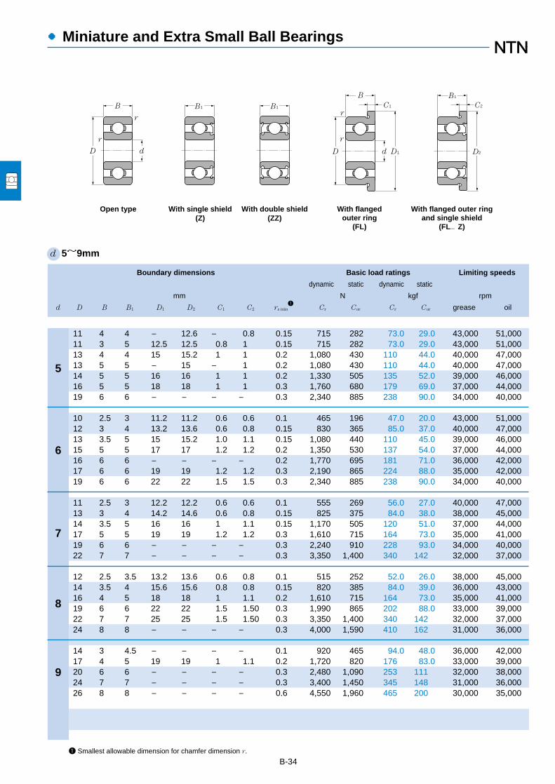
●Miniature and Extra Small Ball Bearings
B-34
Boundary dimensions Basic load ratings Limiting speeds
dynamic static dynamic static
mm N kgf rpm
d D B B1 D1 D2 C1 C2 rs min1
Cr Cor Cr Cor grease oil
5
6
7
8
9
1 Smallest allowable dimension for chamfer dimension r.
d 5~9mm
B1
r
B1
D d D1dD
B
B1
C1 C2
D2
B
r
r
r
With flanged outer ringand single shield
(FL…Z)
With flangedouter ring
(FL)
With double shield(ZZ)
With single shield(Z)
Open type
11 4 4 ― 12.6 ― 0.8 0.15 715 282 73.0 29.0 43,000 51,00011 3 5 12.5 12.5 0.8 1 0.15 715 282 73.0 29.0 43,000 51,00013 4 4 15 15.2 1 1 0.2 1,080 430 110 44.0 40,000 47,00013 5 5 ― 15 ― 1 0.2 1,080 430 110 44.0 40,000 47,00014 5 5 16 16 1 1 0.2 1,330 505 135 52.0 39,000 46,00016 5 5 18 18 1 1 0.3 1,760 680 179 69.0 37,000 44,00019 6 6 ― ― ― ― 0.3 2,340 885 238 90.0 34,000 40,000
10 2.5 3 11.2 11.2 0.6 0.6 0.1 465 196 47.0 20.0 43,000 51,00012 3 4 13.2 13.6 0.6 0.8 0.15 830 365 85.0 37.0 40,000 47,00013 3.5 5 15 15.2 1.0 1.1 0.15 1,080 440 110 45.0 39,000 46,00015 5 5 17 17 1.2 1.2 0.2 1,350 530 137 54.0 37,000 44,00016 6 6 ― ― ― ― 0.2 1,770 695 181 71.0 36,000 42,00017 6 6 19 19 1.2 1.2 0.3 2,190 865 224 88.0 35,000 42,00019 6 6 22 22 1.5 1.5 0.3 2,340 885 238 90.0 34,000 40,000
11 2.5 3 12.2 12.2 0.6 0.6 0.1 555 269 56.0 27.0 40,000 47,00013 3 4 14.2 14.6 0.6 0.8 0.15 825 375 84.0 38.0 38,000 45,00014 3.5 5 16 16 1 1.1 0.15 1,170 505 120 51.0 37,000 44,00017 5 5 19 19 1.2 1.2 0.3 1,610 715 164 73.0 35,000 41,00019 6 6 ― ― ― ― 0.3 2,240 910 228 93.0 34,000 40,00022 7 7 ― ― ― ― 0.3 3,350 1,400 340 142 32,000 37,000
12 2.5 3.5 13.2 13.6 0.6 0.8 0.1 515 252 52.0 26.0 38,000 45,00014 3.5 4 15.6 15.6 0.8 0.8 0.15 820 385 84.0 39.0 36,000 43,00016 4 5 18 18 1 1.1 0.2 1,610 715 164 73.0 35,000 41,00019 6 6 22 22 1.5 1.50 0.3 1,990 865 202 88.0 33,000 39,00022 7 7 25 25 1.5 1.50 0.3 3,350 1,400 340 142 32,000 37,00024 8 8 ― ― ― ― 0.3 4,000 1,590 410 162 31,000 36,000
14 3 4.5 ― ― ― ― 0.1 920 465 94.0 48.0 36,000 42,00017 4 5 19 19 1 1.1 0.2 1,720 820 176 83.0 33,000 39,00020 6 6 ― ― ― ― 0.3 2,480 1,090 253 111 32,000 38,00024 7 7 ― ― ― ― 0.3 3,400 1,450 345 148 31,000 36,00026 8 8 ― ― ― ― 0.6 4,550 1,960 465 200 30,000 35,000
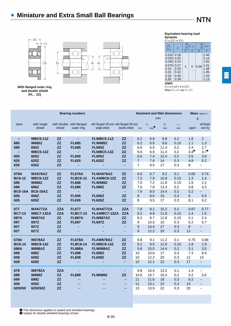
B-35
2 This dimension applies to sealed and shielded bearings.3 Values for double shielded bearings shown.
Bearing numbers Abutment and fillet dimensions Mass (approx.)
mm g
open with single with double with flanged with flanged OR and with flanged OR and da Da ras with flangedshield shield outer ring single shield double shield min max
2max max open outer ring
●Miniature and Extra Small Ball Bearings
0.0100.0200.0400.0700.100.150.200.30
0.180.200.240.270.290.320.350.38
1 0 0.56
2.462.141.831.611.481.351.251.13
Fa
FreX Y X Y
≦eFa
Cor
Fa
Fr>e
Pr=XFr+YFa
Por=0.6Fr+0.5Fa
When Por<Fr use Por=Fr
Equivalent bearing loaddynamic
static
B1
C2
D2
With flanged outer ringand double shield
(FL…ZZ)
Da
ra
ra ra
da da
- WBC5-11Z ZZ ― FLWBC5-11Z ZZ 6.2 6.8 9.8 0.2 1.8 2685 W685Z ZZ FL685 FLW685Z ZZ 6.2 6.8 9.8 0.15 1.1 1.3695 695Z ZZ FL695 FL695Z ZZ 6.6 6.9 11.4 0.2 2.4 2.7- WBC5-13Z ZZ ― FLWBC5-13Z ZZ 6.6 6.9 11.4 0.2 3.43 3.73
605 605Z ZZ FL605 FL605Z ZZ 6.6 7.4 12.4 0.2 3.5 3.9625 625Z ZZ FL625 FL625Z ZZ 7 7.6 14 0.3 4.8 5.2635 635Z ZZ ― ― ― 7 9.5 17 0.3 8 ―
676A WA676AZ ZZ FL676A FLWA676AZ ZZ 6.6 6.7 9.2 0.1 0.65 0.74BC6-12 WBC6-12Z ZZ FLBC6-12 FLAWBC6-12Z ZZ 7.2 7.9 10.8 0.15 1.3 1.4686 W686Z ZZ FL686 FLW686Z ZZ 7.0 7.2 11.8 0.15 1.9 2.2696 696Z ZZ FL696 FL696Z ZZ 7.6 7.8 13.4 0.2 3.8 4.3BC6-16A BC6-16AZ ZZ ― ― ― 7.6 8.0 14.4 0.2 5.2 ―606 606Z ZZ FL606 FL606Z ZZ 8 8.6 15 0.3 6 6.5626 626Z ZZ FL626 FL626Z ZZ 8 9.5 17 0.3 8.1 9.2
677 WA677ZA ZZA FL677 FLWA677ZA ZZA 7.8 8.1 10.2 0.1 0.67 0.77BC7-13 WBC7-13ZA ZZA FLBC7-13 FLAWBC7-13ZA ZZA 8.2 8.9 11.8 0.15 1.4 1.5687A W687AZ ZZ FL687A FLW687AZ ZZ 8.2 8.7 12.8 0.15 2.1 2.4697 697Z ZZ FL697 FL697Z ZZ 9 10.0 15 0.3 5.2 5.7607 607Z ZZ ― ― ― 9 10.4 17 0.3 8 ―627 627Z ZZ ― ― ― 9 12.2 20 0.3 13 ―
678A W678AZ ZZ FL678A FLAW678AZ ZZ 8.8 9.1 11.2 0.1 0.75 0.86BC8-14 WBC8-14Z ZZ FLBC8-14 FLWBC8-14Z ZZ 9.2 9.5 12.8 0.15 1.8 1.9688A W688AZ ZZ FL688A FLW688AZ ZZ 9.6 10.0 14.4 0.2 3.1 3.5698 698Z ZZ FL698 FL698Z ZZ 10 10.6 17 0.3 7.3 8.4608 608Z ZZ FL608 FL608Z ZZ 10 12.2 20 0.3 12 13628 628Z ZZ ― ― ― 10 12.1 22 0.3 17 ―
679 W679ZA ZZA ― ― ― 9.8 10.4 13.2 0.1 1.4 ―689 W689Z ZZ FL689 FLW689Z ZZ 10.6 10.7 15.4 0.2 3.2 3.6699 699Z ZZ - - - 11 11.6 18 0.3 8.2 ―609 609Z ZZ - - - 11 13.1 22 0.3 14 ―629X50 629X50Z ZZ - - - 13 13.9 22 0.3 20 ―

Miniature and Extra Small Ball Bearings
B-36
Boundary dimensions Basic load ratings Limiting speeds
dynamic static dynamic static
mm N kgf rpm
d D B B1 D1 C1 C2 rs min1
Cr Cor Cr Cor grease oil
1.984
2.380
3.175
3.967
4.762
6.350
9.525
1 Smallest allowable dimension for chamfer dimension r.
d 1.984~9.525mm
6.35 2.38 3.571 7.52 0.58 0.79 0.08 279 89.0 28 9 67,000 79,000
4.762 1.588 2.38 5.94 0.46 0.79 0.08 124 42.0 13 4.5 73,000 85,0007.938 2.779 3.571 9.12 0.58 0.79 0.13 430 152 44 16 56,000 66,000
6.35 2.38 2.779 7.52 0.58 0.79 0.08 284 96.0 29 10 59,000 70,0007.938 2.779 3.571 9.12 0.58 0.79 0.08 560 180 57 18 54,000 63,0009.525 2.779 3.571 10.72 0.53 0.79 0.13 640 224 65 23 49,000 58,0009.525 3.967 3.967 11.18 0.76 0.76 0.3 640 224 65 23 49,000 58,000
12.7 4.366 4.366 ― ― ― 0.3 1,150 395 117 40 43,000 51,000
7.938 2.779 3.175 9.12 0.58 0.91 0.08 335 133 34 14 51,000 60,000
7.938 2.779 3.175 9.12 0.58 0.91 0.08 395 143 40 15 49,000 58,0009.525 3.175 3.175 10.72 0.58 0.79 0.08 710 268 72 27 46,000 55,000
12.7 3.967 ― ― ― ― 0.3 1,310 490 134 50 41,000 48,00012.7 4.978 4.978 14.35 1.07 1.07 0.3 1,310 490 134 50 41,000 48,000
9.525 3.175 3.175 10.72 0.58 0.91 0.08 210 94.0 21 9.5 43,000 51,00012.7 3.175 4.762 13.89 0.58 1.14 0.13 830 370 84 38 39,000 46,00015.875 4.978 4.978 17.53 1.07 1.07 0.3 1,480 615 151 63 36,000 43,00019.05 ― 7.142 ― ― ― 0.41 2,340 885 238 90 34,000 40,000
22.225 ― 7.142 24.61 ― 1.57 0.41 3,300 1,400 340 142 31,000 37,000
Inch system sizes
B1
r
B1
D d D1dD
B
B1
C1 C2
D1
B
r
r
r
With flanged outer ringand single shield
(FL…Z)
With flangedouter ring
(FL)
With double shield(ZZ)
With single shield(Z)
Open type

B-37
2 This dimension applies to sealed and shielded bearings.3 Values for double shielded bearings shown.
Bearing numbers Abutment and fillet dimensions Mass (approx. j
mm g
open with single with double with flanged with flanged OR and with flanged OR and da Da ras with flangedshield shield outer ring single shield double shield min max
2max max open outer ring
Miniature and Extra Small Ball Bearings
B1
C2
D1 Da
ra
ra ra
da da
With flanged outer ringand double shield
(FL…ZZ)
0.0100.0200.0400.0700.100.150.200.30
0.180.200.240.270.290.320.350.38
1 0 0.56
2.462.141.831.611.481.351.251.13
Fa
FreX Y X Y
≦eFa
Cor
Fa
Fr>e
Pr=XFr+YFa
Por=0.6Fr+0.5Fa
When Por<Fr use Por=Fr
Equivalent bearing loaddynamic
static
R1-4 RA1-4ZA ZZA FLR1-4 FLRA1-4ZA ZZA 2.8 3.3 5.5 0.08 0.35 0.41
R133 RA133ZA ZZA FLR133 FLRA133ZA ZZA 2.9 3.1 4 0.08 0.12 0.16R1-5 RA1-5ZA ZZA FLR1-5 FLRA1-5ZA ZZA 3.2 4.3 7.1 0.1 0.69 0.76
R144 RA144ZA ZZA FLR144 FLRA144ZA ZZA 3.9 4.0 5.5 0.08 0.27 0.33R2-5 RA2-5Z ZZ FLR2-5 FLRA2-5Z ZZ 4 4.4 7 0.08 0.61 0.68R2-6 RA2-6ZA ZZA FLR2-6 FLRA2-6ZA ZZA 4 5.2 8.7 0.1 0.88 0.96R2 RA2ZA ZZA FLR2 FLRA2ZA ZZA 4.8 5.2 7.8 0.3 1.3 1.5RA2 RA2Z ZZ ― ― ― 4.8 5.4 11 0.3 2.5 ―
R155 RA155ZA ZZA FLR155 FLRA155ZA ZZA 4.8 5.3 7 0.08 0.54 0.61
R156 RA156Z ZZ FLR156 FLRA156Z ZZ 5.5 5.6 7 0.08 0.44 0.51R166 R166Z ZZ FLR166 FLRA166Z ZZ 5.6 5.9 8.7 0.08 0.8 0.89R3 ― ― ― ― ― 6.4 7.2 11 0.3 2.2 ―RA3 RA3Z ZZ FLRA3 FLRA3Z ZZ 6.0 6.4 11 0.3 2.4 2.7
R168A R168AZ AZZ ― FLRA168AZ ZZ 7.1 7.3 8.7 0.08 0.6 0.69R188 RA188ZA ZZA FLR188 FLRA188ZA ZZA 7.2 8.2 11.8 0.1 1.6 1.7R4 R4Z ZZ FLR4 FLR4Z ZZ 8 8.6 14.2 0.3 4.4 4.8― RA4Z ZZ ― ― ― 8.4 9.5 17 0.4 112 ―
― R6Z ZZ ― FLR6Z ZZ 11.5 11.9 20.2 0.4 143 153
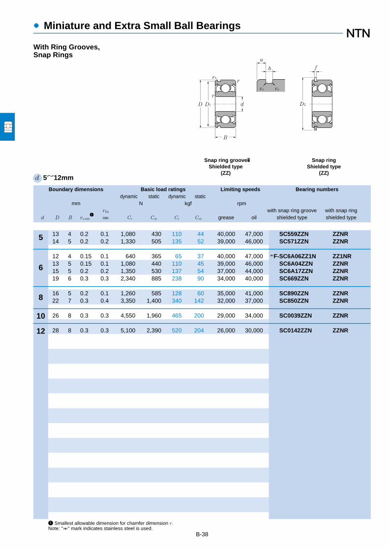
Boundary dimensions Basic load ratings Limiting speeds Bearing numbersdynamic static dynamic static
mm N kgf rpmrNa with snap ring groove with snap ring
d D B rs min1
min Cr Cor Cr Cor grease oil shielded type shielded type
●Miniature and Extra Small Ball Bearings
B-38
1 Smallest allowable dimension for chamfer dimension r.Note: "*" mark indicates stainless steel is used.
d 5~12mm
5
6
8
10
12
13 4 0.2 0.1 1,080 430 110 44 40,000 47,000 SC559ZZN ZZNR14 5 0.2 0.2 1,330 505 135 52 39,000 46,000 SC571ZZN ZZNR
12 4 0.15 0.1 640 365 65 37 40,000 47,000 *F-SC6A06ZZ1N ZZ1NR13 5 0.15 0.1 1,080 440 110 45 39,000 46,000 SC6A04ZZN ZZNR15 5 0.2 0.2 1,350 530 137 54 37,000 44,000 SC6A17ZZN ZZNR19 6 0.3 0.3 2,340 885 238 90 34,000 40,000 SC669ZZN ZZNR
16 5 0.2 0.1 1,260 585 128 60 35,000 41,000 SC890ZZN ZZNR22 7 0.3 0.4 3,350 1,400 340 142 32,000 37,000 SC850ZZN ZZNR
26 8 0.3 0.3 4,550 1,960 465 200 29,000 34,000 SC0039ZZN ZZNR
28 8 0.3 0.3 5,100 2,390 520 204 26,000 30,000 SC0142ZZN ZZNR
r
d
B
r
Snap ringShielded type
(ZZ)
Snap ring groove�Shielded type
(ZZ)
a
b
ro ro
D2
f
rN
D1D
With Ring Grooves,Snap Rings

●Miniature and Extra Small Ball Bearings
Snap ring groove dimensions Snap ring dimensions Abutment and fillet dimensions Mass
mm mm mm kg
D1 a b ro D2 f da Da DX CY CZ ras rNas with snap ringmax max min max max max min max max (approx.) max min max max (approx.)
B-39
12.15 0.88 0.55 0.2 15.2 0.55 6.6 6.9 11.4 15.9 1.2 0.6 0.2 0.1 0.00213.03 1.28 0.65 0.06 16.13 0.54 6.6 7.4 12.4 16.9 1.6 0.6 0.2 0.2 0.004
11.15 0.78 0.60 0.02 14.2 0.55 7.2 7.9 10.8 14.9 1.1 0.6 0.15 0.1 0.00112.15 1.08 0.55 0.2 15.2 0.55 7.0 7.2 11.8 15.9 1.4 0.6 0.15 0.1 0.00214.03 1.03 0.65 0.06 17.2 0.60 7.6 7.8 13.4 17.9 1.4 0.7 0.2 0.2 0.00417.9 0.93 0.80 0.2 22.0 0.70 8.0 9.5 17.0 22.8 1.4 0.7 0.3 0.3 0.008
14.95 0.53 0.65 0.05 18.2 0.54 9.6 10.0 14.4 18.9 0.9 0.6 0.2 0.1 0.00320.8 2.35 0.80 0.2 24.8 0.70 10.0 12.7 20 25.5 2.8 0.7 0.3 0.4 0.013
24.5 2.20 0.90 0.3 28.8 0.85 12 13.5 24 29.5 2.8 0.9 0.3 0.3 0.02
26.44 2.20 0.90 0.3 32.7 0.85 14 16 26 33.4 2.8 0.9 0.3 0.3 0.022
Da da
ra
ra
DX
rNa
CZ
CY
0.0100.0200.0400.0700.100.150.200.30
0.180.200.240.270.290.320.350.38
1 0 0.56
2.462.141.831.611.481.351.251.13
Fa
FreX Y X Y
≦eFa
Cor
Fa
Fr>e
Pr=XFr+YFa
Por=0.6Fr+0.5Fa
When Por<Fr use Por=Fr
Equivalent bearing loaddynamic
static
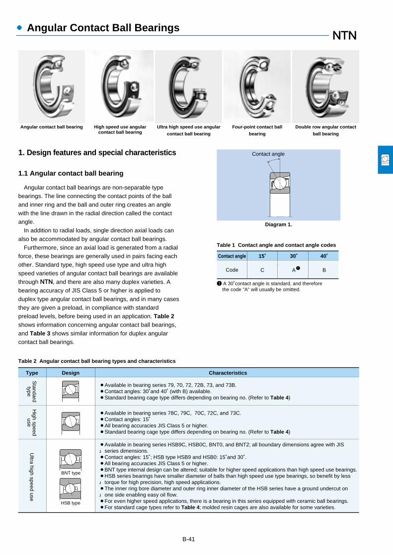
●Angular Contact Ball Bearings
1. Design features and special characteristics
1.1 Angular contact ball bearing
Angular contact ball bearings are non-separable typebearings. The line connecting the contact points of the balland inner ring and the ball and outer ring creates an anglewith the line drawn in the radial direction called the contactangle.
In addition to radial loads, single direction axial loads canalso be accommodated by angular contact ball bearings.
Furthermore, since an axial load is generated from a radialforce, these bearings are generally used in pairs facing eachother. Standard type, high speed use type and ultra highspeed varieties of angular contact ball bearings are availablethrough NTN, and there are also many duplex varieties. Abearing accuracy of JIS Class 5 or higher is applied toduplex type angular contact ball bearings, and in many casesthey are given a preload, in compliance with standardpreload levels, before being used in an application. Table 2shows information concerning angular contact ball bearings,and Table 3 shows similar information for duplex angularcontact ball bearings.
B-41
Contact angle
Code
15˚
C
30˚
A
40˚
B
1 A 30˚contact angle is standard, and therefore the code "A" will usually be omitted.
1
Table 1 Contact angle and contact angle codes
Table 2 Angular contact ball bearing types and characteristics
Contact angle
Type CharacteristicsDesign
¡Available in bearing series 79, 70, 72, 72B, 73, and 73B.¡Contact angles: 30˚and 40˚ (with B) available.¡Standard bearing cage type differs depending on bearing no. (Refer to Table 4)
¡Available in bearing series 78C, 79C, 70C, 72C, and 73C.¡Contact angles: 15˚¡All bearing accuracies JIS Class 5 or higher.¡Standard bearing cage type differs depending on bearing no. (Refer to Table 4)
Standardtype
¡Available in bearing series HSB9C, HSB0C, BNT0, and BNT2; all boundary dimensions agree with JIS series dimensions.¡Contact angles: 15˚; HSB type HSB9 and HSB0: 15˚and 30˚.¡All bearing accuracies JIS Class 5 or higher.¡BNT type internal design can be altered; suitable for higher speed applications than high speed use bearings.¡HSB series bearings have smaller diameter of balls than high speed use type bearings, so benefit by less torque for high precision, high speed applications.¡The inner ring bore diameter and outer ring inner diameter of the HSB series have a ground undercut on one side enabling easy oil flow.¡For even higher speed applications, there is a bearing in this series equipped with ceramic ball bearings.¡For standard cage types refer to Table 4; molded resin cages are also available for some varieties.
Ultra high speed use
High speed
use
BNT type
HSB type
Diagram 1.
Angular contact ball bearing High speed use angularcontact ball bearing
Ultra high speed use angular
contact ball bearing
Four-point contact ball
bearing
Double row angular contact
ball bearing

●Angular Contact Ball Bearings
B-42
1.2 Four-point angular contact ball bearings
Four-point angular contact ball bearings have a contactangle of 30˚ and inner rings which are separated in half. Asshown in Diagram 2, when the inner and outer rings receivea radial load the ball bearings contact the inner and outerrings at four points. This construction enables a singlebearing to accommodate axial loads from either direction,and when generally under a simple axial load or heavy axialload, the bearing functions in reliance on two contact pointslike ordinary bearings.
■Flush ground"Flush ground" is the name given to the finishing
method shown in Diagram 4 where the offset of thefront and back faces of the bearing are ground to thesame value. By doing this, a stated clearance orpreload value can be achieved by using bearings withidentical codes for these values, in other words bycombining either DB or DF series bearings. DT seriesbearings can also be used in various arrangements toachieve uniform load distribution.
All BNT type bearings are flush ground, but otherangular contact ball bearing series are not. If it isnecessary to flush grind any of these other bearings,please consult NTN Engineering.
Offset B
Front faceBack face
Offset AA=B
Diagram 2.
Diagram 3.
Diagram 4.
1.3 Double row angular contact ball bearings
The structure of double row angular contact ball bearingsis designed by arranging two single row angular contactbearings back-to-back in duplex (DB) to form one unitedbearing with a contact angle of 30˚.
These bearings are capable of accommodating radial
Non-contact sealed type(LLB)
Contact sealed type(LLU)
Shielded type(ZZ)
Open type
Duplex type Characteristics
¡Can accommodate radial loads and axial loads in either direction.¡Has a large distanceRbetween the acting load center of the bearing, and therefore a large momentary force load capacity.¡Allowable misalignment angle is small.
¡Can accommodate radial loads and axial loads in either direction.¡Has a smaller distanceRbetween the acting load center of the bearing, and therefore a smaller momentary force load capacity.¡Has a larger allowable misalignment angle than back-to-back duplex type.
Back-to-backduplex(DB)
¡Can accommodate radial loads and single direction axial loads.¡Axial loads are received by both bearings as a set, and therefore heavy axial loads can be accommodated.
Tandem duplex(DT)
Face-to faceduplex(DF)
Note: 1. Duplex bearings are manufactured in a set to specified clearance and preload values, therefore they must be assembled together withidentically numbered bearings and not mixed with other arrangements.
2. Triplex arrangements of angular contact bearings are also available. Consult NTN Engineering for details.
r
r
Table 3 Duplex angular contact ball bearings ― types and characteristics
loads, axial loads in either direction, and have a highcapacity for momentary loads as well.
As shown in Diagram 3, sealed and shielded type doublerow angular contact ball bearings are also available.Standard loads vary from those of open type bearings.

●Angular Contact Ball Bearings
B-43
2. Standard cage types
Table 4 lists the standard cage types for angular contactball bearings. For high speed use angular contact ballbearings, molded resin cages and machined cages arewidely used.
Table 4 Standard cages for angular contact ball bearings
Bearing series Pressed cage
7970727372B73B
Standard
4-pointcontact
High speed use
Type Machined cageMolded resin cage
78C79C70C72C73C
BNT0BNT2HSB9CHSB0C
QJ2QJ3
Doublerow
Ultra high
speed use
5253
7904~79137000~7024
――――
― 7904C~7913C 7000C~7024C 7200C~7220C 7303C~7312C
―――
HSB010C~HSB032C
――
――
79147026722473247224B7324B
7805C7914C7026C 7221C7300C7313C
BNT000BNT200HSB910C
QJ208QJ306
5219,5220
― ― 7200 ~7222 7300 ~7322 7200B~7222B 7300B~7322B
―――――
――――
――
5200 ~5218 5302 ~5315
~~~~~~
~~~~~~
~~~
~~
―
79607040724073407240B7340B
7834C7934C7040C7240C7302C7340C
BNT009BNT209HSB934CHSB034C
QJ224QJ324
Note: 1. Standard cages for 5S-BNT and 5S-HSB type bearings are the same as cages for BNT and HSB type bearings.2. Due to the material characteristics of molded resin cages, use at application temperatures in excess of
120℃ is not possible.
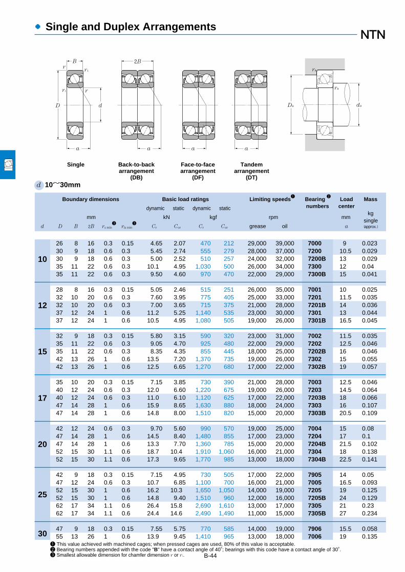
●Single and Duplex Arrangements
Boundary dimensions Basic load ratings Limiting speeds1
Bearing 2
Load Mass
dynamic static dynamic static numbers centerkg
mm kN kgf rpm mmsingle
d D B 2B rs min3
rls min3
Cr Cor Cr Cor grease oil a (approx.)
10
12
15
17
20
25
301 This value achieved with machined cages; when pressed cages are used, 80% of this value is acceptable.2 Bearing numbers appended with the code "B" have a contact angle of 40˚; bearings with this code have a contact angle of 30˚.3 Smallest allowable dimension for chamfer dimension r or r1.
d 10~30mm
26 8 16 0.3 0.15 4.65 2.07 470 212 29,000 39,000 7000 9 0.02330 9 18 0.6 0.3 5.45 2.74 555 279 28,000 37,000 7200 10.5 0.02930 9 18 0.6 0.3 5.00 2.52 510 257 24,000 32,000 7200B 13 0.02935 11 22 0.6 0.3 10.1 4.95 1,030 500 26,000 34,000 7300 12 0.0435 11 22 0.6 0.3 9.50 4.60 970 470 22,000 29,000 7300B 15 0.041
28 8 16 0.3 0.15 5.05 2.46 515 251 26,000 35,000 7001 10 0.02532 10 20 0.6 0.3 7.60 3.95 775 405 25,000 33,000 7201 11.5 0.03532 10 20 0.6 0.3 7.00 3.65 715 375 21,000 28,000 7201B 14 0.03637 12 24 1 0.6 11.2 5.25 1,140 535 23,000 30,000 7301 13 0.04437 12 24 1 0.6 10.5 4.95 1,080 505 19,000 26,000 7301B 16.5 0.045
32 9 18 0.3 0.15 5.80 3.15 590 320 23,000 31,000 7002 11.5 0.03535 11 22 0.6 0.3 9.05 4.70 925 480 22,000 29,000 7202 12.5 0.04635 11 22 0.6 0.3 8.35 4.35 855 445 18,000 25,000 7202B 16 0.04642 13 26 1 0.6 13.5 7.20 1,370 735 19,000 26,000 7302 15 0.05542 13 26 1 0.6 12.5 6.65 1,270 680 17,000 22,000 7302B 19 0.057
35 10 20 0.3 0.15 7.15 3.85 730 390 21,000 28,000 7003 12.5 0.04640 12 24 0.6 0.3 12.0 6.60 1,220 675 19,000 26,000 7203 14.5 0.06440 12 24 0.6 0.3 11.0 6.10 1,120 625 17,000 22,000 7203B 18 0.06647 14 28 1 0.6 15.9 8.65 1,630 880 18,000 24,000 7303 16 0.10747 14 28 1 0.6 14.8 8.00 1,510 820 15,000 20,000 7303B 20.5 0.109
42 12 24 0.6 0.3 9.70 5.60 990 570 19,000 25,000 7004 15 0.0847 14 28 1 0.6 14.5 8.40 1,480 855 17,000 23,000 7204 17 0.147 14 28 1 0.6 13.3 7.70 1,360 785 15,000 20,000 7204B 21.5 0.10252 15 30 1.1 0.6 18.7 10.4 1,910 1,060 16,000 21,000 7304 18 0.13852 15 30 1.1 0.6 17.3 9.65 1,770 985 13,000 18,000 7304B 22.5 0.141
42 9 18 0.3 0.15 7.15 4.95 730 505 17,000 22,000 7905 14 0.0547 12 24 0.6 0.3 10.7 6.85 1,100 700 16,000 21,000 7005 16.5 0.09352 15 30 1 0.6 16.2 10.3 1,650 1,050 14,000 19,000 7205 19 0.12552 15 30 1 0.6 14.8 9.40 1,510 960 12,000 16,000 7205B 24 0.12962 17 34 1.1 0.6 26.4 15.8 2,690 1,610 13,000 17,000 7305 21 0.2362 17 34 1.1 0.6 24.4 14.6 2,490 1,490 11,000 15,000 7305B 27 0.234
47 9 18 0.3 0.15 7.55 5.75 770 585 14,000 19,000 7906 15.5 0.05855 13 26 1 0.6 13.9 9.45 1,410 965 13,000 18,000 7006 19 0.135
ra
ra
daDa
a
2BB
d D
r1
rr1
r
a a
Single Back-to-backarrangement
(DB)
Face-to-facearrangement
(DF)
Tandemarrangement
(DT)
a
B-44
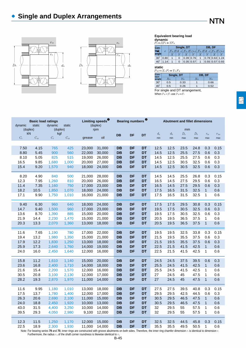
B-45
Note: For bearing series 79 and 70, inner rings are constructed with groove abutments on both sides. Therefore, the inner ring chamfer dimension r1 is identical to dimension r.Furthermore, the radius r1a of the shaft corner roundness is likewise identical to ra.
Basic load ratings Limiting speeds1
Bearing numbers 2
Abutment and fillet dimensionsdynamic static dynamic static (duplex)
(duplex) (duplex) rpm mmkN kgf DB DF DT da db Da Db ras r1as
Cr Cor Cr Cor grease oil min min max max max max
●Single and Duplex Arrangements
7.50 4.15 765 425 23,000 31,000 DB DF DT 12.5 12.5 23.5 24.8 0.3 0.158.80 5.45 900 560 22,000 30,000 DB DF DT 14.5 12.5 25.5 27.5 0.6 0.38.10 5.05 825 515 19,000 26,000 DB DF DT 14.5 12.5 25.5 27.5 0.6 0.3
16.5 9.85 1,680 1,000 20,000 27,000 DB DF DT 14.5 12.5 30.5 32.5 0.6 0.315.4 9.20 1,570 940 18,000 24,000 DB DF DT 14.5 12.5 30.5 32.5 0.6 0.3
8.20 4.90 840 500 21,000 28,000 DB DF DT 14.5 14.5 25.5 26.8 0.3 0.1512.3 7.95 1,260 810 20,000 26,000 DB DF DT 16.5 14.5 27.5 29.5 0.6 0.311.4 7.35 1,160 750 17,000 23,000 DB DF DT 16.5 14.5 27.5 29.5 0.6 0.318.2 10.5 1,850 1,070 18,000 24,000 DB DF DT 17.5 16.5 31.5 32.5 1 0.617.1 9.90 1,750 1,010 16,000 21,000 DB DF DT 17.5 16.5 31.5 32.5 1 0.6
9.40 6.30 960 640 18,000 24,000 DB DF DT 17.5 17.5 29.5 30.8 0.3 0.1514.7 9.40 1,500 960 17,000 23,000 DB DF DT 19.5 17.5 30.5 32.5 0.6 0.313.6 8.70 1,390 885 15,000 20,000 DB DF DT 19.5 17.5 30.5 32.5 0.6 0.321.9 14.4 2,230 1,470 15,000 21,000 DB DF DT 20.5 19.5 36.5 37.5 1 0.620.3 13.3 2,070 1,360 13,000 18,000 DB DF DT 20.5 19.5 36.5 37.5 1 0.6
11.6 7.65 1,190 780 17,000 22,000 DB DF DT 19.5 19.5 32.5 33.8 0.3 0.1519.4 13.2 1,980 1,350 15,000 21,000 DB DF DT 21.5 19.5 35.5 37.5 0.6 0.317.9 12.2 1,830 1,250 13,000 18,000 DB DF DT 21.5 19.5 35.5 37.5 0.6 0.325.9 17.3 2,640 1,760 14,000 19,000 DB DF DT 22.5 21.5 41.5 42.5 1 0.624.0 16.0 2,450 1,640 12,000 16,000 DB DF DT 22.5 21.5 41.5 42.5 1 0.6
15.8 11.2 1,610 1,140 15,000 20,000 DB DF DT 24.5 24.5 37.5 39.5 0.6 0.323.6 16.8 2,400 1,710 14,000 18,000 DB DF DT 25.5 24.5 41.5 42.5 1 0.621.6 15.4 2,200 1,570 12,000 16,000 DB DF DT 25.5 24.5 41.5 42.5 1 0.630.5 20.8 3,100 2,130 12,000 17,000 DB DF DT 27 24.5 45 47.5 1 0.628.2 19.3 2,870 1,970 11,000 14,000 DB DF DT 27 24.5 45 47.5 1 0.6
11.6 9.95 1,180 1,010 13,000 18,000 DB DF DT 27.5 27.5 39.5 40.8 0.3 0.1517.5 13.7 1,780 1,400 12,000 17,000 DB DF DT 29.5 29.5 42.5 44.5 0.6 0.326.3 20.6 2,690 2,100 11,000 15,000 DB DF DT 30.5 29.5 46.5 47.5 1 0.624.0 18.8 2,450 1,920 10,000 13,000 DB DF DT 30.5 29.5 46.5 47.5 1 0.643.0 31.5 4,400 3,250 10,000 14,000 DB DF DT 32 29.5 55 57.5 1 0.639.5 29.3 4,050 2,980 9,100 12,000 DB DF DT 32 29.5 55 57.5 1 0.6
12.3 11.5 1,250 1,170 12,000 15,000 DB DF DT 32.5 32.5 44.5 45.8 0.3 0.1522.5 18.9 2,300 1,930 11,000 14,000 DB DF DT 35.5 35.5 49.5 50.5 1 0.6
30˚
e
X Y
Pr=XFr+YFa
Por=Xo Fr+Yo Fa
Fa / Fr≦e Fa / Fr>e
Single, DT DB, DFFa / Fr≦e Fa / Fr>e
X Y X Y X Y
�
40˚0.801.14
11
00
0.390.35
0.760.57
11
0.780.55
0.630.57
1.240.93
30˚Xo
40˚0.50.5
Yo Xo Yo0.330.26
11
0.660.52
For single and DT arrangement,When Por<Fr use Por=Fr
Equivalent bearing loaddynamic
static
Con-tactangle
Con-tactangle
Single, DT DB, DF
ra r1a
daDb dbDa
r1a ra

●Single and Duplex Arrangements
B-46
Boundary dimensions Basic load ratings Limiting speeds1
Bearing 2
Load Mass
dynamic static dynamic static numbers centerkg
mm kN kgf rpm mmsingle
d D B 2B rs min3
rls min3
Cr Cor Cr Cor grease oil a (approx.)
30
35
40
45
50
55
1 This value achieved with machined cages; when pressed cages are used, 80% of this value is acceptable.2 Bearing numbers appended with the code "B" have a contact angle of 40˚; bearings with this code have a contact angle of 30˚.3 Minimal allowable dimension for chamfer dimension r or r1.
d 30~55mm
62 16 32 1 0.6 22.5 14.8 2,300 1,510 12,000 16,000 7206 21.5 0.19362 16 32 1 0.6 20.5 13.5 2,090 1,380 11,000 14,000 7206B 27.5 0.19772 19 38 1.1 0.6 33.5 22.3 3,450 2,280 11,000 15,000 7306 24.5 0.34572 19 38 1.1 0.6 31.0 20.5 3,150 2,090 9,600 13,000 7306B 31.5 0.352
55 10 20 0.6 0.3 12.0 8.85 1,220 905 13,000 17,000 7907 18 0.08862 14 28 1 0.6 17.5 12.6 1,790 1,280 12,000 16,000 7007 21 0.1872 17 34 1.1 0.6 29.7 20.1 3,050 2,050 11,000 14,000 7207 24 0.28172 17 34 1.1 0.6 27.1 18.4 2,760 1,870 9,300 12,000 7207B 31 0.28780 21 42 1.5 1 40.0 26.3 4,050 2,680 9,800 13,000 7307 27 0.46280 21 42 1.5 1 36.5 24.2 3,750 2,470 8,400 11,000 7307B 34.5 0.469
62 12 24 0.6 0.3 12.7 10.2 1,290 1,040 11,000 15,000 7908 20.5 0.1368 15 30 1 0.6 18.8 14.6 1,910 1,490 10,000 14,000 7008 23 0.22280 18 36 1.1 0.6 35.5 25.1 3,600 2,560 9,600 13,000 7208 26.5 0.35580 18 36 1.1 0.6 32.0 23.0 3,250 2,340 8,300 11,000 7208B 34 0.37590 23 46 1.5 1 49.0 33.0 5,000 3,350 8,600 12,000 7308 30.5 0.62590 23 46 1.5 1 45.0 30.5 4,550 3,100 7,400 9,900 7308B 39 0.636
68 12 24 0.6 0.3 15.7 12.9 1,600 1,310 10,000 14,000 7909 22.5 0.1575 16 32 1 0.6 22.3 17.7 2,270 1,800 9,500 13,000 7009 25.5 0.28285 19 38 1.1 0.6 39.5 28.7 4,050 2,930 8,700 12,000 7209 28.5 0.40485 19 38 1.1 0.6 36.0 26.2 3,650 2,680 7,400 9,900 7209B 37 0.41
100 25 50 1.5 1 63.5 44.0 6,450 4,500 7,800 10,000 7309 33.5 0.837100 25 50 1.5 1 58.5 40.0 5,950 4,100 6,600 8,900 7309B 43.0 0.854
72 12 24 0.6 0.3 16.6 14.5 1,690 1,470 9,200 12,000 7910 23.5 0.15780 16 32 1 0.6 23.7 20.1 2,410 2,050 8,600 11,000 7010 27 0.30690 20 40 1.1 0.6 41.5 31.5 4,200 3,200 7,900 10,000 7210 30 0.45790 20 40 1.1 0.6 37.5 28.6 3,800 2,920 6,700 9,000 7210B 39.5 0.466
110 27 54 2 1 74.0 52.0 7,600 5,350 7,100 9,400 7310 36.5 1.09110 27 54 2 1 68.0 48.0 6,950 4,950 6,000 8,100 7310B 47 1.11
80 13 26 1 0.6 17.3 16.1 1,770 1,640 8,400 11,000 7911 26 0.21490 18 36 1.1 0.6 31.0 26.3 3,150 2,680 7,900 11,000 7011 30 0.447
100 21 42 1.5 1 51.0 39.5 5,200 4,050 7,100 9,500 7211 33 0.6100 21 42 1.5 1 46.5 36.0 4,700 3,700 6,100 8,200 7211B 43 0.612120 29 58 2 1 86.0 61.5 8,750 6,300 6,400 8,600 7311 40 1.39120 29 58 2 1 79.0 56.5 8,050 5,800 5,500 7,300 7311B 52 1.42
ra
ra
daDa
a
2BB
d D
r1
rr1
r
a a
Single Back-to-backarrangement
(DB)
Face-to-facearrangement
(DF)
Tandemarrangement
(DT)
a

B-47
Note: For bearing series 79 and 70, inner rings are constructed with groove abutments on both sides. Therefore, the inner ring chamfer dimension r1 is identical to dimension r.Furthermore, the radius r1a of the shaft corner roundness is, likewise, identical to ra.
Basic load ratings Limiting speeds1
Bearing numbers 2
Abutment and fillet dimensionsdynamic static dynamic static (duplex)
(duplex) (duplex) rpm mmkN kgf DB DF DT da db Da Db ras r1as
Cr Cor Cr Cor grease oil min min max max max max
●Single and Duplex Arrangements
36.5 29.6 3,750 3,000 9,800 13,000 DB DF DT 35.5 34.5 56.5 57.5 1 0.633.5 27.1 3,400 2,760 8,600 11,000 DB DF DT 35.5 34.5 56.5 57.5 1 0.654.5 44.5 5,550 4,550 8,900 12,000 DB DF DT 37 34.5 65 67.5 1 0.650.0 41.0 5,100 4,200 7,700 10,000 DB DF DT 37 34.5 65 67.5 1 0.6
19.5 17.7 1,990 1,810 10,000 13,000 DB DF DT 39.5 39.5 50.5 52.5 0.6 0.328.5 25.1 2,900 2,560 9,400 13,000 DB DF DT 40.5 40.5 56.5 57.5 1 0.648.5 40.0 4,900 4,100 8,600 11,000 DB DF DT 42 39.5 65 67.5 1 0.644.0 36.5 4,500 3,750 7,500 10,000 DB DF DT 42 39.5 65 67.5 1 0.665.0 52.5 6,600 5,350 7,800 10,000 DB DF DT 43.5 40.5 71.5 74.5 1.5 159.5 48.5 6,100 4,950 6,800 9,000 DB DF DT 43.5 40.5 71.5 74.5 1.5 1
20.6 20.4 2,100 2,080 9,000 12,000 DB DF DT 44.5 44.5 57.5 59.5 0.6 0.330.5 29.2 3,100 2,970 8,300 11,000 DB DF DT 45.5 45.5 62.5 63.5 1 0.657.5 50.5 5,850 5,150 7,700 10,000 DB DF DT 47 44.5 73.0 75.5 1 0.652.0 46.0 5,300 4,700 6,700 8,900 DB DF DT 47 44.5 73 75.5 1 0.679.5 66.0 8,100 6,700 6,900 9,200 DB DF DT 48.5 45.5 81.5 84.5 1.5 173.0 60.5 7,400 6,200 6,000 8,000 DB DF DT 48.5 45.5 81.5 84.5 1.5 1
25.5 25.7 2,600 2,620 8,100 11,000 DB DF DT 49.5 49.5 63.5 65.5 0.6 0.336.0 35.5 3,700 3,600 7,500 10,000 DB DF DT 50.5 50.5 69.5 70.5 1 0.664.5 57.5 6,550 5,850 6,900 9,200 DB DF DT 52 49.5 78 80.5 1 0.658.5 52.5 5,950 5,350 6,000 8,000 DB DF DT 52 49.5 78 80.5 1 0.6
103 88.0 10,500 8,950 6,200 8,200 DB DF DT 53.5 50.5 91.5 94.5 1.5 195.0 80.5 9,650 8,250 5,400 7,200 DB DF DT 53.5 50.5 91.5 94.5 1.5 1
27.0 28.9 2,750 2,950 7,300 9,800 DB DF DT 54.5 54.5 67.5 69.5 0.6 0.338.5 40.0 3,900 4,100 6,800 9,100 DB DF DT 55.5 55.5 74.5 75.5 1 0.667.0 63.0 6,850 6,400 6,300 8,300 DB DF DT 57 54.5 83 85.5 1 0.660.5 57.0 6,200 5,850 5,500 7,300 DB DF DT 57 54.5 83 85.5 1 0.6
121 105 12,300 10,700 5,600 7,500 DB DF DT 60 55.5 100 104.5 2 1111 96.0 11,300 9,850 4,900 6,500 DB DF DT 60 55.5 100 104.5 2 1
28.1 32.0 2,870 3,300 6,700 8,900 DB DF DT 60.5 60.5 74.5 75.5 1 0.650.5 52.5 5,150 5,350 6,300 8,400 DB DF DT 62 62 83 85.5 1 0.683.0 79.0 8,450 8,050 5,700 7,600 DB DF DT 63.5 60.5 91.5 94.5 1.5 175.0 72.0 7,650 7,350 5,000 6,600 DB DF DT 63.5 60.5 91.5 94.5 1.5 1
139 123 14,200 12,600 5,100 6,800 DB DF DT 65 60.5 110 114.5 2 1128 113 13,000 11,600 4,500 5,900 DB DF DT 65 60.5 110 114.5 2 1
30˚
e
X Y
Pr=XFr+YFa
Por=Xo Fr+Yo Fa
Fa / Fr≦e Fa / Fr>e
Single, DT DB, DFFa / Fr≦e Fa / Fr>e
X Y X Y X Y
�
40˚0.801.14
11
00
0.390.35
0.760.57
11
0.780.55
0.630.57
1.240.93
30˚Xo
40˚0.50.5
Yo Xo Yo0.330.26
11
0.660.52
For single and DT arrangement,When Por<Fr use Por=Fr
Equivalent bearing loaddynamic
static
Con-tactangle
Con-tactangle
Single, DT DB, DF
ra r1a
daDb dbDa
r1a ra

●Single and Duplex Arrangements
B-48
Boundary dimensions Basic load ratings Limiting speeds1
Bearing 2
Load Mass
dynamic static dynamic static numbers centerkg
mm kN kgf rpm mmsingle
d D B 2B rs min3
rls min3
Cr Cor Cr Cor grease oil a (approx.)
60
65
70
75
80
85
1 This value achieved with machined cages; when pressed cages are used, 80% of this value is acceptable.2 Bearing numbers appended with the code "B" have a contact angle of 40˚; bearings with this code have a contact angle of 30˚.3 Minimal allowable dimension for chamfer dimension r or r1.
d 60~85mm
85 13 26 1 0.6 18.1 17.4 1,840 1,780 7,800 10,000 7912 27.5 0.2395 18 36 1.1 0.6 32.0 28.1 3,250 2,860 7,200 9,600 7012 31.5 0.478
110 22 44 1.5 1 61.5 49.0 6,300 5,000 6,600 8,800 7212 36 0.765110 22 44 1.5 1 56.0 44.5 5,700 4,550 5,700 7,600 7212B 47.5 0.78130 31 62 2.1 1.1 98.0 71.5 10,000 7,300 5,900 7,900 7312 43 1.74130 31 62 2.1 1.1 90.0 66.0 9,200 6,700 5,100 6,800 7312B 56 1.77
90 13 26 1 0.6 18.3 18.0 1,860 1,840 7,200 9,600 7913 29 0.245100 18 36 1.1 0.6 33.5 31.5 3,450 3,200 6,700 9,000 7013 33 0.509120 23 46 1.5 1 70.5 58.0 7,150 5,900 6,100 8,100 7213 38 0.962120 23 46 1.5 1 63.5 52.5 6,500 5,350 5,200 7,000 7213B 50.5 0.981140 33 66 2.1 1.1 111 82.0 11,300 8,350 5,500 7,300 7313 46 2.11140 33 66 2.1 1.1 102 75.0 10,400 7,700 4,700 6,300 7313B 59.5 2.15
100 16 32 1 0.6 26.2 26.2 2,670 2,670 6,700 9,000 7914 32.5 0.397110 20 40 1.1 0.6 42.5 39.5 4,350 4,000 6,200 8,300 7014 36 0.705125 24 48 1.5 1 76.5 63.5 7,800 6,500 5,700 7,600 7214 40 1.09125 24 48 1.5 1 69.0 58.0 7,050 5,900 4,900 6,500 7214B 53 1.11150 35 70 2.1 1.1 125 93.5 12,700 9,550 5,100 6,800 7314 49.5 2.56150 35 70 2.1 1.1 114 86 11,700 8,800 4,400 5,800 7314B 63.5 2.61
105 16 32 1 0.6 26.50 27.1 2,710 2,760 6,300 8,400 7915 34 0.42115 20 40 1.1 0.6 43.50 41.5 4,450 4,250 5,800 7,800 7015 37.5 0.745130 25 50 1.5 1 79.0 68.5 8,050 7,000 5,300 7,100 7215 42.5 1.17130 25 50 1.5 1 71.5 62.0 7,300 6,350 4,500 6,000 7215B 56 1.19160 37 74 2.1 1.1 136 106 13,800 10,800 4,800 6,300 7315 52.5 3.07160 37 74 2.1 1.1 125. 97.5 12,700 9,900 4,100 5,400 7315B 68 3.13
110 16 32 1 0.6 26.9 28.0 2,740 2,860 5,900 7,800 7916 35.5 0.444125 22 44 1.1 0.6 53.5 50.5 5,450 5,150 5,500 7,300 7016 40.5 0.994140 26 52 2 1 89.0 76.0 9,100 7,750 5,000 6,600 7216 45 1.39140 26 52 2 1 80.5 69.5 8,200 7,050 4,300 5,700 7216B 59 1.42170 39 78 2.1 1.1 147 119 15,000 12,100 4,500 5,900 7316 55.5 3.65170 39 78 2.1 1.1 135 109 13,800 11,100 3,800 5,100 7316B 72 3.72
120 18 36 1.1 0.6 36.0 38.0 3,700 3,850 5,500 7,400 7917 38.5 0.628130 22 44 1.1 0.6 54.5 53.5 5,600 5,450 5,100 6,900 7017 42 1.04150 28 56 2 1 99.5 88.5 10,100 9,050 4,700 6,200 7217 48 1.78150 28 56 2 1 90.0 80.5 9,150 8,200 4,000 5,300 7217B 63.5 1.82
ra
ra
daDa
a
2BB
d D
r1
rr1
r
a a
Single Back-to-backarrangement
(DB)
Face-to-facearrangement
(DF)
Tandemarrangement
(DT)
a

B-49
Note: For bearing series 79 and 70, inner rings are constructed with groove abutments on both sides. Therefore, the inner ring chamfer dimension r1 is identical to dimension r.Furthermore, the radius r1a of the shaft corner roundness is, likewise, identical to ra.
Basic load ratings Limiting speeds1
Bearing numbers 2
Abutment and fillet dimensionsdynamic static dynamic static (duplex)
(duplex) (duplex) rpm mmkN kgf DB DF DT da db Da Db ras r1as
Cr Cor Cr Cor grease oil min min max max max max
●Single and Duplex Arrangements
29.3 35.0 2,990 3,550 6,200 8,300 DB DF DT 65.5 65.5 79.5 80.5 1 0.652.0 56.0 5,300 5,700 5,800 7,700 DB DF DT 67 67 88 90.5 1 0.6
100 98.0 10,200 10,000 5,300 7,000 DB DF DT 68.5 65.5 101.5 104.5 1.5 191.0 89.0 9,250 9,100 4,600 6,100 DB DF DT 68.5 65.5 101.5 104.5 1.5 1
159 143 16,200 14,600 4,700 6,300 DB DF DT 72 67 118 123 2 1146 132 14,900 13,400 4,100 5,500 DB DF DT 72 67 118 123 2 1
29.7 36.0 3,050 3,700 5,700 7,600 DB DF DT 70.5 70.5 84.5 85.5 1 0.655.0 62.5 5,600 6,400 5,400 7,100 DB DF DT 72 72 93 95.5 1 0.6
114 116 11,600 11,800 4,900 6,500 DB DF DT 73.5 70.5 111.5 114.5 1.5 1103 105 10,500 10,700 4,200 5,600 DB DF DT 73.5 70.5 111.5 114.5 1.5 1180 164 18,400 16,700 4,400 5,800 DB DF DT 77 72 128 133 2 1166 151 16,900 15,400 3,800 5,100 DB DF DT 77 72 128 133 2 1
42.5 52.5 4,350 5,350 5,300 7,100 DB DF DT 75.5 75.5 94.5 95.5 1 0.669.5 78.5 7,050 8,050 5,000 6,600 DB DF DT 77 77 103 105.5 1 0.6
124 127 12,600 13,000 4,500 6,000 DB DF DT 78.5 75.5 116.5 119.5 1.5 1112 116 11,500 11,800 3,900 5,200 DB DF DT 78.5 75.5 116.5 119.5 1.5 1203 187 20,700 19,100 4,100 5,400 DB DF DT 82 77 138 143 2 1186 172 19,000 17,600 3,500 4,700 DB DF DT 82 77 138 143 2 1
43.0 54.0 4,400 5,500 5,000 6,700 DB DF DT 80.5 80.5 99.5 100.5 1 0.671.0 83.5 7,250 8,500 4,600 6,200 DB DF DT 82 82 108 110.5 1 0.6
128 137 13,100 14,000 4,200 5,600 DB DF DT 83.5 80.5 121.5 124.5 1.5 1116 124 11,800 12,700 3,700 4,900 DB DF DT 83.5 80.5 121.5 124.5 1.5 1221 212 22,500 21,600 3,800 5,000 DB DF DT 87 82 148 153 2 1202 195 20,600 19,800 3,300 4,400 DB DF DT 87 82 148 153 2 1
43.5 56.0 4,450 5,700 4,700 6,200 DB DF DT 85.5 85.5 104.5 105.5 1 0.686.5 101 8,850 10,300 4,400 5,800 DB DF DT 87 87 118 120.5 1 0.6
145 152 14,700 15,500 3,900 5,300 DB DF DT 90 85.5 130 134.5 2 1131 139 13,300 14,100 3,400 4,600 DB DF DT 90 85.5 130 134.5 2 1239 238 24,400 24,200 3,500 4,700 DB DF DT 92 87 158 163 2 1219 218 22,300 22,300 3,100 4,100 DB DF DT 92 87 158 163 2 1
59.0 76.0 6,000 7,750 4,400 5,900 DB DF DT 92 92 113 115.5 1 0.689.0 107 9,050 10,900 4,100 5,500 DB DF DT 92 92 123 125.5 1 0.6
162 177 16,500 18,100 3,700 5,000 DB DF DT 95 90.5 140 144.5 2 1146 161 14,900 16,400 3,200 4,300 DB DF DT 95 90.5 140 144.5 2 1
30˚
e
X Y
Pr=XFr+YFa
Por=Xo Fr+Yo Fa
Fa / Fr≦e Fa / Fr>e
Single, DT DB, DFFa / Fr≦e Fa / Fr>e
X Y X Y X Y
�
40˚0.801.14
11
00
0.390.35
0.760.57
11
0.780.55
0.630.57
1.240.93
30˚Xo
40˚0.50.5
Yo Xo Yo0.330.26
11
0.660.52
For single and DT arrangement,When Por<Fr use Por=Fr
Equivalent bearing loaddynamic
static
Con-tactangle
Con-tactangle
Single, DT DB, DF
ra r1a
daDb dbDa
r1a ra

●Single and Duplex Arrangements
B-50
Boundary dimensions Basic load ratings Limiting speeds1
Bearing 2
Load Mass
dynamic static dynamic static numbers centerkg
mm kN kgf rpm mmsingle
d D B 2B rs min3
rls min3
Cr Cor Cr Cor grease oil a (approx.)
85
90
95
100
105
110
1201 This value achieved with machined cages; when pressed cages are used, 80% of this value is acceptable.2 Bearing numbers appended with the code "B" have a contact angle of 40˚; bearings with this code have a contact angle of 30˚.3 Minimal allowable dimension for chamfer dimension r or r1.
d 85~120mm
180 41 82 3 1.1 159 133 16,200 13,500 4,200 5,600 7317 59 4.34180 41 82 3 1.1 146 122 14,800 12,400 3,600 4,800 7317B 76 4.43
125 18 36 1.1 0.6 36.0 38.0 3,650 3,850 5,200 7,000 7918 40 0.658140 24 48 1.5 1 65.0 63.5 6,650 6,450 4,900 6,500 7018 45 1.35160 30 60 2.0 1 118 103 12,000 10,500 4,400 5,900 7218 51 2.18160 30 60 2.0 1 107 94.0 10,900 9,550 3,800 5,000 7218B 67.5 2.22190 43 86 3.0 1.1 171 147 17,400 15,000 4,000 5,300 7318 62 5.06190 43 86 3.0 1.1 156 135 15,900 13,800 3,400 4,500 7318B 80.5 5.16
130 18 36 1.1 0.6 37.0 40.5 3,800 4,150 5,000 6,600 7919 41.5 0.688145 24 48 1.5 1 67.0 67.0 6,800 6,800 4,600 6,100 7019 46.5 1.41170 32 64 2.1 1.1 133 118 13,600 12,000 4,100 5,500 7219 54.5 2.67170 32 64 2.1 1.1 121 107 12,300 11,000 3,500 4,700 7219B 71.5 2.72200 45 90 3 1.1 183 162 18,600 16,600 3,700 5,000 7319 65 5.89200 45 90 3 1.1 167 149 17,100 15,200 3,200 4,200 7319B 84.5 6
140 20 40 1.1 0.6 48.0 52.5 4,900 5,350 4,700 6,200 7920 44.5 0.934150 24 48 1.5 1 68.5 70.5 6,950 7,200 4,400 5,800 7020 48 1.47180 34 68 2.1 1.1 144 126 14,700 12,800 3,900 5,200 7220 57.5 3.2180 34 68 2.1 1.1 130 114 13,300 11,700 3,400 4,500 7220B 76 3.26215 47 94 3 1.1 207 193 21,100 19,700 3,500 4,700 7320 69 7.18215 47 94 3 1.1 190 178 19,400 18,100 3,000 4,000 7320B 89.5 7.32
145 20 40 1.1 0.6 48.5 54.5 4,950 5,550 4,400 5,900 7921 46 0.972160 26 52 2 1 80.0 81.5 8,150 8,350 4,100 5,500 7021 51.5 1.86190 36 72 2.1 1.1 157 142 16,000 14,400 3,700 5,000 7221 60.5 3.79190 36 72 2.1 1.1 142 129 14,500 13,100 3,200 4,300 7221B 80 3.87225 49 98 3 1.1 220 210 22,400 21,500 3,400 4,500 7321 72 8.2225 49 98 3 1.1 202 194 20,600 19,700 2,900 3,800 7321B 93.5 8.36
150 20 40 1.1 0.6 49.5 56.0 5,050 5,700 4,200 5,700 7922 47.5 1.01170 28 56 2 1 92.0 93.0 9,350 9,450 3,900 5,300 7022 54.5 2.3200 38 76 2.1 1.1 170 158 17,300 16,100 3,500 4,700 7222 64 4.45200 38 76 2.1 1.1 154 144 15,700 14,700 3,000 4,000 7222B 84 4.54240 50 100 3 1.1 246 246 25,100 25,100 3,200 4,300 7322 76 9.6240 50 100 3 1.1 226 226 23,000 23,100 2,700 3,700 7322B 99 9.8
165 22 44 1.1 0.6 61.0 69.5 6,200 7,100 3,900 5,200 7924 52 1.66
ra
ra
daDa
a
2BB
d D
r1
rr1
r
a a
Single Back-to-backarrangement
(DB)
Face-to-facearrangement
(DF)
Tandemarrangement
(DT)
a
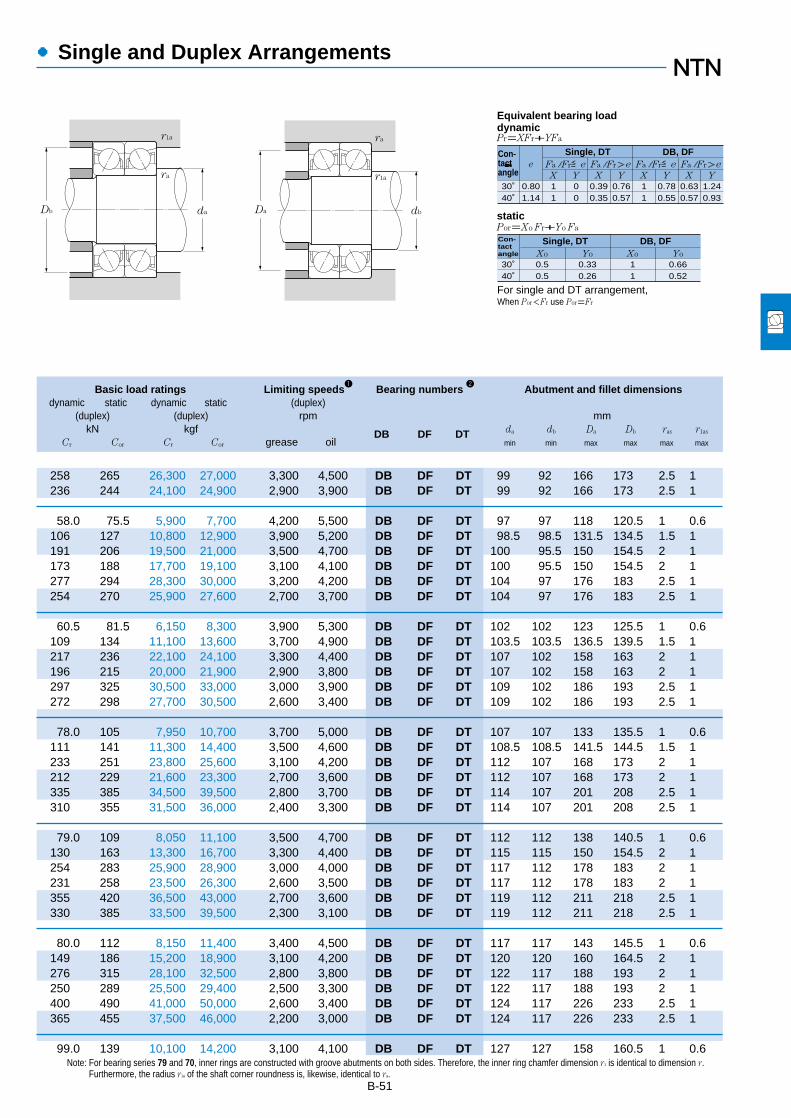
B-51
Note: For bearing series 79 and 70, inner rings are constructed with groove abutments on both sides. Therefore, the inner ring chamfer dimension r1 is identical to dimension r.Furthermore, the radius r1a of the shaft corner roundness is, likewise, identical to ra.
Basic load ratings Limiting speeds1
Bearing numbers 2
Abutment and fillet dimensionsdynamic static dynamic static (duplex)
(duplex) (duplex) rpm mmkN kgf DB DF DT da db Da Db ras r1as
Cr Cor Cr Cor grease oil min min max max max max
●Single and Duplex Arrangements
258 265 26,300 27,000 3,300 4,500 DB DF DT 99 92 166 173 2.5 1236 244 24,100 24,900 2,900 3,900 DB DF DT 99 92 166 173 2.5 1
58.0 75.5 5,900 7,700 4,200 5,500 DB DF DT 97 97 118 120.5 1 0.6106 127 10,800 12,900 3,900 5,200 DB DF DT 98.5 98.5 131.5 134.5 1.5 1191 206 19,500 21,000 3,500 4,700 DB DF DT 100 95.5 150 154.5 2 1173 188 17,700 19,100 3,100 4,100 DB DF DT 100 95.5 150 154.5 2 1277 294 28,300 30,000 3,200 4,200 DB DF DT 104 97 176 183 2.5 1254 270 25,900 27,600 2,700 3,700 DB DF DT 104 97 176 183 2.5 1
60.5 81.5 6,150 8,300 3,900 5,300 DB DF DT 102 102 123 125.5 1 0.6109 134 11,100 13,600 3,700 4,900 DB DF DT 103.5 103.5 136.5 139.5 1.5 1217 236 22,100 24,100 3,300 4,400 DB DF DT 107 102 158 163 2 1196 215 20,000 21,900 2,900 3,800 DB DF DT 107 102 158 163 2 1297 325 30,500 33,000 3,000 3,900 DB DF DT 109 102 186 193 2.5 1272 298 27,700 30,500 2,600 3,400 DB DF DT 109 102 186 193 2.5 1
78.0 105 7,950 10,700 3,700 5,000 DB DF DT 107 107 133 135.5 1 0.6111 141 11,300 14,400 3,500 4,600 DB DF DT 108.5 108.5 141.5 144.5 1.5 1233 251 23,800 25,600 3,100 4,200 DB DF DT 112 107 168 173 2 1212 229 21,600 23,300 2,700 3,600 DB DF DT 112 107 168 173 2 1335 385 34,500 39,500 2,800 3,700 DB DF DT 114 107 201 208 2.5 1310 355 31,500 36,000 2,400 3,300 DB DF DT 114 107 201 208 2.5 1
79.0 109 8,050 11,100 3,500 4,700 DB DF DT 112 112 138 140.5 1 0.6130 163 13,300 16,700 3,300 4,400 DB DF DT 115 115 150 154.5 2 1254 283 25,900 28,900 3,000 4,000 DB DF DT 117 112 178 183 2 1231 258 23,500 26,300 2,600 3,500 DB DF DT 117 112 178 183 2 1355 420 36,500 43,000 2,700 3,600 DB DF DT 119 112 211 218 2.5 1330 385 33,500 39,500 2,300 3,100 DB DF DT 119 112 211 218 2.5 1
80.0 112 8,150 11,400 3,400 4,500 DB DF DT 117 117 143 145.5 1 0.6149 186 15,200 18,900 3,100 4,200 DB DF DT 120 120 160 164.5 2 1276 315 28,100 32,500 2,800 3,800 DB DF DT 122 117 188 193 2 1250 289 25,500 29,400 2,500 3,300 DB DF DT 122 117 188 193 2 1400 490 41,000 50,000 2,600 3,400 DB DF DT 124 117 226 233 2.5 1365 455 37,500 46,000 2,200 3,000 DB DF DT 124 117 226 233 2.5 1
99.0 139 10,100 14,200 3,100 4,100 DB DF DT 127 127 158 160.5 1 0.6
30˚
e
X Y
Pr=XFr+YFa
Por=Xo Fr+Yo Fa
Fa / Fr≦e Fa / Fr>e
Single, DT DB, DFFa / Fr≦e Fa / Fr>e
X Y X Y X Y
�
40˚0.801.14
11
00
0.390.35
0.760.57
11
0.780.55
0.630.57
1.240.93
30˚Xo
40˚0.50.5
Yo Xo Yo0.330.26
11
0.660.52
For single and DT arrangement,When Por<Fr use Por=Fr
Equivalent bearing loaddynamic
static
Con-tactangle
Con-tactangle
Single, DT DB, DF
ra r1a
daDb dbDa
r1a ra

●Single and Duplex Arrangements
B-52
Boundary dimensions Basic load ratings Limiting speeds Bearing 1
Load Mass
dynamic static dynamic static numbers centerkg
mm kN kgf rpm mmsingle
d D B 2B rs min2
rls min2
Cr Cor Cr Cor grease oil a (approx.)
120
130
140
150
160
170
1 Bearing numbers appended with the code "B" have a contact angle of 40˚; bearings with this code have a contact angle of 30˚.2 Smallest allowable dimension for chamfer dimension r.
d 120~170mm
180 28 56 2 1 93.5 98.5 9,550 10,000 3,600 4,800 7024 57.5 2.47215 40 80 2.1 1.1 183 177 18,600 18,100 3,200 4,300 7224 68.5 6.26215 40 80 2.1 1.1 165 162 16,900 16,500 2,800 3,700 7224B 90.5 6.26260 55 110 3 1.1 246 252 25,100 25,700 2,900 3,900 7324 82.5 14.7260 55 110 3 1.1 225 231 23,000 23,600 2,500 3,300 7324B 107 14.7
180 24 48 1.5 1 75.0 87.5 7,650 8,900 3,600 4,700 7926 56.5 1.82200 33 66 2 1 117 125 12,000 12,800 3,300 4,400 7026 64 3.73230 40 80 3 1.1 196 198 20,000 20,200 3,000 4,000 7226 72 7.15230 40 80 3 1.1 177 180 18,100 18,300 2,500 3,400 7226B 95.5 7.15280 58 116 4 1.5 273 293 27,900 29,800 2,700 3,600 7326 88 17.6280 58 116 4 1.5 250 268 25,500 27,400 2,300 3,100 7326B 115 17.6
190 24 48 1.5 1 75.5 90.0 7,700 9,150 3,300 4,400 7928 59.5 1.94210 33 66 2 1 120 133 12,200 13,500 3,100 4,100 7028 67 3.96250 42 84 3 1.1 203 215 20,700 21,900 2,700 3,600 7228 77.5 8.78250 42 84 3 1.1 183 195 18,700 19,900 2,300 3,100 7228B 103 8.78300 62 124 4 1.5 300 335 30,500 34,500 2,500 3,300 7328 94.5 21.5300 62 124 4 1.5 275 310 28,100 31,500 2,100 2,800 7328B 123 21.5
210 28 56 2 1 97.5 117 9,900 11,900 3,100 4,100 7930 66 2.96225 35 70 2.1 1.1 137 154 14,000 15,700 2,800 3,800 7030 71.5 4.82270 45 90 3 1.1 232 259 23,700 26,400 2,500 3,400 7230 83 11270 45 90 3 1.1 210 235 21,400 24,000 2,200 2,900 7230B 111 11320 65 130 4 1.5 330 380 33,500 39,000 2,300 3,100 7330 100 25.1320 65 130 4 1.5 300 350 30,500 36,000 2,000 2,600 7330B 131 25.1
220 28 56 2 1 98.5 121 10,000 12,300 2,800 3,800 7932 69 3.13240 38 76 2.1 1.1 155 176 15,800 18,000 2,700 3,600 7032 77 5.96290 48 96 3 1.1 263 305 26,800 31,500 2,400 3,200 7232 89 13.7290 48 96 3 1.1 238 279 24,200 28,400 2,000 2,700 7232B 118 13.7340 68 136 4 1.5 345 420 35,500 43,000 2,100 2,800 7332 106 29.8340 68 136 4 1.5 315 385 32,000 39,500 1,800 2,400 7332B 139 29.8
230 28 56 2 1 102 129 10,400 13,100 2,700 3,600 7934 71.5 3.29260 42 84 2.1 1.1 186 214 18,900 21,900 2,500 3,300 7034 83 7.96310 52 104 4 1.5 295 360 30,000 36,500 2,200 3,000 7234 95.5 17310 52 104 4 1.5 266 325 27,200 33,000 1,900 2,500 7234B 127 17360 72 144 4 1.5 390 485 39,500 49,500 2,000 2,700 7334 113 35.3
ra
ra
daDa
a
2BB
d D
r1
rr
r
a a
Single
a
Back-to-backarrangement
(DB)
Face-to-facearrangement
(DF)
Tandemarrangement
(DT)

B-53
Basic load ratings Limiting speeds Bearing numbers 1
Abutment and fillet dimensionsdynamic static dynamic static (duplex)
(duplex) (duplex) rpm mmkN kgf DB DF DT da Da Db ras r1as
Cr Cor Cr Cor grease oil min max max max max
●Single and Duplex Arrangements
152 197 15,500 20,100 2,900 3,800 DB DF DT 130 170 174.5 2 1297 355 30,500 36,000 2,600 3,400 DB DF DT 132 203 208 2 1269 325 27,400 33,000 2,300 3,000 DB DF DT 132 203 208 2 1400 505 41,000 51,500 2,300 3,100 DB DF DT 134 246 253 2.5 1365 460 37,500 47,000 2,000 2,700 DB DF DT 134 246 253 2.5 1
121 175 12,400 17,800 2,800 3,800 DB DF DT 138.5 171.5 174.5 1.5 1191 251 19,400 25,600 2,600 3,500 DB DF DT 140 190 194.5 2 1320 395 32,500 40,500 2,400 3,100 DB DF DT 144 216 223 2.5 1288 360 29,400 36,500 2,100 2,700 DB DF DT 144 216 223 2.5 1445 585 45,500 59,500 2,100 2,800 DB DF DT 148 262 271.5 3 1.5405 535 41,500 54,500 1,900 2,500 DB DF DT 148 262 271.5 3 1.5
123 180 12,500 18,300 2,600 3,500 DB DF DT 148.5 181.5 184.5 1.5 1194 265 19,800 27,000 2,400 3,300 DB DF DT 150 200 204.5 2 1330 430 33,500 44,000 2,200 2,900 DB DF DT 154 236 243 2.5 1297 390 30,500 40,000 1,900 2,500 DB DF DT 154 236 243 2.5 1490 670 50,000 68,500 2,000 2,600 DB DF DT 158 282 291.5 3 1.5445 615 45,500 63,000 1,700 2,300 DB DF DT 158 282 291.5 3 1.5
158 234 16,100 23,900 2,400 3,300 DB DF DT 160 200 204.5 2 1222 305 22,700 31,500 2,300 3,000 DB DF DT 162 213 218 2 1375 515 38,500 53,000 2,000 2,700 DB DF DT 164 256 263 2.5 1340 470 34,500 48,000 1,800 2,400 DB DF DT 164 256 263 2.5 1535 765 54,500 78,000 1,800 2,400 DB DF DT 168 302 311.5 3 1.5490 700 50,000 71,500 1,600 2,100 DB DF DT 168 302 311.5 3 1.5
160 241 16,300 24,600 2,300 3,000 DB DF DT 170 210 214.5 2 1252 355 25,700 36,000 2,100 2,800 DB DF DT 172 228 233 2 1425 615 43,500 62,500 1,900 2,500 DB DF DT 174 276 283 2.5 1385 555 39,500 57,000 1,600 2,200 DB DF DT 174 276 283 2.5 1565 845 57,500 86,000 1,700 2,300 DB DF DT 178 322 331.5 3 1.5515 770 52,500 79,000 1,500 2,000 DB DF DT 178 322 331.5 3 1.5
165 257 16,900 26,200 2,100 2,800 DB DF DT 180 220 224.5 2 1300 430 31,000 43,500 2,000 2,600 DB DF DT 182 248 253 2 1480 715 49,000 73,000 1,800 2,400 DB DF DT 188 292 301.5 3 1.5435 650 44,000 66,500 1,500 2,100 DB DF DT 188 292 301.5 3 1.5630 970 64,500 99,000 1,600 2,100 DB DF DT 188 342 351.5 3 1.5
30˚
e
X Y
Pr=XFr+YFa
Por=Xo Fr+Yo Fa
Fa / Fr≦e Fa / Fr>e
Single, DT DB, DFFa / Fr≦e Fa / Fr>e
X Y X Y X Y
�
40˚0.801.14
11
00
0.390.35
0.760.57
11
0.780.55
0.630.57
1.240.93
30˚Xo
40˚0.50.5
Yo Xo Yo0.330.26
11
0.660.52
For single and DT arrangement,When Por<Fr use Por=Fr
Equivalent bearing loaddynamic
static
Con-tactangle
Con-tactangle
Single, DT DB, DF
ra r1a
daDb daDa
r1a ra
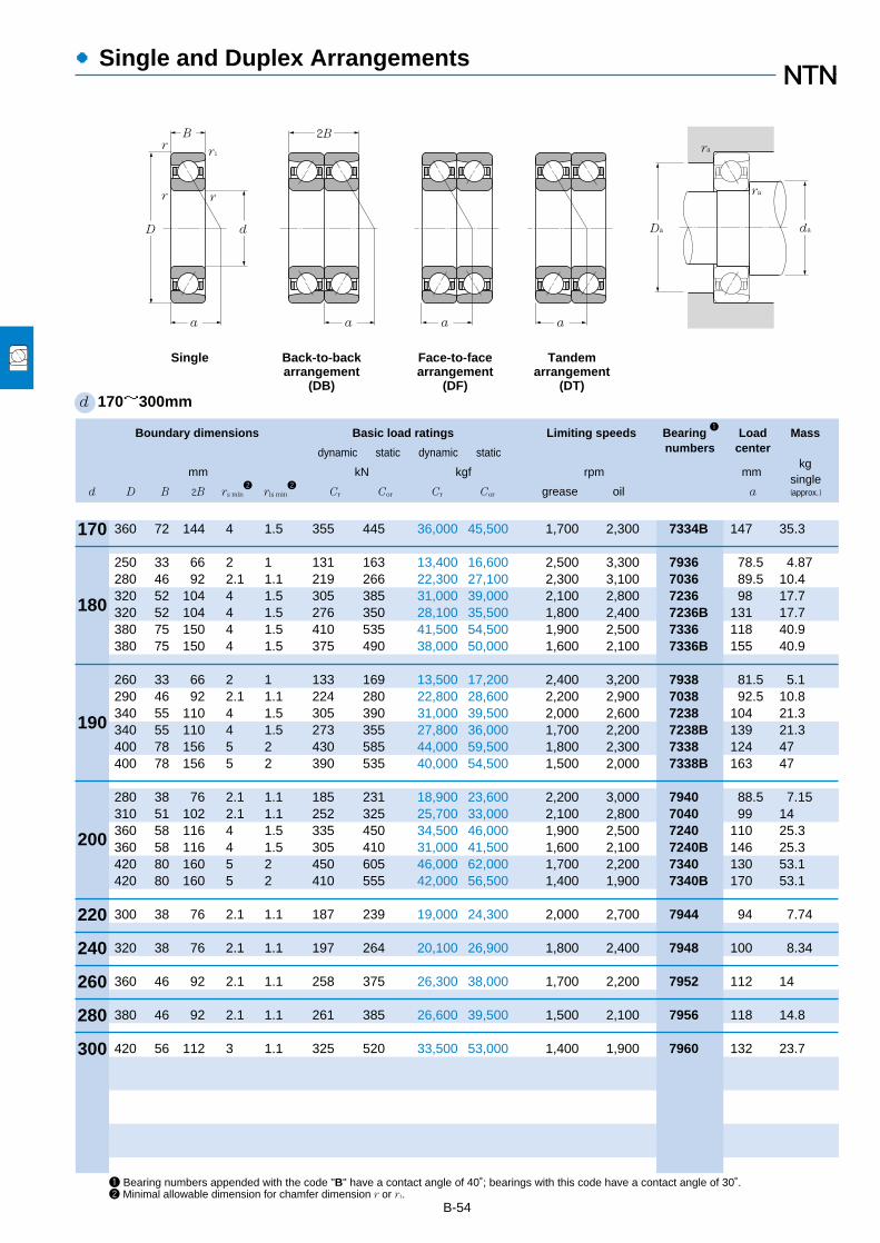
●Single and Duplex Arrangements
B-54
Boundary dimensions Basic load ratings Limiting speeds Bearing 1
Load Mass
dynamic static dynamic static numbers centerkg
mm kN kgf rpm mmsingle
d D B 2B rs min2
rls min2
Cr Cor Cr Cor grease oil a (approx.)
170
180
190
200
220
240
260
280
300
1 Bearing numbers appended with the code "B" have a contact angle of 40˚; bearings with this code have a contact angle of 30˚.2 Minimal allowable dimension for chamfer dimension r or r1.
d 170~300mm
360 72 144 4 1.5 355 445 36,000 45,500 1,700 2,300 7334B 147 35.3
250 33 66 2 1 131 163 13,400 16,600 2,500 3,300 7936 78.5 4.87280 46 92 2.1 1.1 219 266 22,300 27,100 2,300 3,100 7036 89.5 10.4320 52 104 4 1.5 305 385 31,000 39,000 2,100 2,800 7236 98 17.7320 52 104 4 1.5 276 350 28,100 35,500 1,800 2,400 7236B 131 17.7380 75 150 4 1.5 410 535 41,500 54,500 1,900 2,500 7336 118 40.9380 75 150 4 1.5 375 490 38,000 50,000 1,600 2,100 7336B 155 40.9
260 33 66 2 1 133 169 13,500 17,200 2,400 3,200 7938 81.5 5.1290 46 92 2.1 1.1 224 280 22,800 28,600 2,200 2,900 7038 92.5 10.8340 55 110 4 1.5 305 390 31,000 39,500 2,000 2,600 7238 104 21.3340 55 110 4 1.5 273 355 27,800 36,000 1,700 2,200 7238B 139 21.3400 78 156 5 2 430 585 44,000 59,500 1,800 2,300 7338 124 47400 78 156 5 2 390 535 40,000 54,500 1,500 2,000 7338B 163 47
280 38 76 2.1 1.1 185 231 18,900 23,600 2,200 3,000 7940 88.5 7.15310 51 102 2.1 1.1 252 325 25,700 33,000 2,100 2,800 7040 99 14360 58 116 4 1.5 335 450 34,500 46,000 1,900 2,500 7240 110 25.3360 58 116 4 1.5 305 410 31,000 41,500 1,600 2,100 7240B 146 25.3420 80 160 5 2 450 605 46,000 62,000 1,700 2,200 7340 130 53.1420 80 160 5 2 410 555 42,000 56,500 1,400 1,900 7340B 170 53.1
300 38 76 2.1 1.1 187 239 19,000 24,300 2,000 2,700 7944 94 7.74
320 38 76 2.1 1.1 197 264 20,100 26,900 1,800 2,400 7948 100 8.34
360 46 92 2.1 1.1 258 375 26,300 38,000 1,700 2,200 7952 112 14
380 46 92 2.1 1.1 261 385 26,600 39,500 1,500 2,100 7956 118 14.8
420 56 112 3 1.1 325 520 33,500 53,000 1,400 1,900 7960 132 23.7
ra
ra
daDa
a
2BB
d D
r1
rr
r
a a
Single
a
Back-to-backarrangement
(DB)
Face-to-facearrangement
(DF)
Tandemarrangement
(DT)
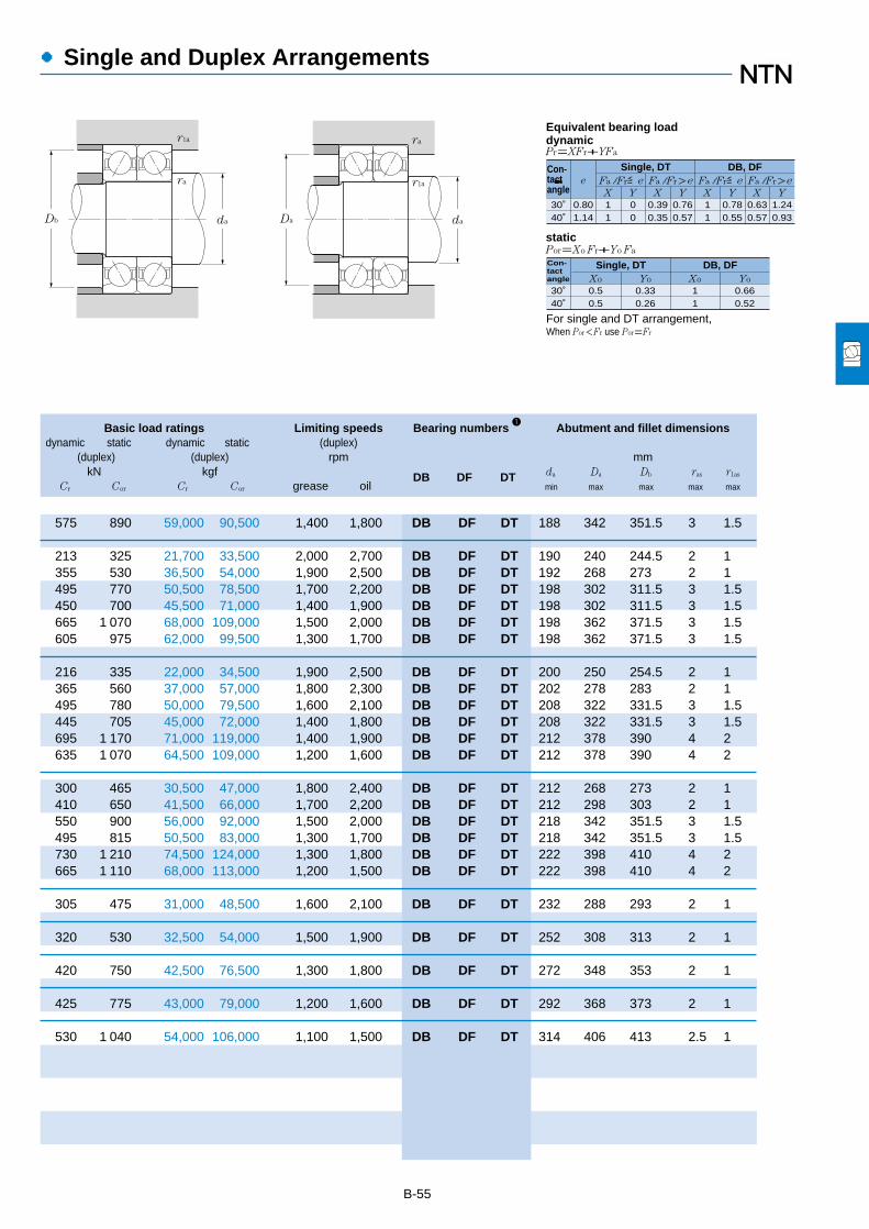
B-55
Basic load ratings Limiting speeds Bearing numbers 1
Abutment and fillet dimensionsdynamic static dynamic static (duplex)
(duplex) (duplex) rpm mmkN kgf DB DF DT da Da Db ras r1as
Cr Cor Cr Cor grease oil min max max max max
●Single and Duplex Arrangements
575 890 59,000 90,500 1,400 1,800 DB DF DT 188 342 351.5 3 1.5
213 325 21,700 33,500 2,000 2,700 DB DF DT 190 240 244.5 2 1355 530 36,500 54,000 1,900 2,500 DB DF DT 192 268 273 2 1495 770 50,500 78,500 1,700 2,200 DB DF DT 198 302 311.5 3 1.5450 700 45,500 71,000 1,400 1,900 DB DF DT 198 302 311.5 3 1.5665 1 070 68,000 109,000 1,500 2,000 DB DF DT 198 362 371.5 3 1.5605 975 62,000 99,500 1,300 1,700 DB DF DT 198 362 371.5 3 1.5
216 335 22,000 34,500 1,900 2,500 DB DF DT 200 250 254.5 2 1365 560 37,000 57,000 1,800 2,300 DB DF DT 202 278 283 2 1495 780 50,000 79,500 1,600 2,100 DB DF DT 208 322 331.5 3 1.5445 705 45,000 72,000 1,400 1,800 DB DF DT 208 322 331.5 3 1.5695 1 170 71,000 119,000 1,400 1,900 DB DF DT 212 378 390 4 2635 1 070 64,500 109,000 1,200 1,600 DB DF DT 212 378 390 4 2
300 465 30,500 47,000 1,800 2,400 DB DF DT 212 268 273 2 1410 650 41,500 66,000 1,700 2,200 DB DF DT 212 298 303 2 1550 900 56,000 92,000 1,500 2,000 DB DF DT 218 342 351.5 3 1.5495 815 50,500 83,000 1,300 1,700 DB DF DT 218 342 351.5 3 1.5730 1 210 74,500 124,000 1,300 1,800 DB DF DT 222 398 410 4 2665 1 110 68,000 113,000 1,200 1,500 DB DF DT 222 398 410 4 2
305 475 31,000 48,500 1,600 2,100 DB DF DT 232 288 293 2 1
320 530 32,500 54,000 1,500 1,900 DB DF DT 252 308 313 2 1
420 750 42,500 76,500 1,300 1,800 DB DF DT 272 348 353 2 1
425 775 43,000 79,000 1,200 1,600 DB DF DT 292 368 373 2 1
530 1 040 54,000 106,000 1,100 1,500 DB DF DT 314 406 413 2.5 1
30˚
e
X Y
Pr=XFr+YFa
Por=Xo Fr+Yo Fa
Fa / Fr≦e Fa / Fr>e
Single, DT DB, DFFa / Fr≦e Fa / Fr>e
X Y X Y X Y
�
40˚0.801.14
11
00
0.390.35
0.760.57
11
0.780.55
0.630.57
1.240.93
30˚Xo
40˚0.50.5
Yo Xo Yo0.330.26
11
0.660.52
For single and DT arrangement,When Por<Fr use Por=Fr
Equivalent bearing loaddynamic
static
Con-tactangle
Con-tactangle
Single, DT DB, DF
ra r1a
daDb daDa
r1a ra

●High Speed Single and Duplex Arrangements
B-56
Boundary dimensions Basic load ratings Limiting speeds1
Bearing Load Mass
dynamic static dynamic static numbers centerkg
mm kN kgf rpm mmsingle
d D B 2B rs min2
rls min2
Cr Cor Cr Cor grease oil a (approx.)
10
12
15
17
20
25
30
35
40
1 This value was achieved with laminated phenol resin machined cages; in the case of molded resin cages,with oil lubricant, the value will be 75% of this.2 Minimal allowable dimension for chamfer dimension r or r1.
d 10~40mm
D d
B
a a
2B
a a
Da da
ra
ra
Single Back-to-backarrangement
(DB)
Face-to-facearrangement
(DF)
Tandemarrangement
(DT)
r1
rr
r
26 8 16 0.3 0.15 4.90 2.20 500 225 43,000 58,000 7000C 6.5 0.01930 9 18 0.6 0.3 5.40 2.64 555 269 41,000 55,000 7200C 7 0.029
28 8 16 0.3 0.15 5.40 2.64 555 269 39,000 52,000 7001C 6.5 0.02132 10 20 0.6 0.3 7.10 3.45 720 355 36,000 49,000 7201C 8 0.036
32 9 18 0.3 0.15 6.25 3.40 635 345 34,000 45,000 7002C 7.5 0.02935 11 22 0.6 0.3 9.00 4.50 915 460 32,000 42,000 7202C 9 0.04542 13 26 1 0.6 13.30 6.85 1,360 700 28,000 38,000 7302C 10.5 0.081
35 10 20 0.3 0.15 7.70 4.10 785 420 31,000 41,000 7003C 8.5 0.03840 12 24 0.6 0.3 11.2 5.75 1,140 590 29,000 38,000 7203C 10 0.06247 14 28 1 0.6 15.7 8.25 1,600 840 26,000 35,000 7303C 11.5 0.109
42 12 24 0.6 0.3 10.5 6.05 1,070 615 27,000 36,000 7004C 10 0.06647 14 28 1 0.6 14.6 8.15 1,490 835 25,000 34,000 7204C 11.5 0.152 15 30 1.1 0.6 18.5 9.95 1,890 1,020 23,000 31,000 7304C 12.5 0.14
37 7 14 0.3 0.15 5.05 3.85 515 390 27,000 36,000 7805C 7.5 0.02142 9 18 0.3 0.15 7.85 5.40 800 555 25,000 33,000 7905C 9 0.04247 12 24 0.6 0.3 11.7 7.45 1,190 755 23,000 31,000 7005C 11 0.07852 15 30 1 0.6 16.6 10.2 1,690 1,050 21,000 28,000 7205C 12.5 0.12162 17 34 1.1 0.6 26.4 15.3 2,690 1,560 19,000 26,000 7305C 14.5 0.222
42 7 14 0.3 0.15 5.35 4.50 545 460 23,000 31,000 7806C 8.5 0.02547 9 18 0.3 0.15 8.30 6.25 845 640 21,000 28,000 7906C 9.5 0.04855 13 26 1 0.6 15.1 10.3 1,540 1,050 20,000 26,000 7006C 12.5 0.11262 16 32 1 0.6 23.0 14.7 2,350 1,500 18,000 24,000 7206C 14 0.19172 19 38 1.1 0.6 32.5 20.3 3,300 2,070 16,000 22,000 7306C 16.5 0.33
47 7 14 0.3 0.15 5.80 5.25 590 535 20,000 27,000 7807C 9 0.02855 10 20 0.6 0.3 13.2 9.65 1,340 985 19,000 25,000 7907C 11 0.07362 14 28 1 0.6 19.1 13.7 1,950 1,390 17,000 23,000 7007C 13.5 0.14972 17 34 1.1 0.6 30.5 19.9 3,100 2,030 16,000 21,000 7207C 15.5 0.27380 21 42 1.5 1 40.5 25.8 4,100 2,630 14,000 19,000 7307C 18 0.44
52 7 14 0.3 0.15 6.05 5.75 615 585 18,000 24,000 7808C 9.5 0.03162 12 24 0.6 0.3 14.0 11.1 1,420 1,140 17,000 22,000 7908C 13 0.10968 15 30 1 0.6 20.6 15.9 2,100 1,620 15,000 21,000 7008C 14.5 0.18480 18 36 1.1 0.6 36.5 25.2 3,700 2,570 14,000 19,000 7208C 17 0.35

B-57
3 For back-to-back and face-to-face duplex arrangements, find with the formula 2Fa / Cor.Note: This bearing has a contact angle of 15°and is manufactured with accuracies of JIS Class 5 or higher.
Basic load ratings Limiting speeds1
Bearing numbers Abutment and fillet dimensionsdynamic static dynamic static (duplex)
(duplex) (duplex) mmkN kgf rpm DB DF DT da Da Db ras r1as
Cr Cor Cr Cor grease oil min max max max max
●High Speed Single and Duplex Arrangements
Db da
rara
Dada
rar1a
0.0100.0200.0400.0700.100.150.200.300.400.50
e
X Y
Pr=XFr+YFa
Por=Xo Fr+Yo Fa
Fa/Fr≦e Fa/Fr>e
Single, DT DB, DFFa/Fr≦e Fa/Fr>e
X Y X Y X Y
0.370.390.410.440.460.490.510.550.560.56
1 0 0.44
1.511.451.361.281.221.151.101.021.001.00
1
1.701.621.521.431.371.291.231.151.121.12
0.72
2.462.352.212.081.981.871.781.661.631.63
Xo0.5
Yo Xo Yo0.46 1 0.92
Cor
Fa3)�
For single and DT arrangement,When Por<Fr use Por=Fr
Equivalent bearing loaddynamic
static
Single, DT DB, DF
7.95 4.40 815 450 34,000 46,000 DB DF DT 12.5 23.5 24.8 0.3 0.158.80 5.25 900 540 32,000 43,000 DB DF DT 14.5 25.5 27.5 0.6 0.3
8.80 5.25 900 540 31,000 41,000 DB DF DT 14.5 25.5 26.8 0.3 0.1511.5 6.95 1,170 705 29,000 38,000 DB DF DT 16.5 27.5 29.5 0.6 0.3
10.1 6.75 1,030 690 27,000 36,000 DB DF DT 17.5 29.5 30.8 0.3 0.1514.6 9.05 1,490 920 25,000 33,000 DB DF DT 19.5 30.5 32.5 0.6 0.321.6 13.7 2,200 1,400 23,000 30,000 DB DF DT 20.5 36.5 37.5 1 0.6
12.5 8.25 1,280 840 24,000 33,000 DB DF DT 19.5 32.5 33.8 0.3 0.1518.1 11.5 1,850 1,180 23,000 30,000 DB DF DT 21.5 35.5 37.5 0.6 0.325.6 16.5 2,610 1,680 21,000 27,000 DB DF DT 22.5 41.5 42.5 1 0.6
17.0 12.1 1,740 1,230 22,000 29,000 DB DF DT 24.5 37.5 39.5 0.6 0.323.7 16.3 2,420 1,670 20,000 27,000 DB DF DT 25.5 41.5 42.5 1 0.630.0 19.9 3,050 2,030 18,000 24,000 DB DF DT 27 45 47.5 1 0.6
8.20 7.65 835 780 21,000 28,000 DB DF DT 27.5 34.5 35.8 0.3 0.1512.7 10.8 1,300 1,110 19,000 26,000 DB DF DT 27.5 39.5 40.8 0.3 0.1519.0 14.9 1,940 1,510 18,000 24,000 DB DF DT 29.5 42.5 44.5 0.6 0.327.0 20.5 2,750 2,090 17,000 22,000 DB DF DT 30.5 46.5 47.5 1 0.643.0 30.5 4,350 3,100 15,000 20,000 DB DF DT 32 55 57.5 1 0.6
8.70 9.00 890 920 18,000 24,000 DB DF DT 32.5 39.5 40.8 0.3 0.1513.5 12.5 1,380 1,280 17,000 22,000 DB DF DT 32.5 44.5 45.8 0.3 0.1524.6 20.6 2,510 2,100 16,000 21,000 DB DF DT 35.5 49.5 50.5 1 0.637.5 29.5 3,800 3,000 14,000 19,000 DB DF DT 35.5 56.5 57.5 1 0.652.5 40.5 5,350 4,150 13,000 17,000 DB DF DT 37 65 67.5 1 0.6
9.40 10.5 960 1,070 16,000 21,000 DB DF DT 37.5 44.5 45.8 0.3 0.1521.4 19.3 2,180 1,970 15,000 20,000 DB DF DT 39.5 50.5 52.5 0.6 0.331.0 27.3 3,150 2,790 14,000 18,000 DB DF DT 40.5 56.5 57.5 1 0.649.5 40.0 5,050 4,050 13,000 17,000 DB DF DT 42 65 67.5 1 0.665.5 51.5 6,700 5,250 11,000 15,000 DB DF DT 43.5 71.5 74.5 1.5 1
9.80 11.5 1,000 1,170 14,000 19,000 DB DF DT 42.5 49.5 50.8 0.3 0.1522.7 22.3 2,310 2,270 13,000 18,000 DB DF DT 44.5 57.5 59.5 0.6 0.333.5 32.0 3,400 3,250 12,000 16,000 DB DF DT 45.5 62.5 63.5 1 0.659.0 50.5 6,000 5,150 11,000 15,000 DB DF DT 47 73 75.5 1 0.6

●High Speed Single and Duplex Arrangements
B-58
Boundary dimensions Basic load ratings Limiting speeds1
Bearing Load Mass
dynamic static dynamic static numbers centerkg
mm kN kgf rpm mmsingle
d D B 2B rs min2
rls min2
Cr Cor Cr Cor grease oil a (approx.)
40
45
50
55
60
65
70
1 This value was achieved with laminated phenol resin machined cages; in the case of molded resin cages,with oil lubricant, the value will be 75% of this.2 Minimal allowable dimension for chamfer dimension r or r1.
d 40~75mm
D d
B
a a
2B
a a
Da da
ra
ra
Single Back-to-backarrangement
(DB)
Face-to-facearrangement
(DF)
Tandemarrangement
(DT)
r1
rr
r
75
90 23 46 1.5 1 49.5 32.5 5,050 3,300 13,000 17,000 7308C 20 0.606
58 7 14 0.3 0.15 7.60 7.40 775 755 16,000 21,000 7809C 10.5 0.03868 12 24 0.6 0.3 17.3 14.1 1,760 1,430 15,000 20,000 7909C 13.5 0.12675 16 32 1 0.6 24.4 19.3 2,490 1,960 14,000 19,000 7009C 16 0.23385 19 38 1.1 0.6 41.0 28.8 4,150 2,940 13,000 17,000 7209C 18 0.4
100 25 50 1.5 1 64.0 43.0 6,550 4,400 11,000 15,000 7309C 22.5 0.83
65 7 14 0.3 0.15 7.90 8.05 805 820 14,000 19,000 7810C 11 0.04972 12 24 0.6 0.3 18.3 15.8 1,870 1,620 14,000 18,000 7910C 14 0.13180 16 32 1 0.6 26.0 21.9 2,650 2,230 13,000 17,000 7010C 16.5 0.25390 20 40 1.1 0.6 43.0 31.5 4,350 3,250 12,000 15,000 7210C 19.5 0.454
110 27 54 2 1 75.0 51.5 7,650 5,250 10,000 14,000 7310C 24.5 1.05
72 9 18 0.3 0.15 13.1 12.7 1,330 1,300 13,000 18,000 7811C 13 0.07980 13 26 1.0 0.6 19.1 17.7 1,950 1,810 12,000 16,000 7911C 15.5 0.17890 18 36 1.1 0.6 34.0 28.6 3,500 2,920 12,000 15,000 7011C 18.5 0.37
100 21 42 1.5 1 53.0 40.0 5,400 4,100 11,000 14,000 7211C 21 0.593120 29 58 2.0 1 87.0 60.5 8,850 6,200 9,400 13,000 7311C 26.5 1.34
78 10 20 0.3 0.15 13.4 13.6 1,370 1,390 12,000 16,000 7812C 14 0.10185 13 26 1 0.6 20.0 19.5 2,040 1,990 11,000 15,000 7912C 16 0.19195 18 36 1.1 0.6 35.0 30.5 3,550 3,150 11,000 14,000 7012C 19.5 0.387
110 22 44 1.5 1 64.0 49.5 6,550 5,050 9,700 13,000 7212C 22.5 0.757130 31 62 2.1 1.1 99.0 70.5 10,100 7,150 8,700 12,000 7312C 28.5 1.68
85 10 20 0.6 0.3 14.1 14.9 1,440 1,520 11,000 15,000 7813C 15 0.12290 13 26 1 0.6 20.2 20.4 2,060 2,080 11,000 14,000 7913C 17 0.204
100 18 36 1.1 0.6 37.0 34.5 3,800 3,500 9,900 13,000 7013C 20 0.421120 23 46 1.5 1 70.0 55.0 7,100 5,600 9,000 12,000 7213C 24 0.948140 33 66 2.1 1.1 112 80.5 11,400 8,200 8,100 11,000 7313C 30 2.06
90 10 20 0.6 0.3 14.5 15.8 1,470 1,610 10,000 14,000 7814C 15.5 0.13100 16 32 1 0.6 28.9 29.0 2,950 2,960 9,900 13,000 7914C 19.5 0.331110 20 40 1.1 0.6 47.0 43.0 4,800 4,400 9,200 12,000 7014C 22 0.583125 24 48 1.5 1 76.0 60.0 7,750 6,150 8,300 11,000 7214C 25 1.04150 35 70 2.1 1.1 126 92.0 12,900 9,350 7,500 10,000 7314C 32 2.5
95 10 20 0.6 0.3 14.8 16.7 1,510 1,700 9,700 13,000 7815C 16.5 0.138105 16 32 1 0.6 29.4 30.5 3,000 3,100 9,200 12,000 7915C 20 0.35

B-59
3 For back-to-back and face-to-face duplex arrangements, find with the formula 2Fa / Cor.Note: This bearing has a contact angle of 15°and is manufactured with accuracies of JIS Class 5 or higher.
Basic load ratings Limiting speeds1
Bearing numbers Abutment and fillet dimensionsdynamic static dynamic static (duplex)
(duplex) (duplex) mmkN kgf rpm DB DF DT da Da Db ras r1as
Cr Cor Cr Cor grease oil min max max max max
●High Speed Single and Duplex Arrangements
Db da
rara
Dada
rar1a
0.0100.0200.0400.0700.100.150.200.300.400.50
e
X Y
Pr=XFr+YFa
Por=Xo Fr+Yo Fa
Fa/Fr≦e Fa/Fr>e
Single, DT DB, DFFa/Fr≦e Fa/Fr>e
X Y X Y X Y
0.370.390.410.440.460.490.510.550.560.56
1 0 0.44
1.511.451.361.281.221.151.101.021.001.00
1
1.701.621.521.431.371.291.231.151.121.12
0.72
2.462.352.212.081.981.871.781.661.631.63
Xo0.5
Yo Xo Yo0.46 1 0.92
Cor
Fa3)�
For single and DT arrangement,When Por<Fr use Por=Fr
Equivalent bearing loaddynamic
static
Single, DT DB, DF
80.0 64.5 8,150 6,600 10,000 13,000 DB DF DT 48.5 81.5 84.5 1.5 1
12.3 14.8 1,260 1,510 13,000 17,000 DB DF DT 47.5 55.5 56.8 0.3 0.1528.1 28.1 2,870 2,870 12,000 16,000 DB DF DT 49.5 63.5 65.5 0.6 0.339.5 38.5 4,050 3,950 11,000 15,000 DB DF DT 50.5 69.5 70.5 1 0.666.5 57.5 6,750 5,850 10,000 13,000 DB DF DT 52 78 80.5 1 0.6
104 86.0 10,600 8,800 9,000 12,000 DB DF DT 53.5 91.5 94.5 1.5 1
12.8 16.1 1,300 1,640 11,000 15,000 DB DF DT 52.5 62.5 63.8 0.3 0.1529.8 31.5 3,050 3,250 11,000 14,000 DB DF DT 54.5 67.5 69.5 0.6 0.342.0 44.0 4,300 4,450 10,000 13,000 DB DF DT 55.5 74.5 75.5 1 0.669.5 63.5 7,100 6,450 9,100 12,000 DB DF DT 57 83 85.5 1 0.6
122 103 12,400 10,500 8,200 11,000 DB DF DT 60 100 104.5 2 1
21.2 25.5 2,160 2,600 10,000 14,000 DB DF DT 57.5 69.5 70.8 0.3 0.1531.0 35.5 3,150 3,600 9,800 13,000 DB DF DT 60.5 74.5 75.5 1 0.655.5 57.5 5,650 5,850 9,200 12,000 DB DF DT 62 83 85.5 1 0.686.0 80.0 8,750 8,150 8,300 11,000 DB DF DT 63.5 91.5 94.5 1.5 1
141 121 14,400 12,400 7,500 9,900 DB DF DT 65 110 114.5 2 1
21.8 27.2 2,230 2,770 9,600 13,000 DB DF DT 62.5 75.5 76.8 0.3 0.1532.5 39.0 3,300 4,000 9,000 12,000 DB DF DT 65.5 79.5 80.5 1 0.657.0 61.5 5,800 6,250 8,400 11,000 DB DF DT 67 88 90.5 1 0.6
104 99.0 10,600 10,100 7,700 10,000 DB DF DT 68.5 101.5 104.5 1.5 1161 141 16,400 14,300 6,900 9,200 DB DF DT 72 118 123 2 1
22.9 29.9 2,340 3,050 8,900 12,000 DB DF DT 69.5 80.5 82.5 0.6 0.333.0 40.5 3,350 4,150 8,400 11,000 DB DF DT 70.5 84.5 85.5 1 0.660.5 68.5 6,150 7,000 7,800 10,000 DB DF DT 72 93 95.5 1 0.6
113 110 11,600 11,200 7,100 9,500 DB DF DT 73.5 111.5 114.5 1.5 1182 161 18,600 16,400 6,400 8,500 DB DF DT 77 128 133 2 1
23.5 31.5 2,390 3,250 8,200 11,000 DB DF DT 74.5 85.5 87.5 0.6 0.347.0 58.0 4,800 5,900 7,800 10,000 DB DF DT 75.5 94.5 95.5 1 0.676.0 86.0 7,750 8,750 7,300 9,700 DB DF DT 77 103 105.5 1 0.6
123 120 12,600 12,300 6,600 8,800 DB DF DT 78.5 116.5 119.5 1.5 1205 184 20,900 18,700 5,900 7,900 DB DF DT 82 138 143 2 1
24.0 33.5 2,450 3,400 7,700 10,000 DB DF DT 79.5 90.5 92.5 0.6 0.347.5 61.0 4,850 6,200 7,300 9,700 DB DF DT 80.5 99.5 100.5 1 0.6
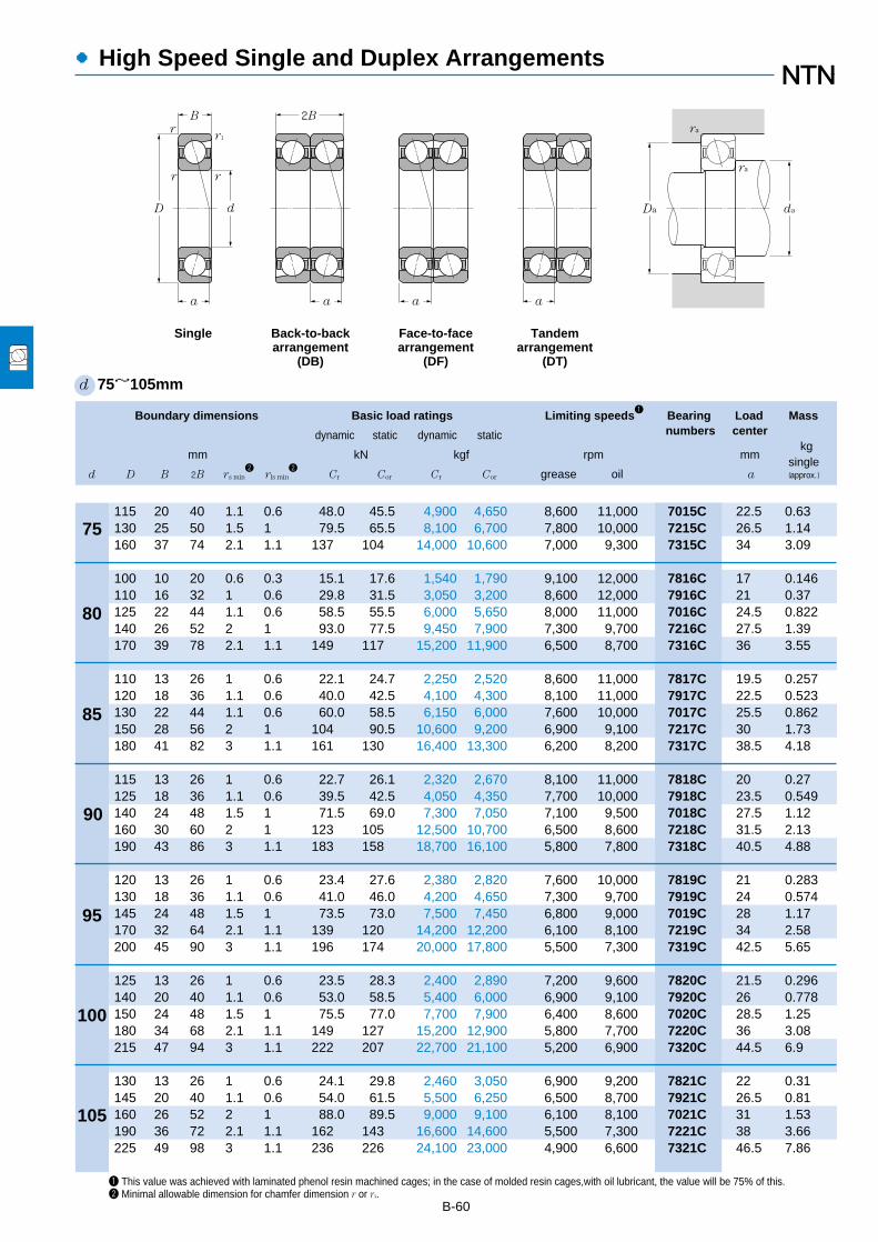
●High Speed Single and Duplex Arrangements
B-60
Boundary dimensions Basic load ratings Limiting speeds1
Bearing Load Mass
dynamic static dynamic static numbers centerkg
mm kN kgf rpm mmsingle
d D B 2B rs min2
rls min2
Cr Cor Cr Cor grease oil a (approx.)
80
85
90
95
100
105
1 This value was achieved with laminated phenol resin machined cages; in the case of molded resin cages,with oil lubricant, the value will be 75% of this.2 Minimal allowable dimension for chamfer dimension r or r1.
d 75~105mm
D d
B
a a
2B
a a
Da da
ra
ra
Single Back-to-backarrangement
(DB)
Face-to-facearrangement
(DF)
Tandemarrangement
(DT)
r1
rr
r
75115 20 40 1.1 0.6 48.0 45.5 4,900 4,650 8,600 11,000 7015C 22.5 0.63130 25 50 1.5 1 79.5 65.5 8,100 6,700 7,800 10,000 7215C 26.5 1.14160 37 74 2.1 1.1 137 104 14,000 10,600 7,000 9,300 7315C 34 3.09
100 10 20 0.6 0.3 15.1 17.6 1,540 1,790 9,100 12,000 7816C 17 0.146110 16 32 1 0.6 29.8 31.5 3,050 3,200 8,600 12,000 7916C 21 0.37125 22 44 1.1 0.6 58.5 55.5 6,000 5,650 8,000 11,000 7016C 24.5 0.822140 26 52 2 1 93.0 77.5 9,450 7,900 7,300 9,700 7216C 27.5 1.39170 39 78 2.1 1.1 149 117 15,200 11,900 6,500 8,700 7316C 36 3.55
110 13 26 1 0.6 22.1 24.7 2,250 2,520 8,600 11,000 7817C 19.5 0.257120 18 36 1.1 0.6 40.0 42.5 4,100 4,300 8,100 11,000 7917C 22.5 0.523130 22 44 1.1 0.6 60.0 58.5 6,150 6,000 7,600 10,000 7017C 25.5 0.862150 28 56 2 1 104 90.5 10,600 9,200 6,900 9,100 7217C 30 1.73180 41 82 3 1.1 161 130 16,400 13,300 6,200 8,200 7317C 38.5 4.18
115 13 26 1 0.6 22.7 26.1 2,320 2,670 8,100 11,000 7818C 20 0.27125 18 36 1.1 0.6 39.5 42.5 4,050 4,350 7,700 10,000 7918C 23.5 0.549140 24 48 1.5 1 71.5 69.0 7,300 7,050 7,100 9,500 7018C 27.5 1.12160 30 60 2 1 123 105 12,500 10,700 6,500 8,600 7218C 31.5 2.13190 43 86 3 1.1 183 158 18,700 16,100 5,800 7,800 7318C 40.5 4.88
120 13 26 1 0.6 23.4 27.6 2,380 2,820 7,600 10,000 7819C 21 0.283130 18 36 1.1 0.6 41.0 46.0 4,200 4,650 7,300 9,700 7919C 24 0.574145 24 48 1.5 1 73.5 73.0 7,500 7,450 6,800 9,000 7019C 28 1.17170 32 64 2.1 1.1 139 120 14,200 12,200 6,100 8,100 7219C 34 2.58200 45 90 3 1.1 196 174 20,000 17,800 5,500 7,300 7319C 42.5 5.65
125 13 26 1 0.6 23.5 28.3 2,400 2,890 7,200 9,600 7820C 21.5 0.296140 20 40 1.1 0.6 53.0 58.5 5,400 6,000 6,900 9,100 7920C 26 0.778150 24 48 1.5 1 75.5 77.0 7,700 7,900 6,400 8,600 7020C 28.5 1.25180 34 68 2.1 1.1 149 127 15,200 12,900 5,800 7,700 7220C 36 3.08215 47 94 3 1.1 222 207 22,700 21,100 5,200 6,900 7320C 44.5 6.9
130 13 26 1 0.6 24.1 29.8 2,460 3,050 6,900 9,200 7821C 22 0.31145 20 40 1.1 0.6 54.0 61.5 5,500 6,250 6,500 8,700 7921C 26.5 0.81160 26 52 2 1 88.0 89.5 9,000 9,100 6,100 8,100 7021C 31 1.53190 36 72 2.1 1.1 162 143 16,600 14,600 5,500 7,300 7221C 38 3.66225 49 98 3 1.1 236 226 24,100 23,000 4,900 6,600 7321C 46.5 7.86

B-61
3 For back-to-back and face-to-face duplex arrangements, find with the formula 2Fa / Cor.Note: This bearing has a contact angle of 15°and is manufactured with accuracies of JIS Class 5 or higher.
Basic load ratings Limiting speeds1
Bearing numbers Abutment and fillet dimensionsdynamic static dynamic static (duplex)
(duplex) (duplex) mmkN kgf rpm DB DF DT da Da Db ras r1as
Cr Cor Cr Cor grease oil min max max max max
●High Speed Single and Duplex Arrangements
Db da
rara
Dada
rar1a
0.0100.0200.0400.0700.100.150.200.300.400.50
e
X Y
Pr=XFr+YFa
Por=Xo Fr+Yo Fa
Fa/Fr≦e Fa/Fr>e
Single, DT DB, DFFa/Fr≦e Fa/Fr>e
X Y X Y X Y
0.370.390.410.440.460.490.510.550.560.56
1 0 0.44
1.511.451.361.281.221.151.101.021.001.00
1
1.701.621.521.431.371.291.231.151.121.12
0.72
2.462.352.212.081.981.871.781.661.631.63
Xo0.5
Yo Xo Yo0.46 1 0.92
Cor
Fa3)�
For single and DT arrangement,When Por<Fr use Por=Fr
Equivalent bearing loaddynamic
static
Single, DT DB, DF
78.0 91.5 7,950 9,300 6,800 9,000 DB DF DT 82 108 110.5 1 0.6129 131 13,100 13,400 6,200 8,200 DB DF DT 83.5 121.5 124.5 1.5 1223 208 22,800 21,200 5,500 7,400 DB DF DT 87 148 153 2 1
24.6 35.0 2,510 3,600 7,200 9,600 DB DF DT 84.5 95.5 97.5 0.6 0.348.5 63.0 4,950 6,450 6,800 9,100 DB DF DT 85.5 104.5 105.5 1 0.695.5 111 9,700 11,300 6,400 8,500 DB DF DT 87 118 120.5 1 0.6
151 155 15,400 15,800 5,800 7,700 DB DF DT 90 130 134.5 2 1242 234 24,700 23,800 5,200 6,900 DB DF DT 92 158 163 2 1
36.0 49.5 3,650 5,050 6,800 9,100 DB DF DT 90.5 104.5 105.5 1 0.665.0 84.5 6,650 8,650 6,400 8,600 DB DF DT 92 113 115.5 1 0.698.0 117 9,950 12,000 6,000 8,000 DB DF DT 92 123 125.5 1 0.6
169 181 17,200 18,400 5,400 7,200 DB DF DT 95 140 144.5 2 1261 261 26,600 26,600 4,900 6,500 DB DF DT 99 166 173 2.5 1
37.0 52.5 3,750 5,350 6,400 8,500 DB DF DT 95.5 109.5 110.5 1 0.664.5 85.0 6,550 8,700 6,100 8,100 DB DF DT 97 118 120.5 1 0.6
116 138 11,900 14,100 5,700 7,500 DB DF DT 98.5 131.5 134.5 1.5 1199 209 20,300 21,400 5,100 6,800 DB DF DT 100 150 154.5 2 1297 315 30,500 32,000 4,600 6,100 DB DF DT 104 176 183 2.5 1
38.0 55.5 3,850 5,650 6,000 8,000 DB DF DT 100.5 114.5 115.5 1 0.667.0 91.5 6,850 9,350 5,800 7,700 DB DF DT 102 123 125.5 1 0.6
119 146 12,200 14,900 5,400 7,100 DB DF DT 103.5 136.5 139.5 1.5 1226 240 23,000 24,400 4,800 6,400 DB DF DT 107 158 163 2 1320 350 32,500 35,500 4,300 5,800 DB DF DT 109 186 193 2.5 1
38.0 56.5 3,900 5,750 5,700 7,600 DB DF DT 105.5 119.5 120.5 1 0.686.0 117 8,750 12,000 5,400 7,200 DB DF DT 107 133 135.5 1 0.6
122 154 12,500 15,800 5,100 6,800 DB DF DT 108.5 141.5 144.5 1.5 1242 254 24,700 25,900 4,600 6,100 DB DF DT 112 168 173 2 1360 415 37,000 42,000 4,100 5,500 DB DF DT 114 201 208 2.5 1
39.0 59.5 4,000 6,050 5,500 7,300 DB DF DT 110.5 124.5 125.5 1 0.687.5 123 8,900 12,500 5,200 6,900 DB DF DT 112 138 140.5 1 0.6
143 179 14,600 18,200 4,800 6,400 DB DF DT 115 150 154.5 2 1264 286 26,900 29,100 4,400 5,800 DB DF DT 117 178 183 2 1385 450 39,000 46,000 3,900 5,200 DB DF DT 119 211 218 2.5 1
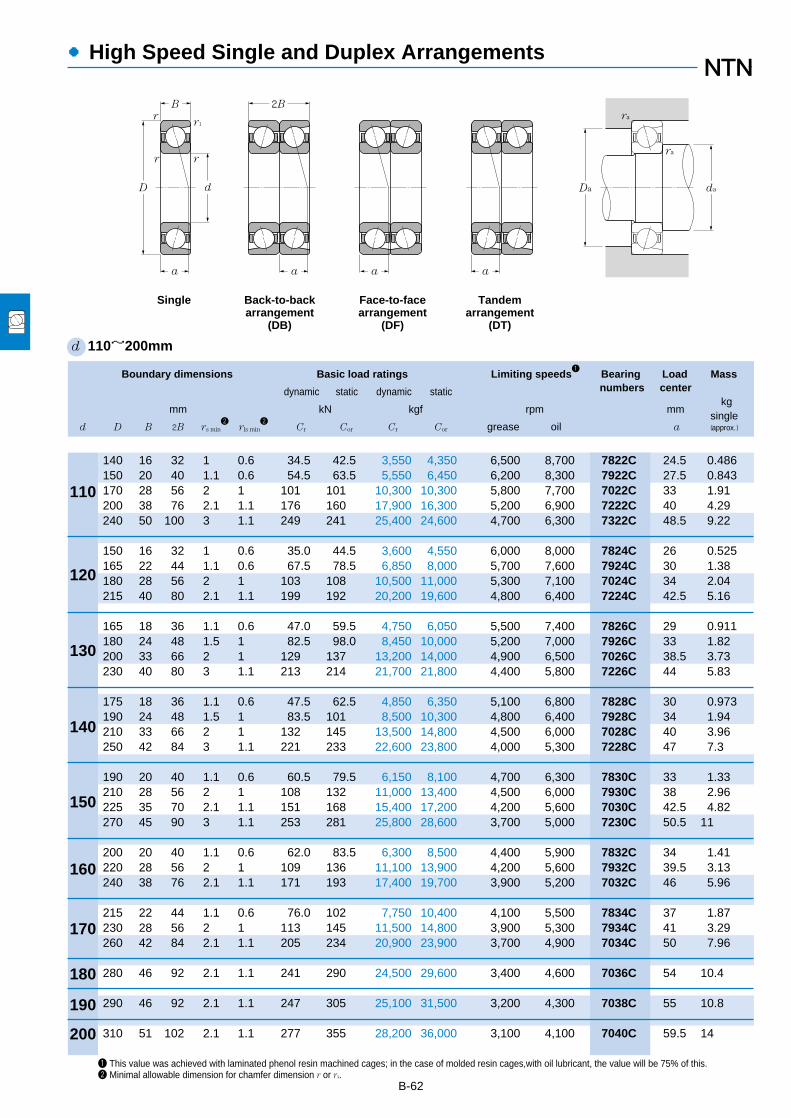
●High Speed Single and Duplex Arrangements
B-62
Boundary dimensions Basic load ratings Limiting speeds1
Bearing Load Mass
dynamic static dynamic static numbers centerkg
mm kN kgf rpm mmsingle
d D B 2B rs min2
rls min2
Cr Cor Cr Cor grease oil a (approx.)
110
120
130
140
150
160
170
180
1 This value was achieved with laminated phenol resin machined cages; in the case of molded resin cages,with oil lubricant, the value will be 75% of this.2 Minimal allowable dimension for chamfer dimension r or r1.
d 110~200mm
D d
B
a a
2B
a a
Da da
ra
ra
Single Back-to-backarrangement
(DB)
Face-to-facearrangement
(DF)
Tandemarrangement
(DT)
r1
rr
r
190
200
140 16 32 1 0.6 34.5 42.5 3,550 4,350 6,500 8,700 7822C 24.5 0.486150 20 40 1.1 0.6 54.5 63.5 5,550 6,450 6,200 8,300 7922C 27.5 0.843170 28 56 2 1 101 101 10,300 10,300 5,800 7,700 7022C 33 1.91200 38 76 2.1 1.1 176 160 17,900 16,300 5,200 6,900 7222C 40 4.29240 50 100 3 1.1 249 241 25,400 24,600 4,700 6,300 7322C 48.5 9.22
150 16 32 1 0.6 35.0 44.5 3,600 4,550 6,000 8,000 7824C 26 0.525165 22 44 1.1 0.6 67.5 78.5 6,850 8,000 5,700 7,600 7924C 30 1.38180 28 56 2 1 103 108 10,500 11,000 5,300 7,100 7024C 34 2.04215 40 80 2.1 1.1 199 192 20,200 19,600 4,800 6,400 7224C 42.5 5.16
165 18 36 1.1 0.6 47.0 59.5 4,750 6,050 5,500 7,400 7826C 29 0.911180 24 48 1.5 1 82.5 98.0 8,450 10,000 5,200 7,000 7926C 33 1.82200 33 66 2 1 129 137 13,200 14,000 4,900 6,500 7026C 38.5 3.73230 40 80 3 1.1 213 214 21,700 21,800 4,400 5,800 7226C 44 5.83
175 18 36 1.1 0.6 47.5 62.5 4,850 6,350 5,100 6,800 7828C 30 0.973190 24 48 1.5 1 83.5 101 8,500 10,300 4,800 6,400 7928C 34 1.94210 33 66 2 1 132 145 13,500 14,800 4,500 6,000 7028C 40 3.96250 42 84 3 1.1 221 233 22,600 23,800 4,000 5,300 7228C 47 7.3
190 20 40 1.1 0.6 60.5 79.5 6,150 8,100 4,700 6,300 7830C 33 1.33210 28 56 2 1 108 132 11,000 13,400 4,500 6,000 7930C 38 2.96225 35 70 2.1 1.1 151 168 15,400 17,200 4,200 5,600 7030C 42.5 4.82270 45 90 3 1.1 253 281 25,800 28,600 3,700 5,000 7230C 50.5 11
200 20 40 1.1 0.6 62.0 83.5 6,300 8,500 4,400 5,900 7832C 34 1.41220 28 56 2 1 109 136 11,100 13,900 4,200 5,600 7932C 39.5 3.13240 38 76 2.1 1.1 171 193 17,400 19,700 3,900 5,200 7032C 46 5.96
215 22 44 1.1 0.6 76.0 102 7,750 10,400 4,100 5,500 7834C 37 1.87230 28 56 2 1 113 145 11,500 14,800 3,900 5,300 7934C 41 3.29260 42 84 2.1 1.1 205 234 20,900 23,900 3,700 4,900 7034C 50 7.96
280 46 92 2.1 1.1 241 290 24,500 29,600 3,400 4,600 7036C 54 10.4
290 46 92 2.1 1.1 247 305 25,100 31,500 3,200 4,300 7038C 55 10.8
310 51 102 2.1 1.1 277 355 28,200 36,000 3,100 4,100 7040C 59.5 14

B-63
3 For back-to-back and face-to-face duplex arrangements, find with the formula 2Fa / Cor.Note: This bearing has a contact angle of 15°and is manufactured with accuracies of JIS Class 5 or higher.
Basic load ratings Limiting speeds1
Bearing numbers Abutment and fillet dimensionsdynamic static dynamic static (duplex)
(duplex) (duplex) mmkN kgf rpm DB DF DT da Da Db ras r1as
Cr Cor Cr Cor grease oil min max max max max
●High Speed Single and Duplex Arrangements
Db da
rara
Dada
rar1a
0.0100.0200.0400.0700.100.150.200.300.400.50
e
X Y
Pr=XFr+YFa
Por=Xo Fr+Yo Fa
Fa/Fr≦e Fa/Fr>e
Single, DT DB, DFFa/Fr≦e Fa/Fr>e
X Y X Y X Y
0.370.390.410.440.460.490.510.550.560.56
1 0 0.44
1.511.451.361.281.221.151.101.021.001.00
1
1.701.621.521.431.371.291.231.151.121.12
0.72
2.462.352.212.081.981.871.781.661.631.63
Xo0.5
Yo Xo Yo0.46 1 0.92
Cor
Fa3)�
For single and DT arrangement,When Por<Fr use Por=Fr
Equivalent bearing loaddynamic
static
Single, DT DB, DF
56.0 85.0 5,750 8,700 5,200 6,900 DB DF DT 115.5 134.5 135.5 1 0.689.0 127 9,050 12,900 4,900 6,600 DB DF DT 117 143 145.5 1 0.6
164 203 16,700 20,700 4,600 6,100 DB DF DT 120 160 164.5 2 1286 320 29,200 32,500 4,100 5,500 DB DF DT 122 188 193 2 1405 485 41,000 49,000 3,700 5,000 DB DF DT 124 226 233 2.5 1
57.0 89.5 5,800 9,100 4,700 6,300 DB DF DT 125.5 144.5 145.5 1 0.6109 157 11,200 16,000 4,500 6,000 DB DF DT 127 158 160.5 1 0.6168 216 17,100 22,000 4,200 5,600 DB DF DT 130 170 174.5 2 1325 385 33,000 39,000 3,800 5,000 DB DF DT 132 203 208 2 1
76.0 119 7,750 12,100 4,400 5,800 DB DF DT 137 158 160.5 1 0.60134 196 13,700 20,000 4,100 5,500 DB DF DT 138.5 171.5 174.5 1.5 1210 274 21,400 28,000 3,800 5,100 DB DF DT 140 190 194.5 2 1345 430 35,500 43,500 3,500 4,600 DB DF DT 144 216 223 2.5 1
77.5 125 7,900 12,700 4,000 5,400 DB DF DT 147 168 170.5 1 0.6136 203 13,800 20,700 3,800 5,100 DB DF DT 148.5 181.5 184.5 1.5 1214 290 21,900 29,600 3,600 4,800 DB DF DT 150 200 204.5 2 1360 465 36,500 47,500 3,200 4,200 DB DF DT 154 236 243 2.5 1
98.5 159 10,000 16,200 3,700 5,000 DB DF DT 157 183 185.5 1 0.6175 263 17,800 26,800 3,600 4,800 DB DF DT 160 200 204.5 2 1245 335 25,000 34,500 3,300 4,400 DB DF DT 162 213 218 2 1410 560 42,000 57,500 3,000 4,000 DB DF DT 164 256 263 2.5 1
100 167 10,200 17,000 3,500 4,700 DB DF DT 167 193 195.5 1 0.6177 272 18,100 27,800 3,300 4,400 DB DF DT 170 210 214.5 2 1278 385 28,300 39,500 3,100 4,100 DB DF DT 172 228 233 2 1
123 204 12,600 20,800 3,300 4,400 DB DF DT 177 208 210.5 1 0.6183 290 18,700 29,600 3,100 4,200 DB DF DT 180 220 224.5 2 1330 470 34,000 48,000 2,900 3,900 DB DF DT 182 248 253 2 1
390 580 40,000 59,000 2,700 3,600 DB DF DT 192 268 273 2 1
400 615 41,000 62,500 2,600 3,400 DB DF DT 202 278 283 2 1
450 710 46,000 72,500 2,400 3,200 DB DF DT 212 298 303 2 1
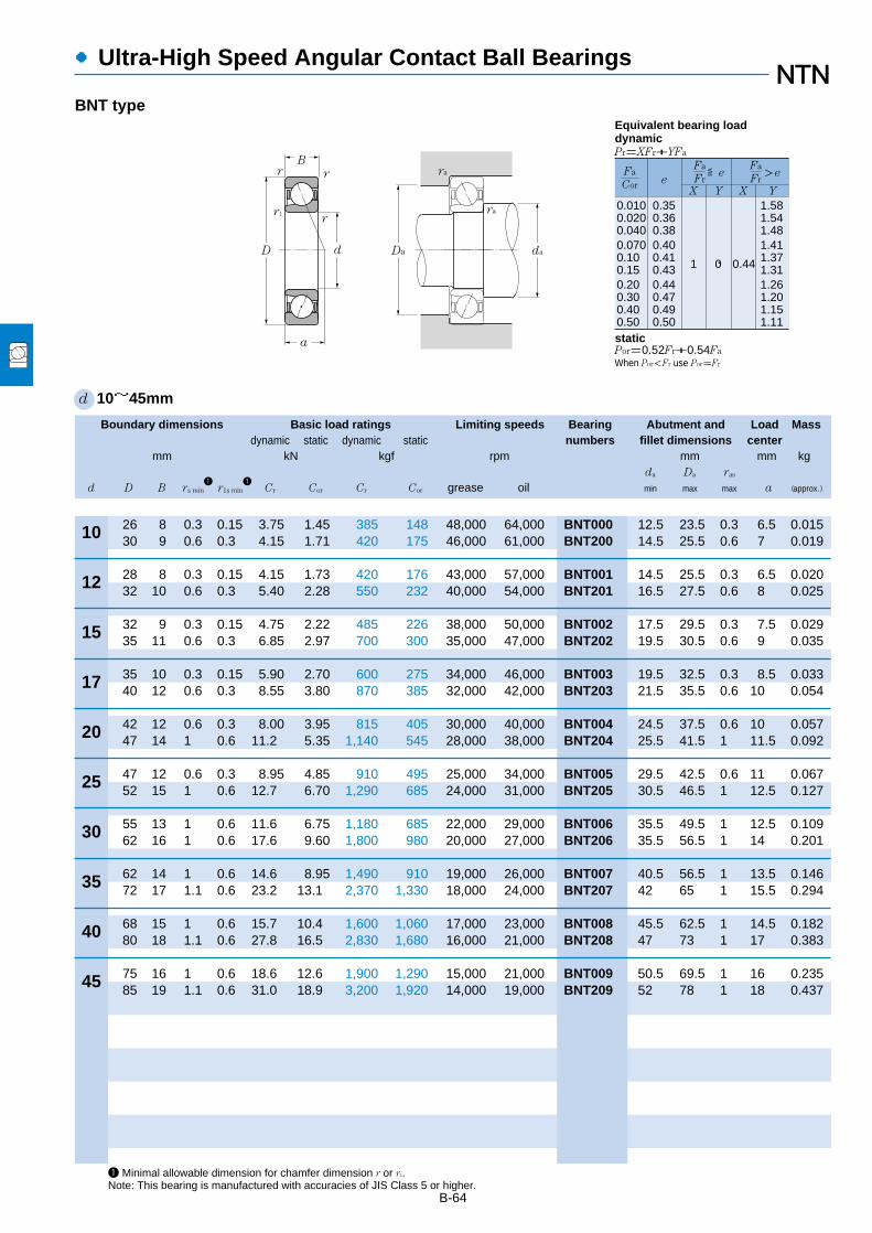
Boundary dimensions Basic load ratings Limiting speeds Bearing Abutment and Load Massdynamic static dynamic static numbers fillet dimensions center
mm kN kgf rpm mm mm kgda Da ras
d D B rs min1
r1s min1
Cr Cor Cr Cor grease oil min max max a (approx.)
●Ultra-High Speed Angular Contact Ball Bearings
B-64
1 Minimal allowable dimension for chamfer dimension r or r1.Note: This bearing is manufactured with accuracies of JIS Class 5 or higher.
d 10~45mm
12
15
17
20
25
30
35
40
45
10
0.0100.0200.0400.0700.100.150.200.300.400.50
0.350.360.380.400.410.430.440.470.490.50
1 0 0.44
1.581.541.481.411.371.311.261.201.151.11
Fa
FreX Y X Y
≦eFa
Cor
Fa
Fr>e
Pr=XFr+YFa
D d
B
a
r1r
rr
Da da
ra
ra
Por=0.52Fr+0.54Fa
When Por<Fr use Por=Fr
Equivalent bearing loaddynamic
static
26 8 0.3 0.15 3.75 1.45 385 148 48,000 64,000 BNT000 12.5 23.5 0.3 6.5 0.01530 9 0.6 0.3 4.15 1.71 420 175 46,000 61,000 BNT200 14.5 25.5 0.6 7 0.019
28 8 0.3 0.15 4.15 1.73 420 176 43,000 57,000 BNT001 14.5 25.5 0.3 6.5 0.02032 10 0.6 0.3 5.40 2.28 550 232 40,000 54,000 BNT201 16.5 27.5 0.6 8 0.025
32 9 0.3 0.15 4.75 2.22 485 226 38,000 50,000 BNT002 17.5 29.5 0.3 7.5 0.02935 11 0.6 0.3 6.85 2.97 700 300 35,000 47,000 BNT202 19.5 30.5 0.6 9 0.035
35 10 0.3 0.15 5.90 2.70 600 275 34,000 46,000 BNT003 19.5 32.5 0.3 8.5 0.03340 12 0.6 0.3 8.55 3.80 870 385 32,000 42,000 BNT203 21.5 35.5 0.6 10 0.054
42 12 0.6 0.3 8.00 3.95 815 405 30,000 40,000 BNT004 24.5 37.5 0.6 10 0.05747 14 1 0.6 11.2 5.35 1,140 545 28,000 38,000 BNT204 25.5 41.5 1 11.5 0.092
47 12 0.6 0.3 8.95 4.85 910 495 25,000 34,000 BNT005 29.5 42.5 0.6 11 0.06752 15 1 0.6 12.7 6.70 1,290 685 24,000 31,000 BNT205 30.5 46.5 1 12.5 0.127
55 13 1 0.6 11.6 6.75 1,180 685 22,000 29,000 BNT006 35.5 49.5 1 12.5 0.10962 16 1 0.6 17.6 9.60 1,800 980 20,000 27,000 BNT206 35.5 56.5 1 14 0.201
62 14 1 0.6 14.6 8.95 1,490 910 19,000 26,000 BNT007 40.5 56.5 1 13.5 0.14672 17 1.1 0.6 23.2 13.1 2,370 1,330 18,000 24,000 BNT207 42 65 1 15.5 0.294
68 15 1 0.6 15.7 10.4 1,600 1,060 17,000 23,000 BNT008 45.5 62.5 1 14.5 0.18280 18 1.1 0.6 27.8 16.5 2,830 1,680 16,000 21,000 BNT208 47 73 1 17 0.383
75 16 1 0.6 18.6 12.6 1,900 1,290 15,000 21,000 BNT009 50.5 69.5 1 16 0.23585 19 1.1 0.6 31.0 18.9 3,200 1,920 14,000 19,000 BNT209 52 78 1 18 0.437
BNT type

B-65
●Ultra-High Speed Angular Contact Ball Bearings
Boundary dimensions Basic load ratings Limiting speeds Bearing Abutment and Load Massdynamic static dynamic static numbers fillet dimensions center
mm kN kgf rpm mm mm kgda Da ras
d D B rs min1
r1s min1
Cr Cor Cr Cor grease oil min max max a (approx.)
1 Minimal allowable dimension for chamfer dimension r or r1.Note: This bearing is manufactured with accuracies of JIS Class 5 or higher.
d 50~110mm
72 12 0.6 0.3 10.6 7.30 1,080 745 15,000 20,000 HSB910C 54.5 67.5 0.6 14 0.14180 16 1 0.6 20.8 11.4 2,120 1,160 14,000 19,000 HSB010C 55.5 74.5 1 16.5 0.256
80 13 1 0.6 13.5 9.20 1,380 940 14,000 18,000 HSB911C 60.5 74.5 1 15.5 0.19290 18 1.1 0.6 22.6 13.6 2,300 1,380 13,000 17,000 HSB011C 62 83 1 18.5 0.397
85 13 1 0.6 13.9 9.95 1,420 1,010 13,000 17,000 HSB912C 65.5 79.5 1 16 0.20695 18 1.1 0.6 23.7 15.0 2,410 1,530 12,000 16,000 HSB012C 67 88 1 19.5 0.425
90 13 1 0.6 14.3 10.7 1,460 1,090 12,000 16,000 HSB913C 70.5 84.5 1 17 0.22100 18 1.1 0.6 24 15.8 2,450 1,610 11,000 15,000 HSB013C 72 93 1 20 0.452
100 16 1 0.6 18 13.5 1,830 1,370 11,000 15,000 HSB914C 75.5 94.5 1 19.5 0.362110 20 1.1 0.6 29.4 19.9 3,000 2,030 10,000 14,000 HSB014C 77 103 1 22 0.64
105 16 1 0.6 18.5 14.4 1,880 1,470 10,000 14,000 HSB915C 80.5 99.5 1 20 0.383115 20 1.1 0.6 31.5 22.4 3,200 2,290 9,500 13,000 HSB015C 82 108 1 22.5 0.68
110 16 1 0.6 18.9 15.4 1,930 1,570 9,600 13,000 HSB916C 85.5 104.5 1 20.5 0.405125 22 1.1 0.6 36 25.7 3,650 2,620 8,900 12,000 HSB016C 87 118 1 24.5 0.915
120 18 1.1 0.6 22.7 18.3 2,320 1,860 9,000 12,000 HSB917C 92 113 1 22.5 0.578130 22 1.1 0.6 36.5 26.8 3,700 2,740 8,400 11,000 HSB017C 92 123 1 25.5 0.959
125 18 1.1 0.6 23.4 19.5 2,380 1,980 8,500 11,000 HSB918C 97 118 1 23.5 0.607140 24 1.5 1 42 31.5 4,300 3,200 7,900 11,000 HSB018C 98.5 131.5 1.5 27.5 1.25
130 18 1.1 0.6 24 20.6 2,440 2,110 8,100 11,000 HSB919C 102 123 1 24 0.636145 24 1.5 1 42.5 32.5 4,350 3,350 7,500 10,000 HSB019C 103.5 136.5 1.5 28 1.3
140 20 1.1 0.6 33.5 28 3,450 2,850 7,600 10,000 HSB920C 107 133 1 26 0.856150 24 1.5 1 44 35 4,500 3,600 7,100 9,500 HSB020C 108.5 141.5 1.5 28.5 1.36
145 20 1.1 0.6 34.5 29.7 3,550 3,050 7,300 9,700 HSB921C 112 138 1 26.5 0.893160 26 2 1 50.5 40.5 5,150 4,150 6,700 9,000 HSB021C 115 150 2 31 1.73
150 20 1.1 0.6 35 30.5 3,550 3,150 6,900 9,200 HSB922C 117 143 1 27.5 0.928170 28 2 1 62.5 49.5 6,400 5,000 6,400 8,600 HSB022C 120 160 2 33 2.13
50
55
60
70
75
80
85
90
95
100
105
110
65
d
ra
r1
D
B
da
ra
rr1
r
Da
a
0.0100.0200.0400.0700.100.150.200.300.400.50
0.350.360.380.400.410.430.440.470.490.50
1 0 0.44
1.581.541.481.411.371.311.261.201.151.11
Fa
FreX Y X Y
≦eFa
Cor
Fa
Fr>e
Pr=XFr+YFa
Por=0.52Fr+0.54Fa
When Por<Fr use Por=Fr
Equivalent bearing loaddynamic
static
HSB type
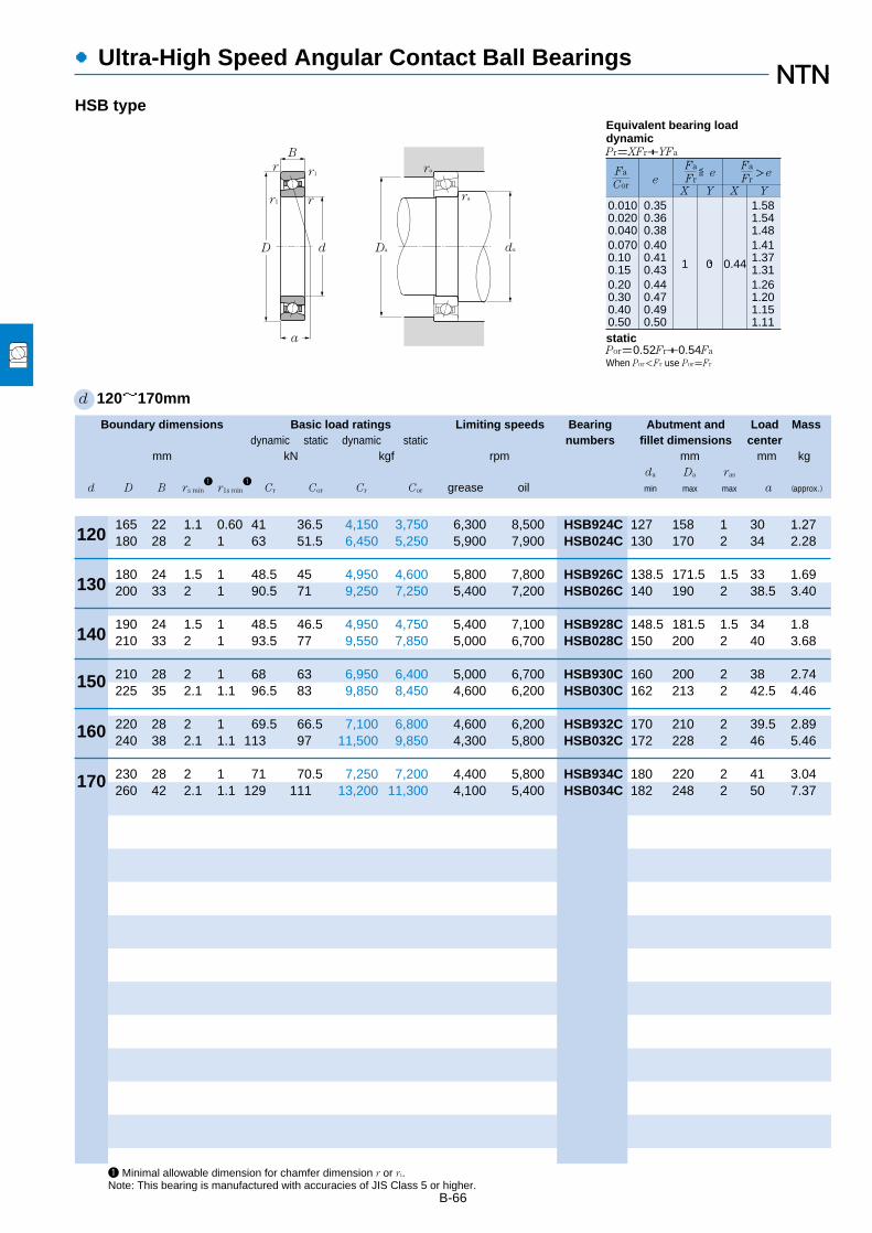
B-66
●Ultra-High Speed Angular Contact Ball Bearings
Boundary dimensions Basic load ratings Limiting speeds Bearing Abutment and Load Massdynamic static dynamic static numbers fillet dimensions center
mm kN kgf rpm mm mm kgda Da ras
d D B rs min1
r1s min1
Cr Cor Cr Cor grease oil min max max a (approx.)
1 Minimal allowable dimension for chamfer dimension r or r1.Note: This bearing is manufactured with accuracies of JIS Class 5 or higher.
d 120~170mm
160
170
150
d
ra
r1
D
B
da
ra
rr1
r
Da
a
0.0100.0200.0400.0700.100.150.200.300.400.50
0.350.360.380.400.410.430.440.470.490.50
1 0 0.44
1.581.541.481.411.371.311.261.201.151.11
Fa
FreX Y X Y
≦eFa
Cor
Fa
Fr>e
Pr=XFr+YFa
Por=0.52Fr+0.54Fa
When Por<Fr use Por=Fr
Equivalent bearing loaddynamic
static
120
130
140
165 22 1.1 0.60 41 36.5 4,150 3,750 6,300 8,500 HSB924C 127 158 1 30 1.27180 28 2 1 63 51.5 6,450 5,250 5,900 7,900 HSB024C 130 170 2 34 2.28
180 24 1.5 1 48.5 45 4,950 4,600 5,800 7,800 HSB926C 138.5 171.5 1.5 33 1.69200 33 2 1 90.5 71 9,250 7,250 5,400 7,200 HSB026C 140 190 2 38.5 3.40
190 24 1.5 1 48.5 46.5 4,950 4,750 5,400 7,100 HSB928C 148.5 181.5 1.5 34 1.8210 33 2 1 93.5 77 9,550 7,850 5,000 6,700 HSB028C 150 200 2 40 3.68
210 28 2 1 68 63 6,950 6,400 5,000 6,700 HSB930C 160 200 2 38 2.74225 35 2.1 1.1 96.5 83 9,850 8,450 4,600 6,200 HSB030C 162 213 2 42.5 4.46
220 28 2 1 69.5 66.5 7,100 6,800 4,600 6,200 HSB932C 170 210 2 39.5 2.89240 38 2.1 1.1 113 97 11,500 9,850 4,300 5,800 HSB032C 172 228 2 46 5.46
230 28 2 1 71 70.5 7,250 7,200 4,400 5,800 HSB934C 180 220 2 41 3.04260 42 2.1 1.1 129 111 13,200 11,300 4,100 5,400 HSB034C 182 248 2 50 7.37
HSB type

B-67
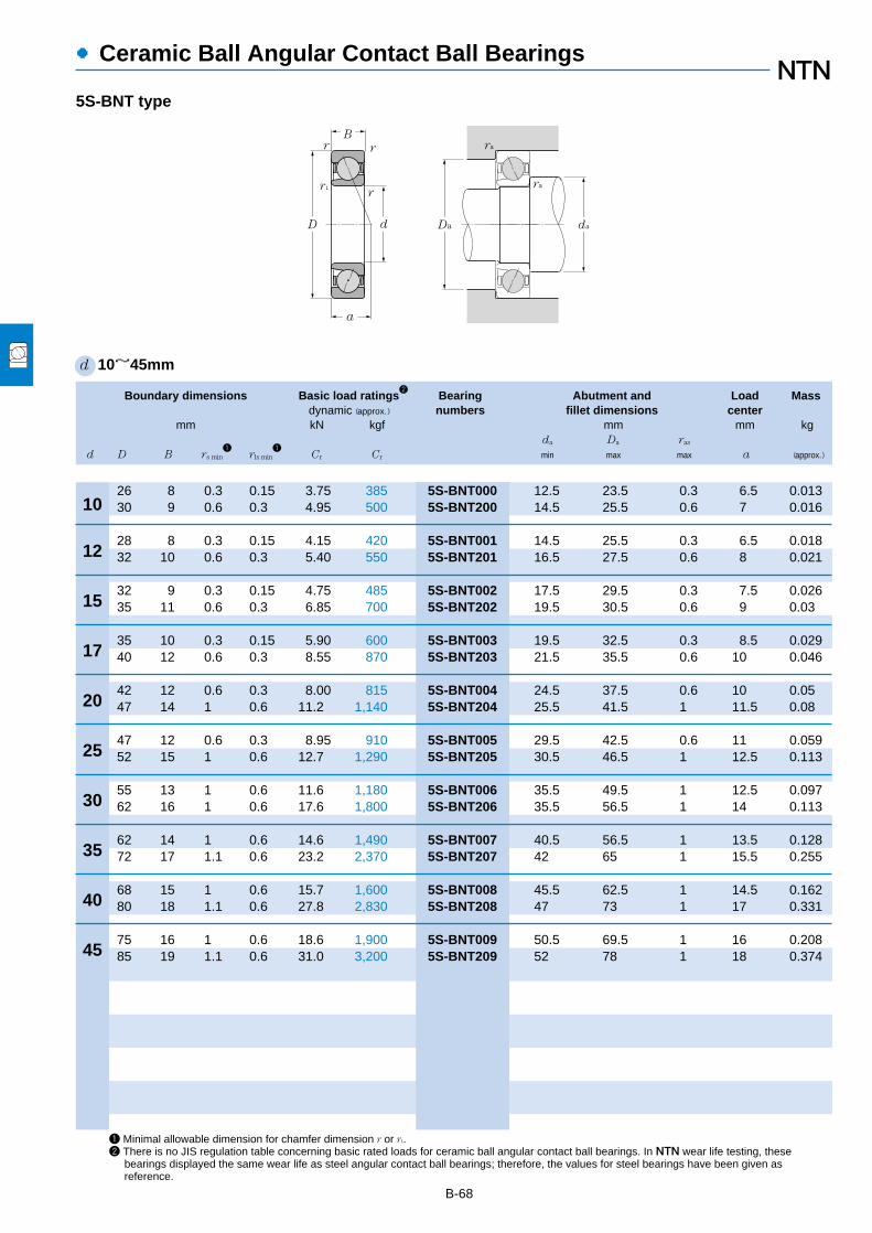
B-68
●Ceramic Ball Angular Contact Ball Bearings
10
12
15
17
20
25
30
35
40
45
1 Minimal allowable dimension for chamfer dimension r or r1.2 There is no JIS regulation table concerning basic rated loads for ceramic ball angular contact ball bearings. In NTN wear life testing, these
bearings displayed the same wear life as steel angular contact ball bearings; therefore, the values for steel bearings have been given as reference.
d 10~45mm
D d
B
a
r1r
rr
Da da
ra
ra
Boundary dimensions Basic load ratings2
Bearing Abutment and Load Massdynamic (approx.) numbers fillet dimensions center
mm kN kgf mm mm kgda Da ras
d D B rs min1
rls min1
Cr Cr min max max a (approx.)
5S-BNT type
26 8 0.3 0.15 3.75 385 5S-BNT000 12.5 23.5 0.3 6.5 0.01330 9 0.6 0.3 4.95 500 5S-BNT200 14.5 25.5 0.6 7 0.016
28 8 0.3 0.15 4.15 420 5S-BNT001 14.5 25.5 0.3 6.5 0.01832 10 0.6 0.3 5.40 550 5S-BNT201 16.5 27.5 0.6 8 0.021
32 9 0.3 0.15 4.75 485 5S-BNT002 17.5 29.5 0.3 7.5 0.02635 11 0.6 0.3 6.85 700 5S-BNT202 19.5 30.5 0.6 9 0.03
35 10 0.3 0.15 5.90 600 5S-BNT003 19.5 32.5 0.3 8.5 0.02940 12 0.6 0.3 8.55 870 5S-BNT203 21.5 35.5 0.6 10 0.046
42 12 0.6 0.3 8.00 815 5S-BNT004 24.5 37.5 0.6 10 0.0547 14 1 0.6 11.2 1,140 5S-BNT204 25.5 41.5 1 11.5 0.08
47 12 0.6 0.3 8.95 910 5S-BNT005 29.5 42.5 0.6 11 0.05952 15 1 0.6 12.7 1,290 5S-BNT205 30.5 46.5 1 12.5 0.113
55 13 1 0.6 11.6 1,180 5S-BNT006 35.5 49.5 1 12.5 0.09762 16 1 0.6 17.6 1,800 5S-BNT206 35.5 56.5 1 14 0.113
62 14 1 0.6 14.6 1,490 5S-BNT007 40.5 56.5 1 13.5 0.12872 17 1.1 0.6 23.2 2,370 5S-BNT207 42 65 1 15.5 0.255
68 15 1 0.6 15.7 1,600 5S-BNT008 45.5 62.5 1 14.5 0.16280 18 1.1 0.6 27.8 2,830 5S-BNT208 47 73 1 17 0.331
75 16 1 0.6 18.6 1,900 5S-BNT009 50.5 69.5 1 16 0.20885 19 1.1 0.6 31.0 3,200 5S-BNT209 52 78 1 18 0.374

d
ra
r1
D
B
da
ra
rr1
r
Da
a
B-69
1 Minimal allowable dimension for chamfer dimension r or r1. 2 There is no JIS formula concerning basic rated loads for ceramic ball angular contact ball bearings. In NTN fatigue life tests, these bearingsachieved the same fatigue life as steel angular contact ball bearings; therefore, the values for steel bearings have been given as reference.Note: For bearings with a bore diameter larger than 120mm, consult NTN Engineering.
Boundary dimensions Basic load ratings2
Bearing Abutment and Load Massdynamic (approx.) numbers fillet dimensions center
mm kN kgf mm mm kgda Da ras
d D B rs min1
rls min1
Cr Cr min max max a (approx.)
●Ceramic Ball Angular Contact Ball Bearings
5S-HSB type
50
55
60
65
70
75
80
85
90
95
100
105
110
d 50~120mm
120
72 12 0.6 0.3 10.6 1,080 5S-HSB910C 54.5 67.5 0.6 14 0.13480 16 1 0.6 20.8 2,120 5S-HSB010C 55.5 74.5 1 16.5 0.234
80 13 1 0.6 13.5 1,380 5S-HSB911C 60.5 74.5 1 15.5 0.1890 18 1.1 0.6 22.6 2,300 5S-HSB011C 62 83 1 18.5 0.372
85 13 1 0.6 13.9 1,420 5S-HSB912C 65.5 79.5 1 16 0.19495 18 1.1 0.6 23.7 2,410 5S-HSB012C 67 88 1 19.5 0.398
90 13 1 0.6 14.3 1,460 5S-HSB913C 70.5 84.5 1 17 0.207100 18 1.1 0.6 24.0 2,450 5S-HSB103C 72 93 1 20 0.423
100 16 1 0.6 18.0 1,830 5S-HSB914C 75.5 94.5 1 19.5 0.343110 20 1.1 0.6 29.4 3,000 5S-HSB014C 77 103 1 22 0.601
105 16 1 0.6 18.5 1,880 5S-HSB915C 80.5 99.5 1 20 0.363115 20 1.1 0.6 31.5 3,200 5S-HSB015C 82 108 1 22.5 0.636
110 16 1 0.6 18.9 1,930 5S-HSB916C 85.5 104.5 1 20.5 0.384125 22 1.1 0.6 36.0 3,650 5S-HSB016C 87 118 1 24.5 0.86
120 18 1.1 0.6 22.7 2,320 5S-HSB917C 92 113 1 22.5 0.55130 22 1.1 0.6 36.5 3,700 5S-HSB017C 92 123 1 25.5 0.901
125 18 1.1 0.6 23.4 2,380 5S-HSB918C 97 118 1 23.5 0.577140 24 1.5 1 42.0 4,300 5S-HSB018C 98.5 131.5 1.5 27.5 1.18
130 18 1.1 0.6 24.0 2,440 5S-HSB919C 102 123 1 24 0.604145 24 1.5 1 42.5 4,350 5S-HSB019C 103.5 136.5 1.5 28 1.23
140 20 1.1 0.6 33.5 3,450 5S-HSB920C 107 133 1 26 0.837150 24 1.5 1 44.0 4,500 5S-HSB020C 108.5 141.5 1.5 28.5 1.28
145 20 1.1 0.6 34.5 3,550 5S-HSB921C 112 138 1 26.5 0.837160 26 2 1 50.5 5,150 5S-HSB021C 115 150 2 31 1.63
150 20 1.1 0.6 35.0 3,550 5S-HSB922C 117 143 1 27.5 0.87170 28 2 1 62.5 6,400 5S-HSB022C 120 160 2 33 1.99
165 22 1.1 0.6 41.0 4,150 5S-HSB924C 127 158 1 30 1.2180 28 2 1 63.0 6,450 5S-HSB024C 130 170 2 34 2.13

Boundary dimensions Basic load ratings Limiting speeds Bearing Abutment and Load Massdynamic static dynamic static numbers fillet dimensions center
mm kN kgf rpm mm mm kgda Da ras
d D B rs min1
Ca Coa Ca Coa grease oil min max max a (approx.)
●Four-Point Contact Ball Bearings
B-70
1 Smallest allowable dimension for chamfer dimension r.Note: 1. These bearings are also manufactured with a slot in the chamfer section of the outer ring to stop whirling.
2. This bearing is widely used in applications where the only type of load is axial. When considering it for use where radial loads are applied, consult NTN Engineering.
d 30~90mm
40
45
35
30
50
55
60
65
70
75
80
85
90
B
Da
ra
r
d da
ra
D
r
a
Pa=Fa
Poa= Fa
Equivalent bearing loaddynamic
static
72 19 1.1 39.5 57.5 4,050 5,850 8,000 11,000 QJ306 37 65 1 30 0.42
80 21 1.5 49.5 73.0 5,050 7,450 7,000 9,300 QJ307 43.5 71.5 1.5 33 0.57
80 18 1.1 44.0 70.5 4,500 7,200 6,900 9,200 QJ208 47 73 1 34.5 0.4590 23 1.5 60.5 91.5 6,200 9,350 6,200 8,200 QJ308 48.5 81.5 1.5 37.5 0.78
85 19 1.1 49.5 81.0 5,050 8,250 6,200 8,200 QJ209 52 78 1 37.5 0.52100 25 1.5 79.0 121 8,050 12,300 5,500 7,400 QJ309 53.5 91.5 1.5 42 1.05
90 20 1.1 52.0 89.0 5,300 9,050 5,600 7,500 QJ210 57 83 1 40.5 0.603110 27 2 92.0 145 9,400 14,700 5,000 6,700 QJ310 60 100 2 46 1.38
100 21 1.5 64.0 112 6,550 11,400 5,100 6,800 QJ211 63.5 91.5 1.5 44.5 0.78120 29 2 106 170 10,900 17,400 4,600 6,100 QJ311 65 110 2 50.5 1.76
110 22 1.5 77.5 138 7,900 14,000 4,700 6,300 QJ212 68.5 101.5 1.5 49 0.98130 31 2.1 122 198 12,400 20,200 4,200 5,700 QJ312 72 118 2 55 2.18
120 23 1.5 84.5 153 8,600 15,600 4,400 5,800 QJ213 73.5 111.5 1.5 53.5 1.24140 33 2.1 138 228 14,100 23,200 3,900 5,200 QJ313 77 128 2 59 2.7
125 24 1.5 92.0 168 9,350 17,200 4,000 5,400 QJ214 78.5 116.5 1.5 56.5 1.36150 35 2.1 155 260 15,800 26,500 3,600 4,800 QJ314 82 138 2 63.5 3.27
130 25 1.5 96.0 183 9,750 18,600 3,800 5,000 QJ215 83.5 121.5 1.5 59 1.53160 37 2.1 169 294 17,200 30,000 3,400 4,500 QJ315 87 148 2 68 3.9
140 26 2 112 217 11,400 22,100 3,500 4,700 QJ216 90 130 2 63.5 1.83170 39 2.1 183 330 18,600 33,500 3,200 4,200 QJ316 92 158 2 72 4.64
150 28 2 126 252 12,800 25,700 3,300 4,400 QJ217 95 140 2 68 2.3180 41 3 197 370 20,100 37,500 3,000 4,000 QJ317 99 166 2.5 76.5 5.43
160 30 2 148 293 15,100 29,900 3,100 4,200 QJ218 100 150 2 72 2.76190 43 3 212 410 21,600 41,500 2,800 3,800 QJ318 104 176 2.5 81 6.31
QJ type

B-71
●Four-Point Contact Ball Bearings
Boundary dimensions Basic load ratings Limiting speeds Bearing Abutment and Load Massdynamic static dynamic static numbers fillet dimensions center
mm kN kgf rpm mm mm kgda Da ras
d D B rs min1
Ca Coa Ca Coa grease oil min max max a (approx.)
1 Smallest allowable dimension for chamfer dimension r.Note: 1. These bearings are also manufactured with a slot in the chamfer section of the outer ring to stop whirling.
2. This bearing is widely used in applications where the only type of load is axial. When considering it for use where radial loads are applied, consult NTN Engineering.
d 95~120mm
105
110
120
100
95
B
Da
ra
r
d da
ra
D
r
a
Pa=Fa
Poa= Fa
Equivalent bearing loaddynamic
static
170 32 2.1 168 335 17,200 34,000 3,000 3,900 QJ219 107 158 2 76.5 3.35200 45 3 227 450 23,100 46,000 2,700 3,500 QJ319 109 186 2.5 85 7.41
180 34 2.1 181 355 18,400 36,000 2,800 3,700 QJ220 112 168 2 81 4.02215 47 3 273 585 27,800 59,500 2,500 3,400 QJ320 114 201 2.5 91 9.14
190 36 2.1 197 400 20,100 41,000 2,700 3,600 QJ221 117 178 2 85 4.75225 49 3 273 585 27,900 59,500 2,400 3,200 QJ321 119 211 2.5 95.5 10.4
200 38 2.1 213 450 21,700 45,500 2,500 3,400 QJ222 122 188 2 89.5 5.62240 50 3 305 680 31,000 69,500 2,300 3,100 QJ322 124 226 2.5 101 12
215 40 2.1 240 540 24,500 55,000 2,300 3,100 QJ224 132 203 2 96.5 6.75260 55 3 325 765 33,000 78,000 2,100 2,800 QJ324 134 246 2.5 110 15.9
QJ type
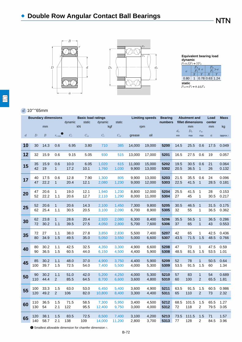
Boundary dimensions Basic load ratings Limiting speeds Bearing Abutment and Load Massdynamic static dynamic static numbers fillet dimensions center
mm kN kgf rpm mm mm kgda Da ras
d D B rs min1
Cr Cor Cr Cor grease oil min max max a (approx.)
●Double Row Angular Contact Ball Bearings
B-721 Smallest allowable dimension for chamfer dimension r.
d 10~65mm
12
15
17
20
25
30
35
40
45
50
55
60
65
10 30 14.3 0.6 6.95 3.80 710 385 14,000 19,000 5200 14.5 25.5 0.6 17.5 0.049
32 15.9 0.6 9.15 5.05 930 515 13,000 17,000 5201 16.5 27.5 0.6 19 0.057
35 15.9 0.6 10.0 6.05 1,020 615 11,000 15,000 5202 19.5 30.5 0.6 21 0.06442 19 1 17.2 10.1 1,760 1,030 9,900 13,000 5302 20.5 36.5 1 26 0.132
40 17.5 0.6 12.8 7.90 1,300 805 9,900 13,000 5203 21.5 35.5 0.6 24 0.09647 22.2 1 20.4 12.1 2,080 1,230 9,000 12,000 5303 22.5 41.5 1 28.5 0.181
47 20.6 1 19.0 12.1 1,940 1,230 8,800 12,000 5204 25.5 41.5 1 28 0.15352 22.2 1.1 20.6 12.7 2,110 1,290 8,000 11,000 5304 27 45 1 30.5 0.217
52 20.6 1 20.6 14.3 2,100 1,450 7,300 9,800 5205 30.5 46.5 1 31.5 0.17562 25.4 1.1 30.5 20.5 3,100 2,090 6,700 8,900 5305 32 55 1 36.5 0.362
62 23.8 1 28.6 20.4 2,920 2,080 6,300 8,400 5206 35.5 56.5 1 36.5 0.28672 30.2 1.1 39.5 27.5 4,050 2,800 5,700 7,600 5306 37 65 1 43 0.553
72 27 1.1 38.0 27.8 3,850 2,830 5,500 7,400 5207 42 65 1 42.5 0.43680 34.9 1.5 49.5 35.0 5,050 3,550 5,000 6,600 5307 43.5 71.5 1.5 48.5 0.766
80 30.2 1.1 42.5 32.5 4,350 3,300 4,900 6,600 5208 47 73 1 47.5 0.5990 36.5 1.5 60.5 44.0 6,150 4,500 4,400 5,900 5308 48.5 81.5 1.5 53.5 1.01
85 30.2 1.1 48.0 37.0 4,900 3,750 4,400 5,900 5209 52 78 1 50.5 0.64100 39.7 1.5 72.5 54.0 7,400 5,500 4,000 5,300 5309 53.5 91.5 1.5 60 1.34
90 30.2 1.1 51.0 42.0 5,200 4,250 4,000 5,300 5210 57 83 1 54 0.689110 44.4 2 85.5 64.5 8,700 6,600 3,600 4,800 5310 60 100 2 65.5 1.81
100 33.3 1.5 63.0 53.0 6,450 5,400 3,600 4,900 5211 63.5 91.5 1.5 60.5 0.986120 49.2 2 106 82.0 10,800 8,400 3,300 4,400 5311 65 110 2 73 2.32
110 36.5 1.5 71.5 58.5 7,300 5,950 3,400 4,500 5212 68.5 101.5 1.5 65.5 1.27130 54 2.1 122 95.5 12,400 9,750 3,000 4,000 5312 72 118 2 79.5 3.05
120 38.1 1.5 83.5 72.5 8,500 7,400 3,100 4,200 5213 73.5 111.5 1.5 71 1.57140 58.7 2.1 138 109 14,000 11,200 2,800 3,700 5313 77 128 2 84.5 3.96
d
rar
D Da da
B
a
r ra
0.80 1 0.78 0.63 1.24
Fa
FreX Y X Y
≦eFa
Fr>e
Pr=XFr+YFa
Por=Fr+0.66Fa
Equivalent bearing loaddynamic
static

B-73
●Double Row Angular Contact Ball Bearings
Boundary dimensions Basic load ratings Limiting speeds Bearing Abutment and Load Massdynamic static dynamic static numbers fillet dimensions center
mm kN kgf rpm mm mm kgda Da ras
d D B rs min1
Cr Cor Cr Cor grease oil min max max a (approx.)
1 Smallest allowable dimension for chamfer dimension r.
d 70~100mm
75
80
85
90
95
100
70 125 39.7 1.5 90.5 79.5 9,250 8,100 2,900 3,900 5214 78.5 116.5 1.5 74.5 1.8150 63.5 2.1 155 125 15,800 12,700 2,600 3,500 5314 82 138 2 93 4.74
130 41.3 1.5 90.0 80.5 9,200 8,200 2,700 3,600 5215 83.5 121.5 1.5 78 1.9160 68.3 2.1 168 141 17,200 14,400 2,400 3,200 5315 87 148 2 98 5.65
140 44.4 2 106 95.5 10,800 9,700 2,500 3,400 5216 90 130 2 83.5 2.39
150 49.2 2 112 106 11,400 10,900 2,400 3,200 5217 95 140 2 91 3.06
160 52.4 2 140 129 14,300 13,100 2,200 3,000 5218 100 150 2 95.5 3.73
170 55.6 2.1 159 148 16,200 15,000 2,100 2,800 5219 107 158 2 101 4.86
180 60.3 2.1 178 167 18,200 17,100 2,000 2,700 5220 112 168 2 108 5.94
d
rar
D Da da
B
a
r ra
0.80 1 0.78 0.63 1.24
Fa
FreX Y X Y
≦eFa
Fr>e
Pr=XFr+YFa
Por=Fr+0.66Fa
Equivalent bearing loaddynamic
static
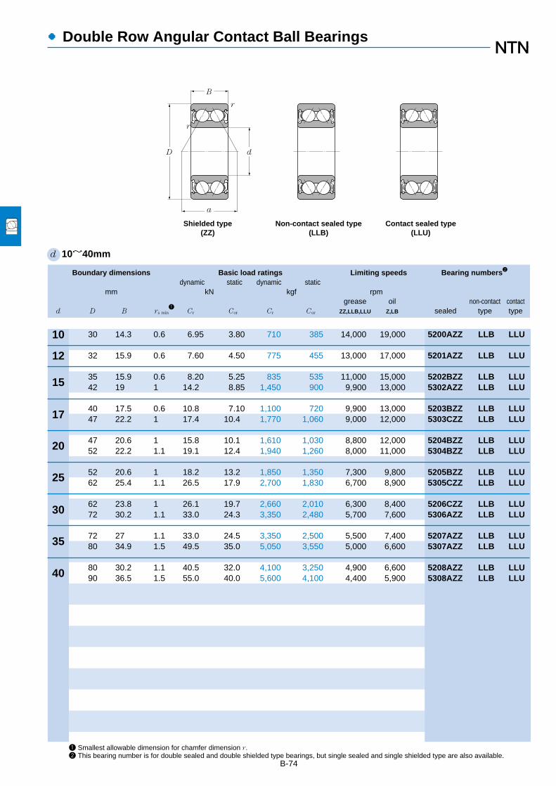
●Double Row Angular Contact Ball Bearings
B-74
Boundary dimensions Basic load ratings Limiting speeds Bearing numbers2
dynamic static dynamic staticmm kN kgf rpm
grease oil non-contact contactd D B rs min
1Cr Cor Cr Cor ZZ,LLB,LLU Z,LB sealed type type
10
12
15
17
20
25
30
35
40
1 Smallest allowable dimension for chamfer dimension r.2 This bearing number is for double sealed and double shielded type bearings, but single sealed and single shielded type are also available.
Non-contact sealed type(LLB)
Contact sealed type(LLU)
d
r
D
B
a
r
Shielded type(ZZ)
30 14.3 0.6 6.95 3.80 710 385 14,000 19,000 5200AZZ LLB LLU
32 15.9 0.6 7.60 4.50 775 455 13,000 17,000 5201AZZ LLB LLU
35 15.9 0.6 8.20 5.25 835 535 11,000 15,000 5202BZZ LLB LLU42 19 1 14.2 8.85 1,450 900 9,900 13,000 5302AZZ LLB LLU
40 17.5 0.6 10.8 7.10 1,100 720 9,900 13,000 5203BZZ LLB LLU47 22.2 1 17.4 10.4 1,770 1,060 9,000 12,000 5303CZZ LLB LLU
47 20.6 1 15.8 10.1 1,610 1,030 8,800 12,000 5204BZZ LLB LLU52 22.2 1.1 19.1 12.4 1,940 1,260 8,000 11,000 5304BZZ LLB LLU
52 20.6 1 18.2 13.2 1,850 1,350 7,300 9,800 5205BZZ LLB LLU62 25.4 1.1 26.5 17.9 2,700 1,830 6,700 8,900 5305CZZ LLB LLU
62 23.8 1 26.1 19.7 2,660 2,010 6,300 8,400 5206CZZ LLB LLU72 30.2 1.1 33.0 24.3 3,350 2,480 5,700 7,600 5306AZZ LLB LLU
72 27 1.1 33.0 24.5 3,350 2,500 5,500 7,400 5207AZZ LLB LLU80 34.9 1.5 49.5 35.0 5,050 3,550 5,000 6,600 5307AZZ LLB LLU
80 30.2 1.1 40.5 32.0 4,100 3,250 4,900 6,600 5208AZZ LLB LLU90 36.5 1.5 55.0 40.0 5,600 4,100 4,400 5,900 5308AZZ LLB LLU
d 10~40mm
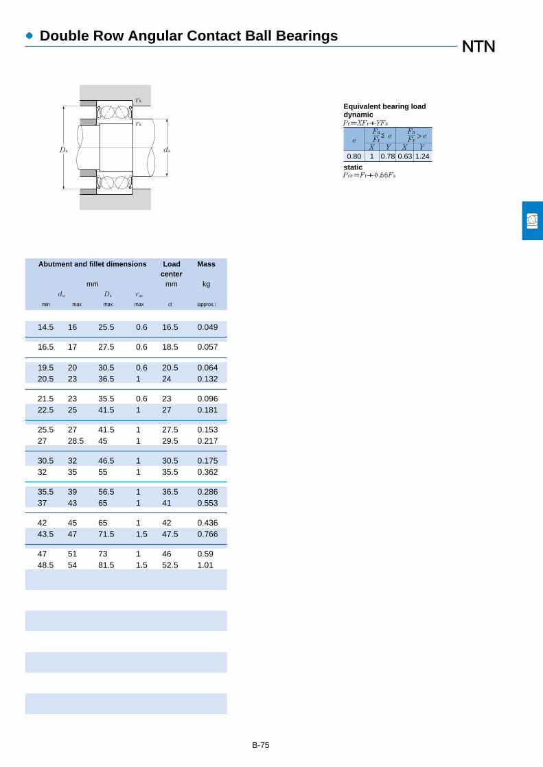
B-75
Abutment and fillet dimensions Load Masscenter
mm mm kgda Da ras
min max max max a (approx.)
●Double Row Angular Contact Ball Bearings
0.80 1 0.78 0.63 1.24
Fa
FreX Y X Y
≦eFa
Fr>e
Pr=XFr+YFa
Por=Fr+0.66Fa
Equivalent bearing loaddynamic
static
ra
Da da
ra
14.5 16 25.5 0.6 16.5 0.049
16.5 17 27.5 0.6 18.5 0.057
19.5 20 30.5 0.6 20.5 0.06420.5 23 36.5 1 24 0.132
21.5 23 35.5 0.6 23 0.09622.5 25 41.5 1 27 0.181
25.5 27 41.5 1 27.5 0.15327 28.5 45 1 29.5 0.217
30.5 32 46.5 1 30.5 0.17532 35 55 1 35.5 0.362
35.5 39 56.5 1 36.5 0.28637 43 65 1 41 0.553
42 45 65 1 42 0.43643.5 47 71.5 1.5 47.5 0.766
47 51 73 1 46 0.5948.5 54 81.5 1.5 52.5 1.01


●Self-Aligning Ball Bearings
1. Design features and characteristics
The outer ring raceway of self-aligning ball bearings formsa spherical surface whose center is common to the bearingcenter. The inner ring of the bearing has two raceways. Theballs, cage, and inner ring of these bearings are capable of ashifting in order to compensate for a certain degree ofmisalignment with the outer rings. As a result, the bearing isable to align itself and compensate for shaft / housingfinishing unevenness, bearing fitting error, and other sourcesof misalignment as shown in Diagram 1.
However, since axial load capacity is limited, self-aligningbearings are not suitable for applications with heavy axialloads.
Furthermore, if an adapter is used on the tapered bore ofthe inner diameter, installation and disassembly are muchsimpler and for this reason adapters are often used onequipment with drive shafts.
B-77
2. Standard cage types
Self aligning ball bearings use pressed cages with theexception of the 1200-1206 series which use molded resincages. The material characteristics of the resin cages makethem unsuitable for use in applications where temperaturesexceed 120˚C.
3. Ball protrusion
Bearings with part numbers listed in Diagram 2 belowhave balls which protrude slightly from the bearing face.
Their degree of protrusion is listed in Diagram 2.
�Allowablemisalignment
Diagram 1. Diagram 2.
B1
B
1318(K)1319(K)1320(K)13211322(K)
Bearingnumber
Widthdimension B
Total widthdimension B1
4345474950
4548525455
Units mm
4. Allowable misalignment angle
Listed below are the allowable misalignment angles forbearings with self-aligning characteristics when placedunder normal load conditions. This degree of allowablemisalignment may be limited by the design of structuresaround the bearing.
Allowable misalignment under normal loads (loadsequivalent to 0.09 Cr): 0.07 rad (4˚)
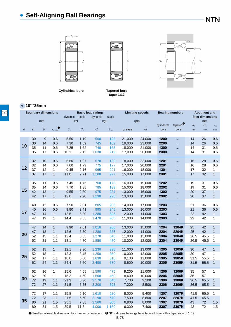
Boundary dimensions Basic load ratings Limiting speeds Bearing numbers Abutment anddynamic static dynamic static fillet dimensions
mm kN kgf rpm mmcylindrical tapered
2da Da ras
d D B rs min1
Cr Cor Cr Cor grease oil bore bore min max max
●Self-Aligning Ball Bearings
B-78
10
12
15
17
20
25
30
35
1 Smallest allowable dimension for chamfer dimension r. 2 "K" indicates bearings have tapered bore with a taper ratio of 1: 12.
d 10~35mm
30 9 0.6 5.50 1.19 560 122 21,000 24,000 1200 ― 14 26 0.630 14 0.6 7.30 1.59 745 162 19,000 23,000 2200 ― 14 26 0.635 11 0.6 7.25 1.62 740 165 18,000 21,000 1300 ― 14 31 0.635 17 0.6 10.1 2.15 1,030 219 17,000 20,000 2300 ― 14 31 0.6
32 10 0.6 5.60 1.27 570 130 18,000 22,000 1201 ― 16 28 0.632 14 0.6 7.60 1.73 775 177 17,000 20,000 2201 ― 16 28 0.637 12 1 9.45 2.16 965 221 16,000 18,000 1301 ― 17 32 137 17 1 11.8 2.71 1,200 277 15,000 17,000 2301 ― 17 32 1
35 11 0.6 7.45 1.75 760 178 16,000 19,000 1202 ― 19 31 0.635 14 0.6 7.70 1.85 785 188 15,000 18,000 2202 ― 19 31 0.642 13 1 9.55 2.30 975 234 13,000 16,000 1302 ― 20 37 142 17 1 12.0 2.90 1,230 295 13,000 15,000 2302 ― 20 37 1
40 12 0.6 7.90 2.01 805 205 14,000 17,000 1203 ― 21 36 0.640 16 0.6 9.80 2.41 995 246 13,000 16,000 2203 ― 21 36 0.647 14 1 12.5 3.20 1,280 325 12,000 14,000 1303 ― 22 42 147 19 1 14.4 3.55 1,470 365 11,000 14,000 2303 ― 22 42 1
47 14 1 9.90 2.61 1,010 266 13,000 15,000 1204 1204K 25 42 147 18 1 12.6 3.30 1,280 335 12,000 14,000 2204 2204K 25 42 152 15 1.1 12.4 3.35 1,270 340 11,000 13,000 1304 1304K 26.5 45.5 152 21 1.1 18.1 4.70 1,850 480 10,000 12,000 2304 2304K 26.5 45.5 1
52 15 1 12.1 3.30 1,230 335 11,000 13,000 1205 1205K 30 47 152 18 1 12.3 3.45 1,250 350 10,000 12,000 2205 2205K 30 47 162 17 1.1 18.0 5.00 1,830 510 9,100 11,000 1305 1305K 31.5 55.5 162 24 1.1 24.4 6.60 2,490 670 8,500 10,000 2305 2305K 31.5 55.5 1
62 16 1 15.6 4.65 1,590 475 9,200 11,000 1206 1206K 35 57 162 20 1 15.2 4.50 1,550 460 8,600 10,000 2206 2206K 35 57 172 19 1.1 21.3 6.30 2,170 645 7,700 9,100 1306 1306K 36.5 65.5 172 27 1.1 31.5 8.75 3,200 895 7,200 8,500 2306 2306K 36.5 65.5 1
72 17 1.1 15.8 5.10 1,610 520 8,000 9,400 1207 1207K 41.5 65.5 172 23 1.1 21.5 6.60 2,190 670 7,500 8,800 2207 2207K 41.5 65.5 180 21 1.5 25.1 7.85 2,560 800 6,800 8,000 1307 1307K 43 72 1.580 31 1.5 39.5 11.3 4,000 1,150 6,300 7,400 2307 2307K 43 72 1.5
dD
r
B
r
d
Cylindrical bore Tapered boretaper 1:12
Da da
ra
ra

Constant Axial load factors Mass
kgcylindrical bore tapered bore
e Y1 Y2 Yo (approx.)
B-79
●Self-Aligning Ball Bearings
Fa
FrX Y X Y
≦eFa
Fr>e
Pr=XFr+YFa
Por=Fr+Yo Fa
For values of e,Y1,Y2 and Yosee the table below.
1 Y1 0.65 Y2
Equivalent bearing loaddynamic
static
0.32 2 3.09 2.09 0.033 ―0.64 0.98 1.52 1.03 0.047 ―0.34 1.85 2.87 1.94 0.058 ―0.67 0.95 1.46 0.99 0.083 ―
0.36 1.76 2.73 1.85 0.04 ―0.58 1.09 1.69 1.14 0.051 ―0.33 1.91 2.95 2 0.066 ―0.61 1.03 1.59 1.08 0.091 ―
0.33 1.91 2.95 2 0.049 ―0.50 1.25 1.94 1.31 0.06 ―0.34 1.86 2.88 1.95 0.092 ―0.52 1.22 1.88 1.27 0.114 ―
0.31 2.03 3.14 2.12 0.072 ―0.51 1.23 1.90 1.29 0.088 ―0.32 1.97 3.06 2.07 0.128 ―0.52 1.22 1.88 1.28 0.156 ―
0.29 2.2 3.4 2.3 0.116 0.1140.49 1.3 2.01 1.36 0.14 0.1370.29 2.16 3.34 2.26 0.16 0.1580.51 1.23 1.9 1.29 0.206 0.201
0.28 2.28 3.53 2.39 0.138 0.1350.41 1.55 2.39 1.62 0.157 0.1530.28 2.28 3.53 2.39 0.255 0.2510.48 1.32 2.05 1.39 0.334 0.326
0.25 2.55 3.94 2.67 0.217 0.2130.38 1.64 2.53 1.72 0.256 0.250.26 2.40 3.72 2.52 0.383 0.3770.44 1.42 2.2 1.49 0.496 0.485
0.23 2.71 4.2 2.84 0.317 0.3120.37 1.69 2.61 1.77 0.392 0.3820.25 2.48 3.84 2.60 0.5 0.4920.46 1.37 2.13 1.44 0.671 0.653

1 Smallest allowable dimension for chamfer dimension r. 2 "K" indicates bearings have tapered bore with a taper ratio of 1: 12.
B-80
●Self-Aligning Ball Bearings
Boundary dimensions Basic load ratings Limiting speeds Bearing numbers Abutment anddynamic static dynamic static fillet dimensions
mm kN kgf rpm mmcylindrical tapered
2da Da ras
d D B rs min1
Cr Cor Cr Cor grease oil bore bore min max max
40
45
50
55
60
65
70
75
d 40~75mm
80 18 1.1 19.3 6.55 1,970 665 7,100 8,400 1208 1208K 46.5 73.5 180 23 1.1 22.3 7.35 2,270 750 6,700 7,900 2208 2208K 46.5 73.5 190 23 1.5 29.6 9.70 3,000 990 6,000 7,000 1308 1308K 48 82 1.590 33 1.5 45.0 13.5 4,600 1,380 5,600 6,600 2308 2308K 48 82 1.5
85 19 1.1 21.9 7.35 2,230 750 6,400 7,500 1209 1209K 51.5 78.5 185 23 1.1 23.2 8.15 2,360 830 6,000 7,100 2209 2209K 51.5 78.5 1
100 25 1.5 38.0 12.7 3,900 1,300 5,400 6,300 1309 1309K 53 92 1.5100 36 1.5 54.0 16.7 5,500 1,700 5,000 5,900 2309 2309K 53 92 1.5
90 20 1.1 22.7 8.10 2,320 830 5,800 6,800 1210 1210K 56.5 83.5 190 23 1.1 23.2 8.45 2,370 865 5,500 6,400 2210 2210K 56.5 83.5 1
110 27 2 43.5 14.1 4,400 1,440 4,900 5,800 1310 1310K 59 101 2110 40 2 64.5 20.2 6,550 2,060 4,600 5,400 2310 2310K 59 101 2
100 21 1.5 26.8 10.0 2,730 1,020 5,300 6,200 1211 1211K 63 92 1.5100 25 1.5 26.5 9.90 2,700 1,010 5,000 5,800 2211 2211K 63 92 1.5120 29 2 51.5 17.9 5,250 1,820 4,500 5,200 1311 1311K 64 111 2120 43 2 75.5 24.0 7,700 2,450 4,200 4,900 2311 2311K 64 111 2
110 22 1.5 30.0 11.5 3,100 1,180 4,900 5,800 1212 1212K 68 102 1.5110 28 1.5 34.0 12.6 3,450 1,290 4,600 5,400 2212 2212K 68 102 1.5130 31 2.1 57.0 20.8 5,850 2,130 4,100 4,800 1312 1312K 71 119 2130 46 2.1 87.0 28.2 8,850 2,880 3,800 4,500 2312 2312K 71 119 2
120 23 1.5 31.0 12.5 3,150 1,280 4,500 5,300 1213 1213K 73 112 1.5120 31 1.5 43.5 16.4 4,450 1,670 4,200 5,000 2213 2213K 73 112 1.5140 33 2.1 62.0 22.9 6,350 2,330 3,800 4,500 1313 1313K 76 129 2140 48 2.1 96.0 32.5 9,800 3,300 3,600 4,200 2313 2313K 76 129 2
125 24 1.5 34.5 13.8 3,550 1,410 4,200 4,900 1214 ― 78 117 1.5125 31 1.5 44.0 17.1 4,500 1,740 3,900 4,600 2214 ― 78 117 1.5150 35 2.1 74.5 27.7 7,600 2,830 3,500 4,200 1314 ― 81 139 2150 51 2.1 109 37.5 11,100 3,850 3,300 3,900 2314 ― 81 139 2
130 25 1.5 39.0 15.7 3,950 1,600 3,900 4,600 1215 1215K 83 122 1.5130 31 1.5 44.5 17.8 4,500 1,820 3,700 4,300 2215 2215K 83 122 1.5160 37 2.1 79.5 30.0 8,100 3,050 3,300 3,900 1315 1315K 86 149 2160 55 2.1 123 43.0 12,500 4,350 3,100 3,600 2315 2315K 86 149 2
dD
r
B
r
d
Cylindrical bore Tapered boretaper 1:12
Da da
ra
ra

B-81
Constant Axial load factors Mass
kgcylindrical bore tapered bore
e Y1 Y2 Yo (approx.)
●Self-Aligning Ball Bearings
0.22 2.81 4.35 2.95 0.414 0.4070.33 1.91 2.95 2.00 0.493 0.4820.25 2.57 3.98 2.69 0.709 0.6980.43 1.45 2.25 1.52 0.918 0.895
0.21 2.99 4.63 3.13 0.457 0.4480.30 2.07 3.20 2.17 0.54 0.5280.25 2.56 3.95 2.68 0.953 0.9380.41 1.53 2.36 1.60 1.23 1.2
0.21 3.07 4.75 3.21 0.515 0.5040.28 2.23 3.45 2.33 0.583 0.5690.23 2.7 4.19 2.83 1.2 1.180.42 1.49 2.3 1.56 1.63 1.59
0.20 3.19 4.94 3.34 0.692 0.6790.28 2.24 3.47 2.35 0.787 0.7690.23 2.71 4.20 2.84 1.58 1.560.41 1.53 2.37 1.6 2.1 2.05
0.18 3.41 5.27 3.57 0.879 0.8640.28 2.26 3.5 2.37 1.08 1.060.22 2.85 4.42 2.99 1.96 1.930.40 1.56 2.41 1.63 2.59 2.52
0.17 3.70 5.73 3.88 1.13 1.110.28 2.26 3.5 2.37 1.44 1.410.23 2.74 4.25 2.87 2.42 2.380.38 1.64 2.54 1.72 3.2 3.12
0.18 3.48 5.38 3.64 1.24 ―0.26 2.38 3.68 2.49 1.52 ―0.22 2.83 4.37 2.96 2.99 ―0.38 1.67 2.59 1.75 3.92 ―
0.17 3.61 5.58 3.78 1.33 1.310.25 2.52 3.89 2.63 1.58 1.540.22 2.81 4.35 2.95 3.55 3.50.38 1.65 2.55 1.72 4.78 4.66
Fa
FrX Y X Y
≦eFa
Fr>e
Pr=XFr+YFa
Por=Fr+Yo Fa
For values of e,Y1,Y2 and Yosee the table below.
1 Y1 0.65 Y2
Equivalent bearing loaddynamic
static

1 Smallest allowable dimension for chamfer dimension r. 2 "K" indicates bearings have tapered bore with a taper ratio of 1: 12.
B-82
●Self-Aligning Ball Bearings
Boundary dimensions Basic load ratings Limiting speeds Bearing numbers Abutment anddynamic static dynamic static fillet dimensions
mm kN kgf rpm mmcylindrical tapered
2da Da ras
d D B rs min1
Cr Cor Cr Cor grease oil bore bore min max max
80
85
90
95
100
105
110
d 80~110mm
140 26 2 40.0 17.0 4,050 1,730 3,700 4,300 1216 1216K 89 131 2140 33 2 48.5 19.9 4,950 2,030 3,400 4,000 2216 2216K 89 131 2170 39 2.1 88.5 33.0 9,000 3,400 3,100 3,600 1316 1316K 91 159 2170 58 2.1 128 45.0 13,100 4,600 2,900 3,400 2316 2316K 91 159 2
150 28 2 49.0 20.8 5,000 2,120 3,500 4,100 1217 1217K 94 141 2150 36 2 58.0 23.6 5,950 2,400 3,200 3,800 2217 2217K 94 141 2180 41 3 97.5 38.0 9,950 3,850 2,900 3,400 1317 1317K 98 167 2.5180 60 3 140 51.5 14,300 5,250 2,700 3,200 2317 2317K 98 167 2.5
160 30 2 57.0 23.5 5,800 2,390 3,300 3,800 1218 1218K 99 151 2160 40 2 70.0 28.7 7,150 2,930 3,100 3,600 2218 2218K 99 151 2190 43 3 116 44.5 11,900 4,550 2,700 3,200 1318 1318K 103 177 2.5190 64 3 152 57.5 15,500 5,850 2,600 3,000 2318 2318K 103 177 2.5
170 32 2.1 64.0 27.1 6,500 2,770 3,100 3,600 1219 1219K 106 159 2170 43 2.1 83.5 34.5 8,500 3,500 2,900 3,400 2219 2219K 106 159 2200 45 3 132 51.0 13,400 5,200 2,600 3,000 1319 1319K 108 187 2.5200 67 3 165 64.5 16,800 6,550 2,400 2,800 2319 2319K 108 187 2.5
180 34 2.1 69.0 29.7 7,050 3,050 2,900 3,400 1220 1220K 111 169 2180 46 2.1 94.0 38.5 9,600 3,900 2,700 3,200 2220 2220K 111 169 2215 47 3 143 57.5 14,600 5,850 2,400 2,900 1320 1320K 113 202 2.5215 73 3 192 79.0 19,600 8,100 2,300 2,700 2320 2320K 113 202 2.5
190 36 2.1 74.5 32.5 7,600 3,300 2,800 3,300 1221 ― 116 179 2190 50 2.1 109 45.0 11,100 4,550 2,600 3,100 2221 ― 116 179 2225 49 3 156 64.5 15,900 6,600 2,300 2,700 1321 ― 118 212 2.5225 77 3 205 87.0 20,900 8,850 2,200 2,600 2321 ― 118 212 2.5
200 38 2.1 80.5 35.5 8,200 3,600 2,600 3,100 1222 1222K 121 189 2200 53 2.1 124 51.5 12,700 5,250 2,500 2,900 2222 2222K 121 189 2240 50 3 164 71.5 16,700 7,300 2,200 2,600 1322 1322K 123 227 2.5240 80 3 217 94.5 22,100 9,650 2,100 2,400 2322 2322K 123 227 2.5
dD
r
B
r
d
Cylindrical bore Tapered boretaper 1:12
Da da
ra
ra

B-83
Constant Axial load factors Mass
kgcylindrical bore tapered bore
e Y1 Y2 Yo (approx.)
●Self-Aligning Ball Bearings
0.16 3.9 6.04 4.09 1.65 1.620.25 2.52 3.9 2.64 1.99 1.950.22 2.92 4.52 3.06 4.17 4.110.39 1.63 2.52 1.71 5.65 5.51
0.17 3.67 5.68 3.85 2.06 2.030.25 2.49 3.86 2.61 2.54 2.490.21 2.94 4.55 3.08 4.96 4.890.37 1.71 2.64 1.79 6.55 6.39
0.17 3.76 5.82 3.94 2.51 2.470.27 2.35 3.64 2.47 3.19 3.120.22 2.8 4.34 2.94 5.78 5.690.38 1.67 2.58 1.75 7.75 7.56
0.17 3.74 5.79 3.92 3.1 3.050.27 2.36 3.65 2.47 3.89 3.80.23 2.76 4.27 2.89 6.69 6.590.38 1.67 2.59 1.75 9.05 8.83
0.17 3.64 5.64 3.82 3.7 3.640.27 2.35 3.64 2.46 4.65 4.540.24 2.65 4.11 2.78 8.3 8.190.37 1.69 2.61 1.77 11.5 11.2
0.18 3.56 5.52 3.73 4.34 ―0.28 2.25 3.49 2.36 6.07 ―0.23 2.73 4.22 2.86 10 ―0.38 1.67 2.58 1.75 13.2 ―
0.18 3.44 5.33 3.61 5.15 5.070.28 2.24 3.47 2.35 7.1 6.940.22 2.85 4.4 2.98 11.8 11.70.37 1.71 2.65 1.79 15.8 15.4
Fa
FrX Y X Y
≦eFa
Fr>e
Pr=XFr+YFa
Por=Fr+Yo Fa
For values of e,Y1,Y2 and Yosee the table below.
1 Y1 0.65 Y2
Equivalent bearing loaddynamic
static

Boundary dimensions Bearing numbers Abutment and fillet dimensions Mass1
mm mm kg
da db S1 Da ras
d1 B1 d2 B2 min max min max max (approx.)
●Adapters
B-84
1 Refers to adapter mass.Note: 1. For bearing dimensions, basic rated loads, allowable rotations, and mass, refer to pages B-80 to B-82.
2. Adapters for series 12 bearings can also be used with H2 and H3 series bearings.Caution: the B1 dimension of H3 series bearings is longer than that of H2 series bearings.
3. Adapter numbers which are appended with the code "X" indicate narrow slit type adapters which use washer with straight inner tabs.4. For adapter locknut and washer dimensions, please refer to pages D-2 to D-7, and D-12 to D-14.
d 17~50mm
(for self-aligning ball bearings)
17
20
25
30
35
40
45
50
d1 d2
B2
B1
Da
S1
db da
ra
24 32 7 1204K;H 204 23 27 5 41 1 0.04128 32 7 2204K;H 304 24 28 5 41 1 0.04528 32 7 1304K;H 304 24 31 8 45 1 0.04531 32 7 2304K;H2304 24 28 5 45 1 0.049
26 38 8 1205K;H 205X 28 33 5 46 1 0.0729 38 8 2205K;H 305X 29 33 5 46 1 0.07529 38 8 1305K;H 305X 29 37 6 55 1 0.07535 38 8 2305K;H2305X 29 34 5 55 1 0.087
27 45 8 1206K;H 206X 33 39 5 56 1 0.09931 45 8 2206K;H 306X 34 39 5 56 1 0.10931 45 8 1306K;H 306X 34 44 6 65 1 0.10938 45 8 2306K;H2306X 35 40 5 65 1 0.126
29 52 9 1207K;H 207X 38 46 5 65 1 0.12535 52 9 2207K;H 307X 39 45 5 65 1 0.14235 52 9 1307K;H 307X 39 50 7 71.5 1.5 0.14243 52 9 2307K;H2307X 40 46 5 71.5 1.5 0.165
31 58 10 1208K;H 208X 44 52 5 73 1 0.17436 58 10 2208K;H 308X 44 50 5 73 1 0.18936 58 10 1308K;H 308X 44 56 5 81.5 1.5 0.18946 58 10 2308K;H2308X 45 52 5 81.5 1.5 0.224
33 65 11 1209K;H 209X 49 57 5 78 1 0.22739 65 11 2209K;H 309X 49 57 8 78 1 0.24839 65 11 1309K;H 309X 49 61 5 91.5 1.5 0.24850 65 11 2309K;H2309X 50 58 5 91.5 1.5 0.28
35 70 12 1210K;H 210X 53 62 5 83 1 0.27442 70 12 2210K;H 310X 54 63 10 83 1 0.30342 70 12 1310K;H 310X 54 67 5 100 2 0.30355 70 12 2310K;H2310X 56 65 5 100 2 0.362
37 75 12 1211K;H 211X 60 70 6 91.5 1.5 0.308

●Adapters
Boundary dimensions Bearing numbers Abutment and fillet dimensions Mass1
mm mm kg
da db S1 Da ras
d1 B1 d2 B2 min max min max max (approx.)
B-85
d 50~85mm
(for self-aligning ball bearings)
1 Refers to adapter mass.Note: 1. For bearing dimensions, basic rated loads, allowable rotations, and mass, refer to pages B-80 to B-82.
2. Adapters for series 12 bearings can also be used with H2 and H3 series bearings.Caution: the B1 dimension of H3 series bearings is longer than that of H2 series bearings.
3. Adapter numbers which are appended with the code "X" indicate narrow slit type adapters which use washer with straight inner tabs.4. For adapter locknut and washer dimensions, please refer to pages D-2 to D-7, and D-12 to D-14.
d1 d2
B2
B1
Da
S1
db da
ra
45 75 12 2211K;H 311X 60 69 11 91.5 1.5 0.34545 75 12 1311K;H 311X 60 73 6 110 2 0.34559 75 12 2311K;H2311X 61 71 6 110 2 0.42
38 80 13 1212K;H 212X 64 76 5 101.5 1.5 0.34647 80 13 2212K;H 312X 65 75 9 101.5 1.5 0.39447 80 13 1312K;H 312X 65 79 5 118 2 0.39462 80 13 2312K;H2312X 66 77 5 118 2 0.481
40 85 14 1213K;H 213X 70 83 5 111.5 1.5 0.40150 85 14 2213K;H 313X 70 81 8 111.5 1.5 0.45850 85 14 1313K;H 313X 70 85 5 128 2 0.45865 85 14 2313K;H2313X 72 84 5 128 2 0.557
43 98 15 1215K;H 215X 80 93 5 121.5 1.5 0.70755 98 15 2215K;H 315X 80 93 12 121.5 1.5 0.83155 98 15 1315K;H 315X 80 97 5 148 2 0.83173 98 15 2315K;H2315X 82 96 5 148 2 1.05
46 105 17 1216K;H 216X 85 100 5 130 2 0.88259 105 17 2216K;H 316X 86 98 12 130 2 1.0359 105 17 1316K;H 316X 86 103 5 158 2 1.0378 105 17 2316K;H2316X 87 103 5 158 2 1.28
50 110 18 1217K;H 217X 90 106 6 140 2 1.0263 110 18 2217K;H 317X 91 104 12 140 2 1.1863 110 18 1317K;H 317X 91 110 6 166 2.5 1.1882 110 18 2317K;H2317X 94 110 6 166 2.5 1.45
52 120 18 1218K;H 218X 95 111 6 150 2 1.1965 120 18 2218K;H 318X 96 112 10 150 2 1.3765 120 18 1318K;H 318X 96 116 6 176 2.5 1.3786 120 18 2318K;H2318X 99 117 6 176 2.5 1.69
55 125 19 1219K;H 219X 101 118 7 158 2 1.3768 125 19 2219K;H 319X 102 117 9 158 2 1.56
50
55
60
65
70
75
80
85

●Adapters
(for self-aligning ball bearings)
Boundary dimensions Bearing numbers Abutment and fillet dimensions Mass1
mm mm kg
da db S1 Da ras
d1 B1 d2 B2 min max min max max (approx.)
B-86
d 85~100mm
1 Refers to adapter mass.Note: 1. For bearing dimensions, basic rated loads, allowable rotations, and mass, refer to pages B-80 to B-82.
2. Adapters for series 12 bearings can also be used with H2 and H3 series bearings.Caution: the B1 dimension of H3 series bearings is longer than that of H2 series bearings.
3. Adapter numbers which are appended with the code "X" indicate narrow slit type adapters which use washer with straight inner tabs.4. For adapter locknut and washer dimensions, please refer to pages D-2 to D-7, and D-12 to D-14.
68 125 19 1319K;H 319X 102 123 7 186 2.5 1.5690 125 19 2319K;H2319X 105 123 7 186 2.5 1.92
58 130 20 1220K;H 220X 106 125 7 168 2 1.4971 130 20 2220K;H 320X 107 123 8 168 2 1.6971 130 20 1320K;H 320X 107 130 7 201 2.5 1.6997 130 20 2320K;H2320X 110 129 7 201 2.5 2.15
63 145 21 1222K;H 222X 116 138 7 188 2 1.9377 145 21 2222K;H 322X 117 137 6 188 2 2.1877 145 21 1322K;H 322X 117 150 9 226 2.5 2.18
105 145 21 2322K;H2322X 121 142 7 226 2.5 2.74
90
85
100
d1 d2
B2
B1
Da
S1
db da
ra
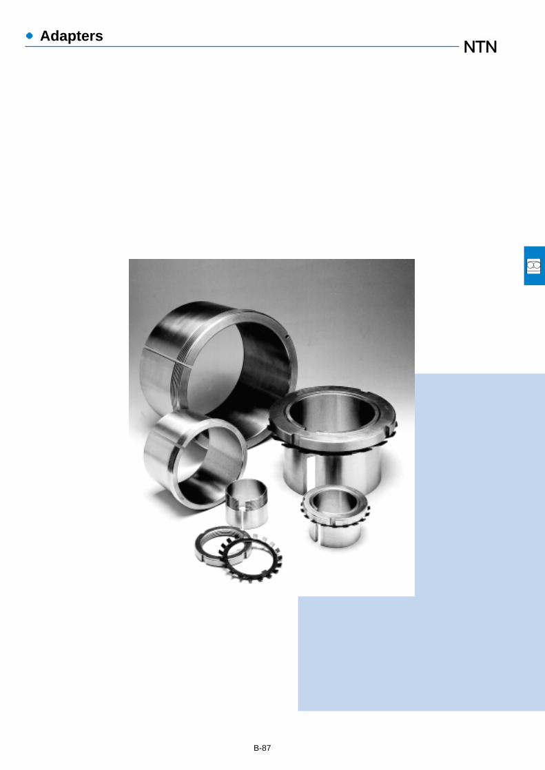
●Adapters
B-87
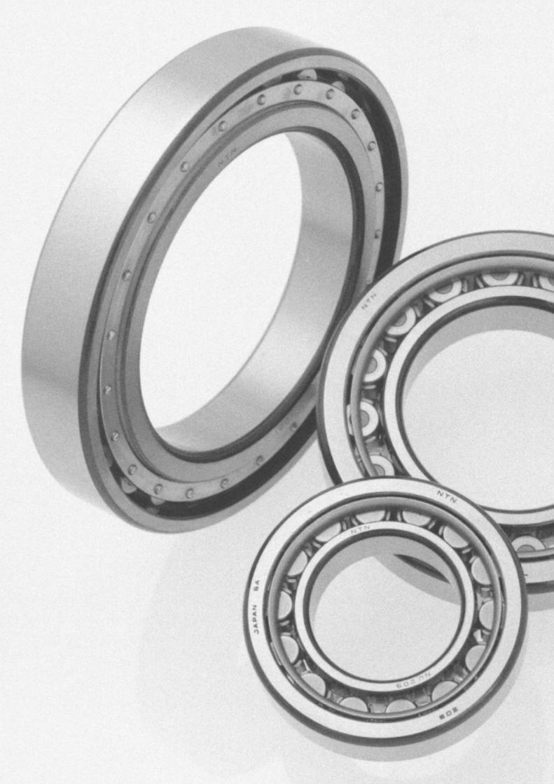

●Cylindrical Roller Bearings
1. Types, design features, andcharacteristics
Since the rolling elements in cylindrical roller bearingsmake line contact with raceways, these bearings canaccommodate heavy radial loads. The rollers are guided byribs on either the inner or outer ring, therefore these bearingsare also suitable for high speed applications. Furthermore,cylindrical roller bearings are separable, and relatively easyto install and disassemble even when interference fits arerequired.
Among the various types of cylindrical roller bearings,Type E has a high load capacity and its boundary
B-89
dimensions are identical to standard type. HT type has alarge axial load capacity, and HL type provides extendedwear life in conditions where the development of a lubricatingfilm inside the bearing is difficult.
Double and multiple row bearing arrangements are alsoavailable.
For extremely heavy load applications, the non-separablefull complement SL type bearing offers special advantages.
Table 1 shows the various types and characteristics ofsingle row cylindrical roller bearings. Table 2 shows thecharacteristics of non-standard type cylindrical rollerbearings.
Type code Design Characteristics
¡NU type outer rings have double ribs; outer ring and roller as well as cage can be separated
from inner ring. N type inner ring have double ribs; inner ring and roller as well as cage can
be separated from outer ring.
¡Unable to accommodate even the slightest axial loads.
¡This type is extremely suitable for, and widely used as, the floating side bearing.
¡NJ type has double ribs on outer ring, single rib on inner ring; NF type has single rib on outer
ring, and double rib on inner ring.
¡Can receive single direction axial loads.
¡When there is no distinction between the fixed side and floating side bearing, can be used as
a pair in close proximity.
¡NUP type has a collar ring attached to the ribless side of the inner ring; NH type is NJ type
with an L type collar ring attached. All of these collar rings are separable, and therefore it is
necessary to fix the inner ring axially.
¡Can accommodate axial loads in either direction.
¡Widely used as the shaft's fixed-side bearing.
NU type
N type
NJ type
NF type
NUP type
NH type(NJ + HJ)
NUP type
NF type
NJ type
N type
NU type
NH type
Table 1 Cylindrical roller bearing types and characteristics
Cylindrical roller bearing E Type cylindrical roller bearing Double row cylindrical roller bearing Four row cylindrical roller bearing
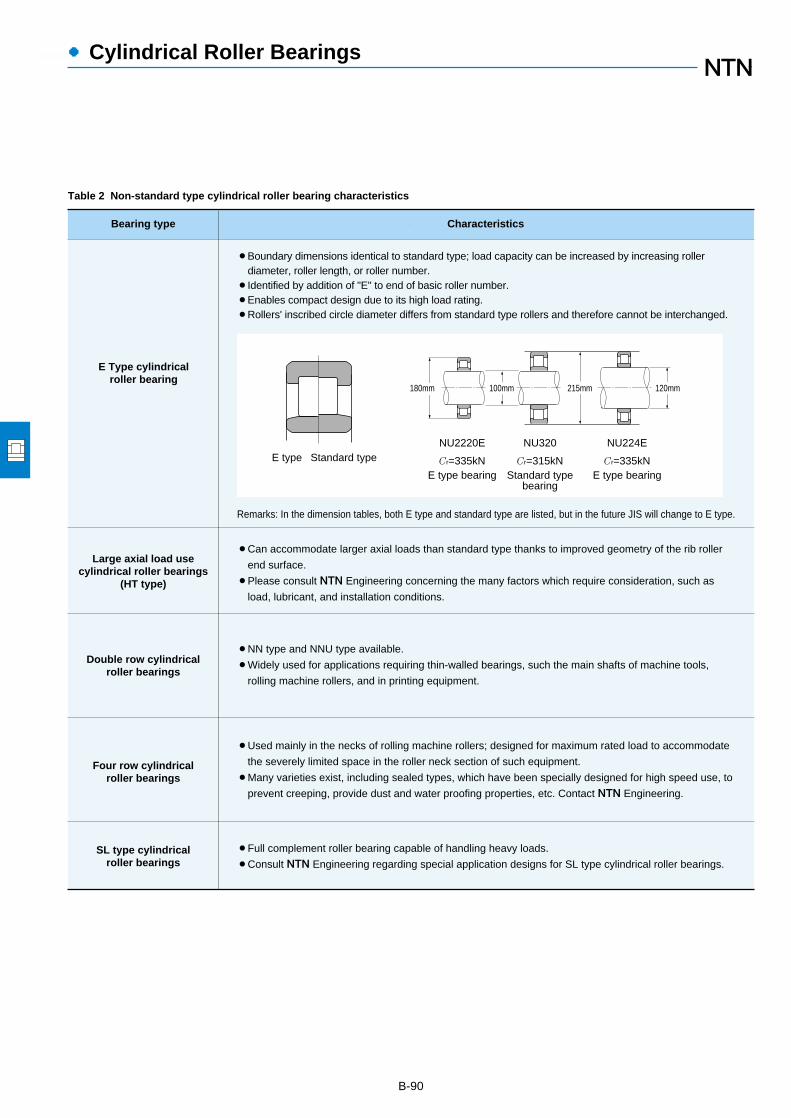
●Cylindrical Roller Bearings
B-90
Bearing type Characteristics
E Type cylindricalroller bearing
¡Boundary dimensions identical to standard type; load capacity can be increased by increasing roller diameter, roller length, or roller number.
¡Identified by addition of "E" to end of basic roller number.¡Enables compact design due to its high load rating.¡Rollers' inscribed circle diameter differs from standard type rollers and therefore cannot be interchanged.
Large axial load usecylindrical roller bearings
(HT type)
Double row cylindricalroller bearings
¡Can accommodate larger axial loads than standard type thanks to improved geometry of the rib roller
end surface.
¡Please consult NTN Engineering concerning the many factors which require consideration, such as
load, lubricant, and installation conditions.
Four row cylindricalroller bearings
SL type cylindricalroller bearings
¡NN type and NNU type available.
¡Widely used for applications requiring thin-walled bearings, such the main shafts of machine tools,
rolling machine rollers, and in printing equipment.
¡Used mainly in the necks of rolling machine rollers; designed for maximum rated load to accommodate
the severely limited space in the roller neck section of such equipment.
¡Many varieties exist, including sealed types, which have been specially designed for high speed use, to
prevent creeping, provide dust and water proofing properties, etc. Contact NTN Engineering.
¡Full complement roller bearing capable of handling heavy loads.
¡Consult NTN Engineering regarding special application designs for SL type cylindrical roller bearings.
Remarks: In the dimension tables, both E type and standard type are listed, but in the future JIS will change to E type.
180mm 100mm 215mm 120mm
E type Standard typeNU2220E
Cr=335kNE type bearing
NU320
Cr=315kNStandard type
bearing
NU224E
Cr=335kNE type bearing
Table 2 Non-standard type cylindrical roller bearing characteristics

●Cylindrical Roller Bearings
B-91
2. Standard cage types
Table 3 shows the standard varieties for cylindrical rollerbearings.
The basic rated loads listed in the dimension chartscorrespond to values achieved with the standard cages listedin Table 3. Furthermore, please note that even for theidentical bearing, in cases where the number of rollingelements or the cage type differs, the basic rated load willalso differ from the values listed in the dimension charts.
Table 3 Standard cage types
Bearingseries
Molded resincage Pressed cage Machined cage
NU10
NU 2NU2E
NU22NU22E
NU3NU3E
NU23NU23E
NU4
― 1005~10/500
208~230 232~264219E~240E204E~218E
2204E~2218E
304E~314E
2304E~2311E
2208~2230
308~324
2308~2320
2232~22642219E~2240E
326~356315E~332E
2322~23562312E~2332E
405~416
Note: 1) Within the same bearing series, cage type is identical evenif the type code (NJ, NUP, N, NF) differs.
2) For high speed and other special applications, machinedcages can be manufactured when necessary.Consult NTN Engineering.
3) Among E type bearings (those using molded resincages), certain varieties may also use pressed cages.Consult NTN Engineering.
4) Although machined cages are standard for two row and fourrow cylindrical roller bearings, molded resin cages may alsobe used in some of these bearings for machine toolapplications.
5) Due to their material properties, molded resin cagescannot be used in applications where temperaturesexceed 120℃.
―
― ―
――
――
――
――
3. Allowable misalignment
Although values vary somewhat depending on bearingtype and internal specifications, under general loadconditions, to avoid the occurrence of edge loading,allowable misalignments have been set as follows:
Bearing width series 0 or 1:………………0.001 rad (3.5')Bearing width series 2:……………………0.0005 rad (1.5')Double row cylindrical roller bearings 1 :……0.0005 rad (1.5')
1 Does not include high precision bearings for machine toolmain shaft applications.

Boundary dimensions Basic load ratings Limiting speeds1
Bearing numbersdynamic static dynamic static
mm kN kgf rpm type type type type d D B rs min
2r1s min
2Cr Cor Cr Cor grease oil NU NJ NUP N
●Cylindrical Roller Bearings
B-92
1 This value achieved with machined cages; when pressed cages are used, 80% of this value is acceptable.2 Minimal allowable dimension for chamfer dimension r or r1.
d 20~35mm
r
r1
D FW
B
d
B
D d J
r1r
J
r1 r
r
J
r1 r1
EW
r
Type NU Type NJ Type NUP Type N Type NF
20
25
30
35
40
47 14 1 0.6 25.7 22.6 2,620 2,310 15,000 18,000 NU204E NJ NUP N47 18 1 0.6 30.5 28.3 3,100 2,890 14,000 16,000 NU2204E NJ NUP N52 15 1.1 0.6 31.5 26.9 3,200 2,740 13,000 15,000 NU304E NJ NUP N52 21 1.1 0.6 42.0 39.0 4,300 3,950 12,000 14,000 NU2304E NJ NUP N
47 12 0.6 0.3 15.1 14.1 1,540 1,430 16,000 19,000 NU1005 NJ NUP N52 15 1 0.6 29.3 27.7 2,990 2,830 13,000 15,000 NU205E NJ NUP N52 18 1 0.6 35.0 34.5 3,550 3,550 11,000 13,000 NU2205E NJ NUP N62 17 1.1 1.1 41.5 37.5 4,250 3,800 11,000 13,000 NU305E NJ NUP N62 24 1.1 1.1 57.0 56.0 5,800 5,700 9,700 11,000 NU2305E NJ NUP N80 21 1.5 1.5 46.5 40.0 4,750 4,050 8,500 10,000 NU405 NJ NUP N
55 13 1 0.6 19.7 19.6 2,000 2,000 14,000 16,000 NU1006 NJ NUP N62 16 1 0.6 39.0 37.5 4,000 3,800 11,000 13,000 NU206E NJ NUP N62 20 1 0.6 49.0 50.0 5,000 5,100 9,700 11,000 NU2206E NJ NUP N72 19 1.1 1.1 53.0 50.0 5,400 5,100 9,300 11,000 NU306E NJ NUP N72 27 1.1 1.1 74.5 77.5 7,600 7,900 8,300 9,700 NU2306E NJ NUP N90 23 1.5 1.5 62.5 55.0 6,400 5,600 7,300 8,500 NU406 NJ NUP N
62 14 1 0.6 22.6 23.2 2,310 2,360 12,000 15,000 NU1007 NJ NUP N72 17 1.1 0.6 50.5 50.0 5,150 5,100 9,500 11,000 NU207E NJ NUP N72 23 1.1 0.6 61.5 65.5 6,300 6,650 8,500 10,000 NU2207E NJ NUP N80 21 1.5 1.1 71.0 71.0 7,200 7,200 8,100 9,600 NU307E NJ NUP N80 31 1.5 1.1 99.0 109 10,100 11,100 7,200 8,500 NU2307E NJ NUP N
100 25 1.5 1.5 75.5 69.0 7,700 7,050 6,400 7,500 NU407 NJ NUP N
68 15 1 0.6 27.3 29.0 2,780 2,950 11,000 13,000 NU1008 NJ NUP N80 18 1.1 1.1 43.5 43.0 4,450 4,350 9,400 11,000 NU208 NJ NUP N80 18 1.1 1.1 55.5 55.5 5,700 5,650 8,500 10,000 NU208E NJ NUP ―80 23 1.1 1.1 58.0 62.0 5,950 6,300 8,500 10,000 NU2208 NJ NUP N80 23 1.1 1.1 72.5 77.5 7,400 7,900 7,600 8,900 NU2208E NJ NUP ―90 23 1.5 1.5 58.5 57.0 6,000 5,800 8,000 9,400 NU308 NJ NUP N90 23 1.5 1.5 83.0 81.5 8,500 8,300 7,200 8,500 NU308E NJ NUP ―90 33 1.5 1.5 82.5 88.0 8,400 8,950 7,000 8,200 NU2308 NJ NUP N90 33 1.5 1.5 114 122 11,600 12,500 6,400 7,500 NU2308E NJ NUP ―
110 27 2 2 95.5 89.0 9,750 9,100 5,700 6,700 NU408 NJ NUP N

●Cylindrical Roller Bearings
Dimensions Abutment and fillet dimensions Mass
mm mm kgtype da db dc dd de Da Db ras r1as type NU type NNF Fw Ew J min min max min min max max min
4max max (approx.)
B-934 Does not apply to side of the outer ring rib of type NF bearings.
― 26.5 ― 29.5 24 ― 26 29 32 42 ― ― 1 0.6 0.122 ―― 26.5 ― 29.5 24 ― 26 29 32 42 ― ― 1 0.6 0.158 ―― 27.5 ― 31.1 24 ― 27 30 33 45.5 ― ― 1 0.6 0.176 ―― 27.5 ― 31.1 24 ― 27 30 33 45.5 ― ― 1 0.6 0.242 ―
― 30.5 41.5 32.7 27 29 30 32 33 43 45 42.5 0.6 0.3 0.092 0.091― 31.5 ― 34.5 29 ― 31 34 37 47 ― ― 1 0.6 0.151 ―― 31.5 ― 34.5 29 ― 31 34 37 47 ― ― 1 0.6 0.186 ―― 34 ― 38 31.5 ― 33 37 40 55.5 ― ― 1 1 0.275 ―― 34 ― 38 31.5 ― 33 37 40 55.5 ― ― 1 1 0.386 ―NF 38.8 62.8 43.6 33 33 38 41 46 72 72 64 1.5 1.5 0.55 0.536
― 36.5 48.5 38.9 34 35 35 38 39.5 50 51 49.5 1 0.6 0.13 0.128― 37.5 ― 41.1 34 ― 37 40 44 57 ― ― 1 0.6 0.226 ―― 37.5 ― 41.1 34 ― 37 40 44 57 ― ― 1 0.6 0.297 ―― 40.5 ― 44.9 36.5 ― 40 44 48 65.5 ― ― 1 1 0.398 ―― 40.5 ― 44.9 36.5 ― 40 44 48 65.5 ― ― 1 1 0.58 ―NF 45 73 50.5 38 38 44 47 52 82 82 74 1.5 1.5 0.751 0.732
― 42 55 44.6 39 40 41 44 45 57 58 56 1 0.6 0.179 0.176― 44 ― 48 39 ― 43 46 50 65.5 ― ― 1 0.6 0.327 ―― 44 ― 48 39 ― 43 46 50 65.5 ― ― 1 0.6 0.455 ―― 46.2 ― 51 41.5 ― 45 48 53 72 ― ― 1.5 1 0.545 ―― 46.2 ― 51 41.5 ― 45 48 53 72 ― ― 1.5 1 0.78 ―NF 53 83 59 43 43 52 55 61 92 92 84 1.5 1.5 0.99 0.965
― 47 61 49.8 44 45 46 49 50.5 63 64 62 1 0.6 0.22 0.217NF 50 70 54.2 46.5 46.5 49 52 56 73.5 73.5 72 1 1 0.378 0.37― 49.5 ― 53.9 46.5 ― 49 52 56 73.5 ― ― 1 1 0.426 ―― 50 70 54.2 46.5 46.5 49 52 56 73.5 73.5 72 1 1 0.49 0.48― 49.5 ― 53.9 46.5 ― 49 52 56 73.5 ― ― 1 1 0.552 ―NF 53.5 77.5 58.4 48 48 51 55 60 82 82 80 1.5 1.5 0.658 0.643― 52 ― 57.6 48 ― 51 55 60 82 ― ― 1.5 1.5 0.754 ―― 53.5 77.5 58.4 48 48 51 55 60 82 82 80 1.5 1.5 0.951 0.932― 52 ― 57.6 48 ― 51 55 60 82 ― ― 1.5 1.5 1.06 ―NF 58 92 64.8 49 49 57 60 67 101 101 93 2 2 1.3 1.27
dd dcda
ra
r1a
dc Da de db
ra
Db Db
Pr=Fr
Por=Fr
r1a
Equivalent bearing loaddynamic
static

●Cylindrical Roller Bearings
Boundary dimensions Basic load ratings Limiting speeds1
Bearing numbersdynamic static dynamic static
mm kN kgf rpm type type type type d D B rs min
2r1s min
2Cr Cor Cr Cor grease oil NU NJ NUP N
B-94
1 This value achieved with machined cages; when pressed cages are used, 80% of this value is acceptable.2 Minimal allowable dimension for chamfer dimension r or r1.
d 35~55mm
75 16 1 0.6 31.0 34.0 3,200 3,450 9,900 12,000 NU1009 NJ NUP N85 19 1.1 1.1 46.0 47.0 4,700 4,800 8,400 9,900 NU209 NJ NUP N85 19 1.1 1.1 63.0 66.5 6,450 6,800 7,600 9,000 NU209E NJ NUP ―85 23 1.1 1.1 61.5 68.0 6,250 6,900 7,600 9,000 NU2209 NJ NUP N85 23 1.1 1.1 76.0 84.5 7,750 8,600 6,800 8,000 NU2209E NJ NUP ―
100 25 1.5 1.5 74.0 71.0 7,550 7,250 7,200 8,400 NU309 NJ NUP N100 25 1.5 1.5 97.5 98.5 9,950 10,000 6,500 7,600 NU309E NJ NUP ―100 36 1.5 1.5 99.0 104 10,100 10,600 6,300 7,400 NU2309 NJ NUP N100 36 1.5 1.5 137 153 14,000 15,600 5,700 6,800 NU2309E NJ NUP ―120 29 2 2 107 102 10,900 10,400 5,100 6,000 NU409 NJ NUP N
80 16 1 0.6 32.0 36.0 3,300 3,700 8,900 11,000 NU1010 NJ NUP N90 20 1.1 1.1 48.0 51.0 4,900 5,200 7,600 9,000 NU210 NJ NUP N90 20 1.1 1.1 66.0 72.0 6,750 7,350 6,900 8,100 NU210E NJ NUP ―90 23 1.1 1.1 64.0 73.5 6,550 7,500 6,900 8,100 NU2210 NJ NUP N90 23 1.1 1.1 79.5 91.5 8,100 9,350 6,200 7,300 NU2210E NJ NUP ―
110 27 2 2 87.0 86.0 8,850 8,800 6,500 7,700 NU310 NJ NUP N110 27 2 2 110 113 11,200 11,500 5,900 6,900 NU310E NJ NUP ―110 40 2 2 121 131 12,300 13,400 5,700 6,700 NU2310 NJ NUP N110 40 2 2 163 187 16,600 19,000 5,200 6,100 NU2310E NJ NUP ―130 31 2.1 2.1 129 124 13,200 12,600 4,700 5,500 NU410 NJ NUP N
90 18 1.1 1 37.5 44.0 3,850 4,450 8,200 9,700 NU1011 NJ NUP N100 21 1.5 1.1 58.0 62.5 5,900 6,350 6,900 8,200 NU211 NJ NUP N100 21 1.5 1.1 82.5 93.0 8,400 9,500 6,300 7,400 NU211E NJ NUP ―100 25 1.5 1.1 75.5 87.0 7,700 8,900 6,300 7,400 NU2211 NJ NUP N100 25 1.5 1.1 97.0 114 9,900 11,700 5,600 6,600 NU2211E NJ NUP ―120 29 2 2 111 111 11,300 11,400 5,900 7,000 NU311 NJ NUP N120 29 2 2 137 143 14,000 14,600 5,300 6,300 NU311E NJ NUP ―120 43 2 2 148 162 15,100 16,500 5,200 6,100 NU2311 NJ NUP N120 43 2 2 201 233 20,500 23,800 4,700 5,600 NU2311E NJ NUP ―140 33 2.1 2.1 139 138 14,200 14,100 4,300 5,000 NU411 NJ NUP N
95 18 1.1 1 40.0 48.5 4,100 4,950 7,500 8,800 NU1012 NJ NUP N110 22 1.5 1.5 68.5 75.0 7,000 7,650 6,400 7,600 NU212 NJ NUP N110 22 1.5 1.5 97.5 107 9,950 10,900 5,800 6,800 NU212E NJ NUP ―110 28 1.5 1.5 96.0 116 9,800 11,800 5,800 6,800 NU2212 NJ NUP N
r
r1
D FW
B
d
B
D d J
r1r
J
r1 r
r
J
r1 r1
EW
r
Type NU Type NJ Type NUP Type N Type NF
45
50
55
60

●Cylindrical Roller Bearings
Dimensions Abutment and fillet dimensions Mass
mm mm kgtype da db dc dd de Da Db ras r1as type NU type NNF Fw Ew J min min max min min max max min
4max max (approx.)
B-954 Does not apply to side of the outer ring rib of type NF bearings.
― 52.5 67.5 55.5 49 50 52 54 56 70 71 68.5 1 0.6 0.28 0.276NF 55 75 59 51.5 51.5 54 57 61 78.5 78.5 77 1 1 0.432 0.423― 54.5 ― 58.9 51.5 ― 54 57 61 78.5 ― ― 1 1 0.495 ―― 55 75 59 51.5 51.5 54 57 61 78.5 78.5 77 1 1 0.53 0.52― 54.5 ― 58.9 51.5 ― 54 57 61 78.5 ― ― 1 1 0.6 ―NF 58.5 86.5 64 53 53 57 60 66 92 92 89 1.5 1.5 0.877 0.857― 58.5 ― 64.5 53 ― 57 60 66 92 ― ― 1.5 1.5 0.996 ―― 58.5 86.5 64 53 53 57 60 66 92 92 89 1.5 1.5 1.27 1.24― 58.5 ― 64.5 53 ― 57 60 66 92 ― ― 1.5 1.5 1.41 ―NF 64.5 100.5 71.8 54 54 63 66 74 111 111 102 2 2 1.62 1.58
― 57.5 72.5 60.5 54 55 57 59 61 75 76 73.5 1 0.6 0.295 0.291NF 60.4 80.4 64.6 56.5 56.5 58 62 67 83.5 83.5 83 1 1 0.47 0.46― 59.5 ― 63.9 56.5 ― 58 62 67 83.5 ― ― 1 1 0.54 ―― 60.4 80.4 64.6 56.5 56.5 58 62 67 83.5 83.5 83 1 1 0.571 0.56― 59.5 ― 63.9 56.5 ― 58 62 67 83.5 ― ― 1 1 0.652 ―NF 65 95 71 59 59 63 67 73 101 101 98 2 2 1.14 1.11― 65 ― 71.4 59 ― 63 67 73 101 ― ― 2 2 1.3 ―― 65 95 71 59 59 63 67 73 101 101 98 2 2 1.7 1.67― 65 ― 71.4 59 ― 63 67 73 101 ― ― 2 2 1.9 ―NF 70.8 110.8 78.8 61 61 69 73 81 119 119 112 2 2 2.02 1.97
― 64.5 80.5 67.7 60 61.5 63 66 68.5 83.5 85 81.5 1 1 0.442 0.435NF 66.5 88.5 70.8 61.5 63 65 68 73 92 93.5 91 1.5 1 0.638 0.626― 66 ― 70.8 61.5 ― 65 68 73 92 ― ― 1.5 1 0.718 ―― 66.5 88.5 70.8 61.5 63 65 68 73 92 93.5 91 1.5 1 0.773 0.758― 66 ― 70.8 61.5 ― 65 68 73 92 ― ― 1.5 1 0.968 ―NF 70.5 104.5 77.2 64 64 69 72 80 111 111 107 2 2 1.45 1.42― 70.5 ― 77.7 64 ― 69 72 80 111 ― ― 2 2 1.65 ―― 70.5 104.5 77.2 64 64 69 72 80 111 111 107 2 2 2.17 2.13― 70.5 ― 77.7 64 ― 69 72 80 111 ― ― 2 2 2.37 ―NF 77.2 117.2 85.2 66 66 76 79 87 129 129 119 2 2 2.48 2.42
― 69.5 85.5 72.7 65 66.5 68 71 73.5 88.5 90 86.5 1 1 0.474 0.467NF 73.5 97.5 78.4 68 68 71 75 80 102 102 100 1.5 1.5 0.818 0.802― 72 ― 77.6 68 ― 71 75 80 102 ― ― 1.5 1.5 0.923 ―― 73.5 97.5 78.4 68 68 71 75 80 102 102 100 1.5 1.5 1.06 1.04
dd dcda
ra
r1a
dc Da de db
ra
Db Db
Pr=Fr
Por=Fr
r1a
Equivalent bearing loaddynamic
static
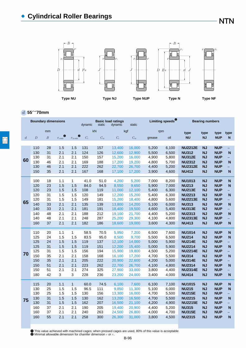
●Cylindrical Roller Bearings
Boundary dimensions Basic load ratings Limiting speeds1
Bearing numbersdynamic static dynamic static
mm kN kgf rpm type type type type d D B rs min
2r1s min
2Cr Cor Cr Cor grease oil NU NJ NUP N
B-96
1 This value achieved with machined cages; when pressed cages are used, 80% of this value is acceptable.2 Minimal allowable dimension for chamfer dimension r or r1.
d 55~70mm
110 28 1.5 1.5 131 157 13,400 16,000 5,200 6,100 NU2212E NJ NUP ―130 31 2.1 2.1 124 126 12,600 12,900 5,500 6,500 NU312 NJ NUP N130 31 2.1 2.1 150 157 15,200 16,000 4,900 5,800 NU312E NJ NUP ―130 46 2.1 2.1 169 188 17,200 19,200 4,800 5,700 NU2312 NJ NUP N130 46 2.1 2.1 222 262 22,700 26,700 4,400 5,200 NU2312E NJ NUP ―150 35 2.1 2.1 167 168 17,100 17,200 3,900 4,600 NU412 NJ NUP N
100 18 1.1 1 41.0 51.0 4,200 5,200 7,000 8,200 NU1013 NJ NUP N120 23 1.5 1.5 84.0 94.5 8,550 9,650 5,900 7,000 NU213 NJ NUP N120 23 1.5 1.5 108 119 11,000 12,100 5,400 6,300 NU213E NJ NUP ―120 31 1.5 1.5 120 149 12,200 15,200 5,400 6,300 NU2213 NJ NUP N120 31 1.5 1.5 149 181 15,200 18,400 4,800 5,600 NU2213E NJ NUP ―140 33 2.1 2.1 135 139 13,800 14,200 5,100 6,000 NU313 NJ NUP N140 33 2.1 2.1 181 191 18,400 19,500 4,600 5,400 NU313E NJ NUP ―140 48 2.1 2.1 188 212 19,100 21,700 4,400 5,200 NU2313 NJ NUP N140 48 2.1 2.1 248 287 25,200 29,300 4,100 4,800 NU2313E NJ NUP ―160 37 2.1 2.1 182 186 18,600 19,000 3,600 4,300 NU413 NJ NUP N
110 20 1.1 1 58.5 70.5 5,950 7,200 6,500 7,600 NU1014 NJ NUP N125 24 1.5 1.5 83.5 95.0 8,500 9,700 5,500 6,500 NU214 NJ NUP N125 24 1.5 1.5 119 137 12,100 14,000 5,000 5,900 NU214E NJ NUP ―125 31 1.5 1.5 119 151 12,200 15,400 5,000 5,900 NU2214 NJ NUP N125 31 1.5 1.5 156 194 15,900 19,800 4,500 5,200 NU2214E NJ NUP ―150 35 2.1 2.1 158 168 16,100 17,200 4,700 5,500 NU314 NJ NUP N150 35 2.1 2.1 205 222 20,900 22,600 4,200 5,000 NU314E NJ NUP ―150 51 2.1 2.1 223 262 22,700 26,700 4,100 4,800 NU2314 NJ NUP N150 51 2.1 2.1 274 325 27,900 33,000 3,800 4,400 NU2314E NJ NUP ―180 42 3 3 228 236 23,200 24,000 3,400 4,000 NU414 NJ NUP N
115 20 1.1 1 60.0 74.5 6,100 7,600 6,100 7,100 NU1015 NJ NUP N130 25 1.5 1.5 96.5 111 9,850 11,300 5,100 6,000 NU215 NJ NUP N130 25 1.5 1.5 130 156 13,300 16,000 4,700 5,500 NU215E NJ NUP ―130 31 1.5 1.5 130 162 13,200 16,500 4,700 5,500 NU2215 NJ NUP N130 31 1.5 1.5 162 207 16,500 21,100 4,200 4,900 NU2215E NJ NUP ―160 37 2.1 2.1 190 205 19,400 20,900 4,400 5,200 NU315 NJ NUP N160 37 2.1 2.1 240 263 24,500 26,800 4,000 4,700 NU315E NJ NUP ―160 55 2.1 2.1 258 300 26,300 31,000 3,800 4,500 NU2315 NJ NUP N
r
r1
D FW
B
d
B
D d J
r1r
J
r1 r
r
J
r1 r1
EW
r
Type NU Type NJ Type NUP Type N Type NF
60
65
70
75
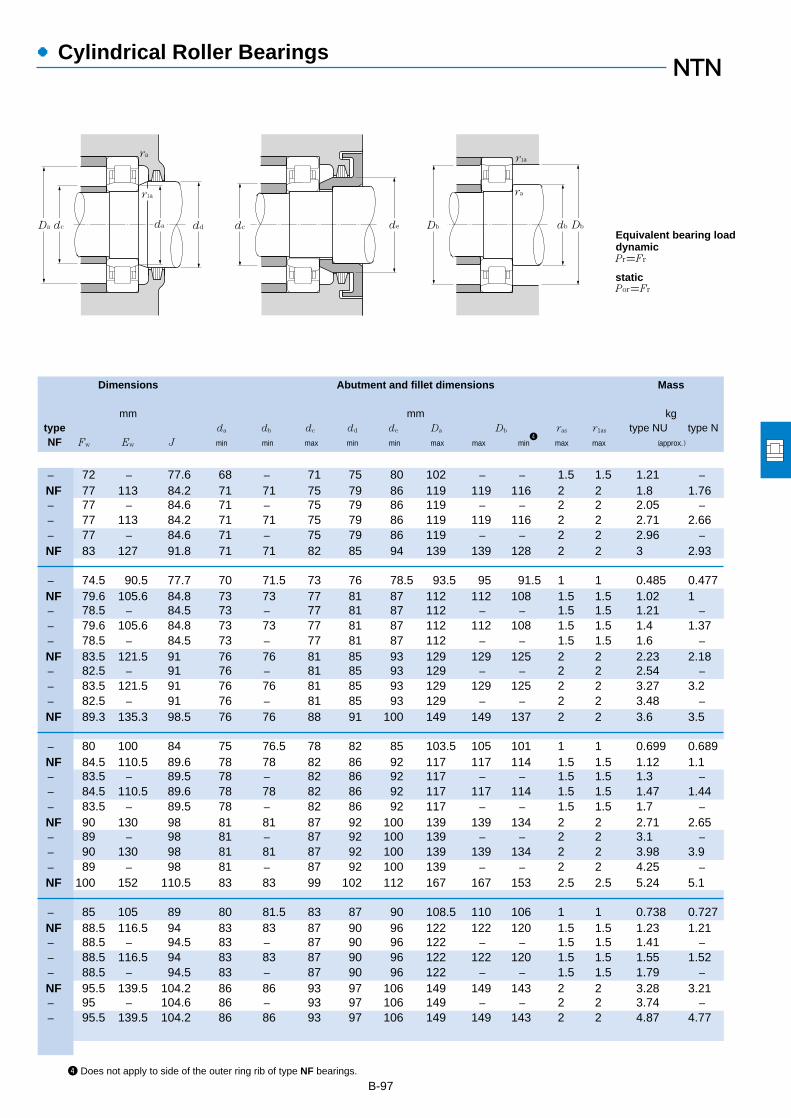
●Cylindrical Roller Bearings
Dimensions Abutment and fillet dimensions Mass
mm mm kgtype da db dc dd de Da Db ras r1as type NU type NNF Fw Ew J min min max min min max max min
4max max (approx.)
B-974 Does not apply to side of the outer ring rib of type NF bearings.
― 72 ― 77.6 68 ― 71 75 80 102 ― ― 1.5 1.5 1.21 ―NF 77 113 84.2 71 71 75 79 86 119 119 116 2 2 1.8 1.76― 77 ― 84.6 71 ― 75 79 86 119 ― ― 2 2 2.05 ―― 77 113 84.2 71 71 75 79 86 119 119 116 2 2 2.71 2.66― 77 ― 84.6 71 ― 75 79 86 119 ― ― 2 2 2.96 ―NF 83 127 91.8 71 71 82 85 94 139 139 128 2 2 3 2.93
― 74.5 90.5 77.7 70 71.5 73 76 78.5 93.5 95 91.5 1 1 0.485 0.477NF 79.6 105.6 84.8 73 73 77 81 87 112 112 108 1.5 1.5 1.02 1― 78.5 ― 84.5 73 ― 77 81 87 112 ― ― 1.5 1.5 1.21 ―― 79.6 105.6 84.8 73 73 77 81 87 112 112 108 1.5 1.5 1.4 1.37― 78.5 ― 84.5 73 ― 77 81 87 112 ― ― 1.5 1.5 1.6 ―NF 83.5 121.5 91 76 76 81 85 93 129 129 125 2 2 2.23 2.18― 82.5 ― 91 76 ― 81 85 93 129 ― ― 2 2 2.54 ―― 83.5 121.5 91 76 76 81 85 93 129 129 125 2 2 3.27 3.2― 82.5 ― 91 76 ― 81 85 93 129 ― ― 2 2 3.48 ―NF 89.3 135.3 98.5 76 76 88 91 100 149 149 137 2 2 3.6 3.5
― 80 100 84 75 76.5 78 82 85 103.5 105 101 1 1 0.699 0.689NF 84.5 110.5 89.6 78 78 82 86 92 117 117 114 1.5 1.5 1.12 1.1― 83.5 ― 89.5 78 ― 82 86 92 117 ― ― 1.5 1.5 1.3 ―― 84.5 110.5 89.6 78 78 82 86 92 117 117 114 1.5 1.5 1.47 1.44― 83.5 ― 89.5 78 ― 82 86 92 117 ― ― 1.5 1.5 1.7 ―NF 90 130 98 81 81 87 92 100 139 139 134 2 2 2.71 2.65― 89 ― 98 81 ― 87 92 100 139 ― ― 2 2 3.1 ―― 90 130 98 81 81 87 92 100 139 139 134 2 2 3.98 3.9― 89 ― 98 81 ― 87 92 100 139 ― ― 2 2 4.25 ―NF 100 152 110.5 83 83 99 102 112 167 167 153 2.5 2.5 5.24 5.1
― 85 105 89 80 81.5 83 87 90 108.5 110 106 1 1 0.738 0.727NF 88.5 116.5 94 83 83 87 90 96 122 122 120 1.5 1.5 1.23 1.21― 88.5 ― 94.5 83 ― 87 90 96 122 ― ― 1.5 1.5 1.41 ―― 88.5 116.5 94 83 83 87 90 96 122 122 120 1.5 1.5 1.55 1.52― 88.5 ― 94.5 83 ― 87 90 96 122 ― ― 1.5 1.5 1.79 ―NF 95.5 139.5 104.2 86 86 93 97 106 149 149 143 2 2 3.28 3.21― 95 ― 104.6 86 ― 93 97 106 149 ― ― 2 2 3.74 ―― 95.5 139.5 104.2 86 86 93 97 106 149 149 143 2 2 4.87 4.77
dd dcda
ra
r1a
dc Da de db
ra
Db Db
Pr=Fr
Por=Fr
r1a
Equivalent bearing loaddynamic
static

●Cylindrical Roller Bearings
Boundary dimensions Basic load ratings Limiting speeds1
Bearing numbersdynamic static dynamic static
mm kN kgf rpm type type type type d D B rs min
2r1s min
2Cr Cor Cr Cor grease oil NU NJ NUP N
B-98
1 This value achieved with machined cages; when pressed cages are used, 80% of this value is acceptable.2 Minimal allowable dimension for chamfer dimension r or r1.
d 70~90mm
160 55 2.1 2.1 330 395 33,500 40,000 3,500 4,100 NU2315E NJ NUP ―190 45 3 3 262 274 26,800 27,900 3,200 3,700 NU415 NJ NUP N
125 22 1.1 1 72.5 90.5 7,400 9,250 5,700 6,700 NU1016 NJ NUP N140 26 2 2 106 122 10,800 12,500 4,800 5,700 NU216 NJ NUP N140 26 2 2 139 167 14,200 17,000 4,400 5,100 NU216E NJ NUP ―140 33 2 2 147 186 15,000 19,000 4,400 5,100 NU2216 NJ NUP N140 33 2 2 186 243 19,000 24,800 3,900 4,600 NU2216E NJ NUP ―170 39 2.1 2.1 190 207 19,400 21,100 4,100 4,800 NU316 NJ NUP N170 39 2.1 2.1 256 282 26,100 28,800 3,700 4,400 NU316E NJ NUP ―170 58 2.1 2.1 274 330 27,900 34,000 3,600 4,200 NU2316 NJ NUP N170 58 2.1 2.1 355 430 36,500 44,000 3,300 3,900 NU2316E NJ NUP ―200 48 3 3 299 315 30,500 32,000 3,000 3,500 NU416 NJ NUP N
130 22 1.1 1 74.5 95.5 7,600 9,750 5,400 6,300 NU1017 NJ NUP N150 28 2 2 120 140 12,300 14,300 4,500 5,300 NU217 NJ NUP N150 28 2 2 167 199 17,000 20,300 4,100 4,800 NU217E NJ NUP ―150 36 2 2 170 218 17,300 22,200 4,100 4,800 NU2217 NJ NUP N150 36 2 2 217 279 22,200 28,400 3,700 4,300 NU2217E NJ NUP ―180 41 3 3 212 228 21,600 23,300 3,900 4,600 NU317 NJ NUP N180 41 3 3 291 330 29,700 33,500 3,500 4,100 NU317E NJ NUP ―180 60 3 3 315 380 32,000 39,000 3,400 4,000 NU2317 NJ NUP N180 60 3 3 395 485 40,000 49,500 3,100 3,700 NU2317E NJ NUP ―
140 24 1.5 1.1 88.0 114 9,000 11,700 5,100 5,900 NU1018 NJ NUP N160 30 2 2 152 178 15,500 18,100 4,300 5,000 NU218 NJ NUP N160 30 2 2 182 217 18,500 22,200 3,900 4,600 NU218E NJ NUP ―160 40 2 2 197 248 20,100 25,300 3,900 4,600 NU2218 NJ NUP N160 40 2 2 242 315 24,700 32,000 3,500 4,100 NU2218E NJ NUP ―190 43 3 3 240 265 24,500 27,100 3,700 4,300 NU318 NJ NUP N190 43 3 3 315 355 32,000 36,000 3,300 3,900 NU318E NJ NUP ―190 64 3 3 325 395 33,500 40,000 3,200 3,800 NU2318 NJ NUP N190 64 3 3 435 535 44,500 54,500 2,900 3,400 NU2318E NJ NUP ―
145 24 1.5 1.1 90.5 120 9,250 12,300 4,800 5,600 NU1019 NJ NUP N170 32 2.1 2.1 166 195 16,900 19,900 4,000 4,700 NU219 NJ NUP N170 32 2.1 2.1 220 265 22,500 27,000 3,600 4,300 NU219E NJ NUP ―
r
r1
D FW
B
d
B
D d J
r1r
J
r1 r
r
J
r1 r1
EW
r
Type NU Type NJ Type NUP Type N Type NF
75
80
85
90
95

●Cylindrical Roller Bearings
Dimensions Abutment and fillet dimensions Mass
mm mm kgtype da db dc dd de Da Db ras r1as type NU type NNF Fw Ew J min min max min min max max min
4max max (approx.)
B-994 Does not apply to side of the outer ring rib of type NF bearings.
― 95 ― 104.6 86 ― 93 97 106 149 ― ― 2 2 5.25 ―NF 104.5 160.5 116 88 88 103 107 118 177 177 162 2.5 2.5 6.22 6.06
― 91.5 113.5 95.9 85 86.5 90 94 97 118.5 120 114.5 1 1 0.98 0.965NF 95.3 125.3 101.2 89 89 94 97 104 131 131 128 2 2 1.5 1.47― 95.3 ― 101.7 89 ― 94 97 104 131 ― ― 2 2 1.67 ―― 95.3 125.3 101.2 89 89 94 97 104 131 131 128 2 2 1.93 1.89― 95.3 ― 101.7 89 ― 94 97 104 131 ― ― 2 2 2.12 ―NF 103 147 111.8 91 91 99 105 114 159 159 151 2 2 3.86 3.77― 101 ― 111 91 ― 99 105 114 159 ― ― 2 2 4.22 ―― 103 147 111.8 91 91 99 105 114 159 159 151 2 2 5.79 5.67― 101 ― 111 91 ― 99 105 114 159 ― ― 2 2 6.25 ―NF 110 170 122 93 93 109 112 124 187 187 172 2.5 2.5 7.32 7.14
― 96.5 118.5 100.9 90 91.5 95 99 102 123.5 125 119.5 1 1 1.03 1.01NF 101.8 133.8 108.2 94 94 99 104 110 141 141 137 2 2 1.87 1.83― 100.5 ― 107.7 94 ― 99 104 110 141 ― ― 2 2 2.11 ―― 101.8 133.8 108.2 94 94 99 104 110 141 141 137 2 2 2.44 2.39― 100.5 ― 107.7 94 ― 99 104 110 141 ― ― 2 2 2.68 ―NF 108 156 117.5 98 98 106 110 119 167 167 160 2.5 2.5 4.54 4.44― 108 ― 118.4 98 ― 106 110 119 167 ― ― 2.5 2.5 4.81 ―― 108 156 117.5 98 98 106 110 119 167 167 160 2.5 2.5 6.7 6.57― 108 ― 118.4 98 ― 106 110 119 167 ― ― 2.5 2.5 7.16 ―
― 103 127 107.8 96.5 98 101 106 109 132 133.5 129 1.5 1 1.33 1.31NF 107 143 114.2 99 99 105 109 116 151 151 146 2 2 2.3 2.25― 107 ― 114.6 99 ― 105 109 116 151 ― ― 2 2 2.44 ―― 107 143 114.2 99 99 105 109 116 151 151 146 2 2 3.1 3.04― 107 ― 114.6 99 ― 105 109 116 151 ― ― 2 2 3.33 ―NF 115 165 125 103 103 111 117 127 177 177 169 2.5 2.5 5.3 5.18― 113.5 ― 124.7 103 ― 111 117 127 177 ― ― 2.5 2.5 5.72 ―― 115 165 125 103 103 111 117 127 177 177 169 2.5 2.5 7.95 7.79― 113.5 ― 124.7 103 ― 111 117 127 177 ― ― 2.5 2.5 8.56 ―
― 108 132 112.8 101.5 103 106 111 114 137 138.5 134 1.5 1 1.4 1.38NF 113.5 151.5 121 106 106 111 116 123 159 159 155 2 2 2.78 2.72― 112.5 ― 121 106 ― 111 116 123 159 ― ― 2 2 3.02 ―
dd dcda
ra
r1a
dc Da de db
ra
Db Db
Pr=Fr
Por=Fr
r1a
Equivalent bearing loaddynamic
static

●Cylindrical Roller Bearings
Boundary dimensions Basic load ratings Limiting speeds1
Bearing numbersdynamic static dynamic static
mm kN kgf rpm type type type type d D B rs min
2r1s min
2Cr Cor Cr Cor grease oil NU NJ NUP N
B-100
1 This value achieved with machined cages; when pressed cages are used, 80% of this value is acceptable.2 Minimal allowable dimension for chamfer dimension r or r1.
d 90~110mm
170 43 2.1 2.1 230 298 23,500 30,500 3,600 4,300 NU2219 NJ NUP N170 43 2.1 2.1 286 370 29,200 38,000 3,300 3,800 NU2219E NJ NUP ―200 45 3 3 259 285 26,400 29,500 3,400 4,000 NU319 NJ NUP N200 45 3 3 335 385 34,000 39,500 3,100 3,600 NU319E NJ NUP ―200 67 3 3 370 460 38,000 47,000 3,000 3,500 NU2319 NJ NUP N200 67 3 3 460 585 47,000 59,500 2,700 3,200 NU2319E NJ NUP ―
150 24 1.5 1.1 93.0 126 9,500 12,800 4,600 5,400 NU1020 NJ NUP N180 34 2.1 2.1 183 217 18,600 22,200 3,800 4,500 NU220 NJ NUP N180 34 2.1 2.1 249 305 25,400 31,000 3,500 4,100 NU220E NJ NUP ―180 46 2.1 2.1 258 340 26,300 34,500 3,500 4,100 NU2220 NJ NUP N180 46 2.1 2.1 335 445 34,000 45,500 3,100 3,600 NU2220E NJ NUP ―215 47 3 3 299 335 30,500 34,500 3,300 3,800 NU320 NJ NUP N215 47 3 3 380 425 38,500 43,500 2,900 3,500 NU320E NJ NUP ―215 73 3 3 410 505 42,000 51,500 2,900 3,400 NU2320 NJ NUP N215 73 3 3 570 715 58,000 73,000 2,600 3,100 NU2320E NJ NUP ―
160 26 2 1.1 105 142 10,700 14,500 4,300 5,100 NU1021 NJ NUP N190 36 2.1 2.1 201 241 20,500 24,600 3,600 4,300 NU221 NJ NUP N225 49 3 3 320 360 32,500 36,500 3,100 3,700 NU321 NJ NUP N
170 28 2 1.1 131 174 13,400 17,700 4,100 4,800 NU1022 NJ NUP N200 38 2.1 2.1 240 290 24,500 29,500 3,400 4,000 NU222 NJ NUP N200 38 2.1 2.1 293 365 29,800 37,000 3,100 3,700 NU222E NJ NUP ―200 53 2.1 2.1 320 415 32,500 42,000 3,100 3,700 NU2222 NJ NUP N200 53 2.1 2.1 385 515 39,000 52,500 2,800 3,300 NU2222E NJ NUP ―240 50 3 3 360 400 36,500 41,000 3,000 3,500 NU322 NJ NUP N240 50 3 3 450 525 46,000 53,500 2,700 3,100 NU322E NJ NUP ―240 80 3 3 605 790 61,500 80,500 2,600 3,100 NU2322 NJ NUP N240 80 3 3 675 880 69,000 89,500 2,400 2,800 NU2322E NJ NUP ―
180 28 2 1.1 139 191 14,100 19,500 3,800 4,400 NU1024 NJ NUP N215 40 2.1 2.1 260 320 26,500 32,500 3,200 3,700 NU224 NJ NUP N215 40 2.1 2.1 335 420 34,000 43,000 2,900 3,400 NU224E NJ NUP ―215 58 2.1 2.1 350 460 35,500 47,000 2,900 3,400 NU2224 NJ NUP N215 58 2.1 2.1 450 620 46,000 63,000 2,600 3,000 NU2224E NJ NUP ―260 55 3 3 450 510 46,000 52,000 2,700 3,200 NU324 NJ NUP N
r
r1
D FW
B
d
B
D d J
r1r
J
r1 r
r
J
r1 r1
EW
r
Type NU Type NJ Type NUP Type N Type NF
95
100
105
110
120
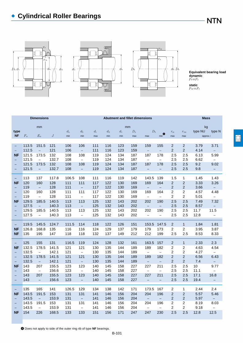
●Cylindrical Roller Bearings
Dimensions Abutment and fillet dimensions Mass
mm mm kgtype da db dc dd de Da Db ras r1as type NU type NNF Fw Ew J min min max min min max max min
4max max (approx.)
B-1014 Does not apply to side of the outer ring rib of type NF bearings.
― 113.5 151.5 121 106 106 111 116 123 159 159 155 2 2 3.79 3.71― 112.5 ― 121 106 ― 111 116 123 159 ― ― 2 2 4.14 ―NF 121.5 173.5 132 108 108 119 124 134 187 187 178 2.5 2.5 6.13 5.99― 121.5 ― 132.7 108 ― 119 124 134 187 ― ― 2.5 2.5 6.62 ―― 121.5 173.5 132 108 108 119 124 134 187 187 178 2.5 2.5 9.2 9.02― 121.5 ― 132.7 108 ― 119 124 134 187 ― ― 2.5 2.5 9.8 ―
― 113 137 117.8 106.5 108 111 116 119 142 143.5 139 1.5 1 1.45 1.43NF 120 160 128 111 111 117 122 130 169 169 164 2 2 3.33 3.26― 119 ― 128 111 ― 117 122 130 169 ― ― 2 2 3.66 ―― 120 160 128 111 111 117 122 130 169 169 164 2 2 4.57 4.48― 119 ― 128 111 ― 117 122 130 169 ― ― 2 2 5.01 ―NF 129.5 185.5 140.5 113 113 125 132 143 202 202 190 2.5 2.5 7.49 7.32― 127.5 ― 140.3 113 ― 125 132 143 202 ― ― 2.5 2.5 8.57 ―― 129.5 185.5 140.5 113 113 125 132 143 202 202 190 2.5 2.5 11.7 11.5― 127.5 ― 140.3 113 ― 125 132 143 202 ― ― 2.5 2.5 12.8 ―
― 119.5 145.5 124.7 111.5 114 118 122 126 151 153.5 147.5 2 1 1.84 1.81NF 126.8 168.8 135 116 116 124 129 137 179 179 173 2 2 3.95 3.87NF 135 195 147 118 118 132 137 149 212 212 199 2.5 2.5 8.53 8.33
― 125 155 131 116.5 119 124 128 132 161 163.5 157 2 1 2.33 2.3NF 132.5 178.5 141.5 121 121 130 135 144 189 189 182 2 2 4.63 4.54― 132.5 ― 142.1 121 ― 130 135 144 189 ― ― 2 2 4.27 ―― 132.5 178.5 141.5 121 121 130 135 144 189 189 182 2 2 6.56 6.43― 132.5 ― 142.1 121 ― 130 135 144 189 ― ― 2 2 7.4 ―NF 143 207 155.5 123 123 140 145 158 227 227 211 2.5 2.5 10 9.77― 143 ― 156.6 123 ― 140 145 158 227 ― ― 2.5 2.5 11.1 ―― 143 207 155.5 123 123 140 145 158 227 227 211 2.5 2.5 17.1 16.8― 143 ― 156.6 123 ― 140 145 158 227 ― ― 2.5 2.5 19.4 ―
― 135 165 141 126.5 129 134 138 142 171 173.5 167 2 1 2.44 2.4NF 143.5 191.5 153 131 131 141 146 156 204 204 196 2 2 5.57 5.46― 143.5 ― 153.9 131 ― 141 146 156 204 ― ― 2 2 5.97 ―― 143.5 191.5 153 131 131 141 146 156 204 204 196 2 2 8.19 8.03― 143.5 ― 153.9 131 ― 141 146 156 204 ― ― 2 2 9.18 ―NF 154 226 168.5 133 133 151 156 171 247 247 230 2.5 2.5 12.8 12.5
dd dcda
ra
r1a
dc Da de db
ra
Db Db
Pr=Fr
Por=Fr
r1a
Equivalent bearing loaddynamic
static

●Cylindrical Roller Bearings
Boundary dimensions Basic load ratings Limiting speeds1
Bearing numbersdynamic static dynamic static
mm kN kgf rpm type type type type d D B rs min
2r1s min
2Cr Cor Cr Cor grease oil NU NJ NUP N
B-102
1 This value achieved with machined cages; when pressed cages are used, 80% of this value is acceptable.2 Minimal allowable dimension for chamfer dimension r or r1.
d 120~150mm
260 55 3 3 530 610 54,000 62,000 2,400 2,800 NU324E NJ NUP ―260 86 3 3 710 920 72,500 93,500 2,400 2,800 NU2324 NJ NUP N260 86 3 3 795 1,030 81,000 105,000 2,200 2,500 NU2324E NJ NUP ―
200 33 2 1.1 172 238 17,500 24,200 3,400 4,000 NU1026 NJ NUP N230 40 3 3 270 340 27,600 35,000 2,900 3,400 NU226 NJ NUP N230 40 3 3 365 455 37,000 46,000 2,600 3,100 NU226E NJ NUP ―230 64 3 3 380 530 38,500 54,000 2,600 3,100 NU2226 NJ NUP N230 64 3 3 530 735 54,000 75,000 2,300 2,700 NU2226E NJ NUP ―280 58 4 4 560 665 57,000 68,000 2,500 2,900 NU326 NJ NUP N280 58 4 4 615 735 63,000 75,000 2,200 2,600 NU326E NJ NUP ―280 93 4 4 840 1,130 85,500 115,000 2,200 2,600 NU2326 NJ NUP N280 93 4 4 920 1,230 94,000 126,000 2,000 2,300 NU2326E NJ NUP ―
210 33 2 1.1 176 250 17,900 25,500 3,200 3,800 NU1028 NJ NUP N250 42 3 3 310 400 31,500 40,500 2,700 3,100 NU228 NJ NUP N250 42 3 3 395 515 40,000 52,500 2,400 2,800 NU228E NJ NUP ―250 68 3 3 445 635 45,500 64,500 2,400 2,800 NU2228 NJ NUP N250 68 3 3 575 835 58,500 85,000 2,100 2,500 NU2228E NJ NUP ―300 62 4 4 615 745 63,000 76,000 2,300 2,700 NU328 NJ NUP N300 62 4 4 665 795 67,500 81,500 2,100 2,400 NU328E NJ NUP ―300 102 4 4 920 1,250 94,000 127,000 2,000 2,300 NU2328 NJ NUP N300 102 4 4 1,020 1,380 104,000 141,000 1,800 2,100 NU2328E NJ NUP ―
225 35 2.1 1.5 202 294 20,600 29,900 3,000 3,500 NU1030 NJ NUP N270 45 3 3 345 435 35,000 44,500 2,500 2,900 NU230 NJ NUP N270 45 3 3 450 595 45,500 60,500 2,200 2,600 NU230E NJ NUP ―270 73 3 3 500 710 51,000 72,500 2,200 2,600 NU2230 NJ NUP N270 73 3 3 660 980 67,500 100,000 2,000 2,400 NU2230E NJ NUP ―320 65 4 4 665 805 67,500 82,500 2,100 2,500 NU330 NJ NUP N320 65 4 4 760 920 77,500 94,000 1,900 2,300 NU330E NJ NUP ―320 108 4 4 1,020 1,400 104,000 143,000 1,900 2,200 NU2330 NJ NUP N320 108 4 4 1,160 1,600 118,000 163,000 1,700 2,000 NU2330E NJ NUP ―
240 38 2.1 1.5 238 340 24,200 35,000 2,800 3,300 NU1032 NJ NUP N290 48 3 3 430 570 43,500 58,000 2,300 2,700 NU232 NJ NUP N290 48 3 3 500 665 51,000 68,000 2,100 2,400 NU232E NJ NUP ―
d
r
r1
D FW J
r
B
Type NU Type NJ
r1
J
r
Type NUP
d
r
r1
J
B
Type N
D
r1
Type NF
r
EW
r1
120
130
140
150
160
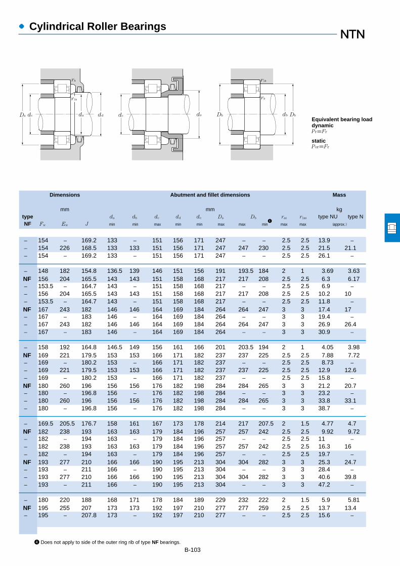
●Cylindrical Roller Bearings
Dimensions Abutment and fillet dimensions Mass
mm mm kgtype da db dc dd de Da Db ras r1as type NU type NNF Fw Ew J min min max min min max max min
4max max (approx.)
B-1034 Does not apply to side of the outer ring rib of type NF bearings.
― 154 ― 169.2 133 ― 151 156 171 247 ― ― 2.5 2.5 13.9 ―― 154 226 168.5 133 133 151 156 171 247 247 230 2.5 2.5 21.5 21.1― 154 ― 169.2 133 ― 151 156 171 247 ― ― 2.5 2.5 26.1 ―
― 148 182 154.8 136.5 139 146 151 156 191 193.5 184 2 1 3.69 3.63NF 156 204 165.5 143 143 151 158 168 217 217 208 2.5 2.5 6.3 6.17― 153.5 ― 164.7 143 ― 151 158 168 217 ― ― 2.5 2.5 6.9 ―― 156 204 165.5 143 143 151 158 168 217 217 208 2.5 2.5 10.2 10― 153.5 ― 164.7 143 ― 151 158 168 217 ― ― 2.5 2.5 11.8 ―NF 167 243 182 146 146 164 169 184 264 264 247 3 3 17.4 17― 167 ― 183 146 ― 164 169 184 264 ― ― 3 3 19.4 ―― 167 243 182 146 146 164 169 184 264 264 247 3 3 26.9 26.4― 167 ― 183 146 ― 164 169 184 264 ― ― 3 3 30.9 ―
― 158 192 164.8 146.5 149 156 161 166 201 203.5 194 2 1 4.05 3.98NF 169 221 179.5 153 153 166 171 182 237 237 225 2.5 2.5 7.88 7.72― 169 ― 180.2 153 ― 166 171 182 237 ― ― 2.5 2.5 8.73 ―― 169 221 179.5 153 153 166 171 182 237 237 225 2.5 2.5 12.9 12.6― 169 ― 180.2 153 ― 166 171 182 237 ― ― 2.5 2.5 15.8 ―NF 180 260 196 156 156 176 182 198 284 284 265 3 3 21.2 20.7― 180 ― 196.8 156 ― 176 182 198 284 ― ― 3 3 23.2 ―― 180 260 196 156 156 176 182 198 284 284 265 3 3 33.8 33.1― 180 ― 196.8 156 ― 176 182 198 284 ― ― 3 3 38.7 ―
― 169.5 205.5 176.7 158 161 167 173 178 214 217 207.5 2 1.5 4.77 4.7NF 182 238 193 163 163 179 184 196 257 257 242 2.5 2.5 9.92 9.72― 182 ― 194 163 ― 179 184 196 257 ― ― 2.5 2.5 11 ―― 182 238 193 163 163 179 184 196 257 257 242 2.5 2.5 16.3 16― 182 ― 194 163 ― 179 184 196 257 ― ― 2.5 2.5 19.7 ―NF 193 277 210 166 166 190 195 213 304 304 282 3 3 25.3 24.7― 193 ― 211 166 ― 190 195 213 304 ― ― 3 3 28.4 ―― 193 277 210 166 166 190 195 213 304 304 282 3 3 40.6 39.8― 193 ― 211 166 ― 190 195 213 304 ― ― 3 3 47.2 ―
― 180 220 188 168 171 178 184 189 229 232 222 2 1.5 5.9 5.81NF 195 255 207 173 173 192 197 210 277 277 259 2.5 2.5 13.7 13.4― 195 ― 207.8 173 ― 192 197 210 277 ― ― 2.5 2.5 15.6 ―
dd dc da
ra
r1a
dc Da de db
ra
r1a
Db Db
Pr=Fr
Por=Fr
Equivalent bearing loaddynamic
static

●Cylindrical Roller Bearings
Boundary dimensions Basic load ratings Limiting speeds1
Bearing numbersdynamic static dynamic static
mm kN kgf rpm type type type type d D B rs min
2r1s min
2Cr Cor Cr Cor grease oil NU NJ NUP N
B-104
1 This value achieved with machined cages; when pressed cages are used, 80% of this value is acceptable.2 Minimal allowable dimension for chamfer dimension r or r1.
d 160~200mm
290 80 3 3 630 940 64,500 96,000 2,100 2,400 NU2232 NJ NUP N290 80 3 3 810 1,190 82,500 121,000 1,900 2,200 NU2232E NJ NUP ―340 68 4 4 700 875 71,000 89,500 2,000 2,300 NU332 NJ NUP N340 68 4 4 860 1,050 87,500 107,000 1,800 2,100 NU332E NJ NUP ―340 114 4 4 1,070 1,520 109,000 155,000 1,700 2,000 NU2332 NJ NUP N340 114 4 4 1,310 1,820 134,000 186,000 1,600 1,900 NU2332E NJ NUP ―
260 42 2.1 2.1 278 400 28,300 41,000 2,600 3,000 NU1034 NJ NUP N310 52 4 4 475 635 48,500 65,000 2,200 2,500 NU234 NJ NUP N310 52 4 4 605 800 61,500 81,500 2,000 2,300 NU234E NJ NUP ―310 86 4 4 715 1,080 73,000 110,000 2,000 2,300 NU2234 NJ NUP N310 86 4 4 965 1,410 98,500 144,000 1,800 2,100 NU2234E NJ NUP ―360 72 4 4 795 1,010 81,500 103,000 1,800 2,200 NU334 NJ NUP N360 120 4 4 1,220 1,750 125,000 179,000 1,600 1,900 NU2334 NJ NUP N
280 46 2.1 2.1 340 485 35,000 49,500 2,400 2,900 NU1036 NJ NUP N320 52 4 4 495 675 50,500 69,000 2,000 2,400 NU236 NJ NUP N320 52 4 4 625 850 64,000 87,000 1,800 2,200 NU236E NJ NUP ―320 86 4 4 745 1,140 76,000 117,000 1,800 2,200 NU2236 NJ NUP N320 86 4 4 1,010 1,510 103,000 154,000 1,600 1,900 NU2236E NJ NUP ―380 75 4 4 905 1,150 92,000 118,000 1,700 2,000 NU336 NJ NUP N380 126 4 4 1,380 1,990 141,000 203,000 1,500 1,800 NU2336 NJ NUP N
290 46 2.1 2.1 350 510 36,000 52,000 2,300 2,700 NU1038 NJ NUP N340 55 4 4 555 770 56,500 78,500 1,900 2,200 NU238 NJ NUP N340 55 4 4 695 955 71,000 97,500 1,700 2,000 NU238E NJ NUP ―340 92 4 4 830 1,290 84,500 131,000 1,700 2,000 NU2238 NJ NUP N340 92 4 4 1,100 1,670 113,000 170,000 1,500 1,800 NU2238E NJ NUP ―400 78 5 5 975 1,260 99,500 129,000 1,600 1,900 NU338 NJ NUP N400 132 5 5 1,520 2,220 155,000 226,000 1,400 1,700 NU2338 NJ NUP N
310 51 2.1 2.1 390 580 40,000 59,500 2,200 2,600 NU1040 NJ NUP N360 58 4 4 620 865 63,500 88,500 1,800 2,100 NU240 NJ NUP N360 58 4 4 765 1,060 78,000 108,000 1,600 1,900 NU240E NJ NUP ―360 98 4 4 925 1,440 94,000 147,000 1,600 1,900 NU2240 NJ NUP N360 98 4 4 1,220 1,870 125,000 191,000 1,500 1,700 NU2240E NJ NUP ―420 80 5 5 975 1,270 99,500 130,000 1,500 1,800 NU340 NJ NUP N
d
r
r1
D FW J
r
B
Type NU Type NJ
r1
J
r
Type NUP
d
r
r1
J
B
Type N
D
r1
Type NF
r
EW
r1
160
170
180
190
200
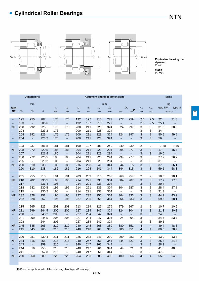
●Cylindrical Roller Bearings
Dimensions Abutment and fillet dimensions Mass
mm mm kgtype da db dc dd de Da Db ras r1as type NU type NNF Fw Ew J min min max min min max max min
4max max (approx.)
B-1054 Does not apply to side of the outer ring rib of type NF bearings.
― 195 255 207 173 173 192 197 210 277 277 259 2.5 2.5 22 21.6― 193 ― 206.6 173 ― 192 197 210 277 ― ― 2.5 2.5 25.1 ―NF 208 292 225 176 176 200 211 228 324 324 297 3 3 31.3 30.6― 204 ― 223.2 176 ― 200 211 228 324 ― ― 3 3 34 ―― 208 292 225 176 176 200 211 228 324 324 297 3 3 50.5 49.5― 204 ― 223.2 176 ― 200 211 228 324 ― ― 3 3 56 ―
― 193 237 201.8 181 181 190 197 203 249 249 239 2 2 7.88 7.76NF 208 272 220.5 186 186 204 211 223 294 294 277 3 3 17 16.7― 207 ― 221.4 186 ― 204 211 223 294 ― ― 3 3 19.6 ―― 208 272 220.5 186 186 204 211 223 294 294 277 3 3 27.2 26.7― 205 ― 220.2 186 ― 204 211 223 294 ― ― 3 3 31 ―NF 220 310 238 186 186 216 223 241 344 344 315 3 3 37 36.1― 220 310 238 186 186 216 223 241 344 344 315 3 3 59.5 58.3
― 205 255 215 191 191 203 209 216 269 269 257 2 2 10.3 10.1NF 218 282 230.5 196 196 214 221 233 304 304 287 3 3 17.7 17.3― 217 ― 231.4 196 ― 214 221 233 304 ― ― 3 3 20.4 ―― 218 282 230.5 196 196 214 221 233 304 304 287 3 3 28.4 27.8― 215 ― 230.2 196 ― 214 221 233 304 ― ― 3 3 31.9 ―NF 232 328 252 196 196 227 235 255 364 364 333 3 3 44.2 43.2― 232 328 252 196 196 227 235 255 364 364 333 3 3 69.5 68.1
― 215 265 225 201 201 213 219 226 279 279 267 2 2 10.7 10.5NF 231 299 244.5 206 206 227 234 247 324 324 304 3 3 21.3 20.8― 230 ― 245.2 206 ― 227 234 247 324 ― ― 3 3 24.2 ―― 231 299 244.5 206 206 227 234 247 324 324 304 3 3 34.4 33.7― 228 ― 244 206 ― 227 234 247 324 ― ― 3 3 39.5 ―NF 245 345 265 210 210 240 248 268 380 380 351 4 4 49.4 48.3― 245 345 265 210 210 240 248 268 380 380 351 4 4 80.5 78.9
― 229 281 239.4 211 211 226 233 241 299 299 283 2 2 13.9 13.7NF 244 316 258 216 216 240 247 261 344 344 321 3 3 25.3 24.8― 243 ― 259 216 ― 240 247 261 344 ― ― 3 3 28.1 ―― 244 316 258 216 216 240 247 261 344 344 321 3 3 41.3 40.5― 241 ― 257.8 216 ― 240 247 261 344 ― ― 3 3 47.8NF 260 360 280 220 220 254 263 283 400 400 366 4 4 55.8 54.5
dd dc da
ra
r1a
dc Da de db
ra
r1a
Db Db
Pr=Fr
Por=Fr
Equivalent bearing loaddynamic
static

●Cylindrical Roller Bearings
Boundary dimensions Basic load ratings Limiting speeds1
Bearing numbersdynamic static dynamic static
mm kN kgf rpm type type type type d D B rs min
2r1s min
2Cr Cor Cr Cor grease oil NU NJ NUP N
B-106
1 This value achieved with machined cages; when pressed cages are used, 80% of this value is acceptable.2 Minimal allowable dimension for chamfer dimension r or r1.
d 200~360mm
420 138 5 5 1,510 2,240 154,000 229,000 1,400 1,600 NU2340 NJ NUP N
340 56 3 3 500 750 51,000 76,500 2,000 2,300 NU1044 NJ NUP N400 65 4 4 760 1,080 77,500 110,000 1,600 1,900 NU244 NJ NUP N400 108 4 4 1,140 1,810 116,000 184,000 1,500 1,700 NU2244 NJ NUP N460 88 5 5 1,190 1,570 122,000 161,000 1,400 1,600 NU344 NJ NUP N460 145 5 5 1,780 2,620 181,000 268,000 1,200 1,400 NU2344 NJ NUP N
360 56 3 3 530 820 54,000 83,500 1,800 2,100 NU1048 NJ NUP N440 72 4 4 935 1,340 95,500 136,000 1,500 1,700 NU248 NJ NUP N440 120 4 4 1,440 2,320 146,000 236,000 1,300 1,600 NU2248 NJ NUP N500 95 5 5 1,430 1,950 146,000 198,000 1,300 1,500 NU348 NJ NUP N500 155 5 5 2,100 3,200 214,000 325,000 1,100 1,300 NU2348 NJ NUP N
400 65 4 4 645 1,000 65,500 102,000 1,600 1,900 NU1052 NJ NUP N480 80 5 5 1,150 1,660 117,000 170,000 1,300 1,600 NU252 NJ NUP N480 130 5 5 1,780 2,930 182,000 299,000 1,200 1,400 NU2252 NJ NUP N540 102 6 6 1,620 2,230 165,000 228,000 1,200 1,400 NU352 NJ NUP N540 165 6 6 2,340 3,600 239,000 365,000 1,000 1,200 NU2352 NJ NUP N
420 65 4 4 660 1,050 67,000 107,000 1,500 1,800 NU1056 NJ NUP N500 80 5 5 1,190 1,760 121,000 180,000 1,200 1,400 NU256 NJ NUP N500 130 5 5 1,840 3,100 188,000 315,000 1,100 1,300 NU2256 NJ NUP N580 108 6 6 1,820 2,540 185,000 259,000 1,100 1,200 NU356 NJ NUP N580 175 6 6 2,700 4,250 275,000 430,000 920 1,100 NU2356 NJ NUP N
460 74 4 4 855 1,340 87,000 137,000 1,400 1,600 NU1060 NJ NUP N540 85 5 5 1,400 2,070 143,000 211,000 1,100 1,300 NU260 NJ NUP N540 140 5 5 2,180 3,650 223,000 370,000 1,000 1,200 NU2260 NJ NUP N
480 74 4 4 875 1,410 89,500 143,000 1,300 1,500 NU1064 NJ NUP N580 92 5 5 1,600 2,390 164,000 244,000 1,000 1,200 NU264 NJ NUP N580 150 5 5 2,550 4,350 260,000 445,000 950 1,100 NU2264 NJ NUP N
520 82 5 5 1,050 1,670 107,000 170,000 1,200 1,400 NU1068 NJ NUP N
540 82 5 5 1,080 1,750 110,000 179,000 1,100 1,300 NU1072 NJ NUP N
d
r
r1
D FW J
r
B
Type NU Type NJ
r1
J
r
Type NUP
d
r
r1
J
B
Type N
D
r1
Type NF
r
EW
r1
220
200
240
260
280
300
320
340
360

●Cylindrical Roller Bearings
Dimensions Abutment and fillet dimensions Mass
mm mm kgtype da db dc dd de Da Db ras r1as type NU type NNF Fw Ew J min min max min min max max min
4max max (approx.)
B-1074 Does not apply to side of the outer ring rib of type NF bearings.
― 260 360 280 220 220 254 263 283 400 400 366 4 4 92.6 90.7
― 250 310 262 233 233 248 254 264 327 327 313 2.5 2.5 18.2 17.9NF 270 350 286 236 236 266 273 289 384 384 355 3 3 37.7 37― 270 350 286 236 236 266 273 289 384 384 355 3 3 59 57.8NF 284 396 307 240 240 279 287 307 440 440 402 4 4 73.4 71.7― 284 396 307 240 240 279 287 307 440 440 402 4 4 116 114
― 270 330 282 253 253 268 275 284 347 347 333 2.5 2.5 19.6 19.3NF 295 385 313 256 256 293 298 316 424 424 390 3 3 50.2 49.2― 295 385 313 256 256 293 298 316 424 424 390 3 3 80 78.4NF 310 430 335 260 260 305 313 333 480 480 436 4 4 93.4 91.3― 310 430 335 260 260 305 313 333 480 480 436 4 4 147 144
― 296 364 309.6 276 276 292 300 312 384 384 367 3 3 29.1 28.7NF 320 420 340 280 280 318 323 343 460 460 426 4 4 66.9 65.6― 320 420 340 280 280 318 323 343 460 460 426 4 4 104 102NF 336 464 362 284 284 331 339 359 516 516 471 5 5 117 114― 336 464 362 284 284 331 339 359 516 516 471 5 5 182 178
― 316 384 329.6 296 296 312 320 332 404 404 387 3 3 30.9 30.4NF 340 440 360 300 300 336 343 365 480 480 446 4 4 70.8 69.4― 340 440 360 300 300 336 343 365 480 480 446 4 4 109 107NF 362 498 390 304 304 356 366 386 556 556 505 5 5 142 139― 362 498 390 304 304 356 366 386 556 556 505 5 5 222 218
― 340 420 356 316 316 336 344 358 444 444 423 3 3 43.6 42.9NF 364 476 387 320 320 361 368 392 520 520 482 4 4 88.2 86.4― 364 476 387 320 320 361 368 392 520 520 482 4 4 138 135
― 360 440 376 336 336 356 364 378 464 464 443 3 3 46 45.3NF 390 510 415 340 340 386 393 419 560 560 516 4 4 111 109― 390 510 415 340 340 386 393 419 560 560 516 4 4 172 168
― 385 475 403 360 360 381 390 405 500 500 479 4 4 61.8 60.8
― 405 495 423 380 380 401 410 425 520 520 499 4 4 64.7 63.7
dd dc da
ra
r1a
dc Da de db
ra
r1a
Db Db
Pr=Fr
Por=Fr
Equivalent bearing loaddynamic
static

●Cylindrical Roller Bearings
Boundary dimensions Basic load ratings Limiting speeds1
Bearing numbersdynamic static dynamic static
mm kN kgf rpm type type type type d D B rs min
2r1s min
2Cr Cor Cr Cor grease oil NU NJ NUP N
B-108
1 This value achieved with machined cages; when pressed cages are used, 80% of this value is acceptable.2 Minimal allowable dimension for chamfer dimension r or r1.
d 380~500mm
560 82 5 5 1,100 1,840 112,000 187,000 1,100 1,200 NU1076 NJ NUP N
600 90 5 5 1,320 2,190 134,000 223,000 990 1,200 NU1080 NJ NUP N
620 90 5 5 1,350 2,290 138,000 233,000 950 1,100 NU1084 NJ NUP N
650 94 6 6 1,430 2,430 146,000 248,000 900 1,100 NU1088 NJ NUP N
680 100 6 6 1,540 2,630 157,000 269,000 850 1,000 NU1092 NJ NUP N
700 100 6 6 1,580 2,750 161,000 280,000 810 960 NU1096 NJ NUP N
720 100 6 6 1,610 2,870 164,000 292,000 770 910 NU10/500 NJ NUP N
d
r
r1
D FW J
r
B
Type NU Type NJ
r1
J
r
Type NUP
d
r
r1
J
B
Type N
D
r1
Type NF
r
EW
r1
380
400
420
440
460
480
500
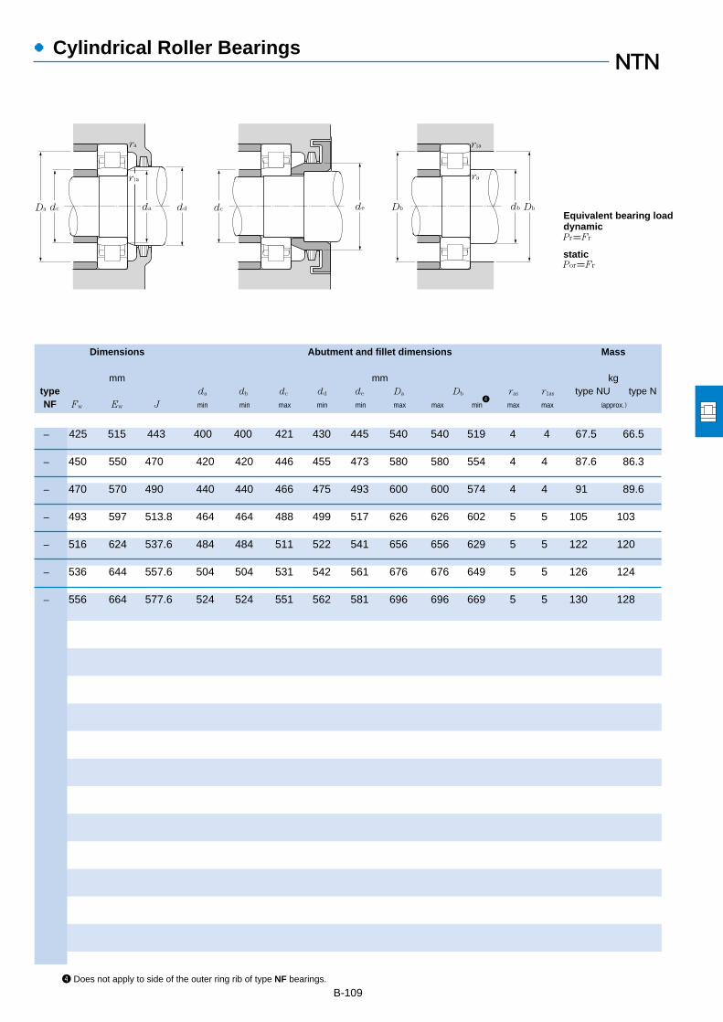
●Cylindrical Roller Bearings
Dimensions Abutment and fillet dimensions Mass
mm mm kgtype da db dc dd de Da Db ras r1as type NU type NNF Fw Ew J min min max min min max max min
4max max (approx.)
B-1094 Does not apply to side of the outer ring rib of type NF bearings.
― 425 515 443 400 400 421 430 445 540 540 519 4 4 67.5 66.5
― 450 550 470 420 420 446 455 473 580 580 554 4 4 87.6 86.3
― 470 570 490 440 440 466 475 493 600 600 574 4 4 91 89.6
― 493 597 513.8 464 464 488 499 517 626 626 602 5 5 105 103
― 516 624 537.6 484 484 511 522 541 656 656 629 5 5 122 120
― 536 644 557.6 504 504 531 542 561 676 676 649 5 5 126 124
― 556 664 577.6 524 524 551 562 581 696 696 669 5 5 130 128
dd dc da
ra
r1a
dc Da de db
ra
r1a
Db Db
Pr=Fr
Por=Fr
Equivalent bearing loaddynamic
static

Dimensions Bearing Mass
mmnumbers
kg
d d1 B1 B2 r1s min1
(approx.)
●L Type Loose Rib
B-110
1 Maximum allowable dimension for chamfer dimension r. Note: 1. This L type collar ring is used with NU type cylindrical roller bearings; in duplexarrangements with NJ or NU type bearing numbers, they become NH type and NUJ type respectively. For bearing dimensions, allowable rotations,and mass, please refer to pages B-94 to B-99. 2. "*" indicates L type collar rings that can also be used with dimension series 22 bearings.
Dimensions Bearing Mass
mmnumbers
kg
d d1 B1 B2 r1s min1
(approx.)
d 20~60mm
L type collar ring
20
25
30
35
40
45
50
55
60
54.2 5 9 1.1 HJ208 0.04653.9 5 8.5 1.1 HJ208E 0.04254.2 5 9.5 1.1 HJ2208 0.04753.9 5 9 1.1 HJ2208E 0.04558.4 7 12.5 1.5 HJ308 0.08357.6 7 11 1.5 HJ308E 0.0758.4 7 14.5 1.5 HJ2308 0.0957.6 7 12.5 1.5 HJ2308E 0.0864.8 8 13. 2 HJ408 0.14
59 5 9.5 1.1 *HJ209 0.05358.9 5 8.5 1.1 HJ209E 0.04758.9 5 9 1.1 HJ2209E 0.0564 7 12.5 1.5 HJ309 0.09964.5 7 11.5 1.5 HJ309E 0.09364 7 15 1.5 HJ2309 0.10964.5 7 13 1.5 HJ2309E 0.10371.8 8 13.5 2 HJ409 0.175
64.6 5 10 1.1 HJ210 0.06363.9 5 9 1.1 *HJ210E 0.05564.6 5 9.5 1.1 HJ2210 0.06171 8 14 2 HJ310 0.14271.4 8 13 2 HJ310E 0.13471 8 17 2 HJ2310 0.15771.4 8 14.5 2 HJ2310E 0.1578.8 9 14.5 2.1 HJ410 0.23
70.8 6 11 1.1 *HJ211 0.08470.8 6 9.5 1.1 HJ211E 0.07270.8 6 10 1.1 HJ2211E 0.07677.2 9 15 2 HJ311 0.18277.7 9 14 2 HJ311E 0.16877.2 9 18.5 2 HJ2311 0.20377.7 9 15.5 2 HJ2311E 0.18585.2 10 16.5 2.1 HJ411 0.29
78.4 6 11 1.5 *HJ212 0.10877.6 6 10 1.5 *HJ212E 0.094
NH=NJ+HJ NUJ=NU+HJ
d
r1
d1 d d1
B2 B2
B1 B1
r1
29.9 3 6.75 0.6 HJ204 0.01229.5 3 5.5 0.6 HJ204E 0.00929.9 3 7.5 0.6 HJ2204 0.01329.5 3 6.5 0.6 HJ2204E 0.0131.8 4 7.5 0.6 HJ304 0.01731.1 4 6.5 0.6 HJ304E 0.01431.8 4 8.5 0.6 HJ2304 0.01831.1 4 7.5 0.6 HJ2304E 0.015
34.8 3 7.25 0.6 HJ205 0.01534.5 3 6. 0.6 HJ205E 0.01234.8 3 7.5 0.6 HJ2205 0.01534.5 3 6.5 0.6 HJ2205E 0.01339 4 8 1.1 HJ305 0.02538 4 7 1.1 HJ305E 0.02139 4 9 1.1 HJ2305 0.02738 4 8 1.1 HJ2305E 0.02443.6 6 10.5 1.5 HJ405 0.057
41.7 4 8.25 0.6 HJ206 0.02541.1 4 7 0.6 HJ206E 0.01741.7 4 8.5 0.6 HJ2206 0.02541.1 4 7.5 0.6 HJ2206E 0.0245.9 5 9.5 1.1 HJ306 0.03944.9 5 8.5 1.1 HJ306E 0.03545.9 5 11.5 1.1 HJ2306 0.04344.9 5 9.5 1.1 HJ2306E 0.03550.5 7 11.5 1.5 HJ406 0.08
47.6 4 8 0.6 HJ207 0.0348 4 7 0.6 HJ207E 0.02747.6 4 8.5 0.6 HJ2207 0.03148 4 8.5 0.6 HJ2207E 0.03150.8 6 11 1.1 HJ307 0.05651 6 9.5 1.1 HJ307E 0.04850.8 6 14 1.1 HJ2307 0.06451 6 11 1.1 HJ2307E 0.05559 8 13 1.5 HJ407 0.12
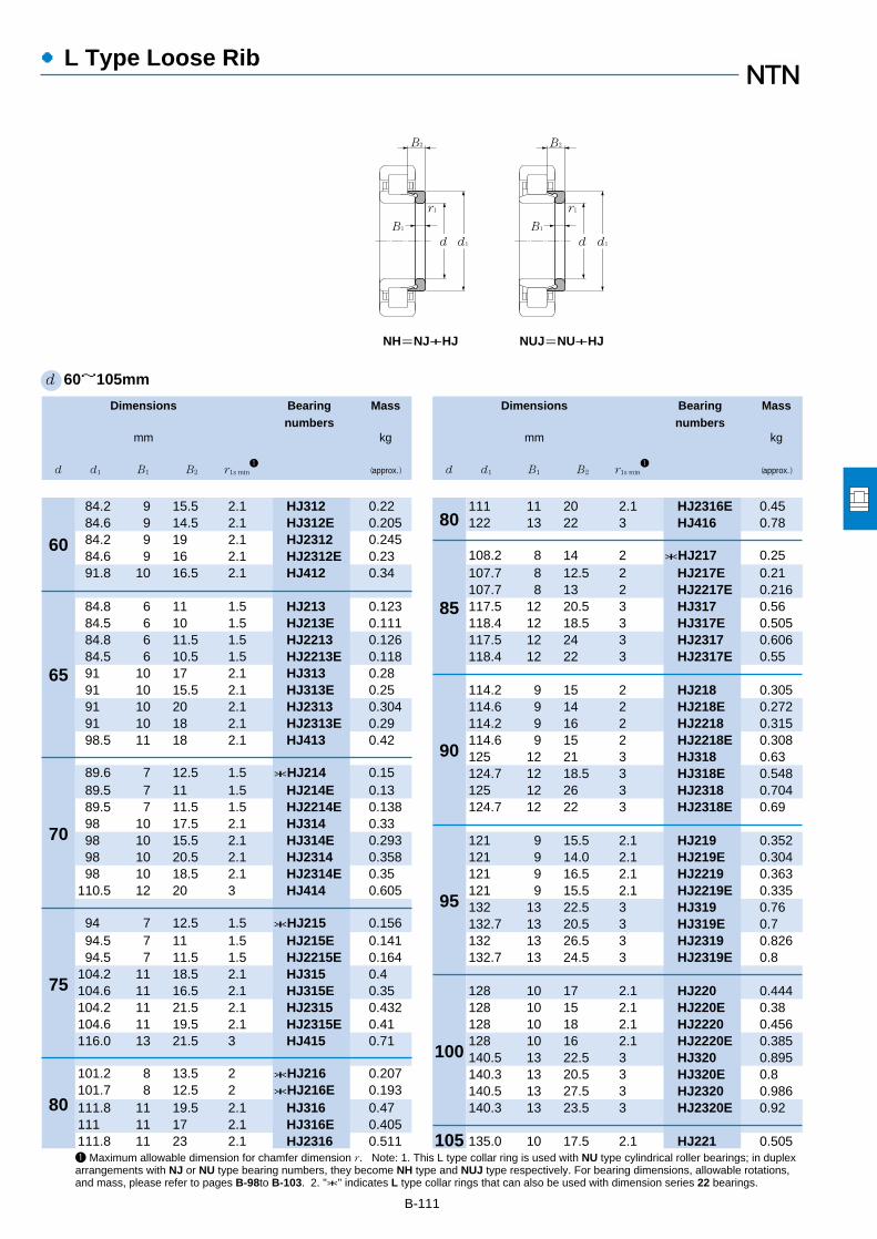
●L Type Loose Rib
Dimensions Bearing Mass
mmnumbers
kg
d d1 B1 B2 r1s min1
(approx.)
B-111
1 Maximum allowable dimension for chamfer dimension r. Note: 1. This L type collar ring is used with NU type cylindrical roller bearings; in duplexarrangements with NJ or NU type bearing numbers, they become NH type and NUJ type respectively. For bearing dimensions, allowable rotations,and mass, please refer to pages B-98to B-103. 2. "*" indicates L type collar rings that can also be used with dimension series 22 bearings.
Dimensions Bearing Mass
mmnumbers
kg
d d1 B1 B2 r1s min1
(approx.)
d 60~105mm
60
65
70
75
80
80
85
90
95
100
105
84.2 9 15.5 2.1 HJ312 0.2284.6 9 14.5 2.1 HJ312E 0.20584.2 9 19 2.1 HJ2312 0.24584.6 9 16 2.1 HJ2312E 0.2391.8 10 16.5 2.1 HJ412 0.34
84.8 6 11 1.5 HJ213 0.12384.5 6 10 1.5 HJ213E 0.11184.8 6 11.5 1.5 HJ2213 0.12684.5 6 10.5 1.5 HJ2213E 0.11891 10 17 2.1 HJ313 0.2891 10 15.5 2.1 HJ313E 0.2591 10 20 2.1 HJ2313 0.30491 10 18 2.1 HJ2313E 0.2998.5 11 18 2.1 HJ413 0.42
89.6 7 12.5 1.5 *HJ214 0.1589.5 7 11 1.5 HJ214E 0.1389.5 7 11.5 1.5 HJ2214E 0.13898 10 17.5 2.1 HJ314 0.3398 10 15.5 2.1 HJ314E 0.29398 10 20.5 2.1 HJ2314 0.35898 10 18.5 2.1 HJ2314E 0.35
110.5 12 20 3 HJ414 0.605
94 7 12.5 1.5 *HJ215 0.15694.5 7 11 1.5 HJ215E 0.14194.5 7 11.5 1.5 HJ2215E 0.164
104.2 11 18.5 2.1 HJ315 0.4104.6 11 16.5 2.1 HJ315E 0.35104.2 11 21.5 2.1 HJ2315 0.432104.6 11 19.5 2.1 HJ2315E 0.41116.0 13 21.5 3 HJ415 0.71
101.2 8 13.5 2 *HJ216 0.207101.7 8 12.5 2 *HJ216E 0.193111.8 11 19.5 2.1 HJ316 0.47111 11 17 2.1 HJ316E 0.405111.8 11 23 2.1 HJ2316 0.511
111 11 20 2.1 HJ2316E 0.45122 13 22 3 HJ416 0.78
108.2 8 14 2 *HJ217 0.25107.7 8 12.5 2 HJ217E 0.21107.7 8 13 2 HJ2217E 0.216117.5 12 20.5 3 HJ317 0.56118.4 12 18.5 3 HJ317E 0.505117.5 12 24 3 HJ2317 0.606118.4 12 22 3 HJ2317E 0.55
114.2 9 15 2 HJ218 0.305114.6 9 14 2 HJ218E 0.272114.2 9 16 2 HJ2218 0.315114.6 9 15 2 HJ2218E 0.308125 12 21 3 HJ318 0.63124.7 12 18.5 3 HJ318E 0.548125 12 26 3 HJ2318 0.704124.7 12 22 3 HJ2318E 0.69
121 9 15.5 2.1 HJ219 0.352121 9 14.0 2.1 HJ219E 0.304121 9 16.5 2.1 HJ2219 0.363121 9 15.5 2.1 HJ2219E 0.335132 13 22.5 3 HJ319 0.76132.7 13 20.5 3 HJ319E 0.7132 13 26.5 3 HJ2319 0.826132.7 13 24.5 3 HJ2319E 0.8
128 10 17 2.1 HJ220 0.444128 10 15 2.1 HJ220E 0.38128 10 18 2.1 HJ2220 0.456128 10 16 2.1 HJ2220E 0.385140.5 13 22.5 3 HJ320 0.895140.3 13 20.5 3 HJ320E 0.8140.5 13 27.5 3 HJ2320 0.986140.3 13 23.5 3 HJ2320E 0.92
135.0 10 17.5 2.1 HJ221 0.505
NH=NJ+HJ NUJ=NU+HJ
d
r1
d1 d d1
B2 B2
B1 B1
r1

●L Type Loose Rib
L type collar ring
Dimensions Bearing Mass
mmnumbers
kg
d d1 B1 B2 r1s min1
(approx.)
B-112
1 Maximum allowable dimension for chamfer dimension r. Note: 1. This L type collar ring is used with NU type cylindrical roller bearings; in duplexarrangements with NJ or NU type bearing numbers, they become NH type and NUJ type respectively. For bearing dimensions, allowable rotations,and mass, please refer to pages B-102 to B-109. 2. "*" indicates L type collar rings that can also be used with dimension series 22 bearings.
Dimensions Bearing Mass
mmnumbers
kg
d d1 B1 B2 r1s min1
(approx.)
d 105~200mm
105
110
120
130
140
150
150
160
170
180
190
200
NH=NJ+HJ NUJ=NU+HJ
d
r1
d1 d d1
B2 B2
B1 B1
r1
147.0 13 22.5 3 HJ321 0.97
141.5 11 18.5 2.1 HJ222 0.615142.1 11 17 2.1 HJ222E 0.553141.5 11 20.5 2.1 HJ2222 0.645142.1 11 19.5 2.1 HJ2222E 0.605155.5 14 23 3 HJ322 1.17156.6 14 22 3 HJ322E 1.09155.5 14 28 3 HJ2322 1.28156.6 14 26.5 3 HJ2322E 1.25
153 11 19 2.1 HJ224 0.715153.9 11 17 2.1 HJ224E 0.634153 11 22 2.1 HJ2224 0.767153.9 11 20 2.1 HJ2224E 0.705168.5 14 23.5 3 HJ324 1.4169.2 14 22.5 3 HJ324E 1.28168.5 14 28 3 HJ2324 1.53169.2 14 26 3 HJ2324E 1.42
165.5 11 19 3 HJ226 0.84164.7 11 17 3 HJ226E 0.684165.5 11 25 3 HJ2226 0.953164.7 11 21 3 HJ2226E 0.831182 14 24 4 HJ326 1.62183 14 23 4 HJ326E 1.53182 14 29.5 4 HJ2326 1.8183 14 28 4 HJ2326E 1.75
179.5 11 19 3 HJ228 1180.2 11 18 3 HJ228E 0.929179.5 11 25 3 HJ2228 1.14180.2 11 23 3 HJ2228E 1.11196 15 26 4 HJ328 1.93196.8 15 25 4 HJ328E 1.91196 15 33.5 4 HJ2328 2.21196.8 15 31 4 HJ2328E 2.3
193 12 20.5 3 HJ230 1.24
194 12 19.5 3 HJ230E 1.18193 12 26.5 3 HJ2230 1.39194 12 24.5 3 HJ2230E 1.42210 15 26.5 4 HJ330 2.37211 15 25 4 HJ330E 2.25210 15 34 4 HJ2330 2.69211 15 31.5 4 HJ2330E 2.6
207 12 21 3 HJ232 1.48207.8 12 20 3 HJ232E 1.34207 12 28 3 HJ2232 1.69206.6 12 24.5 3 HJ2232E 1.61225 15 28 4 HJ332 2.75223.2 15 25 4 HJ332E 2.4225 15 37 4 HJ2332 3.16223.2 15 32 4 HJ2332E 2.85
220.5 12 22 4 HJ234 1.7221.4 12 20 4 HJ234E 1.51220.5 12 29 4 HJ2234 1.93220.2 12 24 4 HJ2234E 1.82238 16 29.5 4 HJ334 3.25238 16 38.5 4 HJ2334 3.71
230.5 12 22 4 HJ236 1.8231.4 12 20 4 HJ236E 1.7230.5 12 29 4 HJ2236 2.04230.2 12 24 4 HJ2236E 1.91252 17 30.5 4 HJ336 3.85252 17 40 4 HJ2336 4.42
244.5 13 23.5 4 HJ238 2.2245.2 13 21.5 4 HJ238E 1.94244.5 13 31.5 4 HJ2238 2.52244 13 26.5 4 HJ2238E 2.38265 18 32 5 HJ338 4.45265 18 41.5 5 HJ2338 5.05
258 14 25 4 HJ240 2.6

●L Type Loose Rib
Dimensions Bearing Mass
mmnumbers
kg
d d1 B1 B2 r1s min1
(approx.)
B-113
1 Maximum allowable dimension for chamfer dimension r. Note: 1. This L type collar ring is used with NU type cylindrical roller bearings; in duplexarrangements with NJ or NU type bearing numbers, they become NH type and NUJ type respectively. For bearing dimensions, allowable rotations,and mass, please refer to pages B-108 to B-109. 2. "*" indicates L type collar rings that can also be used with dimension series 22 bearings.
d 200~320mm
200
220
240
260
280
300
320
NH=NJ+HJ NUJ=NU+HJ
d
r1
d1 d d1
B2 B2
B1 B1
r1
259 14 23 4 HJ240E 2.35258 14 34 4 HJ2240 2.99257.8 14 28 4 HJ2240E 2.86280 18 33 5 HJ340 5280 18 44.5 5 HJ2340 5.76
286 15 27.5 4 HJ244 3.55307 20 36 5 HJ344 7.05
313 16 29.5 4 HJ248 4.65335 22 39.5 5 HJ348 8.2
340 18 33 5 HJ252 6.2362 24 43 6 HJ352 11.4
360 18 33 5 HJ256 7.39390 26 46 6 HJ356 13.9
387 20 34.5 5 HJ260 9.14
415 21 37 5 HJ264 11.3
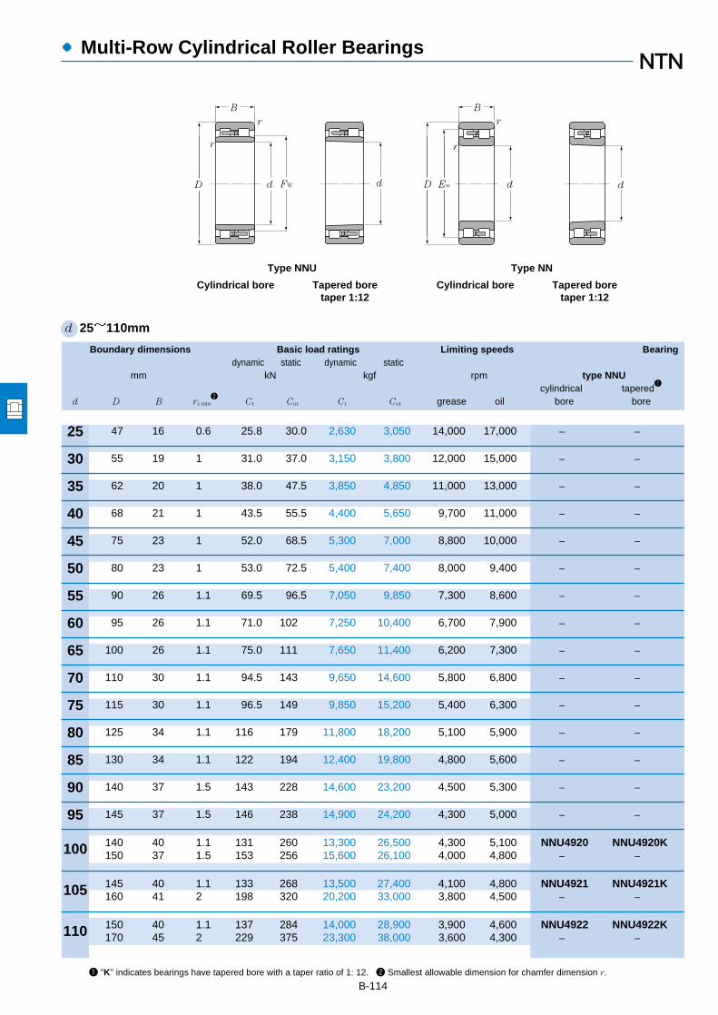
Boundary dimensions Basic load ratings Limiting speeds Bearingdynamic static dynamic static
mm kN kgf rpm type NNUcylindrical tapered
1
d D B rs min2
Cr Cor Cr Cor grease oil bore bore
●Multi-Row Cylindrical Roller Bearings
B-1141 "K" indicates bearings have tapered bore with a taper ratio of 1: 12. 2 Smallest allowable dimension for chamfer dimension r.
d 25~110mm
30
35
40
45
50
55
60
65
70
75
80
85
90
95
100
105
110
25
r
r
B
r
r
dd EwD
B
d d FWD
Type NNU
Cylindrical bore Tapered boretaper 1:12
Type NN
Cylindrical bore Tapered boretaper 1:12
47 16 0.6 25.8 30.0 2,630 3,050 14,000 17,000 ― ―
55 19 1 31.0 37.0 3,150 3,800 12,000 15,000 ― ―
62 20 1 38.0 47.5 3,850 4,850 11,000 13,000 ― ―
68 21 1 43.5 55.5 4,400 5,650 9,700 11,000 ― ―
75 23 1 52.0 68.5 5,300 7,000 8,800 10,000 ― ―
80 23 1 53.0 72.5 5,400 7,400 8,000 9,400 ― ―
90 26 1.1 69.5 96.5 7,050 9,850 7,300 8,600 ― ―
95 26 1.1 71.0 102 7,250 10,400 6,700 7,900 ― ―
100 26 1.1 75.0 111 7,650 11,400 6,200 7,300 ― ―
110 30 1.1 94.5 143 9,650 14,600 5,800 6,800 ― ―
115 30 1.1 96.5 149 9,850 15,200 5,400 6,300 ― ―
125 34 1.1 116 179 11,800 18,200 5,100 5,900 ― ―
130 34 1.1 122 194 12,400 19,800 4,800 5,600 ― ―
140 37 1.5 143 228 14,600 23,200 4,500 5,300 ― ―
145 37 1.5 146 238 14,900 24,200 4,300 5,000 ― ―
140 40 1.1 131 260 13,300 26,500 4,300 5,100 NNU4920 NNU4920K150 37 1.5 153 256 15,600 26,100 4,000 4,800 ― ―
145 40 1.1 133 268 13,500 27,400 4,100 4,800 NNU4921 NNU4921K160 41 2 198 320 20,200 33,000 3,800 4,500 ― ―
150 40 1.1 137 284 14,000 28,900 3,900 4,600 NNU4922 NNU4922K170 45 2 229 375 23,300 38,000 3,600 4,300 ― ―
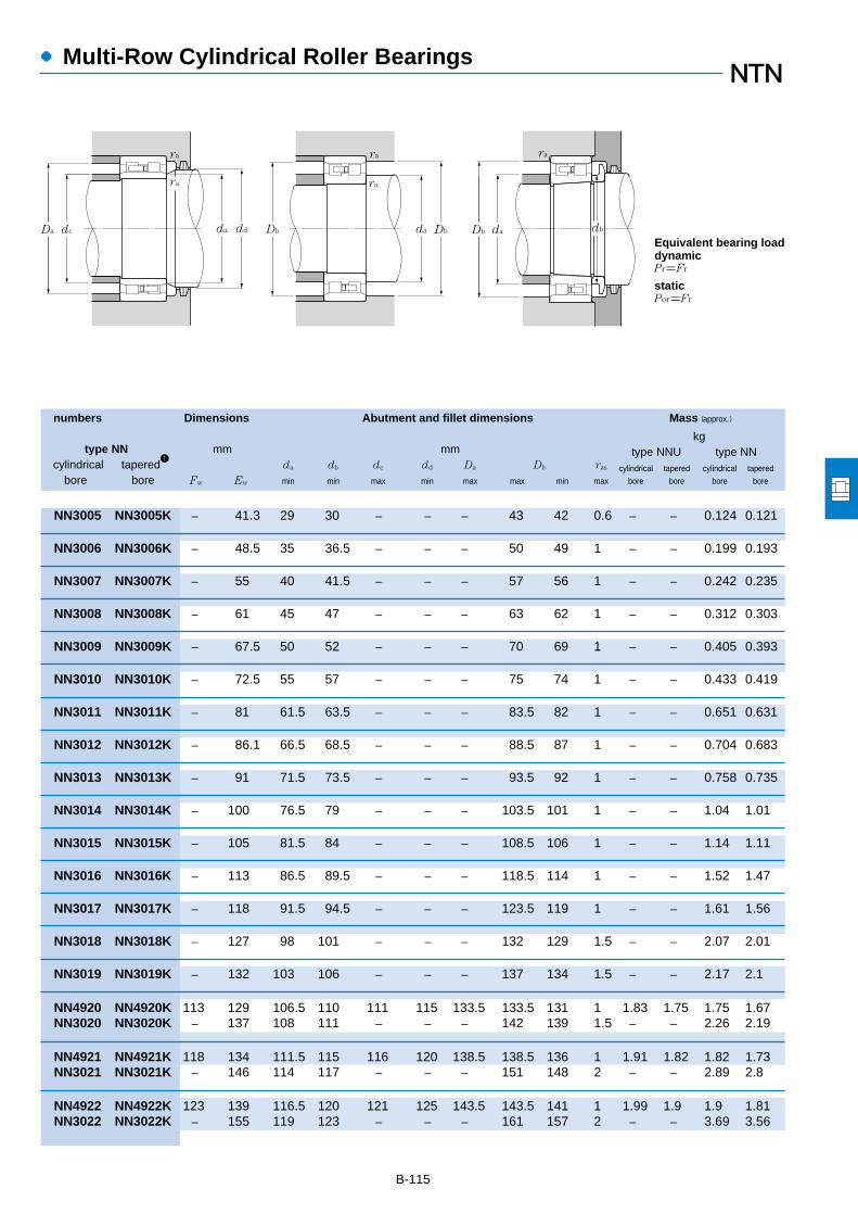
●Multi-Row Cylindrical Roller Bearings
numbers Dimensions Abutment and fillet dimensions Mass (approx.)
kgtype NN mm mm type NNU type NN
cylindrical tapered1
da db dc dd Da Db ras cylindrical tapered cylindrical tapered
bore bore Fw Ew min min max min max max min max bore bore bore bore
B-115
ra
ra ra
ra
ra
dbdaDb Db daDbdadc ddDa
Pr=Fr
Por=Fr
Equivalent bearing loaddynamic
static
NN3005 NN3005K ― 41.3 29 30 ― ― ― 43 42 0.6 ― ― 0.124 0.121
NN3006 NN3006K ― 48.5 35 36.5 ― ― ― 50 49 1 ― ― 0.199 0.193
NN3007 NN3007K ― 55 40 41.5 ― ― ― 57 56 1 ― ― 0.242 0.235
NN3008 NN3008K ― 61 45 47 ― ― ― 63 62 1 ― ― 0.312 0.303
NN3009 NN3009K ― 67.5 50 52 ― ― ― 70 69 1 ― ― 0.405 0.393
NN3010 NN3010K ― 72.5 55 57 ― ― ― 75 74 1 ― ― 0.433 0.419
NN3011 NN3011K ― 81 61.5 63.5 ― ― ― 83.5 82 1 ― ― 0.651 0.631
NN3012 NN3012K ― 86.1 66.5 68.5 ― ― ― 88.5 87 1 ― ― 0.704 0.683
NN3013 NN3013K ― 91 71.5 73.5 ― ― ― 93.5 92 1 ― ― 0.758 0.735
NN3014 NN3014K ― 100 76.5 79 ― ― ― 103.5 101 1 ― ― 1.04 1.01
NN3015 NN3015K ― 105 81.5 84 ― ― ― 108.5 106 1 ― ― 1.14 1.11
NN3016 NN3016K ― 113 86.5 89.5 ― ― ― 118.5 114 1 ― ― 1.52 1.47
NN3017 NN3017K ― 118 91.5 94.5 ― ― ― 123.5 119 1 ― ― 1.61 1.56
NN3018 NN3018K ― 127 98 101 ― ― ― 132 129 1.5 ― ― 2.07 2.01
NN3019 NN3019K ― 132 103 106 ― ― ― 137 134 1.5 ― ― 2.17 2.1
NN4920 NN4920K 113 129 106.5 110 111 115 133.5 133.5 131 1 1.83 1.75 1.75 1.67NN3020 NN3020K ― 137 108 111 ― ― ― 142 139 1.5 ― ― 2.26 2.19
NN4921 NN4921K 118 134 111.5 115 116 120 138.5 138.5 136 1 1.91 1.82 1.82 1.73NN3021 NN3021K ― 146 114 117 ― ― ― 151 148 2 ― ― 2.89 2.8
NN4922 NN4922K 123 139 116.5 120 121 125 143.5 143.5 141 1 1.99 1.9 1.9 1.81NN3022 NN3022K ― 155 119 123 ― ― ― 161 157 2 ― ― 3.69 3.56

B-116
●Multi-Row Cylindrical Roller Bearings
Boundary dimensions Basic load ratings Limiting speeds Bearingdynamic static dynamic static
mm kN kgf rpm type NNUcylindrical tapered
1
d D B rs min2
Cr Cor Cr Cor grease oil bore bore
1 "K" indicates bearings have tapered bore with a taper ratio of 1: 12. 2 Smallest allowable dimension for chamfer dimension r.
d 120~280mm
120
130
140
150
160
170
180
190
200
220
240
260
280
r
r
B
r
r
dd EwD
B
d d FWD
Type NNU
Cylindrical bore Tapered boretaper 1:12
Type NN
Cylindrical bore Tapered boretaper 1:12
165 45 1.1 183 360 18,700 37,000 3,600 4,200 NNU4924 NNU4924K180 46 2 233 390 23,700 40,000 3,300 3,900 ― ―
180 50 1.5 220 440 22,400 45,000 3,300 3,900 NNU4926 NNU4926K200 52 2 284 475 29,000 48,500 3,100 3,600 ― ―
190 50 1.5 227 470 23,100 48,000 3,000 3,600 NNU4928 NNU4928K210 53 2 298 515 30,500 52,500 2,800 3,300 ― ―
210 60 2 345 690 35,000 70,500 2,800 3,300 NNU4930 NNU4930K225 56 2.1 335 585 34,000 60,000 2,600 3,100 ― ―
220 60 2 355 740 36,500 75,500 2,600 3,100 NNU4932 NNU4932K240 60 2.1 375 660 38,000 67,500 2,500 2,900 ― ―
230 60 2 360 765 37,000 78,000 2,500 2,900 NNU4934 NNU4934K260 67 2.1 440 775 45,000 79,000 2,300 2,700 ― ―
250 69 2 460 965 46,500 98,500 2,300 2,700 NNU4936 NNU4936K280 74 2.1 565 995 57,500 102,000 2,200 2,600 ― ―
260 69 2 475 1,030 48,500 105,000 2,200 2,600 NNU4938 NNU4938K290 75 2.1 580 1,040 59,000 106,000 2,000 2,400 ― ―
280 80 2.1 555 1,180 56,500 120,000 2,100 2,400 NNU4940 NNU4940K310 82 2.1 655 1,170 66,500 119,000 1,900 2,300 ― ―
300 80 2.1 585 1,300 59,500 132,000 1,900 2,200 NNU4944 NNU4944K340 90 3 815 1,480 83,000 151,000 1,700 2,100 ― ―
320 80 2.1 610 1,410 62,500 144,000 1,700 2,000 NNU4948 NNU4948K360 92 3 855 1,600 87,000 163,000 1,600 1,900 ― ―
360 100 2.1 900 2,070 92,000 211,000 1,600 1,800 NNU4952 NNU4952K400 104 4 1,060 1,990 108,000 203,000 1,500 1,700 ― ―
380 100 2.1 925 2,200 94,500 224,000 1,400 1,700 NNU4956 NNU4956K420 106 4 1,080 2,080 110,000 212,000 1,300 1,600 ― ―
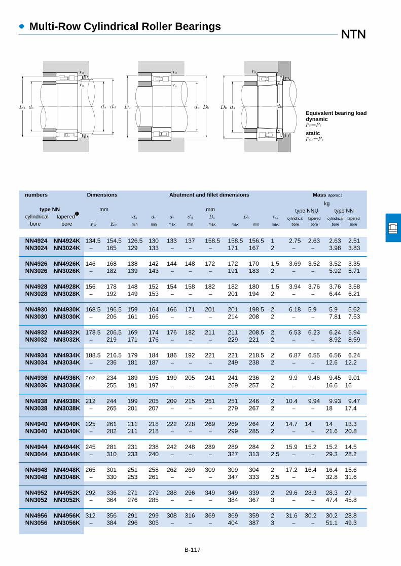
B-117
●Multi-Row Cylindrical Roller Bearings
numbers Dimensions Abutment and fillet dimensions Mass (approx.)
kgtype NN mm mm type NNU type NN
cylindrical tapered1
da db dc dd Da Db ras cylindrical tapered cylindrical tapered
bore bore Fw Ew min min max min max max min max bore bore bore bore
ra
ra ra
ra
ra
dbdaDb Db daDbdadc ddDa
Pr=Fr
Por=Fr
Equivalent bearing loaddynamic
static
NN4924 NN4924K 134.5 154.5 126.5 130 133 137 158.5 158.5 156.5 1 2.75 2.63 2.63 2.51NN3024 NN3024K ― 165 129 133 ― ― ― 171 167 2 ― ― 3.98 3.83
NN4926 NN4926K 146 168 138 142 144 148 172 172 170 1.5 3.69 3.52 3.52 3.35NN3026 NN3026K ― 182 139 143 ― ― ― 191 183 2 ― ― 5.92 5.71
NN4928 NN4928K 156 178 148 152 154 158 182 182 180 1.5 3.94 3.76 3.76 3.58NN3028 NN3028K ― 192 149 153 ― ― ― 201 194 2 ― ― 6.44 6.21
NN4930 NN4930K 168.5 196.5 159 164 166 171 201 201 198.5 2 6.18 5.9 5.9 5.62NN3030 NN3030K ― 206 161 166 ― ― ― 214 208 2 ― ― 7.81 7.53
NN4932 NN4932K 178.5 206.5 169 174 176 182 211 211 208.5 2 6.53 6.23 6.24 5.94NN3032 NN3032K ― 219 171 176 ― ― ― 229 221 2 ― ― 8.92 8.59
NN4934 NN4934K 188.5 216.5 179 184 186 192 221 221 218.5 2 6.87 6.55 6.56 6.24NN3034 NN3034K ― 236 181 187 ― ― ― 249 238 2 ― ― 12.6 12.2
NN4936 NN4936K 202 234 189 195 199 205 241 241 236 2 9.9 9.46 9.45 9.01NN3036 NN3036K ― 255 191 197 ― ― ― 269 257 2 ― ― 16.6 16
NN4938 NN4938K 212 244 199 205 209 215 251 251 246 2 10.4 9.94 9.93 9.47NN3038 NN3038K ― 265 201 207 ― ― ― 279 267 2 ― ― 18 17.4
NN4940 NN4940K 225 261 211 218 222 228 269 269 264 2 14.7 14 14 13.3NN3040 NN3040K ― 282 211 218 ― ― ― 299 285 2 ― ― 21.6 20.8
NN4944 NN4944K 245 281 231 238 242 248 289 289 284 2 15.9 15.2 15.2 14.5NN3044 NN3044K ― 310 233 240 ― ― ― 327 313 2.5 ― ― 29.3 28.2
NN4948 NN4948K 265 301 251 258 262 269 309 309 304 2 17.2 16.4 16.4 15.6NN3048 NN3048K ― 330 253 261 ― ― ― 347 333 2.5 ― ― 32.8 31.6
NN4952 NN4952K 292 336 271 279 288 296 349 349 339 2 29.6 28.3 28.3 27NN3052 NN3052K ― 364 276 285 ― ― ― 384 367 3 ― ― 47.4 45.8
NN4956 NN4956K 312 356 291 299 308 316 369 369 359 2 31.6 30.2 30.2 28.8NN3056 NN3056K ― 384 296 305 ― ― ― 404 387 3 ― ― 51.1 49.3
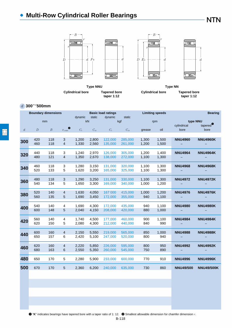
B-118
●Multi-Row Cylindrical Roller Bearings
Boundary dimensions Basic load ratings Limiting speeds Bearingdynamic static dynamic static
mm kN kgf rpm type NNUcylindrical tapered
1
d D B rs min2
Cr Cor Cr Cor grease oil bore bore
1 "K" indicates bearings have tapered bore with a taper ratio of 1: 12. 2 Smallest allowable dimension for chamfer dimension r.
d 300~500mm
320
340
360
380
400
420
440
460
480
500
300
r
r
B
r
r
dd EwD
B
d d FWD
Type NNU
Cylindrical bore Tapered boretaper 1:12
Type NN
Cylindrical bore Tapered boretaper 1:12
420 118 3 1,200 2,800 122,000 285,000 1,300 1,500 NNU4960 NNU4960K460 118 4 1,330 2,560 135,000 261,000 1,200 1,500 ― ―
440 118 3 1,240 2,970 126,000 305,000 1,200 1,400 NNU4964 NNU4964K480 121 4 1,350 2,670 138,000 272,000 1,100 1,300 ― ―
460 118 3 1,280 3,150 131,000 320,000 1,100 1,300 NNU4968 NNU4968K520 133 5 1,620 3,200 165,000 325,000 1,100 1,300 ― ―
480 118 3 1,290 3,250 131,000 330,000 1,100 1,300 NNU4972 NNU4972K540 134 5 1,650 3,300 169,000 340,000 1,000 1,200 ― ―
520 140 4 1,630 4,050 167,000 415,000 1,000 1,200 NNU4976 NNU4976K560 135 5 1,690 3,450 172,000 355,000 940 1,100 ― ―
540 140 4 1,690 4,300 172,000 435,000 940 1,100 NNU4980 NNU4980K600 148 5 2,040 4,150 208,000 420,000 880 1,000 ― ―
560 140 4 1,740 4,500 177,000 460,000 900 1,100 NNU4984 NNU4984K620 150 5 2,080 4,300 212,000 440,000 840 990 ― ―
600 160 4 2,150 5,550 219,000 565,000 850 1,000 NNU4988 NNU4988K650 157 6 2,420 5,100 247,000 520,000 800 940 ― ―
620 160 4 2,220 5,850 226,000 595,000 800 950 NNU4992 NNU4992K680 163 6 2,550 5,350 260,000 545,000 750 890 ― ―
650 170 5 2,280 5,900 233,000 600,000 770 910 NNU4996 NNU4996K
670 170 5 2,360 6,200 240,000 635,000 730 860 NNU49/500 NNU49/500K

B-119
●Multi-Row Cylindrical Roller Bearings
numbers Dimensions Abutment and fillet dimensions Mass (approx.)
kgtype NN mm mm type NNU type NN
cylindrical tapered1
da db dc dd Da Db ras cylindrical tapered cylindrical tapered
bore bore Fw Ew min min max min max max min max bore bore bore bore
ra
ra ra
ra
ra
dbdaDb Db daDbdadc ddDa
Pr=Fr
Por=Fr
Equivalent bearing loaddynamic
static
NN4960 NN4960K 339 391 313 323 335 343 407 407 394 2.5 48.6 46.4 46.4 44.2NN3060 NN3060K ― 418 316 326 ― ― ― 444 421 3 ― ― 70.8 68.6
NN4964 NN4964K 359 411 333 343 355 363 427 427 414 2.5 51.4 49.1 49 46.7NN3064 NN3064K ― 438 336 346 ― ― ― 464 441 3 ― ― 76.2 73.5
― ― 379 ― 353 363 375 383 447 ― ― 2.5 54.2 51.7 ― ―NN3068 NN3068K ― 473 360 371 ― ― ― 500 477 4 ― ― 102 98.5
― ― 398 ― 373 383 394 402 467 ― ― 2.5 57 54.4 ― ―NN3072 NN3072K ― 493 380 391 ― ― ― 520 497 4 ― ― 107 103
― ― 425 ― 396 408 420 430 504 ― ― 3 84.5 80.6 ― ―NN3076 NN3076K ― 512 400 411 ― ― ― 540 516 4 ― ― 113 109
― ― 445 ― 416 428 440 450 524 ― ― 3 88.2 84.1 ― ―NN3080 NN3080K ― 547 420 432 ― ― ― 580 551 4 ― ― 146 141
― ― 465 ― 436 448 460 470 544 ― ― 3 92 87.7 ― ―NN3084 NN3084K ― 567 440 452 ― ― ― 600 571 4 ― ― 154 148
― ― 492 ― 456 469 487 497 584 ― ― 3 127 121 ― ―NN3088 NN3088K ― 596 464 477 ― ― ― 626 601 5 ― ― 178 172
― ― 512 ― 476 489 507 517 604 ― ― 3 132 126 ― ―NN3092 NN3092K ― 622 484 498 ― ― ― 656 627 5 ― ― 202 195
― ― 534 ― 500 514 531 541 630 ― ― 4 156 149 ― ―
― ― 556 ― 520 534 551 561 650 ― ― 4 162 155 ― ―

Boundary dimensions Basic load ratingsdynamic static dynamic static
mm kN kgf
d D B1 C1 rs min1
r1s min1
Cr Cor Cr Cor
●Four-Row Cylindrical Roller Bearings
B-1201 Minimal allowable dimension for chamfer dimension r or r1. 2 Oil groove and oil inlet are in center of outer ring.
d 120~200mm
130
140
145
150
160
170
180
190
200
120
C1
d
r1
B1
D
Drawing 1
FW
r
180 92 92 2.5 2.5 400 785 40,500 80,000180 105 105 2.5 2.5 445 855 45,500 87,000
200 104 104 2.5 2.5 490 955 49,500 97,000
210 116 116 2.5 2.5 510 1,030 52,000 105,000
210 155 155 2.5 2.5 705 1,640 71,500 168,000225 156 156 2.5 2.5 810 1,750 82,500 178,000
220 150 150 2.5 2.5 750 1,640 76,500 168,000230 130 130 2.5 2.5 725 1,520 73,500 155,000230 156 156 2.5 2.5 930 2,040 95,000 208,000250 150 150 2.5 2.5 885 1,640 90,500 167,000
220 180 180 2.5 2.5 920 2,490 93,500 254,000230 130 130 2.5 2.5 665 1,340 68,000 136,000230 168 168 2.5 2.5 915 2,170 93,500 222,000240 170 170 2 2.5 980 2,290 100,000 234,000
230 120 120 2.5 2.5 620 1,520 63,000 155,000240 156 156 2.5 2.5 905 2,170 92,500 222,000240 160 160 2.5 2.5 905 2,180 92,000 222,000250 168 168 2.5 2.5 970 2,220 99,000 226,000255 180 180 2.5 2.5 1,100 2,430 112,000 247,000260 150 150 2.5 2.5 835 1,750 85,000 179,000260 225 225 2.5 2.5 1,310 3,150 134,000 320,000
250 156 156 2.5 2.5 895 2,180 91,500 223,000260 168 168 2.5 2.5 1,020 2,400 104,000 244,000265 180 180 2.5 2.5 1,090 2,510 111,000 256,000
260 168 168 2.5 2.5 980 2,600 100,000 265,000270 170 170 2.5 2.5 1,090 2,660 111,000 272,000270 200 200 2.5 2.5 1,260 3,100 128,000 315,000280 200 200 2.5 2.5 1,240 2,910 126,000 297,000
270 170 170 2.5 2.5 970 2,610 99,000 266,000280 190 190 2.5 2.5 1,190 3,150 121,000 320,000280 200 200 2.5 2.5 1,310 3,300 134,000 335,000
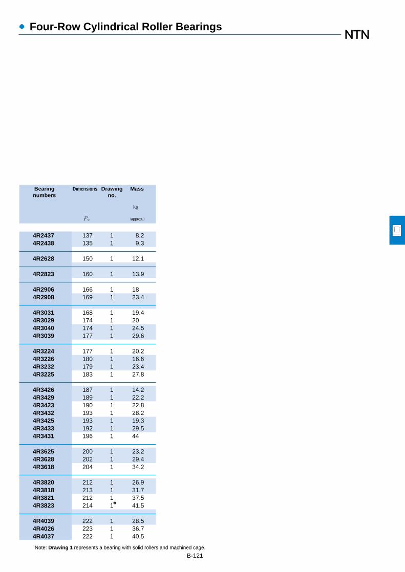
●Four-Row Cylindrical Roller Bearings
Bearing Dimensions Drawing Massnumbers no.
kg
Fw (approx.)
B-121Note: Drawing 1 represents a bearing with solid rollers and machined cage.
4R2437 137 1 8.24R2438 135 1 9.3
4R2628 150 1 12.1
4R2823 160 1 13.9
4R2906 166 1 184R2908 169 1 23.4
4R3031 168 1 19.44R3029 174 1 204R3040 174 1 24.54R3039 177 1 29.6
4R3224 177 1 20.24R3226 180 1 16.64R3232 179 1 23.44R3225 183 1 27.8
4R3426 187 1 14.24R3429 189 1 22.24R3423 190 1 22.84R3432 193 1 28.24R3425 193 1 19.34R3433 192 1 29.54R3431 196 1 44
4R3625 200 1 23.24R3628 202 1 29.44R3618 204 1 34.2
4R3820 212 1 26.94R3818 213 1 31.74R3821 212 1 37.54R3823 214 1
2
41.5
4R4039 222 1 28.54R4026 223 1 36.74R4037 222 1 40.5

B-122
●Four-Row Cylindrical Roller Bearings
Boundary dimensions Basic load ratingsdynamic static dynamic static
mm kN kgf
d D B1 C1 rs min1
r1s min1
Cr Cor Cr Cor
1 Minimal allowable dimension for chamfer dimension r or r1. 2 Oil groove and oil inlet are in center of outer ring.3 Oil groove and oil inlet not on outer ring spacer.
d 200~300mm
210
200
220
230
250
260
270
280
290
300
240
r1
d FW
C1
d
r1
B1
D
B1
Drawing 1 Drawing 2
r
C1
FW
r
D
290 192 192 2.5 2.5 1,290 3,150 132,000 320,000320 216 216 3 3 1,750 3,650 179,000 375,000
290 192 192 2.5 2.5 1,230 3,350 126,000 340,000
290 192 192 2.5 2.5 1,190 3,350 122,000 340,000300 160 160 2.5 2.5 1,000 2,590 102,000 264,000310 192 192 2.5 2.5 1,390 3,400 141,000 350,000310 204 204 2.5 2.5 1,420 3,750 144,000 385,000310 215 215 2.5 2.5 1,530 3,750 156,000 380,000310 225 225 2.5 2.5 1,480 3,950 151,000 405,000310 265 265 2.5 2.5 1,630 4,500 167,000 460,000320 160 160 3 3 1,190 2,550 121,000 260,000320 210 210 2.5 2.5 1,550 3,650 158,000 370,000
330 206 206 2.5 2.5 1,520 3,800 155,000 385,000340 260 260 3 3 2,050 5,100 209,000 520,000
330 220 220 3 3 1,490 4,150 152,000 420,000340 220 220 3 3 1,670 4,200 170,000 425,000360 220 220 2.5 2.5 1,760 4,050 179,000 415,000
350 220 220 3 3 1,730 4,300 176,000 440,000
370 220 220 3 3 1,760 4,450 179,000 455,000380 280 280 3 3 2,420 6,250 247,000 635,000
380 280 280 2.5 2.5 2,580 6,850 263,000 700,000
390 220 220 3 3 1,780 4,650 181,000 475,000390 275 275 2.5 2.5 2,290 6,250 233,000 635,000420 280 280 4 4 2,430 6,150 248,000 630,000
410 240 240 3 3 2,240 5,550 228,000 565,000420 300 300 3 3 2,830 7,500 288,000 765,000
400 300 300 3 3 2,480 7,500 253,000 765,000420 240 240 3 3 2,020 5,450 206,000 555,000420 300 300 3 3 2,720 7,600 278,000 775,000420 300 300 3 3 2,900 7,850 295,000 800,000

●Four-Row Cylindrical Roller Bearings
Bearing Dimensions Drawing Massnumbers no.
kg
Fw (approx.)
B-123Note: Drawing 1 represents a bearing with solid rollers and machined cage; Drawing 2 represents a bearing with hollow rollers and pin type cage.
4R4041 226 1 42.54R4028 231 1 67
4R4206 236 1 39.5
4R4413 239 1 33.84R4419 245 1 32.84R4426 246 1 46.94R4425 247 1 49.84R4420 242 1 51.54R4416 245 1 54.94R4430 245 1 63.54R4428 245 1 46.54R4429 248 1 60.5
4R4614 258 1 58.64R4611 261 1 82.6
4R4811 270 12
56.84R4806 268 1 63.64R4807 274 1 79.6
4R5008 278 1 66
4R5217 292 1 76.54R5213 294 1 109
4R5405 299.7 23
105
4R5611 312 1 81.34R5612 312 1 1054R5605 323 1 139
4R5806 320 1 1034R5805 327 1 141
E-4R6014 328 1 104E-4R6017 334 1 106E-4R6015 334 1 125E-4R6020 332 2 130
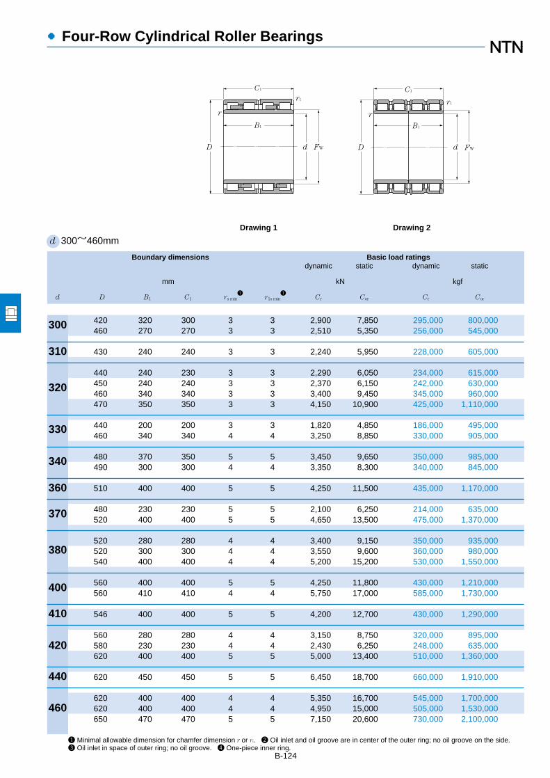
B-124
●Four-Row Cylindrical Roller Bearings
Boundary dimensions Basic load ratingsdynamic static dynamic static
mm kN kgf
d D B1 C1 rs min1
r1s min1
Cr Cor Cr Cor
1 Minimal allowable dimension for chamfer dimension r or r1. 2 Oil inlet and oil groove are in center of the outer ring; no oil groove on the side. 3 Oil inlet in space of outer ring; no oil groove. 4 One-piece inner ring.
d 300~460mm
310
320
330
340
360
370
380
400
410
420
440
460
300
r1
d FW
C1
d
r1
B1
D
B1
Drawing 1 Drawing 2
r
C1
FW
r
D
420 320 300 3 3 2,900 7,850 295,000 800,000460 270 270 3 3 2,510 5,350 256,000 545,000
430 240 240 3 3 2,240 5,950 228,000 605,000
440 240 230 3 3 2,290 6,050 234,000 615,000450 240 240 3 3 2,370 6,150 242,000 630,000460 340 340 3 3 3,400 9,450 345,000 960,000470 350 350 3 3 4,150 10,900 425,000 1,110,000
440 200 200 3 3 1,820 4,850 186,000 495,000460 340 340 4 4 3,250 8,850 330,000 905,000
480 370 350 5 5 3,450 9,650 350,000 985,000490 300 300 4 4 3,350 8,300 340,000 845,000
510 400 400 5 5 4,250 11,500 435,000 1,170,000
480 230 230 5 5 2,100 6,250 214,000 635,000520 400 400 5 5 4,650 13,500 475,000 1,370,000
520 280 280 4 4 3,400 9,150 350,000 935,000520 300 300 4 4 3,550 9,600 360,000 980,000540 400 400 4 4 5,200 15,200 530,000 1,550,000
560 400 400 5 5 4,250 11,800 430,000 1,210,000560 410 410 4 4 5,750 17,000 585,000 1,730,000
546 400 400 5 5 4,200 12,700 430,000 1,290,000
560 280 280 4 4 3,150 8,750 320,000 895,000580 230 230 4 4 2,430 6,250 248,000 635,000620 400 400 5 5 5,000 13,400 510,000 1,360,000
620 450 450 5 5 6,450 18,700 660,000 1,910,000
620 400 400 4 4 5,350 16,700 545,000 1,700,000620 400 400 4 4 4,950 15,000 505,000 1,530,000650 470 470 5 5 7,150 20,600 730,000 2,100,000

●Four-Row Cylindrical Roller Bearings
Bearing Dimensions Drawing Massnumbers no.
kg
Fw (approx.)
B-125Note: Drawing 1 represents a bearing with solid rollers and machined cage; Drawing 2 represents a bearing with hollow rollers and pin type cage.
E-4R6018 332 2 136E-4R6019 344 1 162
E-4R6202 344.5 1 108
E-4R6414 351 1 106E-4R6411 358 1 125E-4R6412 360 1 178E-4R6406 361.7 2 212
E-4R6603 360 12
83.6E-4R6605 365 1 181
E-4R6811 378 1 198E-4R6804 377 1 187
E-4R7203 397 12
262
E-4R7405 400 1 106E-4R7404 409 1 273
E-4R7605 417 1 174E-4R7607 416 2
3
210E-4R7604 422 2
3
325
E-4R8007 446 1 303E-4R8010 445 2 349
E-4R8201 444 12
256
E-4R8403 457 1 189E-4R8404 466 1 181E-4R8401 478 1 410
E-4R8801 487 2 437
E-4R9211 502 234
383E-4R9209 502 1 341E-4R9216 509 2 540
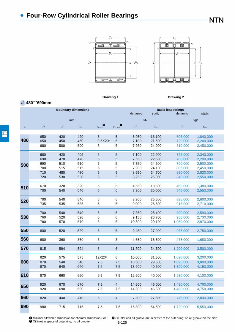
B-126
●Four-Row Cylindrical Roller Bearings
Boundary dimensions Basic load ratingsdynamic static dynamic static
mm kN kgf
d D B1 C1 rs min1
r1s min1
Cr Cor Cr Cor
1 Minimal allowable dimension for chamfer dimension r or r1. 2 Oil inlet and oil groove are in center of the outer ring; no oil groove on the side. 3 Oil inlet in space of outer ring; no oil groove.
d 480~690mm
480
500
510
520
530
550
560
570
600
610
650
r1
d FW
C1
d
r1
B1
D
B1
Drawing 1 Drawing 2
r
C1
FW
r
D
690
660
650 420 420 5 5 5,950 18,100 605,000 1,840,000650 450 450 9.5X20° 5 7,100 21,600 720,000 2,200,000680 500 500 6 6 7,950 24,000 810,000 2,450,000
680 420 405 5 5 7,100 22,900 725,000 2,340,000690 470 470 5 5 7,650 22,500 780,000 2,290,000690 510 510 5 5 7,750 24,600 790,000 2,500,000700 515 515 5 5 7,900 24,100 805,000 2,450,000710 480 480 6 6 8,650 24,700 880,000 2,520,000720 530 530 5 5 8,250 25,000 840,000 2,550,000
670 320 320 5 5 4,550 13,500 465,000 1,380,000700 540 540 6 6 8,300 25,000 845,000 2,550,000
700 540 540 6 6 8,200 25,500 835,000 2,600,000735 535 535 5 5 9,000 26,600 915,000 2,710,000
700 540 540 6 6 7,850 25,400 800,000 2,590,000760 520 520 6 6 9,150 26,700 935,000 2,730,000780 570 570 6 6 10,300 29,100 1,050,000 2,970,000
800 520 520 6 6 9,450 27,000 965,000 2,750,000
680 360 360 3 3 4,650 16,500 475,000 1,680,000
815 594 594 6 6 11,800 34,500 1,200,000 3,500,000
820 575 575 12X20° 6 10,000 31,500 1,020,000 3,200,000870 540 540 7.5 7.5 10,600 29,600 1,090,000 3,000,000870 640 640 7.5 7.5 13,600 40,500 1,390,000 4,150,000
870 660 660 9.5 7.5 12,600 40,000 1,280,000 4,100,000
920 670 670 7.5 4 14,600 46,000 1,490,000 4,700,000920 690 690 7.5 7.5 14,300 46,500 1,460,000 4,750,000
820 440 440 5 4 7,300 27,800 745,000 2,840,000
980 715 715 7.5 7.5 16,800 54,500 1,720,000 5,550,000

●Four-Row Cylindrical Roller Bearings
Bearing Dimensions Drawing Massnumbers no.
kg
Fw (approx.)
B-1274 One-piece inner ring. Note: Drawing 1 represents a bearing with solid rollers and machined cage; Drawing 2 represents a bearing with hollowrollers and pin type cage.
E-4R9607 523 24
369E-4R9609 525 2
4
395E-4R9604 532 2 640
E-4R10010 550 23
495E-4R10016 547 2 590E-4R10006 552 2 640E-4R10011 554 2 680E-4R10008 556 2 675E-4R10015 568 2 780
E-4R10201 554 24
335E-4R10202 558 2 689
E-4R10403 564 2 658E-4R10402 574.5 2 740
E-4R10603 574 2 626E-4R10601 590 2 800E-4R10602 601 2 1 010
E-4R11001 622 2 965
E-4R11202 590 1 265
E-4R11402 628 2 1 040
E-4R12003 655 2 980E-4R12002 672 2 1 150E-4R12001 672 2 1 330
E-4R12202 680 22
1 400
E-4R13005 723 2 1 500E-4R13003 723 2 1 550
E-4R13201 702 2 580
E-4R13802 767.5 2 1 850

B-128
●Four-Row Cylindrical Roller Bearings
Boundary dimensions Basic load ratingsdynamic static dynamic static
mm kN kgf
d D B1 C1 rs min1
r1s min1
Cr Cor Cr Cor
1 Minimal allowable dimension for chamfer dimension r or r1. 2 Inner ring is divided into four. 3 Oil mist nozzles are attached.4 Oil inlet in space of outer ring; no oil groove.
d 700~1 200mm
700
710
725
750
760
800
820
840
850
860
900
920
1000
r1
d FW
C1
d
r1
B1
D
B1
Drawing 1 Drawing 2
r
C1
FW
r
D
1030
1200
930 620 620 15X20° 6 12,900 43,000 1,320,000 4,400,000
1,000 715 715 9.5 6 16,800 54,500 1,710,000 5,550,000
1,000 700 700 6 6 15,900 53,500 1,620,000 5,450,000
1,050 745 720 7.5 7.5 17,600 58,000 1,790,000 5,900,0001,090 745 720 7.5 7.5 19,100 60,500 1,950,000 6,150,000
1,030 750 750 7.5 7.5 17,300 59,500 1,760,000 6,050,0001,080 805 790 6 6 18,700 61,000 1,900,000 6,250,0001,100 745 720 7.5 7.5 19,100 60,500 1,950,000 6,150,000
1,080 700 700 7.5 7.5 16,500 55,000 1,680,000 5,600,0001,080 750 750 6 6 17,300 59,000 1,760,000 6,000,000
1,130 800 800 7.5 7.5 19,600 66,500 2,000,000 6,800,0001,130 825 800 7.5 7.5 19,600 66,500 2,000,000 6,800,0001,160 840 840 7.5 7.5 21,600 71,000 2,200,000 7,250,000
1,160 840 840 5 7.5 21,600 71,000 2,200,000 7,250,000
1,150 650 650 9.5 9.5 15,700 51,000 1,610,000 5,200,0001,150 800 800 6 6 19,700 71,000 2,010,000 7,250,0001,180 650 650 7.5 7.5 16,400 51,500 1,670,000 5,250,0001,180 850 850 9.5 9.5 24,100 78,500 2,460,000 8,000,000
1,160 735 710 6 6 17,800 62,500 1,810,000 6,400,000
1,230 895 870 7.5 7.5 24,700 88,000 2,520,000 9,000,000
1,280 865 850 7.5 7.5 26,200 88,500 2,670,000 9,000,000
1,310 880 880 9.5 9.5 23,400 88,500 2,380,000 9,000,0001,360 800 800 7.5 7.5 25,000 85,000 2,550,000 8,650,000
1,380 850 850 7.5 7.5 24,400 89,000 2,490,000 9,100,000
1,590 1,050 1,050 7.5 7.5 36,000 133,000 3,650,000 13,600,000

●Four-Row Cylindrical Roller Bearings
Bearing Dimensions Drawing Massnumbers no.
kg
Fw (approx.)
B-129Note: Drawing 2 represents a bearing with hollow rollers and pin type cage.
E-4R14003 763 2 1 200
E-4R14205 787.5 22
1 900
E-4R14501 796 2 1 730
E-4R15001 830 23
2 180E-4R15002 845 2
3
2 530
E-4R15204 828 23
2 000E-4R15207 845 2
3
2 550E-4R15203 855 2
3
2 560
E-4R16004 870 2 1 950E-4R16005 880 2 2 090
E-4R16406 903 23
2 450E-4R16405 903 2 2 520E-4R16403 910 2 2 930
E-4R16801 920 2 2 840
E-4R17001 941 2 1 980E-4R17003 930 2 2 430E-4R17004 945 2 2 270E-4R17002 928 2 2 970
E-4R17201 940 2 2 310
E-4R18001 985 23
3 250
E-4R18401 1 015 2 3 560
E-4R20001 1 080 2 3 260E-4R20002 1 090 2 3 530
E-4R20601 1 124 2 3 800
E-4R24002 1 295 22
6 220

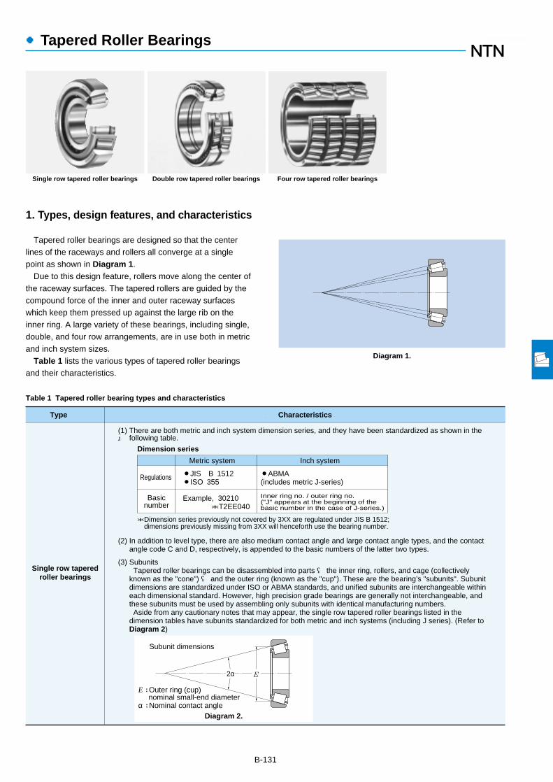
●Tapered Roller Bearings
1. Types, design features, and characteristics
Tapered roller bearings are designed so that the centerlines of the raceways and rollers all converge at a singlepoint as shown in Diagram 1.
Due to this design feature, rollers move along the center ofthe raceway surfaces. The tapered rollers are guided by thecompound force of the inner and outer raceway surfaceswhich keep them pressed up against the large rib on theinner ring. A large variety of these bearings, including single,double, and four row arrangements, are in use both in metricand inch system sizes.
Table 1 lists the various types of tapered roller bearingsand their characteristics.
B-131
Type Characteristics
Single row taperedroller bearings
(2) In addition to level type, there are also medium contact angle and large contact angle types, and the contact angle code C and D, respectively, is appended to the basic numbers of the latter two types.
(3) Subunits Tapered roller bearings can be disassembled into parts ― the inner ring, rollers, and cage (collectively known as the "cone") ― and the outer ring (known as the "cup"). These are the bearing’s "subunits". Subunit dimensions are standardized under ISO or ABMA standards, and unified subunits are interchangeable within each dimensional standard. However, high precision grade bearings are generally not interchangeable, and these subunits must be used by assembling only subunits with identical manufacturing numbers. Aside from any cautionary notes that may appear, the single row tapered roller bearings listed in the dimension tables have subunits standardized for both metric and inch systems (including J series). (Refer to Diagram 2)
Diagram 2.
E2α
Subunit dimensions
E : Outer ring (cup) nominal small-end diameterα : Nominal contact angle
*Dimension series previously not covered by 3XX are regulated under JIS B 1512; dimensions previously missing from 3XX will henceforth use the bearing number.
Dimension series
Basicnumber
Regulations
Metric system Inch system
Example, 30210 *T2EE040
¡JIS B 1512¡ISO 355
¡ABMA(includes metric J-series)
Inner ring no. / outer ring no.("J" appears at the beginning of thebasic number in the case of J-series.)
(1) There are both metric and inch system dimension series, and they have been standardized as shown in the following table.
Table 1 Tapered roller bearing types and characteristics
Diagram 1.
Single row tapered roller bearings Double row tapered roller bearings Four row tapered roller bearings
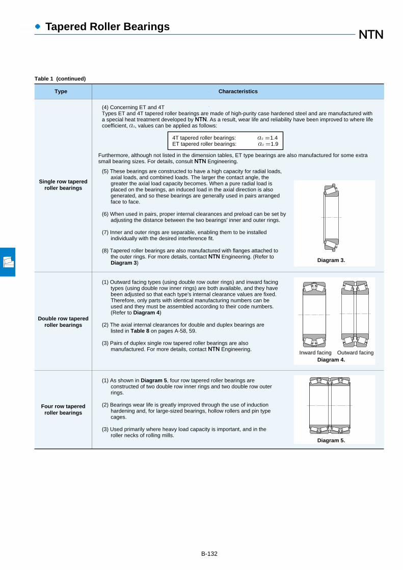
●Tapered Roller Bearings
B-132
Type Characteristics
(5) These bearings are constructed to have a high capacity for radial loads, axial loads, and combined loads. The larger the contact angle, the greater the axial load capacity becomes. When a pure radial load is placed on the bearings, an induced load in the axial direction is also generated, and so these bearings are generally used in pairs arranged face to face.
(6) When used in pairs, proper internal clearances and preload can be set by adjusting the distance between the two bearings' inner and outer rings.
(7) Inner and outer rings are separable, enabling them to be installed individually with the desired interference fit.
(8) Tapered roller bearings are also manufactured with flanges attached to the outer rings. For more details, contact NTN Engineering. (Refer to Diagram 3)
Single row taperedroller bearings
(1) Outward facing types (using double row outer rings) and inward facing types (using double row inner rings) are both available, and they have been adjusted so that each type's internal clearance values are fixed. Therefore, only parts with identical manufacturing numbers can be used and they must be assembled according to their code numbers. (Refer to Diagram 4)
(2) The axial internal clearances for double and duplex bearings are listed in Table 8 on pages A-58, 59.
(3) Pairs of duplex single row tapered roller bearings are also manufactured. For more details, contact NTN Engineering.
Double row taperedroller bearings
(1) As shown in Diagram 5, four row tapered roller bearings are constructed of two double row inner rings and two double row outer rings.
(2) Bearings wear life is greatly improved through the use of induction hardening and, for large-sized bearings, hollow rollers and pin type cages.
(3) Used primarily where heavy load capacity is important, and in the roller necks of rolling mills.
Four row taperedroller bearings
Furthermore, although not listed in the dimension tables, ET type bearings are also manufactured for some extrasmall bearing sizes. For details, consult NTN Engineering.
(4) Concerning ET and 4TTypes ET and 4T tapered roller bearings are made of high-purity case hardened steel and are manufactured with a special heat treatment developed by NTN. As a result, wear life and reliability have been improved to where life coefficient, a2, values can be applied as follows:
4T tapered roller bearings: a2 =1.4 ET tapered roller bearings: a2 =1.9
Diagram 4.Inward facing Outward facing
Diagram 3.
Diagram 5.
Table 1 (continued)

●Tapered Roller Bearings
B-133
2. Standard cage type
In general, pressed cages are used in tapered rollerbearings.
However, for large sized bearings, machined or pin typecages are also used; and for small sized bearings, moldedresin cages are also used.
3. Allowable misalignment
Single row and back-to-back arrangement: ………0.0005rad(1.5')
Face-to-face:…………………………0.001rad (3.5')
In situations where large displacement is necessary,please consult NTN Engineering.

B-134
●Tapered Roller Bearings
Inch Tapered Roller Bearings index
Series Cone or cup number Page of bearing
number is between dimension table
335 4T-332~4T-344 B-165,167,169
355 4T-350A~4T-359S B-167,169,171
365 4T-362~4T-370A B-171,173,175
385 4T-382A~4T-389A B-171,173,175,177
395 4T-390~4T-399A B-173,177,179,181
415 4T-414~4T-420 B-167
435 4T-432~4T-438 B-169,171
455 4T-453A~4T-469 B-169,171,175,177
475 4T-472~4T-484 B-179,181,183
495 4T-492A~4T-498 B-183,185,187
525 4T-522~4T-529 B-169,171,175
535 4T-532A~4T-543 B-167,175
555 4T-522~4T-560S B-175,177,179,181
565 4T-563~4T-568 B-179,181
575 4T-572~4T-582 B-183,185
595 4T-592A~4T-598A B-185,187,189
615 4T-612~4T-623 B-175,177
635 4T-632~4T-644 B-179,181,183
655 4T-652~4T-665 B-181,183,185,187
675 4T-672~4T-687 B-187,189
745 4T-740~4T-749A B-181,183,185,187
755 4T-752~4T-760 B-185,187
775 4T-772~4T-782 B-189
795 4T-792~4T-799A B-191
835 4T-832~4T-850 B-181,185,187
855 4T-854~4T-861 B-189
895 4T-892~4T-898 B-193
935 4T-932~4T-941 B-189
1200 4T-1220~4T-1280 B-159
1300 4T-1328~4T-1380 B-157
1700 4T-1729~4T-1780 B-157,159
1900 4T-1930~4T-1985 B-159,161
2400 4T-2420~4T-2474 B-161
2500 4T-2520~4T-2585 B-161,163
2600 4T-2631~4T-2690 B-159,161
Series Cone or cup number Page of bearing
number is between dimension table
2700 4T-2720~4T-2793 B-163,165,167
2800 4T-2820~4T-2879 B-163
2900 4T-2924~4T-2984 B-171
3100 4T-3120~4T-3196 B-161,163
3300 4T-3320~4T-3386 B-165,167
3400 4T-3420~4T-3490 B-163,165,167
3500 4T-3520~4T-3586 B-167,169,171
JS3500 4T-JS3510~4T-JS3549A B-165
3700 4T-3720~4T-3782 B-169,171,173,175
3800 4T-3820~4T-3880 B-165,167,169
3900 4T-3920~4T-3994 B-175,177,179,181
A4000 4T-A4050~4T-A4138 B-157
4300 4T-4335~4T-4395 B-169
5300 4T-5335~4T-5395 B-173
5500 4T-5535~4T-5584 B-175,179
5700 4T-5735~4T-5760 B-183
A6000 4T-A6075~4T-A6157 B-157
6200 4T-6220~4T-6277 B-171
6300 4T-6320~4T-6386 B-181
6400 4T-6420~4T-6461A B-183,185
6500 4T-6535~4T-6580 B-185,187
02400 4T-02420~4T-02476 B-161,163
02800 4T-02820~4T-02878 B-161,163
03000 4T-03062~4T-03162 B-157
05000 4T-05062~4T-05185 B-157
07000 4T-07079~4T-07204 B-157,159
09000 4T-09062~4T-09196 B-157
11000 4T-11162~4T-11315 B-167
11500 4T-11520~4T-11590 B-157
LM11700 4T-LM11710~4T-LM11749 B-157
LM11900 4T-LM11910~4T-LM11949 B-157
12000 4T-12175~4T-12303 B-169
12500 4T-12520~4T-12580 B-157
M12600 4T-M12610~4T-M12649 B-157
LM12700 4T-LM12711~4T-LM12749 B-157

B-135
●Tapered Roller Bearings
Inch Tapered Roller Bearings index
Series Cone or cup number Page of bearing
number is between dimension table
13000 4T-13621~4T-13687 B-165
13800 4T-13830~4T-13889 B-165
14000 4T-14116~4T-14276 B-161,163,165
15000 4T-15100~4T-15245 B-159,161,163
15500 4T-15520~4T-15590 B-159,161
16000 4T-16137~4T-16284 B-163,165
17000 4T-17118~4T-17244 B-161
17500 4T-17520~4T-17580 B-157
18500 4T-18520~4T-18590 B-167
18600 4T-18620~4T-18690 B-169,171
18700 4T-18720~4T-18790 B-173
19000 4T-19150~4T-19281 B-165
21000 4T-21075~4T-21212 B-157
22700 4T-22720~4T-22780 B-169
23000 4T-23100~4T-23256 B-159
24700 4T-24720~4T-24780 B-167
25500 4T-25519~4T-25592 B-167,169,171
25800 4T-25820~4T-25880 B-163,165
26800 4T-26820~4T-26885 B-165,167,169
27600 4T-27620~4T-27691 B-185
27800 4T-27820~4T-27880 B-167
28000 4T-28150~4T-28315 B-167
28500 4T-28521~4T-28584 B-173,175
28600 4T-28622~4T-28682 B-173,177
28900 4T-28920~4T-28995 B-179
29500 4T-29520~4T-29590 B-177,179,181
29600 4T-29620~4T-29688 B-181,183
LM29700 4T-LM29710~4T-LM29748 B-165
31500 4T-31520~4T-31597 B-165
33000 4T-33225~4T-33462 B-177,181,183
33800 4T-33821~4T-33895 B-169,173,175
34000 4T-34274~4T-34478 B-181,183,185
36600 4T-36620~4T-36691 B-193
36900 4T-36920~4T-36990 B-193
37000 4T-37425~4T-37625 B-189
Series Cone or cup number Page of bearing
number is between dimension table
39500 4T-39520~4T-39590 B-175,177,179,181
41000 4T-41125~4T-41286 B-161
42000 4T-42346~4T-42584 B-187,189
42600 4T-42620~4T-42690 B-183,185
43000 4T-43131~4T-43312 B-163
44000 4T-44143~4T-44348 B-165,167
L44600 4T-L44610~4T-L44649 B-159
45200 4T-45220~4T-45289 B-171,173,175,177
L45400 4T-L45410~4T-L45449 B-161
46000 4T-46162~4T-46368 B-169
46700 4T-46720~4T-46790 B-193
47400 4T-47420~4T-47490 B-181
47600 4T-47620~4T-47686 B-183,185
47800 4T-47820~4T-47896 B-187,189
48200 4T-48220~4T-48290 B-191
48300 4T-48320~4T-48393 B-193
LM48500 4T-LM48510~4T-LM48548A B-163
48600 4T-48620~4T-48685 B-193
49500 4T-49520~4T-49585 B-175
52000 4T-52375~4T-52400 B-189
53000 4T-53162~4T-53377 B-169
55000C 4T-55175C~4T-55443 B-171,173,175
56000 4T-56425~4T-56650 B-189
59000 4T-59200~4T-59412 B-175
64000 4T-64433~4T-64700 B-191
65000 4T-65237~4T-65500 B-179
63500 4T-65320~4T-65390 B-173
66000 4T-66200~4T-66462 B-175,177
66500 4T-66520~4T-66589 B-175,177
LM67000 4T-LM67010~4T-LM67048 B-161
67300 4T-67332~4T-67391 B-191,193
67700 4T-67720~4T-67790 B-193
68000 4T-68450~4T-68712 B-191
L68100 4T-L68111~4T-L68149 B-165
L69300 4T-JL69310~4T-JL69349 B-165

B-136
Series Cone or cup number Page of bearing
number is between dimension table
Series Cone or cup number Page of bearing
number is between dimension table
●Tapered Roller Bearings
Inch Tapered Roller Bearings index
71000 4T-71453~4T-71750 B-191
72000C 4T-72188C~4T-72487 B-173,175,177
LM728000 4T-LM72810~4T-LM72849 B-159
74000 4T-74500~4T-74850 B-191,193
78000 4T-78225~4T-78551 B-177,179
78000C 4T-78214C~4T-78551 B-175
LM78300 4T-LM78310A~4T-LM78349A B-165
M84500 4T-M84510~4T-M84548 B-159
M86600 4T-M86610~4T-M86649 B-159,161
M88000 4T-M88010~4T-M88048 B-163
HM88500 4T-HM88510~4T-HM88547 B-161,163
HM88600 4T-HM88610~4T-HM88649 B-163,165
HM89200 4T-HM89210~4T-HM89249 B-165
HM89400 4T-HM89410~4T-HM89499 B-163,165
90000 4T-J90354~4T-J90748 B-187,189
95000 4T-95475~4T-95925 B-191,193
97000 4T-97500~4T-97900 B-191
99000 4T-99100~4T-99575 B-193
LM102900 4T-LM102910~4T-LM102949 B-171
LM104900 4T-JLM104910~4T-LM104949 B-173
M205100 4T-JM205110~4T-JM205149 B-173
M207000 4T-JM207010~4T-JM207049 B-177
H211700 4T-JH211710~4T-JH211749 B-181
HM212000 4T-HM212010~4T-HM212049 B-179,181
L217800 4T-L217810~4T-L217849 B-187
LL217800 4T-LL217810~4T-LL217849 B-187
HM218200 4T-HM218210~4T-HM218248 B-187
HH221400 4T-HH221410~4T-HH221449A B-185,189
HH224300 4T-HH224310~4T-HH224346 B-189,191
HH228300 4T-HH228310~4T-HH228349 B-191
M231600 4T-M231610~4T-M231648 B-193
LM300800 4T-LM300811~4T-LM300849 B-167
H307700 4T-JH307710~4T-JH307749 B-177
HM318400 4T-JHM318410~4T-JHM318448 B-187
L327200 4T-L327210~4T-L327249 B-191
H414200 4T-H414210~4T-H414249 B-181,183
H415600 4T-JH415610~4T-JH415647 B-183
L432300 4T-L402310~4T-L432349 B-193
LM501300 4T-LM501310~4T-LM501349 B-167
LM503300 4T-LM503310~4T-LM503349A B-171
HH506300 4T-HH506310~4T-HH506349 B-173
LM506800 4T-JLM506810~4T-JLM506849 B-175
LM508700 4T-JLM508710~4T-JLM508748 B-177
M511900 4T-JM511910~4T-JM511946 B-179
M515600 4T-JM515610~4T-JM515649 B-185
HM516400 4T-HM516410~4T-HM516448 B-183,185
HM516800 4T-JHM516810~4T-JHM516849 B-187
LM522500 4T-LM522510~4T-LM522548 B-189
HM522600 4T-JHM522610~4T-JHM522649 B-191
HM534100 4T-JHM534110~4T-JHM534149 B-193
LM603000 4T-LM603011~4T-LM603049 B-171
L610500 4T-L610510~4T-L610549 B-179
M612900 4T-JM612910~4T-JM612949 B-181
HM61700 4T-HM617010~4T-HM617049 B-187
L630300 4T-L630310~4T-L630349 B-193
LL639200 4T-LL639210~4T-LL639249 B-193
LM704600 4T-JLM704610~4T-JLM704649 B-173
LM710900 4T-JLM710910~4T-JLM710949 B-179
LM714100 4T-JLM714110~4T-JLM714149 B-183
M714200 4T-JM714210~4T-JM714249 B-183
H715300 4T-H714311~4T-H715348 B-179,181,183
M716600 4T-JM716610~4T-JM716648 B-187
M718100 4T-JM718110~4T-JM718149 B-187
M719100 4T-JM719113~4T-JM719149 B-187
M720200 4T-JM720210~4T-JM720249 B-189
L724300 4T-JL724314~4T-JL724348 B-191
M736100 4T-JM736110~4T-JM736149 B-193
M738200 4T-JM738210~4T-JM738249A B-193
HM801300 4T-HM801310~4T-HM801349 B-167
M802000 4T-M802011~4T-M802048 B-169

B-137
Series Cone or cup number Page of bearing
number is between dimension table
●Tapered Roller Bearings
Inch Tapered Roller Bearings index
HM803100 4T-HM803110~4T-HM803149 B-169
M804000 4T-M804010~4T-M804048 B-171
HM804800 4T-HM804810~4T-HM804849 B-169,173
LM806600 4T-LM806610~4T-LM806649 B-175
HM807000 4T-HM807010~4T-HM807049 B-171,173,175
L812100 4T-L812111~4T-L812148 B-181
LM813000 4T-JLM813010~4T-JLM813049 B-181
HM813800 4T-HM813810~4T-HM813844 B-177,179,181
L814700 4T-L814710~4T-L814749 B-183
LM814800 4T-LM814810~4T-LM814849 B-185
M822000 4T-JM822010~4T-JM822049 B-191
HM903200 4T-HM903210~4T-HM903249 B-169
M903300 4T-M903310~4T-M903345 B-169
HM907600 4T-HM907614~4T-HM907643 B-175
HM911200 4T-HM911210~4T-HM911245 B-175,179
H913800 4T-H913810~4T-JH913848 B-177,179,183
H917800 4T-H917810~4T-H917840 B-185
H924000 4T-H924010~4T-H924045 B-191
HM926700 4T-HM926710~4T-HM926747 B-191
How to use the IndexFor example, when accessing the dimension tables with the bearing numbers 4T-HM911244 and 4T-
HM911216, we see that the inner ring and outer ring bearing numbers are in the range 4T-HM911210~4T-HM911245. Therefore, information about this bearing will be on either page B-175 or B-179.

●Tapered Roller Bearings
B-138
Boundary dimensions Basic load ratings Limiting speeds Bearingdynamic static dynamic static numbers
mm kN kgf rpm
d D T B C rs min1
r ls min1
Cr Cor Cr Cor grease oil
1 Minimal allowable dimension for chamfer dimension r or r1.2 This bearing does not incorporate the subunit dimensions.
d 15~30mm
Metric system sizes
T
C
D
B
r1
d
r
a
42 14.25 13 11 1 1 23.2 20.8 2,370 2,120 9,900 13,000 4T-30302
40 13.25 12 11 1 1 20.5 20.3 2,090 2,070 9,900 13,000 4T-3020340 17.25 16 14 1 1 27.3 28.3 2,790 2,880 9,900 13,000 4T-3220340 17.25 16 14 1 1 26.2 28.2 2,670 2,870 9,900 13,000 4T-32203R2
47 15.25 14 12 1 1 28.9 26.3 2,940 2,680 9,000 12,000 4T-30303
42 15 15 12 0.6 0.6 24.9 27.9 2,540 2,840 9,500 13,000 4T-32004X47 15.25 14 12 1 1 28.2 28.7 2,870 2,930 8,800 12,000 4T-3020447 19.25 18 15 1 1 36.5 39.5 3,700 4,000 8,800 12,000 4T-3220452 16.25 16 13 1.5 1.5 35.5 34.0 3,600 3,450 8,000 11,000 4T-30304A52 16.25 16 12 1.5 1.5 31.0 31.0 3,150 3,150 7,600 10,000 4T-30304CA52 22.25 21 18 1.5 1.5 46.5 48.5 4,750 4,950 8,000 11,000 4T-32304
44 15 15 11.5 0.6 0.6 27.0 31.5 2,760 3,250 8,900 12,000 4T-320/22X
47 15 15 11.5 0.6 0.6 27.8 33.5 2,830 3,450 7,900 11,000 4T-32005X47 17 17 14 0.6 0.6 32.5 40.5 3,300 4,150 8,000 11,000 4T-3300552 16.25 15 13 1 1 31.5 34.0 3,200 3,450 7,300 9,800 4T-3020552 19.25 18 16 1 1 42.0 47.0 4,300 4,800 7,300 9,800 4T-3220552 19.25 18 15 1 1 38.0 43.0 3,850 4,400 7,300 9,800 4T-32205R2
52 19.25 18 15 1 1 38.0 46.5 3,900 4,750 7,100 9,400 4T-32205C52 19.25 18 15 1 1 34.5 42.0 3,500 4,250 7,100 9,400 4T-32205CR2
52 22 22 18 1 1 47.5 57.5 4,850 5,850 7,300 9,800 4T-3320562 18.25 17 15 1.5 1.5 48.5 47.5 4,950 4,850 6,700 8,900 4T-3030562 18.25 17 14 1.5 1.5 41.5 41.5 4,250 4,250 6,400 8,500 4T-30305C62 18.25 17 13 1.5 1.5 40.5 43.5 4,150 4,450 5,900 7,800 4T-30305D62 25.25 24 20 1.5 1.5 61.5 64.5 6,250 6,600 6,700 8,900 4T-32305
52 16 16 12 1 1 33.0 40.5 3,400 4,150 7,300 9,700 4T-320/28X58 24 24 19 1 1 58.0 69.5 5,950 7,100 6,700 8,900 4T-332/28
55 17 17 13 1 1 37.5 46.0 3,800 4,700 6,900 9,200 4T-32006X55 20 20 16 1 1 42.5 54.0 4,300 5,500 6,900 9,200 4T-3300662 17.25 16 14 1 1 43.5 48.0 4,450 4,900 6,300 8,400 4T-3020662 21.25 20 17 1 1 54.5 64.0 5,600 6,550 6,300 8,400 4T-3220662 21.25 20 17 1 1 50.0 60.0 5,100 6,100 6,100 8,100 4T-32206C62 25 25 19.5 1 1 65.0 77.0 6,600 7,850 6,300 8,400 4T-3320672 20.75 19 16 1.5 1.5 60.0 61.0 6,100 6,200 5,700 7,600 4T-30306
15
17
20
22
25
28
30
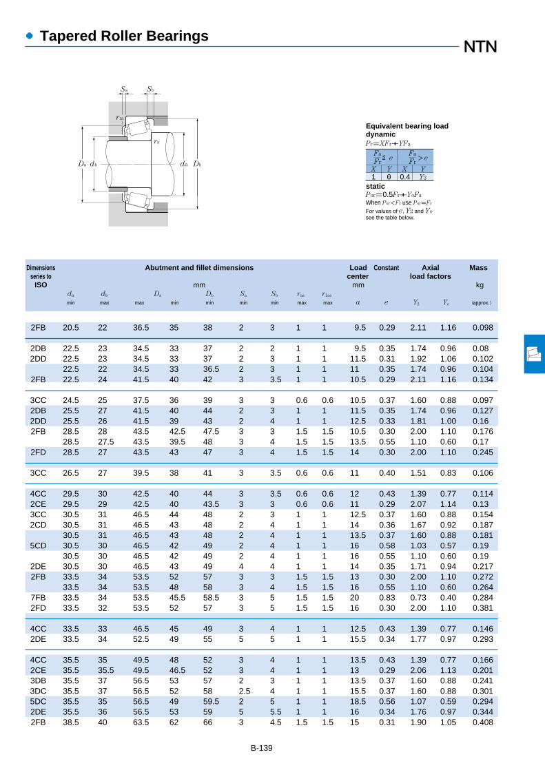
Dimensions Abutment and fillet dimensions Load Constant Axial Massseries to center load factors
ISO mm mm kgda db Da Db Sa Sb ras r1as
min max max min min min min max max a e Y2 Yo (approx.)
B-139
備考1.ET円すいころ軸受も製作しているのでNTNに御照会ください。
●Tapered Roller Bearings
2FB 20.5 22 36.5 35 38 2 3 1 1 9.5 0.29 2.11 1.16 0.098
2DB 22.5 23 34.5 33 37 2 2 1 1 9.5 0.35 1.74 0.96 0.082DD 22.5 23 34.5 33 37 2 3 1 1 11.5 0.31 1.92 1.06 0.102
22.5 22 34.5 33 36.5 2 3 1 1 11 0.35 1.74 0.96 0.1042FB 22.5 24 41.5 40 42 3 3.5 1 1 10.5 0.29 2.11 1.16 0.134
3CC 24.5 25 37.5 36 39 3 3 0.6 0.6 10.5 0.37 1.60 0.88 0.0972DB 25.5 27 41.5 40 44 2 3 1 1 11.5 0.35 1.74 0.96 0.1272DD 25.5 26 41.5 39 43 2 4 1 1 12.5 0.33 1.81 1.00 0.162FB 28.5 28 43.5 42.5 47.5 3 3 1.5 1.5 10.5 0.30 2.00 1.10 0.176
28.5 27.5 43.5 39.5 48 3 4 1.5 1.5 13.5 0.55 1.10 0.60 0.172FD 28.5 27 43.5 43 47 3 4 1.5 1.5 14 0.30 2.00 1.10 0.245
3CC 26.5 27 39.5 38 41 3 3.5 0.6 0.6 11 0.40 1.51 0.83 0.106
4CC 29.5 30 42.5 40 44 3 3.5 0.6 0.6 12 0.43 1.39 0.77 0.1142CE 29.5 29 42.5 40 43.5 3 3 0.6 0.6 11 0.29 2.07 1.14 0.133CC 30.5 31 46.5 44 48 2 3 1 1 12.5 0.37 1.60 0.88 0.1542CD 30.5 31 46.5 43 48 2 4 1 1 14 0.36 1.67 0.92 0.187
30.5 31 46.5 43 48 2 4 1 1 13.5 0.37 1.60 0.88 0.1815CD 30.5 30 46.5 42 49 2 4 1 1 16 0.58 1.03 0.57 0.19
30.5 30 46.5 42 49 2 4 1 1 16 0.55 1.10 0.60 0.192DE 30.5 30 46.5 43 49 4 4 1 1 14 0.35 1.71 0.94 0.2172FB 33.5 34 53.5 52 57 3 3 1.5 1.5 13 0.30 2.00 1.10 0.272
33.5 34 53.5 48 58 3 4 1.5 1.5 16 0.55 1.10 0.60 0.2647FB 33.5 34 53.5 45.5 58.5 3 5 1.5 1.5 20 0.83 0.73 0.40 0.2842FD 33.5 32 53.5 52 57 3 5 1.5 1.5 16 0.30 2.00 1.10 0.381
4CC 33.5 33 46.5 45 49 3 4 1 1 12.5 0.43 1.39 0.77 0.1462DE 33.5 34 52.5 49 55 5 5 1 1 15.5 0.34 1.77 0.97 0.293
4CC 35.5 35 49.5 48 52 3 4 1 1 13.5 0.43 1.39 0.77 0.1662CE 35.5 35.5 49.5 46.5 52 3 4 1 1 13 0.29 2.06 1.13 0.2013DB 35.5 37 56.5 53 57 2 3 1 1 13.5 0.37 1.60 0.88 0.2413DC 35.5 37 56.5 52 58 2.5 4 1 1 15.5 0.37 1.60 0.88 0.3015DC 35.5 35 56.5 49 59.5 2 5 1 1 18.5 0.56 1.07 0.59 0.2942DE 35.5 36 56.5 53 59 5 5.5 1 1 16 0.34 1.76 0.97 0.3442FB 38.5 40 63.5 62 66 3 4.5 1.5 1.5 15 0.31 1.90 1.05 0.408
1 0 0.4 Y2
Fa
FrX Y X Y
≦eFa
Fr>e
Pr=XFr+YFa
Por=0.5Fr+YoFa
When Por<Fr use Por=Fr
For values of e, Y2 and Yosee the table below.
Equivalent bearing loaddynamic
static
Sa
r1a
Sb
ra
da DbDa db

1 Minimal allowable dimension for chamfer dimension r or r1. 2 This bearing does not incorporate the subunit dimensions.Note: When selecting bearings with bearing numbers marked with "*", please consult NTN Engineering.
B-140
●Tapered Roller Bearings
Boundary dimensions Basic load ratings Limiting speeds Bearingdynamic static dynamic static numbers
mm kN kgf rpm
d D T B C rs min1
r ls min1
Cr Cor Cr Cor grease oil
d 30~45mm
Metric system sizes
T
C
D
B
r1
d
r
a
30
32
35
40
45
72 20.75 19 15 1.5 1.5 58.5 58.5 6,000 5,950 5,500 7,300 4T-30306CA72 20.75 19 14 1.5 1.5 48.5 51.5 4,950 5,250 5,000 6,700 4T-30306D72 28.75 27 23 1.5 1.5 81.0 90.0 8,250 9,150 5,700 7,600 4T-3230672 28.75 27 23 1.5 1.5 79.0 94.0 8,050 9,550 5,500 7,300 *4T-32306C72 28.75 27 23 1.5 1.5 70.0 88.5 7,150 9,050 5,500 7,300 4T-32306CR2
58 17 17 13 1 1 37.0 46.5 3,750 4,750 6,600 8,700 4T-320/32X65 26 26 20.5 1 1 70.5 85.0 7,200 8,650 6,000 8,000 4T-332/3275 29.75 28 23 1.5 1.5 84.0 102 8,600 10,400 5,200 6,900 4T-323/32C
55 14 14 11.5 0.6 0.6 27.4 37.5 2,790 3,850 6,800 9,000 32907XU62 18 18 14 1 1 41.5 52.5 4,250 5,350 6,100 8,100 4T-32007X62 21 21 17 1 1 50.5 66.5 5,150 6,800 6,100 8,100 4T-3300772 18.25 17 15 1.5 1.5 55.5 61.5 5,650 6,250 5,500 7,400 4T-3020772 24.25 23 19 1.5 1.5 72.5 87.0 7,400 8,900 5,500 7,400 4T-3220772 24.25 23 19 1.5 1.5 68.0 85.5 6,950 8,750 5,300 7,100 4T-32207C72 24.25 23 18 1.5 1.5 62.0 78.5 6,300 8,000 5,300 7,100 4T-32207CR2
72 28 28 22 1.5 1.5 87.5 109 8,900 11,200 5,500 7,400 4T-3320780 22.75 21 18 2 1.5 75.0 77.0 7,650 7,900 5,000 6,600 4T-3030780 22.75 21 17 2 1.5 66.5 68.5 6,750 7,000 4,800 6,400 4T-30307C80 22.75 21 15 2 1.5 63.5 70.0 6,450 7,100 4,400 5,800 4T-30307D80 32.75 31 25 2 1.5 101 115 10,300 11,700 5,000 6,600 4T-3230780 32.75 31 25 2 1.5 93.0 117 9,500 12,000 4,800 6,400 4T-32307C
62 15 15 12 0.6 0.6 32.5 48.0 3,350 4,900 5,900 7,800 32908XU68 19 19 14.5 1 1 50.0 65.5 5,100 6,650 5,300 7,100 4T-32008X68 22 22 18 1 1 59.5 82.5 6,050 8,400 5,300 7,100 4T-3300875 26 26 20.5 1.5 1.5 79.5 103 8,100 10,500 5,200 6,900 4T-3310880 19.75 18 16 1.5 1.5 61.0 67.0 6,250 6,850 4,900 6,600 4T-3020880 24.75 23 19 1.5 1.5 79.5 93.5 8,100 9,550 4,900 6,600 4T-3220880 32 32 25 1.5 1.5 103 132 10,500 13,400 4,900 6,600 4T-3320885 33 32.5 28 2.5 2 118 144 12,000 14,700 4,600 6,200 4T-T2EE04090 25.25 23 20 2 1.5 91.5 102 9,350 10,400 4,400 5,900 4T-3030890 25.25 23 19 2 1.5 83.0 87.0 8,450 8,900 4,200 5,600 4T-30308C90 25.25 23 17 2 1.5 77.0 85.5 7,850 8,700 3,900 5,200 4T-30308D90 35.25 33 27 2 1.5 122 150 12,500 15,300 4,400 5,900 32308U90 35.25 33 27 2 1.5 110 140 11,300 14,300 4,200 5,600 4T-32308C
68 15 15 12 0.6 0.6 33.5 51.5 3,450 5,250 5,300 7,000 *32909XU

B-141
備考1.ET円すいころ軸受も製作しているのでNTNに御照会ください。
Dimensions Abutment and fillet dimensions Load Constant Axial Massseries to center load factors
ISO mm mm kgda db Da Db Sa Sb ras r1as
min max max min min min min max max a e Y2 Yo (approx.)
●Tapered Roller Bearings
38.5 39.5 63.5 57 67 3 5.5 1.5 1.5 17.5 0.47 1.27 0.70 0.3987FB 38.5 39 63.5 55 68 3 6.5 1.5 1.5 23.5 0.83 0.73 0.40 0.3982FD 38.5 38 63.5 59 66 3 5.5 1.5 1.5 18.5 0.31 1.90 1.05 0.5835FD 38.5 37 63.5 57 68 2 5.5 1.5 1.5 23 0.55 1.10 0.60 0.592
38.5 37 63.5 57 67.5 2 5.5 1.5 1.5 23 0.61 0.99 0.54 0.594
4CC 37.5 38 52.5 50 55 3 4 1 1 14.5 0.45 1.32 0.73 0.1812DE 37.5 38 59.5 55 62 5 5.5 1 1 17 0.35 1.73 0.95 0.3955FD 40.5 39 66.5 61 71 3 6.5 1.5 1.5 23 0.55 1.10 0.60 0.659
2BD 39.5 40 50.5 48 52.5 2.5 2.5 0.6 0.6 10.5 0.29 2.06 1.13 0.1214CC 40.5 40 56.5 54 59 4 4 1 1 15.5 0.45 1.32 0.73 0.2242CE 40.5 40.5 56.5 52 59 3 4 1 1 14 0.31 1.97 1.08 0.2633DB 43.5 44 63.5 62 67 3 3 1.5 1.5 15 0.37 1.60 0.88 0.3443DC 43.5 43 63.5 61 67 3 5 1.5 1.5 17.5 0.37 1.60 0.88 0.4575DC 43.5 42 63.5 59 68 3 6 1.5 1.5 21.5 0.58 1.03 0.57 0.461
43.5 42 63.5 59 68 3 6 1.5 1.5 20.5 0.55 1.10 0.60 0.4612DE 43.5 42 63.5 61 68 5 6 1.5 1.5 18.5 0.35 1.70 0.93 0.5312FB 45 45 71.5 70 74 3 4.5 2 1.5 17 0.31 1.90 1.05 0.540
45 44 71.5 63.5 75.5 3 5.5 2 1.5 20.5 0.55 1.10 0.60 0.5177FB 45 44 71.5 62 76.5 3 7.5 2 1.5 26 0.83 0.73 0.40 0.5302FE 45 43 71.5 66 74 3 7.5 2 1.5 20.5 0.31 1.90 1.05 0.7875FE 45 43 71.5 66 76 3 7.5 2 1.5 25 0.55 1.10 0.60 0.797
2BC 44.5 45.5 57.5 54 58.5 3 3 0.6 0.6 11.5 0.29 2.07 1.14 0.1613CD 45.5 46 62.5 60 65 4 4.5 1 1 15 0.38 1.58 0.87 0.2732BE 45.5 46 62.5 60 64 2.5 4 1 1 15 0.28 2.12 1.17 0.3122CE 48.5 47 66.5 65 71 4 5.5 1.5 1.5 18 0.36 1.69 0.93 0.4943DB 48.5 49 71.5 69 75 3 3.5 1.5 1.5 16.5 0.37 1.60 0.88 0.4353DC 48.5 48 71.5 68 75 3 5.5 1.5 1.5 19 0.37 1.60 0.88 0.5582DE 48.5 47 71.5 67 76 5 7 1.5 1.5 21 0.36 1.68 0.92 0.7282EE 52 48 75 70 80 5 5 2 2 22.5 0.34 1.74 0.96 0.9072FB 50 52 81.5 77 82 3 5 2 1.5 19.5 0.35 1.74 0.96 0.769
50 50 80 72 85.5 3.5 6 2 1.5 23 0.55 1.10 0.60 0.7287FB 50 50 81.5 71 86.5 3 8 2 1.5 29.5 0.83 0.73 0.40 0.7382FD 50 50 81.5 73 82 3 8 2 1.5 23 0.35 1.74 0.96 1.085FD 50 48 81.5 72 84 3 8 2 1.5 27.5 0.55 1.10 0.60 1.1
2BC 50 50 63.5 59.5 64.5 3 3 0.6 0.6 12 0.32 1.88 1.04 0.188
1 0 0.4 Y2
Fa
FrX Y X Y
≦eFa
Fr>e
Pr=XFr+YFa
Por=0.5Fr+YoFa
When Por<Fr use Por=Fr
For values of e, Y2 and Yosee the table below.
Equivalent bearing loaddynamic
static
Sa
r1a
Sb
ra
da DbDa db
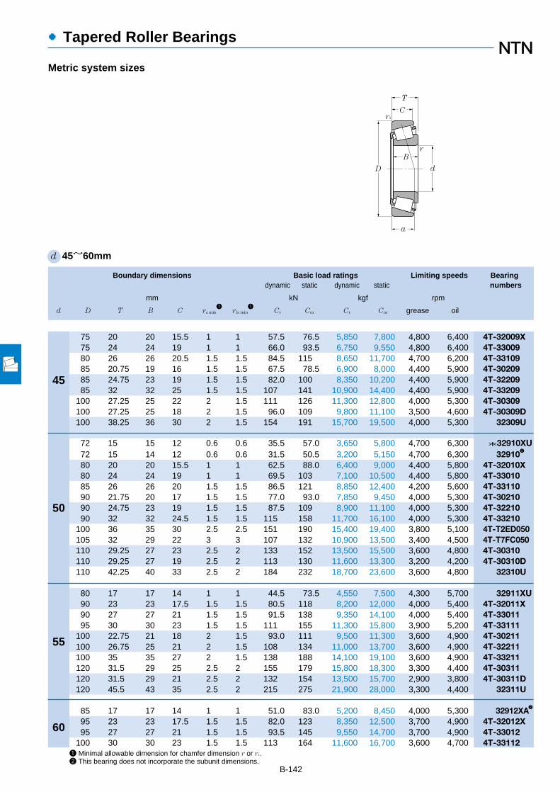
1 Minimal allowable dimension for chamfer dimension r or r1.2 This bearing does not incorporate the subunit dimensions.
B-142
●Tapered Roller Bearings
Boundary dimensions Basic load ratings Limiting speeds Bearingdynamic static dynamic static numbers
mm kN kgf rpm
d D T B C rs min1
r ls min1
Cr Cor Cr Cor grease oil
d 45~60mm
Metric system sizes
T
C
D
B
r1
d
r
a
45
50
55
60
75 20 20 15.5 1 1 57.5 76.5 5,850 7,800 4,800 6,400 4T-32009X75 24 24 19 1 1 66.0 93.5 6,750 9,550 4,800 6,400 4T-3300980 26 26 20.5 1.5 1.5 84.5 115 8,650 11,700 4,700 6,200 4T-3310985 20.75 19 16 1.5 1.5 67.5 78.5 6,900 8,000 4,400 5,900 4T-3020985 24.75 23 19 1.5 1.5 82.0 100 8,350 10,200 4,400 5,900 4T-3220985 32 32 25 1.5 1.5 107 141 10,900 14,400 4,400 5,900 4T-33209
100 27.25 25 22 2 1.5 111 126 11,300 12,800 4,000 5,300 4T-30309100 27.25 25 18 2 1.5 96.0 109 9,800 11,100 3,500 4,600 4T-30309D100 38.25 36 30 2 1.5 154 191 15,700 19,500 4,000 5,300 32309U
72 15 15 12 0.6 0.6 35.5 57.0 3,650 5,800 4,700 6,300 *32910XU72 15 14 12 0.6 0.6 31.5 50.5 3,200 5,150 4,700 6,300 329102
80 20 20 15.5 1 1 62.5 88.0 6,400 9,000 4,400 5,800 4T-32010X80 24 24 19 1 1 69.5 103 7,100 10,500 4,400 5,800 4T-3301085 26 26 20 1.5 1.5 86.5 121 8,850 12,400 4,200 5,600 4T-3311090 21.75 20 17 1.5 1.5 77.0 93.0 7,850 9,450 4,000 5,300 4T-3021090 24.75 23 19 1.5 1.5 87.5 109 8,900 11,100 4,000 5,300 4T-3221090 32 32 24.5 1.5 1.5 115 158 11,700 16,100 4,000 5,300 4T-33210
100 36 35 30 2.5 2.5 151 190 15,400 19,400 3,800 5,100 4T-T2ED050105 32 29 22 3 3 107 132 10,900 13,500 3,400 4,500 4T-T7FC050110 29.25 27 23 2.5 2 133 152 13,500 15,500 3,600 4,800 4T-30310110 29.25 27 19 2.5 2 113 130 11,600 13,300 3,200 4,200 4T-30310D110 42.25 40 33 2.5 2 184 232 18,700 23,600 3,600 4,800 32310U
80 17 17 14 1 1 44.5 73.5 4,550 7,500 4,300 5,700 32911XU90 23 23 17.5 1.5 1.5 80.5 118 8,200 12,000 4,000 5,400 4T-32011X90 27 27 21 1.5 1.5 91.5 138 9,350 14,100 4,000 5,400 4T-3301195 30 30 23 1.5 1.5 111 155 11,300 15,800 3,900 5,200 4T-33111
100 22.75 21 18 2 1.5 93.0 111 9,500 11,300 3,600 4,900 4T-30211100 26.75 25 21 2 1.5 108 134 11,000 13,700 3,600 4,900 4T-32211100 35 35 27 2 1.5 138 188 14,100 19,100 3,600 4,900 4T-33211120 31.5 29 25 2.5 2 155 179 15,800 18,300 3,300 4,400 4T-30311120 31.5 29 21 2.5 2 132 154 13,500 15,700 2,900 3,800 4T-30311D120 45.5 43 35 2.5 2 215 275 21,900 28,000 3,300 4,400 32311U
85 17 17 14 1 1 51.0 83.0 5,200 8,450 4,000 5,300 32912XA2
95 23 23 17.5 1.5 1.5 82.0 123 8,350 12,500 3,700 4,900 4T-32012X95 27 27 21 1.5 1.5 93.5 145 9,550 14,700 3,700 4,900 4T-33012
100 30 30 23 1.5 1.5 113 164 11,600 16,700 3,600 4,700 4T-33112
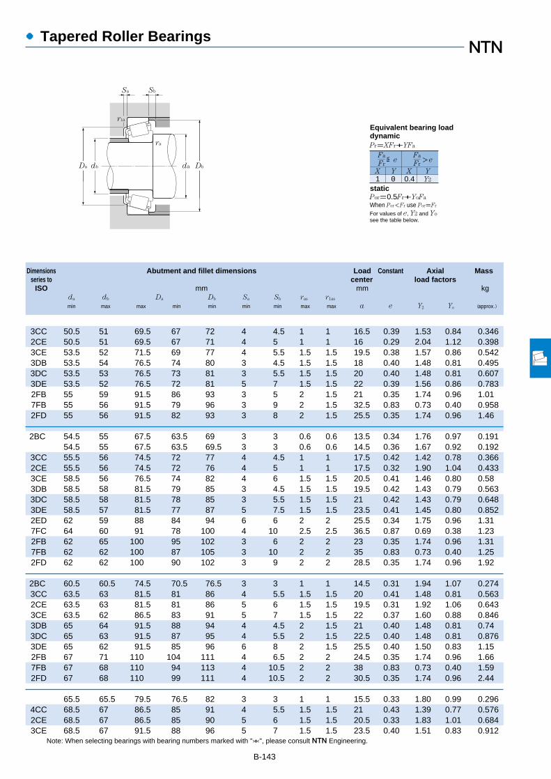
B-143
Note: When selecting bearings with bearing numbers marked with "*", please consult NTN Engineering.
Dimensions Abutment and fillet dimensions Load Constant Axial Massseries to center load factors
ISO mm mm kgda db Da Db Sa Sb ras r1as
min max max min min min min max max a e Y2 Yo (approx.)
●Tapered Roller Bearings
3CC 50.5 51 69.5 67 72 4 4.5 1 1 16.5 0.39 1.53 0.84 0.3462CE 50.5 51 69.5 67 71 4 5 1 1 16 0.29 2.04 1.12 0.3983CE 53.5 52 71.5 69 77 4 5.5 1.5 1.5 19.5 0.38 1.57 0.86 0.5423DB 53.5 54 76.5 74 80 3 4.5 1.5 1.5 18 0.40 1.48 0.81 0.4953DC 53.5 53 76.5 73 81 3 5.5 1.5 1.5 20 0.40 1.48 0.81 0.6073DE 53.5 52 76.5 72 81 5 7 1.5 1.5 22 0.39 1.56 0.86 0.7832FB 55 59 91.5 86 93 3 5 2 1.5 21 0.35 1.74 0.96 1.017FB 55 56 91.5 79 96 3 9 2 1.5 32.5 0.83 0.73 0.40 0.9582FD 55 56 91.5 82 93 3 8 2 1.5 25.5 0.35 1.74 0.96 1.46
2BC 54.5 55 67.5 63.5 69 3 3 0.6 0.6 13.5 0.34 1.76 0.97 0.19154.5 55 67.5 63.5 69.5 3 3 0.6 0.6 14.5 0.36 1.67 0.92 0.192
3CC 55.5 56 74.5 72 77 4 4.5 1 1 17.5 0.42 1.42 0.78 0.3662CE 55.5 56 74.5 72 76 4 5 1 1 17.5 0.32 1.90 1.04 0.4333CE 58.5 56 76.5 74 82 4 6 1.5 1.5 20.5 0.41 1.46 0.80 0.583DB 58.5 58 81.5 79 85 3 4.5 1.5 1.5 19.5 0.42 1.43 0.79 0.5633DC 58.5 58 81.5 78 85 3 5.5 1.5 1.5 21 0.42 1.43 0.79 0.6483DE 58.5 57 81.5 77 87 5 7.5 1.5 1.5 23.5 0.41 1.45 0.80 0.8522ED 62 59 88 84 94 6 6 2 2 25.5 0.34 1.75 0.96 1.317FC 64 60 91 78 100 4 10 2.5 2.5 36.5 0.87 0.69 0.38 1.232FB 62 65 100 95 102 3 6 2 2 23 0.35 1.74 0.96 1.317FB 62 62 100 87 105 3 10 2 2 35 0.83 0.73 0.40 1.252FD 62 62 100 90 102 3 9 2 2 28.5 0.35 1.74 0.96 1.92
2BC 60.5 60.5 74.5 70.5 76.5 3 3 1 1 14.5 0.31 1.94 1.07 0.2743CC 63.5 63 81.5 81 86 4 5.5 1.5 1.5 20 0.41 1.48 0.81 0.5632CE 63.5 63 81.5 81 86 5 6 1.5 1.5 19.5 0.31 1.92 1.06 0.6433CE 63.5 62 86.5 83 91 5 7 1.5 1.5 22 0.37 1.60 0.88 0.8463DB 65 64 91.5 88 94 4 4.5 2 1.5 21 0.40 1.48 0.81 0.743DC 65 63 91.5 87 95 4 5.5 2 1.5 22.5 0.40 1.48 0.81 0.8763DE 65 62 91.5 85 96 6 8 2 1.5 25.5 0.40 1.50 0.83 1.152FB 67 71 110 104 111 4 6.5 2 2 24.5 0.35 1.74 0.96 1.667FB 67 68 110 94 113 4 10.5 2 2 38 0.83 0.73 0.40 1.592FD 67 68 110 99 111 4 10.5 2 2 30.5 0.35 1.74 0.96 2.44
65.5 65.5 79.5 76.5 82 3 3 1 1 15.5 0.33 1.80 0.99 0.2964CC 68.5 67 86.5 85 91 4 5.5 1.5 1.5 21 0.43 1.39 0.77 0.5762CE 68.5 67 86.5 85 90 5 6 1.5 1.5 20.5 0.33 1.83 1.01 0.6843CE 68.5 67 91.5 88 96 5 7 1.5 1.5 23.5 0.40 1.51 0.83 0.912
1 0 0.4 Y2
Fa
FrX Y X Y
≦eFa
Fr>e
Pr=XFr+YFa
Por=0.5Fr+YoFa
When Por<Fr use Por=Fr
For values of e, Y2 and Yosee the table below.
Equivalent bearing loaddynamic
static
Sa
r1a
Sb
ra
da DbDa db
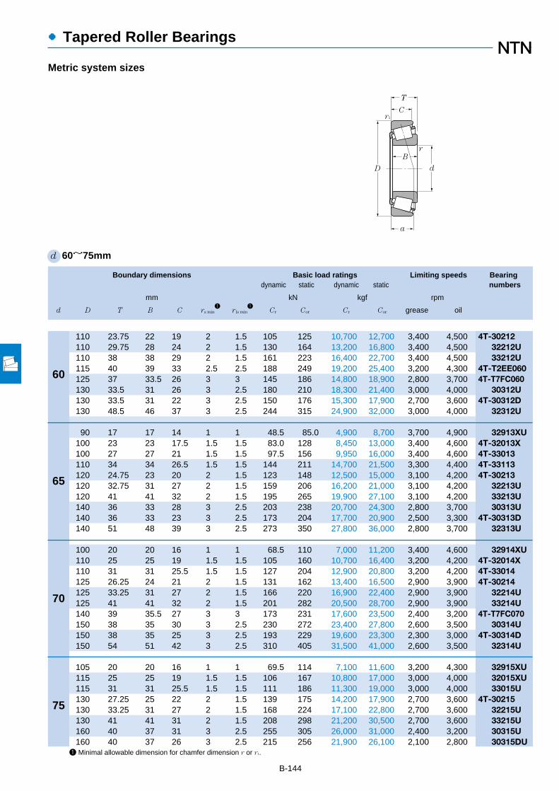
1 Minimal allowable dimension for chamfer dimension r or r1.
B-144
●Tapered Roller Bearings
Boundary dimensions Basic load ratings Limiting speeds Bearingdynamic static dynamic static numbers
mm kN kgf rpm
d D T B C rs min1
r ls min1
Cr Cor Cr Cor grease oil
d 60~75mm
Metric system sizes
T
C
D
B
r1
d
r
a
110 23.75 22 19 2 1.5 105 125 10,700 12,700 3,400 4,500 4T-30212110 29.75 28 24 2 1.5 130 164 13,200 16,800 3,400 4,500 32212U110 38 38 29 2 1.5 161 223 16,400 22,700 3,400 4,500 33212U115 40 39 33 2.5 2.5 188 249 19,200 25,400 3,200 4,300 4T-T2EE060125 37 33.5 26 3 3 145 186 14,800 18,900 2,800 3,700 4T-T7FC060130 33.5 31 26 3 2.5 180 210 18,300 21,400 3,000 4,000 30312U130 33.5 31 22 3 2.5 150 176 15,300 17,900 2,700 3,600 4T-30312D130 48.5 46 37 3 2.5 244 315 24,900 32,000 3,000 4,000 32312U
90 17 17 14 1 1 48.5 85.0 4,900 8,700 3,700 4,900 32913XU100 23 23 17.5 1.5 1.5 83.0 128 8,450 13,000 3,400 4,600 4T-32013X100 27 27 21 1.5 1.5 97.5 156 9,950 16,000 3,400 4,600 4T-33013110 34 34 26.5 1.5 1.5 144 211 14,700 21,500 3,300 4,400 4T-33113120 24.75 23 20 2 1.5 123 148 12,500 15,000 3,100 4,200 4T-30213120 32.75 31 27 2 1.5 159 206 16,200 21,000 3,100 4,200 32213U120 41 41 32 2 1.5 195 265 19,900 27,100 3,100 4,200 33213U140 36 33 28 3 2.5 203 238 20,700 24,300 2,800 3,700 30313U140 36 33 23 3 2.5 173 204 17,700 20,900 2,500 3,300 4T-30313D140 51 48 39 3 2.5 273 350 27,800 36,000 2,800 3,700 32313U
100 20 20 16 1 1 68.5 110 7,000 11,200 3,400 4,600 32914XU110 25 25 19 1.5 1.5 105 160 10,700 16,400 3,200 4,200 4T-32014X110 31 31 25.5 1.5 1.5 127 204 12,900 20,800 3,200 4,200 4T-33014125 26.25 24 21 2 1.5 131 162 13,400 16,500 2,900 3,900 4T-30214125 33.25 31 27 2 1.5 166 220 16,900 22,400 2,900 3,900 32214U125 41 41 32 2 1.5 201 282 20,500 28,700 2,900 3,900 33214U140 39 35.5 27 3 3 173 231 17,600 23,500 2,400 3,200 4T-T7FC070150 38 35 30 3 2.5 230 272 23,400 27,800 2,600 3,500 30314U150 38 35 25 3 2.5 193 229 19,600 23,300 2,300 3,000 4T-30314D150 54 51 42 3 2.5 310 405 31,500 41,000 2,600 3,500 32314U
105 20 20 16 1 1 69.5 114 7,100 11,600 3,200 4,300 32915XU115 25 25 19 1.5 1.5 106 167 10,800 17,000 3,000 4,000 32015XU115 31 31 25.5 1.5 1.5 111 186 11,300 19,000 3,000 4,000 33015U130 27.25 25 22 2 1.5 139 175 14,200 17,900 2,700 3,600 4T-30215130 33.25 31 27 2 1.5 168 224 17,100 22,800 2,700 3,600 32215U130 41 41 31 2 1.5 208 298 21,200 30,500 2,700 3,600 33215U160 40 37 31 3 2.5 255 305 26,000 31,000 2,400 3,200 30315U160 40 37 26 3 2.5 215 256 21,900 26,100 2,100 2,800 30315DU
60
65
70
75
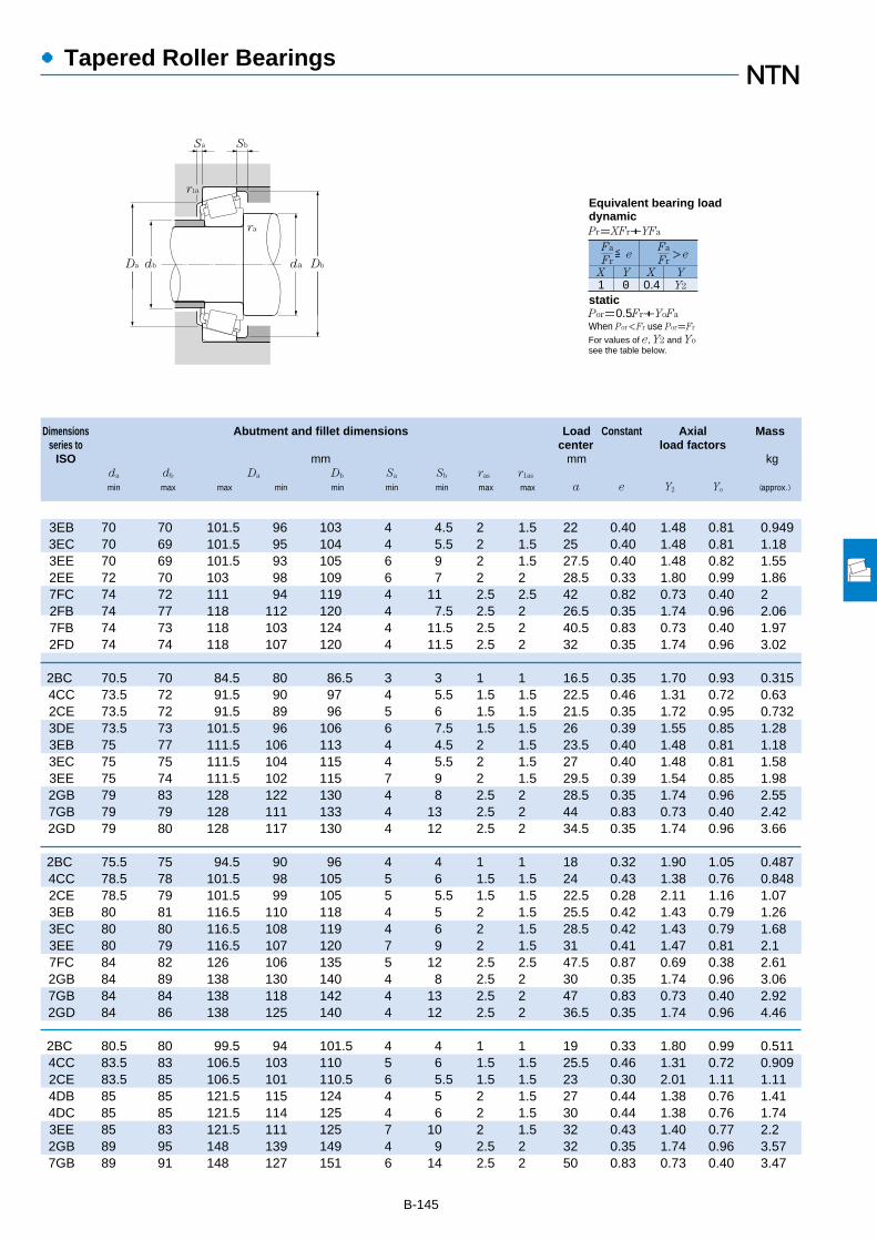
備考1.ET-4T円すいころ軸受の寿命補正係数a2の値はB-000ページを参照ください。2.ET円すいころ軸受も製作しているのでNTNに御照会ください。
B-145
Dimensions Abutment and fillet dimensions Load Constant Axial Massseries to center load factors
ISO mm mm kgda db Da Db Sa Sb ras r1as
min max max min min min min max max a e Y2 Yo (approx.)
●Tapered Roller Bearings
3EB 70 70 101.5 96 103 4 4.5 2 1.5 22 0.40 1.48 0.81 0.9493EC 70 69 101.5 95 104 4 5.5 2 1.5 25 0.40 1.48 0.81 1.183EE 70 69 101.5 93 105 6 9 2 1.5 27.5 0.40 1.48 0.82 1.552EE 72 70 103 98 109 6 7 2 2 28.5 0.33 1.80 0.99 1.867FC 74 72 111 94 119 4 11 2.5 2.5 42 0.82 0.73 0.40 22FB 74 77 118 112 120 4 7.5 2.5 2 26.5 0.35 1.74 0.96 2.067FB 74 73 118 103 124 4 11.5 2.5 2 40.5 0.83 0.73 0.40 1.972FD 74 74 118 107 120 4 11.5 2.5 2 32 0.35 1.74 0.96 3.02
2BC 70.5 70 84.5 80 86.5 3 3 1 1 16.5 0.35 1.70 0.93 0.3154CC 73.5 72 91.5 90 97 4 5.5 1.5 1.5 22.5 0.46 1.31 0.72 0.632CE 73.5 72 91.5 89 96 5 6 1.5 1.5 21.5 0.35 1.72 0.95 0.7323DE 73.5 73 101.5 96 106 6 7.5 1.5 1.5 26 0.39 1.55 0.85 1.283EB 75 77 111.5 106 113 4 4.5 2 1.5 23.5 0.40 1.48 0.81 1.183EC 75 75 111.5 104 115 4 5.5 2 1.5 27 0.40 1.48 0.81 1.583EE 75 74 111.5 102 115 7 9 2 1.5 29.5 0.39 1.54 0.85 1.982GB 79 83 128 122 130 4 8 2.5 2 28.5 0.35 1.74 0.96 2.557GB 79 79 128 111 133 4 13 2.5 2 44 0.83 0.73 0.40 2.422GD 79 80 128 117 130 4 12 2.5 2 34.5 0.35 1.74 0.96 3.66
2BC 75.5 75 94.5 90 96 4 4 1 1 18 0.32 1.90 1.05 0.4874CC 78.5 78 101.5 98 105 5 6 1.5 1.5 24 0.43 1.38 0.76 0.8482CE 78.5 79 101.5 99 105 5 5.5 1.5 1.5 22.5 0.28 2.11 1.16 1.073EB 80 81 116.5 110 118 4 5 2 1.5 25.5 0.42 1.43 0.79 1.263EC 80 80 116.5 108 119 4 6 2 1.5 28.5 0.42 1.43 0.79 1.683EE 80 79 116.5 107 120 7 9 2 1.5 31 0.41 1.47 0.81 2.17FC 84 82 126 106 135 5 12 2.5 2.5 47.5 0.87 0.69 0.38 2.612GB 84 89 138 130 140 4 8 2.5 2 30 0.35 1.74 0.96 3.067GB 84 84 138 118 142 4 13 2.5 2 47 0.83 0.73 0.40 2.922GD 84 86 138 125 140 4 12 2.5 2 36.5 0.35 1.74 0.96 4.46
2BC 80.5 80 99.5 94 101.5 4 4 1 1 19 0.33 1.80 0.99 0.5114CC 83.5 83 106.5 103 110 5 6 1.5 1.5 25.5 0.46 1.31 0.72 0.9092CE 83.5 85 106.5 101 110.5 6 5.5 1.5 1.5 23 0.30 2.01 1.11 1.114DB 85 85 121.5 115 124 4 5 2 1.5 27 0.44 1.38 0.76 1.414DC 85 85 121.5 114 125 4 6 2 1.5 30 0.44 1.38 0.76 1.743EE 85 83 121.5 111 125 7 10 2 1.5 32 0.43 1.40 0.77 2.22GB 89 95 148 139 149 4 9 2.5 2 32 0.35 1.74 0.96 3.577GB 89 91 148 127 151 6 14 2.5 2 50 0.83 0.73 0.40 3.47
1 0 0.4 Y2
Fa
FrX Y X Y
≦eFa
Fr>e
Pr=XFr+YFa
Por=0.5Fr+YoFa
When Por<Fr use Por=Fr
For values of e, Y2 and Yosee the table below.
Equivalent bearing loaddynamic
static
Sa
r1a
Sb
ra
da DbDa db
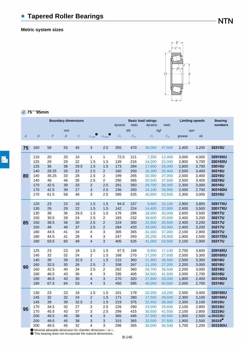
1 Minimal allowable dimension for chamfer dimension r or r1.2 This bearing does not incorporate the subunit dimensions.
B-146
●Tapered Roller Bearings
Boundary dimensions Basic load ratings Limiting speeds Bearingdynamic static dynamic static numbers
mm kN kgf rpm
d D T B C rs min1
r ls min1
Cr Cor Cr Cor grease oil
d 75~95mm
Metric system sizes
T
C
D
B
r1
d
r
a
160 58 55 45 3 2.5 355 470 36,000 47,500 2,400 3,200 32315U
110 20 20 16 1 1 72.0 121 7,350 12,400 3,000 4,000 32916XU125 29 29 22 1.5 1.5 139 216 14,200 22,000 2,800 3,700 32016XU125 36 36 29.5 1.5 1.5 173 284 17,600 29,000 2,800 3,700 33016U140 28.25 26 22 2.5 2 160 200 16,300 20,400 2,500 3,400 30216U140 35.25 33 28 2.5 2 199 265 20,300 27,000 2,500 3,400 32216U140 46 46 35 2.5 2 250 365 25,500 37,500 2,500 3,400 33216U170 42.5 39 33 3 2.5 291 350 29,700 36,000 2,300 3,000 30316U170 42.5 39 27 3 2.5 236 283 24,100 28,900 2,000 2,700 30316DU170 61.5 58 48 3 2.5 395 525 40,500 53,500 2,300 3,000 32316U
120 23 23 18 1.5 1.5 94.0 157 9,600 16,100 2,800 3,800 32917XU130 29 29 22 1.5 1.5 142 224 14,400 22,900 2,600 3,500 32017XU130 36 36 29.5 1.5 1.5 176 296 18,000 30,000 2,600 3,500 33017U150 30.5 28 24 2.5 2 183 232 18,600 23,600 2,400 3,200 30217U150 38.5 36 30 2.5 2 224 300 22,900 30,500 2,400 3,200 32217U150 49 49 37 2.5 2 284 420 29,000 43,000 2,400 3,200 33217U180 44.5 41 34 4 3 305 365 31,000 37,000 2,100 2,900 30317U180 44.5 41 28 4 3 247 293 25,200 29,900 1,900 2,500 30317DU180 63.5 60 49 4 3 405 525 41,000 53,500 2,100 2,900 32317U
125 23 23 18 1.5 1.5 97.5 168 9,950 17,100 2,700 3,600 32918XU140 32 32 24 2 1.5 168 270 17,200 27,600 2,500 3,300 32018XU140 39 39 32.5 2 1.5 215 360 21,900 36,500 2,500 3,300 33018U160 32.5 30 26 2.5 2 208 267 21,200 27,200 2,200 3,000 30218U160 42.5 40 34 2.5 2 262 360 26,700 36,500 2,200 3,000 32218U190 46.5 43 36 4 3 335 405 34,500 41,500 2,000 2,700 30318U190 46.5 43 30 4 3 270 320 27,600 33,000 1,800 2,400 30318DU190 67.5 64 53 4 3 450 595 46,000 60,500 2,000 2,700 32318U
130 23 23 18 1.5 1.5 101 178 10,300 18,200 2,500 3,400 32919XU145 32 32 24 2 1.5 171 280 17,500 28,600 2,300 3,100 32019XU145 39 39 32.5 2 1.5 219 375 22,400 38,000 2,300 3,100 33019U170 34.5 32 27 3 2.5 226 290 23,000 29,600 2,100 2,800 30219U170 45.5 43 37 3 2.5 299 415 30,500 42,500 2,100 2,800 32219U200 49.5 45 38 4 3 365 445 37,500 45,500 1,900 2,500 *30319U200 49.5 45 38 3 3 315 365 32,500 37,500 1,900 2,500 303192
200 49.5 45 32 4 3 296 355 30,000 36,500 1,700 2,200 30319DU
75
80
85
90
95

B-147
Note: When selecting bearings with bearing numbers marked with "*", please consult NTN Engineering.
Dimensions Abutment and fillet dimensions Load Constant Axial Massseries to center load factors
ISO mm mm kgda db Da Db Sa Sb ras r1as
min max max min min min min max max a e Y2 Yo (approx.)
●Tapered Roller Bearings
2GD 89 91 148 133 149 4 13 2.5 2 39 0.35 1.74 0.96 5.35
2BC 85.5 85 104.5 99 106.5 4 4 1 1 20 0.35 1.71 0.94 0.543CC 88.5 89 116.5 112 120 6 7 1.5 1.5 27 0.42 1.42 0.78 1.282CE 88.5 89 116.5 112 119 6 6.5 1.5 1.5 25 0.28 2.16 1.19 1.63EB 92 91 130 124 132 4 6 2 2 27.5 0.42 1.43 0.79 1.723EC 92 90 130 122 134 4 7 2 2 31 0.42 1.43 0.79 2.183EE 92 89 130 119 135 7 11 2 2 35 0.43 1.41 0.78 2.922GB 94 102 158 148 159 4 9.5 2.5 2 34 0.35 1.74 0.96 4.417GB 94 97 158 134 159 6 15.5 2.5 2 53.5 0.83 0.73 0.40 4.112GD 94 98 158 142 159 4 13.5 2.5 2 41.5 0.35 1.74 0.96 6.41
2BC 93.5 92 111.5 111 115 4 5 1.5 1.5 21 0.33 1.83 1.01 0.7734CC 93.5 94 121.5 117 125 6 7 1.5 1.5 28.5 0.44 1.36 0.75 1.352CE 93.5 94 121.5 118 125 6 6.5 1.5 1.5 26 0.29 2.06 1.13 1.73EB 97 97 140 132 141 5 6.5 2 2 30 0.42 1.43 0.79 2.143EC 97 96 140 130 142 5 8.5 2 2 33.5 0.42 1.43 0.79 2.753EE 97 95 140 128 144 7 12 2 2 37.5 0.42 1.43 0.79 3.582GB 103 107 166 156 167 5 10.5 3 2.5 35.5 0.35 1.74 0.96 5.27GB 103 103 166 143 169 6 16.5 3 2.5 56 0.83 0.73 0.40 4.852GD 103 102 166 150 167 5 14.5 3 2.5 43 0.35 1.74 0.96 7.15
2BC 98.5 96 116.5 112.5 120.5 4 5 1.5 1.5 22 0.34 1.75 0.96 0.8173CC 100 100 131.5 125 134 6 8 2 1.5 30 0.42 1.42 0.78 1.792CE 100 100 131.5 127 135 7 6.5 2 1.5 28 0.27 2.23 1.23 2.183FB 102 103 150 140 150 5 6.5 2 2 32 0.42 1.43 0.79 2.663FC 102 102 150 138 152 5 8.5 2 2 36 0.42 1.43 0.79 3.492GB 108 113 176 165 177 5 10.5 3 2.5 37.5 0.35 1.74 0.96 6.037GB 108 109 176 151 179 6 16.5 3 2.5 59 0.83 0.73 0.40 5.662GD 108 108 176 157 177 5 14.5 3 2.5 45.5 0.35 1.74 0.96 8.57
2BC 103.5 101 121.5 117 125.5 4 5 1.5 1.5 23.5 0.36 1.68 0.92 0.8514CC 105 105 136.5 130 140 6 8 2 1.5 31.5 0.44 1.36 0.75 1.832CE 105 104 136.5 131 139 7 6.5 2 1.5 28.5 0.28 2.16 1.19 2.273FB 109 110 158 149 159 5 7.5 2.5 2 34 0.42 1.43 0.79 3.073FC 109 108 158 145 161 5 8.5 2.5 2 39 0.42 1.43 0.79 4.32GB 113 118 186 172 186 5 11.5 3 2.5 40 0.35 1.74 0.96 6.98
113 118 186 172 186 5 11.5 3 2.5 40 0.35 1.73 0.95 6.587GB 113 114 186 154 187 6 17.5 3 2.5 62.5 0.83 0.73 0.40 6.47
1 0 0.4 Y2
Fa
FrX Y X Y
≦eFa
Fr>e
Pr=XFr+YFa
Por=0.5Fr+YoFa
When Por<Fr use Por=Fr
For values of e, Y2 and Yosee the table below.
Equivalent bearing loaddynamic
static
Sa
r1a
Sb
ra
da DbDa db

1 Minimal allowable dimension for chamfer dimension r or r1.2 ThIS bearing does not incorporate the subunit dimensions.
B-148
●Tapered Roller Bearings
Boundary dimensions Basic load ratings Limiting speeds Bearingdynamic static dynamic static numbers
mm kN kgf rpm
d D T B C rs min1
r ls min1
Cr Cor Cr Cor grease oil
d 95~120mm
Metric system sizes
T
C
D
B
r1
d
r
a
200 71.5 67 55 4 3 505 670 51,500 68,500 1,900 2,500 32319U
140 25 25 20 1.5 1.5 121 206 12,300 21,000 2,400 3,200 *32920XU140 25 24 20 1.5 1.5 97.5 162 9,950 16,500 2,400 3,200 329202
145 24 22.5 17.5 3 3 107 153 10,900 15,600 1,800 2,400 4T-T4CB100150 32 32 24 2 1.5 170 281 17,300 28,600 2,200 3,000 32020XU150 39 39 32.5 2 1.5 224 390 22,800 39,500 2,200 3,000 33020U180 37 34 29 3 2.5 258 335 26,300 34,500 2,000 2,700 30220U180 49 46 39 3 2.5 330 465 33,500 47,500 2,000 2,700 32220U215 51.5 47 39 4 3 410 500 41,500 51,000 1,800 2,400 30320U215 51.5 47 39 3 3 345 400 35,000 40,500 1,800 2,400 303202
215 56.5 51 35 4 3 355 435 36,000 44,000 1,800 2,400 31320XU215 77.5 73 60 4 3 570 770 58,500 78,500 1,800 2,400 32320U
145 25 25 20 1.5 1.5 126 219 12,800 22,400 2,300 3,000 32921XA2
160 35 35 26 2.5 2 201 335 20,500 34,000 2,100 2,800 32021XU160 43 43 34 2.5 2 245 420 25,000 43,000 2,100 2,800 33021U190 39 36 30 3 2.5 287 380 29,300 38,500 1,900 2,500 30221U190 53 50 43 3 2.5 380 540 38,500 55,500 1,900 2,500 32221U225 53.5 49 41 4 3 435 530 44,500 54,500 1,700 2,300 *30321U225 53.5 49 41 3 3 365 420 37,000 43,000 1,700 2,300 303212
225 58 53 36 4 3 380 470 39,000 47,500 1,700 2,300 *31321XU225 81.5 77 63 4 3 610 825 62,500 84,500 1,700 2,300 32321U
150 25 25 20 1.5 1.5 127 226 13,000 23,100 2,200 2,900 32922XA2
170 38 38 29 2.5 2 236 390 24,000 39,500 2,000 2,700 32022XU170 47 47 37 2.5 2 288 500 29,400 51,000 2,000 2,700 33022U200 41 38 32 3 2.5 325 435 33,000 44,000 1,800 2,400 30222U200 56 53 46 3 2.5 420 605 43,000 62,000 1,800 2,400 32222U240 54.5 50 42 4 3 480 590 49,000 60,000 1,600 2,200 *30322U240 54.5 50 42 3 3 400 465 40,500 47,000 1,600 2,200 303222
240 63 57 38 4 3 430 535 44,000 54,500 1,600 2,200 31322XU240 84.5 80 65 4 3 705 970 72,000 98,500 1,600 2,200 *32322U240 84.5 80 65 3 3 620 830 63,500 84,500 1,600 2,200 323222
165 29 29 23 1.5 1.5 162 294 16,500 30,000 2,000 2,600 *32924XU165 29 27 23 1.5 1.5 118 205 12,000 20,900 2,000 2,600 329242
180 38 38 29 2.5 2 245 420 25,000 43,000 1,800 2,500 32024XU215 43.5 40 34 3 2.5 345 470 35,500 48,000 1,700 2,200 30224U
95
100
105
110
120

B-149
Note: When selecting bearings with bearing numbers marked with "*", please consult NTN Engineering.
Dimensions Abutment and fillet dimensions Load Constant Axial Massseries to center load factors
ISO mm mm kgda db Da Db Sa Sb ras r1as
min max max min min min min max max a e Y2 Yo (approx.)
●Tapered Roller Bearings
2GD 113 113 186 166 186 5 16.5 3 2.5 49 0.35 1.74 0.96 10.1
2CC 108.5 107.5 131.5 127.5 135.5 4 5 1.5 1.5 24.5 0.33 1.82 1.00 1.14108.5 107.5 131.5 127.5 135.5 4 5 1.5 1.5 25 0.35 1.73 0.95 1.08
4CB 114 109 131 130 140 4 6.5 2.5 2.5 30 0.47 1.27 0.70 1.154CC 110 109 141.5 134 144 6 8 2 1.5 32.5 0.46 1.31 0.72 1.912CE 110 108 141.5 135 143 7 6.5 2 1.5 29.5 0.29 2.09 1.15 2.373FB 114 116 168 157 168 5 8 2.5 2 36 0.42 1.43 0.79 3.783FC 114 114 168 154 171 5 10 2.5 2 41.5 0.42 1.43 0.79 5.122GB 118 127 201 184 200 5 12.5 3 2.5 41.5 0.35 1.74 0.96 8.56
118 127 201 184 200 5 12.5 3 2.5 42 0.35 1.73 0.95 7.727GB 118 121 201 168 202 7 21.5 3 2.5 69 0.83 0.73 0.40 8.672GD 118 121 201 177 200 5 17.5 3 2.5 53 0.35 1.74 0.96 12.7
113.5 113.5 136.5 131.5 140.5 5 5 1.5 1.5 25 0.34 1.76 0.97 1.204DC 117 116 150 143 154 6 9 2 2 34.5 0.44 1.35 0.74 2.422DE 117 116 150 145 153 7 9 2 2 31 0.28 2.12 1.17 3.003FB 119 122 178 165 178 6 9 2.5 2 38 0.42 1.43 0.79 4.393FC 119 119 178 161 180 6 10 2.5 2 44 0.42 1.43 0.79 6.252GB 123 132 211 193 209 6 12.5 3 2.5 43.5 0.35 1.74 0.96 9.79
123 132 211 193 209 6 12.5 3 2.5 43.5 0.35 1.73 0.95 8.937GB 123 126 211 176 211 7 22 3 2.5 71.5 0.83 0.73 0.40 9.682GD 123 128 211 185 209 6 18.5 3 2.5 55 0.35 1.74 0.96 14.5
118.5 117.5 141.5 137 145.5 5 5 1.5 1.5 26.5 0.36 1.69 0.93 1.234DC 122 122 160 152 163 7 9 2 2 36.5 0.43 1.39 0.77 3.072DE 122 121 160 152 161 7 10 2 2 33.5 0.29 2.09 1.15 3.803FB 124 129 188 174 188 6 9 2.5 2 40 0.42 1.43 0.79 5.183FC 124 126 188 170 190 6 10 2.5 2 47 0.42 1.43 0.79 7.432GB 128 141 226 206 222 6 12.5 3 2.5 45.5 0.35 1.74 0.96 11.4
128 141 226 206 222 6 12.5 3 2.5 44 0.35 1.73 0.95 10.57GB 128 135 226 188 224 7 25 3 2.5 76 0.83 0.73 0.40 11.92GD 128 135 226 198 222 6 19.5 3 2.5 57.5 0.35 1.74 0.96 18.0
128 135 226 198 222 6.5 19.5 3 2.5 56 0.35 1.73 0.95 16.9
2CC 128.5 128.5 156.5 150 160 6 6 1.5 1.5 29.5 0.35 1.72 0.95 1.77128.5 130.5 156.5 147.5 159.5 6 6 1.5 1.5 31 0.37 1.60 0.88 1.63
4DC 132 131 170 161 173 7 9 2 2 39 0.46 1.31 0.72 3.254FB 134 140 203 187 203 6 9.5 2.5 2 44 0.44 1.38 0.76 6.23
1 0 0.4 Y2
Fa
FrX Y X Y
≦eFa
Fr>e
Pr=XFr+YFa
Por=0.5Fr+YoFa
When Por<Fr use Por=Fr
For values of e, Y2 and Yosee the table below.
Equivalent bearing loaddynamic
static
Sa
r1a
Sb
ra
da DbDa db
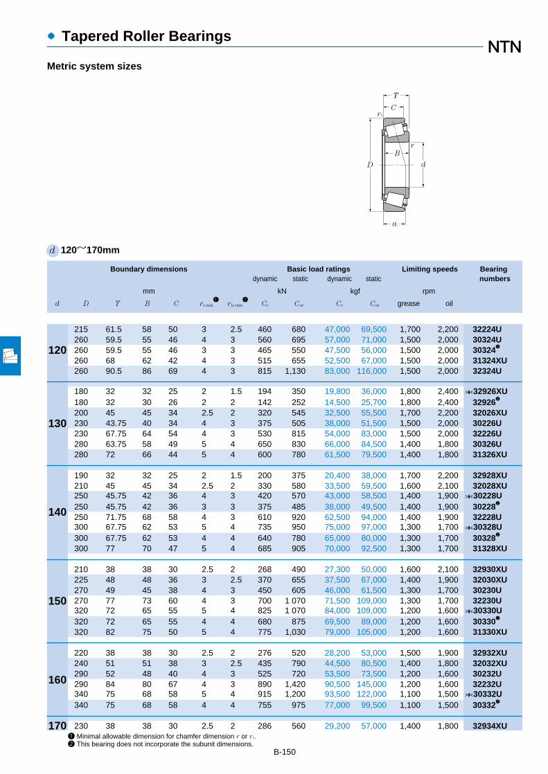
1 Minimal allowable dimension for chamfer dimension r or r1.2 This bearing does not incorporate the subunit dimensions.
B-150
●Tapered Roller Bearings
Boundary dimensions Basic load ratings Limiting speeds Bearingdynamic static dynamic static numbers
mm kN kgf rpm
d D T B C rs min1
r ls min1
Cr Cor Cr Cor grease oil
d 120~170mm
Metric system sizes
T
C
D
B
r1
d
r
a
215 61.5 58 50 3 2.5 460 680 47,000 69,500 1,700 2,200 32224U260 59.5 55 46 4 3 560 695 57,000 71,000 1,500 2,000 30324U260 59.5 55 46 3 3 465 550 47,500 56,000 1,500 2,000 303242
260 68 62 42 4 3 515 655 52,500 67,000 1,500 2,000 31324XU260 90.5 86 69 4 3 815 1,130 83,000 116,000 1,500 2,000 32324U
180 32 32 25 2 1.5 194 350 19,800 36,000 1,800 2,400 *32926XU180 32 30 26 2 2 142 252 14,500 25,700 1,800 2,400 329262
200 45 45 34 2.5 2 320 545 32,500 55,500 1,700 2,200 32026XU230 43.75 40 34 4 3 375 505 38,000 51,500 1,500 2,000 30226U230 67.75 64 54 4 3 530 815 54,000 83,000 1,500 2,000 32226U280 63.75 58 49 5 4 650 830 66,000 84,500 1,400 1,800 30326U280 72 66 44 5 4 600 780 61,500 79,500 1,400 1,800 31326XU
190 32 32 25 2 1.5 200 375 20,400 38,000 1,700 2,200 32928XU210 45 45 34 2.5 2 330 580 33,500 59,500 1,600 2,100 32028XU250 45.75 42 36 4 3 420 570 43,000 58,500 1,400 1,900 *30228U250 45.75 42 36 3 3 375 485 38,000 49,500 1,400 1,900 302282
250 71.75 68 58 4 3 610 920 62,500 94,000 1,400 1,900 32228U300 67.75 62 53 5 4 735 950 75,000 97,000 1,300 1,700 *30328U300 67.75 62 53 4 4 640 780 65,000 80,000 1,300 1,700 303282
300 77 70 47 5 4 685 905 70,000 92,500 1,300 1,700 31328XU
210 38 38 30 2.5 2 268 490 27,300 50,000 1,600 2,100 32930XU225 48 48 36 3 2.5 370 655 37,500 67,000 1,400 1,900 32030XU270 49 45 38 4 3 450 605 46,000 61,500 1,300 1,700 30230U270 77 73 60 4 3 700 1 070 71,500 109,000 1,300 1,700 32230U320 72 65 55 5 4 825 1 070 84,000 109,000 1,200 1,600 *30330U320 72 65 55 4 4 680 875 69,500 89,000 1,200 1,600 303302
320 82 75 50 5 4 775 1,030 79,000 105,000 1,200 1,600 31330XU
220 38 38 30 2.5 2 276 520 28,200 53,000 1,500 1,900 32932XU240 51 51 38 3 2.5 435 790 44,500 80,500 1,400 1,800 32032XU290 52 48 40 4 3 525 720 53,500 73,500 1,200 1,600 30232U290 84 80 67 4 3 890 1,420 90,500 145,000 1,200 1,600 32232U340 75 68 58 5 4 915 1,200 93,500 122,000 1,100 1,500 *30332U340 75 68 58 4 4 755 975 77,000 99,500 1,100 1,500 303322
230 38 38 30 2.5 2 286 560 29,200 57,000 1,400 1,800 32934XU
120
130
140
150
160
170

B-151
Note: When selecting bearings with bearing numbers marked with "*", please consult NTN Engineering.
Dimensions Abutment and fillet dimensions Load Constant Axial Massseries to center load factors
ISO mm mm kgda db Da Db Sa Sb ras r1as
min max max min min min min max max a e Y2 Yo (approx.)
●Tapered Roller Bearings
4FD 134 136 203 181 204 6 11.5 2.5 2 51.5 0.44 1.38 0.76 9.082GB 138 152 246 221 239 6 13.5 3 2.5 49 0.35 1.74 0.96 14.2
138 152 246 221 239 6 13.5 3 2.5 48.5 0.35 1.73 0.95 13.27GB 138 145 246 203 244 9 26 3 2.5 82.5 0.83 0.73 0.40 15.42GD 138 145 246 213 239 6 21.5 3 2.5 61.5 0.35 1.74 0.96 22.4
2CC 140 139 171.5 163.5 174 6 7 2 1.5 31.5 0.34 1.77 0.97 2.36140 139 170 163.5 174 6 6 2 2 34 0.37 1.60 0.88 2.22
4EC 142 144 190 178 192 8 11 2 2 43.5 0.43 1.38 0.76 4.964FB 148 152 216 203 218 7 9.5 3 2.5 45.5 0.44 1.38 0.76 7.254FD 148 146 216 193 219 7 13.5 3 2.5 57 0.44 1.38 0.76 11.22GB 152 164 262 239 255 8 14.5 4 3 53.5 0.35 1.74 0.96 17.47GB 152 152 262 218 261 9 28 4 3 87.5 0.83 0.73 0.40 19
2CC 150 150 181.5 177 184 6 6 2 1.5 34 0.36 1.67 0.92 2.514DC 152 153 200 187 202 8 11 2 2 46 0.46 1.31 0.72 5.284FB 158 163 236 219 237 7 9.5 3 2.5 48.5 0.44 1.38 0.76 9.26
158 163 236 219 237 7 9.5 2.5 2.5 47.5 0.43 1.39 0.77 8.374FD 158 158 236 210 238 9 13.5 3 2.5 61 0.44 1.38 0.76 14.12GB 162 179 282 251 273 9 14.5 4 3 56.5 0.35 1.74 0.96 21.2
162 179 282 252 273 9 14.5 4 3 57 0.35 1.73 0.95 20.47GB 162 165 282 234 280 9 30 4 3 94 0.83 0.73 0.40 23
2DC 162 162 200 192 202 7 8 2 2 36.5 0.33 1.83 1.01 3.924EC 164 164 213 200 216 8 12 2.5 2 49.5 0.46 1.31 0.72 6.374GB 168 175 256 234 255 7 11 3 2.5 51.5 0.44 1.38 0.76 11.24GD 168 170 256 226 254 8 17 3 2.5 64.5 0.44 1.38 0.76 18.22GB 172 193 302 269 292 8 17 4 3 61 0.35 1.74 0.96 25.5
172 193 302 269 292 8 17 4 3 62.5 0.37 1.60 0.88 24.7172 176 302 250 302 9 32 4 3 100.5 0.83 0.73 0.40 27.7
2DC 172 170.5 210 199 213.5 7 8 2 2 38.5 0.35 1.73 0.95 4.154EC 174 175 228 213 231 8 13 2.5 2 52.5 0.46 1.31 0.72 7.84GB 178 189 276 252 272 8 12 3 2.5 55.5 0.44 1.38 0.76 12.94GD 178 182 276 242 275 10 17 3 2.5 70 0.44 1.38 0.76 23.52GB 182 205 322 286 310 10 17 4 3 64 0.35 1.74 0.96 29.9
182 205 322 286 311 10 17 4 3 65.5 0.37 1.60 0.88 29.2
3DC 182 183 220 213 222 7 8 2 2 42.5 0.38 1.57 0.86 4.4
1 0 0.4 Y2
Fa
FrX Y X Y
≦eFa
Fr>e
Pr=XFr+YFa
Por=0.5Fr+YoFa
When Por<Fr use Por=Fr
For values of e, Y2 and Yosee the table below.
Equivalent bearing loaddynamic
static
Sa
r1a
Sb
ra
da DbDa db

1 Minimal allowable dimension for chamfer dimension r or r1.2 This bearing does not incorporate the subunit dimensions.
B-152
●Tapered Roller Bearings
Boundary dimensions Basic load ratings Limiting speeds Bearingdynamic static dynamic static numbers
mm kN kgf rpm
d D T B C rs min1
r ls min1
Cr Cor Cr Cor grease oil
d 170~300mm
Metric system sizes
T
C
D
B
r1
d
r
a
260 57 57 43 3 2.5 500 895 51,000 91,000 1,300 1,700 32034XU310 57 52 43 5 4 610 845 62,000 86,500 1,100 1,500 30234U310 91 86 71 5 4 1,000 1,600 102,000 163,000 1,100 1,500 32234U360 80 72 62 5 4 1,010 1,320 103,000 135,000 1,000 1,400 *30334U360 80 72 62 4 4 845 1,100 86,000 113,000 1,000 1,400 303342
250 45 45 34 2.5 2 350 700 36,000 71,500 1,300 1,700 32936XU280 64 64 48 3 2.5 645 1,170 66,000 119,000 1,200 1,600 32036XUE1320 57 52 43 5 4 630 890 64,000 91,000 1,100 1,400 30236U320 91 86 71 5 4 1,030 1,690 105,000 172,000 1,100 1,400 32236U
260 45 45 34 2.5 2 355 710 36,000 72,000 1,200 1,600 *32938XU260 45 42 36 2.5 2.5 280 525 28,600 53,500 1,200 1,600 329382
290 64 64 48 3 2.5 655 1,210 67,000 124,000 1,100 1,500 32038XUE1340 60 55 46 5 4 715 1,000 73,000 102,000 1,000 1,300 30238U340 97 92 75 5 4 1,150 1,850 117,000 189,000 1,000 1,300 *32238U340 97 92 75 4 4 1,000 1,670 102,000 171,000 1,000 1,300 322382
280 51 51 39 3 2.5 485 895 49,000 91,000 1,100 1,500 32940XUE1310 70 70 53 3 2.5 800 1,470 81,500 149,000 1,100 1,400 32040XUE1360 64 58 48 5 4 785 1,110 80,000 113,000 950 1,300 30240U360 104 98 82 5 4 1,320 2,130 134,000 217,000 950 1,300 *32240U360 104 98 82 4 4 1,150 1,970 118,000 201,000 950 1,300 322402
300 51 51 39 3 2.5 480 950 49,000 97,000 1,000 1,400 *32944XUE1300 51 48 41 2.5 2.5 345 670 35,500 68,500 1,000 1,400 32944E12
340 76 76 57 4 3 920 1,690 94,000 173,000 960 1,300 32044XU
320 51 51 39 3 2.5 490 1,000 50,000 102,000 940 1,200 32948XUE1360 76 76 57 4 3 930 1,760 95,000 179,000 870 1,200 32048XU
360 63.5 63.5 48 3 2.5 705 1,430 72,000 146,000 860 1,100 32952XUE1400 87 87 65 5 4 1,200 2,270 123,000 231,000 800 1,100 32052XU
380 63.5 63.5 48 3 2.5 725 1,520 74,000 155,000 790 1,100 32956XUE1420 87 87 65 5 4 1,220 2,350 125,000 240,000 740 980 32056XU
420 76 76 57 4 3 1,010 2,090 103,000 213,000 720 970 32960XUE1460 100 100 74 5 4 1,490 2,830 152,000 289,000 680 910 32060XU
170
180
190
200
220
240
260
280
300
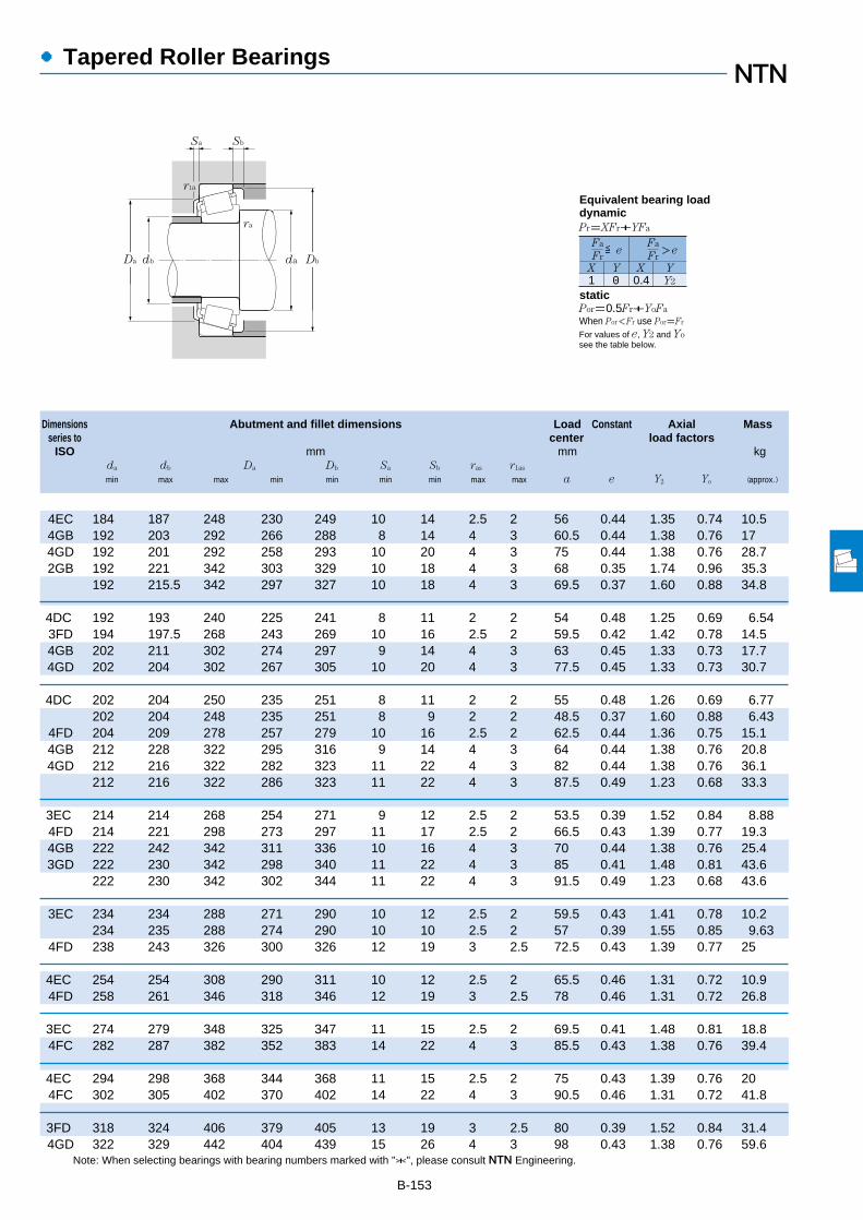
B-153
Note: When selecting bearings with bearing numbers marked with "*", please consult NTN Engineering.
Dimensions Abutment and fillet dimensions Load Constant Axial Massseries to center load factors
ISO mm mm kgda db Da Db Sa Sb ras r1as
min max max min min min min max max a e Y2 Yo (approx.)
●Tapered Roller Bearings
4EC 184 187 248 230 249 10 14 2.5 2 56 0.44 1.35 0.74 10.54GB 192 203 292 266 288 8 14 4 3 60.5 0.44 1.38 0.76 174GD 192 201 292 258 293 10 20 4 3 75 0.44 1.38 0.76 28.72GB 192 221 342 303 329 10 18 4 3 68 0.35 1.74 0.96 35.3
192 215.5 342 297 327 10 18 4 3 69.5 0.37 1.60 0.88 34.8
4DC 192 193 240 225 241 8 11 2 2 54 0.48 1.25 0.69 6.543FD 194 197.5 268 243 269 10 16 2.5 2 59.5 0.42 1.42 0.78 14.54GB 202 211 302 274 297 9 14 4 3 63 0.45 1.33 0.73 17.74GD 202 204 302 267 305 10 20 4 3 77.5 0.45 1.33 0.73 30.7
4DC 202 204 250 235 251 8 11 2 2 55 0.48 1.26 0.69 6.77202 204 248 235 251 8 9 2 2 48.5 0.37 1.60 0.88 6.43
4FD 204 209 278 257 279 10 16 2.5 2 62.5 0.44 1.36 0.75 15.14GB 212 228 322 295 316 9 14 4 3 64 0.44 1.38 0.76 20.84GD 212 216 322 282 323 11 22 4 3 82 0.44 1.38 0.76 36.1
212 216 322 286 323 11 22 4 3 87.5 0.49 1.23 0.68 33.3
3EC 214 214 268 254 271 9 12 2.5 2 53.5 0.39 1.52 0.84 8.884FD 214 221 298 273 297 11 17 2.5 2 66.5 0.43 1.39 0.77 19.34GB 222 242 342 311 336 10 16 4 3 70 0.44 1.38 0.76 25.43GD 222 230 342 298 340 11 22 4 3 85 0.41 1.48 0.81 43.6
222 230 342 302 344 11 22 4 3 91.5 0.49 1.23 0.68 43.6
3EC 234 234 288 271 290 10 12 2.5 2 59.5 0.43 1.41 0.78 10.2234 235 288 274 290 10 10 2.5 2 57 0.39 1.55 0.85 9.63
4FD 238 243 326 300 326 12 19 3 2.5 72.5 0.43 1.39 0.77 25
4EC 254 254 308 290 311 10 12 2.5 2 65.5 0.46 1.31 0.72 10.94FD 258 261 346 318 346 12 19 3 2.5 78 0.46 1.31 0.72 26.8
3EC 274 279 348 325 347 11 15 2.5 2 69.5 0.41 1.48 0.81 18.84FC 282 287 382 352 383 14 22 4 3 85.5 0.43 1.38 0.76 39.4
4EC 294 298 368 344 368 11 15 2.5 2 75 0.43 1.39 0.76 204FC 302 305 402 370 402 14 22 4 3 90.5 0.46 1.31 0.72 41.8
3FD 318 324 406 379 405 13 19 3 2.5 80 0.39 1.52 0.84 31.44GD 322 329 442 404 439 15 26 4 3 98 0.43 1.38 0.76 59.6
1 0 0.4 Y2
Fa
FrX Y X Y
≦eFa
Fr>e
Pr=XFr+YFa
Por=0.5Fr+YoFa
When Por<Fr use Por=Fr
For values of e, Y2 and Yosee the table below.
Equivalent bearing loaddynamic
static
Sa
r1a
Sb
ra
da DbDa db
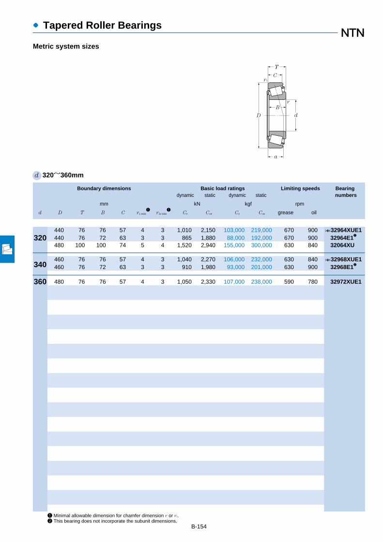
1 Minimal allowable dimension for chamfer dimension r or r1.2 This bearing does not incorporate the subunit dimensions.
B-154
●Tapered Roller Bearings
Boundary dimensions Basic load ratings Limiting speeds Bearingdynamic static dynamic static numbers
mm kN kgf rpm
d D T B C rs min1
r ls min1
Cr Cor Cr Cor grease oil
d 320~360mm
Metric system sizes
T
C
D
B
r1
d
r
a
440 76 76 57 4 3 1,010 2,150 103,000 219,000 670 900 *32964XUE1440 76 72 63 3 3 865 1,880 88,000 192,000 670 900 32964E12
480 100 100 74 5 4 1,520 2,940 155,000 300,000 630 840 32064XU
460 76 76 57 4 3 1,040 2,270 106,000 232,000 630 840 *32968XUE1460 76 72 63 3 3 910 1,980 93,000 201,000 630 900 32968E12
480 76 76 57 4 3 1,050 2,330 107,000 238,000 590 780 32972XUE1
320
340
360

B-155
Note: When selecting bearings with bearing numbers marked with "*", please consult NTN Engineering.
Dimensions Abutment and fillet dimensions Load Constant Axial Massseries to center load factors
ISO mm mm kgda db Da Db Sa Sb ras r1as
min max max min min min min max max a e Y2 Yo (approx.)
●Tapered Roller Bearings
3FD 338 344 426 398 426 13 19 3 2.5 85 0.42 1.44 0.79 33.1338 344 426 398 425 13 13 3 2.5 85 0.39 1.55 0.85 31.7
4GD 342 344.5 462 418.5 463 15 26 4 3 104 0.46 1.31 0.72 60.2
4FD 358 362 446 417 446 13 19 3 2.5 90.5 0.44 1.37 0.75 34.9358 362 446 414 445.5 13 13 3 2.5 87 0.39 1.55 0.85 36.0
4FD 378 381 466 436 466 13 19 3 2.5 96.5 0.46 1.31 0.72 36.6
1 0 0.4 Y2
Fa
FrX Y X Y
≦eFa
Fr>e
Pr=XFr+YFa
Por=0.5Fr+YoFa
When Por<Fr use Por=Fr
For values of e, Y2 and Yosee the table below.
Equivalent bearing loaddynamic
static
Sa
r1a
Sb
ra
da DbDa db
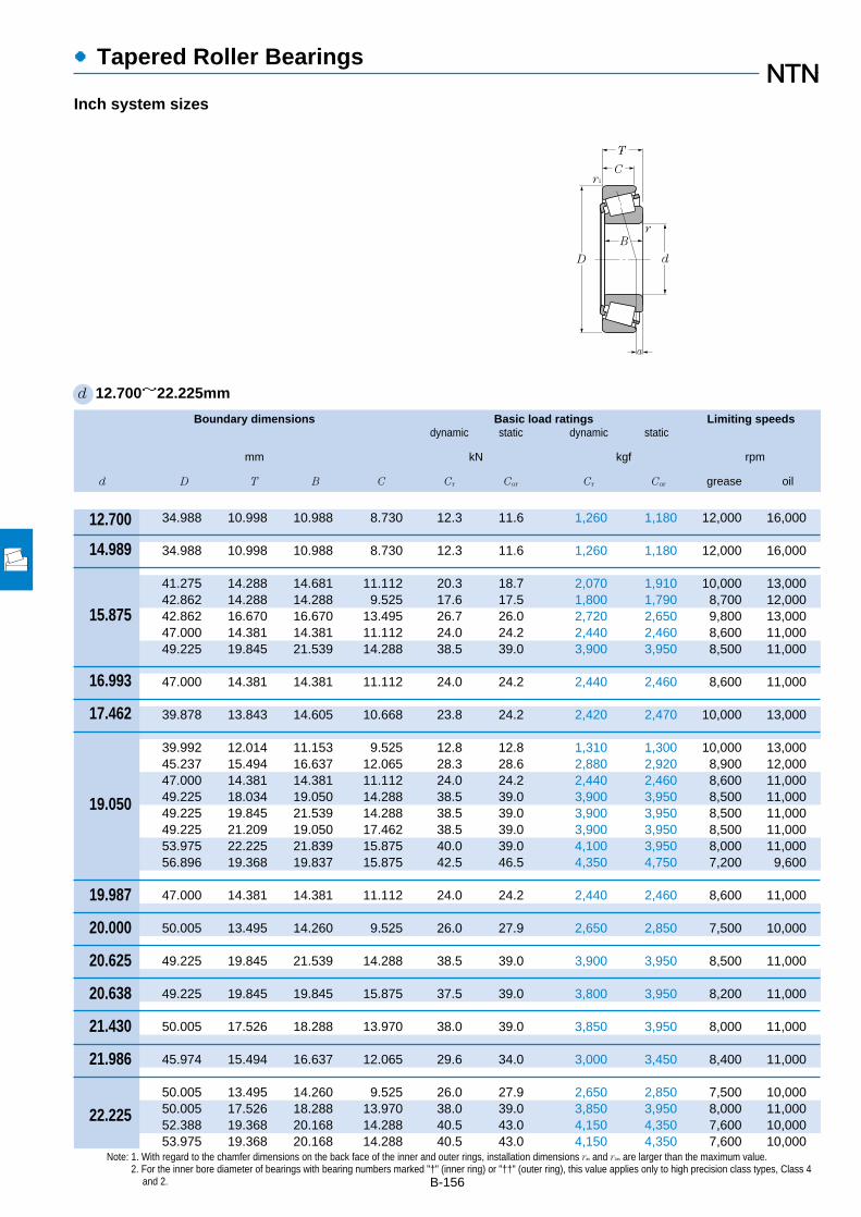
Boundary dimensions Basic load ratings Limiting speedsdynamic static dynamic static
mm kN kgf rpm
d D T B C Cr Cor Cr Cor grease oil
●Tapered Roller Bearings
B-156
Note: 1. With regard to the chamfer dimensions on the back face of the inner and outer rings, installation dimensions ras and r1as are larger than the maximum value.2. For the inner bore diameter of bearings with bearing numbers marked "†" (inner ring) or "††" (outer ring), this value applies only to high precision class types, Class 4
and 2.
d 12.700~22.225mm
Inch system sizes
12.700
14.989
15.875
16.993
19.050
19.987
20.000
20.625
20.638
21.430
21.986
22.225
17.462
T
C
D
B
r1
d
r
a
34.988 10.998 10.988 8.730 12.3 11.6 1,260 1,180 12,000 16,000
34.988 10.998 10.988 8.730 12.3 11.6 1,260 1,180 12,000 16,000
41.275 14.288 14.681 11.112 20.3 18.7 2,070 1,910 10,000 13,00042.862 14.288 14.288 9.525 17.6 17.5 1,800 1,790 8,700 12,00042.862 16.670 16.670 13.495 26.7 26.0 2,720 2,650 9,800 13,00047.000 14.381 14.381 11.112 24.0 24.2 2,440 2,460 8,600 11,00049.225 19.845 21.539 14.288 38.5 39.0 3,900 3,950 8,500 11,000
47.000 14.381 14.381 11.112 24.0 24.2 2,440 2,460 8,600 11,000
39.878 13.843 14.605 10.668 23.8 24.2 2,420 2,470 10,000 13,000
39.992 12.014 11.153 9.525 12.8 12.8 1,310 1,300 10,000 13,00045.237 15.494 16.637 12.065 28.3 28.6 2,880 2,920 8,900 12,00047.000 14.381 14.381 11.112 24.0 24.2 2,440 2,460 8,600 11,00049.225 18.034 19.050 14.288 38.5 39.0 3,900 3,950 8,500 11,00049.225 19.845 21.539 14.288 38.5 39.0 3,900 3,950 8,500 11,00049.225 21.209 19.050 17.462 38.5 39.0 3,900 3,950 8,500 11,00053.975 22.225 21.839 15.875 40.0 39.0 4,100 3,950 8,000 11,00056.896 19.368 19.837 15.875 42.5 46.5 4,350 4,750 7,200 9,600
47.000 14.381 14.381 11.112 24.0 24.2 2,440 2,460 8,600 11,000
50.005 13.495 14.260 9.525 26.0 27.9 2,650 2,850 7,500 10,000
49.225 19.845 21.539 14.288 38.5 39.0 3,900 3,950 8,500 11,000
49.225 19.845 19.845 15.875 37.5 39.0 3,800 3,950 8,200 11,000
50.005 17.526 18.288 13.970 38.0 39.0 3,850 3,950 8,000 11,000
45.974 15.494 16.637 12.065 29.6 34.0 3,000 3,450 8,400 11,000
50.005 13.495 14.260 9.525 26.0 27.9 2,650 2,850 7,500 10,00050.005 17.526 18.288 13.970 38.0 39.0 3,850 3,950 8,000 11,00052.388 19.368 20.168 14.288 40.5 43.0 4,150 4,350 7,600 10,00053.975 19.368 20.168 14.288 40.5 43.0 4,150 4,350 7,600 10,000
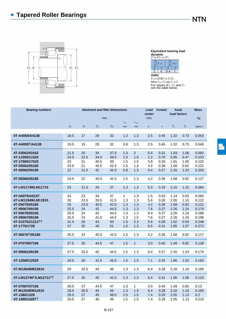
●Tapered Roller Bearings
Bearing numbers Abutment and fillet dimensions Load Constant Axial Masscenter load factors
mm mm kgras r1as
da db Da Db max max a e Y2 Yo (approx.)
B-157
備考3.ET円すいころ軸受も製作しております。NTNにご照会ください。
4T-A4050/A4138 18.5 17 29 32 1.3 1.3 2.5 0.45 1.32 0.73 0.053
4T-A4059†/A4138 19.5 19 29 32 0.8 1.3 2.5 0.45 1.32 0.73 0.049
4T-03062/03162 21.5 20 34 37.5 1.3 2 5.4 0.31 1.93 1.06 0.0924T-11590/11520 24.5 22.5 34.5 39.5 1.5 1.5 1.2 0.70 0.85 0.47 0.1034T-17580/17520 23 21 36.5 39 1.5 1.5 5.8 0.33 1.81 1.00 0.1224T-05062/05185 23.5 21 40.5 42.5 1.5 1.3 4.2 0.36 1.68 0.92 0.1314T-09062/09195 22 21.5 42 44.5 0.8 1.3 9.4 0.27 2.26 1.24 0.203
4T-05066/05185 24.5 22 40.5 42.5 1.5 1.3 4.2 0.36 1.68 0.92 0.127
4T-LM11749/LM11710 23 21.5 34 37 1.3 1.3 5.3 0.29 2.10 1.15 0.084
4T-A6075/A6157 24 23 34 37 1 1.3 1.5 0.53 1.14 0.63 0.0654T-LM11949/LM11910 28 23.5 39.5 41.5 1.3 1.3 5.6 0.30 2.00 1.10 0.1224T-05075/05185 25 23.5 40.5 42.5 1.3 1.3 4.2 0.36 1.68 0.92 0.1214T-09067/09195 25.5 24 42 44.5 1.3 1.3 7.6 0.27 2.26 1.24 0.1794T-09078/09195 25.5 24 42 44.5 1.3 1.3 9.4 0.27 2.26 1.24 0.1884T-09067/09196 25.5 24 41.5 44.5 1.3 1.5 7.6 0.27 2.26 1.24 0.1984T-21075/21212†† 31.5 26 43 50 1.5 2.3 5.6 0.59 1.02 0.56 0.2484T-1775/1729 27 25 49 51 1.5 1.3 6.5 0.31 1.95 1.07 0.272
4T-05079†/05185 26.5 24 40.5 42.5 1.5 1.3 4.2 0.36 1.68 0.92 0.117
4T-07079/07196 27.5 26 44.5 47 1.5 1 3.0 0.40 1.49 0.82 0.138
4T-09081/09195 27.5 25.5 42 44.5 1.5 1.3 9.4 0.27 2.26 1.24 0.179
4T-12580/12520 28.5 26 42.5 45.5 1.5 1.5 7.1 0.32 1.86 1.02 0.182
4T-M12649/M12610 29 25.5 44 46 1.3 1.3 6.4 0.28 2.16 1.19 0.169
4T-LM12749†/LM12711†† 27.5 26 40 42.5 1.3 1.3 5.4 0.31 1.96 1.08 0.123
4T-07087/07196 28.5 27 44.5 47 1.3 1 3.0 0.40 1.49 0.82 0.134T-M12648/M12610 28.5 26.5 44 46 1.3 1.3 6.4 0.28 2.16 1.19 0.1654T-1380/1328 29.5 27 45 48.5 1.5 1.5 7.4 0.29 2.05 1.13 0.24T-1380/1329†† 29.5 27 46 49 1.5 1.5 7.4 0.29 2.05 1.13 0.215
1 0 0.4 Y2
Fa
Fr
X Y X Y
≦eFa
Fr>e
Pr=XFr+YFa
Por=0.5Fr+YoFa
When Por<Fr use Por=Fr
For values of e, Y2 and Yosee the table below.
Equivalent bearing loaddynamic
static
r1a
ra
da DbDa db

Boundary dimensions Basic load ratings Limiting speedsdynamic static dynamic static
mm kN kgf rpm
d D T B C Cr Cor Cr Cor grease oil
●Tapered Roller Bearings
B-158
Note: 1. With regard to the chamfer dimensions on the back face of the inner and outer rings, installation dimensions ras and r1as are larger than the maximum value.2. For the inner bore diameter of bearings with bearing numbers marked "†" (inner ring), this value applies only to high precision class types, Class 4 and 2.
d 22.225~28.575mm
Inch system sizes
56.896 19.368 19.837 15.875 42.5 46.5 4,350 4,750 7,200 9,60057.150 22.225 22.225 17.462 47.0 49.5 4,800 5,050 7,100 9,500
47.000 15.500 15.500 12.000 27.5 32.5 2,800 3,300 8,200 11,000
50.005 13.495 14.260 9.525 26.0 27.9 2,650 2,850 7,500 10,00050.292 14.224 14.732 10.668 28.8 34.0 2,940 3,450 7,400 9,90056.896 19.368 19.837 15.875 42.5 46.5 4,350 4,750 7,200 9,600
50.005 13.495 14.260 9.525 26.0 27.9 2,650 2,850 7,500 10,000
50.005 13.495 14.260 9.525 26.0 27.9 2,650 2,850 7,500 10,000
50.005 13.495 14.260 9.525 26.0 27.9 2,650 2,850 7,500 10,000
50.005 13.495 14.260 9.525 26.0 27.9 2,650 2,850 7,500 10,00050.005 13.495 14.260 9.525 26.0 27.9 2,650 2,850 7,500 10,00050.292 14.224 14.732 10.668 28.8 34.0 2,940 3,450 7,400 9,90051.994 15.011 14.260 12.700 26.0 27.9 2,650 2,850 7,500 10,00056.896 19.368 19.837 15.875 42.5 46.5 4,350 4,750 7,200 9,60057.150 19.431 19.431 14.732 42.0 48.5 4,300 4,950 6,900 9,20061.912 19.050 20.638 14.288 46.5 54.0 4,750 5,500 6,100 8,20062.000 19.050 20.638 14.288 46.5 54.0 4,750 5,500 6,100 8,20062.000 19.050 20.638 14.288 46.5 54.0 4,750 5,500 6,100 8,20064.292 21.433 21.433 16.670 51.5 64.5 5,250 6,600 6,100 8,10065.088 22.225 21.463 15.875 47.0 50.5 4,800 5,150 5,700 7,60066.421 23.812 25.433 19.050 64.5 72.5 6,550 7,400 6,200 8,200
62.000 19.050 20.638 14.288 46.5 54.0 4,750 5,500 6,100 8,200
66.421 23.812 25.433 19.050 64.5 72.5 6,550 7,400 6,200 8,200
50.292 14.224 14.732 10.668 28.8 34.0 2,940 3,450 7,400 9,90060.325 19.842 17.462 15.875 39.5 45.5 4,050 4,650 6,700 8,90062.000 19.050 20.638 14.288 46.5 54.0 4,750 5,500 6,100 8,20066.421 23.812 25.433 19.050 64.5 72.5 6,550 7,400 6,200 8,200
56.896 19.845 19.355 15.875 40.5 44.5 4,150 4,550 6,700 8,90057.150 17.462 17.462 13.495 39.5 45.5 4,050 4,650 6,700 8,900
25.000
25.159
25.400
26.157
26.162
26.988
28.575
22.606
23.812
24.981
22.225
T
C
D
B
r1
d
r
a
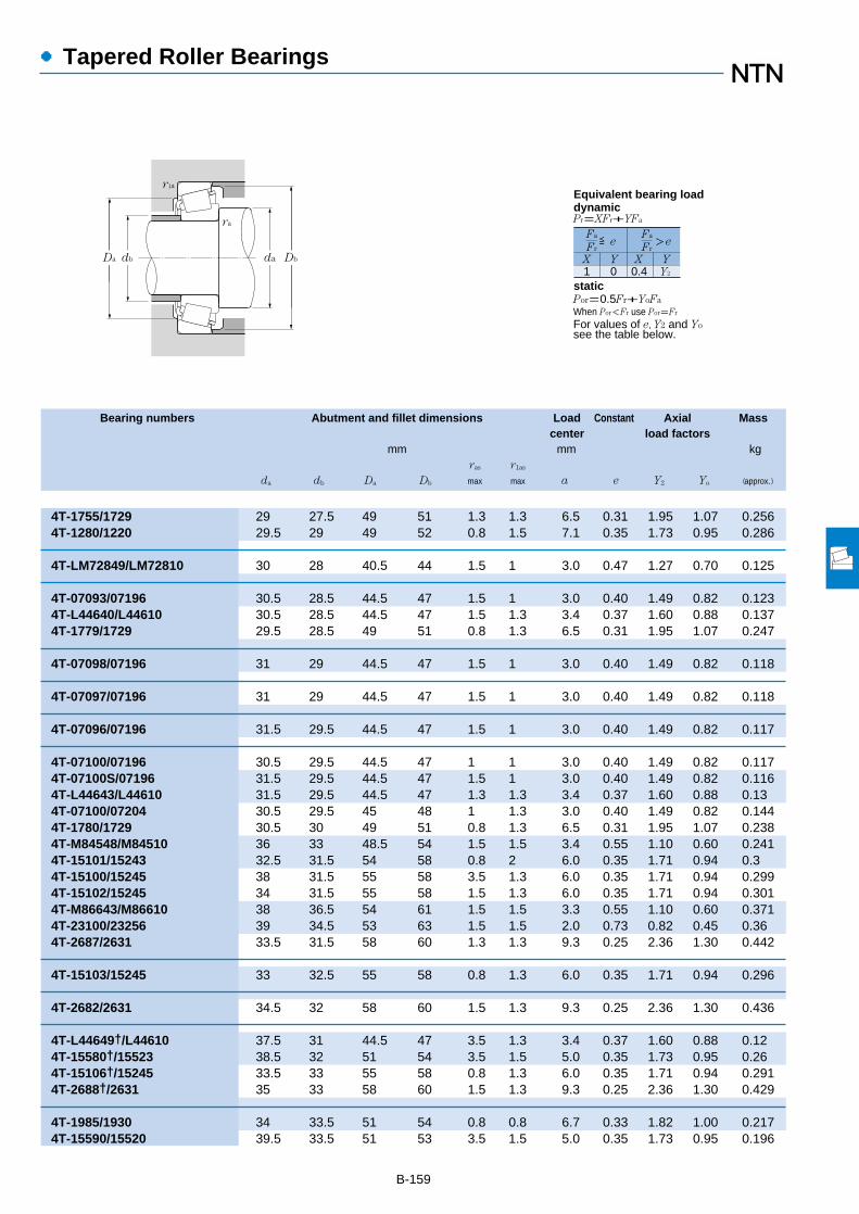
●Tapered Roller Bearings
Bearing numbers Abutment and fillet dimensions Load Constant Axial Masscenter load factors
mm mm kgras r1as
da db Da Db max max a e Y2 Yo (approx.)
B-159
備考3.ET円すいころ軸受も製作しております。NTNにご照会ください。
4T-1755/1729 29 27.5 49 51 1.3 1.3 6.5 0.31 1.95 1.07 0.2564T-1280/1220 29.5 29 49 52 0.8 1.5 7.1 0.35 1.73 0.95 0.286
4T-LM72849/LM72810 30 28 40.5 44 1.5 1 3.0 0.47 1.27 0.70 0.125
4T-07093/07196 30.5 28.5 44.5 47 1.5 1 3.0 0.40 1.49 0.82 0.1234T-L44640/L44610 30.5 28.5 44.5 47 1.5 1.3 3.4 0.37 1.60 0.88 0.1374T-1779/1729 29.5 28.5 49 51 0.8 1.3 6.5 0.31 1.95 1.07 0.247
4T-07098/07196 31 29 44.5 47 1.5 1 3.0 0.40 1.49 0.82 0.118
4T-07097/07196 31 29 44.5 47 1.5 1 3.0 0.40 1.49 0.82 0.118
4T-07096/07196 31.5 29.5 44.5 47 1.5 1 3.0 0.40 1.49 0.82 0.117
4T-07100/07196 30.5 29.5 44.5 47 1 1 3.0 0.40 1.49 0.82 0.1174T-07100S/07196 31.5 29.5 44.5 47 1.5 1 3.0 0.40 1.49 0.82 0.1164T-L44643/L44610 31.5 29.5 44.5 47 1.3 1.3 3.4 0.37 1.60 0.88 0.134T-07100/07204 30.5 29.5 45 48 1 1.3 3.0 0.40 1.49 0.82 0.1444T-1780/1729 30.5 30 49 51 0.8 1.3 6.5 0.31 1.95 1.07 0.2384T-M84548/M84510 36 33 48.5 54 1.5 1.5 3.4 0.55 1.10 0.60 0.2414T-15101/15243 32.5 31.5 54 58 0.8 2 6.0 0.35 1.71 0.94 0.34T-15100/15245 38 31.5 55 58 3.5 1.3 6.0 0.35 1.71 0.94 0.2994T-15102/15245 34 31.5 55 58 1.5 1.3 6.0 0.35 1.71 0.94 0.3014T-M86643/M86610 38 36.5 54 61 1.5 1.5 3.3 0.55 1.10 0.60 0.3714T-23100/23256 39 34.5 53 63 1.5 1.5 2.0 0.73 0.82 0.45 0.364T-2687/2631 33.5 31.5 58 60 1.3 1.3 9.3 0.25 2.36 1.30 0.442
4T-15103/15245 33 32.5 55 58 0.8 1.3 6.0 0.35 1.71 0.94 0.296
4T-2682/2631 34.5 32 58 60 1.5 1.3 9.3 0.25 2.36 1.30 0.436
4T-L44649†/L44610 37.5 31 44.5 47 3.5 1.3 3.4 0.37 1.60 0.88 0.124T-15580†/15523 38.5 32 51 54 3.5 1.5 5.0 0.35 1.73 0.95 0.264T-15106†/15245 33.5 33 55 58 0.8 1.3 6.0 0.35 1.71 0.94 0.2914T-2688†/2631 35 33 58 60 1.5 1.3 9.3 0.25 2.36 1.30 0.429
4T-1985/1930 34 33.5 51 54 0.8 0.8 6.7 0.33 1.82 1.00 0.2174T-15590/15520 39.5 33.5 51 53 3.5 1.5 5.0 0.35 1.73 0.95 0.196
1 0 0.4 Y2
Fa
Fr
X Y X Y
≦eFa
Fr>e
Pr=XFr+YFa
Por=0.5Fr+YoFa
When Por<Fr use Por=Fr
For values of e, Y2 and Yosee the table below.
Equivalent bearing loaddynamic
static
r1a
ra
da DbDa db

Boundary dimensions Basic load ratings Limiting speedsdynamic static dynamic static
mm kN kgf rpm
d D T B C Cr Cor Cr Cor grease oil
●Tapered Roller Bearings
B-160
Note: 1. With regard to the chamfer dimensions on the back face of the inner and outer rings, installation dimensions ras and r1as are larger than the maximum value.2. For the inner bore diameter of bearings with bearing numbers marked "†" (inner ring), this value applies only to high precision class types, Class 4 and 2.
d 28.575~31.750mm
Inch system sizesJ system series
58.738 19.050 19.355 15.080 40.5 44.5 4,150 4,550 6,700 8,90060.325 19.842 17.462 15.875 39.5 45.5 4,050 4,650 6,700 8,90060.325 19.845 19.355 15.875 40.5 44.5 4,150 4,550 6,700 8,90062.000 19.050 20.638 14.288 46.5 54.0 4,750 5,500 6,100 8,20064.292 21.433 21.433 16.670 51.5 64.5 5,250 6,600 6,100 8,10066.421 23.812 25.433 19.050 64.5 72.5 6,550 7,400 6,200 8,20068.262 22.225 22.225 17.462 57.0 67.0 5,800 6,850 5,800 7,70068.262 22.225 23.812 17.462 57.5 65.5 5,850 6,700 5,700 7,70069.850 23.812 25.357 19.050 69.0 81.5 7,050 8,300 5,700 7,60072.626 24.608 24.257 17.462 58.0 55.5 5,900 5,700 5,800 7,70073.025 22.225 22.225 17.462 56.5 68.0 5,750 6,900 5,300 7,000
50.292 14.224 14.732 10.668 28.0 35.5 2,860 3,600 7,200 9,600
66.421 23.812 25.433 19.050 64.5 72.5 6,550 7,400 6,200 8,200
62.000 16.002 16.566 14.288 39.0 42.0 3,950 4,300 6,300 8,40062.000 19.050 20.638 14.288 46.5 54.0 4,750 5,500 6,100 8,200
69.012 19.845 19.583 15.875 48.5 58.0 4,900 5,900 5,600 7,40072.000 29.370 27.783 23.020 72.0 97.0 7,350 9,850 5,400 7,100
62.000 19.050 20.638 14.288 46.5 54.0 4,750 5,500 6,100 8,200
62.000 16.002 16.566 14.288 39.0 42.0 3,950 4,300 6,300 8,40064.292 21.433 21.433 16.670 51.5 64.5 5,250 6,600 6,100 8,10069.850 23.812 25.357 19.050 69.0 81.5 7,050 8,300 5,700 7,60072.626 30.162 29.997 23.812 84.5 98.0 8,600 9,950 5,500 7,300
62.000 19.050 20.638 14.288 46.5 54.0 4,750 5,500 6,100 8,20062.000 19.050 20.638 14.288 46.5 54.0 4,750 5,500 6,100 8,20062.000 19.050 20.638 14.288 46.5 54.0 4,750 5,500 6,100 8,200
69.012 19.845 19.583 15.875 48.5 58.0 4,900 5,900 5,600 7,40069.012 19.845 19.583 15.875 48.5 58.0 4,900 5,900 5,600 7,400
59.131 15.875 16.764 11.811 34.5 41.0 3,500 4,150 6,300 8,40062.000 18.161 19.050 14.288 46.5 54.0 4,750 5,500 6,100 8,20062.000 19.050 20.638 14.288 46.5 54.0 4,750 5,500 6,100 8,200
30.000
30.112
30.162
30.213
30.226
31.750
29.000
29.367
29.987
28.575
T
C
D
B
r1
d
r
a

●Tapered Roller Bearings
Bearing numbers Abutment and fillet dimensions Load Constant Axial Masscenter load factors
mm mm kgras r1as
da db Da Db max max a e Y2 Yo (approx.)
B-161
Note: 3. Bearing numbers marked "#" designate J-series bearings. The tolerances of these bearings is listed in Table 6.6 on page A-40.4. Chamfer dimensions of bearings marked "*" are shown in drawings.
4T-1985/1932 34 33.5 52 54 0.8 1.3 5.9 0.33 1.82 1.00 0.234T-15590/15523 39.5 33.5 51 54 3.5 1.5 5.0 0.35 1.73 0.95 0.254T-1985/1931 34 33.5 52 55 0.8 1.3 5.9 0.33 1.82 1.00 0.2554T-15112/15245 40 34 55 58 3.5 1.3 6.0 0.35 1.71 0.94 0.2774T-M86647/M86610 40 38 54 61 1.5 1.5 3.3 0.55 1.10 0.60 0.3484T-2689/2631 36 34 58 60 1.3 1.3 9.3 0.25 2.36 1.30 0.4164T-02474/02420 36.5 36 59 63 0.8 1.5 5.2 0.42 1.44 0.79 0.4094T-2474/2420 36 35 60 63 0.8 1.5 6.5 0.34 1.77 0.97 0.414T-2578/2523 39 35 61 64 2.3 1.3 9.1 0.27 2.19 1.21 0.4834T-41125/41286 48 36.5 61 68 4.8 1.5 3.7 0.60 1.00 0.55 0.4774T-02872/02820 37.5 37 62 68 0.8 3.3 3.9 0.45 1.32 0.73 0.48
4T-L45449/L45410 39.5 33 44.5 48 3.5 1.3 3.5 0.37 1.62 0.89 0.113
4T-2690/2631 41 35 58 60 3.5 1.3 9.3 0.25 2.36 1.30 0.406
4T-17118†/17244 37 34.5 54 57 1.5 1.5 3.3 0.38 1.57 0.86 0.2284T-15117†/15245 36.5 35 55 58 1.3 1.3 6.0 0.35 1.71 0.94 0.269
4T-14117A/14276 42.5 39.5 60 63 3.5 1.3 4.1 0.38 1.57 0.86 0.369#4T-JHM88540/JHM88513 44.5 42.5 58 69 1.3 3.3 6.0 0.55 1.10 0.60 0.619
4T-15116/15245 36 35.5 55 58 0.8 1.3 6.0 0.35 1.71 0.94 0.268
4T-17119/17244 37 34.5 54 57 1.5 1.5 3.3 0.38 1.57 0.86 0.2264T-M86649/M86610 41 38 54 61 1.5 1.5 3.3 0.55 1.10 0.60 0.3364T-2558/2523 40 36.5 61 64 2.3 1.3 9.1 0.27 2.19 1.21 0.4684T-3187/3120 39 38.5 61 67 0.8 3.3 9.9 0.33 1.80 0.99 0.621
4T-15118/15245 41.5 35.5 55 58 3.5 1.3 6.0 0.35 1.71 0.94 0.2654T-15119/15245 37.5 35.5 55 58 1.5 1.3 6.0 0.35 1.71 0.94 0.2674T-15120/15245 36 35.5 55 58 0.8 1.3 6.0 0.35 1.71 0.94 0.267
4T-14116/14274 37 36.5 59 63 0.8 3.3 4.1 0.38 1.57 0.86 0.3664T-14116/14276 37 36.5 60 63 0.8 1.3 4.1 0.38 1.57 0.86 0.37
4T-LM67048/LM67010 42.5 36 52 56 * 1.3 2.8 0.41 1.46 0.80 0.1824T-15123/15245 42.5 36.5 55 58 * 1.3 5.1 0.35 1.71 0.94 0.2444T-15125/15245 42.5 36.5 55 58 3.5 1.3 6.0 0.35 1.71 0.94 0.253
ras 2.3ras 5.6
min 3.56
min�4.75
15°�1 0 0.4 Y2
Fa
Fr
X Y X Y
≦eFa
Fr>e
Pr=XFr+YFa
*�
Por=0.5Fr+YoFa
When Por<Fr use Por=Fr
For values of e, Y2 and Yosee the table below.
Equivalent bearing loaddynamic
static
r1a
ra
da DbDa db
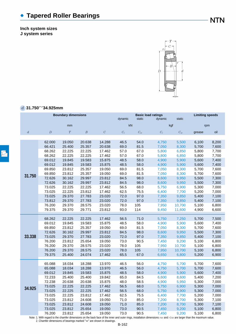
Boundary dimensions Basic load ratings Limiting speedsdynamic static dynamic static
mm kN kgf rpm
d D T B C Cr Cor Cr Cor grease oil
●Tapered Roller Bearings
B-162
Note: 1. With regard to the chamfer dimensions on the back face of the inner and outer rings, installation dimensions ras and r1as are larger than the maximum value.2. Chamfer dimensions of bearings marked "*" are shown in drawings.
d 31.750~34.925mm
Inch system sizesJ system series
62.000 19.050 20.638 14.288 46.5 54.0 4,750 5,500 6,100 8,20066.421 25.400 25.357 20.638 69.0 81.5 7,050 8,300 5,700 7,60068.262 22.225 22.225 17.462 57.0 67.0 5,800 6,850 5,800 7,70068.262 22.225 22.225 17.462 57.0 67.0 5,800 6,850 5,800 7,70069.012 19.845 19.583 15.875 48.5 58.0 4,900 5,900 5,600 7,40069.012 19.845 19.583 15.875 48.5 58.0 4,900 5,900 5,600 7,40069.850 23.812 25.357 19.050 69.0 81.5 7,050 8,300 5,700 7,60069.850 23.812 25.357 19.050 69.0 81.5 7,050 8,300 5,700 7,60072.626 30.162 29.997 23.812 84.5 98.0 8,600 9,950 5,500 7,30072.626 30.162 29.997 23.812 84.5 98.0 8,600 9,950 5,500 7,30073.025 22.225 22.225 17.462 56.5 68.0 5,750 6,900 5,300 7,00073.025 22.225 23.812 17.462 62.5 75.5 6,400 7,700 5,200 7,00073.025 29.370 27.783 23.020 72.0 97.0 7,350 9,850 5,400 7,10073.812 29.370 27.783 23.020 72.0 97.0 7,350 9,850 5,400 7,10076.200 29.370 28.575 23.020 78.0 105 7,950 10,700 5,100 6,80079.375 29.370 29.771 23.812 93.0 114 9,450 11,600 4,900 6,600
68.262 22.225 22.225 17.462 56.5 71.0 5,750 7,250 5,700 7,50069.012 19.845 19.583 15.875 48.5 58.0 4,900 5,900 5,600 7,40069.850 23.812 25.357 19.050 69.0 81.5 7,050 8,300 5,700 7,60072.626 30.162 29.997 23.812 84.5 98.0 8,600 9,950 5,500 7,30073.025 29.370 27.783 23.020 72.0 97.0 7,350 9,850 5,400 7,10076.200 23.812 25.654 19.050 73.0 90.5 7,450 9,200 5,100 6,80076.200 29.370 28.575 23.020 78.0 105 7,950 10,700 5,100 6,80076.200 29.370 28.575 23.020 78.0 105 7,950 10,700 5,100 6,80079.375 25.400 24.074 17.462 65.5 67.0 6,650 6,800 5,200 6,900
65.088 18.034 18.288 13.970 46.5 56.0 4,750 5,700 5,700 7,60065.088 18.034 18.288 13.970 46.5 56.0 4,750 5,700 5,700 7,60069.012 19.845 19.583 15.875 48.5 58.0 4,900 5,900 5,600 7,40072.233 25.400 25.400 19.842 65.0 84.5 6,600 8,600 5,400 7,20072.238 20.638 20.638 15.875 48.0 58.5 4,900 5,950 5,300 7,00073.025 22.225 22.225 17.462 56.5 68.0 5,750 6,900 5,300 7,00073.025 22.225 22.225 17.462 56.5 68.0 5,750 6,900 5,300 7,00073.025 22.225 23.812 17.462 62.5 75.5 6,400 7,700 5,200 7,00073.025 23.812 24.608 19.050 71.0 85.0 7,200 8,700 5,300 7,10073.025 23.812 24.608 19.050 71.0 85.0 7,200 8,700 5,300 7,10073.025 23.812 25.654 19.050 73.0 90.5 7,450 9,200 5,100 6,80076.200 23.812 25.654 19.050 73.0 90.5 7,450 9,200 5,100 6,800
34.925
31.750
33.338
T
C
D
B
r1
d
r
a

●Tapered Roller Bearings
Bearing numbers Abutment and fillet dimensions Load Constant Axial Masscenter load factors
mm mm kgras r1as
da db Da Db max max a e Y2 Yo (approx.)
B-163
備考3.ET円すいころ軸受も製作しております。NTNにご照会ください。
4T-15126/15245 37 36.5 55 58 0.8 1.3 6.0 0.35 1.71 0.94 0.2554T-2580/2520 38.5 37.5 57 62 0.8 3.3 9.1 0.27 2.19 1.21 0.4094T-02475/02420 44.5 38.5 59 63 3.5 1.5 5.2 0.42 1.44 0.79 0.384T-02476/02420 39 38.5 59 63 0.8 1.5 5.2 0.42 1.44 0.79 0.3834T-14124/14276 38.5 37.5 60 63 0.8 1.3 4.1 0.38 1.57 0.86 0.3594T-14125A/14276 44 37.5 60 63 3.5 1.3 4.1 0.38 1.57 0.86 0.3564T-2580/2523 38.5 37.5 61 64 0.8 1.3 9.1 0.27 2.19 1.21 0.4544T-2582/2523 44 37.5 61 64 3.5 1.3 9.1 0.27 2.19 1.21 0.4514T-3188/3120 40 39.5 61 67 0.8 3.3 9.9 0.33 1.80 0.99 0.6034T-3193/3120 45.5 39.5 61 67 3.5 3.3 9.9 0.33 1.80 0.99 0.6014T-02875/02820 45.5 39.5 62 68 3.5 3.3 3.9 0.45 1.32 0.73 0.4514T-2879/2820 39.5 38.5 63 68 0.8 3.3 5.5 0.37 1.63 0.90 0.4654T-HM88542/HM88510 45.5 42.5 59 70 1.3 3.3 6.0 0.55 1.10 0.60 0.6224T-HM88542/HM88512 45.5 42.5 60 70 1.3 3.3 6.0 0.55 1.10 0.60 0.6384T-HM89440/HM89410 45.5 44.5 62 73 0.8 3.3 5.8 0.55 1.10 0.60 0.6864T-3476/3420 43 41 67 74 1.3 3.3 8.7 0.37 1.64 0.90 0.767
4T-M88048/M88010 42.5 41 58 65 0.8 1.5 2.9 0.55 1.10 0.60 0.3784T-14130/14276 45 38.5 60 63 3.5 1.3 4.1 0.38 1.57 0.86 0.3444T-2585/2523 45 39 61 64 3.5 1.3 9.1 0.27 2.19 1.21 0.4354T-3196/3120 47 40.5 61 67 3.5 3.3 9.9 0.33 1.80 0.99 0.5814T-HM88547/HM88510 45.5 42.5 59 70 0.8 3.3 6.0 0.55 1.10 0.60 0.6044T-2785/2720 46 40 66 70 3.5 3.3 7.8 0.30 1.98 1.09 0.5514T-HM89443/HM89410 46.5 44.5 62 73 0.8 3.3 5.8 0.55 1.10 0.60 0.6684T-HM89444/HM89410 53 44.5 62 73 3.8 3.3 5.8 0.55 1.10 0.60 0.6654T-43131/43312 51 42 67 74 3.5 1.5 1.4 0.67 0.90 0.49 0.568
4T-LM48548/LM48510 46 40 58 61 * 1.3 3.7 0.38 1.59 0.88 0.2494T-LM48548A/LM48510 40.5 42 58 61 0.8 1.3 3.7 0.38 1.59 0.88 0.2524T-14137A/14276 42 40 60 63 1.5 1.3 4.1 0.38 1.57 0.86 0.3334T-HM88649/HM88610 48.5 42.5 60 69 2.3 2.3 4.6 0.55 1.10 0.60 0.4894T-16137/16284 47 40.5 63 67 3.5 1.3 4.2 0.40 1.49 0.82 0.3854T-02877/02820 48.5 42 62 68 3.5 3.3 3.9 0.45 1.32 0.73 0.4224T-02878/02820 42.5 42 62 68 0.8 3.3 3.9 0.45 1.32 0.73 0.4254T-2878/2820 42 41 63 68 0.8 3.3 5.5 0.37 1.63 0.90 0.4344T-25877/25820 43 40.5 64 68 1.5 2.3 8.1 0.29 2.07 1.14 0.4714T-25877/25821 43 40.5 65 68 1.5 0.8 8.1 0.29 2.07 1.14 0.4744T-2793/2735X 42 41 66 69 0.8 0.8 7.8 0.30 1.98 1.09 0.4854T-2793/2720 42 41 66 70 0.8 3.3 7.8 0.30 1.98 1.09 0.536
ras 2.3ras 5.6
min 3.56
min�4.75
15°�1 0 0.4 Y2
Fa
Fr
X Y X Y
≦eFa
Fr>e
Pr=XFr+YFa
*�
Por=0.5Fr+YoFa
When Por<Fr use Por=Fr
For values of e, Y2 and Yosee the table below.
Equivalent bearing loaddynamic
static
r1a
ra
da DbDa db

Boundary dimensions Basic load ratings Limiting speedsdynamic static dynamic static
mm kN kgf rpm
d D T B C Cr Cor Cr Cor grease oil
●Tapered Roller Bearings
B-164
Note: 1. With regard to the chamfer dimensions on the back face of the inner and outer rings, installation dimensions ras and r1as are larger than the maximum value.2. For the inner bore diameter of bearings with bearing numbers marked "†" (inner ring) or "††" (outer ring), this value applies only to high precision class types, Class 4
and 2.
d 34.925~38.100mm
Inch system sizesJ system series
76.200 23.812 25.654 19.050 73.0 90.5 7,450 9,200 5,100 6,80076.200 29.370 28.575 23.020 78.0 105 7,950 10,700 5,100 6,80076.200 29.370 28.575 23.812 80.5 97.0 8,200 9,900 5,100 6,80076.200 29.370 28.575 23.812 80.5 97.0 8,200 9,900 5,100 6,80079.375 29.370 29.771 23.812 93.0 114 9,450 11,600 4,900 6,60080.167 29.370 30.391 23.812 95.0 112 9,700 11,400 4,800 6,40085.725 30.162 30.162 23.812 105 132 10,700 13,400 4,500 6,000
69.012 19.845 19.583 15.875 48.5 58.0 4,900 5,900 5,600 7,400
59.974 15.875 16.764 11.938 35.5 47.5 3,600 4,850 6,100 8,10061.973 16.700 17.000 13.600 37.0 48.0 3,800 4,900 5,900 7,90061.973 18.000 17.000 15.000 37.0 48.0 3,800 4,900 5,900 7,900
70.000 24.000 23.500 19.000 62.0 78.0 6,350 7,950 5,500 7,30079.375 23.812 25.400 19.050 76.5 97.5 7,800 9,950 4,800 6,40080.000 21.000 22.403 17.826 68.0 75.0 6,950 7,650 4,700 6,300
72.233 25.400 25.400 19.842 65.0 84.5 6,600 8,600 5,400 7,20072.626 25.400 25.400 19.842 65.0 84.5 6,600 8,600 5,400 7,200
73.025 23.812 24.608 19.050 71.0 85.0 7,200 8,700 5,300 7,10076.200 23.812 25.654 19.050 73.0 90.5 7,450 9,200 5,100 6,800
76.200 29.370 28.575 23.020 78.0 105 7,950 10,700 5,100 6,80076.200 29.370 28.575 23.020 78.0 105 7,950 10,700 5,100 6,80076.200 29.370 28.575 23.812 80.5 97.0 8,200 9,900 5,100 6,80079.375 29.370 28.829 22.664 86.5 104 8,800 10,600 5,000 6,60079.375 29.370 29.771 23.812 93.0 114 9,450 11,600 4,900 6,60088.500 25.400 23.698 17.462 70.5 78.0 7,200 7,950 4,000 5,300
63.000 17.000 17.000 13.500 38.5 52.5 3,950 5,350 5,700 7,600
63.500 12.700 11.908 9.525 25.9 33.5 2,640 3,400 5,500 7,30065.088 18.034 18.288 13.970 43.5 57.0 4,400 5,800 5,500 7,40069.012 19.050 19.050 15.083 47.5 59.5 4,850 6,050 5,300 7,10069.012 19.050 19.050 15.083 47.5 59.5 4,850 6,050 5,300 7,10071.438 15.875 16.520 11.908 43.5 51.0 4,400 5,200 5,400 7,20072.000 19.000 20.638 14.237 48.0 58.5 4,900 5,950 5,300 7,000
34.976
34.988
35.000
35.717
36.487
36.512
38.000
38.100
34.925
T
C
D
B
r1
d
r
a
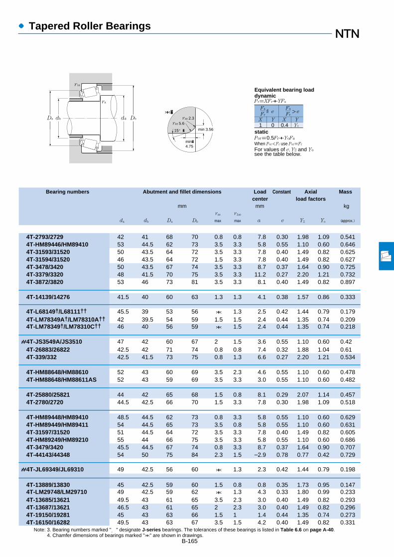
●Tapered Roller Bearings
Bearing numbers Abutment and fillet dimensions Load Constant Axial Masscenter load factors
mm mm kgras r1as
da db Da Db max max a e Y2 Yo (approx.)
B-165
Note: 3. Bearing numbers marked "#" designate J-series bearings. The tolerances of these bearings is listed in Table 6.6 on page A-40.4. Chamfer dimensions of bearings marked "*" are shown in drawings.
4T-2793/2729 42 41 68 70 0.8 0.8 7.8 0.30 1.98 1.09 0.5414T-HM89446/HM89410 53 44.5 62 73 3.5 3.3 5.8 0.55 1.10 0.60 0.6464T-31593/31520 50 43.5 64 72 3.5 3.3 7.8 0.40 1.49 0.82 0.6254T-31594/31520 46 43.5 64 72 1.5 3.3 7.8 0.40 1.49 0.82 0.6274T-3478/3420 50 43.5 67 74 3.5 3.3 8.7 0.37 1.64 0.90 0.7254T-3379/3320 48 41.5 70 75 3.5 3.3 11.2 0.27 2.20 1.21 0.7324T-3872/3820 53 46 73 81 3.5 3.3 8.1 0.40 1.49 0.82 0.897
4T-14139/14276 41.5 40 60 63 1.3 1.3 4.1 0.38 1.57 0.86 0.333
4T-L68149†/L68111†† 45.5 39 53 56 * 1.3 2.5 0.42 1.44 0.79 0.1794T-LM78349A†/LM78310A†† 42 39.5 54 59 1.5 1.5 2.4 0.44 1.35 0.74 0.2094T-LM78349†/LM78310C†† 46 40 56 59 * 1.5 2.4 0.44 1.35 0.74 0.218
#4T-JS3549A/JS3510 47 42 60 67 2 1.5 3.6 0.55 1.10 0.60 0.424T-26883/26822 42.5 42 71 74 0.8 0.8 7.4 0.32 1.88 1.04 0.614T-339/332 42.5 41.5 73 75 0.8 1.3 6.6 0.27 2.20 1.21 0.534
4T-HM88648/HM88610 52 43 60 69 3.5 2.3 4.6 0.55 1.10 0.60 0.4784T-HM88648/HM88611AS 52 43 59 69 3.5 3.3 3.0 0.55 1.10 0.60 0.482
4T-25880/25821 44 42 65 68 1.5 0.8 8.1 0.29 2.07 1.14 0.4574T-2780/2720 44.5 42.5 66 70 1.5 3.3 7.8 0.30 1.98 1.09 0.518
4T-HM89448/HM89410 48.5 44.5 62 73 0.8 3.3 5.8 0.55 1.10 0.60 0.6294T-HM89449/HM89411 54 44.5 65 73 3.5 0.8 5.8 0.55 1.10 0.60 0.6314T-31597/31520 51 44.5 64 72 3.5 3.3 7.8 0.40 1.49 0.82 0.6054T-HM89249/HM89210 55 44 66 75 3.5 3.3 5.8 0.55 1.10 0.60 0.6864T-3479/3420 45.5 44.5 67 74 0.8 3.3 8.7 0.37 1.64 0.90 0.7074T-44143/44348 54 50 75 84 2.3 1.5 –2.9 0.78 0.77 0.42 0.729
#4T-JL69349/JL69310 49 42.5 56 60 * 1.3 2.3 0.42 1.44 0.79 0.198
4T-13889/13830 45 42.5 59 60 1.5 0.8 0.8 0.35 1.73 0.95 0.1474T-LM29748/LM29710 49 42.5 59 62 * 1.3 4.3 0.33 1.80 0.99 0.2334T-13685/13621 49.5 43 61 65 3.5 2.3 3.0 0.40 1.49 0.82 0.2934T-13687/13621 46.5 43 61 65 2 2.3 3.0 0.40 1.49 0.82 0.2964T-19150/19281 45 43 63 66 1.5 1 1.4 0.44 1.35 0.74 0.2734T-16150/16282 49.5 43 63 67 3.5 1.5 4.2 0.40 1.49 0.82 0.331
ras 2.3ras 5.6
min 3.56
min�4.75
15°�1 0 0.4 Y2
Fa
Fr
X Y X Y
≦eFa
Fr>e
Pr=XFr+YFa
*�
Por=0.5Fr+YoFa
When Por<Fr use Por=Fr
For values of e, Y2 and Yosee the table below.
Equivalent bearing loaddynamic
static
r1a
ra
da DbDa db

Boundary dimensions Basic load ratings Limiting speedsdynamic static dynamic static
mm kN kgf rpm
d D T B C Cr Cor Cr Cor grease oil
●Tapered Roller Bearings
B-166
Note: 1. With regard to the chamfer dimensions on the back face of the inner and outer rings, installation dimensions ras and r1as are larger than the maximum value.2. For the inner bore diameter of bearings with bearing numbers marked "†" (inner ring) or "††" (outer ring), this value applies only to high precision class types, Class 4
and 2.
d 38.100~41.275mm
Inch system sizes
76.200 20.638 20.940 15.507 55.5 63.0 5,650 6,450 5,000 6,70076.200 23.812 25.654 19.050 73.0 90.5 7,450 9,200 5,100 6,80076.200 23.812 25.654 19.050 73.0 90.5 7,450 9,200 5,100 6,80079.375 23.812 25.400 19.050 76.5 97.5 7,800 9,950 4,800 6,40079.375 29.370 29.771 23.812 93.0 114 9,450 11,600 4,900 6,60080.000 21.006 20.940 15.875 55.5 63.0 5,650 6,450 5,000 6,70080.035 24.608 23.698 18.512 67.0 82.5 6,850 8,400 4,800 6,40082.550 29.370 28.575 23.020 87.0 117 8,850 11,900 4,700 6,20082.931 23.812 25.400 19.050 76.0 98.0 7,750 10,000 4,500 6,00085.725 30.162 30.162 23.812 105 132 10,700 13,400 4,500 6,00087.312 30.162 30.886 23.812 94.0 117 9,600 12,000 4,400 5,90088.500 25.400 23.698 17.462 70.5 78.0 7,200 7,950 4,000 5,30088.500 26.988 29.083 22.225 95.5 107 9,750 10,900 4,600 6,100
76.200 23.812 25.654 19.050 73.0 90.5 7,450 9,200 5,100 6,80077.534 29.370 30.391 23.812 95.0 112 9,700 11,400 4,800 6,40079.375 23.812 25.400 19.050 76.5 97.5 7,800 9,950 4,800 6,40080.035 29.370 30.391 23.812 95.0 112 9,700 11,400 4,800 6,40080.167 29.370 30.391 23.812 95.0 112 9,700 11,400 4,800 6,40088.500 25.400 23.698 17.462 70.5 78.0 7,200 7,950 4,000 5,300
76.200 20.638 20.940 15.507 55.5 63.0 5,650 6,450 5,000 6,70080.000 21.000 22.403 17.826 68.0 75.0 6,950 7,650 4,700 6,30085.000 20.638 21.692 17.462 69.5 79.5 7,100 8,100 4,400 5,80088.500 26.988 29.083 22.225 95.5 107 9,750 10,900 4,600 6,100
107.950 36.512 36.957 28.575 141 177 14,400 18,100 3,600 4,800
82.550 29.370 28.575 23.020 87.0 117 8,850 11,900 4,700 6,200
67.975 17.500 18.000 13.500 46.0 62.5 4,700 6,400 5,300 7,000
73.025 16.667 17.462 12.700 46.0 55.5 4,700 5,700 5,000 6,60073.431 19.558 19.812 14.732 56.0 69.5 5,700 7,100 5,000 6,60073.431 21.430 19.812 16.604 56.0 69.5 5,700 7,100 5,000 6,60076.200 18.009 17.384 14.288 42.5 51.5 4,350 5,250 4,900 6,50076.200 22.225 23.020 17.462 65.0 80.5 6,600 8,200 4,900 6,50076.200 25.400 25.400 20.638 76.5 97.5 7,800 9,950 4,800 6,40079.375 23.812 25.400 19.050 76.5 97.5 7,800 9,950 4,800 6,40080.000 18.009 17.384 14.288 42.5 51.5 4,350 5,250 4,900 6,500
38.100
39.688
40.000
40.483
40.988
41.275
T
C
D
B
r1
d
r
a

●Tapered Roller Bearings
Bearing numbers Abutment and fillet dimensions Load Constant Axial Masscenter load factors
mm mm kgras r1as
da db Da Db max max a e Y2 Yo (approx.)
B-167
Note: 3. Chamfer dimensions of bearings marked "*" are shown in drawings.1 "-" means that load center at outside on end of inner ring.
4T-28150/28300 45.5 43.5 68 71 1.5 1.3 4.8 0.40 1.49 0.82 0.4054T-2776/2720 52 43.5 66 70 4.3 3.3 7.8 0.30 1.98 1.09 0.4954T-2788/2720 50 43.5 66 70 3.5 3.3 7.8 0.30 1.98 1.09 0.4974T-26878/26822 45 44.5 71 74 0.8 0.8 7.4 0.32 1.88 1.04 0.5744T-3490/3420 52 45.5 67 74 3.5 3.3 8.7 0.37 1.64 0.90 0.6834T-28150/28315 45.5 43.5 69 73 1.5 1.5 4.8 0.40 1.49 0.82 0.4674T-27880/27820 48 47 68 75 0.8 1.5 2.5 0.56 1.07 0.59 0.5624T-HM801346/HM801310 51 49 68 78 0.8 3.3 4.7 0.55 1.10 0.60 0.7674T-25572/25520 46 46 74 77 0.8 0.8 6.2 0.33 1.79 0.99 0.6454T-3875/3820 49.5 48.5 73 81 0.8 3.3 8.1 0.40 1.49 0.82 0.8574T-3580/3525 48 45.5 75 81 1.5 3.3 10.0 0.31 1.96 1.08 0.8814T-44150/44348 55 51 75 84 2.3 1.5 –2.91 0.78 0.77 0.42 0.7114T-418/414 51 44.5 77 80 3.5 1.5 9.1 0.26 2.28 1.25 0.84
4T-2789/2720 52 45 66 70 3.5 3.3 7.8 0.30 1.98 1.09 0.4774T-3382/3321 52 45.5 68 75 3.5 3.3 11.2 0.27 2.20 1.21 0.6694T-26880/26822 48 45.5 71 74 1.5 0.8 7.4 0.32 1.88 1.04 0.5544T-3382/3339 52 45.5 71 75 3.5 1.5 11.2 0.27 2.20 1.21 0.6664T-3386/3320 46.5 45.5 70 75 0.8 3.3 11.2 0.27 2.20 1.21 0.6684T-44158/44348 58 51 75 84 3.5 1.5 –2.91 0.78 0.77 0.42 0.691
4T-28158/28300 47.5 45 68 71 1.5 1.3 4.8 0.40 1.49 0.82 0.3864T-344/332 52 45.5 73 75 3.5 1.3 6.6 0.27 2.20 1.21 0.4794T-350A/354A 47.5 46.5 77 80 0.8 1.3 5.1 0.31 1.96 1.08 0.5624T-420/414 52 46 77 80 3.5 1.5 9.1 0.26 2.28 1.25 0.8134T-543/532X 57 50 94 100 3.5 3.3 12.3 0.30 2.02 1.11 1.77
4T-HM801349/HM801310 58 49 68 78 3.5 3.3 4.7 0.55 1.10 0.60 0.731
4T-LM300849†/LM300811†† 52 45 61 65 * 1.5 3.6 0.35 1.72 0.95 0.239
4T-18590/18520 53 46 66 69 3.5 1.5 2.9 0.35 1.71 0.94 0.2814T-LM501349/LM501310 53 46.5 67 70 3.5 0.8 3.3 0.40 1.50 0.83 0.3354T-LM501349/LM501314 53 46.5 66 70 3.5 0.8 3.3 0.40 1.50 0.83 0.3554T-11162/11300 49 46.5 67 71 1.5 1.5 0.7 0.49 1.23 0.68 0.3374T-24780/24720 54 47 68 72 3.5 0.8 4.5 0.39 1.53 0.84 0.4324T-26882/26823 54 47 69 73 3.5 1.5 7.4 0.32 1.88 1.04 0.4884T-26885/26822 48 47 71 74 0.8 0.8 7.4 0.32 1.88 1.04 0.5354T-11162/11315 49 46.5 69 73 1.5 1.5 0.7 0.49 1.23 0.68 0.389
ras 2.3ras 5.6
min 3.56
min�4.75
15°�1 0 0.4 Y2
Fa
Fr
X Y X Y
≦eFa
Fr>e
Pr=XFr+YFa
*�
Por=0.5Fr+YoFa
When Por<Fr use Por=Fr
For values of e, Y2 and Yosee the table below.
Equivalent bearing loaddynamic
static
r1a
ra
da DbDa db

Boundary dimensions Basic load ratings Limiting speedsdynamic static dynamic static
mm kN kgf rpm
d D T B C Cr Cor Cr Cor grease oil
●Tapered Roller Bearings
B-168
Note: 1. With regard to the chamfer dimensions on the back face of the inner and outer rings, installation dimensions ras and r1as are larger than the maximum value.
d 41.275~44.450mm
Inch system sizes
41.275
42.070
42.862
42.875
44.450
T
C
D
B
r1
d
r
a
80.000 21.000 22.403 17.826 68.0 75.0 6,950 7,650 4,700 6,30080.000 23.812 25.400 19.050 76.5 97.5 7,800 9,950 4,800 6,40082.550 26.543 25.654 20.193 80.5 104 8,200 10,600 4,600 6,10085.725 30.162 30.162 23.812 105 132 10,700 13,400 4,500 6,00087.312 30.162 30.886 23.812 94.0 117 9,600 12,000 4,400 5,90088.900 30.162 29.370 23.020 93.5 125 9,550 12,700 4,300 5,80090.488 39.688 40.386 33.338 136 175 13,900 17,900 4,300 5,80092.075 26.195 23.812 16.670 72.5 81.5 7,400 8,300 3,800 5,00093.662 31.750 31.750 26.195 104 131 10,600 13,400 4,100 5,50095.250 30.162 29.370 23.020 109 147 11,100 15,000 4,000 5,30095.250 30.958 28.300 20.638 82.5 92.0 8,400 9,350 3,700 5,00095.250 30.958 28.575 22.225 96.0 116 9,800 11,800 3,700 4,900
90.488 39.688 40.386 33.338 136 175 13,900 17,900 4,300 5,800
82.550 26.195 26.988 20.638 75.5 97.0 7,700 9,900 4,600 6,10082.931 23.812 25.400 19.050 76.0 98.0 7,750 10,000 4,500 6,00087.312 30.162 30.886 23.812 94.0 117 9,600 12,000 4,400 5,900
79.375 23.812 25.400 19.050 76.5 97.5 7,800 9,950 4,800 6,40082.931 23.812 25.400 19.050 76.0 98.0 7,750 10,000 4,500 6,000
76.992 17.462 17.145 11.908 44.0 54.0 4,450 5,550 4,700 6,30079.375 17.462 17.462 13.495 45.5 56.0 4,600 5,700 4,600 6,20082.931 23.812 25.400 19.050 76.0 98.0 7,750 10,000 4,500 6,00082.931 23.812 25.400 19.050 76.0 98.0 7,750 10,000 4,500 6,00084.138 30.162 30.886 23.812 94.0 117 9,600 12,000 4,400 5,90085.000 20.638 21.692 17.462 69.5 79.5 7,100 8,100 4,400 5,80087.312 30.162 30.886 23.812 94.0 117 9,600 12,000 4,400 5,90088.900 30.162 29.370 23.020 93.5 125 9,550 12,700 4,300 5,80093.264 30.162 30.302 23.812 102 134 10,400 13,700 4,000 5,30093.662 31.750 31.750 26.195 103 131 10,600 13,400 4,100 5,50095.250 27.783 28.575 22.225 107 139 10,900 14,200 3,900 5,20095.250 27.783 29.900 22.225 108 129 11,000 13,200 4,200 5,60095.250 30.162 29.370 23.020 109 147 11,100 15,000 4,000 5,30095.250 30.958 28.300 20.638 82.5 92.0 8,400 9,350 3,700 5,00095.250 30.958 28.575 22.225 96.0 116 9,800 11,800 3,700 4,900
101.600 34.925 36.068 26.988 135 165 13,800 16,800 3,800 5,000104.775 30.162 29.317 24.605 115 148 11,700 15,000 3,500 4,700

●Tapered Roller Bearings
Bearing numbers Abutment and fillet dimensions Load Constant Axial Masscenter load factors
mm mm kgras r1as
da db Da Db max max a e Y2 Yo (approx.)
B-169
1 "-" means that load center at outside on end of inner ring.
4T-336/332 47 46 73 75 0.8 1.3 6.6 0.27 2.20 1.21 0.4684T-26882/26824 54 47 70 74 3.5 1.3 7.4 0.32 1.88 1.04 0.5424T-M802048/M802011 57 51 70 79 3.5 3.3 3.2 0.55 1.10 0.60 0.6424T-3880/3820 52 50 73 81 0.8 3.3 8.1 0.40 1.49 0.82 0.814T-3576/3525 49 48 75 81 0.8 3.3 10.0 0.31 1.96 1.08 0.8344T-HM803145/HM803110 54 53 74 85 0.8 3.3 4.6 0.55 1.10 0.60 0.9014T-4388/4335 57 51 77 85 3.5 3.3 15.0 0.28 2.11 1.16 1.254T-M903345/M903310 60 54 78 88 3.5 1.5 – 3.61 0.83 0.72 0.40 0.7584T-46162/46368 52 51 79 87 0.8 3.3 7.1 0.40 1.49 0.82 1.094T-HM804840/HM804810 61 54 81 91 3.5 3.3 3.7 0.55 1.10 0.60 1.084T-53162/53375 57 53 81 89 1.5 0.8 0.5 0.74 0.81 0.45 0.9754T-HM903245/HM903210 63 54 81 91 3.5 0.8 – 0.41 0.74 0.81 0.45 1.05
4T-4395/4335 58 51 77 85 3.5 3.3 15.0 0.28 2.11 1.16 1.24
4T-22780/22720 56 50 71 77 3.5 3.3 6.4 0.40 1.49 0.82 0.6174T-25578/25520 53 49.5 74 77 2.3 0.8 6.2 0.33 1.79 0.99 0.5844T-3579/3525 56 49.5 75 81 3.5 3.3 10.0 0.31 1.96 1.08 0.805
4T-26884/26822 55 48.5 71 74 3.5 0.8 7.4 0.32 1.88 1.04 0.514T-25577/25520 55 49 74 77 3.5 0.8 6.2 0.33 1.79 0.99 0.581
4T-12175/12303 52 49.5 68 73 1.5 1.5 – 0.21 0.51 1.19 0.65 0.3084T-18685/18620 54 49.5 71 74 2.8 1.5 2.2 0.37 1.60 0.88 0.3454T-25580/25520 57 50 74 77 3.5 0.8 6.2 0.33 1.79 0.99 0.564T-25582/25520 60 50 74 77 5 0.8 6.2 0.33 1.79 0.99 0.5564T-3578/3520 57 51 74 80 3.5 3.3 10.0 0.31 1.96 1.08 0.6994T-355/354A 54 50 77 80 2.3 1.3 5.1 0.31 1.96 1.08 0.5114T-3578/3525 57 51 75 81 3.5 3.3 10.0 0.31 1.96 1.08 0.7794T-HM803149/HM803110 62 53 74 85 3.5 3.3 4.6 0.55 1.10 0.60 0.8494T-3782/3720 58 52 82 88 3.5 3.3 8.3 0.34 1.77 0.97 0.9614T-46175/46368 55 54 79 87 0.8 3.3 7.1 0.40 1.49 0.82 1.044T-33885/33821 53 53 85 90 0.8 2.3 8.0 0.33 1.82 1.00 0.9874T-438/432 57 51 83 87 3.5 2.3 9.2 0.28 2.11 1.16 0.9534T-HM804842/HM804810 57 57 81 91 0.8 3.3 3.7 0.55 1.10 0.60 1.044T-53177/53375 63 53 81 89 3.5 0.8 0.5 0.74 0.81 0.45 0.9254T-HM903249/HM903210 65 54 81 91 3.5 0.8 – 0.41 0.74 0.81 0.45 14T-527/522 59 53 89 95 3.5 3.3 12.9 0.29 2.10 1.16 1.374T-460/453X 60 54 92 98 3.5 3.3 7.1 0.34 1.79 0.98 1.29
ras 2.3ras 5.6
min 3.56
min�4.75
15°�1 0 0.4 Y2
Fa
Fr
X Y X Y
≦eFa
Fr>e
Pr=XFr+YFa
*�
Por=0.5Fr+YoFa
When Por<Fr use Por=Fr
For values of e, Y2 and Yosee the table below.
Equivalent bearing loaddynamic
static
r1a
ra
da DbDa db

Boundary dimensions Basic load ratings Limiting speedsdynamic static dynamic static
mm kN kgf rpm
d D T B C Cr Cor Cr Cor grease oil
●Tapered Roller Bearings
B-170
Note: 1. With regard to the chamfer dimensions on the back face of the inner and outer rings, installation dimensions ras and r1as are larger than the maximum value.2. For the inner bore diameter of bearings with bearing numbers marked "†" (inner ring) or "††" (outer ring), this value applies only to high precision class types, Class 4
and 2.
d 44.450~47.625mm
Inch system sizes
104.775 30.162 30.958 23.812 130 169 13,200 17,300 3,500 4,700104.775 36.512 36.512 28.575 138 189 14,000 19,300 3,600 4,800111.125 30.162 26.909 20.638 104 136 10,600 13,900 3,200 4,200111.125 30.162 26.909 20.638 104 136 10,600 13,900 3,200 4,200127.000 50.800 52.388 41.275 250 320 25,500 33,000 3,200 4,300
82.931 23.812 25.400 19.050 76.0 98.0 7,750 10,000 4,500 6,00093.264 30.162 30.302 23.812 102 134 10,400 13,700 4,000 5,300
85.000 20.638 21.692 17.462 69.5 79.5 7,100 8,100 4,400 5,80088.900 20.638 22.225 16.513 76.5 90.5 7,800 9,250 4,100 5,500
87.312 30.162 30.886 23.812 94.0 117 9,600 12,000 4,400 5,900
73.431 19.558 19.812 15.748 54.0 76.0 5,550 7,750 4,800 6,40077.788 19.842 19.842 15.080 57.5 73.5 5,850 7,500 4,600 6,200
82.550 23.812 25.400 19.050 76.0 98.0 7,750 10,000 4,500 6,00082.931 23.812 25.400 19.050 76.0 98.0 7,750 10,000 4,500 6,00083.058 23.876 25.400 19.114 76.0 98.0 7,750 10,000 4,500 6,00085.000 23.812 25.400 19.050 76.0 98.0 7,750 10,000 4,500 6,000
74.976 18.000 18.000 14.000 51.0 71.0 5,200 7,250 4,700 6,300
79.375 17.462 17.462 13.495 45.5 56.0 4,600 5,700 4,600 6,20082.931 23.812 25.400 19.050 76.0 98.0 7,750 10,000 4,500 6,00085.000 20.638 21.692 17.462 69.5 79.5 7,100 8,100 4,400 5,80085.000 25.400 25.608 20.638 79.0 104 8,050 10,600 4,400 5,80090.119 23.000 21.692 21.808 69.5 79.5 7,100 8,100 4,400 5,80093.264 30.162 30.302 23.812 102 134 10,400 13,700 4,000 5,30095.250 27.783 29.900 22.225 108 129 11,000 13,200 4,200 5,600
88.900 20.638 22.225 16.513 76.5 90.5 7,800 9,250 4,100 5,50088.900 25.400 25.400 19.050 82.0 101 8,350 10,300 4,200 5,60093.264 30.162 30.302 23.812 102 134 10,400 13,700 4,000 5,30095.250 30.162 29.370 23.020 109 147 11,100 15,000 4,000 5,30096.838 21.000 21.946 15.875 78.0 96.5 7,950 9,850 3,700 5,000
101.600 34.925 36.068 26.988 135 165 13,800 16,800 3,800 5,000104.775 30.162 29.317 24.605 115 148 11,700 15,000 3,500 4,700
44.450
44.983
45.000
45.237
45.242
45.618
45.987
46.038
47.625
T
C
D
B
r1
d
r
a

●Tapered Roller Bearings
Bearing numbers Abutment and fillet dimensions Load Constant Axial Masscenter load factors
mm mm kgras r1as
da db Da Db max max a e Y2 Yo (approx.)
B-171
Note: 3. Chamfer dimensions of bearings marked "*" are shown in drawings.1 "-" means that load center at outside on end of inner ring.
4T-45280/45220 55 54 93 99 0.8 3.3 7.9 0.33 1.80 0.99 1.354T-HM807040/HM807010 66 59 89 100 3.5 3.3 7.4 0.49 1.23 0.68 1.624T-55175C/55437 70 64 92 105 3.5 3.3 –7.41 0.88 0.68 0.37 1.454T-55176C/55437 65 65 92 105 0.8 3.3 –7.41 0.88 0.68 0.37 1.094T-6277/6220 67 60 108 117 3.5 3.3 19.5 0.30 2.01 1.11 3.58
4T-25584/25520 53 51 74 77 1.5 0.8 6.2 0.33 1.79 0.99 0.5554T-3776/3720 59 53 82 88 3.5 3.3 8.3 0.34 1.77 0.97 0.952
4T-358/354A 53 50 77 80 1.5 1.3 5.1 0.31 1.96 1.08 0.5054T-367/362A 55 51 81 84 2 1.3 4.0 0.32 1.88 1.03 0.595
4T-3586/3525 58 52 75 81 3.5 3.3 10.0 0.31 1.96 1.08 0.765
4T-LM102949/LM102910 56 50 68 70 3.5 0.8 4.7 0.31 1.97 1.08 0.3074T-LM603049/LM603011 57 50 71 74 3.5 0.8 2.2 0.43 1.41 0.77 0.372
4T-25590/25519 58 51 73 77 3.5 2 6.2 0.33 1.79 0.99 0.5344T-25590/25520 58 51 74 77 3.5 0.8 6.2 0.33 1.79 0.99 0.5434T-25590/25522 58 51 73 77 3.5 2 6.2 0.33 1.79 0.99 0.5454T-25590/25526 58 51 74 78 3.5 2.3 6.2 0.33 1.79 0.99 0.581
4T-LM503349A†/LM503310†† 57 51 67 71 * 1.5 1.9 0.40 1.49 0.82 0.296
4T-18690/18620 56 51 71 74 2.8 1.5 2.2 0.37 1.60 0.88 0.3294T-25592/25520 58 52 74 77 3.5 0.8 6.2 0.33 1.79 0.99 0.5384T-359A/354A 57 51 77 80 3.5 1.3 5.1 0.31 1.96 1.08 0.4894T-2984/2924 58 52 76 80 3.5 1.3 6.4 0.35 1.73 0.95 0.6154T-359S/352 55 51 78 82 2.3 2.3 5.1 0.31 1.96 1.08 0.6514T-3777/3720 60 53 82 88 3.5 3.3 8.3 0.34 1.77 0.97 0.9344T-436/432 59 52 83 87 3.5 2.3 9.2 0.28 2.11 1.16 0.927
4T-369A/362A 60 53 81 84 3.5 1.3 4.0 0.32 1.88 1.03 0.5594T-M804048/M804010 57 56 77 85 0.8 3.3 1.7 0.55 1.10 0.60 0.6624T-3778/3720 67 55 82 88 6.4 3.3 8.3 0.34 1.77 0.97 0.8984T-HM804846/HM804810 66 57 81 91 3.5 3.3 3.7 0.55 1.10 0.60 0.9784T-386A/382A 56 55 89 92 0.8 0.8 3.1 0.35 1.69 0.93 0.724T-528/522 62 55 89 95 3.5 3.3 12.9 0.29 2.10 1.16 1.34T-463/453X 65 56 92 98 4.8 3.3 7.1 0.34 1.79 0.98 1.24
ras 2.3ras 5.6
min 3.56
min�4.75
15°�1 0 0.4 Y2
Fa
Fr
X Y X Y
≦eFa
Fr>e
Pr=XFr+YFa
*�
Por=0.5Fr+YoFa
When Por<Fr use Por=Fr
For values of e, Y2 and Yosee the table below.
Equivalent bearing loaddynamic
static
r1a
ra
da DbDa db
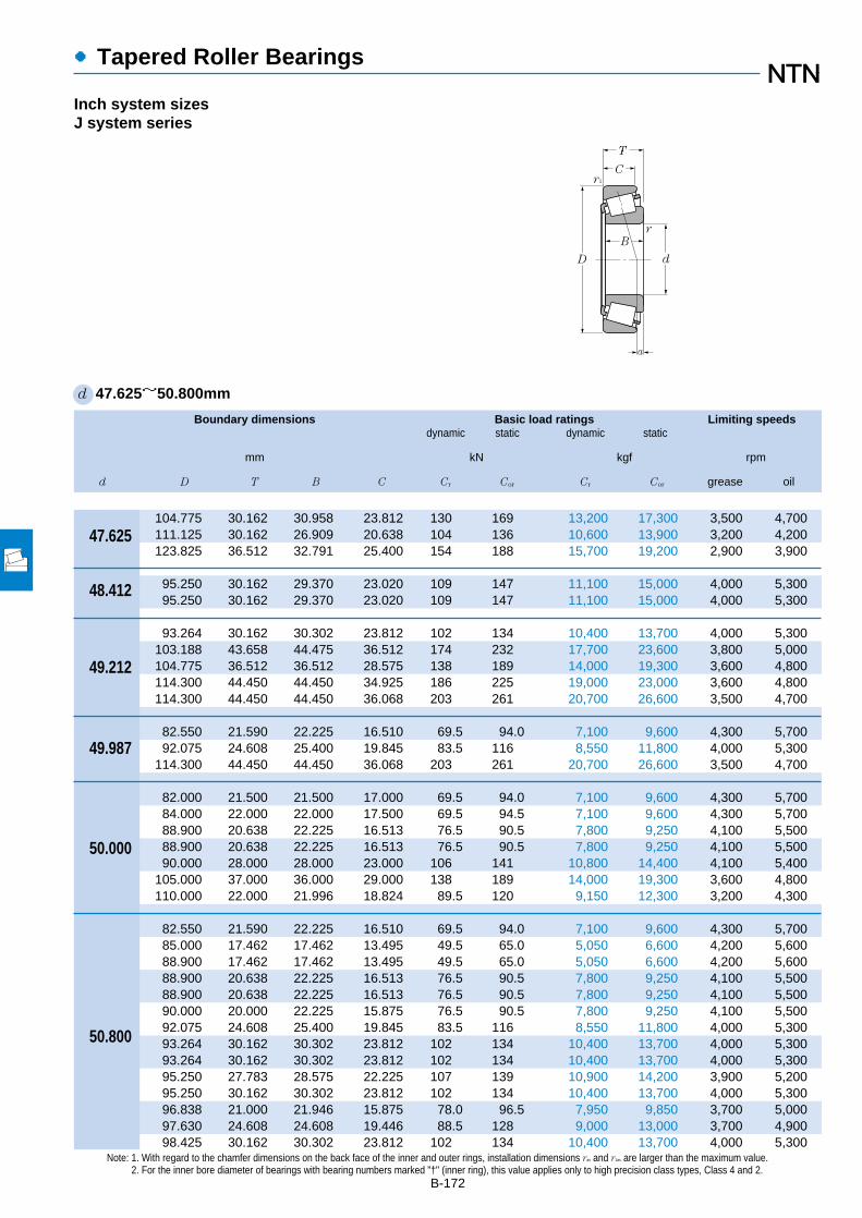
Boundary dimensions Basic load ratings Limiting speedsdynamic static dynamic static
mm kN kgf rpm
d D T B C Cr Cor Cr Cor grease oil
●Tapered Roller Bearings
B-172
Note: 1. With regard to the chamfer dimensions on the back face of the inner and outer rings, installation dimensions ras and r1as are larger than the maximum value.2. For the inner bore diameter of bearings with bearing numbers marked "†" (inner ring), this value applies only to high precision class types, Class 4 and 2.
d 47.625~50.800mm
Inch system sizesJ system series
104.775 30.162 30.958 23.812 130 169 13,200 17,300 3,500 4,700111.125 30.162 26.909 20.638 104 136 10,600 13,900 3,200 4,200123.825 36.512 32.791 25.400 154 188 15,700 19,200 2,900 3,900
95.250 30.162 29.370 23.020 109 147 11,100 15,000 4,000 5,30095.250 30.162 29.370 23.020 109 147 11,100 15,000 4,000 5,300
93.264 30.162 30.302 23.812 102 134 10,400 13,700 4,000 5,300103.188 43.658 44.475 36.512 174 232 17,700 23,600 3,800 5,000104.775 36.512 36.512 28.575 138 189 14,000 19,300 3,600 4,800114.300 44.450 44.450 34.925 186 225 19,000 23,000 3,600 4,800114.300 44.450 44.450 36.068 203 261 20,700 26,600 3,500 4,700
82.550 21.590 22.225 16.510 69.5 94.0 7,100 9,600 4,300 5,70092.075 24.608 25.400 19.845 83.5 116 8,550 11,800 4,000 5,300
114.300 44.450 44.450 36.068 203 261 20,700 26,600 3,500 4,700
82.000 21.500 21.500 17.000 69.5 94.0 7,100 9,600 4,300 5,70084.000 22.000 22.000 17.500 69.5 94.5 7,100 9,600 4,300 5,70088.900 20.638 22.225 16.513 76.5 90.5 7,800 9,250 4,100 5,50088.900 20.638 22.225 16.513 76.5 90.5 7,800 9,250 4,100 5,50090.000 28.000 28.000 23.000 106 141 10,800 14,400 4,100 5,400
105.000 37.000 36.000 29.000 138 189 14,000 19,300 3,600 4,800110.000 22.000 21.996 18.824 89.5 120 9,150 12,300 3,200 4,300
82.550 21.590 22.225 16.510 69.5 94.0 7,100 9,600 4,300 5,70085.000 17.462 17.462 13.495 49.5 65.0 5,050 6,600 4,200 5,60088.900 17.462 17.462 13.495 49.5 65.0 5,050 6,600 4,200 5,60088.900 20.638 22.225 16.513 76.5 90.5 7,800 9,250 4,100 5,50088.900 20.638 22.225 16.513 76.5 90.5 7,800 9,250 4,100 5,50090.000 20.000 22.225 15.875 76.5 90.5 7,800 9,250 4,100 5,50092.075 24.608 25.400 19.845 83.5 116 8,550 11,800 4,000 5,30093.264 30.162 30.302 23.812 102 134 10,400 13,700 4,000 5,30093.264 30.162 30.302 23.812 102 134 10,400 13,700 4,000 5,30095.250 27.783 28.575 22.225 107 139 10,900 14,200 3,900 5,20095.250 30.162 30.302 23.812 102 134 10,400 13,700 4,000 5,30096.838 21.000 21.946 15.875 78.0 96.5 7,950 9,850 3,700 5,00097.630 24.608 24.608 19.446 88.5 128 9,000 13,000 3,700 4,90098.425 30.162 30.302 23.812 102 134 10,400 13,700 4,000 5,300
47.625
48.412
49.212
49.987
50.000
50.800
T
C
D
B
r1
d
r
a

●Tapered Roller Bearings
Bearing numbers Abutment and fillet dimensions Load Constant Axial Masscenter load factors
mm mm kgras r1as
da db Da Db max max a e Y2 Yo (approx.)
B-173
Note: 3. Bearing numbers marked "#" designate J-series bearings. The tolerances of these bearings is listed in Table 6.6 on page A-40.1 "-" means that load center at outside on end of inner ring.
4T-45282/45220 63 57 93 99 3.5 3.3 7.9 0.33 1.80 0.99 1.294T-55187C/55437 69 62 92 105 3.5 3.3 –7.41 0.88 0.68 0.37 1.44T-72188C/72487 69 67 102 116 0.8 3.3 –1.51 0.74 0.81 0.45 2.16
4T-HM804848/HM804810 63 57 81 91 2.3 3.3 3.7 0.55 1.10 0.60 0.9674T-HM804849/HM804810 66 57 81 91 3.5 3.3 3.7 0.55 1.10 0.60 0.964
4T-3781/3720 62 56 82 88 3.5 3.3 8.3 0.34 1.77 0.97 0.8774T-5395/5335 66 60 89 97 3.5 3.3 16.1 0.30 2.02 1.11 1.754T-HM807044/HM807010 69 63 89 100 3.5 3.3 7.4 0.49 1.23 0.68 1.524T-65390/65320 70 60 97 107 3.5 3.3 12.5 0.43 1.39 0.77 2.234T-HH506348/HH506310 71 61 97 107 3.5 3.3 13.3 0.40 1.49 0.82 2.33
4T-LM104947A†/LM104911 55 55 75 78 0.5 1.3 5.8 0.31 1.97 1.08 0.4344T-28579†/28521 60 56 83 87 2.3 0.8 4.6 0.38 1.59 0.87 0.7184T-HH506349†/HH506310 72 61 97 107 3.5 3.3 13.3 0.40 1.49 0.82 2.27
#4T-JLM104948/JLM104910 60 55 76 78 3 0.5 5.4 0.31 1.97 1.08 0.42#4T-JLM704649/JLM704610 62 56 76 80 3.5 1.5 2.3 0.44 1.37 0.75 0.466
4T-365/362A 58 55 81 84 2 1.3 4.0 0.32 1.88 1.03 0.534T-366/362A 59 55 81 84 2.3 1.3 4.0 0.32 1.88 1.03 0.529#4T-JM205149/JM205110 62 57 80 85 3 2.5 7.4 0.33 1.82 1.00 0.752#4T-JHM807045/JHM807012 69 63 90 100 3 2.5 7.5 0.49 1.23 0.68 1.52
4T-396/394A 61 60 101 104 0.8 1.3 0.7 0.40 1.49 0.82 1.06
4T-LM104949/LM104911 62 55 75 78 3.5 1.3 5.8 0.31 1.97 1.08 0.4194T-18790/18720 62 56 77 80 3.5 1.5 0.8 0.41 1.48 0.81 0.3744T-18790/18724 62 56 78 82 3.5 1.3 0.8 0.41 1.48 0.81 0.4314T-368/362A 58 56 81 84 1.5 1.3 4.0 0.32 1.88 1.03 0.5194T-370A/362A 65 56 81 84 5 1.3 4.0 0.32 1.88 1.03 0.5114T-368A/362 62 56 81 84 3.5 2 4.0 0.32 1.88 1.03 0.5254T-28580/28521 63 57 83 87 3.5 0.8 4.6 0.38 1.59 0.87 0.7034T-3775/3720 58 58 82 88 0.8 3.3 8.3 0.34 1.77 0.97 0.8524T-3780/3720 64 58 82 88 3.5 3.3 8.3 0.34 1.77 0.97 0.8484T-33889/33821 64 58 85 90 3.5 2.3 8.0 0.33 1.82 1.00 0.8764T-3780/3726 64 58 83 89 3.5 3.3 8.3 0.34 1.77 0.97 0.9034T-385A/382A 61 60 89 92 2.3 0.8 3.1 0.35 1.69 0.93 0.6764T-28678/28622 65 58 88 92 3.5 0.8 3.3 0.40 1.49 0.82 0.8524T-3780/3732 64 58 84 90 3.5 3.3 8.3 0.34 1.77 0.97 0.993
1 0 0.4 Y2
Fa
Fr
X Y X Y
≦eFa
Fr>e
Pr=XFr+YFa
Por=0.5Fr+YoFa
When Por<Fr use Por=Fr
For values of e, Y2 and Yosee the table below.
Equivalent bearing loaddynamic
static
r1a
ra
da DbDa db

Boundary dimensions Basic load ratings Limiting speedsdynamic static dynamic static
mm kN kgf rpm
d D T B C Cr Cor Cr Cor grease oil
●Tapered Roller Bearings
B-174
Note: 1. With regard to the chamfer dimensions on the back face of the inner and outer rings, installation dimensions ras and r1as are larger than the maximum value.2. Bearing numbers marked "#" designate J-series bearings. The tolerances of these bearings is listed in Table 6.6 on page A-40.
d 50.800~55.000mm
Inch system sizesJ system series
101.600 31.750 31.750 25.400 110 136 11,200 13,900 3,700 5,000101.600 34.925 36.068 26.988 135 165 13,800 16,800 3,800 5,000104.775 30.162 29.317 24.605 115 148 11,700 15,000 3,500 4,700104.775 30.162 30.958 23.812 130 169 13,200 17,300 3,500 4,700104.775 36.512 36.512 28.575 138 189 14,000 19,300 3,600 4,800104.775 36.512 36.512 28.575 143 178 14,500 18,100 3,700 4,900107.950 36.512 36.957 28.575 141 177 14,400 18,100 3,600 4,800111.125 30.162 28.575 20.638 104 136 10,600 13,900 3,200 4,200112.712 30.162 26.909 20.638 104 136 10,600 13,900 3,200 4,200112.712 30.162 30.048 23.812 119 174 12,200 17,800 3,200 4,300112.712 30.162 30.162 23.812 138 195 14,100 19,800 3,200 4,200117.475 33.338 31.750 23.812 130 153 13,200 15,600 3,300 4,400120.650 41.275 41.275 31.750 172 213 17,500 21,700 3,300 4,400123.825 36.512 32.791 25.400 154 188 15,700 19,200 2,900 3,900123.825 38.100 36.678 30.162 158 216 16,100 22,000 3,000 4,100
88.900 20.638 22.225 16.513 76.5 90.5 7,800 9,250 4,100 5,500
92.075 24.608 25.400 19.845 83.5 116 8,550 11,800 4,000 5,30093.264 30.162 30.302 23.812 102 134 10,400 13,700 4,000 5,30095.250 27.783 28.575 22.225 107 139 10,900 14,200 3,900 5,200
88.900 19.050 19.050 13.492 61.0 82.5 6,200 8,450 4,000 5,30095.250 27.783 28.575 22.225 107 139 10,900 14,200 3,900 5,20096.838 21.000 21.946 15.875 78.0 96.5 7,950 9,850 3,700 5,000
104.775 30.162 30.958 23.812 130 169 13,200 17,300 3,500 4,700104.775 36.512 36.512 28.575 138 189 14,000 19,300 3,600 4,800107.950 36.512 36.957 28.575 141 177 14,400 18,100 3,600 4,800120.650 41.275 41.275 31.750 172 213 17,500 21,700 3,300 4,400122.238 33.338 31.750 23.812 134 163 13,700 16,600 3,100 4,200122.238 43.658 43.764 36.512 194 283 19,700 28,900 3,100 4,100123.825 36.512 32.791 25.400 154 188 15,700 19,200 2,900 3,900123.825 38.100 36.678 30.162 158 216 16,100 22,000 3,000 4,100130.175 36.512 33.338 23.812 156 186 15,900 19,000 2,700 3,600140.030 36.512 33.236 23.520 171 212 17,400 21,600 2,600 3,400
104.775 36.512 36.512 28.575 138 189 14,000 19,300 3,600 4,800
90.000 23.000 23.000 18.500 77.5 109 7,900 11,100 3,900 5,300
50.800
51.592
52.388
53.975
54.488
55.000
T
C
D
B
r1
d
r
a

●Tapered Roller Bearings
Bearing numbers Abutment and fillet dimensions Load Constant Axial Masscenter load factors
mm mm kgras r1as
da db Da Db max max a e Y2 Yo (approx.)
B-1751 "-" means that load center at outside on end of inner ring.
4T-49585/49520 66 59 88 96 3.5 3.3 7.1 0.40 1.50 0.82 1.134T-529/522 59 58 89 95 0.8 3.3 12.9 0.29 2.10 1.16 1.244T-455/453X 60 59 92 98 0.8 3.3 7.1 0.34 1.79 0.98 1.194T-45284/45220 71 59 93 99 6.4 3.3 7.9 0.33 1.80 0.99 1.224T-HM807046/HM807010 70 63 89 100 3.5 3.3 7.4 0.49 1.23 0.68 1.494T-59200/59412 68 61 92 99 3.5 3.3 9.6 0.40 1.49 0.82 1.444T-537/532X 65 59 94 100 3.5 3.3 12.3 0.30 2.02 1.11 1.554T-HM907643/HM907614 74 65 91 105 3.5 3.3 –7.21 0.88 0.68 0.37 1.364T-55200C/55443 71 65 92 106 3.5 3.3 –7.41 0.88 0.68 0.37 1.344T-3975/3920 68 61 99 106 3.5 3.3 4.5 0.40 1.49 0.82 1.534T-39575/39520 68 61 101 107 3.5 3.3 6.6 0.34 1.77 0.97 1.544T-66200/66462 71 65 100 111 3.5 3.3 0.4 0.63 0.96 0.53 1.674T-619/612 67 61 105 110 3.5 3.3 14.4 0.31 1.91 1.05 2.34T-72200C/72487 77 67 102 116 3.5 3.3 –1.51 0.74 0.81 0.45 2.14T-555/552A 66 62 109 116 2.3 3.3 9.4 0.35 1.73 0.95 2.34
4T-368S/362A 59 56 81 84 2 1.3 4.0 0.32 1.88 1.03 0.507
4T-28584/28521 65 58 83 87 3.5 0.8 4.6 0.38 1.59 0.87 0.6774T-3767/3720 63 59 82 88 2.3 3.3 8.3 0.34 1.77 0.97 0.8194T-33890/33821 61 59 85 90 1.5 2.3 8.0 0.33 1.82 1.00 0.851
4T-LM806649/LM806610 63 60 80 85 2.3 2 –2.21 0.55 1.10 0.60 0.4374T-33895/33822 63 60 86 90 1.5 0.8 8.0 0.33 1.82 1.00 0.8244T-389A/382A 61 60 89 92 0.8 0.8 3.1 0.35 1.69 0.93 0.6334T-45287/45220 62 62 93 99 0.8 3.3 7.9 0.33 1.80 0.99 1.174T-HM807049/HM807010 73 63 89 100 3.5 3.3 7.4 0.49 1.23 0.68 1.414T-539/532X 68 61 94 100 3.5 3.3 12.3 0.30 2.02 1.11 1.474T-621/612 70 63 105 110 3.5 3.3 14.4 0.31 1.91 1.05 2.214T-66584/66520 75 68 105 116 3.5 3.3 –1.81 0.67 0.90 0.50 1.794T-5578/5535 73 67 106 116 3.5 3.3 13.3 0.36 1.67 0.92 2.644T-72212C/72487 79 67 102 116 3.5 3.3 –1.51 0.74 0.81 0.45 2.034T-557S/552A 71 65 109 116 3.5 3.3 9.4 0.35 1.73 0.95 2.264T-HM911242/HM911210 79 74 109 124 3.5 3.3 –5.21 0.82 0.73 0.40 2.274T-78214C/78551 79 77 117 132 0.8 2.3 –8.51 0.87 0.69 0.38 2.77
4T-HM807048/HM807010 73 63 89 100 3.5 3.3 7.4 0.49 1.23 0.68 1.40
#4T-JLM506849/JLM506810 63 61 82 86 1.5 0.5 2.8 0.40 1.49 0.82 0.558
1 0 0.4 Y2
Fa
Fr
X Y X Y
≦eFa
Fr>e
Pr=XFr+YFa
Por=0.5Fr+YoFa
When Por<Fr use Por=Fr
For values of e, Y2 and Yosee the table below.
Equivalent bearing loaddynamic
static
r1a
ra
da DbDa db

Boundary dimensions Basic load ratings Limiting speedsdynamic static dynamic static
mm kN kgf rpm
d D T B C Cr Cor Cr Cor grease oil
●Tapered Roller Bearings
B-176
Note: 1. With regard to the chamfer dimensions on the back face of the inner and outer rings, installation dimensions ras and r1as are larger than the maximum value.2. For the inner bore diameter of bearings with bearing numbers marked "†" (inner ring), this value applies only to high precision class types, Class 4 and 2.
d 55.000~60.000mm
Inch system sizesJ system series
95.000 29.000 29.000 23.500 107 144 10,900 14,700 3,800 5,10096.838 21.000 21.946 15.875 78.0 96.5 7,950 9,850 3,700 5,000
110.000 39.000 39.000 32.000 173 219 17,600 22,400 3,500 4,600
97.630 24.608 24.608 19.446 88.5 128 9,000 13,000 3,700 4,900123.825 36.512 32.791 25.400 154 188 15,700 19,200 2,900 3,900127.000 36.512 36.512 26.988 163 228 16,600 23,300 2,900 3,800
96.838 21.000 21.946 15.875 78 96.5 7,950 9,850 3,700 5,000
96.838 21.000 21.946 15.875 78 96.5 7,950 9,850 3,700 5,00096.838 21.000 21.946 15.875 78 96.5 7,950 9,850 3,700 5,00096.838 21.000 21.946 15.875 78 96.5 7,950 9,850 3,700 5,00096.838 21.000 21.946 15.875 78 96.5 7,950 9,850 3,700 5,00097.630 24.608 24.608 19.446 88.5 128 9,000 13,000 3,700 4,900
104.775 30.162 29.317 24.605 115 148 11,700 15,000 3,500 4,700104.775 30.162 29.317 24.605 115 148 11,700 15,000 3,500 4,700104.775 30.162 30.958 23.812 130 169 13,200 17,300 3,500 4,700107.950 27.783 29.317 22.225 115 148 11,700 15,000 3,500 4,700110.000 22.000 21.996 18.824 89.5 120 9,150 12,300 3,200 4,300110.000 27.795 29.317 27.000 115 148 11,700 15,000 3,500 4,700112.712 30.162 30.048 23.812 119 174 12,200 17,800 3,200 4,300112.712 30.162 30.162 23.812 138 195 14,100 19,800 3,200 4,200112.712 30.162 30.162 23.812 138 195 14,100 19,800 3,200 4,200117.475 30.162 30.162 23.812 117 175 11,900 17,900 3,000 4,000117.475 33.338 31.750 23.812 130 153 13,200 15,600 3,300 4,400120.650 41.275 41.275 31.750 172 213 17,500 21,700 3,300 4,400123.825 36.512 32.791 25.400 154 188 15,700 19,200 2,900 3,900123.825 38.100 36.678 30.162 158 216 16,100 22,000 3,000 4,100140.030 36.512 33.236 23.520 171 212 17,400 21,600 2,600 3,400
96.838 21.000 21.946 15.875 78.0 96.5 7,950 9,850 3,700 5,000
122.238 33.338 31.750 23.812 134 163 13,700 16,600 3,100 4,200
146.050 41.275 39.688 25.400 199 234 20,300 23,900 2,400 3,200
95.000 24.000 24.000 19.000 83.0 122 8,500 12,400 3,700 4,900107.950 25.400 25.400 19.050 91.5 140 9,350 14,200 3,200 4,300
55.000
55.562
55.575
57.150
57.531
59.972
59.987
60.000
T
C
D
B
r1
d
r
a

●Tapered Roller Bearings
Bearing numbers Abutment and fillet dimensions Load Constant Axial Masscenter load factors
mm mm kgras r1as
da db Da Db max max a e Y2 Yo (approx.)
B-177
Note: 3. Bearing numbers marked "#" designate J-series bearings. The tolerances of these bearings is listed in Table 6.6 on page A-40.1 "-" means that load center at outside on end of inner ring.
#4T-JM207049/JM207010 64 62 85 91 1.5 2.5 7.6 0.33 1.79 0.99 0.824T-385/382A 65 61 89 92 2.3 0.8 3.1 0.35 1.69 0.93 0.616#4T-JH307749/JH307710 71 64 97 104 3 2.5 11.7 0.35 1.73 0.95 1.71
4T-28680/28622 68 62 88 92 3.5 0.8 3.3 0.40 1.49 0.82 0.7744T-72218C/72487 80 67 102 116 3.5 3.3 –1.51 0.74 0.81 0.45 1.994T-HM813840/HM813810 76 70 111 121 3.5 3.3 3.7 0.50 1.20 0.66 2.34
4T-389/382A 65 61 89 92 2.3 0.8 3.1 0.35 1.69 0.93 0.608
4T-387/382A 66 62 89 92 2.3 0.8 3.1 0.35 1.69 0.93 0.5834T-387A/382A 69 62 89 92 3.5 0.8 3.1 0.35 1.69 0.93 0.5814T-387AS/382A 72 62 89 92 5 0.8 3.1 0.35 1.69 0.93 0.5764T-387S/382A 63 62 89 92 0.8 0.8 3.1 0.35 1.69 0.93 0.5854T-28682/28622 70 63 88 92 3.5 0.8 3.3 0.40 1.49 0.82 0.7474T-462/453X 67 63 92 98 2.3 3.3 7.1 0.34 1.79 0.98 1.064T-469/453X 70 63 92 98 3.5 3.3 7.1 0.34 1.79 0.98 1.064T-45289/45220 65 65 93 99 0.8 3.3 7.9 0.33 1.80 0.99 1.14T-469/453A 70 63 97 100 3.5 0.8 7.1 0.34 1.79 0.98 1.114T-390/394A 70 66 101 104 2.3 1.3 0.7 0.40 1.49 0.82 0.9544T-469/454 70 63 96 100 3.5 2 7.1 0.34 1.79 0.98 1.244T-3979/3920 72 66 99 106 3.5 3.3 4.5 0.40 1.49 0.82 1.44T-39580/39520 72 66 101 107 3.5 3.3 6.6 0.34 1.77 0.97 1.414T-39581/39520 81 66 101 107 8 3.3 6.6 0.34 1.77 0.97 1.44T-33225/33462 74 68 104 112 3.5 3.3 2.6 0.44 1.38 0.76 1.584T-66225/66462 76 69 100 111 3.5 3.3 0.4 0.63 0.96 0.53 1.544T-623/612 72 66 105 110 3.5 3.3 14.4 0.31 1.91 1.05 2.124T-72225C/72487 81 67 102 116 3.5 3.3 –1.51 0.74 0.81 0.45 1.964T-555S/552A 73 67 109 116 3.5 3.3 9.4 0.35 1.73 0.95 2.184T-78225/78551 83 77 117 132 3.5 2.3 –8.51 0.87 0.69 0.38 2.69
4T-388A/382A 69 63 89 92 3.5 0.8 3.1 0.35 1.69 0.93 0.575
4T-66589/66520 74 73 105 116 0.8 3.3 –1.81 0.67 0.90 0.50 1.66
4T-H913840†/H913810 88 82 124 138 3.5 3.3 –4.31 0.78 0.77 0.42 3.22
#4T-JLM508748/JLM508710 75 66 85 91 5 2.5 3.0 0.40 1.49 0.82 0.6064T-29580/29520 75 68 96 103 3.5 3.3 0.6 0.46 1.31 0.72 0.992
1 0 0.4 Y2
Fa
Fr
X Y X Y
≦eFa
Fr>e
Pr=XFr+YFa
Por=0.5Fr+YoFa
When Por<Fr use Por=Fr
For values of e, Y2 and Yosee the table below.
Equivalent bearing loaddynamic
static
r1a
ra
da DbDa db
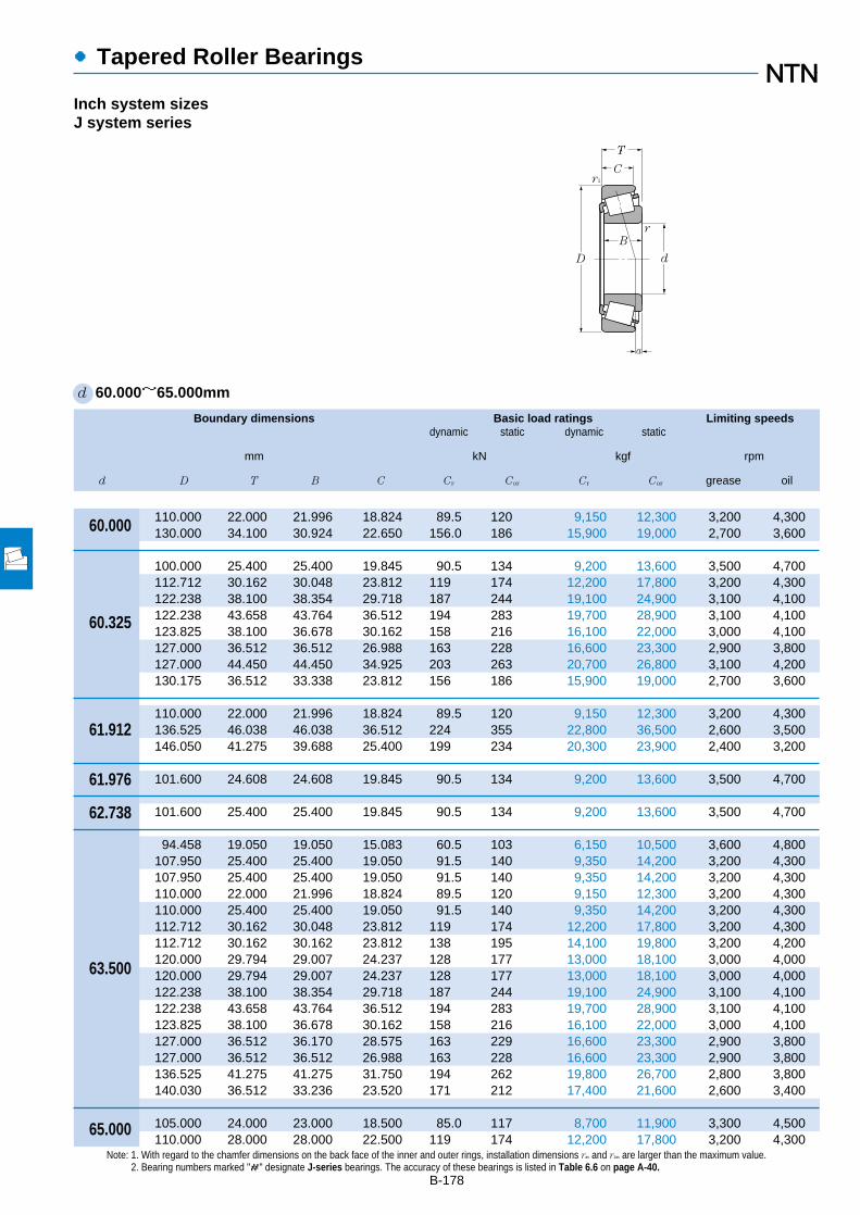
Boundary dimensions Basic load ratings Limiting speedsdynamic static dynamic static
mm kN kgf rpm
d D T B C Cr Cor Cr Cor grease oil
●Tapered Roller Bearings
B-178
Note: 1. With regard to the chamfer dimensions on the back face of the inner and outer rings, installation dimensions ras and r1as are larger than the maximum value.2. Bearing numbers marked "#" designate J-series bearings. The accuracy of these bearings is listed in Table 6.6 on page A-40.
d 60.000~65.000mm
Inch system sizesJ system series
110.000 22.000 21.996 18.824 89.5 120 9,150 12,300 3,200 4,300130.000 34.100 30.924 22.650 156.0 186 15,900 19,000 2,700 3,600
100.000 25.400 25.400 19.845 90.5 134 9,200 13,600 3,500 4,700112.712 30.162 30.048 23.812 119 174 12,200 17,800 3,200 4,300122.238 38.100 38.354 29.718 187 244 19,100 24,900 3,100 4,100122.238 43.658 43.764 36.512 194 283 19,700 28,900 3,100 4,100123.825 38.100 36.678 30.162 158 216 16,100 22,000 3,000 4,100127.000 36.512 36.512 26.988 163 228 16,600 23,300 2,900 3,800127.000 44.450 44.450 34.925 203 263 20,700 26,800 3,100 4,200130.175 36.512 33.338 23.812 156 186 15,900 19,000 2,700 3,600
110.000 22.000 21.996 18.824 89.5 120 9,150 12,300 3,200 4,300136.525 46.038 46.038 36.512 224 355 22,800 36,500 2,600 3,500146.050 41.275 39.688 25.400 199 234 20,300 23,900 2,400 3,200
101.600 24.608 24.608 19.845 90.5 134 9,200 13,600 3,500 4,700
101.600 25.400 25.400 19.845 90.5 134 9,200 13,600 3,500 4,700
94.458 19.050 19.050 15.083 60.5 103 6,150 10,500 3,600 4,800107.950 25.400 25.400 19.050 91.5 140 9,350 14,200 3,200 4,300107.950 25.400 25.400 19.050 91.5 140 9,350 14,200 3,200 4,300110.000 22.000 21.996 18.824 89.5 120 9,150 12,300 3,200 4,300110.000 25.400 25.400 19.050 91.5 140 9,350 14,200 3,200 4,300112.712 30.162 30.048 23.812 119 174 12,200 17,800 3,200 4,300112.712 30.162 30.162 23.812 138 195 14,100 19,800 3,200 4,200120.000 29.794 29.007 24.237 128 177 13,000 18,100 3,000 4,000120.000 29.794 29.007 24.237 128 177 13,000 18,100 3,000 4,000122.238 38.100 38.354 29.718 187 244 19,100 24,900 3,100 4,100122.238 43.658 43.764 36.512 194 283 19,700 28,900 3,100 4,100123.825 38.100 36.678 30.162 158 216 16,100 22,000 3,000 4,100127.000 36.512 36.170 28.575 163 229 16,600 23,300 2,900 3,800127.000 36.512 36.512 26.988 163 228 16,600 23,300 2,900 3,800136.525 41.275 41.275 31.750 194 262 19,800 26,700 2,800 3,800140.030 36.512 33.236 23.520 171 212 17,400 21,600 2,600 3,400
105.000 24.000 23.000 18.500 85.0 117 8,700 11,900 3,300 4,500110.000 28.000 28.000 22.500 119 174 12,200 17,800 3,200 4,300
60.000
60.325
61.912
61.976
62.738
63.500
65.000
T
C
D
B
r1
d
r
a

●Tapered Roller Bearings
Bearing numbers Abutment and fillet dimensions Load Constant Axial Masscenter load factors
mm mm kgras r1as
da db Da Db max max a e Y2 Yo (approx.)
B-179
1 "-" means that load center at outside on end of inner ring.
4T-397/394A 69 68 101 104 0.8 1.3 0.7 0.40 1.49 0.82 0.91#4T-JHM911244/JHM911211 84 74 109 123 3.5 3.3 –7.61 0.82 0.73 0.40 2.01
4T-28985/28921 73 67 89 96 3.5 3.3 2.5 0.43 1.41 0.78 0.7724T-3980/3920 75 68 99 106 3.5 3.3 4.5 0.40 1.49 0.82 1.334T-HM212044/HM212011 85 70 108 116 8 3.3 11.1 0.34 1.78 0.98 2.024T-5583/5535 78 72 106 116 3.5 3.3 13.3 0.36 1.67 0.92 2.444T-558/552A 73 69 109 116 2.3 3.3 9.4 0.35 1.73 0.95 2.14T-HM813841/HM813810 80 73 111 121 3.5 3.3 3.7 0.50 1.20 0.66 2.214T-65237/65500 82 71 107 119 3.5 3.3 9.3 0.49 1.23 0.68 2.654T-HM911245/HM911210 87 74 109 124 5 3.3 –5.21 0.82 0.73 0.40 2.12
4T-392/394A 70 69 101 104 0.8 1.3 0.7 0.40 1.49 0.82 0.8794T-H715334/H715311 86 79 118 132 3.5 3.3 8.7 0.47 1.27 0.70 3.474T-H913842/H913810 90 82 124 138 3.5 3.3 –4.31 0.78 0.77 0.42 3.17
4T-28990/28920 72 68 90 97 2 3.3 1.7 0.43 1.41 0.78 0.768
4T-28995/28920 75 69 90 97 3.5 3.3 2.5 0.43 1.41 0.78 0.764
4T-L610549/L610510 71 69 86 91 1.5 1.5 –0.61 0.42 1.41 0.78 0.4494T-29585/29520 77 71 96 103 3.5 3.3 0.6 0.46 1.31 0.72 0.9244T-29586/29520 73 71 96 103 1.5 3.3 0.6 0.46 1.31 0.72 0.9294T-390A/394A 73 70 101 104 1.5 1.3 0.7 0.40 1.49 0.82 0.8514T-29585/29521 77 71 99 104 3.5 1.3 0.6 0.46 1.31 0.72 0.9824T-3982/3920 77 71 99 106 3.5 3.3 4.5 0.40 1.49 0.82 1.264T-39585/39520 77 71 101 107 3.5 3.3 6.6 0.34 1.77 0.97 1.274T-477/472 73 72 107 114 0.8 2 3.9 0.38 1.56 0.86 1.494T-483/472 78 72 107 114 3.5 2 3.9 0.38 1.56 0.86 1.484T-HM212046/HM212011 80 73 108 116 3.5 3.3 11.1 0.34 1.78 0.98 1.954T-5584/5535 81 75 106 116 3.5 3.3 13.3 0.36 1.67 0.92 2.344T-559/552A 78 72 109 116 3.5 3.3 9.4 0.35 1.73 0.95 2.014T-565/563 80 73 112 120 3.5 3.3 8.3 0.36 1.65 0.91 2.114T-HM813842/HM813810 82 76 111 121 3.5 3.3 3.7 0.50 1.20 0.66 2.124T-639/632 81 74 118 125 3.5 3.3 11.4 0.36 1.66 0.91 2.854T-78250/78551 85 79 117 132 2.3 2.3 –8.51 0.87 0.69 0.38 2.54
#4T-JLM710949/JLM710910 77 71 96 101 3 1 0.3 0.45 1.32 0.73 0.742#4T-JM511946/JM511910 78 72 99 105 3 2.5 3.4 0.40 1.49 0.82 1.08
1 0 0.4 Y2
Fa
Fr
X Y X Y
≦eFa
Fr>e
Pr=XFr+YFa
Por=0.5Fr+YoFa
When Por<Fr use Por=Fr
For values of e, Y2 and Yosee the table below.
Equivalent bearing loaddynamic
static
r1a
ra
da DbDa db

Boundary dimensions Basic load ratings Limiting speedsdynamic static dynamic static
mm kN kgf rpm
d D T B C Cr Cor Cr Cor grease oil
●Tapered Roller Bearings
B-180
Note: 1. With regard to the chamfer dimensions on the back face of the inner and outer rings, installation dimensions ras and r1as are larger than the maximum value.2. Bearing numbers marked "#" designate J-series bearings. The tolerances of these bearings is listed in Table 6.6 on page A-40.
d 65.000~70.000mm
Inch system sizesJ system series
120.000 39.000 38.500 32.000 185 248 18,800 25,300 3,100 4,100
135.755 53.975 56.007 44.450 278 380 28,300 38,500 2,900 3,800
103.213 17.602 17.602 11.989 60.0 78.0 6,100 8,000 3,300 4,400107.950 25.400 25.400 19.050 91.5 140 9,350 14,200 3,200 4,300110.000 22.000 21.996 18.824 89.5 120 9,150 12,300 3,200 4,300112.712 30.162 30.048 23.812 119 174 12,200 17,800 3,200 4,300112.712 30.162 30.048 23.812 119 174 12,200 17,800 3,200 4,300112.712 30.162 30.162 23.812 138 195 14,100 19,800 3,200 4,200122.238 38.100 38.354 29.718 187 244 19,100 24,900 3,100 4,100123.825 38.100 36.678 30.162 158 216 16,100 22,000 3,000 4,100127.000 36.512 36.512 26.988 163 228 16,600 23,300 2,900 3,800130.175 41.275 41.275 31.750 194 262 19,800 26,700 2,800 3,800135.755 53.975 56.007 44.450 278 380 28,300 38,500 2,900 3,800136.525 41.275 41.275 31.750 194 262 19,800 26,700 2,800 3,800136.525 41.275 41.275 31.750 226 293 23,100 29,900 2,700 3,700
110.000 22.000 21.996 18.824 89.5 120 9,150 12,300 3,200 4,300120.000 29.794 29.007 24.237 128 177 13,000 18,100 3,000 4,000123.825 38.100 36.678 30.162 158 216 16,100 22,000 3,000 4,100136.525 41.275 41.275 31.750 226 293 23,100 29,900 2,700 3,700136.525 46.038 46.038 36.512 224 355 22,800 36,500 2,600 3,500
112.712 25.400 25.400 19.050 95.5 151 9,750 15,400 3,100 4,100117.475 30.162 30.162 23.812 117 175 11,900 17,900 3,000 4,000120.000 29.794 29.007 24.237 128 177 13,000 18,100 3,000 4,000120.000 32.545 32.545 26.195 147 214 15,000 21,800 3,000 4,000120.650 25.400 25.400 19.050 95.5 151 9,750 15,400 3,100 4,100127.000 36.512 36.170 28.575 163 229 16,600 23,300 2,900 3,800136.525 41.275 41.275 31.750 194 262 19,800 26,700 2,800 3,800146.050 41.275 41.275 31.750 206 295 21,000 30,000 2,500 3,300150.089 44.450 46.672 36.512 261 360 26,600 37,000 2,400 3,200168.275 53.975 56.363 41.275 340 460 34,500 46,500 2,200 3,000
121.442 24.608 23.012 17.462 91.0 127 9,300 13,000 2,900 3,800
110.000 26.000 25.000 20.500 97.0 150 9,900 15,300 3,200 4,200115.000 29.000 29.000 23.000 124 171 12,700 17,500 3,100 4,100
65.000
65.088
66.675
68.262
69.850
69.952
70.000
T
C
D
B
r1
d
r
a

●Tapered Roller Bearings
Bearing numbers Abutment and fillet dimensions Load Constant Axial Masscenter load factors
mm mm kgras r1as
da db Da Db max max a e Y2 Yo (approx.)
B-181
1 "-" means that load center at outside on end of inner ring.
#4T-JH211749/JH211710 80 74 107 114 3 2.5 10.9 0.34 1.78 0.98 1.90
4T-6379/6320 84 77 117 126 3.5 3.3 18.8 0.32 1.85 1.02 3.71
4T-L812148/L812111 74 72 96 99 1.5 0.8 –3.71 0.49 1.23 0.68 0.484T-29590/29520 80 73 96 103 3.5 3.3 0.6 0.46 1.31 0.72 0.864T-395A/394A 73 73 101 104 0.8 1.3 0.7 0.40 1.49 0.82 0.7964T-3984/3925 80 74 101 106 3.5 0.8 4.5 0.40 1.49 0.82 1.194T-3994/3920 84 74 99 106 5.5 3.3 4.5 0.40 1.49 0.82 1.184T-39590/39520 80 74 101 107 3.5 3.3 6.6 0.34 1.77 0.97 1.194T-HM212049/HM212010 82 75 110 116 3.5 1.5 11.1 0.34 1.78 0.98 1.864T-560/552A 81 75 109 116 3.5 3.3 9.4 0.35 1.73 0.95 1.924T-HM813844/HM813810 85 78 111 121 3.5 3.3 3.7 0.50 1.20 0.66 2.034T-641/633 83 77 116 124 3.5 3.3 11.4 0.36 1.66 0.91 2.414T-6386/6320 87 77 117 126 4.3 3.3 18.8 0.32 1.85 1.02 3.644T-641/632 83 77 118 125 3.5 3.3 11.4 0.36 1.66 0.91 2.744T-H414242/H414210 85 81 121 129 3.5 3.3 11.0 0.36 1.67 0.92 2.75
4T-399A/394A 78 74 101 104 2.3 1.3 0.7 0.40 1.49 0.82 0.7644T-480/472 82 75 107 114 3.5 2 3.9 0.38 1.56 0.86 1.374T-560S/552A 83 76 109 116 3.5 3.3 9.4 0.35 1.73 0.95 1.874T-H414245/H414210 86 82 121 129 3.5 3.3 11.0 0.36 1.67 0.92 2.74T-H715343/H715311 90 84 118 132 3.5 3.3 8.7 0.47 1.27 0.70 3.24
4T-29675/29620 80 77 101 109 1.5 3.3 –0.91 0.49 1.23 0.68 0.9494T-33275/33462 84 77 104 112 3.5 3.3 2.6 0.44 1.38 0.76 1.284T-482/472 83 77 107 114 3.5 2 3.9 0.38 1.56 0.86 1.334T-47487/47420 84 78 107 114 3.5 3.3 6.1 0.36 1.67 0.92 1.474T-29675/29630 80 77 104 113 1.5 3.3 –0.91 0.49 1.23 0.68 1.174T-566/563 85 78 112 120 3.5 3.3 8.3 0.36 1.65 0.91 1.924T-643/632 86 80 118 125 3.5 3.3 11.4 0.36 1.66 0.91 2.634T-655/653 88 82 131 139 3.5 3.3 8.0 0.41 1.47 0.81 3.284T-745A/742 88 82 134 142 3.5 3.3 12.0 0.33 1.84 1.01 3.924T-835/832 91 84 149 155 3.5 3.3 18.5 0.30 2.00 1.10 6.13
4T-34274/34478 81 78 110 116 2 2 –1.21 0.45 1.33 0.73 1.11
#4T-JLM813049/JLM813010 78 77 98 105 1 2.5 –0.31 0.49 1.23 0.68 0.889#4T-JM612949/JM612910 83 77 103 110 3 2.5 2.5 0.43 1.39 0.77 1.13
1 0 0.4 Y2
Fa
Fr
X Y X Y
≦eFa
Fr>e
Pr=XFr+YFa
Por=0.5Fr+YoFa
When Por<Fr use Por=Fr
For values of e, Y2 and Yosee the table below.
Equivalent bearing loaddynamic
static
r1a
ra
da DbDa db

Boundary dimensions Basic load ratings Limiting speedsdynamic static dynamic static
mm kN kgf rpm
d D T B C Cr Cor Cr Cor grease oil
●Tapered Roller Bearings
B-182
Note: 1. With regard to the chamfer dimensions on the back face of the inner and outer rings, installation dimensions ras and r1as are larger than the maximum value.2. Bearing numbers marked "#" designate J-series bearings. The tolerances of these bearings is listed in Table 6.6 on page A-40.
d 70.000~76.200mm
Inch system sizesJ system series
120.000 29.794 29.007 24.237 128 177 13,000 18,100 3,000 4,000150.000 41.275 39.688 25.400 199 234 20,300 23,900 2,400 3,200
117.475 30.162 30.162 23.812 117 175 11,900 17,900 3,000 4,000120.000 32.545 32.545 26.195 147 214 15,000 21,800 3,000 4,000127.000 36.512 36.170 28.575 163 229 16,600 23,300 2,900 3,800136.525 41.275 41.275 31.750 194 262 19,800 26,700 2,800 3,800136.525 41.275 41.275 31.750 226 293 23,100 29,900 2,700 3,700136.525 46.038 46.038 36.512 224 355 22,800 36,500 2,600 3,500
112.712 25.400 25.400 19.050 95.5 151 9,750 15,400 3,100 4,100117.475 30.162 30.162 23.812 117 175 11,900 17,900 3,000 4,000127.000 36.512 36.170 28.575 163 229 16,600 23,300 2,900 3,800139.992 36.512 36.098 28.575 178 265 18,100 27,100 2,600 3,400149.225 53.975 54.229 44.450 287 410 29,300 41,500 2,500 3,400150.089 44.450 46.672 36.512 261 360 26,600 37,000 2,400 3,200
112.712 25.400 25.400 19.050 95.5 151 9,750 15,400 3,100 4,100127.000 36.512 36.170 28.575 163 229 16,600 23,300 2,900 3,800
139.992 36.512 36.098 28.575 178 265 18,100 27,100 2,600 3,400
115.000 25.000 25.000 19.000 94.5 143 9,650 14,600 3,000 4,000120.000 31.000 29.500 25.000 131 197 13,300 20,100 2,900 3,900145.000 51.000 51.000 42.000 287 410 29,300 41,500 2,500 3,400
109.538 19.050 19.050 15.083 63.0 115 6,450 11,700 3,100 4,100121.442 24.608 23.012 17.462 91.0 127 9,300 13,000 2,900 3,800121.442 24.608 23.012 17.462 91.0 127 9,300 13,000 2,900 3,800127.000 30.162 31.000 22.225 135 194 13,800 19,800 2,800 3,700133.350 33.338 33.338 26.195 153 235 15,600 24,000 2,600 3,500133.350 39.688 39.688 32.545 177 305 18,000 31,000 2,600 3,500135.733 44.450 46.100 34.925 211 330 21,600 34,000 2,700 3,500136.525 30.162 29.769 22.225 129 189 13,200 19,300 2,600 3,500139.992 36.512 36.098 28.575 178 265 18,100 27,100 2,600 3,400139.992 36.512 36.098 28.575 178 265 18,100 27,100 2,600 3,400146.050 41.275 41.275 31.750 206 295 21,000 30,000 2,500 3,300149.225 53.975 54.229 44.450 287 410 29,300 41,500 2,500 3,400150.089 44.450 46.672 36.512 261 360 26,600 37,000 2,400 3,200
70.000
71.438
73.025
73.817
74.612
75.000
76.200
T
C
D
B
r1
d
r
a

●Tapered Roller Bearings
Bearing numbers Abutment and fillet dimensions Load Constant Axial Masscenter load factors
mm mm kgras r1as
da db Da Db max max a e Y2 Yo (approx.)
B-183
1 "-" means that load center at outside on end of inner ring.
4T-484/472 80 77 107 114 2 2 3.9 0.38 1.56 0.86 1.33#4T-JH913848/JH913811 92 82 126 146 2 3.3 –4.31 0.78 0.77 0.42 3.08
4T-33281/33462 85 79 104 112 3.5 3.3 2.6 0.44 1.38 0.76 1.244T-47490/47420 86 79 107 114 3.5 3.3 6.1 0.36 1.67 0.92 1.424T-567A/563 86 80 112 120 3.5 3.3 8.3 0.36 1.65 0.91 1.874T-644/632 87 81 118 125 3.5 3.3 11.4 0.36 1.66 0.91 2.574T-H414249/H414210 89 83 121 129 3.5 3.3 11.0 0.36 1.67 0.92 2.584T-H715345/H715311 93 87 118 132 3.5 3.3 8.7 0.47 1.27 0.70 3.11
4T-29685/29620 86 80 101 109 3.5 3.3 –0.91 0.49 1.23 0.68 0.8734T-33287/33462 87 80 104 112 3.5 3.3 2.6 0.44 1.38 0.76 1.194T-567/563 88 81 112 120 3.5 3.3 8.3 0.36 1.65 0.91 1.824T-576/572 90 83 125 133 3.5 3.3 5.5 0.40 1.49 0.82 2.534T-6460/6420 93 87 129 140 3.5 3.3 14.8 0.36 1.66 0.91 4.424T-744/742 91 85 134 142 3.5 3.3 12.0 0.33 1.84 1.01 3.79
4T-29688/29620 83 80 101 109 1.5 3.3 –0.91 0.49 1.23 0.68 0.864T-568/563 83 82 112 120 0.8 3.3 8.3 0.36 1.65 0.91 1.80
4T-577/572 91 85 125 133 3.5 3.3 5.5 0.40 1.49 0.82 2.48
#4T-JLM714149/JLM714110 87 81 104 110 3 2.5 –0.31 0.46 1.31 0.72 0.875#4T-JM714249/JM714210 88 83 108 115 3 2.5 1.9 0.44 1.35 0.74 1.29#4T-JH415647/JH415610 94 89 129 139 3 2.5 14.1 0.36 1.66 0.91 3.81
4T-L814749/L814710 84 82 100 105 1.5 1.5 –5.01 0.50 1.20 0.66 0.5794T-34300/34478 86 83 110 116 2 2 –1.21 0.45 1.33 0.73 0.9824T-34301/34478 89 83 110 116 3.5 2 –1.21 0.45 1.33 0.73 0.9774T-42687/42620 90 84 114 121 3.5 3.3 2.8 0.42 1.43 0.79 1.464T-47678/47620 97 85 119 128 6.4 3.3 3.9 0.40 1.48 0.82 1.924T-HM516442/HM516410 93 87 118 128 3.5 3.3 7.5 0.40 1.49 0.82 2.434T-5760/5735 94 88 119 130 3.5 3.3 11.0 0.41 1.48 0.81 2.754T-495A/493 92 86 122 130 3.5 3.3 0.7 0.44 1.35 0.74 1.834T-575/572 92 86 125 133 3.5 3.3 5.5 0.40 1.49 0.82 2.434T-575S/572 99 86 125 133 6.8 3.3 5.5 0.40 1.49 0.82 2.414T-659/653 93 87 131 139 3.5 3.3 8.0 0.41 1.47 0.81 3.044T-6461A/6420 108 89 129 140 9.7 3.3 14.8 0.36 1.66 0.91 4.234T-748S/742 93 87 134 142 3.5 3.3 12.0 0.33 1.84 1.01 3.66
1 0 0.4 Y2
Fa
Fr
X Y X Y
≦eFa
Fr>e
Pr=XFr+YFa
Por=0.5Fr+YoFa
When Por<Fr use Por=Fr
For values of e, Y2 and Yosee the table below.
Equivalent bearing loaddynamic
static
r1a
ra
da DbDa db
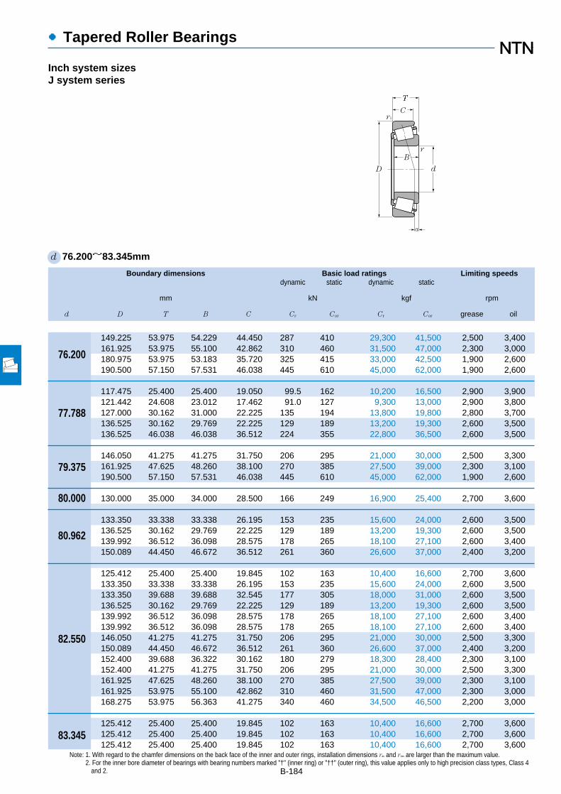
Boundary dimensions Basic load ratings Limiting speedsdynamic static dynamic static
mm kN kgf rpm
d D T B C Cr Cor Cr Cor grease oil
●Tapered Roller Bearings
B-184
d 76.200~83.345mm
Inch system sizesJ system series
149.225 53.975 54.229 44.450 287 410 29,300 41,500 2,500 3,400161.925 53.975 55.100 42.862 310 460 31,500 47,000 2,300 3,000180.975 53.975 53.183 35.720 325 415 33,000 42,500 1,900 2,600190.500 57.150 57.531 46.038 445 610 45,000 62,000 1,900 2,600
117.475 25.400 25.400 19.050 99.5 162 10,200 16,500 2,900 3,900121.442 24.608 23.012 17.462 91.0 127 9,300 13,000 2,900 3,800127.000 30.162 31.000 22.225 135 194 13,800 19,800 2,800 3,700136.525 30.162 29.769 22.225 129 189 13,200 19,300 2,600 3,500136.525 46.038 46.038 36.512 224 355 22,800 36,500 2,600 3,500
146.050 41.275 41.275 31.750 206 295 21,000 30,000 2,500 3,300161.925 47.625 48.260 38.100 270 385 27,500 39,000 2,300 3,100190.500 57.150 57.531 46.038 445 610 45,000 62,000 1,900 2,600
130.000 35.000 34.000 28.500 166 249 16,900 25,400 2,700 3,600
133.350 33.338 33.338 26.195 153 235 15,600 24,000 2,600 3,500136.525 30.162 29.769 22.225 129 189 13,200 19,300 2,600 3,500139.992 36.512 36.098 28.575 178 265 18,100 27,100 2,600 3,400150.089 44.450 46.672 36.512 261 360 26,600 37,000 2,400 3,200
125.412 25.400 25.400 19.845 102 163 10,400 16,600 2,700 3,600133.350 33.338 33.338 26.195 153 235 15,600 24,000 2,600 3,500133.350 39.688 39.688 32.545 177 305 18,000 31,000 2,600 3,500136.525 30.162 29.769 22.225 129 189 13,200 19,300 2,600 3,500139.992 36.512 36.098 28.575 178 265 18,100 27,100 2,600 3,400139.992 36.512 36.098 28.575 178 265 18,100 27,100 2,600 3,400146.050 41.275 41.275 31.750 206 295 21,000 30,000 2,500 3,300150.089 44.450 46.672 36.512 261 360 26,600 37,000 2,400 3,200152.400 39.688 36.322 30.162 180 279 18,300 28,400 2,300 3,100152.400 41.275 41.275 31.750 206 295 21,000 30,000 2,500 3,300161.925 47.625 48.260 38.100 270 385 27,500 39,000 2,300 3,100161.925 53.975 55.100 42.862 310 460 31,500 47,000 2,300 3,000168.275 53.975 56.363 41.275 340 460 34,500 46,500 2,200 3,000
125.412 25.400 25.400 19.845 102 163 10,400 16,600 2,700 3,600125.412 25.400 25.400 19.845 102 163 10,400 16,600 2,700 3,600125.412 25.400 25.400 19.845 102 163 10,400 16,600 2,700 3,600
76.200
77.788
79.375
80.000
80.962
82.550
83.345
T
C
D
B
r1
d
r
a
Note: 1. With regard to the chamfer dimensions on the back face of the inner and outer rings, installation dimensions ras and r1as are larger than the maximum value.2. For the inner bore diameter of bearings with bearing numbers marked "†" (inner ring) or "††" (outer ring), this value applies only to high precision class types, Class 4
and 2.

●Tapered Roller Bearings
Bearing numbers Abutment and fillet dimensions Load Constant Axial Masscenter load factors
mm mm kgras r1as
da db Da Db max max a e Y2 Yo (approx.)
B-185
Note: 3. Bearing numbers marked "#" designate J-series bearings. The tolerances of these bearings is listed in Table 6.6 on page A-40.1 "-" means that load center at outside on end of inner ring.
4T-6461/6420 96 89 129 140 3.5 3.3 14.8 0.36 1.66 0.91 4.264T-6576/6535 99 92 141 154 3.5 3.3 12.8 0.40 1.50 0.82 5.444T-H917840/H917810†† 110 100 152 170 3.5 3.3 –0.51 0.73 0.82 0.45 6.574T-HH221430/HH221410 101 95 171 179 3.5 3.3 14.4 0.33 1.79 0.99 8.69
4T-LM814849/LM814810 91 85 105 113 3.5 3.3 –2.31 0.51 1.18 0.65 0.9324T-34306/34478 90 84 110 116 3.5 2 –1.21 0.45 1.33 0.73 0.9434T-42690/42620 91 85 114 121 3.5 3.3 2.8 0.42 1.43 0.79 1.414T-495AS/493 93 87 122 130 3.5 3.3 0.7 0.44 1.35 0.74 1.784T-H715348/H715311 98 88 118 132 3.5 3.3 8.7 0.47 1.27 0.70 2.84
4T-661/653 96 90 131 139 3.5 3.3 8.0 0.41 1.47 0.81 2.914T-756A/752 106 91 144 150 8 3.3 12.0 0.34 1.76 0.97 4.554T-HH221431/HH221410 103 97 171 179 3.5 3.3 14.4 0.33 1.79 0.99 8.52
#4T-JM515649/JM515610 94 88 117 125 3 2.5 4.9 0.39 1.54 0.85 1.73
4T-47681/47620 95 89 119 128 3.5 3.3 3.9 0.40 1.48 0.82 1.784T-496/493 95 89 122 130 3.5 3.3 0.7 0.44 1.35 0.74 1.694T-581/572 96 90 125 133 3.5 3.3 5.5 0.40 1.49 0.82 2.264T-740/742 101 91 134 142 5 3.3 12.0 0.33 1.84 1.01 3.43
4T-27687/27620 96 89 115 120 3.5 1.5 –0.61 0.42 1.44 0.79 1.074T-47686/47620 97 90 119 128 3.5 3.3 3.9 0.40 1.48 0.82 1.724T-HM516448/HM516410 105 92 118 128 6.8 3.3 7.5 0.40 1.49 0.82 2.164T-495/493 97 90 122 130 3.5 3.3 0.7 0.44 1.35 0.74 1.644T-580/572 98 91 125 133 3.5 3.3 5.5 0.40 1.49 0.82 2.24T-582/572 104 91 125 133 6.8 3.3 5.5 0.40 1.49 0.82 2.194T-663/653 99 92 131 139 3.5 3.3 8.0 0.41 1.47 0.81 2.784T-749A/742 99 93 134 142 3.5 3.3 12.0 0.33 1.84 1.01 3.374T-595/592A 100 93 135 144 3.5 3.3 2.6 0.44 1.36 0.75 3.024T-663/652 99 92 134 141 3.5 3.3 8.0 0.41 1.47 0.81 3.154T-757/752 100 94 144 150 3.5 3.3 12.0 0.34 1.76 0.97 4.424T-6559C/6535 104 98 141 154 3.5 3.3 12.8 0.40 1.50 0.82 5.094T-842/832 101 94 149 155 3.5 3.3 18.5 0.30 2.00 1.10 5.46
4T-27689/27620 90 90 115 120 0.8 1.5 –0.61 0.42 1.44 0.79 1.064T-27690/27620 96 90 115 120 3.5 1.5 –0.61 0.42 1.44 0.79 1.054T-27691/27620 102 90 115 120 6.4 1.5 –0.61 0.42 1.44 0.79 1.04
1 0 0.4 Y2
Fa
Fr
X Y X Y
≦eFa
Fr>e
Pr=XFr+YFa
Por=0.5Fr+YoFa
When Por<Fr use Por=Fr
For values of e, Y2 and Yosee the table below.
Equivalent bearing loaddynamic
static
r1a
ra
da DbDa db
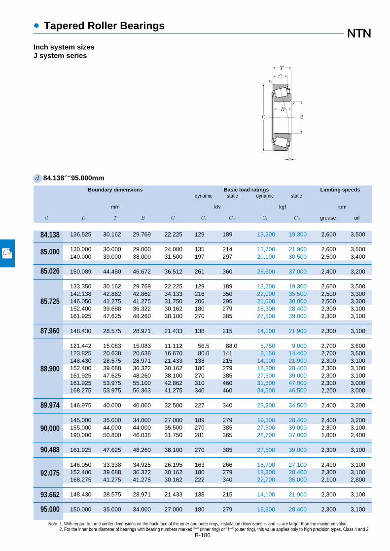
Boundary dimensions Basic load ratings Limiting speedsdynamic static dynamic static
mm kN kgf rpm
d D T B C Cr Cor Cr Cor grease oil
●Tapered Roller Bearings
B-186
Note: 1. With regard to the chamfer dimensions on the back face of the inner and outer rings, installation dimensions ras and r1as are larger than the maximum value.2. For the inner bore diameter of bearings with bearing numbers marked "†" (inner ring) or "††" (outer ring), this value applies only to high precision types, Class 4 and 2.
d 84.138~95.000mm
Inch system sizesJ system series
136.525 30.162 29.769 22.225 129 189 13,200 19,300 2,600 3,500
130.000 30.000 29.000 24.000 135 214 13,700 21,900 2,600 3,500140.000 39.000 38.000 31.500 197 297 20,100 30,500 2,500 3,400
150.089 44.450 46.672 36.512 261 360 26,600 37,000 2,400 3,200
133.350 30.162 29.769 22.225 129 189 13,200 19,300 2,600 3,500142.138 42.862 42.862 34.133 216 350 22,000 35,500 2,500 3,300146.050 41.275 41.275 31.750 206 295 21,000 30,000 2,500 3,300152.400 39.688 36.322 30.162 180 279 18,300 28,400 2,300 3,100161.925 47.625 48.260 38.100 270 385 27,500 39,000 2,300 3,100
148.430 28.575 28.971 21.433 138 215 14,100 21,900 2,300 3,100
121.442 15.083 15.083 11.112 56.5 88.0 5,750 9,000 2,700 3,600123.825 20.638 20.638 16.670 80.0 141 8,150 14,400 2,700 3,500148.430 28.575 28.971 21.433 138 215 14,100 21,900 2,300 3,100152.400 39.688 36.322 30.162 180 279 18,300 28,400 2,300 3,100161.925 47.625 48.260 38.100 270 385 27,500 39,000 2,300 3,100161.925 53.975 55.100 42.862 310 460 31,500 47,000 2,300 3,000168.275 53.975 56.363 41.275 340 460 34,500 46,500 2,200 3,000
146.975 40.000 40.000 32.500 227 340 23,200 34,500 2,400 3,200
145.000 35.000 34.000 27.000 189 279 19,300 28,400 2,400 3,200155.000 44.000 44.000 35.500 270 385 27,500 39,000 2,300 3,100190.000 50.800 46.038 31.750 281 365 28,700 37,000 1,800 2,400
161.925 47.625 48.260 38.100 270 385 27,500 39,000 2,300 3,100
146.050 33.338 34.925 26.195 163 266 16,700 27,100 2,400 3,100152.400 39.688 36.322 30.162 180 279 18,300 28,400 2,300 3,100168.275 41.275 41.275 30.162 222 340 22,700 35,000 2,100 2,800
148.430 28.575 28.971 21.433 138 215 14,100 21,900 2,300 3,100
150.000 35.000 34.000 27.000 180 279 18,300 28,400 2,300 3,100
84.138
85.000
85.026
85.725
87.960
88.900
89.974
90.000
90.488
92.075
93.662
95.000
T
C
D
B
r1
d
r
a

●Tapered Roller Bearings
Bearing numbers Abutment and fillet dimensions Load Constant Axial Masscenter load factors
mm mm kgras r1as
da db Da Db max max a e Y2 Yo (approx.)
B-187
Note: 3. Bearing numbers marked "#" designate J-series bearings. The tolerances of these bearings is listed in Table 6.6 on page A-40.1 "-" means that load center at outside on end of inner ring.
4T-498/493 98 91 122 130 3.5 3.3 0.7 0.44 1.35 0.74 1.6
#4T-JM716648/JM716610 104 92 117 125 6 2.5 0.2 0.44 1.35 0.74 1.37#4T-JHM516849/JHM516810 100 94 125 134 3 2.5 5.9 0.41 1.47 0.81 2.3
4T-749/742 101 95 134 142 3.5 3.3 12.0 0.33 1.84 1.01 3.25
4T-497/492A 99 93 120 128 3.5 3.3 0.7 0.44 1.35 0.74 1.434T-HM617049/HM617010 106 95 125 137 4.8 3.3 6.9 0.43 1.39 0.76 2.694T-665/653 102 95 131 139 3.5 3.3 8.0 0.41 1.47 0.81 2.654T-596/592A 102 96 135 144 3.5 3.3 2.6 0.44 1.36 0.75 2.94T-758/752 103 97 144 150 3.5 3.3 12.0 0.34 1.76 0.97 4.26
4T-42346/42584 103 98 134 142 3 3 –3.01 0.49 1.22 0.67 1.99
4T-LL217849/LL217810 97 94 115 117 1.5 1.5 –2.91 0.33 1.81 1.00 0.4524T-L217849/L217810 97 94 116 119 1.5 1.5 –0.71 0.33 1.82 1.00 0.7374T-42350/42584 104 98 134 142 3 3 –3.01 0.49 1.22 0.67 1.964T-593/592A 104 98 135 144 3.5 3.3 2.6 0.44 1.36 0.75 2.784T-759/752 106 99 144 150 3.5 3.3 12.0 0.34 1.76 0.97 4.094T-6580/6535 109 102 141 154 3.5 3.3 12.8 0.40 1.50 0.82 4.734T-850/832 106 100 149 155 3.5 3.3 18.5 0.30 2.00 1.10 5.08
4T-HM218248†/HM218210†† 112 99 133 141 7 3.5 8.6 0.33 1.80 0.99 2.55
#4T-JM718149/JM718110 105 99 131 139 3 2.5 2.0 0.44 1.35 0.74 2.14#4T-JHM318448/JHM318410 106 100 140 148 3 2.5 10.1 0.34 1.76 0.97 3.32#4T-J90354/J90748 120 112 162 179 3.5 3.3 –12.91 0.87 0.69 0.38 6.32
4T-760/752 107 101 144 150 3.5 3.3 12.0 0.34 1.76 0.97 4.01
4T-47890/47820 107 101 131 140 3.5 3.3 0.6 0.45 1.34 0.74 2.084T-598A/592A 113 101 135 144 6.4 3.3 2.6 0.44 1.36 0.75 2.634T-681/672 110 104 149 160 3.5 3.3 3.0 0.47 1.28 0.70 3.87
4T-42368/42584 107 102 134 142 3 3 –3.01 0.49 1.22 0.67 1.8
#4T-JM719149/JM719113 109 104 135 143 3 2.5 1.7 0.44 1.36 0.75 2.19
1 0 0.4 Y2
Fa
Fr
X Y X Y
≦eFa
Fr>e
Pr=XFr+YFa
Por=0.5Fr+YoFa
When Por<Fr use Por=Fr
For values of e, Y2 and Yosee the table below.
Equivalent bearing loaddynamic
static
r1a
ra
da DbDa db

Boundary dimensions Basic load ratings Limiting speedsdynamic static dynamic static
mm kN kgf rpm
d D T B C Cr Cor Cr Cor grease oil
●Tapered Roller Bearings
B-188
Note: 1. With regard to the chamfer dimensions on the back face of the inner and outer rings, installation dimensions ras and r1as are larger than the maximum value.2. For the inner bore diameter of bearings with bearing numbers marked "†" (inner ring) or "††" (outer ring), this value applies only to high precision class types, Class 4
and 2.
d 95.250~
109.538mm
Inch system sizesJ system series
130.175 20.638 21.433 16.670 81.0 147 8,300 15,000 2,500 3,300146.050 33.338 34.925 26.195 163 266 16,700 27,100 2,400 3,100147.638 35.717 36.322 26.192 180 279 18,300 28,400 2,300 3,100148.430 28.575 28.971 21.433 138 215 14,100 21,900 2,300 3,100152.400 39.688 36.322 30.162 180 279 18,300 28,400 2,300 3,100157.162 36.512 36.116 26.195 188 305 19,200 31,000 2,200 2,900168.275 41.275 41.275 30.162 222 340 22,700 35,000 2,100 2,800190.500 57.150 57.531 46.038 445 610 45,000 62,000 1,900 2,600
148.430 28.575 28.971 21.433 138 215 14,100 21,900 2,300 3,100188.912 50.800 46.038 31.750 281 365 28,700 37,000 1,800 2,400
157.162 36.512 36.116 26.195 188 305 19,200 31,000 2,200 2,900168.275 41.275 41.275 30.162 222 340 22,700 35,000 2,100 2,800
212.725 66.675 66.675 53.975 575 810 58,500 82,500 1,700 2,300
155.000 36.000 35.000 28.000 192 310 19,600 31,500 2,200 2,900
157.162 36.512 36.116 26.195 188 305 19,200 31,000 2,200 2,900
157.162 36.512 36.116 26.195 188 305 19,200 31,000 2,200 2,900168.275 41.275 41.275 30.162 222 340 22,700 35,000 2,100 2,800180.975 47.625 48.006 38.100 285 430 29,100 44,000 2,000 2,700190.500 57.150 57.531 44.450 380 555 38,500 56,500 2,000 2,600190.500 57.150 57.531 46.038 445 610 45,000 62,000 1,900 2,600190.500 57.150 57.531 46.038 445 610 45,000 62,000 1,900 2,600212.725 66.675 66.675 53.975 475 695 48,500 71,000 1,800 2,300212.725 66.675 66.675 53.975 575 810 58,500 82,500 1,700 2,300
180.975 47.625 48.006 38.100 285 430 29,100 44,000 2,000 2,700
158.750 23.020 21.438 15.875 102 166 10,400 17,000 2,100 2,800159.987 34.925 34.925 26.988 167 320 17,100 33,000 2,100 2,800165.100 36.512 36.512 26.988 191 315 19,500 32,000 2,100 2,700212.725 66.675 66.675 53.975 475 695 48,500 71,000 1,800 2,300
158.750 23.020 21.438 15.875 102 166 10,400 17,000 2,100 2,800
95.250
96.838
98.425
99.974
100.000
100.012
101.600
104.775
107.950
109.538
T
C
D
B
r1
d
r
a

●Tapered Roller Bearings
Bearing numbers Abutment and fillet dimensions Load Constant Axial Masscenter load factors
mm mm kgras r1as
da db Da Db max max a e Y2 Yo (approx.)
B-189
Note: 3. Bearing numbers marked "#" designate J-series bearings. The tolerances of these bearings is listed in Table 6.6 on page A-40.1 "-" means that load center at outside on end of inner ring.
4T-L319249/L319210 103 101 122 125 1.5 1.5 –1.01 0.35 1.72 0.95 0.7894T-47896/47820 110 103 131 140 3.5 3.3 0.6 0.45 1.34 0.74 1.954T-594A/592XE 113 104 135 142 5 0.8 2.6 0.44 1.36 0.75 2.094T-42375/42584 108 103 134 142 3 3 –3.01 0.49 1.22 0.67 1.754T-594/592A 110 104 135 144 3.5 3.3 2.6 0.44 1.36 0.75 2.514T-52375/52618 112 105 142 152 3.5 3.3 0.6 0.47 1.26 0.69 2.764T-683/672 113 106 149 160 3.5 3.3 3.0 0.47 1.28 0.70 3.724T-HH221440/HH221410 125 110 171 179 8 3.3 14.4 0.33 1.79 0.99 7.5
4T-42381/42584 110 104 134 142 3.5 3 –3.01 0.49 1.22 0.67 1.694T-90381/90744 125 113 161 179 3.5 3.3 –12.91 0.87 0.69 0.38 5.67
4T-52387/52618 114 108 142 152 3.5 3.3 0.6 0.47 1.26 0.69 2.624T-685/672 116 109 149 160 3.5 3.3 3.0 0.47 1.28 0.70 3.56
4T-HH224334†/HH224310 124 120 192 202 3.5 3.3 18.9 0.33 1.84 1.01 11.5
#4T-JM720249/JM720210 115 109 140 149 3 2.5 –0.31 0.47 1.27 0.70 2.4
4T-52393/52618 116 109 142 152 3.5 3.3 0.6 0.47 1.26 0.69 2.55
4T-52400/52618 117 111 142 152 3.5 3.3 0.6 0.47 1.26 0.69 2.484T-687/672 118 112 149 160 3.5 3.3 3.0 0.47 1.28 0.70 3.44T-780/772†† 119 113 161 168 3.5 3.3 8.1 0.39 1.56 0.86 5.114T-861/854 129 114 170 174 8 3.3 15.3 0.33 1.79 0.99 74T-HH221449/HH221410 131 116 171 179 8 3.3 14.4 0.33 1.79 0.99 7.064T-HH221449A/HH221410 122 116 171 179 3.5 3.3 14.4 0.33 1.79 0.99 7.064T-941/932 130 117 187 193 7 3.3 19.7 0.33 1.84 1.01 11.24T-HH224335/HH224310 132 121 192 202 7 3.3 18.9 0.33 1.84 1.01 11.3
4T-782/772†† 122 116 161 168 3.5 3.3 8.1 0.39 1.56 0.86 4.92
4T-37425/37625 122 115 143 152 3.5 3.3 –14.01 0.61 0.99 0.54 1.374T-LM522546/LM522510 122 116 146 154 3.5 3.3 1.4 0.40 1.49 0.82 2.374T-56425/56650 123 117 149 159 3.5 3.3 –2.01 0.50 1.21 0.66 2.694T-936/932 137 122 187 193 8 3.3 19.7 0.33 1.84 1.01 10.7
4T-37431/37625 123 116 143 152 3.5 3.3 –14.01 0.61 0.99 0.54 1.33
1 0 0.4 Y2
Fa
Fr
X Y X Y
≦eFa
Fr>e
Pr=XFr+YFa
Por=0.5Fr+YoFa
When Por<Fr use Por=Fr
For values of e, Y2 and Yosee the table below.
Equivalent bearing loaddynamic
static
r1a
ra
da DbDa db

Boundary dimensions Basic load ratings Limiting speedsdynamic static dynamic static
mm kN kgf rpm
d D T B C Cr Cor Cr Cor grease oil
●Tapered Roller Bearings
B-190
Note: 1. With regard to the chamfer dimensions on the back face of the inner and outer rings, installation dimensions ras and r1as are larger than the maximum value.2. For the inner bore diameter of bearings with bearing numbers marked "†" (inner ring) or "††" (outer ring), this value applies only to high precision types, Class 4 and 2.
d 109.987~133.350mm
Inch system sizesJ system series
159.987 34.925 34.925 26.988 167 320 17,100 33,000 2,100 2,800
177.800 41.275 41.275 30.162 232 375 23,600 38,000 1,900 2,600
165.000 35.000 35.000 26.500 191 315 19,500 32,000 2,100 2,700180.000 47.000 46.000 38.000 305 480 31,000 49,000 1,900 2,600
214.312 55.562 52.388 39.688 405 560 41,500 57,000 1,500 2,000
177.800 41.275 41.275 30.162 232 375 23,600 38,000 1,900 2,600180.975 34.925 31.750 25.400 169 245 17,200 25,000 1,900 2,500212.725 66.675 66.675 53.975 475 695 48,500 71,000 1,800 2,300212.725 66.675 66.675 53.975 575 810 58,500 82,500 1,700 2,300228.600 53.975 49.428 38.100 430 620 44,000 63,500 1,400 1,900
190.500 47.625 49.212 34.925 300 475 30,500 48,500 1,800 2,500
180.975 34.925 31.750 25.400 169 245 17,200 25,000 1,900 2,500
170.000 25.400 25.400 19.050 127 210 13,000 21,400 2,000 2,600
234.950 63.500 63.500 49.212 525 825 53,500 84,000 1,500 2,000
182.562 39.688 38.100 33.338 224 435 22,900 44,000 1,800 2,400
182.562 39.688 38.100 33.338 224 435 22,900 44,000 1,800 2,400196.850 46.038 46.038 38.100 310 550 31,500 56,500 1,700 2,200215.900 47.625 47.625 34.925 320 540 32,500 55,000 1,600 2,100228.600 53.975 49.428 38.100 320 445 32,500 45,000 1,400 1,900228.600 53.975 49.428 38.100 430 620 44,000 63,500 1,400 1,900230.000 63.500 63.500 49.212 525 825 53,500 84,000 1,500 2,000254.000 77.788 82.550 61.912 740 1,070 75,500 109,000 1,400 1,900
206.375 47.625 47.625 34.925 315 520 32,000 53,000 1,700 2,200
196.850 46.038 46.038 38.100 310 550 31,500 56,500 1,700 2,200206.375 47.625 47.625 34.925 315 520 32,000 53,000 1,700 2,200
177.008 25.400 26.195 20.638 126 259 12,900 26,400 1,800 2,400
109.987
109.992
110.000
111.125
114.300
115.087
117.475
120.000
120.650
123.825
127.000
128.588
130.175
133.350
T
C
D
B
r1
d
r
a

●Tapered Roller Bearings
Bearing numbers Abutment and fillet dimensions Load Constant Axial Masscenter load factors
mm mm kgras r1as
da db Da Db max max a e Y2 Yo (approx.)
B-191
Note: 3. Bearing numbers marked "#" designate J-series bearings. The tolerances of these bearings is listed in Table 6.6 on page A-40.1 "-" means that load center at outside on end of inner ring.
4T-LM522548/LM522510 133 118 146 154 8 3.3 1.4 0.40 1.49 0.82 2.24
4T-64433/64700 128 121 160 172 3.5 3.3 –1.11 0.52 1.16 0.64 3.77
#4T-JM822049/JM822010 124 119 149 159 3 2.5 –3.01 0.50 1.21 0.66 2.52#4T-JHM522649/JHM522610 127 122 162 172 3 2.5 6.0 0.41 1.48 0.81 4.61
4T-H924045/H924010 139 131 186 205 3.5 3.3 –6.81 0.67 0.89 0.49 8.18
4T-64450/64700 131 125 160 172 3.5 3.3 –1.11 0.52 1.16 0.64 3.524T-68450/68712†† 130 123 163 172 3.5 3.3 –5.41 0.50 1.21 0.66 2.934T-938/932 141 128 187 193 7 3.3 19.7 0.33 1.84 1.01 10.14T-HH224346/HH224310 143 131 192 202 7 3.3 18.9 0.33 1.84 1.01 10.24T-HM926740/HM926710 146 142 200 219 3.5 3.3 –13.51 0.74 0.81 0.45 9.76
4T-71453/71750 133 126 171 181 3.5 3.3 6.7 0.42 1.44 0.79 5.11
4T-68462/68712†† 132 125 163 172 3.5 3.3 –5.41 0.50 1.21 0.66 2.78
#4T-JL724348/JL724314 132 127 156 163 3.3 3.3 –7.91 0.46 1.31 0.72 1.67
4T-95475/95925 149 137 209 217 6.4 3.3 14.0 0.37 1.62 0.89 12.6
4T-48286/48220 139 133 168 176 3.5 3.3 5.7 0.31 1.97 1.08 3.52
4T-48290/48220 141 135 168 176 3.5 3.3 5.7 0.31 1.97 1.08 3.334T-67388/67322 144 138 180 189 3.5 3.3 6.3 0.34 1.74 0.96 5.14T-74500/74850 148 141 196 208 3.5 3.3 –2.21 0.49 1.23 0.68 7.054T-97500/97900 151 144 197 213 3.5 3.3 –13.41 0.74 0.81 0.45 8.434T-HM926747/HM926710 156 143 200 219 3.5 3.3 –13.51 0.74 0.81 0.45 8.834T-95500/95905 154 142 207 217 6.4 3.3 14.0 0.37 1.62 0.89 12.94T-HH228349/HH228310 164 148 223 234 9.7 6.4 23.4 0.32 1.87 1.03 19.5
4T-799/792 146 140 186 198 3.3 3.3 1.9 0.46 1.31 0.72 5.77
4T-67389/67322 146 141 180 189 3.5 3.3 6.3 0.34 1.74 0.96 4.874T-799A/792 148 142 186 198 3.5 3.3 1.9 0.46 1.31 0.72 5.65
4T-L327249/L327210 142 140 167 171 1.5 1.5 –3.71 0.35 1.72 0.95 1.7
1 0 0.4 Y2
Fa
Fr
X Y X Y
≦eFa
Fr>e
Pr=XFr+YFa
Por=0.5Fr+YoFa
When Por<Fr use Por=Fr
For values of e, Y2 and Yosee the table below.
Equivalent bearing loaddynamic
static
r1a
ra
da DbDa db
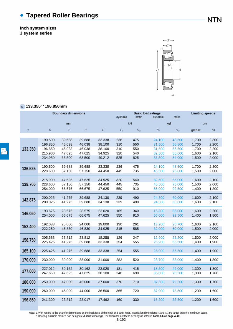
Boundary dimensions Basic load ratings Limiting speedsdynamic static dynamic static
mm kN kgf rpm
d D T B C Cr Cor Cr Cor grease oil
●Tapered Roller Bearings
B-192
Note: 1. With regard to the chamfer dimensions on the back face of the inner and outer rings, installation dimensions ras and r1as are larger than the maximum value.2. Bearing numbers marked "#" designate J-series bearings. The tolerances of these bearings is listed in Table 6.6 on page A-40.
d 133.350~196.850mm
Inch system sizesJ system series
190.500 39.688 39.688 33.338 236 475 24,100 48,500 1,700 2,300196.850 46.038 46.038 38.100 310 550 31,500 56,500 1,700 2,200196.850 46.038 46.038 38.100 310 550 31,500 56,500 1,700 2,200215.900 47.625 47.625 34.925 320 540 32,500 55,000 1,600 2,100234.950 63.500 63.500 49.212 525 825 53,500 84,000 1,500 2,000
190.500 39.688 39.688 33.338 236 475 24,100 48,500 1,700 2,300228.600 57.150 57.150 44.450 445 735 45,500 75,000 1,500 2,000
215.900 47.625 47.625 34.925 320 540 32,500 55,000 1,600 2,100228.600 57.150 57.150 44.450 445 735 45,500 75,000 1,500 2,000254.000 66.675 66.675 47.625 550 910 56,000 92,500 1,400 1,800
200.025 41.275 39.688 34.130 239 490 24,300 50,000 1,600 2,100200.025 41.275 39.688 34.130 239 490 24,300 50,000 1,600 2,100
193.675 28.575 28.575 23.020 165 340 16,800 35,000 1,600 2,200254.000 66.675 66.675 47.625 550 910 56,000 92,500 1,400 1,800
192.088 25.000 24.000 19.000 130 261 13,200 26,700 1,600 2,100222.250 46.830 46.830 34.925 315 585 32,000 60,000 1,500 2,000
205.583 23.812 23.812 18.258 126 247 12,900 25,200 1,500 2,000225.425 41.275 39.688 33.338 254 555 25,900 56,500 1,400 1,900
225.425 41.275 39.688 33.338 254 555 25,900 56,500 1,400 1,900
230.000 39.000 38.000 31.000 282 520 28,700 53,000 1,400 1,800
227.012 30.162 30.162 23.020 181 415 18,500 42,000 1,300 1,800247.650 47.625 47.625 38.100 340 690 35,000 70,500 1,300 1,700
250.000 47.000 45.000 37.000 370 710 37,500 72,500 1,300 1,700
260.000 46.000 44.000 36.500 365 720 37,000 73,500 1,200 1,600
241.300 23.812 23.017 17.462 160 330 16,300 33,500 1,200 1,600
133.350
136.525
139.700
142.875
146.050
152.400
158.750
165.100
170.000
177.800
180.000
190.000
196.850
T
C
D
B
r1
d
r
a

●Tapered Roller Bearings
Bearing numbers Abutment and fillet dimensions Load Constant Axial Masscenter load factors
mm mm kgras r1as
da db Da Db max max a e Y2 Yo (approx.)
B-193
1 "-" means that load center at outside on end of inner ring.
4T-48385/48320 148 142 177 184 3.5 3.3 4.0 0.32 1.87 1.03 3.644T-67390/67322 149 143 180 189 3.5 3.3 6.3 0.34 1.74 0.96 4.634T-67391/67322 157 143 180 189 8 3.3 6.3 0.34 1.74 0.96 4.594T-74525/74850 152 146 196 208 3.5 3.3 –2.21 0.49 1.23 0.68 6.564T-95525/95925 166 148 209 217 9.7 3.3 14.0 0.37 1.62 0.89 11.3
4T-48393/48320 151 144 177 184 3.5 3.3 4.0 0.32 1.87 1.03 3.434T-896/892 156 150 205 216 3.5 3.3 6.0 0.42 1.43 0.78 9.07
4T-74550/74850 158 151 196 208 3.5 3.3 –2.21 0.49 1.23 0.68 6.054T-898/892 160 153 205 216 3.5 3.3 6.0 0.42 1.43 0.78 8.764T-99550/99100 170 156 227 238 7 3.3 12.1 0.41 1.47 0.81 14.3
4T-48684/48620 166 151 185 193 8 3.3 3.1 0.34 1.78 0.98 3.854T-48685/48620 158 151 185 193 3.5 3.3 3.1 0.34 1.78 0.98 3.89
4T-36690/36620 155 153 182 188 1.5 1.5 –5.01 0.37 1.63 0.90 2.274T-99575/99100 175 162 227 238 7 3.3 12.1 0.41 1.47 0.81 13.5
4T-L630349/L630310 162 158 183 187 2 2 –10.01 0.42 1.44 0.79 1.534T-M231648/M231610 178 163 207 213 8 1.5 5.9 0.33 1.8 0.99 5.72
4T-L432349/L432310 168 166 195 199 1.5 1.5 –9.81 0.37 1.61 0.88 1.894T-46780/46720 176 169 209 218 3.5 3.3 –2.61 0.38 1.57 0.86 5.2
4T-46790/46720 181 174 209 218 3.5 3.3 –2.61 0.38 1.57 0.86 4.69
#4T-JHM534149/JHM534110 184 178 217 224 3 2.5 –4.71 0.38 1.57 0.86 4.37
4T-36990/36920 188 186 214 221 1.5 1.5 –12.81 0.44 1.36 0.75 2.924T-67790/67720 194 188 229 240 3.5 3.3 –4.81 0.44 1.36 0.75 6.57
#4T-JM736149/JM736110 196 190 232 243 3 2.5 –9.01 0.48 1.25 0.69 6.76
#4T-JM738249/JM738210 206 200 242 252 3 2.5 –10.91 0.48 1.26 0.69 6.85
4T-LL639249/LL639210 205 203 232 236 1.5 1.5 –17.31 0.42 1.44 0.79 2.07
1 0 0.4 Y2
Fa
Fr
X Y X Y
≦eFa
Fr>e
Pr=XFr+YFa
Por=0.5Fr+YoFa
When Por<Fr use Por=Fr
For values of e, Y2 and Yosee the table below.
Equivalent bearing loaddynamic
static
r1a
ra
da DbDa db

Boundary dimensions Basic load ratings Limiting speedsdynamic static dynamic static
mm kN kgf rpm
d D B1 C rs min1
r1s min1
Cr Cor Cr Cor grease oil
●Multi-Row Tapered Roller Bearings
B-1941 Minimum allowable dimension for chamfer dimension r or r1.
d 40~70mm
Outward facing type
40
45
50
55
60
65
70
80 45 37.5 1.5 0.6 105 134 10,700 13,700 4,100 5,50080 55 43.5 1.5 0.6 136 187 13,900 19,100 4,100 5,50090 56 39.5 2 0.6 132 171 13,500 17,400 3,200 4,20090 56 45.5 2 0.6 157 204 16,000 20,800 3,700 4,900
85 47 37.5 1.5 0.6 116 157 11,800 16,000 3,700 4,90085 55 43.5 1.5 0.6 141 200 14,300 20,400 3,700 4,900
100 60 41.5 2 0.6 165 218 16,800 22,200 2,800 3,800100 60 49.5 2 0.6 191 251 19,500 25,600 3,300 4,400
90 49 39.5 1.5 0.6 132 186 13,500 18,900 3,400 4,50090 55 43.5 1.5 0.6 150 218 15,300 22,200 3,400 4,500
110 64 43.5 2.5 0.6 194 260 19,800 26,600 2,600 3,500110 64 51.5 2.5 0.6 227 305 23,200 31,000 3,000 4,000110 90 71.5 2.5 0.6 315 465 32,000 47,500 3,000 4,000
100 51 41.5 2 0.6 160 221 16,300 22,600 3,100 4,100100 60 48.5 2 0.6 186 269 18,900 27,400 3,100 4,100120 70 49 2.5 0.6 226 305 23,100 31,500 2,400 3,100120 70 57 2.5 0.6 266 360 27,100 36,500 2,700 3,700120 97 76 2.5 0.6 370 550 37,500 56,000 2,700 3,700
110 53 43.5 2 0.6 180 249 18,300 25,400 2,800 3,800110 66 54.5 2 0.6 223 330 22,700 33,500 2,800 3,800130 74 51 3 1 258 350 26,300 36,000 2,200 2,900130 74 59 3 1 310 420 31,500 43,000 2,500 3,400130 104 81 3 1 420 625 42,500 64,000 2,500 3,400
120 56 46.5 2 0.6 211 295 21,500 30,000 2,600 3,500120 73 61.5 2 0.6 273 410 27,800 42,000 2,600 3,500140 79 53 3 1 297 410 30,500 41,500 2,000 2,700140 79 63 3 1 350 475 35,500 48,500 2,300 3,100140 108 84 3 1 470 700 47,500 71,500 2,300 3,100
125 59 48.5 2 0.6 225 325 23,000 33,000 2,400 3,200125 74 61.5 2 0.6 285 440 29,000 45,000 2,400 3,200150 83 57 3 1 330 460 33,500 46,500 1,900 2,500150 83 67 3 1 395 545 40,000 55,500 2,200 2,900150 116 92 3 1 530 805 54,000 82,500 2,200 2,900
D
C
d
a
B1
r
r1

●Multi-Row Tapered Roller Bearings
Bearing numbers Abutment and fillet dimensions Load Constant Axial load factors Masscenter
mm mm kg
da Db Sb ras r1as
min min min max max a e Y1 Y2 Yo (approx.)
B-195
4T-430208X 48.5 75 3.5 1.5 0.6 38.5 0.37 1.80 2.68 1.76 0.9294T-432208X 48.5 75 5.5 1.5 0.6 43 0.37 1.80 2.68 1.76 1.184T-430308DX 50 86.5 8 2 0.6 64.5 0.83 0.82 1.22 0.80 1.564T-430308 50 82 5 2 0.6 44.5 0.35 1.96 2.91 1.91 1.61
4T-430209 53.5 80 4.5 1.5 0.6 42 0.40 1.67 2.48 1.63 1.044T-432209 53.5 81 5.5 1.5 0.6 46 0.40 1.67 2.48 1.63 1.274T-430309DX 55 96 9 2 0.6 70 0.83 0.82 1.22 0.80 2.114T-430309 55 93 5 2 0.6 47.5 0.35 1.96 2.91 1.91 2.11
4T-430210 58.5 85 4.5 1.5 0.6 44.5 0.42 1.61 2.39 1.57 1.18432210U 58.5 85 5.5 1.5 0.6 47.5 0.42 1.61 2.39 1.57 1.36
4T-430310DX 62 105 10 2 0.6 75 0.83 0.82 1.22 0.80 2.654T-430310 62 102 6 2 0.6 51 0.35 1.96 2.91 1.91 2.72
432310U 62 102 9 2 0.6 62.5 0.35 1.96 2.91 1.91 3.98
4T-430211X 65 94 4.5 2 0.6 47 0.40 1.67 2.48 1.63 1.55432211U 65 95 5.5 2 0.6 51 0.40 1.67 2.48 1.63 1.85
4T-430311DX 67 113 10.5 2 0.6 83 0.83 0.82 1.22 0.80 3.42430311XU 67 111 6.5 2 0.6 55.5 0.35 1.96 2.91 1.91 3.48432311U 67 111 10.5 2 0.6 66.5 0.35 1.96 2.91 1.91 5.05
4T-430212X 70 103 4.5 2 0.6 49.5 0.40 1.67 2.48 1.63 1.99432212U 70 104 5.5 2 0.6 56 0.40 1.67 2.48 1.63 2.49
4T-430312DX 74 124 11.5 2.5 1 88.5 0.83 0.82 1.22 0.80 4.22430312U 74 120 7.5 2.5 1 59.5 0.35 1.96 2.91 1.91 4.31432312U 74 120 11.5 2.5 1 71 0.35 1.96 2.91 1.91 6.29
4T-430213X 75 113 4.5 2 0.6 53.5 0.40 1.67 2.48 1.63 2.49432213U 75 115 5.5 2 0.6 61.5 0.40 1.67 2.48 1.63 3.33
4T-430313DX 79 133 13 2.5 1 94.5 0.83 0.82 1.22 0.80 5.16430313XU 79 130 8 2.5 1 64 0.35 1.96 2.91 1.91 5.32432313U 79 130 12 2.5 1 74.5 0.35 1.96 2.91 1.91 7.55
4T-430214 80 118 5 2 0.6 57 0.42 1.61 2.39 1.57 2.67432214U 80 119 6 2 0.6 64.5 0.42 1.61 2.39 1.57 3.56
4T-430314DX 84 142 13 2.5 1 101 0.83 0.82 1.22 0.80 6.23430314XU 84 140 8 2.5 1 67 0.35 1.96 2.91 1.91 6.37432314U 84 140 12 2.5 1 80.5 0.35 1.96 2.91 1.91 9.28
Db
Sb
da
ra
r1a
1 Y1 0.67 Y2
Fa
Fr
X Y X Y
≦eFa
Fr>e
Pr=XFr+YFa
Por=Fr+YoFa�For values of e, Y2 and Yo
see the table below.
Equivalent bearing loaddynamic
static
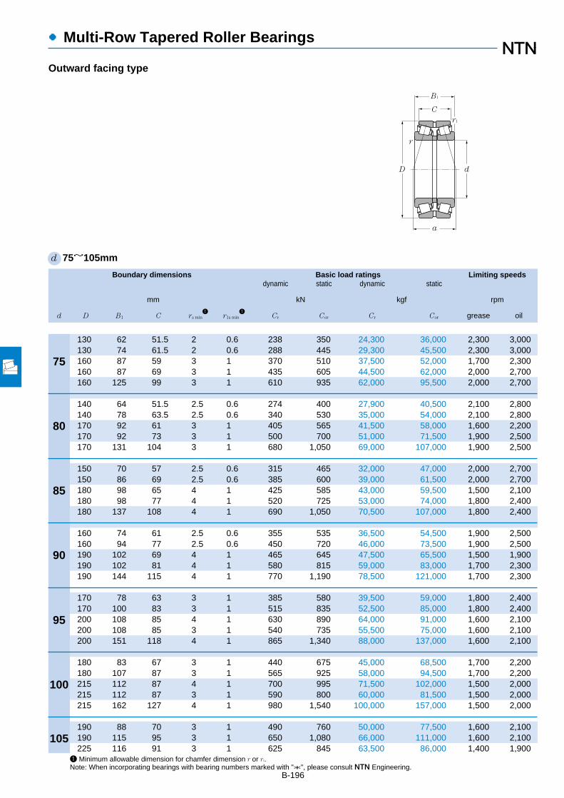
Boundary dimensions Basic load ratings Limiting speedsdynamic static dynamic static
mm kN kgf rpm
d D B1 C rs min1
r1s min1
Cr Cor Cr Cor grease oil
●Multi-Row Tapered Roller Bearings
B-196
d 75~105mm
Outward facing type
75
80
85
90
95
100
105
130 62 51.5 2 0.6 238 350 24,300 36,000 2,300 3,000130 74 61.5 2 0.6 288 445 29,300 45,500 2,300 3,000160 87 59 3 1 370 510 37,500 52,000 1,700 2,300160 87 69 3 1 435 605 44,500 62,000 2,000 2,700160 125 99 3 1 610 935 62,000 95,500 2,000 2,700
140 64 51.5 2.5 0.6 274 400 27,900 40,500 2,100 2,800140 78 63.5 2.5 0.6 340 530 35,000 54,000 2,100 2,800170 92 61 3 1 405 565 41,500 58,000 1,600 2,200170 92 73 3 1 500 700 51,000 71,500 1,900 2,500170 131 104 3 1 680 1,050 69,000 107,000 1,900 2,500
150 70 57 2.5 0.6 315 465 32,000 47,000 2,000 2,700150 86 69 2.5 0.6 385 600 39,000 61,500 2,000 2,700180 98 65 4 1 425 585 43,000 59,500 1,500 2,100180 98 77 4 1 520 725 53,000 74,000 1,800 2,400180 137 108 4 1 690 1,050 70,500 107,000 1,800 2,400
160 74 61 2.5 0.6 355 535 36,500 54,500 1,900 2,500160 94 77 2.5 0.6 450 720 46,000 73,500 1,900 2,500190 102 69 4 1 465 645 47,500 65,500 1,500 1,900190 102 81 4 1 580 815 59,000 83,000 1,700 2,300190 144 115 4 1 770 1,190 78,500 121,000 1,700 2,300
170 78 63 3 1 385 580 39,500 59,000 1,800 2,400170 100 83 3 1 515 835 52,500 85,000 1,800 2,400200 108 85 4 1 630 890 64,000 91,000 1,600 2,100200 108 85 3 1 540 735 55,500 75,000 1,600 2,100200 151 118 4 1 865 1,340 88,000 137,000 1,600 2,100
180 83 67 3 1 440 675 45,000 68,500 1,700 2,200180 107 87 3 1 565 925 58,000 94,500 1,700 2,200215 112 87 4 1 700 995 71,500 102,000 1,500 2,000215 112 87 3 1 590 800 60,000 81,500 1,500 2,000215 162 127 4 1 980 1,540 100,000 157,000 1,500 2,000
190 88 70 3 1 490 760 50,000 77,500 1,600 2,100190 115 95 3 1 650 1,080 66,000 111,000 1,600 2,100225 116 91 3 1 625 845 63,500 86,000 1,400 1,900
1 Minimum allowable dimension for chamfer dimension r or r1.Note: When incorporating bearings with bearing numbers marked with "*", please consult NTN Engineering.
D
C
d
a
B1
r
r1
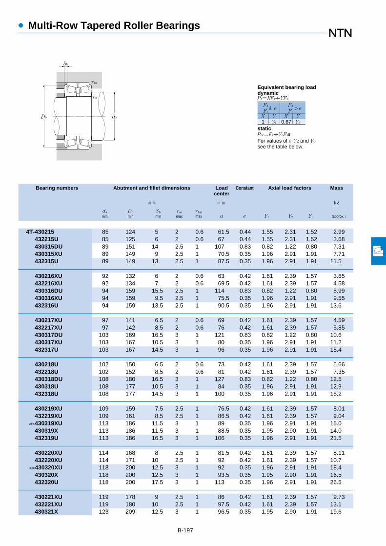
B-197
●Multi-Row Tapered Roller Bearings
Bearing numbers Abutment and fillet dimensions Load Constant Axial load factors Masscenter
mm mm kg
da Db Sb ras r1as
min min min max max a e Y1 Y2 Yo (approx.)
4T-430215 85 124 5 2 0.6 61.5 0.44 1.55 2.31 1.52 2.99432215U 85 125 6 2 0.6 67 0.44 1.55 2.31 1.52 3.68430315DU 89 151 14 2.5 1 107 0.83 0.82 1.22 0.80 7.31430315XU 89 149 9 2.5 1 70.5 0.35 1.96 2.91 1.91 7.71432315U 89 149 13 2.5 1 87.5 0.35 1.96 2.91 1.91 11.5
430216XU 92 132 6 2 0.6 63 0.42 1.61 2.39 1.57 3.65432216XU 92 134 7 2 0.6 69.5 0.42 1.61 2.39 1.57 4.58430316DU 94 159 15.5 2.5 1 114 0.83 0.82 1.22 0.80 8.99430316XU 94 159 9.5 2.5 1 75.5 0.35 1.96 2.91 1.91 9.55432316U 94 159 13.5 2.5 1 90.5 0.35 1.96 2.91 1.91 13.6
430217XU 97 141 6.5 2 0.6 69 0.42 1.61 2.39 1.57 4.59432217XU 97 142 8.5 2 0.6 76 0.42 1.61 2.39 1.57 5.85430317DU 103 169 16.5 3 1 121 0.83 0.82 1.22 0.80 10.6430317XU 103 167 10.5 3 1 80 0.35 1.96 2.91 1.91 11.2432317U 103 167 14.5 3 1 96 0.35 1.96 2.91 1.91 15.4
430218U 102 150 6.5 2 0.6 73 0.42 1.61 2.39 1.57 5.66432218U 102 152 8.5 2 0.6 81 0.42 1.61 2.39 1.57 7.35430318DU 108 180 16.5 3 1 127 0.83 0.82 1.22 0.80 12.5430318U 108 177 10.5 3 1 84 0.35 1.96 2.91 1.91 12.9432318U 108 177 14.5 3 1 100 0.35 1.96 2.91 1.91 18.2
430219XU 109 159 7.5 2.5 1 76.5 0.42 1.61 2.39 1.57 8.01432219XU 109 161 8.5 2.5 1 86.5 0.42 1.61 2.39 1.57 9.04
*430319XU 113 186 11.5 3 1 89 0.35 1.96 2.91 1.91 15.0430319X 113 186 11.5 3 1 88.5 0.35 1.95 2.90 1.91 14.0432319U 113 186 16.5 3 1 106 0.35 1.96 2.91 1.91 21.5
430220XU 114 168 8 2.5 1 81.5 0.42 1.61 2.39 1.57 8.11432220XU 114 171 10 2.5 1 92 0.42 1.61 2.39 1.57 10.7*430320XU 118 200 12.5 3 1 92 0.35 1.96 2.91 1.91 18.4
430320X 118 200 12.5 3 1 93.5 0.35 1.95 2.90 1.91 16.5432320U 118 200 17.5 3 1 113 0.35 1.96 2.91 1.91 26.5
430221XU 119 178 9 2.5 1 86 0.42 1.61 2.39 1.57 9.73432221XU 119 180 10 2.5 1 97.5 0.42 1.61 2.39 1.57 13.1430321X 123 209 12.5 3 1 96.5 0.35 1.95 2.90 1.91 19.6
Db
Sb
da
ra
r1a
1 Y1 0.67 Y2
Fa
Fr
X Y X Y
≦eFa
Fr>e
Pr=XFr+YFa
Por=Fr+YoFa�For values of e, Y2 and Yo
see the table below.
Equivalent bearing loaddynamic
static
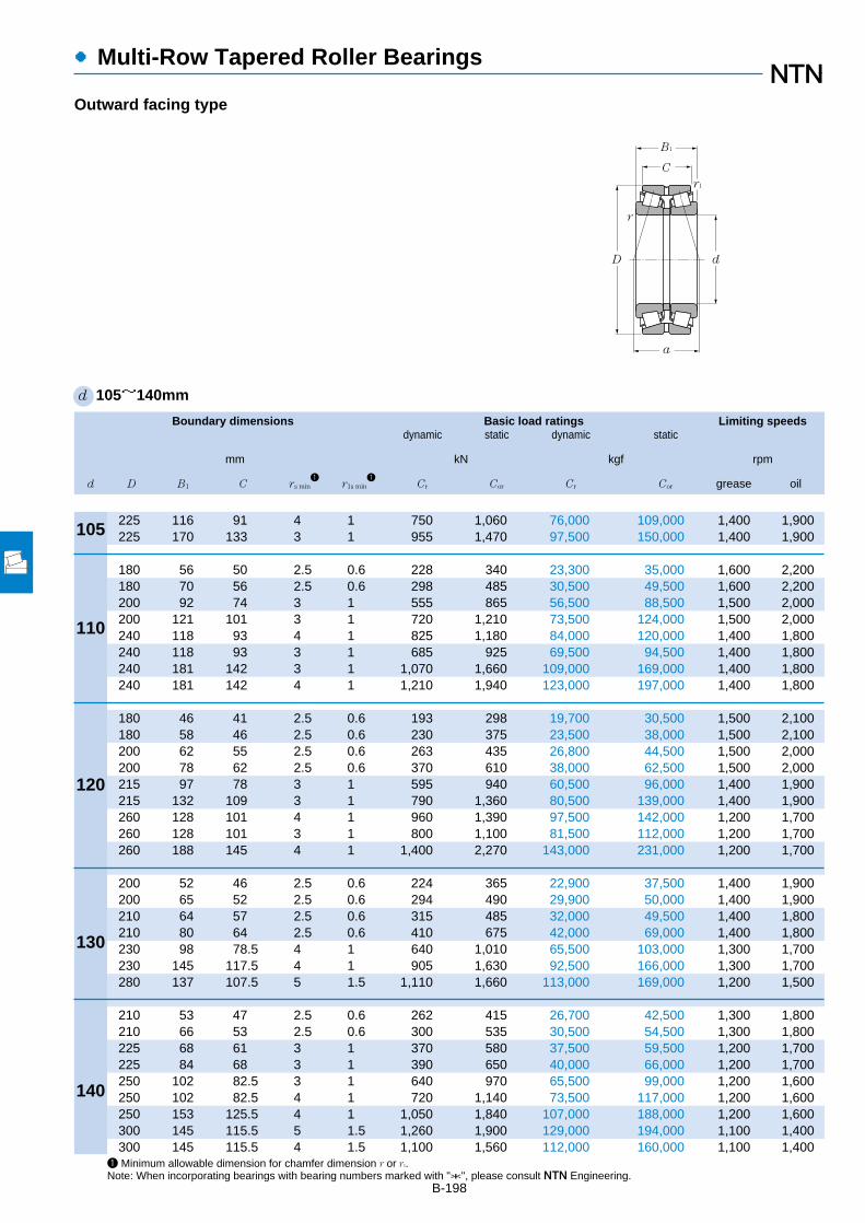
1 Minimum allowable dimension for chamfer dimension r or r1.Note: When incorporating bearings with bearing numbers marked with "*", please consult NTN Engineering.
Boundary dimensions Basic load ratings Limiting speedsdynamic static dynamic static
mm kN kgf rpm
d D B1 C rs min1
r1s min1
Cr Cor Cr Cor grease oil
●Multi-Row Tapered Roller Bearings
B-198
d 105~140mm
Outward facing type
105
110
120
130
140
225 116 91 4 1 750 1,060 76,000 109,000 1,400 1,900225 170 133 3 1 955 1,470 97,500 150,000 1,400 1,900
180 56 50 2.5 0.6 228 340 23,300 35,000 1,600 2,200180 70 56 2.5 0.6 298 485 30,500 49,500 1,600 2,200200 92 74 3 1 555 865 56,500 88,500 1,500 2,000200 121 101 3 1 720 1,210 73,500 124,000 1,500 2,000240 118 93 4 1 825 1,180 84,000 120,000 1,400 1,800240 118 93 3 1 685 925 69,500 94,500 1,400 1,800240 181 142 3 1 1,070 1,660 109,000 169,000 1,400 1,800240 181 142 4 1 1,210 1,940 123,000 197,000 1,400 1,800
180 46 41 2.5 0.6 193 298 19,700 30,500 1,500 2,100180 58 46 2.5 0.6 230 375 23,500 38,000 1,500 2,100200 62 55 2.5 0.6 263 435 26,800 44,500 1,500 2,000200 78 62 2.5 0.6 370 610 38,000 62,500 1,500 2,000215 97 78 3 1 595 940 60,500 96,000 1,400 1,900215 132 109 3 1 790 1,360 80,500 139,000 1,400 1,900260 128 101 4 1 960 1,390 97,500 142,000 1,200 1,700260 128 101 3 1 800 1,100 81,500 112,000 1,200 1,700260 188 145 4 1 1,400 2,270 143,000 231,000 1,200 1,700
200 52 46 2.5 0.6 224 365 22,900 37,500 1,400 1,900200 65 52 2.5 0.6 294 490 29,900 50,000 1,400 1,900210 64 57 2.5 0.6 315 485 32,000 49,500 1,400 1,800210 80 64 2.5 0.6 410 675 42,000 69,000 1,400 1,800230 98 78.5 4 1 640 1,010 65,500 103,000 1,300 1,700230 145 117.5 4 1 905 1,630 92,500 166,000 1,300 1,700280 137 107.5 5 1.5 1,110 1,660 113,000 169,000 1,200 1,500
210 53 47 2.5 0.6 262 415 26,700 42,500 1,300 1,800210 66 53 2.5 0.6 300 535 30,500 54,500 1,300 1,800225 68 61 3 1 370 580 37,500 59,500 1,200 1,700225 84 68 3 1 390 650 40,000 66,000 1,200 1,700250 102 82.5 3 1 640 970 65,500 99,000 1,200 1,600250 102 82.5 4 1 720 1,140 73,500 117,000 1,200 1,600250 153 125.5 4 1 1,050 1,840 107,000 188,000 1,200 1,600300 145 115.5 5 1.5 1,260 1,900 129,000 194,000 1,100 1,400300 145 115.5 4 1.5 1,100 1,560 112,000 160,000 1,100 1,400
D
C
d
a
B1
r
r1

B-199
●Multi-Row Tapered Roller Bearings
Bearing numbers Abutment and fillet dimensions Load Constant Axial load factors Masscenter
mm mm kg
da Db Sb ras r1as
min min min max max a e Y1 Y2 Yo (approx.)
*430321XU 123 209 12.5 3 1 96.5 0.35 1.96 2.91 1.91 21.0432321 119 208 18.5 2.5 1 117.5 0.35 1.96 2.90 1.91 30.2
413122 122 169 3 2 0.6 66.5 0.40 1.68 2.50 1.64 5.20423122 122 166 7 2 0.6 66.5 0.33 2.03 3.02 1.98 6.38430222XU 124 188 9 2.5 1 90 0.42 1.61 2.39 1.57 11.4432222XU 124 190 10 2.5 1 102 0.42 1.61 2.39 1.57 15.5
*430322U 128 222 12.5 3 1 100 0.35 1.96 2.91 1.91 24.5430322 128 222 12.5 3 1 97.5 0.35 1.95 2.90 1.91 22.1432322 128 222 19.5 3 1 124 0.35 1.95 2.90 1.91 35.6
*432322U 128 222 19.5 3 1 127 0.35 1.96 2.91 1.91 38.2
413024 132 171 2.5 2 0.6 59 0.37 1.80 2.69 1.76 3.85423024 132 170 6 2 0.6 66 0.37 1.80 2.69 1.76 4.41413124 132 184 3.5 2 0.6 76.5 0.43 1.57 2.34 1.53 7.24423124 132 188 8 2 0.6 76.5 0.37 1.80 2.69 1.76 8.96430224XU 134 203 9.5 2.5 1 98 0.44 1.55 2.31 1.52 13.6432224XU 134 204 11.5 2.5 1 112 0.44 1.55 2.31 1.52 18.9430324XU 138 239 13.5 3 1 107 0.35 1.96 2.91 1.91 30.5430324X 138 239 13.5 3 1 106 0.35 1.95 2.90 1.91 29.4432324U 138 239 21.5 3 1 130 0.35 1.96 2.91 1.91 47.0
413026 142 186 3 2 0.6 66 0.37 1.80 2.69 1.76 5.55423026 142 189 6.5 2 0.6 71.5 0.37 1.80 2.69 1.76 6.62413126 142 196 3.5 2 0.6 69 0.33 2.03 3.02 1.98 7.83423126 142 198 8 2 0.6 79.5 0.37 1.80 2.69 1.76 9.77430226XU 148 218 9.5 3 1 102 0.44 1.55 2.31 1.52 15.9432226XU 148 219 13.5 3 1 124 0.44 1.55 2.31 1.52 24.1430326XU 152 255 14.5 4 1.5 116 0.35 1.96 2.91 1.91 37.9
413028 152 199 3 2 0.6 68.5 0.37 1.80 2.69 1.76 5.88423028 152 197 6.5 2 0.6 75 0.37 1.84 2.74 1.80 7.11413128 154 210 3.5 2.5 1 73.5 0.33 2.03 3.02 1.98 9.18423128 154 209 8 2.5 1 88 0.37 1.80 2.69 1.76 11.8430228X 158 237 9.5 3 1 106 0.43 1.57 2.34 1.53 18.0
*430228XU 158 237 9.5 3 1 107 0.44 1.55 2.31 1.52 19.9432228XU 158 238 13.5 3 1 131 0.44 1.55 2.31 1.52 30.1
*430328XU 162 273 14.5 4 1.5 123 0.35 1.96 2.91 1.91 46.6430328X 162 272 14.5 4 1.5 123 0.35 1.95 2.90 1.91 44.4
Db
Sb
da
ra
r1a
1 Y1 0.67 Y2
Fa
Fr
X Y X Y
≦eFa
Fr>e
Pr=XFr+YFa
Por=Fr+YoFa�For values of e, Y2 and Yo
see the table below.
Equivalent bearing loaddynamic
static

1 Minimum allowable dimension for chamfer dimension r or r1.Note: When incorporating bearings with bearing numbers marked with "*", please consult NTN Engineering.
Boundary dimensions Basic load ratings Limiting speedsdynamic static dynamic static
mm kN kgf rpm
d D B1 C rs min1
r1s min1
Cr Cor Cr Cor grease oil
●Multi-Row Tapered Roller Bearings
B-200
d 140~190mm
Outward facing type
150
160
170
180
190
D
C
d
a
B1
r
r1
225 56 50 3 1 274 430 27,900 44,000 1,200 1,600225 70 56 3 1 355 630 36,000 64,500 1,200 1,600250 80 71 3 1 485 805 49,500 82,000 1,200 1,500250 100 80 3 1 600 1,040 61,500 106,000 1,200 1,500270 109 87 4 1 770 1,210 78,500 123,000 1,100 1,500270 164 130 4 1 1,200 2,140 122,000 218,000 1,100 1,500320 154 120 5 1.5 1,410 2,140 144,000 218,000 990 1,300320 154 120 4 1.5 1,170 1,750 119,000 178,000 990 1,300
240 60 53 3 1 330 535 34,000 54,500 1,100 1,500240 75 60 3 1 430 765 44,000 78,000 1,100 1,500270 86 76 3 1 595 965 60,500 98,000 1,100 1,400270 108 86 3 1 675 1,180 69,000 120,000 1,100 1,400290 115 91 4 1 900 1,440 92,000 147,000 1,000 1,400290 178 144 4 1 1,530 2,840 156,000 290,000 1,000 1,400340 160 126 5 1.5 1,570 2,390 160,000 244,000 920 1,200340 160 126 4 1.5 1,290 1,950 132,000 199,000 920 1,200
260 67 60 3 1 365 620 37,000 63,500 1,100 1,400260 84 67 3 1 490 865 50,000 88,000 1,100 1,400280 88 78 3 1 550 900 56,000 92,000 1,000 1,300280 110 88 3 1 725 1,270 74,000 130,000 1,000 1,300310 125 97 5 1.5 1,050 1,690 107,000 173,000 950 1,300310 192 152 5 1.5 1,710 3,200 174,000 325,000 950 1,300
280 74 66 3 1 425 735 43,000 75,000 1,000 1,300280 93 74 3 1 580 1,050 59,500 107,000 1,000 1,300300 96 85 4 1.5 705 1,190 72,000 121,000 940 1,300300 120 96 4 1.5 885 1,530 90,500 156,000 940 1,300320 127 99 5 1.5 1,080 1,780 110,000 182,000 890 1,200320 192 152 5 1.5 1,760 3,350 180,000 345,000 890 1,200
290 75 67 3 1 430 740 44,000 75,500 940 1,300290 94 75 3 1 615 1,110 63,000 113,000 940 1,300320 104 92 4 1.5 780 1,280 79,500 131,000 890 1,200320 130 104 4 1.5 985 1,710 100,000 174,000 890 1,200340 133 105 5 1.5 1,230 2,010 125,000 205,000 840 1,100340 204 160 5 1.5 1,970 3,700 201,000 380,000 840 1,100340 204 160 4 1.5 1,710 3,350 175,000 340,000 840 1,100

B-201
●Multi-Row Tapered Roller Bearings
Bearing numbers Abutment and fillet dimensions Load Constant Axial load factors Masscenter
mm mm kg
da Db Sb ras r1as
min min min max max a e Y1 Y2 Yo (approx.)
*413030 164 213 3 2.5 1 73.5 0.37 1.80 2.69 1.76 6.66423030 164 212 7 2.5 1 79.5 0.37 1.80 2.69 1.76 8.76413130 164 231 4.5 2.5 1 82.5 0.33 2.03 3.02 1.98 14.3423130 164 234 10 2.5 1 96.5 0.37 1.80 2.69 1.76 18.0430230U 168 255 11 3 1 114 0.44 1.55 2.31 1.52 24.4432230XU 168 254 17 3 1 139 0.44 1.55 2.31 1.52 37.3
*430330U 172 292 17 4 1.5 132 0.35 1.96 2.91 1.91 55.4430330 172 292 17 4 1.5 135 0.37 1.80 2.69 1.76 52.8
413032 174 227 3.5 2.5 1 79 0.37 1.80 2.69 1.76 8.29423032 174 227 7.5 2.5 1 85.5 0.37 1.80 2.69 1.76 10.7413132E1 174 254 5 2.5 1 98.5 0.40 1.68 2.50 1.64 18.2423132E1 174 250 11 2.5 1 106 0.37 1.80 2.69 1.76 22.8430232U 178 272 12 3 1 122 0.44 1.55 2.31 1.52 31.9432232U 178 275 17 3 1 150 0.44 1.55 2.31 1.52 46.9
*430332XU 182 310 17 4 1.5 138 0.35 1.96 2.91 1.91 65.5430332X 182 311 17 4 1.5 141 0.37 1.80 2.69 1.76 62.4
413034 184 242 3.5 2.5 1 86.5 0.37 1.80 2.69 1.76 11.6423034 184 244 8.5 2.5 1 93.5 0.37 1.80 2.69 1.76 14.3413134E1 184 260 5 2.5 1 104 0.40 1.68 2.50 1.64 19.5423134E1 184 260 11 2.5 1 109 0.37 1.80 2.69 1.76 24.7430234U 192 288 14 4 1.5 132 0.44 1.55 2.31 1.52 38.0432234XU 192 293 20 4 1.5 160 0.44 1.55 2.31 1.52 58.2
413036E1 194 260 4 2.5 1 94 0.37 1.80 2.69 1.76 15.9423036E1 194 262 9.5 2.5 1 102 0.37 1.80 2.69 1.76 19.0413136E1 198 280 5.5 3 1.5 111 0.40 1.68 2.50 1.64 24.6423136E1 198 279 12 3 1.5 119 0.37 1.80 2.69 1.76 31.4430236U 202 297 14 4 1.5 139 0.45 1.50 2.23 1.47 39.4432236U 202 305 20 4 1.5 165 0.45 1.50 2.23 1.47 60.6
413038E1 204 271 4 2.5 1 96 0.37 1.80 2.69 1.76 16.2423038E1 204 272 9.5 2.5 1 104 0.37 1.80 2.69 1.76 19.6413138 208 300 6 3 1.5 119 0.40 1.68 2.50 1.64 30.8423138 208 299 13 3 1.5 126 0.37 1.80 2.69 1.76 38.6430238U 212 316 14 4 1.5 141 0.44 1.55 2.31 1.52 45.4
*432238U 212 323 22 4 1.5 174 0.44 1.55 2.31 1.52 73.3432238 212 323 22 4 1.5 185 0.49 1.38 2.06 1.35 69.8
Db
Sb
da
ra
r1a
1 Y1 0.67 Y2
Fa
Fr
X Y X Y
≦eFa
Fr>e
Pr=XFr+YFa
Por=Fr+YoFa�For values of e, Y2 and Yo
see the table below.
Equivalent bearing loaddynamic
static

Boundary dimensions Basic load ratings Limiting speedsdynamic static dynamic static
mm kN kgf rpm
d D B1 C rs min1
r1s min1
Cr Cor Cr Cor grease oil
●Multi-Row Tapered Roller Bearings
B-202
d 190~340mm
Outward facing type
200
220
240
260
280
300
320
1 Minimum allowable dimension for chamfer dimension r or r1.Note: When incorporating bearings with bearing numbers marked with "*", please consult NTN Engineering.
D
C
d
a
B1
r
r1
340
310 82 73 3 1 530 940 54,000 96,000 900 1,200310 103 82 3 1 720 1,320 73,000 135,000 900 1,200340 112 100 4 1.5 965 1,660 98,500 169,000 840 1,100340 140 112 4 1.5 1,090 1,910 111,000 195,000 840 1,100360 142 110 5 1.5 1,350 2,210 137,000 226,000 800 1,100360 218 174 5 1.5 2,260 4,250 230,000 435,000 800 1,100360 218 174 4 1.5 1,980 3,950 201,000 400,000 800 1,100
340 90 80 4 1.5 595 1,060 61,000 108,000 810 1,100340 113 90 4 1.5 880 1,650 89,500 168,000 810 1,100370 120 107 5 1.5 1,110 1,920 113,000 196,000 760 1,000370 150 120 5 1.5 1,220 2,260 125,000 230,000 760 1,000
360 92 82 4 1.5 655 1,160 66,500 118,000 730 980360 115 92 4 1.5 910 1,770 92,500 181,000 730 980400 128 114 5 1.5 1,230 2,130 126,000 217,000 690 920400 160 128 5 1.5 1,400 2,600 142,000 265,000 690 920
400 104 92 5 1.5 840 1,540 85,500 157,000 670 900400 130 104 5 1.5 1,150 2,190 117,000 223,000 670 900440 144 128 5 1.5 1,500 2,630 152,000 268,000 630 840440 180 144 5 1.5 1,940 3,750 198,000 380,000 630 840
420 106 94 5 1.5 890 1,630 91,000 166,000 620 820420 133 106 5 1.5 1,200 2,340 123,000 238,000 620 820460 146 130 6 2 1,640 2,900 167,000 296,000 580 770460 183 146 6 2 1,940 3,650 198,000 375,000 580 770
460 118 105 5 1.5 1,070 1,990 109,000 203,000 570 760460 148 118 5 1.5 1,610 3,150 165,000 320,000 570 760500 160 142 6 2 2,010 3,600 205,000 370,000 530 710500 200 160 6 2 2,100 4,050 214,000 415,000 530 710
480 121 108 5 1.5 1,190 2,250 121,000 229,000 530 710480 151 121 5 1.5 1,580 3,100 162,000 315,000 530 710540 176 157 6 2 2,240 4,100 228,000 415,000 500 660540 220 176 6 2 2,500 4,900 255,000 500,000 500 660
520 133 118 6 2 1,480 2,870 150,000 293,000 500 660
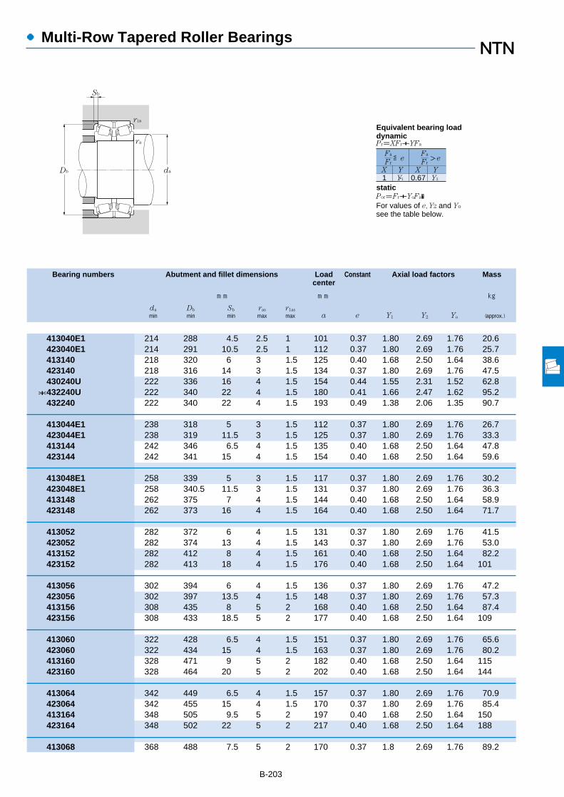
B-203
●Multi-Row Tapered Roller Bearings
Bearing numbers Abutment and fillet dimensions Load Constant Axial load factors Masscenter
mm mm kg
da Db Sb ras r1as
min min min max max a e Y1 Y2 Yo (approx.)
413040E1 214 288 4.5 2.5 1 101 0.37 1.80 2.69 1.76 20.6423040E1 214 291 10.5 2.5 1 112 0.37 1.80 2.69 1.76 25.7413140 218 320 6 3 1.5 125 0.40 1.68 2.50 1.64 38.6423140 218 316 14 3 1.5 134 0.37 1.80 2.69 1.76 47.5430240U 222 336 16 4 1.5 154 0.44 1.55 2.31 1.52 62.8
*432240U 222 340 22 4 1.5 180 0.41 1.66 2.47 1.62 95.2432240 222 340 22 4 1.5 193 0.49 1.38 2.06 1.35 90.7
413044E1 238 318 5 3 1.5 112 0.37 1.80 2.69 1.76 26.7423044E1 238 319 11.5 3 1.5 125 0.37 1.80 2.69 1.76 33.3413144 242 346 6.5 4 1.5 135 0.40 1.68 2.50 1.64 47.8423144 242 341 15 4 1.5 154 0.40 1.68 2.50 1.64 59.6
413048E1 258 339 5 3 1.5 117 0.37 1.80 2.69 1.76 30.2423048E1 258 340.5 11.5 3 1.5 131 0.37 1.80 2.69 1.76 36.3413148 262 375 7 4 1.5 144 0.40 1.68 2.50 1.64 58.9423148 262 373 16 4 1.5 164 0.40 1.68 2.50 1.64 71.7
413052 282 372 6 4 1.5 131 0.37 1.80 2.69 1.76 41.5423052 282 374 13 4 1.5 143 0.37 1.80 2.69 1.76 53.0413152 282 412 8 4 1.5 161 0.40 1.68 2.50 1.64 82.2423152 282 413 18 4 1.5 176 0.40 1.68 2.50 1.64 101
413056 302 394 6 4 1.5 136 0.37 1.80 2.69 1.76 47.2423056 302 397 13.5 4 1.5 148 0.37 1.80 2.69 1.76 57.3413156 308 435 8 5 2 168 0.40 1.68 2.50 1.64 87.4423156 308 433 18.5 5 2 177 0.40 1.68 2.50 1.64 109
413060 322 428 6.5 4 1.5 151 0.37 1.80 2.69 1.76 65.6423060 322 434 15 4 1.5 163 0.37 1.80 2.69 1.76 80.2413160 328 471 9 5 2 182 0.40 1.68 2.50 1.64 115423160 328 464 20 5 2 202 0.40 1.68 2.50 1.64 144
413064 342 449 6.5 4 1.5 157 0.37 1.80 2.69 1.76 70.9423064 342 455 15 4 1.5 170 0.37 1.80 2.69 1.76 85.4413164 348 505 9.5 5 2 197 0.40 1.68 2.50 1.64 150423164 348 502 22 5 2 217 0.40 1.68 2.50 1.64 188
413068 368 488 7.5 5 2 170 0.37 1.8 2.69 1.76 89.2
Db
Sb
da
ra
r1a
1 Y1 0.67 Y2
Fa
Fr
X Y X Y
≦eFa
Fr>e
Pr=XFr+YFa
Por=Fr+YoFa�For values of e, Y2 and Yo
see the table below.
Equivalent bearing loaddynamic
static
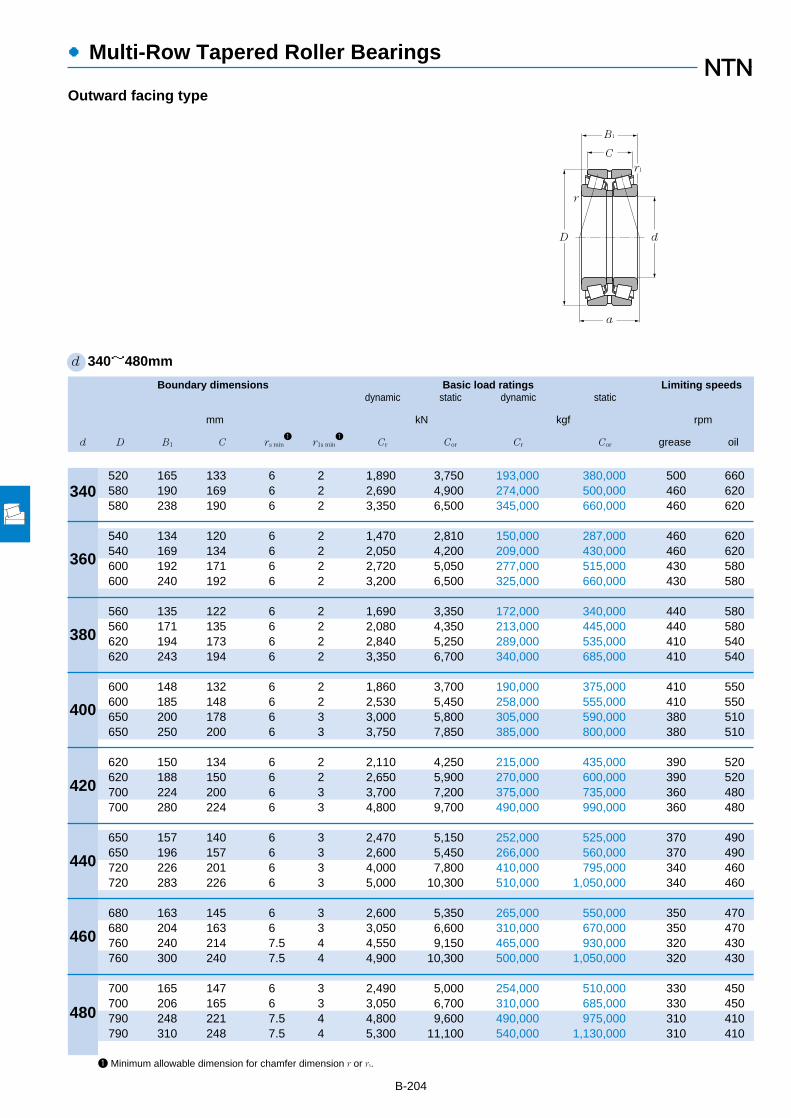
Boundary dimensions Basic load ratings Limiting speedsdynamic static dynamic static
mm kN kgf rpm
d D B1 C rs min1
r1s min1
Cr Cor Cr Cor grease oil
●Multi-Row Tapered Roller Bearings
B-204
d 340~480mm
Outward facing type
340
360
380
400
420
440
460
480
1 Minimum allowable dimension for chamfer dimension r or r1.
D
C
d
a
B1
r
r1
520 165 133 6 2 1,890 3,750 193,000 380,000 500 660580 190 169 6 2 2,690 4,900 274,000 500,000 460 620580 238 190 6 2 3,350 6,500 345,000 660,000 460 620
540 134 120 6 2 1,470 2,810 150,000 287,000 460 620540 169 134 6 2 2,050 4,200 209,000 430,000 460 620600 192 171 6 2 2,720 5,050 277,000 515,000 430 580600 240 192 6 2 3,200 6,500 325,000 660,000 430 580
560 135 122 6 2 1,690 3,350 172,000 340,000 440 580560 171 135 6 2 2,080 4,350 213,000 445,000 440 580620 194 173 6 2 2,840 5,250 289,000 535,000 410 540620 243 194 6 2 3,350 6,700 340,000 685,000 410 540
600 148 132 6 2 1,860 3,700 190,000 375,000 410 550600 185 148 6 2 2,530 5,450 258,000 555,000 410 550650 200 178 6 3 3,000 5,800 305,000 590,000 380 510650 250 200 6 3 3,750 7,850 385,000 800,000 380 510
620 150 134 6 2 2,110 4,250 215,000 435,000 390 520620 188 150 6 2 2,650 5,900 270,000 600,000 390 520700 224 200 6 3 3,700 7,200 375,000 735,000 360 480700 280 224 6 3 4,800 9,700 490,000 990,000 360 480
650 157 140 6 3 2,470 5,150 252,000 525,000 370 490650 196 157 6 3 2,600 5,450 266,000 560,000 370 490720 226 201 6 3 4,000 7,800 410,000 795,000 340 460720 283 226 6 3 5,000 10,300 510,000 1,050,000 340 460
680 163 145 6 3 2,600 5,350 265,000 550,000 350 470680 204 163 6 3 3,050 6,600 310,000 670,000 350 470760 240 214 7.5 4 4,550 9,150 465,000 930,000 320 430760 300 240 7.5 4 4,900 10,300 500,000 1,050,000 320 430
700 165 147 6 3 2,490 5,000 254,000 510,000 330 450700 206 165 6 3 3,050 6,700 310,000 685,000 330 450790 248 221 7.5 4 4,800 9,600 490,000 975,000 310 410790 310 248 7.5 4 5,300 11,100 540,000 1,130,000 310 410

B-205
●Multi-Row Tapered Roller Bearings
Bearing numbers Abutment and fillet dimensions Load Constant Axial load factors Masscenter
mm mm kg
da Db Sb ras r1as
min min min max max a e Y1 Y2 Yo (approx.)
423068 368 489 16 5 2 184 0.37 1.80 2.69 1.76 113413168 368 544 10.5 5 2 213 0.40 1.68 2.50 1.64 188423168 368 542 24 5 2 237 0.40 1.68 2.50 1.64 235
413072 388 507 7 5 2 176 0.37 1.80 2.69 1.76 92.7423072 388 509 17.5 5 2 192 0.37 1.80 2.69 1.76 120413172 388 561 10.5 5 2 219 0.40 1.68 2.50 1.64 199423172 388 560 24 5 2 240 0.40 1.68 2.50 1.64 248
413076 408 528 6.5 5 2 183 0.37 1.80 2.69 1.76 95.9423076 408 529 18 5 2 196 0.37 1.80 2.69 1.76 126413176 408 583 10.5 5 2 225 0.40 1.68 2.50 1.64 210423176 408 578 24.5 5 2 249 0.40 1.68 2.50 1.64 262
413080 428 564 8 5 2 194 0.37 1.80 2.69 1.76 105423080 428 564 18.5 5 2 210 0.37 1.80 2.69 1.76 163413180 428 610 11 5 2.5 232 0.40 1.68 2.50 1.64 236423180 428 610 25 5 2.5 256 0.40 1.68 2.50 1.64 294
413084 448 586 8 5 2 200 0.37 1.80 2.69 1.76 135423084 448 583 19 5 2 220 0.37 1.80 2.69 1.76 172413184 448 655 12 5 2.5 258 0.40 1.68 2.50 1.64 317423184 448 659 28 5 2.5 287 0.40 1.68 2.50 1.64 394
413088 468 614 8.5 5 2.5 208 0.37 1.80 2.69 1.76 160423088 468 614 19.5 5 2.5 229 0.37 1.80 2.69 1.76 198413188 468 675 12.5 5 2.5 263 0.40 1.68 2.50 1.64 330423188 468 678 28.5 5 2.5 288 0.40 1.68 2.50 1.64 412
413092 488 646 9 5 2.5 217 0.37 1.80 2.69 1.76 179423092 488 644 20.5 5 2.5 239 0.37 1.80 2.69 1.76 225413192 496 714 13 6 3 276 0.40 1.68 2.50 1.64 395423192 496 712 30 6 3 305 0.40 1.68 2.50 1.64 493
413096 508 665 9 5 2.5 223 0.37 1.80 2.69 1.76 189423096 508 664 20.5 5 2.5 246 0.37 1.80 2.69 1.76 236413196 516 743 13.5 6 3 281 0.40 1.68 2.50 1.64 442423196 516 738 31 6 3 329 0.40 1.68 2.50 1.64 548
Db
Sb
da
ra
r1a
1 Y1 0.67 Y2
Fa
Fr
X Y X Y
≦eFa
Fr>e
Pr=XFr+YFa
Por=Fr+YoFa�For values of e, Y2 and Yo
see the table below.
Equivalent bearing loaddynamic
static

1 Minimum allowable dimension for chamfer dimension r or r1.
Boundary dimensions Basic load ratings Limiting speedsdynamic static dynamic static
mm kN kgf rpm
d D B1 C rs min1
r1s min1
Cr Cor Cr Cor grease oil
●Multi-Row Tapered Roller Bearings
B-206
d 500mm
Outward facing type
500
D
C
d
a
B1
r
r1
720 167 149 6 3 2,610 5,400 266,000 550,000 320 420720 209 167 6 3 3,050 6,900 315,000 700,000 320 420830 264 235 7.5 4 5,200 10,500 530,000 1,070,000 290 390830 330 264 7.5 4 6,400 14,000 650,000 1,420,000 290 390

B-207
●Multi-Row Tapered Roller Bearings
Bearing numbers Abutment and fillet dimensions Load Constant Axial load factors Masscenter
mm mm kg
da Db Sb ras r1as
min min min max max a e Y1 Y2 Yo (approx.)
4130/500 528 686 9 5 2.5 230 0.37 1.80 2.69 1.76 2024230/500 528 683 21 5 2.5 250 0.37 1.80 2.69 1.76 2474131/500 536 780 14.5 6 3 296 0.40 1.68 2.50 1.64 528
5E-4231/500G2 536 773 33 6 3 331 0.40 1.68 2.50 1.64 678
Db
Sb
da
ra
r1a
1 Y1 0.67 Y2
Fa
Fr
X Y X Y
≦eFa
Fr>e
Pr=XFr+YFa
Por=Fr+YoFa�For values of e, Y2 and Yo
see the table below.
Equivalent bearing loaddynamic
static

Boundary dimensions Basic load ratings Limiting speedsdynamic static dynamic static
mm kN kgf rpm
d D B C1 r1s min1
rs min1
Cr Cor Cr Cor grease oil
●Multi-Row Tapered Roller Bearings
B-208
d 110~280mm
Inward facing type
110
120
130
140
150
160
170
180
190
200
220
240
260
2801 Minimum allowable dimension for chamfer dimension r or r1.
180 56 56 2.5 2 298 485 30,500 49,500 1,600 2,200
180 46 46 2.5 2 230 375 23,500 38,000 1,500 2,100200 62 62 2.5 2 370 610 38,000 62,500 1,500 2,000
200 52 52 2.5 2 294 490 29,900 50,000 1,400 1,900210 64 64 2.5 2 410 675 42,000 69,000 1,400 1,800
210 53 53 2.5 2 300 535 30,500 54,500 1,300 1,800225 68 68 3 2.5 390 650 40,000 66,000 1,200 1,700
225 56 56 3 2.5 355 630 36,000 64,500 1,200 1,600250 80 80 3 2.5 600 1,040 61,500 106,000 1,200 1,500
240 60 60 3 2.5 430 765 44,000 78,000 1,100 1,500270 86 86 3 2.5 675 1,180 69,000 120,000 1,100 1,400
260 67 67 3 2.5 490 865 50,000 88,000 1,100 1,400280 88 88 3 2.5 725 1,270 74,000 130,000 1,000 1,300
280 74 74 3 2.5 580 1,050 59,500 107,000 1,000 1,300300 96 96 4 3 885 1,530 90,500 156,000 940 1,300
290 75 75 3 2.5 615 1,110 63,000 113,000 940 1,300320 104 104 4 3 985 1,710 100,000 174,000 890 1,200
310 82 82 3 2.5 720 1,320 73,000 135,000 900 1,200340 112 112 4 3 1,090 1,910 111,000 195,000 840 1,100
340 90 90 4 3 880 1,650 89,500 168,000 810 1,100370 120 120 5 4 1,220 2,260 125,000 230,000 760 1,000
360 92 92 4 3 910 1,770 92,500 181,000 730 980400 128 128 5 4 1,400 2,600 142,000 265,000 690 920
400 104 104 5 4 1,150 2,190 117,000 223,000 670 900440 144 144 5 4 1,960 3,750 200,000 380,000 630 840
420 106 106 5 4 1,200 2,340 123,000 238,000 620 820
d
r
D
C1
a
r1
B
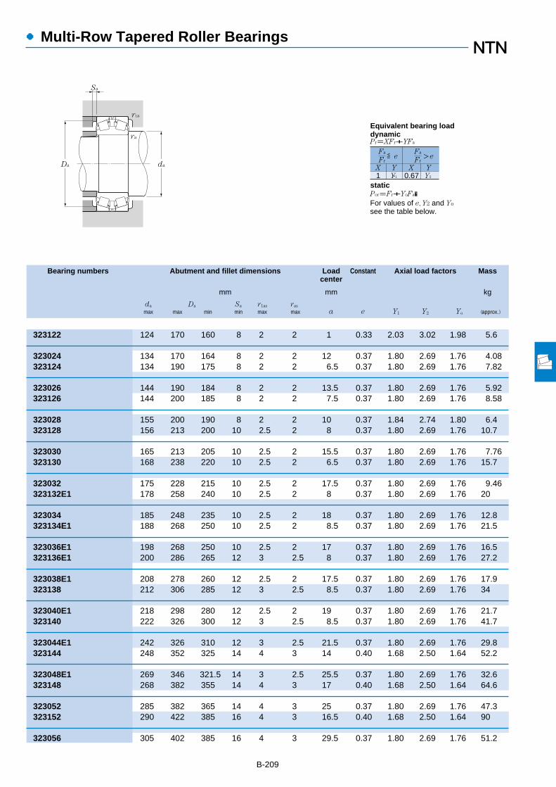
●Multi-Row Tapered Roller Bearings
Bearing numbers Abutment and fillet dimensions Load Constant Axial load factors Masscenter
mm mm kg
da Da Sa r1as ras
max max min min max max a e Y1 Y2 Yo (approx.)
B-209
323122 124 170 160 8 2 2 1 0.33 2.03 3.02 1.98 5.6
323024 134 170 164 8 2 2 12 0.37 1.80 2.69 1.76 4.08323124 134 190 175 8 2 2 6.5 0.37 1.80 2.69 1.76 7.82
323026 144 190 184 8 2 2 13.5 0.37 1.80 2.69 1.76 5.92323126 144 200 185 8 2 2 7.5 0.37 1.80 2.69 1.76 8.58
323028 155 200 190 8 2 2 10 0.37 1.84 2.74 1.80 6.4323128 156 213 200 10 2.5 2 8 0.37 1.80 2.69 1.76 10.7
323030 165 213 205 10 2.5 2 15.5 0.37 1.80 2.69 1.76 7.76323130 168 238 220 10 2.5 2 6.5 0.37 1.80 2.69 1.76 15.7
323032 175 228 215 10 2.5 2 17.5 0.37 1.80 2.69 1.76 9.46323132E1 178 258 240 10 2.5 2 8 0.37 1.80 2.69 1.76 20
323034 185 248 235 10 2.5 2 18 0.37 1.80 2.69 1.76 12.8323134E1 188 268 250 10 2.5 2 8.5 0.37 1.80 2.69 1.76 21.5
323036E1 198 268 250 10 2.5 2 17 0.37 1.80 2.69 1.76 16.5323136E1 200 286 265 12 3 2.5 8 0.37 1.80 2.69 1.76 27.2
323038E1 208 278 260 12 2.5 2 17.5 0.37 1.80 2.69 1.76 17.9323138 212 306 285 12 3 2.5 8.5 0.37 1.80 2.69 1.76 34
323040E1 218 298 280 12 2.5 2 19 0.37 1.80 2.69 1.76 21.7323140 222 326 300 12 3 2.5 8.5 0.37 1.80 2.69 1.76 41.7
323044E1 242 326 310 12 3 2.5 21.5 0.37 1.80 2.69 1.76 29.8323144 248 352 325 14 4 3 14 0.40 1.68 2.50 1.64 52.2
323048E1 269 346 321.5 14 3 2.5 25.5 0.37 1.80 2.69 1.76 32.6323148 268 382 355 14 4 3 17 0.40 1.68 2.50 1.64 64.6
323052 285 382 365 14 4 3 25 0.37 1.80 2.69 1.76 47.3323152 290 422 385 16 4 3 16.5 0.40 1.68 2.50 1.64 90
323056 305 402 385 16 4 3 29.5 0.37 1.80 2.69 1.76 51.2
Da
Sa
da
r1a
ra
1 Y1 0.67 Y2
Fa
Fr
X Y X Y
≦eFa
Fr>e
Pr=XFr+YFa
Por=Fr+YoFa�For values of e, Y2 and Yo
see the table below.
Equivalent bearing loaddynamic
static

B-210
Boundary dimensions Basic load ratings Limiting speedsdynamic static dynamic static
mm kN kgf rpm
d D B C1 r1s min1
rs min1
Cr Cor Cr Cor grease oil
●Multi-Row Tapered Roller Bearings
d 280~500mm
Inward facing type
280
300
320
340
360
380
400
420
440
460
480
500
1 Minimum allowable dimension for chamfer dimension r or r1.
460 146 146 6 5 1,940 3,650 198,000 375,000 580 770
460 118 118 5 4 1,610 3,150 165,000 320,000 570 760500 160 160 6 5 2,100 4,050 214,000 415,000 530 710
480 121 121 5 4 1,580 3,100 162,000 315,000 530 710540 176 176 6 5 2,500 4,900 255,000 500,000 500 660
520 133 133 6 5 1,890 3,750 193,000 380,000 500 660580 190 190 6 5 3,350 6,500 345,000 660,000 460 620
540 134 134 6 5 2,050 4,200 209,000 430,000 460 620600 192 192 6 5 3,200 6,500 325,000 660,000 430 580
560 135 135 6 5 2,080 4,350 213,000 445,000 440 580620 194 194 6 5 3,350 6,700 340,000 685,000 410 540
600 148 148 6 5 2,530 5,450 258,000 555,000 410 550650 200 200 6 6 3,750 7,850 385,000 800,000 380 510
620 150 150 6 5 2,650 5,900 270,000 600,000 390 520700 224 224 6 6 4,800 9,700 490,000 990,000 360 480
650 157 157 6 6 2,600 5,450 266,000 560,000 370 490720 226 226 6 6 5,000 10,300 510,000 1,050,000 340 460
680 163 163 6 6 3,050 6,600 310,000 670,000 350 470760 240 240 7.5 7.5 4,900 10,300 500,000 1,050,000 320 430
700 165 165 6 6 3,050 6,700 310,000 685,000 330 450790 248 248 7.5 7.5 5,300 11,100 540,000 1,130,000 310 410
720 167 167 6 6 3,050 6,900 315,000 700,000 320 420830 264 264 7.5 7.5 6,400 14,000 650,000 1,420,000 290 390
d
r
D
C1
a
r1
B

B-211
●Multi-Row Tapered Roller Bearings
Bearing numbers Abutment and fillet dimensions Load Constant Axial load factors Masscenter
mm mm kg
da Da Sa r1as ras
max max min min max max a e Y1 Y2 Yo (approx.)
323156 315 438 400 16 5 4 16 0.40 1.68 2.50 1.64 95.8
323060 330 442 425 16 4 3 31 0.37 1.80 2.69 1.76 70.7323160 335 478 440 16 5 4 18 0.40 1.68 2.50 1.64 126
323064 350 462 440 16 4 3 34 0.37 1.80 2.69 1.76 76.3323164 355 518 480 18 5 4 18.5 0.40 1.68 2.50 1.64 164
323068 370 498 480 18 5 4 36 0.37 1.80 2.69 1.76 101323168 380 558 515 18 5 4 35.5 0.40 1.68 2.50 1.64 207
323072 395 518 495 18 5 4 41 0.37 1.80 2.69 1.76 107323172 400 578 535 18 5 4 25.5 0.40 1.68 2.50 1.64 218
323076 415 538 515 18 5 4 44.5 0.37 1.80 2.69 1.76 113323176 420 598 550 20 5 4 29 0.40 1.68 2.50 1.64 229
323080 440 578 550 18 5 4 45 0.37 1.80 2.69 1.76 146323180 445 622 580 20 5 5 32.5 0.40 1.68 2.50 1.64 259
323084 460 598 570 20 5 4 48.5 0.37 1.80 2.69 1.76 154323184 465 672 625 25 5 5 60 0.40 1.68 2.50 1.64 346
323088 480 622 600 20 5 5 53.5 0.37 1.80 2.69 1.76 177323188 485 692 645 25 5 5 44 0.40 1.68 2.50 1.64 361
323092 500 652 620 25 5 5 56.5 0.37 1.80 2.69 1.76 201323192 510 724 680 25 6 6 34.5 0.40 1.68 2.50 1.64 433
323096 520 672 640 25 5 5 63 0.37 1.80 2.69 1.76 211323196 530 754 705 30 6 6 36 0.40 1.68 2.50 1.64 481
3230/500 540 692 655 25 5 5 61.5 0.37 1.80 2.69 1.76 2215E-3231/500G2 550 794 740 30 6 6 37.5 0.40 1.68 2.50 1.64 570
Da
Sa
da
r1a
ra
1 Y1 0.67 Y2
Fa
Fr
X Y X Y
≦eFa
Fr>e
Pr=XFr+YFa
Por=Fr+YoFa�For values of e, Y2 and Yo
see the table below.
Equivalent bearing loaddynamic
static

Boundary dimensions Basic load ratingsdynamic static dynamic static
mm kN kgf
d D B2 C2 r1s min1
rs min1
Cr Cor Cr Cor
●Four Row Tapered Roller Bearings
B-2121 Minimum allowable dimension for chamfer dimension r or r1.
d 120~187.325mm
120
120.650
127
130
135
136.525
139.700
140
146.050
150
152.400
160
165.100
170
177.800
180
187.325
r1
B2
DaD
C2
dad
Sa
r
170 124 124 2.5 2 390 1,020 40,000 104,000210 174 174 2.5 2.5 855 1,710 87,500 174,000
174.625 141.288 139.703 0.8 1.5 510 1,220 52,000 124,000
182.562 158.750 158.750 1.5 3.3 660 1,730 67,000 177,000
184 134 134 2.5 2 480 1,190 49,000 122,000
180 160 160 1 2 500 1,360 51,000 138,000
190.500 161.925 161.925 1.5 3.3 695 1,900 71,000 193,000
200.025 157.165 160.340 0.8 3.3 700 1,950 71,500 199,000
198 144 144 2.5 2 575 1,460 58,500 149,000
244.475 192.088 187.325 1.5 3.3 955 1,980 97,000 202,000
212 155 155 3 2.5 660 1,700 67,500 173,000
222.250 174.625 174.625 1.5 1.5 930 2,350 94,500 239,000
226 165 165 3 2.5 775 2,030 79,000 207,000265 173 173 2.5 2.5 1,100 2,270 112,000 231,000
225.425 165.100 168.275 0.8 3.3 745 2,220 76,000 226,000
240 175 175 3 2.5 835 2,200 85,500 224,000280 181 181 2.5 2.5 1,150 2,420 117,000 247,000
247.650 192.088 192.088 1.5 3.3 1,000 2,760 102,000 281,000279.400 234.950 234.947 1.5 3.3 1,420 3,400 145,000 345,000304.800 238.227 233.365 3.3 3.3 1,580 3,100 161,000 320,000
254 185 185 3 2.5 910 2,390 93,000 244,000300 280 280 3 3 2,160 4,800 220,000 490,000
269.875 211.138 211.138 1.5 3.3 1,240 3,400 127,000 345,000

●Four Row Tapered Roller Bearings
Bearing numbers Abutment and fillet dimensions Mass
mm kg
da Da Sa (approx.)
B-213Note: 1. Bearing numbers marked "*" designate inch system bearings.
E-625924 135 155.5 5 8.97E-CRO-2418 140 190 4.5 22.2
*E-M224749D/M224710/M224710D 129 163 3 11.5
*T-E-48290D/48220/48220D 137 168 4.5 14.3
E-625926 144.5 169 5 11.3
E-CRO-2701 143 165 2 13.5
*T-E-48393D/48320/48320D 144 177 4 14.8
*T-E-48680D/48620/48620D 150 185 3 17.3
E-625928 156 183 5 14
*E-81576D/81962/81963D 163 225 6.5 36.8
E-625930 167.5 195 5.5 16.9
*T-E-M231649D/M231610/M231610D 165 207 4 24.7
E-625932 177.5 208.5 5.5 20.2E-CRO-3209 184 247 4.5 33.6
*E-46791D/46720/46721D 175 209 3 20.7
E-625934 187.5 220 5.5 24.4E-CRO-3409 192 255 5 44
*E-67791D/67720/67721D 190 229 5 29.4*E-82681D/82620/82620D 195 251 5 55.3*E-EE280700D/281200/281201D 198 279 7 69.9
E-625936 200.5 233.5 5.5 28.9E-CRO-3617 201 274 5 69.4
*E-M238849D/M238810/M238810D 199.9 250 4 41.8
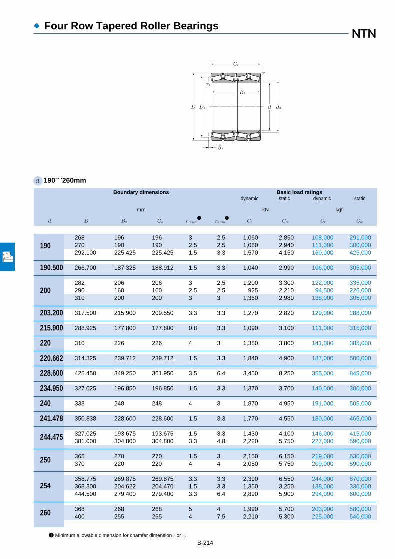
B-214
Boundary dimensions Basic load ratingsdynamic static dynamic static
mm kN kgf
d D B2 C2 r1s min1
rs min1
Cr Cor Cr Cor
●Four Row Tapered Roller Bearings
1 Minimum allowable dimension for chamfer dimension r or r1.
d 190~260mm
190
190.500
200
203.200
215.900
220
220.662
228.600
234.950
240
241.478
244.475
250
254
260
r1
B2
DaD
C2
dad
Sa
r
268 196 196 3 2.5 1,060 2,850 108,000 291,000270 190 190 2.5 2.5 1,080 2,940 111,000 300,000292.100 225.425 225.425 1.5 3.3 1,570 4,150 160,000 425,000
266.700 187.325 188.912 1.5 3.3 1,040 2,990 106,000 305,000
282 206 206 3 2.5 1,200 3,300 122,000 335,000290 160 160 2.5 2.5 925 2,210 94,500 226,000310 200 200 3 3 1,360 2,980 138,000 305,000
317.500 215.900 209.550 3.3 3.3 1,270 2,820 129,000 288,000
288.925 177.800 177.800 0.8 3.3 1,090 3,100 111,000 315,000
310 226 226 4 3 1,380 3,800 141,000 385,000
314.325 239.712 239.712 1.5 3.3 1,840 4,900 187,000 500,000
425.450 349.250 361.950 3.5 6.4 3,450 8,250 355,000 845,000
327.025 196.850 196.850 1.5 3.3 1,370 3,700 140,000 380,000
338 248 248 4 3 1,870 4,950 191,000 505,000
350.838 228.600 228.600 1.5 3.3 1,770 4,550 180,000 465,000
327.025 193.675 193.675 1.5 3.3 1,430 4,100 146,000 415,000381.000 304.800 304.800 3.3 4.8 2,220 5,750 227,000 590,000
365 270 270 1.5 3 2,150 6,150 219,000 630,000370 220 220 4 4 2,050 5,750 209,000 590,000
358.775 269.875 269.875 3.3 3.3 2,390 6,550 244,000 670,000368.300 204.622 204.470 1.5 3.3 1,350 3,250 138,000 330,000444.500 279.400 279.400 3.3 6.4 2,890 5,900 294,000 600,000
368 268 268 5 4 1,990 5,700 203,000 580,000400 255 255 4 7.5 2,210 5,300 225,000 540,000
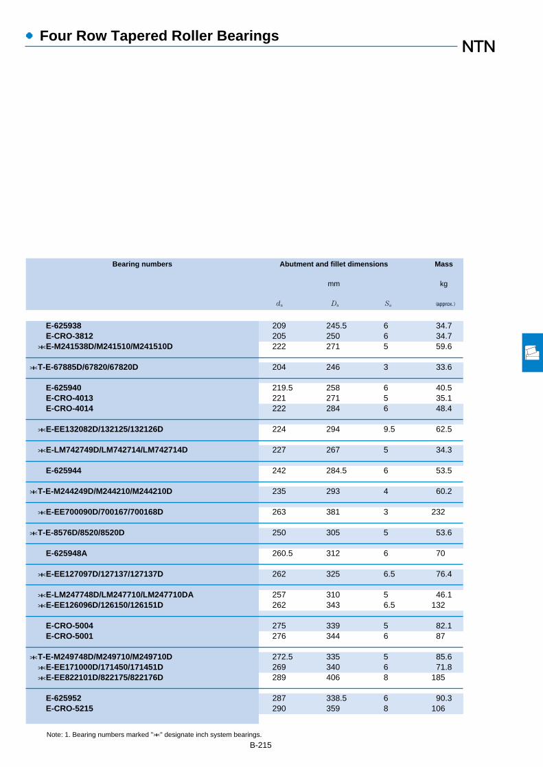
B-215
●Four Row Tapered Roller Bearings
Bearing numbers Abutment and fillet dimensions Mass
mm kg
da Da Sa (approx.)
Note: 1. Bearing numbers marked "*" designate inch system bearings.
E-625938 209 245.5 6 34.7E-CRO-3812 205 250 6 34.7*E-M241538D/M241510/M241510D 222 271 5 59.6
*T-E-67885D/67820/67820D 204 246 3 33.6
E-625940 219.5 258 6 40.5E-CRO-4013 221 271 5 35.1E-CRO-4014 222 284 6 48.4
*E-EE132082D/132125/132126D 224 294 9.5 62.5
*E-LM742749D/LM742714/LM742714D 227 267 5 34.3
E-625944 242 284.5 6 53.5
*T-E-M244249D/M244210/M244210D 235 293 4 60.2
*E-EE700090D/700167/700168D 263 381 3 232
*T-E-8576D/8520/8520D 250 305 5 53.6
E-625948A 260.5 312 6 70
*E-EE127097D/127137/127137D 262 325 6.5 76.4
*E-LM247748D/LM247710/LM247710DA 257 310 5 46.1*E-EE126096D/126150/126151D 262 343 6.5 132
E-CRO-5004 275 339 5 82.1E-CRO-5001 276 344 6 87
*T-E-M249748D/M249710/M249710D 272.5 335 5 85.6*E-EE171000D/171450/171451D 269 340 6 71.8*E-EE822101D/822175/822176D 289 406 8 185
E-625952 287 338.5 6 90.3E-CRO-5215 290 359 8 106
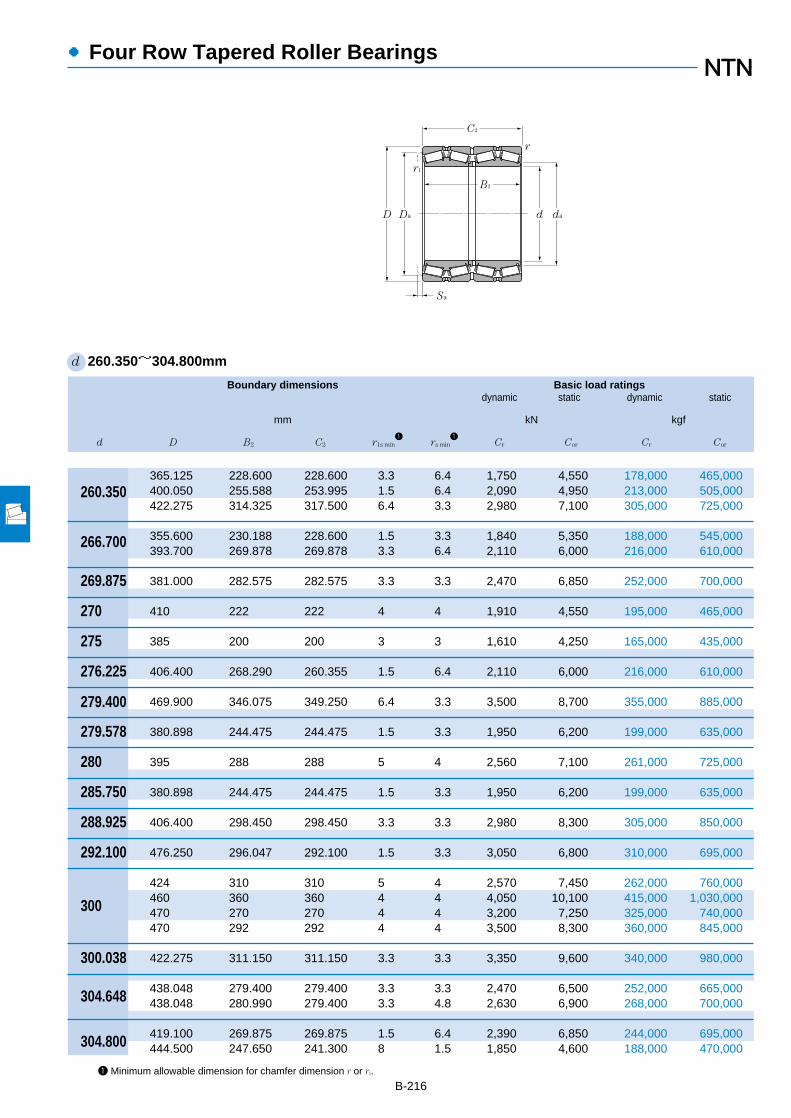
B-216
Boundary dimensions Basic load ratingsdynamic static dynamic static
mm kN kgf
d D B2 C2 r1s min1
rs min1
Cr Cor Cr Cor
●Four Row Tapered Roller Bearings
1 Minimum allowable dimension for chamfer dimension r or r1.
d 260.350~304.800mm
365.125 228.600 228.600 3.3 6.4 1,750 4,550 178,000 465,000400.050 255.588 253.995 1.5 6.4 2,090 4,950 213,000 505,000422.275 314.325 317.500 6.4 3.3 2,980 7,100 305,000 725,000
355.600 230.188 228.600 1.5 3.3 1,840 5,350 188,000 545,000393.700 269.878 269.878 3.3 6.4 2,110 6,000 216,000 610,000
381.000 282.575 282.575 3.3 3.3 2,470 6,850 252,000 700,000
410 222 222 4 4 1,910 4,550 195,000 465,000
385 200 200 3 3 1,610 4,250 165,000 435,000
406.400 268.290 260.355 1.5 6.4 2,110 6,000 216,000 610,000
469.900 346.075 349.250 6.4 3.3 3,500 8,700 355,000 885,000
380.898 244.475 244.475 1.5 3.3 1,950 6,200 199,000 635,000
395 288 288 5 4 2,560 7,100 261,000 725,000
380.898 244.475 244.475 1.5 3.3 1,950 6,200 199,000 635,000
406.400 298.450 298.450 3.3 3.3 2,980 8,300 305,000 850,000
476.250 296.047 292.100 1.5 3.3 3,050 6,800 310,000 695,000
424 310 310 5 4 2,570 7,450 262,000 760,000460 360 360 4 4 4,050 10,100 415,000 1,030,000470 270 270 4 4 3,200 7,250 325,000 740,000470 292 292 4 4 3,500 8,300 360,000 845,000
422.275 311.150 311.150 3.3 3.3 3,350 9,600 340,000 980,000
438.048 279.400 279.400 3.3 3.3 2,470 6,500 252,000 665,000438.048 280.990 279.400 3.3 4.8 2,630 6,900 268,000 700,000
419.100 269.875 269.875 1.5 6.4 2,390 6,850 244,000 695,000444.500 247.650 241.300 8 1.5 1,850 4,600 188,000 470,000
260.350
266.700
269.875
270
275
276.225
279.400
279.578
280
285.750
288.925
292.100
300
300.038
304.648
304.800
r1
B2
DaD
C2
dad
Sa
r

B-217
●Four Row Tapered Roller Bearings
Bearing numbers Abutment and fillet dimensions Mass
mm kg
da Da Sa (approx.)
Note: 1. Bearing numbers marked "*" designate inch system bearings.2. Bearing numbers marked "☆" designate bearing with hollow rollers and pin type cages.
*E-EE134102D/134143/134144D 282 340 6.5 76.5*E-EE221027D/221575/221576D 292 367 8 117*E-HM252349D/HM252310/HM252310D 290 392 5.5 180
*T-E-LM451349D/LM451310/LM451310D 281 335 6.5 62*E-EE275106D/275155/275156D 292 367 5 116
*E-M252349D/M252310/M252310D 290 356 6 97.5
E-CRO-5403 305 382 6 91
E-CRO-5501 300 355 6 62.5
*E-EE275109D/275160/275161D 293.6 366 8 122
*E-EE722111D/722185/722186D 316 432 5 258
*T-E-LM654644D/LM654610/LM654610D 297 356 5 83.2
E-625956 304.5 363.5 7 111
*T-E-LM654648D/LM654610/LM654610D 302 356 5 77.9
*E-M255449D/M255410/M255410D 310 379 5 125
*E-EE921150D/921875/921876D 321 441 7 208
E-625960 329 389.5 7 138E-CRO-6015 330 427 10 180☆E-CRO-6012 338 438 7 152☆E-CRO-6013 336 437 7 164
☆*T-E-HM256849D/HM256810/HM256810DG2 322 394 6 143
*E-EE329119D/329172/329173D 328 409 8 143*E-M757448D/M757410/M757410D 328 407 7 140
*E-M257149D/M257110/M257110D 322 392 5 115*E-EE291202D/291750/291751D 328 416 9.5 127
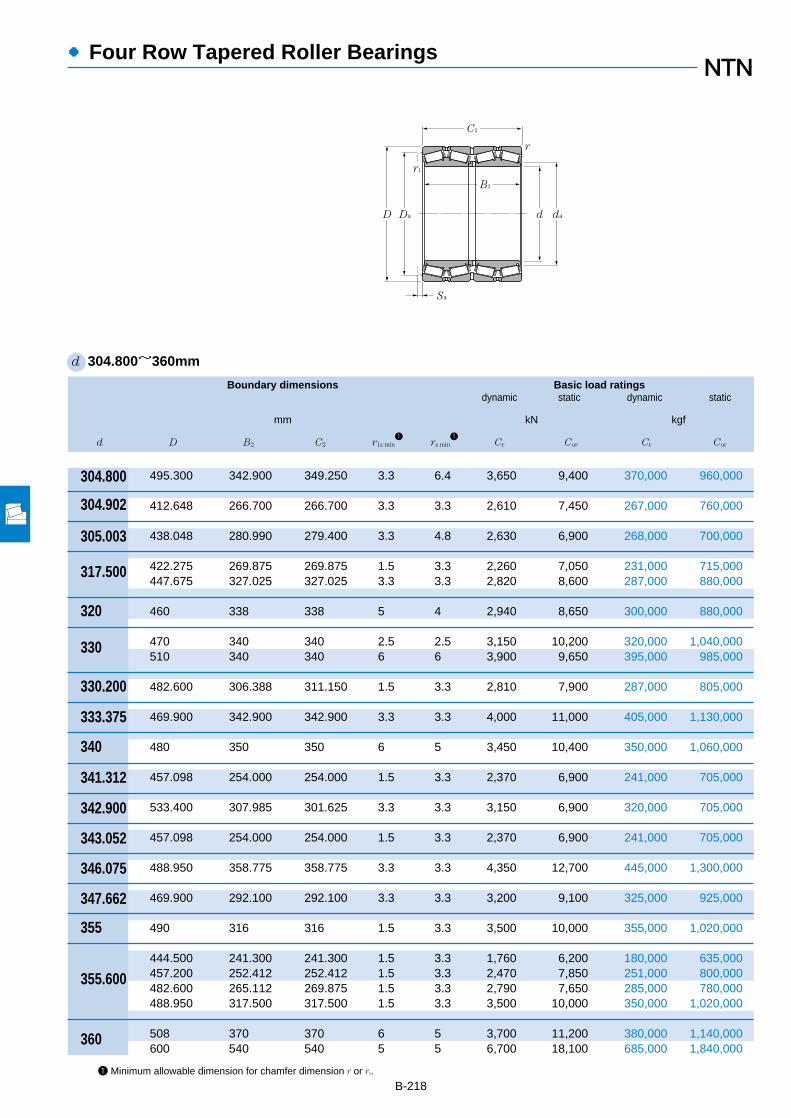
B-218
Boundary dimensions Basic load ratingsdynamic static dynamic static
mm kN kgf
d D B2 C2 r1s min1
rs min1
Cr Cor Cr Cor
●Four Row Tapered Roller Bearings
1 Minimum allowable dimension for chamfer dimension r or r1.
d 304.800~360mm
495.300 342.900 349.250 3.3 6.4 3,650 9,400 370,000 960,000
412.648 266.700 266.700 3.3 3.3 2,610 7,450 267,000 760,000
438.048 280.990 279.400 3.3 4.8 2,630 6,900 268,000 700,000
422.275 269.875 269.875 1.5 3.3 2,260 7,050 231,000 715,000447.675 327.025 327.025 3.3 3.3 2,820 8,600 287,000 880,000
460 338 338 5 4 2,940 8,650 300,000 880,000
470 340 340 2.5 2.5 3,150 10,200 320,000 1,040,000510 340 340 6 6 3,900 9,650 395,000 985,000
482.600 306.388 311.150 1.5 3.3 2,810 7,900 287,000 805,000
469.900 342.900 342.900 3.3 3.3 4,000 11,000 405,000 1,130,000
480 350 350 6 5 3,450 10,400 350,000 1,060,000
457.098 254.000 254.000 1.5 3.3 2,370 6,900 241,000 705,000
533.400 307.985 301.625 3.3 3.3 3,150 6,900 320,000 705,000
457.098 254.000 254.000 1.5 3.3 2,370 6,900 241,000 705,000
488.950 358.775 358.775 3.3 3.3 4,350 12,700 445,000 1,300,000
469.900 292.100 292.100 3.3 3.3 3,200 9,100 325,000 925,000
490 316 316 1.5 3.3 3,500 10,000 355,000 1,020,000
444.500 241.300 241.300 1.5 3.3 1,760 6,200 180,000 635,000457.200 252.412 252.412 1.5 3.3 2,470 7,850 251,000 800,000482.600 265.112 269.875 1.5 3.3 2,790 7,650 285,000 780,000488.950 317.500 317.500 1.5 3.3 3,500 10,000 350,000 1,020,000
508 370 370 6 5 3,700 11,200 380,000 1,140,000600 540 540 5 5 6,700 18,100 685,000 1,840,000
304.800
304.902
305.003
317.500
320
330
330.200
333.375
340
341.312
342.900
343.052
346.075
347.662
355
355.600
360
r1
B2
DaD
C2
dad
Sa
r

B-219
●Four Row Tapered Roller Bearings
Bearing numbers Abutment and fillet dimensions Mass
mm kg
da Da Sa (approx.)
Note: 1. Bearing numbers marked "*" designate inch system bearings.2. Bearing numbers marked "☆" designate bearing with hollow rollers and pin type cages.
*E-EE724121D/724195/724196D 330 450 3 273
*E-M257248D/M257210/M257210D 325 388 5 107
*E-M757449D/M757410/M757410D 328 407 7 139
*E-LM258649D/LM258610/LM258610D 333.3 398 7 110*E-HM259049D/HM259010/HM259010D 339.6 418 5 170
E-625964 355 420.5 7 183
E-CRO-6604 366 440 5.5 141E-CRO-6602 366 469 5 221
*E-EE526131D/526190/526191D 351 448 3 197
*E-HM261049D/HM261010/HM261010D 357 439 5 187
E-625968 373 440 7 200
*E-LM761648D/LM761610/LM761610D 359 432 5 125
*E-EE971355D/972100/972103D 378 502 11 252
*E-LM761649D/LM761610/LM761610D 361 432 5 117
☆*E-HM262749D/HM262710/HM262710DG2 371 456 6 227
*E-M262449D/M262410/M262410D 369 443 8 148
E-CRO-7105 378 450 7 170
*E-L163149D/L163110/L163110D 370 422 6.5 89.5*E-LM263149D/LM263110/LM263110D 372 434 6 106*E-LM763449D/LM763410/LM763410D 375 453 3 145*E-M263349D/M263310/M263310D 374 459 5 173
E-625972 394 466.5 7 236E-CRO-7210 400 550 8 520
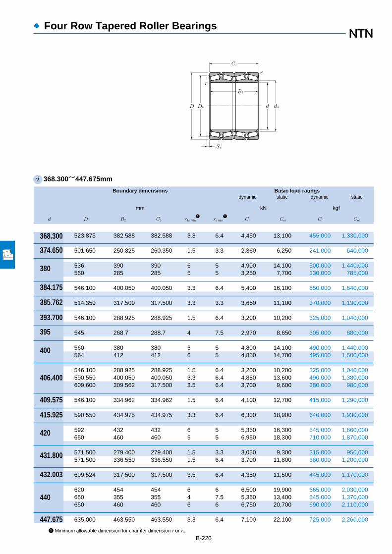
B-220
Boundary dimensions Basic load ratingsdynamic static dynamic static
mm kN kgf
d D B2 C2 r1s min1
rs min1
Cr Cor Cr Cor
●Four Row Tapered Roller Bearings
1 Minimum allowable dimension for chamfer dimension r or r1.
d 368.300~447.675mm
368.300
374.650
380
384.175
385.762
393.700
395
400
406.400
409.575
415.925
420
431.800
432.003
440
447.675
r1
B2
DaD
C2
dad
Sa
r
523.875 382.588 382.588 3.3 6.4 4,450 13,100 455,000 1,330,000
501.650 250.825 260.350 1.5 3.3 2,360 6,250 241,000 640,000
536 390 390 6 5 4,900 14,100 500,000 1,440,000560 285 285 5 5 3,250 7,700 330,000 785,000
546.100 400.050 400.050 3.3 6.4 5,400 16,100 550,000 1,640,000
514.350 317.500 317.500 3.3 3.3 3,650 11,100 370,000 1,130,000
546.100 288.925 288.925 1.5 6.4 3,200 10,200 325,000 1,040,000
545 268.7 288.7 4 7.5 2,970 8,650 305,000 880,000
560 380 380 5 5 4,800 14,100 490,000 1,440,000564 412 412 6 5 4,850 14,700 495,000 1,500,000
546.100 288.925 288.925 1.5 6.4 3,200 10,200 325,000 1,040,000590.550 400.050 400.050 3.3 6.4 4,850 13,600 490,000 1,380,000609.600 309.562 317.500 3.5 6.4 3,700 9,600 380,000 980,000
546.100 334.962 334.962 1.5 6.4 4,100 12,700 415,000 1,290,000
590.550 434.975 434.975 3.3 6.4 6,300 18,900 640,000 1,930,000
592 432 432 6 5 5,350 16,300 545,000 1,660,000650 460 460 5 5 6,950 18,300 710,000 1,870,000
571.500 279.400 279.400 1.5 3.3 3,050 9,300 315,000 950,000571.500 336.550 336.550 1.5 6.4 3,700 11,800 380,000 1,200,000
609.524 317.500 317.500 3.5 6.4 4,350 11,500 445,000 1,170,000
620 454 454 6 6 6,500 19,900 665,000 2,030,000650 355 355 4 7.5 5,350 13,400 545,000 1,370,000650 460 460 6 6 6,750 20,700 690,000 2,110,000
635.000 463.550 463.550 3.3 6.4 7,100 22,100 725,000 2,260,000

B-221
●Four Row Tapered Roller Bearings
Bearing numbers Abutment and fillet dimensions Mass
mm kg
da Da Sa (approx.)
Note: 1. Bearing numbers marked "*" designate inch system bearings.2. Bearing numbers marked "☆" designate bearing with hollow rollers and pin type cages.
☆*E-HM265049D/HM265010/HM265010DG2 393.7 487 6 280
*E-LM765149D/LM765110/LM765110D 393 472 2 145
E-625976 410 495 8 277E-CRO-7612 417 525 7 208
☆*E-HM266449D/HM266410/HM266410DG2 411 507 6.5 328
*E-LM665949D/LM665910/LM665910D 409 482 7 240
*E-LM767745D/LM767710/LM767710D 418 510 6.5 219
E-CRO-7901 434 508 3 200
☆E-CRO-8005 426 510 8 300E-625980 434 518.5 7 324
*E-LM767749D/LM767710/LM767710D 427 510 6.5 201*E-EE833161D/833232/833233D 448 549 6.5 395*E-EE911603D/912400/912401D 441 568 1.5 332
☆*E-M667947D/M667911/M667911DG2 431 510 5.5 226
☆*T-E-M268749D/M268710/M268710DG2 444 549 9 421
E-625984 457 545 7 374E-CRO-8402 455 593 8 600
☆*E-LM869449D/LM869410/LM869410DG2 453 537 8 198*E-LM769349D/LM769310/LM769310D 453 534 6.5 232
*E-EE736173D/736238/736239D 464 572 6.5 297
E-625988 479 572.5 8 430☆E-CRO-8807 484 607 9 400
E-CRO-8806 483 595 11 600
☆*E-M270749D/M270710/M270710DAG2 478 591 8 509

B-222
●Four Row Tapered Roller Bearings
1 Minimum allowable dimension for chamfer dimension r or r1.
d 457.200~571.500mm
596.900 276.225 279.400 1.5 3.3 3,350 10,300 360,000 1,060,000660.400 323.850 323.847 3.3 6.4 4,150 11,200 425,000 1,140,000
650 474 474 6 6 6,500 19,900 665,000 2,030,000
660 450 450 3 5 6,300 20,400 645,000 2,080,000
678 494 494 6 6 6,250 19,600 640,000 2,000,000700 390 390 6 6 4,700 13,400 480,000 1,370,000
615.950 330.200 330.200 3.3 6.4 4,000 13,400 405,000 1,370,000
660.400 365.125 361.950 8 6.4 4,700 15,400 480,000 1,570,000
634.873 320.675 320.675 3.3 3.3 3,650 12,000 370,000 1,220,000
670 515 515 1.5 5 6,900 24,600 700,000 2,510,000690 480 480 5 5 6,000 19,900 610,000 2,020,000705 515 515 6 6 8,450 27,100 860,000 2,760,000730 440 440 6 6 7,200 20,600 735,000 2,100,000
711.200 520.700 520.700 3.3 6.4 8,650 27,300 885,000 2,790,000
673.100 422.275 422.275 3.3 6.4 5,950 20,500 605,000 2,090,000
736.600 536.575 536.575 3.3 6.4 9,100 28,700 925,000 2,930,000
735 535 535 7 5 9,100 28,700 925,000 2,930,000
761.873 558.800 558.800 3.3 6.4 10,100 30,500 1,030,000 3,100,000
736.600 322.265 322.268 3.3 6.4 4,300 13,500 435,000 1,380,000736.600 409.575 409.575 3.3 6.4 6,100 20,500 625,000 2,090,000
780 515 515 6 6 9,200 31,000 935,000 3,150,000810 590 590 6 6 11,000 35,500 1,120,000 3,600,000
812.800 593.725 593.725 3.3 6.4 11,900 36,500 1,220,000 3,750,000
457.200
460
475
480
482.600
488.950
489.026
500
501.650
514.350
519.112
520
536.575
558.800
570
r1
B2
DaD
C2
dad
Sa
r
571.500
Boundary dimensions Basic load ratingsdynamic static dynamic static
mm kN kgf
d D B2 C2 r1s min1
rs min1
Cr Cor Cr Cor
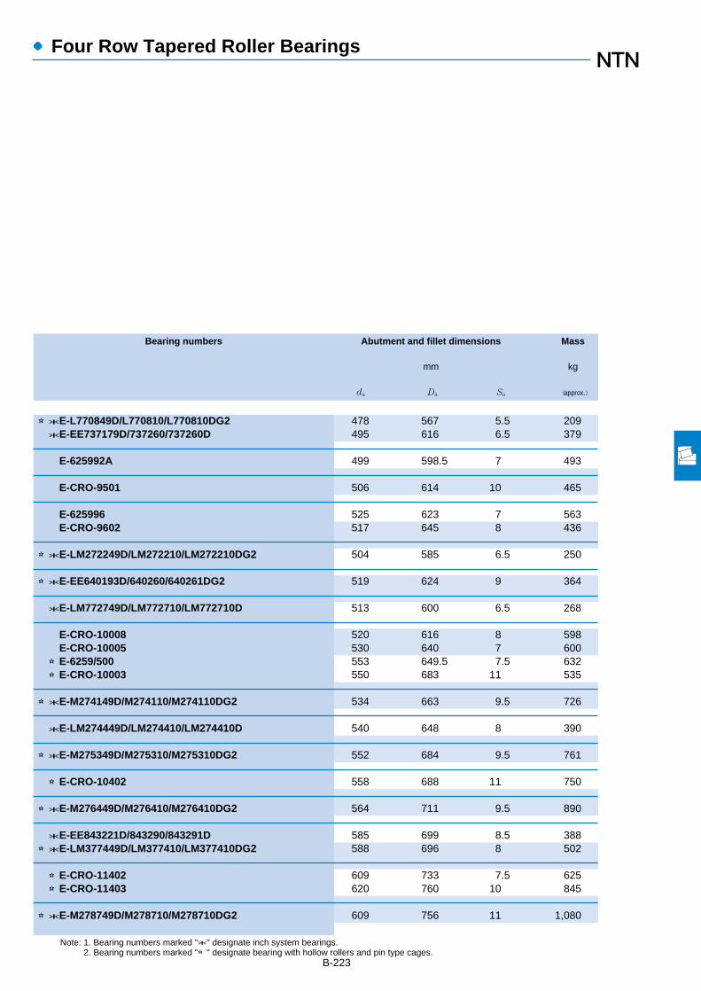
B-223
●Four Row Tapered Roller Bearings
Bearing numbers Abutment and fillet dimensions Mass
mm kg
da Da Sa (approx.)
Note: 1. Bearing numbers marked "*" designate inch system bearings.2. Bearing numbers marked "☆" designate bearing with hollow rollers and pin type cages.
☆*E-L770849D/L770810/L770810DG2 478 567 5.5 209*E-EE737179D/737260/737260D 495 616 6.5 379
E-625992A 499 598.5 7 493
E-CRO-9501 506 614 10 465
E-625996 525 623 7 563E-CRO-9602 517 645 8 436
☆*E-LM272249D/LM272210/LM272210DG2 504 585 6.5 250
☆*E-EE640193D/640260/640261DG2 519 624 9 364
*E-LM772749D/LM772710/LM772710D 513 600 6.5 268
E-CRO-10008 520 616 8 598E-CRO-10005 530 640 7 600☆E-6259/500 553 649.5 7.5 632☆E-CRO-10003 550 683 11 535
☆*E-M274149D/M274110/M274110DG2 534 663 9.5 726
*E-LM274449D/LM274410/LM274410D 540 648 8 390
☆*E-M275349D/M275310/M275310DG2 552 684 9.5 761
☆E-CRO-10402 558 688 11 750
☆*E-M276449D/M276410/M276410DG2 564 711 9.5 890
*E-EE843221D/843290/843291D 585 699 8.5 388☆*E-LM377449D/LM377410/LM377410DG2 588 696 8 502
☆E-CRO-11402 609 733 7.5 625☆E-CRO-11403 620 760 10 845
☆*E-M278749D/M278710/M278710DG2 609 756 11 1,080

B-224
Boundary dimensions Basic load ratingsdynamic static dynamic static
mm kN kgf
d D B2 C2 r1s min1
rs min1
Cr Cor Cr Cor
●Four Row Tapered Roller Bearings
1 Minimum allowable dimension for chamfer dimension r or r1.
d 584.200~825.500mm
762.000 396.875 401.638 3.3 6.4 6,550 22,300 670,000 2,280,000
771.525 479.425 479.425 3.3 6.4 7,350 25,700 750,000 2,620,000
844.550 615.950 615.950 3.3 6.4 12,600 40,500 1,290,000 4,100,000
787.400 361.950 361.950 3.3 6.4 6,450 20,300 655,000 2,070,000
933.450 676.275 676.275 3.3 6.4 15,300 48,000 1,560,000 4,900,000
1,070 642 642 7.5 7.5 15,400 43,500 1,570,000 4,450,000
812.800 365.125 365.125 3.3 6.4 6,200 23,200 630,000 2,360,000
960 700 700 7.5 7.5 16,700 51,500 1,700,000 5,300,000
901.700 552.450 552.450 3.3 6.4 11,200 38,000 1,140,000 3,900,000
870 460 460 3 6 7,500 27,400 765,000 2,790,000
965.200 701.675 701.675 3.3 6.4 16,100 50,500 1,640,000 5,150,000
876.300 352.425 355.600 3.3 6.4 6,050 21,800 615,000 2,220,000
900 410 410 2.5 5 7,650 26,900 780,000 2,740,000
914.400 317.500 317.500 3.3 6.4 5,350 17,900 545,000 1,820,000
1,070 642 642 7.5 7.5 15,400 46,500 1,570,000 4,750,000
1,035.050 755.650 755.650 3.3 6.4 18,300 60,000 1,870,000 6,100,000
990.600 605.000 605.000 3.3 6.4 12,600 45,500 1,290,000 4,650,000
1,079.500 787.400 787.400 4.8 12.7 19,200 65,000 1,960,000 6,600,000
1,120 820 820 7 7.5 21,000 72,500 2,140,000 7,400,000
1,168.400 844.550 844.550 4.8 12.7 22,300 76,500 2,270,000 7,800,000
584.200
585.788
595.312
609.600
657.225
660
660.400
670
679.450
680
682.625
685.800
710
711.200
730
730.250
749.300
762.000
800
r1
B2
DaD
C2
dad
Sa
r
825.500
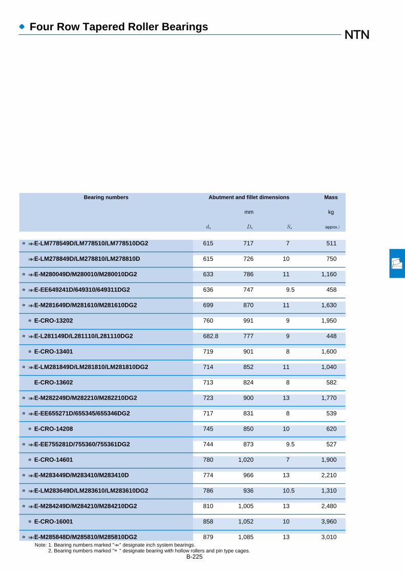
B-225
●Four Row Tapered Roller Bearings
Bearing numbers Abutment and fillet dimensions Mass
mm kg
da Da Sa (approx.)
Note: 1. Bearing numbers marked "*" designate inch system bearings.2. Bearing numbers marked "☆" designate bearing with hollow rollers and pin type cages.
☆*E-LM778549D/LM778510/LM778510DG2 615 717 7 511
*E-LM278849D/LM278810/LM278810D 615 726 10 750
☆*E-M280049D/M280010/M280010DG2 633 786 11 1,160
☆*E-EE649241D/649310/649311DG2 636 747 9.5 458
☆*E-M281649D/M281610/M281610DG2 699 870 11 1,630
☆E-CRO-13202 760 991 9 1,950
☆*E-L281149D/L281110/L281110DG2 682.8 777 9 448
☆E-CRO-13401 719 901 8 1,600
☆*E-LM281849D/LM281810/LM281810DG2 714 852 11 1,040
E-CRO-13602 713 824 8 582
☆*E-M282249D/M282210/M282210DG2 723 900 13 1,770
☆*E-EE655271D/655345/655346DG2 717 831 8 539
☆E-CRO-14208 745 850 10 620
☆*E-EE755281D/755360/755361DG2 744 873 9.5 527
☆E-CRO-14601 780 1,020 7 1,900
☆*E-M283449D/M283410/M283410D 774 966 13 2,210
☆*E-LM283649D/LM283610/LM283610DG2 786 936 10.5 1,310
☆*E-M284249D/M284210/M284210DG2 810 1,005 13 2,480
☆E-CRO-16001 858 1,052 10 3,960
☆*E-M285848D/M285810/M285810DG2 879 1,085 13 3,010

1,170 840 840 6 6 21,900 76,500 2,230,000 7,800,000
1,130.300 669.925 669.925 4.8 12.7 15,800 59,500 1,610,000 6,050,0001,219.200 876.300 889.000 4.8 12.7 24,100 83,000 2,450,000 8,450,000
1,270.000 825.500 825.500 4.8 12.7 22,500 80,000 2,300,000 8,150,000
1,360 880 880 4 7.5 27,000 89,000 2,750,000 9,050,000
1,593.850 990.600 990.600 4.8 12.7 33,500 132,000 3,400,000 13,500,000
B-226
Boundary dimensions Basic load ratingsdynamic static dynamic static
mm kN kgf
d D B2 C2 r1s min1
rs min1
Cr Cor Cr Cor
●Four Row Tapered Roller Bearings
1 Minimum allowable dimension for chamfer dimension r or r1.
d 840~1 200.150mm
840
863.600
938.212
950
1,200.150
r1
B2
DaD
C2
dad
Sa
r

B-227
●Four Row Tapered Roller Bearings
Bearing numbers Abutment and fillet dimensions Mass
mm kg
da Da Sa (approx.)
Note: 1. Bearing numbers marked "*" designate inch system bearings.2. Bearing numbers marked "☆" designate bearing with hollow rollers and pin type cages.
☆E-CRO-16803 897 1,099 12 3,970
☆*E-LM286249D/LM286210/LM286210DG2 906 1,065 11 1,950☆*E-EE547341D/547480/547481DG2 918 1,135 6.5 3,640
☆*E-LM287649D/LM287610/LM287610DG2 990 1,190 10 4,100
☆E-CRO-19001 1,030 1,278 12 4,100
☆*E-LM288949D/LM288910/LM288910DG2 1,260 1,500 13 6,130


●Spherical Roller Bearings
1. Types, construction and characteristics
Spherical roller bearings consist of an outer ring having acontinuous spherical raceway within which operates tworows of barrel-shaped rollers which are in turn guided by aninner ring with two raceways separated by a center rib.(Refer to Diagram 1) This bearing has self-aligningproperties, and therefore is suited for use wheremisalignment between the inner and outer rings occurs fromhousing installation error or shaft flexure.
Spherical roller bearings have a large capacity for radialloads, axial loads in either direction, and complex loads.They are also suited for applications where vibration andshock loads are encountered. When operating under axialloads, however, it is desirable to maintain conditions so thatFa /Fr≦2e in order to prevent sliding movement along the rowof rollers not receiving the axial load. (For the value of e,refer to dimension tables.)
As shown in Table 1, in addition to standard type there arevarious other types of spherical roller bearings. Amongthese, Type E has a particularly high load capacity.
B-229
Type Standard type (B type) C type 213 type E type
Construction
Bearing series
Rollers
Roller guidemethod
Cage type
Does not include C typeSeries 222, 223, and 213with bore dia. of 50 mm orless; series 24024 to 24038.
Series 213 with boredia. of 50 mm or more Series 22211 to 22218
Asymmetrical Symmetrical Asymmetrical Symmetrical
Unified inner ringcenter rib
Separable guide ringbetween rows on innerraceway
Separable guide ringbetween rows on outerraceway
High precision cage(center rib, guide ring)
Pressed Cage;machined cage
Pressed Cage Machined cage Molded resin cage
Table 1 Types of spherical roller bearings
Diagram 1.
Allowablemisalignment
In addition to bearings with cylindrical bore diameters,those with tapered bore diameters are also available.Bearings with tapered bore diameters are specified byattaching the suffix "K" to the end of the bearing's basicnumber. The standard taper ratio is 1:12 for bearings with a"K" suffix, but for bearings in series 240 and 241 the suffix"K30" indicates the taper ratio for a bearing is 1:30. Mosttapered bore bearings incorporate the use of adapters andwithdrawal sleeves for shaft mounting.
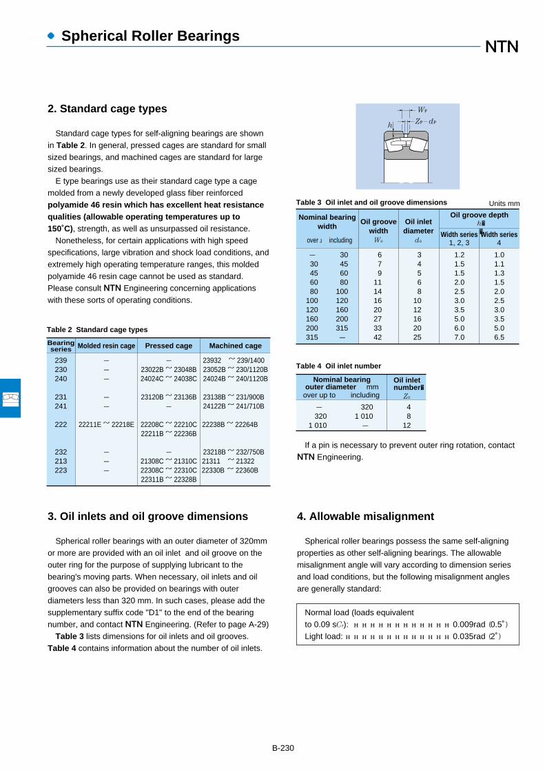
Units mm
- 30456080
100120160200315
Nominal bearingwidth
over including
Oil groovewidth
Wo
Oil inletdiameter
do
Oil groove depthh��Width series
4Width series
1, 2, 3
30456080
100120160200315-
679
11141620273342
34568
1012162025
1.21.51.52.02.53.03.55.06.07.0
1.01.11.31.52.02.53.03.55.06.5
●Spherical Roller Bearings
B-230
Table 3 Oil inlet and oil groove dimensions
Table 4 Oil inlet number
2. Standard cage types
Standard cage types for self-aligning bearings are shownin Table 2. In general, pressed cages are standard for smallsized bearings, and machined cages are standard for largesized bearings.
E type bearings use as their standard cage type a cagemolded from a newly developed glass fiber reinforcedpolyamide 46 resin which has excellent heat resistancequalities (allowable operating temperatures up to150˚C), strength, as well as unsurpassed oil resistance.
Nonetheless, for certain applications with high speedspecifications, large vibration and shock load conditions, andextremely high operating temperature ranges, this moldedpolyamide 46 resin cage cannot be used as standard.Please consult NTN Engineering concerning applicationswith these sorts of operating conditions.
If a pin is necessary to prevent outer ring rotation, contactNTN Engineering.
Wo
Zo doh
Nominal bearingouter diameter mm
- 320
1 010
3201 010-
48
12
over up to including
Oil inletnumber�
Zo
239230240
231241
222
232213223
Molded resin cage Pressed cage Machined cageBearingseries
---
--
22211E ~ 22218E
---
-23022B ~ 23048B24024C ~ 24038C
23120B ~ 23136B-
22208C ~ 22210C22211B ~ 22236B
-21308C ~ 21310C22308C ~ 22310C22311B ~ 22328B
23932 ~ 239/1400 23052B ~ 230/1120B24024B ~ 240/1120B
23138B ~ 231/900B 24122B ~ 241/710B
22238B ~ 22264B
23218B ~ 232/750B 21311 ~ 21322 22330B ~ 22360B
Table 2 Standard cage types
3. Oil inlets and oil groove dimensions
Spherical roller bearings with an outer diameter of 320mmor more are provided with an oil inlet and oil groove on theouter ring for the purpose of supplying lubricant to thebearing's moving parts. When necessary, oil inlets and oilgrooves can also be provided on bearings with outerdiameters less than 320 mm. In such cases, please add thesupplementary suffix code "D1" to the end of the bearingnumber, and contact NTN Engineering. (Refer to page A-29)
Table 3 lists dimensions for oil inlets and oil grooves.Table 4 contains information about the number of oil inlets.
4. Allowable misalignment
Spherical roller bearings possess the same self-aligningproperties as other self-aligning bearings. The allowablemisalignment angle will vary according to dimension seriesand load conditions, but the following misalignment anglesare generally standard:
Normal load (loads equivalentto 0.09 sCr): ………………………………0.009rad (0.5˚)Light load: …………………………………0.035rad (2˚)

5. Adapters and withdrawal sleeves
Adapters are used for installation of bearings with taperedbore diameters on cylindrical shafts. Withdrawal sleeves arealso used to install and disassemble bearings with taperedbore diameters onto and off of cylindrical shafts. Indisassembling the bearing from the shaft, the nut is presseddown against the edge of the inner ring utilizing the boltprovided on the withdrawal sleeve, and then the sleeve isdrawn away from the bearing's inner diameter surface.
For bearings with a bore diameter of 200 mm or more, highpressure oil (hydraulic) type adapters and withdrawal sleeveshave been standardized to make installation anddisassembly easier. As shown in Diagram 2 construction isdesigned to reduce friction by injecting high pressure oilbetween the surfaces of the adapter sleeve and bearinginner bore by means of a pressure fitting.
If the oil supply inlet is attached in the nut side of theadapter, the supplementary suffix "HF" should be added tothe bearing number; if the oil supply inlet is attached on theopposite side, the suffix "HB" should be added to the bearingnumber. For adapter sleeves, the supplementary suffix "H" isadded to the bearing's number in both cases.
For the hydraulic sleeve's nut, the supplementary suffix"SP" should be added to the nut's part number if a threadedbolt hole will be provided for installation / disassemblypurposes; if a hole for a hydraulic pressure fitting will beprovided, "SPB" should be added to the end of the nut's partnumber.
For more information regarding high pressure oil(hydraulic) adapters and withdrawal sleeves, pleaserefer to their special catalog.
●Spherical Roller Bearings
B-231
Diagram 2.
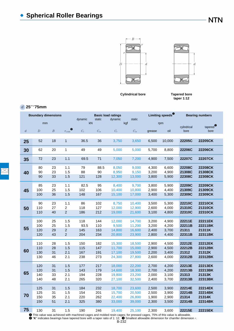
Boundary dimensions Basic load ratings Limiting speeds1
Bearing numbersdynamic static dynamic static
mm kN kgf rpmcylindrical tapered
2
d D B rs min3
Cr Cor Cr Cor grease oil bore bore
●Spherical Roller Bearings
B-232
1 This value was achieved with machined cages and molded resin cages; for pressed cages, 75% of this value is allowable. 2 "K" indicates bearings have tapered bore with a taper ratio of 1: 12. 3 Smallest allowable dimension for chamfer dimension r.
d 25~75mm
40
35
30
25
45
50
55
60
65
70
75
r
dD
B
r
d
Cylindrical bore Tapered boretaper 1:12
52 18 1 36.5 36 3,750 3,650 6,500 10,000 22205C 22205CK
62 20 1 49 49 5,000 5,000 5,700 8,800 22206C 22206CK
72 23 1.1 69.5 71 7,050 7,200 4,900 7,500 22207C 22207CK
80 23 1.1 79 88.5 8,050 9,000 4,300 6,600 22208C 22208CK90 23 1.5 88 90 8,950 9,150 3,200 4,900 21308C 21308CK90 33 1.5 121 128 12,300 13,000 3,800 5,900 22308C 22308CK
85 23 1.1 82.5 95 8,400 9,700 3,800 5,900 22209C 22209CK100 25 1.5 102 106 10,400 10,800 2,900 4,400 21309C 21309CK100 36 1.5 148 167 15,100 17,000 3,400 5,300 22309C 22309CK
90 23 1.1 86 102 8,750 10,400 3,500 5,300 22210C 22210CK110 27 2 118 127 12,000 12,900 2,600 4,000 21310C 21310CK110 40 2 186 212 19,000 21,600 3,100 4,800 22310C 22310CK
100 25 1.5 118 144 12,000 14,700 3,200 4,900 22211E 22211EK100 25 1.5 93.5 110 9,500 11,200 3,200 4,200 22211B 22211BK120 29 2 145 163 14,800 16,600 2,400 3,700 21311 21311K120 43 2 204 234 20,800 23,900 2,800 4,400 22311B 22311BK
110 28 1.5 150 182 15,300 18,500 2,900 4,500 22212E 22212EK110 28 1.5 115 147 11,700 15,000 2,900 4,500 22212B 22212BK130 31 2.1 167 191 17,100 19,500 2,200 3,400 21312 21312K130 46 2.1 238 273 24,300 27,800 2,600 4,000 22312B 22312BK
120 31 1.5 177 217 18,000 22,200 2,700 4,200 22213E 22213EK120 31 1.5 143 179 14,600 18,300 2,700 4,200 22213B 22213BK140 33 2.1 194 228 19,800 23,200 2,000 3,100 21313 21313K140 48 2.1 265 320 27,100 32,500 2,400 3,700 22313B 22313BK
125 31 1.5 184 232 18,700 23,600 2,500 3,900 22214E 22214EK125 31 1.5 154 201 15,700 20,500 2,500 3,900 22214B 22214BK150 35 2.1 220 262 22,400 26,800 1,900 2,900 21314 21314K150 51 2.1 325 380 33,000 39,000 2,300 3,500 22314B 22314BK
130 31 1.5 190 246 19,400 25,100 2,300 3,600 22215E 22215EK
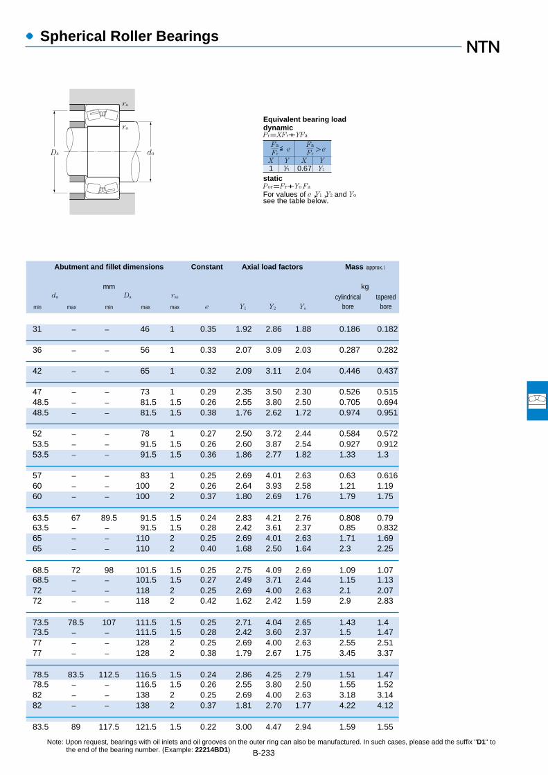
●Spherical Roller Bearings
Abutment and fillet dimensions Constant Axial load factors Mass (approx.)
mm kgda Da ras cylindrical tapered
min max min max max e Y1 Y2 Yo bore bore
B-233Note: Upon request, bearings with oil inlets and oil grooves on the outer ring can also be manufactured. In such cases, please add the suffix "D1" to
the end of the bearing number. (Example: 22214BD1)
31 ― ― 46 1 0.35 1.92 2.86 1.88 0.186 0.182
36 ― ― 56 1 0.33 2.07 3.09 2.03 0.287 0.282
42 ― ― 65 1 0.32 2.09 3.11 2.04 0.446 0.437
47 ― ― 73 1 0.29 2.35 3.50 2.30 0.526 0.51548.5 ― ― 81.5 1.5 0.26 2.55 3.80 2.50 0.705 0.69448.5 ― ― 81.5 1.5 0.38 1.76 2.62 1.72 0.974 0.951
52 ― ― 78 1 0.27 2.50 3.72 2.44 0.584 0.57253.5 ― ― 91.5 1.5 0.26 2.60 3.87 2.54 0.927 0.91253.5 ― ― 91.5 1.5 0.36 1.86 2.77 1.82 1.33 1.3
57 ― ― 83 1 0.25 2.69 4.01 2.63 0.63 0.61660 ― ― 100 2 0.26 2.64 3.93 2.58 1.21 1.1960 ― ― 100 2 0.37 1.80 2.69 1.76 1.79 1.75
63.5 67 89.5 91.5 1.5 0.24 2.83 4.21 2.76 0.808 0.7963.5 ― ― 91.5 1.5 0.28 2.42 3.61 2.37 0.85 0.83265 ― ― 110 2 0.25 2.69 4.01 2.63 1.71 1.6965 ― ― 110 2 0.40 1.68 2.50 1.64 2.3 2.25
68.5 72 98 101.5 1.5 0.25 2.75 4.09 2.69 1.09 1.0768.5 ― ― 101.5 1.5 0.27 2.49 3.71 2.44 1.15 1.1372 ― ― 118 2 0.25 2.69 4.00 2.63 2.1 2.0772 ― ― 118 2 0.42 1.62 2.42 1.59 2.9 2.83
73.5 78.5 107 111.5 1.5 0.25 2.71 4.04 2.65 1.43 1.473.5 ― ― 111.5 1.5 0.28 2.42 3.60 2.37 1.5 1.4777 ― ― 128 2 0.25 2.69 4.00 2.63 2.55 2.5177 ― ― 128 2 0.38 1.79 2.67 1.75 3.45 3.37
78.5 83.5 112.5 116.5 1.5 0.24 2.86 4.25 2.79 1.51 1.4778.5 ― ― 116.5 1.5 0.26 2.55 3.80 2.50 1.55 1.5282 ― ― 138 2 0.25 2.69 4.00 2.63 3.18 3.1482 ― ― 138 2 0.37 1.81 2.70 1.77 4.22 4.12
83.5 89 117.5 121.5 1.5 0.22 3.00 4.47 2.94 1.59 1.55
ra
ra
Da da
1 Y1 0.67 Y2
Fa
Fr
X Y X Y
≦eFa
Fr>e
Pr=XFr+YFa
Por=Fr+Yo Fa
For values of e,Y1,Y2 and Yosee the table below.
Equivalent bearing loaddynamic
static
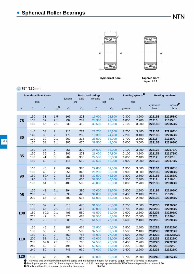
●Spherical Roller Bearings
Boundary dimensions Basic load ratings Limiting speeds1
Bearing numbersdynamic static dynamic static
mm kN kgf rpmcylindrical tapered
2
d D B rs min3
Cr Cor Cr Cor grease oil bore bore
B-234
1 This value was achieved with machined cages and molded resin cages; for pressed cages, 75% of this value is allowable. 2 Bearings appended with "K" have a tapered bore ratio of 1:12; bearings appended with "K30" have a tapered bore ratio of 1:30. 3 Smallest allowable dimension for chamfer dimension r.
d 75~120mm
80
75
85
90
95
100
110
120
130 31 1.5 166 223 16,900 22,800 2,300 3,600 22215B 22215BK160 37 2.1 239 287 24,300 29,300 1,800 2,700 21315 21315K160 55 2.1 330 410 33,500 42,000 2,100 3,200 22315B 22315BK
140 33 2 213 277 21,700 28,200 2,200 3,400 22216E 22216EK140 33 2 179 239 18,300 24,400 2,200 3,400 22216B 22216BK170 39 2.1 260 315 26,500 32,000 1,700 2,500 21316 21316K170 58 2.1 385 470 39,500 48,000 2,000 3,000 22316B 22316BK
150 36 2 251 320 25,600 33,000 2,100 3,200 22217E 22217EK150 36 2 206 272 21,000 27,800 2,100 3,200 22217B 22217BK180 41 3 289 355 29,500 36,000 1,600 2,400 21317 21317K180 60 3 415 510 42,500 52,000 1,900 2,900 22317B 22317BK
160 40 2 292 385 29,800 39,500 1,900 3,000 22218E 22218EK160 40 2 256 345 26,200 35,000 1,900 3,000 22218B 22218BK160 52.4 2 315 455 32,500 46,500 1,800 2,800 23218B 23218BK190 43 3 320 400 32,500 40,500 1,500 2,300 21318 21318K190 64 3 480 590 49,000 60,000 1,800 2,700 22318B 22318BK
170 43 2.1 294 390 30,000 39,500 1,800 2,800 22219B 22219BK200 45 3 335 420 34,000 43,000 1,400 2,100 21319 21319K200 67 3 500 615 51,000 63,000 1,600 2,500 22319B 22319BK
165 52 2 310 470 31,500 47,500 1,700 2,600 23120B 23120BK180 46 2.1 315 415 32,000 42,500 1,700 2,700 22220B 22220BK180 60.3 2.1 405 580 41,500 59,000 1,600 2,500 23220B 23220BK215 47 3 370 465 37,500 47,500 1,300 2,000 21320 21320K215 73 3 605 755 61,500 77,000 1,600 2,400 22320B 22320BK
170 45 2 282 455 28,800 46,500 1,800 2,800 23022B 23022BK180 56 2 370 580 37,500 59,500 1,500 2,400 23122B 23122BK180 69 2 450 755 46,000 77,000 1,500 2,400 24122B 24122BK30200 53 2.1 410 570 42,000 58,000 1,600 2,400 22222B 22222BK200 69.8 2.1 515 760 52,500 77,500 1,400 2,200 23222B 23222BK240 50 3 495 615 50,500 62,500 1,200 1,800 21322 21322K240 80 3 745 930 76,000 95,000 1,400 2,200 22322B 22322BK
180 46 2 296 495 30,000 50,500 1,700 2,600 23024B 23024BK
r
dD
B
r
d
Cylindrical bore Tapered boretaper 1:12

●Spherical Roller Bearings
Abutment and fillet dimensions Constant Axial load factors Mass (approx.)
mm kgda Da ras cylindrical tapered
min max min max max e Y1 Y2 Yo bore bore
B-235Note: Upon request, bearings with oil inlets and oil grooves on the outer ring can also be manufactured. In such cases, please add the suffix "D1" to
the end of the bearing number. (Example: 23024BD1)
83.5 ― ― 121.5 1.5 0.24 2.81 4.19 2.75 1.65 1.6187 ― ― 148 2 0.24 2.84 4.23 2.78 3.81 3.7687 ― ― 148 2 0.37 1.80 2.69 1.76 5.25 5.13
90 94.5 125.5 130 2 0.22 3.01 4.48 2.94 1.99 1.9490 ― ― 130 2 0.26 2.64 3.93 2.58 2.15 2.1192 ― ― 158 2 0.23 2.95 4.39 2.88 4.53 4.4792 ― ― 158 2 0.37 1.80 2.69 1.76 6.05 5.91
95 100.5 135 140 2 0.23 2.96 4.41 2.90 2.49 2.4395 ― ― 140 2 0.26 2.60 3.88 2.55 2.66 2.6199 ― ― 166 2.5 0.25 2.69 4.00 2.63 5.35 5.2899 ― ― 166 2.5 0.37 1.82 2.71 1.78 7.1 6.94
100 107.5 144 150 2 0.24 2.86 4.25 2.79 3.24 3.16100 ― ― 150 2 0.26 2.55 3.80 2.49 3.5 3.42100 ― ― 150 2 0.33 2.04 3.03 1.99 4.45 4.32104 ― ― 176 2.5 0.24 2.83 4.22 2.77 6.3 6.21104 ― ― 176 2.5 0.37 1.80 2.69 1.76 8.35 8.16
107 ― ― 158 2 0.26 2.63 3.92 2.57 4.1 4.01109 ― ― 186 2.5 0.23 3.00 4.46 2.93 7.1 7109 ― ― 186 2.5 0.37 1.80 2.69 1.76 9.76 9.54
110 ― ― 155 2 0.32 2.12 3.15 2.07 4.3 4.16112 ― ― 168 2 0.26 2.55 3.80 2.49 4.95 4.84112 ― ― 168 2 0.34 1.98 2.94 1.93 6.47 6.28114 ― ― 201 2.5 0.22 3.01 4.48 2.94 8.89 8.78114 ― ― 201 2.5 0.37 1.80 2.69 1.76 12.4 12.1
120 ― ― 160 2 0.26 2.59 3.85 2.53 3.71 3.58120 ― ― 170 2 0.31 2.17 3.24 2.13 5.4 5.22120 ― ― 170 2 0.38 1.76 2.63 1.73 7.07 6.96122 ― ― 188 2 0.27 2.51 3.74 2.46 7.2 7.04122 ― ― 188 2 0.35 1.91 2.84 1.86 9.71 9.43124 ― ― 226 2.5 0.21 3.20 4.77 3.13 11.2 11.1124 ― ― 226 2.5 0.36 1.87 2.79 1.83 17.1 16.7
130 ― ― 170 2 0.25 2.69 4.01 2.63 4.05 3.9
ra
ra
Da da
1 Y1 0.67 Y2
Fa
Fr
X Y X Y
≦eFa
Fr>e
Pr=XFr+YFa
Por=Fr+Yo Fa
For values of e,Y1,Y2 and Yosee the table below.
Equivalent bearing loaddynamic
static

●Spherical Roller Bearings
Boundary dimensions Basic load ratings Limiting speeds1
Bearing numbersdynamic static dynamic static
mm kN kgf rpmcylindrical tapered
2
d D B rs min3
Cr Cor Cr Cor grease oil bore bore
B-236
1 This value was achieved with machined cages and molded resin cages; for pressed cages, 75% of this value is allowable. 2 Bearings appended with "K" have a tapered bore ratio of 1:12; bearings appended with "K30" have a tapered bore ratio of 1:30. 3 Smallest allowable dimension for chamfer dimension r.
d 120~160mm
120
130
140
150
160
r
dD
B
r
d
Cylindrical bore Tapered boretaper 1:12
180 60 2 390 670 39,500 68,500 1,500 2,300 24024B 24024BK30180 60 2 395 695 40,000 71,000 1,500 2,300 24024C 24024CK30200 62 2 455 705 46,500 71,500 1,400 2,100 23124B 23124BK200 80 2 575 945 58,500 96,500 1,400 2,100 24124B 24124BK30215 58 2.1 485 700 49,500 71,500 1,400 2,200 22224B 22224BK215 76 2.1 585 880 59,500 89,500 1,300 2,000 23224B 23224BK260 86 3 880 1,120 89,500 114,000 1,300 2,000 22324B 22324BK
200 52 2 375 620 38,500 63,500 1,500 2,300 23026B 23026BK200 69 2 505 895 51,500 91,000 1,300 2,100 24026B 24026BK30200 69 2 490 860 50,000 87,500 1,300 2,100 24026C 24026CK30210 64 2 495 795 50,500 81,000 1,300 2,000 23126B 23126BK210 80 2 585 995 60,000 102,000 1,300 2,000 24126B 24126BK30230 64 3 570 790 58,000 80,500 1,300 2,000 22226B 22226BK230 80 3 685 1,060 70,000 108,000 1,200 1,900 23226B 23226BK280 93 4 1,000 1,290 102,000 131,000 1,200 1,800 22326B 22326BK
210 53 2 405 690 41,000 70,500 1,400 2,200 23028B 23028BK210 69 2 510 945 52,000 96,500 1,200 1,900 24028B 24028BK30210 69 2 520 940 53,000 95,500 1,200 1,900 24028C 24028CK30225 68 2.1 540 895 55,000 91,000 1,200 1,800 23128B 23128BK225 85 2.1 670 1,150 68,500 117,000 1,200 1,800 24128B 24128BK30250 68 3 685 975 70,000 99,500 1,200 1,900 22228B 22228BK250 88 3 805 1,270 82,000 129,000 1,100 1,700 23228B 23228BK300 102 4 1,130 1,460 115,000 149,000 1,100 1,700 22328B 22328BK
225 56 2.1 445 775 45,500 79,000 1,300 2,000 23030B 23030BK225 75 2.1 585 1,060 59,500 108,000 1,200 1,800 24030B 24030BK30225 75 2.1 600 1,090 61,000 111,000 1,200 1,800 24030C 24030CK30250 80 2.1 730 1,190 74,500 121,000 1,100 1,700 23130B 23130BK250 100 2.1 885 1,520 90,500 155,000 1,100 1,700 24130B 24130BK30270 73 3 775 1,160 79,000 119,000 1,100 1,700 22230B 22230BK270 96 3 935 1,460 95,000 149,000 1,000 1,600 23230B 23230BK320 108 4 1,270 1,750 130,000 179,000 1,000 1,600 22330B 22330BK
220 45 2 320 610 33,000 62,500 1,300 2,000 23932 23932K240 60 2.1 505 885 51,500 90,000 1,200 1,900 23032B 23032BK240 80 2.1 650 1,200 66,500 122,000 1,100 1,700 24032B 24032BK30240 80 2.1 665 1,250 67,500 127,000 1,100 1,700 24032C 24032CK30

●Spherical Roller Bearings
Abutment and Constant Axial load factors Mass (approx.)fillet dimensions
mm kg
da Da ras cylindrical taperedmin max max e Y1 Y2 Yo bore bore
B-237
Note: When the outer diameter of a Spherical Roller Bearing is 320mm or larger, an oil groove is on OD. See page B-230 on dimensions. We can make bearingswith oil hole or oil groove in the outer ring, per your request, for an outer diameter of 320mm or less. Such bearings are indicated by attaching "D1" to the end ofthe bearing number. (ex. 23032BD1)
ra
ra
Da da
1 Y1 0.67 Y2
Fa
Fr
X Y X Y
≦eFa
Fr>e
Pr=XFr+YFa
Por=Fr+Yo Fa
For values of e,Y1,Y2 and Yosee the table below.
Equivalent bearing loaddynamic
static
130 170 2 0.33 2.06 3.07 2.02 5.48 5.39130 170 2 0.32 2.12 3.15 2.07 5.48 4.91130 190 2 0.31 2.17 3.24 2.13 7.7 7.46130 190 2 0.40 1.68 2.50 1.64 10.3 10.1132 203 2 0.27 2.47 3.68 2.42 9.1 8.89132 203 2 0.36 1.89 2.82 1.85 12.1 11.7134 246 2.5 0.37 1.80 2.69 1.76 21.5 21
140 190 2 0.26 2.63 3.92 2.57 5.9 5.69140 190 2 0.34 1.98 2.95 1.94 8.08 7.95140 190 2 0.32 2.12 3.15 2.07 7.91 7.78140 200 2 0.30 2.23 3.32 2.18 8.47 8.2140 200 2 0.38 1.78 2.65 1.74 11 10.8144 216 2.5 0.28 2.39 3.56 2.33 11.2 10.9144 216 2.5 0.35 1.92 2.86 1.88 14.3 13.9148 262 3 0.37 1.81 2.69 1.77 26.8 26.2
150 200 2 0.25 2.73 4.06 2.67 6.35 6.12150 200 2 0.32 2.09 3.12 2.05 8.57 8.43150 200 2 0.30 2.23 3.32 2.18 8.48 7.66152 213 2 0.30 2.25 3.35 2.20 10.2 9.86152 213 2 0.38 1.80 2.68 1.76 13.3 13.1154 236 2.5 0.28 2.39 3.55 2.33 14 13.7154 236 2.5 0.36 1.90 2.83 1.86 18.8 18.2158 282 3 0.37 1.80 2.69 1.76 33.8 33
162 213 2 0.24 2.76 4.11 2.70 7.73 7.45162 213 2 0.33 2.06 3.07 2.02 10.7 10.5162 213 2 0.30 2.25 3.34 2.20 10.5 10.3162 238 2 0.32 2.11 3.15 2.06 15.6 15.1162 238 2 0.40 1.69 2.51 1.65 20.2 20164 256 2.5 0.27 2.46 3.66 2.4 18.1 17.7164 256 2.5 0.36 1.88 2.79 1.83 24.1 23.4168 302 3 0.35 1.92 2.86 1.88 42.7 41.8
170 210 2 0.18 3.69 5.49 3.61 5.5 5.33172 228 2 0.25 2.74 4.09 2.68 9.42 9.09172 228 2 0.32 2.10 3.13 2.06 13 12.8172 228 2 0.31 2.18 3.24 2.13 12 11.8

●Spherical Roller Bearings
Boundary dimensions Basic load ratings Limiting speeds1
Bearing numbersdynamic static dynamic static
mm kN kgf rpmcylindrical tapered
2
d D B rs min3
Cr Cor Cr Cor grease oil bore bore
B-238
1 This value was achieved with machined cages and molded resin cages; for pressed cages, 75% of this value is allowable. 2 Bearings appended with "K" have a tapered bore ratio of 1:12; bearings appended with "K30" have a tapered bore ratio of 1:30. 3 Smallest allowable dimension for chamfer dimension r.
d 160~200mm
270 86 2.1 840 1,370 85,500 140,000 1,000 1,600 23132B 23132BK270 109 2.1 1,040 1,780 106,000 181,000 1,000 1,600 24132B 24132BK30290 80 3 870 1,290 88,500 132,000 1,000 1,600 22232B 22232BK290 104 3 1,050 1,660 107,000 170,000 960 1,500 23232B 23232BK340 114 4 1,410 1,990 144,000 203,000 940 1,500 22332B 22332BK
230 45 2 330 650 34,000 66,000 1,200 1,900 23934 23934K260 67 2.1 630 1,080 64,000 110,000 1,100 1,800 23034B 23034BK260 90 2.1 800 1,470 81,500 150,000 1,000 1,600 24034B 24034BK30260 90 2.1 815 1,500 83,000 153,000 1,000 1,600 24034C 24034CK30280 88 2.1 885 1,490 90,500 152,000 960 1,500 23134B 23134BK280 109 2.1 1,080 1,880 110,000 191,000 960 1,500 24134B 24134BK30310 86 4 1,000 1,520 102,000 155,000 980 1,500 22234B 22234BK310 110 4 1,180 1,960 120,000 200,000 910 1,400 23234B 23234BK360 120 4 1,540 2,180 157,000 223,000 880 1,400 22334B 22334BK
250 52 2 440 835 45,000 85,000 1,200 1,800 23936 23936K280 74 2.1 740 1,290 75,500 132,000 1,100 1,700 23036B 23036BK280 100 2.1 965 1,770 98,500 181,000 950 1,500 24036B 24036BK30280 100 2.1 965 1,770 98,500 181,000 950 1,500 24036C 24036CK30300 96 3 1,030 1,730 105,000 176,000 900 1,400 23136B 23136BK300 118 3 1,250 2,210 127,000 225,000 900 1,400 24136B 24136BK30320 86 4 1,040 1,610 106,000 164,000 920 1,400 22236B 22236BK320 112 4 1,230 2,000 125,000 204,000 850 1,300 23236B 23236BK380 126 4 1,740 2,560 177,000 261,000 830 1,300 22336B 22336BK
260 52 2 460 890 47,000 91,000 1,100 1,700 23938 23938K290 75 2.1 755 1,350 77,000 138,000 1,000 1,600 23038B 23038BK290 100 2.1 995 1,850 102,000 188,000 900 1,400 24038B 24038BK30290 100 2.1 970 1,820 98,500 186,000 900 1,400 24038C 24038CK30320 104 3 1,190 2,020 122,000 206,000 850 1,300 23138B 23138BK320 128 3 1,420 2,480 144,000 253,000 850 1,300 24138B 24138BK30340 92 4 1,160 1,810 118,000 185,000 860 1,300 22238B 22238BK340 120 4 1,400 2,330 143,000 237,000 790 1,200 23238B 23238BK400 132 5 1,870 2,790 191,000 284,000 780 1,200 22338B 22338BK
280 60 2.1 545 1,100 56,000 112,000 1,000 1,600 23940 23940K310 82 2.1 915 1,620 93,000 165,000 960 1,500 23040B 23040BK310 109 2.1 1,160 2,140 118,000 219,000 850 1,300 24040B 24040BK30
170
160
180
190
200
r
d
B
dD
r
Cylindrical bore Tapered boretaper 1:12
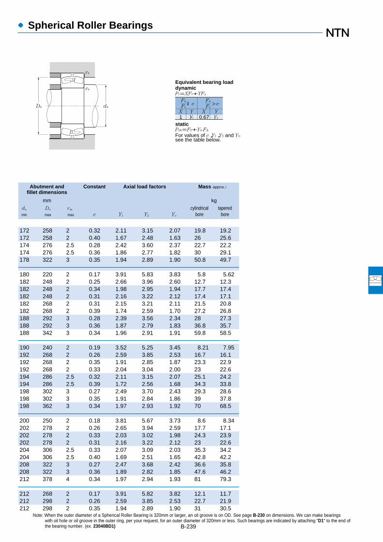
●Spherical Roller Bearings
Abutment and Constant Axial load factors Mass (approx.)fillet dimensions
mm kg
da Da ras cylindrical taperedmin max max e Y1 Y2 Yo bore bore
B-239
Note: When the outer diameter of a Spherical Roller Bearing is 320mm or larger, an oil groove is on OD. See page B-230 on dimensions. We can make bearingswith oil hole or oil groove in the outer ring, per your request, for an outer diameter of 320mm or less. Such bearings are indicated by attaching "D1" to the end ofthe bearing number. (ex. 23040BD1)
172 258 2 0.32 2.11 3.15 2.07 19.8 19.2172 258 2 0.40 1.67 2.48 1.63 26 25.6174 276 2.5 0.28 2.42 3.60 2.37 22.7 22.2174 276 2.5 0.36 1.86 2.77 1.82 30 29.1178 322 3 0.35 1.94 2.89 1.90 50.8 49.7
180 220 2 0.17 3.91 5.83 3.83 5.8 5.62182 248 2 0.25 2.66 3.96 2.60 12.7 12.3182 248 2 0.34 1.98 2.95 1.94 17.7 17.4182 248 2 0.31 2.16 3.22 2.12 17.4 17.1182 268 2 0.31 2.15 3.21 2.11 21.5 20.8182 268 2 0.39 1.74 2.59 1.70 27.2 26.8188 292 3 0.28 2.39 3.56 2.34 28 27.3188 292 3 0.36 1.87 2.79 1.83 36.8 35.7188 342 3 0.34 1.96 2.91 1.91 59.8 58.5
190 240 2 0.19 3.52 5.25 3.45 8.21 7.95192 268 2 0.26 2.59 3.85 2.53 16.7 16.1192 268 2 0.35 1.91 2.85 1.87 23.3 22.9192 268 2 0.33 2.04 3.04 2.00 23 22.6194 286 2.5 0.32 2.11 3.15 2.07 25.1 24.2194 286 2.5 0.39 1.72 2.56 1.68 34.3 33.8198 302 3 0.27 2.49 3.70 2.43 29.3 28.6198 302 3 0.35 1.91 2.84 1.86 39 37.8198 362 3 0.34 1.97 2.93 1.92 70 68.5
200 250 2 0.18 3.81 5.67 3.73 8.6 8.34202 278 2 0.26 2.65 3.94 2.59 17.7 17.1202 278 2 0.33 2.03 3.02 1.98 24.3 23.9202 278 2 0.31 2.16 3.22 2.12 23 22.6204 306 2.5 0.33 2.07 3.09 2.03 35.3 34.2204 306 2.5 0.40 1.69 2.51 1.65 42.8 42.2208 322 3 0.27 2.47 3.68 2.42 36.6 35.8208 322 3 0.36 1.89 2.82 1.85 47.6 46.2212 378 4 0.34 1.97 2.94 1.93 81 79.3
212 268 2 0.17 3.91 5.82 3.82 12.1 11.7212 298 2 0.26 2.59 3.85 2.53 22.7 21.9212 298 2 0.35 1.94 2.89 1.90 31 30.5
1 Y1 0.67 Y2
Fa
Fr
X Y X Y
≦eFa
Fr>e
Pr=XFr+YFa
ra
ra
daDa
Por=Fr+Yo Fa
For values of e,Y1,Y2 and Yosee the table below.
Equivalent bearing loaddynamic
static

●Spherical Roller Bearings
Boundary dimensions Basic load ratings Limiting speeds Bearing numbersdynamic static dynamic static
mm kN kgf rpmcylindrical tapered
1
d D B rs min2
Cr Cor Cr Cor grease oil bore bore
B-2401 Bearings appended with "K" have a tapered bore ratio of 1:12; bearings appended with "K30" have a tapered bore ratio of 1:30. 2 Smallest allowable dimension for chamfer dimension r.
d 200~280mm
220
200
240
260
280
r
d
B
dD
r
Cylindrical bore Tapered boretaper 1:12
340 112 3 1,350 2,270 137,000 231,000 800 1,200 23140B 23140BK340 140 3 1,630 2,900 166,000 295,000 800 1,200 24140B 24140BK30360 98 4 1,310 2,010 134,000 205,000 820 1,300 22240B 22240BK360 128 4 1,610 2,640 165,000 269,000 750 1,200 23240B 23240BK420 138 5 2,040 3,050 208,000 310,000 740 1,100 22340B 22340BK
300 60 2.1 565 1,170 57,500 119,000 930 1,400 23944 23944K340 90 3 1,060 1,920 108,000 195,000 870 1,300 23044B 23044BK340 118 3 1,350 2,570 138,000 262,000 770 1,200 24044B 24044BK30370 120 4 1,540 2,670 157,000 272,000 720 1,100 23144B 23144BK370 150 4 1,880 3,400 192,000 345,000 720 1,100 24144B 24144BK30400 108 4 1,580 2,460 161,000 251,000 730 1,100 22244B 22244BK400 144 4 2,010 3,350 205,000 340,000 670 1,000 23244B 23244BK460 145 5 2,350 3,500 240,000 360,000 660 1,000 22344B 22344BK
320 60 2.1 565 1,190 58,000 121,000 840 1,300 23948 23948K360 92 3 1,130 2,140 116,000 219,000 790 1,200 23048B 23048BK360 118 3 1,410 2,770 144,000 282,000 700 1,100 24048B 24048BK30400 128 4 1,730 3,050 177,000 310,000 650 1,000 23148B 23148BK400 160 4 2,110 3,800 215,000 390,000 650 1,000 24148B 24148BK30440 120 4 1,940 3,100 198,000 315,000 660 1,000 22248B 22248BK440 160 4 2,430 4,100 247,000 420,000 610 940 23248B 23248BK500 155 5 2,720 4,100 278,000 420,000 600 930 22348B 22348BK
360 75 2.1 760 1,580 77,500 161,000 770 1,200 23952 23952K400 104 4 1,420 2,620 144,000 267,000 720 1,100 23052B 23052BK400 140 4 1,830 3,550 186,000 365,000 640 980 24052B 24052BK30440 144 4 2,140 3,850 219,000 395,000 600 920 23152B 23152BK440 180 4 2,510 4,600 256,000 470,000 600 920 24152B 24152BK30480 130 5 2,230 3,600 228,000 365,000 610 930 22252B 22252BK480 174 5 2,760 4,700 281,000 480,000 560 860 23252B 23252BK540 165 6 3,100 4,750 320,000 485,000 550 850 22352B 22352BK
380 75 2.1 830 1,750 84,500 179,000 710 1,100 23956 23956K420 106 4 1,510 2,920 154,000 297,000 660 1,000 23056B 23056BK420 140 4 1,950 3,950 199,000 405,000 590 900 24056B 24056BK30460 146 5 2,300 4,250 234,000 435,000 550 850 23156B 23156BK460 180 5 2,730 5,200 278,000 530,000 550 850 24156B 24156BK30500 130 5 2,310 3,800 236,000 390,000 560 860 22256B 22256BK

●Spherical Roller Bearings
Abutment and Constant Axial load factors Mass (approx.)fillet dimensions
mm kg
da Da ras cylindrical taperedmin max max e Y1 Y2 Yo bore bore
B-241Note: Please refer to page B-230 for outer ring oil inlet and oil groove dimensions.
214 326 2.5 0.33 2.05 3.05 2.00 43.3 42214 326 2.5 0.41 1.64 2.44 1.60 53.4 52.6218 342 3 0.28 2.45 3.64 2.39 44 43218 342 3 0.36 1.88 2.79 1.83 57.2 55.5222 398 4 0.34 1.98 2.95 1.94 93.2 91.2
232 288 2 0.19 3.62 5.39 3.54 13.1 12.7234 326 2.5 0.26 2.59 3.85 2.53 29.9 28.8234 326 2.5 0.34 1.97 2.94 1.93 40.2 39.6238 352 3 0.33 2.07 3.09 2.03 53.3 51.6238 352 3 0.41 1.66 2.47 1.62 67 66238 382 3 0.27 2.46 3.66 2.40 60.4 59.1238 382 3 0.36 1.85 2.76 1.81 80 77.6242 438 4 0.33 2.06 3.07 2.02 117 115
252 308 2 0.16 4.13 6.15 4.04 14 13.6254 346 2.5 0.25 2.69 4.01 2.63 33.4 32.2254 346 2.5 0.32 2.09 3.12 2.05 43 42.3258 382 3 0.32 2.11 3.15 2.07 65.8 63.8258 382 3 0.40 1.69 2.51 1.65 82.2 80.9258 422 3 0.28 2.43 3.62 2.38 81.7 80258 422 3 0.37 1.83 2.72 1.79 108 105262 478 4 0.32 2.10 3.13 2.06 148 145
272 348 2 0.19 3.53 5.26 3.45 24 23.3278 382 3 0.26 2.63 3.92 2.57 48.5 46.8278 382 3 0.34 1.96 2.91 1.91 65.2 64.1278 422 3 0.33 2.05 3.06 2.01 91.4 88.6278 422 3 0.41 1.63 2.43 1.60 114 112282 458 4 0.28 2.45 3.64 2.39 106 104282 458 4 0.37 1.83 2.72 1.79 141 137288 512 5 0.32 2.13 3.18 2.09 183 179
292 368 2 0.17 3.88 5.78 3.79 26.4 25.6298 402 3 0.25 2.73 4.06 2.67 52.4 50.6298 402 3 0.33 2.06 3.07 2.02 69 67.9302 438 4 0.32 2.13 3.18 2.09 97.7 94.6302 438 4 0.39 1.73 2.58 1.69 120 118302 478 4 0.26 2.57 3.83 2.51 112 110
1 Y1 0.67 Y2
Fa
Fr
X Y X Y
≦eFa
Fr>e
Pr=XFr+YFa
ra
ra
daDa
Por=Fr+Yo Fa
For values of e,Y1,Y2 and Yosee the table below.
Equivalent bearing loaddynamic
static
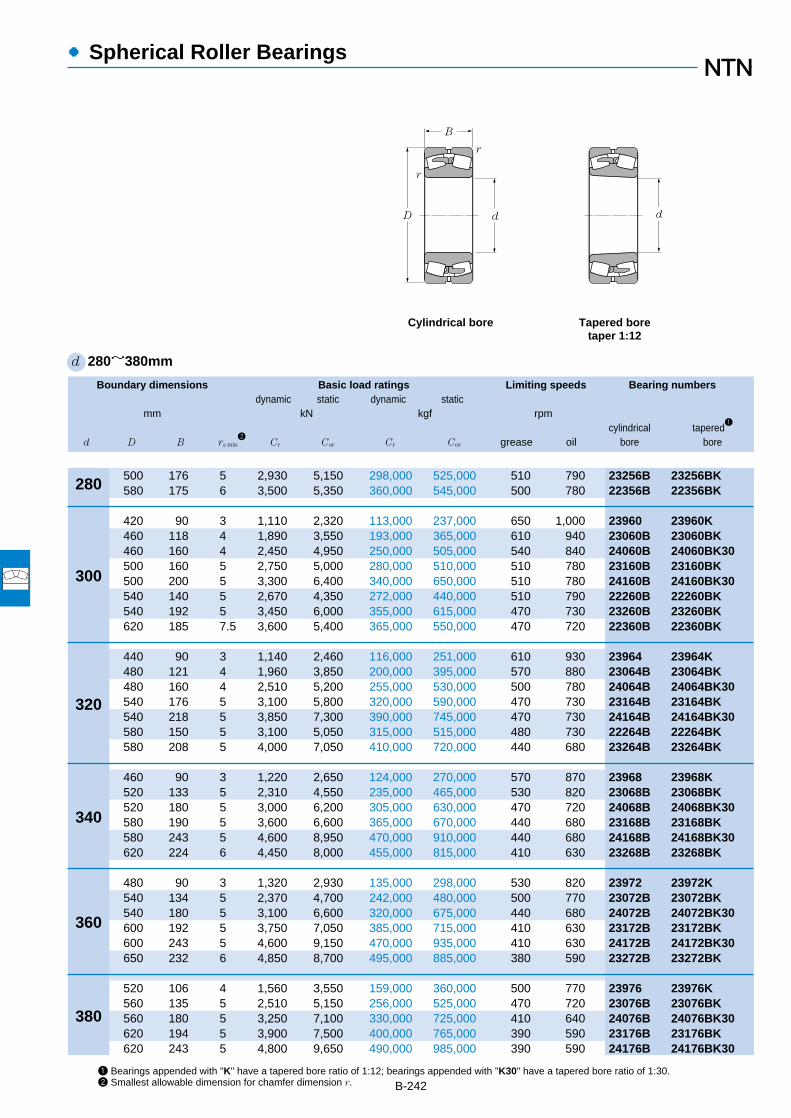
●Spherical Roller Bearings
Boundary dimensions Basic load ratings Limiting speeds Bearing numbersdynamic static dynamic static
mm kN kgf rpmcylindrical tapered
1
d D B rs min2
Cr Cor Cr Cor grease oil bore bore
B-2421 Bearings appended with "K" have a tapered bore ratio of 1:12; bearings appended with "K30" have a tapered bore ratio of 1:30. 2 Smallest allowable dimension for chamfer dimension r.
d 280~380mm
500 176 5 2,930 5,150 298,000 525,000 510 790 23256B 23256BK580 175 6 3,500 5,350 360,000 545,000 500 780 22356B 22356BK
420 90 3 1,110 2,320 113,000 237,000 650 1,000 23960 23960K460 118 4 1,890 3,550 193,000 365,000 610 940 23060B 23060BK460 160 4 2,450 4,950 250,000 505,000 540 840 24060B 24060BK30500 160 5 2,750 5,000 280,000 510,000 510 780 23160B 23160BK500 200 5 3,300 6,400 340,000 650,000 510 780 24160B 24160BK30540 140 5 2,670 4,350 272,000 440,000 510 790 22260B 22260BK540 192 5 3,450 6,000 355,000 615,000 470 730 23260B 23260BK620 185 7.5 3,600 5,400 365,000 550,000 470 720 22360B 22360BK
440 90 3 1,140 2,460 116,000 251,000 610 930 23964 23964K480 121 4 1,960 3,850 200,000 395,000 570 880 23064B 23064BK480 160 4 2,510 5,200 255,000 530,000 500 780 24064B 24064BK30540 176 5 3,100 5,800 320,000 590,000 470 730 23164B 23164BK540 218 5 3,850 7,300 390,000 745,000 470 730 24164B 24164BK30580 150 5 3,100 5,050 315,000 515,000 480 730 22264B 22264BK580 208 5 4,000 7,050 410,000 720,000 440 680 23264B 23264BK
460 90 3 1,220 2,650 124,000 270,000 570 870 23968 23968K520 133 5 2,310 4,550 235,000 465,000 530 820 23068B 23068BK520 180 5 3,000 6,200 305,000 630,000 470 720 24068B 24068BK30580 190 5 3,600 6,600 365,000 670,000 440 680 23168B 23168BK580 243 5 4,600 8,950 470,000 910,000 440 680 24168B 24168BK30620 224 6 4,450 8,000 455,000 815,000 410 630 23268B 23268BK
480 90 3 1,320 2,930 135,000 298,000 530 820 23972 23972K540 134 5 2,370 4,700 242,000 480,000 500 770 23072B 23072BK540 180 5 3,100 6,600 320,000 675,000 440 680 24072B 24072BK30600 192 5 3,750 7,050 385,000 715,000 410 630 23172B 23172BK600 243 5 4,600 9,150 470,000 935,000 410 630 24172B 24172BK30650 232 6 4,850 8,700 495,000 885,000 380 590 23272B 23272BK
520 106 4 1,560 3,550 159,000 360,000 500 770 23976 23976K560 135 5 2,510 5,150 256,000 525,000 470 720 23076B 23076BK560 180 5 3,250 7,100 330,000 725,000 410 640 24076B 24076BK30620 194 5 3,900 7,500 400,000 765,000 390 590 23176B 23176BK620 243 5 4,800 9,650 490,000 985,000 390 590 24176B 24176BK30
300
280
320
340
360
380
r
d
B
dD
r
Cylindrical bore Tapered boretaper 1:12
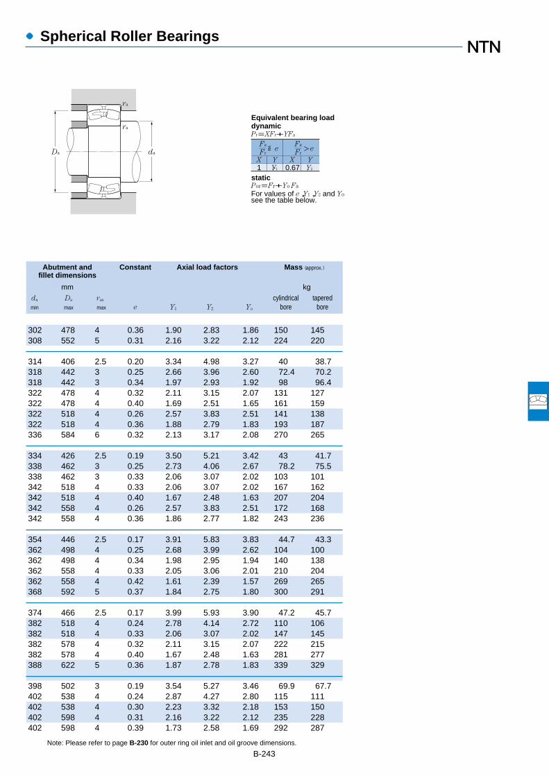
●Spherical Roller Bearings
Abutment and Constant Axial load factors Mass (approx.)fillet dimensions
mm kg
da Da ras cylindrical taperedmin max max e Y1 Y2 Yo bore bore
B-243Note: Please refer to page B-230 for outer ring oil inlet and oil groove dimensions.
302 478 4 0.36 1.90 2.83 1.86 150 145308 552 5 0.31 2.16 3.22 2.12 224 220
314 406 2.5 0.20 3.34 4.98 3.27 40 38.7318 442 3 0.25 2.66 3.96 2.60 72.4 70.2318 442 3 0.34 1.97 2.93 1.92 98 96.4322 478 4 0.32 2.11 3.15 2.07 131 127322 478 4 0.40 1.69 2.51 1.65 161 159322 518 4 0.26 2.57 3.83 2.51 141 138322 518 4 0.36 1.88 2.79 1.83 193 187336 584 6 0.32 2.13 3.17 2.08 270 265
334 426 2.5 0.19 3.50 5.21 3.42 43 41.7338 462 3 0.25 2.73 4.06 2.67 78.2 75.5338 462 3 0.33 2.06 3.07 2.02 103 101342 518 4 0.33 2.06 3.07 2.02 167 162342 518 4 0.40 1.67 2.48 1.63 207 204342 558 4 0.26 2.57 3.83 2.51 172 168342 558 4 0.36 1.86 2.77 1.82 243 236
354 446 2.5 0.17 3.91 5.83 3.83 44.7 43.3362 498 4 0.25 2.68 3.99 2.62 104 100362 498 4 0.34 1.98 2.95 1.94 140 138362 558 4 0.33 2.05 3.06 2.01 210 204362 558 4 0.42 1.61 2.39 1.57 269 265368 592 5 0.37 1.84 2.75 1.80 300 291
374 466 2.5 0.17 3.99 5.93 3.90 47.2 45.7382 518 4 0.24 2.78 4.14 2.72 110 106382 518 4 0.33 2.06 3.07 2.02 147 145382 578 4 0.32 2.11 3.15 2.07 222 215382 578 4 0.40 1.67 2.48 1.63 281 277388 622 5 0.36 1.87 2.78 1.83 339 329
398 502 3 0.19 3.54 5.27 3.46 69.9 67.7402 538 4 0.24 2.87 4.27 2.80 115 111402 538 4 0.30 2.23 3.32 2.18 153 150402 598 4 0.31 2.16 3.22 2.12 235 228402 598 4 0.39 1.73 2.58 1.69 292 287
1 Y1 0.67 Y2
Fa
Fr
X Y X Y
≦eFa
Fr>e
Pr=XFr+YFa
ra
ra
daDa
Por=Fr+Yo Fa
For values of e,Y1,Y2 and Yosee the table below.
Equivalent bearing loaddynamic
static

●Spherical Roller Bearings
Boundary dimensions Basic load ratings Limiting speeds Bearing numbersdynamic static dynamic static
mm kN kgf rpmcylindrical tapered
1
d D B rs min2
Cr Cor Cr Cor grease oil bore bore
B-2441 Bearings appended with "K" have a tapered bore ratio of 1:12; bearings appended with "K30" have a tapered bore ratio of 1:30. 2 Smallest allowable dimension for chamfer dimension r.
d 380~500mm
680 240 6 5,200 9,650 530,000 985,000 360 550 23276B 23276BK
540 106 4 1,580 3,650 161,000 370,000 470 720 23980 23980K600 148 5 2,980 6,050 305,000 615,000 440 680 23080B 23080BK600 200 5 3,850 8,400 390,000 855,000 390 600 24080B 24080BK30650 200 6 4,200 8,050 425,000 820,000 360 560 23180B 23180BK650 250 6 5,100 10,300 520,000 1,060,000 360 560 24180B 24180BK30720 256 6 5,850 10,600 595,000 1,080,000 340 520 23280B 23280BK
560 106 4 1,630 3,850 166,000 390,000 450 690 23984 23984K620 150 5 3,100 6,400 315,000 650,000 420 640 23084B 23084BK620 200 5 3,850 8,450 395,000 865,000 370 570 24084B 24084BK30700 224 6 5,200 9,950 530,000 1,020,000 350 530 23184B 23184BK700 280 6 6,150 12,200 625,000 1,240,000 350 530 24184B 24184BK30760 272 7.5 6,550 12,000 665,000 1,230,000 320 490 23284B 23284BK
600 118 4 2,030 4,700 207,000 480,000 420 650 23988 23988K650 157 6 3,300 6,850 335,000 695,000 400 610 23088B 23088BK650 212 6 4,300 9,450 440,000 960,000 350 540 24088B 24088BK30720 226 6 5,200 10,100 530,000 1,030,000 330 500 23188B 23188BK720 280 6 6,450 13,100 660,000 1,330,000 330 500 24188B 24188BK30790 280 7.5 6,900 12,800 705,000 1,310,000 300 470 23288B 23288BK
620 118 4 2,100 4,950 214,000 505,000 400 620 23992 23992K680 163 6 3,600 7,450 365,000 760,000 370 580 23092B 23092BK680 218 6 4,600 10,200 470,000 1,040,000 330 510 24092B 24092BK30760 240 7.5 5,700 11,400 585,000 1,160,000 310 470 23192B 23192BK760 300 7.5 7,100 14,500 725,000 1,480,000 310 470 24192B 24192BK30830 296 7.5 7,750 14,500 790,000 1,470,000 290 440 23292B 23292BK
650 128 5 2,330 5,500 238,000 565,000 380 590 23996 23996K700 165 6 3,650 7,700 370,000 785,000 360 550 23096B 23096BK700 218 6 4,650 10,500 475,000 1,070,000 320 490 24096B 24096BK30790 248 7.5 6,200 12,300 635,000 1,260,000 290 450 23196B 23196BK790 308 7.5 7,450 15,300 760,000 1,560,000 290 450 24196B 24196BK30870 310 7.5 8,300 15,500 845,000 1,580,000 270 420 23296B 23296BK
670 128 5 2,370 5,600 242,000 570,000 360 560 239/500 239/500K720 167 6 3,850 8,300 390,000 845,000 340 530 230/500B 230/500BK
400
380
420
440
460
480
500
r
d
B
dD
r
Cylindrical bore Tapered boretaper 1:12

●Spherical Roller Bearings
Abutment and Constant Axial load factors Mass (approx.)fillet dimensions
mm kg
da Da ras cylindrical taperedmin max max e Y1 Y2 Yo bore bore
B-245Note: Please refer to page B-230 for outer ring oil inlet and oil groove dimensions.
408 652 5 0.36 1.89 2.82 1.85 380 369
418 522 3 0.18 3.71 5.53 3.63 73 70.7422 578 4 0.24 2.80 4.16 2.73 149 144422 578 4 0.32 2.09 3.11 2.04 202 200428 622 5 0.31 2.21 3.28 2.16 264 256428 622 5 0.38 1.77 2.63 1.73 329 324428 692 5 0.37 1.81 2.69 1.77 457 443
438 542 3 0.17 3.95 5.88 3.86 76.2 73.8442 598 4 0.24 2.85 4.24 2.78 157 152442 598 4 0.32 2.13 3.18 2.09 210 207448 672 5 0.32 2.11 3.15 2.07 354 343448 672 5 0.40 1.69 2.51 1.65 440 433456 724 6 0.36 1.86 2.77 1.82 544 528
458 582 3 0.18 3.66 5.46 3.58 101 98468 622 5 0.24 2.85 4.24 2.78 181 175468 622 5 0.32 2.11 3.15 2.07 245 241468 692 5 0.31 2.15 3.21 2.11 370 358468 692 5 0.39 1.75 2.61 1.71 456 449476 754 6 0.36 1.88 2.80 1.84 600 582
478 602 3 0.17 3.95 5.88 3.86 107 104488 652 5 0.23 2.88 4.29 2.82 206 200488 652 5 0.31 2.15 3.21 2.11 276 272496 724 6 0.31 2.14 3.19 2.10 443 429496 724 6 0.39 1.71 2.55 1.67 550 541496 794 6 0.36 1.87 2.78 1.83 704 683
502 628 4 0.18 3.85 5.73 3.76 123 119508 672 5 0.23 2.94 4.38 2.88 217 209508 672 5 0.30 2.22 3.30 2.17 285 280516 754 6 0.31 2.15 3.21 2.11 492 477516 754 6 0.39 1.74 2.59 1.70 608 600516 834 6 0.36 1.87 2.78 1.83 814 790
522 648 4 0.17 4.02 5.98 3.93 131 127528 692 5 0.23 2.98 4.44 2.91 226 218
1 Y1 0.67 Y2
Fa
Fr
X Y X Y
≦eFa
Fr>e
Pr=XFr+YFa
ra
ra
daDa
Por=Fr+Yo Fa
For values of e,Y1,Y2 and Yosee the table below.
Equivalent bearing loaddynamic
static

●Spherical Roller Bearings
Boundary dimensions Basic load ratings Limiting speeds Bearing numbersdynamic static dynamic static
mm kN kgf rpmcylindrical tapered
1
d D B rs min2
Cr Cor Cr Cor grease oil bore bore
B-2461 Bearings appended with "K" have a tapered bore ratio of 1:12; bearings appended with "K30" have a tapered bore ratio of 1:30. 2 Smallest allowable dimension for chamfer dimension r.
d 500~670mm
720 218 6 4,750 10,900 485,000 1,110,000 300 460 240/500B 240/500BK30830 264 7.5 6,950 13,700 705,000 1,400,000 280 430 231/500B 231/500BK830 325 7.5 8,050 16,700 825,000 1,700,000 280 430 241/500B 241/500BK30920 336 7.5 9,400 17,800 960,000 1,820,000 260 400 232/500B 232/500BK
710 136 5 2,640 6,450 269,000 655,000 340 520 239/530 239/530K780 185 6 4,400 9,350 445,000 955,000 320 490 230/530B 230/530BK780 250 6 5,600 12,700 570,000 1,290,000 280 430 240/530B 240/530BK30870 272 7.5 7,000 14,200 715,000 1,450,000 260 400 231/530B 231/530BK870 335 7.5 8,300 17,400 850,000 1,770,000 260 400 241/530B 241/530BK30980 355 9.5 10,400 19,800 1,060,000 2,020,000 240 370 232/530B 232/530BK
750 140 5 2,830 6,700 288,000 680,000 320 490 239/560 239/560K820 195 6 4,800 10,500 490,000 1,070,000 300 450 230/560B 230/560BK820 258 6 6,100 14,100 620,000 1,440,000 260 400 240/560B 240/560BK30920 280 7.5 7,650 15,500 780,000 1,580,000 240 370 231/560B 231/560BK920 355 7.5 9,950 20,800 1,010,000 2,120,000 240 370 241/560B 241/560BK30
1,030 365 9.5 11,100 21,100 1,130,000 2,150,000 220 340 232/560B 232/560BK
800 150 5 3,150 7,800 325,000 795,000 290 450 239/600 239/600K870 200 6 5,250 12,000 535,000 1,220,000 270 420 230/600B 230/600BK870 272 6 6,450 15,600 655,000 1,590,000 240 370 240/600B 240/600BK30980 300 7.5 9,000 18,400 920,000 1,880,000 220 340 231/600B 231/600BK980 375 7.5 10,700 23,200 1,090,000 2,360,000 220 340 241/600B 241/600BK30
1,090 388 9.5 12,200 23,700 1,240,000 2,420,000 210 320 232/600B 232/600BK
850 165 6 3,700 9,250 375,000 945,000 270 420 239/630 239/630K920 212 7.5 5,900 13,000 600,000 1,330,000 260 400 230/630B 230/630BK920 290 7.5 7,550 17,900 770,000 1,830,000 230 350 240/630B 240/630BK30
1,030 315 7.5 9,600 19,900 975,000 2,030,000 210 320 231/630B 231/630BK1,030 400 7.5 11,600 25,000 1,180,000 2,550,000 210 320 241/630B 241/630BK301,150 412 12 13,700 26,800 1,400,000 2,740,000 190 300 232/630B 232/630BK
900 170 6 4,100 10,300 420,000 1,050,000 250 390 239/670 239/670K980 230 7.5 6,550 14,600 665,000 1,490,000 240 360 230/670B 230/670BK980 308 7.5 8,650 20,600 885,000 2,100,000 210 320 240/670B 240/670BK30
1,090 336 7.5 11,000 22,800 1,120,000 2,330,000 190 300 231/670B 231/670BK1,090 412 7.5 12,700 28,000 1,300,000 2,850,000 190 300 241/670B 241/670BK301,220 438 12 16,100 32,000 1,640,000 3,250,000 180 280 232/670B 232/670BK
530
500
560
600
630
670
r
d
B
dD
r
Cylindrical bore Tapered boretaper 1:12
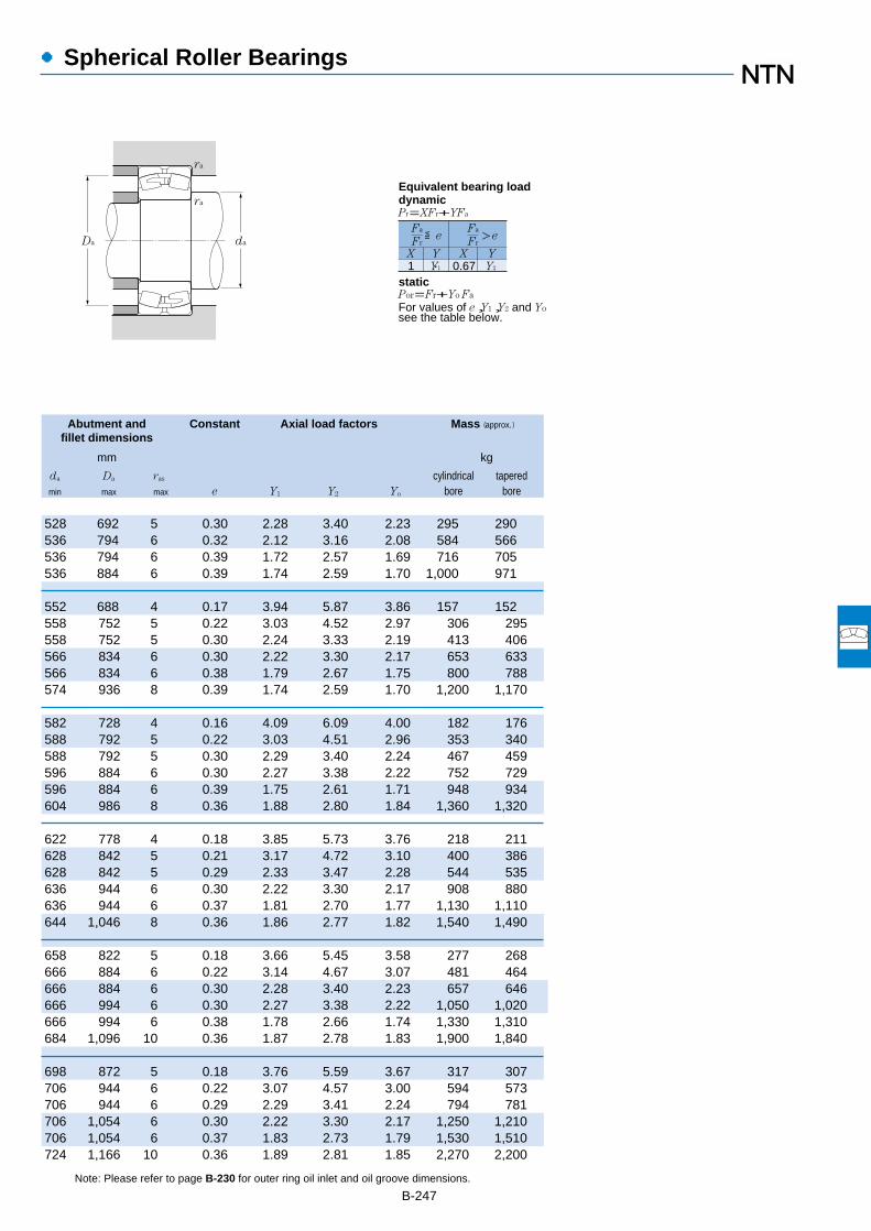
●Spherical Roller Bearings
Abutment and Constant Axial load factors Mass (approx.)
fillet dimensions
mm kg
da Da ras cylindrical taperedmin max max e Y1 Y2 Yo bore bore
B-247Note: Please refer to page B-230 for outer ring oil inlet and oil groove dimensions.
1 Y1 0.67 Y2
Fa
Fr
X Y X Y
≦eFa
Fr>e
Pr=XFr+YFa
ra
ra
daDa
Por=Fr+Yo Fa
For values of e,Y1,Y2 and Yosee the table below.
Equivalent bearing loaddynamic
static
528 692 5 0.30 2.28 3.40 2.23 295 290536 794 6 0.32 2.12 3.16 2.08 584 566536 794 6 0.39 1.72 2.57 1.69 716 705536 884 6 0.39 1.74 2.59 1.70 1,000 971
552 688 4 0.17 3.94 5.87 3.86 157 152558 752 5 0.22 3.03 4.52 2.97 306 295558 752 5 0.30 2.24 3.33 2.19 413 406566 834 6 0.30 2.22 3.30 2.17 653 633566 834 6 0.38 1.79 2.67 1.75 800 788574 936 8 0.39 1.74 2.59 1.70 1,200 1,170
582 728 4 0.16 4.09 6.09 4.00 182 176588 792 5 0.22 3.03 4.51 2.96 353 340588 792 5 0.30 2.29 3.40 2.24 467 459596 884 6 0.30 2.27 3.38 2.22 752 729596 884 6 0.39 1.75 2.61 1.71 948 934604 986 8 0.36 1.88 2.80 1.84 1,360 1,320
622 778 4 0.18 3.85 5.73 3.76 218 211628 842 5 0.21 3.17 4.72 3.10 400 386628 842 5 0.29 2.33 3.47 2.28 544 535636 944 6 0.30 2.22 3.30 2.17 908 880636 944 6 0.37 1.81 2.70 1.77 1,130 1,110644 1,046 8 0.36 1.86 2.77 1.82 1,540 1,490
658 822 5 0.18 3.66 5.45 3.58 277 268666 884 6 0.22 3.14 4.67 3.07 481 464666 884 6 0.30 2.28 3.40 2.23 657 646666 994 6 0.30 2.27 3.38 2.22 1,050 1,020666 994 6 0.38 1.78 2.66 1.74 1,330 1,310684 1,096 10 0.36 1.87 2.78 1.83 1,900 1,840
698 872 5 0.18 3.76 5.59 3.67 317 307706 944 6 0.22 3.07 4.57 3.00 594 573706 944 6 0.29 2.29 3.41 2.24 794 781706 1,054 6 0.30 2.22 3.30 2.17 1,250 1,210706 1,054 6 0.37 1.83 2.73 1.79 1,530 1,510724 1,166 10 0.36 1.89 2.81 1.85 2,270 2,200

●Spherical Roller Bearings
Boundary dimensions Basic load ratings Limiting speeds Bearing numbersdynamic static dynamic static
mm kN kgf rpmcylindrical tapered
1
d D B rs min2
Cr Cor Cr Cor grease oil bore bore
B-2481 Bearings appended with "K" have a tapered bore ratio of 1:12; bearings appended with "K30" have a tapered bore ratio of 1:30.2 Smallest allowable dimension for chamfer dimension r.
d 710~1060mm
750
800
850
900
950
1000
1060
r
d
B
dD
r
Cylindrical bore Tapered boretaper 1:12
710
950 180 6 4,450 11,500 450,000 1,170,000 240 370 239/710 239/710K1,030 236 7.5 7,200 16,200 730,000 1,650,000 220 340 230/710B 230/710BK1,030 315 7.5 9,300 22,500 945,000 2,300,000 200 300 240/710B 240/710BK301,150 345 9.5 11,600 24,900 1,190,000 2,540,000 180 280 231/710B 231/710BK1,150 438 9.5 14,500 32,000 1,470,000 3,250,000 180 280 241/710B 241/710BK301,280 450 12 16,300 32,500 1,660,000 3,300,000 170 260 232/710B 232/710BK
1,000 185 6 5,000 13,000 510,000 1,330,000 220 340 239/750 239/750K1,090 250 7.5 8,150 18,300 835,000 1,860,000 210 320 230/750B 230/750BK1,090 335 7.5 10,100 24,600 1,030,000 2,500,000 180 280 240/750B 240/750BK301,220 365 9.5 12,800 27,200 1,310,000 2,780,000 170 260 231/750B 231/750BK1,360 475 15 18,200 36,500 1,860,000 3,750,000 160 240 232/750B 232/750BK
1,060 195 6 5,400 13,700 550,000 1,400,000 200 310 239/800 239/800K1,150 258 7.5 8,400 19,500 860,000 1,990,000 190 290 230/800B 230/800BK1,150 345 7.5 11,200 27,800 1,140,000 2,840,000 170 260 240/800B 240/800BK301,280 375 9.5 14,400 31,000 1,460,000 3,150,000 150 240 231/800B 231/800BK
1,120 200 6 5,850 15,100 595,000 1,540,000 190 290 239/850 239/850K1,220 272 7.5 9,750 22,700 995,000 2,310,000 170 270 230/850B 230/850BK1,220 365 7.5 12,500 31,500 1,270,000 3,200,000 150 240 240/850B 240/850BK301,360 400 12 15,500 34,000 1,580,000 3,500,000 140 220 231/850B 231/850BK
1,180 206 6 6,650 17,300 675,000 1,770,000 170 270 239/900 239/900K1,280 280 7.5 10,300 24,700 1,050,000 2,520,000 160 250 230/900B 230/900BK1,280 375 7.5 13,200 33,500 1,350,000 3,450,000 140 220 240/900B 240/900BK301,420 412 12 16,800 38,000 1,720,000 3,850,000 130 200 231/900B 231/900BK
1,250 224 7.5 7,750 20,500 790,000 2,090,000 160 250 239/950 239/950K1,360 300 7.5 11,500 28,400 1,180,000 2,900,000 150 230 230/950B 230/950BK1,360 412 7.5 15,500 40,000 1,580,000 4,100,000 130 210 240/950B 240/950BK30
1,320 236 7.5 8,600 22,700 875,000 2,310,000 150 230 239/1000 239/1000K1,420 308 7.5 12,400 30,000 1,260,000 3,050,000 140 220 230/1000B 230/1000BK1,420 412 7.5 16,000 42,000 1,640,000 4,250,000 120 190 240/1000B 240/1000BK30
1,400 250 7.5 9,300 24,700 950,000 2,520,000 140 210 239/1060 239/1060K1,500 325 9.5 13,600 33,500 1,390,000 3,400,000 130 200 230/1060B 230/1060BK1,500 438 9.5 17,800 47,000 1,810,000 4,800,000 120 180 240/1060B 240/1060BK30
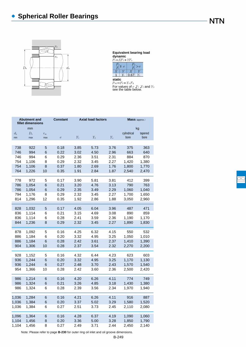
●Spherical Roller Bearings
Abutment and Constant Axial load factors Mass (approx.)fillet dimensions
mm kg
da Da ras cylindrical taperedmin max max e Y1 Y2 Yo bore bore
B-249Note: Please refer to page B-230 for outer ring oil inlet and oil groove dimensions.
738 922 5 0.18 3.85 5.73 3.76 375 363746 994 6 0.22 3.02 4.50 2.96 663 640746 994 6 0.29 2.36 3.51 2.31 884 870754 1,106 8 0.29 2.32 3.45 2.27 1,420 1,380754 1,106 8 0.37 1.80 2.69 1.76 1,800 1,770764 1,226 10 0.35 1.91 2.84 1.87 2,540 2,470
778 972 5 0.17 3.90 5.81 3.81 412 399786 1,054 6 0.21 3.20 4.76 3.13 790 763786 1,054 6 0.29 2.35 3.49 2.29 1,060 1,040794 1,176 8 0.29 2.32 3.45 2.27 1,700 1,650814 1,296 12 0.35 1.92 2.86 1.88 3,050 2,960
828 1,032 5 0.17 4.05 6.04 3.96 487 471836 1,114 6 0.21 3.15 4.69 3.08 890 859836 1,114 6 0.28 2.41 3.59 2.36 1,190 1,170844 1,236 8 0.29 2.32 3.45 2.27 1,890 1,830
878 1,092 5 0.16 4.25 6.32 4.15 550 532886 1,184 6 0.20 3.32 4.95 3.25 1,050 1,010886 1,184 6 0.28 2.42 3.61 2.37 1,410 1,390904 1,306 10 0.28 2.37 3.54 2.32 2,270 2,200
928 1,152 5 0.16 4.32 6.44 4.23 623 603936 1,244 6 0.20 3.32 4.95 3.25 1,170 1,130936 1,244 6 0.27 2.48 3.70 2.43 1,570 1,540954 1,366 10 0.28 2.42 3.60 2.36 2,500 2,420
986 1,214 6 0.16 4.20 6.26 4.11 774 749986 1,324 6 0.21 3.26 4.85 3.18 1,430 1,380986 1,324 6 0.28 2.39 3.56 2.34 1,970 1,940
1,036 1,284 6 0.16 4.21 6.26 4.11 916 8871,036 1,384 6 0.20 3.37 5.02 3.29 1,580 1,5201,036 1,384 6 0.27 2.51 3.73 2.45 2,110 2,080
1,096 1,364 6 0.16 4.28 6.37 4.19 1,090 1,0601,104 1,456 8 0.20 3.36 5.00 3.28 1,850 1,7901,104 1,456 8 0.27 2.49 3.71 2.44 2,450 2,140
1 Y1 0.67 Y2
Fa
Fr
X Y X Y
≦eFa
Fr>e
Pr=XFr+YFa
ra
ra
daDa
Por=Fr+Yo Fa
For values of e,Y1,Y2 and Yosee the table below.
Equivalent bearing loaddynamic
static

●Spherical Roller Bearings
Boundary dimensions Basic load ratings Limiting speeds Bearing numbersdynamic static dynamic static
mm kN kgf rpmcylindrical tapered
1
d D B rs min2
Cr Cor Cr Cor grease oil bore bore
B-2501 "K" indicates bearings have tapered bore with a taper ratio of 1: 12. 2 Smallest allowable dimension for chamfer dimension r.
d 1120~1400mm
1,460 250 7.5 9,850 26,700 1,000,000 2,720,000 130 200 239/1120 239/1120K1,580 345 9.5 15,600 39,000 1,590,000 4,000,000 120 190 230/1120B 230/1120BK1,580 462 9.5 19,500 52,500 1,990,000 5,350,000 110 160 240/1120B 240/1120BK30
1,540 272 7.5 11,000 29,800 1,120,000 3,050,000 120 180 239/1180 239/1180K
1,630 280 7.5 12,100 33,500 1,230,000 3,400,000 110 160 239/1250 239/1250K
1,720 300 7.5 13,600 38,000 1,390,000 3,900,000 95 150 239/1320 239/1320K
1,820 315 9.5 15,100 43,000 1,540,000 4,400,000 86 130 239/1400 239/1400K
1250
1320
1400
r
d
B
dD
r
Cylindrical bore Tapered boretaper 1:12
1180
1120

●Spherical Roller Bearings
Abutment and Constant Axial load factors Mass (approx.)fillet dimensions
mm kg
da Da ras cylindrical taperedmin max max e Y1 Y2 Yo bore bore
B-251Note: Please refer to page B-230 for outer ring oil inlet and oil groove dimensions.
1,156 1,424 6 0.15 4.42 6.58 4.32 1,140 1,1001,164 1,536 8 0.21 3.29 4.80 3.21 2,160 2,0901,164 1,536 8 0.27 2.50 3.72 2.44 2,890 2,840
1,216 1,504 6 0.15 4.40 6.55 4.30 1,390 1,340
1,286 1,594 6 0.15 4.42 6.58 4.32 1,600 1,550
1,356 1,684 6 0.16 4.34 6.46 4.24 1,900 1,840
1,444 1,776 8 0.15 4.39 6.54 4.29 2,230 2,160
1 Y1 0.67 Y2
Fa
Fr
X Y X Y
≦eFa
Fr>e
Pr=XFr+YFa
ra
ra
daDa
Por=Fr+Yo Fa
For values of e,Y1,Y2 and Yosee the table below.
Equivalent bearing loaddynamic
static

Boundary dimensions Bearing numbers Abutment and fillet dimensions Mass1
mm mm kg
da db Ba Da ras
d1 B1 d2 B2 min max min min max max (approx.)
●Adapter
B-252
1 Indicates adapter mass.Note: 1. Please refer to page B-232 to B-235 for bearing dimensions, rated loads, allowable rotations, and mass.
2. Please refer to page D-2 to D-10 and D-12 to D-14 for adapter locknut and washer dimensions.3. Adapter numbers with the suffix "X" signify narrow slit type adapters, and use washers with straight inner tabs.
d1 35~70mm
(For spherical roller bearings)
35
40
45
50
55
60
65
d1 d2
B2
B1
Dadb
ra
Ba
da
70
36 58 10 22208CK;H 308X 44 50 5 ― 73 1 0.18936 58 10 21308CK;H 308X 44 54 5 ― 81.5 1.5 0.18946 58 10 22308CK;H2308X 45 52 5 ― 81.5 1.5 0.224
39 65 11 22209CK;H 309X 49 57 8 ― 78 1 0.24839 65 11 21309CK;H 309X 49 61 5 ― 91.5 1.5 0.24850 65 11 22309CK;H2309X 50 58 5 ― 91.5 1.5 0.28
42 70 12 22210CK;H 310X 54 63 10 ― 83 1 0.30342 70 12 21310CK;H 310X 54 67 5 ― 100 2 0.30355 70 12 22310CK;H2310X 56 65 5 ― 100 2 0.362
45 75 12 22211EK;H 311X 60 67 11 89.5 91.5 1.5 0.34545 75 12 22211BK;H 311X 60 67 11 ― 91.5 1.5 0.34545 75 12 21311K ;H 311X 60 73 6 ― 110 2 0.34559 75 12 22311BK;H2311X 61 71 6 ― 110 2 0.42
47 80 13 22212EK;H 312X 65 72 9 98 101.5 1.5 0.39447 80 13 22212BK;H 312X 65 72 9 ― 101.5 1.5 0.39447 80 13 21312K ;H 312X 65 79 5 ― 118 2 0.39462 80 13 22312BK;H2312X 66 77 5 ― 118 2 0.481
50 85 14 22213EK;H 313X 70 78.5 8 107 111.5 1.5 0.45850 85 14 22213BK;H 313X 70 78.5 9 ― 111.5 1.5 0.45850 85 14 21313K ;H 313X 70 85 5 ― 128 2 0.45865 85 14 22313BK;H2313X 72 84 5 ― 128 2 0.557
55 98 15 22215EK;H 315X 80 89 12 117.5 121.5 1.5 0.83155 98 15 22215BK;H 315X 80 89 12 ― 121.5 1.5 0.83155 98 15 21315K ;H 315X 80 97 5 ― 148 2 0.83173 98 15 22315BK;H2315X 82 96 5 ― 148 2 1.05
59 105 17 22216EK;H 316X 86 94.5 12 125.5 130 2 1.0359 105 17 22216BK;H 316X 86 94.5 12 ― 130 2 1.0359 105 17 21316K ;H 316X 86 103 5 ― 158 2 1.0378 105 17 22316BK;H2316X 87 103 5 ― 158 2 1.28

●Adapter
Boundary dimensions Bearing numbers Abutment and fillet dimensions Mass1
mm mm kg
da db Ba Da ras
d1 B1 d2 B2 min max min min max max (approx.)
B-253
1 Indicates adapter mass.Note: 1. Please refer to page B-234 to B-237 for bearing dimensions, rated loads, allowable rotations, and mass.
2. Please refer to page D-2 to D-10 and D-12 to D-14 for adapter locknut and washer dimensions.3. Adapter numbers with the suffix "X" signify narrow slit type adapters, and use washers with straight inner tabs.
d1 75~115mm
(For spherical roller bearings)
75
80
85
90
100
110
115
d1 d2
B2
B1
Dadb
ra
Ba
da
63 110 18 22217EK;H 317X 91 100.5 12 135 140 2 1.1863 110 18 22217BK;H 317X 91 100.5 12 ― 140 2 1.1863 110 18 21317K ;H 317X 91 110 6 ― 166 2.5 1.1882 110 18 22317BK;H2317X 94 110 6 ― 166 2.5 1.45
65 120 18 22218EK;H 318X 96 107.5 10 144 150 2 1.3765 120 18 22218BK;H 318X 96 107.5 10 ― 150 2 1.3786 120 18 23218BK;H2318X 99 110 18 ― 150 2 1.6965 120 18 21318K ;H 318X 96 116 6 ― 176 2.5 1.3786 120 18 22318BK;H2318X 99 117 6 ― 176 2.5 1.69
68 125 19 22219BK;H 319X 102 117 9 ― 158 2 1.5668 125 19 21319K ;H 319X 102 123 7 ― 186 2.5 1.5690 125 19 22319BK;H2319X 105 123 7 ― 186 2.5 1.92
71 130 20 22220BK;H 320X 107 123 8 ― 168 2 1.6997 130 20 23220BK;H2320X 110 122 19 ― 168 2 2.1571 130 20 21320K ;H 320X 107 130 7 ― 201 2.5 1.6997 130 20 22320BK;H2320X 110 129 7 ― 201 2.5 2.15
81 145 21 23122BK;H3122X 117 127 7 ― 170 2 2.2577 145 21 22222BK;H 322X 117 137 6 ― 188 2 2.18
105 145 21 23222BK;H2322X 121 135 17 ― 188 2 2.7477 145 21 21322K ;H 322X 117 142 9 ― 226 2.5 2.18
105 145 21 22322BK;H2322X 121 142 7 ― 226 2.5 2.74
72 145 22 23024BK;H3024X 127 136 7 ― 170 2 1.9388 155 22 23124BK;H3124X 128 140 7 ― 190 2 2.6488 155 22 22224BK;H3124X 128 150 11 ― 203 2 2.64
112 155 22 23224BK;H2324X 131 147 17 ― 203 2 3.19112 155 22 22324BK;H2324X 131 154 7 ― 246 2.5 3.19
80 155 23 23026BK;H3026 137 147 8 ― 190 2 2.8592 165 23 23126BK;H3126 138 152 8 ― 200 2 3.6692 165 23 22226BK;H3126 138 161 8 ― 216 2.5 3.66
121 165 23 23226BK;H2326 142 160 21 ― 216 2.5 4.6

●Adapter
(For spherical roller bearings)
Boundary dimensions Bearing numbers Abutment and fillet dimensions Mass1
mm mm kg
da db Ba Da ras
d1 B1 d2 B2 min max min max max (approx.)
B-254
1 Indicates adapter mass.Note: 1. Please refer to page B-236 to B-239 for bearing dimensions, rated loads, allowable rotations, and mass.
2. Please refer to page D-2 to D-10 and D-12 to D-14 for adapter locknut and washer dimensions.
d1 115~170mm
135
140
150
115
125
160
170
121 165 23 22326BK;H2326 142 167 8 262 3 4.6
82 165 24 23028BK;H3028 147 158 8 200 2 3.1697 180 24 23128BK;H3128 149 165 8 213 2 4.3497 180 24 22228BK;H3128 149 173 8 236 2.5 4.34
131 180 24 23228BK;H2328 152 172 22 236 2.5 5.55131 180 24 22328BK;H2328 152 179 8 282 3 5.55
87 180 26 23030BK;H3030 158 170 8 213 2 3.89111 195 26 23130BK;H3130 160 178 8 238 2 5.52111 195 26 22230BK;H3130 160 188 15 256 2.5 5.52139 195 26 23230BK;H2330 163 185 20 256 2.5 6.63139 195 26 22330BK;H2330 163 192 8 302 3 6.63
93 190 28 23032BK;H3032 168 181 8 228 2 5.21119 210 28 23132BK;H3132 170 190 8 258 2 7.67119 210 28 22232BK;H3132 170 200 14 276 2.5 7.67147 210 28 23232BK;H2332 174 198 18 276 2.5 9.14147 210 28 22332BK;H2332 174 205 8 322 3 9.14
101 200 29 23034BK;H3034 179 193 8 248 2 5.99122 220 29 23134BK;H3134 180 202 8 268 2 8.38122 220 29 22234BK;H3134 180 212 10 292 3 8.38154 220 29 23234BK;H2334 185 218 18 292 3 10.2154 220 29 22334BK;H2334 185 218 8 342 3 10.2
109 210 30 23036BK;H3036 189 204 8 268 2 6.83131 230 30 23136BK;H3136 191 215 8 286 2.5 9.5131 230 30 22236BK;H3136 191 225 18 302 3 9.5161 230 30 23236BK;H2336 195 223 22 302 3 11.3161 230 30 22336BK;H2336 195 230 8 362 3 11.3
112 220 31 23038BK;H3038 199 215 9 278 2 7.45141 240 31 23138BK;H3138 202 228 9 306 2.5 10.8141 240 31 22238BK;H3138 202 238 21 322 3 10.8169 240 31 23238BK;H2338 206 236 21 322 3 12.6169 240 31 22338BK;H2338 206 243 9 378 4 12.6
d1 d2
B2
B1
Dadb
ra
Ba
da

●Adapter
Boundary dimensions Bearing numbers Abutment and fillet dimensions Mass1
mm mm kg
da db Ba Da ras
d1 B1 d2 B2 B3 min max min max max (approx.)
B-255
1 Indicates adapter mass.Note: 1. Please refer to page B-238 to B-243 for bearing dimensions, rated loads, allowable rotations, and mass.
2. Please refer to page D-2 to D-10 and D-12 to D-14 for adapter locknut and washer dimensions.
d1 180~300mm
(For spherical roller bearings)
120 240 32 ― 23040BK;H3040 210 227 10 298 2 9.19150 250 32 ― 23140BK;H3140 212 240 10 326 2.5 12.1150 250 32 ― 22240BK;H3140 212 250 24 342 3 12.1176 250 32 ― 23240BK;H2340 216 248 20 342 3 13.9176 250 32 ― 22340BK;H2340 216 255 10 398 4 13.9
126 260 ― 41 23044BK;H3044 231 250 12 326 2.5 10.2158 280 ― 44 23144BK;H3144 233 264 10 352 3 14.7158 280 ― 44 22244BK;H3144 233 274 22 382 3 14.7183 280 ― 44 23244BK;H2344 236 271 11 382 3 16.7183 280 ― 44 22344BK;H2344 236 278 10 438 4 16.7
133 290 ― 46 23048BK;H3048 251 272 11 346 2.5 13.2169 300 ― 46 23148BK;H3148 254 288 11 382 3 17.3169 300 ― 46 22248BK;H3148 254 298 19 422 3 17.3196 300 ― 46 23248BK;H2348 257 295 6 422 3 19.7196 300 ― 46 22348BK;H2348 257 302 11 478 4 19.7
145 310 ― 46 23052BK;H3052 272 295 13 382 3 15.1187 330 ― 49 23152BK;H3152 276 313 11 422 3 22187 330 ― 49 22252BK;H3152 276 323 25 458 4 22208 330 ― 49 23252BK;H2352 278 319 2 458 4 24.2208 330 ― 49 22352BK;H2352 278 326 11 512 5 24.2
152 330 ― 50 23056BK;H3056 292 317 12 402 3 17.7192 350 ― 51 23156BK;H3156 296 336 12 438 4 24.5192 350 ― 51 22256BK;H3156 296 346 28 478 4 24.5221 350 ― 51 23256BK;H2356 299 343 11 478 4 27.8221 350 ― 51 22356BK;H2356 299 350 12 552 5 27.8
168 360 ― 54 23060BK;H3060 313 340 12 442 3 22.8208 380 ― 53 23160BK;H3160 317 361 12 478 4 30.2208 380 ― 53 22260BK;H3160 317 371 32 518 4 30.2240 380 ― 53 23260BK;H3260 321 368 12 518 4 34.1
171 380 ― 55 23064BK;H3064 334 363 13 462 3 24.6226 400 ― 56 23164BK;H3164 339 384 13 518 4 34.9226 400 ― 56 22264BK;H3164 339 394 39 558 4 34.9
180
200
220
240
260
280
300
d1 d2
B2
B1
Dadb
ra
Ba
da Dada
ra
Ba
dbd1 d2
B1
B3
d1≦180mm d1≧200mm
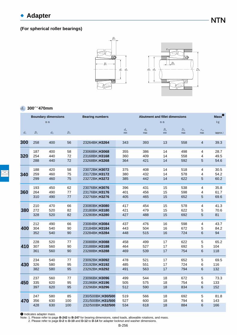
●Adapter
(For spherical roller bearings)
Boundary dimensions Bearing numbers Abutment and fillet dimensions Mass1
mm mm kg
da db Ba Da ras
d1 B1 d2 B3 min max min max max (approx.)
B-256
1 Indicates adapter mass.Note: 1. Please refer to page B-242 to B-247 for bearing dimensions, rated loads, allowable rotations, and mass.
2. Please refer to page D-2 to D-10 and D-12 to D-14 for adapter locknut and washer dimensions.
d1 300~470mm
ra
Ba
d1 d2
B1
B3
dadb Da
380
360
340
400
410
430
450
470
300
320
258 400 56 23264BK;H3264 343 393 13 558 4 39.3
187 400 58 23068BK;H3068 355 386 14 498 4 28.7254 440 72 23168BK;H3168 360 409 14 558 4 49.5288 440 72 23268BK;H3268 364 421 14 592 5 54.6
188 420 58 23072BK;H3072 375 408 14 518 4 30.5259 460 75 23172BK;H3172 380 432 14 578 4 54.2299 460 75 23272BK;H3272 385 442 14 622 5 60.2
193 450 62 23076BK;H3076 396 431 15 538 4 35.8264 490 77 23176BK;H3176 401 456 15 598 4 61.7310 490 77 23276BK;H3276 405 465 15 652 5 69.6
210 470 66 23080BK;H3080 417 454 15 578 4 41.3272 520 82 23180BK;H3180 421 479 15 622 5 70.6328 520 82 23280BK;H3280 427 488 15 692 5 81
212 490 66 23084BK;H3084 437 476 16 598 4 43.7304 540 90 23184BK;H3184 443 504 16 672 5 84.2352 540 90 23284BK;H3284 448 515 16 724 6 94
228 520 77 23088BK;H3088 458 499 17 622 5 65.2307 560 90 23188BK;H3188 464 527 17 692 5 104361 560 90 23288BK;H3288 469 539 17 754 6 118
234 540 77 23092BK;H3092 478 521 17 652 5 69.5326 580 95 23192BK;H3192 485 551 17 724 6 116382 580 95 23292BK;H3292 491 563 17 794 6 132
237 560 77 23096BK;H3096 499 544 18 672 5 73.3335 620 95 23196BK;H3196 505 575 18 754 6 133397 620 95 23296BK;H3296 512 590 18 834 6 152
247 580 85 230/500BK;H30/500 519 566 18 692 5 81.8356 630 100 231/500BK;H31/500 527 600 18 794 6 143428 630 100 232/500BK;H32/500 534 618 18 884 6 166

Boundary dimensions Bearing numbers Abutment and fillet dimensions Mass3
Appro-4
priatemm mm kg nut no.
da Da ras
d1 G1
B3 G1 B42
min max min max max (approx.)
●Withdrawal Sleeves
B-257
1 Standard thread shapes and dimensions are as per JIS B0207 (metric thread).2 Indicates reference dimensions before attachment of withdrawal sleeve.3 Indicates withdrawal sleeve mass.4 Indicates number of nut to be used at time of disassembly. See pages D-2 to D-10 for nut dimensions.Note: 1. Please refer to page B-232, B-235 for bearing dimensions, rated loads, allowable rotations, and mass.
d1 35~70mm
(For spherical roller bearings)
M45×1.5 29 6 32 22208CK; AH 308 47 ― ― 73 1 0.09 AN09M45×1.5 29 6 32 21308CK; AH 308 48.5 ― ― 81.5 1.5 0.09 AN09M45×1.5 40 7 43 22308CK; AH 2308 48.5 ― ― 81.5 1.5 0.128 AN09
M50×1.5 31 6 34 22209CK; AH 309 52 ― ― 78 1 0.109 AN10M50×1.5 31 6 34 21309CK; AH 309 53.5 ― ― 91.5 1.5 0.109 AN10M50×1.5 44 7 47 22309CK; AH 2309 53.5 ― ― 91.5 1.5 0.164 AN10
M55×2 35 7 38 22210CK; AHX 310 57 ― ― 83 1 0.137 AN11M55×2 35 7 38 21310CK; AHX 310 60 ― ― 100 2 0.137 AN11M55×2 50 9 53 22310CK; AHX 2310 60 ― ― 100 2 0.209 AN11
M60×2 37 7 40 22211EK ; AHX 311 63.5 67 89.5 91.5 1.5 0.161 AN12M60×2 37 7 40 22211BK ; AHX 311 63.5 ― ― 91.5 1.5 0.161 AN12M60×2 37 7 40 21311K ; AHX 311 65 ― ― 110 2 0.161 AN12M60×2 54 10 57 22311BK ; AHX 2311 65 ― ― 110 2 0.253 AN12
M65×2 40 8 43 22212EK ; AHX 312 68.5 72 98 101.5 1.5 0.189 AN13M65×2 40 8 43 22212BK ; AHX 312 68.5 ― ― 101.5 1.5 0.189 AN13M65×2 40 8 43 21312K ; AHX 312 72 ― ― 118 2 0.189 AN13M65×2 58 11 61 22312BK ; AHX 2312 72 ― ― 118 2 0.297 AN13
M75×2 42 8 45 22213EK ; AH 313 73.5 78.5 107 111.5 1.5 0.253 AN15M75×2 42 8 45 22213BK ; AH 313 73.5 ― ― 111.5 1.5 0.253 AN15M75×2 42 8 45 21313K ; AH 313 77 ― ― 128 2 0.253 AN15M75×2 61 12 64 22313BK ; AH 2313 77 ― ― 128 2 0.395 AN15
M80×2 43 8 47 22214EK ; AH 314 78.5 83.5 112.5 116.5 1.5 0.28 AN16M80×2 43 8 47 22214BK ; AH 314 78.5 ― ― 116.5 1.5 0.28 AN16M80×2 43 8 47 21314K ; AH 314 82 ― ― 138 2 0.28 AN16M80×2 64 12 68 22314BK ; AHX 2314 82 ― ― 138 2 0.466 AN16
M85×2 45 8 49 22215EK ; AH 315 83.5 89 117.5 121.5 1.5 0.313 AN17M85×2 45 8 49 22215BK ; AH 315 83.5 ― ― 121.5 1.5 0.313 AN17M85×2 45 8 49 21315K ; AH 315 87 ― ― 148 2 0.313 AN17M85×2 68 12 72 22315BK ; AHX 2315 87 ― ― 148 2 0.534 AN17
40
45
50
55
60
65
70
35
d1
G1
B3
B4
daDa
ra
G

B-258
●Withdrawal Sleeves
Boundary dimensions Bearing numbers Abutment and fillet dimensions Mass3
Appro-4
priatemm mm kg nut no.
da Da ras
d1 G1
B3 G1 B42
min max min max max (approx.)
1 Standard thread shapes and dimensions are as per JIS B0207 (metric thread).2 Indicates reference dimensions before attachment of withdrawal sleeve.3 Indicates withdrawal sleeve mass.4 Indicates number of nut to be used at time of disassembly. See pages D-2 to D-10 for nut dimensions.Note: 1. Please refer to page B-234, B-237 for bearing dimensions, rated loads, allowable rotations, and mass.
d1 75~115mm
75
80
90
95
105
115
85
d1
G1
B3
B4
daDa
ra
G
M90×2 48 8 52 22216EK ;AH 316 90 94.5 125.5 130 2 0.365 AN18M90×2 48 8 52 22216BK ;AH 316 90 ― ― 130 2 0.365 AN18M90×2 48 8 52 21316K ;AH 316 92 ― ― 158 2 0.365 AN18M90×2 71 12 75 22316BK ;AHX 2316 92 ― ― 158 2 0.597 AN18
M95×2 52 9 56 22217EK ;AHX 317 95 100.5 135 140 2 0.429 AN19M95×2 52 9 56 22217BK ;AHX 317 95 ― ― 140 2 0.429 AN19M95×2 52 9 56 21317K ;AHX 317 99 ― ― 166 2.5 0.429 AN19M95×2 74 13 78 22317BK ;AHX 2317 99 ― ― 166 2.5 0.67 AN19
M100×2 53 9 57 22218EK ;AHX 318 100 107.5 144 150 2 0.461 AN20M100×2 53 9 57 22218BK ;AHX 318 100 ― ― 150 2 0.461 AN20M100×2 63 10 67 23218BK ;AHX 3218 100 ― ― 150 2 0.576 AN20M100×2 53 9 57 21318K ;AHX 318 104 ― ― 176 2.5 0.461 AN20M100×2 79 14 83 22318BK ;AHX 2318 104 ― ― 176 2.5 0.779 AN20
M105×2 57 10 61 22219BK ;AHX 319 107 ― ― 158 2 0.532 AN21M105×2 57 10 61 21319K ;AHX 319 109 ― ― 186 2.5 0.532 AN21M105×2 85 16 89 22319BK ;AHX 2319 109 ― ― 186 2.5 0.886 AN21
M110×2 59 10 63 22220BK ;AHX 320 112 ― ― 168 2 0.582 AN22M110×2 73 11 77 23220BK ;AHX 3220 112 ― ― 168 2 0.767 AN22M110×2 59 10 63 21320K ;AHX 320 114 ― ― 201 2.5 0.582 AN22M110×2 90 16 94 22320BK ;AHX 2320 114 ― ― 201 2.5 0.998 AN22
M120×2 68 11 72 23122BK ;AHX 3122 120 ― ― 170 2 0.76 AN24M115×2 82 13 91 24122BK30 ;AH 24122 120 ― ― 170 2 0.73 AN23M120×2 68 11 72 22222BK ;AHX 3122 122 ― ― 188 2 0.76 AN24M125×2 82 11 86 23222BK ;AHX 3222 122 ― ― 188 2 1.04 AN25M120×2 63 12 67 21322K ;AHX 322 124 ― ― 226 2.5 0.663 AN24M125×2 98 16 102 22322BK ;AHX 2322 124 ― ― 226 2.5 1.35 AN25
M130×2 60 13 64 23024BK ;AHX 3024 130 ― ― 170 2 0.75 AN26M125×2 73 13 82 24024BK30 ;AH 24024 130 ― ― 170 2 0.65 AN25M125×2 73 13 82 24024CK30;AH 24024 130 ― ― 170 2 0.65 AN25M130×2 75 12 79 23124BK ;AHX 3124 130 ― ― 190 2 0.95 AN26
(For spherical roller bearings)

B-259
●Withdrawal Sleeves
(For spherical roller bearings)
Boundary dimensions Bearing numbers Abutment and fillet dimensions Mass3
Appro-4
priatemm mm kg nut no.
da Da ras
d1 G1
B3 G1 B42
min max max (approx.)
1 Standard thread shapes and dimensions are as per JIS B0207 (metric thread).2 Indicates reference dimensions before attachment of withdrawal sleeve.3 Indicates withdrawal sleeve mass.4 Indicates number of nut to be used at time of disassembly. See pages D-2 to D-10 for nut dimensions.Note: 1. Please refer to page B-236, B-239 for bearing dimensions, rated loads, allowable rotations, and mass.
d1 115~150mm
135
145
150
d1
G1
B3
B4
daDa
ra
G
115
125
M130×2 93 13 102 24124BK30 ;AH 24124 130 190 2 1 AN26M130×2 75 12 79 22224BK ;AHX 3124 132 203 2 0.95 AN26M135×2 90 13 94 23224BK ;AHX 3224 132 203 2 1.3 AN27M135×2 105 17 109 22324BK ;AHX 2324 134 246 2.5 1.6 AN27
M140×2 67 14 71 23026BK ;AHX 3026 140 190 2 0.93 AN28M135×2 83 14 93 24026BK30 ;AH 24026 140 190 2 0.84 AN27M135×2 83 14 93 24026CK30 ;AH 24026 140 190 2 0.84 AN27M140×2 78 12 82 23126BK ;AHX 3126 140 200 2 1.08 AN28M140×2 94 14 104 24126BK30 ;AH 24126 140 200 2 1.11 AN28M140×2 78 12 82 22226BK ;AHX 3126 144 216 2.5 1.08 AN28M145×2 98 15 102 23226BK ;AHX 3226 144 216 2.5 1.58 AN29M145×2 115 19 119 22326BK ;AHX 2326 148 262 3 1.97 AN29
M150×2 68 14 73 23028BK ;AHX 3028 150 200 2 1.01 AN30M145×2 83 14 93 24028BK30 ;AH 24028 150 200 2 0.91 AN29M145×2 83 14 93 24028CK30 ;AH 24028 150 200 2 0.91 AN29M150×2 83 14 88 23128BK ;AHX 3128 152 213 2 1.28 AN30M150×2 99 14 109 24128BK30 ;AH 24128 152 213 2 1.25 AN30M150×2 83 14 88 22228BK ;AHX 3128 154 236 2.5 1.28 AN30M155×3 104 15 109 23228BK ;AHX 3228 154 236 2.5 1.84 AN31M155×3 125 20 130 22328BK ;AHX 2328 158 282 3 2.33 AN31
M160×3 72 15 77 23030BK ;AHX 3030 162 213 2 1.15 AN32M155×3 90 15 101 24030BK30 ;AH 24030 162 213 2 1.04 AN31M155×3 90 15 101 24030CK30 ;AH 24030 162 213 2 1.04 AN31M165×3 96 15 101 23130BK ;AHX 3130 162 238 2 1.79 AN33M160×3 115 15 126 24130BK30 ;AH 24130 162 238 2 1.56 AN32M165×3 96 15 101 22230BK ;AHX 3130 164 256 2.5 1.79 AN33M165×3 114 17 119 23230BK ;AHX 3230 164 256 2.5 2.22 AN33M165×3 135 24 140 22330BK ;AHX 2330 168 302 3 2.82 AN33
M170×3 77 16 82 23032BK ;AH 3032 172 228 2 2.06 AN34M170×3 95 15 106 24032BK30 ;AH 24032 172 228 2 2.33 AN34M170×3 95 15 106 24032CK30 ;AH 24032 172 228 2 2.33 AN34M180×3 103 16 108 23132BK ;AH 3132 172 258 2 3.21 AN36

B-260
●Withdrawal Sleeves
Boundary dimensions Bearing numbers Abutment and fillet dimensions Mass3
Appro-4
priatemm mm kg nut no.
da Da ras
d1 G1
B3 G1 B42
min max max (approx.)
1 Standard thread shapes and dimensions are as per JIS B0207 (metric thread).2 Indicates reference dimensions before attachment of withdrawal sleeve.3 Indicates withdrawal sleeve mass.4 Indicates number of nut to be used at time of disassembly. See pages D-2 to D-10 for nut dimensions.Note: 1. Please refer to page B-238, B-241 for bearing dimensions, rated loads, allowable rotations, and mass.
d1 150~190mm
150
160
170
180
190
d1
G1
B3
B4
daDa
ra
G
M170×3 124 15 135 24132BK30 ;AH 24132 172 258 2 3 AN34M180×3 103 16 108 22232BK ;AH 3132 174 276 2.5 3.21 AN36M180×3 124 20 130 23232BK ;AH 3232 174 276 2.5 4.08 AN36M180×3 140 24 146 22332BK ;AH 2332 178 322 3 4.72 AN36
M180×3 85 17 90 23034BK ;AH 3034 182 248 2 2.43 AN36M180×3 106 16 117 24034BK30 ;AH 24034 182 248 2 2.8 AN36M180×3 106 16 117 24034CK30 ;AH 24034 182 248 2 2.8 AN36M190×3 104 16 109 23134BK ;AH 3134 182 268 2 3.4 AN38M180×3 125 16 136 24134BK30 ;AH 24134 182 268 2 3.21 AN36M190×3 104 16 109 22234BK ;AH 3134 188 292 3 3.4 AN38M190×3 134 24 140 23234BK ;AH 3234 188 292 3 4.8 AN38M190×3 146 24 152 22334BK ;AH 2334 188 342 3 5.25 AN38
M190×3 92 17 98 23036BK ;AH 3036 192 268 2 2.81 AN38M190×3 116 16 127 24036BK30 ;AH 24036 192 268 2 3.1 AN38M190×3 116 16 127 24036CK30 ;AH 24036 192 268 2 3.1 AN38M200×3 116 19 122 23136BK ;AH 3136 194 286 2.5 4.22 AN40M190×3 134 16 145 24136BK30 ;AH 24136 194 286 2.5 3.68 AN38M200×3 105 17 110 22236BK ;AH 2236 198 302 3 3.73 AN40M200×3 140 24 146 23236BK ;AH 3236 198 302 3 5.32 AN40M200×3 154 26 160 22336BK ;AH 2336 198 362 3 5.83 AN40
Tr205×4 96 18 102 23038BK ;AH 3038 202 278 2 3.32 HNL41M200×3 118 18 131 24038BK30 ;AH 24038 202 278 2 3.5 AN40M200×3 118 18 131 24038CK30 ;AH 24038 202 278 2 3.5 AN40Tr210×4 125 20 131 23138BK ;AH 3138 204 306 2.5 4.89 HN42M200×3 146 18 159 24138BK30 ;AH 24138 204 306 2.5 4.28 AN40Tr210×4 112 18 117 22238BK ;AH 2238 208 322 3 4.25 HN42Tr210×4 145 25 152 23238BK ;AH 3238 208 322 3 5.9 HN42Tr210×4 160 26 167 22338BK ;AH 2338 212 378 4 6.63 HN42
Tr215×4 102 19 108 23040BK ;AH 3040 212 298 2 3.8 HNL43Tr210×4 127 18 140 24040BK30 ;AH 24040 212 298 2 3.93 HN42Tr220×4 134 21 140 23140BK ;AH 3140 214 326 2.5 5.49 HN44Tr210×4 158 18 171 24140BK30 ;AH 24140 214 326 2.5 5.1 HN42
(For spherical roller bearings)

B-261
●Withdrawal Sleeves
(For spherical roller bearings)
Boundary dimensions Bearing numbers Abutment and fillet dimensions Mass3
Appro-4
priatemm mm kg nut no.
da Da ras
d1 G1
B3 G1 B42
min max max (approx.)
1 Standard thread shapes and dimensions are as per JIS B0207 (metric thread).2 Indicates reference dimensions before attachment of withdrawal sleeve.3 Indicates withdrawal sleeve mass.4 Indicates number of nut to be used at time of disassembly. See pages D-2 to D-10 for nut dimensions.Note: 1. Please refer to page B-240, B-243 for bearing dimensions, rated loads, allowable rotations, and mass.
2. Withdrawal sleeve numbers appended with the suffix "H" signify high pressure oil (hydraulic) design. (See page B-231)
d1 190~260mm
260
d1
G1
B3
B4
daDa
ra
G
190
200
220
240
Tr220×4 118 19 123 22240BK ;AH 2240 218 342 3 4.68 HN44Tr220×4 153 25 160 23240BK ;AH 3240 218 342 3 6.68 HN44Tr220×4 170 30 177 22340BK ;AH 2340 222 398 4 7.54 HN44
Tr235×4 111 20 117 23044BK ;AH 3044 234 326 2.5 7.4 HNL47Tr230×4 138 20 152 24044BK30 ;AH 24044H 234 326 2.5 8.25 HN46Tr240×4 145 23 151 23144BK ;AH 3144 238 352 3 10.4 HN48Tr230×4 170 20 184 24144BK30 ;AH 24144H 238 352 3 10.2 HN46Tr240×4 130 20 136 22244BK ;AH 2244 238 382 3 9.1 HN48Tr240×4 181 30 189 23244BK ;AH 2344 238 382 3 13.5 HN48Tr240×4 181 30 189 22344BK ;AH 2344 242 438 4 13.5 HN48
Tr260×4 116 21 123 23048BK ;AH 3048 254 346 2.5 8.75 HNL52Tr250×4 138 20 153 24048BK30 ;AH 24048H 254 346 2.5 8.98 HN50Tr260×4 154 25 161 23148BK ;AH 3148 258 382 3 12 HN52Tr260×4 180 20 195 24148BK30 ;AH 24148H 258 382 3 12.5 HN52Tr260×4 144 21 150 22248BK ;AH 2248 258 422 3 11.1 HN52Tr260×4 189 30 197 23248BK ;AH 2348 258 422 3 15.5 HN52Tr260×4 189 30 197 22348BK ;AH 2348 262 478 4 15.5 HN52
Tr280×4 128 23 135 23052BK ;AH 3052 278 382 3 10.7 HNL56Tr270×4 162 22 178 24052BK30 ;AH 24052 278 382 3 11.8 HN54Tr290×4 172 26 179 23152BK ;AH 3152 278 422 3 16.2 HN58Tr280×4 202 22 218 24152BK30 ;AH 24152H 278 422 3 15.4 HN56Tr290×4 155 23 161 22252BK ;AH 2252 282 458 4 14 HN58Tr290×4 205 30 213 23252BK ;AH 2352 282 458 4 19.6 HN58Tr290×4 205 30 213 22352BK ;AH 2352 288 512 5 19.6 HN58
Tr300×4 131 24 139 23056BK ;AH3056 298 402 3 12 HNL60Tr290×4 162 22 179 24056BK30 ;AH24056H 298 402 3 12.8 HN58Tr310×5 175 28 183 23156BK ;AH3156 302 438 4 17.5 HN62Tr300×4 202 22 219 24156BK30 ;AH24156H 302 438 4 16.3 HN60Tr310×5 155 24 163 22256BK ;AH2256 302 478 4 15.2 HN62Tr310×5 212 30 220 23256BK ;AH2356 302 478 4 21.6 HN62Tr310×5 212 30 220 22356BK ;AH2356 308 552 5 21.6 HN62

B-262
●Withdrawal Sleeves
Boundary dimensions Bearing numbers Abutment and fillet dimensions Mass3
Appro-4
priatemm mm kg nut no.
da Da ras
d1 G1
B3 G1 B42
min max max (approx.)
1 Standard thread shapes and dimensions are as per JIS B0207 (metric thread).2 Indicates reference dimensions before attachment of withdrawal sleeve.3 Indicates withdrawal sleeve mass.4 Indicates number of nut to be used at time of disassembly. See pages D-2 to D-10 for nut dimensions.Note: 1. Please refer to page B-242, B-245 for bearing dimensions, rated loads, allowable rotations, and mass.
2. Withdrawal sleeve numbers appended with the suffix "H" signify high pressure oil (hydraulic) design. (See page B-231)
d1 280~400mm
280
300
320
340
360
380
400
d1
G1
B3
B4
daDa
ra
G
Tr320×5 145 26 153 23060BK ;AH 3060 318 442 3 14.4 HNL64Tr310×5 184 24 202 24060BK30 ;AH 24060H 318 442 3 15.5 HN62Tr330×5 192 30 200 23160BK ;AH 3160 322 478 4 20.8 HN66Tr320×5 224 24 242 24160BK30 ;AH 24160H 322 478 4 19.5 HN64Tr330×5 170 26 178 22260B ;AH 2260 322 518 4 18.1 HN66Tr330×5 228 34 236 23260BK ;AH 3260 322 518 4 26 HN66
Tr345×5 149 27 157 23064BK ;AH 3064 338 462 3 16 HNL69Tr330×5 184 24 202 24064BK30 ;AH 24064H 338 462 3 16.6 HN66Tr350×5 209 31 217 23164BK ;AH 3164 342 518 4 24.5 HN70Tr340×5 242 24 260 24164BK30 ;AH 24164H 342 518 4 21.4 HN68Tr350×5 180 27 190 22264BK ;AH 2264 342 558 4 20.2 HN70Tr350×5 246 36 254 23264BK ;AH 3264 342 558 4 30.6 HN70
Tr365×5 162 28 171 23068BK ;AH 3068 362 498 4 19.5 HN73Tr360×5 206 26 225 24068BK30 ;AH 24068H 362 498 4 21.7 HNL72Tr370×5 225 33 234 23168BK ;AH 3168 362 558 4 29 HN74Tr360×5 269 26 288 24168BK30 ;AH 24168H 362 558 4 27.1 HN72
Tr385×5 167 30 176 23072BK ;AH 3072 382 518 4 21 HNL77Tr380×5 206 26 226 24072BK30 ;AH 24072H 382 518 4 22.7 HNL76Tr400×5 229 35 238 23172BK ;AH 3172 382 578 4 33 HN80Tr380×5 269 26 289 24172BK30 ;AH 24172H 382 578 4 29.6 HN76
Tr410×5 170 31 180 23076BK ;AH 3076 402 538 4 23.2 HNL82Tr400×5 208 28 228 24076BK30 ;AH 24076H 402 538 4 23.7 HNL80Tr420×5 232 36 242 23176BK ;AH 3176 402 598 4 35.7 HN84Tr400×5 271 28 291 24176BK30 ;AH 24176H 402 598 4 31.3 HN80
Tr430×5 183 33 193 23080BK ;AH 3080 422 578 4 27.3 HNL86Tr420×5 228 28 248 24080BK30 ;AH 24080H 422 578 4 27.1 HNL84Tr440×5 240 38 250 23180BK ;AH 3180 428 622 5 39.5 HN88Tr420×5 278 28 298 24180BK30 ;AH 24180H 428 622 5 34.4 HN84
Tr450×5 186 34 196 23084BK ;AH 3084 442 598 4 29 HNL90Tr440×5 230 30 252 24084BK30 ;AH 24084H 442 598 4 29 HNL88
(For spherical roller bearings)
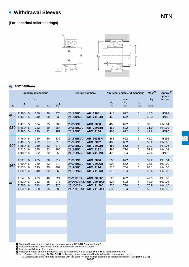
B-263
●Withdrawal Sleeves
(For spherical roller bearings)
Boundary dimensions Bearing numbers Abutment and fillet dimensions Mass3
Appro-4
priatemm mm kg nut no.
da Da ras
d1 G1
B3 G1 B42
min max max (approx.)
1 Standard thread shapes and dimensions are as per JIS B0207 (metric thread).2 Indicates reference dimensions before attachment of withdrawal sleeve.3 Indicates withdrawal sleeve mass.4 Indicates number of nut to be used at time of disassembly. See pages D-2 to D-10 for nut dimensions.Note: 1. Please refer to page B-244, B-247 for bearing dimensions, rated loads, allowable rotations, and mass.
2. Withdrawal sleeve numbers appended with the suffix "H" signify high pressure oil (hydraulic) design. (See page B-231)
d1 400~480mm
d1
G1
B3
B4
daDa
ra
G
400
420
440
460
480
Tr460×5 266 40 276 23184BK ;AH 3184 448 672 5 46.5 HN92Tr440×5 310 30 332 24184BK30 ;AH 24184H 448 672 5 40.3 HN88
Tr470×5 194 35 205 23088BK ;AHX 3088 468 622 5 32 HNL94Tr460×5 242 30 264 24088BK30 ;AH 24088H 468 622 5 31.9 HNL92Tr480×5 270 42 281 23188BK ;AHX 3188 468 692 5 49.8 HN96
Tr460×5 310 30 332 24188BK30 ;AH 24188H 468 692 5 42.3 HN92Tr490×5 202 37 213 23092BK ;AHX 3092 488 652 5 35.2 HNL98Tr480×5 250 32 273 24092BK30 ;AH 24092H 488 652 5 34.7 HNL96Tr510×6 285 43 296 23192BK ;AHX 3192 496 724 6 57.9 HN102Tr480×5 332 32 355 24192BK30 ;AH 24192H 496 724 6 47.6 HN96
Tr520×6 205 38 217 23096BK ;AHX 3096 508 672 5 39.2 HNL104Tr500×5 250 32 273 24096BK30 ;AH 24096H 508 672 5 36.6 HNL100Tr530×6 295 45 307 23196BK ;AHX 3196 516 754 6 63.1 HN106Tr500×5 340 32 363 24196BK30 ;AH 24196H 516 754 6 52.6 HN100
Tr540×6 209 40 221 230/500BK ;AHX 30/500 528 692 5 42.5 HNL108Tr530×6 253 35 276 240/500BK30;AH 240/500H 528 692 5 43.9 HNL106Tr550×6 313 47 325 231/500BK ;AHX 31/500 536 794 6 70.9 HN110Tr530×6 360 35 383 241/500BK30;AH 241/500H 536 794 6 59 HN106
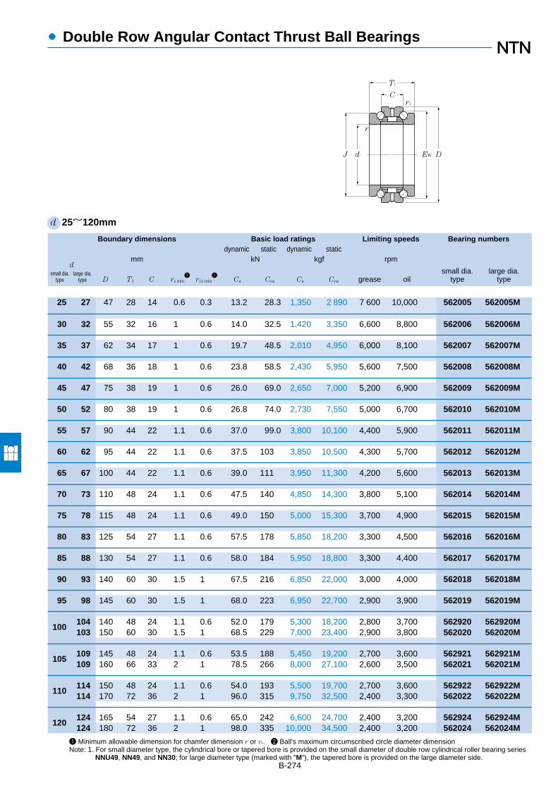
Boundary dimensions Basic load ratings Limiting speeds Bearing numbersdynamic static dynamic static
dmm kN kgf rpm
small dia. large dia. small dia. large dia.type type D T1 C rs min
1r1s min
1Ca Coa Ca Coa grease oil type type
●Double Row Angular Contact Thrust Ball Bearings
B-274
1 Minimum allowable dimension for chamfer dimension r or r1. 2 Ball's maximum circumscribed circle diameter dimensionNote: 1. For small diameter type, the cylindrical bore or tapered bore is provided on the small diameter of double row cylindrical roller bearing series
NNU49, NN49, and NN30; for large diameter type (marked with "M"), the tapered bore is provided on the large diameter side.
d 25~120mm
25 27 47 28 14 0.6 0.3 13.2 28.3 1,350 2,890 7,600 10,000 562005 562005M
30 32 55 32 16 1 0.6 14.0 32.5 1,420 3,350 6,600 8,800 562006 562006M
35 37 62 34 17 1 0.6 19.7 48.5 2,010 4,950 6,000 8,100 562007 562007M
40 42 68 36 18 1 0.6 23.8 58.5 2,430 5,950 5,600 7,500 562008 562008M
45 47 75 38 19 1 0.6 26.0 69.0 2,650 7,000 5,200 6,900 562009 562009M
50 52 80 38 19 1 0.6 26.8 74.0 2,730 7,550 5,000 6,700 562010 562010M
55 57 90 44 22 1.1 0.6 37.0 99.0 3,800 10,100 4,400 5,900 562011 562011M
60 62 95 44 22 1.1 0.6 37.5 103 3,850 10,500 4,300 5,700 562012 562012M
65 67 100 44 22 1.1 0.6 39.0 111 3,950 11,300 4,200 5,600 562013 562013M
70 73 110 48 24 1.1 0.6 47.5 140 4,850 14,300 3,800 5,100 562014 562014M
75 78 115 48 24 1.1 0.6 49.0 150 5,000 15,300 3,700 4,900 562015 562015M
80 83 125 54 27 1.1 0.6 57.5 178 5,850 18,200 3,300 4,500 562016 562016M
85 88 130 54 27 1.1 0.6 58.0 184 5,950 18,800 3,300 4,400 562017 562017M
90 93 140 60 30 1.5 1 67.5 216 6,850 22,000 3,000 4,000 562018 562018M
95 98 145 60 30 1.5 1 68.0 223 6,950 22,700 2,900 3,900 562019 562019M
100104 140 48 24 1.1 0.6 52.0 179 5,300 18,200 2,800 3,700 562920 562920M103 150 60 30 1.5 1 68.5 229 7,000 23,400 2,900 3,800 562020 562020M
105109 145 48 24 1.1 0.6 53.5 188 5,450 19,200 2,700 3,600 562921 562921M109 160 66 33 2 1 78.5 266 8,000 27,100 2,600 3,500 562021 562021M
110114 150 48 24 1.1 0.6 54.0 193 5,500 19,700 2,700 3,600 562922 562922M114 170 72 36 2 1 96.0 315 9,750 32,500 2,400 3,300 562022 562022M
120124 165 54 27 1.1 0.6 65.0 242 6,600 24,700 2,400 3,200 562924 562924M124 180 72 36 2 1 98.0 335 10,000 34,500 2,400 3,200 562024 562024M
T1
C
J
r1
r
d EW D
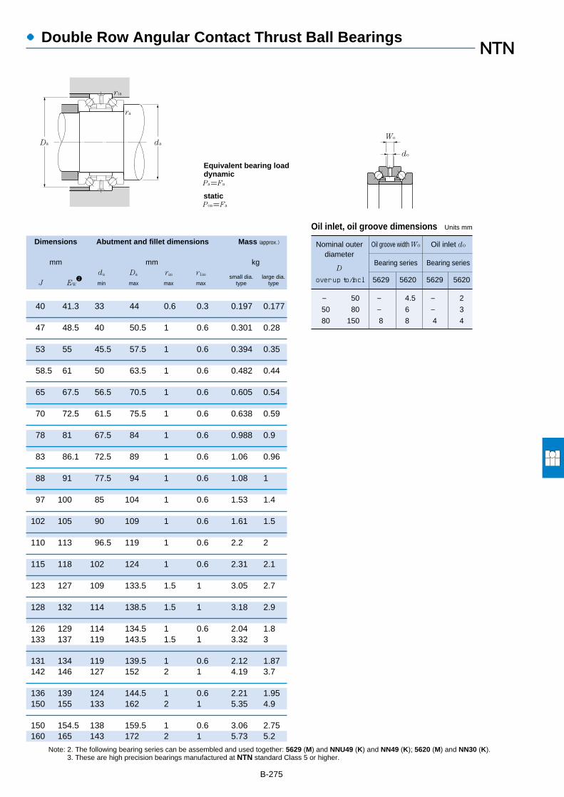
●Double Row Angular Contact Thrust Ball Bearings
Dimensions Abutment and fillet dimensions Mass (approx.)
mm mm kgda Da ras r1as small dia. large dia.
J EW2
min max max max type type
Nominal outer Oil groove width Wo Oil inlet do
diameterBearing series Bearing series
D
over up to/incl 5629 5620 5629 5620
― 50 ― 4.5 ― 2
50 80 ― 6 ― 3
80 150 8 8 4 4
B-275
Note: 2. The following bearing series can be assembled and used together: 5629 (M) and NNU49 (K) and NN49 (K); 5620 (M) and NN30 (K). 3. These are high precision bearings manufactured at NTN standard Class 5 or higher.
40 41.3 33 44 0.6 0.3 0.197 0.177
47 48.5 40 50.5 1 0.6 0.301 0.28
53 55 45.5 57.5 1 0.6 0.394 0.35
58.5 61 50 63.5 1 0.6 0.482 0.44
65 67.5 56.5 70.5 1 0.6 0.605 0.54
70 72.5 61.5 75.5 1 0.6 0.638 0.59
78 81 67.5 84 1 0.6 0.988 0.9
83 86.1 72.5 89 1 0.6 1.06 0.96
88 91 77.5 94 1 0.6 1.08 1
97 100 85 104 1 0.6 1.53 1.4
102 105 90 109 1 0.6 1.61 1.5
110 113 96.5 119 1 0.6 2.2 2
115 118 102 124 1 0.6 2.31 2.1
123 127 109 133.5 1.5 1 3.05 2.7
128 132 114 138.5 1.5 1 3.18 2.9
126 129 114 134.5 1 0.6 2.04 1.8133 137 119 143.5 1.5 1 3.32 3
131 134 119 139.5 1 0.6 2.12 1.87142 146 127 152 2 1 4.19 3.7
136 139 124 144.5 1 0.6 2.21 1.95150 155 133 162 2 1 5.35 4.9
150 154.5 138 159.5 1 0.6 3.06 2.75160 165 143 172 2 1 5.73 5.2
Oil inlet, oil groove dimensions Units mm
daDa
r1a
Pa=Fa
Poa=Fa
ra
Equivalent bearing loaddynamic
static
do
Wo
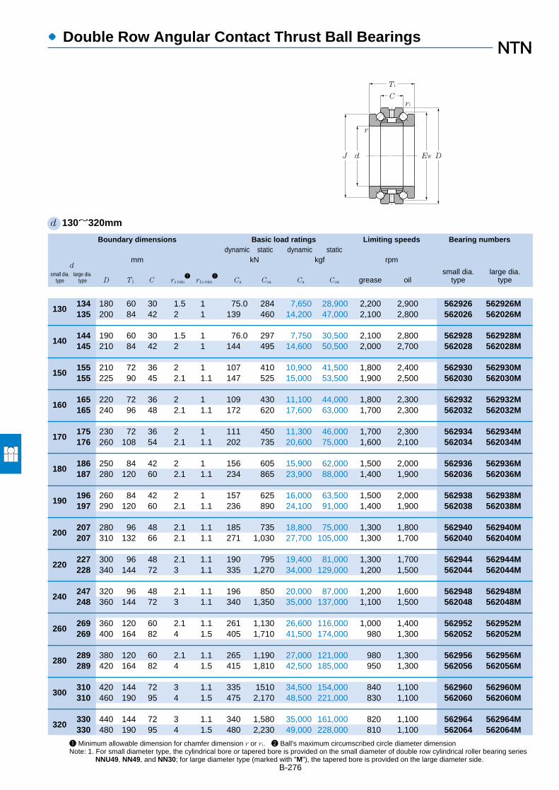
Boundary dimensions Basic load ratings Limiting speeds Bearing numbersdynamic static dynamic static
dmm kN kgf rpm
small dia. large dia. small dia. large dia.type type D T1 C rs min
1r1s min
1Ca Coa Ca Coa grease oil type type
●Double Row Angular Contact Thrust Ball Bearings
B-276
1 Minimum allowable dimension for chamfer dimension r or r1. 2 Ball's maximum circumscribed circle diameter dimensionNote: 1. For small diameter type, the cylindrical bore or tapered bore is provided on the small diameter of double row cylindrical roller bearing series
NNU49, NN49, and NN30; for large diameter type (marked with "M"), the tapered bore is provided on the large diameter side.
d 130~320mm
130134 180 60 30 1.5 1 75.0 284 7,650 28,900 2,200 2,900 562926 562926M135 200 84 42 2 1 139 460 14,200 47,000 2,100 2,800 562026 562026M
140144 190 60 30 1.5 1 76.0 297 7,750 30,500 2,100 2,800 562928 562928M145 210 84 42 2 1 144 495 14,600 50,500 2,000 2,700 562028 562028M
150155 210 72 36 2 1 107 410 10,900 41,500 1,800 2,400 562930 562930M155 225 90 45 2.1 1.1 147 525 15,000 53,500 1,900 2,500 562030 562030M
160165 220 72 36 2 1 109 430 11,100 44,000 1,800 2,300 562932 562932M165 240 96 48 2.1 1.1 172 620 17,600 63,000 1,700 2,300 562032 562032M
170175 230 72 36 2 1 111 450 11,300 46,000 1,700 2,300 562934 562934M176 260 108 54 2.1 1.1 202 735 20,600 75,000 1,600 2,100 562034 562034M
180186 250 84 42 2 1 156 605 15,900 62,000 1,500 2,000 562936 562936M187 280 120 60 2.1 1.1 234 865 23,900 88,000 1,400 1,900 562036 562036M
190196 260 84 42 2 1 157 625 16,000 63,500 1,500 2,000 562938 562938M197 290 120 60 2.1 1.1 236 890 24,100 91,000 1,400 1,900 562038 562038M
200207 280 96 48 2.1 1.1 185 735 18,800 75,000 1,300 1,800 562940 562940M207 310 132 66 2.1 1.1 271 1,030 27,700 105,000 1,300 1,700 562040 562040M
220227 300 96 48 2.1 1.1 190 795 19,400 81,000 1,300 1,700 562944 562944M228 340 144 72 3 1.1 335 1,270 34,000 129,000 1,200 1,500 562044 562044M
240247 320 96 48 2.1 1.1 196 850 20,000 87,000 1,200 1,600 562948 562948M248 360 144 72 3 1.1 340 1,350 35,000 137,000 1,100 1,500 562048 562048M
260269 360 120 60 2.1 1.1 261 1,130 26,600 116,000 1,000 1,400 562952 562952M269 400 164 82 4 1.5 405 1,710 41,500 174,000 980 1,300 562052 562052M
280289 380 120 60 2.1 1.1 265 1,190 27,000 121,000 980 1,300 562956 562956M289 420 164 82 4 1.5 415 1,810 42,500 185,000 950 1,300 562056 562056M
300310 420 144 72 3 1.1 335 1510 34,500 154,000 840 1,100 562960 562960M310 460 190 95 4 1.5 475 2,170 48,500 221,000 830 1,100 562060 562060M
320330 440 144 72 3 1.1 340 1,580 35,000 161,000 820 1,100 562964 562964M330 480 190 95 4 1.5 480 2,230 49,000 228,000 810 1,100 562064 562064M
T1
C
J
r1
r
d EW D

80 150 8 8 4 4
150 200 8 12 4 6
200 210 12 12 6 6
210 260 12 14 6 6
260 320 14 16 6 8
320 400 16 23 8 12
400 480 22 22 12 12
Nominal outer Oil groove width Wo Oil inlet do
diameterBearing series Bearing series
D
over up to/incl 5629 5620 5629 5620
Oil inlet, oil groove dimensions Units mm
●Double Row Angular Contact Thrust Ball Bearings
Dimensions Abutment and fillet dimensions Mass (approx.)
mm mm kgda Da ras r1as small dia. large dia.
J EW2
min max max max type type
B-277
Note: 2. The following bearing series can be assembled and used together: 5629 (M) and NNU49 (K) and NN49 (K); 5620 (M) and NN30 (K). 3. These are high precision bearings manufactured at NTN standard Class 5 or higher.
163 168 150 173.5 1.5 1 4.11 3.7177 182 155 192 2 1 8.58 7.6
173 178 160 183.5 1.5 1 4.38 3.94187 192 165 202 2 1 9.1 8.1
190 196.5 174 202 2 1 6.88 6.2200 206 178 215 2 1 11.2 10
200 206.5 184 212 2 1 7.26 6.53212 219 189 230 2 1 13.6 11.9
210 216.5 194 222 2 1 7.64 6.88230 236 203 250 2 1 18.5 16.5
227 234 207 242 2 1 11.2 10248 255 219 270 2 1 24.7 21.8
237 244 217 252 2 1 11.7 10.5258 265 229 280 2 1 25.5 23
252 261 231 270 2 1 16.3 14.7274 282 243 300 2 1 32.7 29.7
272 281 251 290 2 1 17.7 16304 310 267 330 2.5 1 42.8 38.5
292 301 271 310 2 1 19 17322 330 287 350 2.5 1 45.8 41.2
328 336 299 350 2 1 32.9 29.6354 364 315 388 3 1.5 67 60.3
348 356 319 370 2 1 35 31.5374 384 335 408 3 1.5 71.1 64
384 391 349 410 2.5 1 55 49.5406 418 364 448 3 1.5 102 91.8
404 411 369 430 2.5 1 58.1 52.3426 438 384 468 3 1.5 108 97.2
daDa
r1a
Pa=Fa
Poa=Fa
ra
Equivalent bearing loaddynamic
static
do
Wo

Boundary dimensions Basic load ratings Limiting speeds Bearingdynamic static dynamic static numbers
mm kN kgf rpm
d D 2B rs min1
r1s min1
Ca Coa Ca Coa grease oil
●High Speed Duplex Angular Contact Thrust Ball Bearings
B-278
d 25~120mm
47 21 0.6 0.3 16.2 22.1 1,650 2,260 16,000 21,000 HTA005DB
55 24 1 0.6 17.5 26.7 1,780 2,720 14,000 18,000 HTA006DB
62 25.5 1 0.6 25.2 38.0 2,570 3,900 12,000 16,000 HTA007DB
68 27 1 0.6 27.2 45.0 2,780 4,550 11,000 14,000 HTA008DB
75 28.5 1 0.6 27.9 48.5 2,840 4,950 9,700 13,000 HTA009DB
80 28.5 1 0.6 29.6 55.5 3,000 5,650 8,800 12,000 HTA010DB
90 33 1.1 0.6 32.0 64.0 3,250 6,500 8,000 11,000 HTA011DB
95 33 1.1 0.6 33.5 69.5 3,400 7,100 7,400 9,800 HTA012DB
100 33 1.1 0.6 34.0 72.0 3,450 7,350 6,900 9,200 HTA013DB
110 36 1.1 0.6 41.5 91.0 4,250 9,300 6,400 8,500 HTA014DB
115 36 1.1 0.6 44.0 101 4,500 10,300 5,900 7,900 HTA015DB
125 40.5 1.1 0.6 50.5 117 5,150 11,900 5,600 7,400 HTA016DB
130 40.5 1.1 0.6 51.0 120 5,200 12,300 5,200 7,000 HTA017DB
140 45 1.5 1 59.5 141 6,050 14,400 5,000 6,600 HTA018DB
145 45 1.5 1 60.0 146 6,100 14,900 4,700 6,300 HTA019DB
140 36 1.1 0.6 47.0 121 4,800 12,300 4,800 6,300 HTA920DB150 45 1.5 1 62.0 156 6,350 15,900 4,500 5,900 HTA020DB
145 36 1.1 0.6 48.5 128 4,950 13,000 4,500 6,000 HTA921DB160 49.5 2 1 71.0 181 7,250 18,400 4,200 5,600 HTA021DB
150 36 1.1 0.6 49.0 131 5,000 13,400 4,300 5,800 HTA922DB170 54 2 1 88.5 222 9,000 22,700 4,000 5,400 HTA022DB
165 40.5 1.1 0.6 57.0 156 5,800 15,900 4,000 5,300 HTA924DB180 54 2 1 89.0 228 9,050 23,300 3,700 4,900 HTA024DB
1 Minimum allowable dimension for chamfer dimension r or r1.Note: 1. This bearing can be used in place of high speed double row angular contact thrust ball bearings. 2. These are high precision bearings
manufactured at NTN standard Class 5 or higher.
25
30
35
40
45
50
55
60
65
70
75
80
85
90
95
100
105
110
120
2a
D d
2Br1
r1
r r
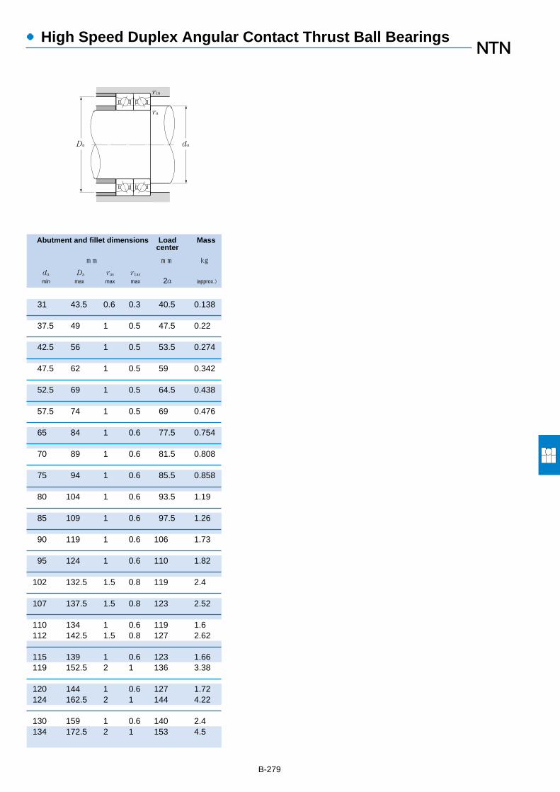
●High Speed Duplex Angular Contact Thrust Ball Bearings
Abutment and fillet dimensions Load Masscenter
mm mm kg
da Da ras r1as
min max max max 2a (approx.)
B-279
31 43.5 0.6 0.3 40.5 0.138
37.5 49 1 0.5 47.5 0.22
42.5 56 1 0.5 53.5 0.274
47.5 62 1 0.5 59 0.342
52.5 69 1 0.5 64.5 0.438
57.5 74 1 0.5 69 0.476
65 84 1 0.6 77.5 0.754
70 89 1 0.6 81.5 0.808
75 94 1 0.6 85.5 0.858
80 104 1 0.6 93.5 1.19
85 109 1 0.6 97.5 1.26
90 119 1 0.6 106 1.73
95 124 1 0.6 110 1.82
102 132.5 1.5 0.8 119 2.4
107 137.5 1.5 0.8 123 2.52
110 134 1 0.6 119 1.6112 142.5 1.5 0.8 127 2.62
115 139 1 0.6 123 1.66119 152.5 2 1 136 3.38
120 144 1 0.6 127 1.72124 162.5 2 1 144 4.22
130 159 1 0.6 140 2.4134 172.5 2 1 153 4.5
da Da
r1a
ra

B-280
Boundary dimensions Basic load ratings Limiting speeds Bearingdynamic static dynamic static numbers
mm kN kgf rpm
d D 2B rs min1
r1s min1
Ca Coa Ca Coa grease oil
●High Speed Duplex Angular Contact Thrust Ball Bearings
d 130~320mm
180 45 1.5 1 68.0 193 6,950 19,600 3,600 4,800 HTA926DB200 63 2 1 128 325 13,000 33,000 3,400 4,500 HTA026DB
190 45 1.5 1 68.0 197 6,950 20,100 3,300 4,500 HTA928DB210 63 2 1 132 345 13,500 35,500 3,100 4,200 HTA028DB
210 54 2 1 95.5 270 9,750 27,600 3,100 4,200 HTA930DB225 67.5 2.1 1.1 136 370 13,800 37,500 2,900 3,900 HTA030DB
220 54 2 1 97.5 284 9,950 29,000 2,900 3,900 HTA932DB240 72 2.1 1.1 159 435 16,200 44,000 2,700 3,600 HTA032DB
230 54 2 1 99.5 298 10,100 30,500 2,700 3,600 HTA934DB260 81 2.1 1.1 182 500 18,600 51,000 2,500 3,400 HTA034DB
250 63 2 1 150 445 15,300 45,500 2,600 3,400 HTA936DB280 90 2.1 1.1 211 585 21,500 60,000 2,400 3,200 HTA036DB
260 63 2 1 153 470 15,600 48,000 2,400 3,200 HTA938DB290 90 2.1 1.1 214 605 21,800 61,500 2,200 3,000 HTA038DB
280 72 2.1 1.1 180 555 18,400 56,500 2,300 3,000 HTA940DB310 99 2.1 1.1 240 680 24,400 69,000 2,100 2,800 HTA040DB
300 72 2.1 1.1 185 595 18,900 60,500 2,100 2,700 HTA944DB340 108 3 1.1 300 860 30,500 87,500 1,900 2,600 HTA044DB
320 72 2.1 1.1 190 635 19,400 64,500 1,900 2,500 HTA948DB360 108 3 1.1 310 915 31,500 93,000 1,700 2,300 HTA048DB
360 90 2.1 1.1 250 830 25,400 84,500 1,700 2,300 HTA952DB400 123 4 1.5 365 1,160 37,500 118,000 1,600 2,100 HTA052DB
380 90 2.1 1.1 257 885 26,200 90,500 1,600 2,100 HTA956DB420 123 4 1.5 375 1,230 38,500 125,000 1,500 2,000 HTA056DB
420 108 3 1.1 325 1,130 33,500 115,000 1,400 1,900 HTA960DB460 142.5 4 1.5 430 1,470 44,000 150,000 1,400 1,800 HTA060DB
440 108 3 1.1 330 1,180 34,000 120,000 1,300 1,800 HTA964DB480 142.5 4 1.5 435 1,520 44,000 155,000 1,300 1,700 HTA064DB
1 Minimum allowable dimension for chamfer dimension r or r1.Note: 1. This bearing can be used in place of high speed double row angular contact thrust ball bearings. 2. These are high precision bearings
manufactured at NTN standard Class 5 or higher.
140
130
160
150
170
180
190
200
220
240
260
280
300
320
2a
D d
2Br1
r1
r r

B-281
●High Speed Duplex Angular Contact Thrust Ball Bearings
Abutment and fillet dimensions Load Masscenter
mm mm kg
da Da ras r1as
min max max max 2a (approx.)
142 172.5 1.5 0.8 153 3.26144 192.5 2 1 170 6.66
152 182.5 1.5 1 161 3.46154 202.5 2 1 178 7.08
164 202.5 2 1 178 5.4167 215 2 1 191 8.82
174 212.5 2 1 186 5.7177 230 2 1 204 10.6
184 222.5 2 1 195 6187 250 2 1 221 14.5
194 242.5 2 1 212 9.38197 270 2 1 238 20.6
204 252.5 2 1 220 9.82207 280 2 1 246 21.4
217 270 2 1 237 13.7217 300 2 1 263 27.4
237 290 2 1 254 14.8240 330 2.5 1 289 35.8
257 310 2 1 271 16260 350 2.5 1 306 38.2
277 350 2 1 305 27.8283 388 3 1.5 338 56.2
297 370 2 1 322 28303 408 3 1.5 355 59.6
320 410 2.5 1 356 46.6323 448 3 1.5 390 85.6
340 430 2.5 1 373 49343 468 3 1.5 407 90
da Da
r1a
ra
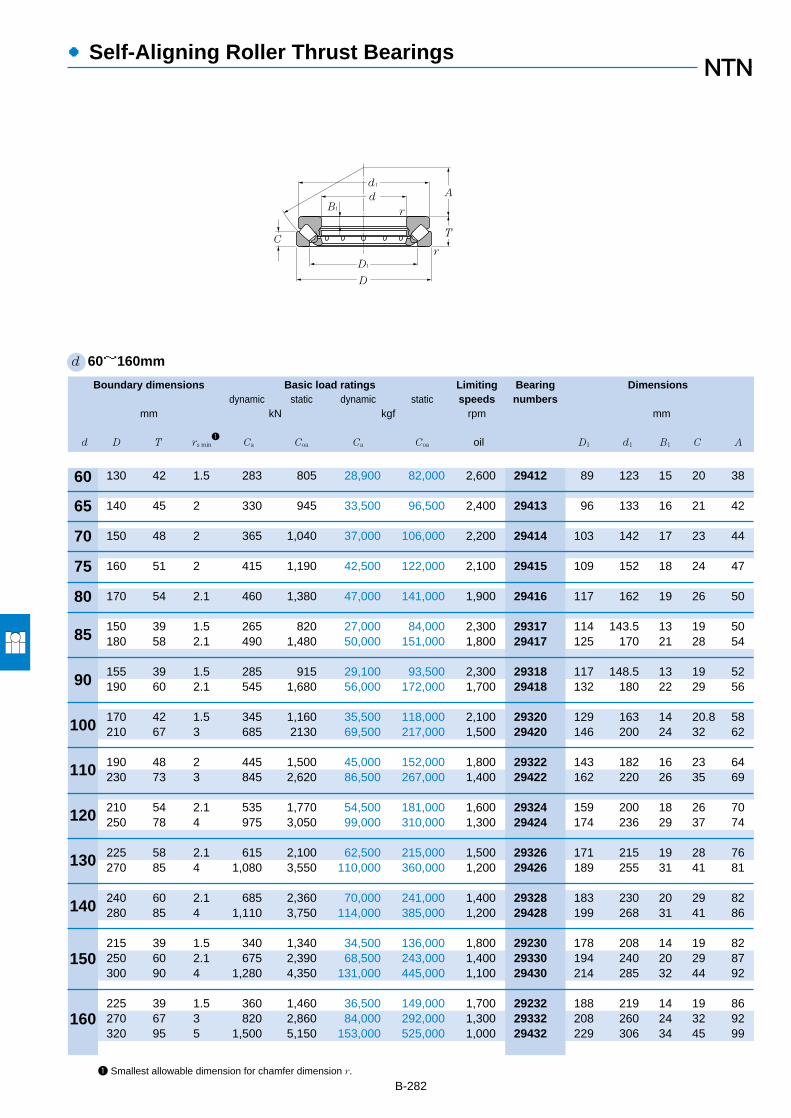
Boundary dimensions Basic load ratings Limiting Bearing Dimensionsdynamic static dynamic static speeds numbers
mm kN kgf rpm mm
d D T rs min1
Ca Coa Ca Coa oil D1 d1 B1 C A
●Self-Aligning Roller Thrust Bearings
B-2821 Smallest allowable dimension for chamfer dimension r.
d 60~160mm
60
65
70
75
80
85
90
100
110
120
130
140
150
160
130 42 1.5 283 805 28,900 82,000 2,600 29412 89 123 15 20 38
140 45 2 330 945 33,500 96,500 2,400 29413 96 133 16 21 42
150 48 2 365 1,040 37,000 106,000 2,200 29414 103 142 17 23 44
160 51 2 415 1,190 42,500 122,000 2,100 29415 109 152 18 24 47
170 54 2.1 460 1,380 47,000 141,000 1,900 29416 117 162 19 26 50
150 39 1.5 265 820 27,000 84,000 2,300 29317 114 143.5 13 19 50180 58 2.1 490 1,480 50,000 151,000 1,800 29417 125 170 21 28 54
155 39 1.5 285 915 29,100 93,500 2,300 29318 117 148.5 13 19 52190 60 2.1 545 1,680 56,000 172,000 1,700 29418 132 180 22 29 56
170 42 1.5 345 1,160 35,500 118,000 2,100 29320 129 163 14 20.8 58210 67 3 685 2130 69,500 217,000 1,500 29420 146 200 24 32 62
190 48 2 445 1,500 45,000 152,000 1,800 29322 143 182 16 23 64230 73 3 845 2,620 86,500 267,000 1,400 29422 162 220 26 35 69
210 54 2.1 535 1,770 54,500 181,000 1,600 29324 159 200 18 26 70250 78 4 975 3,050 99,000 310,000 1,300 29424 174 236 29 37 74
225 58 2.1 615 2,100 62,500 215,000 1,500 29326 171 215 19 28 76270 85 4 1,080 3,550 110,000 360,000 1,200 29426 189 255 31 41 81
240 60 2.1 685 2,360 70,000 241,000 1,400 29328 183 230 20 29 82280 85 4 1,110 3,750 114,000 385,000 1,200 29428 199 268 31 41 86
215 39 1.5 340 1,340 34,500 136,000 1,800 29230 178 208 14 19 82250 60 2.1 675 2,390 68,500 243,000 1,400 29330 194 240 20 29 87300 90 4 1,280 4,350 131,000 445,000 1,100 29430 214 285 32 44 92
225 39 1.5 360 1,460 36,500 149,000 1,700 29232 188 219 14 19 86270 67 3 820 2,860 84,000 292,000 1,300 29332 208 260 24 32 92320 95 5 1,500 5,150 153,000 525,000 1,000 29432 229 306 34 45 99
D1
D
C
A
T
d1
dB1 r
r
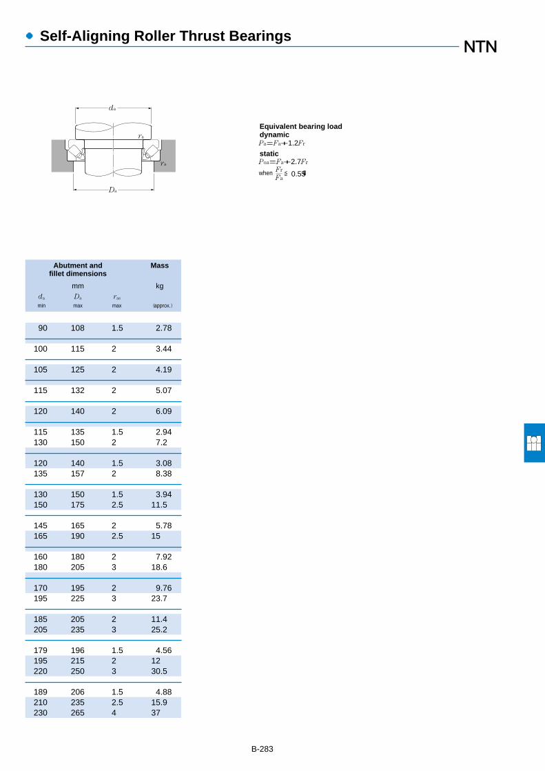
●Self-Aligning Roller Thrust Bearings
Abutment and Massfillet dimensions
mm kgda Da ras
min max max (approx.)
B-283
90 108 1.5 2.78
100 115 2 3.44
105 125 2 4.19
115 132 2 5.07
120 140 2 6.09
115 135 1.5 2.94130 150 2 7.2
120 140 1.5 3.08135 157 2 8.38
130 150 1.5 3.94150 175 2.5 11.5
145 165 2 5.78165 190 2.5 15
160 180 2 7.92180 205 3 18.6
170 195 2 9.76195 225 3 23.7
185 205 2 11.4205 235 3 25.2
179 196 1.5 4.56195 215 2 12220 250 3 30.5
189 206 1.5 4.88210 235 2.5 15.9230 265 4 37
Da
da
ra
ra Fr
Fa≦0.55
Pa=Fa+1.2Fr
Poa=Fa+2.7Fr
when �
Equivalent bearing loaddynamic
static

B-284
Boundary dimensions Basic load ratings Limiting Bearing Dimensionsdynamic static dynamic static speeds numbers
mm kN kgf rpm mm
d D T rs min1
Ca Coa Ca Coa oil D1 d1 B1 C A
●Self-Aligning Roller Thrust Bearings
1 Smallest allowable dimension for chamfer dimension r.
d 170~320mm
240 42 1.5 425 1,770 43,500 180,000 1,600 29234 198 233 15 20 92280 67 3 855 3,050 87,000 310,000 1,200 29334 216 270 23 32 96340 103 5 1,660 5,750 169,000 590,000 940 29434 243 324 37 50 104
250 42 1.5 450 1,920 45,500 196,000 1,600 29236 208 243 15 20 97300 73 3 995 3,600 102,000 365,000 1,100 29336 232 290 25 35 103360 109 5 1,840 6,200 188,000 635,000 890 29436 255 342 39 52 110
270 48 2 530 2,230 54,000 227,000 1,400 29238 223 262 15 24 104320 78 4 1,150 4,250 117,000 430,000 1,100 29338 246 308 27 38 110380 115 5 2,010 6,800 205,000 695,000 840 29438 271 360 41 55 117
280 48 2 535 2,300 54,500 234,000 1,400 29240 236 271 15 24 108340 85 4 1,280 4,600 131,000 470,000 980 29340 261 325 29 41 116400 122 5 2,230 7,650 228,000 780,000 790 29440 286 380 43 59 122
300 48 2 555 2,480 56,500 253,000 1,300 29244 254 292 15 24 117360 85 4 1,390 5,200 141,000 530,000 940 29344 280 345 29 41 125420 122 6 2,300 8,100 235,000 825,000 760 29444 308 400 43 58 132
340 60 2.1 825 3,600 84,000 365,000 1,100 29248 283 330 19 30 130380 85 4 1,380 5,250 140,000 535,000 910 29348 300 365 29 41 135440 122 6 2,400 8,700 245,000 885,000 740 29448 326 420 43 59 142
360 60 2.1 870 3,950 88,500 400,000 1,100 29252 302 350 19 30 139420 95 5 1,710 6,800 175,000 695,000 810 29352 329 405 32 45 148480 132 6 2,740 10,000 279,000 1,020,000 670 29452 357 460 48 64 154
380 60 2.1 875 4,050 89,000 415,000 1,000 29256 323 370 19 30 150440 95 5 1,800 7,250 184,000 740,000 790 29356 348 423 32 46 158520 145 6 3,350 12,400 340,000 1,270,000 610 29456 387 495 52 68 166
420 73 3 1,190 5,350 121,000 545,000 870 29260 353 405 21 38 162480 109 5 2,140 8,250 218,000 840,000 700 29360 379 460 37 50 168540 145 6 3,450 13,200 350,000 1,340,000 590 29460 402 515 52 70 175
440 73 3 1,260 5,800 128,000 595,000 840 29264 372 430 21 38 172500 109 5 2,220 8,800 226,000 895,000 680 29364 399 482 37 53 180580 155 7.5 3,700 14,200 375,000 1,440,000 550 29464 435 555 55 75 191
170
180
190
200
220
240
260
280
300
320
D1
D
C
A
T
d1
dB1 r
r
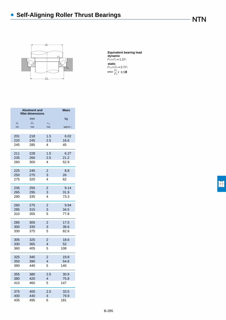
B-285
●Self-Aligning Roller Thrust Bearings
Abutment and Massfillet dimensions
mm kgda Da ras
min max max (approx.)
201 218 1.5 6.02220 245 2.5 16.6245 285 4 45
211 228 1.5 6.27235 260 2.5 21.2260 300 4 52.9
225 245 2 8.8250 275 3 26275 320 4 62
235 255 2 9.14265 295 3 31.9290 335 4 73.3
260 275 2 9.94285 315 3 34.5310 355 5 77.8
285 305 2 17.5300 330 3 36.6330 375 5 82.6
305 325 2 18.6330 365 4 52360 405 5 108
325 345 2 19.8350 390 4 54.6390 440 5 140
355 380 2.5 30.9380 420 4 75.8410 460 5 147
375 400 2.5 33.5400 440 4 79.9435 495 6 181
Da
da
ra
ra Fr
Fa≦0.55
Pa=Fa+1.2Fr
Poa=Fa+2.7Fr
when �
Equivalent bearing loaddynamic
static

B-286
Boundary dimensions Basic load ratings Limiting Bearing Dimensionsdynamic static dynamic static speeds numbers
mm kN kgf rpm mm
d D T rs min1
Ca Coa Ca Coa oil D1 d1 B1 C A
●Self-Aligning Roller Thrust Bearings
1 Smallest allowable dimension for chamfer dimension r.
d 340~500mm
460 73 3 1,240 5,800 126,000 590,000 820 29268 395 445 21 37 183540 122 5 2,650 10,700 270,000 1,090,000 610 29368 428 520 41 59 192620 170 7.5 4,400 17,500 445,000 1,790,000 500 29468 462 590 61 82 201
500 85 4 1,510 7,050 154,000 720,000 720 29272 423 485 25 44 194560 122 5 2,710 11,100 276,000 1,130,000 590 29372 448 540 41 59 202640 170 7.5 4,500 18,500 460,000 1,890,000 490 29472 480 610 61 82 210
520 85 4 1,590 7,650 162,000 780,000 700 29276 441 505 27 42 202600 132 6 3,200 13,300 325,000 1,360,000 550 29376 477 580 44 63 216670 175 7.5 4,900 19,700 500,000 2,010,000 470 29476 504 640 63 85 230
540 85 4 1,620 7,950 165,000 810,000 680 29280 460 526 27 42 212620 132 6 3,400 14,500 345,000 1,480,000 530 29380 494 596 44 64 225710 185 7.5 5,450 22,100 555,000 2,250,000 440 29480 534 680 67 89 236
580 95 5 2,100 10,400 214,000 1,060,000 620 29284 489 564 30 46 225650 140 6 3,600 15,500 365,000 1,580,000 500 29384 520 626 48 68 235730 185 7.5 5,500 22,800 560,000 2,330,000 430 29484 556 700 67 89 244
600 95 5 2,150 10,900 219,000 1,110,000 600 29288 508 585 30 49 235680 145 6 3,800 16,400 385,000 1,680,000 480 29388 548 655 49 70 245780 206 9.5 6,400 26,200 650,000 2,670,000 390 29488 588 745 74 100 260
620 95 5 2,150 11,000 219,000 1,120,000 590 29292 530 605 30 46 245710 150 6 4,200 18,500 430,000 1,880,000 460 29392 567 685 51 72 257800 206 9.5 6,600 27,900 670,000 2,840,000 380 29492 608 765 74 100 272
650 103 5 2,400 12,000 245,000 1,220,000 550 29296 556 635 33 55 259730 150 6 4,200 18,700 430,000 1,910,000 450 29396 590 705 51 72 270850 224 9.5 7,500 31,500 765,000 3,200,000 350 29496 638 810 81 108 280
670 103 5 2,540 13,000 259,000 1,330,000 530 292/500 574 654 33 55 268750 150 6 4,300 19,300 435,000 1,970,000 440 293/500 611 725 51 74 280870 224 9.5 7,850 33,000 805,000 3,350,000 340 294/500 661 830 81 107 290
340
360
380
400
420
440
460
480
500
D1
D
C
A
T
d1
dB1 r
r

B-287
●Self-Aligning Roller Thrust Bearings
Abutment and Massfillet dimensions
mm kgda Da ras
min max max (approx.)
395 420 2.5 34.4430 470 4 107465 530 6 230
420 455 3 50.5450 495 4 112485 550 6 240
440 475 3 53.4480 525 5 143510 575 6 267
460 490 3 55.8500 550 5 148540 610 6 321
490 525 4 76.6525 575 5 172560 630 6 333
510 545 4 79.6550 600 5 195595 670 8 428
530 570 4 82.8575 630 5 221615 690 8 443
555 595 4 98.6595 650 5 228645 730 8 552
575 615 4 102615 670 5 235670 750 8 569
Da
da
ra
ra Fr
Fa≦0.55
Pa=Fa+1.2Fr
Poa=Fa+2.7Fr
when �
Equivalent bearing loaddynamic
static
Locknuts, Lockwashers & Lockplates
Contents
Locknuts …………………………………… C- 2
Nuts ………………………………………… C- 8
Lockwashers………………………………… C-12
Lockplates…………………………………… C-15
Locknuts, Lockwashers& Lockplates
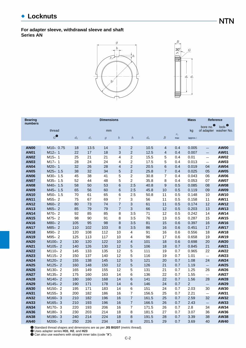
Bearing Dimensions Mass Referencenumbers
bore no.2
lock-3
thread mm kg of adapter washer No.r1
G1
d2 d1 g b h d6 B max (approx.)
●Locknuts
C-2
1 Standard thread shapes and dimensions are as per JIS B0207 (metric thread).2 Uses adapter series H31, H2, and H233 Can also use washers with straight inner tabs (code "X").
For adapter sleeve, withdrawal sleeve and shaftSeries AN
g
b
hr1
B
d6 d1
30˚
d2
G
AN00 M10×0.75 18 13.5 14 3 2 10.5 4 0.4 0.005 - AW00AN01 M12×1 22 17 18 3 2 12.5 4 0.4 0.007 - AW01AN02 M15×1 25 21 21 4 2 15.5 5 0.4 0.01 - AW02AN03 M17×1 28 24 24 4 2 17.5 5 0.4 0.013 - AW03AN04 M20×1 32 26 28 4 2 20.5 6 0.4 0.019 04 AW04AN05 M25×1.5 38 32 34 5 2 25.8 7 0.4 0.025 05 AW05AN06 M30×1.5 45 38 41 5 2 30.8 7 0.4 0.043 06 AW06AN07 M35×1.5 52 44 48 5 2 35.8 8 0.4 0.053 07 AW07AN08 M40×1.5 58 50 53 6 2.5 40.8 9 0.5 0.085 08 AW08AN09 M45×1.5 65 56 60 6 2.5 45.8 10 0.5 0.119 09 AW09AN10 M50×1.5 70 61 65 6 2.5 50.8 11 0.5 0.148 10 AW10AN11 M55×2 75 67 69 7 3 56 11 0.5 0.158 11 AW11AN12 M60×2 80 73 74 7 3 61 11 0.5 0.174 12 AW12AN13 M65×2 85 79 79 7 3 66 12 0.5 0.203 13 AW13AN14 M70×2 92 85 85 8 3.5 71 12 0.5 0.242 14 AW14AN15 M75×2 98 90 91 8 3.5 76 13 0.5 0.287 15 AW15AN16 M80×2 105 95 98 8 3.5 81 15 0.6 0.397 16 AW16AN17 M85×2 110 102 103 8 3.5 86 16 0.6 0.451 17 AW17AN18 M90×2 120 108 112 10 4 91 16 0.6 0.556 18 AW18AN19 M95×2 125 113 117 10 4 96 17 0.6 0.658 19 AW19AN20 M100×2 130 120 122 10 4 101 18 0.6 0.698 20 AW20AN21 M105×2 140 126 130 12 5 106 18 0.7 0.845 21 AW21AN22 M110×2 145 133 135 12 5 111 19 0.7 0.965 22 AW22AN23 M115×2 150 137 140 12 5 116 19 0.7 1.01 - AW23AN24 M120×2 155 138 145 12 5 121 20 0.7 1.08 24 AW24AN25 M125×2 160 148 150 12 5 126 21 0.7 1.19 - AW25AN26 M130×2 165 149 155 12 5 131 21 0.7 1.25 26 AW26AN27 M135×2 175 160 163 14 6 136 22 0.7 1.55 - AW27AN28 M140×2 180 160 168 14 6 141 22 0.7 1.56 28 AW28AN29 M145×2 190 171 178 14 6 146 24 0.7 2 - AW29AN30 M150×2 195 171 183 14 6 151 24 0.7 2.03 30 AW30AN31 M155×3 200 182 186 16 7 156.5 25 0.7 2.21 - AW31AN32 M160×3 210 182 196 16 7 161.5 25 0.7 2.59 32 AW32AN33 M165×3 210 193 196 16 7 166.5 26 0.7 2.43 - AW33AN34 M170×3 220 193 206 16 7 171.5 26 0.7 2.8 34 AW34AN36 M180×3 230 203 214 18 8 181.5 27 0.7 3.07 36 AW36AN38 M190×3 240 214 224 18 8 191.5 28 0.7 3.39 38 AW38AN40 M200×3 250 226 234 18 8 201.5 29 0.7 3.69 40 AW40

●Locknuts
Reference Shaftwithdrawal sleeve No.
mmAH30 AH240 AH31 AH241 AH2 AH32 AH3 AH23
(for shaft)
C-3
- - - - - - - - 10- - - - - - - - 12- - - - - - - - 15- - - - - - - - 17- - - - - - - - 20- - - - - - - - 25- - - - - - - - 30- - - - - - - - 35- - - - - - - - 40- - - - AH208 - AH 308 AH 2308 45- - - - AH209 - AH 309 AH 2309 50- - - - AH210 - AHX310 AHX2310 55- - - - AH211 - AHX311 AHX2311 60- - - - AH212 - AHX312 AHX2312 65- - - - - - - - 70- - - - AH213 - AH 313 AH 2313 75- - - - AH214 - AH 314 AHX2314 80- - - - AH215 - AH 315 AHX2315 85- - - - AH216 - AH 316 AHX2316 90- - - - AH217 - AHX317 AHX2317 95- - - - AH218 AHX3218 AHX318 AHX2318 100- - - - AH219 - AHX319 AHX2319 105- - - - AH220 AHX3220 AHX320 AHX2320 110- - - AH24122 AH221 - AHX321 - 115- - AHX3122 - AH222 - AHX322 - 120- AH24024 - - - AHX3222 - AHX2322 125
AHX3024 - AHX3124 AH24124 AH224 - AHX324 - 130- AH24026 - - - AHX3224 - AHX2324 135
AHX3026 - AHX3126 AH24126 AH226 - AHX326 - 140- AH24028 - - - AHX3226 - AHX2326 145
AHX3028 - AHX3128 AH24128 AH228 - AHX328 - 150- AH24030 - - - AHX3228 - AHX2328 155
AHX3030 - - AH24130 AH230 - - - 160- - AHX3130 - - AHX3230 AHX330 AHX2330 165
AH 3032 AH24032 - AH24132 AH232 - - - 170AH 3034 AH24034 AH 3132 AH24134 AH234 AH 3232 AH 332 AH 2332 180AH 3036 AH24036 AH 3134 AH24136 AH236 AH 3234 AH 334 AH 2334 190- AH24038 AH 3136 AH24138 - AH 3236 - AH 2336 200

Bearing Dimensions Massnumbers
thread mm thread kgr1
G1
d2 d1 g b h d6 B max l s2
dP (approx.)
●Locknuts
C-4
1 Standard thread shapes and dimensions are as per JIS B0216 (metric thread).2 Thread dimensions are as per JIS B0205 (metric coarse screw thread type thread).3 Applied to adapter series H31, H32, and H23
For adapter sleeve and shaftSeries AN
g
b
hs
r1
d2
B
d6 d1dP
30˚
rG
AN 44 Tr220×4 280 250 260 20 10 222 32 0.8 15 M 8×1.25 238 5.2AN 48 Tr240×4 300 270 280 20 10 242 34 0.8 15 M 8×1.25 258 5.95AN 52 Tr260×4 330 300 306 24 12 262 36 0.8 18 M10×1.5 281 8.05AN 56 Tr280×4 350 320 326 24 12 282 38 0.8 18 M10×1.5 301 9.05AN 60 Tr300×4 380 340 356 24 12 302 40 0.8 18 M10×1.5 326 11.8AN 64 Tr320×5 400 360 376 24 12 322.5 42 0.8 18 M10×1.5 345 13.1AN 68 Tr340×5 440 400 410 28 15 342.5 55 1 21 M12×1.75 372 23.1AN 72 Tr360×5 460 420 430 28 15 362.5 58 1 21 M12×1.75 392 25.1AN 76 Tr380×5 490 450 454 32 18 382.5 60 1 21 M12×1.75 414 30.9AN 80 Tr400×5 520 470 484 32 18 402.5 62 1 27 M16×2 439 36.9AN 84 Tr420×5 540 490 504 32 18 422.5 70 1 27 M16×2 459 43.5AN 88 Tr440×5 560 510 520 36 20 442.5 70 1 27 M16×2 477 45.3AN 92 Tr460×5 580 540 540 36 20 462.5 75 1 27 M16×2 497 50.4AN 96 Tr480×5 620 560 580 36 20 482.5 75 1 27 M16×2 527 62.2AN100 Tr500×5 630 580 584 40 23 502.5 80 1 27 M16×2 539 63.3

●Locknuts
Reference Shaftbore no.
3lock-
of adapter plate No.mm
(for shaft)
C-5
44 AL 44 22048 AL 44 24052 AL 52 26056 AL 52 28060 AL 60 30064 AL 64 32068 AL 68 34072 AL 68 36076 AL 76 38080 AL 80 40084 AL 80 42088 AL 88 44092 AL 88 46096 AL 96 480/500 AL100 500

C-8
●Nuts
For withdrawal and shaftSeries HN
Bearing Dimensions Mass Referencenumbers
thread mm kg withdrawal sleeve no.r1 AH240 AH31 AH241
G1
d2 d1 g b h d6 B max (approx.)
1 Standard thread shapes and dimensions are as per JIS B0216 (metric block type thread).
HN 42 Tr210×4 270 238 250 20 10 212 30 0.8 4.75 AH24040 AH 3138 AH24140HN 44 Tr220×4 280 250 260 20 10 222 32 0.8 5.35 - AH 3140 -HN 46 Tr230×4 290 260 270 20 10 232 34 0.8 5.8 AH24044H - AH24144HHN 48 Tr240×4 300 270 280 20 10 242 34 0.8 6.2 - AH 3144 -HN 50 Tr250×4 320 290 300 20 10 252 36 0.8 7 AH24048H - -HN 52 Tr260×4 330 300 306 24 12 262 36 0.8 8.55 - AH 3148 AH24148HHN 54 Tr270×4 340 310 316 24 12 272 38 0.8 9.2 AH24052H - -HN 56 Tr280×4 350 320 326 24 12 282 38 0.8 10 - - AH24152HHN 58 Tr290×4 370 330 346 24 12 292 40 0.8 11.8 AH24056H AH 3152 -HN 60 Tr300×4 380 340 356 24 12 302 40 0.8 12 - - AH24156HHN 62 Tr310×5 390 350 366 24 12 312.5 42 0.8 13.4 AH24060H AH 3156 -HN 64 Tr320×5 400 360 376 24 12 322.5 42 0.8 13.5 - - AH24160HHN 66 Tr330×5 420 380 390 28 15 332.5 52 1 20.4 AH24064H AH 3160 -HN 68 Tr340×5 440 400 410 28 15 342.5 55 1 24.5 - - AH24164HHN 70 Tr350×5 450 410 420 28 15 352.5 55 1 25.2 - AH 3164 -HN 72 Tr360×5 460 420 430 28 15 362.5 58 1 27.5 - - AH24168HHN 74 Tr370×5 470 430 440 28 15 372.5 58 1 28.2 - AH 3168 -HN 76 Tr380×5 490 450 454 32 18 382.5 60 1 33.5 - - AH24172HHN 80 Tr400×5 520 470 484 32 18 402.5 62 1 40 - AH 3172 AH24176HHN 84 Tr420×5 540 490 504 32 18 422.5 70 1 46.9 - AH 3176 AH24180HHN 88 Tr440×5 560 510 520 36 20 442.5 70 1 48.5 - AH 3180 AH24184HHN 92 Tr460×5 580 540 540 36 20 462.5 75 1 55 - AH 3184 AH24188HHN 96 Tr480×5 620 560 580 36 20 482.5 75 1 67 - AHX3188 AH24192HHN100 Tr500×5 630 590 590 40 23 502.5 80 1 69 - - AH24196HHN102 Tr510×6 650 590 604 40 23 513 80 1 75 - AHX3192 -HN106 Tr530×6 670 610 624 40 23 533 80 1 78 - AHX3196 AH241/500HHN110 Tr550×6 700 640 654 40 23 553 80 1 92.5 - AHX31/500 -
g
b
hr1
B
d6 d1
30˚
d2
G

●Nuts
Reference
withdrawal sleeve no.AH22 AH32 AH23
C-9
AH2238 AH 3238 AH2338AH2240 AH 3240 AH2340- - -
AH2244 - AH2344- - -
AH2248 - AH2348- - -- - -
AH2252 - AH2352- - -
AH2256 - AH2356- - -
AH2260 AH 3260 -- - -
AH2264 AH 3264 -- - -- AH 3268 -- - -- AH 3272 -- AH 3276 -- AH 3280 -- AH 3284 -- AHX3288 -- - -- AHX3292 -- AHX3296 -- AHX32/500 -

C-10
●Nuts
For withdrawal and shaftSeries HNL
Bearing Dimensions Mass Reference
thread mm kg withdrawal sleeve no.r1 AH30 AH24D AH2
G1
d2 d1 g b h d6 B max (approx.)
1 Standard thread shapes and dimensions are as per JIS B0216 (metric block type thread).
HNL 41 Tr205×4 250 232 234 18 8 207 30 0.8 3.43 AH 3038 - AH238HNL 43 Tr215×4 260 242 242 20 9 217 30 0.8 3.72 AH 3040 - AH240HNL 47 Tr235×4 280 262 262 20 9 237 34 0.8 4.6 AH 3044 - AH244HNL 52 Tr260×4 310 290 290 20 10 262 34 0.8 5.8 AH 3048 - AH248HNL 56 Tr280×4 330 310 310 24 10 282 38 0.8 6.72 AH 3052 - AH252HNL 60 Tr300×4 360 336 336 24 12 302 42 0.8 9.6 AH 3056 - AH256HNL 64 Tr320×5 380 356 356 24 12 322.5 42 1 10.3 AH 3060 - -HNL 69 Tr345×5 410 384 384 28 13 347.5 45 1 11.5 AH 3064 - -HNL 72 Tr360×5 420 394 394 28 13 362.5 45 1 12.1 - AH24068H -HNL 73 Tr365×5 430 404 404 28 13 367.5 48 1 14.2 AH 3068 - -HNL 76 Tr380×5 450 422 422 28 14 382.5 48 1 16 - AH24072H -HNL 77 Tr385×5 450 422 422 28 14 387.5 48 1 15 AH 3072 - -HNL 80 Tr400×5 470 442 442 28 14 402.5 52 1 18.5 - AH24076H -HNL 82 Tr410×5 480 452 452 32 14 412.5 52 1 19 AH 3076 - -HNL 84 Tr420×5 490 462 462 32 14 422.5 52 1 19.4 - AH24080H -HNL 86 Tr430×5 500 472 472 32 14 432.5 52 1 19.8 AH 3080 - -HNL 88 Tr440×5 520 490 490 32 15 442.5 60 1 27 - AH24084H -HNL 90 Tr450×5 520 490 490 32 15 452.5 60 1 23.8 AH 3084 - -HNL 92 Tr460×5 540 510 510 32 15 462.5 60 1 28 - AH24088H -HNL 94 Tr470×5 540 510 510 32 15 472.5 60 1 25 AHX3088 - -HNL 96 Tr480×5 560 530 530 36 15 482.5 60 1 29.5 - AH24092H -HNL 98 Tr490×5 580 550 550 36 15 492.5 60 1 34 AHX3092 - -HNL100 Tr500×5 580 550 550 36 15 502.5 68 1 35 - AH24096H -HNL104 Tr520×6 600 570 570 36 15 523 68 1 37 AHX3096 - -HNL106 Tr530×6 630 590 590 40 20 533 68 1 47 - AH240/500H -HNL108 Tr540×6 630 590 590 40 20 543 68 1 43.5 AHX30/500 - -
g
b
hr1
B
d6 d1
30˚
d2
G


Bearing numbers Dimensions No.of tabs Mass
mm kgbent inner straight inner bent inner tab type 100 piecestab type tab type d3 M f1 B1 f d4 d5 r2 B2 (approx.)
●Lockwashers
C-121 Uses adapter series H31, H2, H32, H3, and H23.
Series AW
AW00 AW00X 10 8.5 3 1 3 13.5 21 0.5 2 9 0.131AW01 AW01X 12 10.5 3 1 3 17 25 0.5 2 11 0.192AW02 AW02X 15 13.5 4 1 4 21 28 1 2.5 13 0.253AW03 AW03X 17 15.5 4 1 4 24 32 1 2.5 13 0.313AW04 AW04X 20 18.5 4 1 4 26 36 1 2.5 13 0.35AW05 AW05X 25 23 5 1.2 5 32 42 1 2.5 13 0.64AW06 AW06X 30 27.5 5 1.2 5 38 49 1 2.5 13 0.78AW07 AW07X 35 32.5 6 1.2 5 44 57 1 2.5 15 1.04AW08 AW08X 40 37.5 6 1.2 6 50 62 1 2.5 15 1.23AW09 AW09X 45 42.5 6 1.2 6 56 69 1 2.5 17 1.52AW10 AW10X 50 47.5 6 1.2 6 61 74 1 2.5 17 1.6AW11 AW11X 55 52.5 8 1.2 7 67 81 1 4 17 1.96AW12 AW12X 60 57.5 8 1.5 7 73 86 1.2 4 17 2.53AW13 AW13X 65 62.5 8 1.5 7 79 92 1.2 4 19 2.9AW14 AW14X 70 66.5 8 1.5 8 85 98 1.2 4 19 3.34AW15 AW15X 75 71.5 8 1.5 8 90 104 1.2 4 19 3.56AW16 AW16X 80 76.5 10 1.8 8 95 112 1.2 4 19 4.64AW17 AW17X 85 81.5 10 1.8 8 102 119 1.2 4 19 5.24AW18 AW18X 90 86.5 10 1.8 10 108 126 1.2 4 19 6.23AW19 AW19X 95 91.5 10 1.8 10 113 133 1.2 4 19 6.7AW20 AW20X 100 96.5 12 1.8 10 120 142 1.2 6 19 7.65AW21 AW21X 105 100.5 12 1.8 12 126 145 1.2 6 19 8.26AW22 AW22X 110 105.5 12 1.8 12 133 154 1.2 6 19 9.4AW23 AW23X 115 110.5 12 2 12 137 159 1.5 6 19 10.8AW24 AW24X 120 115 14 2 12 138 164 1.5 6 19 10.5AW25 AW25X 125 120 14 2 12 148 170 1.5 6 19 11.8AW26 AW26X 130 125 14 2 12 149 175 1.5 6 19 11.3AW27 AW27X 135 130 14 2 14 160 185 1.5 6 19 14.4AW28 AW28X 140 135 16 2 14 160 192 1.5 8 19 14.2AW29 AW29X 145 140 16 2 14 171 202 1.5 8 19 16.8AW30 AW30X 150 145 16 2 14 171 205 1.5 8 19 15.5AW31 AW31X 155 147.5 16 2.5 16 182 212 1.5 8 19 20.9AW32 AW32X 160 154 18 2.5 16 182 217 1.5 8 19 22.2AW33 AW33X 165 157.5 18 2.5 16 193 222 1.5 8 19 24.1AW34 AW34X 170 164 18 2.5 16 193 232 1.5 8 19 24.7AW36 AW36X 180 174 20 2.5 18 203 242 1.5 8 19 26.8AW38 AW38X 190 184 20 2.5 18 214 252 1.5 8 19 27.8AW40 AW40X 200 194 20 2.5 18 226 262 1.5 8 19 29.3
Bent innertab type
Straight innertab type
25°
d5
B2
B1ƒ1
d3
ƒ
M
r2
d4
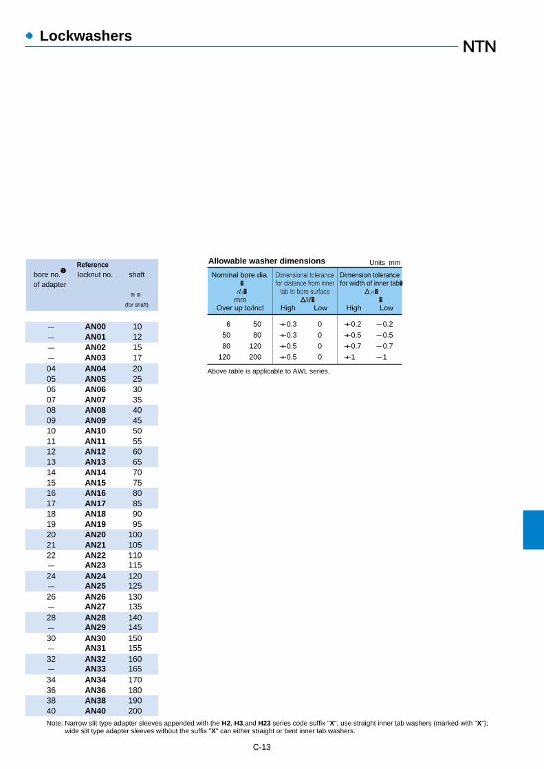
●Lockwashers
Referencebore no.
1locknut no. shaft
of adaptermm
(for shaft)
C-13
Note: Narrow slit type adapter sleeves appended with the H2, H3,and H23 series code suffix "X", use straight inner tab washers (marked with "X");wide slit type adapter sleeves without the suffix "X" can either straight or bent inner tab washers.
- AN00 10- AN01 12- AN02 15- AN03 1704 AN04 2005 AN05 2506 AN06 3007 AN07 3508 AN08 4009 AN09 4510 AN10 5011 AN11 5512 AN12 6013 AN13 6514 AN14 7015 AN15 7516 AN16 8017 AN17 8518 AN18 9019 AN19 9520 AN20 10021 AN21 10522 AN22 110- AN23 11524 AN24 120- AN25 12526 AN26 130- AN27 13528 AN28 140- AN29 14530 AN30 150- AN31 15532 AN32 160- AN33 16534 AN34 17036 AN36 18038 AN38 19040 AN40 200
6
50
80
120
Units mm
Nominal bore dia.�
d3�mm
Over up to/incl
Dimensional tolerancefor distance from inner
tab to bore surface ∆M�
High Low
Dimension tolerancefor width of inner tab�
∆ f1� �
High Low
50
80
120
200
+0.3
+0.3
+0.5
+0.5
0
0
0
0
+0.2
+0.5
+0.7
+1
-0.2
-0.5
-0.7
-1
Allowable washer dimensions
Above table is applicable to AWL series.
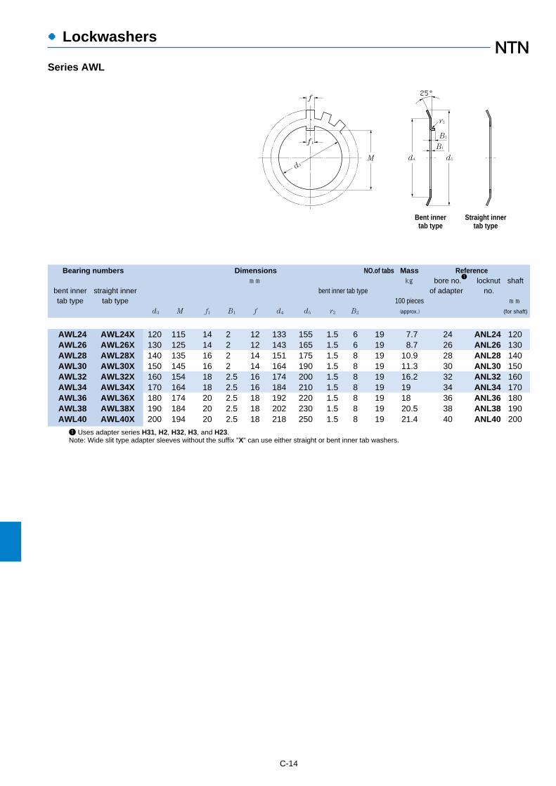
●Lockwashers
C-14
1 Uses adapter series H31, H2, H32, H3, and H23.Note: Wide slit type adapter sleeves without the suffix "X" can use either straight or bent inner tab washers.
Series AWL
Bearing numbers Dimensions NO.of tabs Mass Referencemm kg bore no.
1locknut shaft
bent inner straight inner bent inner tab type of adapter no.tab type tab type 100 pieces mm
d3 M f1 B1 f d4 d5 r2 B2 (approx.) (for shaft)
AWL24 AWL24X 120 115 14 2 12 133 155 1.5 6 19 7.7 24 ANL24 120AWL26 AWL26X 130 125 14 2 12 143 165 1.5 6 19 8.7 26 ANL26 130AWL28 AWL28X 140 135 16 2 14 151 175 1.5 8 19 10.9 28 ANL28 140AWL30 AWL30X 150 145 16 2 14 164 190 1.5 8 19 11.3 30 ANL30 150AWL32 AWL32X 160 154 18 2.5 16 174 200 1.5 8 19 16.2 32 ANL32 160AWL34 AWL34X 170 164 18 2.5 16 184 210 1.5 8 19 19 34 ANL34 170AWL36 AWL36X 180 174 20 2.5 18 192 220 1.5 8 19 18 36 ANL36 180AWL38 AWL38X 190 184 20 2.5 18 202 230 1.5 8 19 20.5 38 ANL38 190AWL40 AWL40X 200 194 20 2.5 18 218 250 1.5 8 19 21.4 40 ANL40 200
Bent innertab type
Straight innertab type
25°
d5
B2
B1ƒ1
d3
ƒ
M
r2
d4
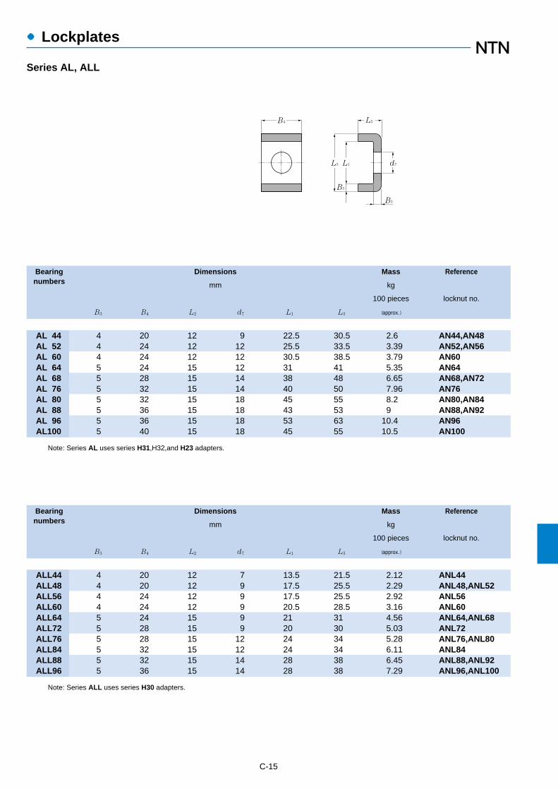
C-15
●Lockplates
Series AL, ALL
Bearing Dimensions Mass Referencenumbers mm kg
100 pieces locknut no.
B3 B4 L2 d7 L1 L3 (approx.)
Note: Series ALL uses series H30 adapters.
Note: Series AL uses series H31,H32,and H23 adapters.
AL 44 4 20 12 9 22.5 30.5 2.6 AN44,AN48AL 52 4 24 12 12 25.5 33.5 3.39 AN52,AN56AL 60 4 24 12 12 30.5 38.5 3.79 AN60AL 64 5 24 15 12 31 41 5.35 AN64AL 68 5 28 15 14 38 48 6.65 AN68,AN72AL 76 5 32 15 14 40 50 7.96 AN76AL 80 5 32 15 18 45 55 8.2 AN80,AN84AL 88 5 36 15 18 43 53 9 AN88,AN92AL 96 5 36 15 18 53 63 10.4 AN96AL100 5 40 15 18 45 55 10.5 AN100
Bearing Dimensions Mass Referencenumbers mm kg
100 pieces locknut no.
B3 B4 L2 d7 L1 L3 (approx.)
ALL44 4 20 12 7 13.5 21.5 2.12 ANL44ALL48 4 20 12 9 17.5 25.5 2.29 ANL48,ANL52ALL56 4 24 12 9 17.5 25.5 2.92 ANL56ALL60 4 24 12 9 20.5 28.5 3.16 ANL60ALL64 5 24 15 9 21 31 4.56 ANL64,ANL68ALL72 5 28 15 9 20 30 5.03 ANL72ALL76 5 28 15 12 24 34 5.28 ANL76,ANL80ALL84 5 32 15 12 24 34 6.11 ANL84ALL88 5 32 15 14 28 38 6.45 ANL88,ANL92ALL96 5 36 15 14 28 38 7.29 ANL96,ANL100
B4 L2
d7
B3
L1L3
B3

Catalog List & Appendix Table

D-2
●Catalog List
●BALL AND ROLLER BEARINGS
Ball and Roller Bearings 2202/C/E/F/D/I/K/S/T/TC
Large Bearings 2250/E
Plastic Cages for Rolling Element Bearings 3012/E
Miniature and Extra Small Ball Bearings 3013/E
Miniature Molded Rubber Bearings 3014/E
Vacuum Bearings 3016/E
Care and Maintenance of Bearings 3017/E/S
Ultra-Clean Bearings 3018/E
HL Bearings 3020/E
Bearings with Solid Grease 3022/E/S
Large Size, Long Operating Life Bearing-EA type 3024/E
Tapered Roller Bearings ECO-Top 3026/E/S
Self-Aligning Spherical Roller Bearings LH Series 3027/E/S
Super Slim Ball Bearings 3101/E
Ceramic Ball / Angular-Contact Bearings 3203/E
Insulated Bearings-Resin Coated Type 3204/E
Cross Roller Thrust Bearings 3501/E
Type E Spherical Roller Bearings 3701/E
Sealed Self-Aligning Roller Bearings-WA Type 3702/E
Aerospace Bearings 8102/E
Precision Rolling Bearings for Machine Tools 8401/E
●NEEDLE ROLLER BEARINGS
Needle Roller Bearings 2300/E/I
Miniature Cam Followers 3601/E
●CONSTANT VELOCITY JOINTS
Constant Velocity Joints for Automobiles 5601/JE
TRI-Ball Joint / Constant Velocity Joints 5602/E
Constant Velocity Joints for Industrial Applications 5603/E
●BEARING UNITS
Bearing Units 2400/E/I/S
Bearing Units with Ductile Cast Iron Housing 3901/E
Bearing Units Steel Series 3902/E
Bearing Units Stainless Series 3903/E
Bearing Units Plastic Housing Series 3904/E
Triple-Sealed Bearings for Bearing Units 3905/E
CATALOG TITLES CATALOG No.

D-3
●Catalog List
●PLUMMER BLOCKS
Plummer Blocks 2500E/S
●PRECISION BALL SCREWS
Precision Ball Screws 6000/E
Rolled Ball Screws 6206/E
●PARTS FEEDER
Parts Feeder 7018/E
NTN Parts Feeder with Standard Attachments (for Bolts or Washer) 7016/E
●CLUTCHES
One-way Clutches (Overrunning Clutches) 6402/E
●PLAIN BEARINGS
"BEAREE" NTN Engineering Plastics 5100/E
NTN "BEARPHITE" Oil Impregnated Sintered Bearings 5202/E
Spherical Plain Bearings 5301/E
●HANDBOOK
Bearing Units Handbook 9011/E/S
Rolling Bearings Handbook 9012/E
Needle Roller Bearings Handbook 9013/E
●GUIDE BOOK
Parts Feeder Guide Book 7019/E
Automotive Products Guide Book 8021/E/D/F
New Products Guide 9208/E
Food Machinery Component Guide 9209/E
Product Catalog for Paper Manufacturing Machinery 9210/E
●ELECTRONIC CATALOG
NTN Electronic Catalog (CD-ROM for Windows) 7903/E
NTN Autoparts Catalog (CD-ROM for Windows) 7905/E
Reference Kit Program -Bearing Interchange- (CD-ROM for Windows) 7907/E
●OTHERS
Adapters Locknuts and Lockwasher-Inch series 2612/E
Steel Balls for Bearing 4202/E
Bearing Handling 9103/E/P/S
CATALOG TITLES CATALOG No.
Note : The above are basic numbers. Renewal of the suffix by a revision.
C:Chinese E:English F:French D:Germany I:ItalianK:Korean S:Spanish T:Thai TC: Taipei Chinese

D-4
●Appendix Table
1/641/323/641/165/643/327/641/ 89/645/32
11/643/16
13/647/32
15/641/ 4
17/649/32
19/645/16
21/6411/3223/64
3/ 825/6413/3227/647/16
29/6415/3231/64
1/ 233/6417/3235/649/16
37/6419/3239/64
5/ 841/6421/3243/6411/1645/6423/3247/64
3/ 449/6425/3251/6413/1653/6427/3255/64
7/ 857/6439/3259/6415/1661/6431/3263/64
0.0156250.0312500.0468750.0625000.0781250.0937500.1093750.1250000.1406250.1562500.1718750.1875000.2031250.2187500.2343750.2500000.2656250.2812500.2968750.3125000.3281250.3437500.3593750.3750000.3906250.4062500.4218750.4375000.4531250.4687500.4843750.5000000.5156250.5312500.5468750.5625000.5781250.5937500.6093750.6250000.6406250.6562500.6718750.6875000.7031250.7187500.7343750.7500000.7656250.7812500.7968750.8125000.8281250.8437500.8593750.8750000.8906250.9062500.9218750.9375000.9531250.9687500.984375
0.3970.7941.1911.5881.9842.3812.7783.1753.5723.9694.3664.7625.1595.5565.9536.3506.7477.1447.5417.9388.3348.7319.1289.5259.922
10.31910.71611.11211.50911.90612.30312.70013.09713.49413.89114.28814.68415.08115.47815.87516.27216.66917.06617.46217.85918.25618.65319.05019.44719.84420.24120.63821.03421.43121.82822.22522.62223.01923.41623.81224.20924.60625.003
25.40025.79726.19426.59126.98827.38427.78128.17828.57528.97229.36929.76630.16230.55930.95631.35331.75032.14732.54432.94133.33833.73434.13134.52834.92535.32235.71936.11636.51236.90937.30637.70338.10038.49738.89439.29139.68840.08440.48140.87841.27541.67242.06942.46642.86243.25943.65644.05344.45044.84745.24445.64146.03846.43446.83147.22847.62548.02248.41948.81649.21249.60950.00650.403
50.80051.19751.59451.99152.38852.78453.18153.57853.97554.37254.76955.16655.56255.95956.35656.75357.15057.54757.94458.34158.73859.13459.53159.92860.32560.72261.11961.51661.91262.30962.70663.10363.50063.89764.29464.69165.08865.48465.88166.27866.67567.07267.46967.86668.26268.65969.05669.45369.85070.24770.64471.04171.43871.83472.23172.62873.02573.42273.81974.21674.61275.0097540675.803
76.20076.59776.99477.39177.78878.18448.58178.97879.37579.77280.16980.56680.96281.35981.75682.15382.55082.94783.34483.74184.13884.53484.93185.32885.72586.12286.51986.91687.31287.70988.10688.50388.90089.29789.69490.09190.48890.88491.28191.67892.07592.47292.86993.26693.66294.05994.45694.85395.25095.64796.04496.44196.83897.23497.63198.02898.42598.82299.21999.616
100.012100.409100.806101.203
101.600101.997102.394102.791103.188103.584103.981104.378104.775105.172105.569105.966106.362106.759107.156107.553107.950108.347108.744109.141109.538109.934110.331110.728111.125111.522111.919112.316112.721113.109113.506113.903114.300114.697115.094115.491115.888116.284116.681117.078117.475117.872118.269118.666119.062119.459119.856120.253120.650121.047121.444121.841122.238122.634123.031123.428123.825124.222124.619125.016125.412125.809126.206126.603
127.000127.397127.794128.191128.588128.984129.381129.778130.175130.572130.969131.366131.762132.159132.556132.953133.350133.747134.144134.541134.938135.334135.731136.128136.525136.922137.319137.716138.112138.509138.906139.303139.700140.097140.494140.891141.283141.684142.081142.478142.875143.272143.669144.066144.462144.859145.256145.653146.050146.447146.844147.241147.638148.034148.431148.828149.225149.622150.019150.416150.812151.209151.606152.003
152.400152.797153.194153.591153.988154.384154.781155.178155.575155.972156.369156.766157.162157.559157.956158.353158.750159.147159.544159.941160.338160.734161.131161.528161.925162.322162.719163.116163.512163.909164.306164.703165.100165.497165.894166.291166.688167.084167.481167.878168.275168.672169.069169.466169.862170.259170.656171.053171.450171.847172.244172.641173.038173.434173.831174.228174.625175.022175.419175.816176.212176.609177.006177.403
203.200203.597203.994204.391204.788205.184205.581205.978206.375206.772207.169207.566207.962208.359208.756209.153209.550209.947210.344210.741211.138211.534211.931212.328212.725213.122213.519213.916214.312214.709215.106215.503215.900216.297216.694217.091217.488217.884218.281218.678219.075219.472219.869220.266220.662221.056221.456221.853222.250222.647223.044223.441223.838224.234224.631225.028225.425225.822226.219226.616227.012227.409227.806228.203
177.800178.197178.594178.991179.388179.784180.181180.578180.975181.372181.769182.166182.562182.959183.356183.753184.150184.547184.944185.341185.738186.134186.531186.928187.325187.722188.119188.516188.912189.309189.706190.103190.500190.897191.294191.691192.088192.484192.881193.278193.675194.072194.469194.866195.262195.659196.056196.453196.850197.247197.644198.041198.438198.834199.231199.628200.025200.422200.819201.216201.612202.009202.406202.803
228.600228.997229.394229.791230.188230.584230.981231.378231.775232.172232.569232.966233.362233.759234.156234.553234.950235.347235.744236.141236.538236.934237.331237.728238.125238.522238.919239.316239.712240.109240.506240.903241.300241.697242.094242.491242.888243.284243.681244.078244.475244.872245.269245.666246.062246.459246.856247.253247.650248.047248.444248.841249.238249.634250.031250.428250.825251.222251.619252.016252.412252.809253.206253.603
inch
fraction decimal0″ 1″ 2″ 3″ 4″ 5″ 6″ 7″ 8″ 9″
Inch-millimetre conversion table
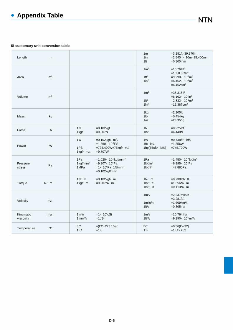
●Appendix Table
D-5
Length
Area
Volume
Mass
Force
Power
Pressure,stress
Torque
Velocity
Kinematicviscosity
Temperature
1N1kgf
1W
1PS1kgf・m/s
1Pa1kgf/mm2
1MPa
1N・m1kgf・m
1m2/s1mm2/s
t˚C1˚C
=0.102kgf=9.807N
=0.102kgf・m/s=1.360×10-3PS=735.499W=75kgf・m/s=9.807W
=1.020×10⁻⁷kgf/mm2
=9.807×10⁶Pa=1×10⁶Pa=1N/mm2
=0.102kgf/mm2
=0.102kgf・m=9.807N・m
=1×10⁶cSt=1cSt
=(t˚C+273.15)K=1K
=3.281ft=39.370in=2.540-2×10m=25.400mm=0.305mm
=10.764ft2
=1550.003in2
=9.290×10⁻²m2
=6.452×10⁻⁴m2
=6.452cm2
=35.315ft3
=6.102×10⁴in3
=2.832×10⁻²m3
=16.387cm3
=2.205lb=0.454kg=28.350g
=0.225lbf=4.448N
=0.738ft・lbf/s=1.356W=745.700W
=1.450×10⁻⁴lbf/in2
=6.895×10³Pa=47.880Pa
=0.738lbf・ft=1.356N・m=0.113N・m
=2.237mile/h=3.281ft/s=1.609km/h=0.305m/s
=10.764ft2/s=9.290×10-2m2/s
=0.56(t˚F-32)=1.8t˚C+32
1m1in1ft
1m2
1ft2
1in2
1m3
1ft3
1in3
1kg1lb1oz
1N1lbf
1W1ft・lbf/s1hp(550ft・lbf/s)
1Pa1lbf/in2
1lbf/ft2
1N・m1lbf・ft1lbf・in
1m/s
1mile/h1ft/s
1m/s1ft2/s
t˚CT˚F
m
m2
m3
kg
N
W
Pa
N・m
m/s
m2/s
˚C
SI-customary unit conversion table