Not All Thin Section Bearings Are Created Equal rev A all thin-section bearings are created equal...
20
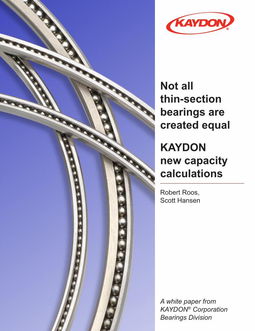
Not all thin-section bearings are created equal KAYDON new capacity calculations Robert Roos, Scott Hansen A white paper from KAYDON ® Corporation Bearings Division
Transcript of Not All Thin Section Bearings Are Created Equal rev A all thin-section bearings are created equal...
Not all
thin-section
bearings are
created equal
KAYDON
new capacity
calculations
Robert Roos,
Scott Hansen
A white paper from
KAYDON® Corporation
Bearings Division
2
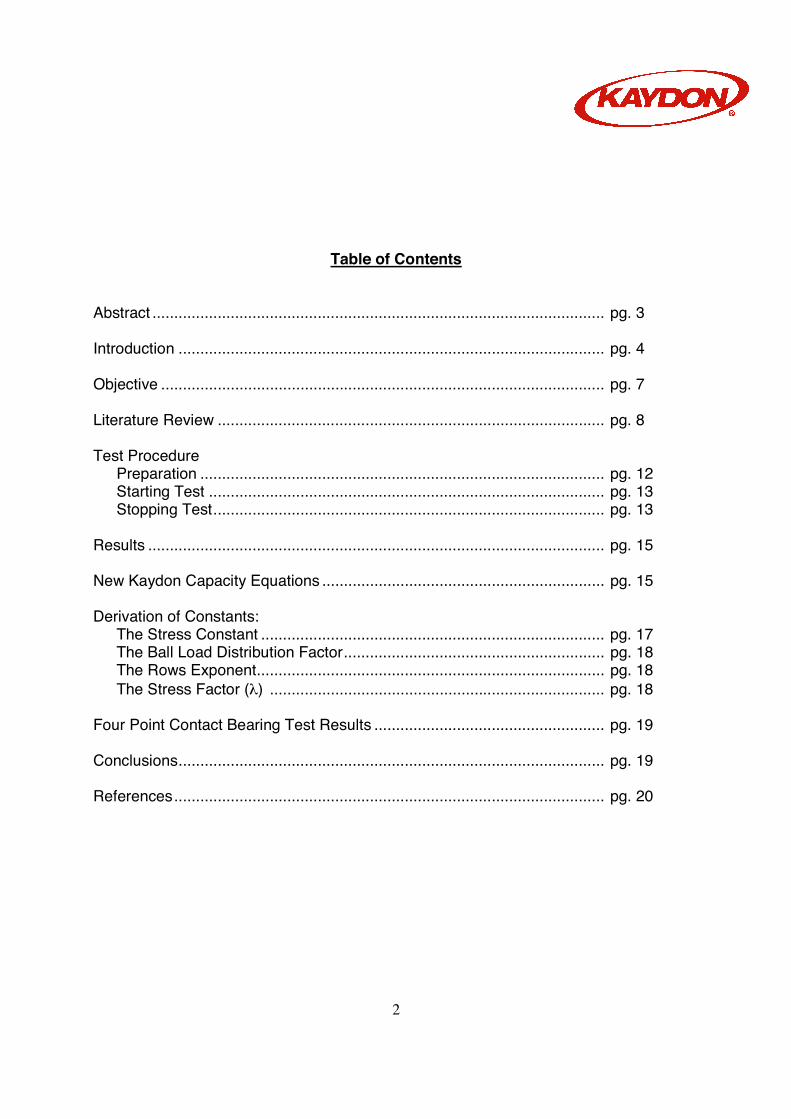
Table of Contents Abstract ........................................................................................................ pg. 3 Introduction .................................................................................................. pg. 4 Objective ...................................................................................................... pg. 7 Literature Review ......................................................................................... pg. 8 Test Procedure Preparation ............................................................................................. pg. 12 Starting Test ........................................................................................... pg. 13 Stopping Test.......................................................................................... pg. 13 Results ......................................................................................................... pg. 15 New Kaydon Capacity Equations ................................................................. pg. 15 Derivation of Constants: The Stress Constant ............................................................................... pg. 17 The Ball Load Distribution Factor............................................................ pg. 18 The Rows Exponent................................................................................ pg. 18 The Stress Factor (λ) ............................................................................. pg. 18 Four Point Contact Bearing Test Results ..................................................... pg. 19 Conclusions.................................................................................................. pg. 19 References................................................................................................... pg. 20
3
Abstract: American Bearing Manufacturers Association (ABMA) standard 9 and International Standards Organization (ISO 281) give equations for calculating the “Basic Dynamic Radial Load Rating” for ball bearings. These equations are based on a number of assumptions. Many of these assumptions are not valid for “Thin-Section” bearings. (Thin-Section bearings are described in ABMA standard 26.2). Nevertheless, many “Thin-Section” bearing catalogs report load ratings based on these equations. Kaydon has developed a new method for calculating the Dynamic Radial Load Rating for “Thin-Section” ball bearings. The new method uses the contact stress and the number of stress cycles per revolution to calculate the capacity. The new numbers are based on five years of actual test results. These equations can also be used to calculate the “Dynamic Radial Load Rating” for Four-Point contact ball bearings, which are not covered in ABMA standard 9 or ISO 281.
4
INTRODUCTION The year was 1944 and the problem that needed to be solved required the development of a new type of bearing. The US Army Air Corp contacted Kaydon Engineering Corporation to engineer and build a light-weight, thin-section ball bearing for a ball gun turret to be used on an aircraft. This bearing became the inspiration for a catalog line of thin-section ball bearings known today as REALI-SLIM®. In many applications, shafts supported by bearings are lightly loaded. Shaft position with respect to the housing or other components is critical. These designs do not need big, heavy bearings and can be supported adequately by thinner bearing races manufactured to close tolerances. Kaydon had identified a need for a bearing that was capable of saving space in designs and reducing overall weight. Thinner bearing races and cross sections allowed designers to also reduce the size and mass of the shafts and housings for even greater space and weight savings. When is a bearing thin-section? Rolling element bearing dimensions have been standardized by the ABMA so that for a given bore diameter, bearings are manufactured with different outside diameters. For a given outside diameter bearings are made in different widths. Each bearing belongs to a dimension series that can be designated by diameter and width. For a conventional series of ball bearings, radial cross section and ball diameter typically increase with bore diameter. Therefore, an increase in bearing weight is significant as bore diameter increases. The graph in Figure 1 compares conventional bearings with thin-section bearings illustrating this change in radial cross section with bore diameter. Bearing weight can be reduced with thin-section bearings because for a given series of bearings, radial cross section and ball size remain constant. Generally, a bearing is considered to be thin-section when:
− Radial cross section is less than one fourth the bore diameter. − Radial cross section is less than twice the rolling element diameter.

5
Figure 1 – Bearing Cross Sections Benchmarking and Fatigue Life Testing: As the world’s inventor and largest producer of thin-section ball bearings, Kaydon Bearings has devised methods for testing the fatigue life of REALI-SLIM® bearings. Daily testing of production product has continued for over 40 years. The testing method is addressed in the section of this paper titled “PROCEDURE FOR TESTING FATIGUE LIFE OF REALI-SLIM® BALL BEARINGS”. Along with testing of Kaydon produced REALI-SLIM® bearings we have also benchmarked most major known producers of thin-section ball bearings by subjecting their catalog equivalent bearings purchased through distribution to the same testing procedure.
6
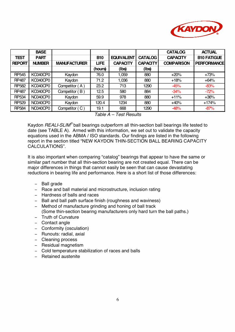
Table A – Test Results Kaydon REALI-SLIM® ball bearings outperform all thin-section ball bearings life tested to date (see TABLE A). Armed with this information, we set out to validate the capacity equations used in the ABMA / ISO standards. Our findings are listed in the following report in the section titled “NEW KAYDON THIN-SECTION BALL BEARING CAPACITY CALCULATIONS”. It is also important when comparing “catalog” bearings that appear to have the same or similar part number that all thin-section bearing are not created equal. There can be major differences in things that cannot easily be seen that can cause devastating reductions in bearing life and performance. Here is a short list of those differences:
− Ball grade − Race and ball material and microstructure, inclusion rating − Hardness of balls and races − Ball and ball path surface finish (roughness and waviness) − Method of manufacture grinding and honing of ball track
(Some thin-section bearing manufacturers only hard turn the ball paths.) − Truth of Curvature − Contact angle − Conformity (osculation) − Runouts: radial, axial − Cleaning process − Residual magnetism − Cold temperature stabilization of races and balls − Retained austenite
BASE CATALOG ACTUAL TEST PART B10 EQUIVALENT CATALOG CAPACITY B10 FATIGUE
REPORT NUMBER MANUFACTURER LIFE CAPACITY CAPACITY COMPARISON PERFORMANCE(hours) (lbs) (lbs)
RP545 KC040CP0 Kaydon 76.0 1,059 880 +20% +73%RP487 KC040CP0 Kaydon 71.2 1,036 880 +18% +64%RP582 KC040CP0 Competitor ( A ) 23.2 713 1290 -45% -83%RP487 KC040CP0 Competitor ( B ) 12.5 580 884 -34% -72%RP534 NC040CP0 Kaydon 59.9 978 880 +11% +36%RP529 NC040CP0 Kaydon 120.4 1234 880 +40% +174%RP584 NC040CP0 Competitor ( C ) 19.1 668 1290 -48% -87%
7
OBJECTIVE The purpose of this study is to develop a new set of equations for calculating the dynamic capacity of Thin Section bearings. The new equations must be supported by both theory and actual test results.

8
LITERATURE REVIEW Many thin-section ball bearing competitors calculate capacity using the methods found in ABMA standard 9, or in ISO-281. These standards define the term “Basic Dynamic Radial Load Rating” which is synonymous with Kaydon definition of “Dynamic Capacity”. The Basic Dynamic Radial Load Rating (Cr) is defined as:
“That constant radial load which a bearing could theoretically endure for a basic rating life of one million revolutions.”
These standards also define the L10 bearing fatigue life as:
“The basic rating life in millions of revolutions for 90% reliability” The L10 life is then calculated from the Load Rating (Cr) using equation 1. Please note that the “Basic Dynamic Radial Load Rating”, as defined in these two standards, is not the maximum operating load for the bearing. It is simply a constant used in the life equation. It is often greater than the “Static” radial load rating (Cor). Loading the bearing beyond the “Static” rating will cause permanent deformation or “Brinelling”. Both standards state:
“The life formula gives satisfactory results for a broad range of bearing loads. However . . . The user should consult the bearing manufacturer to establish the applicability of the life formula in cases where (the applied load) Pr exceeds (the static capacity) Cor or (1/2 the dynamic rating) 0.5 Cr, whichever is smaller.”
Eq. 1 6
3
10 10×
=
r
r
PCL revolutions ................................. ISO 281 par 5.3.1
These two standards give the following equations for calculating the “Basic Dynamic Load Rating” (Cr):
8.13/27.0)cos( bcmr DZifbC α= for ball size (Db) ≤ 1 inch. Eq. 2 ISO 281 par 5.1
8.13/27.0)cos(647.3 bcmr DZifbC α= for ball size (Db) >1 inch where:
L10 = The basic life rating in millions revolutions for 90% reliability Cr = Basic Dynamic Radial Load Rating bm = Material factor for contemporary steels (bm = 1.3) fc = Geometry factor from tables i = Number of rows = Contact angle Z = Number of balls per row Db = Ball Diameter Pr = Applied radial load.
9
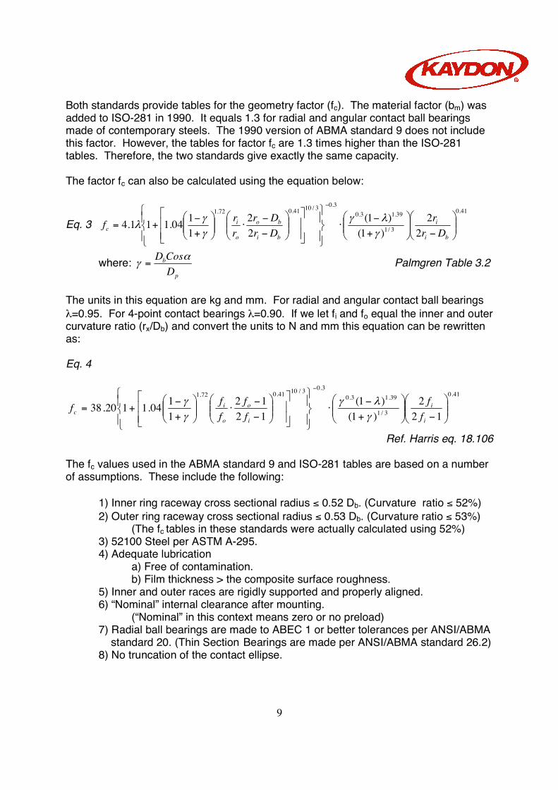
Both standards provide tables for the geometry factor (fc). The material factor (bm) was added to ISO-281 in 1990. It equals 1.3 for radial and angular contact ball bearings made of contemporary steels. The 1990 version of ABMA standard 9 does not include this factor. However, the tables for factor fc are 1.3 times higher than the ISO-281 tables. Therefore, the two standards give exactly the same capacity. The factor fc can also be calculated using the equation below:
Eq. 3 41.0
3/1
39.13.03.03/1041.072.1
22
)1()1(
22
1104.111.4
−
+−
⋅
−−
⋅
+−
+=
−
bi
i
bi
bo
o
ic Dr
rDrDr
rrf
γλγ
γγ
λ
where: p
b
DCosD α
γ = Palmgren Table 3.2
The units in this equation are kg and mm. For radial and angular contact ball bearings λ=0.95. For 4-point contact bearings λ=0.90. If we let fi and fo equal the inner and outer curvature ratio (rx/Db) and convert the units to N and mm this equation can be rewritten as: Eq. 4
41.0
3/1
39.13.03.03/1041.072.1
122
)1()1(
1212
1104.1120.38
−
+−
⋅
−−
⋅
+−
+=
−
i
i
i
o
o
ic f
fff
fff
γλγ
γγ
Ref. Harris eq. 18.106 The fc values used in the ABMA standard 9 and ISO-281 tables are based on a number of assumptions. These include the following: 1) Inner ring raceway cross sectional radius ≤ 0.52 Db. (Curvature ratio ≤ 52%) 2) Outer ring raceway cross sectional radius ≤ 0.53 Db. (Curvature ratio ≤ 53%) (The fc tables in these standards were actually calculated using 52%) 3) 52100 Steel per ASTM A-295. 4) Adequate lubrication a) Free of contamination. b) Film thickness > the composite surface roughness. 5) Inner and outer races are rigidly supported and properly aligned. 6) “Nominal” internal clearance after mounting. (“Nominal” in this context means zero or no preload)
7) Radial ball bearings are made to ABEC 1 or better tolerances per ANSI/ABMA standard 20. (Thin Section Bearings are made per ANSI/ABMA standard 26.2) 8) No truncation of the contact ellipse.

10
Kaydon does not use these equations to calculate Dynamic Capacity because most of these assumptions are not valid for “Thin Section” bearings. They were never intended for “Thin Section” bearings. Most importantly, the life calculated using these equations is not supported by Kaydon testing. Nevertheless, many Kaydon competitors use these equations anyway. (See table B.) Part No. KAA10CL0 KA020CP0 KC040CP0 KF080CP0 KA120CP0 KG120CP0 KG400CP0 Old Kaydon Catalog 300 150 320 880 4100 980 8510 18,310
ISO/ABMA 1990 fc Tables: 558 1012 2321 8081 1904 14,133 21,630 1978 fc Tables: 430 778 1785 6216 1465 10,872 16,638 Calculated fc: 1990:
379
701
1656
6363
1319
11,766
18,006
1978: 291 539 1274 4895 1015 9,050 13,851 INA(1) 558 1012 2316 8094 14,164 21,582 NSK(1) 558 1012 2316 8094 14,164 RBC®(2) 300 560 1290 5140 1060 10,690 16,230 SKF(1) 555 1009 2338 8049 1915 14,029 21,493 (1) INA, NSK and SKF all use the ABMA/ISO ratings taking fc directly from the tables without adjusting for the curvature ratio or diametral clearance. (2) RBC® numbers appear to adjust for curvature, but not clearance.
Table B – Comparative Capacities According to the old Kaydon capacity equations, the dynamic capacity of a KC040CP0 is 880 lbs. Under a radial load of 525 lbs, the predicted L10 life at 1780 RPM is 44.7 hrs. If the capacity is calculated using the 1978 ABMA/ISO equations, with fc calculated using equation 4, (rather then the using the tables), the capacity should be 1274 lbs. This gives a life of 133.8 hours. The actual average L10 life for these bearings over the last 5 years has been 80.2 hours. The actual life is almost double the life predicted by the old Kaydon equations, but “apparently” less than predicted by the ABMA/ISO equations.
Figure 2 – Ball load Distribution
11
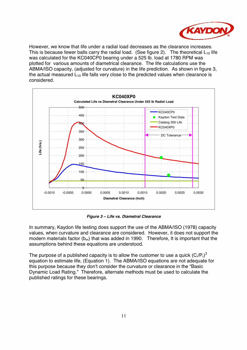
However, we know that life under a radial load decreases as the clearance increases. This is because fewer balls carry the radial load. (See figure 2). The theoretical L10 life was calculated for the KC040CP0 bearing under a 525 lb. load at 1780 RPM was plotted for various amounts of diametrical clearance. The life calculations use the ABMA/ISO capacity, (adjusted for curvature) in the life prediction. As shown in figure 3, the actual measured L10 life falls very close to the predicted values when clearance is considered.
KC040XP0Calculated Life vs Diametral Clearance Under 525 lb Radial Load
0
50
100
150
200
250
300
350
400
450
500
-0.0010 -0.0005 0.0000 0.0005 0.0010 0.0015 0.0020 0.0025 0.0030Diametral Clearance (Inch)
Life
(hrs
.)
KC040CP0Kaydon Test DataCatalog 300 LifeKC040XP0
DC Tolerance
Figure 3 – Life vs. Diametral Clearance In summary, Kaydon life testing does support the use of the ABMA/ISO (1978) capacity values, when curvature and clearance are considered. However, it does not support the modern materials factor (bm) that was added in 1990. Therefore, It is important that the assumptions behind these equations are understood. The purpose of a published capacity is to allow the customer to use a quick (Cr/Pr)3 equation to estimate life, (Equation 1). The ABMA/ISO equations are not adequate for this purpose because they don’t consider the curvature or clearance in the “Basic Dynamic Load Rating.” Therefore, alternate methods must be used to calculate the published ratings for these bearings.
12
TEST METHOD Preparation: The test parameters (i.e. load and speed) must first be calculated. These are selected to cause the bearings to fail by fatigue in a reasonable time period (typically less than 100 hours), while not subjecting the bearing to excessive loads. Therefore the testing speed is set to 1,780 rpm. The desired radial test load is calculated from the life equation, (eq. 1). To get the life in hours, simply divide the life in revolutions by the rotating speed as shown in equation 5, below.
Eq. 5 )(667,1660
1103
minmin
63
hrsNP
CNP
CLr
rrev
hrr
rh
=
×
=
Where Lh is the L10 life in hours under the test conditions Cr is the Dynamic Load Rating for the bearing (from a catalog or calculation) Pr is the Applied Radial Load N is the Speed of the bearing under test, in RPM. We can then rearrange equation 5, and solve for the applied radial load (Pr). For an L10 life of approximately 50 hours, the radial load should be a little less than 60% of the rated capacity, (See eq. 6). Keep in mind that the L10 life is based on 90% reliability. This means that 90% of the test samples are expected to exceed the 50 hours. For the Kaydon KC040CP0 bearing a radial load of 525 lbs was selected.
Eq. 6
3/1667,16
⋅
=
hr
r
LNCP
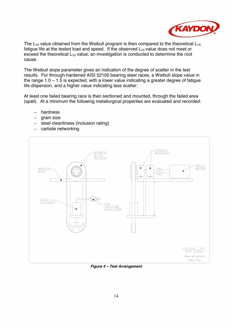
Bearings to be tested are randomly selected from the identified lot. At minimum of 20 pieces are used for each test. Each bearing is identified with a unique reference number. Bearings are cleaned as assemblies prior to test, by mechanical agitation in mineral spirits for at least five (5) minutes. Each bearing is then mounted in a suitable housing, making witness marks to indicate orientation in housings, and then mounted on a driven spindle with the axis horizontal as shown in figure 4. A steel load strap is then attached to the outer race, and connected to an air cylinder arranged to apply radial load to the bearing. The centerline of the air cylinder, the steel strap, and the lower tooling are aligned in the same plane as the bearing centerline.
13
The force exerted by the load cylinder is measured by a portable load cell and digital indicator. The air pressure to the load cylinder is adjusted to produce the desired radial load on the bearing. Note: In calculating the total radial load on the bearing, the weight of the tooling is also considered. An accelerometer is mounted on top of the stationary housing with radial orientation, and is connected to the automatic monitoring equipment. The circulating oil system is checked for adequate oil level, and to ensure that filter replacement is not overdue. Starting Test: The Circulating oil to lubricate the test bearing is connected and turned on. The cooling water to the oil heat exchangers is turned on. Air to the load cylinder is set to “Off.” The drive motor is “jogged” to ensure that no components are loose and that there is no unwanted interference between the rotating and stationary parts. The motor is then turned on, and the reading (in hours and tenths) of the elapsed time meter is noted. All test notes are recorded on the Test Data Collection Sheet. Oil flow to the bearing is adjusted to be as high as possible without causing excessive foaming or leakage from bearing housing. Oil flowing to each bearing should not exceed a temperature of 130 °F. Air to the load cylinder is then turned “On.” The baseline radial vibration is measured. The auto shut-off system is then set for this baseline vibration level. The automatic shut-down occurs when vibration increases to 150% of the baseline level. Stopping Test: When bearing failure is suspected, either due to audible noise or to auto shut-off, the bearing rotation is stopped. The bearing is then disassembled and inspected. If no visible signs of spalling or other failure are found on the balls/rollers or race paths, the bearing is reassembled and remounted in the test housings, noting the orientation of witness marks. The testing is then resumed (with the automatic shut-down system, baseline vibration level reset if necessary). If spalling is found, the hour meter reading is noted and the elapsed time is calculated. Also, the location and degree of spalling is noted, and then the bearing components are bagged, identified and saved. After all bearings in the test have been run to failure, the elapsed times are entered into the Kaydon Weibull analysis software program. This program establishes the best-fit Weibull line for the data, calculates the slope and scale parameters, and determines the L10 fatigue life for the sample group.
14
The L10 value obtained from the Weibull program is then compared to the theoretical L10 fatigue life at the tested load and speed. If the observed L10 value does not meet or exceed the theoretical L10 value, an investigation is conducted to determine the root cause. The Weibull slope parameter gives an indication of the degree of scatter in the test results. For through-hardened AISI 52100 bearing steel races, a Weibull slope value in the range 1.0 – 1.5 is expected, with a lower value indicating a greater degree of fatigue life dispersion, and a higher value indicating less scatter. At least one failed bearing race is then sectioned and mounted, through the failed area (spall). At a minimum the following metallurgical properties are evaluated and recorded:
− hardness − grain size − steel cleanliness (inclusion rating) − carbide networking
Figure 4 – Test Arrangement
15
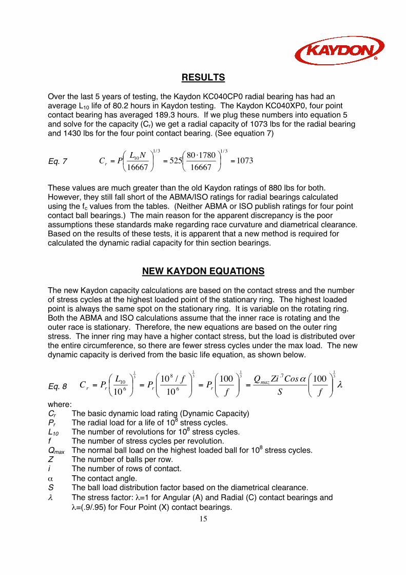
RESULTS Over the last 5 years of testing, the Kaydon KC040CP0 radial bearing has had an average L10 life of 80.2 hours in Kaydon testing. The Kaydon KC040XP0, four point contact bearing has averaged 189.3 hours. If we plug these numbers into equation 5 and solve for the capacity (Cr) we get a radial capacity of 1073 lbs for the radial bearing and 1430 lbs for the four point contact bearing. (See equation 7)
Eq. 7 107316667
17808052516667
3/13/110 =
⋅
=
=NLPCr
These values are much greater than the old Kaydon ratings of 880 lbs for both. However, they still fall short of the ABMA/ISO ratings for radial bearings calculated using the fc values from the tables. (Neither ABMA or ISO publish ratings for four point contact ball bearings.) The main reason for the apparent discrepancy is the poor assumptions these standards make regarding race curvature and diametrical clearance. Based on the results of these tests, it is apparent that a new method is required for calculated the dynamic radial capacity for thin section bearings.
NEW KAYDON EQUATIONS The new Kaydon capacity calculations are based on the contact stress and the number of stress cycles at the highest loaded point of the stationary ring. The highest loaded point is always the same spot on the stationary ring. It is variable on the rotating ring. Both the ABMA and ISO calculations assume that the inner race is rotating and the outer race is stationary. Therefore, the new equations are based on the outer ring stress. The inner ring may have a higher contact stress, but the load is distributed over the entire circumference, so there are fewer stress cycles under the max load. The new dynamic capacity is derived from the basic life equation, as shown below.
Eq. 8 λα 3
131
31
31
10010010
/1010
7.
6
8
610
=
=
=
=fS
CosZiQf
PfPLPC mazrrrr
where: Cr The basic dynamic load rating (Dynamic Capacity) Pr The radial load for a life of 108 stress cycles. L10 The number of revolutions for 108 stress cycles. f The number of stress cycles per revolution. Qmax The normal ball load on the highest loaded ball for 108 stress cycles. Z The number of balls per row. i The number of rows of contact. α The contact angle. S The ball load distribution factor based on the diametrical clearance. λ The stress factor: λ=1 for Angular (A) and Radial (C) contact bearings and
λ=(.9/.95) for Four Point (X) contact bearings.
16
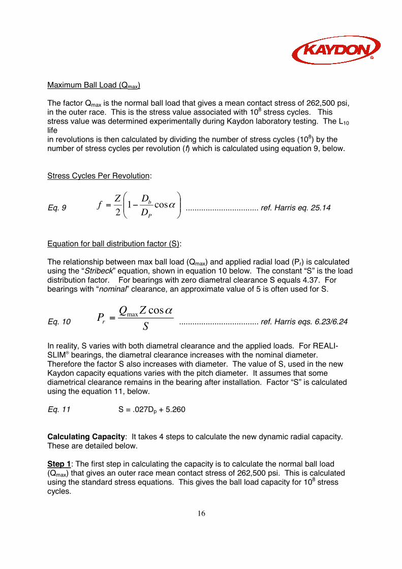
Maximum Ball Load (Qmax) The factor Qmax is the normal ball load that gives a mean contact stress of 262,500 psi, in the outer race. This is the stress value associated with 108 stress cycles. This stress value was determined experimentally during Kaydon laboratory testing. The L10 life in revolutions is then calculated by dividing the number of stress cycles (108) by the number of stress cycles per revolution (f) which is calculated using equation 9, below. Stress Cycles Per Revolution:
Eq. 9
−= αcos1
2 P
b
DDZf ................................. ref. Harris eq. 25.14
Equation for ball distribution factor (S): The relationship between max ball load (Qmax) and applied radial load (Pr) is calculated using the “Stribeck” equation, shown in equation 10 below. The constant “S” is the load distribution factor. For bearings with zero diametral clearance S equals 4.37. For bearings with “nominal” clearance, an approximate value of 5 is often used for S.
Eq. 10 SZQPr
αcosmax= .................................... ref. Harris eqs. 6.23/6.24
In reality, S varies with both diametral clearance and the applied loads. For REALI-SLIM® bearings, the diametral clearance increases with the nominal diameter. Therefore the factor S also increases with diameter. The value of S, used in the new Kaydon capacity equations varies with the pitch diameter. It assumes that some diametrical clearance remains in the bearing after installation. Factor “S” is calculated using the equation 11, below. Eq. 11 S = .027Dp + 5.260 Calculating Capacity: It takes 4 steps to calculate the new dynamic radial capacity. These are detailed below. Step 1: The first step in calculating the capacity is to calculate the normal ball load (Qmax) that gives an outer race mean contact stress of 262,500 psi. This is calculated using the standard stress equations. This gives the ball load capacity for 108 stress cycles.
17
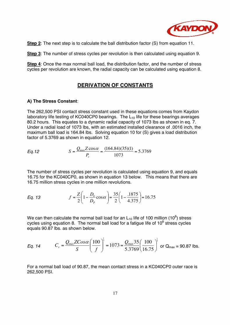
Step 2: The next step is to calculate the ball distribution factor (S) from equation 11. Step 3: The number of stress cycles per revolution is then calculated using equation 9. Step 4: Once the max normal ball load, the distribution factor, and the number of stress cycles per revolution are known, the radial capacity can be calculated using equation 8.
DERIVATION OF CONSTANTS A) The Stress Constant: The 262,500 PSI contact stress constant used in these equations comes from Kaydon laboratory life testing of KC040CP0 bearings. The L10 life for these bearings averages 80.2 hours. This equates to a dynamic radial capacity of 1073 lbs as shown in eq. 7. Under a radial load of 1073 lbs, with an estimated installed clearance of .0016 inch, the maximum ball load is 164.84 lbs. Solving equation 10 for (S) gives a load distribution factor of 5.3769 as shown in equation 12.
Eq.12 3769.51073
)1)(35)(84.164(cosmax ===rP
ZQS α
The number of stress cycles per revolution is calculated using equation 9, and equals 16.75 for the KC040CP0, as shown in equation 13 below. This means that there are 16.75 million stress cycles in one million revolutions.
Eq. 13 75.16375.4
1875.12
35cos12
=
−=
−= α
P
b
DDZf
We can then calculate the normal ball load for an L10 life of 100 million (108) stress cycles using equation 8. The normal ball load for a fatigue life of 108 stress cycles equals 90.87 lbs. as shown below.
Eq. 14 31
31
75.16100
3769.5351073100 max
==
=
QfS
ZCosQC mazr
α or Qmax = 90.87 lbs.
For a normal ball load of 90.87, the mean contact stress in a KC040CP0 outer race is 262,500 PSI.
18
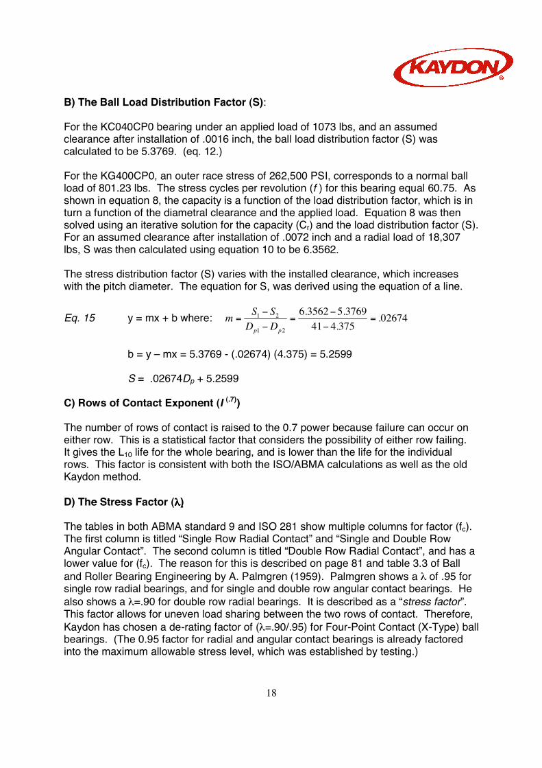
B) The Ball Load Distribution Factor (S): For the KC040CP0 bearing under an applied load of 1073 lbs, and an assumed clearance after installation of .0016 inch, the ball load distribution factor (S) was calculated to be 5.3769. (eq. 12.) For the KG400CP0, an outer race stress of 262,500 PSI, corresponds to a normal ball load of 801.23 lbs. The stress cycles per revolution (f ) for this bearing equal 60.75. As shown in equation 8, the capacity is a function of the load distribution factor, which is in turn a function of the diametral clearance and the applied load. Equation 8 was then solved using an iterative solution for the capacity (Cr) and the load distribution factor (S). For an assumed clearance after installation of .0072 inch and a radial load of 18,307 lbs, S was then calculated using equation 10 to be 6.3562. The stress distribution factor (S) varies with the installed clearance, which increases with the pitch diameter. The equation for S, was derived using the equation of a line.
Eq. 15 y = mx + b where: 02674.375.441
3769.53562.621
21 =−−
=−−
=pp DD
SSm
b = y – mx = 5.3769 - (.02674) (4.375) = 5.2599 S = .02674Dp + 5.2599 C) Rows of Contact Exponent (I (.7)) The number of rows of contact is raised to the 0.7 power because failure can occur on either row. This is a statistical factor that considers the possibility of either row failing. It gives the L10 life for the whole bearing, and is lower than the life for the individual rows. This factor is consistent with both the ISO/ABMA calculations as well as the old Kaydon method. D) The Stress Factor (λλλλ) The tables in both ABMA standard 9 and ISO 281 show multiple columns for factor (fc). The first column is titled “Single Row Radial Contact” and “Single and Double Row Angular Contact”. The second column is titled “Double Row Radial Contact”, and has a lower value for (fc). The reason for this is described on page 81 and table 3.3 of Ball and Roller Bearing Engineering by A. Palmgren (1959). Palmgren shows a λ of .95 for single row radial bearings, and for single and double row angular contact bearings. He also shows a λ=.90 for double row radial bearings. It is described as a “stress factor”. This factor allows for uneven load sharing between the two rows of contact. Therefore, Kaydon has chosen a de-rating factor of (λ=.90/.95) for Four-Point Contact (X-Type) ball bearings. (The 0.95 factor for radial and angular contact bearings is already factored into the maximum allowable stress level, which was established by testing.)
19
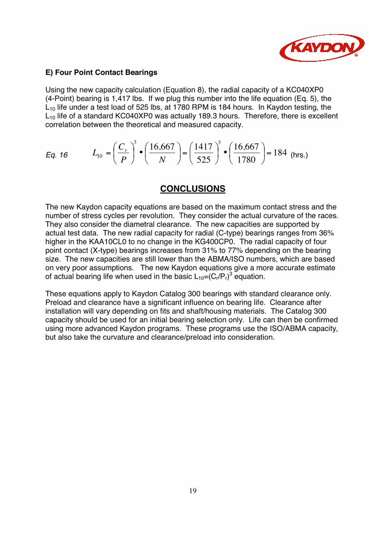
E) Four Point Contact Bearings Using the new capacity calculation (Equation 8), the radial capacity of a KC040XP0 (4-Point) bearing is 1,417 lbs. If we plug this number into the life equation (Eq. 5), the L10 life under a test load of 525 lbs, at 1780 RPM is 184 hours. In Kaydon testing, the L10 life of a standard KC040XP0 was actually 189.3 hours. Therefore, there is excellent correlation between the theoretical and measured capacity.
Eq. 16 1841780
667,16525
1417667,16 33
10 =
•
=
•
=
NPCL r
(hrs.)
CONCLUSIONS The new Kaydon capacity equations are based on the maximum contact stress and the number of stress cycles per revolution. They consider the actual curvature of the races. They also consider the diametral clearance. The new capacities are supported by actual test data. The new radial capacity for radial (C-type) bearings ranges from 36% higher in the KAA10CL0 to no change in the KG400CP0. The radial capacity of four point contact (X-type) bearings increases from 31% to 77% depending on the bearing size. The new capacities are still lower than the ABMA/ISO numbers, which are based on very poor assumptions. The new Kaydon equations give a more accurate estimate of actual bearing life when used in the basic L10=(Cr/Pr)3 equation. These equations apply to Kaydon Catalog 300 bearings with standard clearance only. Preload and clearance have a significant influence on bearing life. Clearance after installation will vary depending on fits and shaft/housing materials. The Catalog 300 capacity should be used for an initial bearing selection only. Life can then be confirmed using more advanced Kaydon programs. These programs use the ISO/ABMA capacity, but also take the curvature and clearance/preload into consideration.
20
References: (1) “Load Ratings and Fatigue Life for Ball Bearings”, ANSI/AFBMA Std 9, (1978) (2) “Load Ratings and Fatigue Life for Ball Bearings”, ANSI/AFBMA Std 9, (1990) (3) “Rolling Bearings – Dynamic Load Ratings and Rating Life” ISO 281, (1990) (4) T. Harris, Rolling Bearing Analysis, 3rd Ed., J Wiley & Sons USA (1991) (5) A. Palmgren, Ball and Roller Bearing Engineering, 3rd Ed., SKF Industries, Inc., Philadelphia, PA. (1959)