NJEX 8300G Manual 2-2011 - YZ · PDF file˘- ˇ ˆ˙ ˝˛˚˜ ˇ ˝ !"# !#$ % ˝ !"#...
126
NJEX 8300G N A T U R A L G A S O D O R I Z A T I O N S Y S T E M
-
Upload
nguyencong -
Category
Documents
-
view
232 -
download
3
Transcript of NJEX 8300G Manual 2-2011 - YZ · PDF file˘- ˇ ˆ˙ ˝˛˚˜ ˇ ˝ !"# !#$ % ˝ !"#...
NJEX 8300GN A T U R A L G A S O D O R I Z A T I O N S Y S T E M


� � � � � � � � � � � � � � � � � � � � � � � � � � � � � � � � � � � � � � � � � � � � � � � � � � � � � � � � � � � � � � � � � � � � � � � � � � � � � � ! " # � ! # $ � � � � � % � � � � ! " # � ! # $ � "��&��'()*��"�����+!��,����
8300G TABLE OF CONTENTS
8300G Table of Contents ....................................................................................................................I
Section 1: First Things To Know About The 8300G ......................................................................1How to Use this Manual.......................................................................................................................1Typographic Conventions ....................................................................................................................1Getting Help.........................................................................................................................................1����������� �� ����......................................................................................................................2Warranty ................................................................................... Visit our website www.yzsystems.comTheory of Operation.............................................................................................................................3System Accessories ............................................................................................................................3
Section 2: System Installation.........................................................................................................5Standard System Components............................................................................................................5System Flow Schematic ......................................................................................................................6Standard System Mounting .................................................................................................................7Standard System Connections ............................................................................................................8Skid System Components .................................................................................................................10System Flow Schematic ....................................................................................................................12Skid System Mounting .......................................................................................................................13Skid System Connections..................................................................................................................14
Section 3: Filling the Bulk Odorant Tank ....................................................................................17Filling the Tank for the First Time .......................................................................................................17�������������������������� .........................................................................................................18
Section 4: System Control & Electronics .....................................................................................19Overview............................................................................................................................................19To Use The Key Pad ..........................................................................................................................19To Power Up The System ..................................................................................................................20Test & Standby Keys .........................................................................................................................21���������������������������� ........................................................................................................22���������������!"#$������$�� ..................................................................................................22Solar Panel ........................................................................................................................................22���������������!"#$������$�� .................................................................................................22Communications Interface .................................................................................................................23#��%����#������� ..................................................................................................................23

� � � � � � � � � � � � � � � � � � � � � � � � � � � � � � � � � � � � � � � � � � � � � - � � � � � � � � � � � � � � � � � � � � � � � � � � � � � � � � � ! " # � ! # $ � � � � � % � � � � ! " # � ! # $ � "��&���� '()*��"�����+!��,����
8300G TABLE OF CONTENTS
Section 5: Programming for Proportional-to-Flow Operation ....................................................25Setting Operator Input Parameters....................................................................................................25�������'� �������������"((#)�*��"�+,�-���� ..........................................................................25����������� ������� "����� ........................................................................................................25������������������"�����*�" ,�/�:;<�) .....................................................................................25(�=�����>!���((#)"?���*�+"�� , ..............................................................................................26Low Flow Shut Off .............................................................................................................................26)�!�*������,����� ........................................................................................................................26(�=���������"����� .......................................................................................................................27The Odorant Output Setting ..............................................................................................................27Odorant Tank .....................................................................................................................................28Expansion Tank Pressure Monitoring ...............................................................................................28Odorant Inlet Pressure Monitoring ....................................................................................................29Alarm to Relay Delay ........................................................................................................................30Alarm to Call Out Delay ....................................................................................................................30(�@�B���������� ............................................................................................................................30(�@�B������������� ......................................................................................................................31Conclusion .........................................................................................................................................31
Section 6: Programming for Proportional-to-Time Operation ....................................................33Setting Operator Input Parameters....................................................................................................33����������� ������� "����� ........................................................................................................33������������������"�����*�" J,�/�:;<) .....................................................................................33���������$������!����������-������������==J==�������"�����N ................................................33The Odorant Output Setting ............................................................................................................34Odorant Tank .....................................................................................................................................34Expansion Tank Pressure Monitoring ...............................................................................................35Odorant Inlet Pressure Monitoring.....................................................................................................35Alarm to Relay Delay ........................................................................................................................36Alarm to Call Out Delay ....................................................................................................................36(�@�B���������� ............................................................................................................................37(�@�B������������� ......................................................................................................................37Conclusion .........................................................................................................................................38
Section 7: Calibrating Signal Inputs .............................................................................................39�����)�!�Q����#��������X�Y%Z�[@#�"�\%];��� ...........................................................................39Expansion Tank Pressure Transmitter Zero Calibration ....................................................................41Odorant Inlet Pressure Transmitter Zero Calibration .........................................................................42Pulse Flow Input Calibration, Dry Contact & Voltage Pulse ..............................................................44Calculation for Determining the Span Frequency Example ...............................................................45

� � � � � � � � � � � � � � � � � � � � � � � � � � � � � � � � � � � � � � � � � � � � � � � � � � � � � � � � � � � � � � � � � � � � � � � � � � � � � � ! " # � ! # $ � � � � � % � � � � ! " # � ! # $ � "��&����'()*��"�����+!��,����
8300G TABLE OF CONTENTS
Section 8: Working with the N-300 System Displays ..................................................................47Display Functionality..........................................................................................................................47To View Real Time Displays ..............................................................................................................48 Strokes Signaled .........................................................................................................................48 Odorant Injected ..........................................................................................................................48 Pump Displacement ....................................................................................................................48 Pump Alarms ............................................................................................................................48 Meter Level – Verometer .............................................................................................................49 Meter Alarms – Verometer ........................................................................................................49 Meter Indicators, non-alarm ......................................................................................................49 Expansion Tank ...........................................................................................................................50 Odorant Inlet ................................................................................................................................50� ��������[����� ............................................................................................................................50� � ������������� ............................................................................................................................50 Flow Input ....................................................................................................................................50 Flow Input Alarms ...................................................................................................................50 Flow Input Indicators, non-alarm ..............................................................................................50 Tank Level ...................................................................................................................................51 Tank Level Alarm ......................................................................................................................51 Odorant Temperature ..................................................................................................................51
Section 9: Setting & Testing Alarms .............................................................................................53Setting Alarm Out Status ...................................................................................................................53Testing Alarm Out Status ...................................................................................................................55Setting The Clock ..............................................................................................................................58
Section 10: Mechanical System ....................................................................................................61Overview............................................................................................................................................61������Q����(��-����������������)�������������� ....................................................................62Fill Valve ............................................................................................................................................62Verometer ..........................................................................................................................................63Model 8000 Pump .............................................................................................................................64Odorant Discharge Manifold ..............................................................................................................64NJEX Gas Filter .................................................................................................................................65Solenoid Valve & Pneumatic Relay Manifold .....................................................................................66Expansion Tank .................................................................................................................................66
Section 11: System Operation .......................................................................................................67Setting System Pressures and Valves ...............................................................................................67Low Pressure Relief Adjustment........................................................................................................67Starting The System ..........................................................................................................................68To Stop The System ..........................................................................................................................69

� � � � � � � � � � � � � � � � � � � � � � � � � � � � � � � � � � � � � � � � � � � � � - � � � � � � � � � � � � � � � � � � � � � � � � � � � � � � � � � ! " # � ! # $ � � � � � % � � � � ! " # � ! # $ � "��&��.� '()*��"�����+!��,����
8300G TABLE OF CONTENTS
Section 12: System Maintenance ..................................................................................................71Preventative Maintenance Schedule .................................................................................................71 Recommended Maintenance Schedule .......................................................................................71 Weekly Inspection .....................................................................................................................71 Semi-Annual Inspection ............................................................................................................71 Annual Inspection .....................................................................................................................71� � ��%�����Q��� �� .................................................................................................................71 Recommended Spare Parts List ..................................................................................................71�$��>!����� ������������Q��� �� ...........................................................................................72Low Pressure Relief Adjustment........................................................................................................73Conducting a Forward Purge.............................................................................................................74Venting Pressure Gas........................................................................................................................76Filling the Verometer..........................................................................................................................78Priming & Starting the NJEX System ................................................................................................80
Section 13: 8300G System Troubleshooting................................................................................83How to Use This Section ...................................................................................................................83 For Additional Help ......................................................................................................................83 Step-by-Step Resolution ..............................................................................................................83Tank Level Alarms .............................................................................................................................83 Tank Level Alarm Troubleshooting Steps ....................................................................................84�������������� ....................................................................................................................................84� ������������������������������� ..........................................................................................84Signal Alarms.....................................................................................................................................85Signal Non-Alarm Indicators ..............................................................................................................85 Signal Alarm & Non-Alarm Indicator Troubleshooting Steps ......................................................85 Loss of Flow Alarm Troubleshooting Steps ..............................................................................85� � �$��>!������������������������ ....................................................................................85 Low Flow Non-Alarm Indicator Troubleshooting Steps .............................................................86� � �$��>!�~%������Q�� ��������������������� ..............................................................86Verometer Alarms ..............................................................................................................................86 Verometer Non-Alarm Indicators ......................................................................................................87 Verometer Troubleshooting Steps ...............................................................................................87 Verometer Cable Alarm Troubleshooting Steps ........................................................................87 Verometer No-Fill Alarm Troubleshooting Steps .......................................................................87 Verometer Slow-Fill Alarm Troubleshooting Steps ..................................................................88 Verometer Leakage Alarm Troubleshooting Steps ...................................................................88 Verometer Fill Valve Failure Alarm Troubleshooting Steps .......................................................89 Verometer Odorant Inlet Cable Alarm Troubleshooting Steps ..................................................89 Verometer Odorant Inlet Low Alarm Troubleshooting Steps .....................................................90 Verometer Odorant Inlet Hi Alarm Troubleshooting Steps ........................................................90 Verometer Expansion Tank Cable Alarm Troubleshooting Steps .............................................90 Verometer Expansion Tank Low Alarm Troubleshooting Steps ................................................90 Verometer Expansion Tank High Alarm Troubleshooting Steps ...............................................91� �� [���������$������~%������Q�� ��������������������� ...............................................91 Verometer Fill Rate Non-Alarm Indicator Troubleshooting Steps .............................................91

� � � � � � � � � � � � � � � � � � � � � � � � � � � � � � � � � � � � � � � � � � � � � � � � � � � � � � � � � � � � � � � � � � � � � � � � � � � � � � ! " # � ! # $ � � � � � % � � � � ! " # � ! # $ � "��&�.'()*��"�����+!��,����
8300G TABLE OF CONTENTS
Section 13: 8300G System Troubleshooting continuedPump Alarms .....................................................................................................................................91 Pump Over Pumping Alarm Troubleshooting Steps .................................................................92 Pump Under Pumping Alarm Troubleshooting Steps ...............................................................92 Pump Failure Alarm Troubleshooting Steps .............................................................................93
Appendix A: Illustrations ...............................................................................................................95NJEX Model 8000 Pump Assembled.................................................................................................95NJEX Model 8000 Pump Actuation Assembly, Exploded View .........................................................96NJEX Model 8000 Pump, Diaphragm and Check Valve Assembly, Exploded View ..........................97Fill Valve, Exploded View ..................................................................................................................98VM-2100 Verometer, with Filter Assembly, Exploded View ...............................................................99�����������)�����...........................................................................................................................100NJEX Gas Filter ...............................................................................................................................101Electronics Assembly.......................................................................................................................102SPS-12 Solar Power Supply Unit ....................................................................................................103���%Y];"]\;�#��������������B�� ..................................................................................................104Heater Wiring Diagram ....................................................................................................................105
���������� ���������������������� ...............................................................................107Communications Settings ................................................................................................................107 N300 Modbus Function Support ................................................................................................107� �������������� .....................................................................................................................107 Control Functions ......................................................................................................................107 Status Functions ........................................................................................................................108 Alarm Functions .........................................................................................................................109 Integer Registers .......................................................................................................................110 Result Data Functions ............................................................................................................110 Parameter functions ..................................................................................................................112 Exception Responses ................................................................................................................112
Appendix C: Response Forms .....................................................................................................113For the Record Form .......................................................................................................................113NJEX Trouble Shooting Form ..........................................................................................................114
Appendix D: Documents ...............................................................................................................115N-300 Controller Display Diagram ...................................................................................................115Wiring Control Document ...............................................................................................................116
Appendix E: ATEX System Connections .....................................................................................117


� � � � � � � � � � � � � � � � � � � � � � � � � � � � � � � � � � � � � � � � � � � � � - � � � � � � � � � � � � � � � � � � � � � � � � � � � � � � � � � ! " # � ! # $ � � � � � % � � � � ! " # � ! # $ � "��&��'()*��"�����+!������
SECTION 1: FIRST THINGS TO KNOW ABOUT THE 8300
How to Use this ManualThe NJEX-8300 Operations Manual is a step-by-step guide containing the procedures needed to work with the 8300 System.
The NJEX System Series of odorizers implement the most advanced technology available in the industry. It is recommended that the technicians working with the NJEX Odorization Systems study the manual prior to ���������!���������������-���������������J��
Typographic ConventionsTo aide in readability, this manual uses several typographic conventions. References to illustrations, photographs, and other related content will appear in italicized text�����!��������� ����-�!����������the item in the manual. Digital versions of the manual, available in Adobe Acrobat™ PDF format, will be highlighted further in blue italic text indicating the copy retains a hyperlink to the referenced item.
Measurement units are listed in italic parenthesis text following their US standard equivalent. As an ex-�����X�-��������������� �X�YZ��(4.5 meters), is how the text will appear throughout the manual.
Items that require action, for example the pressing of a key for programming the controller, will feature the action item in sentence case Bold Text followed in normal text by the item such as, the Up Arrow key or Main Power switch.
Starting with Section 4, System Control & Electronics, the manual will begin discussing the in-depth opera-tion of the N-300 electronic controller where many of these typographic conventions will be found. In the discussion about the controller, the technician will learn about the dual-use keypad. Here, the controller LCD will display a new function for the key located im-mediately below the displayed item. For example, an Up Arrow key may have *Set immediately above it on the LCD indicating to set, or enter, the selected item into the memory of the N-300 controller. The asterisk (*), immediately before Set on the LCD indicates the dual-use keypad is active. Further discussion on the dual-use capability of the N-300 controller keypad will take place in Section 4, System Control and Electron-ics, on page 19.
Getting HelpThis manual provides solutions to typical questions about the 8300 system. If the answer can not be found within this manual, contact YZ Systems at: � � � �N��]�YJ+:]J:Z;;� � � �N���;;J:Z+J�\+Z�(800.NJEX.HELP)� � � )N��]�YJ+:]J:ZY+ Em: [email protected]
When calling, have this manual close at hand. Whether calling or writing, please include in your com-munique the following information:
�� �����������������-�����~������������������version number of this manual. The serial number is located on the inside of the enclosure door just ���!������������>!��������J�����$�����������of this manual is located at the bottom of each page.
�� ����� ������-��������������X��-������ ����������
actions of the technical personnel when the problem occurred.
�� ���������-������������������������$�����������
in the LCD on the N-300G controller, please include: � � YJ�� �����=� ��!�����-������������*�,J
2. The version number of the Sentry software used.

� � � � � � � � � � � � � � � � � � � � � � � � � � � � � � � � � � � � � � � � � � � � � - � � � � � � � � � � � � � � � � � � � � � � � � � � � � � � � � � ! " # � ! # $ � � � � � % � � � � ! " # � ! # $ � "��&��� '()*��"�����+!������
SECTION 1: FIRST THINGS TO KNOW ABOUT THE 8300
1 Actual reserve time is dependant on age and condition of battery and the usage rate of the NJEX System.
����������������������(�=�����������������N�� :�������"��� (257 liters/day)(�=����������������������N� YX\\;������ (99.28 Bar (g)������������������N� ;���Y\;���������)J (17°C to 60°C)�!���������N� ���%Y]������������X��� std.� ���%Y];"]\;�$��%� �� Z;":;?���#� ������X��� opt.Battery Reserve Y: Approximately 30 days ����)�!������Q���������N� Y%Z�[@#X�\%];������� pulse
Note: at temperatures below 32º F (0º C), condi-tioning of the actuation gas supply may be required. Where the actuation gas supply has a high water content and/or a low hydrocarbon dew point, addition-��������������� ������������������������������gas supply may be necessary. Bottled nitrogen can also be used during cold operating conditions to avoid condensation in the actuation gas supply line. In addi-tion, operation at extreme temperatures will affect seal and diaphragm performance. To prolong the service of seals and diaphragm, adequate heat should be provided to maintain an operating environment above 30° F (-1º C).
NJEX Systems are approved class I, Div I and must be installed, grounded, wired and I.S. barrier Protect-ed in accordance with all applicable electrical codes.
Warranty
Please visit our web site www.yzsystems.com for complete details.

� � � � � � � � � � � � � � � � � � � � � � � � � � � � � � � � � � � � � � � � � � � � � - � � � � � � � � � � � � � � � � � � � � � � � � � � � � � � � � � ! " # � ! # $ � � � � � % � � � � ! " # � ! # $ � "��&�"'()*��"�����+!������
SECTION 1: FIRST THINGS TO KNOW ABOUT THE 8300
Theory of OperationOperation of the 8300 centers around three primary components: the Model 8000 pump, the Model [(%]Y;;�[���������������(����~%+;;�� ������J
During normal operation, the Model 8000 pump injects an exact quantity of odorant at a rate determined by the N-300G controller. The quantity of odorant injected per stroke is set using a spacer in the pump actuation assembly. The rate at which the pump is actuated is determined by the N-300G controller.
����[(%]Y;;�[�����������$�������������������� ���������������!�� ��$����������������-�odorant injected by the Model 8000 pump. The N-+;;�� �������������������������-�������[���-eter to determine the amount of odorant that has been injected, as well as the odorant level within the [�������J��� �������������$���-�����������������-mined low level point, the N-300G controller actuates ��������$��$��!�� ��������������$��$�X����!�������[��������������������J��� ������[����������������X�����~%+;;�� ������� �������������$��$�J
The N-300G controller allows the 8300 system to operate in either a time-based mode or a proportional-�%>!����J��Q���������%����������-�������X�the N-300G controller actuates the Model 8000 pump at a regular time interval preset by the operator.
Q�������������%�%>!�����-�������X�����~%+;;�� �������������� ���������$���������>!�rate input signal and several operator input values to calculate the time between strokes of the pump. These operator input values include the odorant injec-tion rate (lbs/MMCF or mg/m3), pump displacement (cc/stroke), and the odorant density (lbs/gal or g/cc). ����>!��������������� ���������$�����������������>!� ��������������>!����������$� ��J��Q������mode, the controller has the capability to distinguish ���!������!�>!������������������-�>!������signal. For systems with analog inputs, if a loss of >!������� ���X����� �������������� �������-�������� ���������%���� ������� ������-�����>!�����J
����>!���������������������������~%+;;�� ���-ler eight times per pump stroke. These readings are
averaged and the time duration until the next stroke is then calculated by the controller. The maximum time ���!���������������J����������*!����������>!-ing), regardless of the time calculated by the controller.
CAUTION:Excessive tubing lengths should be avoided. Instal-lation of the NJEX Odorization system should be as close to the point of injection and Odorant Storage Tank as possible. Maximum tubing length should not exceed 15’ (4.5 meters) with the tubing size maintained as indicated in this manual. If longer tubing lengths are required consult YZ Systems Technical Services at; 800.653.9435 or 281.362.6500.
System Accessories�� Odorant Injection ProbeX�� ��������+Y:����������
steel probe, and isolation valve for location at the pipeline. When ordering, please specify pipeline con-� �����������X�Y"]����+"\�J�
�� Odorant Injection Probe with Sightglass, includes ��+Y:��������������������X�$�����������������indicator, and an isolation valve for location at the pipeline. When ordering, please specify pipeline con-� �����������X�Y"]����+"\�J�
�� +"��������������������� ������������In-line Check Valve. For placement in the odorant discharged tub-ing line immediately preceding the probe assembly, (P/N A3-0025).
�� +"������������������������Dielectric Isolator Union. These should be installed in every tubing line that attaches the odorizer to the pipeline in any manner. For example the supply gas, odorant discharge, and differential pressure switch connections, (P/N A1-0183).
� NJEX ScrubbersJ�����������������������������scrub the exhaust gas vented from the pumps or �$��>!����� ���-������=��������J����������available by ordering P/N C4-0018, 15 gallon scrub-ber.
A complete line of odorization accessories ranging from pre-odorized gas scrubbers to injection probes is available through YZ. Please contact your local �����������$������������-��������;;J+\\JZ+��J�)���� �� ���������� �����;;J:Z+J�\+ZJ

� � � � � � � � � � � � � � � � � � � � � � � � � � � � � � � � � � � � � � � � � � � � � - � � � � � � � � � � � � � � � � � � � � � � � � � � � � � � � � � ! " # � ! # $ � � � � � % � � � � ! " # � ! # $ � "��&��� '()*��"�����+!������
SECTION 1: FIRST THINGS TO KNOW ABOUT THE 8300
Notes

� � � � � � � � � � � � � � � � � � � � � � � � � � � � � � � � � � � � � � � � � � � � � - � � � � � � � � � � � � � � � � � � � � � � � � � � � � � � � � � ! " # � ! # $ � � � � � % � � � � ! " # � ! # $ � "��&�$'()*��"��/���+!������
SECTION 2: SYSTEM INSTALLATIONStandard System ComponentsStandard primary components of the NJEX-8300G include the following:
�� System Enclosure, ������. Houses the Model 8000 pump, the Model VM-2100 Verometer, the ���������$��$�X�����������$��$�"������� �relay manifold, the odorant discharge manifold, the system control enclosure, power supply enclosure*, ������������������J��
�� SPS12 Solar Panel Assembly, ������. The standard solar panel for the 8300G is equipped with a mounting bracket and a connection cable.Op-��������%Y];"]\;���������������������-����������panel*.
�� System Control Enclosure. Houses the N-300G controller. (Not illustrated)
�� *Power Supply Enclosure. Houses the battery, charger supply, and I.S. Barrier. (Not illustrated)
�� Bulk Odorant Filter, ������J����$�����������������������������!���������������������the NJEX-8300G. The Bulk Odorant Filter is pre-installed inside the System Enclosure attachment to ������������ �����$������������������-������������!����Y"\��)~��� � ���� ����������back of the System Enclosure.
�� Service Tray, ����������������� should be installed in the bottom of the system enclosure, to capture any �������������� ������������$� ���-�������-izer.
�� Mechanical Cabinet Cable, ������J����$���������connection between the system control enclosure and the electrical components in the mechanical section.
�� Expansion Tank, ������J����$������� ���������������-�����������>� �������!���������[���-�����������������������"�'� ��� � ��J
�� NJEX Gas Filter, ������. Installed between the actuation gas regulator and the actuation gas ���-���X��������������$�������]Z��� �� ���� ��������������������� ����������� �������J�
�� Actuation Gas Regulator, ������J����$���������-tional regulation of supply gas to actuate the pump.
��������
System Enclosure
��������
� �������!������!����"�!#
ExpansionTank
NJEX Gas Filter
�������� Bulk Odorant Filter
Actuation Gas Regulator
* ATEX installations refer to Appendix E. page 117.

� � � � � � � � � � � � � � � � � � � � � � � � � � � � � � � � � � � � � � � � � � � � � - � � � � � � � � � � � � � � � � � � � � � � � � � � � � � � � � � ! " # � ! # $ � � � � � % � � � � ! " # � ! # $ � "��&�#� '()*��"��/���+!��������
SECTION 2: SYSTEM INSTALLATION
Standard Flow Schematic� ������������
���������
����� ��� ������������������������������ ������ �������������������� ������������ ������������ �������� ��������� ������������� ����������!��� ���!��� �������� ������!!����� �������������� �������� ��������� �!!��������� ������������ ������ ���������� ����������� ��������� �!�!���� �����!���� ������������ �������� ��������
�!������ ��!�������������
"����#�������� �$
"����#�������� �$

� � � � � � � � � � � � � � � � � � � � � � � � � � � � � � � � � � � � � � � � � � � � � - � � � � � � � � � � � � � � � � � � � � � � � � � � � � � � � � � ! " # � ! # $ � � � � � % � � � � ! " # � ! # $ � "��&��'()*��"��/���+!������
SECTION 2: SYSTEM INSTALLATION
%�%�����&'
'����$ �(�)�$*���+��,�%��-�. ��
/)01��234& 53*4�234&��"6�234&
%�% %"%
Standard System Mounting� ���������
1. Bolt down the system enclosure to a concrete �������������������������*�"Y:�,���$�������the bottom of each leg of the enclosure. Recom-���������"�����������-������������� ���������Y"]�J
TABLEA B C
SINGLE 20-3/4” 20-1/4” 9”DUAL 40-1/4” 39-1/2” 9”
2. 2. In order to satisfy NEC requirements you must connect a ground wire from the grounding lug located on the enclosure leg to a properly installed ground rod, located ��'� ����������������� �����J�������-tance to ground must be less than 1 Ohm. To assure proper system operation this ground should not be a shared ground with any other equipment.

� � � � � � � � � � � � � � � � � � � � � � � � � � � � � � � � � � � � � � � � � � � � � - � � � � � � � � � � � � � � � � � � � � � � � � � � � � � � � � � ! " # � ! # $ � � � � � % � � � � ! " # � ! # $ � "��&��� '()*��"��/���+!��������
SECTION 2: SYSTEM INSTALLATION
Standard System Connections�������������� � ��������� �������+;;�����operation are as follows:
1. *Connect the solar panel cable to the system power supply, SPS-12, ������.
Note: ���������������������!��"������������!������������������������!���������������������������"������������������������������������"�������#
1a. *If your system was ordered with the optional ���Y];"]\;��!���������X��#��!������������connected in accordance with explosion-proof ���$��������������'� ����=�*����!,���������� ���������� �������$������������������left side on the system enclosure. The nominal power requirement for 120VAC will be 100 mA, ��-��]\;[�#�!�������Z;��J��������!�����������������-�����!��������=�����-�YZ�X��������J�(���������!��������������$�����������-�����������Z[�#���]Z;[�#J
]J� #� ������>!���������$� �����������������block located in the system control enclosure, �����$, ������������%�����&����'��"���������������*�����+�'#
2a. If used, connect the optional Inhibit Input signal to the termination block located in the system control enclosure, �����$,�������������%�����&����'��"���������������*�����+�'#
]�J� Q-�����X� � ��������%\�Z� ���� ����!��-ing as required to the termination block located in the system control enclosure, �����$,�������������%�����&����'��"���������������*�����+�'#
�������$
�������:
��������
SPS-12
* ATEX installations refer to Appendix E. page 117.
LPS120/240

� � � � � � � � � � � � � � � � � � � � � � � � � � � � � � � � � � � � � � � � � � � � � - � � � � � � � � � � � � � � � � � � � � � � � � � � � � � � � � � ! " # � ! # $ � � � � � % � � � � ! " # � ! # $ � "��&��'()*��"��/���+!������
SECTION 2: SYSTEM INSTALLATION
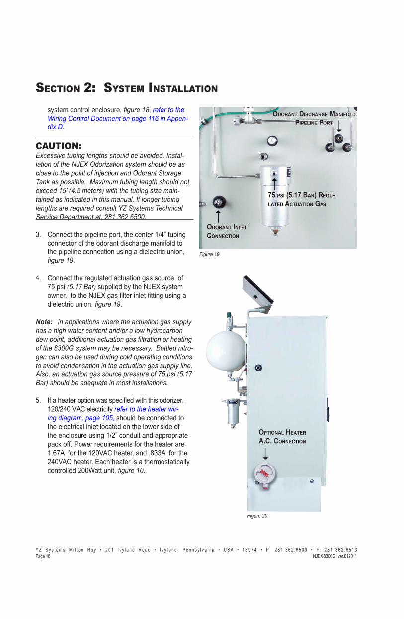
�������<
75 PSI (5.17 BAR) REGU-LATED ACTUATION GAS
ODORANT INLETCONNECTION
ODORANT DISCHARGE MANIFOLD PIPELINE PORT
��������=
OPTIONAL HEATER A.C. CONNECTION
CAUTION: >+�����?����!����������������!���?����#������-������������@>G�K���Q�����R���"�������!�����������������������U��������K�����V������[�\��������!��#��]�+�"�"���!������������������+������� �̂��#��"�������_����������!�����Q��"��-�������������������������"����#�����������!����������������`������������{|�VR���"��[��������V��?�������}��$�#���#��==#3. Connect the odorant supply source to the odorant inlet
���-���!���������� �������Y"\�����������������tubing, �����<J���������������$��$������������ �-porated between the storage tank and this connection, �������
\J� #� ����������������� ������������� �X�-��Z�����*ZJY�����,�����������������~�����������!��X�������~������������������������������������� ��� ���X��������J��� For Pipeline pressures less than 200 psig a single
������������*)������:������"~��+%;;\]����������,���'������������$�����Z���������������������������on the NJEX enclosure should be acceptable.
�� �"�������������$��];;����������������� ���������-tion process:1. Install the primary regulator on the pipeline
�)������Y+;Y�����"~��+%;]�\����������,X������'�����������$����YZ;������������� �����regulator.
2. Install the secondary regulator at the inlet gas ������������� ��-�����~����� ������*)���-���:������"~��+%;;\]����������,X������'�����������$�����Z������������~�����������������be acceptable.
+J� +"��������������������������������������between the two regulators.
�� Dual Pump enclosures, may require larger tubing between the regulators, and the secondary regulator ������������$�������������� ��*)������:\����������,X�if both pumps run simultaneously.
Note:����������������_��������������������������R������������_������������~�����_��R�����!���_��������������������������� ����������������������$�==���R���"�"�R�!���������R#����������������������!�����������������������������������?��������-��������������������������R����#��*�����������������������������������:��������#�:������������!�����`�������"�������������#
ZJ��� #� ������������������-������������� ������manifold to the pipeline connection using a dielectric ������ �� ��$��$�X� �����<#
:J� ����������������_�������� ���_������������Q������=�~���=��*&�����������R��������������������_��������-���"��������=���������!��������������������������������������������_����������������������������~��������������������������\���#��_�����`����-"�����������������������#�:*����������=�*&������������#$��*����������=�*&�������#�>��������������������"���������R����������==%��������� ������=#�'�����������������"�R���?�����������������"����#����������?�����������������������"��#�

� � � � � � � � � � � � � � � � � � � � � � � � � � � � � � � � � � � � � � � � � � � � � - � � � � � � � � � � � � � � � � � � � � � � � � � � � � � � � � � ! " # � ! # $ � � � � � % � � � � ! " # � ! # $ � "��&���� '()*��"��/���+!��������
SECTION 2: SYSTEM INSTALLATION
Skid System ComponentsIntroductionThe NJEX SkidMount Series of odorization systems is a total system approach to odorization. These sys-tems are completely factory assembled, tested, and ����$���������������������������� � ���������fully operational. The NJEX SkidMount Systems offer ����������$�������-�������������+;;�������������������������������-�����������������������J������ �����������!��-�������������������-proach to odorization.
The SkidMount Systems come standard with an ��� ��� ���$������ ����-� ���� � ����������N-300G controller. The controller has an alarm capa-������������ ����!����������������$������������������������-��������!������������������$��������������operator.
�����������������$��������!����];X�:;X�Y];X�]Z;X�Z;;����Y;;;���������������J�*������������������$���-able up to 10,000 Gallons by custom order).
Skid system primary components of the NJEX-8300G include the following:
�� Skid Mounted Tank a pre-assembled, and tested ���� �����������������!������������X�$��$���� �-age, skid piping, and system enclosure.
�� NJEX System Enclosure, ��������� houses and protects the; 8000 pump, VM-2100 Verometer, ���������$��$�X�������$��$�"������� �������manifold, odorant discharge manifold, N-300 system controller enclosure, power supply enclosure*, and ���������������J��
�� SPS-12 – Solar Panel Assembly, �������� is standard equipment for the 8300G and includes a mounting bracket and a connection cable.Op-��������%Y];"]\;��������������������-����������panel*.
�� System Control Enclosure for the N-300G control-ler.
�� Power Supply Enclosure for the battery and charging system*.
���������
* ATEX installations refer to Appendix E. page 117.

� � � � � � � � � � � � � � � � � � � � � � � � � � � � � � � � � � � � � � � � � � � � � - � � � � � � � � � � � � � � � � � � � � � � � � � � � � � � � � � ! " # � ! # $ � � � � � % � � � � ! " # � ! # $ � "��&���'()*��"��/���+!������
SECTION 2: SYSTEM INSTALLATION
���������
���������
ExpansionTank
NJEX Gas Filter
Bulk Odorant Filter
Actuation Gas Regulator�� Bulk Odorant Filter, � �����������$�������������
����������������!�������������������������~���%�+;;�J�������������������������
pre-installed inside the system enclosure attach-������������������ �����$�������������������--������������!����Y"\��)~��� � ���� ������the back of the system enclosure.
�� Mechanical Interconnect Cable, �������� pro-$��������� � ������!�������������� ����enclosure and the electrical components located in the mechanical section.
�� Expansion Tank, � �����������$������� ���������������-�����������>� �������!���������[���-����������������������������'� ��� � ��J
�� NJEX Gas Filter, �������� installed between the actuation gas regulator and the actuation gas mani--������$�������]Z��� �� ���� �������������insure a clean pneumatic supply.
�� Actuation Gas Regulator, �����������$���������-tional regulation of supply gas to actuate the pump.
�� Service Tray, ����������������� should be installed in the bottom of the system enclosure, to capture any �������������� ������������$� ���-�������-izer.

� � � � � � � � � � � � � � � � � � � � � � � � � � � � � � � � � � � � � � � � � � � � � - � � � � � � � � � � � � � � � � � � � � � � � � � � � � � � � � � ! " # � ! # $ � � � � � % � � � � ! " # � ! # $ � "��&���� '()*��"��/���+!��������
SECTION 2: SYSTEM INSTALLATION
System Flow Schematic� ���������
"����#�������� �$
"����#�������� �$
�!������ ��!�������������
���������
����� ��� ������������������������������ ������ �������������������� ������������ ������������ �������� ��������� ������������� ����������!��� ���!��� �������� ������!!����� �������������� �������� ��������� �!!��������� ������������ ������ ���������� ����������� ��������� �!�!���� �����!���� ������������ �������� ��������

� � � � � � � � � � � � � � � � � � � � � � � � � � � � � � � � � � � � � � � � � � � � � - � � � � � � � � � � � � � � � � � � � � � � � � � � � � � � � � � ! " # � ! # $ � � � � � % � � � � ! " # � ! # $ � "��&��"'()*��"��/���+!������
SECTION 2: SYSTEM INSTALLATION
Skid System Mounting� ���������
1. Prepare a concrete slab that exceeds the NJEX ��������������!�������������������������Y]�J
2. �����$�������������������� ��-��!�these lifting guidelines:
a. Lift containment skid systems using all four eyebolts on the corners of the skid.
b. Lift rail skid systems from the bottom of the skid by forklift or other support-�$����$� �J
c. @����$�����������!�������������the odorant tank.
d. Do not lift a system by the tank lugs, these lugs are designed only for the weight of the empty tank.
RAIL SKID SYSTEMSTANK CABINET BL BW L W WEIGHT����� � ����� ����� ����� ����� ����
20 Either \� \� \� \� \Z;60 Either Z] Z] Z\ Z\ ZZ;
120 Single �: ]: 98 28 �Z;Double �: \� 98 \� 800
250 Either 122 \� Y]\ \� YYZ;500 Either Y\� \� Y\� \� Y:;;
1000 Either 220 \� 222 \� ]�Z;2000 Either 318 \��Y"] 322 Z]�Y"] ::;;

� � � � � � � � � � � � � � � � � � � � � � � � � � � � � � � � � � � � � � � � � � � � � - � � � � � � � � � � � � � � � � � � � � � � � � � � � � � � � � � ! " # � ! # $ � � � � � % � � � � ! " # � ! # $ � "��&���� '()*��"��/���+!��������
SECTION 2: SYSTEM INSTALLATION
CONTAINMENT SKID SYSTEMSTANK CABINET BL BW O L W WEIGHT����� � ����� ����� ����� ����� ����� ����
20 Single Z; 32 8 :: +: 800Double 31 Z� 7 \Z :] �Z;
60 Single Z: 32 8 72 +: �Z;Double +: Z� 7 Z; :] 1000
120 Single 82 32 8 98 +: 1200Double 82 Z\ 8 98 Z� Y+Z;
250 Either 108 Z� 8 Y]\ :] Y�Z;500 Either YY: Z� 8 YZ\ :] ]:;;1000 Either 192 :\ 8 ]\; :� \]Z;2000 Either ]Z] :� Y\ 318 73 ��Z;

� � � � � � � � � � � � � � � � � � � � � � � � � � � � � � � � � � � � � � � � � � � � � - � � � � � � � � � � � � � � � � � � � � � � � � � � � � � � � � � ! " # � ! # $ � � � � � % � � � � ! " # � ! # $ � "��&��$'()*��"��/���+!������
SECTION 2: SYSTEM INSTALLATION
Skid System Connections�������������� � ��������� �������+;;�����operation are as follows:
1. Connect the solar panel cable to the system power supply, SPS-12, ��������.
Note:����������������������!��"������������!������������������������!���������������������������"�����������������������������������"�������#
1a. *If your system was ordered with the optional � ���%Y];"]\;��!���������X��#��!������������
connected in accordance with explosion-proof ���$��������������'� ����=���������� ���������� �������$��������������������-��������the system enclosure. The power requirement for 120VAC will be 100 mA. The power requirement -��]\;[�#�!�������Z;���J��������!�����������������-�����!��������=�����-�YZ�X� ������:, ������������%�����&����'��"���������������*�����+�'#
]J� #� ������>!���������$� ����������������������� ������������������ ����� ������$���the conduit hubs to the N-300G, ������$, ������������%�����&����'��"���������������*�-����+�'#
2a. If used, connect the optional Inhibit Input signal to the termination board located in the system control enclosure, ������$,�������������%�����&����'��"���������������*�����+�'#
]�J� Q-�����X� � ��������%\�Z� ���� ����!�����as required to the termination board located in the
��������$
��������:
���������
SPS-12
LPS120/240
* ATEX installations refer to Appendix E. page 117.
� � � � � � � � � � � � � � � � � � � � � � � � � � � � � � � � � � � � � � � � � � � � � - � � � � � � � � � � � � � � � � � � � � � � � � � � � � � � � � � ! " # � ! # $ � � � � � % � � � � ! " # � ! # $ � "��&��#� '()*��"��/���+!��������
SECTION 2: SYSTEM INSTALLATION
��������<
��������=
OPTIONAL HEATER A.C. CONNECTION
75 PSI (5.17 BAR) REGU-LATED ACTUATION GAS
ODORANT INLETCONNECTION
ODORANT DISCHARGE MANIFOLD PIPELINE PORT
system control enclosure, ������$,�������������%�����&����'��"���������������*���-��+�'.
CAUTION: >+�����?����!����������������!���?����#������-������������@>G�K���Q�����R���"�������!�����������������������U��������K�����V������[�\��������!��#��]�+�"�"���!������������������+������� �̂��#��"�������_����������!�����Q��"��-�������������������������"����#�����������!����������������`������������{|�VR���"��[��������V��?����'�����"�����}��$�#���#��==#
+J� #� �����������������X����� �����Y"\��������connector of the odorant discharge manifold to the pipeline connection using a dielectric union,
� ������<.
\J� #� ����������������� ������������� �X�-��Z�������#�:����� supplied by the NJEX system !��X��������~��������������������������������dielectric union, ������<.
Note:����������������_��������������������������R������������_������������~�����_��R�����!���_��������������������������� ����������������������$�==���R���"�"�R�!���������R#������������-����������!�����������������������������������?����������������������������������R����#��*�����������������������������������:��������#�:������������!�����`�������"�������������#
ZJ� Q-��������������!������ �����!���������������X�Y];"]\;�[�#���� ��� �����������������������_��-���������"��������=���should be connected to the electrical inlet located on the lower side of ����� �����������Y"]�� �������������������pack off. Power requirements for the heater are YJ:����-������Y];[�#�������X����J�++���-������]\;[�#�������J��� ������������������������ �����controlled 200Watt unit, ������=.

� � � � � � � � � � � � � � � � � � � � � � � � � � � � � � � � � � � � � � � � � � � � � - � � � � � � � � � � � � � � � � � � � � � � � � � � � � � � � � � ! " # � ! # $ � � � � � % � � � � ! " # � ! # $ � "��&���'()*��"�����+!��,����
SECTION 3: FILLING THE BULK ODORANT TANK
Electronic Level Indicator
Odorant Vapor Return1/2” NPTOdorant Fill1/2” NPT
V15 V13 V12 V11 V10
Filling the Tank for the First TimeCAUTION: Odorant has a very strong odor, which if allowed to escape to the atmosphere, may cause problems in the local community. Take necessary precautions when ���������������������\�������������������������""���R�������������������������� �����������#�Verify that the entire system has no pressure in it before beginning. Additionally, all personnel should wear protective clothing, and use equipment as recommended by the chemical manufacturer during this time. If you are uncertain about any aspect of the odorant itself, you should contact the manufacturer of your chemical prior to proceeding.
1. Verify correct position of valves before beginning, �������.
Open: V12, and V13*
Closed: V10, V11, and V15 ���������V����R��������������K[�!��������
on during this procedure.
2. Attach inert or natural gas supply to V10.
3. To purge the tank open valve V10 to introduce inert or natural gas to the tank to begin displacing any ambient air from the empty tank. Continue until pressure on the gage located directly above V13 is observed, then partially open V11 to allow �����������-������������������>!�����J�Allow this process to continue until all ambient air from the tank is purged, and only inert gas or natural gas is emitting from this valve, then close V11 and V10. The time required to accomplish this task will vary with the tank size.
4. Vent purge gas by opening V11 partially until tank pressure just reaches zero, and then close V11.
5. Attach odorant supply to V10, open V10, and begin transferring odorant to the bulk tank.
6. Connect a line from V11�����>������$������ $-ery device, and open V11.
CAUTION: Fill tank to a maximum level of 80% of the tank capacity.
7. Close V10 and V11, and remove odorant transfer equipment, and line to flare or vapor recov-ery device.
8. Turn Gas Supply to V13 on, and open V13 and V15.
9. Continue through the remaining procedures in this manual.
���������

� � � � � � � � � � � � � � � � � � � � � � � � � � � � � � � � � � � � � � � � � � � � � - � � � � � � � � � � � � � � � � � � � � � � � � � � � � � � � � � ! " # � ! # $ � � � � � % � � � � ! " # � ! # $ � "��&���� '()*��"�����+!��,����
SECTION 3: FILLING THE BULK ODORANT TANK
$��!!��%�'��!(�������TankCAUTION:Odorant has a very strong odor, which if allowed to escape to the atmosphere, may cause problems in the local community. Take necessary precautions _��� ���������������������\�������������������������""���R�������������������������� �����process. Verify that the entire system has no pres-sure in it before beginning. Additionally all personnel should wear protective clothing, and use equipment as recommended by the chemical manufacturer during this time. If you are uncertain about any aspect of the odorant itself, you should contact the manufacturer of your chemical prior to proceeding.
1. Place the N-300G controller in the Standby Mode by pressing the Standby key.
2. Verify correct position of valves before beginning, �������#
Open: V12 Closed: V10, V11, V13, V15
3. Connect a line from V11�����>������$������ $-ery device, and open V11.
4. Attach odorant supply to V10, open V10, and begin transferring odorant to the bulk tank.
CAUTION: Fill tank to a maximum level of 80% of the tank capacity.
5. Close V10 and V11, and remove odorant trans--�����������X����������>������$������ $����device.
6. Open V13 and V15.
7. Place the N-300G controller in the Run Mode by pressing the Standby key.
���������
Electronic Level Indicator
Odorant Vapor Return1/2” NPTOdorant Fill1/2” NPT
V15 V13 V12 V11 V10

� � � � � � � � � � � � � � � � � �- � � � 0 ! � � � � � � � � � � � � � � � � - � � � � � � � - � � � � � � � � � � � � � � � � � � � � � � � �� � � � � � � � � � � � � � ! " # � ! # $ � � � � � % � � � � ! " # � ! # $ � "��&���'()*��"�����+!��,����
SECTION 4: SYSTEM CONTROL & ELECTRONICS
OverviewThe 8300 control/electronics system is composed of the system control enclosure and the SPS-12 solar charged power supply, or a LPS 120/240 charger sup-ply*, �������. Individual components of the system are shown below and are described in the following �����J����>!� �����-�����~%+;;�� ��������������������������������������~%+;;��@�������@�������located ������������*�����+�'.
To Use The Key PadThe three main keys have multiple function capabili-ties. Each key is labeled with it’s primary function used in moving through the menu, they are as follows:
Select / Enter
[���V������~�>������R��������*��_���R��������'_�*��_���R
These keys also have alternative functions. These al-������$��-� ����!���������>� ���������� �����X�proceeded by an asterisk “*”, that appear in a corre-���������������������������~%+;;���������J�For example in �������:
�� �� ����*Start, you would press the Select / Enter key.
�� �� ����*Dsp, you would select the Key.
�� �� ����*Set, you would select the Key.
���������
SYSTEM CONTROL ENCLOSURE
POWER SUPPLY
���������
pmp bat vmtr sig tnkPropFlow Idle*Strt *Dsp *Set
* ATEX version does not include power supply.

� � � � � � � � � � � � � � � � � � � � � � � � � � � � � � � � � � � � � � � � � � � � � - � � � � � � � � � � � � � � � � � � � � � � � � � � � � � � � � � ! " # � ! # $ � � � � � % � � � � ! " # � ! " $ � "��&���� '()*��"�����+!��,����
SECTION 4: SYSTEM CONTROL & ELECTRONICS
To Power Up The System��������~%+;;��#�������� �����X� ���������and ��������������!�� ��S1 located just below center on ���������������-������������#�� ������������#�J�����on the main power switch by toggling the switch to up position.
Once powered-up, the menu sequence, �������� !����������J��)��!�������������� ����������#@�screen as they are presented.
#�� ����������������������������������������shown match the serial number and model type on the left side of the electronics enclosure and on the inside of mechanical enclosure door. Also check to ensure the verometer calibration number matches the verom-eter tag number located at the top of the verometer assembly, �������:���$����<#
~�=�����������$����������-�� ������������-����%#�������������������������X��������$������programmed into the Sentry Module, ������=# This option will only come up if it has been set up in Sentry and not previously uploaded.
Record the version x.xx number, �������� in the For the Record Form��������������������*�����+�&�of this manual for future reference.
IMPORTANT: ���������������"!����"�����R����������?��"����������"!�������"��������������������"!�������������==�������������������������R�!����������������������#
S1
Serial Number 20000
Model Type 8300
Display Contrast Adj50% 22C
Verometer Calibrate154.20 Calibrate cc
Pre-Configure Parms?*Yes *No
N300GE Ver 1.02 --NJEX--
pmp bat vmtr sig tnkPropFlow Idle*Strt *Dsp *Set
pmp bat vmtr sig tnkPropFlow Idle*Stop *Dsp *Set
���������
���������
��������:
��������$
��������<
��������=
���������

� � � � � � � � � � � � � � � � � �- � � � 0 ! � � � � � � � � � � � � � � � � - � � � � � � � - � � � � � � � � � � � � � � � � � � � � � � � �� � � � � � � � � � � � � � ! " # � ! # $ � � � � � % � � � � ! " # � ! # $ � "��&���'()*��"�����+!��,����
SECTION 4: SYSTEM CONTROL & ELECTRONICS
Test & Standby KeysThe Test key, �������� is located in the upper right ��������-�����~%+;;���� �������������������manually stroke the pump. Simply press the test key touch pad to stroke the pump. Each time the test key ���������X����������������� �������������~%+;;��display will show Strk just above the Test key touch pad. The strokes signaled counter, located in the dis-������� ���-�����~%+;;�!������$� ��-���� ��������of the pump. The odorant injected counter, located ���������������� ���-�����~%+;;��!����������$� ��!������������������ �������-� ����$�����-���-ant to register .001 lb (.001 kg) of odorant.
The Standby key, �������� allows the operator to � �����������������������-�����~%+;;�� ������X�by simply pressing this key. This creates a standby ����-�������+;;�������J�Q������$���-����>!�condition in the pipeline, the operator can switch the 8300 to a standby mode for extended periods of time, or to temporarily suspend operation of the system for ������ �J������>!������������� �����X�������maintenance has been completed, the 8300 can be switched from standby to operation without the need ��������������~%+;;�� ������X�������������������the standby key once again.
Remote Inhibit Mode, can also be applied to interrupt odorization in a manner similar to the standby mode; however, it is initiated by applying a dry contact, or open collector signal, to the termination board TS2, terminals #9 and #10 , �������������%�����&����'��"�����������:���*�����+�'. The Remote Inhibit Mode’s function is identical to the Standby ModeJ��� ��$����!���������� ����������~%+;;�����-�����������������\��$���������--������J�Rmt Inhb !����������������~%+;;������ ������������!�����the count down time normally appears, �������.
���������
���������
pmp bat vmtr sig tnkPropFlow Rmt Inhb*Stop *Dsp *Set
pmp bat vmtr sig tnkPropFlow 0:00*Stop *Dsp *Set

� � � � � � � � � � � � � � � � � � � � � � � � � � � � � � � � � � � � � � � � � � � � � - � � � � � � � � � � � � � � � � � � � � � � � � � � � � � � � � � ! " # � ! # $ � � � � � % � � � � ! " # � ! " $ � "��&���� '()*��"�����+!��,����
SECTION 4: SYSTEM CONTROL & ELECTRONICS
Battery & Solar Panel Assem-blyThe 8300 standard system is solar powered using a �$��!�������������X�������������!���������������%Y]�!�� ��� ��������������������Y]�$���@#�battery, �������������. The 8300 will operate ap-proximately 30 days without additional power gener-ated by the solar panel. The battery is continuously monitored and an alarm signal is sent if the voltage -��������!�YYJ;�$���J��@���������� �����������-���������@X�� ����������-���-��������%Y]�!����illuminate*.
*If AC power is available, the solar panel can be ����� ���!������������Y];"]\;��#"@#������!���������������X� ���������intrinsically safe barrier, and ��� ������-��#�����QX�@�$����YX������#X�@�� �-tions. The battery is included in the system to provide system operation and back up power for up to 30 ����X��������$���-����#��!���-������J�
LPS AND BATTERY W/COVER REMOVED SPS AND BATTERY W/COVER REMOVED
���������
�������������������
SOLAR PANEL
* ATEX version does not include power supply.

� � � � � � � � � � � � � � � � � �- � � � 0 ! � � � � � � � � � � � � � � � � - � � � � � � � - � � � � � � � � � � � � � � � � � � � � � � � �� � � � � � � � � � � � � � ! " # � ! # $ � � � � � % � � � � ! " # � ! # $ � "��&��"'()*��"�����+!��,����
SECTION 4: SYSTEM CONTROL & ELECTRONICS
Communications InterfaceThere are three methods of communicating informa-������-�����~%+;;� ������J�
�� Method 1,����������#���� �����(�������-� �J���� �� �������������� �������� �����found in *�����+����������=:.
�� Method 2, utilizes the Sentry Software installed on a computer. In this mode the computer can commu-� ����!��������~�������������������-�����X�������~������������������ �����������-������computer and provide it with information.
�� #� ����-��(�����Y���]�����$�������%\�Z�two wire connection. In a safe, nonhazardous area this may be connected to a RS-232 converter for ����-� ��!�������#�@����������-���������X�������������%�����&����'��"�����������:��*������+�'.
�� Method 3, utilizes two output relays. One relay is for Alarm Output, and provides single output commu-nication to indicate some type of some alarm has occurred with the odorizer. The second output relay is for a Scaled Pulse relative to a programed vol-ume of odorant injected by the system, ������������%�����&����'��"�����������:��*�����+�'#
)�"" +��()���%�������The 8300 system may be communicated to through ������!��$����������\�Z� ���� ��������J
����~%+;;�(�������� �� ���� �����-���������*�����+����������=:#

� � � � � � � � � � � � � � � � � � � � � � � � � � � � � � � � � � � � � � � � � � � � � - � � � � � � � � � � � � � � � � � � � � � � � � � � � � � � � � � ! " # � ! # $ � � � � � % � � � � ! " # � ! " $ � "��&���� '()*��"�����+!��,����
SECTION 4: SYSTEM CONTROL & ELECTRONICS
Notes

� � � � � � � � � � � � � � � � � � � � � � � � � � � � � � � � � � � � � � � � � � � � � - � � � � � � � � � � � � � � � � � � � � � � � � � � � � � � � � � ! " # � ! # $ � � � � � % � � � � ! " # � ! # $ � "��&��$'()*��"�����+!���,����
SECTION 5: PROGRAMMING FOR PROPORTIONAL-TO-FLOW OPERATION
Or
Or
Setting Operator Input Parameters�� #����Set��������������X� ������:.
�� #����Par�������"�������������������� ������X� ������$.
�� #����Flow�������������������������X� ������<#
�� #����Set���������������%�%>!����X� �����40.
Setting the odorant injection rate in lbs/MMCF (mg/m3) of gas�����������'� �������X� �������X����������������������Select����J������$����������!�����������>����!��� ���J��B�������Up Arrow�������� ����������$������������Down Arrow��������� ����������$����J���������!�$������������� ���X�����������Enter�����������������!�$�������������J�������������$�����!��������>������!����������������������������J������������Down Arrow���������$� ���������=�����������J
Pump displacement in cc/stroke��������������������� ����X� ������������������������������Select����J������$����������!�����������>����!��� ���J��B�������Up Arrow��������% ����������$������������Down Arrow���������% ����������$����J���������!�$������������� �%��X�����������Enter�����������������!�$�������������J�������������$�����!��������>������!����������������������������J������������Down Ar-row���������$� ���������=�����������J
Odorant density in lbs/gallon (g/cc) @ 60º F���������������������X� ������������������������������Select����J�����$����������!�����������>����!��� ���J��B�������Up Arrow�������� ����������$������������Down Arrow��������� ����������$����J��������!�$������������� �%��X�����������Enter�����������������!�$�������������J������������$�����!��������>������!����������������������������J�����������Down Arrow���������$� ���������=�����������J
pmp bat vmtr sig tnkPropFlow Idle*Strt *Dsp *Set
���������������������-� ��
pmp bat vmtr sig tnk Set Parameters*Flow *Time *Esc
pmp bat vmtr sig tnk Set Selection*Par *Cal *Esc
��������:
pmp bat vmtr sig tnkProportional to Flow*Set *Alarm *Esc
pmp bat vmtr sig tnk Odorant Density 6.80 lbs/Gal
pmp bat vmtr sig tnk Odorant Density 0.815 g/cc
pmp bat vmtr sig tnk Injection Rate 1.00 lbs/MMCF
pmp bat vmtr sig tnk Injection Rate 16.0 mg/m3
���� ������
pmp bat vmtr sig tnk Pump Displaceplent6.000 cc/Stroke
���� �����
���� �����
��������$
��������<
��������=
���������
���������
���������
pmp bat vmtr sig tnk Set Parameters*Flow *Time *Esc

� � � � � � � � � � � � � � � � � � � � � � � � � � � � � � � � � � � � � � � � � � � � � - � � � � � � � � � � � � � � � � � � � � � � � � � � � � � � � � � ! " # � ! # $ � � � � � % � � � � ! " # � ! # $ � ���&��#� '()*��"�����+!���,����
SECTION 5: PROGRAMMING FOR PROPORTIONAL-TO-FLOW OPERATION
Setting Operator Input Parameters,��� &�����
���%��=�>����)?QZ���["�Q���\(�=�����>!�����������=�����>!���������!�� ������>!��������� ����-����� �������J
]�����'�"��%��=�>^� ������������������������������Select����J������$����������!�����������>����!������� ���J�B�������Up Arrow ������� ����������$������������Down Arrow��������� ����������$����J���������!�$������������� ���X�����������Enter�����������������!�$�������������J������������$�����!��������>������!��������������������������������J������������Down Arrow ��������$� ���������=�����������J
]'�!�>=�>�'���__������%^����!���������������������� ������-���=�����>!���������������~%+;;���������'� ��������J����������!������ ���������������!�>!� ������!����������������������������J�������������!�����$�������������=������"�����������������������J������>!������� ���������$���������������������~%+;;����������������J
]�����'�!�>=�>�'���__^� ������������������������������Select����J������$����������!�����������>����!������� ���J�B�������Up Arrow�������� ����������$������������Down Arrow���������% ����������$����J���������!�$������������� �%��X�����������Enter�����������������!�$�������������J�������������$�����!��������>������!��������������������������������J������������Down Arrow���������$� ���������=�����������J
]'�=�>(no signal) input settingX����������������%�������� ������-���=�����>!�����������������!������������� �����������-��������������$������������� �����>!������������������J��
Note:������Flow (no signal) input��������_�����R�!������?��_��������������������������'&�������=�"*#
]�����'�=�>(no signal) inputX� ������������������������������Select����J������$����������!�����������>����!������� ���J��B�������Up Arrow�������
Or
pmp bat vmtr sig tnk Maximum Gas Flow 5.000 MMCF/hr
pmp bat vmtr sig tnk Maximum Gas Flow 15.00 m3/sec
���� �����
pmp bat vmtr sig tnk Low Flow Shutoff2.0% Max Gas Flow
���� �����
���������
���������
pmp bat vmtr sig tnk Flow (No Signal)20.0% Max Gas Flow
���� �����
���������
� � � � � � � � � � � � � � � � � � � � � � � � � � � � � � � � � � � � � � � � � � � � � - � � � � � � � � � � � � � � � � � � � � � � � � � � � � � � � � � ! " # � ! # $ � � � � � % � � � � ! " # � ! # $ � "��&���'()*��"�����+!���,����
SECTION 5: PROGRAMMING FOR PROPORTIONAL-TO-FLOW OPERATION
� ����������$������������Down Arrow���������% ����������$����J���������!�$������������� �%��X�����������Enter�����������������!�$�������������J�������������$�����!��������>������!��������������������������������J������������Down Arrow���������$� ���������=�����������J
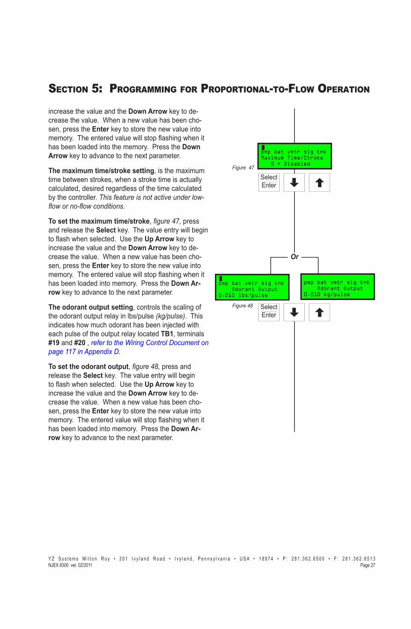
The maximum time/stroke settingX����������=�������������!���������X�!�������������������� ������� �� ������X��������������������-���������� �� �������������� ������J�[���������������������?��������_��_�����_�������#
To set the maximum time/strokeX� ������:�����������������������Select����J������$����������!�����������>����!������� ���J��B�������Up Arrow�������� ����������$������������Down Arrow���������% ����������$����J���������!�$������������� �%��X�����������Enter�����������������!�$�������������J�������������$�����!��������>������!����������������������������J������������Down Ar-row���������$� ���������=�����������J
The odorant output settingX� ���������� �����-���������������������������"�������\�~������J���������� ������!��� ����������������'� ����!������ ��������-������������������ �����TB1X����������#19����#20�X�������������%�����&����'��"������������:���*�����+�'#
To set the odorant outputX� ������$�����������������������Select����J������$����������!�����������>����!������� ���J��B�������Up Arrow�������� ����������$������������Down Arrow���������% ����������$����J���������!�$������������� �%��X�����������Enter�����������������!�$�������������J�������������$�����!��������>������!����������������������������J������������Down Ar-row���������$� ���������=�����������J
Or
pmp bat vmtr sig tnk Odorant Output0.010 lbs/pulse
pmp bat vmtr sig tnk Odorant Output0.010 kg/pulse
���� �����
��������$
pmp bat vmtr sig tnkMaximum Time/Stroke 0 = Disabled
���� �����
���������:

� � � � � � � � � � � � � � � � � � � � � � � � � � � � � � � � � � � � � � � � � � � � � - � � � � � � � � � � � � � � � � � � � � � � � � � � � � � � � � � ! " # � ! # $ � � � � � % � � � � ! " # � ! # $ � ���&���� '()*��"�����+!���,����
SECTION 5: PROGRAMMING FOR PROPORTIONAL-TO-FLOW OPERATION
Setting Operator Input Parameters,��� &�����
Odorant TankK������V�������)� ������~����-��� ���������������(���������������������������J
YJ� Disabled:�����$���������X�=��������!�����!����_����������������"����!������!���.
]J� Enabled:��;%Y;;����$����������!�����!������������������������������-����������$�������%��X���?����������$������������X�������!�������$������������J�
To set the alarm level pointsX� ������<X����������������������Select����J�������!���$���$�����!�����������>����!��� ���J��B�������Up Arrow�������� ����������$������������Down Arrow��������� ����������$����J����������������������� ���������������!���Z�����]Z�J��������!�$������������� ���X�����������Enter�����������������!��!���$������������������������J�������������$�����!��������>������!����������������������������X�����?������$���$�����!�����������>���J�B�������Up Arrow�������� ����������$������������Down Arrow��������� ������������������$����J����������������������� �������������������������;�J��������!�$������������� ���X�����������Enter�����������������!�?������$������������������������J������������Down Arrow���������$� ���������=�����J�
Expansion Tank Pressure Monitoring ���� ����=�������������������������=��������]Z�������#:������J�������������!������������� ���������%�����X���?��������������=��������������X�������!�����������=��������������X� ������=J�
YJ� DisabledN����=����������������������%��X�=��������!�����!����_����������������"����!������!���J�~��������������������$�������-� ���������J�
]J� EnabledN���!���$������������� ������������/�]+�������#�$�����X����������'��������-���;������=����������������������$����������J�?������$���������
Or
pmp bat vmtr sig tnkExpansion Tank (psi)20.0=Low 30.0=High
pmp bat vmtr sig tnkExpansion Tanks (bar)1.40=Low 2.00=High
Select)��+
��������=
pmp bat vmtr sig tnk Odorant Tank10=Low (%) 90=High
Select)��+
���������<

� � � � � � � � � � � � � � � � � � � � � � � � � � � � � � � � � � � � � � � � � � � � � - � � � � � � � � � � � � � � � � � � � � � � � � � � � � � � � � � ! " # � ! # $ � � � � � % � � � � ! " # � ! # $ � "��&���'()*��"�����+!���,����
SECTION 5: PROGRAMMING FOR PROPORTIONAL-TO-FLOW OPERATION
���� ������������/�]��������#$������X����������'���%�����-���;������=��������������������#$������.
To set the alarm level pointsX� ������������������������������Select����J�������!����������$�����!�����������>����!��� ���J��B�������Up Arrow�������� ����������$������������Down Arrow��������� ����������$����J���������!�$������������� ���X�����������Enter�����������������!��!�������������������������J�������������$�����!��������>������!����������������������������J��~�=������?�������������$�����!�����������>���J�B�������Up Arrow�������� ����������$������������Down Arrow��������� ����������$����J���������!�$������������� ���X�����������Enter�����������������!�?����������������������������J������������Down Arrow���������$� ���������=�����J�
Odorant Inlet Pressure Monitoring )����������$��$����-� ��� ��� �����������������-%-�����������!��������������������������������������=��������X�����������������J��������-%-���������������$���������������Z������#��������������� ���������������Y;������#�<�����J�������������!������������������������������-�������������Q�������������������X���?����������Q���������X�������!�������Q���������J�
To set the alarm level pointsX� ������������������������������Select����J����������Q�����!��$�����!�����������>����!��� ���J��~������!������������������������������������+;�������#=:�����J��B�������Up Arrow�������� ����������$������������Down Arrow��������� ����������$����J���������!�$������������� ���X�����������Enter�����������������!�����Q�����!����������������J�������������$�����!��������>������!����������������������������J��~�=����������Q����?����$�����!�����������>���J��~����������������������������������%�����������+Z�������#�������J�B�������Up Arrow�������� ����������$������������Down Arrow��������� ����������$����J���������!�$������������� ���X�����������Enter�����������������!�����Q%����?�������������������J������������Down Arrow���������$� ���������=�����J��
Or
pmp bat vmtr sig tnkExpansion Tank (psi)20.0=Low 30.0=High
pmp bat vmtr sig tnkExpansion Tanks (bar)1.40=Low 2.00=High
SelectEnter
���������
Or
pmp bat vmtr sig tnkOdorant Inlet (psi)25.0=Low 40.0=High
pmp bat vmtr sig tnkOdorant Inlet (bar)1.70=Low 2.80=High
SelectEnter
���������

� � � � � � � � � � � � � � � � � � � � � � � � � � � � � � � � � � � � � � � � � � � � � - � � � � � � � � � � � � � � � � � � � � � � � � � � � � � � � � � ! " # � ! # $ � � � � � % � � � � ! " # � ! # $ � ���&�"�� '()*��"�����+!���,����
SECTION 5: PROGRAMMING FOR PROPORTIONAL-TO-FLOW OPERATION
Setting Operator Input Parameters,��� &�����
Alarm to Relay Delay Q�������������������������� �����������������!�-����������-�������� ������!������������������� ��-����������������� �������������������-�����������$������������������������J
YJ� ;� �~�������#�� ��@����]J� Y�%�]\;� �~������-��(������@����+J�� ¡�]\;� �@�������X�~�������������#�� ��!����� ��
To set the alarm delay timeX� �������������������������������Select����J�������������@�����$�����!�����������>����!��� ���J�B�������Up Arrow�������� ����������$������������Down Arrow���������% ����������$����J��������!�$������������� ���X�����������Enter����������������$����J
Alarm to Call Out Delay Q�������������������������� �����������������!�-����������-�������� ������!������������������� ��-����������������� ������������ � �������-� ���$������������(����� ���� �������J
YJ� ;� �~�������#��������@����]J� Y�%�]\;� �~������-��(������@����+J�� ¡�]\;� �@�������X�~�������#��������!���� ��
To set the alarm to call out delay timeX� ������������������������������Select����J�������������#������@�����$�����!�����������>����!��� ���J�B�������Up Arrow�������� ����������$������������Down Ar-row��������� ����������$����J��������!�$������������� ���X�����������Enter����������������$����J
MODBUS Address Q�(�������� �X��� ����� ��-���������������!�������������-���-���������������������������$��QJ@J���������X������!������#�@���������?�����$� ��������������������������$� �������������-���-�����J�����������������������������������������(�������%�����J������������-���Y%]\�����������������J�Q-�;������������������-� ���!���������������X�� �������J�
pmp bat vmtr sig tnkMaximum Time/Stroke 0 = Disabled
���� �����
����������
pmp bat vmtr sig tnkAlarm to Relay Delay 20 minutes
���� �����
����������
pmp bat vmtr sig tnkAlarm to Callout Dly 10 minutes
���� �����
����������
pmp bat vmtr sig tnk MODBUS Address 1 Device Address
���� �����

� � � � � � � � � � � � � � � � � � � � � � � � � � � � � � � � � � � � � � � � � � � � � - � � � � � � � � � � � � � � � � � � � � � � � � � � � � � � � � � ! " # � ! # $ � � � � � % � � � � ! " # � ! # $ � "��&�"�'()*��"�����+!���,����
SECTION 5: PROGRAMMING FOR PROPORTIONAL-TO-FLOW OPERATION
Note:�����]�!������������������������������V���R���#'#
MODBUS Parameters (Not required unless MODBUS is utilized)����������\�������-��-�������������������������������� ���J��������������X�������X�-���������X� ���������������X� �������.��� Y�������������Enter / Select����������������������
!��!�!�����������>���J�~�=����������Up Arrow���Down Arrow�������� ����������$������������������������������-�����(�����������J��$���%���������������������Y];;X�]\;;X�\�;;X�����:;;J
�� ~�=������������Enter / Select�������������������!��!�!�����������>���J�~�=����������Up Arrow���Down Arrow�������� ����������$���������������������������-�����(�����������J���������%����������X��$�X�����J
�� ����+�����������-�����Enter / Select�����!������������������-����������!��!�!�����������>���J�~�=����������Up Arrow���Down Arrow�������� ����������$��������������������-����������-�����(�����������J��$����������������N���B�����#QQJ
�� ��������������������������Enter / Select����X����� ����������� ��� ���������J�����~%+;;������!� �������J�B�������Up Arrow���Down Arrow�������� ����������$����������� ����-��������%���N
MODBUS Parameters#�((� �J�J��~���#���� ���������¢]�!�������
�$��������-�� ���� �����������������-�%!����#���� �������� �J
#�((� �Y�J�#���� ���������¢Y�!��������$��������-��(������#���� ����X����#���� �%��������¢]�!��������$��������-�� ���� �����������������-�!����#���� �������� �J
#�((� �Y�]�#���� ���������¢Y����#���%� ���������¢]�!��������$��������-��(������#���� ����X����~�������!��������$��������-�� ���� �����������������-�!����#�%��� �������� �J
����������
pmp bat vmtr sig tnk MODBUS Parameters 9600,N,RTU Comm=1.
���� �����
�Conclusion����� ��������������������~%+;;�� �����������������%�%)�!�(��J��Q-������~������������������������������!������������������������������X�V�����:��������<X�&���!������V������������!���� ���������=��������������-�����������~�����+;;����������������%�%)�!�(���������J�Q-������~���������!�������������������������%�%�����(��������� ����������-��!����� ���:J
� � � � � � � � � � � � � � � � � � � � � � � � � � � � � � � � � � � � � � � � � � � � � - � � � � � � � � � � � � � � � � � � � � � � � � � � � � � � � � � ! " # � ! # $ � � � � � % � � � � ! " # � ! # $ � ���&�"�� '()*��"�����+!���,����
SECTION 5: PROGRAMMING FOR PROPORTIONAL-TO-FLOW OPERATION
Notes

� � � � � � � � � � � � � � � � � � � � � � � � � � � � � � � � � � � � � � � � � � � � � - � � � � � � � � � � � � � � � � � � � � � � � � � � � � � � � � � ! " # � ! # $ � � � � � % � � � � ! " # � ! # $ � "��&�""'()*��"�����+!��,����
SECTION 6: PROGRAMMING FOR PROPORTIONAL-TO-TIME OPERATION
Or
*designates optional key function
pmp bat vmtr sig tnk Set Parameters*Flow *Time *Esc
pmp bat vmtr sig tnkProportional to Time*Set *Alarm *Esc
pmp bat vmtr sig tnk Odorant Density 6.80 lbs/Gal
pmp bat vmtr sig tnk Odorant Density 0.815 g/cc
pmp bat vmtr sig tnk Set Selection*Par *Cal *Esc
pmp bat vmtr sig tnkPropFlow Idle*Strt *Dsp *Set
pmp bat vmtr sig tnk Pump Displacement6.000 cc/Stroke
SelectEnter
SelectEnter
SelectEnter
Figure 57
Figure 58
Figure 59
Figure 60
Figure 61
Figure 62
Figure 63
Setting Operator Input ParametersChoose Set from the main menu, ������:.
Choose Par from the set selection menu, ������$.
Choose Time from the set parameters menu, ������<.
Choose Set from the proportional-to-time menu, ������=.
Pump displacement in cc/strokeTo set the pump displacement, �������, press and release the Select key. The value entry will begin to >����!��� ���J��B�������Up Arrow key to in-crease the value and the Down Arrow key to de-crease the value. When a new value has been cho-sen, press the Enter key to store the new value into �����J�������������$�����!��������>������!������has been loaded into memory. Press the Down Ar-row key to advance to the next parameter.
Odorant density in lbs/gallon (g/cc.) @ 60ºFTo set the odorant density, �������� press and release the Select key. The value entry will begin ��>����!������� ���J�B�������Up Arrow key to increase the value and the Down Arrow key to decrease the value. When a new value has been cho-sen, press the Enter key to store the new value into �����J������������$�����!��������>������!������has been loaded into memory. Press the Down Arrow key to advance to the next parameter.
Time interval between strokes of the pump in xx.xx minutes/stroke:
1. 0.00 minutes = proportional-to-time disabled.
2. 0.02 to 99.99 minutes = proportional-to-time en-abled.
To set the time/strokes, �������, press and release the Select����J������$����������!�����������>����!��� ���J�B�������Up Arrow key to increase the value and the Down Arrow key to decrease the value.
pmp bat vmtr sig tnkSet Time Per Stroke 0.50 minutes

� � � � � � � � � � � � � � � � � � � � � � � � � � � � � � � � � � � � � � � � � � � � � - � � � � � � � � � � � � � � � � � � � � � � � � � � � � � � � � � ! " # � ! # $ � � � � � % � � � � ! " # � ! # $ � "��&�"�� '()*��"�����+!��,����!
SECTION 6: PROGRAMMING FOR PROPORTIONAL-TO-TIME OPERATION
Or
Setting Operator Input Parameters, Continued
When a new value has been chosen, press the Enter key to store the new value into memory. The entered $�����!��������>������!�����������������������memory. Press the Down Arrow key to advance to the next parameter.
The Odorant Output Setting This controls the scaling of the odorant output relay in lbs/pulse. This indicates how much odorant has been injected with each pulse of the output relay located TB1, terminals #19 and #20 , refer to the Wiring Con-trol Document on page 117 in Appendix D.
To set the odorant output, �������, press and release the Select key. The value entry will begin ��>����!������� ���J��B�������Up Arrow key to increase the value and the Down Arrow key to de-crease the value. When a new value has been cho-sen, press the Enter key to store the new value into �����J�������������$�����!��������>������!������has been loaded into memory. Press the Down Ar-row key to advance to the next parameter.
Odorant Tank
Optional Setup Note: This parameter functions only if a complete YZ Skid Mounted Tank System is sup-plied.
1. Disabled: no level monitoring, =��������!�����both Low & High settings must be disabled.
2. Enabled: 0-100% level monitoring with two alarms that may be triggered from this level read-ing, a High Tank Level Tank Alarm, and a Low Tank Level Tank Alarm.
To set the alarm level points, �������, press and release the Select key. The Low Level value will �������>����!��� ���J��B�������Up Arrow key to increase the value and the Down Arrow key to decrease the value. This alarm should typically be set between 5% and 25%. When a new value has been chosen, press the Enter key to store the new Low Level Alarm setting into memory. The entered $�����!��������>������!����������������������������X�����?������$���$�����!�����������>���J�B���
pmp bat vmtr sig tnk Odorant Output0.010 lbs/pulse
���������
SelectEnter
Figure 65
SelectEnter
pmp bat vmtr sig tnk Odorant Output0.010 kg/pulse
pmp bat vmtr sig tnk Odorant Tank10=Low (%) 90=High

� � � � � � � � � � � � � � � � � � � � � � � � � � � � � � � � � � � � � � � � � � � � � - � � � � � � � � � � � � � � � � � � � � � � � � � � � � � � � � � ! " # � ! # $ � � � � � % � � � � ! " # � ! # $ � "��&�"$'()*��"�����+!��,����
SECTION 6: PROGRAMMING FOR PROPORTIONAL-TO-TIME OPERATION
Or
Or
the Up Arrow key to increase the value and the Down Arrow key to decrease the desired value. This alarm should typically be set at less than 80%. When a new value has been chosen, press the Enter key to store the new High Level Alarm setting into memory. Press the Down Arrow key to advance to the next menu.
Expansion Tank Pressure Monitoring The expansion tank pressure should typically remain at approximately 25 psi (1.72 Bar). There are two alarms that can be triggered a High Pressure Expan-sion Tank Alarm, and a Low Pressure Expansion Tank Alarm.
1. Disabled: no expansion tank pressure monitor-ing, =�������!����������_����������������"����be disabled. Normal operation should have this function enabled.
2. Enabled: Low Level should typically be set @ 23 psi (1.58 Bar), but is adjustable from 0 psi (0 Bar) up to the high level set point. High Level should typically be set @ 27 psi (1.86 Bar), but is adjust-able from 0 psi (0 Bar) up to 99 psi (6.82 Bar).
To set the alarm level points,� �������, press and release the Select key. The Low Pressure value will �������>����!��� ���J��B�������Up Arrow key to increase the value and the Down Arrow key to decrease the value. When a new value has been chosen, press the Enter key to store the new Low Pressure setting into memory. The entered value will ����>������!������������������������������������?�������������$�����!�����������>���J�B���the Up Arrow key to increase the value and the Down Arrow key to decrease the value. When a new value has been chosen, press the Enter key to store the new High Pressure setting into memory. Press the Down Arrow key to advance to the next menu.
Odorant Inlet Pressure MonitoringQ������-����������$��$����-� ��� ��� ����������-sure differential between the Bulk Odorant Storage Tank and the Expansion Tank, must be maintained. This differential should never be less than 5 psi (.35 Bar) and typically not more than 10 psi (.69 Bar). There are two alarms that can be triggered from the Odorant Inlet Pressure reading, a High Odorant Inlet Alarm, and a Low Odorant Inlet Alarm, ������:.
Figure 66
SelectEnter
Figure 67
SelectEnter
pmp bat vmtr sig tnkExpansion Tank (bar)1.40=Low 2.00=High
pmp bat vmtr sig tnkExpansion Tank (psi)20.0=Low 30.0=High
pmp bat vmtr sig tnkOdorant Inlet (bar)1.70=Low 2.80=High
pmp bat vmtr sig tnkOdorant Inlet (psi)25.0=Low 40.0=High

� � � � � � � � � � � � � � � � � � � � � � � � � � � � � � � � � � � � � � � � � � � � � - � � � � � � � � � � � � � � � � � � � � � � � � � � � � � � � � � ! " # � ! # $ � � � � � % � � � � ! " # � ! # $ � "��&�"#� '()*��"�����+!��,����!
SECTION 6: PROGRAMMING FOR PROPORTIONAL-TO-TIME OPERATION
Or
Setting Operator Input Parameters, Continued
To set the alarm level points, ������$, press and release the Select key. The Odorant Inlet Low value !�����������>����!��� ���J�~������!����������in the Odorant Storage Tank is 30 psi (2.07 Bar)J��B���the Up Arrow key to increase the value and the Down Arrow key to decrease the value. When a new value has been chosen, press the Enter key to store the new Odorant Inlet Low setting into memory. The en-������$�����!��������>������!��������������������into memory and the Odorant Inlet High value will �������>���J�~�������������������������������Storage Tank is 35 psi ��#�������J��B�������Up Arrow key to increase the value and the Down Arrow key to decrease the value. When a new value has been chosen, press the Enter key to store the new Odorant Inlet High setting into memory. Press the Down Ar-row key to advance to the next menu.
Alarm to Relay Delay Is a programmable time that can be entered to allow for a period of time to occur between the initial issu-ance of an alarm and the actual remote reporting of the alarm via the alarm relay output.
1. 0 = No Relay Contact Delay2. 1 - 240 = Number of Minutes Delay3. > 240 = Disabled, No Alarm Relay Contact will occur
To set the alarm delay time, ������<, press and release the Select key. The Alarm to Delay value !�����������>����!��� ���J�B�������Up Arrow key to increase the value and the Down Arrow key to decrease the value. When a new value has been chosen, press the Enter key to store the value.
Alarm to Call Out Delay Is a programmable time that can be entered to allow for a period of time to occur between the initial issu-ance of an alarm and the actual automatic call out function via a modem or Modbus communication port.
1. 0 = No Alarm Call Out Delay2. 1 - 240 = Number of Minutes Delay3. > 240 = Disabled, No Alarm Call Out will occur
Figure 68 SelectEnter
Figure 69
SelectEnter
SelectEnter
pmp bat vmtr sig tnkOdorant Inlet (psi)25.0=Low 40.0=High
pmp bat vmtr sig tnkOdorant Inlet (bar)1.70=Low 2.80=High
pmp bat vmtr sig tnkAlarm to Relay Delay 0 minutes
pmp bat vmtr sig tnkAlarm to Callout Dly 0 minutes

� � � � � � � � � � � � � � � � � � � � � � � � � � � � � � � � � � � � � � � � � � � � � - � � � � � � � � � � � � � � � � � � � � � � � � � � � � � � � � � ! " # � ! # $ � � � � � % � � � � ! " # � ! # $ � "��&�"�'()*��"�����+!��,����
SECTION 6: PROGRAMMING FOR PROPORTIONAL-TO-TIME OPERATION
To set the alarm to call out delay time, �����:=, press and release the Select key. The Alarm to Call-���@���$�����!�����������>����!��� ���J�B�������Up Arrow key to increase the value and the Down Arrow key to decrease the value. When a new value has been chosen, press the Enter key to store the value.
MODBUS Address In Modbus Protocol, each piece of equipment that will be polled for information must be assigned a Slave I.D. address, to allow the SCADA or other Host device to properly address the device to be polled for information. This parameter is to program the odor-izer’s Modbus address. Any address from 1-247 may be programed. If 0 is programed this function will be disabled, �����:�.
Note:�����]�!������������������������������V���R��I.D.
MODBUS Parameters (Not required unless MODBUS is utilized)There are 4 items of information that may be entered on this screen. They are baud, parity, framing mode, comm port designation,� �����:�# �� Y�������������Enter / Select key and the baud rate
!��!�!�����������>���J�~�=����������Up Arrow or Down Arrow key to increment the value to the required baud rate of your Modbus system. Avail-able baud rates are 1200, 2400, 4800, and 9600.
�� ~�=������������Enter / Select key and the parity !��!�!�����������>���J�~�=����������Up Arrow or Down Arrow key to increment the value to the required parity of your Modbus system. Parity op-tions are odd, even, and none.
�� ����+�����������-�����Enter / Select key will bring ���������-����������!��!�!�����������>���J�Next use the Up Arrow or Down Arrow key to increment the value to the required framing mode of ����(�����������J��$����������������N���B���ASCII.
�� ��������������������������Enter / Select key, the comm port selection can be made. The N-300 has �!� �������J�B�������Up Arrow or Down Arrow key to increment the value to select one of three op-tions:
Figure 70
Figure 71
SelectEnter
SelectEnter
Figure 72
SelectEnter
pmp bat vmtr sig tnk MODBUS Parameters9600,N,RTU Comm=1.
pmp bat vmtr sig tnk MODBUS Address 1 Device Address
pmp bat vmtr sig tnkAlarm to Callout Dly 0 minutes
� � � � � � � � � � � � � � � � � � � � � � � � � � � � � � � � � � � � � � � � � � � � � - � � � � � � � � � � � � � � � � � � � � � � � � � � � � � � � � � ! " # � ! # $ � � � � � % � � � � ! " # � ! # $ � "��&�"�� '()*��"�����+!��,����!
SECTION 6: PROGRAMMING FOR PROPORTIONAL-TO-TIME OPERATION
Setting Operator Input Parameters, Continued
MODBUS Parameters, Continued
COMM = . . ONLY Communications Port #2 will be available for communications using Sentry Soft-ware Communications Protocol.
COMM = 1 . Communications Port #1 will be available for Modbuss Communications, and Communica-tions Port #2 will be available for communications using Sentry Software Communications Protocol.
COMM = 1 2 Communications Port #1 and Commu-nications Port #2 will be available for Modbuss Communications, and NO ports will be available for communications using Sentry Software Com-munications Protocol.
ConclusionThis concludes programming the N-300G control-ler in Proportional-to-Time Mode. If the NJEX 8300 System is the only unit that will be initialized at this time the following Section 7, Calibrating Signal Inputs will contain the next appropriate information based on Proportional-to-Time Mode operation.

� � � � � � � � � � � � � � � � � � � � � � � � � � � � � � � � � � � � � � � � � � � � � - � � � � � � � � � � � � � � � � � � � � � � � � � ! " # � ! # $ � � � � � % � � � � ! " # � ! # $ � "��&�"�'()*��"�����+!��,����
SECTION 7: CALIBRATING SIGNAL INPUTS
Analog Flow Input Calibration, 1-5 VDC / 4-20 mA
IMPORTANT:Many factors effect the signal between the signal source and the NJEX System. Elements of the signal electrical system such as the gauge and length of the wire, isolation barrier, grounding, transient voltages, ����������������������������������!R������_�device can effect the signal and how that signal is received by the NJEX System. To truly calibrate the �@>G�VR���"�������������������R������_��`���-"��������_����!����������������Q�����R���"��������}�����_��"��������[�����&�����������+����?�����������������������������������#
Choose *Set in the main menu, �����:�.
Choose *Cal in the set selection menu, �����:�.
Choose *Inputs in the calibration set menu, �����:�.
Choose *Flow in the calibration selection menu, �����:�.
Choose *Ang�������>!��������������X�-�������$�������� �����������X��J�JX�Y%Z[@#���\%];��X� �����::.
Choose *Lin�-�����������������������������!��������� ����>!��J�JX�>!� �������X���B��X��� X� �����:$.
-OR-
Choose *NonLin�-�����������������������%������!��������� ����>!��J�JX���--������������������������%ters, etc., �����:$#
Choose *Zero��� ������������������������X� �����:<#
Zero Adjustment, �����$=������������ �������������~%+;;�� �������-��;��-�������������>!��������������J������~%+;;�����-� ���� ����������-��;��-�>!������� ���� ���������YJ;;�[@#���#=�"*� at ����>!�������������������TB1 terminals #2����#3, ������������%�����&����'��"����������������*�����+�'����"���#
Or
�������:�
pmp bat vmtr sig tnkPropFlow Idle*Strt *Dsp *Set
pmp bat vmtr sig tnk Set Selection*Par *Cal *Esc
pmp bat vmtr sig tnk Calibration Set*Clk *Inputs *Esc
pmp bat vmtr sig tnk Calibration*Flow *Pres *Esc
pmp bat vmtr sig tnk Flow Input Type*Ang *Pulse *Esc
pmp bat vmtr sig tnk Analog Input*Lin *NLin *Esc
pmp bat vmtr sig tnk Linear Input*Zero *Span *Esc
pmp bat vmtr sig tnk Non Linear Input*Zero *Span *Esc
Or
pmp bat vmtr sig tnk Zero Adjustment*Read 1.0V *Esc
�������:�
�������:�
�������:�
�������::
�������:$
�������:<
�������$=

� � � � � � � � � � � � � � � � � � � � � � � � � � � � � � � � � � � � � � � � � � � � � - � � � � � � � � � � � � � � � � � � � � � � � � � ! " # � ! # $ � � � � � % � � � � ! " # � ! # $ � "��&���� '()*��"�����+!��,����
SECTION 7: CALIBRATING SIGNAL INPUTS
Or
Analog Flow Input Calibration, 1-5 VDC / 4-20 mA, &�����
To calibrate the zero set point, �����$���������YJ;;�[@#���#=�"*� to the TB1 terminal #2 ��������?�������������������������#3 ��������?�������������J��Q-���@�--����������������������� �����@����������X�������-���������������������������YJ;;�[@#���#="*�����;�� ����-�!����� ������--���������=��_#�#�.
YJ� ��������������������*Read������������$����������������������������������!���������!�>�������������������J��
]J� ��������������������*Accept�����������������������������������J�������$�����!��������>������!����������� �������X� �����$�.
Note�������������"���������������� �����$�������?��-�������������������"������������������������!������������#�����#��'&���#��"*����#��"*�#
Choose Span to calibrate the full span set point, �����$�������������'����������������� �������������~%+;;�� �������-��Y;;��-���������>!��������������J������~%+;;�����-� ���� ����������-��Y;;��-�>!������� ���� ���������ZJ;;�[@#���=�"*���������>!�������������������TB1 terminals #2����#3, refer to the %�����&����'��"����������������*�����+�'�documents.
To calibrate the span set pointX�������ZJ;;�[@#���=�"*� to TS2 terminal #2 ��������?�����������������terminal #3 ��������?�������������J�Q-���@����������X�������-���������������������������ZJ;;�[@#���=�"*�������=����������-����������X�-���=������ZJ;;�[@#���=�"*�����Y;;�� ����-�!����� ������--����������==��_#�#�.
YJ�� ��������������������*Read������������$����������������������������������!���������!�>�������������������X� �����$�.
]J� ��������������������*Accept��������������������������������������J�������$�����!��������>���%���!����������� �������X� �����$�.
Note�������������"���������������� �����$:������?��-�������������������"������������������������!��tion ��������#=���#��'&�����"*������"*�#
Or
pmp bat vmtr sig tnk Zero Adjustment*Read 1.0V *Esc
pmp bat vmtr sig tnk Zero Adjustment*Accept *1.0v *Esc
pmp bat vmtr sig tnk Zero AdjustmentERROR 2.0v *Esc
�������$�
pmp bat vmtr sig tnk Linear Input*Zero *Span *Esc
pmp bat vmtr sig tnk Non Linear Input*Zero *Span *Esc
pmp bat vmtr sig tnk Span Adjustment*Read 5.0V *Esc
Or
pmp bat vmtr sig tnk Span Adjustment*Accept 5.0V *Esc
pmp bat vmtr sig tnk Span AdjustmentERROR 2.0V *Esc
�������$�
�������$�
�������$� �������$:
�������$�
�������$�

� � � � � � � � � � � � � � � � � � � � � � � � � � � � � � � � � � � � � � � � � � � � � - � � � � � � � � � � � � � � � � � � � � � � � � � ! " # � ! # $ � � � � � % � � � � ! " # � ! # $ � "��&���'()*��"�����+!��,����
SECTION 7: CALIBRATING SIGNAL INPUTS
Or
Expansion Tank Pressure Transmitter Zero CalibrationNote:���������==��������!���������������"���_��������"����������_�������!�����#
Choose *Set in the main menu, �����$$.
Choose *Cal in the set selection menu, �����$<.
Choose *Inputs in the calibration set menu, �����<=.
Choose *Pres in the calibration menu, �����<�.
Choose *XTank�������#���������������������J����������������$���������Y%Z[@#J������������� ������%����������������-��� �X�!�� �� �����������������������X� �����<�.
Zero AdjustmentX����������� �������������~%+;;�� ��������������������������-��� �����J�������������������-� ���� ����������-����������$�������-%��� ���������� �� ������������$��������������J
To calibrate the zero set pointX����$����������%�����-��������=������������$����������=��%����������������$���$��$�����J�����������-���������������������������YJ;;�[@#J
YJ� ��������������������*Read����X� �����<����������� �����$�������������-������������������!���������!�>�������������������J��
]J� ��������������������*Accept�����X� �����<�, to ����������������������������J�������$�����!��������>������!������������ ��������J
Note:������������"���������������� �����<�������?��������������������������!������������#����#��'&#
+J� Q-��������������������������������������� ���%������������������X��� ����������Odorant Inlet ���������[���������|���&���!������������+��sub-section�������������������������=�����tank.
+�J� ImportantX�Q-���������������������������������������� ����������������������X� ����V5������'���������=�������������������� ����]Z�������#:������X�����������������$��$��V4 until the ������������������������X����� ����V4.
�������$$
pmp bat vmtr sig tnkPropFlow Idle*Strt *Dsp *Set
pmp bat vmtr sig tnk Set Selection*Par *Cal *Esc
pmp bat vmtr sig tnk Calibration Set*Clk *Inputs *Esc
pmp bat vmtr sig tnk Calibration*Flow *Pres *Esc
pmp bat vmtr sig tnk Calibrate Pressure*XTnk *Odor *Esc
pmp bat vmtr sig tnk Zero Adjustment*Read 1.0V *Esc
�������$<
�������<=
�������<�
�������<�
�������<�
pmp bat vmtr sig tnk Zero Adjustment*Accept 1.0V *Esc
pmp bat vmtr sig tnk Zero AdjustmentERROR 2.0V *Esc
�������<��������<�

� � � � � � � � � � � � � � � � � � � � � � � � � � � � � � � � � � � � � � � � � � � � � - � � � � � � � � � � � � � � � � � � � � � � � � � ! " # � ! # $ � � � � � % � � � � ! " # � ! # $ � "��&���� '()*��"�����+!��,����
SECTION 7: CALIBRATING SIGNAL INPUTS
Odorant Inlet Pressure Transmitter Zero CalibrationNote:��������==��������!���������������"���_��������"����������_�������!�����#
Choose *Set in the main menu, �����<�.
Choose *Cal in the set selection menu, �����<:.
Choose *Inputs in the calibration set menu, �����<$.
Choose *Pres in the calibration section menu, �����<<.
����������-������������������������������ ���%�����X����$���������������-�������������������N
�� [���-�������������$���������������������-������$��J
�� #����V8.
�� #���������������������[��$��V17X�� �����������������������)������������-������ �����J
�� Q-������=��������������������������X����$��������$����������=������������������$���V5.
�� ����V3.
�� Q�������������� �������������$�������������J
�� ���������������������������������������������J
Choose *Odor�������#���������������������X� ������==J����������������$���������Y%Z[@#J������������� ����������������������-��� �X�!�� �������������here.
Zero Adjustment, ������=�� ���������� �������������~%+;;�� ��������������������������-��� �����J�������������������-� ���� ����������-����������$�������-��� ���������� �� ������������$��������������J
Or
�������<�
pmp bat vmtr sig tnkPropFlow Idle*Strt *Dsp *Set
pmp bat vmtr sig tnk Set Selection*Par *Cal *Esc
pmp bat vmtr sig tnk Calibration Set*Clk *Inputs *Esc
pmp bat vmtr sig tnk Calibration*Flow *Pres *Esc
pmp bat vmtr sig tnk Calibrate Pressure*XTnk *Odor *Esc
pmp bat vmtr sig tnk Zero Adjustment*Read 1.0V *Esc
�������<:
�������<$
�������<<
��������==
��������=�
pmp bat vmtr sig tnk Zero Adjustment*Accept 1.0V *Esc
pmp bat vmtr sig tnk Zero AdjustmentERROR 2.0V *Esc

� � � � � � � � � � � � � � � � � � � � � � � � � � � � � � � � � � � � � � � � � � � � � - � � � � � � � � � � � � � � � � � � � � � � � � � ! " # � ! # $ � � � � � % � � � � ! " # � ! # $ � "��&��"'()*��"�����+!��,����
SECTION 7: CALIBRATING SIGNAL INPUTS
To calibrate the zero set pointX�����������-���������������������������YJ;;�[@#JYJ� ��������������������*Read������������� �����
$�������������-������������������!���������!�>�������������������X� ������=�.
]J� ��������������������*Accept�����������������������������������J�������$�����!��������>���%���!������������ ��������X� ������=�.
Note:������������"���������������� ������=�� the ?��������������������������!������������#����#��'&#
����������$��$���������������������������������-�����������������������J
Or
pmp bat vmtr sig tnk Zero Adjustment*Read 1.0V *Esc��������=�
pmp bat vmtr sig tnk Zero Adjustment*Accept 1.0V *Esc
pmp bat vmtr sig tnk Zero AdjustmentERROR 2.0V *Esc
��������=���������=�

� � � � � � � � � � � � � � � � � � � � � � � � � � � � � � � � � � � � � � � � � � � � � - � � � � � � � � � � � � � � � � � � � � � � � � � ! " # � ! # $ � � � � � % � � � � ! " # � ! # $ � "��&���� '()*��"�����+!��,����
SECTION 7: CALIBRATING SIGNAL INPUTS
Pulse Flow Input Calibration,Dry Contact & Voltage PulseChoose *Set�-��������������X� ������=�.
Choose *Cal�-��������������� �����X� ������=�.
Choose *Inputs�-������� ����������������X� ������=:.
Choose *Flow�-�������>!��������������X� ������=$.
Choose *Pulse�-�������>!���������������-���������������������X��J�J����� �� �X�$�����������X��� X� ������=<.
Calculate Pulse Input FrequencyB�����+�"���������������� a technician can cal% ����������������Q����)����� ��������������--� %��$���� �������������~����������J
Q-����������������-����� ��������!���Y%Y;;;�������������� ��*?�,X� �������X� �������=.
-OR-
Q-����������������-����� ��������!���Y%Y;;�����������������X� ������(X� �������=.
Span AdjustmentX����������� �������������~%+;;�� �������-��Y;;��-���������>!������=����������-����� �X��J�J�Y;;�������������� �������=���������>!J
To set the span adjustment, �������� ������ ���������������������Select����J������$����������!�����������>����!��������� ���J��B�������Up Arrow ������� ����������$������������Down Arrow��������� ����������$����J���������!�$������������� ��������������Enter����������������$�������������J������$����������!��������>������!���������������������J
��������=�
pmp bat vmtr sig tnkPropFlow Idle*Strt *Dsp *Set
pmp bat vmtr sig tnk Set Selection*Par *Cal *Esc
pmp bat vmtr sig tnk Calibration Set*Clk *Inputs *Esc
pmp bat vmtr sig tnk Calibration*Flow *Pres *Esc
pmp bat vmtr sig tnk Flow Input Type*Ang *Pulse *Esc
��������=�
��������=:
��������=$
��������=<
pmp bat vmtr sig tnk Span Adjustment 50 Pul/sec *Esc
pmp bat vmtr sig tnk Span Adjustment 30 Pul/min *Esc
����������
pmp bat vmtr sig tnk Pulse Input Scan*PPS *PPM *Esc
���������=
����������

� � � � � � � � � � � � � � � � � � � � � � � � � � � � � � � � � � � � � � � � � � � � � - � � � � � � � � � � � � � � � � � � � � � � � � � ! " # � ! # $ � � � � � % � � � � ! " # � ! # $ � "��&��$'()*��"�����+!��,����
SECTION 7: CALIBRATING SIGNAL INPUTS
Calculation for Determining the Span Frequency
������ � =� � ��=�>!������ �� �#) = � �������� � � � � #)� � � � � � � � ?�� � � ?� � � � � � � �*�������"����!R������_�"���������?���
Example: Y������ x � YX;;;X;;;#)� � � � � �Y;;X;;;�������"��� � � � � Y;#)� � � � ?�
�� ����������������������������-����������������~%+;;����$�������:;���������������������������������������J
Y;;X;;;������� x Y?�� � � � � � �YX:::J��������"��J� � � � � ?�� ����������� � � :;���J�
�� ������=�����-�Y;;������������������������������������������~%+;;�X���������!���$�������:;��� ��������������������������������� �X��-������$��������� �� ������������������Y;;��������������������� ������$�����������������������~%+;;�J�
YX:::J�������� x Y���J�� � � � � �]�J��������"�� J� � � � � ��J� ����������� � � :;��� �
���� �����������������������]��������������� �J
����������

� � � � � � � � � � � � � � � � � � � � � � � � � � � � � � � � � � � � � � � � � � � � � - � � � � � � � � � � � � � � � � � � � � � � � � � ! " # � ! # $ � � � � � % � � � � ! " # � ! # $ � "��&��#� '()*��"�����+!��,����
SECTION 7: CALIBRATING SIGNAL INPUTS
Notes

� � � � � � � � � � � � � � � � � � � � � � � � � � � � � � � � � � � � � � � � � � � � � - � � � � � � � � � � � � � � � � � � � � � � � � � � � � � � � � � ! " # � ! # $ � � � � � % � � � � ! " # � ! # $ � "��&���'()*��"�����+!��,����
SECTION 8: WORKING WITH THE N-300 SYSTEM DISPLAYS
Display FunctionalityCharacters in the display will change to indicate the varying conditions of NJEX System operation. As discussed in the Introduction, Section 1 and in Section 4 System Control and Electronics, the display inter-acts with the keyboard to access the different levels or areas in the programming function of the N-300 controller.
That extra-functionality in the display plays a further roll in the case of Alarm Indicators and Non-Alarm Indica-tors.
With the activation of an alarm indicator, the alarm function of the NJEX System turns into an UPPER CASE character set. For example, pmp – pump, becomes PMP indicating that an alarm is active, �����114.
����� ����������� �� �� ��$����-����������X�����~%+;;�!����>��������� �����X������������ ���=��� X�������top line of the display, ��������.
The character change indicating that a monitored condition is in alarm status is further accompanied by ��>��������@������J�������������������������������������X����������������@�������!����>����������������light indicator, located just below the Select / Enter key. Any time a non-alarm is simulated or real, a bright �������@�������!����>������������� ������������� ����,located just below the Down Arrow key, ��������.
Further discussion of the display functions can be found under the V��������[������*���"���V�����<�!������_�����������#
����������
PMP bat vmtr sig tnkPropFlow Idle*Strt *Dsp *Set
pmp bat vmtr sig tnkPropFlow Idle*Strt *Dsp *Set����������
Pump Failure
����������

� � � � � � � � � � � � � � � � � � � � � � � � � � � � � � � � � � � � � � � � � � � � � - � � � � � � � � � � � � � � � � � � � � � � � � � � � � � � � � � ! " # � ! # $ � � � � � % � � � � ! " # � ! # $ � "��&���� '()*��"�����+!��,����
SECTION 8: WORKING WITH THE N-300 SYSTEM DISPLAYS
Or
To View Real Time DisplaysChoose *Dsp in the main menu, �������:.
Strokes signaled are the number of pump strokes signaled by the N-300G controller are shown in this display, �������$.
To reset strokes signaled, press the *Rst key and fol-low instructions, ��������<#
Odorant Injected, �������=� is the cumulative total of odorant injected in lbs.��\�� is shown in this display.
To reset lbs. (kg) injected, ���������� press the *Rst key and follow instructions.
Note:����������!�#��\����U������_��������"����R�_�����?�������"����������"�������!�������������#����������!�#��\����U������_����������"��������� ���?��?������"������#
Pump DisplacementThis display illustrates the last value, in cc / stroke, calculated by the N-300G with volume data supplied by the Verometer, ��������.
Note: an asterisk “*�����_�������?�����������������������������R������������������?�����������!��������-���������������������������?����R������������""������"����������"���_����!��������R������������������-���""���V�������������!��������������������#
Pump AlarmsThere are three conditions that will result in a pump alarm indication.
�� Over Pumping, ��������� the calculated pump displacement exceeds the set pump displacement by 30%.
�� Under Pumping, ��������� the calculated pump displacement is less than the set pump displacement by 30%.
�� Pump Failure, ����������the calculated pump displacement is less than the set pump displacement by 75%. For example, low displacement due to an empty meter, the pump cannot inject odorant when required if the meter which supplies the odorant to the pump is empty.
���������:
pmp bat vmtr sig tnkPropFlow Idle*Strt *Dsp *Set
���������$
���������<
���������<
pmp bat vmtr sig tnk 6.000 cc/Stroke *Pump Displacement
pmp bat vmtr sig tnk Reset Strokes?*No *Yes
pmp bat vmtr sig tnk Strokes Signaled*Reset 01169284
pmp bat vmtr sig tnk Strokes Signaled*Reset 00000000
pmp bat vmtr sig tnk Odorant Injected*Reset 0.000lbs
pmp bat vmtr sig tnk Odorant Injected*Reset 0.000kg
pmp bat vmtr sig tnk Reset lbs Injected?*No *Yes
pmp bat vmtr sig tnk Reset kg Injected?*No *Yes
pmp bat vmtr sig tnk Odorant Injected*Reset 83.601lbs
pmp bat vmtr sig tnk Odorant Injected*Reset 1628.082kg
pmp bat vmtr sig tnk 4.00 cc/StrokePump Displacement
pmp bat vmtr sig tnkPropFlow Idle*Strt *Dsp *Set
Under Pump
Pump Failure
���������=
����������
����������
����������
����������
����������
����������
pmp bat vmtr sig tnk 8.000 cc/StrokePump Displacement
Over Pump

� � � � � � � � � � � � � � � � � � � � � � � � � � � � � � � � � � � � � � � � � � � � � - � � � � � � � � � � � � � � � � � � � � � � � � � � � � � � � � � ! " # � ! # $ � � � � � % � � � � ! " # � ! # $ � "��&���'()*��"�����+!��,����
SECTION 8: WORKING WITH THE N-300 SYSTEM DISPLAYS
Meter Level – VerometerThis display illustrates the Verometer level in percent. As odorant is pumped out of the Verometer, the N-300G �������!����������� ���������������������!�������meter level reaches 0%, ��������.
]�"����!!#�!!�'�|���"����^ �������:��press the *Fill key and follow the instructions. The following rep-resent There conditions that will result in a meter alarm indication.
Meter Alarms – VerometerThese are of the displays containing 12 alarm and non-alarm indicators, ��������$, to provide information on Verometer operation.
�� Vmtr-Cable, the Verometer cable is not communicat-ing to the controller.
�� No Fill,���������������-�����������J� �J� ��������������-��������������Y;;��!�������=�
minutes� �J� ��������!������������������������������ ��
�� Slow Fill,���������������-������������!�������������-utes.
�� Fill ValveX���������$��$������-�������� ���J
�� OdorInlet-Cable,����������$��$�������������������������not communicating with the controller
�� OdorInlet Lo, the required inlet pressure of odorant is lower than allowed.
�� OdorInlet Hi, the required inlet pressure of odorant is higher than allowed#
� XTank-Cable,������=��������� ���������������$��$��pressure transmitter is not communicating with the con-troller.
�� XTank Low, the expansion tank pressure has fallen below the programmed low-pressure setting.
�� XTank Hi, the expansion tank pressure has risen above the programmed high-pressure setting.
Meter Indicators, non-alarm �� Over Fill,����������������������������= ����-�
112%. a. The Verometer Fill Rate is too fast, in excess of
10 seconds. b. The verometer Fill Valve has failed to close.
�� Fill Rate,�����������������������-���X����= ����-��10 seconds.
����������
���������:
pmp bat vmtr sig tnkMeter Level 100.0%*Fill
pmp bat vmtr sig tnkMeter Level 00.0%*Fill
pmp bat vmtr sig tnkFill Verometer?*No *Yes
pmp bat VMTR sig tnkMeter Level 0.0%*Fill
Umtr-Cable
pmp bat VMTR sig tnkMeter Level 0.0%*Fill
No Fill
pmp bat VMTR sig tnkMeter Level 0.0%*Fill
Slow Fill
pmp bat VMTR sig tnkMeter Level 106.1%*Fill
Flvalve-Fail
pmp bat VMTR sig tnkMeter Level 99.6%*Fill
OdorInlet-Cabl
pmp bat VMTR sig tnkMeter Level 99.6%*Fill
Odor Inlet-Low
pmp bat VMTR sig tnkMeter Level 99.6%*Fill
Odor Inlet-Hi
pmp bat VMTR sig tnkMeter Level 99.6%*Fill
XTank-Cable
pmp bat VMTR sig tnkMeter Level 99.6%*Fill
XTank-Low
pmp bat VMTR sig tnkMeter Level 99.6%*Fill
XTank-High
pmp bat VMTR sig tnkMeter Level 104.3%*Fill
Over-fill
pmp bat VMTR sig tnkMeter Level 104.3%*Fill
Fillrate
�����������
���������$
���������$
���������$
���������$
���������$
���������$
���������$
���������$
���������$
���������$
���������$
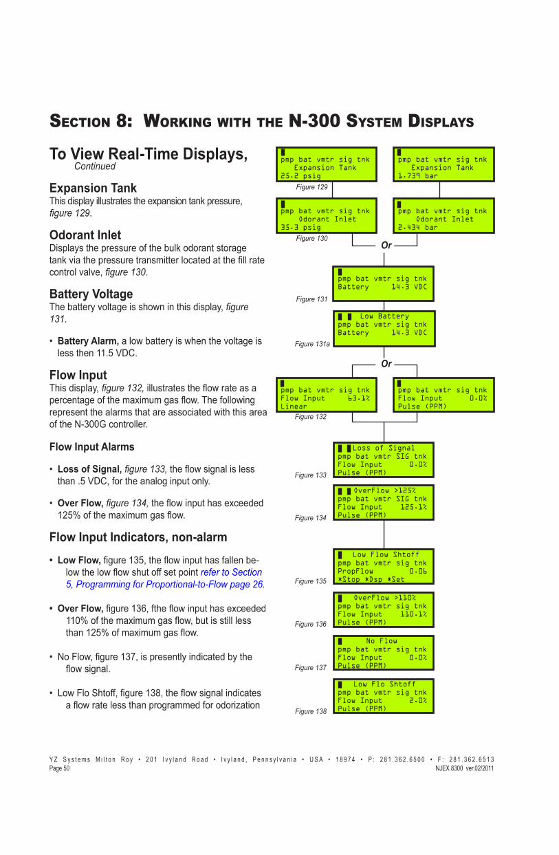
� � � � � � � � � � � � � � � � � � � � � � � � � � � � � � � � � � � � � � � � � � � � � - � � � � � � � � � � � � � � � � � � � � � � � � � � � � � � � � � ! " # � ! # $ � � � � � % � � � � ! " # � ! # $ � "��&�$�� '()*��"�����+!��,����
SECTION 8: WORKING WITH THE N-300 SYSTEM DISPLAYS
Or
To View Real-Time Displays, Continued
Expansion TankThis display illustrates the expansion tank pressure, �������<.
Odorant Inlet@���������������������-��������������������������$���������������������������� ���������������������control valve, �������=.
Battery VoltageThe battery voltage is shown in this display, ��������.
� Battery Alarm, a low battery is when the voltage is ���������YYJZ�[@#J
Flow InputThis display, ��������������������������>!�������������� ������-�������=���������>!J�����-��!���represent the alarms that are associated with this area of the N-300G controller.
Flow Input Alarms
�� Loss of Signal, ��������������>!�������������������JZ�[@#X�-������������������J
�� Over Flow, ��������������>!�����������= ������Y]Z��-�������=���������>!J
Flow Input Indicators, non-alarm� Low Flow, ������Y+ZX�����>!����������-�������-
�!������!�>!������--���������refer to Section ��������""�������������������_��������#
� Over Flow, ������Y+:X�-����>!�����������= ������YY;��-�������=���������>!X�����������������������Y]Z��-���=���������>!J
�� ~�)�!X�������Y+�X���������������� ������������>!������J
�� �!�)�����--X�������Y+�X�����>!���������� �������>!�������������������������-���������
Or
pmp bat vmtr sig tnkBattery 14.3 VDC
pmp bat vmtr sig tnk Odorant Inlet35.3 psig
pmp bat vmtr sig tnk Odorant Inlet2.434 bar
pmp bat vmtr sig tnk Expansion Tank25.2 psig
pmp bat vmtr sig tnk Expansion Tank1.739 bar
���������<
���������=
pmp bat vmtr SIG tnkFlow Input 0.0%Pulse (PPM)
Loss of Signal
pmp bat vmtr sig tnkBattery 14.3 VDC
Low Battery
pmp bat vmtr sig tnkFlow Input 63.1%Linear
pmp bat vmtr sig tnkFlow Input 0.0%Pulse (PPM)
pmp bat vmtr SIG tnkFlow Input 125.1%Pulse (PPM)
OverFlow >125%
pmp bat vmtr sig tnkPropFlow 0.06*Stop *Dsp *Set
Low Flow Shtoff
pmp bat vmtr sig tnkFlow Input 110.1%Pulse (PPM)
OverFlow >110%
pmp bat vmtr sig tnkFlow Input 0.0%Pulse (PPM)
No Flow
pmp bat vmtr sig tnkFlow Input 2.0%Pulse (PPM)
Low Flo Shtoff
����������
�����������
����������
����������
����������
����������
����������
���������:
���������$
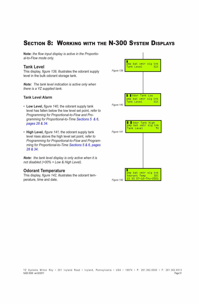
� � � � � � � � � � � � � � � � � � � � � � � � � � � � � � � � � � � � � � � � � � � � � - � � � � � � � � � � � � � � � � � � � � � � � � � � � � � � � � � ! " # � ! # $ � � � � � % � � � � ! " # � ! # $ � "��&�$�'()*��"�����+!��,����
SECTION 8: WORKING WITH THE N-300 SYSTEM DISPLAYS
Note: �����_������������R��������?��������������-�������_�"����R#
Tank LevelThis display, �������<� illustrates the odorant supply level in the bulk odorant storage tank.
Note:��[�����\���?������������������?���R�_��������������{|������������\#
Tank Level Alarm
�� Low Level, �������=� the odorant supply tank level has fallen below the low level set point, refer to �����""�������������������_������-���""�����������������[�"��V���������������������$�����#
�� Z�%'+�}�!^ ��������� the odorant supply tank level rises above the high level set point, refer to �����""�������������������_���������"-"�����������������[�"��V��������������������$�����#
Note:��������\���?���������R�����R�����?��_���������������!������==�����_����������?���#
Odorant TemperatureThis display, ��������� illustrates the odorant tem-perature, time and date.
pmp bat vmtr sig tnkTank Level 51%
pmp bat vmtr sig tnkTank Level 51%
Odor Tank Low
pmp bat vmtr sig tnkTank Level 9%
Odor Tank High
pmp bat vmtr sig tnkOdorant Temp 32C15 55 07-12-Thu-2001
���������<
���������=
����������
����������

� � � � � � � � � � � � � � � � � � � � � � � � � � � � � � � � � � � � � � � � � � � � � - � � � � � � � � � � � � � � � � � � � � � � � � � � � � � � � � � ! " # � ! # $ � � � � � % � � � � ! " # � ! # $ � "��&�$�� '()*��"�����+!��,����
SECTION 8: WORKING WITH THE N-300 SYSTEM DISPLAYS
Notes

� � � � � � � � � � � � � � � � � � � � � � � � � � � � � � � � � � � � � � � � � � � � � - � � � � � � � � � � � � � � � � � � � � � � � � � � � � � � � � � ! # " � ! # $ � � � � � % � � � � ! " # � ! # $ � "��&�$"'()*��"�����+!��,����
SECTION 9: SETTING & TESTING ALARMS
Or
Or
Setting Alarm Out Status������������� ����� �������������������������!�� ������������ ��$�������������������� �� ��� ������TB1X����������#17����#18, refer to the Wiring Control Document on page 116 in Appendix D. ���������������������������������������-���=��-ple, pump alarms.
CAUTION: Alarm outputs are critical for monitoring system per-formance. Outputs should not be disabled except for testing/troubleshooting.
Choose *Set��������������X� ��������.
Choose *Par���������������������������� ������X� ��������.
Choose *Flow or *Time�������������������������X� ���������#
Choose *Alarm�-���������������%�%���������������%�%)�!����X� ��������#
Choose *Set�-���������������������������X� �������:#
To set the pump alarm status, �������$�����������release the Select����J�������������$�����!����>����!��������� ���J�B�������Down Arrow or Up Arrow ������� ���������������J�����������Enter key to ���������������������J�������������!��������>���-���!��������������$��������������������������J�����������Down Arrow���������$� ���������=��parameter.
To set the battery alarm status, �������<� press ���������������Select����J������������$�����!�����������>����!��� ���J��B�������Up Arrow or Down Arrow�������� ���������$����J���������!�$������������� ���X�����������Enter key to store �����!�$�������������J�������������$�����!��������>������!����������������������������J������������Down Arrow���������$� ���������=��parameter.
Or
pmp bat vmtr sig tnkProportional to Flow*Set *Alarm * Esc
pmp bat vmtr sig tnkProportional to Time*Set *Alarm * Esc
����������
pmp bat vmtr sig tnkPropFlow Idle*Strt *Dsp *Set
pmp bat vmtr sig tnk Set Selection*Par *Cal *Esc
pmp bat vmtr sig tnk Set Parameters*Flow *Time *Esc
pmp bat vmtr sig tnkAlarm Output Status*Set *Test *Esc
SelectEnter
pmp bat vmtr sig tnk Pump Alarm Enabled
pmp bat vmtr sig tnk Pump Alarm Disabled
pmp bat vmtr sig tnk Battery Alarm Enabled
pmp bat vmtr sig tnk Battery Alarm Disabled
SelectEnter
����������
����������
����������
���������:
���������$
���������<

� � � � � � � � � � � � � � � � � � � � � � � � � � � � � � � � � � � � - � � � � � � � � � � � � � � � � - � � � � � � � � � � � � � � � � �� � � � � � � � � � � � � � � � ! " # � ! # $ � � � � � % � � � � ! " # � ! # $ � "��&�$�� '()*��"�����+!��,����
SECTION 9: SETTING & TESTING ALARMS
Setting Alarm Out Status, Continued
To set the Verometer alarm status, �������=� press ���������������Select����J������������$�����!�����������>����!��� ���J��B�������Up Arrow or Down Arrow�������� ���������$����J��������!�$������������� ���X�����������Enter key to store �����!�$�������������J������������$�����!��������>������!����������������������������J�����������Down Arrow���������$� ���������=��parameter.
To set the Signal alarm status, �������������������release the Select����J������������$�����!�����������>����!��� ���J�B�������Up Arrow or Down Ar-row�������� ���������$����J��������!�$���������been chosen, press the Enter key to store the new $�������������J�������������$�����!��������>���-���!����������������������������J�����������Down Arrow���������$� ���������=�����������J
Note: this alarm window option will only display if you have chosen the Proportional-to-Flow path.
Note: this option should only be active if your system was supplied with a YZ skid mounted odorant storage tank.
To set the Tank alarm status, �������������������release the Select����J�������������$�����!�����������>����!��� ���J��B�������Up Arrow or Down Arrow�������� ���������$����J���������!�$�����has been chosen, press the Enter key to store the �!�$�������������J�������������$�����!��������>������!����������������������������J��������the Down Arrow���������$� ���������=�������-eter.
pmp bat vmtr sig tnk Verometer Alarm Enabled
pmp bat vmtr sig tnk Verometer Alarm Disabled
SelectEnter
���������=
pmp bat vmtr sig tnk Signal Alarm Enabled
pmp bat vmtr sig tnk Signal Alarm Disabled
SelectEnter
pmp bat vmtr sig tnk Tank Alarm Enabled
pmp bat vmtr sig tnk Tank Alarm Disabled
SelectEnter
����������
����������

� � � � � � � � � � � � � � � � � � � � � � � � � � � � � � � � � � � � � � � � � � � � � - � � � � � � � � � � � � � � � � � � � � � � � � � � � � � � � � � ! # " � ! # $ � � � � � % � � � � ! " # � ! # $ � "��&�$$'()*��"�����+!��,����
SECTION 9: SETTING & TESTING ALARMS
Testing Alarm Out Status��������������������$���������������!������� ��$�������������������� �� ��� ������TB1X����������#17����#18, refer to the Wiring Control Document on page 116 in Appendix D. You may test the alarm out-���������������� ���������Alarm SwitchTest op-������!X� ��������, or you may choose to Simulate ��� �� �������������������������������� ������!���J
Choose *Set��������������X� ��������.
Choose *Par���������������������������� ������X� ��������.
Choose *Flow or *Time�������������������������X� ��������.
Choose *Alarm�-���������������%�%�������)�!�menus, ��������.
Choose *Test�-���������������������������X� �������:#
Choose *SW��������!�� ��"�������������X� ��������$#
To activate the Alarm Test Switch, ��������<, ���������������������Select����J�������������$�����!����>����!��������� ���J��B�������Down Arrow or Up Arrow�������� ���������������J��ON / Relay Open���� ��������������������������������������J�OFF / Relay Closed���� �������������������������-�������J�����������Enter����������������������������J�����������������������Alarm Test Mode, �������������������!����>������������������������� ����� �����'�������!�����SELECT /ENTER��!�� �J��������������!��������>������!��������������$��������������������������J�����������Up Arrow key to ��$� �����������������!�� ��"��������� menu.
Choose *Sim��������!�� ��"�������������J������������������������������������X��������������������!����>������������������������� ����� �����'�������!�the SELECT / ENTER��!�� �J�����������~%�������������������������X���������������������!����>������������� ������������� ����� �����'�������!�����Down Arrow key.
Or
pmp bat vmtr sig tnkProportional to Flow*Set *Alarm * Esc
pmp bat vmtr sig tnkProportional to Time*Set *Alarm * Esc
����������
pmp bat vmtr sig tnkPropFlow Idle*Strt *Dsp *Set
pmp bat vmtr sig tnk Set Selection*Par *Cal *Esc
pmp bat vmtr sig tnk Set Parameters*Flow *Time *Esc
pmp bat vmtr sig tnkAlarm Output Status*Set *Test *Esc
����������
����������
����������
���������:
pmp bat vmtr sig tnkSwitch / Simulation*Sw *Sim *Esc
pmp bat vmtr sig tnk Alarm Switch Test ON / Relay Open
pmp bat vmtr sig tnk Alarm Switch Test Alarm Relay Closed
���������$
���������<
���������<

� � � � � � � � � � � � � � � � � � � � � � � � � � � � � � � � � � � � - � � � � � � � � � � � � � � � � - � � � � � � � � � � � � � � � � �� � � � � � � � � � � � � � � � ! " # � ! # $ � � � � � % � � � � ! " # � ! # $ � "��&�$#� '()*��"�����+!��,����
SECTION 9: SETTING & TESTING ALARMS
Testing Alarm Out Status, Continued
To Simulate the pump alarm status, ��������=� ���������������������Select����J������pmp Alarm ��� ������������������-�������-�����~%+;;����������!����>����!������������� ���J��B�������Down Arrow or Up Arrow�����������������!�� �������-���������������� ��$���J������!���������!��������������� ����-��������=����Over Pump, Under Pump, or Pump Failure���=������������-�����~%+;;���������X��������PMP���� ����!�������������������B�����#�������-����X����!����>��������--J�����������Enter key to ������������������������� ���� ���J��������������!��������>�����J������������Down Arrow���������-$� ���������=��������������J
To Simulate the battery alarm status, ���������� ���������������������Select����J������bat alarm ��� ������������������-�� ����������-�����~%+;;����������!����>����!������������� ����J��B�������Down Arrow or Up Arrow�������������������Low Battery �����J������!���������!��������������� ��������-����=����Low Battery���=������������-�����~%+;;���������X��������BAT���� ����!����!����������������B�����#�����������X����!����>��������--J������������Enter�������������������������������� -���� ���J��������������!��������>�����J������������Down Arrow���������$� ���������=��������������J
To Simulate the verometer alarm status, ��������������������������������Select����J������vmtr ��������� ���������������� ����������-�����~%+;;����������!����>����!������������� ���J��B�������Down Arrow or Up Arrow�����������������!�� �������-��[������������������������J������!���������!��������������� ������������=����Odor Inlet-Cabl, Odor Inlet Lo, Odor Inlet Hi, XTank-Cable, XTank Low, XTank High, Flvalve-Fail, Leakage, Slow Fill, No Fill, or Vmtr-CableX���=�������������-�����~%+;;���������X��������VMTR���� ����!����!����������������B�����#�����������X����!����>��������--J������������X����������������!�[��������Q�� ����X��}���!!����Fillrate, that are non-alarms may be �������������������������J������!���������� ������������������ ���������~%+;;���������X�����!��������$������������� ������������=��������X����the vmtr ��� ����!�������������������!��� ���X�
pmp bat vmtr sig tnk Pump Alarm Simulate
���������=
pmp bat vmtr sig tnk Battery Alarm Simulate
pmp BAT vmtr sig tnk Battery Alarm Simulate
Low Battery
pmp bat vmtr sig tnk Verometer Alarm Simulate
pmp bat VMTR sig tnkAlarm Output Status*Set *Test *Esc
XTank High
pmp bat VMTR sig tnkAlarm Output Status*Set *Test *Esc
Vmtr-Cable
pmp bat VMTR sig tnkAlarm Output Status*Set *Test *Esc
No Fill
pmp bat VMTR sig tnkAlarm Output Status*Set *Test *Esc
Slow Fill
pmp bat VMTR sig tnkAlarm Output Status*Set *Test *Esc
Leakage
pmp bat VMTR sig tnkAlarm Output Status*Set *Test *Esc
Flvalv-Fail
pmp bat VMTR sig tnk Verometer Alarm Simulate
Odor Inlet-Cable
pmp bat VMTR sig tnk Verometer Alarm Simulate
Odor Inlet Low
Odor Inlet Hipmp bat VMTR sig tnk Verometer Alarm Simulate
pmp bat VMTR sig tnk Verometer Alarm Simulate
XTank-Cable
pmp bat VMTR sig tnk Verometer Alarm Simulate
XTank-Low
PMP bat vmtr sig tnk Pump Alarm Simulate
Over Pump
PMP bat vmtr sig tnk Pump Alarm Simulate
Under Pump
PMP bat vmtr sig tnk Pump Alarm Simulate
Pump Failure
���������=
���������=
���������=
Figure 161 Figure 161
���������� ����������
���������� ����������
���������� ����������
���������� ����������
���������� ����������
����������

� � � � � � � � � � � � � � � � � � � � � � � � � � � � � � � � � � � � � � � � � � � � � - � � � � � � � � � � � � � � � � � � � � � � � � � � � � � � � � � ! # " � ! # $ � � � � � % � � � � ! " # � ! # $ � "��&�$�'()*��"�����+!��,����
SECTION 9: SETTING & TESTING ALARMS
����!���� �������>����--����J������������Enter ������������������������������� ���� ���J��������������!��������>�����J������������Down Arrow key ����$� ���������=��������������J
To Simulate the Signal alarm status, ���������� ���������������������Select����J������sig����������- ������������������-�������-�����~%+;;����������!����>����!��������� ���J��B�������Down Arrow or Up Arrow�����������������!�� �������-�����������������������J������!���������!��������������� ��������-����=����Over Flow > 125%, or Loss of Signa����=�������������-�����~%+;;���������X���������SIG���� �-���!����!����������������B�����#�����������X����!����>���������--J��������������������������������������Q�� ����X�OverFlow >110%, No FlowX����Low Flo ShtoffX�����������%������������������-���������������������J������!���������� ������������������ ���������~%+;;���������X�����!��������$������������� ������������=��������X��������sig ��� ����!�������������������!��� ���X�����!���� -�������>��������--J�����������Enter key to return ������������������� ���� �������������������!��������>�����J������������Down Arrow���������$� ���������=��������������J
To simulate the Tank alarm status, ���������� ���������������������Select����J�����tnk alarm ��� ������������������-�������-�����~%+;;����������!����>����!��������� ���J��B�������Down Arrow or Up Arrow�����������������!�� �������-���������������������J������!���������!��������������� ��������-����=����Odor Tank Low, or Odor Tank High���=������������-�����~%+;;���������X���������TNK���� �-���!����!����������������B�����#�����������X����!����>��������--J�����������Enter key to return to ����������������� ���� ���J��������������!��������>�����J��
pmp bat vmtr sig tnk Signal Alarm Simulate����������
����������
PMP bat vmtr SIG tnk Pump Alarm Simulate
OverFlow >125%
PMP bat vmtr sig tnk Pump Alarm Simulate
OverFlow >110%
PMP bat vmtr sig tnk Alarm Simulate
Loss of Signal
PMP bat vmtr sig tnk Pump Alarm Simulate
No Flow
PMP bat vmtr sig tnk Pump Alarm Simulate
Low Flo Shtoff
pmp bat vmtr sig tnk Tank Alarm Simulate
pmp bat vmtr sig TNK Tank Alarm Simulate
Odor Tank Low
pmp bat vmtr sig TNK Tank Alarm Simulate
Odor Tank High
����������
����������
����������
����������
����������
����������

� � � � � � � � � � � � � � � � � � � � � � � � � � � � � � � � � � � � - � � � � � � � � � � � � � � � � - � � � � � � � � � � � � � � � � �� � � � � � � � � � � � � � � � ! " # � ! # $ � � � � � % � � � � ! " # � ! # $ � "��&�$�� '()*��"�����+!��,����
SECTION 9: SETTING & TESTING ALARMS
Setting The Clock����������� � ��������~%+;;������������������������>� ������ ������� ���������������J����������-��������������� ���������$� ������ � ���������������-��� ���������������J������ � �������]\����X��������������X� � ����������-�����������-���������!��������������!���;;N;;����]+NZ�J�Q��������������������������������������� ��� ����������������!���������>� ����-�������� � ��������J�Q-������������$��������X�������������������%���-����'������X��������$��X������� ���������������������������������� � ���������� ��J���� ����������� � ��!������������������������\���������J
Choose *Set��������������X� ��������.
Choose *Cal��������������� ������X� ��������.
Choose *Clk������� ������������� ������X� �������:.
To set the Clock, �������$�����������������������Select����J��)����X���������� ���$�����-������Month !���������>������!��� ���J�B�������Up Arrow ������� ����������$������������Down Arrow key ���� ����������$����J���������!�$�������������chosen, press the Enter key to store the new Month ��������J������������$�����!��������>���-���!����������������������������X�������������� ���Day�-���������$�����!�����������>���J�B�������Up Arrow�������� ����������$������������Down Arrow��������� ����������$����J���������!�Day�$������������� ���X�����������Enter key to store the new Day�����������������Day of The Week�!�����������>���J�B�������Up Arrow key to � ����������$������������Down Arrow���������- ����������$����J���������!�Day of the Week has been chosen, press the Enter key to store the new Day of the Week���������J�~!�����Year�$�����!�����������>���J�B�������Up Arrow�������� ����������$������������Down Arrow��������� ����������$����J��������!�Year has been chosen, press the Enter key to store the new Year���������J�����������!���������!�������-������Hour�-������������������������-��������HourJ�����Hour�$�����!�����������>���J�B�������Up Arrow�������� ����������$�����
����������
pmp bat vmtr sig tnkPropFlow Idle*Strt *Dsp *Set
pmp bat vmtr sig tnk Set Selection*Par *Cal *EscFigure 166
pmp bat vmtr sig tnk Calibration Set*Clk *Inputs *Esc
pmp bat vmtr sig tnkSet Date and Time12:07 07-12-Thu-2001
���������:
���������$

� � � � � � � � � � � � � � � � � � � � � � � � � � � � � � � � � � � � � � � � � � � � � - � � � � � � � � � � � � � � � � � � � � � � � � � � � � � � � � � ! # " � ! # $ � � � � � % � � � � ! " # � ! # $ � "��&�$�'()*��"�����+!��,����
SECTION 9: SETTING & TESTING ALARMS
�������Down Arrow��������� ����������$����J���������!�Hour has been chosen, press the Enter key to store the new Hour���������J����������Minutes��-��������Hour�!�����������>���J�B�������Up Arrow�������� ����������$������������Down Arrow �������� ����������$����J���������!�Minute�$�����has been chosen, press the Enter key to store the �!����������������J������� ����������#� ����������� ��J�����������Up Arrow���������������������������������������J

� � � � � � � � � � � � � � � � � � � � � � � � � � � � � � � � � � � � - � � � � � � � � � � � � � � � � - � � � � � � � � � � � � � � � � �� � � � � � � � � � � � � � � � ! " # � ! # $ � � � � � % � � � � ! " # � ! # $ � "��&�#�� '()*��"�����+!��,����
SECTION 9: SETTING & TESTING ALARMS
Notes

� � � � � � � � � � � � � � � � � � � � � � � � � � � � � � � � � � � � � � � � � � � � � - � � � � � � � � � � � � � � � � � � � � � � � � � � � � � � � � � ! " # � ! # $ � � � � � % � � � � ! " # � ! # $ � "��&�#�'()*��"�����+!��,����
SECTION 10: MECHANICAL SYSTEM
OverviewThe 8300G mechanical system, ��������<���:=�����:������� ������-��������������������X�����$��$�X�Verometer, 8000 pump, odorant discharge manifold, ~��������������������X����������-��X�������� ����������-��X���������=��������J��Q��$������components of the system are shown below and de-scribed in the following pages.
Expansion Tank
75 - 90 PSI (5.17- 6.20 BAR) REGULATED ACTUATION GAS
ODORANT INLETCONNECTION
ODORANT DISCHARGE MANIFOLD PIPELINE PORT
��������:�
��������:=
���������< Bulk Odorant Filter
Actuation Gas Regulator

� � � � � � � � � � � � � � � � � � � � � � � � � � � � � � � � � � � � � � � � � � � � � - � � � � � � � � � � � � � � � � � � � � � � � � � � � � � � � � � ! " # � ! # $ � � � � � % � � � � ! " # � ! # $ � "��&�#�� '()*��"�����+!��,����
SECTION 10: MECHANICAL SYSTEM
Odorant Inlet Manifold & Bulk Odorant Filter Assembly�����������������-��������������������������-bly, ������:�, is located adjacent to each pump / $�����������������������-��������-��!���-� -tions:
�� ��$������������������������������ � ������������-���Y"\��)~��� � ���� ����������back of the enclosure.
�� ��$�������������������������!�������������pressure from storage tank.
�� ��$��������������������������$��$�J
�� ?��������������-��!��������������������!�����the 8300G System.
�� � ������������������������-����������������purge operations, ��������&�����������_������������V��������������:�#
Q������$����������������������������������� ��������X����������������������������������$�������J
Fill Valve�����������-���������$��$������� ���������>!�into the Verometer, ������:�J����������$��$����������!������������ �������-�������������$��$�����-���������������������$��$�����������J������$��$����� �����!�������������� �������������$��������������$��$������������������� �� ��$��$��!�-���to its seat. The transfer of odorant from the bulk stor-��������������[�������X�!��������$��$������ ��$��-ed, is dependant on an adequate pressure differential between the bulk storage tank and the Verometer, with the bulk storage tank retaining the higher of the two pressures. These pressures are monitored by two pressure transmitters mounted in the system. One transmitter monitors the incoming pressure from the bulk storage tank, while the other, mounted on the ex-��������X��������������������������$�������J�����--����������������������-�Z�%�Y;������#������#�<����� must be present, with the differential not exceed-ing either end of the range.
��������:�
��������:�

� � � � � � � � � � � � � � � � � � � � � � � � � � � � � � � � � � � � � � � � � � � � � - � � � � � � � � � � � � � � � � � � � � � � � � � � � � � � � � � ! " # � ! # $ � � � � � % � � � � ! " # � ! # $ � "��&�#"'()*��"�����+!��,����
SECTION 10: MECHANICAL SYSTEM
��������:�
������������������ � �������������$��$�����!��� ���������� �� ��$��$��!�-��X������������X����o-ring seal without disturbing the diaphragm and its seals.
VerometerThe purpose of the Verometer, ������:�, is to act ���������������X�$���-�������������-��'� ��������J������[�������� ���������$������������$� �����!�������~%+;;�� ��������� ����������actual amount of odorant injected to the displacement �������-���������J�����~%+;;������ ���������������[������������ ��$���������[��������������-� ����������������-���������$������������$� �J
����������������[��������-�����������$��$�J�Odorant exits the Verometer by passing through a �� ��������������������!�������������J������������������������������� ��������������������� ������������bottom of the Verometer.
���������������-�����[�������X���$��������-���>������$��X���� � �����������=������������stainless steel tubing and the odorant discharge mani--��J��������������-������� �����������N
1. The Verometer / expansion tank connection ��$������� ���������������!�� �����$����odorant escape into the atmosphere.
]J� �������[����������������X�����������������!�����the closed Verometer / expansion tank system. �������������$�������$�������������=������������$��������� ������������������������Verometer from equaling the blanket gas pressure in the odorant storage tank. This ensures an un-�����������>!�-������-������������������to the Verometer.

� � � � � � � � � � � � � � � � � � � � � � � � � � � � � � � � � � � � � � � � � � � � � - � � � � � � � � � � � � � � � � � � � � � � � � � � � � � � � � � ! " # � ! # $ � � � � � % � � � � ! " # � ! # $ � "��&�#�� '()*��"�����+!��,����
SECTION 10: MECHANICAL SYSTEM
Model 8000 PumpThe NJEX 8000 pump,� ������:���is a pneumatically � ������X������$�������� ����X��� ��� ������������pump. The 8000 is actuated with compressed air or pipeline gas at a pressure of 30 - 90 psi ��#=:����#�=�����, ��������V������������VR���"���_�V���"������ ��������������. The pump has an adjustable ������ �����-�:J; X��ZJ; X��\J; X��+J; X����]J; J���Q��� ���$�����������%�%>!��'� ����������adjustment of the stroke rate. The 8000 is rated for a maximum stroke rate of 30 strokes per minute.
Each time the pump strokes, the plunger displaces �������� �>�����������������������������X�!�� ����turn displaces odorant through the discharge check $��$�J���������������������� �����������������$� �����!��������������� �>���������������X�minimizing the risk of odorant escape into the atmo-sphere. Each time the plunger returns, it completely ���$��������-�-������������������J����������!������������������������������� �������������$����J
Odorant Discharge ManifoldThis manifold is located on the back wall of the �� ��� ���� �����X�'������������-��-�����$���-����������$����������X� ������:�. This manifold, located inside the enclosure, has three connections on the bottom of the manifold. The inlet connection in the center of the manifold is the pump discharge, the connection to the right is to the Verometer and the third connection to the left is to the purge bypass loop. ����������������� � �������-� �����������������-ate component.
Three outlet ports for the odorant discharge manifold are located on the back of the manifold and extend through the enclosure wall. When facing the back of the enclosure from right to left, these ports are for the expansion tank drain, the pipeline connection, and the expansion tank pressure connection.
��������:�
��������:�

� � � � � � � � � � � � � � � � � � � � � � � � � � � � � � � � � � � � � � � � � � � � � - � � � � � � � � � � � � � � � � � � � � � � � � � � � � � � � � � ! " # � ! # $ � � � � � % � � � � ! " # � ! # $ � "��&�#$'()*��"�����+!��,����
SECTION 10: MECHANICAL SYSTEM
��������::
�!�$��$���� �������������-��� ��������>!�-�the odorant blanket gas through the manifold. The $��$��� ������������-�X�!�����������������������������$��$�X���������V���������VR���"�]��������������:����������<:��?��?��V3J������$��$�X�!��������������X���������������$��$�X���������V���������VR���"�]���������������:����������<:��?��?��V2. During �����������X�����$��$������� ����J�������������$��$�����������������������+;;��-�����X���������V���������VR���"�]���������������:����������<:�!���������������$��$������������������-����-paring the system for operation ��������V���������VR���"�]��������������$=����������==#
����������!�-��� �� ��$��$�����������������������discharge manifold. The wafer is located on top of the plug that is inserted in the bottom of the manifold. This �� ��$��$������ �����������>������������!�������pump discharge connection and the pipeline connec-tion port.
The gage located on top of this manifold displays the Expansion Tank pressure.
NJEX Gas Filter��]Z��� �� ���� ��������������$�����!������ ���+;;�J������������X� ������::� is installed on the back outside of the enclosure and should be connected to the regulated �:��<=�����~��#�:��#�=����� actuation gas ���������$�������������������������J����� ����-ing the incoming actuation gas, a clean pneumatic �������!���������$�����������������$��$��J�������will ensure a longer operational life for the pneumatic control system. If the actuation gas supply has a high water content and / or a low hydrocarbon dew point, ���������������������������-������ ������������������������� ������J��������������� ������be used as an alternate gas supply source if gas conditioning is a problem.

� � � � � � � � � � � � � � � � � � � � � � � � � � � � � � � � � � � � � � � � � � � � � - � � � � � � � � � � � � � � � � � � � � � � � � � � � � � � � � � ! " # � ! # $ � � � � � % � � � � ! " # � ! # $ � "��&�##� '()*��"�����+!��,����
SECTION 10: MECHANICAL SYSTEM
Solenoid Valve & Pneumatic Relay Manifold�!��!��!���������$��$�������������������manifold, ������:$J�����������$��$�X�SV2 located �������-�X�� ���������������$��$�X�!�����������������-���$��$�X�SV1 located on the right, pilots the pump ������� �������$��$�J��
���������� �������$��$������������������������-��J�Q������ �����'�������!�����������$��$���������$������ ���������������!�������� ��$��������-���� �������-��������������������� ���������������$����paragraph.
Supply and exhaust ports are located on the outside of the manifold to permit operator connections on the back of the system enclosure.
����������X����������������� ����$��$���� �����on this manifold, V4 lower right with a gold knob, V5 upper center with a green knob, and V16 lower left !��������� ����J�[��$��V4 is normally closed, but is opened to charge the expansion tank with gas as ����������������������������������������� ���J���-��������X�$��$��V5 is normally closed, but is opened ��$�����������-��������=���������-�������-nance. Finally, V16 is normally open, and is the supply �����������$��$�J��
Expansion TankThe expansion tank, ������:<���is mounted on the back of the enclosure and acts as a pressure source �����--���-������[�������J���������[��������������������������X������������>!����������-������=��������������������J���� �����-�����������$������������--��� ��������$������-�����[����������������=��������X�����>� ��������������������-sure within this system is minimal.
(�����������=������������N���������-�$��$�X�����������Z�������#$������}�����������������X���$���$��$�¦�������=����������������$��$�J������ � �������������-��������X�$��$��V14, is used to connect the expansion tank to the bypass loop.
[��$��V14 is normally closed, but can be opened as an optional step in the forward purge process to purge ����������-��������=��������������������$��accumulated, and place it back into the bulk storage tank.
��������:$
��������:<
Expansion Tank

� � � � � � � � � � � � � � � � � � � � � � � � � � � � � � � � � � � � � � � � � � � � � - � � � � � � � � � � � � � � � � � � � � � � � � � � � � � � � � � ! " # � ! # $ � � � � � % � � � � ! " # � ! # $ � "��&�#�'()*��"�����+!��,����
SECTION 11: SYSTEM OPERATION
Setting System Pressures and ValvesBefore attempting to start the system, check for proper valve positions as indicated on the normal operation schematic on the enclosure door, and set all pressures accordingly, ������$=.
1. Adjust supply gas regulator to provide 75 psi ��#�:������������~�������������J��;����J*:J]Y����,�!����be required for this pressure if the pipeline pres-��������$���Y;;;����J
]J� ��������������$��$��V4������������=������������ �����������-�]Z�������#:������ then close V4.
+J� [���-���!���������������-�������������'��������� ��������������������� �� ����������-�]Z������#:������.
4. Adjust the pump actuation regulator to the re-quired pressure to inject into pipeline pressure as indicated on the normal operation schematic located on the enclosure door.
5. Adjust the blanket gas regulator for the bulk stor-age tank.
:J� #�� ���������������-���������������$���-�������the set pressures remain constant.
Low Pressure Relief Adjustment����$��>!����� ��X� ������$���� �����������!�pressure relief in the cap assembly for the purpose of ���������������=������=���������������������]Z�������#:������.
������������'����-��!������������N
1. With valve V6���X���!������$��$��V4 until ������������� �����������=����������-�����$��>!����� ��J
]J� #����$��$��V4��������!�������������������������!�� �����������]Z�������#:������.
+J� Q-���'���������������N � �,� )����X�������'�������� ����X�� ��������
�������-�����$��>!����� ��J���� ������pressure in the tank, turn the adjustment � ��!�� �X��������������J�����!���������������X������ ������'�������� ��!���X���to the left.
� �,� ������������ ����J
� ,� ���������������������������������-�]Z�������#:����������������������� �������������]�above.
��������$= Valve V4
��������$�

� � � � � � � � � � � � � � � � � � � � � � � � � � � � � � � � � � � � � � � � � � � � � - � � � � � � � � � � � � � � � � � � � � � � � � � � � � � � � � � ! " # � ! # $ � � � � � % � � � � ! " # � ! # $ � "��&�#�� '()*��"�����+!��,����
SECTION 11: SYSTEM OPERATION
Starting The System�������������!����!�� �X�� ���������������~%+;;��� �����X� ������$�J���� ���������!�� �X��������������!�����������$���� ���������������������of the ~%+;;��� �����J������� �� �������������������~%+;;��� �����X�������"��--��!�� ������ �����������!�������������J�)���������!�� ��������������������!���J
� ������~���������������!����%��X�����-��!��������!������������������#@�� ���������~%+;;�� ������X�-��!������ ������$����J�
�� �����$�������#@�� ����������������Serial Num-ber and Model Type���!���� ������Serial Num-ber and Model Type on the inside of the enclosure door, �������$�.
�� [���-��Verometer Calibration Number matches the Verometer tag number located at the top of the Verometer assembly, ������$�.
�� )��-��������-��� �X��� �������Version x.xx num-ber, ������$�� on the ���������������"���������������*�����+�&�����������"������������.
IMPORTANT: ���������������"!����"�����R���������?��"����������"!���������"��������������������"!���������������������==�������������������������R�!���������������������#
Press the Down Arrow key four times to scroll the display menu to the Meter Level display, ������$�.
Press the Select / Enter key to choose the *Fill com-mand, ������$�J�������������$�����������!������!�����[����������$���������������������$����������Y;;�X� ������$:#
Note:��������� �����"�R���\������"�����#��*�U�������� ��������������� �������������?��?��V9#��*������������ ������ ����R������������\���������������"����#
����$��$��V3 and use the Test key to stroke the ��������������-�];������J����������������������be necessary if the pump displacement is restricted !�������������������� ��J
��������$�
pmp bat vmtr sig tnk Serial Number 00000
pmp bat vmtr sig tnk Model Type 8300G
pmp bat vmtr sig tnk Verometer Calibrate 000.00 calibrate cc
pmp bat vmtr sig tnk N-300G Ver 0.00 -NJEX-
pmp bat vmtr sig tnkPropFlow Stop*Start *Dsp *Set
pmp bat vmtr sig tnk Fill Verometer?*No *Yes
S1
pmp bat vmtr sig tnk Meter Level 000%*Fill
pmp bat vmtr sig tnkDisplay Contrast Adj42% 22
��������$�
��������$�
��������$�
��������$�
��������$:
��������$�
���� �Enter

� � � � � � � � � � � � � � � � � � � � � � � � � � � � � � � � � � � � � � � � � � � � � - � � � � � � � � � � � � � � � � � � � � � � � � � � � � � � � � � ! " # � ! # $ � � � � � % � � � � ! " # � ! # $ � "��&�#�'()*��"�����+!��,����
SECTION 11: SYSTEM OPERATION
��������$$
pmp bat vmtr sig tnkPropFlow Stop*Start *Dsp *Set
��������$$
pmp bat vmtr sig tnk Meter Level 000% Filling
SelectEnter
pmp bat vmtr sig tnk Proportional to?*Flow *Time *Esc
pmp bat vmtr sig tnk Start Pump?*Yes *No *Esc
pmp bat vmtr sig tnkProp Flow/Time 0:00:00*Stop *Dsp *Set
pmp bat vmtr sig tnkTime/Stroke Calculated Exceeds minimum
pmp bat vmtr sig tnk Stop Pump?*Yes *No *Esc
��������$<
��������<=
��������<� ��������<�
��������<�
���� ������������[����������$�������������-���$��J�#����$��$��V3 and press the Up Arrow key four times to return to the main menu.
#��������*Start entry from the main menu, �������$$J�������������$�����������!������� ��������[���-�������$����������$������������������Y;;�J
~�=�X� ������������-����������������������%�%)�!���������������X�-������������ *Flow or *Time entry, ������$<#
Note: ����*Time�����_��������������������!�������������"������?�������������������V�������������"�"�����������������[�"��K�����������������[�"������?���!��_������\�����������"�###.
���������������������������*Yes entry, ������<=.
Q-����� �� ������������"�����������������������minimum, the Time / Stroke Calculated Exceeds Minimum���������!����������X����������������!����not start, ������<�. ��������V��������������:�������������_�]����V������K�����������������"�����������������������������"��������������@>G�$�==��VR���"#
����Prop Flow / Time x:xx:xx��������������-��!�X� ������<�����$������� ����!��������=�������stroke.
To Stop The System��������������X�������Prop Flow/Time x:xx:xx display, ������<�� press the *Stop�����J������-��!-ing Stop Pump display, ������<�� then provides the option to press the *No or *Yes entry. Press the *Yes entry to stop the pump.

� � � � � � � � � � � � � � � � � � � � � � � � � � � � � � � � � � � � � � � � � � � � � - � � � � � � � � � � � � � � � � � � � � � � � � � � � � � � � � � ! " # � ! # $ � � � � � % � � � � ! " # � ! # $ � "��&���� '()*��"�����+!��,����
SECTION 11: SYSTEM OPERATION
Notes

� � � � � � � � � � � � � � � � � � � � � � � � � � � � � � � � � � � � � � � � � � � � � - � � � � � � � � � � � � � � � � � � � � � � � � � � � � � � � � � ! " # � ! # $ � � � � � % � � � � ! " # � ! # $ � ���&���'()*��"�����+!��,����
SECTION 12: SYSTEM MAINTENANCE
Preventative Maintenance ScheduleA preventative maintenance program serves to an-ticipate maintenance issues prior to waiting until the �������������������$� �J������ ����������������������in an automobile, by choosing to service the various parts and operation in the NJEX System at regular intervals, the technician can perform the maintenance service when desired, rather than when required, such as in the middle of night.
The key is to perform maintenance before it is re-quired. The preventative maintenance schedule implemented should consider the application of the odorizer. Many of these considerations include: the weather environment; the condition of, the actuation gas, the odorant and the odorant bulk storage tank, and the pump stroke frequency. All of these issues must be considered when establishing a preventative maintenance schedule.
Recommended Maintenance ScheduleWeekly Inspection
1. Verify gas pressures2. Check for gas and odorant leaks3. Examine the oil level in the pump4. View the N-300G Controller for alarm indications
Semi-Annual InspectionYJ� Q��� ��$��>!����� ���������$� ����������]J� Q��� �����������������$��$���� �����-�������J
Annual InspectionYJ� #�����������2. Rebuild pump3. Replace solenoids4. Test the relief valve and service, as needed5. Test regulators and service, as needed6. Condition the odorant, as needed.7. Test the NJEX System performance
Bi-Annual Inspection1. Perform the annual inspection listed above2. Replace the battery3. Replace pneumatic relay valve
Recommended Spare Parts ListPart # Description Recommended QuantityA4-0010 3-way solenoid valve 2A3-0290 Pneumatic relay valve 1#\%;Y++� ~������������������� ������ ������������� Y@+%;Y;+� ���������������������� replacement kit 1D3-0102 Model 8000 pump seal replacement kit 1@+%;Y]:� [������������������������� YD2-0001 NJEX pump oil, 16 oz. pint 1

� � � � � � � � � � � � � � � � � � � � � � � � � � � � � � � � � � � � � � � � � � � � � - � � � � � � � � � � � � � � � � � � � � � � � � � � � � � � � � � ! " # � ! # $ � � � � � % � � � � ! " # � ! # $ � "��&���� '()*��"�����+!��,����
SECTION 12: SYSTEM MAINTENANCE
�}��=�>�������������"�!# Inspection����$��>!����� ������������������������� ����as follows on each NJEX System in operation, �����194:
1. Isolate the protector by closing valve V6 located '�������!�����$��>!����� ���������=�����tank.
2. Slowly remove the protector upper housing, item A, by unscrewing it from the protector lower valve body, item B.
3. Inspect the dart and o-ring seal, item C, located in the upper body. It should not be sticky or unusu-ally shaped. If any distortion to this o-ring is found ����������������� ��������������J��������������o-ring will exhibit a slight interference between the dart and the o-ring when in contact with each other. This contact is what causes the seal when necessary.
4. Inspect the cap to body o-ring, item D, and lubri-cate or replace as necessary.
5. Inspect the reset push button. When pushed in, the button should depress, then spring back freely. If any sticking occurs, the o-ring, item E, should be lubricated.
:J� ������������������� ��������������X��������-sure that the dart is fully inserted into the housing contacting the o-ring seal. Second, install the upper housing onto the lower body, assuring that the cap comes to a full seated position against the protector lower body.
7. Depress the Reset button to reset the dart.
8. Slowly open valve V6 below the protector.
9. The Reset ����������������-�����$��>!�protector is utilized to test the function of the low ��������������-����������������$��>!�����J�Pressing this button will over-ride the low pressure �����-���������$��>!����� �������J�
��������<�
Valve V6
D
C
B
A
E

� � � � � � � � � � � � � � � � � � � � � � � � � � � � � � � � � � � � � � � � � � � � � - � � � � � � � � � � � � � � � � � � � � � � � � � � � � � � � � � ! " # � ! # $ � � � � � % � � � � ! " # � ! # $ � ���&��"'()*��"�����+!��,����
SECTION 12: SYSTEM MAINTENANCE
Note:�[����������!�����������!R�����"����������������������������!����#��&�������������_�R��!���������������"�R����������������+�������\�����!������_����� �����_��������#��K����� ����������+�������\���������"��������""������������������#
+�>��������$�!��_������"�������$��>!����� ���� �����������!����������relief in the cap assembly for the purpose of maintain-ing the maximum expansion tank pressure at 25 psi ��#:������.
To test and adjust follow these steps:
1. With valve V6 open, ������<�, slowly open valve V4, ������<�, until gas begins discharging at exhaust port.
2. Close valve V4 and see where pressure stabilizes which should be 25 psi ��#:������.
3. If adjustment is needed: a) First, loosen adjustment lock nut, located
����-�����$��>!����� ��J���� ������pressure in the tank, turn the adjustment screw in, or to the right. To lower pressure tank, turn the adjustment screw out, or to the left.
b) Tighten lock nut.
c) Repeat until the desired pressure of 25 psi ��#:������ is obtained as described in in step 2 above.
Valve V4��������<�
��������<�
������"���lock nut
������"�������>

� � � � � � � � � � � � � � � � � � � � � � � � � � � � � � � � � � � � � � � � � � � � � - � � � � � � � � � � � � � � � � � � � � � � � � � � � � � � � � � ! " # � ! # $ � � � � � % � � � � ! " # � ! # $ � "��&���� '()*��"�����+!��,����
SECTION 12: SYSTEM MAINTENANCE
)��������%�?��>������%���������<:
1. Place the NJEX System in ������# mode by pressing the ������# key on the N-300 controller.
2. Close valves V8 and V6
3. Open valve V4 until pressure reaches 50-60 psi (3.4-4 Bar) in the expansion tank, then close valve V4.
4. Scroll to the Meter Level display on the N-300 controller
5. Open valve V2 until: a) Empty is indicated in the Meter Level display And
b) Gas bubbling in the bulk odorant storage tank becomes audible.
6. Close valve V17
7. Proceed to the Venting Pressure Gas procedure on �����:�.

� � � � � � � � � � � � � � � � � � � � � � � � � � � � � � � � � � � � � � � � � � � � � - � � � � � � � � � � � � � � � � � � � � � � � � � � � � � � � � � ! " # � ! # $ � � � � � % � � � � ! " # � ! # $ � ���&��$'()*��"�����+!��,����
SECTION 12: SYSTEM MAINTENANCE
"����#�������� �$
"����#�������� �$
�!������ ��!�������������
���������
����� ��� ������������������������������ ������ �������������������� ������������ ������������ �������� ��������� ������������� ����������!��� ���!��� �������� ������!!����� �������������� �������� ��������� �!!��������� ������������ ������ ���������� ����������� ��������� �!�!���� �����!���� ������������ �������� ��������
��������<:
Table 18300
Pipeline Pressure Actuation Pressure200-400psi(13.89-27.6Bar) 40psi(2.76Bar)400-600psi(27.6-41.4Bar) 50psi(3.45Bar)600-800psi(41.4-55.2Bar) 60psi(4.14Bar)800-1000psi(55.2-68.9Bar) 70psi(4.83Bar)1000-1300psi(68.9-89.6Bar) 80psi(5.52Bar)1300-1500psi(89.6-103.4Bar) 90psi(6.21Bar)

� � � � � � � � � � � � � � � � � � � � � � � � � � � � � � � � � � � � � � � � � � � � � - � � � � � � � � � � � � � � � � � � � � � � � � � � � � � � � � � ! " # � ! # $ � � � � � % � � � � ! " # � ! # $ � "��&��#� '()*��"�����+!��,����
SECTION 12: SYSTEM MAINTENANCE
Venting Pressure Gas��������<$
�������������������������������K���������V���-"����� ������<$��������::#
1. Open valve V3
CAUTION: ����������_������?���������������"���#
2. Connect a Gas Flare Device or Odorant Filter Q�������� as required, to the Expansion Tank Vent connection on the back of the NJEX System enclosure
3. Slowly open valve V5 and allow all pressure to vent from the NJEX System
4. Perform required maintenance, then proceed to the Fill Procedure on �����:$#

� � � � � � � � � � � � � � � � � � � � � � � � � � � � � � � � � � � � � � � � � � � � � - � � � � � � � � � � � � � � � � � � � � � � � � � � � � � � � � � ! " # � ! # $ � � � � � % � � � � ! " # � ! # $ � ���&���'()*��"�����+!��,����
SECTION 12: SYSTEM MAINTENANCE
"����#�������� �$
"����#�������� �$
�!������ ��!�������������
���������
����� ��� ������������������������������ ������ �������������������� ������������ ������������ �������� ��������� ������������� ����������!��� ���!��� �������� ������!!����� �������������� �������� ��������� �!!��������� ������������ ������ ���������� ����������� ��������� �!�!���� �����!���� ������������ �������� ��������
��������<$

� � � � � � � � � � � � � � � � � � � � � � � � � � � � � � � � � � � � � � � � � � � � � - � � � � � � � � � � � � � � � � � � � � � � � � � � � � � � � � � ! " # � ! # $ � � � � � % � � � � ! " # � ! # $ � "��&���� '()*��"�����+!��,����
SECTION 12: SYSTEM MAINTENANCE
Filling the Verometer��������<<
��������������������������"�����K���������V���-"����� ������<<��������:<#
1. Close valve V2, V3, and V5
2. Open valve V4 until gauge reads 25 psi (1.72 Bar) and then close V4.
3. Open valve V17
4. Place the NJEX System in ������# mode by pressing the ������# key on the front of the N-300 controller. The Standby LED indicator will �������>��������--J
5. Scroll to the Meter Level display on the N-300 controller and select *Fill.
6. Press ������# key to reactivate normal opera-��J������[��������!��������������J�
7. Proceed to the Prime & Start procedure of �����$=.

� � � � � � � � � � � � � � � � � � � � � � � � � � � � � � � � � � � � � � � � � � � � � - � � � � � � � � � � � � � � � � � � � � � � � � � � � � � � � � � ! " # � ! # $ � � � � � % � � � � ! " # � ! # $ � ���&���'()*��"�����+!��,����
SECTION 12: SYSTEM MAINTENANCE
"����#�������� �$
"����#�������� �$
�!������ ��!�������������
���������
����� ��� ������������������������������ ������ �������������������� ������������ ������������ �������� ��������� ������������� ����������!��� ���!��� �������� ������!!����� �������������� �������� ��������� �!!��������� ������������ ������ ���������� ����������� ��������� �!�!���� �����!���� ������������ �������� ��������
��������<<

� � � � � � � � � � � � � � � � � � � � � � � � � � � � � � � � � � � � � � � � � � � � � - � � � � � � � � � � � � � � � � � � � � � � � � � � � � � � � � � ! " # � ! # $ � � � � � % � � � � ! " # � ! # $ � "��&���� '()*��"�����+!��,����
SECTION 12: SYSTEM MAINTENANCE
Priming & Starting the NJEX System���������������"������V������������@>G�VR���"�K���������V���"����� ������==��������$=#
1. Place unit in the ������# mode by pressing the Standby key located on the front of the N-300 controller. The ������#��@�!�������������>����on and off.
2. Verify that valve V8 is closed.
3. Open valve V3
4. Press the Standby key one more time to remove the system from the ������# mode. The ������#��@�����������>����������--X����������off.
5. Manually stroke the pump 15-20 times.
6. Close valve V3
7. Open valve V8
8. Select *Start from the main N-300 controller menu, and follow N-300 instructions to start the system.

� � � � � � � � � � � � � � � � � � � � � � � � � � � � � � � � � � � � � � � � � � � � � - � � � � � � � � � � � � � � � � � � � � � � � � � � � � � � � � � ! " # � ! # $ � � � � � % � � � � ! " # � ! # $ � ���&���'()*��"�����+!��,����
SECTION 12: SYSTEM MAINTENANCE
"����#�������� �$
"����#�������� �$
�!������ ��!�������������
���������
����� ��� ������������������������������ ������ �������������������� ������������ ������������ �������� ��������� ������������� ����������!��� ���!��� �������� ������!!����� �������������� �������� ��������� �!!��������� ������������ ������ ���������� ����������� ��������� �!�!���� �����!���� ������������ �������� ��������
��������==

� � � � � � � � � � � � � � � � � � � � � � � � � � � � � � � � � � � � � � � � � � � � � - � � � � � � � � � � � � � � � � � � � � � � � � � � � � � � � � � ! " # � ! # $ � � � � � % � � � � ! " # � ! # $ � "��&���� '()*��"�����+!��,����
SECTION 12: SYSTEM MAINTENANCE
Notes

� � � � � � � � � � � � � � � � � � � � � � � � � � � � � � � � � � � � � � � � � � � � � - � � � � � � � � � � � � � � � � � � � � � � � � � � � � � � � � � ! " # � ! # $ � � � � � % � � � � ! " # � ! # $ � "��&��"'()*��"�����+!��,����
SECTION 13: 8300 SYSTEM TROUBLESHOOTING
How to Use This SectionThe recommendations contained in this section should be used as a preliminary information resource to remedy operational issues with the NJEX System. It is �������������������-�������������������������to initiating work.
Each sub-section contains a description of the alarm and non-alarm indicators followed by a step-by-step trouble shooting proceedure.
For sub-sections containing information on alarms and non-alarm indicators, keep in mind that alarms will trigger the alarm relay output, and the red LED light ������������������!����>���J��~%��������� �����!������������������#@X� ����������������@���>� ��on and off and generate an entry in the Sentry reports but, will not trigger the alarm relay.
For Additional HelpAny issue that can not be resolved through the use of this reference, please contact YZ Technical Service at:
T: 1.800.653.9435 (1.800.NJEX-HELP) T: 1.281.362.6500, International Calls F: 1.281.362.6513 Em: [email protected]
Assistance is available 24 hours a day, 7 days a week, 365 days a year, via the telephone numbers listed above.
SAFETY NOTES�� ��!���������=������ ����!������-����������-
nance on an odorization system. Check to ensure the removal of liquid odorant and pressure from the portion of the system on which work will be per--���������������$��� ��������������J
�� Q��� ���������������������$��$���� ���������%annually to ensure that liquid odorant remains within the system.
Step-by-Step Resolution
Using a step-by-step method to resolve issues on the NJEX System will reduce maintenance time and assit in returning the odorization system to service quicker.
The following repesent the recommended chronology to resolve issues:
1. Complete the Troubleshooting Form located in the Appendix XX on page XX. Some of the informa-tion entered on the For the Record Form on page XX in Appendix XX can be of use.
2. Re-establish the correct pressures.� �J� �=��������X�]Z����(1.72 Bar) b. Bulk Storage Tank, 30-35psi (2.07-2.41 Bar) c. Actuation Supply, 75-90psi (5.17-6.20 Bar) d. Pump Actuation, refer to ��������VR���"�
��_�V���"������V�����������
3. Resolve alarm issues to the following order: a. Tank Level, ������$��$� b. Battery, page 85 c. Signal, ������$��$� d. Verometer, ������$��<� e. Pump, ������<��<�
Tank Level AlarmThese alarms should only be active with skid mounted odorizer and tank assemblies furnished pre-assembled by YZ Systems, Inc. The set points for these alarms are adjustable in the parameter section of the N-300 control-ler.
�� ��� Odor Tank Low Level Alarm should be set be-tween 5% to 25%. This alarm indicates a tank level at or lower that the alarm set point.
�� ��� Odor Tank High Level Alarm should be set between 80% to 90%. This alarm indicates a tank level at or above the alarm set point.
If your system was not purchased as a skid mounted assembly with a tank from YZ Systems, this alarm should be set to disabled in the alarm parameters sec-tion of the controller.

� � � � � � � � � � � � � � � � � � � � � � � � � � � � � � � � � � � � � � � � � � � � � - � � � � � � � � � � � � � � � � � � � � � � � � � � � � � � � � � ! " # � ! # $ � � � � � % � � � � ! " # � ! # $ � "��&���� '()*��"�����+!��,����
SECTION 13: 8300 SYSTEM TROUBLESHOOTING
Tank Level Alarm, &�����
IMPORTANT NOTE: [�����\���?�����������������?���������+��������-�����R#�������������"������������"�����������?�����������������������������"�����������������"������!�!�R�?�������������������R�?����������������������being noted.
Tank Level Alarm Troubleshooting Steps1. Verify the tank level indication on the manual
tank gage. If the level indication does not ap-��=����������� ��������� ��� ���$������ ����perform the following checks.
a. Inspect to verify that the wiring to the control-ler termination strip TB-1 is still intact. Look for loose or broken wires at TB-1, pin num-ber 21 (Red Wire), 22 (Black Wire), and 24 (Shield). Repair any loose or broken wires.
b. Inspect the level sensor at the tank for possible
damage or moisture in the sensor head. Repair or replace as required if moisture is inside the sensor.
c. Inspect the cable between the sensor an control head for damage. Repair or replace as necessary.
d. Observe the other values on the N-300 control-ler such as the temperature, battery voltage, and [����������$��X��� J�-�������=�� ����$�����J��Q-�another value is found to be abnormal, inspect the bulkhead connector to interconnect cable connec-tions for the presence of moisture or corrosion. If moisture or corrosion is found correct by replacing affected components. Simply cleaning the con-nection may not correct the problem temporarily or permanently.
2. If the level indication on the manual gage and the ��� ��� ���$������ ������������=������������same, within +2% as indicated above, then the system is working correctly. If you wish to change the alarm set points, or disable the alarm, proceed to the Set Parameters section of the controller and make necessary changes to clear the alarm.
Battery Alarm � The Low Battery Alarm indicates that the battery
or power supply voltage for the system has dropped below 11.0 volts.
Battery Alarm Troubleshooting StepsYJ� )��������������!�������������������!J�)���=-
ample, inspect for charging system issues, battery �������X����= ����$�� ���������!J
a. Disconnect the solar panel power supply cable (Yellow cable) from the lower bulkhead connection on the electronics enclosure.
b. Evaluate connections for any corrosion that may have prevented current from reaching the battery. If corrosion is found clean or replace affected com-ponents as necessary, and place back into service with a fully charged battery pack in place.
c. Test the output from the solar panel power supply cable (yellow) with a volt meter. Volt-age from this cable should read 18 - 20VDC, when the sun is shining directly on the panel, or the Line Power Supply - LPS connected to AC current is in use. If voltage is low, service, or replace solar or LPS components as nec-essary.
d. If everything has checked out to this point, ������� ���������������������=������������������ �J�~�=���%�����������������pack at the cable connection on the left side of the enclosure. Carefully read the voltage from the battery. Typically, the battery should read over 12.5VDC. If no reading is found here the fuse to the battery is blown and must be replaced. Contact YZ Systems for the a replacement.
~��N��B��������������������� �����-����-������� �-ment.
e. )���������$�������-�����������= ����$�� ������draw. Begin by disconnecting the cables one at a time to each solenoid and to the verometer. Note the change in voltage reading on the screen as ����� ����������� � ���J���������������!����������� ����--� ��������������$�����X�that component should be replaced.

� � � � � � � � � � � � � � � � � � � � � � � � � � � � � � � � � � � � � � � � � � � � � - � � � � � � � � � � � � � � � � � � � � � � � � � � � � � � � � � ! " # � ! # $ � � � � � % � � � � ! " # � ! # $ � "��&��$'()*��"�����+!��,����
SECTION 13: 8300 SYSTEM TROUBLESHOOTING
2. If problem can not be resolved at this point con-tact YZ Systems Technical Service.
Signal Alarm� The Loss / Signal alarm will be active only in the
Analog Proportional-To-Flow mode. It indicates ���������>!�������$��������������������!�JZ[@#J��� ��� ��>!��������������$���������-low 1VDC.
� Over Flow >125%�������� �������������>!����-��������!���������������Y]Z��-�������=���������>!�� ������������������ ��������� �����in the parameter and calibration sections of the controller.
Non-Alarm Signal Indicators� Low Flow���� ��������������>!X������� ��������
����>!������X�������������������!�����$������indicated by the Low Flow Shutoff default parameter in the controller.
� Over Flow >110%��������� �������������>!�signal is showing greater than 110% and less than Y]Z��-���=���������>!�� ������������������conditions indicated in the Parameter and Calibra-tion sections of the N-300 controller
� No Flow��������� �������������>!���������-ing recieved by the NJEX System currently reads ���>!�������������������������������-����odorant is currently being injected. Odorization will ������� ������������!�������>!���������� �����>!��������������J
� Low Flow Shut Off �������� �������������>!�signal being recieved by the odorizer, indicates ������������>!�����������������������������������value for the Low Flow shut Off set in the in the ������������ ���-�����~%+;;��J����������>!�rate drops below this value odorant injection stops and therefore no odorization is presently occuring. ���������!����������� ������������!�������>!�signal returns to a level above the set point to stop odorization.
Signal Alarm & Non-Alarm Troubleshooting Steps1. The Loss of Flow alarm will only be active with
a Linear or Non-linear Analog signal. This alarm !�������� ��$�����������������>!�����������completely away or drops below .5v (2Ma). ����������������� ��� �� ������>!��������TB-1 pins 2 and 3�J������ ����������>!����������connected to TB-1, via the ten pin connector at pins 2 and 3. If the signal is above .5v (2Ma), check your grounding system. If it is .5v (2Ma) ������X������������>!���������� ���� ��������required.
2. The �}��=�> alarm will be indicated when the >!���������� �����Y]Z��-�������� ���������set point.
�� �J� Q-���������������>!������X���������%linear), a grounding reference error can cause this condition. Check that the grounding ���������� ��� ��������� �J�����������>!�signal voltage on TB-1 pins 2 and 3. If the voltage reading on the volt meter is greater than 5v, the problem resides with the trans-mitted signal. Correct as necessary at the signal source. If the voltage on the volt meter is within the 1-5v range, the problem is most likely a grounding or isolation issue. This can be corrected by re-establishing the ground or installing a signal isolator device.
b. If the NJEX System is set to recieve a pulse signal and this alarm activates, two issues could generate this alarm. First, the span fre-quency could be set incorrectly. Recalculate the span frequency and inspect the setting in the Calibration section of the N-300 Controller. The other cause could be the result of electri-cal noise interferance resulting in the system intrepreing this noise as pulses.
c. If it is believed this is in error or the situation ���������� ��X�����>!������� ������-tions, and parameters should be re-calibrated with corrected values.

� � � � � � � � � � � � � � � � � � � � � � � � � � � � � � � � � � � � � � � � � � � � � - � � � � � � � � � � � � � � � � � � � � � � � � � � � � � � � � � ! " # � ! # $ � � � � � % � � � � ! " # � ! # $ � "��&��#� '()*��"�����+!��,����
SECTION 13: 8300 SYSTEM TROUBLESHOOTING
Signal Alarm & Non-Alarm Troubleshooting Steps, &�����
3. +�>=�> indication is not an actual alarm, but ����� ����������������������������������>!������������ �������������������������!�>!������--� ������������������������!�>!������--�parameter. If it is felt this indicator should not be X���$������ ������>!X������ �� �����������-eter for the Low Flow Shut-Off to verify it is set as �������J�������� ������X��$�����������>!����-nal being recived. Verify that the signal indicats ���� ��� ��>!X����������������������������zero referenced correctly. If necissary correct as required.
4. �}��=�>���� ����!����� ��$����!�������>!�signal is showing greater than 110% and less than Y]Z��-�������=���������>!�� �����������set up conditions indicated in the parameter and calibration sections of the N-300 controller.
� �J� Q-���������������>!������X���������%linear), a grounding reference error can cause this condition. Check that the grounding ���������� ��� ��������� �J�����������>!�signal voltage on TB-1 pins 2 and 3. If the voltage reading on the volt meter is greater than 5v, the problem resides with the trans-mitted signal. Correct as necessary at the signal source. If the voltage on the volt meter is within the 1-5v range, the problem is most likely a grounding or isolation issue. This can be corrected by re-establishing the ground or installing a signal isolator device.
b. If the NJEX System is set to recieve a pulse
signal and recieve this alarm, two issues could genreate this alarm. First, the span fre-quency could be set incorrectly. Recalculate the span frequency and inspect the setting in the Claibration section of the N-300 Control-ler. The other cause could be the result of electrical noise interferance resulting in the system intrepreing this noise as pulses.
Verometer AlarmThere are a variety of Veromter alarms monitored by the N-300 Controller to ensure correct and safe operation of the NJEX System. The alarms relating to Verometer performance and their description is as follows:
� Vmtr-Cable alarm indicates a failure to comunicate between the verometer and the N-300G controller.
� No Fill alarm is activated triggered if the Verometer -�������������Y;;��!�����:���������-�������������requested.
� Slow Fill������������� ������!���������-�����Verometer is requested and the Verometer does not ������Y;;��!�����+�������J�������������� �������!�������������������� ��������������������J�
� Leakage is indicated when pump displacement is calculated with a greater than 50% above param-�������-���J������-�[��������!����������>��������������!������ ������������J
� Flvalv-Fail alarm indication is signaled if the level in ����[��������� �������!����������������������-ed by the controller.
� OdorInlet Cable alarm indicates a failure to comu-� �������!�����������$��$����������������� ����the Bulk Odorant Storage Tank side and the N-300G controller.
� OdorInlet Lo alarm indicates that the odorant pres-�����������������!��������������������������parameters in the N-300G controller.
� OdorInlet Hi alarm indicates that the odorant ��������������= ������������=�����������������������������������������������������~%+;;��controller.
� XTank - Cable alarm indicates a failure to comuni- �������!��������=��������������� ������������$��$������������������~%+;;�� ������J
� XTank Low alarm indicates the pressure in the �=�����������������������!��������������-������������-�������=��������J

� � � � � � � � � � � � � � � � � � � � � � � � � � � � � � � � � � � � � � � � � � � � � - � � � � � � � � � � � � � � � � � � � � � � � � � � � � � � � � � ! " # � ! # $ � � � � � % � � � � ! " # � ! # $ � "��&���'()*��"�����+!��,����
SECTION 13: 8300 SYSTEM TROUBLESHOOTING
� XTank High alarm indicates the pressure in the �=��������������= �������������������������-�������������-�������=��������J
Non-Alarm Verometer Indica-tors�� �}���!!������� �����!�������[������������������
to a level of 112% or greater.
�� Fillrate������������� �����!�������[�������������to 112% or greater in less than 10 seconds.
Verometer Troubleshooting Steps1. Verify the following operating conditions, and cor-
rect as necessary:
� �J� �=����������������������������]Z�����(1.72 Bar).
b. Bulk odorant storage tank pressure is at least
5 psi �#������� and not more than 10 psi �#�<�Bar)X���$���=�����������������J
c. Actuation supply pressure is maintained dur-ing operation at 75 psi (5.17 Bar).
d. Verify that the bulk odorant storage tank has odorant and all valves are in the correct posi-���������!�����$�������������J
2. Important: &���\������U�����������������?��?���� � ����������������� ������������������������� � ���!�������#
Restart the NJEX System to inspect the verometer for a ���J�Q-������ ���X�����$���-���No Fill alarm is indicated under the Verometer display sequence and trouble-shoot accordingly.
Verometer Cable Alarm Troubleshooting StepsWhen an active VMTR-Cable alarm is indicated the following steps should be taken:
YJ�� Q��� ������ ������-������=��������������� ����� ������ �������������=������ ���������$����moisture inside the cable connector.
2. Loosen and inspect the cable orientation pins -�� ��� ���������J������ ��������$������� �� �mating connection to ensure that the correct pins on the opposing sides of the connector align. These pins must be correctly aligned to ensure the electronic signals reach the correct electronic address in the microprocessor.
3. Reconnect cables as noted above, ensuring that the alignment pins are mated correctly and that locking rings are tight. Observe if the alarm is still active, if it is, contact YZ Technical Services.
Verometer No-Fill Alarm Troubleshooting StepsWhen an active No-Fill alarm is indicated the follow-ing steps should be taken:
IMPORTANT NOTE: ����������"����������!���������� ���?��?���?����R������������������_���������������������������������"���������������������?��������#�[��� ���?��?���""���������!���������������������"����������������������������_������������������!R������#
YJ� #�� ��� ��������������������������$��$���-��possible restriction or closure, and adjust or re-place as necessary.
]J� #�� ��������������-���������������� ������replace as necessary.
3. Check tubing between bulk odorant storage tank and enclosure for damage. If tubing is crimped, bent or damaged by any form that could restrict >!X������ �����������J
\J� �����-���������������$��$��������� �� ������pressure. Place a guage at the tubing connection � ���������-���������$��$�������� � ���������J��@����������X�����$��$��� ���������������should be 75 psi (5.17 Bar).

� � � � � � � � � � � � � � � � � � � � � � � � � � � � � � � � � � � � � � � � � � � � � - � � � � � � � � � � � � � � � � � � � � � � � � � � � � � � � � � ! " # � ! # $ � � � � � % � � � � ! " # � ! # $ � "��&���� '()*��"�����+!��,����
SECTION 13: 8300 SYSTEM TROUBLESHOOTING
Verometer No-Fill Alarm Troubleshooting Steps, &�����
5. Verify that the status switch be in the run position.� Q-��������� ������������� ��$��������������$��$��
!������������ ������-�X��������� ��� ��������������������� $��$��������� ������������-�J����������$������������� �����������������Y][@#������������$��$��������!���������������������J��Q-�$����������������!���������������������X���������!������>!�����������$��$�X������ �����������J��
a. If a volt meter is unavailable, you may test �������������!��������������!�� ����$���-������other solenoid and cable are active. To test, temporarily switch the solenoid cables. Now !�������������!�� ������ ��$����X����������$��$��solenoid should send pneumatic supply gas ������������ � ��������������$��$��-������=��������J]��� ����� ����������������switch is activated. If this does occur there ��������������!����������������������������������������J��?!�$��X��-���������������������������� ��������������������$��$��the solenoid is bad and should be replaced.
If the signal is not getting to the solenoid, test at terminal strip TB-1, located inside the termination enclosure just below the N-300 Controller, with a volt meter at pins 7 positive (orange wire) and 8 negative (violet wire,X��-��Y][@#��!��������������requested from the N-300 controller. If the volt-age is present, check the wiring for proper polarity connections. Verify that pin 7 has an orange wire, and pin 8 a violet wire connected.
:J� Q-������ ��� ���������������������!������������requested, check all cables for corrosion, mois-ture, or damage and replace if any signs of the previous mentioned problems are present and perform the test again.
7. If an electrical signal is still not present contact YZ Systems Technical Service.
Verometer Slow-Fill Alarm Troubleshooting StepsIMPORTANT NOTE:����������!������������_� �������"��?����R�������������"���������������������?���������������� ���?��?���""���������!���������������������"������������#
YJ�� Q��� ������� �����������������������-����������restriction, and replace as necessary.
]J�� Q��� ������������������-���������������� ���and replace as necessary.
3. Check tubing between bulk odorant storage tank and enclosure for damage. If tubing is crimped, bent or damaged by any form that could restrict >!X������ �����������J��[���-������������������>!�-����������������������������$��$�J
\J� �����-���������������$��$��������� �� ������pressure. Place a guage at the tubing connection � ���������-���������$��$�������� � ���������J�@����������X�����$��$��� ���������������should be 75 psi (5.17 Bar).
ZJ� @����������X� ���X����������������$��$�������-bly.
Verometer Leakage Alarm Troubleshooting Steps1. Inspect the system for any obvious leaks and
repair as necessary.
2. If the Leakage alarm occurs during purging of the system or the packing of the lines with odorant on ���!�������X���������������-�����$��������!����be required and this will clear the alarm.
3. Verify that the pump displacement parameter cor-rectly matches the actual pump performance on the system, and correct if necessary.
4. Verify the correct balance of pressures between the pump actuation pressure and the pipeline pressure, �������� ��������������VR���"���_�V���"��������������V�������-����� �� ����-tem pressures.

� � � � � � � � � � � � � � � � � � � � � � � � � � � � � � � � � � � � � � � � � � � � � - � � � � � � � � � � � � � � � � � � � � � � � � � � � � � � � � � ! " # � ! # $ � � � � � % � � � � ! " # � ! # $ � "��&���'()*��"�����+!��,����
SECTION 13: 8300 SYSTEM TROUBLESHOOTING
5. If the pipleine pressure is near or below 250 psi (17.24 Bar), a back pressure regulating device must be installed immediately outside the NJEX enclosure, on the odorant line leading to the pipe-line injection point. If this device is installed, verify that is is maintaining a back pressure regulating device above 250 psi (17.24 Bar).
6. Verify that the total run of tubing from the pipeline ������~������������������= ����YZ��(4.5 ]������#
Verometer Fill Valve Failure Alarm Troubleshooting StepsWhen an active Flvalv-Fail alarm is indicated the fol-lowing steps should be taken:
CAUTION:�����R��������_�����������"�����_�\�
1. *����������������������+�����?�#��[��������� � ���������� ���?��?��������������������R�_����� � �������"�����\����_�����_����������� ���?��?��� and trigger an alarm.
2. �����R����������?��?����������R���"��������������� � ����������#��*�?��?������������������������ � "�R����_��������������������"�����?������� � ������������������������� ���?��?������������������ � ���?��?������"#�����+�"��������?��?���V2 and V3�_������������������������_������������ ���� valve alarm.
Verometer at 116%
1. Initiate a forward purge to lower Verometer ��$���������=��������Z;���������������~����System to normal operating pressures and valve positions.
2. Place the NJEX System in standby mode and ob-serve level changes in the Verometer by monitoring the Verometer level status on the N-300 controller display.
3. If the level increases disconnect the pneumatic ����������������������-���������$��$�������� ���-�actuation gas is present. If actuation gas is not present when the tube is disconnected, and the Verometer level continues to increase, repair or
����� ����������$��$�J��Q-������ �����������������-ent in the tube when disconnected, the Verometer ��$��������������������-������� � ������������valve pneumatic supply tube. Proceed to step 4.
4. ��������������$��$��������� ������������������� -nected, toggle the mode switch from run to standby and back again. This should stop and start the pneu-matic supply.
a. If the pneumatic supply stays on, disconnect ��������$��$�������� ����J�Q-���� � ����the cable does not stop the pneumatic supply, replace the solenoid.
b. If disconnecting the cable in step 4a listed above caused the pneumatic supply to stop, check the electrical connections for the pres-ence of moisture. Dry the connections if mois-ture is present and try test again. If moisture on the solenoid was not the problem, check the interconnect cable for possible moisture or corrosion where it connects to the mechanical enclosure. Replace if corrosion or moisture is present.
5. If the step taken above do not resolve the issue entire control head assembly must be replaced.
Verometer Odorant Inlet Cable Alarm Troubleshooting StepsWhen an active OdorInlet-Cable alarm is indicated the following steps should be taken:
YJ� Q��� ������ ������-������=��������������� ����� ������ �������������=������ ���������$����moisture inside the cable connector.
2. Loosen and inspect the cable orientation pins for ��� ���������J������ ��������$������� �� �������connection to ensure that the correct pins on the op-posing sides of the connector align. These pins must be correctly aligned to ensure the electronic signals reach the correct electronic address in the micropro-cessor.
3. Reconnect cables as noted above, ensuring that the alignment pins are mated correctly and that locking rings are tight. Observe if the alarm is still active, if it is, contact YZ Technical Services.

� � � � � � � � � � � � � � � � � � � � � � � � � � � � � � � � � � � � � � � � � � � � � - � � � � � � � � � � � � � � � � � � � � � � � � � � � � � � � � � ! " # � ! # $ � � � � � % � � � � ! " # � ! # $ � "��&���� '()*��"�����+!��,����
SECTION 13: 8300 SYSTEM TROUBLESHOOTING
Verometer Odorant Inlet Low Alarm Troubleshooting StepsWhen an active OdorInlet Lo alarm is indicated the following steps should be taken:
1. Verify that the bulk odorant storage tank pressure �=��������������-�+;���+Z�����(2.07 to 2.41 Bar) and re-establish the correct pressure if necissary.
2. Inspect the alarm set point programmed into the N-300 controller and verify that it is correclty programmed and correct if necessary, ����������������"������������������""����������==�controller V�������������������������������������������"�����������#
3. Observe if the alarm is still active, if it is, contact YZ Technical Services.
Verometer Odorant Inlet Hi Alarm Troubleshooting StepsWhen an active OdorInlet Hi alarm is indicated the following steps should be taken:
1. Verify that the bulk odorant storage tank pressure �=��������������-�+;���+Z�����(2.07 to 2.41 Bar) and re-establish the correct pressure if necissary.
2. Inspect the alarm set point programmed into the N-300 controller and verify that it is correclty programmed and correct if necessary, ����������������"������������������""����������==�controller V��������������������������������-�����������"�����������#
3. Observe if the alarm is still active, if it is, contact YZ Technical Services.
Verometer Expansion Tank Cable Alarm Troubleshooting StepsWhen an active XTank-Cable alarm is indicated the following steps should be taken:
YJ� Q��� ������ ������-������=��������������� ����� ������ �������������=������ ���������$����moisture inside the cable connector.
2. Loosen and inspect the cable orientation pins -�� ��� ���������J������ ��������$������� �� �mating connection to ensure that the correct pins on the opposing sides of the connector align. These pins must be correctly aligned to ensure the electronic signals reach the correct electronic address in the microprocessor.
3. Reconnect cables as noted above, ensuring that the alignment pins are mated correctly and that locking rings are tight. Observe if the alarm is still active, if it is, contact YZ Technical Services.
Verometer Expansion Tank Low Alarm Issues Troubleshooting StepsWhen an active XTank Low alarm is indicated the fol-lowing steps should be taken:
YJ� [���-������������=������������������������]Z�psi (1.72 Bar) and correct if necessary.
2. Inspect the alarm set point programmed into the N-300 controller and verify that it is correclty programmed and correct if necessary, ����������������"������������������""����������==�controller V�������������������������������������������"�����������#
3. Observe if the alarm is still active, if it is, contact YZ Technical Services.

� � � � � � � � � � � � � � � � � � � � � � � � � � � � � � � � � � � � � � � � � � � � � - � � � � � � � � � � � � � � � � � � � � � � � � � � � � � � � � � ! " # � ! # $ � � � � � % � � � � ! " # � ! # $ � "��&���'()*��"�����+!��,����
SECTION 13: 8300 SYSTEM TROUBLESHOOTING
Verometer Expansion Tank High Alarm Troubleshooting StepsWhen an active XTank High alarm is indicated the following steps should be taken:
YJ� [���-������������=������������������������]Z�psi (1.72 Bar) and correct if necessary.
2. Inspect the alarm set point programmed into the N-300 controller and verify that it is correclty programmed and correct if necessary, ����������������"������������������""����������==�controller V������������������$�������������-�����������"�����������#
3. Observe if the alarm is still active, if it is, contact YZ Technical Services.
|���"�����}���!!��� �!��"Indicator Troubleshooting StepsWhen an active �}���!!non-alarm is indicated the following steps should be taken:
IMPORTANT NOTE: ����������!����������?�� �����������?����R�������������"���������������������?���������������� ���?��?���""���������!���������������������"-������������#
1. Empty the Verometer by performing a forward purge.
2. After returning all pressures and valves to their normal operating position. Observe the Verom-eter level for 5 -10 minutes and note if a change in the Verometer level occurs without operator �>�� �J��Q-���$���������[������������� ����-���!��������������>�� �X�proceed to the Fill ���?��[��!�����������������������"�����������$<. If the level in the Verometer does not � ��������������!������ �����������=�������below.
+J� Q���������[����������������� �����������������������������Y;;�X�������������$��J�Q-�����[����������������������-����������+;��� ��X�partially close the volume throttling valve between the odorant storage tank and the NJEX System.
T������������!�������������J���������������+����������~������������������$���+;��� ��X������������$��$�������--����!���Y;;��%�Y;���-�����volume.
Verometer Fill Rate Non-Alarm Indica-tor Troubleshooting StepsWhen an active Fillrate non-alarm is indicated the fol-lowing steps should be taken:
1. Verify the correct set pints on the following pres-sures.
� �J� �=����������������]Z�����(1.72 Bar)
b. Bulk Tank set at 30 - 36 psi (2.07-2.41 Bar)
c. System Supply set at 75 psi (5.17 Bar)
2. Empty the Verometer by performing a forward purge. Re-establish the pressures and valves to their normal operating position, and then proceed to step 3.
+J� ���-�������[�������������� ������������ �����in VR���"�]���������V��������������:$� and ��'������������� ����$��$��V9 to achieve a ap-���������������J�
Pump Alarm TroubleshootingThere are three pump alarms monitored by the N-300 Controller to ensure correct and safe operation of the NJEX System. The alarms relating to the pump per-formance and their description is as follows:
�� Over Pump alarm will indicate if the actual pump ������ ������= ��������������������������-placement value by 30%.
�� Under Pump alarm will indicate when the actual
pump displacement ranges from 30 - 75% of the programed pump displacement value.
�� Pump Failure alarm will indicate when the actual pump displacement is less than 25% of the pro-gramed pump displacement value.

� � � � � � � � � � � � � � � � � � � � � � � � � � � � � � � � � � � � � � � � � � � � � - � � � � � � � � � � � � � � � � � � � � � � � � � � � � � � � � � ! " # � ! # $ � � � � � % � � � � ! " # � ! # $ � "��&���� '()*��"�����+!��,����
SECTION 13: 8300 SYSTEM TROUBLESHOOTING
IMPORTANT NOTE:%������R���"���������������`�����������"�������������������������?���������@>G�VR���"�������������==�������������������������������R���"���"�����"���"��#�
*����������������������������?������_����!��������������������������"��_����!���������������������������"����?���������!�������������!R��������==��������#��������������������"����������"��������"�R�������������������"��������������������"-�����������+�"����R�����<=����?��#��*�* will appear !R����������������"����������"�������������������������#��[����������������������������R���?����������������������"�����?������_�������������������"�������"�����������#��*���������������������������"�������"��������������������!����������������������������"�������"���#����
'������"������R�����"��������!��"�����!�������?������"��R�����������������������������������-�����������"���""�������R�������������������������@>G�VR���"#�� Pump Over Pumping Alarm Troubleshooting StepsWhen an active Over Pumping alarm is indicated the following steps should be taken:
1. This alarm may occur after service or mainte-nance has been performed due to variances in the Verometer level during the conduct of ser-vice. If service has recently been performed, and this alarm occurs, stop and restart the system to observe if the alarm re-occurs, thus indicating a real alarm. If the alarm re-occurs continue to step 2 below.
2. Verify that the operating conditions remain unchanged and correct as needed. The pipeline pressure should be at least 250 psi (17.24 Bar).
a. Inspect the installation for the use of a back
pressure regulating device. For pipeline pres-sures less than 250 psi (17.24 Bar) a back pressure regulating device must be installed immediately outside the NJEX enclosure on the odorant line leading to the pipeline injec-
tion point. A back pressure regulating device can aliviate the over pumping conditions that can result by the varying pressures and tem-peratures in the pipeline for pressures less than 250 psi (17.4 Bar). If a back pressure regulating device is not installed as described above, install the device before proceeding.
b. If line pressure is less than 250 psi (17.24 Bar) and a back pressure regulating device is installed on the odorant injection line, inspect the back pressure regulating device for proper operation, and installation as described above.
3. Verify that the actuation pressure remains un-changed from previous setting.
4. Verify the pump displacement parameter setting is the same as the desired pump displacement.
Pump Under Pumping Alarm Troubleshooting StepsWhen an active Under Pumping alarm is indicated the following steps should be taken:
1. If maintenance or repair has just been performed, stop and restart the system to see if the alarm re-occurs indicating a real alarm. If the alarm re- ���� ������������=������J
2. Verify operating conditions. Correct as needed. 3. Verify that the pump displacement parameter
matches the accurate pump displacement.
Note: �%��������������R���"�������� ������"�������+���������"����������"���������!��������������==��������������"�����������#�[����R���"�����������!������������������������"���������"������R�����������������������"����������-"���������#�*�����������������������"�R���?�����������������������"�������"���#��������������������"����������"�����������������!R�������������������� �����"����������"�������"�����to be entered into the controller.
4. Check to see if the pump operation sounds the same as previously. A distinct bottoming of the plunger piston and return a return to the top of the plunger piston housing should be audible with each actua-

� � � � � � � � � � � � � � � � � � � � � � � � � � � � � � � � � � � � � � � � � � � � � - � � � � � � � � � � � � � � � � � � � � � � � � � � � � � � � � � ! " # � ! # $ � � � � � % � � � � ! " # � ! # $ � "��&��"'()*��"�����+!��,����
SECTION 13: 8300 SYSTEM TROUBLESHOOTING
tion. If not, remove the actuation cylinder. Inspect for a broken return spring, or a stuck / sticking actuator piston or plunger. Replace the spring if broken. Clean and Lubricate the actuation cylinder and actuation piston assembly. Manually push the plunger into the seal assembly and ensure it returns completely and freely. If sticking continues to occur, the seals should be replaced. Reassemble and see if alarm reoccurs after a system restart.
5. If pump actuation is normal: a. Inspect the discharge lines and valves for a
restriction.
b. Inspect all the check valves on the discharge side of the pump, from the NJEX System to the pipeline, for proper operation.
c. A back pressure regulating device must be installed immediately outside the NJEX enclo-sure on the odorant line leading to the pipe-line injection point. Perform a forward purge noting the time required to empty the Verom-eter. If the time to empty the Verometer is longer than 30-45 seconds, after the level ������������X������ ������[�������������X�and restart the system. During the system restart monitor the controller and observe if the alarm reoccurs.
d. Replace the inlet check valve to the pump.
6. If problems persist, contact YZ technical service for additional assistance.
Pump Failure Alarm Troubleshooting StepsWhen an active Pump Failure alarm is indicated the following steps should be taken:
1. Verify that the Verometer has odorant in it, and ����������=��������������������������������in it of 25 psi ( 1.72 Bar).
Note:������������"���������"��R���������������R���"#��V��\����������"�����R��������������������R���"����!���?�������������"��������#
2. Verify that the pump volume spacer matches the pump displacement parameter in the controller.
3. Verify that all valves and check valves are proper-ly set system operation. Inspect for valve settings that can restrict pump displacement.
\J� #�� ������� ����������������-��>!������ �����closure.
5. Ascertain whether the pump is properly stroking. a. If pump actuation does not occur as the Test
key is pressed, remove the actuation gas line at the top of the pump and test the pump stroke again. As the Test key is pressed, there should be a burst of gas at the open ac-tuation supply connection. If gas is released from the open actuation supply line skip to subsection 5.g. , otherwise continue to 5.b.
b. If gas is not blown from the loose connection, disconnect the hose leading from the pump solenoid to air relay valve. Test stroke the pump again and observe if gas is discharged from the small hose.
� J� Q-����� �������-���������������>��!���the Test key is pressed the solenoid is good but, the air relay valve requires service or repair.
d. If small hose does not release gas, remove the pump solenoid wiring cable, the solenoid located on the right of the two solenoids. ~�=�X� � ����$����������������!����������posts of the solenoid cable. As the Test key is pressed, obseve if a 12VDC current be-comes present. If a voltage is detected the solenoid should be replaced.
� � Q-���$��������������$�������X���������$��$��signal may be used to test the solenoid. )����X��������������$��$��-� �����$���-�������it is working properly before using it to test the pump solenoid. Second, verify that the Verometer is less than 100 % full on the level indication. Thrid, take the cable connected to ��������$��$�������X����$����������% -nect it to the pump solenoid. With the status key in the run mode instruct the NJEX System �����J�Q-����������������X��������������

� � � � � � � � � � � � � � � � � � � � � � � � � � � � � � � � � � � � � � � � � � � � � - � � � � � � � � � � � � � � � � � � � � � � � � � � � � � � � � � ! " # � ! # $ � � � � � % � � � � ! " # � ! # $ � "��&���� '()*��"�����+!��,����
SECTION 13: 8300 SYSTEM TROUBLESHOOTING
gas from the solenoid. To stop it, place in the ~�������������������������������>!����������J�Q-������>!��������������-noid is bad and should be replaced.
e. If the above test indicates the solenoid is -� ����X��=������������-����������������-ing sent by the controller, or lost in the cabling and connections. Open the termination enclo-sure ,enclosure door just below the N-300, and connect your volt meter to TB-1 terminals 9 and 10, with 9 being the positive (yellow wire) and 10 being the negative (blue wire). ~!X�������������������!��������������!�� �J�������������$�����������X����=��������.2 seconds in duration, should be observed. �����!���������@#�$���������������= ���-ing 12VDC. If the pulse is at the termination ������=�� �� ��������������-� � ����of the wiring. The terminal 9 should have a yellow wire attached and, the terminal 10 should have a blue wire attached. If the polarity is correct, on the wiring, the cable assembly to the solenoid should be replaced.
f. If no voltage is detected, contact the technical service department at the factory.
g. With the actuation gas line reconnected to the pump, test stroke the pump. Observe if there is an audible pump stroke with the piston bottoming out and returning to the top of the pump housing. If an audible pump actuation is not present , remove the actuation cylinder and inspect for a broken return spring, or a stuck / sticking plunger assembly. Replace the spring if broken, clean and relubricate the plunger assembly and actuation cylinder. Make certain the seals are not sticking to the plunger as-sembly.
h. Inspect the pump oil level and action during actuation. The oil level should rise slightly during an actuation of the pump, and the oil level must be above the nipple connecting the
reservoir to the pump body. The oil should not smell strongly of odorant and the oil color should be red, not clear. If the oil appears clear and / or smells strongly of odorant, the pump diaphragm and seals need service. Q-���������������!����X������-���X�������the oil level reference mark inside of the oil reservoir about half way down with proper oil. If the pump was completely out of oil, or if the level was below the top of the nipple, the pump will need repeated stroking to permit the trapped air to work out of the oil reservoir. If possible, let the pump run overnight with ���������$��� ������$��J�Q-���������!����oil seems to bring the displacement back, monitor for a while and observe if the oil level drops again. If the pump continues to use oil, service the seals and diaphragm servicing.
6. Assure that the pump is properly primed by: a. Placing the unit in stand by. b. Closing valve V8 at the pipeline.
c. Open valve V3. d. Test stroke the pump 15 - 20 strokes with the
Test key, then place back in standby.
e. Close valve V3 and open valve V8.
f. Place the controller in run mode. g. Monitor the pump performance and observe if
pump actuation is occurring.
7. If problems persist, contact YZ technical service for additional assistance.

� � � � � � � � � � � � � � � � � � � � � � � � � � � � � � � � � � � � � � � � � � � � � - � � � � � � � � � � � � � � � � � � � � � � � � � � � � � � � � � ! " # � ! # $ � � � � � % � � � � ! " # � ! # $ � "��&��$'()*��"�����+!��,����
APPENDIX A: ILLUSTRATIONS
NJEX Model 8000 Pump Assembled, Figure 201
NJEX 8000 PumpActuation
GasOdorant
Actuation Gas
Hydraulic Oil
OdorantInlet
NOTE: Contact YZ Technical Support ���$==��@>G��>�������K���� ���?��?��disassembly and/or installation of a re-pair kit.

� � � � � � � � � � � � � � � � � � � � � � � � � � � � � � � � � � � � � � � � � � � � � - � � � � � � � � � � � � � � � � � � � � � � � � � � � � � � � � � ! " # � ! # $ � � � � � % � � � � ! " # � ! # $ � "��&��#� '()*��"�����+!��,����
APPENDIX A: ILLUSTRATIONS
NJEX Model 8000 Pump Actuation Assembly, Exploded View, Figure 202

� � � � � � � � � � � � � � � � � � � � � � � � � � � � � � � � � � � � � � � � � � � � � - � � � � � � � � � � � � � � � � � � � � � � � � � � � � � � � � � ! " # � ! # $ � � � � � % � � � � ! " # � ! # $ � "��&���'()*��"�����+!��,����
APPENDIX A: ILLUSTRATIONSNJEX Model 8000 Pump Diaphragm/C.V. Cartridges, Exploded View, Figure 203

� � � � � � � � � � � � � � � � � � � � � � � � � � � � � � � � � � � � � � � � � � � � � - � � � � � � � � � � � � � � � � � � � � � � � � � � � � � � � � � ! " # � ! # $ � � � � � % � � � � ! " # � ! # $ � "��&���� '()*��"�����+!��,����
APPENDIX A: ILLUSTRATIONS
Fill Valve, Exploded View, Figure 204
SS Bolts, 4 eachPN: C0-0215
Upper HousingPN: A3-0205
O-Ring1
PN: A5-1027
O-RingPN: A5-1030
DartPN: A3-0206
O-Ring1
PN: A5-1012
SpringPN: C3-0048
O-Ring1
PN: A5-1021
Tubbing FittingPN: A1-0012
Diaphragm1
PN: A6-0087
O-Ring1
PN: A5-1023
Lower HousingPN: A3-0207
SeatPN: A3-0208
Check Valve Wafer1
PN: B0-0074
O-Ring1
PN: A5-1017
Inlet Fitting WeldmentPN: A3-0177
1 A component of the Fill Valve Seal Kit PN: D3-0141

� � � � � � � � � � � � � � � � � � � � � � � � � � � � � � � � � � � � � � � � � � � � � - � � � � � � � � � � � � � � � � � � � � � � � � � � � � � � � � � ! " # � ! # $ � � � � � % � � � � ! " # � ! # $ � "��&���'()*��"�����+!��,����
APPENDIX A: ILLUSTRATIONS
VM-2100 Verometer,with Filter AssemblyExploded View, Figure 205
1 Verometer Filter Element KitPN: D3-0126

� � � � � � � � � � � � � � � � � � � � � � � � � � � � � � � � � � � � � � � � � � � � � - � � � � � � � � � � � � � � � � � � � � � � � � � � � � � � � � � ! " # � ! # $ � � � � � % � � � � ! " # � ! # $ � "��&����� '()*��"�����+!��,����
APPENDIX A: ILLUSTRATIONS
Bulk Odorant Filter Figure 206
O-RingP/N A5-1334
Odorant Filter Cap
Odorant From Odorant Storage Tank
Odorant Filter Elements (12 Ea.) P/N C4-0103
Odorant Filter TubeP/N C4-0108
1/4” - 20 ss NutP/N C0-0095
Washer Suspension RodP/N C4-0109
Washer RetainerP/N C4-0102
1/4” - 20 ss NutP/N C0-0095
Odorant Filter BodyP/N C4-0100
Odorant Filter SupportP/N C4-0104
Bypass LineFrom OdorantDischarge Manifold

� � � � � � � � � � � � � � � � � � � � � � � � � � � � � � � � � � � � � � � � � � � � � - � � � � � � � � � � � � � � � � � � � � � � � � � � � � � � � � � ! " # � ! # $ � � � � � % � � � � ! " # � ! # $ � "��&����'()*��"�����+!��,����
APPENDIX A: ILLUSTRATIONS
NJEX Gas Filter Figure 207Gas Filter Label P/N: D5-0074
O-Ring 334 VitonP/N: A5-1334
In OutGas Filter CapP/N: C4-0130
Filter Suspension RodP/N: C4-0109
Coalescing Filter Element1 P/N: C4-0133
Filter Retainer WasherP/N: C4-0102
Filter BowlP/N: C4-0131
1/4” NPT Drain CockP/N: A3-0044
1/4” - 20 ss Hex NutP/N: C0-0095
Filter Locator BushingP/N: C4-0132
1 NJEX Gas Filter Replacement ElementP/N: C4-0133

� � � � � � � � � � � � � � � � � � � � � � � � � � � � � � � � � � � � � � � � � � � � � - � � � � � � � � � � � � � � � � � � � � � � � � � � � � � � � � � ! " # � ! # $ � � � � � % � � � � ! " # � ! # $ � "��&����� '()*��"�����+!��,����
APPENDIX A: ILLUSTRATIONS
Electronics Assembly Figure 208

� � � � � � � � � � � � � � � � � � � � � � � � � � � � � � � � � � � � � � � � � � � � � - � � � � � � � � � � � � � � � � � � � � � � � � � � � � � � � � � ! " # � ! # $ � � � � � % � � � � ! " # � ! # $ � "��&���"'()*��"�����+!��,����
APPENDIX A: ILLUSTRATIONS
SPS-12 Solar Power Supply Unit Figure 209

� � � � � � � � � � � � � � � � � � � � � � � � � � � � � � � � � � � � � � � � � � � � � - � � � � � � � � � � � � � � � � � � � � � � � � � � � � � � � � � ! " # � ! # $ � � � � � % � � � � ! " # � ! # $ � "��&����� '()*��"�����+!��,����
APPENDIX A: ILLUSTRATIONS
LPS-120/240 Charger Supply Unit, Figure 210

� � � � � � � � � � � � � � � � � � � � � � � � � � � � � � � � � � � � � � � � � � � � � - � � � � � � � � � � � � � � � � � � � � � � � � � � � � � � � � � ! " # � ! # $ � � � � � % � � � � ! " # � ! # $ � "��&���$'()*��"�����+!��,����
APPENDIX A: ILLUSTRATIONSHeater Wiring Diagram(Optional), Figure 211

� � � � � � � � � � � � � � � � � � � � � � � � � � � � � � � � � � � � � � � � � � � � � - � � � � � � � � � � � � � � � � � � � � � � � � � � � � � � � � � ! " # � ! # $ � � � � � % � � � � ! " # � ! # $ � "��&���#� '()*��"�����+!��,����
APPENDIX A: ILLUSTRATIONS
Notes

� � � � � � � � � � � � � � � � � � � � � � � � � � � � � � � � � � � � � � � � � � � � � - � � � � � � � � � � � � � � � � �� � � � � � � � � � � � � � � � � ! " # � ! # $ � � � � � % � � � � ! " # � ! # $ � "��&����'()*��"��/���+!��,����
APPENDIX B: N-300 MODBUS SPECIFICATIONSAPPENDIX B: N-300 MODBUS SPECIFICATIONS
Communications SettingsProtocol ............................................................................. ModbusData framing ...................................................................... Modbus RTU and ASCII Slave Address range ......................................................... 0-247, 0 = Modbus disabled Baud rates ......................................................................... 1200, 2400, 4800, and 9600Number of data bits ........................................................... 7 or 8Parity ................................................................................. None, Odd, EvenStop bits: ........................................................................... 1 or 2Serial communications: ..................................................... Redundant RS-485 2 wire
N300 Modbus Function SupportFunction Code Function Description 1.............................. Read Coil Status .................. Reads the ON/OFF status of discrete outputs (coils)3.............................. Read Holding Registers ....... Reads the binary contents of holding registers 5.............................. Force Single Coil ................. Forces a single coil to either the ON or OFF state6.............................. Preset Single Registers ....... Presets a value into a single holding register 16............................ Preset Multiple Registers Presets values into a sequence of holding registers Boolean Registers������������������� ������������-��������X���� ���J��������� ��������������¨ ���������������������(�������� �� ������������"!��������������J��������~"�))����������� ���������������������(�-bus functions 1 and 5.
The valid address range for this data type is 00001 to 09999. Function 1, allows reading a single coil per query Function 5, allows writing single or multiple coils per query.
Control FunctionsThe control functions available via Modbus are listed below. The registers are accessed using Modbus functions 1 and 5. The master device can initiate a state change by setting a control coil. The N300 con-troller will clear non-toggle type coils to acknowledge the state change has been acted upon. Toggle type coils hold their current state until changed either locally or remotely. The local/remote load cycle control (00007) determines whether a load cycle can be initiated via contact closure (local) connected to the load cycle inputs on the controller or by Modbus coil 00006 (remote). These coils are only active in an N300 Liquid system. Coil 00011 determines whether a remote inhibit can be initiated by a contact closure (local) connected to the inhibit inputs on the controller or by Modbus coil 00010 (remote). Coil 00009 is used to save all the current parameters to the controller EEPROM.
IMPORTANT: Coil 00009, must be used to save any parameters that were changed via Modbus.
Address Access Description 00001............ Read/Write .............. Start/Stop the pump (toggle) 00002............ Read/Write .............. System Standby (toggle) 00003............ Read/Write .............. Reset Accumulated Stroke Count 00004............ Read/Write .............. Reset Accumulated Odorant Injected 00005............ Read/Write .............. Fill Verometer (toggle) 00006............ Read/Write .............. Start/Stop a Load Cycle (toggle) (Liquid System Only)
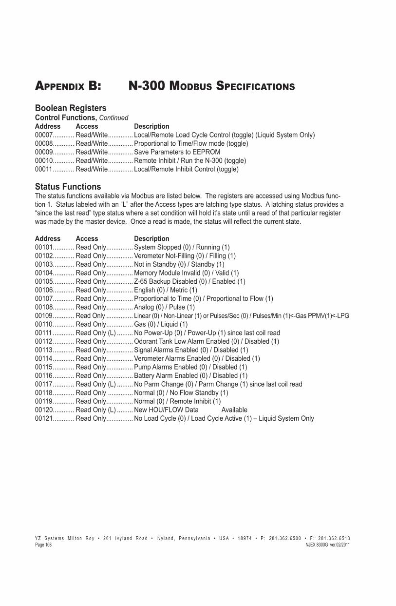
� � � � � � � � � � � � � � � � � � � � � � � � � � � � � � � � � � � � � � � � � � � � � - � � � � � � � � � � � � � � � � � � � � � � � � � � � � � � � � � ! " # � ! # $ � � � � � % � � � � ! " # � ! # $ � "��&����� '()*��"��/���+!��,����
APPENDIX B: N-300 MODBUS SPECIFICATIONS
Boolean RegistersControl Functions, ContinuedAddress Access Description 00007............ Read/Write .............. Local/Remote Load Cycle Control (toggle) (Liquid System Only) 00008............ Read/Write .............. Proportional to Time/Flow mode (toggle) 00009............ Read/Write .............. Save Parameters to EEPROM00010............ Read/Write .............. Remote Inhibit / Run the N-300 (toggle)00011 ............ Read/Write .............. Local/Remote Inhibit Control (toggle)
Status FunctionsThe status functions available via Modbus are listed below. The registers are accessed using Modbus func-tion 1. Status labeled with an “L” after the Access types are latching type status. A latching status provides a “since the last read” type status where a set condition will hold it’s state until a read of that particular register !������������������������$� �J��� ����������������X������������!������>� ������ �����������J
Address Access Description 00101............ Read Only ............... System Stopped (0) / Running (1) 00102............ Read Only ............... Verometer Not-Filling (0) / Filling (1) 00103............ Read Only ............... Not in Standby (0) / Standby (1) 00104............ Read Only ............... Memory Module Invalid (0) / Valid (1) 00105............ Read Only ............... Z-65 Backup Disabled (0) / Enabled (1) 00106............ Read Only ............... English (0) / Metric (1) 00107............ Read Only ............... Proportional to Time (0) / Proportional to Flow (1) 00108............ Read Only ............... Analog (0) / Pulse (1) 00109 ............ Read Only ............... Linear (0) / Non-Linear (1) or Pulses/Sec (0) / Pulses/Min (1)<-Gas PPMV(1)<-LPG00110 ............ Read Only ............... Gas (0) / Liquid (1) 00111 ............ Read Only (L) ......... No Power-Up (0) / Power-Up (1) since last coil read 00112 ............ Read Only ............... Odorant Tank Low Alarm Enabled (0) / Disabled (1) 00113 ............ Read Only ............... Signal Alarms Enabled (0) / Disabled (1) 00114 ............ Read Only ............... Verometer Alarms Enabled (0) / Disabled (1) 00115 ............ Read Only ............... Pump Alarms Enabled (0) / Disabled (1) 00116 ............ Read Only ............... Battery Alarm Enabled (0) / Disabled (1)00117 ............ Read Only (L) ......... No Parm Change (0) / Parm Change (1) since last coil read 00118 ............ Read Only .............. Normal (0) / No Flow Standby (1) 00119 ............ Read Only ............... Normal (0) / Remote Inhibit (1) 00120............ Read Only (L) ......... New HOU/FLOW Data Available00121............ Read Only ............... No Load Cycle (0) / Load Cycle Active (1) – Liquid System Only

� � � � � � � � � � � � � � � � � � � � � � � � � � � � � � � � � � � � � � � � � � � � � - � � � � � � � � � � � � � � � � �� � � � � � � � � � � � � � � � � ! " # � ! # $ � � � � � % � � � � ! " # � ! # $ � "��&����'()*��"��/���+!��,����
APPENDIX B: N-300 MODBUS SPECIFICATIONS
Alarm FunctionsThe alarm functions available via Modbus are listed below. The registers are accessed using Modbus function 1. All the alarms are latching and provide a “since the last read” output where a set condition will hold it’s state until a read of that particular register was made by the master device. Once a read is made, the alarm will ��>� ������ �����������J
Address Access Description 01001............ Read Only ............... Global Alarm (1) (set if any alarm condition exists) 01002............ Read Only ............... Pump Failure Alarm (1) 01003............ Read Only ............... Over Pump Alarm (1) 01004............ Read Only ............... Under Pump Alarm (1) 01005............ Read Only ............... Verometer Cable Alarm (1) 01006............ Read Only ............... Verometer Slow Fill Alarm (1) 01007............ Read Only ............... Verometer No Fill Alarm (1) 01008............ Read Only ............... Verometer Over Fill non-Alarm (1) 01009............ Read Only ............... Verometer Leakage Alarm (1) 01010............ Read Only ............... Verometer Fill Valve Alarm (1) 01011 ............ Read Only ............... Verometer Fill Rate non-Alarm (1) 01012............ Read Only ............... Signal Low Flow non-Alarm (1) 01013............ Read Only ............... Signal No Flow non-Alarm (1) 01014............ Read Only ............... �������$��>!�%������*Y,�01015............ Read Only ............... �������$��>!�������*Y,�01016............ Read Only ............... Signal Loss of Signal Flow Alarm (1) 01017............ Read Only ............... Low Battery Alarm (1) 01018............ Read Only ............... External Tank level High Alarm (1) 01019............ Read Only ............... External Tank level Low Alarm (1) 01020............ Read Only ............... Expansion Tank Pressure High Alarm (1) 01021............ Read Only ............... Expansion Tank Pressure Low Alarm (1) 01022............ Read Only ............... Expansion Tank Pressure Cable Alarm (1) 01023............ Read Only ............... Odorant Inlet Pressure High Alarm (1) 01024............ Read Only ............... Odorant Inlet Pressure Low Alarm (1) 01025............ Read Only ............... Odorant Inlet Pressure Cable Alarm (1)

� � � � � � � � � � � � � � � � � � � � � � � � � � � � � � � � � � � � � � � � � � � � � - � � � � � � � � � � � � � � � � � � � � � � � � � � � � � � � � � ! " # � ! # $ � � � � � % � � � � ! " # � ! # $ � "��&����� '()*��"��/���+!��,����
APPENDIX B: N-300 MODBUS SPECIFICATIONS
Integer Registers��������������������� ������������-���������������������� �������" ��������������J������¨����������������������-���������������(�������� �� ���X���������"!��������������J�������Y:%��������������������� ��be manipulated using functions 3, 6, and 16.
Function 3, allows the host to read one or more holding registers per query. Function 6, allows the host to write a single holding register per query. Function 16, allows the host to write multiple holding registers per query.
Result Data FunctionsThe result data functions available via Modbus are listed below. The registers are accessed using Modbus func-tion 3.
Address Access Description 40001 ................Read Only ....................HOU/LOU – Accum. Odorant Usage – High - Unsigned integer *See formatting info.40002...............Read Only ..................HOU/LOU – Accum. Odorant Usage – Low - Unsigned integer *See formatting info.40003 ...............Read Only ....................HOU/LOU - Accumulated Flow rate – High - Unsigned integer *See formatting info.40004...............Read Only ..................HOU/LOU - Accumulated Flow rate – Low - Unsigned integer *See formatting info.40005...............Read Only ..................HOU/LOU Start Date (Day of Month/Month) (1-31/1-12) - BCD 40006...............Read Only ..................HOU/LOU Start Date (Century/Year) (0000-9999) - BCD 40007...............Read Only ..................HOU/LOU Start Time (Seconds/Minutes) (00-59/00-59) - BCD 40008...............Read Only ..................HOU/LOU Start Time (Hours/Day of Week) (00-23/0-7) - BCD 40009...............Read Only ..................HOU/LOU End Date (Day of Month/Month) (1-31/1-12) - BCD 40010...............Read Only ..................HOU/LOU End Date (Century/Year) (0000-9999) – BCD 40011 ...............Read Only ..................HOU/LOU End Time (Seconds/Minutes) (00-59/00-59) – BCD 40012...............Read Only ..................HOU/LOU End Time (Hours/Day of Week) (00-23/0-7) – BCD 40013...............Read Only ..................Stroke Count High (0000-9999) – BCD 40014...............Read Only ..................Stroke Count Low (0000-9999) – BCD 40015...............Read Only ..................Total Odorant Injected High (0000-9999) – BCD *See formatting info. 40016...............Read Only ..................Total Odorant Injected Low (0000-9999) – BCD *See formatting info. 40017...............Read Only ..................Model Number – Unsigned Integer *See formatting info. 40018...............Read Only ..................Serial Number (xxxxx) – Unsigned Integer 40019...............Read Only ..................Verometer Calibration Data – Unsigned Integer *See formatting info. 40020...............Read Only ..................Odorant Tank Level (xxx %) – Unsigned Integer 40021...............Read Only ..................Expansion Tank Pressure (xxx.x psi / x.xxx bar) – Unsigned Integer 40022...............Read Only ..................Odorant Inlet Pressure (xxx.x psi / x.xxx bar) – Unsigned Integer 40023...............Read Only ..................Calculated Time per Stroke High – Unsigned Integer – sec. 40024...............Read Only ..................Calculated Time per Stroke Low – Unsigned Integer - (x.xx sec.) 40025...............Read Only ..................Verometer Level (xxx.x %) – Unsigned Integer 40026...............Read Only ..................Battery Voltage (xx.x volts) – Unsigned Integer

� � � � � � � � � � � � � � � � � � � � � � � � � � � � � � � � � � � � � � � � � � � � � - � � � � � � � � � � � � � � � � �� � � � � � � � � � � � � � � � � ! " # � ! # $ � � � � � % � � � � ! " # � ! # $ � "��&����'()*��"��/���+!��,����
APPENDIX B: N-300 MODBUS SPECIFICATIONS
�����!�������?��"�����%��_��"�����_��$���!�����_��������Address Description40001...................... High bytes for Accumulated odorant injected, combine with address 40002 for total.40002...................... 6300GE/LE = .XXXXX, 7300GE/LE = X.XXXX, 8300GE/LE = XX.XXX (lbs), 6300GM/LM = .XXXXX, 7300GM/LM = X.XXXX, 8300GM/LM = XX.XXX (kg) Note: Low bytes only, combine with address 40001 for total odorant injected.40003...................... ?����������-��� ���������>!X� �����!������������\;;;\�-������J40004...................... 6300GE = .XXXXX, 7300GE = X.XXXX, 8300GE = XX.XXX (MMCF/hr), 6300GM = X.XXX, 7300GM = XX.XXX, 8300GM = XXX.XX (M3/sec) 6300LE = XXX.XX, 7300LE = XXXX.X, 8300LE = XXXXX (gallons), 6300LM = XXX.XX, 7300LM = XXXX.X, 8300LM = XXXXX (liters), 6300/7300/8300LE (PPMV mode) = XXXXX (gallons), 6300/7300/8300LM (PPMV mode) = XXXXX (liters) Note:��!���������X� �����!������������\;;;+�-�������� ���������>!J�� ���40015...................... High bytes only, combine with address 40016 for total odorant injected.40016...................... 6300 = .XXXX, 7300 = X.XXX, 8300 = XX.XX (lbs/kg) Note: Low bytes only, combine with address 40015 for total odorant injected.40017...................... Model number format: 63XX = 6300, 73XX = 7300, 83XX = 8300. XX= 11= GE, XX=12=GM, XX=21=LE, XX=22=LM. Example: 6311 = 6300 Gas English, 7322 = 7300 Liquid Metric40019...................... 6300 = XX.XXX, 7300 = XXX.XX, 8300 = XXXX.X (cc)
����"����_��������The result data functions available via Modbus are listed below. The registers are accessed using Modbus functions 3, 6, and 16.
Note: The system must be stopped in order for any parameter changes to be accepted. An exception re-sponse will be returned if a parameter change query is issued while the system is running. Once the param-eter changes have been made, use coil 00009 to save the updated parameters before restarting the system.Address Access Description 40101............ Read Only ............... Current Date (Day of Month / Month) (01-31 / 01-12) – BCD 40102............ Read Only ............... Current Date (Century / Year) (0000-9999) – BCD40103............ Read Only ............... Current Time (Seconds / Minutes) (00-59 / 00-59) – BCD 40104............ Read Only ............... Current Time (Hours / Day of Week) (00-23/01-07) – BCD 40105............ Read/Write .............. Injection Rate - Unsigned Integer *See formatting info. 40106............ Read/Write .............. Pump Displacement (cc/Stroke) – Unsigned Integer *See formatting info.40107 ............ Read/Write .............. Odorant Density – Unsigned Integer X.XX (GE/LE = lbs/gal, GM/LM = g/cc) 40108............ Read/Write .............. Proportional to Time Stroke Rate X.XX (minutes) – Unsigned Integer 40109............ Read/Write .............. Maximum Gas Flow – Unsigned Integer *See formatting info. 40110 ............ Read/Write .............. Low Flow Shutoff (xx.x of Max Gas Flow) – Unsigned Integer 40111 ............ Read/Write .............. Flow No Signal (xx.x of Max Gas Flow) – Unsigned Integer 40112 ............ Read/Write .............. Maximum time per stroke (xxx minutes/stroke) – Unsigned Integer 40113 ............ Read/Write .............. Odorant Output (lbs/pulse) – Unsigned Integer *See formatting info. 40114 ............ Read/Write .............. Pulses per Second (xx Pulses/Seconds) – Unsigned Integer 40115 ............ Read/Write .............. Pulses per Minute / Pulses per Gallon (xx Pulses/Minute - Gas, xx Pulses/Gal– Liquid PPMV) – Unsigned Integer

� � � � � � � � � � � � � � � � � � � � � � � � � � � � � � � � � � � � � � � � � � � � � - � � � � � � � � � � � � � � � � � � � � � � � � � � � � � � � � � ! " # � ! # $ � � � � � % � � � � ! " # � ! # $ � "��&����� '()*��"��/���+!��,����
APPENDIX B: N-300 MODBUS SPECIFICATIONS����"����_��������^ Continued 40116 ............ Read/Write .............. Odorant Tank Level High (xx %) – Unsigned Integer 40117 ............ Read/Write .............. Odorant Tank Level Low (xx %) – Unsigned Integer 40118 ............ Read/Write .............. Expansion Tank Pressure High (xx.x psi / x.xxx bar) – Unsigned Integer 40119 ............ Read/Write .............. Expansion Tank Pressure Low (xx.x psi / x.xxx bar) – Unsigned Integer40120............ Read/Write .............. Odorant Inlet Pressure High (xx.x psi / x.xxx bar) – Unsigned Integer 40121............ Read/Write .............. Odorant Inlet Pressure Low (xx.x psi / x.xxx bar) – Unsigned Integer
��(������� �� �)��������Q-������-������������-� ���Address 40105: GE = X.XX (lbs/MMCF) GM = XXX.X (mg/m3) LE = X.XX (lbs/10K gal) LM = XXX.X (mg/liter)Address 40106: 6300 = X.XXXX, 7300 = X.XXX, 8300 = XX.XX (cc/stroke)Address 40109: 6300GE = X.XXXX, 7300/8300GE = XX.XXX (MMCF/hr)
6300GM = XX.XXX, 7300/8300GM = XXX.XX (m3/sec) 6300LE = XXXX.X, 7300/8300LE = XXXXX (gal/min) 6300LM = XXXX.X, 7300/8300LM = XXXXX (liter/min)
Address 40113: 6300 = X.XXXX, 7300 = X.XXX, 8300 = X.XX (English = lbs/pulse, Metric = kg/pulse)
Exception ResponsesException responses are a means for the Slave device to indicate to the Master device that a query received could not be acted upon for a particular reason. Below is a listing of Exception codes.
Exception Code Name/Description 1.............................. Illegal Function: Function received in the query is not supported by the slave2.............................. Illegal Data Address: Data address received in the query is not supported by the slave3.............................. Illegal Data Value:�[����� ����������������������������������������������������$�4.............................. Slave Device Failure: An unrecoverable error occurred while performing this action5.............................. Acknowledge: Query being processed but needs some time to complete6.............................. Slave device busy: Slave cannot process an incoming query at this time7.............................. Negative Acknowledge: Slave cannot perform the program function received8 ............................. Memory parity error: A memory parity error occurred in the slave read attempt

� � � � � � � � � � � � � � � � � � � � � � � � � � � � � � � � � � � � � � � � � � � � � - � � � � � � � � � � � � � � � � � � � � � � � � � � � � � � � � � ! " # � ! # $ � � � � � % � � � � ! " # � ! # $ � "��&���"'()*��"�����+!��,����
APPENDIX C: RESPONSE FORMS
For the RecordTo assist in trouble shooting, if required, please record the following information as the NJEX 8300 is intital-�����-���������������J
Basic information on the NJEX-8300
�� ������������N� _____________________________�� ~%+;;��$�����*=J==,N� _______________________ �� (��-� �����������N� ________________________ �� @����-���������N� ____________________________ �� �� �� �����~���N _________________________
Location�� �����Q@N� ___________________________________ �� ���������� �� ��N� _________________________ �� ������������N� ____________________________
Conditions�� ����������������N� __________________________ �� �=����������������N� ____________________ 25 psi (1.72 Bar) expansion tank pressure is required.
�� ��������N� ________________________________ 30-35 psi (2.07-2.41 Bar) bulk tank pressure range is required.
�� �������� ��������������N� ___________________ 75 psi (5.17 Bar) supply actuation pressure is required.
�� ������ ��������������N� ____________________ Refer to System Schematic Illustration, Table 1, page 10 for
required pressures.
�� ����)�!�����N� ____________________________ Record in MMCF/hr or m3/sec.
�� ��������������������$��N� __________________ �� ����������������N� _______________________ �� �����������[����N� _______________________ Record in cc/stroke
Parameters�� Q'� �������N� _____________________________ �� �����@����� ����N� ________________________ �� ������@�����N� ___________________________ �� (�=�����)�!N� _____________________________ �� �!�)�!�����--N� __________________________ �� )�!�*������,N� ___________________________ �� (�=�����"�����N� ___________________________ �� ������������N� ____________________________
Run Mode
Select One
____��������%�%���� ___��������%�%)�!If Proportional to-Flow, select one
__ ����%����� __ ����%~%����� __ ������%���%�� � __ ������%���%(����
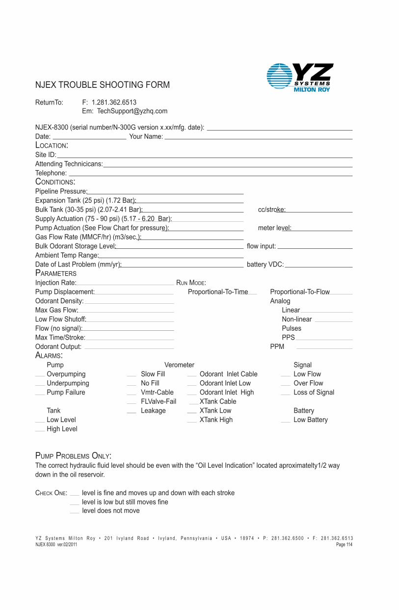
������N� )N��YJ]�YJ+:]J:ZY+�� � � � � � ��N���� �������/����J �
~���%�+;;�*������������"~%+;;��$�����=J=="�-�J�����,N@���N�� � � � � � � ����~���NLOCATION:�����Q@N���������� �� � ��N�������NCONDITIONS:����������������N� � � � � � � � ��=���������*]Z����,�*YJ�]����,N� � � � � � ����������*+;%+Z����,�*]J;�%]J\Y����,N� � � � � � � � � � "�����N�������� ������*�Z�%��;����,�*ZJY��%�:J];�����,N������ ������*����)�!�#�����-����������,N� � � � � � � � ��������$��N�����)�!������*((#)"��,�*�+"�� J,N��������������������$��N�� � � � � � � � � � � >!�����N����������������N� � � � � �@����-�������������*��"��,N������� � � � � � � � � � ��������[@#NPARAMETERSQ'� �������N� � � � � � � � RUN MODE:�����@����� ����N� � � � � � � � ��������%�%����� � ��������%�%)�!������@�����N� � � � � � � � � � � � � � � � ����(�=�����)�!N� � � � � � � � � � � � � � � � � � ������!�)�!�����--N� � � � � � � � � � � � � � � � � ~%�����)�!�*������,N� � � � � � � � � � � � � � � � � ������(�=�����"�����N� � � � � � � � � � � � � � � � � ���������������N�� � � � � � � � � � � � � � � � ��(ALARMS:� � ����� � � � � � � � � [�������� � � � � � � � � ������ � ����� � �$��������� � � � � ��!�)���� � � �������Q����#������ � � �!�)�!������ B���������� � � � � ~�)���� � � � ������Q�����!� � � � �$���)�!������ �����)������� � � � � [���%#����� � � ������Q�����?���� � � � ����-������� � � � � � � � � � � )�[��$�%)���� � �����#����� � ���� � � � � � � �������� � � ������!� � � � � � ��������� � �!���$��� � � � � � � � � � � �����?����� � � � � �!��������� � ?������$��� � �
PUMP PROBLEMS ONLY:���� ��� ���������� �>������$�������������$��!��������¨������$���Q�� ������ ��������=��������Y"]�!����!���������������$��J
CHECK ONE:� � ��$�������������$����������!�!������ �������� � � � � � ��$�������!������������$������ � ��$����������$�
~�������B�����?���Q~��)��(�
� � � � � � � � � � � � � � � � � � � � � � � � � � � � � � � � � � � � � � � � � � � � � - � � � � � � � � � � � � � � � � � � � � � � � � � � � � � � � � � ! " # � ! # $ � � � � � % � � � � ! " # � ! # $ � "'()*��"�����+!��,���� ��&����

��
��
��
��
��
�
��
��
��
��
��
��
��
�
��
��
��
��
��
��
�
��
�-
��
�
��
�
��
��
��
��
��
��
��
��
��
��
��
�
��
��
!"
#�
!#
$�
��
��
%
��
��
!"
#�
!#
$�
"��
&���
$�'
()*�
�"��
/���
+!��,�
���
APP
END
IX D
: D
OC
UM
ENTS
pmp
bat v
mtr
sig
tnk
Cal
ibra
tion
Set
*Clk
*
Inpu
ts
*E
sc
pmp
bat v
mtr
sig
tnk
Set
Dat
e an
d Ti
me
00:0
0 0
6-01
-Thu
-200
0pm
p ba
t vm
tr si
g tn
k
C
alib
ratio
n*F
low
*
Pre
s
*E
sc
pmp
bat v
mtr
sig
tnk
Cal
ibra
te P
ress
ure
*XTa
nk
*O
dor
*
Esc
pmp
bat v
mtr
sig
tnk
Zer
o A
djus
tmen
t*R
ead
1.
0 V
DC
*Esc
pmp
bat v
mtr
sig
tnk
Zer
o A
djus
tmen
tA
ccep
t/ER
RO
R
x.
x V
*E
sc
pmp
bat v
mtr
sig
tnk
Flo
w In
put T
ype
*Ang
*
Pul
se
*E
sc
pmp
bat v
mtr
sig
tnk
Ana
log
Inpu
t*L
in
*N
Lin
*
Esc
pmp
bat v
mtr
sig
tnk
Spa
n A
djus
tmen
t x
xx P
ulse
s/(M
in)(
Sec
) *E
sc
pmp
bat v
mtr
sig
tnk
Pul
se In
put
*PP
S
*P
PM
*Esc
pmp
bat v
mtr
sig
tnk
Lin
ear/N
on-L
inea
r Inp
ut*Z
ero
*S
pan
*
Esc
pmp
bat v
mtr
sig
tnk
Z
ero
Adj
ustm
ent
Rea
d
1.0
VD
C
*E
sc
pmp
bat v
mtr
sig
tnk
Spa
n A
djus
tmen
t*R
ead
5.0
VD
C
*E
sc
pmp
bat v
mtr
sig
tnk
Spa
n A
djus
tmen
tA
ccep
t/ER
RO
R x
.x
V *
Esc
pmp
bat v
mtr
sig
tnk
Zer
o A
djus
tmen
tA
ccep
t/ER
RO
R
x.x
V
*E
sc
pmp
bat v
mtr
sig
tnk
A
larm
Out
Sta
tus
*Set
*Tes
t
*Esc
pmp
bat v
mtr
sig
tnk
P
ump
Ala
rm
Dis
able
d/E
nabl
ed
pmp
bat v
mtr
sig
tnk
A
larm
Sw
itch
Test
OFF
/Ala
rm R
elay
Clo
sed/
(ON
/Ala
rm R
elay
Ope
n)
pmp
bat v
mtr
sig
tnk
Sw
itch/
Sim
ulat
ion
*Sw
*S
im
*E
sc
pmp
bat v
mtr
sig
tnk
Bat
tery
Ala
rm
Dis
able
d/E
nabl
ed
pmp
bat v
mtr
sig
tnk
V
erom
eter
Ala
rm
Dis
able
d/E
nabl
ed
pmp
bat v
mtr
sig
tnk
S
igna
l Ala
rm
Dis
able
d/E
nabl
ed
pmp
bat v
mtr
sig
tnk
T
ank
Ala
rm
Dis
able
d/E
nabl
ed
pmp
bat v
mtr
sig
tnk
P
ump
Ala
rm
S
imul
ate
pmp
bat v
mtr
sig
tnk
B
atte
ry A
larm
Sim
ulat
e
pmp
bat v
mtr
sig
tnk
V
erom
eter
Ala
rm
S
imul
ate
pmp
bat v
mtr
sig
tnk
S
igna
l Ala
rm
S
imul
ate
pmp
bat v
mtr
sig
tnk
T
ank
Ala
rm
S
imul
ate
Ove
r Pum
pP
MP
bat v
mtr
sig
tnk
P
ump
Ala
rm
S
imul
ate
Und
er P
ump
PM
P ba
t vm
tr si
g tn
k
Pum
p A
larm
Sim
ulat
e
Pum
p Fa
ilure
PM
P ba
t vm
tr si
g tn
k
Pum
p A
larm
Sim
ulat
e
Low
Bat
tery
pmp
BAT
vm
tr si
g tn
k
B
atte
ry A
larm
Sim
ulat
e
Vm
tr-C
able
pmp
bat V
MTR
sig
tnk
V
erom
eter
Ala
rm
S
imul
ate
No-
Fill
pmp
bat V
MTR
sig
tnk
V
erom
eter
Ala
rm
S
imul
ate
S
low
Fill
pmp
bat V
MTR
sig
tnk
V
erom
eter
Ala
rm
S
imul
ate
F
lval
v-Fa
il
pmp
bat V
MTR
sig
tnk
V
erom
eter
Ala
rm
S
imul
ate
������
������
��$�
�����
����
pmp
bat V
MTR
sig
tnk
V
erom
eter
Ala
rm
S
imul
ate
Fi
llrat
epm
p ba
t VM
TR s
ig tn
k
Ver
omet
er A
larm
Sim
ulat
e
Odo
rInle
t-Cab
l
pm
p ba
t VM
TR s
ig tn
k
Ver
omet
er A
larm
Sim
ulat
e
O
dorIn
let-L
o
pm
p ba
t VM
TR s
ig tn
k
Ver
omet
er A
larm
Sim
ulat
e
XTa
nk-C
able
pmp
bat V
MTR
sig
tnk
V
erom
eter
Ala
rm
S
imul
ate
X
Tank
-Hi
pmp
bat V
MTR
sig
tnk
V
erom
eter
Ala
rm
S
imul
ate
O
dodI
nlet
-Hi
pmp
bat V
MTR
sig
tnk
V
erom
eter
Ala
rm
S
imul
ate
Leak
age
pmp
bat V
MTR
sig
tnk
V
erom
eter
Ala
rm
S
imul
ate
XTa
nk-L
opm
p ba
t VM
TR s
ig tn
k
Ver
omet
er A
larm
Sim
ulat
e
Ove
rFlo
w>1
25%
pmp
bat v
mtr
SIG
tnk
S
igna
l Ala
rm
S
imul
ate
Ove
rFlo
w>1
10%
pmp
bat v
mtr
sig
tnk
V
erom
eter
Ala
rm
S
imul
ate
Low
-Flo
Sht
off
pmp
bat v
mtr
sig
tnk
V
erom
eter
Ala
rm
S
imul
ate
N
o Fl
owpm
p ba
t vm
tr si
g tn
k
Ver
omet
er A
larm
Sim
ulat
e
Loss
of S
igna
lpm
p ba
t vm
tr S
IG tn
k
Sig
nal A
larm
Sim
ulat
e
O
dor T
ank
Hi
pmp
bat v
mtr
sig
TNK
T
ank
Ala
rm
S
imul
ate
O
dor T
ank
Low
pmp
bat v
mtr
sig
TNK
T
ank
Ala
rm
S
imul
ate
N-30
0 Co
ntro
ller D
ispl
ay
Dia
gram
, Fig
ure
212
Seria
l Num
ber
xxx
xx
Mod
el T
ype
830
0G
Vero
met
er C
alib
rate
xx
.xxx
cal
ibra
te c
c
pmp
bat v
mtr
sig
tnk
Pro
pFlo
w (T
ime)
Idle
*Strt
*
Dsp
*
Set
pmp
bat v
mtr
sig
tnk
Stro
kes
Sig
nale
d*R
eset
xx
xxxx
xx
pmp
bat v
mtr
sig
tnk
R
eset
Stro
kes?
*No
*Y
es
pmp
bat v
mtr
sig
tnk
Odo
rant
Inje
cted
*Res
et
xx.
xxxx
lbs(
kg)
�����
����
��
Ye
s
No
pmp
bat v
mtr
sig
tnk
Res
et lb
s(kg
) In
ject
ed?
*No
*Y
es
N-3
00G
Ve
r x.x
x
-- N
JEX
--
PM
P ba
t vm
tr si
g tn
kxx
.xxx
cc/
stro
ke*
Pum
p D
ispl
acem
ent
Ala
rmov
er p
ump
unde
r pum
ppu
mp
failu
re
pmp
bat V
MTR
sig
tnk
Met
er L
evel
xxx
%*F
illFi
ll Ve
rom
eter
?
*N
o
*Ye
s
Ala
rmVm
tr-Ca
ble
No F
illSl
ow F
illFi
ll Val
veO
dorIn
let-
Cabl
eO
dorIn
let L
oO
dorIn
let H
iXT
ank-
Cabl
eXT
ank
Low
XTan
k H
Non-
Alar
ms
ver F
ill���
�����
Leak
age
pmp
bat v
mtr
sig
tnk
Exp
ansi
on T
ank
xx.x
psi
(Bar
)
pmp
bat v
mtr
sig
tnk
Odo
rInle
t Inl
etxx
.x p
sig
(Bar
)
Line
arN
on L
inea
rP
ulse
PP
S/P
PM
Ala
rmLo
ss o
f S
igna
l(A
nalo
g in
put o
nly)
Ove
r Flo
w
>125
%N
on A
larm
No
Flow
Low
Flo
S
htof
f�
$���>
!�
<125
%
Ala
rm
low
bat
tery
pmp
BAT
vm
tr si
g tn
kB
atte
ry x
x.x
VD
C
Ala
rm
pmp
bat v
mtr
SIG
tnk
Flow
Inpu
t xx.
x%
Ala
rm
pmp
bat v
mtr
sig
TNK
Low
Lev
elH
igh
Leve
l
Odo
rant
Tem
p x
x C
12:0
0 04
-12-
Wed
-20
00
pmp
bat v
mtr
sig
tnk
Met
er L
evel
xxx
%
pmp
bat v
mtr
sig
tnk
Pro
porti
onal
To
?*F
low
*Tim
e
*E
sc
pmp
bat v
mtr
sig
tnk
Sta
rt P
ump?
*Yes
*
No
*E
sc
pmp
bat v
mtr
sig
tnk
Pro
p Fl
ow/T
ime
x:x
x:xx
*Sto
p
*D
sp
*S
et
pmp
bat v
mtr
sig
tnk
Tim
e/S
troke
Cal
cula
ted
Exc
eeds
min
imum
pmp
bat v
mtr
sig
tnk
Sto
p P
ump
*No
*Y
es
pmp
bat v
mtr
sig
tnk
Set
Sel
ectio
n*P
ar
*C
al
*
Esc
pmp
bat v
mtr
sig
tnk
Set
Par
amet
ers
*Flo
w
*Ti
me
*
Esc
pmp
bat v
mtr
sig
tnk
Inje
ctio
n R
ate
x.xx
x lb
s/M
MC
F(m
g/m
3)
pmp
bat v
mtr
sig
tnk
Pro
porti
onal
To
Flow
* S
et
*A
larm
*
Esc
pmp
bat v
mtr
sig
tnk
Pum
p D
ispl
acem
ent
x.xx
x cc
/stro
ke
pmp
bat v
mtr
sig
tnk
Odo
rant
Den
sity
x.xx
x lb
s/ga
llon
(g/c
c)
pmp
bat v
mtr
sig
tnk
Pro
porti
onal
To
Tim
e*
Set
*
Ala
rm
* E
sc
Pro
porti
onal
To
Tim
epm
p ba
t vm
tr si
g tn
kS
et T
ime/
Stro
kexx
.xx
Min
utes
pmp
bat v
mtr
sig
tnk
Max
Gas
Flo
wxx
.xxx
MM
CF/
(m3/
sec)
pmp
bat v
mtr
sig
tnk
Low
Flo
w S
hut O
ff==
J=�
���=
����
�>!
pmp
bat v
mtr
sig
tnk
Flow
(no
sign
al)
==J=
=���
�=��
���>
!
pmp
bat v
mtr
sig
tnk
Max
Tim
e/S
troke
xxx
min
utes
/stro
ke
pmp
bat v
mtr
sig
tnk
Odo
rant
Out
put
x.xx
lb/p
ulse
(kg/
puls
e)
pmp
bat v
mtr
sig
tnk
Odo
rant
Tan
kxx
=Low
(%)
xx=H
igh
pmp
bat v
mtr
sig
tnk
Exp
ansi
on T
ank
xx=L
ow (
psi)
xx=
Hig
h
pmp
bat v
mtr
sig
tnk
Odo
rant
Inle
txx
=Low
(psi
)(B
ar) x
x=H
igh
pmp
bat v
mtr
sig
tnk
Ala
rm to
Rel
ay D
elay
xxx
min
utes
pmp
bat v
mtr
sig
tnk
Ala
rm to
Cal
lout
Del
ayxx
x m
inut
es
pmp
bat v
mtr
sig
tnk
MO
DB
US
Add
ress
xxx
= D
evic
e A
ddre
ss
pmp
bat v
mtr
sig
tnk
MO
DB
US
Par
amet
ers
9600
,N,R
TU,C
omm
=..

��
��
��
�
�
��
�
��
��
��
��
��
��
��
��
�
��
��
��
��
��
��
��
�
��
-�
�
��
��
�
��
��
��
��
��
��
��
��
��
��
��
�
��
�!
"#
�!
#$
��
��
�%
�
��
�!
"#
�!
#$
�"�
��&
���#�
'()*
��"��
/���
+!��,�
���
APP
END
IX D
: D
OC
UM
ENTS
�®¯
°±²³
�!�´
µ���
����
¶´-
´°

� � � � � � � � � � � � � � � � � � � � � � � � � � � � � � � � � � � � � � � � � � � � � - � � � � � � � � � � � � � � � � � � � � � � � � � � � � � � � � � ! " # � ! # $ � � � � � % � � � � ! " # � ! # $ � "��&����'()*��"�����+���,����
APPENDIX E: N-300 ATEX CONNECTIONS
ATEX System Connections�������������� � ��������� �������+;;�������������������-��!�N
YJ� #� ������QJ�J��!��������������������!� ����� � ��� ����-������������-�����~%+;;� ������X�����=��������������-��������-����� �����X�refer to the Wiring Control Docu-ment on page 116 in Appendix D..
]J� #� ������>!���������$� ������������������� ��� ������������������ ����� �����X� �����$X�refer to the Wiring Control Document on page 116 in Appendix D.
]�J� Q-�����X� � ������������Q������Q��������������������������� ��� ������������������ ����� �����X� �����$X refer to the Wiring Control Document on page 116 in Appendix D.
]�J� Q-�����X� � ��������%\�Z� ���� ����!��-�������������������������������� ��� ������������������ ����� �����X� �����$X refer to the Wiring Control Document on page 116 in Appendix D.
QJ�J��!���������#� ��

201 Ivyland Road
Ivyland, PA 18974
800.344.5399
P: 281.362.6500
F: 281.362.6513
Web: www.yzsystems.com