
NG M 13 - نمایندگی ESTUN · NG M 13. The information contained in this document are for...
19
www.promax.it www.promax.it Next Generation System NGM 13 User manual Revision 3.00.01 Date 17 ott 2012 NG M 13
Transcript of NG M 13 - نمایندگی ESTUN · NG M 13. The information contained in this document are for...

www.promax.itwww.promax.it
Next Generation
System
NGM 13
User manualRevision 3.00.01
Date 17 ott 2012
NG M 13

The information contained in this document are for informational purposes only and are subject to change without notice and should not be interpreted by any commitment by Promax srl. Promax Ltd. assumes no responsibility or liability for errors or inaccuracies that may be found in this manual. Except as permitted by the license, no part of this publication may be reproduced, stored in a retrieval system or transmitted in any form or by any means, electronic, mechanical, recording or otherwise without prior permission Promax srl.Any references to company names and products are for demonstration purposes only and does not allude to any actual organization.
User Manual NGM 13
Document : NGM13_eng Revision 00.00.82 del 17/10/2012
pag 2 di 19
© Promax s.r.l. – Via Newton, 5/G – Z.I. Malacoda – CastelFiorentino (Fi) ITALY
email:[email protected] - internet:www.promax.it

User Manual NGM 13
1 Features
The system NGM13 is a numerical control based on the Freescale MCF5213 ColdFire
microprocessor. NGM13 born as a stand alone and can also be used as SLAVE CANOPEN with
appropriate firmware.
• Microprocessor type MCF MCF5213 80MHz
• 192 KbFlash
• 32 Kb RAM
• 16 Kb RAM FRAM (permanent)
• 2 serial ports RS232
• 1 CAN OPEN
• 8 analog-inputs 12 bit configurable (0-10V dc) or (4-20mA)
• 16 digital inputs PNP 24 Vdc
• 14 digital outpust PNP 24 VDC up to 1 A
• 4 out STEP/DIR 400 Khz tot. Line Drive or Open Collector
2 Identigìfication Code NGM 13
Order Code NGM13/X – X yyyyyy
STEP/DIR
0 None STEP/DIR
1 STEP/DIR Open
Collector
2 STEP/DIR LINE DRIVE
Analog inputs
B 0-10 V
C 4-20 Ma
yyyyy Channel number (ex: 1 2 3 etc.)
Document : NGM13_eng Revision 00.00.82 del 17/10/2012 pag 3 di 19
User Manual NGM 13
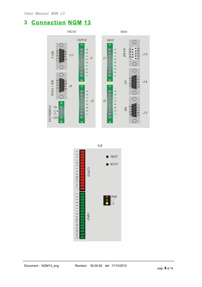
3 Connection NGM 13
Document : NGM13_eng Revision 00.00.82 del 17/10/2012 pag 4 di 19

User Manual NGM 13
4 Connections Description
4.1 Power and Can PWR/CAN
The NGM13 requires two separate power supplies:
• Logical Power
• Digital Outputs Power J3 e J4
To supply the digital outputs, see the relevant chapter.
As regards the supply of the logic section, this is necessary for normal operation of the card.
4.1.1 Electrical Characteristics
U.m. Min Standard Max
DC IN Vdc 12 24 35
Power (to 24Vdc) W 2,6
4.1.2 Connections PWR
PIN Description
1 + 24 VDC
2 CAN L
3 CAN H
4 0V GND
4.2 Serial Ports
4.2.1 General
The serial ports on the NGM13 allow communication with external devices to the control, PC-type,
PLC and other.
The two serial differ in the use that can be done:
• is normally used both for the download of the programs on the control, both for the
debugging from a PC application. It is also the port to use for updating the firmware1.
• SER2: can be used for communication with other devices, such as a PLC, inverters or
other.
For the electrical signal, the serial ports are in compliance with RS232.
1See Programming Section (pag.15)
Document : NGM13_eng Revision 00.00.82 del 17/10/2012 pag 5 di 19

User Manual NGM 13
4.2.2 Connections J11/J6 SER1/PROG -SER2
SER1 – RS232 J6 SER2 -RS232 J11
Pin 1 n.c. n.c.
Pin 2 RX RX
Pin 3 TX TX
Pin 4 n.c. n.c.
Pin 5 GND GND
Pin 6 n.c. n.c.
Pin 7 n.c. n.c.
Pin 8 n.c. n.c.
Pin 9 n.c. n.c.
Document : NGM13_eng Revision 00.00.82 del 17/10/2012 pag 6 di 19

User Manual NGM 13
4.3 CAN BUS
4.3.1 General
The port CAN BUS allows the communication of the card NGM13 with type devices for motors
drives, slave of various kinds, encoders, and more.
Communication takes place via the CAN OPEN protocol, based on its specifications DS401 and
DS402 as regards the objects and the modes supported.
In terms of data exchange, the line complies with DS301.
The port can be configured as master or slave depending on the firmware present.
The port CAN-BUS meets the specifications of ISO 11898-24V.
4.3.2 Connections PWR/CAN
PIN Description
1 + 24 VDC
2 CAN L
3 CAN H
4 GND
4.3.3 CAN BUS
You can enter the terminating resistor, enabling the jumper JP7 inside the card NGM13 (default ON)
Document : NGM13_eng Revision 00.00.82 del 17/10/2012 pag 7 di 19

User Manual NGM 13
4.4 Analog Inputs
The analog converter reads an input voltage from 0 to 10V or 4/20 mA with respect to GND.
To get the full scale 12V or 24V, an external resistor must be inserted between the signal and card
input. In any case, the value of the input voltage can exceed the full scale is not more than 0.2 V.
NGM13 of the analog input signals are shared with digital input connector J2, so the use of
analogue channels preclude the use of the corresponding digital inputs. The configuration is
hardware and is made by PROMAX during assembly at the request of the customer.
(eg, analog 1.2 channels ->. inputs 9 and 10 not used)
4.4.1 Analogs Connections J12
PIN Description
1 Analog input 1
2 Analog input 2
3 Analog input 3
4 Analog input 4
5 Analog input 5
6 Analog input 6
7 Analog input 7
8 Analog input 8
9 GND
4.4.2 Input ResistanceMIN Typical MAX
VDC 25 Kῼ 72 Kῼ
4-20 Ma 175 ῼ
4.4.3 External resistance for voltages other than 0-10V or 4-20Ma
VIN Rext
0-12 V 63 Kῼ
0-24 V 424 Kῼ
4.4.4 Connection example
Document : NGM13_eng Revision 00.00.82 del 17/10/2012 pag 8 di 19
22 Kῼ

User Manual NGM 13
4.5 Outputs STEP/DIRThe card NGM13 can use, up to four outputs STEP / DIR for a total frequency of 400 Khz.
The outputs can be configured with OPEN COLLECTOR signals, 5V or LINE DRIVE.
4.5.1 OPEN-COLLECTOR
POWER MAX 48 VDCLOAD 100 Ma continuative 500 Ma peakV STATE ON MIN 0V MAX 1VFREQUENCY MAX 30 Khz
4.5.2 LINE DRIVE
OUTPUT DIFFERENTIAL MIN 2.2V MAX 3.3V specific TIA/EIA-422-B (RS422)*FREQUENCY MAX 400 Khz in position mode –125 Khz in interpolation mode
specific TIA/EIA-422-B (RS422)
LOAD V Min V Typical3,9 Kῼ 3,2 V
100 ῼ 2 2,6 V
4.5.3 Connection STEP/DIR OPEN COLLECTOR J13 /J14PIN J13 J14
1 N.C. N.C.
2 N.C. N.C.
3 Dir ch. B Dir ch. D
4 Dir ch. A Dir ch. C
5 GND GND
6 N.C. N.C.
7 N.C. N.C.
8 Step ch. B Step ch. D
9 Step ch. A Step ch. C
Document : NGM13_eng Revision 00.00.82 del 17/10/2012 pag 9 di 19

User Manual NGM 13
Document : NGM13_eng Revision 00.00.82 del 17/10/2012 pag 10 di 19

User Manual NGM 13
4.5.4 Connection STEP/DIR LINE DRIVE
PIN J13 J141 Step + ch. A Step + ch. C
2 Step - ch. A Step - ch. C
3 Dir + ch. A Dir + ch. C
4 Dir - ch. A Dir - ch. C
5 GND GND
6 Step + ch. B Step + ch. D
7 Step - ch. B Step - ch. D.
8 Dir + ch. B Dir + ch. D
9 Dir - ch. B Dir - ch. D
Document : NGM13_eng Revision 00.00.82 del 17/10/2012 pag 11 di 19

User Manual NGM 13
4.6 Digital Inputs
All these signals are PNP Tye optically isolated. Therefore, to enable an input must bring a positive
VDC (24 Vdc typical) on the desired channel refers to the common inputs.
4.6.1 Electrical
U.m. Min Standard Max
State On Vdc 10 24 28
State Off Vdc 0 4
Delay ON ms 3 (@ 24Vdc)
OFF ms 2 (@ 24Vdc)
Current mA 4 (10Vdc) 14 (@ 28Vdc)
4.6.2 Connections J1/J2
PIN J1 J121 INPUT 1 INPUT 9
2 INPUT 2 INPUT 10
3 INPUT 3 INPUT 11
4 INPUT 4 INPUT 12
5 INPUT 5 INPUT 13
6 INPUT 6 INPUT 14
7 INPUT 7 INPUT 15
8 INPUT 8 INPUT 16
9 COMMON INPUTS GND COMMON INPUTS GND
Document : NGM13_eng Revision 00.00.82 del 17/10/2012 pag 12 di 19

User Manual NGM 13
4.7 Digital Outputs
These outputs are optically isolated with respect to GND. In order to function should therefore feed
them separately with a voltage of 24 Vdc. The load is driven by a transistor of the PNP type which
when activated will provide a positive voltage equal to the voltage supply of the outputs.
On the card there is a protection diode so you can also directly drive inductive loads. In case of
inductive loads with absorption greater than or equal to 1 A or when the cable connection between
the load and board exceeds a length of 3 meters, you should put the protection diode also close to
the load (diode type 1N4007 or similar).
4.7.1 Electrical
U.m. Min Standard Max Note
Power Vdc 10 24 30
Load A 1 Continue (Tamb 25°)
A 2 Duty Cycle 25% (Tamb 25°)
A 6 Peak (10 ms)
Delay ON μs 5
OFF μs 30
4.7.2 Connections J3/J4
PIN J3 J41 OUTPUT 1 OUTPUT 8
2 OUTPUT 2 OUTPUT 9
3 OUTPUT 3 OUTPUT 10
4 OUTPUT 4 OUTPUT 11
5 OUTPUT 5 OUTPUT 12
6 OUTPUT 6 OUTPUT 13
7 OUTPUT 7 OUTPUT 14
8 + 24 VDC + 24 VDC
9 GND OUTPUTS (-24 Vdc) GND OUTPUTS (-24 Vdc)
Document : NGM13_eng Revision 00.00.82 del 17/10/2012 pag 13 di 19

User Manual NGM 13
Document : NGM13_eng Revision 00.00.82 del 17/10/2012 pag 14 di 19
User Manual NGM 13
5 Programming
5.1 Manual Boot
The board usually uses an automatic boot.
In case, the automatic boot is not available, it is necessary to proceed in the following way:
1) Run the program NGPROG (if used VTB skip step 2 and 3)
2) Set the COM and the type of card NGM13
3) Load the application. SREC and press TRANSFER APPLICATION
4) Press the keys simultaneously within 15 seconds RESET AND BOOT on the board
5) Release the RESET button
5.2 Upload VTB application
For upload VTB application, is possible use the following mode:
The board NGM13 is automatically in BOOT MODE (if is not available, see 5.1) when you use the
BUTTON UPLOAD APPLICATION. The application is automatically RUN when the transfer is
finish.
5.3 NGPROG
The application was developed by Promax NGPROG to allow the update software and firmware of
the new controls based on μP ColdFire.
5.3.1 Upload firmware
1) Press button “GESTIONE FIRMWARE” on NGProg
2) If you use “UPDATE da File” use the standard windows Browser for find the .SREC file
2) If you use “UPDATE da Server” you must have a intenet active connection, NGPROG
search in Promax server the new version of firmware
3) Select the serial port to PC and NGM13 board type
4) Start the upload firmware
5.3.2 Upload VTB application
1) Select the NGM13 Board
2) Select the COM on PC
3) Selct the .SREC file by button “LOAD”4) Start the upload by button “TRASFERISCI APPLICAZIONE”
Document : NGM13_eng Revision 00.00.82 del 17/10/2012 pag 15 di 19

User Manual NGM 13
6 Status Led
ST-1/L1 (Green led):
• · Fast blink – board in BOOT MODE
• · blink1 sec – application RUN
ST-2/L2 (Yellow led):
• · NO BLINK - No activity on RS232 or CAN SLAVE
• · BLINK - activity on RS232 or CAN SLAVE
PWR (Red led): Power On
Document : NGM13_eng Revision 00.00.82 del 17/10/2012 pag 16 di 19

User Manual NGM 13
7 Dimension
Document : NGM13_eng Revision 00.00.82 del 17/10/2012 pag 17 di 19

User Manual NGM 13
8 Notes on the CE legislation
NGM13 complies all the legislation about CE tagging.
We have two directives about electronic devices, regarding the NG35 : la 2006/42/CE (machine directive) about safety use of the devices and 2004/108/CE about electromagnetic compatibility.
About the first (machine directive) electric/electronic devices, must complies the "low voltage" directive (2006/95/CE) but it can be applied on devices supplied at 50-1000Vac o 75-1500Vdc. NGM13 works at a voltage of 24Vdc (thus Intrinsically “safe” ), so it belongs to "very low voltage" devices (class 0 legislation CEI 11.1), on which it isn't no legislation about.
On electromagnetic compatibility, regarding the 2004/108/CE norm, this device can be classified as a "finished appliance".Due to the fact that the NG35 will be normally integrated inside a complex electromechanics system, the machine electric board, by a manufacturer in an industrial ambit and not by a final customer, it haven’t any certification duty.
PROMAX however, can institute some specific measure as a pre-compliance, in case of particular demands of costumers, regarding the device electromagnetic characterization.
For example, can be made some measure under the CEI EN 61000-6-1 norm (2007 generic norms – residential , commercial and light industrial ambient immunity) or CEI EN 61000-6-1 (2007 generic norms - residential , commercial and light industrial ambient emission)
Document : NGM13_eng Revision 00.00.82 del 17/10/2012 pag 18 di 19

Index
1. Features .................................................................................................................3
2. Identigìfication Code NGM 13 ................................................................................3
3. Connection NGM 13 ...............................................................................................4
4. Connections Description .........................................................................................5 4.1 Power and Can PWR/CAN .............................................................................................5
4.2 Serial Ports ..................................................................................................................... 5
4.3 CAN BUS ........................................................................................................................7
4.4 Analog Inputs ..................................................................................................................8
4.5 Outputs STEP/DIR ..........................................................................................................9
4.6 Digital Inputs ................................................................................................................. 12
4.7 Digital Outputs ..............................................................................................................13
5. Programming .......................................................................................................15 5.1 Manual Boot .................................................................................................................. 15
5.2 Upload VTB application .................................................................................................15
5.3 NGPROG ...................................................................................................................... 15
6. Status Led ............................................................................................................16
7. Dimension ............................................................................................................17
8. Notes on the CE legislation ..................................................................................18