N672287 5 - NASA STAINLESS STEELS WITH INORGANIC ADHESIVES ..... 84 Surface Preparation of Adherends...
125
NASA TECHNICAL MEMORANDUM u'_ o_ L_ E-- C_ z: ADHESIVE BONDING OF STAINLESS STEELS By R. E. Keith, M. D. Randall_ and D. C. Martin Prepared Under the Supervision of the Research Branch_ Redstone Scientific Information Center Directorate of Research and Development U. S. Army Missile Command Redstone Arsenal_ Alabama _N672287_5 (N_A CR OR TMX OR AD NUMB{R) NASA N_SA TMX-53574 February 16, 1967 (THRU)' (P-A_;XGO RY) George C. Marshall Space Flight Center, Huntsville, Alabama GPO PRICE $ CFSTI PRICE(S) $ Ha, .._opy (HC) Microfiche (MF) ff 853 July S5 https://ntrs.nasa.gov/search.jsp?R=19670019427 2018-07-09T20:44:34+00:00Z
-
Upload
vuongthuan -
Category
Documents
-
view
215 -
download
0
Transcript of N672287 5 - NASA STAINLESS STEELS WITH INORGANIC ADHESIVES ..... 84 Surface Preparation of Adherends...

NASA TECHNICAL
MEMORANDUM
u'_o_L_
E--
C_
z:
ADHESIVE BONDING OF STAINLESS STEELS
By R. E. Keith, M. D. Randall_ and D. C. Martin
Prepared Under the Supervision of the
Research Branch_ Redstone Scientific Information Center
Directorate of Research and Development
U. S. Army Missile Command
Redstone Arsenal_ Alabama
_N672287_5
(N_A CR OR TMX OR AD NUMB{R)
NASA
N_SA TMX-53574
February 16, 1967
(THRU)'
(P-A_;XGO RY)
George C. Marshall
Space Flight Center,
Huntsville, AlabamaGPO PRICE $
CFSTI PRICE(S) $
Ha, .._opy (HC)
Microfiche (MF)
ff 853 July S5
https://ntrs.nasa.gov/search.jsp?R=19670019427 2018-07-09T20:44:34+00:00Z

TECHNICAL MEMORANDUM X-53574
ADHESIVE BONDING OF STAINLESS STEELS
By
R. E. Keith, M. D. Randall, and D. C. Martin*
ABSTRACT
This report covers the state of the art of adhesive bonding of stainless
steels. Typical joint designs, surface preparation procedures, and environmental
factors are described as they influence choice among the available adhesives and
processing techniques. Both organic and inorganic adhesives are covered.
* Principal Investigators, Battelle Memorial Institute,
Contract No. DA-OI-021-AMC-II651(Z)
NASA-GEORGE C. MARSHALL SPACE FLIGHT CENTER

NASA-GEORGEC, MARSHALLSPACEFLIGHTCENTER
TECHNICALMEMORANDUMX-53574
ADHESIVEBONDINGOFSTAINLESSSTEELS
By
R. E. Keith, M. D. Randall, and D. C. Martin
Preparedfor
Manufacturing Engineering Laboratory
In Cooperationwith
TechnologyUtilization Office
Under the Supervision of
RedstoneScientific Information CenterU. S. ArmyMissile CommandRedstoneArsenal, Alabama
MSFCOrder No. H-76715Report No. RSIC-599
Subcontracted to
Battelle Memorial Institute505 King AvenueColumbus,Ohio
Contract No. DA-01-021-AMC-II651(Z)

PREFACE
This report is one of a series of state-of-the-art reports being preparedby Battelle Memorial Institute, Columbus,Ohio, under Contract DA-01-021-AMC-11651(Z), in the general field of materials fabrication.
This report deals with the adhesive bonding of stainless steels, and isoriented toward the interests of the designer and the manufacturing engineer.The processing incident to adhesive bonding, the types of ahdesives used forbonding stainless steels and the available test results on adhesive-bondedstainless steels are included in the report.
In accumulating the information necessary to prepare this report, thefollowing sources within Battelle were searched for the period from 1957tothe present:
Main LibrarySlavic LibraryChemistry LibraryDefenseMetals Information CenterAtomic Energy CommissionLibrary
Outside Battelle, the following information centers were searched:
RedstoneScientific Information CenterDefenseDocumentationCenterPlastics Technical Evaluation CenterNASA
In addition to the literature search, personal contacts were madebytelephone or visits with the following organizations and individuals:
SamAkerBell Helicopter CompanyFort Worth, Texas
Robert J. StoutGeneral DynamicsCorporationFort Worth, Texas
Floyd H. Ba_rMaterials LaboratoryWright Patterson Air Force BaseOhio
E. HagbergLockheedCalifornia CompanyBurbank, California
RaymondB. KriegerBloomingdaleDivisionAmericanCyanamidCompanyHavre de Grace, Maryland
SamuelE. SusmanNarmcoResearchand Development
DivisionWhittaker CorporationSanDiego, California
Hill M. WalkerManufacturing Engineering
LaboratoryGeorgeC. Marshall Space
Flight CenterHuntsville, Alabama
Donald YurekMinnesota Mining and Manufacturing
CompanySt. Paul, Minnesota
ii

The authors wish to thank each of these individuals and their organiza-tions for their contributions. Theyalso wish to thank VernonW. Ellzey andJohn A. Gibson of Battelle, Project Technical Coordinators.
iii

TABLEOFCONTENTS
Page
SUMMARY................................... i
INTRODUCTION................................ 2
Stainless Steels ............................ 5Series 200 Stainless Steels .................... 7Series 300 Stainless Steels .................... 7Precipitation-Hardening Stainless Steels ............. 7
Advantages of Adhesive Bonding ..................... i0
Disadvantages of Adhesive Bonding .................. 13
GENERAL COMMENTS ON ADHESIVE BONDING OF METALS ............... 17
Adhesion Mechanisms .......................... 17
Differential Dimensional Changes .................... 18
Use of Solvent Carriers ........................ 19
BONDING STAINLESS STEELS WITH ORGANIC ADHESIVES ............... 21
Designing the Joint .......................... 21
Preparing theAdherend Surfaces .................... 36
Step I. Degrease ......................... 38
Step 2. Acid Etch or Alkaline Clean ............... 38
Step 3. Rinse'. ......................... 38
Step 4. Dry ........................... 39
Step 5. Condition Surface .................... 39
Steps 6 and 7. Rinse and Dry ................... 40
Step 8o Prime or Bond ...................... 40
Reported Surface Preparation Procedures for Bonding Stainless
Steels With Organic Adhesives .................. 40
Compromises ........................... 45
Tests for Proper Surface Preparation ............... 46
Selecting the Organic Adhesive ..................... 46
Adhesive Tests ......................... 47
Adhesive Standards and Specifications ............... 54
Physical Forms of Adhesives Packaging ............... 54
Working and Storage Requirements ................. 56
Service Conditions ........................ 57
High Temperature ....................... 58
Thermal Catalytic Degradation ................ 58
New High-Temperature Adhesives ................ 61
Cryogenic Temperatures .................... 62
Radiation .......................... 69
Combined Variables ...................... 72
Applying the Adhesive ......................... 75
Tooling and Fixturing--Joint Assembly ................. 76
Curing ................................. 78
Novel Curing Techniques ...................... 78
iv
YTABLE OF CONTENTS
(Continued)
Page
Cleaning the Cured Joint ....................... 79
Testing and Inspection ........................ 80
Adhesive Evaluation ....................... 80
Tooling Evaluation ....................... 80
Destructive Testing ....................... 81
Nondestructive Testing ..................... 81
BONDING STAINLESS STEELS WITH INORGANIC ADHESIVES ............. 84
Surface Preparation of Adherends ................... 85
Surface Preparation of Facing Sheets .............. 86
Surface Preparation of Core ................... 87
Adhesive Selection .......................... 87
Preparation of Inorganic Adhesives .................. 88
Preparing the Adhesive ..................... 89
Application of the Adhesive ..................... 91
Applying Adhesive to the Facing Sheets ............. 92
Applying Adhesive to the Core .................. 93
Assembly and Firing ......................... 94
Tooling and Fixturing ........................ 95
Assembling the Sandwich ..................... 95
Finishing the Joint ......................... 97
Exothermic Adhesive Bonding ..................... 97
APPLICATIONS ............................... I00
Aft-End Closure for Polaris A-3 Motor Case .............. I00
Helicopter Rotor Blading ....................... i00
Helicopter Firewall ......................... 102
CONCLUSIONS AND RECOMMENDATIONS ...................... 103
Adhesion .............................. 103
Adhesives Development ........................ 104
Processing .............................. 105
Service Behavior ........................... 105
REFERENCES ................................ 106
V

Figure
i.
2.
3.
,
5.
6.
7.
8.
9.
I0°
II.
12.
13.
14.
15.
16.
17.
18.
19.
20.
21.
22.
23.
24.
LIST OF ILLUSTRATIONS
Title Page
Schematic Program of Operations Performed in Adhesive Bonding. 3
Peel and Cleavage Stresses in Adhesive-Bonded Joints (Ref. 31) 20
Exploded Schematic View of Simple Lap Joint Showing Distribution
of Stresses in Adhesive and Adherends ............... 22
Some Designs for Offset Lap Joints ................ 23
Some Designs for Colinear Lap Joints ............... 24
Some Designs for Edge_ Angle_ and Tee Joints ........... 25
Some Designs for Tubular Joints .................. 26
Some Designs for Butt Joints ................... 27
Some Designs for Corner Joints (Ref. 27) ............. 27
Peel-Resistant Designs for Flexible Members (Ref. 31) ....... 27
Some Designs for Hat-Section Skin-and-Stringer Construction
(Ref. 22) ............................. 29
Typical Bonded Sandwich Panel (Ref. 44) .............. 30
Some Designs for Panel Edge Joints (Ref. 45) ........... 31
Circumferential Joint in Large Honeycomb Cylinder (Ref. 46) .... 32
Design for a Honeycomb Edge Joint (Ref. 44) ............ 33
Methods of Attaching Panels to Substructure (Ref. 44) ....... 34
Internal Vs. External Skin Steps (Ref. 47) ............ 35
Generalized Flow Chart of Adherend Surface-Preparation Processes 37
Configuration of Simple Lap Tensile-Shear Test Specimen ...... 48
Configuration of Panel and Individual Tee-Peel Test
Specimen (Ref. 64) ........................ 48
Adherend Block and Testing Arrangement for Pi-Tension Test .... 50
Adhesive Torsional Shear Specimen and Alignment Setup (Ref. 65). . 51
Torsional Shear Jig (Ref. 65) ................... 52
Double Overlap Tension Test Specimen (Ref. 47) .......... 53
vi

Figure
25.
26.
27.
28.
29.
30.
31.
32.
33.
34.
35.
36°
39.
40.
41o
42.
LIST OFILLUSTRATIONS(Continued)
Title Page
DoubleOverlap CompressionTest Specimen(Ref. 47) ....... 53
Drawingof Portashear AdhesiveTester (Ref. 65)......... 55
SchematicDrawing of Portashear ShearMechanism(Ref. 65).... 55
TemperatureDependenceof Short-TimeTensile-Shear Strengthsof Various Classes of Adhesives (Ref. 69)............ 59
Effect of Time at TemperatureonTensile-Shear Strengths ofJoints BondedWith Various Adhesives (Ref. 69) ......... 60
Effect of Time_Temperature_andExposure in Air or in Nitrogenon Tensile-Shear Strength of Joints BondedWith an Epoxy-Phenolic Adhesive (Ref. 69)................... 60
Tensile-Shear Strength of PBI Adhesiveson VariousSubstrates (Ref. 73) ...................... 63
Tensile-Shear Strength of PBI Adhesiveon VariousSubstrates (Ref. 73) ...................... 64
Tensile-Shear Strength Vs. Exposureof PolymideAdhesiveBondedStainless Steel (Ref. 73) ................ 65
Fatigue Strength of Imidite 850Joints at Various Temperatures(Ref. 74)............................ 66
Tensile-Shear Strengths of AdhesiveSystemsfor CryogenicService as a Function of Temperature(Ref. 69) ......... 68
Tensile-Shear Strengths of Modified Phenolic AdhesivesatCryogenic Temperatures(Ref. 69) ................ 68
Tensile-Shear Strength Versus Radiation Dosage(Ref. 85) .... 71
Time to Failure VersusStress for AdhesiveZ inEnvironmentC (Ref. 87)..................... 73
Cyclic Temperature-HumidityTest Environment (EnvironmentC)(Ref. 87)............................ 74
Methodsfor Curing Adhesive-BondedAssemblies (Ref. 43)..... 77
Typical CeramicAdhesiveBondingVacuumPressure Fixture(Ref. 108) ........................... 96
Locations of Adhesive-BondedReinforcementPatches on Aft-EndDomeof Polaris A-3 Motor Case(Ref. II0) ............ i01
vii

Table
I.
II.
III.
IV.
Vo
LIST OF TABLES
Title Page
Compositions of Some Widely Used Austenitic Stainless
Steels (Ref. 32) ........................ 6
Compositions of Commercial Precipitation-Hardening
Stainless Steels (Refo 33-37) .................. 9
Surface Preparation Procedures for Stainless Steels Prior to
Bonding With Organic Adhesives ................. 42
Effect of Glue-Line Thickness on Tee-Peel Strength of a
Nitrile-Phenolic Adhesive With Radiation Exposures
(Ref. 86)--Stainless Steel Adherends .............. 72
Exothermic Systems (Ref. 109) .................. 99
viii

TECHNICALMEMORANDUMX-53574
ADHESIVEBONDINGOFSTAINLESSSTEELS
SUMMARY
Stainless steels can be successfully adhesive bondedusing presently
available techniques and adhesives. Service temperatures for stainless steels,
however, are often abovethe present maximumservice temperatures or organic
adhesives. Inorganic adhesives of sufficient mechanical shock resistance have
not been developed to competeeffectively with brazing and welding for joining
high-temperature structures. Also, bond-line thicknesses of inorganic adhesive
bondedjoints are considerably thicker than those of brazed joints resulting in
increased weight. As the maximumservice temperatures of neworganic adhesives
continue to increase, production applications of adhesive bonding to stainless
steels should becomeincreasingly attractive. Since the principles of adhesive
bonding are generally similar for all metals, the information contained in
this report is expected to be useful for suchanticipated applications, as
well as for the occasional specialized applications that maybe presently
encountered.
The preparation of the metal surfaces prior to bonding has a marked
effect on the strength and quality of the joints obtained. Particular
attention must be given to metal-surface preparation for joints intended to
be used at elevated temperatures or at cryogenic temperatures.
For successful production of quantities of adhesive-bondedassemblies
having uniformly high mechanical properties, careful inspection and quality-
control procedures are essential throughout the manufacturing process.

Continual monitoring of adhesive characteristics, compositions of surface-
preparation solutions, adjustment of processing equipment, accuracy of
process control instruments, and testing of completed joints is essential.
INTRODUCTION
Adhesivebonding, the various forms of welding, brazing, and soldering,
and mechanical fastening, comprise the available methodsfor joining of
materials. All five of these methodshave long been in use becauseeach
joining methodhas particular advantagesthat are responsible for its
continued use. Eachmethodhas its drawbacks. For example,welding can
result in the lightest joints; mechanical fastening usually results in the
heaviest joints. On the other hand, welded joints are permanent,whereas
mechanically fastened joints can be madeto be taken apart. Weldedjoints
are usually madeat high temperatures, at or near the melting point of the
metal. Adhesivebonding mayrequire no external heating at all. The range
of dissimilar metals that can be joined by welding is severely limited by
metallurgical and physical property considerations. Adhesive bonding can
be used with relative freedomnot only to join dissimilar metals, even in
thin sections, but to join metals to wood, ceramics, and plastics as well.
Manyother comparisonscould be madeamongthe different joining processes,
but those given aboveare illustrative of the considerations that result in one
methodbeing chosenover the others to makea joint for a given application.
This report deals specifically with adhesive bonding as applied to stainless
steels.
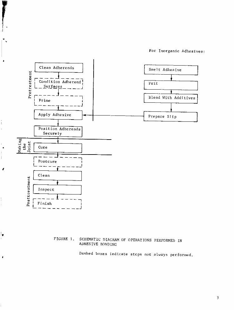
The steps necessary to makean adhesive bond are shownin Figure i. The
surfaces to be joined, usually referred to as the adherends, must be properly
ii
4J
4_
OO_
Clean Adherends
JCondition Adherend
Surfaces
J_Prime
Apply Adhesive j-
[[_uro i[ DJ Postcure iI t
f-I Clean
I Inspect ]
f Ii Finish lL ......... J
For Inorganic Adhesives:
i Smelt Adhesive i
l_r_ It
Blend With Additives
Prepare Slip 1
I_f
F IG URE i. SCHEMATIC DIAGRAM OF OPERATIONS PERFORMED IN
ADHESIVE BONDING
Dashed boxes indicate steps not always performed.
cleaned and conditioned. The conditioning mayinvolve application of an
electrolytic or a chemical-conversion coating, and maybe followed by applica-
tion of a _rimer adhesive in a volatile solvent. The substanceused to form
the bond, knownas the adhesive, is placed on the area to be bonded. The
adherends are placed in the desired relative position, both adherends being
in contact with the adhesive, and some means of maintaining them in this
relationship is provided. Time is allowed for the adhesive to cure, or harden;
during this period many adhesives require the application of external heating.
After the cure, the adhesive, now a solid, is hopefully uniformly distributed
as a film several thousandths of an inch thick between the adherend surfaces.
When viewed in cross section, the plane of adhesive has the appearance of
a thin line, referred to as the _lue line, or bond line. The joint is now
complete, although for some a_plications a second during cycle, or postcure,
is desirable. Posttreatment of the joint may include removal of any excess
adhesive that has oozed out of the bond area. For critical adhesive joints,
nondestructive testing is employed, following which the joint may be painted.
When inorganic adhesives are used, the bonding procedure differs somewhat.
Since inorganic metal-bonding adhesives are not generally available commercially,
it is necessary to prepare the adhesives from raw materials. These are
typically inorganic chemicals similar to those used in glass manufacture. The
proper mixture of raw materials is fused or smelted at a temperature that may be
as high as 4500 F depending on composition. The melt is then poured into water.
This quenching operation, referred to as fritting, rapidly cools the adhesive
and results in the formation of a coarse powder or frit. The frit may be
blended with additives prior to use. These additives may be metal or metal-
oxide powders, which are added to improve the bond strength, or they may be
materials added to stabilize the water suspension, or slip, the form in which
the adhesive is to be ultimately applied. After the additives have beenmixed
with the frit, they are blended in a milling operation, during which the
particle sizes are reduced. Whenthe desired range and distribution of
particle sizes has been attained, as evidencedby screening analysis, water
is mixedwith the powderto form the slip. The slip is then ready for applica-
tion to the adherends. The remaining steps in the bonding process with inorganic
adhesives are similar to those using organic adhesives, except that the curing
step is referred to as maturin$. Maturing temperatures are typically much higher
than curing temperatures of organic adhesives.
The increasing interest in adhesive bonding as a practical means of joining
of metals is attested to by the large number of books and handbooks (Refs. 1-7),
bibliographies (Refs. 8-12), symposia transactions (Refs. 13-21), and sun_nary
articles (Refs. 22-31), which have appeared during the last several years. The
reader is referred to these publications for a general background in metal-to-
metal adhesive bonding. The bulk of the metal-adhesive-bonding work done in
this country has been on aluminum, and the largest volume of literature is
concerned with bonding of various aluminum alloys. Stainless steels have
also been adhesively bonded with organic adhesives. The majority of the
development work on inorganic (ceramic) adhesives has been done using
precipitation-hardening stainless steel adherends.
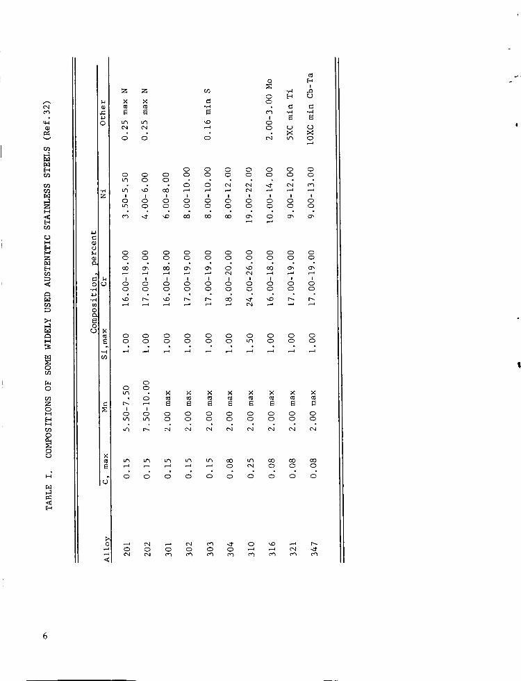
STAINLESS STEELS
Several different groups of alloys are included in the general category
of "stainless" steels. Composition limits of the more commonly used stainless
steels are given in Table I. The term "stainless" itself is a misnomer, since
some chemical agents will attack these materials. It may be because of
v
,.1
I-w
I-I
I-IZ
,-1
I-¢
0
0
c_Z0I.-I
I-I
0
0Q_
,-1
<
(Du
cD
J_0 C.D
0
0N
E
03
N
d
0
<
Z
N
Z
N
('M
0 0 0L_ 0 0
& & &
0 0 00 0 0
d __ ,--4
Io 60 0
,...1 ,....-i
0 00 0
• .
00 0
6 _u-i _'3
,.-i ,....4
,..-4 _0 0
0
0 _ _.Dz_ 0
,-" 0 (0 CD
,.....4
0 0 0 0 0 0 00 0 0 0 0 0 0
0 0 0 0 0 0 0
,-...4 i-.4
0 0 0 0 0 0 00 0 0 0 0 0 0
I / I I ! I ! I0 0 0 0 0 0 0 00 0 0 0 0 0 0 0
0 0 0 0 0 0 0 00 0 0 0 u_ 0 0 0
• • ° • • . •
X _ X X X _ X
0 0 0 0 0 0 0 00 0 0 0 0 0 0 0
L_ _ _ CO L,_ O0 O0 O0"_ "4 _ 0 _1 0 0 0
_ d o _ d d d
0 0 0 ,-'4 ,--_ c_ -..1"
objections to calling these steels stainless that they are sometimes designated
in the aerospace industry by the American Iron and Steel Institute (AISI) type
number followed by the letters CRES. CRES is an acronym for "Corrosion-
REsistant Steel". In this report the more familiar designation, stainless
steel, will be used.
There are three series of wrought alloys known as "conventional" stainless
steels, designated by the AISI as Series 200, 300, and 400. The 400 series
alloys are not austenitic and are bonded using _ocedures similar to those
for carbon steels and low-alloy steels. This report is concerned with the
adhesive bonding of those stainless steels that consist principally or entirely
of austenite, the face-centered cubic crystal structure of iron.
Series 200 Stainless Steels. These are alloys designed during and
after the Second World War as substitutes for the 300 series alloys. They
contain smaller quantities of nickel than the 300 series alloys, manganese
and nitrogen being substituted. The 200 series alloys are not heat treatable.
Series 300 Stainless Steels. The 300 series alloys are the oldest and
most common stainless steels. Their compositions are variations from the basic
Fe-18Cr-8Ni composition. As a class, they are austenitic, nonmagnetic alloys, al-
though some may be ferromagnetic under some conditions. Properties of these alloys
cannot be improved by heat treatment.
Precipitation-Hardening Stainless Steels. In recent years, alloys
have been introduced that contain small amounts of such elements as titanium _
and aluminum. These elements render the alloys heat treatable.

The precipltation-hardening stainless steels are groupedinto three types:
(I) Martensltic
(2) Semiaustenitic
(3) Austenitic.
This classification is based on the behavior of the steel when it is cooled
from an appropriate austenltlzing (solution treating) temperature.
In martensitic types, the austenite transforms to martensite on cooling.
This transformation causes some hardening. Additional strength is obtained
by aging at the proper temperature.
After cooling from the austenitizing temperature to room temperature,
the semiaustenitic types remain austenitic. Reheating to an appropriate tempera-
ture conditions the austenite so that it transforms to martenslte on cooling
to room temperature or lower. Subsequent aging at the proper temperature
increases strength over that obtained by the austenite-martensite transforma-
tion.
The austenitic types do not transform on cooling to room temperature.
Strengthening is obtained by aging the austenitic structure at an appropriate
temperature. Table II shows the compositions of a number of precipitation-
hardening stainless steels.
For a complete discussion of the stainless steels, the reader is referred
to a standard work on the subject, such as the ASM Metals Handbook (Ref. 32).
The curing temperatures required for adhesive bonding with organic adhesives
are below the heat treatment temperatures, if any, for the stainless steels.
If heat treatments of the adherends are required, they are performed prior to
organic adhesive bonding. The maturing cycle for ceramic adhesives may be
combined with the final heat treatment for precipitation-hardening stainless
8

I
v
[-,
r.n
r._
zI--I
r..9
!
i-i
i-i
I--I
0
i-ir.)
oo
o
I-4
H
O
A
c-
O
O
4.1
_ZO
U
>O
&
°,.-I O
..o,_O ¢'4 ¢',1
.z:;j
X
J
"_:1 j_._I ¢xl Ox
_1 o.
AA o
o0 X
_,oo._1- _o u_
Jc;o
oo
o •...4
N I
&oo• o .
00_,o
_o
xm
0_
_u
_ • °NOO
_ O_ -_
..... o
I i i ii i i i
N
ii io
RR_ R _
_o
ooo_
OOOO_
2_goo
ZOo
,'IJJ
o_
'&AA
oou-3u_
• 0.--i ,-4
i i ! ii_Lq i ir-- r_.
• .oO
_OO
IIII_OO
_JJ
RRRR
OOOO
ZjZM
_EE
oooo_
_m
oo__jj
JJJJ
0
r,- ,-_ m o'%
9

steels, but for organic adhesive bonding of the precipitation-hardening
stainless steels, procedures are similar to those for the conventional
stainless steels, and it is appropriate to include both types of stainless
steels in the same report.
ADVANTAGES OF ADHESIVE BONDING
It is appropriate to review briefly the advantages and disadvantages of
the adhesive bonding process itself. Knowledge concerning adhesive bonding
is not yet as widespread throughout industry as is knowledge of such other
joining techniques as riveting, welding, and brazing.
Advantages of adhesive bonding include:
(i) Mechanical strength
(2) Mechanical damping
(3) Smooth external appearance
(4) Electrical insulation under some conditions
(5) Capable of joining dissimilar materials
(6) Usable with thin or brittle materials
(7) Possible weight and size reduction
(8) Combined sealing and structural function
(9) Minimum finishing required
(i0) No thermal damage to metals
(II) May be least expensive joining method.
Adhesive-bonded joints made with organic adhesives, when properly designed
and fabricated, have lap-shear tensile strengths at room temperature up to 7000
psi, and in some cases fracture includes pieces of metal pulled from the surface
at the bond plane. Not only do the tensile strengths of adhesive-bonded joints
i0

comparefavorably with riveted and spot-welded joints, but adhesive-bonded
joints are often superior under cyclic-loading conditions. They distribute
the load moreuniformly across the joint than is possible with rivets or
spot welds.
The high dampingcapacity of organic adhesives relative to metals is
advantageousin reducing sensitivity of a structure to vibrational loading
and contributes to the lowering of noise level.
Smooth,unbroken lines are obtainable by adhesive bonding. A smooth
exterior surface is an absolute requirement for such applications as high-
speedaircraft. There are manyother applications where smoothcontours
contribute to the pleasing appearanceof a product.
Since organic adhesives are electrical insulators, they mayserveto
isolate structural membersthat are joined by adhesive bonding. In cases
were electrical isolation is not desired, a limited electrical conductivity can
be provided in the adhesive, or direct metallic connection can be madebetween
the adherends. If the primary purposeof a joint is for electrical insulation,
however, superior insulators are available, and the joint must be designed to
provide sufficient insulator path length to avoid electrical leakage.
The electrical insulating properties of adhesives makepossible the
joining of dissimilar metals with muchreduceddanger from galvanic corrosion.
This characteristic gives a designer increased freedomin materials selection.
The often-cited claim that adhesive-bondedjoints can be expected to provide
electrical insulation betweenadherendshas recently been questioned by Heimel
(Ref. 38). Resistance measurementsof a large numberof production joints were
madeand it was found that in every joint there was electrical continuity.
II

Keimel attributed this to local asperity contact betweenthe adherendsthrough
the adhesive. It is to be noted, however, that an unsupportedfluid adhesive
was used. Adherendinsulation, if it had beendesired, might have been
achieved using a supported film or tape adhesive.
Adhesive-bondedjoints can be madeeasily with very thin materials, such
as paper andmetal foil. Both mechanical fastening and welding become
difficult for thin material. Freedomfrom high intensity or suddenmechanical
loading during the makingof an adhesive-bondedjoint is also an advantagewhen
joining brittle materials.
Butt-welded joints are the llghtest possible type of construction. Adhesive-
bonded-lap joints, although they are inherently heavier than butt joints,
nevertheless mayoffer considerable weight and size advantageover mechanically
fastened lap joints in caseswhere parts are small, thin, or light, or would
otherwise have to be joined with large numbersof fasteners.
Certain adhesives, notably the elastomers and elastomer-phenolic blends,
are frequently used as sealants as well as structural adhesives. Oneexample
of their use for this purpose is in the so-called "wet wing" type of aircraft
construction, in which no separate fuel tank is used. The fuelin this instance
is contained within the wing by i00 percent sealing of structural joints.
Following curing of the organlc-adhesive-bonded joint, there is little
or no further work necessary. It maybe desirable to removeany small amount
of adhesive that extends beyond the joint, but this is easily accomplished.
Most joints are put in service without further attention after curing.
Oxidation which occurred on adherendsurfaces during maturing of inorganic
adhesives mayhave to be removed.
12
The curing temperatures required for most organic adhesives are below the
temperature range that will cause alternation of the metallurgical structure
of the commonmetals. In an adhesive-bondedjoint there is nothing corresponding
to the heat-affected zone of a weld. However,in the case of inorganic adhesives
and someorganic adhesives for high-temperature service, curing temperatures
maybe high enoughto causealteration of the metallurgical structure of the
adherends.
Whenthe entire cost of makinga joint is accounted for, adhesive bonding
maybe found to be less expensive than other methodsof joining. Such factors
as capital costs associated with tooling and fixturing, special joint prepara-
tion, bond-area coverageper unit volumeof adhesive, finishing, and the
associated labor costs must be considered. Thesecosts must be balanced against
all corresponding costs for other joining methods.
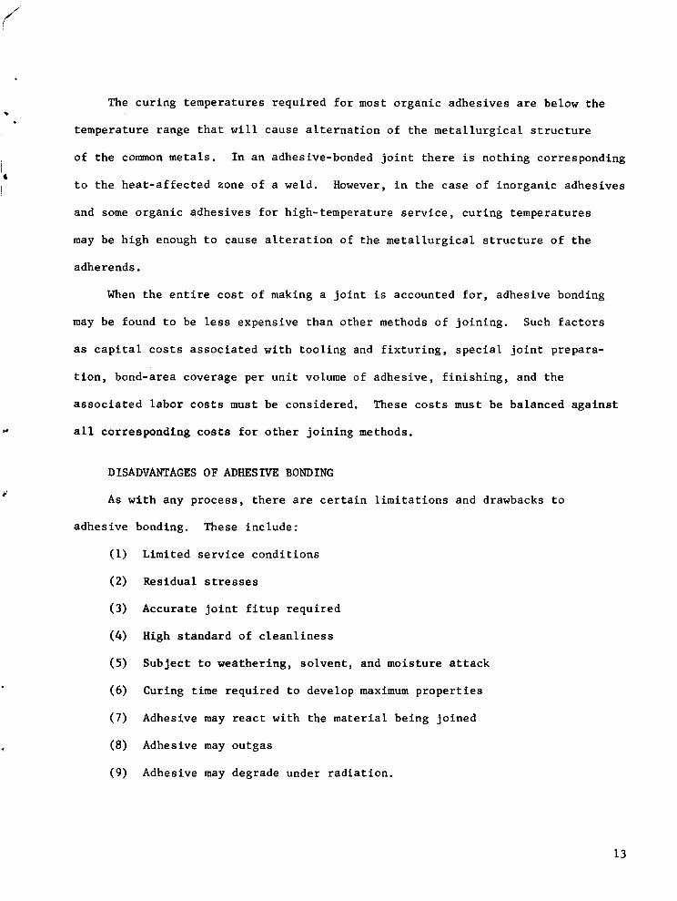
DISADVANTAGES OF ADHESIVE BONDING
As with any process, there are certain limitations and drawbacks to
adhesive bonding. These include:
(I) Limited service conditions
(2) Residual stresses
(3) Accurate joint fitup required
(4) High standard of cleanliness
(5) Subject to weathering, solvent, and moisture attack
(6) Curing time required to develop maximum properties
(7) Adhesive may react with the material being joined
(8) Adhesive may outgas
(9) Adhesive may degrade under radiation.
13

The upper-service-temperature limit that a goodexpoxy or phenolic
adhesive can withstand for an indefinite time is usually given as about
350 F. Although adhesives are available that will withstand short-time
exposureat 900 F and about i000 hours at 500 F (Ref. 39), and someRussianwork
reports tests madeat temperaturesup to 1832F (Ref. 40), allowable service
time at high temperatures for adhesive-bondedjoints is limited.
The presenceof residual stresses in an adhesive-bondedjoint becomes
an increasingly serious problemas curing temperature increases. The
stresses arise partly becauseof differential thermal expansionbetweenthe
adhesive and the adherend. Typically the thermal-expansion coefficient of the
adhesive is greater than that of the metal adherend, so the adhesive layer is
put in tension as the joint cools following curing. Unlike the residual
stresses resulting from welding, these residual stresses cannot readily be
annealedout. They can be minimized, however, by using a thicker glue line, by
altering the adhesive composition to makeit more resilient, and by postcuring.
Clearancebetweenadherendsto be adhesively joined should be uniform and
usually somewherebetween0.005 and 0.010 inch. This is a moreaccurate fitup
tolerance than someplants are accustomedto using.
Any but the most rudimentary joining process requires at least some
treatment of the surface prior to makingthe joint, even if it is only removal
of the burr arounda drilled hole. In welding, this surface is obtained by
melting awaythe surface layers of metal. In brazing and soldering, surface
films are removedby fluxing. In adhesive bonding, where neither of these
methodscan be used as presently practiced, adherendsurfaces must be
pretreated andkept clean until bonded. The difficulty of accomplishing the
14

necessary surface treatment dependsupon the accustomedstandards within a
particular plant or industry, and often it represents no major changesfrom
practices already in use for preparing a surface to be painted.
Caremust be exercised in the choice of an adhesive for a given applica-
tion, since there is dangerof degradation of the adhesive by its environment.
Thermoplastic adhesives, in particular, are subject to attach by solvents.
Cyanoacrylates are moisture-sensitive. Intelligent choice amongthe many
available adhesives can minimize the dangers from the service environment.
In somemanufacturing operations, the curing time for an adhesive-bonded
joint presents a problem. Typically, this time ranges from a few minutes to
several hours. During this period, the adherendsmust be fixtured so that there
is no relative motion betweenthem. Thereare possibilities of reducing the
magnitudeof this disadvantage. In somecases the parts can be designed so as
to be self-registering, for example. In someapplications, the adhesive cure
is accomplishedat the sametime the paint is bakedon.
Care must be taken in the selection of adhesives, fillers, extenders, and
curing agents to avoid compoundsthat will corrode the adherends. For example,
amine-curedadhesives are corrosive to copper-basealloys. Themagnitudeof the
problemcan be appreciated whenit is realized that there are over I00 different
curing agents for epoxy resins on the market today, manyunder trade namesthat
give no indication of their composition. There is no substitute for knowledge
and testing experience at this point.
Useof any organic material in enclosed or hermetically sealed devices
should be with caution, since sufficient vapor maybe given off from the organic
material during and after curing to impair the function of the device.
15

Considerable difficulty has been encounteredin the past with contact fidelity
in small electrical relays from deposits traceable to volatile componentsand
decompositionproducts from organic materials.
While all materials are damagedby radiation, rates of accumulation of
damageto the relatively delicate molecules of organic materials are greater
than for metals exposedto the sameradiation. Adhesive bondingwith organic
adhesives is the most radiation sensitive of the joining processes. Ceramic
adhesives, on the other hand, are amongthe least sensitive materials to
radiation.
With the present state of the art, inorganic adhesives do not possess
the advantagespreviously cited to the sameextent that organic adhesives do.
The high mechanicalstrengths obtained using inorganic adhesives, in the
9000-psi range, are considerably higher than the highest strengths that have
beenobtained with organic adhesives. Inorganic adhesives tend to be brittle,
however, and possesslittle dampingcapability. Inorganic adhesives intended
for metal bondingmaycontain metal powdersthat mayprovide electrically
conductive paths. The higher density of inorganic adhesives and the necessity
to maintain bond-line thicknesses of the order of approximately 0.010 inch to
assure uniform joint filling are unfavorable for weight reduction. High
maturing temperatures required with inorganic adhesives maycausemetallurgical
damageto the adherends, although it is sometimespossible to combinethe
adhesive maturing treatment with the adherendheat treatment. Not enough
inorganic-adhesive bondinghas been done to makean accurate estimate of its
economicsrelative to other joining methods.
On the other hand, inorganic adhesives in comparisonwith organic
adhesives are: (I) usable at higher temperatures, (2) require less
elaborate adherendpreparation, (3) not as sensitive to weathering, solvent,
16

and moisture attack, (4) outgas less in service, and (5) more radiation-
resistant.
To summarize,adhesive bonding is a joining process that has unique advantages.
It supplementsother joining techniques, and, whenfull advantageis taken of
the design opportunities offered by adhesive bonding, it maysupplant the more
traditional metal-joining processesin a surprising numberof applications.
However, failure to allow for the limitations and peculiar characteristics
of adhesives can lead to unsatisfactory results.
GENERALCOMMENTSONADHESIVEBONDINGOFMETALS
It is beyondthe scopeof this report to go into detail concerning adhesion
theory. The reader is referred to the general references cited earlier for
information on the subject. In this section, someprinciples which are particularly
important in metal-to-metal adhesive bondingwill be mentionedbriefly.
ADHESIONMECHANISMS
Any adhesive, to be effective, must wet the adherendsurface. Although
the forces of adhesion of organic materials to metal surfaces are not clearly
understood, it is knownthat these are short-range forces with respect to the
molecular dimensions. Therefore, presenceof foreign substancesthat do not
permit the close approach of the adhesivemolecules to the metal surface is
likely to result in poor bonding.
In the case of inorganic adhesives, the bonding mechanismappears to
involve transport of adherendions into the adhesive as well as transport of
metal ions from the adhesive into the surface layer on the adherend. Adherends
to be bondedwith inorganic adhesives are often deliberately oxidized, then
17
pickled, prior to bonding. This heat-scaling operation by removal of the oxide
formed, possibly serves to set up beneficial alloy concentration gradients at
the adherendsurface that improvewetting or shorten the diffusion time
necessary to establish a strong bondacross the metal-oxide interface.
Specifically, the adherendsurface would have beendepleted in chromium,
silicon, andmanganese,and enriched in nickel.
A significant finding of the programson inorganic adhesives development
was that presenceof a glassy phasewasnecessary for the formation of a strong
adhesive joint. Crystalline ceramics, air-drying cements, and recrystallizable
glasses were all examined,but gave inferior results.
DIFFERENTIALDIMENSIONALCHANGES
Thermalexpansioncoefficients of adhesives as a class of materials are
higher than those of metals. As has beenmentionedpreviously, the mismatch
in thermal expansioncoefficients can cause residual stresses in the joint with
temperature changes. An adhesive bondwill tend to be under internal stress
on cooling after the cure, the adhesive tending to be in tension. If there
has been shrinkage of the adhesive during the cure, the tensile stress in the
adhesive will be further increased in the completed joint. Delayed room-
temperature failure of joints due to these residual stresses is a fairly
frequent occurrenceduring the developmental stage of an adhesive-bonding
application, particularly whenthe bond area is large. This problemcan
usually be solved by adjustment of the curing cycle. If the joint is intended
for service below roomtemperature, even greater stresses will develop during
cooling to the service temperature, which mayresult in immediateand
spontaneousfailure of the bond.
18

Onemethodsometimesused to reduce thermal expansionmismatchis to fill
the adhesive with metal powder, preferably of the metal being bonded. This
is donewith risk of causing loss of adhesion, however.
Adhesives intended for use with metals are often complexmixtures of an
epoxy or phenolic resin blendedwith an elastomer, such as nitrile rubber, or
a thermoplastic, such as nylon. The purposeof these latter materials is to
increase the resiliency of the adhesive. A resilient adhesive is better able
to accommodateto the internal stresses in the joint and to resist failure by
peeling than a hard or brittle one (Figure 2).
USEOFSOLVENTCARRIERS
Adhesives intended for use in the bondingof metals, ceramics, and glasses
usually contain only small amountsof the solvents or other volatile materials
that are com_nonlyfound in adhesives intended for use with such porous materials
as wood, concrete, paper, and leather. The inability of solvents, if used,
to escape from betweennonporoussurfaces leads to greatly extendedcure times
and mayresult in porous bonds. Primers for metal joints do contain solvents,
but it is intended that these solvents be allowed to evaporate before the bonding
operation is carried out. Adhesivescontaining solvents can be used with
metals if they are coated and left apart until most of the solvent has evaporated,
but the most widely used metal adhesives, such as the epoxies and phenolics,
contain little or no solvent. Phenolics do liberate water on curing, however,
and joints bondedwith themshould be vented and securely clamped.
Inorganic adhesives, regardless of the methodof application, will generally
contain somewater. Heating rates must be controlled to allow this water to
escapeslowly. Adherendsmust be rigidly fixed to prevent anymovementduring
water evolution.
19
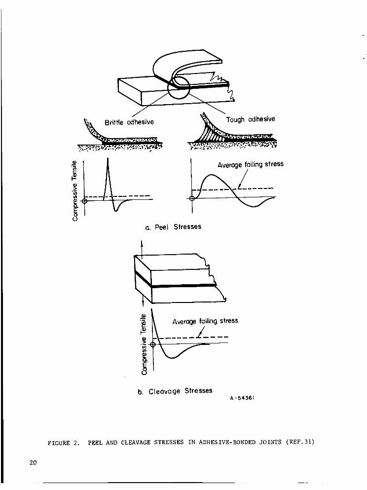
Average failing stress
Stresses
Q)
Average foiling stress-\- ..... .Z/__ __
b. Cleavage StressesA - 54:561
FIGURE 2. PEEL AND CLEAVAGE STRESSES IN ADHESIVE-BONDED JOINTS (REF.31)
2O

BONDING STAINLESS STEELS WITH ORGANIC ADHESIVES
DESIGNING THE JOINT
Since the best strength properties of adhesives are typically those
obtained under shear loading, lap joints are the preferred type where
possible. The detailed stress analysis of an adhesive-bonded joint is difficult,
partly because of the nonlinear stress-strain characteristics of adhesives.
Stress analyses have been made, however, and a recent survey report (Ref. 41)
presents a critical review of the present knowledge in this area. For purposes
of this report, it is sufficient to point out that stresses are not uniformly
distributed across an adhesive joint. Stress concentrations occur at the free
edges of the glue line, as shown in Figure 3. If the adherends are thin enough
to bend as shown in Figure 3, the stress concentrations in the plane of the
adhesive are accompanied by appearance of a tensile stress in the free edges of
the adhesive in a direction normal to the glue line, causing a tendency toward
peeling.
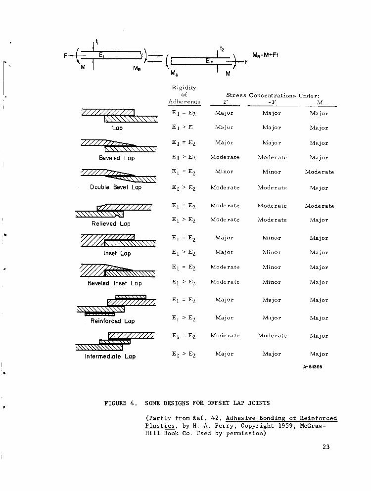
A compilation of the numerous designs developed for adhesive-bonded lap
joints is shown in Figures 4 and 5. Selection among these joint designs is a
compromise between strength and joint preparation cost. Similar principles of
placing the glue line in shear can be applied in the design of other types of
joints. Figure 6 shows some edge, angle, and tee joint designs. Sheet-metal
corner joints usually require a third component, which may be a formed, machined,
or extruded part. Tubular joints in hollow components should be designed using
sleeves around the bond area or by sizing one adherend to fit within the other
(Figure 7). Where butt joints must be made in thick materials, edges should be
prepared so that a shearing component exists along at least part of the glue
line, as shown in Figure 8. Similarly prepared faces having radial symmetry
21

FX
Y
_Q
O
O II II iI I
I iI I
I
IIIII
II
IIIII
IIIII
O
r_ a II
I i I
•ZzyaI I II i II i iI i
I II I III I I
I I
IIIII
A-54333
FIGURE 3. EXPLODED SCIIEMATIC VIEW OF SIMPLE LAP JOINT SHOWING
DISTRIBUTION OF STRESSES IN ADHESIVE AND ADHERENDS
22
MR M_
Lop
Beveled Lop
7///////77"r,-.--
Double Bevel Lop
r'/F/////////2
_\\\\\\\'>_3Relieved Lop
////////////_"////Ak\\\\\\\\\\\\"
Inset Lop
_\\\\\\\\
Beveled Inset Lap
Reinforced Lop
Intermediate Lap
MR:M+Ft
Rigidityof Stress Concentrations Under:
Adherends F -F M
El = EZ Major Major Major
E l > ]E Major Major Major
El = EZ Major Major Major
El > E2 Moderate Moderate Major
El = E Z Minor Minor Moderate
El > EZ Moderate Moderate Major
El = E Z Moderate Moderate Moderate
El > EZ Moderate Moderate Major
E1 = E2 Major Minor Major
E1 > EZ Major Minor Major
E1 = EZ Moderate Minor Major
E1 > E 2 Moderate Minor Major
El = Ez Major Major Major
E1 > E2 Major Major Major
EI = EZ Moderate Moderate Major
E1 > EZ Major Major Major
A- 54365
FIGURE 4. SOME DESIGNS FOR OFFSET LAP JOINTS
(Partly from Ref. 42, Adhesive Bonding of Reinforced
Plastics_ by H. A. Perry, Copyright 1959, McGraw-
Hill Book Co. Used by permission)
23

FI"_-- El _I
Mi Mi
;l/Ill/Ill,L\\\\\\\"Butt
Scarf
Offset Lap
F-/-/-r/-A////// / / / _\\\\\\N"
Strap
Double Strap
Recessed Double Strap
Beveled Double Strap
Double Lop
Rigidity
of
Adherends F
El = E2 Major
E l > E 2 Major
E 1 = E2 Minor
E 1 > E Z Major
MI =
Mz
Stress Concentrations Under:
-F M
Major Major
Major Major
Minor Major
Major Major
E 1 = E 2 Major Major Major
E 1 > E 2 Major Major Major
E 1 = E Z Major Major Major
E l > E 2 Major Major Major
E l = E g Major Major Major
E 1 > E 2 Major Major Major
E 1 = E 2 Moderate Minor Major
E 1 > E 2 Major Minor Major
E 1 = E2 Minor Minor Minor
E l > E 2 Moderate Moderate Moderate
E I = E2 Major
E I >> E2
Elt 2 = Eft 2 Major
Solid Double Lap
Double Butt Lap E1 > E2
/////_,_._\.._ E _ : EzDouble Scoff Lap E l > E 2
E l =E Z
E 1 > E 2
Elt I = E2t 2
Major Major
Major Moderate
Major Moderate Major
Major Minor Moderate
Moderate Minor Major
Major Minor Major
Moderate Minor Major
Major Minor Major
A " 54562
FIGURE 5. SOME DESIGNS FOR COLINEAR LAP JOINTS
(Partly from Ref. 42, Adhesive Bonding of Reinforced
Plastics L by H. A. Perry_ Copyright 1959, McGraw-
Hill Book Co. Used by permission)
24

Corners and An$1es
Ge ornetr)r Effic ienc y
Poor
Good
Excellent
Poor
Exc ellent
Geometry,,
Tees
_/////////////////////
-_/////////_\\\\\\_\<,
7//////7?//////////////Z,
Efficiency
Good when unbeveled;
excellent beveled
Poor without strap;
excellent with strap
Poor without straps;
excellent with straps
Good without strap;
excellent with strap
Good; excellent when
beveled
Fair
V Good
_//////////////////////_
__7_///////////i
Good when unbeveled;
excellent beveled
Fair
A - 54363
FIGURE 6. SOME DESIGNS FOR EDGE, ANGLE_ AND TEE JOINTS
(Partly from Ref 42, Adhesive Bonding of Reinforced
Plastics_ by H. A. Perry_ Copyright 1959_ McGraw-
Hill Book Co. Used by permission)
25

M El _P2 Ez
El
.F
Rigidity
of
Adherends
Stress Concentrations Under:
F -F PI>P2 P2>PI M
E l = E 2 Minor Minor Minor Minor Minor
E l > E 2 Major Major Minor Major Major
E l < E 2 Major Major Major Minor Major
Eltl - Egtg Major Major Minor Minor Major
dl dg
Eltl > Ezt2 Major Major Major Minor Major
dz
Eltl < E2t2 Major Major Minor Major Majord--7
E_ It, _P2 Ez M
F
Eltl - Eztz Major Minor Minor Minor Majordl d 2
Elt-- 1 > E2t2 Major Minor Major Minor Majord d
Elt l < Ezt__g Major Minor Minor Major Major
d 1 d 2
Eltl - E2t2 Major Minor Minor Minor Major
dl d2
Eltl > E2t2 Major Minor Major Minor Majord d
Elt.--_ 1 < Ezt--_ Z Major Minor Minor Major Major
dl d 2
A-54364
FIGURE 7. SOME DESIGNS FOR TUBULAR JOINTS
(Partly from Ref. 42, Adhesive Bonding of Reinforce8
Plastics, by H. A. Perry_ Copyright 1959, McGraw-
Hill Book Co. Used by permission)
26

Conventional Tongue and Groove
Landed Scarfed Tongue and Groove
Scarfed Tongue and Groove
J
FIGURE 8. SOME DESIGNS FOR BUTT JOINTS (Ref. 27)
End lap Mitered joint with sp_ine
__Mortise and tenon
FIGURE 9. SOME DESIGNS FOR CORNER JOINTS (Ref. 27)
A- 54554
FIGURE i0. PEEL-RESISTANT DESIGNS FOR FLEXIBLE MEMBERS (Ref.31)
27

can be used when bonding solid rods. Some corner joint designs for beams
and struts are shown in Figure 9. Thin strips of bonded metal that are likely
to peel in flexure loading can be secured in several ways (Figure i0).
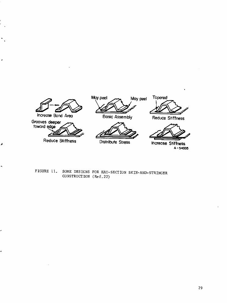
In adhesive-bonded skin-and-stringer panels, the designer has considerably
control over lateral stiffness of the joints through the use of doublers and
changes in details of the stringer cross sections, as shown in Figure 11.
Honeycomb-panel construction is becoming increasingly important as a
light-weight, rigid structural configuration. Such panels (Figure 12) have
been fabricated from wood, plastics, light metals, and ceramics by organic
and inorganic adhesive bonding, brazing, welding, and diffusion bonding. The
Armed Forces Supply Center has published a comprehensive handbook which covers
details of adhesive bonding of honeycomb (Ref.43). Figure 13 shows a variety
of edge-closure configurations that have been used with adhesively bonded
honeycomb panels.
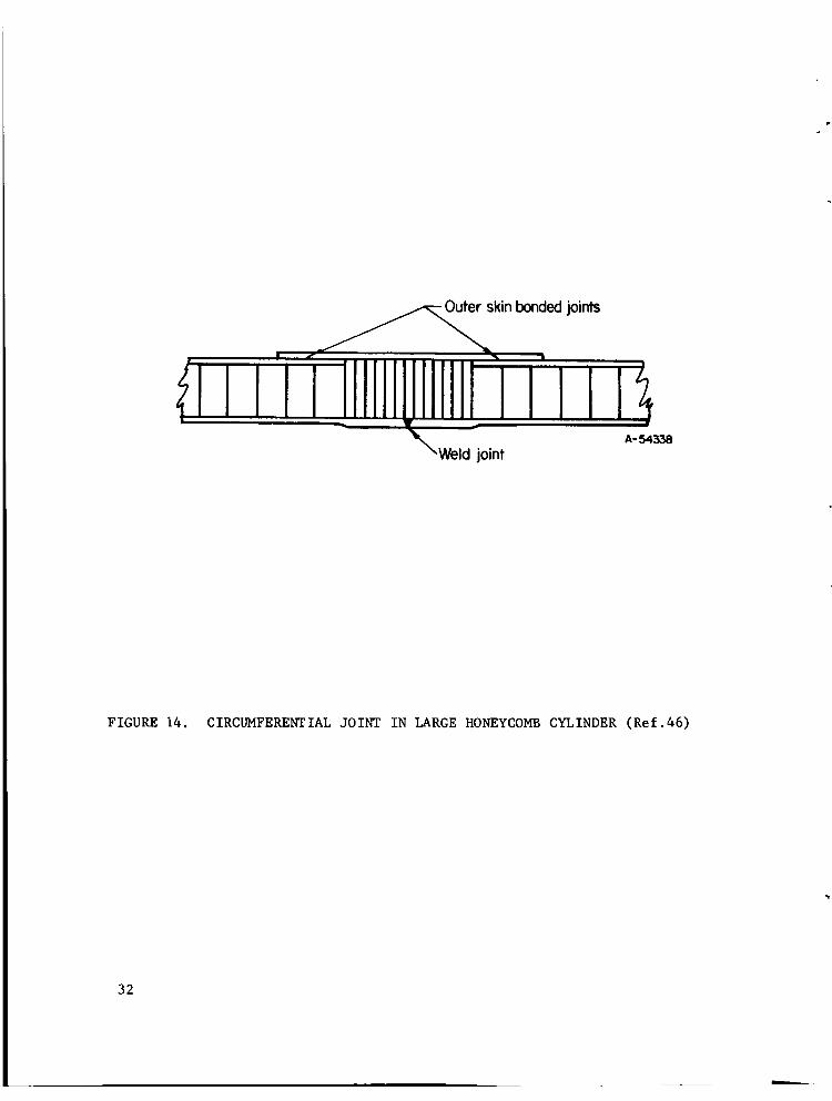
Fabricating large honeycomb structures that require continuous-core
construction or sharp bends is difficult. Some techniques that have been
used in these cases are shown in Figures 14 and 15. Some methods of
attachment of panels are shown in Figure 16.
In some recent bonded honeycomb sandwich design, it has been necessary to
used a stepped skin (Figure 17). Herndon (Ref.47) has pointed out the desirability
of making the steps external if possible, rather than internal, from the
standpoint of obtaining a reliable core-to-skin bond. With internal skin steps,
the core must be contoured, and tolerance mismatches in layup are likely. These
will result in voids or crushed regions in the core. Although the figure shows
the external steps as being integral with the skin, they might also be bonded
doubler sheets.
28
Increase Bond Area
Mo_y peel
Basic Assembly
Tapered
Reduce Stiffness
toward
Reduce Stiffness Distribute Stress Increase StiffnessA - 54335
FIGURE ii. SOME DESIGNS FOR HAT-SECTION SKIN-AND-STRINGER
CONSTRUCTION (Ref.22)
29

A -54336
FIGURE 12. TYPICAL BONDED SANDWICH PANEL (Ref.44)
30

"o"oC:
::::::::_ I _0
_ 2_ X
_ D
86
_ rn
:==_1
=:=:_ Ie- ¢--
Ixla.
om _
m r-e"
r
n
-.-t
,dIlJ
v
Zt11o
Z
0
z
K_
r.,¢3
r_I-.I
•- _o_
If-'II._|
I| ::::::::II_-a.
o(.J
31
skin bonded joints
"Weld joint
FIGURE 14. CIRCUMFERENTIAL JOINT IN LARGE HONEYCOMB CYLINDER (Ref.46)
32

Normal core splice
ond foil sheet interlayers
A-54337
FIGURE 15. DESIGN FOR A HONEYCOMB EDGE JOINT (Ref.44)
33
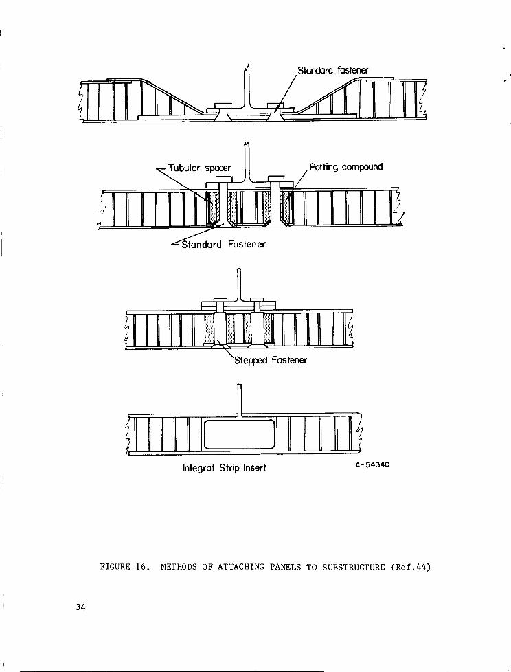
Standard fastener
!11II'! IL I1'IIIlilar sp__.rl j[_ [_] . Potting compound
!'!II!IIi I !: IIlllIIIll_rd Fastene; "
F_,, ! 1,,_1 . -
Stepped Fastener
,HI "
Integral Strip Insert A-54340
FIGURE 16. METHODS OF ATTACHING PANELS TO SUBSTRUCTURE (Ref.44)
34

Internal skin steps
_L
_ lillillll
External skin steps
tlllLlllti llllllllilllllll !|
A -54341
FIGURE 17. INTERNAL VS. EXTERNAL SKIN STEPS (Ref.47)
35

When using some of the stronger adhesives with thin metal adherends in
the metallurgically soft condition, cases have been encountered in which the
bond apparently fails adhesively, that is, at the adhesive-adherend interface.
Closer examination has revealed that the failure is not a result of poor
adhesion, but is caused by mechanical yielding of the metal, with the conse-
quent development of a large shear stress at the interface. The remedy for
this type of failure is to change the metal to a heat-treated or cold-worked
condition that has a higher yield point (Ref.48), to use a larger overlap,
or to make the adherend thicker.
PREPARING THE ADHEREND SURFACES
Perhaps the most critical step in achieving a good adhesive bond is the
preparation of the surfaces to be joined. Although it is frequently stated
that the surfaces must be "clean", what is really meant is that certain types
of contamination must not be present. This fact was not appreciated in some
of the early work with metal-to-metal adhesive bonding, and many bond failures
that were attributed to poor adhesion are now believed to have resulted from
the presence of a mechanically weak surface film on the metal.
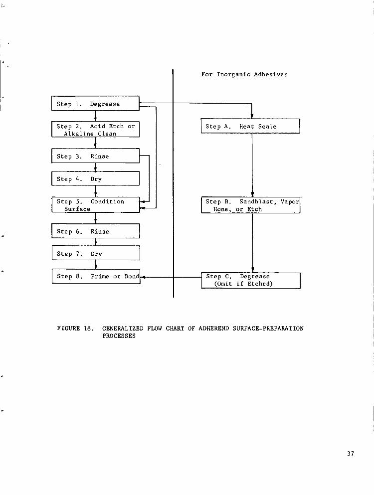
Figure 18 shows the sequence of operations common to most adherend
preparation processes.
36
Step i. Degrease
I Step 2. Acid Etch orAlkaline Clean
Rinse
Dry
I Step 3.
Step 4.
Step 5. ConditionSurface
Step 6. Rinse
Step 7. Dry
Step 8.
1
Prime or Bond_
For Inorganic Adhesives
I IStep A. Heat Scale
Step B. Sandblast, Vapor]
Hone, or Etch I
F
[ Step C. Degrease J(Omit if Etched)
FIGURE 18. GENERALIZED FLOW CHART OF ADHEREND SURFACE-PREPARATION
PROCESSES
37
Step i. Degrease. Degreasing is common to all processes and usually
employs a chlorinated solvent such as trichloroethylene. Other solvents, such as
acetone, methylethyl ketone, carbon tetrachloride, isopropyl alcohol, xylene,
toluene, and perchloroethylene, can be used with proper regard for their flamma-
bility, toxicity, and cost. Parts may be immersed, vapor degreased, or swabbed
with solvent-moistened cloths.
Vapor-phase degreasing removes contamination by a refluxing action in which
the pure solvent vapor condenses on the cold workpiece, dissolves the contaminants
capable of solution, and drips off the workpiece. This action ceases when the work-
piece reaches the vapor temperature, and it serves no purpose to leave the workpiece
in the degreaser for longer times.
When using the solvent-wiping technique, often necessary when the pieces to
be bonded are large, it is important to use clean, soap-free cloths, plenty of oil-
free solvent, and to wipe the solvent off the surface before it has time to dry.
Step 2. Acid Etch or Alkaline Clean. The next step is to remove any
visible oxide film or scale by a pickling or acid-etching treatment or to remove
any organic material with an alkaline cleaning solution. Whether either of these
treatments is necessary depends upon the history of the adherend. They may be
omitted for a cold-finished mill product if tests indicate no improvement in
adhesive-joint properties from their use. Many of the cleaning solutions used
are proprietary, and manufacturers' instructions should be followed concerning
their use. For large parts which require the wipe-on process, mechanical abrasion
with an abrasive pad or fine-grit paper has been substituted for this step in the
procedure (Ref. 46).
Step 3. Rinse. Opinions differ as to whether water rinses should be
hot or cold; tap, demineralized, or distilled water; immersion or spray; or
whether the hot rinse should precede the cold. Rider (Ref. 49) recommends that
38

electrical conductanceof water to be used for a spray rinse be less than i0 mi-
crohms,water for a tank rinse be less than 30 microhms,and warns that water in
manyplants contains organic materials. To determine whether tap water in a
given locality can be used for rinsing, long-term strength retention tests
should be madeof adhesive bondsmadeusing tap-water-rinsed adherendsas com-
pared with similar bondsmadeusing organic-free distilled water. Useof tap-water
rinsing is not recommended,however. The impurity levels in tap water, even
from a single source, are not subjected to long-term control and maybe responsible
for apparently randomtime periods during which bondstrengths producedare below
specification. Theobjective of any rinsing procedure is the complete removal of
the etching or cleaning solution as indicated by neutrality of the effluent rinse
water (pH= 7). Presenceof residual etching or cleaning solutions maycause
corrosion of the adherendsand mayaffect the adhesive chemically.
Step 4. Dry. Few processes include this drying step, preferable prac-
tice being to proceed directly to the surface-conditioning step following the
rinse. If it is necessary to dry the workpiece after Step 3, it should be done
in air as clean, still, and dust free as possible, or drying can be forced
using a clean, warm air blast or a circulating oven.
Step 5. Condition Surface. In the surface-conditioning step, a cor-
rosion film of controlled chemical composition and thickness is deliberately
formed on the adherend surface. Surface roughness is also modified, and if the
operation is properly carried out, any microscopic subsurface contamination
pockets that might have been rolled into the surface during mill processing are
exposed and removed. Typically, the films used are complex mixtures of phosphates,
fluorides, chromates, sulfates, or nitrates. The composition of the film may be
the most important single factor controlling the strength of the adhesive-bonded
joint under the desired service conditions. Evidence suggests that some film
compositions and thicknesses are markedly superior to others, especially at ex-
39

tremes of service temperatures. No systematic study has been published of the
influence on joint properties of film compositions and thicknesses as functions
of solution composition, treatment time and temperature, and alloy. Theapproach
has instead beenempirical, which is understandable considering the complexity
of the relationships and the experimental difficulties in characterizing the
films. Until more fundamentalinformation is available, the user must choose
amongpossible surface-conditioning processeson the basis of tests madeusing
his parts bondedand tested under simulated service conditions.
Steps 6 and 7. Rinse and Dry. Statements made under Steps 3 and 4
apply here also.
Step 8. Prime or Bond. Metals differ in the rate at which atmospheric
oxygen and moisture will reform a sufficiently thick film on the metal surface
so that the value of the surface preparation is lost. For example, copper and
brass should be bonded in,mediately after cleaning. Bonding of aluminum can be
delayed a half hour after cleaning. For titanium, an elapsed time no greater
than 8 hours between cleaning and bonding is recommended. Stainless steels have
been successfully bonded days after cleaning. The longer the time, however, the
more the likelihood of organic contamination from handling, from airborne liquids
or solids, or from accidental causes, or of mechanical damage to the surface film.
Best practice, therefore, is to bond immediately after surface preparation. If
this is not possible, the prepared surfaces should be primed according to the
adhesive manufacturer's directions and the parts stored in a clean, dry place,
preferably protected by a cover of some sort, until ready for bonding. Handling
of cleaned parts should be done only using clean cotton or nylon gloves.
Reported Surface Preparation Procedures for Bonding Stainless Steels
With Organic Adhesives. Mechanical abrasion and chemical treatments have both
been used for preparing stainless steel surfaces for adhesive bonding. The Ameri-
40

can Society for Testing and Materials tentatively recommendsthe mechanical treat-
ment--sandblasting, grit blasting, or vapor honing--of previously degreasedparts
as the preferred surface treatment (Ref. 50). Following the abrasion step, sur-
faces must be washed,brushed, or blasted with an oil-free air or nitrogen jet to
removeabrasive and metal dust. TheMinnesotaMining and Manufacturing Company
uses a trichloroethylene rinse (Ref. 51). Bondingshould be doneas soon as
possible following surface preparation. Thetentative ASTMprocedure would sub-
stitute a chemical methodof surface preparation only for adherendsthat are so
thin that they would be distorted by the forces involved in the mechanical treat-
ment. Onthe other hand, Hill (Ref. 52) reports superior tensile-shear strengths
with polybenzimidazole adhesive on 17-7 PHstainless steel using a chemical
treatment (G in Table III), whendirectly comparedwith a wet grit-blasting
treatment.
Bell Helicopter Companyuses a sulfuric acid chemical treatment, both because
their parts are thin and becausethey can control the chemical process moreac-
curately than a mechanicalprocess. They also buy their stainless steel heats on
the basis of a bondability acceptance test (Ref. 53).
Lockheedhas been successful in achieving high-strength bonds in both
stainless steels and titanium with the samealkaline cleaner. Theybelieve that
the alkali, if incompletely rinsed, is less likely to degrade an adhesive than
an acid would. Theyhave not observedany stainless steel heats that were not
bondable (Ref. 54).
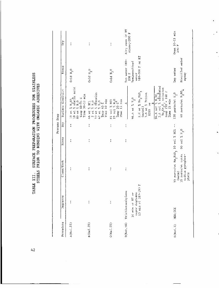
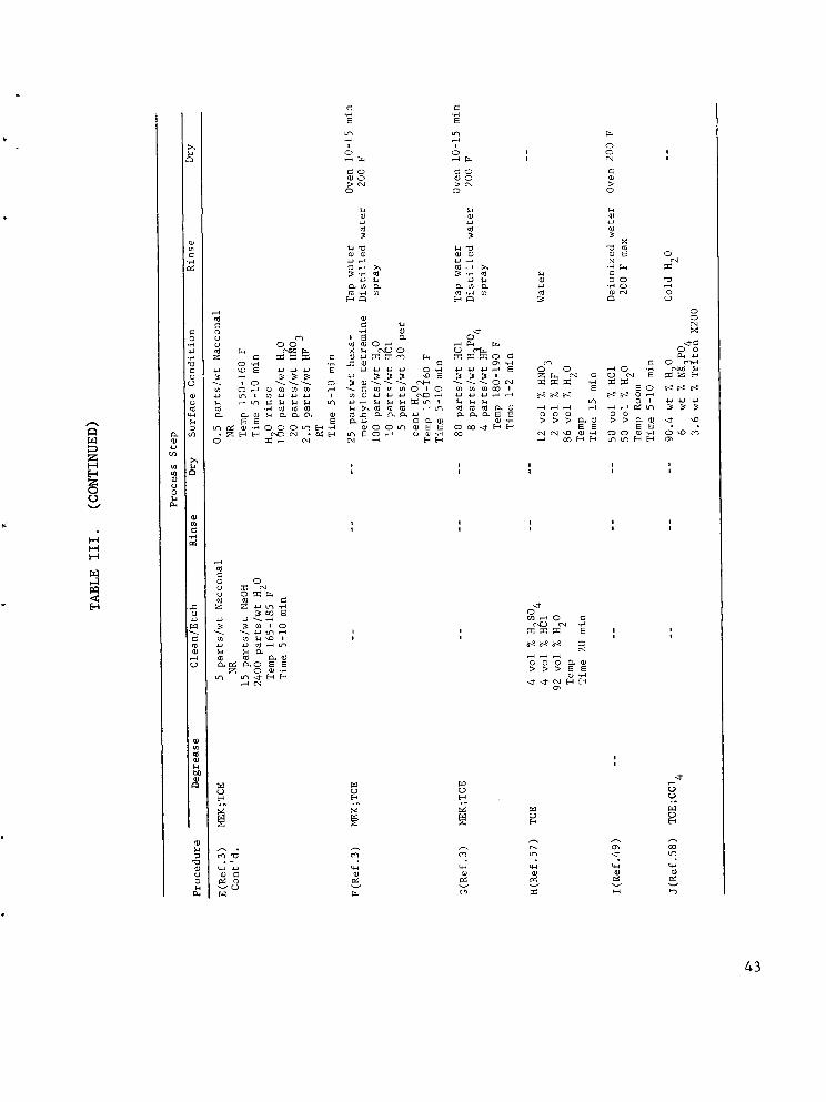
Table III summarizesthe various chemical surface treatments that have been
reported for stainless steels. Oneoften finds slight compositional variations
in the reagents as reported by different investigators, but an attempt has been
madein the table to include representative recipes for the different baths
reported.
41
MZI--I r._
r._ I--I
I--4
oo
I--I
E_
I-=1
_rq
or.,_l _
H M
.,4
6
u_
,-,,.
,12
_4
i ii i I
o
o
o 0
o o
.=.
ooo_ _o_o_ .--,O_E_
Lq Lq
V v v
_oo_V
E_
i
o ._00
•_ r_
_ o
o_o_
u_
c_
o_ °_0 c-_ .,-i
_ _ o
o _ o
,--4
I0,--4 r-_
0
.,-t
_.o r_ o
o _ c_l
0 ,-_
®-,_ _._
ii
_ 0
p_
,--4o _
©
u'3 _
[-_
/+2
i.-IIll
<
I i
gg go>(-1 >_,a0 0
g
>0
43

I--I
U
v
I--I
I-I
o
¢.u.u
L)
S.I
t
;> ,,.-i0
iJ
[--i i:::1
o4
O_ _e.l o,1_
oo'_,
1..i
e_
Coo
._ _ _.,_ o_oO_ ,-.4 _1_' N O
0 N _ a,_
•-_ 0", ,,=4 0 _ ,,-4
_N
,--.i
m O
_F-_
o_
• ._ _
_o
v
o_ o ._Z _,.
_oo.,..i
44

Meckelburg, Schlothauer, and Neumann (Ref. 55) studied a variety of surface-
preparation processes for stainless steels and reported that the three identified
in the table as A, B, and C resulted in the highest tensile-shear-strength
adhesive bonds. They also noted, however, that sandblasting or simply degreasing
in carbon tetrachloride gave almost equivalent results. Guttman (Ref. 3) lists
four procedures (D through G) for stainless steels, the first (D) also recommended
by Lindsay (Ref. 56). The procedures given in G and K have been used on PH 15-7
Mo precipitation-hardening stainless steel.
A powdery surface deposit, or smut, frequently forms on stainless steels
during chemical treatment. The smut can usually be scrubbed off, or, according
to Rogers (Ref. 62), can be chemically removed with a 25% H2SO4-2.5% N2Cr207
solution at 160 F. The precipitation-hardening stainless steels are said to be
more prone to smut formation than the conventional stainless steels.
In setting up a surface preparation procedure for critical structural
joints, one should try one or more candidate procedures, select one on the
basis of comparative joint strength tests, and then vary bath compositions and
process parameters to optimize joint strength.
Compromises. Relaxing of the surface-preparation requirements must be
done cautiously, because some very subtle factors may cause an unexpected loss of
bond strength. Bikerman (Ref. 2) suggests that surfaces may actually be con-
taminated by a sandblasting operation if the sand contains organic matter, as is
often the case if the sand has not been prebaked. He also cites results by other
investigators that show a 50 percent loss in adhesive bond strength due to 0.i
microgram of decanoic acid (a material similar to a perspiration film) per square
centimeter of adherend surface. When beginning work with a new material, the user
probably will save time and money in the long run if he will use moreelaborate
procedures than he believes are necessary and will then work toward their simpli-
fication, instead of the other way around. This is true even if the user is
experienced in the art of adhesive bonding. 45
Tests for Proper Surface Preparation. The so-called water-break test,
which can be used at any stage of the cleaning procedure, is the simplest and
most widely used method of determining surface cleanliness. If a drop of dis-
tilled water wets the metal surface and spreads, or if a film of distilled water
on the surface does not break up into individual droplets, the surface can be
presumed to be free of harmful organic films. A surface which is uniformly wet
by distilled water will probably also be wet by the adhesive.
A drop of an organic solvent has sometimes been substituted for the drop of
water. This is not a suitable test, since the organic solvent may have the power
of dissolving any organic film present and then wetting the surface. Thus it
would not indicate presence of the contaminant.
It should be emphasized that satisfactory wetting of the surface in the
water-break test merely shows whether the surface energy of the metal (which
may still be coated with a hydrophilic film) is higher than that of water. It
gives no information concerning the strength of any film present and, therefore,
is not a test of attainable adhesive-bond strength. A satisfactory waterbreak
test is at best a necessary, but not a sufficient, requirement for high bond
strengths.
SELECTING THE ORGANIC ADHESIVE
Because of the large number of organic compounds, it is not surprising to
find that there are hundreds of commercially available adhesives. Although these
substances fall into a limited number of chemical categories, it is probably safe
to say that no two adhesives manufactured by different companies are precisely
alike. For example, each of the many different curing agents for epoxy resins
imparts something of its own characteristics to the adhesive. Innumerable
variations are possible in details of resin chemistry and blending, and the
industry pattern is that detailed information concerning adhesive compositions
is usually proprietary with the adhesive manufacturer. For these reason§ un-
46
satisfactory performanceof one manufacturer's adhesive in an application cannot
be interpreted as an indication that no adhesiveof that class can be used. The
unsatisfactory behavior maybe due to somedetail of the user's bonding process
to which another adhesive might not be so sensitive. A goodexamplemight be
high sensitivity of one adhesive to alkalinity of a poorly rinsed adherendsurface,
while another adhesive maybe relatively unaffected. Twoor three promising ad-
hesives should therefore be tried for a newapplication if there is any uncertainty
of results.
The adhesives that are most useful for structural adhesive bonding belong to
the class knownas thermosetting adhesives. Theseadhesives undergochemical
changesduring the curing cycle which render themincapableof being dissolved in
the commonsolvents or melted. They tend to char whenoverheated. Chemically,
the changeduring curing consists of the formation of crosslinkages betweenresin
molecules to form three-dimensional polymernetworks. Thermosetting adhesives are
the strongest class of adhesives and the only class worthy of consideration for
high-temperature ap_iications.
Adhesive Tests. In this report, comparisons of bond strengths will be
made on the basis of simple overlap tensile-shear tests. Although other types of
tests are necessary to evaluate an adhesive completely, and may even be preferable
from a theoretical standpoint (Ref. 63), the simple lap joint pulled in tension
is easy to make and test and provides meaningful comparative results. Dimensions
of the tensile-shear specimen have become generally accepted as set forth in
Federal Test Method No. 175, Tentative Standard Method I033.1-T. A sketch of the
test specimen is shown in Figure 19. All tensile-shear results mentioned in this
report were obtained using specimens having dimensions shown in the sketch unless
otherwise noted.
47

.'_#;';q i" 1 ]:?_ss¢/, _ _'J i I I, ,,, / _ fin.(x,,'t'I i I ii/i//
--3in. --'l I-in. I"L"I I-in. V3in. -- -_-
= 9 in • _ 1 0.064 in.I " --I
L_=_-in.,
Where Y = adherend yield strength, psit =adherend thickness, in.r = 1.5x estimated adhesive
shear strength, psi
L is usually token as 0.5 in. for metol odherends.
/
FIGURE 20. CONFIGURATION OF PANEL AND INDIVIDUAL TEE-PEEL TEST
SPECIMEN (REF. 64)
48

Another type of mechanical test that is sometimes used in adhesive evaluation
is the tee-peel test, one specimen for which is shown in Figure 20. This test
is not covered by Federal Test Method No. 175. It is apparent that adherend
material and thickness can influence the results of this test, which are reported
in terms of strain energy per unit width of specimen, in-lb/in.
A third type of test, referred to as the pi-tension test, is one in which
two circular blocks of the adherend metal are bonded with the adhesive under
test and then pulled in tension normal to the bond plane. This test is covered
by Federal Test Method No. 175, and sketches of the adherend block and the test-
ing arrangement appear in Figure 21. This test has been adapted for testing
adherence of honeycomb-panel cover sheets to core. Circular portions of the
cover sheets opposite each other are first isolated from the rest of the cover
sheets using a fly cutter. They are then bonded toblocks, and the entire as-
sembly is pulled in tension. Results will be influenced by the details of core
configuration, so this is a specialized test.
Figures 22 and 23 show the specimen design and test fixture for determina-
tion of the shear modulus of an adhesive. Lunsford (Ref. 65) discusses the use
of this test and the design significance of the modulus values obtained, as well
as design testing of honeycomb panel specimens. Two relatively simple test
specimens have been used at General Dynamics/Fort Worth to generate panel edge
fitting design data (Figures 24 and 25) by varying the ratio between the overlap
test length and the core thickness, L/T. It has been found that use of the
compression L/T specimen gives higher strength values than the tension specimen.
Reed and Marano (Ref. 66) have shown that for polybenzimidazole adhesives
tested at high temperature, the perimeter of the bond, or the amount of adhesive
exposed directly to air is a joint design factor of equal importance with the L/T
ratio and the adhesive shear modulus.
49

_o.oo_"..I-_
1.129" cl_ /
I
ation of food
st gripAdherend
Testgrip
.---Appticotion of foodA- 54343
FIGURE 21. ADHEREND BLOCK AND TESTING ARRANGEMENT
FOR PI-TENSION TEST
From Federal Test Method No. 175, Method i011.i.
50

Alignment shaft ,o.ooo"
Loading-block alignment pins / Use sleeveooo2.000 "°.°'suse precision hardened dowels _ _ (5.080 -Eo3e cm)of 0.50"(I.27 an) diam.
• 2.9 cm)
.xl.15"__, ,_ ,, \kJ v _ ] Isometric View, 7"(29cm) _ _ _ J_V
4" 0"003 ' II " •
2 103-o.ooo 10-32 NFX 0.3 (0.76 cm),_ -""-,_+..L.-_'_Speclmen• ,o.ooe Oval point set screw _ --
(5.350-o.ooo cm)
I(2.540 + O.O015cm)
"a()
\ ,Z _/R= 1.500 ÷aoos"
/__;:_oo.oo,_c_)Z--Die m = 0.500 -0.ooo
+0.013"( I.27 -o.ooo cm)
i
.°o
b-
t
I
-!... 12.2cm)=OD ring
5.0"(12.8 cm)LI
=-' 11 ,
Side View
FO'500" //Loading block;c,_. c_)'_._,o_ ,o.,.=+.,oo.,no_,oc.._l._
"_ _.Two adhesive layers __ _._Three adhesive
Interlaminar adherend ring _ layerst 't f I Thickness'_ O.20 t°'°°3"I/9.o9o"(2290m)I W,dth j" (0.508'°'°%m)? 1
/_" -0,006 +0.015I D: 4.400-o.ooo (I I. 18-°.°°° cm)
Section A-A A-54344
FIGURE 22. ADHESIVE TORSIONAL SHEAR SPECIMEN AND
ALIGNMENT SETUP (REF. 65)
51

Moin pillow block,
Secondary Moment armpillow block
Specimen\
|/
1
Two bondlines
//
p p_te
Secondarypillow
A
Main pll lowblock
Specimen
Me_nt armEyeb°lt-/
/
A - 54345
FIGURE 23. TORSIONAL SHEAR JIG (REF. 65)
52

Overlap test length
FIGURE 24. OVERLAP COMPRESSION TEST SPECIMEN
Overlop test
A- 54346
FIGURE 25. DOUBLE OVERLAP COMPRESSION TEST SPECIMEN
(REF. 47)
53

General Dynamics' Portashear test has been used as a production quality
control test on bonded panels (Figures 26 and 27). Although in the test a cir-
cular piece of the face sheet is sheared losse from the core, the damaged region
is small and can be patched. A direct measure of bond strength achieved in pro-
duction can thus be obtained without destroying the panel.
Other mechanical tests applied to honeycomb include the climbing-drum peel
test (covered by Federal Test Method No. 175), and various forms of tests in which
honeycomb panels are loaded as 3-point and 4-point beams, in flatwise compression,
and in edgewise compression, tension, or shear. A detailed study of these tests
is beyond the scope of this report, however, some information concerning them will
be found in Reference 33.
Adhesive Standards and Specifications. Guttman (Ref. 3), Katz (Ref. 7)_
and Licari (Ref. 67), have summarized or reproduced in their entirety the numerous
Government, military, and industry-wide specifications relating to adhesive bonding.
Physical Forms of Adhesives Packaging. Metal-bonding adhesives are most
commonly used as liquids, films, or tapes. Some of the thicker liquids are thixo-
tropic*, which is an aid in maintaining proper positioning of adherends following
adhesive application, but prior to curing.
Adhesive films and tapes, either unsupported or supported on a carrier, are
attractive for production operations because of easy control of bond-line thickness
and convenience of handling. The form in which the adhesive is used in a particular
application will depend upon the joint area to be bonded, the production volume,
the types of equipment on hand, and the available forms of the adhesive to be used.
Most of the two-part liquid adhesives used in industrial quantities are
shipped in cans or drums. A wide variety of equipment is available commercially
that can meter and proportion the resin and hardener as desired, mix them, and
dispense the mi×ture.
* Thixotropic materials are viscous if allowed to stand undisturbed, but decrease
in viscosity temporarily followitlg stirring or other agitation. On standing,
54 they revert to their former gelled state.
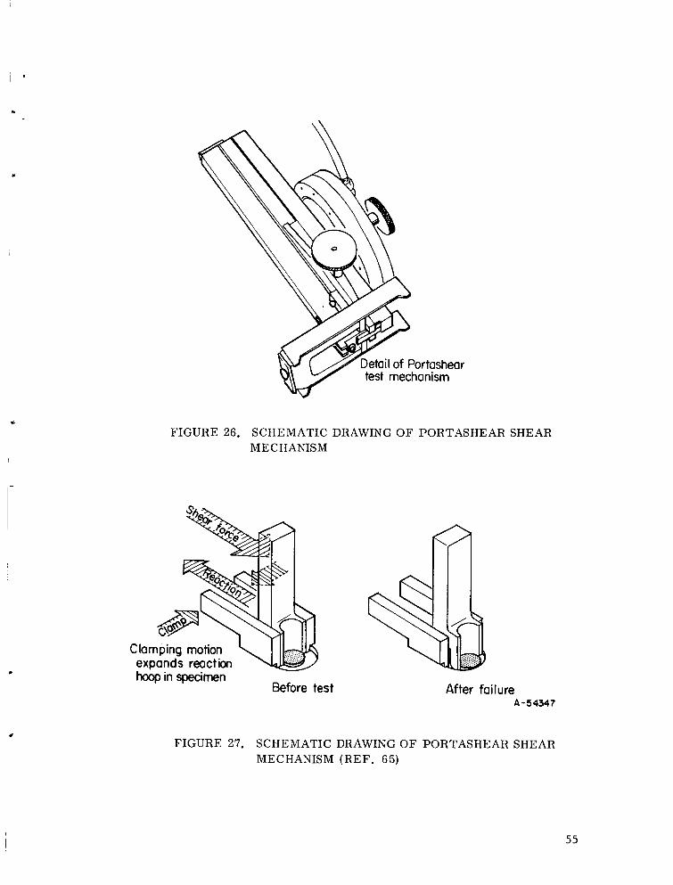
Detail of Portasheartest mechanism
FIGURE 26. SCHEMATIC DRAWING OF PORTASHEAR SHEARMECHANISM
Clamping motion '-.,expands reactionhoop in specimen
Before test After failureA-54_1.7
FIGURE 27. SCHEMATIC DRAWING OF PORTASHEAR SHEAR
MECHANISM (REF. 65)
55

Two-part epoxy adhesives are being packaged in small quantities in separate
collapsible tubes with extenders in the hardener so that one squeezes out equal
lengths of material from each tube and mixes them with a spatula on a clean sur-
face, such as glass.* Thorough mixing is often assured by coloring one of the
components and mixing until the color of the resin-hardener mixture is uniform.
A more convenient method of packaging two-part adhesives in small quantities
is the use of a two-compartment flexible plastic container. The container is so
designed that the compartment divider can be ruptured by manual pressure, allow-
ing the premeasured quantitites of resin and hardener to come in contact. Mixing
is accomplished by kneading the package, after which the package is opened and
the adhesive is dispensed.
A popular packing method for silicone sealant adhesive as a one-part liquid
is based on the evaporation of a volatile chemical blocking agent after the adhesive
is exposed to air. Departure of the blocking agent permits the resin-hardener
reaction to occur.
Development is under way for mechanically blocked packaging systems, in
which the hardener is held suspended and dispersed in the resin within molecular
sieve particles or microcapsules that can be ruptured by heat or mechanical
pressure.
Working and Storage Requirements. Prior to mixing, many two-part epoxy
adhesives, consisting of resin and curing agent, can be stored at room tempera-
ture almost indefinitely. Once mixed, however, they have working times of only
minutes or hours, depending upon the ratio of resin to curing agent and the speci-
fic curing agent used. The adhesives must be applied during the working time or
the cure will have progressed to the point that the resins may be too stiff to
* Use of organic fi|ms, such a_ C_llopha_e, a:_ ._i×ing surfaces is not recommended.
Cases are known where chemica1:_ ir_m _uch i _ Im_ have been absorbed by adhe-
sives, causing a loss in bond _:t,_'_I_th.
56

apply. Two-part epoxies have the advantagethat they can be cured at room
temperature, thus requiring no curing ovens, autoclaves, or heated presses.
Their properties are generally inferior to those of heat-cured epoxies, however,
unless they are given an elevated-temperature postcure.
One-part epoxies and phenolics generally must be cured at elevated tempera-
tures, although a room-temperature-curing epoxy film adhesive has recently become
available. The former are compoundedmixtures of resin and curing agent and have
a limited shelf life. Usual shelf life of present commercially available one-part
epoxies and phenolic adhesives is from 6 monthsto a year at roomtemperature.
Shelf life can be extended if the adhesives can be stored in a freezer or refrigera-
tor. The recently developed film adhesive mentionedabovehas very limited room-
temperature working life and is shipped from the manufacturer to the user under
dry-ice refrigeration.
Cansof adhesives and curing agents, onceopened, should be used as quickly
as possible or tightly reclosed and returned to storage in a cool place. Curing
agents should be ordered with, and used with, specific batches of adhesive. Use
of adhesives from storage should be on a first in-first out basis, and outdated
adhesives should be discarded or should not be used without at least first making
bond-strength measurementsto insure that they have not deteriorated. Users of
large quantities of adhesives makesimple quality assurance tests on their ad-
hesives (such as tensile shear and tee-peel, for example)at frequent intervals
to eliminate the possibility of off-specification adhesives being used in their
manufacturing operations (Ref. 68).
Service Conditions. No single adhesive is available that is superior
for all service conditions. A user therefore makes a selection among possible
adhesives on the basis of known or anticipated service conditions for the appli-
cation.
57

High Temperature. Strengths of adhesives, like strengths of metals,
decreasewith increasing temperature (Figure 28). It is difficult to state
precise upper limits for service temperatures of the various types of adhesives.
The limiting temperature dependson the anticipated service life, the metals be-
ing bonded, the magnitudeand state of stresses imposed, and the presenceor
absenceof deleterious environmental factors such as oxygenand radiation.
Several helpful review articles have recently appeareddealing with high-
temperature adhesives (Re_. 69-71). It is generally observed that the same
adhesive will give different tensile-shear-strength values whenused to bond
different adherends. It is therefore dangerousto assumewithout makingtests
that strength values reported for bondsare valid whenmadeusing adherends
other than the stainless steel of interest. Additional variables influence the
bond strength, amongthemsurface treatments and degradation reactions.
At elevated temperatures, strengths of adhesive bondsgenerally decrease
with time (Figure 29). Over someranges of temperature, and dependingon prior
curing conditions, bondstrength mayincrease with time for awhile (Figure 30).
The general trend, however, is towards progressive loss of strength with time,
the loss occurring at increasing rate with increasing temperature.
Atmosphericoxygenattack has been identified as being amongthe most im-
portant mechanismsby which organic adhesives degrade at high temperatures.
Figure 30 showsthe behavior of one adhesive at 600 F in air and in nitrogen,
for example.
ThermalCatalytic Degradation. An adhesive-bondedjoint must be thought
of as a dynamicsystemconsisting of an adhesive polymer molecule/adherend
constituent cations/atmospheric oxygenand water vapor. Recognition of the
dynamicnature of the bond is particularly important for high-temperature ap-
plications. Under the influence of heat, reactions tend to take place that include
cracking of the adhesive molecules, evolution of low molecular weight, volatile
reaction products, and diffusion of metal ions, oxygen, and water vapor into the
adhesive.

4 I Epoxy_/Polybenzimidazole
,i j_ _ _......_Epoxy- phenolic -
Igpoxy-si.lic6ne_MZ_i _ed_eooxv_.--'_--_) I I I , , ,'-- y
0 2OO 4O0 6OO 8O0Test Temperature, F A-5,_4e
FIGURE 28. TEMPERATURE DEPENDENCE OF SHORT-TIME
TENSILE-SHEAR STRENGTHS OF VARIOUS CLASSES
OF ADHESIVES (REF. 69)
Adherends unspecified.
59

.w
_3.5
3.0
2.5
2.0
1.5
1.0
0.5
..... T I I I 1 I
;./Nitrile-phenolic at 230 F __ , //.. Epoxy-phenolic at 250 F
N_' _'c_ L_o,35oF _ m_._Epo_y-_,i__(Tested_, ogi,ngternpem,tures)at =350 F I
_. , ,._L 2 2-#Aging Time, years
FIGURE 29. EFFECT OF TIME AT TEMPERATURE ON TENSILE-SHEAR STRENGTHS OF JOZNTS BONDED WITH
VARIOUS ADHESIVES (REF. 69)
Adherends unspecified.
"_- 2.8, _ Epoxy-_)henolic _lhesives
--' .___L \1 I_/
x _'_ '600 F in nitrogen --
\_. ' ,,.,_,_25 F. \%.,,1450F -_
__600 F _
:_0.4#. o
20 60 K)O HO leo
Aging Time, hours A-s4349
FIGURE 30. EFFECT OF TIME, TEMPERATURE, AND EXPOSURE
IN AIR OR IN NITROGEN ON TENSILE-SHEAR
STRENGTH OF JOINTS BONDED WITH AN EPOXY-
PHENOLIC ADHESIVE (REFo 69)
Adherends unspecified.
60

For adhesive-bonded joints intended for service in air, the degradation
due to oxygen must be largely tolerated, although access of oxygen to the adhesive
can be minimized by use of thin bond lines and clever joint design. The chemical
nature of the metal ions diffusing into the adhesive from the adherends has also
been found to be an important cause of deterioration of adhesives at elevated
temperatures. Some metal ions accelerate the degradation reactions in the ad-
hesive. Arsenic, a semimetal, in the form of pentoxide or sulfide, has been
found to retard degradation and has been purposely added to some high-temperature
adhesives.
Recent work by Flom, Speece, and Schmidt (Ref. 72) employing neutron acti-
vation analysis, electron paramagnetic resonance, thermochemiluminescence,
infrared and mass spectrometry, and vapor phase chromatography, has shed new
light on the detailed degradation mechanisms of epoxy, phenolic, and poly-
benzimidazole adhesives with aluminum and stainless steel adherends. The epoxy
was found to degrade in two stages, the second of which is catalyzed by iron, but
not by aluminum. Degradation of the phenolic adhesive was accelerated to some
extent by aluminum and catastrophically by iron. Polybenzimidazole, though more
stable than the other two adhesives, did degrade, and the degradation mechanism
was different depending on whether the adhesive was in contact with aluminum or
iron. Flom, et al, did not include the tensile-shear strength values for their
specimens in their published report.
New High-Temperature Adhesives. The polybenzimidazoles (PBI) and polyi-
mides (PI), are being investigated for service at temperatures above 350 F. Levine
(Ref. 39) has coined the term "heteromatic" to describe the molecular structures
of these adhesives, which have high proportions of aromatic and heterocyclic rings.
The molecules tend to be spatially compact, with strong interatomic bonds that re-
sist oxidative attack.
61
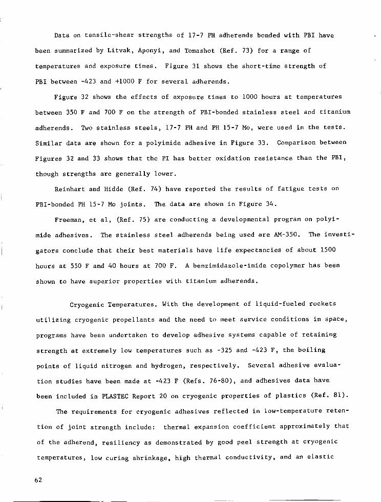
Data on tensile-shear strengths of 17-7 PHadherendsbondedwith PBI have
been summarizedby Litvak, Aponyi, and Tomashot(Ref. 73) for a range of
temperaturesand exposure times. Figure 31 showsthe short-time strength of
PBI between-423 and +i000 F for several adherends.
Figure 32 showsthe effects of exposure times to i000 hours at temperatures
between350 F and 700F on the strength of PBl-bondedstainless steel and titanium
adherends. Twostainless steels, 17-7 PHand PH15-7 Mo, were used in the tests.
Similar data are shownfor a polyimide adhesive in Figure 33. Comparisonbetween
Figures 32 and 33 showsthat the PI has better oxidation resistance than the PBI,
though strengths are generally lower.
Reinhart and Hidde (Ref. 74) have reported the results of fatigue tests on
PBl-bondedPH15-7 Mojoints. Thedata are shownin Figure 34.
Freeman,et al, (Ref. 75) are conducting a developmental programon polyi-
mide adhesives. Thestainless steel adherendsbeing used are AM-350. The investi-
gators conclude that their best materials have life expectancies of about 1500
hours at 550F and 40 hours at 700 F. A benzimidazole-imide copolymerhas been
shownto have superior properties with titanium adherends.
Cryogenic Temperatures. With the developmentof liquid-fueled rockets
utilizing cryogenic propellants and the needto meet service conditions in space,
programshave beenundertaken to develop adhesive systemscapable of retaining
strength at extremely low temperatures such as -325 and -423 F, the boiling
points of liquid nitrogen and hydrogen, respectively. Several adhesive evalua-
tion studies have beenmadeat -423 F (Refs. 76-80), and adhesives data have
been included in PLASTECReport 20 on cryogenic properties of plastics (Ref. 81).
The requirements for cryogenic adhesives reflected in low-temperature reten-
tion of joint strength include: thermal expansioncoefficient approximately that
of the adherend, resiliency as demonstratedby goodpeel strength at cryogenic
temperatures, low curing shrinkage, high thermal conductivity, and an elastic
62

u_ _" ro oJ -- 0
!sd 0001 'qJ,SueJ_,S J0eqs-el!sUel
c_
r./3
E_
E_03
03
OH
ZO
03
H
h_
0
_._Z
.<
r_I
Z
E-.t
,A
63
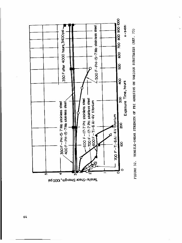
Li
/
.sd00_ ' q_,6ueJ_,S JoeqS- el!SUe.L
°
64
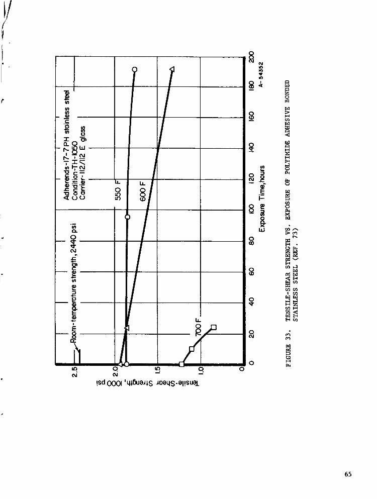
u_
w
oCO
0_0
0
0oJ
00
Zo
t_
I-4
i.-t
H
g
Q
O
d,-,r_
E-tm_
r._ H
I--t
65

E 0o-:Eo
o _,
I
o,_<_
%
!
"o
_" eO oa
o_
o
(J
%
-_o
v
E_
O
E_ZHO
O
o0
H
PI
I-I
C3H
c_
E
o iu_u_
,_=(_4J
H
00r!.e! (_
,13 (_m,.t=o,-o
66 !sd 0001'sseJ_,S pa!ldd_,

modulus no greater than that of the adherend. Other desirable characteristics,
some of which are of interest only in specific applications, include low specific
gravity, long shelf life, short cure time, room temperature curing without pres-
sure, sufficient flow to fill voids, good impact and vibration resistance, and
freedom from reaction with liquid oxygen when mechanically shocked (LOX compati-
bility).
Kausen's survey (Ref. 69) includes adhesives for cryogenic temperature
service. Figures 35 and 36, taken from his paper, summarize the tensile shear
strengths of different adhesive types and some specified modified phenolic sys-
tems. From Figure 22 it will be noted that polyurethane and epoxy-nylon adhesives
have superior strengths up to around room temperature. As with high-temperature
adhesives, however, these data should be applied to specific adherends with
caution.
Figure 36 shows detailed data for specific adhesives of the modified
phenolic class. It is interesting to note that the two rubber-phenolic blends
had the highest and lowest shear strengths in the group, which emphasizes the
fact that adhesives, even of the same type, differ widely in their properties.
British experiments (Ref. 82) have been conducted using stainless steel
and titanium alloys bonded with epoxy adhesives in which tensile-shear specimens
were repeatedly cycled between room temperature and various cryogenic temperatures.
After ten complete cycles, the specimens were tested at room temperature. Tempera-
ture cycling caused little change in maximum strength but a noticeable increase
in strength variation. The investigators noted an embrittling effect of the
temperature cycling on the adhesives as evidenced by abrupt failures of cycled
specimens during testing. Uncycled specimens pulled apart gradually.
Smith and Susman (Ref. 80) tested three of their developmental cryogenic
adhesives using aluminum adherends, after twenty cycles between room temperature
and -320 F. They, too, found no significant deterioration of tensile-shear
strength following cycling.
67
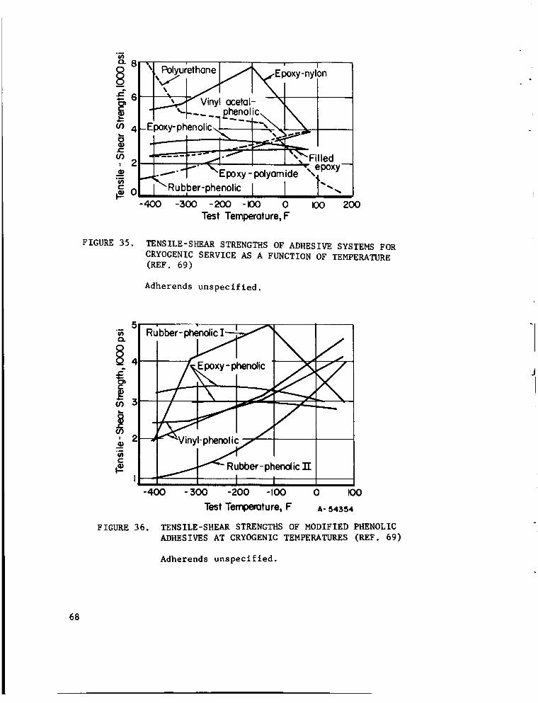
8
_4
o_, 2
¢-
_o
\ ,, _urethone EI;oxy-nylon
i. ,_.... E_no=ic. \
.............. _.I "_" "'%'_"Filled
-,, epoxy_./"_"" \Epoxy-polyomide ',
I"Rub,ber-phen°licI I "---4(X) -500 -200 -I00 0 _30
Test Temperoture, F
200
FIGURE 35. TENSILE-SHEAR STRENGTHS OF ADHESIVE SYSTEMS FOR
CRYOGENIC SERVICE AS A FUNCTION OF TEMPERATURE(REF. 69)
Adherends unspecified.
5
R
4
_3
I
__ 2
FIGURE 36.
J
---W
-400
__phenol,._.._ .__ _ _
I-p_lic_'
_ Rubber-phenol ic TrI I
- 300 -200 -I00 0 I00
Test Temperature, F A- 54354
TENSILE-SHEAR STRENGTHS OF MODIFIED PHENOLIC
ADHESIVES AT CRYOGENIC TEMPERATURES (REF. 69)
Adherends unspecified.
68

Polyurethanes are generally favored as adhesives for service at liquid
hydrogen temperatures at the present time, despite their relatively poor
properties above room temperature.
Radiation. Kircher and Bowman (Ref. 83) have summarized the
known information on the effects of radiation on materials. Their book, though
it does not deal specifically with adhesives, provides a timely and comprehensive
view of the field of radiation damage. Several earlier reviews have been pub-
lished that consider radiation effects on adhesives (Refs. 84-86). Two types
of high-radiation environments are visualized as being of principal interest for
possible applications of adhesive-bonded structures. These are the radiation
fields in space and those in the vicinity of nuclear reactors. Radiation fields
in space, so far as is known, consist principally of electrons, protons, and
gamma radiation. Fields in and around reactors consist principally of neutrons,
alpha particles, and gamma radiation.
Most organic materials, probably because of the low atomic numbers of
their constituent atoms, are affected much the same by the different varieties of
radiation. The damage mechanism consists of the transfer of large amounts of
energy to electrons within the material by their interaction with the incident
radiation, of whatever form. Organic materials, as a class, are sensitive to
radiation dosage, and the differences in damage due to differences in type or in-
tensity of radiation are secondary. Aromatic and heterocyclic (rlng-contalning)
molecules are generally more radiation resistant than straight-chain polymers.
Although in some cases there are constructive chemical reactions due to radiation
bombardment, the common form of damage consists of bond rupture due to the high-
energy electrons, with consequent loss in molecular weight and decreased mechanical
strength and ductility. Organic materials as a class are more radiation sensitive
than metals and ceramics. Radiation damage to an adhesive shows up first as a
loss of peel strength.
69
Radiation effects should be relatively independentof adherendexcept in
those caseswherethe adherenditself becomesradioactive. Theadherends, in
fact, offer to the adhesive a degree of protection against soft radiation.
Figure 37, taken from Arlook and Harvey (Ref. 85) showstypical behavior
of the tensile-shear strength of several adhesives, bondedto aluminumadherends,
with increasing amountsof gammaradiation. Underroom-temperaturetensile-
testing conditions, most of the adhesives showedcontinued loss of strength with
increasing amountsof radiation. Oneadhesive showeda strength maximum,and
another showedincreasing strength over the entire range of dosagestudied.
For specimenstested at elevated temperatures following irradiation, the order
of ranking of the adhesive strengths wassomewhatdifferent.
McCurdyand Rambosek(Ref. 86), using aluminumand stainless steel adherends
bondedwith a nitrile-phenolic adhesive, report that thick glue lines are less
susceptible than thin glue lines to damagefrom gammaradiation as measuredby
tee-peel strength (Table IV). The sameinvestigators report the results of tests
madeon honeycombpanels using composite film adhesives. In these composite
adhesives, which are fairly widely used for honeycombfabrication, a glass-cloth
carrier is coated on the face-sheet side with a flexible adhesive for peel
strength and is coated on the core side with a more rigid adhesive that has
better filleting characteristics. Loss of peel strength following irradiation
was found to be severe, adhesion failure occurring on the core side.
The amountsof radiation required to cause serious deterioration of adhesive
bonds appear to be such that adhesive bonding can be considered for use in space
for missions lasting at least of the order of months. The newheterocyclic
adhesives, such as the polybenzimidazoles, should be less radiation-sensitive
than types heretofore available. However,adhesives that can withstand the in-
tense radiation found in the immediatevicinity of nuclear reactors are not
presently available.
70

0
0q- 8 8 o o_ _ _ _ 8 o
q_Bu_ls p_o!po_!un jo _uaoJed'q_ueJ_S JooqS_el!SUa.L
0
7i

TABLE IV. EFFECT OF GLUE-LINE THICKNESS ON TEE-PEEL
STRENGTH OF A NITRILE-PHENOLIC ADHESIVE
WITH RADIATION EXPOSURES (REF. 86)--
STAINLESS STEEL ADHERENDS
Glue-Line
Thickness,
mils
Tee-Peel Strength, in-lb/in., At
Indicated Dosage, megarads
None i00 300 600 900
1.2 I0 7 5 3.5 2.5
3.7 14 9 7 4 2.5
i0.0 30 20 9 3.7 3.5
16.1 19 14 6 4.5 3.5
Combined Variables. Relatively little is known concerning the influence
on adhesive-bonded joint strength of the interaction effects between simultan-
eously applied environmental variables. Adhesives are commonly tested by exposing
joints to these variables singly. Sharpe (Ref. 87) has recently reported the
existence of a hitherto-unsuspected interaction between humidity and mechanical
stress. This effect consists of a substantial and progressively increasing loss
of strength with time, an example of which is shown in Figure 38. The shapes of
the curves are similar to those of stress-rupture curves for metals. Although
the curves presented are for a cyclic environment (Figure 39), the effect also
occurs under static humidity-stress conditions. Sharpe did not reveal the identi-
ties of the adhesives tested, but stated that he found significant strength losses
in all types of adhesives. The effect was shown to occur with 2024-T3 aluminum
and Type 302 stainless steel adherends.* Relative strength loss for the two ad-
* A simple surface preparation was used for the stainless steel, with "reliable,
excellent" results. It consisted of vapor degreasing, followed by 15 minutes
at room temperature in a 12 weight percent HC solution, rinsing in distilled
water, and drying with oil-free compressed air.
72

6
5
(/3
o 5
J_Or)
Io,)
0
Adherends
0--0 2024- T3 aluminum
X----X Type 302 stainless steel
2 4 6 8 I0 20 40
Time To Failure, days
60 80 I00
A- 54560
FIGURE 38. TIME TO FAILURE VERSUS STRESS FOR ADHESIVE
Z IN ENVIRONMENT C (REF. 87)
73
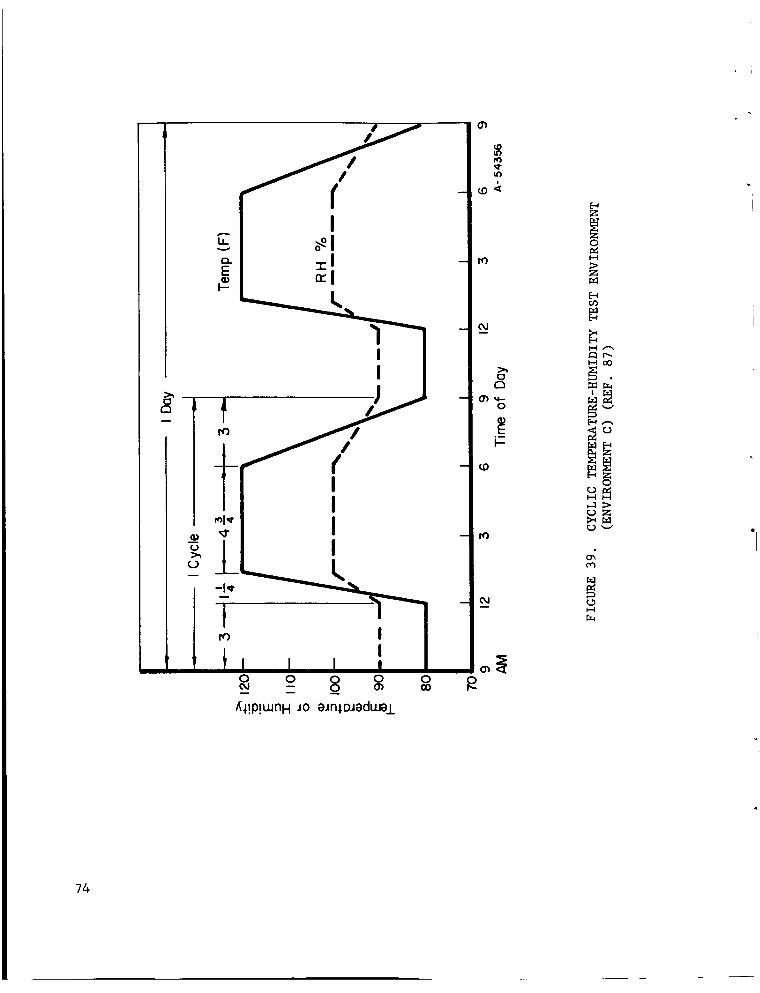
0O0
oJ
E_Z
0
r._E-_
I--I _'-x
_r_I-_oo
v
E_
tJZ
r.jv
i-I
74

herends differed for different adhesives. Ruptures occurred with no prior deforma-
tion of the adhesives. The failure mechanism is not yet understood.
APPLYING THE ADHESIVE
The manner in which adhesives are applied to adherend surfaces will depend
upon the form of the adhesive and the production rates desired. Thick liquid
adhesives can be applied by roller coating, brushing, troweling, or dip coating.
Thinner liquids can be brushed on, flow coated, or sprayed. Dip coating is useful
only for joint geometries that do not result in much adhesive loss or for parts
that can be wiped to remove adhesive from areas of the part where it is not desired.
Flow, or curtain, coating is a high-production process widely used in the plywood
industry. Flat parts are passed under a flowing curtain of adhesive. Tapes and
films can be conveniently hand applied if the adherend is first laid out on a
heated table. Alternatively, the adherend may be laid on an unheated table and a
tacking iron used in spots to cause sufficient adhesion of the film to the adherend
to hold the adhesive in place. Film adhesives are popular in aerospace structural
bonding because they are neat and clean to apply. Adhesives in powder or stick
forms do not appear to be as widely used as liquids, pastes, and films in this
country for metal-to-metal adhesive bonding. Powders, when used, have been applied
by sprinkling over the adherend or by immersing the heated adherend in a fluidized
bed of the powder adhesive.
When two-part liquid adhesives are used, they must be adequately mixed and
applied with minimum delay after mixing, since their working lives are limited.
Mixing and dispensing equipment for two-part adhesives is designed for accurate
metering and proportioning of the components of the adhesives. The actual mixing
is usually done in the dispensing nozzle just before the adhesive emerges. The
apparatus, and especially the nozzle, is designed for easy cleaning.
Most aerospace adhesive bonding applications involving two-part adhesives
are hand lay-up operations involving small quantities of adhesive. When adhesive
75

quantities are sufficiently large that handmixing is too slow, use of metering
and dispensing equipmentshould be considered.
TOOLINGANDFIXTURING--JOINTASSEMBLY
Whenbonding with adhesives that release water, solvents, or other volatile
substancesduring curing, it is often necessary to clamp the adherendsin proper
relation to each other with pressures up to several hundred poundsper square
inch. With "i00 percent solids" adhesives, such as the epoxies, such curing
pressures are not necessaryexcept in critical work where clamping will be used
to control glue-line thickness and alignment. Manufacturer's instructions for
the specific adhesive should be followed. In somecases, parts can be made
self-aligning and self-clamping by appropriate design.
Methodsof applying pressure during curing will dependupon the size and
shapeof the part, the magnitudeof the pressure to be applied, and the quantity
to be produced. There are several basic methodsin use. The simplest method
is to makethe adherendsself-clamplng. Another methodis to combineadhesive
bonding with another fastening methodsuch as riveting. Dead-welght loading can
also be used for parts having simple shapes.
For parts having morecomplexshapes, the vacuum-bagtechnique can be used
as shownin Figure 40a. Thevacuum-bagmethodis limited to pressures below
14 psi, however. Wherehigher pressures are necessary, the pressure-shell method
shownusedwith a heated mold in Figure 40b can be used. With the pressure-shell
method, pressure is limited only by the mechanical design of the confining parts.
It could be used equally well with oven curing as shown in Figure 40a, and, in
the same way, the vacuum-bag method could be used with a heated mold.
The autoclave method shown in Figure 40c is more elaborate. The
part must be sealed into a flexible-blanket assembly vented to atmosphere
so that a differential pressure across the bond can be applied. A hot-lnert-gas
atmosphere under forced circulation is used in the autoclave. Use of a sheet-
76

o.Vacuum- Bag Curing
=----_Tovacuum pump
Inletforpressurefluid
reSsureshell
Blanket(attached
ressureshell)
LSandwich
b. Pressure-Shell Curing
Inlet forpressure fluid
ylinder ,,Wing
" I,,-,, _" / 15psi
[ =_ ! ._- .J.,---IOOpsitoatmosphere)
Pressurebag_ ZElectricblanket
heetmetalmold
Discharge
c.Autoclave Curing d. Press Curing
A- 54357
FIGITRE 40. METHODSFOR CURING ADHESIVE-BONDED ASSEMBLIES (REF. 43)
77
metal mold is shown with the autoclave. This type of mold can be used if it is
not essential to maintain the maximum degree of smoothness on one side of the
bonded assembly. However, for such applications as aircraft skins, in which the
exterior surface must meet stringent aerodynamic requirements, a rigid mold must
be used for the exterior, all tolerance mismatches being taken up on the back,
or interior, side of the panel. For those situations where both surfaces of a
bonded assembly must meet smoothness and shape requirements, tolerances of parts
to be bonded must be held very closely, and heated presses such as the one shown
in Figure 40d must be used.
CURING
Usually, but not always, the adhesive manufacturer's recommended curing
conditions will result in bonds of optimum quality in a given application. Where
maximum properties are important, such as for aircraft skin panels, development
work by airframe manufacturers has resulted in complex curing cycles in which
heating rates are controlled, and temperatures and pressures are varied during
the cure in a precise manner.
Adhesive systems of the film and liquid types are available that cure at
room temperature. Precautions to be observed with this type of adhesive are:
(i) be certain that the working life has not been exceeded before use, and (2)
keep the volume of adhesive small. Considerable heat is often generated during
curing.
Novel Curing Techniques. Curing can sometimes be accomplished in ways
which take advantage of heating done for other reasons. In some automotive
applications, for example, the adhesive is cured by the heat applied to dry the
body enamel.
Radio-frequency dielectric heating is sometimes used to cure adhesive bonds
in which the adherends are insulators, such as wood or plastics. Smith and Susman
78

(Ref. 88) have reported results of the application of direct and alternating
electric potential across a metal-to-metal bond. Thedirect voltage is to be
avoided, since it results in electrolysis of the adhesive, but slight increase
over roomtemperature-cured strengths resulted from a 700-volt alternating
potential (frequency not specified) with an epoxy-polyamideadhesive. Hagberg
(Ref. 54) has achieved very rapid cures with metal-to-metal bondswith r-f
energy directly applied through adherendcontacts.
North AmericanAviation (Ref. 89) has developeda film adhesive containing
an array of fine, high-resistance wires. Current is passedthrough the wires for
a sufficient time to accomplish the cure. Whena wing flap cured in this manner
was tested in peel, failure occurred in the rivets used to attach the flap to
the testing frame at 7.5 times design load. Theadhesive-containing resistance
wires is commercially available.
Bandaruk(Ref. 90) has reported on theuse of internal electrical resistance
heating elements of graphite fabric. Sandwichpanels were bondedusing an epoxy
adhesive, and tensile-shear specimenswere preparedwith a hot-melt adhesive.
Another novel approachto adhesive curing consists of using an exothermic-
adhesive-reaction mixture (Ref. 91). The mixture is placed betweenthe surfaces
to be bonded, and they are then clampedin contact. Theparts are then heated to
the ignition temperature of the exo-reactant mixture, whereuponthe reaction takes
place, and a cured adhesive bond results. It is apparent that the short time at
temperature limits the adhesive composition to one which will cure rapidly.
CLEANINGTHECUREDJOINT
Very little cleaning of the cured organic adhesive-bondedjoint is usually
necessary, and most often none is performed. Any adhesive extruded from the bond
line can be removedby scraping or single-point machining, if its removal is
required.
79

TESTINGANDINSPECTION
The importanceof testing for adhesive acceptance, process control, and
outgoing quality assurancecannot be overstressed. Lot-to-lot variation in ad-
hesives is sometimessignificant for critical applications. Adhesivesand
primers already in-plant must be checkedbefore and during use to be certain that
they have not deteriorated with age or improper storage conditions. The adherend
surface preparation process must be continually monitored, and the curing process
controls must be in calibration. Finally, the bondedparts must be inspected
to assure quality. Successful manufacturers of high-integrity adhesive-bonded
structures invariably maintain effective testing programs. Somehave goneto
great lengths to establish their own tests. The literature on adhesive-bond
testing is extensive (Refs. 3, 63-65, 92-98, for example), and only a few
salient features will be mentionedhere.
Adhesive Evaluation. General Dynamics (Ref. 68) uses the tensile-shear
test for incoming batches of adhesive, a peel test for day-to-day checking of
adhesive quality and adherent cleaning efficiency, a beam-compression test if
the adhesive is to be used in honeycomb bonding, and a flow or gel time test to
measure ability of the adhesive to flow and wet the adherend surface. In the
case of low-flow adhesives, measurement of compressibility is substituted for
the flow test. Filleting strength of adhesives intended for bonding honeycomb
is measured by a variant of the pi-tension test in which a circular skin sample
is bonded to a core and the skin is then pulled in tension.
ToolinK Evaluation. Before bonding tools and fixtures are placed in
production, they must be proved by making destructive tests on parts bonded with
them. Process equipment and instrumentation must be periodically checked to in-
sure satisfactory operation. On-the-spot inspection during adhesive bonding is
necessary to enable adjustment of processing equipment with a minimum scrap loss
of product.
80

Destructive Testing. It is desirable to hold to a minimum any destruc-
tive testing that renders the bonded parts unsuitable for service. One way this
objective has been met is through the use of small detachable test coupons. Plan-
ning for this type of testing must be done at the time the tooling is designed.
The specific tests performed will depend upon the nature of the bonded parts and
their intended service. Use of test coupons does not entirely eliminate the need
for some destructive testing of the parts themselves. Use of the Portashear test
has already been mentioned.
Nondestructive Testing. The test techniques most widely used are
adaptations of ultrasonic test methods developed for metals, and may be carried
out with the parts immersed in water or dry with only a fluid-coupled transducer.
Several types of sonic test equipment are available from United States and foreign
manufacturers.
At the very least, sonic bond-testing equipment can detect unbonded regions
in adhesive joints. The Fokker Bond Tester can locate such flaws on the remote
side of a honeycomb panel. However, if detection of unbonded regions is the only
information desired, they can also be located by a skilled inspector using a coin
or a special light hammer to tap the part. Ultrasonic testers are capable of
giving additional information concerning adhesive-bonded joints. Correlations
have been made between Fokker Bond Tester reading and tensile-shear or face
sheet bond strength, so that as-bonded strengths can be predicted (Refs. 99,100).
Several aerospace manufacturers have worked out these correlations for their
particular bonding systems, and they are presently being used in quality control.
An attempt has been made to carry the use of the sonic tester one step
further, viz., to detect in-service bond-strength deterioration (Ref. I01). This
attempt was not successful. Tester readings did no___tgive consistent correlation
with losses in bond strength following exposure to salt spray, boiling water, high
81

temperature, vacuum,gaseousand liquid fluorine, and FLOX(30 percent F2 and
70 percent 02).
Sonic/ultrasonic emission, consisting of the detection and amplification
of the noise generatedwithin a specimenwith increasing load, has been applied
to adhesive-bondedjoints (Ref. 102). It was found that an easily detectable
increase in the noise at frequencies above16 kc occurred as the applied stress
exceed70 to 80 percent of the fracture stress. Presumablythis changein the
character of the soundemission wasassociated with local yielding or micro-
cracking of the adhesive. If the specimenis unloadedwithout exceeding this
microyield point more than a small amount,Schmitz and Frank believe that the
structure will still be serviceable. Themethodshould be useful in proof test-
ing of complexparts and pressure vessels. If was not established whether the
16 kc threshold is a function of specimensize or shape. The technique was not
successful with a highly flexible polyurethane adhesive.
Amongother methodsthat require the mechanical stressing of the part being
tested are the use of brittle or birefringent (Ref. 103) coatings. Thesetech-
niques, although successful in detecting unbondedhoneycombface sheet regions,
give no indication of bond strength. Thebirefringent coating can be used to
determine the residual stresses in face sheets following pressure testing. Unlike
the sonic/ultrasonic emission technique, both of these methodsare sensitive to
face sheet thickness.
Thermaltechniques have been used for examininghoneycombcore-to-face sheet
bonds, with muchthe samelimitations as the brittle and birefringent coatings.
Themethodsare basedon differing cooling rates of the face sheet in bondedand
unbondedareas. Onesystemdesigned for checking the bondbetweensolid-rocket
motor fuel and the motor case liner used a traveling radiant heat source followed
by an infrared pickup of the thermopile type (Ref. 104). A continuous chart record
of the scan waskept, and unbondedregions appearedas hot spots. The methodde-
82

tected i/2-inch-wide unbondedregions, but has the disadvantage that considerable
time maybe necessary to scana large part, a disadvantage it shares with sonic
flaw testing.
Other thermal techniques have employedwaxesor organic compoundsthat melt
or changecolor with temperature. Thecompoundis applied to the entire face
sheet, following which the specimenis heated. Unbondedregions appearas hot
spots becauseof their relative inability to conduct heat into the core. Although
the entire specimencan be examinedat the sametime, the effect for which one is
looking is transient, and there are problemsin heating the specimenuniformly.
Themost recently reported investigation of a methodof this type (Ref. 105) made
use of "liquid crystals" that showa very sharp and reproducible color change
at a desired temperature.
Although someX-ray examination of adhesive-bondedparts has beendone,
nondestructive tests basedon introduction of sonic wavesgive more information
and are most widely used. Unlike the case of brazed honeycomb,whereX-ray is
a major inspection tool, adhesive bondsare transparent to X-rays of the ener-
gies necessary to penetrate metal cores and face sheets.
Schmitz and Frank (op. cit.) have studied the electrical properties of the
bond line without obtaining any correlation with strength. Theywere unable to
obtain repeatable values of d-c resistance, loss tangent, and dielectric constant,
and concluded that these are not promising nondestructive test methodsfor
adhesive-bondedjoints.
The sameinvestigators devoted considerable effort to possible methodsfor
applying mechanical stress to panels for nondestructive testing. This informa-
tion is noted here becauseof its possible value to others concernedwith such
testing, but is beyond the scope of this report.
83

BONDINGSTAINLESSSTEELSWITHINORGANICADHESIVES
As part of a continuing search for adhesive bonding processeshaving improved
elevated-temperature service capability, the Air Force and the Navysponsoredwork
on inorganic (ceramic) adhesive developmentwith several organizations during the
years between1954and 1962. Adherendsused were principally 17-7 PH, although some
work was doneusing PH15-7 Mo, AM350, Inconel X, and Ren_41.
While the results of this programfell short of desired objectives in some
respects, particularly in the failure to achieve satisfactory mechanical shock
resistance, significant results were obtained that maystill be useful. Remarkable
slow bend joint ductilities and service temperatures (800-1000F) considerably in
excessof those of the organic adhesives available at the time were achieved with
stainless steel adherends. Somewhathigher service temperatures were achieved with
superalloy adherends.
The improvedservice temperatures over those of organic adhesives are the only
apparent advantageof the inorganic adhesives. With the developmentof polybenzi-
midazole and polyimide adhesives having service temperatures in the 600-700F range,
the temperature advantageof the inorganics has lessened and will probably lessen
further as improvementof organic adhesive systemscontinues.
Ceramicadhesive bonding must competewith brazing as a fabrication process.
The ceramic adhesivesare potentially less expensive than brazing alloys, do not
require vacuumor protective atmospheresduring firing, and require less precise
tolerances than brazing. The ceramic adhesives are not likely to attack or em-
brittle the adherends, sometimesa difficulty with brazing. Becauseof the rela-
tive inertness of the adhesives, joints can be refired if necessary. Firing
temperature%and times do not have to be controlled as precisely as with brazing
for manyjoints.
84

The disadvantagesof ceramic adhesive joints with respect to brazed joints are
considerable, however. Amongthese disadvantagesis that the adhesives weigh at
least twice as muchper unit area of joint. In complexaerospacestructures con-
taining considerable bondedarea, such as honeycombpanels, the weight penalty
associated with the inorganic adhesives becomesappreciable. Weight, plus the poor
resistance of ceramic adhesive joints to shockand impact loading and their lower
unit mechanical strengths comparedwith brazing alloys have resulted in the selec-
tion of brazing in preference to ceramic adhesive bonding for production applications.
SURFACEPREPARATIONOFADHERENDS
Proceduresfor surface treatment of stainless steel adherendsprior to bonding
with inorganic adhesives have varied in complexity amongthe different investigators.
Most have treated the surface preparation as incidental to the investigation and
have not reported their procedure in detail. It is probably true that surface
treatment is not as critical as for organic adhesive bonding becauseof the higher
firing temperatures involved and the (assumed)ability of the ceramic to absorb the
amountsof contaminant metal ions likely to be present without affecting the adhe-
sive materially. Nevertheless, the one group that did study the adherendpreparation
process in detail found that bond strength wassignificantly decreasedif any step
in their procedure was omitted.
The simplest procedure used for surface preparation, used for 17-7 PH, wasat
the University of Illinois (Ref. 106), and consisted of a sandblasting treatment.
Investigators at Boeing/Wichita (Ref. 107) also tried sand- and shot-blasting,
but found both processes unsuitable becausethey distorted the thin-gage sheet
being used in the fabrication of honeycombpanels. Boeing then settled on a treat-
ment consisting of a vapor degrease followed by an alkaline cleaner. Somework was
also doneusing a hydrofluoric-nitric acid etch.
85

Bayer, Johnson, and Patterson (Ref. 108) report in detail the developmentof
the surface treatment adoptedat Aeronca for use on 17-7 PH, AM-350,PH15-7 Mo, and
Inconel X nickel-base alloy in the honeycombpanel application. Panels produced
consisted of 0.032-inch 17-7 PHfacing sheets, 0.500-inch 17-7 PHand O.002-inch
foil, I/4-inch cell core bondedwith ACAI00-i adhesive. The process consisted of
the following steps:
Surface Preparation of Facing Sheets
NOTE: Handle all parts with clean white cotton gloves.
A. Cut sheets to size.
B. Vapor degrease facing sheets using best practice.
C. Lay skins on the firing rack. The skins should be separated from each
other. Any support should touch the nonbonding side of the skin.
D. Place in furnace at i000 F (1200 F for Inconel X) for 30 minutes to heat
scale the sheet.
E. Remove from furnace and air cool.
F. Place vertically in an acid bath of 20?o by volume of 63% nitric acid and
4% by volume of 70% hydrofluoric acid for 5 minutes at 150-160 F. If all
of the scale is not removed, return to the etch. Excess etch time should
be held to the absolute minimum. At no time should the total in_nersion
time in the etch exceed 7 minutes.
G. Cold water rinse for 5 minutes. Wipe off smut with soft, clean cloth.
Rinse and return to complete rinse for 5 additional minutes.
H. Place the skin in a neutralizer water solution of 0.16 oz/gal of borax and
0.48 oz/gal soda ash at 125-130 F for 30 minutes.
I. Cold water rinse for I0 minutes.
J. Air dry vertically, with forced ventilation.
86

Surface Preparation of Core
A. Cut core to size.
B. Vapor degrease using the best practice. NOTE: Core should be in horizontal
position.
C. Core position (horizontal or vertical) is optional during the heat scaling.
D. Place in furnace at I000 F for 30 minutes.
E. Remove from furnace and air cool.
F. Place the core horizontally in the acid etch bath referred to above for
approximately 3 minutes. If the etching and heat scale removal are not
completed, the etching may be continued in 30-second increments. Excess
etch time should be held to the absolute minimum. At no time should the
total immersion time exceed 5 minutes.
G. Rinse in cold water for i0 minutes. The core should be agitated to aid
removal of the heat scale.
H. Place in the 0.16 oz/gal borax, 0.48 oz/gal soda ash solution at 125-130 F
for 30 minutes. Agitate core occasionally to assure neutralization of all
acid in capillaries.
I. Cold water rinse for ten minutes.
J. Air dry in the horizontal position with forced ventilation.
ADHESIVE SELECTION
An inorganic adhesive for bonding stainless steels would probably be selected
and compounded by duplicating the best recipe and joint preparation procedure from
the research investigation reports mentioned earlier. For one to consider inorganic
adhesive bonding, service temperature would have to be between about 500 and I000 F.
At lower temperatures, an organic adhesive would probably be specified, and for
higher temperatures, a different alloy would probably be used.
87

The ceramic adhesives for which information is available are compositions of
borosilicate glasses plus metal or crystalline oxide phases. The compositions
developedwere arrived at after due consideration for wetting of the adherend,
matching the adherendthermal expansioncoefficient and elastic modulusas closely
as possible, and attainment of goodmechanical strength. Unless one is prepared to
undertake an extension of the research done to date, the choice of adhesives is
limited. A specific adhesive recipe and bonding procedure will be discussed in
subsequentsections.
PREPARATIONOFINORGANICADHESIVES
Oncethe desired adhesive and composition has been specified basedon the re-
quired thermal expansion coefficient, softening point, and elastic modulus, the
raw material recipe can be calculated. The raw materials will consist of suchcom-
poundsas the oxides, carbonates, nitrates, silicates, etc., of the constituent
metals. Rawmaterials should be of a high degreeof purity, since presenceof minor
quantities of undesired metals can changethe physical and mechanical properties of
the finished ceramic adhesive.
The rawmaterial charge is placed in a crucible and raised to the smelting
temperature. Care should be taken in the selection of the crucible material to
avoid crucible-charge reactions. A fireclay crucible has proved satisfactory for
the compositions used in past ceramic adhesive work on stainless steels. The
smelting furnace can be gas-fired, and the smelting is done in air.
After smelting, the molten charge is poured into a water tank. The rapid
cooling rate causesthe shattering of the material into a powder, or frit. The
frit is dried, following which it is sized by passing through a set of gradedsieves.
A wet or dry grinding operation maybe interposed between fritting and sizing.
Both the averagesize and the distribution of particle sizes will influence
the subsequentbehavior of the ceramic.
88

The sized frit, plus additives, is charged to a ball mill or a blender for
mixing and further sizing. The additives typically will consist of metal powders
intended to increase strength and ductility, suspendingagents such as ammonium
molybdate to control slip properties, possibly someorganic binder, and water.
Product from this operation, having the form of a slurry, or slip, is ready for
application to the adherendsat this point.
The technology of ceramic slips is complex. Thenatural settling tendency of
the insoluble ceramic and metal particles is offset by the fact that part or all of
the particles are in the colloidal size range and thus will tend to remain in sus-
pension. As is commonwith colloidal suspensions, however, there maybe a tendency
for the slip to gel, or "set up" with time. Themetallic and dielectric particles
themselveswould also tend to agglomerateand settle out rapidly if it were not for
their being electrically charged, all with the samesign. Careful control of the
pH of the sllp is necessary to maintain the proper suspensionand flow characteris-
tics. The reader should consult up-to-date textbooks on ceramic science and
technology for detailed discussions of the rheology of slips.
The detailed procedure used at Aeronca for preparing the ACAi00-I adhesive
is as follows:
Preparing the Adhesive
A. Raw Materials, Frit ACA I00-I
400 Mesh Silica, Chicago Vitreous
Sodium Nitrate, Coarse Granular, Tech.
Boric Acid, Chicago Vitreous
Ferric Oxide, J. T. Baker
Grams/
% 2000-batch
24.5 490
8.8 176
65.2 1304
1.5 30
89

B. Calculated ACAI00-I Frit Oxide Composition
SiO2 37.2%Na20 4.9%
B203 55.9%Fe203 2.0%
C. Methodof Manufacturing Frit
Basic laboratory size batch - 2000gramsof raw materials.
i. Heat the smelter and smelting crucible slowly, during a 1-hour period,
to approximately 2400F.
2. Addapproximately I000 gramsof the well-mixed raw materials.
3. Heat at 2400F for approximately 20 minutes until most of the frothing
has stoppedand volumereduction is obvious.
4. Add the rest of the raw materials.
5. Heat at 2400-2500F for 60 to 90 minutes until all frothing has stopped
and a pulled thread of the glass contains no bubbles.
6. Quenchthe molten glass in a 3-gallon bucket of cold water. Slow
pouring is necessary to produce the smallest possible frit.
7. Removethe excesswater by draining. Dry the frit thoroughly in an
ovenat 250 F for a minimumof 3 hours.
Milling of the Frits and Preparation of the Slip
i. Fill a dry 3-quart capacity ball mill to 40?=of its capacity with 50%
1/2" porcelain balls.
2. Add the frit to the 3/4 level of the mill.
3. Mill the frit for 3 hours at 68 rpmon a ball mill.
4. Removeall material passing the 48 meshscreen. Approximately half
of the frit will pass the 48 meshscreen.
D,
90
5. Mill the remaining frit at the samespeedfor approximately 5 more
hours or until less than 1/2%of the frit is contained on the 48 mesh
screen. Discard the material retained on the 48 meshscreen.
6. Weigh all of the ground frit and return to the ball mill.
7. Add 20 parts of -400 mesh17-7 PHstainless steel powderper I00 parts
of groundACAI00-i frit already in the mill.
8. Add 160 parts of water and mill the mixture for i hour. Additions up
to 240 parts of water mayhave to be madeto makeflowable slip. A
dip weight test of 35-45 gr/ft 2 should be obtained.
9. Continue wet milling until all but 1/2%of the material passes the
200meshscreen. This takes approximately 3 hours.
The slip should be discarded after 3 days or at any time there is
evidence of crystals forming in the slip.
i0.
APPLICATIONOFTHEADHESIVE
The ceramic adhesive can be applied to the adherendsurface either by dipping
part or all of the adherendin the slip or by spraying the slip onto the adherend.
If dipping is done, the slip on the back side of the adherendmust be wiped or
squeegeedoff before placing the adherendon the firing tray. Otherwise, an un-
desired joint mayresult. If spraying is the application method, care must be taken
to spray evenly. Boeing used spraying, dipping, and brushing. Aeronca found that
spraying gave superior results in honeycombpanel fabrication. TheUniversity of
Illinois, in their small-scale specimens,used dipping. Repeateddipping maybe
required to build up the coating.
After the slip has been applied to the adherendsurface, the water must be
driven off before the top adherendcan be put in place. Although drying can safely
be done in a baking oven at a temperature just in excessof the boiling point of
water, care should be taken to avoid excessive temperatures or heating rates
91
during the period of water removal. Thesecan result in shrinkage cracking of the
bisque, as the dried green (unfired) ceramic is called.
A fourth possible methodof applying the ceramic adhesive consists of pre-
forming a bisque sheet in a mold and manually placing it on the adherend. This
methodis not as satisfactory as the others becauseof the fragility of the bisque.
Thickness of the adhesive in the finished bond maybe controlled by means
analogous to the methodused with organic adhesives. A spacer layer of metal screen
of knownthickness can be incorporated into the joint, or shims can be used.
Aeronca's procedure for applying the adhesive, including a prefiring step for
easier handling during assembly, is as follows:
Applying Adhesive to the Facin_ Sheets
A. Heat the skins to be coated to 350 F + 20 F. One of several heating methods
can be used. Maintain this temperature during the coating operation.
B. Shake the ACA I00-I slip thoroughly. Do not use slips over 3 days old or
slips containing crystals.
C. The spray gun and accessories suggested for this use are:
I. Binks, Model 18, stainless steel spray gun
2. Binks, 64PA, stainless steel cap
3. Binks, 64VT, stainless steel nozzle
4. Binks, Model 80, pressure cup.
D. Fill pressure cup with ACA i00-I adhesive.
E. The technique for spraying material can be learned only by experience.
The following suggestions may assist in developing the technique:
i. Slips applied too rapidly will form undesirable glossy bisques.
2. The best results have been obtained with air pressures between 40-60 psi
and pot pressures between 2 and 5 psi.
92

3. The rate of spraying of material, the rate of flow of atomizing air,
and the proximity of the gun to the sheets are adjusted to control the
applied slips. The viscosity of the slip itself will affect all of
these adjustments.
F. All spraying is donewith the gun normal to the surface.
G. Apply a coat of adhesive by cross coating to result in a 0.006-inch to
0.007-inch dry bisque.
H. Allow 5 minutes for bisque to dry thoroughly.
I. Spray a secondcoat repeating GandH above.
J. Spray a third coat of the samethickness. The final bisque thickness
should be approximately 0.018 inch_ 0.002 inch. The thickness maybe
checkedby weight. The total dried bisque should weigh 0.35 _ 0.05
gram/sq.in. Allow adhesive to dry for a minimumof 30minutes.
K. Prefire by placing the hot coated skins immediately in the furnace at
1750F for 8 minutes. Skins should be in a horizontal position.
L. Removefrom furnace and air cool.
Applying Adhesive to the Core
A. A sample piece of core should be weighed. This sample should be sprayed
simultaneously with the core being prepared for use. In some cases, the
core itself can be weighed for checking purposes.
B. The core should be sprayed quite wet - almost to the point of flowing.
C. Spray one coat with the core held in such a position that all of cell walls
facing the gun are coated. Repeat the procedure, rotating the core 90
degrees after each application, until all the cell walls have been sprayed
in a position facing the gun.
D. Invert the core and repeat Step C.
E. Dry the adhesive at room temperature for a minimum of 4 hours.
93

F. Dry under heat lamps for a minimumof 30 minutes.
G. Weighsamplepiece of core and determine the pickup in gramsper square
inch of core.
H. If the pickup is insufficient, repeat Steps C through Guntil the desired
pickup is achieved. The travel rate of the gun and the material flow may
be varied to add small amountsof adhesive.
I. Thedesired pickup of bisque for the 0.500 inch, I/4-ineh cell, 0.02-inch
foil honeycombcore used in this programis 2.5 to 3.0 gramsper square
inch of core.
J. Place in the furnace at 1750F for 4 minutes. Core should be in horizontal
position.
K. Removefrom furnace and air cool.
ASSEMBLYANDFIRING
After assemblyof the joint, it is placed in the furnace under a pressure that
has beenexperimentally determined to be sufficient to result in exudation of
molten glassy phase from the joint during firing. Trays, weights, and fixtures of
stainless steel, a superalloy, or a suitable ceramic should be used within the fur-
nace. Theseoxidation-resistant materials are necessary becausethe firing of
ceramic bodies is done in an oxidizing atmosphereto avoid the occurrence of reducing
reactions at the surface of the ceramic.
The firing temperature is dictated by the melting range of the ceramic and is
limited by the metallurgy of the adherendalloys. In the inorganic adhesive develop-
ment studies the final adhesive firing wascombinedwith the austenite conditioning
or solution treating of the adherends. This required that the ceramics used mature
at temperaturesbetween1750and 2000F. Fromthe standpoint of the adhesive, it is
desirable that the firing temperature be about 200 to 300 F abovethe maximum
service temperature of the joint.
94
TOOLINGANDFIXTURING
Tooling and fixturing for bonding with inorganic adhesives is similar to that
used with organic adhesives, with due allowance for the higher temperatures involved.
Since inorganic adhesives have not beenused commercially in production of large
parts, elaborate tooling, suchas exists for organic-adhesive-bondedaircraft parts,
has not been built. Large autoclaves and electric blankets are clearly impractical
for the temperatures required with inorganic adhesives. Furnaces are usually re-
quired, although quartz heat lampshave been successfully used.
Figure 41 showsa cross section drawing of Aeronca's fixture for makinghoney-
combpanels. It is analogous to fixtures used in fabricating suchpanels by organic-
adhesive bonding or by brazing. The tool is essentially a flat stainless steel
trough in which a sandwichto be bondedis enclosed and held under vacuum. The
"Glasrock" base is separated from the panel by an 0.045-inch-thick indexing plate
and an 0.012-inch-thick slip sheet. Edgememberbars maintain dimension require-
ments. An additional slip sheet, "Fiberfrax", and an additional indexing plate
complete the layup. An 0.012-inch stainless steel lid is welded to the flange of
the tool. Heat balance is achieved by placing several layers of a "Refrasil"
blanket on the pan assembly.
Assembling the Sandwich
A. Place the "Glasrock" base at the bottom of the trough.
B. Place the edge member bars in place on the "Glasrock" slab and connect with
shear pins.
C. Center one 0.045-inch-thick stainless steel buffer plate on the "Glasrock".
This and the 0.012-inch-thick slip sheet should be evenly coated with a
deposit of levigated alumina.
D. Assemble the sandwich.
E. Place the additional slip sheet on the sandwich, followed by a 0.080-inch-
thick "Fiberfrax" sheet.
95

o
_J
_J
I-I
i-4
c_
T.x.l
I--I
96

F. Place the second 0.045-inch-thick buffer plate on the "Fiberfrax" sheet
to complete the layup.
G. Locate the lid properly and hold in place with weights. Weld the lid
airtight onto the pan flange.
H. Pull a 5 psi vacuum on the envelope. Any leak detected should be repaired
before any further processing.
I. Place several thicknesses of "Refrasil" blanket over the pan assembly.
J. Place the tool in the furnace, heat the panel to the proper temperature
(1700-1750 F) as rapidly as possible, and hold in this temperature range
for I0 minutes.
K. Remove the tool from the furnace and air cool until the panel temperature
is 200 F.
L. Remove the panel from the tool, place in a -i00 F environment, and hold
at this temperature for at least 8 hours.
M. Age the panel at 950 F for 60 minutes.
FINISHING THE JOINT
During firing, a scale will be formed on the adherend surfaces. If it is
objectionable, the scale can be removed by one or another of the conventional scale-
removal techniques, such as pickling, sandblasting, vapor honing, or machining.
EXOTHE_IC ADHESIVE BONDING
A novel firing technique for adhesives was developed by the Narmco Research and
Development Division of Whittaker Corp. in which the curing of a ceramic adhesive is
accomplished by heat from an exothermic reaction of the oxidation-reduction type
within the bond line (Ref. 109). As in the case of conventional inorganic adhesive
bonding, presence of a glass phase after exotherm was found to be necessary. The
adhesives also contained a reduced metal phase, either silver or copper, after firing.
97
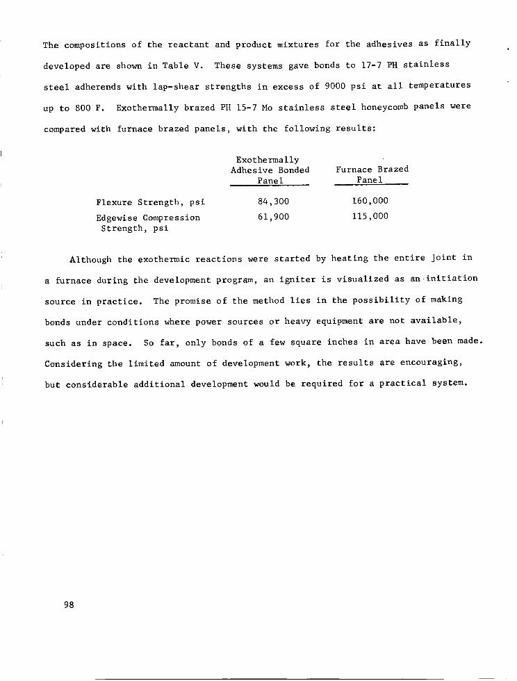
The compositions of the reactant and product mixtures for the adhesives as finally
developedare shownin Table V. Thesesystemsgave bondsto 17-7 PHstainless
steel adherendswith lap-shear strengths in excess of 9000psi at all temperatures
up to 800F. Exothermally brazed PH15-7 Mo stainless steel honeycombpanels were
comparedwith furnace brazed panels, with the following results:
Flexure Strength, psiEdgewiseCompressionStrength, psi
ExothermallyAdhesiveBonded
PanelFurnace Brazed
PaneI
84,300 160,00061,900 115,000
Although the exothermic reactions were started by heating the entire joint in
a furnace during the developmentprogram, an igniter is visualized as an initiation
source in practice. The promise of the methodlies in the possibility of making
bondsunder conditions wherepowersources or heavy equipmentare not available,
such as in space. So far, only bondsof a few square inches in area have beenmade.
Considering the limited amountof developmentwork, the results are encouraging,
but considerable additional developmentwould be required for a practical system.
98
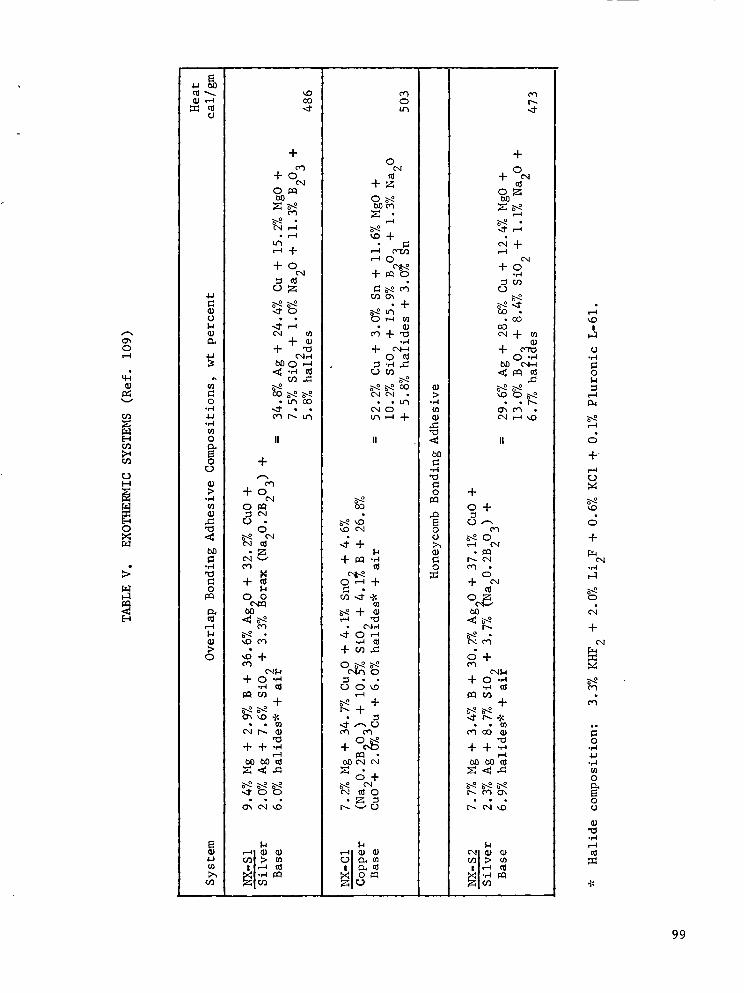
o
p_v
L)H
0
r-_
,-1
_,--i
rj
(_{J14
4.,i
0.ra
4-J
oc_Ho
t_
J_
o
c_
0
O0
+
+oC_
o1:_::lc_
dz
N
O o
4- 0 ._._I
_m. I_
d_z_+ + .,_
_Jz
dd,_
I ,_
+
+0
0D
z_
• ,--ILr_
+0c_
o_
_,1 r/)
++._
ga_g
°L_OO
_zd
O
u'3
.g++ _ ._
_.+
o,-I _
_2+ +
ee_ _
+o._
N_+
I o_(_
o
+_o_
_+
,_o
.+
+_:3 .,_ .z:
ro_
>
017
o_:_
,._
0
0
o
-..-r
+
o+r.j ..-_
p.. o..I
+
p_
_+
+ 0 .,_• _-I _1
+
O'3 CO _
+ + .,_
_Zd,d
I ,--t
+
+%O_
_+,--I
+o.,-I
oO
O0
+0 .,-I
I,-1
-,-I
o
P_
+-
M
+
o4.M
+_4
_4
o._I
4J
.r-I
o
0
.r-I
99

APPLICATIONS
There are relatively few production aerospace applications of adhesive bonding
of stainless steels. By comparison, welding and mechanical fastening applications
are much more frequent. Where adhesive bonding has been used, however, performance
of the joints has been from satisfactory to excellent. Adhesive bonding is a possi-
ble joining method for stainless steels that should be considered by designers for
applications within the capabilities of the newer adhesive systems.
AFT-END CLOSURE FOR POLARIS A-3 MOTOR CASE
Although it is not a production application, the experimental use of 0.005-
inch-thick Type 304 stainless steel reinforcement patches on the Polaris A-3 aft-
end closure is included because it is representative of a class of secondary joints
(Ref. II0). The adhesive used to bond the stainless steel to the subscale filament-L
wound dome was a modified epoxy. The patches were placed between plies of the dome.
The completed dome was pressure tested and failed by one patch tearing along a
shear line in the structure. Adhesion of the patches to the glass fiber-epoxy
structure was reported as being generally excellent. A schematic drawing of the
dome configuration, showing locations of the stainless steel patches, is shown in
Figure 42.
HELICOPTER ROTOR BLADING
Rotor blades for helicopters are commonly fabricated using adhesive bonding as
the joining technique. Rotor blades are being produced in large numbers at the
present time. They consistute the most important example of adhesive-bonded primary
structure involving stainless steel in the aerospace field. Adhesive bonding is
the preferred joining method in the rotor blade application because of good fatigue
strength, possibility of producing smooth, accurate airfoil blade shapes, and ability
to join dissimilar metals.
i00
Patches overlapped 1.0 inch
/ I
_n;,iL_-_*
A- 54559
FIGURE 42. LOCATIONS OF ADHESIVE-BONDED REINFORC]_IENT PATCHES ON
AFT-END DOME OF POLARIS A-3 MOTOR CASE. (Ref. ii0)
i01

Stainless steel appears in present rotor blades as the leading edgeerosion
shield. Bell helicopter uses stretch-formed Type 301 or 302 stainless for the erosion
shield on all but the outer three or four feet of the blade. Hastelloy X, a stronger
cobalt-base alloy, is used near the blade tip, where linear velocities are highest
(Ref. 53). The stainless steel leading edge is bondedto a brass substrate that
serves as a ballasting weight as well as a solid backupfor the stainless steel.
Onpresent blades, the remaining portion of the cross section, from about the maxi-
mumchord to the trailing edge, is madeof aluminum. On smaller blades, the airfoil
shapeof the aluminumskins is maintained by extruded aluminuminternal stiffener
sections. Onlarger blades, tapered aluminumhoneycombis used. Stainless steel
doublers and pressure pads are also bondedto the blade in the vicinity of the hub.
All of the adhesive-bondedjoints are autoclave cured simultaneously. Blades under
developmentfor helicopters of advanceddesign will incorporate a greater proportion
of stainless steel parts, both conventional and precipitation-hardening.
HELICOPTERFIREWALL
A stainless steel face sheet is used in present helicopter firewall panel con-
struction (Ref. 53). The stainless steel sheet, singly curved, is bondedto an
aluminumhoneycombcore. A glass-reinforced phenolic face sheet is used on the
opposite side of the core.
102

CONCLUSIONS AND RECOMMENDATIONS
Work is already under way on most problems associated with adhesive bonding of
stainless steel. Actually, these problems are the same as those encountered in
adhesive bonding in general and fall into four categories. These are: adhesion,
adhesives development, processing, and service behavior. The problems in each of
these areas are discussed separately below.
ADHESION
Despite years of research concerning forces of adhesion, man is still unable
to predict in any detail its occurrence or nonoccurrence. If calculations based
on our present knowledge of molecular forces were accurate, we would probably be
in trouble of another kind, with things sticking together because, according to
these calculations, adhesion should occur much more generally and between a far
wider range of materials than it does. That it does not, indicates our knowledge
is incomplete. There are two major areas regarding adhesion in which greater
understanding is needed. The first is the role of surfaces in adhesion; the second,
closely related, is the role of surface film.
Study of surfaces is difficult because of the problem of distinguishing pro-
perties of the two-dimensional surfaces from those of the underlying solid or
liquid. However, techniques such as ion-emission microscopy and low-energy elec-
tron diffraction are being used to study surface phenomena. Such studies should
yield useful information regarding adhesion and are recon_nended.
In the area of surface films, it is known that oxide films and layers of
absorbed gases often prevent adhesion. It is also known that naturally occurring
films will always be present in normal atmospheres and that other films are often
deliberately added to surfaces. (These are added for either corrosion resistance
or a more attractive surface.) What is not understood in any detail is what are
desirable properties of surface film for maximum adhesive qualities.
know of no work being conducted to gain such understanding.
The authors
103

Suchwork is necessary_however. As stated in this report_ reaction products_
in the form of films_ are created in the surface preparation of stainless steels
for adhesive bonding. The composition of these surface films will only be in-
directly related to the adherent alloy. It would appear safe to assumethat an
adhesive molecule would bond to this surface film_ and be unawareof the nature
of the metallic adherend. Becauseof the lack of understanding of these films,
surface treatment for adherendsis often an arbitrary thing. Thus_greater under-
standing of these films is imperative. Again_ investigation is difficult because
distinctions must be drawnbetween the bulk and surface effects of both the film
and actual surface. It is recommendedthat studies be undertaken to gain an
understanding of effects of film on adhesion through the study of extremely thin
vacuum-depositedand electroplated films for electronic application.
ADHESIVESDEVELOPMENT
Unlike the area of adhesion_ there is a great deal of activity in the develop-
ment of adhesives through tailoring of molecules for particular applications.
Muchwork is being done to develop heterocyclic adhesives. Thesepromise to
answerthe urgent need for organic adhesives for use at higher temperatures. They
also appear to be goodroom-temperatureadhesives and to have superior radiation
resistance as comparedto other organic adhesives. On the other end of the scale_
polyurethanes appear to be satisfactory for use at liquid-hydrogen temperatures.
Their temperature strength dependencedownto -423 F would indicate that they will
perform at even lower temperatures_perhaps at liquid-helium level and on to
absolute zero. This has yet to be demonstrated_however. Studies should be
started which will determine their usefulness at these extremely low temperatures.
There are several problemsyet unansweredin the developmentof inorganic
adhesives. Application of inorganic adhesives would be in high temperature
structures. Theproblems to be solved involve ductility_ bond strength, and
maturing temperatures.
i04
PROCESSING
In developing adhesives, care must be taken to keep thempractical from the
manufacturing viewpoint. A goodadhesive should be easily applied, non-toxic,
inexpensive, tolerant of shortcomings in adherendpreparation, and it should cure
at roomtemperature, or with only a short, moderate-temperaturecuring cycle. It
will, of course, not always be possible to producea high-performance adhesive with
all these qualities, but they should always be kept in mind.
There are several examplesof recently producedadhesives that use newmethods
of handling, applying, and curing, but morework is neededin the area. Among
those producedare internally heated film adhesives and roomtemperature curing
epoxy film. Another exampleis chemically blocked adhesives, such as silicone
sealants. A particular need, as yet unperfected, is for mechanically blocked
adhesives. In these, hardeners, encapsulated in frangible membranesthroughout
the resin, are activated by mechanical rupture of the membranes.Neededto accom-
plish this are membranematerials that will withstand chemical action of resin and
hardeners. The entire area of mechanically blocked adhesives developmentis in
needof continued research.
SERVICEBEHAVIOR
Further work is neededin the testing of bondstrength and of useful life of
adhesive-bondedjoints. There are presently nondestructive techniques for testing
as-welded bond strength. However, they should be further refined to allow detec-
tion of in-service or postexposure loss of bond strength.
Environmental factors effecting useful life of adhesive bonds are temperature,
humidity, stress, and time. Procedures are needed to test the combined interaction
effects of these factors.
105

REFERENCES
I. Skeist, Irving, Editor, Handbook of Adhesives, Reinhold Publishing Company,
New York (1962) (RSIC 0345).
2. Bikerman, J. J., The Science of Adhesive Joints, Academic Press, Inc., New York
(1961) (RSIC 0340).
3. Guttmann, W. H., Concise Guide to Structural Adhesives, Reinhold Publishing
Company, New York (1961) (RSIC 0344).
4. Voyutskii, S. S., Autohesion and Adhesion of High Polymers, Interscience
Publishers, New York (1963) (RSIC 0355).
5. Kozlov, P. V., Editor, Adhesion of Polymers, Izd-vo Akademii Nauk SSSR, Moscow
(1963) (RSIC 0356).
6. Kardashov, D. A., Synthetic Glues, Izd-vo Khimiia, Moscow (1964) (RSIC 0275).
7. Katz, Irving, Adhesive Materials - Their Properties and Usage, Foster Publishing
Company, Long Beach, California (1964) (RSIC 0337).
8. BiBliography on Adhesive Bondin$ of Metals, Engineering Societies Library,
New York (1957) (RSIC 0361).
9. "Honeycomb Bibliography", Hexcel Products, Inc., Oakland, California, Research
and Development Report (1957) (RSIC 0362).
i0. Adhesives - Selective Bibliosraphy SB-406, U. S. Office of Technical Services,
Supplement to CTR-300 (RSIC 0363).
II. Lee, R.W.H., "Bibliography on Metal-Bonding Adhesives", National Academy of
Sciences-National Research Council, Prevention of Deterioration Center,
Report PDL-46448 (February 4, 1963) (RSIC 0364).
12. Loew, S., "Selected Bibliography on Thermally Stable Polymers", IDEP Rept No.
347.10.00.00-B8-03, June 1964, Research and Development Div., AVCO Corp.AD 459892.
13. Newhall, R. G., Editor, Papers presented at the Metal-to-Metal Adhesives for
the Assembly of Aircraft Conference, University of California (September 9-11,
1954) Western Business Publications, San Francisco, California (1955) (RSIC 0279).
14. "Bonded Aircraft Structures", Paper presented at a Conference at CIBA (Aero
Research Ltd.), Duxford, Cambridge, England (1957) (RSIC 0349).
15. Goryimov, Yu. V., "Applications of Glued and Glued-Riveted Joints to Repairs of
Aircraft"; Phgochev, A. I., et al., "Glued-Welded Joints in Aircraft Structures",
papers presented at the Glue and Technology of Adhesives Symposium (1960)(RSIC 0365).
16. Eley, D. D., Editor, Adhesion, Oxford University Press, Amen House, London,England (1961) (RSIC 0347).
106

REFERENCES (Continued)
17.
18.
19.
20.
21.
22.
23.
24.
25.
26.
27.
28.
29.
30.
Papers presented at the ASTM Symposium on Adhesion and Adhesives, Philadelphia,
Pennsylvania, STP-271 (1961) (RSIC 0341).
Bodnar, M. J., Editor, Adhesives for Structural Applications, Paper presented
at the Symposium on Adhesives for Structural Applications, Picatinny Arsenal,
Dover, New Jersey (September 27-28, 1961), Interscience Publishers, New York
(1962) (RSIC 0350).
"Adhesion", Symposium at the 66th Annual Meeting of the ASTM, Atlantic City,
New Jersey (June 26, 1963) (RSIC 0338).
"Symposium on Structural Adhesives Bonding" at Stevens Institute of Technology,
sponsored by Picatinny Arsenal and Stevens Institute of Technology, September
14-16, 1965.
"Papers from the Structural Adhesive Bonding Conference" at George C. Marshall
Space Flight Center, National Aeronautics and Space Adminstration, Huntsville,
Alabama, sponsored by the Manufacturing Engineering Laboratory, March 15-16,
1966.
Reinhart, F. W., and Callomon, I. G., "Survey of Adhesion and Adhesives", U. S.
National Bureau of Standards, WADC-TR-58-450, Contract AF 33(616)-5379 , (1959)
(RSIC 0294).
Blomquist, R. F., "Adhesives: Past, Present and Future", American Society for
Testing and Materials, Edgar Marburg Lecture, Philadelphia, Pennsylvania (1963)
(RSIC 0295).
Twiss, S. B., "Structural Adhesive Bonding: Part I. Adhesive Characteristics,
Part II. Adhesive Classification", Adhesives Age, _ (12) 26-31 (December,
1964); _ (I) 30-34 (January, 1965) (RSIC 0303 and RSIC 0307).
Morse, William, "Industrial Adhesives Survey: Part I, II, and III", Engineering
Materials and Design, _ (9) 656-61 (September, 1962); _ (I0) 743-46 (October,
1962); _ (ii) 823-27 (November, 1962) (RSIC 0299).
"Structural Adhesives - Will They Replace Other Forms of Joining?", Welding
Engineer, 49 (9) 35-39 (September, 1964) (RSIC 0310).
Hause, C. I., "Structural Adhesives - Some Types Designed for Metal-to-Metal
Bonding", Welding Engineer, 49 (9) 40-43 (September, 1964) (RSIC 0366).
Scott, R. C., "Guide to Joint Sealants", Product Engineering, 35 (6) 73-84
(March 16, 1964) (RSIC 0302).
Hess, E. F., "Today's Film Adhesives", Product Engineering, 32 (43) 86-89
(December II, 1961) (RSIC 0301).
"How to Get More for Your Adhesives Dollar", The Iron Age, 183, 76-90 (March 5,
1959) (RSIC 0300).
i07
REFERENCES (Continued_
31.
32.
Rider, D. K., "Which Adhesive for Bonded Metal Assembly?", Product Engineering,
35 (II) 85-98 (May 25, 1964) (RSIC 0367).
Metals Handbook, Vol. i, 8th Ed., American Society for Metals, Cleveland, Ohio
(1961).
33. Harkins, F. G., "Welding of Age Hardenable Stainless Steels", Welding Research
Council Bulletin No. 103, American Welding Society, New York (February 1965).
34. Armco 15-5 PH Precipitation Hardening Stainless Steel Product Data, Armco Steel
Corporation (1965).
35. Armco 414 Ti Stainless Steel Product Data, Armco Steel Corporation (1965).
36. Personal Con_nunication, R. Kaltenhauser, Allegheny Ludlum Steel Corporation.
37. "Almar 362, A Mar-Aging Stainless Steel", Technical Horizons, Allegheny Ludlum
Steel Corporation (1966).
38. Heimel_ F. A._ "Design - The Keystone of Structural Bonded Equipment Enclosures",
in "Symposium on Structural Adhesives Bonding" at Stevens Institute of Tech-
nology, sponsored by Picatinny Arsenal and Stevens Institute of Technology,
September 14-16, 1965.
39. Levine, H. H., "Heteromatic Structural Adhesives", in "Joining of Materials
for Aerospace Systems", 9th National Symposium of the Society of Aerospace
Materials and Process Engineers at Dayton, Ohio, November 15-17, 1965.
40. Ivanova, Z. G., and Davidov, A. B., "Thermostable Siliconorganic Adhesives
VK-2 and VK-6", Plastichiskiye Massy, No. 4, 37-39 (1963) (RSIC 0274).
41. Kutscha, Dieter, "Mechanics of Adhesive Bonded Lap-Type Joints: Survey and
Review", Forest Products Laboratory, Report ML TDR-64-298, for Wright-Patterson
Air Force Base, Contract AF 33(657)-63-358 (December, 1964) (RSIC 0308).
42. Perry, H. A., Adhesive Bondin_ of Reinforced Plastics, McGraw-Hill, (New York)
1959, 275 p.
43.
44.
45.
Composite Construction for Fli_ht Vehicles: Part I. Fabrication I Inspectionl
Durabilityj and Repair, Armed Forces Supply Support Center, Military Handbook
MIL-HDBK-23 (October 5, 1959) (RISC 0289).
Burkart, E. C., "Some Design Considerations for Adhesive Bonding", in "Papers
from the Structural Adhesive Bonding Conference" at George C. Marshall Spare
Flight Center, National Aeronautics and Space Administration, Huntsville,
Alabama, sponsored by the Manufacturing Engineering Laboratory, March 15-16,
1966.
Pajak, T. P., "Sandwich Panel Attachments", Paper presented at the Metal-to-
Metal Adhesives for the Assembly of Aircraft Conference, University of California
(September 9-11, 1954) (RISC 0280).
108

REFERENCES (Continued)
46. Morita, W. H., "Titanium Tankage Program - Titanium Tankage Development",
North American Aviation, Inc., Space and Information Systems Division, Techni-
cal Documentary Report AFRPL-TR-64-154 (November, 1964) (RSIC 0304).
47. Herndon, C. F., "Design of Heavy-Gage Bonded Honeycomb Sandwich", in "Papers
from the Structural Adhesive Bonding Conference" at George C. Marshall Space
Flight Center, National Aeronautics and Space Administration, Huntsville,
Alabama, sponsored by the Manufacturing Engineering Laboratory, March 15-16,
1966.
48. Personal communication from Robert J. Stout, General Dynamics/Fort Worth,
Texas (RSIC 0368).
49. Rider, D. K., "Surface Preparation for Bonded Metal Assembly", Product Engine-
ering, 35 (12) 75-78 (June 8, 1964) (RSIC 0305).
50. "Proposed Recommended Practice for Preparation of Metal Surfaces for Adhesive
Bonding", American Society for Testing and Materials, Subcommittee D-14
(In preparation) (RSlC 0373).
51. Personal communication from C. I. Hause, Minnesota Mining and Manufacturing
Co., St. Paul, Minnesota (RSIC 1281).
52. Hill, J. R., "Process Development of Polybenzimidazole Adhesive", in "Joining
of Materials for Aerospace Systems", 9th National Symposium of the Society of
Aerospace Materials and Process Engineers at Dayton, Ohio, November 15-17, 1965.
53. Personal Communication from S. Aker, Bell Helicopter Company, Ft. Worth, Texas.
54. Personal Communication from E. Hagberg, Lockheed California Company, Burbank,
California.
55. Meckelburg, H., Schlothauer, H., and Neumann, G., "Untersuchung des
Best_ndigkeitsverhaltens von Metallklebverbindungen gegen_ber verschiedenen
Umwelteinfl_ssen", Deutsche Forschungsanstalt fur Luft- und Raumfahrt, DFL
Report No. 179 (April 16, 1962) (RSIC 0372).
56. Lindsay, R., Jr., "Treatment of Metal Surfaces for Adhesive Bonding. Part VI.
Summary of Methods", Franklin Institute, Philadelphia, Pennsylvania, WADC-TR-
55-87, Contract AF 33(616)-2347, AD 150999 (February, 1958) (RSIC 0082).
57. Kempf, J. N., "Preclean Metals and Plastics for Adhesive Bonding", Product
Engrg., 32 (33) 14 Aug 1961, pp. 44-46.
58. Genzsch, E. O., "Wie kann man Metalle verkleben?", Plastverarbeiter, 12 (12)
Dec 1961, pp. 559-563.
59. Spiker, I. K., "Material - Adhesives - Aerobond 500, Dynabond 132 - Creep
Rupture - Test of", 15 apr 1964, Contract No. AF 33(657)-11214, General Dynamics/
Ft. Worth, Report No. FTDM-3197, 8 p.
109

REFERENCES (Continued_
60.
61.
62.
63.
64.
65.
66.
67.
68.
69.
70.
71.
Spiker, I. K., "Material - Adhesive - Dynabond 132 - Additional Testing and
Disposition of Specimens Remaining from 420 F Creep Test (50-2895)", 15 Apr
1964, Contract No. AF 33(657)-11214, General Dynamics/Ft. Worth, Report No.
FGT-3093, 15 p.
Krieger, R. B., Jr., and Politi, R. E., "High Temperature Structural Adhesives",
in "Joining of Materials for Aerospace Systems", 9th National Symposium of the
Society of Aerospace Materials and Process Engineers at Dayton, Ohio, November
15-17, 1965.
Rogers, N. L., "Surface Preparation of Metals for Adhesive Bonding", in
"Symposium on Structural Adhesives Bonding" at Stevens Institute of Technology,
sponsored by Picatinny Arsenal and Stevens Institute of Technology, September
14-16, 1965.
Lunsford, L. R., "Bonded Metal-to-Metal Shear Testing", Paper presented at the
Symposium on Adhesion and Adhesives, ASTM, Philadelphia, Pennsylvania (1961)
(RSlC 0342).
"Bonding Inspection", Federal Aviation Agency, Quality Control Digest, No. 5
(July, 1960) (RSlC 0385).
Lunsford, L. R., "Stress Analysis of Bonded Joints", in "Symposium on Structural
Adhesives Bonding" at Stevens Institute of Technology, sponsored by Picatinny
Arsenal and Stevens Institute of Technology, September 14-16, 1965.
Reed, R., and Marano, D., "Research to Determine Mechanical Properties of
Polybenzimidazole Metal-to-Metal Adhesives", Technical Report AFML-TR-65-136,
April 1965, Contract No. AF 33(615)-1207, Narmco Research and Development Div.,
Whittaker Corp.
Licari, J. J., "High Temperature Adhesives", Product Engineering, 35 (25)
102-108 (December 7, 1964) (RSIC 0297).
Hay, W. S., "Adhesive Bonding of Primary Aircraft Structure", Paper presented
at the American Society for Metals New Fabrication Techniques Meeting, Cleveland,
Ohio (1958) (RSIC 0282).
Kausen, R. C., "Adhesives for High and Low Temperatures", Paper presented at the
7th National SAMPE Symposium, Los Angeles, California (May 20-22, 1964) (RSIC
0375).
Kuno, J. K., "Comparison of Adhesive Classes for Structural Bonding at Ultra-
High and Cryogenic Tenperature Extremes", Paper presented at the 7th National
SAMPE Symposium, Los Angeles, California (May 20-22, 1964) (RSIC 0281).
Eickner, H. W., "Strength Properties of Metal-Bonding Adhesives at Temperatures
From -I00 F to +800 F", Forest Products Laboratory, Madison, Wisconsin, WADC-
TR-59-152, for Wright Air Development Center, Contract DO 33(616)-58-1 (July,
1959) (RSIC 0017).
Ii0

REFERENCES (Continued)
72.
73.
74.
75.
76.
77.
78.
79.
80.
81.
82.
83.
Flom, D. G., Speece, A. L., and Schmidt, G. A., "Investigation of Catalytic
Thermal Oxidative Degradation of Organic Polymers at Elevated Temperatures",
July 1965, Contract No. AF 33(657)-11240, Rept No. AFML-TR-65-235, General
Electric Co., Valley Forge, Pa. AD 626847.
Litvak, S., Aponyi, T. J., and Tomashot, R. C., "Structural Plastics and
Adhesives", in Air Force Materials Symposium/1965, AFML -TR-65-29.
Reinhart, T. J., Jr., and Hidde, R., "Mechanical Properties of Imidite Adhesives",
in "Symposium on Structural Adhesives Bonding" at Stevens Institute of Tech-
nology, sponsored by Picatinny Arsenal and Stevens Institute of Technology,
September 14-16, 1965.
Freeman, J. H., Frost, L. W., Burgman, H. A., Bower, G. M., Ruffing, C. R.,
Traynor, E. J., and Quirk, J. F., "Development of Polyimide Resin Based Struc-
tural Adhesives and Laminates for Long Time High Temperature Use", Report No.
AFML-TR-65-188, May 1965, Contract No. AF 33(615)-1327, Westinghouse Research
Laboratories, AD 475510.
Hertz, J., "Cryogenic Adhesive Evaluation Study", Convair-Astronautics, San
Diego, California, Report ERR-AN-032, Third Quarterly Progress Report, Phase I,
Contract AF 33(616)-7984, AD 273219 (January 25, 1961) (RSlC 0020).
Frost, W. M., "Strengths of Structural Adhesives at Temperatures Down to Minus
424 F", National Bureau of Standards, Boulder, Colorado, Report WADC-TR-59-260,
Contract DO 33(616)-58-12 (November, 1959) (RSIC 0015).
Smith, M. B., and Susman, S. E., "New Easy-Bonding Adhesives Retain Toughness
at -400 F", SAE Journal, 71, 38-41 (May, 1963) (RSIC 0382).
Miller, R. N., Bailey, C. D., Freeman, S. M., Beall, R. T., and Coxe, E. F.,
"Properties of Foams, Adhesives, and Plastic Films at Cryogenic Temperatures",
Industrial and Engineering Chemistry, _ (4) 257-61 (December 1962) (RSIC 0022).
Smith, M. B., and Susman, S. E., "Development of Adhesives of Very Low Tempera-
ture Applications", Whittaker Corporation, Narmco Research and Development
Division, San Diego, California, Summary Report, Contract NAS-8-1565 (July 15,
1962) (RSlC 0276).
"Properties of Plastics and Related Materials at Cryogenic Temperatures",
PLASTEC Rept. 20, July 1965, Plastics Technical Evaluation Center, Picatinny
Arsenal, AD 469126.
Arslett, J. P., and Jeffs, A. T., "The Effects on Structural Adhesives of
Cycling to Cryogenic Temperatures", Rocket Propulsion Establishment, Westcott,
England, Technical Note 230, AD 445335 (March, 1964) (RSIC 0013).
Kircher, J. F., and Bowman, R. E., Effects of Radiation on Materials and
Components, Reinhold Publishing Company, New York (1964) (RSIC 0415).
iii

REFERENCES (Continued)
84. Kinderman, E. M., Radding, S. B., Mixer, R. Y., and Parkinson, D. B., "Nuclear
Radiation Effects on Structural Plastics and Adhesives. Part I. Literature
Survey; Part II. Extension of Literature Survey; Part III. Experimental
Research", Stanford Research Institute, Report WADC-TR-56-534 for the U. S.
Air Force, Contract AF 33(616)-3632 (RSIC 0290, 2091, 0292).
85. Arlook, R. S., and Harvey, D. G., "Effects of Nuclear Radiation on Structural
Adhesive Bonds", Wright Air Development Center, Report WADC-TR-56-467 (February
1957) (RSIC 0288).
86. McCurdy, R. M., and Rambosek, G. M., "The Effect of Gam_na Radiation on Struc-
tural Adhesive Joints", Paper presented at the Society of Aerospace Materials
and Process Engineers Symposium on Effects of Space Environment on Materials,
St. Jouis, Missouri (May 7-9, 1962) (RSIC 0311).
87. Sharpe, L. H., "Some Aspects of the Permanence of Adhesive Joints", in
"Symposium on Structural Adhesives Bonding" at Stevens Institute of Technology,
sponsored by Picatinny Arsenal and Stevens Institute of Technology, September
14-16, 1965.
88. Smith, M. B., and Susman, S. E., "Development of Adhesives for Very Low Tempera-
ture Application", Whitaker Corporation, Narmco Research and Development Divi-
sion, San Diego, California, Quarterly Summary Report, Contract NAS-8-1565
(October 15, 1962) (RSIC 0287).
89. Tipton, J. P., Corson, H. B., Steen, R. P., Newsome, R. K., and Hutchinson,
J. G., "Evaluation of Integrally Cured Adhesives", North American Aviation,
Inc., Columbus, Ohio, Technical Report AFML-TR-65-19, Contract AF 33(615)-1182
(February, 1965) (RSIC 0416).
90. Bandaruk, W., "Adhesive Bonding with Graphite Fibers as an Internal Electrical
Resistance Heat Source", in "Symposium on Structural Adhesives Bonding" at
Stevens Institute of Technology, sponsored by Picatinny Arsenal and Stevens
Institute of Technology, September 14-16, 1965.
91. Long, R. A., "Exothermic Reactive Materials for Bonding Operations", Paper
presented at the Fall Meeting of the Society of Aircraft Materials and Process
Engineers, Washington, D. C. (November 17, 1959) (RSIC 0384).
92. Blackwell, R. F., "Inspection and Testing of Honeycomb and Honeycomb Sandwiches",
Bonded Aircraft Structures, CIBA (Aero Research Ltd.), Duxford, Cambridge,
England (1957) (RSIC 0351).
93. Jeffery, F.D.C., "Inspection of Bonded Aircraft Structures", Bonded Aircraft
Structures, CIBA (Aero Research Ltd.), Duxford, Cambridge, England (1957)
(RSlC 0352).
94. Greenwood, L., "The Physical Testing of Adhesives and Adhesive Joints", Adhesion,
Oxford, London, England (1961) (RSlC 0348).
i12

REFERENCES (Continued)
• 95.
96.
97.
98.
99.
i00.
I01.
102.
103.
i04.
I05.
106.
Hahn, K. F., "Lap-Shear and Creep Testing of Metal-to-Metal Adhesive Bonds in
Germany", Paper presented at the Symposium on Adhesion and Adhesives, ASTM,
STP-271 (1961) (RSIC 0343).
Yurenka, S., "Peel Testing of Adhesive Bonded Metals", Paper presented at the
Symposium on Adhesives for Structural Applications, Interscience Publishers,
New York (1962) (RSIC 0346).
Wegman, R. F., and Tanner, W. C., "Strength of Epoxy Adhesives When Stressed
to Failure in Milliseconds", Adhesion-1963, ASTM, STP-360 (1963) (RSIC 0354).
Gonzalez, H. M., and Cagle, C. V., "Nondestructive Testing of Adhesive-Bonded
Joints", Adhesion-1963, ASTM, STP-360 (1963) (RSIC 0353).
Clemens, R. E., "Adhesive Bonded Honeycomb Integrity: Fokker Bond Tester",
Northrop Corporation, Norair Division, Hawthorne, California, Report NB-61-273
(November, 1961) (RSIC 0286).
Smith, D. F., and Cagle, C. V., "A Quality Control System for Adhesive Bonding
Utilizing Ultrasonic Testing", in "Symposium on Structural Adhesives Bonding"
at Stevens Institute of Technology, sponsored by Picatinny Arsenal and Stevens
Institute of Technology, September 14-16, 1965.
Hertz, J., "Investigation of Bond Deterioration by Use of the Fokker Bond
Tester", General Dynamics Corporation, San Diego, California, Report GD/A-
ERR-AN-682 (December 31, 1964) (RSlC 0285).
Schmitz, G., and Frank, L., "Nondestructive Testing for Evaluation of Strength
of Bonded Material", Sept 1965, Contract NAS8-I1456, General American Transpor-
tation Corp., N66-I1761.
Walker, H. M., "Inspection of Honeycomb Structures Using Birefringent Plastic
Coatings", in "Papers from the Structural Adhesive Bonding Conference" at
George C. Marshall Space Flight Center, National Aeronautics and Space Admin-
istration, Huntsville, Alabama, sponsored by the Manufacturing Engineering
Laboratory, March 15-16, 1966.
Yettito, P. R., "A Thermal Infrared Inspection Technique for Bond Flaw
Inspection", in "Symposium on Structural Adhesives Bonding" at Stevens Institute
of Technology, sponsored by Picatinny Arsenal and Stevens Institute of Technology,
September 14-16, 1965.
Sabourin, L., "Nondestructive Testing of Bonded Structures with Liquid Crystals",
in "Papers from the Structural Adhesive Bonding Conference" at George C.
Marshall Space Flight Center, National Aeronautics and Space Administration,
Huntsville, Alabama, sponsored by the Manufacturing Engineering Laboratory,
March 15-16, 1966.
Thornton, H. R., "Bond Strength and Elastic Properties of Ceramic Adhesives",
Journal American Ceramic Society, 45 (5) 201-209 (May I, 1962) (RSIC 1282).
113

REFERENCES (Continued)
107.
108.
109.
Ii0.
Brown, D. A., "Application of Ceramic Adhesive-Braze Alloy Combination Technique
to the Bonding of Assemblies", The Boeing Company, Military Aircraft Systems
Division, Wichita, Kansas, Technical Documentary Report No. 62-631 (June 1962)
(RSIC 1283).
Bayer, J., Johnston, O. E., and Patterson, W. A., "Research and Development on
Inorganic High Temperature Adhesives for Metals and Composite Constructions",
Aeronca Manufacturing Corp., WADC Technical Report 59-113, Pt. II (July 1960)
(RSIC 1284) AD 247410L.
Bassett, W., Caughey, R., and Long, R. A., "Development of Exo-Reactant Inorganic
Adhesive System", Summary Technical Report, 31 Jan 1961, covering the period
I July 1958 - 31 Jan 1961, Contract No. NOas-60-6061c, Narmco Research and
Development Div., Whittaker Corp.
Stevenson, H. W., and Harrington, R. A., "Aft-End Closure Study for Polaris A-3
Rocket Motor Case", Progress Report No. 5, Feb. 28, 1962, Contract No. NOw-61-
0499c (FBM), The B. F. Goodrich Co.
114

NASATMX-53574 APPROVAL February 16, 1967
ADHESIVEBONDINGOFSTAINLESSSTEELS
By R. E. Keith, M. D. Randall, and D. C. Martin
Theinformation in this report has been reviewed for security classi-fication. Reviewof any information concerning Departmentof DefenseorAtomic EnergyCommissionprogramshas beenmadeby the MSFCSecurityClassification Officer. This report, in its entirety, has been determinedto be unclassified.
This report has also been reviewed and approved for technical accuracy.
W. A. WILSONChief, MethodsDevelopmentBranch
J. P. ORRChief, Manufacturing Research&TechnologyDivision
/
WERNER R. KUERS
Director, Manufacturing Engineering
Laboratory
115