Surface treatment of alumina ceramic for improved adhesion ...

www.paintsquare.comJ P C L / N o v e m b e r 2 0 0 4 / P C E44
number of parameters
affect the adhesion of coat-
ings to steel substrates.
According to ISO 8503,1
these conditions include
the following substrate properties:
• rust and mill scale;
• contaminants, such as dust, oil, grease, and salts;
and
• profile (roughness).
In turn, the conditions above influence the selection
of a method to prepare the substrate for coating
application. Several studies have evaluated the
effects of surface preparation methods, primarily dry
abrasive blasting (AB) and waterjetting (UHP), on
coating performance. These studies also investigated
the long-term behaviour of coating systems. These
studies, however, focused on the effects of flash rust
and salt contamination.2,3
Combining AB and UHP (UHPAB) into a single
blasting process is an innovative approach to surface
preparation. Although this method has already been
introduced into ship repair practice, there is not
enough information available to evaluate the quality
of surfaces and coating adhesion associated with
UHPAB. This study’s goal is to systematically investi-
gate parameters that are suitable for evaluating the
quality of a steel substrate after the use of three
surface preparation methods: AB, UHP, and
UHPAB. The investigation focuses on repair of ships
and steel structures. The selected coating systems
were mainly suitable for ballast tank applications.
However, one coating, originally designed for steel
structures in water, such as weirs and flood bar-
rages, was also included to check the capabilities of
the investigated methods to prepare such surfaces.
The exposure environment for the coatings to be
studied was selected according to the classifications
Effects of Surface Preparation Methodson Adhesion of Organic Coatingsto Steel Substrates
A
By A.W. Momber, Mühlhan Equipment Services GmbH,
Hamburg, Germany
S. Koller, Germanischer Lloyd AG
Hamburg, Germany
and H.J. Dittmers, Cor roconsult GmbH
Hamburg, Germany
Fig. 1a: AB (dry abrasive blast cleaning)
Fig. 1c: UHPAB (ultra-high pressure abrasive blasting)
A
B
C

surface of each panel was separated
into three parts: one for AB, one for
UHP, and one for UHPAB. All test pan-
els were originally coated with an
organic coating system at an average
DFT between 400 and 800 µm (16 and
32 mils). After coating removal, the
surfaces treated with UHP and
UHPAB were allowed to dry (Fig. 2).
At the dry surfaces, roughness para-
meters were measured as described
below. Thereafter, the new coatings
were applied to the entire panel sur-
face. Thus, each coating was applied
identically over the three types of pre-
pared surfaces. After the coatings
cured, adhesion tests were performed
as described below.
Five commercially available epoxy
coating systems were selected. Their
major properties are listed in Table 3.
The coatings were applied by airless
spray in a paint booth with a con-
trolled climate. The coatings cured for
50 days. Then, specimens for the labo-
ratory tests were manufactured. Each
was 15 cm x 10 cm (6 in. x 4 in.)
according to the requirements of ISO
face preparation and coating applica-
tion were excellent because they were
performed under ideal, controlled con-
ditions. Such conditions cannot be
expected in field work.
Surface Preparationand Coating Procedures
Three methods were used for surface
preparation:
• AB as shown in Fig. 1a;
• UHP as shown in Fig. 1b; and
• UHPAB as shown in Fig. 1c.
The performance parameters of these
methods are listed in Table 2. The abra-
sive used for AB and UHPAB was a
commercial copper slag with the fol-
lowing properties in accordance with
ISO 11126-36:
• hardness > 7 (Mohs);
• density = 3600 kg/m3;
• particle size range = 0.4–1.2 mm; and
• particle shape—irregular.
For the UHP and UHPAB applications,
tap water with an electrical conductiv-
ity of 650 S/cm was used.
Test panel size was 3 m (~10 ft) in
length and 0.5 m (1.6 ft) in width. The
45www.paintsquare.com J P C L / N o v e m b e r 2 0 0 4 / P C E
listed in ISO 12944-2.4 The following
categories were considered.
• Atmospheric-corrosivity: C5-M
(marine). This category covers coastal
and offshore areas with high salinity as
well as areas with almost permanent
condensation.
• Categories for water and soil: Im2.
This category covers sea or brackish
water; structures considered include
sluice gates, locks, offshore structures,
and other completely or partially
immersed constructions.
These categories determined the type
and intensity of the laboratory tests to
be performed according to ISO 12944-
6.5 These tests are listed in Table 1. The
results of the neutral salt spray test
will be reported at a future date. The
present article reports about the
results of the pull-off strength measure-
ments. For the temporal and technical
conditions of our study, condensation
tests and a water immersion test did
not allow an evaluation of the coating
systems’ performance. This was mainly
due to two reasons. First, the duration
of testing was too short. Second, sur-
Corrosivity
Categor y
C5-M
Im2
Table 1: Test Procedures for Paint Systems Applied to Steel(ISO 12944-65)
Durability
Ranges
medium
medium
ISO 2812-2
(Cold Water Immersion)
—
2,000 h
ISO 6270
(Cold Water Condensation)
480 h
—
ISO 7253
(Neutral Salt Spray)
720 h
720 h
Parameter
Operating pressure in MPA
Nozzle diameter in mm
Water consumption in l/min
Abrasive consumption in kg/min
Table 2: Surface Preparation Method ParametersMethod
AB
8.5 (air)
10
0
12
UHP
200 (water)
6 x 0.3
10
0
UHPAB
150 (water), 8 (air)
19
10
12
Fig. 1a–c: clockwise from p. 44, top left, Surfacepreparation methods (see Table 2 for operationalparameters)
Fig. 1b: UHP (waterjetting)
12944-6.4 The specimens were cut
with plate shears. Commercially avail -
able coatings were manually applied to
each sample for edge protection. One
sample of the plates prepared with AB
and UHPAB was not coated, but was
saved for scanning electron microscopy
(SEM) inspections. From these samples,
small specimens with the dimensions
20 mm x 20 mm (~1 in. x 1 in.) were
cut.
Roughness was measured according
to ISO 8503-47 using a portable stylus
instrument. Adhesion between the
coating and the substrate was estimat-
ed according to ISO 4624,8 by means
of a commercial pull-off testing device
J P C L / N o v e m b e r 2 0 0 4 / P C E46 www.paintsquare.com
1a
EP
Zn
2
2.8
67
70
—
Table 3: Properties of Applied Coating SystemsProperty
Binder
Primer
Number of coatings
Density in kg/l
Solid content in vol.-%
DFT in µm
VOC in g/l
Coating System
1b
EP
—
—
1.5
100
490
—
2
EP
—
1
—
96
346
free
3
EP
—
1
—
83
253
—
4
EP
—
1
1.3
60
273
385
5
EP
—
1
—
80
374
170
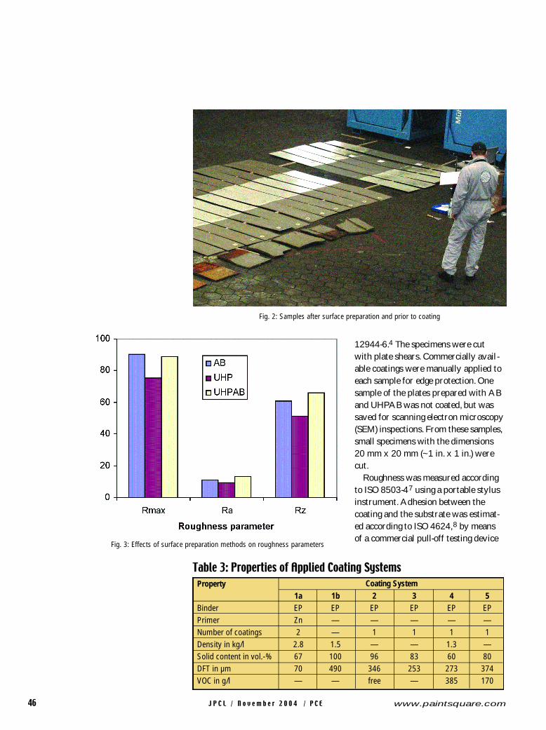
Fig. 3: Effects of surface preparation methods on roughness parameters
Fig. 2: Samples after surface preparation and prior to coating

what different trend. Here,
AB forms the deepest pro-
file, followed by UHPA B
and UHP. But the differ-
ences in the maximum
roughness between
UHPAB and AB are only
3%. It seems from these
results that UHP does not
have the capability to form
a new profile under the
conditions of this study.
The results of the pull-off
tests are summarised in
Figs. 4 and 5. In Fig. 4, two
groups of columns can be
distinguished. The first
group covers coating sys-
tems 1, 3, and 4, whereas
the second group covers
coating systems 2 and 5.
The first group is charac-
terised by two features.
First, the pull-off fa i l u r e
was always cohesive (within the coat-
ing), not adhesive (between the substrate
and the coating). Second, the individual
coating systems showed a more or less
constant level of pull-off strength val-
J P C L / N o v e m b e r 2 0 0 4 / P C E 47www.paintsquare.com
with a maximum load capacity of 18
MPa. The dollies were stainless steel,
20 mm (~1in.) in diameter. The drying
time for the glue was four hours. The
samples were pre-cut before the pull-
off tests were performed. Six measure-
ments were taken for each sample.
Because three samples were available
for testing, 18 measurements were
taken for each condition. The portion
of adhesive failure and cohesive failure
was evaluated from the appearance of
the failed sections.
Results and DiscussionThe results of the roughness measure-
ments are summarized in Fig. 3. For
substrate evaluation, the roughness
parameter “average maximum rough-
ness,” RY 5, in accordance with ISO
5803, is very often specified. This para-
meter is equal to the roughness para-
meter RZ measured with the stylus.
This parameter has high values for the
UHPAB surfaces, followed by the AB
s u r faces and the UHP surfaces. The
same trend is true for the average
roughness Ra. The maximum rough-
ness, Rmax, however, shows a some
Fig. 5: Failure types after pull-off testing (coating system 5)a – adhesive failure (AB, dry abrasive blast cleaning)b – mixed adhesive-cohesive failure (UHP, waterjetting)c – cohesive failure (UHPAB, ultra-high pressure abrasive blasting)
Fig. 4: Effects of coating systems and preparation methods on pull-off strength
A
B
C

the coating system. As shown in Fig.
5b, the failure at the UHP blasted sam-
ples is partly adhesive. The failure on
the substrate prepared with UHPAB is
shown in Fig. 5c, where a totally cohe-
sive failure of the bulk coating can be
seen. A very interesting result is that
J P C L / N o v e m b e r 2 0 0 4 / P C E48 www.paintsquare.com
ues. The maximum deviation estimated
for the results of this group is 4.3% fo r
coating system 3. Thus, the surfa c e
preparation method as measured by
these tests does not have
a relevant effect on pull-
off strength. The average
pull-off values measured
on the corresponding
samples do not depend on
the substrate surfa c e
q u a l i t y, but rather charac-
terise the tensile strength
of the coating system.
They are, therefore, a
property of the bulk coat-
ing.
The situation with
the second group is quite different.
This group is characterised by two fea-
tures. First, pull-off strengths show a
dependence on the surface preparation
method and, therefore, on the proper-
ties of the prepared steel substrate.
Second, there is a notable trend in the
strength values: AB shows the lowest
values, followed by UHP, whereas the
highest values are measured after
UHPAB. An interesting observation
was made regarding coating system 5
(Fig. 5). Figure 5a shows that the AB
substrate is the only one with a plain
adhesive failure between the steel and
Sample Number
1 (AB)
2 (AB)
3 (AB)
4 (AB)
5 (AB)
Table 4: Grit Contaminationof Substrates after AB
Contamination in %
27.7
60.9
49.4
54.1
68.9
Fig. 7: Effects of surface preparation methods ontype-ii-grit contamination a, b – after AB (dryabrasive blast cleaning); c, d – after UHPAB
(ultra-high pressure abrasive blasting)
Fig. 6: Type i grit contamination after AB (dry abrasive blast cleaning)
A
B
C
D
J P C L / N o v e m b e r 2 0 0 4 / P C E 49www.paintsquare.com
the trends in roughness and pull-off
strength were different. Samples with
high roughness values (such as samples
prepared with AB) do not show the
highest values for pull-off strength.
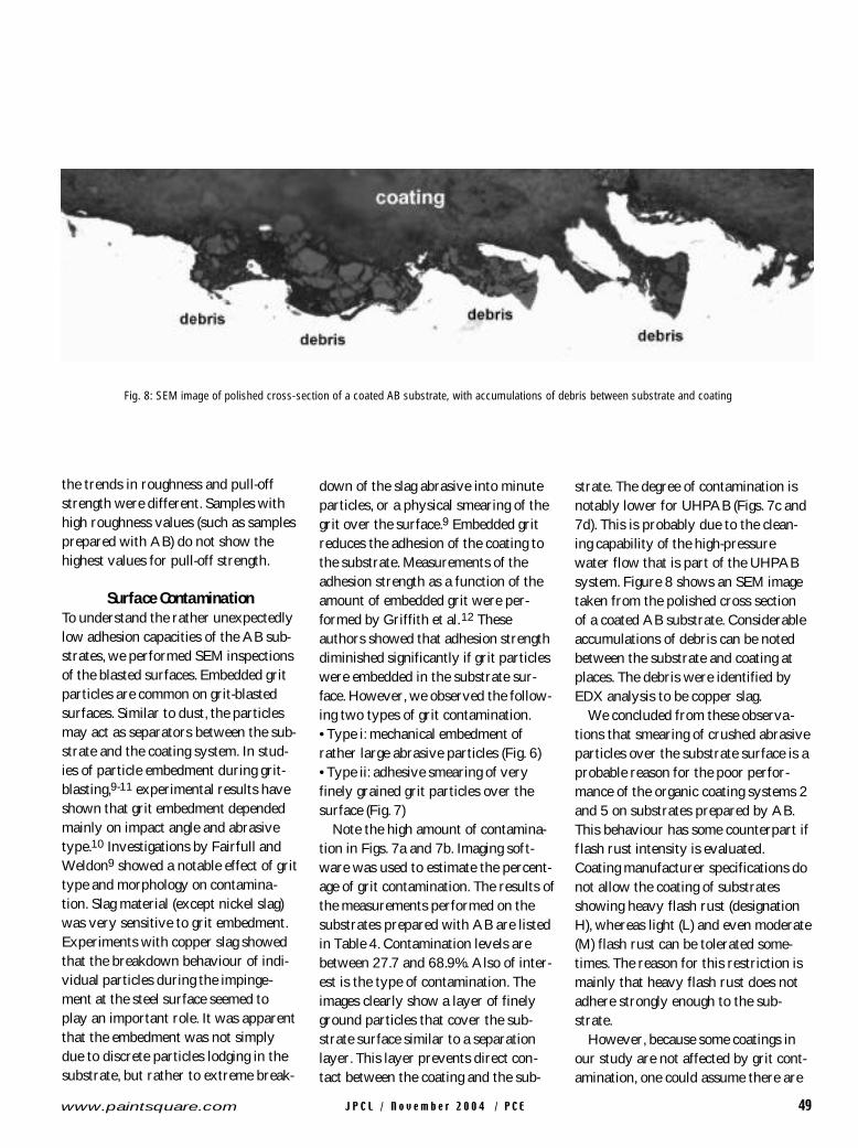
Surface ContaminationTo understand the rather unexpectedly
low adhesion capacities of the AB sub-
strates, we performed SEM inspections
of the blasted surfaces. Embedded grit
particles are common on grit-blasted
surfaces. Similar to dust, the particles
may act as separators between the sub-
strate and the coating system. In stud-
ies of particle embedment during grit-
blasting,9-11 experimental results have
shown that grit embedment depended
mainly on impact angle and abrasive
type.10 Investigations by Fairfull and
Weldon9 showed a notable effect of grit
type and morphology on contamina-
tion. Slag material (except nickel slag)
was very sensitive to grit embedment.
Experiments with copper slag showed
that the breakdown behaviour of indi-
vidual particles during the impinge-
ment at the steel surface seemed to
play an important role. It was apparent
that the embedment was not simply
due to discrete particles lodging in the
substrate, but rather to extreme break-
down of the slag abrasive into minute
particles, or a physical smearing of the
grit over the surface.9 Embedded grit
reduces the adhesion of the coating to
the substrate. Measurements of the
adhesion strength as a function of the
amount of embedded grit were per-
formed by Griffith et al.12 These
authors showed that adhesion strength
diminished significantly if grit particles
were embedded in the substrate sur-
face. However, we observed the follow-
ing two types of grit contamination.
• Type i: mechanical embedment of
rather large abrasive particles (Fig. 6)
• Type ii: adhesive smearing of very
finely grained grit particles over the
surface (Fig. 7)
Note the high amount of contamina-
tion in Figs. 7a and 7b. Imaging soft-
ware was used to estimate the percent-
age of grit contamination. The results of
the measurements performed on the
substrates prepared with AB are listed
in Table 4. Contamination levels are
between 27.7 and 68.9%. Also of inter-
est is the type of contamination. The
images clearly show a layer of finely
ground particles that cover the sub-
strate surface similar to a separation
layer. This layer prevents direct con-
tact between the coating and the sub-
strate. The degree of contamination is
notably lower for UHPAB (Figs. 7c and
7d). This is probably due to the clean-
ing capability of the high-pressure
water flow that is part of the UHPAB
system. Figure 8 shows an SEM image
taken from the polished cross section
of a coated AB substrate. Considerable
accumulations of debris can be noted
between the substrate and coating at
places. The debris were identified by
EDX analysis to be copper slag.
We concluded from these observa-
tions that smearing of crushed abrasive
particles over the substrate surface is a
probable reason for the poor perfor-
mance of the organic coating systems 2
and 5 on substrates prepared by AB.
This behaviour has some counterpart if
flash rust intensity is evaluated.
Coating manufacturer specifications do
not allow the coating of substrates
showing heavy flash rust (designation
H), whereas light (L) and even moderate
(M) flash rust can be tolerated some-
times. The reason for this restriction is
mainly that heavy flash rust does not
adhere strongly enough to the sub-
strate.
However, because some coatings in
our study are not affected by grit cont-
amination, one could assume there are
Fig. 8: SEM image of polished cross-section of a coated AB substrate, with accumulations of debris between substrate and coating
J P C L / N o v e m b e r 2 0 0 4 / P C E50 www.paintsquare.com
other causes of the difference in adhe-
sion. The question arises of whether
some types of coatings are compatible
with grit-contaminated surfaces. Such
coatings could be analogous to those
defined as flash rust-tolerant coatings.
The capability of the liquid coating to
penetrate the grit layer and to encapsu-
late individual grit particles may play a
notable role. A similar process was
reported by Kaiser and Schütz13 with
regard to rust. A programme is
planned to investigate this issue. For
coating systems 2 and 5, the UHP sam-
ples show slightly lower adhesion val-
ues than the UHPAB samples. These
discrepancies could be explained by the
lower roughness of the substrates pre-
pared with UHP. Although UHP sam-
ples are completely clean in terms of
grit contamination, their profile is too
low to contribute to better adhesion.
Another conclusion from our study
is that the assessment of dust on steel
surfaces according to ISO 8502-314 is
not sufficient because it considers only
dust particles visible under 10x magni-
fication. The microscopically small
abrasive debris found in our study can-
not be detected by this method.
Therefore, even substrates that are cat-
egorised as dust size class “0” in ISO
8502-314 may not be completely free
of dust contamination.
SummaryThe investigation shows that a sensi-
tive balance exists between surface
preparation method and the coating
system to be applied. A proper combi-
nation of both can notably improve
adhesion and corrosion resistance in
general because good adhesion is a pre-
condition for good performance of pro-
tective coating systems. A layer of
microscopic, finely crushed abrasive
particles embedded in the surface
seems to affect bonding between the
substrate and coating for some coating
systems, while for others it does not.
With UHP and UHPAB, this effect can
be eliminated, and an optimum surface
morphology can be achieved with
UHPAB. Salt spray test results for the
performance of the coating systems
and substrates discussed in this article
will be reported later.
References1. ISO 8503: Preparation of Steel
Substrates before Application of
Paints and Related Products.
2. Allen, B., “Evaluating UHP
Waterjetting for Ballast Tank
Coating Systems,” PCE (October
1997), pp. 38–43.
3. Morris, M., “Update: Evaluating
UHP Waterjetting as Preparation
for Ballast Tank Coating,” PCE
(September 2000), pp. 54–59.
4. ISO 12944-2: Paints and
Varnishes—Corrosion Protection
of Steel Structures by Protective
Paint Systems—Part 2:
Classification of Environments,
1998.
5. ISO 12944-6: Paints and
Varnishes—Corrosion Protection
of Steel Structures by Protective
Paint Systems—Part 6: Laboratory
Performance Test Methods, 1998.
6. ISO 11126-3: Preparation of Steel
Substrates before Application of
Paints and Related Products—
Specifications for Non-metallic
Blast-cleaning Abrasives—Part 3:
Copper Refinery Slag, 1993.
7. ISO 8503-4: Preparation of Steel
Substrates before Application of
Paints and Related Products—
Surface Roughness Characteristics
of Blast-cleaned Steel Substrates—
Part 4: Method for the Calibration
of ISO Surface Profile Comparators
and for the Determination of
Surface Profile, Stylus Instrument
Procedure, 1988.
8. ISO 4624: Paints and Varnishes—
Pull-off Test for Adhesion, 2002.
9. Fairfull, C.L., Weldon, D.G., “Salt
Contaminated Abrasives and their
Effect on Coating Performance,”
Proceedings of the SSPC
Conference, Atlanta, 2001
(Pittsburgh, PA: SSPC: The Society
for Protective Coatings, 2001).
10. Amada, S., Hirose, T., Senda, T.,
“Quantitative Evaluation of
Residual Grits under Angled
Blasting,” Surface and Coatings
Technol., Vol. 111, 1–9, 1999.
11. Momber, A.W., Wong, Y.,
Budidharma, E., Tjo, R., “Profiling
of Low-carbon Steel with
Supersonic Water Jets,” Wear, Vol.
249, 2002, pp. 853–859.
12. Griffith, B.J., Gawne, D.T., Dong, G.,
“A Definition of the Topography of
Grit-blasted Surfaces for Plasma
Sprayed Alumina Coatings,” Trans.
ASME, J. of Manuf. Sci. and Engng.,
Vol. 121, 1999, pp. 49–53.
13. Kaiser, W.D., Schütz, A., 2001,
Hochdruckwasserstrahlen und
Restrostverträglicher
Beschichtungsstoff—eine Mögliche
Instandsetzungsstrategie, WEKA,
Bd. 2, Teil 9, Kapitel 8.5, pp. 1–26.
(See also: Momber, A.W.,
Hydroblasting and Coating of Steel
Structures, Elsevier Advanced
Technology, Oxford, 2003,
pp.124–125.)
14. ISO 8502-3: Preparation of Steel
Surfaces before Application of
Paint and Related Products—Tests
for the Assessment of Surface
Cleanliness—Part 3: Assessment
of Dust on Steel Surfaces Prepared
for Painting (Pressure-sensitive
Tape Method), 1992.