MUNICIPAL CORPORATION OF GREATER MUMBAI Schedule of Rate… · municipal corporation of greater...
176
MUNICIPAL CORPORATION OF GREATER MUMBAI ROAD DEPARTMENT VOLUME-II TECHNICAL SPECIFICATIONS FOR ROAD WORKS 2013
-
Upload
phungthien -
Category
Documents
-
view
254 -
download
1
Transcript of MUNICIPAL CORPORATION OF GREATER MUMBAI Schedule of Rate… · municipal corporation of greater...
MUNICIPAL CORPORATION OF
GREATER MUMBAI
ROAD DEPARTMENT
VOLUME-II
TECHNICAL SPECIFICATIONS FOR
ROAD WORKS
2013

ROADS SCHEDULE 2013
Municipal Corporation of Greater Mumbai
Foreword
Ever since establishment of Bombay Municipal Corporation (now Municipal Corporation of Greater
Mumbai) in 1888 by the erstwhile British rulers in India, in the last 125 years of the history of its
existence MCGM has catered to every aspect of the citizen of Mumbai that can be conceived of.
Look to heritage buildings like Victoria Terminus (Chhatrapati Shivaji Terminus), Office of Municipal
Corporation, Dadabai Naoroji Road, Dr. Babasaheb Ambedkar Road, Marine Drive (Netaji Subhash
Road), Prince of Wales Museum, Gateway of India, Malabar Hill Reservoir, Nair Hospital, Lokmanya
Tilak Hospital, KEM Hospital etc which are the service centers for the citizens. Municipal Services
have also been provided in the suburban and extended suburban areas merged in 1950 & 1957
respectively. The obligatory duties are performed well but still there is need to improve in quantity
and quality of services to be provided to the citizens.
Ethical governance and righteous work culture will certainly bring positive changes in design and
implementation of projects. One may take an example of the first Municipal Head Quarter Building,
that was completed in year 1893, in four years, designed by F W Stevens and the execution part
was dealt by Project Engineer Shri Rao Saheb Sitaram Khanderrao Vaidya, who executed the
project of 77.70m high structure and saved Rs.68,000/- as against estimated cost of Rs. 11.80
Lakhs.
The need is to work with precision and accuracy. There shall be harmony between planning and
execution so as to evolve best economics with focused goals.
MCGM is one of the largest local self governments in the Asian Continent. In observance of historic
traditions of strong civic activism, with the change in time and living conditions to match with the
urbanization, MCGM has focused in providing variety of engineering services viz, storm water drain,
sewerage, water supply, roads, bridges, solid waste management, environmental services. Beside
this, the Corporation is also providing dedicated services in the Health sector by establishing Major
and Peripheral hospitals.
To update and modernize the mechanism being used for working on related projects from the stage
of conceptualization to execution, the need was realized to revise prevailing “Schedule Of Rates”
along with specifications which were in operation with various departments and being prepared
individually as per their need and revised at different span of time, resulting into various anomalies.
To overcome all these, it was essential to revise the schedule of rates, not only with simple
mechanized revision but incorporating major changes to keep up with the pace of urbanization,
civilization, construction techniques / mechanization and voluminous developments by restructuring

ROADS SCHEDULE 2013
Municipal Corporation of Greater Mumbai
items in the schedule to cover all requirements. This exercise would provide comfort with designs
and field necessities and will assist in effective checks on creation of extra items during execution.
A conscious decision has been taken to prepare Unified Schedule of Rates to keep pace with the
changing time; a first step forward in this direction. Since long time, there have been demands made
by the stake holders like Municipal Engineers and Contractors to remove non-uniformity, anomalies
and discrepancies in various schedules of rates for work contracts of various departments of MCGM.
Every department had its own expertise and way of functioning which got reflected in its independent
schedule of rates, which however, had no linkage with the fair market rates and schedules of other
departments, resulting into extra items and fair rates. In place of earlier 9 Schedule Of Rates, the
Unified Schedule of Rates is an effort and seeks to rectify the defects, discrepancies and non
uniformities which will provide ease and accuracy of estimation to the Engineers.
In view of the enormous and voluminous nature of work, keeping time frame in perspective and
above all, to ensure professionalism, the work of preparation of Unified Schedule of Rates (USR)
was awarded to the eminent consultants M/s. TATA Consulting Engineers Ltd. M/s. TATA Consulting
Engineers Ltd were directed to conduct a integrated factual market research for major materials from
stockists/manufacturers/dealers and to study schedules of rates of Govt. bodies like C.P.W.D.,
P.W.D. etc The new Rate Analysis are based on Factual Market research done by M/s.TATA
Consulting Engineers Ltd.
The anomalies in rate are minimized after extensive market research and collection of quotations
from reputed large scale stockists/dealers, and also after comparison with rates of CPWD, PWD etc.
The Unified Scheduled of Rates is linked with its comprehensive specifications of basic important
activities so as to have clarity in execution. These specifications follow a chronology of general
scope of the item, material required, processing of material, construction operation, finishing and
mode of measurement. Rigid Standard Operating Procedures (SOPs) and complete control on
processes will certainly satisfy quality parameter. The need for checking the quality of construction is
quite apparent and shall be ensured throughout the construction process. To achieve this, the
Unified Scheduled of Rates incorporates quality assurance procedures.
All the rates are also linked to their detailed specifications and wherever required, with drawings.
Though there are about 12500 items, every item is now given a Unique Code No. which will
eliminate the repetition.
It has been our endeavor to include all the necessary modern materials and technologies in Unified
Schedule of Rates, for example, the concept of green building, which will go a long way to have
control on creation of extra items and fair rates. A salient feature of this Unified Schedule of Rates is
'Starring of items' specified categorically which can be used only at certain works or locations.

ROADS SCHEDULE 2013
Municipal Corporation of Greater Mumbai
Another salient feature is 'Dynamic Rate System' which will be based on study of data base of
quantities and bidding prices of awarded contracts on the basis of which necessary corrections can
be applied to the Unified Schedule of Rates at specified intervals. The MCGM will be now be in a
position to revise the Unified Scheduled of Rates every year, after incumbency period of M/s.TATA
Consulting Engineers Ltd of one year, to work with and correct the system as and when necessary.
I am sure that this 'Unified Scheduled of Rates' will be a milestone in civic governance by MCGM.
This publication shall be of great help and guidance to the officers engaged in the project work of
MCGM.
A.M.C. (Project) Municipal Commissioner
STANDARD SPECIFICATIONS FOR ROAD WORKS SP-RW
MUNICIPAL CORPORATION OF GREATER MUMBAI
Page 1
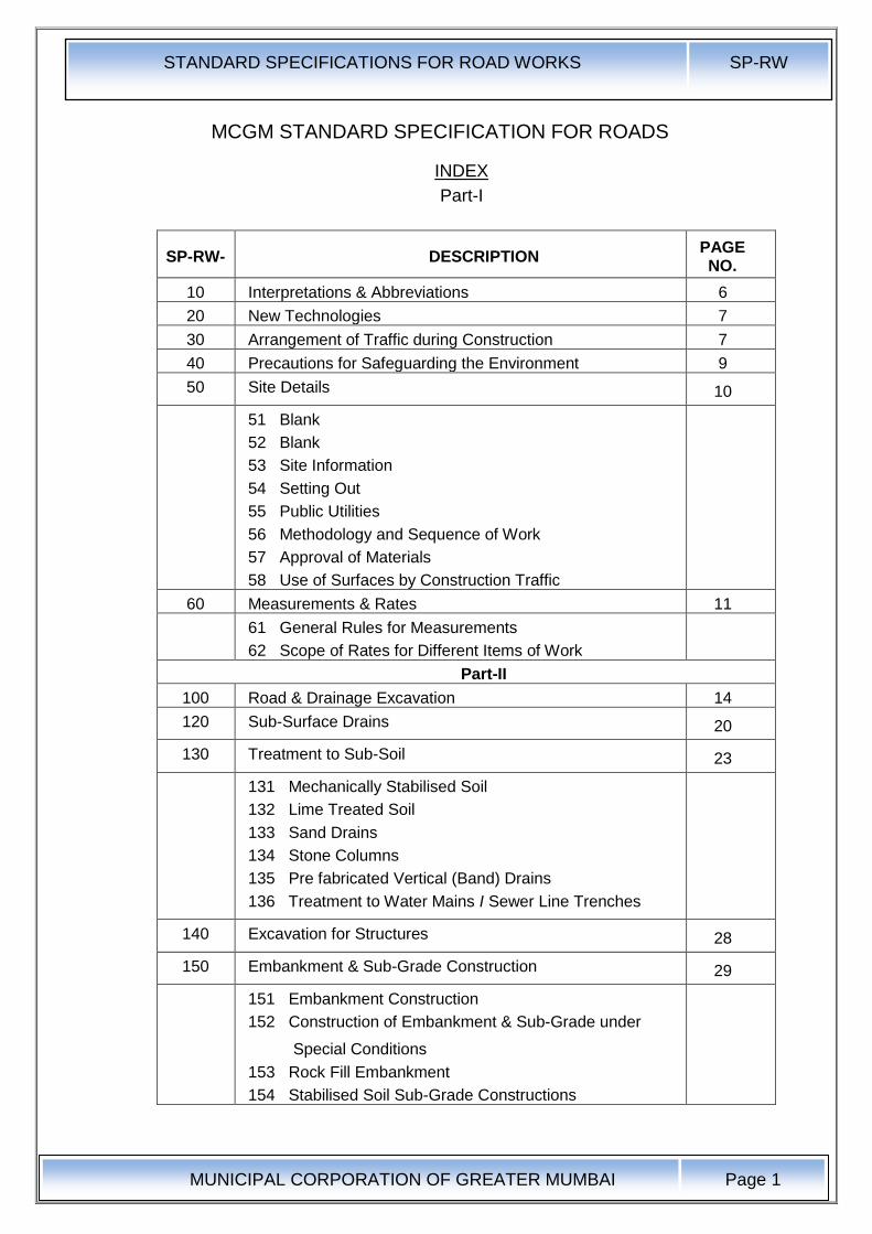
MCGM STANDARD SPECIFICATION FOR ROADS
INDEX
Part-I
SP-RW- DESCRIPTION PAGE NO.
10 Interpretations & Abbreviations 6
20 New Technologies 7
30 Arrangement of Traffic during Construction 7
40 Precautions for Safeguarding the Environment 9
50 Site Details 10
51 Blank
52 Blank
53 Site Information
54 Setting Out
55 Public Utilities
56 Methodology and Sequence of Work
57 Approval of Materials
58 Use of Surfaces by Construction Traffic
60 Measurements & Rates 11
61 General Rules for Measurements
62 Scope of Rates for Different Items of Work
Part-II
100 Road & Drainage Excavation 14
120 Sub-Surface Drains 20
130 Treatment to Sub-Soil 23
131 Mechanically Stabilised Soil
132 Lime Treated Soil
133 Sand Drains
134 Stone Columns
135 Pre fabricated Vertical (Band) Drains
136 Treatment to Water Mains I Sewer Line Trenches
140 Excavation for Structures 28
150 Embankment & Sub-Grade Construction 29
151 Embankment Construction
152 Construction of Embankment & Sub-Grade under
Special Conditions
153 Rock Fill Embankment
154 Stabilised Soil Sub-Grade Constructions
STANDARD SPECIFICATIONS FOR ROAD WORKS SP-RW
MUNICIPAL CORPORATION OF GREATER MUMBAI
Page 2
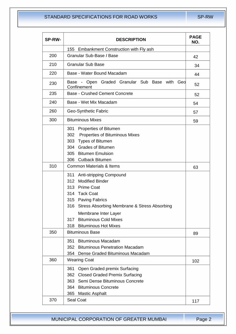
SP-RW- DESCRIPTION PAGE NO.
155 Embankment Construction with Fly ash
200 Granular Sub-Base I Base 42
210 Granular Sub Base 34
220 Base - Water Bound Macadam 44
230 Base - Open Graded Granular Sub Base with Geo-Cell Confinement
52
235 Base - Crushed Cement Concrete 52
240 Base - Wet Mix Macadam 54
260 Geo-Synthetic Fabric 57
300 Bituminous Mixes 59
301 Properties of Bitumen
302 Properties of Bituminous Mixes
303 Types of Bitumen
304 Grades of Bitumen
305 Bitumen Emulsion
306 Cutback Bitumen
310 Common Materials & Items 63
311 Anti-stripping Compound
312 Modified Binder
313 Prime Coat
314 Tack Coat
315 Paving Fabrics
316 Stress Absorbing Membrane & Stress Absorbing
Membrane Inter Layer
317 Bituminous Cold Mixes
318 Bituminous Hot Mixes
350 Bituminous Base 89
351 Bituminous Macadam
352 Bituminous Penetration Macadam
354 Dense Graded Bituminous Macadam
360 Wearing Coat 102
361 Open Graded premix Surfacing
362 Closed Graded Premix Surfacing
363 Semi Dense Bituminous Concrete
364 Bituminous Concrete
365 Mastic Asphalt
370 Seal Coat 117
STANDARD SPECIFICATIONS FOR ROAD WORKS SP-RW
MUNICIPAL CORPORATION OF GREATER MUMBAI
Page 3
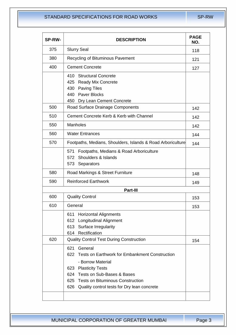
SP-RW- DESCRIPTION PAGE NO.
375 Slurry Seal 118
380 Recycling of Bituminous Pavement 121
400 Cement Concrete 127
410 Structural Concrete
425 Ready Mix Concrete
430 Paving Tiles
440 Paver Blocks
450 Dry Lean Cement Concrete
500 Road Surface Drainage Components 142
510 Cement Concrete Kerb & Kerb with Channel 142
550 Manholes 142
560 Water Entrances 144
570 Footpaths, Medians, Shoulders, Islands & Road Arboriculture 144
571 Footpaths, Medians & Road Arboriculture
572 Shoulders & Islands
573 Separators
580 Road Markings & Street Furniture 148
590 Reinforced Earthwork 149
Part-III
600 Quality Control 153
610 General 153
611 Horizontal Alignments
612 Longitudinal Alignment
613 Surface Irregularity
614 Rectification
620 Quality Control Test During Construction 154
621 General
622 Tests on Earthwork for Embankment Construction
- Borrow Material
623 Plasticity Tests
624 Tests on Sub-Bases & Bases
625 Tests on Bituminous Construction
626 Quality control tests for Dry lean concrete

STANDARD SPECIFICATIONS FOR ROAD WORKS SP-RW
MUNICIPAL CORPORATION OF GREATER MUMBAI
Page 4
MCGM
Technical Specifications for Roads
10 Interpretations & Abbreviations
Interpretations
Order of Priority
Specifications indicated in BOQ
Technical Specifications outlined in MCGM Standard Specifications Drawings
Specifications of MORT & H - Latest Edition till 30 days before the final date of submission of the tender
Indian Road Congress Specifications - Latest Edition till 30 days before the final date of submission of the tender
Bureau of Indian Standard Specifications - Latest Edition till 30 days before the final date of submission of the tender
British Standard Specifications - Latest Edition till 30 days before the final date of submission of the tender
The Asphalt Institute, U.S.A. Publication of Specifications - Latest Edition till 30 days before the final date of submission of the tender
11 Abbreviations
AASHTO : American Association of State Highway and Transportation Officials
ASTM : American Society for Testing and Materials
BS : British Standard published by the British Standards Institution
BOQ : Bill of Quantities forming part of the contract
CBR: California Bearing Ratio
IRC : Indian Road Congress
IS : Indian Standard published by the Bureau of Indian Standards
WC : Water Cement Ratio
CRRI : Central Road Research Institute
UCS : Unconfined Compressive Strength
WBM : Water Bound Macadam
SAM: Stress Absorbing Membrane
SAMI : Stress Absorbing Membrane Interlayer
MoRTH: Ministry of Road Transport and Highways

STANDARD SPECIFICATIONS FOR ROAD WORKS SP-RW
MUNICIPAL CORPORATION OF GREATER MUMBAI
Page 5
20.0 New Technologies I Materials
20.1 New Technologies I Materials are the one that are not incorporated in this or MoRTH Standard Specifications
New technologies can make use of Newly Invented / patented materials, equipment or machinery. It can also make use of conventional materials / equipment with innovative design. In case of New Patented Material a warrantee from the manufacturer! Contractor for three years and certification from two Institute like Central Road Research Institute, Indian Institute of Technology for its acceptance for field application shall be essential. In case of innovative designs, it is essential for the contractor to indemnify the corporation against loss due to failure in addition to certification from an Institute like Central Road Research Institute(CRRI).
20.2 The Engineer, on satisfactory completion of above formalities, will allot a suitable stretch of road for mock up purposes. Its performance shall be monitored by the Engineer and Quality Control Cell for one year. Based on the performance, a decision will be taken regarding qualification of the material design for field application. The successful performance will qualify Technology Materials to be incorporated as provisional specifications as alternative to these standard specifications. The product shall be under observation for five years during which its performance shall be monitored. On successful completion of the period with extensions, if any, the product shall be included in the Standard Specifications.
20.3 Measurements & Payment
The unit of measurements shall be as per mutual agreement between the contractor and the Engineer.
20.4 Rate
The rate shall be derived from data given by the supplier / contractor.
30.0 Arrangement for Traffic During Construction
30.1 General: The Contractor shall at all time carry out work on the roads in a manner creating least interference to the flow of traffic while consistent with the satisfactory execution of the same. For all works involving improvements to the existing roads, the Contractor shall, in accordance with the directives of the Engineer, provide and maintain, during execution of the work, a passage for traffic either along a part of the existing carriageway under improvement, or along a temporary diversion constructed close to the roads. The Contractor shall take prior approval of the Engineer regarding traffic arrangements during construction.
30.2 Passage of Traffic along a part of the Existing Carriageway under Improvement: For widening / strengthening existing carriageway where part width of the existing carriageway is proposed to be used for passage of traffic, treated shoulders shall be provided on the side on which work is not in progress. The treatment to the shoulder shall consist of providing at least 150mm thick granular base course covered with bituminous surface dressing in a width of at least 1.5m and the surface shall be maintained throughout the period during which traffic uses the same to the satisfaction of the Engineer.
In case of widening existing two-lane to four-lane, the additional two lanes would be constructed first and the traffic diverted to it and only thereafter the required treatment to the existing carriageway would be carried out. However, in case where on the request of the Contractor, work on existing two-lane carriageway is allowed by the Engineer with traffic using part of the existing carriageway, stipulations as in Para above shall apply. After obtaining permission of the
STANDARD SPECIFICATIONS FOR ROAD WORKS SP-RW
MUNICIPAL CORPORATION OF GREATER MUMBAI
Page 6
Engineer, the treated shoulder shall be dismantled, the debris disposed of and the area cleared as per the direction of the Engineer.
30.3 Passage of Traffic along a Temporary Diversion: In stretches where it is not possible to pass the traffic on apart width of the carriageway, a temporary diversion shall be constructed with 7m carriageway and 2.5m earthen shoulders on each side (total width of roadway 12m) with the following provision for road crust in the 7m width:
i. 200mm (compacted) granular sub base;
ii. 225mm (compacted) granular base course; and
iii. Premix carpet with Seal Coat / Mix Seal Surfacing.
The alignment and longitudinal section of diversion including junctions and temporary cross drainage provision shall be as approved by the Engineer.
30.4 Traffic Safety and Control: The Contractor shall take all necessary measures for the safety of traffic during construction and provide, erect and maintain such barricades, including signs, markings, flags, lights and flagmen as may be required by the Engineer for the information and protection of traffic approaching or passing through the section of the highway under improvement. Before taking up any construction, an agreed phased programme for the diversion of traffic on the highway shall be drawn up in consultation with the Engineer.
The barricades erected on either side of the carriageway / portion of the carriageway closed to traffic, shall be of strong design to resist violation, and painted with alternate black and white stripes. Red lanterns or warning lights of similar type shall be mounted on the barricades at night and kept lit throughout from sunset to sunrise. At the points where traffic is to deviate from its normal part (whether on temporary diversion or part width of the carriageway) the channel for traffic shall be clearly marked with the aid of pavement markings, painted drums or a similar device to the directions of the Engineer. At night, the passage shall be delineated with lanterns or other suitable light source. One-way traffic operation shall be established whenever the traffic is to be passed over part of the carriageway inadequate for two-lane traffic. This shall be done with the help of temporary traffic signals or flagmen kept positioned on opposite sides during all hours. For regulation of traffic, the flagmen shall be equipped with red and green flags and lanterns / lights.
On both sides, suitably regulatory / warning signs as approved by the Engineer shall be installed for the guidance of road users. On each approach, at least two signs shall be put up, one close to the point where transition of carriageway begins and the other 120m away. The signs shall be of approved design and of reflectory type, if so directed by the Engineer.
30.5 Maintenance of Diversions and Traffic Control Devices: Signs, lights, barriers and other traffic control devices, as well as the riding surface of diversions shall be maintained in a satisfactory condition till such time they are required as directed by the Engineer. The temporary travelled way shall be kept free of dust by frequent applications of water, if necessary. Wardens for monitoring traffic as per requirement of traffic police shall be provided by the contractor at his own cost.
30.6 The minimum curing time required during which the traffic is to be kept off the surface for different types of layers / materials shall be as mentioned below:
a) Cement / Lime Stabilised Surfaces: Seven Days
b) Earthen Embankment: One Day
c) Granular Layer: Three Days
STANDARD SPECIFICATIONS FOR ROAD WORKS SP-RW
MUNICIPAL CORPORATION OF GREATER MUMBAI
Page 7
d) Bituminous Cold Mixes / Seal Coat : Twelve Hours for heavy vehicles and Eight hours for light vehicles.
e) Bituminous Hot Mixes: Twenty Four Hours for heavy vehicles and eight hours for light vehicles
f) Slurry Seals: Four Hours
30.7 Measurements for Payment and Rate: All arrangements for traffic during construction including provision of temporary cross drainage structures, if required, and treated shoulder as described in clause 30.2 including their maintenance, dismantling and clearing debris, where necessary, shall be considered as incidental to the works and shall be the Contractor's responsibility.
The construction of temporary diversion including temporary cross drainage structures as described in clause 30.3 shall be measured in linear metre and the unit contract rate shall be inclusive of full compensation for construction (including supply of material, labour, tools, etc.), maintenance, final dismantling, and disposal.
40.0 Precautions for Safeguarding the Environment:
40.1 General: The Contractor shall take all precautions for safeguarding the environment during the course of the construction of the works. He shall abide by all laws, rules and regulations in force governing pollution and environmental protection that are applicable in the area where the works are situated.
40.2 Borrow pits for Embankment Construction: Borrow pits shall not be dug in the right-of-way of the road.
40.3 Quarry Operations: The Contractor shall obtain materials form quarries only after the consent of the Forest Department or other concerned authorities is obtained. The quarry operations shall be undertaken within the purview of the rules and regulations in force.
40.4 Control of Soil Erosion, Sedimentation and Water Pollution: The Contractor shall carry out the works in such a manner that soil erosion is fully controlled, and sedimentation and pollution of natural water courses, ponds, tanks and reservoirs are avoided. The stipulations in Clause 306 of MORT&H. Specifications shall govern.
40.5 Pollution from Hot-Mix Plants and Batching Plants: Bituminous hot-mix plants and concrete batching plants shall be located sufficiently away from habitation, agricultural operations or industrial establishments. The Contractor shall take every precaution to reduce the levels of noise, vibrations, dust and emissions from his plant and shall be fully responsible for any claims for damages caused to the owners of property, fields and residences in the vicinity.
40.6 Substances Hazardous to Health: The Contractor shall not use or generate any materials in the works which are hazardous to the health of persons, animals or vegetation. Where it is necessary to use some substances which can cause injury to the health of workers, the Contractor shall provide protective clothing or appliances to his workers.
40.7 Use of Nuclear Gauges: Nuclear gauges shall be used only where permitted by the Engineer. The nuclear gauges shall be calibrated as per the conditions laid down in the contract document. The Contractor· shall provide the Engineer with a copy of the regulations governing the safe use of nuclear gauges he intends to employ and shall abide by such regulations.
40.8 The Contractor must take all reasonable steps to minimize dust nuisance during the construction of the works.
STANDARD SPECIFICATIONS FOR ROAD WORKS SP-RW
MUNICIPAL CORPORATION OF GREATER MUMBAI
Page 8
40.9 All existing roads used by vehicle of the Contractor or any of his subcontractors or suppliers of materials or plant, and similarly any new roads which are part of the works and which are being used by traffic, shall be kept clean and clear of all dust/mud or other extraneous materials dropped by the said vehicles or their tyres. Similarly, all dust/mud or other extraneous materials from the works spreading on these roads shall be immediately cleared by the Contractor.
40.10 Clearance shall be effected immediately by manual sweeping and removal of debris, or if so directed by the Engineer, by mechanical sweeping and clearing equipment, and all dust, mud and other debris shall be' removed entirely from the road surface. Additionally, if so directed by the Engineer, the road surface shall be hosed or watered using suitable equipment.
40.11 Any structural damage caused to the existing roads by the Contractor's construction equipment shall be made good without any extra cost.
40.12 Compliance with the foregoing will not relieve the Contractor of any responsibility for complying with the requirements of any Authority in respect of the roads used by him.
50.0 Site Details
53.0 Site Information:
53.1 The information about the site of work and site conditions in the Tender Documents is given in good faith for guidance only but the Contractor shall satisfy himself regarding all aspects of site conditions.
53.2 The location of the works and the general site particulars are as generally shown on the Site plan I Index plan enclosed with the Tender Documents.
53.3 Whereas the right-of-way to the bridge sites I road works shall be provided to the Contractor by the Engineer, the Contractor shall have to make his own arrangement for the land required by him for site offices, labour camps, stores, etc.
54.0 Setting Out:
54.1 The Contractor shall establish working Bench Marks related with the Town Hall Reference Bench Mark (THD) in the area soon after taking possession of the site. The Reference Bench Mark for the area shall be as indicated. The working Bench Marks shall be at the rate of four per km and also at or near all drainage structures, over-bridges and underpasses. The working Bench Marks I levels should be got approved from the Engineer. Checks must be made on these Bench Marks once every month and adjustments, if any, got agreed with the Engineer and recorded. An up-to-date record of all Bench Marks including approved adjustments, if any, shall be maintained by the Contractor and also a copy supplied to the Engineer for his record.
54.2 The lines and levels of formation, side slopes, drainage works, carriageways and shoulders shall be carefully set out and frequently checked, care being taken to ensure that correct gradients and cross-sections are obtained everywhere.
54.3 In order to facilitate the setting out of the works, the centre line of the carriageway or road must be accurately established by the Contractor and approved by the Engineer. it must then be accurately referenced in a manner satisfactory to the Engineer, every 50m intervals in plain and rolling terrains and 20m intervals in hilly terrain and in all curve points as directed by the Engineer, with marker pegs and chainage boards set in or near the fence line, and a schedule of reference dimensions shall be prepared and supplied by the Contractor to the Engineer. These markers shall be maintained until the works reach finished formation level and are accepted by the Engineer.
STANDARD SPECIFICATIONS FOR ROAD WORKS SP-RW
MUNICIPAL CORPORATION OF GREATER MUMBAI
Page 9
54.4 On construction reaching the formation level stage, the centre line shall again be set out by the Contractor and when approved by the Engineer, shall be accurately referenced in a manner satisfactory to the Engineer by marker pegs at the outer limits of the formation.
54.5 No reference peg or marker shall be moved or withdrawn without the approval of the Engineer and no earthwork or structural work shall be commenced until the centre line has been referenced.
54.6 The Contractor will be the sole responsible party for safeguarding all survey monuments, bench marks, beacons, etc. The Engineer will provide the Contractor with the data necessary for setting out of the centre line. All dimensions and levels shown on the drawings or mentioned in documents forming part of or issued under the Contract shall be verified by the Contractor on the site and he shall immediately inform the Engineer of any apparent errors or discrepancies in such dimensions or levels. The Contractor shall, in connection with the staking out of the centre line, survey the terrain along the road and shall submit to the Engineer for this approval, a profile along the road centre line and cross-sections at intervals as required by the Engineer.
54.7 After obtaining approval of the Engineer, work on earthwork can commence and the profile and cross-sections shall form the basis for measurements and payment. The Contractor shall be responsible for ensuring that all the basic traverse points are in place at the commencement of the contract and if any are missing, or appear to have been disturbed, the Contractor shall make arrangements to reestablish these points. A "Survey File" containing the necessary data will be made available for this purpose. If in the opinion of the Engineer, design modifications of the centre line or grade are advisable, the Engineer will issue detailed instruction to the Contractor and the Contractor shall perform the modifications in the field, as required, and modify the ground levels on the cross-sections accordingly as many times as required. There will be no separate payment for any survey work performed by the Contractor. The cost of these services shall be considered as being included in the cost of the items of work in the Bill of Quantities.
54.8 The work of setting out shall be deemed to be a part of general works preparatory to the execution of work and no separate payment shall be made for the same.
54.9 Precision automatic levels, having a standard deviation of ±2mm per Km, and fitted with micrometer attachment shall be used for all double run levelling work. Setting out of the road alignment and measurement of angles shall be done by using theodolite with traversing target, having an accuracy of one second. Measurement of distances shall be done preferably using precision instruments like Distomat.
55.0 Public Utilities:
55.1 Drawings scheduling the affected services like water pipes, sewers, oil pipelines, cables, gas ducts etc. owned by various authorities including Public Undertakings and Local Authorities included in the Contract Documents shall be verified by the Contractor for the accuracy of the information prior to the commencement of any work.
55.2 Notwithstanding the fact that the information on affected services may not be exhaustive, the final position of these services within the works shall be supposed to have been indicated based on the information furnished by different bodies and to the extent the bodies are familiar with the final proposals. The intermediate stages of the works are, however, unknown at the design stage, these being dictated by the Contractor's methods of working. Accordingly, the

STANDARD SPECIFICATIONS FOR ROAD WORKS SP-RW
MUNICIPAL CORPORATION OF GREATER MUMBAI
Page 10
Contractors programme must take into account the period of notice and duration of diversionary works of each body as given on the Drawings and: the Contractor must also allow for any effect of these services and alterations upon the Works and for arranging regular meetings with the various bodies at the commencement of the Contract and throughout the period of the Works in order to maintain the required co-ordination. During the period of the Works, the Contractor shall have no objection if the public utility bodies vary their decisions in the execution of their proposals in terms of programme and construction, provided that, in the opinion of the Engineer, the Contractor has received reasonable notice thereof before the relevant alterations are put in hand.
55.3 No clearance or alterations to the utility shall be carried out unless specially ordered by the Engineer.
55.4 Any services affected by the Works must be temporarily supported by the Contractor who must also take all measures reasonably required by the various bodies to protect their services and property during the progress of the Works.
55.5 The Contractor may be required to carry out certain works for and on behalf of the various bodies and he shall also provide, with the prior approval of the Engineer, such assistance to the various bodies as may be authorized by the Engineer.
55.6 The work of temporarily supporting and protecting the public utility services during execution of the Works shall be deemed to be the part of the Contract and no extra payment shall be made for the same.
55.7 The Contractor may be required to carry out the removal or shifting of certain services I utilities on specified orders from the Engineer for which payment shall be made to him. Such works shall be taken up by the Contractor only after obtaining clearance from the Engineer and ensuring adequate safety measures.
56.0 Methodology and Sequence of Work
56.1 Prior to start of the construction activities at site, the Contractor shall, within 15 days after the date of the Letter of Acceptance, submit to the Engineer for approval, the detailed construction methodology including mechanical equipment proposed to be used, sequence of various activities and schedule from start to end of the project. Programme relating to pavement and shoulder from start to end of the project. Programme relating to pavement and shoulder construction shall be an integrated activity to be done simultaneously in a co-ordinated manner. The methodology and the sequence shall be so planned as to provide proper safety, drainage and free flow of traffic.
57.0 Approval of Materials
57.1 Approval of all sources of material for work shall be obtained in writing from the Engineer before their use on the project.
58.0 Use bf Surfaces by Construction Traffic
Ordinarily, no construction traffic shall be allowed on pavement under construction unless authorized by the Engineer. Even in that case the load and intensity of construction traffic should be so regulated that no damage is caused to the sub-grade or pavement layers already constructed. Where necessary service roads shall be constructed for this purpose and the same shall be considered as incidental to the work.
The wheels or tracks of plant moving over the various pavement courses shall be kept free of deleterious materials.
Bituminous base course shall be kept clean and uncontaminated as long as the same remains uncovered by a wearing course or surface treatment. The only traffic permitted access to the base course shall be that engaged in laying and

STANDARD SPECIFICATIONS FOR ROAD WORKS SP-RW
MUNICIPAL CORPORATION OF GREATER MUMBAI
Page 11
compacting the wearing course or that engaged on such surface treatment where the base-course is to be blinded and I or surface dressed. Should the base course or tack coat on the base course become contaminated, the Contractor shall make good by clearing it to the satisfaction of the Engineer, and if this is impracticable, by removing the layer and replacing it to Specification without any extra cost.
60.0 Measurements & Rates
61.0 General Rules for the Measurement of Works for Payment
61.1 General: All measurements shall be made in the metric system. Different items of work shall be measured in accordance with the procedures set forth in the relevant sections read in conjunction with the General Conditions of Contract. The same shall not, however, apply in the case of lump sum contracts.
All measurements and computations, unless otherwise indicated, shall be carried nearest to the following limits:
a) length and breadth 10mm
b) height, depth or thickness of earthwork, 5mm
sub-grade, sub-bases, bases, surfacing
and structural members
c) areas 0.01 Sq. M.
d) cubic contents 0.01 Cu. M.
In recording dimensions of work, the sequence of length, width and height or depth or thickness shall be followed.
61.2 Measurement of Lead for Materials: Where lead is specified in the Contract for construction materials, the same shall be measured as described hereunder:
Lead shall be measured over the shortest practicable route and not the one actually taken and the decision of the Engineer in this regard shall be taken as final. Distances upto and including 100m shall be measured in units of 50m, exceeding 100m but not exceeding 1 Km. in units of 100m and exceeding 1 Km. in units of 500m, the half and greater than half of the unit shall be reckoned as one and less than half of the unit ignored. In this regard, the source If material shall be divided into suitable blocks and for each block, the distance from the centre of the block to the centre of placing pertaining to that block shall be taken as the lead distance.
61.3 Measurement of Pavement Thickness for Payment on Volume Basis: The finished thickness of sub-base, base and bituminous courses to be paid on volume basis shall be computed in the following manner:
Levels shall be taken before and after construction, at grid of points 10m centre to centre longitudinally in straight reaches but 5m at curves. Transverse levels shall be taken at an interval of 2 / 2.5 M as directed by the Engineer.
Suitable references for the transverse grid lines should be left in the form of embedded bricks on either ends or by other means so that it is possible to locate the grid points for level measurements after each successive course is laid. For pavement courses laid only over widening portions, at least one line of levels shall be taken on each strip of widening, or more depending on the width of widening as decided by the Engineer.
Notwithstanding the above, the measurements may be taken at closer intervals also, if so desired by the Engineer, the need for which may arise particularly in the case of estimation of the volume of the material for profile corrective course (levelling course). The average thickness of the pavement course in any area shall be the arithmetic mean of the difference of levels before and after

STANDARD SPECIFICATIONS FOR ROAD WORKS SP-RW
MUNICIPAL CORPORATION OF GREATER MUMBAI
Page 12
construction at all the grid points falling in that area, provided that the thickness of finished work shall be limited to those shown on the drawings or approved by the Engineer in writing.
As supplement to level measurements, the Engineer shall have the option to take cores/make holes to check the depth of construction. The holes made and the portions cut for taking cores shall be made good by the Contractor by laying fresh mix / material including compacting as required at no extra cost immediately after the measurements are recorded.
61 .4 Checking of Pavement Thickness for Payment on Area Basis : Where payment for any bituminous course in Section 300 is allowed to be made on area basis, the Engineer may have its thickness checked with the help of a suitable penetration gauge at regular intervals or other means as he may decide.
61.5 Measurement of Bituminous Courses for Payment on Weight Basis: Plant-mixed bituminous materials for pavement courses where designated to be paid on weight basis shall be weighed on accurate scales approved by the Engineer. Approved scales shall mean scales that area of size, capacity, kind and type suitable for the weighing to be done, and these shall be properly and adequately installed and maintained. Prior to the use of the scales and as frequently thereafter as the Engineer may deem necessary to ensure accuracy, the scales shall be checked and approved by the Engineer, or the Engineer may direct the Contractor to have the scales checked by other competent agency at the cost of the Contractor.
Location of the scales shall be as designated by the Engineer. Trucks used for hauling the material to be weighed shall be weighed empty daily at such times as the Engineer directs, and each truck shall bear a plainly legible identification mark.
For materials specified to be measured by weight, the Engineer will have the option to make measurements of the finished work by volume and such volumes shall be converted into weight for payment purposes. The factor for conversion from volume measurement to weight measurement shall be computed from the representative density of the compacted material at site determined at locations approved by the Engineer.
62.0 Scope of Rates for Different Items of Work
For ·item rate contracts, the contract unit rates for different items of work shall be payment in full for completing the work to the requirements of the Specifications including full compensation for all the operations detailed in the relevant sections of these Specifications under "Rates". In the absence of any directions to the contrary, the rates are to be considered as the full inclusive rate for finished work covering all labour, materials, wastage, temporary work, plant, equipment, overhead charges and profit as well as the general liabilities, obligations, insurance and risks arising out of General Conditions of Contract.
The item rates quoted by the Contractor shall, unless otherwise specified, also include compliance with I supply of the following:
a) General works such as setting out, clearance of site before setting out and clearance of works after completion,
b) A detailed programme for the construction and completion of the work (using CPM/PERT techniques) giving, in addition to construction activities, detailed network activities for the submission and approval of materials, procurement of critical materials and equipment, fabrication of special products I equipment and their installation and testing, and for all activities of the Employer that are likely to affect the progress of work, etc. including

STANDARD SPECIFICATIONS FOR ROAD WORKS SP-RW
MUNICIPAL CORPORATION OF GREATER MUMBAI
Page 13
updating of all .such activities on the basis of the decisions taken at the periodic site review meetings or as directed by the Engineer;
c) Samples of various materials proposed to be used on the Work for conducting tests thereon as required as per the provisions of the Contract;
d) Design of mixes as per the relevant Clauses of the Specifications giving proportions of ingredients, sources of aggregates and binder along with accompanying trial mixes as per the relevant Clauses of these Specifications to be submitted to the Engineer for his approval before use on the Works;
e) Detailed design calculations and drawings for all Temporary Works (such as formwork, staging, centering; specialized constructional handling and launching equipment and the like);
f) Detailed drawings for templates, support and end anchorage, details of pre-stressing cable profiles, bar bending and cutting schedules for reinforcement, material lists for fabrication of structural steel, etc;
g) Mill test reports for all mild and high tensile steel and cast steel as per the relevant provisions of the Specifications;
h) Testing of various finished items and materials including bitumen, cement, concrete, bearings as required under these Specifications and furnishing test reports/certificates;
i) Inspections Reports in respect of formwork, staging, reinforcement and other items of work as per the relevant Specifications;
j) Any other date which may be required as per these Specifications for the Conditions of Contract or any other annexures / schedules forming part of the contract;
k) Any other item of work which is not specifically provided in the Bill of Quantities but which is necessary for complying with the provisions of the Contract;
I) All temporary works, formwork and false work;
m) Establishing and running a laboratory with facilities for testing for various items of works as specified in Section 600 and other relevant Clauses, where there is no separate item in the Bill of Quantities for establishing and running a laboratory;
n) Cost of in-built provisions for Quality Assurance;
o) Cost of providing "as-built drawings" in original and two sets of prints and C.D.
Portions of road works beyond the limits and / or any other work may be got constructed by the Employer directly through other agencies. Accordingly, other agencies employed by the Employer may be working in the vicinity of the Works being executed by the Contractor. The Contractor shall liaise with such agencies and adjust his construction programme for the completion of work accordingly and no claim or compensation due to any reason whatsoever will be entertained on this account. The Employer will be indemnified by the Contractor for any claims from other agencies on this account.

STANDARD SPECIFICATIONS FOR ROAD WORKS SP-RW
MUNICIPAL CORPORATION OF GREATER MUMBAI
Page 14
100.0 Road and Drainage Excavation
101.0 Description :
Roadway and drainage excavation shall consist of excavation removal and satisfactory disposal of all excavated materials and necessary for the requirements of those specifications and in the lines, grades and cross-sections shown on the drawings of indicated by the by the engineer. This work shall include the hauling and stacking or of hauling to sites of embankment construction of suitable cut materials as required, as also the disposal of unsuitable cut materials in specified manner and the trimming and finishing of the road way.
102.0 Classification of excavations: All materials involved in excavation shall be classified by engineer either under two groups as 102.1 and 102.2 or as per sub classes of these groups as stated in the contract.
102.1 General Classification: This shall comprise of excavation in soils, road metal, made ground, clays, moorum, boulders, sand, masonry or concrete in foundation, plinths and walls and all other material including whatever description not requiring to be blasted.
102.1.1 Soil
This shall comprise of topsoil, sand, silt, loam, clay, mud, marine clay, loose moorum, or similar material which yields to the ordinary application of pick, spade and / or shovel. Removal of gravel or any other nodular material having dimension not exceeding 75 mm occurring in such strata shall be deemed to be covered.
102.1.2 Soft rock
This shall include : Macadam surfaces, soling or hard core of roads, stabilised soil, compact moorum gravel, cobble stone having maximum dimension between 75 & 300 mm, masonry work, concrete , boulders etc which can be removed with JCB.
102.1.3 Marshy Soil
This shall include soils like marine clays, peats below original levels of marshes and swamps requiring continuous pumping or bailing out of water
102.2 Rock Excavation: This shall comprise of rock, big boulders more than 0.25 cubic meters (8 c ft). In volume, very hard stone or littoral concrete or any material requiring to be blasted by an explosive or broken into small pieces by iron wedges or chisels. The rock excavation shall have two classes
102.2.1 Rock Excavation by Blasting: This shall comprise boulders, hard rock, RCC, cement concrete for excavation of which the use of blasting is required.
102.2.2 Hard Rock (Blasting Prohibited): Due to restrictions, where excavation in rock cannot be done by blasting and chiseling, weighing or mechanically chisels, pavement breakers·are required to be used.
102.3 In case of any question arising as the class of excavation, the engineer shall determine under which category and that to what extent any particular excavation shall be classed.
103.0 Construction Operations:
103.1 After the site has been cleared, the limits of excavation shall be set out true lines, curves, slopes grades and sections as shown on the drawings or as directed by engineer. The Contractor shall provide all labour, survey instruments and materials, such as strings pegs, nails, bamboo, stones, lime, mortar, concrete, etc. required in connection with the setting out of works and establishment of

STANDARD SPECIFICATIONS FOR ROAD WORKS SP-RW
MUNICIPAL CORPORATION OF GREATER MUMBAI
Page 15
bench marks. The Contractor shall be responsible for the maintenance of bench marks and stokes as long as they are required for the work in the opinion of the Engineer.
103.2 Excavation-General: All excavation shall be carried out in conformity with the directions laid here in under and in a manner approved by the engineer. The work shall be so planned that the suitable materials available from excavation are satisfactorily utilised as decided upon of the Engineer.
The excavation shall conform to the lines, grades, side slopes and levels shown on the drawings or as directed by Engineer. The contractor shall not excavate outside the slopes or below the established grades or loosen any material outside the limits of excavation. Subject to the permitted tolerances, any excess depth excavated below the specified levels on the roadway shall be made good at the cost of the contractor with suitable material of similar characteristics to that removed and compacted to the requirements of clause 150.
All debris and loose material on the slopes of cutting shall be removed. No back filling shall be allowed to obtain required slopes except when boulders or soft pockets are encountered in cut slopes these shall be excavated to approved depth on instructions of the Engineer and regulating cavity filled with suitable material and thoroughly composted in as approved manner.
103.3 Rock Excavation:
103.3.1 Rock when encountered in roadway excavation, shall be removed upto the subgrade level or as otherwise indicate on the drawings. Where however unstable material is intersected at the subgrade level, these shall be excavated to the extent of 500mm below the subgrade level or as otherwise specified. In all cases, the excavation operation shall be so carried out that at no point on cut foundation the rock protrudes above the specified levels, provides however that a negative tolerance of 150 mm shall be permissible.
Where excavation is done to levels lower than this specified, the excess excavation shall be made good by hand packing with rubble and chips to designate level and compacting to the satisfaction of the Engineer.
Slopes in rock cuttings shall be finished to uniform lines corresponding to slope lines shown on the drawing or as directed by the Engineer. Notwithstanding the foregoing all loose pieces of rock on excavated slope surface, which move when prised by a crow bar, shall be removed.
Where blasting is to be resorted to, the same shall be carried out to clause 103.3.2 and precautions indicated there in observed.
103.3.2 Blasting:
103.3.2.1 Blasting shall not be done without the previous consent of the Engineer and shall be restricted to the hours which he may prescribe. If in the opinion of the Engineer, blasting would be dangerous to persons or adjacent structure, or is being carried on in a reckless manner, the rock shall be excavated by other means.
103.3.2.2 Storage of Explosives: The contractors shall obtain the previous permission of the Chief of Fire Services for the site, manner and method of storing explosives near the sites of works. All handlings of explosives, including storage and transporting shall be carried out under the rules approved by the Explosives Department of the Government.
103.3.2.3 In carrying out rock blasting, the Contractors shall take all necessary precaution by the use of screens weighted down and other means for the protection of life and property and shall strictly comply with all rules and regulations that may be laid down by the Commissioner of Police, by the Engineer or by other regularly
STANDARD SPECIFICATIONS FOR ROAD WORKS SP-RW
MUNICIPAL CORPORATION OF GREATER MUMBAI
Page 16
constituted authority having jurisdictions relative to handling, storing and use of explosive.
103.3.2.4 In order to ensure the safety of surrounding property and persons no charge shall be used which is larger than necessary properly to start the work and rock excavation contiguous to any structure shall be carried on so as not to cause damage to such structure.
103.4 Marsh Excavation: The excavation of marshes \ swamps \ waterlogged areas shall be carried out to clause as per the programme laid down by the Engineer. The Excavation of such portions shall begin at one end and proceed in one direction across the entire marsh immediately ahead of back filling. The method and sequence of excavating and back filling shall be such as to assure , to the extend practicable , the complete removal or displacement of all muck from within the lateral limits called for on the drawings or as directed by the Engineer and to the bottom of the marsh, firm support or Levels indicated
103.5 Excavation of Road shoulders for widening pavement: In works involving widening of existing pavements, unless otherwise specified the shoulders shall be removed to their full width and to levels shown on the Drawing or as directed by the Engineer. While doing so, care shall be taken to see that, no portion of the existing pavement, designated to retained, is loosened or distributed.
104.0 Dewatering: If water is met in the excavations due to springs, seepage, rain or other causes, it shall be removed by suitable diversions, pumping or baling out and the excavations kept dry whenever so required or directed by Engineer. Care shall be taken to discharge the drained water in such a manner as not to be retained, is loosened or distributed.
The contractors shall provide and work at their own cost all pumps engines and machinery requisite to keep the trenches for the sewers, drains or foundation and other excavation clear of water, whether subsoil water, storm water or leakages from tanks, wells, drains sewers of pipes so that there may be no accumulations of such water and that no setting out may be done, no masonry may be laid, no concretes deposited, no joints made no measurements taken the water. The pumping shall be continued so long after execution of any portion of the work and repeated often as the Engineer may consider necessary. The pumps and power applied must be such as the Engineer may determine to be sufficient at any particular time, or he may himself supply pumps and power at the contractor's cost or he may stop the work altogether until he is satisfied and also impose a fine upon the contractors. No nuisance shall be caused to the traffic and residents at the place due to the dewatering operations etc.
105.0 Disposal of Excavated Material:
105.1 All the excavated materials shall be the property of the Corporation.
The excavated materials shall be utilised without any extra charge in forming the bank of the road as specified in that behalf or filling in trenches, low lying ground or wells or shall be deposited in such places and to such heights and levelled as the Engineer may direct within a distance of 30 metres (100 Ft.) from any edge of the proposed road site in the contract.
If there be any stone in the excavated materials, suitable for rubble packing, road metal or for building or any other Municipal purposes, it shall be separated and deposited as stated above, also without any extra charges.
If any excavation in the road metal or rubble packing be carried out in connection with pipes sewers, drains, manholes, etc. the road metal or the rubble packing shall be first stripped of for the whole width of the trench and for the whole extent of the chamber required and separately deposited to be again utilized as the

STANDARD SPECIFICATIONS FOR ROAD WORKS SP-RW
MUNICIPAL CORPORATION OF GREATER MUMBAI
Page 17
Engineer may direct while the other material from the excavation shall be disposed of a specified herein above or same, as may be necessary to prevent the weight of the materials from causing the sides of trench to slip or fall.
In case where the Engineer decides that the width of the road or lane where work of excavation is to be carried out is so narrow as to warrant stacking excavated material away from the site of the work the contractors shall have to remove the same if so directed within a lead of 300 metres (1000 Ft.). The excavated stuff shall be brought back from any edge of the proposed work site, for refilling the trenches when required. The surplus material shall be removed as directed. No claims for stacking the excavated stuff away from the site of work or bringing it back for refilling trenches shall be entertained.
105.2 Disposal of Surplus Material : The surplus earth, stones, boulders and other materials that will be left after using them for embankments in filling in hollows, wells and rubble packing etc. within the limits of the work, shall be removed to a place with the distance quoted in tenders and as directed by the Engineer. The rate for removal of surplus material to any given place, shall include fencing and lighting at site, loading and unloading spreading in layers not more than 25cms (10") thick at dumping ground or stacking in depots of suitable sizes wherever required, as directed by the Engineer. It must be thoroughly understood that this shall be paid upon the quantity of space, the material will occupy after excavation and also after deducting the quantity of earth that may have been used on work for filing in embankment hollows, wells, and other low lying grounds within the limits of the work. This shall also include the removal of surplus material from trenches taken by any Public utility company or by other department of the Municipal Corporation.
106.0 Preservation of Property:
106.1 The contractor shall take all reasonable precautions for the protection and preservations of any or all existing road side trees, drains, sewers or other subsurface drains pipes, conducts and any other structure under or above ground, which may be affected by constructions, operations and which in the opinion of the Engineer shall be continued in use without any charges. Safeguards taken by the contractors in this respect shall be got approved by him from the Engineer. However, if any of these objects is damaged by reason of the contractor's negligence, it shall be replaced or restored to the original condition at his expense.
106.2 Precaution : If the work which the excavation shall have been made be not completed by the 20th day of May next following or the settling on of rain or before the day fixed by the Engineer for filling in any excavation on account of the Mohorrum, or Diwali or other holiday or of any special occasion or ceremony, the contractors shall refill any such excavation or the Engineer may refill and compact at their expenses, notwithstanding the non-completion of the work as aforesaid and in no such case shall the contractor have any claim for such excavation, refilling or compaction or for any such incomplete work but on the other hand, the contractors shall bear the cost of road repairs in respect of such excavations at such time, together with the cost of such procedure as may be adopted by the Engineer. The contractors may be permitted to continue to work up to 21 st May on sewers passing through open land or unpaved road or roads not carrying heavy traffic and wide enough to permit reinstatement being carried out after setting in of rain without affecting traffic movement.
106.3 Lighting of Excavations : All excavations, trenches, obstructions, materials, etc. taken, kept or deposited in connection with the work would be sufficiently lighted at night in order to guard against any damage or danger to the traffic and to take
STANDARD SPECIFICATIONS FOR ROAD WORKS SP-RW
MUNICIPAL CORPORATION OF GREATER MUMBAI
Page 18
all precautions to keep all the lamps lighted whole night for the guidance of the traffic in the following manner:
106.4 All lamps must be kept at a height of about 1 m to 1.25m at strategic points.
a) All lamps should be red in colour.
b) All lamps across, the direction of traffic should be spaced at a distance of not more than 2m apart.
c) The lamps along the line of traffic should be spaced not more than 9m to 15m apart.
d) To take such other measures as may be directed by the Engineer from time to time for the safety of the traffic.
e) The contractor shall make all proper provision for protecting the work by providing portable traffic barricade with flashers otherwise known as Blinkers. Specification of Blinkers are as follows:
Series 6,100 blinker unit consisting of a solid state oscillator - dryer circuit using silicon transistors, tropicalised printed circuit card, driving a 2.4 watt filament lamp in a screw holder. The unit contains four flashlight cells (type D, 1.5 V) in a battery compartment in the base. Removable bottom to facilitate quick battery change.
The assembly is housed in a specially shaped handy box, MS fabricated, painted in attractive traffic yellow with regulation strips on the visible base. Bakelite handles on top for carrying. The sides fitted with pre-focused moulded polystyrene lenses red or amber having prismatic inner surface for efficient light transmission. Visibility approximately 150 metres on dark night.
106.5 In the event of the contractors not complying with the provisions of this clauses, the Engineer may without notice to the contractors put up the barricade or improve upon the same or provide or improve the lighting to adopt such other measures as he may deem necessary and all the cost of such procedure as may be adopted by the Engineer shall be borne by the contractors shall be charged a penalty of Rs.100/- per day till compliance of this requirement.
107.0 Finishing Operations:
107.1 Finishing operations shall include the work of properly shaping and dressing all excavated surfaces.
When completed, to point on the slopes shall vary from the designated slopes by more than 150mm measured at right angles to the slope except where excavation is in rocks (hard or soft) where no point shall vary more than 600mm from the designated slope. In no case shall any portion of the slope encroach on the roadway.
The finished cut formation shall satisfy the surface tolerances described in Clause 610 & 620.
When directed, the top soil removed earlier and conserved, shall be spread over out slopes, berms and other disturbed areas. Slopes may be roughened and moistened slightly, prior to the application of top soil, in order to provide satisfactory bond.
107.2 Laying of Sub-Grade (Preparation of Cut Formation):
The subsoil shall be levelled approximately to proper level and camber by filling depressions with excavated material and cutting off protuberances. The subsoil shall be made to have as nearly as practicable a uniform bearing power and all hard spots therefore be properly excavated and refilled.
All soft and spongy parts of the subsoil shall also be excavated and refilled with approved materials in 15cm (6") layers for the same reason. (The cost of this

STANDARD SPECIFICATIONS FOR ROAD WORKS SP-RW
MUNICIPAL CORPORATION OF GREATER MUMBAI
Page 19
excavation will be paid after under the item for excavation). The subsoil shall be watered adequately as directed before a roller as put on it. Proper accesses should be prepared for the roller to get to the subsoil and all manholes frames and covers should be removed by plates free of cost whenever they interface with the free rolling of the subsoil.
After rolling, the camber super elevation and longitudinal slope etc. of the subsoil shall conform in shape to those of the finished road surface. This should be checked with the help of level stakes, strings and camber board if necessary.
107.3 In rocky formations, the surface irregularities shall be corrected and the levels brought up to the specified elevation with granular base material as directed by the Engineer, laid and compacted in accordance with the respective Specifications for these materials. The unsuitable material shall be disposed of in accordance with Clause 105.2. After satisfying the density requirements, the cut formation shall be prepared to receive the sub-base / base course in accordance with Clauses 107.2 to receive the sub-base/base course.
108.0 Measurements & Rates
108.1 Works involved in the preparation of cut formation shall be measured in units indicated below:
i. Loosening and re-compacting the loosened material
at sub-grade. Cu. M.
ii. Loosening and removal of unsuitable material and
replacing with a suitable material and compacting
to required density Cu. M.
iii. Preparing rocky sub-grade Sq. M.
iv. Stripping including storing and reapplication of top soil Cu. M.
v. Disposal of surplus material beyond initial 1000m lead Cu. M.
108.2 The rates for excavation shall be held to include and cover without extra charge all the stipulations contained in every portion of clause with regard to shoring, pumping, shaping the trenches, filling grounds or embanking with the excavated materials, or removing surplus materials, and separating stones suitable for Municipal Work, maintenance of pipes, drain and other work, fencing, lighting, watching, ramming foundation and all matters and things connected with a or rendered necessary or otherwise involved by the excavation.
The excavation for the road work will be paid on the basis of sectional measurements irrespective of the work.
In case of rock excavation, where cross-sectional measurements are not possible due to irregular configuration or where the rock is admixed with other classes of materials, the volumes shall be computed on the basis of stacks of excavated rubble after making 40% deduction due to voids therein.
If in any place, the Engineer may consider that on account of the nature of subsoil, additional foundations of concrete, rubble otherwise are necessary, or if in any place, he may require the excavation, for any purpose whatsoever, not shown on plans or described in the specification, the excavation shall be carried out as may be ordered by the Engineer and such additional works shall be measured and paid for the contractors.
The disposal of surplus material shall be measured and paid extra or shall be part of the excavation item as per the provisions of the Bill of Quantities.
STANDARD SPECIFICATIONS FOR ROAD WORKS SP-RW
MUNICIPAL CORPORATION OF GREATER MUMBAI
Page 20
108.2.1 The Contract unit rates for the items of roadway and drain excavation shall be payment in full for carrying out the operations required for the individual items including full compensation for:
i. Setting out,
ii. Transporting the excavated materials and depositing the same on sites of embankments, spoil banks or stacking as directed within all lifts and lead upto 1000 m or as otherwise specified,
iii. Trimming bottoms and slopes of excavation,
iv. Dewatering,
v. Keeping the work free of water
vi. All labour, materials, tools, equipment, safety measures, testing and incidentals necessary to complete the work to Specifications.
1082.1.1 The Contract unit rate for loosening and re-compacting the loosened materials at sub-grade, if provided separately in the contract, shall include full compensation for loosening to the specified depth, including breaking clods, spreading in layers, watering where necessary and compacting to the requirements.
108.2.1.2 Clauses 108.2.1, 153.2 and 153.3 shall apply as regards Contract unit rate for item of removal of unsuitable material and replacement with suitable material respectively.
108.2.1.3 The Contract unit rate, if provided separately, for item of preparing rocky sub-grade as per Clause 107.2 shall be full compensation for providing, laying and compacting granular base material for correcting surface irregularities including all materials, labour and incidentals necessary to complete the work and all leads and lifts.
108.2.1.4 The Contract unit rate, if provided separately, for the items of stripping and storing topsoil and of reapplication of topsoil shall include full compensation for all the necessary operations including all lifts, but leads as stated in the contract.
108.2.1.5 The Contract unit rate, if separately provided in the contract, for disposal of surplus earth from roadway and drain excavation shall be full compensation for all labour, equipment, tools and incidentals necessary on account of the additional haul or transportation involved beyond the initial lead provided in the respective item of excavation.
120.0 Sub-Surface Drains:
120.1 Scope: Sub-Surface drains shall be of close-jointed perforated pipes, open-jointed unperforated pipes, surrounded by granular material laid in a trench or aggregate drains to drain the pavement courses. Subsurface drains designed using Geo-synthetics and approved by the Engineer can also be used.
120.2 Materials:
120.3 Pipe : Perforated pipes for the drains may be of metal I asbestos cement I cement concrete I PVC, and unperforated pipes of I cement concrete I asbestos cement. The type, size and grade of the pipe to be used shall be as specified in the Contract. In no case, however, shall the internal diameter of the pipe be less than 100mm. Holes for perforated pipes shall be on one half of the circumference only and conform to the spacing indicated on the drawings. Size of the holes shall not ordinarily be greater than half of D85 size of the material surrounding the pipe, subject to being minimum 3mm and maximum 6mm. D85 stands for the size of the sieve that allows 85 per cent of the material to pass through it.
120.3.1 Backfill Material: Backfill Material shall consist of sound, tough, hard, durable particles of free draining sand-gravel material or crushed stone and shall be free
STANDARD SPECIFICATIONS FOR ROAD WORKS SP-RW
MUNICIPAL CORPORATION OF GREATER MUMBAI
Page 21
of organic material, clay balls or other deleterious matter. Unless the Contract specifies any particular grading for the backfill material or requires these to be designed on inverted filler criteria for filtration and permeability to the approval of the Engineer, the backfill material shall be provided on the following lines:
120.3.2 Where the soil met with in the trench is of fine grained type (e.g. silt, clay or a mixture thereof), the backfill material shall conform to Class I grading set out in Table 100.1.
120.3.3 Where the soil met with in the trench is of coarse silt to medium sand or sandy type, the backfill material shall correspond to Class II grading of Table 100.1.
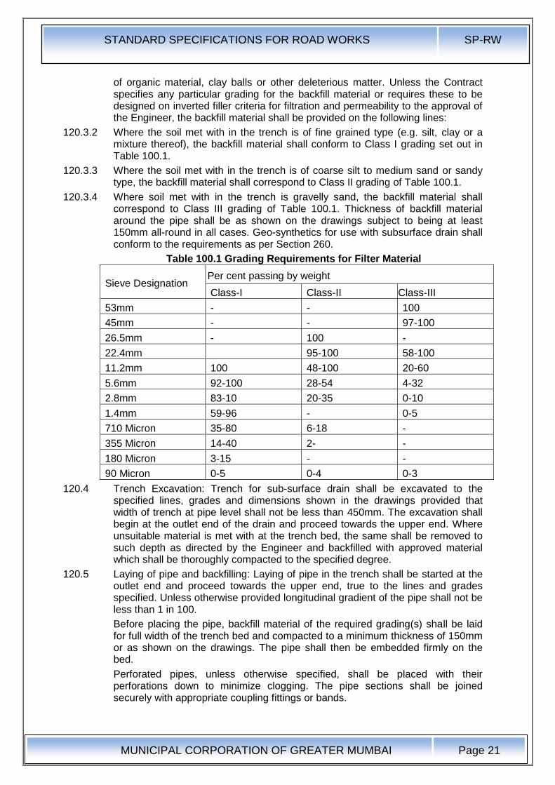
120.3.4 Where soil met with in the trench is gravelly sand, the backfill material shall correspond to Class III grading of Table 100.1. Thickness of backfill material around the pipe shall be as shown on the drawings subject to being at least 150mm all-round in all cases. Geo-synthetics for use with subsurface drain shall conform to the requirements as per Section 260.
Table 100.1 Grading Requirements for Filter Material
Sieve Designation Per cent passing by weight
Class-I Class-II Class-III
53mm - - 100
45mm - - 97-100
26.5mm - 100 -
22.4mm 95-100 58-100
11.2mm 100 48-100 20-60
5.6mm 92-100 28-54 4-32
2.8mm 83-10 20-35 0-10
1.4mm 59-96 - 0-5
710 Micron 35-80 6-18 -
355 Micron 14-40 2- -
180 Micron 3-15 - -
90 Micron 0-5 0-4 0-3
120.4 Trench Excavation: Trench for sub-surface drain shall be excavated to the specified lines, grades and dimensions shown in the drawings provided that width of trench at pipe level shall not be less than 450mm. The excavation shall begin at the outlet end of the drain and proceed towards the upper end. Where unsuitable material is met with at the trench bed, the same shall be removed to such depth as directed by the Engineer and backfilled with approved material which shall be thoroughly compacted to the specified degree.
120.5 Laying of pipe and backfilling: Laying of pipe in the trench shall be started at the outlet end and proceed towards the upper end, true to the lines and grades specified. Unless otherwise provided longitudinal gradient of the pipe shall not be less than 1 in 100.
Before placing the pipe, backfill material of the required grading(s) shall be laid for full width of the trench bed and compacted to a minimum thickness of 150mm or as shown on the drawings. The pipe shall then be embedded firmly on the bed.
Perforated pipes, unless otherwise specified, shall be placed with their perforations down to minimize clogging. The pipe sections shall be joined securely with appropriate coupling fittings or bands.
STANDARD SPECIFICATIONS FOR ROAD WORKS SP-RW
MUNICIPAL CORPORATION OF GREATER MUMBAI
Page 22
Non-perforated pipes shall be laid with joints as close as possible with the open joints wrapped with suitable pervious material (like double layer of Hessian, suitable Geo-synthetics or some other material of not less than 150mm width) to permit entry of water but prevent fines entering the pipe. In the case of non-perforated pipes with bell end, the bell shall face upgrade. Upgrade end sections of the pipe installation shall be tightly closed by means of concrete plugs or plugs fabricated from the same material as the pipe and securely held in place to prevent entry of soil materials.
After the pipe installation has been completed and approved, backfill material of the required grading(s) (see Clause 120.2.2) shall be placed over the pipe to the required level in horizontal layers not exceeding 150mm in thickness and thoroughly compacted. The minimum thickness of material above the top of the pipe shall be 300mm.
Unless otherwise provided, sub-surface drains not located below the road pavement shall be sealed at the top by means of 150mm thick layer of compacted clay so as to prevent percolation of surface water.
120.6 Use of Geo-synthetic in laying of pipe and backfilling: After excavating the trench for sub-surface drain, the filter fabric (Geo- Textile as per clause 262) shall be placed, the pipe installed and the trench backfilled with permeable material according to dimensions and details shown on the plans. Surfaces to receive filter fabric prior to placing shall be free of loose of extraneous material and sharp objects that may damage the filter fabric during installation. Adjacent rolls of the fabric shall be overlapped a minimum of 450mm. the preceding roll shall overlap the following roll in the direction the material is being spread.
Damage to the fabric resulting from Contractor's vehicles, equipment or operations shall be replaced or repaired by the Contractor at his expense.
120.7 Drain Outlet : The outlet for a sub-drain shall not be under water or plugged with debris but should be a free outlet discharging into a stream, culvert or open ditch. The bottom of the pipe shall be kept above high water in the ditch and the end protected with a grate or screen. For a length of 500mm from the outlet end, the trench for pipe shall not be provided with granular material but backfilled with excavated soil and thoroughly compacted so as to stop water directly percolating from the backfill material around the pipe. The pipe in this section shall not have any perforations.
120.8 Aggregate Drains: Aggregate Drains shall be placed within the verge / shoulders after completion of the pavement. Depth, thickness and spacing of the aggregate drains shall be as shown on the plan.
Trenches for aggregate drains shall be excavated to a minimum width of 300mm and to the depth shown on the plans or ordered by the Engineer. The bottom of the trench shall be sloped to drain and shall be free from loose particles of soil. The trench shall be excavated so as to expose clearly the granular pavement courses to be drained.
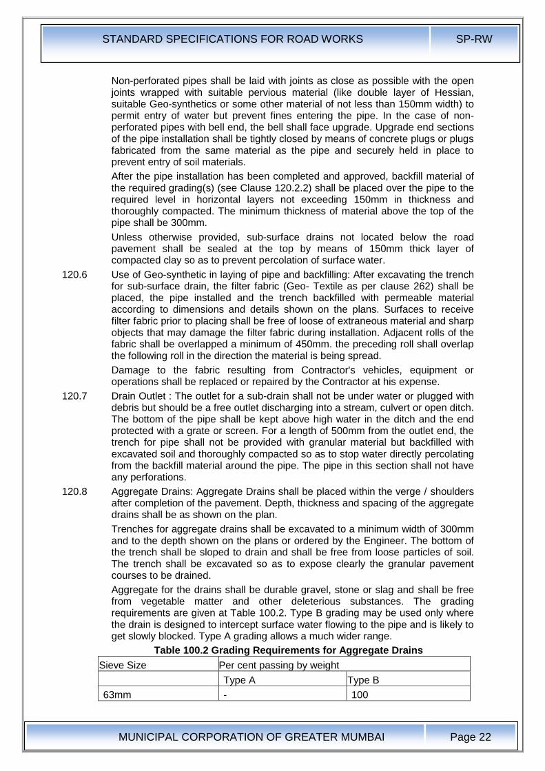
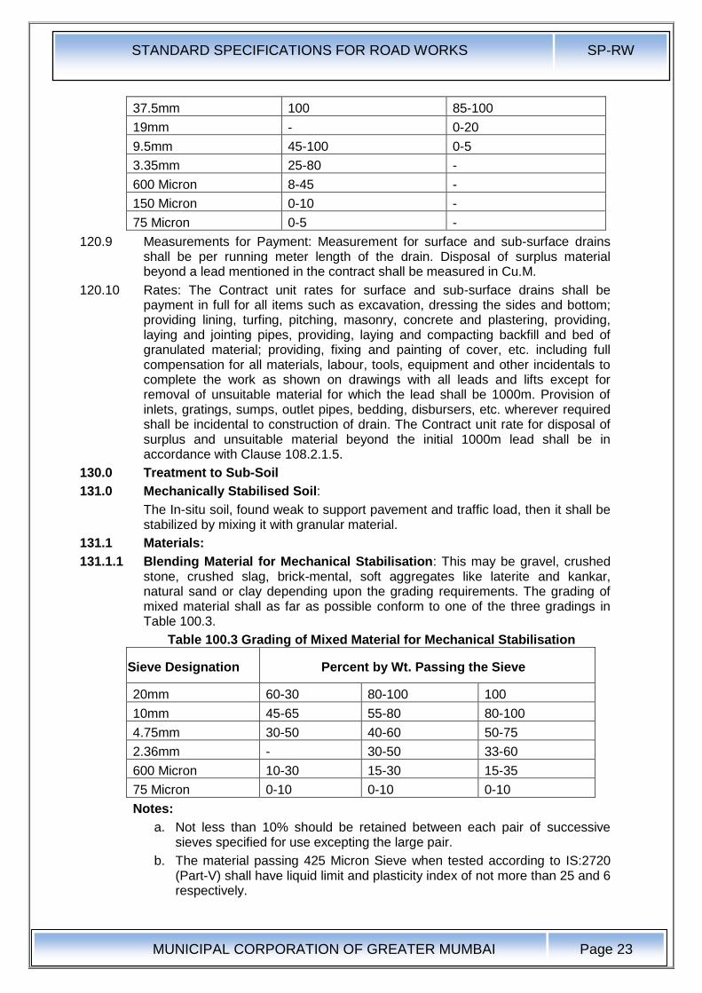
Aggregate for the drains shall be durable gravel, stone or slag and shall be free from vegetable matter and other deleterious substances. The grading requirements are given at Table 100.2. Type B grading may be used only where the drain is designed to intercept surface water flowing to the pipe and is likely to get slowly blocked. Type A grading allows a much wider range.
Table 100.2 Grading Requirements for Aggregate Drains
Sieve Size Per cent passing by weight
Type A Type B
63mm - 100
STANDARD SPECIFICATIONS FOR ROAD WORKS SP-RW
MUNICIPAL CORPORATION OF GREATER MUMBAI
Page 23
37.5mm 100 85-100
19mm - 0-20
9.5mm 45-100 0-5
3.35mm 25-80 -
600 Micron 8-45 -
150 Micron 0-10 -
75 Micron 0-5 -
120.9 Measurements for Payment: Measurement for surface and sub-surface drains shall be per running meter length of the drain. Disposal of surplus material beyond a lead mentioned in the contract shall be measured in Cu.M.
120.10 Rates: The Contract unit rates for surface and sub-surface drains shall be payment in full for all items such as excavation, dressing the sides and bottom; providing lining, turfing, pitching, masonry, concrete and plastering, providing, laying and jointing pipes, providing, laying and compacting backfill and bed of granulated material; providing, fixing and painting of cover, etc. including full compensation for all materials, labour, tools, equipment and other incidentals to complete the work as shown on drawings with all leads and lifts except for removal of unsuitable material for which the lead shall be 1000m. Provision of inlets, gratings, sumps, outlet pipes, bedding, disbursers, etc. wherever required shall be incidental to construction of drain. The Contract unit rate for disposal of surplus and unsuitable material beyond the initial 1000m lead shall be in accordance with Clause 108.2.1.5.
130.0 Treatment to Sub-Soil
131.0 Mechanically Stabilised Soil:
The In-situ soil, found weak to support pavement and traffic load, then it shall be stabilized by mixing it with granular material.
131.1 Materials:
131.1.1 Blending Material for Mechanical Stabilisation: This may be gravel, crushed stone, crushed slag, brick-mental, soft aggregates like laterite and kankar, natural sand or clay depending upon the grading requirements. The grading of mixed material shall as far as possible conform to one of the three gradings in Table 100.3.
Table 100.3 Grading of Mixed Material for Mechanical Stabilisation
Sieve Designation Percent by Wt. Passing the Sieve
20mm 60-30 80-100 100
10mm 45-65 55-80 80-100
4.75mm 30-50 40-60 50-75
2.36mm - 30-50 33-60
600 Micron 10-30 15-30 15-35
75 Micron 0-10 0-10 0-10
Notes:
a. Not less than 10% should be retained between each pair of successive sieves specified for use excepting the large pair.
b. The material passing 425 Micron Sieve when tested according to IS:2720 (Part-V) shall have liquid limit and plasticity index of not more than 25 and 6 respectively.

STANDARD SPECIFICATIONS FOR ROAD WORKS SP-RW
MUNICIPAL CORPORATION OF GREATER MUMBAI
Page 24
c.. The soaked CBR value of the compacted material shall not be less than 10
d; Moisture Content For Compaction - The moisture content at compaction checked vide IS2720 (part 2) shall neither be less than optimum moisture content corresponding to IS2720 (part 8) nor more than 2% above it.
131.1.2 Construction Operation
The mixing shall be carried out by using a mechanical mixer. The mix shall be spread and compacted by using three wheeled power or tandem roller of 80 to 100 KN capacities.
(a) Measurements for Payment: Stabilised soil sub-base/base shall be measured as finished work in position in cubic metres.
(b) Rates : The contract unit rate for cement treated soil sub-base / base with pre-treatment with lime if required shall be payment in full for carrying out the required operations.
132.0 Lime Treated Soil:
132.1 Materials:
132.1.1 Lime: Lime for lime-soil stabilization work shall be commercial dry lime slaked at site or pre-slaked lime delivered to the site in suitable packing. Unless otherwise permitted by the Engineer, the lime shall have purity of not less than 70 per cent by weight of Quick-lime (CaO) when tested in accordance with IS:1514. Lime shall be properly stored to avoid prolonged exposure to the atmosphere and consequent carbonation which would reduce its binding properties.
132.1.2 Water: The water to be used for lime stabilization shall be clean and free from injurious substances. Potable water shall be preferred.
132.2 Quantity of Lime in Stabilised Mix: Quantity of lime to be added as percentage by weight of the dry soil shall be as specified in the Contract. The quantity of lime used shall be related to its calcium oxide content which shall be specified. Where the lime of different calcium oxide content is to be used, its quantity shall be suitably adjusted to the approval the Engineer so that equivalent calcium oxide as incorporated in the work. The mix design shall be done to arrive at the appropriate quantity of lime to be added, having due regard to the purity of lime, the type of soil, the moisture-density relationship, and the design CBR/Unconfined Compressive Strength (UCS) value specified in the Contract. The laboratory CBR/UCS value shall be at least 1.5 times the minimum field value of CBR / UCS stipulated in the Contract.
132.3 Construction Procedure: The following procedure for mix in place soil-lime stabilization is recommended.
The soil, to be stabilized, shall be laid to a uniform loose thickness of 9" over the prepared sub-grade. Clods or other gravel over 4.75mm diameter shall be either removed or pulverized to within the above size.
The surface area shall then be divided into convenient panels, preferably of 3M x 3M.
Pre-calculated quantity of lime, required for the quantity of soil contained in the panel, shall be made to thin fine slurry by mixing the same with sufficient quantity of water in a drum.
Furrows shall be made in the soil by means of pickaxes, their edges going to the full depth of the loose soil layer. These shall be made in the longitudinal, transverse and again longitudinal directions and in that order. One third of the lime slurry shall be added to the furrows, every time.
As far as possible, alternate panel method shall be adhered to, for a better field control.
STANDARD SPECIFICATIONS FOR ROAD WORKS SP-RW
MUNICIPAL CORPORATION OF GREATER MUMBAI
Page 25
After the excess moisture content in the soil-lime mix gets evaporate, the same shall be dressed to a uniform layer and rolled.
The layer shall then be cured, i.e., the rolled surface shall be maintained in a moist state by sprinkling water at intervals till the next layer is laid over it.
132.3.1 Moisture Content for Compaction: For mechanical stabilizations, moisture content at compaction shall be within the range of 1 % above of 2% below the optimum moisture content corresponding to IS: 2720 (Part-VIII) whereas for cement / lime stabilization it shall not be Jess than O.M.C. nor more than 2% above it. The moisture content shall be adjusted during the mixing operations (making allowance for evaporation losses) and checked before rolling starts.
132.3.2 Rolling: A power roller shall, as a rule, be not less than 10 tonnes but if at any time still heavier rollers are required on the works, the contractors shall have to bring them as may be directed by the Engineer. In case of trenches not more than 8' in width, an earth master or any other similar equipment manually or machine operated, shall be invariably employed.
Rolling shall progress from edges to the centre of the road in strips parallel to the centre line of the road.
Rolling shall be done by lapping uniformly each proceeding rear wheel track by at least one half width of the track.
On super elevations, rolling shall be started at inner edge and shall progress towards outer edge. During and after rolling, the surface shall be checked for grade and camber. Rolling shall be started worked or stopped without jerks. Rolling shall not normally be done in length less than 100m (300ft).
On completion of day's work, the roller shall be made to stand on the side width of the road and shall be guarded by a watchman. A red lantern shall be hung on the roller at night so as to be visible from both sides of the road.
Care shall be taken to see that the compaction of cement stabilized material is completed within two hours of its mixing or such
132.3.3 Curing:
132.3.4 The sub-base course, stabilized with lime or cement shall be suitably cured for 7 days or less if so desired by the Engineer soon after which subsequent pavement courses shall be laid to prevent the surface from drying out and becoming friable. No traffic of any kind shall ply over the completed sub-base unless permitted by the Engineer.
132.4 Quality Control
In the Laboratory: A sample of the soil, to be stabilized, (minimum 30 Kg.) together with a sample of lime, to be used for stabilization shall be submitted to the Municipal Soil Testing Laboratory, at least one week prior to taking up the stabilization work.
The Laboratory shall furnish:
The percentage of lime required to be added to the soil for achieving the designed value of CBR.
The maximum dry density and optimum moisture content for the soil-lime mix.
On the Field:
i) During the rolling operations, field density test shall be taken to ascertain that at least 95% of the laboratory density has been attained.
ii) Field CBR tests shall be performed after a period of 7 days
132.5 Measurements for Payment: Stabilised soil sub-base/base shall be measured as finished work in position in cubic meters.

STANDARD SPECIFICATIONS FOR ROAD WORKS SP-RW
MUNICIPAL CORPORATION OF GREATER MUMBAI
Page 26
132.6 Rates: The contract unit rate for cement treated soil sub-base / base with pre-treatment with lime if required shall be payment in full for carrying out the required operations including full compensation for all components listed below:
i. Making arrangements for traffic to Clause 30 except for initial treatment to verges, shoulders and construction of diversions,
ii. furnishing all materials to be incorporated in the work including all royalties, fees, rents where necessary and all leads and lifts,
iii. All labour, tools, equipment and incidentals to complete the work to the Specifications,
iv. Carrying out the work in part widths of road where directed and carrying out the required tests for quality control.
133.0 Sand Drains (100 to 200mm Diameter) :
133.1 Materials: Material shall consist of sound, hard, durable particles of free draining sand-gravel crushed stone with grading as per Class-I of Table 100.1. The material shall be free from organic materials, clay balls or other deleterious matter.
133.2 Construction: Pre-boring of holes of specified diameter and specified spacing & depth shall be done either by manual auguring or by mechanical push through method in which detachable shoe at the bottom of the casing is mechanically pushed through the weak strata. The premixed aggregate shall be poured into the hole through the tremie pipe and tamped mechanically. The height of compacted pour shall not exceed 0.5m. The filling shall be done up to specified level.
133.3 Measurements: The work of providing sand drains shall be measured finished in running meter depth of specified diameter.
133.4 Rate: The contract per running meter rate for provision of sand drains shall be payment in full for supply of materials, boring of holes and filling of materials including tamping.
134.0 Stone Columns (300 to 500mm Diameter):
134.1 Materials: Material shall consist of sound, hard, durable particles of free draining sand-gravel / crushed stone with grading as per Class-III of Table 100.1. The material shall be free from organic materials, clay balls or other deleterious matter.
134.2 Construction: The stone column may be installed by making the bore into the ground by removal of material or by driving a metal casing with a shoe at the tip and displacing the material laterally. The premixed aggregate shall be poured into the hole through the tremie pipe and tamped mechanically. The height of compacted pour shall not exceed 0.5m. The filling shall be done up to specified level.
134.3 Measurements: The work of providing sand drains shall be measured finished in running meter depth of specified diameter.
134.4 Rate: The contract per running meter rate for provision of sand drains shall be payment in full for supply of materials, boring of holes and filling of materials including tamping.
135.0 Prefabricated Vertical Drains:
135.1 Material: Prefabricated drains of composite construction made of inner core acting as drainage channel with outer sleeve fabricated out of non-woven Geo-textiles with ISO-9000 certification from reputed manufacturers are to be installed by mechanical or hydraulic equipment.
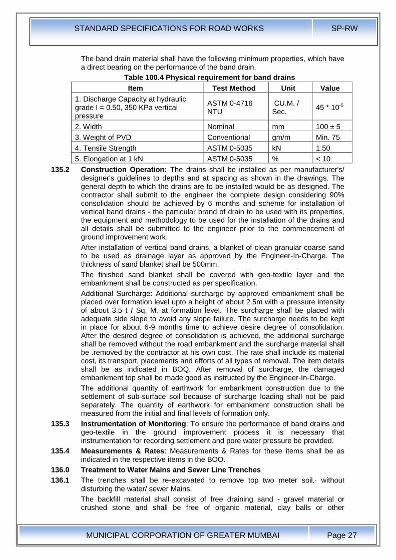
STANDARD SPECIFICATIONS FOR ROAD WORKS SP-RW
MUNICIPAL CORPORATION OF GREATER MUMBAI
Page 27
The band drain material shall have the following minimum properties, which have a direct bearing on the performance of the band drain.
Table 100.4 Physical requirement for band drains
Item Test Method Unit Value
1. Discharge Capacity at hydraulic grade I = 0.50, 350 KPa vertical pressure
ASTM 0-4716 NTU
CU.M. / Sec.
45 * 10-6
2. Width Nominal mm 100 ± 5
3. Weight of PVD Conventional gm/m Min. 75
4. Tensile Strength ASTM 0-5035 kN 1.50
5. Elongation at 1 kN ASTM 0-5035 % < 10
135.2 Construction Operation: The drains shall be installed as per manufacturer's/ designer's guidelines to depths and at spacing as shown in the drawings. The general depth to which the drains are to be installed would be as designed. The contractor shall submit to the engineer the complete design considering 90% consolidation should be achieved by 6 months and scheme for installation of vertical band drains - the particular brand of drain to be used with its properties, the equipment and methodology to be used for the installation of the drains and all details shall be submitted to the engineer prior to the commencement of ground improvement work.
After installation of vertical band drains, a blanket of clean granular coarse sand to be used as drainage layer as approved by the Engineer-In-Charge. The thickness of sand blanket shall be 500mm.
The finished sand blanket shall be covered with geo-textile layer and the embankment shall be constructed as per specification.
Additional Surcharge: Additional surcharge by approved embankment shall be placed over formation level upto a height of about 2.5m with a pressure intensity of about 3.5 t I Sq. M. at formation level. The surcharge shall be placed with adequate side slope to avoid any slope failure. The surcharge needs to be kept in place for about 6-9 months time to achieve desire degree of consolidation. After the desired degree of consolidation is achieved, the additional surcharge shall be removed without the road embankment and the surcharge material shall be .removed by the contractor at his own cost. The rate shall include its material cost, its transport, placements and efforts of all types of removal. The item details shall be as indicated in BOQ. After removal of surcharge, the damaged embankment top shall be made good as instructed by the Engineer-In-Charge.
The additional quantity of earthwork for embankment construction due to the settlement of sub-surface soil because of surcharge loading shall not be paid separately. The quantity of earthwork for embankment construction shall be measured from the initial and final levels of formation only.
135.3 Instrumentation of Monitoring: To ensure the performance of band drains and geo-textile in the ground improvement process it is necessary that instrumentation for recording settlement and pore water pressure be provided.
135.4 Measurements & Rates: Measurements & Rates for these items shall be as indicated in the respective items in the BOO.
136.0 Treatment to Water Mains and Sewer Line Trenches
136.1 The trenches shall be re-excavated to remove top two meter soil.· without disturbing the water/ sewer Mains.
The backfill material shall consist of free draining sand - gravel material or crushed stone and shall be free of organic material, clay balls or other
STANDARD SPECIFICATIONS FOR ROAD WORKS SP-RW
MUNICIPAL CORPORATION OF GREATER MUMBAI
Page 28
deleterious matter of grading specified in the contract. The trench to be covered with Geo-membrane that shall be as per Clause 260.
136.2 Measurements for Payment:
Measurements for re-excavation of trenches and backfilling shall be per running meter length of trench including disposal of excavated material. The measurements for Geo- membrane shall be per square meter of the membrane as laid as per the drawing.
136.3 Rates:
The contract unit rates shall be payment in full for all items such as excavation, dressing the -sides, backfilling the trench with granular material as per specification including full compensation for all materials, labour tools equipment and other incidentals to complete the work as shown on the drawing with all leads and lifts. The rate for geo-membrane shall be per square meter as per clause 260.
140.0 Excavation for Structures
141.0 Scope : Excavation for structures shall consist of the removal of material for the construction of foundations for bridges, culverts, retaining walls, headwalls, cut-off walls, pipe culverts and other similar structures, in accordance with the requirements of these Specifications and the lines and dimensions shown on the drawings or as indicated by the Engineer. The work shall include construction of the necessary cofferdams and cribs and their subsequent removal; all necessary sheeting, shoring, bracing, draining and pumping; the removal of all logs, stumps, grubs and other deleterious matter and obstructions, necessary for placing the foundations; trimming bottoms of excavations, backfilling and clearing up the site and the disposal of all surplus material.
141.1 Classification of Excavation : All materials involved in excavation shall be classified in accordance with Clauses 102 and 103.
141.2 Construction Operations:
141.2.1 Setting Out: After the site has been cleared, the limits of excavation shall be set out true to lines, curves and slopes.
141.2.2 Excavation: Excavation shall be taken to the width of the lowest step of the footing and the sides shall be left plumb where the nature of soil allows it. Where the nature of soil or the depth of the trench and season of the year do not permit vertical sides, the Contractor at his own expense shall put up necessary shoring, strutting and planking or cut slopes to a safer angle or both with due regard to the safety of personnel and works and to the satisfaction of the Engineer.
The depth to which the excavation is to be carried out shall be as shown on the drawings, unless the type of material encountered is such as to require changes, in which case the depth shall be as ordered by the Engineer. Propping shall be undertaken when any foundation or stressed zone from an adjoining structure is within a line of 1 vertical to 2 horizontal from the bottom of the excavation.
Where blasting is to be resorted to, the same shall be carried out in accordance with Clause 103.3.2 and all precautions indicated therein observed. Where blasting is likely to endanger adjoining foundations or other structures, necessary precautions such as controlled blasting, providing rubber mat cover to prevent flying of debris etc. shall be taken to prevent any damage.
141.2.3 Dewatering and Protection: Normally, open foundations shall be laid dry. Where water is met with in excavation due to stream flow, seepage, springs, rain or other reasons, the Contractor shall take adequate measures such as bailing, pumping, constructing diversion channels, drainage channels, bunds, depression of water level by well-point system, cofferdams, and other necessary works to
STANDARD SPECIFICATIONS FOR ROAD WORKS SP-RW
MUNICIPAL CORPORATION OF GREATER MUMBAI
Page 29
keep the foundation trenches dry when so required and to protect the green concrete / masonry against damage by erosion or sudden rising of water level. The methods to be adopted in this regard and other details thereof shall be left to the choice of the Contractor but subject to approval of the Engineer. Approval of the Engineer shall, however, not relieve the Contractor of the responsibility for the adequacy of dewatering and protection arrangements and for the quality and safety of the works.
Where cofferdams are required, these shall be carried to adequate depths and heights, be safely designed and constructed and be made as watertight as is necessary for facilitating construction to be carried out inside them. The interior dimensions of the cofferdams shall be such as to give sufficient clearance for the construction and inspection and to permit installation of pumping equipments, etc., inside the enclosed area.
If it is determined beforehand that the foundations cannot be laid dry or the situation is found that the percolation is too heavy for keeping the foundation dry, the foundation concrete shall be laid under water by tremie pipe only. In case of flowing water or artesian springs, the flow shall be stopped or reduced as far as possible at the time of placing the concrete.
Pumping from the interior of any foundation enclosure shall be done in such a manner as to preclude the possibility of the movement of water through any fresh concrete. No pumping shall be permitted during the placing of concrete or for any period of at least 24 hours thereafter, unless it is done from a suitable sump separated from the concrete work by a watertight wall or other similar means.
At the discretion of the Contractor, cement grouting or other approved methods may be used to prevent or reduce seepage and to protect the excavation area.
The Contractor shall take all precautions in diverting channels and in discharging the drained water as not to cause damage to the works, crops or any other property.
141.2.4 Preparation of Foundation: The bottom of the foundation shall be levelled both longitudinally and transversely or stepped as directed by the Engineer. Before footing is laid, the surface shall be slightly watered and rammed. In the event of excavation having been made deeper than that shown on the drawings or as otherwise ordered by the Engineer, the extra depth shall be made up with concrete or masonry of the foundation at the cost the Contractor.. Ordinary filling shall not be used for the purpose to bring the foundation to level.
When rock or other hard strata is encountered, it shall be freed of all soft and loose material, cleaned and cut to a firm surface either level and stepped as directed by the Engineer. All seams shall be cleaned our and filled with cement mortar or grout to the satisfaction of the Engineer. In the case of excavation in rock, annular space around footing shall be filled with lean concrete (1:3:6 nominal mix) up to the top level of rock.
If the depth of fill required is more than 1.5m above the top of the footing, filling up to 1.5m above top of footing shall be done with lean concrete (1:3:6 nominal mix) followed by boulders grouted with cement.
When foundation piles are used, the excavation of each pit shall be substantially completed before beginning pile-driving operations therein. After pile driving operations in a given pit are completed, all loose and displaced material therein shall be removed to the elevation of the bottom of the footings.
141.2.5 Slips and Slip-outs: If there are any slips or slip-outs in the excavation, these shall be removed by the Contractor at his own cost.
STANDARD SPECIFICATIONS FOR ROAD WORKS SP-RW
MUNICIPAL CORPORATION OF GREATER MUMBAI
Page 30
141.2.6 Public Safety: Near towns, villages and all frequented places, trenches and foundation pits shall be securely fenced, provided with proper caution signs and marked with red lights at night to avoid accidents. The Contractor shall take adequate protective measures to see that the excavation operations do not affect or damage adjoining structures. For safety precautions, guidance may be taken from 18:3764.
141.2.7 Backfilling : Backfilling shall be done with approved material after concrete or masonry is fully set and carried out in such a way as not to cause undue thrust on any part of the structure. All space between foundation masonry or concrete and the sides of excavation shall be refilled to the original surface in layers not exceeding 150 mm compacted thicknesses. The compaction shall be done with the help of suitable equipment such as mechanical tamper, rammer, plate vibrator etc., after necessary watering, so as to achieve a density not less than the field density before excavation.
141.2.8 Disposal of Surplus Excavated Materials: Clause 105 shall apply.
141.3 Measurements for Payment: Excavation for structures shall be measured in cum. for each class of material encountered, limited to the dimensions shown on the drawings or as directed by the Engineer. Excavation over increase width, cutting of slopes, shoring, shuttering and planking shall be deemed as convenience for the Contractor in executing the work and shall not be measured and paid for separately.
Preparation of rock foundation shall be measured in square metres. Foundation sealing, dewatering, including pumping shall be deemed to be incidental to the work unless separate provision is made for in the Contract. In the latter case, payment shall be on lump sum basis as provided in the Bill of Quantities.
141.4 Rates:
141.4.1 The Contract unit rate for the items of excavation for structures shall be payment in full for carrying out the required operations including full compensation for:
o setting out; o construction of necessary cofferdams, cribs, sheeting, shoring, bracing and
their subsequent removal; o removal of all logs, stumps, grubs and other deleterious matter and
obstructions, for placing the foundations including trimming of bottoms of excavations;
o foundation sealing, dewatering including pumping when no separate provision for it is made in the Contract;
o backfilling, clearing up the site and disposal of all surplus material within all lifts and leads up to 1000 m or as otherwise specified; and
o all labour, materials, tools, equipment, safety measures, diversion of traffic and incidentals necessary to complete the work to Specification.
141.4.2 The Contract unit rate for preparation of rock foundation shall be full compensation for cutting, trimming and cleaning the foundation surface and filling I sealing of all seams with cement grout or mortar including all materials, labour and incidentals required for completing the work.
141.4.3 The Contract unit rate for transporting ·material from the excavation for structures shall be full compensation for all labour, equipment, tools and incidentals necessary on account of the additional haul or transportation involved beyond the initial lead of 1000m.
STANDARD SPECIFICATIONS FOR ROAD WORKS SP-RW
MUNICIPAL CORPORATION OF GREATER MUMBAI
Page 31
150.0 Embankment & Sub-Grade Construction
151.0 Embankment Construction:
151.1 General
151.1.1 Description: These Specifications shall apply to the construction of embankments including sub-grades, earthen shoulders and miscellaneous backfills with approved material obtained from roadway and drain excavation, borrow pits or other sources. All embankments, sub-grades, earthen shoulders and miscellaneous backfills shall be constructed in accordance with the requirements of these Specifications and in conformity with the lines, grades and crosssections shown on the drawings or as directed by the Engineer.
151.2 Materials and General Requirements:
151.2.1 Physical Requirements:
151.2.2 The materials used in embankments, sub-grades, earthen shoulders and miscellaneous backfills shall be soil, moorum, gravel, a mixture of these or any other material approved by the Engineer. Such materials shall be free of logs, stumps, roots, rubbish or any other ingredient likely to deteriorate or affect the stability of the embankment / subgrade.
151.2.2.1 The following types of material shall be considered unsuitable for embankment:
a) Materials from swamps, marshes and bogs;
b) Peat, log, stump and perishable material; any soil that classifies as OL, OI, OH or Pt in accordance with IS:1498;
c) Materials susceptible to spontaneous combustion;
d) Materials in a frozen condition;
e) Clay having liquid limit exceeding 50 and plasticity index exceeding 35;
f) Materials with salts resulting in leaching in the embankment.
151.2.2.2 Expansive clay exhibiting marked swell and shrinkage properties ("free swelling index" exceeding 50 per cent when tested as per IS: 2720 - Part-40) shall not be used as a fill material. Where expansive clay with acceptable "free swelling index" value is used as a fill material, subgrade and top 500mm portion of the embankment just below sub-grade shall be non-expansive in nature.
151.2.2.3 Any fill material with a soluble sulphate content exceeding 1.9 grams of sulphate (expressed as S03) per litre when tested in accordance with BS:1377 Test 10, but using a 2:1 water-soil ratio shall not be deposited within 500 mm or other distance described in the Contract, of concrete, cement bound materials or other cementitious materials forming part of the Permanent Works.
Materials with a total sulphate content (expressed as S03) exceeding 0.5 per cent by mass, when tested in accordance with 8S:1377 Test 9 shall not be deposited within 500mm, or other distances described in the Contract, of metallic items forming part of the Permanent Works.
151.2.2.4 The size of the coarse material in the mixture of earth shall ordinarily not exceed 75mm when being placed in the embankment and 50mm when placed in the sub-grade. However, the Engineer may at his discretion permit the use of material coarser than this also if he is satisfied that the same will not present any difficulty as regards the placement of fill material and its compaction to the requirements of these Specifications. The maximum particle size shall not be more than two-thirds of the compacted layer thickness.
151.2.2.5 Ordinarily, only the materials satisfying the density requirements given in Table 100.5 shall be employed for the construction of the embankment and the sub-grade.
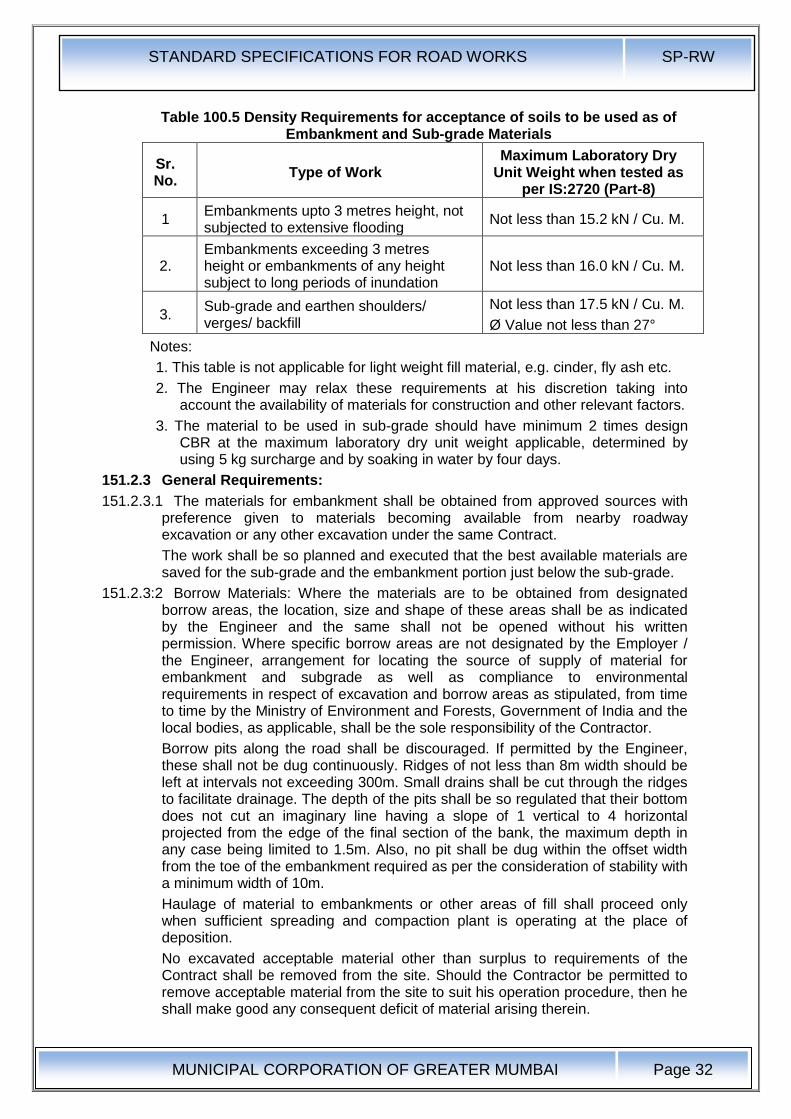
STANDARD SPECIFICATIONS FOR ROAD WORKS SP-RW
MUNICIPAL CORPORATION OF GREATER MUMBAI
Page 32
Table 100.5 Density Requirements for acceptance of soils to be used as of Embankment and Sub-grade Materials
Sr. No.
Type of Work Maximum Laboratory Dry
Unit Weight when tested as per IS:2720 (Part-8)
1 Embankments upto 3 metres height, not subjected to extensive flooding
Not less than 15.2 kN / Cu. M.
2. Embankments exceeding 3 metres height or embankments of any height subject to long periods of inundation
Not less than 16.0 kN / Cu. M.
3. Sub-grade and earthen shoulders/ verges/ backfill
Not less than 17.5 kN / Cu. M.
Ø Value not less than 27°
Notes:
1. This table is not applicable for light weight fill material, e.g. cinder, fly ash etc.
2. The Engineer may relax these requirements at his discretion taking into account the availability of materials for construction and other relevant factors.
3. The material to be used in sub-grade should have minimum 2 times design CBR at the maximum laboratory dry unit weight applicable, determined by using 5 kg surcharge and by soaking in water by four days.
151.2.3 General Requirements:
151.2.3.1 The materials for embankment shall be obtained from approved sources with preference given to materials becoming available from nearby roadway excavation or any other excavation under the same Contract.
The work shall be so planned and executed that the best available materials are saved for the sub-grade and the embankment portion just below the sub-grade.
151.2.3:2 Borrow Materials: Where the materials are to be obtained from designated borrow areas, the location, size and shape of these areas shall be as indicated by the Engineer and the same shall not be opened without his written permission. Where specific borrow areas are not designated by the Employer / the Engineer, arrangement for locating the source of supply of material for embankment and subgrade as well as compliance to environmental requirements in respect of excavation and borrow areas as stipulated, from time to time by the Ministry of Environment and Forests, Government of India and the local bodies, as applicable, shall be the sole responsibility of the Contractor.
Borrow pits along the road shall be discouraged. If permitted by the Engineer, these shall not be dug continuously. Ridges of not less than 8m width should be left at intervals not exceeding 300m. Small drains shall be cut through the ridges to facilitate drainage. The depth of the pits shall be so regulated that their bottom does not cut an imaginary line having a slope of 1 vertical to 4 horizontal projected from the edge of the final section of the bank, the maximum depth in any case being limited to 1.5m. Also, no pit shall be dug within the offset width from the toe of the embankment required as per the consideration of stability with a minimum width of 10m.
Haulage of material to embankments or other areas of fill shall proceed only when sufficient spreading and compaction plant is operating at the place of deposition.
No excavated acceptable material other than surplus to requirements of the Contract shall be removed from the site. Should the Contractor be permitted to remove acceptable material from the site to suit his operation procedure, then he shall make good any consequent deficit of material arising therein.
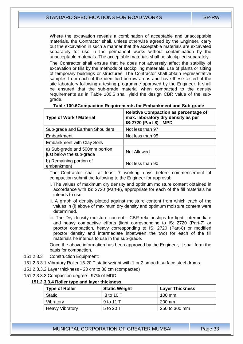
STANDARD SPECIFICATIONS FOR ROAD WORKS SP-RW
MUNICIPAL CORPORATION OF GREATER MUMBAI
Page 33
Where the excavation reveals a combination of acceptable and unacceptable materials, the Contractor shall, unless otherwise agreed by the Engineer, carry out the excavation in such a manner that the acceptable materials are excavated separately for use in the permanent works without contamination by the unacceptable materials. The acceptable materials shall be stockpiled separately.
The Contractor shall ensure that he does not adversely affect the stability of excavation or fills by the methods of stockpiling materials, use of plants or sitting of temporary buildings or structures. The Contractor shall obtain representative samples from each of the identified borrow areas and have these tested at the site laboratory following a testing programme approved by the Engineer. It shall be ensured that the sub-grade material when compacted to the density requirements as in Table 100.6 shall yield the design CBR value of the sub-grade.
Table 100.6Compaction Requirements for Embankment and Sub-grade
Type of Work / Material Relative Compaction as percentage of max. laboratory dry density as per IS:2720 (Part-8) - MPD
Sub-grade and Earthen Shoulders Not less than 97
Embankment Not less than 95
Embankment with Clay Soils
a) Sub-grade and 500mm portion just below the sub-grade
Not Allowed
b) Remaining portion of embankment
Not less than 90
The Contractor shall at least 7 working days before commencement of compaction submit the following to the Engineer for approval:
i. The values of maximum dry density and optimum moisture content obtained in accordance with IS: 2720 (Part-8), appropriate for each of the fill materials he intends to use.
ii. A graph of density plotted against moisture content from which each of the values in (i) above of maximum dry density and optimum moisture content were determined.
iii. The Dry density-moisture content - CBR relationships for light, intermediate and heavy compactive efforts (light corresponding to IS: 2720 (Part-7) or proctor compaction, heavy corresponding to IS: 2720 (Part-8) or modified proctor density and intermediate inbetween the two) for each of the fill materials he intends to use in the sub-grade.
Once the above information has been approved by the Engineer, it shall form the basis for compaction.
151.2.3.3 Construction Equipment:
151.2.3.3.1 Vibratory Roller 15-20 T static weight with 1 or 2 smooth surface steel drums
151.2.3.3.2 Layer thickness - 20 cm to 30 cm (compacted)
151.2.3.3.3 Compaction degree - 97% of MDD
151.2.3.3.4 Roller type and layer thickness:
Type of Roller Static Weight Layer Thickness
Static 8 to 10 T 100 mm
Vibratory 9 to 11 T 200mm
Heavy Vibratory 5 to 20 T 250 to 300 mm
STANDARD SPECIFICATIONS FOR ROAD WORKS SP-RW
MUNICIPAL CORPORATION OF GREATER MUMBAI
Page 34
151.2.4 Construction Operations: These specifications shall "apply to the construction of embankments, shoulders and miscellaneous backfills with approved material obtained either from excavation for road construction or brought from outside by the contractor. All embankments shall be constructed in accordance with the requirements of these specifications and in conformity with the lines, grades and cross sections shown on the drawings or as directed by the Engineer.
151.2.5 After the site has been cleared, the work shall be set out to Clause 54. The limits of the embankment shall be marked by fixing better pegs on both sides at regular intervals as guides before commencing the earthwork. To ensure their safety, it is desirable to fix the pegs about 0.5 metres back from the actual limits of the fill and to paint them in distinctive colour.
In all cases, the original ground shall be compacted by rolling as directed by the Engineer. When the height of the embankment is less than 0.5m and the original ground does not already have a relative compaction of at least 95% then same shall be loosened to a depth of 0.5m watered and compacted in layers not exceeding 250mm in loose thickness to the maximum dry density of the material, determined in accordance with IS: 2720 (Part-VII). However, before relaying and compacting the loosened material, the surface below this level shall be suitably compacted as directed by the Engineer. When so directed by the Engineer, any suitable materials occurring in the embankment foundation shall be removed and replaced by approved material suitably compacted. Embankment work shall not proceed until the foundations for embankment have been inspected by the Engineer, found satisfactory and approved.
151.2.6 Spreading Materials in layers and bringing to appropriate Moisture Content: The embankment material shall be spread uniformly over the entire width of the embankment in layers not exceeding 250mm in loose thickness. Successive layers of embankment shall not be placed until the layer under construction has been thoroughly compacted to the requirements set down herein under:
Moisture content of the material shall be checked at the source of supply and if found less than specified for compaction, the same shall be made good either at the source or after spreading the soil in loose thickness for compaction. In latter case, water shall be sprinkled directly from hose line or from a water tank mounted on a truck, flooding shall not be permitted under any circumstances.
If the material delivered to the road bed is too wet, it shall be dried, by compaction. Should circumstances arise where owing to wet weather, the moisture content cannot be reduced to the required amount by the above procedure, work on compaction shall be suspended.
Moisture content of each layer of soil shall be adjusted (making due allowance for evaporation loss), so that at the time of compaction, it is in the range of 1 % above 2% below the optimum moisture content.
After adding the required amount of water, soil shall be processed by means of hammer rotary mixer or as otherwise until the layer is uniformly wet.
Clods or hard lumps of earth shall be broken to have maximum size of 150mm, when being placed in the lower layers of the embankment and maximum size of 60mm, when being placed in the top 0.5 meter portion of the embankment below the sub-grade.
151.2.7 Compaction: Each layer of the material shall be thoroughly compacted by using a power roller of not less than 8-10 Tonne or any other approved plant. Rolling shall be done as specified in Clause 151.2.7. The field dry density of material
STANDARD SPECIFICATIONS FOR ROAD WORKS SP-RW
MUNICIPAL CORPORATION OF GREATER MUMBAI
Page 35
after compaction shall be not less than specified % in Table 100.6 of the maximum laboratory dry density as per IS:2720 (Part-VIII).
Subsequent layers shall be placed only after the finished layer has been tested according to Clause 622 and accepted by the Engineer.
When density measurements reveal any soft areas in the embankment, further compaction shall be carried out as directed by the Engineer. If in spite of that the specified compaction is not achieved, the material in the soft areas shall be removed and replaced by approved material, compacted to the density requirements and satisfaction of the Engineer.
The surface of the embankment at all time during construction be maintained at such cross fall as well shed water and to prevent flooding.
151.2.8 Rolling : A power roller shall, as a rule, be not less than 10 tonnes but if at any time still heavier rollers are required on the works, the contractors shall have to bring them as may be directed by the Engineer. In case of trenches not more than 2.5 m in width, an earth master or any other similar equipment manually or machine operated, shall be invariably employed.
Rolling shall progress from edges to the centre of the road in strips parallel to the centre line of the road. Rolling shall be done by lapping uniformly each proceeding rear wheel track by at least one half width of the track. On super elevations, rolling shall be started at inner edge and shall progress towards outer edge. During and after rolling, the surface shall be checked for grade and camber. Rolling shall be started worked or stopped without jerks. Rolling shall not be normally done in length less than 100m (300'). On completion of day's work, the roller shall be made to stand on the side width of the road and shall be guarded by a watchman.
A red lantern shall be hung on the roller at night so as to be visible from . both sides of the road.
151.2.9 Finishing Operations: These shall include the work of shaping and dressing the shoulders, road bed and side slopes to conform to the alignment, levels, cross sections and dimensions shown on the drawings or as directed by the Engineer, subject to the surface tolerances described in Clause 613. Both the upper and lower ends of the side slopes shall be rounded off to improve appearance and merge the embankment with the adjacent terrain.
When earthwork operations have been subsequently, compacted the roadway area shall be cleared or all debris and ugly scars in the construction areas, responsible for objectionable appearance be eliminated.
152.0 Construction of Embankment and Sub-grade under Special Conditions:
152.1 Embankment and Sub-grade around Structures: To avoid interference with the construction of abutments, wing walls or of culvert / bridge structures, the Contractor shall, at points to be determined by the Engineer suspend work on embankment forming approaches to such structures, until such time as the construction of the latter is sufficiently advanced to permit the completion of approaches without the risk of damage to the structure.
Unless directed otherwise, the filling around culverts, bridges and other structures upto a distance of twice the height of the road from the back of the abutment shall be carried out independent of the work on the main embankment. The fill material shall not be placed against any abutment or wing wall, unless permission has been given by the Engineer but in any case not until the concrete or masonry has been in position for 14 days. The embankment and subgrade shall be brought up simultaneously in equal layers on each side of the structure
STANDARD SPECIFICATIONS FOR ROAD WORKS SP-RW
MUNICIPAL CORPORATION OF GREATER MUMBAI
Page 36
to avoid displacement and unequal pressure. The sequence of work in this regard shall be got approved from the Engineer.
The material used for backfill shall not be an organic soil or highly plastic clay having plasticity index and liquid limit more than 20 and 40 respectively when tested according to IS:2720 (Part-5). Filling behind abutments and wing walls for all structures shall conform to the general guidelines given in Appendix 6 of IRC:78 (Standard Specifications and Code of Practice for Road Bridges - Section VII) in respect of the type of material, the extent of backfill, its laying and compaction etc. The fill material shall be deposited in horizontal layers in loose thickness and compacted thoroughly to the requirements of Table 100.6.
Where the provision of any filter medium is specified behind the abutment, the same shall be laid in layers simultaneously with the laying of fill material. The material used for filter shall conform to the requirements for filter medium spelt out in Clause 120.2.2 unless otherwise specified in the Contract.
Where it may be impracticable to use conventional rollers, the compaction shall be carried out by appropriate mechanical means such as small vibratory roller, plate compactor or power rammer. Care shall be taken to see that the compaction equipment does not hit or come too close to any structural member so as to cause any damage to them or excessive pressure against the structure.
152.2 Construction of embankment over ground incapable of supporting construction equipment: Where embankment is to be constructed across ground which will not support the weight of repeated heavy loads of construction equipment, the first layer of the fill may be constructed by placing successive loads of material in a uniformly distributed layer of a minimum thickness required to support the construction equipment so that no pore pressure is built up or no bearing pressure failure of sub-soil takes place to cause movement of sub-soil as permitted by the Engineer. The Contractor, if so desired by him, may also use suitable geosynthetic material to increase the bearing capacity of the foundation. This exception to normal procedure will not be permitted where, in the opinion of the Engineer, the embankments could be constructed in the approved manner over such ground by the use of lighter or modified equipment after proper ditching and drainage have been provided. Where this exception is permitted, the selection of the material and the construction procedure to obtain an acceptable layer shall be the responsibility of the Contractor. The cost of providing suitable traffic conditions for construction equipment over any area of the Contract will be the responsibility of the Contractor and no extra payment will be made to him. The remainder of the embankment shall be constructed as specified in Clause 151.2.4.
152.3 Embankment Construction under water: Where filling or backfilling is to be placed under water, only acceptable granular material or rock shall be used unless otherwise approved by the Engineer. Acceptable granular material shall consist of graded, hard durable particles with maximum particle size not exceeding 75mm. The material should be non-plastic having uniformly coefficient of not less than 10. The material placed I open water shall be deposited by end tipping without compaction.
152.4 Earthwork for High Embankment: In the case of high embankments, the Contractor shall normally use the material from the specified borrow area. In case, he desires to use different material for his own convenience, he shall have to carry out necessary soil investigations and redesign the high embankment at his own cost. The Contractor shall then furnish the soil test data and design of high embankment for approval of the Engineer, who reserves the right to accept or reject it.
STANDARD SPECIFICATIONS FOR ROAD WORKS SP-RW
MUNICIPAL CORPORATION OF GREATER MUMBAI
Page 37
If necessary, stage construction of fills and any controlled rates of filling shall be carried out in accordance with the Contract including installation of instruments and its monitoring.
Where required, the Contractor shall surcharge embankments or other areas of fill with approved material for the periods specified in the Contract. If settlement of surcharged fill results in any surcharging material, which is unacceptable for use in the fill being surcharged, lying below formation level, the Contractor shall remove the unacceptable material and dispose it as per direction of the Engineer. He shall then bring the resultant level up to formation level with acceptable material.
152.4.1 Earthwork for widening existing road embankment : When an existing embankment and/or subgrade is to be widened and its slopes are steeper than 1 vertical on 4 horizontal, continuous horizontal benches, each at least 300mm wide, shall be cut into the old slope for ensuring adequate bond with the fresh embankment / subgrade material to be added. The material obtained from cutting benches could be utilized in the widening of the embankment subgrade. However, when the existing slope against which the fresh material is to be placed is flatter than 1 vertical on 4 horizontal, the slope surface may only be ploughed or scarified instead of resorting to benching.
Where the width of the widened portions is insufficient to permit the use of conventional rollers, compaction shall be carried out with the help of small vibratory rollers / plate compactors / power rammers or any other appropriate equipment approved by the Engineer. End dumping of material from trucks for widening operations shall be avoided except in difficult circumstances when the extra width is too narrow to permit the movement of any other types of hauling equipment.
152.4.2 Earthwork for embankment and subgrade to be placed against sloping ground Where an embankment / subgrade is to be placed against sloping ground, the latter shall be appropriately benched or ploughed / scarified as required in Clause 152.1 before placing the embankment / subgrade material. Extra earthwork involved in benching or due to ploughing / scarifying etc. shall be considered incidental to the work.
For wet conditions, benches with slightly inward fall and subsoil drains at the lowest point shall be provided as per the drawings, before the fill is placed against sloping ground. Where the Contract requires construction of transverse subsurface drain at the cut-fill interface, work on the same shall be carried out to Clause 309 in proper sequence with the embankment and subgrade work as approved by the Engineer.
152.4.3 Earthwork over existing road surface: Where the embankment is to be placed over an existing road surface, the work shall be carried out as indicated below:
a) If the existing road surface is of granular or bituminous type and lies within 1 m of the new sub-grade level, the same shall be scarified to a depth of 150mm or more is specified, so as to provide ample bond between the old and new material ensuring that at least 500mm portion below the top of new sub-grade level is compacted to the desired density.
b) If the existing road surface is of cement concrete type and lies within 1 m of the new sub-grade level the same shall be removed completely.
c) If the level difference between the existing surface and the new formation level is more than 1 m, the existing surface shall be permitted to stay in place without any modification.
STANDARD SPECIFICATIONS FOR ROAD WORKS SP-RW
MUNICIPAL CORPORATION OF GREATER MUMBAI
Page 38
152.4.4 Settlement Period: Where settlement period is specified in the Contract, the embankment shall remain in place for the required settlement period before excavating for abutment, wing wall, retaining wall, footings, etc. or driving foundation piles. The duration of the required settlement period at each location shall be as provided for in the Contract or as directed by the Engineer.
152.1 Measurements & Payments: Measurements of embankment shall be made by made by taking cross-section at intervals in the original position before the work starts and after its completion and computing the volume in cu. m. by the- method of average end areas.
The measurements of fill material from borrow areas shall be the difference between the net quantities. of compacted fill and the net quantities of suitable material brought from roadway and drainage excavation. For this purpose it shall be assumed that one Cu.M. of suitable material brought to site from road and drainage excavation forms one Cu.M. of compacted fill and all bulking or shrinkage shall be ignored.
152.2 The rate: for embankment or filling in with contractor's earth or moorum shall include the cost of materials, fencing lighting watching, haulage, spreading, levelling, watering, rolling etc. complete.
153.0 Rock Fill Embankment:
The size of rock pieces in rock fill embankment shall be such that they can be deposited in layers so as to suit the conditions evaluated in the field compaction trials or as directed by the engineer. The rock fill shall consist of hard, durable and inert material, preferably maximum size not exceeding 300 mm and percent finer than 125 mm not exceeding 10 percent.
153.1 Spreading & Compaction:
The material shall be tipped, spread and levelled in layers extending to the full width of embankment by a suitable dozer. Fragments of rock shall then be spread on top of layer to the required extent and layer compacted by minimum of 5 passes of vibratory roller having static weight 8-10 tonnes. The compacted thickness of each layer shall not exceed 500mm. After compaction of each layer, the surface voids shall be filled with broken fragments. The top layer of rockfill, on which normal earth fill will rest shall be thoroughly blinded with suitable material to seal its surface.
153.2 Measurements for Payment:
Measurement shall be made by taking cross-sections at intervals in the original position before the work starts and after its completion and computing the volume in Cu. M. by the method of average and areas.
153.3 Rate:
The Contract unit rate shall be paid in full for carrying out all the above operations including cost of rock fill, broken fragments and blinding material and shall provide full compensation for all items as per Clause 213.1.
154.0 Stabilised Soil Sub-Grade Construction:
154.1 Lime Treated Soil: Soil used shall be local clay soil having plasticity" index greater than 8 and lime for stabilization work shall be as per specifications in clause 132.1.1. Quantity of lime to be added as percentage by weight of the dry soil shall be related to its calcium oxide content. The mix design shall be done to arrive at the appropriate quantity of lime to be added, having due regard to the purity of lime, the type of soil, the moisture density relationship, and the design CBR value specified in the contract. The laboratory CBR value shall be at least 1.5 times the minimum field value of CBR stipulated in the contract. The design
STANDARD SPECIFICATIONS FOR ROAD WORKS SP-RW
MUNICIPAL CORPORATION OF GREATER MUMBAI
Page 39
CBR is to be limited to 15 for 2.5cm penetration. Water to be used for lime stabilization shall be cleaned and free from injurious, substances.
154.1.1 Materials:
154.1.1.1 Soil: Except when otherwise specified, the soil used for stabilization shall be the local clayey soil having a plasticity index greater than 8.
154.1.1.2 The material to be used for the work shall be sand, moorum, crushed stone or combination thereof. The material shall be free from all deleterious constituents. The materials passing 425 micron sieve when tested according to IS: 2720 shall have liquid limit and plasticity index not more than 25% and 6 % respectively.
154.1.1.3 All other details as per Clause No.132.0.
154.2 Cement Treated Soil
154.2.1 The material to be used for cement treatment shall be soil sand, gravel including crushed rock. The material shall have grading shown in Table 100.7. If material passing 425 micron sieve is plastic, it shall not have liquid greater than 45 percent and plasticity index not greater than 20 per cent determined in according with IS 2720 part 5.
Table 100.7 Grading Limits of Material For Stabilisation With Cement
IS Sieve Size Percentage by Mass Passing
Sub-Base Base
Finer Than Within the range
53.00 mm 100 100
37.50 mm 95 95-100
19.0 mm 45 45-100
9.50 mm 35 35-100'
4.75 mm 25 25-100
600 Micron 8 8-65
300 Micron 5 5-40
75 Micron 0 0-10
154.2.2 Materials :
154.2.2.1 Cement : Cement shall comply with the requirements of IS: 269, 455, or 1489.
154.2.2.2 Lime : If needed for pre-treatment of highly clayey soils as per Clause 132.1.1.
154.2.2.3 Water : The water to be used for cement stabilization shall be clean and free from injurious substances. Potable water shall be preferred.
154.2.3 Quantity of Cement in Stabilised Mix: The quantity of cement to be added as per cent by weight of the dry soil shall be specified in the Contract. Also if lime is used as pre-treatment for highly clayey soils, the quantity as per cent by weight of dry soil shall be specified in the Contract. The mix design shall be done on the basis of 7 -day unconfined compressive strength (UCS) and/or durability test under 12 cycles of wet-dry conditions. The laboratory strength values shall be at least 1.5 times the minimum field UCS value stipulated in the Contract.
154.2.4 Construction Operations:
154.2.4.1 Weather Limitations: Stabilisation shall not be done when the air temperature in the shade is less than 10°C.
154.2.4.2 Degree of Pulverisation: For stabilization, the soil before addition of stabilizer shall be pulverized, where necessary, to the extent that it passes the requirements as set out in Table 100.8 when tested in accordance with the method described in Appendix 3.
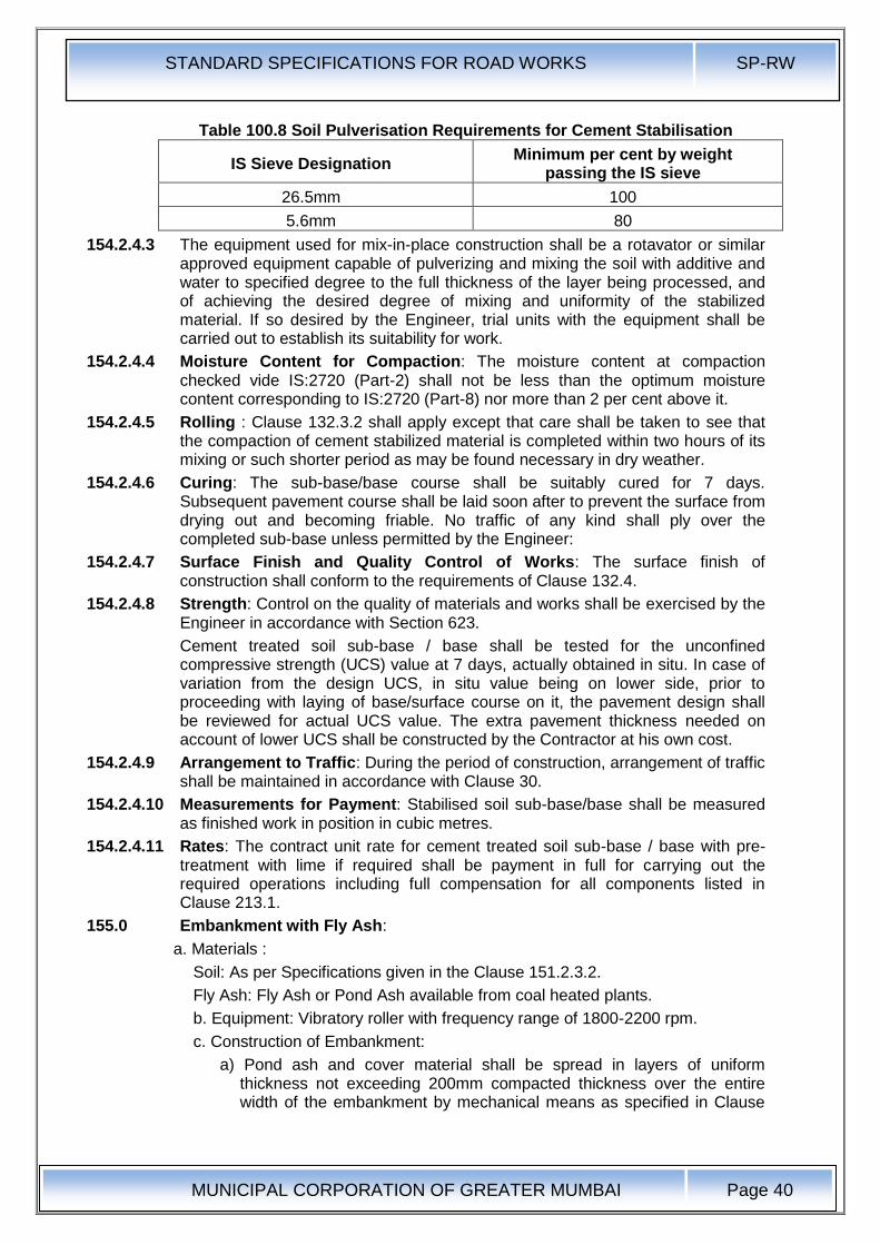
STANDARD SPECIFICATIONS FOR ROAD WORKS SP-RW
MUNICIPAL CORPORATION OF GREATER MUMBAI
Page 40
Table 100.8 Soil Pulverisation Requirements for Cement Stabilisation
IS Sieve Designation Minimum per cent by weight
passing the IS sieve
26.5mm 100
5.6mm 80
154.2.4.3 The equipment used for mix-in-place construction shall be a rotavator or similar approved equipment capable of pulverizing and mixing the soil with additive and water to specified degree to the full thickness of the layer being processed, and of achieving the desired degree of mixing and uniformity of the stabilized material. If so desired by the Engineer, trial units with the equipment shall be carried out to establish its suitability for work.
154.2.4.4 Moisture Content for Compaction: The moisture content at compaction checked vide IS:2720 (Part-2) shall not be less than the optimum moisture content corresponding to IS:2720 (Part-8) nor more than 2 per cent above it.
154.2.4.5 Rolling : Clause 132.3.2 shall apply except that care shall be taken to see that the compaction of cement stabilized material is completed within two hours of its mixing or such shorter period as may be found necessary in dry weather.
154.2.4.6 Curing: The sub-base/base course shall be suitably cured for 7 days. Subsequent pavement course shall be laid soon after to prevent the surface from drying out and becoming friable. No traffic of any kind shall ply over the completed sub-base unless permitted by the Engineer:
154.2.4.7 Surface Finish and Quality Control of Works: The surface finish of construction shall conform to the requirements of Clause 132.4.
154.2.4.8 Strength: Control on the quality of materials and works shall be exercised by the Engineer in accordance with Section 623.
Cement treated soil sub-base / base shall be tested for the unconfined compressive strength (UCS) value at 7 days, actually obtained in situ. In case of variation from the design UCS, in situ value being on lower side, prior to proceeding with laying of base/surface course on it, the pavement design shall be reviewed for actual UCS value. The extra pavement thickness needed on account of lower UCS shall be constructed by the Contractor at his own cost.
154.2.4.9 Arrangement to Traffic: During the period of construction, arrangement of traffic shall be maintained in accordance with Clause 30.
154.2.4.10 Measurements for Payment: Stabilised soil sub-base/base shall be measured as finished work in position in cubic metres.
154.2.4.11 Rates: The contract unit rate for cement treated soil sub-base / base with pre-treatment with lime if required shall be payment in full for carrying out the required operations including full compensation for all components listed in Clause 213.1.
155.0 Embankment with Fly Ash:
a. Materials :
Soil: As per Specifications given in the Clause 151.2.3.2.
Fly Ash: Fly Ash or Pond Ash available from coal heated plants.
b. Equipment: Vibratory roller with frequency range of 1800-2200 rpm.
c. Construction of Embankment:
a) Pond ash and cover material shall be spread in layers of uniform thickness not exceeding 200mm compacted thickness over the entire width of the embankment by mechanical means as specified in Clause
STANDARD SPECIFICATIONS FOR ROAD WORKS SP-RW
MUNICIPAL CORPORATION OF GREATER MUMBAI
Page 41
No.151.2.6. Moisture control of both pond ash and cover shall be done as per Clause No.151.2.6.
b). For better compaction of pond ash, it is preferred to have a vibratory roller with frequency' range (1800-2200 rpm). For compaction of pond ash static as well as vibratory rollers may be employed. In case of vibratory roller, the lift thickness shall be restricted to 25cm compacted over the entire width of the embankment. The pond ash should be compacted to 95% of its MDD and in no case its maximum density should be less than 1.2 gm/cc. Moisture content of pond ash at compaction will vary from OMC to OMC +2%.
c) After achieving the designed thickness of first pond ash layer, a cover soil layer of 40cm compacted thickness shall be provided as Clause NO.151.
d) The same procedure shall be adopted for subsequent pond ash and soil layers, till the required height is achieved.
e) Pond ash shall be used upto 500mm below GSB layer.
f) Width of side cover soil shall be 2000mm measured horizontally. The cover soil shall comprise soil as per Clause 151.
d. Payment shall be made in accordance with Clause 151.
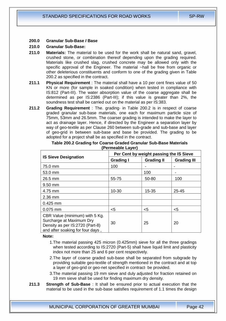
STANDARD SPECIFICATIONS FOR ROAD WORKS SP-RW
MUNICIPAL CORPORATION OF GREATER MUMBAI
Page 42
200.0 Granular Sub-Base I Base
210.0 Granular Sub-Base:
211.0 Materials: The material to be used for the work shall be natural sand, gravel, crushed stone, or combination thereof depending upon the grading required. Materials like crushed slag, crushed concrete may be allowed only with the specific approval of the Engineer. The material ~hall be free from organic or other deleterious constituents and conform to one of the grading given in Table 200.2 as specified in the contract.
211.1 Physical Requirement : The material shall have a 10 per cent fines value of 50 KN or more (for sample in soaked condition) when tested in compliance with IS:812 (Part-III). The water absorption value of the coarse aggregate shall be determined as per IS:2386 (Part-III); if this value is greater than 2%, the soundness test shall be carried out on the material as per IS:383.
211.2 Grading Requirement : The. grading· in Table 200.2 is in respect of coarse graded granular sub-base materials, one each for maximum particle size of 75mm, 53mm and 26.5mm. The coarser grading is intended to make the layer to act as drainage layer. Hence, if directed by the Engineer a separation layer by way of geo-textile as per Clause 260 between sub-grade and sub-base and layer of geo-grid in between sub-base and base be provided. The grading to be adopted for a project shall be as specified in the contract.
Table 200.2 Grading for Coarse Graded Granular Sub-Base Materials (Permeable Layer)
IS Sieve Designation Per Cent by weight passing the IS Sieve
Grading I Grading II Grading III
75.0 mm 100 - -
53.0 mm 100 -
26.5 mm 55-75 50-80 100
9.50 mm
4.75 mm 10-30 15-35 25-45
2.36 mm
0.425 mm
0.075 mm <5 <5 <5
CBR Value (minimum) with 5 Kg. Surcharge at Maximum Dry Density as per IS:2720 (Part-8) and after soaking for four days ,
30 25 20
Note:
1.The material passing 425 micron (0.425mm) sieve for all the three gradings when tested according to IS:2720 (Part-5) shall have liquid limit and plasticity index not more than 25 and 6 per cent respectively.
2.The layer of coarse graded sub-base shall be separated from subgrade by providing suitable geo-textile of strength mentioned in the contract and at top a layer of geo-grid or geo-net specified in contract· be provided.
3.The material passing 19 mm sieve and duly adjusted for fraction retained on 19 mm sieve shall be used for finding maximum dry density.
211.3 Strength of Sub-Base : It shall be ensured prior to actual execution that the material to be used in the sub-base satisfies requirement of 1.1 times the design

STANDARD SPECIFICATIONS FOR ROAD WORKS SP-RW
MUNICIPAL CORPORATION OF GREATER MUMBAI
Page 43
CBR mentioned in Table 200.2 and other physical requirements when compacted and finished.
When directed by the Engineer, this shall be verified by performing CBR test in the laboratory as required on specimens re-moulded at maximum dry density and at OMC using material passing 19 mm sieve.
The value of laboratory CBR shall be 1.5 times the design CBR mentioned in Table 200.2.
211.4 Equipment : Roller 80 to 100 KN weight if thickness of layer is less than 100 mm. 80 to 100 KN static weight vibratory or pneumatic tyred roller of 200 to 300 KN weight having minimum tyre pressure of 0.7 KN /sq. m.
212.0 Preparation of Sub-grade: Immediately prior to ·the laying of subbase, the sub grade already finished to Clause 100 or 150 as applicable shall be prepared by removing all vegetation and other extraneous matter, lightly sprinkled with water if necessary and rolled with two passes of 80-100 kN smooth wheeled roller.
212.1 Spreading and Compacting: The sub-base material of grading specified in the Contract shall be spread on the prepared sub-grade with the help of a motor grader of adequate capacity, its blade having hydraulic controls suitable for initial adjustment and for maintaining the required slope and grade during the operation or other means as approved by the Engineer. When the sub-base material consists of combination of materials mentioned in Clause 211, mixing shall be done mechanically by the mix-in-place method.
Manual mixing shall be permitted only where the width of laying is not adequate for mechanical operations, as in small-sized jobs. The equipment used for mix-in-place construction shall be a rotavator or similar approved equipment capable of mixing the material to the desired degree. If so desired by the Engineer, trail runs with the equipment shall be carried out to establish its suitability for the work.
Moisture content of the loose material shall be checked in accordance with IS:2720 (Part-2) and suitably adjusted by sprinkling additional water from a truck mounted or trailer mounted water and suitable for applying water uniformly and at controlled quantities to variable widths of surface or other means approved by the Engineer so that, at the time of compaction, it is from 1 per cent above to 2 per cent below the optimum moisture content corresponding to IS:2720 (Part-8). While adding water, due allowance shall be made for evaporation losses. After water has been added, the material shall be processed by mechanical or other approved means like disc harrows, rotavators until the layer is uniformly wet.
Immediately thereafter, rolling shall start. If the thickness of the compacted layer does not exceed 100mm, a smooth wheeled roller of 80 to 100 kN weight may be used. For a compacted single layer upto 225mm, the compaction shall be done with the help of a vibratory roller of minimum 80 to 100 kN static weight with plain drum or pad foot-drum or heavy pneumatic tyred roller of minimum 200 to 300 kN weight having a minimum tyre pressure of 0.7 MN/m2 or equivalent capacity roller capable of achieving the required compaction. Rolling shall commence at the lower edge and proceed towards the upper edge longitudinally for portions having unidirectional cross fall and super-elevation and shall commence at the edges and progress towards the centre for portions having cross fall on both sides.
Each pass of the roller shall uniformly overlap not less than one-third of the track made in the preceding pass. During rolling, the grade and cross fall (camber) shall be checked and any high spots or depressions, which become apparent, corrected by removing or adding fresh material. The speed of the roller shall not exceed 5 km per hour.
STANDARD SPECIFICATIONS FOR ROAD WORKS SP-RW
MUNICIPAL CORPORATION OF GREATER MUMBAI
Page 44
Rolling shall be continued till the density achieved is at least 98 per cent of the maximum dry density for the material determined as per IS:2720 (Part-8). The surface of any layer of material on completion of compaction shall be well closed, free from movement under compaction equipment and from compaction planes, ridges, cracks or loose material. All loose, segregated or otherwise defective areas shall be made good to the full thickness of layer and re-compacted.
212.2 Surface Finish and Quality Control of Works: The surface finish of construction shall conform to the requirements of Clause 613. Control on the quality of materials and works shall be exercised by the Engineer in accordance with Section 620.
212.3 Arrangement for Traffic: During the period of construction, arrangement of traffic shall be maintained in accordance with Clause 30.
213.0 Measurements for Payment: Granular sub-base shall be measured as finished work in position in cubic metres.
The protection of edges of granular sub-base extended over the full formation as shown in the drawing shall be considered incidental to the work of providing granular sub-base and as such no extra payment shall be made for the same.
213.1 Rates: The contract unit rate for granular sub-base shall be payment in full for carrying out the required operations including full compensation for:
a) Making arrangements for traffic to Clause 30 except for initial treatment to verges, shoulders and construction of diversions,
b) Furnishing all materials to be incorporated in the work including all royalties, fees, rents where necessary and all leads and lifts,
c) All labour, tools, equipment and incidentals to complete the work to the Specifications,
d) Carrying out the work in part widths of road where directed and
e) Carrying out the required tests for quality control.
220.0 Water Bound Macadam:
221.0 Description : Coarse aggregates shall be crushed or broken stone, crushed slab. The aggregate shall confirm to the physical requirements given in Table 200.3(Table:1 of IRC:19-2005.) The type and size of the aggregate shall be specified in the contract. If the water absorption value of the coarse aggregate is greater than 2%, the soundness test shall be carried out on the material as per IS : 2386 (Part 5). The crushed or broken stone shall be hard, durable and free from excess flat, elongated, soft and disintegrated particles, dirt and other deleterious materials. Screening to field wise in the coarse aggregate shall generally consist of the same material as the coarse aggregate.
WBM should not be laid directly over a silty or clayey subgrage. It is advisable to lay a suitable intervening granular layer. (As per clause 2.1.3 of IRC:19-2005)
222.0 Materials:
222.1 Coarse Aggregates – General Requirements ( clause 3.1 of IRC:19-2005)
222.1.1 Coarse aggregates shall consists of clean crushed or broken stone, crushed slag, overburnt brick ( Jhama ) metal or naturally occurring aggregates such as kankar and laterite of requisite quantity as stated hereinafter. Use of crushable type aaggregates should generally be restricted to lower layers of the pavement. The aggregate shall conform to the physical requirements set forth in Table:200.3 (clause 3.1.1 of IRC: 19-2005)
222.1.2 Physical Requirements of crushed stone : The crushed or broken stone shall be hard, durable and free from excess flat, elongated, soft and disintegrated

STANDARD SPECIFICATIONS FOR ROAD WORKS SP-RW
MUNICIPAL CORPORATION OF GREATER MUMBAI
Page 45
particles, dirt and other deleterious material and shall meet requirement given in table 200.3.
222.1.3 Crushed slag: Crushed Slag shall be manufactured from air –cooled blast furnace slage. It shall be angular in shape, reasonably uniform in quality and density, and generally free from soft, alongated and flat pieces, dirt or other deleterious material. Crushed slag shall not weigh less than 11.2 kM per m3 and the glassy material in it shall not be in excess of 20 percent . It should also compty with the following requirements.
(i) Chemical stability: To comply with requirement of Appendix of BS : 1047
(ii) Sulphur Content: Maximum 2 percent
(IS 14685 – 1999)
(iii) Water absorption: Maximum 10 percent
(IS 2386, Part 3)
(clause 3.1.3 of IRC: 19-2005)
222.1.4 Overburnt (Jhama) Brick metal: Brick metal shall be made out of overburnt bricks or brick bats and be free from dust and other deleterious materials. (clause 3.1.4 of IRC: 19-2005)
222.1.5 Kankar: Kankar shall be tough having a blue opalescent fracture. It shall not contain any clay in the cavities between nodules. (clause 3.1.5 of IRC: 19-2005)
222.1.6 Laterite: Laterite shall be hard, compact, heavy and of dark colour. Light coloured sandy laterities, as also those containing ochreous clay shall not be used. (clause 3.1.6 of IRC: 19-2005)
Table 200.3Physical Requirements of Coarse Aggregates for Water Bound Macadam
Sl No.
Type of Consutruction
Test Test Method equipments
1 Sub-Base
Los Angeles Abrasion Value* or
IS 2386 (Part 4) Max. 50 %
Aggregate Impact Value*
IS 2386 (Part 4) or IS 5640**
Max. 40 %
2 Base course with bituminous surfacing
Los Angeles Abrasion Value* or
IS 2386 (Part 4) Max. 40 %
Aggregate Impact Value+
IS 2386 (Part 4) or IS 5640**
Max. 30 %
Flakiness Index*** IS 2386 (Part 1) Max. 20 %
3 Surfacing course
Los Angeles Abrasion Value* or
IS 2386 (Part 4) Max. 40 %
Aggregate Impact Value+
IS 2386 (Part 4) or IS 5640**
Max. 30 %
Flakiness Index*** IS 2386 (Part 1) Max. 15 %
* Aggregates may satisfy the requirements of either the Los Angeles test or Aggregate Impact Value Test.
** Aggregates like brick metal, Kankar. Laterite, etc., which get softened in presence of water should invariably be tested for impact value under wet condition in accordance with IS 5640
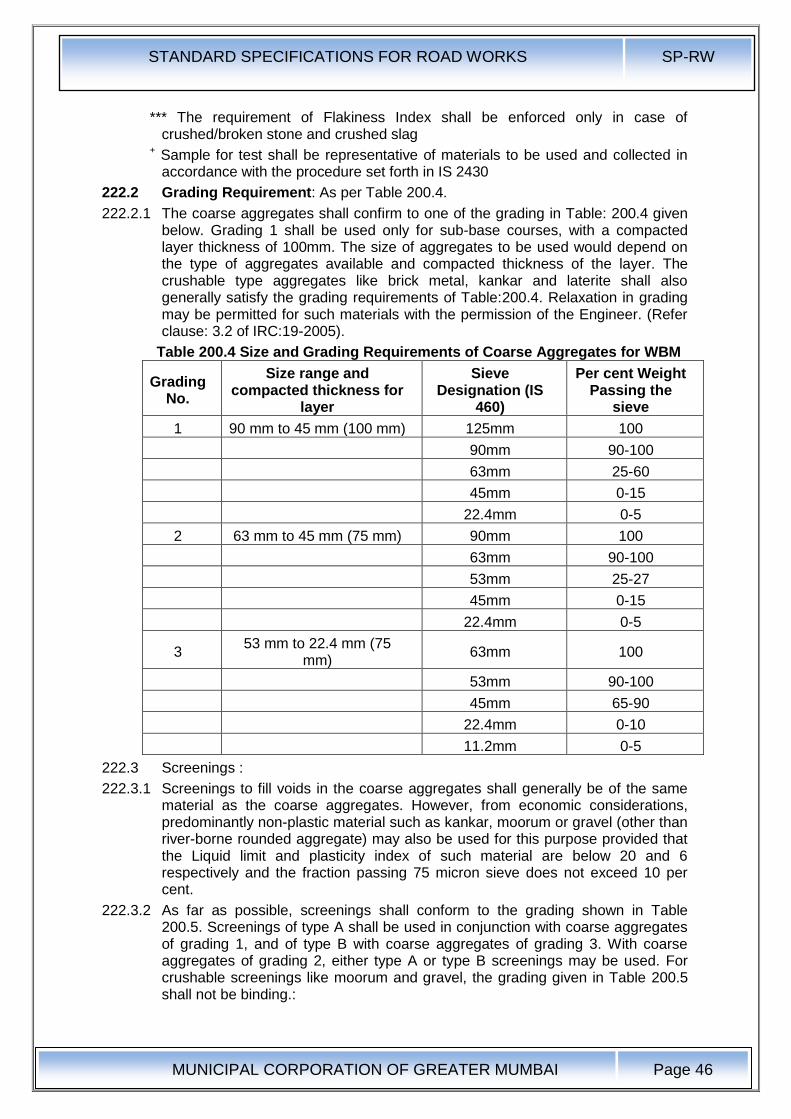
STANDARD SPECIFICATIONS FOR ROAD WORKS SP-RW
MUNICIPAL CORPORATION OF GREATER MUMBAI
Page 46
*** The requirement of Flakiness Index shall be enforced only in case of crushed/broken stone and crushed slag
+ Sample for test shall be representative of materials to be used and collected in accordance with the procedure set forth in IS 2430
222.2 Grading Requirement: As per Table 200.4.
222.2.1 The coarse aggregates shall confirm to one of the grading in Table: 200.4 given below. Grading 1 shall be used only for sub-base courses, with a compacted layer thickness of 100mm. The size of aggregates to be used would depend on the type of aggregates available and compacted thickness of the layer. The crushable type aggregates like brick metal, kankar and laterite shall also generally satisfy the grading requirements of Table:200.4. Relaxation in grading may be permitted for such materials with the permission of the Engineer. (Refer clause: 3.2 of IRC:19-2005).
Table 200.4 Size and Grading Requirements of Coarse Aggregates for WBM
Grading No.
Size range and compacted thickness for
layer
Sieve Designation (IS
460)
Per cent Weight Passing the
sieve
1 90 mm to 45 mm (100 mm) 125mm 100
90mm 90-100
63mm 25-60
45mm 0-15
22.4mm 0-5
2 63 mm to 45 mm (75 mm) 90mm 100
63mm 90-100
53mm 25-27
45mm 0-15
22.4mm 0-5
3 53 mm to 22.4 mm (75
mm) 63mm 100
53mm 90-100
45mm 65-90
22.4mm 0-10
11.2mm 0-5
222.3 Screenings :
222.3.1 Screenings to fill voids in the coarse aggregates shall generally be of the same material as the coarse aggregates. However, from economic considerations, predominantly non-plastic material such as kankar, moorum or gravel (other than river-borne rounded aggregate) may also be used for this purpose provided that the Liquid limit and plasticity index of such material are below 20 and 6 respectively and the fraction passing 75 micron sieve does not exceed 10 per cent.
222.3.2 As far as possible, screenings shall conform to the grading shown in Table 200.5. Screenings of type A shall be used in conjunction with coarse aggregates of grading 1, and of type B with coarse aggregates of grading 3. With coarse aggregates of grading 2, either type A or type B screenings may be used. For crushable screenings like moorum and gravel, the grading given in Table 200.5 shall not be binding.:
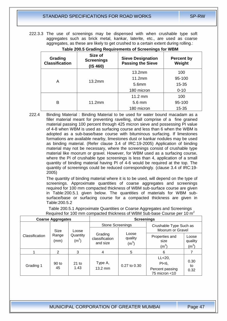
STANDARD SPECIFICATIONS FOR ROAD WORKS SP-RW
MUNICIPAL CORPORATION OF GREATER MUMBAI
Page 47
222.3.3 The use of screenings may be dispensed with when crushable type soft aggregates such as brick metal, kankar, laterite, etc., are used as coarse aggregates, as these are likely to get crushed to a certain extent during rolling.:
Table 200.5 Grading Requirements of Screenings for WBM
Grading Classification
Size of Screenings
(IS 460)
Sieve Designation Passing the Sieve
Percent by Weight
A 13.2mm
13.2mm
11.2mm
5.6mm
180 micron
100
95-100
15-35
0-10
B 11.2mm
11.2 mm
5.6 mm
180 micron
100
95-100
15-35
222.4 Binding Material : Binding Material to be used for water bound macadam as a filler material meant for preventing ravelling, shall comprise of a fine grained material passing 100 percent through 425 micron sieve and possessing PI value of 4-8 when WBM is used as surfacing course and less than 6 when the WBM is adopted as a sub-base/base course with bituminous surfacing. If limestones formations are available nearby, limestones dust or kankar nodules may be used as binding material. (Refer clause 3.4 of IRC:19-2005) Application of binding material may not be necessary, where the screenings consist of crushable type material like moorum or gravel. However, for WBM used as a surfacing course, where the PI of crushable type screenings is less than 4, application of a small quantity of binding material having PI of 4-6 would be required at the top. The quantity of screenings could be reduced correspondingly. (clause 3.4 of IRC:19-2005)
The quantity of binding material where it is to be used, will depend on the type of screenings. Approximate quantities of coarse aggregates and screenings required for 100 mm compacted thickness of WBM sub-surface course are given in Table:200.5.1 given below. The quantities of materials for WBM sub-surface/base or surfacing course for a compacted thickness are given in Table:200.5.2
Table 200.5.1 Approximate Quantities or Coarse Aggregates and Screenings Required for 100 mm compacted thickness of WBM Sub·base Course per 10 m2
Coarse Aggregates Screenings
Classification
Size Range
(mm)
Loose Quantity
(m2)
Stone Screenings Crushable Type Such as Moorum or Gravel
Grading classification
and size
Loose quality
(m3)
Properties and size
(m3)
Loose quality
(m3)
1 2 3 4 5 6 7
Grading 1 90 to 45
21 to 1.43
Type A,
13.2 mm 0.27 to 0.30
LL<20,
PI<6,
Percent passing 75 micron <10
0.30 to
0.32
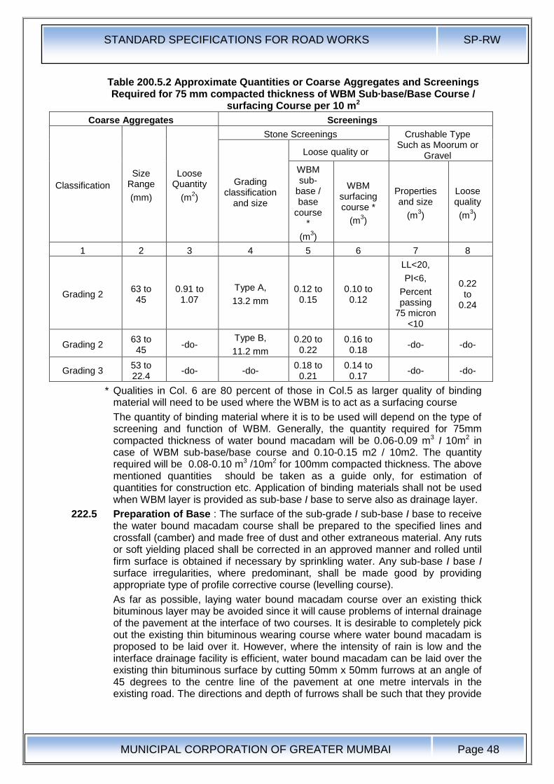
STANDARD SPECIFICATIONS FOR ROAD WORKS SP-RW
MUNICIPAL CORPORATION OF GREATER MUMBAI
Page 48
Table 200.5.2 Approximate Quantities or Coarse Aggregates and Screenings Required for 75 mm compacted thickness of WBM Sub·base/Base Course /
surfacing Course per 10 m2
Coarse Aggregates Screenings
Classification
Size Range
(mm)
Loose Quantity
(m2)
Stone Screenings Crushable Type Such as Moorum or
Gravel
Grading classification
and size
Loose quality or
WBM sub-
base / base
course *
(m3)
WBM surfacing course *
(m3)
Properties and size
(m3)
Loose quality
(m3)
1 2 3 4 5 6 7 8
Grading 2 63 to 45
0.91 to 1.07
Type A,
13.2 mm
0.12 to 0.15
0.10 to 0.12
LL<20,
PI<6,
Percent passing
75 micron <10
0.22 to
0.24
Grading 2 63 to 45
-do- Type B,
11.2 mm
0.20 to 0.22
0.16 to 0.18
-do- -do-
Grading 3 53 to 22.4
-do- -do- 0.18 to
0.21 0.14 to 0.17
-do- -do-
* Qualities in Col. 6 are 80 percent of those in Col.5 as larger quality of binding material will need to be used where the WBM is to act as a surfacing course
The quantity of binding material where it is to be used will depend on the type of screening and function of WBM. Generally, the quantity required for 75mm compacted thickness of water bound macadam will be 0.06-0.09 m3 I 10m2 in case of WBM sub-base/base course and 0.10-0.15 m2 / 10m2. The quantity required will be 0.08-0.10 m3 /10m2 for 100mm compacted thickness. The above mentioned quantities should be taken as a guide only, for estimation of quantities for construction etc. Application of binding materials shall not be used when WBM layer is provided as sub-base I base to serve also as drainage layer.
222.5 Preparation of Base : The surface of the sub-grade I sub-base I base to receive the water bound macadam course shall be prepared to the specified lines and crossfall (camber) and made free of dust and other extraneous material. Any ruts or soft yielding placed shall be corrected in an approved manner and rolled until firm surface is obtained if necessary by sprinkling water. Any sub-base I base I surface irregularities, where predominant, shall be made good by providing appropriate type of profile corrective course (levelling course).
As far as possible, laying water bound macadam course over an existing thick bituminous layer may be avoided since it will cause problems of internal drainage of the pavement at the interface of two courses. It is desirable to completely pick out the existing thin bituminous wearing course where water bound macadam is proposed to be laid over it. However, where the intensity of rain is low and the interface drainage facility is efficient, water bound macadam can be laid over the existing thin bituminous surface by cutting 50mm x 50mm furrows at an angle of 45 degrees to the centre line of the pavement at one metre intervals in the existing road. The directions and depth of furrows shall be such that they provide
STANDARD SPECIFICATIONS FOR ROAD WORKS SP-RW
MUNICIPAL CORPORATION OF GREATER MUMBAI
Page 49
adequate bondage and also serve to drain water to the existing granular base course beneath the existing thin bituminous surface.
Inverted Choke: If water bound macadam is to be laid directly over the sub-grade, without any other intervening pavement course, a 25mm course of screenings (Grading B) or coarse sand shall be spread on the prepared sub-grade before application of the aggregates is taken up. In case of a fine sand or silty or clayey sub-grade, it is advisable to lay 100mm insulating layer of screening or coarse sand on top of fine grained soil, the gradation of which will depend upon whether it is intended to act as a drainage layer as well. As a preferred alternative to inverted choke, appropriate geosynthetic performing functions of separation and drainage may be used over the prepared sub-grade as directed by the Engineer. Section 260 shall be applicable for use of geo-synthetics.
222.6 Spreading Coarse Aggregates : The coarse aggregates shall be spread uniformly and evenly upon the prepared sub-grade I sub-base I base to proper profile by using templates placed across the road about 6m apart, in such quantities that the thickness of each compacted layer is not more than 75mm as specified in Clause 222.2 Wherever possible, approved mechanical devices such as aggregate spreader shall be used to spread the aggregates uniformly so as to minimize the need for manual rectification afterwards. Aggregates placed at locations which are inaccessible to the spreading equipment, may be spread in one or more layers by any approved means so as to achieve the specified results.
The spreading shall be done from stockpiles along the side of the roadway or directly from vehicles. No segregation of large or fine aggregates shall be allowed and the coarse aggregate as spread shall be of uniform gradation with no pockets of fine material.
The surface of the aggregates spread shall be carefully checked with templates and all high or low spots remedied by removing or adding aggregates as may be required. The surface shall be checked frequently with a straight edge while spreading and rolling so as to ensure a finished surface as per approved drawings.
The coarse aggregates shall normally be spread more than 3 days in advance of the subsequent construction operations.
222.7 Roller: If the thickness of single layer does not exceed 100mm a smooth wheeled Roller of 80-100 KN weight be used. For a compacted single layer upto 200mm, the compaction shall be done with the help of vibratory Roller of minimum static weight of 80-100 KN.
222.8 Rolling: Immediately following the spreading of the coarse aggregate, rolling shall be started with three wheeled power rollers of 80 to 100 KN capacity or tandem or vibratory rollers of 80 to 100 KN static weight. The type of roller to be used shall be approved by the Engineer based on trial run.
Except on super-elevated portions where the rolling shall proceed from inner edge to the outer, rolling shall begin from the edges gradually progressing towards the centre. First the edge / edges shall be compacted with roller running forward and backward. The roller shall then move inward parallel to the centre line of the road, in successive passes uniformly lapping preceding tracks by at least one half widths. Rolling shall be discontinued when the aggregates are partially compacted with sufficient void space in them to permit application of screenings. Compaction shall be continued until the aggregates are thoroughly keyed. During rolling, slight sprinkling of water may be done, if necessary. Rolling shall not be done when the sub-grade is soft or yielding or when it causes a
STANDARD SPECIFICATIONS FOR ROAD WORKS SP-RW
MUNICIPAL CORPORATION OF GREATER MUMBAI
Page 50
wave-line motion in the sub-grade or sub-base course. If irregularities develop during rolling, which exceed 12 mm when tested with a 3 m straight edge, the surface shall be loosened and aggregates added or removed as required before rolling again so as to achieve all uniform surface conforming to the desired cross section and grade. (Refere clause 4.4.4 of IRC:19- 2005)-
The rolled surface shall be checked transversely and longitudinally, with templates and any irregularities corrected by loosening the surface, adding or removing necessary amount of aggregates and rerolling until the entire surface conforms to desired cross fall (camber) and grade. In no case shall the use of screenings be permitted to make up depressions.
Material which gets crushed excessively during compaction or becomes segregated shall be removed and replaced with suitable aggregates.
222.9 Application of Screenings : After the coarse aggregate has been rolled to Clause 222.9 screenings to completely fill the interstices shall be applied gradually over the surface. These shall not be damp or wet at the time of application. Dry rolling shall be done while the screenings are being spread so that vibrations of the roller cause them to settle into the voids of the coarse aggregate. The screenings shall not be dumped in piles but be spread uniformly in successive thin layers either by the spreading motions of hand shovels or by mechanical spreaders, or directly from tipper with suitable grit spreading arrangement. Tipper operating for spreading the screenings shall be so driven as not to disturb the coarse aggregate.
The screenings shall be applied at a slow and uniform rate (in three or more applications) so as to ensure filling of all voids. This shall be accompanied by dry rolling and brooming with mechanical brooms, hand-brooms or both. In no case shall be the screenings be applied so fast and thick as to form cakes or ridges on the surface in such a manner as would prevent filling of voids or prevent the direct bearing of the roller on the coarse aggregate. These operations shall continue until no more screenings can be forced into the voids of the coarse aggregate.
The spreading, rolling and brooming of screenings shall be carried out in only such lengths of the road which could be completed within one day's operation.
222.10 Sprinkling of Water and Grouting : After the screenings have been applied, the surface shall be copiously sprinkled with water, swept and rolled. Hand brooms shall be used to sweep the wet screenings into voids and to distribute them evenly. The sprinkling, sweeping and rolling operation shall be continued, with additional screenings applied as necessary until the coarse aggregate has been thoroughly keyed, well-bonded and firmly set in its full depth and a grout has been formed of screenings. Care shall be taken to see that the base or sub-grade does not get damaged due to the addition of excessive quantities of water during construction. .
In case of lime treated soil sub-base, construction of water bound macadam on top of it can cause excessive water to flow down to the lime treated sub-base before it has picked up enough strength (is still "green") and thus cause damage to the sub-base layer. The laying of water bound macadam layer in such cases shall be done after the subbase attains adequate strength, as directed by the Engineer.
222.11 Application of Binding Material: After the application of screenings in accordance with Clauses 222.10 the binding material where it is required to be used (Clause 222.4) shall be applied successively in two or more thin layers at a slow and uniform rate. After each application, the surface shall be copiously sprinkled with water, the resulting slurry swept in with hand brooms, or
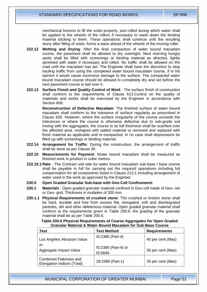
STANDARD SPECIFICATIONS FOR ROAD WORKS SP-RW
MUNICIPAL CORPORATION OF GREATER MUMBAI
Page 51
mechanical brooms to fill the voids properly, and rolled during which water shall be applied to the wheels of the rollers if necessary to wash down the binding material sticking to them. These operations shall continue until the resulting slurry after filling of voids, forms a wave ahead of the wheels of the moving roller.
222.12 Wetting and Drying: After the final compaction of water bound macadam course, the pavement shall be allowed to dry overnight. Next morning hungry spots shall be filled with screenings or binding material as directed, lightly sprinkled with water if necessary and rolled. No traffic shall be allowed on the road until the macadam has set. The Engineer shall have the discretion to stop hauling traffic from using the completed water bound macadam course, if in his opinion it would cause excessive damage to the surface. The compacted water bound macadam course should be allowed to completely dry and set before the next pavement course is laid over it.
222.13 Surface Finish and Quality Control of Work : The surface finish of construction shall conform to the requirements of Clause 613.Control on the quality of materials and works shall be exercised by the Engineer in accordance with Section 600.
Reconstruction of Defective Macadam: The finished surface of water bound macadam shall conform to the tolerance of surface regularity as prescribed in Clause 600. However, where the surface irregularity of the course exceeds the tolerances or where the course is otherwise defective due to sub-grade soil mixing with the aggregates, the course to its full thickness shall be scarified over the affected area, reshaped with added material or removed and replaced with fresh material as applicable and re-compacted. In no case shall depressions be filled up with screenings or binding material.
222.14 Arrangement for Traffic: During the construction, the arrangement of traffic shall be done as per Clause 30.
222.15 Measurements for Payment: Water bound macadam shall be measured as finished work in position in cubic metres.
222.15.1 Rate : The Contract unit rate for water bound macadam sub-base I base course shall be payable in full for carrying out the required operations including full compensation for all components listed in Clause 213.1 including arrangement of water used in the work as approved by the Engineer.
230.0 Open Graded Granular Sub-base with Geo-Cell Confinement:
230.1 Materials : Open graded granular material confined in Geo cell made of Geo- net or Geo- grid. Thickness in multiples of 300 mm.
230.1.1 Physical Requirements of crushed stone: The crushed or broken stone shall be hard, durable and free from excess flat, elongated, soft and disintegrated particles, dirt and other deleterious material. Open graded granular material shall conform to the requirements given in Table 200.6. the grading of the granular material shall be as per Table 200.6.
Table 200.6 Physical Requirements of Coarse Aggregates for Open Graded Granular Material & Water Bound Macadam for Sub-Base Course
Test Test Method Requirements
Los Angeles Abrasion Value
or
Aggregate Impact Value
IS:2386 (Part-4)
IS:2386 (Part-4) or
IS:5640
40 per cent (Max)
30 per cent (Max)
Combined Flakiness and Elongation Indices (Total)
18:2386 (Part-1) 30 per cent (Max)
STANDARD SPECIFICATIONS FOR ROAD WORKS SP-RW
MUNICIPAL CORPORATION OF GREATER MUMBAI
Page 52
230.1.2 Grading Requirements: As in Table 200.4
230.1.3 Geo-Cell : Geo-net or Geo-Grid of design strength shall provide open graded aggregate of sub-base with confinement, the thickness of layer shall be as per the design. The geo-net or geo-grid shall be laid in vertical plain, in zigzag ,pattern and tied at the nodes forming compartment or cells of designed diameter. The spacing of the geo-net or geo-grid shall be not more than 1.2 times the depth of the geo-cell. Geo-net, Geo-grid is as per Clause No. 260.
230.1.4 Geo-Textile : Geo-Textile shall be as per the specifications given in Clause No. 260
230.1.5 Laying : Layer of Geo-Textile shall be provided at bottom on the prepared sub-grade. The Geo-cell shall be laid on the geo-membrane. The nodes shall be tied as per manufacturer's directions. The cells so formed are then filled to the full depth as one layer.
230.1.6 Rolling as single layer with 80-100 KN smooth wheeled Roller and 60-80 KN static weight vibratory Roller.
230.1.7 Measurements for Payment : The geo-textile and geo-cell shall be measured per Square Metre of the sub-base as laid. Measurement for the aggregate shall be as per WBM given in Clause No.220.
230.1.8 Rates : Rates shall be per 8quare Metre of the sub-base area for geo-cell and geo-membrane and as per Clause No.220 for aggregate.
235.0 Crushed Cement Concrete
235.1 Scope : This work shall consist of breaking and crushing the damaged cement concrete slabs and re-compacting the same as sub-base/base course in one or more layers. Where specified, it shall also include treating the surface of the top layer with a penetration cot of bitumen. The work shall be performed on such widths and lengths as may be specified, in accordance with the requirements of these Specifications and in conformity with the lines, grades and cross-sections shown on :the drawings or as otherwise directed by the Engineer.
235.2 Materials:
235.2.1 Coarse Aggregate : Coarse Aggregate for this work shall be broken cement concrete slabs crushed to a size not exceeding 75mm and as far as possible, conforming to one of the gradings given in Table 200.4.
235.2.2 Key Aggregate: Key Aggregate for the penetration coat shall consist of crushed stone, crushed gravel, shingle or other stones. It shall be clean, strong, durable, of fairly cubical shape and free of disintegrated pieces, organic or other deleterious matter and adherent coatings. The aggregate shall be hydrophobic and of low porosity.
The aggregate shall be of 11.2mm size defined as 100 per cent passing through 13.2mm sieve and retained on 5.6mm sieve and shall satisfy the physical requirements set forth in Table 200-5.
235.2.3 Binder: Binder for the penetration coat for the top layer shall be bitumen of a suitable grade, as directed by the Engineer and satisfying the requirements of 18:73, 217 or 454, as applicable or any approved cutback or emulsion satisfying the requirements of 18:8887.
235.2.4 Construction Operations
235.2.5 General: Crushed cement concrete sub-base/base course may be constructed in one or two layers, depending upon the thickness of the concrete slabs dismantled and crushed. The thickness of each layer shall, however, not exceed 100 mm in case of sub-base and 75mm in case of base course.
STANDARD SPECIFICATIONS FOR ROAD WORKS SP-RW
MUNICIPAL CORPORATION OF GREATER MUMBAI
Page 53
The course shall be constructed as water bound macadam to Clause 220, using crushed cement concrete as coarse aggregate except that no screenings or binding material need be applied. Where specified, the top layer shall be treated with a penetration coat of binder described in Clause 235.2.6.
235.2.6 Application of penetration coat over the top layer: Before the application of the penetration coat, the surface shall be cleaned of dust, dirt and other foreign matter, using mechanical broom or any other equipment specified by the Engineer. Dust removed in the process shall be blown off with the help of compressed air.
The binder shall be heated to the temperature appropriate to the grade of bitumen used and sprayed on the dry surface in a uniform manner at the rate of 25 Kg per 10 sq. m area in terms of the residual bitumen with the help of either self-propelled or towed bitumen pressure sprayer with self-heating arrangement and spray nozzle capable of spraying bitumen at specified rates and temperatures so as to provide a uniform, unbroken spread of bitumen. Excessive deposits of binder caused by stopping or staring of the sprayer or through leakage or any other reason shall be suitably corrected.
Immediately after the applicable of binder, the key aggregates, in a clean and dry state shall be spread uniformly on the surface at the rate of 0.13 Cu. M. per 10 sq.m area, preferably by means of a mechanical grader, capable of spreading aggregate uniformly at specified rates or otherwise manually with the approval of the Engineer, so as to cover the surface completely. Immediately after the application of the key aggregates, the entire surface shall rolled to Clause 352.4.4.
235.2.7 Surface Finish and Quality Control of Works : The surface finish of construction shall conform to the requirements of Clause 600.Control on the quality of material and works shall be exercised by the Engineer in accordance with Section 600.
235.2.8 Arrangements for Traffic: During the period of construction, arrangement of traffic shall be done as per Clause 30.
235.2.9 Measurements for Payment: Breaking the existing cement concrete pavement slabs, crushing and re-compacting the slab material as sub-base/ base course shall be measured as a single item in terms of the volume of sub-base/base laid in position in cubic metres. Penetration coat shall be measured as finished work in square metres.
235.2.10 Rates:
235.2.10.1 The Contract unit rate for crushed cement concrete sub-base/base course shall be payment in full for carrying out the required operations including full compensation for:
a) making arrangements for traffic to Clause 30 except for initial treatment to verges I shoulders and construction of diversions;
b) breaking the cement concrete slabs, crushing, sieving and re-compacting the slab material as sub-base/base course;
c) all labour, tools, equipment and incidentals to complete the work to the Specifications; and
d) carrying out the work in part widths of road where directed. 235.2.10.2 The Contract unit rate for penetration coat shall be payment in full for carrying out the required operations including full compensation for all components listed in Clause 504.8.
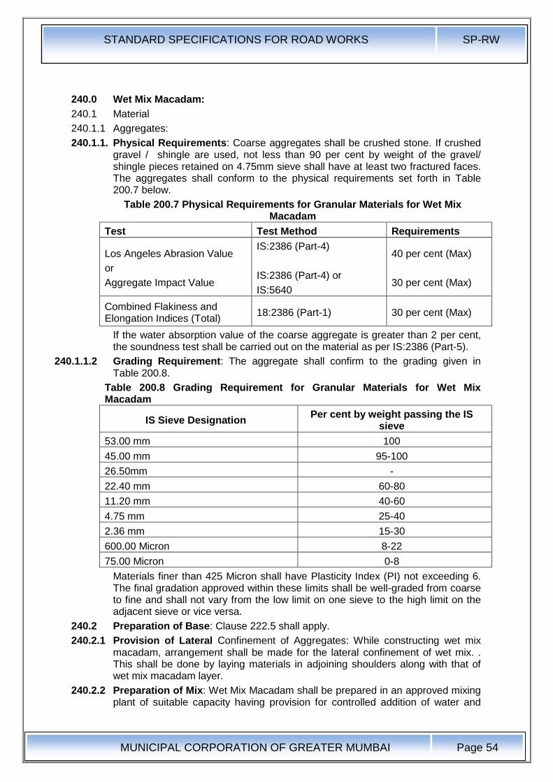
STANDARD SPECIFICATIONS FOR ROAD WORKS SP-RW
MUNICIPAL CORPORATION OF GREATER MUMBAI
Page 54
240.0 Wet Mix Macadam:
240.1 Material
240.1.1 Aggregates:
240.1.1. Physical Requirements: Coarse aggregates shall be crushed stone. If crushed gravel / shingle are used, not less than 90 per cent by weight of the gravel/ shingle pieces retained on 4.75mm sieve shall have at least two fractured faces. The aggregates shall conform to the physical requirements set forth in Table 200.7 below.
Table 200.7 Physical Requirements for Granular Materials for Wet Mix Macadam
Test Test Method Requirements
Los Angeles Abrasion Value
or
Aggregate Impact Value
IS:2386 (Part-4)
IS:2386 (Part-4) or
IS:5640
40 per cent (Max)
30 per cent (Max)
Combined Flakiness and Elongation Indices (Total)
18:2386 (Part-1) 30 per cent (Max)
If the water absorption value of the coarse aggregate is greater than 2 per cent, the soundness test shall be carried out on the material as per IS:2386 (Part-5).
240.1.1.2 Grading Requirement: The aggregate shall confirm to the grading given in Table 200.8.
Table 200.8 Grading Requirement for Granular Materials for Wet Mix Macadam
IS Sieve Designation Per cent by weight passing the IS
sieve
53.00 mm 100
45.00 mm 95-100
26.50mm -
22.40 mm 60-80
11.20 mm 40-60
4.75 mm 25-40
2.36 mm 15-30
600.00 Micron 8-22
75.00 Micron 0-8
Materials finer than 425 Micron shall have Plasticity Index (PI) not exceeding 6. The final gradation approved within these limits shall be well-graded from coarse to fine and shall not vary from the low limit on one sieve to the high limit on the adjacent sieve or vice versa.
240.2 Preparation of Base: Clause 222.5 shall apply.
240.2.1 Provision of Lateral Confinement of Aggregates: While constructing wet mix macadam, arrangement shall be made for the lateral confinement of wet mix. . This shall be done by laying materials in adjoining shoulders along with that of wet mix macadam layer.
240.2.2 Preparation of Mix: Wet Mix Macadam shall be prepared in an approved mixing plant of suitable capacity having provision for controlled addition of water and
STANDARD SPECIFICATIONS FOR ROAD WORKS SP-RW
MUNICIPAL CORPORATION OF GREATER MUMBAI
Page 55
forced / positive mixing arrangement like pugmill or pan type mixer of concrete batching plant. For small quantity of wet mix work, the Engineer may permit the mixing to be done in concrete mixers.
Optimum moisture for mixing shall be determined in accordance with 15:2720 (Part-8) after replacing the aggregate fraction retained on 22.4mm sieve with material of 4.75mm to 22.4mm size. While adding water, due allowance should be made for evaporation losses. However, at the time of compaction, water in the wet mix should not vary from the optimum value by more than agreed limits. The mixed material should be uniformly wet and no segregation should be permitted
240.2.3 Spreading of Mix: Immediately after mixing, the aggregates shall be spread uniformly and evenly upon the prepared sub-grade/ sub-base I base in required quantities. In no case should these be dumped in heaps directly on the area where these are to be .Iaid nor shall their hauling over a partly completed stretch be permitted.
The mix may be spread either by a pave finisher or motor grader. For portions where mechanical means cannot be used, manual means as approved, by the Engineer shall be used. The motor grader shall be capable of spreading the material uniformly all over the surface. Its blade shall have hydraulic control suitable for initial adjustments and maintaining the same so as to achieve the specified slope and grade.
The paver finisher shall be self-propelled, having the following features:
a) Loading hoppers and suitable distribution mechanism
b) The screed shall have tamping and vibrating arrangement for initial compaction to the layer as it is spread without rutting or otherwise marring the surface profile.
c) The paver shall be equipped with necessary control mechanism so as to ensure that the finished surface is free from surface blemishes.
The surface of the aggregate shall be carefully checked with templates and all high or low spots remedied by removing or adding aggregate as may be required. The layer may be tested by depth blocks during construction. No segregation of larger and fine particles should be allowed. The aggregates as spread should be of uniform gradation with no pockets of fine materials.
240.2.4 Compaction: After the mix has been laid to the required thickness, grade and cross fall I camber the same shall be uniformly compacted, to the full depth with suitable roller. If the thickness of single compacted layer does not exceed 100mm, a smooth wheel roller of 80 to 100 kN weight may be used. For a compacted single layer upto 200mm, the compaction shall be done with the help of vibratory roller of minimum static weight of 100 to 200 kN or equivalent capacity roller. The speed of the roller shall not exceed 5 Km/H.
In portions having unidirectional cross fall / super elevation, rolling shall commence from the lower edge and progress gradually towards the upper edge. Thereafter, roller should progress parallel to the centre line of the road, uniformly over-lapping each preceding track by at least one third width until the entire surface has been rolled. Alternate trips of the roller shall be terminated in stops at least 1 m away from any preceding stop.
In portions in camber, rolling should begin at the edge with the roller running forward and backward until the edges have been firmly compacted. The roller shall then progress gradually towards the centre parallel to the centre line of the road uniformly overlapping each of the preceding tracks by at least one-third width until the entire surface has been rolled.
STANDARD SPECIFICATIONS FOR ROAD WORKS SP-RW
MUNICIPAL CORPORATION OF GREATER MUMBAI
Page 56
Any displacement occurring as a result of reversing of the direction of a roller or from any other cause shall be corrected at once as specified and I or removed and made good.
Along forms, kerbs, walls or other places not accessible to the roller, the mixture shall be thoroughly compacted with mechanical tampers or a plate compactor. Skin patching of an area without scarifying the surface to permit proper bonding of the added material shall not be permitted.
Rolling should not be done when the sub-grade is soft or yielding or when it causes a wave-line motion in the sub-base I base course or sub-grade. If irregularities develop during rolling which exceed 12mm when tested with a 3 metre straight edge, the surface should be loosened and premixed material added or removed as required before rolling again so as to achieve a uniform surface conforming to the desired grade and cross fall. In no case should be the use of unmixed material be permitted to make up the depressions.
Rolling shall be continued till the density achieved is at least 98 per cent of the maximum dry density for the material as determined by the method outlined in IS:2720 (Part-8).
After completion, the surface of any finished layer shall be well-closed, free from movement under compaction equipment or any compaction planes, ridges, cracks and loose material. All loose, segregated or otherwise defective areas shall be good to the full thickness of the layer and re-compacted.
240.2.5 Setting and Drying : After final compaction of wet mix macadam course, the road shall be allowed to dry for 24 hours.
240.2.6 Opening to Traffic: Preferably no vehicular traffic of any kind should be allowed on the finished wet mix macadam surface till it has dried and the wearing course has been laid.
240.2.7 Surface Finish and Quality Control of Work:
240.2.7.1 Surface Evenness: The surface finish of construction shall conform to the requirements of Clause 600.
240.2.7.2 Quality Control: Control on the quality of materials and works shall be exercised by the Engineer in accordance with Section 600.
240.2.7.3 Rectification of Surface Irregularity: Where the surface irregularity of the wet mix macadam course exceeds the permissible tolerances or where the course is otherwise defective due to sub-grade soil getting mixed with the aggregates, the full thickness of the layer shall be scarified over the affected area, reshaped with added premixed material or removed and replaced with fresh premixed material as applicable and re-compacted in accordance with Clause 240.2.4. The area treated in the aforesaid manner shall not be less than 5m long and 2m wide. In no case shall depressions be filled up with unmixed and ungraded material or fines.
240.2.8 Arrangement for Traffic : During the period of construction, arrangement for traffic shall be done as per Clause 30.
240.2.9 Measurements for Payment : Wet mix macadam shall be measured as finished work in position in cubic metres.
240.2.9.1 Rates: The Contract unit rate for wet mix macadam shall be payment in full for carrying out the required operations including full compensation for all components.
STANDARD SPECIFICATIONS FOR ROAD WORKS SP-RW
MUNICIPAL CORPORATION OF GREATER MUMBAI
Page 57
260.0 Geo-Synthetic Fabric
261.0 Geo-Synthetic: Geo-Synthetic is .a general classification for all synthetic materials used in geo-technical engineering application. It includes geo-textiles, geo-grids, geo-nets, geo-membranes and geo-composites.
262.0 Geo-Textiles : Any permeable textile natural or synthetic, used with foundation, soil, rock, earth, or any other geo-technical engineering related material. In the present specifications, it is related to synthetic material only.
Geo-textile shall be made of polyethylene or polypropylene or polyester or similar fibres, either woven or non-woven in variety, through machine made process of heat bonding or needle punching or weaving' techniques. These fabrics are required to pass water through but retain the soil particles, which require specific cross-plant permeability or permittivity and apparent opening size or equivalent opening size of 0.095mm. The above two requirements along with the requirement of strength and durability denote general characteristics of geo-textiles to be used. The type of geo-textile to be used in a particular application shall be decided on the basis of design.
The physical properties include specific gravity, mass per unit area, thickness. The mechanical properties include tensile strength (machine direction, cross M direction) strain at failure, modulus, fatigue strength, puncture strength; friction and creep. Environmental properties include resistance to chemicals, temperature, light & weather, bacteria and design life.
263.0 Geo-Grid : A deformed or non-deformed grid of polymeric material used primarily for reinforcement purposes with foundation, soil, rock, earth, or any other geo-technical engineering related material.
Geo-Grid shall be made from integrally jointed, mono or bi-directionally orientated or stretched meshes made from polyethylene or polypropylene or polyester or similar polymer, with high secant modulus, in square, rectangular, hexagonal or oval mesh form. Their junction strength shall be high with high creep resistance, and dimensional stability. Their open structure shall permit effective interlocking with soil, aggregates, rock, etc., they shall be used as a tensile member or reinforcement. Characteristic strength at a maximum elongation of 15 per cent in the direction of the length of the roll. The physical properties include mass per unit area, thickness at rib & junction and polymer type. The mechanical properties shall include peak tensile strength, yield point elongation, tensile strength at 2% strain & 5% strain.
264.0 Geo-Net : These are net made of polymeric material used for drainage of foundation, soil, rock, earth or any other geo-technical engineering related material.
Geo-Net shall be made from a single extruded un-oriented process from polyethylene or polypropylene 'or similar polymer. It shall have square or rectangular net shape aperture when used for protective works like gabions and mattresses. While in polygonal aperture, it shall be used as a separator. It shall not be used as soil reinforcement due to its high creep characteristics, neither as a slope reinforcement or soil retaining wall or asphaltic reinforcement. Geo-nets used in protective works for highway structures shall be at least 650 Gm. / sq. m in unit weight. It shall be black in colour, available in roll form in suitable width.
265.0 Geo-Membrane : An essentially impermeable membrane of polymeric material used with foundation, soil, rock, earth or any other geotechnical engineering be made from PVC or polyethylene sheets of at least 0.8mm thickness, duly protected from ultra-violet exposure with 2.5 per cent carbon black, in black

STANDARD SPECIFICATIONS FOR ROAD WORKS SP-RW
MUNICIPAL CORPORATION OF GREATER MUMBAI
Page 58
colour, supplied in roll form with 3m or above width. The joints of these sheets shall be heat bonded or seamed for effective permeation cut off, at site using standard equipment as part of the laying process. While fixing on to a slope, they shall not be punctured or stapled to impair their use. The physical properties include thickness, specific gravity and mass per unit area. The mechanical properties shall include tensile strength at yield, elongation at yield, modulus of elasticity, tear resistance, impact resistance ,puncture resistance, soil to liner friction
266.0 Geo-Composite : A manufactured material using geo-textiles, geogrids, geo-nets and / or geo-membrane in laminated or composite form. Geo-Composites shall be made from combination of geo-nets, geogrids, or geo-membranes of above description using heat bonded, seamed, stitched or wrap techniques. Their principal use shall be to regulate drainage in cross,.plane or in-plane directions. Minimum unit weight of such material shall conform to the special provisions or as per Contract drawing. .
267.0 The placement of Geo-synthetic shall conform to manufacturer's specifications. The contractor shall submit to the engineer the complete design & scheme of installation - the particular brand and its properties equipment and methodology to be used for installation.
268.0 The payment shall be as per area covered. No separate payment shall be made for laps.
269.0 The rate shall be per square meter of geo-synthetic installed.
STANDARD SPECIFICATIONS FOR ROAD WORKS SP-RW
MUNICIPAL CORPORATION OF GREATER MUMBAI
Page 59
300.0 Bituminous Mixes
301.0 Properties of Bitumen
301.1 Density: Density is the unit weight of a given bituminous mix. This gives an indication· of the bitumen content in the designed mix and helps to establish the basis for controlling/determination of compaction during construction. Densities of specimens obtained from pavements determine the effectiveness of rolling.
301.2 Ductility: Ductility is an indication of the extension or stretch ability of bitumen under standard conditions. A small briquette of bitumen of a given dimension at a standard test condition is pulled in an apparatus at a standard rate of speed until the thread of bitumen breaks. The length of the pull measured in centimeters is designated as ductility of the bitumen sample under test.
301.3 Flash point : Flash point is the minimum temperature at which bitumen gives an instantaneous flash in the presence of an external open flame.
301.4 Penetration: Penetration determines the relative hardness or consistency of bitumen by measuring the distance that a standard needle will penetrate vertically into a sample of bitumen at 25°C under a load of 100 grams applied for 5 seconds.
301.5 Softening point: Softening point is the temperature at which a standard quantity of bitumen will become fluid. It is usually tested by a ball/ring test method.
301.6 Solubility: The portion of bitumen which fully dissolves in carbon tetrachloride represents the actual binder material in the bitumen sample.
301.7 Thin film oven test: This test indicates the amount of hardness that may be expected to occur in bitumen during plant mixing. The tendency to harden is measured as a percentage of penetration after and before the thin film oven test. 50 grams of the sample is held in a standard size cup, rotated on a shelf inside a well ventilated oven maintained at 165°C for 5 hours. Penetration is taken before and after the test.
301.8 Viscosity: Viscosity of bitumen determines the flow characteristics of bitumen at a given temperature. It is measured by Saybolt Furol or using Brookfield DV-II apparatus and is stated in the seconds or in Poise.
302.0 Properties of Bituminous Mixes:
302.1 Voids: Determination of voids in a compact specimen of paving mixture is done by checking the specific gravity of aggregate and the specific gravity of bitumen used.
302.2 Bleeding: The exudation of bituminous material on a roadway surface after construction.
302.3 Blinding: A covering of stone ships, sand or other suitable material applied to a road surface after an application of asphalt.
302.4 Corrugations- Ripples, waves or uniform undulations which are liable to appear in all types of road surfaces.
302.5 Foam - The condition of hot asphalt cement caused by rain or water getting into the hot bitumen and causing excessive building up of small steam bubbles.
302.6 Greedy- Applied to an aggregate or surface which will absorb a large quantity of bituminous binding material.
302.7 Hot laid mixtures - Plant mixes of bitumen and aggregates which must be spread and compacted while in a heated condition. They are prepared with bituminous cements and lose their workability when cooled to atmosphere temperature. The following thumb rules have been evolved on normal paving bitumen on hot laid mixtures:
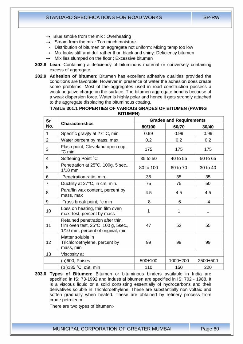
STANDARD SPECIFICATIONS FOR ROAD WORKS SP-RW
MUNICIPAL CORPORATION OF GREATER MUMBAI
Page 60
Blue smoke from the mix : Overheating
Steam from the mix : Too much moisture
Distribution of bitumen on aggregate not uniform: Mixing temp too low
Mix looks stiff and dull rather than black and shiny: Deficiency bitumen
Mix lies slumped on the floor : Excessive bitumen
302.8 Lean: Containing a deficiency of bituminous material or conversely containing excess of aggregate.
302.9 Adhesion of bitumen: Bitumen has excellent adhesive qualities provided the conditions are favorable. However in presence of water the adhesion does create some problems. Most of the aggregates used in road construction possess a weak negative charge on the surface. The bitumen aggregate bond is because of a weak dispersion force. Water is highly polar and hence it gets strongly attached to the aggregate displacing the bituminous coating.
TABLE 301.1 PROPERTIES OF VARIOUS GRADES OF BITUMEN (PAVING BITUMEN)
Sr No.
Characteristics Grades and Requirements
80/100 60/70 30/40
1 Specific gravjty at 27° C, min 0.99 0.99 0.99
2 Water percent by mass, max 0.2 0.2 0.2
3 Flash point, Cleveland open cup, oC min.
175 175 175
4 Softening Point oC 35 to 50 40 to 55 50 to 65
5 Penetration at 25oC, 100g, 5 sec., 1/10 mm
80 to 100 60 to 70 30 to 40
6 Penetration ratio, min. 35 35 35
7 Ductility at 27°C, in cm, min. 75 75 50
8 Paraffin wax content, percent by mass, max
4.5 4.5 4.5
9 Frass break point, °c min -8 -6 -4
10 Loss on heating, thin film oven max, test, percent by mass
1 1 1
11 Retained penetration after thin film oven test, 25°C 100 g, 5sec., 1/10 mm, percent of original, min
47 52 55
12 Matter soluble in Trichloroethylene, percent by mass, min
99 99 99
13 Viscosity at
(a)600, Poises 500±100 1000±200 2500±500
(b )135 oC, cSt, min 110 150 220
303.0 Types of Bitumen: Bitumen or bituminous binders available in India are specified in IS: 73-1992 and industrial bitumen are specified in IS: 702 - 1988. It is a viscous liquid or a solid consisting essentially of hydrocarbons and their derivatives soluble in Trichloroethylene. These are substantially non voltaic and soften gradually when heated. These are obtained by refinery process from crude petroleum.
There are two types of bitumen:-

STANDARD SPECIFICATIONS FOR ROAD WORKS SP-RW
MUNICIPAL CORPORATION OF GREATER MUMBAI
Page 61
i. Paving bitumen from non waxy crude referred as Type S
ii. Paving Bitumen from waxy crude referred as Type A
These are generally referred to based on the penetration characteristic as:
(i) S 35, S 45, S 65, S 90, S 200
(ii) A 35, A 55, A 65, A 90
Paving bitumen is further classified as
(a) Conventional paving binder bitumen
(b) Bitumen emulsions
(c). Cutback bitumen
(d) Modified bitumen
304.0 GRADES OF BITUMEN GENERALLY IN USE ON ROADS
The different grades of paving bitumen are described further:
304.1 Bitumen 80/100 (90): The characteristics of this grade conform to that of S-90 grade of IS: 73-1992.
304.2 Bitumen 60/70 (65): The characteristics of this grade conform to that of S-65 grade of IS: 73-1992. 60170 grade is harder in comparison to 80/100 grade and is used mainly in construction of National Highways & State Highways and in hot climate areas.
304.3 Bitumen 30/40: The characteristics of this grade conform to that of S- 35 grade of IS:73 -1992. Bitumen 30/40 is used in specialized applications like airport runway construction as this grade is harder than 60/70 grade.
305.0 Bitumen Emulsion: Bitumen emulsion is a free flowing liquid at ambient temperatures. Bitumen emulsion is a stable dispersion of fine globules of bitumen in continuous water phase. Dispersion is obtained by processing bitumen and water under controlled conditions through a colloidal mill together with selected additives. The use of proper quality and quantity of emulsifiers is essential to ensure that the emulsion has stability over time and also that it breaks and sets when applied on aggregates/road surface.
305.1 Emulsions: Different Types of Emulsion and their application are given in following Table
Table 301.2 Types of Bitumen Emulsions and their Application
Type Application
Rapid Setting These emulsions are suitable for single coat or two coat surface dressing Tack coat etc
Medium Setting Applicable to premix carpet, patch work and pot hole filling
Slow Setting Suitable for recycling prime coat, slurry sealing, dense and semi-dense cold mixes, mix seal surfacing,
Polymer Modified Bitumen Emulsion Suitable for chip-sealing and micro surfacing
The recommended uses of emulsified bitumen of cationic type suggested are as follows:
RS-1 Tack coat applications
RS-2 Surfacing dressing work
MS Premix carpet, patch work
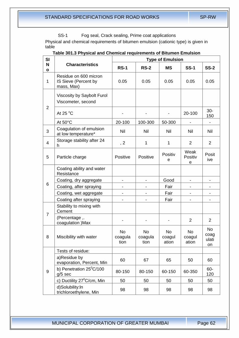
STANDARD SPECIFICATIONS FOR ROAD WORKS SP-RW
MUNICIPAL CORPORATION OF GREATER MUMBAI
Page 62
SS-1 Fog seal, Crack sealing, Prime coat applications
Physical and chemical requirements of bitumen emulsion (cationic type) is given in table
Table 301.3 Physical and Chemical requirements of Bitumen Emulsion
SI No
Characteristics Type of Emulsion
RS-1 RS-2 MS SS-1 SS-2
1 Residue on 600 micron IS Sieve (Percent by mass, Max)
0.05 0.05 0.05 0.05 0.05
2
Viscosity by Saybolt Furol
Viscometer, second
At 25 oC - - - 20-100 30-150
At 50°C 20-100 100-300 50-300 - -
3 Coagulation of emulsion at low temperature*
Nil Nil Nil Nil Nil
4 Storage stability after 24 h
, 2 1 1 2 2
5 Particle charge Positive Positive Positiv
e
Weak Positiv
e
Positive
6
Coating ability and water Resistance
Coating, dry aggregate - - Good - -
Coating, after spraying - - Fair - -
Coating, wet aggregate - - Fair - -
Coating after spraying - - Fair - -
7
Stability to mixing with Cement
(Percentage ,. coagulation )Max
- - - 2 2
8 Miscibility with water No
coagulation
No coagula
tion
No coagulation
No coagulation
No coagulation
9
Tests of residue:
a)Residue by evaporation, Percent, Min
60 67 65 50 60
b) Penetration 250C/100 g/5 sec
80-150 80-150 60-150 60-350 60-120
c) Ductility 270C/cm, Min 50 50 50 50 50
d)Solubility:ln trichloroethylene, Min
98 98 98 98 98
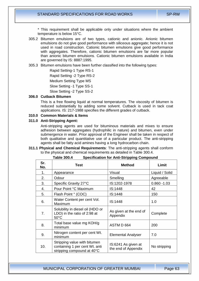
STANDARD SPECIFICATIONS FOR ROAD WORKS SP-RW
MUNICIPAL CORPORATION OF GREATER MUMBAI
Page 63
* This requirement shall be applicable only under situations where the ambient temperature is below 15°C.
305.2 Bitumen emulsions are of two types, cationic and anionic. Anionic bitumen emulsions do not give good performance with siliceous aggregate; hence it is not used in road construction. Cationic bitumen emulsions give good performance with aggregates. Therefore, cationic bitumen emulsions are far more popular than anionic bitumen emulsions. Cationic bitumen emulsions available in India are governed by IS: 8887:1995.
305.3 Bitumen emulsions have been further classified into the following types:
Rapid Setting-1 Type RS-1
Rapid Setting -2 Type RS-2
Medium Setting Type MS
Slow Setting -1 Type SS-1
Slow Setting -2 Type SS-2
306.0 Cutback Bitumen
This is a free flowing liquid at normal temperatures. The viscosity of bitumen is reduced substantially by adding some solvent. Cutback is used in tack coat applications. IS: 217-1988 specifies the different grades of cutback.
310.0 Common Materials & Items
311.0 Anti-Stripping Agent:
Anti-stripping agents are used for bituminous materials and mixes to ensure adhesion between aggregates (hydrophilic in nature) and bitumen, even under submergence in water. Prior approval of the Engineer shall be taken in respect of both qualitative and quantitative use of a particular product. The anti-stripping agents shall be fatty acid amines having a long hydrocarbon chain.
311.1 Physical and Chemical Requirements: The anti-stripping agents shall conform to the physical and chemical requirements as detailed in Table 300.4.
Table 300.4 Specification for Anti-Stripping Compound
Sr. No.
Test Method Limit
1. Appearance Visual Liquid / Solid
2. Odour Smelling Agreeable
3. Specific Gravity 27°C IS:1202-1978 0.860 -1.03
4. Pour Point °C Maximum IS:1448 42
5. Flash Point ° (COC) IS:1448 150
6. Water Content per cent Vol. Maximum
IS:1448 1.0
7. Solubility in diesel oil (HDO or LDO) in the ratio of 2:98 at 50°C
As given at the end of Appendix
Complete
8. Total base value mg KOH/g minimum
ASTM D 664 200
9. Nitrogen content per cent Wt. minimum
Elemental Analyser 7.0
10. Stripping value with bitumen containing 1 per cent Wt. anti stripping compound at 40°C
IS:6241 As given at the end of Appendix
No stripping
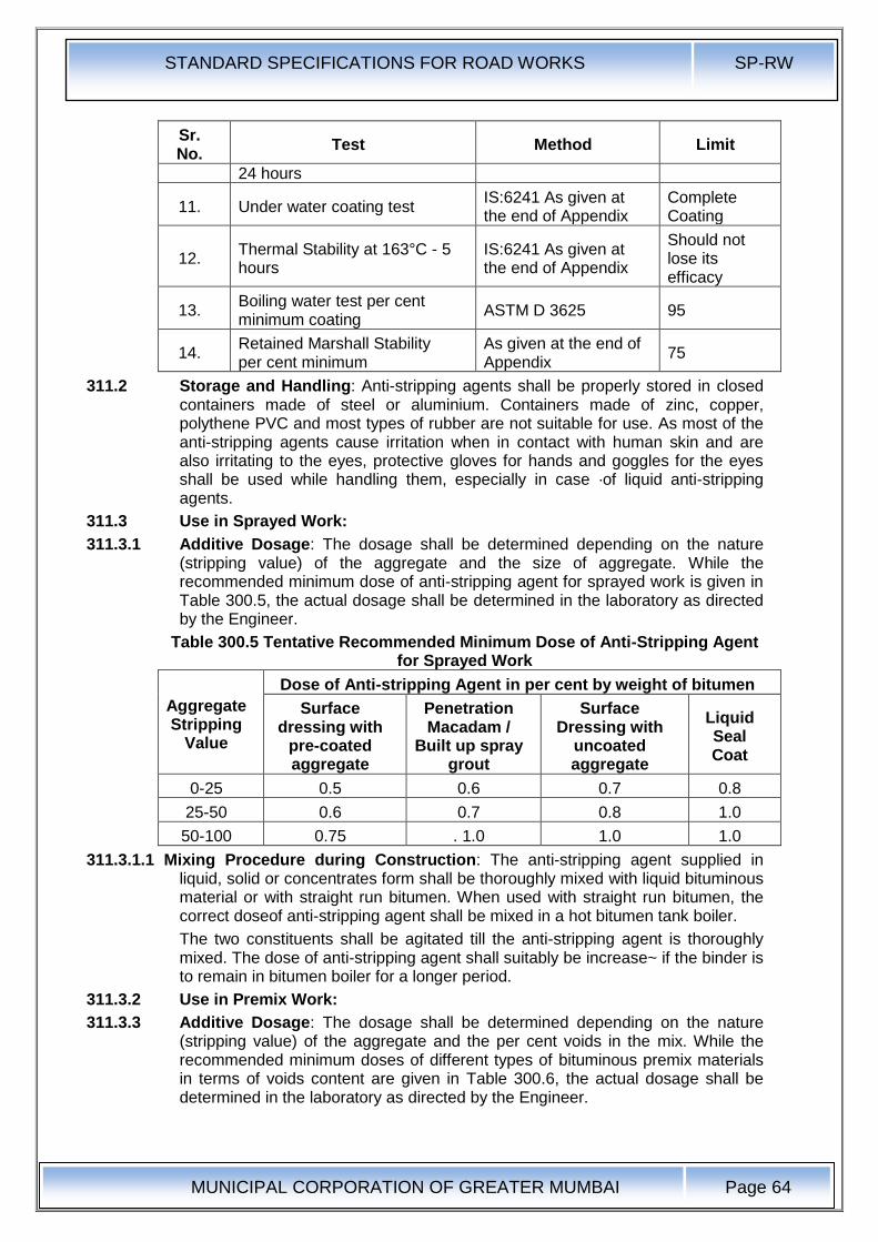
STANDARD SPECIFICATIONS FOR ROAD WORKS SP-RW
MUNICIPAL CORPORATION OF GREATER MUMBAI
Page 64
Sr. No.
Test Method Limit
24 hours
11. Under water coating test IS:6241 As given at the end of Appendix
Complete Coating
12. Thermal Stability at 163°C - 5 hours
IS:6241 As given at the end of Appendix
Should not lose its efficacy
13. Boiling water test per cent minimum coating
ASTM D 3625 95
14. Retained Marshall Stability per cent minimum
As given at the end of Appendix
75
311.2 Storage and Handling: Anti-stripping agents shall be properly stored in closed containers made of steel or aluminium. Containers made of zinc, copper, polythene PVC and most types of rubber are not suitable for use. As most of the anti-stripping agents cause irritation when in contact with human skin and are also irritating to the eyes, protective gloves for hands and goggles for the eyes shall be used while handling them, especially in case ·of liquid anti-stripping agents.
311.3 Use in Sprayed Work:
311.3.1 Additive Dosage: The dosage shall be determined depending on the nature (stripping value) of the aggregate and the size of aggregate. While the recommended minimum dose of anti-stripping agent for sprayed work is given in Table 300.5, the actual dosage shall be determined in the laboratory as directed by the Engineer.
Table 300.5 Tentative Recommended Minimum Dose of Anti-Stripping Agent for Sprayed Work
Aggregate Stripping
Value
Dose of Anti-stripping Agent in per cent by weight of bitumen
Surface dressing with
pre-coated aggregate
Penetration Macadam /
Built up spray grout
Surface Dressing with
uncoated aggregate
Liquid Seal Coat
0-25 0.5 0.6 0.7 0.8
25-50 0.6 0.7 0.8 1.0
50-100 0.75 . 1.0 1.0 1.0
311.3.1.1 Mixing Procedure during Construction: The anti-stripping agent supplied in liquid, solid or concentrates form shall be thoroughly mixed with liquid bituminous material or with straight run bitumen. When used with straight run bitumen, the correct doseof anti-stripping agent shall be mixed in a hot bitumen tank boiler.
The two constituents shall be agitated till the anti-stripping agent is thoroughly mixed. The dose of anti-stripping agent shall suitably be increase~ if the binder is to remain in bitumen boiler for a longer period.
311.3.2 Use in Premix Work:
311.3.3 Additive Dosage: The dosage shall be determined depending on the nature (stripping value) of the aggregate and the per cent voids in the mix. While the recommended minimum doses of different types of bituminous premix materials in terms of voids content are given in Table 300.6, the actual dosage shall be determined in the laboratory as directed by the Engineer.
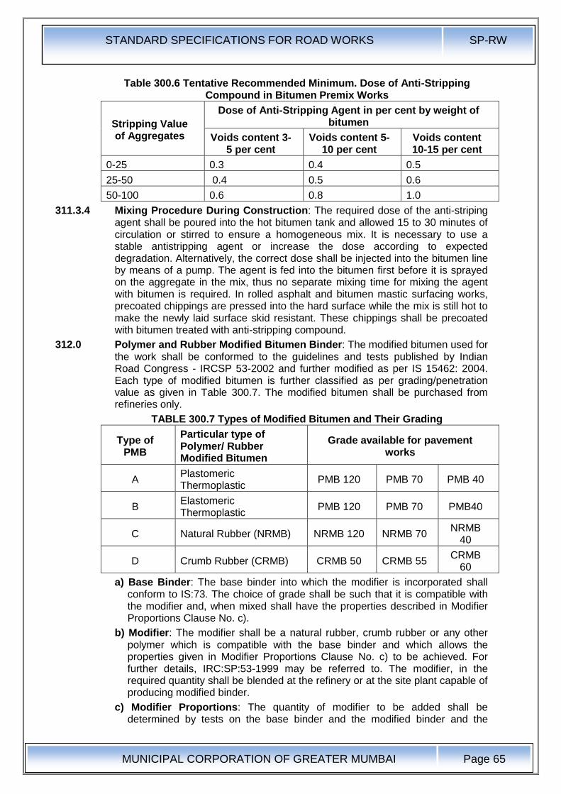
STANDARD SPECIFICATIONS FOR ROAD WORKS SP-RW
MUNICIPAL CORPORATION OF GREATER MUMBAI
Page 65
Table 300.6 Tentative Recommended Minimum. Dose of Anti-Stripping Compound in Bitumen Premix Works
Stripping Value of Aggregates
Dose of Anti-Stripping Agent in per cent by weight of bitumen
Voids content 3-5 per cent
Voids content 5-10 per cent
Voids content 10-15 per cent
0-25 0.3 0.4 0.5
25-50 0.4 0.5 0.6
50-100 0.6 0.8 1.0
311.3.4 Mixing Procedure During Construction: The required dose of the anti-striping agent shall be poured into the hot bitumen tank and allowed 15 to 30 minutes of circulation or stirred to ensure a homogeneous mix. It is necessary to use a stable antistripping agent or increase the dose according to expected degradation. Alternatively, the correct dose shall be injected into the bitumen line by means of a pump. The agent is fed into the bitumen first before it is sprayed on the aggregate in the mix, thus no separate mixing time for mixing the agent with bitumen is required. In rolled asphalt and bitumen mastic surfacing works, precoated chippings are pressed into the hard surface while the mix is still hot to make the newly laid surface skid resistant. These chippings shall be precoated with bitumen treated with anti-stripping compound.
312.0 Polymer and Rubber Modified Bitumen Binder: The modified bitumen used for the work shall be conformed to the guidelines and tests published by Indian Road Congress - IRCSP 53-2002 and further modified as per IS 15462: 2004. Each type of modified bitumen is further classified as per grading/penetration value as given in Table 300.7. The modified bitumen shall be purchased from refineries only.
TABLE 300.7 Types of Modified Bitumen and Their Grading
Type of PMB
Particular type of Polymer/ Rubber Modified Bitumen
Grade available for pavement works
A Plastomeric Thermoplastic
PMB 120 PMB 70 PMB 40
B Elastomeric Thermoplastic
PMB 120 PMB 70 PMB40
C Natural Rubber (NRMB) NRMB 120 NRMB 70 NRMB
40
D Crumb Rubber (CRMB) CRMB 50 CRMB 55 CRMB
60
a) Base Binder: The base binder into which the modifier is incorporated shall conform to IS:73. The choice of grade shall be such that it is compatible with the modifier and, when mixed shall have the properties described in Modifier Proportions Clause No. c).
b) Modifier: The modifier shall be a natural rubber, crumb rubber or any other polymer which is compatible with the base binder and which allows the properties given in Modifier Proportions Clause No. c) to be achieved. For further details, IRC:SP:53-1999 may be referred to. The modifier, in the required quantity shall be blended at the refinery or at the site plant capable of producing modified binder.
c) Modifier Proportions: The quantity of modifier to be added shall be determined by tests on the base binder and the modified binder and the
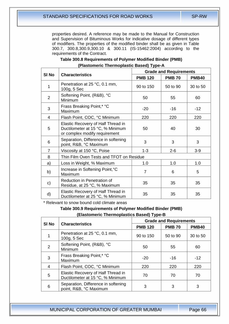
STANDARD SPECIFICATIONS FOR ROAD WORKS SP-RW
MUNICIPAL CORPORATION OF GREATER MUMBAI
Page 66
properties desired. A reference may be made to the Manual for Construction and Supervision of Bituminous Works for indicative dosage of different types of modifiers. The properties of the modified binder shall be as given in Table 300.7, 300.8,300.9,300.10 & 300.11 (IS-15462:2004) according to the requirements of the Contract.
Table 300.8 Requirements of Polymer Modified Binder (PMB)
(Plastomeric Thermoplastic Based) Type-A
Sl No Characteristics Grade and Requirements
PMB 120 PMB 70 PMB40
1 Penetration at 25 °C, 0.1 mm, 100g, 5 Sec
90 to 150 50 to 90 30 to 50
2 Softening Point, (R&B), °C Minimum
50 55 60
3 Frass Breaking Point,* °C Maximum
-20 -16 -12
4 Flash Point, COC, °C Minimum 220 220 220
5 Elastic Recovery of Half Thread in Ductilometer at 15 °C, % Minimum or complex modify requirement
50 40 30
6 Separation, Difference in softening point, R&B, °C Maximum
3 3 3
7 Viscosity at 150 °C, Poise 1-3 2-6 3-9
8 Thin Film Oven Tests and TFOT on Residue
a) Loss in Weight, % Maximum 1.0 1.0 1.0
b) Increase in Softening Point,°C Maximum
7 6 5
c) Reduction in Penetration of Residue, at 25 °C, % Maximum
35 35 35
d) Elastic Recovery of Half Thread in Ductilometer at 25 °C, % Minimum
35 35 35
* Relevant to snow bound cold climate areas
Table 300.9 Requirements of Polymer Modified Binder (PMB)
(Elastomeric Thermoplastics Based) Type-B
Sl No Characteristics Grade and Requirements
PMB 120 PMB 70 PMB40
1 Penetration at 25 °C, 0.1 mm, 100g, 5 Sec
90 to 150 50 to 90 30 to 50
2 Softening Point, (R&B), °C Minimum
50 55 60
3 Frass Breaking Point,* °C Maximum
-20 -16 -12
4 Flash Point, COC, °C Minimum 220 220 220
5 Elastic Recovery of Half Thread in Ductilometer at 15 °C, % Minimum
70 70 70
6 Separation, Difference in softening point, R&B, °C Maximum
3 3 3

STANDARD SPECIFICATIONS FOR ROAD WORKS SP-RW
MUNICIPAL CORPORATION OF GREATER MUMBAI
Page 67
Sl No Characteristics Grade and Requirements
PMB 120 PMB 70 PMB40
7 Viscosity at 150 °C, Poise 1-3 2-6 3-9
8 Thin Film Oven Tests and TFOT on Residue
a) Loss in Weight, % Maximum 1.0 1.0 1.0
b) Increase in Softening Point,°C Maximum
7 6 5
c) Reduction in Penetration of Residue, at 25 °C, % Maximum
35 35 35
d) Elastic Recovery of Half Thread in Ductilometer at 25 °C, % Minimum
50 50 50
* Relevant to snow bound cold climate area
Table 300.10 Requirements of Natural Rubber Binder (NRMB)
(Natural Rubber Based) Type-C
Sl No Characteristics Grade and Requirements
NRMB 120 NRMB 70 NRMB 40
1 Penetration at 25 °C, 0.1 mm, 100g, 5 Sec
90 to 150 50 to 90 30 to 50
2 Softening Point, (R&B), °C Minimum
45 50 55
3 Frass Breaking Point,* °C Maximum
-20 -16 -12
4 Flash Point, COC, °C Minimum 220 220 220
5 Elastic Recovery of Half Thread in Ductilometer at 15 °C, % Minimum
50 40 30
6 Separation, Difference in softening point, R&B, °C Maximum
4 4 4
7 Viscosity at 150 °C, Poise 1-3 2-6 3-9
8 Thin Film Oven Tests and TFOT on Residue
a) Loss in Weight, % Maximum 1.0 1.0 1.0
b) Increase in Softening Point,°C Maximum
7 6 5
c) Reduction in Penetration of Residue, at 25 °C, % Maximum
40 40 40
d) Elastic Recovery of Half Thread in Ductilometer at 25 °C, % Minimum
35 25 20
* Relevant to Snow Bound Cold Climate Areas
Table 300.11 Requirements of Crumb Rubber Modified Binder
(Crumb and Modified Crumb Rubber Based) Type-D
Sl No Characteristics Grade and Requirements
CRMB 50 CRMB 55 CRMB 60
1 Penetration at 25 °C, 0.1 mm, 100g, 5 Sec
<70 <60 <50
2 Softening Point, (R&B), °C 50 55 60

STANDARD SPECIFICATIONS FOR ROAD WORKS SP-RW
MUNICIPAL CORPORATION OF GREATER MUMBAI
Page 68
Sl No Characteristics Grade and Requirements
CRMB 50 CRMB 55 CRMB 60
Minimum
3 Flash Point, COC, °C Minimum 220 220 220
4 Elastic Recovery of Half Thread in Ductilometer at 15 °C, % Minimum
50 50 50
5 Separation, Difference in softening point, R&B, °C Maximum
4 4 4
6 Viscosity at 150 °C, Poise 1-3 2-6 3-9
7 Thin Film Oven Tests and TFOT on Residue
a) Loss in mass, % Maximum 1.0 1.0 1.0
b) Increase in Softening Point,°C Maximum
7 6 5
c) Reduction in Penetration of Residue, at 25 °C, % Maximum
40 40 40
d) Elastic Recovery of Half Thread in Ductilometer at 25 °C, % Minimum
35 35 35
d) Mixing: The modifier shall be blended with the base binder so that it disperses thoroughly prior to use. The type of mixing equipment used shall be suited to the modified type. Further guidance is given in the Manual for Construction and Supervision of Bituminous Works.
312.1 Quality Control of Materials:
(1) Binder Properties: For control of the quality of the base binder, the relevant provisions of Section 600 shall apply. Additionally, the modified binder shall be tested for all the properties listed in Table 300.7, 300.8, 300.9, 300.10 & 300.11 as appropriate and certificates produced prior to use.
During use, the requirements for softening point, penetration and elastic recovery shall be tested regularly. If the modified binder is produced on site then tests shall be carried out daily. If pre-blended modified binder is used test shall be carried out weekly.
(2) Storage Stability: Pre-blended modified binders which are to be stored without circulation or agitation facility shall be tested for storage stability prior to use, in accordance with Appendix-I of IRC:SP:53-1999. The mean of the differences in softening point, top to bottom, of not less than three pairs of samples shall not exceed 5° C.
Other pre-blended modified binders shall be stored with appropriate circulation or agitation facility, according to the manufacturer's instructions.
312.2 Measurement for Payment: Modified binder supplied for the Contract shall be paid for in Tonnes.
312.3 Rate: The contract rate for modified binder shall be as per contract agreement.
313.0 Prime Coat
313.1 Prime coat: This work shall consist of the application of a single coat of low viscosity liquid bituminous material to a porous granular surface preparatory to the superimposition of bituminous treatment or mix.
Priming is spraying of low viscosity liquid bituminous materials on the surface of non-bituminous granular base course preparatory to the superimposition of bituminous treatment. The objectives of priming a granular surface are as under:
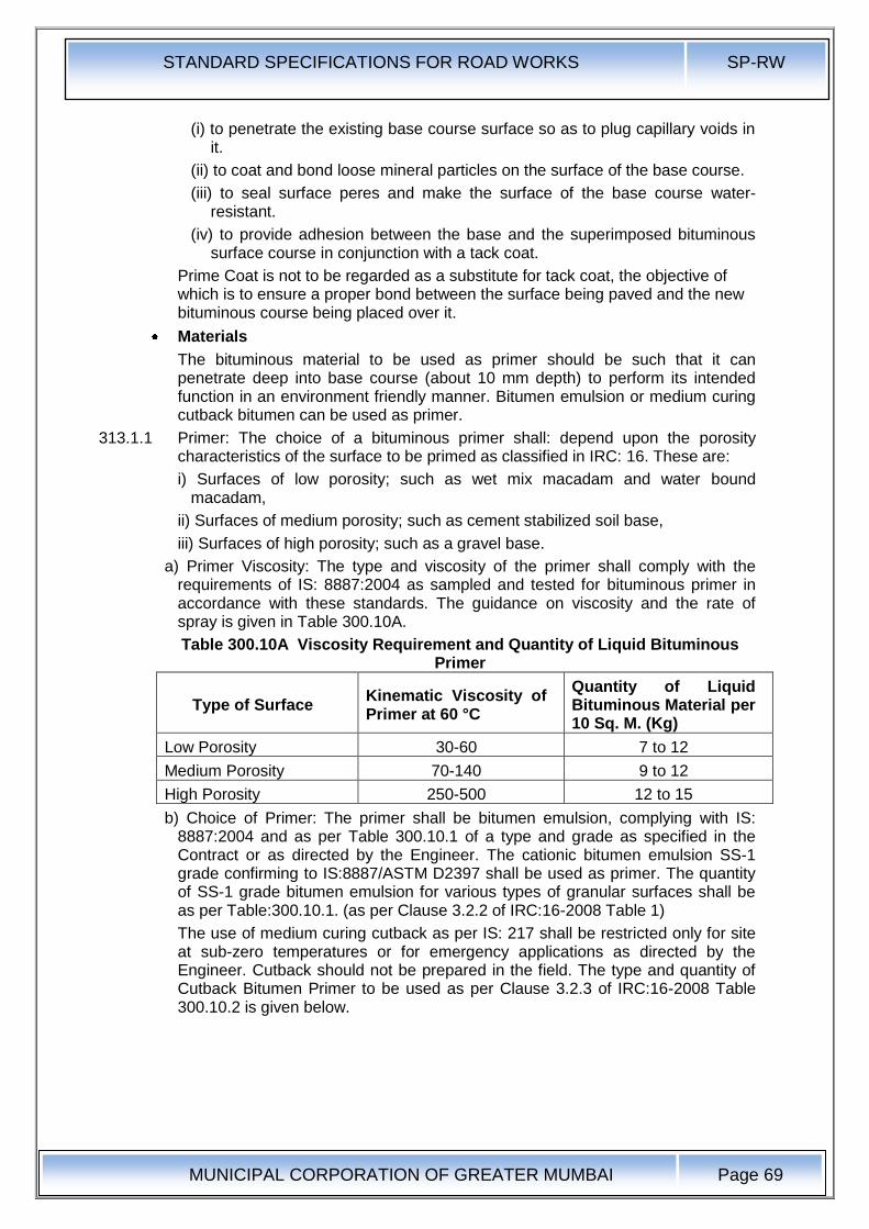
STANDARD SPECIFICATIONS FOR ROAD WORKS SP-RW
MUNICIPAL CORPORATION OF GREATER MUMBAI
Page 69
(i) to penetrate the existing base course surface so as to plug capillary voids in it.
(ii) to coat and bond loose mineral particles on the surface of the base course.
(iii) to seal surface peres and make the surface of the base course water-resistant.
(iv) to provide adhesion between the base and the superimposed bituminous surface course in conjunction with a tack coat.
Prime Coat is not to be regarded as a substitute for tack coat, the objective of which is to ensure a proper bond between the surface being paved and the new bituminous course being placed over it.
Materials
The bituminous material to be used as primer should be such that it can penetrate deep into base course (about 10 mm depth) to perform its intended function in an environment friendly manner. Bitumen emulsion or medium curing cutback bitumen can be used as primer.
313.1.1 Primer: The choice of a bituminous primer shall: depend upon the porosity characteristics of the surface to be primed as classified in IRC: 16. These are:
i) Surfaces of low porosity; such as wet mix macadam and water bound macadam,
ii) Surfaces of medium porosity; such as cement stabilized soil base,
iii) Surfaces of high porosity; such as a gravel base.
a) Primer Viscosity: The type and viscosity of the primer shall comply with the requirements of IS: 8887:2004 as sampled and tested for bituminous primer in accordance with these standards. The guidance on viscosity and the rate of spray is given in Table 300.10A.
Table 300.10A Viscosity Requirement and Quantity of Liquid Bituminous Primer
Type of Surface Kinematic Viscosity of Primer at 60 °C
Quantity of Liquid Bituminous Material per 10 Sq. M. (Kg)
Low Porosity 30-60 7 to 12
Medium Porosity 70-140 9 to 12
High Porosity 250-500 12 to 15
b) Choice of Primer: The primer shall be bitumen emulsion, complying with IS: 8887:2004 and as per Table 300.10.1 of a type and grade as specified in the Contract or as directed by the Engineer. The cationic bitumen emulsion SS-1 grade confirming to IS:8887/ASTM D2397 shall be used as primer. The quantity of SS-1 grade bitumen emulsion for various types of granular surfaces shall be as per Table:300.10.1. (as per Clause 3.2.2 of IRC:16-2008 Table 1)
The use of medium curing cutback as per IS: 217 shall be restricted only for site at sub-zero temperatures or for emergency applications as directed by the Engineer. Cutback should not be prepared in the field. The type and quantity of Cutback Bitumen Primer to be used as per Clause 3.2.3 of IRC:16-2008 Table 300.10.2 is given below.
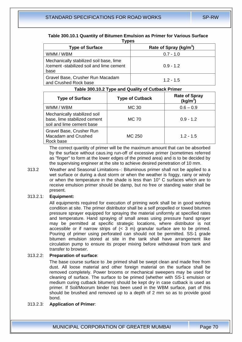
STANDARD SPECIFICATIONS FOR ROAD WORKS SP-RW
MUNICIPAL CORPORATION OF GREATER MUMBAI
Page 70
Table 300.10.1 Quantity of Bitumen Emulsion as Primer for Various Surface Types
Type of Surface Rate of Spray (kg/m3)
WMM / WBM 0.7 - 1.0
Mechanically stabilized soil base, lime /cement -stabilized soil and lime cement base
0.9 - 1.2
Gravel Base, Crusher Run Macadam and Crushed Rock base
1.2 - 1.5
Table 300.10.2 Type and Quality of Cutback Primer
Type of Surface Type of Cutback Rate of Spray
(kg/m3)
WMM / WBM MC 30 0.6 – 0.9
Mechanically stabilized soil base, lime stabilized cement soil and lime cement base
MC 70 0.9 - 1.2
Gravel Base, Crusher Run Macadam and Crushed Rock base
MC 250 1.2 - 1.5
The correct quantity of primer will be the maximum amount that can be absorbed by the surface without caus.ing run-off of excessive primer (sometimes referred as "finger" to form at the lower edges of the primed area) and is to be decided by the supervising engineer at the site to achieve desired penetration of 10 mm.
313.2 Weather and Seasonal Limitations··: Bituminous primer shall not be applied to a wet surface or during a dust storm or when the weather is foggy, rainy or windy or when the temperature in the shade is less than 10° C surfaces which are to receive emulsion primer should be damp, but no free or standing water shall be present.
313.2.1: Equipment:
All equipments required for execution of priming work shall be in good working condition at site. The primer distributor shall be a self propelled or towed bitumen pressure sprayer equipped for spraying the material uniformly at specified rates and temperature. Hand spraying of small areas using pressure hand sprayer may be permitted at specific strategic locations, where distributor is not accessible or if narrow strips of (< 3 m) granular surface are to be primed. Pouring of primer using perforated can should not be permitted. SS-1 grade bitumen emulsion stored at site in the tank shall have arrangement like circulation pump to ensure its proper mixing before withdrawal from tank and transfer to browser.
313.2.2: Preparation of surface:
The base course surface to .be primed shall be swept clean and made free from dust. All loose material and other foreign material on the surface shall be removed completely. Power brooms or mechanical sweepers may be used for cleaning of surface. The surface to be primed (whether with SS-1 emulsion or medium curing cutback bitumen) should be kept dry in case cutback is used as primer. If Soil/Moorum binder has been used in the WBM surface, part of this should be brushed and removed up to a depth of 2 mm so as to provide good bond.
313.2.3: Application of Primer:
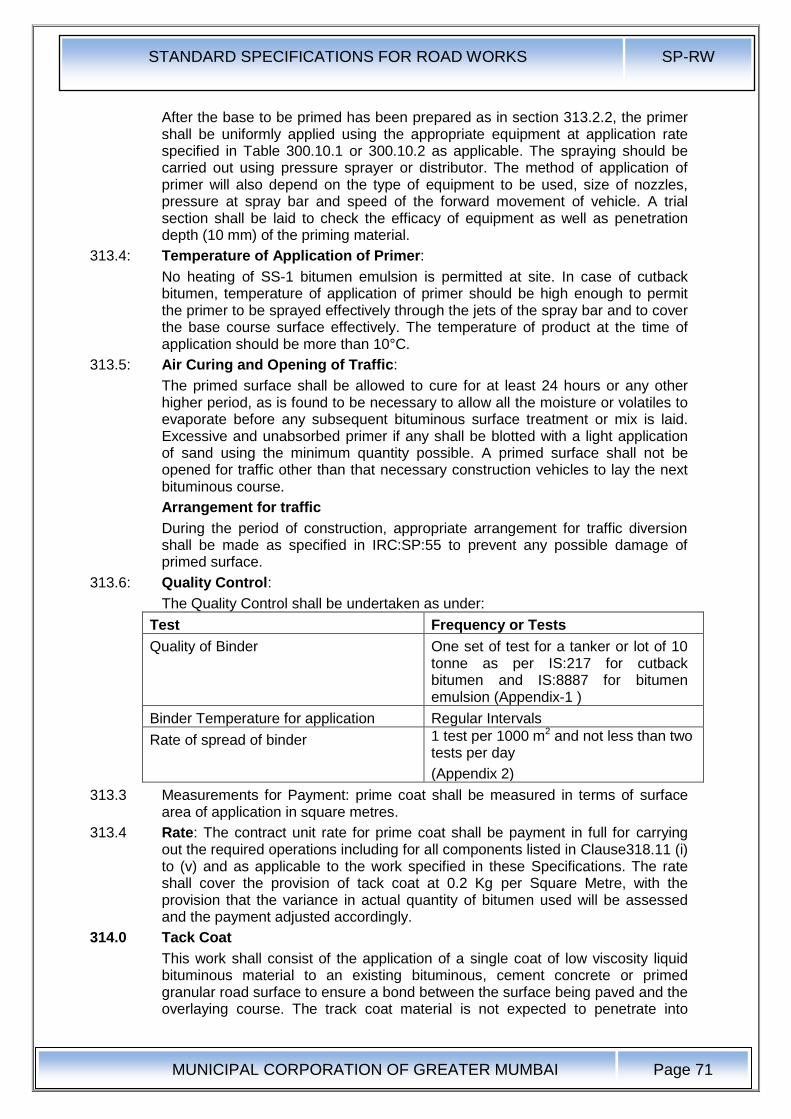
STANDARD SPECIFICATIONS FOR ROAD WORKS SP-RW
MUNICIPAL CORPORATION OF GREATER MUMBAI
Page 71
After the base to be primed has been prepared as in section 313.2.2, the primer shall be uniformly applied using the appropriate equipment at application rate specified in Table 300.10.1 or 300.10.2 as applicable. The spraying should be carried out using pressure sprayer or distributor. The method of application of primer will also depend on the type of equipment to be used, size of nozzles, pressure at spray bar and speed of the forward movement of vehicle. A trial section shall be laid to check the efficacy of equipment as well as penetration depth (10 mm) of the priming material.
313.4: Temperature of Application of Primer:
No heating of SS-1 bitumen emulsion is permitted at site. In case of cutback bitumen, temperature of application of primer should be high enough to permit the primer to be sprayed effectively through the jets of the spray bar and to cover the base course surface effectively. The temperature of product at the time of application should be more than 10°C.
313.5: Air Curing and Opening of Traffic:
The primed surface shall be allowed to cure for at least 24 hours or any other higher period, as is found to be necessary to allow all the moisture or volatiles to evaporate before any subsequent bituminous surface treatment or mix is laid. Excessive and unabsorbed primer if any shall be blotted with a light application of sand using the minimum quantity possible. A primed surface shall not be opened for traffic other than that necessary construction vehicles to lay the next bituminous course.
Arrangement for traffic
During the period of construction, appropriate arrangement for traffic diversion shall be made as specified in IRC:SP:55 to prevent any possible damage of primed surface.
313.6: Quality Control:
The Quality Control shall be undertaken as under:
Test Frequency or Tests
Quality of Binder One set of test for a tanker or lot of 10 tonne as per IS:217 for cutback bitumen and IS:8887 for bitumen emulsion (Appendix-1 )
Binder Temperature for application Regular Intervals
Rate of spread of binder 1 test per 1000 m2 and not less than two tests per day
(Appendix 2)
313.3 Measurements for Payment: prime coat shall be measured in terms of surface area of application in square metres.
313.4 Rate: The contract unit rate for prime coat shall be payment in full for carrying out the required operations including for all components listed in Clause318.11 (i) to (v) and as applicable to the work specified in these Specifications. The rate shall cover the provision of tack coat at 0.2 Kg per Square Metre, with the provision that the variance in actual quantity of bitumen used will be assessed and the payment adjusted accordingly.
314.0 Tack Coat
This work shall consist of the application of a single coat of low viscosity liquid bituminous material to an existing bituminous, cement concrete or primed granular road surface to ensure a bond between the surface being paved and the overlaying course. The track coat material is not expected to penetrate into
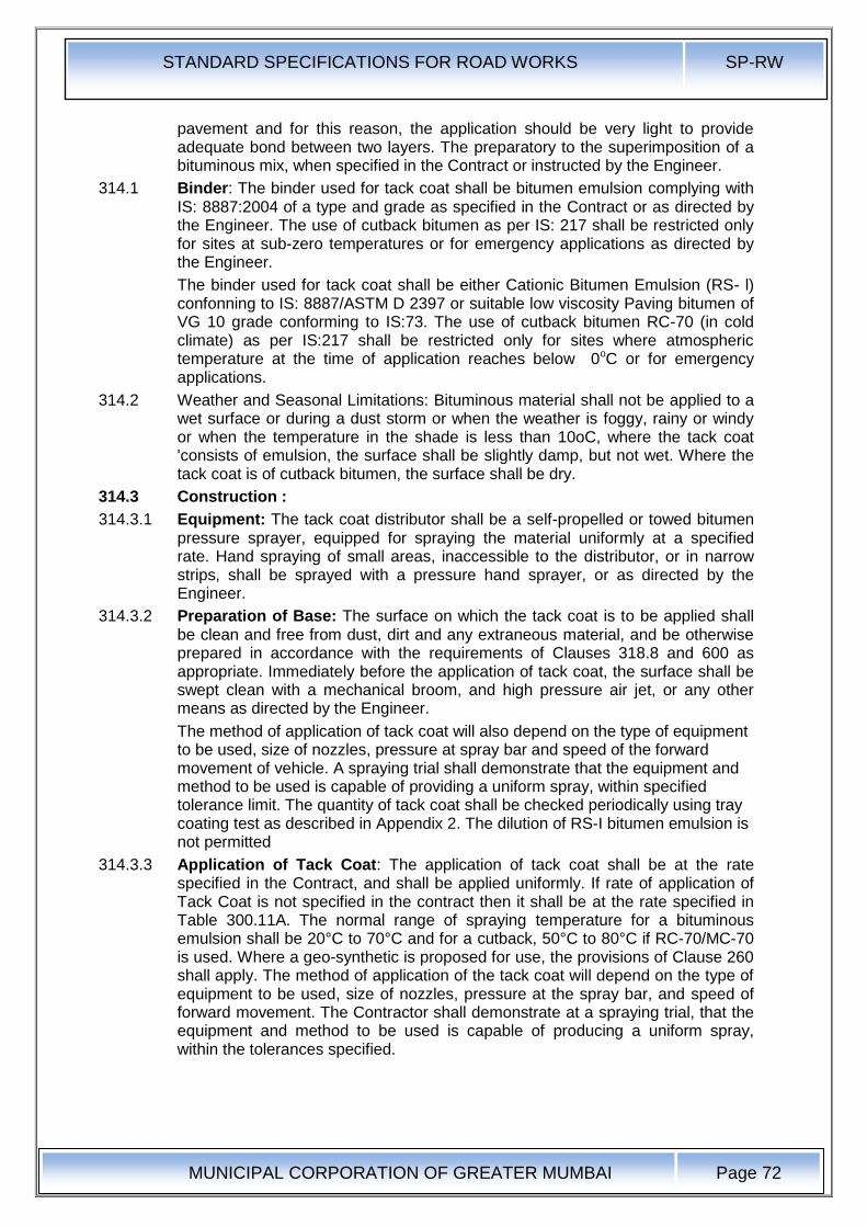
STANDARD SPECIFICATIONS FOR ROAD WORKS SP-RW
MUNICIPAL CORPORATION OF GREATER MUMBAI
Page 72
pavement and for this reason, the application should be very light to provide adequate bond between two layers. The preparatory to the superimposition of a bituminous mix, when specified in the Contract or instructed by the Engineer.
314.1 Binder: The binder used for tack coat shall be bitumen emulsion complying with IS: 8887:2004 of a type and grade as specified in the Contract or as directed by the Engineer. The use of cutback bitumen as per IS: 217 shall be restricted only for sites at sub-zero temperatures or for emergency applications as directed by the Engineer.
The binder used for tack coat shall be either Cationic Bitumen Emulsion (RS- l) confonning to IS: 8887/ASTM D 2397 or suitable low viscosity Paving bitumen of VG 10 grade conforming to IS:73. The use of cutback bitumen RC-70 (in cold climate) as per IS:217 shall be restricted only for sites where atmospheric temperature at the time of application reaches below 0oC or for emergency applications.
314.2 Weather and Seasonal Limitations: Bituminous material shall not be applied to a wet surface or during a dust storm or when the weather is foggy, rainy or windy or when the temperature in the shade is less than 10oC, where the tack coat 'consists of emulsion, the surface shall be slightly damp, but not wet. Where the tack coat is of cutback bitumen, the surface shall be dry.
314.3 Construction :
314.3.1 Equipment: The tack coat distributor shall be a self-propelled or towed bitumen pressure sprayer, equipped for spraying the material uniformly at a specified rate. Hand spraying of small areas, inaccessible to the distributor, or in narrow strips, shall be sprayed with a pressure hand sprayer, or as directed by the Engineer.
314.3.2 Preparation of Base: The surface on which the tack coat is to be applied shall be clean and free from dust, dirt and any extraneous material, and be otherwise prepared in accordance with the requirements of Clauses 318.8 and 600 as appropriate. Immediately before the application of tack coat, the surface shall be swept clean with a mechanical broom, and high pressure air jet, or any other means as directed by the Engineer.
The method of application of tack coat will also depend on the type of equipment to be used, size of nozzles, pressure at spray bar and speed of the forward movement of vehicle. A spraying trial shall demonstrate that the equipment and method to be used is capable of providing a uniform spray, within specified tolerance limit. The quantity of tack coat shall be checked periodically using tray coating test as described in Appendix 2. The dilution of RS-I bitumen emulsion is not permitted
314.3.3 Application of Tack Coat: The application of tack coat shall be at the rate specified in the Contract, and shall be applied uniformly. If rate of application of Tack Coat is not specified in the contract then it shall be at the rate specified in Table 300.11A. The normal range of spraying temperature for a bituminous emulsion shall be 20°C to 70°C and for a cutback, 50°C to 80°C if RC-70/MC-70 is used. Where a geo-synthetic is proposed for use, the provisions of Clause 260 shall apply. The method of application of the tack coat will depend on the type of equipment to be used, size of nozzles, pressure at the spray bar, and speed of forward movement. The Contractor shall demonstrate at a spraying trial, that the equipment and method to be used is capable of producing a uniform spray, within the tolerances specified.
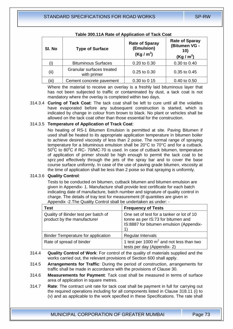
STANDARD SPECIFICATIONS FOR ROAD WORKS SP-RW
MUNICIPAL CORPORATION OF GREATER MUMBAI
Page 73
Table 300.11A Rate of Application of Tack Coat
Sl. No Type of Surface
Rate of Sparay (Emulsion)
(Kg / m2)
Rate of Sparay (Bitumen VG -
10)
(Kg / m2)
(i) Bituminous Surfaces 0.20 to 0.30 0.30 to 0.40
(ii) Granular surfaces treated
with primer 0.25 to 0.30 0.35 to 0.45
(iii) Cement concrete pavement 0.30 to 0 15 0.40 to 0.50
Where the material to receive an overlay is a freshly laid bituminous layer that has not been subjected to traffic or contaminated by dust, a tack coat is not mandatory where the overlay is completed within two days.
314.3.4 Curing of Tack Coat: The tack coat shall be left to cure until all the volatiles have evaporated before any subsequent construction is started, which is indicated by change in colour from brown to black. No plant or vehicles shall be allowed on the tack coat other than those essential for the construction.
314.3.5 Temperature of Application of Track Coat:
No heating of RS-1 Bitumen Emulsion is permitted at site. Paving Bitumen if used shall be heated to its appropriate application temperature in bitumen boiler to achieve desired viscosity of less than 2 poise. The normal range of spraying temperature for a bituminous emulsion shall be 20°C to 70°C and for a cutback. 500C to 800C if RC- 70/MC·70 is used. In case of cutback bitumen, temperature of application of primer should be high enough to permit the tack coat to be sprz.yed effectively through the jets of the spray bar and to cover the base course surface uniformly. In case of the use of paving grade bitumen, viscosity at the time of application shall be less than 2 poise so that spraying is uniformly.
314.3.6 Quality Control:
Tests to be conducted on bitumen, cutback bitumen and bitumen emulsion are given in Appendix- 1. Manufacture shall provide test certificate for each batch indicating date of manufacture, batch number and signature of quality control in charge. The details of tray test for measurement (If quantities are given in Appendix -2.The Quality Control sball be undertaken as under: -
Test Frequency of Tests
Quality of Binder test per batch of product by the manufacturer
One set of test for a tanker or lot of 10 tonne as per IS:73 for bitumen and IS:8887 for bitumen emulsion (Appendix- 1)
Binder Temperature for application Regular Intervals
Rate of spread of binder 1 test per 1000 m2 and not less than two tests per day (Appendix- 2)
314.4 Quality Control of Work: For control of the quality of materials supplied and the works carried out, the relevant provisions of Section 600 shall apply.
314.5 Arrangements for Traffic: During the period of construction, arrangements for traffic shall be made in accordance with the provisions of Clause 30.
314.6 Measurements for Payment: Tack coat shall be measured in terms of surface area of application in square metres.
314.7 Rate: The contract unit rate for tack coat shall be payment in full for carrying out the required operations including for all components listed in Clause 318.11 (i) to (v) and as applicable to the work specified in these Specifications. The rate shall
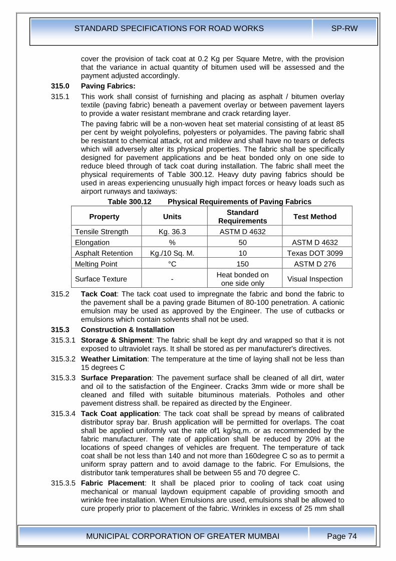
STANDARD SPECIFICATIONS FOR ROAD WORKS SP-RW
MUNICIPAL CORPORATION OF GREATER MUMBAI
Page 74
cover the provision of tack coat at 0.2 Kg per Square Metre, with the provision that the variance in actual quantity of bitumen used will be assessed and the payment adjusted accordingly.
315.0 Paving Fabrics:
315.1 This work shall consist of furnishing and placing as asphalt / bitumen overlay textile (paving fabric) beneath a pavement overlay or between pavement layers to provide a water resistant membrane and crack retarding layer.
The paving fabric will be a non-woven heat set material consisting of at least 85 per cent by weight polyolefins, polyesters or polyamides. The paving fabric shall be resistant to chemical attack, rot and mildew and shall have no tears or defects which will adversely alter its physical properties. The fabric shall be specifically designed for pavement applications and be heat bonded only on one side to reduce bleed through of tack coat during installation. The fabric shall meet the physical requirements of Table 300.12. Heavy duty paving fabrics should be used in areas experiencing unusually high impact forces or heavy loads such as airport runways and taxiways:
Table 300.12 Physical Requirements of Paving Fabrics
Property Units Standard
Requirements Test Method
Tensile Strength Kg. 36.3 ASTM D 4632
Elongation % 50 ASTM D 4632
Asphalt Retention Kg./10 Sq. M. 10 Texas DOT 3099
Melting Point °C 150 ASTM D 276
Surface Texture - Heat bonded on
one side only Visual Inspection
315.2 Tack Coat: The tack coat used to impregnate the fabric and bond the fabric to the pavement shall be a paving grade Bitumen of 80-100 penetration. A cationic emulsion may be used as approved by the Engineer. The use of cutbacks or emulsions which contain solvents shall not be used.
315.3 Construction & Installation
315.3.1 Storage & Shipment: The fabric shall be kept dry and wrapped so that it is not exposed to ultraviolet rays. It shall be stored as per manufacturer's directives.
315.3.2 Weather Limitation: The temperature at the time of laying shall not be less than 15 degrees C
315.3.3 Surface Preparation: The pavement surface shall be cleaned of all dirt, water and oil to the satisfaction of the Engineer. Cracks 3mm wide or more shall be cleaned and filled with suitable bituminous materials. Potholes and other pavement distress shall. be repaired as directed by the Engineer.
315.3.4 Tack Coat application: The tack coat shall be spread by means of calibrated distributor spray bar. Brush application will be permitted for overlaps. The coat shall be applied uniformly vat the rate of1 kg/sq,m. or as recommended by the fabric manufacturer. The rate of application shall be reduced by 20% at the locations of speed changes of vehicles are frequent. The temperature of tack coat shall be not less than 140 and not more than 160degree C so as to permit a uniform spray pattern and to avoid damage to the fabric. For Emulsions, the distributor tank temperatures shall be between 55 and 70 degree C.
315.3.5 Fabric Placement: It shall be placed prior to cooling of tack coat using mechanical or manual laydown equipment capable of providing smooth and wrinkle free installation. When Emulsions are used, emulsions shall be allowed to cure properly prior to placement of the fabric. Wrinkles in excess of 25 mm shall
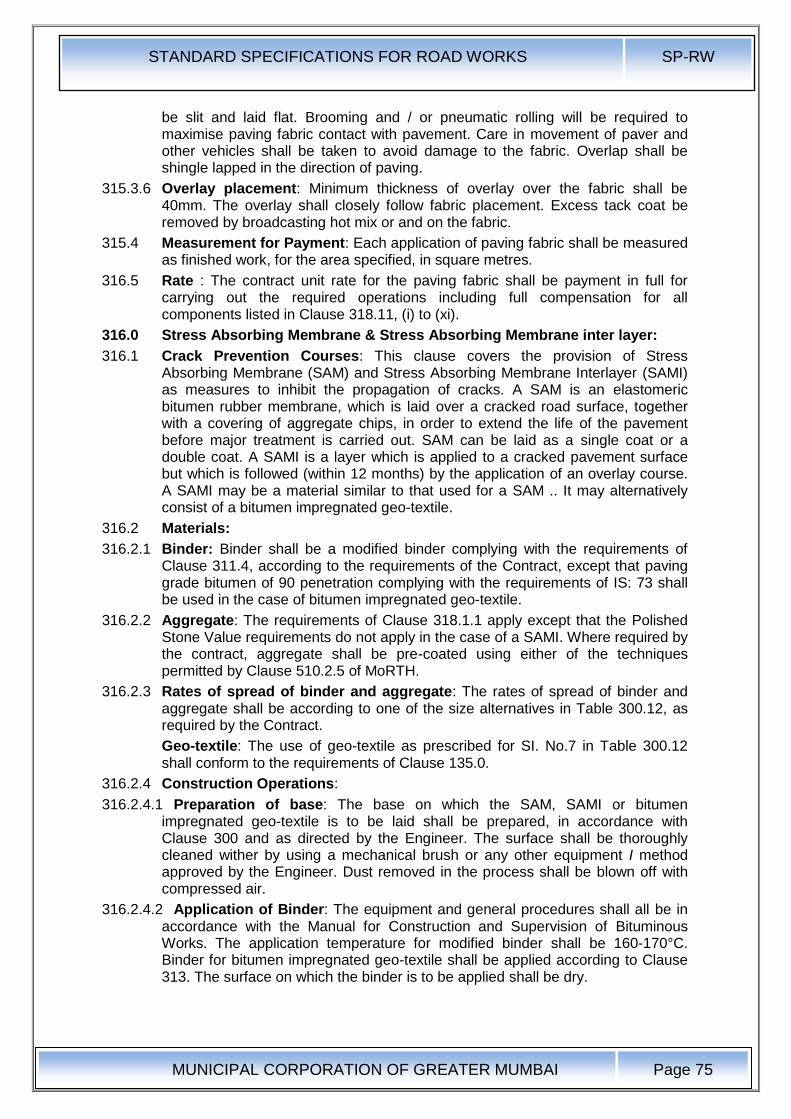
STANDARD SPECIFICATIONS FOR ROAD WORKS SP-RW
MUNICIPAL CORPORATION OF GREATER MUMBAI
Page 75
be slit and laid flat. Brooming and / or pneumatic rolling will be required to maximise paving fabric contact with pavement. Care in movement of paver and other vehicles shall be taken to avoid damage to the fabric. Overlap shall be shingle lapped in the direction of paving.
315.3.6 Overlay placement: Minimum thickness of overlay over the fabric shall be 40mm. The overlay shall closely follow fabric placement. Excess tack coat be removed by broadcasting hot mix or and on the fabric.
315.4 Measurement for Payment: Each application of paving fabric shall be measured as finished work, for the area specified, in square metres.
316.5 Rate : The contract unit rate for the paving fabric shall be payment in full for carrying out the required operations including full compensation for all components listed in Clause 318.11, (i) to (xi).
316.0 Stress Absorbing Membrane & Stress Absorbing Membrane inter layer:
316.1 Crack Prevention Courses: This clause covers the provision of Stress Absorbing Membrane (SAM) and Stress Absorbing Membrane Interlayer (SAMI) as measures to inhibit the propagation of cracks. A SAM is an elastomeric bitumen rubber membrane, which is laid over a cracked road surface, together with a covering of aggregate chips, in order to extend the life of the pavement before major treatment is carried out. SAM can be laid as a single coat or a double coat. A SAMI is a layer which is applied to a cracked pavement surface but which is followed (within 12 months) by the application of an overlay course. A SAMI may be a material similar to that used for a SAM .. It may alternatively consist of a bitumen impregnated geo-textile.
316.2 Materials:
316.2.1 Binder: Binder shall be a modified binder complying with the requirements of Clause 311.4, according to the requirements of the Contract, except that paving grade bitumen of 90 penetration complying with the requirements of IS: 73 shall be used in the case of bitumen impregnated geo-textile.
316.2.2 Aggregate: The requirements of Clause 318.1.1 apply except that the Polished Stone Value requirements do not apply in the case of a SAMI. Where required by the contract, aggregate shall be pre-coated using either of the techniques permitted by Clause 510.2.5 of MoRTH.
316.2.3 Rates of spread of binder and aggregate: The rates of spread of binder and aggregate shall be according to one of the size alternatives in Table 300.12, as required by the Contract.
Geo-textile: The use of geo-textile as prescribed for SI. No.7 in Table 300.12 shall conform to the requirements of Clause 135.0.
316.2.4 Construction Operations:
316.2.4.1 Preparation of base: The base on which the SAM, SAMI or bitumen impregnated geo-textile is to be laid shall be prepared, in accordance with Clause 300 and as directed by the Engineer. The surface shall be thoroughly cleaned wither by using a mechanical brush or any other equipment I method approved by the Engineer. Dust removed in the process shall be blown off with compressed air.
316.2.4.2 Application of Binder: The equipment and general procedures shall all be in accordance with the Manual for Construction and Supervision of Bituminous Works. The application temperature for modified binder shall be 160-170°C. Binder for bitumen impregnated geo-textile shall be applied according to Clause 313. The surface on which the binder is to be applied shall be dry.
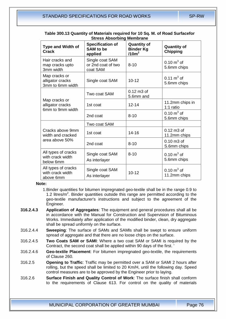
STANDARD SPECIFICATIONS FOR ROAD WORKS SP-RW
MUNICIPAL CORPORATION OF GREATER MUMBAI
Page 76
Table 300.13 Quantity of Materials required for 10 Sq. M. of Road Surfacefor Stress Absorbing Membrane
Type and Width of Crack
Specification of SAM to be applied
Quantity of Binder Kg /10m2
Quantity of Chipping
Hair cracks and map cracks upto 3mm width
Single coat SAM or 2nd coat of two coat SAM
8-10 0.10 m3 of 5.6mm chips
Map cracks or alligator cracks 3mm to 6mm width
Single coat SAM 10-12 0.11 m3 of 5.6mm chips
Map cracks or alligator cracks 6mm to 9mm width
Two coat SAM 0.12 m3 of 5.6mm and
1st coat 12-14 11.2mm chips in 1:1 ratio
2nd coat 8-10 0.10 m3 of 5.6mm chips
Cracks above 9mm width and cracked area above 50%
Two coat SAM
1st coat 14-16 0.12 m3 of 11.2mm chips
2nd coat 8-10 0.10 m3 of S.6mm chips
All types of cracks with crack width below 6mm
Single coat SAM
As interlayer
8-10
0.10 m3 of 5.6mm chips
All types of cracks with crack width above 6mm
Single coat SAM
As interlayer 10-12
0.10 m3 of 11.2mm chips
Note:
1.Binder quantities for bitumen impregnated geo-textile shall be in the range 0.9 to 1.2 litres/m2. Binder quantities outside this range are permitted according to the geo-textile manufacturer's instructions and subject to the agreement of the Engineer.
316.2.4.3 Application of Aggregates: The equipment and general procedures shall all be in accordance with the Manual for Construction and Supervision of Bituminous Works. Immediately after application of the modified binder, clean, dry aggregate shall be spread uniformly on the surface.
316.2.4.4 Sweeping: The surface of SAMs and SAMls shall be swept to ensure uniform spread of aggregate and that there are no loose chips on the surface.
316.2.4.5 Two Coats SAM or SAMI: Where a two coat SAM or SAMI is required by the Contract, the second coat shall be applied within 90 days of the first. '
316.2.4.6 Geo-textile Placement: For bitumen impregnated geo-textile, the requirements of Clause 260.
316.2.5 Opening to Traffic: Traffic may be permitted over a SAM or SAMI 2 hours after rolling, but the speed shall be limited to 20 Km/H, until the following day. Speed control measures are to be approved by the Engineer prior to laying.
316.2.6 Surface Finish and Quality Control of Work: The surface finish shall conform to the requirements of Clause 613. For control on the quality of materials
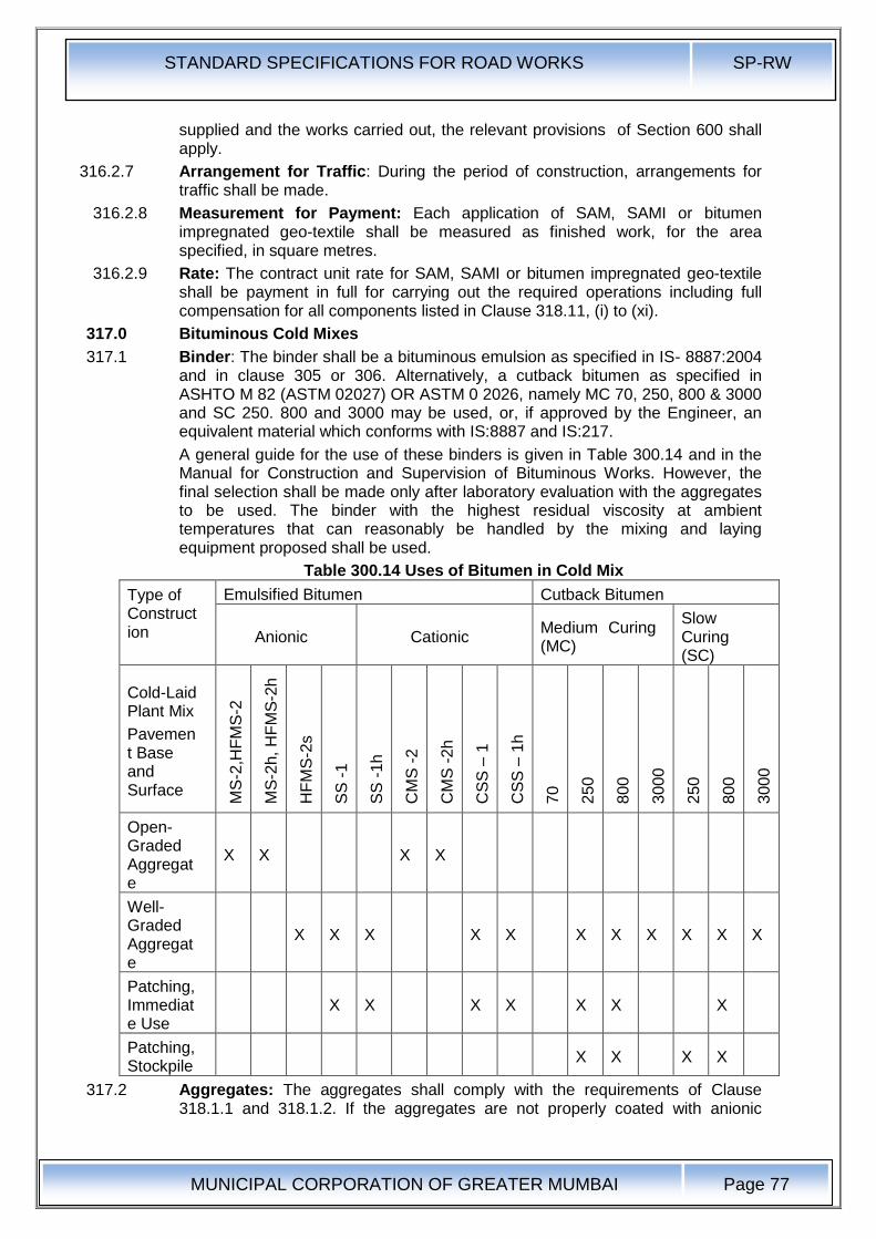
STANDARD SPECIFICATIONS FOR ROAD WORKS SP-RW
MUNICIPAL CORPORATION OF GREATER MUMBAI
Page 77
supplied and the works carried out, the relevant provisions of Section 600 shall apply.
316.2.7 Arrangement for Traffic: During the period of construction, arrangements for traffic shall be made.
316.2.8 Measurement for Payment: Each application of SAM, SAMI or bitumen impregnated geo-textile shall be measured as finished work, for the area specified, in square metres.
316.2.9 Rate: The contract unit rate for SAM, SAMI or bitumen impregnated geo-textile shall be payment in full for carrying out the required operations including full compensation for all components listed in Clause 318.11, (i) to (xi).
317.0 Bituminous Cold Mixes
317.1 Binder: The binder shall be a bituminous emulsion as specified in IS- 8887:2004 and in clause 305 or 306. Alternatively, a cutback bitumen as specified in ASHTO M 82 (ASTM 02027) OR ASTM 0 2026, namely MC 70, 250, 800 & 3000 and SC 250. 800 and 3000 may be used, or, if approved by the Engineer, an equivalent material which conforms with IS:8887 and IS:217.
A general guide for the use of these binders is given in Table 300.14 and in the Manual for Construction and Supervision of Bituminous Works. However, the final selection shall be made only after laboratory evaluation with the aggregates to be used. The binder with the highest residual viscosity at ambient temperatures that can reasonably be handled by the mixing and laying equipment proposed shall be used.
Table 300.14 Uses of Bitumen in Cold Mix
Type of Construction
Emulsified Bitumen Cutback Bitumen
Anionic Cationic Medium Curing (MC)
Slow Curing (SC)
Cold-Laid Plant Mix
Pavement Base and Surface
MS
-2,H
FM
S-2
MS
-2h,
HF
MS
-2h
HF
MS
-2s
SS
-1
SS
-1h
CM
S -
2
CM
S -
2h
CS
S –
1
CS
S –
1h
70
250
800
3000
250
800
3000
Open-Graded Aggregate
X X X X
Well-Graded Aggregate
X X X X X X X X X X X
Patching, Immediate Use
X X X X X X X
Patching, Stockpile
X X X X
317.2 Aggregates: The aggregates shall comply with the requirements of Clause 318.1.1 and 318.1.2. If the aggregates are not properly coated with anionic
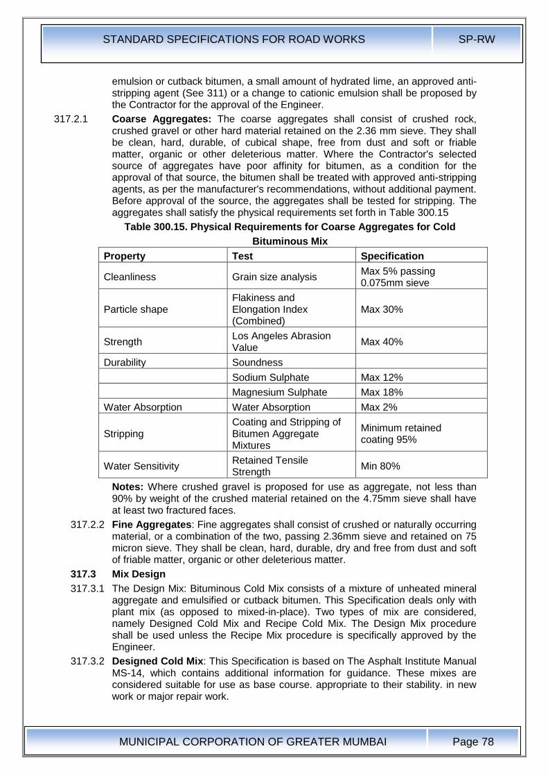
STANDARD SPECIFICATIONS FOR ROAD WORKS SP-RW
MUNICIPAL CORPORATION OF GREATER MUMBAI
Page 78
emulsion or cutback bitumen, a small amount of hydrated lime, an approved anti-stripping agent (See 311) or a change to cationic emulsion shall be proposed by the Contractor for the approval of the Engineer.
317.2.1 Coarse Aggregates: The coarse aggregates shall consist of crushed rock, crushed gravel or other hard material retained on the 2.36 mm sieve. They shall be clean, hard, durable, of cubical shape, free from dust and soft or friable matter, organic or other deleterious matter. Where the Contractor's selected source of aggregates have poor affinity for bitumen, as a condition for the approval of that source, the bitumen shall be treated with approved anti-stripping agents, as per the manufacturer's recommendations, without additional payment. Before approval of the source, the aggregates shall be tested for stripping. The aggregates shall satisfy the physical requirements set forth in Table 300.15
Table 300.15. Physical Requirements for Coarse Aggregates for Cold
Bituminous Mix
Property Test Specification
Cleanliness Grain size analysis Max 5% passing 0.075mm sieve
Particle shape Flakiness and Elongation Index (Combined)
Max 30%
Strength Los Angeles Abrasion Value
Max 40%
Durability Soundness
Sodium Sulphate Max 12%
Magnesium Sulphate Max 18%
Water Absorption Water Absorption Max 2%
Stripping Coating and Stripping of Bitumen Aggregate Mixtures
Minimum retained coating 95%
Water Sensitivity Retained Tensile Strength
Min 80%
Notes: Where crushed gravel is proposed for use as aggregate, not less than 90% by weight of the crushed material retained on the 4.75mm sieve shall have at least two fractured faces.
317.2.2 Fine Aggregates: Fine aggregates shall consist of crushed or naturally occurring material, or a combination of the two, passing 2.36mm sieve and retained on 75 micron sieve. They shall be clean, hard, durable, dry and free from dust and soft of friable matter, organic or other deleterious matter.
317.3 Mix Design
317.3.1 The Design Mix: Bituminous Cold Mix consists of a mixture of unheated mineral aggregate and emulsified or cutback bitumen. This Specification deals only with plant mix (as opposed to mixed-in-place). Two types of mix are considered, namely Designed Cold Mix and Recipe Cold Mix. The Design Mix procedure shall be used unless the Recipe Mix procedure is specifically approved by the Engineer.
317.3.2 Designed Cold Mix: This Specification is based on The Asphalt Institute Manual MS-14, which contains additional information for guidance. These mixes are considered suitable for use as base course. appropriate to their stability. in new work or major repair work.
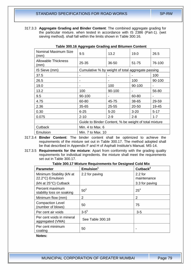
STANDARD SPECIFICATIONS FOR ROAD WORKS SP-RW
MUNICIPAL CORPORATION OF GREATER MUMBAI
Page 79
317.3.3 Aggregate Grading and Binder Content: The combined aggregate grading for the particular mixture. when tested in accordance with IS 2386 (Part-1). (wet sieving method). shall fall within the limits shown in Table 300.16.
Table 300.16 Aggregate Grading and Bitumen Content
Nominal Maximum Size (mm)
9.5 13.2 19.0 26.5
Allowable Thickness (mm)
25-35 36-50 51-75 76-100
IS Sieve (mm) Cumulative % by weight of total aggregate passing
37.5 - - - 100
26.5 - - 100 90-100
19.0 - 100 90-100 -
13.2 100 90-100 - 56-80
9.5 90-100 - 60-80 -
4.75 60-80 45-75 38-65 29-59
2.36 35-65 25-55 20-50 19-45
0.30 6-25 5-20 3-20 5-17
0.075 2-10 2-9 2-8 1-7
Guide to Binder Content, % be weight of total mixture
Cutback Min. 4 to Max. 6
Emulsion Min. 7 to Max. 10
317.3.4 Binder Content: The binder content shall be optimized to achieve the requirements of the mixture set out in Table 300.17. The method adopted shall be that described in Appendix F and H of Asphalt Institute's Manual. MS-14.
317.3.5 Requirements for the mixture: Apart from conformity with the grading quality requirements for individual ingredients. the mixture shall meet the requirements set out in Table 300.17.
Table 300.17 Mixture Requirements for Designed Cold Mix
Parameter Emulsion1 Cutback2
Minimum Stability (kN at 22.2°C) Emulsion
(kN at 25°C) Cutback
2.2 for paving 2.2 for maintenance
3.3 for paving
Percent maximum stability loss on soaking
503 254
Minimum flow (mm) 2 2
Compaction Level (number of blows)
50 75
Per cent air voids 3-55 3-5
Per cent voids in mineral aggregated (VMA)
See Table 300.18
Per cent minimum coating
50 -
Notes:
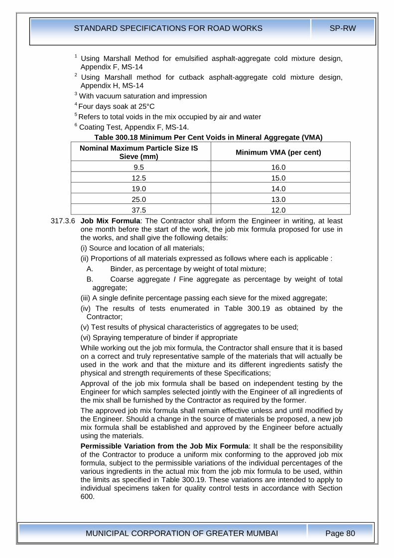
STANDARD SPECIFICATIONS FOR ROAD WORKS SP-RW
MUNICIPAL CORPORATION OF GREATER MUMBAI
Page 80
1 Using Marshall Method for emulsified asphalt-aggregate cold mixture design, Appendix F, MS-14
2 Using Marshall method for cutback asphalt-aggregate cold mixture design, Appendix H, MS-14
3 With vacuum saturation and impression 4 Four days soak at 25°C 5 Refers to total voids in the mix occupied by air and water 6 Coating Test, Appendix F, MS-14.
Table 300.18 Minimum Per Cent Voids in Mineral Aggregate (VMA)
Nominal Maximum Particle Size IS Sieve (mm)
Minimum VMA (per cent)
9.5 16.0
12.5 15.0
19.0 14.0
25.0 13.0
37.5 12.0
317.3.6 Job Mix Formula: The Contractor shall inform the Engineer in writing, at least one month before the start of the work, the job mix formula proposed for use in the works, and shall give the following details:
(i) Source and location of all materials;
(ii) Proportions of all materials expressed as follows where each is applicable :
A. Binder, as percentage by weight of total mixture;
B. Coarse aggregate I Fine aggregate as percentage by weight of total aggregate;
(iii) A single definite percentage passing each sieve for the mixed aggregate;
(iv) The results of tests enumerated in Table 300.19 as obtained by the Contractor;
(v) Test results of physical characteristics of aggregates to be used;
(vi) Spraying temperature of binder if appropriate
While working out the job mix formula, the Contractor shall ensure that it is based on a correct and truly representative sample of the materials that will actually be used in the work and that the mixture and its different ingredients satisfy the physical and strength requirements of these Specifications;
Approval of the job mix formula shall be based on independent testing by the Engineer for which samples selected jointly with the Engineer of all ingredients of the mix shall be furnished by the Contractor as required by the former.
The approved job mix formula shall remain effective unless and until modified by the Engineer. Should a change in the source of materials be proposed, a new job mix formula shall be established and approved by the Engineer before actually using the materials.
Permissible Variation from the Job Mix Formula: It shall be the responsibility of the Contractor to produce a uniform mix conforming to the approved job mix formula, subject to the permissible variations of the individual percentages of the various ingredients in the actual mix from the job mix formula to be used, within the limits as specified in Table 300.19. These variations are intended to apply to individual specimens taken for quality control tests in accordance with Section 600.
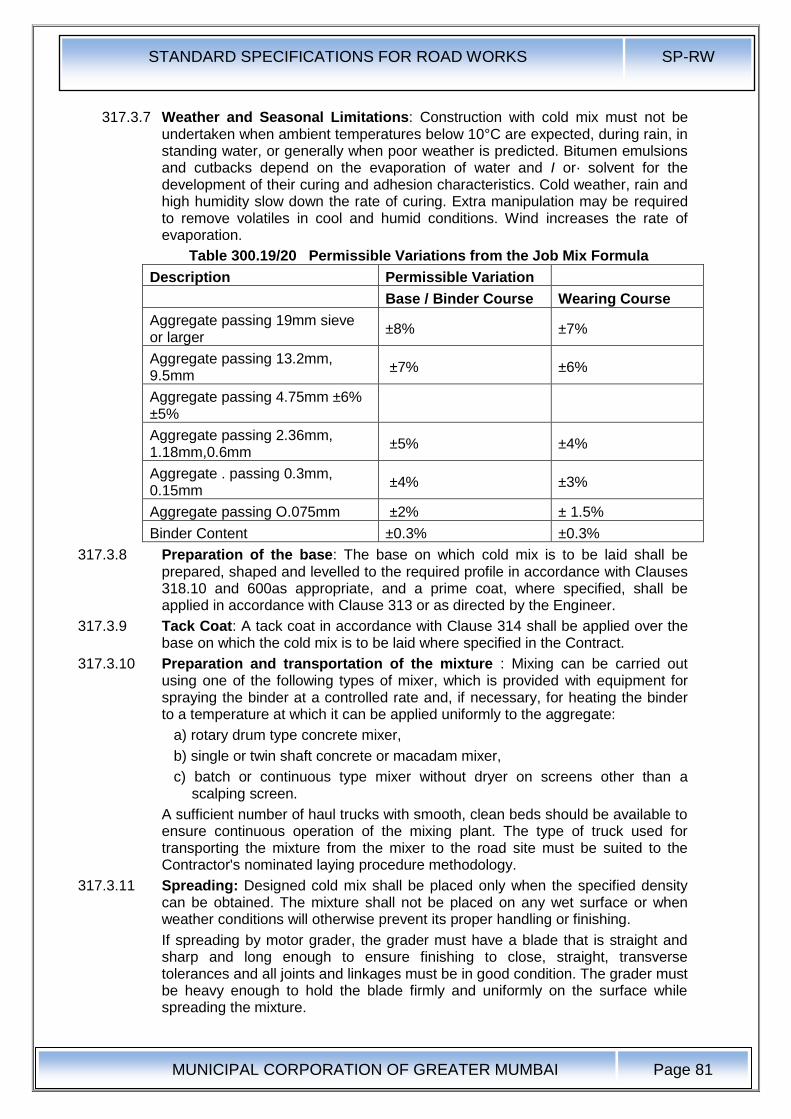
STANDARD SPECIFICATIONS FOR ROAD WORKS SP-RW
MUNICIPAL CORPORATION OF GREATER MUMBAI
Page 81
317.3.7 Weather and Seasonal Limitations: Construction with cold mix must not be undertaken when ambient temperatures below 10°C are expected, during rain, in standing water, or generally when poor weather is predicted. Bitumen emulsions and cutbacks depend on the evaporation of water and I or· solvent for the development of their curing and adhesion characteristics. Cold weather, rain and high humidity slow down the rate of curing. Extra manipulation may be required to remove volatiles in cool and humid conditions. Wind increases the rate of evaporation.
Table 300.19/20 Permissible Variations from the Job Mix Formula
Description Permissible Variation
Base / Binder Course Wearing Course
Aggregate passing 19mm sieve or larger
±8% ±7%
Aggregate passing 13.2mm, 9.5mm
±7% ±6%
Aggregate passing 4.75mm ±6% ±5%
Aggregate passing 2.36mm, 1.18mm,0.6mm
±5% ±4%
Aggregate . passing 0.3mm, 0.15mm
±4% ±3%
Aggregate passing O.075mm ±2% ± 1.5%
Binder Content ±0.3% ±0.3%
317.3.8 Preparation of the base: The base on which cold mix is to be laid shall be prepared, shaped and levelled to the required profile in accordance with Clauses 318.10 and 600as appropriate, and a prime coat, where specified, shall be applied in accordance with Clause 313 or as directed by the Engineer.
317.3.9 Tack Coat: A tack coat in accordance with Clause 314 shall be applied over the base on which the cold mix is to be laid where specified in the Contract.
317.3.10 Preparation and transportation of the mixture : Mixing can be carried out using one of the following types of mixer, which is provided with equipment for spraying the binder at a controlled rate and, if necessary, for heating the binder to a temperature at which it can be applied uniformly to the aggregate:
a) rotary drum type concrete mixer,
b) single or twin shaft concrete or macadam mixer,
c) batch or continuous type mixer without dryer on screens other than a scalping screen.
A sufficient number of haul trucks with smooth, clean beds should be available to ensure continuous operation of the mixing plant. The type of truck used for transporting the mixture from the mixer to the road site must be suited to the Contractor's nominated laying procedure methodology.
317.3.11 Spreading: Designed cold mix shall be placed only when the specified density can be obtained. The mixture shall not be placed on any wet surface or when weather conditions will otherwise prevent its proper handling or finishing.
If spreading by motor grader, the grader must have a blade that is straight and sharp and long enough to ensure finishing to close, straight, transverse tolerances and all joints and linkages must be in good condition. The grader must be heavy enough to hold the blade firmly and uniformly on the surface while spreading the mixture.
STANDARD SPECIFICATIONS FOR ROAD WORKS SP-RW
MUNICIPAL CORPORATION OF GREATER MUMBAI
Page 82
If climatic conditions and aggregate grading permit evaporation of moisture of volatiles without aeration by manipulation, a conventional self-propelled asphalt paver shall be used to place designed cold mix.
Other methods of spreading may be used as approved by the Engineer.
317.3.12 Compaction: Initial compaction of the laid material shall be carried out using a pneumatic-tyred roller of a weight appropriate to the layer thickness to be compacted with single layer thickness being 25-100mm and all compaction being in accordance with Clause 318.8. Smooth tyres shall be used. Final rolling and smoothing of the surface should be completed using steel wheel rollers. The Contractor shall demonstrate at laying trials that his: proposed laying and compaction methods can achieve a satisfactory result.
317.3.13 Opening to Traffic: Traffic shall not be allowed to run on new work until all the water or volatiles in the mixture have evaporated, as determined by the Engineer. The rate of evaporation will be influenced by the temperature, humidity and wind conditions.
317.3.14 Surface Finish and Quality Control of Work: The surface finish of construction shall conform to the requirements of Clause 900. For control of the quality of supplied materials and the works carried out, the relevant provisions of Section 600shall apply.
317.3.15 Arrangements for Traffic: During the period of construction, arrangements for traffic shall be made in accordance with the provisions of Clause 30.
317.3.16 Measurement for Payment: Designed Cold Mix shall be measured as finished work, for the area covered, in cubic metres, by weight in metric tones, or by square metres at a specified thickness as specified in the Contract.
317.3.17 Rate: The contract unit rate for Designed Cold Mix shall be payment in full for carrying out the required operations including full compensation for all components listed in Clause 318.11 (i) to (xi). The rate shall cover the provision of the specified grade of cutback in the mix at 5 percent of the weight of the total mix or emulsion at 8 per cent of the weight of the total mix, with the provision that the variation of quantity of binder will be assessed on the basis of the amount agreed by the Engineer and the payment adjusted as per the rate for cutback or emulsion .quoted in the Bill of Quantities.
318.0 Bituminous Hot Mixes
318.1 Aggregates:
318.1.1 Coarse Aggregates: Coarse Aggregates shall consists of crushed rock retained on 2.36mm sieve. They shall be cleaned, hard, durable, of cubical shape, free from dust, and soft or friable matter, organic or other deleterious matter. Where the selected sources of aggregate have poor affinity for bitumen, the bitumen shall be treated with approved anti-stripping agents as per the manufacturer's recommendations. The aggregate shall satisfy the physical requirements set forth in the individual relevant clause for the material in question.
318.1.2 Fine Aggregates: Fine aggregates shall consist of crushed or naturally occurring material or a combination of the two passing 4.75mm sieve and retained on 75 Micron sieve. They shall be cleaned, hard, durable, dry, and free from dust, and soft or friable matter, organic or other deleterious matter. The amount of rounded, natural sand in the total fine aggregate shall be 10 percent if the BM is used within 100 mm from the road surface and to 50 percent if the BM is used more than 100 mm below the road surface. (clause 3.3 of IRC: 27-2009)
318.1.3 Source of Materials·: The source of all materials to be used on the: project must be tested to the satisfaction of and be expressly approved by the Engineer. The Engineer may from time to time withdraw approval of a specific source, or attach
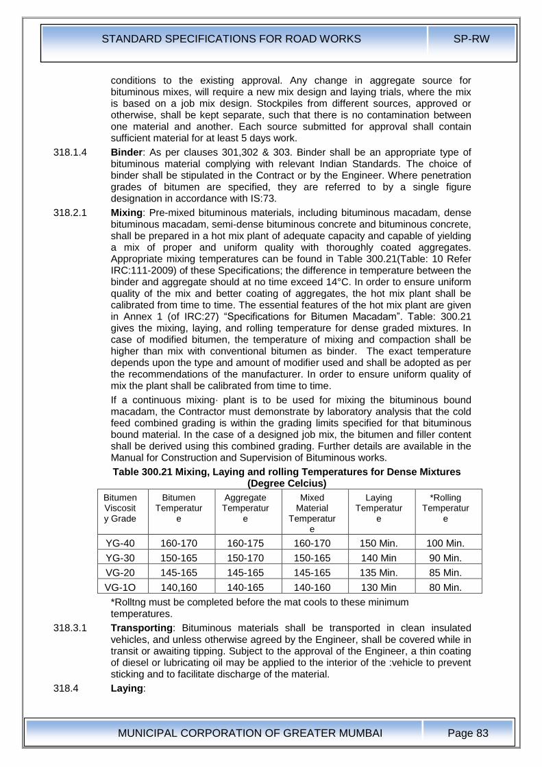
STANDARD SPECIFICATIONS FOR ROAD WORKS SP-RW
MUNICIPAL CORPORATION OF GREATER MUMBAI
Page 83
conditions to the existing approval. Any change in aggregate source for bituminous mixes, will require a new mix design and laying trials, where the mix is based on a job mix design. Stockpiles from different sources, approved or otherwise, shall be kept separate, such that there is no contamination between one material and another. Each source submitted for approval shall contain sufficient material for at least 5 days work.
318.1.4 Binder: As per clauses 301,302 & 303. Binder shall be an appropriate type of bituminous material complying with relevant Indian Standards. The choice of binder shall be stipulated in the Contract or by the Engineer. Where penetration grades of bitumen are specified, they are referred to by a single figure designation in accordance with IS:73.
318.2.1 Mixing: Pre-mixed bituminous materials, including bituminous macadam, dense bituminous macadam, semi-dense bituminous concrete and bituminous concrete, shall be prepared in a hot mix plant of adequate capacity and capable of yielding a mix of proper and uniform quality with thoroughly coated aggregates. Appropriate mixing temperatures can be found in Table 300.21(Table: 10 Refer IRC:111-2009) of these Specifications; the difference in temperature between the binder and aggregate should at no time exceed 14°C. In order to ensure uniform quality of the mix and better coating of aggregates, the hot mix plant shall be calibrated from time to time. The essential features of the hot mix plant are given in Annex 1 (of IRC:27) “Specifications for Bitumen Macadam”. Table: 300.21 gives the mixing, laying, and rolling temperature for dense graded mixtures. In case of modified bitumen, the temperature of mixing and compaction shall be higher than mix with conventional bitumen as binder. The exact temperature depends upon the type and amount of modifier used and shall be adopted as per the recommendations of the manufacturer. In order to ensure uniform quality of mix the plant shall be calibrated from time to time.
If a continuous mixing· plant is to be used for mixing the bituminous bound macadam, the Contractor must demonstrate by laboratory analysis that the cold feed combined grading is within the grading limits specified for that bituminous bound material. In the case of a designed job mix, the bitumen and filler content shall be derived using this combined grading. Further details are available in the Manual for Construction and Supervision of Bituminous works.
Table 300.21 Mixing, Laying and rolling Temperatures for Dense Mixtures (Degree Celcius)
Bitumen Viscosity Grade
Bitumen Temperatur
e
Aggregate Temperatur
e
Mixed Material
Temperature
Laying Temperatur
e
*Rolling Temperatur
e
YG-40 160-170 160-175 160-170 150 Min. 100 Min.
YG-30 150-165 150-170 150-165 140 Min 90 Min.
VG-20 145-165 145-165 145-165 135 Min. 85 Min.
VG-1O 140,160 140-165 140-160 130 Min 80 Min.
*Rolltng must be completed before the mat cools to these minimum temperatures.
318.3.1 Transporting: Bituminous materials shall be transported in clean insulated vehicles, and unless otherwise agreed by the Engineer, shall be covered while in transit or awaiting tipping. Subject to the approval of the Engineer, a thin coating of diesel or lubricating oil may be applied to the interior of the :vehicle to prevent sticking and to facilitate discharge of the material.
318.4 Laying:
STANDARD SPECIFICATIONS FOR ROAD WORKS SP-RW
MUNICIPAL CORPORATION OF GREATER MUMBAI
Page 84
318.4.1 Weather and Seasonal Limitations: Laying shall be suspended while free-standing water is present on the surface to be covered, or during rain, fog and dust storms. After rain, the bituminous surface, prime or tack coat, shall be blown off with a high pressure air jet to remove excess moisture, or the surface left to dry before laying shall start. Laying of bituminous mixtures shall not be carried out when the air temperature at the surface on which it is to be laid is below 10°C for mix with conventional bitumen as binder and is less than 15°C for mix with modified bitumen as binder or when the wind speed at any temperature exceeds 40 Km/H at 2m height unless specifically approved by the Engineer.
318.5 Cleaning of Surface : The surface on which the bituminous work is to be laid shall be cleaned of all loose and extraneous matter by means of a mechanical broom or any other approved equipment I method as specified in the contract. The use of a high pressure air jet from a compressor to remove dust or loose matter shall be available full time on the site, unless otherwise specified in the Contract.
318.6 Spreading: Except in areas where a mechanical paver cannot access, bituminous materials shall be spread, levelled and tamped by an approved self-propelled hydrostatic paver finisher preferably with sensor. As soon as possible after arrival at site, the materials shall be supplied continuously to the paver and laid without delay.
The rate of delivery of material to the paver shall be regulated to enable the paver to operate continuously. The travel rate of the paver, and its method of operations, shall be adjusted to ensure an even and uniform flow of bituminous material across the screed, free from dragging, tearing and segregation of the material. In areas with restricted space ( such as confined space, footways, irregular shape and varying thickness, approaches to expansion joints, etc) where a mechanical paver cannot be used, the material shall be spread, raked and levelled with suitable hand tools by experienced staff, and compacted to the satisfaction of the Engineer.
The minimum thickness of material laid in each paver pass shall be in accordance with the minimum values given in the relevant part of these Specifications. When laying binder course or wearing course approaching an expansion joint of ,a structure, machine laying shall stop 300mm short of the joint. The remainder of the pavement up to the joint, and the corresponding area beyond it, shall be laid by hand, and the joint or joint cavity shall be kept clear of surfacing material.
Bituminous material, with a temperature greater than 145°C, shall not be laid or deposited on bridge deck waterproofing systems, unless precautions against heat damage have been approved by the Engineer.
Hand placing of pre-mixed bituminous materials shall only be permitted in the following circumstances:
i) For laying regulating courses of irregular shape and varying thickness,
ii) In confined spaces where it is impracticable for a paver to operate
iii) For footways
iv) At the approaches to expansion joints at bridges, viaducts or other structures
Manual spreading of pre-mixed wearing course material or the addition of such material by hand-spreading to the paved area, for adjustment of level, shall only be permitted in the following circumstances:
i. At the edges of the layers of material and at gullies and manholes
ii. At the approaches to expansion joints at bridges, viaducts or other structures
STANDARD SPECIFICATIONS FOR ROAD WORKS SP-RW
MUNICIPAL CORPORATION OF GREATER MUMBAI
Page 85
iii. As directed by the Engineer
318.7 Cleanliness and Overlaying: Bituminous material shall be kept clean and uncontaminated. The only traffic permitted to run on bituminous material to be overlaid shall be that engaged in laying and compacting the next course or, where a binder course is to be sealed or surface dressed, that engaged on such surface treatment.
Binder course material shall not remain uncovered by either the wearing course or· surface treatment, whichever is specified in the Contract, for more than three consecutive days after being laid. The Engineer may extend this period, by the minimum amount of time necessary, because of weather conditions or for any other reason. If the surface of the base is subjected to traffic, or not covered within three days, a tack coat shall be applied, as directed by the Engineer.
318.8 Compaction: Bituminous materials shall be laid and compacted in layers which enable the specified thickness, surface level, regularity requirements and compaction to be achieved.
Compaction of bituminous materials shall commence as soon as possible after laying. Compaction-shall be substantially completed before the temperature falls below the minimum rolling temperatures stated in the relevant part of these Specifications. Rolling of the longitudinal joints shall be done immediately behind the paving operation. After this, rolling shall commence at the edges and progress towards the centre longitudinally except that on super elevated and unidirectional cambered portions, it shall progress from the lower to the upper edge parallel to the centre line of the pavement. Rolling shall continue until all roller marks- have been removed from the surface and minimum specified field density is achieved . All deficiencies in the surface after laying shall be made good by the attendants behind the paver, before initial rolling is commenced. The initial or breakdown rolling shall be done with 8-10 tonnes dead weight smooth-wheeled rollers. The intermediate rolling shall be done with 8- 10 tonnes dead weight or vibratory roller or with a pneumatic tyred roller of 12 to 15 tonnes weight having nine wheels, with a tyre pressure of at least 5.6 Kg / Sq. Cm. The finish rolling shall be done with 6 to 8 tonnes smooth wheeled tandem rollers.Where compaction is to be determined by density of cores the requirements to prove the performance of rollers shall apply in order to demonstrate that the specified density can be achieved. In such cases the Contractor shall nominate the plant, and the method by which he intends to achieve the specified level of compaction and finish at temperatures above the minimum specified rolling temperature. Laying trials shall then demonstrate the acceptability of the plant and method used.
Bituminous materials shall be rolled in a longitudinal direction, with the roller as close as possible to the paver. The roller shall first compact material adjacent to joints and then work from the lower to the upper side of the layer, overlapping on successive passes by at least one-third of the width of the rear roll or, in the case of a pneumatic-tyred roller, at least the nominal width of 300mm.
In portions with super-elevated and unidirectional camber, after the edge has been rolled, the roller shall progress from the lower to the upper edge.
Rollers should move at a speed of not more than 5 km per hour. The roller shall not be permitted to stand on pavement which has not been fully compacted, and necessary precautions shall be taken to prevent dropping oil, grease, petrol, or other foreign matter on the pavement either when the rollers are operating or standing. The wheels of rollers shall be kept moist with water, and the spray system provided with the machine shall be in good working order, to prevent the mixture from adhering to the wheels. Only sufficient moisture to prevent adhesion
STANDARD SPECIFICATIONS FOR ROAD WORKS SP-RW
MUNICIPAL CORPORATION OF GREATER MUMBAI
Page 86
between the wheels of rollers and the mixture should be used. Surplus water shall not be allowed to stand on the partially compacted pavement.
The density of the finished paving layer shall be determined by taking 150mm diameter cores. The density of finished paving layer shall not be less than 92% of the average (sample size N = 2 ) theoretical maximum specific gravity of the loose mix (Gmm) obtained on that day in accordance with ASTM D2041. See Annex 3 for the outline of ASTM D2041
318.9 Joints : Where longitudinal joints are made in pre-mixed bituminous materials, the materials shall be fully compacted and the joint made flush in one of the following ways; only method (iii) shall be used for . transverse joints:
a) All joints shall be cut vertical to the full thickness of the previously laid mix. All loosened material shall be discarded and the vertical face be coated with any viscosity grade bitumen, or cold applied emulsified bitumen. While spreading the material along the joint the material spread shall overlap 25 mm 10 50 mill on the previously laid mix beyond the vertical face of the joint. The thickness of the loose overlap material should be approximately a qum1er more than the final compacted thickness. The overlapped mix should be dragged back 10 the hot lane so that the roller can press the small excess into the hot side of the joint to obtain a high joint density.
b) By using two or more pavers in echelon, where this is practicable and in sufficient proximity for adjacent width to be fully compacted by continuous rolling.
In multilayer construction the longitudinal joint in one layer shall offset the joint in the underneath layer by about 150 mm.
For transverse joints method a) above can apply Transverse joints in the successive and adjoining layers should have a minimum offset of 2 m.
i. By heating the joints with an approved joint heater when the adjacent width is being laid, but without cutting back or coating with binder. The heater shall raise the temperature of the full depth of material, to within the specified> range of minimum rolling temperature and maximum temperature at any stage for the material, for a width not less than 75mm. The Contractor shall have equipment available, for use in the event of a heater breakdown, to form joints by method (iii);
ii. By using two or more pavers operating in echelon, where this is practicable, and in sufficient proximity for adjacent widths to be fully compacted by continuous rolling;
iii. By cutting back the exposed joint, for a distance equal to the specified layer thickness, to a vertical face, discarding all loosened material and coating the vertical face completely with 80/100 penetration grade hot bitumen, or cold-applied bitumen, or polymer modified adhesive bitumen tape with a minimum thickness of 2mm, before the adjacent width is laid.
All joints shall be offset at least 300mm from parallel joints in the layer beneath or as directed, and in a layout approved by the Engineer. Joints in the wearing course shall coincide with either the lane edge or the lane marking, whichever is appropriate. Longitudinal joints shall not be situated in wheel track zones. Transverse joints in the successive and adjoining layers should have a minimum offset of 2m. (IRC:111-2009 clause 5.7.3)
All joints shall be cut vertical to the full thickness of the previously laid mix. All loosened material shall be discarded and the vertical face be coated with any viscosity grade bitumen, or cold applied emulsified bitumen. While spreading the material along the joint the material spread shall overlap 25 mm to 50 mm on the
STANDARD SPECIFICATIONS FOR ROAD WORKS SP-RW
MUNICIPAL CORPORATION OF GREATER MUMBAI
Page 87
previously laid mix beyond the vertical face of the joint. The thickness of the loose overlap material should be approximately a quarter more than the final compacted thickness. The overlapped mix should be dragged back to the hot lane so that the roller can press the small excess into the hot side of the joint to obtain a high joint density. (IRC:111-2009 clause 5.7.3)
318.10 Preparation of Surface:
This work shall consist of preparing an existing granular or blacktopped surface bituminous course. The work shall be performed on such widths and lengths as shown on the drawings or as instructed by the" Engineer. The existing surface shall be firm and clean, and treated with Prime and Tack Coat as shown on the drawings as otherwise stated in the Contract.
318.10.1 Preparing existing granular surface: Where the existing surface is granular, all loose materials shall be removed, and the surface lightly watered where the profile corrective course to be provided as a separate layer is also granular. Where the profile corrective course of bituminous material is to be laid over the existing granular surface, the latter shall, after removal of all loose material, be primed in accordance with Clause 313.
The surface finish of all granular layers on which bituminous works are to be placed, shall, unless otherwise specifically instructed by the Engineer, be free from dust. All such layers must be capable of being swept, after the removal of any non-integral loose material, by means of a mechanical broom, without shedding significant quantities of material and dust removed by air jet, washing, or other means approved by the Engineer.
After cleaning the surface shall be correct to line and level, within the tolerances specified for base course.
318.10.1.1 Scarifying existing bituminous surface: Where specified or shown on the drawings, the existing bituminous layer in the specified width shall be removed with care and without causing undue disturbance to the underlying layer, by a suitable method approved by the Engineer. After removal, all loose and disintegrated material, the underlying layers which might have been disturbed should be suitably reworked and compacted to line and level. After supplementing the base material as necessary with suitable fresh stone, the compacted finished surface shall be primed in accordance with Clause 313. Reusable materials shall be stacked as directed by the Engineer within 1000m of their origin.
318.11 Rates for Premixed Bituminous Material : The contract unit rate for premixed bituminous material shall be payment in full or carrying out the required operations including full compensation for, but not necessarily limited to:
i. Making arrangements for traffic to Clause 30 except for initial treatment to verge, shoulders and construction of diversions,
ii. Preparation of the surface to receive the material,
iii. Providing all materials to be incorporated in the work including arrangement for stock yards, all royalties, fees, rents where necessary and all leads and lifts,
iv. Mixing, transporting, laying and compacting the mix, as specified,
v. All labour, tools, equipment, plant including installation of hot mix plant, power supply units and all machinery, incidental to complete the work to these Specifications,
vi. Carrying out the work in part widths of the road where directed,
vii. Carrying out all tests for control of quality and,

STANDARD SPECIFICATIONS FOR ROAD WORKS SP-RW
MUNICIPAL CORPORATION OF GREATER MUMBAI
Page 88
viii. The rate shall cover the provision of bitumen at the rate specified in the contract, with the provision that the variation in actual percentage of bitumen used will be assessed and the payment adjusted accordingly.
ix. The rates for premixed material are to include for all wastage in cutting of joints etc.,
x. The rates are to include for all necessary testing, mix design, transporting and testing of samples, and cores. If there is not a project specific laboratory, the Contractor must arrange to carry out all necessary testing at an outside Laboratory, approved by the Engineer, and all costs incurred are deemed to be included in the rate quoted for the material.
xi. The cost of all plant and laying trials as specified to prove the mixing and laying methods is deemed to be included in the Contractor's rates for the material.
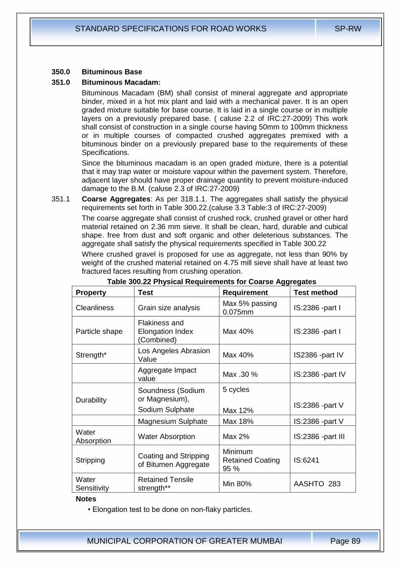
STANDARD SPECIFICATIONS FOR ROAD WORKS SP-RW
MUNICIPAL CORPORATION OF GREATER MUMBAI
Page 89
350.0 Bituminous Base
351.0 Bituminous Macadam:
Bituminous Macadam (BM) shall consist of mineral aggregate and appropriate binder, mixed in a hot mix plant and laid with a mechanical paver. It is an open graded mixture suitable for base course. It is laid in a single course or in multiple layers on a previously prepared base. ( caluse 2.2 of IRC:27-2009) This work shall consist of construction in a single course having 50mm to 100mm thickness or in multiple courses of compacted crushed aggregates premixed with a bituminous binder on a previously prepared base to the requirements of these Specifications.
Since the bituminous macadam is an open graded mixture, there is a potential that it may trap water or moisture vapour within the pavement system. Therefore, adjacent layer should have proper drainage quantity to prevent moisture-induced damage to the B.M. (caluse 2.3 of IRC:27-2009)
351.1 Coarse Aggregates: As per 318.1.1. The aggregates shall satisfy the physical requirements set forth in Table 300.22.(caluse 3.3 Table:3 of IRC:27-2009)
The coarse aggregate shall consist of crushed rock, crushed gravel or other hard material retained on 2.36 mm sieve. It shall be clean, hard, durable and cubical shape. free from dust and soft organic and other deleterious substances. The aggregate shall satisfy the physical requirements specified in Table 300.22
Where crushed gravel is proposed for use as aggregate, not less than 90% by weight of the crushed material retained on 4.75 mill sieve shall have at least two fractured faces resulting from crushing operation.
Table 300.22 Physical Requirements for Coarse Aggregates
Property Test Requirement Test method
Cleanliness Grain size analysis Max 5% passing 0.075mm
IS:2386 -part I
Particle shape Flakiness and Elongation Index (Combined)
Max 40% IS:2386 -part I
Strength* Los Angeles Abrasion Value
Max 40% IS2386 -part IV
Aggregate Impact value
Max .30 % IS:2386 -part IV
Durability
Soundness (Sodium or Magnesium),
Sodium Sulphate
5 cycles
Max 12%
IS:2386 -part V
Magnesium Sulphate Max 18% IS:2386 -part V
Water Absorption
Water Absorption Max 2% IS:2386 -part III
Stripping Coating and Stripping of Bitumen Aggregate
Minimum Retained Coating 95 %
IS:6241
Water Sensitivity
Retained Tensile strength**
Min 80% AASHTO 283
Notes
• Elongation test to be done on non-flaky particles.
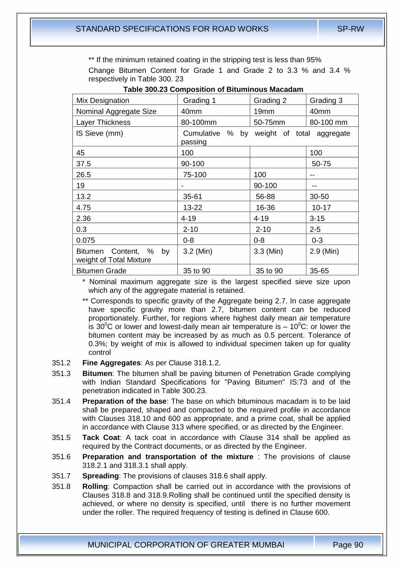
STANDARD SPECIFICATIONS FOR ROAD WORKS SP-RW
MUNICIPAL CORPORATION OF GREATER MUMBAI
Page 90
** If the minimum retained coating in the stripping test is less than 95%
Change Bitumen Content for Grade 1 and Grade 2 to 3.3 % and 3.4 % respectively in Table 300. 23
Table 300.23 Composition of Bituminous Macadam
Mix Designation Grading 1 Grading 2 Grading 3
Nominal Aggregate Size 40mm 19mm 40mm
Layer Thickness 80-100mm 50-75mm 80-100 mm
lS Sieve (mm) Cumulative % by weight of total aggregate passing
45 100 100
37.5 90-100 50-75
26.5 75-100 100 --
19 - 90-100 --
13.2 35-61 56-88 30-50
4.75 13-22 16-36 10-17
2.36 4-19 4-19 3-15
0.3 2-10 2-10 2-5
0.075 0-8 0-8 0-3
Bitumen Content, % by weight of Total Mixture
3.2 (Min) 3.3 (Min) 2.9 (Min)
Bitumen Grade 35 to 90 35 to 90 35-65
* Nominal maximum aggregate size is the largest specified sieve size upon which any of the aggregate material is retained.
** Corresponds to specific gravity of the Aggregate being 2.7. In case aggregate have specific gravity more than 2.7, bitumen content can be reduced proportionately. Further, for regions where highest daily mean air temperature is 300C or lower and lowest-daily mean air temperature is – 100C: or lower the bitumen content may be increased by as much as 0.5 percent. Tolerance of 0.3%; by weight of mix is allowed to individual specimen taken up for quality control
351.2 Fine Aggregates: As per Clause 318.1.2.
351.3 Bitumen: The bitumen shall be paving bitumen of Penetration Grade complying with Indian Standard Specifications for "Paving Bitumen" IS:73 and of the penetration indicated in Table 300.23.
351.4 Preparation of the base: The base on which bituminous macadam is to be laid shall be prepared, shaped and compacted to the required profile in accordance with Clauses 318.10 and 600 as appropriate, and a prime coat, shall be applied in accordance with Clause 313 where specified, or as directed by the Engineer.
351.5 Tack Coat: A tack coat in accordance with Clause 314 shall be applied as required by the Contract documents, or as directed by the Engineer.
351.6 Preparation and transportation of the mixture : The provisions of clause 318.2.1 and 318.3.1 shall apply.
351.7 Spreading: The provisions of clauses 318.6 shall apply.
351.8 Rolling: Compaction shall be carried out in accordance with the provisions of Clauses 318.8 and 318.9.Rolling shall be continued until the specified density is achieved, or where no density is specified, until there is no further movement under the roller. The required frequency of testing is defined in Clause 600.
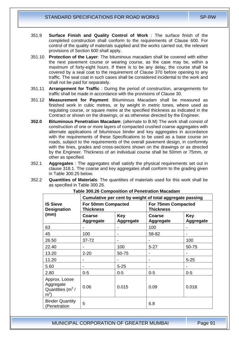
STANDARD SPECIFICATIONS FOR ROAD WORKS SP-RW
MUNICIPAL CORPORATION OF GREATER MUMBAI
Page 91
351.9 Surface Finish and Quality Control of Work : The surface finish of the completed construction shall conform to the requirements of Clause 600. For control of the quality of materials supplied and the works carried out, the relevant provisions of Section 600 shall apply.
351.10 Protection of the Layer: The bituminous macadam shall be covered with either the next pavement course or wearing course, as the case may be, within a maximum of forty-eight hours. If there is to be any delay, the course shall be covered by a seal coat to the requirement of Clause 370 before opening to any traffic. The seal coat in such cases shall be considered incidental to the work and shall not be paid for separately.
351.11 Arrangement for Traffic : During the period of construction, arrangements for traffic shall be made in accordance with the provisions of Clause 30.
351.12 Measurement for Payment: Bituminous Macadam shall be measured as finished work in cubic metres, or by weight in metric tones, where used as regulating course, or square metre at the specified thickness as indicated in the Contract or shown on the drawings, or as otherwise directed by the Engineer.
352.0 Bituminous Penetration Macadam: (alternate to B.M) The work shall consist of construction of one or more layers of compacted crushed coarse aggregates with alternate applications of bituminous binder and key aggregates in accordance with the requirements of these Specifications to be used as a base course on roads, subject to the requirements of the overall pavement design, in conformity with the lines, grades and cross-sections shown on the drawings or as directed by the Engineer. Thickness of an individual course shall be 50mm or 75mm, or other as specified.
352.1 Aggregates : The aggregates shall satisfy the physical requirements set out in clause 318.1. The coarse and key aggregates shall conform to the grading given in Table 300.25 below.
352.2 Quantities of Materials: The quantities of materials used for this work shall be as specified in Table 300.26.
Table 300.26 Composition of Penetration Macadam
IS Sieve Designation (mm)
Cumulative per cent by weight of total aggregate passing
For 50mm Compacted Thickness
For 75mm Compacted Thickness
Coarse Aggregate
Key Aggregate
Coarse Aggregate
Key Aggregate
63 - - 100 -
45 100 - 58-82 -
26.50 37-72 - - 100
22.40 - 100 5-27 50-75
13.20 2-20 50-75 - -
11.20 - - - 5-25
5.60 - 5-25 - -
2.80 0-5 0-5 0-5 0-5
Approx. Loose Aggregate Quantities (m3 / m2)
0.06 0.015 0.09 0.018
Binder Quantity (Penetration
5 6.8
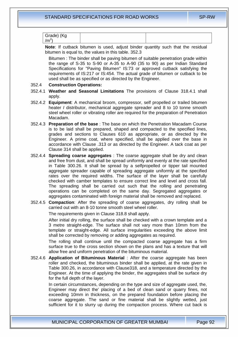
STANDARD SPECIFICATIONS FOR ROAD WORKS SP-RW
MUNICIPAL CORPORATION OF GREATER MUMBAI
Page 92
Grade) (Kg /m2)
Note: If cutback bitumen is used, adjust binder quantity such that the residual bitumen is equal to, the values in this table. 352.3
Bitumen : The binder shall be paving bitumen of suitable penetration grade within the range of S-35 to S-90 or A-35 to A-90 (35 to 90) as per Indian Standard Specifications for "Paving Bitumen" IS:73 or approved cutback satisfying the requirements of IS:217 or IS:454. The actual grade of bitumen or cutback to be used shall be as specified or as directed by the Engineer.
352.4 Construction Operations:
352.4.1 Weather and Seasonal Limitations The provisions of Clause 318.4.1 shall apply.
352.4.2 Equipment: A mechanical broom, compressor, self propelled or trailed bitumen heater I distributor, mechanical aggregate spreader and 8 to 10 tonne smooth steel wheel roller or vibrating roller are required for the preparation of Penetration Macadam.
352.4.3 Preparation of the base : The base on which the Penetration Macadam Course is to be laid shall be prepared, shaped and compacted to the specified lines, grades and sections to Clauses 610 as appropriate, or as directed by the Engineer. A prime coat, where specified, shall be applied over the base in accordance with Clause .313 or as directed by the Engineer. A tack coat as per Clause 314 shall be applied.
352.4.4 Spreading coarse aggregates : The coarse aggregate shall be dry and clean and free from dust, and shall be spread uniformly and evenly at the rate specified in Table 300.26. It shall be spread by a selfpropelled or tipper tail mounted aggregate spreader capable of spreading aggregate uniformly at the specified rates over the required widths. The surface of the layer shall be carefully checked with camber templates to ensure correct line and level and cross fall. The spreading shall be carried out such that the rolling and penetrating operations can be completed on the same day. Segregated aggregates or aggregates contaminated with foreign material shall be removed and replaced.
352.4.5 Compaction: After the spreading of coarse aggregates, dry rolling shall be carried out with an 8-10 tonne smooth steel wheel roller.
The requirements given in Clause 318.8 shall apply.
After initial dry rolling, the surface shall be checked with a crown template and a 3 metre straight-edge. The surface shall not vary more than 10mm from the template or straight-edge. All surface irregularities exceeding the above limit shall be corrected by removing or adding aggregates as required.
The rolling shall continue until the compacted coarse aggregate has a firm surface true to the cross section shown on the plans and has a texture that will allow free and uniform penetration of the bituminous material.
352.4.6 Application of Bituminous Material : After the coarse aggregate has been roller and checked, the bituminous binder shall be applied, at the rate given in Table 300.26, in accordance with Clause318, and a temperature directed by the Engineer. At the time of applying the binder, the aggregates shall be surface dry for the full depth of the layer.
In certain circumstances, depending on the type and size of aggregate used, the, Engineer may direct the' placing of a bed of clean sand or quarry fines, not exceeding 10mm in thickness, on the prepared foundation before placing the coarse aggregate. The sand or fine material shall be slightly wetted, just sufficient for it to slurry up during the compaction process. Where cut back is

STANDARD SPECIFICATIONS FOR ROAD WORKS SP-RW
MUNICIPAL CORPORATION OF GREATER MUMBAI
Page 93
used, if flooding of the binder occurs it should be applied in two operations, or as directed by the Engineer.
352.4.7 Application of Key Aggregates : Immediately after the first application of bitumen, the key aggregates, which shall be clean, dry, and free from dust shall be spread uniformly over the surface by means of an approved mechanical spreader' or by approved manual methods at the rate specified in Table 300.26.
Where directed by the Engineer, the surface shall be swept and the quantity of key aggregate adjusted to ensure uniform application, with all the surface voids in the coarse aggregate being filled without excess. The entire surface shall then be rolled with an 8-10 tonnes smooth steel wheel Toller (or vibrating roller operating in non-vibratory mode) in accordance with the procedure specified in Clause 352.4.5.
352.4.8 Surface Finish and Quality Control : The surface finish of the completed construction shall conform to the requirements of Clauses 610 & 620. For control of the quality of materials supplied and the works carried out the relevant provisions of Section 600 shall apply.
352.4.9 Surfacing: The Penetration Macadam shall be provided with a surfacing (binder / wearing course) within a maximum of forty-eight hours. If there is to be any delay, the penetration macadam shall be covered by a seal coat to the requirements of Clause 370: before opening to traffic. The seal coat in such cases shall be considered incidental to the work and shall not be paid for separately.
352.4.10 Arrangements for Traffic : During the period of construction, arrangements for traffic shall be made in accordance with the provision of Clause 30.
352.4.11 Measurement for Payment: Penetration Macadam base course shall be measured as finished work in square metres.
352.4.12 Rate: The contract unit rate for Penetration Macadam course shall be payment in full for carrying out the required operations including, but not necessarily limited to, all components listed in Clause 318.11.
353.0
354.0 Dense Graded Bituminous Macadam (DBM) : Dense Graded Bituminous Macadam with polymer or rubber modified binder laid over crack prevention course as per clause 316.
(Clause 2.2: IRC:111- 2009)
Dense graded bituminous mixes shall consist of mineral aggregate and appropriate bituminous binder. mixed in a hot mix plant and laid with a mechanized paver. Dense graded bituminous mixes. such as binder and wearing courses are usually laid on a previously prepared bituminous layer. Binder course is the intermediate layer between bituminous base course and bituminous wearing course, Three different specifications for dense graded bituminous mixes are available for use for highways, Purpose, layer thickness and number of layers allowed for these specifications are given in Table 300.26.1, Table 300.26.1 Types of Dense Graded Bituminous Mixes, their Use, Number
of Layers and Layer Thickness
Specification Purpose Number of Layers
Thickness of each Layer
Dense Bituminous Macadam (DBM)
Base/ Binder course/ Overlay for strengthening
Single or Multiple
50mm – 100mm
Semi Dense Wearing Course Single 25mm – 40mm

STANDARD SPECIFICATIONS FOR ROAD WORKS SP-RW
MUNICIPAL CORPORATION OF GREATER MUMBAI
Page 94
Specification Purpose Number of Layers
Thickness of each Layer
Bituminous Concrete (SDBC)
Bituminous Concrete (BC)
Wearing Course Single 25 mm/ 40 mm/ 50 mm
354.1 Materials .
354.2 Bitumen : The bitumen shall be paving bitumen of Penetration Grade complying with Indian Standard Specifications for viscosity graded "Paving Bitumen" IS:73 and of the penetration indicated in Table 300.29 ,for dense bituminous macadam, or this bitumen as polymer or rubber modified complying with the IS:15462 or as otherwise specified in the Contract. Guidance on the selection of an appropriate grade of viscosity-graded paving bitumen is given in the Manual for Construction and Supervision of Bituminous Works and also shown in Table: 300.26.2 to 300.26.4.
Table 300.26.2 Viscosity Graded (VG) Bitumens and their General Applications
Viscosity Grade (VG) General Applications
VG-40
(40 - 60 penetration)
Use in highly stressed areas such as those in intersections, near toll booths, and truck parking lots in lieu of old 30/40 penetration grade
VG-30
(50 - 70 penetration)
Use for paving in most of India in lieu of old 60/70 penetration grade
VG-20
(60 - 80 penetration)
Use for paving in cold climatic. hIgh altitude regions of North India
VG-10
(80 - 100 penetration)
Use in spraying applications and for paving in very cold climate in lieu of old 80/100 penetration grade
Table 300.26.3 Selection Criteria for Viscosity-Graded (VG) Paving Bitumen Based on Climatic Conditions
Lowest Daily Mean Air Temperature, oC
Less than 20 oC
20oC to 30oC
More than 30oC
More than -10oC VG-10 VG-20 VG-30
-10oC or lower VG-10 VG-10 VG-20
Table 300.26.4 Selection Criteria for Grade of Modified Bitumen Highest Daily Mean Air Temperature, 0C
Lowest Daily :mean Air Temperature, 0C
Less than 20oC
20oC to 30oC More than 30oC
Grade of Modified Bitumen
More than -10oC PMB/NRMB 120
CRMB 50
PMB/NRMB 70
CRMB 55
PMB/NRMB 40
CRMB 60
-10oC or lower PMB/NRMB 120
CRMB 50
PMB/NRMB 120
CRMB 50
PMB/NRMB 70
CRMB 55
PMB =Polymer Modified Bitumen NRMB =Natural Rubber Modified Bitumen
CRMB = Crumb Rubber Modified Bitumen
Note : When commercial vehicles exceeds 2000 per day per lane and the highest daily mean temperature exceeds 400C. VG-40 or modified bitumen of equivalent stiffness are recommended for bituminous concrete and top layer of dense bituminous macadam.
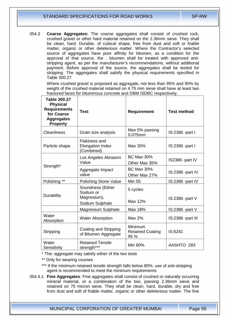
STANDARD SPECIFICATIONS FOR ROAD WORKS SP-RW
MUNICIPAL CORPORATION OF GREATER MUMBAI
Page 95
354.3 Coarse Aggregates: The coarse aggregates shall consist of crushed rock, crushed gravel or other hard material retained on the 2.36mm sieve. They shall be clean, hard. Durable, of cubical shape, free from dust and soft or friable matter, organic or other deleterious matter. Where the Contractor's selected source of aggregates have poor affinity for bitumen, as a condition for the approval of that source, the . bitumen shall be treated with approved anti-stripping agent, as per the manufacturer's recommendations, without additional payment. Before approval of the source, the aggregates shall be tested for stripping. The aggregates shall satisfy the physical requirements specified in Table 300.27
Where crushed gravel is proposed as aggregate, not less than 95% and 90% by weight of the crushed material retained on 4.75 mm sieve shall have at least two fractured faces for bituminous concrete and DBM /SDBC respectively,
Table 300.27 Physical
Requirements for Coarse Aggregates
Property
Test Requirement Test method
Cleanliness Grain size analysis Max 5% passing 0.075mm
IS:2386 -part I
Particle shape Flakiness and Elongation Index (Combined)
Max 35% IS:2386 -part I
Strength*
Los Angeles Abrasion Value
BC Max 30%
Other Max 35% IS2386 -part IV
Aggregate Impact value
BC Max 30%
Other Max 27% IS:2386 -part IV
Polishing ** Polishing Stone Value Min 55 IS:2386 -part IV
Durability
Soundness (Either Sodium or Magnesium),
Sodium Sulphate
5 cycles
Max 12%
IS:2386 -part V
Magnesium Sulphate Max 18% IS:2386 -part V
Water Absorption
Water Absorption Max 2% IS:2386 -part III
Stripping Coating and Stripping of Bitumen Aggregate
Minimum Retained Coating 95 %
IS:6241
Water Sensitivity
Retained Tensile strength***
Min 80% AASHTO 283
* The: aggregate may satisfy either of the two tests
** Only for wearing courses
*** If the minimum retained tensile strength falls below 80%. use of anti-stripping agent is recommended to meet the minimum requirements
354.4.1 Fine Aggregates: Fine aggregates shall consist of crushed or naturally occurring mineral material, or a combination of the two, passing 2.36mm sieve and retained on 75 micron sieve. They shall be clean, hard, durable, dry and free from dust and soft of friable matter, organic or other deleterious matter. The fine
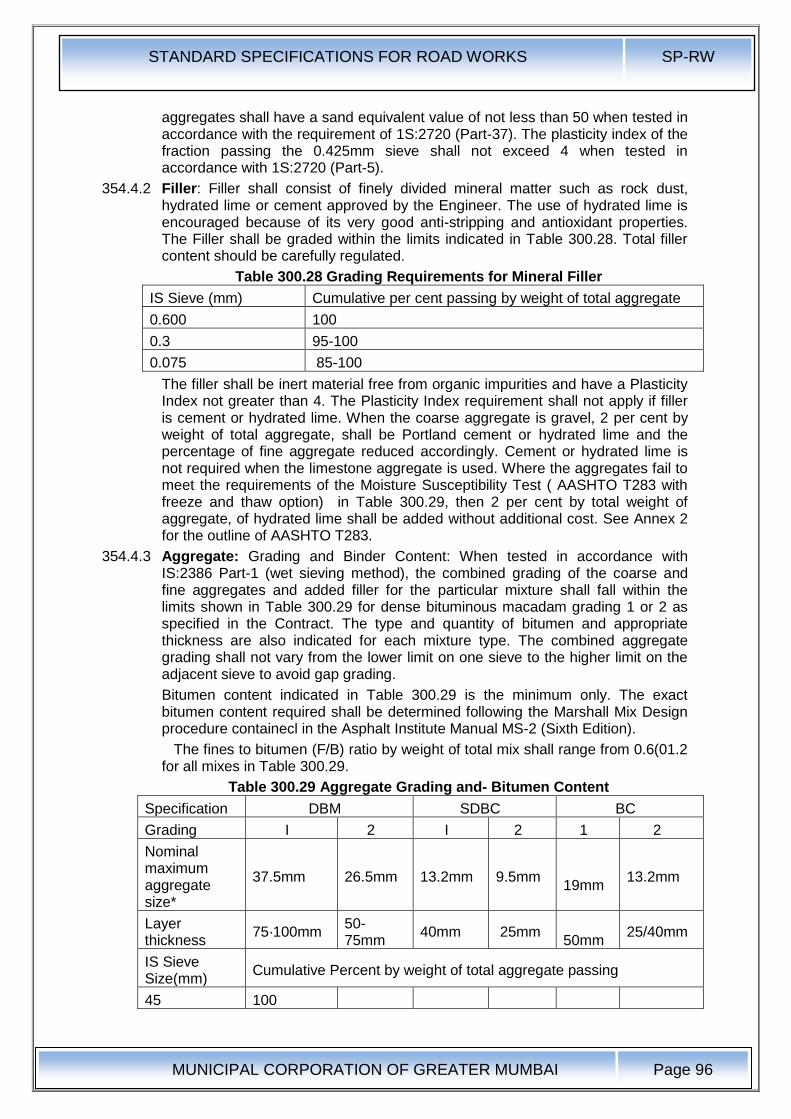
STANDARD SPECIFICATIONS FOR ROAD WORKS SP-RW
MUNICIPAL CORPORATION OF GREATER MUMBAI
Page 96
aggregates shall have a sand equivalent value of not less than 50 when tested in accordance with the requirement of 1S:2720 (Part-37). The plasticity index of the fraction passing the 0.425mm sieve shall not exceed 4 when tested in accordance with 1S:2720 (Part-5).
354.4.2 Filler: Filler shall consist of finely divided mineral matter such as rock dust, hydrated lime or cement approved by the Engineer. The use of hydrated lime is encouraged because of its very good anti-stripping and antioxidant properties. The Filler shall be graded within the limits indicated in Table 300.28. Total filler content should be carefully regulated.
Table 300.28 Grading Requirements for Mineral Filler
IS Sieve (mm) Cumulative per cent passing by weight of total aggregate
0.600 100
0.3 95-100
0.075 85-100
The filler shall be inert material free from organic impurities and have a Plasticity Index not greater than 4. The Plasticity Index requirement shall not apply if filler is cement or hydrated lime. When the coarse aggregate is gravel, 2 per cent by weight of total aggregate, shall be Portland cement or hydrated lime and the percentage of fine aggregate reduced accordingly. Cement or hydrated lime is not required when the limestone aggregate is used. Where the aggregates fail to meet the requirements of the Moisture Susceptibility Test ( AASHTO T283 with freeze and thaw option) in Table 300.29, then 2 per cent by total weight of aggregate, of hydrated lime shall be added without additional cost. See Annex 2 for the outline of AASHTO T283.
354.4.3 Aggregate: Grading and Binder Content: When tested in accordance with IS:2386 Part-1 (wet sieving method), the combined grading of the coarse and fine aggregates and added filler for the particular mixture shall fall within the limits shown in Table 300.29 for dense bituminous macadam grading 1 or 2 as specified in the Contract. The type and quantity of bitumen and appropriate thickness are also indicated for each mixture type. The combined aggregate grading shall not vary from the lower limit on one sieve to the higher limit on the adjacent sieve to avoid gap grading.
Bitumen content indicated in Table 300.29 is the minimum only. The exact bitumen content required shall be determined following the Marshall Mix Design procedure containecl in the Asphalt Institute Manual MS-2 (Sixth Edition).
The fines to bitumen (F/B) ratio by weight of total mix shall range from 0.6(01.2 for all mixes in Table 300.29.
Table 300.29 Aggregate Grading and- Bitumen Content
Specification DBM SDBC BC
Grading I 2 I 2 1 2
Nominal maximum aggregate size*
37.5mm 26.5mm 13.2mm 9.5mm 19mm
13.2mm
Layer thickness
75·100mm 50-75mm
40mm 25mm 50mm
25/40mm
IS Sieve Size(mm)
Cumulative Percent by weight of total aggregate passing
45 100
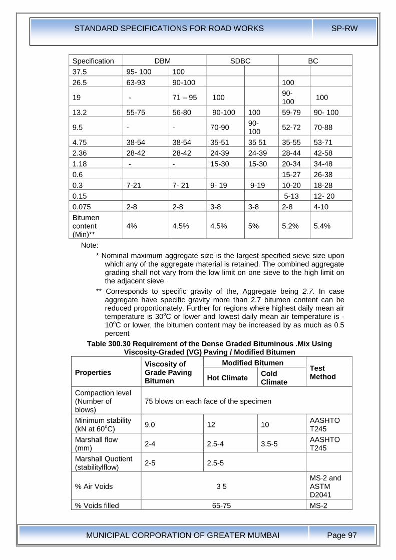
STANDARD SPECIFICATIONS FOR ROAD WORKS SP-RW
MUNICIPAL CORPORATION OF GREATER MUMBAI
Page 97
Specification DBM SDBC BC
37.5 95- 100 100
26.5 63-93 90-100 100
19 - 71 – 95 100 90-100
100
13.2 55-75 56-80 90-100 100 59-79 90- 100
9.5 - - 70-90 90-100
52-72 70-88
4.75 38-54 38-54 35-51 35 51 35-55 53-71
2.36 28-42 28-42 24-39 24-39 28-44 42-58
1.18 - - 15-30 15-30 20-34 34-48
0.6 15-27 26-38
0.3 7-21 7- 21 9- 19 9-19 10-20 18-28
0.15 5-13 12- 20
0.075 2-8 2-8 3-8 3-8 2-8 4-10
Bitumen content (Min)**
4% 4.5% 4.5% 5% 5.2% 5.4%
Note:
* Nominal maximum aggregate size is the largest specified sieve size upon which any of the aggregate material is retained. The combined aggregate grading shall not vary from the low limit on one sieve to the high limit on the adjacent sieve.
** Corresponds to specific gravity of the, Aggregate being 2.7. In case aggregate have specific gravity more than 2.7 bitumen content can be reduced proportionately. Further for regions where highest daily mean air temperature is 30oC or lower and Iowest daily mean air temperature is -10oC or lower, the bitumen content may be increased by as much as 0.5 percent
Table 300.30 Requirement of the Dense Graded Bituminous .Mix Using Viscosity-Graded (VG) Paving / Modified Bitumen
Properties Viscosity of Grade Paving Bitumen
Modified Bitumen Test Method Hot Climate
Cold Climate
Compaction level (Number of blows)
75 blows on each face of the specimen
Minimum stability (kN at 60oC)
9.0 12 10 AASHTO T245
Marshall flow (mm)
2-4 2.5-4 3.5-5 AASHTO T245
Marshall Quotient (stabilitylflow)
2-5 2.5-5
% Air Voids 3 5 MS·2 and ASTM D2041
% Voids filled 65-75 MS-2
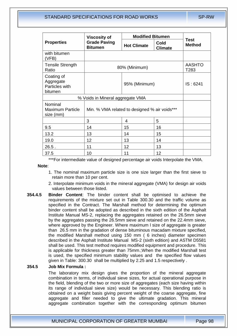
STANDARD SPECIFICATIONS FOR ROAD WORKS SP-RW
MUNICIPAL CORPORATION OF GREATER MUMBAI
Page 98
Properties Viscosity of Grade Paving Bitumen
Modified Bitumen Test Method Hot Climate
Cold Climate
with bitumen (VFB)
Tensile Strength Ratio
80% (Minimum) AASHTO T283
Coating of Aggregate Particles with bitumen
95% (Minimum) IS : 6241
% Voids in Mineral aggregate VMA
Nominal Maximum Particle size (mm)
Min. % VMA related to designed % air voids***
3 4 5
9.5 14 15 16
13.2 13 14 15
19.0 12 13 14
26.5 . 11 12 13
37.5 10 11 12
***For intermediate value of designed percentage air voids Interpolate the VMA.
Note:
1. The nominal maximum particle size is one size larger than the first sieve to retain more than 10 per cent.
2. Interpolate minimum voids in the mineral aggregate (VMA) for design air voids values between those listed.
354.4.5 Binder Content: The binder content shall be optimised to achieve the requirements of the mixture set out in Table 300.30 and the traffic volume as specified in the Contract. The Marshall method for determining the optimum binder content shall be adopted as described in the sixth edition of the Asphalt Institute Manual MS-2, replacing the aggregates retained on the 26.5mm sieve by the aggregates passing the 26.5mm sieve and retained on the 22.4mm sieve, where approved by the Engineer. Where maximum l size of aggregate is greater than 26.5 mm in the gradation of dense bituminous macadam mixture specified, the modified Marshall method using 150 mm ( 6 inches) diameter specimen described in the Asphalt Institute Manual MS-2 (sixth edition) and ASTM D5581 shall be used. This test method requires modified equipment and procedure. This is applicable for thickness greater than 75mm.;When the modified Marshall test is used, the specified minimum stability values and the specified flow values given in Table: 300.30 shall be multiplied by 2.25 and 1.5 respectively .
354.5 Job Mix Formula :
The laboratory mix design gives the proportion of the mineral aggregate combination in terms, of individual sieve sizes, for actual operational purpose in the field, blending of the two or more size of aggregates (each size having within its range of individual sieve size) would be necessary. This blending ratio is obtained on a weight basis giving percent weight of the coarse aggregate, fine aggregate and filler needed to give the ultimate gradation. This mineral aggregate combination together with the corresponding optimum bitumen
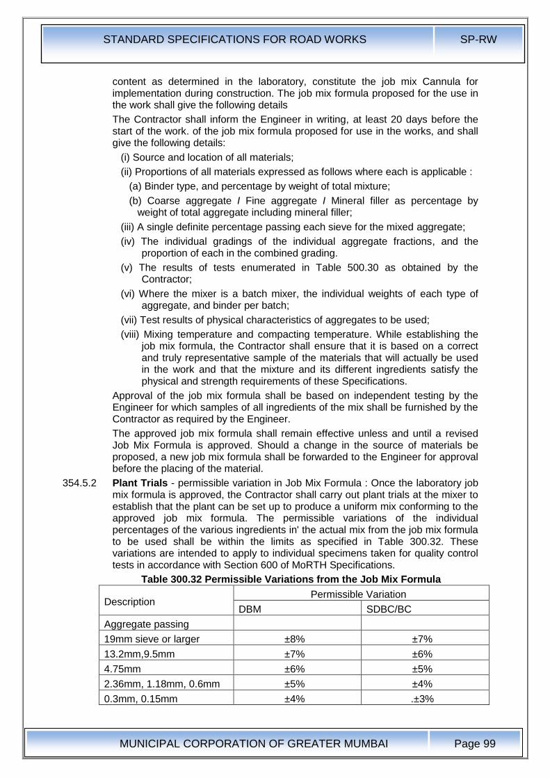
STANDARD SPECIFICATIONS FOR ROAD WORKS SP-RW
MUNICIPAL CORPORATION OF GREATER MUMBAI
Page 99
content as determined in the laboratory, constitute the job mix Cannula for implementation during construction. The job mix formula proposed for the use in the work shall give the following details
The Contractor shall inform the Engineer in writing, at least 20 days before the start of the work. of the job mix formula proposed for use in the works, and shall give the following details:
(i) Source and location of all materials;
(ii) Proportions of all materials expressed as follows where each is applicable :
(a) Binder type, and percentage by weight of total mixture;
(b) Coarse aggregate I Fine aggregate I Mineral filler as percentage by weight of total aggregate including mineral filler;
(iii) A single definite percentage passing each sieve for the mixed aggregate;
(iv) The individual gradings of the individual aggregate fractions, and the proportion of each in the combined grading.
(v) The results of tests enumerated in Table 500.30 as obtained by the Contractor;
(vi) Where the mixer is a batch mixer, the individual weights of each type of aggregate, and binder per batch;
(vii) Test results of physical characteristics of aggregates to be used;
(viii) Mixing temperature and compacting temperature. While establishing the job mix formula, the Contractor shall ensure that it is based on a correct and truly representative sample of the materials that will actually be used in the work and that the mixture and its different ingredients satisfy the physical and strength requirements of these Specifications.
Approval of the job mix formula shall be based on independent testing by the Engineer for which samples of all ingredients of the mix shall be furnished by the Contractor as required by the Engineer.
The approved job mix formula shall remain effective unless and until a revised Job Mix Formula is approved. Should a change in the source of materials be proposed, a new job mix formula shall be forwarded to the Engineer for approval before the placing of the material.
354.5.2 Plant Trials - permissible variation in Job Mix Formula : Once the laboratory job mix formula is approved, the Contractor shall carry out plant trials at the mixer to establish that the plant can be set up to produce a uniform mix conforming to the approved job mix formula. The permissible variations of the individual percentages of the various ingredients in' the actual mix from the job mix formula to be used shall be within the limits as specified in Table 300.32. These variations are intended to apply to individual specimens taken for quality control tests in accordance with Section 600 of MoRTH Specifications.
Table 300.32 Permissible Variations from the Job Mix Formula
Description Permissible Variation
DBM SDBC/BC
Aggregate passing
19mm sieve or larger ±8% ±7%
13.2mm,9.5mm ±7% ±6%
4.75mm ±6% ±5%
2.36mm, 1.18mm, 0.6mm ±5% ±4%
0.3mm, 0.15mm ±4% .±3%
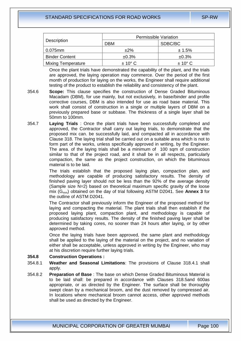
STANDARD SPECIFICATIONS FOR ROAD WORKS SP-RW
MUNICIPAL CORPORATION OF GREATER MUMBAI
Page 100
Description Permissible Variation
DBM SDBC/BC
0.075mm ±2% ± 1.5%
Binder Content ±0.3% ±0.3%
Mixing Temperature ± 10° C ± 10° C
Once the plant trials have demonstrated the capability of the plant, and the trials are approved, the laying operation may commerce. Over the period of the first month of production for laying on the works, the Engineer shall require additional testing of the product to establish the reliability and consistency of the plant.
354.6 Scope: This clause specifies the construction of Dense Graded Bituminous Macadam (DBM), for use mainly, but not exclusively, in base/binder and profile corrective courses, DBM is also intended for use as road base material. This work shall consist of construction in a single or multiple layers of DBM on a previously prepared base or subbase. The thickness of a single layer shall be 50mm to 100mm.
354.7 Laying Trials : Once the plant trials have been successfully completed and approved, the Contractor shall carry out laying trials, to demonstrate that the proposed mix can. be successfully laid, and compacted all in accordance with Clause 318. The laying trial shall be carried out on a suitable area which is not to form part of the works, unless specifically approved in writing, by the Engineer. The area. of the laying trials shall be a minimum of 100 sqm of construction similar to that of the project road, and it shall be in all respects, particularly compaction, the same as the project construction, on which the bituminous material is to be laid.
The trials establish that the proposed laying plan, compaction plan, and methodology are capable of producing satisfactory results. The density of finished paving layer should not be less than the 92% of the average density (Sample size N=2) based on theoretical maximum specific gravity of the loose mix (Gmm) obtained on the day of trial following ASTM D2041. See Annex 3 for the outline of ASTM D2041.
The Contractor shall previously inform the Engineer of the proposed method for laying and compacting the material. The plant trials shall then establish if the proposed laying plant, compaction plant, and methodology is capable of producing satisfactory results. The density of the finished paving layer shall be determined by taking cores, no sooner than 24 hours after laying, or by other approved method.
Once the laying trials have been approved, the same plant and methodology shall be applied to the laying of the material on the project, and no variation of either shall be acceptable, unless approved in writing by the Engineer, who may at his discretion require further laying trials.
354.8 Construction Operations :
354.8.1 Weather and Seasonal Limitations: The provisions of Clause 318.4.1 shall apply.
354.8.2 Preparation of Base : The base on which Dense Graded Bituminous Material is to be laid shall: be prepared in accordance with Clauses 318.5and 600as appropriate, or as directed by the Engineer. The surface shall be thoroughly swept clean by a mechanical broom, and the dust removed by compressed air. In locations where mechanical broom cannot access, other approved methods shall be used as directed by the Engineer.
STANDARD SPECIFICATIONS FOR ROAD WORKS SP-RW
MUNICIPAL CORPORATION OF GREATER MUMBAI
Page 101
354.8.3 Geo-Synthetics : Where Geo-synthetics are specified in the Contract, this shall be in accordance with the requirements stated in Clause 260.
354.8.4 Stress Absorbing Layer: Where a stress absorbing layer is specified in the Contract, this shall be applied in accordance with the requirements of Clause 316.
354.8.4.1 Profile correcting coarse:
Profile correcting Course: Depending upon requirement, profile-correcting course for correcting the existing pavement profile shall be laid either as a separate layer or as a composite layer with varying thickness. Where the maximum thickness of the profile corrective course is less than 40 mm, the profile corrective course shall be laid as an integral part of the overlaying layer. In other cases the profile corrective course shall be constructed as a separate layer. When it is laid as a separate layer, type of material for the use as the profile corrective course may differ.
354.8.5 Prime Coat : Where the material on which the dense bituminous macadam is to be laid is other than a bitumen bound layer, a prime coat shall be applied, as specified, in accordance with the provisions of Clause 313, or as directed by the Engineer.
354.8.6 Tack Coat : Where the material on which the dense bituminous macadam is to be placed is bitumen bound surface, a tack coat shall be applied as specified, in accordance with the provisions of Clause 314, or as directed by the Engineer.
354.8.7 Mixing and Transportation of the mixture : The provisions as specified in Clauses 318.2.1 and 318.3.1 shall apply.
354.8.8 Spreading: The provisions of Clauses 318.6 shall apply.
354.8.9 Rolling: The general provisions of Clauses 318.8 shall apply, as modified by the approved by laying trials. The compaction process shall be carried out by the same plant, and .using the same method, as approved in the laying trials, which may be varied only with the express approval of the Engineer in writing.
354.8.10 Opening to Traffic : The newly laid surface shall not be open to traffic for at least 24 hrs. after laying and completion of compaction, without the express approval of the Engineer in writing.
354.8.11 Surface Finish and Quality Control of Work : The surface finish of the completed construction shall conform to the requirements of Clause 600. All materials and workmanship shall comply with the provisions set out in Section 600.
354.8.12 Arrangements for Traffic : During the period of construction, arrangements for traffic shall be made in accordance with the provisions of Clause 30.
354.8.13 Measurements for Payment : Dense Graded Bituminous Materials shall be measured as finished work wither in cubic metres, tons or by the square metre at a specified thickness as detailed on the Contract drawings, or documents, or as directed by the Engineer.
354.8.14 Rate: The contract unit rate for Dense Graded Bituminous Macadam shall be payment in full for carrying out the all required operations as specified, and shall include, but not necessarily limited to all components listed in Clause 318.11. The rate shall include the provision of bitumen, at 4.25 per cent by weight of the total mixture.The variation in actual percentage of bitumen used will be assessed and the payment adjusted, up or down, accordingly.
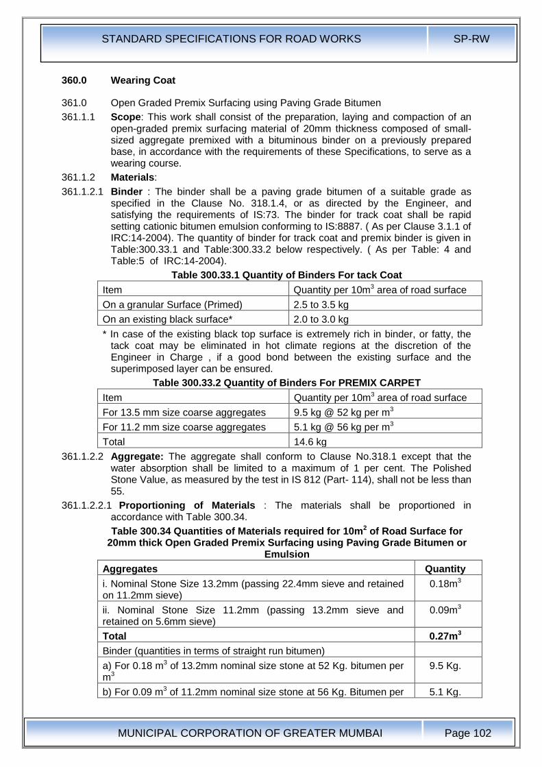
STANDARD SPECIFICATIONS FOR ROAD WORKS SP-RW
MUNICIPAL CORPORATION OF GREATER MUMBAI
Page 102
360.0 Wearing Coat
361.0 Open Graded Premix Surfacing using Paving Grade Bitumen
361.1.1 Scope: This work shall consist of the preparation, laying and compaction of an open-graded premix surfacing material of 20mm thickness composed of small-sized aggregate premixed with a bituminous binder on a previously prepared base, in accordance with the requirements of these Specifications, to serve as a wearing course.
361.1.2 Materials:
361.1.2.1 Binder : The binder shall be a paving grade bitumen of a suitable grade as specified in the Clause No. 318.1.4, or as directed by the Engineer, and satisfying the requirements of IS:73. The binder for track coat shall be rapid setting cationic bitumen emulsion conforming to IS:8887. ( As per Clause 3.1.1 of IRC:14-2004). The quantity of binder for track coat and premix binder is given in Table:300.33.1 and Table:300.33.2 below respectively. ( As per Table: 4 and Table:5 of IRC:14-2004).
Table 300.33.1 Quantity of Binders For tack Coat
Item Quantity per 10m3 area of road surface
On a granular Surface (Primed) 2.5 to 3.5 kg
On an existing black surface* 2.0 to 3.0 kg
* In case of the existing black top surface is extremely rich in binder, or fatty, the tack coat may be eliminated in hot climate regions at the discretion of the Engineer in Charge , if a good bond between the existing surface and the superimposed layer can be ensured.
Table 300.33.2 Quantity of Binders For PREMIX CARPET
Item Quantity per 10m3 area of road surface
For 13.5 mm size coarse aggregates 9.5 kg @ 52 kg per m3
For 11.2 mm size coarse aggregates 5.1 kg @ 56 kg per m3
Total 14.6 kg
361.1.2.2 Aggregate: The aggregate shall conform to Clause No.318.1 except that the water absorption shall be limited to a maximum of 1 per cent. The Polished Stone Value, as measured by the test in IS 812 (Part- 114), shall not be less than 55.
361.1.2.2.1 Proportioning of Materials : The materials shall be proportioned in accordance with Table 300.34.
Table 300.34 Quantities of Materials required for 10m2 of Road Surface for 20mm thick Open Graded Premix Surfacing using Paving Grade Bitumen or
Emulsion
Aggregates Quantity
i. Nominal Stone Size 13.2mm (passing 22.4mm sieve and retained on 11.2mm sieve)
0.18m3
ii. Nominal Stone Size 11.2mm (passing 13.2mm sieve and retained on 5.6mm sieve)
0.09m3
Total 0.27m3
Binder (quantities in terms of straight run bitumen)
a) For 0.18 m3 of 13.2mm nominal size stone at 52 Kg. bitumen per m3
9.5 Kg.
b) For 0.09 m3 of 11.2mm nominal size stone at 56 Kg. Bitumen per 5.1 Kg.
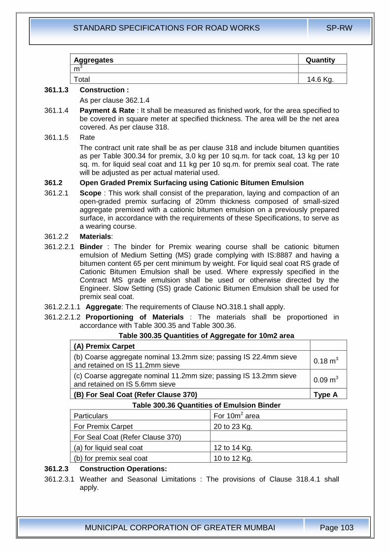
STANDARD SPECIFICATIONS FOR ROAD WORKS SP-RW
MUNICIPAL CORPORATION OF GREATER MUMBAI
Page 103
Aggregates Quantity
m3
Total 14.6 Kg.
361.1.3 Construction :
As per clause 362.1.4
361.1.4 Payment & Rate : It shall be measured as finished work, for the area specified to be covered in square meter at specified thickness. The area will be the net area covered. As per clause 318.
361.1.5 Rate
The contract unit rate shall be as per clause 318 and include bitumen quantities as per Table 300.34 for premix, 3.0 kg per 10 sq.m. for tack coat, 13 kg per 10 sq. m. for liquid seal coat and 11 kg per 10 sq.m. for premix seal coat. The rate will be adjusted as per actual material used.
361.2 Open Graded Premix Surfacing using Cationic Bitumen Emulsion
361.2.1 Scope : This work shall consist of the preparation, laying and compaction of an open-graded premix surfacing of 20mm thickness composed of small-sized aggregate premixed with a cationic bitumen emulsion on a previously prepared surface, in accordance with the requirements of these Specifications, to serve as a wearing course.
361.2.2 Materials:
361.2.2.1 Binder : The binder for Premix wearing course shall be cationic bitumen emulsion of Medium Setting (MS) grade complying with IS:8887 and having a bitumen content 65 per cent minimum by weight. For liquid seal coat RS grade of Cationic Bitumen Emulsion shall be used. Where expressly specified in the Contract MS grade emulsion shall be used or otherwise directed by the Engineer. Slow Setting (SS) grade Cationic Bitumen Emulsion shall be used for premix seal coat.
361.2.2.1.1 Aggregate: The requirements of Clause NO.318.1 shall apply.
361.2.2.1.2 Proportioning of Materials : The materials shall be proportioned in accordance with Table 300.35 and Table 300.36.
Table 300.35 Quantities of Aggregate for 10m2 area
(A) Premix Carpet
(b) Coarse aggregate nominal 13.2mm size; passing IS 22.4mm sieve and retained on IS 11.2mm sieve
0.18 m3
(c) Coarse aggregate nominal 11.2mm size; passing IS 13.2mm sieve and retained on IS 5.6mm sieve
0.09 m3
(B) For Seal Coat (Refer Clause 370) Type A
Table 300.36 Quantities of Emulsion Binder
Particulars For 10m2 area
For Premix Carpet 20 to 23 Kg.
For Seal Coat (Refer Clause 370)
(a) for liquid seal coat 12 to 14 Kg.
(b) for premix seal coat 10 to 12 Kg.
361.2.3 Construction Operations:
361.2.3.1 Weather and Seasonal Limitations : The provisions of Clause 318.4.1 shall apply.
STANDARD SPECIFICATIONS FOR ROAD WORKS SP-RW
MUNICIPAL CORPORATION OF GREATER MUMBAI
Page 104
361.2.3.2 Preparation of Base: The underlying surface on which the bituminous surfacing is to be laid shall be prepared, shaped and conditioned to the specified lines, grade and cross-section in accordance with Clause
318.10. A prime coat where needed shall be applied in accordance with Clause 313 as directed by the Engineer.
361.2.3.3 Tack Coat: A tack coat shall be applied over the base preparatory to laying of the surfacing in accordance with the requirements of Clause 314.
361.2.3.4 Preparation of Premix : Hot mix plant of appropriate capacity and type shall be used for the preparation of the mix material. The hot mix plant shall have separate dryer arrangement for heating aggregate.
The temperature of the binder at the time of mixing shall be in the range of 150°C to 163°C and that of the aggregate in the range of 155°C to 163°C provided that the difference in temperature between the binder and aggregate at no time exceeds 14°C. Mixing shall be thorough to ensure that a homogeneous mixture is obtained in which all particles of the aggregates are coated uniformly and the discharge temperature of mix shall be between 130°C and 160°C.
The mix shall be immediately transported from the mixer to the point of use in suitable vehicles or hand barrows. The vehicles employed for transport shall be clean and the mix being transported covered in transit if so directed by the Engineer.
361.2.3.5 Spreading and Rolling : The pre mixed material shall be spread by suitable means to the desired thickness, grades and cross-full (camber) making due allowance for any extra quantity required to fill up depressions, if any. The cross-fall should be checked by means of camber boards and irregularities levelled out. Excessive use of blades or rakes should be avoided. As soon as sufficient length of bituminous material has been laid, rolling shall commence with 8-10 tonne rollers, smooth wheel tandem type, or other approved equipment. Rolling shall begin at the edge and progress toward the centre longitudinally, except that on super elevated and unidirectional cambered portions, it shall progress from the lower to upper edge parallel to the centre line of the pavement.
When the roller has passed over the whole area once, any high spots or depressions, . which become apparent, shall be corrected by removing or adding premixed materials. Rolling shall then be continued until the entire surface has been rolled and all the roller marks eliminated. In each pass of the roller, the preceding track shall be overlapped uniformly by at least 1/3 width. The roller wheels shall be kept damp to prevent the premix from adhering to the wheels. In no case shall fuel/lubricating oil be used for this purpose. Excess use of water for this purpose shall also be avoided.
Rollers shall not stand on newly laid material. Rolling operations shall be completed in every respect before the temperature of the mix falls below 100°C. joints along and transverse to the surfacing laid and compacted earlier shall be cut vertically to their full depth so as to expose fresh surface which shall be painted with a thin coat of appropriate binder before the new mix is placed against it.
361.2.3.6 Seal Coat: A seal coat conforming to Clause 370 of the type specified in the Contract shall be applied to the surface immediately after laying the surfacing.
361.2.3.7 Opening to Traffic: No traffic shall be allowed on the road until the seal coat has been laid. After the seal coat is laid, the road may be opened to traffic according to Clause 30.
361.2.3.8 Surface Finish and Quality Control of Work: The surface finish of the construction shall conform to the requirements of Clause 600. For control on the
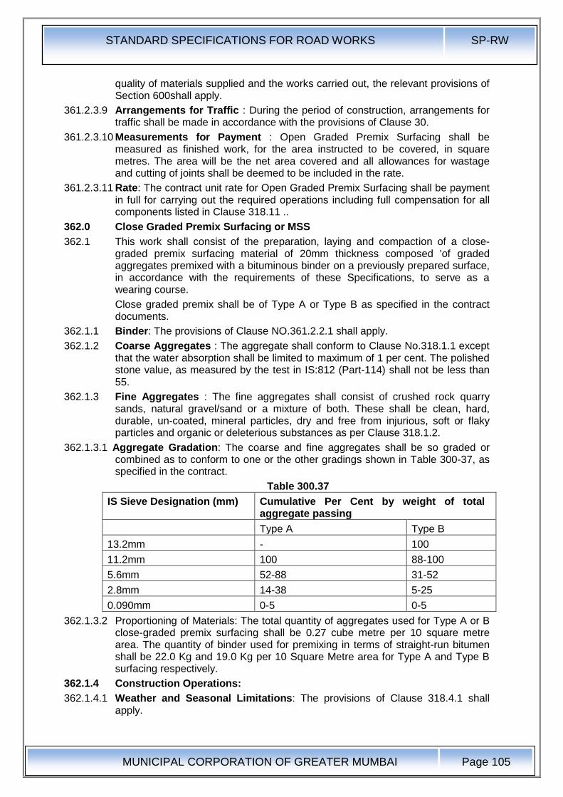
STANDARD SPECIFICATIONS FOR ROAD WORKS SP-RW
MUNICIPAL CORPORATION OF GREATER MUMBAI
Page 105
quality of materials supplied and the works carried out, the relevant provisions of Section 600shall apply.
361.2.3.9 Arrangements for Traffic : During the period of construction, arrangements for traffic shall be made in accordance with the provisions of Clause 30.
361.2.3.10 Measurements for Payment : Open Graded Premix Surfacing shall be measured as finished work, for the area instructed to be covered, in square metres. The area will be the net area covered and all allowances for wastage and cutting of joints shall be deemed to be included in the rate.
361.2.3.11 Rate: The contract unit rate for Open Graded Premix Surfacing shall be payment in full for carrying out the required operations including full compensation for all components listed in Clause 318.11 ..
362.0 Close Graded Premix Surfacing or MSS
362.1 This work shall consist of the preparation, laying and compaction of a close-graded premix surfacing material of 20mm thickness composed 'of graded aggregates premixed with a bituminous binder on a previously prepared surface, in accordance with the requirements of these Specifications, to serve as a wearing course.
Close graded premix shall be of Type A or Type B as specified in the contract documents.
362.1.1 Binder: The provisions of Clause NO.361.2.2.1 shall apply.
362.1.2 Coarse Aggregates : The aggregate shall conform to Clause No.318.1.1 except that the water absorption shall be limited to maximum of 1 per cent. The polished stone value, as measured by the test in IS:812 (Part-114) shall not be less than 55.
362.1.3 Fine Aggregates : The fine aggregates shall consist of crushed rock quarry sands, natural gravel/sand or a mixture of both. These shall be clean, hard, durable, un-coated, mineral particles, dry and free from injurious, soft or flaky particles and organic or deleterious substances as per Clause 318.1.2.
362.1.3.1 Aggregate Gradation: The coarse and fine aggregates shall be so graded or combined as to conform to one or the other gradings shown in Table 300-37, as specified in the contract.
Table 300.37
IS Sieve Designation (mm) Cumulative Per Cent by weight of total aggregate passing
Type A Type B
13.2mm - 100
11.2mm 100 88-100
5.6mm 52-88 31-52
2.8mm 14-38 5-25
0.090mm 0-5 0-5
362.1.3.2 Proportioning of Materials: The total quantity of aggregates used for Type A or B close-graded premix surfacing shall be 0.27 cube metre per 10 square metre area. The quantity of binder used for premixing in terms of straight-run bitumen shall be 22.0 Kg and 19.0 Kg per 10 Square Metre area for Type A and Type B surfacing respectively.
362.1.4 Construction Operations:
362.1.4.1 Weather and Seasonal Limitations: The provisions of Clause 318.4.1 shall apply.
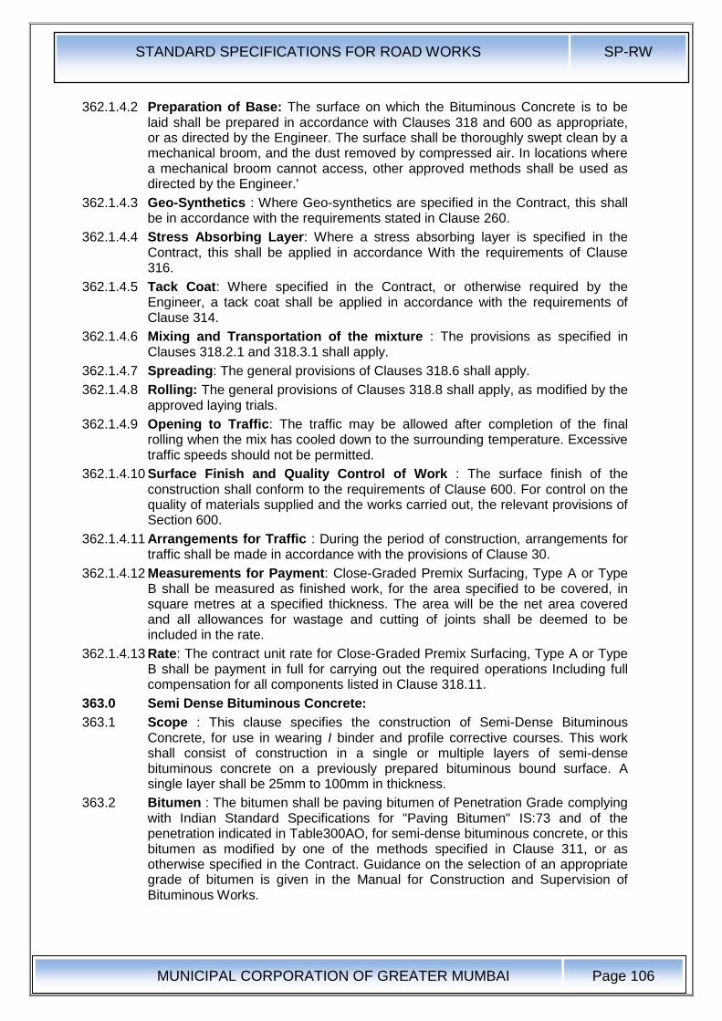
STANDARD SPECIFICATIONS FOR ROAD WORKS SP-RW
MUNICIPAL CORPORATION OF GREATER MUMBAI
Page 106
362.1.4.2 Preparation of Base: The surface on which the Bituminous Concrete is to be laid shall be prepared in accordance with Clauses 318 and 600 as appropriate, or as directed by the Engineer. The surface shall be thoroughly swept clean by a mechanical broom, and the dust removed by compressed air. In locations where a mechanical broom cannot access, other approved methods shall be used as directed by the Engineer.'
362.1.4.3 Geo-Synthetics : Where Geo-synthetics are specified in the Contract, this shall be in accordance with the requirements stated in Clause 260.
362.1.4.4 Stress Absorbing Layer: Where a stress absorbing layer is specified in the Contract, this shall be applied in accordance With the requirements of Clause 316.
362.1.4.5 Tack Coat: Where specified in the Contract, or otherwise required by the Engineer, a tack coat shall be applied in accordance with the requirements of Clause 314.
362.1.4.6 Mixing and Transportation of the mixture : The provisions as specified in Clauses 318.2.1 and 318.3.1 shall apply.
362.1.4.7 Spreading: The general provisions of Clauses 318.6 shall apply.
362.1.4.8 Rolling: The general provisions of Clauses 318.8 shall apply, as modified by the approved laying trials.
362.1.4.9 Opening to Traffic: The traffic may be allowed after completion of the final rolling when the mix has cooled down to the surrounding temperature. Excessive traffic speeds should not be permitted.
362.1.4.10 Surface Finish and Quality Control of Work : The surface finish of the construction shall conform to the requirements of Clause 600. For control on the quality of materials supplied and the works carried out, the relevant provisions of Section 600.
362.1.4.11 Arrangements for Traffic : During the period of construction, arrangements for traffic shall be made in accordance with the provisions of Clause 30.
362.1.4.12 Measurements for Payment: Close-Graded Premix Surfacing, Type A or Type B shall be measured as finished work, for the area specified to be covered, in square metres at a specified thickness. The area will be the net area covered and all allowances for wastage and cutting of joints shall be deemed to be included in the rate.
362.1.4.13 Rate: The contract unit rate for Close-Graded Premix Surfacing, Type A or Type B shall be payment in full for carrying out the required operations Including full compensation for all components listed in Clause 318.11.
363.0 Semi Dense Bituminous Concrete:
363.1 Scope : This clause specifies the construction of Semi-Dense Bituminous Concrete, for use in wearing I binder and profile corrective courses. This work shall consist of construction in a single or multiple layers of semi-dense bituminous concrete on a previously prepared bituminous bound surface. A single layer shall be 25mm to 100mm in thickness.
363.2 Bitumen : The bitumen shall be paving bitumen of Penetration Grade complying with Indian Standard Specifications for "Paving Bitumen" IS:73 and of the penetration indicated in Table300AO, for semi-dense bituminous concrete, or this bitumen as modified by one of the methods specified in Clause 311, or as otherwise specified in the Contract. Guidance on the selection of an appropriate grade of bitumen is given in the Manual for Construction and Supervision of Bituminous Works.
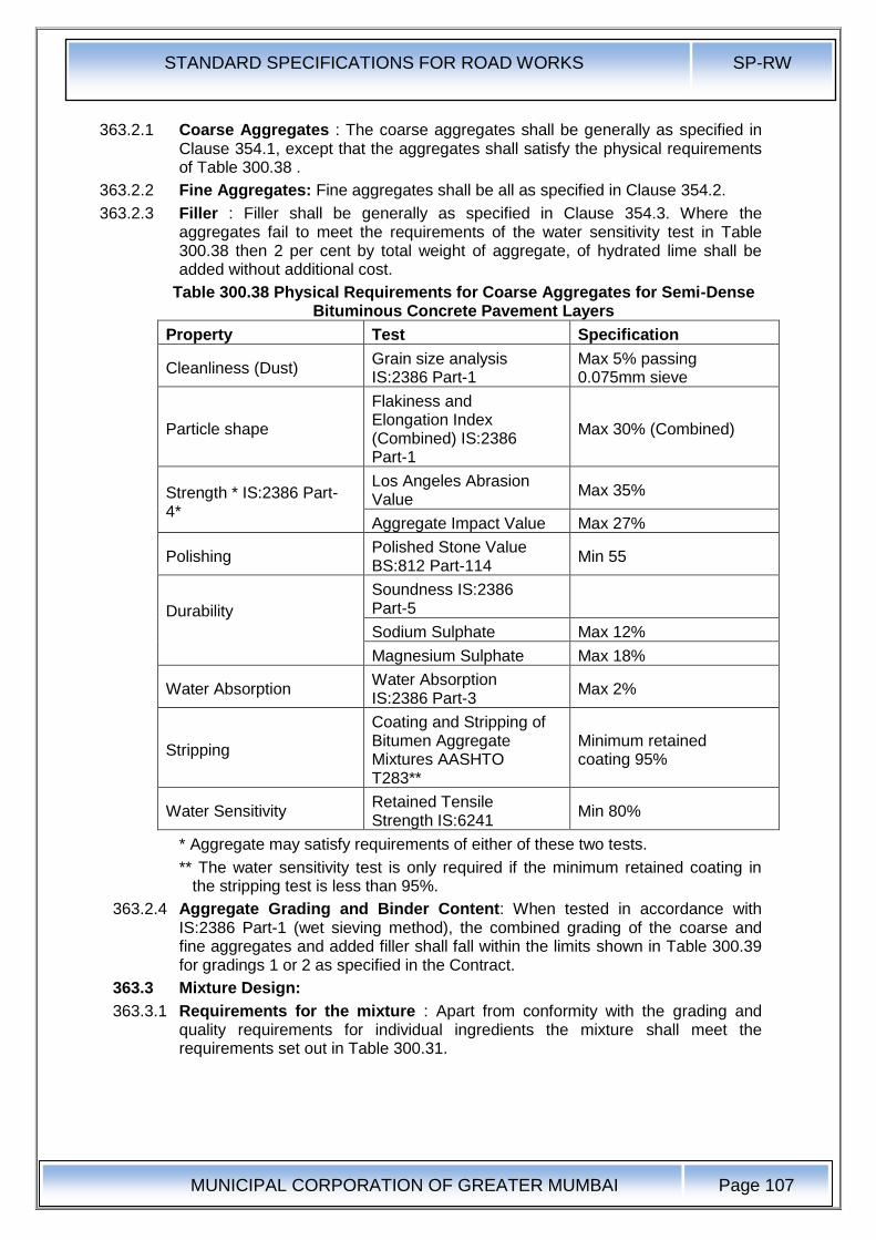
STANDARD SPECIFICATIONS FOR ROAD WORKS SP-RW
MUNICIPAL CORPORATION OF GREATER MUMBAI
Page 107
363.2.1 Coarse Aggregates : The coarse aggregates shall be generally as specified in Clause 354.1, except that the aggregates shall satisfy the physical requirements of Table 300.38 .
363.2.2 Fine Aggregates: Fine aggregates shall be all as specified in Clause 354.2.
363.2.3 Filler : Filler shall be generally as specified in Clause 354.3. Where the aggregates fail to meet the requirements of the water sensitivity test in Table 300.38 then 2 per cent by total weight of aggregate, of hydrated lime shall be added without additional cost.
Table 300.38 Physical Requirements for Coarse Aggregates for Semi-Dense Bituminous Concrete Pavement Layers
Property Test Specification
Cleanliness (Dust) Grain size analysis IS:2386 Part-1
Max 5% passing 0.075mm sieve
Particle shape
Flakiness and Elongation Index (Combined) IS:2386 Part-1
Max 30% (Combined)
Strength * IS:2386 Part-4*
Los Angeles Abrasion Value
Max 35%
Aggregate Impact Value Max 27%
Polishing Polished Stone Value BS:812 Part-114
Min 55
Durability
Soundness IS:2386 Part-5
Sodium Sulphate Max 12%
Magnesium Sulphate Max 18%
Water Absorption Water Absorption IS:2386 Part-3
Max 2%
Stripping
Coating and Stripping of Bitumen Aggregate Mixtures AASHTO T283**
Minimum retained coating 95%
Water Sensitivity Retained Tensile Strength IS:6241
Min 80%
* Aggregate may satisfy requirements of either of these two tests.
** The water sensitivity test is only required if the minimum retained coating in the stripping test is less than 95%.
363.2.4 Aggregate Grading and Binder Content: When tested in accordance with IS:2386 Part-1 (wet sieving method), the combined grading of the coarse and fine aggregates and added filler shall fall within the limits shown in Table 300.39 for gradings 1 or 2 as specified in the Contract.
363.3 Mixture Design:
363.3.1 Requirements for the mixture : Apart from conformity with the grading and quality requirements for individual ingredients the mixture shall meet the requirements set out in Table 300.31.
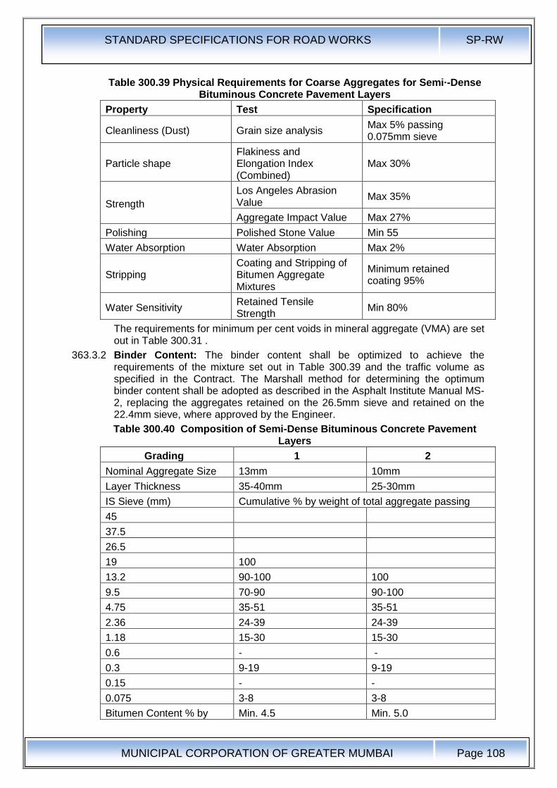
STANDARD SPECIFICATIONS FOR ROAD WORKS SP-RW
MUNICIPAL CORPORATION OF GREATER MUMBAI
Page 108
Table 300.39 Physical Requirements for Coarse Aggregates for Semi·-Dense Bituminous Concrete Pavement Layers
Property Test Specification
Cleanliness (Dust) Grain size analysis Max 5% passing 0.075mm sieve
Particle shape Flakiness and Elongation Index (Combined)
Max 30%
Strength
Los Angeles Abrasion Value
Max 35%
Aggregate Impact Value Max 27%
Polishing Polished Stone Value Min 55
Water Absorption Water Absorption Max 2%
Stripping Coating and Stripping of Bitumen Aggregate Mixtures
Minimum retained coating 95%
Water Sensitivity Retained Tensile Strength
Min 80%
The requirements for minimum per cent voids in mineral aggregate (VMA) are set out in Table 300.31 .
363.3.2 Binder Content: The binder content shall be optimized to achieve the requirements of the mixture set out in Table 300.39 and the traffic volume as specified in the Contract. The Marshall method for determining the optimum binder content shall be adopted as described in the Asphalt Institute Manual MS-2, replacing the aggregates retained on the 26.5mm sieve and retained on the 22.4mm sieve, where approved by the Engineer.
Table 300.40 Composition of Semi-Dense Bituminous Concrete Pavement Layers
Grading 1 2
Nominal Aggregate Size 13mm 10mm
Layer Thickness 35-40mm 25-30mm
IS Sieve (mm) Cumulative % by weight of total aggregate passing
45
37.5
26.5
19 100
13.2 90-100 100
9.5 70-90 90-100
4.75 35-51 35-51
2.36 24-39 24-39
1.18 15-30 15-30
0.6 - -
0.3 9-19 9-19
0.15 - -
0.075 3-8 3-8
Bitumen Content % by Min. 4.5 Min. 5.0
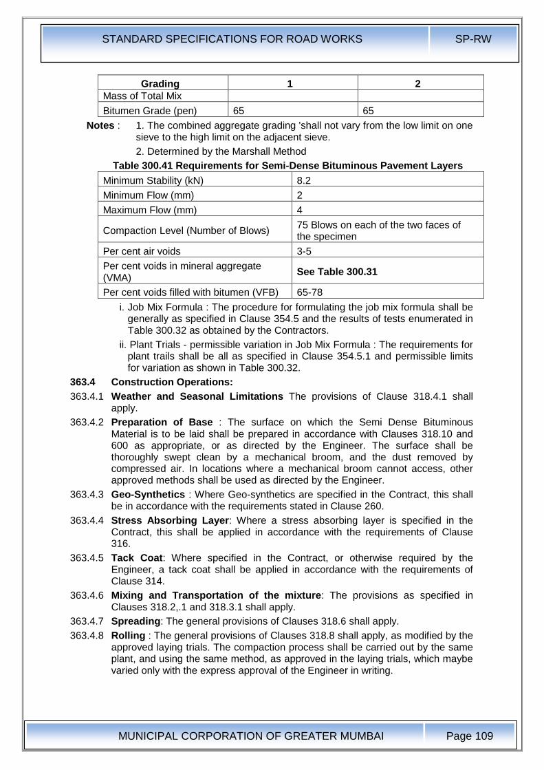
STANDARD SPECIFICATIONS FOR ROAD WORKS SP-RW
MUNICIPAL CORPORATION OF GREATER MUMBAI
Page 109
Grading 1 2
Mass of Total Mix
Bitumen Grade (pen) 65 65
Notes : 1. The combined aggregate grading 'shall not vary from the low limit on one sieve to the high limit on the adjacent sieve.
2. Determined by the Marshall Method
Table 300.41 Requirements for Semi-Dense Bituminous Pavement Layers
Minimum Stability (kN) 8.2
Minimum Flow (mm) 2
Maximum Flow (mm) 4
Compaction Level (Number of Blows) 75 Blows on each of the two faces of the specimen
Per cent air voids 3-5
Per cent voids in mineral aggregate (VMA)
See Table 300.31
Per cent voids filled with bitumen (VFB) 65-78
i. Job Mix Formula : The procedure for formulating the job mix formula shall be generally as specified in Clause 354.5 and the results of tests enumerated in Table 300.32 as obtained by the Contractors.
ii. Plant Trials - permissible variation in Job Mix Formula : The requirements for plant trails shall be all as specified in Clause 354.5.1 and permissible limits for variation as shown in Table 300.32.
363.4 Construction Operations:
363.4.1 Weather and Seasonal Limitations The provisions of Clause 318.4.1 shall apply.
363.4.2 Preparation of Base : The surface on which the Semi Dense Bituminous Material is to be laid shall be prepared in accordance with Clauses 318.10 and 600 as appropriate, or as directed by the Engineer. The surface shall be thoroughly swept clean by a mechanical broom, and the dust removed by compressed air. In locations where a mechanical broom cannot access, other approved methods shall be used as directed by the Engineer.
363.4.3 Geo-Synthetics : Where Geo-synthetics are specified in the Contract, this shall be in accordance with the requirements stated in Clause 260.
363.4.4 Stress Absorbing Layer: Where a stress absorbing layer is specified in the Contract, this shall be applied in accordance with the requirements of Clause 316.
363.4.5 Tack Coat: Where specified in the Contract, or otherwise required by the Engineer, a tack coat shall be applied in accordance with the requirements of Clause 314.
363.4.6 Mixing and Transportation of the mixture: The provisions as specified in Clauses 318.2,.1 and 318.3.1 shall apply.
363.4.7 Spreading: The general provisions of Clauses 318.6 shall apply.
363.4.8 Rolling : The general provisions of Clauses 318.8 shall apply, as modified by the approved laying trials. The compaction process shall be carried out by the same plant, and using the same method, as approved in the laying trials, which maybe varied only with the express approval of the Engineer in writing.
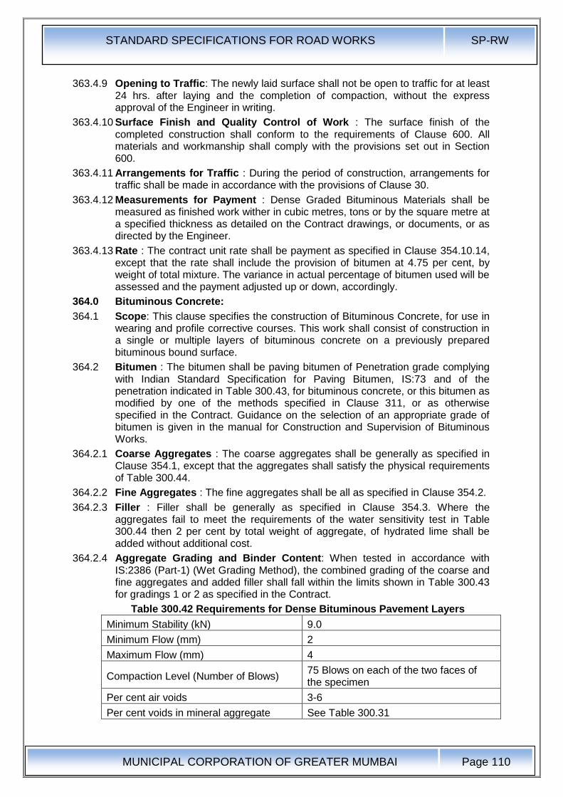
STANDARD SPECIFICATIONS FOR ROAD WORKS SP-RW
MUNICIPAL CORPORATION OF GREATER MUMBAI
Page 110
363.4.9 Opening to Traffic: The newly laid surface shall not be open to traffic for at least 24 hrs. after laying and the completion of compaction, without the express approval of the Engineer in writing.
363.4.10 Surface Finish and Quality Control of Work : The surface finish of the completed construction shall conform to the requirements of Clause 600. All materials and workmanship shall comply with the provisions set out in Section 600.
363.4.11 Arrangements for Traffic : During the period of construction, arrangements for traffic shall be made in accordance with the provisions of Clause 30.
363.4.12 Measurements for Payment : Dense Graded Bituminous Materials shall be measured as finished work wither in cubic metres, tons or by the square metre at a specified thickness as detailed on the Contract drawings, or documents, or as directed by the Engineer.
363.4.13 Rate : The contract unit rate shall be payment as specified in Clause 354.10.14, except that the rate shall include the provision of bitumen at 4.75 per cent, by weight of total mixture. The variance in actual percentage of bitumen used will be assessed and the payment adjusted up or down, accordingly.
364.0 Bituminous Concrete:
364.1 Scope: This clause specifies the construction of Bituminous Concrete, for use in wearing and profile corrective courses. This work shall consist of construction in a single or multiple layers of bituminous concrete on a previously prepared bituminous bound surface.
364.2 Bitumen : The bitumen shall be paving bitumen of Penetration grade complying with Indian Standard Specification for Paving Bitumen, IS:73 and of the penetration indicated in Table 300.43, for bituminous concrete, or this bitumen as modified by one of the methods specified in Clause 311, or as otherwise specified in the Contract. Guidance on the selection of an appropriate grade of bitumen is given in the manual for Construction and Supervision of Bituminous Works.
364.2.1 Coarse Aggregates : The coarse aggregates shall be generally as specified in Clause 354.1, except that the aggregates shall satisfy the physical requirements of Table 300.44.
364.2.2 Fine Aggregates : The fine aggregates shall be all as specified in Clause 354.2.
364.2.3 Filler : Filler shall be generally as specified in Clause 354.3. Where the aggregates fail to meet the requirements of the water sensitivity test in Table 300.44 then 2 per cent by total weight of aggregate, of hydrated lime shall be added without additional cost.
364.2.4 Aggregate Grading and Binder Content: When tested in accordance with IS:2386 (Part-1) (Wet Grading Method), the combined grading of the coarse and fine aggregates and added filler shall fall within the limits shown in Table 300.43 for gradings 1 or 2 as specified in the Contract.
Table 300.42 Requirements for Dense Bituminous Pavement Layers
Minimum Stability (kN) 9.0
Minimum Flow (mm) 2
Maximum Flow (mm) 4
Compaction Level (Number of Blows) 75 Blows on each of the two faces of the specimen
Per cent air voids 3-6
Per cent voids in mineral aggregate See Table 300.31
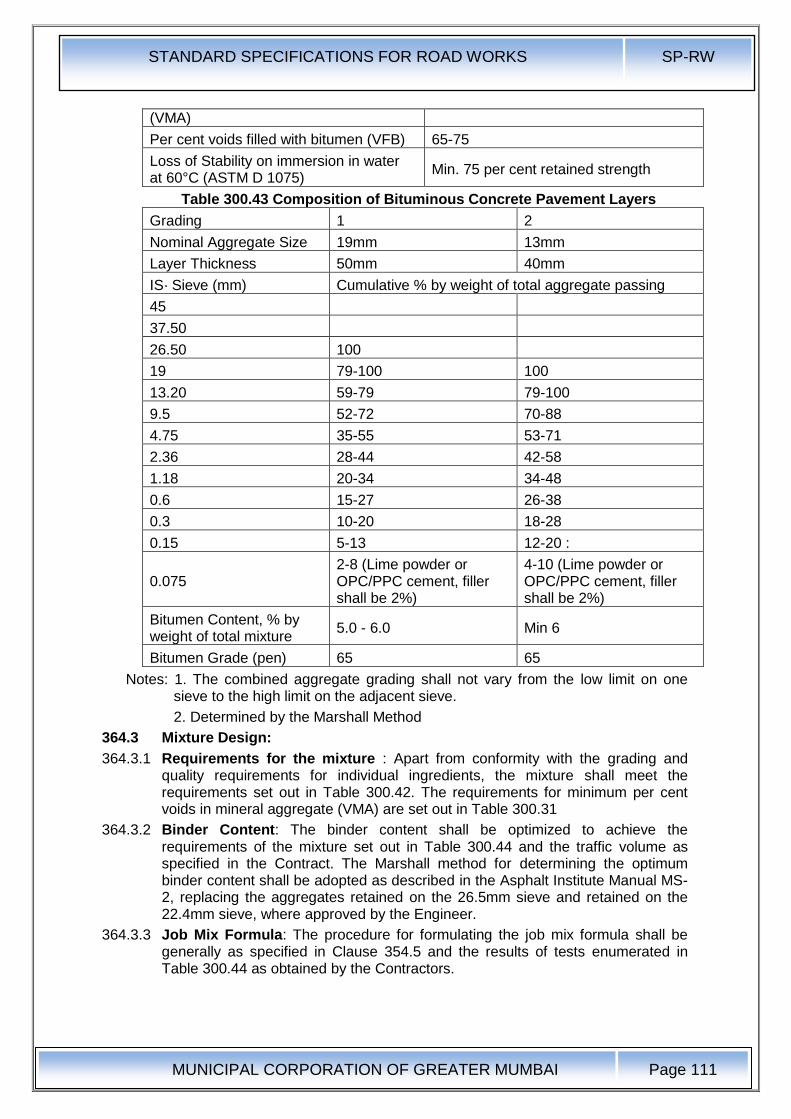
STANDARD SPECIFICATIONS FOR ROAD WORKS SP-RW
MUNICIPAL CORPORATION OF GREATER MUMBAI
Page 111
(VMA)
Per cent voids filled with bitumen (VFB) 65-75
Loss of Stability on immersion in water at 60°C (ASTM D 1075)
Min. 75 per cent retained strength
Table 300.43 Composition of Bituminous Concrete Pavement Layers
Grading 1 2
Nominal Aggregate Size 19mm 13mm
Layer Thickness 50mm 40mm
IS· Sieve (mm) Cumulative % by weight of total aggregate passing
45
37.50
26.50 100
19 79-100 100
13.20 59-79 79-100
9.5 52-72 70-88
4.75 35-55 53-71
2.36 28-44 42-58
1.18 20-34 34-48
0.6 15-27 26-38
0.3 10-20 18-28
0.15 5-13 12-20 :
0.075 2-8 (Lime powder or OPC/PPC cement, filler shall be 2%)
4-10 (Lime powder or OPC/PPC cement, filler shall be 2%)
Bitumen Content, % by weight of total mixture
5.0 - 6.0 Min 6
Bitumen Grade (pen) 65 65
Notes: 1. The combined aggregate grading shall not vary from the low limit on one sieve to the high limit on the adjacent sieve.
2. Determined by the Marshall Method
364.3 Mixture Design:
364.3.1 Requirements for the mixture : Apart from conformity with the grading and quality requirements for individual ingredients, the mixture shall meet the requirements set out in Table 300.42. The requirements for minimum per cent voids in mineral aggregate (VMA) are set out in Table 300.31
364.3.2 Binder Content: The binder content shall be optimized to achieve the requirements of the mixture set out in Table 300.44 and the traffic volume as specified in the Contract. The Marshall method for determining the optimum binder content shall be adopted as described in the Asphalt Institute Manual MS-2, replacing the aggregates retained on the 26.5mm sieve and retained on the 22.4mm sieve, where approved by the Engineer.
364.3.3 Job Mix Formula: The procedure for formulating the job mix formula shall be generally as specified in Clause 354.5 and the results of tests enumerated in Table 300.44 as obtained by the Contractors.
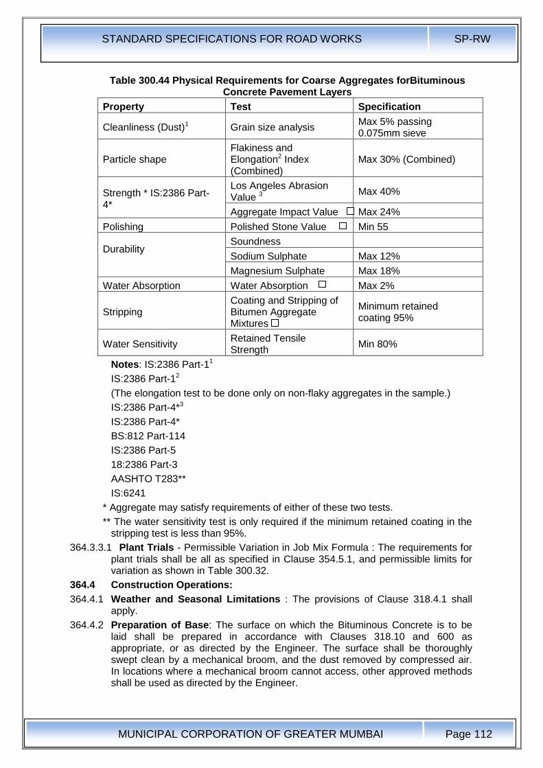
STANDARD SPECIFICATIONS FOR ROAD WORKS SP-RW
MUNICIPAL CORPORATION OF GREATER MUMBAI
Page 112
Table 300.44 Physical Requirements for Coarse Aggregates forBituminous Concrete Pavement Layers
Property Test Specification
Cleanliness (Dust)1 Grain size analysis Max 5% passing 0.075mm sieve
Particle shape Flakiness and Elongation2 Index (Combined)
Max 30% (Combined)
Strength * IS:2386 Part-4*
Los Angeles Abrasion Value 3
Max 40%
Aggregate Impact Value Max 24%
Polishing Polished Stone Value Min 55
Durability
Soundness
Sodium Sulphate Max 12%
Magnesium Sulphate Max 18%
Water Absorption Water Absorption Max 2%
Stripping Coating and Stripping of Bitumen Aggregate Mixtures
Minimum retained coating 95%
Water Sensitivity Retained Tensile Strength
Min 80%
Notes: IS:2386 Part-11
IS:2386 Part-12
(The elongation test to be done only on non-flaky aggregates in the sample.)
IS:2386 Part-4*3
IS:2386 Part-4*
BS:812 Part-114
IS:2386 Part-5
18:2386 Part-3
AASHTO T283**
IS:6241
* Aggregate may satisfy requirements of either of these two tests.
** The water sensitivity test is only required if the minimum retained coating in the stripping test is less than 95%.
364.3.3.1 Plant Trials - Permissible Variation in Job Mix Formula : The requirements for plant trials shall be all as specified in Clause 354.5.1, and permissible limits for variation as shown in Table 300.32.
364.4 Construction Operations:
364.4.1 Weather and Seasonal Limitations : The provisions of Clause 318.4.1 shall apply.
364.4.2 Preparation of Base: The surface on which the Bituminous Concrete is to be laid shall be prepared in accordance with Clauses 318.10 and 600 as appropriate, or as directed by the Engineer. The surface shall be thoroughly swept clean by a mechanical broom, and the dust removed by compressed air. In locations where a mechanical broom cannot access, other approved methods shall be used as directed by the Engineer.
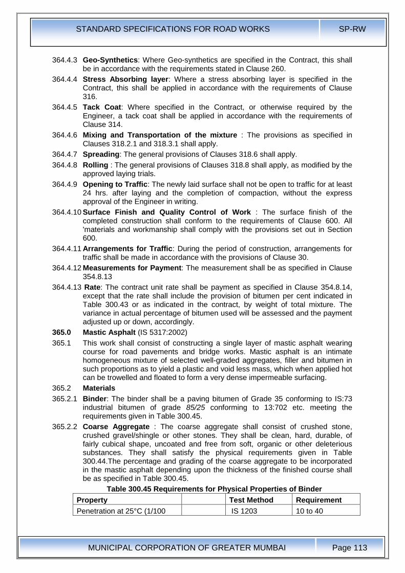
STANDARD SPECIFICATIONS FOR ROAD WORKS SP-RW
MUNICIPAL CORPORATION OF GREATER MUMBAI
Page 113
364.4.3 Geo-Synthetics: Where Geo-synthetics are specified in the Contract, this shall be in accordance with the requirements stated in Clause 260.
364.4.4 Stress Absorbing layer: Where a stress absorbing layer is specified in the Contract, this shall be applied in accordance with the requirements of Clause 316.
364.4.5 Tack Coat: Where specified in the Contract, or otherwise required by the Engineer, a tack coat shall be applied in accordance with the requirements of Clause 314.
364.4.6 Mixing and Transportation of the mixture : The provisions as specified in Clauses 318.2.1 and 318.3.1 shall apply.
364.4.7 Spreading: The general provisions of Clauses 318.6 shall apply.
364.4.8 Rolling : The general provisions of Clauses 318.8 shall apply, as modified by the approved laying trials.
364.4.9 Opening to Traffic: The newly laid surface shall not be open to traffic for at least 24 hrs. after laying and the completion of compaction, without the express approval of the Engineer in writing.
364.4.10 Surface Finish and Quality Control of Work : The surface finish of the completed construction shall conform to the requirements of Clause 600. All 'materials and workmanship shall comply with the provisions set out in Section 600.
364.4.11 Arrangements for Traffic: During the period of construction, arrangements for traffic shall be made in accordance with the provisions of Clause 30.
364.4.12 Measurements for Payment: The measurement shall be as specified in Clause 354.8.13
364.4.13 Rate: The contract unit rate shall be payment as specified in Clause 354.8.14, except that the rate shall include the provision of bitumen per cent indicated in Table 300.43 or as indicated in the contract, by weight of total mixture. The variance in actual percentage of bitumen used will be assessed and the payment adjusted up or down, accordingly.
365.0 Mastic Asphalt (IS 5317:2002)
365.1 This work shall consist of constructing a single layer of mastic asphalt wearing course for road pavements and bridge works. Mastic asphalt is an intimate homogeneous mixture of selected well-graded aggregates, filler and bitumen in such proportions as to yield a plastic and void less mass, which when applied hot can be trowelled and floated to form a very dense impermeable surfacing.
365.2 Materials
365.2.1 Binder: The binder shall be a paving bitumen of Grade 35 conforming to IS:73 industrial bitumen of grade 85/25 conforming to 13:702 etc. meeting the requirements given in Table 300.45.
365.2.2 Coarse Aggregate : The coarse aggregate shall consist of crushed stone, crushed gravel/shingle or other stones. They shall be clean, hard, durable, of fairly cubical shape, uncoated and free from soft, organic or other deleterious substances. They shall satisfy the physical requirements given in Table 300.44.The percentage and grading of the coarse aggregate to be incorporated in the mastic asphalt depending upon the thickness of the finished course shall be as specified in Table 300.45.
Table 300.45 Requirements for Physical Properties of Binder
Property Test Method Requirement
Penetration at 25°C (1/100 IS 1203 10 to 40
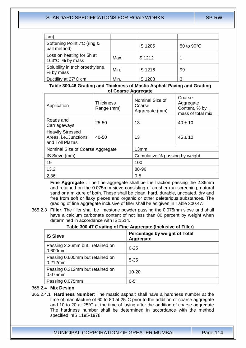
STANDARD SPECIFICATIONS FOR ROAD WORKS SP-RW
MUNICIPAL CORPORATION OF GREATER MUMBAI
Page 114
cm)
Softening Point,.°C (ring & ball method)
IS 1205 50 to 90°C
Loss on heating for 5h at 163°C, % by mass
Max. S 1212 1
Solubility in trichloroethylene, % by mass
Min. IS 1216 99
Ductility at 27°C cm Min. IS 1208 3
Table 300.46 Grading and Thickness of Mastic Asphalt Paving and Grading of Coarse Aggregate
Application Thickness Range (mm)
Nominal Size of Coarse Aggregate (mm)
Coarse Aggregate Content, % by mass of total mix
Roads and Carriageways
25-50 13 40 ± 10
Heavily Stressed Areas, i.e.,Junctions and Toll Plazas
40-50 13 45 ± 10
Nominal Size of Coarse Aggregate
IS Sieve (mm)
13mm
Cumulative % passing by weight
19 100
13.2 88-96
2.36 0-5
Fine Aggregate : The fine aggregate shall be the fraction passing the 2.36mm and retained on the 0.075mm sieve consisting of crusher run screening, natural sand or a mixture of both. These shall be clean, hard, durable, uncoated, dry and free from soft or flaky pieces and organic or other deleterious substances. The grading of fine aggregate inclusive of filler shall be as given in Table 300.47.
365.2.3 Filler: The filler shall be limestone powder passing the 0.075mm sieve and shall have a calcium carbonate content of not less than 80 percent by weight when determined in accordance with IS:1514.
Table 300.47 Grading of Fine Aggregate (Inclusive of Filler)
IS Sieve Percentage by weight of Total Aggregate
Passing 2.36mm but . retained on 0.600mm
0-25
Passing 0.600mm but retained on 0.212mm
5-35
Passing 0.212mm but retained on 0.075mm
10-20
Passing 0.075mm 0-5
365.2.4 Mix Design
365.2.4.1 Hardness Number: The mastic asphalt shall have a hardness number at the time of manufacture of 60 to 80 at 25°C prior to the addition of coarse aggregate and 10 to 20 at 25°C at the time of laying after the addition of coarse aggregate The hardness number shall be determined in accordance with the method specified inIS:1195-1978.
STANDARD SPECIFICATIONS FOR ROAD WORKS SP-RW
MUNICIPAL CORPORATION OF GREATER MUMBAI
Page 115
365.2.5 Binder Content : The binder content shall be so fixed as to achieve the requirements of the mixture specified in Clause 365.2.5.1 and shall be in the range of 14 to 17 per cent by weight of total mixture as indicated in Table 300.47.
365.2.6 Job Mix Formula: The Contractor shall inform the Engineer in writing at least 1 month before the start of the work of the job mix formula proposed to be used by him for the work, indicating the source and location of all materials, proportions of all materials such as binder and aggregates, single definite percentage passing each sieve for the mixed aggregate and results of the tests recommended in the various Tables and Clauses of this Specification.
365.3 Construction Operations
365.3.1 Weather and Seasonal Limitations: The provisions of Clause 318 shall apply, except that laying shall not be carried out when the air temperature at the surface on which the Mastic Asphalt is to be laid is below 10°C.
365.3.2 Preparation of the base : The base on which mastic asphalt is to be laid shall be prepared, shaped and conditioned to the profile required, in accordance with Clause 318 or 600 as 'appropriate or as directed by the Engineer. In the case of a cement concrete base, the surface shall be thoroughly power brushed clean and free of dust and other deleterious matter. Under no circumstances shall mastic asphalt be spread on a base containing a binder which might soften under high application temperatures. If such material exists, the same shall be cut out and repaired before the mastic asphalt is laid.
365.3.3 Tack Coat: A tack coat in accordance with Clause 314 shall be applied on the base or as directed by the Engineer.
365.3.4 Preparation of Mastic Asphalt : Penetration of mastic asphalt consists of two stages. The first stage shall be mixing of filler and fine aggregates and then heating the mixture· to a temperature of 170°C to 210°C. Required quantity of bitumen shall be heated to 170°C to 180°C and added to the heated aggregated. They shall be mixed and cooked in an approved type of mechanically agitated mastic cooker for some tim'e till the materials are thoroughly mixed. Initially the filler along is to be heated in the cooker for an hour and then half the quantity of binder is added. After heating and mixing for some time, the fine aggregates and the balance of binder are to be added and further cooked for about one hour. The second stage is incorporation of coarse aggregates and cooling the mixture for a total period of 3 hours. During cooking and mixing, care shall be taken to ensure that the contents in the cooker are at no time heated to a temperature exceeding 210°C.
Where the material is not required for immediate use it shall be cast . into blocks consisting of filler, fine aggregates and binder, but without the addition of coarse aggregate, weighing about 25 Kgs each. Before . use, these blocks shall be reheated to a temperature of not less than 175°C and not more than 210°C, thoroughly incorporated with the requisite quantity of coarse aggregates and mixed continuously. Mixing shall be continued until laying operations are ,completed so as to maintain the coarse aggregates in suspension. At no stage during the process of mixing shall be the temperature exceeds 210°C.
The mastic asphalt blocks (without coarse aggregate) shall show on analysis a composition within the limits as given in Table 300.47.
The mixture shall be transported to the laying site in a towed mixer transporter having arrangement for stirring and keeping the mixture hot during transportation.
365.3.5 Spreading: The mastic asphalt shall be laid, normally in one coat, at a temperature between 175°C and 210°C and spread uniformly by hand using
STANDARD SPECIFICATIONS FOR ROAD WORKS SP-RW
MUNICIPAL CORPORATION OF GREATER MUMBAI
Page 116
wooden floats or by machine on the prepared and regulated surface. The thickness of the mastic asphalt and the percentage of added coarse aggregate shall be in accordance with Table 300. 46 or as specified by the Engineer. Where necessary, battens of the requisite dimensions should be employed. Any blow holes that appear in the surface shall be punctured while the material is hot, and the surface made good by further floating.
365.3.6 Joints: All construction joints shall be properly and truly made. These joints shall be made by warming existing mastic asphalt by the application of an excess quantity of the hot mastic asphalt mixture which afterwards shall be trimmed to leave it flush with the surfaces on either side.
365.3.7 Surface Finish: The mastic asphalt surface can have poor skid resistance to skidding, the mastic asphalt after spreading, while still hot and in a plastic condition shall be covered with a layer of stone aggregate. This aggregate shall be 13.2mm size (passing the 19.0mm sieve and retained on the 9.5mm sieve) or 9.5mm size (passing the 13.2mm sieve and retained on the 6.7mm sieve) subject to the approval of the Engineer. Hard stone chips, complying with the quality requirements of Table 300.44 ,shall be pre-coated with bitumen at the rate of 2 ± 0.4% of S-65 penetration grade. The addition of 2% of filler complying with Table 300.47 may be required to enable this quantity of binder to be held without draining. The chips shall then be applied at the rate of 0.005 Cu. M. per 10 Sq. M. and rolled or otherwise pressed into the surface of the mastic layer when the temperature of the mastic asphalt Is not less than 100°C.
365.3.8 Opening to Traffic: Traffic may be allowed after completion of the work when the mastic asphalt temperature at the mid-depth of the completed layer has cooled to the daytime maximum ambient temperature.
365.3.9 Surface Finish and Quality Control of Work: The surface finish of the completed construction shall conform to the requirements of Clause 620.
365.3.10 For control of the quality of materials supplied and the works carried out, the relevant provisions of Section 600shall apply.
The surface of the mastic asphalt,' tested with a straight edge 3.0m long, placed parallel to the centre line of the carriageway, shall have no depression greater than 7mm. the same limit shall also apply to the transverse profile when tested with a camber template.
365.3.11 Arrangements for Traffic : During the period of construction, arrangements for traffic shall be made in accordance with the provisions of Clause 30.
365.3.12 Measurement for Payment: Mastic asphalt shall be measured as finished· work in square metres at a specified thickness, or by weight in tones as stated in the Contract.
365.3.13 Rate : The contract unit rate for mastic asphalt shall be payment in full for carrying out the required operations including full compensation for all components listed under Clause 318.11 (i) to (ix).
STANDARD SPECIFICATIONS FOR ROAD WORKS SP-RW
MUNICIPAL CORPORATION OF GREATER MUMBAI
Page 117
370.0 Seal Coat
370.1 Scope : This work shall consist of the application of a seal coat for sealing the voids in a bituminous surface laid to the specified levels, grade and cross fall (camber).
Seal coat shall be of either of the two types specified below:
Liquid seal coat comprising of an application of a layer of bituminous binder followed by a cover of stone chips.
370.2 Binder: The requirements of Clauses 361.2.2.1 shall apply.
The quantity of bitumen per 10 square metres, shall be 9.8 Kg. for Type A seal coat. Where bituminous' emulsion is used as a binder the quantities for Type A seal coats shall be 15 Kg per 10 square meters rapid setting (clause 4.2.2 of IRC:14-2004). .
370.2.1 Stone Chips for Type A Seal Coat: The stone chips shall consist of angular fragments of clean, hard, tough and durable rock of uniform quality throughout. They should be free of soft or disintegrated stone, organic or other deleterious matter. Stone chips shall be of 6.7mm size defined as 100 per cent passing through 11.2mm sieve and retained on 2.36mm sieve the quantity used for spreading shall be 0.09 cubic metre per 10 square metre area. The chips shall satisfy the quality requirements in Table300.22 except that the upper limit for water absorption value shall be 1 per cent.
370.3 Construction Operations:
370.3.1 Weather and Seasonal Limitations : The requirements of Clause 318.6.1 shall apply.
370.3.2 Preparation of Surface : The seal coat shall be applied immediately after laying the bituminous course which is required to be sealed. Before application of seal coat materials, the surface shall be cleaned free of any dust or other extraneous matter.
370.3.3 Construction of Type A Seal Coat : Bitumen shall be heated to 150°C-163°C and sprayed at the rate specified on the dry surface in a uniform manner with a self-propelled mechanical sprayer as described in the Manual for Construction and Supervision of Bituminous Works.
Immediately after the application of binder, stone chips, which shall be clean and dry, shall be spread uniformly at the rate specified on the surface preferably by means of a self-propelled or towed mechanical grit spreader so as to cover the surface completely. If necessary, the surface shall be brushed to ensure uniform spread of chips.
Immediately after the application of the cover material, the entire surface shall be rolled with a 8-10 tonne smooth wheeled steel roller, 8-10 tonne static weight vibratory roller, or other equipment approved by the Engineer after laying trials if required. Rolling shall commence at the edge~ and progress towards the centre except in super elevated and unidirectional cambered portions where it shall proceed from the lower edge to the higher edge. Each pass of the roller shall uniformly overlap not less than one-third of the track made in the preceding pass. While rolling is in progress, additional chips shall be spread by hand in necessary quantities required to make up irregularities. Rolling shall continue until all aggregate particles are firmly embedded in the binder and present a uniform closed surface.
370.3.4 Opening to Traffic : In the case of Type A Seal Coat, traffic shall not be permitted to run on any newly sealed area until the following day. In special
STANDARD SPECIFICATIONS FOR ROAD WORKS SP-RW
MUNICIPAL CORPORATION OF GREATER MUMBAI
Page 118
circumstances, however, the Engineer may open the road to traffic immediately after rolling, but in such cases, traffic speed shall be rigorously limited to 16 Km. per hour until the following day.
370.3.5 Surface Finish and Quality Control of Work : The surface finish of construction shall conform to the requirements of Clause 610
For -control on the quality of materials supplied and the works carried out, the relevant provisions of Section 600 shall apply.
370.3.6 Arrangement for Traffic: During the period of construction, arrangements for traffic shall be made in accordance with the provisions of Clause 30.
370.3.7 Measurement for Payment: Seal Coat shall be measured as finished work, over the area specified to be covered, in square metre at the thickness specified in the Contract.
370.3.8 Rate: The contract unit rate for seal coat shall be payment in full for carrying out the' required operations including full compensation for all components listed in Clause 318.11.
375.0 Slurry Seal
375.1 Scope : Slurry seals are mixtures of fine aggregate, Portland cement filler, bitumen emulsion and additional water. When freshly mixed, they have a thick consistency and can be spread to a thickness of 1.5 - 5 mm. They may be used to seal cracks, arrest fretting and fill voids and minor depressions, to provide a more even riding surface or a base for further treatment; they may also be used on top of a single coat surface dressing.
375.2 Materials : The materials for slurry seal immediately prior to mixing shall conform to the following requirements :
375.2.1 Emulsified Bitumen : The emulsified bitumen shall be a cationic rapid setting type as approved by the Engineer, conforming to the requirements of IS:8887 .. Where special mobile mixing machines are available, Class .A4* rapid setting .or Class K3* road emulsions to BS~ 434: Part I should be used, to obtain very early resistance to traffic and rain. Generally, emulsion for slurry seal should be capable of producing a slurry that will develop early resistance to traffic and rain and is sufficiently stable to permit mixing with the specified aggregate, without breaking during the mixing and laying processes. If approved by the Engineer, a slow setting emulsion may be used. Guidance on selection of an appropriate grade of emulsion is given in the Manual for Construction and Supervision of Bituminous Works.
375.2.2 Water : Water shall be of such quality that the bitumen will not separate from the emulsion before the slurry seal is in place.
The pH of the water must lie in the range 4 to 7, and if the total dissolved solids in the water amount to more than 500ppm, the Engineer may reject it, or order the Contractor to conduct a trial emulsion mix to demonstrate that it does not cause early separation.
375.2.3 Aggregate : The aggregate shall be crushed rock, or slag and may be blended, if required, with clean, sharp, naturally occurring sand free from soft pieces and organic and other deleterious substances to produce a grading as given in Table 300.47 A. The aggregates shall meet the requirements of the film stripping test (IS:6241). and a suitable amount and type of anti-stripping agent added, as may be needed (details given in Appendix 5).
375.2.4 Additives: It is usual to use ordinary Portland cement, hydrated lime or other additives to control consistency, mix segregation and setting rate. The proportion of the additive should not normally exceed 2 per cent by weight of dry aggregates.
STANDARD SPECIFICATIONS FOR ROAD WORKS SP-RW
MUNICIPAL CORPORATION OF GREATER MUMBAI
Page 119
375.3 Mixture Design : A range of residual binder contents for each aggregate grading is given in Table 300.47 A. The optimum mixture design for the aggregate additive, water and bitumen emulsion mixture should be determined in accordance with ASTM D 3910.
375.4 Construction Operations:
375.4.1 Weather and Seasonal Limitations: Clause 318.4.1 shall apply.
Table 300.47 Aggregate Grading, Binder Content and Approximate Coverage Rate
Sieve Size (mm)
Percentage by Mass Passing Finished Thickness of Sealing
5mm 3mm 1.5mm
9.5 100 - -
4.75 90-100 100 -
3.35 - 80-100 100
2.36 65-90 75-100 95-100
1.18 45-70 55-90 70-95
0.600 30-50 35-70 55-75
0.300 18-30 20-45 30-50
0.150 10-21 10-25 10-30
0.075 5-15 5-15 5-15
Quantity of residual binder, percentage by mass of aggregate
7.5-13.5 10-16 12-20
Approximate coverage rate (Kg./m2) 8-15 4-6 2-4
375.4.2 Surface Preparation : Any necessary remedial work to the road surface and structure shall be completed either prior to or as part of the Contract and agreed as acceptable by the Engineer, according to the provisions of Clause 318.
Before slurry seal is applied, street furniture and, where directed by the Engineer, road markings, shall be masked using self-adhesive masking material or other material firmly secured against the passage of the spreader box or the tools used for hand laying. Any packed mud or other deposits on the surface shall be removed, all organic growth shall be removed by suitable means, and the surface shall be swept free of all loose material.
375.4.3 Tack Coat : If required by the Engineer, a tack coat may be applied prior to the slurry seal, with or without grit or chips, in order to seal the existing substrata and enhance the bond to the existing road surface. Unless otherwise agreed by the Engineer, the rate of spread of tack coat shall be 0.15 to 0.30 Iitres I m2 for bituminous surfa.ces and .04 to 0.6 litres I m2 for concrete surfaces.
375.4.4 Mixing and Transportation of Mixture : Mixing (and laying) techniques vary according to the type of emulsion used. For class A4 rapid setting and K3 emulsions, only special mobile mixing machines should be used. These carry supplies of aggregate, emulsion, water and filler (e.g. ordinary Portland cement or hydrated lime) and are fitted with metering devices to feed the ingredients in their correct proportions to a mixer fitted to the rear of the machine. From the mixer the slurry is fed into the screed box towed by the machine.
For all other emulsions, mixing may be by hand, concrete mixer or other mixer which effectively coats the aggregate uniformly and produces a slurry seal of suitable consistency for satisfactory laying. For large areas, a bulk transit concrete mixer may be used into which the ingredients (including water) are
STANDARD SPECIFICATIONS FOR ROAD WORKS SP-RW
MUNICIPAL CORPORATION OF GREATER MUMBAI
Page 120
measured and mixed as the mixer travels to the area to be treated. A screed box fitted with an adjustable rubber screed should be towed by the mixer which feeds it during laying.
The special mobile mixing machine, when used, shall be capable of uniform application to provide a continuous surface without ridges or segregation. Before laying begins, the Contractor shall provide the Engineer with a test certificate showing test results for rate of application carried out under the supervision of a competent authority, demonstrating that the machine has been tested, using the system to be· used in the Contract, not more than six weeks before the commencement of the work.
Where the material is to be hand laid, the slurry may be supplied to site pre-mixed in suitable containers and steps shall be taken to ensure that the material in each container is of an even consistency throughout the container immediately prior to use.
375.4.5 Application : Transverse joints for machine laid areas shall be formed with spreading, starting and finishing on a protective strip not less than 100 mm wide at each end of the length being treated. Transverse joints shall be formed such that there shall be no ridges or bare strips.
Unless otherwise approved by the Engineer, longitudinal joints shall coincide with lane markings. Longitudinal joints shall be formed such that there shall be no ridges or bare strips. Hand work around street furniture and other obstructions should meet the same performance requirements and form a homogeneous surface with the rest of the treated carriageway.
Footways and other confined areas may be spread by hand using squeegees and brooms. Transverse joints shall be formed with spreading, starting and finishing on a protective strip not less than 100mm wide at each of the lane length being treated. Transverse joints shall be formed such that there shall be no ridges or bare strips. Kerb edges and other areas not being treated shall be suitably masked with self adhesive masking material. Footways shall be finished by dragging a dampened broom transversely over the footway under its own weight.
All voids, cracks and surface irregularities shall be completely filled. In warm dry weather the surface, immediately ahead of the spreading, shall be slightly damped by mist water spray applied mechanically, or for hand laying by a hand operated pressure sprayer, unless otherwise approved by the Engineer.
375.4.6 Rolling : The need for rolling shall be as instructed by the Engineer. Where rolling is required. a pneumatic-tyred roller having an individual wheel load between 0.75 and 1.5 tonnes shall be used, or as may be directed by the Engineer. Rolling shall commence as soon as the slurry has set sufficiently to ensure that rutting or excessive movement will not occur.
375.5 Opening to Traffic : Masking shall be removed after the slurry seal has been applied, without damage to the edge of the surfacing, and before opening the road or footway to traffic.
The Contractor shall remove surplus aggregate from the treated areas using a method agreed by the Engineer. The Contractor shall monitor the slurry seal closely for a minimum period of 2 hours and if necessary the lane shall be swept again. The monitoring shall continue until the slurry seal has reached sufficient stability to carry unrestricted traffic. If there are' signs of distress, the Engineer shall require the Contractor to reinstate traffic safety and management procedures or other such remedial action where necessary in order to prevent further damage.
STANDARD SPECIFICATIONS FOR ROAD WORKS SP-RW
MUNICIPAL CORPORATION OF GREATER MUMBAI
Page 121
Further operations to remove subsequently loosened aggregate shall be carried out over the next 48 hours. The areas treated and adjacent side roads, footways and paved areas shall be kept substantially free of loose aggregate for a period of 30 days after completion of the work. 375.6 Surface Finish and Quality Control of Work : Generally, the surface finish of the completed construction shall conform to the requirements supplied and the works carried out, the relevant provisions of Section 600 shall apply.
In addition, the finished slurry shall have a uniform surface texture throughout the work, without variations of texture within the lane width, or from lane to lane, due to segregation of aggregates, or due to variations in the emulsion / water content of the mixture.
The finished surface shall be free from blow holes and surface irregularities in excess of 3mm beneath a 1 metre straight edge due to scraping, scabbing, dragging, droppings, excess overlapping or badly aligned longitudinal or transverse joints, damage by rain or frost, or other defects which remain 24 hours after laying. 375.7 Arrangements for Traffic : During the period of construction, arrangements for traffic shall be made in accordance with the provisions of Clause 30.
375.8 Measurements for Payment : Slurry seal shall be measured as finished work as specified, in square metres.
375.9 Rates: The contract unit rate for slurry seal shall be payment in full for carrying out the required operations including full compensation for all components listed in Clause 318.11 (i) to (xi).
380.0 Recycling of Bituminous Pavement
380.2 Scope : This Clause of the Specifications covers the recycling of existing bituminous pavement materials to upgrade an existing bituminous pavement which has served its first-intended purpose. The work shall be performed on such widths and lengths as may be directed by the Engineer and may consist of pavement removal, stockpiling of materials from the old pavement, addition of new bitumen and untreated aggregate in the requisite proportions, mixing, spreading and compaction of the blended materials.
Recycling processes can be categorised into in-situ recycling (where processing takes placed on site), and central plant recycling (where reclaimed material is processed off site). The processes can be further sub-divided into hot and cold processes. This Specification covers the hot process only. However, reclaimed aggregated from cold in-situ recycling can be used in the Bituminous Cold Mix process specified in Clause 317, subject to the resultant mixes achieving the specified standards.
380.3 Reclaimed Bituminous Materials for Central Plant Recycling:
380.3.4 Proportion of reclaimed materials less than 10 per cent : If not more than 10% of reclaimed bituminous material is to be used in the production of bituminous macadam or dense graded bituminous base or binder course material, then Clauses 380.2.2 to 380,2.9 do not apply. However:
i) all reclaimed bituminous material shall be pre-treated before use such that the material is homogeneously mixed and the maximum particle size of reclaimed materials does not exceed 40mm.
ii) the mixed material shall comply with the requirements of Clauses 351 or 354 as appropriate.
380.2.2 Proportions of reclaimed materials greater than 10 per cent : Reclaimed bituminous material of an amount greater than 10 per cent, may be used in the production of bituminous macadam and dense graded bituminous base and

STANDARD SPECIFICATIONS FOR ROAD WORKS SP-RW
MUNICIPAL CORPORATION OF GREATER MUMBAI
Page 122
binder course material, subject to the requirements of Clauses 380.2.3 to 380.2.9 and subject to the satisfactory completion of full trial investigations in respect of all related materials, layer thickness, machine operations and finished works on a case-by-case basis entirely at the contractors cost and subject to the approval of the Engineer. For estimating purposes, a maximum amount not greater than 30 per cent reclaimed bituminous material should be assumed.
380.2.3 Materials for Recycled Pavement: The recycled materials shall be a blend of reclaimed and new materials proportioned to achieve a paving mixture with the specified engineering properties. The reclaimed materials shall be tested and evaluated to find the optimum blend meeting the mixture requirements. Such testing and evaluation shall be carried out on representative samples, either cores sampled from the carriageway or samples taken from stockpiles in accordance with current practice. The sampling frequency should be sufficient to determine how consistent the reclaimed material is and to provide representative samples for composition analysis and measurement of properties of recovered binder. As an absolute minimum, one sample to represent 500n:t0f lane carriageway shall be taken.
380.2.4 Bitumen Extraction: The procedure described in ASTM 0-2172 shall be used to quantitatively separate aggregate and bitumen from any representative sample of reclaimed bituminous pavement.
380.2.5 Aggregate Evaluation: Mechanical sieve analysis (lS: 2386, Part-I, wet . sieving method) shall be performed on the aggregate portion of the reclaimed bituminous pavement sample to determine the grading. It is essential that the reclaimed materials to be recycled are consistent, as variable materials will cause problems with the control of quality and impede the efficiency of the recycling operation. Suitable sources of consistent material of sufficient quantity for the scheme being considered need to be identified either in existing pavements, from stockpiled planings of known origin or from another suitable source, before a decision can be made on the optimum percentage of reclaimed material.
After selecting the proportion of reclaimed materials to be recycled, the grading of the mixture may need adjustment, to meet Specification requirements, by the addition of selected aggregate sizes. Evaluation of bitumen : When the amount of reclaimed bituminous material to be used in the mixture exceeds 10%, the penetration value of the recovered binder from the reclaimed bituminous material, before mixing, shall exceed 15 pen, after recovery of binder in accordance with the requirements of IS 2000 : Part-397, when tested in accordance with IS:1203. Provided the above requirement is met, hardening of the old binder, during the original mixing process or through ageing, can be compensated for by adding a softer bitumen, to obtain the appropriate final grade of binder.
The determination of the type and amount of binder required to be added in the final mix is essentially a trial and error procedure.
After mixing with recycled materials, the binder recovered from the mixture shall have a recovered penetration value not less than the value specified in Table 300.48.
Table 300.48 Minimum Recovered Binder Penetration of Recycled Mixture
Specified Grade of Binder (Penetration)
Minimum Recovered Penetration Value of Binder after Mixing
45 27
65 39
90 54
STANDARD SPECIFICATIONS FOR ROAD WORKS SP-RW
MUNICIPAL CORPORATION OF GREATER MUMBAI
Page 123
380.2.7 Rejuvenators : The use of rejuvenators, and a test to measure their effectiveness, is described in Clause 380.6.3.
380.2.8 Untreated Aggregate: If necessary, fresh untreated aggregate shall be added to the reclaimed bituminous pavement to produce a mix with the desired grading. The aggregate shall be checked for quality requirements in accordance with Table 300.22 as appropriate. Reclaimed aggregate, if any, or any aggregate normally used for the desired bituminous mixture, or both, may be used for this purpose.
380.2.9 Combined Aggregate Grading : The blend of reclaimed and new aggregate shall meet the grading criteria specified in the relevant parts of Clause 351 or 354, as appropriate and as approved by the Engineer. The blend of aggregates shall be checked for resistance to stripping as specified in Tables 300.22 as appropriate.
380.3 Mixture Design : The combined aggregate grading and binder content shall comply with the relevant tables in Clauses 351 or 354. For dense graded bituminous mixtures, the mixture design shall also comply with the requirements of Table 300.30.
380.4 Reclaiming Old Pavement Materials : The removal of pavement materials to the required depth shall be accomplished either at ambient temperature (cold process) or at an elevated temperature (hot process). as approved by the Engineer.
380.4.1 Cold Removal Process: In the cold process, the ripping and crushing operations shall be carried out using scarifiers, grid rollers, or rippers or by any other means as directed by the Engineer. The removed materials shall be loaded and hauled for crushing to the' required size as directed by the Engineer. Alternatively, cold miling or planing machines can be used to reclaim bituminous pavement to controlled depths. After the bituminous layers are removed, any remaining aggregate materials that are to be incorporated in the recycled hot mixture shall be scarified and removed. When the pavement material removal is completed, any drainage deficiencies shall be corrected. After that, the base I sub-base as the case may be shall be cut, graded and compacted to the required profile and density.
380.4.2 Hot Removal Process : In this process, the road surface shall be heated, by any suitable means approved by the Engineer, before scarification. A self-propelled plant shall be used, and a milling drum that follows the planer removes the heated soft bituminous layer. The depth, width and speed of travel shall be adjusted to suit specified requirements as directed by the Engineer. During the heating process, the surface temperature of the road shall not exceed 200°C for more than 5 minutes.
380.4.3 Stockpiling : In the cold process, the reclaimed bituminous pavement material shall be stockpiled with the height of stockpiles not exceeding 3m. The reclaimed untreated aggregate base I sub-base material shall be stockpiled in the same manner as new aggregate. The number and location of stockpiles shall be carefully planned for efficient operation of the hot-mix plant.
380.5 Mixing and Laying: Generally, the requirements of Clauses 351 or 354, as appropriate, shall apply.
380.6 In Situ Recycling - The Remix and Repave Processes : These processes are suitable for the production of· bituminous concrete wearing course in accordance with the provisions of Clause 364.
380.6.1 Scope : In the process of repaving, the existing surface is preheated and scarified but the scarified material is not removed. A layer of fresh bituminous

STANDARD SPECIFICATIONS FOR ROAD WORKS SP-RW
MUNICIPAL CORPORATION OF GREATER MUMBAI
Page 124
mix material prepared in the integrated mixing unit of the plant is then spread evenly on the scarified surface to give a uniform profile. The spread material should be compacted as soon as possible after laying. In the process, the total thickness of the pavement is increased by up to 50mm.
In the remix process, the scarified material should be taken from the mixing unit of the plant where it is recycled with fresh binder, aggregate and recycling agent. Then the recycled mixture is spread on the preheated surface and tamped and compacted to the required profile.
380.6.2 Heating and Scarifying: Surfaces to be treated shall be heated by plant with surfaced insulated and fully enclosed. The heated width of surfacing shall exceed the scarified width by at least 75mm on each side, except against the edge of the carriageway or kerb face. When new surfacing material is spilled onto the road surface it shall be removed before the existing surface is heated and scarified. Areas of unscarified material shall not .exceed 50mm x 50mm.
The depth of scarification shall be such that the bottom of the scarified layer is parallel to and below the finished road surface level by. the thickness of wearing course material specified. A tolerance of ±6mm is permissible.
Where street furniture and other obstructions occur, these shall be suitably protected or removed and the void covered. Surface dressing and large areas of road marking shall be removed by milling, planning, scarifying or by similar approved processes.
The heated surface shall be evenly scarified to comply with the requirements of this Clause. When street furniture is left in place or raise, the adjacent areas shall be scarified by other means, with the material either left in place or removed, prior to passage of the machine. If furniture needs to be repositioned on completion of work, the new wearing course material shall be used to make good the road surface for a maximum width of 200mm around the obstruction.
During the reheating process the surface temperature of the road shall not exceed 200°C for more than 5 minutes.
380.6.3 Rejuvenator : For Remix, when required, rejuvenator shall be uniformly sprayed across the full-width of the processed material. The machine shall incorporate a meter for continuous verification of quantities which shall be within ±5% of the specified rate. The volume of rejuvenator shall vary in relation to the operating speed the machine, which shall be related to the volume of material mixed or scarified.
The rejuvenator shall be a non-emulsified aromatic extract. Its properties shall be verified using the Rolling Thin Film Oven Test.
Rejuvenation of the existing pavement may also be performed by adding new hot-mix bituminous material containing a soft binder of suitable penetration for restoring the binder in the existing pavement to the required penetration.
380.6.4 Mixing : When required, new hot-mix material shall be mixed with the heated and scarified road pavement material in a pugmill within the Remix machine, observing the mixing temperatures specified in the Table 300.24.
After mixing, the recycled bituminous materials shall be automatically fed to a finishing unit, which spreads and levels the mixture to the specified thickness and cross-section. The new bituminous concrete wearing course shall be material complying with Clause 364.
380.6.5 Additional Material (General) : The proportion of new hot-mix' bituminous material, and the proportion of existing bituminous pavement material shall be as directed by the Engineer, together with the amount the road surface level is to be raised (if any).
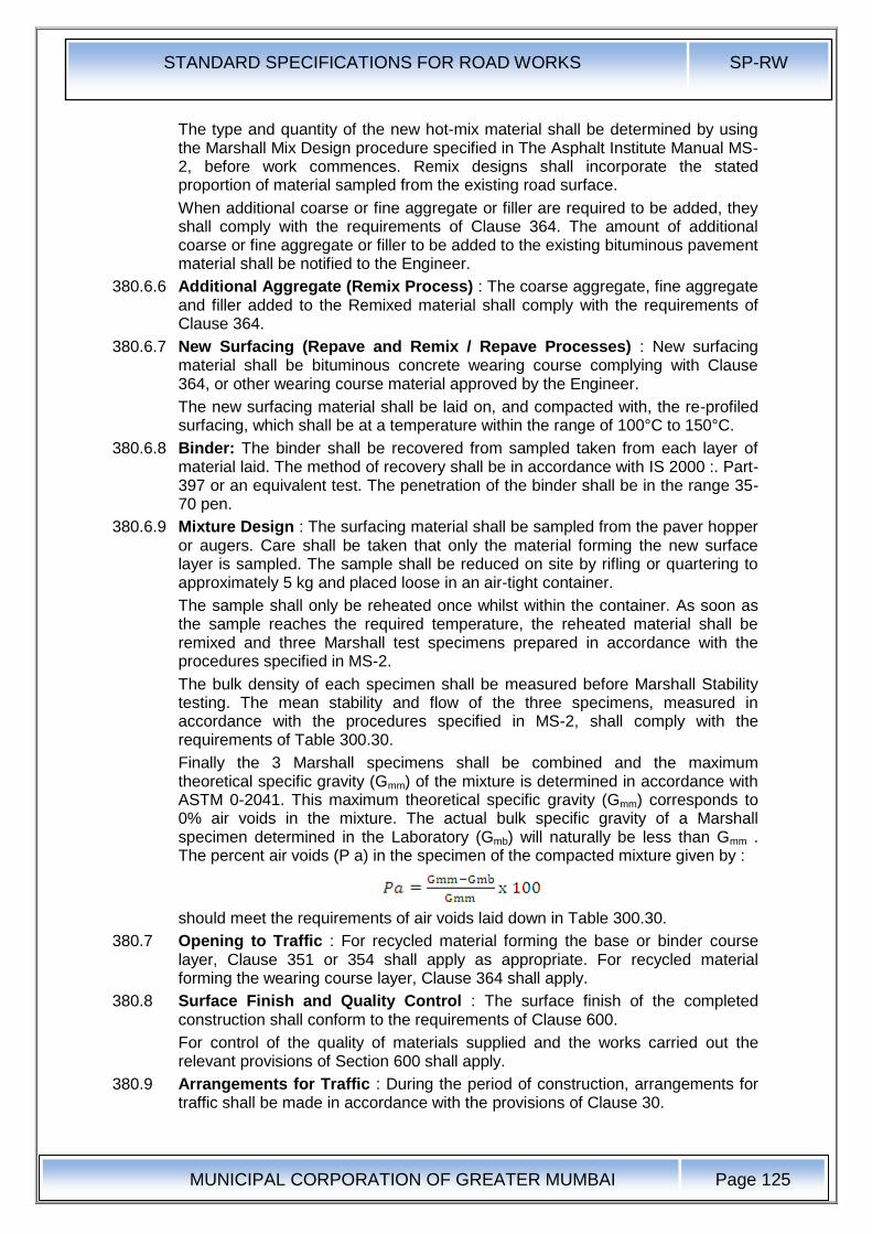
STANDARD SPECIFICATIONS FOR ROAD WORKS SP-RW
MUNICIPAL CORPORATION OF GREATER MUMBAI
Page 125
The type and quantity of the new hot-mix material shall be determined by using the Marshall Mix Design procedure specified in The Asphalt Institute Manual MS-2, before work commences. Remix designs shall incorporate the stated proportion of material sampled from the existing road surface.
When additional coarse or fine aggregate or filler are required to be added, they shall comply with the requirements of Clause 364. The amount of additional coarse or fine aggregate or filler to be added to the existing bituminous pavement material shall be notified to the Engineer.
380.6.6 Additional Aggregate (Remix Process) : The coarse aggregate, fine aggregate and filler added to the Remixed material shall comply with the requirements of Clause 364.
380.6.7 New Surfacing (Repave and Remix / Repave Processes) : New surfacing material shall be bituminous concrete wearing course complying with Clause 364, or other wearing course material approved by the Engineer.
The new surfacing material shall be laid on, and compacted with, the re-profiled surfacing, which shall be at a temperature within the range of 100°C to 150°C.
380.6.8 Binder: The binder shall be recovered from sampled taken from each layer of material laid. The method of recovery shall be in accordance with IS 2000 :. Part-397 or an equivalent test. The penetration of the binder shall be in the range 35-70 pen.
380.6.9 Mixture Design : The surfacing material shall be sampled from the paver hopper or augers. Care shall be taken that only the material forming the new surface layer is sampled. The sample shall be reduced on site by rifling or quartering to approximately 5 kg and placed loose in an air-tight container.
The sample shall only be reheated once whilst within the container. As soon as the sample reaches the required temperature, the reheated material shall be remixed and three Marshall test specimens prepared in accordance with the procedures specified in MS-2.
The bulk density of each specimen shall be measured before Marshall Stability testing. The mean stability and flow of the three specimens, measured in accordance with the procedures specified in MS-2, shall comply with the requirements of Table 300.30.
Finally the 3 Marshall specimens shall be combined and the maximum theoretical specific gravity (Gmm) of the mixture is determined in accordance with ASTM 0-2041. This maximum theoretical specific gravity (Gmm) corresponds to 0% air voids in the mixture. The actual bulk specific gravity of a Marshall specimen determined in the Laboratory (Gmb) will naturally be less than Gmm . The percent air voids (P a) in the specimen of the compacted mixture given by :
should meet the requirements of air voids laid down in Table 300.30.
380.7 Opening to Traffic : For recycled material forming the base or binder course layer, Clause 351 or 354 shall apply as appropriate. For recycled material forming the wearing course layer, Clause 364 shall apply.
380.8 Surface Finish and Quality Control : The surface finish of the completed construction shall conform to the requirements of Clause 600.
For control of the quality of materials supplied and the works carried out the relevant provisions of Section 600 shall apply.
380.9 Arrangements for Traffic : During the period of construction, arrangements for traffic shall be made in accordance with the provisions of Clause 30.

STANDARD SPECIFICATIONS FOR ROAD WORKS SP-RW
MUNICIPAL CORPORATION OF GREATER MUMBAI
Page 126
380.10 Measurement for Payment : The recycled pavement work shall be payment in full for carrying out the required operations including full compensation for all items as Clause 318.11 (i) to (xi).
STANDARD SPECIFICATIONS FOR ROAD WORKS SP-RW
MUNICIPAL CORPORATION OF GREATER MUMBAI
Page 127
400.0 Cement Concrete
410.0 Structural Concrete :
Structural Concrete shall be as per IS:456-2000 : Clause-6.
410.1 Concrete Making Materials
410.1.1 Cement: Ordinary Portland Cement conforming to IS:269, IS:8112, IS:12269; Portland Slag Cement conforming to IS:455, Portland Pozzolana Cement as per IS:1489 (Part-1)
410.1.2 Mineral Admixtures: Fly Ash conforming to Grade-I of IS:3812
410.1.3 Aggregates: Aggregates shall comply with requirements of IS:383
The size of Aggregate : The nominal maximum size of coarse aggregate should be 20mm.
410.1.4 Water: Water as per Clause 5.4 of IS:456 2000.
410.1.5 Admixtures: Admixtures shall comply with IS:9103
410.1.6 Reinforcement: Reinforcement shall be mild steel and medium tensile steel bars conforming to IS:432 (Part-1), high strength deformed steel bars conforming to 15:1786
410.2 Storage of Materials : Storage of Materials shall be as per IS:4082
410.3 Production of Concrete as per Clause 10 of IS:456.
425.0 Ready Mix Concrete
The contractor shall procure RMC from the RMC plant approved by MCGM only. The RMC prepared and transported will be as per relevant IS:4926. The following information on the performance of Ready Mix Concrete supplied by the plant shall be obtained.
425.1 Following past data regarding raw materials and equipment deployed shall be obtained from RMC manufacturer .
Proforma Table 400.1
Cement Grade Source Type IS
Strength (N/mm2) 3 days 7 days 28 days 6 months 1 Year
Average
Standard
Deviation
Initial Setting Time
Final Setting Time
425.2 Coarse Aggregate
Size Source Grading Zone
Proforma Table 400.2
Characteristic Property Average Value Standard Deviation
Remarks
Fineness Modules
Specific Gravity
Bulk Density
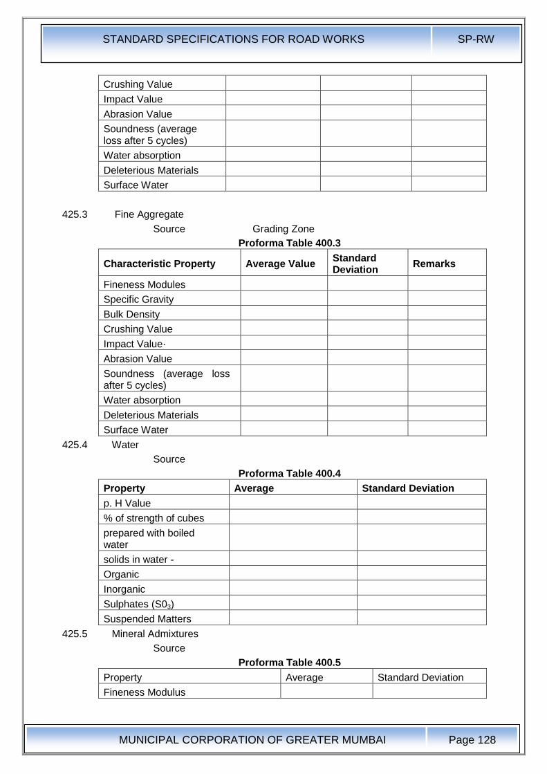
STANDARD SPECIFICATIONS FOR ROAD WORKS SP-RW
MUNICIPAL CORPORATION OF GREATER MUMBAI
Page 128
Crushing Value
Impact Value
Abrasion Value
Soundness (average loss after 5 cycles)
Water absorption
Deleterious Materials
Surface Water
425.3 Fine Aggregate
Source Grading Zone
Proforma Table 400.3
Characteristic Property Average Value Standard Deviation
Remarks
Fineness Modules
Specific Gravity
Bulk Density
Crushing Value
Impact Value·
Abrasion Value
Soundness (average loss after 5 cycles)
Water absorption
Deleterious Materials
Surface Water
425.4 Water
Source
Proforma Table 400.4
Property Average Standard Deviation
p. H Value
% of strength of cubes
prepared with boiled water
solids in water -
Organic
Inorganic
Sulphates (S03)
Suspended Matters
425.5 Mineral Admixtures
Source
Proforma Table 400.5
Property Average Standard Deviation
Fineness Modulus
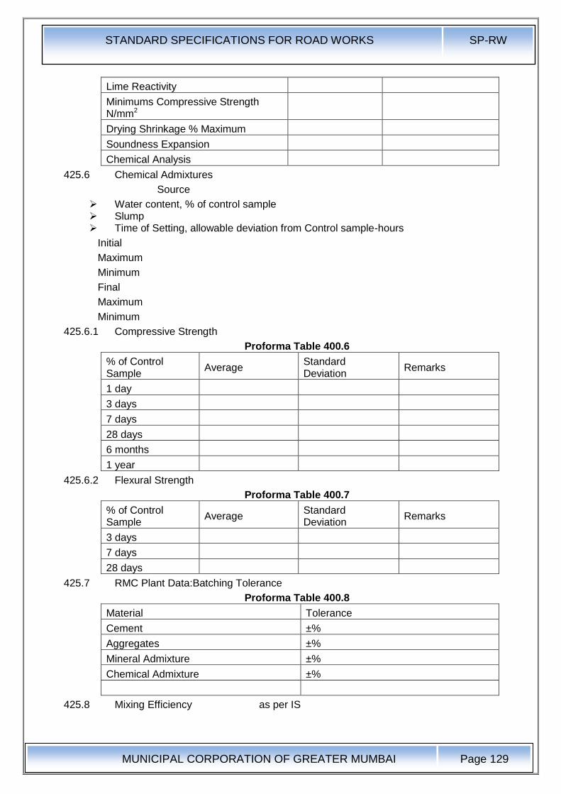
STANDARD SPECIFICATIONS FOR ROAD WORKS SP-RW
MUNICIPAL CORPORATION OF GREATER MUMBAI
Page 129
Lime Reactivity
Minimums Compressive Strength N/mm2
Drying Shrinkage % Maximum
Soundness Expansion
Chemical Analysis
425.6 Chemical Admixtures
Source
Water content, % of control sample Slump Time of Setting, allowable deviation from Control sample-hours
Initial
Maximum
Minimum
Final
Maximum
Minimum
425.6.1 Compressive Strength
Proforma Table 400.6
% of Control Sample
Average Standard Deviation
Remarks
1 day
3 days
7 days
28 days
6 months
1 year
425.6.2 Flexural Strength
Proforma Table 400.7
% of Control Sample
Average Standard Deviation
Remarks
3 days
7 days
28 days
425.7 RMC Plant Data:Batching Tolerance
Proforma Table 400.8
Material Tolerance
Cement ±%
Aggregates ±%
Mineral Admixture ±%
Chemical Admixture ±%
425.8 Mixing Efficiency as per IS
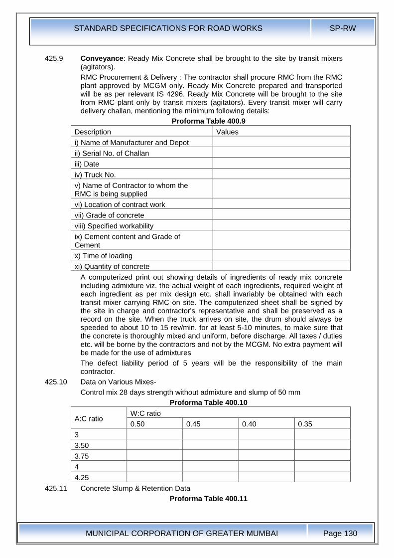
STANDARD SPECIFICATIONS FOR ROAD WORKS SP-RW
MUNICIPAL CORPORATION OF GREATER MUMBAI
Page 130
425.9 Conveyance: Ready Mix Concrete shall be brought to the site by transit mixers (agitators).
RMC Procurement & Delivery : The contractor shall procure RMC from the RMC plant approved by MCGM only. Ready Mix Concrete prepared and transported will be as per relevant IS 4296. Ready Mix Concrete will be brought to the site from RMC plant only by transit mixers (agitators). Every transit mixer will carry delivery challan, mentioning the minimum following details:
Proforma Table 400.9
Description Values
i) Name of Manufacturer and Depot
ii) Serial No. of Challan
iii) Date
iv) Truck No.
v) Name of Contractor to whom the RMC is being supplied
vi) Location of contract work
vii) Grade of concrete
viii) Specified workability
ix) Cement content and Grade of Cement
x) Time of loading
xi) Quantity of concrete
A computerized print out showing details of ingredients of ready mix concrete including admixture viz. the actual weight of each ingredients, required weight of each ingredient as per mix design etc. shall invariably be obtained with each transit mixer carrying RMC on site. The computerized sheet shall be signed by the site in charge and contractor's representative and shall be preserved as a record on the site. When the truck arrives on site, the drum should always be speeded to about 10 to 15 rev/min. for at least 5-10 minutes, to make sure that the concrete is thoroughly mixed and uniform, before discharge. All taxes / duties etc. will be borne by the contractors and not by the MCGM. No extra payment will be made for the use of admixtures
The defect liability period of 5 years will be the responsibility of the main contractor.
425.10 Data on Various Mixes-
Control mix 28 days strength without admixture and slump of 50 mm
Proforma Table 400.10
A:C ratio W:C ratio
0.50 0.45 0.40 0.35
3
3.50
3.75
4
4.25
425.11 Concrete Slump & Retention Data
Proforma Table 400.11
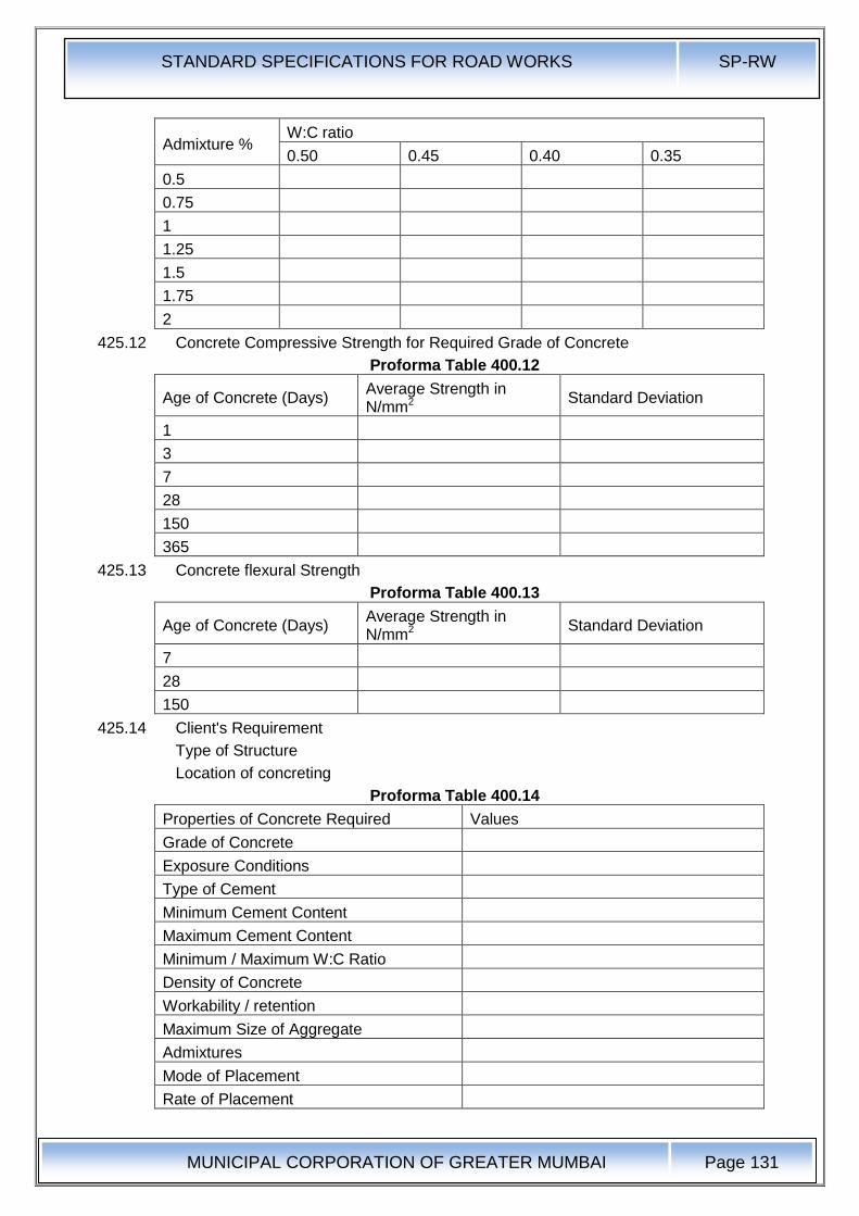
STANDARD SPECIFICATIONS FOR ROAD WORKS SP-RW
MUNICIPAL CORPORATION OF GREATER MUMBAI
Page 131
Admixture % W:C ratio
0.50 0.45 0.40 0.35
0.5
0.75
1
1.25
1.5
1.75
2
425.12 Concrete Compressive Strength for Required Grade of Concrete
Proforma Table 400.12
Age of Concrete (Days) Average Strength in N/mm2
Standard Deviation
1
3
7
28
150
365
425.13 Concrete flexural Strength
Proforma Table 400.13
Age of Concrete (Days) Average Strength in N/mm2
Standard Deviation
7
28
150
425.14 Client's Requirement
Type of Structure
Location of concreting
Proforma Table 400.14
Properties of Concrete Required Values
Grade of Concrete
Exposure Conditions
Type of Cement
Minimum Cement Content
Maximum Cement Content
Minimum / Maximum W:C Ratio
Density of Concrete
Workability / retention
Maximum Size of Aggregate
Admixtures
Mode of Placement
Rate of Placement
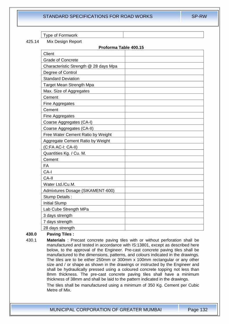
STANDARD SPECIFICATIONS FOR ROAD WORKS SP-RW
MUNICIPAL CORPORATION OF GREATER MUMBAI
Page 132
Type of Formwork
425.14 Mix Design Report
Proforma Table 400.15
Client
Grade of Concrete
Characteristic Strength @ 28 days Mpa
Degree of Control
Standard Deviation
Target Mean Strength Mpa
Max. Size of Aggregates
Cement
Fine Aggregates
Cement
Fine Aggregates
Coarse Aggregates (CA-I)
Coarse Aggregates (CA-II)
Free Water Cement Ratio by Weight
Aggregate Cement Ratio by Weight
(C:FA AC-I: CA-II)
Quantities Kg. I Cu. M.
Cement
FA
CA-I
CA-II
Water Ltd./Cu.M.
Admixtures Dosage (SIKAMENT-600)
Stump Details :
Initial Slump
Lab Cube Strength MPa
3 days strength
7 days strength
28 days strength
430.0 Paving Tiles :
430.1 Materials : Precast concrete paving tiles with or without perforation shall be manufactured and tested in accordance with IS:13801, except as described here below, to the approval of the Engineer. Pre-cast concrete paving tiles shall be manufactured to the dimensions, patterns, and colours indicated in the drawings. The tiles are to be either 250mm or 300mm x 100mm rectangular or any other size and / or shape as shown in the drawings or instructed by the Engineer and shall be hydraulically pressed using a coloured concrete topping not less than 8mm thickness. The pre-cast concrete paving tiles shall have a minimum thickness of 38mm and shall be laid to the pattern indicated in the drawings.
The tiles shall be manufactured using a minimum of 350 Kg. Cement per Cubic Metre of Mix.
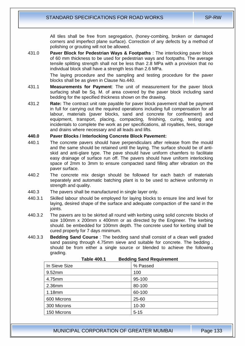
STANDARD SPECIFICATIONS FOR ROAD WORKS SP-RW
MUNICIPAL CORPORATION OF GREATER MUMBAI
Page 133
All tiles shall be free from segregation, (honey-combing, broken or damaged corners and imperfect plane surface). Correction of any defects by a method of polishing or grouting will not be allowed.
431.0 Paver Block for Pedestrian Ways & Footpaths : The interlocking paver block of 60 mm thickness to be used for pedestrian ways and footpaths. The average tensile splitting strength shall not be less than 2.8 MPa with a provision that no individual block shall have a strength less than 2.6 MPa.
The laying procedure and the sampling and testing procedure for the paver blocks shall be as given in Clause No.440.
431.1 Measurements for Payment: The unit of measurement for the paver block surfacing shall be Sq. M. of area covered by the paver block including sand bedding for the specified thickness shown on the drawing.
431.2 Rate: The contract unit rate payable for paver block pavement shall be payment in full for carrying out the required operations including full compensation for all labour, materials (paver blocks, sand and concrete for confinement) and equipment, transport, placing, compacting, finishing, curing, testing and incidentals to complete the work as per specifications, all royalties, fees, storage and drains where necessary and all leads and lifts.
440.0 Paver Blocks / Interlocking Concrete Block Pavement:
440.1 The concrete pavers should have perpendiculars after release from the mould and the same should be retained until the laying. The surface should be of anti-skid and anti-glare type. The pave should have uniform chamfers to facilitate easy drainage of surface run off. The pavers should have uniform interlocking space of 2mm to 3mm to ensure compacted sand filling after vibration on the paver surface.
440.2 The concrete mix design should be followed for each batch of materials separately and automatic batching plant is to be used to achieve uniformity in strength and quality.
440.3 The pavers shall be manufactured in single layer only.
440.3.1 Skilled labour should be employed for laying blocks to ensure line and level for laying, desired shape of the surface and adequate compaction of the sand in the joints.
440.3.2 The pavers are to be skirted all round with kerbing using solid concrete blocks of size 100mm x 200mm x 400mm or as directed by the Engineer. The kerbing should. be embedded for 100mm depth. The concrete used for kerbing shall be cured properly for 7 days minimum.
440.3.3 Bedding Sand Course : The bedding sand shall consist of a clean well graded sand passing through 4.75mm sieve and suitable for concrete. The bedding . should be from either a single source or blended to achieve the following grading.
Table 400.1 Bedding Sand Requirement
In Sieve Size % Passed
9.52mm 100
4.75mm 95-100
2.36mm 80-100
1.18mm 60-100
600 Microns 25-60
300 Microns 10-30
150 Microns 5-15
STANDARD SPECIFICATIONS FOR ROAD WORKS SP-RW
MUNICIPAL CORPORATION OF GREATER MUMBAI
Page 134
75 Microns 0-10
Contractor shall be responsible to ensure that single-sized, gap-graded sands or sands containing an excessive amount of fines or plastic fines are not used. The sand particles should preferably be sharp not rounded as sharp sand possess higher strength and resist the migration of sand from under the block to less frequently areas even though sharp sands are relatively more difficult to compact than rounded sands, the use of sharp sands is preferred for the more heavily trafficked driveways. The sand use for bedding shall be free of any deleterious soluble salts or other contaminants likely to cause . efflorescence.
The sand shall be of uniform moisture content and within 4% - 8% when spread and shall be protected against rain when stock piled prior to spreading. Saturated sand shall not be used. The bedding sand shall be spread loose in a uniform layer as per drawing. The compacted uniform thickness shall be of 45mm and within +/- 5mm thickness variation shall not be used to correct irregularities in the base course surface. ..
The spread sand shall be carefully maintained in a loose dry condition and protected against pre-compaction both prior to and following screeding. Any pre-compacted sand or screeded sand left overnight shall be loosened before further laying of paving blocks take place.
Sand shall be slightly screeded in a loose condition to the predetermined depth only slightly ahead of the laying of paving unit.
Any depressions in the screeded sand exceeding 5mm shall be loosened, raked and rescreeded before laying of paving blocks. Sampling and Testing Procedures for Paver Blocks:
440.4 Sample Size: Following are the sample sizes:
a) Internal: Average of minimum 3 samples per 5000 blocks - for paver block manufacturers
b) External: Minimum 9 Blocks per 5000 Blocks. Average of minimum 9 Blocks per site: for captioned contractors.
440.4.1 Sampling for Testing: Sampling for testing of paver blocks shall be done in accordance with clause No. 440.5, 440.6 and 440.7
440.4.2 Compressive Strength : Testing for compressive strength shall be undertaken in accordance with clause 440.7. The average compressive strength of the 80mm thick paver blocks tested shall be 45 N/Sq. mm. and average compressive strength of the 60mm to 50 mm:thick paver blocks shall be 35 N/Sq. mm.
440.4.3 Water Absorption: Testing for water absorption shall be in accordance with IS:2185 : 1979 : Part I (Specifications for Concrete Masonry Blocks) Appendix C.
440.4.4 In case of failure of test sample : In case of failure of test sample for above test, the contractor should replace the entire lot of paver blocks representing samples are taken. The samples of replaced lots shall be tested. However, 25% of the payment of the measurement of the lot will be recovered as penalty.
440.4.5 Tensile Splitting Test: (for blocks subject to vehicular traffic) -The mean tensile strength of 8 blocks shall be not less than 3.9 MPa and no individual block shall have tensile strength less than 3.6 MP when tested as per Annex E of BS 6717:2001
440.4.6 Abrasion Resistance ( blocks subject to vehicular traffic) : Set of 3 blocs tested as per Annex F of BS 6717 :2001 shall be more than 23mm.
440.5 Method for the determination of Water Absorption :
440.5.1 The test specimens shall be completely immersed in water at room temperature for 24 hours.
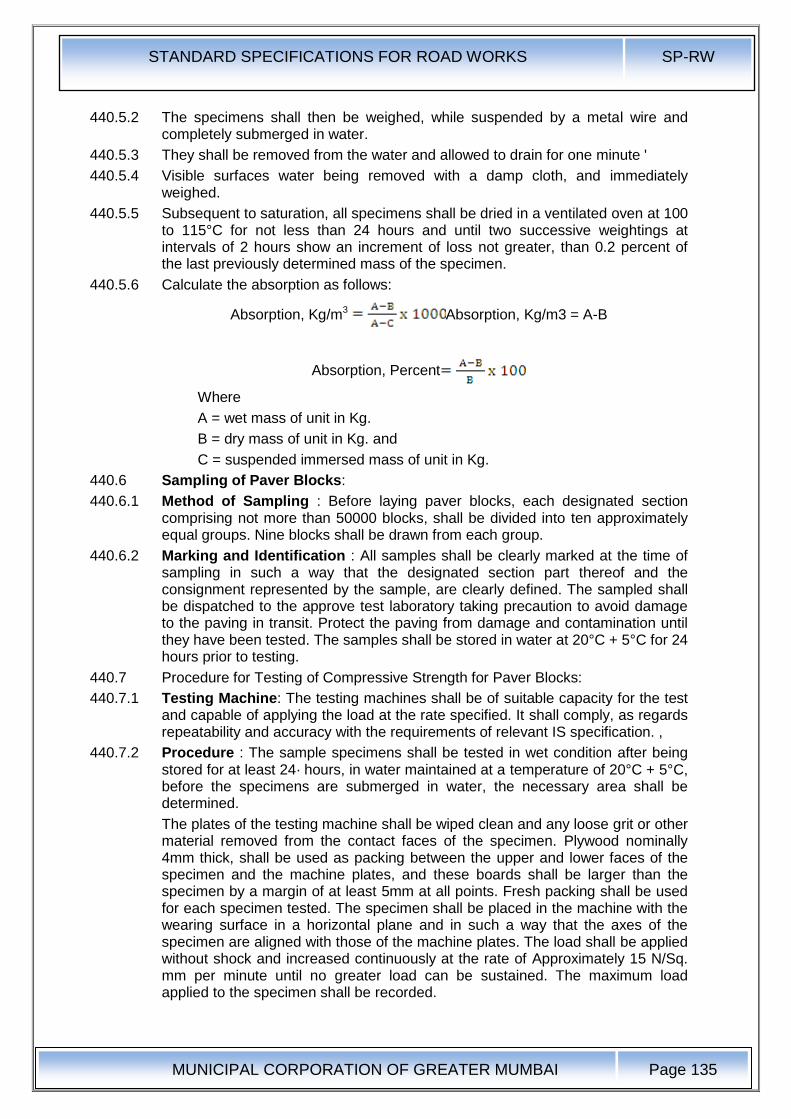
STANDARD SPECIFICATIONS FOR ROAD WORKS SP-RW
MUNICIPAL CORPORATION OF GREATER MUMBAI
Page 135
440.5.2 The specimens shall then be weighed, while suspended by a metal wire and completely submerged in water.
440.5.3 They shall be removed from the water and allowed to drain for one minute '
440.5.4 Visible surfaces water being removed with a damp cloth, and immediately weighed.
440.5.5 Subsequent to saturation, all specimens shall be dried in a ventilated oven at 100 to 115°C for not less than 24 hours and until two successive weightings at intervals of 2 hours show an increment of loss not greater, than 0.2 percent of the last previously determined mass of the specimen.
440.5.6 Calculate the absorption as follows:
Absorption, Kg/m3 Absorption, Kg/m3 = A-B
Absorption, Percent
Where
A = wet mass of unit in Kg.
B = dry mass of unit in Kg. and
C = suspended immersed mass of unit in Kg.
440.6 Sampling of Paver Blocks:
440.6.1 Method of Sampling : Before laying paver blocks, each designated section comprising not more than 50000 blocks, shall be divided into ten approximately equal groups. Nine blocks shall be drawn from each group.
440.6.2 Marking and Identification : All samples shall be clearly marked at the time of sampling in such a way that the designated section part thereof and the consignment represented by the sample, are clearly defined. The sampled shall be dispatched to the approve test laboratory taking precaution to avoid damage to the paving in transit. Protect the paving from damage and contamination until they have been tested. The samples shall be stored in water at 20°C + 5°C for 24 hours prior to testing.
440.7 Procedure for Testing of Compressive Strength for Paver Blocks:
440.7.1 Testing Machine: The testing machines shall be of suitable capacity for the test and capable of applying the load at the rate specified. It shall comply, as regards repeatability and accuracy with the requirements of relevant IS specification. ,
440.7.2 Procedure : The sample specimens shall be tested in wet condition after being stored for at least 24· hours, in water maintained at a temperature of 20°C + 5°C, before the specimens are submerged in water, the necessary area shall be determined.
The plates of the testing machine shall be wiped clean and any loose grit or other material removed from the contact faces of the specimen. Plywood nominally 4mm thick, shall be used as packing between the upper and lower faces of the specimen and the machine plates, and these boards shall be larger than the specimen by a margin of at least 5mm at all points. Fresh packing shall be used for each specimen tested. The specimen shall be placed in the machine with the wearing surface in a horizontal plane and in such a way that the axes of the specimen are aligned with those of the machine plates. The load shall be applied without shock and increased continuously at the rate of Approximately 15 N/Sq. mm per minute until no greater load can be sustained. The maximum load applied to the specimen shall be recorded.
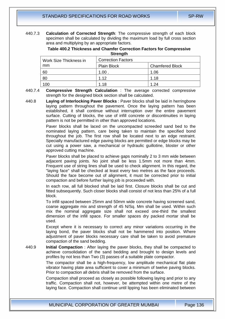
STANDARD SPECIFICATIONS FOR ROAD WORKS SP-RW
MUNICIPAL CORPORATION OF GREATER MUMBAI
Page 136
440.7.3 Calculation of Corrected Strength: The compressive strength of each block specimen shall be calculated by dividing the maximum load by full cross section area and multiplying by an appropriate factors.
Table 400.2 Thickness and Chamfer Correction Factors for Compressive Strength
Work Size Thickness in mm
Correction Factors
Plain Block Chamfered Block
60 1.00 . 1.06
80 1.12 1.18
100 1.18 1.24
440.7.4 Compressive Strength Calculation : The average corrected compressive strength for the designed block section shall be calculated.
440.8 Laying of Interlocking Paver Blocks : Paver blocks shall be laid in herringbone laying pattern throughout the pavement. Once the laying pattern has been established, it shall continue without interruption over the entire pavement surface. Cutting of blocks, the use of infill concrete or discontinuities in laying pattern is not be permitted in other than approved locations.
Paver blocks shall be laced on the uncompacted screeded sand bed to the nominated laying pattern, care being taken to maintain the specified bond throughout the job. The first row shall be located next to an edge restraint. Specially manufactured edge paving blocks are permitted or edge blocks may be cut using a power saw, a mechanical or hydraulic guillotine, bloster or other approved cutting machine.
Paver blocks shall be placed to achieve gaps nominally 2 to 3 mm wide between adjacent paving joints. No joint shall be less 1.5mm not more than 4mm. Frequent use of string lines shall be used to check alignment. In this regard, the "laying face" shall be checked at least every two metres as the face proceeds. Should the face become out of alignment, it must be corrected prior to initial compaction and before further laying job is proceeded with.
In each row, all full blocked shall be laid first. Closure blocks shall be cut and fitted subsequently. Such closer blocks shall consist of not less than 25% of a full block.
To infill spaced between 25mm and 50mm wide concrete having screened sand, coarse aggregate mix and strength of 45 N/Sq. Mm shall be used. Within such mix the nominal aggregate size shall not exceed one-third the smallest dimension of the infill space. For smaller spaces dry packed mortar shall be used.
Except where it is necessary to correct any minor variations occurring in the laying bond, the paver blocks shall not be hammered into position. Where adjustment of paver blocks necessary care shall be taken to avoid premature compaction of the sand bedding.
440.9 Initial Compaction : After laying the paver blocks, they shall be compacted to achieve consolidation of the sand bedding and brought to design levels and profiles by not less than Two (3) passes of a suitable plate compactor.
The compactor shall be a high-frequency, low amplitude mechanical flat plate vibrator having plate area sufficient to cover a minimum of twelve paving blocks. Prior to compaction all debris shall be removed from the surface.
Compaction shall proceed as closely as possible following laying and prior to any traffic. Compaction shall not, however, be attempted within one metre of the laying face. Compaction shall continue until lipping has been eliminated between
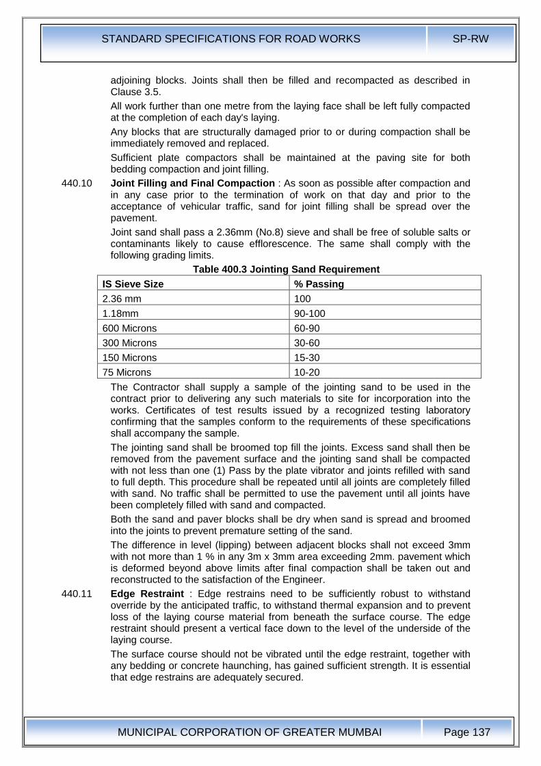
STANDARD SPECIFICATIONS FOR ROAD WORKS SP-RW
MUNICIPAL CORPORATION OF GREATER MUMBAI
Page 137
adjoining blocks. Joints shall then be filled and recompacted as described in Clause 3.5.
All work further than one metre from the laying face shall be left fully compacted at the completion of each day's laying.
Any blocks that are structurally damaged prior to or during compaction shall be immediately removed and replaced.
Sufficient plate compactors shall be maintained at the paving site for both bedding compaction and joint filling.
440.10 Joint Filling and Final Compaction : As soon as possible after compaction and in any case prior to the termination of work on that day and prior to the acceptance of vehicular traffic, sand for joint filling shall be spread over the pavement.
Joint sand shall pass a 2.36mm (No.8) sieve and shall be free of soluble salts or contaminants likely to cause efflorescence. The same shall comply with the following grading limits.
Table 400.3 Jointing Sand Requirement
IS Sieve Size % Passing
2.36 mm 100
1.18mm 90-100
600 Microns 60-90
300 Microns 30-60
150 Microns 15-30
75 Microns 10-20
The Contractor shall supply a sample of the jointing sand to be used in the contract prior to delivering any such materials to site for incorporation into the works. Certificates of test results issued by a recognized testing laboratory confirming that the samples conform to the requirements of these specifications shall accompany the sample.
The jointing sand shall be broomed top fill the joints. Excess sand shall then be removed from the pavement surface and the jointing sand shall be compacted with not less than one (1) Pass by the plate vibrator and joints refilled with sand to full depth. This procedure shall be repeated until all joints are completely filled with sand. No traffic shall be permitted to use the pavement until all joints have been completely filled with sand and compacted.
Both the sand and paver blocks shall be dry when sand is spread and broomed into the joints to prevent premature setting of the sand.
The difference in level (lipping) between adjacent blocks shall not exceed 3mm with not more than 1 % in any 3m x 3mm area exceeding 2mm. pavement which is deformed beyond above limits after final compaction shall be taken out and reconstructed to the satisfaction of the Engineer.
440.11 Edge Restraint : Edge restrains need to be sufficiently robust to withstand override by the anticipated traffic, to withstand thermal expansion and to prevent loss of the laying course material from beneath the surface course. The edge restraint should present a vertical face down to the level of the underside of the laying course.
The surface course should not be vibrated until the edge restraint, together with any bedding or concrete haunching, has gained sufficient strength. It is essential that edge restrains are adequately secured.
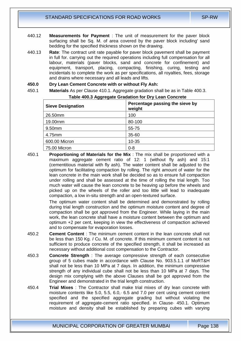
STANDARD SPECIFICATIONS FOR ROAD WORKS SP-RW
MUNICIPAL CORPORATION OF GREATER MUMBAI
Page 138
440.12 Measurements for Payment : The unit of measurement for the paver block surfacing shall be Sq. M. of area covered by the paver block including' sand bedding for the specified thickness shown on the drawing.
440.13 Rate: The contract unit rate payable for paver block pavement shall be payment in full for. carrying out the required operations including full compensation for all labour, materials (paver blocks, sand and concrete for confinement) and equipment, transport, placing, compacting, finishing, curing, testing and incidentals to complete the work as per specifications, all royalties, fees, storage and drains where necessary and all leads and lifts.
450.0 Dry Lean Cement Concrete with or without Fly Ash:
450.1 Materials As per Clause 410.1. Aggregate gradation shall be as in Table 400.3.
Table 400.3 Aggregate Gradation for Dry Lean Concrete
Sieve Designation Percentage passing the sieve by weight
26.50mm 100
19.00rnm 80-100
9.50mm 55-75
4.75mm 35-60
600.00 Micron 10-35
75.00 Micron 0-8
450.1 Proportioning of Materials for the Mix : The mix shall be proportioned with a maximum aggregate cement ratio of 12: 1 (without fly ash) and 15:1 (cementitious material with fly ash). The water content shall be adjusted to the optimum for facilitating compaction by rolling. The right amount of water for the lean concrete in the main work shall be decided so as to ensure full compaction under rolling and shall be assessed at the time of rolling the trial length. Too much water will cause the lean concrete to be heaving up before the wheels and picked up on the wheels of the roller and too little will lead to inadequate compaction, a low in-situ strength and an open-textured surface.
The optimum water content shall be determined and demonstrated by rolling during trial length construction and the optimum moisture content and degree of compaction shall be got approved from the Engineer. While laying in the main work, the lean concrete shall have a moisture content between the optimum and optimum +2 per cent, keeping in view the effectiveness of compaction achieved and to compensate for evaporation losses.
450.2 Cement Content : The minimum cement content in the lean concrete shall not be less than 150 Kg. I Cu. M. of concrete. If this minimum cement content is not sufficient to produce concrete of the specified strength, it shall be increased as necessary without additional cost compensation to the Contractor.
450.3 Concrete Strength : The average compressive strength of each consecutive group of 5 cubes made in accordance with Clause No. 903.5.1.1 of MoRT&H shall not be less than 10 MPa at 7 days. In addition, the minimum compressive strength of any individual cube shall not be less than 10 MPa at 7 days. The design mix complying with the above Clauses shall be got approved from the Engineer and demonstrated in the trial length construction.
450.4 Trial Mixes : The Contractor shall make trial mixes of dry lean concrete with moisture contents like 5.0, 5.5, 6.0,· 6.5 and 7.0 per cent using cement content specified and the specified aggregate grading but without violating the requirement of aggregate-cement ratio specified. in Clause· 450.1. Optimum moisture and density shall be established by preparing cubes with varying

STANDARD SPECIFICATIONS FOR ROAD WORKS SP-RW
MUNICIPAL CORPORATION OF GREATER MUMBAI
Page 139
moisture contents. Compaction of the mix shall be done in three layer with vibratory hammer fitted with a square or rectangular foot as described in Clause 903.5.1.1 of M.O.R.T. & H. After establishing the optimum moisture, a set of six cubes shall be cast at that moisture for the determination of compressive strength on the 3rd and the 7th day. Trial mixes shall be repeated if the strength is not satisfactory either by increasing cement content or using higher grade of cement. After the mix design is approved, the Contractor shall construct a trial section in accordance with Clause 601.7 of MoRT&H.
450.5 If during the construction of the trial length, the optimum moisture content determined· as above is found to be unsatisfactory, the Contractor may make suitable changes in the moisture content to achieve a satisfactory mix. The cube specimens prepared with the changed moisture content should satisfy the strength requirement. Before· production of the mix, natural moisture content of the aggregate should be determined on a day-to-day basis so that the moisture content could be adjusted. The mix finally designed should neither stick to the rollers nor become too dry resulting in ravelling of surface.
450.6 Construction
450.6.1 General : The pace and programme of the lean concrete sub-base construction shall be matching suitably with the programme of construction of the cement concrete pavement over it. The sub-base shall be overlaid with cement concrete pavement only after 7 days after sub-base construction.
450.6.2 Batching and Mixing : The batching plant shall be capable of proportioning the materials by weight, each type of material being weighed separately in accordance with Clause 602.9.3.2 of M.O.R.T.&H Specifications. The cement from the bulk stock shall be weighed separately from the aggregates. The capacity of batching and mixing plant shall be at least 25 per cent higher than the proposed capacity for the laying arrangements. The batching and mixing shall be carried out preferably in a forced action central batching and mixing plant having necessary automatic controls to ensure accurate proportioning and mixing. Other types of mixers shall be permitted subject to demonstration of their satisfactory performance during the trial length. The type and capacity of the plant shall be got approved by the Engineer before commencement of the trial length. The weighing balances shall be calibrated by weighing the aggregates, cement, water and admixtures physically either by weighing with large weighing machine or in a weigh bridge. The accuracy of weighing scales of the batching plant shall be within ±2 per cent in the case of aggregates and ±1 per cent in the case of cement and water.
The design features of Batching Plant should be such that the shifting operations of the plant will not take very long tie when they are to be shifted from place to place with the progress of the work.
450.6.3 Transporting : Plant mix lean concrete shall be discharge immediately from the mixer, transported directly to the point where it is to be laid and protected from the weather by covering the tippers I dumpers with tarpaulin during transit. The concrete shall be transported by tipping trucks, sufficient in number to ensure a continuous supply of material to feed the laying equipment to work at a uniform speed and in an uninterrupted manner. The lead of the batching plant to paving site shall be such that the travel time available from mixing to paving as specified in Clause 450.5.5 will be adhered to.
450.6.4 Placing: Lean concrete shall be laid I placed by a paver with electronic sensor. The equipment shall be capable of laying the material in one layer in an even manner without segregation, so that after compaction the total thickness is as
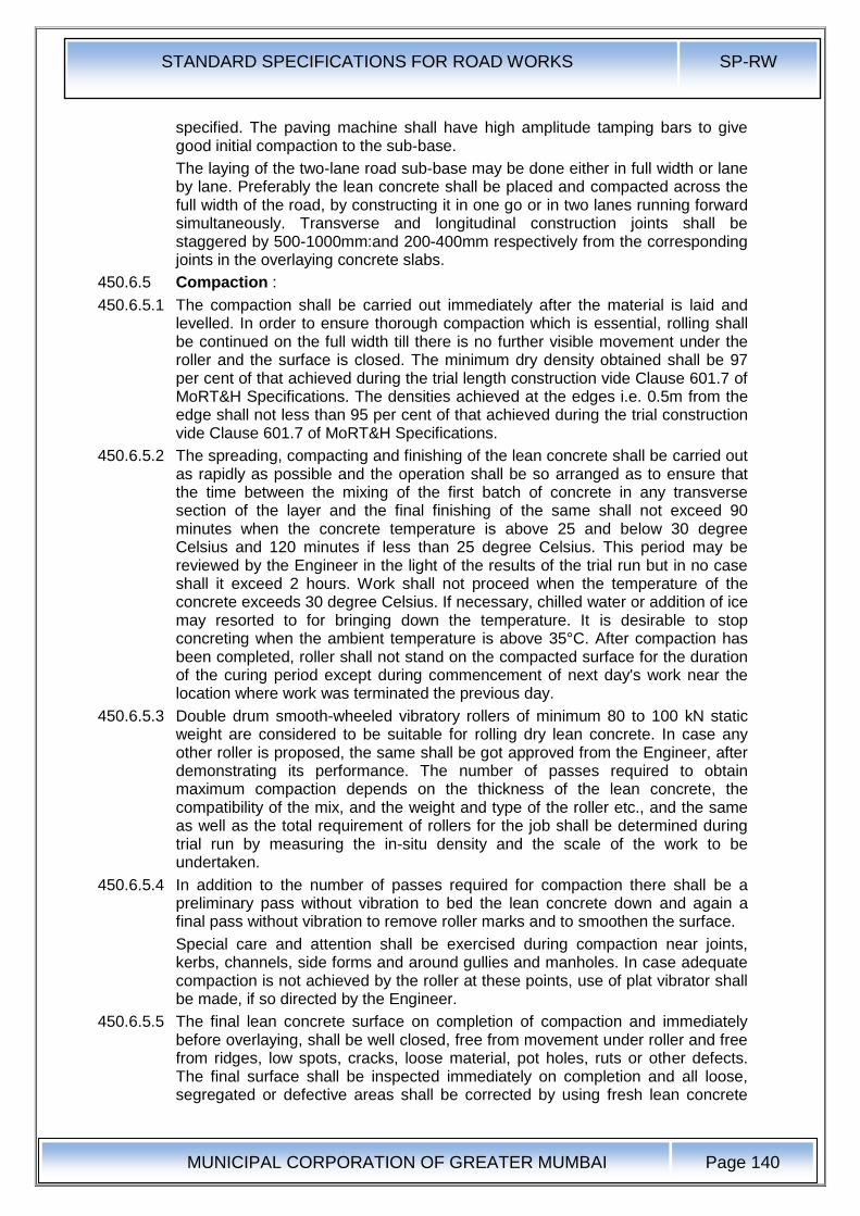
STANDARD SPECIFICATIONS FOR ROAD WORKS SP-RW
MUNICIPAL CORPORATION OF GREATER MUMBAI
Page 140
specified. The paving machine shall have high amplitude tamping bars to give good initial compaction to the sub-base.
The laying of the two-lane road sub-base may be done either in full width or lane by lane. Preferably the lean concrete shall be placed and compacted across the full width of the road, by constructing it in one go or in two lanes running forward simultaneously. Transverse and longitudinal construction joints shall be staggered by 500-1000mm:and 200-400mm respectively from the corresponding joints in the overlaying concrete slabs.
450.6.5 Compaction :
450.6.5.1 The compaction shall be carried out immediately after the material is laid and levelled. In order to ensure thorough compaction which is essential, rolling shall be continued on the full width till there is no further visible movement under the roller and the surface is closed. The minimum dry density obtained shall be 97 per cent of that achieved during the trial length construction vide Clause 601.7 of MoRT&H Specifications. The densities achieved at the edges i.e. 0.5m from the edge shall not less than 95 per cent of that achieved during the trial construction vide Clause 601.7 of MoRT&H Specifications.
450.6.5.2 The spreading, compacting and finishing of the lean concrete shall be carried out as rapidly as possible and the operation shall be so arranged as to ensure that the time between the mixing of the first batch of concrete in any transverse section of the layer and the final finishing of the same shall not exceed 90 minutes when the concrete temperature is above 25 and below 30 degree Celsius and 120 minutes if less than 25 degree Celsius. This period may be reviewed by the Engineer in the light of the results of the trial run but in no case shall it exceed 2 hours. Work shall not proceed when the temperature of the concrete exceeds 30 degree Celsius. If necessary, chilled water or addition of ice may resorted to for bringing down the temperature. It is desirable to stop concreting when the ambient temperature is above 35°C. After compaction has been completed, roller shall not stand on the compacted surface for the duration of the curing period except during commencement of next day's work near the location where work was terminated the previous day.
450.6.5.3 Double drum smooth-wheeled vibratory rollers of minimum 80 to 100 kN static weight are considered to be suitable for rolling dry lean concrete. In case any other roller is proposed, the same shall be got approved from the Engineer, after demonstrating its performance. The number of passes required to obtain maximum compaction depends on the thickness of the lean concrete, the compatibility of the mix, and the weight and type of the roller etc., and the same as well as the total requirement of rollers for the job shall be determined during trial run by measuring the in-situ density and the scale of the work to be undertaken.
450.6.5.4 In addition to the number of passes required for compaction there shall be a preliminary pass without vibration to bed the lean concrete down and again a final pass without vibration to remove roller marks and to smoothen the surface.
Special care and attention shall be exercised during compaction near joints, kerbs, channels, side forms and around gullies and manholes. In case adequate compaction is not achieved by the roller at these points, use of plat vibrator shall be made, if so directed by the Engineer.
450.6.5.5 The final lean concrete surface on completion of compaction and immediately before overlaying, shall be well closed, free from movement under roller and free from ridges, low spots, cracks, loose material, pot holes, ruts or other defects. The final surface shall be inspected immediately on completion and all loose, segregated or defective areas shall be corrected by using fresh lean concrete
STANDARD SPECIFICATIONS FOR ROAD WORKS SP-RW
MUNICIPAL CORPORATION OF GREATER MUMBAI
Page 141
material laid and compacted as per Specification. For repairing honeycombed surface, concrete with aggregates of size 10mm and below shall be spread and compacted. It is necessary to check the level of the roller surface for compliance. Any level/thickness deficiency should be corrected after applying concrete with aggregates of size 10mm and below after roughening the surface. Similarly, the surface regularity also should be checked with 3m straight edge. The deficiency should be made up with concrete with aggregates of size 10mm and below. 450.6.5.6 Segregation of concrete in the dumpers shall be controlled by premixing each fraction of the aggregates before loading in the bin of the batching plant, by moving the dumper back and forth while discharging the mix on it and other means. Even paving operation shall be such that the mix does not segregate.
450.6.6 Joints: Contraction and longitudinal joints shall be provided as per the drawing. .
At longitudinal or transverse construction joints, unless vertical forms are used, the edge of compacted material shall be cut back to a vertical face where the correct thickness of the properly compacted material has been obtained.
450.6.7 Curing : As soon as the lean concrete surface is compacted, curing shall commence. One of the following two methods shall be adopted:
i) The initial curing shall be done by spraying with liquid curing compound. The curing compound shall be white pigmented or transparent type with water retention index of 90 per cent when tested in accordance with 8S:7542. Curing compound shall be sprayed immediately after rolling is complete. As soon as the curing compound has lost its tackiness, the surface shall be covered with wet Hessian for three days.
ii) Curing shall be done by covering the surface buy gunny bags/Hessian, which shall be kept continuously moist for 7 days by sprinkling water.
Tolerances for Surface Regularity, Level, Thickness, Density and Strength : The tolerances for surface· regularity, level, thickness, density "and strength shall conform to the requirements given in Clause 903.5 of MoRT&H Specifications. Control of quality of materials and works shall be exercised by the Engineer in accordance with Section 900 of MoRT&H. Specifications.
450.6.8 Traffic : No heavy commercial vehicles like trucks and buses shall be permitted on the lean concrete sub-base after its construction. Light vehicles if unavoidable may, however, be allowed after 7 days of its construction with prior approval of the Engineer.
450.6.9 Measurements for Payment : The unit of measurement for dry lean concrete pavement shall be the cubic metre of concrete placed, based on the net plan areas for the specified thickness shown on the drawings or as directed by the Engineer.
450.6.10 Rate : The Contract unit rate payable for dry lean concrete, sub-base shall be payment in full for carrying out the required operations including full compensation for all labour, materials and equipment, mixing, transport, placing, compacting, finishing, curing, testing and incidentals to complete the work as per Specifications, all royalties, fees, storage and rents where necessary and all leads and lifts.
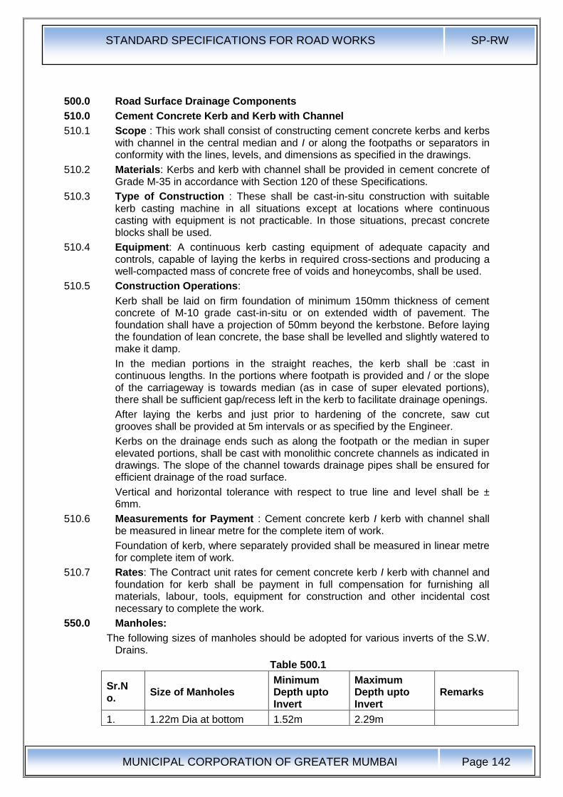
STANDARD SPECIFICATIONS FOR ROAD WORKS SP-RW
MUNICIPAL CORPORATION OF GREATER MUMBAI
Page 142
500.0 Road Surface Drainage Components
510.0 Cement Concrete Kerb and Kerb with Channel
510.1 Scope : This work shall consist of constructing cement concrete kerbs and kerbs with channel in the central median and I or along the footpaths or separators in conformity with the lines, levels, and dimensions as specified in the drawings.
510.2 Materials: Kerbs and kerb with channel shall be provided in cement concrete of Grade M-35 in accordance with Section 120 of these Specifications.
510.3 Type of Construction : These shall be cast-in-situ construction with suitable kerb casting machine in all situations except at locations where continuous casting with equipment is not practicable. In those situations, precast concrete blocks shall be used.
510.4 Equipment: A continuous kerb casting equipment of adequate capacity and controls, capable of laying the kerbs in required cross-sections and producing a well-compacted mass of concrete free of voids and honeycombs, shall be used.
510.5 Construction Operations:
Kerb shall be laid on firm foundation of minimum 150mm thickness of cement concrete of M-10 grade cast-in-situ or on extended width of pavement. The foundation shall have a projection of 50mm beyond the kerbstone. Before laying the foundation of lean concrete, the base shall be levelled and slightly watered to make it damp.
In the median portions in the straight reaches, the kerb shall be :cast in continuous lengths. In the portions where footpath is provided and / or the slope of the carriageway is towards median (as in case of super elevated portions), there shall be sufficient gap/recess left in the kerb to facilitate drainage openings.
After laying the kerbs and just prior to hardening of the concrete, saw cut grooves shall be provided at 5m intervals or as specified by the Engineer.
Kerbs on the drainage ends such as along the footpath or the median in super elevated portions, shall be cast with monolithic concrete channels as indicated in drawings. The slope of the channel towards drainage pipes shall be ensured for efficient drainage of the road surface.
Vertical and horizontal tolerance with respect to true line and level shall be ± 6mm.
510.6 Measurements for Payment : Cement concrete kerb I kerb with channel shall be measured in linear metre for the complete item of work.
Foundation of kerb, where separately provided shall be measured in linear metre for complete item of work.
510.7 Rates: The Contract unit rates for cement concrete kerb I kerb with channel and foundation for kerb shall be payment in full compensation for furnishing all materials, labour, tools, equipment for construction and other incidental cost necessary to complete the work.
550.0 Manholes:
The following sizes of manholes should be adopted for various inverts of the S.W. Drains.
Table 500.1
Sr.No.
Size of Manholes Minimum Depth upto Invert
Maximum Depth upto Invert
Remarks
1. 1.22m Dia at bottom 1.52m 2.29m
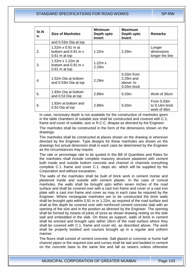
STANDARD SPECIFICATIONS FOR ROAD WORKS SP-RW
MUNICIPAL CORPORATION OF GREATER MUMBAI
Page 143
Sr.No.
Size of Manholes Minimum Depth upto Invert
Maximum Depth upto Invert
Remarks
and 0.53m Dia at top
2. 1.52m x 0.91 m at bottom and 0.91 m x 0.61 m at top
1.22m 2.29m Longer dimensions longer the line
3. 1.52m x 1.22m at bottom and 0.91 m x 0.61 m at top
1.22m x 2.29m
4. 1.52m Dia at bottom and 0.53m Dia at top
2.29m
5.03m from 2.29m and above: to 5.03m brick
5. 1.83m Dia at bottom and 0.53 Dia at top
2.89m 5.03m Work of 36cm
6. 1.83m at bottom and 0.53 Dia at top
2.89m 5.03m From 5.03m to 9.14m brick work of 46m
In case, necessary depth is not available for the construction of manholes given in the table chambers of suitable size shall be constructed and covered with C.1. frame and cover of suitable, size or R.C.C. dhapas as directed by the Engineer.
The manholes shall be constructed in the form of the dimensions shown on the drawings.
The manholes shall be constructed at places shown on the drawing or wherever directed by the Engineer. Type designs for these manholes are shown on the drawings but actual dimension shall in each case be determined by the Engineer as the circumstances may require.
The rate or percentage rate to be quoted in the Bill of Quantities and Rates for the manholes shall include complete masonry structure plastered with cement both inside and outside bottom concrete and channel or channels everything complete C.1. frame and cover C.1. steps etc. which will be supplied by the Corporation and without excavation.
The walls of the manholes shall be built of brick work in cement mortar and plastered inside and outside with cement plaster. In the case of conical manholes, the walls shall be brought upto within seven inches of the road surface and shall be covered over with a cast iron frame and cover or a cast iron plate with a cast iron frame and cover as may in each case be required by the Engineer. Where rectangular manholes are to be constructed the brick walls shall be brought upto within 0.91 m or 1.22m, as required of the road surface and shall at this depth be covered over with reinforced cement concrete slab with an opening of the size and in the position as directed by the Engineer. The opening shall be formed by means of joints of sizes as shown drawing resting on the side wall and embedded in the slab. On these as support, walls of brick in cement shall be erected and brought upto within 18cm of the road surface where they shall be covered with C.1. frame and cover etc. as described above. The work shall be properly bedded and courses brought up in a regular and uniform manner.
The floors shall consist of cement concrete. Salt glazed or concrete or hume half channel pipes or the required size and curves shall be laid and bedded in cement on the concrete base to the same line and fall as sewers unless otherwise
STANDARD SPECIFICATIONS FOR ROAD WORKS SP-RW
MUNICIPAL CORPORATION OF GREATER MUMBAI
Page 144
directed. Both sides of the channel pipes shall be benched up in concrete and rendered in cement 20mm thick and formed to a slope of not less than 1 in 12 to the channel.
Whenever a pipe enters or leaves manholes bricks on edge must be cut to a proper form and laid around the upper half of the pipe so as to form an arch. All around the pipe, there shall be a joint of cement mortar 12mm thick between it and the bricks. The ends of all pipes shall be properly built in and neatly finished with cement mortar.
Where the depth of the invert exceeds 1 m below the surface of the galvanized wrought iron or cast iron steps of approved pattern shall be built in the brick work ground every four courses with such additional hand irons as may be necessary for safety.
560.0 Water Entrances:
The chamber for water entrances shall be constructed of bricks work in 1:5 cement mortar plastered with cement plastering 12mm thick. The bed of the chamber shall consist of 23cm layer of 1 :4:8 cement concrete. The invert shall be formed of cement concrete as shown in the drawing and shall be plastered with cement plastering 12mm thick. The parda of diaphragm shall be of cast iron 25mm thick and shall be so fixed as to carry the dhapas and to dip into the water seal to a depth of 20cm. The part of the chamber which is shown on drawing as below the surface of the road, shall be covered with blue stone dhapas as shown on the drawing. The other part of the chamber shall be covered with two mosquito proof close C.1. gratings; fair weather plates in the case of full sized water gullies and one for single water gullies the grating or gratings being supported on C.1. frame as shown on the drawing.
Whenever any hole or other communication has to be cut into the wall or made with a drain or sewer or a manhole or into or with other masonry, the hole or communication shall be cut or made neatly to the requisite value size and pipe tail piece, elbow or other article or work for which it is required shall be neatly and soundly stopped around with, or built in cement and sand (1 to 1). The rate for cutting the hole or that for the work or which the communication is required shall include the cost of such stopping. that of any making good that may be required and also that of any arrangements which the contractors may have to make in order to stop the access of sewage or water during the execution of their work. No payment will be allowed to the contractors for cutting out any portion of the new work for the purpose of other work under contract or in such for stopping and making good as above described. If the sewer or the drain into which hole or communication is to be cut is in a working condition and if there is a likelihood of the workmen being exposed to the danger arising from the sewage gases, such work and also that of removing such or plug shall be done by the municipal staff trained for such work and under the supervision of responsible officers as may be directed .by the Engineer and the cost of such work shall be borne by the Contractor.
Payment for the items of making connection shall be made only if the connection is made by making a hole in the masonry of the existing manhole or sump etc., and making it good from inside and outside. No payment shall be made if the connection is made to existing pipe.
All cement work pointing, plastering and concrete work shall be shaded from the sun and the surface kept moist until, in the opinion of the Engineer, it is thoroughly set.
Whenever a new work meets the old, certain portions of the old work as may be ordered by the Engineer, shall be cut away in order that the new work may be
STANDARD SPECIFICATIONS FOR ROAD WORKS SP-RW
MUNICIPAL CORPORATION OF GREATER MUMBAI
Page 145
properly bonded into the old. No payment will be allowed to the Contractors cutting away any portion of the work done under this contract or the purpose of other similar work or in such case for bonding and making good the same as above described.
570.0 Footpaths, Medians, Shoulders, Islands & Road Arboriculture
571.0 Footpaths, Medians & Road Arboriculture
571.1 Description : The work shall consist of constructing finishing to footpaths, medians and/or separators and landscaped areas at locations specified in the drawings in conformity with the lines and levels and dimensions ·as specified In the drawings or as directed by the Engineer. The scope of the work shall include provision of all drainage arrangements within the footpaths as shown on the drawings or as directed.
571.2 Construction Operation: General: All utility diversions within the footpath and / or median and / or other paved areas shall be completed to the satisfaction of the Engineer prior to commending footpath and other pavement finishing.
All drainage works crossing the footpath and / or median shall be laid to the required slope and connected to the drains / sumps / storm water drain / drainage chutes gullies etc., as indicated in Drawings and Specification prior to commencing footpath and other pavement finishing.
Installation of all street lighting installations, traffic sign and traffic signal posts, and other utility appurtenances and road side barriers shall be completed prior to commencing the footpath and other pavement finishing.
All permanent obstacles within the footpath area, such as manhole covers, shall be adjusted to the correct finished levels prior to commencing footpath and other pavement finishing.
If footpath and / or median finishing is undertaken prior to completion of the adjacent carriageway construction, the contractor shall protect the footpath and / or median finishing from damage from road works operations, and shall take whatever measures are deemed necessary by the Engineer to protect the finished works.
The contractor shall provide and maintain a temporary surface of completed granular sub-base material for pedestrians until such time as. the permanent finishes are constructed.
572.0 Shoulders & Islands:
572.1 Scope: The work shall consist of constructing shoulder (hard / paved / earthen with brick or stone block edging) on either side of the pavement, median in the road dividing the carriageway into separate lanes and islands for channelising the traffic at junctions in accordance with the requirements of these Specifications and in conformity with the lines, grades and cross-section shown on the drawings or as directed by the Engineer.
572.2 Materials : Shoulder on either side of the road may be of selected earth I granular material I paved conforming to the requirements of Clause 150 or 200 and the median may be of selected earth.
Median I Traffic islands shall be raised and kerbed at the perimeter and the enclosed area filled with earth and suitably covered with grass turf I shrubs and I or paved as per Clause 571.
Paved shoulders shall consist of sub-base, base and surfacing courses, . as shown in the drawings and materials for the same shall conform to relevant Specifications of the corresponding items. Where paved or hard shoulders are
STANDARD SPECIFICATIONS FOR ROAD WORKS SP-RW
MUNICIPAL CORPORATION OF GREATER MUMBAI
Page 146
not provided, the pavement shall be provided with brick I stone block edging as shown in the drawings.
Size of Shoulders I Median I Islands : Shoulder (earthen I hard I paved) I median I traffic island dimensions shall be as shown on the drawings or as directed by the Engineer.
572.3 Construction Operations :
572.3.1 Shoulder : The sequence of operations shall be such that the construction of paved shoulder is done in layers each matching the thickness of adjoining pavement layer. Only after a layer of pavement and corresponding layers in paved and earth shoulder portion have been laid and compacted, the construction of next layer of pavement and shoulder shall be taken up.
Where the materials in adjacent layers are different, these shall be laid together and the pavement layer shall be compacted first. The corresponding layer in paved shoulder portion shall be compacted thereafter, which shall be followed by compaction of earth shoulder layer. The adjacent layers having same material shall be laid and compacted together.
In all case where paved shoulders have to be provided along side of existing carriageway, the existing shoulders shall be excavated in full width and to the required depth as per Clause 103.5.
Compaction requirement of earthen shoulder shall be as per Table 100.5. In the case of bituminous courses, work on shoulder (earthen I hard I paved), shall start only after .the pavement course has been laid compacted.
During all stages of shoulder (earthen I hard I paved) construction, the required cross-fall shall be maintained to drain off surface water. Regardless of the method of laying, all shoulder construction material shall be placed directly on the shoulder. Any spilled material dragged on to the pavement surface shall be immediately removed, without damage to the pavement, and the area so affected thoroughly cleaned.
572.3.2 Median and Islands : Median and Islands shall be constructed in a manner similar to shoulder up to the road level. Thereafter the median and islands, if raised, shall be raised at least 300mm by using kerb stones of approved material and dimensions and suitably finished and painted as directed by the Engineer. If not raised, the median and islands shall be differentiated from the shoulder I pavement as the case may be, as directed by the Engineer. The confined area of the median and islands shall be filled with local earth or granular material or any other approved material and compacted by plate compactor I power rammer. The confined area after filling with earth shall be turfed with grass or planted with shrubs and In case of granular fill it can be finished with tiles I slabs as directed by the Engineer.
572.3.2.1 Brick I Stone Block Edging : The bricks I stone blocks shall be laid on the edge, with the length parallel to the transverse direction of the road. They shall be laid on a bed of 25mm sand, set carefully, rolled into position by a light roller and made flush with the finished level of the pavement. .
572.3.2.2 Surface Finish and Quality Control of Works : The surface finish of construction shall conform to the requirements of Clause600.cntrol on the quality of materials and works shall be exercised by the Engineer in accordance with Section 600.
572.3.2.3 Measurement for Payment: Shoulder (earthen I hard I paved), island and median construction shall be measured as finished work in position as below:
a) For excavation in Cu. M.
b) For earthwork I granular fill in C~. M.
STANDARD SPECIFICATIONS FOR ROAD WORKS SP-RW
MUNICIPAL CORPORATION OF GREATER MUMBAI
Page 147
c) For sub-base, base, surfacing courses in units as for respective items
d) For kerb in running metres
e) For turfing and tile I slab in Sq. M.
f) For brick I stone block edging in Sq. M.
572.3.2.4 Rate : The Contract unit rate for shoulder (hard I paved I earthen with brick or stone block edging), island and median construction shall be payment in full for carrying out the required operations including full compensation for all components listed in Clause 401.8 "(i) to (v) as applicable. The rate for brick I stone block edging shall include the cost of sand cushion.
573.0 Footpaths and Separators:
573.1 Scope : The work shall consist of constructing footpaths and I or separators at locations as specified in the drawings or as directed by the Engineer. The lines, levels and dimensions shall be as per the drawings. The scope of the work shall include provision of all drainage arrangements as shown in the drawings or as directed.
573;2 Materials: The footpaths and separators shall be constructed with any of the following types:
a) Cast-in-situ cement concrete for Grade M-35 as per Section 400 of the Specifications,
b) Precast cement concrete blocks I tiles of M-35 Grade as per Section 400 of the Specifications.
c) Natural stone slab cut and dressed from stone of good and sound quality, uniform in texture, free from defects, and at least equal to a sample submitted by the Contractor and approved by the Engineer. The minimum thickness of the natural stone slab shall be 25mm and minimum size shall be 300mm x 300mm.
d) Precast un-reinforced concrete paving blocks of 40 to 50mm thickness: As per Clause 440.
573.3 Construction Operations: Drainage pipes below the footpath originating from the kerbs shall be first laid in the required slope and connected to the drains I sumps I storm water drain I drainage chutes as per provisions of the drawings, or as specified.
Portion on back side of kerbs shall be filled and compacted with granular sub-base material as per Clause 401 of the Specifications in the specified thickness.
The base shall be prepared and finished to the required lines, levels, and dimensions as indicated in the drawings with the following:
a) Minimum 150mm thick, compacted granular sub-base material as per Clause 401 of the Specifications,
b) Minimum 25mm thick cement concrete of Grade M-15.
Over the prepared base, precast concrete blocks I tiles I natural stone slabs and I or cast-in-situ slab shall be set I laid
573.3.1 Precast cement concrete blocks I tiles / natural stone slab: The blocks I tiles / slabs shall be set on a layer of average 12mm thick cement sand mortar (1 :3) laid on prepared base in such a way that there is no rocking. The gaps between the blocks I tiles I slabs shall not be more than 12mm and shall be filled with cement-sand mortar (1:3).
573.3.2 Cast-In-Situ Cement Concrete : The minimum thickness of the cement concrete shall be 25mm and it shall be cast on the prepared base in panels of specified
STANDARD SPECIFICATIONS FOR ROAD WORKS SP-RW
MUNICIPAL CORPORATION OF GREATER MUMBAI
Page 148
size in a staggered manner. Construction joints shall be provided as per Section 400 of the Specifications.
573.3.3 Measurements for Payment : Footpaths and separators shall be measured in Sq. M. between inside of kerbs.
573.3.4 Rates : Contract unit rates shall be inclusive of full compensation of all labour, materials, tools, equipment and incidentals to construction of footpaths. Cost of providing pipes and arrangement for their discharge into appropriate drainage channels shall be incidental to the construction of footpaths.
580.0 Road Markings & Street Furniture:
580.1 Specifications of Traffic Signs and Road Markings:
580.1.1 Traffic Signs : Temporary traffic and construction signs are to be provided during construction and maintenance operations for traffic diversion and pedestrian safety.
580.1.2 Road Marking:
580.1.2.1 Road markings shall be of hot applied thermoplastic materials with glass reflectorising beads as per relevant clauses of Section 803 of MoRTH Specifications.
580.1.2.2 Road markings shall be as per IRC : 35-1997. These markings shall be applied to road centre lines, edge lines, continuity line, stop lines, give-way lines, diagonal/chevron markings, zebra crossing and at parking areas by means of an approved self-propelled machine which has a satisfactory cut-off valves capable of applying broken lines automatically.
580.1.2.3 Synthetic enamel paints shall be used to display details of structure number, span arrangement etc. on all culverts and bridges with required description as per M.O.S.T. guidelines.
580.2 Specifications of Thermo-Plastic Road Marking:
580.2.1 All markings should be strictly in accordance with code of practice for road marking, paintslRC-35 and as specified by the Engineer-InCharge.
580.2.2 The Thermoplastic material shall be homogeneous / composed of aggregate, pigment, resins and glass reflector zing beads and shall conform to 8.S.3262 Part-I / ASTMD36.
580.2.3 Requirements:
580.2.3.1 Composition: The material shall be free from all skins, dirt and foreign objects.
Sr. No.
Component White Yellow
1. Binder · 18.0 Min. 18.0 Min.
2. Glass Beads 20.0 Min. 20.0 Min.
3. Titanium Dioxide 10.0 Min. -
580.2.4 Properties : The properties of thermoplastic material, when tested in accordance with A.S.T.M.D. 361 BS-3262 (Part-I) shall be as below:
i) Luminance:
White Day Light - Luminance at 45° - 65% min, as per AASHTO M 249 -
Yellow Day Light - Luminance at 45° - 45% as per AASHTO M249
ii) Drying Time : When applied at a temperature specified by the manufacturer and to the required thickness, the material shall set to beat traffic in not more than 15 min.
iii) Skid Resistance - not less than 45 as per BS-6044.
STANDARD SPECIFICATIONS FOR ROAD WORKS SP-RW
MUNICIPAL CORPORATION OF GREATER MUMBAI
Page 149
iv) Cracking Resistance at Low Temperature: The material $hall show no cracks on application to concrete blocks.
v) Softening Point: 102.5 as per 9.5c as per ASTMD 36.
vi) Flow Resistance: Not more than 25% per ASSHTO M249.
vii) Yellowness Index (for white thermoplastic paint) not more than 0.12 as per AASHTO M249.
580.2.4.1 Reflectorisation shall be achieved by incorporation of beads. The grading and other properties of the beads shall be as under:
580.2.4.2 The glass beads shall be transparent, colourless and free from milkiness, dark particles and excessive air inclusions. The thermoplastic material shall readily get screeded 1 extruded at temperature specified by the manufacturers for respective method of application to produce a line of specified thickness which shall be continuous and uniform in shape having clear and sharp edges.
580.2.4.3 The subject material upto heating to application temperature, shall not exude fumes which are toxic, obnoxious or injurious to persons or property.
580.2.4.4 Properties of finished road marking shall be as under:
i) The strip shall not be slippery when wet.
ii) After application and proper drying the strip shall not show appreciable deformation or discolouration under traffic.
iii) The marking shall· not deteriorate by contact with sodium chloride or oil drippings from traffic.
iv) The strip of marking shall maintain its original dimensions in position. Cold ductility of the material shall be such as to permit normal movement with the road surface without chopping or cracking.
v) The colour of yellow marking shall conform to LS. Code No. 356 as given in IS 164.
vi) Durability: The road markings shall be highly durable in all weather and traffic conditions. It shall last for a period of five years. The markings when tested shall show no sign of cracking, flaking, peeling off or disintegration.
580.2.4.5 The marking shall be done by machine.
580.2.4.6 The thermoplastic material shall be applied hot either by screeding of extrusion machine at a temperature within the range specified by the manufacturer.
580.2.4.7 The surface shall be thoroughly cleaned of all dust, dirt, grease, oil and all other foreign matter before application of the paint.
580.2.4.8 The paint shall be applied in intermittent or continuous lines as directed and specified and of uniform thickness of at least 2.5mm, unless specified otherwise.
580.2.4.9 Where arrows or letters are to be provided, the paint may be hand applied.
580.2.4.10 The tenderer shall furnish a copy of certified test reports from the manufacturer of glass beads obtained from a reputed laboratory showing results of all the tests specified and shall certify that the material meets all the requirements of specifications.
580.2.4.11 The thermoplastic material used should be complying to specifications of B.S.3262 (Part-I) / ASTMD-36.
590.0 Reinforced Earthwork
590.1 Scope : The work covers the construction of reinforced earth structures, together with the construction of earthwork in layers, assembly and erection of reinforcing elements and placement of facing panels and all associated components.
STANDARD SPECIFICATIONS FOR ROAD WORKS SP-RW
MUNICIPAL CORPORATION OF GREATER MUMBAI
Page 150
590.2 Reinforcing Element:
590.2.1 The reinforcing element shall be Geotextile, aluminium alloy strip, copper strip, copper strip, carbon steel strip, mats of metal or synthetic grids, or any other proprietary material which may be approved by the Engineer and indicated on the drawings.
590.2.2 Geotextile : The material shall conform to Clause 260.
590.2.3 Aluminium alloy strip shall comply with BS:1470 quality 5454 in the H 24 condition.
590.2.4 Copper strip shall comply with BS:2870 quality C 101 or C 102 in the 1/2 H condition and shall have 0.2 per cent proof stress of not less than 180 N/mm2
590.2.5 Carbon steel strip which shall be galvanized shall comply with BS:1449 (Part 1), either quality KHR 34/20 P or quality 50/35 P, each having a silicon content of not less than 0.25 per cent and not more than 0.40 per cent. The fabricated element shall be galvanized in accordance with BS:729, and the average zinc coating weight for any individual test area shall not be less than 1000 Gm 1 Sq. M.
590.2.6 Stainless steel strip shall comply with BS:1449 (Part 2) quality 316 S 31· or 3/6 S 33 except that the material shall be cold: rolled to provide a 0.2 per cent proof stress of not less than 400 N 1 Sq. Mm. and the tensile strength shall not be less than 540 N 1 Sq. M.
590.2.7 All metallic components buried in soil shall be of electrolytically compatible materials.
590.2.8 Geogrids : The supply of geo-grids shall carry a certification of BIS or ISO 9002 for all works. While the reinforcing element for wall or slope portion shall be with mono oriented Geo-grid, the reinforcement for the foundation of a reinforced earth wall or slope shall be with bidirectionally oriented Geo-grid. For mono oriented Geo-grid, the characteristic design tensile strength at a strain not exceeding 10 per cent in 100 years shall be at least 40 KN 1 m when measured as per GRI:GG3. The strength for bi-directionally oriented Geo-grid in the longitudinal direction shall be at least 40 KN 1 m at a maximum elongation of 15 per cent. The Geo-grid shall be inert to all naturally occurring chemicals, minerals and salts found in soil.
590.3 Earth Fill : The fill material fat reinforced earth structures shall have an angle of interface friction between the compacted fill and the reinforcing element of not less than 25°C, measured in accordance with 18:1326 (Part 1). The soil should be predominantly coarse grained; not more than 10 per cent of the particles shall pass 75 micron sieve. The soil should have properties such that the salts in the soil should not react chemically. or electrically with the reinforcing elements in an adverse manner.
590.4 Facia Material:
590.4.1 The facing shall comprise of one of following:
i) Reinforced concrete (Cast in situ or precast) slabs
ii) Plain cement concrete form fill hollow block (Precast)
iii) Masonry construction, Rubble Facia
iv) Other proprietary and patented proven system
The facing shall be sufficiently flexible to withstand any deformation of the fill.
590.4.2 Facia unit joint filler should be durable resistant to the effect of air pollution and water / saline water.
590.4.3 Bedding material shall consist of either cement mortar or a durable gasket seating such as resin bonded cork strip.
STANDARD SPECIFICATIONS FOR ROAD WORKS SP-RW
MUNICIPAL CORPORATION OF GREATER MUMBAI
Page 151
590.4.4 Connection between the facia and the reinforcing element shall be by using polyethylene strips I rods, fibre glass dowels or any other material shown in the drawing. Any other material used shall be tested to provide 100 per cent joint strength as of parent element !n continuity.
Overlapping in principal reinforcement or in the joint shall ensure load transfer through joints, perpendicular to the direction of laying.
590.5 Construction Details:
590.5.1 The plan area of the reinforced earth structure shall be excavated to provide a nominally level base which may be stepped at the back as required to receive the horizontal reinforcing element grid.
The depth of the foundation below the finished ground level at the foot of the slope or wall shall not be less than 1000mm.
Additional strip footing, trough guide made of concrete or anchor key pad shall be provided at founding level to receive the facia or the bottom most reinforcement connection. This shall have adequate soil cover against erosion and scour in particular cases.
590.5.2 Orientation : The reinforcing elements shall be placed at right angles to the face of the wall, with greater cross-sectional dimension in the horizontal plane. The placement of the elements including their vertical I horizontal spacing and length shall be as in the drawing.
590.5.3 Facing Batter: It may be necessary to set facing unit at an additional batter than as provided in the drawing as there is a tendency for initially positioned units of facia to lean outward as the fill material is placed and compacted. Care and caution shall be taken to rectify this phenomenon.
590.5.4 Drainage : Drainage shall be provided as per drawing given in detail. The retained fill shall have a suitably designed drainage bay to allow free draining of the reinforced fill.
590.5.5 Laying and Compacting : The reinforcing elements shall be laid free from all kinks, damage and displacement during deposition, spreading, levelling and compaction of the fill. The programme of filling shall be such that no construction plant runs directly on the reinforcement. All construction plant having a mass exceeding 1000 Kg shall be kept at least 1.5m away from the fact of slope or wall. In this area (up to 1.5m from the face of slope or wall), following compaction plant shall be used:
i) Vibratory roller having a weight per metre width of roll not exceeding 1300 Kg with total weight not exceeding 10,000 Kg.
ii) Vibratory plate compactor of maximum weight 1,000 Kg.
iii) Vibro tamper having a weight not exceeding 75 Kg.
Compaction by any other method like using dozer or back blade ,- compaction by dozer or excavator bucket shall be permitted with due approval from the Engineer after ascertaining the level of compaction so achieved.
During construction of reinforced fill, the retained material beyond the reinforcement at the rear or the structure shall be maintained at the same level as reinforced fill.
The compacted layer shall not be more than 200mm, to achieve compaction of 95 per cent of maximum laboratory density where measured as per IS:2720 (Part 8). Temporary formwork shall be used to support the construction as per specified details give in the drawing. The forms, scaffolding and props shall be sufficient in numbers to allow taking up of a sectoral construction schedule specified in the design. 590.6 Measurements for Payment: Measurement for
STANDARD SPECIFICATIONS FOR ROAD WORKS SP-RW
MUNICIPAL CORPORATION OF GREATER MUMBAI
Page 152
reinforcing elements shall be in linear metre for anchor strips or in Sq. M. for geo-grid I geotextile etc.
The measurement for facia shall be in Square Metres. The measurement for foundation for facia and capping beam shall be in linear metres. Measurement for compacted earthfill shall be in Cubic Metres for compacted soil.
590.7 Rates : Rate shall include cost of labour, plant hire, material storage and handling expenses, for completing the works.
Rate for providing reinforcing elements shall include material cost, all transportation costs and storage of the same as per special provisions. The rate shall also include cost of laying of the reinforcing elements including all overlaps, jointing or stitching, heat bonding or extension.
Rate for facia fixing shall include cost of joints, all necessary temporary formwork, scaffolding and all lifts and leads, if any, as shown in the drawing, unless otherwise specified to the treated separately along with foundation or slope / wall kerb at the top of slope or wall. Rate for bed block and capping beam shall include all items of excavation, concrete, reinforcing steel, formwork, labour and equipment.
Rate for soil fill shall include compaction as desired in requisite layers through mechanical means, cost of hire or labour for plant operations, dressing and levelling slopes, including special measures for edge reinforcement as shown in the drawing.
STANDARD SPECIFICATIONS FOR ROAD WORKS SP-RW
MUNICIPAL CORPORATION OF GREATER MUMBAI
Page 153
600.0 Quality Control
610.0 General: All works performed shall conform to the lines, grades, cross-sections and dimensions shown on the drawing or as directed by the Engineer subject to the permitted tolerances described here-in-after.
611.0 Horizontal alignments : These shall be reckoned with respect to the centreline of the carriageway as shown on the drawings. The edges of the carriageway .as constructed and all other parallel alignments shall be correct within a tolerance of + 20 mm there from.
612.0 Longitudinal Profile: The levels of the sub-grade and different pavement courses as constructed shall not vary from those calculated with reference to the longitudinal and cross profile of the road shown on the drawings or as directed by the Engineer, beyond the tolerances mentioned below:
Sub-grade ±25mm.
Sub-base ±20 mm.
Base course ± 10 mm.
Wearing Course ± 10 mm.
Provided, however, that the negative tolerances for wearing course shall not be permitted in conjunction with the positive tolerance for base course if the thickness of the former is thereby reduced by more than 6 mm. 613.0 Sub-Grade and Pavement Courses Thickness Tolerance : The thickness tolerance for constructed sub-base, base courses & wearing coats shall be as follows :
Sub-grade ± 10 mm
Sub-base ±5mm.
Base course ±3mm.
Wearing Course ±2mm.
614.0 Rectification: Where the surface irregularity of sub-grade and the various pavement courses falls outside the specified tolerances, the contractor shall be liable to rectify these in the manner described below and to the satisfaction of the Engineer .
614.1 Sub-grade: Where the surface is high it shall -be trimmed and suitably compacted. Where the same is low, the deficiency shall be corrected by adding fresh material. The degree of compaction and the type of material to be used shall conform to the requirements of Clause 614.2.
614.2 Stabilised Sub-base: Where the surface is high, the same shall be suitably trimmed while taking care that the material below is not disturbed due to this operation. However, where the surface is low, the same shall be corrected as described herein below.
When the time elapsed between detection of irregularity and the time of mixing is less than 2 hours, the surface shall. be scarified to a depth of 50mm, supplemented with freshly mixed material as necessary and recompacted to the relevant specification. When this time is more than 2 hours, the full depth of the layer shall be removed from the pavement and replaced with fresh material to specification. In either case the area treated shall not be less than 5 metres long by 2 metres wide.
614.3 Water Bound Layer: Where the surface is high or low, the top 75mm shall be scarified, reshaped with added material as necessary and recompacted to clause 6. The area treated at a place shall be not less than 5 metres long and 2.0 metres wide.
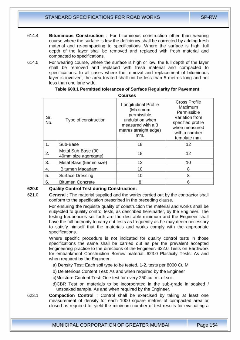
STANDARD SPECIFICATIONS FOR ROAD WORKS SP-RW
MUNICIPAL CORPORATION OF GREATER MUMBAI
Page 154
614.4 Bituminous Construction : For bituminous construction other than wearing course where the surface is low the deficiency shall be corrected by adding fresh material and re-compacting to specifications. Where the surface is high, full depth of the layer shall be removed and replaced with fresh material and compacted to specifications.
614.5 For wearing course, where the surface is high or low, the full depth of the layer shall be removed and replaced with fresh material and compacted to specifications. In all cases where the removal and replacement of bituminous layer is involved, the area treated shall not be less than 5 metres long and not less than one lane wide.
Table 600.1 Permitted tolerances of Surface Regularity for Pavement
Courses
Sr. No.
Type of construction
Longitudinal Profile (Maximum permissible
undulation when measured with a 3
metres straight edge) mm.
Cross Profile Maximum
Permissible Variation from
specified profile when measured with a camber template mm.
1. Sub-Base 18 12
2. Metal Sub-Base (90-40mm size aggregate)
18 12
3. Metal Base (55mm size) 12 10
4. Bitumen Macadam 10 8
5. Surface Dressing 10 8
6. Bitumen Concrete 8 6
620.0 Quality Control Test during Construction:
621.0 General : The material supplied and the works carried out by the contractor shall conform to the specification prescribed in the preceding clause.
For ensuring the requisite quality of construction the material and works shall be subjected to quality control tests, as described hereinafter, by the Engineer. The testing frequencies set forth are the desirable minimum and the Engineer shall have the full authority to carry out tests as frequently as he may deem necessary to satisfy himself that the materials and works comply with the appropriate specifications.
Where specific procedure is not indicated for quality control tests in those specifications the same shall be carried out as per the prevalent accepted Engineering practice to the directions of the Engineer. 622.0 Tests on Earthwork for embankment Construction Borrow material: 623.0 Plasticity Tests: As and when required by the Engineer.
a) Density Test: Each soil type to be tested, 1-2, tests per 8000 Cu M.
b) Deleterious Content Test: As and when required by the Engineer
c)Moisture Content Test: One test for every 250 cu. m. of soil.
d)CBR Test on materials to be incorporated in the sub-grade in soaked I unsoaked sample. As and when required by the Engineer.
623.1 Compaction Control : Control shall be exercised by taking at least one measurement of density for each 1000 square metres of compacted area or closed as required to: yield the minimum number of test results for evaluating a
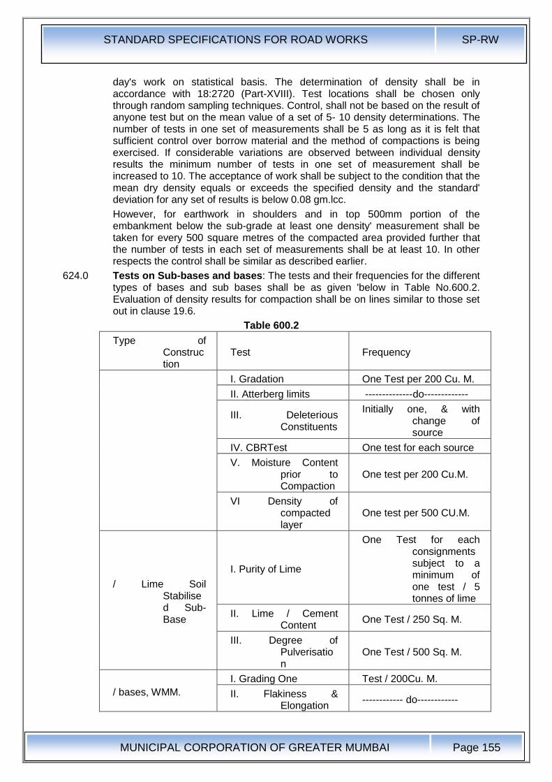
STANDARD SPECIFICATIONS FOR ROAD WORKS SP-RW
MUNICIPAL CORPORATION OF GREATER MUMBAI
Page 155
day's work on statistical basis. The determination of density shall be in accordance with 18:2720 (Part-XVIII). Test locations shall be chosen only through random sampling techniques. Control, shall not be based on the result of anyone test but on the mean value of a set of 5- 10 density determinations. The number of tests in one set of measurements shall be 5 as long as it is felt that sufficient control over borrow material and the method of compactions is being exercised. If considerable variations are observed between individual density results the minimum number of tests in one set of measurement shall be increased to 10. The acceptance of work shall be subject to the condition that the mean dry density equals or exceeds the specified density and the standard' deviation for any set of results is below 0.08 gm.lcc.
However, for earthwork in shoulders and in top 500mm portion of the embankment below the sub-grade at least one density' measurement shall be taken for every 500 square metres of the compacted area provided further that the number of tests in each set of measurements shall be at least 10. In other respects the control shall be similar as described earlier.
624.0 Tests on Sub-bases and bases: The tests and their frequencies for the different types of bases and sub bases shall be as given 'below in Table No.600.2. Evaluation of density results for compaction shall be on lines similar to those set out in clause 19.6.
Table 600.2
Type of Construction
Test Frequency
I. Gradation One Test per 200 Cu. M.
II. Atterberg limits --------------do-------------
III. Deleterious Constituents
Initially one, & with change of source
IV. CBRTest One test for each source
V. Moisture Content prior to Compaction
One test per 200 Cu.M.
VI Density of compacted layer
One test per 500 CU.M.
/ Lime Soil Stabilised Sub-Base
I. Purity of Lime
One Test for each consignments subject to a minimum of one test / 5 tonnes of lime
II. Lime / Cement Content
One Test / 250 Sq. M.
III. Degree of Pulverisation
One Test / 500 Sq. M.
/ bases, WMM.
I. Grading One Test / 200Cu. M.
II. Flakiness & Elongation
------------ do------------
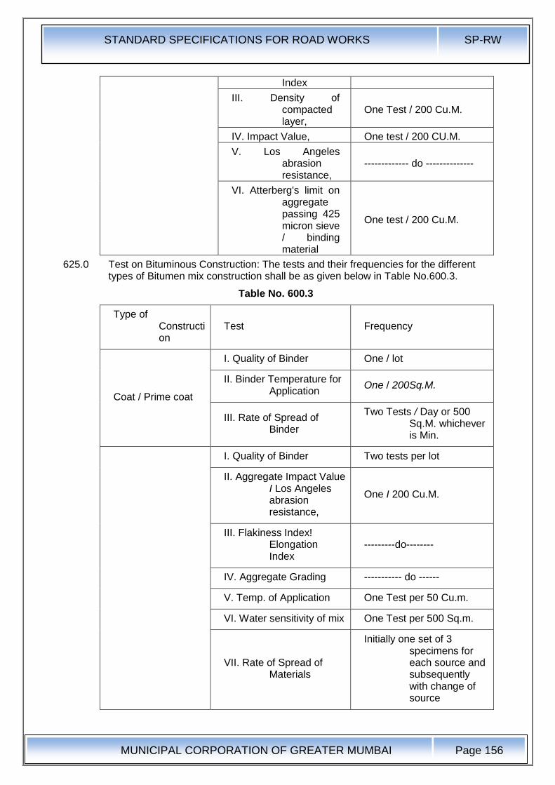
STANDARD SPECIFICATIONS FOR ROAD WORKS SP-RW
MUNICIPAL CORPORATION OF GREATER MUMBAI
Page 156
Index
III. Density of compacted layer,
One Test / 200 Cu.M.
IV. Impact Value, One test / 200 CU.M.
V. Los Angeles abrasion resistance,
------------- do --------------
VI. Atterberg's limit on aggregate passing 425 micron sieve / binding material
One test / 200 Cu.M.
625.0 Test on Bituminous Construction: The tests and their frequencies for the different types of Bitumen mix construction shall be as given below in Table No.600.3.
Table No. 600.3
Type of Construction
Test Frequency
Coat / Prime coat
I. Quality of Binder One / lot
II. Binder Temperature for Application
One / 200Sq.M.
III. Rate of Spread of Binder
Two Tests / Day or 500 Sq.M. whichever is Min.
I. Quality of Binder Two tests per lot
II. Aggregate Impact Value I Los Angeles abrasion resistance,
One I 200 Cu.M.
III. Flakiness Index! Elongation Index
---------do--------
IV. Aggregate Grading ----------- do ------
V. Temp. of Application One Test per 50 Cu.m.
VI. Water sensitivity of mix One Test per 500 Sq.m.
VII. Rate of Spread of Materials
Initially one set of 3 specimens for each source and subsequently with change of source
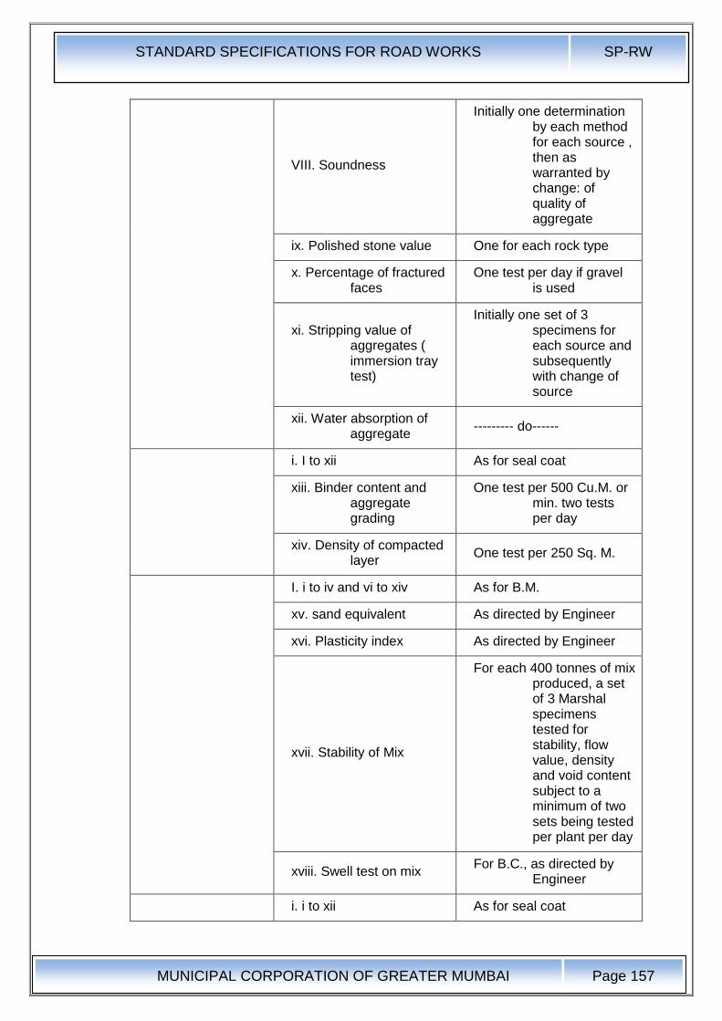
STANDARD SPECIFICATIONS FOR ROAD WORKS SP-RW
MUNICIPAL CORPORATION OF GREATER MUMBAI
Page 157
VIII. Soundness
Initially one determination by each method for each source , then as warranted by change: of quality of aggregate
ix. Polished stone value One for each rock type
x. Percentage of fractured faces
One test per day if gravel is used
xi. Stripping value of aggregates ( immersion tray test)
Initially one set of 3 specimens for each source and subsequently with change of source
xii. Water absorption of aggregate
--------- do------
i. I to xii As for seal coat
xiii. Binder content and aggregate grading
One test per 500 Cu.M. or min. two tests per day
xiv. Density of compacted layer
One test per 250 Sq. M.
I. i to iv and vi to xiv As for B.M.
xv. sand equivalent As directed by Engineer
xvi. Plasticity index As directed by Engineer
xvii. Stability of Mix
For each 400 tonnes of mix produced, a set of 3 Marshal specimens tested for stability, flow value, density and void content subject to a minimum of two sets being tested per plant per day
xviii. Swell test on mix For B.C., as directed by
Engineer
i. i to xii As for seal coat
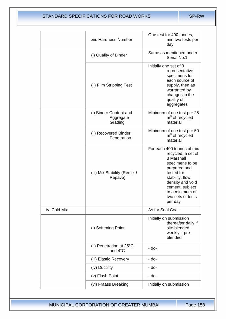
STANDARD SPECIFICATIONS FOR ROAD WORKS SP-RW
MUNICIPAL CORPORATION OF GREATER MUMBAI
Page 158
xiii. Hardness Number One test for 400 tonnes,
min two tests per day
(i) Quality of Binder Same as mentioned under
Serial No.1
(ii) Film Stripping Test
Initially one set of 3 representative specimens for each source of supply, then as warranted by changes in the quality of aggregates
(i) Binder Content and Aggregate Grading
Minimum of one test per 25 m3 of recycled material
(ii) Recovered Binder Penetration
Minimum of one test per 50 m3 of recycled material
(iii) Mix Stability (Remix I Repave)
For each 400 tonnes of mix recycled, a set of 3 Marshall specimens to be prepared and tested for stability, flow, density and void cement, subject to a minimum of two sets of tests per day
iv. Cold Mix As for Seal Coat
(i) Softening Point
Initially on submission thereafter daily if site blended, weekly if pre-blended
(ii) Penetration at 25°C and 4°C
- do-
(iii) Elastic Recovery - do-
(iv) Ductility - do-
(v) Flash Point - do-
(vi) Fraass Breaking Initially on submission
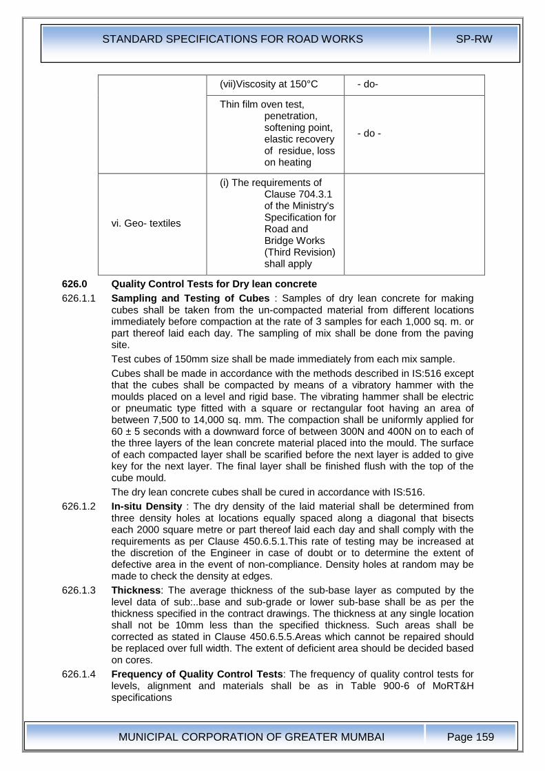
STANDARD SPECIFICATIONS FOR ROAD WORKS SP-RW
MUNICIPAL CORPORATION OF GREATER MUMBAI
Page 159
(vii)Viscosity at 150°C - do-
Thin film oven test, penetration, softening point, elastic recovery of residue, loss on heating
- do -
vi. Geo- textiles
(i) The requirements of Clause 704.3.1 of the Ministry's Specification for Road and Bridge Works (Third Revision) shall apply
626.0 Quality Control Tests for Dry lean concrete
626.1.1 Sampling and Testing of Cubes : Samples of dry lean concrete for making cubes shall be taken from the un-compacted material from different locations immediately before compaction at the rate of 3 samples for each 1,000 sq. m. or part thereof laid each day. The sampling of mix shall be done from the paving site.
Test cubes of 150mm size shall be made immediately from each mix sample.
Cubes shall be made in accordance with the methods described in IS:516 except that the cubes shall be compacted by means of a vibratory hammer with the moulds placed on a level and rigid base. The vibrating hammer shall be electric or pneumatic type fitted with a square or rectangular foot having an area of between 7,500 to 14,000 sq. mm. The compaction shall be uniformly applied for 60 ± 5 seconds with a downward force of between 300N and 400N on to each of the three layers of the lean concrete material placed into the mould. The surface of each compacted layer shall be scarified before the next layer is added to give key for the next layer. The final layer shall be finished flush with the top of the cube mould.
The dry lean concrete cubes shall be cured in accordance with IS:516.
626.1.2 In-situ Density : The dry density of the laid material shall be determined from three density holes at locations equally spaced along a diagonal that bisects each 2000 square metre or part thereof laid each day and shall comply with the requirements as per Clause 450.6.5.1.This rate of testing may be increased at the discretion of the Engineer in case of doubt or to determine the extent of defective area in the event of non-compliance. Density holes at random may be made to check the density at edges.
626.1.3 Thickness: The average thickness of the sub-base layer as computed by the level data of sub:..base and sub-grade or lower sub-base shall be as per the thickness specified in the contract drawings. The thickness at any single location shall not be 10mm less than the specified thickness. Such areas shall be corrected as stated in Clause 450.6.5.5.Areas which cannot be repaired should be replaced over full width. The extent of deficient area should be decided based on cores.
626.1.4 Frequency of Quality Control Tests: The frequency of quality control tests for levels, alignment and materials shall be as in Table 900-6 of MoRT&H specifications

STANDARD SPECIFICATIONS FOR ROAD WORKS SP-RW
MUNICIPAL CORPORATION OF GREATER MUMBAI
Page 160
Table 600.4 Control Tests for Dense Graded Bituminous Mixes and their Minimum Frequency
S.N Test Frequency
1 Quality of binder Number of samples per lot and tests as per IS, 73 or IRC:SP, 53
2 Aggregate impacl value/Los Angeles Abrasion value
One test per 350 ml of aggregate for each source and whenever there is change in the quality of aggregate
3 Flakiness index One lest per 350 m3 of aggregate for each source and whenever there is change in the quality of aggregate
4 Soundness lest (Sodium and Magnesium Sulphate test)
1 test for each source and whenever there is change in the quality of aggregate
5 Water absorption of aggregate
1 test for each source and whenever there is change in the quality of aggregate
6 Sand equivalent test 1 test for each source and whenever there is change in the.: quality of aggregate
7 Plasticity Index 1 test for each source and whenever there is change in the: quality of aggregate
8 Polished stone value 1 test for each source and whenever there is change in the quality of aggregate
9 Percent of fractured faces
One test per 350 m3 of aggregate when crushed gravel is used.
10 Mix grading
One set for individual constituent and mixed aggregate from dryer for each 400 tonnes of mix subject to minimum of two tests per day per plant
11
Stability and voids analysis of mix including theoretical maximum specific gravity of loose mix
3 tests for stability flow value. density and void contents for each 400 tonnes of mix subject to minimum of two tests per day per plant
12 Moisture Susceptibility of mix (AASHTO T283)
1 test for t:ach mix type whenever there is change in the quality or source of coarse or fine aggregate
13
Temperature of binder in boiler,aggregate in dryer and mix at the time of laying and compaction
At regular intervals
14 Binder content One set for each 400 tonnes of mix subject 10 minimum of two tests per day per plant
15 Rate of spread of mix material
After every 5th truck load
16 Density of compacted layer
One test per 700 m2area
Table 600.5 Control Tests for Bituminous Macadam Work and Their Minimum Frequency
S.N Test Frequency
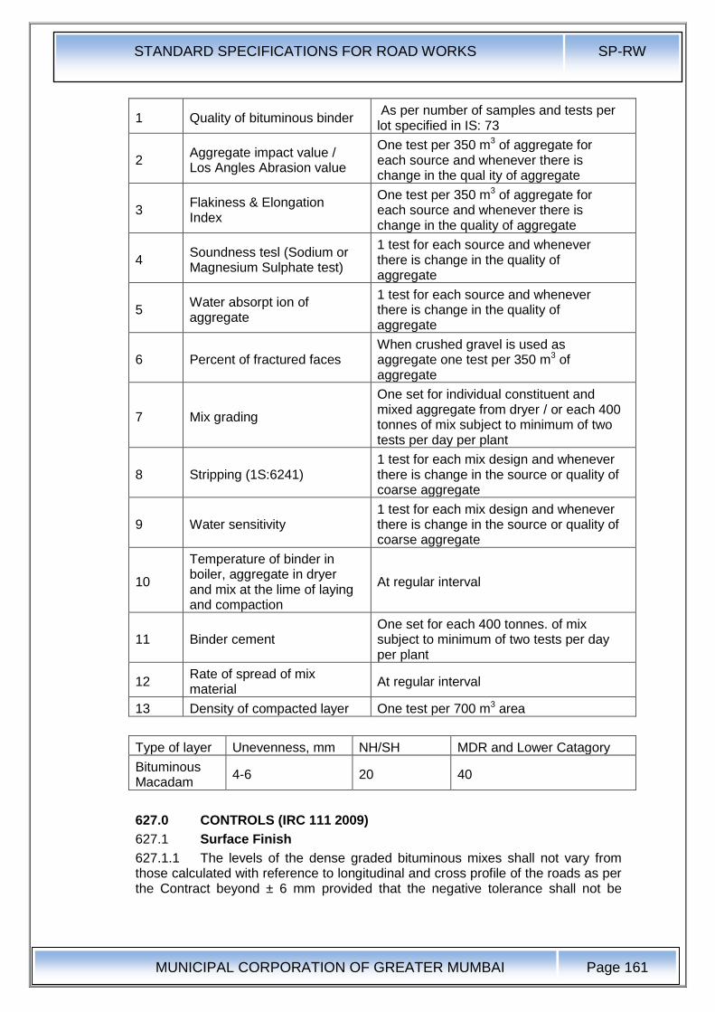
STANDARD SPECIFICATIONS FOR ROAD WORKS SP-RW
MUNICIPAL CORPORATION OF GREATER MUMBAI
Page 161
1 Quality of bituminous binder As per number of samples and tests per lot specified in IS: 73
2 Aggregate impact value / Los Angles Abrasion value
One test per 350 m3 of aggregate for each source and whenever there is change in the qual ity of aggregate
3 Flakiness & Elongation Index
One test per 350 m3 of aggregate for each source and whenever there is change in the quality of aggregate
4 Soundness tesl (Sodium or Magnesium Sulphate test)
1 test for each source and whenever there is change in the quality of aggregate
5 Water absorpt ion of aggregate
1 test for each source and whenever there is change in the quality of aggregate
6 Percent of fractured faces When crushed gravel is used as aggregate one test per 350 m3 of aggregate
7 Mix grading
One set for individual constituent and mixed aggregate from dryer / or each 400 tonnes of mix subject to minimum of two tests per day per plant
8 Stripping (1S:6241) 1 test for each mix design and whenever there is change in the source or quality of coarse aggregate
9 Water sensitivity 1 test for each mix design and whenever there is change in the source or quality of coarse aggregate
10
Temperature of binder in boiler, aggregate in dryer and mix at the lime of laying and compaction
At regular interval
11 Binder cement One set for each 400 tonnes. of mix subject to minimum of two tests per day per plant
12 Rate of spread of mix material
At regular interval
13 Density of compacted layer One test per 700 m3 area
Type of layer Unevenness, mm NH/SH MDR and Lower Catagory
Bituminous Macadam
4-6 20 40
627.0 CONTROLS (IRC 111 2009)
627.1 Surface Finish
627.1.1 The levels of the dense graded bituminous mixes shall not vary from those calculated with reference to longitudinal and cross profile of the roads as per the Contract beyond ± 6 mm provided that the negative tolerance shall not be
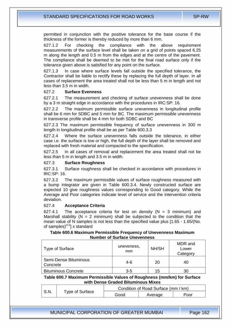
STANDARD SPECIFICATIONS FOR ROAD WORKS SP-RW
MUNICIPAL CORPORATION OF GREATER MUMBAI
Page 162
permitted in conjunction with the positive tolerance for the base course if the thickness of the former is thereby reduced by more than 6 mm.
627.1.2 For checking the compliance with the above requirement measurements of the surface level shall be taken on a grid of points spaced 6.25 m along the length and 0.5 m from the edges and at the centre of the pavement. The compliance shall be deemed to be met for the final road surface only if the tolerance given above is satisfied for any point on the surface.
627.1.3 In case where surface levels fall outside the specified tolerance, the Contractor shall be liable to rectify these by replacing the full depth of layer. In all cases of replacement the area treated shall not be less than 5 m in length and not less than 3.5 m in width.
627.2 Surface Evenness
627.2.1 The measurement and checking of surface unevenness shall be done by a 3 m straight edge in accordance with the procedures in IRC:SP: 16.
627.2.2 The maximum permissible surface unevenness in longitudinal profile shall be 6 mm for SDBC and 5 mm for BC. The maximum permissible unevenness in transverse profile shall be 4 mm for both SDBC and BC
627.2.3 The maximum permissible frequency of surface unevenness in 300 m length in longitudinal profile shall be as per Table 600.3.3
627.2.4 Where the surface unevenness falls outside the tolerance, in either case i.e. the surface is low or high, the full depth of the layer shall be removed and replaced with fresh material and compacted to the specification.
627.2.5 In all cases of removal and replacement the area treated shall not be less than 5 m in length and 3.5 m in width.
627.3 Surface Roughness
627.3.1 Surface roughness shall be checked in accordance with procedures in lRC:SP: 16.
627.3.2 The maximum permissible values of surface roughness measured with a bump integrator are given in Table 600.3.4. Newly constructed surface are expected 10 give roughness values corresponding to Good category. While the Average and Poor categories indicate level of service and the intervention criteria deviation.
627.4 Acceptance Criteria
627.4.1 The acceptance criteria for test on density (N = 3 minimum) and Marshall stability (N = 2 minimum) shall be subjected to the condition that the mean value of N samples is not less than the specified value plus [1.65 - 1.65/(No. of samples)O.5] x standard
Table 600.6 Maximum Permissible Frequency of Unevenness Maximum Number of Surface Unevenness
Type of Surface uneveness,
mm NH/SH
MDR and Lower
Category
Semi-Dense Bituminous Concrete
4-6 20 40
Bituminous Concrete 3-5 15 30
Table 600.7 Maximum Permissible Values of Roughness (mm/km) for Surface with Dense Graded Bituminous Mixes
S.N. Type of Surface Condition of Road Surface (mm I km)
Good Average Poor
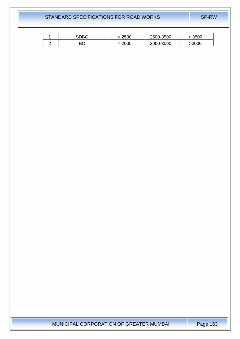
STANDARD SPECIFICATIONS FOR ROAD WORKS SP-RW
MUNICIPAL CORPORATION OF GREATER MUMBAI
Page 163
1 SDBC < 2500 2500-3500 > 3500
2 BC < 2000 2000-3000 >3000
STANDARD SPECIFICATIONS FOR ROAD WORKS SP-RW
MUNICIPAL CORPORATION OF GREATER MUMBAI
Page 164
APPENDIX-1
Quality Tests for Tack Coat and Prime Coat
In case of bitumen emulsion residue on 600 micron sieve, viscosity test and storage stability tests shall be conducted at site. In case of cutback bitumen, viscosity test, flash point test and residue test shall be conducted at site. In case of paving grade bitumen, viscosity at 60°C and 160°C shall be determined.
APPENDIX - 2
Method of Test for Measurement of Spread of Binder for Prime Coat and Tack Coat
Aluminum or other light metal tray of 200 mm x 200 mm size and 20 mm depth are to be used. A set of three plates is essential for one test. All the plates are to be weighed and numbered. These are placed at intervals of 10 m along the road in path between wheels of bitumen distributor. After the distributor crosses a length of 50 m, trays are to be removed and wrapped in weighed polyethylene bags so that these can be handled, stocked safely for further weighing in laboratory. The trays shall be weighed to first place of decimal. Similarly, transverse distribution of liquid bituminous material can be checked by placing three numbers of plates at interval of 50 cm in the path of binder spraying equipment.
STANDARD SPECIFICATIONS FOR ROAD WORKS SP-RW
MUNICIPAL CORPORATION OF GREATER MUMBAI
Page 165
ANNEXURE 1 Features of Hot Mix Plants & Pavers for Bituminous Construction: Hot mix plant shall be of suitable capacity preferably of batch mix type. Total system for crushing of stone aggregates arid feeding of aggregate fractions in required proportions to achieve the desired mix, must be capable of meeting the overall specification requirements under stringent quality control. The plant shall have the following essential features: A General a) The plant shall have a coordinated set of essential units capable of producing uniform mix as per the job mix formula. b) Cold aggregate feed system with minimum 4 bins having bell conveyor arrangement for initial proportioning of aggregates from each bin in the required quantities. In order to have free flow of fines from the bin, bin should be titled with vibrator to intermittently shake it. c) Belt conveyers below each bin should have variable speed drive motors. There should be electronic load sensor on the main conveyer for measuring the flow of aggregates. d) Dryer unit with burner capable of heating the aggregate to the required temperature without any visible unburnt fuel or carbon residue on the aggregate and reducing the moisture con lent of the aggregate to the specified minimum. e) The plant shall be fitted with suitable type of thermometric instruments at appropriate places so as to indicate or record/register the temperature of healed aggregate, bitumen and mix. f) Bitumen supply unit capable of heating, measuring/metering and spraying of bitumen at specific temperature with automatic synchronization of bitumen and aggregate feed in the required proportion. g) A filler system suitable to receive bagged or bulk supply of filler material and its incorporation to the mix in the correct quantity wherever required. h) A suitable built-in dust control system for the dryer to contain/recycle permissible fines into the mix. It should be capable of preventing the exhaust of fine dust into atmosphere for environmental control wherever so specified by the Engineer. i) The plant- should have centralized control panel cabin capable of presetting, controlling / synchronizing all operations stating from feeding of cold aggregates to the discharge of the hot mix to ensure proper quality of mix. It should have indicators for any malfunClionit1g in the operation. j) Every hot mix plant should be equipped with siren or horn so that the operator may use the same before starting the plant every time in the interest of safety of staff. B For Batch Type Plant i) Gradation control unit having minimum four decks vibratory screens for accurate sizing of hot aggregate and storing them in separate bins. This unit should be fully covered to reduce the maintenance cost and for better environmental condition. ii) Proper arrangement for accurate weighing of each size of hot aggregate from the control panel before mixing. iii) Paddle mixer unit shall be capable of producing a homogeneous mix with uniform coating of all particles or the mineral aggregate-with binder C For Continuous Type Plant
STANDARD SPECIFICATIONS FOR ROAD WORKS SP-RW
MUNICIPAL CORPORATION OF GREATER MUMBAI
Page 166
i) Gradation control unit having vibratory screens for accurate sizing of hot aggregate and storing them in separate bins. This unit should be fully covered to reduce the maintenance cost and for better environmental condition. ii) There should be appropriate arrangement for regulating and volumetric condition of the flow of hot aggregate from each bin to achieve the required proportioning. iii) Paddle mixer unit shall be capable of producing a homogeneous mix with uniform coating of all particles of the mineral aggregate with binder. D For Drum Mix Plant i) It is a prerequisite that only properly screened and graded materials are fed to the bins. If required, a vibratory screening unit shall be installed at the plant site to ensure the same. A primary 4-deck vibratory screening unit shall be installed before the multiple bin cold feed system for screening the aggregates and grading the same. ii) Belt conveyers below each bin should have variable speed drive motors. There should be electronic' load sensor on the main conveyer for measuring the flow of aggregate.
iii) There should be arrangement to measure moisture content of the aggregate(s) so that moisture correction may be applied for working out requirements of binder and filler.
E . Paver Finisher The paver finisher shall have the following essential features: a) Loading hoppers and suitable distributing mechanism. b) All drives having hydrostatic drive/control. c) The machine shall have a hydraulically extendable screed for appropriate with requirement. d) The screed shall have tamping and vibrating arrangement for initial compaction to the layer as it is spread without rutting or otherwise marring the surface. It shall have adjustable amplitude and variable frequency. e) The paver shall be equipped with necessary control mechanism so as to ensure that the finished surface is free from surface blemishes. f) The paver shall be fitted with an electronic sensing device for automatic levelling and profile control within the specified tolerances. g) The screed shall have an internal heating arrangement. h) The paver shall be capable of laying either 2.5 to 4.0 m width or 4.0 to 7.0 m width as stipulated in the Contract.
i) The paver shall be so designed as to eliminate skidding/slippage of the tyres during operations.
STANDARD SPECIFICATIONS FOR ROAD WORKS SP-RW
MUNICIPAL CORPORATION OF GREATER MUMBAI
Page 167
ANNEXURE 2
Outline of AASHTO T283, "Resistance of Compacted Asphalt Mixtures to Moisture-Induced Damage"
A. Scope and Summary of Test Method
This method covers preparation of compacted bituminous mixtures and the measurement of the change of diametral tensile strength resulting from the effects of water saturation and laboratory accelerated stripping phenomenon with a freeze-thaw cycle. The result may be used to predict long-term stripping susceptibility of bituminous mixtures and evaluate liquid anti-stripping additives that are added to bitumen or pulverized mineral materials such as hydrated lime, which are added to the mineral aggregate.
Each Set of 6 compacted specimens is divided into two equal subsets. One subset is tested in dry condition for indirect tensile strength. The other subset is subjected to vacuum saturation and a freeze-thaw cycle (thawing in a hot water bath) before testing for indirect tensile strength. Numerical indices of retained indirect tensile strength properties are calculated from the test data obtained by testing the two subsets :dry and conditioned.
B. Testing Equipment
I. Vacuum container, vacuum pump, manometer, and other accessories as specified in ASTM D2041, "Theoretical Maximum Specific Gravity and Density of Bituminous Paving Mixtures".
2. Balance or scale accurate to 0.1 percent of the test load
3. Two water baths capable of maintaining temperatures of 60°C ± 1°C and 25°C ± 0.5°C
4. Freezer maintained at - 18°C ± 3°C
5. 10-ml graduate cylinder
6. Loading jack ,and ring dynamometer (Marshall stability testing machine can be used) to provide a vertical rate of deformation of 50 mm (2 inches) per minute and capable of reading the maximum failure load
7. Steel loading Strips with a concave surface having a radius equal to the normal radius of the test specimen. The loading strips shall be 12.7 mm (0.5 inch) wide for specimens 100 mm (4 inches) in diameter. The loading strips for 150 mm (6 inches) diameter specimens shall be 19.05 mm (0.75 inch) wide. The length of the loading strips shall exceed the thickness of the specimens. Steel strip are provided at the top and bottom of specimens during indirect tensile testing.
C. Test Procedure
1. Make at least 6 compacted specimens for each mixture. 3 to be tested dry and 3 to be tested after partial saturation and moisture conditioning with a freeze-thaw cycle. Some extra specimens will need to be made 10 establish compaction procedures in order to obtain specified air void contents in the test specimens by trial and error.
2. Compact the 6 specimens with a Marshall compactor so that the compacted specimens have air voids of 7.0 ± 0.5 percent. This level of high air voids can be obtained by adjusting the number of Marshall blows applied on each side of the specimen by trial and error (start at about 10 blows as a starting point). Air void content must be calculated from the bulk specific gravity of the compacted specimen (determined by saturated surface dry method as per procedure given in
STANDARD SPECIFICATIONS FOR ROAD WORKS SP-RW
MUNICIPAL CORPORATION OF GREATER MUMBAI
Page 168
the Asphalt Institute MS-2) and the maximum theoretical specific gravity of the loose bituminous mixture obtained by ASTM D2041.
3. Separate the 6 specimens into 2 subsets so that the average air voids of the two subsets are approximately equal.
4. One set will be tested dry. Keep it at room temperature and then place in a 250C ± 0.50C water bath for 2 hours prior to determining their indirect tensile strength.
5. The other subset will be conditioned as follows:
a) Place and submerge the 3 specimens in the vacuum container filled with water at room temperature. Apply a vacuum of 13-67 kPa absolute pressure (10-26 inches Hg partial pressure) for 30 minutes. Remove the vacuum and leave the specimens submerged in water for 5 to 10 minutes. [Note: The water saturation procedure noted above deviates from AASHTO T283, which obtains a specified degree of saturation. The above procedure keeps the time of saturation constant:
b) Wrap a plastic film around each saturated specimen and place the wrapped specimen in a plastic bag containing 10 ml of water and seal the plastic bag. Place the plastic bag in a freezer at temperature of - 180C± 30C for a minimum of 16 hours. Remove the specimens from the freezer.
c) Place the specimens in a water bath maintained at 600C ± 10C for 24 hours. Remove the plastic bag and the plastic film from each specimen after placing the specimens under water.
d) . Remove the specimens from hot water bath and place in a water bath maintained at 250C ± 0.50C for 2 hours
e) Remove the conditioned specimens and test for indirect tensile strength.
6. Determine the indirect tensile strength of the 3 dry and 3 conditioned specimens at 250C ± 0.50C after removing from water bath. First, measure their mean thicknesses (t). Then place the two steel loading strips on the bottom and top of the specimens across diameter and place in the Marshall testing machine or a compression testing machine. Apply load to the specimens diametrally at a vertical rate of 50 mm (2 inches) per minute.
7. Record the maximum compressive strength noted on the testing machine and continue loading until a vertical crack appears in the specimen. Remove the cracked specimen from the machine and visually estimate the approximate degree of moisture damage (extent of stripped or bare aggregate) on the fractured faces of the specimen on a scale of 0 to 5 (5 being the most stripping).
8. Calculate the tensile strength of each specimen as follows in SI units:
St = 2000 P/¶td
Where,
st= tensile strength. kPa
P = maximum loads, N
t = specimen-thickness, mm
d = specimen diameter. mm
9. Express the numerical index of resistance of bituminous mixture to the detrimental effects of water as the ratio of the original strength that is retained after accelerated moisture and freeze-thaw conditioning.
Calculate the tensile strength ratio (TSR) as follows:
Tensile strength ratio (TSR) =S2/S1
Where.
S1 = average tensile strength of the dry subset. kPa
STANDARD SPECIFICATIONS FOR ROAD WORKS SP-RW
MUNICIPAL CORPORATION OF GREATER MUMBAI
Page 169
S2 = average tensile strength of the conditioned subset, kPa
STANDARD SPECIFICATIONS FOR ROAD WORKS SP-RW
MUNICIPAL CORPORATION OF GREATER MUMBAI
Page 170
ANNEXURE 3
Outline of ASTM D2041, "Theoretical Maximum Specific Gravity and Density of Bituminous Paving Mixtures"
A. Scope and Summary of the Test Method
This test method covers the determination of the theoretical maximum specific gravity and density of uncompacted bituminous paving mixtures at 25°C. The theoretical maximum specific gravity (Gmm) is used: (a) 10 calculate air voids in compacted bituminous mixtures. (b) to calculate the amount of bitumen absorbed by the aggregate, and (e) to provide target value for the compaction of paving mixtures in the field.
A sample of loose paving mixture is placed in a tared vacuum vessel. Water at 25°C is added to complete ly submerge the sample. A specified amount of vacuum is gradually applied to remove the air bubbles entrapped between asphalt mix particles. After the vacuum is released, the volume of the sample of the void less paving mixture is obtained by either immersing the vacuum container with the sample in a water bath and weighing or by filling the calibrated vacuum container level full of water and weighing in air.
B. Testing Equipment
1. Container (either a or b below)
a) Vacuum bowls - Either a metal or plastic bowl with a diameter ranging from 180 10260 mm and a bowl height of at least 160 mm. The bowl shall be equipped with a stiff, transparent cover fitted with a rubber gasket and a connection for the vacuum line. The hose connection shall be covered with a small piece of fine wire mesh to minimize loss of any fine material from the mix.
b) Vacuum flask for weighing in air only - A thick-walled volumetric glass flask with a capacity of approx. 4000 ml, fitted with a rubber stopper with a connect ion for the vacuum line. The hose connection shall be covered with a small piece of fine wire mesh to minimize loss of any fine material from the mix .
2.Balance capable of being read to the nearest 0.1 gram. If weighing is to be done under water. a suitable suspension arrangement shall be provided for weighing the sample while suspended from the center of the balance.
3. Vacuum pump, capable of excavating air from the vacuum container to a residual pressure of 4.0 kPa (30 mm of Hg) or less. Provide a suitable trap between the pump and container to minimize water vapour entering the vacuum pump
4. Residual pressure manometer or calibrated absolute pressure gauge with a bleed valve to adjust the vacuum level.
5. Water bath capable of maintaining a constant temperature of 25 ± 1°C and suitable for immersion of the suspended container.
C. Calibration of Containers
1. Bowls - Determine the mass (B) of the container immersed in water at 25 ± 1 0C. If the bowl is used for weighing in air place the volumetric lid on the bowl while under water. Remove the water-filled bowl with the lid in place and dry prior to determining the combined mass of the bowl, lid and water. Repeat 3 times and average the 3 masses. Designate the average mass as D.
2. Flasks - Calibrate the volumetric flask by accurately determining the mass of the flask filled with water at 25 ± 1°Co Use a glass cover plate to ensure the flask is completely full.
D. Test Procedure
STANDARD SPECIFICATIONS FOR ROAD WORKS SP-RW
MUNICIPAL CORPORATION OF GREATER MUMBAI
Page 171
I. Separate the particles of the loose paving mixture (while it is warm) by hand so that the particles are not larger than about 6 mm. Don't fracture the aggregate. Place the mix sample directly into the tared bowl or flask. Weigh the container with the sample and designate the net mass of the sample only as A.[Note: The minimum sample size shall be 1500g for mixes with nominal maximum aggregate sizes of 12.5 mm or smaller; and shall be 2500g for mixes with nominal maximum aggregate sizes from 19 to 25 mm]
2. Add sufficient water at 25°C to cover the sample completely. Place the cover (bowls) or stopper (flasks) on the containers.
3. Place the container with the sample and water on a mechanical agitation device or agitate manually at frequent intervals (2 to 3 minutes). Begin removing entrapped air by gradually applying vacuum and increasing the vacuum pressure until the residual manometer reads 3.7 ± 0.3 kPa (27.5 ± 2.5 mm of Hg). After achieving this level within 2 minutes, continue the vacuum and agitation for 15 ± 2 minutes. Gradually release the vacuum with the bleed valve.
4. Weighing in water - Suspend the bowl (without lid) and contents in water for 10 ± 1 minutes and then determine mass. Designate the mass under water of the bowl and sample as °C
5. Weighing in air
a) Bowl- Submerge the bowl and sample slowly in the 25 ± 1°C water bath. Keep it there for 10 ± 1 minutes. Immerse the lid in water and slide it onto the bowl without removing water from the bowl so that no ai r is trapped inside the bowl. Remove the bowl with the lid in place from the water bath. Dry the bowl and lid with a dry cloth. Determine the mass of the bowl, sample, and lid and designate it as E.
b) Flask - Fill the flask slowly with water ensuring not to introduce any air into the sample. Place the flask in water bath for 10 ± 1 minutes to stabilize the temperature aI 25°C without submerging the top of the flask. Completely fill the flask with water using a cover plate without entrapping air beneath the cover plate. Wipe the exterior of the fl ask and cover plate. Determine the mass of the flask, plate and its contents completely filled with water. Designate this mass as E.
6. Calculations
Calculate the maximum specific gravity of the sample of loose paving mixure as follows:
a) Bowls Used Under Water Determination:
Gmm.=A / [A-(C-B)]
Where,
Gmm = maximum specific gravity of the mixture
A = mass of the dry sample in air. g
B = mass of bowl under water, g
C = mass of bowl and sample under water, g
b) Bowls in Air Determination:
Gmm.=A / (A+D-E)
Where,
Gmm = maximum specific gravity of the mixture
A = mass of the dry sample in air. g
D = mass of lid and bowl with water at 25°C, g

STANDARD SPECIFICATIONS FOR ROAD WORKS SP-RW
MUNICIPAL CORPORATION OF GREATER MUMBAI
Page 172
E = mass of lid, bowl, sample and water at 25°C, ,g
c) Flask Determination
Gmm.=A / (A+D-E)
Where,
Gmm = maximum specific gravity of the mixture
A = mass of the dry sample in air. g
D = mass of cover plate and flask filled with water at 25°C. g
E = mass of flask, cover plate, sample. and water at 25°C, ,g