MUNICIPAL CORPORATION OF GREATER MUMBAI Department...Order/ Demand Draft in the name of Municipal...
171
1 MUNICIPAL CORPORATION OF GREATER MUMBAI TENDER FOR STORM WATER DRAIN WORKS Name of the work:- WS-151 Training/ Widening of Walbhat River from Western Express Highway to S.V. Road in P/South ward.
Transcript of MUNICIPAL CORPORATION OF GREATER MUMBAI Department...Order/ Demand Draft in the name of Municipal...
1
MUNICIPAL CORPORATION OF GREATER MUMBAI TENDER FOR STORM WATER DRAIN WORKS
Name of the work:- WS-151 Training/ Widening of Walbhat River from Western Express Highway to S.V. Road in P/South ward.

2
I N D E X
Section No. Topic Page No.
1 Tender Notice 3
2 Scope of Work 8
3 Instruction to Tenderers
A - General
B - Tendering Documents
C - Preparation of Tenders
D - Submission of Tenders
E - Tender Opening & Evaluation
F - Award of Contract
G - General Information
10
4 General Conditions of Contract 55
5 Special Conditions of Contract 58
6 Specifications 72
7 Annexure 'A' Annexure ‘B’ Form of Tender Form of Bank Guarantee Form of Agreement Undertaking Circular
151
8 Typical Drawings 164
9 List of works & Bill of Quantities & Rates 165
10 Financial bid form Form-B 169

3
SECTION - 1
TENDER NOTICE

4
BRIHANMUMBAI MAHANAGARPALIKA
OFFICE OF DEPUTY CHIEF ENGINEER (STORM WATER DRAINS) WESTERN SUBURBS
Greenwood complex, Andheri Kurla Road, Near Gurunanak Petrol Pump, Andheri (E) Mumbai-400 093
THIS IS A e- TENDER NOTICE
The Municipal Commissioner of Greater Mumbai (MCGM) invites online e-tender for the following work in Packet ‘A; Packet ‘B’ and Packet ‘C’ on percentage basis from the firm registered with the Municipal Corporation of Greater Mumbai, (MCGM) under respective Class, as per registration and also from the contractors having equivalent Class and Category registered with P.W.D and other Government organizations in India excluding those who are black listed and demoted. Consortium/JV of the firms for these works are not allowed. The tenderers should submit supporting documents along with their tender bids.
The tender copy can be downloaded from MCGM’s portal (http://portal.mcgm.gov.in).
All interested vendors/ contractors whether already registered or not registered with MCGM are mandated to get registered with MCGM for e-tendering process & obtain login credentials to participate in the online bidding process. The details of the same are available on the above mentioned portal under ‘e-procurement’ tab.
For registration enrollment for digital signature certificates and user manual, please refer to respective links provided in e-tendering tab. Vendors can get digital signature from any one of the Certifying Authorities’ (CA’s) licensed by controller of certifying authorities namely Safescrypt, IDRBT, National informatics center, TCS, CUSTOMS, MTNL, GNFC and e-Mudhra CA.
Sr No
Name of the Work Estimated Cost
(in Rs.)
Earnest Money Deposit (in Rs.)
Class Time Period
Cost of Blank
e-Tender form
1
WS-149 Widening and reconstruction of Navajalpada nalla from Jitendra road to Parshurampuria building, Haji Bapu road,Malad (e) in P/north ward.
2,31,21,900/- 2,31,219/- “A” &
above
Twelve (12)
Months (Excluding Monsoon)
Rs 10,000/-
+5% VAT

5
2
WS-150 Modification of culverts by removing obstruction and replacement of pipe culverts into box culverts to relieve flooding in P/North ward, Malad
10,36,81,400 /- 10,36,814/- “AA”
Twelve (12)
Months (Excluding Monsoon)
Rs 10,000/-
+5% VAT
3
WS-151 Training/ Widening of Walbhat River from Western Express Highway to S.V. Road in P/South ward.
24,96,00,000/-
24,96,000/-
“AA” Eighteen
(18) Months (Excluding Monsoon)
Rs. 10,000/-
+5% VAT
4
WS-152 Construction of R.C.C box drain & culverts at Shivaji Nagar, Madh-Marve Road, Malad (w) in P/North ward.
14,48,47,707.40
14,48,500/-
“AA”
Fifteen
(15) Months
(Excluding Monsoon)
Rs 10,000/-
+ 5%VAT
Blank e-tender forms shall be downloaded from MCGM’s portal on payment of
Cost of blank e-Tender form per copy as mentioned above by e-tendering process from the approved banks under section “Payment of Tender Fees”.
e-Tenders shall be submitted up to 4.00 PM on 24.01.2014 by e-tender
process.
The tenderer(s) shall pay the EMD through Demand Draft and shall upload the scanned copy of the DD in packet ‘A’. The tenderer shall submit such DD physically in Packet ‘A’ on the date of submission of tender. If such DD is not submitted physically in packet ‘A’. the tender shall be treated as non-responsive and shall not be opened.
The tenderer quoting /bidding for more than one work, shall pay separate E.M.D. (in form of DD/Pay Order) corresponding to the tender estimated cost as mentioned in this e-tender notice of SWD works.
The tenderer quoting/bidding for more than one work with respect to this e-tender notice and intends to pay A.S.D. as specified in the tender then the same shall be paid corresponding to highest A.S.D. and certified copies of the same in sealed envelope of the other tenders shall be submitted physically .In case the A.S.D. submitted is more than the percentage quoted by the bidder, then the percentage quoted shall prevail.
6
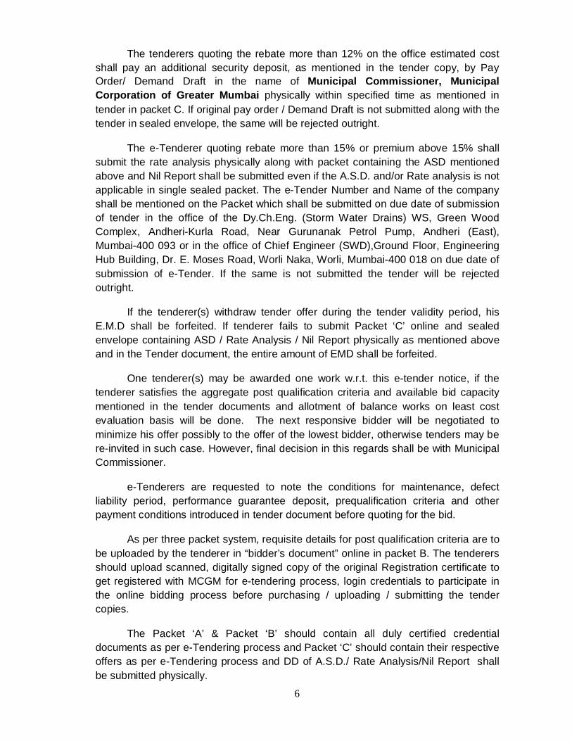
The tenderers quoting the rebate more than 12% on the office estimated cost shall pay an additional security deposit, as mentioned in the tender copy, by Pay Order/ Demand Draft in the name of Municipal Commissioner, Municipal Corporation of Greater Mumbai physically within specified time as mentioned in tender in packet C. If original pay order / Demand Draft is not submitted along with the tender in sealed envelope, the same will be rejected outright.
The e-Tenderer quoting rebate more than 15% or premium above 15% shall submit the rate analysis physically along with packet containing the ASD mentioned above and Nil Report shall be submitted even if the A.S.D. and/or Rate analysis is not applicable in single sealed packet. The e-Tender Number and Name of the company shall be mentioned on the Packet which shall be submitted on due date of submission of tender in the office of the Dy.Ch.Eng. (Storm Water Drains) WS, Green Wood Complex, Andheri-Kurla Road, Near Gurunanak Petrol Pump, Andheri (East), Mumbai-400 093 or in the office of Chief Engineer (SWD),Ground Floor, Engineering Hub Building, Dr. E. Moses Road, Worli Naka, Worli, Mumbai-400 018 on due date of submission of e-Tender. If the same is not submitted the tender will be rejected outright.
If the tenderer(s) withdraw tender offer during the tender validity period, his E.M.D shall be forfeited. If tenderer fails to submit Packet ‘C’ online and sealed envelope containing ASD / Rate Analysis / Nil Report physically as mentioned above and in the Tender document, the entire amount of EMD shall be forfeited.
One tenderer(s) may be awarded one work w.r.t. this e-tender notice, if the tenderer satisfies the aggregate post qualification criteria and available bid capacity mentioned in the tender documents and allotment of balance works on least cost evaluation basis will be done. The next responsive bidder will be negotiated to minimize his offer possibly to the offer of the lowest bidder, otherwise tenders may be re-invited in such case. However, final decision in this regards shall be with Municipal Commissioner.
e-Tenderers are requested to note the conditions for maintenance, defect liability period, performance guarantee deposit, prequalification criteria and other payment conditions introduced in tender document before quoting for the bid.
As per three packet system, requisite details for post qualification criteria are to be uploaded by the tenderer in “bidder’s document” online in packet B. The tenderers should upload scanned, digitally signed copy of the original Registration certificate to get registered with MCGM for e-tendering process, login credentials to participate in the online bidding process before purchasing / uploading / submitting the tender copies.
The Packet ‘A’ & Packet ‘B’ should contain all duly certified credential documents as per e-Tendering process and Packet ‘C’ should contain their respective offers as per e-Tendering process and DD of A.S.D./ Rate Analysis/Nil Report shall be submitted physically.

7
The said works broadly involve construction of R.C.C. Nalla/ box drain/ culverts, more particularly described in the tender documents.
The dates and time for uploading e-Tender & opening of the e-Tenders are as under: If there are any changes in the dates the same will be displayed on the MCGM portal. (http://portal.mcgm.gov.in) or will be displayed on the notice board in the office of Dy.Ch.E (SWD) WS.
The e-tender sale starts from : 17.01.2014 from 11.00 a.m. The last date of e-tender sale : 24.01.2014 up to 01.00 p.m. Last date for Submission of e-Tender : 24.01.2014 up to 4.00 p.m. The packet ‘A’ & ‘B’ to be opened on : 24.01.2014 at 4.30 p.m. The packet ‘C’ to be opened on : 30.01.2014 at 2.00 p.m. The Packet ‘A’, ‘B’ & ‘C’ shall be uploaded online before last date and time
for submission.
The scrutiny of Packets A, B & C will be strictly done from scanned uploaded documents in stipulated period by the e-tenderers in e-tendering process, MCGM may call for verification of the ORIGINAL documents which are uploaded by the e-tenderers at any STAGE whenever it is felt required by MCGM before awarding the work. In case of any fake information, MCGM Authority as empowered may take decision to disqualify the Bid.
Tenderer (s) are requested to submit and upload the tenders in time on or before the stipulated day so as to avoid rush at closing hours. MCGM will not be responsible for poor connectivity of network/ internet services/ connectivity of servers/ snag in system/ breakdown of network/ or any other interruption.
Preferably tenderer should upload bids one day prior to last date of submission. No claim shall be entertained on account of failure of e-tendering systems or otherwise.
The Pre-bid meeting for Sr.No. 2,3 and 4 will be held on 21.01.2014 at 2:00 PM in the office of Director(E.S.&P.),Municipal Head Office,3rd floor, Mahapalika Marg, Mumbai-400 001. The venue/change of timing of the same, if any, will be displayed on the notice board in the office of Dy.Ch.E. (SWD) WS for the above Tender.
The Municipal Commissioner reserves the right to reject any or all e-tenders without giving any reason to the tenderers.
The details are available on MCGM’s website http://portal.mcgm.gov.in
Sd/-
Deputy Chief Engineer (Storm Water Drains) Western Suburbs.

8
SECTION – 2
SCOPE OF WORK
9
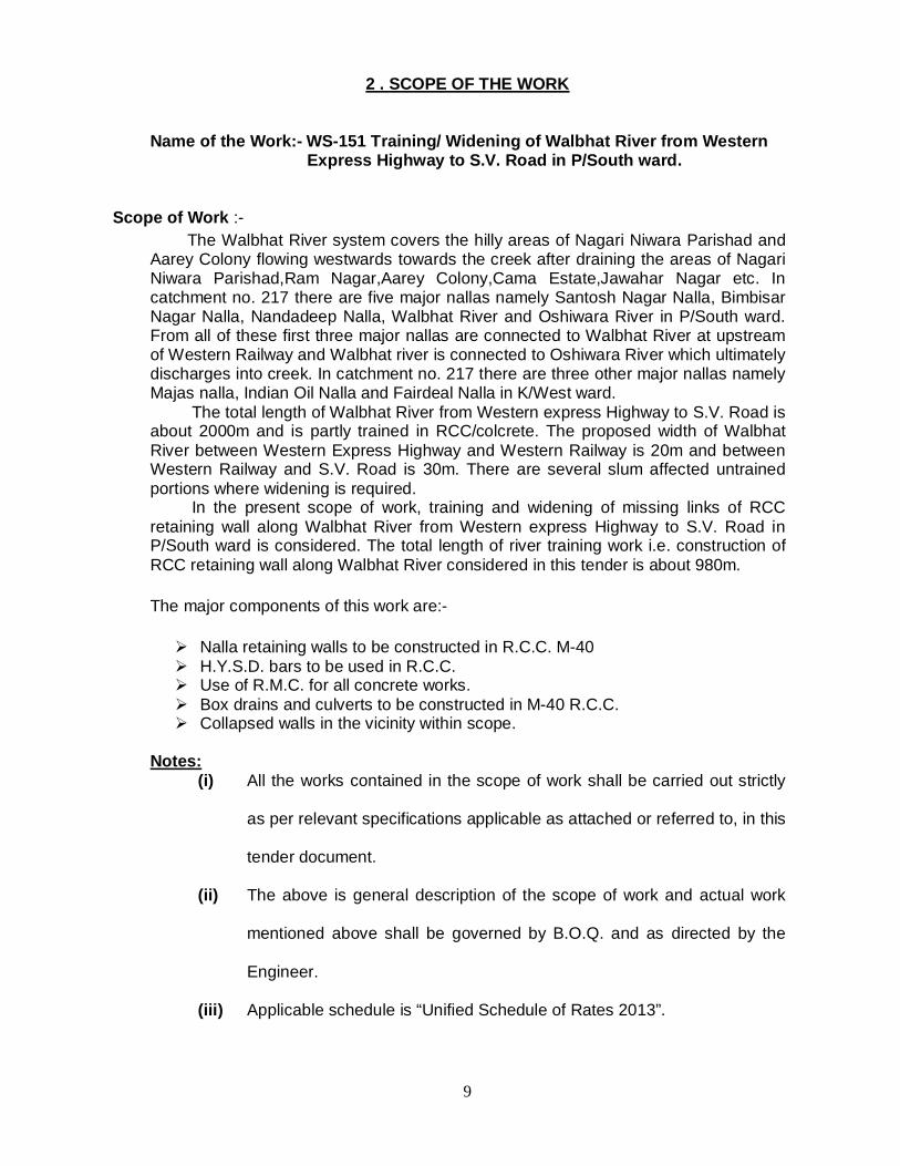
2 . SCOPE OF THE WORK
Name of the Work:- WS-151 Training/ Widening of Walbhat River from Western Express Highway to S.V. Road in P/South ward.
Scope of Work :- The Walbhat River system covers the hilly areas of Nagari Niwara Parishad and Aarey Colony flowing westwards towards the creek after draining the areas of Nagari Niwara Parishad,Ram Nagar,Aarey Colony,Cama Estate,Jawahar Nagar etc. In catchment no. 217 there are five major nallas namely Santosh Nagar Nalla, Bimbisar Nagar Nalla, Nandadeep Nalla, Walbhat River and Oshiwara River in P/South ward. From all of these first three major nallas are connected to Walbhat River at upstream of Western Railway and Walbhat river is connected to Oshiwara River which ultimately discharges into creek. In catchment no. 217 there are three other major nallas namely Majas nalla, Indian Oil Nalla and Fairdeal Nalla in K/West ward. The total length of Walbhat River from Western express Highway to S.V. Road is about 2000m and is partly trained in RCC/colcrete. The proposed width of Walbhat River between Western Express Highway and Western Railway is 20m and between Western Railway and S.V. Road is 30m. There are several slum affected untrained portions where widening is required. In the present scope of work, training and widening of missing links of RCC retaining wall along Walbhat River from Western express Highway to S.V. Road in P/South ward is considered. The total length of river training work i.e. construction of RCC retaining wall along Walbhat River considered in this tender is about 980m. The major components of this work are:- Nalla retaining walls to be constructed in R.C.C. M-40 H.Y.S.D. bars to be used in R.C.C. Use of R.M.C. for all concrete works. Box drains and culverts to be constructed in M-40 R.C.C. Collapsed walls in the vicinity within scope.
Notes:
(i) All the works contained in the scope of work shall be carried out strictly
as per relevant specifications applicable as attached or referred to, in this
tender document.
(ii) The above is general description of the scope of work and actual work
mentioned above shall be governed by B.O.Q. and as directed by the
Engineer.
(iii) Applicable schedule is “Unified Schedule of Rates 2013”.

10
SECTION – 3
INSTRUCTIONS TO TENDERERS

11
3 : INSTRUCTION TO E-TENDERERS
A - GENERAL
3.1 Invitation of E-Tender The Municipal Commissioner for and on behalf of the Municipal Corporation of Greater Mumbai, hereinafter referred as ‘The Corporation’ invites tender for the work as detailed in the tender document.
3.1.1 The tenderers are requested to seek the details on MCGM website,
e-tendering, instructions to vendors.
3.2 Qualification of the Tenderer(s): 3.2.1 All tenderer(s) shall upload online Qualification Information, as necessary to
enable their post Qualification.
The tenderer(s) shall upload online in Packet ‘B’ notarized undertaking on Rs. 200/- stamp paper stating therein that the information submitted in Packet ‘A’ & ’B’ is true and correct.
3.2.2 To qualify for a package of contracts made up of this and other contracts for which tenders are invited, the tenderer(s) must submit and upload requisite documents for having experience and resources sufficient to meet the aggregate of the qualifying criteria for the individual contracts.
3.2.3 Post Qualification Criteria – i) General
a) Post qualification will be based on tenderer’s meeting all the following criteria regarding their general and particular construction experience, financial position, personnel and equipment capabilities and other relevant information as uploaded and submitted online by tenderer's responses in the information forms attached to the tender.
b) The Post qualification criteria as prescribed below shall be filled and uploaded in the proformae and uploaded and supported by documents as mentioned under relevant clauses.
c) The cost of the executed works and turnover will be enhanced by 10% every year to bring the same to present level for purpose of post qualification.
d) The cost of executed works and the turnover of the current financial year to meet the requirements will be accepted, subject to online submission and uploaded of non-audited financial statement (original documents) duly certified by C.A. and digitally signed by tenderers.
ii) General Construction Experience
The tenderer(s) shall upload online digitally signed evidence that: -

12
a) It has been actively engaged in the civil works construction business for similar
works such as those pertaining to Roads/ Highways/ Runways / Storm Water Drains / desilting during the last 5 financial years in the role of prime contractor, partner in a joint venture or approved Sub Contractor.
b) The tenderer shall provide documentary evidence that he has successfully completed during last 5 financial years at least one work similar to the tendered work whose value shall not be less than 40 % of Cost of the work tendered for (i.e. for this tender work it should not be less than Rs.9,98,40,000/-)
OR successfully executing currently one work of similar nature with at least 75% progress (finance value as on the date of invitation of tender) of cost of magnitude of at least 40% of the cost of the work tendered for (i.e. for this tender work it shall not be less than Rs. 9,98,40,000/-)
iii) Particular construction experience :- a) The prequalification criteria shall be for three major items of the
estimate(Cost wise) as mentioned in (b) below
b) The tenderer(s) shall also upload online digitally signed evidence that the tenderer(s) in their own name should have successfully completed at least one work of the minimum 40 % quantity of 3 major items of estimate as mentioned below in the time period equal to or less than the time period of the tender, in last five years.
(i) that it has achieved the minimum quantity of the total Concrete Work to the tune of 40% of the tendered quantity of Controlled Concrete (M 40) on volumetric basis (i.e. for this tender quantity required is 4124 Cum. of M-40 C.C. in R.C.C. Nalla/River/Creek work)
(ii) that it has achieved the minimum quantity of Providing steel in RCC Work to the tune of 40 % of the tendered quantity on weight basis (i.e. for this tender quantity required is 466 M.T. of Steel in R.C.C. Nalla/River/Creek work)
(iii) that it has achieved the minimum quantity of excavation of hard rock to the tune of 40 % of the tendered quantity on volumetric basis (i.e. for this tender quantity required is 6,600 cum of hard rock in Nalla/River/Creek work)
c) The work (a) and (b) above should have been carried out in M.C.G.M. (Central Agency), Government / Semi Government / Public Sector Organization in time period equal to or less than time period of this tender in last five years. Such certificate, duly signed by an officer not below the rank of Executive Engineer of the concerned organization shall be uploaded online.

13
The works may have been executed by the tenderer as a prime contractor, or proportionately as member of a joint venture or approved subcontractor, with references being uploaded online to confirm satisfactory performance.
In support of (b) and (c) above, certificates from the employer shall be uploaded online incorporating clearly the contract value, billing amount, date of commencement of work, bifurcation of amount of work done and quantity of concrete( M40), Steel and CPCC treatment to steel executed in the time period equal to or less than the time period of the tender, in last five years, satisfactory performance of the contract and other relevant information.
iv) Financial Capabilities a) The tenderer(s) has generated a Maximum annual turnover of any one
financial year during the last 3 (Three) financial years not less than 90% of the cost of the work (i.e. for this tender it shall not be less than Rs. 22,46,40,000/-) tendered for, Chartered Accountant Certificate in this regards shall be uploaded and submitted online.
b) The tenderer(s) shall demonstrate that it has access to, or has available liquid assets, unencumbered assets, lines of credit and other financial means (independent of any contractual advance payment) sufficient to meet the construction / work cash flow requirements for the subject contract in the event of stoppage, start-up, or other delay in payment, of the minimum 15% of the cost of the work tendered for (i.e. for this tender it should not be less than Rs. 3,74,40,000/-), as certified by a registered Chartered Accountant/Approved Banks based on Audited Balance Sheet of the tenderer and shall be uploaded and submitted online in packet ‘B’.
c) The audited balance sheets for the last 3 years shall be submitted and uploaded online and must demonstrate the current soundness of the tenderer's financial position and indicate its prospective long term profitability. If deemed necessary, MCGM shall have the authority to make enquiries with the tenderer's bankers.
d) The tenderer shall have a Solvency as per the practice being followed depending upon class registered with MCGM.
V) Personnel Capabilities

14
Tenderer(s) shall upload online general information on the management structure of the firm, and shall make provision of suitably qualified personnel to fill the key positions as required during the contract implementation.
The tenderers shall upload online information of a prime candidate for each key position and each shall meet the requirements specified, as under:
Sr. No. Post Qualification
Minimum nos. to be deployed on Project
Tender cost up
to 5 crores
Tender cost
5 crores to 25
crores
Tender cost
above 25
crores 1 Project Manager At least B.E. (Civil) with min.
10 years experience or D.C.E. with min. 20 years experience.
0 0 1
2 Site Engineers At least B.E. (Civil) with min. 2 years experience or D.C.E. with min. 4 years experience.
1 1 1
3 Site Supervisors At least 2 years experience 1 2 2
In addition, Quality Control engineer per work is to be deployed, qualification being B.E. (Civil) with site experience and having experience of minimum 2 years working in Material Testing Laboratory. A notarized undertaking on Rs.200/- stamp paper shall be uploaded in packet 'B' stating that "Quality Control engineer per work having experience of working in Material Testing Laboratory, will be appointed/ deployed on the work on award of the contract." NOTE: The minimum suggested Personnel, to begin with for execution of works, in accordance with the prescribed construction schedule are shown in the above list. VI) Equipment Capabilities
A. The tenderer(s) shall own or have assured access to the equipments, in full working order, as listed below, and must demonstrate that based on known commitments, they will be available for timely use in the proposed contract. The tenderers may also list alternative types of equipments that are proposed for use on the contract, together with an explanation of the proposal.
Sr.No. Equipment
Equipment Nos. Tender
cost up to 5 crores
Tender cost 5 crores to 25 crores
Tender cost above 25
crores 1 Hydraulic Excavator (J.C.B.) 1 1 2 (Shall be
owned) 2 Dumpers/Tippers 2 4 6 (Shall be
owned) 3 Hydraulic excavator (poclain) 0 1 1 (Shall be

15
owned)
B. The tenderer shall own or have assured access (through hire, lease, purchase agreement or other commercial means) in full working order, to the plant & equipments as listed below, and must demonstrate that based on known commitments, they will be available for timely use in the proposed contract. The tenderers may also list alternative types of equipments that are proposed for use on the contract, together with an explanation of the proposal.
Sr.No.
Equipment
Equipment Nos.
Tender cost up to 5 crores
Tender cost
5 crores to 25
crores
Tender cost
above 25
crores 1 R.M.C. Plant (computerised) Capacity 30
M.T. per hr. 1 1 1
2 Vibratory Roller (Min 10 T) 1 1 1 3 Concrete Pumps 1 1 1 4 Transit Mixer 1 1 2 5 Rock Breaker (with splitter machine) 1 1 2
Note :
a. The minimum suggested major equipments to begin with for execution of works in accordance with the prescribed construction schedule are shown in the above list. The contractor shall mobilize additional equipments as directed by engineer- in-charge.
b. If assured access to R.M.C. is not available, in such cases a B.G. equivalent to Rs.1.00 (One) Cr. shall be submitted physically and scanned copy shall be uploaded in Packet ‘B’. The assured access from RMC plant shall be submitted within one month by the successful bidder from the date of work order issued.
VII) Bid Capacity –
The Assessed Available Bid Capacity (AABC) at the time of bidding shall be more than the estimated cost of the work tendered as on date of submission of tender.The available bid capacity will be calculated as under :-
Assessed Available Bid Capacity = (A x N x 1.50 - B) Where,
16
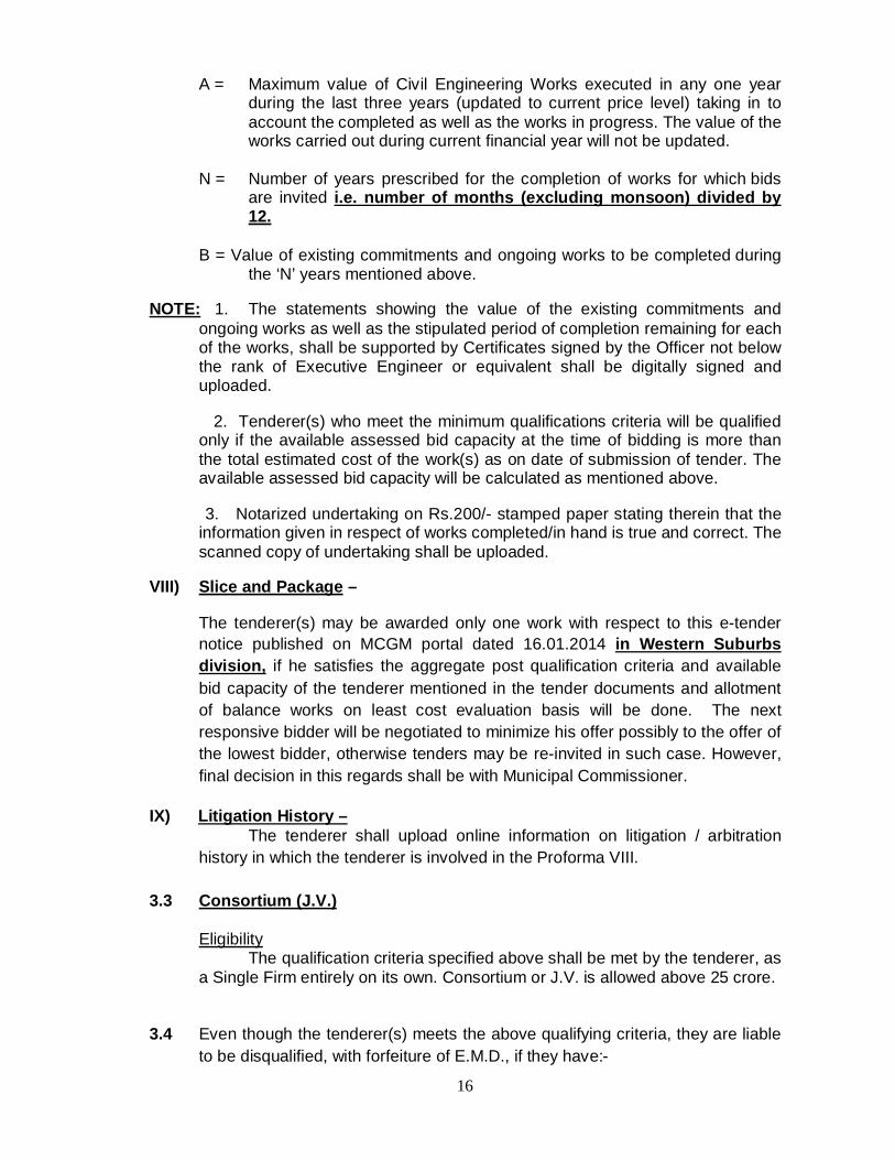
A = Maximum value of Civil Engineering Works executed in any one year during the last three years (updated to current price level) taking in to account the completed as well as the works in progress. The value of the works carried out during current financial year will not be updated.
N = Number of years prescribed for the completion of works for which bids
are invited i.e. number of months (excluding monsoon) divided by 12.
B = Value of existing commitments and ongoing works to be completed during
the ‘N’ years mentioned above.
NOTE: 1. The statements showing the value of the existing commitments and ongoing works as well as the stipulated period of completion remaining for each of the works, shall be supported by Certificates signed by the Officer not below the rank of Executive Engineer or equivalent shall be digitally signed and uploaded.
2. Tenderer(s) who meet the minimum qualifications criteria will be qualified only if the available assessed bid capacity at the time of bidding is more than the total estimated cost of the work(s) as on date of submission of tender. The available assessed bid capacity will be calculated as mentioned above.
3. Notarized undertaking on Rs.200/- stamped paper stating therein that the information given in respect of works completed/in hand is true and correct. The scanned copy of undertaking shall be uploaded.
VIII) Slice and Package –
The tenderer(s) may be awarded only one work with respect to this e-tender notice published on MCGM portal dated 16.01.2014 in Western Suburbs division, if he satisfies the aggregate post qualification criteria and available bid capacity of the tenderer mentioned in the tender documents and allotment of balance works on least cost evaluation basis will be done. The next responsive bidder will be negotiated to minimize his offer possibly to the offer of the lowest bidder, otherwise tenders may be re-invited in such case. However, final decision in this regards shall be with Municipal Commissioner.
IX) Litigation History – The tenderer shall upload online information on litigation / arbitration
history in which the tenderer is involved in the Proforma VIII.
3.3 Consortium (J.V.) Eligibility The qualification criteria specified above shall be met by the tenderer, as
a Single Firm entirely on its own. Consortium or J.V. is allowed above 25 crore. 3.4 Even though the tenderer(s) meets the above qualifying criteria, they are liable
to be disqualified, with forfeiture of E.M.D., if they have:-
17
a) Made misleading or false representations in the forms, statements and attachments submitted online in proof of the qualification requirements; and/or
b) Record of poor performance such as abandoning the works, not properly completing the contract, inordinate delays in completion, or financial failures etc; and/or.
c) Participated in the previous tendering for the same work and had quoted unreasonably high tender prices and could not furnish rational justification to the Corporation.
d) Not uploaded details of ongoing works/commitments. 3.5 One Tender per Tenderer (s) – Each tenderer(s) shall submit online only one tender for one work.
Tenderer(s) who submits more than one bid for one work, individually will cause all the proposals with the tenderer(s) participation to be disqualified.
a) Firms with common proprietors/ partners connected with one another either financially or as principal agent or as master and servant or with proprietor/partners closely related with each other such as minor son/daughter and minor brother/sister shall not tender separately under different names for the same contract.
b) If it is found that firms described vide above clause have tendered separately under different names for the same contract, all such tenders shall stand rejected and tender deposits shall be forfeited. Any contract entered into under such conditions will also be liable to be cancelled at any time during its currency and penal action including black listing of such firms will be taken.
3.6 Cost of Tendering- The tenderer(s) shall bear all costs associated with the preparation, submission
and uploading of his Tender, and the M.C.G.M. will in no case be responsible and liable for those costs.
3.7 Site Visit :- The tenderer(s), prior to online submitting and uploading his tender for
the work is encouraged to visit and examine the site of works and its surroundings at his own expenses and obtain and ascertain for himself, on his own responsibility and risk, all information, technical data, etc. that may be necessary for preparing his tender and entering into a contract including, inter-alia, the actual conditions regarding the nature and conditions of site, availability of materials, labour, probable sites for chowky/stores etc. and the extent of lead and lift required for the execution of the work over the entire duration of the contract, after taking into consideration local conditions, traffic restrictions, obstructions in work if any, allow all such extra expenses that are likely to be incurred due to any such conditions, restrictions, obstructions, etc. in the quoted and uploaded contract price for the work.
3.8 (i) Site Office :-
18
On receipt of the work order, the contractor will have to provide site office as per requirement either on his / her owned place or rented / leased place in the vicinity of the work. Cost for this may be charged to MCGM by incorporating in the offer. No separate payment may be made for providing the chowky and ancillary items. No permission and space for site chowky will be given/provided on Municipal road /footpath. The contractors have to make their own arrangement on hire/lease for site office. If the work is at various sites, necessary chowky to be provided at work places as required.
The contractors shall provide following in each above stated site office – 1) A air-conditioned site office of area admeasuring about 20 sq.m. (Minimum)
with at least two windows. 2) It should have better toilet facility. (with one water closet, basin with adequate
water supply and shall be maintained in hygienic condition). 3) This site office should be equipped with electric supply, Air Conditioner, Fans,
sufficiently big tables, chairs, water filter and cupboard with locking arrangement etc.
4) A Telephone connection, Android mobile phones (at least two), one advanced Laptop (with 4GB DDR and Intel i3 / i5 / i7 Processor) installed with AutoCAD and necessary software’s and 4GB Pen drive with printer and internet connection. The laptop will be property of MCGM.
5) Site godown & separate cabin adjacent to site office for contractors staff/any other Consultant/Quality control auditors if appointed by MCGM as per requirement.
6) All the security kits and measures for labourers shall be provided by the contractors.
7) Digital camera with minimum 16 Mega Pixel lenses.
The site office/chowky will have to be removed from the site, leaving the site clear of all material within the period of seven days from the date of completion of work. In case of failure to do so, the chowky will be demolished without any intimation to the contractor at their risk and cost and no request for compensation will be entertained.
i. If site office/chowky with necessary requirements is not provided within 15 days from the receipt work order/permission to erect chowky, a penalty of Rs. 2000/- per day per item and additional Rs. 2000/- per day, if computer/laptop is not provided, will be imposed.
ii. If there is further delay more than 30 days, a penalty of Rs. 20000/- per day (i.e. starting from 31st day from issue of work order) will be forfeited from paid ASD,OR will be recovered from 1st R.A. Bill.
iii. If there is further delay more than 45 days, a penalty of Rs. 50000/- per day (i.e. starting from 46th day from issue of work order) will be forfeited from paid ASD,OR will be recovered from 1st R.A. Bill.
NOTE:- The bidders have to consider the costs of all items in 3.8 above and 3.9 below and quote their % accordingly.
(ii) Work Records: -

19
All specified up to date site record should be maintained by the contractors. If the contractor fails to comply with this condition, the penalty of Rs.1000/- per day per record will be imposed on the contractors.
List of Registers
Register Code
Name of Register
1. Inventory Register 2. Correspondence file 3. External & internal utility remarks file 4. File containing drawings 5. Daily Progress Register 6. Instruction Register 7. Level Book 8. Mix design file 9. Materials Testing Result file
10. Photograph file 11. Excavation Register (Asphalt , rock, soil etc) 12. Barricading Register 13. Filling/Embankment Register 14. Removal Challans 15. Desilting Register 16. Granular Sub-base / K.T.R.Register 17. Wet mix Macadam ./ Water Bound Macadam .Register 18. Sand Metal Filling Register 19. Misc work register 20. M 15 CC Register 21. M 20 CC Register 22. M 40 CC Register 23. M15,M20, M35/M40 Cube & Beam registers 24. Ready Mix Concrete Challan file 25. Cement Variation Register 26. Cement Register 27. Asphalt macadam (mixes) register 28. Dense Bituminous Macadam Register 29. Asphalt concrete /Seal coat Register 30. Asphalt challan file 31. Penalty Register. 32. Steel register 33. Visual/ video recordings in form of CD’s 34. Form work shuttering register 35. Precast register 36. Any other register as per directions
(iii) Minimum 2 security guards round the clock shall be provided on every worksite. A penalty of Rs 500/- per security guard per shift will be levied if the same is not provided. 3.9 Site laboratory:- (Applicable for works costing above Rs.5.0 Cr. of office estimate) Contractors shall set up a laboratory at site of size 3 m X 6 m (about 20
sq.mt.) min., before commencement of work at their cost for performing various

20
tests and at least the following machines and equipments shall be provided therein –
a) Compressive strength testing machine (for cube tests) of minimum 130 ton capacity electrically operated and duly calibrated every 6 months. Testing machine should be maintained properly. In case of failure, the same shall be repaired or replaced within 2 days.
b) Laboratory weighing balance of minimum 20 kg. Capacity, with set of standard weights from 1 gm to 5 kg.
c) Equipment for testing of silt content in sand.
d) Dial thermometer calibrated up to 250 degree Celsius (for checking asphalt / bitumen temperature).
e) Kadappa stone platform of size 2.5m. x 0.90m. approx.
f) Curing tank
g) First Aid Box
h) Other machines as may be directed by the Engineer
All the test records shall be maintained in the site office and made available as and when required.
The laboratory must be established within 15 days from the date of receipt of the Site Office permission from the concerned Ward Office. On failure to do so, a penalty of Rs 2000/- per day shall be imposed.
Penalty of Rs. 2000/- per day will be imposed if Quality Control Engineer is not found appointed / deployed on work.
All materials used prior to establishment of Site Lab, shall be tested in MTL / VJTI/Registered lab.
3.10 Taxes and duties on material:- All charges towards Octroi, Terminal or Sales Tax/VAT /custom duty etc. and
other duties on material / machinery obtained for the work from any source including the tax applicable, as per Maharashtra Sales Tax Act; on the transfer of property in good involved in the execution of work contracts, (re-enacted) Act 1991 or as amended shall be borne by the tenderer.
The royalty charges in respect of excavated material shall be paid by the contractors to the collector as and when asked for.
3.11 Address and Telephone Nos.:-
Tenderer should specifically state and upload their residential address besides their official addresses, along with the telephone, mobile, fax no. and e-Mail address of the firm The successful tenderer will have to establish office in Greater Mumbai with telephone and fax facility. The contractor or their partners or authorized representative shall be available on the given telephone number. The said local office telephone & fax no shall be communicated to MCGM Engineer-in-charge. Any Communication sent on the said fax /E mail/Tele No shall be considered sufficient communication to the Contractors.

21
B - e- TENDERING DOCUMENT
3.12 Contents of e-Tendering Document – The set of tendering documents comprises the documents listed below –
1) e-Tender Notice 2) Scope of work 3) Instruction to Tenderers 4) General Conditions of Contract 5) Special Conditions of Contract 6) Specifications 7) Annexure A
Annexure B Form of Tender
Proforma of Bank Guarantee Agreement Form Undertaking Circular copy
8) Typical Drawings 9) Bill of Quantities 10) Financial Bid Form (Form B). 11) Addendum/corrigendum issued, if any 12) Minutes of pre-bid meeting if any
3.13 Clarification of Tendering Documents:-
i. Pre-bid meeting – Applicable :- a) The tenderer or his authorized representative is invited to attend a
pre-bid meeting as per the date, time and venue mentioned in the tender notice/header data
b) The purpose of the meeting will be to clarify issues and to answer questions on any matter that may be raised at that stage.
c) Any tenderer requiring any clarification of the tender document and/or the works may submit his questions in writing to reach the respective Dy.Ch.Eng. (S.W.D.) WS’s office at least 2 days before the meeting.
d) The text of the questions raised (without identifying the source of enquiry) and the response given will be circulated/informed vide addendum on MCGM portal /displayed on Notice board of respective Zonal office within 7 days. Any modification of the tendering documents, which may become necessary as a result of the pre-bid meeting, shall be made by the M.C.G.M. exclusively through the issue of an Addendum and not through the minutes of the pre-bid meeting.
e) Non-attendance at the pre-bid meeting will not be a cause for disqualification of tenderer.
ii. Amendment of Tendering Documents:- a) Before the deadline for submission of tenders, the M.C.G.M. may modify
the tendering documents by issuing addendum/ corrigendum and publishing on portal of MCGM or e-mailed or displayed on notice board of the respective divisions of Dy. Ch.E.

22
b) Any addendum/corrigendum/clarification thus issued shall be part of the tendering documents
c) The addendum/corrigendum thus issued shall be digitally signed by the tenderer and uploaded in Packet ‘B’.
d) To give prospective tenderers reasonable time to consider the addendum/corrigendum before submitting and uploading their bids, the M.C.G.M. shall extend if necessary the deadline for submission and uploading of tenders.
Only the bidders who qualify in Packet A and B will be considered as
responsive for Financial Bid i.e. Packet C. But the physical submission of Packet A & B of all bidders will be required as & when demanded by M.C.G.M. for verification and the same will be compared with this scan soft copies of the documents uploaded by the bidders in E-tenders. If any discrepancies are observed or false documents are found to be uploaded by the bidders, such bidders will be disqualified from the bidding process and the names of such bidders/firms will be published on MCGM Portal or displayed at divisional offices. Further action as liable under rules /regulation shall also be initiated against such bidders, who submits false documents.
C- PREPARATION OF e-TENDERS Note: All the documents uploaded for online submission must be digitally signed and self attested with digital signature by the bidders, if not the bidder / tenderer will be disqualified.
23
3.14 Language of Tender
Tender shall be written in English. Documents/ Information in any other language shall be accompanied by its translation in English. Only English text shall be governing in E Tendering.
3.15 Tenderer(s) shall not amend the text of these documents. If it is found that the
tenderer has violated this condition, his tender is liable to be rejected. 3.16 Bid Prices:
a. The contract shall be for the whole work as described in scope of work attached hereto based on the Bill of Quantities submitted and uploaded by the tenderers.
b. The tenderer shall fill / upload in the percentage either plus or minus (i.e. above or below) in the financial bid in figures or at par % quoted 0 (zero) will be considered as at par (by default also). Corrections, if any can be made till end date (i.e. last date) and time, before submitting the bid.
c. Rates of each item of work mentioned in the schedule should be well scrutinized with due consideration of each item before submitting the tender as no variation in rates will be allowed on any ground as mistake or misunderstanding after the tender has been submitted.
d. Tenderer should note that percentage should be quoted for total estimated amount. No separate percentage can be quoted for roadwork and storm water drain work.
e. Tenderer should execute the additional work to the extent of 15% over and above of office estimate {as shown in the Bill of Quantities of this work} at the quoted percentage and terms and conditions of contract but within the same contract period as called upon by the Chief Engineer {S.W.D.}
f. If the tenderer fails to attend the work in whole / part {as shown in bill of Quantities of this work} at the quoted percentage and terms and conditions of contract but within the prescribed time limit ,the said work will be carried out at his risk and cost thro” the other contractor at this quoted percentage + 15% supervision charges.
g. All taxes, duties, cess and charges such as Octroi, Service Tax, Terminal or Sales Tax, VAT and Royalty charges etc. and other duties on material obtained for the work from any source including the tax applicable as per Maharashtra Sales Tax Act, on the transfer of property in good involved in the execution of work contracts (re-enacted) Act 1989 or as amended shall be borne by the tenderer. The tenderer shall not be reimbursed the taxes, duties, cess and charges whether now in force or that may be enforced in future.
h. The tenderer shall be registered under Maharashtra Sales Tax/ VAT on the transfer of property in goods involved in the execution of works
Contracts (Reenacted) Act 1989 and should produce and upload documentary evidence to that effect (a copy of registration of certificate from the Sales Tax department).

24
i. The successful bidder within 15 days from the date of issue of work order for executing the contract work under reference shall enter into contract agreement with the MCGM. The contract agreement shall be adjudicated for payment of stamp duty by the successful bidder and accordingly the successful bidder shall pay the stamp duty on the contract agreement, as per government directives issued in this respect u/n no. Enforcement -I / works contract / W.S.-1343 dated 21/07/2009, so as to ensure that, the contract agreement is executed within the stipulated period as aforesaid.
3.17 Tender Validity :
The tender offer shall be kept valid for 120 (one Hundred and Twenty) calendar days from the date of submission of the tender. Thereafter validity may be extended for further period as may be mutually agreed upon between the Tenderer(s) and M.C.G.M.
3.18 Earnest Money Deposit (E.M.D.) : a. The tenderers have to get the vendor/validation number registered with MCGM,
in all cases. The E.M.D. shall be 1% of the estimated cost. The tenderers shall pay the same through Demand Draft (DD) and shall upload the scan copy of the DD in Packet `A`. The tenderer shall submit such DD Physically in the office of Deputy Chief Engineer, SWD (WS) in packet ‘A’ on due date of submission of tender. If such DD is not submitted physically, the tenderer shall be treated as non-responsive and his tender shall not be opened. The tender will be rejected if the tenderer failed to upload scanned copy of the requisite DD for EMD online in Packet ‘A’. The standing deposit with the MCGM will not be considered for EMD, bidder has to pay full amount of EMD.
b. The tenderer quoting / bidding for more than one work, shall pay as mentioned above EMD by DD separately for each offer for which the bidder is quoting the tender.
c. The tenderer shall upload in packet ‘A’ a scanned copy of DD of requisite EMD. d. If the tenderer(s) withdraw tender offer during the tender validity period and
tenderer fails to submit Packet ‘C’ physically and online and sealed packet containing ASD and rate analysis or NIL report physically, the entire amount of EMD shall be forfeited.
e. The earnest money deposit (E.M.D.) of the 5th lowest responsive tenderer and others shall be refunded before the Tender Committee’s meeting. The earnest money deposit (E.M.D.) of the 3rd and 4th lowest responsive tenderer shall be retained till the Tender Committee’s recommendation to DL to MS. The earnest money deposit (E.M.D.) of the 2nd lowest responsive tenderer shall be retained till the standing committee’s approval is obtained and the acceptance letter/work order is given to the successful bidder. It is generally observed that the successful tenderer prefers to convert EMD into Contract Deposit / Security Deposit and, therefore, there remains nothing as EMD. However, if the successful tenderer does not convert the EMD into Contract Deposit / Security

25
Deposit, the EMD shall be refunded immediately after the Contract Deposit / Security Deposit is paid by him.
f. Tenderers has to submit the original EMD receipt at the time of refund of EMD.
3.19 Alternative/ Conditional Proposals by Tenderers- Tenderers shall submit and upload offers that comply with the requirements of
the tendering documents, including the basic technical design as indicated in the drawing & specifications. If the tenderer suggests any alternative or stipulates his own condition(s), the tender shall be rejected.
3.20 Format & Signing of Tender Tenderer(s) shall digitally sign the Financial Bid Form, Annexure 'A' & the
Addendum, undertaking before uploading and submitting the tender online. Please note that –
a) If a tender is submitted online by an individual, it shall be digitally signed with date, giving his full name and address.
b) If a tender is submitted online by a proprietary firm, it shall be digitally signed by the proprietor with date, full name, name of the firm and address.
c) If a tender is submitted online by a firm in partnership, it shall be digitally signed by all partners of the firm with date, full names and addresses or by a partner/person holding the power of attorney on behalf of the firm for digitally signing the tender with a copy of the Power of attorney accompanying the tender. A certified copy of the partnership deed duly registered with C.A (Treasury), addresses of the firm and full names and addresses of all partners of the firm shall be submitted and uploaded online with the tender.
d) If a limited company or a Corporation submits a tender online, it shall be digitally signed by a person holding power of attorney for digitally signing the tender with the certified copy of the Power of Attorney accompanying & uploading the tender. Such limited company or Corporation shall furnish evidence of its existence before the contract is awarded.
e) The person submitting tender online shall digitally sign each page of tender.
f) Power of Attorney shall be registered with the office of Chief Accountant (Treasury).
g) The person digitally signing the tender shall initial erasures and changes, if any, during uploading the E-Tender
D – SUBMISSION OF ONLINE E-TENDER NOTE :-
26
THE TERMINOLOGY OF E-TENDERING IS SOLELY DEPENDING UPON POLICIES IN EXISTENCE, GUIDELINES AND METHODOLOGY ADOPTED SINCE DECADES. THE SRM IS ONLY CHANGE IN PROCESS OF ACCEPTING AND EVALUATION OF TENDERS IN ADDITION TO MANUAL. THE SAP MODULE TO BE USED IN THIS E-TENDERING IS KNOWN AS SUPPLIER RELATIONSHIP MODULE(SRM).SRM IS DESIGNED AND INTRODUCED BY ABM KNOWLEDGE WARE LTD. WHO WILL ASSIST MCGM IN THROUGHOUT THE TENDERING PROCESS FOR SUCCESSFUL IMPLEMENTATION. NOTE:- This tendering process is covered under Information Technology Act & Cyber Laws as applicable.
1) In E-tendering process some of the terms and it’s definitions are to be read as under wherever it reflects in online tendering process. Start Date read as “Sale Date” End Date read as “Submission Date” Supplier read as “Contractor/bidder” Vendor read as “Contractor/bidder” Vendor Quotation read as “Contractors Bid/Offer” Percentage Variation read as “Percentage Quoted” Purchaser read as “Department/MCGM”
2) Only numeric values upto two decimal places are accepted in “Percentage Quoted” by the contractors in online tender Process, therefore the contractors/bidders should take care while quoting their %rates in numeric values up to two decimal places
(I) Before entering in to online tendering process, the contractors should complete the
registration process so as to get User ID for E-tendering links. For this the contractors can access through Supplier registration via MCGM Portal.
There are two methods for this registration: (II and III) (II.) Transfer from R3 (registered contractors with MCGM) to SRM
a. Contractors already registered with MCGM will approach to Vendor Transfer cell.
b. Submit his details such as (name, vendor code, address, registered Email ID, pan card etc.) to Vendor transfer cell created at each divisional office of Storm Water Drains Department.
c. MCGM authority for Vendor Transfer transfers the Vendor to SRM application from R3 system to SRM system.
d. Transferred Vendor receives User ID creation link on his supplied mail Id. e. Vendor creates his User ID and Password for E-tendering applications by
accessing link sent to his mail ID.
(III.) Online Self Registration(Temporary registration for tenderers not registered with MCGM)
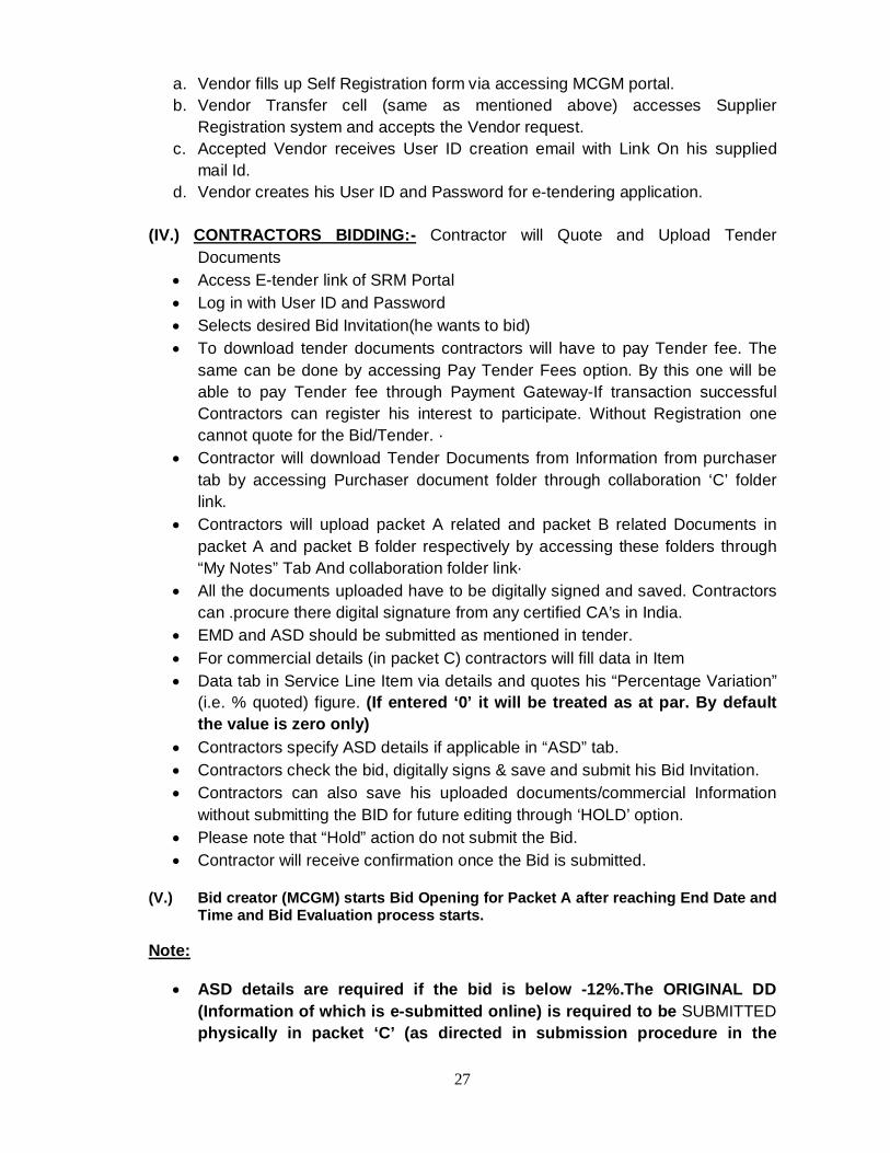
27
a. Vendor fills up Self Registration form via accessing MCGM portal. b. Vendor Transfer cell (same as mentioned above) accesses Supplier
Registration system and accepts the Vendor request. c. Accepted Vendor receives User ID creation email with Link On his supplied
mail Id. d. Vendor creates his User ID and Password for e-tendering application.
(IV.) CONTRACTORS BIDDING:- Contractor will Quote and Upload Tender
Documents Access E-tender link of SRM Portal Log in with User ID and Password Selects desired Bid Invitation(he wants to bid) To download tender documents contractors will have to pay Tender fee. The
same can be done by accessing Pay Tender Fees option. By this one will be able to pay Tender fee through Payment Gateway-If transaction successful Contractors can register his interest to participate. Without Registration one cannot quote for the Bid/Tender. ·
Contractor will download Tender Documents from Information from purchaser tab by accessing Purchaser document folder through collaboration ‘C’ folder link.
Contractors will upload packet A related and packet B related Documents in packet A and packet B folder respectively by accessing these folders through “My Notes” Tab And collaboration folder link·
All the documents uploaded have to be digitally signed and saved. Contractors can .procure there digital signature from any certified CA’s in India.
EMD and ASD should be submitted as mentioned in tender. For commercial details (in packet C) contractors will fill data in Item Data tab in Service Line Item via details and quotes his “Percentage Variation”
(i.e. % quoted) figure. (If entered ‘0’ it will be treated as at par. By default the value is zero only)
Contractors specify ASD details if applicable in “ASD” tab. Contractors check the bid, digitally signs & save and submit his Bid Invitation. Contractors can also save his uploaded documents/commercial Information
without submitting the BID for future editing through ‘HOLD’ option. Please note that “Hold” action do not submit the Bid. Contractor will receive confirmation once the Bid is submitted.
(V.) Bid creator (MCGM) starts Bid Opening for Packet A after reaching End Date and
Time and Bid Evaluation process starts. Note:
ASD details are required if the bid is below -12%.The ORIGINAL DD (Information of which is e-submitted online) is required to be SUBMITTED physically in packet ‘C’ (as directed in submission procedure in the
28
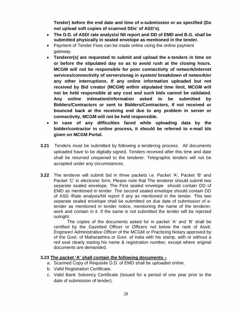
Tender) before the end date and time of e-submission or as specified (Do not upload soft copies of scanned DDs’ of ASD’s).
The D.D. of ASD/ rate analysis/ Nil report and DD of EMD and B.G. shall be submitted physically in sealed envelope as mentioned in the tender.
Payment of Tender Fees can be made online using the online payment gateway.
Tenderer(s) are requested to submit and upload the e-tenders in time on or before the stipulated day so as to avoid rush at the closing hours. MCGM will not be responsible for poor connectivity of network/internet services/connectivity of servers/snag in system/ breakdown of network/or any other interruptions. If any online information uploaded but not received by Bid creator (MCGM) within stipulated time limit, MCGM will not be held responsible at any cost and such bids cannot be validated. Any online intimation/information asked to be submitted by Bidders/Contractors or sent to Bidders/Contractors, if not received or bounced back at the receiving end due to any problem in server or connectivity, MCGM will not be held responsible.
In case of any difficulties faced while uploading data by the bidder/contractor in online process, it should be referred to e-mail Ids given on MCGM Portal.
3.21 Tenders must be submitted by following e-tendering process. All documents
uploaded have to be digitally signed. Tenders received after this time and date shall be returned unopened to the tenderer. Telegraphic tenders will not be accepted under any circumstances.
3.22 The tenderer will submit bid in three packets i.e. Packet ‘A’, Packet ‘B’ and
Packet ‘C’ in electronic form. Please note that The tenderer should submit two separate sealed envelope. The First sealed envelope should contain DD of EMD as mentioned in tender .The second sealed envelope should contain DD of ASD /Rate analysis/Nil report if any as mentioned in the tender. This two separate sealed envelope shall be submitted on due date of submission of e-tender as mentioned in tender notice, mentioning the name of the tenderer, work and contain in it. If the same is not submitted the tender will be rejected outright.
The copies of the documents asked for in packet ‘A’ and ‘B’ shall be certified by the Gazetted Officer or Officers not below the rank of Asstt. Engineer/ Administrative Officer of the MCGM or Practicing Notary approved by of the Govt. of Maharashtra or Govt. of India with his stamp, with or without a red seal clearly stating his name & registration number, except where original documents are demanded.
3.23 The packet ‘A’ shall contain the following documents –
a. Scanned Copy of Requisite D.D. of EMD shall be uploaded online. b. Valid Registration Certificate. c. Valid Bank Solvency Certificate (Issued for a period of one year prior to the
date of submission of tender).

29
d. Sales Tax Registration Certificate in Maharashtra (or equivalent requirement under VAT). Those not registered in Maharashtra, shall submit an undertaking to the effect that if they are successful tenderer, they shall submit Sales Tax Registration Certificate in Maharashtra within 15 days of issue of work order, failing which payment for the work executed will not be released.
e. The ‘PAN’ documents and photographs of the individuals, owners, Karta of Hindu undivided Family, firms, private limited companies, registered co-operative societies, partners of partnership firms and at least two Directors, if number of Directors are more than two in case of Private Limited Companies, as the case may be. However, in case of Public Limited companies, Semi Government Undertakings, Government Undertakings, no ‘PAN’ documents are insisted.
f. Latest Partnership Deed in case of Partnership firm duly registered with C.A. (Treasury) and Registered Power of Attorney if any.
g. If the tenderer(s) have more than 20(twenty) Labours/persons on his establishment then the tenderer(s) has to upload the copy of registration certificate under Employees Provident fund and misc. Provision Act 1952(EPF & MP Act 1952) and registration certificate under state Labour Insurance Scheme (E.S.I.C. Act 1948). If the tenderer(s) has less than 20 labourers/persons on his establishment, then tenderer(s) has to upload the Undertaking on Rs.200/- Stamp paper stating the same.
h. Valid E-mail id of the bidder . i. Memorandum of Understanding(M.O.U.) (Duly Notarized)/A letter of Intent to
execute a JV/Consortium in the event of successful bid signed by all partners(Duly Notarized) OR Registered Consortium Agreement.
3.24 The Packet “B” shall contain the copies of following documents –
a. Notarized undertaking on Rs. 200/- stamp paper stating therein that the information uploaded in Packet ‘A’ & ’B’ is true and correct. Notarized undertaking on Rs. 200/- stamped paper stating therein that the tenderer has assured access (through hire, lease, purchase agreement (notarized) or other commercial means) to the plants and equipments as stated in Proforma “VI-A” and “VI-B”.
b. The names of civil works construction business for similar works such as those pertaining to R.C.C. Water retaining structures / R.C.C. retaining walls Nalla training works in R.C.C. / R.C.C. structural works carried out in water bodies during last 5 financial years in the role of prime contractor, partner in Joint Venture or approved Sub-Contractor. (Proforma – I) (original).
c. Annual turnover of any one year during the last 3 (three) financial years (excluding the current financial year) (Proforma – II) (original).
d. Evidence stating that the tenderer has successfully completed during the last 5 (five) financial years at least one contract pertaining to R.C.C. Water retaining structures / R.C.C. retaining walls Nalla training works in R.C.C. / R.C.C. structural works carried out in water bodies in the role of prime contractor, partner in Joint Venture or approved Sub-Contractor as per Clause no. 3.2.3 (ii) (Proforma – III) (original).

30
e. The tenderer shall also provide evidence that it has achieved the minimum annual quantity of three major items as mentioned in no. 3.2.3(iii)(b).. (Proforma – IV) (Original).
f. Evidence stating that it has access to, or has available liquid assets, unencumbered assets, lines of credit and other financial means (independent of any contractual advance payment) sufficient to meet the construction cash flow requirements for the subject contract in the event of stoppage, start-up, or other delay in payment, of the minimum 15% of the cost of the work tendered for, net of the tenderer’s commitment of other contracts.
g. The audited balance sheets for the last 3 years.
h. Information on provision of suitably qualified personnel (Proforma- V) (original).
i. Information about ownership, or assured access (through hire, lease, purchase agreement or other commercial means) to key items of equipments (Proforma VI A & VI B) (original). If assured access to R.M.C. is not available, in such cases a B.G. equivalent to Rs.1 Cr. shall be submitted physically in sealed envelope containing EMD and upload scanned copy in packet ‘B’. The assured access from RMC plant shall be submitted within one month by the successful bidder from the date of work order issued.
j. Details of works in hand (Proforma VII A & VII B) (original).
k. Programme of work in the form of a Bar chart/PERT/ Mile stone chart.
l. Financial & physical Milestones of various stages of the work during the contract period. m. Signed copy of the addendum and corrigendum, if any. n. Organizational set up envisaged by the contractors. o. Plant & equipment proposed to be deployed for this work. p. Bid Capacity & Notarized undertaking on Rs.200/- Stamp paper stating there in
that the information given in respect of works completed/in hand is true and correct.
q. Litigation history. (Proforma VIII) r. Declaration Form ‘B’ as specified in tender. s. Undertaking on Rs.200/- stamp paper in the given format in head 7.6
UNDERTAKING stating that bidder have offered the best prices for the work and they have not quoted lower price for similar work to any other agency including Govt./Semi-Govt agencies and also within M.C.G.M.
(Note : The tenderer has to submit hard copies of documents uploaded in packet ‘A’ & packet B’ as when demanded by M.C.G.M. The tenderer shall note that the uploaded scanned copies shall be clear & readable.)

31
3.25 Packet “C” shall contain the following-
a) For Packet ‘C’ tenderer(s) will fill data in Item Data Tab in Service Line Item via Details and quotes his percentage variation figures. (If entered ‘0’ it will be treated as at par. By default the value is zero only).
b) Demand draft of required amount for additional Security deposit shall be submitted in sealed envelope physically as per condition incorporated in this tender (i.e. if rebate quoted is more than 12 %). If the tenderer intends to quote more than one work then, the DD shall be submitted physically in sealed envelope of the tender corresponding to highest A.S.D. and certified copies of the same in sealed envelope of the other tenders shall be submitted physically. In case the A.S.D. submitted is more than the percentage quoted by the bidder, then the percentage quoted shall prevail. The tenderer shall physically submit the NIL report in sealed envelope even though ASD is not applicable. Otherwise their offer will be treated as non-responsive.
c) If the tenderer quoting the rebate more than 15% or premium more than 15% on the office estimated cost shall submit rate analysis for major items in BOQ & NIL report shall be submitted even if the same is not applicable, in separate sealed envelope to this office as stated in e- tender notice. Otherwise their offer will be treated as non-responsive.
3.26 Physical submission of 3.25 (b) & (c) above shall be put in a envelope, which
shall also be sealed and submitted as specified in Tender. 3.27 PROFORMAE: -
PROFORMA – I The list of Civil Works construction business for similar works pertaining to
S.W.D/Nalla Works during last five financial years –
Name of the Project
Name of the Employer
Stipulated Date of
Completion
Actual Date of Completion
Actual cost of work done
1 2 3 4 5
NOTE: 1) Attested copies of completion/performance certificates from the Engineer-in-charge of rank not below Assistant Engineer of M.C.G.M or
equivalent post in other Government/Semi-Government organization, for each work should be annexed, self digitally attested, scanned & uploaded.
2) Works shall be grouped financial year-wise.
PROFORMA-II Annual turnover of Civil Engineering Construction Works of any one year during last 3 (Three) financial years.
Sr. No.
Financial Year Annual Turnover of Construction Works
Updated value to current year
1 2 3 4

32
Note: - The above figures shall tally with the audited balance sheets submitted by the tenderers duly certified by Chartered Accountant. self digitally attested, scanned & uploaded.
PROFORMA – III At least one work, pertaining to Civil Engineering Works of size as mentioned in the post qualification criteria during last five financial years Name of the
Project
Name of the
Employer
Cost of the
Project
Stipulated Date of
Completion
Actual Date of
Completion
Actual cost of
work done
Remarks explaining reasons for
delay, if any.
1 2 3 5 6 7 8 Note: Attested copies of completion/performance certificates from the Engineer-in-charge for each work should be annexed, self digitally attested,
scanned & uploaded. PROFORMA – IV
Quantity three major items executed in the time period equal to or less than the time period of this tender in last five years.
Item No. Year Name of the
Works Name of the Employers
Quantity Executed
Remarks
1 2 3 4 5
Note: To be supported by requisite certificates from the Engineer-in-charge, self digitally attested, scanned & uploaded.
PERSONNEL :-
PROFORMA – V
Sr No.
Post Qualification Minimum Nos. to be deployed on this Project.
1 2 3 4 1 Project Manager 2 Site Engineers 3 Quality Control Engineer 4 Site Supervisor
A notarized undertaking on Rs.200/- stamp paper shall be submitted online in packet 'B' stating that "Quality Control engineer per work having experience of working in Material Testing Laboratory, will be appointed/ deployed on the work on award of the contract." NOTE: Attested copies of qualification certificates and details of work
experience shall be submitted online, self digitally attested, scanned & uploaded.

33
3.28 MACHINERY:-
PROFORMA –VI /A
(A)The tenderer(s) shall own equipments or have assured access, in full working order, as listed below, and must demonstrate that based on known commitments, they will be available for timely use in the proposed contract.
Sr.No. Equipment No.
1 Hydraulic Excavator(J.C.B.)/ 2 Dumpers/Tippers 3 Hydraulic excavator(poclain)
PROFORMA –VI/B
The tenderer(s) shall own or have assured access (through hire, lease, purchase agreement (notarized) or other commercial means), in full working order, to the plant as listed below, and must demonstrate that based on known commitments, they will be available for timely use in the proposed contract.
Sr.No. Equipment No. 1 R.M.C. Plant (computerized) Capacity 30
M.T. per hr.
2 Vibratory Roller (Min 10 T) 3 Concrete Pumps 4 Transit Mixer 5 Rock Breaker / splitter machine
Note: The tenderer(s) shall upload digitally signed requisite documents and
notarized undertaking on Rs. 200/- stamped paper stating therein that the tenderer has assured access (through hire, lease, purchase agreement (notarized) or other commercial means) to the plants and equipments as stated above. The tenderer has to submit ownership documents of the machineries and equipments owned (i.e. R.C. Book, Purchase Invoice, Purchase Agreement). If the tenderer acquires the assured access from any other agency then the tenderer has to submit ownership documents of that agency for the machineries and equipments owned by them (i.e. R.C. Book, Purchase Invoice, Purchase Agreement)including notarized consent letter of assured access on Rs 200/-stamp paper.
If assured access to R.M.C. is not available, in such cases a B.G. equivalent to Rs.1.00 (One) Cr. shall be submitted physically in sealed envelope containing EMD and upload scanned copy in packet ‘B’. The assured access from RMC plant shall be submitted within one month by the successful bidder from the date of work order issued.
34
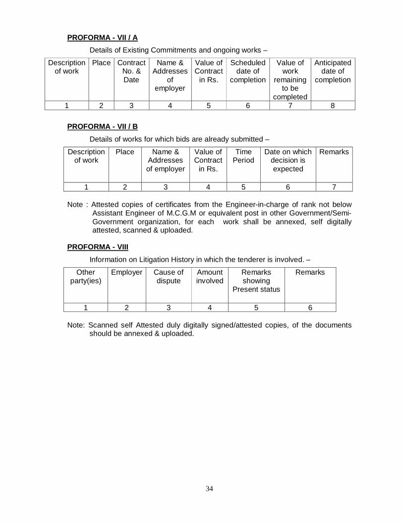
PROFORMA - VII / A Details of Existing Commitments and ongoing works –
Description of work
Place Contract No. & Date
Name & Addresses
of employer
Value of Contract
in Rs.
Scheduled date of
completion
Value of work
remaining to be
completed
Anticipated date of
completion
1 2 3 4 5 6 7 8 PROFORMA - VII / B Details of works for which bids are already submitted –
Description of work
Place Name & Addresses of employer
Value of Contract
in Rs.
Time Period
Date on which decision is expected
Remarks
1 2 3 4 5 6 7 Note : Attested copies of certificates from the Engineer-in-charge of rank not below
Assistant Engineer of M.C.G.M or equivalent post in other Government/Semi-Government organization, for each work shall be annexed, self digitally attested, scanned & uploaded.
PROFORMA - VIII Information on Litigation History in which the tenderer is involved. –
Other party(ies)
Employer Cause of dispute
Amount involved
Remarks showing
Present status
Remarks
1 2 3 4 5 6 Note: Scanned self Attested duly digitally signed/attested copies, of the documents
should be annexed & uploaded.

35
E- e-TENDER OPENING AND EVALUATION
3.29 Deadline for downloading and Submission of E-Tender – a) e-Tender copy can be downloaded from the start date and time up to
End Date or within a time as mentioned in Header Data or Tender Notice. Online tenders can be uploaded and submitted till End Date and time. During the Evaluation of the tender Packets, either the tenderers OR their one authorized representative may attend the process.
b) The Tenderers/ Bidders (only those who have submitted online bids)
have to submit sealed envelopes containing EMD,B.G. (if assured access for RMC is not available) physically as specified in tender. If tenderer fails to submit DD of requisite E.M.D. physically then the tender shall be treated as non-responsive and list of such tenderer will be E-mailed OR Displayed on Notice board of the respective Divisions of Dy.ChE(SWD).
Once the Packet A (Eligibility criteria) opening date and time is reached Bidders Bid Tab gets activated, MCGM department (bid creator) or Tender evaluation committee members can log in with user ID and password, check the list of the Bidders who have applied for the Bid Invitation in the “Bidders/Bid” tab.
The TENDERER/CONTRACTORs who are having status as “Bid submitted” will be considered eligible for the Bid opening Process. MCGM selects Bid one by one for evaluation of packet A.
After packet A opening date and time, MCGM department can access the Private “collaboration” C folder area of the Bidders where they have uploaded their tender relevant document in packet A as required by MCGM. Department will then open TENDERER/CONTRACTORs Packet A folder and download the documents submitted by TENDERER/CONTRACTOR in the Packet A. The ‘Tender Evaluation Committee’ then scrutinize these eligibility documents.
The tenderer(s) should upload all the required documents while uploading the tender in Packet A. It is not binding on M.C.G.M. to call for required documents. If MCGM desires then and then only short fall documents will be asked from tenderer and tenderer has to submit it physically before the opening of Packet ‘C’ or as directed and if the tenderer fails to do so, as stipulated, then 10% amount of the E.M.D paid by them shall be recovered & the tender shall be treated as non-responsive.
On completion of this process the non responsive TENDERER /CONTRACTORs are rejected in the e-Tendering system against their respective bids in the “Bidders/Bid” tab for eligibility criteria and list of rejected Bid with reason for rejection will be displayed either at Divisional office or on MCGM portal or Emailed.
c) Bid Opening for Packet B and Bid Rejection: After completion of Evaluation of packet ‘A’(Eligibility criteria) opening
process when Date and Time of Packet ‘B’ opening reaches the MCGM department or Tender evaluation committee members then can accesses Packet B folder of responsive TENDERER/CONTRACTORs and download the documents submitted by TENDERER/CONTRACTOR in the Packet B. The authorized MCGM staff ‘Tender Evaluation Committee’ then scrutinize these technical documents.

36
It is expected that contractor should upload all the requisite documents during submission of tender in packet B. It is not binding on M.C.G.M. to call for required documents. If MCGM desires then and then only short fall documents will be asked from tenderer and tenderer has to submit it physically before the opening of Packet ‘C’ or as directed and if the tenderer fails to do so, as stipulated, then 10% amount of the E.M.D paid by them shall be recovered & the tender shall be treated as non-responsive.
Once the scrutiny of technical documents are completed, the disqualified TENDERER/CONTRACTORs are rejected in the e-Tendering system against their respective bids in the “Bidders/Bid” tab for technical criteria failure and list of rejected Bid with reason for rejection will be displayed either at Divisional office or on MCGM portal or Emailed. The 'C' packets (financial bid) of the only responsive /eligible tenderers /bidders will be opened there after as per the schedule.
Non-responsive tenderers those informed by Email specifying the reasons can collect the unopened sealed Packet (physically submitted) from the Office.
d) Price Bid Opening Process:
Bids which are technically qualified or responsive are evaluated for price comparison once price bid opening i.e. Packet ‘C’ date and time is reached. The system allows the MCGM users (Tender evaluation committee members) to start this process of opening of price bid. The authorized employees (tender Evaluation committee members) with their user ID and Password will log in the system. The sys- tem will generate and give a comparative statement showing list and details of qualified TENDERER/CONTRACTORs with ranking based on the %(percentage)/commercial quote on office estimated cost. If rate analysis by the bidders/Contractors quoting percentage rebate/premium more than 15% is not submitted, such bidders/contractors will be disqualified from tendering/financial bid process. . If the tenderer(s) withdraw tender offer during the tender validity period, his E.M.D shall be forfeited. If tenderer fails to submit sealed envelope containing DD of ASD/Rate analysis/Nil Report physically as mentioned in tender and fails to submit the price bid online, the entire amount of EMD shall be forfeited.
e) Any change in date & time of opening of Packet 'A, B & C' as specified in the tender notice, will be displayed either at Divisional office or on MCGM portal or Emailed.
Bid opening authentication:
The price bids have to be opened in presence of three MCGM persons who are authorized to approve the Price bid opening process. User IDs of these three Tender Evaluation committee members are assigned for respective bid invitation number and these authorized MCGM Tender Evaluation committee members will enter their passwords simultaneously for authenticating this Price Bid Opening Process.
f) The MCGM reserves the right to reject all or any of the tender(s) without assigning any reason.

37
3.30 Process to be Confidential - Information relating to the examination, clarification, evaluation and comparison of tender and recommendations for the award of a contract shall not be disclosed to tenderers or any other persons not officially concerned with such process until the award to the successful tenderer has been announced. Any effort by a tenderer to influence the Employer's processing of tenders or award decisions may result in the rejection of his tender, and his disqualification.
3.31 Examination of Tenders and Determination of Responsiveness - Prior to the detailed evaluation of tenders, the M.C.G.M. will determine whether each tender - (a) Meets the eligibility criteria (b) Has been properly digitally signed. (c) Is accompanied by the required securities. (d)Is responsive to the requirement of the tendering uploaded documents.
3.32 A responsive tender is one, which confirms to all the terms, conditions and specifications of the tendering documents, without material deviation or reservation a material deviation or reservation is one- (a) Which affects in any way the scope, quality or performance of the work. (b) which limits in any way, the employer’s rights or the tenderer’s obligation under the contract and inconsistent with tendering documents. (c) Whose rectification would affect unfairly the competitive position of other tenderers presenting responsive tenders.
Mandatory Requirements
The tender shall be rejected if the tenderers - i) Stipulates the validity period less than 120 days. ii) Stipulates his own condition/s. iii) Does not fill and digitally signs the uploaded tender documents. iv) Does not submit adequate amount of Earnest Money Deposit and Additional
Security deposit in the form of D.D. for rebate, as per the relevant conditions in the tender within stipulated date and time period as mentioned in physical & online submission process above.
v) If Does not quote percentage in figures. vi) Does not submit/uploaded documents listed in Packet ‘A’ & ‘B’. vii) Non submission of sealed envelope containing DD of EMD, and B.G. due date
as mentioned in tender. viii)The entire amount of EMD shall be forfeited, if tenderer fails to submit Packet
‘C’ online and sealed envelope containing DD of ASD /Rate analysis/Nil report physically as mentioned in tender.
3.33 The tenderers shall note that –
i. For detailed description of items, rates, units and the corresponding notes, the following Fair Market Rate Schedules of MCGM in force at the time of invitation of the tender shall be referred to and be applicable – common schedule, road works, storm water drain works, bridge and building works, sewerage project and Hydraulic Engineer dept.
38
ii. Though tenders may not be rejected for non-compliance of any of other than mandatory requirements, tenderers are liable for suitable action by way of scrutiny fee as penalty, as decided by Tender Committee.
iii. The tenderer shall specifically note that his/ their registration class on the date of submission of the tender will be considered for considering responsiveness of the tender.
iv. In case of tenders having equal percentage from tenderer, the preference will be given as below:-
a) In case of contractors registered with M.C.G.M. and contractors registered with other organization, preference will be given to the contractors registered with M.C.G.M w.r.t. Class & Category mentioned in e-tender notice.
b) On the basis of higher class (AA, A, B…..) in relevant category C-V (SWD).
c) If the class of tenderers is same, the preference shall be given to the tenderer whose registration date in higher class stands ahead of the other.
d) If the tenderers are registered in higher class on the same date, then the preference shall be given to the tenderer whose registration stands ahead of the others in M.C.G.M. or to the tenderer who have higher registration in various other categories.
e) In case of a tie between two or more Consortiums, the aforestated criteria shall be applicable.
f) In case of a tie between a tenderer and a Consortium, the preference shall be given to the tenderer.
g) As per Circular no. CA/FRT/623 dated 08.10.2012; the party of the second part shall duly observe and comply with all the provisions of Law, Rules and Regulations referred by Government/Municipal Corporation or any other Competent Authority applicable to the said Tender work and the activity being conducted therein. Also as per the Circular no. CA/FRT/12 dated 21.06.2012, 1% amount as Labour Welfare Cess will be recovered.
v. The tenderers who have been registered in M.C.G.M. and also in Govt.
Body of Maharashtra and/or Central Government, then their class whichever higher will be considered for deciding eligibility criteria. If any Tenderer fails to comply with any of the above mandatory conditions or fails to submit relevant information with the tender, it will be open to the department to call for necessary information/ clarification / document from the tenderer before proceeding further with the evaluation of the bid. If such short fall in packet ‘A’ is not submitted within a period of 3 days and packet ‘B’ is not submitted within a period of 7 days from the date of opening of Packet ‘A’& 'B’ then 10% of EMD will be forfeited. In such a case, opening of Packet ‘C’ will be suitably differed. However, no changes what so ever will be permitted on opening of Packet ‘C’.
39
The documents can be certified by the Gazzetted Officer, or officers not below the rank of Assistant Engineers / Administrative Officers of Municipal Corporation Of Greater Mumbai or practicing Notary approved by the Government of Maharashtra or Government of India with his stamp with or without a red seal clearly stating his name & Registration number. In case of foreign contractors, the Consulate/ Embassy of that country shall certify similar documents with photo identity.
3.34 Evaluation of Tenders
In comparing tenders, efficiency and reliability of tenderer(s) and the eligibility criteria mentioned in the tender document shall be considered.
3.35 Correction of Errors No errors can be computed in online e-tendering. The SRM doesn’t consider it,
therefore all the bidders / contractors should fill the online tender carefully after reading all instructions given in tender document and confirming the information which is uploaded on MCGM portal.
40
F - AWARD of CONTRACT
3.36 Award Criteria 3.36.1 Notification of award will be issued in writing to successful tenderer(s). The
contract will be awarded to the lowest biding responsive tenderer(s) uniformity with the tender document.
Prior to the expiry of the Tender validity, the Corporation will notify the successful tenderer(s) by letter / e-mail that his tender has been accepted. This letter herein after and in condition of contract called “The Letter of the Acceptance”. Notification of Award will constitute the formation of Contract.
3.36.2 MCGM reserves right to accept/reject any or all tenders and to annul the
tendering process at any time prior to award of contract, without thereby incurring any liability to the affected tenderer(s) or any obligation to inform the affected tenderer(s) of the grounds for the Employer's action.
3.37 Signing of the Contract/Agreement
a) Within 15 days of receipt of the Notification of Award (Letter of Acceptance), the
successful tenderer shall furnish the required Contract Deposit (2% of the contract sum), and thereafter sign the form of Agreement along with all documents required for execution of contract.
b) The tenderers paying contract deposits in the form of Govt. Securities/Bonds/N.S.C. to the Municipal Corporation of Greater Mumbai shall have to pay service charges and depositing/withdrawing charges on the face value of the securities for the entire period of deposit. The charges shall be paid in cash before submitting Securities/Bonds/N.S.C. etc.
c) All cost charges and expenses incurred in connection with this work (contract) including stamp duty registration charges and such other incidental charges of this agreement shall be borne by the tenderers.
Note:- In the event, the successful tenderer submit the aforesaid security deposit by submitting Bankers Guarantee from the Bank from the approved list of M.C.G.M., the successful tenderer shall submit the Bank Guarantee after paying adequate stamp duty for the Bank Guarantee. No Bank Guarantee shall be accepted without stamp duty paid by successful tenderer
3.38 Contract Deposit and Retention Money –
a. Within 15 days of receipt of the notification of award, the successful tenderer shall furnish a Contract Deposit of required amount of the Contract Sum for faithful compliance of the work. The B.Gs. shall be from a Bank acceptable to the M.C.G.M. and shall be strictly in the prescribed proforma attached to tender. The B.G.'s shall be kept valid till the completion of defect liability period. Penalty of Rs.500/- per day will be recovered till signing of agreement and furnishing the contract deposit at the discretion of Engineer of contract.
41
If BG is not renewed within time a penalty at rate of 1% /day on BG amount will be imposed till date of renewal.
b. In addition to the Contract Deposit, Retention Money at the rate of Five Percent (5%) of bill amount shall be deducted from each Running Account Bill.
Total Security Deposit shall be 10%,17% or 27% respectively till completion of Defects Liability Period which comprises of 2% contract deposit, 5% Retention Money and 3%,10% or 20% Performance Guarantee as per the quoted percentage as detailed in condition (h) below. On successful completion of work, by withholding Rs.5.0 lacs, balance retention amount shall be released against submission of Bank Guarantee valid up to Defect Liability Period. The BG will not be accepted in broken period and same will be of one complete BG of entire period of DLP.
c. If the successful tenderer fails to comply with the requirement of the clause 3.38.a, it shall constitute sufficient grounds for annulment of the award and forfeiture of 10% the E.M.D.
d. THE TOTAL SECURITY DEPOSIT SHALL BE 10%, 17% or 27% AS GIVEN BELOW CONTRACT DEPOSIT: 2% of the Contract Sum to be furnished within 15 days of receipt of Notification of Award.
RETENTION MONEY: 5% from the certified bill amount shall be deducted as
retention money on which no interest shall be paid. THE PERFORMANCE GUARANTEE : 3 %,10% or 20% of the contract sum as
mentioned in condition (h) below. e. The banks with their branches in Greater Mumbai and upto Virar and Kalyan
have been approved for the purpose of accepting Banker’s Guarantee. (Please see the list of Banks attached).
f. The bankers guarantee issued by branches of Approved Bank beyond Kalyan and Virar can be accepted only if the Banker’s Guarantee is countersigned by the Manager of a Branch of the same Bank within the Mumbai limit categorically endorsing there on that the said Banker’s Guarantee is binding enforced against the said Branch of the bank in case of default by the tenderer(s) /supplier furnishing the banker’s guarantee.
g. In the event if successful tenderer submits the aforesaid security deposit by submitting Banker’s Guarantee from the banks of the appointed list of MCGM, the successful tenderer shall submit the B.G. only after paying adequate stamp duty for the B.G shall be as narrated under clause 3.38 b.
. No Bankers Guarantee shall be accepted without stamp duty paid by the successful tenderer and.
h. Performance Guarantee as tabulated below will have to be paid & shall be valid till the Defect Liability Period.

42
Sr. No.
% quoted Amount of Performance Guarantee
1. Any premium or At par 3% of contract sum 2. Rebate upto 15% 3% of contract sum 3. Rebate from 15.01% to 20% 10% of contract sum 4. Rebate from 20.01% & more 20% 0f contract sum
The Performance Guarantee will be in the form of deposit in addition to other prevailing deposits (i.e. 2% contract deposit & 5% retention money). This deposit will be allowed in the form of Bank Guarantee and shall be paid within 8 days after receipt of acceptance letter/ e-mail but before issue of work order. In case, the contractor fails to give, the Performance Bank Guarantee in given time, the EMD shall be forfeited. The total deposit retained with MCGM shall be 10%, 17% or 27% respectively as per the quoted percentage, till completion of defects Liability Period, which comprises of 2% contract deposit, 5% retention money and Performance guarantee as tabulated above. The B.G. for performance Guarantee will not be accepted in broken period and same will be one complete B.G. for entire DLP period. The B.G.’s of 2% contract deposit and Performance Guarantee as tabulated above shall be kept valid by renewal until finalization of final bill, settlement of accounts of work by the contractor in all respect or the completion of Defect Liability Period whichever is later. 3.39 Mode of Payment for Contractual Work :-
a) It will be obligatory on the part of successful tenderer to get himself
registered as MCGM's vendor by paying necessary fees to MCGM by following due procedure. Contractors to open a Bank Account in the State Bank of India. All payments under the contract will be made only on this Bank Account through Electronic Clearing System/ RTGS.
b) In case of any lapse in maintenance, the penalties shall be recovered and if necessary the work shall be got done at the risk and cost of the contractor after the prescribed period. The said cost shall be recovered from the contract deposit / retention money or any other deposits, dues with MCGM. The contractor shall be liable to pay the excess cost if incurred, punitive damages and face penal action in the case of insufficiency of the aforesaid amount.
c) Billing Clause : The Central Agency Contractors /petty works contractors have to submit the bill for the work carried out within 15 days from the date of completion of the work to the respective executing department and the concerned executing has to process the bill for vigilance NOC, wherever necessary, and for onward submission to the Accounts department for admiting the payment within next 8 days. If these contractual agencies fail to submit their bills to concerned executing department for the completed work/running bill within 15 days, penalty or action as shown below will be taken for each delayed bill :-

43
After 15 days from the date of completion/running bill upto certain date, upto to next 15 days i.e. upto 30 days.
Equal to 5 % of bill amount.
Next 15 days upto 45 days from the date of completion/running bill upto specified date.
Equal to 10 % of bill amount
If not submitted within 45 days from the date of completion/RA Bill
Bill will not be admitted for payment.
3.40 Legal Charges, Charges for Bill Forms and Stationery – a. The successful tenderer shall pay the Legal charges as per Circular issued by
Legal Department of MCGM under no. 4 of 24.05.2012. It is compulsory for successful tenderers to pay requisite amount of stamp duty on Bank guarantee & contract agreement.
It is compulsory for successful tenderers to pay requisite amount of stamp duty, Bank guarantee & contract agreement.
b. All costs, charges & expenses incurred in connection with this work (contract) including stamp duty, Registration charges & such other incidental charges of this agreement shall be borne & paid by tenderers.
c. As per the provision made in Article 63, Schedule I of Bombay stamp Act 1958
,stamp duty is payable for “ works contract” that is to say , a contract for works and Labour or services involving transfer of property in goods ( whether as goods or in some other form ). In its execution and includes a subcontract , as under : (i) Where the amount or value set forth in
such contract does not exceed rupees 10 lakh
One hundred rupees stamp duty
(ii) Where it exceeds rupees ten lakhs One hundred rupees plus one hundred rupees for every Rs. 1, 00,000/- or part
Sr.No. Nature of Documents Revised charges in Rs.
Legal Charges on Contract Agreement / Contract Value.
1 Upto Rs.3,00,000/- -- 2 Rs.3,00,001/- to 20,00,000/- 500/- 3 Rs.20,00,001/- to 1,00,00,000/- 2,000/- 4 Rs.1,00,00,001/- to Any amount 5,000/-
44
thereof, above rupees ten lakh subject to the maximum or rupees five lakh stamp duty.
1) The successful bidder shall enter into a contract agreement with M.C.G.M
within 30 days from the date of issue of work order and the same should be adjudicated for payment of stamp duty by the successful bidder. The stamp duty is also payable on Bankers Guarantee.
2) Further shortfall if any, in amount of stamp duty paid as against prescribed amount for the documents executed in Mumbai City & Mumbai suburban District be recovered from the concerned work contractors and to deposit the deficit or unpaid stamp duty and penalty by two separate Demand Draft or pay order in favor of “Superintendent of Stamp, Mumbai” within 15 days from intimation thereof.
3) All legal charges and incidental expenses in this respect shall be borne and paid by successful tenderer.
3.41 Additional Security Deposit –
a. The tenderers quoting rebate more than 12% of the office estimate shall have to pay Additional Security Deposit for the entire amount calculated as per the formula given below :
Additional Security Deposit = 1 x ( X/100) x office estimated cost. Subject to maximum of 10% of the estimated cost.
Where, ‘X’ = percentage rebate quoted on the office estimated cost by the tenderer minus 12%..
i. The ASD shall be paid in the form of DD only. ii. The DD of required amount as per the above formula must be submitted by
the tenderer only in the name of the same company under which he is quoting for the tender. The tenderer must also give the amount of DD, No. of DDs and the bank from which it is drawn along with the confirmation letter from the concerned bank authorities for having issued the DD.
iii. All the DDS shall be in favor of Municipal Commissioner, Municipal Corporation of Greater Mumbai.
iv. The ASD of the successful tenderer shall be refunded only after successful completion of work in all respect or on completion of the contract period whichever is later.
b. Additional Security Deposit of all the responsive tenderers, other than successful tenderer will be refunded as under—
L-2 = Refunded after Standing Committee’s approval. L-3 = Refunded after Tender Committee’s recommendations to DL to MS L-4 & Others= Before Tender committee’s meeting.
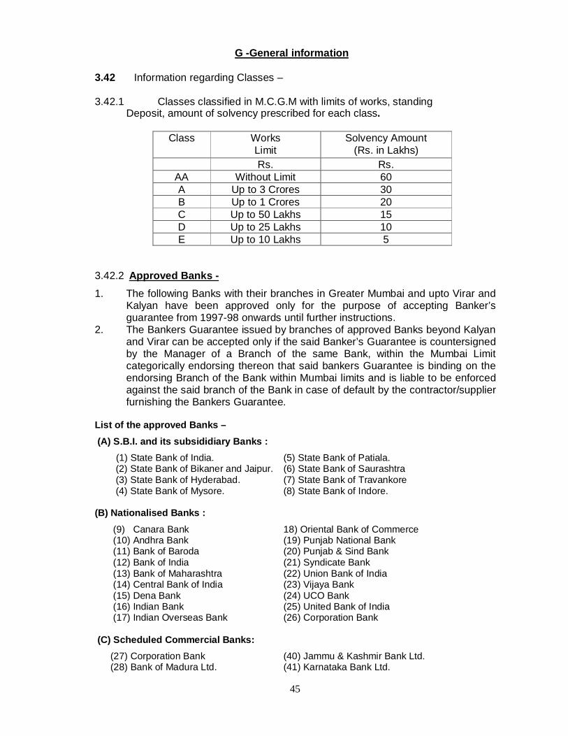
45
G -General information
3.42 Information regarding Classes –
3.42.1 Classes classified in M.C.G.M with limits of works, standing Deposit, amount of solvency prescribed for each class.
Class Works Limit
Solvency Amount (Rs. in Lakhs)
Rs. Rs. AA Without Limit 60 A Up to 3 Crores 30 B Up to 1 Crores 20 C Up to 50 Lakhs 15 D Up to 25 Lakhs 10 E Up to 10 Lakhs 5
3.42.2 Approved Banks - 1. The following Banks with their branches in Greater Mumbai and upto Virar and
Kalyan have been approved only for the purpose of accepting Banker’s guarantee from 1997-98 onwards until further instructions.
2. The Bankers Guarantee issued by branches of approved Banks beyond Kalyan and Virar can be accepted only if the said Banker’s Guarantee is countersigned by the Manager of a Branch of the same Bank, within the Mumbai Limit categorically endorsing thereon that said bankers Guarantee is binding on the endorsing Branch of the Bank within Mumbai limits and is liable to be enforced against the said branch of the Bank in case of default by the contractor/supplier furnishing the Bankers Guarantee.
List of the approved Banks – (A) S.B.I. and its subsididiary Banks :
(1) State Bank of India. (5) State Bank of Patiala. (2) State Bank of Bikaner and Jaipur. (6) State Bank of Saurashtra (3) State Bank of Hyderabad. (7) State Bank of Travankore (4) State Bank of Mysore. (8) State Bank of Indore.
(B) Nationalised Banks :
(9) Canara Bank 18) Oriental Bank of Commerce (10) Andhra Bank (19) Punjab National Bank (11) Bank of Baroda (20) Punjab & Sind Bank (12) Bank of India (21) Syndicate Bank (13) Bank of Maharashtra (22) Union Bank of India (14) Central Bank of India (23) Vijaya Bank (15) Dena Bank (24) UCO Bank (16) Indian Bank (25) United Bank of India (17) Indian Overseas Bank (26) Corporation Bank
(C) Scheduled Commercial Banks: (27) Corporation Bank (40) Jammu & Kashmir Bank Ltd. (28) Bank of Madura Ltd. (41) Karnataka Bank Ltd.

46
(29) Bank of Rajasthan Ltd. (42) Karur Vysya Bank Ltd. (20) Banaras State Bank Ltd. (42) Lakshmi Vilas bank Ltd. (21) Bharat Overseas Bank Ltd (44) Nadungadi bank Ltd. (22) Catholic Syrian Bank Ltd. (45) Ratnakar bank Ltd. (23) City Union Bank Ltd. (46) Sangli Bank Ltd. (24) Development Credit Bank (47) South Indian Bank Ltd. (25) Dhanalakshmi Bank Ltd. (48)S.B.I. Comm. & Int. Bank Ltd. (26) Federal Bank Ltd. (49)Tamilnadu Mercantile Bank Ltd. (27) Indsind Bank Ltd. (50) United Western Bank Ltd. (28) I.C.I.C.I. Banking Corporation Ltd. (51) Vysya Bank Ltd. (29) Global Trust Bank Ltd. (52) IDBI Bank Ltd.
D) Scheduled Urban Co-Op. Banks -
(53) Abhyudaya Co-op. Bank Ltd. (62) New India Co-op. bank Ltd. (54) Bassein Catholic Co-op. Bank Ltd. (63) North Canara G.S.B. Co-op. Bank Ltd. (55) Bharat Co-op. Bank Ltd. (64) Rupee Co-op Bank Ltd. (56) Bombay Mercantile Co-op. Bank Ltd(65) Sangli Urban Co-op Bank Ltd. (57) Cosmos Co-op. Bank Ltd. (66) Saraswat Co-op Bank Ltd. (58) Greater Mumbai Co-op. Bank Ltd. (67) Shamroa Vithal Co-op Bank Ltd. (59) Maharashtra State Co-op. Bank Ltd.(68) Citizen Bank Ltd. (60) Mumbai District Central Co-op. Bank(69) Mahanagar Co-op Bank Ltd.
(61) Janata Sahakari Bank Ltd. (70) Punjab & Maharashtra Co-op Bank Ltd.
(E) Foreign banks: (71) A.B.N. Amro Bank (N.V.) (77) Barclays Bank (72) American Express Bank Ltd. (78) Citi bank N.A. (73) ANZ Grindlays Bank (79) Mitsui Taiyokbe Bank Ltd. (74) Bank of America N.T. & S.A. (80) Standard Chartered Bank. (75) Bank of Tokyo Ltd. (81) Cho Hung Bank
(76) Bank Indosuez (82) H.S.B.C.
3.42.3 List of Approved Asphalt Plants:
Contractor shall arrange to bring asphalt mixes from approved plants registered with M.C.G.M., during the execution of the work. The valid list of approved asphalt plants at “the time of execution of works” to be obtained from the Dy.Ch.Engineer (Roads)City office. The Municipal Site Engineer to ensure the validity of registration certificate of asphalt plant and compliance of conditions laid down in the registration certificate issued to the asphalt plant owner before receiving asphalt mixes.
3.42.4 List of approved manufacturer of interlocking paver blocks
Contractor shall arrange to bring asphalt mixes from approved plants
registered with M.C.G.M., during the execution of the work. The valid list of approved paver blocks manufacturers plants at “the time of execution of works” to be obtained from the Dy.Ch.Engineer (Roads)City office.
The Municipal Site Engineer to ensure the validity of registration certificate of asphalt plant and compliance of conditions laid down in the registration certificate issued to the asphalt plant owner before receiving asphalt mixes.

47
3.42.5 List of approved R.M.C. Plants
Contractor shall arrange to bring RMC mixes from approved plants registered with M.C.G.M., during the execution of the work. The valid list of approved R.M.C. plants at “the time of execution of works” to be obtained from the Dy.Ch.Engineer (Rds)E.S.'s office.
The Municipal Site Engineer to ensure the validity of registration certificate of RMC plant and compliance of conditions laid down in the registration certificate issued to the RMC plant owner before receiving RMC mixes.
3.42.6 LIST OF THE APPROVED MANUFACTURERS FOR SUPPLYING M-35
GRADE PRECAST KERB STONES AND WATER TABLES
Sr. No.
Name & Address of the manufacturer
Location of RMC Plant/ Place of manufacturing
1. M/s.Surface Road Constructions, D-30/004, Yogi Vaibhav CHS Ltd., Yogi Nagar, Eksar Road, Borivali ( W), MUMBAI – 400 091. Ph.No.30903429/9821277744
Plot No.472, Opp. Text Tube Factory, Nr. Garuda Petrol Pump, Charkop Industrial Estate, Kandivili (W), MUMBAI – 400 091.
2. M/s. Unity Infraprojects Ltd. 1252, Pushpanjali Apartment, 1st floor, Old Prabhadevi Road, Prabhadevi, MUMBAI-400025.
MMRDA Plot, Phase IV, Wadala Truck Terminal, Wadala, MUMBAI - 400 034.
3. M/s.Magnum Const. C-107, Shyamkamal, Agarwal Market, Tejpal Road,Vile Parle (East), MUMBAI- 400 057.
Behind Diamond Ind. Estate, Ahead of Dahisar Toll Naka, Ketkipada, Dahisar (E), MUMBAI-
4. Relcon Infraprojects Pvt. Ltd., 105/C, Shyam Kamal, 1st floor, Agarwal Market,Vile Parle (East), MUMBAI- 400 057.
BEST Plot, Kandarpada, Dahisar (W), Mumbai,
5. M/s. Shree Constructions, 8/44, Vineet Nagar, Cotton Green, MUMBAI- 400 033.
Tembhode village, New Panvel, Dist. Raigad
Note : The valid list at the time of execution of works can be obtained from the Dy.Ch.Eng. (Roads) E.S.'s office.

48
3.42.7 LIST OF THE APPROVED MANUFACTURERS FOR SUPPLYING M-25 GRADE PRECAST FRAME & COVERS AND M 35 GRADE DIVIDERS (CENTRE MEDIAN)
Sr. No.
Name & Address of the manufacturer Location of RMC Plant/ Place of manufacturing
1. Relcon Infraprojects Pvt. Ltd., 105/C, Shyam Kamal, 1st floor, Agarwal Market, Vile Parle (East), MUMBAI- 400 057.
BEST Plot, Kandarpada, Dahisar (W), Mumbai,
2. M/s.Shree Constructions, 8/44, Vineet Nagar, Cotton Green, MUMBAI- 400 033.
Tembhode village, New Panvel, Dist. Raigad
Note : The valid list at the time of execution of works can be obtained from the Dy.Ch.Eng. (Roads) E.S.'s office. LIST OF THE APPROVED MANUFACTURERS FOR SUPPLYING FRP / GRP FRAME & COVERS
Sr. No.
Name & Address of the manufacturer Brand Name
1. M/S Thermo Poly Products (I) Pvt Ltd, Ameza plaza, C-302, 3rd floor, plot no 52, Sector 15, CBD belapur, New Mumbai – 400614.
Thermodrain
2. M/S Titan Enterprises, 44, Khanna Construction House, East wing 2nd floor, above flora Chinese restaurant, AGK road, Worali, MUMBAI-400018.
Everplast
3. M/S Parshwanath Concrete, Shop No. 5, Shivom Co Op Hsg Soc, Opp Greater Bombay Co Op Bank, Ratan Nagar, Borivali (E), Mumbai.
Parshaw
Note : The validity of the list of approved manufacturers shall be confirmed from Dy.Ch.Eng. (SWD) PC.'s office at the time of execution of works.

49
3.42.8 Dumping Grounds –
The tenderers will have to make their own provision/arrangement for dumping/disposal of desilted and excavated materials/silt and submit the list of location of plot for disposing the same with proper permission/N.O.C. of plot owner within 30 days from the issue of work order. Please note that obtaining all the necessary permissions from Govt. or any other organization for disposal of desilted and excavated material / silt on private plot is responsibility of the tenderer. Tenderers will have to make their own arrangement for leveling, rolling, transportation of the desilted and excavated materials / silt etc. at their own cost. All the necessary charges including toll etc. will have to be borne / paid by the tenderer. The payment for transportation shall be made only upto 25 km or upto MCGM limits whichever is minimum. Tenderers will have to take the cognizance of the same while quoting the tender. Any disputes / litigations regarding dumping on private plot is sole responsibility of tenderer and MCGM shall not be party for that in any case. Necessary ownership documents of private plot as required / as insisted by MCGM shall be submitted. Note:-
1. The tenderer should compulsorily install Vehicle Tracking System (VTS) with automation loading / unloading switch for vehicles transporting desilted and excavated materials / silt at their own cost. Please note that transportation payment will be made only if VTS System is working.
2. MCGM may appoint third party auditors to verify the quantity of desilted and excavated materials / silt transported / dumped on the private plot. Tenderer has to maintain records as directed by Engineer in charge / Third Party Auditors regarding dumping of desilted materials / silt on private plot.
3. Tenderer will not be allowed to select more than 3 (three) private plots for dumping / unloading the desilted and excavated material / silt.

50
Rates of testing fees and quantity of samples for tests as approved
Sr.No.
Description of test Reference Standard Rate in Rs.per test
Quantity of sample
required A AGGREGATES(COARSE & FINE) 1 Sieve Analysis(dry)/
Fineness Modulus IS 2386:Part I-1963 IS 383-1970, MORTh-4th Revision, 2001
200 20 Kg.
2 Silt Content 350 2 Kg. 3 Specific Gravity IS 2386:Part III-1963 250 1 Kg. 4 Impact Test IS 2386:Part IV- 1963,
MORTH- 4th Revision 2001
350 10 Kg. 5 Crushing Value/10% Fine
Value 400 10 Kg.
6 Los Angeles Abrasion Value
600 1 Kg.
7 Water absorption IS 2386:Part III- 1963 4th Revision 2001
250 10 Kg.
8 Flakiness Index IS 2386:Part I- 1963 4th Revision 2001
250 10 Kg. 9 Elongation Index 250 10 Kg.
10 Combined Flakiness & Elongation Index
500 20 Kg.
11 Striping test IS 6241-1971 (Reafirmed 1998)
400 5 Kg.
12 Soundness(Per Test) IS 2386 Part-V 1600 5 Kg. B ASPHALT 13 a)Asphalt Macadam/
Bituminous Macadam, Asphalt Mixes (Extraction & gradation)
IRC 27-1967 500 7 Kg. See Note-2
b) Seal Coat (Extraction & Gradation)
Specification MORTH-2001
500 3 Kg. See Note-2
14 Binder Course (Extraction Gradation Density, Voids)
Specification 825 7 Kg. See Note-2
15 Asphalt Concrete/ Bituminous Concrete/ Dense Bituminous Concrete/Polymer Modified Binder (PMB)/ Crumb Rubber Modified Binder(CRMB) (Extraction, Gradation, Density, Voids, Flow Value, Marshall Stability.
IRC 29, MORTH 2001, IRC-SP-53-1999
1400 7 Kg. See Note-2
16 Mastic Asphalt (Extraction, Gradation, Hardness No)
IS 5317-1987 IS 1195-1978
700 2 specimen each of 10 cm dia or 10 cm
square 2.5/thick cm.
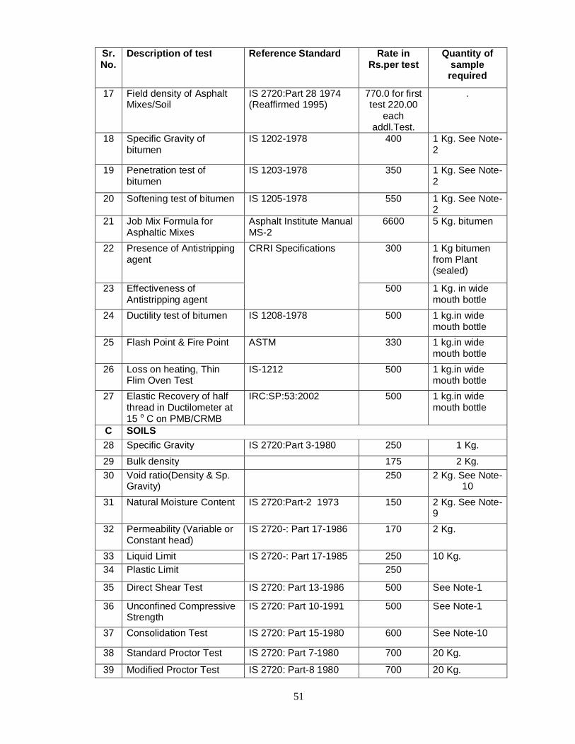
51
Sr.No.
Description of test Reference Standard Rate in Rs.per test
Quantity of sample
required
17 Field density of Asphalt Mixes/Soil
IS 2720:Part 28 1974 (Reaffirmed 1995)
770.0 for first test 220.00
each addl.Test.
.
18 Specific Gravity of bitumen
IS 1202-1978 400 1 Kg. See Note-2
19 Penetration test of bitumen
IS 1203-1978 350 1 Kg. See Note-2
20 Softening test of bitumen IS 1205-1978 550 1 Kg. See Note-2
21 Job Mix Formula for Asphaltic Mixes
Asphalt Institute Manual MS-2
6600 5 Kg. bitumen
22 Presence of Antistripping agent
CRRI Specifications 300 1 Kg bitumen from Plant (sealed)
23 Effectiveness of Antistripping agent
500 1 Kg. in wide mouth bottle
24 Ductility test of bitumen IS 1208-1978 500 1 kg.in wide mouth bottle
25 Flash Point & Fire Point ASTM 330 1 kg.in wide mouth bottle
26 Loss on heating, Thin Flim Oven Test
IS-1212 500 1 kg.in wide mouth bottle
27 Elastic Recovery of half thread in Ductilometer at 15 o C on PMB/CRMB
IRC:SP:53:2002 500 1 kg.in wide mouth bottle
C SOILS 28 Specific Gravity IS 2720:Part 3-1980 250 1 Kg.
29 Bulk density 175 2 Kg. 30 Void ratio(Density & Sp.
Gravity) 250 2 Kg. See Note-
10 31 Natural Moisture Content IS 2720:Part-2 1973 150 2 Kg. See Note-
9 32 Permeability (Variable or
Constant head) IS 2720-: Part 17-1986 170 2 Kg.
33 Liquid Limit IS 2720-: Part 17-1985 250 10 Kg. 34 Plastic Limit 250
35 Direct Shear Test IS 2720: Part 13-1986 500 See Note-1
36 Unconfined Compressive Strength
IS 2720: Part 10-1991 500 See Note-1
37 Consolidation Test IS 2720: Part 15-1980 600 See Note-10
38 Standard Proctor Test IS 2720: Part 7-1980 700 20 Kg.
39 Modified Proctor Test IS 2720: Part-8 1980 700 20 Kg.

52
Sr.No.
Description of test Reference Standard Rate in Rs.per test
Quantity of sample required
40 Laboratory C.B.R. Test IS 2720: Part 16-1987 1200 25 Kg.
41 Dry Sieve Analysis IS 2720: Part 15- 1980 200 25 Kg. 42 Wet Sieve Analysis 250 10 Kg. 43 Field C.B.R. Test IS 2720:Part 31, 1990 770.00 for
first test and Rs.330.00 for each addl.test
44 Site visit for S.B.C. ---- 700.00 for first pit and Rs.300.00 for each addl.pit
D BUILDING MATERIALS CEMENT
45 Cement (Initial & Final Setting time, Compressive Strength)
IS 269, IS 8112, IS 12269
975 5 Kg. See Note-6
46 Soundness of cement IS 4031 (Part-III)-988 280 BRICKS
47 (a) Bricks (Set of Ten) (Compression Test, Absorption Test)
IS 1077-1986 650 10 Nos.
(b) Autoclaved Cellular Concrete Blocks (Siporex) (i) Compression Test (ii) Density in oven dry condition
IS -6441(Part-V) IS-6441(Part-I)
300 200
3 Nos cube of 15 cm or 10 cm 3 Nos 100 mm x 200 mm x 50 mm
STEEL 48 Steel bars (6 mm dia to
20 mm dia) (Area on Weight basis, Yield Stress/0.02% Proof Stress, Ultimate Tensile Strength % Elongation)
IS 432-1986 IS-1786-1985
600 60 cm. see Note 1 (c)7
49 Steel bars (above 20 mm dia ) (Area on Weight basis, Yield Stress/0.02% Proof Stress, Ultimate Tensile Strength % Elongation)
800 60 cm. see Note 1 (c)7
CONCRETE 50 Concrete Cube
(Compressive Strength IS 456-2000, IS 516-1959
300 3 Nos. See Note 1(c )
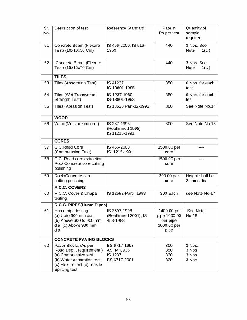
53
Sr.No.
Description of test Reference Standard Rate in Rs.per test
Quantity of sample required
51 Concrete Beam (Flexure Test) (10x10x50 Cm)
IS 456-2000, IS 516-1959
440 3 Nos. See Note 1(c )
52 Concrete Beam (Flexure Test) (15x15x70 Cm)
440 3 Nos. See Note 1(c )
TILES 53 Tiles (Absorption Test) IS 41237
IS-13801-1985 350 6 Nos. for each
test 54 Tiles (Wet Transverse
Strength Test) IS-1237-1980 IS-13801-1993
350 6 Nos. for each tes
55 Tiles (Abrasion Test) IS 13630 Part-12-1993 800 See Note No.14
WOOD 56 Wood(Moisture content) IS 287-1993
(Reaffirmed 1998) IS 11215-1991
300 See Note No.13
CORES 57 C.C.Road Core
(Compression Test) IS 456-2000 IS11215-1991
1500.00 per core
----
58 C.C. Road core extraction Roc/ Concrete core cutting polishing
1500.00 per core
----
59 Rock/Concrete core cutting polishing
300.00 per core
Height shall be 2 times dia
R.C.C. COVERS 60 R.C.C. Cover & Dhapa
testing IS 12592-Part-I 1998 300 Each see Note No-17
R.C.C. PIPES(Hume Pipes) 61 Hume pipe testing
(a) Upto 600 mm dia (b) Above 600 to 900 mm dia (c) Above 900 mm dia
IS 3597-1998 (Reaffirmed 2001), IS 458-1988
1400.00 per pipe 1600.00
per pipe 1800.00 per
pipe
See Note No.18
CONCRETE PAVING BLOCKS 62 Paver Blocks (As per
Road Dept., requirement ) (a) Compressive test (b) Water absorption test (c) Flexure test (d)Tensile Splitting test
BS 6717-1993 ASTM C936 IS 1237 BS 6717-2001
300 350 330 330
3 Nos. 3 Nos 3 Nos. 3 Nos.

54
Sr.No.
Description of test Reference Standard Rate in Rs.per test
Quantity of sample required
63 Paver Blocks (As per Road Dept., requirement) (a) Water absorption test (b) Compressive test (c) Flexure test (d)Tensile Splitting test (e) Abrasion Test (Dry or wet condition)
IS-15658 350 800 800 800 800
3 Nos. 8 Nos 8 Nos. 8 Nos. 8 Nos. (see Note No.19)
OTHER CHARGES 64 Duplicate additional copy
of test report not older than 5 years
25.00 per copy
Note: The aforesaid Testing charges are as per Circular issued by Ch.E (Vig) U/no Ch.E(V)/1142/B dtd 25/07/2007. The same may vary as per circular issued in this reagrd by Ch.E(Vig) of MCGM from time to time.

55
SECTION - 4
GENERAL CONDITIONS OF
CONTRACT

56
4. GENERAL CONDITIONS OF CONTRACT
Copies of General Conditions Contract :
Copies of General Conditions of Contract (G.C.C.) effective from 01.04.2000 are
available in the office of the Dy.Chief Engineer (SWD) City / Western / Eastern Subs.
in office hours on payment of Rs. 1000/- + 5% VAT in cash for each.
Tenderers shall note that if the conditions of G.C.C. are in variance with the conditions
contained in the tender document, the conditions of the tender document shall prevail.
If it is observed that Contractors carrying out the work fail to comply with the
instructions given by the A.M.C./M.C. during execution of work twice, the work shall be
deemed to have been terminated and will be carried out at the risk and cost of the
Contractors and penal action will be taken against them. This decision shall not be
arbitrable at all.
The above condition will be in addition to the relevant conditions in General Conditions
of Contract (G.C.C) regarding cancellation of full or part of the work, finality of the
decisions on the disputes, differences or claims raised by the Contractors relating to
any matter arising out of the contract.
The total Security Deposit shall be 10% till completion of Defects Liability Period which
comprises of 2% contract deposit, 5% Retention Money and 3% Performance
Guarantee. On successful completion of work, by withholding Rs.5.0 lacs, balance
retention amount shall be released against submission of Bank Guarantee valid up to
Defect Liability Period. The BG will not be accepted in broken period and same will be
of one complete BG of entire period of DLP.
. The clause no. 73(a) and 73 (b) of G.C.C. for Civil Works, which now will stand modified as described below:-

57
Amended provisions of G.C.C.
73(a)(i) Rates for excess The contractor shall arrive at the rates after carefully preparing the rate analysis taking into consideration site conditions. For increase up to any limit during the contract period over the quantity shown in the Bill of Quantities shall be paid at the rate mentioned in the Bill of Quantities by adding or subtracting the percentage quoted by the contractor.
73(a)(ii)
In the case of item rate tender the price shall be worked out as per 73(b)(iv)
73(b) Rates for extra
Rates for such additional, altered or substituted item of work shall be determined as follows:-
(i) If rate for additional, altered or substituted item of work is specified in the Bill of Quantity and rates, the contractor shall carry out the additional, altered or substituted item at the same rate mentioned in the Bill of Quantities by adding or subtracting the percentage quoted by the contractors.
(ii) If the rate for any additional, altered or substituted item of work is not included in the Bill of Quantity and rates but if such item exists in the relevant Fair Market Schedule applicable at the time of invitation of tender, such item of work shall be carried out at the Fair Market Schedule rates applicable at the time of tender by adding or subtracting the percentage quoted by the contractor.
(iii) If the rate for any additional, altered or substituted item of work is not included in the Bill of Quantity and rates and if such item of work does not exist in the relevant Fair Marked Schedule applicable at the time of invitation of tender, such item of work shall be carried out at the relevant Corporation’s Fair Market Schedule rates prevailing at the time of extra work subject to deducting the rebate quoted by the contractor. If however, the contractor has quoted premium, such item of work shall be paid “at par”.
(iv) If the rates for any additional, altered or substituted item of work cannot be determined in the manner specified in (i), (ii) and (iii) above, then the contractor will be paid at such fair and reasonable rates as worked out by the Engineer on the basis of material, labour and operations of construction equipment required to execute the item and allowing 15% to cover profits and overhead charges.

58
SECTION - 5
SPECIAL CONDITIONS
OF CONTRACT

59
5 - SPECIAL CONDITIONS OF CONTRACT
1) The Tenderer/ Contractor shall note that this contract envisages following works in general -
2) The representative of the Engineer for this work will be from the offices of
respective Dy. Chief Engineer (SWD). 3) Detailed plans will be available for inspection in the office of respective
Deputy Chief Engineer (SWD) 4) The contract period is including period required for mobilization, procurement
of material, traffic permission, NOC from Land owning authorities , also other required permission viz. erection of site office etc. and shall be reckoned from the date of issue of work order.
5) The Contractor should simultaneously work at number of places or more and complete the work within contract period.
6) The contractors will have to obtain permission from the land owner/Land owning authorities etc, well in advance before commencement of work through their premises for execution of the work by displaying appropriate boards. The work may be required to be executed in phases as per respective authority permission. The contractors should therefore take this factor in to account while quoting.
7) Programme of work: If at any stage the previously approved programme is required to be modified the contractors shall do so immediately as directed by the Engineer. If it is necessary to close some phase of the work and start a new phase as directed the tenderer do so without claiming any extra payment. The programme shall be reviewed periodically and rescheduled as directed.
8) All material required for the work can be stacked near the site of work in such manner so as not to cause any inconvenience to the pedestrian and vehicular traffic. If no space is available on site then tenderer shall make his own arrangement for stacking of material etc. No extra payment will be made on this account.
9) The Contractor shall maintain smooth flow of storm water in nalla/ S.W.D through out contract period by way of desilting as directed and it is payable.
10) No extra payment shall be admissible for dewatering the trenches, carrying the material by head load transport or approaches to the work site.
11) The contractors will have to obtain water connection for drinking purposes as per conditions in G.C.C. Extra water required for construction purposes will have to be brought by the contractors at his own cost and no extra claims on this behalf will be entertained.
12) The Tenderer/ Contractor shall note that first class quality of material & workmanship is expected.
13) Quantities of all items provided in the B.O.Q. may not be required to be executed depending upon the site conditions. The tenderer shall not be entitled for any compensation on this account. Before starting the work
i) Construction of New Nallas as per the alignment shown in typical Drawing. However the same may vary in accordance with the site condition and as directed by the site–in-charge.
ii) Construction of Access road abutting to nalla if required. iii) Construction / Remodeling of existing culverts if required iv) Reconstruction of collapsed existing Nalla walls, etc.
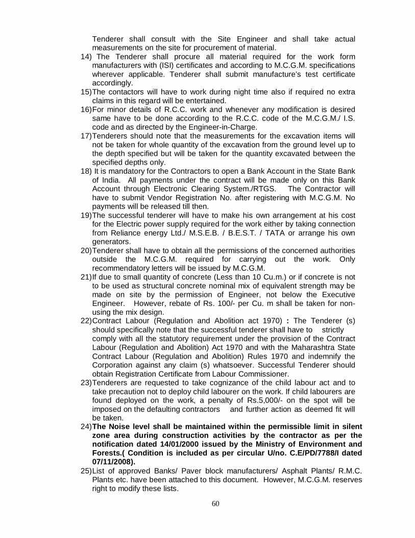
60
Tenderer shall consult with the Site Engineer and shall take actual measurements on the site for procurement of material.
14) The Tenderer shall procure all material required for the work form manufacturers with (ISI) certificates and according to M.C.G.M. specifications wherever applicable. Tenderer shall submit manufacture’s test certificate accordingly.
15) The contactors will have to work during night time also if required no extra claims in this regard will be entertained.
16) For minor details of R.C.C. work and whenever any modification is desired same have to be done according to the R.C.C. code of the M.C.G.M./ I.S. code and as directed by the Engineer-in-Charge.
17) Tenderers should note that the measurements for the excavation items will not be taken for whole quantity of the excavation from the ground level up to the depth specified but will be taken for the quantity excavated between the specified depths only.
18) It is mandatory for the Contractors to open a Bank Account in the State Bank of India. All payments under the contract will be made only on this Bank Account through Electronic Clearing System./RTGS. The Contractor will have to submit Vendor Registration No. after registering with M.C.G.M. No payments will be released till then.
19) The successful tenderer will have to make his own arrangement at his cost for the Electric power supply required for the work either by taking connection from Reliance energy Ltd./ M.S.E.B. / B.E.S.T. / TATA or arrange his own generators.
20) Tenderer shall have to obtain all the permissions of the concerned authorities outside the M.C.G.M. required for carrying out the work. Only recommendatory letters will be issued by M.C.G.M.
21) If due to small quantity of concrete (Less than 10 Cu.m.) or if concrete is not to be used as structural concrete nominal mix of equivalent strength may be made on site by the permission of Engineer, not below the Executive Engineer. However, rebate of Rs. 100/- per Cu. m shall be taken for non-using the mix design.
22) Contract Labour (Regulation and Abolition act 1970) : The Tenderer (s) should specifically note that the successful tenderer shall have to strictly comply with all the statutory requirement under the provision of the Contract Labour (Regulation and Abolition) Act 1970 and with the Maharashtra State Contract Labour (Regulation and Abolition) Rules 1970 and indemnify the Corporation against any claim (s) whatsoever. Successful Tenderer should obtain Registration Certificate from Labour Commissioner.
23) Tenderers are requested to take cognizance of the child labour act and to take precaution not to deploy child labourer on the work. If child labourers are found deployed on the work, a penalty of Rs.5,000/- on the spot will be imposed on the defaulting contractors and further action as deemed fit will be taken.
24) The Noise level shall be maintained within the permissible limit in silent zone area during construction activities by the contractor as per the notification dated 14/01/2000 issued by the Ministry of Environment and Forests.( Condition is included as per circular U/no. C.E/PD/7788/I dated 07/11/2008).
25) List of approved Banks/ Paver block manufacturers/ Asphalt Plants/ R.M.C. Plants etc. have been attached to this document. However, M.C.G.M. reserves right to modify these lists.

61
25.1) All the asphalt works required to be done under the captioned contract shall be got executed with the specified asphalt mixes manufactured in M.C.G.M. approved asphalt plants only.
25.2) All the Paver blocks/ Kerb stones/ Water tables/ Frame & covers required for the works to be carried out under the captioned contract shall be procured from the specified manufacturers registered with M.C.G.M. only.
25.3) The R.M.C. works required to be done under the captioned contract shall be got executed with the specified R M C mixes supplied by M.C.G.M. approved R.M.C. plants
25.4) The Mastic Asphalt work will be got done through the specialized agencies having expertise in Mastic Asphalt work.
26) While constructing/improving footpath, provision for slopping ramp of atleast 1.00 m width or as directed, shall be made at every carriage entrance, junctions, bus stops etc., for convenience of physically challenged persons.
27) The full time services of the Personnel Team of the contractor is mandatory during the entire period of the project.
28) The site shall be cleared by removing all surplus material on or before 31st May of every year.
29) If the contractor excavates certain portion of the road and fails to reinstate the same within the stipulated time limit, as per the programme and or before 31st of May, the reinstatement will be got carried out at contractor’s risk and cost through other agency in addition to further penal action.
30) All the excavated material belongs to the Municipal Corporation of Brihan Mumbai & therefore shall be the property of Municipal Corporation of Brihan Mumbai. It will be mandatory on the part of contractor to use this material in the execution of works under contract if the quality of material available is as per the specification. “The contractor shall have to dump the surplus excavated material as directed by the Engineer-in-charge. The contractors shall have to submit to the site staff the receipts from the staff of the receiving dumping ground acknowledging receipt of the material. If the specific requests are received from zonal DMCs for the filling up low lying municipal plots of their wards with surplus excavated material the site staff may direct the contractors to dump the surplus material to those municipal plots. The acknowledgement receipts shall be given by the representative of concerned Assistant Commissioner of the respective ward. In case of non availability of Municipal Dumping ground, the contractor will have to arrange for their own private dumping ground within or out side M.C.G.M. limit and surplus excavated material will have to be disposed off to such private dumping ground. M.C.G.M. will pay the transportation charges after deduction for voids and according to the distance of dumping ground from site of work for a maximum distance of 25km or upto MCGM limit whichever is minimum. However if private dumping plot is situated beyond 25km then maximum distance considered for payment will be 25km or upto MCGM limit whichever is minimum. Contractor will have to submit the permission of private plot owner for dumping surplus earth.
31) Any dispute/litigation regarding dumping on private plot is sole responsibility of tenderer and MCGM shall not be party for that in any case. The necessary ownership documents of private plot as required/ as insisted by MCGM shall be submitted.
32) The tenderer should compulsorily install vehicles tracking system (VTS System) with automation loading/unloading switch for vehicles transporting surplus excavated material/silt at their own cost. Please note that payment for

62
transporting surplus excavated material/silt will be made only if VTS system is working. The dumpers carrying the excavated material will directly report at private computerized weighing bridge on the way of transportation or convenient to the tenderer. The dumper will be weighed loaded as well as empty. The charges for weighing the loaded as well as empty dumpers at private weigh bridge will be borne by the contractor.
33) As per revised policy of M.C.G.M., Contractors will be charged for tipping excess earth / material @ the rate of Rs. 1000/- per trip or prevailing charges during execution of work only if M.C.G.M. dumping ground is made available to the contractor. However, tipping charges including weighing the same shall have to be borne by the tenderers for which no payment / reimbursement will be made. Considering these charges, tenderers shall quote their percentage accordingly.
34) The contractor should note that during the execution of the work, debris etc, dumped on the public streets / places will have to be removed immediately after completion of the work as per direction of the Engineer failing which the same will be got removed at their risk and cost.
35) The work will be treated as completed only after cleaning the site in all respect after completion of the work.
36) Tenderer should maintain the asphalt road stretches after reinstatement in traffic worthy conditions during monsoon free of cost by using asphalt mixes during the course of work.
37) The contractors shall display the boards giving information of name of the work, date of starting completion, Name of the department and contact telephone numbers. Non-compliance of this condition a penalty of Rs. 1000/- per day per site shall be imposed on contractor.
38) The contractor shall take photographs of site as and when directed by Engineer. The Photographs should be so arranged in the Register that original site position and finished site position of the same location should be vis-à-vis. The register should be duly signed by site-in-charge and contractor fortnightly. Failure to abide this condition of Rs. 1000/- per photograph copy will be recovered from the contractor`s bill.
39) On Completion of the work, the contractors shall furnish free of cost 2 sets of final completion drawings in AutoCAD along with the soft copy in CD, showing all the details checked and signed by the Engineer within 2 months of completion of works. The payment of final bill shall be made to the contractors after receipt of above sets. In case the contractors fail to submit the completion drawings, the same shall be got done through outside agency and cost of the same shall be recovered from the contractor along with the penalty of Rs. 5,000/- per drawing (applicable for only identified works.)
40) All trenches taken in connection with the work should be sufficiently barricaded, as specified. If barricading is not provided a penalty of Rs. 1000/-per day for every 10.0 m stretches will be imposed.
41) Tenderers should note since the work is to be completed expeditiously The work should be in progress at several points along the length of the nalla.
The contractor should put in sufficient resources so as to ensure that the work is completed within the prescribed time period. Time is the essence of the contract. For this purpose, the tenderers may be required to submit a PERT CHART showing the proposed schedule on which basis they intend to execute the work within the prescribed time period. The contractor will have to submit BAR CHART, PERT Chart within 15 days from the issue of work order failing which a penalty of Rs. 2000/- per day will be imposed to the contractors.

63
42) (a) The quantities mentioned in the Bill of Quantities have been worked out by adding the estimated quantities for each individual work mentioned in the tender document.
( b) Any excess or saving in any item will be considered on total quantities included in the Bill of Quantity of that item in the tender documents.
43) The contractors should carry out if required any minor works pertaining to S.W.D. works, as may be decided by the Engineer-in-charge any where in the ward limit where the work is in progress under contract at the rates included in the Bill of Quantities of the above work with his percentage quoted.
44) The payment for excavation shall be made on cross sectional basis. Before starting the work initial levels will be taken at every 5 m to 2 m or less depending on site conditions along the entire length of the proposed work levels at every 1.50 m to 2m minimum would be taken along the width of the section. The excavation quantity would be computed on the basis of levels thus taken by resorting the Prismoidal Formula or as directed by the Engineer-in-charge in case of encroachment and other structures. For establishing the datum line the average of the two end points of the ultimate cross-section required for excavation work will be considered.
45) Contractor should remove cofferdams constructed along / across the nalla before 15th May or as and when directed by engineer to keep the flow of storm water in the nalla unobstructed.
46) The contractors are also required to reconstruct the cofferdam if required / directed by the Engineer to complete the balance work. No extra payment on this account will be made.
47) The proposed width for excavation of trenches for various sizes of pipes will be as shown in table at Condition No.6.5.2.
48) R.C.C. pipes to have used on site shall be as per specifications mentioned in the Tender and shall be procured from the Company Registered with M.C.G.M.
49) PENALTY CLAUSES :- 47.1 Penalties:
The Engineer not below the rank of Assistant Engineer is entitled to impose a penalty of Rs. 2500/- per day for each defective work/lapse, disobedience of orders of the officer not below the rank of Site Engineer. Penalty amount will be recovered form contractors running bill. This penalty is over and above Penalty mentioned under G.C.C. clause No. 100.
If it is observed that, the contractor carrying out the work fails to comply with the instructions given by the authorities at the A.M.C./M.C.'s level during execution of work twice, the work will be terminated and will be carried out at the risk and cost of the contractor and penal action will be taken against them. This decision will not be arbitrable at all. The abovementioned condition will be in addition to the provision of relevant condition in the General Condition of contract.
47.2 Respect for work dates: Time is the essence of the contract and the work dates decided by the
MCGM shall be binding on the Bidder. No variation of scheduled dates shall be permitted except in exceptional cases for which prior written authorization from MCGM is necessary.
64
In the event of any delay on the part of the Bidder to adhere to the Contract, MCGM shall be entitled at its option to recover from the Bidder as agreed liquidated damages which shall not be way of penalty but shall be genuine pre-estimate of the losses that MCGM shall incur, a sum of 0.5% of the price of the total Contact Cost for each week or part thereof by which the delivery has been delayed work subject however to a limit of 10% of total contract cost without prejudice to MCGM’s other rights mentioned in the Contract.
47.3 Other Penalties: In addition to any penal action under the General Conditions of Individual Contracts, a registered contractor will be liable under the registration Rule to one or More of the following penalties:
(i) Warning / Fine (ii) Demotion (iii) Deregistration
(i)Warning / Penalties
A Contractor will be liable to a warning and / or penalty for a) Non-compliance of any provision of the rules. b) Failure to comply with any clause or direction under these rules
or comply with any conditions of tenders / contracts. a) In adequate progress/ performance under the contract.
For the first default of any type mentioned above a warning will be issued. For each subsequent default of the types in (a) & (b) above the minimum penalty will be fine of Rs. 2,500/- while that for a default of the type (c) The minimum penalty will be Rs. 5,000/- for contracts of upto Rs. 25 Lakhs and Rs. 10,000/- for contracts of above Rs. 25 lakhs. Higher Amount of penalty shall be levied by the competent authority for reasons to be recorded. (ii) Demotion A contractor will be liable to be demoted to a lower class of registration on any of the following grounds: (a) Specific failure or default in execution of individual works in respect of
physical progress for qualify of such works. (b) Inadequate performance as revealed by quarterly performance report. (c) Deterioration in financial or technical ability / capacity (d) Repeated failure to fill in tender documents fully and correctly or delay in
execution of formal contract documents. (iii)Deregistration.
A contractor will be liable to be deregistered on any of the following grounds. a) Attempt to defraud the Corporation.

65
b) Attempt to bribe any employee / officer of corporation. c) Attempt to secure a contract through unfair means or by bringing to bear out
side influence. d) Attempt to secure unauthorized copies of Municipal Records, any documents
in relation to any tender/ contract or any other official matter. e) Furnishing or tempered with Municipal record and documents. f) Furnishing false and / or misleading information to registration and / or any
tender / contract. g) Threatening, Misbehaving with or physical attack on any Municipal
Employees/ Officer. h) Attempt to instigate or collude with other contractors with a view to securing
undue advantage. i) Any of the grounds mentioned in 47.3(ii)b, if it is deemed to serious enough.
50) If a registered contractor (a firm, partnership or company) is deregistered, then
any other registered contractor (a firms partnership or company), with any partner or shareholder who is also a partner or shareholder or a “spouse” of such partner or shareholder of the deregistered contractor shall also stand automatically deregistered.
51) Demotion shall be restricted to one class immediately below the existing class of registration, Demotion from the lowest class of registration will amount to deregistration.
52) Demotion and deregistration shall apply to all the classes, categories and disciplines under which the contractor is registered and will be valid for the remaining period of the contractors current period or registration or the period specified in the order of demotion, deregistration/ whichever is longer.
53) A deregistered contractor shall not be entitled to be issued any tender document / or quotations for any M.C.G.M. works. Such contractors shall also not be entitled to apply and be considered for renewal of registration or fresh registration at the expiry of period of deregistration. Similarly a demoted contractor shall not be entitled to apply and be considered for renewal / fresh registration in a class higher than that to which he was demoted.
54) AUTHORITY :
i. A Chief Engineer (Including City/Hydraulic Engineer) of M.C.G.M. will be
competent either sue motto or on the basis of reports received, to issue warning to impose fine on and order demotion of a contractor.
ii. The registration Committee constituted under these rules will be competent either sue motto or on the basis of reports received, to impose on a contractor any of the penalties mentioned in the tender.
iii. The Municipal Commissioner or any of the Additional Municipal Commissioners will be competent, either sue motto or on the basis of reports received to impose on a contractor any of the penalties mentioned in the tender.
55) It will be the responsibility of the contractors to arrange for a joint inspection
by 15th May every year after completion of the work till the expiry of defect liability period and also 4 weeks before expiry of the defect liability period. Further, if the contractor fails to do so, the observations made by the staff during site inspection will be considered for the purpose of noting the defects.

66
56) In super session of clause 96 of G.C.C., the following conditions shall apply: -
If any dispute, difference or claim is raised by either party relating to any matter arising out of the contract, the aggrieved party within a period of seven days can appeal to the concerned Addl. Municipal Commissioner who shall constitute a committee comprising of three officers i.e. the concerned Dy. Municipal Commissioner or Director (E.S.& P.), Chief Engineer other than the Engineer of the Contract and the concerned Chief Accountant. The Committee shall give its decision in writing within 60 days of its formation, after giving at least one hearing to the contractors.
Appeal against the order of the Committee may be referred to the Municipal
Commissioner within seven days. Thereafter, the Municipal Commissioner shall constitute a Committee comprising of three Addl. Municipal Commissioners including the Addl. Municipal Commissioners in charge of Finance Department and an expert from outside M.C.G.M. The Committee shall give at least one hearing to the contractors. The decision shall be given within 60 days. The decision given by this Committee shall be final and binding upon the parties.
55) Temporary huts for the labourers’ huts for the S.W.Drains work may be permitted
on work site in consultation with the respective Assistant Commissioners and subject to the following conditions or any other condition imposed by the Asstt. Commissioner.
i) The labourers hutments will be completely isolated from the public by
providing a tin sheet fencing around them. ii) They will be specifically identified by M.C.G.M. staff by numbering them
suitably. iii) Adequate toilet and bathing facilities will be provided for them inside this
fencing. iv) The contractors will strictly observe that labourers will use these toilets
and bathing facilities and no unhygienic conditions are created at site. v) In case, any of the above conditions is violated such hutments will be
removed by the Assistant Commissioner without giving any notice to the contractor in consultation with the Executive Engineer in charge of the work.
vi) The labourers hutments will be removed by the contactors within 7 days or the completion of the work or the last day of the month of May whichever is earlier.
vii) The contractor has to check healths of all the labours employed by him at every fortnight and take precautionary measures and treatments as per advise of medical officer. If record is not maintained, penalty of Rs.1000/- per labour will be imposed.
56) Price Variation –
i) Price variation shall be permitted for the following material. The basic rates applicable to this tender are as per Annexure-‘A’ in section-7.
(1) Cement - Rs. 6,000/MT. (2) Steel Fe-415 - Rs. 48,400/- per M.T. (3) Bitumen - a) 30/40 Rs. 31240.95 per M.T.
- b) 60/70 Rs. 30121.07 per M.T.

67
Any variation in the rates of above materials shall be considered for reimbursement/ refund, as the case may be, in accordance with G.R.P.W.D. No. CAT/06/04/148 dt. 16.05.2005. The quantity of material to be used shall be evaluated as per minimum specified requirement. However, price variation shall not be admissible beyond theoretical date of completion of contract period, as also for the fair items created during execution. The said variation shall be applicable only for Asphalt & Concrete mixes procured and brought on sight from Plants and for steel being paid separately as item in BOQ. ii) The price variation for labour and other materials (excluding (1),(2),(3)
above), shall be considered as per amended clause No. 4B of G.C.C. iii) However, maximum amount of price variation payable for (i) and (ii) above
shall be restricted to 5% of the contract cost.
57) Tenderer shall note that no extra payment shall be made for carrying out filling / constructing coffer dam / carrying out preparatory works like excavation, dewatering, compaction, access road, working platform etc. in / adjacent to nalla / river to facilitate implementation of piling works / construction of side walls and the quoted rates of tenderer shall be deemed to include carrying out all temporary works etc. and removal of all temporary works after completion of construction to the entire satisfaction of the Engineer-in-charge or before 15th May, whichever is earlier.
58) Directives of Hon. Court shall be followed while desilting of the nallas in the vicinity of Mangrooves under the same terms and condition of contract for which no extra payment shall be paid to the contractor.
59) It is required to prepare structural design of the nalla retaining wall / R.C.C. work as per the site conditions. Contractors shall have to appoint licensed Structural Engineer / R.C.C. Consultant at his own cost to prepare the structural designs based on tender items conditions and get the design approval from the department of M.C.G.M. The expenditure on this account will be deemed to have been considered in the rates quoted by the tenderers.
60) The tenderers shall carry out subsoil exploration / investigations at the site at his own cost wherever required. Expenditure on this account will be deemed to have been considered in the rate quoted by the tenderers.
61) Any recommendation / alteration in the work as per decision of Competent Authority of M.C.G.M. shall have to be executed under the same tender conditions.
62) No claim shall be entertained on account of delay in removal of encroachment. 63) If the alignment of nalla retaining wall is affected by mangroves. The orders in
cases pending in various courts in regard shall be binding on the contractors. The tenderers can not claim any damages / compensation etc. for delay or cancellation of the work or part thereof. This fact shall be kept in mind while quoting for tender.
64) It is observed that Contractors carrying out the work fail to comply with the instructions given by the A.M.C./M.C. during execution of work twice, the work shall be deemed to have been terminated and will be carried out at the risk and cost of the Contractors and penal action will be taken against them. This decision shall not be arbitrable at all.
65) The above condition will be in addition to the relevant conditions in General Conditions of Contract regarding cancellation of full or part of the work, finality of the decisions on the disputes, differences or claims raised by the Contractors relating to any matter arising out of the contract.

68
66) If concrete surface Finish of work is not as per specified class of finish (i.e F1,F2 ..etc.) and honeycombing is observed in the surface, penalty of Rs. 5000/- per Sq.m. will be imposed.
67) Any recommendation / alteration in the work as per decision of Competent Authority of M.C.G.M. shall have to be executed under the same tender conditions.
68) The contractor shall implement anti-malarial measures for each site during execution of works in case of failure to implement above measures a penalty of Rs.5000/- per day per personnel shall be imposed.
69) The contractors will have to obtain permission from the traffic police department well in advance either for closing down the road stretch or for diversion of traffic for execution of the work by displaying appropriate boards. The work may be required to be executed in phases as per traffic police permission. The contractors should therefore take this factor in to account while quoting.
70) The guide wall of iron channels / brick masonry wall of sufficient section height shall be constructed to guide touch piles/meter panels for which no extra payment shall be made. If longitudinal alignment of the touch pile/meter panel differ more than 50 mm a penalty of Rs. 5000/- per meter depth of pile / meter panel will be imposed.
71) The tenderers should note that the work shall be carried out preferably during day time i.e. from 10.00 am to 05.00 pm only.
72) As per the provision made in the Article 63, schedule –I of Bombay Stamp Duty Act-1958, Stamp duty is payable for ‘Work Contract’, i.e. to say, a contract for works and labours of services inviting transfer of property in goods (Whether as good or in some form) in its execution and includes a sub contract as under,
73) The contractors shall get the structures demolished from concerned Asst.
Commissioner of ward for necessary working place to be made available for the subject work.
74) If the tenderer(s) withdraw tender offer during the tender validity period, his
E.M.D shall be forfeited. If tenderer fails to submit Packet ‘C’ physically and online, the entire amount of EMD shall be forfeited.
75) Contractor shall have to execute the additional work to the extent of 15% over
and above the office estimate (as shown in the bill of quantities) at the quoated percentage, terms and conditions of the contract, within the contract period, as directed by Ch.E(SWD).
76) Even though the Contractor takes all the precautionary measures and by
chance any workman is injured or dies due to negligence or otherwise, the Contractor will be responsible for the claims of damages by the workman or his legal heirs.
a. When the amount of such set forth in such contract does not exceed Rupees ten Lakhs.
Rupees one thousand stamp duty.
b. When it exceeds Rupees ten Lakhs Rupees One hundred for every Rupees one lakh subject to maximum Rupees five lakhs stamp duty.

69
77) The Contractor has to check health of all the labourers employed by him at
every fortnight and take precautionary measures and treatment as per the advice of Medical Officer. If record is not maintained by the Contractor, penalty of Rs. 1000/- per labour will be imposed.
78) The design of R.C.C. / structural work shall be obtained from Licensed
Structural Engineer at the cost of the Tenderer.
79) Minimum payable amount to be retained in final bill is as under:- Sr. No.
Amount of Contract Cost
Minimum Payable Amount in final Bill
1 Upto Rs. 5 Crs. - Rs. 10 Lacs or final bill amount whichever is more. 2 Upto Rs. 25 Crs. - Rs. 1 Crore or final bill amount whichever is more. 3 Upto Rs. 50 Crs. - Rs. 2 Crore or final bill amount whichever is more. 4 Upto Rs.100 Crs. - Rs. 4 Crore or final bill amount whichever is more. 5 More than Rs.
100 Crs. - Rs. 7 Crore or final bill amount whichever is more.
80) Special clause for Cement concrete /Asphalting works:
The tenderer must comply following machinery with installation before
quoting and should remember that the cost of installation shall be taken into account while quoting their percentage:
Particulars
Intelligent Compaction system - compatible for L&T, Escort, JCB, Greaves make Compactors Agent Software for Compactor Batch Mix Plant Scada Automation Software Agent Batch Mix Plant connectivity RMC plant Automation with SCADA Software agent RMC plant connectivity Vehicle Tracking System with automation loading unloading Switch Vehicle Tracking System Per month Subscription charges SCADA automation for ICPB factory.
80.1 Asphalt /Concrete mixing Plant The contractor shall provide RMC/Asphalt Plant/Paver Blocks Plant of min capacity as per clause 3.2.3(VI)B The RMC plant /hot mixing plant /P.B.Plant shall sense data like aggregate weight and temperature batches through digital sensors & logic controller. The contractor shall provide a SCADA based data reader & logging software to collect the sensed data from the logic controller & convert it into machine readable file with date and time stamp. The particular file shall contain the work identification number of the works management e-

70
governance software the contractor shall provide the web connectivity to the RMC /asphalt plant and software that will send the machine readable file generated from SCADA software to contractors web application as well as the e-governance web application of MCGM dash board. The plant register shall be provided on the web application shall have following information Batch ID, quantity of all aggregates, time & date, work identification number, agency name, temperatures (in case of asphalts) & any other information asked by Engineer in charge. The plant can be shared among multiple works & / or multiple contractors. The plant register shall have all the data of for which work contractor a particular batch is processed.
80.2 Vehicle Tracking Equipments: The contractor shall provide VTS (vehicle tracking system) for all vehicles used for particular work of MCGM. The VTS shall record the latitude & longitude of the vehicles & shall send the data of the works management e-governance software of MCGM dashboard. The contractor shall provide web application that will show all vehicles of contractor on a GIS map along with the batch mixing plant. The contractor shall also provide software that will update entire mapping on the MCGM's e-governance works management system dashboard. The VTS shall continuously send the data of vehicle latitude & longitude at every 5 seconds to the web application & dashboard. The contractor shall provide web application i.e. integrated with MCGM's works management e-governance application system. This web application shall have software for vehicle loading & unloading for each batch. The vehicles carrying batches should show the batch details sensed through the SCADA software on GIS map. VTS shall be made available for all types of works i.e. asphalt, concrete, earthwork or any other type as applicable as part of the terms of the contract.
80.3 Intelligent Compacting System:
The contractor shall also provide intelligent compacting system on the compactor used for compaction work of MCGM. The intelligent compacting system shall have GPS, temperature sensors, accelerometer & IP-67 compliant PC fitted on the compactor. This compaction system shall also record the number of passes made by the compactor. The system shall have the mirror that shall show the compaction in the graphical form to the operator on the compactor. The contractor shall provide the real time data transferred to the web application to the monitor the compaction remotely. The contractor shall provide the web application in such a manner that it also updates the compaction data in real time on MCGM's works management e-governance application dashboard. The intelligent compacting system shall be connected with dash board system the contractor shall provide the software facility for MCGM officials to update QAP (quality assurance plan) related data for compaction through its web application that will get transferred to the intelligent compacting system to bench mark the acceptance norms for color coding, no of passes and acceptable temp & density levels.

71
The contractor shall provide compaction register that shall contain information related to the compaction for further analysis. The compaction register shall maintain following record RUN ID, DATE & TIME of compaction, latitude, longitude, location, temperatures (in case of asphalts), density (for soil it can be derived as a compaction measurement value) no of passes, color for temp, color for no. of passes.
The contractor shall provide web application to view the actual monitor on the compactor through web remote monitoring as a live streaming of the compaction operations.
The contractor shall provide certificate & guarantee from the
manufacturer of the compactor for compatibility of the system with the compactor. If the system retrofitted to the compactor should not be old than three years.
80.4 Quality Reports
The contractor shall provide web application to record the quality reports to related to material acceptance by agency, TIPA. The system shall have intelligent forms that will record the observations and generate quality reports & upload them to MCGM's e-governance web application dashboard.
80.5 Web Connectivity
The contractor shall provide web connectivity to all above monitoring system. Web connectivity shall have minimum 1 MBPS Internet speed & 100% availability. Software should be intelligent. In case of connectivity failure it should maintain the pending files and send them as soon as it is connected. The contractor shall make sure that the entire software and hardware solution is virus free.
81. M.C.G.M. may appoint a consultant / Third party audit for quality/quantity audit,
during execution period. The contractor will extend all help in carrying out any survey, test etc. as directed and adverse decision there of including rectification shall be carried out by the contractor at their cost.
82. The contractors shall provide proper safety gears to their staff, labors. Failure
to provide safety gears as per above clause a penalty of Rs.1000/- per labour per day shall be imposed. The contractor will be fully responsible towards the safety of staff and labors for the entire Contract period.
83. Boards of size 4’ x 3’ showing all the necessary details should be displayed at
each and every nalla site. For non-compliance of this condition, penalty of Rs.1000/- per day per site will be imposed on the contractors.
Digital Signature of Tenderer(s)

72
SECTION - 6
SPECIFICATIONS

73
6 TECHNICAL SPECIFICATIONS PART-I (Storm Water Drain)
6.1 PREAMBLE 1.0 All works shall be carried out strictly as per detailed specifications whether
actually specified or not. If not specified work shall be carried out as per directions of Owner/Engineer.
2.0 No separate payment whatsoever shall be made for dewatering if required to be
done during excavation, laying of PCC and RCC laying and jointing of pipes, construction of manholes, testing and backfilling etc. and Contractor should quote accordingly.
3.0 If the Tenderer needs any clarification, they shall obtain the same in writing from
Owner/Engineer. No notice will be taken of any verbal discussions in such matters.
4.0 Abbreviations used in this section: Civil Specifications document have the
meanings shown below:
mm Millimetre CI Cast Iron cm Centimetre GI Galvanized Iron M Metre GSW Glazed Stone Ware km Kilometre BBCC Burnt Brick Cement Concrete Sq.m Square Metre RCC Reinforced Cement Concrete cum. Cubic Metre PCC Plain Cement Concrete M.T. Metric Ton wt Weight SWG Standard Wire Gauge kg Kilogram R.M. Running Metre I.D. Internal Diameter nos. Numbers C.M. Cement Mortar MS Mild Steel IS Indian Standards M.D Metre Depth of Manhole SS Stainless Steel
6.2 GENERAL 6.2.1 Specification Drawings
The alignment drawing of proposed storm water drain is incorporated in tender documents. This drawing is made for Tenderer's guidance only. The bidders are free to visit and inspect the sites till the submission date for the purpose of quoting and estimation.
Work shall be carried out by Contractor exactly in accordance with the Drawings
issued by MCGM and marked as "RELEASED FOR CONSTRUCTION" and as per the instructions of the Engineer-in-Charge in writing.
6.2.2 Materials The term "Materials" shall mean all materials, goods and articles of every kind
whether raw, processed or manufactured and equipment and plant of every kind to be supplied by the Contractor for incorporation in the works. Except as may be otherwise specified for particular parts of the Works the provision of clauses in "materials and workmanship" shall apply to materials and workmanship for any part of the works.

74
All materials shall be new and of the kinds and qualities described in the Contract and shall be approved by the Engineer in- charge.
Materials shall be transported, handled and stored in such a manner as to prevent deterioration, damage or contamination failing which such damaged materials will be rejected and shall not be used on any part of the Works under this contract.
6.2.3 Samples and Tests of Materials 1. The Contractor should submit test certificates of the materials at the time of
material unloading on the site 2. The Contractor shall submit samples of such materials as may be required
by the Engineer-in-Charge and shall carry out the specified tests directed by the Engineer-inCharge at the site, at the supplier's premises and at a laboratory approved by the Engineer-in-Charge.
3. The Contractor should give Engineer-in-Charge seven days notice in writing
about the date on which any of the materials will be ready for testing or inspection at the supplier's premises or at a laboratory as approved by the Engineer-in-Charge. The Engineer shall attend the test at the appointed place within 7 days of the said date on which the materials are expected to be ready for testing or inspection according to Contractor, failing to which the test may proceed in his absence unless instructed by Engineer-in-Charge to carry out such a test on a mutually agreed upon date in his presence. The Contractor shall in any case submit to the Engineer-in-Charge within seven days of every test such number of certified copies (not exceeding six) of the test readings as the Engineer-in-Charge in charge may require.
4. Approval by the Engineer-in-Charge as to the placing of orders for materials
or as to samples or tests shall not prejudice any of the Engineer-in-Charge's powers under the contract particularly as to the provisions under the conditions of contract.
5. The provisions of this clause shall also apply to materials supplied under
any nominated sub-contract. 6. In any case the Contractor shall not use any material without prior testing
and clearance by the Engineer-in-Charge. In case such material is used, this will be liable for rejection either partly or fully.
7. If required rejected material shall be marked and stockpiled separately; and
such rejected material shall be taken out within a week from construction site.
The cost of the material testing at the supplier premises and as on the site
shall be borne by the Contractor and without prior testing and clearance of the Engineer-in-Charge, the materials should not be used for the work.
The cost of the material testing at the supplier premises and as on the
site/MCGM laboratory shall be borne by the Contractor and without prior

75
testing and clearance of the Engineer-in-Charge, the materials should not be used for the work.
8. The rates of tests in municipal laboratory shall be as per prevailing rates as
decided by the competent authority. 6.3 Standards 1. The special attention of the Contractor is drawn to the relevant sections and
clauses of the National Building Code of India 1984 & Maharashtra PWD specifications and latest BIS Codes (Latest editions along with amendments) and should follow them strictly in addition to the specifications & conditions stipulated in this volume.
2. Materials and workmanship shall comply with the relevant Indian Standards
(with amendments) current at the lot January 2007, unless a more recent amendment is specified hereinafter, or with the requirements of any other authoritative standard approved by the Engineer-in-Charge which shall be no less exacting in the opinion of the Engineer-in-Charge than the corresponding standard quoted here in.
3. Where the relevant standard provides for the furnishing of a certificate to the MCGM on request, stating that the materials supplied comply in all respects with the standard, the Contractor shall obtain the certificate and forward it to the Engineer-in-Charge.
4. The specifications, standards and codes listed below are made a part of this
specification. All standards, tentative specifications, specifications, codes of practice referred to herein shall be the latest editions including all applicable official amendments and revisions.
5. If no standard is indicated, the relevant Indian Standard, if any, shall apply.
Indian standards are published by BIS. 6. HandBook (1990) shall be followed, wherever not specified in this "Volume
Il: Technical Specifications", Maharashtra PWD specifications (1990) and IS specifications shall be applicable in case of discrepancy Engineer-in-Charge's decision will be final & binding. Specifications for different Materials as per IS codes
6.3.1 List of Important Indian Standards The following list includes various Indian Standards which are IMPORTANT and
are referred to in the general specifications and used in construction works. These standards are to be strictly adhered to unless otherwise is applicable in the relevant context. These standards are to be followed both in respect of materials and construction of civil engineering works included in the tenders.
Though the list of Indian Standards includes the year of Publication of the standard, it may not in all cases be the latest. It is obligatory that only the latest edition of the standard is referred to and followed, along with all amendments and revisions issued with respect to the standard under consideration. This list is not exhaustive but contains only the standards that are very frequently used on the construction works. If a standard exists for a particular item of material or equipment or code of practice the same shall be followed whether the same is included in this list, specifications, other parts of the tender documents or not.

76
Some Indian Standards are referred to in the specifications/ drawings/ other parts of the tender documents and they are supplementing this list if they do not find a place in the list.
Table 1: List of IS Sr.No. IS Code No. / Year Title 1 153-1950 Ready mixed paint, spraying, stoving, lead free, for
general purposes 2 171-1985 Cotton and cotton regenerated cellulosic fibre
blended grey yam 3 2062-1984 Specification for Structural Steel (Fusion Welding
Quality) 4 269-1976 Ordinary and low heat Portland cement 5 383-1970 Coarse and fine aggregates from natural sources for
concrete 6 432(partl )-1982 Mild steel and medium tensile steel bars 7 455-1976 Portland slag cement 8 456 Code of practice for plain and reinforced cement
concrete 9 458-1971 Concrete pipes 10 516-1959 Methods of test for strength of concrete 11 651-1981 Salt-glazed stoneware pipes and fittings 12 783-1985 Code of practice for laying of concrete pipes 13 784-1978 Pre-stressed concrete pipes 14 800-1984 Code of practice for general construction in steel 15 816-1969 Code of practice for use of metal arc welding for
general construction in mild steel 16 1038-1983 Steel-doors, windows and ventilators 17 1077-1986 Common burnt clay building bricks 18 1199-1959 Methods of sampling and analysis of concrete 19 1200 (partl-26) Method of measurement of building and civil
engineering works 20 1363 (part 1-3) Hexagon head bolts, screws and nuts of product
grade C 21 1367 Technical supply conditions for threaded steel
Fasteners 22 1477 (part 1-2) Code of practice for painting of ferrous metals in
buildings 23 1542-1977 Sand of plaster 24 1726 (part 1,2 & 4) Cast iron manhole covers and frames 25 1786-1985 High strength deformed steel bars and wires for
concrete reinforcement 26 2074-1979 Ready mixed paint, air drying red oxide zinc chrome
Priming 27 2116-1980 Sand for masonry mortars 28 2212-1962 Code of practice for brickwork 29 2250-1981 Code of practice for preparation and use of masonry
mortars 30 2339-1963 Aluminum paint for general purpose in dual container 31 2386 (part I-Vill) Methods of tests for aggregate for concrete

77
32 2502-1963 Code of practice for bending and fixing of bars for reinforced concrete
33 2720 (part IV,VIII) Methods of test for soil 34 3006-1979 Chemically resistant glazed stoneware pipes and
fittings
Sr.No. IS Code No. / Year Title 35 3370 (part I-IV) Code of practice for concrete structures for the
storage of liquids 36 3696 Safety code for scaffolds and ladders 37 3764-1966 (part 1-2) Safety code for excavation work 38 4082-1977 Recommendations on stacking and storage of
construction materials at site 39 4111 (part 1-4) Code of practice for ancillary structures in sewerage
systems 40 4127-1983 Code of practice for laying of glazed stone ware pipes 41 6248-1979 Metal rolling shutters and rolling grills 42 6909-1973 Super sulphated cement 43 7293-1974 Safety code for working with construction machinery 44 7969-1975 Safety code for handling and storage of building
materials 45 Code National Building Code of India 46 4014 Code of practice for steel. tubular scaffoldinq. 47 5121 Code of practice for deep foundation 48 2911-1980 Part III &
IV Code of practice for design and construction of pile foundation
49 3764 Safety code for excavation work 50 4082 Recommendations on stocking & storage material at
site. 51 7293 Safety code of working with construction machinery. 52 3114 Code of practice for laying Cl pipes 53 5822 Code of practice for laying of welded steel for pipes 54 7364 Plastic pipe work for potable water supply (part I-III) Indian Standards Institution Manak Bhavan 9, Bahadur Shah Zafar Marg New Delhi - 110 002. 6.4 GENERAL SPECIFICATIONS 1. Road Works
Copies of Technical Specifications for Road Works are available in the office of the Dy. Chief Engineer (Roads) City/Westem/Eastern Suburbs during office hours on payment of Rs.1000/- + 5% VAT in cash for each.
2. Storm Water Drain Works
i) The work under this contract requires execution in NaIIas / S.W.D subjected to tidal fluctuations moreover, even during fair-season the Nallas/S.W.D carry appreciable quantity of silage. This fact should be borne in mind by the tenderers while quoting their percentage.
78
ii) During the course of the work it will be essential to construct temporary coffer dams as and when found necessary and extensive pumping will have to be resorted to for making the site for working conditions. It may be noted that no separate payment for this purpose will be made either for constructing cofferdams or pumping.
iii) The coffer dams should be constructed as found necessary for proper
progress of the work and approved by the Engineer. iv) In order to neutralize the action of possibility of uplift forces 150 mm
diameter, M. S. pipes 250 mm long and 10 mm thick shall be inserted vertically in the concrete bed of the nalla before concreting. These pipes will be in two rows at a distance of quarter width from the nalla edge and 3 m centre to centre and in a staggered manner. It may be noted that no separate payment will be made for this purpose. However, while paying for the concreting in the nalla bed the whole area of the nalla bed shall be taken into consideration i.e., no deduction in the concrete quantity due to the pipes.
v) Adequate working areas may not be available for construction activities.
Hence, the contractors may be required to construct accesses wherever feasible, at their own cost. Arrangements for movement of the trucks, machinery etc., along the entire length of the work will also have to be done by the contractors at their own cost. Wherever it would not be possible for the transport to reach the site of work, the contractors will have to resort to carrying the material by head-load for which no extra payment will be made. During excavation for the work, it may be possible for the contractors to stack excavated material required for back filling after completion of the retaining wall, due to inadequate working place. In such an eventuality, the contractors would be required to transport the excavated material away from the site and bring back the same for refilling at their own cost.
vi) The contractor should note that in case where it will not be possible to
provide necessary water way for the diversion of water course of nalla due to its inadequate width it will be necessary to block the complete water way and make such arrangements either to divert the flow or to resort to pumping the water from up stream side to down stream of work site by using any number of pumps for any length of time. Waterway of the diverted way shall be more than original. Permission to block the complete water way shall be given only after inspecting this arrangement. If work cannot be completed before rains, original waterway be restored. No extra payment on this account shall be entertained.
vii) Normal foundation depth in the section is based on the assumption that
good strata (i.e. having bearing pressure of 15 t/Sq. m) will be available at a depth of 1.5 m below the final invert level and upto the top of rubble-soling. In case the soil is not of good' quality, it will be necessary to have a deeper excavation, as directed by the Engineer, and the section of the walls will be proportionately modified and payment will be made accordingly.
79
viii) Repairs to the damaged S.W. open drains, drain pipes, water entrances shall be carried out by the contractor, as directed by the Engineer, for which payment will be made to the contractor.
3. The testing of construction materials shall be done in material testing laboratory
or any other laboratory approved by the Engineer. The charges for testing of construction materials shall be as per the rates in force at the time of testing of materials and the entire testing charges shall be borne by the contractor.
The list of testing fees in material testing laboratory and corresponding quantities of samples for tests is available in the respective divisional offices.
3.1 All requests for testing of samples must be made in written in duplicate,
specifying therein the following information. (Separate memo should be sent for cement, concrete, steel, soil, asphalt etc) -
a) Name of the work, work code number if any. b) Type of material and tests desired (i.e. grade of cement, date of
consignment) c) Identification mark on the sample should be mentioned on the forwarding
memo (in case of concrete beams and cubes identification mark, grade of concrete, date of casting, specimen number etc. should be engraved on concrete). If these details are marked by paint, samples will not be accepted. In case of reinforcement bars, details shall be displayed on label pasted on bar and label must be signed by the officer who has taken samples.
d) Name and full postal address of the Officer to whom the result must be sent. e) Date of sampling (i.e. date of laying asphaltic mix, Sr. No. Of load, casting
concrete or taking sample) f) Name of Contractors carrying out the work. g) Any other information, which is specified by the user department. 3.2 Samples must also bear the identification mark and signature of site-in-charge/
Officer taking the sample. In case of samples of asphaltic mixes sent in polythene bags, a legible-duplicate tag should be stapled from outside.
3.3 Quantity of sample must be adequate as shown in schedule and the specification
with which the sample is to be tested shall be clearly mention on forwarding memo by the site in-charge.
3.4 Full testing fees shall be paid in advance between 10.30A.M. and 1.00 P.M. on
working days except Saturday, and between 10.30 A.M. and 12 noon on Saturday.
3.5 For issuing additional copies or duplicate copies, Rs.25/- will be charged for each
copy. Request for additional/ duplicate copy should be made in writing by site-in-charge or higher Officers of the user department.
3.6 Cement samples should be forwarded in sealed airtight. Container, one opening
on top not less than 10 cm. in diameter.
80
3.7 The steel samples for tensile testing of reinforcing bars, shall be straight for entire length without bends. The ends of bars shall be hacksaw cut and not chisel cut. One sample of each dia. Bar shall be sent for first test and for retest two bars shall be sent. The length of the bars shall be 50 cm. for dia. Less than 25 cm. and 60 cm. for dia equal to and greater than 25 mm.
3.8 Samples of bitumen, cut back, emulsions shall be forwarded in wide mouthed
metal containers with labels pasted on the lid. 3.9 Samples sent for testing natural moisture content shall be forwarded in wax
coated packing or sealed airtight polythene bags. 3.10 Undisturbed samples sent in sampling tube shall be wax coated on both open
ends. 3.11 The sample thus taken shall be sent to Municipal Testing Laboratory within
4(four) days from the date of laying of asphalt mix at site. In case of delay, additional testing charges as penalty would be recovered from the Contractor at following rates.
a) From 5th day to 7th day from : 100% additional testing charges. Date of laying Asphalt mix. b) From 8th day to 14th day from : 200% additional testing charges. Date of laying of Asphalt mix. The above charges i.e. (a) and (b) shall be paid by the Contractor at the time of submitting the samples in Municipal Laboratory.
c) From 15th day to 20th day from: Rs., 5000/- or 25% cost of the days date of laying of Asphalt mix work whichever is more.
d) Beyond 20 days-do- Rs 10,000/- or 50% of the days work whichever is more.
As regards (c) and (d), the charges would be recovered from the respective bills payable to the Contractor by respective dept. and credited to: -
XV- Traffic Operations, Roads and Bridges H- Material Testing Laboratory Testing Charges and Voucher No. and date shall be intimated to A.E. (Soil Mech.)
3.12 Field Density test shall be taken in Asphalt concrete Carpet for any thickness.
The Contractor shall obtain the intimation letter from the Engineer-in-charge and furnish the same to A.E. (Soil Mech) within a day from the date of laying of Asphalt concrete, for carrying out the field density test. If the Contractor fails to intimate the same within 7 days period, the additional charges as penalty would be recovered from the Contractor at Rs. 200/- per test per week at the time of submission of intimation to A.E. (Soil Mech.)'s Office.
3.13 Sample shall be carefully brought and unload at Lab without any defects.

81
3.14 The sample taken for cubes shall be sent to Municipal Testing Lab at least two days before or actual date of testing. In case of delay additional testing charges as penalty shall be recovered from the Contractors at following rates
a) 100% additional testing charges per week shall be recovered other than
concrete road works. b) for concrete road works, Rs.500/- per day will be recovered. 4. The contractors shall make necessary arrangement for adequate lighting during
night-time. No extra claims will be entertained for the same. 6.5 EARTHWORK AND EXCAVATION 6.5.1 RELEVANT IS CODES
IS: 1200 : Method of Measurement for Building Works
IS: 3764 : Safety code for Excavation Work
IS: 3385 : Code of practice for measurement of civil engineering works
IS: 2720 : Part II - Determination of Moisture Content
Part VII - Determination of Moisture content dry density relation using light
compaction
Part VIII - Determination of Moisture Content Dry Density using heavy
compaction
Part XXVIII - Determination of Dry Density of soils, in place, by the sand
replacement method
Part XXIX - Determination of Dry Density of soils, in place, by the core cutter
method.
6.5.2 EXCAVATION
Size of pipe Excavation in ordinary soil Excavation in rock wherever it is met
with Diameter Shoring In
one stage upto
2 M depth
Above 2 M
& upto 5 M
depth.
Shoring In two Stages more
than 5 m. depth
Shoring In
one stage
upto 5 m depth
Shoring In
two stages more than 5 m
depth. 1 2a 2b 2c 3a 3b
150 mm S.W. 0.80 M 0.90 M ... ... 230 mm S.W. 0.90 M 1.00 M 1.4 M up to 5 M
1 M below 5 M 0.90 M 1.00M
300 mmS.W. 0.90 M 1.00 M 1.4 M up to 5 M I M below 5 M
0.90 M 1.00 M
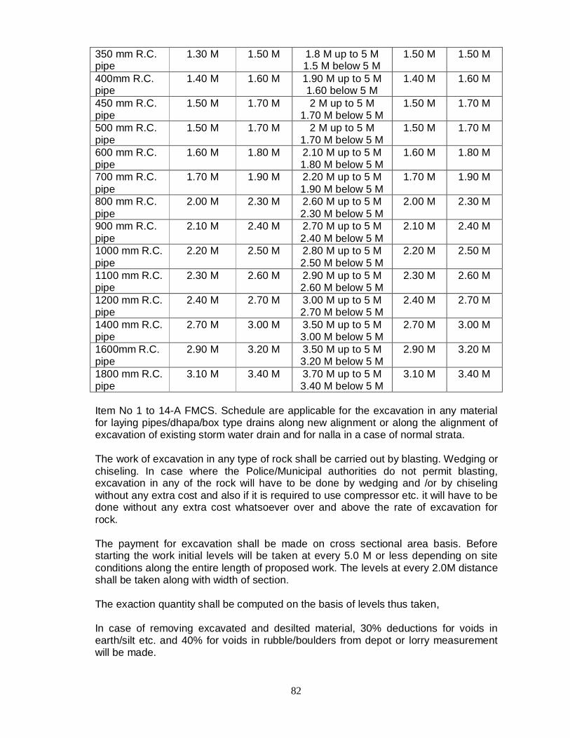
82
350 mm R.C. pipe
1.30 M 1.50 M 1.8 M up to 5 M 1.5 M below 5 M
1.50 M 1.50 M
400mm R.C. pipe
1.40 M 1.60 M 1.90 M up to 5 M 1.60 below 5 M
1.40 M 1.60 M
450 mm R.C. pipe
1.50 M 1.70 M 2 M up to 5 M 1.70 M below 5 M
1.50 M 1.70 M
500 mm R.C. pipe
1.50 M 1.70 M 2 M up to 5 M 1.70 M below 5 M
1.50 M 1.70 M
600 mm R.C. pipe
1.60 M 1.80 M 2.10 M up to 5 M 1.80 M below 5 M
1.60 M 1.80 M
700 mm R.C. pipe
1.70 M 1.90 M 2.20 M up to 5 M 1.90 M below 5 M
1.70 M 1.90 M
800 mm R.C. pipe
2.00 M 2.30 M 2.60 M up to 5 M 2.30 M below 5 M
2.00 M 2.30 M
900 mm R.C. pipe
2.10 M 2.40 M 2.70 M up to 5 M 2.40 M below 5 M
2.10 M 2.40 M
1000 mm R.C. pipe
2.20 M 2.50 M 2.80 M up to 5 M 2.50 M below 5 M
2.20 M 2.50 M
1100 mm R.C. pipe
2.30 M 2.60 M 2.90 M up to 5 M 2.60 M below 5 M
2.30 M 2.60 M
1200 mm R.C. pipe
2.40 M 2.70 M 3.00 M up to 5 M 2.70 M below 5 M
2.40 M 2.70 M
1400 mm R.C. pipe
2.70 M 3.00 M 3.50 M up to 5 M 3.00 M below 5 M
2.70 M 3.00 M
1600mm R.C. pipe
2.90 M 3.20 M 3.50 M up to 5 M 3.20 M below 5 M
2.90 M 3.20 M
1800 mm R.C. pipe
3.10 M 3.40 M 3.70 M up to 5 M 3.40 M below 5 M
3.10 M 3.40 M
Item No 1 to 14-A FMCS. Schedule are applicable for the excavation in any material for laying pipes/dhapa/box type drains along new alignment or along the alignment of excavation of existing storm water drain and for nalla in a case of normal strata. The work of excavation in any type of rock shall be carried out by blasting. Wedging or chiseling. In case where the Police/Municipal authorities do not permit blasting, excavation in any of the rock will have to be done by wedging and /or by chiseling without any extra cost and also if it is required to use compressor etc. it will have to be done without any extra cost whatsoever over and above the rate of excavation for rock. The payment for excavation shall be made on cross sectional area basis. Before starting the work initial levels will be taken at every 5.0 M or less depending on site conditions along the entire length of proposed work. The levels at every 2.0M distance shall be taken along with width of section. The exaction quantity shall be computed on the basis of levels thus taken, In case of removing excavated and desilted material, 30% deductions for voids in earth/silt etc. and 40% for voids in rubble/boulders from depot or lorry measurement will be made.

83
6.6 CAST-IN-SITU END BEARING PILES 6.6.1 Mobilisation & Setting Out The contractor shall provide everything necessary for true and faithful
performance of the contract.
The contractor shall be furnished with setting out or lining out drawings and a base line shall be actually set at site by the engineer. The entire work then shall be set out by the contractors from the base line and the lining out checked by the Supervising Engineer before starting the work.
Before commencing with boring, removable casings shall be driven into the ground and their centre lines checked jointly by the Contractors and Supervising Engineers.
6.6.2 Boring Through Over-Burden
Boring in overburden through whatever strata encountered, upto rock as defined in 6.6.1, shall be done by using a flap valve bailer.
Use of heavy cutting chisels shall be restored to, if required, for boring through locally encountered boulders or hard strata through which a bailer cannot penetrate. The diameter of the bore hole shall be such that the pile reinforcement cage with a shroud of geofabric liner of specified diameter can be properly lowered into the bore.
The tops of the bore holes shall be defined and stabilised by driving removable casings to a level below which boring can be continued without them. The walls of the bore holes shall be stabilised by circulating drilling mud with bentonite slurry of required consistency. It shall be the contractors responsibility to ensure the stability of the bore holes and to make good the damage if any resulting from the collapse of the sides.
All bored material including circulating mud shall be carted away and the site kept clean at the contractors expense. This muck-disposal shall be done simultaneously while boring is in progress. The Supervising Engineer may stop the work if muckaccumulates at site and delay in completion of the work due to such stoppage shall be to the contractors account.
6.6.3 Chiselling Through Rock & Establishing The Founding Strata
Boring through overburden shall be deemed to have been terminated at the lower of the two levels determined by the following requirements.
i) The level at which further boring by bailer is not possible, after having
chiselled through locally encountered boulders or hard strata. The strata encountered at the lower of the two levels determined as above
shall be considered as rock. Further boring shall be continued by chiselling and shall be as boring through rock for the purposes of measurement and payment.
The chisel diameter shall correspond to the diameter of the bore hole and its
weight shall be 2.00 tonne to 3.00 tonnes for piles upto and including 1200

84
mm diameter and 10.00 tonnes to 15.00 tonnes for piles upto and including 2500 mm diameter. The fall of chisel shall not be less than I m nor more than 1.5 m. The weight of chisel and its fall shall be so adjusted that atleast 3 t-m of energy is imparted per blow per I Sq.m. cross sectional area of pile.
Having reached the rock level as defined in 4.3.2, 1000 chisel blows shall
be given ensuring that atleast 3 t-m of energy per 1 Sq.m. pile cross area is imparted per blow. Bore shall then be cleaned, penetration measured and the reduced level determined.
Further boring shall then be continued by chiselling till the acceptability of the founding statum is proven as in 4.3.6 below.
The acceptability of the founding stratum shall be that atleast 75 t-m of energy is required per 1 Sq.m. pile cross-sectional area per 1 cm penetration. This shall be checked consecutively three times for 5 cms penetration each time. If this requirement is not satisfied further penetration into the rock shall be effected till the requirement is satisfied. The bore hole shall then be cleaned, penetration measured and the reduced level determined.
The penetration into the rock from the level at which rock was first encountered as defined in 4.3.2 upto the founding stratum level as defined in 4.3.6 should be such that a socket length of atleast 3 m. for 600 dia pile and 2:25 for 450 dia pile or as per recommendations of soil consultant into the rock is obtained. If not, further penetration shall be effected in to the rock till the required socket length is obtained. The level at which atleast 20 t-m of chiselling energy is required per I Sq.m. of pile cross-sectional area for penetrating the strata further by 1 cm. This requirement shall be checked by imparting 100 t-m of chiselling energy per 1 Sq.m. of pile cross- sectional area and measuring the penetration, which should be less than 5 cm.
If at any stage during the chiselling for obtaining the socket length as described in Clause 4.3.7, after having given 1000 chisel blows as mentioned in Clause 4.3.4, the rock encountered is such that more than 225 t-m of energy is required per I Sq.m of pile cross-sectional area per 1 cm of penetration then the founding stratum shall be considered to have been reached and further chiselling shall be stopped, unless directed otherwise by the Consulting Engineers. If so directed, further chiselling shall be recorded as t-m-hrs. A chiselling equipment operating for 1 hr. in such a way that 3 t-m of energy are consistently imparted per blow, shall be considered as 3 t-m-hrs, subject to a minimum of 10 blows per minute.
It shall be the contractors responsibility to ensure the stability of the hale and, far making good the damage if any, resulting from the collapse of the sides.
All chiselled material including circulating mud shall be carted away and site kept clean at contractors expense.

85
The entire process of proving the acceptability of the final founding level shall be carried out in the presence of the Supervising Engineer. Full record of chisel weight, drop height; number of blows, penetration time taken etc. shall be regularly maintained.
6.6.4 Cleaning and Flushing the Tip Zone
After reaching the founding stratum the pile tip zone shall be thoroughly cleaned by flushing the bore with fresh bentonite slurry to completely replace the old bentonite slurry used during the previous operations.
A tremie pipe of 150 to 200 mm diameter shall be lowered into the bore & fresh slurry shall be circulated at sufficiently high pressure so that the slurry discharge rate shall be 500 litres per minute for piles upto 600mm dia, 2000 litres per minute for piles upto 1200mm dia. and 8000 litres per minute for piles upto 2400 mm dia. The specific gravity of the slurry at inflow shall be between 1.1 to 1.08. At the outflow it may be mare than 1.1 or less than 1.08. The specific gravity shall be checked again after settlement and before recirculation. Fresh bentonite shall be added to maintain the specific gravity at inflow within the range of 1.08 to 1.10. Gravel and sand particles in the discharge after cleaning shall not be less than 4mm.
The cleaning shall be carried out for a total period of 45 minutes in two stages. Cleaning of the first stage of 30 minutes shall be carried out before lowering the reinforcement cage and for the second stage of 15 minutes after lowering the reinforcement cage. If required by the Supervising Engineer the cleaning,of the tip zone shall be further checked by operating an air lift for 30-minutes. The contents of the discharge at the outflow shall be examined for the-purpose. This check shall be carried out for every pile at the beginning of the work and on finding the cleaning process satisfactory further check shall be made cm atleast 1 pile out of 10 or often as required by the Supervising 'Engineer.
6.6.5 Reinforcement All piles shall be reinforced using Mildsteel bars or high yield strength deformed bars as specified by the Consulting Engineers. Reinforcement shall be cut and fabricated as per the Consulting Engineers drawings. Binding wire shall be galvanised.
The main longitudinal reinforcement of the piles shall be in one unbroken length. When this length exceeds the commercially available lengths then the bar length may be made up by lapping of reinforcement rods by 55 times their diameters. In addition, the overlapping portion shall be held rigid by tack welding t three locations along the lap. The longitudinal reinforcement in the piles shall be held by providing spiral stirrups. At the end of the spiral the next spiral shall overlap by two rounds and the spirals shall be alternately left handed and right handed.
86
The assembly of the fabricated reinforcement of the piles into a cage shall be carried out on a level platform so as to maintain its linearity in the longitudinal direction. The entire assembly shall be rigid and stable during handling and placing. All reinforcement shall be provided with proper specified cover. This cover shall be ensured by providing precast concrete circular disc shaped cover blocks with a hole in the centre. These shall be threaded on to the spiral stirrups. The assembled cage of the reinforcement shall be carefully lowered into the bore hole by a crane or a hoist so that no muck or soil or other impurities fall into the bore hole.
6.6.6 Concreting the Piles
Concrete shall be prepared to conform to the specifications Part: A in general and Clause 5 therein in particular. The workability requirements for placement by tremie shall be achieved not by exceeding the water: cement ratio beyond 0.55 but by use of approved plasticisers or water reducing admixtures Concrete shall be deposited in the pile using a tremie pipe. A minimum concrete height of 1 m shall be maintained inside the tremie over that of the concrete in the pile. A minimum tremie penetration of I m into the concrete shall be ensured at all times so that during the up and down movement of the tremie its bottom does not come out of the concrete in the pile. All piles shall be concreted to a level atleast 1 pile dia or 1 meter whichever is more, higher than the specified cut-off-elevation of the pile. 1 in 20 piles shall be cast upto the ground level to permit-visual inspection of the overflow of concrete.
6.6.7 Stripping the Pile Tops
After excavation, the permanent steel liners, if provided, shall be first flame cut about 125 mm below the cut off elevation of the piles. Care shall be exercised that the concrete is not damaged during the progress.
The as-cast portions of the pile tops shall then be carefully chipped off upto the cutoff elevation or until hard dense concrete is obtained whichever is the lower. If piles are required to be rebuilt upto specified cut-off elevation, the same shall be done at the contractors expense. First 50 mm deep groove shall be cut around the pile using sharp chisel 20 mm wide and only thereafter the inner concrete shall be removed. Care shall be exercised to ensure that the reinforcement is not damaged. All debris shall be carted away and the site kept dean. Mode of Measurement
This item shall be measured by numbers separately for different pile diameters.
87
6.7 CONCRETE AND ALLIED WORKS 6.7.1 READY MIX CONCRETE
All concrete works shall be carried out by Ready Mix Concrete only. Testing for compressive strength of concrete works shall be carried out as directed by the Engineer in-charge. Twelve cubes (150 mm x 150 mm x 150 mm) shall be cast & tested for compressive strength for 7, 14 & 28 days at the site laboratory for everyday's work. For concrete of grade M 35 or higher, corresponding three flexural beams (700 mm x 150 mm x 150 mm) for flexural strength of 28 days shall also be cast & tested, for every day's work at the laboratory attached to the R.M.C. plant. In case of failure in compressive strength for 28 days, the remaining three cubes shall be sent to the municipal laboratory or any other approved laboratory, as directed by engineer in-charge for re-testing. Besides, once in a month, compressive strength for 7 & 28 days (for concrete of grade M 35 or higher) shall be carried out at municipal laboratory or approved laboratory as directed by the Engineer in-charge. In addition to above specified cube and flexural behavior testing, the contractor shall carryout concrete core testing @ 4 cores per 50m length of RCC wall. Location on core shall be approved by the engineer-in -charge. The site of each core shall be min -75 mm dia x200 mm long. All core samples be tested for compressive strength of fully cured concrete. The core testing shall be carried out in an approved concrete testing laboratory and reports submitted to the engineer-in-charge. Core cut holes shall be filled with single component Pan fibre Reinforced Thixotropic dual shrinkage.
Compensated structural repair mortar of the minimum compressive strength as that of concrete used for the construction of the wall. Note: - R.M.C. Conditions regarding 14 days compressive strength, 28 days flexural strength and concrete core test shall be applicable only if C.C. road work, is included in the scope of the tender. Initial curing shall be done immediately, either by covering with hessian cloth and sprinkling with water over the concreted portion as soon as the concrete starts setting or by the application of approved resin based aluminized reflective curing compound which hardens into an impervious film of membrane (with the help of mechanical sprayer.) Further curing of concrete shall be done as directed, for a minimum period of 14 days from the date of casting of c.c. slab.
A penalty of Rs.100/- per Sq.M. per day will be levied for broken vatas. A penalty of Rs.500/- per day will be levied for improper curing.
88
In controlled concrete the determination of the proportions of cement, aggregate and water to attain the required strength shall be made with preliminary test by designing the concrete mix at contractors cost. Mix - design to give the target strength as required shall be prepared preferably in accordance with the relevant IRC / IS specifications. The same shall be checked by the Asst. Engineer / Executive Engineer. All type of concrete works shall conform to relevant I.S. Codes as mentioned below or their latest editions: a. I.S. 10262 1982 for concrete mix design. b. I.S. 383 1970 for aggregates. c. I.S. 456 1978 for concrete. (As modified) d. I.S. 1791 for mixer e. I.S. 516. 1959 for testing concrete. f. I.S. 9103 for admixtures for concrete. g. I. S. 8142 & 8122 for cement concrete vibrators h. I.S. 2505 for immersion type vibrators i. I. S. 2911 1 to IV water retaining structures j. Any other relevant I.S. codes as directed.
Ready mix concrete will be brought to the site from RMC plant only by transit mixers. (agitators). Every transit mixer will carry delivery challan, mentioning the minimum following details
i) Name of Manufacturer and Depot. ii) Serial No. of challan. iii) Date iv) Truck No. v) Name of contractor to whom the RMC is being supplied. vi) Location of
contract work. vii) Grade of concrete. viii) Specified workability.
Municipal Corporation Of Greater Mumbai Tender For Storm Water Drain Works -
ix) Cement content and Grade of cement. x) Time of loading xi) Quantity of concrete. When the truck arrives on site, the drum should always be speeded to about 10 to 15 rev/min, for at least 3 minutes, to make sure that the concrete is thoroughly mixed and uniform, before discharge. Testing of Ready Mixed Concrete:- The sampling and testing requirements for ready mixed concrete are the same as those for site mixed concrete. As regards testing of workability, following procedure be followed. After making sure that the concrete has been uniformly mixed, take a sample from the first 0.5 cu.m. of concrete discharge, and do a slump (or compacting factor) test on the sample. If the result complies with the specified requirements, then the load should be accepted. If the results are

89
beyond limits, a further sample should be taken from the second 0.5 cu.m. of the discharge, and if this is satisfactory, the load should be accepted, if not, the concrete load shall be rejected, as the same is not as per the specification range. The specified slump is 50 mm while carrying out above tests, it may vary by 10 mm as per IS 4926-1976. No extra payment will be made for the use of admixtures. The defect liability period will be the responsibility of the main tenderer. It will be the sole right of the Administration to allow or disallow the use of ready mixed concrete in specific works based on the site situation, number of works, distance of plant from the site of work, etc. The rate shall cover the cost of complete work including boxing, ramming consolidating, watering, placing, curing. Concrete lost in interstices of rubble and / or metal packing etc. will not be paid for. The rate includes cost of finishing all exposed surfaces to match with type of finish to surrounding surfaces or as directed by the engineer. The rates also include cost of providing, placing, launching, removing, cleaning, striping the form work unless otherwise specifically mentioned. The rates are also inclusive of cost of vibrating by mechanical vibrator of appropriate type.
REINFORCED CONCRETE The coarse aggregate in R.C.C. work will consist of metal No. I and 2 as per mix design for controlled concrete and as per specifications. The rates shall cover the cost of complete work including mix design, site laboratory equipment centering placing vibrating tamping, watering, curing, compacting, roughening the exposed surfaces for accepting plaster and finishing. The sizes of members shall be the designed dimensions exclusive of finishing. Use of mechanical vibrator of appropriate type shall be made for all R.C.C. works wherever directed. All joints and gaps in the formwork shall be covered with waterproof papers as directed. Precast cement mortar (1:2) cover block or approved plastic cover blocks shall be used for all R.C.C. works as directed for which no extra payment will be made. As soon as form work of slab is removed immediate steps will be taken by the contractor to remove the water proof paper and cement slurry from underside of slab. These operations shall be done within a week's time after removal of the centering. If directed sharp internal comers of walls, etc. which are likely to be broken and which are difficult to rectify shall be rounded or chamfered as directed for which no extra payment will be made. All the items of R.C.C. are based on controlled concrete mix design & are to be carried out only by R.M.C.

90
Wastage in cutting steel will not be paid for. Only steel actually fixed in position shall be paid by linear measurements including hooks and bends. No extra payment will be made for binding wires, pins, chairs and laps and I or welding. This shall be noted while quoting the rates. The M.S. reinforcement / for steel / corrosion resistant steel will be as per detailed design drawing and schedule or as directed. Same will be as per municipal code 'B' for R.C.C. structures or as per relevant I.S. codes specifications. All the materials to the used in R.C.C. shall be got tested according to relevant I.S. specifications. The material conforming to I.S. specifications only will be used in the works. Wherever Tiscon or equivalent corrosion resistant steel (C.R.S.) is used in works it shall conform to the chemical and physical properties laid down in manufacturer's manual and will be got tested as directed. LIST OF MACHINERY REQUIRED TO BE PROVIDED BY THE CONTRACTOR ON EACH WORK. 1. a) Min. two needle vibrators (60 mm) & b) Min. two needle vibrators (40 mm) 2. One water tanks of 5000 Ltrs. capacity each. 3. 2 straight edges with scaled wedge. 4. Requisite finishing instrument. 5. Portable air compressor. 6. 2 templates for checking camber 7. 12 cube moulds, 150 mm x 150 mm x 150 mm 8. 1 slump cone with two additional measuring rods. 9. 3 flexural beam moulds of size 700 mm x 150 mm x 150 mm 10. Min. two
sprinklers. 11. Levelling instruments. 12. Two pharmas 13. a) Measuring tape b) Steel tape 14. Generator Set - Min. one no. NOTE:- Machinaries/equipments at 3,6,9,14 shall be applicable only if C.C.Road work is included in the scope of tender. Contractor must procure all the aforesaid equipments and machinery before commencement of the respective work in good working condition. The quality of materials and method and control of manufacture and transportation of all concrete work irrespective of mix, whether reinforced or otherwise shall conform to the applicable portions of this specification. The Engineer in-charge shall have the right to inspect the source/s of material/s, the layout and operation of procurement and storage of materials, the concrete batching and mixing equipment, and the quality control system. Such an inspection shall be arranged and Engineer-in-charge's approval obtained, prior to starting of concrete work. However, this shall not relieve the contractor with any of his responsibilities and all the materials, which do not conform to the specifications, will be rejected. The Contractor will maintain a register for quantity of steel consumed and concreting done updated on daily basis.
91
6.7.2 Applicable Codes
The following specifications, standards and codes, including all official amendments/revisions and other specifications & codes referred to therein to therein, should be considered a part of this specification. In all cases the latest issue/edition/revision shall apply. In case of discrepancy between this specification and those referred to herein this bid document, this specification shall govern.
MATERIALS 1. IS:269 Specification for 33 grade ordinary Portland cement 2. IS:455 Specification for Portland slag cement. 3. IS:1489 Specification for Portland-pozzolana cement. 4. IS: 8112 Specification for 43-grade ordinary Portland cement. 5. IS: 12330 Specification for sulphate resisting Portland cement. 6. IS: 383 Specification for coarse and fine aggregates from natural sources
for concrete. 7. IS: 432 Specification for mild steel and medium tensile steel (Parts-I & II)
bars and hard-drawn steel wires for concrete reinforcement. 8. IS: 1786 - Specification for high strength deformed steel bars and wires for concrete reinforcement.
9. IS: 1566 Specification for hard-drawn steel wire fabric for (Part-I) concrete reinforcement.
10. IS: 9103 Specification for admixtures for concrete. 11. IS: 2645 Specification for integral cement waterproofing compounds. 12. IS: 4990 Specification for plywood for concrete shuttering work. MATERIAL TESTING 1. IS: 4021 Methods of physical tests for hydraulic cement. (Parts-1 to 13) 2. IS: 4032 Method of chemical analysis of hydraulic cement. 3. IS: 650 Specification for standard sand for testing of cement. 4. IS: 2430 Methods for sampling of aggregates for concrete. 5. IS: 2386 Methods of test for aggregates for concrete. (parts-I to VIII) 6. IS: 3025 Methods of sampling and test (physical and chemical) water used
in industry. 7. IS: 6925 Methods of test for determination of water-soluble chlorides in
concrete admixtures. MATERIALS STORAGE 1. IS: 4082 Recommendations on stacking and storing of construction
materials at site. CONCRETE MIX DESIGN 1. IS: 10262 Recommended guidelines for concrete mix design. 2. SP: 23 Handbook on Concrete Mixes. (S & T)

92
CONCRETE TESTING 1. IS: 1199 Method of sampling and analysis of concrete. 2. IS:516 Method of test for strength of concrete
3. IS: 9013 Method of making, curing and determining compressive strength of accelerated cured concrete test specimens.
4. IS: 8142 Method of test for determining setting time of concrete by penetration resistance.
5. IS: 9284 Method of test for abrasion resistance of concrete. 6. IS: 2770 Methods of testing bond in reinforced concrete.
EQUIPMENT 1. IS: 1791 Specification for batch type concrete mixers. 2. IS: 2438 Specification for roller pan mixer. 3. IS: 4925 Specification for concrete batching and mixing plant. 4. IS: 5892 Specification for concrete transit mixer and agitator. 5. IS: 7242 Specification for concrete spreaders. 6. IS: 2505 General Requirements for concrete vibrators: Immersion type. 7. IS: 2506 General Requirements for screed board concrete vibrators. 8. IS: 2514 Specification for concrete vibrating tables. 9. IS: 3366 Specification for pan vibrators. 10. IS: 4656 Specification for form vibrators for concrete. 11. IS: 11993 Code of practice for use of screed board concrete vibrators. 12. IS: 7251 Specification for concrete finishers. 13. IS: 2722 Specification for portable swing weigh batchers for concrete
(single and double bucket type). 14. IS: 2750 Specification for steel scaffoldings. CODES OF PRACTICE 1. IS: 456 Code of practice for plain and reinforced concrete. 2. IS: 457 Code of practice for general construction of plain and reinforced
concrete for dams and other massive structures. 3. lS:3370 Code of practice for concrete structures for storage of liquids. (parts-I
to IV) 4. IS: 3935 Code of practice for composite construction. 5. IS: 2204 Code of practice for construction of reinforced concrete shell roof. 6. IS: 2210 Criteria for the design of reinforced concrete shell structures and folded
plates. 7. IS: 2502 Code of practice for bending and fixing of bars for concrete
reinforcement. 8. IS: 5525 Recommendation for detailing of reinforcement in reinforced concrete
works. 9. IS: 2751 Code of practice for welding of mild steel plain and deformed bars
used for reinforced concrete construction. 10. IS: 9417 Specification for welding cold worked bars for reinforced concrete
construction. 11. IS: 3558 Code of practice for use of immersion vibrators for consolidating
concrete. 12. IS: 3414 Code of practice for design and installation of joints in building. 13. IS: 4326 Code of practice for earthquake resistant construction of building. 14. IS:4014 Code of practice for steel tubular scaffolding.(parts-I & II)
93
15. IS: 2571 Code of practice for laying in-situ cement concrete flooring. 16. IS: 7861 Code of practice for extreme weather concreting. Part-I: Recommended practice for hot weather concreting. Part-II: Recommended practice for cold weather concreting. 17. IS: 13920 Ductile Detailing of Reinforced Concrete Structure subjected to 1993
seismic forces. 18. SP-16 Design Aids for Reinforcement Concrete to IS:456-1978(S&T) -1980 19. SP-24 Explanatory Handbook on IS:456-1978 20. SP-34 Handbook on Concrete Reinforcement and Detailing (S&T) - 1987 CONSTRUCTION SAFETY 1. IS:3696 - Safety code for scaffolds and ladders.(Parts-I & II) 2. IS:7969 - Safety code for handling and storage of building materials 3. IS: 8989 - Safety code for erection of concrete framed structures. MEASUREMENT 1. IS: 1200 Method of measurement of building and engineering works. 2. IS: 3385 Code of practice for measurement of civil engineering works. 6.7.3 MATERIALS FOR STANDARD CONCRETE The ingredients to be used in the manufacture of concrete shall consist solely of Ordinary Portland Cements, clean sand, natural coarse aggregate, clean water, and admixtures, if specifically called for on conditions at site warrant its use. Cement i) The contractor will have to make own arrangements for procuring cement and
steel. ii) The Contractor will have to make his own arrangements for transport from
supplier godown and storage of adequate quantity of cement. Contractor will construct cement godown at site as per MCGM rules. Cement in bulk may be stored in bins or silos, in batches of 10x10, which will provide complete protection from dampness, contamination and minimize caking and false set. Cement bags shall be stored in a dry enclosed shed (storage under tarpaulins will not be permitted), well away from the outer walls and insulated from the floor to avoid contact with moisture from the ground and so arranged as to provide ready access. Damaged or reclaimed or partly set cement will not be permitted to be used and shall be removed from the site. The storage bins and storage arrangement shall be approved by the Engineer-in-charge. Consignments of cement shall be stored as received and shall be consumed in the order of their delivery.
iii) Cement held in storage for a period of ninety (90) days or longer shall be tested.
Should at any time the Engineer-in-charge have reasons to consider that any cement is defective, then irrespective of its origin, date of manufacture and or manufacturer's test certificate, such cement shall be tested immediately at the Contractor's cost at an approved laboratory and until the results of such tests are found satisfactory, it shall not be used in any work. Testing certificates for each batch of cement should be submitted by the contractor to the Engineer in charge,
94
before starting the concreting work. The Contractor shall not be entitled to any claim of any nature on this account.
Aggregates i) General "Aggregate" in general designates both fine and coarse inert materials used in
the manufacture of concrete (Vide BIS 456 & BIS 383) and confirming to tests as per BIS 2386 (Part I to VI)
"Coarse Aggregate" is aggregate most of which is retained when passed through
on 4.75 mm BIS sieve. All fine and coarse aggregates proposed for use in the works shall be subject to
the Engineer-in-charge's approval and after specific materials have been accepted, the source of supply of such materials shall not be changed without prior approval of the Engineer-in-charge.
Aggregates shall consist of natural sands, stone (crushed or uncrushed) and
gravel from a source known to produce satisfactory aggregate for concrete and shall be chemically inert, non-flaky, strong, hard, durable against weathering, of limited porosity and free from deleterious materials that may cause corrosion of the reinforcement or may impair the strength and or durability of concrete. The grading of aggregates shall be such as to produce a dense concrete of specified strength and consistency that will work readily into position without segregation and shall be based on the "mix design" and preliminary tests on concrete specified later.
ii) Sampling and testing
Samples of the aggregates for mixed design and determination of suitability shall be taken under the supervision of the Engineer in-charge and delivered to the laboratory, well in advance of the scheduled placing of concrete. Records of tests, which have been made on proposed aggregates and on concrete made from this source of aggregates, shall be furnished to Engineer in-charge in advance of the work, for use in determining aggregate suitability. The costs of all such tests, sampling etc. shall be borne by the contractor.
iii) Storage of aggregates
All coarse and fine aggregates shall be stacked separately in stock piles in the material yard near the work site in bins properly constructed to avoid inter mixing of different aggregates. Contamination with foreign material and earth during storage and while heaping the materials shall be avoided. The aggregates must be of specified quality not only at the time of receiving at site but more so at the time of loading into mixer. Rakers shall be piled in layers not exceeding 1.20 m in height to prevent coning or segregation. Each layer shall cover the entire area of stockpile before succeeding layers are started. Aggregates that have become segregated shall be rejected.
iv) Specific Gravity
Aggregates having a specific gravity below 2.4 (saturated surface dry basis) shall not be used.

95
6.7.4 FINE AGGREGATE
Fine aggregate shall consist of natural or crushed sand conforming to BIS 383 confirming to tests as per BIS 2386 part I to VI. The sand shall be clean, sharp, hard, strong and durable and shall be free from dust, vegetable substances, adherent coating, clay, alkali, organic matter, mica, salt, or other deleterious substances, which can be injurious to the setting qualities/strength/durability of concrete.
Screening and Washing: Sand shall be prepared for use by such screening or washing, or both, as necessary, to remove all objectionable foreign matter while separating the sand grains to the -required size fraction.
a) Foreign Material limitations : The percentage, deleterious substances in.
sand delivered to the mixer shall not exceed the following:. Table 2 : Foreign Material Limitations in Fine Aggregate
Sr. Foreign material Percentage by weight Uncrushed Crushed
1 Material finer than 75 micron BIS sieve 3.0 15.0 2 Shale 1.0 - 3 Coal & Lignite 1.0 1.0 4 Clay Lumps - 1.0 Total 5.0 17.0
b) Gradation : Unless otherwise directed or approved by the Engineer-in-charge, the grading of sand shall be within the limits indicated hereunder.
Table 3 : Grading of Sand for Fine Aggregate
Sr. BIS :Sieve Designation
Grading Zone I
Grading Zone II
Grading Zone III
Grading Zone IV
1 10 mm 100 100 100 100 2 4.75 mm 99-100 90-100 90-100 95-100 3 2.36 mm 60-95 75-100 85-100 95-100 4 1.18 mm 30-70 55-90 75-100 90-100 5 600 microns 15-34 35-59 60-79 80-100 6 300 microns 5-20 8-30 12-40 15-50 7 150 microns 0-10 0-10 0-10 0-15
Where the grading falls outside the limits of any particular grading zone of sieves, other than 600 microns IS sieve, by total amount not exceeding 5%, it shall be regarded as falling within that grading zone. This tolerance shall not be applied to percentage passing the 600 micron IS sieve or to percentage passing any other sieve on the coarser limit of grading zone I or the finer limit of grading zone IV. Fine aggregates conforming to grading zone IV shall be used. Mix designs and preliminary tests shall show its suitability for producing concrete of specified strength and workability.

96
c) Fineness Modulus
The sand shall have a fineness modulus of not less than 2.2 or more than 4.2. The fineness modulus is determined by adding the cumulative percentages retained on, the following IS sieve sizes (4.75 mm, 2.36 mm, 1.18 mm, 600 microns'and 150 microns) and dividing the sum by 100.
6.7.5 Coarse Aggregate
a) Coarse aggregate for concrete, except as noted above, shall conform to IS 383 & IS 2386. This shall consist of crushed stone and shall be clean and free from elongated, flaky or laminated pieces, adhering coatings, clay lumps, coal residue, clinkers, slag, alkali, mica, organic matter or other deleterious matter.
b) Screening and Washing: Crushed rock shall be screened and or washed for the removal of dirt or dust coating, if so requested by the Engineer in-Charge c) Grading
i) Coarse aggregate shall be either in single size or graded, in both cases the grading shall be within the following limits:
BIS Sieve Size (mm)
Percentage passing for single sized aggregate of normal size
Percentage Passing For Graded Aggregate Of Normal Size
40 mm 20 mm 16 mm 12.5 mm
10mm 40 mm 20 mm 16 mm 12.5 Mm
63 100 - - - - 100 - - - 40 85-100 100 - - - 95-100 - - - 20 0-20 85-100 100 - - 30-70 95-100 100 - 16 - - 85-100 100 - - 90-100 -
12.5 - - - 85-100 100 - - - 90-100 10 0-5 0-20 0-30 0-45 85-100 10-35 25-35 30-70 40-85
4.75 - 0-5 0-5 0-10 0-20 0-5 0-10 0-10 0-10 2.36 - - - - 0-5 - - - -
ii) The pieces shall be angular in shape and shall have granular or crystalline surfaces. Friable, flaky and laminated pieces, mica and shale, if present, shall be only within tolerance limits, which will not affect adversely the strength and or durability of concrete. The maximum size of coarse aggregate, shall be 40 mm for M-7.5 and M-10 and 20mm for M-15 to M-20 concrete, or as directed by the Engineer-in-charge or specified otherwise. The maximum size of coarse aggregate shall be the maximum size specified above but in no case greater than 1/4"' of the minimum thickness of the member, provided that the concrete can be placed without difficulty so as to surround all reinforcement thoroughly and fill the comers of the form. For plain concrete the maximum size of aggregate shall be of 40 mm. For heavily reinforced concrete members, the nominal maximum size of the aggregate shall be 5 mm less than the minimum clear distance between the reinforcing main bars or 5 mm less than the minimum cover to reinforcement whichever is smaller. d) Foreign material limitations
The percentage of deleterious materials in the aggregate delivered to the mixer shall not exceed the following:
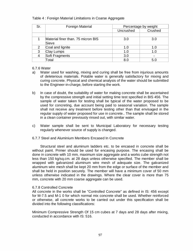
97
Table 4 : Foreign Material Limitations in Coarse Aggregate
Sr. Foreign Material Percentage by weight Uncrushed Crushed
1 Material finer than. 75 micron BIS
Sieve 3.0 3.0
2 Coal and lignite 1.0 1.0 3 Clay Lumps 1.0 1.0 4 Soft Fragments 3.0 - Total 8.0 5.0
6.7.6 Water a) Water used for washing, mixing and curing shall be free from injurious amounts
of deleterious materials. Potable water is generally satisfactory for mixing and curing concrete. Physical and chemical analysis of the water should be submitted to the Engineer-in-charge, before starting the work.
b) In case of doubt, the suitability of water for making concrete shall be ascertained
by the compressive strength and initial setting time test specified in BIS 456. The sample of water taken for testing shall be typical of the water proposed to be used for concreting, due account being paid to seasonal variation. The sample shall not receive any treatment before testing other than that envisaged in the regular supply of water proposed for use in concrete.. The sample shall be stored in a clean container previously rinsed out, with similar water.
c) Water sample shall be sent to Municipal Laboratory for necessary testing
regularly whenever source of supply is changed. 6.7.7 Steel and Aluminium Members Encased In Concrete Structural steel and aluminum ladders etc. to be encased in concrete shall be without paint. Primer should be used for encasing purpose. The encasing shall be done in concrete with 10 mm, maximum size aggregate and a works cube strength not less than 150 kg/sq.cm. at 28 days unless otherwise specified. The member shall be wrapped with galvanized aluminum wire mesh of adequate size. The galvanized aluminum wire mesh shall be kept 20 mm from the edge or surface of the member and shall be held in position securely. The member will have a minimum cover of 50 mm unless otherwise indicated in the drawings. Where the clear cover is more than 75 mm, concrete with 20 mm coarse aggregate can be used. 6.7.8 Controlled Concrete All concrete in the works shall be "Controlled Concrete" as defined in IS: 456 except for M-7.5 and M-1 0 for which normal mix concrete shall be used. Whether reinforced or otherwise, all concrete works to be carried out under this specification shall be divided into the following classifications: Minimum Compressive Strength Of 15 cm cubes at 7 days and 28 days after mixing, conducted in accordance with IS: 516.

98
Class Preliminary Test N/mm2
Works Test N/mm2
Maximum Size Of Aggregate
Mm
Locations For Use
At 7 Days
At 28 days
At 7 days
At 28 days
M40 33.5 50.0 27.0 40.0 20 As indicated in the specifications or as required M35 30.0 44.0 23.5 35.0 20 -do-
M30 25.0 38.0 20.0 30.0 40 or 20 -do- M25 22.0 32.0 17.0 25.0 40 or 20 -do- M20 17.5 26.0 13.5 20.0 40 or 20 -do- M15 13.5 20.0 10.0 15.0 40 or 20 -do-
Note: It shall be very clearly understood that whenever the grade of concrete such as M-20, etc. is specified it shall be contractor's responsibility to ensure the minimum crushing strength stipulated for the respective grade of concrete is obtained at works. 6.7.9 Mix Design 6.7.9.1 General This is essential for investigating the grading of aggregates, water-cement ratio, workability and the quality of cement required to give preliminary and works cubes of the minimum strength specified. The proportions of the mix shall be determined by weight Adjustment of aggregate proportions due to moisture present in the aggregate shall be made. Determination of mix proportions shall be carried out according to "Recommended guidelines for Concrete Mix Design" conforming to IS:10262. Whenever there is a change either in required strength of concrete, or water-cement ratio or workability or the source of aggregates and/or cement, preliminary tests shall be repeated to determine the revised proportions of the mix to suit the altered conditions. While designing proportions, over-wet mixes shall always be avoided. While fixing the value for water/cement ratio for preliminary mixes, assistance may be derived from the graph (Appendix A, BIS 456 showing the relationship between the 28 day compressive strengths of concrete mixes with different water/cement ratios and the 7-day compressive strength of cement tested in accordance with IS:269. 6.7.9.2 Preliminary Tests Test specimens shall be prepared with at least two different water/cement ratios for each class of concrete, consistent with work ability required for the nature of the work. The materials and proportions used in making preliminary tests shall be similar in all respects to those to be actually employed in the works as the object of these tests is to determine the properties of cement, aggregates and water necessary to produce concrete of required consistency and to give the specified strength, it will be contractor's sole responsibility to carry out these tests and he shall therefore furnish to Engineer-in-Charge a statement of proportions proposed to be used for the various concrete mixes. For preliminary tests, the following procedure shall be followed. Materials shall be brought to the room temperature and all materials shall be in a dry condition. The quantities of water cement and aggregate for each batch shall be determined by weight to an accuracy of 1 part in 100 parts.

99
Mixing concrete shall be done by hand (for small quantities, as directed by Engineerin-Charge) or in a small batch mixer as per IS:516 in such a manner as to avoid loss of water. The cement and fine aggregate shall first be mixed dry until the mixture is uniform in color. The coarse aggregate shall then be added, mixed and water added and the whole batch mixed thoroughly for a period of not less than two minutes until the resulting concrete is uniform in appearance. Each batch of concrete shall be such a size as to leave about 10% excess concrete, after moulding the desired number of test specimens. The consistency of each batch of concrete shall be measured immediately after mixing, by the slump test in accordance with IS:1199. If in the slump test, care is taken to ensure that no water or other material is lost, the material used for the slump test may be re-mixed with the remainder of the concrete for making the specimen test cubes. The period of re-mixing shall be as short as possible yet sufficient to produce a homogeneous mass. The samples for compression tests of concrete shall be made as per IS:516 on 15 cm cubes. Each mould shall be provided with a metal base plate having a plate surface so as to support the mould during filling without leakage. The base plate shall be preferably attached to the mould by springs or screws. The parts of the mould when assembled shall be positively and rigidly held together. Before placing concrete, the mould and base plate shall be leaned and oiled. The dimensions and internal faces of the mould shall be accurate within the following limits. Height and distance between the opposite faces of the mould shall be of specified size ±0.2 mm. The angle between the adjacent internal faces and between internal faces and top and bottom faces of mould shall be 90-degree +0.5 degree. The interior faces of the mould shall be plane surfaces with a permissible variation of 0.03 mm. Concrete test cubes shall be moulded by placing fresh concrete in the mould and compacted as specified in IS 516. Curing shall be as specified in IS 516. The cubes shall be kept in moist air of at least 90% relative humidity at a temperature of 27 degree C ± 2 degree C for 24 hours ±2 hours from the time of adding water to the dry ingredients. Thereafter they shall be removed from the moulds and kept immersed in clean, fresh water and kept at 27 degree C +2 degree C temperature until required for test. Curing water shall be renewed every-seven days. A record of maximum and minimum temperatures at the place of storage of the cubes shall be maintained during the period they remain in storage. The strength shall be determined based on not less than five cube test specimens for each age and each water cement ratio. All these laboratory test results shall be tabulated and furnished to the Engineer-in-charge. The test results shall be accepted by the Engineer-in-charge if the average compressive strengths of the specimens tested is not less than the compressive strength specified for the age at which specimens are tested subject to the condition that only one out of the five consecutive tests may give a value less than the specified strength for that age. The Engineer-in-charge may direct the contractor to repeat the tests if the results are not satisfactory and also make such changes as he considers necessary to meet the requirements specified. All these preliminary tests shall be conducted by the contractor at his own cost in an approved laboratory or in laboratory of MCGM.

100
6.7.10 Proportioning, Consistency, Batching and Mixing of Concrete The determination of the water cement ratio and proportion of aggregates to obtain the required strength shall be made from preliminary tests by designing the concrete mix. Controlled concrete shall be used on all concrete work complying with all the requirements of IS:456. Cube tests shall be carried out by the contractor on the trial mixes before the actual concreting operation starts. Based on the strength of the concrete mix sanction for the use has to be obtained from engineer in charge. If during the execution of the works it is found necessary to revise the mix because of the cube tests showing lower strengths than the required one due to inconsistency of quality of material or otherwise, The Engineer in charge shall ask for fresh trial mixes to be made by the contractor. No claim to alter the rates of concrete work shall be entertained due to such change in mix variations as it is the contractor's responsibility to produce the concrete of the required grade. Great care shall be exercised when mixing the actual works concrete using the proportions of the selected trial mix. The final concrete mix shall have the same proportions of cement, fine and coarse aggregates and water as that of the approved selected mix. A reasonable number of bags should be weighed separately to check the Net weight, where the weight of cement is determined by accepting the manufacturer's weight per bag at the site. Proper control of mixing water is deemed to be of paramount importance. If mixers with automatic addition of water are used, water should be either measured by volume in calibrated buckets, tins or weighed. All measuring equipment shall be maintained in a clean serviceable condition and their accuracy periodically checked and certified and the Engineer-in-Charge's approval obtained. The Engineer-in-Charge may require the contractor to carry out moisture content tests in both fine and coarse aggregates. The amount of the added water shall then be adjusted to compensate for any observed variations in the moisture contents. BIS: 2386 shall be referred to for determination of moisture content. No substitution in material, used on the work or alteration in the established proportions shall be made without additional tests to show that the quality and strength of concrete are satisfactory. No alterations shall be permitted without the prior sanction of the Engineer-in-Charge. 6.7.11 Mixing of Concrete The mixing of concrete shall be strictly carried out in an approved type of BATCHING & MIXING PLANT FOR CONCRETE. Ready Mix Concrete as per IS 4926-1976 shall be used for which Concrete Batching Plant should be provided at site. The Concrete Batching Plant shall be fully computerised. The Concrete Batching Plant shall have a Capacity of 30 Cum/Hr. Minimum Four Transit Mixer shall be provided with Concrete Pumps along with line pumps for ready mix concrete. Fully equipped Quality Assurance Laboratory shall be provided and following tests shall be done: Equipment Tests Calibration of Electronic Load Cell (Weigh Batcher) Calibration of Water Meter. Calibration of Admixture Dispenser Calibration of Cube Testing Machine.
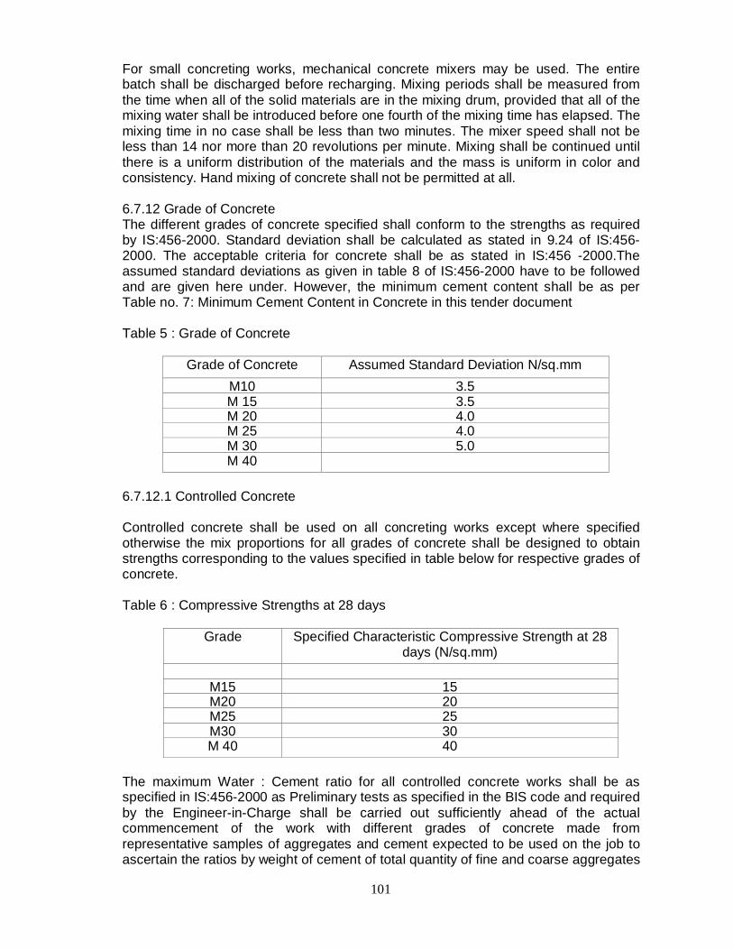
101
For small concreting works, mechanical concrete mixers may be used. The entire batch shall be discharged before recharging. Mixing periods shall be measured from the time when all of the solid materials are in the mixing drum, provided that all of the mixing water shall be introduced before one fourth of the mixing time has elapsed. The mixing time in no case shall be less than two minutes. The mixer speed shall not be less than 14 nor more than 20 revolutions per minute. Mixing shall be continued until there is a uniform distribution of the materials and the mass is uniform in color and consistency. Hand mixing of concrete shall not be permitted at all. 6.7.12 Grade of Concrete The different grades of concrete specified shall conform to the strengths as required by IS:456-2000. Standard deviation shall be calculated as stated in 9.24 of IS:456-2000. The acceptable criteria for concrete shall be as stated in IS:456 -2000.The assumed standard deviations as given in table 8 of IS:456-2000 have to be followed and are given here under. However, the minimum cement content shall be as per Table no. 7: Minimum Cement Content in Concrete in this tender document Table 5 : Grade of Concrete
Grade of Concrete Assumed Standard Deviation N/sq.mm M10 3.5 M 15 3.5 M 20 4.0 M 25 4.0 M 30 5.0 M 40
6.7.12.1 Controlled Concrete Controlled concrete shall be used on all concreting works except where specified otherwise the mix proportions for all grades of concrete shall be designed to obtain strengths corresponding to the values specified in table below for respective grades of concrete. Table 6 : Compressive Strengths at 28 days
Grade Specified Characteristic Compressive Strength at 28 days (N/sq.mm)
M15 15 M20 20 M25 25 M30 30 M 40 40
The maximum Water : Cement ratio for all controlled concrete works shall be as specified in IS:456-2000 as Preliminary tests as specified in the BIS code and required by the Engineer-in-Charge shall be carried out sufficiently ahead of the actual commencement of the work with different grades of concrete made from representative samples of aggregates and cement expected to be used on the job to ascertain the ratios by weight of cement of total quantity of fine and coarse aggregates

102
and the water cement ratio required to produce a concrete of specified strength and desired workability. The minimum cement content for each grade of concrete shall be as per table below.
Table 7 : Minimum Cement Content in Concrete and Maximum free Water Cement
Ratio
Grade of Concrete
Minimum Cement Content in Concrete (kg/cum of
finished Concrete)
Maximum Free Water Cement Ratio
M 20 300 0.55 M 25 300 0.50 M 30 320 0.45 M 35 340 0.45 M 40 360 0.40
At least 4 (four) trial batches are to be made and 7 test cubes should be taken for each batch noting the slump on each mix. These cubes shall then be property cured and two cubes for each mix shall be tested in a testing. laboratory approved by the Engineer-in-Charge at 7 days and others at 28 days for obtaining the ultimate compressive strength. The test reports shall be submitted to the Engineer in charge. The cost of mix design and testing shall be borne by the contractor. On the basis of the preliminary test reports for trial mix, a proportion of mix by weight and water cement ratio will be approved by the Engineer in charge, which will be expected to give the required strength. Consistency and workability and the proportions so decided for different grades of concrete shall be adhered to during all concreting operations. If however at any time the Engineer-in-Charge feels that the quality of material, being used has been changed from those used for preliminary mix design, the contractor shall have to run similar trial mixes to ascertain the mix proportions and consistency. The mix once approved must not be varied without prior approval of the Engineer-in-Charge. However should the contractor anticipate any change in the quality of future supply of materials than that used for preliminary mix design, he shall inform the same to the Engineer- in charge and bring fresh samples sufficiently ahead to carry out fresh trial mixes. The engineer in charge shall have access to all places and laboratory where design mix is prepared. Design mix will indicate by means of graphs and curves etc. the extent of variation in the grading of aggregates, which can be allowed.
In designing the mix proportions of concrete, the quantity of both cement and aggregate shall be determined by weight. All measuring equipment shall be maintained in clean and serviceable condition and their accuracy periodically checked. To keep the water cement ratio to the designed value, allowance shall be made for the moisture contents in both fine and course aggregates and determination of the same shall be made as frequently as directed by the Engineer-in-Charge. The determination of moisture contents shall be according to IS:2386 (Part Ill). 6.7.12.2 Strength Requirements Where ordinary Portland cement conforming to IS:269 or Portland blast furnace slag cement conforming to IS:455 and Dortland pozzolana cements conforming to IS:1489 is used the compressive strength requirements for various grades of concrete shall be as shown in table below. Where rapid hardening Portland cement is used the 28 days compressive strength requirements specified in Table- hereunder shall be
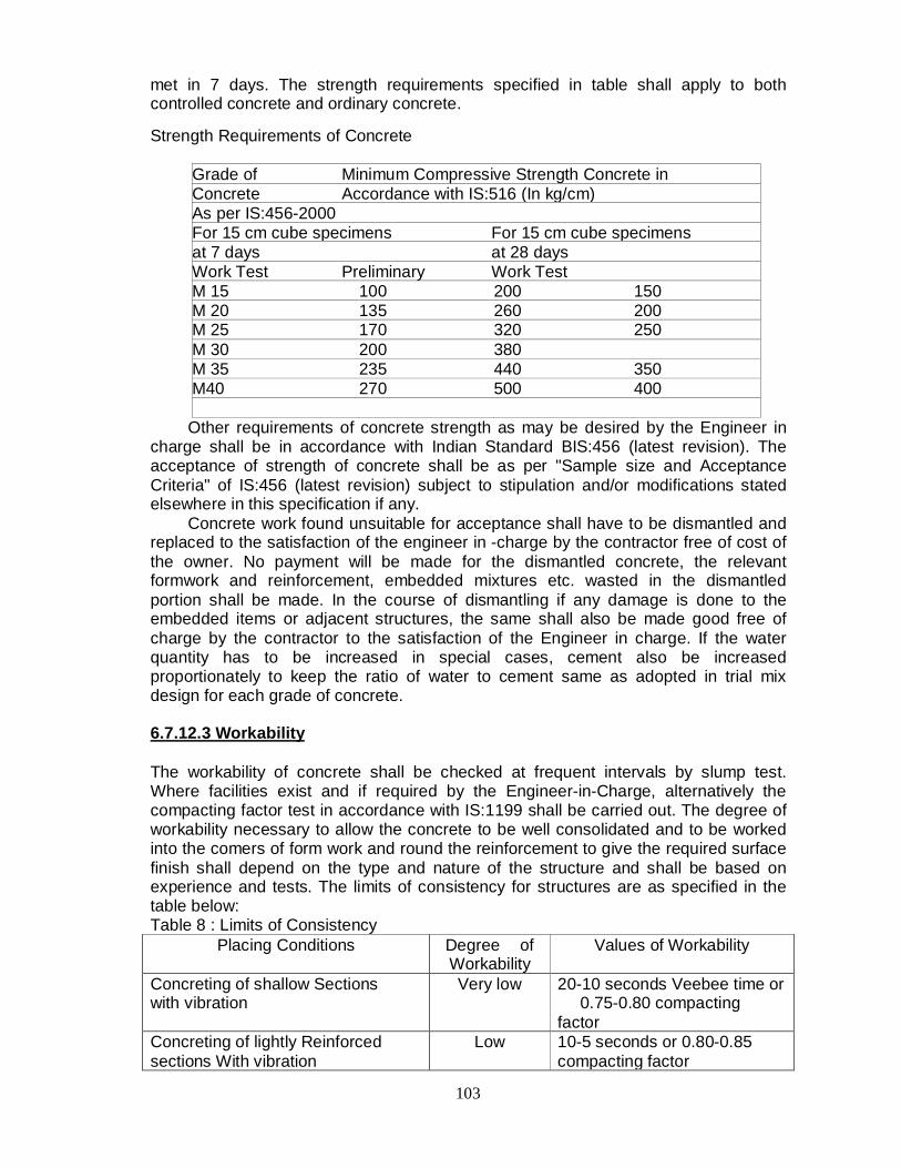
103
met in 7 days. The strength requirements specified in table shall apply to both controlled concrete and ordinary concrete. Strength Requirements of Concrete
Grade of Minimum Compressive Strength Concrete in Concrete Accordance with IS:516 (In kg/cm) As per IS:456-2000 For 15 cm cube specimens For 15 cm cube specimens at 7 days at 28 days Work Test Preliminary Work Test M 15 100 200 150 M 20 135 260 200 M 25 170 320 250 M 30 200 380 M 35 235 440 350 M40 270 500 400
Other requirements of concrete strength as may be desired by the Engineer in charge shall be in accordance with Indian Standard BIS:456 (latest revision). The acceptance of strength of concrete shall be as per "Sample size and Acceptance Criteria" of IS:456 (latest revision) subject to stipulation and/or modifications stated elsewhere in this specification if any. Concrete work found unsuitable for acceptance shall have to be dismantled and replaced to the satisfaction of the engineer in -charge by the contractor free of cost of the owner. No payment will be made for the dismantled concrete, the relevant formwork and reinforcement, embedded mixtures etc. wasted in the dismantled portion shall be made. In the course of dismantling if any damage is done to the embedded items or adjacent structures, the same shall also be made good free of charge by the contractor to the satisfaction of the Engineer in charge. If the water quantity has to be increased in special cases, cement also be increased proportionately to keep the ratio of water to cement same as adopted in trial mix design for each grade of concrete. 6.7.12.3 Workability The workability of concrete shall be checked at frequent intervals by slump test. Where facilities exist and if required by the Engineer-in-Charge, alternatively the compacting factor test in accordance with IS:1199 shall be carried out. The degree of workability necessary to allow the concrete to be well consolidated and to be worked into the comers of form work and round the reinforcement to give the required surface finish shall depend on the type and nature of the structure and shall be based on experience and tests. The limits of consistency for structures are as specified in the table below: Table 8 : Limits of Consistency
Placing Conditions Degree of Workability
Values of Workability
Concreting of shallow Sections with vibration
Very low 20-10 seconds Veebee time or 0.75-0.80 compacting factor
Concreting of lightly Reinforced sections With vibration
Low 10-5 seconds or 0.80-0.85 compacting factor

104
Concreting of lightly Reinforced sections Without Vibration or Heavily reinforced Section with Vibration
Medium 5-2 seconds Veebee time or 0.85-0.92 compacting factor or 25-75mm slump for 20 mm Aggregate
Concreting of heavily Reinforced sections compacting Without vibration factor
High Above 0.92 compacting factor or 75-125 mm slumps for 20 mm aggregate
6.7.13 Workmanship All workmanship shall be according to the latest relevant standards. Before starting a pour the contractor shall obtain the approval of the Engineer-in-Charge in a "Pour Card" maintained for this purpose. He shall obtain complete instructions about the material and proportion to be used, slump, workability of water per unit of cement, number of test cubes to be taken, finishing to be done and any admixture to be added etc. 6.7.14 Sampling And Testing Concrete In The Field Sampling and Testing of Concrete shall conform to IS:456 2000. a) Facilities required for sampling materials and concrete including whether proof buildings to house the facilities in the field, shall be provided by the contractor at no extra cost. The following equipment with operator shall be made available in serviceable conditions. i. Concrete cube-testing machine suitable for 15 cm cubes of 100 tonnes capacity with proving calibration ring 1 no. ii. Cast iron cube moulds 15 cm size 6 nos. iii. Slump cone complete with tamping rod 1 set iv. Laboratory balance to weigh upto 5 kg with sensitivity of 10 gm 1 no. v. BIS sieves for coarse and fine aggregates 1 set vi. Set of measures from 5 litres to 0.1 litre 1 set vii. Electric oven with thermostat upto 120° C 1 no. viii. Flakiness gauge 1 no. ix. Elongation index gauge 1 no. x. Sedimentation pipette I no. xi. Calibrated glass jar 1.0 litre capacity 2 nos. xii. Glass flasks and metal containers As required xiii. Chemical reagents like sodium hydroxide, tannic acid, litmus paper etc. - As required xiv. Laboratory balance of 2 kg capacity and sensitivity of I gm - I no. xv. Weighing Machine for cement bags of 6 Nos.: 2 no. xvi. Vernier Calipers As required. xvii. Thermometer for concrete b) No concrete of any kind may be placed until the field concrete testing laboratory
as specified is provided to the satisfaction of the Engineer-in charge.. The contractor shall notify the Engineer in charge in advance of all concrete and concrete material testing as provided in the clause to provide the Engineer/his representative with 'an opportunity to witness all prescribed tests.
105
c) At least 6 test cubes of each class of concrete shall be made of every 50cum concrete or part thereof or from different batches as directed by Engineer-in-charge. Such samples shall be drawn on each day for each type of concrete. Of each set of 6 cubes, three shall be tested at 7 days age and three at 28 days age. The cubes must be cast from various batches to arrive at an average strength. The laboratory test results shall be tabulated and furnished to the Engineer. The Engineer will pass the concrete if average strength of the specimens tested is not less than the strength specified, subject to the condition that only one out of three consecutive tests may give a value less than the specified strength but this shall not be less than 90% of the specified strength.
d) Consistency: Slump tests shall be carried out as often as requested by the
Engineer and invariably from the same batch of concrete from which the test cubes are made. Slump tests shall be done immediately after sampling.
6.7.15 Concrete Tests
The Engineer-in-Charge, may order tests to be carried out on cement, sand, coarse aggregate, water in accordance with the relevant Indian standards.
Tests on Cement shall include:
Fineness test Test for normal consistency Test for setting time Test for soundness Test for tensile strength Test for compressive strength Test for heat of hydration (by experiment and by calculations) in accordance
with BIS 269 Tests on Sand shall include:
Sieve test Test for organic impurities Decantation test for determining clay and silt content Specific gravity test Test for unit weight and bulkage factor Test for sieve analysis and fineness modulus
Tests on Coarse Aggregate shall Include:
Sieve analysis Specific gravity and unit weight of dry, loose and rodded aggregate Soundness and alkali aggregate reactivity Petrography examination Deleterious materials and organic impurities Test for aggregate crushing value
Any or all these tests would normally be ordered to be carried out only if the Engineer feels the materials are not obtained and shall be performed by the contractor at an approved test laboratory or at MCGM laboratory. The contractor shall. bear the charges of these optional tests.

106
Concrete not made to the requirements of specification in all respects may be rejected by the Engineer-in-Charge in which case it shall be removed and reconstructed entirely at the expense of the contractor.
6.7.16 Load test on Members or any other tests
i) In the event of any work being suspected of material or workmanship or both, the Engineer-in-charge requiring its removal and reconstruction may order, or the contractor may request that it should be load tested in accordance with the following provisions.
ii) The test load shall be 125% of the maximum superimposed load for which
the structure was designed. Such test load shall not be applied before 56 days after the effective hardening of concrete. During the test, struts strong enough to take the whole load shall be placed in position leaving a gap under the members. The test load shall be maintained for 24 hours before removal.
iii) If within 24 hours of the removal of the load, the structure does not show a
recovery of at least 75% of the maximum deflection shown during the 24 hours under load, the test loading shall be repeated after a lapse of at least 72 hours. The structure shall be considered to have failed to pass the test if the recovery after the second test is not at least 75% of the maximum deflection shown during the second test. If the structure is certified as failed by the Engineer-in-Charge, the cost of all the new construction and the load tests shall be borne by the contractor.
iv) Any other tests, e.g. taking out in an approved manner concrete cores,
examination and tests on such cores removed from such parts of the structure as directed by the Engineer-in-charge, sonic testing etc. shall 'be carried out by the contractor, if so directed, at no extra cost.
6.7.17 Unsatisfactory tests
Should the results of any test prove unsatisfactory, or the structure shows signs of weakness, undue deflection or faulty construction, the contractor shall remove and rebuild the member or members involved or carry out such other remedial measures as may be required by the Engineer-in-Charge.
6.7.18 Admixtures 6.7.18.1 General
Admixtures may be used in concrete where required, only with the approval of the Engineer-in-Charge. How ever it should be seen that, with the passage of time, neither the compressive strength nor its durability is reduced. Calcium chloride shall not be used for accelerating set of the cement for any concrete containing reinforcement or embedded steel parts. When calcium chloride is permitted to be used, such as in mass concrete works, it shall be dissolved in water and added to the mixing water in an amount not to exceed 1.5% of the weight of the cement in each batch of concrete. When admixtures are used, the designed concrete mix shall be corrected accordingly. Admixtures shall be used as per manufacturer's instruction and in the manner and with the control specified by the Engineer-in-Charge.

107
6.7.18.2 Air Entraining Agents Neutralized vinson resin or other approved air in the concrete mix agents shall conform to the requirements of ASTM standard 6.260; Air Entraining Admixtures for Concrete. The recommended total air content of the concrete is 4% + 1%. The method of measuring air content shall be as per IS: 1199.
6.7.18.3 Water Reducing Admixtures Water reducing lignosulfonate admixture may be added in quantities approved by the Engineer-in-charge. The admixtures shall be added in the form of a solution.
6.7.18.4 Retarding Admixtures
Retarding agents may be added to the concrete mix in quantities approved by the Engineer-in-Charge.
6.7.18.5 Water Proofing Agent
Water proofing agents shall conform to IS:2645. 6.7.18.6 Other Admixtures. The Engineer-in-Charge may at his discretion allow the contractor to use any other admixture in the concrete.
6.7.19 Preparation Prior to Concrete Placement, Final Inspection and Approval a. Before the concrete is actually placed in position, the insides of the
formwork shall be inspected to see that they have been cleaned and oiled. Temporary openings shall be provided to facilitate inspection, especially at bottoms of columns and wall forms, to permit removal of sawdust, wood shavings, binding wire, dirt etc. Openings shall be placed or holes drilled so that these materials and water can be removed easily. Such openings/holes shall be suitably plugged later.
b. The various agencies shall be permitted ample time to install drainage and
plumbing lines, floor and trench drains, conduits, hangers, anchors, inserts, sleeves, bolts, frames and other miscellaneous embedment to be cast in the concrete as specified or required or as is necessary for the proper execution of the work as specified in the drawings.
c. All embedded parts, inserts, etc. supplied by the MCGM or the contractor
shall be correctly positioned and securely held in the forms to prevent displacement during depositing and vibrating of concrete.
d. All anchor bolts shall be positioned and kept in place with the help of
properly manufactured templates unless specifically waived in writing by the Engineer-incharge.
e. Slots, openings, holes, pockets etc. shall be provided in the concrete work
in the position specified in drawing or required or as directed by the Engineer-in-charge.
f. Reinforcement and other items to be cast in concrete shall have clean
surfaces that will not impair bond. g. Prior to concrete placement, all work shall be inspected and approved by
the Engineer-in-Charge and if found unsatisfactory, concrete shall not be poured until after all defects have been corrected.

108
h. Approval by the Engineer-in-Charge of any and all materials and work as required herein shall not relieve the contractor from, his obligation to produce finished concrete in accordance with the requirements of the specifications.
i. Rain or wash water
No concrete shall be placed in wet weather or on a water-covered surface. Any concrete that has been washed by heavy rains shall be entirely removed, if there is any sign of cement and sand having been washed away from the concrete mixture. To guard against damage, which may be caused by rains, the works shall be covered with tarpaulins immediately after the concrete has been placed and compacted before leaving the work unattended. Any water accumulating on the surface of the newly placed concrete shall be removed by approved means and no further concrete shall be placed thereon until such water is removed. To avoid flow of water over/around freshly placed concrete, suitable drains and sumps shall be provided. During summer season, temperature of water should be maintained, as per the criteria and for the same, icing should be done for concreting work.
j. Bonding Mortar Immediately before concrete placement begins, prepared surfaces except formwork, which will come in contact with the concrete to be placed, shall be covered with a bonding mortar as specified.
k. The corrosive on the reinforcement should be removed by means of wire
brush. I. Laitance should be removed by means of chiseling from top concrete layer,
which was earlier concreted 6.7.20 Transportation 6.7.20.1 General
All buckets, containers or conveyors used for transporting concrete shall be mortar tight, leak proof irrespective of the method of transportation adopted, concrete shall be delivered with the required consistency and plasticity without segregation or loss of slump. However, chutes shall not be used for transport of concrete without the written permission of the Engineer-in-charge and concrete shall not be re-handled before placing.
6.7.20.2 Retempered or Contaminated Concrete
Concrete must be placed in its final position before it becomes too stiff to work. On no account, water shall be added after the initial mixing. Concrete, which has become stiff or has been contaminated with foreign materials shall be rejected and disposed off as directed by the Engineer-in-Charge.
6.7.20.3 Avoiding Segregation Concrete shall, in all cases, be deposited as nearly as practicable directly, in its final position and shall not be re-handled to flow in a manner which will cause segregation, loss of materials, displacement of reinforcement, shuttering or embedded insets, or impair its strength. For locations where direct placement is not possible, and in narrow forms, the Contractor shall provide suitable drop and

109
"Elephant Trunks" to confine the movement of concrete. Special care shall be taken when concrete is dropped from a height, especially if reinforcement is in the way, particularly in column and, the walls.
6.7.20.4 Placing by Manual Labour
Except when otherwise approved by the Engineer-in-Charge, concrete shall be placed in the shuttering by shovels or other approved implements, and shall not be dropped from a height more than 1.0 m or handled in a manner, which will cause segregation.
6.7.20.5 Placing by Mechanical Equipment
The following specification shall apply when placing concrete by use of mechanical equipment is warranted considering the nature of work involved. The control of placing shall begin at the mixer discharge. Concrete shall be discharged by a vertical drop into the middle of the bucket or hopper and this principle of a vertical discharge of concrete shall be adhered to throughout all stages of delivery until the concrete comes to rest in its final position.
6.7.20.6 Types of Buckets
Central-bottom-dump buckets of a type that provides for positive regulation of the amount and rate of deposition of concrete in all dumping positions, shall be employed.
6.7.20.7 Operation of Bucket
In placing concrete in large open areas, the bucket shall be spotted directly over the position designated and then lowered for dumping. The open bucket shall clear the concrete already in place and the height of drop shall not exceed 1.0 m. The bucket shall be opened slowly to avoid high vertical bounce. Dumping of buckets on the swing or in any manner, which results in separation of ingredients or disturbance of previously placed concrete, will not be permitted.
6.7.20.8 Placement of Restricted Forms Concrete placed in restricted forms by barrows, buggies, cars, short chutes or hand shoveling shall be subject to the requirement for vertical delivery of limited height to avoid segregation and shall be deposited as nearly as practicable in its final position.
6.7.20.9 Chuting
Where it is necessary to use transfer chutes, specific approval of Engineer-in-charge must be obtained to type, length slopes, baffles, vertical terminals and timing of operations. These shall be so arranged that an almost continuous flow of concrete be obtained at the discharge and without segregation. Concrete should flow smoothly in the chute and there should not be any obstruction to the flow. To allow for the loss of mortar against the sides of the chutes, the first mixes shall have less coarse aggregate. During cleaning of chutes, the wastewater shall be kept dear of the forms. Concrete shall not be permitted to fall from the end of the chutes by more than 1.0 m. Chutes, when approved for use shall have slopes not flatter than 1 vertical, 3 horizontal and not steeper than 1 vertical, 2 horizontal. Chutes shall be of metal or metal lines end of rounded cross section. The slopes of all chute sections shall be approximately the same. The slopes of all chute sections shall be approximately the same. The discharge end of the chutes shall be maintained above the surface of the concrete in the forms.

110
6.7.20.10 Placing by Pumping/Pneumatic Placers Concrete may be conveyed and placed by mechanically operated equipment e.g., pumps or pneumatic placers only with the written permission of the- Engineer-inCharge at no extra cost. The slump shall be held to the minimum necessary for conveying concrete by this method.
When pumping is adopted, before pumping of concrete is started, the pipeline shall be lubricated with one or two batches of mortar composed of one part cement and two parts sand. Care shall be taken to avoid stoppages in work once pumping has started.
When a pneumatic placer is used, the manufacturer's advice on layout of the pipeline shall be followed to avoid blockages and excessive wear. Restraint shall be provided at the discharge box to cater for the reaction at this end. Manufacturer's recommendations shall be followed regarding concrete quality and all other related matters when pumping/ pneumatic placing equipment is used. It should be noted that no extra payment is made for these items, if required and directed by Engineer-in-Charge.
6.7.20.11 Concrete in Layers
Concreting, once started, shall be continuous until the pour is completed. Concrete shall be placed in successive horizontal layers of uniform thickness ranging from 15 cm to 45 cm directed by Engineer-in-Charge. These shall be placed as rapidly practicable to prevent the formation of cold joints or planes of weakness between each succeeding layer within the pour.. The thickness of each layer shall be such that it can be deposited before the previous layer has stiffened. The bucket loads or other units of deposit, shall be spotted progressively along the face of the layer with such overlap as will facilitate spreading the layer to uniform depth and. texture with a minimum shoveling.. Any tendency to segregation shall be corrected by shoveling stones into mortar rather than mortar on to stones. Such a condition shall be corrected by redesign of mix or other means, as directed by the Engineer-in-charge.
6.7.20.12 Cover Blocks
Cover blocks of required size depending on the cover of the reinforcement as mentioned in the drawings shall be prepared. in 1:3 cement mortar with fine aggregates.
6.7.20.13 Bedding of Layers
The top surface of each pour and bedding planes shall be approximately horizontal unless otherwise instructed. Top layer should be rough and with key for further extension of work.
6.7.20.14 Compaction
Concrete shall be compacted during placing with approved vibrating equipment until the concrete has been consolidated to the maximum practicable density, as specified in the IS, is free of pockets of coarse aggregate and fits tightly against all form surfaces, reinforcement and embedded fixtures. Particular care shall be taken to ensure that all concrete placed against the form faces and into corners of forms against hardened concrete at joints is free from voids or cavities. The use of vibrators shall be consistent with the concrete mix and caution exercised not to over vibrate the concrete to the point that segregation results.

111
6.7.20.15 Type of Vibrators Vibrators shall conform to BIS specifications. Type of vibrator to be used shall depend on the structures where concrete is to be placed. Shutter vibrators to be effective, shall be firmly secured to the formwork which must be sufficiently rigid to transmit the vibration and strong enough not to be damaged by it. Immersion vibrators in sufficient numbers and each of adequate size shall be used to properly consolidate all concrete. Tapping or external vibrating of forms by hand tools or immersion vibrators will not be permitted.
6.7.20.16 Use of Vibrators
The exact manner of application and the most suitable machines for the purpose must be carefully considered and operated by experienced men. Immersion vibrators shall be inserted vertically at points not more than. 450 mm apart and withdrawn when air bubbles cease to come to the surface. Immersion vibrators shall be withdrawn very slowly. In no case shall immersion vibrators be used to transport concrete inside the forms. Particular attention be paid to vibration at the top of a lift e.g. in a column or wall.
6.7.20.17 Melding Successive Batches
When placing concrete in layers, which are advancing horizontally as the work progresses, great care shall be exercised to ensure adequate vibration blending and melding of the concrete between the succeeding layers.
6.7.20.18 Penetration of Vibrators
The immersion vibrator shall penetrate the layer being placed and also penetrate the layer below while the under layer is still plastic to ensure good bond and homogeneity between the two layers and prevent the formation of cold joints.
6.7.20.19 Vibrating against Reinforcement
Care shall be taken to prevent contact of immersion vibrators against reinforcement steel. Immersion vibrators shall not be allowed to come in contact with reinforcement steel after start of initial set. They shall also not be allowed to come in contact with forms or finished surfaces.
6.7.20.20 Use of Form Attached Vibrators
Form attached vibrators shall be used only with specific authorization of the Engineer-in-Charge.
6.7.20.21 Use of surface Vibrators
The use of surface vibrators will not be permitted under normal conditions. However, for thin slabs, surface vibrating by specially designed vibrators may be permitted, upon approval of Engineer-in-charge.
6.7.20.22 Stone Pockets And Mortar Pondages
The formation of stone pockets and mortar pondages in comers and against faces of forms shall not be permitted. Should these occur,, they shall be dug out, reformed and refilled to sufficient depth and shape for thorough bonding, as directed by the Engineer-in-charge.
112
6.7.21 Placement Interval Except when placing with slip forms, each placement of concrete in multiple lift work, shall be allowed to set for at least 24 hours after the final set of concrete and before the start of a subsequent placement.
6.7.22 Special Provision in Placing
When placing concrete in walls with openings, in floors of integral slabs and beam construction and other similar conditions, the placing shall stop when the concrete reaches the top of the opening in walls or bottom horizontal surface of the slab, as the case may be. Placing shall be resumed before the concrete in place takes initial set, but not until it has had time to settle as determined by the Engineer-in-Charge.
6.7.23 Placing Concrete Through Reinforcing Steel
When placing concrete through reinforcing steel, care shall be taken to prevent segregation of the coarse aggregate. Where the congestion of steel makes placing difficult, it may be necessary to obtain Engineer in-Charge's permission for temporarily moving the top steel aside for proper placement & for restoring reinforcement as per drawing.
6.7.24 Bleeding
Bleeding or free water on top of concrete being deposited into the forms, shall be the cause to stop the concrete pour and the conditions causing this defect corrected before any further Concreting is resumed.
6.8 Application of Araldite for Bonding of New and Old Concrete 6.8.1 General
Araldite epoxy resins will be used to bond fresh concrete to concrete that is fully cured, to give a monolithic bond capable of transmitting high stresses when traditional bonding agents such as cement slurry cannot always be relied upon to provide good adhesion which is particularly the case when large areas are involved. The Araldite based formulation shall be applied to a suitably prepared concrete substrata and the fresh concrete poured as soon as possible, but always during the 'open time' of the adhesive.
Materials used shall be of best quality and approved by the Engineer-in-charge. Manufacturer's instructions shall be followed in all respects. No separate payment shall be paid for this item of work.
6.8.2 Formulation
ARALDITE GY250 100 Parts by weight Hardener HY825 20 Parts by weight Hardener HY830 20 Parts by weight Hardener HY850 20 Parts by weight Silica Flour 20 Parts by weight

113
6.8.3 Application 6.8.3.1 Preparation of the Substrata
To obtain good adhesion, it is necessary to have dean and sound substrata. Preparation can be carried out using a variety of techniques including chemical treatment and mechanical methods such as grinding, milling, abrading, planning and sand blasting. Dust and loose particles resulting from the pretreatment should be removed by vacuum cleaning or oil-free or blast.
6.8.3.2 Mixing
The resin and hardener should be thoroughly mixed in the dry filler. The mixed, ready to use adhesive should not contain lumps of unwetted filler and should be of uniform color. For a total weight of 1 kg or less hand mixing should be sufficient. For quantities in excess of 1 kg, the use of a mechanical mixer is recommended.
6.8.3.3 Pot life and `Open time'
The pot life is the period during which the ready to use ARALDITE based formulation must be applied. After this period, the mix can no longer be worked and will have begun to set in its container. The table below indicates the pot life at different temperatures: Mix Temperature Pot life in minutes 25° C 90 Minutes 30° C 60 Minutes 35° C 45 Minutes
(The figures in this table are for batches less than 1 kilogram).
The 'Open time' is the maximum period of time allowable between application of the ARALDITE adhesive and pouring the fresh concrete. Exceeding the 'Open time' would result in considerably reduced adhesion. The adhesive should be applied to the pre-treated substrata as soon as the components have been mixed and fresh concrete poured immediately afterwards.
Accurate knowledge of the 'Open time' is essential in case the work is interrupted. Table gives the 'Open time' of ARALDITE based formulations as a function of substrata temperature. In all cases, the adhesives shall be applied immediately after mixing. Any delay between mixing and application will reduce the 'Open time'. Fresh concrete must be poured before the adhesive begins to gel. New to old concrete bonding is not recommended at temperatures below, 5 Degree Centigrade as curing cannot be assured under these circumstances.
6.8.3.4 Methods of Application
The shape and size of the concrete structure will determine the method of application used. The ARALDITE based adhesive may be applied by hand using brushed, brooms or any other suitable applicator.
6.8.3.5 Suitability of Fresh Concrete
Best results are obtained when the water/ cement ratio of the new concrete is low as is practicable.

114
6.8.3.6 Coverage
One kilogram of the mixed -ARALDITE adhesive including hardeners and filler covers an area of 2 to 3 sq.m. when applied with a stiff nylon bristle brush. However, the coverage is very much dependent on the finish in the concrete.
6.8.3.7 Handling Precautions
Epoxy resins can cause irritation of the skin in sensitive person if incorrectly handled. Certain safety precautions must therefore be observed and those handling the resins and hardeners should be given suitable instructions. Those working with epoxy resins should, above all, be instructed that personal cleanliness at the place of work is essential. The resin and hardener should not be allowed to come into direct contact with the skin. The most effective protection is achieved by wearing rubber or polythene gloves, the latter having the advantage that they can be replaced when dirty. They are more pleasant to wear if cotton gloves are worn underneath. Parts of the skins, which have come into contact with the resin or hardener, should be washed with lukewarm water and a mild soap. Special leaning creams may be used as they have proved to be highly suitable.
6.8.4 Construction Joints
A construction joint is defined as a joint in the concrete introduced for convenience in construction at which special measures are taken to achieve subsequent continuity without provision for further relative movement.
No concreting shall be started until the Engineer-in-Charge has approved the method of placing the positions and form of the construction joints and lifts. The construction joints shall be so located as not to impair the strength of the structure. Water stops shall be inserted as per clause 3.20
Concrete placed to form the face of a construction joint shall have all Laitance removed and the aggregate exposed prior to the placing of fresh concrete. The Laitance shall wherever practicable be removed by spraying the concrete where it is still green. The whole of the concrete surface forming part of the joint shall be hacked to expose the aggregate. Where aggregate is damaged during hacking, it shall be removed from the concrete face by further hacking. All loose matter shall be removed and the exposed surface thoroughly cleaned by wire brushing, air blasting or washing, leaving the surface clean and damp. Immediately before fresh concrete is placed, a 12 mm thick layer of sand/cement mortar mixed in the same proportions as in the concrete shall be spread in the horizontal face of the construction joint. A drier mix shall be used for the top lift of horizontal face of the construction joint. A drier mix shall be used for the top lift of horizontal pours to avoid Laitance. The new concrete shall be well worked against the prepared face before the mortar sets. Special care shall be taken to obtain thorough compaction and to avoid segregation of the concrete along the joint plane.
6.8.5 Movement Joints
Movement joints are defined as all joints intended to accommodate relative movement between adjoining parts of a structure, special provision being made where necessary for maintaining the water tightness of the joint. The contractor shall comply with the instructions of manufacturers of proprietary jointing

115
materials and shall, if required by the Engineer-in-Charge, demonstrate that the jointing materials can be applied satisfactorily. The surface of set concrete in a movement joint shall, as shown on the drawings, be painted with two coats of bituminous paint and new concrete shall be placed against it only when the paint is dry. Expansion joints shall be formed by a separating strip of approved preformed joint filler. Caulking grooves shall be provided. At all joints where a caulking groove is formed, immediately prior to caulking, the groove shall be wire brushed and loose material removed and blown out by compressed air. After the groove has dried, it shall be primed and caulked with approved sealing compound applied in accordance with the manufacturer's instructions. At all caulked joints, the face of the caulking strip and a width of concrete on either side shall be painted with two coats of paint having the same base as the sealing compound.
6.8.6 Water Stops and Joint Fillers 6.8.6.1 Water stops
At all construction, contraction and expansion joints in the water retaining structures and wherever specified or directed by the Engineer-in-Charge, water stops shall be provided. The water stops shall be PVC type or of any other equivalent material as approved by the Engineer-in-charge. PVC water stops shall have a tensile strength of not less than 14 MN/m2 and elongation at break of not less than 300%. Water stops shall not be exposed to direct sunlight for long periods. Before being concreted in water stops shall be cleaned of all foreign materials. Wherever provided, water stops shall be placed in such a manner that they are embedded in the adjacent sections of the panels for equal width. As far as possible, jointing on site shall be confined to the making of butt joints in straight runs of water stops and all the joints should be monolithic. Where it is agreed with the Engineer-in-charge that it is necessary to make an intersection or change of direction of any joint, other than a butt joint in a straight run on site, a preliminary joint, intersection or change of direction piece shall be made and submitted to such tests as the Engineer-in-charge may require. Flexible water stops shall be fully supported in the formwork, free of nails and clear of reinforcement and other fixtures. Damaged water stops shall be replaced and during concreting care shall be taken to place the concrete so that water stops do not bend or distort. The different types of water stops to be used in liquid retaining structures will be as follows:
Table 9 : Types of Water Stops Sr. Type of Joint Type of water stops 1. Partial/complete contraction
joint in walls and slabs 230 mm wide, ribbed with hollo centre bulb & 6 mm minimum thickness
2. Expansion joints in walls and slabs
230 mm wide, ribbed with hollo centre bulb & 6 mm minimum thickness
3. Construction joint in raft 230 mm wide, ribbed with hollo centre bulb & 6 mm minimum thickness
4. Construction joint in wall 230 mm wide, ribbed with hollo centre bulb & 6 mm minimum thickness
5. Expansion joint raft 230 mm wide, ribbed with hollo centre bulb & 6 mm minimum thickness
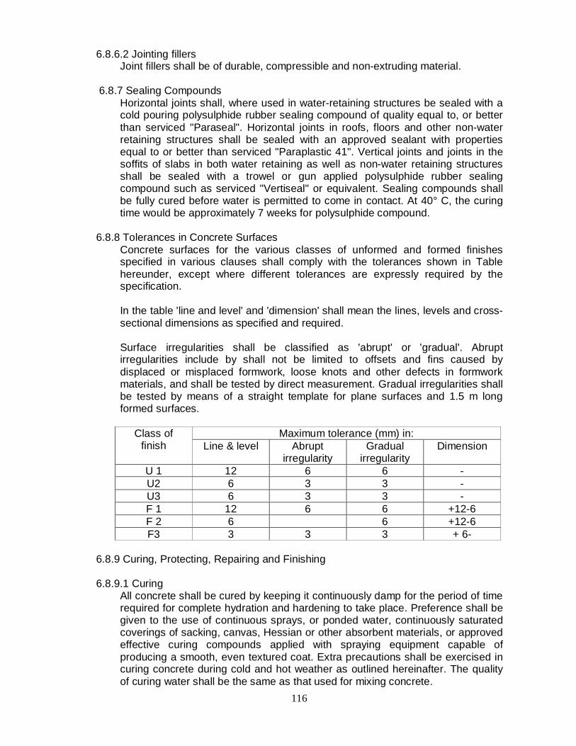
116
6.8.6.2 Jointing fillers Joint fillers shall be of durable, compressible and non-extruding material.
6.8.7 Sealing Compounds
Horizontal joints shall, where used in water-retaining structures be sealed with a cold pouring polysulphide rubber sealing compound of quality equal to, or better than serviced "Paraseal". Horizontal joints in roofs, floors and other non-water retaining structures shall be sealed with an approved sealant with properties equal to or better than serviced "Paraplastic 41". Vertical joints and joints in the soffits of slabs in both water retaining as well as non-water retaining structures shall be sealed with a trowel or gun applied polysulphide rubber sealing compound such as serviced "Vertiseal" or equivalent. Sealing compounds shall be fully cured before water is permitted to come in contact. At 40° C, the curing time would be approximately 7 weeks for polysulphide compound.
6.8.8 Tolerances in Concrete Surfaces
Concrete surfaces for the various classes of unformed and formed finishes specified in various clauses shall comply with the tolerances shown in Table hereunder, except where different tolerances are expressly required by the specification.
In the table 'line and level' and 'dimension' shall mean the lines, levels and cross-sectional dimensions as specified and required.
Surface irregularities shall be classified as 'abrupt' or 'gradual'. Abrupt irregularities include by shall not be limited to offsets and fins caused by displaced or misplaced formwork, loose knots and other defects in formwork materials, and shall be tested by direct measurement. Gradual irregularities shall be tested by means of a straight template for plane surfaces and 1.5 m long formed surfaces.
Class of finish
Maximum tolerance (mm) in: Line & level Abrupt
irregularity Gradual
irregularity Dimension
U 1 12 6 6 - U2 6 3 3 - U3 6 3 3 - F 1 12 6 6 +12-6 F 2 6 6 +12-6 F3 3 3 3 + 6-
6.8.9 Curing, Protecting, Repairing and Finishing 6.8.9.1 Curing
All concrete shall be cured by keeping it continuously damp for the period of time required for complete hydration and hardening to take place. Preference shall be given to the use of continuous sprays, or ponded water, continuously saturated coverings of sacking, canvas, Hessian or other absorbent materials, or approved effective curing compounds applied with spraying equipment capable of producing a smooth, even textured coat. Extra precautions shall be exercised in curing concrete during cold and hot weather as outlined hereinafter. The quality of curing water shall be the same as that used for mixing concrete.
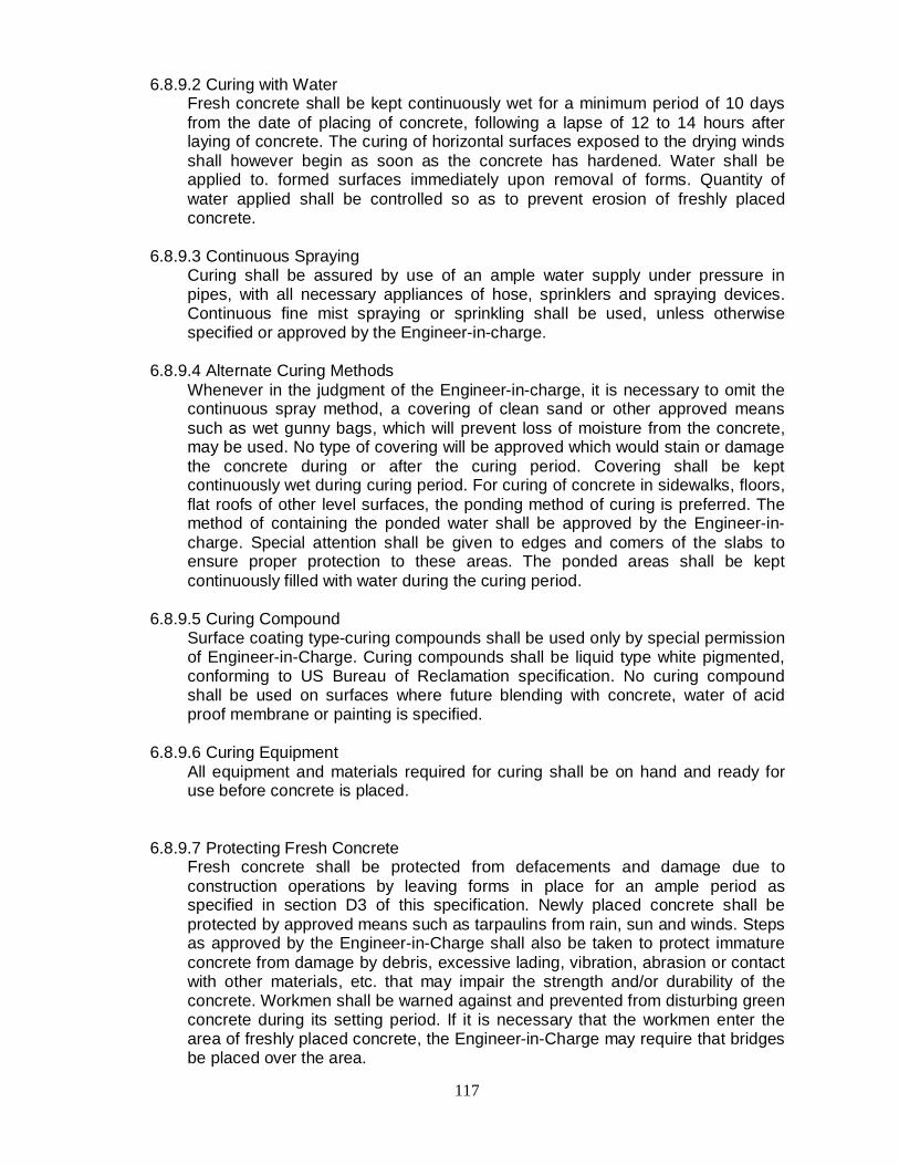
117
6.8.9.2 Curing with Water Fresh concrete shall be kept continuously wet for a minimum period of 10 days from the date of placing of concrete, following a lapse of 12 to 14 hours after laying of concrete. The curing of horizontal surfaces exposed to the drying winds shall however begin as soon as the concrete has hardened. Water shall be applied to. formed surfaces immediately upon removal of forms. Quantity of water applied shall be controlled so as to prevent erosion of freshly placed concrete.
6.8.9.3 Continuous Spraying
Curing shall be assured by use of an ample water supply under pressure in pipes, with all necessary appliances of hose, sprinklers and spraying devices. Continuous fine mist spraying or sprinkling shall be used, unless otherwise specified or approved by the Engineer-in-charge.
6.8.9.4 Alternate Curing Methods
Whenever in the judgment of the Engineer-in-charge, it is necessary to omit the continuous spray method, a covering of clean sand or other approved means such as wet gunny bags, which will prevent loss of moisture from the concrete, may be used. No type of covering will be approved which would stain or damage the concrete during or after the curing period. Covering shall be kept continuously wet during curing period. For curing of concrete in sidewalks, floors, flat roofs of other level surfaces, the ponding method of curing is preferred. The method of containing the ponded water shall be approved by the Engineer-in-charge. Special attention shall be given to edges and comers of the slabs to ensure proper protection to these areas. The ponded areas shall be kept continuously filled with water during the curing period.
6.8.9.5 Curing Compound
Surface coating type-curing compounds shall be used only by special permission of Engineer-in-Charge. Curing compounds shall be liquid type white pigmented, conforming to US Bureau of Reclamation specification. No curing compound shall be used on surfaces where future blending with concrete, water of acid proof membrane or painting is specified.
6.8.9.6 Curing Equipment
All equipment and materials required for curing shall be on hand and ready for use before concrete is placed.
6.8.9.7 Protecting Fresh Concrete Fresh concrete shall be protected from defacements and damage due to construction operations by leaving forms in place for an ample period as specified in section D3 of this specification. Newly placed concrete shall be protected by approved means such as tarpaulins from rain, sun and winds. Steps as approved by the Engineer-in-Charge shall also be taken to protect immature concrete from damage by debris, excessive lading, vibration, abrasion or contact with other materials, etc. that may impair the strength and/or durability of the concrete. Workmen shall be warned against and prevented from disturbing green concrete during its setting period. If it is necessary that the workmen enter the area of freshly placed concrete, the Engineer-in-Charge may require that bridges be placed over the area.

118
6.8.10 Repair and Replacement of Unsatisfactory Concrete 6.8.10.1 General
Immediately after the shuttering is removed, the surface of concrete shall be very carefully gone over and all defective areas called to the attention of the Engineer-in-charge who may permit patching of the defective areas or also reject the concrete unit either partially or in its entirety. Rejected concrete shall be removed and replaced by the contractor. Holes shall be filled with mortar composed of one part of cement to one and half parts of sand passing 2.36 mm LS sieve after removing any loose stones adhering to the concrete. Concrete surfaces shall be finished as described in specifications or as directed by the, Engineer-in-charge. Superficial honey combed surfaces and rough patches shall be similarly made good immediately after removal of shuttering, in the presence of the Engineer-in-charge and superficial water and air holes shall be filled in. The mortar shall be well worked into the surface with a wooden float. Excess water shall be avoided. Unless instructed otherwise by the Engineer-in-charge, the surface of the exposed concrete placed against shuttering shall be rubbed down immediately on removal of shuttering to remove fine or other irregularities, care being taken to avoid damaging the surface. Surface irregularities shall be removed by grinding. If reinforcement is exposed or the honeycombing occurs at vulnerable positions e.g. ends of beams or columns, it may be necessary to cut out the member completely or in part and reconstruct. The decision of the Engineer-in-charge shall be final in this regard. If only patching is necessary, the edges being cut perpendicular to the affected surface or with a small under cut if possible. Anchors, tees or dovetail slots shall be provided whenever necessary to attach the new concrete securely in place. An area extending several centimeters beyond the edges and the surfaces of the prepared voids shall be saturated with water for 24 hours immediately before the patching material is placed.
6.8.10.2 Use of Epoxy
The use of epoxy for bonding fresh concrete used for repairs will be permitted upon written approval of the Engineer-in-charge. Epoxies shall be applied in strict accordance with the instructions of the manufacturer.
6.8.10.3 Method of Repair
Small size holes having surface dimensions about equal to the depth of the hole, holes left after removal of form bolts, grout insert holes and slots cut for repair of cracks shall be repaired as follows. The hole to be patched shall be roughened and thoroughly soaked with clean water until absorption stops. A 5 mm thick layer of grout of equal parts of cement and sand shall be well brushed into the surface to be patched, followed immediately by the patching concrete which shall be well consolidated with a wooden float and left slightly protrude of the surrounding surface. The concrete patch shall be built up in 10 mm thick layers, after an hour or more, depending upon weather conditions, it shall be worked off flush with a wooden float and a smooth finish obtained by wiping with hessian. A steel trowel shall be used for this purpose. The mix for patching shall be of the same materials and in the same proportion as that used in the concrete being repaired, although some reduction in the maximum size of the coarse aggregates may be necessary and the mix shall be kept as dry as possible. Mortar filling by air pressure (guniting)

119
shall be used for repair of areas too large and/or too shallow for patching with mortar. Patched surfaces shall be given a final treatment to match the colour and texture of the surrounding concrete. White cement shall be substituted for ordinary cement, if so directed by the Engineer-in-charge, to match the shade of the patch with the original concrete.
6.8.10.4 Curing of Patched Work
The patched area shall. be covered immediately with an approved non-staining, water-saturated material such as gunny bags, which shall be kept continuously wet and protected against sun and wind for a period of 24 hours. Thereafter, the patched area shall be kept wet continuously by a fine spray, or sprinkling for not less than 10 days. All fillings shall be tightly bounded to the concrete and shall be sound, free from shrinkage cracks after the fillings have been cured and dried.
6.8.10.5 Approval by the Engineer-in-Charge
All materials, procedures and operations used in the repair work shall be subject to the approval of the Engineer-in-Charge.
6.8.11 Finishing 6.8.11.1 General
The type of finish for formed concrete surfaces shall be as follows, unless varied by the Engineer-in-Charge.
When the structure is in service all the surfaces shall receive no special finish, except repair of damaged or defective concrete, removal of fine and abrupt irregularities, filling defective concrete, filling of holes left by form ties and rods and clean up of loose or adhering debris. Surfaces which will be exposed to the weather and which would normally be level shall be sloped for drainage. Unless a horizontal surface or the slope required is specified, the tops of narrow surfaces such as stair treads, walls, curbs and parapets shall be sloped across the width approximately I in 30. Broader surfaces such as walkways, and platforms shall be sloped about I in 50. Surfaces that will be covered by backfill or concrete, sub floors to be covered with concrete topping, terrazzo or quarry tiles and similar surfaces shall be smooth ascended and leveled to produce even surfaces. Surface irregularities shall not exceed 6 mm. Surfaces which will not be covered. by backfill, concrete or tile toppings such as outside decks, floors of galleries and sumps, parapets, gutters, side-walks, floors and slabs, shall be consolidated, screened and floated. Excess water and laitance shall be removed before final finishing. Floating may be done with hand or power tools and started as soon as the screened surface has attained a stiffness to permit finishing operations and these shall be the minimum required to produce a surface uniform in texture and free from screened marks or other imperfections. Joints and edges shall be tooled as specified or as directed by the Engineer-in-Charge.
6.8.11.2 Standard Finish For Exposed Concrete
Exposed concrete shall mean any concrete, other than floors or slabs, exposed to view upon completion of the works. Unless otherwise specified, the standard finish for exposed concrete shall be a smooth finish. A smooth finish shall be obtained with the use of lined or plywood forms having smooth and even surfaces and edges. Panels of forms shall be of uniform size and be as large as practicable and installed with closed joints. Upon removal of forms the joint

120
marks shall be smoothed off and all blemishes, protections etc., removed leaving the surfaces smooth.
6.8.11.3 Integral cement concrete finish
When specified, an integral cement concrete finish of specified thickness for floors and slabs shall be applied either monolithic or bonded, as specified or directed by the Engineer-in-charge. The surface shall be tested with a straight edge and any high and low spots eliminated. Floating or toweling of the finish shall be permitted only after all surface water has evaporated. Dry cement or a mixture of dry cement and sand shall not be sprinkled directly on the surface of the cement finish to absorb moisture or to stiffen the mix.
6.8.11.4 Rubbed finish A rubbed finish shall be provided only on exposed concrete surfaces. Upon removal of forms, all fins and other projections on the surfaces shall be carefully removed, offsets leveled and voids and/or damaged sections immediately saturated with water and repaired by filling with a concrete or mortar of the same composition as was used in the surface. The surfaces shall then be thoroughly wetted and rubbed with carborundun or other abrasive. Cement mortar may be used in the rubbing, but the finished surfaces shall not be brush coated with either cement or grout after rubbing. The finished surfaces shall present a uniform and smooth appearance.
6.8.11.5 Protection
All concrete shall be protected against damage until final acceptance by the Engineer-in-charge.
6.8.12 Hot Weather Requirement
All Concrete work performed in hot weather shall be in accordance with IS:456, except as herein modified.
Admixtures may be used only when approved by the Engineer-in-Charge.
Adequate provisions shall be made to lower concrete temperatures by cool ingredients, eliminating excessive mixing, preventing exposure of mixers and conveyors to direct sunlight and the use of reflective paint on mixers, etc. The temperature of the freshly placed concrete shall not be permitted to exceed 38 degrees centigrade.
Consideration shall be given to shading aggregate stockpiles from direct rays of the sun and spraying stockpiles with water, use of cold water when available, and burying, insulating, shading and/or painting white the pipelines and water storage tanks and conveyance.
In order to reduce loss of mixing water, the aggregate, wooden forms, subgrade, adjacent concrete and other moisture absorbing surfaces shall be well wetted prior to concreting, placement and finishing shall be done as quickly as possible. Extra precautions shall be taken for the protection and curing of concrete. Consideration shall be given to continuous water curing and protection against high temperatures and drying hot winds for a period of at least 7 days
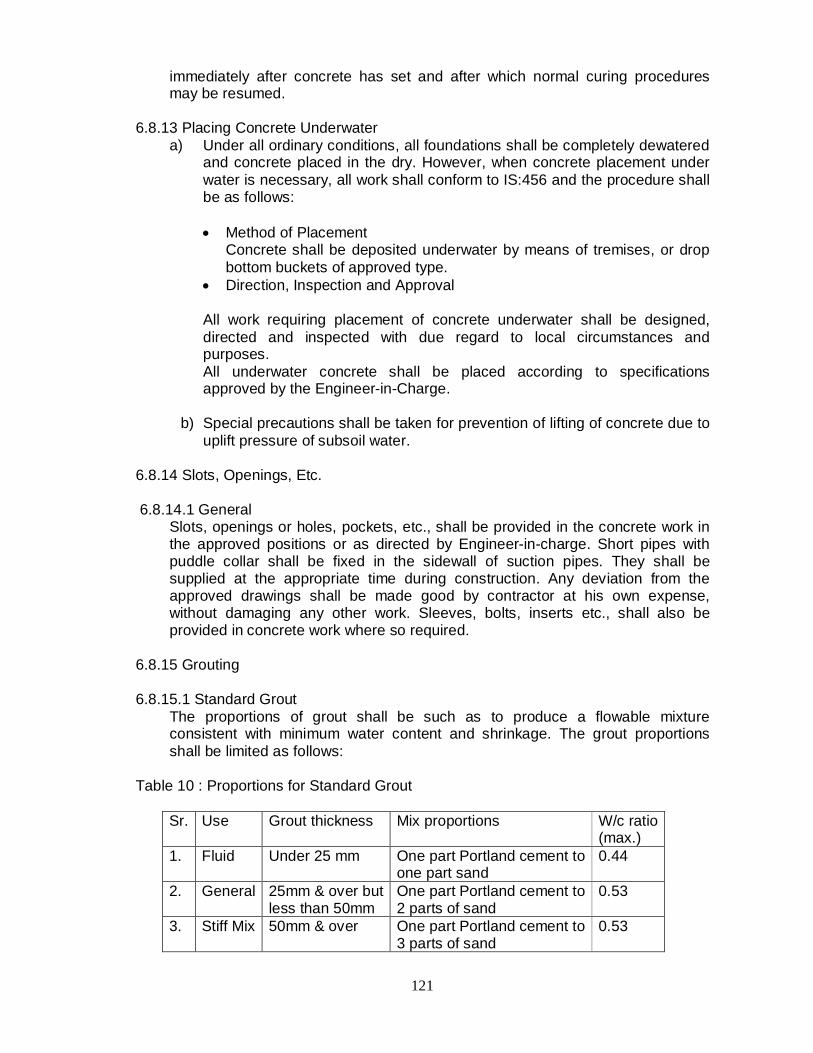
121
immediately after concrete has set and after which normal curing procedures may be resumed.
6.8.13 Placing Concrete Underwater
a) Under all ordinary conditions, all foundations shall be completely dewatered and concrete placed in the dry. However, when concrete placement under water is necessary, all work shall conform to IS:456 and the procedure shall be as follows:
Method of Placement
Concrete shall be deposited underwater by means of tremises, or drop bottom buckets of approved type.
Direction, Inspection and Approval
All work requiring placement of concrete underwater shall be designed, directed and inspected with due regard to local circumstances and purposes. All underwater concrete shall be placed according to specifications approved by the Engineer-in-Charge.
b) Special precautions shall be taken for prevention of lifting of concrete due to
uplift pressure of subsoil water. 6.8.14 Slots, Openings, Etc. 6.8.14.1 General
Slots, openings or holes, pockets, etc., shall be provided in the concrete work in the approved positions or as directed by Engineer-in-charge. Short pipes with puddle collar shall be fixed in the sidewall of suction pipes. They shall be supplied at the appropriate time during construction. Any deviation from the approved drawings shall be made good by contractor at his own expense, without damaging any other work. Sleeves, bolts, inserts etc., shall also be provided in concrete work where so required.
6.8.15 Grouting 6.8.15.1 Standard Grout
The proportions of grout shall be such as to produce a flowable mixture consistent with minimum water content and shrinkage. The grout proportions shall be limited as follows:
Table 10 : Proportions for Standard Grout
Sr. Use Grout thickness Mix proportions W/c ratio (max.)
1. Fluid Under 25 mm One part Portland cement to one part sand
0.44
2. General 25mm & over but less than 50mm
One part Portland cement to 2 parts of sand
0.53
3. Stiff Mix 50mm & over One part Portland cement to 3 parts of sand
0.53

122
Sand shall be such as to produce a flowable grout without any tendency to segregate. Sand for general grouting purposes, shall be graded within the following limits:
Passing BIS 2.36 mm sieve 95 to 100% Passing BIS 1.18 mm sieve 65 to 95% Passing BIS 300 micron sieve 10 to 30% Passing BIS 150 micron sieve 3 to 10%
Sand for fluid grouts, shall have the fine material passing the 300 and 150 micron sieves at the upper limits specified above. Sand, for still grouts, shall meet the usual grading specifications for concrete laitance. Anchor bolts, anchor bolt holes and the bottoms of equipment and column base plates shall be cleaned of all oil, grease, dirt and loose material. The use of hot, strong caustic solution for this purpose will be permitted. Prior to grouting, the hardened concrete surfaces to be grouted shall be saturated with water. Water in anchor bolt holes shall be removed before grouting is started. Forms around base plates shall be reasonably tight to prevent leakage of the grout. Adequate clearance shall be provided between forms and base plate to permit grout to be worked properly into place. Grouting, once started, shall be done quickly and continuously to prevent segregation, bleeding and breakdown of initial set. Grout shall be worked from one side of one end to the other to prevent entrapment of air. To distribute the grout and to ensure more complete contact between base plate and foundation and to help release trapped air, link chains can be used to work the grout into place. Grout throughout holes in base plates shall be by pressure grouting. Variations in grout mixes and procedures shall be permitted if approved by the Engineer-in-charge.
6.8.15.2 Non-Shrinking Grout for Equipment Foundation
Non-shrinking grout shall be used for grouting of machine base plates, anchor bolts, other anchoring devices and at locations where ordinary grouts are ineffective due to shrinkage. It shall be composed of a type of expansive hydraulic sheeting binder and select-graded aggregates. It shall have properties as mentioned below:
Table 11 : Proportions for Non-Shrinking Grout
Sr. Properties Values I Maximum grain size 6 mm 2 Water % (for 80% flow) 15.17 3 Density of hardened grout 2.27 - 2.30 gm/ml 4 Compressive strength N/mm2 Minimum 3 days 23 7 days 34 28 days 45, 5 Expansion Free 0.10-0.20 Restrained 0.08-0.12 Restrained 0.08-0.12
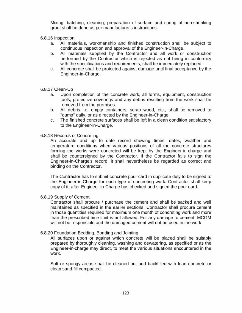
123
Mixing, batching, cleaning, preparation of surface and curing of non-shrinking grout shall be done as per manufacturer's instructions.
6.8.16 Inspection
a. All materials, workmanship and finished construction shall be subject to continuous inspection and approval of the Engineer-in-Charge.
b. All materials supplied by the Contractor and all work or construction performed by the Contractor which is rejected as not being in conformity with the specifications and requirements, shall be immediately replaced.
c. All concrete shall be protected against damage until final acceptance by the Engineer-in-Charge.
6.8.17 Clean-Up
a. Upon completion of the concrete work, all forms, equipment, construction tools, protective coverings and any debris resulting from the work shall be removed from the premises.
b. All debris i.e. empty containers, scrap wood, etc., shall be removed to "dump" daily, or as directed by the Engineer-in-Charge.
c. The finished concrete surfaces shall be left in a clean condition satisfactory to the Engineer-in-Charge.
6.8.18 Records of Concreting
An accurate and up to date record showing times, dates, weather and temperature conditions when various positions of all the concrete structures forming the works were concreted will be kept by the Engineer-in-charge and shall be countersigned by the Contractor. If the Contractor fails to sign the Engineer-in-Charge's record, it shall nevertheless be regarded as correct and binding on the Contractor.
The Contractor has to submit concrete pour card in duplicate duly to be signed to the Engineer-in-Charge for each type of concreting work. Contractor shall keep copy of it, after Engineer-in-Charge has checked and signed the pour card.
6.8.19 Supply of Cement
Contractor shall procure / purchase the cement and shall be sacked and well maintained as specified in the earlier sections. Contractor shall procure cement in those quantities required for maximum one month of concreting work and more than the prescribed time limit is not allowed. For any damage to cement, MCGM will not be responsible and the damaged cement will not be used in the work
6.8.20 Foundation Bedding, Bonding and Jointing
All surfaces upon or against which concrete will be placed shall be suitably prepared by thoroughly cleaning, washing and dewatering, as specified or as the Engineer-in-charge may direct, to meet the various situations encountered in the work.
Soft or spongy areas shall be cleaned out and backfilled with lean concrete or clean sand fill compacted.

124
Prior to construction of formwork for any item where soil will act as bottom form, approval shall be obtained from the Engineer-in-Charge for the suitability of the soil.
6.8.21 Preparation of Rock Strata of Foundations a. To provide tight bond with rock foundations, the rock surface shall be
prepared and the following general requirements shall be observed. b. Concrete shall not be deposited on large sloping rock surfaces. Where
required by the Engineer-in-charge, the rock shall be cut to form rough steps or benches to provide roughness or a more suitable bearing surface.
c. Rock foundation stratum shall be prepared by picking, barring, wedging and similar methods which will leave the rock in an entirely sound and un-shattered condition.
d. Shortly before concrete is placed, the rock surface shall be cleaned with high pressure water and air jet even though it may have been previously cleaned in that manner.
f. Prior to placing concrete, the rock surface shall be kept wet for a period of 2 to 4 hours unless otherwise directed by the Engineer-in-Charge.
g. Before placing concrete on rock surfaces all water shall be removed from depressions to permit thorough inspection and proper bonding of the concrete to the rock.
6.9 FORMWORK 6.9.1 Formwork, Fixing and General a) All formwork shall be constructed of waterproof plywood or preferably sheet
metal. Plywood used for formwork shall be -conforming to BIS:4990 i.e. Specification for plywood for concrete shuttering works. The materials for formwork shall be got approved by the Engineer-in-charge before starting the work. Formwork shall be firmly supported, adequately strutted, braced and tied to withstand the placing and vibrating of concrete and the effects of weather. The tolerance on line and level shall not exceed 3 mm and the soffits of beams other than pre-stressed beams shall in the absence of any specified camber, be erected with an upward camber of 6 mm for each 3 meters of span.
b) The Contractor shall be responsible for the calculations and designs for the
formwork, and if required, shall submit them to the Engineer-in-charge for approval before construction. On formwork to external faces, which will be permanently, exposed, all horizontal and vertical formwork joints shall be so arranged that joint lines will form a uniform pattern on the face of the concrete. Where the Contractor proposes to make up the formwork for standard sized manufactured formwork panels, the size of such panels shall be approved by the Engineer-in-charge before they are used in the construction of the Works. The finished appearance of the entire elevation of the structure and adjoining structures shall be considered when planning the pattern of joint lines caused by formwork and by construction joint to ensure continuity of horizontal and vertical lines.
c) Faces of form work in contact with concrete shall be free from adhering foreign
matter, projecting nails and the like, splits or other defects, and all form work shall be dean and free from standing water, dirt, shavings, chippings or other
125
foreign matter. Joints shall. be sufficiently watertight to prevent the escape of mortar or the formation of fins or other blemishes on the face of the concrete and no bleeding should be allowed through the joints.
d) Form work shall be provided for the top surfaces of sloping work where the slope
exceeds fifteen degrees from the horizontal (except where such top surface is specified as spaded finish) and shall be anchored to enable the concrete to be properly compacted and to prevent flotation, care being taken to prevent air being trapped.
e) Openings for inspection of the inside of the form work and for the removal of
water used for washing down shall be provided and so formed as to be easily closed before placing concrete. Before placing concrete, all bolts, pipes or conduits or other fixtures which are to be built in shall be fixed in their correct positions, and cores and other devices for forming holes shall be held fast by fixing to the formwork or otherwise. Holes shall not be cut in any concrete without approval of the Engineer-in-charge.
f) All exterior angles on the finished concrete of 90 degree or less shall be given 20
mm x 20 mm chamfers unless otherwise ordered by the Engineer-in-charge. g) No ties or bolts or other device shall be built into the concrete for the purpose of
supporting formwork without the prior approval of the Engineer-in-charge. The whole or part of any such supports shall be capable of removal so that no part .remaining embedded in the concrete shall be nearer than 50 mm from the surface in the case of reinforced concrete and 150 mm in the case of un-reinforced concrete. Holes left after removal of such supports shall be neatly filled with well-rammed dry-pack mortar.
h) Formwork in contact with the concrete shall be treated with suitable non-staining
mould oil to prevent adherence of the concrete except where the surface is subsequently to be rendered. Care shall be taken to prevent the oil from coming in contact with reinforcement or with concrete at construction joints. Surface retarding agents shall be used only where ordered by the Engineer-in-Charge.
i) No formwork shall be started or placed unless the requirement work is fully
completed and checked by Engineer-in-Charge. j) Necessary cover blocks shall be provided before starting connection. 6.9.2 Removal of Formwork a) Formwork shall be so designed as to permit any removal without resorting
to hammering or levering against the surface of the concrete.
c) The periods of time elapsing between the placing of the concrete and the striking of the loads likely to be imposed on the concrete and shall in any case be not less than the periods shown in Table below. Where soffit formwork is constructed in a manner during and after such removal of a sufficient number of adequate supporting props in an undisturbed condition, the Contractor may, with the agreement of the Engineer-in-charge, remove the formwork at the earlier times listed below provided that the props are left in position.

126
Table 12: Period for Formwork
Position of formwork Days "for striking Walls 1 Sides of beams and columns 2 Slabs (Drops left under) 3 Props to slabs (span not exceeding 4.5m) 7 Props to slabs (span exceeding 4.5 m) 14 Beams soffits (props left under) 7 Props to beams (span not exceeding 6 m) 14 Props to beams (span exceeding 6 m) 21
c) Notwithstanding the foregoing, the Contractor shall be held responsible for any
damage arising from removal of formwork before the structure is capable of carrying its own weight and any incidental loading.
d) Striking shall be done slowly with utmost care to avoid damage to projections and
without shock or vibration, by gently easing the wedges. If after removing the formwork it is found that timber has been embedded in the concrete. It shall be removed and made good as specified earlier.
e) Reinforced temporary openings shall be provided, as directed by the Engineer-in
charge, to facilitate removal of formwork which otherwise may be inaccessible. f) The rods, clamps, form bolts, etc. which must be entirely removed from walls or
similar structures shall be loosened not sooner than 24 hours not later than 40 hours after the concrete has been deposited. Ties, except those required to hold forms in place, may be removed at the same time. Ties, withdrawn from walls and grade beams shall be pulled toward the inside face. Cutting ties back from the faces of the walls and grade beams will not be permitted.
g) For liquid retaining structures, no sleeves for through bolts shall be used nor shall
through bolts be removed as indicated above. The bolts, in this case, shall be cut at 25 mm depth or more from the surface and then the hole shall be made good by cement sand mortar of the same proportions as the concrete just after striking the formwork.
6.9.3 Formed Surfaces - Classes of Finish a) Finishes to formed surfaces of concrete shall be classified as F1, F2, or F3, or
such other special finish as may be particularly specified. Where the class of finish is not specified the concrete shall be finished to Class Fl.
b) Form work for Class F3 finish shall be lined with as large panels as possible of non-staining material with a smooth unblemished surface such as sanded plywood or hard compressed fiber board, arranged in a uniform approved pattern and. fixed to back form work by oval nails. Unfaced wrought boarding or standard steel panels shall not be permitted.
c) Form work for Class F2 finish shall be faced with wrought tongued and grooved boards or plywood or metal panels arranged in a uniform approved pattern free from defects likely to detract from the appearance of the surface.
Form work for Class F1 finish shall be constructed in sheet metal. Surfaces subsequently to be rendered, plastered or tiled shall be adequately scrabbled or

127
hacked as soon as the form work is removed to reduce the irregularities to not more than half the thickness of such rendering, plastering or bedding for tiles and to provide a satisfactory key.
6.9.4 Defects in Formed Surfaces a. Workmanship in formwork and concreting shall be such that concrete shall
normally require no making good, surfaces being perfectly compacted and smooth.
If any blemishes are revealed after removal of formwork, the Engineer-incharge's decisions concerning remedial measures shall be obtained immediately. These measures may include, but shall not be limited to the following:
Fins, pinhole bubbles, surface discolouration and minor defects may be rubbed down with sacking immediately after the formwork is removed.
Abrupt and gradual irregularities may be rubbed down with carborundun and water after the concrete has been fully cured. These and any other defects shall be remedied by methods approved by the Engineer-in-charge which may include using a suitable epoxy resin or, where necessary, cutting out to a regular dovetails shape at least 75 mm deep and refilling with concrete over steel mesh reinforcement sprung into the dovetail.
b. The form work shall be checked by the Engineer-in-charge before the form work
starts and form found defective shall be rejected and the same can be used after rectifying the defects and with due approval of the Engineer-incharge
6.9.5 Holes to be Filled 1. Holes formed in concrete surfaces by form work supports or the like shall be
filled with dry-pack mortar made from one part by weight of ordinary Portland cement and one part fine aggregate passing BIS sieve 1.18 mm. The mortar shall be mixed with only sufficient water to make the materials stick together when being moulded in the hands.
2. The contractor shall thoroughly clean any hole that is to be filled with dry-pack mortar and where the surface has been damaged, the contractor shall break out any loose, broken or cracked concrete or aggregate. The concrete surrounding the hole shall then be thoroughly soaked after which the surface shall be dried so as to leave a small amount of free water on the surface. The surface shall then be dusted lightly with ordinary Portland cement by means of a small dry brush until the whole surface that will come into contact with the dry-pack mortar has been covered and darkened by absorption of the free water on the surface. The surface shall then be dusted lightly with ordinary Portland cement by means of a small dry brush until the whole surface that will come into contact with the dry-pack mortar has been covered and darkened by absorption of the free water by the cement. Any dry cement in the hole shall be removed.
3. The dry-pack material shall then be placed and packed in layers having a compacted thickness not greater then 15 mm. The compaction shall be carried out by use of a hardwood stick and a hammer and shall extend over the full area of the layer, particular care being taken to compact the dry-pack against the sides of the hole. After compaction, the surface of each layer shall be scratched the dry-pack fill and striking the block several times. Steel finishing tools shall not be used and water shall not be added to facilitate finishing.

128
6.9.6 Tolerances Tolerance is a specified permissible variation from lines, grade or dimensions given in approved drawings. No tolerance specified for horizontal or vertical building lines or footings shall be construed to permit encroachment beyond the legal boundaries. Unless otherwise specified, the following tolerances will be permitted:
Tolerances for RCC Structures i. Variation from the plumb In the lines and surfaces of columns, piers, walls 5 mm per 2.5 m or 25 mm,
whichever is less. For exposed corner columns and other conspicuous lines In any bay or 5 m
maximum 5 mm In 10 m or more 10 mm ii. Variation from the level or from the grades indicated on the approved drawings In
slab soffits, ceilings, beam soffit, and in arise In 2.5m 5mm In any bay or 5 m maximum 10 mm In 10 m or more 15 mm
For exposed lintels, sills, parapets, horizontal grooves and other conspicuous lines In any bay or 5 m maximum 5 mm
In 10 m or more 10 mm iii. Variation of the linear building lines from established position in plan and related
position of columns, wall and partitions In any bay or 5 m maximum 10 mm
In 10 m or more 20 mm iv. Variation in the sizes and locations of sleeves, openings in walls and floors
Except in the case of and for 5mm anchor bolts v. Variation in cross sectional dimensions of columns and beams and in the
thickness of slabs and walls Minus 5 mm Plus 10 mm vi. Footings Variation in dimension in plan Minus 5 mm Plus 10 mm vii. Misplacement or eccentricity 2% of footing width in the direction of misplacement
but not more than 50 mm Reduction in thickness: Minus 5% of specified thickness subject to a maximum of 50 mm
viii. Variation in steps In a flight of stairs Rise 3 mm Tread 5 mm

129
In consecutive steps Rise 1.5 mm Tread 3 mm Tolerances in other Concrete Structures ix. All structures Variation of the constructed linear outlines from established position in plan In 5m 10 mm In 10 m or more 15 mm Variations of dimensions to individual structural features from established
positions In 20 m or more 25 mm In buried construction 50 mm Variation from plumb, from specified batter or from curved surfaces of all
structures In 2.5m 10 mm In5m 15 mm In 10 m or more 25 mm In buried construction twice the above amounts Variation from level or grade indicated on approved drawings in slab, beams,
soffits, horizontal grooves and visible arises In 2.5m 5mm In 7.5 m or more 10 mm In buried construction Twice the above amounts Variation in cross-sectional dimensions of columns, beams, buttresses, piers and
similar members Minus 5 mm Plus 10 mm x. Footings for columns, piers, walls, buttresses and similar members Variation of dimensions in plan Minus 10 mm Plus 50 mm Misplacement or eccentricity 2% of footing width in the direction of misplacement but not more than 50 mm.
Reduction in thickness 5% of specified thickness subject to a maximum of 50 mm xi. Tolerance in other types of structures shall generally conform to those given in
Clause 2.4 of Recommended Practice for Concrete Formwork (American Concrete Institute Act 347).
xii. Tolerance in fixing anchor bolts shall be as follows: Anchor bolts without sleeves + 5 mm Anchor bolts with sleeves + 5 mm for bolts up to 20 mm dia 3 mm for bolts above 32 mm dia Embedded parts + 5 mm in all directions
130
6.9.7 Bracing, Struts and Props a. Form work shall be braced, strutted, propped and so supported that it shall
not deform under weight and pressure of the concrete and also due to the movement of men and other materials. Bamboo shall not be used as props or cross bearers.
b. The formwork for beams and slabs shall be so erected that the formwork on
the sides of the beams and under the soffit of slabs can be removed without disturbing the beam bottoms. Repropping of beams shall not be done except when props have to be reinstated to take care of construction loads anticipated to be in excess of the design load. Vertical props shall be supported on wedges or other measures shall be taken whereby the props can be gently lowered vertically while striking the formwork.
c. If the formwork for a column is erected for the full height of the column, one
side shall be left open and built up in sections as placing of the concrete proceeds, or windows may be left for pouring concrete from the sides to limit the drop of concrete to 1.0 m as directed by the Engineer-in-Charge.
Contractor shall submit the detailed design and methodology with applicable drawings if any of Formwork system for different members for approval of Engineer-in-Charge.
6.10 REINFORCEMENT 6.10.1 Relevant IS Codes IS:432 Mild steel and medium tensile steel bars and hard drawn steel
wire for concrete reinforcement IS:1786 Cold twisted steel bars for concrete reinforcement (CTD) IS:2502 (1963) Code of practice for bending and fixing of bars for concrete
reinforcement IS:55225(1969) Recommendations for detailing of reinforcement in RCC works IS:2751 C. P. for welding of MS bars used for RCC
IS:9417 Recommendations for welding cold worked steel bars for RCC IS: 10790 Methods of sampling of reinforced steel
6.10.2 General
Reinforcement shall be CTD of high strength deformed corrosion resistant (CRS) bars as per IS:1786 - Fe415. Wire mesh or fabric shall be in accordance with IS:456. Substitution of reinforcement will not be permitted except upon written approval from the Engineer-in-charge.
6.10.3 Storage
a. The reinforcement shall not be kept in direct contact with the ground but stacked on top of an arrangement of timber sleepers or the like.
b. If the reinforcing rods have to be stored for a long duration, they shall be coated with cement wash before stacking and/or be kept under cover or stored as directed by the Engineer-in-Charge.
c. Fabricated reinforcement shall be carefully stored to prevent damage, distortion, corrosion and deterioration.
131
d. It should be seen that the reinforcement will not be exposed to direct sunlight and preventive measures should be taken for the same.
6.10.4 Quality
All reinforcements shall be clean, free from grease, oil paint, dirt, loose mill scale, loose rust, dust bituminous material or any other substances that will destroy or reduce the bond. All rods shall be thoroughly cleaned before being fabricated. Pitted and defective rods shall not be used. No welding of rods to obtain continuity shall be allowed unless approved by the Engineer-in-charge. If welding is approved, the work shall be carried out as per IS:1786 - Fe415 according to the best modem practices and as directed by the Engineer-in-Charge. In all cases of important connections, tests shall be made to prove that the joints are of full strength of bars welded. Special precautions, as specified by the Engineer-in-charge, shall be taken in the welding of cold worked reinforcing bars and bars other than mild steel.
6.10.5 Laps
Laps and splices for reinforcement shall be as per IS:456. Splices in adjacent bars shall be staggered and locations of all splices shall be approved by the Engineer-in-Charge.
6.10.6 Bending Reinforcement bars supplied bent or in coils, shall be straightened before they are cut to size. Straightening of bars shall be done cold and without damaging the bars.
All bars shall be accurately bent according to the sizes and shapes shown on the approved detailed working drawings/bar bending schedules. They shall be bent gradually by machine or other approved means. Reinforcing bars shall not be straightened and re-bent in a manner that will injure the material;; bars containing cracks/splits shall be rejected. They shall be bent cold, except bars of over 25 mm in diameter, which may be bent hot if specifically, approved by the Engineer-in-charge. Bars, which depend for their strength of cold working, shall not be bent hot. Bars bent hot shall not be treated beyond cherry red colour (nor exceeding 845°C) and after bending shall be allowed to cool slowly without quenching. Bars incorrectly bent shall be used only if the means used for straightening and re-bending be such as shall not, in the opinion of the Engineer-in-charge, injure the material. No reinforcement shall be bent when in position in the work without approval, whether or not it is partially embedded in hardened concrete. Bars having kinks or bends other than those required by design shall not be used.
6.10.7 Fixing
Reinforcement shall be accurately fixed by any approved means and maintained in the correct position shown in the approved Drawings by the use of blocks, spacers and chairs, as per IS:2502 to prevent displacement during placing and compaction of concrete. Bars intended to be in contact at crossing points shall be securely bound together at all such points with number 16 gauge annealed soft iron wire. The vertical distances required between successive layers of bars in beams or similar members shall be maintained by the provision of mild steel spacer bars at such intervals that the main bars do not perceptibly sag between adjacent spacer bars.

132
6.10.8 Cover a. Unless indicated otherwise, clear concrete cover for reinforcement
(exclusive of plaster or other decorative finish) shall be as follows: b. At each end of a reinforcement bar, not less than 25 mm nor less than twice
the diameter of the bar. c. For a longitudinal reinforcing bar in a column, not less than 40 mm, nor less
than the diameter of the bar. In case of columns of minimum dimension of 20 cm or under with reinforcing bars of 12 mm and less in diameter, a cover of 25 mm may be used.
d. For longitudinal reinforcing bars in a beam, not less than 25 mm nor less than the diameter of the bar.
e. For tensile, compressive, shear or other reinforcement in a slab, or wall, not less than, 15 mm, nor less than the diameter of such reinforcement.
f. For any other reinforcement, not less than 15 mm, nor less than the diameter of such reinforcement.
g. For footing and other principal structural members in which the concrete is poured on a layer of lean concrete, the bottom cover shall be reduced to 50 mm.
h. For concrete surfaces exposed to the weather or the ground after removal of forms, such as retaining walls, grade beams, footing sides and tops, etc. not less than 50 mm for bars larger than 16 mm diameter and not less than 40 mm for bars 16 mm diameter or smaller.
i. For liquid retaining structures, the minimum cover to all steel shall be 25 mm or the diameter of the main bar, whichever is greater. In the presence of soils and waters of a corrosive character, the cover shall be increased by 10 mm.
j. The correct cover shall be maintained by cement mortar cubes or other approved means. Reinforcement for footings, grade beams and slabs on sub-grade shall be supported on pre-cast concrete "blocks as approved by the Engineer-in-charge. The use of pebbles or stones shall not be permitted.
k. The 28 day crushing strength of cement mortar cubes/precast concrete cover blocks shall be at least equal to the specified strength of concrete in which these cubes/blocks are embedded.
I. The minimum clear distance between reinforcing bars shall be in accordance with IS:456
6.10.9 Inspection
After final erection of reinforcement, it shall be intimated to Engineer-in-charge in writing or through pour cards. Erected and secured reinforcement shall be inspected and approved by the Engineer-in-Charge prior to placement of concrete.
6.10.10 Welding of Reinforcement a. Reinforcement which is specified to be welded shall be welded by any
process which conforms with the requirements of IS:2751 and which the Contractor can demonstrate by bend and tensile tests will ensure that the strength of the parent metal is not reduced and that the weld possesses a strength not less than that of the parent metal. The welding procedure established by successful test welds shall be maintained and no deviation from this procedure, shall. be permitted.
133
b. Welds in positions other than those shown on the approved Drawings shall not be permitted. Tack welding to lightly secure reinforcement in place will be permitted subject to approval of the Engineer-in-charge.
6.10.11 Supply of Reinforcing Bars .
Contractor shall procure / purchase the cement and shall be sacked and well 'maintained as specified in the earlier sections. Contractor shall procure cement in those quantities required for maximum 1 month of concreting work and more than the prescribed time limit is not allowed. MCGM will not be responsible for any damage to cement and the damaged cement will not be used in the work.
6.11 ANTI-CORROSIVE TREATMENT WITH CPCC TO REINFORCING STEEL BARS Detailed specifications for providing an anticorrosive treatment with cement polymer composite coating C.P.C.C. (Karaikudi) to H.Y.S.D. / M.S. Bars bent to the require shape and size including transportation of steel bars for treatment and bringing back the same for fixing including all accessories and material required for giving the treatment using chemicals as per specifications etc. complete (only from approved suppliers) as directed.
SPECIFICATION FOR ANTI-CORROSIVE TREATMENT TO H.Y.S.D. / M.S. REINFORCEMENT BARS BY CEMENT POLYMER COMPOSITE COATING (C.P.C.C.) TREATMENT (Method developed by C.E.C.R.I. Karikudi, Tamilnadu) Materials :- The material required for C.P.C.C. treatment shall be procured from the approved licensee of CECRI and also got approved from Engineer-in-charge. Materials shall be tested for following tests prior to use. 1) Density
2) pH Value 3) Specific gravity 4) Chloride content 1) METHOD OF APPLICATION OF COATING SYSTEM :
The application of the cement polymer composite coating system comprises the
following sequence.
1.1 SURFACE PREPARATION:
The surface of the steel reinforcing bars to be coated shall be cleaned by abrasive (dry sand) blast cleaning the metal to near while in accordance with SSPC – SPIONCE – No.2-1994. It includes following procedures – i. Prior to blast cleaning, visible deposits of oil or grease shall be
removed by suitable cleaning method. ii Clean compressed air shall be used for Nozzle blasting. ii. Dry uniformly graded silica shall be used for blast cleaning which
should be free from contaminants iv Suitable arrangement shall be made I the sand blasting unit to
suit automation. v During the operation, the pressure at the nozzle shall be
regulated as per the suppliers specifications. vi Dust and residue shall be removed from prepared surface by

134
brushing, blowing off with clean dry air, vacuum cleaning and other methods.
vii Any visible rust that forms on the surface of the steel after blast leaning shall be removed by re-blasting the rusted areas before coating.
viii The prepared surface shall meet the visual standards of comparison as in SSPC-VIS 1 of SSPC-VIS 2.
1.2 APPLICATION OF THE COATING :
i) The coating shall be applied to the cleaned surface as soon as after cleaning and before oxidation of the surface discernible to the unaided eye occurs. However, the application of the coating shall not be delayed more than 4 Hrs. after cleaning.
ii) A rapid setting primer shall be applied over the prepared surface of the reinforcing steel either by brushing or dipping.
iii) After 30 minutes of application of the primer, a cement polymer sealing coat shall be applied either by brushing or dipping.
iv) The coated rods shall be handled after 6 hours.
1.3 The above process of surface preparation and coating shall be mechanized
/ automatic.
2) REQUIREMENTS OF THE COATED BARS The coated reinforcement rods of cement polymer composite coating system shall meet the following requirements :- i) Thickness of the coating :
After curing, the minimum average dry film thickness of coated rods shall not be less than 150+25 microns. Measurement shall be made using commercially available coating thickness meter which should be specifically suitable for curved surfaces.
ii) Continuities of coating. The coated rod when visually examined should be fairly uniform in thickness and should be devoid of any effects such as cracks, peeling, bulging etc.. No surface area should be left uncoated. No spot should be visible with unaided eye.
iii) After 30 minutes of application of the primer, a cement polymer sealing coat shall be applied either by brushing or dipping. iv) The coated rods shall be handled after 6 Hrs.
1.3 The above process of surface preparation and coating shall be mechanized / automatic.
3) REQUIREMENTS OF THE COATED BARS :
The coated reinforcement rods of cement polymer composite coating system shall meet the following requirements :- i) Thickness of the coating :
After curing, the minimum average dry film thickness of coated rods shall not be less than 150+25 microns. Measurement shall be made using commercially available coating thickness meter which should be specifically suitable for curved surfaces.
ii) Continuities of Coating : The coated rod when visually examined should be fairly uniform in thickness and should be devoid of any effects such as cracks, peeling, bulging, etc.
135
No surface area should be left uncoated. No spot should be visible with unaided eye.
iii) Adhesion of coating :- The coating should not peel off or racked or disbanded on the outside radius when the coated bars are bent to 180o around a mandrel (as per test procedure A)
iv) Relative bond strength The bond strength of the coated bar and concrete should not be less than that specified in IS 456-2000 Clause 44.1.2 (Bond stress for deformed bars in tension). The test procedure is to be followed as per BIS 2770-Part-I, 1967.
v) Resistance to applied voltage test No film failure as evidenced by evolution of Hydrogen gas at the cathode or appearance of corrosion product at the anode shall take place during 1 Hr.of testing (As per test procedure-B).
vi) Abrasion Resistance The abrasion resistance of the coating by TABER Abrasor should not be more than 100mmg/1000 cycles. Using CS 10 wheel under 1 Kg. load / per wheel (As per test procedure-C).
vii) Chemical resistance of coating The coated rods are kept partially immersed in the following four individual environments for 45 days. Distilled water, 3 M CACL2, 3M NaOH and saturated Ca(OH)2 for 45 days, the coating should not blister, soften, or loose bond when visually examined at the end of the test period (as per Procedure-E).
All the text procedures of CECRI for CPCC treatment shall be followed. QUALITY CONTROL MEASURES TO BE TAKEN AT SITE : 1) The application and test are to be supervised strictly as per the
specifications. 2) Sand blasting of the surface of reinforcement steel is to be done as per the
surface preparation mentioned in Application System. 3) Primer coat and sealing coat are to be applied by brush or by spraying or by
dipping under supervision. 4) Coating thickness of the finished bar can be checked frequently by pen type
Alcometer. 5) The 2V Impressed current test (ASTM A-775/775/5m-90) is to be taken
randomly at site laboratory (every 15 days). It is most critical test for finished products.
6) The coated bars bending test can be observed frequently at site. 4) GUIDELINES FOR HANDLING, STACKING AND TRANSPORTING OF
COATED REINFORCING BARS : The durability of the coating rebars is related to the coating quality. The more damage to the coating is more prone to corrosion. Good job site practices can minimize the coating damage. For this reason, standards from ASTM, JSCE, NACE (USA) have laid down specific procedures. For stacking and transporting coated bars, some important guidelines are referred here. 5) STACKING: I) t is preferable to store the coated bars on buffer materials placed at suitable
intervals instead of placing them directly on the ground. ii) It is not desirable to store coated bars by piling them on top of one another.
If they are to be stored by piling, buffer materials such as wood, rubber, jute,
136
sack etc. should be used to separate the layers. However, the number of layers allowed shall be limited to a maximum of five.
iii) The coated bars shall be stored in the Yard. iv) If any damage had occurred during stacking, it should be repaired
immediately by the same coating formulation before any rusting occurs. 6) HANDLING AND TRANSPORTATION : I) The coated bars shall be securely bound together using a buffer material
(padding) and it is desirable that the bent bars shall be supplied with same canvas cover.
ii) When loading and unloading of bundles of coated bars, it shall be preferable to lift them with a strong back, spreader bar multiple supports etc.. To avoid extreme bending, nylon slings at 2 to 3 points shall be used.
iii) The bundle of bars shall not be dropped. iv) If damage had occurred to the coating during transportation, it must be
repaired before rusting occurs. 7) SPECIFICATIONS FOR PATCH REPAIRS OF COATING DAMAGES: a) Coating repairs is requested when peeling off and other damages exits.
prior to repairs, the damaged area shall be cleaned by removing loose or deleterious material. In case where rust is present, it shall also be mechanically removed to repair.
b) After this primer coat shall be brush applied, after curing (15-30) minutes) sealing coat shall be applied and it is desirable to ensure thickness of 150 microns.
8) SPECIFICATION FOR CUTTING, BENDING AND WELDING OF COATED REBARS AT FIELD.
I) It is desirable that the coated rods shall be bent gradually. ii) In the field, the cut and welded portions of the coated rebars shall be repaired by the same formulations. iii) The cut ends of the coated rebars shall be repaired by the same formulations.
9) SAFETY PRECAUTIONS AND GUIDELINES TO BE FOLLOWED DURING THE PREPARATION AND APPLICATION OF THE CEMENT POLYMER COMPOSITE COATING ( A knowhow released by CECRI):
I) A solvent resistant hand gloves must be used during the handling of chemicals.
ii) Gum shoes must be used during the preparation and application. iii) Facemasks should be worn during the preparation and application. iv) Other safety measures should be adopted for the persons handling solvents, chemicals, finished produces and during applications. v) Closed sand blasting unit shall be used to avoid dust spreading. vi) Aprons made preferably from rubber and plastic must be used. vii) The container containing chemicals and finished products shall be properly
sealed. viii) Adequate safety measures should be adopted for field operatins. ix) In general, all the safety measures should be followed as per industrial
safety regulations.
10) REFERENCE DOCUMENTS : a) ASTM G8-90 Standard Test methods for cathodic disbanding or pipeline
coating (Method A). b) ASTM G20-88 Standard Test methods for chemical resistance of pipeline
coatings.

137
c) ASTM G12-83 Standard Test methods non-destructive measurement of film thickness of pipeline coating on steel.
d) ASTM D-4060-90 Standard Test methods for abrasion resistance organic coatings by the Taber abraser industrial safety regulations.
e) ASTM G14-88 Standard Test methods for impact resistance of pipe line coatings (Falling-weight test).
f) GIS 2770-POart 1:1967 Methods of Testing bond in reinforced concrete Part-I-Pullout Test (1967).
g) SSPC-SP10/NACE No.2-1994 Near white blasting. h) SSPC VIS 2-Guide to standard method -\ degree of rusting on painted steel
surface. i) SSPC SP COM-Surface preparation specifications. 11) TESTS FOR CPCC:
11.1 Test Procedure A
Determination of Adhesion of the Coating
Adhesion of the coating is to be tested as per ASTM A 775/775 M 94 d. 10mm dia coated rods of length 1M shall be used in this test. The coated rods shall be placed with sponge and bent to 180o around a 75mm diameter mandrel. The bending shall be done at an uniform rate and not suddenly. No cracking of the coating shall be visible to the unaided eye on the outside radius of the bar. If the test is to be conducted on other than 10mm diameter rod, then the diameter of the mandrel has to be changed accordingly, as tabulated below :-
Diameter of the Rod (mm) Diameter of the mandrel (mm) 8mm and 10mm 75
16 100 25 200 32 250
11.2 Test Procedure B :-
Two identical coated bars of the same size and length shall be used in the test. 14mm gauge copper wire shall be soldered on the one end of each bar. The other end of the bars shall be sealed with an insulating material to a length of 2.5cm. The exposed area on which test is to be conducted shall not be less than 240 cm2. If 10mm dia rods are used, then the length exposed shall not be less than 80 cm.
A non-conductive plaster container of size not less than 150mm x 150mm x 850 mm. is filled with 7% NaCl solution (70 gms/litre) up to the height of 800mm. The coated rebars shall be suspended vertically so as to have a clearance of 25mm from the bottom, 40mm from the sides and 40mm between the rods. A potential of 2V in between the coated rods shall be impressed for a period of 60 minutes using suitable DC power source. The voltage and current shall be measured by using a high resistance voltmeter having an internal resistance of not less than 10 Mega Ohms and having a range upto 5 V (minimum). Storage batteries may also be used for impressing the voltage.

138
During this 60 minutes of testing, there shall not be any coating / failure as evidenced by evolution of hydrogen gas at the cathode or by appearance of corrosion production of iron at the anode.
11.3 Test Procedure C- Determination of Abrasion Resistance of the Coating.
Test shall be conducted as per ASTM D 4060 using Taber CS-10 wheel under 1 Kg. load per wheel. Abrasion resistance of the coating shall be conducted on panel of size 100mm x 100mm in which 8mm dia hole shall be drilled. The panel shall be coated as per specified procedure. After curing, thickness of the coating shall be measured in several locations along the path to be abraded. The initial weight of the panel shall be measured to the nearest 0.1 mg. Then the coated panel shall be mounted on the turn table. The abrading heads shall be placed on the panel and the vacuum, pick up nozzle kept in position. The counter shall be set in position. The vacuum picks up and turn table of the abrader shall be fixed for 1000 cycles. After 1000 cycles loose abradings remaining on the test specimen shall be removed by light brushing. The final weight of the specimen shall be measured for finding the loss in weight. The weight loss shall not exceed 100mg. The test shall be conducted on duplicate specimens.
11.4 Test Procedure D Chloride Tolerable Limit.
10mm dia cement polymer coated rod of length 10cm. shall be used. Bottom edge of the coated rod shall be sealed using lacquer. Then test specimen is kept immersed in 0.04 N NaOH + 10,000 ppm chloride and potential is monitored using high impedance Multimeter against suitable reference electrode, such as saturated calomel electrode. After getting established potential, using appropriate current regular (0-100mmA), the test specimen is anodically polarized at a constant current density of 290 uA/cm2, using a platinum / stainless steel /TSIA/Polished mild steel as cathode. Potential with time is followed for 5 minutes. At the end of 5 minutes, no rust spots shall be observed on the coated rod.
11.5 Test Procedure E Chemical Resistance of the Coating
The coated rods (any diameter) of length 30cm shall be used in this test. The bottom edges of the coated rods are to be sealed using lacquer. Transparent PVC cylindrical container shall be used. 3M CaCl2 M NaOH, Saturated Ca(OH)2 and distilled water are prepared as individual test solution and filled in the separate container up to the half of its height. Then the coated rods are kept partially immersed in the test solution so that they are in long term contact with both the liquid and vapour phase of the test solution. The test shall be conducted for 45 days. The coating should not blister, soften or disband during this period.

139
11.6 Test Procedure F Impact Resistance of the Coating. The resistance of a cement polymer coated reinforcing bar to a mechanical damage shall be determined by the falling weight test. A test apparatus similar to the described in test method G14 of the ASTM standard shall be used. Impact shall occur on the low lying area of the coated bar, that is between deformation and ridges. The test shall be performed at room temperature. With an impact force of 9 NM, no shattering, racking or disbandment of the coating shall occur except at the impact area i.e. area permanently deformed by the tup.
6.12 PLASTERING Relevant IS Codes IS:1542 Sand and Plaster IS: 1661 C.P. for application of ferrous metals in building IS:2394 C.P. for application of lime plaster finish
Cement mortar used for plastering shall be of the mix proportions and thickness as specified on the drawings or bill of quantities or particular specifications for the various different parts of the works.
The materials used i.e. cement, sand and water shall be of the same quality and of the same specifications as indicated for plain and reinforced cement concrete works in this tender.
Sand further shall meet the specifications as laid down in IS: 1542-1977 Specification for sand for plaster.
The surfaces that are to be applied with plaster shall be thoroughly cleaned to remove dust, dirt, loose particles, oil, soil, slats etc. that may be sticking to the surfaces. The surfaces shall be washed clean and watered properly for 4 hours before applying plaster.
Plaster shall not, in any case, be thinner than specified. It shall have uniform specified thickness. When smooth finishing is required the cement plastering shall be floated over with neat cement within 15 minutes after application of the last coat of plastering.
The plaster shall be protected from the sun and rain by such means as the Engineerin-charge in charge may approve. The plastered surfaces shall be cured for 7 (seven) days. Construction joints in plastering shall be kept at places approved by the Engineer-in-charge. When the thickness of the plaster specified is to be made up in more than one layer, the second layer shall be applied only when the lower coat is still green. After applying the first layer the surface should be roughed and wherever specified, approved brands of additives like waterproofing compounds shall be added in specified quantities as recommended by the manufacturer of the compound, or as directed by the Engineer-in-charge.
Wherever scaffolds are necessary for plastering they shall be provided. Stage scaffolding shall be provided for ceiling plaster. To ensure even thickness and

140
true surface, patches of plaster about 15 cms x 15 cms shall be first applied both horizontally as vertically 2 m apart. Plastering shall be done from top to bottom and care shall be taken to avoid joints on continuous surface. Sand face plaster shall consist of first layer of 16mm average thick cement plaster in cement mortar 1: 6 (One part cement and Six parts coarse sand). A second layer of 4 mm average thick in cement mortar 1:4 (one part cement and four part coarse sand) shall be applied. After the application of final coat, the surface shall be finished with the application of sponge rubber or as directed to obtain a uniform sand particle surface finish. In case any other finish like roughcast finish or dry dash finish is specified in the drawings the same shall be provided as directed by the Engineer-in-charge. Surfaces, which are to be plastered, shall be roughened while they are. still green or raked so as to give proper bond between the surface and plaster. All corner junctions shall be truly vertical or horizontal as the case may be and carefully finished. Rounding or chamfering of comers shall be carried out with proper templates to the required size and shapes. No additional charges for works like scaffolding curing etc. are payable over and above the rates quoted for brickwork. The rates quoted shall be deemed to be inclusive of all such works.
6.13 EXPANSION JOINTS AND CONSTRUCTION JOINTS 6.13.1 General
The item of providing expansion joints and construction joints in concrete includes all the material, labour,. tools and plants necessary for completing the item in best workmanlike manner.
6.13.2 Material The Material to be used in the joints shall be ribbed PVC water stop of specified width approved by the Engineer, bitumen impregnated fibre board as filler conforming to IS:10566 and approved sealant material (In case of movement joint only). In addition, IS:12220-1987 and 1838 shall also be adhered.
6.13.3 Joints In Floor Joints in floor shall be provided as specified on drawings. In case of PVC water stops to be provided horizontal position flat-footed PVC water stops shall be used. The water stops shall be provided in such a way that half the portion of water stop (width wise) is embedded in the concrete and half remains exposed for next concrete. Steel reinforcement shall not be discontinued where construction joints in floor are provided.
6.13.4 Joints In Walls 6.13.4.1 Movement Joints
Movement joints shall be provided in the walls at positions shown on drawings. Water stops shall be kept in position with the help of bitumen impregnated fiberboard fillers. Concrete shall be laid in such a way that half the portion of
141
water stops remains exposed for next concreting. Steel reinforcement shall be discontinued at the joints as shown on drawings.
6.13.4.2 Construction Joints Construction joints shall be provided between two lifts of concrete as shown on drawings. A groove shall be formed around exposed portion the PVC water-stop for proper jointing. Care shall be taken during concreting to keep the water stop in vertical position. In no case shall the water stop be punctured on nailed with the binding wire to keep it in position. Wherever required to be jointed the water-stop shall be welded in T, X or L pattern as per the instructions of Engineer.
6.13.4.3 Complete Construction Joints These joints are provided in the top layer of the floor of the reservoir with a view to localise shrinkage cracks at these joints. These joints are characterised by complete discontinuity of steel without any initial gap as in the case of expansion joints. The joints between the adjacent panels of the floor shall be provided with a groove at top of dimension 12 mm x 20 mm and it shall be filled with poly-sulphide sealant and they shall be provided with water stops as specified earlier. The joint between top layer of the floor and the walls or between the top layer of the floor and the column footing, shall also be provided with a groove of 12 mm x 20 mm which shall be filled with sealant material as per specifications given below: Joint Fillers: Joint fillers shall be of durable, compressible and non-extruding material. It shall be non-staining, non-absorbent and compatible with sealant material used. Sealant Material: The joint sealing compounds should be capable of properly ensuring water tightness in vertical and horizontal and inclined joints in water retaining and other structures having severe service conditions in respect of anticipated movement or exposure to weather. Typical uses include expansion joints in the walls of water tanks, and in roof and deck slabs exposed to the weather. The compound should be flexible, durable and weather proof and should have sufficient elasticity to allow joint movements of the concrete components wherever necessary. The sealant shall be poly-sulphide rubber sealing compound conforming to BS 4254 of 1967 or ASA-A 116-1-1960 or any other equivalent specifications. It, shall be capable of cold pouf application for horizontal joints and cold application of vertical and inclined joints. The sealing compounds shall be suitable for use in the tropics where it will be subjected to high ambient temperatures, humidity and very strong sunlight. It shall not degrade under these conditions and shall be suitable for use with raw and treated water including water dosed with chlorine. The sealant shall be odour and taint free from lead. It shall be available in choice of colours and shall give a though, permanent seal, be waterproof, non-staining
142
and remain resilient. Sealing compounds for vertical and horizontal joints shall be used complete with the appropriate quantity of primer as per manufacturer's instruction for use. The primers should ensure good adhesion to the concrete and should be specially developed for respective sealing compounds. The sealants shall be applied with 'pressure guns or without guns as specified by the manufacturers. Sealing compound shall be fully cured before water is permitted to come in contact. The sealant material should be formulated as to have a storage period of one year at a temperature of 40°C.
6.14 RCC NP2 PIPES
RCC NP2 pipe shall be as per ISI Standard Indian Standard specifications 458-1971 (latest edition shall prevail while providing R.C.C. NP2 Class, spigot and socket and pipes of required dimension and type as mentioned schedule 'B' in the item of item of provision of pipes. All the materials required such as cement, steel, metal sand required for manufacturing above pipes, confirming to standard specifications shall be procured by the contractor. All the requirement mentioned in the specifications regarding dimensions, workmanship finish and tests etc. shall be strictly adhered and failing to which the pipes shall be discarded forthwith. The testing of above pipes shall be carried but in presence of competent authority of the department/before supplying the pipes to worksites. Manufacturers test certificate for pipe and rubber gaskets shall be furnished as per IS code. Only the pipes, which are in good conditions and confirmed to above tests and specification will be allowed to lay in trench. The third party inspection of manufactured Pipes, collars and Rubber Rinqs shall be carried out by contractor as per I.S. provisions at his own cost through the laboratory approved by the Engineer-in-charge. Lowering laying and jointing RCC NP class S&S pipes with rubber rings complete.
6.14.1 Transporting pipes and collars etc: This is included in the item of lowering and laying of pipe lines. The contractor shall have to make his own arrangement for pulley block, inclined planks, tyres etc. at his cost.
6.14.2 Providing, Lowering, laying and jointing R.C.C. NP class pipes: 1) Heavy pipes shall be lowered in trenches by means of a tripod steel chain
and pulley block and laid in position, The sewer shall be ' laid to the alignment and gradient shown on the plans and section, or as given by the Engineer-in-charge face upstream of sewers flow. Broken or defective pipes or connections shall not be used.

143
2) The sewer shall run in perfectly straight lines between manholes as shown
in plans. 3) The alignment and gradient of each pipe shall be checked by means of
boning rods and sight rails and the level of invert shall be tested by means of straight edge.
4) The pipes before being laid shall be the roughly cleaned specially at the
inside of the pipes Cracked pipes shall be rejected. 5) Sewers shall be laid from the lower end to upper end with socket end face
upstream. 6) Sewers shall always be joined at soffit-to-soffit and invert-to-invert 7) The barrel of the pipe shall rest on the ground or specially proposed bed
while below sockets hollows should be scooped out to allow hands to pass round the sockets for making proper joints.
8) Jointing R.C.C. pipes The loose ring shall be slipped over and clear off at the end of the pipe near its joint with the next pipe. Hamp or Ambadi dipped in hot bitumen will be inserted inside the gap between the two adjacent pipes and the next pipe pressed with the help of a screw jack at the end of every two pipes. The contractor shall examine thoroughly the pipe etc., he is responsible for transporting stacking & its safety. During execution, he will have to replace it if pipes etc. are damaged at his own cost. If the sides of the trench are not vertical, then side slopes shall end at the level of top of the pipe and practically vertical trench shall be during from this level down to the sub-grade. The sand shall be got approved from the Executive Engineer, This will consist of clean, hard strong durable uncoated and well-graded particles maximum size limited to 5 mm shall be washed and screened if necessary. The mixtures of cement and sand will be wetted by adding a little quantity of water just to make the mixture moist so that when the mixture is gripped lightly in hand it shall just retain its shape and not fall down and leave on trace of moist cement on the fingers. The angle iron ring shall be removed after caulking as completed and neat fill joints of cement mortar 1:1 shall then be made for outer annul as per dia of pipe socket. The joints shall then be kept wet for 7 days for curing. All jointing materials such as cement sand, hamp, bitumen angle iron ring etc. shall be used by the contractor at his own cost. The expenses being covered by the rate for laying and jointing. Walking or working on the completed pipe shall not be permitted until the trench has been back filled to a height of at least 30 cms. over the pipes.

144
Test of Water Tightness: After an interval of seven days has been allowed, all sewers shall be proved water tight by filling the pipes with water to the level of six feet above the top of the highest pipe in the length to be tested, closing the end of the sections and maintaining this water level for the period of one hour or to such further time as may be directed by he Engineer- in-charge. The water test shall be made by inserting a plug at the lower end of each length and right angles bend at the top, brought into position and made water tight with clay. After the air bubbles have escaped after first filling water shall be again added to completely fill the pipe. The permissible drop in 15 cms dia. funnel during the test of 15 minutes for a length of 30 mtrs of pipe line shall be as under Dia Drop per 100or 30 mtr Length(m) 1 100 mm 6.35 mm 2 150 mm 6.35 mm 3 250 mm 12.7 mm 4 300 mm 25.4 mm 5 400 mm 31.75 mm 6 450 mm 57.15 mm 7 500 mm 76.20 mm 8 600 mm 100. 00 mm 9 700 mm 113.00mm 10 800 mm 125. 00 mm 11 900 mm 150.00 mm 12 1000 mm 160.00 mm 13 1100 mm 176.00 mm Water for the test shall be supplied by the Contractor at his own cost. He can take temporary non domestic connection from distribution mains as per rules of the municipality the water charges for the same.
Any joint found defective during the test should be remade and the line tested again. The water put in the pipes during the test shall not be removed until the trenches are filled in some three feets above the pipes to detect if any joint has given way during fillings. The ends of the single pipes laid near manholes for connecting branch sewers in future shall be firmly closed by means of gunny bags or any other material approved by the Engineer-in-charge so as to prevent any earth etc. from entering into the chambers. The end of the pipes inserted into the walls of the manholes, if necessary be out so as to make flush with the insides face of the walls. The rate for laying sewers shall include the cost of this cutting.
6.14.3 Mode of Measurement and Payment: a) Measurement shall be on running meter basis of pipe line actually laid.
b) Measurement of collars shall not be recorded and shall not be paid. c) 90% amount at the tendered rate for this item shall be released after
lowering, laying and jointing the pipes to proper grade and alignment. Remaining amount shall be withheld till satisfactory hydraulic test is done.

145
d) Advance on pipe if demanded by the contractor it can be paid only 70% of the cost of pipe only mentioned in schedule-B after approval of Engineer-In-Charge. And submission of third party testing report of pipes brought at site and approved Bill.
e) The rate for the pipe laying shall include the cost of connecting the pipe line to an existing (already constructed) manhole by making hole into the M.H. by making hole into the M.H. chamber. Preparing suitable channel in the benching plastering the channel with c.m.1:2 repairing the new hole made after fixing the pipe in position, watering etc. complete. The rate shall be per running meter or specified dia. of pipe sewer as above. The length will be deepening from the inside the manhole to inside of the next manhole i.e clear opening of the manhole will be deducted from the total length.
f) The mode of measurement and the payment is on the basis. of laid length on site in the units as mentioned in Schedule "B" including lengths occupied by specials 'Y' junctions valves etc. the tender item of lowering, laying and jointing cover the cost of all the operations in-numerated above, entire labour and entire cost of hydraulic testing as desired. Till the pipe lines are satisfactorily tested hydraulically,' only 90% of the tendered rate shall be admissible for payment through running bills. The tendered rates shall be for NP Class. Executive .Engineer's decision on such conversion of sizes shall be final and binding on the contractor.
g) The supply of materials by the, department shall be governed as per the details mentioned in Scheduled 'A' such supply shall be affected after the order is given as per availability of materials with the Dept. or as necessary and if there is delay with in supplying these materials on accounts of their non availability with the department or otherwise no compensation for delay shall be admissible, though proportionate time limit extension shall be admissible on all of the reason of delay in supply of Schedule 'A' materials by the Department.
6.15 DETAILED DESCRIPTION OF SURVEY METHODS METHODOLOGY AND
SAFE WORKING PROCEDURE The methodology and safe working procedures followed in carrying out the condition survey of drains in Bombay are given below in some detail.
6.15.1 The Men Entry Team
Two teams have been mobilized and each re-fully equipped to work independently of one another. Each team contains the following personnel. a. Surface Supervisor to co-ordinate the work from the surface whilst
continually monitoring the safety and well being. of all persons below ground.
b. Surveyor, who will carry out the survey by man-entry means. c. Assistant Surveyor, who will accompany the surveyor in traversing the
sewer. d. Two Bottom Safety Men, who will be positioned at the bottom of each
access manhole. They will communicate with and ensure the safety of the survey team who are traversing the drain or sewer.
e. Two Top Safety Men, who will be stationed at the access manholes on the surface and will communicate with and ensure the safety of the Bottom Safety Men.
f. Labour as required to open covers, control traffic etc.

146
6.15.2 Entry Procedures a. Prior to start of actual survey work, the access covers are lifted, the shafts
secured and the sewer allowed to vent. b. Prior to entry, the atmosphere is tested for oxygen deficiency, toxic gas (HS)
and explosive gases. c. If a dangerous atmosphere is detected, further venting or use of air flowing
equipment is carried out. Entry is only permitted when a safe atmosphere is monitored.
d. Survey and safety men descend the manhole shafts attached to rescue lines, fully equipped will all necessary safety equipment.
e. At the start manhole, the survey team establishes communication with the bottom safety man in the finish manhole.
f. The survey team begins to traverse the sewer after testing the atmosphere in the sewer and assessing all other relevant factors such as the levels of flow, etc.
g. At all times during the survey, the team continually monitors the atmosphere in the sewer and manholes.
6.15.3 Equipment
The surveyor and Assistant Surveyor are equipped with the following. 1. Full overalls. 2. Protective footwear (water proof) 3. Protective gloves (water proof) 4. Rescue harness. 5. Hard hat 6. Safety torch 7. Escape breathing apparatus (one each). 8. Gas detector 9. Pedometer to measure distances 10. Dictaphone 11. Tape measure 12. SLR camera with 28mm lens (wide angle) and flash. The bottom safety men are each equipped with the following. 1. Full overalls. 2. Protective footwear (water proof) 3. Protective gloves (water proof) 4. Rescue harness. 5. Hard hat 6. Safety torch 7. Gas detector Additional equipment available on site (for each team) 1. 2 Overalls 2. 2 Rescue harnesses 3. 2 Hand hats 4. Gloves 5. Protective footwear 6. Drag Sheet 7. 2 sets 30 minutes Rescue breathing apparatus 8. Safety ropes

147
9. 1 Resuscitator 10. Tempo van to carry equipment 11. Ladders 12. Signboards, markers, small tools etc. Additional equipment available at a central store for use by any team if conditions require. 1. Generator sets two air blowers to provide forced ventilation of drains. 2. Flood lights for surface illumination for night time working. 3. Man winch for emergency evacuation to be used for any drain or sewer deeper than 4m.
6.15.4 Accident and Emergency Procedures The field staff were initially trained to understand and carry out practice drills to familiarize themselves with the accident and emergency procedures. A few procedures are outlines below: a. Atmosphere Alarm - in the event of a monitor indicating a dangerous
atmosphere or there being other indications of noxious fumes, all personnel below ground will done their escape breathing apparatus and evacuate the sewer as trained.
b. General Alarm - in the event of any general indications of danger, i.e. flow levels rising, warning of dangerous spillages, etc. the work be abandoned and the sewer evacuated, as trained, until the level of risk can be assessed and acted upon.
c Accident or Injury - in. the event of any significant accident or injury the surface supervisor will immediately summon the emergency services and inform the relevant authorities. Where the casualty can be safely evacuated from the sewer, he will be brought to the surface and attended to, until the arrival of the emergency services.
Where the casualty cannot be moved due to the nature of the injury, then he will be made as safe as possible and tended to until the arrival of the emergency services. Where danger threatens the safety of the man-entry team and it is impossible to move the casualty, the team will. evacuate the sewer after making the casualty as safe as possible for rescue by the emergency services. Upon the arrival of the emergency services, the surface supervisor will inform the relevant people of the present situation, highlighting any known dangers. The emergency service will then assume control of the rescue with the man entry team rendering any assistance required.
d. Although the survey team are continuously monitoring the atmosphere for
oxygen deficiency, toxic atmosphere and explosive gas, other damages may be noxious fumes may be as follows: Stinging of eyes or throat. Burning or itching of skin Nausea Dizziness

148
Damage to sewer fabric due to chemical attacks Headaches Unusual smells
All team members must be vigilant of these and other damagers at all times, when men are underground and immediately follow evacuation procedures, if there is any doubt as to the safety of the environment in which they find themselves.
6.15.5 Requirement for Safe Entry (Guidelines for Safety in Drain Work)
Staff members of MCGM have required guideline for minimum acceptable conditions relating to water and silt depth to enable a survey to take place and be of value. It is not possible to give categorical quantities values of these parameters, which are valid for all situations. Entry into sewers or drains is by nature, a hazardous operation and it is essential that whenever possible, all risk is eliminated. The safety equipment provided and the rigorous training in procedures to a long was in achieving this goal. Each man who traverses the drain is provided with an escape set which has a nominal 10 min. supply of air. This supply can last for anything between 6 and 15 min. depending upon the physical exertion and fitness of the individual. Should the team meet a dangerous atmosphere, despite the precautions taken, the escape set should enable safe evacuation to the nearest manhole. The team should therefore never be further from an open manhole where assistance is at hand than they can reach with an adequate margin before the air supply is exhausted. The distance is governed by many factors including. 1. Water level and velocity - Deeper water will reduce the speed of travel and
increase the effort required thus reducing the time available before the air supply is exhausted.
2. Silt depth - Silt will also impede progress and increase required effort. Deep
silt also increases the risk of pockets of gas being disturbed during the survey thus increasing the risk for emergency evacuation.
3. Size and shape of drain - Larger pipes are easier and quicker to travel
through and therefore greater distances between access points can be tolerated. Drains with relatively flat inverts are also easier to walk through than ones that are curved which, if slippery, are more likely to result in falls.
4. Structural integrity, Debris - If the invert of the drain is littered with fallen
bricks or other debris, progress will be impeded. Apart from evacuation, the other considerations for safe access are : 1. Water depth and velocity should not be such as to endanger the survey
team through drowning or being swept away. 2. The survey team should at all times be in visible or audible contract with at
least one bottom safety man. 3. There should be no danger of imminent collapse of the drain structure, open
excavation etc. which could trap the survey team.

149
In all cases, the decision on whether conditions are acceptable rests with the surveyor as head of the man-entry team. As a general guide and assuming the access is available at approximately 30mt, intervals, we give the following parameters for minimum requirements for safe entry into drain and sewers. It must be stressed however, that in some circumstances, even if these parameters are complied with entry into the drains will be deemed unsafe. In other cases, it may be possible to survey some lengths were the parameters are not fully met. 1. The free distance between water level & soffit should not be less than
900mm. 2. The free distance between sit & soffit should not be less than 1.0mm. 3. Silt depth should not be greater than 300mm If the silt is hard and firm in
drains with a height greater than 1.5m between silt and soffit, greater depth of silt may be accepted. In this case, the silt should be probed in advance to assure that soft spots are not encountered. If they are, the survey may have to be abandoned.
4. The combined depth of silt and water should not exceed 750mm. 5. Water velocity should not exceed 1 m/s if the depth is greater than 300mm.
6.15.6 Surveying Procedures
The condition survey is conducted by the two people who traverse the drain. A permanent record of the surveyed drain is made by a series of photographs, as explained below: Each film used is identified by photographing a board indicating the manhole number and location of the starting point as the first frame. All details are recorded on tape by means of a Dictaphone as the survey proceeds. As the starting manhole, depths of flow and silt and size of the drain to be surveyed are measured and recorded and the depth of the pipe is checked to confirm the details from the manhole survey. A photograph is taken of the pipeline from the manhole. The chainage is measured by the pedometer running along the side or invert of the drain. AS the survey proceeds, photographs are taken every 5 m for the entire length and additional photographs taken of all major defects. As each photograph is taken, it is recorded on the Dictaphone. The surveyor records all features and gives chainage and position by clock reference when looking in the direction of survey. The features recorded include:
o Cracks, features and breaks in the structure o Deformation o collapses o Open joints o Surface damage spalling and wear o Displaced or missing bricks o Dropper inverts
150
o Ingress of roots o Infiltration o Encrustation o Debris, grease and silt o Obstructions o Deviation of the line of the drain o Junctions and whether defective o Connections and whether defective o Intruding connections o Manholes or other accesses not used for entry (possibly buried or covered at the time of survey) o Change in drain shape, diversion or material
For continuous features, longitudinal cracks, spalling etc. both the start and finish chainages are recorded.
At the exit manhole, the manhole number, total length between entry and exit, water and silt depth and drain size and shape are recorded. 6.15.7 Road, Bridges and Sewerage works : The latest detailed specifications as applicable to Road, Bridges and Sewerage departments shall be applicable to the aforesaid tender work. The contractor shall obtain the same from the respective department and be acquainted with the same before quoting for the work.
151
SECTION – 7
ANNEXURE 'A' ANNEXURE 'B'
FORM OF TENDER BANK GUARANTEE AGREEMENT FORM
UNDERTAKING

152
7.1 ANNEXURE 'A'
(a) Estimated cost of tender : Rs . 24,96,00,000/-
(b) Earnest Money Deposit (1% of the estimated cost of work):Rs. 24,96,000/-
Time allowed (Period of completion)
1) Contract as a whole - Period of completion : 18 (Eighteen) months (Excluding monsoon)
DEFECT LIABILITY PERIOD
1) Storm water Drain Works : 36 (Thirty Six ) Months
2) Cement Concrete pavements : 60 (Sixty) Months 3) Asphalt Mix Works : 36 (Thirty Six) Months 4) R.C.C. Box Drain and : 60 (Sixty) Months
R.C.C. retaining wall works
5) Paver Blocks : 36 (Thirty Six) Months NOTE:
1. The contractors would not have to pay water & sewerage charges, to the M.C.G.M. 2. Percentage to be charged as supervision charges for the work got executed through other means/ at risk and cost of the contractors = 15% (fifteen Percent). Digital Signature of Tenderer(s)

153
7.2 – ANNEXURE ‘B’ 1) Name and style (of the Company, Firm, HUF
or Individual) in which the tender is assessed or assessable to Income Tax and the addresses for the purpose of assessment and Telephone No
__________________________
2) Name and Address of all Company, Firms or Association or persons in which the applicant is substantially interested in his individual or fiduciary capacity
__________________________
3) The Income Tax Circle/Ward/District in which the tenderer is assessed to Income Tax
__________________________
4) Reference number of the assessment and assessment year.
__________________________
Signature of Tenderer

154
7.3 FORM OF TENDER
To : The Municipal Commissioner for Greater Mumbai, Mahapalika Marg, Mumbai. Sir, “I/We…………………………………………………………………………… (full name in capital letters, starting with surname), the Proprietor/Managing Partner/Managing Director/Holder of the Business, for the establishment/ firm/ registered company, named herein below, do hereby offer to ..............................................................................………………………………… …………………………………………………………………………………………… …………………………………………………………………………………………… referred to in the specifications and schedule to the accompanying form of contract at the rates entered in the schedule of rates sent herewith and signed by me/us” (Strike out the portions which are not applicable). “I/We M/s………………………………………………………… do hereby state and declare that I/We, whose names are given herein below in details with the addresses, have not filled in this tender under any other name or under the name of any other establishment/firm or otherwise, nor are we in any way related or concerned with the establishment/firm or any other person, who have filled in the tender for the aforesaid work.” “I/We ……………………………………………………………… have filled in the accompanying tender with full knowledge of liabilities and therefore, we will not raise any objection or dispute in any manner relating to any action, including forfeiture of deposit and deregistration, for giving any information which is found to be incorrect and against the instructions and given in this tender.” “I/We further agree and undertake that in the event it is revealed subsequently after the allotment of work/contract to me/us, that any information given by me/us in this tender is false or incorrect, I/We shall compensate the Municipal Corporation of Greater Mumbai for any such losses or inconvenience caused to the Corporation in any manner and will not resist any claim for such compensation on any ground whatsoever. I/We agree and undertake that I/We shall not claim in such case any amount to way of damages or compensation for cancellation of the contract given to me/us or any work assigned to me/us or is withdrawn by the Corporation.” I/We have read the following clause and agree to the same. “For reasons to be recorded the Municipal Commissioner, Additional Municipal Commissioner or Director (E.S.& P.), as the case may be, may require a contractor to carry out works costing upto Rs. 3,00,000/- in respect of the works involved in this tender, pending acceptance of the tender as a whole by the authority competent to do so under the relevant provisions of the B.M.C. Act. Issuance of work order for

155
execution of such works costing upto Rs. 3.00 lakh shall not amount to a counter offer by the M.C.G.M. and the Contractor shall be bound to implement such work order without claiming any compensation and shall start the work positively within the period specified in such work orders.”
I/We hereby agree to execute the additional work to the extent of 15 % over and above the office estimates (as shown in the bill of Quantities of this work) at the quoted percentage and terms and conditions of contract, but within the contract period as and when called upon by the Chief Engineer (S.W. Drains) to do so. I/We hereby agree and understand that if I/We fail to attend the work in whole/part as shown in the Bill of Quantities of this work within the prescribed time limit, the said work will be carried out at our risk and cost by any other contractor at their quoted percentage plus 15 % supervision charges.
I /We hereby agree to carry out similar works as under this contract in the same or any adjacent SWD river system group at the same percentage under this work contract if so directed by Engineer-in-charge in writing. I/We have read and examined the following documents relating to the WS-151
Training/ Widening of Walbhat River from Western Express Highway to S.V. Road in P/South ward.
(a) Notice inviting tender.
(b) Instructions to the Tenderers.
(c) “General Conditions of Contract for Civil Works of the Municipal Corporation
of Greater Mumbai (Revised from 1-4-2000 and as amended upto date).
(d) Spl conditions of Contract.
(e) Annexure ‘A’
(f) Specifications
(g) Bill of Quantities and Rates.
(h) Agreement Form
I/We hereby tender for the execution of the works referred to in the aforesaid
documents, upon the terms and conditions, contained or referred to therein and in accordance in all respects with the specifications designs, drawings and other relevant details.
*At the rates quoted in the aforesaid Bill of Quantities and within the period/s of completion as stipulated in Annexure ‘A’. According to your requirements for payment of earnest money as specified :-
*(a) I/We have deposited that amount in cash with the Additional Chief Accountant/Deputy Accountant (Suburbs) of the Corporation not to bear interest or,
*(b) I/We have deposited with and transferred to the Additional Chief Accountant/Deputy Accountant (Suburbs) the equivalent of that amount in Public Securities or,
*(c) I/We have delivered to the Additional Chief Accountant/Deputy Accountant (Suburbs) a General Undertaking and Guarantee by our Bankers in your favour for inter alia to above amount on which you are entitled now or at any time thereafter to demand payment from our Bankers.

156
I/We have already deposited with the Additional Chief Accountant the sum of Rs. 0.30 lakh/ 0.75 lakh/1 lakh/2 lakhs/3 lakhs/5 Lakhs not to bear interest or the equivalent of Rs. 0.30 lakh/0.75 lakh/1 lakh/2 lakhs/3 lakhs/5 lakhs in National Saving Certificate by way of standing deposit as security.
I/We hereby request you not to enter into a contract with any other person/s for the execution of the works until notice of non-acceptance of this tender has first been communicated to me/us, and in consideration of your agreeing to refrain from so doing, I/We agree not to withdraw the offer constituted by this tender before the date of communication to me/us of such notice of non-acceptance, which date shall be not later than Ten days from the date of the decision of the Standing Committee or Education Committee of the Corporation, as may be required under the Mumbai Municipal Corporation Act, not to accept this tender.
I/We also agree to keep this tender open for acceptance for a period of 120 days from the date of opening the same and not to make any modifications in its terms and conditions which are not acceptable to the Corporation.
I/We agree that the Corporation shall, without prejudice to any other right or remedy, be at liberty to forfeit the said earnest money absolutely, if :--
(a) I/We fail to keep the tender open as aforesaid.
(b) I/We fail to execute the formal contract or make the contract deposit when
called upon to do so.
(c) I/We do not commence the work on or before the date specified by the
Engineer in his work order.
(d) I/We fail to produce the required information, testimonial, etc. whenever
called upon to do so or I/We fail to give satisfactory reason for not producing
such information, testimonial, letter, etc. within a period of one week from
receipt of such demand.
I/We hereby further agree to pay all the charges of whatsoever nature in connection with the preparation, stamping and execution of the said contract.
I/We hereby further agree to take all insurance as described in General Conditions of Contract for Civil Works of Municipal Corporation of Greater Mumbai revised from 1st April 2000 as amended upto date from the Director of Insurance, Maharashtra State, New Administrative Building 16th and 17th Floor, Opp. Mantralaya, Madam Cama Road, Mumbai-400 032 only. If in case the Insurance cover is not offered by the Maharashtra State Insurance Funds, then that cover shall be taken out from the Insurance Company/Companies approved by the Director of Insurance, Maharashtra.
Yours faithfully, Address :
………………………………………………………… ………………………………………………………… ………………………………………………………… Signature of the Tenderer
1. ………………………………
2. ………………………………
3. ………………………………
157
4. ………………………………
5. ………………………………
6.
Full Names and Residential Address of all the partners constituting the firm : 1. Category in which registered. …………… Bankers : ………….............… 2. Class in that Category ............................. Branch : ……………………… 3. Registration No. ………………………...... Account No. ………………… 4. Validity of Registration ………………….. VENDOR NO.------------------
Note : The tenderers must give full details about the names and residential addresses of all the partners constituting the firm and the required information as detailed below.
Tenderers not complying with this should note that their tender may be rejected outright if these details are not mentioned on this page.
* Tenderer to strike out whichever is not applicable.

158
7.4 BANKERS' GUARANTEE IN LIEU OF TENDER AND CONTRACT DEPOSIT FOR WORK
THIS INDENTURE made this ____________day of _______________2013. BETWEEN THE__________________________________________________BANK incorporated under the English/Indian Companies Act and carrying on business in Mumbai (hereinafter referred to as ' the bank' which expression shall be deemed to include its successors and assigns) of the first part __________________________________________________________________________________________________________________________________________________________________________________________________________________ inhabitants carrying on business at_______________________________________ _____________________________________________________________________ in Mumbai under the style and name of Messers __________________________ ______________________________________________________________________ (hereinafter referred to as 'the contractors') of the second part Shri____________ ______________________________________________________________________ THE MUNICIPAL COMMISSIONER FOR GREATER MUMBAI (hereinafter referred to as 'the Commissioner' which expression shall be deemed, also to include his successor or successors for the time being in the said office of Municipal Commissioner) of the third part and THE MUNICIPAL CORPORATION OF GREATER MUMBAI (hereinafter referred to as 'the Corporation') of the forth part WHEREAS the contractors have submitted to the Commissioner tender for the execution of the work of ____________________________________________________________________________________________________________________________________________ and the terms of such tender/contract require that the contractors shall deposit with the Commissioner as earnest money and/or the security a sum of Rs._____________(Rupees_______________________________________________ _______________________________________________) AND WHEREAS if and when any such tender is accepted by the Commissioner, the contract to be entered into in furtherance thereof by the contractors will provide that such deposit shall remain with and be appropriated by the Commissioner towards the security deposit to be taken under the contract and be redeemable by the contractors, if they shall duly and faithfully carry out the terms and provisions of such contract and shall duly satisfy all claims properly chargeable against them thereunder AND WHEREAS the contractors are constituents of the Bank and in order to facilitate the keeping of the accounts of the contractors, the Bank with the consent and concurrence of the Contractors has requested the Commissioner to accept the undertaking of the Bank hereinafter contained in place of the contractors depositing with the Commissioner the said sum as Earnest Money and/or the security as aforesaid AND WHEREAS accordingly the Commissioner has agreed to accept such undertaking. NOW THIS AGREEMENT WITHNESSES that in consideration of the premises, the Bank at the request of the Contractors(hereby testiied) UNDERTAKES WITH the Commissioner to pay to the Commissioner upon demand in writing, whenever required by him, from time to time, so to do, a sum not exceeding in the whole Rs.__________________________ (Rupees_____________________________________________________________________________________________________________________________________under the terms of the said tender and/or the contract. The B.G. is valid upto ______________________________________________________________________ "Not withstanding anything what has been stated above, our liability under the above guarantee is restricted to Rs.____________________________________only and guarantee shall remain in force upto __________________________________________ unless the demand or claim

159
under this guarantee is made on us in writing on or before __________ all your right under the above guarantee shall be forfeited and we shall be released from all liabilities under the guarantee thereafter." IN WITNESS WHEREOF WITNESS (1) _______________________________ Name and _______________________________ Address _______________________________ _______________________________ WITNESS (2) _______________________________ Name and _______________________________ the duly constituted Attorney Manager Address _______________________________ _______________________________ the Bank and the said Messers ________________________________ ____________________________________________(Name of the Bank) WITNESS (1) _______________________________ Name and _______________________________ Address _______________________________ _______________________________ WITNESS (2) _______________________________ for Messers _______________ Name and ________________________________ (Name of the Contractor) Address _______________________________ _______________________________

160
7.5 AGREEMENT FORM
THIS AGREEMENT made at Mumbai, this ______________ day of _______________ Two thousand ___________ BETWEEN THE MUNICIPAL CORPORATION OF BRIHAN MUMBAI, a body Corporate having a common seal and perpetual succession constituted under the Mumbai Municipal Corporation Act 1888, hereinafter referred to as the " MCGM " (which expression unless repugnant to the context or meaning thereof shall deem to mean and include its successor or successors and assigns) of the FIRST PART; Shri _________________________________ Director (E.S.& P.) for and on behalf of the MCGM, hereinafter referred to as "the Commissioner" (in which expression unless excluded by or repugnant to the context or meaning thereof shall be deemed to mean and include the successor or successors for the time being holding the office of the Director (E.S.& P.) of the SECOND PART; AND SHRI ___________________________________________ Proprietor of M/s __________________________________ having his office at __________________________________________, hereinafter referred to as "the Contractor" (which expression unless it be repugnant to the context or meaning thereof shall be deemed to mean and include his heirs, executors, administrators and assigns)of the THIRD PART OR SHRI ________________________ SHRI__________________________AND SHRI_______________________________ all of _________________ partners of the Partnership Firm registered under the Indian Partnership Act, 1932 carrying on business under the name and style of _________________________________ having its registered office at _________________________________ hereinafter referred to as " the Contractors " (which expression unless repugnant to the context or meaning thereof shall deem to mean and include the partners or partner for the time being of the said firm, the survivor or survivors of them and the heirs, executors, administrators of the last surviving partners, their or his assigns) OF THE THIRD PART OR M/s._________________________________________________ a Company registered under the Companies Act, 1956 having its registered office at ______________________________________________ hereinafter referred to as " the Contractor " (which expression unless repugnant to the meaning thereof shall be deemed to man and include its successor or successors and assigns). WHEREAS the Commissioner on behalf of MCGM had invited sealed tenders on percentage basis for ____________________ AND WHEREAS the Contractor, along with other Contractor has tendered for the hereinabove referred works pursuant to the tenders invited. AND WHEREAS the tender of the Contractor on evaluation being the lowest responsive tender has been accepted and recommended by the Commissioner for approval of the Standing Committee of the MCGM. AND WHEREAS the Standing Committee of the MCGM has accorded its approval vide SCR No. __________ dated ___________ in the matter of awarding the contract to the Contractor. AND WHEREAS the parties hereto are desirous of recording the conditions on which the contract is awarded to the Contractor. NOW THIS AGREEMENT WITNESSETH AND IT IS HEREBY AGREED BY AND BETWEEN THE PARTIES AS FOLLOWS: (1) In this agreement, words and expressions shall have the same meanings as
are respectively assigned to them in the General Conditions of Contract for

161
works hereinafter referred to, and shall be deemed to form and be read and construed as part of this agreement.
(2) The following documents shall be deemed to form and be read and construed, along with correspondence exchanged with contractors after opening of the Tender and before issue of Work Order as part of this agreement, viz.
(a) The said Tender Document (b) The General Conditions of Contract for Civil Works (effective from
01.04.2000), and amendments thereof. (c) The Specifications (d) The Schedule of Rates (e) The booklet of Guidelines for Trench Reinstatement and amendments thereof. (f) Corrigendum / Addendum and clarifications, if any.
(g) Notification of Award (h) Any other document listed in the Contract data as forming part of the contract. (3) In consideration of the payments to be made by the Commissioner to the
contractor as hereinafter mentioned " the Contractor " hereby covenants with the Commissioner to construct, complete and maintain the works in conformity in all respects with the provision of the contract.
(4) The Commissioner hereby covenants to pay to the Contractor in consideration of the construction, completion and maintenance of the works, the contract sum at times and in the manner prescribed by the contract.
IN WITNESS WHEREOF the Parties hereto have hereunto put their respective hand and seal on the day and year hereinabove mentioned. The Common Seal of the ) MCGM is hereto affixed ) In the presence of ) 1. ) 2. ) Two members of the Standing ) Committee of the MCGM who, in ) token thereof have set their ) respective hands ) in the presence of ) 1. ) 2. )
162
SIGNED, SEALED AND DELIVERED ) by the within-named ) Shri _______________________ ) Director (E.S. & P.) ) in the presence of ) 1. ) 2. ) SIGNED, SEALED AND DELIVERED ) by the within-named ) Shri _________________________ ) Proprietor of ) M/s ________________________ ) in the presence of ) 1. ) ) 2. ) O R ) SIGNED, SEALED AND DELIVERED ) by the within-named ) 1. Shri _____________________ ) 2. Shri _____________________ ) 3. Shri _____________________ ) Partners of the Partnership Firm ) M/s ______________________ ) in the presence of )
) ) 1. ) ) 2. ) O R ) ) The Common Seal of ) M/s ___________________ has ) been hereunto affixed pursuant to ) the Resolution of the Board of ) Directors, dated _____________ )

163
7.6 UNDERTAKING
(Note: This affidavit should be given on Rs. 200/- stamp paper duly notorized by notary with red
seal and registration number and copy of the same shall be digitally signed and uploaded in packet’B’)
Bid No…………………………………………………………………… “I/We …………………………………………………………………….
(full name in capital letters, starting with Surname), the Proprietor/Managing Partner/Managing Director/Holder of the Business/Manufacturer/Authorized Dealer, for the establishment /firm/ registered company, named herein below, do hereby state and declared that I/We ………………………………………………………………………... Whose names are given herein below in details with the addresses have not filled in this tender under any other name or under the name of any other establishment / firm or otherwise, nor are we in any way related or concerned with any establishment / firm or any other person, who have filled in the tender for the aforesaid work”.
“I/We ……………………………………………………………… (full name in capital letters, starting with Surname), the Proprietor/Managing Partner/Managing Director/Holder of the Business/Manufacturer/Authorized Dealer, for the establishment /firm/ registered company, named herein below, do hereby undertake that we have offered the best prices for the subject supply/work as per the present market rates and that we have not offered less prices for the subject supply/work to any other outside agencies including Govt./semi Govt. agencies and within the MCGM also. Further, we have filled in the accompanying tender with full knowledge of the above liabilities and therefore we will not raise any objection or dispute in any manner relating to any action, including forfeiture of deposit and blacklisting, for giving any information which is found to be incorrect and against the instructions and directions given in this behalf in this tender.
I/We further agree and undertake that in the event it is revealed subsequently after the allotment of work/contract to me/us, that any information given by me/us in this tender is false or incorrect, I/We shall compensate the Municipal Corporation of Greater Mumbai for any such losses or inconvenience caused to the Corporation in any manner and will not resist any claim for such compensation on any ground whatsoever, I/We agree and undertake that I/We shall not claim in such case any amount, by way of damages or compensation for cancellation of the contract given to me/us or any work assigned to me/us or is withdrawn by the Corporation.”
However, in the case of price difference, if it is result of differential tax structure, different Dollar value of Rupee, differential logistic of transport etc. Considering this aspect, before invoking the penalty , blacklisting. I/We will be given a reasonable opportunity of being heard by representing our case as to why such price variation / differential has been arisen.
In case if the explanation submitted by me / us is unsatisfactory then action including forfeiture of deposit and blacklisting may be taken against me / us.
Tenderer’s Full name,Signature and address with rubber stamp.

164
SECTION – 8
TYPICAL DRAWINGS
NOTE: THE TENDER DRAWINGS ARE AVAILABLE FOR INSPECTION
IN THE OFFICE OF DY.CH.E(S.W.D.)W.S.
165
SECTION – 9
LIST OF WORKS &
BILL OF QUANTITIES

166
9.1 List of various works in P/South ward List of works
Works in R/North Ward
Sr. No.
Name of work Estimated Cost (Rs.)
1 WS- 151 Training/ Widening of Walbhat River from Western Express Highway to S.V. Road in P/South ward.
24,96,00,000/-

167
9.2 BILL OF QUANTITIES Name of Work:- WS-151 Training and widening of Walbhat River from Western Express Highway to S.V. Road in P/south ward. Sr. No. Schedule Item Total Qty. Rate in
Rs. Unit Amount
A) S.W.DRAIN WORKS
1 CS-EW-1 Excavtion in all type of soil upto 1.50 M depth etc. Nalla bed 44000.00 220 Cu.M 9680000
2 CS-EW-2-a Extra over above item CS-EW-1 for lift from 1.50m to 3.00 12150.00 48 Cu.M 583200
3 CS-EW-2-b Extra over above item CS-EW-1 for lift from 3.00m to 4.50 12150.00 71 Cu.M 862650
4 CS-EW-2-c Extra over above item CS-EW-1 for lift from 4.50m to 6.00 14100.00 115 Cu.M 1621500
5 CS-EW-2-d Extra over above item CS-EW-1 for lift from 6.00m to 7.50 11500.00 159 Cu.M 1828500
6 CS-EW-3 Excavation in road, carriageway, etc. 150.00 362 Cu.M 54300
7 SWD-180 Excavation in hard rock by chiselling 16500.00 1268 Cu.M 20922000
8 CS-EW-8 Add for lead upto 3km including leveling 25500.00 75 Cu.M 1912500
9 CS-EW-9 Add for each aditional lead of 1km beyond initial lead of 3km
including leveling 765000.00 19 Cu.M 14535000
10 RW-7-36 P/W G.I. Sheet barricading 1050.00 149 R.M 156450
11 SWD - 15A P/L M15 C.C. for bedding etc. by RMC 1190.00 5861 Cu.M 6974590
12 SWD - 16A P/L M15 C.C. for coping & Haunches etc. by RMC 10.00 6117 Cu.M 61170
13 SWD - 29 P/L M20 C.C. in wall & slab etc. By RMC 225.00 7029 Cu.M 1581525
14 SWD - 178 P/L M40 C.C. in raft slab etc. By RMC 6160.00 6934 Cu.M 42713440
15 SWD - 179 P/L M40 C.C. in walls & deck slab etc. By RMC 4150.00 8081 Cu.M 33536150
16 CS-CW-35-b
P/F in position steel bars HYSD (Fe 415) 1165.00 67988 MT 79206020
17 BW-5-7-f Providing and applying CPCC treatment to steel 1165.00 7525.03 MT 8766659.95
18 CS-CW-30-a
Centering and shuttering of steel plates with M.S.angles for raft 2400.00 223 Sq.M 535200
19 CS-CW-30-b
Centering and shuttering of steel plates with M.S.angles for wall 12800.00 387 Sq.M 4953600
20 SWD-160-A Hiring Poclain Machine 50.00 19550 Shift 977500
21 SWD-172 Hiring JCB/Bull Dozer 100.00 12650 Shift 1265000
22 SWD - 38 Providing brick masonary in C.M. 1:5 etc. 200.00 5690 CUM 1138000

168
23 SWD - 46A Providing UCR masonary in C. M. 1:5 using C/S rubble etc. 50.00 3451 CUM 172550
24 SWD - 56 Poviding 12 mm thk. Cement Plaster in 1:2 CM etc. 60.00 156 Sq.M. 9360
25 SWD - 58 Providing 20mm thk Cement Plaster in 1:2 CM etc. 2000.00 240 Sq.M. 480000
26 SWD - 73 RCC pipe 250mm NP2 class pipe. 100.00 741 Rmt 74100
27 SWD- 154 P/F 100MM. Dia weep holes etc. 2100.00 157 RM 329700
28 SWD - 175 P/F M. S. grating 600×500mm. 10.00 9135 Each 91350
29 BW-5-3-c P/A two coat of EPOXY paint on primer to RCC surface. 15500.00 366 SQM 5673000
30 CS-PS-90-a P/L 'C'class GI pipe 15 mm dia 100.00 165 RM 16500
31 CS-PS-90-b P/L 'C'class GI pipe 20 mm dia 100.00 186 RM 18600
32 CS-PS-90-c P/L 'C'class GI pipe 25 mm dia 100.00 239 RM 23900
33 CS-PS-90-d P/L 'C'class GI pipe 32 mm dia 100.00 282 RM 28200
34 CS-PS-90-e P/L 'C'class GI pipe 40 mm dia 100.00 333 RM 33300
35 CS-PS-90-f P/L 'C'class GI pipe 50 mm dia 100.00 400 RM 40000
36 CS-SS-01 P/F structural steel 10.00 77069 MT 770690
TOTAL 241626205
__A
B) Road Works
1 RW - 1.18 Levelling, Watering, Rolling etc. by vibratory roller 2400.00 18 SQM 43200
2 RW - 2.21 Providing and laying, spreading &
compacting specified crushed stone Granular Sub-base (GSB)
375.00 2484 Cu.M 931500
3 RW - 2.20 ---Do---Do-- graded crushed stone aggregate to wet mix macadam 375.00 2768 Cu.M 1038000
4 RW - 7.32 P/F RCC frame and cover of size 1000x500x75 double cover 10.00 3403 set 34030
5 RW-3.18 P/F Paver blocks 80mm thk 2400.00 1124 Sq.M 2697600
6 RW-2.05 Providing dry rubble filling behind wall 2950.00 805 Cu.m 2374750
7 RW-10.50 P/F kerbstone 400.00 1219 RM 487600
8 RW-10.51 P/F watertable 400.00 874 RM 349600
TOTAL 7956280
__B
GROSS TOTAL = A + B 249582485
Estimated Cost = say 249600000

169
SECTION – 10
FINANCIAL BID FORM
(FORM ‘B’)
170
10. Financial Bid Form
XII – FORM `B’
MUNICIPAL CORPORATION OF GREATER MUMBAI.
Sub: e-Tender for WS-151 Training/ Widening of Walbhat River from Western Express Highway to S.V. Road in P/South ward.
Due Date of e-Tender: As on cover page.
Sr. No.
Brief description and office estimate
1. WS- 151Training/ Widening of Walbhat River from Western Express Highway to S.V. Road in P/South ward.
I/We have received, read and am/are agreeable to the content of Page 1 to Page177 including
the Bill of Quantities while quoting the percentages offered. I/We have considered the contents of the documents contained in the above mentioned pages and into thereof, I/We have signed the documents.
Name and Title of Signatory: Name of Tenderer : Address : E-Mail Address of the firm: Telephone numbers :
Digital Signature of Tenderer Trading under the Name and style of
(A separate sheet must be filled, scanned and uploaded along with e-tendering)

171
Names, addresses and telephone nos. of partners. Sr.N
o. Name Office address and
Tel.No. Residential address
and Tel.No. Mobile No. &
email ID