
Multiscale Problems in Multibody System Contacts An ... · Multibody System Contacts – An...
81
Multiscale Problems in Multibody System Contacts – An International IUTAM Symposium Final Program February 20-23, 2006 at the Institute of Engineering and Computational Mechanics University of Stuttgart Germany
Transcript of Multiscale Problems in Multibody System Contacts An ... · Multibody System Contacts – An...
Multiscale Problems in Multibody System Contacts
– An International IUTAM Symposium
Final Program
February 20-23, 2006
at the Institute of Engineering and Computational Mechanics
University of Stuttgart Germany

- 2 -
Symposium on Multiscale Problems in Multibody System Contacts
Stuttgart, Germany February 20-23, 2006
The Symposium was initiated and is sponsored by the International Union of Theoretical and Applied Mechanics (IUTAM).
Scientific Committee Local Organizing Committee P. Eberhard, Stuttgart (Chairman) P. Eberhard J. Ambrósio, Lisboa A. Eiber C. Glocker, Zürich R. Prommersberger A. Klarbring, Linkoping R. Seifried S. Luding, Delft P. Papadopoulos, Berkeley X. Rui, Nanjing W. Schiehlen, Stuttgart (IUTAM) B. Stronge, Cambridge
- 3 -
CONTENTS
Scope of the Symposium ..........................................................................................4
Organization..............................................................................................................5
Scientific Program .....................................................................................................6
Monday, February 20, 2006 ......................................................................................8
Tuesday, February 21, 2006 ...................................................................................10
Wednesday, February 22, 2006..............................................................................12
Thursday, February 23, 2006..................................................................................13
Social Program........................................................................................................15
General Information ................................................................................................16
Map of the University Campus in Stuttgart Vaihingen.............................................18
Abstracts .................................................................................................................19
- 4 -
SCOPE OF THE SYMPOSIUM The investigation of multiscale problems in multibody system contacts is a most interesting and timely topic which is subject of intensive research for more than one decade. While many questions have been answered and the mechanically sound description and simulation is increasingly applied in practical engineering problems, this IUTAM Symposium facilitates discussions between researchers active in the field. It enables us to review the state-of-the-art and to identify for the years to come the hot topics which require further efforts. It will be especially useful to bring together scientists from closely related but traditionally distinct fields such as multibody system contact, molecular dynamics, finite element contact, collision detection or the mathematics of unilateral contact. It is observed that the once clear boundaries between these fields blur and an exchange of ideas will accelerate the development with mutual benefits. Multiscale problems occur very naturally in contact mechanics. Typically the contact forces and stresses are very high and they are transmitted within a very short period of time. This leads to questions, e.g. how the slow rigid body motion and the fast motion changes can be considered simultaneously or how interface effects couple to wave propagation and the large-scale motion. The purpose of the symposium will be to provide a basis for discussion and exchange of new concepts and ideas to scientists from all over Europe and the world. Emphasis will also be placed on sharing algorithms and concepts with young researchers who only recently entered the stage of mechanical contacts.

- 5 -
ORGANIZATION
Symposium Office The address of the Symposium Office before the start of the conference is
Institute of Engineering and Computational Mechanics University of Stuttgart Phone ++ 49-711-685-6388
Fax: ++ 49-711-685-6400 Email: [email protected]
Registration Desk The registration desk is located in the foyer of the
conference building, IWZ, Pfaffenwaldring 9, in front of the lecture hall V 9.01, Phone ++49-711-685-6387
Opening Hours Sunday 6.00 pm – 8.00 pm (institute library) Monday 8.30 am – 6.00 pm Tuesday 8.30 am – 6.00 pm Wednesday 8.30 am – 12.30 pm Thursday 8.30 am – 3.30 pm
All participants are requested to check in at the registration desk in order to get their conference material. Information concerning social events, tourist attractions, etc., and a list of participants will be provided at the registration desk.
Proceedings The proceedings will be published by Springer as a hard-
cover volume. There is a page limit of 10 pages per contribution and all papers will be reviewed in order to ensure a high quality of the book. Please submit your full paper contribution in electronic form as early as possible but not later than April 18, 2006. The instructions and LaTeX templates to prepare the full paper are available as zip or tar archive on the conference homepage. If everything proceeds well, the participants will receive their proceedings book (that is included in the full registration fee) in late summer. It should be emphasized that submission of a full paper is highly appreciated but not mandatory for presentation of the talk.

- 6 -
SCIENTIFIC PROGRAM Sessions The papers are to be presented within 13 sessions
under the following general topics: • Particle Adhesion • Impact of Elastic Bodies • Contact in Applications • Frictional Contact • Granular Media I • Granular Media II • Gears and Bearings • Multiscale Aspects • Fracture • Complementarity • FE Contact and Mortar • Non-Smooth Models • Contact in Multibody Systems
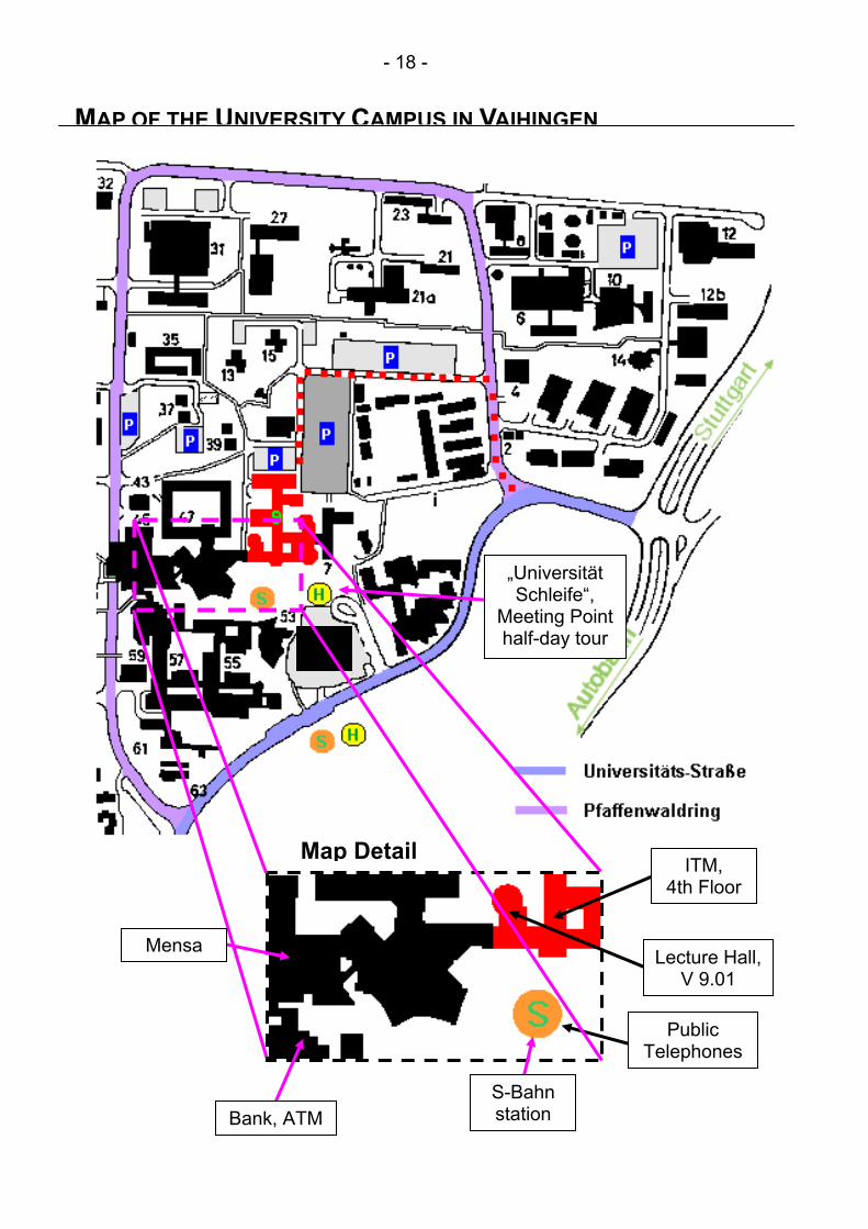
Conference Building The Symposium will take place at the University of Stuttgart, Campus Vaihingen, IWZ, Pfaffenwaldring 9, Lecture Hall V 9.01, ground floor. For details see the enclosed map of the University Campus in Stuttgart-Vaihingen on page 18.
Presentation of Papers Each talk will be 25 minutes plus 5 minutes for discussion.
A Windows XP notebook for beamer presentation of PowerPoint or PDF slides will be available in the lecture hall as well as an overhead projector for printed slides.
Coffee breaks and Lunches Lunch for participants and for accompanying
persons will be served from Monday to Thursday at the Mensa of the University of Stuttgart near the conference building. Please take a tablet with knife, fork and spoon and whatever you want to eat and drink. Then, you can pay directly at the cashier. Depending on what you take it might cost you about

- 7 -
5-7 Euro. A special area directly right of the entrance will be reserved for the participants of the symposium. Coffee breaks are between sessions from 10.30 – 11.00 hours and 15.30 – 16.00 hours. Coffee, tea and cookies are going to be served in the foyer of the conference building in front of the lecture hall.
- 8 -
MONDAY, FEBRUARY 20, 2006
Opening Session 9.30 – 10.00 Introduction Prof. Dr.-Ing. Peter Eberhard Chairman of the Symposium Welcome Addresses Prof. Dr.-Ing. Wolfgang Ehlers Vice Rector of Research, University of Stuttgart Prof. Dr. Ir. Dick van Campen IUTAM Secretary General, Eindhoven University of Technology
Session 1 Particle Adhesion Chairman: Peter Eberhard, Stuttgart, Germany 10.00 – 10.30 J. Tomas
Micromechanics of particle adhesion – an analytical approach
Session 2 Impact of Elastic Bodies Chairman: Christoph Glocker, Zürich, Switzerland 11.00 – 11.30 E. Keskinen, T. Vuoristo, V.-T. Kuokkala, M. Martikainen
Multibody analysis of axially elastic rod chains
11.30 – 12.00 R. Zander, M. Foerg, H. Ulbrich Impacts on beam structures: interactions of wave propagation and global dynamics
12.00 – 12.30 R. Seifried, W. Schiehlen Computational analysis and experimental investigation of impacts in multibody systems
12.30 – 13.00 J.P. Meijaard Lateral impacts on flexible beams in multibody dynamics simulations
- 9 -
MONDAY, FEBRUARY 20, 2006
Session 3 Contact in Applications Chairman: Dick van Campen, Eindhoven, The Netherlands 14.00 – 14.30 F.G. Rauter, J. Pombo, J. Ambrósio, M.S. Pereira
Multibody modeling of pantographs for catenary-pantograph interaction
14.30 – 15.00 V.M. Järvenpää, L. Yuan Numerical modeling of paper machine roll contact with regenerative out-of-roundness excitations
15.00 – 15.30 S. Divenyi, M.A. Savi, H.I. Weber, L.F. Penna Franca Experience and simulation in dynamic systems with discontinuities
Session 4 Frictional Contact Chairman: Javier Cuadrado, La Coruna, Spain 16.00 – 16.30 W. Stamm, A. Fidlin
Regularization of 2D frictional contacts for rigid body dynamics
16.30 – 17.00 R. Keppler, W. Seemann A dynamical model for the elasto-plastic contact with rigid contact areas
17.00 – 17.30 A. Konyukhov, K. Schweizerhof On a continuous transfer of history variables for frictional contact problems based on interpretations of covariant derivatives as a parallel translation
17.30 – 18.00 A. Lünenschloss A multigrid approach in the numerical problem of tangential contact

- 10 -
TUESDAY, FEBRUARY 21, 2006
Session 5 Granular Media I Chairman: Stefan Luding, Delft, The Netherlands 9.00 – 9.30 J. Harting
Computer simulations of particle flows – an overview on available techniques and their applicability
9.30 – 10.00 I. Sielamowicz, T.A. Kowalewski Digital particle image velocimetry as a new technique in granular flow measurements
10.00 – 10.30 R. Kačianauskas, R. Balevičius, D. Markauskas Discrete element method in simulation of granular materials
Session 6 Granular Media II Chairman: Rimantas Kačianauskas, Vilnius, Lithuania 11.00 – 11.30 S. Luding
A discrete model for long time sintering
11.30 – 12.00 F. Fleissner, P. Eberhard Parallel load balanced particle simulation with hierarchical particle grouping strategies
12.00 – 12.30 S. McNamara On the quasi-static behavior of granular packings
12.30 – 13.00 M. Molenda, J. Horabik Grain-to-grain contact conditions and its impact on in-bulk behavior of granular material
Session 7 Gears and Bearings Chairman: Hans Weber, Rio de Janeiro, Brazil 14.00 – 14.30 L. Mauer
Contact modelling of meshing gearwheels in MBS
14.30 – 15.00 B. Schweizer, P. Ziegler Impact studies of gear trains in combustion

- 11 -
TUESDAY, FEBRUARY 21, 2006 15.00 – 15.30 J. Zeischka
Ball bearing modeling based on accurate contact stiffness for efficient mechanical system simulation
Session 8 Multiscale Aspects Chairman: Jorge Ambrósio, Lisboa, Portugal 16.00 – 16.30 S. Mattern, G. Blankenhorn, M. Breidt, N. van Vinh,
S. Höhler, K. Schweizerhof, D. Hartmann, F. Stangenberg Comparison of building collapse analysis results from finite elements and rigid body models
16.30 – 17.00 D. Dureisseix, P. Alart Influence of a domain decomposition coarse space on the numerical homogenization of a non smooth discrete system
17.00 – 17.30 L.-Q. Chen Multiscale analysis of a cantilever with a contact boundary
17.30 – 18.00 A.S. Kuleshov First integrals of equations of motion of a heavy rotational symmetric body on a perfectly rough plane
- 12 -
WEDNESDAY, FEBRUARY 22, 2006
Session 9 Fracture Chairman: Martin Arnold, Halle, Germany 9.00 – 9.30 K. Kolk, G. Kuhn
A module for the simulation of 3D fatigue crack propagation in BEM and FEM environments
9.30 – 10.00 A. Gus, O. Menshykov, W.L. Wendland, V. Zozulya The 3D elastodynamic contact problem for plane cracks
10.00 – 10.30 P. Meinke Multiscale problems in railway contact dynamics
Session 10 Complementarity Chairman: Robert Seifried, Stuttgart, Germany 11.00 – 11.30 S. Launis, E. Keskinen, C. Bohatier, F. Dubois
Complementary models for log grinding
11.30 – 12.00 S. Ebrahimi, P. Eberhard Frictional impact of planar deformable bodies solved by a linear complementarity problem formulation
12.00 – 12.30 C. Liu, Z. Zhao, B. Chen The admissible state space and bouncing motion for a robotic system

- 13 -
THURSDAY, FEBRUARY 23, 2006
Session 11 FE Contact and Mortar Chairman: Xiaoting Rui, Nanjing, China 9.00 – 9.30 B. Wohlmuth
Hybrid methods for contact problems
9.30 – 10.00 C. Hesch, P. Betsch Application of the discrete null space method to domain decomposition and large deformation contact problems
10.00 – 10.30 P. Pedersen Contact indentations determined by a direct super finite element approach
Session 12 Non-Smooth Models Chairman: Erno Keskinen, Tampere, Finland 11.00 – 11.30 M. Moeller, C. Glocker
Analogous non-smooth models of mechanical and electrical systems
11.30 – 12.00 E. Pennestrì, P.P. Valentini, L. Vita Dynamic analysis of intermittent-motion mechanisms through the combined use of Gauss principle and logical functions
12.00 – 12.30 H. Wang, Z. Chang, C. Zhang Cross-over impact in geometric closed mechanisms
12.30 – 13.00 X. Rui, L. Yun, B. He, G. Wang, F. Yang, Y. Lu Advances in discrete time transfer matrix method of multibody systems
Session 13 Contact in Multibody Systems Chairman: Werner Schiehlen, Stuttgart, Germany 14.00 – 14.30 J. Pombo, J. Ambrósio
New developments on the wheel-rail contact problem for railway dynamics

- 14 -
THURSDAY, FEBRUARY 23, 2006 14.30 – 15.00 S. Najafabadi, J. Kövecses, J. Angeles
Generalization of the energetic coefficient of restitution for collisions in multibody systems
15.00 – 15.30 M. Arnold Multi-rate time integration for large scale multibody system models
15.30 Closing Session

- 15 -
SOCIAL PROGRAM The Social Program is open to all registered participants and accompanying persons. Sunday February 19, 2006 6.00 – 8.00 pm
“Wine and Cheese” at the Institute of Engineering and Computational Mechanics (ITM), University of Stuttgart, Campus Vaihingen, Pfaffenwaldring 9, 4th floor, see map on page 18.
Monday February 20, 2006 7.00 pm
“Get-Together” at the Institute of Engineering and Computational Mechanics (ITM), University of Stuttgart, Campus Vaihingen, Pfaffenwaldring 9, 4th floor, see map on page 18.
Wednesday February 21, 2006 1.30 pm
A half-day excursion will lead us first to the Celtic Museum in Hochdorf. After a guided tour (in English) we’ll head on to the Cistercian Monastery of Maulbronn which has been inscribed on the World Cultural Heritage List. A guided tour (in English) will show you one of the best preserved medieval monastery monuments north of the Alps. Afterwards the conference dinner will be in the local restaurant “Zum treuen Bartel” in Markgröningen. Meeting point is the bus station “Universität Schleife”, see map on page 18. We’ll leave at 1.30 pm sharp. The return will be around 10.30 pm.
Some recommendations for tours for accompanying persons can be provided at the registration desk. There is a variety of tourist attractions and museums in and nearby Stuttgart.
- 16 -
GENERAL INFORMATION Transportation on FOOT
The conference building is located at Pfaffenwaldring 9, see map on page 18. The front entry of Pfaffenwaldring 9 (also named IWZ) is located opposite to the main exit of the S-Bahn (Train-Station). Also on the front side of the building there is the bus-stop. If you choose to park your car in the back of Pfaffenwaldring 9 (taking the dotted line in the map on page 18) you take the rear entry to get into the building.
by CAR Coming from highway No. A8 or A81 you should head towards Stuttgart Stadtmitte as soon as you reach the highway intersection Stuttgarter Kreuz. The exit Universität is the second exit after the highway intersection. After the exit you should take a left on the big intersection.
by TRAIN From Stuttgart main railway-station you should take one of the following S-Bah trains which travel every 10 minutes. It takes you 10 minutes to get from the main-station to the station Universität:
• S1: Direction Böblingen / Herrenberg or • S2: Direction Vaihingen / Filderstadt or • S3: Direction Vaihingen / Flughafen
You can easily reach the underground platform for the "S-Bahn" using the stairs directly from the platforms of the main-station. If you do not yet have a train ticket all the way through to Stuttgart University you have to get a ticket to Universität from one of the ticket machines. You have to pay for 2 zones. You find the ticket machines close to all the entries of the S-Bahn, but unfortunately not on the platform of the S-Bahn. Some trains in the direction to University will only take you to Schwabstraße. If you happen to take one of those trains, don't worry. Just get off the train at the last stop Schwabstraße and wait for the next train in the direction University. When arriving from the city center, take the exit opposite to the driving direction.
- 17 -
GENERAL INFORMATION by PLANE If you arrive at Airport Stuttgart, you should take one of the following S-Bahn trains to get to the University:
• S2: Direction Schorndorf or • S3: Direction Backnang
For both S-Bahn trains Universität is the 7th stop on the trip. If you take the S-Bahn from University to Airport Stuttgart to fly out of Stuttgart the following two S-Bahn trains would be your choice:
• S2: Direction Vaihingen / Filderstadt • S3: Direction Vaihingen / Flughafen
Bank Close to the conference building and the S-Bahn station is an
automatic teller machine (ATM), see map on page 18. Telephone A public telephone is on the ground floor of the conference
building close to the lecture hall, it operates with telephone cards. Two additional public telephones are close to the S-Bahn station, one operating with coins, the other with telephone cards.
- 18 -
MAP OF THE UNIVERSITY CAMPUS IN VAIHINGEN
ITM, 4th Floor
Lecture Hall, V 9.01
Mensa
S-Bahn stationBank, ATM
Public Telephones
Map Detail
„Universität Schleife“,
Meeting Point half-day tour
- 19 -
ABSTRACTS
New developments on the wheel-rail contact problem for railway dynamics
João Pombo, Jorge Ambrósio
IDMEC – Instituto Superior Técnico Av. Rovisco Pais, 1049-001, Lisboa, Portugal
e-mail: [jpombo, jorge]@dem.ist.utl.pt
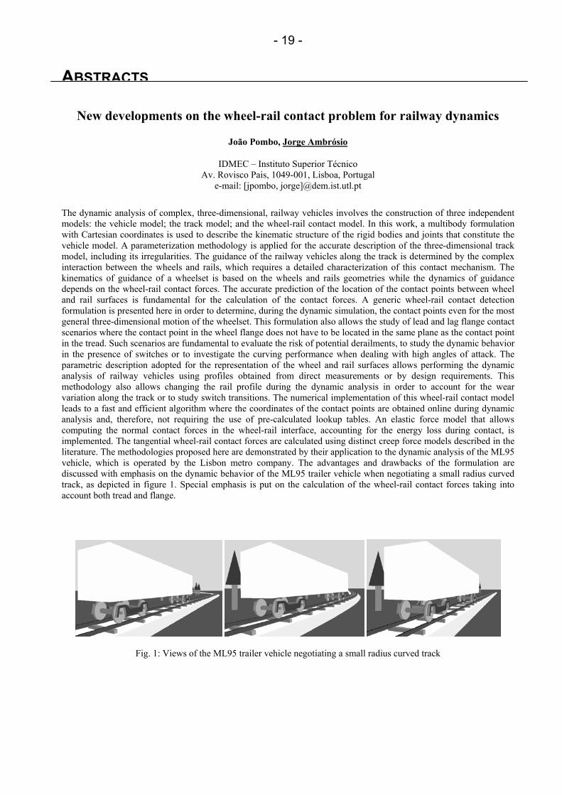
The dynamic analysis of complex, three-dimensional, railway vehicles involves the construction of three independent models: the vehicle model; the track model; and the wheel-rail contact model. In this work, a multibody formulation with Cartesian coordinates is used to describe the kinematic structure of the rigid bodies and joints that constitute the vehicle model. A parameterization methodology is applied for the accurate description of the three-dimensional track model, including its irregularities. The guidance of the railway vehicles along the track is determined by the complex interaction between the wheels and rails, which requires a detailed characterization of this contact mechanism. The kinematics of guidance of a wheelset is based on the wheels and rails geometries while the dynamics of guidance depends on the wheel-rail contact forces. The accurate prediction of the location of the contact points between wheel and rail surfaces is fundamental for the calculation of the contact forces. A generic wheel-rail contact detection formulation is presented here in order to determine, during the dynamic simulation, the contact points even for the most general three-dimensional motion of the wheelset. This formulation also allows the study of lead and lag flange contact scenarios where the contact point in the wheel flange does not have to be located in the same plane as the contact point in the tread. Such scenarios are fundamental to evaluate the risk of potential derailments, to study the dynamic behavior in the presence of switches or to investigate the curving performance when dealing with high angles of attack. The parametric description adopted for the representation of the wheel and rail surfaces allows performing the dynamic analysis of railway vehicles using profiles obtained from direct measurements or by design requirements. This methodology also allows changing the rail profile during the dynamic analysis in order to account for the wear variation along the track or to study switch transitions. The numerical implementation of this wheel-rail contact model leads to a fast and efficient algorithm where the coordinates of the contact points are obtained online during dynamic analysis and, therefore, not requiring the use of pre-calculated lookup tables. An elastic force model that allows computing the normal contact forces in the wheel-rail interface, accounting for the energy loss during contact, is implemented. The tangential wheel-rail contact forces are calculated using distinct creep force models described in the literature. The methodologies proposed here are demonstrated by their application to the dynamic analysis of the ML95 vehicle, which is operated by the Lisbon metro company. The advantages and drawbacks of the formulation are discussed with emphasis on the dynamic behavior of the ML95 trailer vehicle when negotiating a small radius curved track, as depicted in figure 1. Special emphasis is put on the calculation of the wheel-rail contact forces taking into account both tread and flange.
Fig. 1: Views of the ML95 trailer vehicle negotiating a small radius curved track
- 20 -
Multi-rate time integration for large scale multibody system models
Martin Arnold
Institute of Mathematics Martin-Luther University Halle-Wittenberg
D - 06099 Halle (Saale), Germany e-mail: [email protected]
DAE time integration methods in multibody dynamics
Standard time integration methods of multibody dynamics are tailored to small and medium-sized nonlinear differential-algebraic equations of motion
(1a)
(1b)
with position coordinates q(t) ∈ Rnq that have to satisfy ng loop-closing constraints g = 0. The constraints are coupled to the dynamical equations by constraint forces − GT(q,t)λ with G(q,t) := (∂g)/(∂q)(q,t) and Lagrangian multipliers λ (t) ∈ Rng.
Because of the constraints (1b) and because of stiff force terms t),q f(q, & , the standard solvers in industrial applications are implicit [1, 2]. In implicit methods, the Jacobian of the right hand side of (1a) has to be evaluated frequently. Often, the overall computing time is dominated by these Jacobian evaluations. Using specially adapted algorithms for Jacobian approximation and Jacobian update [3], large multibody system models like detailed full vehicle models in automotive and railway engineering may still be handled efficiently (nq = 100 . . . 1000, ng = 10 . . . 50).
Multiscale problems in large scale multibody system models
In high-end applications with thousands of degrees of freedom the implicit solvers show a dramatical loss of efficiency. Typical examples are multibody system models of vehicles or vehicle components that move along large elastic structures [4, 5] and the dynamical simulation of combustion engines with chain drives [6].
Characteristic examples of the first problem class are the dynamical interaction between the pantograph of a high-speed train and the power supplying catenary [4] and the simulation of railway vehicles or heavy trucks that cross a bridge [5]. The contact between vehicle and structure induces a moving load in the finite element model of the elastic structure resulting in oscillations that are far beyond the frequency range of classical multibody system models.
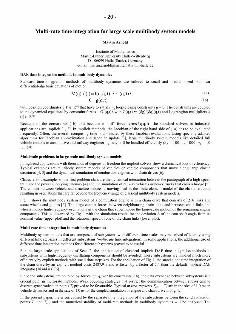
Fig. 1 shows the multibody system model of a combustion engine with a chain drive that consists of 216 links and some wheels and guides [6]. The large contact forces between neighbouring chain links and between chain links and wheels induce high-frequency oscillations in the chain that superimpose the large-scale motion of the remaining engine components. This is illustrated by Fig. 1 with the simulation results for the deviation ∆ of the cam shaft angle from its nominal value (upper plot) and the rotational speed of one of the chain links (lower plot).
Multi-rate time integration in multibody dynamics
Multibody system models that are composed of subsystems with different time scales may be solved efficiently using different time stepsizes in different subsystems (multi-rate time integration). In some applications, the additional use of different time integration methods for different subsystems proved to be useful.
For the large scale applications of Sect. 2, the application of classical implicit DAE time integration methods to subsystems with high-frequency oscillating components should be avoided. These subsystems are handled much more efficiently by explicit methods with small time stepsizes. For the application of Fig. 1, the stand alone time integration of the chain drive by an explicit method costs 2487.9 s and is faster by a factor of 7.4 than the default implicit DAE integrator (18344.4 s) [6].
Since the subsystems are coupled by forces t),q f(q, & or by constraints (1b), the data exchange between subsystems is a crucial point in multi-rate methods. Weak coupling strategies that restrict the communication between subsystems to discrete synchronization points Tn proved to be favourable. Typical macro stepsizes Tn+1 − Tn are in the size of 1.0 ms in vehicle dynamics and in the size of 1.0 µs for the coupled simulation of engine and chain drive in Fig. 1.
In the present paper, the errors caused by the separate time integration of the subsystems between the synchronization points Tn and Tn+1 and the numerical stability of multi-rate methods in multibody dynamics will be analysed. The
, t)(q,G - t),q f(q, (t)q M(q) T λ= &&
t)g(q, 0 =
- 21 -
results of the theoretical investigations are illustrated by numerical test results for large scale industrial applications with several thousand degrees of freedom. Typically, the multi-rate time integration methods reduce the overall computing time by more than 80 % compared to classical implicit DAE time integration.
Fig. 1: Dynamical simulation of an automotive engine with chain drive [6].
References
[1] W. Rulka. Effiziente Simulation der Dynamik mechatronischer Systemefur industrielle Anwendun-gen. PhD thesis, Vienna University of Technology, 1998.
[2] M. Arnold. Simulation algorithms and software tools. Submitted to: G. Mastinu and M. Plochl, editors, Road and Off-Road Vehicle System Dynamics Handbook. Taylor & Francis, London, 2006.
[3] M. Arnold, A. Fuchs, and C. Fiihrer. Efficient corrector iteration for DAE time integration in multi-body dynamics. Comp. Meth. Appl. Mech. Eng., 2005, in print.
[4] A. Veitl and M. Arnold. Coupled simulation of multibody systems and elastic structures. In J.A.C. Ambrosio and W.O. Schiehlen, editors, Advances in Computational Multibody Dynamics, pages 635-644, IDMEC/IST Lisbon, Portugal, 1999.
[5] S. Dietz, G. Hippmann, and G. Schupp. Interaction of vehicles and flexible tracks by co-simulation of multibody vehicle systems and finite element track models. In H. True, editor, Proc. of the 17th IAVSD Symposium , pages 372-384. Vehicle System Dynamics, Vol. 37, Swets & Zeitlinger, 2003.
[6] G. Hippmann, M. Arnold, and M. Schittenhelm. Efficient simulation of bush and roller chain drives. In Proc. of Multibody Dynamics 2005 (ECCOMAS Thematic Conference), Madrid, Spain, 2005.
- 22 -
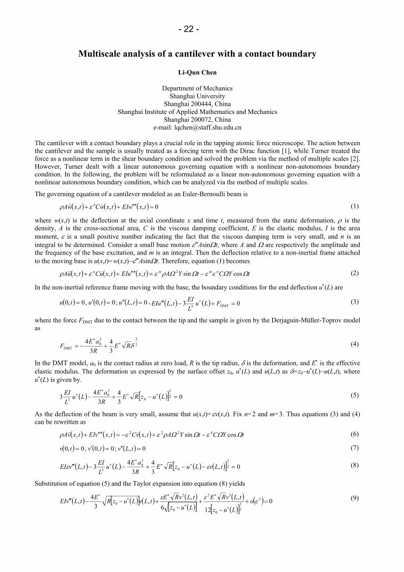
Multiscale analysis of a cantilever with a contact boundary
Li-Qun Chen
Department of Mechanics Shanghai University
Shanghai 200444, China Shanghai Institute of Applied Mathematics and Mechanics
Shanghai 200072, China e-mail: [email protected]
The cantilever with a contact boundary plays a crucial role in the tapping atomic force microscope. The action between the cantilever and the sample is usually treated as a forcing term with the Dirac function [1], while Turner treated the force as a nonlinear term in the shear boundary condition and solved the problem via the method of multiple scales [2]. However, Turner dealt with a linear autonomous governing equation with a nonlinear non-autonomous boundary condition. In the following, the problem will be reformulated as a linear non-autonomous governing equation with a nonlinear autonomous boundary condition, which can be analyzed via the method of multiple scales.
The governing equation of a cantilever modeled as an Euler-Bernoulli beam is
( ) ( ) ( ) 0,,, =′′′′++ txwEItxwCtxwA n &&& ερ (1)
where w(x,t) is the deflection at the axial coordinate x and time t, measured from the static deformation, ρ is the density, A is the cross-sectional area, C is the viscous damping coefficient, E is the elastic modulus, I is the area moment, ε is a small positive number indicating the fact that the viscous damping term is very small, and n is an integral to be determined. Consider a small base motion εmAsinΩt, where A and Ω are respectively the amplitude and the frequency of the base excitation, and m is an integral. Then the deflection relative to a non-inertial frame attached to the moving base is u(x,t)=w(x,t)−εmAsinΩt. Therefore, equation (1) becomes
( ) ( ) ( ) tYCtYAtxuEItxuCtxuA nmmn ΩΩεεΩΩρεερ cossin,,, 2 −=′′′′++ &&& (2)
In the non-inertial reference frame moving with the base, the boundary conditions for the end deflection u∗(L) are
( ) ( ) ( ) 0,;0,0,0,0 =′′=′= tLututu , ( ) ( ) 03, DMT3 =+−′′′ ∗ FLuLEItLuEI (3)
where the force FDMT due to the contact between the tip and the sample is given by the Derjaguin-Müller-Toprov model as
233
0DMT 3
43
4δRE
RaE
F ∗∗
+−= (4)
In the DMT model, a0 is the contact radius at zero load, R is the tip radius, δ is the deformation, and E∗ is the effective elastic modulus. The deformation us expressed by the surface offset z0, u∗(L) and u(L,t) as δ=z0−u∗(L)−u(L,t), where u∗(L) is given by.
( ) ( )[ ] 034
34
3 23
0
30
3 =−+− ∗∗∗
∗ LuzRERaE
LuLEI (5)
As the deflection of the beam is very small, assume that u(x,t)=εv(x,t). Fix n=2 and m=3. Thus equations (3) and (4) can be rewritten as
( ) ( ) ( ) tYCtYAtxvCtxvEItxvA ΩΩεΩΩρεερ cossin,,, 4222 −+−=′′′′+ &&& (6)
( ) ( ) ( ) 0,;0,0,0,0 =′′=′= tLvtvtv (7)
( ) ( ) ( ) ( )[ ] 0,34
34
3, 23
0
30
3 =−−+−−′′′ ∗∗∗
∗ tLvLuzRERaE
LuLEItLvEI εε (8)
Substitution of equation (5) and the Taylor expansion into equation (8) yields
( ) ( )[ ] ( ) ( )( )[ ]
( )( )[ ]
( ) 012
,6
,,3
4, 3
23
0
32
0
2
0 =+−
+−
+−−′′′∗
∗
∗
∗∗
∗
εεε oLuz
tLvRELuz
tLvREtLvLuzREtLvEI (9)

- 23 -
The method of multiple scales proposed in [2] can be modified to solve the non-homogeneous linear equation (6) with nonlinear boundary conditions (7) and (9). Details will be presented in the Symposium.
References
[1] Rützel S, Lee SI, Raman A. Nonlinear dynamics of atomic-force-microscope probes driven in Lennard-Jones potentials. Proc R Soc Lond A, 459(2003): 1925-1948
[2] Turner JA. Non-linear vibration of a beam with cantilever-Hertzian contact boundary conditions. J Sound Vib, 275(2004): 177-191
- 24 -
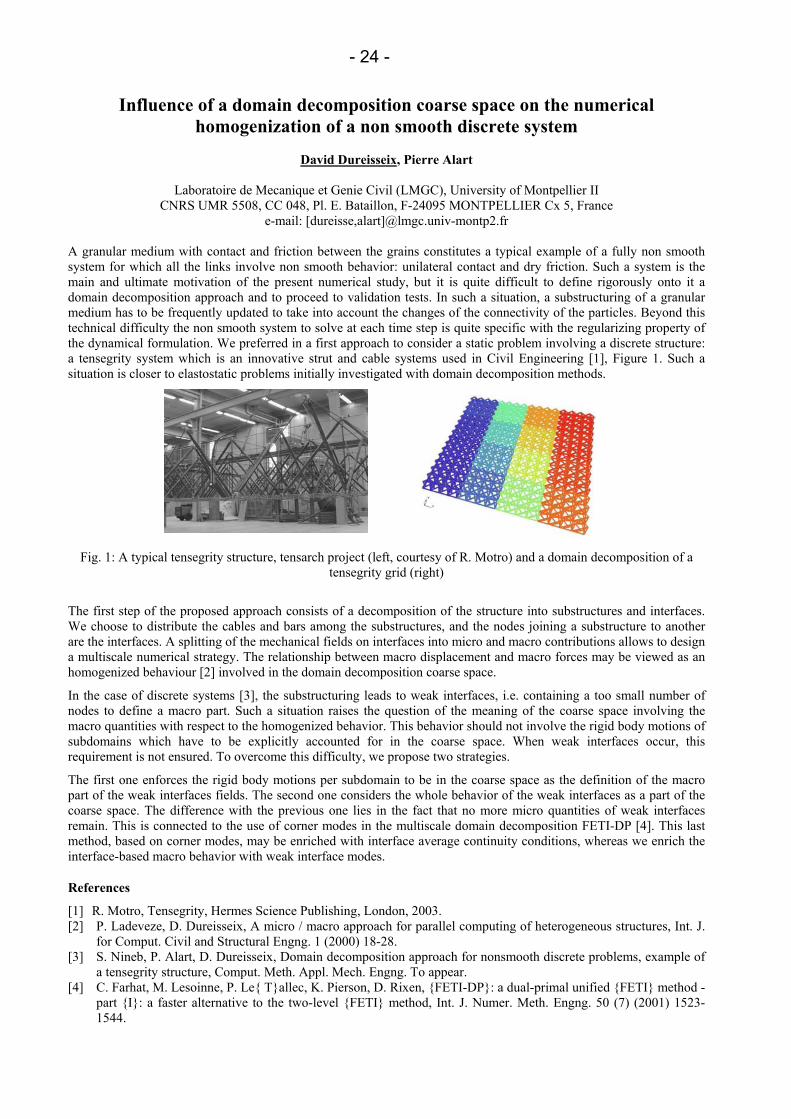
Influence of a domain decomposition coarse space on the numerical homogenization of a non smooth discrete system
David Dureisseix, Pierre Alart
Laboratoire de Mecanique et Genie Civil (LMGC), University of Montpellier II
CNRS UMR 5508, CC 048, Pl. E. Bataillon, F-24095 MONTPELLIER Cx 5, France e-mail: [dureisse,alart]@lmgc.univ-montp2.fr
A granular medium with contact and friction between the grains constitutes a typical example of a fully non smooth system for which all the links involve non smooth behavior: unilateral contact and dry friction. Such a system is the main and ultimate motivation of the present numerical study, but it is quite difficult to define rigorously onto it a domain decomposition approach and to proceed to validation tests. In such a situation, a substructuring of a granular medium has to be frequently updated to take into account the changes of the connectivity of the particles. Beyond this technical difficulty the non smooth system to solve at each time step is quite specific with the regularizing property of the dynamical formulation. We preferred in a first approach to consider a static problem involving a discrete structure: a tensegrity system which is an innovative strut and cable systems used in Civil Engineering [1], Figure 1. Such a situation is closer to elastostatic problems initially investigated with domain decomposition methods.
Fig. 1: A typical tensegrity structure, tensarch project (left, courtesy of R. Motro) and a domain decomposition of a
tensegrity grid (right)
The first step of the proposed approach consists of a decomposition of the structure into substructures and interfaces. We choose to distribute the cables and bars among the substructures, and the nodes joining a substructure to another are the interfaces. A splitting of the mechanical fields on interfaces into micro and macro contributions allows to design a multiscale numerical strategy. The relationship between macro displacement and macro forces may be viewed as an homogenized behaviour [2] involved in the domain decomposition coarse space.
In the case of discrete systems [3], the substructuring leads to weak interfaces, i.e. containing a too small number of nodes to define a macro part. Such a situation raises the question of the meaning of the coarse space involving the macro quantities with respect to the homogenized behavior. This behavior should not involve the rigid body motions of subdomains which have to be explicitly accounted for in the coarse space. When weak interfaces occur, this requirement is not ensured. To overcome this difficulty, we propose two strategies.
The first one enforces the rigid body motions per subdomain to be in the coarse space as the definition of the macro part of the weak interfaces fields. The second one considers the whole behavior of the weak interfaces as a part of the coarse space. The difference with the previous one lies in the fact that no more micro quantities of weak interfaces remain. This is connected to the use of corner modes in the multiscale domain decomposition FETI-DP [4]. This last method, based on corner modes, may be enriched with interface average continuity conditions, whereas we enrich the interface-based macro behavior with weak interface modes.
References
[1] R. Motro, Tensegrity, Hermes Science Publishing, London, 2003. [2] P. Ladeveze, D. Dureisseix, A micro / macro approach for parallel computing of heterogeneous structures, Int. J.
for Comput. Civil and Structural Engng. 1 (2000) 18-28. [3] S. Nineb, P. Alart, D. Dureisseix, Domain decomposition approach for nonsmooth discrete problems, example of
a tensegrity structure, Comput. Meth. Appl. Mech. Engng. To appear. [4] C. Farhat, M. Lesoinne, P. Le Tallec, K. Pierson, D. Rixen, FETI-DP: a dual-primal unified FETI method -
part I: a faster alternative to the two-level FETI method, Int. J. Numer. Meth. Engng. 50 (7) (2001) 1523-1544.
- 25 -
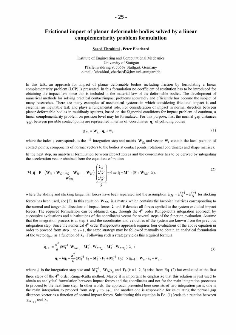
Frictional impact of planar deformable bodies solved by a linear complementarity problem formulation
Saeed Ebrahimi , Peter Eberhard
Institute of Engineering and Computational Mechanics University of Stuttgart
Pfaffenwaldring 9, 70569 Stuttgart, Germany e-mail: [ebrahimi, eberhard]@itm.uni-stuttgart.de
In this talk, an approach for impact of planar deformable bodies including friction by formulating a linear complementarity problem (LCP) is presented. In this formulation no coefficient of restitution has to be introduced for obtaining the impact law since this is included in the material law of the deformable bodies. The development of numerical methods for solving practical contact/impact problems accurately and efficiently has become the subject of many researches. There are many examples of mechanical systems in which considering frictional impact is and essential an inevitable task and plays a fundamental role. For consideration of impact in normal direction between planar deformable bodies in multibody systems, based on the Signorini conditions for impact problem of continua, a linear complementarity problem on position level may be formulated. For this purpose, first the normal gap distances
iNg between possible contact points are represented in terms of coordinates iq of colliding bodies
iigN ii wqWg +⋅= (1)
where the index i corresponds to the thi integration step and matrix igW and vector iw contain the local position of contact points, components of normal vectors to the bodies at contact points, rotational coordinates and shape matrices.
In the next step, an analytical formulation between impact forces and the coordinates has to be derived by integrating the acceleration vector obtained from the equations of motion
( ) .)(1
)(
)( λWFMq0
λ
λλλ
WWµWWFqMW
⋅+⋅=⇒=
⋅−⋅+−−⋅ −
−
+NH
H
H
N
HHGGN
NH
&&
321
444444 3444444 21&&
(2)
where the sliding and sticking tangential forces have been separated and the assumption )()( −+ −= HHH λλλ for sticking
forces has been used, see [2]. In this equation NHW is a matrix which contains the Jacobian matrices corresponding to the normal and tangential directions of impact forces λ and F denotes all forces applied to the system excluded impact forces. The required formulation can be obtained, e.g., through the 4th order Runge-Kutta integration approach by successive evaluations and substitutions of the coordinates vector for several steps of the function evaluation. Assume that the integration process is at step i and the coordinates and velocities of the system are known from the previous integration step. Since the numerical 4th order Runge-Kutta approach requires four evaluations of the above equation in order to proceed from step i to 1+i , the same strategy may be followed manually to obtain an analytical formulation of the vector 1+iq as a function of iλ . Following such a strategy yields this required formula
,)(6
)(6
131
321
211
12
13
12
11
21 321
ii qiqiii
iNHNHNHi
hh
h
wλWqFMFMFMqq
λWMWMWMq
+⋅=⇒⋅+⋅+⋅++
+⋅⋅+⋅+⋅=
+−−−
−−−+
&
(3)
where h is the integration step size and kNHk WM ,1− and )3,2,1( =kkF arise from Eq. (2) but evaluated at the first three steps of the 4th order Runge-Kutta method. Maybe it is important to emphasize that this relation is just used to obtain an analytical formulation between impact forces and the coordinates and not for the main integration processes to proceed to the next time step. In other words, the approach presented here consists of two integration parts: one is the main integration to proceed from step i to 1+i and another one is responsible for calculating the normal gap distances vector as a function of normal impact forces. Substituting this equation in Eq. (1) leads to a relation between
1+iNg and iλ
- 26 -
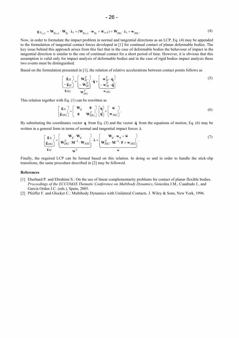
.)( 1111 iiiiiii gqigqiqgiqgN wλWwwWλWWg +⋅=+⋅+⋅⋅= ++++ (4)
Now, in order to formulate the impact problem in normal and tangential directions as an LCP, Eq. (4) may be appended to the formulation of tangential contact forces developed in [1] for continual contact of planar deformable bodies. The key issue behind this approach arises from this fact that in the case of deformable bodies the behaviour of impact in the tangential direction is similar to the one of continual contact for a short period of time. However, it is obvious that this assumption is valid only for impact analysis of deformable bodies and in the case of rigid bodies impact analysis these two events must be distinguished.
Based on the formulation presented in [1], the relation of relative accelerations between contact points follows as
.
43421&
&&&
43421321&&
&&
&& HGTHG
HG
TH
TH
TH
TH
H
H
wWg
qwqwq
WW
gg
⋅−⋅+⋅
−=
−
(5)
This relation together with Eq. (1) can be rewritten as
.
+
⋅
=
HGTHG
g
HG
Nw
wqq
W0
0Wgg
&&&& (6)
By substituting the coordinates vector q from Eq. (3) and the vector q&& from the equations of motion, Eq. (6) may be written in a general form in terms of normal and tangential impact forces λ
.11
4444 34444 21444 3444 21321&&
wWg
wFMW
wwWλWMW
WW
gg
+⋅⋅
+⋅+⋅
⋅⋅
⋅=
−−
HGTHG
qg
NHTHG
qg
HG
N
TM
(7)
Finally, the required LCP can be formed based on this relation. In doing so and in order to handle the stick-slip transitions, the same procedure described in [2] may be followed.
References
[1] Eberhard P. and Ebrahimi S.: On the use of linear complementarity problems for contact of planar flexible bodies. Proceedings of the ECCOMAS Thematic Conference on Multibody Dynamics, Goicolea J.M., Cuadrado J., and Garcia Orden J.C. (eds.), Spain, 2005.
[2] Pfeiffer F. and Glocker C.: Multibody Dynamics with Unilateral Contacts. J. Wiley & Sons, New York, 1996.
- 27 -
Parallel load balanced particle simulation with hierarchical particle grouping
strategies
Florian Fleissner , Peter Eberhard
Institute of Engineering and Computational Mechanics University of Stuttgart
Pfaffenwaldring 9, 70569 Stuttgart, Germany e-mail: [fleissner, eberhard]@itm.uni-stuttgart.de
Depending on the type of particle geometry and the amount of bodies envolved, simulations of granular media can be very demanding in terms of computational expense. Even though the memory of todays PCs would allow the simulation of large systems of particles with complicated surface geometry, such as nonconvex polygonal particles, these simulations require a lot of CPU time for the detection of contact points and the calculation of contact forces. This type of simulation does not suffer that much from memory restrictions as molecular dynamics simulations of large quantities of simple objects where the main problem arises from storing the objects’ state. However, a parallelization of the method is essential to focus the CPU-power of more than one processor on the relatively small amount of data.
The variety of different parallel computation environments a parallelized method should suit reaches from supercomputers over clusters to computational grids. Our method is well suited for inhomegenous clusters of PCs, linked via ethernet, which are the cheapest and most common setup for parallel computations at universities. The method was especially developed to deal with dynamically changing processor loads due to concurrent processes. Nevertheless it can as well be applied on a supercomputer where it prevents imbalances of the work distribution among the nodes due to changes in the particle system’s state.
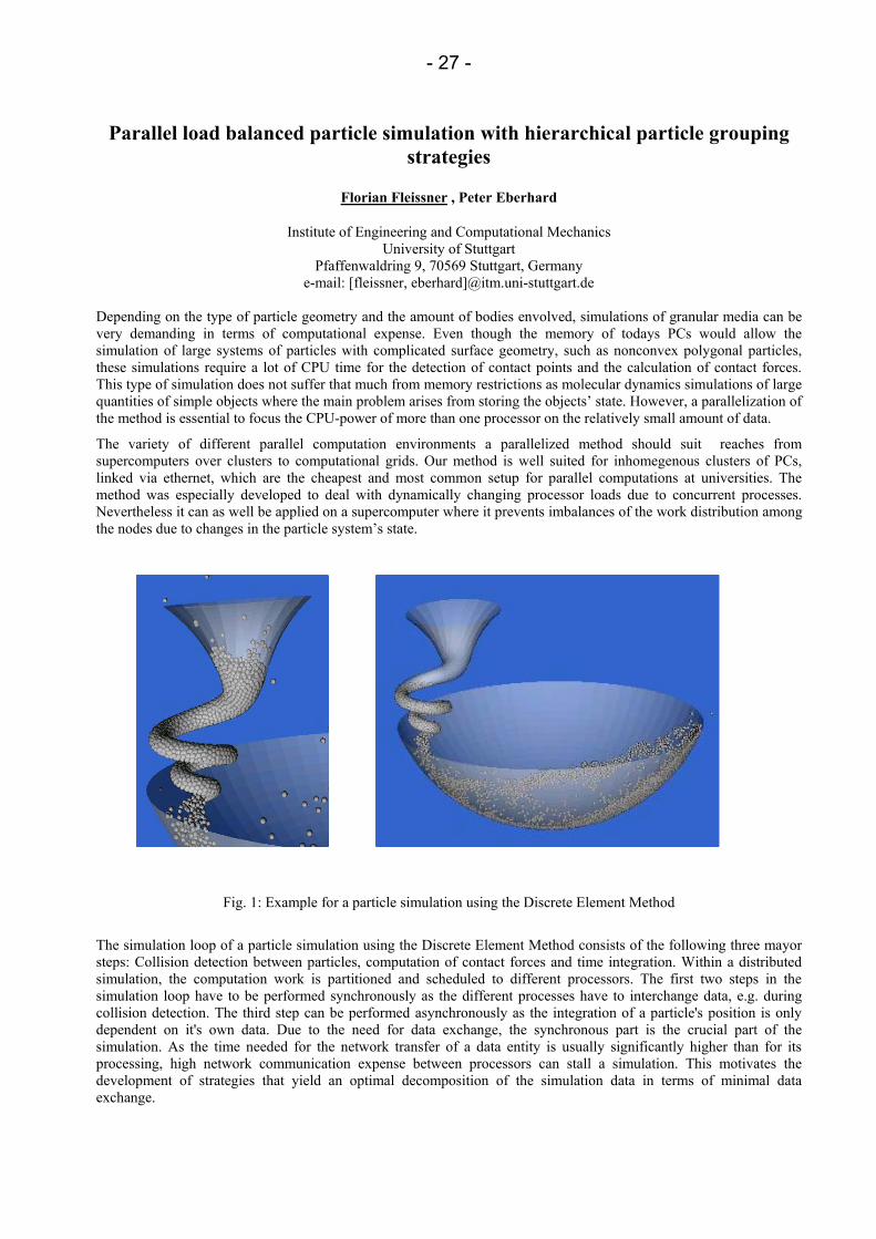
Fig. 1: Example for a particle simulation using the Discrete Element Method
The simulation loop of a particle simulation using the Discrete Element Method consists of the following three mayor steps: Collision detection between particles, computation of contact forces and time integration. Within a distributed simulation, the computation work is partitioned and scheduled to different processors. The first two steps in the simulation loop have to be performed synchronously as the different processes have to interchange data, e.g. during collision detection. The third step can be performed asynchronously as the integration of a particle's position is only dependent on it's own data. Due to the need for data exchange, the synchronous part is the crucial part of the simulation. As the time needed for the network transfer of a data entity is usually significantly higher than for its processing, high network communication expense between processors can stall a simulation. This motivates the development of strategies that yield an optimal decomposition of the simulation data in terms of minimal data exchange.
- 28 -
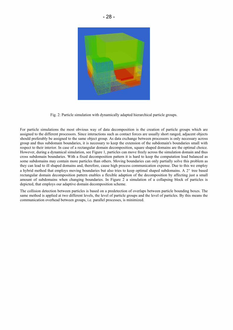
Fig. 2: Particle simulation with dynamically adapted hierarchical particle groups.
For particle simulations the most obvious way of data decomposition is the creation of particle groups which are assigned to the different processors. Since interactions such as contact forces are usually short ranged, adjacent objects should preferably be assigned to the same object group. As data exchange between processors is only necessary across group and thus subdomain boundaries, it is necessary to keep the extension of the subdomain's boundaries small with respect to their interior. In case of a rectangular domain decomposition, square shaped domains are the optimal choice. However, during a dynamical simulation, see Figure 1, particles can move freely across the simulation domain and thus cross subdomain boundaries. With a fixed decomposition pattern it is hard to keep the computation load balanced as some subdomains may contain more particles than others. Moving boundaries can only partially solve this problem as they can lead to ill shaped domains and, therefore, cause high process communication expense. Due to this we employ a hybrid method that employs moving boundaries but also tries to keep optimal shaped subdomains. A n2 tree based rectangular domain decomposition pattern enables a flexible adaption of the decomposition by affecting just a small amount of subdomains when changing boundaries. In Figure 2 a simulation of a collapsing block of particles is depicted, that employs our adaptive domain decomposition scheme.
The collision detection between particles is based on a predetection of overlaps between particle bounding boxes. The same method is applied at two different levels, the level of particle groups and the level of particles. By this means the communication overhead between groups, i.e. parallel processes, is minimized.
- 29 -
Analogous non-smooth models of mechanical and electrical systems
Michael Moeller, Christoph Glocker
IMES - Center of Mechanics, ETH Zurich CH-8092 Zurich, Switzerland
email: [email protected]
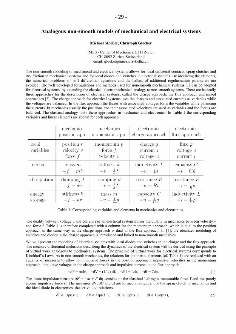
The non-smooth modeling of mechanical and electrical systems allows for ideal unilateral contacts, sprag clutches and dry friction in mechanical systems and for ideal diodes and switches in electrical systems. By idealizing the elements, the numerical problems of stiff differential equations and the ballast of additional regularisation parameters are avoided. The well developed formulations and methods used for non-smooth mechanical systems [1] can be adopted for electrical systems, by extending the classical electromechanical analogy to non-smooth systems. There are basically three approaches for the description of electrical systems, called the charge approach, the flux approach and mixed approaches [2]. The charge approach for electrical systems uses the charges and associated currents as variables while the voltages are balanced. In the flux approach the fluxes with associated voltages form the variables while balancing the currents. In mechanics usually the positions and their associated velocities are used as variables and the forces are balanced. The classical analogy links these approaches in mechanics and electronics. In Table 1 the corresponding variables and linear elements are shown for each approach.
Table 1: Corresponding variables and elements in mechanics and electronics.
The duality between voltage u and current ı of an electrical system mirror the duality in mechanics between velocity v and force f. Table 1 is therefore completed with a column for the momentum approach, which is dual to the position approach in the same way as the charge approach is dual to the flux approach. In [3], the idealized modeling of switches and diodes in the charge approach is introduced and linked to non-smooth mechanics.
We will present the modeling of electrical systems with ideal diodes and switches in the charge and the flux approach. The measure differential inclusions describing the dynamics of the electrical system will be derived using the principle of virtual work analogous to mechanical systems. The principle of virtual work for electrical systems corresponds to Kirchhoff's Laws. As in non-smooth mechanics, the relations for the inertia elements (cf. Table 1) are replaced with an equality of measures to allow for impulsive forces in the position approach, impulsive velocities in the momentum approach, impulsive voltages in the charge approach and impulsive currents in the flux approach
−dF = mdv, −dV = (1/ k) df, −dU = Ldı, −dI = Cdu. (1)
The force impulsion measure dF = f dt + F dη consists of the classical Lebesgue-measurable force f and the purely atomic impulsive force F. The measures dV, dU and dI are formed analogous. For the sprag clutch in mechanics and the ideal diode in electronics, the set-valued relations
−dF ∈ Upr(v+), −dV ∈ Upr(f+), −dU ∈ Upr(ı+), −dI ∈ Upr(u+), (2)
- 30 -
are formulated, where f+ denotes the right limit of f. Switches for electrical systems are modeled as spark gap with variable break-through voltage a. The set-valued relation for a switch in the charge approach and the flux approach can be written as
−dU ∈ dA·Sgn(ı+), −dI ∈ Upr(a+ + u+) − Upr(a+ − u+). (3)
The switch in the charge approach is analogous to dry friction in the position approach. For the numerical solution, the measure differential inclusions can be formulated as a measure complementarity system and discretised with a difference scheme, known in mechanics as time-stepping. For every time-step a linear complementarity problem is obtained. For the example of the DC-DC buck converter, we will present the measure differential inclusions, the link to analogous mechanical models and the numerical results obtained with the time-stepping method.
References
[1] MOREAU, J.J. Unilateral contact and dry friction in finite freedom dynamics. Non-Smooth Mechanics and Applications, CISM Courses and Lectures, Vol. 302, Springer Verlag, Wien, 1988.
[2] ENGE, O., MAISSER, P. Modelling Electromechanical Systems with Electrical Switching Components Using the Linear Complementarity Problem, Multibody System Dynamics, 13(4):421-445, 2005.
[3] GLOCKER, CH. Models of non-smooth switches in electrical systems, International Journal of Circuit Theory and Applications, 33:205-234, 2005.
- 31 -
Computer simulations of particle laden flows - An overview on available techniques and their applicability –
Jens Harting
Institut für Computerphysik, Universität Stuttgart Pfaffenwaldring 27, 70569 Stuttgart, Germany
e-mail: [email protected] Particle-fluid mixtures and suspensions are encountered everywhere in our life: the cacao drink which keeps separating into its constituents, sand grains driven by the wind forming dunes, gravy and soups which sometimes rely on the thickening properties of network forming starch, tooth paste and wall paint which are mixtures of finely ground solid ingredients in fluids. Through our veins blood circulates, made up of many different flexible bodies suspended in a “solvent”. Microscopic properties of these particle-fluid mixtures might cause macroscopic effects: interactions between individual mud particles can be the reason for an avalanche, or sticky particles might cause mechanical apparatuses to fail.
The best way to describe a suspension theoretically strongly depends on the kind of system one is looking at. The fluid might be Newtonian or non-Newtonian and its viscosity can be very low or high. Having to handle systems at small or high Reynolds number has an important impact, too. On the other hand, the particle size distribution, their shape and surface properties, long-range hydrodynamic interactions, electrostatic interactions between solved particles, or the influence of thermal fluctuations must not be neglected.
The majority of analytical results for the particle scale behaviour has been obtained in the regime of vanishing Reynolds numbers (viscous flow). Computer simulation methods are indispensable for many-particle systems, for the inclusion of inertia effects (Reynolds numbers >1) and Brownian motion (Peclet number of order 1). These systems often contain a large number of important time scales which differ by many orders of magnitude, but nevertheless have to be resolved by the simulation, leading to a large numerical effort. However, computer simulations can help to gain a better understanding of the influence of microscopic properties on macroscopic effects. With simulations, the scientist is able to investigate details which are not attainable in experiments or change parameters easily which are very hard or even impossible to tune in real setups.
During the last decades, a number of different simulation approaches came up in the literature with some promising candidates between them. While microscopic approaches for the fluid and the solved particles can resolve all the details of the system, they are computationally too demanding even for todays most powerful supercomputers. Macroscopic or continuum methods do not provide the needed resolution in order to describe the occuring effects properly.
A common technique is to separate the scales of the fluid and the solved particles in a simulation. For the particles, usually Newton's equation of motion is solved and the fluid is simulated by a different method. Momentum is transferred between fluid and particles by a coupling algorithm after a fixed number of timesteps. Depending on the system's properties, various methods can be applied to resolve the flow field.
Molecular dynamics simulations simulations of the fluid are computationally too demanding. Only length scales of the order of nanometers and time scales of the order of nanoseconds can be resolved.
A full Navier-Stokes solver gives a good description of the flow field, but boundary conditions are not easy to implement. Simplified Navier-Stokes solvers are easier to implement and need significantly less computational power, but provide a much less well resolved description of the fluid flow.
Recently, a number of mesoscopic methods has been developed which are able to resolve the flow field properly. They are much less computationally demanding than molecular dynamics simulations and boundary conditions are usually comparably easy to implement. These mesoscopic methods include next to others the lattice Boltzmann technique, Dissipative Particle Dynamics, and Stochastic Rotation Dynamics. Each of them is particularly well applicable for a given class of problems and one has to choose carefully the method of choice.
At the Institute for Computational Physics in Stuttgart we have a long experience with the simulation of particle laden flows. During the last ten years members of the institute have studied sedimentation problems using combined Navier-Stokes and molecular dynamics solvers, while more recently we applied the lattice Boltzmann method to simulate small glass particles in glycerin, Stochastic Rotation Dynamics to investigate claylike colloidal suspensions and a simple description of the pressure drop in a pipe to model clogging effects in pneumatic transport.
In my talk I will give an overview of typical simulation problems, the methods available and our experiences with them. I shall also describe the advantages and limits of the various techniques around.
- 32 -
Application of the discrete null space method to domain decomposition and large deformation contact problems
Christian Hesch, Peter Betsch
Chair of Computational Mechanics Department of Mechanical Engineering
University of Siegen, 57068 Siegen, Germany. e-mail: [hesch, betsch]@imr.mb.uni-siegen.de
In the present talk large deformation contact problems of flexible bodies are addressed within a nonlinear finite element framework. Since 1979 the standard formulation for contact interactions of flexible bodies is the so called node-to-segment (NTS) method, see, for example, Wriggers [7].
We aim at the development of energy consistent `mechanical' integrators for the DAEs associated with the contact problem under consideration. The notion of a mechanical integrator includes nowadays well-established energy-momentum schemes for nonlinear elastodynamics. First steps towards the energy consistent time integration of frictionless dynamic contact problems can be found in the works by Laursen & Chawla [2], Armero & Petoecz [1]and Laursen & Love [3]. These works rely on the NTS method along with a penalty-type enforcement of the nodal contact constraints.
Energy consistent mechanical integrators have been recently developed for DAE-formulations of constrained mechanical systems (Gonzalez [4], Betsch and Steinmann [6]). These works are based on the direct discretization of the underlying DAEs leading to a saddle point system to be solved in each iteration of the iterative solution procedure. Due to the presence of Lagrange multipliers this approach leads to a large number of unknowns and potential conditioning problems. To remedy these drawbacks the discrete null space method (Betsch [5]) has been recently developed.
We apply the discrete null space method to both domain decomposition in the framework of nonlinear elastodynamics and large deformation contact problems.
References
[1] F. Armero and E. Petoecz. Formulation and analysis of conserving algorithms for frictionless dynamic contact/impact problems. Comput. Methods Appl. Mech. Engrg., 158:269-300, 1998.
[2] T.A. Laursen and V. Chawla. Design of energy conserving algorithms for frictionless dynamic contact problems. Int. J. Numer. Methods Eng., 40:863-886, 1997.
[3] T.A. Laursen and G.R. Love. Improved implicit integrators for transient impact problems - geometric admissibility withing the conserving framework. Int. J. Numer. Methods Eng., 53:245-274, 2001.
[4] Gonzalez O. Mechanical systems subject to holonomic constraints: Differential - algebraic formulations and conservative integration. Physica D, 132:165-174, 1999.
[5] Betsch P. The discrete null space method for the energy consistent integration of constrained mechanical systems: Part i: Holonomic constraints. Computer Methods in Applied Mechanics and Engineering, 194:5159-5190, 2005.
[6] Betsch P. and Steinmann P. Conservation properties of a time fe method - part iii: Mechanical systms with holonomic constraints. International Journal for Numerical Methods in Engineering, 53:2271-2304, 2002.
[7] Wriggers P. Computational contact mechanics. John Wiley & Sons Ltd, 2002.
- 33 -
Numerical modeling of paper machine roll contact with regenerative out-of-roundness excitation
V.M. Järvenpää, L. Yuan
Tampere University of Technology Korkeakoulunkatu 6, P.O.Box 589, FIN-33101 Tampere, Finland
e-mail: [email protected]
The rolling contact of two paper machine rolls is one of important processing methods used in the paper manufacturing. The paper web is driven into the contact by the rolling motion of the rolls and the web is processed by the contact to improve its surface texture and interior structure. Typically, the rolls are manufactured from steel, but the contact interaction is softened by using polymer covers on the rolls. Perhaps most common design is to have one roll with a steel surface and another roll with a polymer cover. Many parameters are used to control this rolling contact processes. The main parameter is the contact pressure, or the line load, of the rolls. A constant line load distribution is desired, because all surface of paper web should be processed equally. This must be obtained by using good roll designs. The surfaces of the rolls are manufactured slightly as barrel-shaped to compensate the roll deflections in the contact. Also the polymer cover stiffness must be chosen correctly according to the roll deflection characteristics.
It is observed that the polymer covers can produce complex vibration phenomena, which cannot be fully explained by classical dynamical analyses. These vibrations originate hyperelastic and viscoelastic material behavior. Because the polymer cover is constantly re-entering to the contact due to the rolling motion of the rolls, these non-linear material characteristics become active. If the rotation period of the rolls is shorter than the viscoelastic relaxation time of the cover, it is possible, that an unstable self-excited vibration source is generated into the system. More generally, this can be understood as a time delay excitation source and this means, that the history of the polymer cover deformations contributes to the dynamics of the system. The delay time is the rotation period of the roll with the cover. The stability of a vibration system with a time delay depend on the size of the time delay as well as the parameters of the system, in this case, especially, the stiffness of the polymer cover.
The aim of this presentation is to describe the numerical solution of a roll contact dynamics with the time delay effect. The model consists of the two paper machine rolls and the polymer cover layer and the time domain responses are requested. The modeling is divided into two parts. The metallic rolls are modeled by using multibody substructuring methodology. The equations of motion of the rolls are defined by using local coordinate systems, which perform large spin rotational motion in the inertial system. The dynamics of the rolls are described in the local coordinate systems by sets of modal vectors. The roll geometries are modeled by continuum finite element meshes. The polymer cover layer on one of the rolls is not included in the finite element models. Instead, the polymer cover is introduced to the system as spring reaction forces coupling the equations of the rolls. The contact is considered as a line contact and the contact reaction forces are calculated node to node basis according to the distance of the roll contact lines and the stiffness of the polymer cover. The contact line motion on the roll surfaces is obtained by nodal interpolation in the circumferential direction of the rolls. The time delay effect of the cover deformations is included as follows. The deformation history of the cover is recorded as a penetration function and this is introduced to the system equations as a delayed feedback source. The time delay is non-constant depending on the roll rotation time. To obtain the correct deformation history at the right times according to the stepping of the time integration solution procedure, a time domain interpolation of the penetration history is used.
Numerical simulations are run with combinations of the parameters to produce an overview of the dynamical behavior of the system. The relaxation time and the stiffness of the polymer cover are varied and the rotation speeds of the rolls are steadily increased during the simulations to create frequency sweeps. Typical characteristics observed are listed and discussed at the end.

- 34 -
Discrete element method in simulation of granular materials
R. Kačianauskas1, R. Balevičius1, D. Markauskas1, A. Maknickas2
1Laboratory of Numerical Modelling Vilnius Gediminas Technical University
Sauletekid Al. 11, LT-10223 Vilnius-40, Lithuania e−mail: [email protected]
2Laboratory of Parallel Computations
Vilnius Gediminas Technical University, Vilnius, Lithuania
1. Introduction
The discrete (some times referred to distinct) element method (DEM) introduced by Cundall and Strack started with its first application to simulate the dynamic behaviour of granular material, which is presented as an multibody systems. Recently, the DEM has become a powerful tool for solving many scientific and engineering problems. Contrary to the methods based on the continuum approach, the DEM is based on the Langrangian approach, meaning that particles of the granular material are treated as contacting bodies while dynamical parameters (position, velocity, orientation and etc.) of each body are tracked during the simulation.
Actually applications of DEM are not limited to granular materials. The concept of description of the behaviour of continuum in terms of finite number of discrete elements permits numerical simulation of wide variety of problems. The models may formulated in different scales and comprise even atomistic problems on nano-scale.
2. Concept and methodology
The granular material considered in this paper presents a space filled with deformable bodies, termed here as discrete elements. The most simple and the most popular particle shape in three-dimensions, the sphere, is considered here. When moving, the particles as contacting bodies impact and deform each other..
Individual bodies change their position due to free rigid body motion or interactions with neighbouring bodies or walls. The translation and rotation of each body in time t are described by the second Newton’s law and expressed in terms of resulting forces acting at the centre of gravity. The most popular inter-particle contact model of visco-elastic body considers a combination of elasticity, damping and friction force effects.
3. Computational aspects
Computational aspects of the DEM involve basically problem formulation, contact searching, computation of forces and time integration of equations of motion. Problem formulation involves specific technique to set up of initial and boundary conditions. The predictor-corrector fifth-order Gear scheme with one of the corrector iteration is applied for time integration. The most time consuming step is the procedure of contact searching, which can require up to 60% of CPU time.
The main disadvantages of the DEM technique, in comparison with the well-known numerical methods based on continuum approach, are related to computational capabilities limited by a huge number of particles and relatively small time step used in time integration, therefore, much attention is also paid to software implementation. Improving of computational capacity by using the parallel implementation is also considered.
4. Application examples
Several application examples of DEM to granular material problems have been considered and selected modeling results are presented. Computational aspects are illustrated by numerical simulations of the compacting of particles for the biaxial compression test. Three different compacting scenarios with differently manipulated loading history on the boundaries, namely, compacting by using the moving rigid walls, by the static pressure using flexible membranes as well as combining the above two methods are discussed in details. Several numerical examples present modeling of filling and discharge processes in tree-dimensional hoppers of different shapes. Possibilities of parallel computing are also illustrated.
- 35 -
A dynamical model for the elasto-plastic contact with rigid contact areas
Rainer Keppler, Wolfgang Seemann
Institut für Technische Mechanik Universität Karlsruhe
Kaiserstr. 12, 76131 Karlsruhe, Germany e-mail: [email protected]
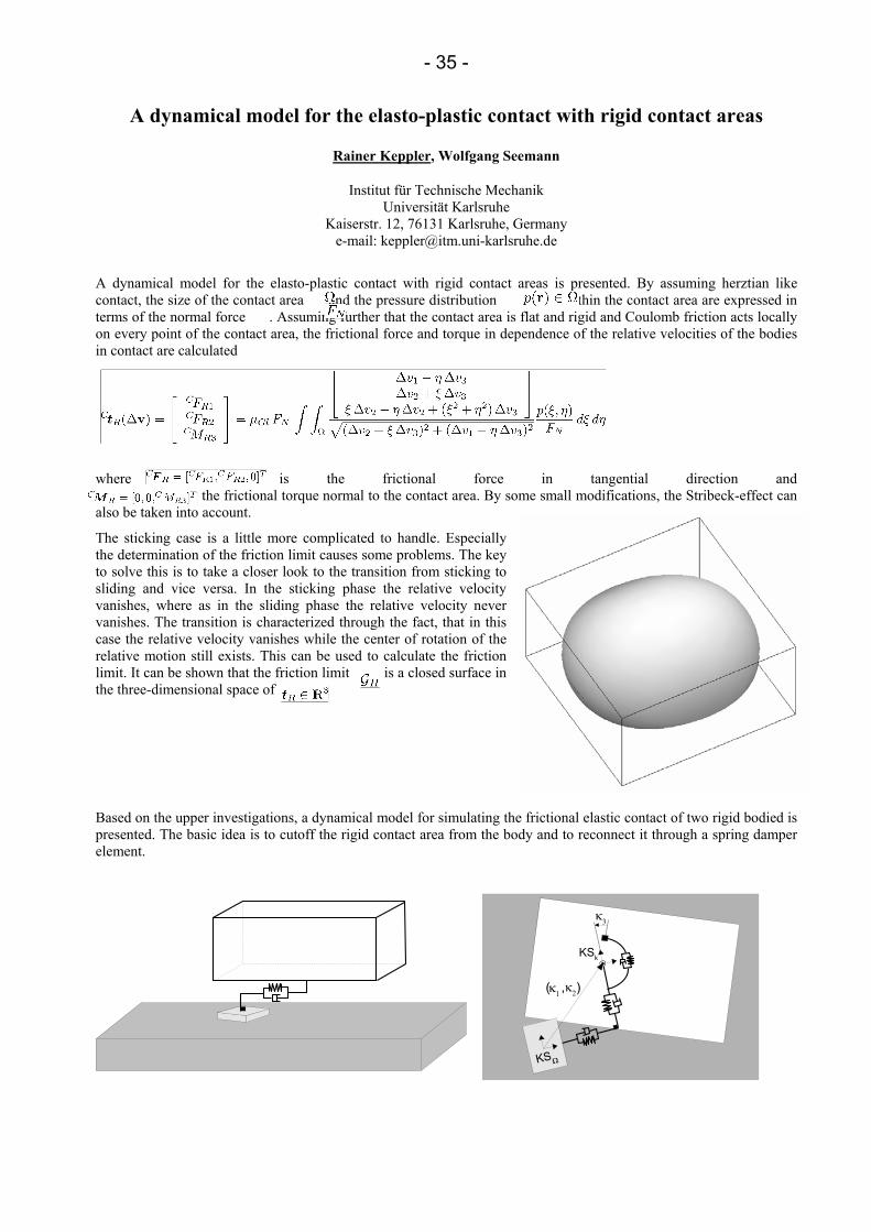
A dynamical model for the elasto-plastic contact with rigid contact areas is presented. By assuming herztian like contact, the size of the contact area and the pressure distribution within the contact area are expressed in terms of the normal force . Assuming further that the contact area is flat and rigid and Coulomb friction acts locally on every point of the contact area, the frictional force and torque in dependence of the relative velocities of the bodies in contact are calculated
where is the frictional force in tangential direction and the frictional torque normal to the contact area. By some small modifications, the Stribeck-effect can also be taken into account.
The sticking case is a little more complicated to handle. Especially the determination of the friction limit causes some problems. The key to solve this is to take a closer look to the transition from sticking to sliding and vice versa. In the sticking phase the relative velocity vanishes, where as in the sliding phase the relative velocity never vanishes. The transition is characterized through the fact, that in this case the relative velocity vanishes while the center of rotation of the relative motion still exists. This can be used to calculate the friction limit. It can be shown that the friction limit is a closed surface in the three-dimensional space of
Based on the upper investigations, a dynamical model for simulating the frictional elastic contact of two rigid bodied is presented. The basic idea is to cutoff the rigid contact area from the body and to reconnect it through a spring damper element.

- 36 -
This results in a singular perturbed problem of the form:
where is a switching parameter with in the sticking phase and during sliding. In the limit case of a vanishing mass of the contact area leads to a differential algebraic problem of index one. In the one-dimensional case, the model is closely related to the elasto-plastic contact model.
As an application of the presented model, the soft finger contact problem of an anthropomorphic hand of a humanoid is investigated.

- 37 -
Multibody analysis of axially elastic rod chains
Erno Keskinen 1 , Taina Vuoristo 2 ,Veli-Tapani Kuokkala 2 , Matti Martikainen 1
1Laboratory of Machine Dynamics, 2Institute of Materials Science Tampere University of Technology
Korkeakoulunkatu 12, FIN-33101Tampere, Finland [erno.keskinen, taina.vuoristo]@tut.fi
The work cycle of many traditional work processes in construction and mining industries is based on repetition of impulses produced by large number of hits on to the work object or work tool. This is, for instance, the case in piling and percussive drilling processes, where a hammer is in reciprocating motion to produce a set of impulsive forces to win the resisting forces produced by the soil or the rock. These hits are generating small-amplitude wave motion to the axial elements in the machine while at the same time these elements are in large amplitude motion. Axial elasticity of these rod-like bodies modifies the response behavior so that depending on the application, sharper or smoother impulse profiles can be produced. Another way to constructively tune the pulse duration time is to use metallic or non-metallic interface elements between the impacting rods. This is utilized in piling machinery, where the viscoelasticity of the cushion body actually controls the penetration of the pile end to the soil. Other use of interface elements is to protect the rods against plastic deformation or just to work as end stoppers to limit the motion.
The design of impacting machinery in industry is normally based on handbook formulas and experimental testing of prototype machinery. Due to the high nonlinearity level of the problem of wave propagation over gaps and non-metallic interface elements, the analysis is very often based on rough boundary conditions, which modify the response too much from the actual one. Experimental testing in dirty conditions under impulsive shock loadings has also been felt very demanding and expensive, because the number of measured quantities is large and the measuring points, and therefore also the sensors, are very often in contact with the work material.
For these reasons there is a need for efficient analysis methods, by which the time history of the impacting systems could be analyzed during a complete work cycle consisting of a large number of separate impulses. A rod assemblage in axial motion represents a multi-body system, the interfaces of which behave nonlinearly. This problem then returns to modeling of rods interconnected by nonlinear contact forces.
This paper presents two alternative analysis methods to solve this problem. The first one is the use of finite elements in an iterative computation scheme and the other one is based on analytical eigenfunctions of an axially vibrating free-free rod.
Comparison of computed responses obtained by two alternative and independent methods represents good scientific tradition. In this case the situation is even better: an excellent platform to experimentally verify the results is actually a classical Hopkinson split bar apparatus. This device was originally developed to produce stress-strain curves for nonlinearly behaving materials under high strain and strain rate conditions. The apparatus consists of a striker rod (or ‘bar’), incident rod, transmitted rod, and optionally of a damper rod. The measuring system consists of only two strain gages, which are used to measure the axial strains in the middle span of the incident and transmitted rods.
The impulsive loading is produced by a projectile, which is shot by pressurized air to hit the free end of the first rod. The duration of the contact depends on the length of the projectile and on the deformation of the hit transmitting pulse-shaper piece, which are the available parameters to adjust the impulse time. As a consequence of the impact, the three bodies are executing a coupled motion as a multi-body system acting on each other by impulsive contact forces. Due to the axial elasticity of the rods, the rods are vibrating during the large amplitude motion. Vibratory motion is related to the propagation of axial stress waves inside the rods. At the end interfaces the waves are split into reflected and transmitted components depending on the boundary condition (free end, hard contact or soft contact). The after-hit motion of the rod system will be damped by a shock absorber, which is working delayed after the interesting stress history has been recorded from the rods.
In our case the Hopkinson apparatus is modeled as a multibody system with nonlinear interface elements. The rod dimensions as well as the specimen materials are varied in order to produce a representative set of test cases. Each case has then been simulated by finite elements and eigenfunction expansions, the results of which are compared with the experimental ones measured from the existing laboratory unit. The results show that both finite element and eigenfunction modeling are efficient and accurate methods in solving stress wave propagation problems in axially moving multibody systems. As machinery including such rod mechanisms are frequently used in work processes in construction and mining industries, the results have significant application potential in design and analysis of new machinery, in which polymers and composites are used in force transmitting, hit softening, or shock absorbing purposes.

- 38 -
On a continuous transfer of history variables for frictional contact problems based on interpretations of covariant derivatives as a parallel translation
Alexander Konyukhov, Karl Schweizerhof
Institut für Mechanik Universität Karlsruhe
Englerstr. 2, 76131 Karlsruhe, Germany e-mail: [email protected]
Several approaches are known to model frictional contact conditions. Regularization methods based on the penalization of the tangent displacements are among the most exploited techniques in finite element method to model the frictional interactions. Usually the global tangent displacements are described via convective coordinates which are e.g. used in a finite element discretization of the contact surface, so-called contact elements, see [1], [2]. These displacements serve to compute the tangent tractions in the case of sticking via a regularization procedure as well as in the case of sliding via a return-mapping scheme. The convective coordinates of the contact point as well as the corresponding tangent tractions can be considered as history variables and have to be stored for each contact points. Since the convective coordinates are defined only locally on each contact element, a problem concerning the correct transfer of history variables while crossing the element boundaries arises for large displacement problems. Various approaches can be exploited to solve this problem. Wriggers et. al. [3] proposed an algorithm for the 2D case, based on the usage of the path length of the projection point. Puso and Laursen [4] proposed to determine increments of convective coordinates in the geometric form for the 3D case. Another very interesting approach based on the moving cone description was proposed by Krstulovic-Opara et al. [5].
In the current contribution we discuss a continuous transfer of history variables based on the interpretation of a covariant derivative. The tangent tractions within the covariant descriptions [6] are modeled via the evolution equations defined via the covariant derivatives in the surface metrics. A geometrical interpretation of the covariant derivations as a parallel translation on the surface, see [7], allows to develop an integration scheme for the tangential tractions and to overcome the problem of the discontinuity of the history variables at element boundaries. The algorithm is constructed considering the relative motion of a projection point on the master surface from surface element A to surface element B. The corresponding incremental displacement vector and the tangent traction vector are defined in the tangent plane of the element A. In order to transfer them correctly, first, the pull-back operation into a reference Cartesian configuration is made. Then the push-forward operation into the element B follows and, in addition, the contact tractions are enforced to lay in the tangent plane of the element B. Finally, the numerical integration of the evolution equations is performed, finally, using the metrics of the element B in tensor form.
The continuous integration technique which is identical for both, rigid or flexible bodies enclosed by contact surfaces, is illustrated by the particular example of a sliding edge on a surface. It is shown that for the non-frictional contact problem the "segment-to-segment" approach with different integration schemes can improve the result computed with the standard "node-to-segment" scheme. However, for frictional contact problems the continuous integration scheme is absolutely necessary in order to avoid jumps in tangential tractions, or even to achieve convergence. These effects are illustrated for both, quasi-static and dynamic cases.
References [1] Wriggers P. Computational Contact Mechanics. John Wiley & Sons. (2002) [2] Laursen T. A. Computational contact and impact mechanics. Fundamentals of modeling interfacial phenomena in
nonlinear finite element analysis. Springer. (2002) [3] Wriggers P., Krstulovic-Opara L., Korelc J. Smooth C1-interpolations for two-dimensional frictional contact
problems. International Journal for Numerical Methods in Engineering. 51, (2001) 1469–1495. [4] Puso, M.A., Laursen, T.A. A 3D contact smoothing method using Gregory patches. International Journal for
Numerical Methods in Engineering. 54, (2002) 1161–1194. [5] Krstulovic-Opara L., Wriggers P., Korelc J. A C1-continuous formulation for 3D Finite deformation frictional
contact. Computational Mechanics. 29, (2002) 27–42. [6] Konyukhov A., Schweizerhof K. Covariant description for frictional contact problems. Computational Mechanics.
35, (2005) 190–213. [7] Marsden JE, Hughes TJR. Mathematical foundations of elasticity. Prentice-Hall, Inc. (1983) [8] Konyukhov A., Schweizerhof K. A special focus on 2D formulations for contact problems using a covariant
description. International Journal for Numerical Methods in Engineering. Accepted for publication, Oct. 2005.
- 39 -
A module for the simulation of 3D fatigue crack propagation in BEM and FEM environments
Karsten Kolk, Günther Kuhn
Institute of Applied Mechanics University of Erlangen
Egerlandstrasse 5, D 91058 Erlangen, Germany e-mail: [kolk, g.kuhn]@ltm.uni-Erlangen.de
A modern fatigue crack growth module considering 3D effects is presented. This module is designed for both BEM and FEM software packages. The crack and the surrounding crack near–field are modeled by the 3D dual boundary element method because this method offers some important advantages [1]. It has been proved for linear elastic stress concentration problems and due to the boundary–only formulation the update of the numerical model is easier compared to finite elements. Therefore, it is natural that the crack module fits perfectly into a complete boundary element model. The corresponding boundary integral equations (BIE) are evaluated in the framework of a collocation method. To speed up the solution time and to handle large scale problems efficiently a so called fast BEM formulation in terms of the adaptive cross approximation (ACA) method is applied.
If the BIE are evaluated in terms of the symmetrical Galerkin boundary element formulation the crack growth module can be treated as a macro finite element incorporating the complete crack. Then it can be easily coupled to any commercial FEM package which offers suitable interfaces, e.g. Abaqus [2]. This coupling combines the advantages of both methods.
The crack module concerning the fatigue crack propagation includes an automatic incremental 3D crack growth algorithm for arbitrary three dimensional problems with linear–elastic material behaviour. In each increment a) the numerical solution of the boundary value problem, b) the determination of the new crack geometry and c) the update of the numerical model for the next increment have to be performed. The utilized 3D crack growth criterion is based on experimental observations [3] and numerically realized in terms of a predictor–corrector procedure [4].
The efficiency of the presented crack module will be shown on both complex fracture specimens and industrial applications with interesting crack paths.
References:
[1] Partheymüller P, Haas M, Kuhn G (2002) Comparison of the basic and the discontinuity formulation of the 3D–Dual boundary element method. Eng Anal Boundary Elements 24: 777–788.
[2] Helldörfer B, Kuhn G (2005) Coupled FEM/BEM analysis of fracture mechanical problems. In: Kuhn G, Ren Z, Skerget L, Hribersek M (eds) Proceeding of the 2nd Workshop of Advanced Computational Engineering Mechanics. pp 63–72.
[3] Heyder M, Kolk K, Kuhn G (2005) Numerical and experimental investigations of the influence of corner singularities on 3D fatigue crack propagation. Engineering Fracture Mechanics 72: 2095–2105.
[4] Kolk K, Kuhn G (2005) A predictor–corrector scheme for the optimization of 3D crack front shapes. Fatigue Fract Engng Mater Struct 28: 117–126.
- 40 -
First integrals of equations of motion of a heavy rotational symmetric body on a perfectly rough plane
Alexander Kuleshov
Department of Mechanics and Mathematics Moscow State University
Department of Mechanics and Mathematics, Main building of MSU Leninskie gory, Moscow 119992, Russia
e-mail: [email protected];
We consider the problem of motion of a heavy dynamically symmetric rigid body bounded by a surface of rotation on a fixed perfectly rough horizontal plane. The integrability of this problem was proved by S.A. Chaplygin [1]. Chaplygin was found that equations of motion of the given mechanical system admit, in addition to the energy integral, two first integrals, linear in generalized velocities. However, the explicit form of these integrals is known only in the case, when the moving body is a nonhomogeneous dynamically symmetric ball. In the case, then the body is a round disk or a hoop, these linear in generalized velocities first integrals are represented as converging hypergeometric series. In the paper of Kh.M. Mushtari [2] the investigation of this problem was continued. Under a certain condition for the surface of moving rigid body and its mass distribution, Mushtari was found two new particular cases, when the motion of the body can be investigated completely. In the first case the moving rigid body is bounded by a surface formed by rotation of an arch of a parabola about the axis, passing through its focus, and in the second case, the moving body is a paraboloid of rotation. For other bodies, bounded by a surface of rotation and moving without sliding on a horizontal plane, the explicit form of additional first integrals is unknown.
In this presentation we find the explicit form of two additional first integrals in the case, when the surface of moving body satisfies to a Mushtari condition. The set of surfaces of moving bodies satisfying to the given condition is described. The results of this work essentially supplement and develop the results of Mushtari investigation.
References
[1] Chaplygin S.A. On a motion of a heavy body of revolution on a horizontal plane // Regular & Chaotic Dynamics. 2002. Vol. 7. 2. P. 119-130.
[2] Mushtari Kh.M. On rolling of a heavy rigid body of rotation on a fixed horizontal plane // Mat. Sbornik. 1932. Vol. 39. 1-2. P. 105-126 (Russian).

- 41 -
Complementary models for log grinding
Sirpa Launis1, Erno Keskinen2, Claude Bohatier3, Frédéric Dubois3
1 VTT Technical Research Centre of Finland, Industrial Systems P.O. Box 1307, FIN-33101 Tampere, Finland
2 Tampere University of Technology, Laboratory of Machine Dynamics P.O.Box 589, FIN-33101 Tampere, Finland
3 LMGC, UMR CNRS 5508, Université Montpellier II cc 048, 34095 Montpellier cedex 5, France
Pulp for making paper is produced in the groundwood (GW) process from logs, which are cut to fixed length. There are different ways for GW pulp production from which the use of batch-type GW machines is the most common method in the industry today. In this kind of machines the control of the log loading is a demanding task because of the complicated log group dynamics where also the heterogeneous wood material has a great influence on the batch behaviour. It is essential to achieve better understanding of the regularities occurring in the process in order to improve the loading control and thus the quality and efficiency of pulp production. For this purpose a virtual model of the complete process has been built up and the system has been studied by simulation.
The virtual model is a coupled system representation of submodels, including the mechanical parts of the grinding machine, the hydraulic and electrical actuators and their feedback control systems and the raw material, i.e. the log batch, and its processing. The focus of this paper is the description of the dynamical behaviour of the log batch and the material removal from the batch during grinding. Our approach is limited to the plane representation of the log behaviour. The chosen plane is the one in perpendicular to the grains of the wood.
The log batch is a multiscale problem. In the beginning of the log loading sequence the batch is loose and the log group has to be considered as a multibody system. During the loading the logs are gradually packed tightly and under heavy compression. In this case the fluctuation caused by void space in the wood batch is minimized and the wood batch progresses towards the grinding stone more like a uniform body than a group of separate logs. Additional scale to the problem is added by the phenomena happening near the grinding contact, the material flow in the contact zone etc. In order to achieve a wider view for the grinding process development, we have chosen three separate approaches to study the different scales of the log batch problem :
1. The phenomenological approach with multibody representation for individual logs.
2. The phenomenological approach with one-dimensional continuum material model for wood.
3. The mesoscopic approach where the logs are discretised to smaller particles.
The first of the approaches describes the batch in the scale of individual logs. With this model we can study the group behaviour of the logs in the batch. The name is based on the fact that in this model the grinding contact is described with a phenomenological model for abrasive wear. The equations of motion ( x, y, θ ) have been derived for each log with various interactions between logs and structural parts of the machine as the loading terms. Logs behave as rigid bodies whereas contacts between them are nonlinearly elastic. Also damping is introduced in the contact representation. The interaction between individual logs and grinding stone is covered by wear equation for abrasive wear, where the rate of material removal is proportional to the sliding distance of the stone and the normal force between the stone and each log. The amount of removed material in grinding as well as contact penetration volume between different parts, which is needed in contact force calculation, are solved from log positions by discretising (delaunay triangulation) the cross-sectional shape logs and using numerical methods to solve the overlapping area between contacting elements. An implicit time-integration method is used to solve the system equations.
In the second approach there is a fluid like representation for the compressible wood flow under material removing conditions. Viscoelastic Kelvin-Voigt material model has been used in modelling the wood batch as a homogeneous one-dimensional continuum. The material removal is accomplished by using the wear equation.
In the third approach, i.e. in the mesoscopic model, the chosen scale is the one of “grain bundles”. In this approach, the logs, in their initial configuration, are formed by small circles each of which represents a bundle of grains. The bundles are held together by cohesion forces. The mesoscopic model is based on the Contact Dynamics (CD) method and the LMGC90 simulation program has been used in the modelling. The CD method was originally developed to deal with rigid, frictional particles. It represents the deformation of the granular medium as a whole, exclusively by particle rearrangements. In the CD method, the volume exclusion of perfectly rigid particles is a unilateral constraint that is formulated as an inequality: the distance between the particle surfaces must be larger than or equal to zero. In our case,

- 42 -
there are cohesive forces present, which means that when the gap between two particles is small enough the particles will attract each other until the gap closes.
The chose of cohesion model is not obvious for the wood material because the cohesion force is difficult to measure and it is not very easy to find such models for wood in the common literature. The current cohesion law is a combination of inelastic quasi-shock model and adhesive-like traction force with Coulomb friction. In tangential direction the Coulomb friction force is applied by one particle to another. The model lacks the torsion but its role is probably not very important in case of soft fibres. The material removal in this model is accomplished so, that when the contact force between a grain bundle and the grinding stone exceed the cohesion forces, the bundle is torn off from the log. Once a cohesion link breaks it cannot evolve again but the contact law changes to the non-cohesive one.
All of the log batch models are such that they can be implied in the system level model. They are complementary and thus we can receive different kind of important information by their usage. This information is utilised in the development of new control systems.

- 43 -
The admissible state space and bouncing motion for a robotic system
Liu Caishan1,2 Zhao Zhen1 Chen Bin1
1Department of Mechanics & Engineering Science Peking University, Beijing, 100871
2State Key Laboratory of Turbulence and Complex Systems e-mail: [email protected]
The controllability properties of a manipulator sliding on a rough surface can be characterized by the admissible states. In this paper, a condition for the occurrence of bouncing motion in a general multi-rigid-body system subjected to only one unilateral constraint is deduced based on LCP theory. A two-link manipulator sliding on a rough surface is studied in detail.
1. Introduction
The bouncing motion of robotic system sliding on the rough surface means that there are some region of the state space are unreachable in the condition of combining the unilateral constraint with friction. This paper has presented a definition of admissible state space for the multibody system with only one unilateral constraint based on LCP theory. The occurrence of the bouncing motion is strongly related to the configuration of the system and the friction coefficient.
The bouncing motions have two different characteristics due to the different conditions of inducing the hopping phenomenon. One is that the bouncing motion can occur during the sliding process. This is because of the action of inertia of the system. The other is that the bouncing motion can appear once the end-effector touches to the contact surface. This case corresponds to the occurrence of Painleve paradox.
This paper has presented a detailed description of the admissible state space for a two-link manipulator sliding on a rough surface. The structures of state space for this system in different friction coefficient are exhibited by using the phase plane method. The results show that the region of the unreachable state space will be enlarged with the increase of the friction coefficient, and the critical friction for the occurrence of Painleve paradox in this system can be arbitrarily small which only depends on the configuration of the system.
The robotic system which movement includes bouncing motion is a typical hybrid system. This paper has also presented an effective numerical method to simulate dynamical behavior. The numerical results have verified the tangential impact, the properties of the singular points, and the phenomenon of bouncing motion in different initial states.
2. LCP Description of a Planar Rigid Multibody System with a Single Unilateral Constraint
The planar multi-rigid body system moving on a rough surface is shown in Fig.1. The generalized coordinates of the system are expressed as ),,,( 21 nqqq L . In terms of Euler-Lagrange Equations, the dynamic equations of multi-body system shown in Fig.1 can be written as
Fig. 1 Multi-body system
SWqqRMKKFMKx 1T1T ++−+= −− )),(( &&& (1)
Amontons-Coulomb friction model is supposed to hold at the contact point with constant friction coefficient µ . The equations of the normal motion of the system become in the forward sliding mode:
),(),( 22 qqq &&& BFAx += µ (2)
Under the assumption of impenetrability of unilateral constraint, the normal component of acceleration and normal component of contact force should satisfy with the following complementarity condition.
02 ≥x&& , 02 ≥F , and 022 =⋅ Fx&& (3)
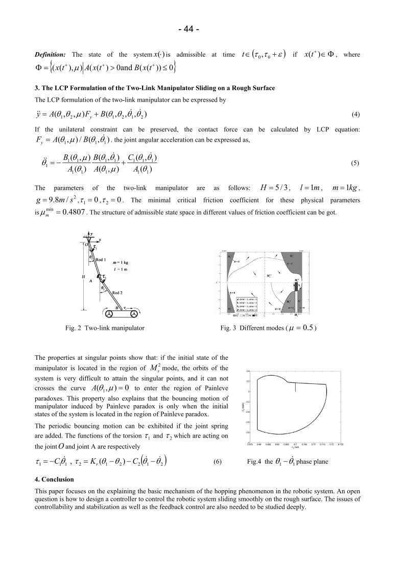
- 44 -
Definition: The state of the system )(⋅x is admissible at time ( )εττ +∈ 00,t if Φ∈+ )(tx , where
0))(( and0)(()),(( ≤>=Φ +++ txBtxAtx µ
3. The LCP Formulation of the Two-Link Manipulator Sliding on a Rough Surface
The LCP formulation of the two-link manipulator can be expressed by
1 2 1 2 1 2( , , ) ( , , , )yy A F Bθ θ µ θ θ θ θ= + & &&& (4)
If the unilateral constraint can be preserved, the contact force can be calculated by LCP equation:
1 1 1( , ) / ( , )yF A Bθ µ θ θ= & . the joint angular acceleration can be expressed as,
1 1 1 1 1 1 11
1 1 1 1 1
( , ) ( , ) ( , )( ) ( , ) ( )
B B CA A A
θ µ θ θ θ θθθ θ µ θ
= − +& &
&& (5)
The parameters of the two-link manipulator are as follows: 3/5=H , ml 1= , kgm 1= , 2/8.9 smg = , 01 =τ , 02 =τ . The minimal critical friction coefficient for these physical parameters
is min 0.4807mµ = . The structure of admissible state space in different values of friction coefficient can be got.
Fig. 2 Two-link manipulator Fig. 3 Different modes ( 5.0=µ )
The properties at singular points show that: if the initial state of the manipulator is located in the region of 2
sM mode, the orbits of the system is very difficult to attain the singular points, and it can not crosses the curve 1( , ) 0A θ µ = to enter the region of Painleve paradoxes. This property also explains that the bouncing motion of manipulator induced by Painleve paradox is only when the initial states of the system is located in the region of Painleve paradox.
The periodic bouncing motion can be exhibited if the joint spring are added. The functions of the torsion 1τ and 2τ which are acting on the jointO and joint A are respectively
111 θτ &C−= , ( )212212 )( θθθθτ && −−−= CKr (6) Fig.4 the 11 θθ &− phase plane
4. Conclusion
This paper focuses on the explaining the basic mechanism of the hopping phenomenon in the robotic system. An open question is how to design a controller to control the robotic system sliding smoothly on the rough surface. The issues of controllability and stabilization as well as the feedback control are also needed to be studied deeply.

- 45 -
A discrete model for long time sintering
Stefan Luding
Particle Technology, Nanostructured Materials, DelftChemTech, TUDelft, Julianalaan 136, 2628 BL Delft, Netherlands
e-mail: [email protected]
A model for the sintering of polydisperse, inhomogeneous arrays of particles is presented with empirical contact force-laws, taking into account plastic deformations, cohesion, temperature dependence (melting), and long-time effects. Samples are prepared under constant isotropic load, and are sintered for different sintering times. Increasing both external load and sintering time leads to a stronger, stiffer sample after cooling down. The material behavior is interpreted from both microscopic and macroscopic points of view.
Among the interesting results is the observation, that the coordination number, even though it has the tendency to increase, sometimes slightly decreases, whereas the density continuously increases during sintering -- this is interpreted as an indicator of reorganization effects in the packing. Another result of this study is the finding, that strongly attractive contacts occur during cool-down of the sample and leave a sintered block of material with almost equally strong attractive and repulsive contact forces.
Fig.1: Sintered sample (temperature remained well below the melting point) before (left) and after (right) compression/vertical-tension/horizontal stress test. The color indicates the (frozen-in) stress in the material, and the
black lines in the right snapshot indicate the cracks.
Method and Example
In the simplest case, the particles are about µm sized spheres of anorganic material in a cuboid container under side pressure. Interaction models for non-organic materials are well established and also for simple viscoelastic polymeric materials. Not much work is available that describes the interaction of particles made of more advanced polymer materials, and even less is known how particles interfere during melting/sintering and, e.g., ongoing polymerization. The sintering under pressure and along a temperature cycle (heat-up – cool-down) of anorganic, ceramic model powders is modeled, see Fig. 1. This particle-based approach has shown two interesting findings, which could not be obtained using other methods. (1) The sintering makes the (brittle) material more homogeneous, but the cool-down process affects the internal structure and frozen-in stresses. Even careful sintering/tempering could not avoid the latter occuring in the final stages of the process. (2) The naturally very low mechanical strength of the powder could be increased by orders of magnitude by sintering (see Fig. 2) and, since the particulate nature of the original particles was kept to the end, the crack evolution under tension-stress test could be simulated and analysed with the same model, see Fig. 1. The effect of sintering time and confining pressure on the final material parameters was reported.
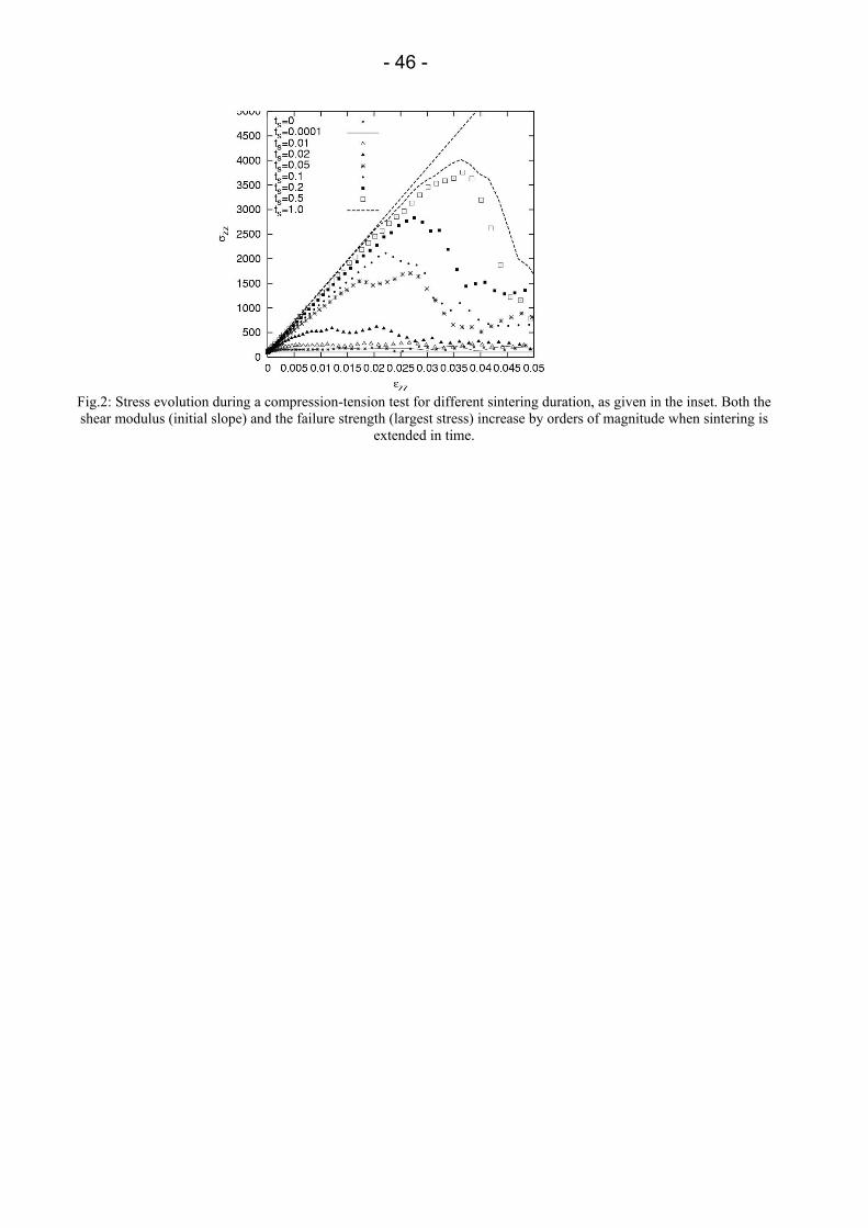
- 46 -
Fig.2: Stress evolution during a compression-tension test for different sintering duration, as given in the inset. Both the shear modulus (initial slope) and the failure strength (largest stress) increase by orders of magnitude when sintering is
extended in time.
- 47 -
A multigrid approach in the numerical problem of tangential contact
Alexander Lünenschloss
Department of Applied Mechanics TU Darmstadt
Hochschulstr. 1, 64289, Darmstadt, Germany e-mail: [email protected]
This work presents the numerical simulation of rolling bodies with multigrid-methods and boundary discretization. The use of different scales during the calculation overcomes known problems, regarding convergence, convergence velocity and the required time for summations. The final objective is the study of roughness in dry, tangential contact. First results show, that surface irregularities affect seriously the transmission of forces and moments.
Geometrical assumptions and derivation of boundary conditions follow the pioneering work in numerics of contact by Kalker [1]. He developed different algorithms for various simplifications, and most of them are based on maximizing complementary energy. In this case there are proofs for existence and uniqueness of solutions. A serious disadvantage is a cubic relationship between number of unknowns and calculation time. This problem of complexity makes it impossible to handle fine resolutions, even with fast computers. A set of multigrid methods, introduced by Venner and Lubrecht for contact with separating liquid [2], lowers the complexity. It works directly with the nonlinear boundary conditions.
The contact areas of rough surfaces require a change in the common operators, that transform arrays between grids of different resolution. The usual vertex-centered geometry adds vertices between the old ones, which leads to an incorrect mapping of corresponding areas. This is undesirable for incoherent contact areas, so all methods must be transformed to the appropriated cell-centered geometry. The resulting multigrid-methods were also applied in the case of normal contact with rough surfaces [3].
In contrast to finite elements, the discretization of the boundary method is limited to the neighborhood of contact. That way discretizations up to 300×300 points are accessible, which is sufficient for study of disturbed surfaces. The high number of influence coefficients, that appears in the boundary approach, can be saved in reduced form under the assumption of smooth macro-geometries.
References [1] Kalker, J. J. Three-Dimensional Elastic Bodies in Rolling Contact. Kluver Academic Publishers, (1990). [2] Venner, C. H. and Lubrecht, A. A. Multilevel methods in lubrication. Number 37 in Tribology Series. Elsevier,
(2000). [3] Bucher, F., Knothe, K., and Luenenschloss, A. Arch Appl Mech 73, 561ff. (2004).
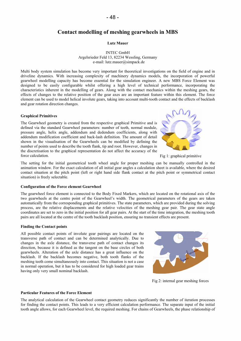
- 48 -
Contact modelling of meshing gearwheels in MBS
Lutz Mauer
INTEC GmbH Argelsrieder Feld 13, 82234 Wessling, Germany
e-mail: [email protected]
Multi body system simulation has become very important for theoretical investigations on the field of engine and in driveline dynamics. With increasing complexity of machinery dynamics models, the incorporation of powerful gearwheel modelling capacity has become essential for the simulation engineer. A new MBS Force Element was designed to be easily configurable whilst offering a high level of technical performance, incorporating the characteristics inherent in the modelling of gears. Along with the contact mechanics within the meshing gears, the effects of changes to the relative position of the gear axes are an important feature within this element. The force element can be used to model helical involute gears, taking into account multi-tooth contact and the effects of backlash and gear rotation direction changes.
Graphical Primitives
The Gearwheel geometry is created from the respective graphical Primitive and is defined via the standard Gearwheel parameters: number of teeth, normal module, pressure angle, helix angle, addendum and dedendum coefficients, along with addendum modification coefficient and back-lash definition. The amount of detail shown in the visualisation of the Gearwheels can be modified by defining the number of points used to describe the tooth flank, tip and root. However, changes in the discretisation to the graphical representation do not affect the accuracy of the force calculation. Fig 1: graphical primitive
The setting for the initial geometrical tooth wheel angle for proper meshing can be manually controlled in the animation window. For the exact calculation of all initial gear angles a calculation sheet is available, where the desired contact situation at the pitch point (left or right hand side flank contact at the pitch point or symmetrical contact situation) is freely selectable.
Configuration of the Force element Gearwheel
The gearwheel force element is connected to the Body Fixed Markers, which are located on the rotational axis of the two gearwheels at the centre point of the Gearwheel’s width. The geometrical parameters of the gears are taken automatically from the corresponding graphical primitives. The state parameters, which are provided during the solving process, are the relative displacements and the relative velocities of the meshing gear pair. The gear state angle coordinates are set to zero in the initial position for all gear pairs. At the start of the time integration, the meshing tooth pairs are all located at the centre of the tooth backlash position, ensuring no transient effects are present.
Finding the Contact points
All possible contact points of involute gear pairings are located on the transverse path of contact and can be determined analytically. Due to changes in the axle distance, the transverse path of contact changes its direction, because it is defined as the tangent on the base circles of both gearwheels. Alteration of the axle distance has a great influence on the backlash. If the backlash becomes negative, both tooth flanks of the meshing teeth come simultaneously into contact. This situation is not a case in normal operation, but it has to be considered for high loaded gear trains having only very small nominal backlash.
Fig 2: internal gear meshing forces
Particular Features of the Force Element
The analytical calculation of the Gearwheel contact geometry reduces significantly the number of iteration processes for finding the contact points. This leads to a very efficient calculation performance. The separate input of the initial tooth angle allows, for each Gearwheel level, the required meshing. For chains of Gearwheels, the phase relationship of

- 49 -
the dependent Gearwheels is calculated from the initial tooth angle input of one of the Gearwheels. The tooth force pulsation, resulting from multi-tooth contact and the tooth stiffness function, can be reset to zero from two Force parameters.
Calculation of meshing Forces The force law for the calculation of the nominal force is calculated linearly or non-linearly as a function of the penetration of the involute tooth profile. The tangential force, during meshing, is calculated from a Coulombic force law, with the friction coefficient given by the user. The total meshing force sums up all contacting teeth, which are found on the path of contact. A maximum of five tooth pairs is considered.
Output Values
The output values for the Gear Force Element are the effective forces and moments applied at each wheel. The forces and moments can also be output in Reference Frames, which do not rotate with the Gearwheels. In addition to other internal measurements, which include gearwheel angle, stiffness, force and position, it is possible to return the current meshing condition concerning the type of flank contact.
Force Law
The nominal value of the single contact stiffness depends on the number of teeth, on the profile shift factors of the meshing gears and on the reference profile angle of attack. For spur gears the stiffness function follows the line of contact as a parabolic function with its maximum at the pitch point. For helical gears a modification of the stiffness function of spur gears has to be performed, which results from integrals over the parabolic function.
The geometrical penetration for the theoretical teeth profiles is used as the input to the normal force calculation. Depending on the normal force, the tangential friction force is calculated from a Coulombic force law, with the friction coefficient given by the user. Contact forces are calculated for each meshing contact. For reduction of the high changes in contact forces occurring by changes between single and multiple contact situations, tip relief can be defined. Instead of modelling tip relief as a modification of the involute profile, modification of the contact stiffness function in the contact path regions of multi meshing contact has been developed. For the calculation of the resulting torque, cross products between all normal and tangential forces and the corresponding location vectors are performed. The resulting forces are outputted in the rotating and in the non-rotating frame. Setting the tip relief factor to 1 and the parabolic factor to zero and switching off the Coulombian friction can achieve linear behaviour of the contact force calculation.
Applications
Driveline of wind turbines, which usually contain a gearbox with a one- or two-stage planetary gears and 2 stages of helical gears. The example shows one stage helical planetary gear and two stages of helical gears. The total gear ratio is 1: 90. The mesh frequency of the last helical gear stage is about 450 – 1000 Hz. This gear model is a part of a wind turbine simulation model composed of pylon, nacelle, hub, rotor blades, brakes and grid-coupled generator. Another MBS simulation example is a V6 combustion engine with gears between the camshafts of the valve train.
Fig 3: example SIMPACK model wind turbine gear Fig 4: example valve train
Summary
The described gearwheel is an easily configurable force element, and allows the data to be entered easily and efficiently. The calculation of the tooth forces considers all of the geometric features of the involute tooth. The calculation algorithm for geometrical contact problem works very fast and reliably due to the analytical algorithm upon

- 50 -
which it is based. The modelling approach of tip relief works very fast and is easy adjustable to quasi-static reference results carried out with the finite element method. The high numerical reliability opens the way for the simulation of the non-linear dynamic behaviour of gearboxes with a large number of gears, whereby the phase differences of all the meshing tooth pairs are accurately modelled. The gearwheel force element has been proved for high revolution engines working with tooth meshing frequencies up to 8000 Hz.

- 51 -
On the quasi-static behavior of granular packings
Sean McNamara
Institut für Computerphysik Universität Stuttgart
Pfaffenwaldring 27, 70569 Stuttgart, Germany e-mail: [email protected]
We consider the quasi-static motion of assemblies of non-cohesive disks with Coulomb friction, subjected to an external load. It is assumed that the disks are always in force equilibrium and their displacements are small. Special attention is paid to the question of when and how these assumptions are violated.
We first examine the relatively simple problem of a disk placed in a symmetric V-shaped channel, forming a system with two contacts and one particle. The disk is subjected to gravity and a torque. We investigate the maximum torque that can be applied to the disk without setting it in motion.
We obtain analytic predictions of the contact forces and the maximum torque using two different models. In the first model, the disk is assumed to be perfectly rigid, leading to force indeterminacy. The contact forces are be constrained by the Coulomb condition at each contact. If the opening angle of the wedge is not too small, this model is sufficient to predict the maximum torque. However, when the opening angle is small, an infinite maximum torque is predicted.
In the second model, the disk is assumed to interact with the walls of the channel via linear springs. We present a formulation of this model where the displacements are related to the applied force by a stiffness matrix. This method can easily be generalized to packings with many particles. In this model, there is a unique solution for the contact forces. It predicts the same maximum torque as the first model for large opening angles. For small opening angles, however, it predicts that a finite maximum torque, which depends on the history of the packing. It is shown that the memory of the packing resides in the forces that the first model could not determine.
It is also shown that there are two possible ways motion can occur – through the appearance of a null eigenvector of the stiffness matrix, or through an instability. When motion occurs through an instability, the first model cannot predict when the disk will rotate; it is necessary to know the undetermined forces in order to predict the motion of the disk. The analytical results are also compared with simulations using two different numerical methods, each related to one of the models.
Finally, the stiffness matrix will be used to study the problem of a large assembly of disks under biaxial test conditions. It will be shown how microscopic parameters, such as the number of sliding contacts, can be related to macroscopic quantities such as the stiffness of the material.

- 52 -
Lateral impacts on flexible beams in multibody dynamics simulations
Jacob Meijaard
School of Mechanical, Materials and Manufacturing Engineering University of Nottingham
University Park, Nottingham NG7 2RD, U.K. e-mail: [email protected]
Mechanical systems with widely varying time scales occur naturally in engineering practice. For instance, in the problem of the driving of pre-curved piles, the longitudinal vibrations that result from the impulse of the motor tup have a smaller time scale than the lateral vibrations of the free-standing pile, which is comparable with the period between impulses [1]. In systems with friction, at the transition between sticking and sliding or at the reversal of the sliding direction, phenomena that arise from the state and rate dependence of the friction force can become noticeable [2]. In mechanisms, backlash may give rise to impacts, which induce high-frequency oscillations [3]. A further question remains whether a discretized system can be used to model the transition at the impact [4].
The key to analysing these systems is the use of asymptotic analysis and of scaling [5]. The scaling can reveal whether the separation in phenomena related to different time scales is allowed, and the number of small time scales. In a multibody dynamics system, the largest time scale can be associated with the large-scale rigid body motion, a smaller scale can be associated with the vibration modes of the system, and a still smaller time scale may be involved in discontinuous phenomena, such as impacts and friction. A procedure to analyse these systems is to use a standard flexible multibody formalism, with the rigid-body motion and low frequency vibrations included in the system description, between events which involve a small time scale, and to use an asymptotic analysis to derive transition conditions at the event, which may be considered as transition conditions for an idealization as a discontinuous event. These transition conditions can sometimes be solved or approximated by explicit equations, but often a separate numerical analysis is needed for the small time scale to evaluate these conditions.
In this presentation, some ideas will be exemplified in an old problem, the lateral impact on a flexible beam. This problem has been studied by, among others, Hodgkinson, Saint-Venant and Timoshenko. Usually, an approximate solution or a series solution in terms of vibration modes is used. Here, the solution is obtained with the help of fundamental solutions and convolution integrals. Different boundary conditions and ways of modelling of the impact can be used. The impact can be by a ball, with Hertzian contact between the ball and the beam, or by another beam that hits transversally or longitudinally. The influence of the support conditions is also investigated. Depending on the conditions, several impacts may occur in a single event. After the impact, the resulting deflections of the beam have to be approximated in the discretization, where the problem of aliasing has to be considered.
References
[1] J. P. Meijaard, `Dynamische knik tijdens het heien', Report LTM 844, Laboratory for Engineering Mechanics, Delft University of Technology, Delft, November 1986.
[2] A. R. Savkoor and J. P. Meijaard, `Application of bifurcation theory to the identification of the constitutive relations for sliding friction', in S. Narayanan and R. N. Iyengar, eds, IUTAM Symposium on Nonlinearity and Stochastic Structural Dynamics, Kluwer Academic Publishers, Dordrecht, 2001, pp. 233-248.
[3] A. L. Schwab, J. P. Meijaard and P. Meijers, `A comparison of revolute joint clearance models in the dynamic analysis of rigid and elastic mechanical systems', Mechanism and Machine Theory 37 (2002), pp. 895-913.
[4] J. P. Meijaard, `The influence of the discretization of a vibrating string on its transition route to chaos', in L. Pust and F. Peterka, eds, Proceedings of the 2nd European Nonlinear Oscillations Conference, Prague, September 9-13, 1996, Institute of Thermomechanics, Academy of Sciences of the Czech Republic, Prague, 1996, Vol. 2, pp. 131-134.
[5] G. I. Barenblatt, Scaling, Cambridge University Press, Cambridge, 2003.
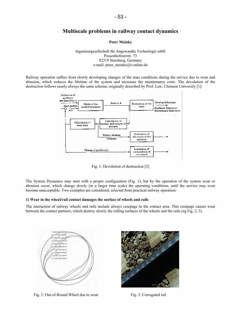
- 53 -
Multiscale problems in railway contact dynamics
Peter Meinke
Ingenieurgesellschaft für Angewandte Technologie mbH Possenhofenerstr. 73
82319 Starnberg, Germany e-mail: [email protected]
Railway operation suffers from slowly developing changes of the state conditions during the service due to wear and abrasion, which reduces the lifetime of the system and increases the maintenance costs. The devolution of the destruction follows nearly always the same scheme, originally described by Prof. Law, Clemson University [1]:
Fig. 1: Devolution of destruction [2]
The System Dynamics may start with a proper configuration (Fig. 1), but by the operation of the system wear or abrasion occur, which change slowly (in a larger time scale) the operating conditions, until the service may even become unacceptable. Two examples are considered, selected from practical railway operation:
1) Wear in the wheel/rail contact damages the surface of wheels and rails
The interaction of railway wheels and rails include always creepage in the contact area. This creepage causes wear between the contact partners, which destroy slowly the rolling surfaces of the wheels and the rails (eg Fig. 2, 3).
Fig. 2: Out-of-Round Wheel due to wear Fig. 3: Corrugated rail
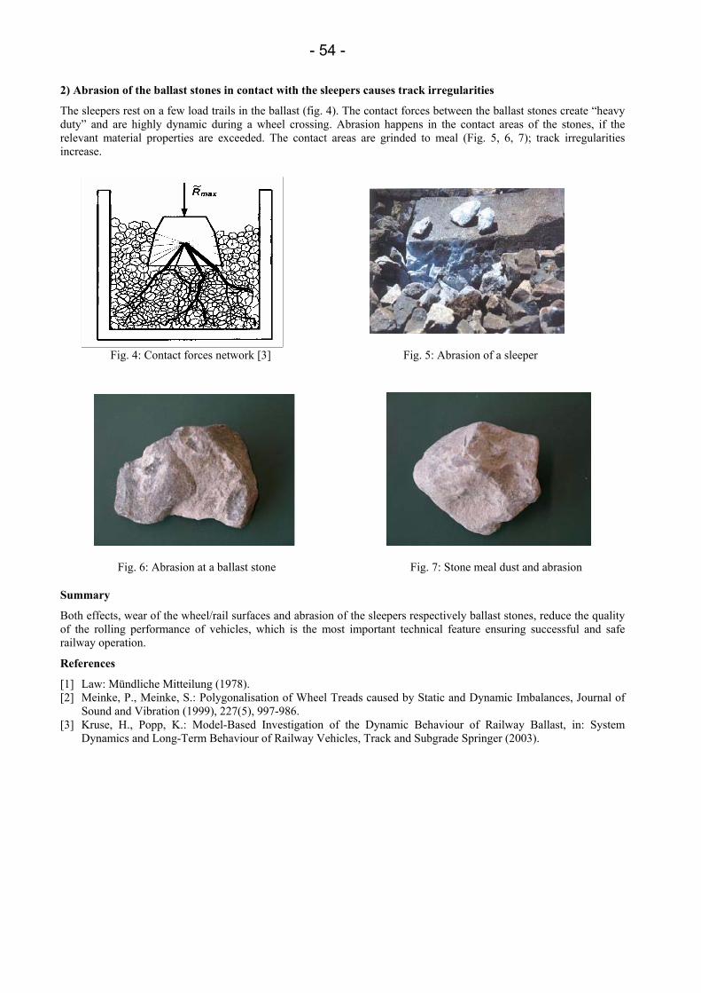
- 54 -
2) Abrasion of the ballast stones in contact with the sleepers causes track irregularities
The sleepers rest on a few load trails in the ballast (fig. 4). The contact forces between the ballast stones create “heavy duty” and are highly dynamic during a wheel crossing. Abrasion happens in the contact areas of the stones, if the relevant material properties are exceeded. The contact areas are grinded to meal (Fig. 5, 6, 7); track irregularities increase.
Fig. 4: Contact forces network [3] Fig. 5: Abrasion of a sleeper
Fig. 6: Abrasion at a ballast stone Fig. 7: Stone meal dust and abrasion
Summary
Both effects, wear of the wheel/rail surfaces and abrasion of the sleepers respectively ballast stones, reduce the quality of the rolling performance of vehicles, which is the most important technical feature ensuring successful and safe railway operation.
References
[1] Law: Mündliche Mitteilung (1978). [2] Meinke, P., Meinke, S.: Polygonalisation of Wheel Treads caused by Static and Dynamic Imbalances, Journal of
Sound and Vibration (1999), 227(5), 997-986. [3] Kruse, H., Popp, K.: Model-Based Investigation of the Dynamic Behaviour of Railway Ballast, in: System
Dynamics and Long-Term Behaviour of Railway Vehicles, Track and Subgrade Springer (2003).
- 55 -
Grain-to-grain contact conditions and its impact on in-bulk behavior of granular material
Marek Molenda, Józef Horabik
Institute of Agrophysics, Polish Academy of Sciences ul. Doświadczalna 4, 20-290 Lublin 27, Poland
e-mail: [email protected]
1. Food- and agro- granular materials
Granular materials of biological origin constitute a coherent group of materials distinguished by large deformability of particles and strong dependence of their mechanical properties on moisture content. Contrary to materials of mineral origin, moisture penetrates inside grain, leading in some cases to qualitative changes in physical properties. This work presents selected results of projects performed by the authors that illustrate characteristic effects observed at single contact and in the bedding of the material.
2. Interactions on individual contact
2.1 Contact surface- moisture content
The contact area was measured between wheat grain and smooth glass plate for normal loading from 0.029 to 4.3 N and five levels of moisture content (from 8 to 18%). Hertz formula was found adequate for description of the relationship between the contact area and normal force. The experiments have shown a significant influence of grain moisture content on the contact area, the exponent of Hertz’s equation was found ranging from 0.72 to 0.78 dependent on moisture content.
2.2 Friction in individual contact
Coefficient of friction was determined for a pair of wheat grains against a flat steel plate sandwiched between them. Five levels of plate roughness (Rt from 0.5 to 11 µm) and five levels of grain moisture content (from 8 to 18%) were tested. Coefficient of friction found in a range from 0.07 to 0.57 increased rapidly with increasing roughness of sliding material. Increase in moisture content resulted in an increase in coefficient of friction for three lower levels of surface roughness (Rt of 0.5, 1.0 and 1.8 µm), while for surfaces of higher roughness (Rt of 6.4 and 11µm) no clear tendency was noticed.
3. In-bulk mechanical behavior
3.1 Compressibility of wheat grain
Compressibility of wheat grain of five levels of moisture content (from 10 to 20%) was examined in loading – unloading cycles in uniaxial compression test. Stress - strain characteristics were found strongly influenced by grain moisture content. At 100 kPa of normal pressure vertical strain of the sample of 10% in moisture content was found equal to 0.06 while in the case of the sample of 20% moisture content the strain was approximately equal to 0.12. Modulus of elasticity of wheat estimated for the linear phase of unloading was found decreasing with an increase in moisture content and ranged from 22.4 to 11.1 MPa.
3.2 Slip-stick effect
During testing friction of wheat against corrugated and smooth steel slip-stick behavior was observed at low speeds. During slip-stick the ‘pull’ force increases monotonically to a ‘high’ point where slip occurs, where upon the force drops rapidly to a ‘low’ stick point. The speed at which slip-stick behavior ends is defined as the critical speed. For a normal pressure of 48kPa the critical speed was found to be 2 mm/min for corrugated steel and 0.2 mm/min for smooth galvanized steel. Frictional forces of greater magnitude were also observed at these lower sliding speeds. Probably, longer ‘stick’ time allowed for higher elastic deformation of grain. When the grain ‘slips’ accumulated energy is released. Similar vibrations of friction force were observed when testing internal friction of wheat. In this case slip-stick influenced sample strength and brought additional difficulties in interpretation of test results.

- 56 -
3.3 Elasto – plastic hystertesis
Measurements of wall and floor loads in model silo were performed with wheat of moisture content of 13%. Four cycles of loading-unloading in a range of vertical pressure from 5 to 13 kPa were executed. Ratio of horizontal to vertical pressure, k, was found the lowest for the bedding without any external load. With an increase in normal pressure the k increased slightly up to value of approximately 0.4, following load decrease resulted in a sharp increase in k up to 0.72. The subsequent loops of k versus vertical pressure, except the first one were very similar. The observed hysteresis loops are a result of composition of plastic and elastic interactions in the bedding. During the first increase in normal pressure majority of irreversible deformation takes place as a result reorientation of grains.
4. Conclusion
Presented effects, as well as other that involve grain dimensions, packing structure and phenomena taking place at intergranular contact areas cannot be interpreted by models of continuum mechanics. One promising approach is Discrete Element Modelling that uses Newton’s equation of motion for each particle (instead of equilibrium equations) and the model of interparticle contact (instead of the constitutive model).

- 57 -
Generalization of the energetic coefficient of restitution for collisions in multibody systems
S. Najafabadi, J. Kövecses, J. Angeles
Department of Mechanical Engineering McGill University
817 Sherbrooke St. West, Montreal, Quebec, Canada H3A 2K6 e-mail: [smodar, jozef.kovecses, angeles]@cim.mcgill.ca
To solve the problem of contact of two single bodies, the relation between the pre- and post-impact states of the system can be found using contact laws characterized by various coefficients of restitution. The modelling process associated with these techniques does not usually involve a detailed characterization of the fast time-scale effects induced by the contact transitions. Instead, these effects are approximated using simplified restitution laws. Among the “kinematic”, “kinetic” and “energetic” types of coefficient of restitution, the latter is known to be the most realistic one [1]. This parameter is defined as the square root of the absolute value of the ratio between the amount of work done by the normal contact force during expansion and the amount of that during compression. This definition was originally given for the impact of two single bodies, and has also been applied to contact scenarios of multibody systems [1].
In this work, we give a new interpretation for the energetic coefficient of restitution. This is given particularly for collisions in multibody systems. This generalization is done using an approach proposed originally for systems subject to bilateral constraints [2] and then extended to applications in unilaterally-constrained systems. The essence of this approach is to decompose the tangent space of the configuration manifold into two mutually orthogonal subspaces, namely, spaces of constrained and admissible motions, in a physically meaningful way. The constrained directions of the tangent space are associated with the normal directions of contact, and the admissible directions correspond to the tangential directions of contact. This leads to the separation of the dynamics characteristics of the system associated with the normal and tangential directions.
Using the said decomposition, the kinetic energy of constrained motion and the kinetic energy of admissible motion are completely separated without any coupling term. On the other hand, considering only the dynamics characteristics associated with the normal direction of contact, the energy loss during impact occurs in the space of constrained motion. Therefore, the absorption and restitution of energy during impact only changes the amount of the kinetic energy of the constrained motion. Based on this, the energetic coefficient of restitution can be interpreted as a parameter relating the values of the kinetic energy of constrained motion after and before impact. In our new definition, we give the energetic coefficient of restitution as the square root of the ratio of the post- and pre-impact kinetic energies of constrained motion of the whole multibody system. This coefficient always lies between zero and one and can be described as a measure of dissipation of the kinetic energy of constrained motion during impact. We believe that, this definition using the said decomposition establishes a novel interpretation for the energetic coefficient of restitution. This interpretation considers the general case of multibody systems in contact, as opposed to the case of the contact of two single bodies.
The basic idea of both the new interpretation and the original one in [1] is based on the energy considerations during impact. However, this newer interpretation can be of advantage in contact problems involving multibody systems. The said coefficient turns out to be not only dependent on the normal relative velocity of the colliding bodies, but also on the configuration of the colliding multibody system. This fact can be advantageous when tuning of contact parameter values is required for impact of multibody systems. The energy dissipation during impact is caused by various physical phenomena (wave propagation, structural damping, etc.). It also greatly depends on how the structural flexibility influences the impact. The new interpretation can lead to simple and practically implementable formulas describing how the energetic coefficient of restitution should be modified to capture the effects of structural flexibility on various contact scenarios. We believe that, this new definition and results can be of considerable potential in dynamics analysis and control of mechanical systems with impacts.
References
[1] Stronge, W. J., 2000. Impact Mechanics. Cambridge University Press, Cambridge, UK. [2] Kövecses, J. and Piedboeuf, J.-C., 2003 “A Novel Approach for the Dynamic Analysis and Simulation of
Constrained Mechanical Systems,” Proceedings of the 2003 ASME Design Engineering Technical Conferences, 5, 143-152.
- 58 -
Contact indentations determined by a direct super finite element approach
Pauli Pedersen
Department of Mechanical Engineering Solid Mechanics Technical University of Denmark
Nils Koppels Alle, Building 404, DK-2800 Kgs. Lyngby, Denmark e-mail: [email protected]
The scalar quantity named indentation is also named penetration, compliance and normal approach, and it is defined relative to the point where contact initiates. In analytical contact mechanics (Hertz contact mechanics) the determination of the indentation is uncertain, because the indentation depends on the flexibility of the total model, including the boundary condition of the model.
We present something in-between analytical solutions and advanced numerical solutions, i.e., a direct analysis of elastic contact without incrementation and iteration, and the procedure is based on a finite element super element technique. This means that the contacting bodies can be analyzed independently, and are only coupled through a direct analysis with low order super element stiffness matrices. The final expression for the nodal contact forces involves the inverse of the sum of two inverse matrices, but the order of these matrices is only equal to the number of contact degrees of freedom. As a function of the total contact force we find (inversely) the size of the contact area, the distribution of the contact pressure, and the contact indentation.
We apply the method to three different cases with two axisymmetric cases and one 2D case. The first case deals with shrink fit analysis and design [2]. Shrink fit or interference fit is an important connection in a number of mechanical parts. In contrast to the importance, the number of three dimensional finite element analyses of this contact problem is small. We determine the shape of a shrink fit surface that will result in a prescribed distribution of contact pressure due to the shrink fit, and also determine the distribution of contact pressure that will result from a prescribed shrink fit interference.
The second axisymmetric case more generally covers contact between elastic solid or hollow spheres [1]. The major part of this paper compares specific Hertz solutions to the corresponding ones obtained by the suggested procedure. For the size of the contact area and the distribution of the contact pressure as a function of the total contact force we find good agreement for all treated problems. However, for the resulting indentation, disagreements are observed and discussed.
In a recent study we restrict to the two dimensional problems of conforming cylindrical contact with focus on the orthotropic disc-pin contact where the hole is in an orthotropic disc,i.e., in a non-isotropic material. Especially the indentation is badly estimated by the analytical methods and therefore deserves special attention.
Results from a number of parameter studies of the influence of clearance is presented, and from this follows that some almost linear relations are found. It is concluded that a simple analytical Hertz formula is useful, but it can-not give detailed information.
References
[1] Pedersen, P. (2005a). A direct analysis of elastic contact. Computational Mechanics 1-12. (on line). [2] Pedersen, P. (2005b). On shrink fit analysis and design. Computational Mechanics 1-10. (on line).
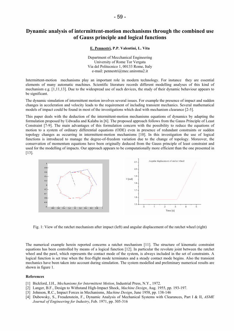
- 59 -
Dynamic analysis of intermittent-motion mechanisms through the combined use of Gauss principle and logical functions
E. Pennestrì, P.P. Valentini, L. Vita
Department of Mecchanical Engineering University of Rome Tor Vergata
Via del Politecnico 1, 00133 Rome, Italy e-mail: [email protected]
Intermittent-motion mechanisms play an important role in modern technology. For instance they are essential elements of many automatic machines. Scientific literature records different modelling analyses of this kind of mechanism e.g. [1,11,13]. Due to the widespread use of such devices, the study of their dynamic behaviour appears to be significant.
The dynamic simulation of intermittent motion involves several issues. For example the presence of impact and sudden changes in acceleration and velocity leads to the requirement of including transient mechanics. Several mathematical models of impact could be found in most of the investigations which deal with mechanism clearance [2-5].
This paper deals with the deduction of the intermittent-motion mechanisms equations of dynamics by adapting the formulation proposed by Udwadia and Kalaba in [6]. The proposed approach follows from the Gauss Principle of Least Constraint [7-9]. The main advantages of this formulation concern with the possibility to reduce the equations of motion to a system of ordinary differential equations (ODE) even in presence of redundant constraints or sudden topology changes as occurring in intermittent-motion mechanisms [10]. In this investigation the use of logical functions is introduced to manage the degree-of-freedom variation due to the change of topology. Moreover, the conservation of momentum equations have been originally deduced from the Gauss principle of least constraint and used for the modelling of impacts. Our approach appears to be computationally more efficient than the one presented in [13].
Fig. 1: View of the ratchet mechanism after impact (left) and angular displacement of the ratchet wheel (right)
The numerical example herein reported concerns a ratchet mechanism [11]. The structure of kinematic constraint equations has been controlled by means of a logical function [12]. In particular the revolute joint between the ratchet wheel and the pawl, which represents the contact mode of the system, is always included in the set of constraints. A logical function is set true when the free-flight mode terminates and a steady contact mode begins. Also the transient mechanics have been taken into account during simulation. The system modelled and preliminary numerical results are shown in figure 1.
References
[1] Bickford, J.H., Mechanisms for Intermittent Motion, Industrial Press, N.Y., 1972. [2] Langer, B.F., Design to Withstand High-Impact Shock, Machine Design, Aug. 1955, pp. 193-197. [3] Johnson, R.C., Impact Forces in Mechanisms, Machine Design, June 1958, pp. 138-146 [4] Dubowsky, S., Freudenstein, F., Dynamic Analysis of Mechanical Systems with Clearances, Part I & II, ASME
Journal of Engineering for Industry, Feb. 1971, pp. 305-316

- 60 -
[5] Hunt, K.H., Crossley, F.R.E., Coefficient of Restitution Interpreted as Damping in Vibroimpact, ASME Journal of Applied Mechanics, June 1975, pp. 440-445
[6] Udwadia, F., Kalaba, R., Analytical Dynamics a New Approach, Cambridge University Press, Cambridge, 1996 [7] Gauss, C.F., ¨Ueber ein neues allgemaines Gründgesetz der Mechanik, Journal für Reine und Angewandte
Mathematik, vol.4, 1829, pp.232-235 [8] Lanczos, C., The Variational Principle of Mechanics, Dover Publications, Inc., Fourth Edition, 1970, pp.106-110 [9] Chetaev, N., M´ecanique Rationelle, ´Editions Mir, Moscou, 1993, pp.251-253 [10] de Falco, D., Pennestrì, E., Vita, L., The Udwadia-Kalaba Formulation: A Report on its Numerical Efficiency in
Multibody Dynamics Simulations and on its Teaching Effectiveness, Multibody Dynamics 2005, ECCOMAS Thematic Conference, Madrid, Spain, 21–24 June 2005
[11] Lee, T. W., Wang, A.C., On the Dynamics of Intermittent-Motion Mechanisms. Part 2: Geneva Mechanism, Ratchets, and Escapements, ASME Journal of Mechanisms, Transmissions, and Automation in Design, Sept. 1983, Vol. 105, pp. 541-551
[12] Pennestrì, E., Cavacece, M., Vita, L., On the Computation of Degrees-Of-Freedom: a Didactic Perspective, Proceedings of IDETC’05, 2005 ASME International Design Engineering Technical Conferences and Computers and Information in Engineering Conference, Long Beach, California, USA, 2005
[13] Lankarani, H. M., Nikravesh, P. E., Application of the Canonical Equations of Motion in problems of Constrained Multibody Systems with Intermittent Motion, Advanced in Design Automation, 1988, ASME DE-Vol. 14, pp. 417-423.
- 61 -
Multibody modeling of pantographs for catenary-pantograph interaction
Frederic Rauter1 , Joao Pombo2 , Jorge Ambrosio1 , Manuel Pereira1
1IDMEC - Institute Superior Tecnico Av. Rovisco Pais, 1049-001, Lisboa, Portugal
e-mail: [email protected]; Jorge,[email protected]
2 Escola Superior de Tec.nologia de Abrantes, Instituto Politecnico de Tomar Rua 17 de Agosto de 1808, 2200-370 Abrantes, Portugal
e-mail: [email protected]
In the great majority of railway networks the electrical power is provided to the locomotives by the pantograph-catenary system. From the mechanical point of view, the single most important feature of this system consists in the quality of the contact between the contact wire(s) of the catenary and the contact strips of the pantograph. Therefore not only the correct modeling of the catenary and of the pantograph must be achieved but also a suitable contact model to describe the interaction between the two systems must be devised. The work proposed here aims at enhancing the understanding of the dynamic behavior of the pantograph and of the interaction phenomena in the pantograph-catenary system. The potential contribution of this work to the railway community includes the decrease of the number of incidents related to this system and the reduction of the maintenance and interoperability development costs. The catenary system is described by a detailed finite element model of the complete subsystem while the pantograph system is described by a detailed multibody model. The dynamics of each one of these models requires the use of different time integration algorithms. In particular the dynamics of the finite element model of the catenary uses a Newmark type of integration algorithm while the multibody model uses a Gear integration algorithm, which is variable order and variable time step. Therefore, an extra difficulty that arises in study of the complete catenary-pantograph interaction concerns the need for the co-simulation of finite element and multibody models. As the gluing element between the two models is the contact model, it is through the representation of the contact and of the integration schemes applied for the finite and multibody models that the co-simulation is carried on. The work presented here proposes an integrated methodology to represent the contact between the finite element and multibody models based on a continuous contact force model that takes into account the co-simulation requirements of the integration algorithms used for each subsystem model. The discussion of the benefits and drawbacks of the proposed methodologies and of its accuracy and suitability is supported by the application to the real operation scenario considered and the comparison of the obtained results with experimental testing data. In the process future developments that include representing the pantograph model with flexible bodies, non-linear force elements and the inclusion of wear and cross-wind effects are also discussed.

- 62 -
Advances in discrete time transfer matrix method of multibody system
Xiaoting Rui, Laifeng Yun, Bin He, Guoping Wang, Fufeng Yang and Yuqi Lu
Institute of Power Engineering Nanjing University of Science and Technology
Nanjing 210094, P. R. China e-mail: [email protected]
There are the same two characteristics of ordinary methods of multibody dynamics: 1 It is necessary to develop overall dynamical equations of the system. 2. The order of system matrix increases with the number of freedom degrees of the system and is rather high for complex system.
Discrete Time Transfer Matrix Method of Multibody System (MS-DT-TMM) presents a new method for multibody system dynamics. There are five characteristics of MS-DT-TMM:
1- It does not require overall dynamical equations of system and simplify the solution procedure.
2- It has high computing speed, because the system matrices are always small irrespective of the size of a system.
3- It avoids the difficulties caused by developing overall dynamical equations of the system and by computing too high order matrices.
4- It provides maximum flexibility in modeling various configurations of multibody systems, by creating library of transfer matrices and assembling them easily, and by introducing any suitable numerical integration scheme.
5- It can be combined with various dynamics methods to solve complicated problems.
In fact, MS-DT-TMM has been used widely in engineering for these characteristics. The advance in the MS-DT-TMM in recent years as following:
Combination of Discrete Time Transfer Matrix Method of Multibody System and Finite Element Method (MS-DT-TMM-FEM), in this new method, DT-TMM-MS is combined firstly with finite element method (FEM) to study the multi – rigid – flexible body system. Any multibody system can be divided into two subsystems; the connected points of the two subsystems are regarded as boundary of each subsystem. The position coordinates and the orientation angles of the two ends of the connected point, the internal forces and the internal torque acted on the two ends of this point are equal each other. The overall transfer equation of one subsystem can be developed by MS-DT-TMM, and the overall dynamics equation of another subsystem can be developed by FEM. The dynamics of the overall system can be obtained by solve these overall dynamics equation of one subsystem and overall transfer equation of another subsystem together. Especially, in MS-DT-TMM-FEM, the subsystem including complex flexible bodies can be deal with by FEM, and the subsystem including multibody with large motion relative to each other can be deal with by DT-TMM-MS.
Combination of Discrete Time Transfer Matrix Method of Multibody System and Ordinary Method of Multibody System Dynamics (MS-DT-TMM-MS-OM)in this new method, DT-TMM-MS is combined firstly with ordinary method of multibody dynamics to study the multi – rigid – flexible body system. Any multibody system can be divided into two subsystems like above method. One subsystem can be modeled by MS-DT-TMM developing overall transfer equation of subsystem; another subsystem can be modeled by ordinary method of multibody dynamics developing overall dynamics equation of the subsystem. And the dynamics of the overall system can be obtained by solve these overall dynamics equation of the subsystem and overall transfer equation of subsystem together.
Riccati Discrete Time Transfer Matrix Method of Multibody System (MS-R-DT-TMM), in this new method, by introduce Riccati transformation in MS-DT-TMM, the order of the system matrix involved is decreased again and the computation speed and the computation stability are increased greatly, comparing with MS-DT-TMM.
Discrete Time Transfer Matrix Method of Control Multibody System (CMS-DT-TMM), Transfer Matrix Method of Control Multibody System (CMS-TMM), in these new methods, the state vectors are the same for control element and non-control element, the transfer matrix of controlled element can be developed using the same method as we used in developing the transfer matrix of non-control element. The nature frequency, model shape and steady state response of linear multibody system can be computed by CMS-TMM. And dynamics of control system can be computed by using CMS- DT-TMM.
Transfer Matrix Method of 2-Dimension System (2D-TMM)classical Transfer Matrix Method (TMM) can be used only for 1-dimension system. In order to study the dynamics of 2-dimension system using TMM, 2D-TMM is developed by expanding the classical transfer matrix method. A 2-dimension system, such as, a thin plate is modeled to

- 63 -
a network structure composed by lumped mass and massless beam, the transfer matrix of sub-structure which is arranged in column has been easily developed. The overall transfer equation of the plate is obtained. The idea of this method can be used to develop transfer matrix method for three-dimensional systems.
These methods studied in this paper extend the application channel of DT-TMM-MS. Several numerical examples are given to validate the proposed methods.
- 64 -
Impact studies of gear trains in combustion engines Bernhard Schweizer1, Pascal Ziegler2
1Fachbereich Maschinen- und Energietechnik HTWK Leipzig, Koburger Straße 62, 04416 Markkleeberg
e-mail: [email protected]
2Institute of Engineering and Computational Mechanics University of Stuttgart
Pfaffenwaldring 9, 70569 Stuttgart, Germany e-mail: [email protected]
Gears are important components in machines and mechanisms and are widely used in many technical applications. Typically, the main purpose of gear pairings is the transmission of torque, e.g. in power trains of cars. Therefore, the transmitted rated load torque is relatively high compared to dynamic loads. As a result, the gears are meshing properly and thus the tooth flanks do not lift off.
However, in combustion engines gear trains are often used to drive camshafts and auxiliary aggregates like high-pressure-pumps by the crankshaft. Since here the transmitted rated torque is comparably small to the dynamic excitations originating from the crankshaft and the high-pressure-pump dynamics, the lift-off of tooth flanks is an often observed phenomenon in gear trains. The reestablishment of contact between the teeth is most often in terms of impacts. These impacts lead to sharp dynamic loads on the flanks causing noise, which is called gear hammering.
In industrial practice, the gears have to be designed. Certainly, the tooth forces are the parameters of most importance for design methods. In current industrial practice contact forces are determined by simulation with multibody systems, wherein each gear is modeled by one rigid body. The contact is typically defined by a linear or nonlinear, parallel arranged spring/damper-system. The spring stiffness takes into account the deformation due to the Hertzian contact, the bending of the contacting tooth pairs and the deformation of the gear bodies. The contact damper represents the oil film damping between the flanks and material damping.
The contact stiffness is not constant and depends on the magnitude of the load as well as the relative orientation of the meshing gears. In common gear contact models, the stiffness is often assumed to be constant and a mean value for the gear stiffness is used. The damping behavior of the oil film is highly nonlinear and heuristic models are used for the damping characteristic. More detailed models use extended contact models, where e.g. an additional damper is modeled in series with the contact spring.
The currently used gear models and methods to calculate the contact parameters are - especially in high dynamic applications - not detailed enough to correctly simulate the contact forces. This is most likely due to unconsidered elastic compliance of the gear bodies. Especially in gear trains, the gear wheel bodies are typically very thin to reduce inertia effects and to reduce the weight of the entire engine.
To get a closer insight in the contact situation und dominant effects, exact finite element contact simulations have to be performed. In a first step, static contact calculations are carried out and stiffness properties of meshing gears are determined. The simulated values are compared with data given in DIN 3990 and with stiffness values calculated with commercial program systems.
Further, transient finite element simulations of impacting gears are performed to get a better understanding in the dynamic effects and vibrations of the tooth and gear body due to gear hammering. Because of the large simulation time, it is currently not possible to model an entire gear train as a finite element model and perform dynamic simulations of complex systems. Hence, we restrict ourselves to investigate one gear pairing, which consists of a gear mounted on the crankshaft and a fly wheel driving the camshaft gear wheel. This pairing is chosen because of the gear body geometry of the wheels. Especially the fly wheel has a very thin body which is additionally weakened by several holes. Due to the high compliance of the gear body a significant influence on the tooth force is expected.
The bearing conditions of the gears and other boundary conditions often show an ample influence on the gear forces. Therefore, impact studies are performed under several boundary and initial conditions. Furthermore, the influence of friction between the flanks and material damping is investigated as well as the influence of misaligned gear wheels.
To overcome the large simulation time of the transient finite element models an order reduction is performed. This is done by decomposing the impact problem in two submodels. The first submodel represents the nonlinear contact in a small contact region, whereas the second submodel describes the dynamic response and wave phenomena of the gear body, respectively. It is assumed that it is possible to describe the dynamic response linearly. Therefore, a modal model is used and modal reduction methods are applied. To compute the local contact force of the Hertzian stress, a quasi

- 65 -
static behavior is assumed and the results from a static finite element analysis can be used. Alternatively, the enhanced Hertzian contact law for contacting cylinders is applied.
On the basis of the finite element impact simulations, the currently used gear models in multibody systems, as well as the modal models in combination with the local force laws can be validated, contact parameters can be determined and new gear contact models can be developed. References [1] Pfeiffer, P.; Prestel, W.: „Hammering in Diesel-Engine Driveline Systems.“ Nonlinear Dynamics, Vol. 5, pp. 477-
492, 1994. [2] Trampert, S.: „Entwicklung eines abwälzenden Zahnkontaktmodells zur Simulation von Zahnrädertrieben.“,
Dissertation RWTH Aachen, 2003. [3] Seifried, R.: "Numerische und experimentelle Stoßanalyse für Mehrkörpersysteme.", Dissertation, Shaker, 2005. [4] Ziegler, P.: Eberhard, P.; Schweizer, B., Heilig, J.: „"Transient finite element simulation of impacting gears", to be
published in „Mathematical and Computer Modelng of Dynamical Systems“.
- 66 -
Comparison of building collapse analysis results from finite element and rigid body models
Steffen Mattern1,2, Gunther Blankenhorn1,2, Michael Breidt1,3, Nguyen van Vinh1,3,
Sebastian Höhler1,4, Karl Schweizerhof1,2, Dietrich Hartmann1,3, Friedhelm Stangenberg1,4
1 Research Unit FOR500 'Computer- aided destruction of complex structures using controlled explosives' funded by the German Research Foundation (Deutsche Forschungsgemeinschaft), http:\\www.sprengen.net
2 Institut für Mechanik, Universität Karlsruhe (TH), D-76131 Karlsruhe e-mail: [email protected]
3 Lehrstuhl für Ingenieurinformatik im Bauwesen, Ruhr Universität Bochum, D-44780 Bochum 4 Lehrstuhl und Institut für Stahlbeton- und Spannbetonbau, Ruhr-Universität Bochum, D-44780 Bochum
The major goal of the research unit FOR500 is to increase the reliability and efficiency of computational models for complex reinforced concrete buildings subjected to blast loads, in particular induced by controlled explosions. For this purpose, an adaptive simulation concept is developed that divides the analysis of the collapse into several problem specific analyses. Based on the interaction of these analyses a reliable prediction is provided. Within this concept the dominant physical and mechanical problems appearing during a demolition and the subsequent collapse mechanism are modeled, including the uncertainty of material and construction parameters.
In the case of planning the destruction of buildings by demolition many of the geometric and material data must be estimated because of lacking documentation. To perform a more secure analysis of the building collapse, intensive and expensive investigations are required, such as measuring the whole building and testing the original material. If such measurements must be avoided, e.g. to reduce the cost of planning for a blast demolition, then the inherent uncertainty has to be accounted for. The simulation by uncertainty analysis methods [1] is an effective and reliable approach to achieve this goal. Further, an appropriate and sufficiently accurate deterministic model (here we aim at a rigid body model) is necessary to solve the involved optimization problem.
The simulation concept is based on the assumption that, during the collapse of reinforced concrete structures, the damage is accumulating in local zones. These local zones can be considered as hinges in a rigid multi-body system [3] combined with characteristic resistance curves. The relevant resistance curves can be determined e.g. by a detailed finite element analysis at the system level taking into account the location of reinforcement (for further details we refer to [2]). To detect the local zones of accumulated damage, numerical studies were performed to investigate also the possible damage due to wave propagation and the formation of the collapse mechanism [4], combined with the analysis of the whole collapse mechanism described in the following.
This contribution focuses on a special topic of the aforementioned analysis and on the comparison of the two basic models, the finite element model and the rigid body model, as well as their influence on the anticipated collapse mechanism.
As reference model a three-storyed framework construction of reinforced concrete has been discretized completely with finite elements and analyzed with the commercial finite element software LS-DYNA [5]. The initial blast effects were modeled in a first step by deleting parts of the columns. Thus, the local damage due to the collapse is modeled with erosion models using different failure criteria (e.g. main stresses, normal and shear strains). Contact between the various parts of the building as well as between building and ground plate is realized as well. Currently, these FE investigations – different parameter studies regarding e.g. erosion parameters were performed – are used to gain information about parts with rigid body like behavior, the location of local zones of damage during the collapse, which are important for the development of the specific rigid body models.
In comparison regarding the kinematics which appears at the beginning of the collapse and the behavior at the local zones performed subsequently, the results of the FE analysis are compared with those of the analysis using a rigid body model having the previously specified hinges and characteristic resistance curves.
The final goal is to calibrate the rigid body model in order to obtain a correct collapse behavior. In addition, the modification procedure resulting from the FE analysis should lead to a basis for rules how to generally generate rigid body models for building collapse analysis.

- 67 -
References
[1] Möller, B.; Liebscher, M., Fuzzy multi body systems and fuzzy probabilistic multi body systems and their application for the numerical simulation of controlled demolitions of structures, 3nd MIT Conference Computational Fluid and Solid Mechanics, Boston, 2005.
[2] Höhler, S., Simulation von Stahlbetonkonstruktionen bei Sprengung, 45. Forschungskolloquium des DAfStb, Wien 2005.
[3] Breidt, M., Computersimulation komplexer Bauwerk-Sprengungen unter Verwendung adaptiver Mehrebenenmodelle, Dissertation, Ruhr-Universität Bochum, Fakultät für Bauingenieurwesen, urn:nbn:de:hbz:294-9703, Bochum 2004.
[4] Blankenhorn, G., Untersuchung der Sprengauswirkung im Nahbereich, Workshop Abbruchsprengen, Karlsruhe 2004.
[5] LS-DYNA 3D, vs 970, Livermore Software Technology Corporation, Livermore, USA, 2004.
- 68 -
Computational analysis and experimental investigation of impacts in multibody systems
Robert Seifried, Werner Schiehlen
Institute of Engineering and Computational Mechanics University of Stuttgart
70569 Stuttgart, Germany [seifried, schiehlen]@itm.uni-stuttgart.de
For many engineering applications the multibody system approach proves to be most efficient for the analysis of the overall motion. Collisions between moving bodies might result in impacts which interrupt the overall motion. During impact kinetic energy is lost by wave propagation in the bodies and/or by plastic deformation of the contact region, see e.g. Goldsmith [1]. For multibody system simulation on the macroscale, these kinetic energy losses during impact are represented by the coefficient of restitution, see e.g. Glocker [2]. However, the coefficient of restitution cannot be computed within the multibody system approach. Replacing costly experiments, the coefficient of restitution may be determined by numerical simulations on a fast time scale, resulting in a multiscale simulation approach [3-6].
This paper deals mainly with the computational analysis and experimental investigation of impact processes for multibody systems on a fast time scale in order to determine the kinetic energy loss during impact and to evaluate the corresponding coefficient of restitution. The computational impact analysis on the fast time scale requires accurate and efficient models which include the phenomena of wave propagation and plasticity. The experimental verification on the fast time scale requires advanced measurement techniques capable for catching high frequency phenomena.
First of all, the computational impact analysis a complete Finite Element (FE) model of the impacting bodies is presented. But for the FE-model a small overall element length is required to comprise the wave propagation with an additional refinement necessary for the modeling of the contact region. Therefore, FE-models for impact analysis are very time consuming.
Then, impact processes are divided into two parts, the contact itself and the resulting wave propagation. The contact is a nonlinear problem which is limited to a small region, while the wave propagation is a linear problem encompassing the entire body. Therefore, combined models are developed in which the elastodynamic behavior of the bodies is represented by a modally reduced model and the deformation of the contact region is presented by a local contact model. Three different contact models are presented. The first contact model is a FE-model of the contact region which is computed concurrently with the reduced elastodynamic model of the entire bodies including all nonlinear effects of the complete FE-model. The second model is confined to quasi-static contact and rate-independent material behavior. The behavior of the contact region is pre-computed by static FE-analysis and represented in force-displacement diagrams. These diagrams are then used to get the impact force for the impact simulation with the modally reduced model. The third contact model is based on the elastostatic Hertzian contact law. A comparison shows the consistency of the modally reduced models with local contact models and the firstly presented complete FE-model. However, compared to complete FE-models, the modally reduced models with local contact models are much more efficient. Furthermore, the modally reduced models with FE-contact are modified to simulate repeated impacts and multiple impacts, including the deformation history of the contact region due to plasticity.
The proposed numerical models are verified by extensive experimental investigations on a fast time scale, too. Therefore, an experimental setup is presented, consisting of two impacting bodies which are suspended in a frame like pendulums. Two Laser-Doppler-Vibrometers are used for the measurement of displacements and velocities of the impacting bodies. The vibrometers are placed on both sides of an impact system along the impact line. So it is possible to measure the motion of both bodies simultaneously. Multiple conducted experiments show the very good reproducibility of the measurements. From the measurements the kinetic coefficient of restitution and the corresponding kinetic energy loss are computed. In addition, for impacts on rods the impact force is found from the velocity measurement at the free end of the rods. A comparison of the so evaluated impact forces with a measurement technique using strain gauges shows a very good agreement, however the measurement using the velocity signal shows much less measurement noise.
Comparisons of measurements and simulations for impacts on simple shaped bodies involving elastic as well as elastic-plastic material behavior prove the high accuracy of the numerical models. Investigations of impacts of steel spheres on different shaped aluminum bodies with elastic material behavior show that a substantial amount of kinetic energy might be transformed into wave propagation. Measurements and simulations for the transverse impact of a steel sphere on an aluminum beam show multiple successive impacts within a very short time period resulting in a chaotic behavior. As a result for impacts on the beam significant differences between measurements and simulations are observed. For repeated impacts involving elastic-plastic material behavior, the influence of the deformation history of the contact

- 69 -
region on the impact process is consistently observed in measurements and simulations. In this case the contact region gets deformed plastically during the first impacts until a stationary configuration is reached without any additional plastic deformation. Correspondingly this yields an increase of the coefficient of restitution with the number of impacts until a stationary value is reached. The presented computational and experimental techniques may be also used for the investigation of impacts involving bearings with clearance. Finally, the impact of an elastic pendulum on a compact aluminum body with elastic-plastic material behavior is investigated experimentally and numerically. For this simple multibody system the high accuracy of the multiscale simulation approach is proven on both time scales.
References
[1] Goldsmith W., Impact: The Theory and Physical Behaviour of Colliding Solids, Edward Arnold Ltd, London, 1960.
[2] Glocker C., On frictionless impact models in rigid-body systems. Philosophical Transactions of the Royal Society of London, A359, 2385-2404, 2001.
[3] Schiehlen W., Seifried R., Three approaches for elastodynamic contact in multibody systems. Multibody System Dynamics, 12, 1-16, 2004.
[4] Schiehlen W., Seifried R., Eberhard P., Elastoplastic phenomena in multibody impact dynamics. Computer Methods in Applied Mechanics and Engineering. [doi:10.1016/j.cma.2005.08.011].
[5] Seifried R., Numerische und experimentelle Stoßanalyse für Mehrkörpersysteme. Schriften aus dem Institut für Technische und Numerische Mechanik der Universität Stuttgart, Shaker, Aachen, 2005, (in German).
[6] Hu B., Schiehlen W., Multi-time scale simulation for impact systems: from wave propagation to rigid body motion. Archive of Applied Mechanics, 72, 885--897, 2003.
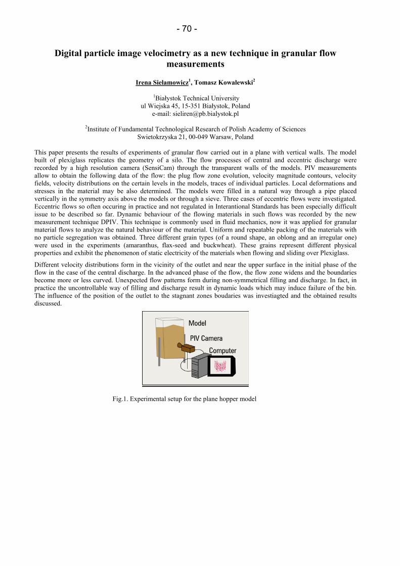
- 70 -
Digital particle image velocimetry as a new technique in granular flow measurements
Irena Sielamowicz1, Tomasz Kowalewski2
1Białystok Technical University ul Wiejska 45, 15-351 Białystok, Poland
e-mail: [email protected]
2Institute of Fundamental Technological Research of Polish Academy of Sciences Swietokrzyska 21, 00-049 Warsaw, Poland
This paper presents the results of experiments of granular flow carried out in a plane with vertical walls. The model built of plexiglass replicates the geometry of a silo. The flow processes of central and eccentric discharge were recorded by a high resolution camera (SensiCam) through the transparent walls of the models. PIV measurements allow to obtain the following data of the flow: the plug flow zone evolution, velocity magnitude contours, velocity fields, velocity distributions on the certain levels in the models, traces of individual particles. Local deformations and stresses in the material may be also determined. The models were filled in a natural way through a pipe placed vertically in the symmetry axis above the models or through a sieve. Three cases of eccentric flows were investigated. Eccentric flows so often occuring in practice and not regulated in Interantional Standards has been especially difficult issue to be described so far. Dynamic behaviour of the flowing materials in such flows was recorded by the new measurement technique DPIV. This technique is commonly used in fluid mechanics, now it was applied for granular material flows to analyze the natural behaviour of the material. Uniform and repeatable packing of the materials with no particle segregation was obtained. Three different grain types (of a round shape, an oblong and an irregular one) were used in the experiments (amaranthus, flax-seed and buckwheat). These grains represent different physical properties and exhibit the phenomenon of static electricity of the materials when flowing and sliding over Plexiglass.
Different velocity distributions form in the vicinity of the outlet and near the upper surface in the initial phase of the flow in the case of the central discharge. In the advanced phase of the flow, the flow zone widens and the boundaries become more or less curved. Unexpected flow patterns form during non-symmetrical filling and discharge. In fact, in practice the uncontrollable way of filling and discharge result in dynamic loads which may induce failure of the bin. The influence of the position of the outlet to the stagnant zones boudaries was investiagted and the obtained results discussed.
Fig.1. Experimental setup for the plane hopper model
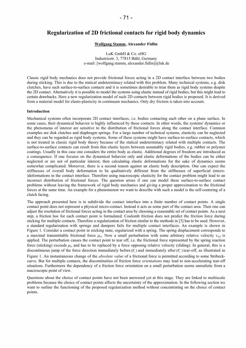
- 71 -
Regularization of 2D frictional contacts for rigid body dynamics
Wolfgang Stamm, Alexander Fidlin
LuK GmbH & Co. oHG Industriestr. 3, 77815 Bühl, Germany
e-mail: [wolfgang.stamm, alexander.fidlin]@luk.de
Classic rigid body mechanics does not provide frictional forces acting in a 2D contact interface between two bodies during sticking. This is due to the statical undeterminacy related with this problem. Many technical systems, e.g. disk clutches, have such surface-to-surface contacts and it is sometimes desirable to treat them as rigid body systems despite the 2D contact. Alternatively it is possible to model the systems using elastic instead of rigid bodies, but this might lead to certain drawbacks. Here a new regularization model of such 2D contacts between rigid bodies is proposed. It is derived from a material model for elasto-plasticity in continuum mechanics. Only dry friction is taken into account.
Introduction
Mechanical systems often incorporate 2D contact interfaces, i.e. bodies contacting each other on a plane surface. In some cases, their dynamical behavior is highly influenced by these contacts. In other words, the systems' dynamics or the phenomena of interest are sensitive to the distribution of frictional forces along the contact interface. Common examples are disk clutches and diaphragm springs. For a large number of technical systems, elasticity can be neglected and they can be regarded as rigid body systems. Some of these systems might have surface-to-surface contacts, which is not treated in classic rigid body theory because of the statical undeterminacy related with multiple contacts. The surface-to-surface contacts can result from thin elastic layers between assumably rigid bodies, e.g. rubber or polymer coatings. Usually in this case one considers the entire body as elastic. Additional degrees of freedom are introduced as a consequence. If one focuses on the dynamical behavior only and elastic deformations of the bodies can be either neglected or are not of particular interest, then calculating elastic deformations for the sake of dynamics seems somewhat complicated. Moreover, there is a second reason against an elastic body description. One can expect the stiffnesses of overall body deformation to be qualitatively different from the stiffnesses of superficial (micro-)deformations in the contact interface. Therefore using macroscopic elasticity for the contact problem might lead to an incorrect distribution of frictional forces. The question arises if one can model these surface-to-surface contact problems without leaving the framework of rigid body mechanics and giving a proper approximation to the frictional forces at the same time. An example for a phenomenon we want to describe with such a model is the self-centering of a clutch facing.
The approach presented here is to subdivide the contact interface into a finite number of contact points. A single contact point does not represent a physical micro-contact. Instead it acts as some part of the contact area. Then one can adjust the resolution of frictional forces acting in the contact area by choosing a reasonable set of contact points. As a next step, a friction law for each contact point is formulated. Coulomb friction does not predict the friction force during sticking for multiple contacts. Therefore a regularization of friction similar to the methods in [3] has to be used. However, a standard regularization with springs and dampers fails for multiple contact interfaces. An example is shown in Figure 1. Consider a contact point in sticking state, regularized with a spring. The spring displacement corresponds to a maximal transmittable frictional force µst. Now a small perturbation with some arbitrary relative velocity vrel is applied. The perturbation causes the contact point to tear off, i.e. the frictional force represented by the spring reaction force (sticking) exceeds µst and has to be replaced by a force opposing relative velocity (sliding). In general, this is a discontinuous jump of the force direction immediately before )(F-
f and immediately after )(Ff+ tear-off, as illustrated in
Figure 1. An instantaneous change of the absolute value of a frictional force is permitted according to some Stribeck-curve. But for multiple contacts, the discontinuities of friction force orientations may lead to non-accelerating tear-off situations. Furthermore the dependency of a friction force orientation on a small perturbation seems unrealistic from a macroscopic point of view.
Questions about the choice of contact points have not been answered yet at this stage. They are linked to multiscale problems because the choice of contact points affects the uncertainty of the approximation. In the following section we want to outline the functioning of the proposed regularization method without concentrating on the choice of contact points.
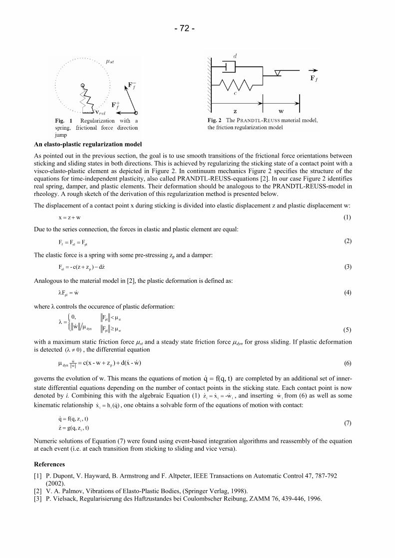
- 72 -
An elasto-plastic regularization model
As pointed out in the previous section, the goal is to use smooth transitions of the frictional force orientations between sticking and sliding states in both directions. This is achieved by regularizing the sticking state of a contact point with a visco-elasto-plastic element as depicted in Figure 2. In continuum mechanics Figure 2 specifies the structure of the equations for time-independent plasticity, also called PRANDTL-REUSS-equations [2]. In our case Figure 2 identifies real spring, damper, and plastic elements. Their deformation should be analogous to the PRANDTL-REUSS-model in rheology. A rough sketch of the derivation of this regularization method is presented below.
The displacement of a contact point x during sticking is divided into elastic displacement z and plastic displacement w:
wzx += (1)
Due to the series connection, the forces in elastic and plastic element are equal:
plelf FFF == (2)
The elastic force is a spring with some pre-stressing zp and a damper:
zd)z c(z- F pel &−+= (3)
Analogous to the material model in [2], the plastic deformation is defined as:
wFpl &=λ (4)
where λ controls the occurence of plastic deformation:
(5)
with a maximum static friction force µst and a steady state friction force µdyn for gross sliding. If plastic deformation is detected 0)( ≠λ , the differential equation
)w-xd()zw-c(x pww
dyn &&&& ++=µ (6)
governs the evolution of w. This means the equations of motion t)f(q,q =& are completed by an additional set of inner-state differential equations depending on the number of contact points in the sticking state. Each contact point is now denoted by i. Combining this with the algebraic Equation (1) iii w-xz &&& == , and inserting iw& from (6) as well as some kinematic relationship )q(hx ii && = , one obtains a solvable form of the equations of motion with contact:
t),z g(q,z t),z f(q,q
i
i
==
&
& (7)
Numeric solutions of Equation (7) were found using event-based integration algorithms and reassembly of the equation at each event (i.e. at each transition from sticking to sliding and vice versa).
References
[1] P. Dupont, V. Hayward, B. Armstrong and F. Altpeter, IEEE Transactions on Automatic Control 47, 787-792 (2002).
[2] V. A. Palmov, Vibrations of Elasto-Plastic Bodies, (Springer Verlag, 1998). [3] P. Vielsack, Regularisierung des Haftzustandes bei Coulombscher Reibung, ZAMM 76, 439-446, 1996.
stpl
stpl
F
F
µ≥
µ<
µ=λ
dynw0,&
- 73 -
Micromechanics of particle adhesion – an analytical approach
Jürgen Tomas
Otto-von-Guericke University Magdeburg
Mechanical Process Engineering P.O.Box 4120, D - 39106 Magdeburg
e-mail: [email protected]
The rapid increasing production of cohesive to very cohesive ultrafine powders, e.g. very adhering pigment particles, micro-carriers in biotechnology or medicine, auxiliary materials in catalysis or chromatography, make technical problems much serious like undesired adhesion in particle conversion and processing, powder handling and transportation, and desired, in agglomeration or coating. Thus, it is very essential to understand the fundamentals of particle adhesion with respect to product quality assessment and process performance in powder technology.
The state of art in modeling of elastic, elastic-adhesive, elastic-dissipative, plastic-adhesive and plastic-dissipative contact deformation response of a single, normal loaded, isotropic, smooth contact of two spheres is briefly discussed. Than the new comprehensive models for force-displacement behaviors of elastic-plastic and viscoplastic-adhesive contacts are shown and discussed by diagrams.
The decreasing contact stiffness with decreasing particle diameter is the major reason for adhesion effects at nanoscale. Using the model “stiff particles with soft contacts”, the combined influence of elastic and elastic-plastic repulsions in a characteristic particle contact is shown. The attractive particle adhesion term is described by a sphere-sphere model for van der Waals forces FH0 without any contact deformation. A plate-plate model is presented to describe the micro-contact flattening. Various contact deformation paths for loading, unloading, reloading and contact detachment are discussed.
Thus, the varying adhesion forces between particles depend directly on this “frozen” irreversible deformation, the so-called contact pre-consolidation history. With respect to the influence of these effects on consolidation history of particle contacts by a normal force FN, adhesion force based model FH(FN) is presented that describe the load dependent adhesion of particle contacts. The contribution of this history dependent adhesion on the tangential force in an elastic-plastic frictional contact FT(FN, FH(FN)), the rolling resistance FR(FN, FH(FN)) and the torque of mobilized frictional contact rotation Mto(FN, FH(FN)) are shown. With this increasing load, normal and tangential contact stiffness, energy absorption, Coulomb friction limit and friction work increase. These constitutive models are generally applicable for solid micro- or nanocontacts but have been shown here for an ultrafine limestone powder (d50 = 1.2 µm).
- 74 -
Cross-over impact in geometric closed mechanisms
Hao Wang1, Zongyu Chang2, Ce Zhang3
1School of Mechanical Engineering, Shanghai Jiaotong University, Shanghai 200030, P.R. China e-mail: [email protected]
2 School of Engineering, Ocean University of China, Qingdao, 266003, P.R. China 3School of Mechanical Engineering, Tianjin University, Tianjin 300072, P.R. China
In general dynamic analysis of multibody mechanical system, it is assumed that kinematic joints are ideal or perfect i.e. clearance, local deformation, lubrication are neglected, as presented in some commercial programs, such as ADAMS or DADS. In actual joints, clearance is inevitable due to the machining tolerance, wear, material deformation, and imperfections. Clearance, friction, lubrication, and impact forces will play an important role and have a significant effect on the dynamic response of the system. For instance, impact forces due to clearance will induce increased vibration and noise, reduce component life, and result in a loss of precision. So, proper modeling and investigation is required to achieve a better understanding of the phenomena induced by clearance and impact.
Many researchers produced theoretical and experimental works devoted to the dynamics of mechanical systems considering the clearance in revolute joints. In general, there are three main modeling strategies for mechanical systems with revolute clearance joints: the massless linkage approach, the spring damper approach, and the momentum exchange approach. Since the existence of impacts in the joint lead to the appearance of high level of contact force during dynamic analysis, the core of the formulation of models for joints with clearance is the simulation of the intermittent contact. The modeling of the impact in multibody systems falls into two types of methods, namely, continuous and discontinues approaches, depending on the assumed duration of contact.
By now, most researches on contact of clearance are focused on the lower kinematic pairs, such as revolute joints. In this investigation, of particular interest and concern is a special impact phenomenon, the cross-over impact, in high kinematic pairs of geometric closed mechanism, especially the cam-roller pair in intermittent mechanism and geometric closed cam mechanism. Impact phenomenon due to clearance between the cam and roller is one of the most important factors that influence such mechanism’s dynamic performance. An experimental and analytical study of a roller gear mechanism is carried out to compare the dynamic response with clearance and without clearance.
Cross-over impact phenomenon is ubiquity in all geometric closed mechanism, and is different in phases of motion with the three phase (contact-freeflight-impact) model in research of clearance in revolute joints. In the lift range of the mechanism, when the acceleration of cam’s motion law is positive, the follower, such as a roller, contact at one side of the cam edge and is ‘driven’ by the cam. At the instance when acceleration is zero, contact force vanish, the roller fly over the clearance between the edge, and collide with other side of the cam edge; after several attenuation collide and detachment, the roller finally contact at the opposite side. When the acceleration of cam’s motion law is negative, the follower contact and ‘drive’ the cam. The severity of the impact are weighted by impact velocity vimp, which is defined by the difference between the maxim velocity of the follower vm and velocity after flying over the clearance vc .The most important geometric parametes on impact velocity are the size of the clearance and the derivative of the acceleration of the motion laws.
To interpret this phenomenon thoroughly, an experiment is carried out on a roller gear mechanism to measure the effects of different size of clearance (without clearance, small clearance, and large clearance) and different motion laws. Experiment result shows that difference between the dynamic responses without clearance and with small clearance are slight, lightening vibration of the follower are oberserved in the case with large clearance. This is opposite to the point that clearance in mechanism will deteriorate the dynamic performance as most teaching material and journal paper mentioned.
To investigate the effect of cross-over impact on the dynamic response of the mechanism, a dynamic model of the roller gear cam system considering cross-over impact is established, in which clearance is modeled by spring damper approach and based on the analysis of motion phasesand contact model mentioned above. The system dynamic equation is established by Kane’s equation.
The numerical solutions of the model partly verify the results of the experiments. The clearance, to a certain range of size, although deteriorate the motion precision, can restrain the vibration to some extent. While, a larger clearance may change the constraint of the follower system, thus ultimately change the dynamic response of the system. The effects of the clearance depend on the parameter of the mechanism, in which the motion laws, stiffness of the follower are of most important.
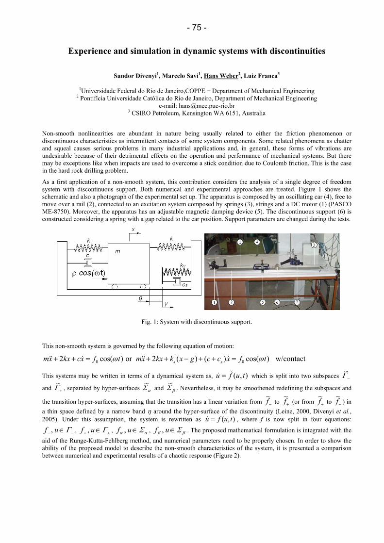
- 75 -
Experience and simulation in dynamic systems with discontinuities
Sandor Divenyi1, Marcelo Savi1, Hans Weber2, Luiz Franca3
1Universidade Federal do Rio de Janeiro,COPPE − Department of Mechanical Engineering 2 Pontifícia Universidade Católica do Rio de Janeiro, Department of Mechanical Engineering
e-mail: [email protected] 3 CSIRO Petroleum, Kensington WA 6151, Australia
Non-smooth nonlinearities are abundant in nature being usually related to either the friction phenomenon or discontinuous characteristics as intermittent contacts of some system components. Some related phenomena as chatter and squeal causes serious problems in many industrial applications and, in general, these forms of vibrations are undesirable because of their detrimental effects on the operation and performance of mechanical systems. But there may be exceptions like when impacts are used to overcome a stick condition due to Coulomb friction. This is the case in the hard rock drilling problem.
As a first application of a non-smooth system, this contribution considers the analysis of a single degree of freedom system with discontinuous support. Both numerical and experimental approaches are treated. Figure 1 shows the schematic and also a photograph of the experimental set up. The apparatus is composed by an oscillating car (4), free to move over a rail (2), connected to an excitation system composed by springs (3), strings and a DC motor (1) (PASCO ME-8750). Moreover, the apparatus has an adjustable magnetic damping device (5). The discontinuous support (6) is constructed considering a spring with a gap related to the car position. Support parameters are changed during the tests.
Fig. 1: System with discontinuous support.
This non-smooth system is governed by the following equation of motion:
0 02 cos( ) or 2 ( ) ( ) cos( ) w/contacts smx kx cx f t mx kx k x g c c x f tω ω+ + = + + − + + =&& & && &
This systems may be written in terms of a dynamical system as, ( , )u f u t= %& which is split into two subspaces −Γ~
and +Γ~ , separated by hyper-surfaces αΣ~ and βΣ~ . Nevertheless, it may be smoothened redefining the subspaces and
the transition hyper-surfaces, assuming that the transition has a linear variation from −f~ to +f~
(or from +f~
to −f~
) in a thin space defined by a narrow band η around the hyper-surface of the discontinuity (Leine, 2000, Divenyi et al., 2005). Under this assumption, the system is rewritten as ),( tufu =& , where f is now split in four equations:
−− ∈Γuf , , ++ ∈Γuf , , αα Σ∈uf , , ββ Σ∈uf , . The proposed mathematical formulation is integrated with the aid of the Runge-Kutta-Fehlberg method, and numerical parameters need to be properly chosen. In order to show the ability of the proposed model to describe the non-smooth characteristics of the system, it is presented a comparison between numerical and experimental results of a chaotic response (Figure 2).
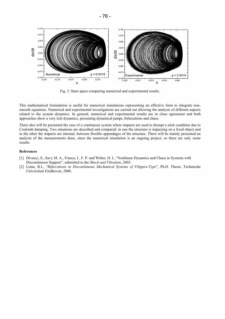
- 76 -
Fig. 2: State space comparing numerical and experimental results.
This mathematical formulation is useful for numerical simulations representing an effective form to integrate non-smooth equations. Numerical and experimental investigations are carried out allowing the analysis of different aspects related to the system dynamics. In general, numerical and experimental results are in close agreement and both approaches show a very rich dynamics, presenting dynamical jumps, bifurcations and chaos.
There also will be presented the case of a continuous system where impacts are used to disrupt a stick condition due to Coulomb damping. Two situations are described and compared: in one the structure is impacting on a fixed object and in the other the impacts are internal, between flexible appendages of the structure. There will be mainly presented an analysis of the measurements done, since the numerical simulation is an ongoing project, so there are only some results.
References
[1] Divenyi, S., Savi, M. A., Franca, L. F. P. and Weber, H. I., “Nonlinear Dynamics and Chaos in Systems with Discontinuous Support”, submitted to the Shock and Vibration, 2005.
[2] Leine, R.I., “Bifurcations in Discontinuous Mechanical Systems of Filippov-Type”, Ph.D. Thesis, Technische Universiteit Eindhoven, 2000.
- 77 -
The 3D elastodynamic contact problem for plane cracks
A. Gus, O. Menshykov, W.L. Wendland, V. Zozulya
Institut für Angewandte Analysis und numerische Simulation Lehrstuhl für Angewandte Mathematik
Universität Stuttgart Pfaffenwaldring 57, D-70569 Stuttgart, Germany e-mail: [email protected]
The paper is devoted to the solution of the time-dependent periodic fracture problems for a cracked material with the allowance of contact between the cracks' faces. The variational formulation of the elastodynamic problem in terms of the actions generated by the contact displacement continuities on the cracks' faces including unilateral Signorini constraints and dry fraction are formulated.
The formulation leads to an infinite system of boundary integral inequalities, the finite section of which is then solved by an iterative procedure. For simple model problems, the corresponding numerical Galerkin approximations demonstrate the applicability of the method and also the clear difference to classical linear crack analysis without contact.
- 78 -
Hybrid methods for contact problems
Barbara Wohlmuth
Institut für Angewandte Analysis und Numerische Simulation Universität Stuttgart
Pfaffenwaldring 57, 70569 Stuttgart, Germany e-mail: [email protected]
The numerical simulation of non-linear multibody contact problems plays an important role for a wide range of technical applications. For such problems, nonconforming domain decomposition techniques provide a powerful an flexible tool. In the case of non-linear contact problems, a natural decomposition of the global problem into subproblems is given. Each reference configuration is associated with on subdomain and an independent triangulation, resulting, in general, in nonmatching meshes at the actual contact zone. Sliding or rotating bodies can easily be handled within the abstact framework of mortar methods, providing a weak integral form of the non-penetration condition. An additional advantage compared to penalty techniques is that the contact stress does not depend on a penalty parameter but is obtained in a variationally consistent way from the displacement. Thus this discretization method automatically passes the patch test and is very attractive from the numerical point of view. From the mathematical point of view, we end up with a finite dimensional variational inequality for frictionless contact problems or for problems including Tresca friction. For the more general case of Coloumb friction, a quasi-variational inequality is obtained. Plasticity, piezo materials or a thermo-mechanical coupling can be considered as well. Of special interest are dual Lagrange multipliers which form with respect to the trace space on the slave side a biorthogonal system. The existence of such multipliers being defined locally and having a suitable reproduction property can be shown analytically. Due to the biorthogonality, the arising mass matrices are diagonal, and a local static condensation can be carried out. Physically, this corresponds to a lumping of the mass matrix and the locality reflects the fact that a local perturbation influences the solution only in a small neighbourhood. Thus, these dual Lagrange multiplier spaces are very attractive from the computational and physical point of view. To obtain an efficient iterative solver for the arising non-linear problems, different strategies can be realized. Quite recently, multigrid and FETI methods have been generalized and quite successfully applied to contact problems. Here, we consider active set methods. Primal-dual active set strategies with in combination with an iterative solver can be analyzed as inexact Newton methods. In each multigrid step, the actual contact zone which enters as Dirichlet boundary condition has to be updated. Superlinear local convergence can be observed; damping techniques guarantee the global convergence. This approach can easily be generalized to Coloumb friction and does not require the choice of a regularization parameter. Numerical test settings illustrate the flexibility, robustness and efficiency of the proposed algorithm in 2D and 3D.

- 79 -
Impacts on beam structures: Interactions of wave propagation and global dynamics
R. Zander, M. Foerg, H. Ulbrich
Lehrstuhl für Angewandte Mathematik TU München
Boltzmannstr. 15, 85748 Garching, Germany e-mail: [zander,foerg,ulbrich]@amm.mw.tu-muenchen.de
In systems with impacts between elastic and rigid bodies the slow rigid body motions can be significatly influenced by fast effects in the elastic components like wave propagation. Thus, a correct description of the elastic behaviour has to be given in multibody systems (MBS) at least in the sense of the large-scale rigid body movements. To describe elastic effects of impacts in MBS, restitution coefficients can be used even for the approximation of instantaneous interactions between different contacts in multiple contact collisions. Nevertheless, effects like wave propagation need to be described seperatly. The paper investigates the modelling of impacts to plain elastic beam structures in flexible MBS.
To model the free plain motion of an elastic beam, ideas of flexible MBS are combined with concepts of the finite element (FE) method. Single elements are treated in a formulation of hybrid MBS giving exact rigid body movements for single elements. A compact form of equations can be maintained. Longitudinal and transversal deformations can be approximated independently. To permit the assembly of several elements to one structure, the equations of motion are transformed to a coordinate set motivated by FE, whereas global positions are used as nodal coordinates instead of displacements. This approach even allows for large translations and geometrically large deformations of the entire structure.
During an impact free phase of the motion the contact law in normal direction is described by an unilateral constraint ensuring that the bodies do not penetrate each other. Special care must be taken for the formulation of the impact law since the spatial discretization has a strong influnce on the local dynamics: for an infinitetly fine discretization of the elastic bodies the elastic impact behaviour is given by the structural elasticity. Due to the spatial discretization, discrete masses are involved in the impact process resulting in an energy loss if only inpenetrability is regarded. In order to control this energy loss, a global restitution coefficient is introduced using the Newton impact law in the formulation of Moreau.
The overall system dynamics including the contact and impact laws is formulated by an Augmented Lagrangian approach. Within this approach the equations of motion are augmented by projections equations representing the physical constraints. The overall set of non-smooth, nonlinear equations can be solved by a root-finding algorithm.
The influence of the spatial discretisation and the restitution coefficient is studied considering two different numerical examples. In the first example, the effect of a single impact on the global dynamics of a plain elastic beam is analysed. The second example considers wave propagations in a multiple-contact situation.
- 80 -
Ball bearing modeling based on accurate contact stiffness for efficient mechanical system simulation
Johann Zeischka1, Junya Saito2
1Katsuyo Osodo / MSC.Software Groningenweg 6h, 2803 PV Gouda, The Netherlands
e-mail: [email protected] 2Tatsuya Iwamoto / Honda R&D Co.,Ltd
Virtual prototyping of complex mechanical systems is generally undertaken by rigid body dynamics. Today it has become a common practice to expand the rigid body system by flexible bodies. The bodies are assembled by libraries of mechanical joints and force elements. The physics of a real mechanical connection differs often from the abstraction of a mathematical joint. The transfer functions of "real" joints can be quite complex; simple modeling by stiffness and/or damping exhibits often inaccurate modeling, when simulation results are compared with test data. This insufficient correlation is asking for more advanced modeling methods.
The ball bearing represents one typical example, where simplified models proof to be insufficient. The load transfer function depends on several parameters, some of them highly non-linear. The transfer function is definitely dependent on the number of rolling elements involved in the load transfer. The properties of the load transfer between rolling element and race are a complex function of load magnitude and the position of the rolling element against the race.
A new simulation process has been developed with following objectives: combine fast modeling, accurate prediction of component loading in the rolling elements and efficient simulation in the time domain. User-friendliness and fast modeling is achieved by a high degree of process automation.
The introduction of the presentation explains briefly the motivation, why accurate contact modeling based on very fine finite element meshes has been preferred over the application of the theory of Hertz. It will be shown later, that the fundamental insight from Hertz is valid. However, the assumptions of the theory of Hertz have been removed by using accepted FE-modeling, what is a prerequisite for modern virtual prototyping.
One major objective of this development was high numerical efficiency for mechanical system simulation. This decision implies, that the contact computations are undertaken outside the simulation in the time domain. The contact force between the ball and the ring is “pre-computed” for the operational space of the ball against the ring.
The principal function of the modeling technique is demonstrated through a simple model for testing a single bearing. This analysis shows the effects, which cannot be achieved by a replacement of the “ball bearing” through a simple bushing element with stiffness and damping.
The quality of the predictions is demonstrated by a real-life problem, namely the correlation of numerical predictions with test data for a single cylinder engine.
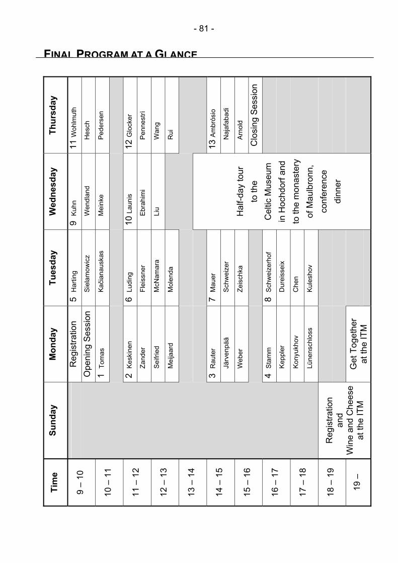
- 81 -
FINAL PROGRAM AT A GLANCE
Thur
sday
11 W
ohlm
uth
H
esch
P
eder
sen
12 G
lock
er
P
enne
strì
W
ang
R
ui
13
Am
brós
io
N
ajaf
abad
i
A
rnol
d
Clo
sing
Ses
sion
Wed
nesd
ay
9 K
uhn
W
endl
and
M
eink
e
10
Lau
nis
E
brah
imi
L
iu
H
alf-d
ay to
ur
to th
e
Cel
tic M
useu
m
in H
ochd
orf a
nd
to th
e m
onas
tery
of
Mau
lbro
nn,
conf
eren
ce
dinn
er
Tues
day
5 H
artin
g
S
iela
mow
icz
K
ačia
naus
kas
6
Lud
ing
F
leis
sner
M
cNam
ara
M
olen
da
7 M
auer
S
chw
eize
r
Z
eisc
hka
8 S
chw
eize
rhof
D
urei
ssei
x
C
hen
K
ules
hov
Mon
day
Reg
istra
tion
Ope
ning
Ses
sion
1
Tom
as
2 K
eski
nen
Z
ande
r
S
eifri
ed
M
eija
ard
3 R
aute
r
Jä
rven
pää
W
eber
4
Sta
mm
K
eppl
er
K
onyu
khov
L
ünen
schl
oss
Get
Tog
ethe
r at
the
ITM
Sund
ay
Reg
istra
tion
and
Win
e an
d C
hees
e at
the
ITM
Tim
e
9 –
10
10 –
11
11 –
12
12 –
13
13 –
14
14 –
15
15 –
16
16 –
17
17 –
18
18 –
19
19 –