MULTIPLEXADO 2012
197
Section Electrical System Service Manual Number PM819003/KM815056 Date 09/16/2011 2010 Multiplexed Electrical System Service Manual — CECU3 with Chassis Node
-
Upload
john-mkcito-ki -
Category
Documents
-
view
729 -
download
97
description
manual de sistemas multiplexion equipos paccar modelo 2012
Transcript of MULTIPLEXADO 2012

Section Electrical System ServiceManual
Number PM819003/KM815056
Date 09/16/2011
2010 Multiplexed Electrical System ServiceManual — CECU3 with Chassis Node

©2011 PACCAR Corporation
Confidentiality Notice: This document and the information contained herein is proprietary. It shall not bereproduced, copied or disclosed, in whole or in part, or used for manufacture without the written permissionof PACCAR. You are hereby notified that any dissemination of this information is strictly prohibited.
ii PM819003/KM815056 (09/16/2011)

Electrical System Service Manual
Table of Contents
Safety . . . . . . . . . . . . . 1
Applies To . . . . . . . . . . . 2
Exploded View . . . . . . . . . 3
What's New . . . . . . . . . . 4
General Information 5
Special Tools . . . . . . . . . . 6
Specifications . . . . . . . . . 7
How It Works . . . . . . . . . . 8
Maintenance . . . . . . . . . . 9
Disassembly / Assembly . . . . 10
Inspection . . . . . . . . . . . 11
Troubleshooting . . . . . . . . 12
Glossary . . . . . . . . . . . . 13
Index . . . . . . . . . . . . . 14
PM819003/KM815056 (09/16/2011) iii

iv PM819003/KM815056 (07/06/2010)

Electrical System Service Manual 1
1 Safety
Important Notes. . . . . . . . . . . . 1 - 2
PM819003/KM815056 (09/16/2011) 1 - 1

1 Electrical System Service Manual
Important Notes
The simulate function within ESA is a gooddiagnosis tool. Safety is a concern, so manyCECU outputs are not accessible for simulationsuch as: cruise control, engine oil pressure, parkbrake switch.
Simulation of gauges is also not permitted if theengine is running.
Replacing the control unit results in the odometerbeing reset. Take appropriate action to record thevehicle miles prior to removing the control unit.
CAUTIONInterrupting the communication or power supplyduring a control unit reflash could result inhardware damage.
ESA recognizes when a software update isrequired on a connected vehicle. If for somereason the user chooses not to reflash the controlunit, ESA triggers a warning display. The LCDbacklighting of the speedometer and outside airtemperature blink for 1 minute. The warning istriggered at every key-on of the vehicle until therequired update is performed. This is to alert theoperator or other technicians that a vehicle reflashis required.
ESA automatically identifies what version ofcontrol unit it is connected to, and only permitssoftware downloads that are applicable for thatcontrol unit.
Check the program menu to see if an inoperativefeature is disabled. This is very important whendiagnosing an inoperative gauge on a CECUequipped vehicle. The gauge may simply havebeen previously disabled.
Instrumentation Service Informationdescribing how to remove, disassemble,and reinstall instrumentation components islocated on ServiceNet. Before attempting anyinstrumentation repairs, the technician shouldhave a complete understanding of the proceduresdescribed in ServiceNet.
This manual contains service manual informationcovering vehicles equipped with software version"CECU3 with Chassis Node" (P30-1009). Forvehicles with prior CECU software versions (suchas: ICU (P30-1003), CECU/CECU2 (P30-1002),and CECU3 (P30-1008)) refer to a separatepublication (PM819010/KM815054).
When replacing a chassis node, disconnectthe batteries and do not reconnect them untilnode installation and all wiring connections arecomplete. A new chassis node and the CECUneed to be powered up simultaneously duringthe node's first power cycle; otherwise a faulton the Multi-Function Display (Kenworth) orDriver Information Display (Peterbilt) will indicatethat the CECU is not recognizing the propercommunication with the chassis node.
1 - 2 PM819003/KM815056 (09/16/2011)

Electrical System Service Manual 2
2 Applies To
Electronic Service Analyst (ESA) . . . . 2 - 2Models–Build Dates . . . . . . . . . . 2 - 3
PM819003/KM815056 (09/16/2011) 2 - 1
2 Electrical System Service Manual
Electronic Service Analyst (ESA)
ESA History
Multiplexed instrumentation was introduced in2005. This method of communication, using asingle wire to transmit multiple signals to manycomponents, has dramatically reduced the sizeand complexity of the wiring bundle behind thedash panel.
While some traditional diagnostic andtroubleshooting methods apply to multiplexedinstruments, other methods do not. Professionalservice technicians needed a new diagnosticsoftware program to make troubleshootingeasier and more efficient. The program is calledElectronic Service Analyst (ESA). It does notreplace basic electrical system troubleshootingskills; it supplements them.
ESA is flexible and allows the technician to usehis own experience and expertise to help findand fix the problem. The technician reviews faultcodes stored in the components, verifies whetherthe instrumentation is working properly, anddiagnoses the root cause of the problem usingtroubleshooting information found in ServiceNet.
Once the software is installed on a personalcomputer, it's easy to use. It's available in English,Spanish, and Canadian French. Much like existingPC-based service applications, this analyticprogram communicates over a wireless data linkadapter (DLA) to the multiplexed components. AUSB Link to data link adapter is used for easyESA connection and communication.
ESA 3 is the latest revision/update to thetroubleshooting software. As more features areadded to take advantage of multiplexing, ESAneeds to grow in order to continue to support thetechnician.
NOTEAt the time of publication "ESA 3.1" was thelatest released version of the Electronic ServiceAnalyst. If there are subsequent releasesof ESA (version 3.2, 3.3, 4.0, etc.), ESA willautomatically update to the most recent version.
CECU3 Multiplexing Overview
This manual provides service informationcovering trucks equipped with the multiplexedinstrumentation system. Before attempting tomake service repairs, the technician shouldbe knowledgeable about the system design,components, operation and troubleshootingprocedures for diagnosing multiplexedinstrumentation problems.
How communication works in a multiplex system:Each major subsystem in the truck’s electricalsystem is operated by a control module that sendsand receives data to and from a central hubcomputer. The subsystem control modules arereferred to as nodes. The central hub computer iscalled the CECU (Cab Electronic Control Unit).Since we’re into the third generation now, wesometimes call it CECU3.
The CECU receives data related to controlling thevarious devices of the electrical system. It thenmakes decisions based on that input and sendsinformation to each of the subsystem systemcontrol modules (nodes) about what that nodeshould do with the components it controls.
In this new generation, the CECU will, as before,control most of the instrumentation and interiorlighting. Additionally it will now control exteriorlighting, turn stalk, and wipers functions. Thenode that receives information from the CECU tocontrol the exterior lighting, turn stalk, and wipersfunctions is called the chassis node.
2 - 2 PM819003/KM815056 (09/16/2011)

Electrical System Service Manual 2
Models–Build Dates
Identifying which control unit is in the vehicle helpsdetermine what features are present and also aidsin troubleshooting.
Control
UnitHardware Part Number Software Version Models
Engine EmissionsLevel
Production BuiltDates
ICU Q21-1029-X-XXX P30-1003-XXX PB: 357, 378, 379, 385, 386
KW: C500, T600, T800, W900,Off-Highway
1998, 2004 2005 - present
PB: 365, 367, 384, 386, 388, 389
KW: C500, T440/T470, T660,T800, W900, Off-Highway
2007 - present
PB: 387
KW: T2000
2008 - present
CECU / CECU2 Q21-1055-X-XXX /Q21-1075-X-XXX
P30-1002-XXX
PB: 325, 330, 335, 340
2007
2009 - presentCECU3 Q21-1076-X-XXX P30-1008-XXX PB: 325, 330, 337, 348, 387
KW: T170, T270, T370, T700
2010 2010 - present
CECU3 withChassis Node
Q21-1076-X-XXX withQ21-1077-X-XXX
P30-1009-XXX PB: 365, 367, 384, 386, 388, 389
KW: C500, T440/T470, T660,T800, W900, Off-Highway
2010 2010 - present
NOTEThis manual contains service manualinformation covering vehicles equipped withsoftware version "CECU3 with Chassis Node"(P30-1009). For vehicles with prior CECUsoftware versions (such as: ICU (P30-1003),CECU/CECU2 (P30-1002), and CECU3(P30-1008)) refer to a separate publication(PM819010/KM815054).
PM819003/KM815056 (09/16/2011) 2 - 3

2 Electrical System Service Manual
Control Unit IdentificationControl unit identification can be made using afew methods:• Searching using the Electronic Catalog (ECAT)• Connecting using the Electronic Service
Analyst (ESA)• Menu Control Switch (MCS), only available
with Multi-Function Display.
Using ECAT or ESA are the easiest and mostexact ways of determining the type of control unitin the truck.
Electronic Catalog (ECAT) Identification
ECAT provides a parts list “as built” and Bill ofMaterials information for each specific truck.The catalog is searchable, and contains the partnumber and identification of the trucks instrumentpanel control unit.• ICU Part Number Q21-1029-X-XXX• CECU Part Number Q21-1055-X-XXX• CECU2 Part Number Q21-1075-X-XXX• CECU3 Part Number Q21-1076-X-XXX• Chassis Node Part Number Q21-1077-X-XXX
The blank digits (denoted by "X") in the above partnumbers represent:• "-X" is the hardware revision.• "-XXX" is the software boot loader version.Electronic Service Analyst (ESA) Identification
Connecting using ESA brings up a control unitinformation window. In this window, the sixthline item is the Control Unit Type and identifieswhether the truck has an ICU or CECU. It alsodetails the variant of the CECU.
Line item ten of this Control Unit Informationwindow displays the current Vehicle SoftwareVersion. This details the current CECU softwareand programming date that is presently installedon the vehicle.
Upon connection, ESA recognizes if a softwareupdate has been issued for the control unit withinthe connected vehicle. If an update is required,ESA prompts the technician to perform the updateoperation.
MCS Identification
For vehicles equipped with the Multi-FunctionDisplay, control unit identification is possible viathe Menu Control Switch (MCS). Using the MCSknob, select the "Truck Information" menu. Usethis menu to look up the "CECU SW Ver." Softwareversion P30-1002-XXX can denote either a CECUor CECU2.
• ICU Software P30-1003-XXX
• CECU Software P30-1002-XXX
• CECU2 Software P30-1002-XXX
• CECU3 Software P30-1008-XXX
• CECU3 with Chassis Node SoftwareP30-1009-XXX
2 - 4 PM819003/KM815056 (09/16/2011)
Electrical System Service Manual 3
3 Exploded View
Control Unit Location . . . . . . . . . 3 - 2
PM819003/KM815056 (09/16/2011) 3 - 1
3 Electrical System Service Manual
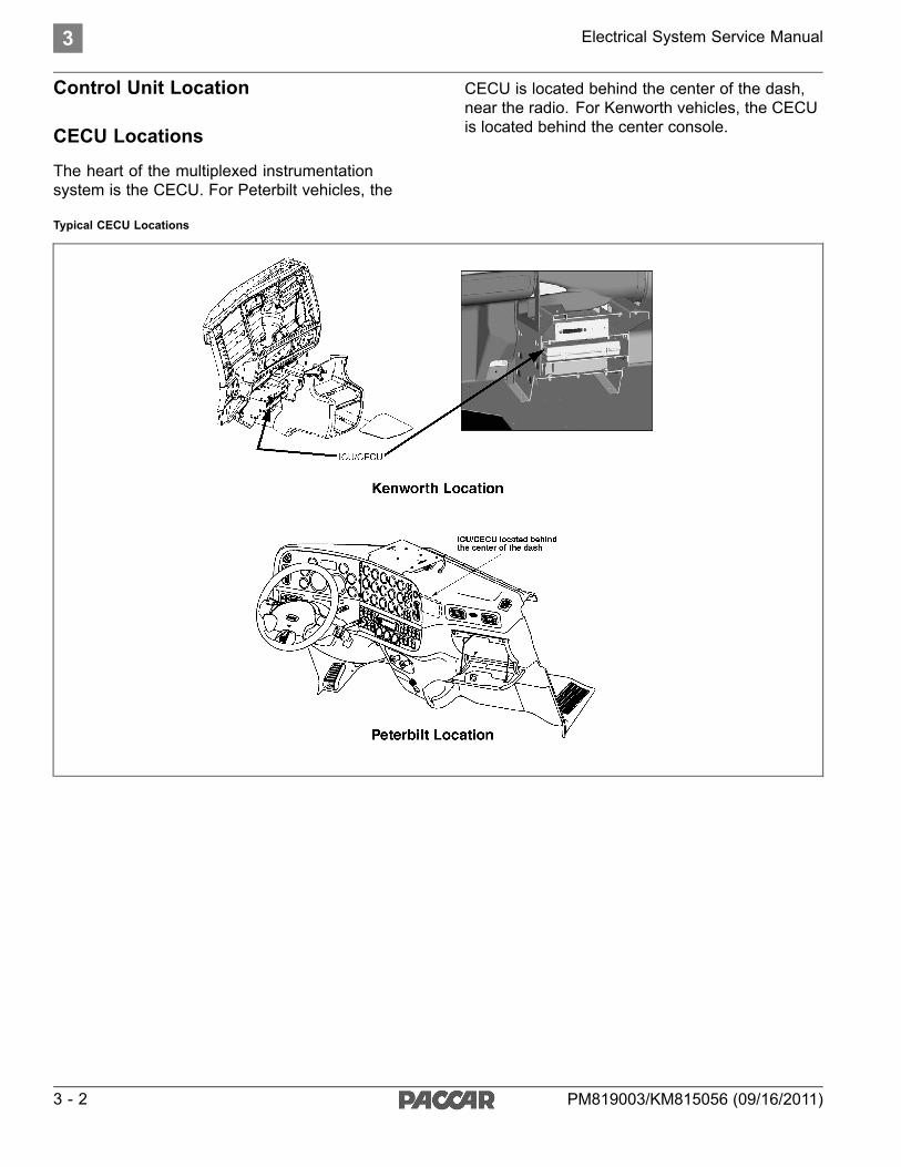
Control Unit Location
CECU Locations
The heart of the multiplexed instrumentationsystem is the CECU. For Peterbilt vehicles, the
CECU is located behind the center of the dash,near the radio. For Kenworth vehicles, the CECUis located behind the center console.
Typical CECU Locations
3 - 2 PM819003/KM815056 (09/16/2011)

Electrical System Service Manual 3
Chassis Node Locations
For Kenworth models with a daycab, the chassisnode is located below the driver side door.
Kenworth Daycab Chassis Node Location
For Kenworth models with a aerocab, the chassisnode is located under the rear sleeper sill.
Kenworth Aerocab Chassis Node Location
PM819003/KM815056 (09/16/2011) 3 - 3

3 Electrical System Service Manual
For Kenworth models with an aerocab withcrossover exhaust, the chassis node is located onthe underbell crossmember.
Kenworth Aerocab with Crossover Exhaust Chassis Node Location
For Peterbilt models, the chassis node is locatedbehind the transmission and is mounted betweenthe frame rails.
Peterbilt Chassis Node Location
3 - 4 PM819003/KM815056 (09/16/2011)

Electrical System Service Manual 4
4 What's New
Electronic Service Analyst (ESA) . . . . 4 - 2New Features of ESA 3 . . . . . . . . 4 - 4
PM819003/KM815056 (09/16/2011) 4 - 1

4 Electrical System Service Manual
Electronic Service Analyst (ESA)
What is ESA?
Multiplexed instrumentation was introduced in2005. This method of communication, using asingle wire to transmit multiple signals to manycomponents, has dramatically reduced the sizeand complexity of the wiring bundle behind thedash panel.
While some traditional diagnostic andtroubleshooting methods apply to multiplexedinstruments, other methods do not. Professionalservice technicians needed a new diagnosticsoftware program to make troubleshootingeasier and more efficient. The program is calledElectronic Service Analyst (ESA). It does notreplace basic electrical system troubleshootingskills; it supplements them.
ESA is flexible and allows the technician to usehis own experience and expertise to help findand fix the problem. The technician reviews faultcodes stored in the components, verifies whetherthe instrumentation is working properly, anddiagnoses the root cause of the problem usingtroubleshooting information found in ServiceNet.
Once the software is installed on a personalcomputer, it's easy to use. It's available in English,Spanish, and Canadian French. Much like existingPC-based service applications, this analyticprogram communicates over a data link adapter(DLA) to the multiplexed components.
A USB Link to data link adapter is used for ESAconnection and communication and is compatiblefor use with all control units.
ESA is a must-have diagnostic tool for dealershipsto troubleshoot the new instrumentation. ESAeliminates much of the time consuming guessworkin some hard to diagnose cases, and significantlyreduces unnecessary gauge replacement.
4 - 2 PM819003/KM815056 (09/16/2011)

Electrical System Service Manual 4
Why ESA?
ESA 3 is the latest revision/update to thetroubleshooting software. As more features areadded to take advantage of multiplexing, ESAneeds to grow in order to continue to support thetechnician.
NOTEAt the time of publication "ESA 3.1" was thelatest released version of the Electronic ServiceAnalyst. If there are subsequent releasesof ESA (version 3.2, 3.3, 4.0, etc.), ESA willautomatically update to the most recent version.
As version 3 is simply an update to the ESAsoftware, many of the functions, navigation andscreen images look and feel just as before.
This ESA update includes diagnostic coverage ofnew features available with the Cab ElectronicControl Unit (CECU), as well as severalenhancements to the program itself.
Keep in mind; although the program and softwarecontain many new improvements, the type ofcontrol unit that is in the truck determines some ofthe ESA features and procedures.
CECU and ESA 3 Highlights• Manufacturer selection available
• Five Data Link Adapter (DLA) selections
• Storage and display of up to 50 DiagnosticTrouble Codes (DTCs)
• Components grouped by type to help find whatyou are looking for
• Monitor capabilities expanded
• Selective simulation permitted while modulesoftware is active
• Many new features/parameters available inthe program menu
• Available backup utility to save vehicleparameters
• Out-of-date software warning
• Diagnostics, monitoring, and simulating ofmost exterior lighting
• Diagnostics, monitoring, and simulating ofwindshield wiper and washer Pump
• Addition of Nexiq USB Link to Data LinkAdapter selections
• Simplified flashing menu
• Faster software flashing times
• Can choose between compatible softwareversions for a particular control unit
• As-Built control unit parameters can beretrieved from ECAT (ePortal access required)
• Print preview function allows printing frommost screens
• Monitoring and logging of J1939 data bus
PM819003/KM815056 (09/16/2011) 4 - 3

4 Electrical System Service Manual
New Features of ESA 3
This section gives a brief overview of the manyenhancements made to ESA.
New Features
Most of the important additions are highlightedhere. Refer to ServiceNet for ESA information andresources.
Connecting ESA
Connecting with ESA has not changed, simplyconnect the vehicle using the DLA and theconnectors included in the ESA kit and click onthe connect icon.
Once the connection is established a revisedControl Unit Information pop-up windowautomatically appears on screen. This is to greetthe user with important criteria that will help incontinuing to troubleshoot a vehicle. Informationsuch as:
• Chassis number
• Vehicle Identification Number (VIN)
• Unit of measure of the cluster
• Type of control unit
• Data bus ESA is using to connect to theControl Unit
• When the module was last flashed
• What version of software is currently loadedonto the module
4 - 4 PM819003/KM815056 (09/16/2011)

Electrical System Service Manual 4
Navigating ESA
The navigation icons are located at the top ofthe ESA screen. Selecting an icon activates thatportion of the program.
The icons are:
• Connect/Disconnect: starts and stopscommunications with the truck via the DLA.
• Diagnose: read, review and monitor faultcodes.
• Monitor: watch activity of inputs to the CECU.
• Simulate: limited activation of CECU outputs.
• Program: disable/enable components of theCECU.
Diagnose - New Features
50 Stored Codes
The Diagnosis screen now has the ability to storeand display up to 50 Diagnostic Trouble Codes(DTCs) for the CECU.
Details
There is a Details columns for CECU diagnosis.Details are recorded at the first instance of theDTC. For example, if the DTC has been recordedtwice, the count displays 2. The information in thedetails screen is also captured when that DTCwas first recorded.
Selecting the magnifying glass in the detailscolumn for a DTC brings up a pop-up screen thatprovides the following freeze-frame information:
• Engine RPM
• Vehicle Speed
• Battery Voltage
• Outside Air Temp
• Coolant Temp
The same criteria are recorded for every DTCfirst occurrence. Some of the information maynot relate to your specific DTC. As seen in theexample there is a very abnormal reading for theoutside air temperature, which is understandablesince the DTC is dealing with a fault on that circuit.
The details screen also provides a brief descriptionof the fault along with some possible causesuggestions.
PM819003/KM815056 (09/16/2011) 4 - 5

4 Electrical System Service Manual
Clearing DTCs
For CECU equipped vehicles, selecting “ClearDTCs” removes all non-active faults and instantlydisplays only active codes.
Service Manual Link
When ESA is updated, the service manual for theMultiplexed Electrical System is also downloadedto the computer that has ESA installed. Theservice manual is accessed through the Helpmenu link at the top of every screen.
If there are any service manual revisions available,they will automatically be updated in ESA whenyou are prompted to check for ESA updates(approximately every 45 days). The servicemanual is where to find a complete DTC list alongwith troubleshooting charts to help the techniciandiagnose problems.
Monitor - New Features
To allow more viewing area when monitoringmultiple components, there are auto-hide pinicons for reducing some of the sub-windows onthe monitor screen. When selected to auto-hide,the sub-window reduces to a tab on the left sideof the monitor screen. Simply place the cursorover the tab to bring the sub-window back up forfurther selection.
To make it easier to navigate to desired features,similar components have been grouped into amenu tree structure.
Monitoring shows a representation of what thecontrol unit sees as input signals. Comparingwhat the unit sees to what the actual component(gauge, telltale, etc.) is doing helps determine ifthere is a problem.
The enhancements made to the CECU increasedthe amount of monitored components using ESA.
ICU CECUGauges 28 38Telltales 26 58Editable telltales 0 9Switches 0 19Alarm 0 7LCD 0 4Knob (driver information display) 0 1
4 - 6 PM819003/KM815056 (09/16/2011)

Electrical System Service Manual 4
Monitoring Data Bus
With ESA 3 the user is now able to monitor thevehicle data bus. Select the data bus group to bemonitored. A table will open that shows all ControlUnits communicating on the bus. If a controlunit stops communicating during the monitoringsession, the status will change from Active toInactive. If needed, the user also has the capabilityto record messages on the data bus to be sent toyour service manager for further analysis.
Simulate - New Features
As with the monitor screen, to allow more viewingarea when simulating components, there areauto-hide pin icons for reducing some of thesub-windows. When selected to auto-hide, thesub-window reduces to a tab on the left side of thescreen. Simply place the cursor over the tab tobring the sub-window back up for further selection.
To make it easier to navigate to desired features,similar components have been grouped into amenu tree structure.
PM819003/KM815056 (09/16/2011) 4 - 7

4 Electrical System Service Manual
Individual Output Simulation
Simulation performed with an ICU would basicallyshutdown the unit software so outputs could besimulated without being influenced by the otheroperations of the ICU. Now, with the CECU,individual outputs may be simulated while thecontrol unit software is active. While this allowsgreater flexibility there is much that cannotand should not be simulated while a vehicle isoperational. For instance, as a safety precaution,gauge simulation will not be permitted if there isengine rpm.
Safety Issues
While the simulate function is a good diagnosistool, safety is a concern, so many CECU outputsare not accessible for simulation such as: cruisecontrol, engine oil pressure, park brake switch.
Program - New Features
Similar components have been grouped into tabsto make finding your choice easier.
Parameters
There were 14 parameters for the ICU. Parametersare like part numbers that tell the control unitwhat features are on the vehicle and hence whatinputs/outputs need activated.
With the CECU3, the available parameters havegrown to around 130. Some parameters arerestricted or locked to ensure proper activation.
Disable Components Now Means No Function
With the ICU, disabling a component would turnoff the diagnostics but not remove the componentfrom operation. An ICU disabled gauge stillfunctions, but is prevented from detectingproblems and triggering DTCs.
Now with the CECU, disabling really meansdisabled. A disabled gauge will not function. It isremoved from all signal transmissions in order toallow the other features faster communication.This is very important when diagnosing acomponent that is inoperative. It may simply havebeen previously disabled.
NOTECheck the programmenu to see if an inoperativefeature is disabled.
Flash - New Features
It may be necessary to reflash a control unit forthe following:
• Replacing a control unit.
• Updating the software of a control unit.
• Obtaining additional features when available.
4 - 8 PM819003/KM815056 (09/16/2011)

Electrical System Service Manual 4
NOTEReplacing the control unit results in the odometerbeing reset. Take appropriate action to recordthe vehicle miles prior to removing the controlunit.
Reflashing takes approximately only 6 minutesover the K-line if using the USB Link adapter. Thecontrol unit must stay connected and power to theunit must be maintained throughout the flashingprocess.
CAUTIONInterrupting the communication or power supplycould result in hardware damage to the unit.
K-Line was the communication bus used fordiagnostics on vehicles with: ICU software(P30-1003-XXX), CECU/CECU2 software(P30-1002-XXX), or CECU3 Software(P30-1008-XXX). Moving forward, vehiclescontaining "CECU3 with Chassis Node" software(P30-1009-XXX), the K-Line has been replacedwith the D-CAN communication bus. Basically theonly difference the technician will notice is a fasterreflash time.
Compatible Software
When initiating the flashing process, the technicianis required to select the appropriate softwareversion to program into the control unit. Onlycompatible software versions for the vehicle unitthat is connected will present in the selectionmenu.
Details on the differences between availablesoftware versions are available through the ViewRelease Notes button at the bottom of the SelectVehicle Software screen.
Backup Parameters
Flashing a control unit or replacing a control unitinvolves backing up the stored parameters of theunit. The backup saves an encrypted file ontothe connected PC that is used to reload all theparameters of the control unit. These are theparameters that are enabled/disabled through theprogram menu. This ensures that your chassisnumber retains all the previously programmedfunctions.
Retrieving Parameters
ESA 3 has the capability to retrieve the parameterconfiguration from ECAT that was on the vehiclewhen issued from the factory. This may aidin restoring parameters in instances such asreplacing a non responsive control unit. Thetechnician must still verify the parameters arecorrect for any settings modified after the vehicleleaves the factory.
The as-built parameter sets can be retrieved fromECAT through the Tools drop down menu. It mayalso be presented as an option when flashing ablank unit or when parameters cannot be retrievedfrom a unit.
PM819003/KM815056 (09/16/2011) 4 - 9

4 Electrical System Service Manual
After selecting "Retrieve Parameters from ECAT",the user needs to enter the chassis number ornumbers for the desired parameter sets to bedownloaded.
At this time, the user is required to log intoServiceNet with a valid ePortal account.
Once the login is verified, ESA will download thedesignated parameter sets and inform the userwhen the transfer is complete.
4 - 10 PM819003/KM815056 (09/16/2011)

Electrical System Service Manual 4
The downloaded files are stored in a secure formatthat prohibits tampering. ESA also prevents anyuser from loading parameters sets designatedfor one chassis number into a control unit that isassigned to another chassis number.
To restore parameters from the downloadedparameter set, the user must Initiate a Flashingfrom the Tools drop down menu and selectRestore Parameters.
Finally, the user needs to designate the source ofthe parameter set to be restored.
Out-of-Date Software Warning
Let's say an update has been issued for the CECUsoftware and a truck is connected to ESA for sometroubleshooting purpose. ESA recognizes thatthere is a software update required and promptsthe technician to perform the operation. If for somereason the user chooses not to reflash the controlunit, maybe there isn't sufficient time to performan update or maybe the Data Link Adapter isn'timmediately available, ESA triggers a warningdisplay in the vehicle. This warning blinksthe LCD backlighting of the speedometer andoutside air temperature for 1 minute. Thewarning is triggered at every key-on of thevehicle until the required update is performed.This is to alert the operator or other techniciansthat a vehicle reflash is required.
PM819003/KM815056 (09/16/2011) 4 - 11

4 Electrical System Service Manual
Administration - New Features
There are a few improvements made to theadministration form that is found under the Toolspull down menu at the top of the ESA screen.
First off, any changes now performed in theadministration form automatically update assoon as the user selects Apply or OK on theadministration window. It is no longer necessaryto shut down and restart the program to initiateadministration changes.
A couple of highlight improvements involveselections under the Manufacturer and Data LinkAdapter (DLA) options.
The manufacturer selection allows ESApresentation as either a Kenworth or Peterbiltdealer.
4 - 12 PM819003/KM815056 (09/16/2011)

Electrical System Service Manual 5
5 General Information
Service Resources . . . . . . . . . . 5 - 2
PM819003/KM815056 (09/16/2011) 5 - 1

5 Electrical System Service Manual
Service Resources
Service Manual Update
If there are any service manual revisions available,they will automatically be updated in ESA whenyou are prompted to check for ESA updates(approximately every 45 days). The servicemanual is accessed through the Help menu linkat the top of every screen. The service manualis where to find a complete DTC list along withtroubleshooting charts to help the techniciandiagnose problems.
Instrumentation Service Informationdescribing how to remove, disassemble,and reinstall instrumentation components islocated on ServiceNet. Before attempting anyinstrumentation repairs, the technician shouldhave a complete understanding of the proceduresdescribed in ServiceNet.
Disabled Gauges
With the CECU, disabling a componentturns the component off completely. Thedisabled component is removed from all signaltransmissions in order to allow the other featureson the vehicle faster communication. A disabledgauge will not function or communicate with thecontrol unit.
NOTECheck the programmenu to see if an inoperativefeature is disabled. This is very important whendiagnosing an inoperative gauge on a CECUequipped vehicle. The gauge may simply havebeen previously disabled.
When a service technician installs an optionalgauge in the multiplexed instrumentation system,the newly installed gauge will initially be disabled.Because the gauge is not factory-installed, thetechnician must program the CECU to monitor it.Until the CECU is programmed, the link betweenthe CECU and the gauge is termed “disabled” –that is, the CECU is prevented from detectingproblems, and also from logging and displayingdiagnostic trouble codes (DTCs).
To program the CECU and enable gauges, select“Program”. If the gauge value is “Disable”, changeit to “Enable”.
Once the CECU is programmed and the link tothe gauge is “enabled”, the CECU monitors it,diagnoses problems like “shorts” and “opens”,logs DTCs for troubleshooting, and displays theDTCs on ESA’s “Diagnose” screen.
5 - 2 PM819003/KM815056 (09/16/2011)

Electrical System Service Manual 5
Communication Diagrams
The following diagram provides an example of thecommunication lines and signal paths of a typicalmultiplexed vehicle. Determining the correctcommunication lines that provide a signal to the
CECU and where these circuits interconnect,help pinpoint possible trouble areas. Sometimesthese connections become loose, have bent ormisaligned pins, and visually inspecting them mayhelp identify why other electrical problems maybe occurring.
Communication Interface Diagram
PM819003/KM815056 (09/16/2011) 5 - 3

5 Electrical System Service Manual
CECU Details
The heart of the multiplexed instrumentationsystem is the CECU. See Control Unit Locationsfor illustrations depicting the physical position ofthe control unit.
The CECU receives data related to controlling thevarious devices of the electrical system. It thenmakes decisions based on that input and sendsinformation to subsystem system control modules(nodes) about what that node should do with thecomponents it controls.
CECU Connector IdentificationThere are 5 electrical connectors that plug intothe CECU.• Connector A - 9 pins• Connector B - 24 pins• Connector C - 52 pins• Connector D - 40 pins• Connector E - 9 pins
For an illustration of the side view of a CECUshowing where the harness connectors attach intothe control unit, see CECU Figure. This figureidentifies connector position on the control unit aswell as individual connector pin locations.
CECU
For connector face views at the harnessconnectors that plug into the CECU, see CECUConnector Face Views Figure. These connectors
all branch from the instrument panel harness thatroutes behind the dash.
CECU Connector Face Views
5 - 4 PM819003/KM815056 (09/16/2011)

Electrical System Service Manual 5
CECU Comparison Chart - (Pinout)
Conn Pin Number Circuit Function1 CVSG power2 Power - battery3 Cab dome lamp4 Menu control switch power5 Ground6 Menu control switch ground7 Dash/panel illumination8 Auxiliary backlighting
A
9 Power - battery1 Menu control switch encode A2 Menu control switch encode B3 Menu control switch enter4 Courtesy lights - right door jamb switch5 Ignition input (Start)6 Dome lamp input7 Seat belt telltale8 Cruise set9 Cruise resume10 Back-up alarm mute11 Retarder select 112 Retarder select 213 Clutch switch14 Headlamps active15 PTO set16 PTO resume17 Engine fan override18 Regen enable19 Inhibit regen20 ABS off road21 Marker lamp (Tractor)22 LVD input23 Transfer Case Engaged
B
24 Spare digital input
Conn Pin Number Circuit Function1 Power supply +5V sensors2 Analog return3 PTO oil temp3 Spare analog input4 K-line5 Dimmer input6 Air pressure transducer - primary7 Air pressure transducer - secondary8 Air pressure transducer - application9 Spare analog input10 Air filter restriction11 Spare analog input12 Spare analog input13 Spare analog input14 CVSG data15 CVSG return16 Outside air temperature17 Spare analog input18 Spare analog input19 Spare analog input20 Spare analog input21 Transmission oil temperature - main22 Spare analog input23 Pyrometer24 Brakesaver oil temperature25 Analog return26 Spare analog input27 Remote throttle signal28 Spare analog input29 Spare analog input30 Spare analog input31 Wiper resistor ladder32 Turn signal resistor ladder33 LVD battery voltage34 Spare digital input35 C-CAN ground36 Not used37 C-CAN high38 C-CAN low39 Trailer stop lamp relay40 D-CAN high41 D-CAN low42 D-CAN ground43 B-CAN high44 B-CAN low45 B-CAN ground46 Marker flash47 Windshield washer pump48 DRL interrupt49 Marker lamp (Trailer)50 Fuel Level Sender Select51 Headlamp flash
C
52 Headlamp high/low
PM819003/KM815056 (09/16/2011) 5 - 5

5 Electrical System Service Manual
Conn Pin Number Circuit Function1 Power - ignition2 Courtesy lights - left door jamb switch3 Power - accessory4 Hazard5 Brake switch6 Spare digital input7 Park brake active8 Fog lamps9 HVAC On Switch10 Cruise on/off11 Interaxle lock telltale12 Fifth wheel lock telltale13 Tractor ABS telltale14 Trailer ABS telltale15 Check engine telltale16 Stop engine telltale17 Windshield wiper (fast)18 Secondary fog lamps19 Editable telltale 1
See editable telltale table20 Editable telltale 2
See editable telltale table21 Editable telltale 3
See editable telltale table22 Editable telltale 4
See editable telltale table23 Spare relay chassis control24 Editable telltale 6
See editable telltale table25 Editable telltale 7
See editable telltale table26 Editable telltale 8
See editable telltale table27 Editable telltale 9
See editable telltale table28 Dash buzzer 1A29 Dash buzzer 1B30 Dash buzzer 1C31 Dash buzzer 232 F-CAN high33 F-CAN low34 I-CAN high35 I-CAN low36 I-CAN ground37 V-CAN high38 V-CAN low39 V-CAN ground
D
40 V-CAN low terminated
Conn Pin Number Circuit Function1 Idle timer relay2 Windshield wiper relay3 Ignition relay (Start)4 Clearance lamp5 Ground6 LVD Bus 17 LVD Bus 28 Spare relay output
E
9 Spare relay output
5 - 6 PM819003/KM815056 (09/16/2011)

Electrical System Service Manual 5
Editable Telltale Application
Editable Telltale Location KW Cluster PB ClusterEditable Telltale 1 Position 4 Position 2Editable Telltale 2 Position 7 Position 3Editable Telltale 3 Position 8 Position 4Editable Telltale 4 Position 9 Position 5Editable Telltale 5 n/a n/aEditable Telltale 6 Position 12 Position 8Editable Telltale 7 Position 13 n/aEditable Telltale 8 Position 14 n/aEditable Telltale 9 Position 16 n/a
See Cluster Components for illustration of possibletelltale locations.
PM819003/KM815056 (09/16/2011) 5 - 7

5 Electrical System Service Manual
Chassis Node Details
The node that receives information from theCECU to control the exterior lighting and wipersfunctions is called the chassis node. The chassisnode serves as a bidirectional conduit for bothinformation and control.
Several sensors that in Multiplex Electrical version1 and 2 were connected to the CECU (ICU forversion 1) are now connected to the chassis node.These include:
• Ammeter
• Auxiliary Transmission Oil Temperature
• Axle Temperature, Rear
• Axle Temperature, Front
• Axle Temperature, Center / Steer
• Back Up Switch
• General Oil Temperature
• Fuel Filter Restriction
• PTO Oil Temperature
• Transfer Case Oil Temperature
The inputs, usually a variable voltage, from thesesensors are fed into the chassis node where theinformation is them processed into data and sentto the CECU by way of the CAN (Controller AreaNetwork) data bus. In addition to receiving andprocessing sensor data, the chassis node alsocontrols the operation of relays that power severalelectrical subsystems. These include:
• Back Up Alarm
• Fog Lamps
• Stop Lights
• Trailer Turn Signals
• Turn Signals
• Windshield Washer
The information sent from the sensors attached tothe chassis node is sent to the CECU, processed,and where appropriate returned to the chassisin the form of commands related to the outputscontrolled by the chassis node.
The design and manufacture of the chassis nodeis such that it is delivered to the plant or dealershipwithout configuration parameters loaded into it.Upon the first power cycle of the system theCECU downloads the appropriate configurationparameters so that the chassis node can setupits I/O correctly. Depending on the softwareconfiguration of the CECU, these parametersmay be different than other trucks and uniqueto the specific requirements of the truck beingassembled. Once the chassis node has receivedits configuration parameters, it stores them inflash memory permanently and does not requireany additional downloads from the CECU. This isa one time event and once complete the chassisnode can be removed and reinstalled without theneed of a power cycle.
NOTEWhen replacing a chassis node, disconnect thebatteries and do not reconnect them until thenew node installation and all wiring connectionsare complete. A new chassis node and theCECU need to be powered up simultaneouslyduring the node's first power cycle; otherwise afault on the Multi-Function Display (Kenworth)or Driver Information Display (Peterbilt) willindicate that the CECU is not recognizing theproper communication with the chassis node.
The problem occurs when the CECU and chassisnode are not powered up simultaneously duringthe first power cycle. This may happen for avariety of reasons which include; missing chassisnode, missing fuses, harnessing not connected,etc. If the CECU recognizes that the chassis nodeis not communicating as expected, it will triggera fault in the Multi-Function Display (Kenworth)or Driver Information Display (Peterbilt). Cyclingthe ignition will not correct this problem since theparameter file is only transmitted to the chassisnode after a complete battery power cycle.
Perform a complete battery power cycle by cyclingbattery power directly at the batteries. Batterypower should be removed from the system for atleast 30 seconds during the power cycle so thatall electrical devices completely discharge and aretruly powered down.
5 - 8 PM819003/KM815056 (09/16/2011)

Electrical System Service Manual 5
Chassis Node Connector IdentificationThere are three 21-pin electrical connectors thatplug into the Chassis Node.• Connector A - 21 pins• Connector B - 21 pins• Connector C - 21 pins
For an illustration of the side view of a ChassisNode showing where the harness connectorsattach into the control unit, see Chassis NodeFigure. This figure identifies connector positionon the control unit as well as individual connectorpin locations.
Chassis Node Figure
For connector face views at the harnessconnectors that plug into the Chassis Node, seeChassis Node Connector Face Views Figure.
Chassis Node Connector Face Views
PM819003/KM815056 (09/16/2011) 5 - 9

5 Electrical System Service Manual
Chassis Node Comparison Chart - (Pinout)
Conn Pin Number Circuit Function1 Left headlamp low beam output (PWM)2 Power - ignition input3 Ground4 Battery power - 15 Neutral switch input6 Fuel level 1 input7 Right headlamp high beam output8 Backup switch input9 Fuel level 2 input10 Marker lamp relay control output11 Spare digital input12 Spare analog input13 Left headlamp high beam output14 (reserved)15 Spare analog input16 Battery power - 217 (reserved)18 F-CAN high19 Right headlamp low beam output (PWM)20 (reserved)
A
21 F-CAN low1 Battery power - 32 Right turn/stop rear output (Tractor)3 Power supply +5V sensors4 Left turn front/side output5 Fuel filter restriction input6 Transmission oil temperature - auxiliary input7 Right turn front/side output8 Spare analog input9 General oil temperature input10 Battery power - 411 Spare analog input12 Spare analog input13 Left turn/stop rear output14 Spare analog input15 Driving/fog lamps output16 Left turn trailer output17 Ammeter input18 Battery power - 719 Battery power - 520 Left turn front/DRL output
B
21 Right turn front/DRL output
Conn Pin Number Circuit Function1 Analog return2 Spare output3 Spare output4 Transfer case oil temperature input5 Spare output6 Spare output7 PTO oil temperature input8 Spare output9 Spare output10 Rear axle temperature input11 Spare output12 Spare output13 Front axle temperature input14 Spare output15 Battery power - 816 Center/steer axle temperature input17 Windshield washer pump control output18 Secondary fog lamp relay control output19 Battery power - 820 Right turn trailer output
C
21 Back-up alarm control output
5 - 10 PM819003/KM815056 (09/16/2011)

Electrical System Service Manual 7
7 Specifications
Parameter Part Numbers. . . . . . . . 7 - 2
PM819003/KM815056 (09/16/2011) 7 - 1

7 Electrical System Service Manual
Parameter Part Numbers
CECU ParametersParameters are used to identify to the CECU whatfeatures are present on a vehicle. The parameterscan be altered by a dealer to enable, disable, orassign certain functionality to that feature.
Parameter part numbers are searchable in ECATand allow a dealer to determine what parameterswere set at the factory. Also, if adding a newfeature to a vehicle, the corresponding parameterneeds to be programmed to the CECU andenabled.
CECU Parameter
Part Number
Parameter
Description
Min.
Value
Max.
ValueExplanation
Q30-1015-000 ABS installed 0 1 Parameter controls DTC's related to ABS system.
Value 0/Disabled means ABS is not installed and DTC's are disabled
Value 1/Enabled means ABS is installed and DTC's are enabled.Q30-1015-001 After Treatment
RegenerationFunction
0 1 Parameter is used to allow information from the engine to turn on thetelltales for the high exhaust temperature (emission system temperature)and regeneration filter.
Value 0/Disabled means not allow cluster to display DPF and HEST telltaleson cluster.
Value 1/Enabled means allow cluster to display DPF and HEST telltales oncluster.
Q30-1015-002 ATC installed 0 1 Currently has no effect on functionality. Parameter will be used to determinethe presence of traction control.
Value 0/Disabled means ATC is not installed.
Value 1/Enabled means ATC is installed.Q30-1015-003 Retarder Range Map 0 4 Parameter is used to define the engine brake levels.
Value 1 means engine brake switches have two braking levels 0%, 100%.
Value 2 means engine brake switches have three braking levels 0%, 50%,100%.
Value 3 means engine brake switches have four braking levels 0%, 33%,66%, 100%.
Value 4 means engine brake switches have three braking levels 0%, 33%,66%.
Q30-1015-004 Clutch Switch Present 1 1 Parameter is used to determine if the clutch switch is connected to theCECU.
Value 0/Disabled means clutch switch is not installed (it has an automatictransmission or is hardwired to engine).
Value 1/Enabled means clutch switch is installed (it has a manualtransmission and is wired to the control unit).
Q30-1015-005 Cruise Control SetSwitch Accel or Decel
0 1 Parameter is used to define the cruise control set/resume switch functionality.
Value 0/Disabled means set switch is used for accelerate, and resumeswitch is used for decelerate.
Value 1/Enabled means set switch is used for decelerate, and resumeswitch is used for accelerate.
Q30-1015-006 Cruise ControlPresent
0 1 Parameter is used to determine if cruise control is installed and controls thecruise control messages to the engine.
Value 0/Disabled means cruise control switches are not installed.
Value 1/Enabled means cruise control switches are installed.
7 - 2 PM819003/KM815056 (09/16/2011)

Electrical System Service Manual 7
CECU Parameter
Part Number
Parameter
Description
Min.
Value
Max.
ValueExplanation
Q30-1015-007 Clock Alarm Available 0 1 Parameter is used to determine if the alarm clock will be displayed on theMulti-Function Display.
Value 0/Disabled means Alarm Clock is not available in Multi-FunctionDisplay.
Value 1/Enabled means Alarm Clock is available in Multi-Function DisplayQ30-1015-008 Clock Available 0 1 Parameter is used to determine if the clock will be displayed on the
Multi-Function Display.
Value 0/Disabled means Clock is not available in Multi-Function Display.
Value 1/Enabled means Clock available in Multi-Function DisplayQ30-1015-009 Diagnostics Available 0 1 Parameter is used to determine if the diagnostics will be displayed on the
Multi-Function Display.
Value 0/Disabled means Diagnostic is not available in Multi-Function Display.
Value 1/Enabled means Diagnostic is available in Multi-Function DisplayQ30-1015-010 Ignition Timer
Available0 1 Parameter is used to determine if the ignition timer will be displayed on
the Multi-Function Display.
Value 0/Disabled means Ignition Timer is not available in Multi-FunctionDisplay.
Value 1/Enabled means Ignition Timer is available in Multi-Function DisplayQ30-1015-011 Languages Available 0 1 Parameter is used to determine if other languages are available on the
Multi-Function Display.
Value 0/Disabled means Language selection is not available inMulti-Function Display.
Value 1/Enabled means Language selection is available in Multi-FunctionDisplay
Q30-1015-012 RPM Detail Available 0 1 Parameter is used to determine if the RPM information will be displayed onthe Multi-Function Display.
Value 0/Disabled means RPM information is not available in Multi-FunctionDisplay.
Value 1/Enabled means RPM information is available in Multi-FunctionDisplay
Q30-1015-013 Trip EconomyAvailable
0 1 Parameter is used to determine if the trip economy information will bedisplayed on the Multi-Function Display.
Value 0/Disabled means Trip Economy is not available in Multi-FunctionDisplay.
Value 1/Enabled means Trip Economy is available in Multi-Function DisplayQ30-1015-014 Trip Information
Available0 1 Parameter is used to determine if the trip information will be displayed on
the Multi-Function Display.
Value 0/Disabled means Trip Information is not available in Multi-FunctionDisplay.
Value 1/Enabled means Trip Information is available in Multi-FunctionDisplay
Q30-1015-015 Truck InformationAvailable
0 1 Parameter is used to determine if the truck information will be displayed onthe Multi-Function Display.
Value 0/Disabled means Truck Information is not available in Multi-FunctionDisplay.
Value 1/Enabled means Truck Information is available in Multi-FunctionDisplay
PM819003/KM815056 (09/16/2011) 7 - 3

7 Electrical System Service Manual
CECU Parameter
Part Number
Parameter
Description
Min.
Value
Max.
ValueExplanation
Q30-1015-016 Multi-FunctionDisplay MenusWraparound
0 1 Parameter is used to control the scrolling in Multi-Function Display.
Value 0/Disabled means that the menu will stop when it reaches the top orthe bottom of the list when scrolling.
Value 1/Enabled means that the menu will wrap around when it reaches thetop or the bottom of the list when scrolling.
Q30-1015-017 Dome LampControlled By Door
0 1 Parameter is used to determine if the dome lamps are controlled by the(driver/passenger) door.
Value 0/Disabled means the door does not control the dome lamps.
Value 1/Enabled means the door does control the dome lamps.Q30-1015-018 Dome Lamp Delay
Present0 1 Parameter is used to determine if the dome lamp delays turning off after
the door is closed.
Value 0/Disabled means there is no delay before the dome lamp turns off.
Value 1/Enabled means there is a delay before the dome lamp turns off.Q30-1015-019 Dome Lamp Dimming
Present0 1 Parameter is used to determine if the dome lamp dims out slowly after the
door is closed.
Value 0/Disabled means dome lamp turns off quickly after the door is closedand delay if enabled.
Value 1/Enabled means dome lamp dims out slowly after the door is closedand delay if enabled.
Q30-1015-020 Air Filter RestrictionGauge Installed
0 1 Parameter controls the functionality (output on CVSG bus and DTC's) ofthe air filter restriction gauge.
Value 0/Disabled means Air Filter Restriction Gauge is not installed.
Value 1/Enabled means Air Filter Restriction Gauge is installed.Q30-1015-021 Allison Transmission
Temperature GaugeInstalled
0 1 Parameter controls the functionality (output on CVSG bus and DTC's) of theAllison transmission temperature gauge.
Value 0/Disabled means Allison Transmission Temperature Gauge is notinstalled.
Value 1/Enabled means Allison Transmission Temperature Gauge isinstalled.
Q30-1015-022 Ammeter GaugeInstalled
0 1 Parameter controls the functionality (output on CVSG bus and DTC's) ofthe ammeter gauge.
Value 0/Disabled means Ammeter Gauge is not installed.
Value 1/Enabled means Ammeter Gauge is installed.Q30-1015-023 Auxiliary
TransmissionTemperature GaugeInstalled
0 1 Parameter controls the functionality (output on CVSG bus and DTC's) of theauxiliary transmission temperature gauge.
Value 0/Disabled means Auxiliary Transmission Temperature is not installed.
Value 1/Enabled means Auxiliary Transmission Temperature is installed.Q30-1015-024 Axle Temperature
Front Gauge Installed0 1 Parameter controls the functionality (output on CVSG bus and DTC's) of the
front axle temperature gauge if installed.
Value 0/Disabled means Axle Temperature Front Gauge is not installed.
Value 1/Enabled means Axle Temperature Front Gauge is installed.Q30-1015-025 Axle Temperature
Rear Gauge Installed0 1 Parameter controls the functionality (output on CVSG bus and DTC's) of the
rear axle temperature gauge.
Value 0/Disabled means Axle Temperature Rear Gauge is not installed.
Value 1/Enabled means Axle Temperature Rear Gauge is installed.
7 - 4 PM819003/KM815056 (09/16/2011)

Electrical System Service Manual 7
CECU Parameter
Part Number
Parameter
Description
Min.
Value
Max.
ValueExplanation
Q30-1015-026 Axle TemperatureCenter/Steer GaugeInstalled
0 1 Parameter controls the functionality (output on CVSG bus and DTC's) ofthe center axle temperature gauge.
Value 0/Disabled means Axle Temperature Center/Steer Gauge is notinstalled.
Value 1/Enabled means Axle Temperature Center/Steer Gauge is installed.Q30-1015-027 Brake Applied
Pressure GaugeInstalled
0 1 Parameter controls the functionality (output on CVSG bus and DTC's) of thebrake application pressure gauge.
Value 0/Disabled means Brake Applied Pressure Gauge is not installed.
Value 1/Enabled means Brake Applied Pressure Gauge is installed.Q30-1015-028 Brakesaver Oil
Temperature GaugeInstalled
0 1 Parameter controls the functionality (output on CVSG bus and DTC's) of thebrakesaver oil temperature gauge.
Valve 0/Disabled means Brakesaver Oil Temperature Gauge is not installed.
Valve 1/Enable means Brakesaver Oil Temperature Gauge is installed.Q30-1015-029 Engine Coolant
Temperature GaugeInstalled
0 1 Parameter controls the functionality (output on CVSG bus and DTC's) of theengine coolant temperature gauge.
Value 0/Disabled means Engine Coolant Temperature Gauge is not installed.
Value 1/Enabled means Engine Coolant Temperature Gauge is installed.Q30-1015-030 Engine Manifold
Pressure (TurboBoost) GaugeInstalled
0 1 Parameter controls the functionality (output on CVSG bus and DTC's) ofthe manifold pressure gauge.
Value 0/Disabled means Manifold Pressure Gauge is not installed.
Value 1/Enabled means Manifold Pressure Gauge is installed.Q30-1015-031 Engine Oil Pressure
Gauge Installed0 1 Parameter controls the functionality (output on CVSG bus and DTC's) of the
engine oil pressure gauge.
Value 0/Disabled means Engine Oil Pressure Gauge is not installed.
Value 1/Enabled means Engine Oil Pressure Gauge is installed.Q30-1015-032 Engine Oil
Temperature GaugeInstalled
0 1 Parameter controls the functionality (output on CVSG bus and DTC's) ofthe engine oil temperature gauge.
Value 0/Disabled means Engine Oil Temperature Gauge is not installed.
Value 1/Enabled means Engine Oil Temperature Gauge is installed.Q30-1015-033 Exhaust Temperature
Gauge (Pyrometer)Installed
0 1 Parameter controls the functionality (output on CVSG bus and DTC's) of theexhaust temperature gauge.
Valve 0/Disabled means Exhaust Temperature Gauge is not installed.
Valve 1/Enable means Exhaust Temperature Gauge is installed.Q30-1015-034 Fuel Delivery
Pressure GaugeInstalled
0 1 Valve 0/Disabled means Fuel Delivery Pressure Gauge is not installed.
Valve 1/Enable means Fuel Delivery Pressure Gauge is installed.
Q30-1015-035 Fuel Filter RestrictionGauge Installed
0 1 Parameter controls the functionality (output on CVSG bus and DTC's) of thefuel restriction gauge.
Value 0/Disabled means Fuel Filter Restriction Gauge is not installed.
Value 1/Enabled means Fuel Filter Restriction Gauge is installed.Q30-1015-036 General Oil
Temperature GaugeInstalled
0 1 Parameter controls the functionality (output on CVSG bus and DTC's) ofthe general oil temperature gauge.
Value 0/Disabled means General Oil Temperature Gauge is not installed.
Value 1/Enabled means General Oil Temperature Gauge is installed.Q30-1015-037 Primary Air Pressure
Gauge Installed0 1 Parameter controls the functionality (output on CVSG bus and DTC's) of the
primary air pressure gauge.
Value 0/Disabled means Primary Air Pressure Gauge is not installed.
Value 1/Enabled means Primary Air Pressure Gauge is installed.
PM819003/KM815056 (09/16/2011) 7 - 5

7 Electrical System Service Manual
CECU Parameter
Part Number
Parameter
Description
Min.
Value
Max.
ValueExplanation
Q30-1015-038 Primary Fuel LevelGauge Installed
0 1 Parameter controls the functionality (output on CVSG bus and DTC's) ofthe primary fuel level gauge.
Value 0/Disabled means Primary Fuel Level Gauge is not installed.
Value 1/Enabled means Primary Fuel Level Gauge is installed.Q30-1015-039 PTO Oil Temperature
Gauge Installed0 1 Valve 0/Disabled means gauge is not installed.
Valve 1/Enable means gauge is installed.Q30-1015-040 Secondary Air
Pressure GaugeInstalled
0 1 Parameter controls the functionality (output on CVSG bus and DTC's) ofthe secondary air pressure gauge.
Value 0/Disabled means Secondary Air Pressure Gauge is not installed.
Value 1/Enabled means Secondary Air Pressure Gauge is installed.Q30-1015-041 Secondary Fuel Level
Gauge Installed0 1 Parameter controls the functionality (output on CVSG bus and DTC's) of the
secondary fuel level gauge.
Value 0/Disabled means Secondary Fuel Level Gauge is not installed.
Value 1/Enabled means Secondary Fuel Level Gauge is installed.Q30-1015-042 Transfer Case Oil
Temperature GaugeInstalled
0 1 Parameter controls the functionality (output on CVSG bus and DTC's) of thetransfer case oil temperature gauge.
Value 0/Disabled means Transfer Case Oil Temperature Gauge is notinstalled.
Value 1/Enabled means Transfer Case Oil Temperature Gauge is installed.Q30-1015-043 Transmission
Temperature GaugeInstalled
0 1 Parameter controls the functionality (output on CVSG bus and DTC's) ofthe transmission temperature gauge.
Value 0/Disabled means Transmission Temperature Gauge is not installed.
Value 1/Enabled means Transmission Temperature Gauge is installed.Q30-1015-044 Voltmeter Gauge
Installed0 1 Parameter controls the functionality (output on CVSG bus and DTC's) of
the voltmeter gauge.
Value 0/Disabled means Voltmeter Gauge is not installed.
Value 1/Enabled means Voltmeter Gauge is installed.Q30-1015-045 Engine Retarder
Present0 1 Parameter is used to determine if the engine brake switch is installed.
Value 0/Disabled means engine brake switches are not installed.
Value 1/Enabled means engine brake switches are installed.Q30-1015-046 Engine Make 0 2 Parameter is used to determine what type of engine is installed.
Value 0 means the truck is equipped with CAT engine.
Value 1 means the truck is equipped with CUMMINS engine.
Value 2 means the truck is equipped with PACCAR engine.Q30-1015-047 Engine Fan Override
Present0 1 Parameter is used to determine if the fan override switch is installed.
Value 0/Disabled means engine fan override switch is not installed.
Value 1/Enabled means engine fan override switch is installed.Q30-1015-048 Gear Display Present 0 1 Parameter is used to determine the presence of gear display on the
Multi-Function Display.
Value 0/Disabled means Gear Display functionality is not available inMulti-Function Display.
Value 1/Enabled means Gear Display functionality is available inMulti-Function Display.
Q30-1015-050 Headlamp WarningPresent
0 1 Parameter controls "headlamp-left-on"-warning.
Value 0/Disabled means an alarm will not sound when the lights are on, thekey is off and the driver door is open.
Value 1/Enabled means an alarm will sound when the lights are on, key isoff and the driver door is open.
7 - 6 PM819003/KM815056 (09/16/2011)

Electrical System Service Manual 7
CECU Parameter
Part Number
Parameter
Description
Min.
Value
Max.
ValueExplanation
Q30-1015-051 Change DistanceUnits
0 1 Parameter controls whether or not the operator can change the units inthe cluster.
Value 0/Disabled means the operator cannot change the units in the cluster.
Value 1/Enabled means the operator can change the units in the cluster.Q30-1015-052 Cluster Backlight Day
Value0 255 Parameter is used to set the intensity of the backlighting for the cluster when
the lights are not on.
Value 0 means minimum illumination.
Value 255 means maximum illumination.Q30-1015-053 CVSG Backlight Day
Value0 127 Parameter is used to set the intensity of the backlighting for the gauges
when the lights are not on.
Value 0 means minimum illumination.
Value 127 means maximum illumination.Q30-1015-054 Dash Backlight Day
Value0 255 Parameter is used to set the intensity of the backlighting for the entire dash
when the lights are not on.
Value 0 means minimum illumination.
Value 255 means maximum illumination.Q30-1015-055 Dash Dim With Dome
Light0 1 Parameter is used to determine if the dash backlighting should dim if the
dome light is on.
Value 0/Disabled means the functionality is disabled.
Value 1/Enabled means the functionality is enabled.Q30-1015-056 Dot-Matrix Backlight
Day Value0 255 Parameter is used to set the intensity of the backlighting for the
Multi-Function Display when the lights are not on.
Value 0 means minimum illumination.
Value 255 means maximum illumination.Q30-1015-057 Cluster LCD Backlight
Day Value0 255 Parameter is used to set the intensity of the backlighting for the Liquid Crystal
Display in the Tachometer and Speedometer when the lights are not on.
Value 0 means minimum illumination.
Value 255 means maximum illumination.Q30-1015-058 Transfer Case
Temperature SensorType
0 1 Parameter is used to determine which type of transfer case temperaturesensor is installed for the transfer case temperature gauge. This determinesthe input range.
Value 0 means Transfer Case Temperature Sensor Type = Delphi.
Value 1 means Transfer Case Temperature Sensor Type = Siemens (orContinental).
Q30-1015-059 Park Brake Symbol InIndication Bar
0 1 Parameter is used to determine if the park brake symbol is available on theindicator bar located on the RH side of the Multi-Function Display.
Value 0/Disabled means park brake symbol will not be displayed.
Value 1/Enabled means park brake symbol will be displayed.Q30-1015-060 PTO Control Present 0 1 Parameter is used to determine the presence of PTO controls. (For
CUMMINS engine, default value is 1 - Cruise Control PTO idle bump).
Value 0/Disabled means PTO Control functionality is disabled.
Value 1/Enabled means PTO Control functionality is enabled.
PM819003/KM815056 (09/16/2011) 7 - 7
7 Electrical System Service Manual
CECU Parameter
Part Number
Parameter
Description
Min.
Value
Max.
ValueExplanation
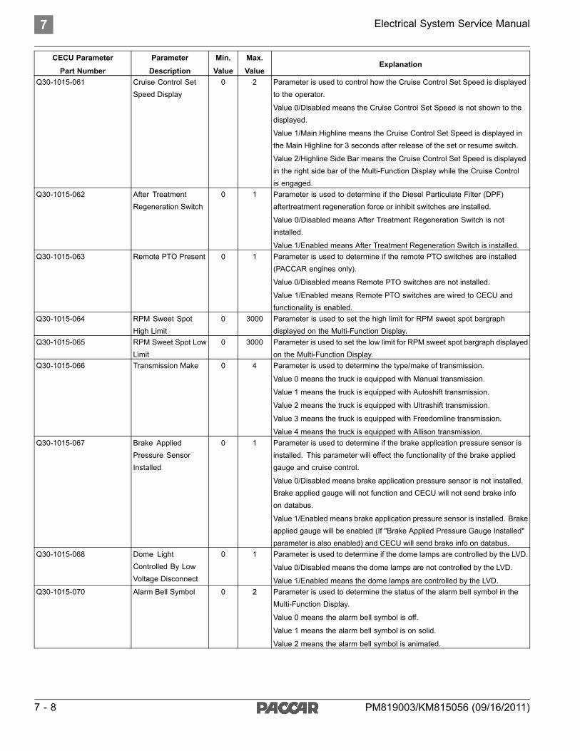
Q30-1015-061 Cruise Control SetSpeed Display
0 2 Parameter is used to control how the Cruise Control Set Speed is displayedto the operator.
Value 0/Disabled means the Cruise Control Set Speed is not shown to thedisplayed.
Value 1/Main Highline means the Cruise Control Set Speed is displayed inthe Main Highline for 3 seconds after release of the set or resume switch.
Value 2/Highline Side Bar means the Cruise Control Set Speed is displayedin the right side bar of the Multi-Function Display while the Cruise Controlis engaged.
Q30-1015-062 After TreatmentRegeneration Switch
0 1 Parameter is used to determine if the Diesel Particulate Filter (DPF)aftertreatment regeneration force or inhibit switches are installed.
Value 0/Disabled means After Treatment Regeneration Switch is notinstalled.
Value 1/Enabled means After Treatment Regeneration Switch is installed.Q30-1015-063 Remote PTO Present 0 1 Parameter is used to determine if the remote PTO switches are installed
(PACCAR engines only).
Value 0/Disabled means Remote PTO switches are not installed.
Value 1/Enabled means Remote PTO switches are wired to CECU andfunctionality is enabled.
Q30-1015-064 RPM Sweet SpotHigh Limit
0 3000 Parameter is used to set the high limit for RPM sweet spot bargraphdisplayed on the Multi-Function Display.
Q30-1015-065 RPM Sweet Spot LowLimit
0 3000 Parameter is used to set the low limit for RPM sweet spot bargraph displayedon the Multi-Function Display.
Q30-1015-066 Transmission Make 0 4 Parameter is used to determine the type/make of transmission.
Value 0 means the truck is equipped with Manual transmission.
Value 1 means the truck is equipped with Autoshift transmission.
Value 2 means the truck is equipped with Ultrashift transmission.
Value 3 means the truck is equipped with Freedomline transmission.
Value 4 means the truck is equipped with Allison transmission.Q30-1015-067 Brake Applied
Pressure SensorInstalled
0 1 Parameter is used to determine if the brake application pressure sensor isinstalled. This parameter will effect the functionality of the brake appliedgauge and cruise control.
Value 0/Disabled means brake application pressure sensor is not installed.Brake applied gauge will not function and CECU will not send brake infoon databus.
Value 1/Enabled means brake application pressure sensor is installed. Brakeapplied gauge will be enabled (If "Brake Applied Pressure Gauge Installed"parameter is also enabled) and CECU will send brake info on databus.
Q30-1015-068 Dome LightControlled By LowVoltage Disconnect
0 1 Parameter is used to determine if the dome lamps are controlled by the LVD.
Value 0/Disabled means the dome lamps are not controlled by the LVD.
Value 1/Enabled means the dome lamps are controlled by the LVD.Q30-1015-070 Alarm Bell Symbol 0 2 Parameter is used to determine the status of the alarm bell symbol in the
Multi-Function Display.
Value 0 means the alarm bell symbol is off.
Value 1 means the alarm bell symbol is on solid.
Value 2 means the alarm bell symbol is animated.
7 - 8 PM819003/KM815056 (09/16/2011)

Electrical System Service Manual 7
CECU Parameter
Part Number
Parameter
Description
Min.
Value
Max.
ValueExplanation
Q30-1015-071 Ignition TimerMaximum Time
5 90 Parameter is used to determine the maximum time the idle timer can be setto. The value can be set in one minute increments.
Value 5 means five minutes.
Value 90 means ninety minutes.Q30-1015-072 Voltage TrimMultiplier 0 999999 Parameter is used to trim or calibrate the voltmeter. This value is the
"multiplier" portion of the trim and has a range between 0 and 999999. See"Voltmeter Trim Procedure" following this chart, for steps to determine thecorrect value.
Q30-1015-073 Voltage Trim Offset 0 10000 Parameter is used to trim or calibrate the voltmeter. This value is the "offset"portion of the trim and has a range between 0 and 10000. See "VoltmeterTrim Procedure" following this chart, for steps to determine the correct value.
Q30-1015-074 Low VoltageDisconnect Installed
0 1 Parameter is used to determine if a low voltage disconnect system isinstalled. Value 0/Disabled means a LVD system is not installed. Value1/Enabled means a LVD system is installed.
Q30-1015-075 Engine Fan With ParkBrake Installed
0 1 Parameter is used to determine if the engine fan will turn on whenever thepark brakes are turned on.
Value 0/Disabled means the engine fan will not come on when the parkbrakes are on.
Value 1/Enabled means the engine fan will come on when the park brakesare on.
Q30-1015-076 Primary Air Pressureon V-CAN
0 1 Parameter is used to determine if the primary air pressure is broadcast onthe V-CAN.
Value 0/Disabled means the primary air pressure is not broadcast on theV-CAN.
Value 1/Enabled means the primary air pressure is broadcast on the V-CAN.Q30-1015-077 Secondary Air
Pressure on V-CAN0 1 Parameter is used to determine if the secondary air pressure is broadcast
on the V-CAN.
Value 0/Disabled means the secondary air pressure is not broadcast onthe V-CAN.
Value 1/Enabled means the secondary air pressure is broadcast on theV-CAN.
Q30-1015-078 Voltage on V-CAN 0 1 Parameter is used to determine if voltage is broadcast on the V-CAN.
Value 0/Disabled means voltage is not broadcast on the V-CAN.
Value 1/Enable means voltage is broadcast on the V-CAN.Q30-1015-079 Primary Fuel Level on
V-CAN0 1 Parameter is used to determine if the primary fuel level is broadcast on
the V-CAN.
Value 0/Disabled means the primary fuel level is not broadcast on theV-CAN.
Value 1/Enable means the primary fuel level is broadcast on the V-CAN.Q30-1015-082 Smart Wheel Installed 0 1 Parameter is used to determine if a smart wheel is installed. This parameter
enables the cluster retarder lamp. This lamp is only enabled when the truckis equipped with a multiplex steering wheel.
Value 0/Disabled means a smart wheel is not installed.
Value 1/Enable means a smart wheel is installed.Q30-1015-083 Governed Speed
Limit Available0 1 Parameter controls if the Governed speed limit transmitted by the Engine on
V-CAN is displayed on the "Engine Info" MFD screen.
Value 0/Disabled means the Governed Speed Limit is not Displayed
Value 1/Enable means the Governed Speed Limit is displayed, if the Engineis transmitting it.
PM819003/KM815056 (09/16/2011) 7 - 9

7 Electrical System Service Manual
CECU Parameter
Part Number
Parameter
Description
Min.
Value
Max.
ValueExplanation
Q30-1015-084 Remote AcceleratorSensor Installed
0 1 Parameter controls fault logging for Remote Accelerator input (C27 ofCECU). Also controls transmission of Remote Accelerator information onV-CAN.
Value 0/Disabled means that no DTCs will be logged if that input is in afailure state (open, short) and "Not Available" is transmitted on V-CAN
Value 1/Enable means that DTCs will be logged if that input is in a failurestate (open, short). The remote accelerator values on V-CAN are populatedwith valid data (or "Error" if a fault is occurring on the input).
Q30-1015-085 Axle TemperatureSteer Gauge Installed
0 1 Parameter controls fault logging of analog input and gauge outputs toCVSG. (For Peterbilt Only)
Value 0/Disabled means that no DTCs will be logged if that input is in afailure state (open, short) and the gauge needle will not move if connectedto the CVSG bus.
Value 1/Enable means that DTCs will be logged if that input is in failurestate (open, short) and the gauge needle will move when connected to theCVSG bus.
Q30-1015-086 Fleet ID Available 0 1 Parameter controls whether the Fleet ID is visible in the Truck Informationscreen in the MFD.
Value 0/Disabled means the Fleet ID is not visible in the Truck Informationscreen.
Value 1/Enable means the Fleet ID is enabled in the Truck Informationscreen. This requires the Fleet ID to be programmed by ESA, otherwiseit will not be visible.
Q30-1015-087 Starter StuckDetection Enabled
0 1 Parameter controls whether the CECU will detect if the starter solenoidis stuck.
Value 0/Disable means the operator will not be warned when the startersolenoid is stuck engaged.
Value 1/Enabled means the operator will be warned when the key is not inSTART, but the starter is still engaged.
Q30-1015-088 Diesel EmissionsFluid Gauge Installed
0 1 Parameter controls fault logging and gauge needle if the DEF gauge isinstalled.
Value 0/Disabled means that no faults will be logged and the gauge needlewill not move if the gauge is installed.
Value 1/Enable means that DTCs will be logged if the DEF information fromthe aftertreatment system is not available and the gauge needle will respondto DEF level changes.
Q30-1015-089 DRL Enabled 0 1 Parameter controls the DRL functionality of the exterior lighting.
Value 0/Disable means the headlamp switch and high beam switch controlthe headlamps. When they are turned off, the headlamps will turn off.
Value 1/Enabled means the low beams (at 50% power) or integrated turnsignal will be on at all times when the headlamp or highbeam switch is not on.
Q30-1015-090 DRL Inhibit SwitchType
0 2 Parameter controls the behavior of the DRL Inhibit Switch.
Value 0/None means that the DRL Inhibit Input is not observed by the CECU.
Value 1=Normal means that the DRL will be disabled when the switch isactive.
Value 2=Canadian (10 sec max) means that the DRL will be disabled whenthe switch is active, for a maximum of 10 seconds. After 10 seconds, theDRL will turn back on and a DTC will be active as long as the DRL switchis still active.
7 - 10 PM819003/KM815056 (09/16/2011)

Electrical System Service Manual 7
CECU Parameter
Part Number
Parameter
Description
Min.
Value
Max.
ValueExplanation
Q30-1015-091 Brightness SensorInstalled
0 1 Parameter controls whether faults are logged on the Brightness SensorAnalog input. It controls whether the dash dims.
Value 0/Disabled means no DTCs are logged and the dash dimming willnot automatically vary.
Value 1/Enabled means DTCs will be logged if the analog input is in a faultcondition (open, short) and the dash dimming will automatically vary.
Q30-1015-092 Fog Lamps Installed 0 1 Parameter controls the fog lamp outputs of the Chassis Node.
Value 0/Disabled means the fog lamp output is not driven. If fog lamps areinstalled, they will never be lit.
Value 1/Enabled means the fog lamp output will output faults (open, short).Q30-1015-093 Lights With Wipers
Enable0 1 Parameter controls whether the menu item is available for Lights with
Wipers. When enabled by the operator through the MFD, the low beamheadlamps will turn on whenever the wipers are active (INT, LOW, or HI).
Value 0/Disabled means the headlamps will not turn on when the wipersare active.
Value 1/Enabled means the headlamps will turn on when the wipers areactive.
Q30-1015-094 Head Lamp Type 0 40 Parameter controls the PWM activity of the headlamps.
Value 0/Single means Single Sealed Beam
Value 1/Dual means Dual Sealed Beam
Value 2-9/reserved means reserved
Value 10/PB means Replaceable Bulb
Value 11-19/reserved means reserved
Value 20/Integral means Integral Beam Pod
Value 21-39/reserved means reserved
Value 40/Integral means Integral Beam Pod HIDQ30-1015-095 Starter RPM
Protection Enable0 1 Parameter controls whether the Starter will be disabled when the engine is
running.
Value 0/Disabled means the engine RPM will be ignored when allowingthe starter to engage.
Value 1/Enabled means the engine RPM must be below 500 rpm for thestarter to engage.
Q30-1015-096 Starter In GearProtection Enable
0 1 Parameter controls whether the starter will be disabled because of thetransmission state.
Value 0/Disabled means the starter will be enabled regardless of thetransmission state.
Value 1/Enabled means the starter will be disabled if the transmission is notin neutral (optional for manual transmissions).
Q30-1015-097 Starter OvercrankProtection Enable
0 1 Parameter controls whether the starter will be disabled due to overuse.
Value 0/Disabled means the starter will not be disabled due to overuse
Value 1/Enabled means the starter will be disabled if the starter is overused(cranking for 90s without sufficient cooldown).
PM819003/KM815056 (09/16/2011) 7 - 11

7 Electrical System Service Manual
CECU Parameter
Part Number
Parameter
Description
Min.
Value
Max.
ValueExplanation
Q30-1015-099 PACCAR LightingModel
0 5 Parameter controls the Lighting Model
Value 0 = No Exterior Lighting
Value 1 = KW BCAB
Value 2 = PB BCAB
Value 3 = KW NGP
Value 4 = PB
Value 5 = KW ECE Russian HomologationQ30-1015-100 Fog Lamps
Secondary Installed0 1 Parameter controls the secondary fog lamp outputs of the Chassis Node.
Value 0/Disabled means the fog lamp output is not driven. If fog lamps areinstalled, they will never be lit.
Value 1/Enabled means the fog lamp output will detect output faults (open,short).
Q30-1015-101 Trailer Detect Enable 0 1 Parameter controls the Trailer Detect functionality.
Value 0/Disabled means there is no addition diagnostics of the trailerconnection.
Value 1/Enabled means there is additional diagnostics of the trailer. Theoperator will be warned if the trailer has become disconnected or isintermittently disconnecting while in motion
Q30-1015-102 Turn Lamps FrontSide Installed
0 1 Parameter controls the outputs for the front side turn lamps.
Value 0/Disabled means with the hardware installed, the lamps will work,but the diagnostics will not (except short circuits)
Value 1/Enabled means the outputs and diagnostics are enabled (mostly forthe fender lamps for T660s). If it is enabled with no hardware installed, youwill get constant open circuit errors.
Q30-1015-103 Turn Lamps TrailerInstalled
0 1 Parameter controls the outputs for the trailer outputs
0/Disabled means with the hardware installed, the lamps will work, but thediagnostics will not (except short circuits)
Value 1/Enabled means outputs and diagnostics are enabled. If it is enabledwith no hardware installed, you will get constant open circuit errors.
Q30-1015-104 OAT Source 0 1 Parameter controls the signal used to populate the LCD in the Tachometer,as well as all other CECU features that use temperature as part of thealgorithm.
Value 0/CECU means that the analog input of the CECU is used (non-OBDengines).
Value 1/Engine means that the J1939 V-CAN input from the Engine willbe used.
CAUTIONModifying the sensor or its location can impact vehicleperformance, emissions, and/or reliability.
Q30-1015-104 DRL Enabled 0 1 Parameter controls the DRL functionality of the exterior lighting.
Value 0/Disable means the headlamp switch and high beam switch controlthe headlamps. When they are turned off, the headlamps will turn off.
Value 1/Enabled means the low beams (at 50% power) or integrated turnsignal will be on at all times when the headlamp or highbeam switch is not on.
7 - 12 PM819003/KM815056 (09/16/2011)

Electrical System Service Manual 7
CECU Parameter
Part Number
Parameter
Description
Min.
Value
Max.
ValueExplanation
Q30-1015-105 Backup Alarm MuteEnabled
0 1 Parameter controls the backup alarm mute functionality.
Value 0/Disabled means the backup alarm will never be muted.
Value 1/Enabled means the external backup alarm speaker will be mutedwhen the dash switch is activated by the operator.
Q30-1015-106 Pre Trip Lighting TestEnabled
0 1 Parameter controls the availability of the Pre Trip Lighting Test.
Value 0/Disabled means the menu item in the settings menu is not availableand the Pre Trip sequence will never be executed.
Value 1/Enabled means the menu item is available in the settings menu.When the operator enables it, the pre trip lighting sequence will be initiated.
Q30-1015-107 Pre Trip TestSequence Interval
10s 30s Parameter controls the interval of the pre trip lighting test. This is how long itstays in any one mode before transition to the next test mode.
Q30-1015-108 Enable Gateway 0 1 Parameter controls the gateway functionality. This must be enabled for thefollowing Gateway parameters to take effect.
Value 0/Disabled means no Gateway of messages will occur.
Value 1/Enabled means the settings of the following gateway parameterswill be observed.
Q30-1015-109 Enable Router 0 1 Parameter controls the router functionality. This must be enabled for thefollowing Router parameters to take effect.
Value 0/Disabled means no Routing of messages will occur.
Value 1/Enabled means the settings of the following router parameters willbe observed.
Q30-1015-110 Gateway EngineCCVS message
0 64 Parameter controls the settings for this individual message. Add thenumbers together for multiple destinations.
Value 0/OFF means this PGN will not be transmitted on any destinationchannels
Value 1/BCAN means this PGN will be transmitted on BCAN
Value 2/CCAN means this PGN will be transmitted on CCAN
Value 4/DCAN means this PGN will be transmitted on DCAN
Value 8/FCAN means this PGN will be transmitted on FCAN
Value 16/ICAN means this PGN will be transmitted on ICAN
Value 32/VCAN means this PGN will be transmitted on VCANQ30-1015-111 Gateway Engine DM1
message0 64 Parameter controls the settings for this individual message. Add the
numbers together for multiple destinations.
Value 0/OFF means this PGN will not be transmitted on any destinationchannels
Value 1/BCAN means this PGN will be transmitted on BCAN
Value 2/CCAN means this PGN will be transmitted on CCAN
Value 4/DCAN means this PGN will be transmitted on DCAN
Value 8/FCAN means this PGN will be transmitted on FCAN
Value 16/ICAN means this PGN will be transmitted on ICAN
Value 32/VCAN means this PGN will be transmitted on VCAN
PM819003/KM815056 (09/16/2011) 7 - 13

7 Electrical System Service Manual
CECU Parameter
Part Number
Parameter
Description
Min.
Value
Max.
ValueExplanation
Q30-1015-112 Gateway EngineEEC1 message
0 64 Parameter controls the settings for this individual message. Add thenumbers together for multiple destinations.
Value 0/OFF means this PGN will not be transmitted on any destinationchannels
Value 1/BCAN means this PGN will be transmitted on BCAN
Value 2/CCAN means this PGN will be transmitted on CCAN
Value 4/DCAN means this PGN will be transmitted on DCAN
Value 8/FCAN means this PGN will be transmitted on FCAN
Value 16/ICAN means this PGN will be transmitted on ICAN
Value 32/VCAN means this PGN will be transmitted on VCANQ30-1015-113 Gateway Engine
EEC2 message0 64 Parameter controls the settings for this individual message. Add the
numbers together for multiple destinations.
Value 0/OFF means this PGN will not be transmitted on any destinationchannels
Value 1/BCAN means this PGN will be transmitted on BCAN
Value 2/CCAN means this PGN will be transmitted on CCAN
Value 4/DCAN means this PGN will be transmitted on DCAN
Value 8/FCAN means this PGN will be transmitted on FCAN
Value 16/ICAN means this PGN will be transmitted on ICAN
Value 32/VCAN means this PGN will be transmitted on VCANQ30-1015-114 Gateway Engine ET1
message0 64 Parameter controls the settings for this individual message. Add the
numbers together for multiple destinations.
Value 0/OFF means this PGN will not be transmitted on any destinationchannels
Value 1/BCAN means this PGN will be transmitted on BCAN
Value 2/CCAN means this PGN will be transmitted on CCAN
Value 4/DCAN means this PGN will be transmitted on DCAN
Value 8/FCAN means this PGN will be transmitted on FCAN
Value 16/ICAN means this PGN will be transmitted on ICAN
Value 32/VCAN means this PGN will be transmitted on VCANQ30-1015-115 Gateway Engine IC1
message0 64 Parameter controls the settings for this individual message. Add the
numbers together for multiple destinations.
Value 0/OFF means this PGN will not be transmitted on any destinationchannels
Value 1/BCAN means this PGN will be transmitted on BCAN
Value 2/CCAN means this PGN will be transmitted on CCAN
Value 4/DCAN means this PGN will be transmitted on DCAN
Value 8/FCAN means this PGN will be transmitted on FCAN
Value 16/ICAN means this PGN will be transmitted on ICAN
Value 32/VCAN means this PGN will be transmitted on VCAN
7 - 14 PM819003/KM815056 (09/16/2011)

Electrical System Service Manual 7
CECU Parameter
Part Number
Parameter
Description
Min.
Value
Max.
ValueExplanation
Q30-1015-116 Gateway Engine LFEmessage
0 64 Parameter controls the settings for this individual message. Add thenumbers together for multiple destinations.
Value 0/OFF means this PGN will not be transmitted on any destinationchannels
Value 1/BCAN means this PGN will be transmitted on BCAN
Value 2/CCAN means this PGN will be transmitted on CCAN
Value 4/DCAN means this PGN will be transmitted on DCAN
Value 8/FCAN means this PGN will be transmitted on FCAN
Value 16/ICAN means this PGN will be transmitted on ICAN
Value 32/VCAN means this PGN will be transmitted on VCANQ30-1015-117 Gateway
Transmission DM1message
0 64 Parameter controls the settings for this individual message. Add thenumbers together for multiple destinations.
Value 0/OFF means this PGN will not be transmitted on any destinationchannels
Value 1/BCAN means this PGN will be transmitted on BCAN
Value 2/CCAN means this PGN will be transmitted on CCAN
Value 4/DCAN means this PGN will be transmitted on DCAN
Value 8/FCAN means this PGN will be transmitted on FCAN
Value 16/ICAN means this PGN will be transmitted on ICAN
Value 32/VCAN means this PGN will be transmitted on VCANQ30-1015-118 Gateway
Transmission ETC1message
0 64 Parameter controls the settings for this individual message. Add thenumbers together for multiple destinations.
Value 0/OFF means this PGN will not be transmitted on any destinationchannels
Value 1/BCAN means this PGN will be transmitted on BCAN
Value 2/CCAN means this PGN will be transmitted on CCAN
Value 4/DCAN means this PGN will be transmitted on DCAN
Value 8/FCAN means this PGN will be transmitted on FCAN
Value 16/ICAN means this PGN will be transmitted on ICAN
Value 32/VCAN means this PGN will be transmitted on VCANQ30-1015-119 Gateway
Transmission ETC2message
0 64 Parameter controls the settings for this individual message. Add thenumbers together for multiple destinations.
Value 0/OFF means this PGN will not be transmitted on any destinationchannels
Value 1/BCAN means this PGN will be transmitted on BCAN
Value 2/CCAN means this PGN will be transmitted on CCAN
Value 4/DCAN means this PGN will be transmitted on DCAN
Value 8/FCAN means this PGN will be transmitted on FCAN
Value 16/ICAN means this PGN will be transmitted on ICAN
Value 32/VCAN means this PGN will be transmitted on VCAN
PM819003/KM815056 (09/16/2011) 7 - 15

7 Electrical System Service Manual
CECU Parameter
Part Number
Parameter
Description
Min.
Value
Max.
ValueExplanation
Q30-1015-120 Route Engine AMBmessage
0 64 Parameter controls the settings for this individual message. Add thenumbers together for multiple destinations.
Value 0/OFF means this PGN will not be transmitted on any destinationchannels
Value 1/BCAN means this PGN will be transmitted on BCAN
Value 2/CCAN means this PGN will be transmitted on CCAN
Value 4/DCAN means this PGN will be transmitted on DCAN
Value 8/FCAN means this PGN will be transmitted on FCAN
Value 16/ICAN means this PGN will be transmitted on ICAN
Value 32/VCAN means this PGN will be transmitted on VCANQ30-1015-121 Route Engine EFLP1
message0 64 Parameter controls the settings for this individual message. Add the
numbers together for multiple destinations.
Value 0/OFF means this PGN will not be transmitted on any destinationchannels
Value 1/BCAN means this PGN will be transmitted on BCAN
Value 2/CCAN means this PGN will be transmitted on CCAN
Value 4/DCAN means this PGN will be transmitted on DCAN
Value 8/FCAN means this PGN will be transmitted on FCAN
Value 16/ICAN means this PGN will be transmitted on ICAN
Value 32/VCAN means this PGN will be transmitted on VCANQ30-1015-122 Route Engine FD
message0 64 Parameter controls the settings for this individual message. Add the
numbers together for multiple destinations.
Value 0/OFF means this PGN will not be transmitted on any destinationchannels
Value 1/BCAN means this PGN will be transmitted on BCAN
Value 2/CCAN means this PGN will be transmitted on CCAN
Value 4/DCAN means this PGN will be transmitted on DCAN
Value 8/FCAN means this PGN will be transmitted on FCAN
Value 16/ICAN means this PGN will be transmitted on ICAN
Value 32/VCAN means this PGN will be transmitted on VCANQ30-1015-123 Route Engine
HOURS message0 64 Parameter controls the settings for this individual message. Add the
numbers together for multiple destinations.
Value 0/OFF means this PGN will not be transmitted on any destinationchannels
Value 1/BCAN means this PGN will be transmitted on BCAN
Value 2/CCAN means this PGN will be transmitted on CCAN
Value 4/DCAN means this PGN will be transmitted on DCAN
Value 8/FCAN means this PGN will be transmitted on FCAN
Value 16/ICAN means this PGN will be transmitted on ICAN
Value 32/VCAN means this PGN will be transmitted on VCAN
7 - 16 PM819003/KM815056 (09/16/2011)

Electrical System Service Manual 7
CECU Parameter
Part Number
Parameter
Description
Min.
Value
Max.
ValueExplanation
Q30-1015-124 Route Engine LFCmessage
0 64 Parameter controls the settings for this individual message. Add thenumbers together for multiple destinations.
Value 0/OFF means this PGN will not be transmitted on any destinationchannels
Value 1/BCAN means this PGN will be transmitted on BCAN
Value 2/CCAN means this PGN will be transmitted on CCAN
Value 4/DCAN means this PGN will be transmitted on DCAN
Value 8/FCAN means this PGN will be transmitted on FCAN
Value 16/ICAN means this PGN will be transmitted on ICAN
Value 32/VCAN means this PGN will be transmitted on VCANQ30-1015-125 Route Engine VD
message0 64 Parameter controls the settings for this individual message. Add the
numbers together for multiple destinations.
Value 0/OFF means this PGN will not be transmitted on any destinationchannels
Value 1/BCAN means this PGN will be transmitted on BCAN
Value 2/CCAN means this PGN will be transmitted on CCAN
Value 4/DCAN means this PGN will be transmitted on DCAN
Value 8/FCAN means this PGN will be transmitted on FCAN
Value 16/ICAN means this PGN will be transmitted on ICAN
Value 32/VCAN means this PGN will be transmitted on VCANQ30-1015-126 Route Transmission
TRF1 message0 64 Parameter controls the settings for this individual message. Add the
numbers together for multiple destinations.
Value 0/OFF means this PGN will not be transmitted on any destinationchannels
Value 1/BCAN means this PGN will be transmitted on BCAN
Value 2/CCAN means this PGN will be transmitted on CCAN
Value 4/DCAN means this PGN will be transmitted on DCAN
Value 8/FCAN means this PGN will be transmitted on FCAN
Value 16/ICAN means this PGN will be transmitted on ICAN
Value 32/VCAN means this PGN will be transmitted on VCANQ30-1015-127 Transmit CECU LC
message0 64 Parameter controls the settings for this individual message. Add the
numbers together for multiple destinations.
Value 0/OFF means this PGN will not be transmitted on any destinationchannels
Value 1/BCAN means this PGN will be transmitted on BCAN
Value 2/CCAN means this PGN will be transmitted on CCAN
Value 4/DCAN means this PGN will be transmitted on DCAN
Value 8/FCAN means this PGN will be transmitted on FCAN
Value 16/ICAN means this PGN will be transmitted on ICAN
Value 32/VCAN means this PGN will be transmitted on VCANQ30-1015-128 Enable LED Front
Side Turn0 1 Parameter controls the ability of the diagnostics to detect faults on this
circuit. These lamps are the rear fender lamps or other supplemental lamps.
Value 0/Disabled means the LEDs will be incorrectly diagnosed as opencircuits due to their electrical characteristics.
Value 1/Enabled means the open circuit detection is disabled.
PM819003/KM815056 (09/16/2011) 7 - 17

7 Electrical System Service Manual
CECU Parameter
Part Number
Parameter
Description
Min.
Value
Max.
ValueExplanation
Q30-1015-129 Enable LED FrontTurn DRL
0 1 Parameter controls the ability of the diagnostics to detect faults on this circuit.These lamps are the Integral Beam turn/DRL lamp or fender turn lamps.
Value 0/Disabled means the LEDs will be incorrectly diagnosed as opencircuits due to their electrical characteristics.
Value 1/Enabled means the open circuit detection is disabled.Q30-1015-130 Enable LED Rear
Stop Turn0 1 Parameter controls the ability of the diagnostics to detect faults on this
circuit. These lamps are the tractor brake/tail lamps.
Value 0/Disabled means the LEDs will be incorrectly diagnosed as opencircuits due to their electrical characteristics.
Value 1/Enabled means the open circuit detection is disabled.Q30-1015-131 Multiplex ABS Off
Road Switch0 1 Parameter is used to determine if the ABS Off Road Switch is connected
to the CECU.
Value 0/Disabled means ABS Offroad Switch is not installed.
Value 1/Enabled means ABS Offroad Switch is installed.
This parameter is required for the ABS Off Road switch to communicatewith the ABS ECU via J1939 V-CAN.
Q30-1015-132 Engine Fan on withAC and Park Brake
0 1 Parameter is used to determine if the engine fan will turn on whenever thepark brakes and the air conditioning are on.
Value 0/Disabled means the engine fan will not come on when the parkbrakes and air conditioning are on.
Value 1/Enabled means the engine fan will come on when the park brakesand air conditioning are on.
Q30-1015-133 Brake Lamps on withEngine Retarder
0 1 Parameter is used to determine if the tractor and trailer brake lamps will turnon when the engine retarder is engaged.
Value 0/Disabled means the tractor and trailer brake lamps will not turn onwhen the engine retarder is engaged.
Value 1/Enabled means the tractor and trailer brake lamps will turn on whenthe engine retarder is engaged.
Q30-1015-134 CECU LVD Enable 0 1 Parameter is used to determine if the CECU is controlling the Low VoltageDisconnect (LVD).
Value 0/Disabled means the CECU is not controlling LVD functionality.
Value 1/Enabled means the CECU is controlling LVD Functionality.Q30-1015-135 Operator Control of
LVD Voltage Level0 1 Parameter is used to determine if the operator can control the Low Voltage
Disconnect (LVD) shutoff voltage.
Value 0/Disabled means the operator is not controlling the LVD shutoffvoltage.
Value 1/Enabled means the operator is controlling the LVD shutoff voltage.Q30-1015-136 Enable Snow Plow
Lamps0 1 Parameter is used to determine if the Chassis Node Primary Fog Lamp
output is being used for Snow Plow Lamps.
Value 0/Disabled means the Primary Fog Lamp output on the Chassis Nodeis not being used for Snow Plow Lamps (and will turn off when the highbeams are turned on).
Value 1/Enabled means the Primary Fog Lamp output on the Chassis Nodeis being used for Snow Plow Lamps (and will not turn off when the highbeams are turned on).
7 - 18 PM819003/KM815056 (09/16/2011)
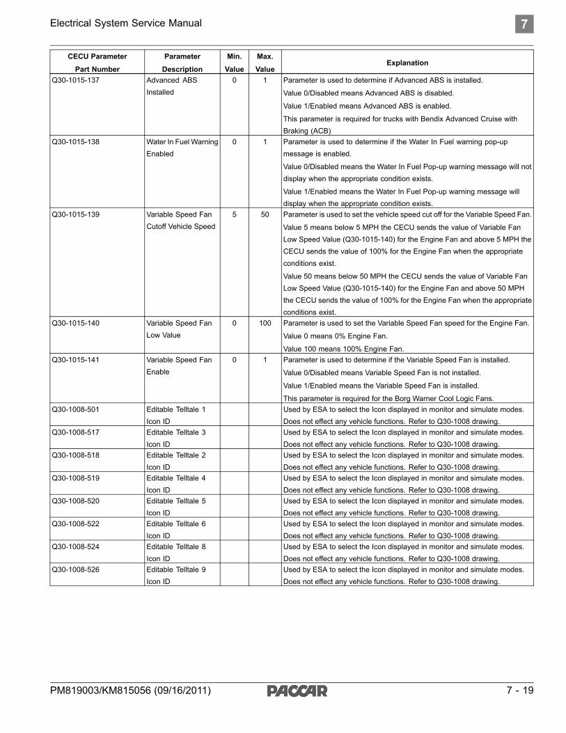
Electrical System Service Manual 7
CECU Parameter
Part Number
Parameter
Description
Min.
Value
Max.
ValueExplanation
Q30-1015-137 Advanced ABSInstalled
0 1 Parameter is used to determine if Advanced ABS is installed.
Value 0/Disabled means Advanced ABS is disabled.
Value 1/Enabled means Advanced ABS is enabled.
This parameter is required for trucks with Bendix Advanced Cruise withBraking (ACB)
Q30-1015-138 Water In Fuel WarningEnabled
0 1 Parameter is used to determine if the Water In Fuel warning pop-upmessage is enabled.
Value 0/Disabled means the Water In Fuel Pop-up warning message will notdisplay when the appropriate condition exists.
Value 1/Enabled means the Water In Fuel Pop-up warning message willdisplay when the appropriate condition exists.
Q30-1015-139 Variable Speed FanCutoff Vehicle Speed
5 50 Parameter is used to set the vehicle speed cut off for the Variable Speed Fan.
Value 5 means below 5 MPH the CECU sends the value of Variable FanLow Speed Value (Q30-1015-140) for the Engine Fan and above 5 MPH theCECU sends the value of 100% for the Engine Fan when the appropriateconditions exist.
Value 50 means below 50 MPH the CECU sends the value of Variable FanLow Speed Value (Q30-1015-140) for the Engine Fan and above 50 MPHthe CECU sends the value of 100% for the Engine Fan when the appropriateconditions exist.
Q30-1015-140 Variable Speed FanLow Value
0 100 Parameter is used to set the Variable Speed Fan speed for the Engine Fan.
Value 0 means 0% Engine Fan.
Value 100 means 100% Engine Fan.Q30-1015-141 Variable Speed Fan
Enable0 1 Parameter is used to determine if the Variable Speed Fan is installed.
Value 0/Disabled means Variable Speed Fan is not installed.
Value 1/Enabled means the Variable Speed Fan is installed.
This parameter is required for the Borg Warner Cool Logic Fans.Q30-1008-501 Editable Telltale 1
Icon IDUsed by ESA to select the Icon displayed in monitor and simulate modes.Does not effect any vehicle functions. Refer to Q30-1008 drawing.
Q30-1008-517 Editable Telltale 3Icon ID
Used by ESA to select the Icon displayed in monitor and simulate modes.Does not effect any vehicle functions. Refer to Q30-1008 drawing.
Q30-1008-518 Editable Telltale 2Icon ID
Used by ESA to select the Icon displayed in monitor and simulate modes.Does not effect any vehicle functions. Refer to Q30-1008 drawing.
Q30-1008-519 Editable Telltale 4Icon ID
Used by ESA to select the Icon displayed in monitor and simulate modes.Does not effect any vehicle functions. Refer to Q30-1008 drawing.
Q30-1008-520 Editable Telltale 5Icon ID
Used by ESA to select the Icon displayed in monitor and simulate modes.Does not effect any vehicle functions. Refer to Q30-1008 drawing.
Q30-1008-522 Editable Telltale 6Icon ID
Used by ESA to select the Icon displayed in monitor and simulate modes.Does not effect any vehicle functions. Refer to Q30-1008 drawing.
Q30-1008-524 Editable Telltale 8Icon ID
Used by ESA to select the Icon displayed in monitor and simulate modes.Does not effect any vehicle functions. Refer to Q30-1008 drawing.
Q30-1008-526 Editable Telltale 9Icon ID
Used by ESA to select the Icon displayed in monitor and simulate modes.Does not effect any vehicle functions. Refer to Q30-1008 drawing.
PM819003/KM815056 (09/16/2011) 7 - 19

7 Electrical System Service Manual
Voltmeter Trim Procedure
Use the following steps when determining theappropriate parameter values for the Voltage TrimMultiplier and Voltage Trim Offset.
1. Turn ignition key to the ON position.
2. Make sure the Voltmeter Trim Offset andVoltmeter Trim Multiplier parameters are setto the default values. Using ESA, select'Parameters' from the main menu screen,then select 'Standard Gauges', then scrolldown to view the Voltmeter Trim Offset andVoltmeter Trim Multiplier. If the values forthese parameters are not set at the defaultvalues, use ESA to reset the values as follows:
a. Default Voltmeter Trim Offset = 5,000
b. Default Voltmeter Trim Multiplier = 100,000
NOTETo correctly calibrate the voltmeter, both theVoltmeter Trim Offset and Voltmeter TrimMultiplier parameters must be reset to theirdefault values before performing this procedure.
3. Measure the voltage at the batteries. Recordthe value on the worksheet as “MeasuredBattery Voltage Engine Off”.
4. Note the displayed voltage using ESA or withthe Voltmeter CVSG. Record the value onthe worksheet as “Displayed Battery VoltageEngine Off”.
5. Start the Engine.
6. Measure the voltage at the batteries (sameplace as in step 3). Record the value onthe worksheet as “Measured Battery VoltageEngine Running”.
7. Note the displayed voltage using ESA or withthe Voltmeter CVSG. Record the value onthe worksheet as “Displayed Battery VoltageEngine Running”.
8. Perform the calculations on the worksheetto determine the appropriate values for theVoltage Trim Multiplier and Voltage Trim Offset.
9. Use ESA to set the parameter values to thecalculated values.
Voltmeter Trim Values Worksheet
Vehicle Voltage
Procedure ValueWorksheet
Entry
STEP 3: Measured BATT Voltage EngineOff
A
STEP 6: Measured BATT Voltage EngineRunning
B
STEP 4: Displayed BATT Voltage EngineOff
C
STEP 7: Displayed BATT Voltage EngineRunning
D
Entry Entry ResultB - A = ED - C = FE + F = GC x G = HA - H = II x 1,000 = JJ + 5,000 = KG x 100,000 = LK = Voltmeter Trim Offset ValueL = Voltmeter Trim Multiplier Value
7 - 20 PM819003/KM815056 (09/16/2011)

Electrical System Service Manual 8
8 How It Works
Functional Description . . . . . . . . 8 - 2CECU Architecture . . . . . . . . . . 8 - 5Cluster Components . . . . . . . . . 8 - 7Commercial Vehicle Smart Gauges(CVSG) . . . . . . . . . . . . . . 8 - 12
Instruments and Controls Operation . 8 - 15Instrumentation TroubleshootingProcedures . . . . . . . . . . . . 8 - 17
Display Diagnostic Codes . . . . . . 8 - 18
PM819003/KM815056 (09/16/2011) 8 - 1

8 Electrical System Service Manual
Functional DescriptionCab Electronic Control Unit (CECU)
The heart of the multiplexed instrumentationsystem is the CECU. For Peterbilt vehicles, the
CECU is located behind the center of the dash,near the radio. For Kenworth vehicles, the CECUis located behind the center console. See ControlUnit Locations for illustrations depicting thephysical position of the control unit.
Typical CECU Locations
8 - 2 PM819003/KM815056 (09/16/2011)

Electrical System Service Manual 8
Vehicle component inputs are sent to the CECUthrough the J1939 data bus or conventionalwiring. The CECU interprets the various inputsand monitors/controls the functions for each inputthrough the CECU software. Output signals fromthe CECU provide data for the gauges, warninglamps, audible alarms, and displays inside thecluster.
The CECU receives data related to controlling thevarious devices of the electrical system. It thenmakes decisions based on that input and sendsinformation to subsystem system control modules(nodes) about what that node should do with thecomponents it controls.
The node that receives information from the CECUto control the exterior lighting and wipers functionsis called the chassis node. Sensor signals areprocessed into data and sent by the chassis nodeto the CECU by way of the CAN (Controller AreaNetwork) data bus. The chassis node serves asa bidirectional conduit for both information andcontrol. In addition to receiving and processingsensor data, the chassis node also controls theoperation of relays that power several electricalsubsystems.
WARNINGDo not cut, tap or disconnect green/yellowtwisted pair wires. Cutting, tapping ordisconnecting these wires may cause disruptionof component communication on the databus,resulting in the delay and/or miscommunicationof warnings to the operator increasing the riskof an accident involving death, personal injuryand/or property damage.
When used in conjunction with the ElectronicService Analyst (ESA) diagnostic software tool,the technician can review fault codes stored inthe CECU, verify whether the instrumentation isworking properly and diagnose the root cause ofthe problem more easily.
PM819003/KM815056 (09/16/2011) 8 - 3
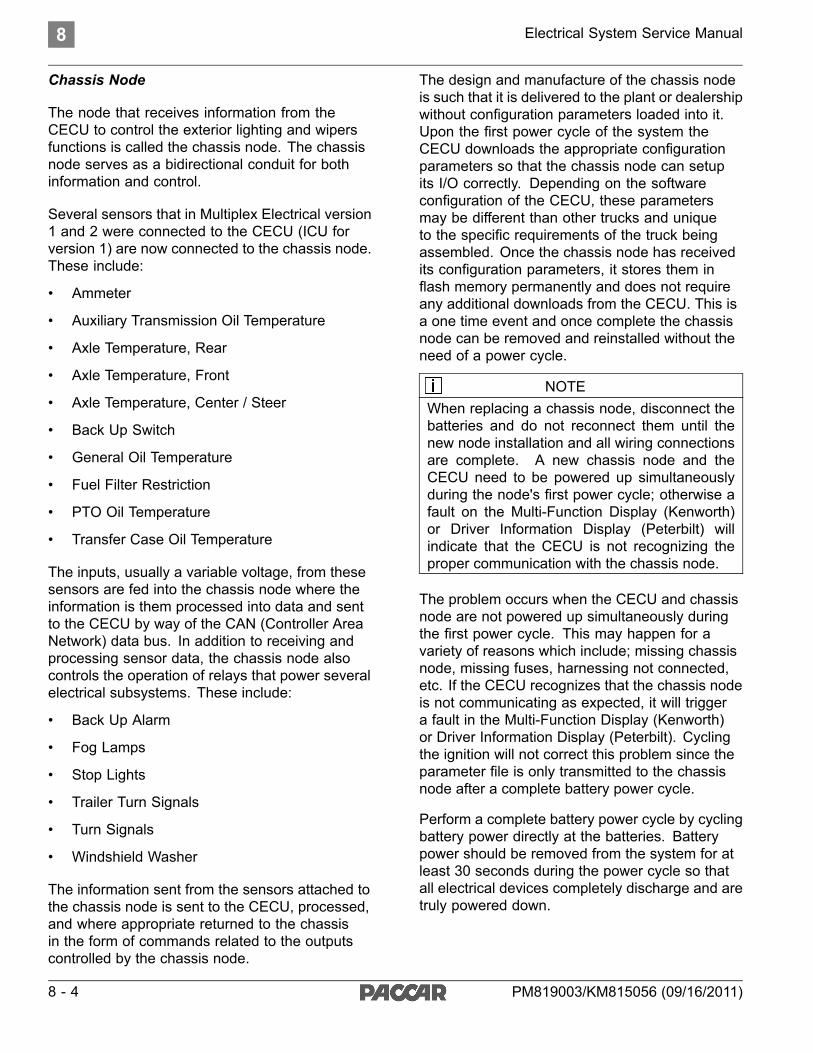
8 Electrical System Service Manual
Chassis Node
The node that receives information from theCECU to control the exterior lighting and wipersfunctions is called the chassis node. The chassisnode serves as a bidirectional conduit for bothinformation and control.
Several sensors that in Multiplex Electrical version1 and 2 were connected to the CECU (ICU forversion 1) are now connected to the chassis node.These include:
• Ammeter
• Auxiliary Transmission Oil Temperature
• Axle Temperature, Rear
• Axle Temperature, Front
• Axle Temperature, Center / Steer
• Back Up Switch
• General Oil Temperature
• Fuel Filter Restriction
• PTO Oil Temperature
• Transfer Case Oil Temperature
The inputs, usually a variable voltage, from thesesensors are fed into the chassis node where theinformation is them processed into data and sentto the CECU by way of the CAN (Controller AreaNetwork) data bus. In addition to receiving andprocessing sensor data, the chassis node alsocontrols the operation of relays that power severalelectrical subsystems. These include:
• Back Up Alarm
• Fog Lamps
• Stop Lights
• Trailer Turn Signals
• Turn Signals
• Windshield Washer
The information sent from the sensors attached tothe chassis node is sent to the CECU, processed,and where appropriate returned to the chassisin the form of commands related to the outputscontrolled by the chassis node.
The design and manufacture of the chassis nodeis such that it is delivered to the plant or dealershipwithout configuration parameters loaded into it.Upon the first power cycle of the system theCECU downloads the appropriate configurationparameters so that the chassis node can setupits I/O correctly. Depending on the softwareconfiguration of the CECU, these parametersmay be different than other trucks and uniqueto the specific requirements of the truck beingassembled. Once the chassis node has receivedits configuration parameters, it stores them inflash memory permanently and does not requireany additional downloads from the CECU. This isa one time event and once complete the chassisnode can be removed and reinstalled without theneed of a power cycle.
NOTEWhen replacing a chassis node, disconnect thebatteries and do not reconnect them until thenew node installation and all wiring connectionsare complete. A new chassis node and theCECU need to be powered up simultaneouslyduring the node's first power cycle; otherwise afault on the Multi-Function Display (Kenworth)or Driver Information Display (Peterbilt) willindicate that the CECU is not recognizing theproper communication with the chassis node.
The problem occurs when the CECU and chassisnode are not powered up simultaneously duringthe first power cycle. This may happen for avariety of reasons which include; missing chassisnode, missing fuses, harnessing not connected,etc. If the CECU recognizes that the chassis nodeis not communicating as expected, it will triggera fault in the Multi-Function Display (Kenworth)or Driver Information Display (Peterbilt). Cyclingthe ignition will not correct this problem since theparameter file is only transmitted to the chassisnode after a complete battery power cycle.
Perform a complete battery power cycle by cyclingbattery power directly at the batteries. Batterypower should be removed from the system for atleast 30 seconds during the power cycle so thatall electrical devices completely discharge and aretruly powered down.
8 - 4 PM819003/KM815056 (09/16/2011)

Electrical System Service Manual 8
CECU Architecture
The software programming of the control unit canbe grouped into three main types:
• Run Time (RT) - which acts as the operatingsystem where all communication takes place.
• Programmable Logic Controller (PLC) Code -manufacturer specific programmed code andsoftware that is developed, accessible andeditable.
• Vendor Module - blocks of code that aredeveloped for specific manufacturers toallow other features to be implemented moreefficiently.
To better understand how Electronic ServiceAnalyst (ESA) functions and why there are current
limitations on some of the multiplexed features,by explaining what ESA can see. Currently ESAcan look at all information that is communicatedbetween the RT and PLC Code portions ofthe programming. Any signals, be they inputs,outputs, or dataline signals, sent between theRT and PLC Code are visible to ESA. These arethe signals that may be monitored and simulatedusing ESA.
Limitations with the ESA program are found inthe communications that go to the pre-developedVendor Modules. Currently this information is notavailable for ESA to look at. That is why somefeatures that have Vendor Module programming,such as the odometer and the message display,are not available to monitor and/or simulatethrough ESA.
CECU3 (P30-1009-XXX) Communication Diagram
PM819003/KM815056 (09/16/2011) 8 - 5

8 Electrical System Service Manual
NOTEIt is possible for the CECU to receive signalsvia the J1939 communications line fromoptional customer installed ECUs. Refer to theappropriate reference literature for any customerinstalled ECU.
8 - 6 PM819003/KM815056 (09/16/2011)

Electrical System Service Manual 8
Cluster Components
The heart of the multiplexed instrumentationsystem is the CECU. For Peterbilt vehicles, theCECU is located behind the center of the dash,near the radio. For Kenworth vehicles, the CECUis located behind the center console. See ControlUnit Locations for illustrations depicting thephysical position of the control unit.
Central Instrument Cluster
The central instrument cluster is theinstrumentation in the dash panel that islocated directly in front of the driver. Theinstrumentation parts in this area include:
• Speedometer (including odometer and tripmeter)
• Tachometer (including engine hour meter andoutside temperature display)
• Kenworth multi-function display (if equipped)
• Peterbilt driver information display (if equipped)
• Pre-installed warning lights (telltale symbols)
Some models have a one-piece integrated clusterwhile the instrument cluster on other modelsconsists of separate parts.
The Multi-Function Display (Kenworth) or DriverInformation Display (Peterbilt), if equipped, islocated at the top of the instrument cluster,displays vehicle information and warnings througha constant monitoring of the vehicle systems. Thevarious functions may be accessed by navigatingthrough menu screens using the menu controlswitch (rotational knob).
The central instrument cluster receives input datafrom the CECU via the I-CAN data bus. When theignition key is first turned ON, the cluster performsa calibration power on self-test that can be usedto troubleshoot the main instrumentation parts.
PM819003/KM815056 (09/16/2011) 8 - 7

8 Electrical System Service Manual
Power On Self-Test for CentralInstrument Cluster
When the ignition key is first turned, the followingcalibration tests will be performed in the centralinstrument cluster parts.
• The speedometer and tachometer gaugepointers move from pointing at zero,counter-clockwise to their mechanical limit(approximately -8°), remain there for 1 secondand return to pointing at zero.
• At the same time, all non-direct telltales (whichare controlled by the CECU) are switched ontogether, and then switched off together.
• A warning sound sequence is also activatedfive times without a break.
• In Peterbilt models, the Driver InformationDisplay will sequentially display warning icons.Then the display will show the last screen thatwas displayed before the ignition was turnedoff.
• In Kenworth models equipped withMulti-Function Display, the display will showthe last screen that was displayed before theignition was turned off.
NOTEBefore replacing the CECU or any gauges,check the wiring and fuses, and perform thediagnostic tests (Diagnostic Trouble Codes )using ESA to verify that you are not replacing agood component.
8 - 8 PM819003/KM815056 (09/16/2011)

Electrical System Service Manual 8
Editable Telltale Lights
The central instrument cluster includespre-installed warning light symbols (telltales).There are two types of telltales, direct and indirect.
Direct telltales are totally controlled by the devicethat is issuing the warning. See Direct WireTelltales for more information.
Indirect telltales are controlled by the CECU.Indirect telltales are turned ON and OFF duringthe Power On Self-Test at ignition. For thesetelltales, the CECU receives inputs directly fromthe source wiring or from the J1939 bus. If anyof the indirect telltales do not turn on during thePower On Self-Test, it means that the LED in thecluster is broken and the cluster needs replacedbecause the individual LEDs are not serviceable.
In some Peterbilt models equipped with aone-piece cluster, the Icon Tray slides into thebottom of the cluster. In certain Peterbilt models,some telltales may be incorporated in the DriverInformation Display. These telltales will besequenced through during the Power On Self-Test.
In Kenworth models equipped with a one piececentral cluster, there are two telltale decals/traysthat plug into the sides of the cluster. In Kenworthmodels, there may be up to four telltales includedin the Speedometer and Tachometer.
Incorporating the telltale icons onto removablepieces adds flexibility. This permits customizingthe telltales according to the features on eachchassis. In Kenworth trucks, the cluster isshipped with a set of decals that meet 95% ofthe requirements for all chassis shipped. For theremaining 5%, the decals are replaced with a setof custom build trays. It is possible to removethe decals and replace them with a set of traysthat can be purchased from Paccar Parts. Thisinformation is currently provided in the BodyBuilder Manual.
The icon content of the decal has beenchanging with the progressive EPA and FMVSSrequirements. Thus, depending on the engineyear and some other factors, decals from similarvehicles may contain different telltales.
PM819003/KM815056 (09/16/2011) 8 - 9

8 Electrical System Service Manual
Cluster and Telltales
Peterbilt One-Piece Cluster
Kenworth One-Piece Cluster
8 - 10 PM819003/KM815056 (09/16/2011)

Electrical System Service Manual 8
Location of Editable Telltale Lights
Peterbilt One-Piece Cluster Telltale Location
Kenworth One-Piece Cluster Telltale Location
Editable Telltale Application
Telltale Number CECU Pin KW Cluster PB Cluster1 19 Position 4 Position 22 20 Position 7 Position 33 21 Position 8 Position 44 22 Position 9 Position 55 n/a Position 10 Position 76 24 Position 12 Position 87 25 Position 13 n/a8 26 Position 14 n/a9 27 Position 16 n/a
PM819003/KM815056 (09/16/2011) 8 - 11

8 Electrical System Service Manual
Commercial Vehicle Smart Gauges(CVSG)
The right and left instrument panel gauges usedwith the multiplexed instrumentation are commonlyreferred to as Commercial Vehicle Smart Gauges(CVSG). Like the central instrument cluster, the2-inch gauges also receive input data directlyfrom the CECU. CVSG's are electronic andmechanical. The electronic CVSG's receive digitaldata from the CECU via the CVSG data bus. Themechanical gauges (i.e. suspension air pressure,etc.) are driven directly by air pressure. Both typesof gauges receive input signals from the CECU viaa 4-wire “daisy chained” jumper harness that linksone gauge to another.
Kenworth CVSG
Peterbilt CVSG
Power On Self-Test
When the ignition key is first turned ON, all theelectronic 2-inch gauges will perform a calibration“power on self-test.”
• Ignition key turned ON.
• The gauge pointers move from pointing atzero, counterclockwise to their mechanicallimit (approx. -5°), remain there for 1 secondand return to pointing at zero.
• At the same time, all LED indicators areswitched on together, and then switched offtogether.
NOTEThe mechanical CVSG do not perform a poweron self-test
8 - 12 PM819003/KM815056 (09/16/2011)

Electrical System Service Manual 8
CVSG Gauge Information
The 2-inch electronic gauges receive their powerfrom the CECU. Backlighting for the 2-inchelectronic gauges is sent from the CECU to thegauges via the data link (Blue wire). The datalink (blue wire) is also used to deliver informationbetween the CECU and the 2-inch gauges.The 2-inch gauges are "series" (daisy-chained)connected using 4-way jumper harnesses linkingthe gauges together.
• Yellow = Power wire (9-16 volts)
• Green = Ground wire (Return)
• Blue = Data link
• Brown = Backlighting (used for mechanicalgauges only)
Service Information and CVSG characteristics thatservice technicians should be aware of:
• There are two generations of CVSGs. The firstis the white CVSG where the plastic housingand nut are made with white plastic. Thesecond is the black CVSG where the plastichousing and nut are black. Use a white nuton a white CVSG and a black nut on a blackCVSG. Otherwise, both generations workexactly the same and can be intermixed onthe truck.
• Specialty CVSG gauges (such as the clock,PTO hour meter, and transmission display)are stand-alone gauges and are independentof the CECU.
• Optional mechanical gauge (such as airsuspension) needles are driven mechanicallyby air pressure. There is no red warning lampand the backlighting is through the brown wirefrom the CECU (a PWM input). The 4-wayjumper harness is still used to pass all 4circuits through the gauge to the next gaugein the chain.
• If the headlamps are on and the dimmer isturned to bright, you can scan the panel andtell which electronic gauges are wired andfunctioning correctly.
• If part of the panel has gauges backlit whilesome of the 2-inch gauges are not backlit, thejumper harness wire between the gauges isprobably not connected properly.
• If the red indicator lamp is on but the gaugeis operational, it indicates the value is out ofnormal range.
• If a 2-inch electronic gauge has a short or openin the sensor wiring, the gauge needle moves5° below the first tick mark (approximately oneneedle thickness).
• The Diesel Exhaust Fluid (DEF) CVSG isunique in that the telltale will flash for extremelow fluid level.
• If a 2-inch electronic gauge has power (yellowwire) and ground (green wire) but is notreceiving data (blue wire), after 30 secondsof waiting for data, the red indicator lamp atthe 6 o'clock position of the gauge will beginto blink. This indicates there is an open orshort in the blue wire between the gaugeand the CECU. Since the 2-inch gauges are"series" (daisy-chain) connected, any othergauges downstream from the gauge that haslost connection will also begin to blink theirwarning lights.
PM819003/KM815056 (09/16/2011) 8 - 13

8 Electrical System Service Manual
Direct Wire TelltalesDirect Wire Telltales are warning lights that are notcontrolled by the software in the CECU (not part ofMultiplex system). The type of warning light (directwire, vs multiplexed) is determined by eitherregulations, or space available in the Cluster.Currently, the direct wire warning lights are madewith LEDs plus some protective circuitry. All directtelltales require 12V at their positive terminal andGround at their negative terminal to light.
The operation of the MIL and Wait to Start can beobserved at ignition during the bulb check function
(engine turns them on and off at ignition). If theyare not working then, unplug the Cluster and apply12V to their connectors per the following table.
For the Direct Wire Telltale in the gauge moduleslisted in the following table, the telltale functioncan be tested by unplugging the gauge from theharness and applying voltage to the connectorpairs that belong to that warning light. If theLED lights up after applying voltage to them, theproblem is either the wiring (in the rest of thesystem), or the controlling device.
Direct Telltale
Direct Telltale Location Related to Functionality TroubleshootingMIL (2010) Kenworth and Peterbilt
clusters after 2010, T7.2010 Engines Directly controlled by engine bulb
check at ignition.Cluster connector (Telltale 11)
Pin 13 = 12V
Pin 14 = GNDWait-To-Start(2010)
Kenworth and Peterbiltclusters after 2010, T7.This lamp was driven bythe CECU before 2010.
2010 Engines Directly controlled by engine bulbcheck at ignition.
Cluster connector (Telltale 2)
Pin 8 = 12V
Pin 10 = GND
Refrigerator Kenworth cluster. New interiorrefrigerator
Light should be ON when therefrigerator is turned ON (switchlocated in the sleeper).
Cluster connector
Pin 1 = 12V
Pin 2 = GNDLane Departure Kenworth Direct
wire telltale gaugeQ43-1128-001.
Lane departuresystem
Refer to lane departure manual. Pin 2 = 12V
Pin 6 = GND
ServiceTransmission
Kenworth Directwire telltale gaugeQ43-1127-001.
Allison 1000/2000 Refer to transmission manual. Pin 2 = 12V
Pin 6 = GND
Range Inhibit Kenworth Directwire telltale gaugeQ43-1127-001.
Allison 1000/2000 Refer to transmission manual. Pin 4 = 12V
Pin 8 = GND
OverspeedShutdown
Kenworth Directwire telltale gaugeQ43-1127-001.
Cummins engineoverspeedshutdown
ON when the shutdown valveis closed and with some testconditions. Refer to EAOSSupplement.
Pin 1 = 12V
Pin 5 = GND
Cab Status Kenworth Directwire telltale gaugeQ43-1127-001.
Cab power statusindicator in firetruckswith cab powershutdown switch
Always ON when power appliedto the cab.
Pin 3 = 12V
Pin 7 = GND
8 - 14 PM819003/KM815056 (09/16/2011)

Electrical System Service Manual 8
Instruments and Controls Operation
Before attempting to repair any instrumentationproblems, the technician should have a completeunderstanding of how the instruments and controlsoperate.
Air Filter Restriction Pressure - The Air FilterRestriction Pressure gauge indicates the conditionof the engine air cleaner and is measured byinches of water (H2O). A clean filter should register7 in. H2O (may vary with system design) and afilter whose life is over registers approximately 25in. H2O.
Air Starter Pressure - The Air Starter PressureGauge indicates the amount of air pressure in theair start reservoir.
Ammeter - The Ammeter monitors the vehicle'selectrical system and makes sure the system isin balance and operating normally. If not, it maybe drawing power from the alternator (positivereading) or from the batteries (negative reading).Under normal conditions the ammeter will readnearly “zero.”
Axle, Drive Oil Temperature - The Drive AxleOil Temperature gauges (front, rear, and center)indicate the temperature of the lubricant in thevehicle's axles.
Axle, Pusher Air Pressure, #1, #2, #3 - ThePusher Axle Air Pressure gauges indicate the airpressure in each of the pusher axles suspensionair bags.
Axle, Tag Air Pressure - The Tag Axle AirPressure gauge indicates the amount of airpressure in the tag axle suspension air bags.
Brake, Application Air Pressure - The BrakeApplication Air Pressure gauge indicates howmuch air pressure is being applied from the footbrake valve or trailer brake hand valve to the airbrakes.
BrakeSaver Application Air Pressure (Exportvehicles only) - The BrakeSaver ApplicationAir Pressure gauge indicates the amount of airpressure applied to the BrakeSaver hand controlvalve.
BrakeSaver Oil Temperature (Export vehiclesonly) - The BrakeSaver Oil Temperature gauge
indicates the temperature in the BrakeSaver. Ifthe oil temperature exceeds the maximum limits, ared warning lamp in the gauge turns on.
Engine Coolant Temperature - The EngineCoolant Temperature gauge indicates thetemperature of the engine coolant. If the coolanttemperature exceeds the maximum limits, ared warning lamp in the gauge illuminatesand an audible warning sounds. If the coolanttemperature continues to rise, the Check Engineand/or Stop Engine lights illuminate. Under normaloperating conditions the water temperature gaugeshould register between 165 and 205°F (74 and90°C). Under certain conditions, somewhat highertemperatures may be acceptable. The maximumallowable temperature is 220°F (104°C) with thecooling system pressurized, except for certainengines.
Engine, Oil Pressure - If the oil pressure dropsbelow the minimum pressure a red warning lightin the gauge illuminates, the Stop Engine lightilluminates and an audible alarm tone sounds.
Engine Oil Temperature - The Engine OilTemperature gauge indicates the engine oiltemperature. If the oil temperature exceeds themaximum limits, a red warning light in the gaugeilluminates.
Engine Pyrometer (Export vehicles only) -The Engine Pyrometer gauge indicates engineexhaust gas temperature. Since it respondsalmost immediately to changes in exhaust gastemperature, the pyrometer is an excellentindicator of engine output. Monitor it in conjunctionwith the tachometer and manifold pressure gauge.
Fuel Filter Restriction Pressure - This gaugetells you the condition of the fuel filter by indicatingthe restriction from the fuel filter to the fuel pump.The restriction is measured by inches of mercury(in-Hg).
Fuel Level, Primary/Secondary (if equipped)- The Primary Fuel gauge and Secondary Fuelgauge (if equipped) indicate the approximateamount of fuel in each fuel tank. In additionto indicating empty and full, the gauge(s) alsoindicate the fuel level in graduated increments.When the fuel level for each tank is below 1/4 full,a red warning light in the gauge illuminates.
PM819003/KM815056 (09/16/2011) 8 - 15

8 Electrical System Service Manual
General Air Pressure #1, #2 - The General AirPressure gauge(s) are used for customer installedcomponent applications.
General Oil Temperature - The General OilTemperature gauge(s) are used for customerinstalled component applications.
Manifold Pressure (Boost) - The ManifoldPressure (Boost) gauge indicates the power theengine is putting out by showing the amount ofturbo boost. If the pressure indicated by themanifold pressure gauge goes down, there maybe something wrong with the engine.
Primary and Secondary Air Pressure Gauge- The Primary Air Pressure gauge indicatespressure in the rear braking system. TheSecondary gauge indicates pressure in the frontbraking system. Each gauge indicates the amountof air pressure in each system in pounds persquare inch (psi). On vehicles equipped withmetric air pressure gauges, the gauge faceplateincludes a kPa (major) scale and psi (minor) scale.If the pressure in either or both circuits falls below65 psi, a red warning light in the gauge illuminatesand an audible alarm tone sounds when theengine is running.
Speedometer - The Speedometer indicates thevehicle speed in miles per hour (mph) and inkilometers per hour (km/h). For KW vehicles, thespeedometer also includes several warning andindicator lamps.
Suspension Load Air Pressure, #1, #2 - TheSuspension Load Air Pressure gauge indicatesthe amount of air pressure in the air suspensionair bags. When the vehicle is equipped with asecond Suspension Load Air pressure gauge, the#1 gauge indicates the air pressure in the driver'sside air bags. The #2 gauge indicates the airpressure in the passenger's side air bags.
Tachometer - The Tachometer measures theengine speed in revolutions per minute (rpm).For KW vehicles, the speedometer also includesseveral warning and indicator lamps.
Tractor Brake Application Air Pressure - TheTractor Brake Application Air Pressure gaugeindicates the amount of air pressure applied to thetractor brakes.
Trailer Brake Application Air Pressure - TheTrailer Brake Application Air Pressure gaugeindicates the amount of air pressure applied to thetrailer brakes during brake foot valve and/or handbrake control valve applications.
Trailer Reservoir Air Pressure - The TrailerReservoir Air Pressure gauge indicates theamount of air pressure in the trailer brakereservoir.
Transfer Case Oil Temperature - The TransferCase Oil Temperature gauge indicates thetemperature of the oil in the transfer case. If theoil temperature exceeds maximum limits, a redwarning light in the gauge illuminates.
Transmission Oil Temperature, Auxiliary - TheAuxiliary Transmission Oil Temperature gaugeindicates the temperature of the oil in the auxiliarytransmission.
Transmission Oil Temperature, Main - The MainTransmission Oil Temperature Gauge indicatesthe temperature of the oil in the transmission.
Transmission Retarder Oil Temperature -The Transmission Retarder Oil Temperaturegauge indicates the temperature of the oil in thetransmission retarder.
Voltmeter - The Voltmeter displays the batteryvoltage. Normally, it shows 12 to 14V (volts). Ared warning light in the gauge illuminates when anout of range condition exists.
8 - 16 PM819003/KM815056 (09/16/2011)

Electrical System Service Manual 8
Instrumentation TroubleshootingProcedures
The troubleshooting procedures in this manualhave been designed to assist the technician indiagnosing multiplexed instrumentation problemsusing the Electronic Service Analyst (ESA)hardware/software diagnostic service tool.While ESA can help the technician diagnosean instrumentation problem quickly and easily,it is not intended to substitute a technician'sknowledge and experience for applying basicelectrical troubleshooting skills (i.e., performingvoltage, open circuit, resistance checks, etc.)when required. The troubleshooting proceduresin this manual incorporate the use of the ESAdiagnostic service tool and certain electricalchecks the technician must be able to perform inorder to correctly diagnose the problem.
Gauge Input Sources
Standard / Optional Input Source Input Source Sensor*Air Filter Restriction Pressure Sensor ActiveAir Starter Pressure MechanicalAmmeter Sensor ActiveAuxiliary Transmission OilTemperature
Sensor Passive
Brake Application Pressure Sensor ActiveBrake Saver Application Air Pressure Mechanical PassiveDrive Axle Oil Temperature Sensor PassiveDiesel Exhaust Fluid V-CAN (J1939)Engine Coolant Temperature V-CAN (J1939) PassiveEngine Oil Pressure V-CAN (J1939)Engine Oil Temperature V-CAN (J1939)Fuel Filter Restriction Pressure SensorFuel Level Sensor ActiveGeneral Air Pressure Mechanical PassiveGeneral Oil Temperature SensorMain Transmission Oil Temperature Sensor PassiveManifold Pressure (Boost) V-CAN (J1939) PassivePrimary & Secondary Air Pressure SensorPusher Axle Air Pressure Mechanical ActiveSpeedometer V-CAN (J1939) PassiveSuspension Load Air Pressure MechanicalTachometer V-CAN (J1939)Tag Axle Air Pressure MechanicalTrailer Brake Application Air Pressure MechanicalTrailer Reservoir Air Pressure MechanicalTransfer Case Oil Temperature MechanicalVoltmeter Internal Voltage
* Sensor Types:
• Active Sensor - Has 3 wires and requires anelectrical power source to operate. Output isa linear voltage.
• Passive Sensor- Has 2 wires and does notrequire an electrical power source to operate.Generate their output via the energy beingsensed (for example: temperature).
PM819003/KM815056 (09/16/2011) 8 - 17

8 Electrical System Service Manual
Display Diagnostic Codes
This section describes the Multi-Function Display(Kenworth) or Driver Information Display (Peterbilt)text in the Diagnostic Screen and the DTC thattriggered it. In the following table, the "xx"represents any two digit Failure Mode Indicator(FMI).
The Source column identifies the system/controllerthat the DTC relates to. Only CECU relatedcodes have troubleshooting procedures inthis publication. Refer to the following for allnon-CECU related codes.
• Engine - see engine service tool and engineservice manual.
• Transmission - see transmission service tooland transmission service manual.
• ABS - see ABS service tool and ABS servicemanual.
• DPF - see engine service tool and engineservice manual.
Display Text Source DTCEGR Valve Leakage Engine 27xxSecondary Fuel Level Engine 38xxIntercooler Coolant Temperature Engine 52xxTwo Speed Axle Switch Engine 69xxPark Brake Switch Engine 70xxMax Vehicle Speed Limit Engine 74xxExhaust Trap Inlet Pressure Engine 81xxVehicle Speed Sensor Engine 84xxThrottle Position Engine 91xxAUX Torque Switch Engine 93xxFuel Delivery Pressure Engine 94xxFuel Filter Restriction Engine 95xxFuel Tank Level Engine 96xxWater In Fuel Engine 97xxEngine Oil Level Engine 98xxEngine Oil Filter Engine 99xxEngine Oil Pressure Engine 100xxCrankcase Pressure Engine 101xxBoost Pressure Engine 102xxTurbo Speed Engine 103xxIntake Manifold Air Temp Engine 105xxIntake Manifold Pressure Engine 106xxBarometric Pressure Engine 108xxEngine Coolant Temperature Engine 110xxLow Coolant Level Engine 111xxWater Pump Engine 112xxEngine Droop Engine 113xxInlet Air Mass Flow Rate Engine 132xxFuel Rail Pressure Engine 157xxSwitched Power Engine 158xx
Display Text Source DTCRated Engine Power Engine 166xxAlternator Potential Engine 167xxBattery Engine 168xxAmbient Air Temperature Engine 171xxAir Inlet Temperature Engine 172xxExhaust Gas Temperature Engine 173xxFuel Temp Engine 174xxEngine Oil Temperature Engine 175xxEngine Fuel Rate Engine 183xxEngine Speed Engine 190xxTrans Output Speed Engine 191xxTrip Fuel Engine 231xxTotal Distance Traveled Engine 245xxClock Real Time Engine 251xxEGR Delta Pressure Engine 411xxEGR Temp Engine 412xxOEM AUX Temperature Engine 441xxEngine Percent Torque Engine 513xxRetarder Torque Engine 520xxGear Out of Range Engine 524xxReference Retarder Engine 556xxThrottle Switch Engine 558xxTorque Converter Lockup Engine 573xxEngine Idle Timer Override Engine 592xxIdle Shutdown Occurrence Engine 593xxEngine Idle Shutdown Alert Engine 594xxCruise Enable Switch Engine 596xxBrake Switch Engine 597xxClutch Switch Engine 598xxCruise Set Switch Engine 599xxCruise Decel Switch Engine 600xxCruise Resume Switch Engine 601xxCruise Accel Switch Engine 602xxBrake Pedal Switch 2 Engine 603xxJ1708 Data Link Error Engine 608xxSystem Diagnostic Code 1 Engine 611xxSystem Diagnostic Code 2 Engine 612xxSystem Diagnostic Code 3 Engine 615xx5V Supply 1 Engine 620xxRed Stop Lamp Status Engine 623xxAmber Stop Lamp Status Engine 624xxIntake Air Heater Engine 626xxECU Power Loss Engine 627xxECU Warning Engine 629xxEngine Software Error Engine 630xxEngine Software Error Engine 631xxFuel Shutoff Valve Engine 632xxFuel Control Valve Engine 633xxTiming Actuator Engine 635xxEngine Speed Signal Engine 637xxJ1939 Datatlink Engine 639xxAUX Dual Output Shutdown Engine 640xxTurbo Actuator Engine 641xxEngine External Speed Command Engine 644xxFan Clutch Driver Engine 647xxBPV Diag SLMP Data Engine 649xx
8 - 18 PM819003/KM815056 (09/16/2011)

Electrical System Service Manual 8
Display Text Source DTCInjector Spill Valve 1 Engine 651xxInjector Spill Valve 2 Engine 652xxInjector Spill Valve 3 Engine 653xxInjector Spill Valve 4 Engine 654xxInjector Spill Valve 5 Engine 655xxInjector Spill Valve 6 Engine 656xxInjector Spill Valve 7 Engine 657xxInjector Spill Valve 8 Engine 658xxInjector Spill Valve 9 Engine 659xxInjector Spill Valve 10 Engine 660xxInjector Spill Valve 11 Engine 661xxInjector Spill Valve 12 Engine 662xxStarter Solenoid Engine 677xx8V Supply Engine 678xxAUX PWM Driver Engine 697xxAUX I/O Circuit 1 Engine 701xxAUX I/O Circuit 2 Engine 702xxAUX I/O Circuit 3 Engine 703xxAUX I/O Circuit 4 Engine 704xxAUX I/O Circuit 5 Engine 705xxAUX I/O Circuit 6 Engine 706xxAUX I/O Circuit 7 Engine 707xxSpeed Sensor 2 Engine 723xxInlet Air Heater Engine 729xxA/C Comp Clutch Switch Engine 876xxFront Axle Speed Engine 904xxPWM Output Engine 923xxAuxiliary Output 2 Engine 925xxAuxiliary Output 3 Engine 926xxFuel Pump Actuator Engine 931xxEngine Retarder Engine 973xxRemote Accel Engine 974xxFan Control Output Engine 977xxPTO Set Speed Switch Engine 979xxPTO Enable Switch Engine 980xxRemote PTO Resume Switch Engine 982xxRemote PTO Set Switch Engine 984xxA/C Pressure Switch Engine 985xxFan Request Speed Engine 986xxSensor Supply Voltage Engine 1043xxFan Driver Engine 1071xxEngine Brake (Jake) Engine 1072xxEngine Brake (Jake) Engine 1073xxExhaust Brake Actuator Engine 1074xxFuel Lift Pump Engine 1075xxFuel Injection Pump Calibration Engine 1076xxFuel Injection Pump Control Engine 1077xx5V Supply 1 Engine 1079xx5V Supply 2 Engine 1080xxEngine Retarder Torque Engine 1085xxAir Supply Pressure Input Engine 1087xxEngine Warning State Engine 1107xxEngine Near Shutdown Engine 1109xxEngine Brake Output Engine 1112xxFoot Brake Switch Engine 1121xxPost Intercooler Temp Engine 1131xx
Display Text Source DTCECU Temp Engine 1136xxTurbo Inlet Temperature Engine 1172xxTurbo Wastegate Actuator Engine 1188xxAnti-Theft Engine 1195xxAnti-Theft Engine 1196xxExhaust Gas Pressure Engine 1209xxWater Pump Temp Engine 1212xxFault CAN Bus 2 Engine 1231xxEngine Shutdown Switch Engine 1237xxHigh Fuel Leakage Engine 1239xxFuel Control Valve Engine 1244xxTiming Actuator Engine 1245xxOil Burn Valve Engine 1265xxIdle Shutdown Engine 1267xxStarter Solenoid Engine 1321xxFuel Rail 1 Engine 1347xxFuel Rail 2 Engine 1348xxInjector Rail Engine 1349xxChange Engine Oil Engine 1378xxEngine Oil Level Engine 1380xxFuel Filter Engine 1382xxAUX Temp 1 Engine 1385xxAUX Pressure Engine 1388xxPressure Relief Valve Engine 1442xxECU Power Relay Engine 1485xxInjector Boost Voltage Engine 1542xxEngine Derated Engine 1569xxCruise Speed Out of Range Engine 1588xxCruise Speed Out of Range Engine 1590xxCruise Pause Switch Engine 1633xxIntake Air Temperature Engine 1636xxFan Speed Engine 1639xxAuto Start Failed Engine 1664xxDemand Retarder Engine 1715xxRetarder Selection Engine 1716xxCatalyst Tank Level Engine 1761xxMaximum Retarder Speed Engine 1780xxYC Engine Control Engine 1817xxYC Brake Control Engine 1819xxAccel Pedal Position Engine 2623xxTurbo 1 Engine 2629xxAuxiliary Output 4 Engine 2646xxAuxiliary Output 5 Engine 2647xxEGR Mass Flow Engine 2659xxTurbo 1 Inlet Engine 2789xxTurbo 1 Output Engine 2790xxEGR Engine 2791xxVGT Position Engine 2795xxEngine Injector Calibration Engine 2797xxAir Shutdown Actuator Engine 2813xxTrans Crank Enable Engine 2900xxIntake Valve Oil Pressure Engine 2948xxIntake Valve Oil Pressure Engine 2949xxIntake Valve Actuator 1 Engine 2950xxIntake Valve Actuator 2 Engine 2951xxIntake Valve Actuator 3 Engine 2952xx
PM819003/KM815056 (09/16/2011) 8 - 19

8 Electrical System Service Manual
Display Text Source DTCIntake Valve Actuator 4 Engine 2953xxIntake Valve Actuator 5 Engine 2954xxIntake Valve Actuator 6 Engine 2955xxCoolant Driver Engine 2988xxCatalyst Missing Engine 3050xxEGR Plugged Engine 3058xxJ1939 DPF Monitor Engine 3064xxExhaust Gas Temp 1 Engine 3241xxParticulate Trap Inlet Temp 1 Engine 3242xxExhaust Gas Temp 3 Engine 3245xxParticulate Trap Outlet Temp Engine 3246xxExhaust Gas Temp 2 Engine 3249xxParticulate Trap 1 Pressure Engine 3251xxParticulate Trap 2 Temp Engine 3258xxParticulate Trap 2 Inlet Temp Engine 3276xxParticulate Trap 2 Outlet Temp Engine 3280xxParticulate Trap 2 Pressure Engine 3285xxCatalyst Dosing Unit Engine 3361xxDPF Fuel Pressure Actuator 1 Engine 3471xxDPF Air Pressure Actuator 1 Engine 3472xxDPF Ignition Failure Engine 3473xxDPF Ignition Loss Engine 3474xxDPF Fuel Pressure Control Engine 3479xxDPF Fuel Pressure Voltage Engine 3480xxRegen Fuel Rate Engine 3481xxDPF Fuel Enable Actuator Engine 3482xxDPF Ignition Current Engine 3484xxDPF Purge Air Pressure Engine 3486xxDPF Air Pressure Control Engine 3487xxDPF Purge Air Actuator Engine 3490xxDPF Fuel Pressure Engine 3494xxSensor Supply Voltage 1 Engine 3509xxSensor Supply Voltage 2 Engine 3510xxSensor Supply Voltage 3 Engine 3511xxSensor Supply Voltage 4 Engine 3512xxSensor Supply Voltage 5 Engine 3513xxRegen Manually Disabled Engine 3530xxAmbient Air Density Engine 3555xxDPF Fuel Injector 1 No Response Engine 3556xxECU Power Output Engine 3598xxEngine Injector 1 Actuator 2 Engine 3659xxEngine Injector 2 Actuator 2 Engine 3660xxEngine Injector 3 Actuator 2 Engine 3661xxEngine Injector 4 Actuator 2 Engine 3662xxEngine Injector 5 Actuator 2 Engine 3663xxEngine Injector 6 Actuator 2 Engine 3664xxParticulate Trap Regen Inhibit Switch Engine 3695xxParticulate Trap Regen Force Switch Engine 3696xxActive Regen Switched Off Engine 3703xxParticulate Trap Regen Inhibited Engine 3711xxParticulate Trap Soot Load Percent Engine 3719xxPart Trap 1 Regen Not Available Engine 3750xxDPF Secondary Air Diff Pressure Engine 3830xxDPF Secondary Air Mass Flow Engine 3832xxNOx Limit Exceed Due to Quality Engine 4094xxNOx Limit Exceed Due to Quantity Engine 4096xx
Display Text Source DTCNOx Limit Exceed Due to Quality Engine 4094xxNOx Limit Exceed Due to Quantity Engine 4096xxDPF Fuel Drain Voltage Engine 4097xxAftertreatment DEF Tank Low LevelIndicator
Engine 5245xx
Aftertreatment SCR OperatorInducement Severity
Engine 5246xx
Electronic Trans Control 1 Engine 61442xxElectronic Trans Control 2 Engine 61445xxSWD Derate Lamp Data Engine 65519xxEXT PWM PCAC Engine 65520xxJ1939CM DPF State Engine 65521xxJ1939CM DPF Shutdown Engine 65522xxEXT PWM Back Pressure Engine 65523xxJ1939CM DPF Post Filter Engine 65524xxJ1939CM DPF Fail WO Engine Engine 65525xxJ1939CM DPF Fail And Engine Engine 65526xxJ1939CM DPF Lamp Data Engine 65527xxFuel Injector 246 HI Engine 65528xxFuel Injector 135 HI Engine 65529xxFuel Injector 4 Lamp Data Engine 65530xxFuel Injector 2 Lamp Data Engine 65531xxFuel Injector 6 Lamp Data Engine 65532xxFuel Injector 3 Lamp Data Engine 65533xxFuel Injector 5 Lamp Data Engine 65534xxFuel Injector 1 Lamp Data Engine 65535xxCGI Mass Flow Rate Engine 520192xxCGI Gas Temp Engine 520193xxCGI Actuator Shaft Position Engine 520194xxCGI Diff Pressure Engine 520196xxCGI Absolute Pressure Engine 520197xxConnect Service Tool Engine Any OtherConnect Service Tool Transmission Any OtherDiff Lock Solenoid ABS 564xxASR Offroad Switch ABS 576xxSystem Diagnostic Code 4 ABS 614xxSystem Voltage ABS 627xxECU Fault ABS 629xxECU Fault ABS 630xxJ1939 ABS 639xxSA LEFT Wheel Speed Sensor ABS 789xxSA RIGHT Wheel Speed Sensor ABS 790xxDA LEFT Wheel Speed Sensor ABS 791xxDA RIGHT Wheel Speed Sensor ABS 792xxAA LEFT Wheel Speed Sensor ABS 793xxAA RIGHT Wheel Speed Sensor ABS 794xxSA LEFT PMV ABS 795xxSA RIGHT PMV ABS 796xxDA LEFT PMV ABS 797xxDA RIGHT PMV ABS 798xxAA LEFT PMV ABS 799xxAA RIGHT PMV ABS 800xxRetarder Relay ABS 801xxRelay Diagonal 1 ABS 802xxTCV DA Solenoid ABS 806xx
8 - 20 PM819003/KM815056 (09/16/2011)

Electrical System Service Manual 8
Display Text Source DTCTCV SA Solenoid ABS 807xxWheel Speed Sensor Reversed ABS 810xxABS Lamp Fault ABS 811xxStop Lamp Switch ABS 1045xxTrailer PMV ABS 1056xxSUSP Pressure Sensor ABS 1059xxPressure Sensor ABS 1067xxPressure Sensor Secondary Circuit ABS 1068xxTires Size Out Of Range ABS 1069xxSAS Signal ABS 1807xxYRS Sensor ABS 1808xxLAS Sensor ABS 1809xxConnect Service Tool ABS Any OtherFuel Filter Restriction CECU 16xxWait Starter Cooldown Enforced CECU 1675xxHigh Beam Lamp(s) Fault CECU 2348xxLow Beam Lamp(s) Fault CECU 2350xxLeft Front Lamp(s) Fault CECU 2368xxRight Front Lamp(s) Fault CECU 2370xxLeft Rear Lamp(s) Fault CECU 2372xxRight Rear Lamp(s) Fault CECU 2374xxMarker Lamp(s) Fault CECU 2378xxClearance Lamp(s) Fault CECU 2382xxPrimary Fog Lamps Fault CECU 2388xxSecondary Fog Lamps Fault CECU 2390xxLeft Trailer Lamp(s) Fault CECU 2396xxRight Trailer Lamp(s) Fault CECU 2398xxCurrent Sensor Fault CECU 2579xxMain Light Switch Fault CECU 2872xxSec. Light Switch Fault CECU 2873xxHigh Beam Switch Fault CECU 2874xxHazard Switch Fault CECU 2875xxTurn Lamp Switch Fault CECU 2876xxVehicle Speed Message Missing CECU 8409Accel Pedal Message Missing CECU 9109App. Air Pressure Sensor Open CECU 11603App. Air Pressure Sensor Short CECU 11604Pri. Air Pressure Sensor Open CECU 11703Pri. Air Pressure Sensor Short CECU 11704Sec. Air Pressure Sensor Open CECU 11803Sec. Air Pressure Sensor Short CECU 11804Ignition Power Circuit Fault CECU 15802Ignition Power Circuit Fault CECU 15803Ignition Power Circuit Fault CECU 15804Control Unit Over Voltage CECU 16800Control Unit Under Voltage CECU 16801Outside Temp Sensor Open CECU 17103Outside Temp Sensor Short CECU 17104Instant Economy Message Missing CECU 18409Engine Speed Message Missing CECU 19009Odometer Offset Recalculated CECU 24510Engine Hours Message Missing CECU 24709Total PTO Hours Message Missing CECU 24809Gauge Bus Power Open Circuit CECU 67805Gauge Bus Power Short Circuit CECU 67806Pri. Fuel Level Sensor Open CECU 82903
Display Text Source DTCPri. Fuel Level Sensor Short CECU 82904Vehicle Distance Message Missing CECU 91709Total PTO Fuel Message Missing CECU 102809Instrument Bus Comm Failure CECU 123109ABS J1939 Failure CECU 148109Trans. J1939 Failure CECU 148209Engine J1939 Failure CECU 148309Dash Dimmer Switch Open CECU 149106Dash Dimmer Switch Short CECU 149206Connect Service Tool CECU Any OtherExhaust Trap Inlet Pressure DPF 81xxVehicle Speed Sensor DPF 84xxFuel Delivery Pressure DPF 94xxBoost Pressure DPF 102xxBarometric Pressure DPF 108xxSwitched Power DPF 158xxEngine Fuel Rate DPF 183xxEngine Speed DPF 190xxTotal Distance Traveled DPF 245xxEngine Percent Torque DPF 513xxJ1939 Datalink DPF 639xxAUX I/O Circuit 1 DPF 701xxAUX I/O Circuit 2 DPF 702xxAUX I/O Circuit 3 DPF 703xxAUX I/O Circuit 4 DPF 704xxAUX I/O Circuit 5 DPF 705xxAUX I/O Circuit 6 DPF 706xxAUX I/O Circuit 7 DPF 707xxAir Supply Pressure Input DPF 1087xxExhaust Gas Temp 1 DPF 3241xxExhaust Gas Temp 3 DPF 3245xxExhaust Gas Temp 2 DPF 3249xxParticulate Trap 1 Pressure DPF 3251xxCatalyst Dosing Unit DPF 3361xxDPF Fuel Pressure Actuator 1 DPF 3471xxDPF Air Pressure Actuator 1 DPF 3472xxDPF Purge Air Pressure DPF 3486xxPart Trap 1 Regen Not Available DPF 3750xxConnect Service Tool DPF Any Other
PM819003/KM815056 (09/16/2011) 8 - 21

8 - 22 PM819003/KM815056 (09/16/2011)

Electrical System Service Manual 12
12 Troubleshooting
DIAGNOSTIC TROUBLE CODES . . . 12 - 3TROUBLESHOOTINGPROCEDURES . . . . . . . . . 12 - 16
Databus Gauge(s) Inoperative . . . 12 - 17Primary Air Pressure GaugeInoperative . . . . . . . . . . . 12 - 20
Secondary Air Pressure GaugeInoperative . . . . . . . . . . . 12 - 24
Application Air Pressure GaugeInoperative . . . . . . . . . . . 12 - 28
Air Filter Restriction Pressure GaugeInoperative . . . . . . . . . . . 12 - 32
Fuel Filter Restriction Pressure GaugeInoperative . . . . . . . . . . . 12 - 36
Ammeter Gauge Inoperative . . . . 12 - 40Pyrometer Gauge Inoperative . . . 12 - 44Front Drive Axle Oil TemperatureGauge . . . . . . . . . . . . . 12 - 48
Rear Drive Axle Oil Temperature GaugeInoperative . . . . . . . . . . . 12 - 53
Center/Steer Axle Oil TemperatureGauge Inoperative. . . . . . . . 12 - 58
Transmission Oil Temperature GaugeInoperative . . . . . . . . . . . 12 - 63
PM819003/KM815056 (09/16/2011) 12 - 1

12 Electrical System Service Manual
Auxiliary Transmission Oil TemperatureGauge Inoperative. . . . . . . . 12 - 68
Transfer Case Oil Temperature GaugeInoperative . . . . . . . . . . . 12 - 74
PTO Oil Temperature GaugeInoperative . . . . . . . . . . . 12 - 78
Brake Saver Oil Temperature GaugeInoperative . . . . . . . . . . . 12 - 82
General Oil Temperature GaugeInoperative . . . . . . . . . . . 12 - 86
Primary Fuel Gauge Inoperative . . 12 - 90Secondary Fuel Gauge Inoperative . 12 - 94Engine Related DTCs . . . . . . . 12 - 98Outside Air Temperature DisplayInoperative . . . . . . . . . . . 12 - 100
CVSG Supply Open or Shorted . . . 12 - 104Dash Dimmer Input Open or Shorted,Dash Dimmer Output Shorted . . 12 - 106
Lite Diagnostic Procedure . . . . . 12 - 108Lite Terminating Resistor TestProcedure . . . . . . . . . . . 12 - 109
Lite Short Circuit Test Procedure . . 12 - 110Lite Short to Chassis Ground TestProcedure . . . . . . . . . . . 12 - 111
Lite Open Circuit Test Procedure . . 12 - 112Lite Diagnostic ProceduresConclusion . . . . . . . . . . . 12 - 113
12 - 2 PM819003/KM815056(09/16/2011)

Electrical System Service Manual 12
DIAGNOSTIC TROUBLE CODESIntroduction
ESA is a PC-based diagnostic tool that detectsfault codes and helps troubleshoot the newmultiplexed electrical system. ESA communicatesover a data-link adapter (DLA) to the vehicleCECU.
ESA will:
• Verify instrumentation functionality
• Read fault codes from components
• Diagnose the problem using information onServiceNet
The following chart provides a listing of possibleCECU diagnostic trouble codes (DTCs) and linksto their corresponding troubleshooting procedures.
DTC CECU3/ChassisNode
Item / System Description Detailed Description
1603 Chassis Node Fuel Filter Restriction Open in fuel filter restrictioncircuit
This DTC will be recorded when the control unit sees anopen or short to ground at the fuel filter restriction sensorinput. Some possible causes for this are a broken wire,corroded or disconnected connector, or sensor failure. Thewiring for this sensor runs from the chassis node throughthe chassis harness and sender extension harness to thesensor on the fuel filter.
1604 Chassis Node Fuel Filter Restriction Short in fuel filter restrictioncircuit
This DTC will be recorded when the control unit sees ashort to +5V at the fuel filter restriction sensor input. Somepossible causes for this are a pinched wire, water in aconnector, or sensor failure. The wiring for this sensor runsfrom the chassis node through the chassis harness andsender extension harness to the sensor on the fuel filter.
7703 Chassis Node Rear Drive Oil Temp Open in rear drive axle oiltemp circuit
This DTC will be recorded when the control unit sees anopen at the rear drive axle oil temperature sensor input.Some possible causes for this are a broken wire, corrodedor disconnected connector, or sensor failure. The wiring forthis sensor runs from the chassis node through the chassisharness and rear axle harness to the sensor on the reardrive axle.
7704 Chassis Node Rear Drive Oil Temp Short in rear drive axle oiltemp circuit
This DTC will be recorded when the control unit sees ashort to ground at the rear drive axle oil temperature sensorinput. Some possible causes for this are a pinched wire,water in a connector, or sensor failure. The wiring for thissensor runs from the chassis node through the chassisharness and rear axle harness to the sensor on the reardrive axle.
7803 Chassis Node Center/Steer axle OilTemp
Open in Center/Steer axleoil temp circuit
This DTC will be recorded when the control unit sees anopen at the center drive axle oil temperature sensor input.Some possible causes for this are a broken wire, corrodedor disconnected connector, or sensor failure. The wiring forthis sensor runs from the chassis node through the chassisharness and rear axle harness to the sensor on the centerdrive axle.
PM819003/KM815056 (09/16/2011) 12 - 3

12 Electrical System Service Manual
DTC CECU3/ChassisNode
Item / System Description Detailed Description
7804 Chassis Node Center Drive axle OilTemp
Short in center drive axle oiltemp circuit
This DTC will be recorded when the control unit sees ashort to ground at the center drive axle oil temperaturesensor input. Some possible causes for this are a pinchedwire, water in a connector, or sensor failure. The wiring forthis sensor runs from the chassis node through the chassisharness and rear axle harness to the sensor on the centerdrive axle.
8409 CECU Wheel-Based VehicleSpeed Message
Wheel Based Vehicle SpeedMessage missing
This DTC will be recorded when the control unit doesnot see the Wheel Based Vehicle Speed message fromthe engine, or when the message has timed out. Somepossible causes for this include faulty wiring to the enginecontroller, incorrect engine programming or a faulty enginecontroller. The data bus wiring runs from the control unitlocated behind the cup holder through the IP harness to theengine harness.
9003 Chassis Node PTO Oil Temp Open in PTO oil temp circuit This DTC will be recorded when the control unit sees anopen at the PTO oil temperature sensor input. Somepossible causes for this are a broken wire, corroded ordisconnected connector, or sensor failure.
9004 Chassis Node PTO Oil Temp Short in PTO oil temp circuit This DTC will be recorded when the control unit sees ashort to ground at the PTO oil temperature sensor input.Some possible causes for this are a pinched wire, water ina connector, or sensor failure.
9109 CECU Accelerator PedalPosition Message
Accelerator Pedal PositionMessage missing
This DTC will be recorded when the control unit does notsee the Accelerator Pedal Position Speed message fromthe engine, or when the message has timed out. Somepossible causes for this include faulty data link wiring tothe engine controller, incorrect engine programming or afaulty engine controller. The data bus wiring runs from thecontrol unit located behind the cup holder through the IPharness to the engine harness.
10703 CECU Air Filter Restriction Open in air filter restrictioncircuit
This DTC will be recorded when the control unit sees anopen at the air filter restriction sensor input. Some possiblecauses for this are a broken wire, corroded or disconnectedconnector, or sensor failure. The wiring for this sensor runsfrom the control unit located behind the cup holder throughthe IP harness to the sensor on the air junction block.
10704 CECU Air Filter Restriction Short in air filter restrictioncircuit
This DTC will be recorded when the control unit sees ashort to +5V at the air filter restriction sensor input. Somepossible causes for this are a pinched wire, water in aconnector, or sensor failure. The wiring for this sensor runsfrom the control unit located behind the cup holder throughthe IP harness to the sensor on the air junction block.
11603 CECU Application Air Pressure Open in application airpressure circuit
This DTC will be recorded when the control unit sees anopen or short to ground at the tractor brake applicationair pressure sensor input. Some possible causes for thisare a broken wire, corroded or disconnected connector,or sensor failure. The wiring for this sensor runs from thecontrol unit located behind the cup holder through the IPharness to the sensor on the air junction block.
12 - 4 PM819003/KM815056 (09/16/2011)

Electrical System Service Manual 12
DTC CECU3/ChassisNode
Item / System Description Detailed Description
11604 CECU Application Air Pressure Short in application airpressure circuit
This DTC will be recorded when the control unit sees ashort to +5V at the tractor brake application air pressuresensor input. Some possible causes for this are a pinchedwire, water in a connector, or sensor failure. The wiringfor this sensor runs from the control unit located behindthe cup holder through the IP harness to the sensor onthe air junction block.
11703 CECU Primary Air Pressure Open in primary air pressurecircuit
This DTC will be recorded when the control unit sees anopen or short to ground at the primary air pressure sensorinput. Some possible causes for this are a broken wire,corroded or disconnected connector, or sensor failure. Thewiring for this sensor runs from the control unit locatedbehind the cup holder through the IP harness to the sensoron the air junction block.
11704 CECU Primary Air Pressure Short in primary air pressurecircuit
This DTC will be recorded when the control unit sees ashort to +5V at the primary air pressure sensor input. Somepossible causes for this are a pinched wire, water in aconnector, or sensor failure. The wiring for this sensor runsfrom the control unit located behind the cup holder throughthe IP harness to the sensor on the air junction block.
11803 CECU Secondary Air Pressure Open in secondary airpressure circuit
This DTC will be recorded when the control unit sees anopen or short to ground at the secondary air pressuresensor input. Some possible causes for this are a brokenwire, corroded or disconnected connector, or sensor failure.The wiring for this sensor runs from the control unit locatedbehind the cup holder through the IP harness to the sensoron the air junction block.
11804 CECU Secondary Air Pressure Short in secondary airpressure circuit
This DTC will be recorded when the control unit sees ashort to +5V at the secondary air pressure sensor input.Some possible causes for this are a pinched wire, water ina connector, or sensor failure. The wiring for this sensorruns from the control unit located behind the cup holderthrough the IP harness to the sensor on the air junctionblock.
15802 CECU Ignition Power Ignition Power is in anindeterminate state
This DTC will be recorded when the control unit seesbetween 33% and 66% of battery voltage on the ignitionpin. A possible cause for this is faulty ignition sense wiring.The ignition sense wire comes from the power distributionbox to the control unit behind the cup holder. This sensewire is also used for other control units such as the doormodules and cluster. The wiring to those control units maybe the issue.
15803 CECU Ignition Power 12V is on control unit ignitionpin but not on cluster ignitionpin
This DTC will be recorded when the control unit sees 12Von control unit ignition pin but not on cluster ignition pin.Some possible causes for this are a broken wire, corrodedor disconnected connector. Ignition power is supplied tothe cluster from the power distribution box near the driversleft foot through the IP harness to the cluster.
PM819003/KM815056 (09/16/2011) 12 - 5

12 Electrical System Service Manual
DTC CECU3/ChassisNode
Item / System Description Detailed Description
15804 CECU Ignition Power 12V is on cluster ignitionpin but not on control unitignition pin
This DTC will be recorded when the control unit sees 12Von cluster ignition pin but not on control unit ignition pin.Some possible causes for this are a broken wire, corrodedor disconnected connector. Ignition power is supplied tothe control unit from the power distribution box near thedrivers left foot through the IP harness to the control unitbehind the cup holder.
16800 CECU Control Unit BatteryVoltage
Over voltage The control unit continually monitors the voltage it issupplied. If the voltage is above 15 volts the system willrecord this fault. Some possible causes for this fault arefaulty alternator, or jump starting with to high of voltage.Power is supplied from the power distribution box near thedrivers left foot through the IP harness to the control unitbehind the cup holder.
16801 CECU Control Unit BatteryVoltage
Under voltage for more than10 minutes
The control unit continually monitors the voltage it issupplied. If the voltage is below 10 volts for 10 minutesthe system will record this fault. Some possible causes forthis fault are low batteries, too much system load, faultyalternator, or corroded connectors. Power is supplied forthe power distribution box near the drivers left foot throughthe IP harness to the control unit behind the cup holder.
17102 CECU Outside Air Temp Outside air temp messagefrom engine error
This DTC will be recorded when the CAN signal for theoutside air temperature sensor from the engine is in theinvalid range. Some possible causes for this are brokenwire or sensor failure.
CAUTIONModifying the sensor or its location canimpact vehicle performance, emissions,and/or reliability.
17103 CECU Outside Air Temp Open in outside air tempcircuit
This DTC will be recorded when the control unit sees anopen at the outside air temperature sensor input. Somepossible causes for this are a broken wire, corroded ordisconnected connector, or sensor failure. The wiring forthis sensor runs from the control unit located behind thecup holder through the IP harness and left hand mirrorharness to the sensor on the mirror.
17104 CECU Outside Air Temp Short in outside air tempcircuit
This DTC will be recorded when the control unit sees ashort to ground at the outside air temperature sensor input.Some possible causes for this are a pinched wire, water ina connector, or sensor failure. The wiring for this sensorruns from the control unit located behind the cup holderthrough the IP harness and left hand mirror harness to thesensor on the mirror.
12 - 6 PM819003/KM815056 (09/16/2011)

Electrical System Service Manual 12
DTC CECU3/ChassisNode
Item / System Description Detailed Description
17131 CECU Outside Air Temp Outside air temp messagefrom engine missing
This DTC will be recorded when the control unit does notreceive an ambient air condition message from the engine.Some possible causes for this are a broken wire, corrodedor disconnected connector, no terminating resistors, nopower to the Engine system or Engine ECU failure.
CAUTIONModifying the sensor or its location canimpact vehicle performance, emissions,and/or reliability.
17303 CECU Exhaust Temp Open in exhaust temp circuit This DTC will be recorded when the control unit sees anopen at the exhaust temp sensor input. Some possiblecauses for this are a broken wire, corroded or disconnectedconnector, or sensor failure. The wiring for this sensorruns from the control unit located behind the cup holderthrough the IP harness and engine harness to the sensoron exhaust pipe just behind turbo.
17304 CECU Exhaust Temp Short in exhaust temp circuit This DTC will be recorded when the control unit sees ashort to ground at the exhaust temp sensor input. Somepossible causes for this are a pinched wire, water in aconnector, or sensor failure. The wiring for this sensorruns from the control unit located behind the cup holderthrough the IP harness and engine harness to the sensoron exhaust pipe just behind turbo.
17703 CECU Transmission Oil Temp Open in transmission oiltemp circuit
This DTC will be recorded when the control unit sees anopen at the transmission oil temperature sensor input.Some possible causes for this are a broken wire, corrodedor disconnected connector, or sensor failure. The wiringfor this sensor runs from the control unit located behindthe cup holder through the IP harness, engine harness,chassis harness and transmission harness to the sensoron transmission.
17704 CECU Transmission Oil Temp Short in transmission oiltemp circuit
This DTC will be recorded when the control unit seesa short to ground at the transmission oil temperaturesensor input. Some possible causes for this are a pinchedwire, water in a connector, or sensor failure. The wiringfor this sensor runs from the control unit located behindthe cup holder through the IP harness, engine harness,chassis harness and transmission harness to the sensoron transmission.
18409 CECU Instantaneous FuelEconomy message
Instantaneous FuelEconomy message missing
This DTC will be recorded when the control unit doesnot see the Instantaneous Fuel Economy message fromthe engine, or when the message has timed out. Somepossible causes for this include faulty wiring to the enginecontroller or a faulty/misconfigured engine controller. Thedata bus wiring runs from the control unit located behind thecup holder through the IP harness to the engine harness.
PM819003/KM815056 (09/16/2011) 12 - 7

12 Electrical System Service Manual
DTC CECU3/ChassisNode
Item / System Description Detailed Description
19009 CECU Engine Speed Message Engine Speed messagemissing
This DTC will be recorded when the control unit doesnot see the Engine Speed message from the engine, orwhen the message has timed out. Some possible causesfor this include faulty wiring to the engine controller or afaulty/misconfigured engine controller. The data bus wiringruns from the control unit located behind the cup holderthrough the IP harness to the engine harness.
23731 CECU Engine VIN
Valid for 2010 emissionscompliant enginesCECU3
MX Engine and CECU3 VINmismatch
This DTC will be recorded when the VIN of the MX Enginedoes not match the VIN of the CECU3. This could becaused by swapping Engine controllers or CECU3's withoutcorrectly reprogramming them.
24510 CECU Offset of Odometer Odometer offset has beenrecalculated
The instrumentation system continually calculates theodometer reading using information from the engineECU. It stores the offset between the engine ECU andinstrumentation system. This offset is recalculated if theengine ECU or the control unit are replaced. This DTC willappear when the offset is recalculated.
24709 CECU Engine Total Hours ofOperation
Engine Total Hours ofOperation message
This DTC will be recorded when the control unit does notsee the Engine Total Hours of Operation message fromthe engine, or when the message has timed out. Somepossible causes for this include faulty data bus wiring tothe engine controller or a faulty/misconfigured enginecontroller. The data bus wiring runs from the control unitlocated behind the cup holder through the IP harness to theengine harness.
24809 CECU Total Power TakeoffHours
Total Power Takeoff Hoursmessage
This DTC will be recorded when the control unit doesnot see the Total Power Takeoff Hours message fromthe engine, or when the message has timed out. Somepossible causes for this include faulty data bus wiring tothe engine controller or a faulty/misconfigured enginecontroller. The data bus wiring runs from the control unitlocated behind the cup holder through the IP harness to theengine harness.
44103 Chassis Node General Temp Open in general oil tempcircuit
This DTC will be recorded when the control unit sees anopen at the general oil temperature sensor input. Somepossible causes for this are a broken wire, corroded ordisconnected connector, or sensor failure. The wiringfor this sensor runs from the chassis node through thechassis and IP harnesses to a connector behind the righthand gauge panel. The sensor can be used to monitormany different components, follow extension harnesses todetermine sensor location.
12 - 8 PM819003/KM815056 (09/16/2011)

Electrical System Service Manual 12
DTC CECU3/ChassisNode
Item / System Description Detailed Description
44104 Chassis Node General Temp Short in general oil tempcircuit
This DTC will be recorded when the control unit sees ashort to ground at the general temperature sensor input.Some possible causes for this are a pinched wire, water ina connector, or sensor failure. The wiring for this sensorruns from the chassis node through the chassis and IPharnesses to a connector behind the right hand gaugepanel. The sensor can be used to monitor many differentcomponents, follow extension harnesses to determinesensor location.
44203 Chassis Node Aux Transmission Temp Open in aux transmissiontemp circuit
This DTC will be recorded when the control unit sees anopen at the auxiliary transmission oil temperature sensorinput. Some possible causes for this are a broken wire,corroded or disconnected connector, or sensor failure. Thewiring for this sensor runs from the control unit locatedbehind the cup holder through the IP harness, chassisharness and sensor extension harness to the sensor onauxiliary transmission.
44204 Chassis Node Aux Transmission Temp Short in aux transmissiontemp circuit
This DTC will be recorded when the control unit sees ashort to ground at the auxiliary transmission oil temperaturesensor input. Some possible causes for this are a pinchedwire, water in a connector, or sensor failure. The wiring forthis sensor runs from the chassis node through the chassisharness and sensor extension harness to the sensor onauxiliary transmission.
57803 Chassis Node Forward Drive Oil Temp Open in forward drive axleoil temp circuit
This DTC will be recorded when the control unit sees anopen at the forward drive axle oil temperature sensor input.Some possible causes for this are a broken wire, corrodedor disconnected connector, or sensor failure. The wiring forthis sensor runs from the chassis node through the chassisharness and sensor extension harness to the sensor onthe forward drive axle.
57804 Chassis Node Forward Drive Oil Temp Short in forward drive axleoil temp circuit
This DTC will be recorded when the control unit sees ashort to ground at the forward drive axle oil temperaturesensor input. Some possible causes for this are a pinchedwire, water in a connector, or sensor failure. The wiring forthis sensor runs from the chassis node through the chassisharness and sensor extension harness to the sensor onthe forward drive axle.
67805 CECU CVSG / MCS Supply CVSG / MCS supply OpenLoad
This DTC will be recorded when the control unit sees anopen load on the power supply to the CVSG bus and theMenu Control Switch. A possible cause of this failure is abroken wire leading to the 2" gauges. A common symptomof this fault is that none of the 2" gauges are working.
PM819003/KM815056 (09/16/2011) 12 - 9

12 Electrical System Service Manual
DTC CECU3/ChassisNode
Item / System Description Detailed Description
67806 CECU CVSG / MCS Supply CVSG / MCS supply Shortedto ground
This DTC will be recorded when the sees a short to groundon the CVSG supply. Some possible causes for this are apinched wire, water in a connector, bent pins on a CVSGor a failed CVSG. The wiring for CVSG runs from thecontrol unit located behind the cup holder through the IPharness to two connectors on each side of the cluster.CVSG jumpers are used to link the remaining gauges. Acommon symptom of this fault is that none of the 2" gaugesare working.
80404 CECU ABS Mode “Tractor ABS Not Installed”Input is shorted and ABSsystem is present.
This DTC will be recorded when the control unit “ABSInstalled” parameter is disabled and it is receivingmessages from an ABS system on V-CAN. If the vehicleis to be equipped with ABS enable the “ABS Installed”parameter. If the vehicle is not to be equipped with ABSremove the ABS control unit.
82903 Chassis Node Primary Fuel Open in primary fuel levelcircuit
This DTC will be recorded when the control unit sees anopen at the primary fuel level sensor input. Some possiblecauses for this are a broken wire, corroded or disconnectedconnector, or sensor failure. The wiring for this sensor runsfrom the chassis node through the chassis harness andsensor extension harness to the sensor on fuel tank.
82904 Chassis Node Primary Fuel Short in primary fuel levelcircuit
This DTC will be recorded when the control unit sees ashort to ground at the primary fuel level sensor input.Some possible causes for this are a pinched wire, water ina connector, or sensor failure. The wiring for this sensorruns from the chassis node through the chassis harnessand sensor extension harness to the sensor on fuel tank.
83003 Chassis Node Secondary Fuel Open in secondary fuel levelcircuit
This DTC will be recorded when the control unit seesan open at the secondary fuel level sensor input. Somepossible causes for this are a broken wire, corroded ordisconnected connector, or sensor failure. The wiring forthis sensor runs from the chassis node through the chassisharness and sensor extension harness to the sensor onfuel tank.
83004 Chassis Node Secondary Fuel Short in secondary fuel levelcircuit
This DTC will be recorded when the control unit sees ashort to ground at the secondary fuel level sensor input.Some possible causes for this are a pinched wire, water ina connector, or sensor failure. The wiring for this sensorruns from the chassis node through the chassis harnessand sensor extension harness to the sensor on fuel tank.
91709 CECU High Resolution VehicleDistance Message
High Resolution VehicleDistance message missing
This DTC will be recorded when the control unit does notsee the High Resolution Vehicle Distance message fromthe engine, or when the message has timed out. Somepossible causes for this include faulty data bus wiring tothe engine controller or a faulty engine controller. The databus wiring runs from the control unit located behind the cupholder through the IP harness to the engine harness.
12 - 10 PM819003/KM815056 (09/16/2011)

Electrical System Service Manual 12
DTC CECU3/ChassisNode
Item / System Description Detailed Description
102809 CECU Total Engine PTO FuelUsed Message
Total Engine PTO Fuel UsedMessage missing
This DTC will be recorded when the control unit doesnot see the Total Engine PTO Fuel Used message fromthe engine, or when the message has timed out. Somepossible causes for this include faulty data bus wiring tothe engine controller or a faulty/misconfigured enginecontroller. The data bus wiring runs from the control unitlocated behind the cup holder through the IP harness to theengine harness.
123109 CECU I-CAN Control Unit cannot readmessages from Cluster onI-CAN
This DTC will be recorded when the control unit cannot readmessages from the cluster. Some possible causes for thisare a broken wire, corroded or disconnected connector, nopower to the cluster or cluster failure. The wiring for I-CANis a twisted pair that runs from the control unit locatedbehind the cup holder through the IP harness to the cluster.
138703 CECU Brake Saver Oil Temp Open in brake saver oil tempcircuit
This DTC will be recorded when the control unit sees anopen at the brake saver oil temperature sensor input.Some possible causes for this are a broken wire, corrodedor disconnected connector, or sensor failure. The wiringfor this sensor runs from the control unit located behindthe cup holder through the IP harness, firewall jumper andsensor extension harness to the sensor on brake saver.
138704 CECU Brake Saver Oil Temp Short in brake saver oil tempcircuit
This DTC will be recorded when the control unit sees ashort to ground at the brake saver oil temperature sensorinput. Some possible causes for this are a pinched wire,water in a connector, or sensor failure. The wiring for thissensor runs from the control unit located behind the cupholder through the IP harness, firewall jumper and sensorextension harness to the sensor on brake saver.
138803 Chassis Node Transfer Case Oil Temp Open in transfer case oiltemp circuit
This DTC will be recorded when the control unit sees anopen at the transfer case oil temperature sensor input.Some possible causes for this are a broken wire, corrodedor disconnected connector, or sensor failure. The wiring forthis sensor runs from the chassis node through the chassisharness and sensor extension harness to the sensor ontransfer case.
138804 Chassis Node Transfer Case Oil Temp Short in transfer case oiltemp circuit
This DTC will be recorded when the control unit sees ashort to ground at the transfer case oil temperature sensorinput. Some possible causes for this are a pinched wire,water in a connector, or sensor failure. The wiring for thissensor runs from the chassis node through the chassisharness and sensor extension harness to the sensor ontransfer case.
148109 CECU V-CAN Control unit cannot readmessages from ABS onV-CAN
This DTC will be recorded when the control unit cannotread messages from the ABS system. Some possiblecauses for this are a broken wire, corroded or disconnectedconnector, no terminating resistors, no power to the ABSsystem or ABS ECU failure.
PM819003/KM815056 (09/16/2011) 12 - 11

12 Electrical System Service Manual
DTC CECU3/ChassisNode
Item / System Description Detailed Description
148209 CECU V-CAN Control Unit cannotread messages fromTransmission on V-CAN
This DTC will be recorded when the control unit cannotread messages from the transmission ECU. Some possiblecauses for this are a broken wire, corroded or disconnectedconnector, no terminating resistors, no power to theTransmission or Transmission ECU failure.
148309 CECU V-CAN Control Unit cannot readmessages from Engine onV-CAN
This DTC will be recorded when the control unit cannotread messages from the engine ECU. Some possiblecauses for this are a broken wire, corroded or disconnectedconnector, no terminating resistors, no power to the engineor engine ECU failure.
148703 CECU Dash Light Dimmer Open in dash dimmer inputcircuit
This DTC will be recorded when the control unit sees anopen at the dash light dimmer control input. Some possiblecauses for this are a broken wire, corroded or disconnectedconnector, or dimmer control failure. The wiring for thiscontrol runs from the control unit located behind the cupholder through the IP harness to the control on the dash.
148704 CECU Dash Light Dimmer Short in dash dimmer inputcircuit
This DTC will be recorded when the control unit sees ashort to ground at the dash light dimmer control input.Some possible causes for this are a pinched wire, water ina connector, or dimmer control failure. The wiring for thiscontrol runs from the control unit located behind the cupholder through the IP harness to the control on the dash.
149106 CECU Dash Light Dimmer Short in dash dimmer output#1 circuit
This DTC will be recorded when the sees a short to groundon the #1 dimmer output. Some possible causes for thisare a pinched wire, water in a connector, or dimmedcomponent failure. This output controls dimming to the leftand right spare backlighting.
149206 CECU Dash Light Dimmer Short in dash dimmer output#2 circuit
This DTC will be recorded when the sees a short to groundon the #2 dimmer output. Some possible causes for thisare a pinched wire, water in a connector, or dimmedcomponent failure. This output controls dimming to muchof the instrument illumination and backlighting.
167502 CECU Starter Motor CooldownEnforce
Diesel Exhaust Fluid LevelMessage Error
This DTC will be recorded when the allowed cranking timehas been reached and the starter is disabled. This DTC willgo away and the starter will be re-enabled after 15 minutes.
176102 CECU Diesel Exhaust Fluid Diesel Exhaust Fluid LevelMessage Error
This DTC will be recorded when the control unit receivesan invalid range on the diesel exhaust fluid level messagefrom the engine ECU or does not receive the message ina timely manner.
2348xx Chassis Node Exterior Lighting - HighBeam
High Beam Output Fault This set of DTCs (xx = anything) will be recorded whenthere is a problem with one of the High Beam circuits. Thiscould be caused by failed bulbs, wiring harness issues, orcorroded connectors.
Left high beam output from Pin 13 of the Chassis Nodeconnector A.
Right high beam output from Pin 7 of the Chassis Nodeconnector A.
12 - 12 PM819003/KM815056 (09/16/2011)

Electrical System Service Manual 12
DTC CECU3/ChassisNode
Item / System Description Detailed Description
2350xx Chassis Node Exterior Lighting - LowBeam
Low Beam Output Fault This set of DTCs (xx = anything) will be recorded whenthere is a problem with one of the Low Beam circuits. Thiscould be caused by failed bulbs, wiring harness issues, orcorroded connectors.
Left low beam output from Pin 1 of the Chassis Nodeconnector A.
Right low beam output from Pin 19 of the Chassis Nodeconnector A.
2368xx Chassis Node Exterior Lighting - LeftFront Turn
Left Front Turn Fault This set of DTCs (xx = anything) will be recorded whenthere is a problem with one of the Left Front Turn circuit.This could be caused by failed bulbs, wiring harnessissues, or corroded connectors.
Left front turn output from Pin 4 of the Chassis Nodeconnector B.
2370xx Chassis Node Exterior Lighting - RightFront Turn
Right Front Turn Fault This set of DTCs (xx = anything) will be recorded whenthere is a problem with one of the Right Front Turn circuit.This could be caused by failed bulbs, wiring harnessissues, or corroded connectors.
Right front turn output from Pin 7 of the Chassis Nodeconnector B.
2372xx Chassis Node Exterior Lighting -Tractor/Truck Left RearTurn/Stop
Tractor/Truck Left RearTurn/Stop Fault
This set of DTCs (xx = anything) will be recorded whenthere is a problem with one of the Left Rear Turn/Stopcircuit. This could be caused by failed bulbs, wiring harnessissues, or corroded connectors.
Tractor/Truck left rear turn/stop output from Pin 13 of theChassis Node connector B.
2374xx Chassis Node Exterior Lighting -Tractor/Truck RightRear Turn/Stop
Tractor/Truck Right RearTurn/Stop Fault
This set of DTCs (xx = anything) will be recorded whenthere is a problem with one of the Right Rear Turn/Stopcircuit. This could be caused by failed bulbs, wiring harnessissues, or corroded connectors.
Tractor/Truck right rear turn/stop output from Pin 2 of theChassis Node connector B.
2378xx Chassis Node Exterior Lighting -Marker Lamp
Marker Lamp Fault This set of DTCs (xx = anything) will be recorded whenthere is a problem with one of the Marker Lamp circuit. Thiscould be caused by failed bulbs, wiring harness issues, orcorroded connectors.
Marker lamp relay control output from Pin 10 of the ChassisNode connector A.
2382xx CECU Exterior Lighting -Clearance Lamp
Clearance Lamp Fault This set of DTCs (xx = anything) will be recorded whenthere is a problem with one of the Clearance Lamp circuit.This could be caused by failed bulbs, wiring harnessissues, or corroded connectors.
2388xx Chassis Node Exterior Lighting - FogLamp
Fog Lamp Fault This set of DTCs (xx = anything) will be recorded whenthere is a problem with one of the Fog Lamp circuit. Thiscould be caused by failed bulbs, wiring harness issues, orcorroded connectors.
Fog lamps output from Pin 15 of the Chassis Nodeconnector B.
PM819003/KM815056 (09/16/2011) 12 - 13

12 Electrical System Service Manual
DTC CECU3/ChassisNode
Item / System Description Detailed Description
2390xx Chassis Node Exterior Lighting -Secondary Fog Lamp
Secondary Fog Lamp Fault This set of DTCs (xx = anything) will be recorded whenthere is a problem with one of the Secondary Fog Lampcircuit. This could be caused by failed bulbs, wiring harnessissues, or corroded connectors.
Secondary fog lamp relay control output from Pin 18 of theChassis Node connector C.
2396xx Chassis Node Exterior Lighting - LeftTurn Trailer Lamp
Left Turn Trailer Lamp Fault This set of DTCs (xx = anything) will be recorded whenthere is a problem with one of the Left Turn Trailer Lampcircuit. This could be caused by failed bulbs, wiring harnessissues, or corroded connectors.
Left turn trailer output from Pin 16 of the Chassis Nodeconnector B.
2398xx Chassis Node Exterior Lighting - RightTurn Trailer Lamp
Right Turn Trailer LampFault
This set of DTCs (xx = anything) will be recorded whenthere is a problem with one of the Right Turn Trailer Lampcircuit. This could be caused by failed bulbs, wiring harnessissues, or corroded connectors.
Right turn trailer output from Pin 20 of the Chassis Nodeconnector C.
257903 CECU Battery Current Open in ammeter sensorcircuit
This DTC will be recorded when the control unit sees anopen at the ammeter sensor input. Some possible causesfor this are a broken wire, corroded or disconnectedconnector, or sensor failure. The wiring for this sensor runsfrom the control unit located behind the cup holder throughthe IP harness, engine harness and ammeter extensionharness to the sensor on the jumper from main cab breakerto the batteries.
257904 CECU Battery Current Short in ammeter sensorcircuit
This DTC will be recorded when the control unit seesa short at the ammeter sensor input. Some possiblecauses for this are pinched wire, water in a connector, orsensor failure. The wiring for this sensor runs from thecontrol unit located behind the cup holder through the IPharness, engine harness and ammeter extension harnessto the sensor on the jumper from main cab breaker to thebatteries.
286307 CECU Wiper Switch Wiper Switch Out of Range This DTC will be recorded when the wiper switch is notproviding a valid value (outside the ranges defined). Thiscould be caused by a fault in the turn stalk or a wiringharness issue.
For trucks equipped with a Turn Stalk Module (TSM),refer to the Turn Signal Stalk/Turn Stalk Module ElectricalService Manual (KM815060) for TSM description andtroubleshooting of any suspect TSM related issues.
286612 CECU Washer Switch Washer Active for over 15s This DTC will be recorded when the washer request hasbeen active for over 15s.
For trucks equipped with a Turn Stalk Module (TSM),refer to the Turn Signal Stalk/Turn Stalk Module ElectricalService Manual (KM815060) for TSM description andtroubleshooting of any suspect TSM related issues.
12 - 14 PM819003/KM815056 (09/16/2011)

Electrical System Service Manual 12
DTC CECU3/ChassisNode
Item / System Description Detailed Description
287204 CECU Flash to Pass Switch Short in Flash to Pass Switch This DTC will be recorded when the control unit sees theflash to pass switch TRUE for over 10 seconds.
For trucks equipped with a Turn Stalk Module (TSM),refer to the Turn Signal Stalk/Turn Stalk Module ElectricalService Manual (KM815060) for TSM description andtroubleshooting of any suspect TSM related issues.
287304 CECU Marker Lamp FlashSwitch
Short in Marker Lamp FlashSwitch
This DTC will be recorded when the control unit sees themarker lamp flash switch TRUE for over 10 seconds.
For trucks equipped with a Turn Stalk Module (TSM),refer to the Turn Signal Stalk/Turn Stalk Module ElectricalService Manual (KM815060) for TSM description andtroubleshooting of any suspect TSM related issues.
287404 CECU High Beam ToggleSwitch
Short in High Beam ToggleSwitch
This DTC will be recorded when the control unit sees thehigh beam toggle switch TRUE for over 10 seconds.
For trucks equipped with a Turn Stalk Module (TSM),refer to the Turn Signal Stalk/Turn Stalk Module ElectricalService Manual (KM815060) for TSM description andtroubleshooting of any suspect TSM related issues.
287604 CECU Turn Signal Switch Short in Turn Signal Switch This DTC will be recorded when the control unit sees theturn stalk input of a short circuit value (< 253Ω).
For trucks equipped with a Turn Stalk Module (TSM),refer to the Turn Signal Stalk/Turn Stalk Module ElectricalService Manual (KM815060) for TSM description andtroubleshooting of any suspect TSM related issues.
287607 CECU Turn Signal Switch Out of Range - Turn SignalSwitch
This DTC will be recorded when the control unit sees theturn stalk input in an invalid range (253Ω < Input < 270ΩOR 580Ω < Input < 685Ω).
For trucks equipped with a Turn Stalk Module (TSM),refer to the Turn Signal Stalk/Turn Stalk Module ElectricalService Manual (KM815060) for TSM description andtroubleshooting of any suspect TSM related issues.
524502 CECU Diesel Exhaust Fluid Diesel Exhaust Fluid TelltaleMessage Error
This DTC will be recorded when the control unit receives aninvalid range on the diesel exhaust fluid telltale messagefrom the engine ECU or does not receive the message ina timely manner.
524602 CECU Diesel Exhaust Fluid Diesel Exhaust FluidInducement Severity Error
This DTC will be recorded when the control unit seesa invalid value from the J1939 network for OperatorInducement Severity.
Return to Table Of Contents
PM819003/KM815056 (09/16/2011) 12 - 15

12 Electrical System Service Manual
TROUBLESHOOTING PROCEDURES
Introduction
This section provides troubleshooting proceduresfor Diagnostic Trouble Codes (DTCs) andsymptoms that result when faults occur in themultiplexed electrical system.
The following procedures have been developedto assist the technician in diagnosing multiplexedproblems using the Electronic Service Analyst(ESA) hardware/software diagnostic tool. Itis assumed the service technician performinginstrumentation repairs is knowledgeable abouthow to use ESA.
12 - 16 PM819003/KM815056 (09/16/2011)

Electrical System Service Manual 12
Databus Gauge(s) Inoperative
DTC148109, DTC148209, DTC148309and DTC176102 V-CAN (J1939)
Symptom: One or more of the following gaugesinoperative. All other non-V-CAN gauges areoperational.
• Engine Oil Pressure Gauge
• Engine Oil Temperature Gauge
• Engine Coolant Temperature Gauge
• Tachometer• Speedometer• Diesel Exhaust Fluid Gauge
V-CAN Databus gauges receive their data fromthe J1939 data link via the engine ECU, whichreceives its data from various sensors on theengine and transmission.
NOTEIn case of a PX-6 engine, the calculated value(instead of measured value) is broadcast by theengine
PM819003/KM815056 (09/16/2011) 12 - 17

12 Electrical System Service Manual
Step Check Result Next Step1 Turn ignition key ON.
Start ESA, then select“Connect” to establishcommunication to thevehicle.
Go to Step 2.
Gauge graphic(s) on screendisplay reasonable readings
Go to Step 3.2 Select “Monitor”. Fromthe “Components”window, select all ofthe failed functions thenselect “Open”.
Gauge graphic(s) on screen do notdisplay reasonable readings
Go to Step 4.
3 Select “Simulate”.Drag the “Value” baruntil the pointers onthe gauge imagesare approximatelymid-scale. Observevehicle gaugemovement.
Vehicle gauge(s) do not move. Goto Step 3-1.
Vehicle gauge reading(s) are inthe same range as the ESA gaugeimage(s). Go to Step 3-7.
Perform the following checks:
NOTEUse the “Program” feature in ESA to make sure thatthe parameter for the inoperative gauge is enabled.An inoperative gauge may simply have its CECUparameter set to disabled.
1. Check CVSG data link wiring: Observe Gauge position in the wiringdaisy chain.
a. If gauge is mounted between two other functioning gauges CVSGdata link wiring is OK. Go to Step 3-5.
b. If gauge is last gauge in daisy chain or followed by othernon-functional gauges, go to Step 3-2.
2. Check continuity between Pin 1 on gauge harness connector and Pin 14of the 52 Pin CECU connector C.
3. Check continuity between Pin 3 on gauge harness connector and Pin 15of the 52 Pin CECU connector C.
4. Repair daisy chain jumper harness as necessary.
5. Once continuity on both wires exists, perform “Simulate” test again.
a. If gauge functions properly during “Simulate” test, repair is complete.Return truck to service.
b. If gauge does not function during “Simulate” test, install Test CECUand perform “Simulate” test again.
i. If gauge functions properly test is complete. Install new CECUpermanently. Re-test and return truck to service.
ii. If gauge does not function properly during “Simulate” test,replace gauge.
6. Once gauge is replaced
a. Verify gauge functionality.
b. Return truck to service.
7. Is this a recheck after Step 4?
a. Yes. Return truck to service
b. No, Gauge and CVSG data link wiring is not the problem. Go toStep 4.
12 - 18 PM819003/KM815056 (09/16/2011)

Electrical System Service Manual 12
Step Check Result Next StepDTC 148309 displayed – CECUcannot read messages fromEngine on V-CAN.
Indicates the problem could be an open or short in the wiring from the CECUto the Engine ECU. In addition, J1939 components such as TerminatingResistors may be missing or damaged. Data from the Engine ECU may bemissing or corrupting the J1939 data stream. Go to J1939 Lite DiagnosticProcedure. Correct faults found in J1939 Diagnostics section and return toStep 2 above.
DTC 148109 displayed – CECUcannot read messages from ABSon V-CAN.
Indicates the problem could be an open or short in the wiring from the CECU tothe ABS ECU. In addition, J1939 components such as Terminating Resistorsmay be missing or damaged. Data from the ABS ECU may be missing orcorrupting the J1939 data stream. Go to J1939 Lite Diagnostic Procedure.Correct faults found in J1939 Diagnostics section and return to Step 2 above.
DTC 148209 displayed – CECUcannot read messages fromTransmission on V-CAN.
Indicates the problem could be an open or short in the wiring from the CECUto the Transmission ECU. In addition, J1939 components such as TerminatingResistors may be missing or damaged. Data from the Transmission ECU maybe missing or corrupting the J1939 data stream. Go to J1939 Lite DiagnosticProcedure. Correct faults found in J1939 Diagnostics section and return toStep 2 above.
4 Select “Diagnose” toview “Active” diagnostictrouble codes.
“Inactive” DTCs or No DTCsdisplayed.
Indicates two possible sets of causes for fault.
1. Indicates the problem could be caused by faulty data from Engine ECU.
a. Connect Engine OE Diagnostic Tool to determine if engine istransmitting engine data when the engine is running.
i. If data from the Engine ECU is not displayed in the OEDiagnostic Tool check for:(1) Missing signal from engine mounted sensor or VehicleSpeed sensor.(a) Faulty sensor(b) Faulty engine sensor wiring supplied by Engine OE(c) Faulty vehicle speed sensor wiring on chassis or engineharness(2) Missing signal from Engine ECU.(a) Faulty Engine ECU hardware(b) Faulty Engine ECU software
ii. If data from the Engine ECU is displayed on the OE DiagnosticTool: Check to insure Engine data has been transmitted overJ1939 circuits as opposed to J1587 circuits. Go to J1939Diagnostics. Correct faults found in J1939 Diagnostics sectionand return to Step 2. -ORConnect test Engine ECU to determine if original ECU hasfailed. Go to Step 2.
2. Indicates the problem could be intermittent in nature. Proceed withdiagnosis of inactive codes while looking for loose connectors, terminalsor bare wiring that might make occasional contact with metal parts orother wires. Technicians may need to manipulate connectors to findintermittent connections. Go to J1939 Diagnostics. Correct faults foundin J1939 Diagnostics section and return to Step 2 above.
Return to Table Of Contents
PM819003/KM815056 (09/16/2011) 12 - 19

12 Electrical System Service Manual
Primary Air Pressure Gauge Inoperative
DTC11703 and DTC11704
Symptom: Primary air pressure gauge inoperative.All other gauges are operational.
The Primary Air Pressure Gauge uses anelectronic transducer (sensor) which monitorssystem air pressure and converts it into a voltage
output that is sent to the instrumentation system.The output voltage of the sensor is proportional tothe pressure it is sensing.
The following procedures have been developedto assist the technician in diagnosing multiplexedinstrumentation problems using the ElectronicService Analyst (ESA) hardware/softwarediagnostic tool. It is assumed the servicetechnician performing instrumentation repairs isknowledgeable about how to use ESA.
12 - 20 PM819003/KM815056 (09/16/2011)

Electrical System Service Manual 12
Step Check Result Next Step1 Turn ignition key ON.
Start ESA, then select“Connect” to establishcommunication to thevehicle.
Go to Step 2.
Gauge graphic on screen displaysreasonable reading.
Go to Step 3.2 Select “Monitor”. Fromthe “Components”window, select “PrimaryAir Pressure”, thenselect “Open.”
Gauge graphic on screen does notdisplay reasonable reading.
Go to Step 4.
Vehicle gauge does not move. Goto Step 3-1.
Perform the following checks:
NOTEUse the "Program" feature in ESA to make sure thatthe parameter for the inoperative gauge is enabled.An inoperative gauge may simply have its CECUparameter set to disabled.
3 Select “Simulate”. Dragthe “Value” bar until thepointer on the gaugeimage is approximatelymid-scale. Observevehicle gaugemovement.
Vehicle gauge reading is in thesame range as the ESA gaugeimage. Go to Step 3-7.
1. Check CVSG data link wiring: Observe Gauge position in the wiringdaisy chain.
a. If gauge is mounted between two other functioning gauges CVSGdata link wiring is OK. Go to Step 3-5
b. If gauge is last gauge in daisy chain or followed by othernon-functional gauges, go to Step 3-2.
2. Check continuity between Pin 1 on gauge harness connector and Pin 14of the 52 Pin CECU connector C.
3. Check continuity between Pin 3 on gauge harness connector and Pin 15of the 52 Pin CECU connector C.
4. Repair daisy chain jumper harness as necessary.
5. Once continuity on both wires exists, perform “Simulate” test again.
a. If gauge functions properly during “Simulate” test, repair is complete.Return truck to service.
b. If gauge does not function during “Simulate” test, install a knowngood gauge and perform “Simulate” test again.
i. If gauge functions properly test is complete. Install new gaugepermanently. Re-test and return truck to service.
ii. If gauge does not function during “Simulate” test, install TestCECU and perform “Simulate” test again.(1) If gauge functions properly test is complete. Install newCECU permanently. Re-test and return truck to service.(2) If gauge does not function properly during “Simulate” test,replace gauge.
6. Once gauge is replaced
a. Verify gauge functionality.
b. Return truck to service.
7. Is this a recheck after Step 5, Step 6 or Step 7?
a. Yes. Return truck to service.
b. No, Gauge and CVSG data link wiring is not the problem. Go toStep 4.
PM819003/KM815056 (09/16/2011) 12 - 21
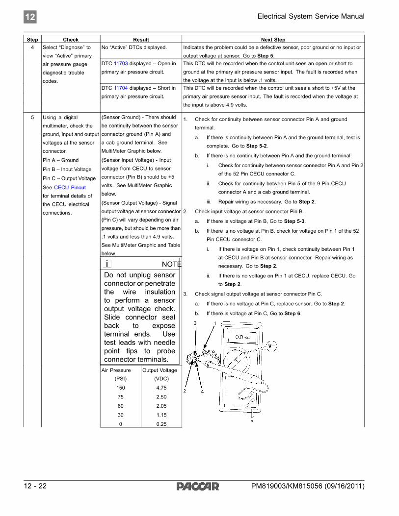
12 Electrical System Service Manual
Step Check Result Next StepNo “Active” DTCs displayed. Indicates the problem could be a defective sensor, poor ground or no input or
output voltage at sensor. Go to Step 5.DTC 11703 displayed – Open inprimary air pressure circuit.
This DTC will be recorded when the control unit sees an open or short toground at the primary air pressure sensor input. The fault is recorded whenthe voltage at the input is below .1 volts.
4 Select “Diagnose” toview “Active” primaryair pressure gaugediagnostic troublecodes.
DTC 11704 displayed – Short inprimary air pressure circuit.
This DTC will be recorded when the control unit sees a short to +5V at theprimary air pressure sensor input. The fault is recorded when the voltage atthe input is above 4.9 volts.
(Sensor Ground) - There shouldbe continuity between the sensorconnector ground (Pin A) anda cab ground terminal. SeeMultiMeter Graphic below.
(Sensor Input Voltage) - Inputvoltage from CECU to sensorconnector (Pin B) should be +5volts. See MultiMeter Graphicbelow.
(Sensor Output Voltage) - Signaloutput voltage at sensor connector(Pin C) will vary depending on airpressure, but should be more than.1 volts and less than 4.9 volts.See MultiMeter Graphic and Tablebelow.
NOTEDo not unplug sensorconnector or penetratethe wire insulationto perform a sensoroutput voltage check.Slide connector sealback to exposeterminal ends. Usetest leads with needlepoint tips to probeconnector terminals.Air Pressure
(PSI)
150
75
60
30
0
Output Voltage(VDC)
4.75
2.50
2.05
1.15
0.25
5 Using a digitalmultimeter, check theground, input and outputvoltages at the sensorconnector.
Pin A – Ground
Pin B – Input Voltage
Pin C – Output Voltage
See CECU Pinoutfor terminal details ofthe CECU electricalconnections.
1. Check for continuity between sensor connector Pin A and groundterminal.
a. If there is continuity between Pin A and the ground terminal, test iscomplete. Go to Step 5-2.
b. If there is no continuity between Pin A and the ground terminal:
i. Check for continuity between sensor connector Pin A and Pin 2of the 52 Pin CECU connector C.
ii. Check for continuity between Pin 5 of the 9 Pin CECUconnector A and a cab ground terminal.
iii. Repair wiring as necessary. Go to Step 2.
2. Check input voltage at sensor connector Pin B.
a. If there is voltage at Pin B, Go to Step 5-3.
b. If there is no voltage at Pin B, check for voltage on Pin 1 of the 52Pin CECU connector C.
i. If there is voltage on Pin 1, check continuity between Pin 1at CECU and Pin B at sensor connector. Repair wiring asnecessary. Go to Step 2.
ii. If there is no voltage on Pin 1 at CECU, replace CECU. Goto Step 2.
3. Check signal output voltage at sensor connector Pin C.
a. If there is no voltage at Pin C, replace sensor. Go to Step 2.
b. If there is voltage at Pin C, Go to Step 6.
12 - 22 PM819003/KM815056 (09/16/2011)

Electrical System Service Manual 12
Step Check Result Next Step
NOTEMake sure that thesystem you are testinghas some pressure tomeasure.
1. Connector Seal
2. Pin A
3. Pin B
4. Place MultiMeter Probe On Pin C
6 Select “Diagnose”to view primary airpressure gauge DTCs.
Next, unplug the primaryair pressure sensorconnector at sensor.
See CECU Pinoutfor terminal details ofthe CECU electricalconnections.
DTC 11703 – Open in primary airpressure circuit is displayed as“Active.”
1. Check resistance between Pin C and ground terminal.
a. If there is less than 5K ohms between Pin C and the ground terminal,
i. Check wiring for short from sensor to CECU. If short found,repair and go to Step 2.
ii. Remove the 52 Pin CECU connector C and measure resistancebetween Pin 6 of the 52 Pin CECU connector C and groundterminal. If less than 5K ohms replace CECU and go to Step 2.
b. If there is more than 20K ohms between Pin C and ground terminal,
i. Check wiring for open from sensor to CECU. If open found,repair and go to Step 2.
ii. Remove the “C” connector from the CECU and measureresistance between Pin 6 of the 52 Pin CECU connector Cand ground terminal. If more than 20K ohms, replace CECUand go to Step 2.
1. If the fault is still “Active” after unplugging the sensor connector, youhave confirmed there is a short. This sensor wire starts at pin 6 of the52 Pin CECU connector C and ends at pin C on the sensor connector.There is a short between the sensor wire and a power source wire. Sometypical power wires to inspect are listed below (you may need to verifyany power source in the main cab harness):
Description CECU PinPower Supply Sensor +5V Connector C, Pin 1Dash Illumination 1 Connector A, Pin 7CVSG Power Connector A, Pin 1Each power supply ends at the following connectors:
Description PinCVSG gauge power 4CVSG lighting 2Primary air pressure transducer BSecondary air pressure BApplication air pressure transducer BAir filter restriction CFor future expansion AThrough the Engine HarnessConnector…
28
For the Ammeter sensor A
DTC 11704 - Short in primary airpressure circuit is displayed as“Active”.
Check for pinched or chaffed sensor and power wiring. Repair or replacewiring as necessary.Go to Step 2.
7 Select “Diagnose”to view primary airpressure gauge DTCs.
Next, unplug the primaryair pressure sensorconnector at sensor.
See CECU Pinoutfor terminal details ofthe CECU electricalconnections.
DTC 11704 - Short in primary airpressure circuit is now displayedas “Inactive.”
If DTC 11704 changes to “Inactive” after unplugging the sensor connector, youhave confirmed the problem is a short to +5V in the sensor itself, not the wiring.
1. Replace sensor. Go to Step 2.
Return to Table Of Contents
PM819003/KM815056 (09/16/2011) 12 - 23

12 Electrical System Service Manual
Secondary Air Pressure GaugeInoperative
DTC11803 and DTC11804Symptom: Secondary air pressure gaugeinoperative. All other gauges are operational.
The Secondary Air Pressure Gauge uses anelectronic transducer (sensor) which monitorssystem air pressure and converts it into a voltage
output that is sent to the instrumentation system.The output voltage of the sensor is proportional tothe pressure it is sensing.
The following procedures have been developedto assist the technician in diagnosing multiplexedinstrumentation problems using the ElectronicService Analyst (ESA) hardware/softwarediagnostic tool. It is assumed the servicetechnician performing instrumentation repairs isknowledgeable about how to use ESA.
12 - 24 PM819003/KM815056 (09/16/2011)

Electrical System Service Manual 12
Step Check Result Next Step1 Turn ignition key ON.
Start ESA, then select“Connect” to establishcommunication to thevehicle.
Go to Step 2.
Gauge graphic on screen displaysreasonable reading.
Go to Step 3.2 Select “Monitor.” Fromthe “Components”window, select“Secondary AirPressure,” then select“Open.”
Gauge graphic on screen does notdisplay reasonable reading.
Go to Step 4.
Vehicle gauge does not move. Goto Step 3-1.
Perform the following checks:
NOTEUse the "Program" feature in ESA to make sure thatthe parameter for the inoperative gauge is enabled.An inoperative gauge may simply have its CECUparameter set to disabled.
3 Select “Simulate”. Dragthe “Value” bar until thepointer on the gaugeimage is approximatelymid-scale. Observevehicle gaugemovement.
Vehicle gauge reading is in thesame range as the ESA gaugeimage. Go to Step 3-7.
1. Check CVSG data link wiring: Observe Gauge position in the wiringdaisy chain.
a. If gauge is mounted between two other functioning gauges CVSGdata link wiring is OK. Go to Step 3-5.
b. If gauge is last gauge in daisy chain or followed by othernon-functional gauges, go to Step 3-2.
2. Check continuity between Pin 1 on gauge harness connector and Pin 14of the 52 Pin CECU connector C.
3. Check continuity between Pin 3 on gauge harness connector and Pin 15of the 52 Pin CECU connector C.
4. Repair daisy chain jumper harness as necessary.
5. Once continuity on both wires exists, perform “Simulate” test again.
a. If gauge functions properly during “Simulate” test, repair is complete.Return truck to service.
b. If gauge does not function during “Simulate” test, install a knowngood gauge and perform “Simulate” test again.
i. If gauge functions properly test is complete. Install new gaugepermanently. Re-test and return truck to service.
ii. If gauge does not function during “Simulate” test, install TestCECU and perform “Simulate” test again.(1) If gauge functions properly test is complete. Install newCECU permanently. Re-test and return truck to service.(2) If gauge does not function properly during “Simulate” test,replace gauge.
6. Once gauge is replaced
a. Verify gauge functionality.
b. Return truck to service.
7. Is this a recheck after Step 5, Step 6 or Step 7?
a. Yes. Return truck to service.
PM819003/KM815056 (09/16/2011) 12 - 25

12 Electrical System Service Manual
Step Check Result Next Step
b. No, Gauge and CVSG data link wiring is not the problem. Go toStep 4.
No “Active” DTCs displayed. Indicates the problem could be a defective sensor, poor ground or no input oroutput voltage at sensor. Go to Step 5.
DTC 11803 displayed – Open insecondary air pressure circuit.
This DTC will be recorded when the control unit sees an open or short toground at the secondary air pressure sensor input. The fault is recorded whenthe voltage at the input is below .1 volts.
4 Select “Diagnose” toview “Active” secondaryair pressure gaugediagnostic troublecodes.
DTC 11804 displayed – Short insecondary air pressure circuit.
This DTC will be recorded when the control unit sees a short to +5V at thesecondary air pressure sensor input. The fault is recorded when the voltage atthe input is above 4.9 volts.
(Sensor Ground) - There shouldbe continuity between the sensorconnector ground (Pin A) anda cab ground terminal. SeeMultiMeter Graphic below.
(Sensor Input Voltage) - Inputvoltage from CECU to sensorconnector (Pin B) should be +5volts. See MultiMeter Graphicbelow.(Sensor Output Voltage) - Signaloutput voltage at sensor connector(Pin C) will vary depending on airpressure, but should be more than.1 volts and less than 4.9 volts.See MultiMeter Graphic and Tablebelow.
NOTEDo not unplug sensorconnector or penetratethe wire insulationto perform a sensoroutput voltage check.Slide connector sealback to exposeterminal ends. Usetest leads with needlepoint tips to probeconnector terminals.Air Pressure
(PSI)
150
75
60
30
0
Output Voltage(VDC)
4.75
2.50
2.05
1.15
0.25
5 Using a digitalmultimeter, check theground, input and outputvoltages at the sensorconnector.
Pin A – Ground
Pin B – Input Voltage
Pin C – Output Voltage
See CECU Pinoutfor terminal details ofthe CECU electricalconnections.
1. Check for continuity between sensor connector Pin A and groundterminal.
a. If there is continuity between Pin A and the ground terminal, test iscomplete. Go to Step 5-2.
b. If there is no continuity between Pin A and the ground terminal:
i. Check for continuity between sensor connector Pin A and Pin 2of the 52 Pin CECU connector C.
ii. Check for continuity between Pin 5 of the 9 Pin CECUconnector A and a cab ground terminal.
iii. Repair wiring as necessary. Go to Step 2.
2. Check input voltage at sensor connector Pin B.
a. If there is voltage at Pin B, Go to Step 5-3.
b. If there is no voltage at Pin B, check for voltage on Pin 1 of the 52Pin CECU connector C.
i. If there is voltage on Pin 1, check continuity between Pin 1at CECU and Pin B at sensor connector. Repair wiring asnecessary. Go to Step 2.
ii. If there is no voltage on Pin 1 at CECU, replace CECU. Goto Step 2.
3. Check signal output voltage at sensor connector Pin C.
a. If there is no voltage at Pin C, replace sensor. Go to Step 2.
b. If there is voltage at Pin C, Go to Step 6.
12 - 26 PM819003/KM815056 (09/16/2011)

Electrical System Service Manual 12
Step Check Result Next Step
NOTEMake sure that thesystem you are testinghas some pressure tomeasure.
1. Connector Seal
2. Pin A
3. Pin B
4. Place MultiMeter Probe On Pin C
6 Select “Diagnose” toview secondary airpressure gauge DTCs.
Next, unplug thesecondary air pressuresensor connector atsensor.
See CECU Pinoutfor terminal details ofthe CECU electricalconnections.
DTC 11803 – Open in secondaryair pressure circuit is displayed as“Active.”
1. Check resistance between Pin C and ground terminal.
a. If there is less than 5K ohms between Pin C and the ground terminal,
i. Check wiring for short from sensor to CECU. If short found,repair and go to Step 2.
ii. Remove the 52 Pin CECU connector C and measure resistancebetween Pin 7 of the 52 Pin CECU connector C and groundterminal. If less than 5K ohms replace CECU and go to Step 2.
b. If there is more than 20K ohms between Pin C and ground terminal,
i. Check wiring for open from sensor to CECU. If open found,repair and go to Step 2.
ii. Remove the “C” connector from the CECU and measureresistance between Pin 7 of the 52 Pin CECU connector Cand ground terminal. If more than 20K ohms, replace CECUand go to Step 2.
1. If the fault is still “Active” after unplugging the sensor connector, youhave confirmed there is a short. This sensor wire starts at pin 7 of the52 Pin CECU connector C and ends at pin C on the sensor connector.There is a short between the sensor wire and a power source wire. Sometypical power wires to inspect are listed below (you may need to verifyany power source in the main cab harness):
Description CECU PinPower Supply Sensor +5V Connector C, Pin 1Dash Illumination 1 Connector A, Pin 7CVSG Power Connector A, Pin 1Each power supply ends at the following connectors:
Description PinCVSG gauge power 4CVSG lighting 2Primary air pressure transducer BSecondary air pressure BApplication air pressure transducer BAir filter restriction CFor future expansion AThrough the Engine HarnessConnector…
28
For the Ammeter sensor A
DTC 11804 - Short in secondaryair pressure circuit is displayed as“Active”.
Check for pinched or chaffed sensor and power wiring. Repair or replacewiring as necessary.Go to Step 2.
7 Select “Diagnose” toview secondary airpressure gauge DTCs.
Next, unplug thesecondary air pressuresensor connector atsensor.
See CECU Pinoutfor terminal details ofthe CECU electricalconnections.
DTC 11804 - Short in secondary airpressure circuit is now displayedas “Inactive.”
If DTC 11804 changes to “Inactive” after unplugging the sensor connector, youhave confirmed the problem is a short to +5V in the sensor itself, not the wiring.
1. Replace sensor. Go to Step 2.
Return to Table Of Contents
PM819003/KM815056 (09/16/2011) 12 - 27

12 Electrical System Service Manual
Application Air Pressure GaugeInoperative
DTC11603 and DTC11604Symptom: Application air pressure gaugeinoperative. All other gauges are operational.
The Application Air Pressure Gauge uses anelectronic transducer (sensor) which monitorssystem air pressure and converts it into a voltage
output that is sent to the instrumentation system.The output voltage of the sensor is proportional tothe pressure it is sensing.
The following procedures have been developedto assist the technician in diagnosing multiplexedinstrumentation problems using the ElectronicService Analyst (ESA) hardware/softwarediagnostic tool. It is assumed the servicetechnician performing instrumentation repairs isknowledgeable about how to use ESA.
12 - 28 PM819003/KM815056 (09/16/2011)

Electrical System Service Manual 12
Step Check Result Next Step1 Turn ignition key ON.
Start ESA, then select“Connect” to establishcommunication to thevehicle.
Go to Step 2.
Gauge graphic on screen displaysreasonable reading.
Go to Step 3.2 Select “Monitor.” Fromthe “Components”window, select“Application AirPressure”, then select“Open.”
Gauge graphic on screen does notdisplay reasonable reading.
Go to Step 4.
Vehicle gauge does not move. Goto Step 3-1.
Perform the following checks:
NOTEUse the "Program" feature in ESA to make sure thatthe parameter for the inoperative gauge is enabled.An inoperative gauge may simply have its CECUparameter set to disabled.
3 Select “Simulate”. Dragthe “Value” bar until thepointer on the gaugeimage is approximatelymid-scale. Observevehicle gaugemovement.
Vehicle gauge reading is in thesame range as the ESA gaugeimage. Go to Step 3-7.
1. Check CVSG data link wiring: Observe Gauge position in the wiringdaisy chain.
a. If gauge is mounted between two other functioning gauges CVSGdata link wiring is OK. Go to Step 3-5.
b. If gauge is last gauge in daisy chain or followed by othernon-functional gauges, go to Step 3-2.
2. Check continuity between Pin 1 on gauge harness connector and Pin 14of the 52 Pin CECU connector C.
3. Check continuity between Pin 3 on gauge harness connector and Pin 15of the 52 Pin CECU connector C.
4. Repair daisy chain jumper harness as necessary.
5. Once continuity on both wires exists, perform “Simulate” test again.
a. If gauge functions properly during “Simulate” test, repair is complete.Return truck to service.
b. If gauge does not function during “Simulate” test, install a knowngood gauge and perform “Simulate” test again.
i. If gauge functions properly test is complete. Install new gaugepermanently. Re-test and return truck to service.
ii. If gauge does not function during “Simulate” test, install TestCECU and perform “Simulate” test again.(1) If gauge functions properly test is complete. Install newCECU permanently. Re-test and return truck to service.(2) If gauge does not function properly during “Simulate” test,replace gauge.
6. Once gauge is replaced
a. Verify gauge functionality.
b. Return truck to service.
7. Is this a recheck after Step 5, Step 6 or Step 7?
a. Yes. Return truck to service.
PM819003/KM815056 (09/16/2011) 12 - 29

12 Electrical System Service Manual
Step Check Result Next Step
b. No, Gauge and CVSG data link wiring is not the problem. Go toStep 4.
No “Active” DTCs displayed. Indicates the problem could be a defective sensor, poor ground or no input oroutput voltage at sensor. Go to Step 5.
DTC 11603 displayed – Open inapplication air pressure circuit.
This DTC will be recorded when the control unit sees an open or short toground at the secondary air pressure sensor input. The fault is recorded whenthe voltage at the input is below .1 volts.
4 Select “Diagnose” toview “Active” Applicationair pressure gaugediagnostic troublecodes.
DTC 11604 displayed – Short inapplication air pressure circuit.
This DTC will be recorded when the control unit sees a short to +5V at thesecondary air pressure sensor input. The fault is recorded when the voltage atthe input is above 4.9 volts.
(Sensor Ground) - There shouldbe continuity between the sensorconnector ground (Pin A) anda cab ground terminal. SeeMultiMeter Graphic below.
(Sensor Input Voltage) - Inputvoltage from CECU to sensorconnector (Pin B) should be +5volts. See MultiMeter Graphicbelow.(Sensor Output Voltage) - Signaloutput voltage at sensor connector(Pin C) will vary depending onair pressure, but should be morethan 0 volts and less than 5 volts.See MultiMeter Graphic and Tablebelow.
NOTEDo not unplug sensorconnector or penetratethe wire insulationto perform a sensoroutput voltage check.Slide connector sealback to exposeterminal ends. Usetest leads with needlepoint tips to probeconnector terminals.Air Pressure
(PSI)
150
75
60
30
0
Output Voltage(VDC)
4.75
2.50
2.05
1.15
0.25
5 Using a digitalmultimeter, check theground, input and outputvoltages at the sensorconnector.
Pin A – Ground
Pin B – Input Voltage
Pin C – Output Voltage
See CECU Pinoutfor terminal details ofthe CECU electricalconnections.
1. Check for continuity between sensor connector Pin A and groundterminal.
a. If there is continuity between Pin A and the ground terminal, test iscomplete. Go to Step 5-2.
b. If there is no continuity between Pin A and the ground terminal:
i. Check for continuity between sensor connector Pin A and Pin 2of the 52 Pin CECU connector C.
ii. Check for continuity between Pin 5 of the 9 Pin CECUconnector A and a cab ground terminal.
iii. Repair wiring as necessary. Go to Step 2.
2. Check input voltage at sensor connector Pin B.
a. If there is voltage at Pin B, Go to Step 5-3.
b. If there is no voltage at Pin B, check for voltage on Pin 1 of the 52Pin CECU connector C.
i. If there is voltage on Pin 1, check continuity between Pin 1at CECU and Pin B at sensor connector. Repair wiring asnecessary. Go to Step 2.
ii. If there is no voltage on Pin 1 at CECU, replace CECU. Goto Step 2.
3. Check signal output voltage at sensor connector Pin C.
a. If there is no voltage at Pin C, replace sensor. Go to Step 2.
b. If there is voltage at Pin C, Go to Step 6.
12 - 30 PM819003/KM815056 (09/16/2011)

Electrical System Service Manual 12
Step Check Result Next Step
NOTEMake sure that thesystem you are testinghas some pressure tomeasure.
1. Connector Seal
2. Pin A
3. Pin B
4. Place MultiMeter Probe On Pin C
6 Select “Diagnose” toview application airpressure gauge DTCs.
Next, unplug theapplication air pressuresensor connector atsensor.
See CECU Pinoutfor terminal details ofthe CECU electricalconnections.
DTC 11603 – Open in applicationair pressure circuit is displayed as“Active.”
1. Check resistance between Pin C and ground terminal.
a. If there is less than 5K ohms between Pin C and the ground terminal,
i. Check wiring for short from sensor to CECU. If short found,repair and go to Step 2.
ii. Remove the “C” connector from the CECU and measureresistance between Pin 8 of the 52 Pin CECU connector Cand ground terminal. If less than 5K ohms replace CECU andgo to Step 2.
b. If there is more than 20K ohms between Pin C and ground terminal,
i. Check wiring for open from sensor to CECU. If open found,repair and go to Step 2.
ii. Remove the “C” connector from the CECU and measureresistance between Pin 8 of the 52 Pin CECU connector Cand ground terminal. If more than 20K ohms, replace CECUand go to Step 2.
1. If the fault is still “Active” after unplugging the sensor connector, youhave confirmed there is a short. This sensor wire starts at pin 8 of the52 Pin CECU connector C and ends at pin C on the sensor connector.There is a short between the sensor wire and a power source wire. Sometypical power wires to inspect are listed below (you may need to verifyany power source in the main cab harness):
Description CECU PinPower Supply Sensor +5V Connector C, Pin 1Dash Illumination 1 Connector A, Pin 7CVSG Power Connector A, Pin 1Each power supply ends at the following connectors:
Description PinCVSG gauge power 4CVSG lighting 2Primary air pressure transducer BSecondary air pressure BApplication air pressure transducer BAir filter restriction CFor future expansion AThrough the Engine HarnessConnector…
28
For the Ammeter sensor A
DTC 11604 - Short in applicationair pressure circuit is displayed as“Active”.
Check for pinched or chaffed sensor and power wiring. Repair or replacewiring as necessary.Go to Step 2.
7 Select “Diagnose” toview application airpressure gauge DTCs.
Next, unplug theapplication air pressuresensor connector atsensor.
See CECU Pinoutfor terminal details ofthe CECU electricalconnections.
DTC 11604 - Short in applicationair pressure circuit is nowdisplayed as “Inactive.”
If DTC 11604 changes to “Inactive” after unplugging the sensor connector, youhave confirmed the problem is a short to +5V in the sensor itself, not the wiring.
1. Replace sensor. Go to Step 2.
Return to Table Of Contents
PM819003/KM815056 (09/16/2011) 12 - 31

12 Electrical System Service Manual
Air Filter Restriction Pressure GaugeInoperative
DTC10703 and DTC10704Symptom: Air filter restriction gauge inoperative.All other gauges are operational.
The Air Filter Restriction Gauge uses an electronictransducer (sensor) to monitor vacuum pressureand converts it into a voltage output that is sent to
the instrumentation system. The output voltageof the sensor is proportional to the vacuum it issensing.
The following procedures have been developedto assist the technician in diagnosing multiplexedinstrumentation problems using the ElectronicService Analyst (ESA) hardware/softwarediagnostic tool. It is assumed the servicetechnician performing instrumentation repairs isknowledgeable about how to use ESA.
12 - 32 PM819003/KM815056 (09/16/2011)
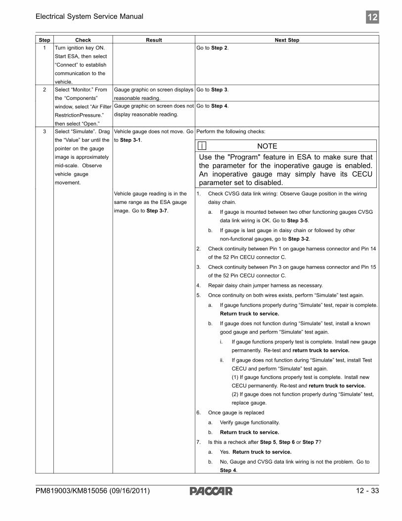
Electrical System Service Manual 12
Step Check Result Next Step1 Turn ignition key ON.
Start ESA, then select“Connect” to establishcommunication to thevehicle.
Go to Step 2.
Gauge graphic on screen displaysreasonable reading.
Go to Step 3.2 Select “Monitor.” Fromthe “Components”window, select “Air FilterRestrictionPressure.”then select “Open.”
Gauge graphic on screen does notdisplay reasonable reading.
Go to Step 4.
Vehicle gauge does not move. Goto Step 3-1.
Perform the following checks:
NOTEUse the "Program" feature in ESA to make sure thatthe parameter for the inoperative gauge is enabled.An inoperative gauge may simply have its CECUparameter set to disabled.
3 Select “Simulate”. Dragthe “Value” bar until thepointer on the gaugeimage is approximatelymid-scale. Observevehicle gaugemovement.
Vehicle gauge reading is in thesame range as the ESA gaugeimage. Go to Step 3-7.
1. Check CVSG data link wiring: Observe Gauge position in the wiringdaisy chain.
a. If gauge is mounted between two other functioning gauges CVSGdata link wiring is OK. Go to Step 3-5.
b. If gauge is last gauge in daisy chain or followed by othernon-functional gauges, go to Step 3-2.
2. Check continuity between Pin 1 on gauge harness connector and Pin 14of the 52 Pin CECU connector C.
3. Check continuity between Pin 3 on gauge harness connector and Pin 15of the 52 Pin CECU connector C.
4. Repair daisy chain jumper harness as necessary.
5. Once continuity on both wires exists, perform “Simulate” test again.
a. If gauge functions properly during “Simulate” test, repair is complete.Return truck to service.
b. If gauge does not function during “Simulate” test, install a knowngood gauge and perform “Simulate” test again.
i. If gauge functions properly test is complete. Install new gaugepermanently. Re-test and return truck to service.
ii. If gauge does not function during “Simulate” test, install TestCECU and perform “Simulate” test again.(1) If gauge functions properly test is complete. Install newCECU permanently. Re-test and return truck to service.(2) If gauge does not function properly during “Simulate” test,replace gauge.
6. Once gauge is replaced
a. Verify gauge functionality.
b. Return truck to service.
7. Is this a recheck after Step 5, Step 6 or Step 7?
a. Yes. Return truck to service.
b. No, Gauge and CVSG data link wiring is not the problem. Go toStep 4.
PM819003/KM815056 (09/16/2011) 12 - 33

12 Electrical System Service Manual
Step Check Result Next StepNo “Active” DTCs displayed. Indicates the problem could be a defective sensor, poor ground or no input or
output voltage at sensor. Go to Step 5.DTC 10703 displayed – Open inair filter restriction circuit.
This DTC will be recorded when the control unit sees an open or short toground at the secondary air pressure sensor input. The fault is recorded whenthe voltage at the input is below .1 volts.
4 Select “Diagnose” toview “Active” air filterrestriction gaugediagnostic troublecodes.
DTC 10704 displayed – Short inair filter restriction circuit.
This DTC will be recorded when the control unit sees a short to +5V at thesecondary air pressure sensor input. The fault is recorded when the voltage atthe input is above 4.9 volts.
(Sensor Ground) - There shouldbe continuity between the sensorconnector ground (Pin A) and thefirewall ground stud.
(Sensor Input Voltage) - Inputvoltage from CECU to sensorconnector (Pin C) should be +5volts. See Table below.
(Sensor Output Voltage) - Signaloutput voltage at sensor connector(Pin B) will vary depending onstrength of vacuum, but should bemore than .1 volts and less than4.9 volts. See Table below.
NOTEDo not unplug sensorconnector or penetratethe wire insulationto perform a sensoroutput voltage check.Slide connector sealback to exposeterminal ends. Usetest leads with needlepoint tips to probeconnector terminals.
Pressure
(PSI)
0
-1.5
Output Voltage(VDC)
0.5
4.5
5 Using a digitalmultimeter, check theground, input and outputvoltages at the sensorconnector.
Pin A – Ground
Pin B – Output Voltage
Pin C – Input Voltage
See CECU Pinoutfor terminal details ofthe CECU electricalconnections.
NOTEMake sure that thesystem you are testinghas some pressure tomeasure.
1. Check for continuity between sensor connector Pin A and groundterminal.
a. If there is continuity between Pin A and the ground terminal, test iscomplete. Go to Step 5-2.
b. If there is no continuity between Pin A and the ground terminal:
i. Check for continuity between sensor connector Pin A and Pin 2of the 52 Pin CECU connector C.
ii. Check for continuity between Pin 5 of the 9 Pin CECUconnector A and a cab ground terminal.
iii. Repair wiring as necessary. Go to Step 2.
2. Check input voltage at sensor connector Pin C.
a. If there is voltage at Pin C, Go to Step 5-3.
b. If there is no voltage at Pin C, check for voltage on Pin 1 of the 52Pin CECU connector C.
i. If there is voltage on Pin 1, check continuity between Pin 1at CECU and Pin C at sensor connector. Repair wiring asnecessary. Go to Step 2.
ii. If there is no voltage on Pin 1 at CECU, replace CECU. Goto Step 2.
3. Check signal output voltage at sensor connector Pin B.
a. If there is no voltage at Pin B, replace sensor. Go to Step 2.
b. If there is voltage at Pin B, Go to Step 6.
1. Pin A
2. Place MultiMeter Probe On Pin B
3. Pin C
12 - 34 PM819003/KM815056 (09/16/2011)

Electrical System Service Manual 12
Step Check Result Next Step6 Select “Diagnose” to
view air filter restrictiongauge DTCs.
Next, unplug the airfilter restriction sensorconnector at sensor.
See CECU Pinoutfor terminal details ofthe CECU electricalconnections.
DTC 10703 – Open in air filterrestriction circuit is displayed as“Active.”
1. Check resistance between Pin B and ground terminal.
a. If there is less than 5K ohms between Pin B and the ground terminal,
i. Check wiring for short from sensor to CECU. If short found,repair and go to Step 2.
ii. Remove the “C” connector from the CECU and measureresistance between Pin 10 of the 52 Pin CECU connector Cand ground terminal. If less than 5K ohms replace CECU andgo to Step 2.
b. If there is more than 20K ohms between Pin B and ground terminal,
i. Check wiring for open from sensor to CECU. If open found,repair and go to Step 2.
ii. Remove the “C” connector from the CECU and measureresistance between Pin 10 of the 52 Pin CECU connector Cand ground terminal. If more than 20K ohms, replace CECUand go to Step 2.
1. If the fault is still “Active” after unplugging the sensor connector, youhave confirmed there is a short. This sensor wire starts at pin 10 of the52 Pin CECU connector C and ends at pin B on the sensor connector.There is a short between the sensor wire and a power source wire. Sometypical power wires to inspect are listed below (you may need to verifyany power source in the main cab harness):
Description CECU PinPower Supply Sensor +5V Connector C, Pin 1Dash Illumination 1 Connector A, Pin 7CVSG Power Connector A, Pin 1Each power supply ends at the following connectors:
Description PinCVSG gauge power 4CVSG lighting 2Primary air pressure transducer BSecondary air pressure BApplication air pressure transducer BAir filter restriction CFor future expansion AThrough the Engine HarnessConnector…
28
For the Ammeter sensor A
DTC 10704 - Short in air filterrestriction circuit is displayed as“Active.”
Check for pinched or chaffed sensor and power wiring. Repair or replacewiring as necessary.Go to Step 2.
7 Select “Diagnose” toview air filter restrictiongauge DTCs.
Next, unplug the airfilter restriction sensorconnector at sensor.
See CECU Pinoutfor terminal details ofthe CECU electricalconnections.
DTC 10704 - Short in air filterrestriction circuit is now displayedas “Inactive.”
If DTC 11704 changes to “Inactive” after unplugging the sensor connector, youhave confirmed the problem is a short to +5V in the sensor itself, not the wiring.
1. Replace sensor. Go to Step 2.
Return to Table Of Contents
PM819003/KM815056 (09/16/2011) 12 - 35
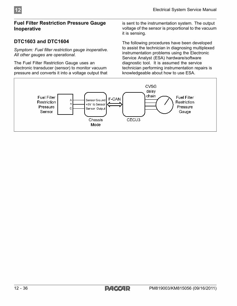
12 Electrical System Service Manual
Fuel Filter Restriction Pressure GaugeInoperative
DTC1603 and DTC1604Symptom: Fuel filter restriction gauge inoperative.All other gauges are operational.
The Fuel Filter Restriction Gauge uses anelectronic transducer (sensor) to monitor vacuumpressure and converts it into a voltage output that
is sent to the instrumentation system. The outputvoltage of the sensor is proportional to the vacuumit is sensing.
The following procedures have been developedto assist the technician in diagnosing multiplexedinstrumentation problems using the ElectronicService Analyst (ESA) hardware/softwarediagnostic tool. It is assumed the servicetechnician performing instrumentation repairs isknowledgeable about how to use ESA.
12 - 36 PM819003/KM815056 (09/16/2011)

Electrical System Service Manual 12
Step Check Result Next Step1 Turn ignition key ON.
Start ESA, then select“Connect” to establishcommunication to thevehicle.
Go to Step 2.
Gauge graphic on screen displaysreasonable reading.
Go to Step 3.2 Select “Monitor.” Fromthe “Components”window, select “FuelFilter RestrictionPressure,” then select“Open.”
Gauge graphic on screen does notdisplay reasonable reading.
Go to Step 4.
Vehicle gauge does not move. Goto Step 3-1.
Perform the following checks:
NOTEUse the "Program" feature in ESA to make sure thatthe parameter for the inoperative gauge is enabled.An inoperative gauge may simply have its CECUparameter set to disabled.
3 Select “Simulate”. Dragthe “Value” bar until thepointer on the gaugeimage is approximatelymid-scale. Observevehicle gaugemovement.
Vehicle gauge reading is in thesame range as the ESA gaugeimage. Go to Step 3-7.
1. Check CVSG data link wiring: Observe Gauge position in the wiringdaisy chain.
a. If gauge is mounted between two other functioning gauges CVSGdata link wiring is OK. Go to Step 3-5.
b. If gauge is last gauge in daisy chain or followed by othernon-functional gauges, go to Step 3-2.
2. Check continuity between Pin 1 on gauge harness connector and Pin 14of the 52 Pin CECU connector C.
3. Check continuity between Pin 3 on gauge harness connector and Pin 15of the 52 Pin CECU connector C.
4. Repair daisy chain jumper harness as necessary.
5. Once continuity on both wires exists, perform “Simulate” test again.
a. If gauge functions properly during “Simulate” test, repair is complete.Return truck to service.
b. If gauge does not function during “Simulate” test, install a knowngood gauge and perform “Simulate” test again.
i. If gauge functions properly test is complete. Install new gaugepermanently. Re-test and return truck to service.
ii. If gauge does not function during “Simulate” test, install TestCECU and perform “Simulate” test again.(1) If gauge functions properly test is complete. Install newCECU permanently. Re-test and return truck to service.(2) If gauge does not function properly during “Simulate” test,replace gauge.
6. Once gauge is replaced
a. Verify gauge functionality.
b. Return truck to service.
7. Is this a recheck after Step 5, Step 6 or Step 7?
a. Yes. Return truck to service.
PM819003/KM815056 (09/16/2011) 12 - 37

12 Electrical System Service Manual
Step Check Result Next Step
b. No, Gauge and CVSG data link wiring is not the problem. Go toStep 4.
No “Active” DTCs displayed. Indicates the problem could be a defective sensor, poor ground or no input oroutput voltage at sensor. Go to Step 5.
DTC 1603 displayed – Open inapplication air pressure circuit.
This DTC will be recorded when the control unit sees an open or short toground at the secondary air pressure sensor input. The fault is recorded whenthe voltage at the input is below .1 volts.
4 Select “Diagnose”to view “Active” fuelfilter restriction gaugediagnostic troublecodes.
DTC 1604 displayed – Short inapplication air pressure circuit.
This DTC will be recorded when the control unit sees a short to +5V at thesecondary air pressure sensor input. The fault is recorded when the voltage atthe input is above 4.9 volts.
(Sensor Ground) - There shouldbe continuity between the sensorconnector ground (Pin A) and thefirewall ground stud.
(Sensor Input Voltage) - Inputvoltage from Chassis Node tosensor connector (Pin B) shouldbe +5 volts. See Table below.
(Sensor Output Voltage) - Signaloutput voltage at sensor connector(Pin C) will vary depending onstrength of vacuum, but should bemore than .1 volts and less than4.9 volts. See Table below.
NOTEDo not unplug sensorconnector or penetratethe wire insulationto perform a sensoroutput voltage check.Slide connector sealback to exposeterminal ends. Usetest leads with needlepoint tips to probeconnector terminals.
Pressure
(PSI)
0
-1.5
Output Voltage(VDC)
0.5
4.5
5 Using a digitalmultimeter, check theground, input and outputvoltages at the sensorconnector.
Pin A – Ground
Pin B – Input Voltage
Pin C – Output Voltage
See Chassis NodePinout for terminaldetails of the ChassisNode electricalconnections.
NOTEMake sure that thesystem you are testinghas some pressure tomeasure.
1. Check for continuity between sensor connector Pin A and groundterminal.
a. If there is continuity between Pin A and the ground terminal, test iscomplete. Go to Step 5-2.
b. If there is no continuity between Pin A and the ground terminal:
i. Check for continuity between sensor connector Pin A and Pin 1of the Chassis Node connector C.
ii. Check for continuity between Pin 3 of the Chassis Nodeconnector A and a cab ground terminal.
iii. Repair wiring as necessary. Go to Step 2.
2. Check input voltage at sensor connector Pin B.
a. If there is voltage at Pin B, Go to Step 5-3.
b. If there is no voltage at Pin B, check for voltage on Pin 3 of theChassis Node connector B.
i. If there is voltage on Pin 3, check continuity between Pin 3 ofthe Chassis Node connector B and Pin B at sensor connector.Repair wiring as necessary. Go to Step 2.
ii. If there is no voltage on Pin 3 of the Chassis Node connectorB, replace Chassis Node. Go to Step 2.
3. Check signal output voltage at sensor connector Pin C.
a. If there is no voltage at Pin C, replace sensor. Go to Step 2.
b. If there is voltage at Pin C, Go to Step 6.
1. Connector Seal
2. Pin A
3. Pin B
4. Place MultiMeter Probe On Pin C12 - 38 PM819003/KM815056 (09/16/2011)

Electrical System Service Manual 12
Step Check Result Next Step6 Select “Diagnose” to
view fuel filter restrictiongauge DTCs.
Next, unplug the fuelfilter restriction sensorconnector at sensor.
See Chassis NodePinout for terminaldetails of the ChassisNode electricalconnections.
DTC 1603 – Open in fuel filterrestriction circuit is displayed as“Active.”
1. Check resistance between Pin C and ground terminal.
a. If there is less than 5K ohms between Pin C and the ground terminal,
i. Check wiring for short from sensor to Chassis Node. If shortfound, repair and go to Step 2.
ii. Remove the “B” connector from the Chassis Node and measureresistance between Pin 5 of the Chassis Node connector Band ground terminal. If less than 5K ohms replace ChassisNode and go to Step 2.
b. If there is more than 20K ohms between Pin C and ground terminal,
i. Check wiring for open from sensor to Chassis Node. If openfound, repair and go to Step 2.
ii. Remove the “B” connector from the Chassis Node and measureresistance between Pin 5 of the Chassis Node connector Band ground terminal. If more than 20K ohms, replace ChassisNode and go to Step 2.
1. If the fault is still “Active” after unplugging the sensor connector, youhave confirmed there is a short. This sensor wire starts at Pin 5 of theChassis Node connector B and ends at pin C on the sensor connector.There is a short between the sensor wire and a power source wire. Sometypical power wires to inspect are listed below (you may need to verifyany power source in the main cab harness):
Description CECU PinPower Supply Sensor +5V Connector C, Pin 1Dash Illumination 1 Connector A, Pin 7CVSG Power Connector A, Pin 1Each power supply ends at the following connectors:
Description PinCVSG gauge power 4CVSG lighting 2Primary air pressure transducer BSecondary air pressure BApplication air pressure transducer BAir filter restriction CFor future expansion AThrough the Engine HarnessConnector…
28
For the Ammeter sensor A
DTC 1604 - Short in fuel filterrestriction circuit is displayed as“Active.”
Check for pinched or chaffed sensor and power wiring. Repair or replacewiring as necessary.Go to Step 2.
7 Select “Diagnose” toview fuel filter restrictiongauge DTCs.
Next, unplug the fuelfilter restriction sensorconnector at sensor.
See Chassis NodePinout for terminaldetails of the ChassisNode electricalconnections.
See CECU Pinoutfor terminal details ofthe CECU electricalconnections.
DTC 1604 - Short in fuel filterrestriction circuit is now displayedas “Inactive.”
If DTC 1604 changes to “Inactive” after unplugging the sensor connector, youhave confirmed the problem is a short in the sensor itself, not the wiring.
1. Replace sensor. Go to Step 2.
Return to Table Of Contents
PM819003/KM815056 (09/16/2011) 12 - 39

12 Electrical System Service Manual
Ammeter Gauge Inoperative
DTC257903 and DTC257904
Symptom: Ammeter gauge inoperative. All othergauges are operational.
The Ammeter Gauge uses a contactless sensorusing Hall Effect. The sensor is positioned on the
cab feed wire inside the battery box, or for firewallmounted circuit breakers, near the firewall.
The following procedures have been developedto assist the technician in diagnosing multiplexedinstrumentation problems using the ElectronicService Analyst (ESA) hardware/softwarediagnostic tool. It is assumed the servicetechnician performing instrumentation repairs isknowledgeable about how to use ESA.
12 - 40 PM819003/KM815056 (09/16/2011)

Electrical System Service Manual 12
Step Check Result Next Step1 Turn ignition key ON.
Start ESA, then select“Connect” to establishcommunication to thevehicle.
Go to Step 2.
Gauge graphic on screen displaysreasonable reading.
Go to Step 3.2 Select “Monitor.” Fromthe “Components”window, select“Ammeter,” then select“Open.”
Gauge graphic on screen does notdisplay reasonable reading.
Go to Step 4.
Vehicle gauge does not move. Goto Step 3-1.
Perform the following checks:
NOTEUse the "Program" feature in ESA to make sure thatthe parameter for the inoperative gauge is enabled.An inoperative gauge may simply have its CECUparameter set to disabled.
3 Select “Simulate”. Dragthe “Value” bar until thepointer on the gaugeimage is approximatelymid-scale. Observevehicle gaugemovement.
Vehicle gauge reading is in thesame range as the ESA gaugeimage. Go to Step 3-7.
1. Check CVSG data link wiring: Observe Gauge position in the wiringdaisy chain.
a. If gauge is mounted between two other functioning gauges CVSGdata link wiring is OK. Go to Step 3-5.
b. If gauge is last gauge in daisy chain or followed by othernon-functional gauges, go to Step 3-2.
2. Check continuity between Pin 1 on gauge harness connector and Pin 14of the 52 Pin CECU connector C.
3. Check continuity between Pin 3 on gauge harness connector and Pin 15of the 52 Pin CECU connector C.
4. Repair daisy chain jumper harness as necessary.
5. Once continuity on both wires exists, perform “Simulate” test again.
a. If gauge functions properly during “Simulate” test, repair is complete.Return truck to service.
b. If gauge does not function during “Simulate” test, install a knowngood gauge and perform “Simulate” test again.
i. If gauge functions properly test is complete. Install new gaugepermanently. Re-test and return truck to service.
ii. If gauge does not function during “Simulate” test, install TestCECU and perform “Simulate” test again.(1) If gauge functions properly test is complete. Install newCECU permanently. Re-test and return truck to service.(2) If gauge does not function properly during “Simulate” test,replace gauge.
6. Once gauge is replaced
a. Verify gauge functionality.
b. Return truck to service.
7. Is this a recheck after Step 5, Step 6 or Step 7?
a. Yes. Return truck to service.
b. No, Gauge and CVSG data link wiring is not the problem. Go toStep 4.
PM819003/KM815056 (09/16/2011) 12 - 41

12 Electrical System Service Manual
Step Check Result Next StepNo “Active” DTCs displayed. Indicates the problem could be a defective sensor, poor ground or no input or
output voltage at sensor. Go to Step 5.DTC 257903 displayed - Open inammeter sensor circuit.
This DTC will be recorded when the control unit sees an open or short toground at the secondary air pressure sensor input. The fault is recorded whenthe voltage at the input is below .1 volts.
4 Select “Diagnose” toview “Active” ammeterdiagnostic troublecodes.
DTC 257904 displayed - Short inammeter sensor circuit.
This DTC will be recorded when the control unit sees a short to +5V at thesecondary air pressure sensor input. The fault is recorded when the voltage atthe input is above 4.9 volts.
(Sensor Ground) - There shouldbe continuity between the sensorconnector ground (Pin B) and thefirewall ground stud.(Sensor Input Voltage) - Inputvoltage from CECU to sensorconnector (Pin A) should be +5volts.
(Sensor Output Voltage) - Signaloutput voltage at sensor connector(Pin C) will vary depending on theamperage, but should be morethan 0 volts and less than 5 volts.See Table below.
NOTEDo not unplug sensorconnector or penetratethe wire insulationto perform a sensoroutput voltage check.Slide connector sealback to exposeterminal ends. Usetest leads with needlepoint tips to probeconnector terminals.
5 Using a digitalmultimeter, check theground, input and outputvoltages at the sensorconnector.
Pin A – Input Voltage
Pin B – Ground
Pin C – Output Voltage
See CECU Pinoutfor terminal details ofthe CECU electricalconnections.
Average
Range
120
60
0
-60
-120
Output Voltage
(VDC)
4.5
3.5
2.5
1.5
0.5
1. Check for continuity between sensor connector Pin B and groundterminal.
a. If there is continuity between Pin B and the ground terminal, test iscomplete. Go to Step 5-2.
b. If there is no continuity between Pin B and the ground terminal
i. Check for continuity between terminal B and Pin 9 of the 52Pin CECU connector C.
ii. Check for continuity between Pin 5 of the 9 Pin CECUconnector A and a cab ground terminal.
iii. Repair wiring as necessary. Go to Step 5-1.
2. Check input voltage at sensor connector Pin A.
a. If there is voltage at Pin A, Go to Step 5-3.
b. If there is no voltage at Pin A, check for voltage on Pin 1 of the 52Pin CECU connector C.
i. If there is voltage on Pin 1, check continuity between Pin 1at CECU and Pin A at sensor connector. Repair wiring asnecessary. Go to Step 5-2.
ii. If there is no voltage on Pin 1 at CECU, replace CECU. Goto Step 2.
3. Check signal output voltage at sensor connector Pin C.
a. If there is no voltage at Pin C, replace sensor. Go to Step 2.
b. If there is voltage at Pin C, check for voltage on Pin 9 of the 52 PinCECU connector C.
i. If voltage is present on Pin 9 at CECU connector, replaceCECU. Go to Step 2.
ii. If there is no voltage on Pin 9 at CECU connector, Go to Step 6.
1. Place MultiMeter Probe On Pin C
2. Pin B
3. Pin A
12 - 42 PM819003/KM815056 (09/16/2011)

Electrical System Service Manual 12
Step Check Result Next Step6 Select “Diagnose” to
view ammeter gaugeDTCs.
Next, unplug theammeter connectorat sensor.
See CECU Pinoutfor terminal details ofthe CECU electricalconnections.
DTC 257903 – Open in ammetersensor circuit is displayed as“Active.”
1. Using a jumper wire, jump across sensor harness connector Pins Band C.
1. Pin B
2. Pin C
a. If an “Active” DTC 257904 - Short in ammeter sensor circuit is nowdisplayed, you have confirmed there is not an open in the sensoroutput voltage wire to the CECU. The original fault (DTC 257903)was logged because there is an open in the ammeter sensor itself,not the wiring. Replace sensor. Go to Step 2.
b. If DTC 257904 is not displayed, there is an open circuit in the wirebetween sensor connector Pin C and Pin 9 of the 52 Pin CECUconnector C. Repair wiring as necessary. Go to Step 2.
Alternate test method: Check for continuity between sensor connector Pin C(sensor output voltage) and Pin 9 of the 52 Pin CECU connector C.
1. If there is no continuity, repair wiring as necessary. After repairs, DTC257903 should now be displayed as “Inactive.”
2. If there is continuity between sensor connector Pin C and Pin 9 of the 52Pin CECU connector C, the open circuit is in the sensor itself, not inthe wiring. Replace sensor.
DTC 257904 - Short in ammetersensor circuit is displayed as“Active.”
If the fault is still “Active” after unplugging the sensor connector, you haveconfirmed there is a short to ground between Pin C (sensor output voltage)and Pin 9 of the 52 Pin CECU connector C
1. Check for a pinched or chaffed wire between Pin C (sensor outputvoltage) and Pin 9 of the 52 Pin CECU connector C. Repair wiring asnecessary. Go to Step 2.
7 Select “Diagnose” toview ammeter gaugeDTCs.
Next, unplug theammeter connectorat sensor.
See CECU Pinoutfor terminal details ofthe CECU electricalconnections.
DTC 257904 - Short in ammetersensor circuit is now displayed as“Inactive.”
If DTC 257904 changes to “Inactive” after unplugging the sensor connector,you have confirmed the problem is a short in the sensor itself, not the wiring.
1. Replace sensor. Go to Step 2.
Return to Table Of Contents
PM819003/KM815056 (09/16/2011) 12 - 43

12 Electrical System Service Manual
Pyrometer Gauge Inoperative
DTC17303 and DTC17304Symptom: Pyrometer gauge inoperative. All othergauges are operational.
The Pyrometer Gauge uses a thermocouplesensor to measure engine exhaust gastemperature after it leaves the turbo.
The following procedures have been developedto assist the technician in diagnosing multiplexedinstrumentation problems using the ElectronicService Analyst (ESA) hardware/softwarediagnostic tool. It is assumed the servicetechnician performing instrumentation repairs isknowledgeable about how to use ESA.
12 - 44 PM819003/KM815056 (09/16/2011)

Electrical System Service Manual 12
Step Check Result Next Step1 Turn ignition key ON.
Start ESA, then select“Connect” to establishcommunication to thevehicle.
Go to Step 2.
Gauge graphic on screen displaysreasonable reading.
Go to Step 3.2 Select “Monitor.” Fromthe “Components”window, select “ExhaustTemperature,” thenselect “Open.”
Gauge graphic on screen does notdisplay reasonable reading.
Go to Step 4.
3 Select “Simulate”. Dragthe “Value” bar until thepointer on the gaugeimage is approximatelymid-scale. Observevehicle gaugemovement.
Vehicle gauge does not move. Goto Step 3-1.
Vehicle gauge reading is in thesame range as the ESA gaugeimage. Go to Step 3-7.
Perform the following checks:
1. Check CVSG data link wiring: Observe Gauge position in the wiringdaisy chain.
2. If gauge is mounted between two other functioning gauges CVSG datalink wiring is OK. go to Step 3-5.
a. If gauge is last gauge in daisy chain or followed by othernon-functional gauges, go to Step 3-2.
b. Check continuity between Pin 1 on gauge harness connector andPin 14 of the 52 Pin ICU connector C.
3. Check continuity between Pin 3 on gauge harness connector and Pin15 of the 52 Pin ICU connector C.
4. Repair daisy chain jumper harness as necessary.
5. Once continuity on both wires exists, perform “Simulate” test again.
a. If gauge functions properly during “Simulate” test, repair is complete.Return truck to service.
b. If gauge does not function during “Simulate” test, install Test ICUand perform “Simulate” test again.
i. If gauge functions properly test is complete. Install new ICUpermanently. Re-test and return truck to service.
ii. If gauge does not function properly during “Simulate” test,replace gauge.
6. Once gauge is replaced.
a. Verify gauge functionality.
b. Return truck to service.
7. Is this a recheck after Step 5, Step 6 or Step 7?
a. Yes. Return truck to service.
b. No, Gauge and CVSG data link wiring is not the problem. Go toStep 4.
DTC 17303 displayed – Open inexhaust temp circuit.
Indicates the problem could be an open in the wiring from the ICU to thepyrometer sensor or a defective sensor. Go to Step 5, and if necessary,Step 6.
4 Select “Diagnose” toview “Active” ammeterdiagnostic troublecodes. DTC 17304 displayed - Short in
exhaust temp circuit.Indicates the problem could be a short to ground in the wiring from the ICU tothe pyrometer sensor or a defective sensor. Go to Step 5, and if necessary,Step 7.
PM819003/KM815056 (09/16/2011) 12 - 45

12 Electrical System Service Manual
Step Check Result Next Step5 Unplug pyrometer
harness connectorat sensor.
Using a digitalmultimeter, checkcontinuity on groundand signal wire atsensor connector.
Pin 1 – Ground
Pin 2 - Signal
See CECU Pinoutfor terminal details ofthe CECU electricalconnections.
(Sensor Ground) - There shouldbe continuity between the sensorconnector ground wire (Pin 1) anda cab ground terminal.
(Signal) - There should becontinuity between the sensorconnector signal wire (Pin 2) andPin 23 of the 52 Pin ICU connectorC.
1. Check for continuity between sensor connector Pin 1 and a cab groundterminal.
a. If there is continuity between Pin 1 and the ground terminal, test iscomplete. Go to Step 5-2.
b. If there is no continuity between Pin 1 and the ground terminal,repair wiring as necessary. Go to Step 5-1.
2. Check for continuity between sensor connector Pin 2 and Pin 23 of the52 Pin ICU connector C.
a. If there is continuity between Pin 2 and Pin 23, test is complete.Go to Step 6.
b. If there is no continuity between Pin 2 and Pin 23 at ICU, repairwiring as necessary. Go to Step 5-2.
Alternate test method: Resistance in the pyrometer sensor (thermocouple)signal wire changes as exhaust temperature increases/decreases.
1. By unplugging the pyrometer sensor harness connector and connectinga resistor decade box (i.e.Ametek PST2000 Tester), or an appropriateresistor to Pins 1 and 2, you can simulate the sensor by dialing in aknown resistance.
2. Observe vehicle gauge reading on dash.
3. If gauge needle moves to approximately the same temperature as in thetable below, the problem is a defective pyrometer sensor. See Tablebelow.
Temp Resistance°C °F Ohms-40
-20
0
25
50
100
150
200
250
300
350
400
450
500
600
700
800
900
1000
-40
-4
32
77
122
212
302
392
482
572
662
752
842
932
1112
1292
1472
1652
1832
169.7
185.1
200.5
219.6
238.5
275.9
312.7
349.0
384.6
419.7
454.2
488.1
521.4
554.1
617.8
679.2
738.2
794.9
849.2
12 - 46 PM819003/KM815056 (09/16/2011)

Electrical System Service Manual 12
Step Check Result Next Step6 Select “Diagnose”
to view exhausttemperature gaugeDTCs.
Unplug pyrometerharness connectorat sensor.
See CECU Pinoutfor terminal details ofthe CECU electricalconnections.
DTC 17303 - Open in exhausttemp circuit is displayed as“Active.”
1. Using a jumper wire, jump across sensor harness connector Pins 1 and 2.
1. Pin 1
2. Pin 2
a. If an “Active” DTC 17304 - Short in exhaust temp circuit is nowdisplayed, you have confirmed there is not an open in the sensorsignal wire to the ICU. The original fault (DTC 17303) was loggedbecause there is an open in the pyrometer sensor itself, not thewiring. Replace sensor.
b. If DTC 17304 is not displayed, there is an open circuit in the signalwire between sensor connector Pin 2 and Pin 23 of the 52 Pin ICUconnector C. Repair wiring as necessary.
Alternate test method: Check for continuity between sensor connector Pin 2(sensor signal) and Pin 23 of the 52 Pin ICU connector C.
1. If there is no continuity, repair wiring as necessary. After repairs, DTC17303 should now be displayed as “Inactive.”
2. If there is continuity between sensor connector Pin 2 and Pin 23 of the52 Pin ICU connector C, the open circuit is in the sensor itself, not inthe wiring. Replace sensor.
DTC 17304 - Short in exhausttemp circuit is displayed as“Active.”
If the fault is still “Active” after unplugging the sensor connector, you haveconfirmed there is a short to ground between Pin 2 (sensor signal) and Pin 23of the 52 Pin ICU connector C.
1. Check for a pinched or chaffed wire between Pin 2 (sensor signal) andPin 23 of the 52 Pin ICU connector C. Repair wiring as necessary. Go toStep 2.
7 Select “Diagnose”to view exhausttemperature gaugeDTCs.
Next, unplug thepyrometer harnessconnector at sensor.
See CECU Pinoutfor terminal details ofthe CECU electricalconnections.
DTC 17304 - Short in exhausttemp circuit is now displayed as“Inactive.”
If DTC 17304 changes to “Inactive” after unplugging the sensor connector, youhave confirmed the problem is a short in the sensor itself, not the wiring.
1. Replace sensor. Go to Step 2.
Return to Table Of Contents
PM819003/KM815056 (09/16/2011) 12 - 47

12 Electrical System Service Manual
Front Drive Axle Oil Temperature Gauge
DTC57803 and DTC57804Symptom: Front drive axle oil temperature gaugeinoperative. All other gauges are operational.
The Front Drive Axle Oil Temperature Gaugeuses a thermistor sensor to measure axle oiltemperature.
The following procedures have been developedto assist the technician in diagnosing multiplexedinstrumentation problems using the ElectronicService Analyst (ESA) hardware/softwarediagnostic tool. It is assumed the servicetechnician performing instrumentation repairs isknowledgeable about how to use ESA.
12 - 48 PM819003/KM815056 (09/16/2011)

Electrical System Service Manual 12
Step Check Result Next Step1 Turn ignition key ON.
Start ESA, then select“Connect” to establishcommunication to thevehicle.
Go to Step 2.
Gauge graphic on screen displaysreasonable reading.
Go to Step 3.2 Select “Monitor.” Fromthe “Components”window, select“Front Drive Axle OilTemperature,” thenselect “Open.”
Gauge graphic on screen does notdisplay reasonable reading.
Go to Step 4.
3 Select “Simulate”. Dragthe “Value” bar until thepointer on the gaugeimage is approximatelymid-scale. Observevehicle gaugemovement.
Vehicle gauge does not move. Goto Step 3-1.
Vehicle gauge reading is in thesame range as the ESA gaugeimage. Go to Step 3-7.
Perform the following checks:
NOTEUse the "Program" feature in ESA to make sure thatthe parameter for the inoperative gauge is enabled.An inoperative gauge may simply have its CECUparameter set to disabled.
1. Check CVSG data link wiring: Observe Gauge position in the wiringdaisy chain.
a. If gauge is mounted between two other functioning gauges CVSGdata link wiring is OK. Go to Step 3-5.
b. If gauge is last gauge in daisy chain or followed by othernon-functional gauges, go to Step 3-2.
2. Check continuity between Pin 1 on gauge harness connector and Pin 14of the 52 Pin CECU connector C.
3. Check continuity between Pin 3 on gauge harness connector and Pin 15of the 52 Pin CECU connector C.
4. Repair daisy chain jumper harness as necessary.
5. Once continuity on both wires exists, perform “Simulate” test again.
a. If gauge functions properly during “Simulate” test, repair is complete.Return truck to service.
b. If gauge does not function during “Simulate” test, install a knowngood gauge and perform “Simulate” test again.
i. If gauge functions properly test is complete. Install new gaugepermanently. Re-test and return truck to service.
ii. If gauge does not function during “Simulate” test, install TestCECU and perform “Simulate” test again.(1) If gauge functions properly test is complete. Install newCECU permanently. Re-test and return truck to service.(2) If gauge does not function properly during “Simulate” test,replace gauge.
6. Once gauge is replaced.
a. Verify gauge functionality.
b. Return truck to service.
7. Is this a recheck after Step 5, Step 6 or Step 7?
a. Yes. Return truck to service.
PM819003/KM815056 (09/16/2011) 12 - 49

12 Electrical System Service Manual
Step Check Result Next Step
b. No, Gauge and CVSG data link wiring is not the problem. Go toStep 4.
DTC 57803 displayed - Open inaxle 1 oil temp circuit.
Indicates the problem could be an open in the wiring from the Chassis Node tothe pyrometer sensor or a defective sensor. Go to Step 5, and if necessary,Step 6.
4 Select “Diagnose” toview front drive axletemperature gaugediagnostic troublecodes.
DTC 57804 displayed - Short inaxle 1 oil temp circuit.
Indicates the problem could be a short to ground in the wiring from the ChassisNode to the sensor or a defective sensor. Go to Step 5, and if necessary,Step 7.
5 Unplug oil temperatureharness connector atsensor.
Using a digitalmultimeter, checkcontinuity on groundand signal wire atsensor connector.
Pin A – Ground
Pin B - Signal
See Chassis NodePinout for terminaldetails of the ChassisNode electricalconnections.
(Sensor Ground) - There shouldbe continuity between the sensorconnector ground wire (Pin A) anda cab ground terminal.
(Signal) - There should becontinuity between the sensorconnector signal wire (Pin B)and Pin 13 of the Chassis Nodeconnector C.
1. Check for continuity between sensor connector Pin A and firewall groundstud.
a. If there is continuity between Pin A and the ground terminal, test iscomplete. Go to Step 5-2.
b. If there is no continuity between Pin A and the ground terminal,repair wiring as necessary. Go to Step 5-1.
2. Check for continuity between sensor connector Pin B and Pin 13 of theChassis Node connector C.
a. If there is continuity between Pin B and Pin 13, test is complete.Go to Step 6.
b. If there is no continuity between Pin B and Pin 13 at Chassis Node,repair wiring as necessary. Go to Step 5-2.
Alternate test method: Resistance in the oil temperature sensor (thermistor)signal wire changes as oil temperature increases/decreases.
1. By unplugging the oil temperature sensor harness connector andconnecting a resistor decade box (i.e., Ametek PST2000 Tester), or anappropriate resistor to Pins A and B, you can simulate the sensor bydialing in a known resistance.
2. Observe vehicle gauge reading on dash.
3. If gauge needle moves to approximately the same temperature as inthe table below, the problem is a defective oil temperature sensor. Seetable below.
Temp °F Resistance Ohms-40
-22
-4
14
32
50
68
86
104
122
140
158
176
194
212
230
248
100,856
52,594
28,582
16,120
9,399
5,658
3,511
2,240
1,465
980.3
670.9
468.7
333.8
241.8
178.03
133.08
100.91
12 - 50 PM819003/KM815056 (09/16/2011)

Electrical System Service Manual 12
Step Check Result Next Step
266
284
302
320
338
356
374
392
77.54
60.32
47.46
37.75
30.32
24.58
20.11
16.586 Select “Diagnose” to
view front drive axletemperature gaugeDTCs.
Unplug oil temperatureharness connector atsensor.
See Chassis NodePinout for terminaldetails of the ChassisNode electricalconnections.
DTC 57803 - Open in axle 1oil temp circuit is displayed as“Active.”
1. Using a jumper wire, jump across sensor harness connector Pins A and B.
1. Pin B
2. Pin A
a. If an “Active” DTC 57804 - Short in axle 1 temp circuit is nowdisplayed, you have confirmed there is not an open in the sensorsignal wire to the Chassis Node. The original fault (DTC 57803) waslogged because there is an open in the oil temperature sensor itself,not the wiring. Replace sensor. Go to Step 2.
b. If DTC 57804 is not displayed, there is an open circuit in the signalwire between sensor connector Pin B and Pin 13 of the ChassisNode connector C. Repair wiring as necessary. Go to Step 2.
Alternate test method: Check for continuity between sensor connector Pin B(sensor signal) and Pin 13 of the Chassis Node connector C.
1. If there is no continuity, repair wiring as necessary. After repairs, DTC57803 should now be displayed as “Inactive.”
2. If there is continuity between sensor connector Pin B and Pin 13 of theChassis Node connector C the open circuit is in the sensor itself, not inthe wiring. Replace sensor.
PM819003/KM815056 (09/16/2011) 12 - 51

12 Electrical System Service Manual
Step Check Result Next StepDTC 57804 - Short in axle 1oil temp circuit is displayed as“Active.”
If the fault is still “Active” after unplugging the sensor connector, you haveconfirmed there is a short to ground between Pin B (sensor signal) and Pin13 of the Chassis Node connector C.
1. Check for a pinched or chaffed wire between Pin B (sensor signal) andPin 13 of the Chassis Node connector C. Repair wiring as necessary.Go to Step 2.
7 Select “Diagnose” toview front drive axletemperature gaugeDTCs.
Next, unplug the oiltemperature harnessconnector at sensor.
See Chassis NodePinout for terminaldetails of the ChassisNode electricalconnections.
DTC 57804 - Short in axle 1temp circuit is now displayed as“Inactive.”
If DTC 57804 changes to “Inactive” after unplugging the sensor connector, youhave confirmed the problem is a short in the sensor itself, not the wiring.
1. Replace sensor. Go to Step 2.
Return to Table Of Contents
12 - 52 PM819003/KM815056 (09/16/2011)

Electrical System Service Manual 12
Rear Drive Axle Oil Temperature GaugeInoperative
DTC7703 and DTC7704Symptom: Rear drive axle oil temperature gaugeinoperative. All other gauges are operational.
The Rear Drive Axle Oil Temperature Gaugeuses a thermistor sensor to measure axle oiltemperature.
The following procedures have been developedto assist the technician in diagnosing multiplexedinstrumentation problems using the ElectronicService Analyst (ESA) hardware/softwarediagnostic tool. It is assumed the servicetechnician performing instrumentation repairs isknowledgeable about how to use ESA.
PM819003/KM815056 (09/16/2011) 12 - 53
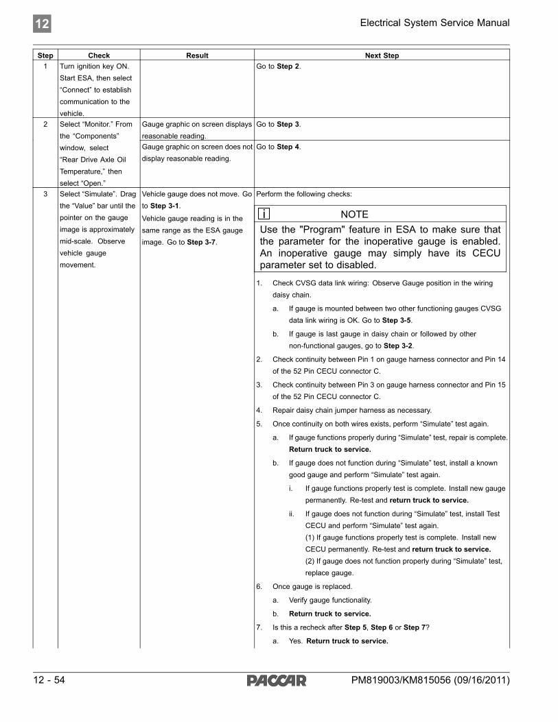
12 Electrical System Service Manual
Step Check Result Next Step1 Turn ignition key ON.
Start ESA, then select“Connect” to establishcommunication to thevehicle.
Go to Step 2.
Gauge graphic on screen displaysreasonable reading.
Go to Step 3.2 Select “Monitor.” Fromthe “Components”window, select“Rear Drive Axle OilTemperature,” thenselect “Open.”
Gauge graphic on screen does notdisplay reasonable reading.
Go to Step 4.
3 Select “Simulate”. Dragthe “Value” bar until thepointer on the gaugeimage is approximatelymid-scale. Observevehicle gaugemovement.
Vehicle gauge does not move. Goto Step 3-1.
Vehicle gauge reading is in thesame range as the ESA gaugeimage. Go to Step 3-7.
Perform the following checks:
NOTEUse the "Program" feature in ESA to make sure thatthe parameter for the inoperative gauge is enabled.An inoperative gauge may simply have its CECUparameter set to disabled.
1. Check CVSG data link wiring: Observe Gauge position in the wiringdaisy chain.
a. If gauge is mounted between two other functioning gauges CVSGdata link wiring is OK. Go to Step 3-5.
b. If gauge is last gauge in daisy chain or followed by othernon-functional gauges, go to Step 3-2.
2. Check continuity between Pin 1 on gauge harness connector and Pin 14of the 52 Pin CECU connector C.
3. Check continuity between Pin 3 on gauge harness connector and Pin 15of the 52 Pin CECU connector C.
4. Repair daisy chain jumper harness as necessary.
5. Once continuity on both wires exists, perform “Simulate” test again.
a. If gauge functions properly during “Simulate” test, repair is complete.Return truck to service.
b. If gauge does not function during “Simulate” test, install a knowngood gauge and perform “Simulate” test again.
i. If gauge functions properly test is complete. Install new gaugepermanently. Re-test and return truck to service.
ii. If gauge does not function during “Simulate” test, install TestCECU and perform “Simulate” test again.(1) If gauge functions properly test is complete. Install newCECU permanently. Re-test and return truck to service.(2) If gauge does not function properly during “Simulate” test,replace gauge.
6. Once gauge is replaced.
a. Verify gauge functionality.
b. Return truck to service.
7. Is this a recheck after Step 5, Step 6 or Step 7?
a. Yes. Return truck to service.
12 - 54 PM819003/KM815056 (09/16/2011)

Electrical System Service Manual 12
Step Check Result Next Step
b. No, Gauge and CVSG data link wiring is not the problem. Go toStep 4.
DTC 7703 displayed - Open inaxle 2 oil temp circuit.
Indicates the problem could be an open in the wiring from the Chassis Node tothe sensor or a defective sensor. Go to Step 5, and if necessary, Step 6.
4 Select “Diagnose” toview rear drive axletemperature gaugediagnostic troublecodes.
DTC 7704 displayed - Short inaxle 2 oil temp circuit.
Indicates the problem could be a short to ground in the wiring from the ChassisNode to the sensor or a defective sensor. Go to Step 5, and if necessary,Step 7.
5 Unplug oil temperatureharness connector atsensor.
Using a digitalmultimeter, checkcontinuity on groundand signal wire atsensor connector.
Pin A – Ground
Pin B - Signal
See Chassis NodePinout for terminaldetails of the ChassisNode electricalconnections.
(Sensor Ground) - There shouldbe continuity between the sensorconnector ground wire (Pin A) anda cab ground terminal.
(Signal) - There should becontinuity between the sensorconnector signal wire (Pin B)and Pin 10 of the Chassis Nodeconnector C.
1. Check for continuity between sensor connector Pin A and firewall groundstud.
a. If there is continuity between Pin A and the ground terminal, test iscomplete. Go to Step 5-2.
b. If there is no continuity between Pin A and the ground terminal,repair wiring as necessary. Go to Step 5-1.
2. Check for continuity between sensor connector Pin B and Pin 10 of theChassis Node connector C.
a. If there is continuity between Pin B and Pin 10, test is complete.Go to Step 6.
b. If there is no continuity between Pin B and Pin 10, repair wiring asnecessary. Go to Step 5-2.
Alternate test method: Resistance in the oil temperature sensor (thermistor)signal wire changes as oil temperature increases/decreases.
1. By unplugging the oil temperature sensor harness connector andconnecting a resistor decade box (i.e., Ametek PST2000 Tester), or anappropriate resistor to Pins A and B, you can simulate the sensor bydialing in a known resistance.
2. Observe vehicle gauge reading on dash.
3. If gauge needle moves to approximately the same temperature as inthe table below, the problem is a defective oil temperature sensor. Seetable below.
Temp °F Resistance Ohms-40
-22
-4
14
32
50
68
86
104
122
140
158
176
194
212
230
248
266
100,856
52,594
28,582
16,120
9,399
5,658
3,511
2,240
1,465
980.3
670.9
468.7
333.8
241.8
178.03
133.08
100.91
77.54
PM819003/KM815056 (09/16/2011) 12 - 55
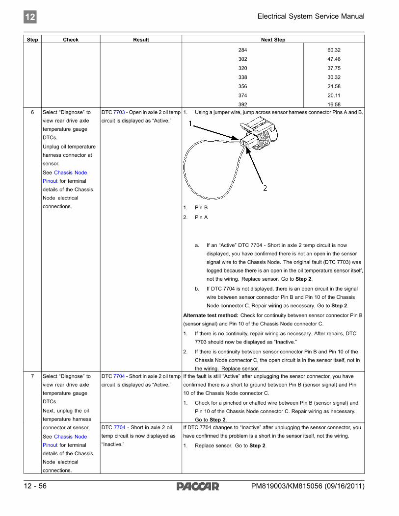
12 Electrical System Service Manual
Step Check Result Next Step
284
302
320
338
356
374
392
60.32
47.46
37.75
30.32
24.58
20.11
16.586 Select “Diagnose” to
view rear drive axletemperature gaugeDTCs.
Unplug oil temperatureharness connector atsensor.
See Chassis NodePinout for terminaldetails of the ChassisNode electricalconnections.
DTC 7703 - Open in axle 2 oil tempcircuit is displayed as “Active.”
1. Using a jumper wire, jump across sensor harness connector Pins A and B.
1. Pin B
2. Pin A
a. If an “Active” DTC 7704 - Short in axle 2 temp circuit is nowdisplayed, you have confirmed there is not an open in the sensorsignal wire to the Chassis Node. The original fault (DTC 7703) waslogged because there is an open in the oil temperature sensor itself,not the wiring. Replace sensor. Go to Step 2.
b. If DTC 7704 is not displayed, there is an open circuit in the signalwire between sensor connector Pin B and Pin 10 of the ChassisNode connector C. Repair wiring as necessary. Go to Step 2.
Alternate test method: Check for continuity between sensor connector Pin B(sensor signal) and Pin 10 of the Chassis Node connector C.
1. If there is no continuity, repair wiring as necessary. After repairs, DTC7703 should now be displayed as “Inactive.”
2. If there is continuity between sensor connector Pin B and Pin 10 of theChassis Node connector C, the open circuit is in the sensor itself, not inthe wiring. Replace sensor.
DTC 7704 - Short in axle 2 oil tempcircuit is displayed as “Active.”
If the fault is still “Active” after unplugging the sensor connector, you haveconfirmed there is a short to ground between Pin B (sensor signal) and Pin10 of the Chassis Node connector C.
1. Check for a pinched or chaffed wire between Pin B (sensor signal) andPin 10 of the Chassis Node connector C. Repair wiring as necessary.Go to Step 2.
7 Select “Diagnose” toview rear drive axletemperature gaugeDTCs.
Next, unplug the oiltemperature harnessconnector at sensor.
See Chassis NodePinout for terminaldetails of the ChassisNode electricalconnections.
DTC 7704 - Short in axle 2 oiltemp circuit is now displayed as“Inactive.”
If DTC 7704 changes to “Inactive” after unplugging the sensor connector, youhave confirmed the problem is a short in the sensor itself, not the wiring.
1. Replace sensor. Go to Step 2.
12 - 56 PM819003/KM815056 (09/16/2011)
Electrical System Service Manual 12
Return to Table Of Contents
PM819003/KM815056 (09/16/2011) 12 - 57

12 Electrical System Service Manual
Center/Steer Axle Oil TemperatureGauge Inoperative
DTC7803 and DTC7804Symptom: Center/Steer axle oil temperaturegauge inoperative. All other gauges areoperational.
The Center/Steer Axle Oil Temperature Gaugeuses a thermistor sensor to measure axle oiltemperature.
The following procedures have been developedto assist the technician in diagnosing multiplexedinstrumentation problems using the ElectronicService Analyst (ESA) hardware/softwarediagnostic tool. It is assumed the servicetechnician performing instrumentation repairs isknowledgeable about how to use ESA.
12 - 58 PM819003/KM815056 (09/16/2011)

Electrical System Service Manual 12
Step Check Result Next Step1 Turn ignition key ON.
Start ESA, then select“Connect” to establishcommunication to thevehicle.
Go to Step 2.
Gauge graphic on screen displaysreasonable reading.
Go to Step 3.2 Select “Monitor.” Fromthe “Components”window, select“Center/Steer AxleOil Temperature,” thenselect “Open.”
Gauge graphic on screen does notdisplay reasonable reading.
Go to Step 4.
3 Select “Simulate”. Dragthe “Value” bar until thepointer on the gaugeimage is approximatelymid-scale. Observevehicle gaugemovement.
Vehicle gauge does not move. Goto Step 3-1.
Vehicle gauge reading is in thesame range as the ESA gaugeimage. Go to Step 3-7.
Perform the following checks:
NOTEUse the "Program" feature in ESA to make sure thatthe parameter for the inoperative gauge is enabled.An inoperative gauge may simply have its CECUparameter set to disabled.
1. Check CVSG data link wiring: Observe Gauge position in the wiringdaisy chain.
a. If gauge is mounted between two other functioning gauges CVSGdata link wiring is OK. Go to Step 3-5.
b. If gauge is last gauge in daisy chain or followed by othernon-functional gauges, go to Step 3-2.
2. Check continuity between Pin 1 on gauge harness connector and Pin 14of the 52 Pin CECU connector C.
3. Check continuity between Pin 3 on gauge harness connector and Pin 15of the 52 Pin CECU connector C.
4. Repair daisy chain jumper harness as necessary.
5. Once continuity on both wires exists, perform “Simulate” test again.
a. If gauge functions properly during “Simulate” test, repair is complete.Return truck to service.
b. If gauge does not function during “Simulate” test, install a knowngood gauge and perform “Simulate” test again.
i. If gauge functions properly test is complete. Install new gaugepermanently. Re-test and return truck to service.
ii. If gauge does not function during “Simulate” test, install TestCECU and perform “Simulate” test again.(1) If gauge functions properly test is complete. Install newCECU permanently. Re-test and return truck to service.(2) If gauge does not function properly during “Simulate” test,replace gauge.
6. Once gauge is replaced.
a. Verify gauge functionality.
b. Return truck to service.
7. Is this a recheck after Step 5, Step 6 or Step 7?
a. Yes. Return truck to service.
PM819003/KM815056 (09/16/2011) 12 - 59

12 Electrical System Service Manual
Step Check Result Next Step
b. No, Gauge and CVSG data link wiring is not the problem. Go toStep 4.
DTC 7803 displayed - Open inaxle 3 oil temp circuit.
Indicates the problem could be an open in the wiring from the Chassis Node tothe sensor or a defective sensor. Go to Step 5, and if necessary, Step 6.
4 Select “Diagnose” toview center/steer axletemperature gaugediagnostic troublecodes.
DTC 7804 displayed - Short inaxle 3 oil temp circuit.
Indicates the problem could be a short to ground in the wiring from the ChassisNode to the sensor or a defective sensor. Go to Step 5, and if necessary,Step 7.
5 Unplug oil temperatureharness connector atsensor.
Using a digitalmultimeter, checkcontinuity on groundand signal wire atsensor connector.
Pin A – Ground
Pin B - Signal
See Chassis NodePinout for terminaldetails of the ChassisNode electricalconnections.
(Sensor Ground) - There shouldbe continuity between the sensorconnector ground wire (Pin A) anda cab ground terminal.
(Signal) - There should becontinuity between the sensorconnector signal wire (Pin B)and Pin 16 of the Chassis Nodeconnector C.
1. Check for continuity between sensor connector Pin A and firewall groundstud.
a. If there is continuity between Pin A and the ground terminal, test iscomplete. Go to Step 5-2.
b. If there is no continuity between Pin A and the ground terminal,repair wiring as necessary. Go to Step 5-1.
2. Check for continuity between sensor connector Pin B and Pin 16 of theChassis Node connector C.
a. If there is continuity between Pin B and Pin 16, test is complete.Go to Step 6.
b. If there is no continuity between Pin B and Pin 16, repair wiring asnecessary. Go to Step 5-2.
Alternate test method: Resistance in the oil temperature sensor (thermistor)signal wire changes as oil temperature increases/decreases.
1. By unplugging the oil temperature sensor harness connector andconnecting a resistor decade box (i.e., Ametek PST2000 Tester), or anappropriate resistor to Pins A and B, you can simulate the sensor bydialing in a known resistance.
2. Observe vehicle gauge reading on dash.
3. If gauge needle moves to approximately the same temperature as inthe table below, the problem is a defective oil temperature sensor. Seetable below.
Temp °F Resistance Ohms-40
-22
-4
14
32
50
68
86
104
122
140
158
176
194
212
230
248
266
100,856
52,594
28,582
16,120
9,399
5,658
3,511
2,240
1,465
980.3
670.9
468.7
333.8
241.8
178.03
133.08
100.91
77.54
12 - 60 PM819003/KM815056 (09/16/2011)

Electrical System Service Manual 12
Step Check Result Next Step
284
302
320
338
356
374
392
60.32
47.46
37.75
30.32
24.58
20.11
16.586 Select “Diagnose” to
view center/steer axletemperature gaugeDTCs.
Unplug oil temperatureharness connector atsensor.
See Chassis NodePinout for terminaldetails of the ChassisNode electricalconnections.
DTC 7803 - Open in axle 3 oil tempcircuit is displayed as “Active.”
1. Using a jumper wire, jump across sensor harness connector Pins A and B.
1. Pin B
2. Pin A
a. If an “Active” DTC 7804 - Short in axle 3 temp circuit is nowdisplayed, you have confirmed there is not an open in the sensorsignal wire to the Chassis Node. The original fault (DTC 7803) waslogged because there is an open in the oil temperature sensor itself,not the wiring. Replace sensor. Go to Step 2.
b. If DTC 7804 is not displayed, there is an open circuit in the signalwire between sensor connector Pin B and Pin 16 of the ChassisNode connector C. Repair wiring as necessary. Go to Step 2.
Alternate test method: Check for continuity between sensor connector Pin B(sensor signal) and Pin 16 of the Chassis Node connector C.
1. If there is no continuity, repair wiring as necessary. After repairs, DTC7803 should now be displayed as “Inactive.”
2. If there is continuity between sensor connector Pin 16 of the ChassisNode connector C, the open circuit is in the sensor itself, not in the wiring.Replace sensor.
DTC 7804 - Short in axle 3 oil tempcircuit is displayed as “Active.”
If the fault is still “Active” after unplugging the sensor connector, you haveconfirmed there is a short to ground between Pin B (sensor signal) and Pin16 of the Chassis Node connector C.
1. Check for a pinched or chaffed wire between Pin B (sensor signal) andPin 16 of the Chassis Node connector C. Repair wiring as necessary.Go to Step 2.
7 Select “Diagnose” toview center/steer axletemperature gaugeDTCs.
Next, unplug the oiltemperature harnessconnector at sensor.
See Chassis NodePinout for terminaldetails of the ChassisNode electricalconnections.
DTC 7804 - Short in axle 3 oiltemp circuit is now displayed as“Inactive.”
If DTC 77804 changes to “Inactive” after unplugging the sensor connector, youhave confirmed the problem is a short in the sensor itself, not the wiring.
1. Replace sensor. Go to Step 2.
PM819003/KM815056 (09/16/2011) 12 - 61

12 Electrical System Service Manual
Return to Table Of Contents
12 - 62 PM819003/KM815056 (09/16/2011)
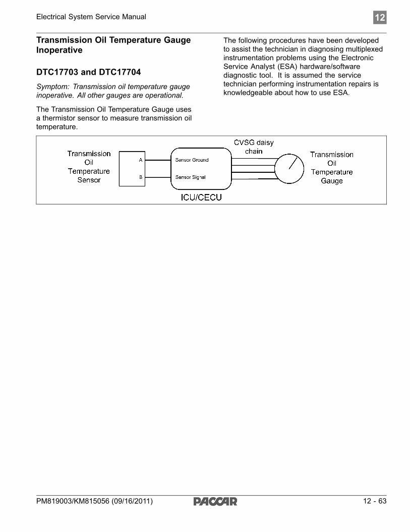
Electrical System Service Manual 12
Transmission Oil Temperature GaugeInoperative
DTC17703 and DTC17704Symptom: Transmission oil temperature gaugeinoperative. All other gauges are operational.
The Transmission Oil Temperature Gauge usesa thermistor sensor to measure transmission oiltemperature.
The following procedures have been developedto assist the technician in diagnosing multiplexedinstrumentation problems using the ElectronicService Analyst (ESA) hardware/softwarediagnostic tool. It is assumed the servicetechnician performing instrumentation repairs isknowledgeable about how to use ESA.
PM819003/KM815056 (09/16/2011) 12 - 63

12 Electrical System Service Manual
Step Check Result Next Step1 Turn ignition key ON.
Start ESA, then select“Connect” to establishcommunication to thevehicle.
Go to Step 2.
Gauge graphic on screen displaysreasonable reading.
Go to Step 3.2 Select “Monitor.” Fromthe “Components”window, select“Transmission OilTemperature,” thenselect “Open.”
Gauge graphic on screen does notdisplay reasonable reading.
Go to Step 4.
3 Select “Simulate”. Dragthe “Value” bar until thepointer on the gaugeimage is approximatelymid-scale. Observevehicle gaugemovement.
Vehicle gauge does not move. Goto Step 3-1.
Vehicle gauge reading is in thesame range as the ESA gaugeimage. Go to Step 3-7.
Perform the following checks:
NOTEUse the "Program" feature in ESA to make sure thatthe parameter for the inoperative gauge is enabled.An inoperative gauge may simply have its CECUparameter set to disabled.
1. Check CVSG data link wiring: Observe Gauge position in the wiringdaisy chain.
a. If gauge is mounted between two other functioning gauges CVSGdata link wiring is OK. Go to Step 3-5.
b. If gauge is last gauge in daisy chain or followed by othernon-functional gauges, go to Step 3-2.
2. Check continuity between Pin 1 on gauge harness connector and Pin 14of the 52 Pin CECU connector C.
3. Check continuity between Pin 3 on gauge harness connector and Pin 15of the 52 Pin CECU connector C.
4. Repair daisy chain jumper harness as necessary.
5. Once continuity on both wires exists, perform “Simulate” test again.
a. If gauge functions properly during “Simulate” test, repair is complete.Return truck to service.
b. If gauge does not function during “Simulate” test, install a knowngood gauge and perform “Simulate” test again.
i. If gauge functions properly test is complete. Install new gaugepermanently. Re-test and return truck to service.
ii. If gauge does not function during “Simulate” test, install TestCECU and perform “Simulate” test again.(1) If gauge functions properly test is complete. Install newCECU permanently. Re-test and return truck to service.(2) If gauge does not function properly during “Simulate” test,replace gauge.
6. Once gauge is replaced.
a. Verify gauge functionality.
b. Return truck to service.
7. Is this a recheck after Step 5, Step 6 or Step 7?
a. Yes. Return truck to service.
12 - 64 PM819003/KM815056 (09/16/2011)

Electrical System Service Manual 12
Step Check Result Next Step
b. No, Gauge and CVSG data link wiring is not the problem. Go toStep 4.
DTC 17703 displayed – Open intransmission oil temp circuit.
Indicates the problem could be an open in the wiring from the CECU to thesensor or a defective sensor. Go to Step 5, and if necessary, Step 6.
4 Select “Diagnose” toview main transmissionoil temperature gaugediagnostic troublecodes.
DTC 17704 displayed – Short intransmission oil temp circuit.
Indicates the problem could be a short to ground in the wiring from the CECUto the sensor or a defective sensor. Go to Step 5, and if necessary, Step 7.
5 Unplug oil temperatureharness connector atsensor.
Using a digitalmultimeter, checkcontinuity on groundand signal wire atsensor connector.
Pin A – Ground
Pin B - Signal
See CECU Pinoutfor terminal details ofthe CECU electricalconnections.
(Sensor Ground) - There shouldbe continuity between the sensorconnector ground wire (Pin A) anda cab ground terminal.
(Signal) - There should becontinuity between the sensorconnector signal wire (Pin B)and Pin 21 of the 52 Pin CECUconnector C.
1. Check for continuity between sensor connector Pin A and firewall groundstud.
a. If there is continuity between Pin A and the ground terminal, test iscomplete. Go to Step 5-2.
b. If there is no continuity between Pin A and the ground terminal,repair wiring as necessary. Go to Step 5-1.
2. Check for continuity between sensor connector Pin B and Pin 21 of the52 Pin CECU connector C.
a. If there is continuity between Pin B and Pin 21, test is complete.Go to Step 6.
b. If there is no continuity between Pin B and Pin 21 at CECU, repairwiring as necessary. Go to Step 5-2.
Alternate test method: Resistance in the oil temperature sensor (thermistor)signal wire changes as oil temperature increases/decreases.
1. By unplugging the oil temperature sensor harness connector andconnecting a resistor decade box (i.e., Ametek PST2000 Tester), or anappropriate resistor to Pins A and B, you can simulate the sensor bydialing in a known resistance.
2. Observe vehicle gauge reading on dash.
3. If gauge needle moves to approximately the same temperature as inthe table below, the problem is a defective oil temperature sensor. Seetable below.
Temp °F Resistance Ohms-40
-22
-4
14
32
50
68
86
104
122
140
158
176
194
212
230
248
266
100,856
52,594
28,582
16,120
9,399
5,658
3,511
2,240
1,465
980.3
670.9
468.7
333.8
241.8
178.03
133.08
100.91
77.54
PM819003/KM815056 (09/16/2011) 12 - 65
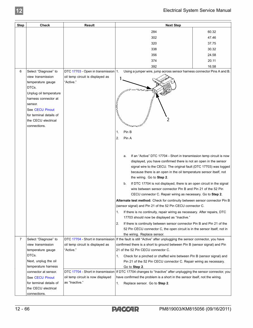
12 Electrical System Service Manual
Step Check Result Next Step
284
302
320
338
356
374
392
60.32
47.46
37.75
30.32
24.58
20.11
16.586 Select “Diagnose” to
view transmissiontemperature gaugeDTCs.
Unplug oil temperatureharness connector atsensor.
See CECU Pinoutfor terminal details ofthe CECU electricalconnections.
DTC 17703 - Open in transmissionoil temp circuit is displayed as“Active.”
1. Using a jumper wire, jump across sensor harness connector Pins A and B.
1. Pin B
2. Pin A
a. If an “Active” DTC 17704 - Short in transmission temp circuit is nowdisplayed, you have confirmed there is not an open in the sensorsignal wire to the CECU. The original fault (DTC 17703) was loggedbecause there is an open in the oil temperature sensor itself, notthe wiring. Go to Step 2.
b. If DTC 17704 is not displayed, there is an open circuit in the signalwire between sensor connector Pin B and Pin 21 of the 52 PinCECU connector C. Repair wiring as necessary. Go to Step 2.
Alternate test method: Check for continuity between sensor connector Pin B(sensor signal) and Pin 21 of the 52 Pin CECU connector C.
1. If there is no continuity, repair wiring as necessary. After repairs, DTC17703 should now be displayed as “Inactive.”
2. If there is continuity between sensor connector Pin B and Pin 21 of the52 Pin CECU connector C, the open circuit is in the sensor itself, not inthe wiring. Replace sensor.
DTC 17704 - Short in transmissionoil temp circuit is displayed as“Active.”
If the fault is still “Active” after unplugging the sensor connector, you haveconfirmed there is a short to ground between Pin B (sensor signal) and Pin21 of the 52 Pin CECU connector C.
1. Check for a pinched or chaffed wire between Pin B (sensor signal) andPin 21 of the 52 Pin CECU connector C. Repair wiring as necessary.Go to Step 2.
7 Select “Diagnose” toview transmissiontemperature gaugeDTCs.
Next, unplug the oiltemperature harnessconnector at sensor.
See CECU Pinoutfor terminal details ofthe CECU electricalconnections.
DTC 17704 - Short in transmissionoil temp circuit is now displayedas “Inactive.”
If DTC 17704 changes to “Inactive” after unplugging the sensor connector, youhave confirmed the problem is a short in the sensor itself, not the wiring.
1. Replace sensor. Go to Step 2.
12 - 66 PM819003/KM815056 (09/16/2011)

Electrical System Service Manual 12
Return to Table Of Contents
PM819003/KM815056 (09/16/2011) 12 - 67
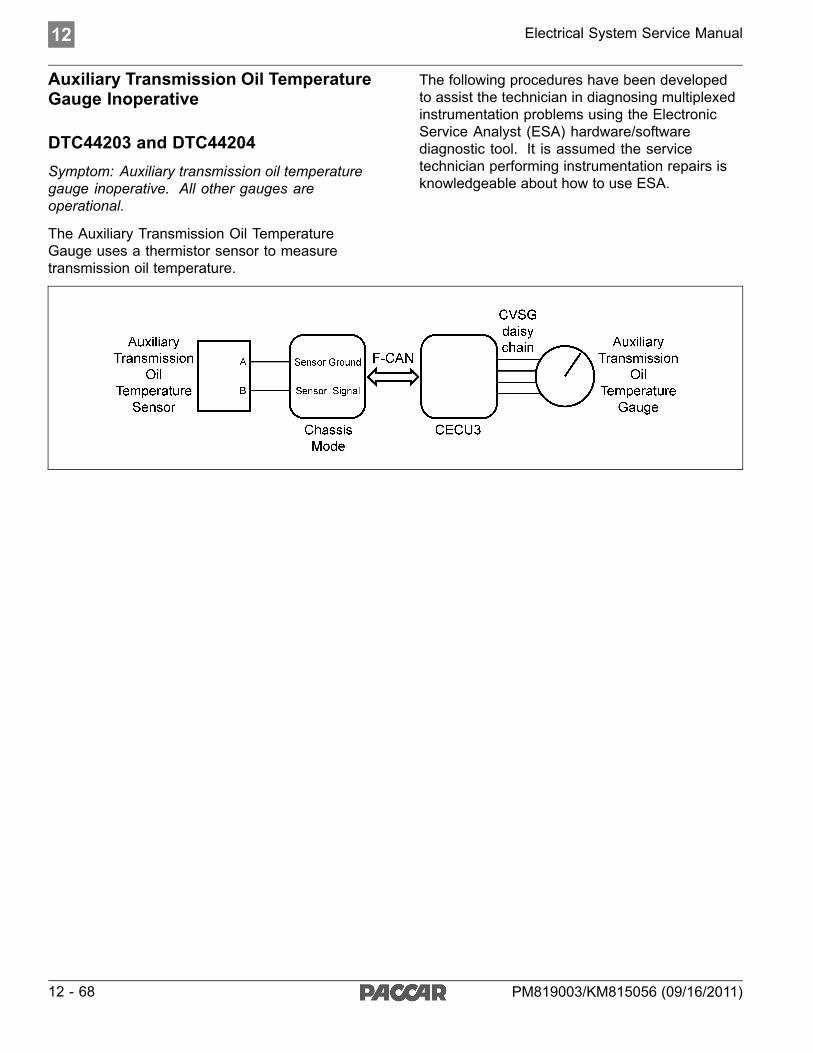
12 Electrical System Service Manual
Auxiliary Transmission Oil TemperatureGauge Inoperative
DTC44203 and DTC44204Symptom: Auxiliary transmission oil temperaturegauge inoperative. All other gauges areoperational.
The Auxiliary Transmission Oil TemperatureGauge uses a thermistor sensor to measuretransmission oil temperature.
The following procedures have been developedto assist the technician in diagnosing multiplexedinstrumentation problems using the ElectronicService Analyst (ESA) hardware/softwarediagnostic tool. It is assumed the servicetechnician performing instrumentation repairs isknowledgeable about how to use ESA.
12 - 68 PM819003/KM815056 (09/16/2011)
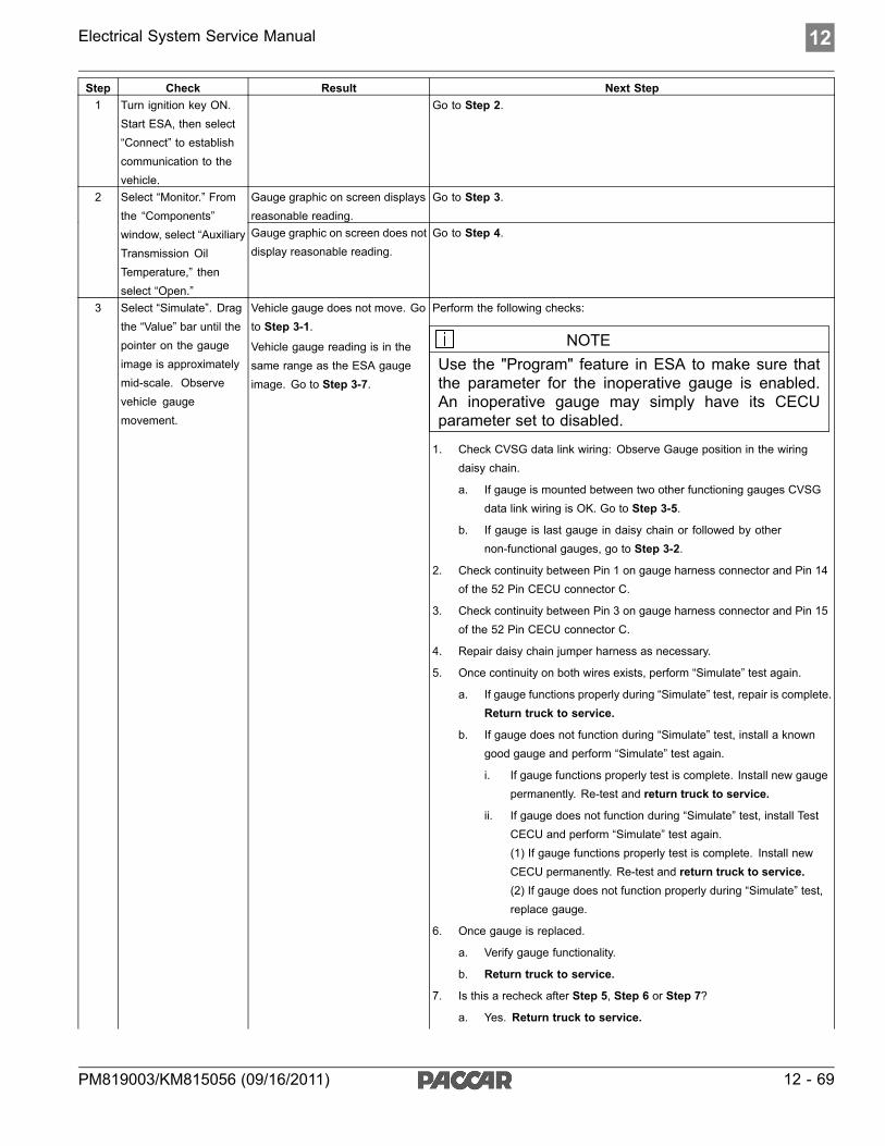
Electrical System Service Manual 12
Step Check Result Next Step1 Turn ignition key ON.
Start ESA, then select“Connect” to establishcommunication to thevehicle.
Go to Step 2.
Gauge graphic on screen displaysreasonable reading.
Go to Step 3.2 Select “Monitor.” Fromthe “Components”window, select “AuxiliaryTransmission OilTemperature,” thenselect “Open.”
Gauge graphic on screen does notdisplay reasonable reading.
Go to Step 4.
3 Select “Simulate”. Dragthe “Value” bar until thepointer on the gaugeimage is approximatelymid-scale. Observevehicle gaugemovement.
Vehicle gauge does not move. Goto Step 3-1.
Vehicle gauge reading is in thesame range as the ESA gaugeimage. Go to Step 3-7.
Perform the following checks:
NOTEUse the "Program" feature in ESA to make sure thatthe parameter for the inoperative gauge is enabled.An inoperative gauge may simply have its CECUparameter set to disabled.
1. Check CVSG data link wiring: Observe Gauge position in the wiringdaisy chain.
a. If gauge is mounted between two other functioning gauges CVSGdata link wiring is OK. Go to Step 3-5.
b. If gauge is last gauge in daisy chain or followed by othernon-functional gauges, go to Step 3-2.
2. Check continuity between Pin 1 on gauge harness connector and Pin 14of the 52 Pin CECU connector C.
3. Check continuity between Pin 3 on gauge harness connector and Pin 15of the 52 Pin CECU connector C.
4. Repair daisy chain jumper harness as necessary.
5. Once continuity on both wires exists, perform “Simulate” test again.
a. If gauge functions properly during “Simulate” test, repair is complete.Return truck to service.
b. If gauge does not function during “Simulate” test, install a knowngood gauge and perform “Simulate” test again.
i. If gauge functions properly test is complete. Install new gaugepermanently. Re-test and return truck to service.
ii. If gauge does not function during “Simulate” test, install TestCECU and perform “Simulate” test again.(1) If gauge functions properly test is complete. Install newCECU permanently. Re-test and return truck to service.(2) If gauge does not function properly during “Simulate” test,replace gauge.
6. Once gauge is replaced.
a. Verify gauge functionality.
b. Return truck to service.
7. Is this a recheck after Step 5, Step 6 or Step 7?
a. Yes. Return truck to service.
PM819003/KM815056 (09/16/2011) 12 - 69

12 Electrical System Service Manual
Step Check Result Next Step
b. No, Gauge and CVSG data link wiring is not the problem. Go toStep 4.
DTC 44203 displayed - Open inaux transmission temp circuit.
Indicates the problem could be an open in the wiring from the Chassis Node tothe sensor or a defective sensor. Go to Step 5, and if necessary, Step 6.
4 Select “Diagnose”to view auxiliarytransmission oiltemperature gaugediagnostic troublecodes.
DTC 44204 displayed - Short inaux transmission temp circuit.
Indicates the problem could be a short to ground in the wiring from the ChassisNode to the sensor or a defective sensor. Go to Step 5, and if necessary,Step 7.
5 Unplug oil temperatureharness connector atsensor.
Using a digitalmultimeter, checkcontinuity on groundand signal wire atsensor connector.
Pin A – Ground
Pin B - Signal
See Chassis NodePinout for terminaldetails of the ChassisNode electricalconnections.
(Sensor Ground)- There shouldbe continuitybetweenthe sensorconnectorground wire (PinA) and a cabground terminal.
(Signal) -There shouldbe continuitybetweenthe sensorconnector signalwire (Pin B) andPin 6 of theChassis Nodeconnector B.
1. Check for continuitybetween sensorconnector Pin A andfirewall ground stud.
a. If there iscontinuitybetween Pin Aand the groundterminal, test iscomplete. Goto Step 5-2.
b. If there isno continuitybetween Pin Aand the groundterminal, repairwiring asnecessary. Goto Step 5-1.
2. Check for continuitybetween sensorconnector Pin B andPin 6 of the ChassisNode connector B.
a. If there iscontinuitybetween Pin Band Pin 6, testis complete.Go to Step 6.
b. If there isno continuitybetween PinB and Pin 6,repair wiring asnecessary. Goto Step 5-2.
Alternate test method:Resistance in theoil temperaturesensor (thermistor)
12 - 70 PM819003/KM815056 (09/16/2011)
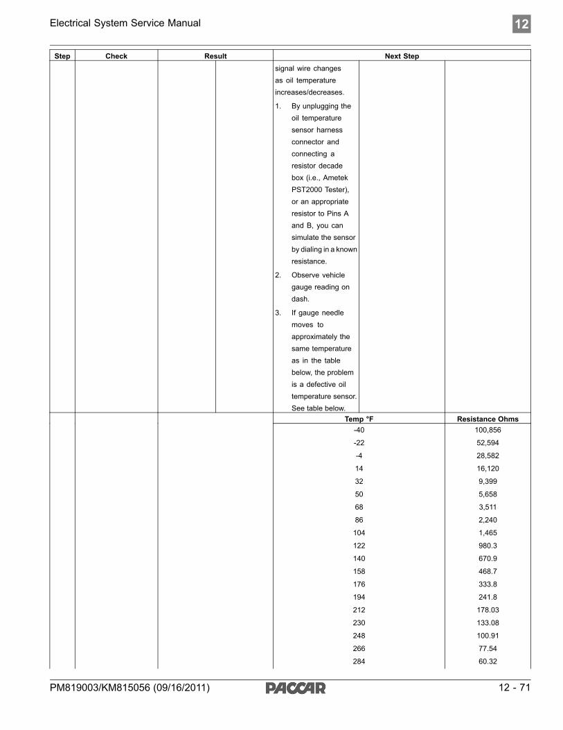
Electrical System Service Manual 12
Step Check Result Next Stepsignal wire changesas oil temperatureincreases/decreases.
1. By unplugging theoil temperaturesensor harnessconnector andconnecting aresistor decadebox (i.e., AmetekPST2000 Tester),or an appropriateresistor to Pins Aand B, you cansimulate the sensorby dialing in a knownresistance.
2. Observe vehiclegauge reading ondash.
3. If gauge needlemoves toapproximately thesame temperatureas in the tablebelow, the problemis a defective oiltemperature sensor.See table below.
Temp °F Resistance Ohms-40
-22
-4
14
32
50
68
86
104
122
140
158
176
194
212
230
248
266
284
100,856
52,594
28,582
16,120
9,399
5,658
3,511
2,240
1,465
980.3
670.9
468.7
333.8
241.8
178.03
133.08
100.91
77.54
60.32
PM819003/KM815056 (09/16/2011) 12 - 71

12 Electrical System Service Manual
Step Check Result Next Step
302
320
338
356
374
392
47.46
37.75
30.32
24.58
20.11
16.586 Select “Diagnose”
to view auxiliarytransmissiontemperature gaugeDTCs.
Unplug oil temperatureharness connector atsensor.
See Chassis NodePinout for terminaldetails of the ChassisNode electricalconnections.
DTC 44203 - Open in auxtransmission temp circuit isdisplayed as “Active.”
1. Using a jumper wire, jump across sensor harness connector Pins A and B.
1. Pin B
2. Pin A
a. If an “Active” DTC 44204 - Short in transmission temp circuit is nowdisplayed, you have confirmed there is not an open in the sensorsignal wire to the Chassis Node. The original fault (DTC 44203)was logged because there is an open in the oil temperature sensoritself, not the wiring. Go to Step 2.
b. If DTC 44204 is not displayed, there is an open circuit in the signalwire between sensor connector Pin B and Pin 6 of the Chassis Nodeconnector B. Repair wiring as necessary. Go to Step 2.
Alternate test method: Check for continuity between sensor connector Pin B(sensor signal) and Pin 6 of the Chassis Node connector B.
1. If there is no continuity, repair wiring as necessary. After repairs, DTC44203 should now be displayed as “Inactive.”
2. If there is continuity between sensor connector Pin B and Pin 6 of theChassis Node connector B, the open circuit is in the sensor itself, not inthe wiring. Replace sensor.
DTC 44204 - Short in auxtransmission temp circuit isdisplayed as “Active.”
If the fault is still “Active” after unplugging the sensor connector, you haveconfirmed there is a short to ground between Pin B (sensor signal) and Pin6 of the Chassis Node connector B.
1. Check for a pinched or chaffed wire between Pin B (sensor signal) andPin 6 of the Chassis Node connector B. Repair wiring as necessary. Goto Step 2.
7 Select “Diagnose”to view auxiliarytransmissiontemperature gaugeDTCs.
Next, unplug the oiltemperature harnessconnector at sensor.
See Chassis NodePinout for terminaldetails of the ChassisNode electricalconnections.
DTC 44204 - Short in auxtransmission temp circuit is nowdisplayed as “Inactive.”
If DTC 44204 changes to “Inactive” after unplugging the sensor connector, youhave confirmed the problem is a short in the sensor itself, not the wiring.
1. Replace sensor. Go to Step 2.
12 - 72 PM819003/KM815056 (09/16/2011)

Electrical System Service Manual 12
Return to Table Of Contents
PM819003/KM815056 (09/16/2011) 12 - 73

12 Electrical System Service Manual
Transfer Case Oil Temperature GaugeInoperative
DTC138803 and DTC138804Symptom: Transfer case oil temperature gaugeinoperative. All other gauges are operational.
The Transfer Case Oil Temperature Gauge uses athermistor sensor to measure the oil temperature.
The following procedures have been developedto assist the technician in diagnosing multiplexedinstrumentation problems using the ElectronicService Analyst (ESA) hardware/softwarediagnostic tool. It is assumed the servicetechnician performing instrumentation repairs isknowledgeable about how to use ESA.
12 - 74 PM819003/KM815056 (09/16/2011)

Electrical System Service Manual 12
Step Check Result Next Step1 Turn ignition key ON.
Start ESA, then select“Connect” to establishcommunication to thevehicle.
Go to Step 2.
Gauge graphic on screen displaysreasonable reading.
Go to Step 3.2 Select “Monitor.” Fromthe “Components”window, select “TransferCase Oil Temperature,”then select “Open.”
Gauge graphic on screen does notdisplay reasonable reading.
Go to Step 4.
3 Select “Simulate”. Dragthe “Value” bar until thepointer on the gaugeimage is approximatelymid-scale. Observevehicle gaugemovement.
Vehicle gauge does not move. Goto Step 3-1.
Vehicle gauge reading is in thesame range as the ESA gaugeimage. Go to Step 3-7.
Perform the following checks:
NOTEUse the "Program" feature in ESA to make sure thatthe parameter for the inoperative gauge is enabled.An inoperative gauge may simply have its CECUparameter set to disabled.
1. Check CVSG data link wiring: Observe Gauge position in the wiringdaisy chain.
a. If gauge is mounted between two other functioning gauges CVSGdata link wiring is OK. Go to Step 3-5.
b. If gauge is last gauge in daisy chain or followed by othernon-functional gauges, go to Step 3-2.
2. Check continuity between Pin 1 on gauge harness connector and Pin 14of the 52 Pin CECU connector C.
3. Check continuity between Pin 3 on gauge harness connector and Pin 15of the 52 Pin CECU connector C.
4. Repair daisy chain jumper harness as necessary.
5. Once continuity on both wires exists, perform “Simulate” test again.
a. If gauge functions properly during “Simulate” test, repair is complete.Return truck to service.
b. If gauge does not function during “Simulate” test, install a knowngood gauge and perform “Simulate” test again.
i. If gauge functions properly test is complete. Install new gaugepermanently. Re-test and return truck to service.
ii. If gauge does not function during “Simulate” test, install TestCECU and perform “Simulate” test again.(1) If gauge functions properly test is complete. Install newCECU permanently. Re-test and return truck to service.(2) If gauge does not function properly during “Simulate” test,replace gauge.
6. Once gauge is replaced.
a. Verify gauge functionality.
b. Return truck to service.
7. Is this a recheck after Step 5, Step 6 or Step 7?
a. Yes. Return truck to service.
b. No, Gauge and CVSG data link wiring is not the problem. Go toStep 4.
PM819003/KM815056 (09/16/2011) 12 - 75

12 Electrical System Service Manual
Step Check Result Next StepDTC 138803 displayed - Open intransfer case oil temp circuit.
Indicates the problem could be an open in the wiring from the Chassis Node tothe sensor or a defective sensor. Go to Step 5, and if necessary, Step 6.
4 Select “Diagnose” toview transfer case oiltemperature gaugediagnostic troublecodes.
DTC 138804 displayed - Short intransfer case oil temp circuit.
Indicates the problem could be a short to ground in the wiring from the ChassisNode to the sensor or a defective sensor. Go to Step 5, and if necessary,Step 7.
5 Unplug oil temperatureharness connector atsensor.
Using a digitalmultimeter, checkcontinuity on groundand signal wire atsensor connector.
Pin A – Ground
Pin B - Signal
See Chassis NodePinout for terminaldetails of the ChassisNode electricalconnections.
(Sensor Ground) - There shouldbe continuity between the sensorconnector ground wire (Pin A) anda cab ground terminal.
(Signal) - There should becontinuity between the sensorconnector signal wire (Pin B)and Pin 4 of the Chassis Nodeconnector C.
1. Check for continuity between sensor connector Pin A and firewall groundstud.
a. If there is continuity between Pin A and the ground terminal, test iscomplete. Go to Step 5-2.
b. If there is no continuity between Pin A and the ground terminal,repair wiring as necessary. Go to Step 5-1.
2. Check for continuity between sensor connector Pin B and Pin 4 of theChassis Node connector C.
a. If there is continuity between Pin B and Pin 4, test is complete .Go to Step 6.
b. If there is no continuity between Pin B and Pin 4 at Chassis Node,repair wiring as necessary. Go to Step 5-2.
Alternate test method: Resistance in the oil temperature sensor (thermistor)signal wire changes as oil temperature increases/decreases.
1. By unplugging the oil temperature sensor harness connector andconnecting a resistor decade box (i.e., Ametek PST2000 Tester), or anappropriate resistor to Pins A and B, you can simulate the sensor bydialing in a known resistance.
2. Observe vehicle gauge reading on dash.
3. If gauge needle moves to approximately the same temperature as inthe table below, the problem is a defective oil temperature sensor. Seetable below.
Temp °F Resistance Ohms-40
-22
-4
14
32
50
68
86
104
122
140
158
176
194
212
230
248
266
284
302
100,856
52,594
28,582
16,120
9,399
5,658
3,511
2,240
1,465
980.3
670.9
468.7
333.8
241.8
178.03
133.08
100.91
77.54
60.32
47.46
12 - 76 PM819003/KM815056 (09/16/2011)

Electrical System Service Manual 12
Step Check Result Next Step
320
338
356
374
392
37.75
30.32
24.58
20.11
16.586 Select “Diagnose” to
view transfer casetemperature gaugeDTCs.
Unplug oil temperatureharness connector atsensor.
See Chassis NodePinout for terminaldetails of the ChassisNode electricalconnections.
DTC 138803 - Open in transfercase oil temp circuit is displayedas “Active.”
1. Using a jumper wire, jump across sensor harness connector Pins A and B.
1. Pin B
2. Pin A
a. If an “Active” DTC 138804 - Short in transfer case oil temp circuitis now displayed, you have confirmed there is not an open in thesensor signal wire to the Chassis Node. The original fault (DTC138803) was logged because there is an open in the oil temperaturesensor itself, not the wiring. Go to Step 2.
b. If DTC 138804 is not displayed, there is an open circuit in the signalwire between sensor connector Pin B and Pin 4 of the Chassis Nodeconnector C. Repair wiring as necessary. Go to Step 2.
Alternate test method: Check for continuity between sensor connector Pin B(sensor signal) and Pin 4 of the Chassis Node connector C.
1. If there is no continuity, repair wiring as necessary. After repairs, DTC138803 should now be displayed as “Inactive.”
2. If there is continuity between sensor connector Pin B and Pin 4 of theChassis Node connector C, the open circuit is in the sensor itself, not inthe wiring. Replace sensor.
DTC 138804 - Short in transfercase oil temp circuit is displayedas “Active.”
A . If the fault is still “Active” after unplugging the sensor connector, you haveconfirmed there is a short to ground between Pin B (sensor signal) and Pin4 of the Chassis Node connector C.
1. Check for a pinched or chaffed wire between Pin B (sensor signal) andPin 4 of the Chassis Node connector C. Repair wiring as necessary.Go to Step 2.
7 Select “Diagnose” toview transfer case oiltemperature gaugeDTCs.
Next, unplug the oiltemperature harnessconnector at sensor.
See Chassis NodePinout for terminaldetails of the ChassisNode electricalconnections.
DTC 138804 - Short in transfercase oil temp circuit is nowdisplayed as “Inactive.”
If DTC 138804 changes to “Inactive” after unplugging the sensor connector,you have confirmed the problem is a short in the sensor itself, not the wiring.
1. Replace sensor. Go to Step 2.
Return to Table Of Contents
PM819003/KM815056 (09/16/2011) 12 - 77
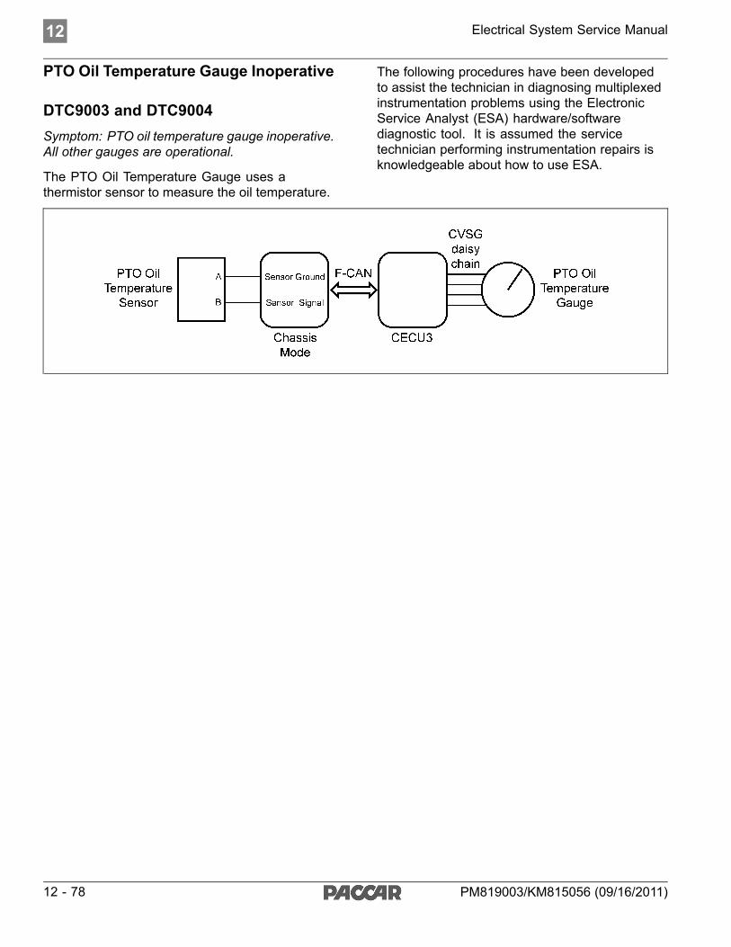
12 Electrical System Service Manual
PTO Oil Temperature Gauge Inoperative
DTC9003 and DTC9004Symptom: PTO oil temperature gauge inoperative.All other gauges are operational.
The PTO Oil Temperature Gauge uses athermistor sensor to measure the oil temperature.
The following procedures have been developedto assist the technician in diagnosing multiplexedinstrumentation problems using the ElectronicService Analyst (ESA) hardware/softwarediagnostic tool. It is assumed the servicetechnician performing instrumentation repairs isknowledgeable about how to use ESA.
12 - 78 PM819003/KM815056 (09/16/2011)

Electrical System Service Manual 12
Step Check Result Next Step1 Turn ignition key ON.
Start ESA, then select“Connect” to establishcommunication to thevehicle.
Go to Step 2.
Gauge graphic on screen displaysreasonable reading.
Go to Step 3.2 Select “Monitor.” Fromthe “Components”window, select “PTOOil Temperature,” thenselect “Open.”
Gauge graphic on screen does notdisplay reasonable reading.
Go to Step 4.
3 Select “Simulate”. Dragthe “Value” bar until thepointer on the gaugeimage is approximatelymid-scale. Observevehicle gaugemovement.
Vehicle gauge does not move. Goto Step 3-1.
Vehicle gauge reading is in thesame range as the ESA gaugeimage. Go to Step 3-7.
Perform the following checks:
NOTEUse the "Program" feature in ESA to make sure thatthe parameter for the inoperative gauge is enabled.An inoperative gauge may simply have its CECUparameter set to disabled.
1. Check CVSG data link wiring: Observe Gauge position in the wiringdaisy chain.
a. If gauge is mounted between two other functioning gauges CVSGdata link wiring is OK. Go to Step 3-5.
b. If gauge is last gauge in daisy chain or followed by othernon-functional gauges, go to Step 3-2.
2. Check continuity between Pin 1 on gauge harness connector and Pin 14of the 52 Pin CECU connector C.
3. Check continuity between Pin 3 on gauge harness connector and Pin 15of the 52 Pin CECU connector C.
4. Repair daisy chain jumper harness as necessary.
5. Once continuity on both wires exists, perform “Simulate” test again.
a. If gauge functions properly during “Simulate” test, repair is complete.Return truck to service.
b. If gauge does not function during “Simulate” test, install a knowngood gauge and perform “Simulate” test again.
i. If gauge functions properly test is complete. Install new gaugepermanently. Re-test and return truck to service.
ii. If gauge does not function during “Simulate” test, install TestCECU and perform “Simulate” test again.(1) If gauge functions properly test is complete. Install newCECU permanently. Re-test and return truck to service.(2) If gauge does not function properly during “Simulate” test,replace gauge.
6. Once gauge is replaced.
a. Verify gauge functionality.
b. Return truck to service.
7. Is this a recheck after Step 5, Step 6 or Step 7?
a. Yes. Return truck to service.
b. No, Gauge and CVSG data link wiring is not the problem. Go toStep 4.
PM819003/KM815056 (09/16/2011) 12 - 79

12 Electrical System Service Manual
Step Check Result Next StepDTC 9003 displayed - Open inPTO oil temp circuit.
Indicates the problem could be an open in the wiring from the Chassis Node tothe sensor or a defective sensor. Go to Step 5, and if necessary, Step 6.
4 Select “Diagnose”to view PTO oiltemperature gaugediagnostic troublecodes.
DTC 9004 displayed - Short inPTO oil temp circuit.
Indicates the problem could be a short to ground in the wiring from the ChassisNode to the sensor or a defective sensor. Go to Step 5, and if necessary,Step 7.
5 Unplug oil temperatureharness connector atsensor.
Using a digitalmultimeter, checkcontinuity on groundand signal wire atsensor connector.
Pin A – Ground
Pin B - Signal
See Chassis NodePinout for terminaldetails of the ChassisNode electricalconnections.
(Sensor Ground) - There shouldbe continuity between the sensorconnector ground wire (Pin A) anda cab ground terminal.
(Signal) - There should becontinuity between the sensorconnector signal wire (Pin B) andPin 7 of Chassis Node connectorC.
1. Check for continuity between sensor connector Pin A and firewall groundstud.
a. If there is continuity between Pin A and the ground terminal, test iscomplete. Go to Step 5-2.
b. If there is no continuity between Pin A and the ground terminal,repair wiring as necessary. Go to Step 5-1.
2. Check for continuity between sensor connector Pin B and Pin 7 ofChassis Node connector C.
a. If there is continuity between Pin B and Pin 7, test is complete .Go to Step 6.
b. If there is no continuity between Pin B and Pin 7, repair wiring asnecessary. Go to Step 5-2.
Alternate test method: Resistance in the oil temperature sensor (thermistor)signal wire changes as oil temperature increases/decreases.
1. By unplugging the oil temperature sensor harness connector andconnecting a resistor decade box (i.e., Ametek PST2000 Tester), or anappropriate resistor to Pins A and B, you can simulate the sensor bydialing in a known resistance.
2. Observe vehicle gauge reading on dash.
3. If gauge needle moves to approximately the same temperature as inthe table below, the problem is a defective oil temperature sensor. Seetable below.
Temp °F Resistance Ohms-40
-22
-4
14
32
50
68
86
104
122
140
158
176
194
212
230
248
266
284
302
100,856
52,594
28,582
16,120
9,399
5,658
3,511
2,240
1,465
980.3
670.9
468.7
333.8
241.8
178.03
133.08
100.91
77.54
60.32
47.46
12 - 80 PM819003/KM815056 (09/16/2011)

Electrical System Service Manual 12
Step Check Result Next Step
320
338
356
374
392
37.75
30.32
24.58
20.11
16.586 Select “Diagnose” to
view PTO temperaturegauge DTCs.
Unplug oil temperatureharness connector atsensor.
See Chassis NodePinout for terminaldetails of the ChassisNode electricalconnections.
DTC 9003 - Open in PTO oil tempcircuit is displayed as “Active.”
1. Using a jumper wire, jump across sensor harness connector Pins A and B.
1. Pin B
2. Pin A
a. If an “Active” DTC 9004 - Short in PTO oil temp circuit is nowdisplayed, you have confirmed there is not an open in the sensorsignal wire to the Chassis Node. The original fault (DTC 9003) waslogged because there is an open in the oil temperature sensor itself,not the wiring. Go to Step 2.
b. If DTC 9004 is not displayed, there is an open circuit in the signalwire between sensor connector Pin B and Pin 7 of Chassis Nodeconnector C. Repair wiring as necessary. Go to Step 2.
Alternate test method: Check for continuity between sensor connector Pin B(sensor signal) and Pin 7 of Chassis Node connector C.
1. If there is no continuity, repair wiring as necessary. After repairs, DTC9003 should now be displayed as “Inactive.”
2. If there is continuity between sensor connector Pin B and Pin 7 ofChassis Node connector C, the open circuit is in the sensor itself, not inthe wiring. Replace sensor.
DTC 9004 - Short in PTO oil tempcircuit is displayed as “Active.”
A . If the fault is still “Active” after unplugging the sensor connector, you haveconfirmed there is a short to ground between Pin B (sensor signal) and Pin 7of Chassis Node connector C.
1. Check for a pinched or chaffed wire between Pin B (sensor signal) andPin 7 of Chassis Node connector C. Repair wiring as necessary. Go toStep 2.
7 Select “Diagnose”to view PTO oiltemperature gaugeDTCs.
Next, unplug the oiltemperature harnessconnector at sensor.
See Chassis NodePinout for terminaldetails of the ChassisNode electricalconnections.
DTC 9004 - Short in PTO oiltemp circuit is now displayed as“Inactive.”
If DTC 9004 changes to “Inactive” after unplugging the sensor connector, youhave confirmed the problem is a short in the sensor itself, not the wiring.
1. Replace sensor. Go to Step 2.
Return to Table Of Contents
PM819003/KM815056 (09/16/2011) 12 - 81

12 Electrical System Service Manual
Brake Saver Oil Temperature GaugeInoperative
DTC138703 and DTC138704Symptom: Brake saver oil temperature gaugeinoperative. All other gauges are operational.
The Brake Saver Oil Temperature Gauge uses athermistor sensor to measure the engine retarderoil temperature.
The following procedures have been developedto assist the technician in diagnosing multiplexedinstrumentation problems using the ElectronicService Analyst (ESA) hardware/softwarediagnostic tool. It is assumed the servicetechnician performing instrumentation repairs isknowledgeable about how to use ESA.
12 - 82 PM819003/KM815056 (09/16/2011)

Electrical System Service Manual 12
Step Check Result Next Step1 Turn ignition key ON.
Start ESA, then select“Connect” to establishcommunication to thevehicle.
Go to Step 2.
Gauge graphic on screen displaysreasonable reading.
Go to Step 3.2 Select “Monitor.” Fromthe “Components”window, select “BrakeSaver Oil Temperature,”then select “Open.”
Gauge graphic on screen does notdisplay reasonable reading.
Go to Step 4.
3 Select “Simulate”. Dragthe “Value” bar until thepointer on the gaugeimage is approximatelymid-scale. Observevehicle gaugemovement.
Vehicle gauge does not move. Goto Step 3-1.
Vehicle gauge reading is in thesame range as the ESA gaugeimage. Go to Step 3-7.
Perform the following checks:
1. Check CVSG data link wiring: Observe Gauge position in the wiringdaisy chain.
a. If gauge is mounted between two other functioning gauges CVSGdata link wiring is OK. Go to Step 3-5.
b. If gauge is last gauge in daisy chain or followed by othernon-functional gauges, go to Step 3-2.
2. Check continuity between Pin 1 on gauge harness connector and Pin14 of the 52 Pin ICUconnector C.
3. Check continuity between Pin 3 on gauge harness connector and Pin15 of the 52 Pin ICUconnector C.
4. Repair daisy chain jumper harness as necessary.
5. Once continuity on both wires exists, perform “Simulate” test again.
a. If gauge functions properly during “Simulate” test, repair is complete.Return truck to service.
b. If gauge does not function during “Simulate” test, install a knowngood gauge and perform “Simulate” test again.
i. If gauge functions properly test is complete. Install new gaugepermanently. Re-test and return truck to service.
ii. If gauge does not function during “Simulate” test, install TestICU and perform “Simulate” test again.(1) If gauge functions properly test is complete. Install new ICUpermanently. Re-test and return truck to service.(2) If gauge does not function properly during “Simulate” test,replace gauge.
6. Once gauge is replaced.
a. Verify gauge functionality.
b. Return truck to service.
7. Is this a recheck after Step 5, Step 6 or Step 7?
a. Yes. Return truck to service.
b. No, Gauge and CVSG data link wiring is not the problem. Go toStep 4.
DTC 138703 displayed - Open inbrake saver oil temp circuit.
Indicates the problem could be an open in the wiring from the CECU to thesensor or a defective sensor. Go to Step 5, and if necessary, Step 6.
4 Select “Diagnose” toview brake saver oiltemperature gaugediagnostic troublecodes.
DTC 138704 displayed - Short inbrake saver oil temp circuit.
Indicates the problem could be a short to ground in the wiring from the CECUto the sensor or a defective sensor. Go to Step 5, and if necessary, Step 7.
PM819003/KM815056 (09/16/2011) 12 - 83

12 Electrical System Service Manual
Step Check Result Next Step5 Unplug oil temperature
harness connector atsensor.
Using a digitalmultimeter, checkcontinuity on groundand signal wire atsensor connector.
Pin A – Ground
Pin B - Signal
See CECU Pinoutfor terminal details ofthe CECU electricalconnections.
(Sensor Ground) - There shouldbe continuity between the sensorconnector ground wire (Pin A) anda cab ground terminal.
(Signal) - There should becontinuity between the sensorconnector signal wire (Pin B)and Pin 24 of the 52 Pin CECUconnector C.
1. Check for continuity between sensor connector Pin A and firewall groundstud.
a. If there is continuity between Pin A and the ground terminal, test iscomplete. Go to Step 5-2.
b. If there is no continuity between Pin A and the ground terminal,repair wiring as necessary. Go to Step 5-1.
2. Check for continuity between sensor connector Pin B and Pin 24 of the52 Pin CECU connector C.
a. If there is continuity between Pin B and Pin 24, test is complete.Go to Step 6.
b. If there is no continuity between Pin B and Pin 24 at CECU, repairwiring as necessary. Go to Step 5-2.
Alternate test method: Resistance in the oil temperature sensor (thermistor)signal wire changes as oil temperature increases/decreases.
1. By unplugging the oil temperature sensor harness connector andconnecting a resistor decade box (i.e., Ametek PST2000 Tester), or anappropriate resistor to Pins A and B, you can simulate the sensor bydialing in a known resistance.
2. Observe vehicle gauge reading on dash.
3. If gauge needle moves to approximately the same temperature as inthe table below, the problem is a defective oil temperature sensor. Seetable below.
Temp °F Resistance Ohms-40
-22
-4
14
32
50
68
86
104
122
140
158
176
194
212
230
248
266
284
302
320
338
356
374
392
100,856
52,594
28,582
16,120
9,399
5,658
3,511
2,240
1,465
980.3
670.9
468.7
333.8
241.8
178.03
133.08
100.91
77.54
60.32
47.46
37.75
30.32
24.58
20.11
16.58
12 - 84 PM819003/KM815056 (09/16/2011)

Electrical System Service Manual 12
Step Check Result Next Step6 Select “Diagnose” to
view brake saver oiltemperature gaugeDTCs.
Unplug oil temperatureharness connector atsensor.
See CECU Pinoutfor terminal details ofthe CECU electricalconnections.
DTC 138703 - Open in brakesaver oil temp circuit is displayedas “Active.”
1. Using a jumper wire, jump across sensor harness connector Pins A and B.
1. Pin B
2. Pin A
a. If an “Active” DTC 138704 - Short in brake saver oil temp circuitis now displayed, you have confirmed there is not an open in thesensor signal wire to the ICU. The original fault (DTC 138703) waslogged because there is an open in the oil temperature sensor itself,not the wiring. Go to Step 2.
b. If DTC 138704 is not displayed, there is an open circuit in the signalwire between sensor connector Pin B and Pin 24 of the 52 Pin ICUconnector C. Repair wiring as necessary. Go to Step 2.
Alternate test method: Check for continuity between sensor connector Pin B(sensor signal) and Pin 24 of the 52 Pin ICU connector C.
1. If there is no continuity, repair wiring as necessary. After repairs, DTC138703 should now be displayed as “Inactive.”
2. If there is continuity between sensor connector Pin B and Pin 24 of the52 Pin CECU connector C, the open circuit is in the sensor itself, not inthe wiring. Replace sensor.
DTC 138704 - Short in brakesaver oil temp circuit is displayedas “Active.”
If the fault is still “Active” after unplugging the sensor connector, you haveconfirmed there is a short to ground between Pin B (sensor signal) and Pin 24of the 52 Pin ICU connector C.
1. Check for a pinched or chaffed wire between Pin B (sensor signal) andPin 24 of the 52 Pin ICU connector C. Repair wiring as necessary. Go toStep 2.
7 Select “Diagnose” toview brake saver oiltemperature gaugeDTCs.
Next, unplug the oiltemperature harnessconnector at sensor.
See CECU Pinoutfor terminal details ofthe CECU electricalconnections.
DTC 138704 - Short in brake saveroil temp circuit is now displayedas “Inactive.”
If DTC 138704 changes to “Inactive” after unplugging the sensor connector,you have confirmed the problem is a short in the sensor itself, not the wiring.
1. Replace sensor. Go to Step 2.
Return to Table Of Contents
PM819003/KM815056 (09/16/2011) 12 - 85

12 Electrical System Service Manual
General Oil Temperature GaugeInoperative
DTC44103 and DTC44104Symptom: General oil temperature gaugeinoperative. All other gauges are operational.
The General Oil Temperature Gauge uses athermistor sensor to measure the oil temperaturefor some optional components.
The following procedures have been developedto assist the technician in diagnosing multiplexedinstrumentation problems using the ElectronicService Analyst (ESA) hardware/softwarediagnostic tool. It is assumed the servicetechnician performing instrumentation repairs isknowledgeable about how to use ESA.
12 - 86 PM819003/KM815056 (09/16/2011)

Electrical System Service Manual 12
Step Check Result Next Step1 Turn ignition key ON.
Start ESA, then select“Connect” to establishcommunication to thevehicle.
Go to Step 2.
Gauge graphic on screen displaysreasonable reading.
Go to Step 3.2 Select “Monitor.” Fromthe “Components”window, select “GeneralOil Temperature,” thenselect “Open.”
Gauge graphic on screen does notdisplay reasonable reading.
Go to Step 4.
3 Select “Simulate”. Dragthe “Value” bar until thepointer on the gaugeimage is approximatelymid-scale. Observevehicle gaugemovement.
Vehicle gauge does not move. Goto Step 3-1.
Vehicle gauge reading is in thesame range as the ESA gaugeimage. Go to Step 3-7.
Perform the following checks:
NOTEUse the "Program" feature in ESA to make sure thatthe parameter for the inoperative gauge is enabled.An inoperative gauge may simply have its CECUparameter set to disabled.
1. Check CVSG data link wiring: Observe Gauge position in the wiringdaisy chain.
a. If gauge is mounted between two other functioning gauges CVSGdata link wiring is OK. go to Step 3-5.
b. If gauge is last gauge in daisy chain or followed by othernon-functional gauges, go to Step 3-2.
2. Check continuity between Pin 1 on gauge harness connector and Pin 14of the 52 Pin CECU connector C.
3. Check continuity between Pin 3 on gauge harness connector and Pin 15of the 52 Pin CECU connector C.
4. Repair daisy chain jumper harness as necessary.
5. Once continuity on both wires exists, perform “Simulate” test again.
a. If gauge functions properly during “Simulate” test, repair is complete.Return truck to service.
b. If gauge does not function during “Simulate” test, install a knowngood gauge and perform “Simulate” test again.
i. If gauge functions properly test is complete. Install new gaugepermanently. Re-test and return truck to service.
ii. If gauge does not function during “Simulate” test, install TestCECU and perform “Simulate” test again.(1) If gauge functions properly test is complete. Install newCECU permanently. Re-test and return truck to service.(2) If gauge does not function properly during “Simulate” test,replace gauge.
6. Once gauge is replaced.
a. Verify gauge functionality.
b. Return truck to service.
7. Is this a recheck after Step 5, Step 6 or Step 7?
a. Yes. Return truck to service.
b. No, Gauge and CVSG data link wiring is not the problem. Go toStep 4.
PM819003/KM815056 (09/16/2011) 12 - 87

12 Electrical System Service Manual
Step Check Result Next StepDTC 44103 displayed - Open ingeneral oil temp circuit.
Indicates the problem could be an open in the wiring from the Chassis Node tothe sensor or a defective sensor. Go to Step 5, and if necessary, Step 6.
4 Select “Diagnose”to view general oiltemperature gaugediagnostic troublecodes.
DTC 44104 displayed - Short ingeneral oil temp circuit.
Indicates the problem could be a short to ground in the wiring from the ChassisNode to the sensor or a defective sensor. Go to Step 5, and if necessary,Step 7.
5 Unplug oil temperatureharness connector atsensor.
Using a digitalmultimeter, checkcontinuity on groundand signal wire atsensor connector.
Pin A – Ground
Pin B - Signal
See Chassis NodePinout for terminaldetails of the ChassisNode electricalconnections.
(Sensor Ground) - There shouldbe continuity between the sensorconnector ground wire (Pin A) anda cab ground terminal.
(Signal) - There should becontinuity between the sensorconnector signal wire (Pin B)and Pin 9 of the Chassis Nodeconnector B.
1. Check for continuity between sensor connector Pin A and firewall groundstud.
a. If there is continuity between Pin A and the ground terminal, test iscomplete. Go to Step 5-2.
b. If there is no continuity between Pin A and the ground terminal,repair wiring as necessary. Go to Step 5-1.
2. Check for continuity between sensor connector Pin B and Pin 9 of theChassis Node connector B.
a. If there is continuity between Pin B and Pin 9, test is complete. Goto Step 6.
b. If there is no continuity between Pin B and Pin 9 at Chassis Node,repair wiring as necessary. Go to Step 5-2.
Alternate test method: Resistance in the oil temperature sensor (thermistor)signal wire changes as oil temperature increases/decreases.
1. By unplugging the oil temperature sensor harness connector andconnecting a resistor decade box (i.e., Ametek PST2000 Tester), or anappropriate resistor to Pins A and B, you can simulate the sensor bydialing in a known resistance.
2. Observe vehicle gauge reading on dash.
3. If gauge needle moves to approximately the same temperature as inthe table below, the problem is a defective oil temperature sensor. Seetable below.
Temp °F Resistance Ohms-40
-22
-4
14
32
50
68
86
104
122
140
158
176
194
212
230
248
266
284
302
100,856
52,594
28,582
16,120
9,399
5,658
3,511
2,240
1,465
980.3
670.9
468.7
333.8
241.8
178.03
133.08
100.91
77.54
60.32
47.46
12 - 88 PM819003/KM815056 (09/16/2011)

Electrical System Service Manual 12
Step Check Result Next Step
320
338
356
374
392
37.75
30.32
24.58
20.11
16.586 Select “Diagnose”
to view general oiltemperature gaugeDTCs.
Unplug oil temperatureharness connector atsensor.
See Chassis NodePinout for terminaldetails of the ChassisNode electricalconnections.
DTC 44103 - Open in generaloil temp circuit is displayed as“Active.”
1. Using a jumper wire, jump across sensor harness connector Pins A and B.
1. Pin B
2. Pin A
a. If an “Active” DTC 44104 - Short in general oil temp circuit is nowdisplayed, you have confirmed there is not an open in the sensorsignal wire to the Chassis Node. The original fault (DTC 44103)was logged because there is an open in the oil temperature sensoritself, not the wiring. Go to Step 2.
b. If DTC 44104 is not displayed, there is an open circuit in the signalwire between sensor connector Pin B and Pin 9 of the Chassis Nodeconnector B. Repair wiring as necessary. Go to Step 2.
Alternate test method: Check for continuity between sensor connector Pin B(sensor signal) and Pin 9 of the Chassis Node connector B.
1. If there is no continuity, repair wiring as necessary. After repairs, DTC44103 should now be displayed as “Inactive.”
2. If there is continuity between sensor connector Pin B and Pin 9 of theChassis Node connector B, the open circuit is in the sensor itself, not inthe wiring. Replace sensor.
DTC 44104 - Short in generaloil temp circuit is displayed as“Active.”
If the fault is still “Active” after unplugging the sensor connector, you haveconfirmed there is a short to ground between Pin B (sensor signal) and Pin9 of the Chassis Node connector B.
1. Check for a pinched or chaffed wire between Pin B (sensor signal) andPin 9 of the Chassis Node connector B. Repair wiring as necessary. Goto Step 2.
7 Select “Diagnose”to view general oiltemperature gaugeDTCs.
Next, unplug the oiltemperature harnessconnector at sensor.
See Chassis NodePinout for terminaldetails of the ChassisNode electricalconnections.
DTC 44104 - Short in general oiltemp circuit is now displayed as“Inactive.”
If DTC 44104 changes to “Inactive” after unplugging the sensor connector, youhave confirmed the problem is a short in the sensor itself, not the wiring.
1. Replace sensor. Go to Step 2.
Return to Table Of Contents
PM819003/KM815056 (09/16/2011) 12 - 89

12 Electrical System Service Manual
Primary Fuel Gauge Inoperative
DTC82903 and DTC82904Symptom: Primary fuel gauge inoperative. Allother gauges are operational.
The Primary Fuel Level Gauge uses a variableresistor sensor to measure the fuel level in thetank.
The following procedures have been developedto assist the technician in diagnosing multiplexedinstrumentation problems using the ElectronicService Analyst (ESA) hardware/softwarediagnostic tool. It is assumed the servicetechnician performing instrumentation repairs isknowledgeable about how to use ESA.
12 - 90 PM819003/KM815056 (09/16/2011)
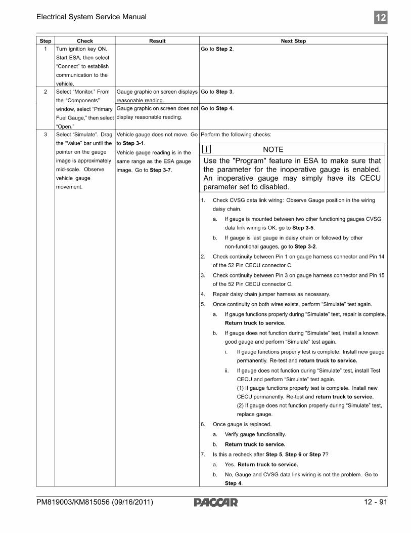
Electrical System Service Manual 12
Step Check Result Next Step1 Turn ignition key ON.
Start ESA, then select“Connect” to establishcommunication to thevehicle.
Go to Step 2.
Gauge graphic on screen displaysreasonable reading.
Go to Step 3.2 Select “Monitor.” Fromthe “Components”window, select “PrimaryFuel Gauge,” then select“Open.”
Gauge graphic on screen does notdisplay reasonable reading.
Go to Step 4.
3 Select “Simulate”. Dragthe “Value” bar until thepointer on the gaugeimage is approximatelymid-scale. Observevehicle gaugemovement.
Vehicle gauge does not move. Goto Step 3-1.
Vehicle gauge reading is in thesame range as the ESA gaugeimage. Go to Step 3-7.
Perform the following checks:
NOTEUse the "Program" feature in ESA to make sure thatthe parameter for the inoperative gauge is enabled.An inoperative gauge may simply have its CECUparameter set to disabled.
1. Check CVSG data link wiring: Observe Gauge position in the wiringdaisy chain.
a. If gauge is mounted between two other functioning gauges CVSGdata link wiring is OK. go to Step 3-5.
b. If gauge is last gauge in daisy chain or followed by othernon-functional gauges, go to Step 3-2.
2. Check continuity between Pin 1 on gauge harness connector and Pin 14of the 52 Pin CECU connector C.
3. Check continuity between Pin 3 on gauge harness connector and Pin 15of the 52 Pin CECU connector C.
4. Repair daisy chain jumper harness as necessary.
5. Once continuity on both wires exists, perform “Simulate” test again.
a. If gauge functions properly during “Simulate” test, repair is complete.Return truck to service.
b. If gauge does not function during “Simulate” test, install a knowngood gauge and perform “Simulate” test again.
i. If gauge functions properly test is complete. Install new gaugepermanently. Re-test and return truck to service.
ii. If gauge does not function during “Simulate” test, install TestCECU and perform “Simulate” test again.(1) If gauge functions properly test is complete. Install newCECU permanently. Re-test and return truck to service.(2) If gauge does not function properly during “Simulate” test,replace gauge.
6. Once gauge is replaced.
a. Verify gauge functionality.
b. Return truck to service.
7. Is this a recheck after Step 5, Step 6 or Step 7?
a. Yes. Return truck to service.
b. No, Gauge and CVSG data link wiring is not the problem. Go toStep 4.
PM819003/KM815056 (09/16/2011) 12 - 91

12 Electrical System Service Manual
Step Check Result Next StepDTC 82903 displayed - Open inprimary fuel level circuit.
Indicates the problem could be an open in the wiring from the Chassis Node tothe sensor or a defective sensor. Go to Step 5, and if necessary, Step 6.
4 Select “Diagnose” toview primary fuelgauge diagnostic troublecodes.
DTC 82904 displayed - Short inprimary fuel level circuit.
Indicates the problem could be a short to ground in the wiring from the ChassisNode to the sensor or a defective sensor. Go to Step 5, and if necessary,Step 7.1. Check for continuity between sensor connector Pin B and firewall ground
stud.
a. If there is continuity between Pin B and the ground terminal, test iscomplete. Go to Step 5-2.
b. If there is no continuity between Pin B and the ground terminal,repair wiring as necessary. Go to Step 5-1.
2. Check for continuity between sensor connector Pin A and Pin 6 of theChassis Node connector A.
a. If there is continuity between Pin A and Pin 6, test is complete. Goto Step 6.
b. If there is no continuity between Pin A and Pin 6 at Chassis Node,repair wiring as necessary. Go to Step 5-2.
Alternate test method: Resistance in the fuel level sensor signal wirechanges as the fuel level changes.
1. By unplugging the fuel gauge sensor harness connector and connectinga resistor decade box (i.e. Ametek PST2000 Tester), or an appropriateresistor to Pins A and B, you can simulate the sensor by dialing in aknown resistance.
2. Observe vehicle gauge reading on dash.
3. If gauge needle moves to approximately the same level as in the tablebelow, the problem is a defective fuel level sensor. See Table below.
Fuel Level Resistance Ohms
5 Unplug fuel gaugeharness connector atsensor.
Using a digitalmultimeter, checkcontinuity on groundand signal wire atsensor connector.
Pin A – Signal
Pin B - Ground
See Chassis NodePinout for terminaldetails of the ChassisNode electricalconnections.
(Sensor Ground) - There shouldbe continuity between the sensorconnector ground wire (Pin B) anda cab ground terminal.
(Signal) - There should becontinuity between the sensorconnector signal wire (Pin A)and Pin 6 of the Chassis Nodeconnector A.
Empty
1/4 Full
1/2 Full
3/4 Full
Full
240
154
103
65
336 Select “Diagnose” to
view primary fuel gaugeDTCs.
Unplug fuel gaugeharness connector.
See Chassis NodePinout for terminaldetails of the ChassisNode electricalconnections.
DTC 82903 - Open in primaryfuel level circuit is displayed as“Active.”
1. Using a jumper wire, jump across sensor harness connector Pins A and B.
a. If an “Active” DTC 82904 - Short in primary fuel level circuit is nowdisplayed, you have confirmed there is not an open in the sensorsignal wire to the Chassis Node. The original fault (DTC 82903)was logged because there is an open in the sensor itself, not thewiring. Go to Step 2.
b. If DTC 82904 is not displayed, there is an open circuit in the signalwire between sensor connector Pin A and Pin 6 of the Chassis Nodeconnector A. Repair wiring as necessary. Go to Step 2.
Alternate test method: Check for continuity between sensor connector Pin A(sensor signal) and Pin 6 of the Chassis Node connector A.
1. If there is no continuity, repair wiring as necessary. After repairs, DTC82903 should now be displayed as “Inactive.”
12 - 92 PM819003/KM815056 (09/16/2011)

Electrical System Service Manual 12
Step Check Result Next Step
2. If there is continuity between sensor connector Pin A and Pin 6 of theChassis Node connector A, the open circuit is in the sensor itself, not inthe wiring. Replace sensor.
DTC 82904 - Short in primaryfuel level circuit is displayed as“Active.”
If the fault is still “Active” after unplugging the sensor connector, you haveconfirmed there is a short to ground between Pin A (sensor signal) and Pin6 of the Chassis Node connector A.
1. Check for a pinched or chaffed wire between Pin A (sensor signal) andPin 6 of the Chassis Node connector A, Repair wiring as necessary. Goto Step 2.
7 Select “Diagnose” toview primary fuel levelgauge DTCs.
Next, unplug thefuel gauge harnessconnector at sensor.
See Chassis NodePinout for terminaldetails of the ChassisNode electricalconnections.
DTC 82904 - Short in primary fuellevel circuit is now displayed as“Inactive.”
If DTC 82904 changes to “Inactive” after unplugging the sensor connector, youhave confirmed the problem is a short in the sensor itself, not the wiring.
1. Replace sensor. Go to Step 2.
Return to Table Of Contents
PM819003/KM815056 (09/16/2011) 12 - 93

12 Electrical System Service Manual
Secondary Fuel Gauge Inoperative
DTC83003 and DTC83004Symptom: Secondary fuel gauge inoperative. Allother gauges are operational.
The Secondary Fuel Level Gauge uses a variableresistor sensor to measure the fuel level in thetank.
The following procedures have been developedto assist the technician in diagnosing multiplexedinstrumentation problems using the ElectronicService Analyst (ESA) hardware/softwarediagnostic tool. It is assumed the servicetechnician performing instrumentation repairs isknowledgeable about how to use ESA.
12 - 94 PM819003/KM815056 (09/16/2011)

Electrical System Service Manual 12
Step Check Result Next Step1 Turn ignition key ON.
Start ESA, then select“Connect” to establishcommunication to thevehicle.
Go to Step 2.
Gauge graphic on screen displaysreasonable reading.
Go to Step 3.2 Select “Monitor.” Fromthe “Components”window, select“Secondary FuelGauge,” then select“Open.”
Gauge graphic on screen does notdisplay reasonable reading.
Go to Step 4.
3 Select “Simulate”. Dragthe “Value” bar until thepointer on the gaugeimage is approximatelymid-scale. Observevehicle gaugemovement.
Vehicle gauge does not move. Goto Step 3-1.
Vehicle gauge reading is in thesame range as the ESA gaugeimage. Go to Step 3-7.
Perform the following checks:
NOTEUse the "Program" feature in ESA to make sure thatthe parameter for the inoperative gauge is enabled.An inoperative gauge may simply have its CECUparameter set to disabled.
1. Check CVSG data link wiring: Observe Gauge position in the wiringdaisy chain.
a. If gauge is mounted between two other functioning gauges CVSGdata link wiring is OK. go to Step 3-5.
b. If gauge is last gauge in daisy chain or followed by othernon-functional gauges, go to Step 3-2.
2. Check continuity between Pin 1 on gauge harness connector and Pin 14of the 52 Pin CECU connector C.
3. Check continuity between Pin 3 on gauge harness connector and Pin 15of the 52 Pin CECU connector C.
4. Repair daisy chain jumper harness as necessary.
5. Once continuity on both wires exists, perform “Simulate” test again.
a. If gauge functions properly during “Simulate” test, repair is complete.Return truck to service.
b. If gauge does not function during “Simulate” test, install a knowngood gauge and perform “Simulate” test again.
i. If gauge functions properly test is complete. Install new gaugepermanently. Re-test and return truck to service.
ii. If gauge does not function during “Simulate” test, install Testand perform “Simulate” test again.(1) If gauge functions properly test is complete. Install newCECU permanently. Re-test and return truck to service.(2) If gauge does not function properly during “Simulate” test,replace gauge.
6. Once gauge is replaced.
a. Verify gauge functionality.
b. Return truck to service.
7. Is this a recheck after Step 5, Step 6 or Step 7?
a. Yes. Return truck to service.
PM819003/KM815056 (09/16/2011) 12 - 95

12 Electrical System Service Manual
Step Check Result Next Step
b. No, Gauge and CVSG data link wiring is not the problem. Go toStep 4.
DTC 83003 displayed - Open insecondary fuel level circuit.
Indicates the problem could be an open in the wiring from the Chassis Node tothe sensor or a defective sensor. Go to Step 5, and if necessary, Step 6.
4 Select “Diagnose” toview secondary fuelgauge diagnostic troublecodes.
DTC 83004 displayed - Short insecondary fuel level circuit.
Indicates the problem could be a short to ground in the wiring from the ChassisNode to the sensor or a defective sensor. Go to Step 5, and if necessary,Step 7.1. Check for continuity between sensor connector Pin B and firewall ground
stud.
a. If there is continuity between Pin B and the ground terminal, test iscomplete. Go to Step 5-2.
b. If there is no continuity between Pin B and the ground terminal,repair wiring as necessary. Go to Step 5-1.
2. Check for continuity between sensor connector Pin A and Pin 9 of theChassis Node connector A.
a. If there is continuity between Pin A and Pin 9, test is complete. Goto Step 6.
b. If there is no continuity between Pin A and Pin 9 at Chassis Node,repair wiring as necessary. Go to Step 5-2.
Alternate test method: Resistance in the fuel level sensor signal wirechanges as the fuel level changes.
1. By unplugging the fuel gauge sensor harness connector and connectinga resistor decade box (i.e. Ametek PST2000 Tester), or an appropriateresistor to Pins A and B, you can simulate the sensor by dialing in aknown resistance.
2. Observe vehicle gauge reading on dash.
3. If gauge needle moves to approximately the same level as in the tablebelow, the problem is a defective fuel level sensor. See Table below.
Fuel Level Resistance Ohms
5 Unplug fuel gaugeharness connector atsensor.
Using a digitalmultimeter, checkcontinuity on groundand signal wire atsensor connector.
Pin A – Signal
Pin B - Ground
See Chassis NodePinout for terminaldetails of the ChassisNode electricalconnections.
(Sensor Ground) - There shouldbe continuity between the sensorconnector ground wire (Pin B) anda cab ground terminal.
(Signal) - There should becontinuity between the sensorconnector signal wire (Pin A)and Pin 9 of the Chassis Nodeconnector A.
Empty
1/4 Full
1/2 Full
3/4 Full
Full
240
154
103
65
336 Select “Diagnose” to
view secondary fuelgauge DTCs.
Unplug fuel gaugeharness connector.
See Chassis NodePinout for terminaldetails of the ChassisNode electricalconnections.
DTC 83003 - Open in secondaryfuel level circuit is displayed as“Active.”
1. Using a jumper wire, jump across sensor harness connector Pins A and B.
a. If an “Active” DTC 83004 - Short in secondary fuel level circuit isnow displayed, you have confirmed there is not an open in thesensor signal wire to the Chassis Node. The original fault (DTC83003) was logged because there is an open in the sensor itself, notthe wiring. Go to Step 2.
b. If DTC 83004 is not displayed, there is an open circuit in the signalwire between sensor connector Pin A and Pin 9 of the Chassis Nodeconnector A. Repair wiring as necessary. Go to Step 2.
Alternate test method: Check for continuity between sensor connector Pin A(sensor signal) and Pin 9 of the Chassis Node connector A.
12 - 96 PM819003/KM815056 (09/16/2011)

Electrical System Service Manual 12
Step Check Result Next Step
1. If there is no continuity, repair wiring as necessary. After repairs, DTC83003 should now be displayed as “Inactive.”
2. If there is continuity between sensor connector Pin A and Pin 9 of theChassis Node connector A, the open circuit is in the sensor itself, not inthe wiring. Replace sensor.
DTC 83004 - Short in secondaryfuel level circuit is displayed as“Active.”
If the fault is still “Active” after unplugging the sensor connector, you haveconfirmed there is a short to ground between Pin A (sensor signal) and Pin9 of the Chassis Node connector A.
1. Check for a pinched or chaffed wire between Pin A (sensor signal) andPin 9 of the Chassis Node connector A. Repair wiring as necessary.
7 Select “Diagnose” toview secondary fuellevel gauge DTCs.
Next, unplug thefuel gauge harnessconnector at sensor.
See Chassis NodePinout for terminaldetails of the ChassisNode electricalconnections.
DTC 83004 - Short in secondaryfuel level circuit is now displayedas “Inactive.”
If DTC 83004 changes to “Inactive” after unplugging the sensor connector, youhave confirmed the problem is a short in the sensor itself, not the wiring.
1. Replace sensor. Go to Step 2.
Return to Table Of Contents
PM819003/KM815056 (09/16/2011) 12 - 97

12 Electrical System Service Manual
Engine Related DTCs
DTC8409, DTC9109, DTC17102,DTC17131, DTC18409, DTC19009,DTC24709, DTC24809, DTC91709,DTC102809, DTC524502 andDTC524602Symptom: numerous engine related componentsinoperative.
The CECU obtains many of its inputs from V-CAN(J1939) datalink communications. The DTCs listed
above are all generated when an Engine ControlModule databused message is not received.
The following procedures have been developedto assist the technician in diagnosing multiplexedinstrumentation problems using the ElectronicService Analyst (ESA) hardware/softwarediagnostic tool. It is assumed the servicetechnician performing instrumentation repairs isknowledgeable about how to use ESA.
12 - 98 PM819003/KM815056 (09/16/2011)
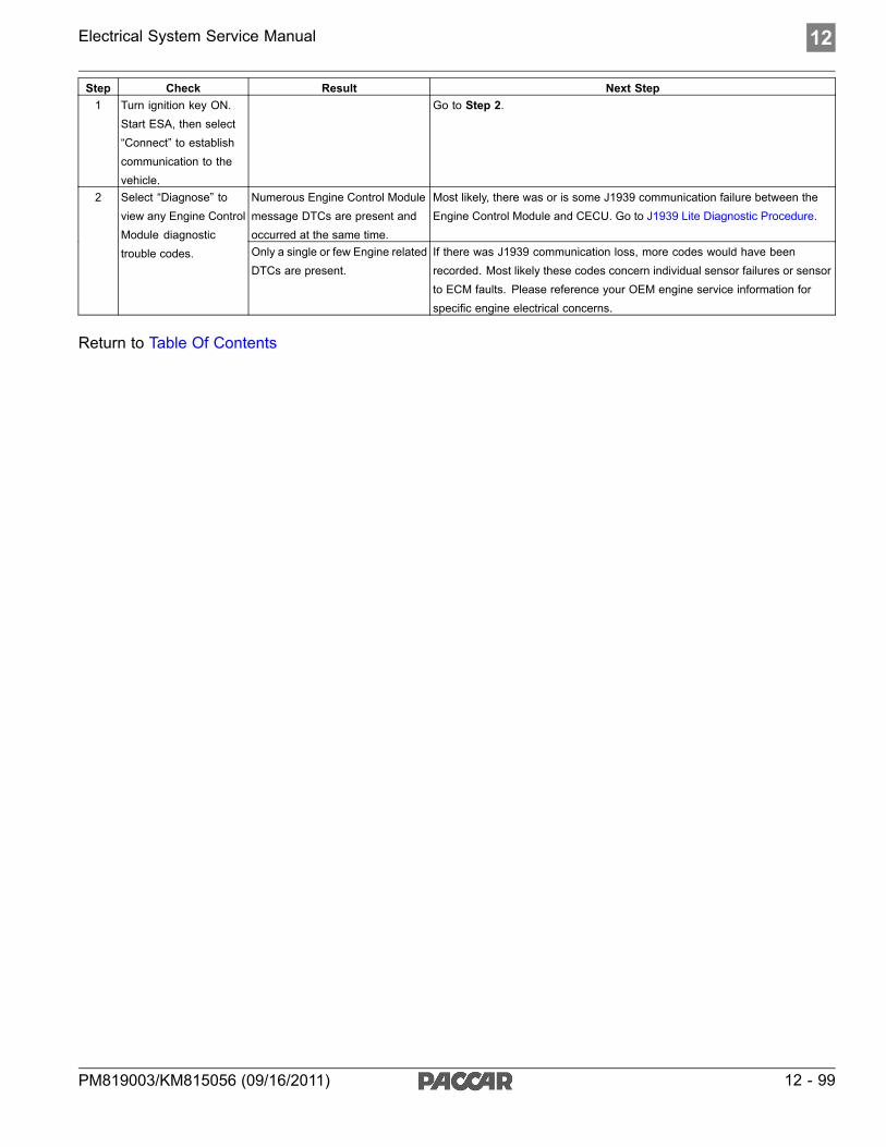
Electrical System Service Manual 12
Step Check Result Next Step1 Turn ignition key ON.
Start ESA, then select“Connect” to establishcommunication to thevehicle.
Go to Step 2.
Numerous Engine Control Modulemessage DTCs are present andoccurred at the same time.
Most likely, there was or is some J1939 communication failure between theEngine Control Module and CECU. Go to J1939 Lite Diagnostic Procedure.
2 Select “Diagnose” toview any Engine ControlModule diagnostictrouble codes. Only a single or few Engine related
DTCs are present.If there was J1939 communication loss, more codes would have beenrecorded. Most likely these codes concern individual sensor failures or sensorto ECM faults. Please reference your OEM engine service information forspecific engine electrical concerns.
Return to Table Of Contents
PM819003/KM815056 (09/16/2011) 12 - 99
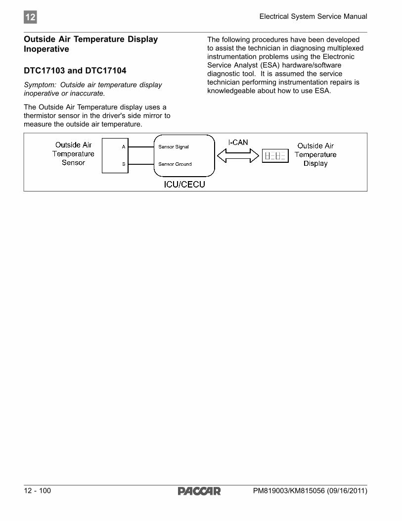
12 Electrical System Service Manual
Outside Air Temperature DisplayInoperative
DTC17103 and DTC17104Symptom: Outside air temperature displayinoperative or inaccurate.
The Outside Air Temperature display uses athermistor sensor in the driver's side mirror tomeasure the outside air temperature.
The following procedures have been developedto assist the technician in diagnosing multiplexedinstrumentation problems using the ElectronicService Analyst (ESA) hardware/softwarediagnostic tool. It is assumed the servicetechnician performing instrumentation repairs isknowledgeable about how to use ESA.
12 - 100 PM819003/KM815056 (09/16/2011)

Electrical System Service Manual 12
Step Check Result Next Step1 Turn ignition key ON.
Start ESA, then select“Connect” to establishcommunication to thevehicle.
Go to Step 2.
Gauge graphic on ESA screen displays correct reading. Thismeans the sensor to control unit is operational.
Go to Step 3.2 Select “Monitor”. Fromthe cluster portion of the“Components” window,select “Outside AirTemperature.
NOTEMonitormode is onlyavailable ifvehicle has aCECU. For anICU, go directlyto Step 3.
Gauge graphic on ESA screen displays an inaccurate reading. Go to Step 4.
Outside air temperature does not function during Cluster test ordoes not function properly.
Replace Gauge Cluster.3 Select “Simulate”. Fromthe cluster portion of the“Components” window,select “Cluster Test” andobserve the outside airtemperature display.
Outside air temperature display proceeds through its test patternas described in the Cluster Test description. This means thecontrol unit to Gauge Cluster communication is operational.
For CECU: Verify gauge is still not workingproperly. If not, install a test CECU and testagain.
For ICU: Go to Step 4No Diagnostic trouble codes Go to Step 5.DTC 17103 displayed. Open in outside air temperature circuit.Indicates the problem could be an open in the wiring from theCECU to the sensor or a defective sensor.
Go to Step 6.4 Select “Diagnose”
to view outside airtemperature diagnostictrouble codes.
DTC 17104 displayed. Short in outside air temperature circuit.Indicates the problem could be a short to ground in the wiring fromthe CECU to the sensor or a defective sensor.
Go to Step 7.
(Sensor Resistance) – Determine the real temperature. Theresistance of the sensor should match the table below. NOTE:the best way to get the real temperature is to put the sensor in acup of crushed ice and water.
(Sensor Ground) - There should be continuity between the sensorconnector ground wire (Pin B) and the firewall ground stud.
(Signal) – There should be continuity between the sensorconnector signal wire (Pin A) and Pin 16 of the 52 Pin CECUconnector C.
Resistance
Ohms
Temp
°C
Temp
°F
5 Unplug outside airtemperature harnessconnector at mirrorharness to instrumentpanel harnessconnector.
Using a digitalmultimeter, check theresistance of the sensor,the continuity on groundand signal wire at sensorconnector.
Pin A – Signal
Pin B – Ground
See CECU Pinoutfor terminal details ofthe CECU electricalconnections.
390,000
180,000
91,000
47,000
27,000
15,000
10,000
-40
-28.5
-18
-6.5
4
16
25
-40
-20
0
20
39
61
77
1. Measure the sensor resistance
a. If sensor resistance is correct. Go toSteps 5-2 and 5-3.
b. If incorrect replace sensor.
2. Check for continuity between sensorconnector Pin B and the ground terminal.
a. If there is continuity between PinB and the ground terminal, test iscomplete. Go to Step 7.
b. If there is no continuity between PinB and the ground terminal, repairwiring as necessary. Go to Step 5-1.
3. Check for continuity between sensorconnector Pin A and Pin 16 of the 52 PinCECU connector C.
a. If there is continuity between PinA and Pin 16 of the 52 Pin CECU
PM819003/KM815056 (09/16/2011) 12 - 101

12 Electrical System Service Manual
Step Check Result Next Step
9,100
5,600
3,900
2,400
1,800
910
27
39
48
61.5
69.5
91.5
81
102
118
142
157
197
connector C, test is complete. Goto Step 6.
b. If there is no continuity betweenPin A and Pin 16 , repair wiring asnecessary. Go to Step 5-2.
Alternate test method: Resistance in theoutside temperature sensor (thermistor) signalwire changes as the outside air temperatureincreases/decreases.
1. By unplugging the outside air temperatureharness connector at the mirror harnessto instrument panel harness connectorand connecting a resistor decade box(i.e. Ametek PST2000 Tester) or anappropriate resistor to Pins A and B, youcan simulate the sensor by dialing in aknown resistance.
a. While performing the test, observethe temperature display on the dash.
b. If the display reads approximatelythe same temperature as in the tableon the previous page, the problem isa defective sensor.
6 Select “Diagnose”to view outside airtemperature DTCs.
Unplug outside airtemperature harnessconnector at mirrorharness to instrumentpanel harnessconnector.
See CECU Pinoutfor terminal details ofthe CECU electricalconnections.
DTC 17103 – Open in outside air temperature circuit is displayedas “Active”.
1. Using a jumper wire, jump across sensorharness connector Pin A and B.
a. If an “Active” DTC 17104 – Short inoutside air temperature circuit is nowdisplayed, you have confirmed thereis not an open in the sensor signalwire to the CECU. The original fault(DTC 17103) was logged becausethere is an open in the sensor itself,not the wiring. Replace the sensor.Go to Step 2.
b. If DTC 17104 is not displayed, thereis an open circuit in the signal wirebetween sensor connector Pin Aand Pin 16 of the 52 Pin CECUconnector C. Repair wiring asnecessary. Go to Step 2.
12 - 102 PM819003/KM815056 (09/16/2011)

Electrical System Service Manual 12
Step Check Result Next StepDTC 17104 – Short in outside air temperature circuit is displayedas “Active”.
If the fault is still “Active” after unpluggingthe sensor connector, you have confirmedthere is a short to ground between Pin A(sensor signal) and Pin 16 of the 52 Pin CECUconnector C.
1. Check for a pinched or chaffed wirebetween Pin A (sensor signal) and Pin 16of the 52 Pin CECU connector C. Repairwiring as necessary. Go to Step 2.
7 Select “Diagnose”to view outside airtemperature DTCs.
Unplug outside airtemperature harnessconnector at mirrorharness to instrumentpanel harnessconnector.
See CECU Pinoutfor terminal details ofthe CECU electricalconnections.
DTC 17104 – Short in outside air temperature circuit is nowdisplayed as “Inactive”.
If DTC 17104 changes to “Inactive” afterunplugging the sensor connector, you haveconfirmed the problem is a short in the sensoritself, not the wiring. Replace the sensor. Goto Step 2.
Return to Table Of Contents
PM819003/KM815056 (09/16/2011) 12 - 103

12 Electrical System Service Manual
CVSG Supply Open or Shorted
DTC67805 and DTC67806
Symptom: CVSG (2” Commercial Vehicle SmartGauges) are inoperative.
The CVSG supply is daisy chained from onegauge to another. The CECU monitors the supply
to these gauges and will issue a trouble code if thesupply is either open or shorted.
The following procedures have been developedto assist the technician in diagnosing multiplexedinstrumentation problems using the ElectronicService Analyst (ESA) hardware/softwarediagnostic tool. It is assumed the servicetechnician performing instrumentation repairs isknowledgeable about how to use ESA.
12 - 104 PM819003/KM815056 (09/16/2011)

Electrical System Service Manual 12
Step Check Result Next Step1 Turn ignition key ON.
Start ESA, then select“Connect” to establishcommunication to thevehicle.
Go to Step 2.
Gauge graphic(s) on screendisplay reasonable readings.
The gauges do not have an active open or short in the CVSG supply.Intermittent causes may include a pinched wire, loose connection, bent orcorroded pins on the CVSG supply circuit.
2 Select “Monitor.” Fromthe “Components”window, select some ofthe suspect functions. Gauge graphic(s) on screen do
not display readings.Go to Step 3.
DTC 67805 displayed –CECUsees an open load on the CVSGpower supply circuit.
Go to Step 4.3 Select “Diagnose” toview “Active” diagnostictrouble codes.
DTC 67806 displayed – CECU hasa short to ground on the CVSGpower supply circuit.
Go to Step 5.
No voltage at Pin 1 of the 9 PinCECU connector A.
Replace CECU and retest.4 Test for CVSG voltagesupply at Pin 1 of the 9Pin CECU connector A. Voltage at Pin 1 of the 9 Pin CECU
connector A.Go to Step 5.
No continuity. Repair and replace circuits as necessary.5 Disconnect the 4 PinCVSG daisy chainconnector. Checkcontinuity between Pin1 of the 9 Pin CECUconnector A and pin 4 ofthe CVSG daisy chainconnector.
Continuity exists. Reconnect the CVSG daisy chain. Make sure the connection is properlyseated and there are no bent or misaligned pins. If the gauges remaininoperative, the First CVSG in the daisy chain is faulty. Replace as necessary.
Return to Table Of Contents
PM819003/KM815056 (09/16/2011) 12 - 105

12 Electrical System Service Manual
Dash Dimmer Input Open or Shorted,Dash Dimmer Output Shorted
DTC148703, DTC148704, DTC149106and DTC149206
Symptom: dash dimmer inoperative.
The Dash Dimmer input signal comes from thedriver controlled dimmer rheostat. The CECU
reads the resistance of the signal to determine thedimming request and varies the voltage output tocontrol the illumination brightness.
The following procedures have been developedto assist the technician in diagnosing multiplexedinstrumentation problems using the ElectronicService Analyst (ESA) hardware/softwarediagnostic tool. It is assumed the servicetechnician performing instrumentation repairs isknowledgeable about how to use ESA.
12 - 106 PM819003/KM815056 (09/16/2011)

Electrical System Service Manual 12
Step Check Result Next Step1 Turn ignition key ON.
Start ESA, then select“Connect” to establishcommunication to thevehicle.
Go to Step 2.
Graphic on screen does notdisplay reading.
Go to Step 3.2 Select “Monitor”. Fromthe switch portion of the“Components” window,select “Dimmer”
Graphic on screen displaysreasonable reading as the Dimmerrheostat is operated. Dimmerinput to the CECU is good.
Go to Step 7.
DTC 148703 displayed – Open indash dimmer input circuit.
Indicates the problem could be an open in the wiring from the CECU to therheostat or a defective rheostat. Go to Step 4.
3 Select “Diagnose” toview dash dimmerinput related diagnostictrouble codes.
DTC 148704 displayed – Short indash dimmer input circuit.
Indicates the problem could be a short to ground in the wiring from the CECUto the rheostat or a defective rheostat. Go to Step 6.
Connect a jumper wirefrom Pin 5 of the 52Pin CECU connector Cto Pin 3 of the dimmercontrol switch.
DTC 148703 is no longer active. The open exists in the wiring from Pin 5 of the 52 Pin CECU connector C toPin 3 of the dimmer control switch. You may confirm this by checking thecontinuity of this circuit. Replace wiring and retest.
Alternate test method: Resistance at Pin 5 of the 52 Pin CECU connectorC should vary between 390 ohms and 1390 ohms as the dimmer switchis operated.
1. Unplug of the 52 Pin CECU connector C from the control unit. Measurethe resistance from Pin 5 of the 52 Pin CECU connector C to ground.
a. If the resistance at Pin 5 varies between 390 ohms and 1390 ohmsas the dimmer switch is operated, the dimmer switch and circuit tothe CECU checks out fine. Check for a loose or bent pin at Pin 5of the CECU connector.
b. If resistance is missing or not within range at Pin 5 and circuit hascontinuity, Dimmer switch may be faulty, Go to Step 5.
4
Select Clear DTCs. DTC 148703 is still active. Dimmer control switch may be faulty. Go to Step 5.
The resistance varies between390 ohms and 1390 ohms as thedimmer switch is operated.
The dimmer switch is operational. Check all electrical connections to makesure that there are no bent pins, corroded terminals, or broken wires. Makesure that all electrical connections are firmly seated. Retest vehicle.
5 Measure the resistancebetween Pin 3 and Pin 9of the Dimmer switch.
Resistance reading is missing ornot within range (390 ohms to1390 ohms)
Dimmer switch is faulty, replace the switch and retest.
DTC 148704 is no longer active. The short to ground is probably the result of a faulty connection at the dimmercontrol switch or the switch itself. Repair as necessary.
6 Unplug the Dimmerconnector at the rheostatcontrol switch.
Pin 3 – Dimmer Signalto the control unit
Select clear DTCs.
DTC 148704 is still active. Short to ground is in the circuit from Pin 5 of the 52 Pin CECU connector C toPin 3 of the dimmer control switch. Repair and retest.
DTC 149106 displayed – Short indash dimmer output circuit 1.
Dimmer output 1 from Pin 7 of the 9 Pin CECU connector A feeds manyinstrumentation and component backlighting.
7 Select “Diagnose” toview dash dimmeroutput related diagnostictrouble codes.
DTC 149206 displayed – Short indash dimmer output circuit 2.
Dimmer output 2 from Pin 8 of the 9 Pin CECU connector A routes to only theleft and right spare backlight connectors. Check wiring for possible short toground conditions and repair as necessary.
Return to Table Of Contents
PM819003/KM815056 (09/16/2011) 12 - 107
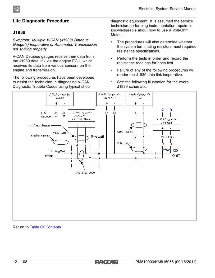
12 Electrical System Service Manual
Lite Diagnostic Procedure
J1939Symptom: Multiple V-CAN (J1939) DatabusGauge(s) Inoperative or Automated Transmissionnot shifting properly
V-CAN Databus gauges receive their data fromthe J1939 data link via the engine ECU, whichreceives its data from various sensors on theengine and transmission.
The following procedures have been developedto assist the technician in diagnosing V-CANDiagnostic Trouble Codes using typical shop
diagnostic equipment. It is assumed the servicetechnician performing instrumentation repairs isknowledgeable about how to use a Volt-OhmMeter.
• The procedures will also determine whetherthe system terminating resistors meet requiredresistance specifications.
• Perform the tests in order and record theresistance readings for each test.
• Failure of any of the following procedures willrender the J1939 data link inoperative.
• See the following illustration for the overallJ1939 schematic.
Return to Table Of Contents
12 - 108 PM819003/KM815056 (09/16/2011)

Electrical System Service Manual 12
Lite Terminating Resistor TestProcedure
J1939
Disconnect Resistors from blue resistor holdersand test resistance (approximately 120 ohm) ofeach resistor across terminals as shown. If OK,then go to the next step.
Return to Table Of Contents
PM819003/KM815056 (09/16/2011) 12 - 109

12 Electrical System Service Manual
Lite Short Circuit Test Procedure
J1939Disconnect all connectors labeled with GREENtext at the component itself (i.e., engine andABS ECU's). Leave Terminating Resistorsdisconnected. Insure all remaining connectors areproperly latched.
• Test circuit continuity at terminals 1 and 2labeled in RED text.
• Resistance reading should be zero or noreading indicating open circuit.
• Any resistance reading indicates anundesirable short circuit condition.
Return to Table Of Contents
12 - 110 PM819003/KM815056 (09/16/2011)

Electrical System Service Manual 12
Lite Short to Chassis Ground TestProcedure
J1939• Insure all connectors labeled with GREEN
text (i.e., engine and ABS ECU's) remaindisconnected. Leave Terminating Resistorsdisconnected. Insure all remaining connectorsare properly latched.
• Test circuit continuity at terminal 2 labeled inRED text with Chassis Ground.
• Move red lead and test circuit continuity atterminal 1 labeled in RED text with ChassisGround.
• Resistance reading should be zero or noreading indicating open circuit.
• Any resistance reading indicates anundesirable short circuit condition.
Return to Table Of Contents
PM819003/KM815056 (09/16/2011) 12 - 111

12 Electrical System Service Manual
Lite Open Circuit Test Procedure
J1939• Insure all connectors labeled with GREEN
text (i.e., engine and ABS ECU's) remaindisconnected.
• Reinstall the Terminating Resistors.
• Insure all remaining connectors are properlylatched.
• Resistance reading should be zero or noreading indicating open circuit.
• Test circuit resistance at terminals C and Dlabeled in BLUE text. Circuit resistance shouldbe approximately 60 ohm.
• Re-test at each of the disconnected connectorslabeled with GREEN text (i.e., engine andABS ECU's)
• Resistance reading of zero or no readingindicates open circuit, check for cut wires orloose connections.
• Resistance reading significantly higher than 60ohm indicates possible corrosion at terminalconnectors.
Return to Table Of Contents
12 - 112 PM819003/KM815056 (09/16/2011)

Electrical System Service Manual 12
Lite Diagnostic Procedures Conclusion
J1939• Once all of the preceding tests are completed
and passed, reconnect the J1939 compatiblecomponents and test the system forfunctionality with appropriate ECU diagnostictools.
° Caterpillar has J1939 Communication testbuilt into diagnostic screen
• If diagnostic tools will not communicatewith ECU's, check for power and ground todiagnostic tool.
• Verify engine ECU parameters areprogrammed to communicate using J1939
• If ECU settings, vehicle J1939 wiring, andpower and ground to diagnostic tool are OKand communication is still impossible, then theECU is suspected to be malfunctioning. Eitherreplace the ECU with a test unit or contact theECU manufacturer for assistance.
Return to Table Of Contents
PM819003/KM815056 (09/16/2011) 12 - 113

12 - 114 PM819003/KM815056 (09/16/2011)

Electrical System Service Manual 13
13 Glossary
Acronyms and Abbreviations . . . . 13 - 2
PM819003/KM815056 (09/16/2011) 13 - 1

13 Electrical System Service Manual
Acronyms and AbbreviationsABS Anti-lock Brakes SystemATC Automatic Traction ControlCAN Controller Area NetworkCECU Cab Electronic Control UnitCVSG Commercial Vehicle Smart GaugesDEF Diesel Emissions FluidDID Driver Information DisplayDLA Data Link AdapterDPF Diesel Particulate FilterDTC Diagnostic Trouble CodeDWIM Driver Warning and Information ModuleECAT Electronic CatalogECM Engine Control ModuleECU Electronic Control UnitEGR Exhaust Gas RecirculationESA Electronic Service AnalystFMI Failure Mode IndicatorHEST High Exhaust System TemperatureICU Instrumentation Control UnitIP Instrument PanelKW KenworthLCD Liquid Crystal DisplayLVD Low Voltage DisconnectMCS Menu Control SwitchMFD Multi-Function DisplayOBD On Board DiagnosticsPB PeterbiltPD Power DistributionPLC Programmable Logic ControllerPTO Power Take OffPWM Pulse Width ModulationRT Run TimeUSB Universal Serial BusVIN Vehicle Identiofication Number
13 - 2 PM819003/KM815056 (09/16/2011)

Index
AAir filter restriction pressuregauge inoperativeDTC10703 12-32DTC10704 12-32
Ammeter gaugeinoperativeDTC257903 12-40DTC257904 12-40
Application air pressuregauge inoperativeDTC11603 12-28DTC11604 12-28
Auxiliary transmissionoil temperature gaugeinoperativeDTC44203 12-68DTC44204 12-68
BBrake saver oil temperaturegauge inoperativeDTC138703 12-82DTC138704 12-82
CCECUArchitecture 8-5Block diagram 8-5CECU details 5-4Comparison chart 5-5Connector face views 5-4Connectoridentification 5-4Side view 5-4
Center/Steer axle oiltemperature gaugeinoperativeDTC7803 12-58DTC7804 12-58
Chassis NodeComparison chart 5-10Connector face views 5-9Connectoridentification 5-9Details 5-8
Side view 5-9Cluster Components 8-7Commercial Vehicle SmartGauges (CVSG) 8-12Communication InterfaceDiagrams 5-3Control UnitBuild dates 2-3Functionaldescription 8-2Identification 2-4Location 3-2
CVSG supply open orshortedDTC67805 12-104DTC67806 12-104
DDash dimmer input open orshortedDTC148703 12-106DTC148704 12-106DTC149106 12-106DTC149206 12-106
Dash dimmer outputshortedDTC148703 12-106DTC148704 12-106DTC149106 12-106DTC149206 12-106
Databus gauge(s)inoperativeDTC148109 12-17DTC148209 12-17DTC148309 V-CAN(J1939) 12-17
Diagnostic troublecodes 12-3DTC102809 12-11DTC10703 12-4DTC10704 12-4DTC11603 12-4DTC11604 12-5DTC116703 12-5DTC11704 12-5DTC11803 12-5
DTC11804 12-5DTC123109 12-11DTC138703 12-11DTC138704 12-11DTC138803 12-11DTC138804 12-11DTC148109 12-11DTC148209 12-12DTC148309 12-12DTC148703 12-12DTC148704 12-12DTC149106 12-12DTC149206 12-12DTC15802 12-5DTC15803 12-5DTC15804 12-6DTC1603 12-3DTC1604 12-3DTC167502 12-12DTC16800 12-6DTC16801 12-6DTC17102 12-6DTC17103 12-6DTC17104 12-6DTC17131 12-7DTC17303 12-7DTC17304 12-7DTC176102 12-12DTC17703 12-7DTC17704 12-7DTC18409 12-7DTC19009 12-8DTC2348xx 12-12DTC2350xx 12-13DTC2368xx 12-13DTC2370xx 12-13DTC2372xx 12-13DTC23731 12-8DTC2374xx 12-13DTC2378xx 12-13DTC2382xx 12-13DTC2388xx 12-13DTC2390xx 12-14DTC2396xx 12-14DTC2398xx 12-14DTC24510 12-8DTC24709 12-8
(09/16/2011) Index - 1
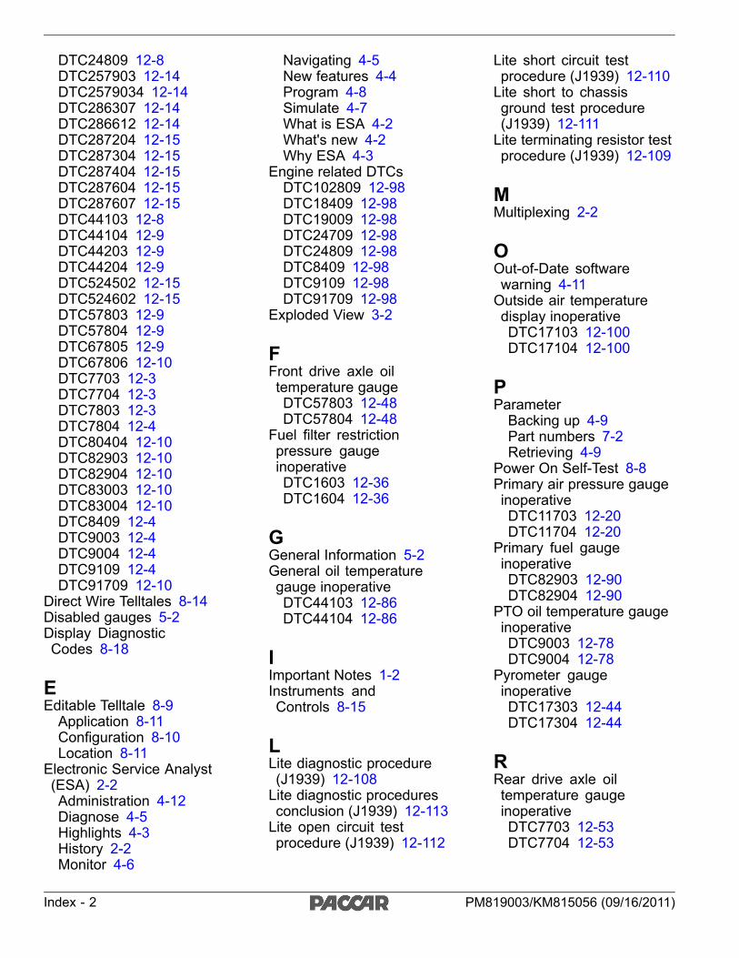
DTC24809 12-8DTC257903 12-14DTC2579034 12-14DTC286307 12-14DTC286612 12-14DTC287204 12-15DTC287304 12-15DTC287404 12-15DTC287604 12-15DTC287607 12-15DTC44103 12-8DTC44104 12-9DTC44203 12-9DTC44204 12-9DTC524502 12-15DTC524602 12-15DTC57803 12-9DTC57804 12-9DTC67805 12-9DTC67806 12-10DTC7703 12-3DTC7704 12-3DTC7803 12-3DTC7804 12-4DTC80404 12-10DTC82903 12-10DTC82904 12-10DTC83003 12-10DTC83004 12-10DTC8409 12-4DTC9003 12-4DTC9004 12-4DTC9109 12-4DTC91709 12-10
Direct Wire Telltales 8-14Disabled gauges 5-2Display DiagnosticCodes 8-18
EEditable Telltale 8-9Application 8-11Configuration 8-10Location 8-11
Electronic Service Analyst(ESA) 2-2Administration 4-12Diagnose 4-5Highlights 4-3History 2-2Monitor 4-6
Navigating 4-5New features 4-4Program 4-8Simulate 4-7What is ESA 4-2What's new 4-2Why ESA 4-3
Engine related DTCsDTC102809 12-98DTC18409 12-98DTC19009 12-98DTC24709 12-98DTC24809 12-98DTC8409 12-98DTC9109 12-98DTC91709 12-98
Exploded View 3-2
FFront drive axle oiltemperature gaugeDTC57803 12-48DTC57804 12-48
Fuel filter restrictionpressure gaugeinoperativeDTC1603 12-36DTC1604 12-36
GGeneral Information 5-2General oil temperaturegauge inoperativeDTC44103 12-86DTC44104 12-86
IImportant Notes 1-2Instruments andControls 8-15
LLite diagnostic procedure(J1939) 12-108Lite diagnostic proceduresconclusion (J1939) 12-113Lite open circuit testprocedure (J1939) 12-112
Lite short circuit testprocedure (J1939) 12-110Lite short to chassisground test procedure(J1939) 12-111Lite terminating resistor testprocedure (J1939) 12-109
MMultiplexing 2-2
OOut-of-Date softwarewarning 4-11Outside air temperaturedisplay inoperativeDTC17103 12-100DTC17104 12-100
PParameterBacking up 4-9Part numbers 7-2Retrieving 4-9
Power On Self-Test 8-8Primary air pressure gaugeinoperativeDTC11703 12-20DTC11704 12-20
Primary fuel gaugeinoperativeDTC82903 12-90DTC82904 12-90
PTO oil temperature gaugeinoperativeDTC9003 12-78DTC9004 12-78
Pyrometer gaugeinoperativeDTC17303 12-44DTC17304 12-44
RRear drive axle oiltemperature gaugeinoperativeDTC7703 12-53DTC7704 12-53
Index - 2 PM819003/KM815056 (09/16/2011)

SSecondary air pressuregauge inoperativeDTC11803 12-24DTC11804 12-24
Secondary fuel gaugeinoperativeDTC83003 12-94DTC83004 12-94
Service manual link 4-6Service Manual Update 5-2Service Resources 5-2CECU details 5-4Chassis node details 5-8Disabled gauges 5-2Service manualupdate 5-2Voltmeter trim valuesworksheet 7-20
Service resourcesVoltmeter trimprocedure 7-20
Service resourcesCommunicationsdiagram 5-3
Specifications 7-2
TTransfer case oiltemperature gaugeinoperativeDTC138803 12-74DTC138804 12-74
Transmission oiltemperature gaugeinoperativeDTC17703 12-63DTC17704 12-63
Troubleshooting 12-3
VVoltmeter Trim Values 7-20
(09/16/2011) Index - 3