MT-201B MATERIAL SCIENCE NEW - Copy.ppt
295
MT-201B MATERIALS SCIENCE
-
Upload
uday-bhardwaj -
Category
Documents
-
view
223 -
download
0
Transcript of MT-201B MATERIAL SCIENCE NEW - Copy.ppt

8/10/2019 MT-201B MATERIAL SCIENCE NEW - Copy.ppt
http://slidepdf.com/reader/full/mt-201b-material-science-new-copyppt 1/295
MT-201B MATERIALS SCIENCE
8/10/2019 MT-201B MATERIAL SCIENCE NEW - Copy.ppt
http://slidepdf.com/reader/full/mt-201b-material-science-new-copyppt 2/295
Why Study Materials Science?
1. Application oriented Properties
2. Cost consideration
3. Processing route
8/10/2019 MT-201B MATERIAL SCIENCE NEW - Copy.ppt
http://slidepdf.com/reader/full/mt-201b-material-science-new-copyppt 3/295
Classification of Materials
1. Metals
2. Ceramics
3. Polymers
4. Composites
5. Semiconductors6. Biomaterials
7. Nanomaterials
8/10/2019 MT-201B MATERIAL SCIENCE NEW - Copy.ppt
http://slidepdf.com/reader/full/mt-201b-material-science-new-copyppt 4/295
1. Introduction to Crystallography
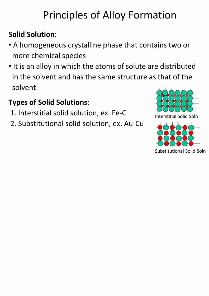
2. Principle of Alloy Formation
3. Binary Equilibria
4. Mechanical Properties
5. Heat Treatments
6. Engineering Materials
7. Advanced Materials
Syllabus
8/10/2019 MT-201B MATERIAL SCIENCE NEW - Copy.ppt
http://slidepdf.com/reader/full/mt-201b-material-science-new-copyppt 5/295
Recommended Books
1. Callister W.D., “Materials Science andEngineering an Introduction”
2. Askeland D.R., “The Science andEngineering of Materials”
3. Raghavan V.,”Materials Science and
Engineering- A first Course,” 4. Avener S.H, “Introduction to Physical
Metallurgy,”
8/10/2019 MT-201B MATERIAL SCIENCE NEW - Copy.ppt
http://slidepdf.com/reader/full/mt-201b-material-science-new-copyppt 6/295
The Structure of Crystalline Solids
CRYSTALLINE STATE• Most solids are crystalline with their atoms arranged in a
regular manner.
• Long-range order: the regularity can extend throughout the
crystal.• Short-range order: the regularity does not persist over
appreciable distances. Ex. amorphous materials such as glass
and wax.
• Liquids have short-range order, but lack long-range order.• Gases lack both long-range and short-range order.
• Some of the properties of crystalline solids depend on the
crystal structure of the material, the manner in which atoms,
ions, or molecules are arranged.
8/10/2019 MT-201B MATERIAL SCIENCE NEW - Copy.ppt
http://slidepdf.com/reader/full/mt-201b-material-science-new-copyppt 7/295
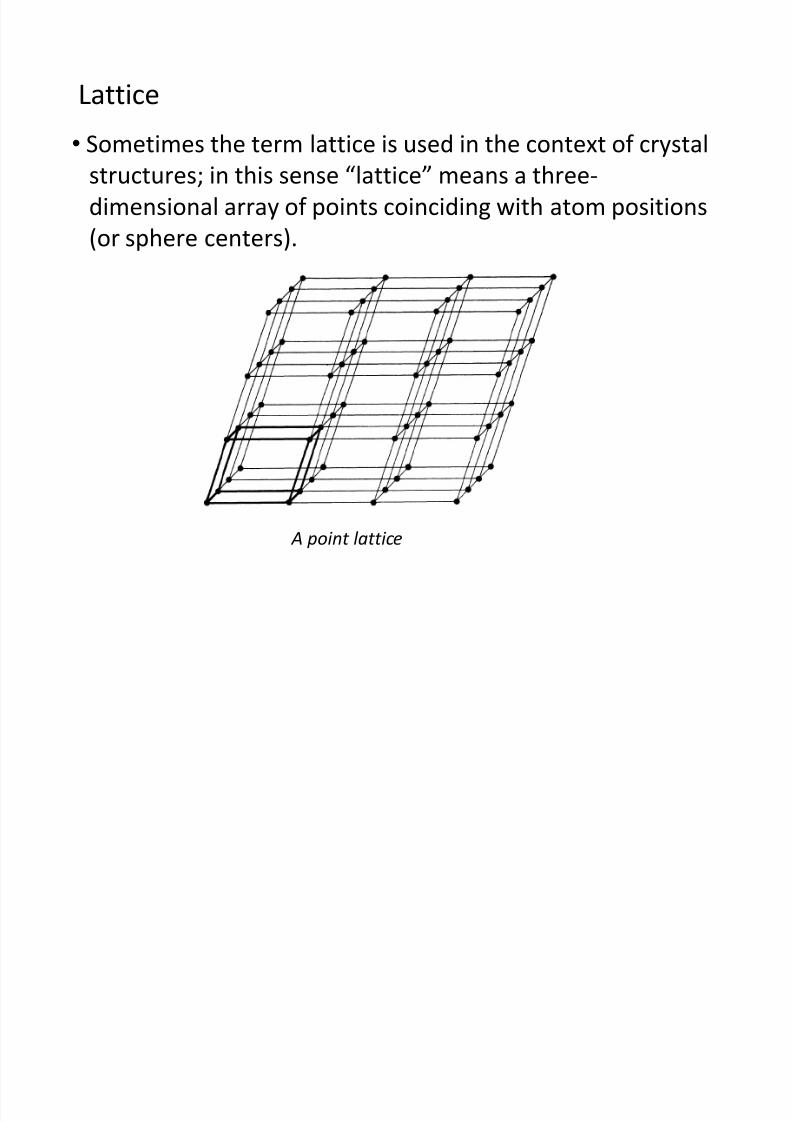
• Sometimes the term lattice is used in the context of crystalstructures; in this sense “lattice” means a three-
dimensional array of points coinciding with atom positions
(or sphere centers).
A point lattice
Lattice
8/10/2019 MT-201B MATERIAL SCIENCE NEW - Copy.ppt
http://slidepdf.com/reader/full/mt-201b-material-science-new-copyppt 8/295
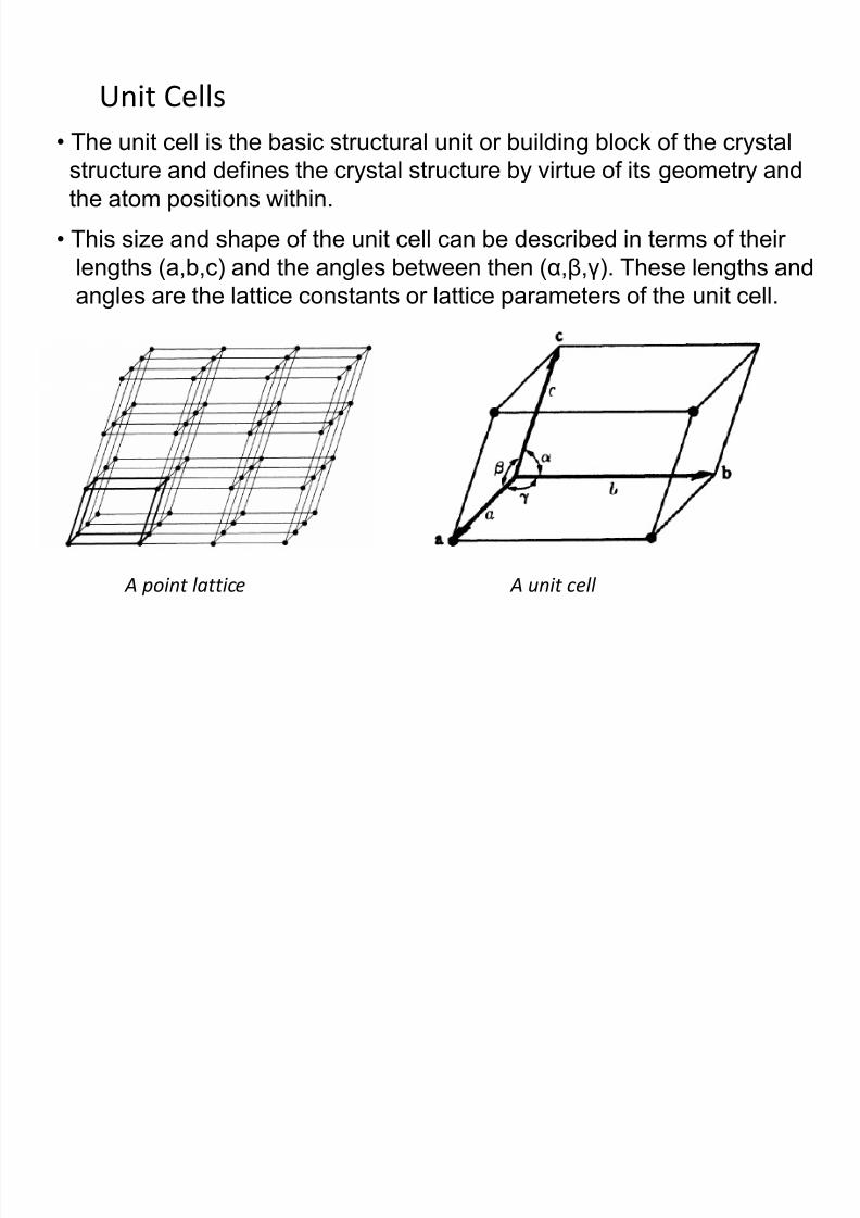
Unit Cells
• The unit cell is the basic structural unit or building block of the crystalstructure and defines the crystal structure by virtue of its geometry and
the atom positions within.
A point lattice A unit cell
• This size and shape of the unit cell can be described in terms of their
lengths (a,b,c) and the angles between then (α,β,γ). These lengths and
angles are the lattice constants or lattice parameters of the unit cell.
8/10/2019 MT-201B MATERIAL SCIENCE NEW - Copy.ppt
http://slidepdf.com/reader/full/mt-201b-material-science-new-copyppt 9/295
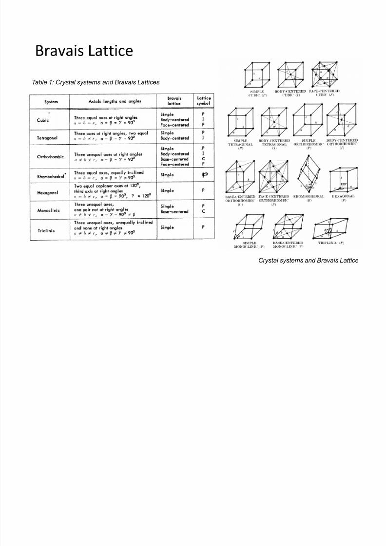
Table 1: Crystal systems and Bravais Lattices
Crystal systems and Bravais Lattice
Bravais Lattice
8/10/2019 MT-201B MATERIAL SCIENCE NEW - Copy.ppt
http://slidepdf.com/reader/full/mt-201b-material-science-new-copyppt 10/295
Types of crystals
Three relatively simple crystal structures are found for most
of the common metals; body-centered cubic, face-centered
cubic, and hexagonal close-packed.
1. Body Centered Cubic Structure (BCC)
2. Face Centered Cubic Structure (FCC)
3. Hexagonal Close Packed (HCP)
8/10/2019 MT-201B MATERIAL SCIENCE NEW - Copy.ppt
http://slidepdf.com/reader/full/mt-201b-material-science-new-copyppt 11/295
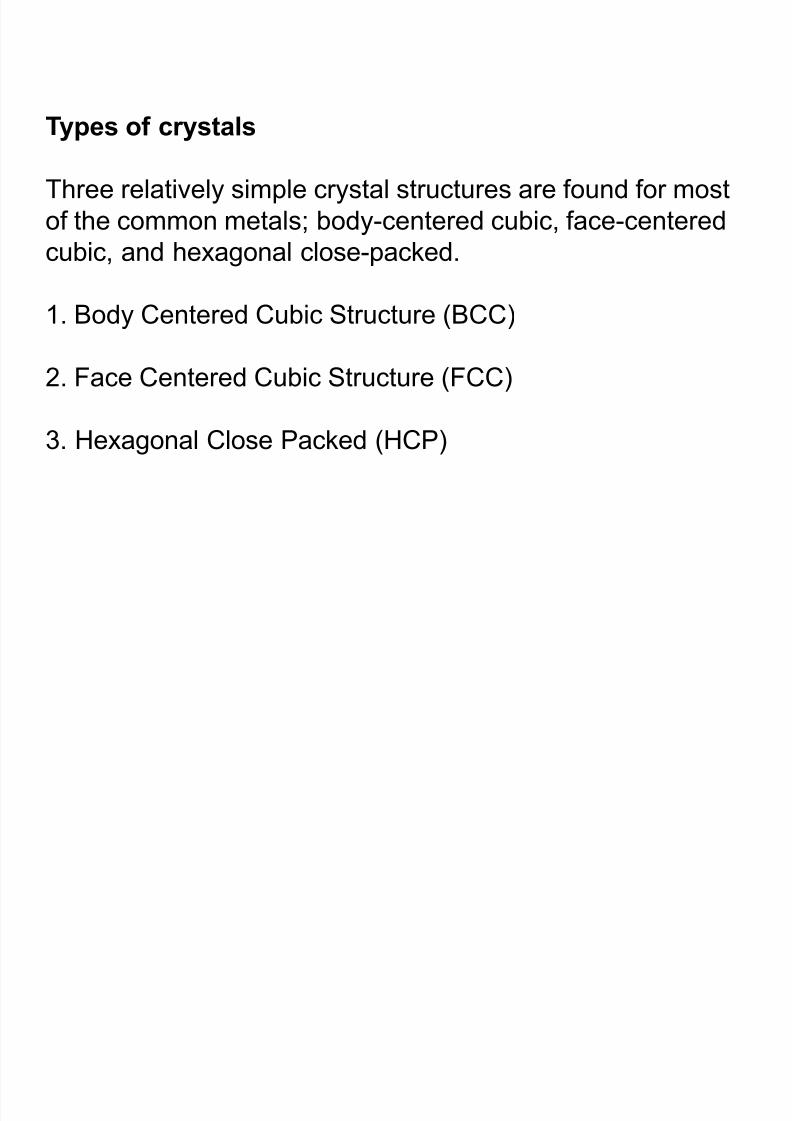
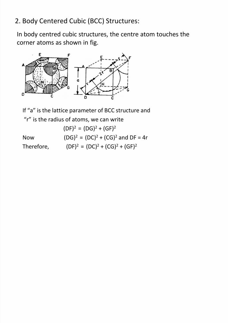
1. Body Centered Cubic Structure (BCC)
In these structures, there are 8 atoms at the 8 corners and
one atom in the interior, i.e. in the centre of the unit cell with
no atoms on the faces.
8/10/2019 MT-201B MATERIAL SCIENCE NEW - Copy.ppt
http://slidepdf.com/reader/full/mt-201b-material-science-new-copyppt 12/295
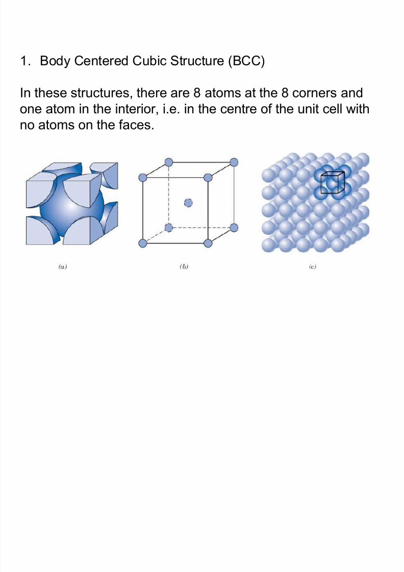
2. Face Centered Cubic Structure (FCC)
In these structures, there are 8 atoms at the 8 corners,
6 atoms at the centers of 6 faces and no interior atom.
8/10/2019 MT-201B MATERIAL SCIENCE NEW - Copy.ppt
http://slidepdf.com/reader/full/mt-201b-material-science-new-copyppt 13/295
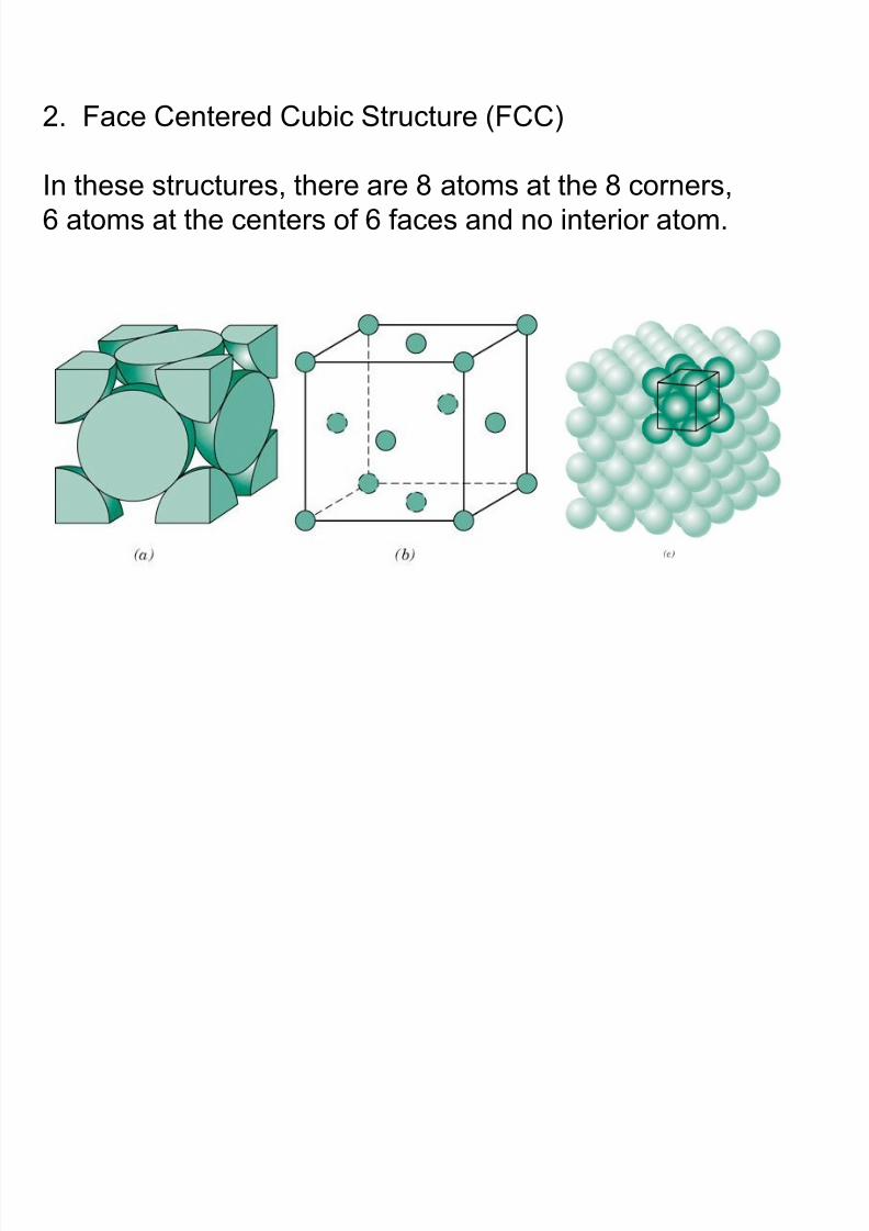
3. Hexagonal Close Packed (HCP)
In these structures, there are 12 corner atoms (6 at the bottom
face and 6 at the top face), 2 atoms at the centers of the
above two faces and 3 atoms in the interior of the unit cell.
8/10/2019 MT-201B MATERIAL SCIENCE NEW - Copy.ppt
http://slidepdf.com/reader/full/mt-201b-material-science-new-copyppt 14/295
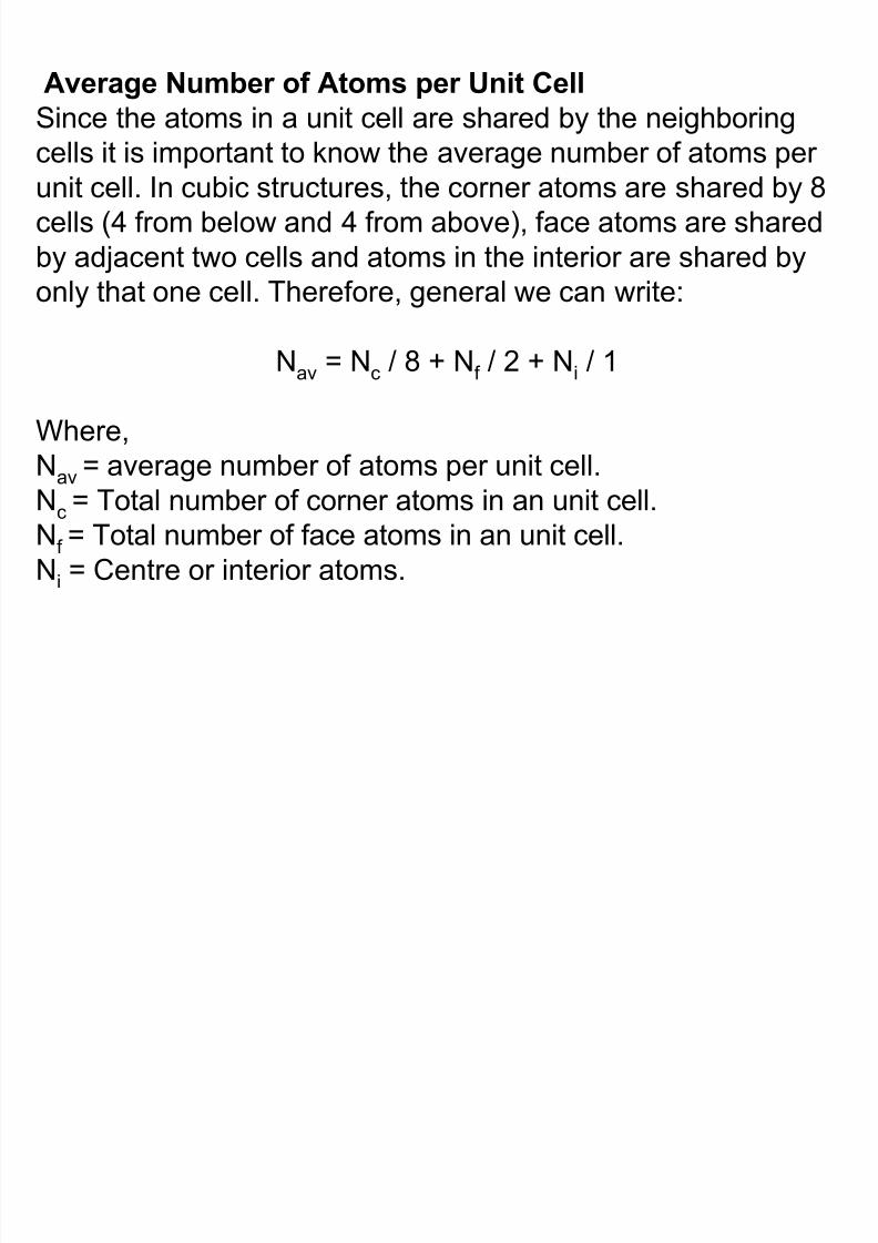
Average Number of Atoms per Unit Cell
Since the atoms in a unit cell are shared by the neighboring
cells it is important to know the average number of atoms perunit cell. In cubic structures, the corner atoms are shared by 8
cells (4 from below and 4 from above), face atoms are shared
by adjacent two cells and atoms in the interior are shared by
only that one cell. Therefore, general we can write:
Nav = Nc / 8 + Nf / 2 + Ni / 1
Where,
Nav = average number of atoms per unit cell.Nc = Total number of corner atoms in an unit cell.
Nf = Total number of face atoms in an unit cell.
Ni = Centre or interior atoms.
8/10/2019 MT-201B MATERIAL SCIENCE NEW - Copy.ppt
http://slidepdf.com/reader/full/mt-201b-material-science-new-copyppt 15/295
• Simple cubic (SC) structures: In these structures there are
8 atoms corresponding to 8 corners and there are no atoms
on the faces or in the interior of the unit cell. Therefore,
Nc = 8, Nf = 0 and Ni = 0
Using above eqn. we get, Nav = 8/8 + 0/2 + 0/1 = 1
8/10/2019 MT-201B MATERIAL SCIENCE NEW - Copy.ppt
http://slidepdf.com/reader/full/mt-201b-material-science-new-copyppt 16/295
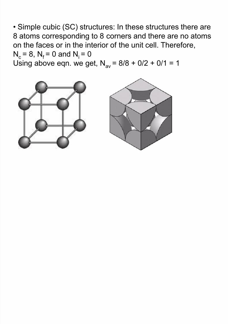
2. Body centered cubic (BCC) structures: In these
structures, there are 8 atoms at the 8 corners and one
atom in the interior, i.e. in the centre of the unit cell withno atoms on the faces. Therefore Nc = 8, Nf = 0 and Ni = 1
Using above eqn. we get, Nav = 8/8 + 0/2 + 1/1 = 2
8/10/2019 MT-201B MATERIAL SCIENCE NEW - Copy.ppt
http://slidepdf.com/reader/full/mt-201b-material-science-new-copyppt 17/295
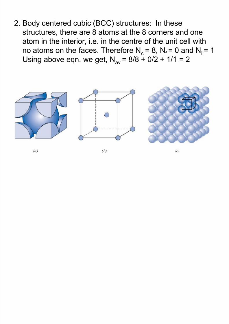
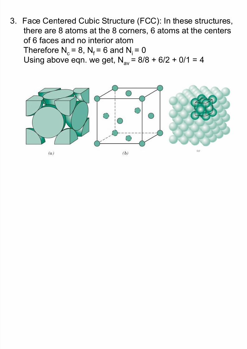
3. Face Centered Cubic Structure (FCC): In these structures,
there are 8 atoms at the 8 corners, 6 atoms at the centers
of 6 faces and no interior atomTherefore Nc = 8, Nf = 6 and Ni = 0
Using above eqn. we get, Nav = 8/8 + 6/2 + 0/1 = 4
8/10/2019 MT-201B MATERIAL SCIENCE NEW - Copy.ppt
http://slidepdf.com/reader/full/mt-201b-material-science-new-copyppt 18/295
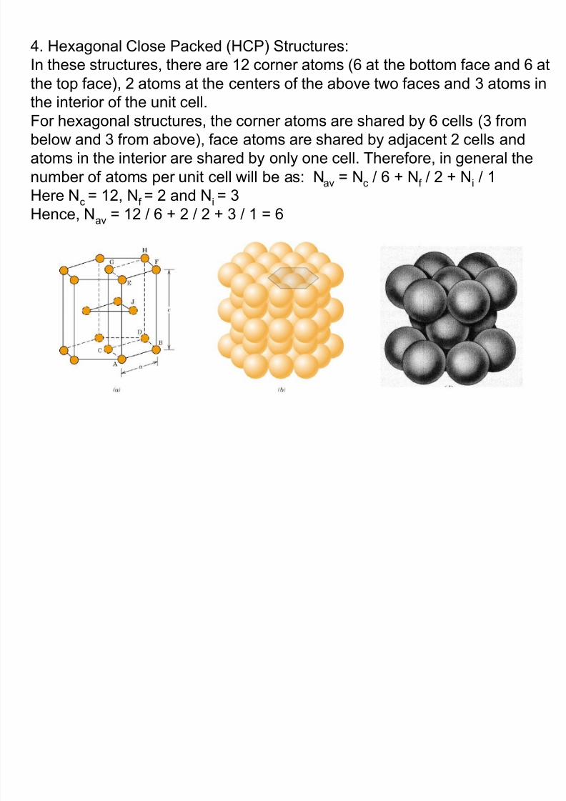
4. Hexagonal Close Packed (HCP) Structures:
In these structures, there are 12 corner atoms (6 at the bottom face and 6 at
the top face), 2 atoms at the centers of the above two faces and 3 atoms in
the interior of the unit cell.For hexagonal structures, the corner atoms are shared by 6 cells (3 from
below and 3 from above), face atoms are shared by adjacent 2 cells and
atoms in the interior are shared by only one cell. Therefore, in general the
number of atoms per unit cell will be as: Nav = Nc / 6 + Nf / 2 + Ni / 1
Here Nc = 12, Nf = 2 and Ni = 3Hence, Nav = 12 / 6 + 2 / 2 + 3 / 1 = 6
8/10/2019 MT-201B MATERIAL SCIENCE NEW - Copy.ppt
http://slidepdf.com/reader/full/mt-201b-material-science-new-copyppt 19/295
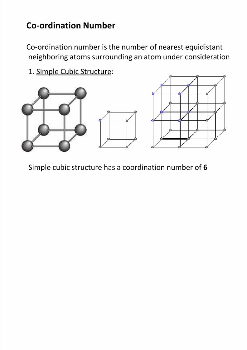
Co-ordination Number
Co-ordination number is the number of nearest equidistant
neighboring atoms surrounding an atom under consideration
1. Simple Cubic Structure:
Simple cubic structure has a coordination number of 6
8/10/2019 MT-201B MATERIAL SCIENCE NEW - Copy.ppt
http://slidepdf.com/reader/full/mt-201b-material-science-new-copyppt 20/295
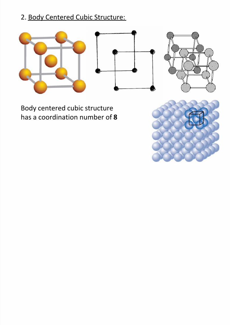
2. Body Centered Cubic Structure:
Body centered cubic structure
has a coordination number of 8
8/10/2019 MT-201B MATERIAL SCIENCE NEW - Copy.ppt
http://slidepdf.com/reader/full/mt-201b-material-science-new-copyppt 21/295
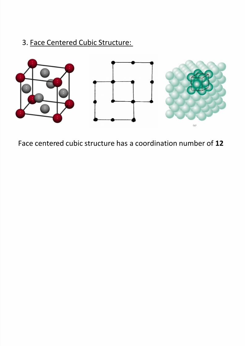
3. Face Centered Cubic Structure:
Face centered cubic structure has a coordination number of 12
8/10/2019 MT-201B MATERIAL SCIENCE NEW - Copy.ppt
http://slidepdf.com/reader/full/mt-201b-material-science-new-copyppt 22/295
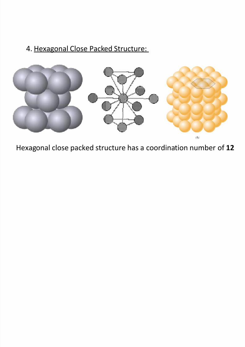
4. Hexagonal Close Packed Structure:
Hexagonal close packed structure has a coordination number of 12
8/10/2019 MT-201B MATERIAL SCIENCE NEW - Copy.ppt
http://slidepdf.com/reader/full/mt-201b-material-science-new-copyppt 23/295
Stacking Sequence for SC, BCC, FCC and HCP
• Lattice structures are described by stacking of identical planes
of atoms one over the other in a definite manner
• Different crystal structures exhibit different stacking sequences
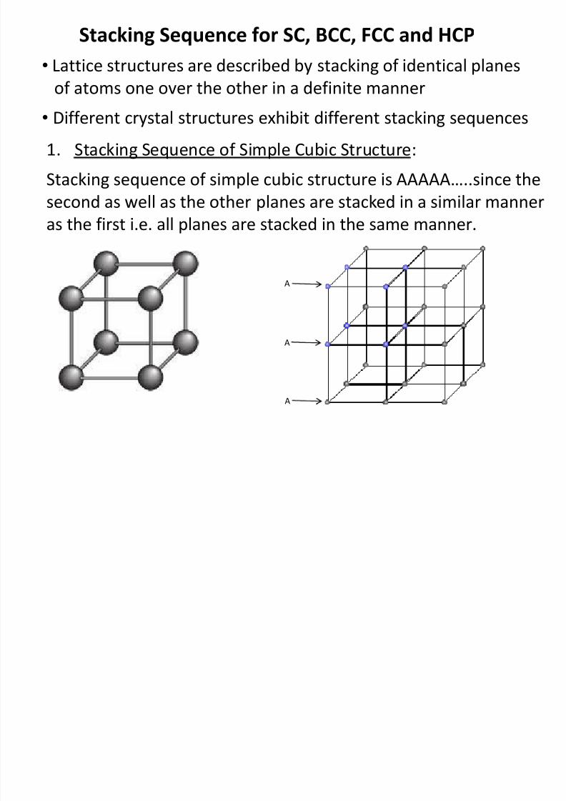
1. Stacking Sequence of Simple Cubic Structure:
Stacking sequence of simple cubic structure is AAAAA…..since the
second as well as the other planes are stacked in a similar manneras the first i.e. all planes are stacked in the same manner.
A
A
A
8/10/2019 MT-201B MATERIAL SCIENCE NEW - Copy.ppt
http://slidepdf.com/reader/full/mt-201b-material-science-new-copyppt 24/295
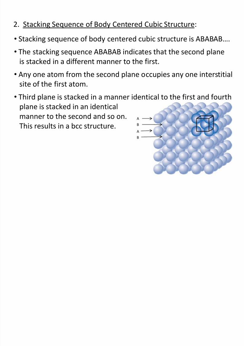
2. Stacking Sequence of Body Centered Cubic Structure:
• Stacking sequence of body centered cubic structure is ABABAB….
• The stacking sequence ABABAB indicates that the second plane
is stacked in a different manner to the first.
• Any one atom from the second plane occupies any one interstitial
site of the first atom.• Third plane is stacked in a manner identical to the first and fourth
plane is stacked in an identical
manner to the second and so on.
This results in a bcc structure.
A
B
A
B
8/10/2019 MT-201B MATERIAL SCIENCE NEW - Copy.ppt
http://slidepdf.com/reader/full/mt-201b-material-science-new-copyppt 25/295
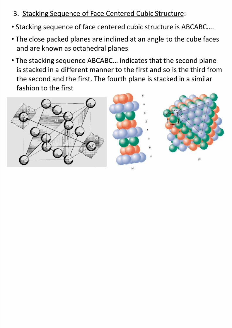
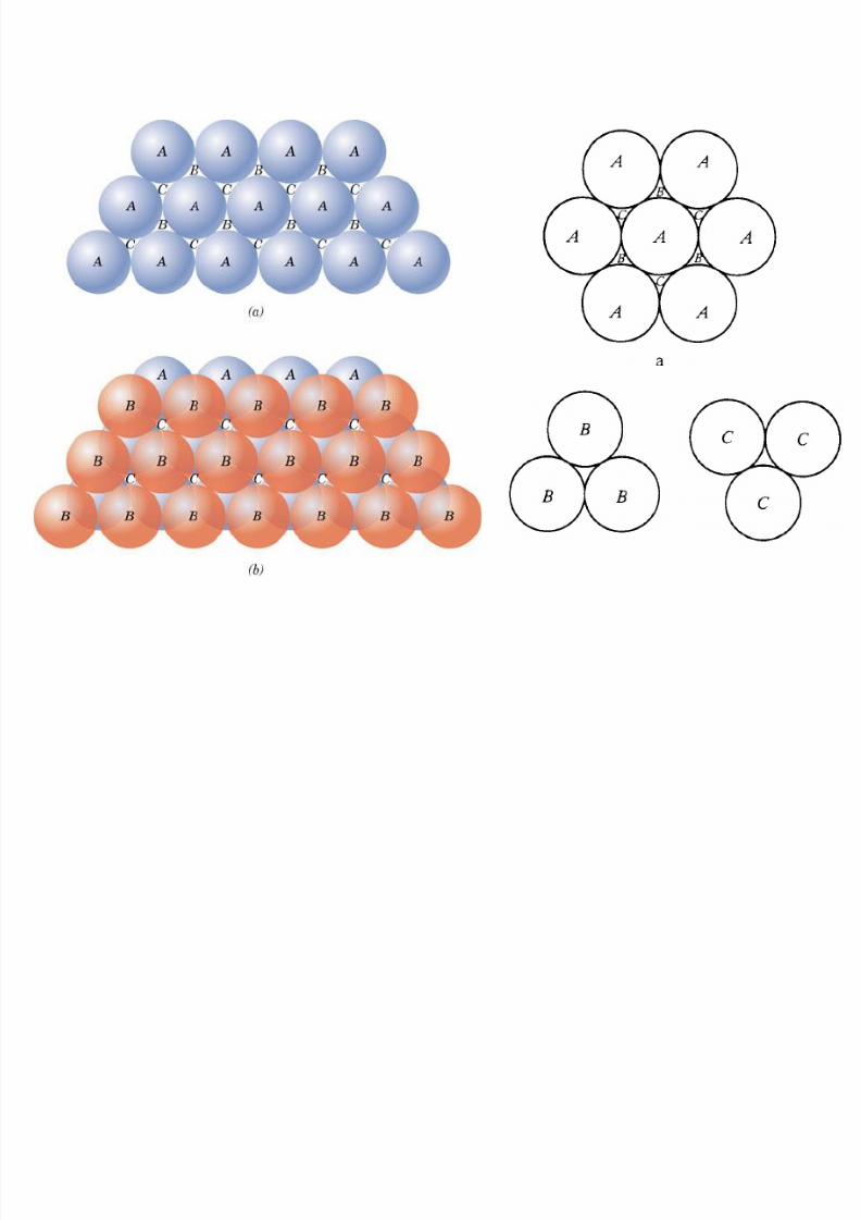
3. Stacking Sequence of Face Centered Cubic Structure:
• Stacking sequence of face centered cubic structure is ABCABC….
• The close packed planes are inclined at an angle to the cube facesand are known as octahedral planes
• The stacking sequence ABCABC… indicates that the second plane
is stacked in a different manner to the first and so is the third from
the second and the first. The fourth plane is stacked in a similarfashion to the first
8/10/2019 MT-201B MATERIAL SCIENCE NEW - Copy.ppt
http://slidepdf.com/reader/full/mt-201b-material-science-new-copyppt 26/295
8/10/2019 MT-201B MATERIAL SCIENCE NEW - Copy.ppt
http://slidepdf.com/reader/full/mt-201b-material-science-new-copyppt 27/295
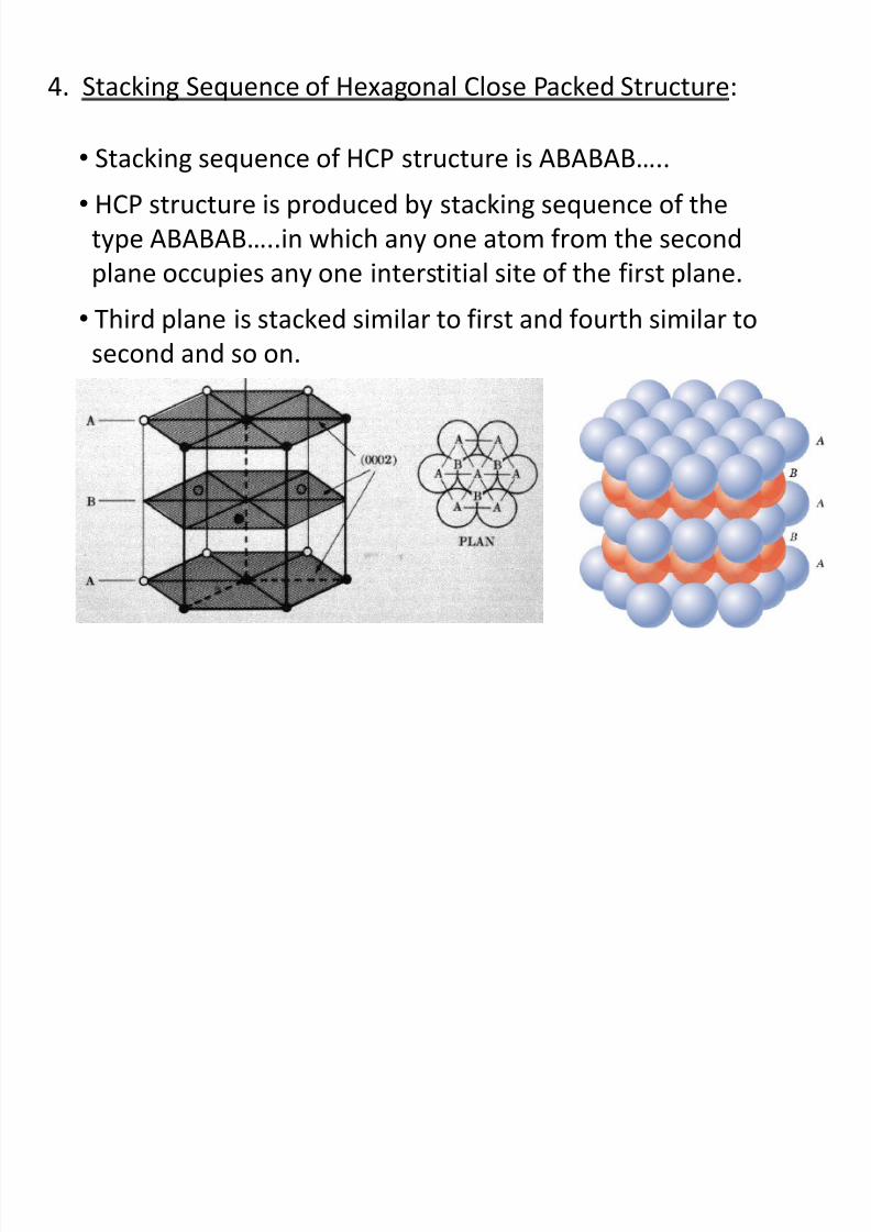
4. Stacking Sequence of Hexagonal Close Packed Structure:
• Stacking sequence of HCP structure is ABABAB…..
• HCP structure is produced by stacking sequence of the
type ABABAB…..in which any one atom from the second
plane occupies any one interstitial site of the first plane.
• Third plane is stacked similar to first and fourth similar to
second and so on.
8/10/2019 MT-201B MATERIAL SCIENCE NEW - Copy.ppt
http://slidepdf.com/reader/full/mt-201b-material-science-new-copyppt 28/295
8/10/2019 MT-201B MATERIAL SCIENCE NEW - Copy.ppt
http://slidepdf.com/reader/full/mt-201b-material-science-new-copyppt 29/295
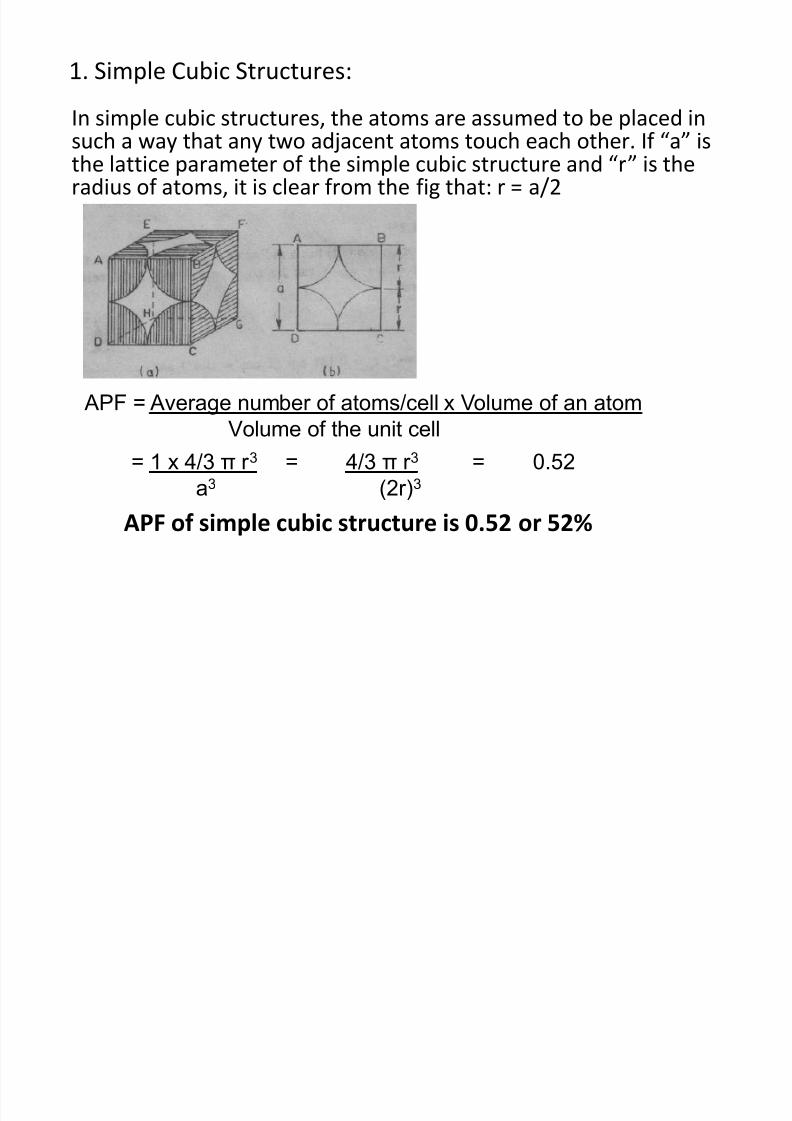
1. Simple Cubic Structures:
In simple cubic structures, the atoms are assumed to be placed in
such a way that any two adjacent atoms touch each other. If “a” isthe lattice parameter of the simple cubic structure and “r” is theradius of atoms, it is clear from the fig that: r = a/2
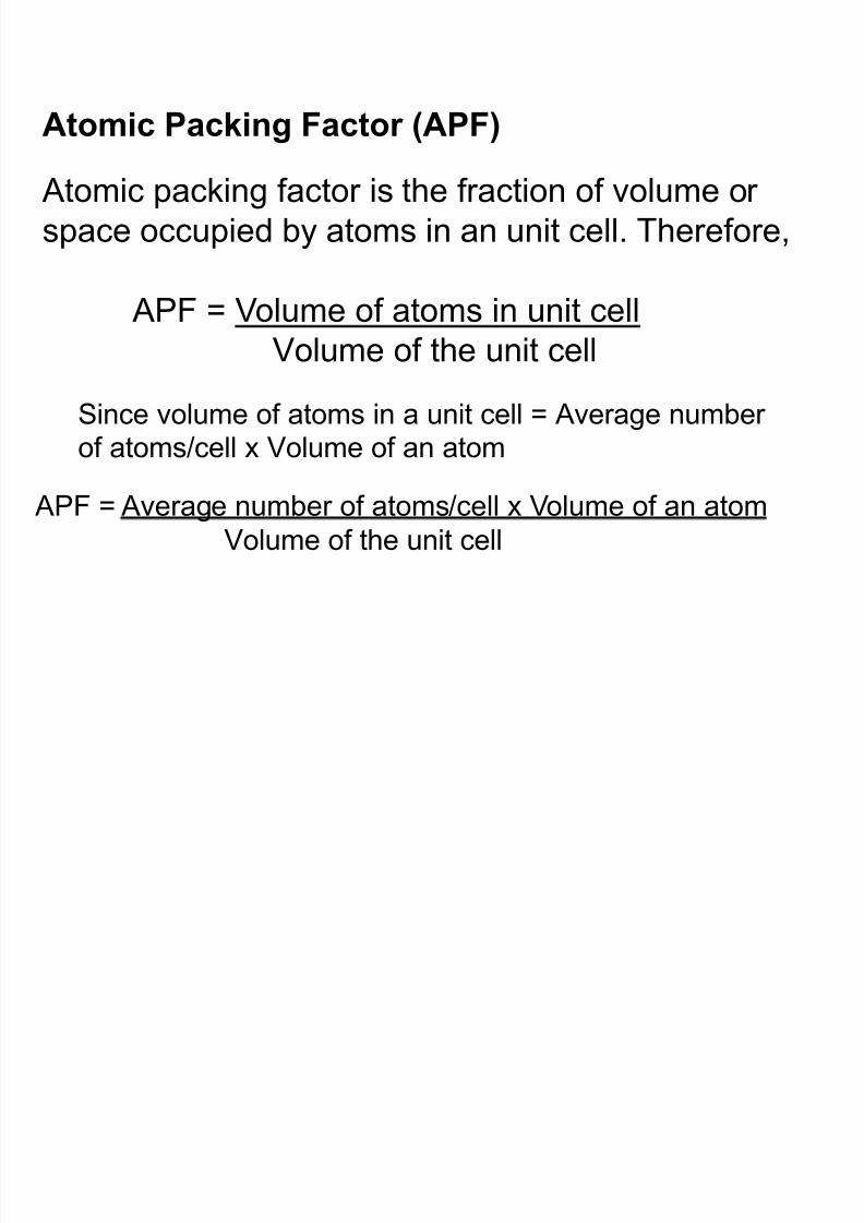
APF = Average number of atoms/cell x Volume of an atom
Volume of the unit cell
= 1 x 4/3 π r 3 = 4/3 π r 3 = 0.52
a3 (2r)3
APF of simple cubic structure is 0.52 or 52%
8/10/2019 MT-201B MATERIAL SCIENCE NEW - Copy.ppt
http://slidepdf.com/reader/full/mt-201b-material-science-new-copyppt 30/295
8/10/2019 MT-201B MATERIAL SCIENCE NEW - Copy.ppt
http://slidepdf.com/reader/full/mt-201b-material-science-new-copyppt 31/295
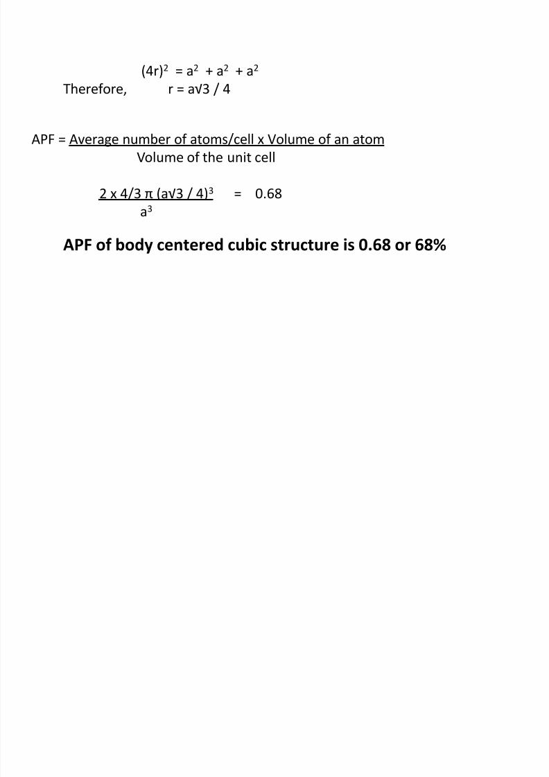
APF = Average number of atoms/cell x Volume of an atom
Volume of the unit cell
2 x 4/3 π (a√3 / 4)3 = 0.68a3
(4r)2 = a2 + a2 + a2
Therefore, r = a√3 / 4
APF of body centered cubic structure is 0.68 or 68%
8/10/2019 MT-201B MATERIAL SCIENCE NEW - Copy.ppt
http://slidepdf.com/reader/full/mt-201b-material-science-new-copyppt 32/295
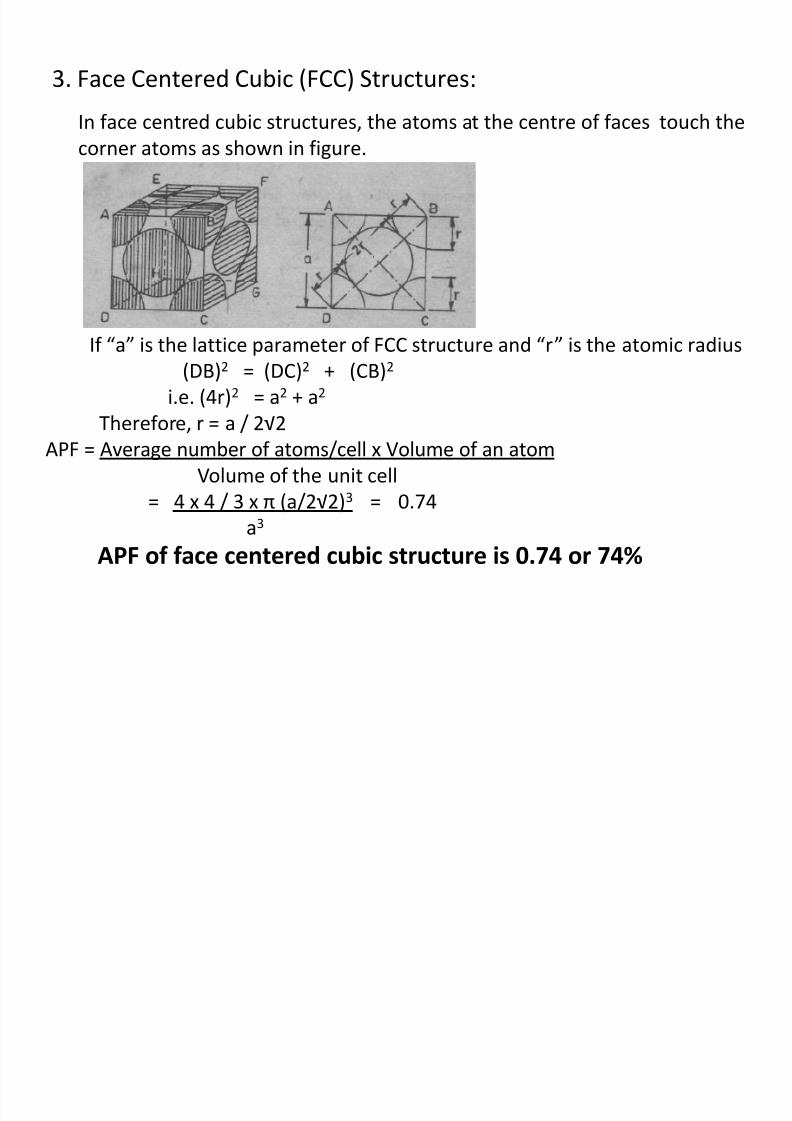
3. Face Centered Cubic (FCC) Structures:
In face centred cubic structures, the atoms at the centre of faces touch the
corner atoms as shown in figure.
If “a” is the lattice parameter of FCC structure and “r” is the atomic radius
(DB)2 = (DC)2 + (CB)2
i.e. (4r)2 = a2 + a2
Therefore, r = a / 2√2 APF = Average number of atoms/cell x Volume of an atom
Volume of the unit cell
= 4 x 4 / 3 x π (a/2√2)3 = 0.74
a3
APF of face centered cubic structure is 0.74 or 74%
8/10/2019 MT-201B MATERIAL SCIENCE NEW - Copy.ppt
http://slidepdf.com/reader/full/mt-201b-material-science-new-copyppt 33/295
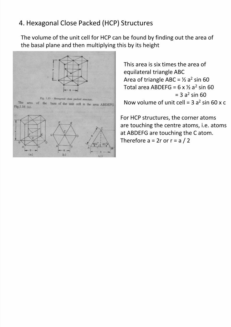
4. Hexagonal Close Packed (HCP) Structures
The volume of the unit cell for HCP can be found by finding out the area of
the basal plane and then multiplying this by its height
This area is six times the area of
equilateral triangle ABC
Area of triangle ABC = ½ a2
sin 60Total area ABDEFG = 6 x ½ a2 sin 60
= 3 a2 sin 60
Now volume of unit cell = 3 a2 sin 60 x c
For HCP structures, the corner atoms
are touching the centre atoms, i.e. atoms
at ABDEFG are touching the C atom.
Therefore a = 2r or r = a / 2
8/10/2019 MT-201B MATERIAL SCIENCE NEW - Copy.ppt
http://slidepdf.com/reader/full/mt-201b-material-science-new-copyppt 34/295
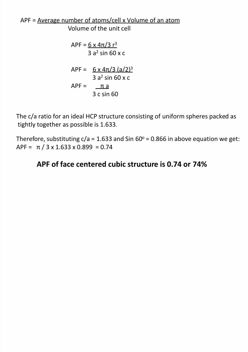
APF = Average number of atoms/cell x Volume of an atom
Volume of the unit cell
APF = 6 x 4π/3 r3 3 a2 sin 60 x c
APF = 6 x 4π/3 (a/2)3
3 a2 sin 60 x c
APF = π a 3 c sin 60
The c/a ratio for an ideal HCP structure consisting of uniform spheres packed as
tightly together as possible is 1.633.
Therefore, substituting c/a = 1.633 and Sin 60o = 0.866 in above equation we get:
APF = π / 3 x 1.633 x 0.899 = 0.74
APF of face centered cubic structure is 0.74 or 74%
8/10/2019 MT-201B MATERIAL SCIENCE NEW - Copy.ppt
http://slidepdf.com/reader/full/mt-201b-material-science-new-copyppt 35/295
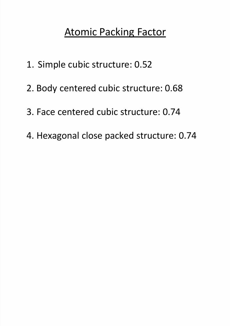
Atomic Packing Factor
1. Simple cubic structure: 0.52
2. Body centered cubic structure: 0.68
3. Face centered cubic structure: 0.74
4. Hexagonal close packed structure: 0.74
8/10/2019 MT-201B MATERIAL SCIENCE NEW - Copy.ppt
http://slidepdf.com/reader/full/mt-201b-material-science-new-copyppt 36/295
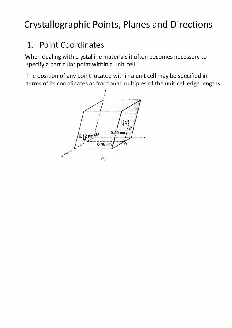
Crystallographic Points, Planes and Directions
1. Point Coordinates
When dealing with crystalline materials it often becomes necessary to
specify a particular point within a unit cell.
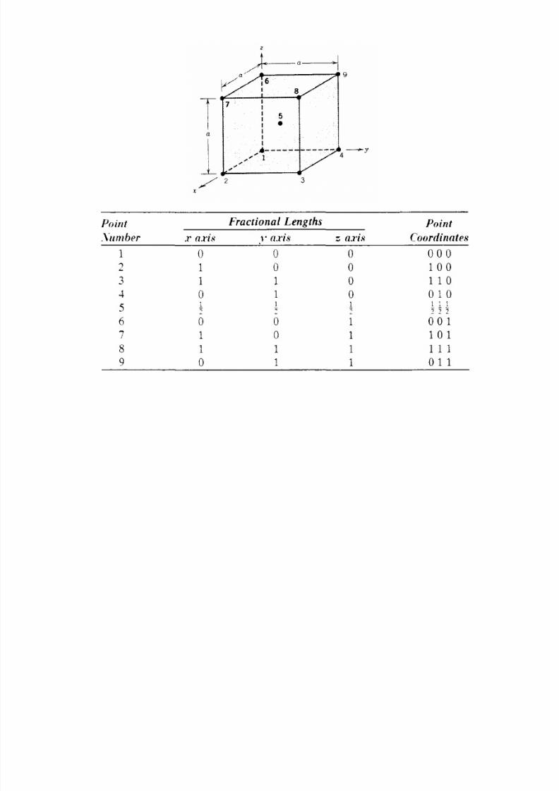
The position of any point located within a unit cell may be specified in
terms of its coordinates as fractional multiples of the unit cell edge lengths.
8/10/2019 MT-201B MATERIAL SCIENCE NEW - Copy.ppt
http://slidepdf.com/reader/full/mt-201b-material-science-new-copyppt 37/295
8/10/2019 MT-201B MATERIAL SCIENCE NEW - Copy.ppt
http://slidepdf.com/reader/full/mt-201b-material-science-new-copyppt 38/295
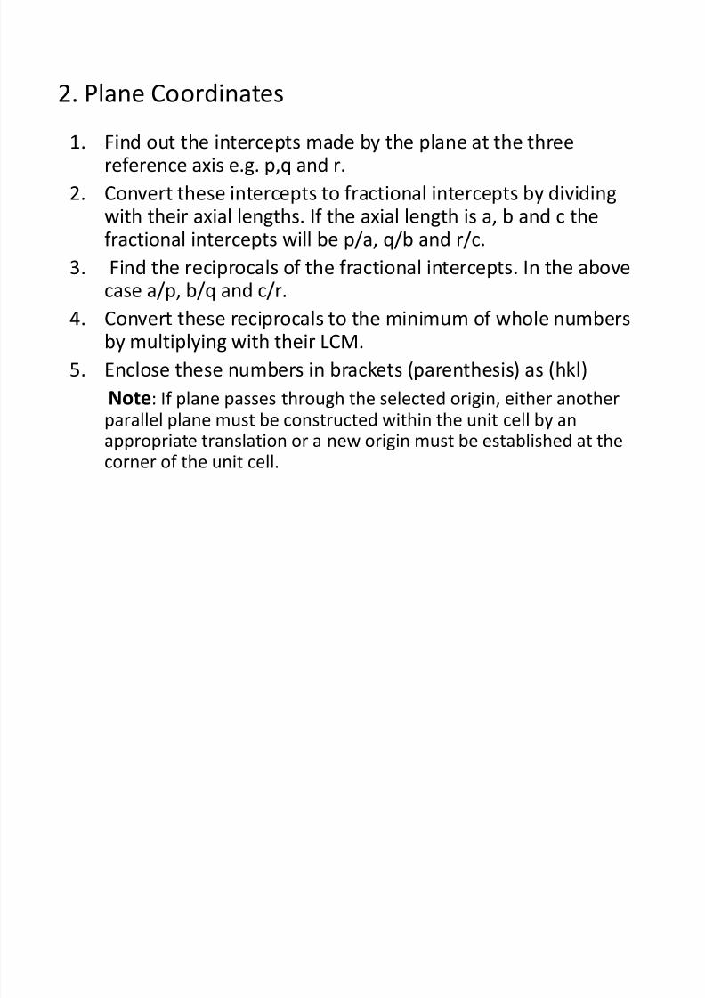
2. Plane Coordinates
1. Find out the intercepts made by the plane at the threereference axis e.g. p,q and r.
2. Convert these intercepts to fractional intercepts by dividingwith their axial lengths. If the axial length is a, b and c thefractional intercepts will be p/a, q/b and r/c.
3. Find the reciprocals of the fractional intercepts. In the abovecase a/p, b/q and c/r.
4. Convert these reciprocals to the minimum of whole numbersby multiplying with their LCM.
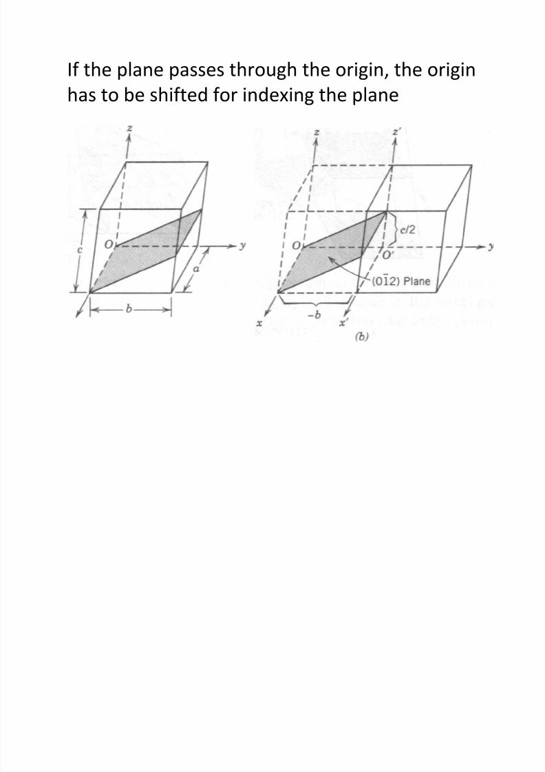
5. Enclose these numbers in brackets (parenthesis) as (hkl)Note: If plane passes through the selected origin, either anotherparallel plane must be constructed within the unit cell by anappropriate translation or a new origin must be established at thecorner of the unit cell.
8/10/2019 MT-201B MATERIAL SCIENCE NEW - Copy.ppt
http://slidepdf.com/reader/full/mt-201b-material-science-new-copyppt 39/295
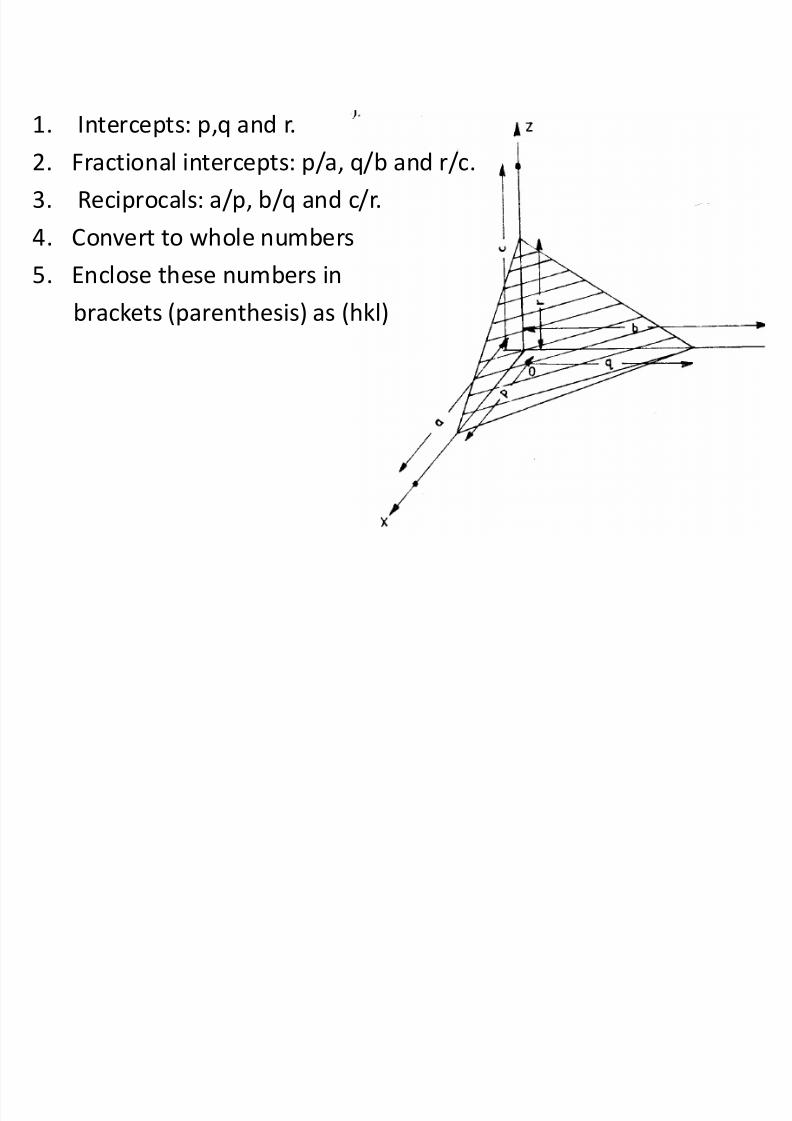
1. Intercepts: p,q and r.
2. Fractional intercepts: p/a, q/b and r/c.
3. Reciprocals: a/p, b/q and c/r.
4. Convert to whole numbers
5. Enclose these numbers inbrackets (parenthesis) as (hkl)
8/10/2019 MT-201B MATERIAL SCIENCE NEW - Copy.ppt
http://slidepdf.com/reader/full/mt-201b-material-science-new-copyppt 40/295
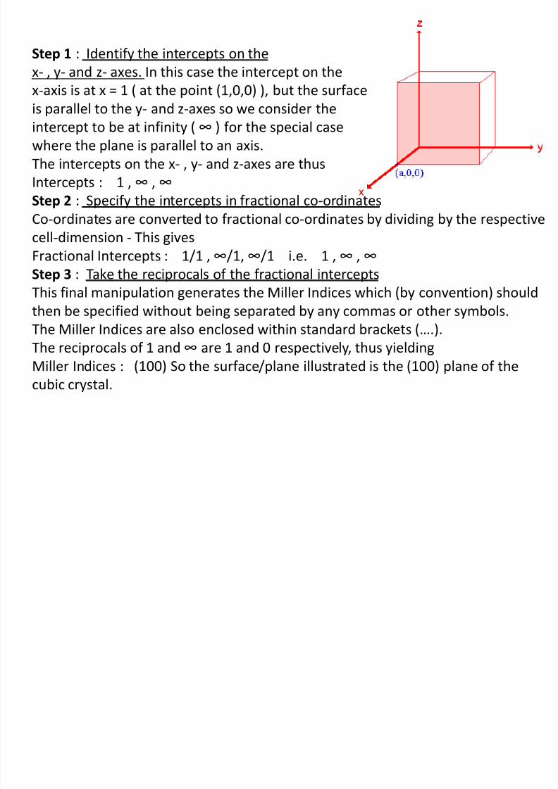
Step 1 : Identify the intercepts on the
x- , y- and z- axes. In this case the intercept on the
x-axis is at x = 1 ( at the point (1,0,0) ), but the surface
is parallel to the y- and z-axes so we consider the
intercept to be at infinity ( ∞ ) for the special case
where the plane is parallel to an axis.
The intercepts on the x- , y- and z-axes are thus
Intercepts : 1 , ∞ , ∞
Step 2 : Specify the intercepts in fractional co-ordinatesCo-ordinates are converted to fractional co-ordinates by dividing by the respective
cell-dimension - This gives
Fractional Intercepts : 1/1 , ∞/1, ∞/1 i.e. 1 , ∞ , ∞
Step 3 : Take the reciprocals of the fractional intercepts
This final manipulation generates the Miller Indices which (by convention) shouldthen be specified without being separated by any commas or other symbols.
The Miller Indices are also enclosed within standard brackets (….).
The reciprocals of 1 and ∞ are 1 and 0 respectively, thus yielding
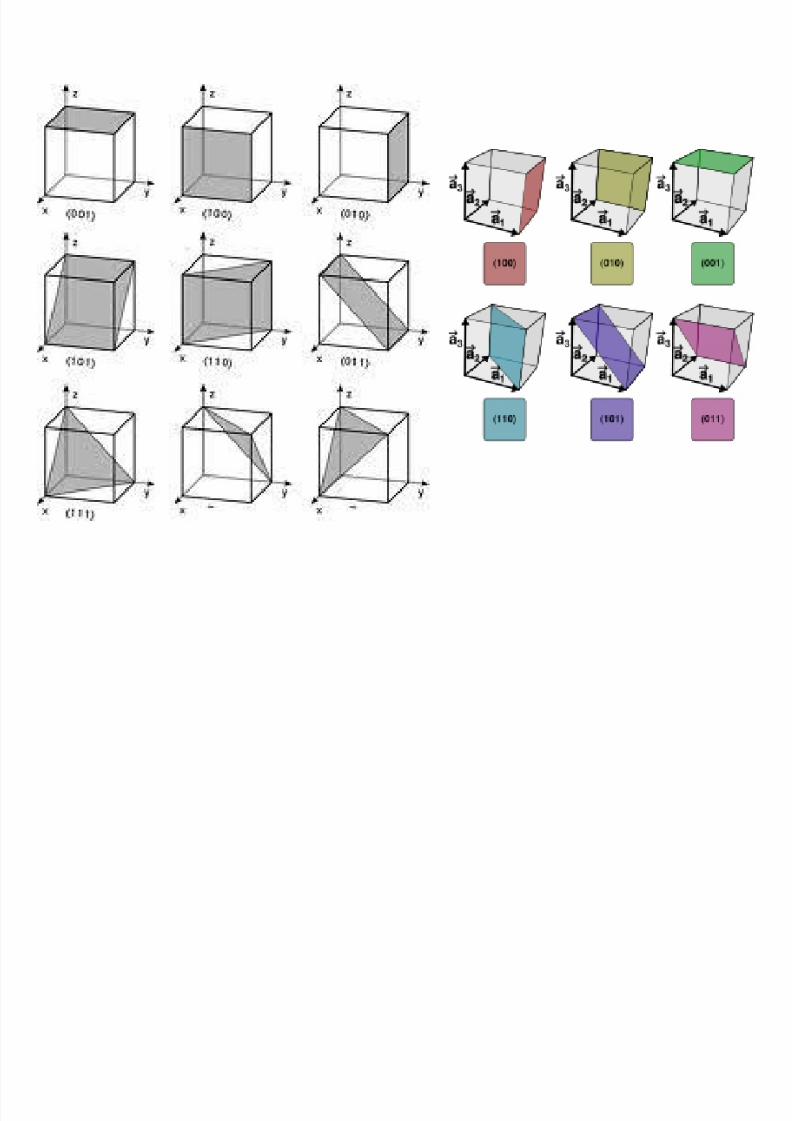
Miller Indices : (100) So the surface/plane illustrated is the (100) plane of the
cubic crystal.
8/10/2019 MT-201B MATERIAL SCIENCE NEW - Copy.ppt
http://slidepdf.com/reader/full/mt-201b-material-science-new-copyppt 41/295
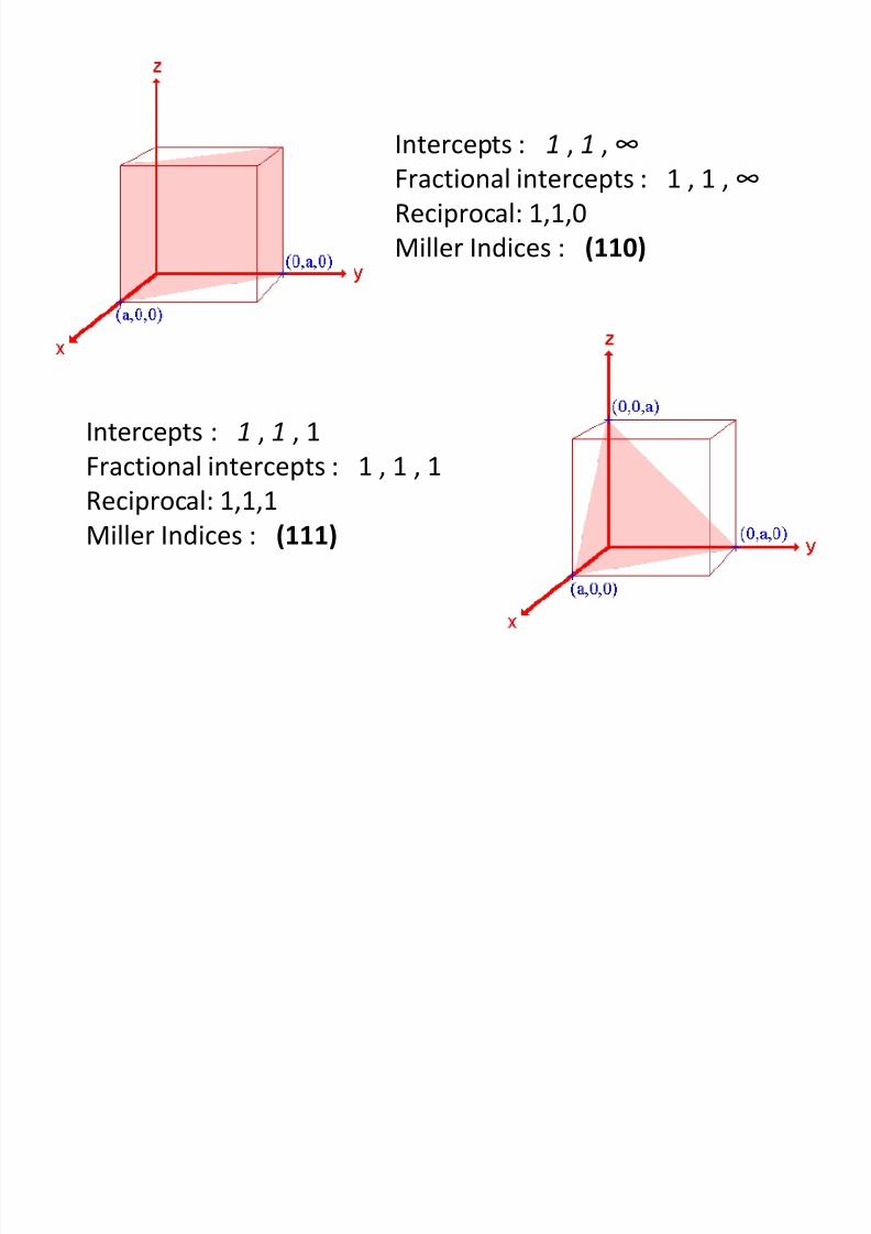
Intercepts : 1 , 1 , ∞
Fractional intercepts : 1 , 1 , ∞
Reciprocal: 1,1,0
Miller Indices : (110)
Intercepts : 1 , 1 , 1
Fractional intercepts : 1 , 1 , 1Reciprocal: 1,1,1
Miller Indices : (111)
8/10/2019 MT-201B MATERIAL SCIENCE NEW - Copy.ppt
http://slidepdf.com/reader/full/mt-201b-material-science-new-copyppt 42/295
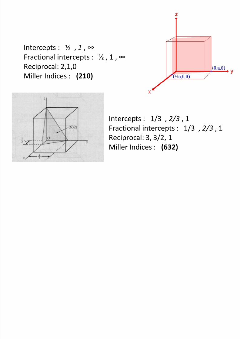
Intercepts : ½ , 1 , ∞
Fractional intercepts : ½ , 1 , ∞
Reciprocal: 2,1,0
Miller Indices : (210)
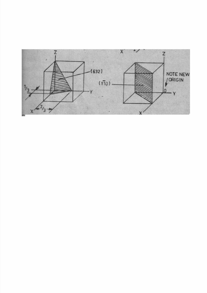
Intercepts : 1/3 , 2/3 , 1
Fractional intercepts : 1/3 , 2/3 , 1Reciprocal: 3, 3/2, 1
Miller Indices : (632)
8/10/2019 MT-201B MATERIAL SCIENCE NEW - Copy.ppt
http://slidepdf.com/reader/full/mt-201b-material-science-new-copyppt 43/295
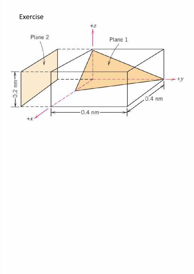
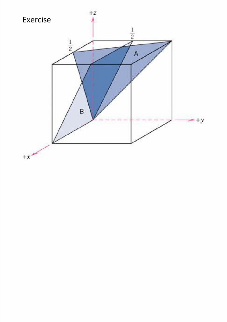
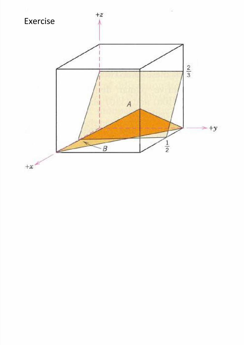
Exercise
8/10/2019 MT-201B MATERIAL SCIENCE NEW - Copy.ppt
http://slidepdf.com/reader/full/mt-201b-material-science-new-copyppt 44/295
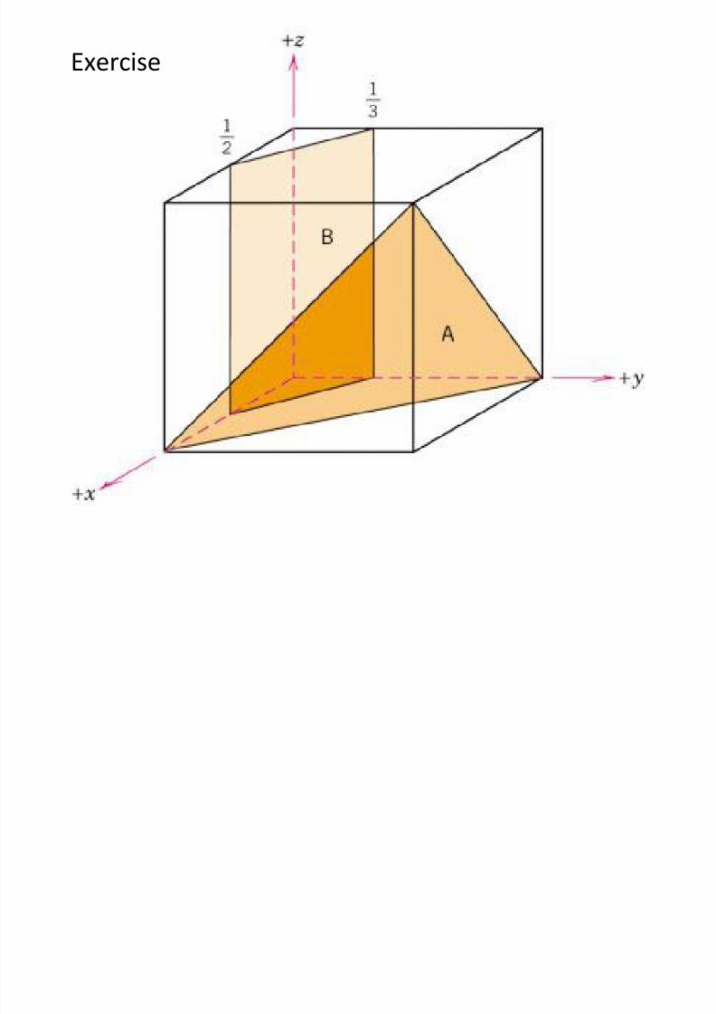
Exercise
8/10/2019 MT-201B MATERIAL SCIENCE NEW - Copy.ppt
http://slidepdf.com/reader/full/mt-201b-material-science-new-copyppt 45/295
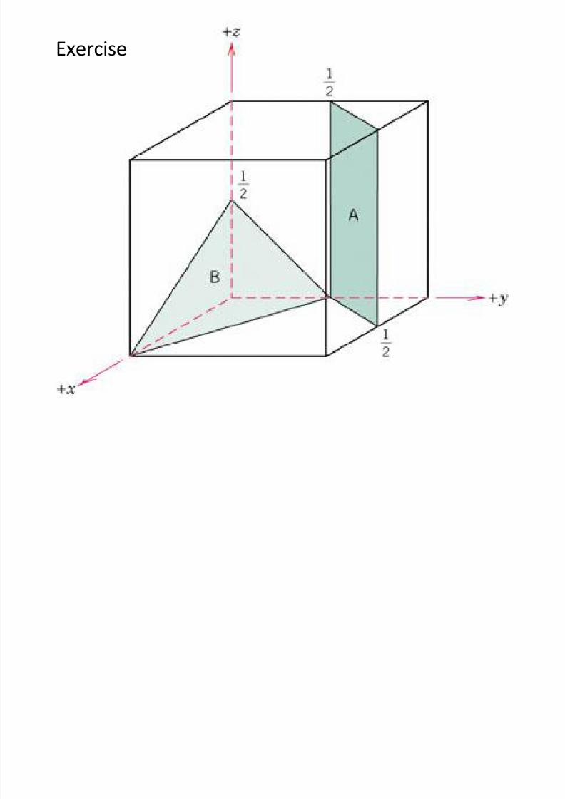
Exercise
8/10/2019 MT-201B MATERIAL SCIENCE NEW - Copy.ppt
http://slidepdf.com/reader/full/mt-201b-material-science-new-copyppt 46/295
Exercise
8/10/2019 MT-201B MATERIAL SCIENCE NEW - Copy.ppt
http://slidepdf.com/reader/full/mt-201b-material-science-new-copyppt 47/295
Exercise
8/10/2019 MT-201B MATERIAL SCIENCE NEW - Copy.ppt
http://slidepdf.com/reader/full/mt-201b-material-science-new-copyppt 48/295
8/10/2019 MT-201B MATERIAL SCIENCE NEW - Copy.ppt
http://slidepdf.com/reader/full/mt-201b-material-science-new-copyppt 49/295
If the plane passes through the origin, the origin
has to be shifted for indexing the plane
8/10/2019 MT-201B MATERIAL SCIENCE NEW - Copy.ppt
http://slidepdf.com/reader/full/mt-201b-material-science-new-copyppt 50/295
8/10/2019 MT-201B MATERIAL SCIENCE NEW - Copy.ppt
http://slidepdf.com/reader/full/mt-201b-material-science-new-copyppt 51/295
Miller Indices of Planes for Hexagonal Crystals
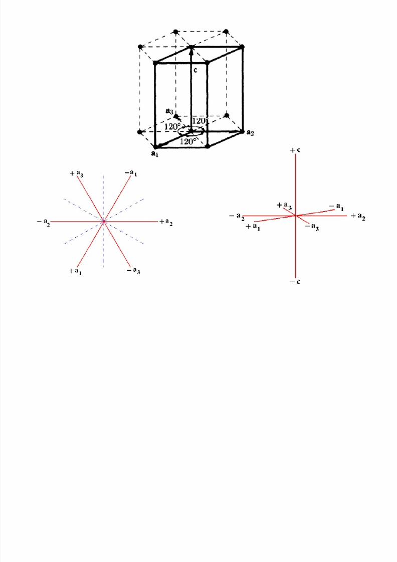
• Crystal Plane in HCP unit cells is commonly identified by using four indices
instead of three.
•The HCP crystal plane indices called Miller-Bravis indices are denoted by the
letters h, k, i and l are enclosed in parentheses as (hkil)
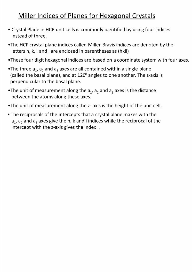
•These four digit hexagonal indices are based on a coordinate system with four axes.
•The three a1, a2 and a3 axes are all contained within a single plane(called the basal plane), and at 1200 angles to one another. The z-axis is
perpendicular to the basal plane.
•The unit of measurement along the a1, a2 and a3 axes is the distance
between the atoms along these axes.
•The unit of measurement along the z- axis is the height of the unit cell.
• The reciprocals of the intercepts that a crystal plane makes with the
a1, a2 and a3 axes give the h, k and I indices while the reciprocal of the
intercept with the z-axis gives the index l.
8/10/2019 MT-201B MATERIAL SCIENCE NEW - Copy.ppt
http://slidepdf.com/reader/full/mt-201b-material-science-new-copyppt 52/295
8/10/2019 MT-201B MATERIAL SCIENCE NEW - Copy.ppt
http://slidepdf.com/reader/full/mt-201b-material-science-new-copyppt 53/295
8/10/2019 MT-201B MATERIAL SCIENCE NEW - Copy.ppt
http://slidepdf.com/reader/full/mt-201b-material-science-new-copyppt 54/295
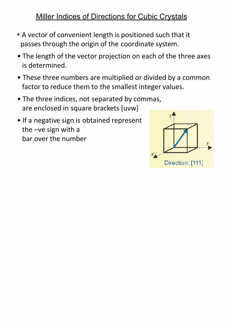
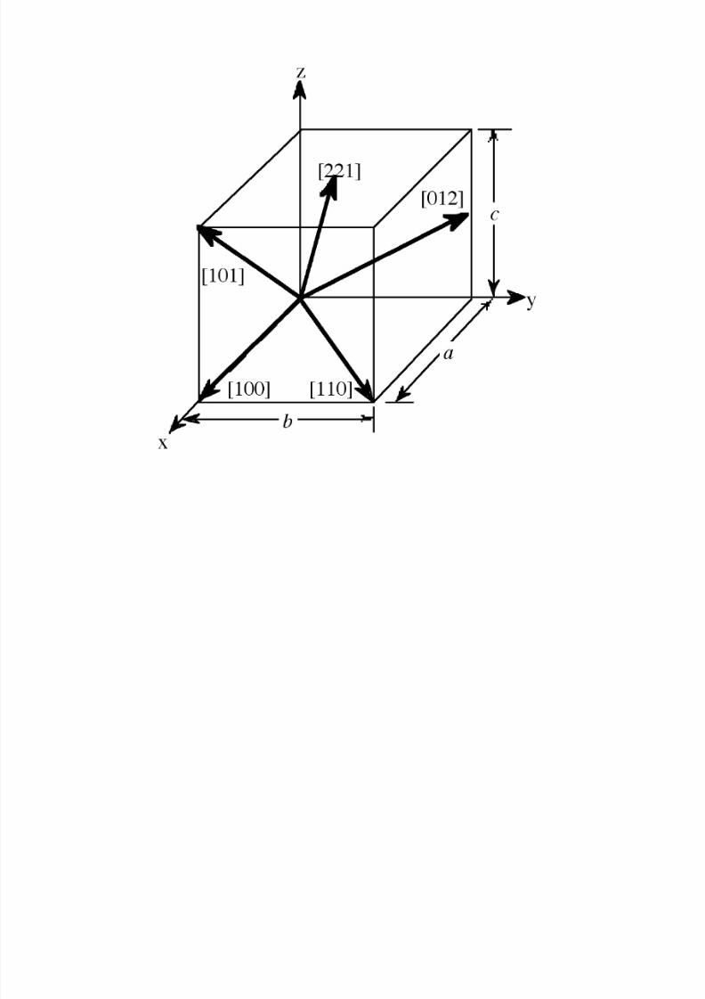
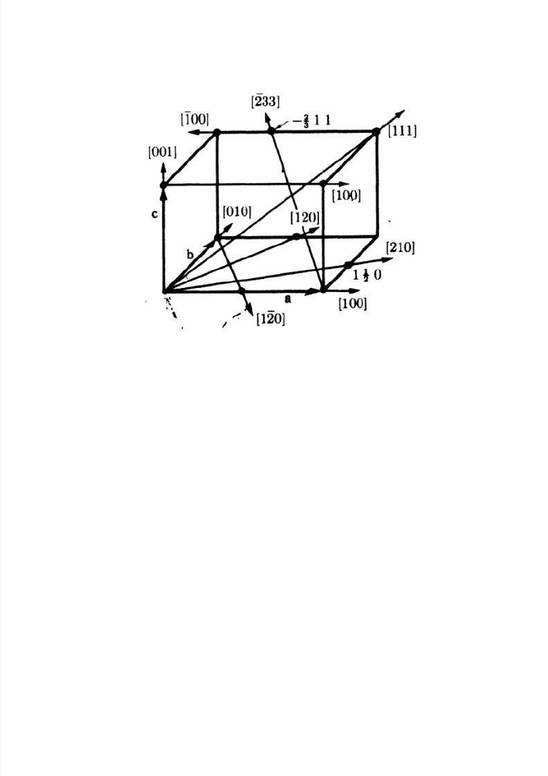
Miller Indices of Directions for Cubic Crystals
• A vector of convenient length is positioned such that it
passes through the origin of the coordinate system.
• The length of the vector projection on each of the three axes
is determined.
• These three numbers are multiplied or divided by a common
factor to reduce them to the smallest integer values.
• The three indices, not separated by commas,
are enclosed in square brackets [uvw]
• If a negative sign is obtained representthe –ve sign with a
bar over the number
8/10/2019 MT-201B MATERIAL SCIENCE NEW - Copy.ppt
http://slidepdf.com/reader/full/mt-201b-material-science-new-copyppt 55/295
8/10/2019 MT-201B MATERIAL SCIENCE NEW - Copy.ppt
http://slidepdf.com/reader/full/mt-201b-material-science-new-copyppt 56/295
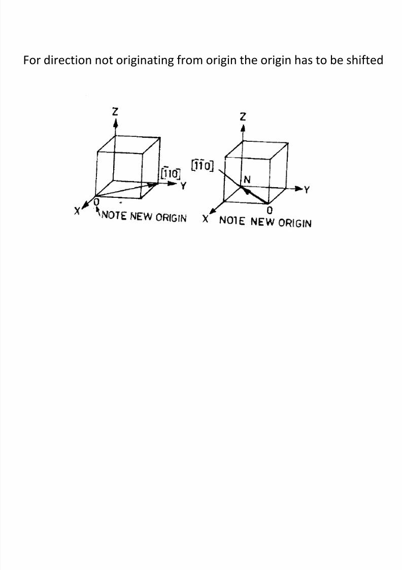
For direction not originating from origin the origin has to be shifted
8/10/2019 MT-201B MATERIAL SCIENCE NEW - Copy.ppt
http://slidepdf.com/reader/full/mt-201b-material-science-new-copyppt 57/295
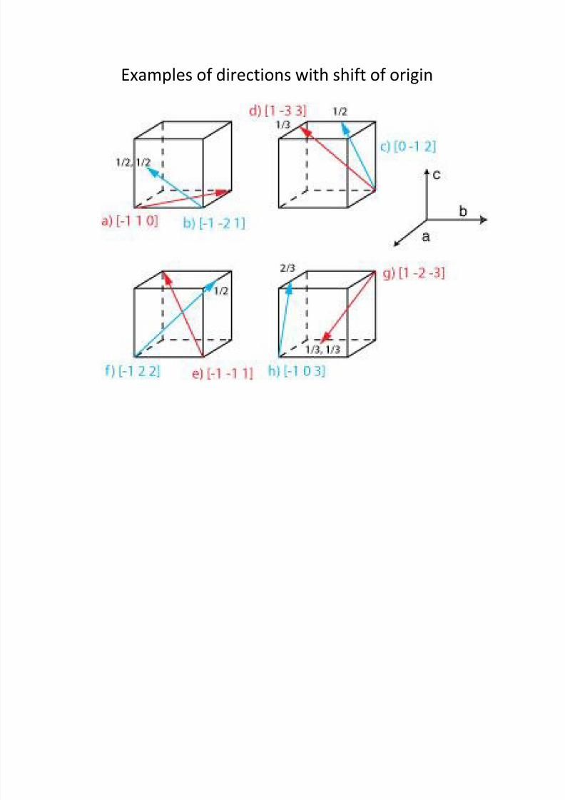
Examples of directions with shift of origin
8/10/2019 MT-201B MATERIAL SCIENCE NEW - Copy.ppt
http://slidepdf.com/reader/full/mt-201b-material-science-new-copyppt 58/295
F il f S t R l t d Pl
8/10/2019 MT-201B MATERIAL SCIENCE NEW - Copy.ppt
http://slidepdf.com/reader/full/mt-201b-material-science-new-copyppt 59/295
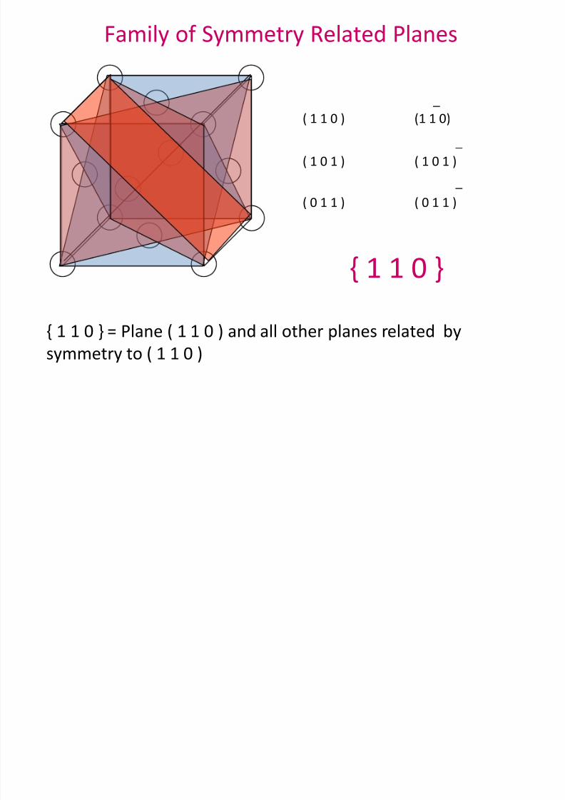
Family of Symmetry Related Planes
(1 1 0) _
( 1 1 0 )
( 1 0 1 )
( 0 1 1 )
_
( 0 1 1 )
( 1 0 1 )
_
{ 1 1 0 }
{ 1 1 0 } = Plane ( 1 1 0 ) and all other planes related by
symmetry to ( 1 1 0 )
Family of Symmetry Related Directions
8/10/2019 MT-201B MATERIAL SCIENCE NEW - Copy.ppt
http://slidepdf.com/reader/full/mt-201b-material-science-new-copyppt 60/295
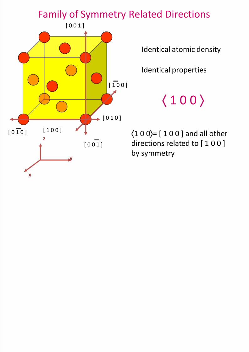
Family of Symmetry Related Directions
x
y
z[ 1 0 0 ]
[ 1 0 0 ]
_
[ 0 0 1 ]
[ 0 0 1 ] _
[ 0 1 0 ]
_[ 0 1 0 ]
Identical atomic density
Identical properties
1 0 0
1 0 0 = [ 1 0 0 ] and all otherdirections related to [ 1 0 0 ]
by symmetry
8/10/2019 MT-201B MATERIAL SCIENCE NEW - Copy.ppt
http://slidepdf.com/reader/full/mt-201b-material-science-new-copyppt 61/295
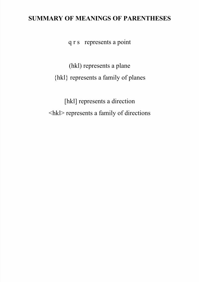
SUMMARY OF MEANINGS OF PARENTHESES
q r s represents a point
(hkl) represents a plane
{hkl} represents a family of planes
[hkl] represents a direction
<hkl> represents a family of directions
A i t f t l
8/10/2019 MT-201B MATERIAL SCIENCE NEW - Copy.ppt
http://slidepdf.com/reader/full/mt-201b-material-science-new-copyppt 62/295
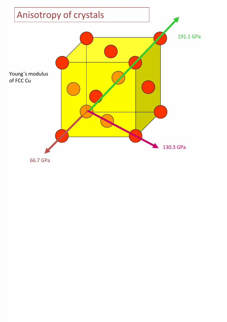
Anisotropy of crystals
66.7 GPa
130.3 GPa
191.1 GPa
Young’s modulus
of FCC Cu
A i t f t l ( td )

8/10/2019 MT-201B MATERIAL SCIENCE NEW - Copy.ppt
http://slidepdf.com/reader/full/mt-201b-material-science-new-copyppt 63/295
Anisotropy of crystals (contd.)
Different crystallographicplanes have different
atomic density
And hence
different
properties
Si Wafer for
computers
8/10/2019 MT-201B MATERIAL SCIENCE NEW - Copy.ppt
http://slidepdf.com/reader/full/mt-201b-material-science-new-copyppt 64/295
8/10/2019 MT-201B MATERIAL SCIENCE NEW - Copy.ppt
http://slidepdf.com/reader/full/mt-201b-material-science-new-copyppt 65/295
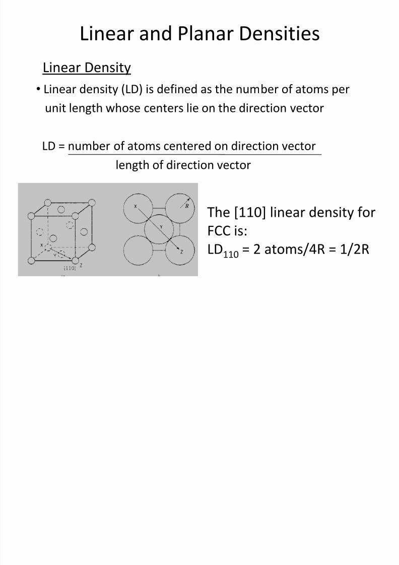
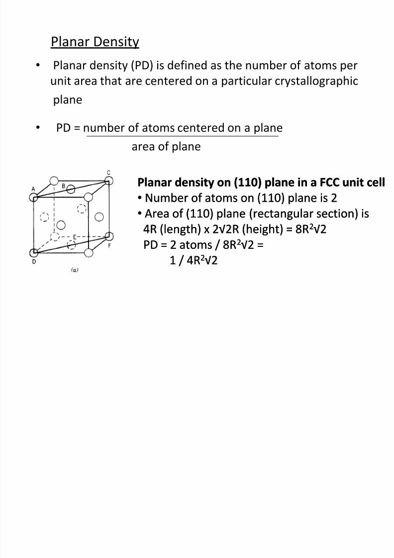
Planar Density
• Planar density (PD) is defined as the number of atoms per
unit area that are centered on a particular crystallographic
plane
• PD = number of atoms centered on a plane
area of plane
Planar density on (110) plane in a FCC unit cell
• Number of atoms on (110) plane is 2
• Area of (110) plane (rectangular section) is4R (length) x 2√2R (height) = 8R2√2
PD = 2 atoms / 8R2√2 =
1 / 4R2√2
Planar density on (110) plane in a FCC unit cell
• Number of atoms on (110) plane is 2
• Area of (110) plane (rectangular section) is4R (length) x 2√2R (height) = 8R2√2
PD = 2 atoms / 8R2√2 =
1 / 4R2√2
8/10/2019 MT-201B MATERIAL SCIENCE NEW - Copy.ppt
http://slidepdf.com/reader/full/mt-201b-material-science-new-copyppt 66/295
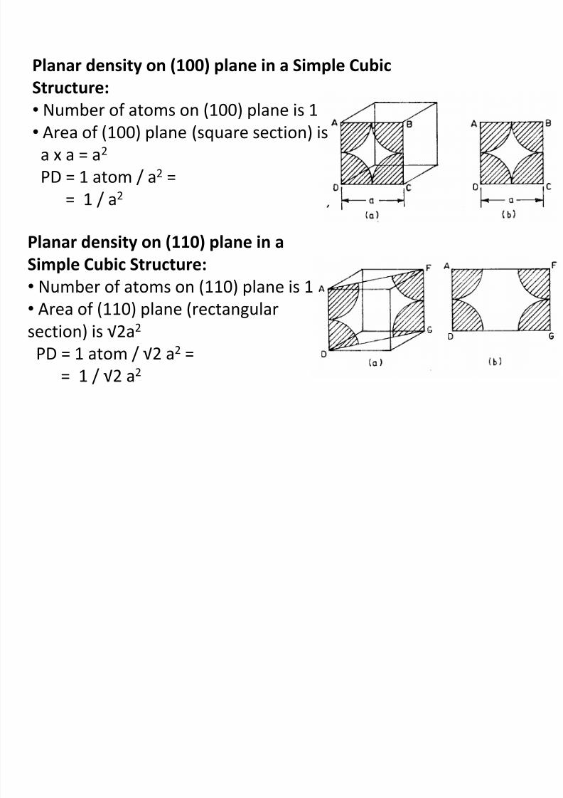
Planar density on (100) plane in a Simple Cubic
Structure:
• Number of atoms on (100) plane is 1• Area of (100) plane (square section) is
a x a = a2
PD = 1 atom / a2 =
= 1 / a2
Planar density on (110) plane in a
Simple Cubic Structure:
• Number of atoms on (110) plane is 1
• Area of (110) plane (rectangular
section) is √2a2
PD = 1 atom / √2 a2 =
= 1 / √2 a2
8/10/2019 MT-201B MATERIAL SCIENCE NEW - Copy.ppt
http://slidepdf.com/reader/full/mt-201b-material-science-new-copyppt 67/295
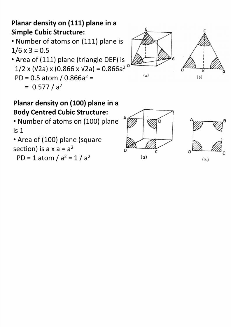
Planar density on (111) plane in a
Simple Cubic Structure:
• Number of atoms on (111) plane is1/6 x 3 = 0.5
• Area of (111) plane (triangle DEF) is
1/2 x (√2a) x (0.866 x √2a) = 0.866a2
PD = 0.5 atom / 0.866a2 =
= 0.577 / a2
Planar density on (100) plane in a
Body Centred Cubic Structure:
• Number of atoms on (100) planeis 1
• Area of (100) plane (square
section) is a x a = a2
PD = 1 atom / a2 = 1 / a2
8/10/2019 MT-201B MATERIAL SCIENCE NEW - Copy.ppt
http://slidepdf.com/reader/full/mt-201b-material-science-new-copyppt 68/295
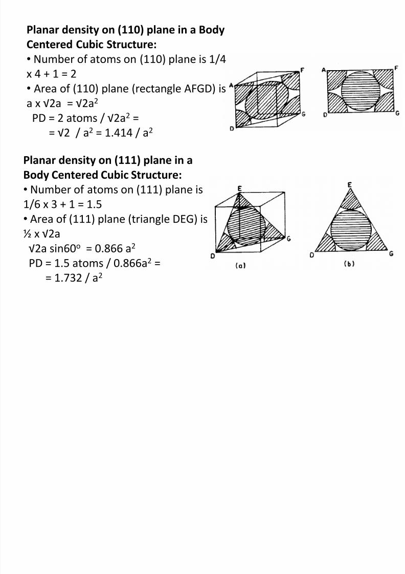
Planar density on (110) plane in a Body
Centered Cubic Structure:
• Number of atoms on (110) plane is 1/4
x 4 + 1 = 2• Area of (110) plane (rectangle AFGD) is
a x √2a = √2a2
PD = 2 atoms / √2a2 =
= √2 / a2 = 1.414 / a2
Planar density on (111) plane in a
Body Centered Cubic Structure:
• Number of atoms on (111) plane is
1/6 x 3 + 1 = 1.5
• Area of (111) plane (triangle DEG) is½ x √2a
√2a sin60o = 0.866 a2
PD = 1.5 atoms / 0.866a2 =
= 1.732 / a2
Voids in crystalline structures
8/10/2019 MT-201B MATERIAL SCIENCE NEW - Copy.ppt
http://slidepdf.com/reader/full/mt-201b-material-science-new-copyppt 69/295
Voids in crystalline structures
We have already seen that as spheres cannot fill entire space the atomic
packing fraction (APF) < 1 (for all crystals)
This implies there are voids between the atoms. Lower the PF, larger the
volume occupied by voids.
These voids have complicated shapes; but we are mostly interested in the
largest sphere which can fit into these voids
The size and distribution of voids in materials play a role in determiningaspects of material behaviour e.g. solubility of interstitials and their
diffusivity
The position of the voids of a particular type will be consistent with the
symmetry of the crystal
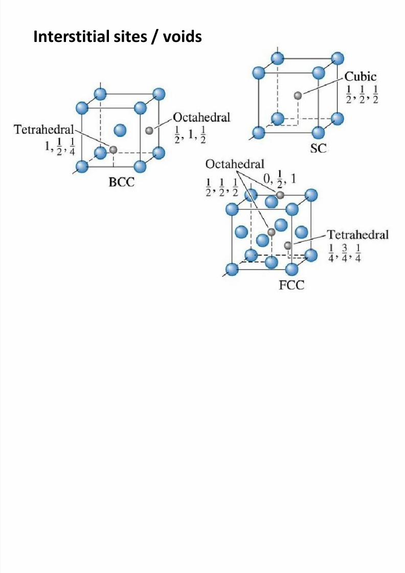
In the close packed crystals (FCC, HCP) there are two types of voids tetrahedral and octahedral voids (identical in both the structures as the voids
are formed between two layers of atoms)
The tetrahedral void has a coordination number of 4
The octahedral void has a coordination number 6
8/10/2019 MT-201B MATERIAL SCIENCE NEW - Copy.ppt
http://slidepdf.com/reader/full/mt-201b-material-science-new-copyppt 70/295
8/10/2019 MT-201B MATERIAL SCIENCE NEW - Copy.ppt
http://slidepdf.com/reader/full/mt-201b-material-science-new-copyppt 71/295
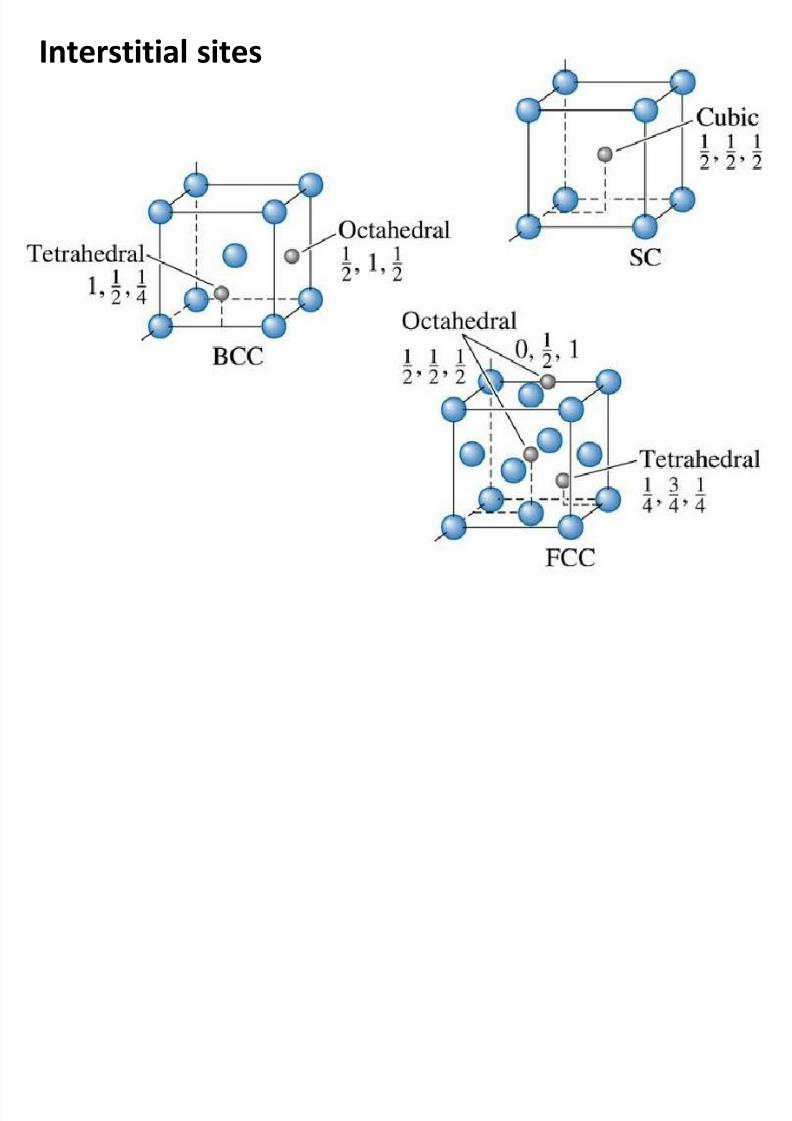
Interstitial sites / voids
8/10/2019 MT-201B MATERIAL SCIENCE NEW - Copy.ppt
http://slidepdf.com/reader/full/mt-201b-material-science-new-copyppt 72/295
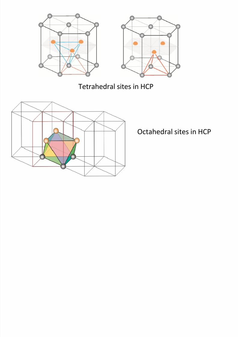
Tetrahedral sites in HCP
Octahedral sites in HCP
8/10/2019 MT-201B MATERIAL SCIENCE NEW - Copy.ppt
http://slidepdf.com/reader/full/mt-201b-material-science-new-copyppt 73/295
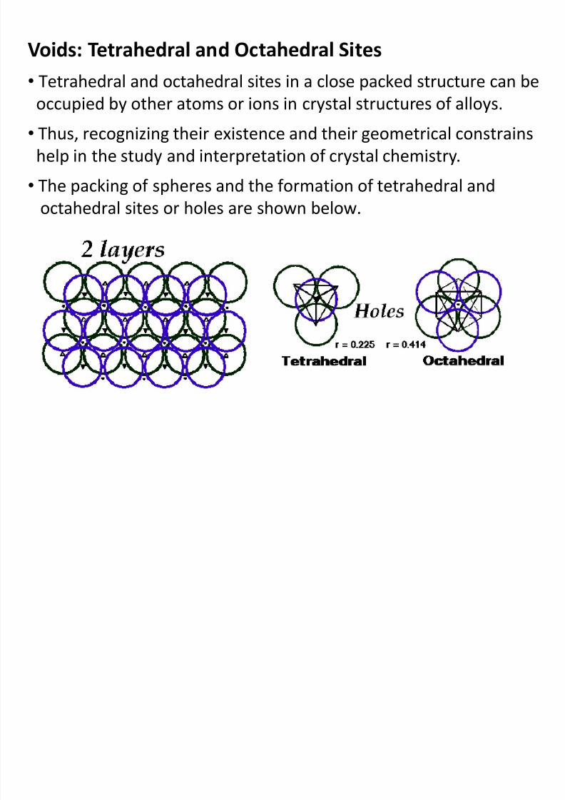
Voids: Tetrahedral and Octahedral Sites
• Tetrahedral and octahedral sites in a close packed structure can be
occupied by other atoms or ions in crystal structures of alloys.• Thus, recognizing their existence and their geometrical constrains
help in the study and interpretation of crystal chemistry.
• The packing of spheres and the formation of tetrahedral and
octahedral sites or holes are shown below.
8/10/2019 MT-201B MATERIAL SCIENCE NEW - Copy.ppt
http://slidepdf.com/reader/full/mt-201b-material-science-new-copyppt 74/295
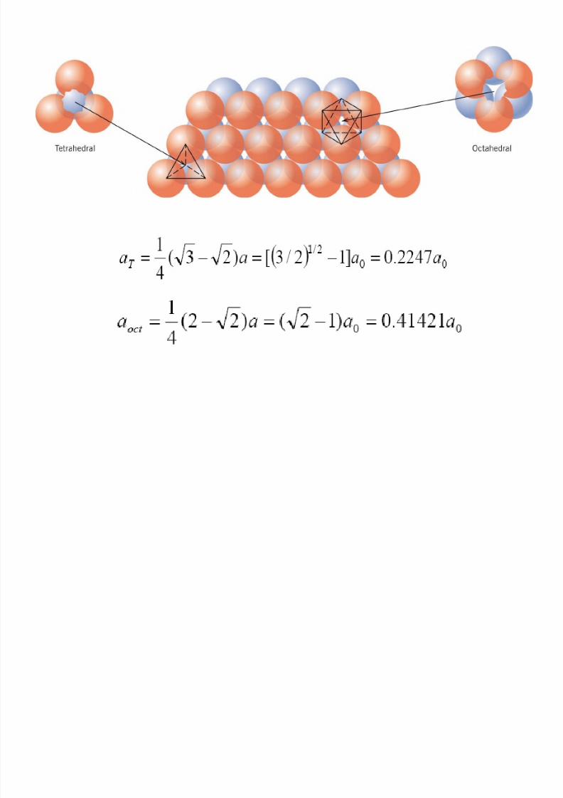
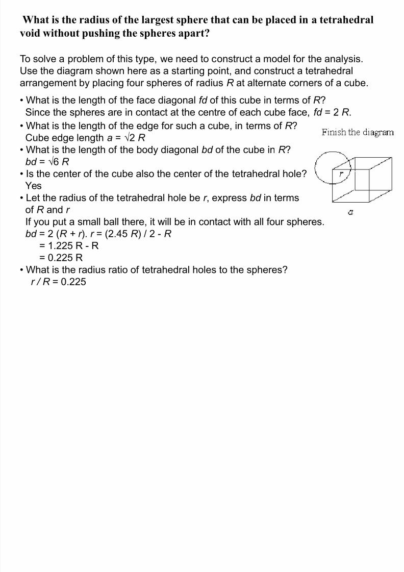
What is the radius of the largest sphere that can be placed in a tetrahedral
8/10/2019 MT-201B MATERIAL SCIENCE NEW - Copy.ppt
http://slidepdf.com/reader/full/mt-201b-material-science-new-copyppt 75/295
void without pushing the spheres apart?
To solve a problem of this type, we need to construct a model for the analysis.
Use the diagram shown here as a starting point, and construct a tetrahedral
arrangement by placing four spheres of radius R at alternate corners of a cube.
• What is the length of the face diagonal fd of this cube in terms of R ?
Since the spheres are in contact at the centre of each cube face, fd = 2 R .
• What is the length of the edge for such a cube, in terms of R ?
Cube edge length a = 2 R
• What is the length of the body diagonal bd of the cube in R ?bd = 6 R
• Is the center of the cube also the center of the tetrahedral hole?
Yes
• Let the radius of the tetrahedral hole be r , express bd in terms
of R and r
If you put a small ball there, it will be in contact with all four spheres.
bd = 2 (R + r ). r = (2.45 R ) / 2 - R
= 1.225 R - R
= 0.225 R
• What is the radius ratio of tetrahedral holes to the spheres?
r / R = 0.225
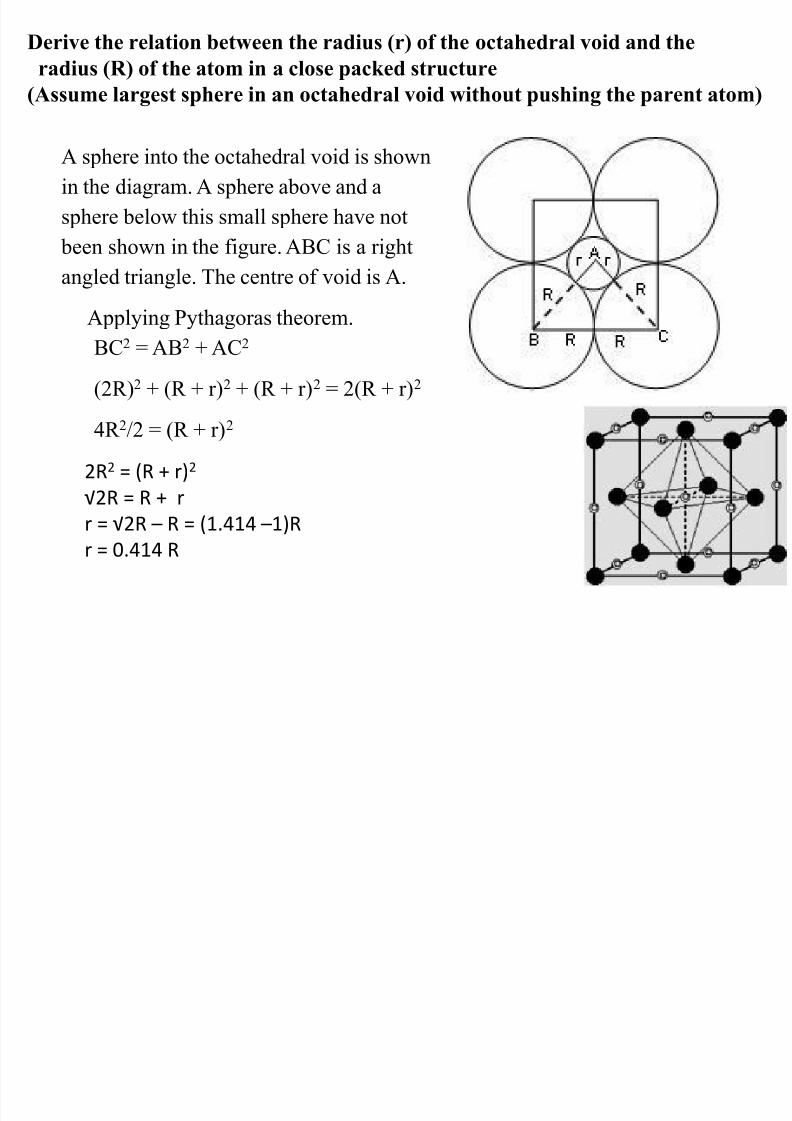
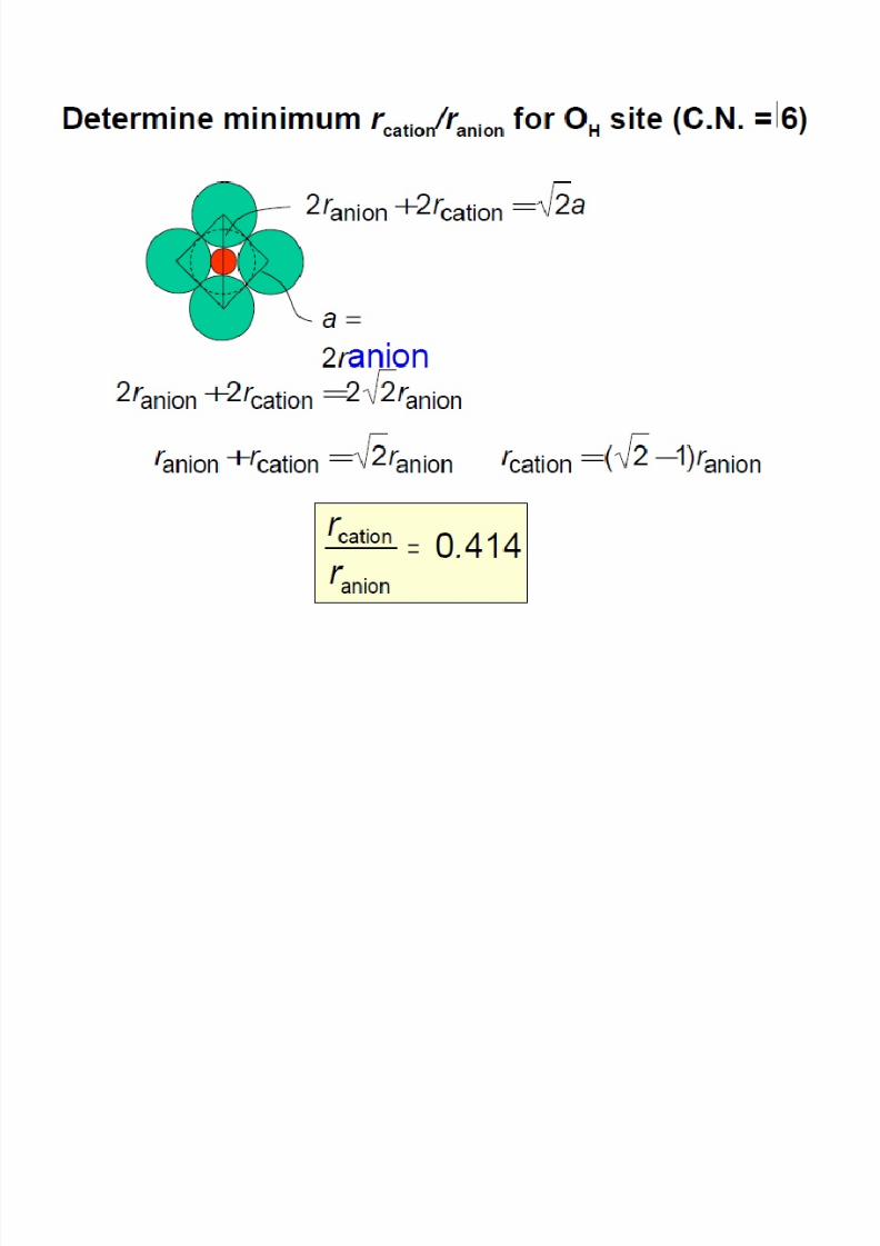
Derive the relation between the radius (r) of the octahedral void and the
8/10/2019 MT-201B MATERIAL SCIENCE NEW - Copy.ppt
http://slidepdf.com/reader/full/mt-201b-material-science-new-copyppt 76/295
A sphere into the octahedral void is shown
in the diagram. A sphere above and a
sphere below this small sphere have not
been shown in the figure. ABC is a right
angled triangle. The centre of void is A.Applying Pythagoras theorem.
BC2 = AB2 + AC2
(2R)2 + (R + r)2 + (R + r)2 = 2(R + r)2
4R 2/2 = (R + r)2
radius (R) of the atom in a close packed structure
(Assume largest sphere in an octahedral void without pushing the parent atom)
2R2 = (R + r)2
√2R = R + r
r = √2R – R = (1.414 –1)R
r = 0.414 R
Si l C l d P l lli
8/10/2019 MT-201B MATERIAL SCIENCE NEW - Copy.ppt
http://slidepdf.com/reader/full/mt-201b-material-science-new-copyppt 77/295
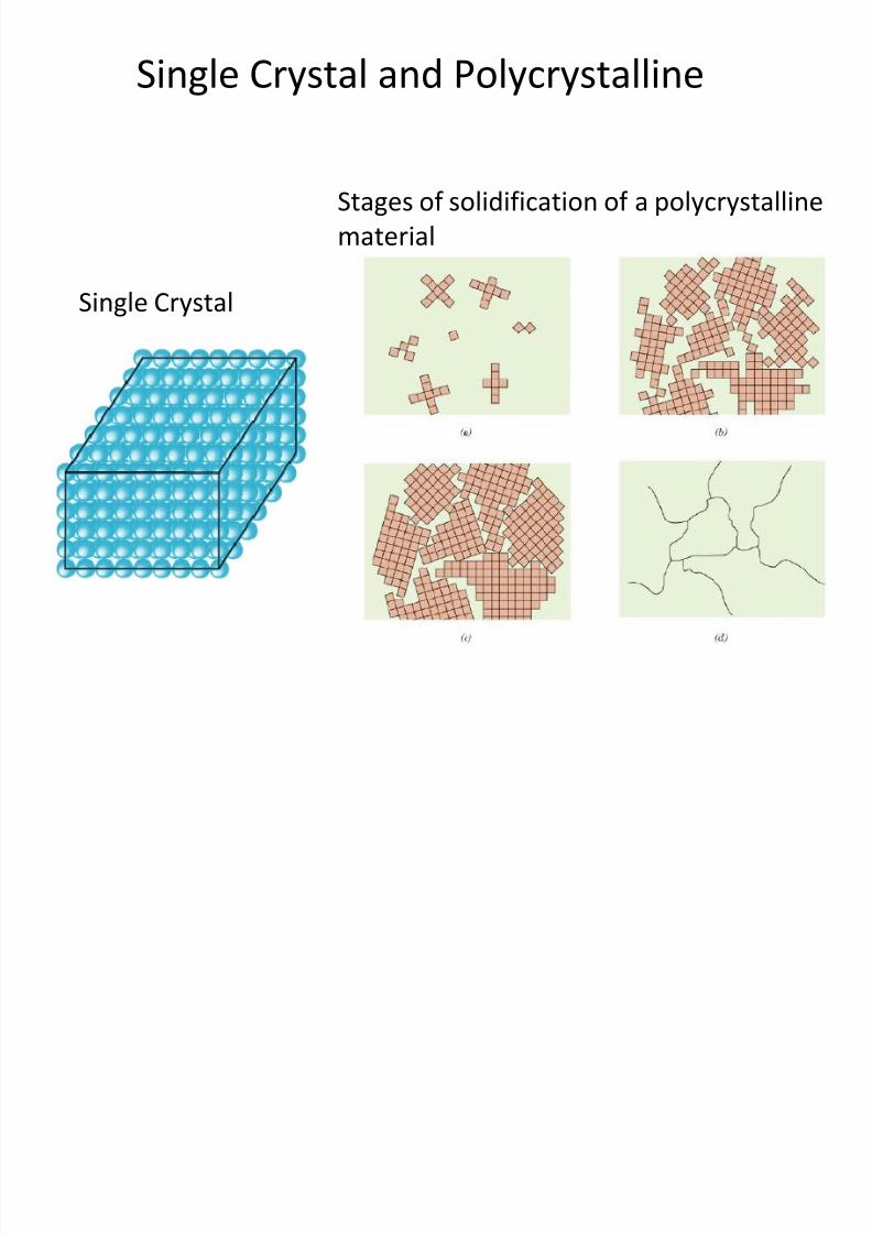
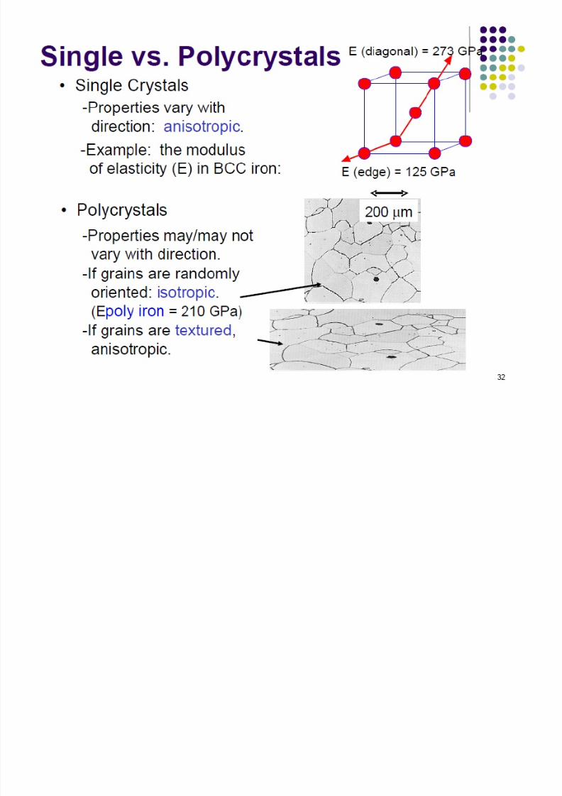
Single Crystal and Polycrystalline
Stages of solidification of a polycrystalline
material
Single Crystal
8/10/2019 MT-201B MATERIAL SCIENCE NEW - Copy.ppt
http://slidepdf.com/reader/full/mt-201b-material-science-new-copyppt 78/295
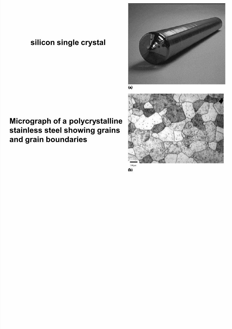
silicon single crystal
Micrograph of a polycrystallinestainless steel showing grains
and grain boundaries
8/10/2019 MT-201B MATERIAL SCIENCE NEW - Copy.ppt
http://slidepdf.com/reader/full/mt-201b-material-science-new-copyppt 79/295
8/10/2019 MT-201B MATERIAL SCIENCE NEW - Copy.ppt
http://slidepdf.com/reader/full/mt-201b-material-science-new-copyppt 80/295
Ceramic Crystal Structures
8/10/2019 MT-201B MATERIAL SCIENCE NEW - Copy.ppt
http://slidepdf.com/reader/full/mt-201b-material-science-new-copyppt 81/295
Ceramic Crystal Structures
• Ceramics are compounds between metallic & nonmetallicelements e.x. Al2O3, FeO, SiC, TiN, NaCl
• They are hard and brittle
• Typically insulative to the passage of electricity & heat
Crystal Structures
• Atomic bonding is mostly ionic i.e. the crystal structure is
composed of electrically charged ions instead of atoms.
• The metallic ions, or cations are positively charged becausethey have given up their valence electrons to the
nonmetallic Ions or anions, which are negatively charged
8/10/2019 MT-201B MATERIAL SCIENCE NEW - Copy.ppt
http://slidepdf.com/reader/full/mt-201b-material-science-new-copyppt 82/295
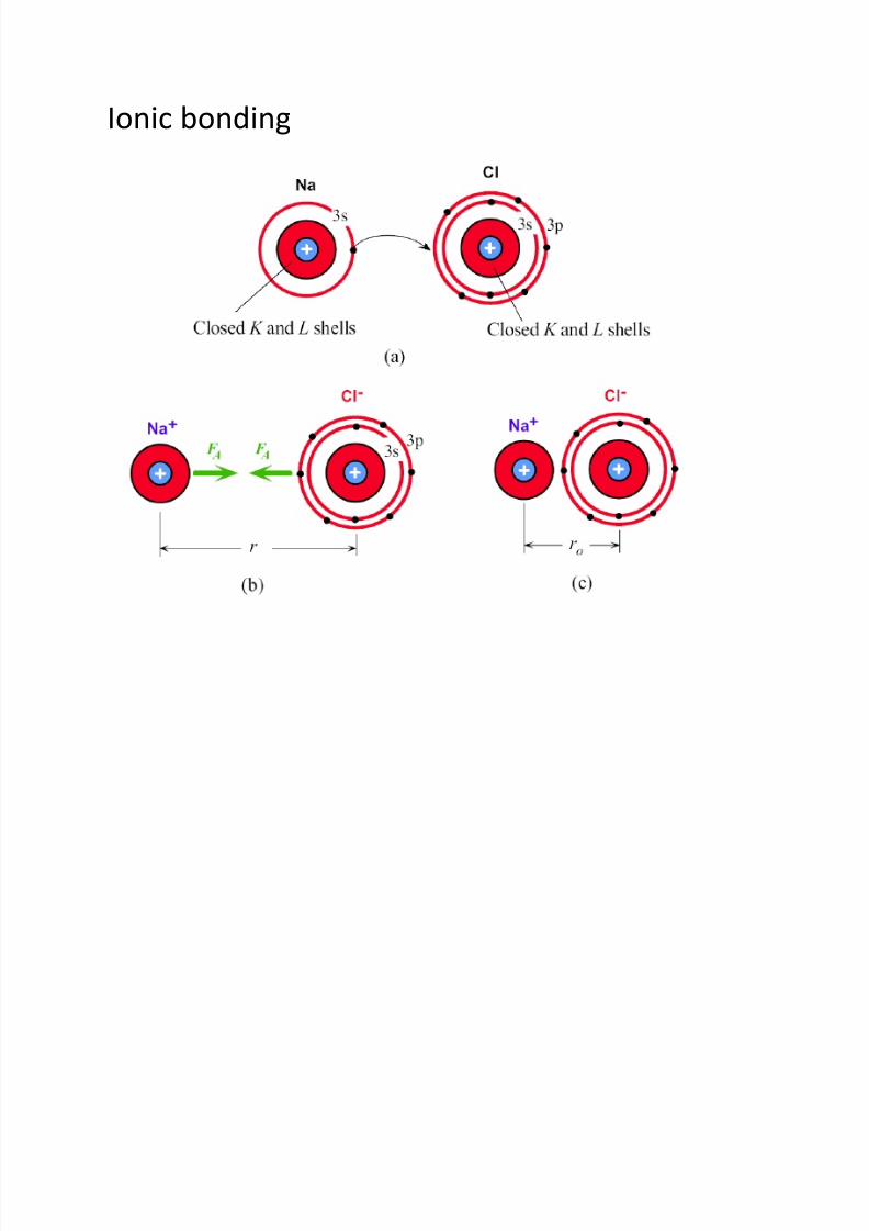
Ionic bonding
8/10/2019 MT-201B MATERIAL SCIENCE NEW - Copy.ppt
http://slidepdf.com/reader/full/mt-201b-material-science-new-copyppt 83/295
8/10/2019 MT-201B MATERIAL SCIENCE NEW - Copy.ppt
http://slidepdf.com/reader/full/mt-201b-material-science-new-copyppt 84/295
1. Charge neutrality: each crystal should be
electrically neutral e.x. NaCl and CaCl2
8/10/2019 MT-201B MATERIAL SCIENCE NEW - Copy.ppt
http://slidepdf.com/reader/full/mt-201b-material-science-new-copyppt 85/295
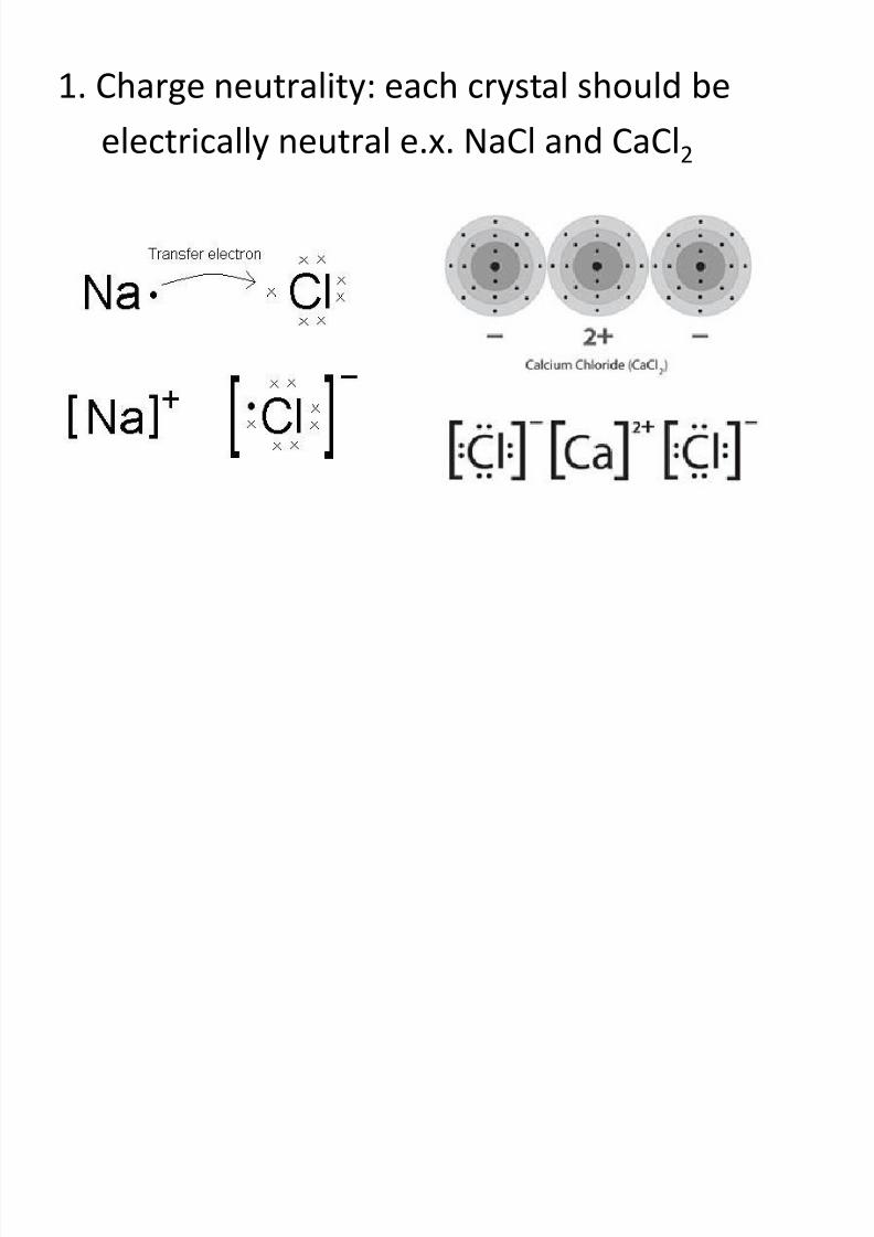
2. The relative sizes of the cations and anions
• Because the metallic elements give up electrons when
Ionized, cations are
smaller than anions
• Hence rc / ra is less than unity
• Stable ceramic crystal structures form when those
anions surrounding a cation are all in contact with thethat cation
8/10/2019 MT-201B MATERIAL SCIENCE NEW - Copy.ppt
http://slidepdf.com/reader/full/mt-201b-material-science-new-copyppt 86/295
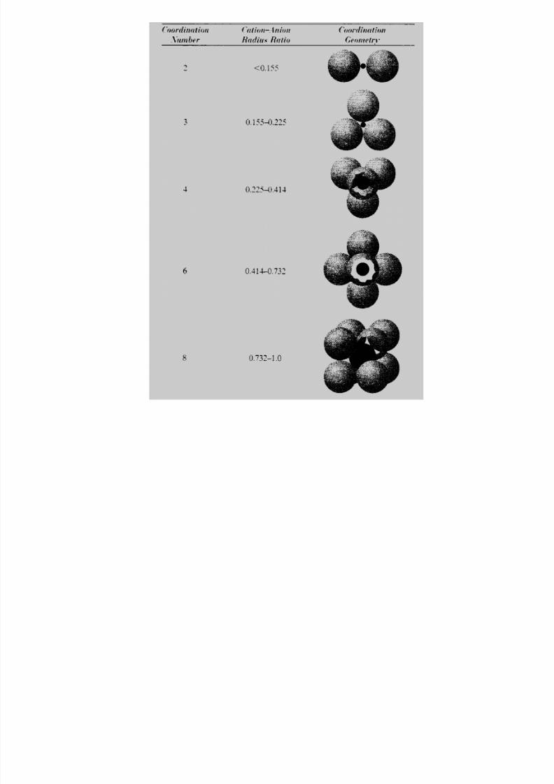
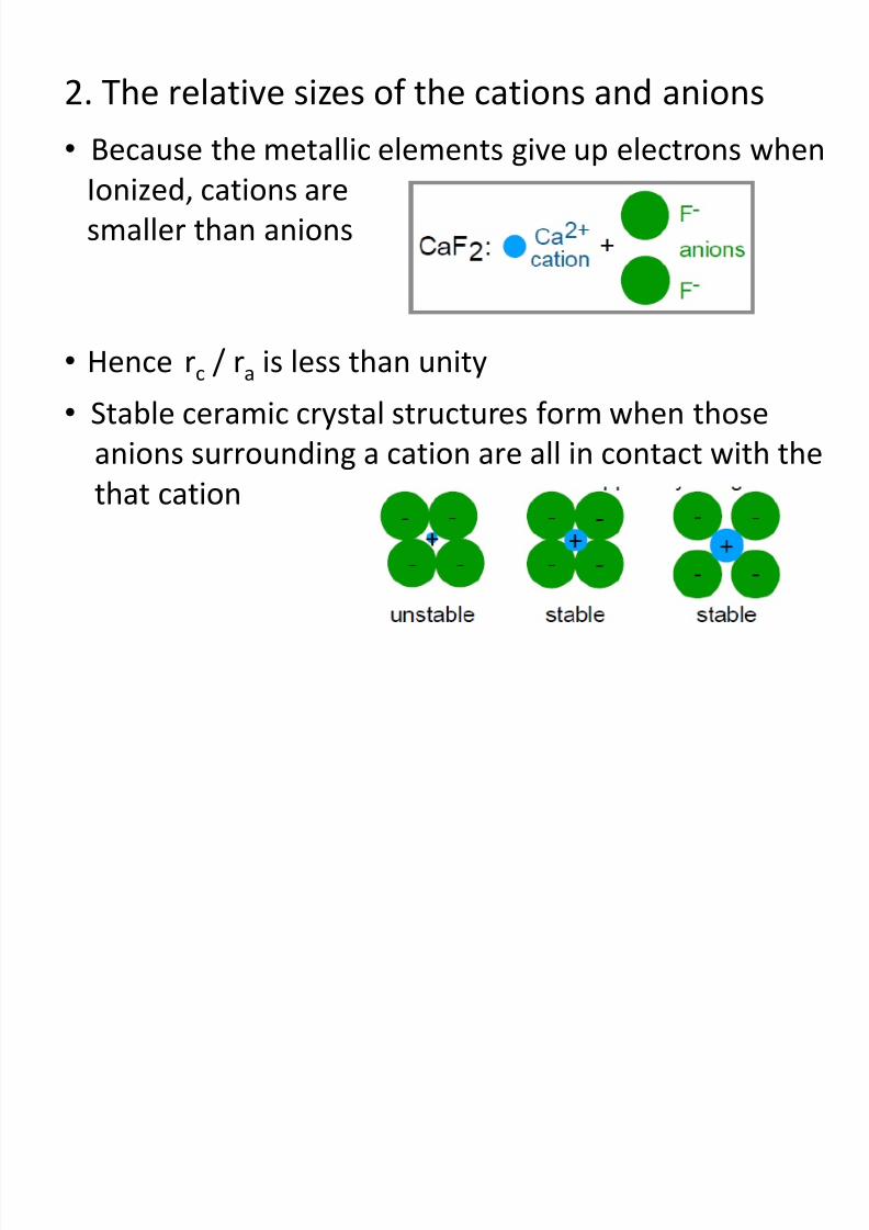
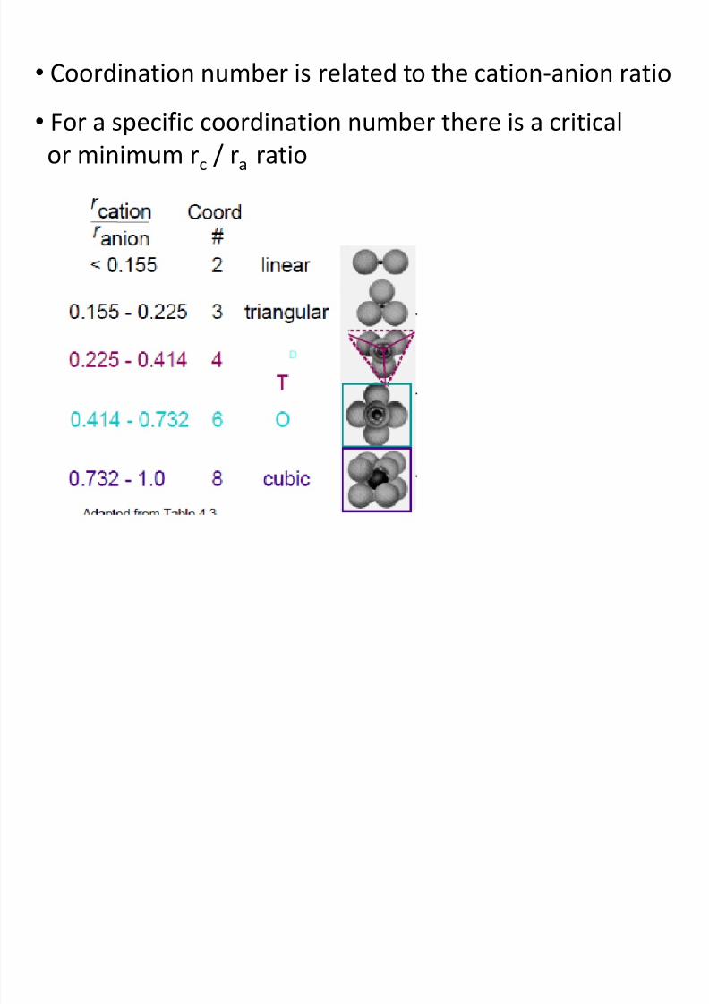
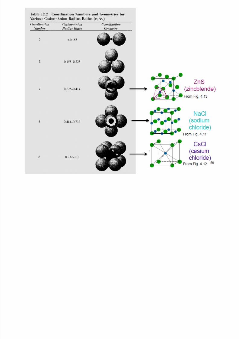
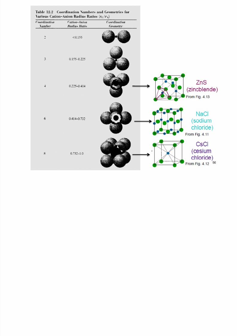
• Coordination number is related to the cation-anion ratio
• For a specific coordination number there is a critical
or minimum rc / ra ratio
8/10/2019 MT-201B MATERIAL SCIENCE NEW - Copy.ppt
http://slidepdf.com/reader/full/mt-201b-material-science-new-copyppt 87/295
8/10/2019 MT-201B MATERIAL SCIENCE NEW - Copy.ppt
http://slidepdf.com/reader/full/mt-201b-material-science-new-copyppt 88/295
Predicting Structure of FeO
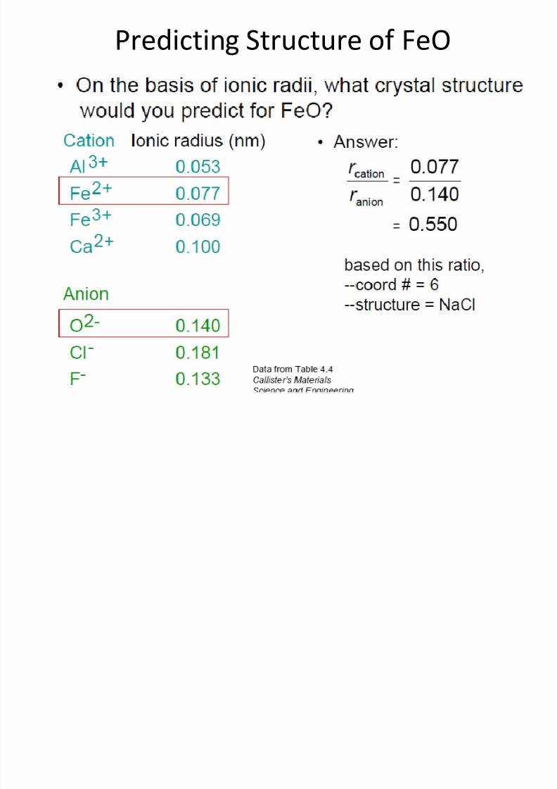
8/10/2019 MT-201B MATERIAL SCIENCE NEW - Copy.ppt
http://slidepdf.com/reader/full/mt-201b-material-science-new-copyppt 89/295
Predicting Structure of FeO
8/10/2019 MT-201B MATERIAL SCIENCE NEW - Copy.ppt
http://slidepdf.com/reader/full/mt-201b-material-science-new-copyppt 90/295
8/10/2019 MT-201B MATERIAL SCIENCE NEW - Copy.ppt
http://slidepdf.com/reader/full/mt-201b-material-science-new-copyppt 91/295
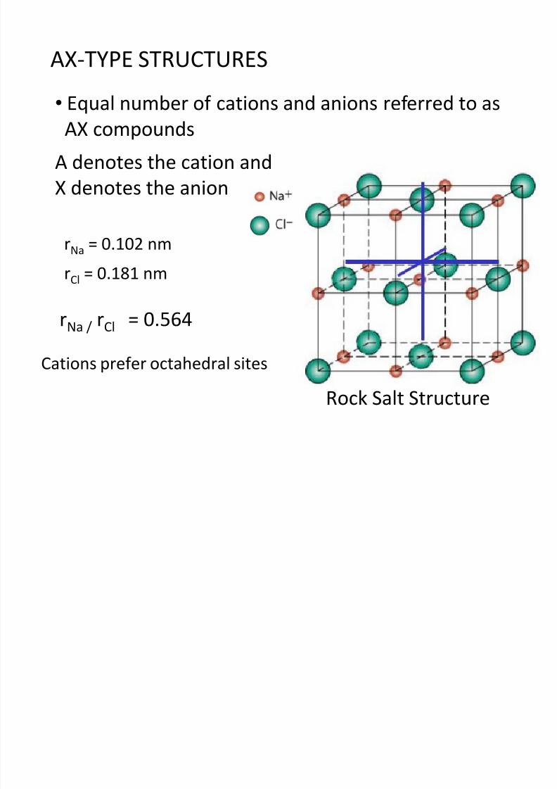
AX-TYPE STRUCTURES
• Equal number of cations and anions referred to asAX compounds
A denotes the cation and
X denotes the anion
rNa = 0.102 nm
rCl = 0.181 nm
rNa / rCl = 0.564
Cations prefer octahedral sites
Rock Salt Structure
8/10/2019 MT-201B MATERIAL SCIENCE NEW - Copy.ppt
http://slidepdf.com/reader/full/mt-201b-material-science-new-copyppt 92/295
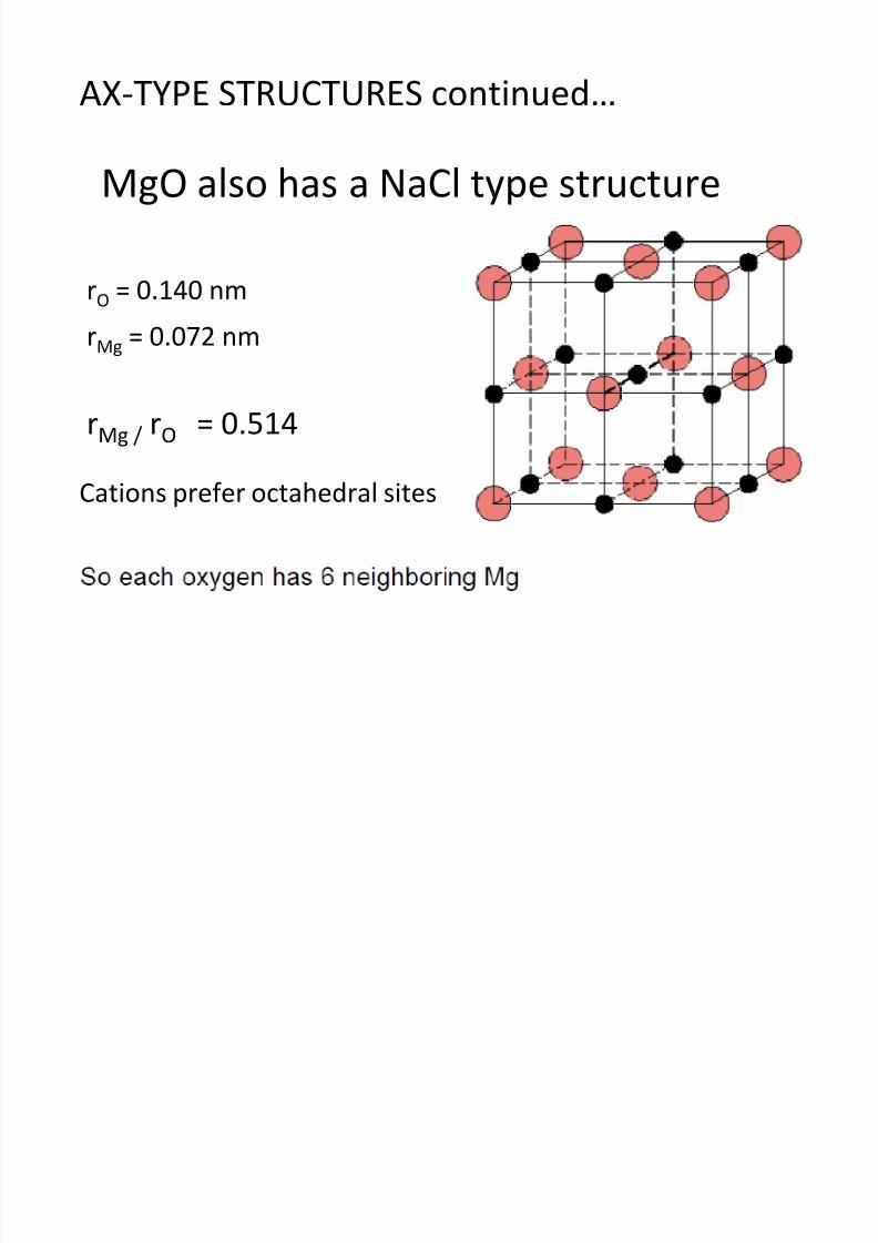
rO = 0.140 nm
rMg = 0.072 nm
rMg / rO = 0.514
Cations prefer octahedral sites
MgO also has a NaCl type structure
AX-TYPE STRUCTURES continued…
8/10/2019 MT-201B MATERIAL SCIENCE NEW - Copy.ppt
http://slidepdf.com/reader/full/mt-201b-material-science-new-copyppt 93/295
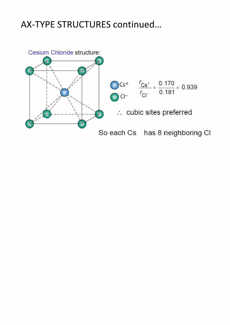
AX-TYPE STRUCTURES continued…
8/10/2019 MT-201B MATERIAL SCIENCE NEW - Copy.ppt
http://slidepdf.com/reader/full/mt-201b-material-science-new-copyppt 94/295
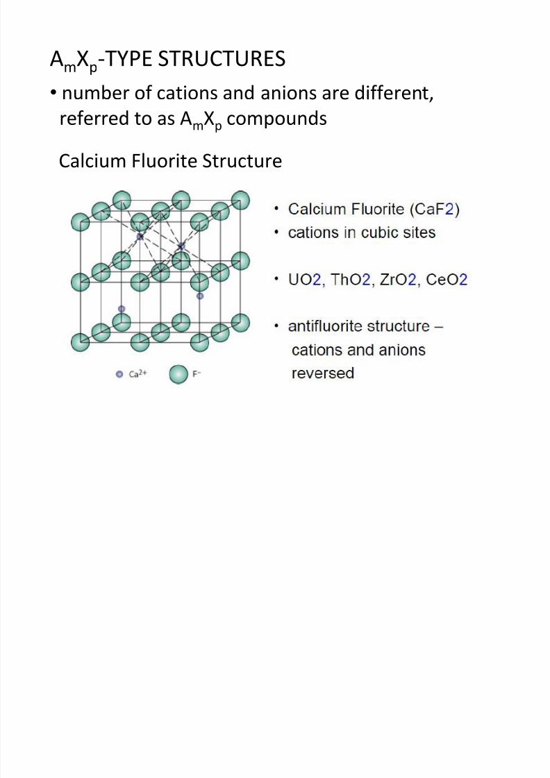
AmXp-TYPE STRUCTURES
• number of cations and anions are different,
referred to as AmXp compounds
Calcium Fluorite Structure
8/10/2019 MT-201B MATERIAL SCIENCE NEW - Copy.ppt
http://slidepdf.com/reader/full/mt-201b-material-science-new-copyppt 95/295
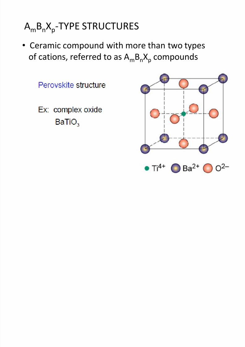
AmBnXp-TYPE STRUCTURES
• Ceramic compound with more than two typesof cations, referred to as AmBnXp compounds
Crystal defects (I f ti i S lid )
8/10/2019 MT-201B MATERIAL SCIENCE NEW - Copy.ppt
http://slidepdf.com/reader/full/mt-201b-material-science-new-copyppt 96/295
Crystal defects (Imperfections in Solids)
• Perfect order does not exist throughout a crystalline materialon an atomic scale. All crystalline materials contain large
number of various defects or imperfections.
• Defects or imperfections influence properties such asmechanical, electrical, magnetic, etc.
• Classification of crystalline defects is generally made
according to geometry or dimensionality of the defect
i.e. zero dimensional defects, one dimensional defects and
two dimensional defects.
Crystal defects / imperfections are broadly classified
8/10/2019 MT-201B MATERIAL SCIENCE NEW - Copy.ppt
http://slidepdf.com/reader/full/mt-201b-material-science-new-copyppt 97/295
1. Point defect (zero dimensional defects)Vacancy,
Impurity atoms ( substitutional and interstitial)
Frankel and Schottky defect
2. Line defect (one dimensional defects)
Edge dislocation
Screw dislocation,
Mixed dislocation
3. Surface defects or Planer defects (two dimensionaldefects)
Grain boundaries
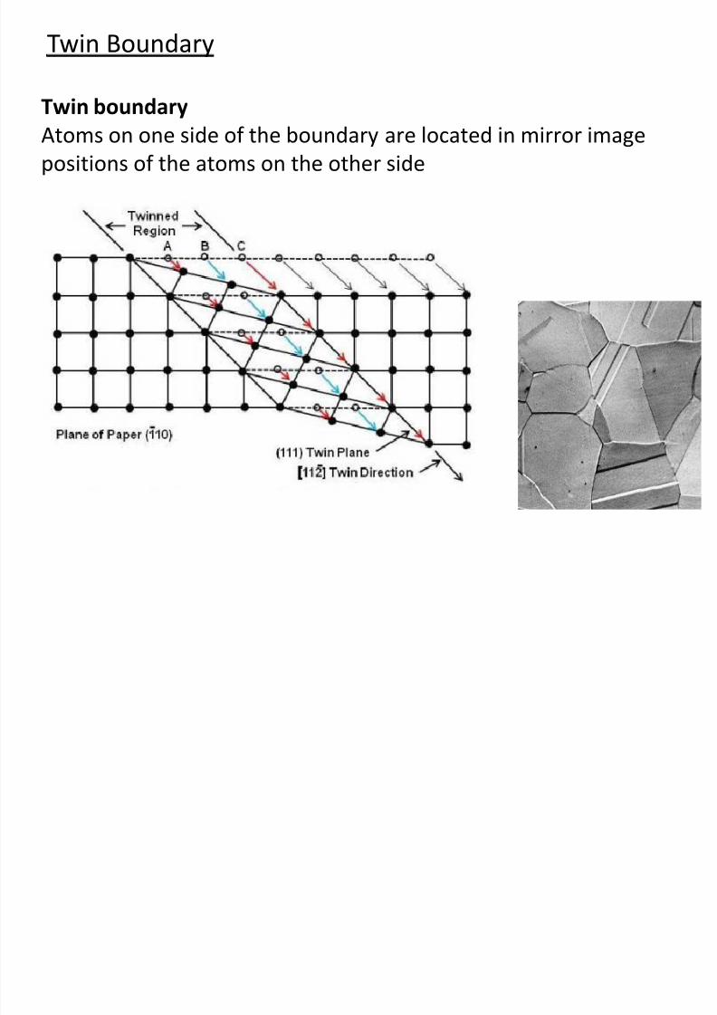
Twin boundary
Stacking faults
y p y
into three classes:
8/10/2019 MT-201B MATERIAL SCIENCE NEW - Copy.ppt
http://slidepdf.com/reader/full/mt-201b-material-science-new-copyppt 98/295
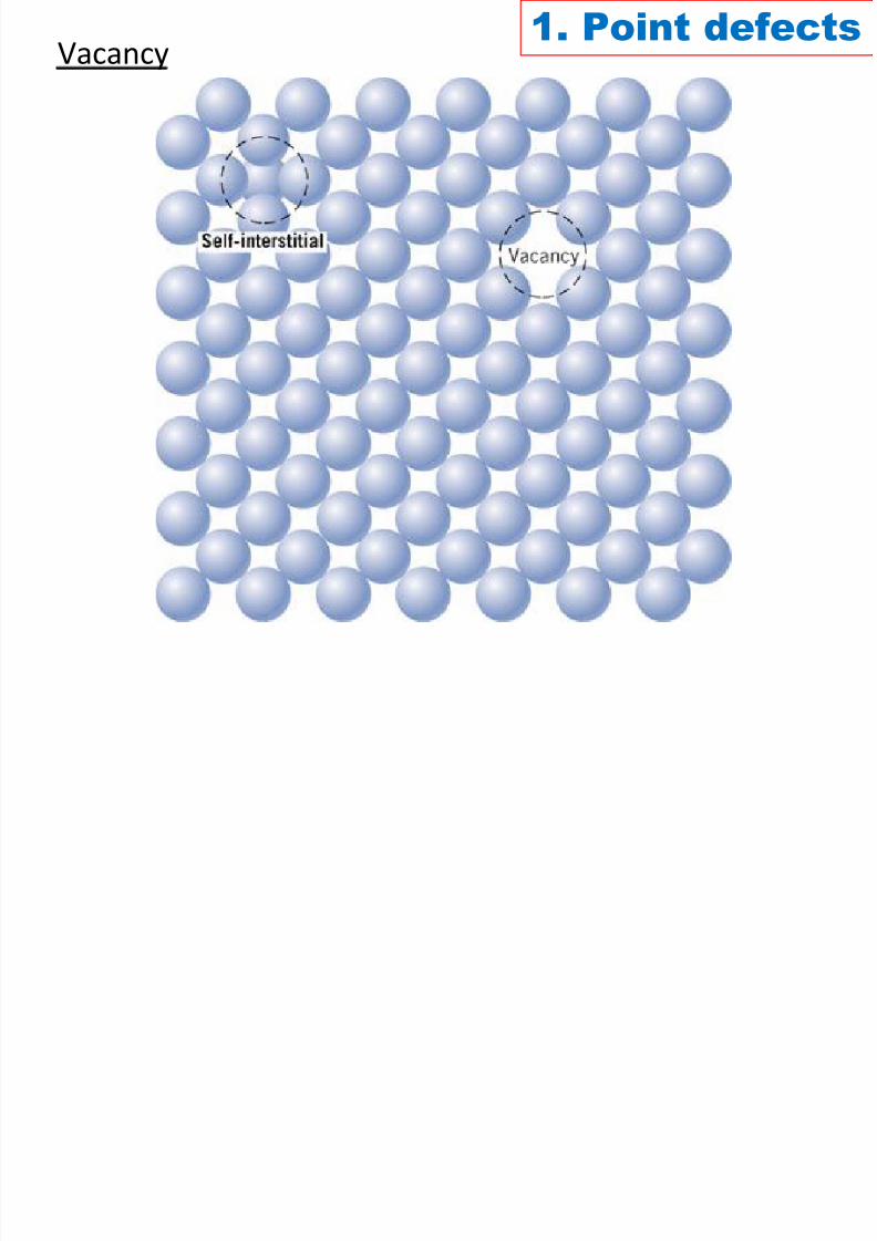
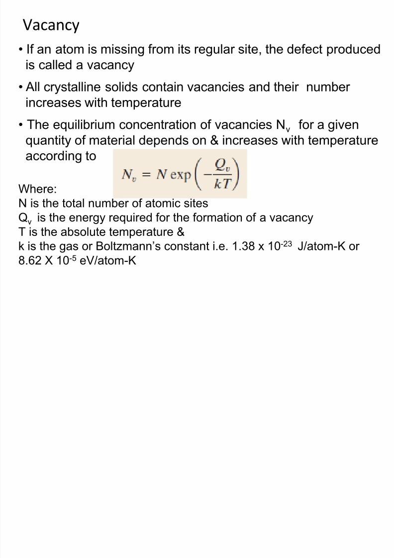
Vacancy
8/10/2019 MT-201B MATERIAL SCIENCE NEW - Copy.ppt
http://slidepdf.com/reader/full/mt-201b-material-science-new-copyppt 99/295
• If an atom is missing from its regular site, the defect produced
is called a vacancy
• All crystalline solids contain vacancies and their number
increases with temperature
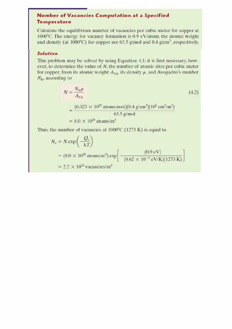
• The equilibrium concentration of vacancies Nv for a given
quantity of material depends on & increases with temperatureaccording to
Where:
N is the total number of atomic sites
Qv is the energy required for the formation of a vacancy
T is the absolute temperature &
k is the gas or Boltzmann’s constant i.e. 1.38 x 10⁻²³ J/atom-K or
8.62 X 10⁻⁵ eV/atom-K
8/10/2019 MT-201B MATERIAL SCIENCE NEW - Copy.ppt
http://slidepdf.com/reader/full/mt-201b-material-science-new-copyppt 100/295
8/10/2019 MT-201B MATERIAL SCIENCE NEW - Copy.ppt
http://slidepdf.com/reader/full/mt-201b-material-science-new-copyppt 101/295
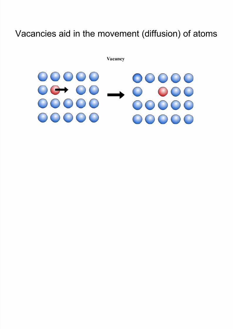
Vacancies aid in the movement (diffusion) of atoms
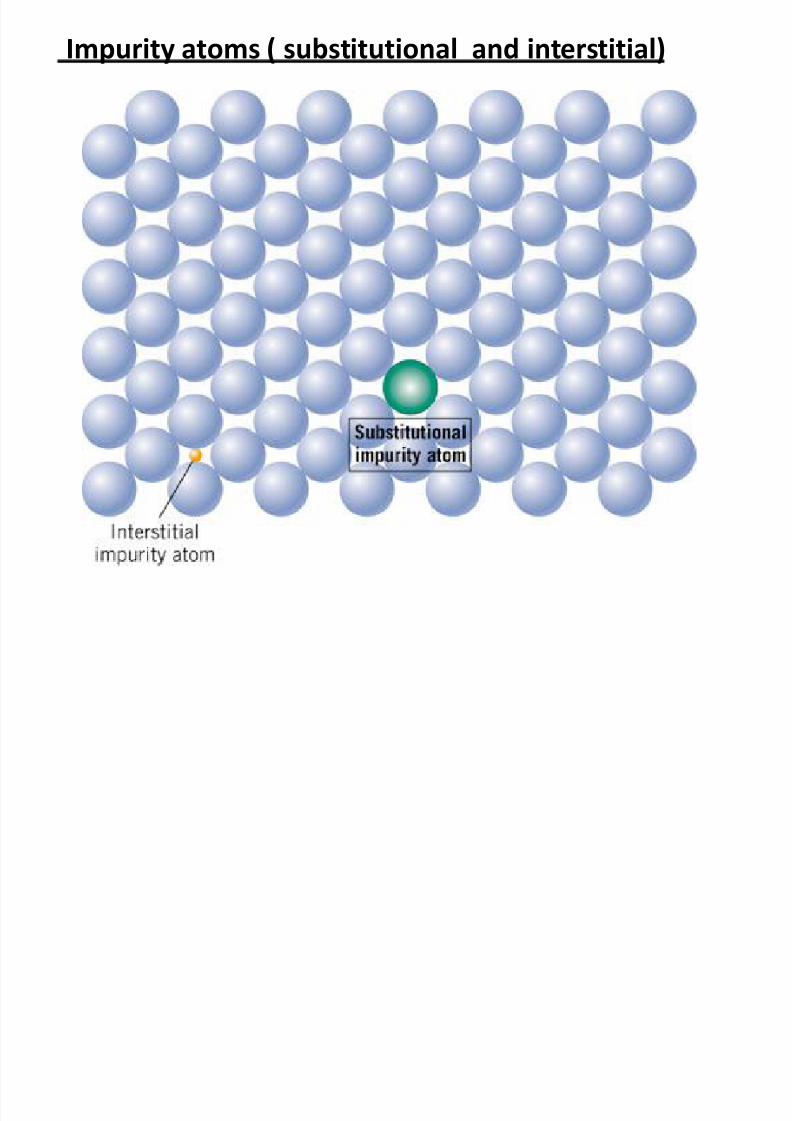
Impurity atoms ( substitutional and interstitial)
8/10/2019 MT-201B MATERIAL SCIENCE NEW - Copy.ppt
http://slidepdf.com/reader/full/mt-201b-material-science-new-copyppt 102/295
I it i t d f t f t t
8/10/2019 MT-201B MATERIAL SCIENCE NEW - Copy.ppt
http://slidepdf.com/reader/full/mt-201b-material-science-new-copyppt 103/295
• Impurity point defects are of two types
1. Substitutional
2. Interstitial
• For substitutional, solute or impurity atoms replace or
substitute for the host atoms
• For interstitial, solute or impurity atoms fill the void or
interstitial space among the host atoms
• Both the substitutional and interstitial impurity atomsdistort the crystal lattice affecting the mechanical and
electrical / electronic properties
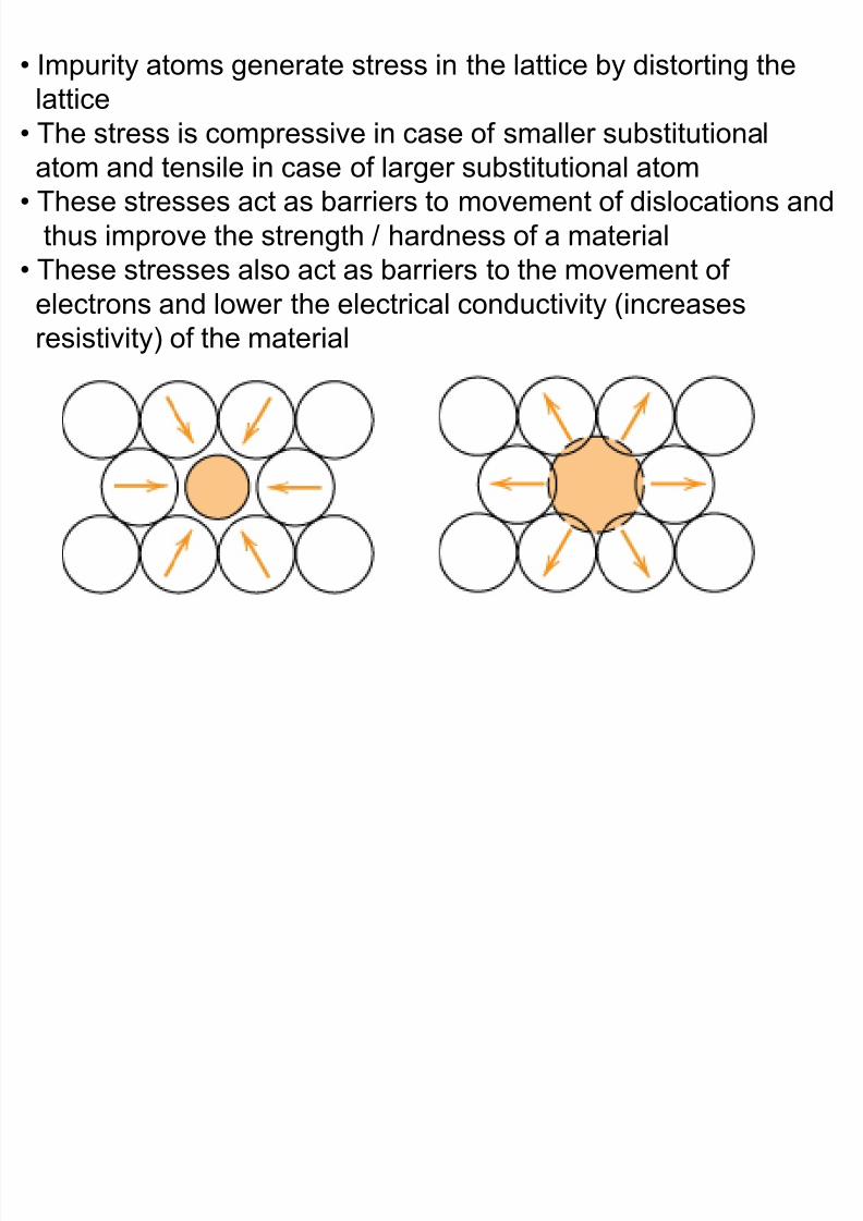
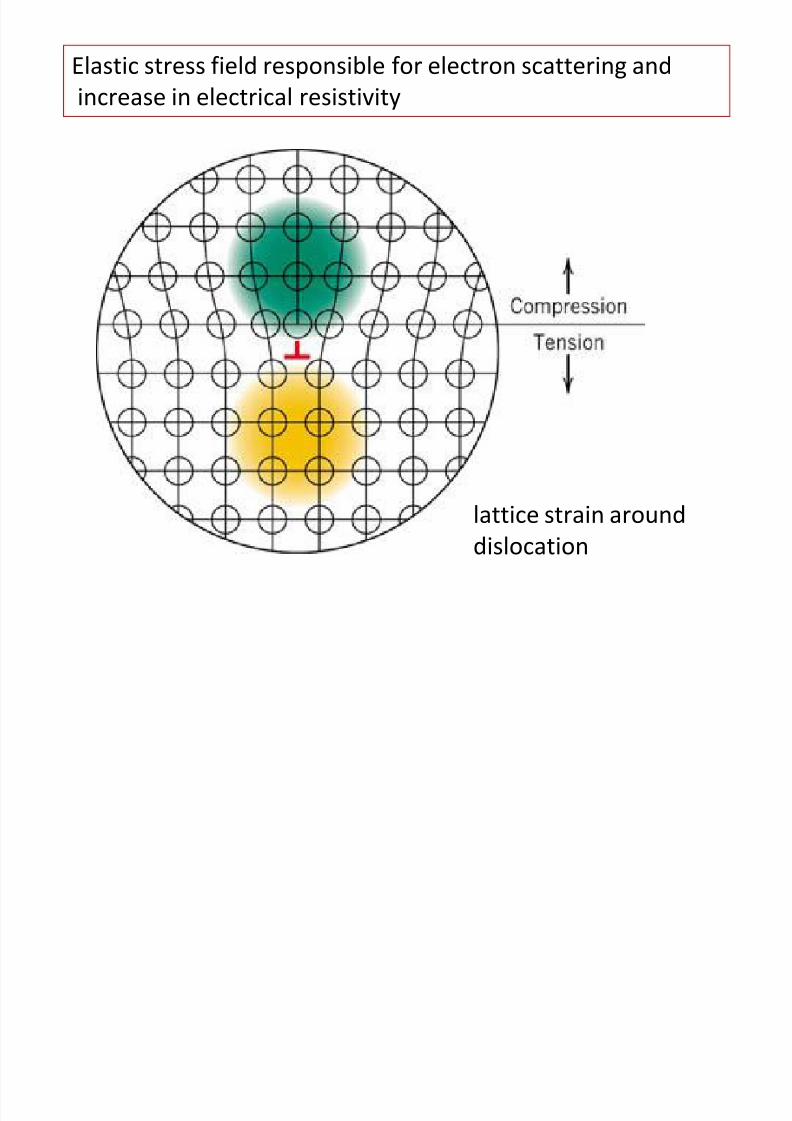
• Impurity atoms generate stress in the lattice by distorting the
8/10/2019 MT-201B MATERIAL SCIENCE NEW - Copy.ppt
http://slidepdf.com/reader/full/mt-201b-material-science-new-copyppt 104/295
lattice
• The stress is compressive in case of smaller substitutional
atom and tensile in case of larger substitutional atom• These stresses act as barriers to movement of dislocations and
thus improve the strength / hardness of a material
• These stresses also act as barriers to the movement of
electrons and lower the electrical conductivity (increasesresistivity) of the material
Frankel and Schottky defects
8/10/2019 MT-201B MATERIAL SCIENCE NEW - Copy.ppt
http://slidepdf.com/reader/full/mt-201b-material-science-new-copyppt 105/295
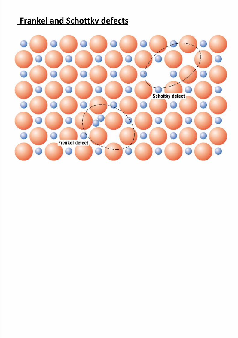
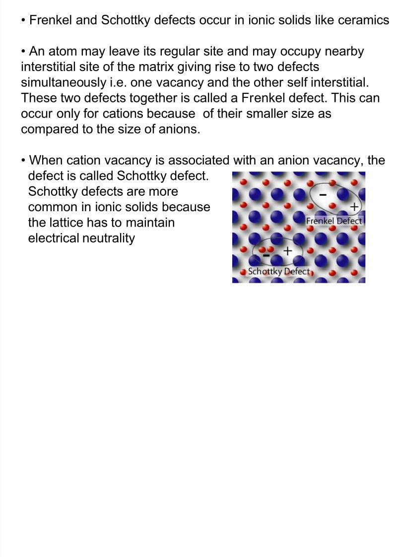
Frankel and Schottky defects
• Frenkel and Schottky defects occur in ionic solids like ceramics
8/10/2019 MT-201B MATERIAL SCIENCE NEW - Copy.ppt
http://slidepdf.com/reader/full/mt-201b-material-science-new-copyppt 106/295
• An atom may leave its regular site and may occupy nearby
interstitial site of the matrix giving rise to two defects
simultaneously i.e. one vacancy and the other self interstitial.
These two defects together is called a Frenkel defect. This can
occur only for cations because of their smaller size as
compared to the size of anions.
• When cation vacancy is associated with an anion vacancy, the
defect is called Schottky defect.
Schottky defects are more
common in ionic solids because
the lattice has to maintain
electrical neutrality
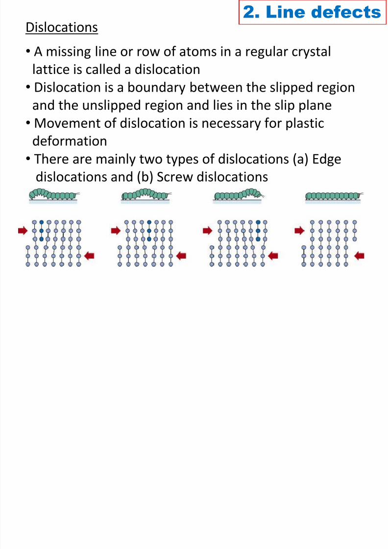
Dislocations2. Line defects
8/10/2019 MT-201B MATERIAL SCIENCE NEW - Copy.ppt
http://slidepdf.com/reader/full/mt-201b-material-science-new-copyppt 107/295
• A missing line or row of atoms in a regular crystal
lattice is called a dislocation• Dislocation is a boundary between the slipped region
and the unslipped region and lies in the slip plane
• Movement of dislocation is necessary for plastic
deformation• There are mainly two types of dislocations (a) Edge
dislocations and (b) Screw dislocations
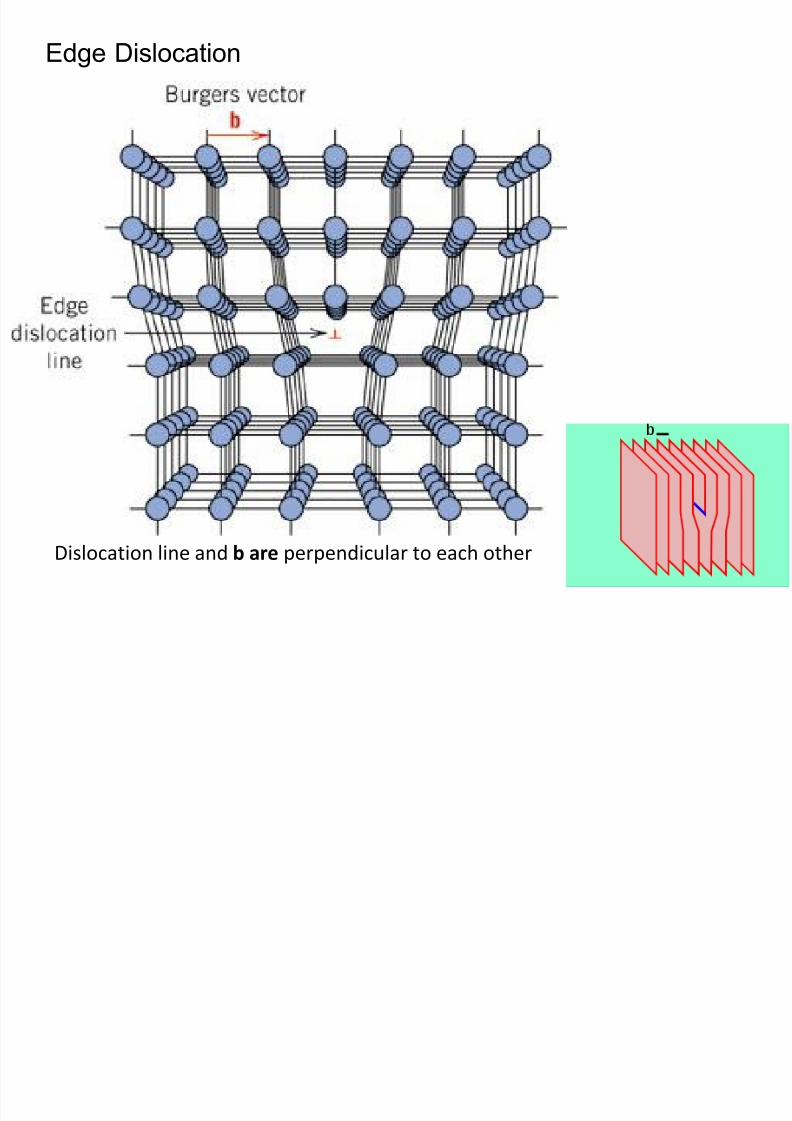
Edge Dislocation
8/10/2019 MT-201B MATERIAL SCIENCE NEW - Copy.ppt
http://slidepdf.com/reader/full/mt-201b-material-science-new-copyppt 108/295
Dislocation line and b are perpendicular to each other
8/10/2019 MT-201B MATERIAL SCIENCE NEW - Copy.ppt
http://slidepdf.com/reader/full/mt-201b-material-science-new-copyppt 109/295
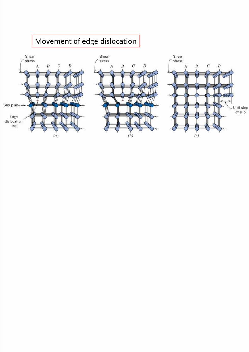
Movement of edge dislocation
8/10/2019 MT-201B MATERIAL SCIENCE NEW - Copy.ppt
http://slidepdf.com/reader/full/mt-201b-material-science-new-copyppt 110/295
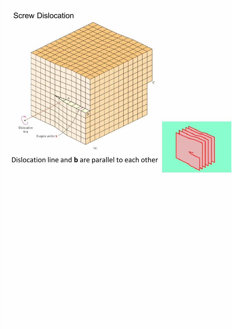
Screw Dislocation
8/10/2019 MT-201B MATERIAL SCIENCE NEW - Copy.ppt
http://slidepdf.com/reader/full/mt-201b-material-science-new-copyppt 111/295
Dislocation line and b are parallel to each other
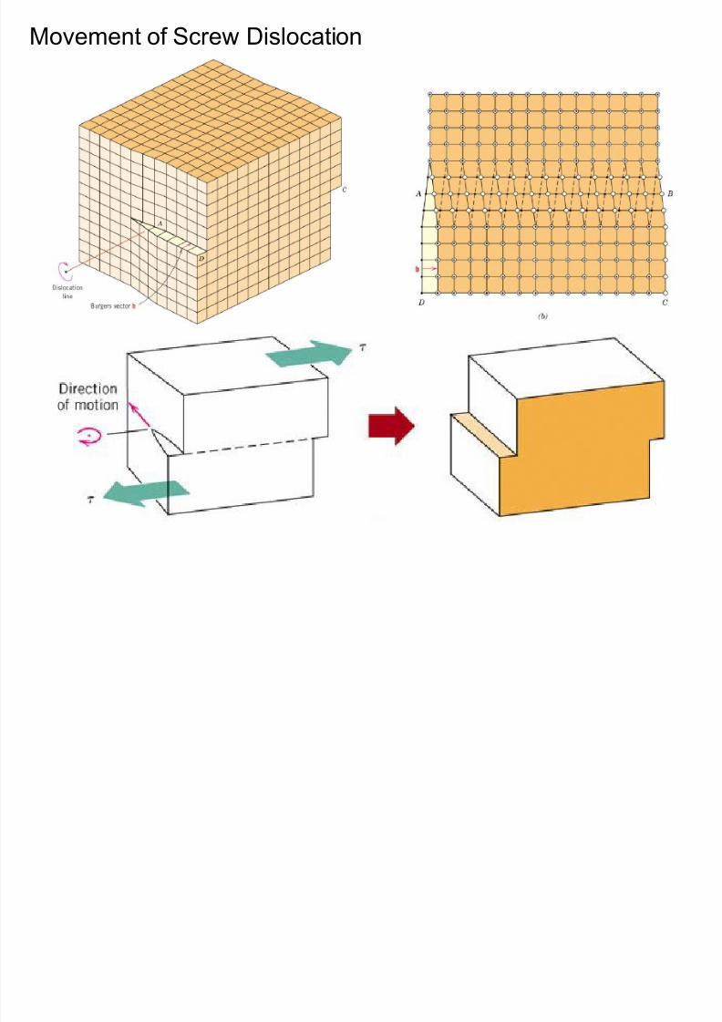
Movement of Screw Dislocation
8/10/2019 MT-201B MATERIAL SCIENCE NEW - Copy.ppt
http://slidepdf.com/reader/full/mt-201b-material-science-new-copyppt 112/295
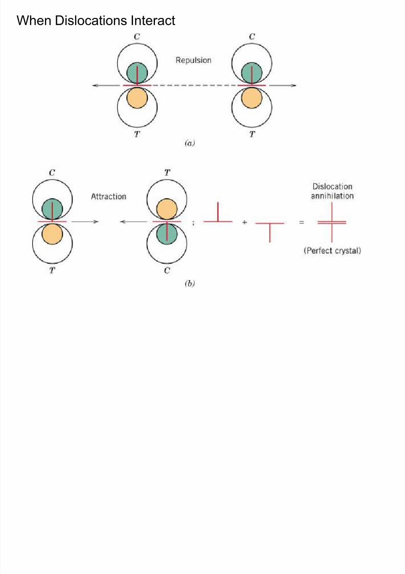
When Dislocations Interact
8/10/2019 MT-201B MATERIAL SCIENCE NEW - Copy.ppt
http://slidepdf.com/reader/full/mt-201b-material-science-new-copyppt 113/295
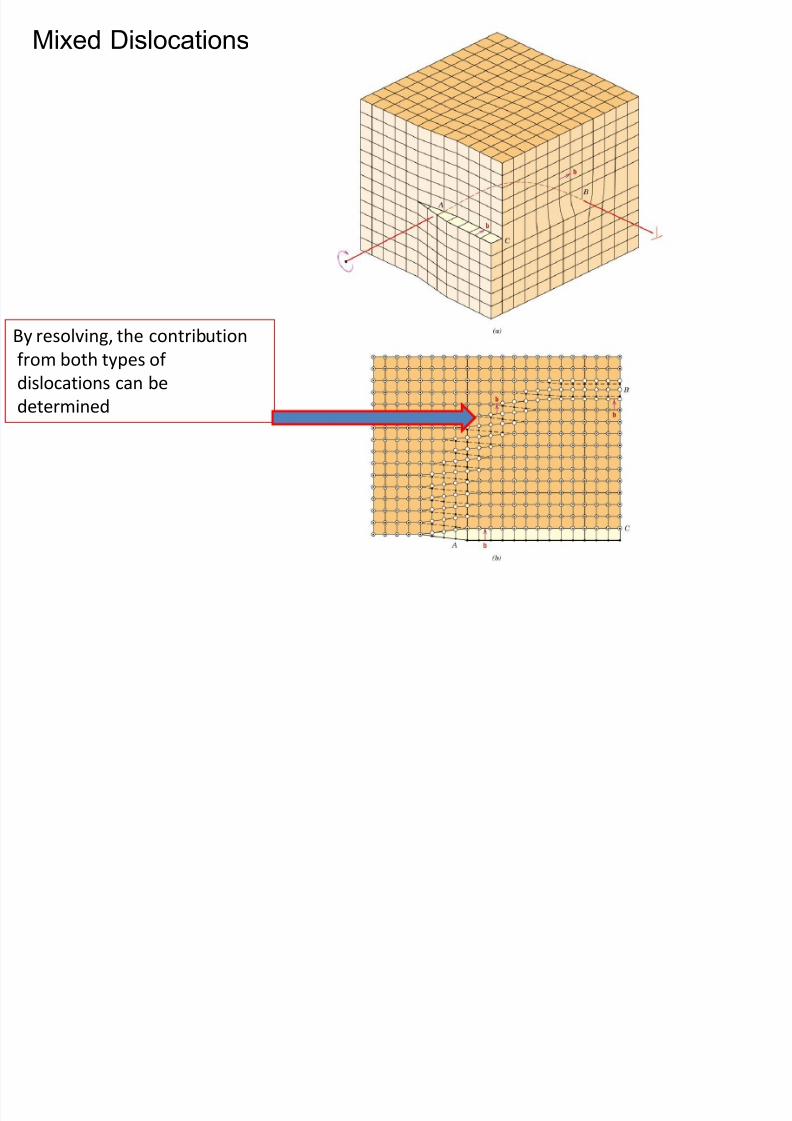
Mixed Dislocations
8/10/2019 MT-201B MATERIAL SCIENCE NEW - Copy.ppt
http://slidepdf.com/reader/full/mt-201b-material-science-new-copyppt 114/295
By resolving, the contribution
from both types of
dislocations can be
determined
i l i
8/10/2019 MT-201B MATERIAL SCIENCE NEW - Copy.ppt
http://slidepdf.com/reader/full/mt-201b-material-science-new-copyppt 115/295
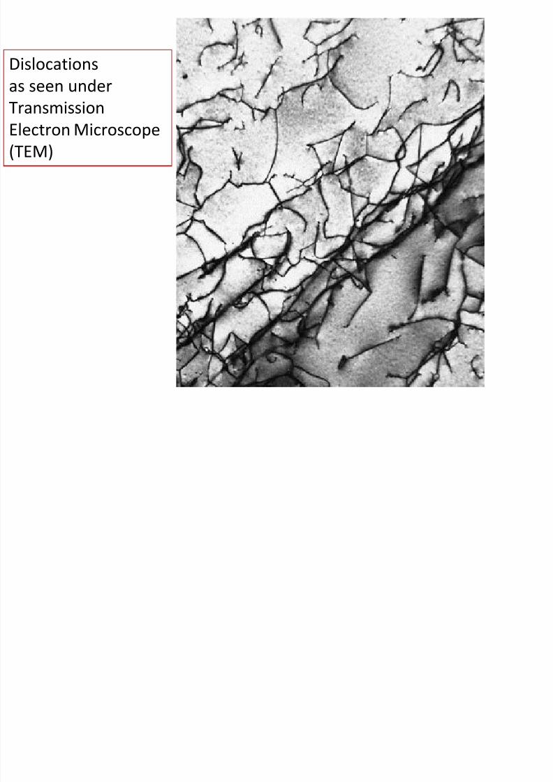
Dislocations
as seen under
TransmissionElectron Microscope
(TEM)
3. Surface defectsGrain Boundary
8/10/2019 MT-201B MATERIAL SCIENCE NEW - Copy.ppt
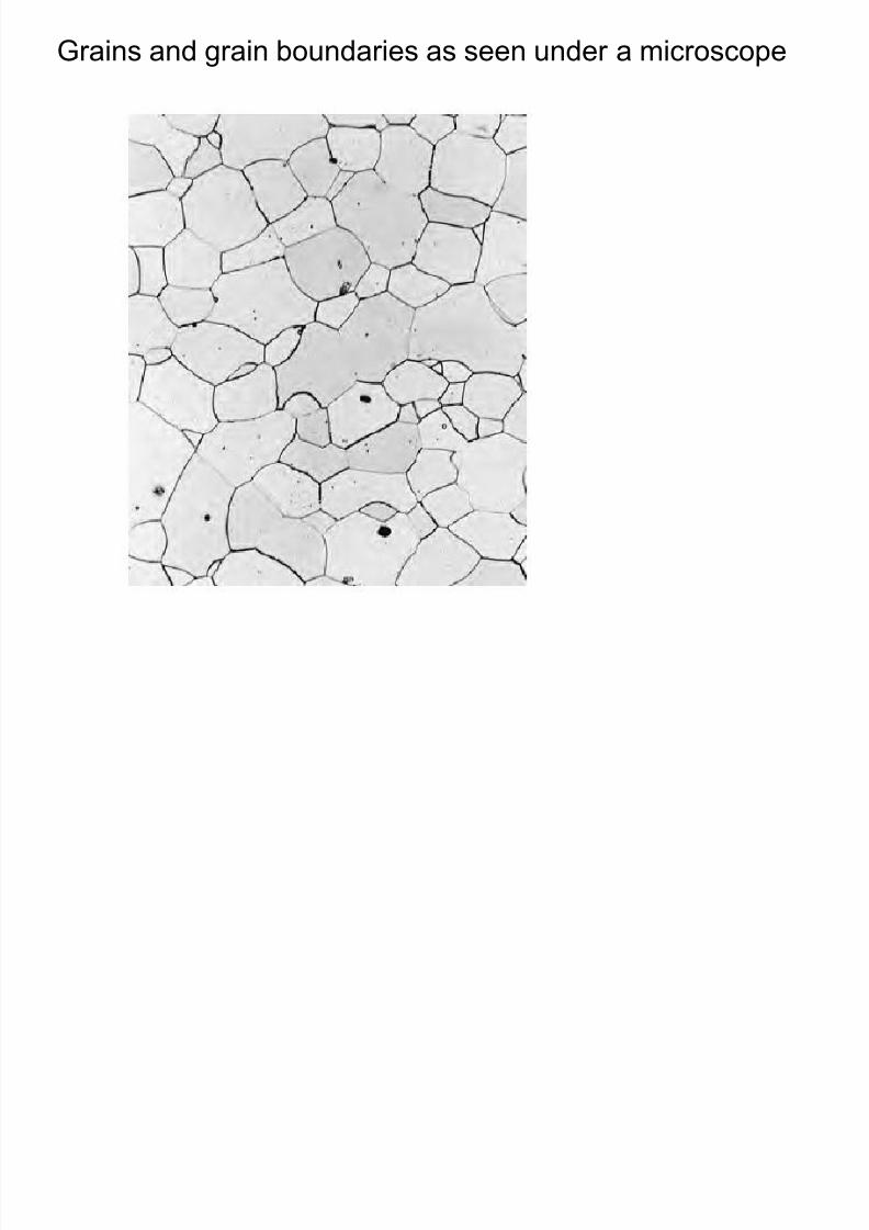
http://slidepdf.com/reader/full/mt-201b-material-science-new-copyppt 116/295
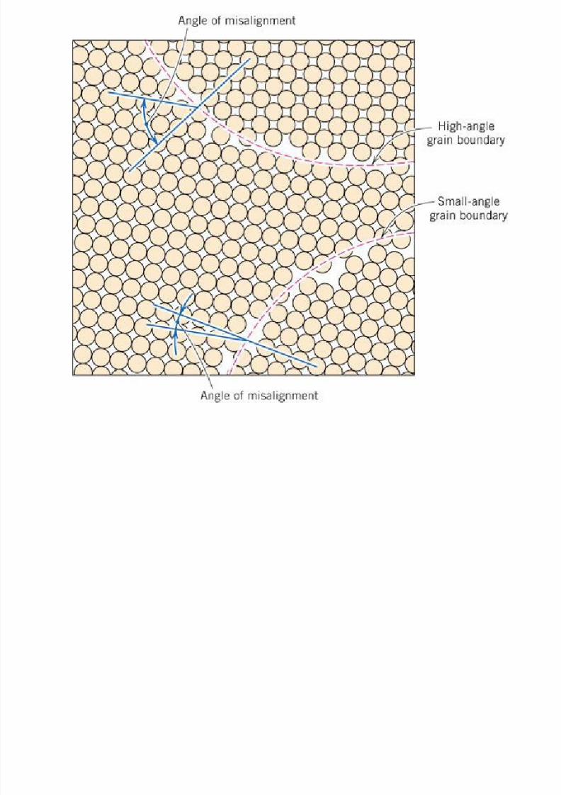
• Grain boundary is a defect which separates grains of different
orientation from each other in a polycrystalline material.
• When this orientation mismatch is slight, on the order of a few
degrees (< 15 degrees) then the term small- (or low- ) angle
grain boundary is used. When the same is more than 15
degrees its is know as a high angle grain boundary.
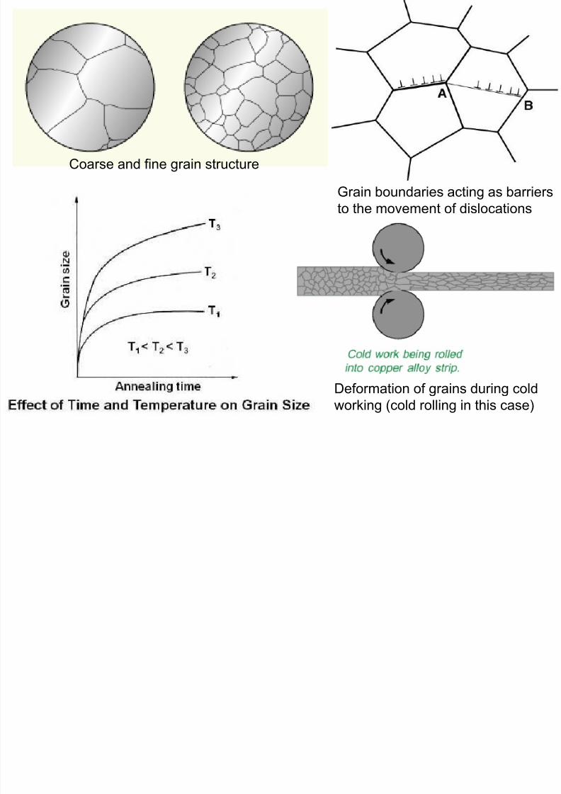
• The total interfacial energy is lower in large or coarse-grained
materials than in fine-grained ones, since there is less total
boundary area in the former.
• Mechanical properties of materials like hardness, strength,ductility etc are influenced by the grain size.
• Grains grow at elevated temperatures to reduce the total
boundary energy.
8/10/2019 MT-201B MATERIAL SCIENCE NEW - Copy.ppt
http://slidepdf.com/reader/full/mt-201b-material-science-new-copyppt 117/295
8/10/2019 MT-201B MATERIAL SCIENCE NEW - Copy.ppt
http://slidepdf.com/reader/full/mt-201b-material-science-new-copyppt 118/295
Coarse and fine grain structure
Grain boundaries acting as barriers
to the movement of dislocations
Deformation of grains during cold
working (cold rolling in this case)
Grains and grain boundaries as seen under a microscope
8/10/2019 MT-201B MATERIAL SCIENCE NEW - Copy.ppt
http://slidepdf.com/reader/full/mt-201b-material-science-new-copyppt 119/295
8/10/2019 MT-201B MATERIAL SCIENCE NEW - Copy.ppt
http://slidepdf.com/reader/full/mt-201b-material-science-new-copyppt 120/295
8/10/2019 MT-201B MATERIAL SCIENCE NEW - Copy.ppt
http://slidepdf.com/reader/full/mt-201b-material-science-new-copyppt 121/295
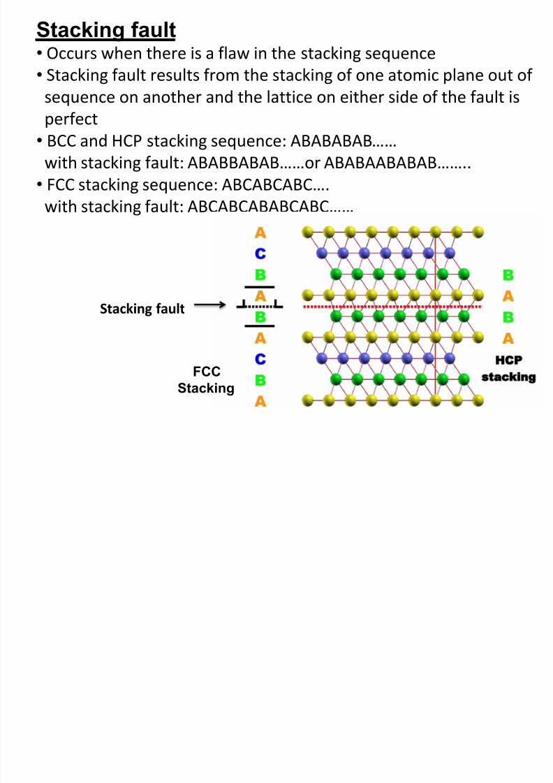
Stacking fault• Occurs when there is a flaw in the stacking sequence
8/10/2019 MT-201B MATERIAL SCIENCE NEW - Copy.ppt
http://slidepdf.com/reader/full/mt-201b-material-science-new-copyppt 122/295
g q
• Stacking fault results from the stacking of one atomic plane out of
sequence on another and the lattice on either side of the fault is
perfect
• BCC and HCP stacking sequence: ABABABAB……
with stacking fault: ABABBABAB……or ABABAABABAB……..
• FCC stacking sequence: ABCABCABC….
with stacking fault: ABCABCABABCABC……
Stacking fault
FCC
Stacking
Plastic Deformation
8/10/2019 MT-201B MATERIAL SCIENCE NEW - Copy.ppt
http://slidepdf.com/reader/full/mt-201b-material-science-new-copyppt 123/295
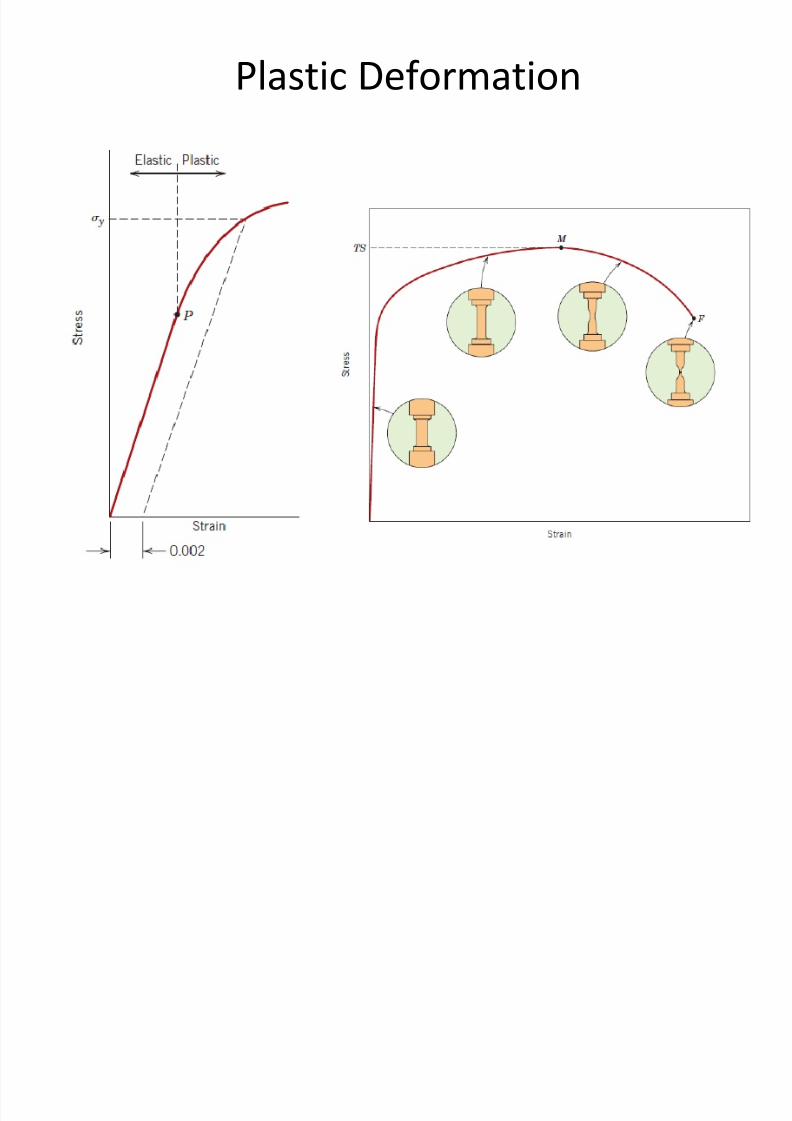
Plastic Deformation
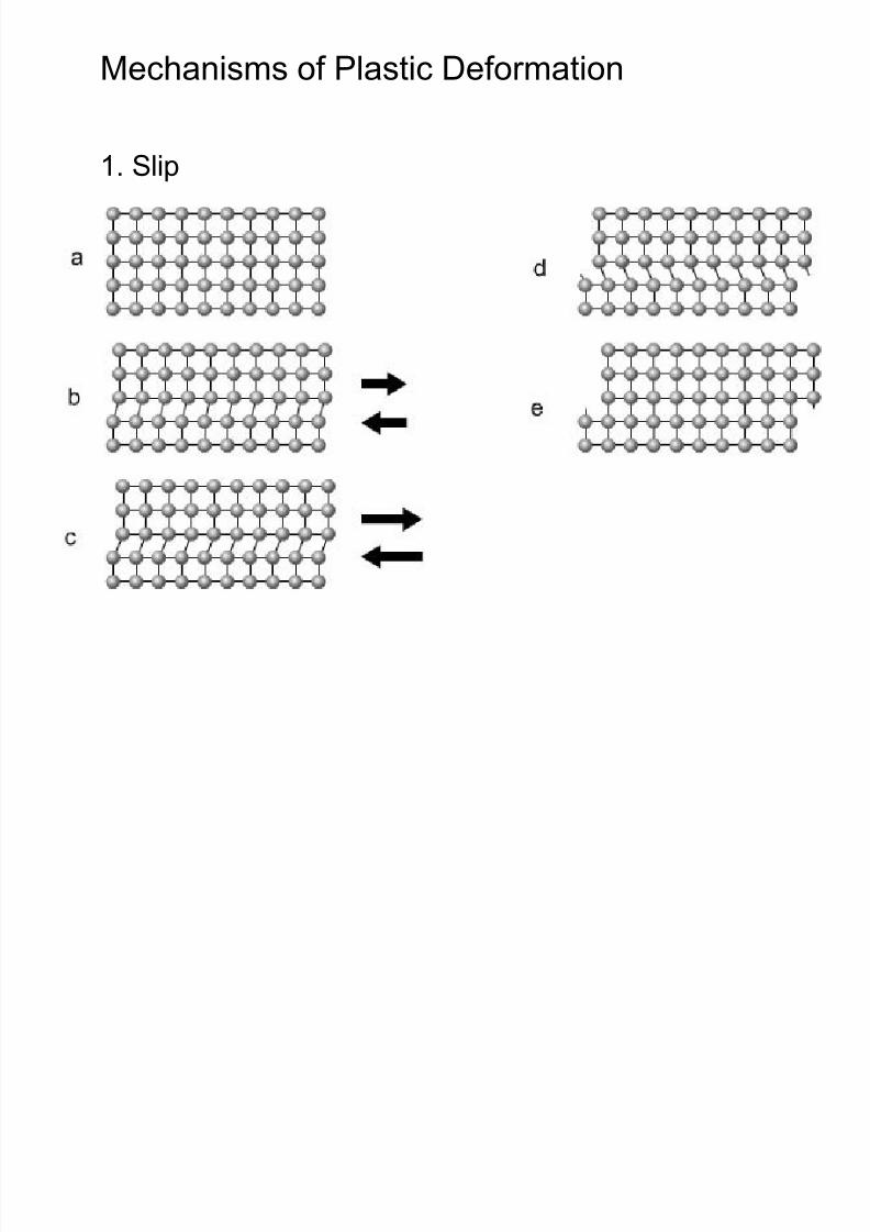
Mechanisms of Plastic Deformation
8/10/2019 MT-201B MATERIAL SCIENCE NEW - Copy.ppt
http://slidepdf.com/reader/full/mt-201b-material-science-new-copyppt 124/295
1. Slip
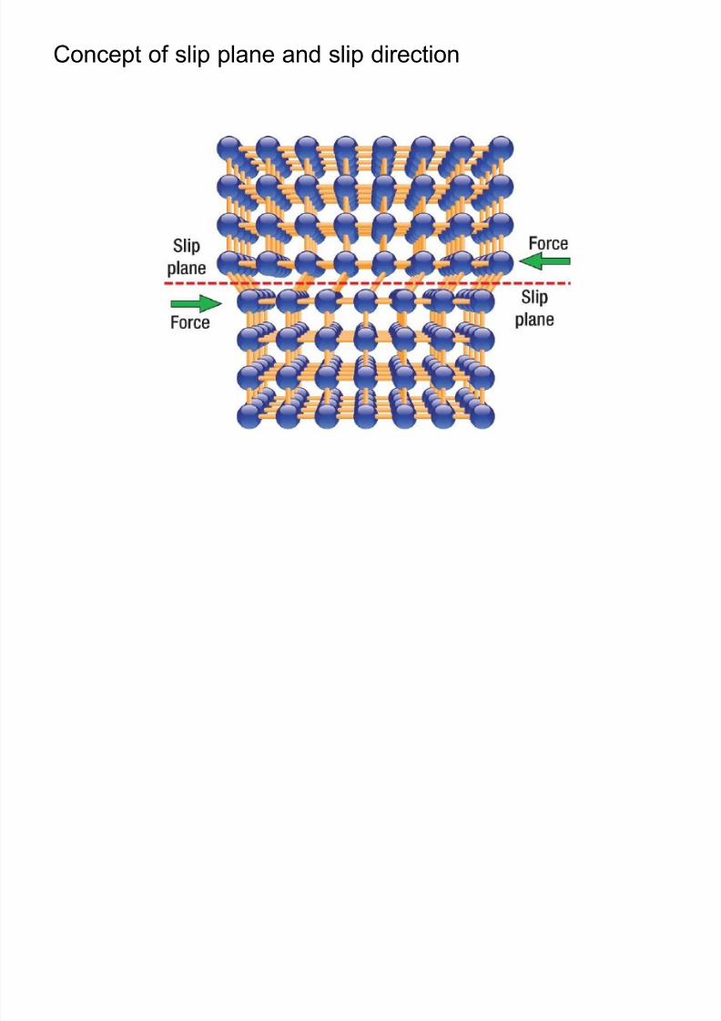
Concept of slip plane and slip direction
8/10/2019 MT-201B MATERIAL SCIENCE NEW - Copy.ppt
http://slidepdf.com/reader/full/mt-201b-material-science-new-copyppt 125/295
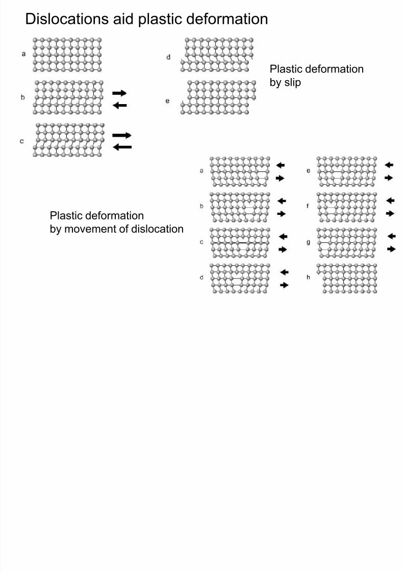
Dislocations aid plastic deformation
8/10/2019 MT-201B MATERIAL SCIENCE NEW - Copy.ppt
http://slidepdf.com/reader/full/mt-201b-material-science-new-copyppt 126/295
Plastic deformation
by slip
Plastic deformationby movement of dislocation
Slip System (slip planes and slip directions)
8/10/2019 MT-201B MATERIAL SCIENCE NEW - Copy.ppt
http://slidepdf.com/reader/full/mt-201b-material-science-new-copyppt 127/295
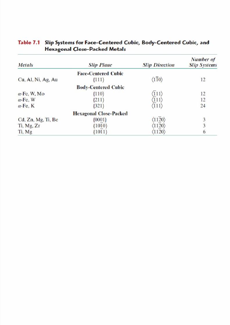
• Plastic deformation takes place by sliding (slip)of close- packed planes over one another.
• The combination of planes and directions on
which slip takes place constitutes the slipsystems of the material.
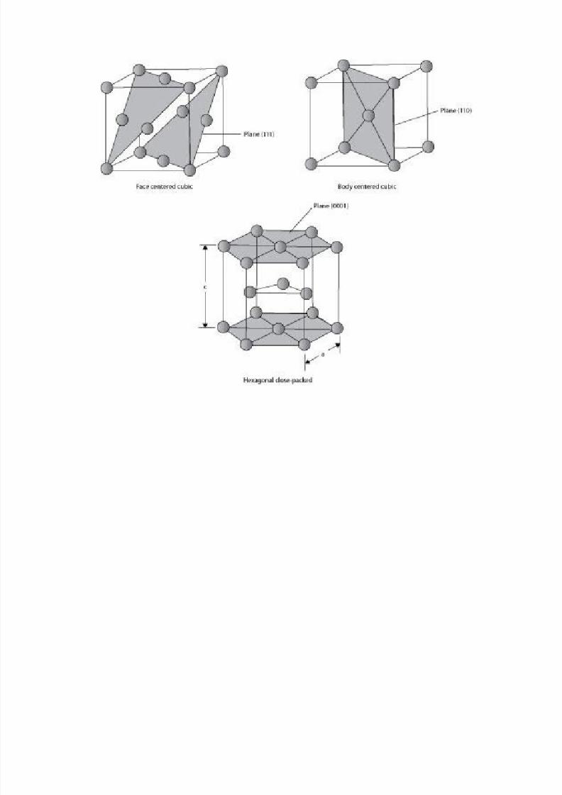
• Slip plane is generally taken as the closest
packed plane in the system.
• Slip direction is taken as the direction on the slip
plane with the highest linear density.
8/10/2019 MT-201B MATERIAL SCIENCE NEW - Copy.ppt
http://slidepdf.com/reader/full/mt-201b-material-science-new-copyppt 128/295
8/10/2019 MT-201B MATERIAL SCIENCE NEW - Copy.ppt
http://slidepdf.com/reader/full/mt-201b-material-science-new-copyppt 129/295
8/10/2019 MT-201B MATERIAL SCIENCE NEW - Copy.ppt
http://slidepdf.com/reader/full/mt-201b-material-science-new-copyppt 130/295
Slip in Single Crystals
Even if an applied stress is purely tensile there are shear

8/10/2019 MT-201B MATERIAL SCIENCE NEW - Copy.ppt
http://slidepdf.com/reader/full/mt-201b-material-science-new-copyppt 131/295
Even if an applied stress is purely tensile, there are shear
components to it in directions at all but the parallel and
perpendicular directions.
Classified as resolved shear stresses magnitude depends on applied stress, as well as its
orientation with respect to both the slip plane and slip
direction
Polycrystalline Deformation
Slip in polycrystalline systems is more complex

8/10/2019 MT-201B MATERIAL SCIENCE NEW - Copy.ppt
http://slidepdf.com/reader/full/mt-201b-material-science-new-copyppt 132/295
y y y
direction of slip will vary from one crystal to another in the system
Polycrystalline slip requires higher values of applied stresses than
single crystal systems.Because even favorably oriented grains cannot slip until the less
favorably oriented grains are capable of deformation.
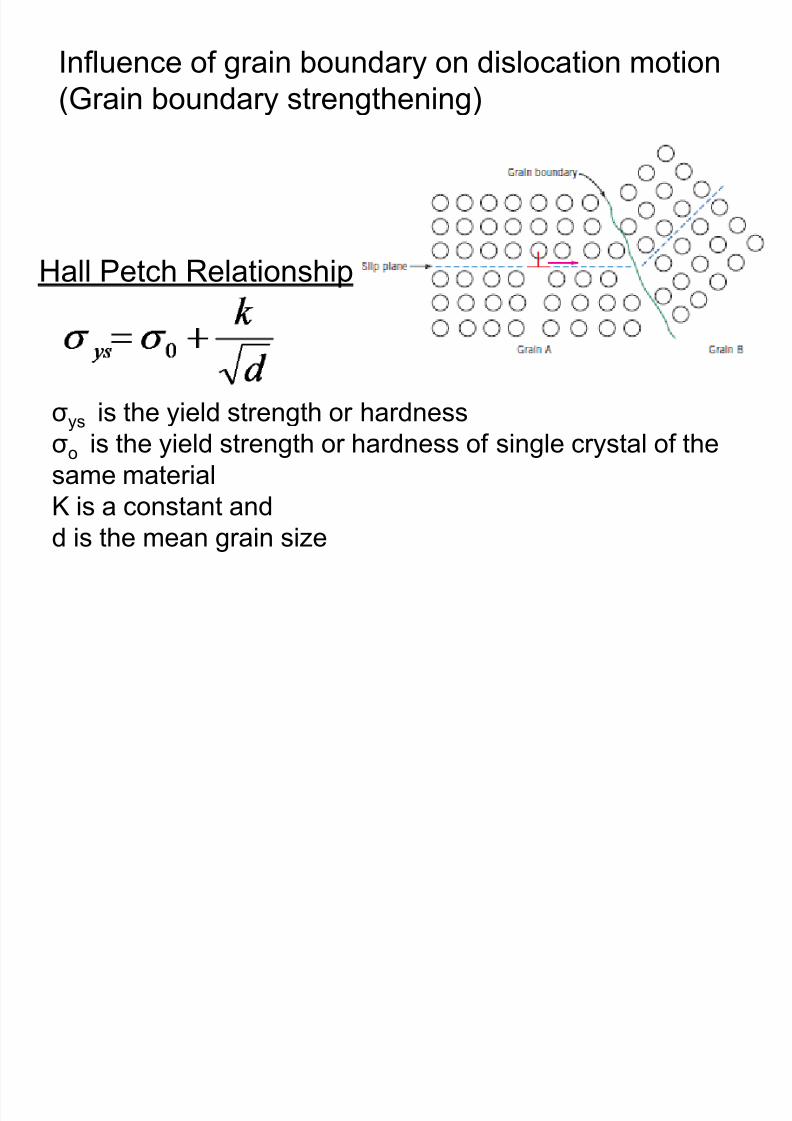
Influence of grain boundary on dislocation motion
(Grain boundary strengthening)
8/10/2019 MT-201B MATERIAL SCIENCE NEW - Copy.ppt
http://slidepdf.com/reader/full/mt-201b-material-science-new-copyppt 133/295
(Grain boundary strengthening)
σys is the yield strength or hardness
σo is the yield strength or hardness of single crystal of thesame material K is a constant and
d is the mean grain size
Hall Petch Relationship
8/10/2019 MT-201B MATERIAL SCIENCE NEW - Copy.ppt
http://slidepdf.com/reader/full/mt-201b-material-science-new-copyppt 134/295
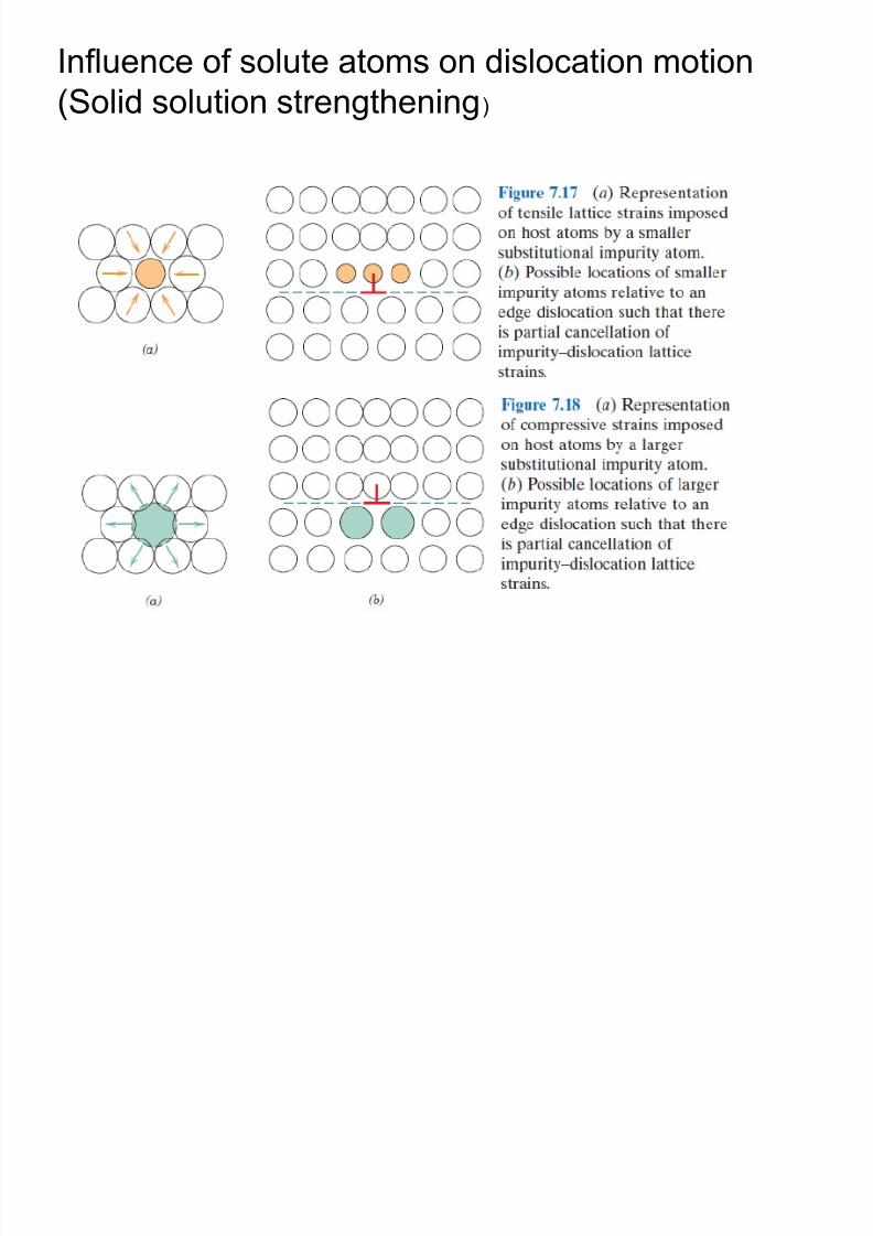
Influence of solute atoms on dislocation motion
(Solid solution strengthening)
8/10/2019 MT-201B MATERIAL SCIENCE NEW - Copy.ppt
http://slidepdf.com/reader/full/mt-201b-material-science-new-copyppt 135/295
(Solid solution strengthening)

8/10/2019 MT-201B MATERIAL SCIENCE NEW - Copy.ppt
http://slidepdf.com/reader/full/mt-201b-material-science-new-copyppt 136/295
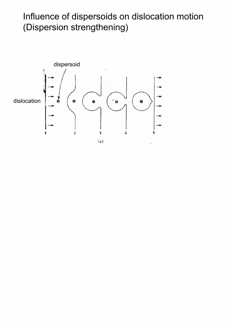
Influence of dispersoids on dislocation motion
(Dispersion strengthening)
8/10/2019 MT-201B MATERIAL SCIENCE NEW - Copy.ppt
http://slidepdf.com/reader/full/mt-201b-material-science-new-copyppt 137/295
(Dispersion strengthening)
dispersoid
dislocation
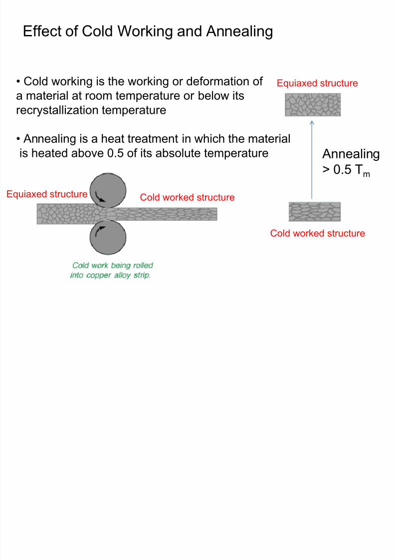
Effect of Cold Working and Annealing
8/10/2019 MT-201B MATERIAL SCIENCE NEW - Copy.ppt
http://slidepdf.com/reader/full/mt-201b-material-science-new-copyppt 138/295
Annealing> 0.5 Tm
Cold worked structure
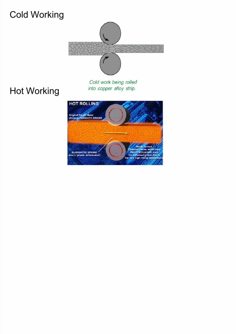
Equiaxed structure• Cold working is the working or deformation ofa material at room temperature or below its
recrystallization temperature
• Annealing is a heat treatment in which the material
is heated above 0.5 of its absolute temperature
Equiaxed structure Cold worked structure
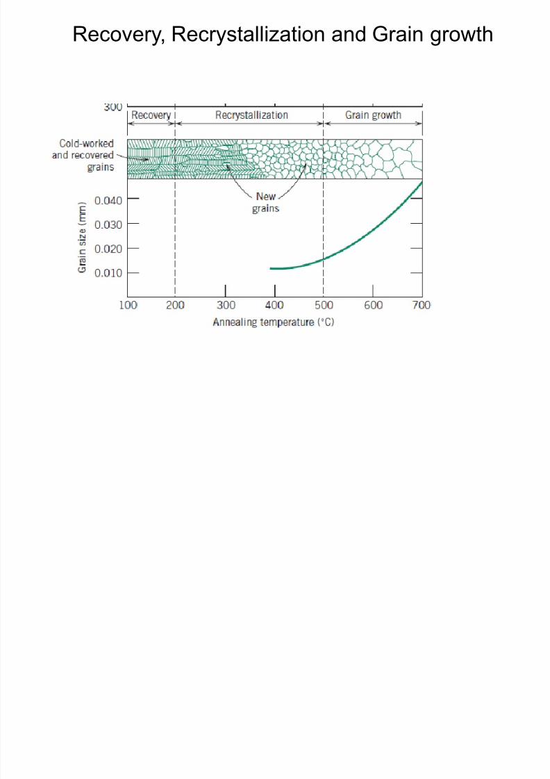
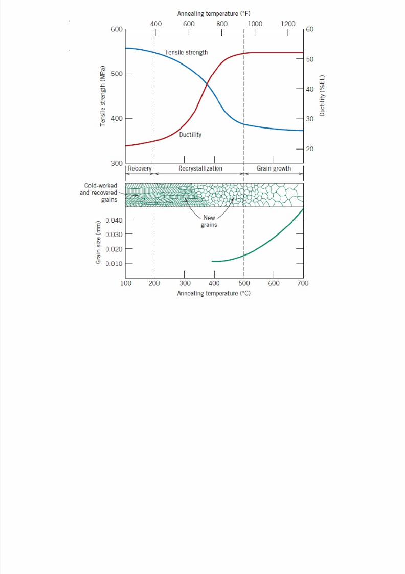
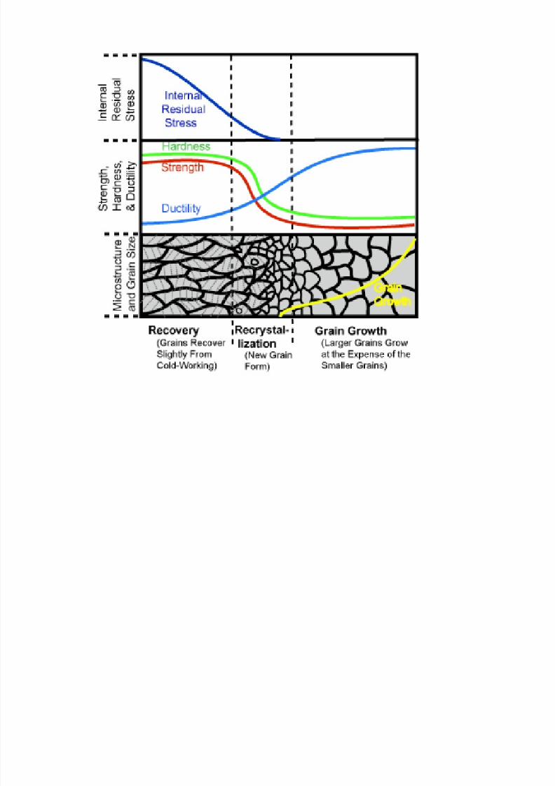
Recovery, Recrystallization and Grain growth
8/10/2019 MT-201B MATERIAL SCIENCE NEW - Copy.ppt
http://slidepdf.com/reader/full/mt-201b-material-science-new-copyppt 139/295
8/10/2019 MT-201B MATERIAL SCIENCE NEW - Copy.ppt
http://slidepdf.com/reader/full/mt-201b-material-science-new-copyppt 140/295
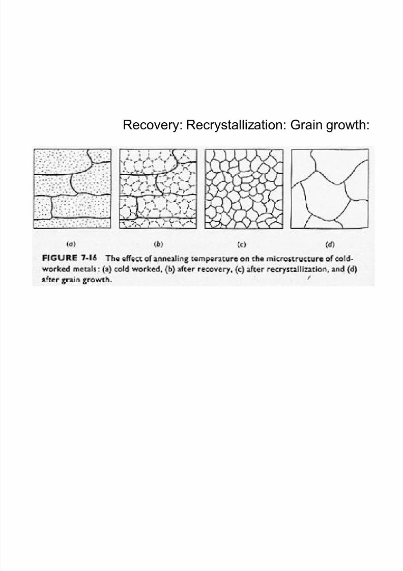
Recovery: Recrystallization: Grain growth:
8/10/2019 MT-201B MATERIAL SCIENCE NEW - Copy.ppt
http://slidepdf.com/reader/full/mt-201b-material-science-new-copyppt 141/295
8/10/2019 MT-201B MATERIAL SCIENCE NEW - Copy.ppt
http://slidepdf.com/reader/full/mt-201b-material-science-new-copyppt 142/295
Cold Working
8/10/2019 MT-201B MATERIAL SCIENCE NEW - Copy.ppt
http://slidepdf.com/reader/full/mt-201b-material-science-new-copyppt 143/295
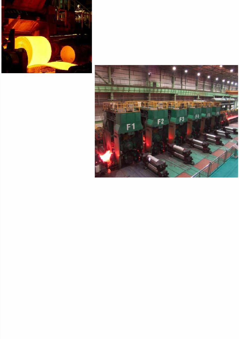
Hot Working
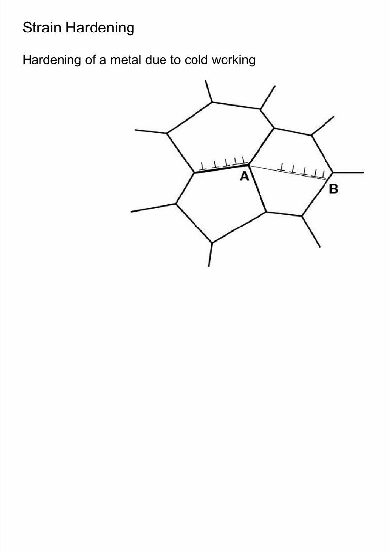
Strain Hardening
8/10/2019 MT-201B MATERIAL SCIENCE NEW - Copy.ppt
http://slidepdf.com/reader/full/mt-201b-material-science-new-copyppt 144/295
Hardening of a metal due to cold working
8/10/2019 MT-201B MATERIAL SCIENCE NEW - Copy.ppt
http://slidepdf.com/reader/full/mt-201b-material-science-new-copyppt 145/295
8/10/2019 MT-201B MATERIAL SCIENCE NEW - Copy.ppt
http://slidepdf.com/reader/full/mt-201b-material-science-new-copyppt 146/295
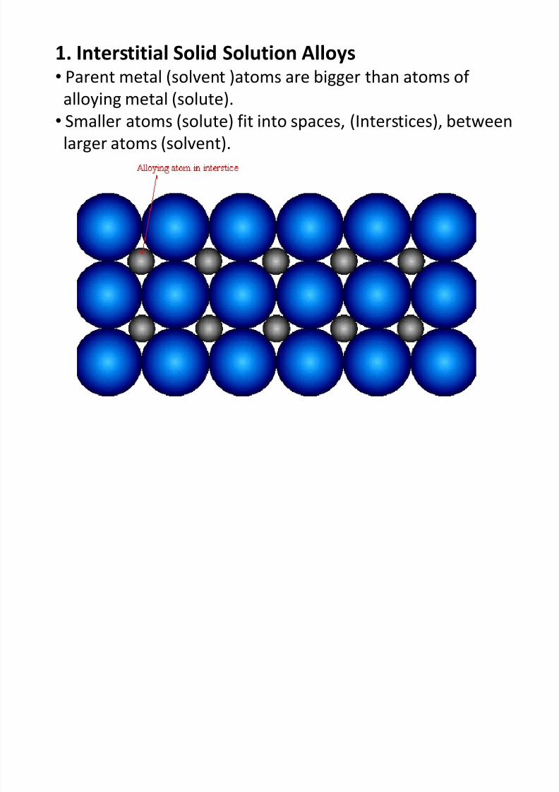
1. Interstitial Solid Solution Alloys • Parent metal (solvent )atoms are bigger than atoms of
8/10/2019 MT-201B MATERIAL SCIENCE NEW - Copy.ppt
http://slidepdf.com/reader/full/mt-201b-material-science-new-copyppt 147/295
• Parent metal (solvent )atoms are bigger than atoms of
alloying metal (solute).
• Smaller atoms (solute) fit into spaces, (Interstices), between
larger atoms (solvent).
Interstitial sites
8/10/2019 MT-201B MATERIAL SCIENCE NEW - Copy.ppt
http://slidepdf.com/reader/full/mt-201b-material-science-new-copyppt 148/295
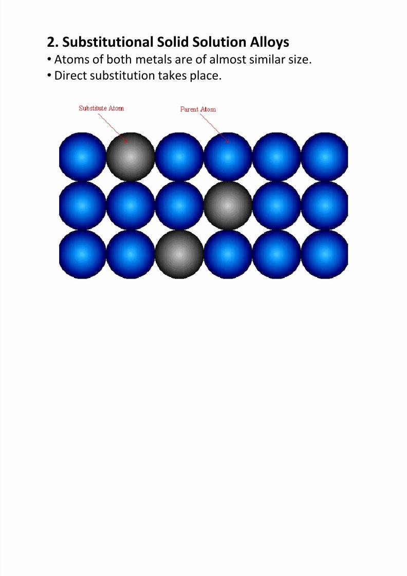
2. Substitutional Solid Solution Alloys At f b th t l f l t i il i
8/10/2019 MT-201B MATERIAL SCIENCE NEW - Copy.ppt
http://slidepdf.com/reader/full/mt-201b-material-science-new-copyppt 149/295
• Atoms of both metals are of almost similar size.
• Direct substitution takes place.
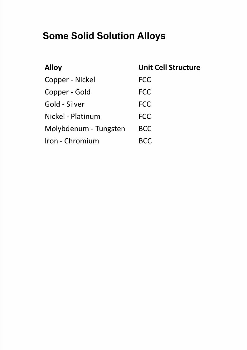
Some Solid Sol tion Allo s
8/10/2019 MT-201B MATERIAL SCIENCE NEW - Copy.ppt
http://slidepdf.com/reader/full/mt-201b-material-science-new-copyppt 150/295
Alloy Unit Cell Structure
Copper - Nickel FCC
Copper - Gold FCCGold - Silver FCC
Nickel - Platinum FCC
Molybdenum - Tungsten BCC
Iron - Chromium BCC
Some Solid Solution Alloys
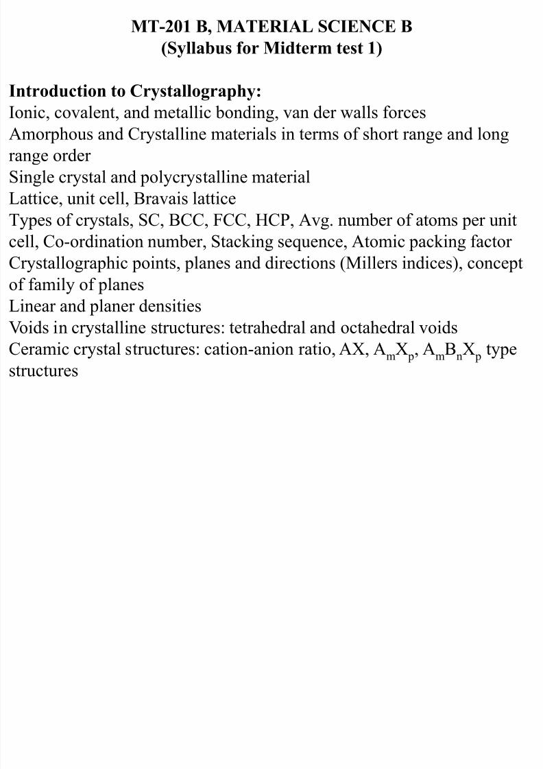
MT-201 B, MATERIAL SCIENCE B
(Syllabus for Midterm test 1)
8/10/2019 MT-201B MATERIAL SCIENCE NEW - Copy.ppt
http://slidepdf.com/reader/full/mt-201b-material-science-new-copyppt 151/295
Introduction to Crystallography:
Ionic, covalent, and metallic bonding, van der walls forces Amorphous and Crystalline materials in terms of short range and long
range order
Single crystal and polycrystalline material
Lattice, unit cell, Bravais lattice Types of crystals, SC, BCC, FCC, HCP, Avg. number of atoms per unit
cell, Co-ordination number, Stacking sequence, Atomic packing factor
Crystallographic points, planes and directions (Millers indices), concept
of family of planes
Linear and planer densities Voids in crystalline structures: tetrahedral and octahedral voids
Ceramic crystal structures: cation-anion ratio, AX, AmX p, AmBnX p type
structures
H R th ’ R l f S lid S l bilit
8/10/2019 MT-201B MATERIAL SCIENCE NEW - Copy.ppt
http://slidepdf.com/reader/full/mt-201b-material-science-new-copyppt 152/295
Hume-Rothery’s Rules of Solid Solubility
1. Atomic size factor
2. Crystal structure factor
3. Electronegativity factor
4. Relative valency factor
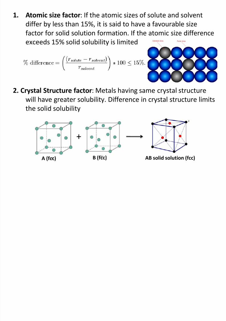
1. Atomic size factor: If the atomic sizes of solute and solvent
differ by less than 15%, it is said to have a favourable size
factor for solid solution formation If the atomic size difference
8/10/2019 MT-201B MATERIAL SCIENCE NEW - Copy.ppt
http://slidepdf.com/reader/full/mt-201b-material-science-new-copyppt 153/295
factor for solid solution formation. If the atomic size difference
exceeds 15% solid solubility is limited
2. Crystal Structure factor: Metals having same crystal structure
will have greater solubility. Difference in crystal structure limits
the solid solubility
+
A (fcc) B (fcc) AB solid solution (fcc)
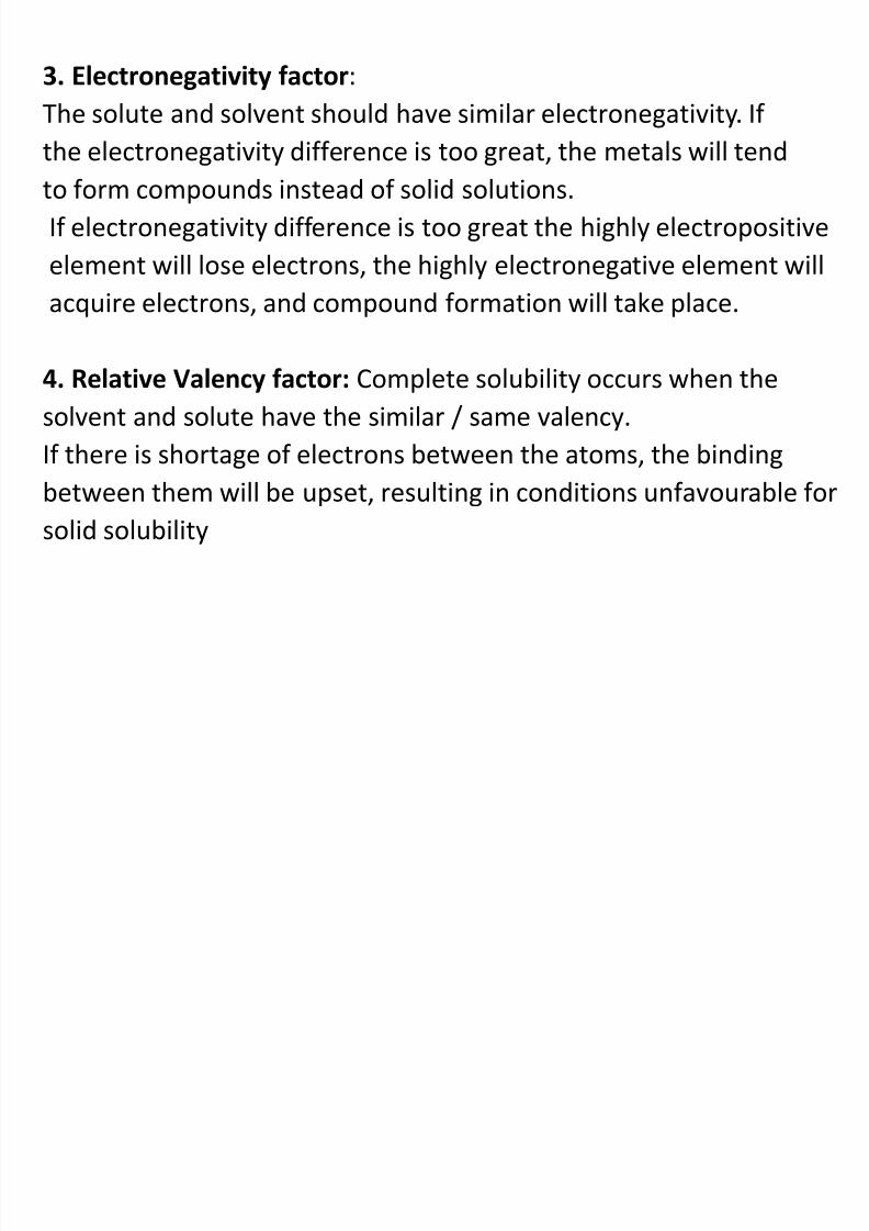
3. Electronegativity factor:
The solute and solvent should have similar electronegativity. If
8/10/2019 MT-201B MATERIAL SCIENCE NEW - Copy.ppt
http://slidepdf.com/reader/full/mt-201b-material-science-new-copyppt 154/295
g y
the electronegativity difference is too great, the metals will tend
to form compounds instead of solid solutions.
If electronegativity difference is too great the highly electropositive
element will lose electrons, the highly electronegative element will
acquire electrons, and compound formation will take place.
4. Relative Valency factor: Complete solubility occurs when the
solvent and solute have the similar / same valency.
If there is shortage of electrons between the atoms, the binding
between them will be upset, resulting in conditions unfavourable for
solid solubility
8/10/2019 MT-201B MATERIAL SCIENCE NEW - Copy.ppt
http://slidepdf.com/reader/full/mt-201b-material-science-new-copyppt 155/295
8/10/2019 MT-201B MATERIAL SCIENCE NEW - Copy.ppt
http://slidepdf.com/reader/full/mt-201b-material-science-new-copyppt 156/295
Terms:
8/10/2019 MT-201B MATERIAL SCIENCE NEW - Copy.ppt
http://slidepdf.com/reader/full/mt-201b-material-science-new-copyppt 157/295
System: A system is that part of the universe which is under
consideration.Phase: A phase is a physically separable part of the system
with distinct physical and chemical properties. (In a system
consisting of ice and water in a glass jar, the ice cubes are
one phase, the water is a second phase, and the humid air
over the water is a third phase. The glass of the jar is
another separate phase.)
Variable: A particular phase exists under various conditions
of temperature, pressure and concentration. These
parameters are called as the variables of the phaseComponent: The elements present in the system are called
as components. For ex. Ice, water or steam all contain H2O
so the number of components is 2, i.e. H and O.
Gibb’s Phase Rule:

8/10/2019 MT-201B MATERIAL SCIENCE NEW - Copy.ppt
http://slidepdf.com/reader/full/mt-201b-material-science-new-copyppt 158/295
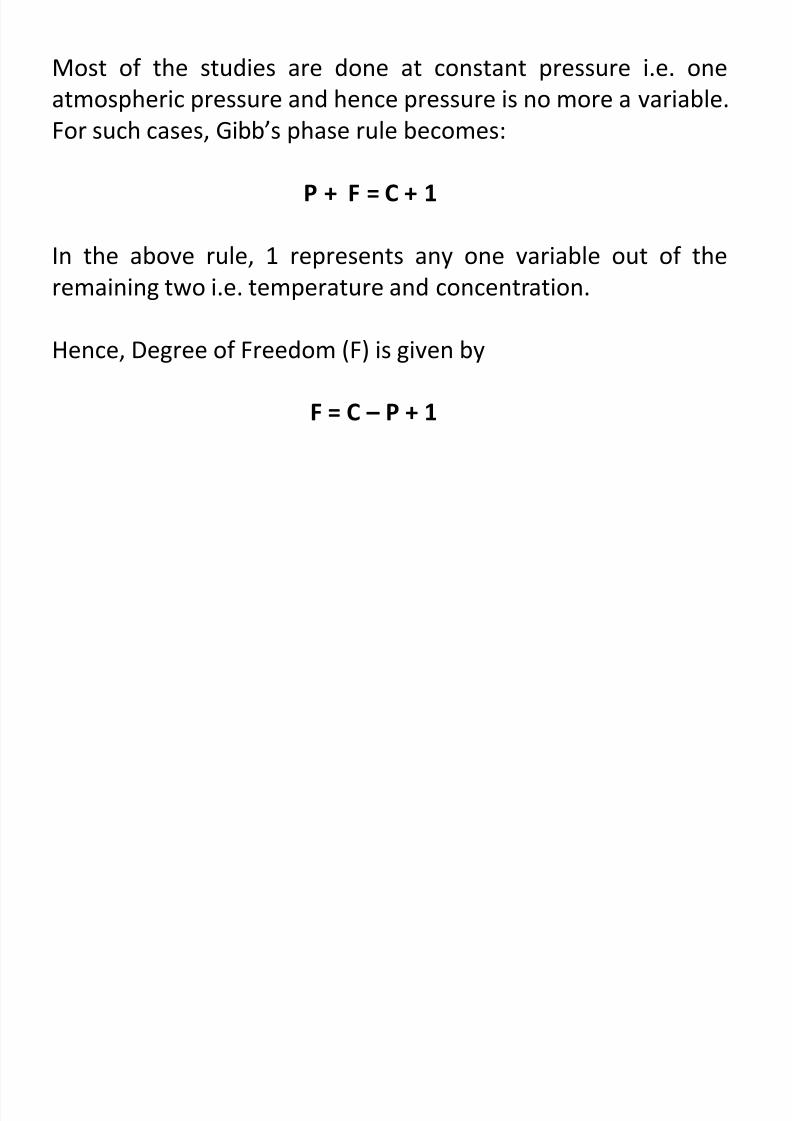
The Gibb’s phase rule states that under equilibrium conditions,
the following relation must be satisfied:P + F = C + 2
Where,
P = number of phases existing in a system under consideration.
F = degree of freedom i.e. the number of variables such as
temperature, pressure or composition (concentration) that can
be changed independently without changing the number of
phases existing in the system.
C = number of components (i.e. elements) in the system, and
2 = represents any two variables out of the above three i.e.temperature pressure and composition.
8/10/2019 MT-201B MATERIAL SCIENCE NEW - Copy.ppt
http://slidepdf.com/reader/full/mt-201b-material-science-new-copyppt 159/295
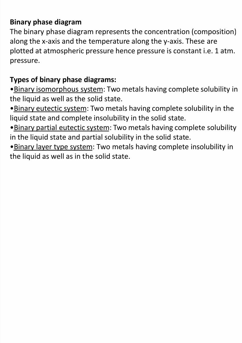
Binary phase diagram
The binary phase diagram represents the concentration (composition)
8/10/2019 MT-201B MATERIAL SCIENCE NEW - Copy.ppt
http://slidepdf.com/reader/full/mt-201b-material-science-new-copyppt 160/295
along the x-axis and the temperature along the y-axis. These are
plotted at atmospheric pressure hence pressure is constant i.e. 1 atm.pressure.
Types of binary phase diagrams:
•Binary isomorphous system: Two metals having complete solubility inthe liquid as well as the solid state.
•Binary eutectic system: Two metals having complete solubility in the
liquid state and complete insolubility in the solid state.
•Binary partial eutectic system: Two metals having complete solubility
in the liquid state and partial solubility in the solid state.•Binary layer type system: Two metals having complete insolubility in
the liquid as well as in the solid state.
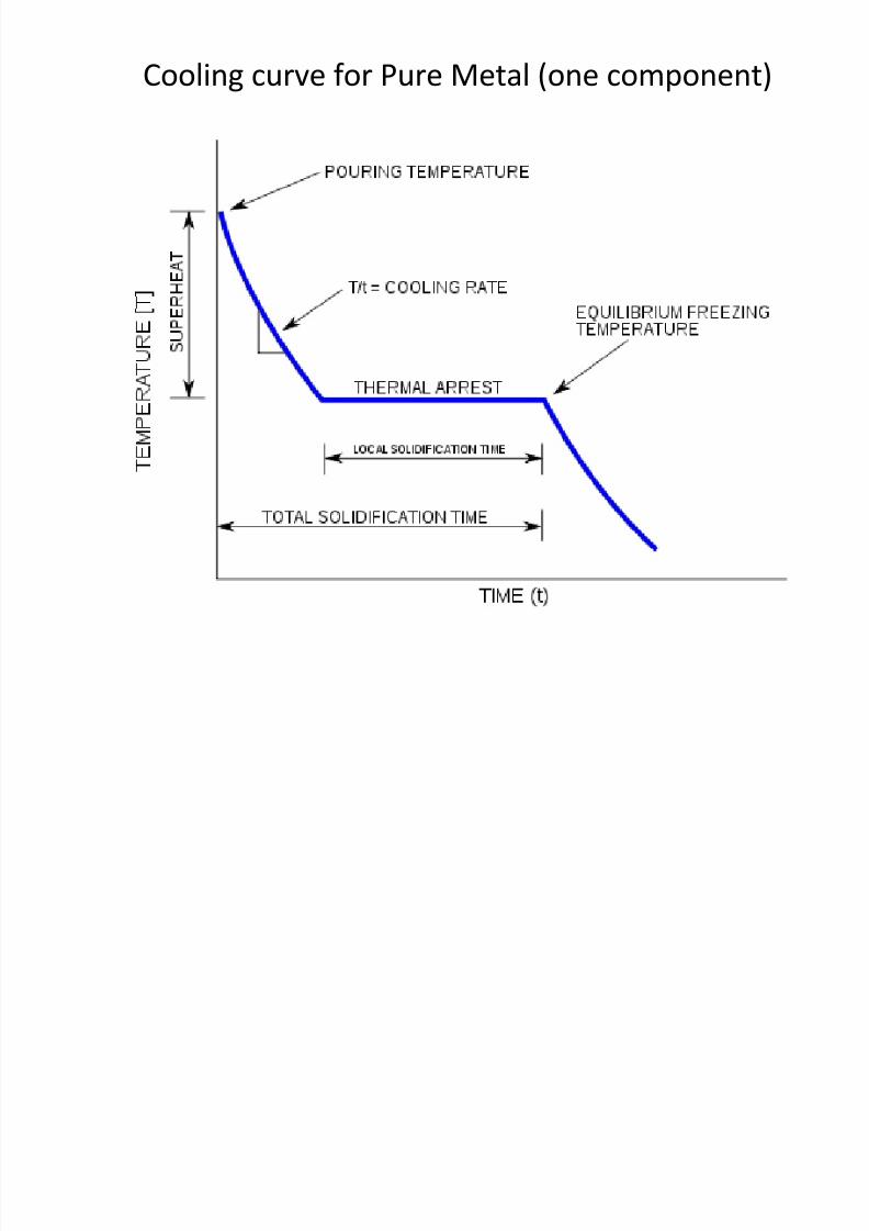
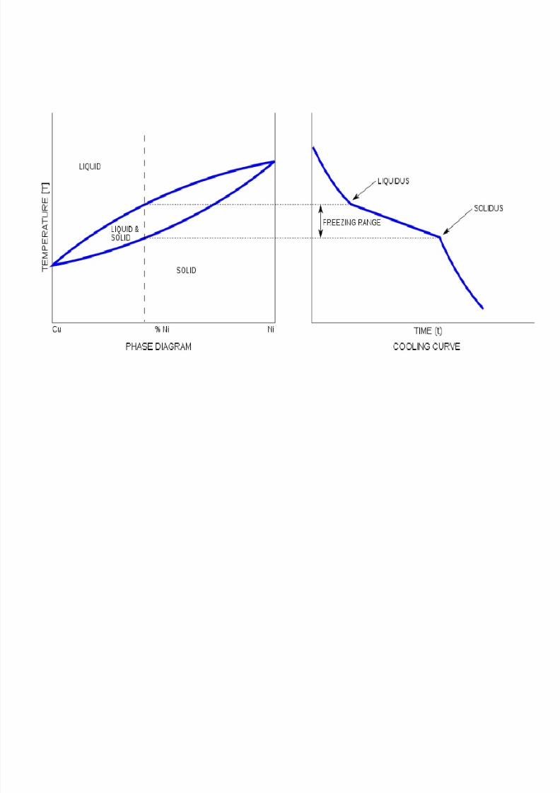
Cooling curve for Pure Metal (one component)
8/10/2019 MT-201B MATERIAL SCIENCE NEW - Copy.ppt
http://slidepdf.com/reader/full/mt-201b-material-science-new-copyppt 161/295
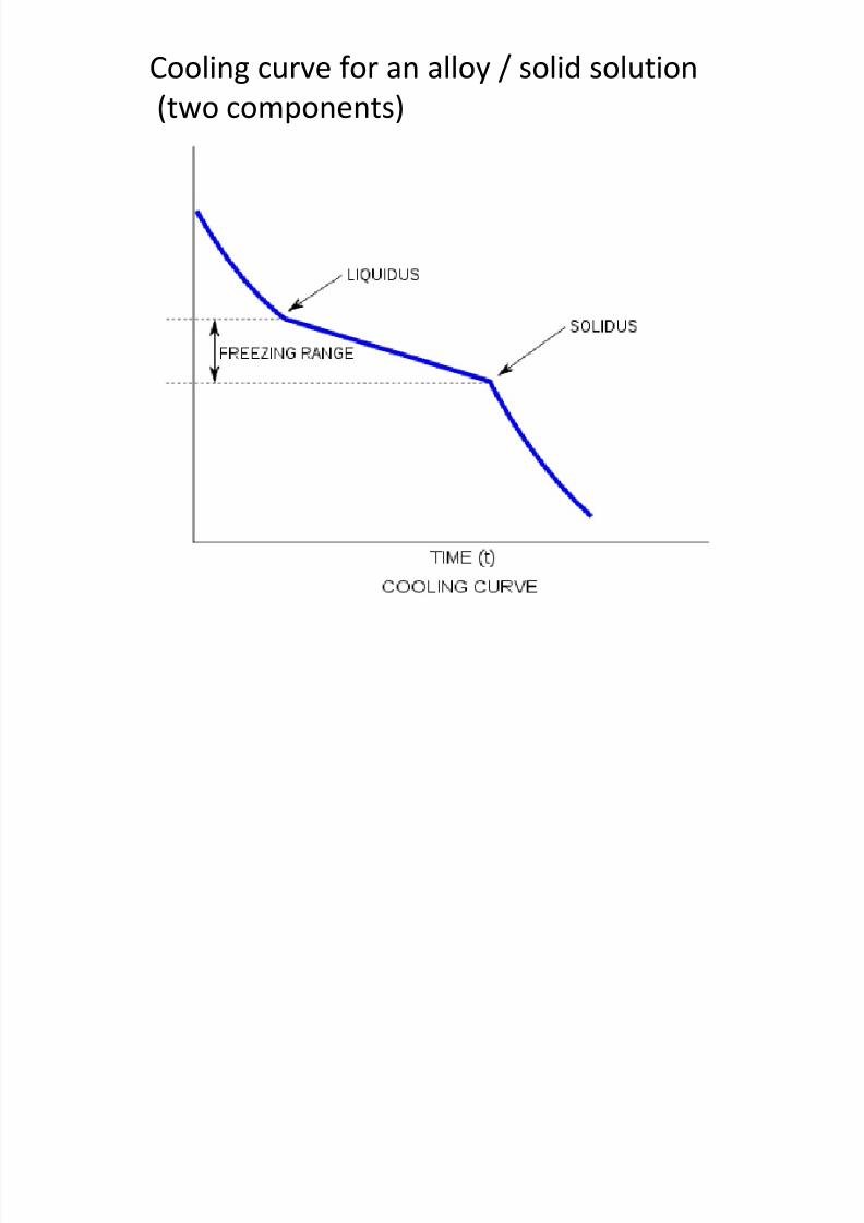
Cooling curve for an alloy / solid solution
(two components)
8/10/2019 MT-201B MATERIAL SCIENCE NEW - Copy.ppt
http://slidepdf.com/reader/full/mt-201b-material-science-new-copyppt 162/295
8/10/2019 MT-201B MATERIAL SCIENCE NEW - Copy.ppt
http://slidepdf.com/reader/full/mt-201b-material-science-new-copyppt 163/295
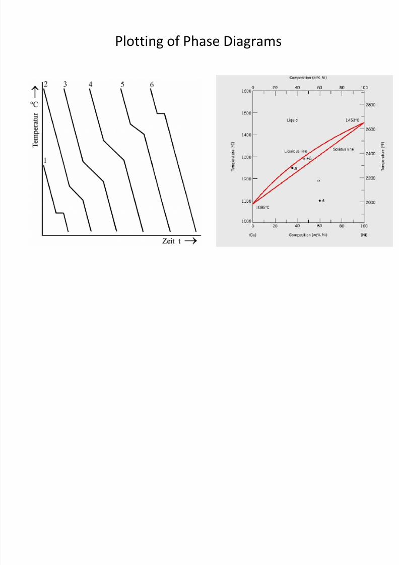
Plotting of Phase Diagrams
8/10/2019 MT-201B MATERIAL SCIENCE NEW - Copy.ppt
http://slidepdf.com/reader/full/mt-201b-material-science-new-copyppt 164/295
•These phase diagrams are of loop type and are obtained for
l h l l b l h l d ll
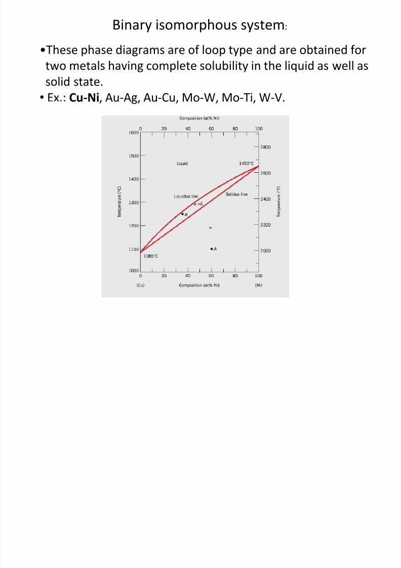
Binary isomorphous system:
8/10/2019 MT-201B MATERIAL SCIENCE NEW - Copy.ppt
http://slidepdf.com/reader/full/mt-201b-material-science-new-copyppt 165/295
two metals having complete solubility in the liquid as well as
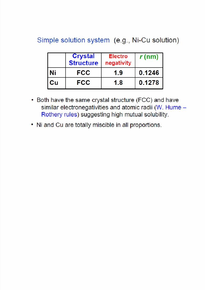
solid state.• Ex.: Cu-Ni, Au-Ag, Au-Cu, Mo-W, Mo-Ti, W-V.
Finding the amounts of phases in a two phase region :
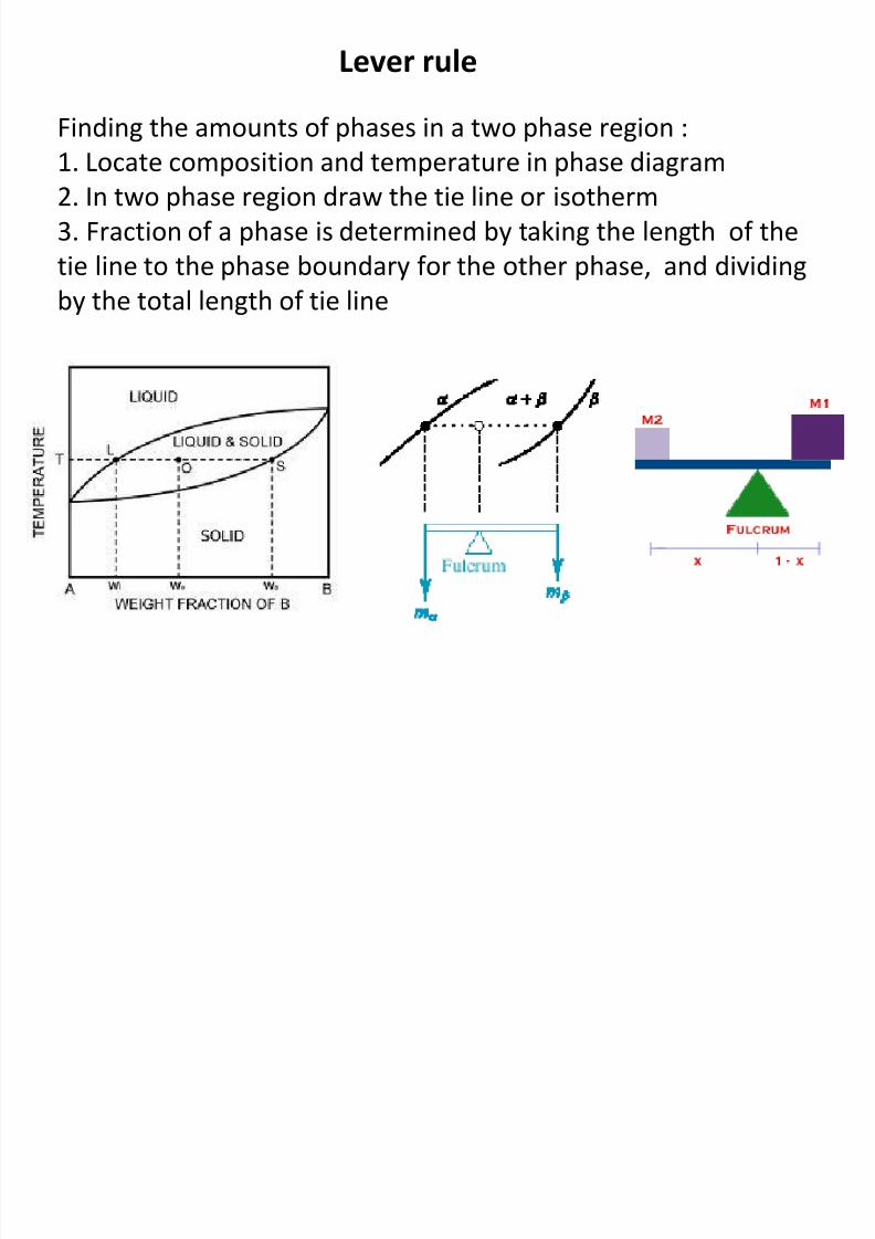
Lever rule
8/10/2019 MT-201B MATERIAL SCIENCE NEW - Copy.ppt
http://slidepdf.com/reader/full/mt-201b-material-science-new-copyppt 166/295
Finding the amounts of phases in a two phase region :
1. Locate composition and temperature in phase diagram
2. In two phase region draw the tie line or isotherm
3. Fraction of a phase is determined by taking the length of the
tie line to the phase boundary for the other phase, and dividing
by the total length of tie line
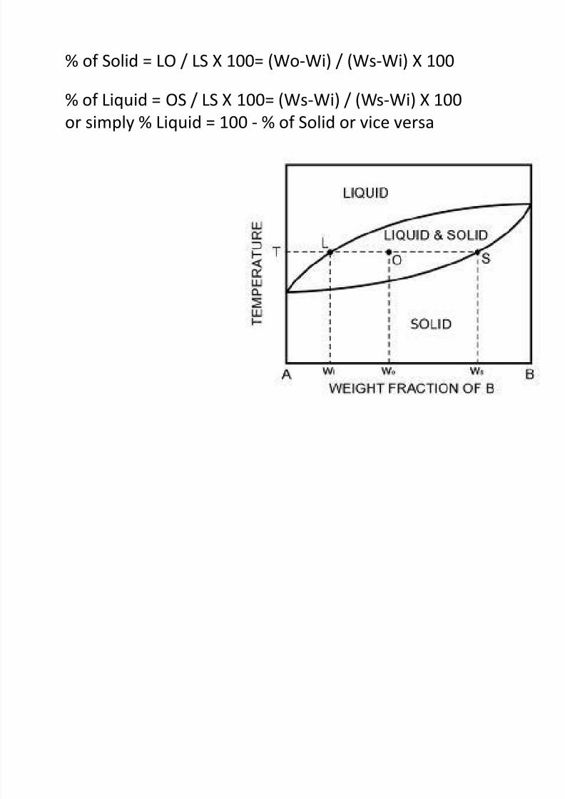
% of Solid = LO / LS X 100= (Wo-Wi) / (Ws-Wi) X 100
8/10/2019 MT-201B MATERIAL SCIENCE NEW - Copy.ppt
http://slidepdf.com/reader/full/mt-201b-material-science-new-copyppt 167/295
% of Liquid = OS / LS X 100= (Ws-Wi) / (Ws-Wi) X 100
or simply % Liquid = 100 - % of Solid or vice versa
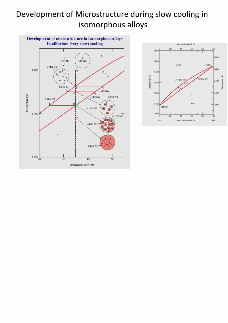
Development of Microstructure during slow cooling in
isomorphous alloys
8/10/2019 MT-201B MATERIAL SCIENCE NEW - Copy.ppt
http://slidepdf.com/reader/full/mt-201b-material-science-new-copyppt 168/295
8/10/2019 MT-201B MATERIAL SCIENCE NEW - Copy.ppt
http://slidepdf.com/reader/full/mt-201b-material-science-new-copyppt 169/295
8/10/2019 MT-201B MATERIAL SCIENCE NEW - Copy.ppt
http://slidepdf.com/reader/full/mt-201b-material-science-new-copyppt 170/295
These diagrams are obtained for two metals having complete
l bili (i i ibili ) i h li id d l
Binary Eutectic System:
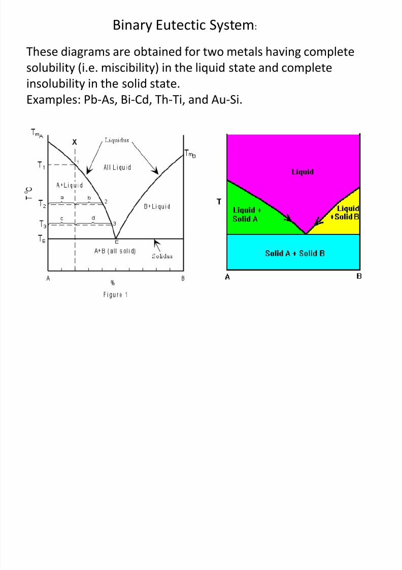
8/10/2019 MT-201B MATERIAL SCIENCE NEW - Copy.ppt
http://slidepdf.com/reader/full/mt-201b-material-science-new-copyppt 171/295
solubility (i.e. miscibility) in the liquid state and complete
insolubility in the solid state.Examples: Pb-As, Bi-Cd, Th-Ti, and Au-Si.
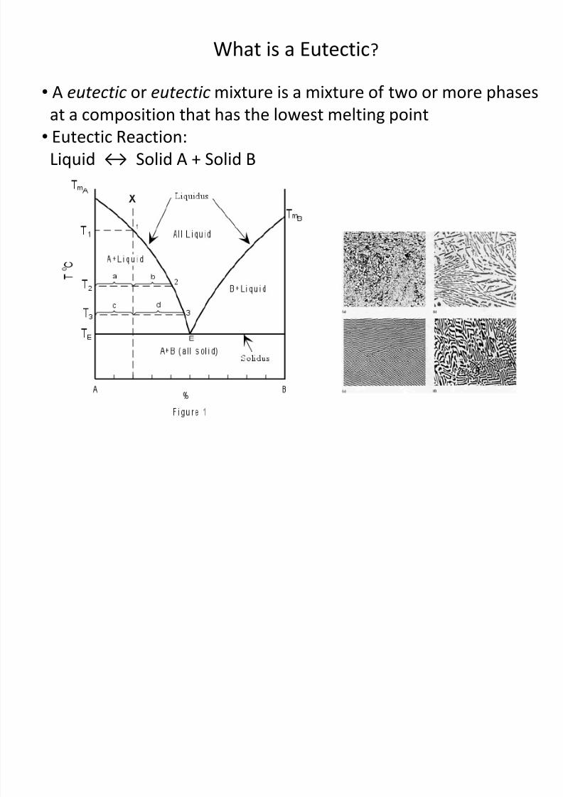
What is a Eutectic?
• A eutectic or eutectic mixture is a mixture of two or more phases
8/10/2019 MT-201B MATERIAL SCIENCE NEW - Copy.ppt
http://slidepdf.com/reader/full/mt-201b-material-science-new-copyppt 172/295
• A eutectic or eutectic mixture is a mixture of two or more phases
at a composition that has the lowest melting point• Eutectic Reaction:
Liquid ↔ Solid A + Solid B
8/10/2019 MT-201B MATERIAL SCIENCE NEW - Copy.ppt
http://slidepdf.com/reader/full/mt-201b-material-science-new-copyppt 173/295
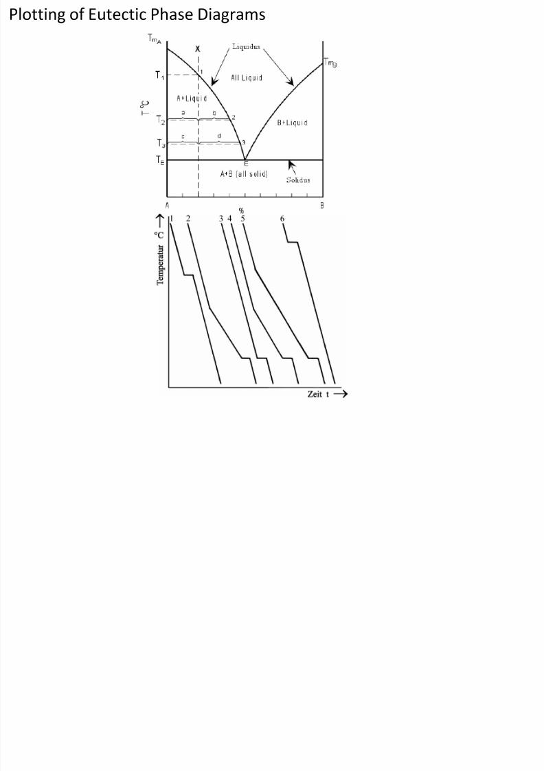
Plotting of Eutectic Phase Diagrams
8/10/2019 MT-201B MATERIAL SCIENCE NEW - Copy.ppt
http://slidepdf.com/reader/full/mt-201b-material-science-new-copyppt 174/295
These diagrams are obtained for two metals having complete
solubility (i e miscibility) in the liquid state and partial solubility
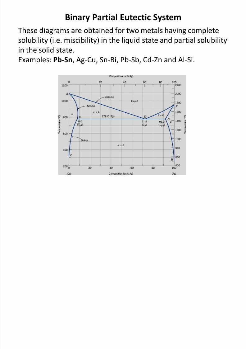
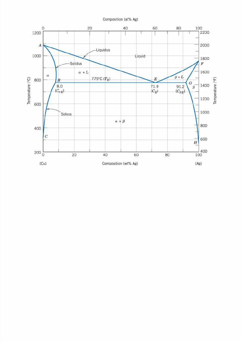
Binary Partial Eutectic System
8/10/2019 MT-201B MATERIAL SCIENCE NEW - Copy.ppt
http://slidepdf.com/reader/full/mt-201b-material-science-new-copyppt 175/295
solubility (i.e. miscibility) in the liquid state and partial solubility
in the solid state.Examples: Pb-Sn, Ag-Cu, Sn-Bi, Pb-Sb, Cd-Zn and Al-Si.
8/10/2019 MT-201B MATERIAL SCIENCE NEW - Copy.ppt
http://slidepdf.com/reader/full/mt-201b-material-science-new-copyppt 176/295
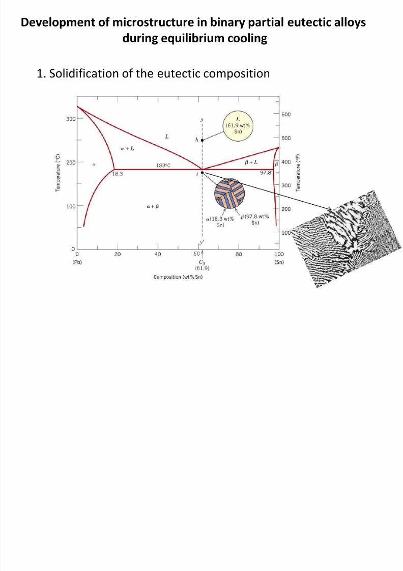
Development of microstructure in binary partial eutectic alloys
during equilibrium cooling
8/10/2019 MT-201B MATERIAL SCIENCE NEW - Copy.ppt
http://slidepdf.com/reader/full/mt-201b-material-science-new-copyppt 177/295
1. Solidification of the eutectic composition
8/10/2019 MT-201B MATERIAL SCIENCE NEW - Copy.ppt
http://slidepdf.com/reader/full/mt-201b-material-science-new-copyppt 178/295
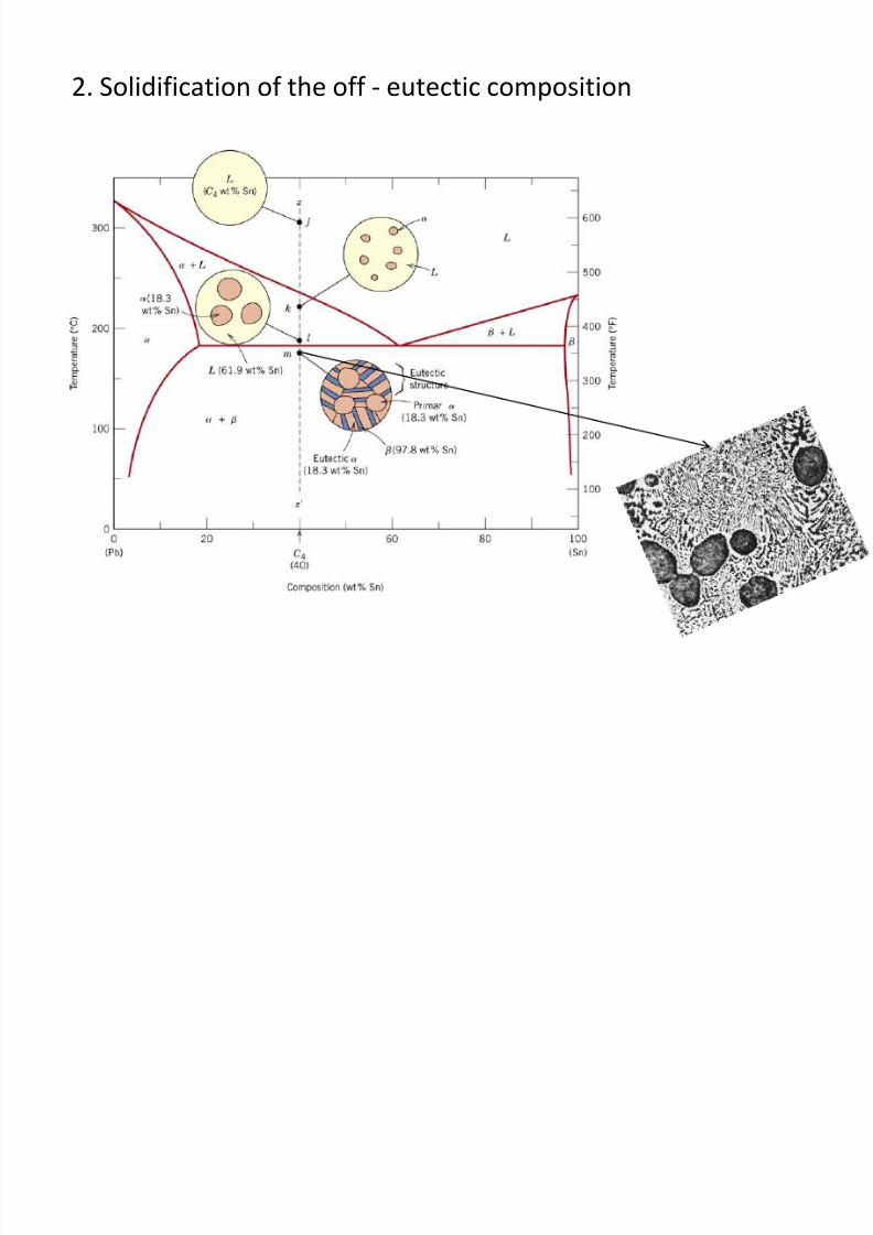
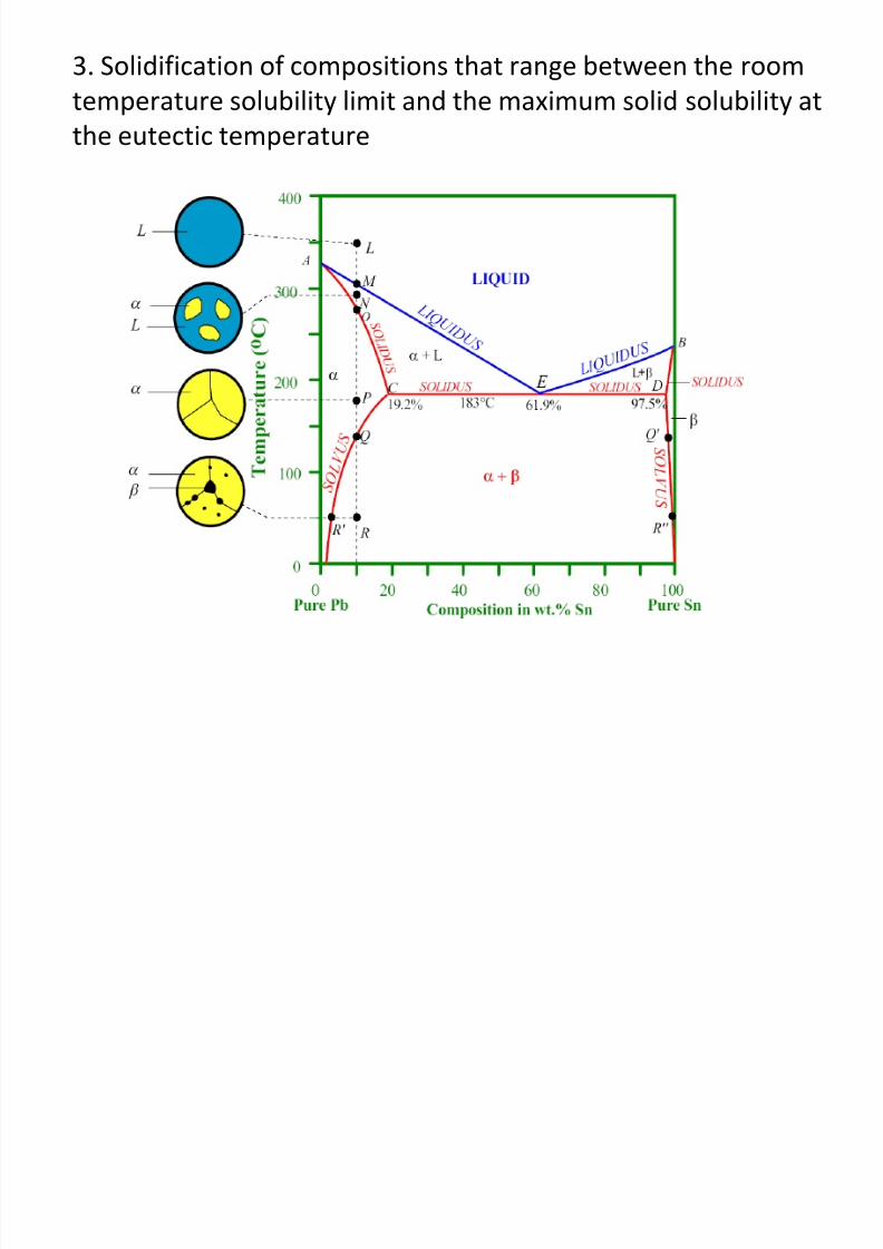
3. Solidification of compositions that range between the room
temperature solubility limit and the maximum solid solubility at
the eutectic temperature
8/10/2019 MT-201B MATERIAL SCIENCE NEW - Copy.ppt
http://slidepdf.com/reader/full/mt-201b-material-science-new-copyppt 179/295
p
8/10/2019 MT-201B MATERIAL SCIENCE NEW - Copy.ppt
http://slidepdf.com/reader/full/mt-201b-material-science-new-copyppt 180/295
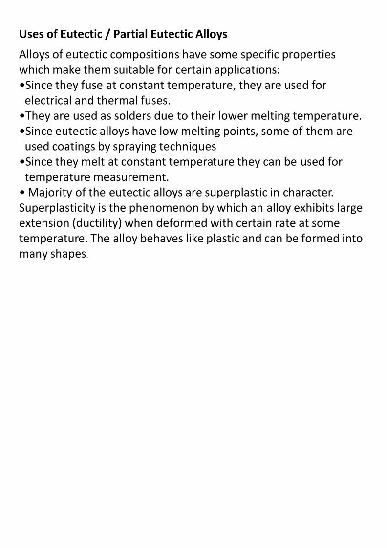
Example:
From the data given below for Bi-Cd system, plot the equilibrium diagram to scale
and find:
(a) Amount of eutectic in 20% Cd alloy at room temperature

8/10/2019 MT-201B MATERIAL SCIENCE NEW - Copy.ppt
http://slidepdf.com/reader/full/mt-201b-material-science-new-copyppt 181/295
(b) Free Cd in 70% Cd alloy at room tempearture
Given:Melting temperature of Bi = 271oC
Melting temperature of Cd = 321oC
Eutectic temperature = 144oC
Eutectic composition = 39.7% Cd
8/10/2019 MT-201B MATERIAL SCIENCE NEW - Copy.ppt
http://slidepdf.com/reader/full/mt-201b-material-science-new-copyppt 182/295

8/10/2019 MT-201B MATERIAL SCIENCE NEW - Copy.ppt
http://slidepdf.com/reader/full/mt-201b-material-science-new-copyppt 183/295
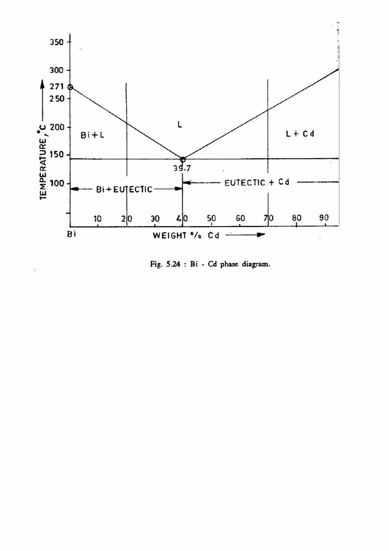
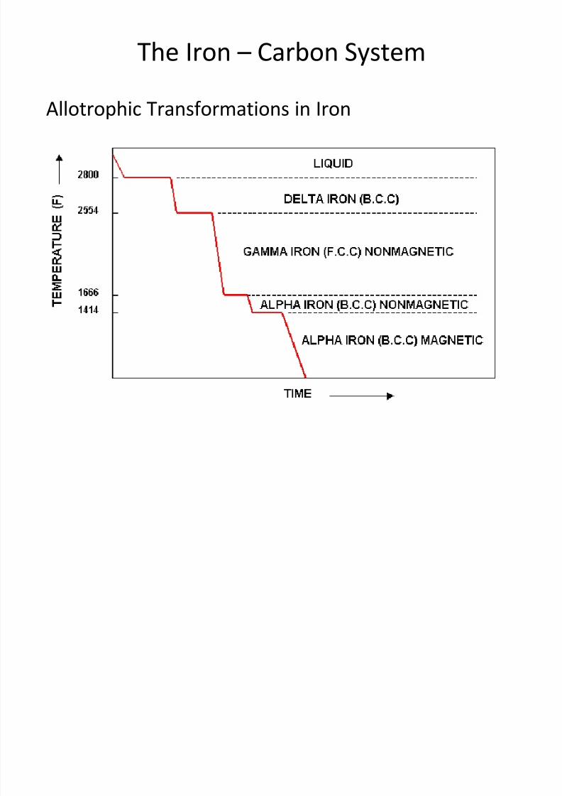
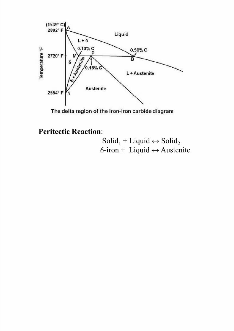
The Iron – Carbon System
8/10/2019 MT-201B MATERIAL SCIENCE NEW - Copy.ppt
http://slidepdf.com/reader/full/mt-201b-material-science-new-copyppt 184/295
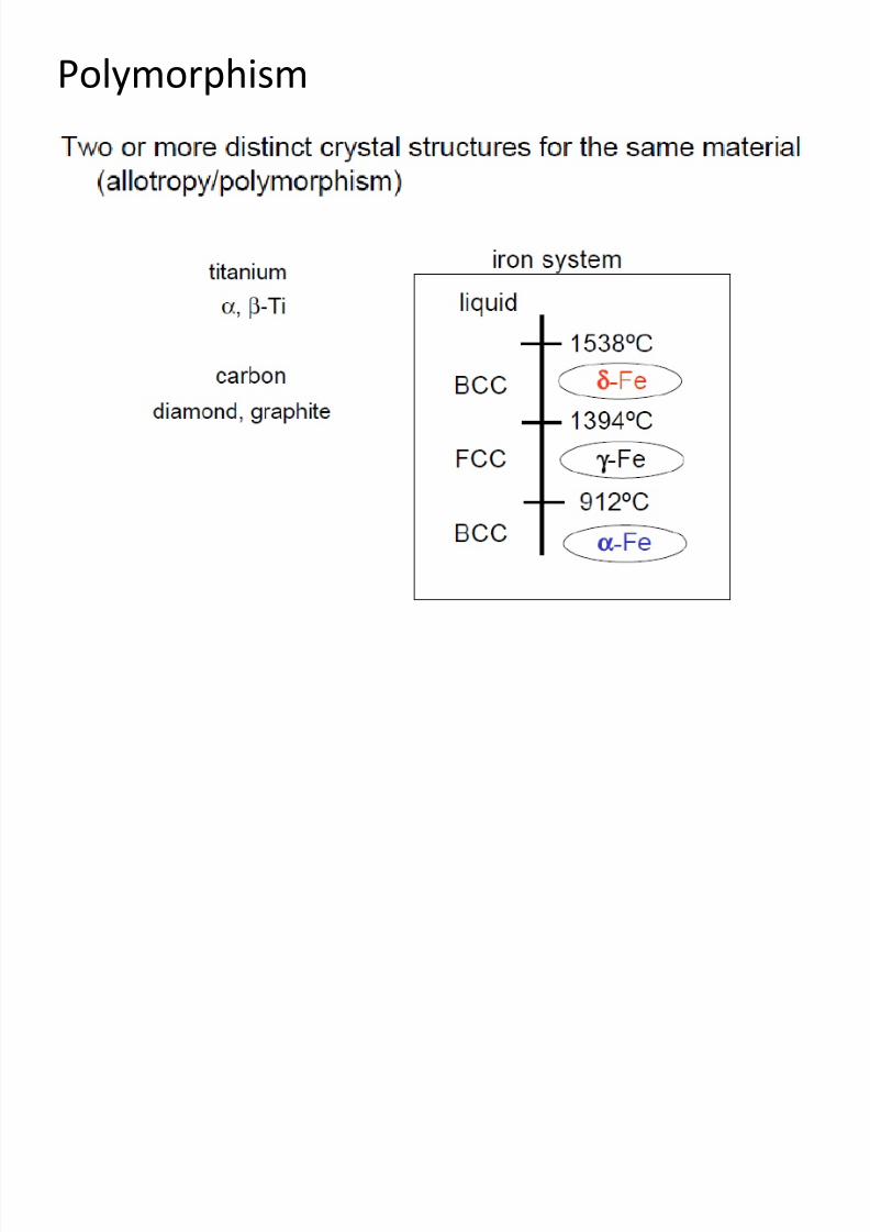
Allotrophic Transformations in Iron
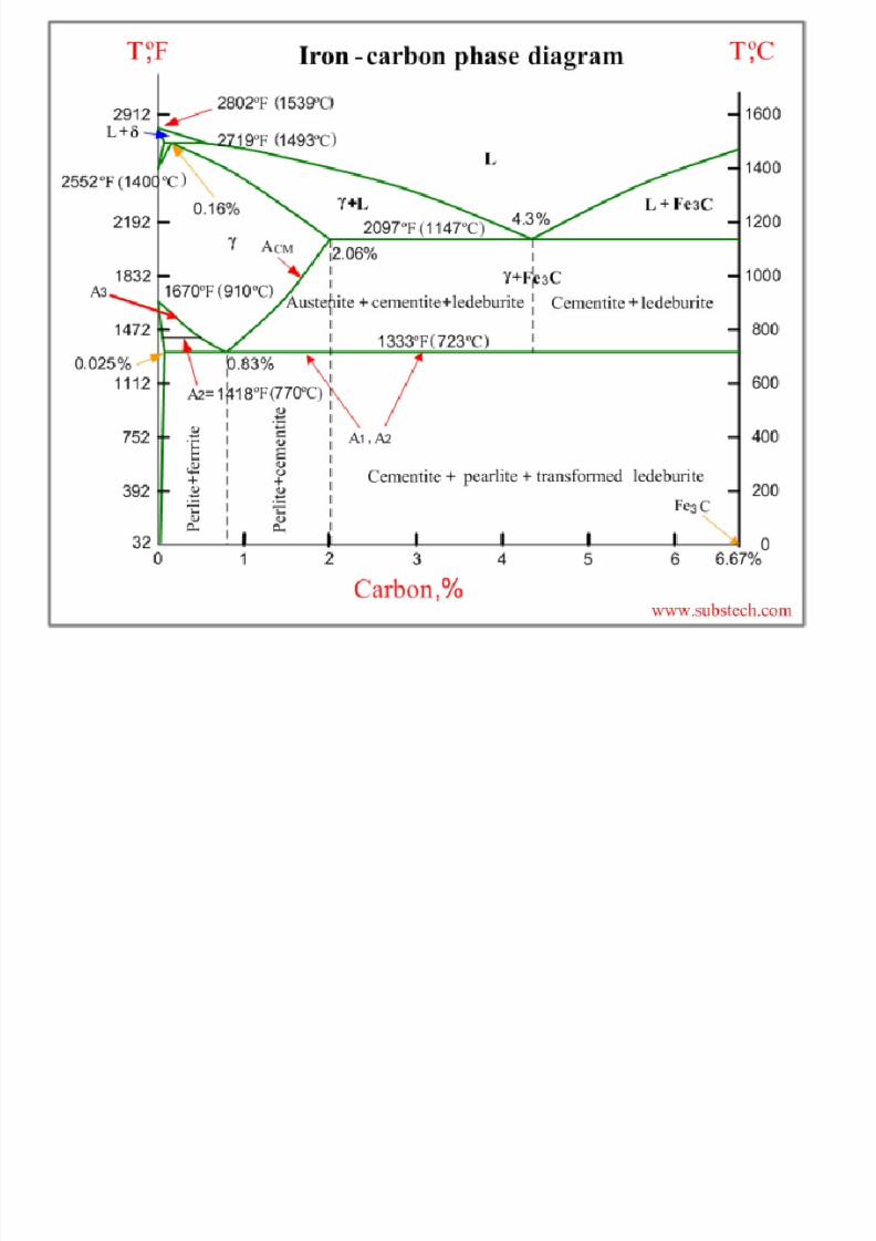
Iron – Carbon Phase Diagram
8/10/2019 MT-201B MATERIAL SCIENCE NEW - Copy.ppt
http://slidepdf.com/reader/full/mt-201b-material-science-new-copyppt 185/295
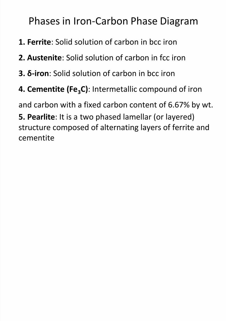
Phases in Iron-Carbon Phase Diagram
i l d l f b b
8/10/2019 MT-201B MATERIAL SCIENCE NEW - Copy.ppt
http://slidepdf.com/reader/full/mt-201b-material-science-new-copyppt 186/295
1. Ferrite: Solid solution of carbon in bcc iron
2. Austenite: Solid solution of carbon in fcc iron
3. δ-iron: Solid solution of carbon in bcc iron
4. Cementite (Fe3C): Intermetallic compound of iron
and carbon with a fixed carbon content of 6.67% by wt.
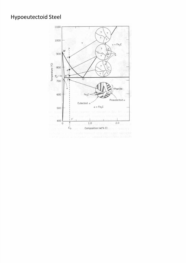
5. Pearlite: It is a two phased lamellar (or layered)
structure composed of alternating layers of ferrite andcementite
8/10/2019 MT-201B MATERIAL SCIENCE NEW - Copy.ppt
http://slidepdf.com/reader/full/mt-201b-material-science-new-copyppt 187/295
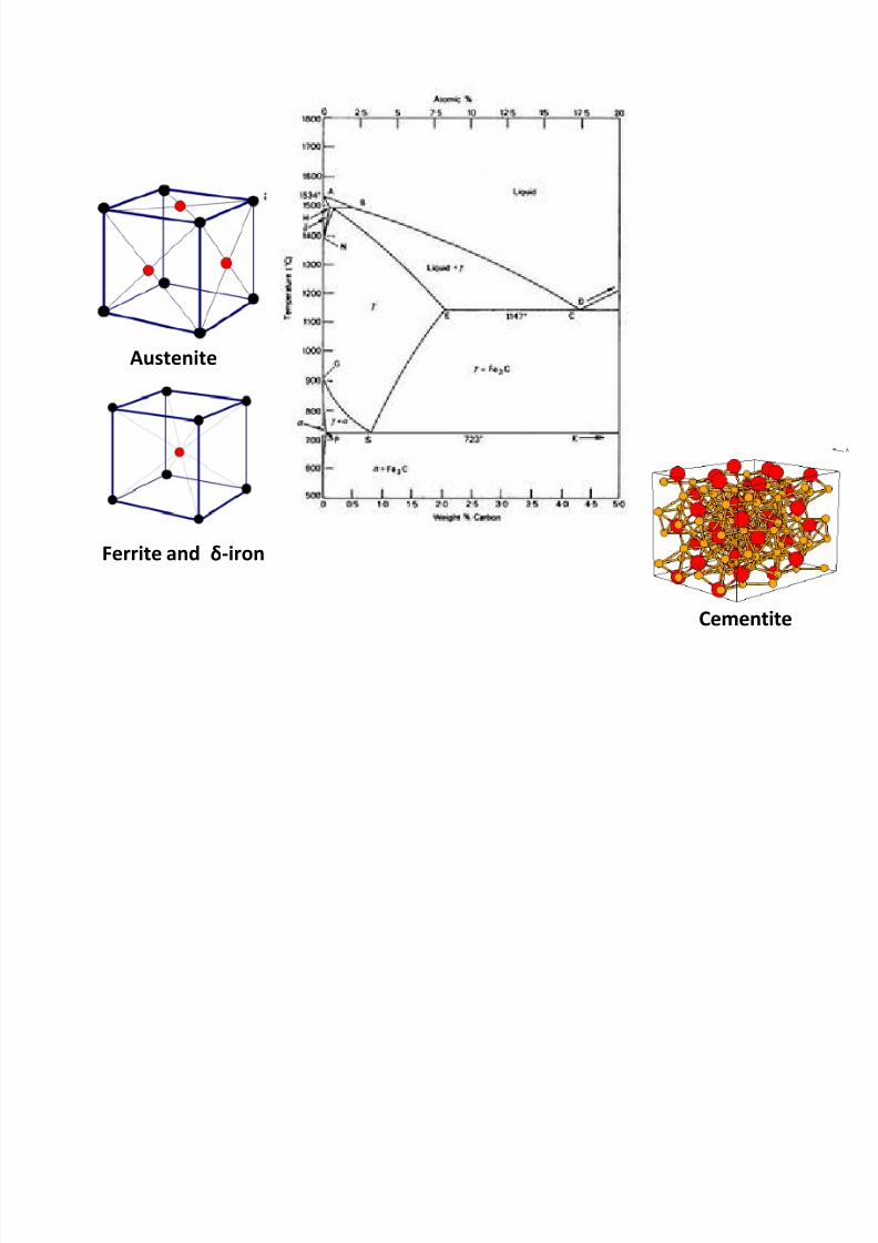
Ferrite and δ-iron
Austenite
Cementite
8/10/2019 MT-201B MATERIAL SCIENCE NEW - Copy.ppt
http://slidepdf.com/reader/full/mt-201b-material-science-new-copyppt 188/295
8/10/2019 MT-201B MATERIAL SCIENCE NEW - Copy.ppt
http://slidepdf.com/reader/full/mt-201b-material-science-new-copyppt 189/295
8/10/2019 MT-201B MATERIAL SCIENCE NEW - Copy.ppt
http://slidepdf.com/reader/full/mt-201b-material-science-new-copyppt 190/295
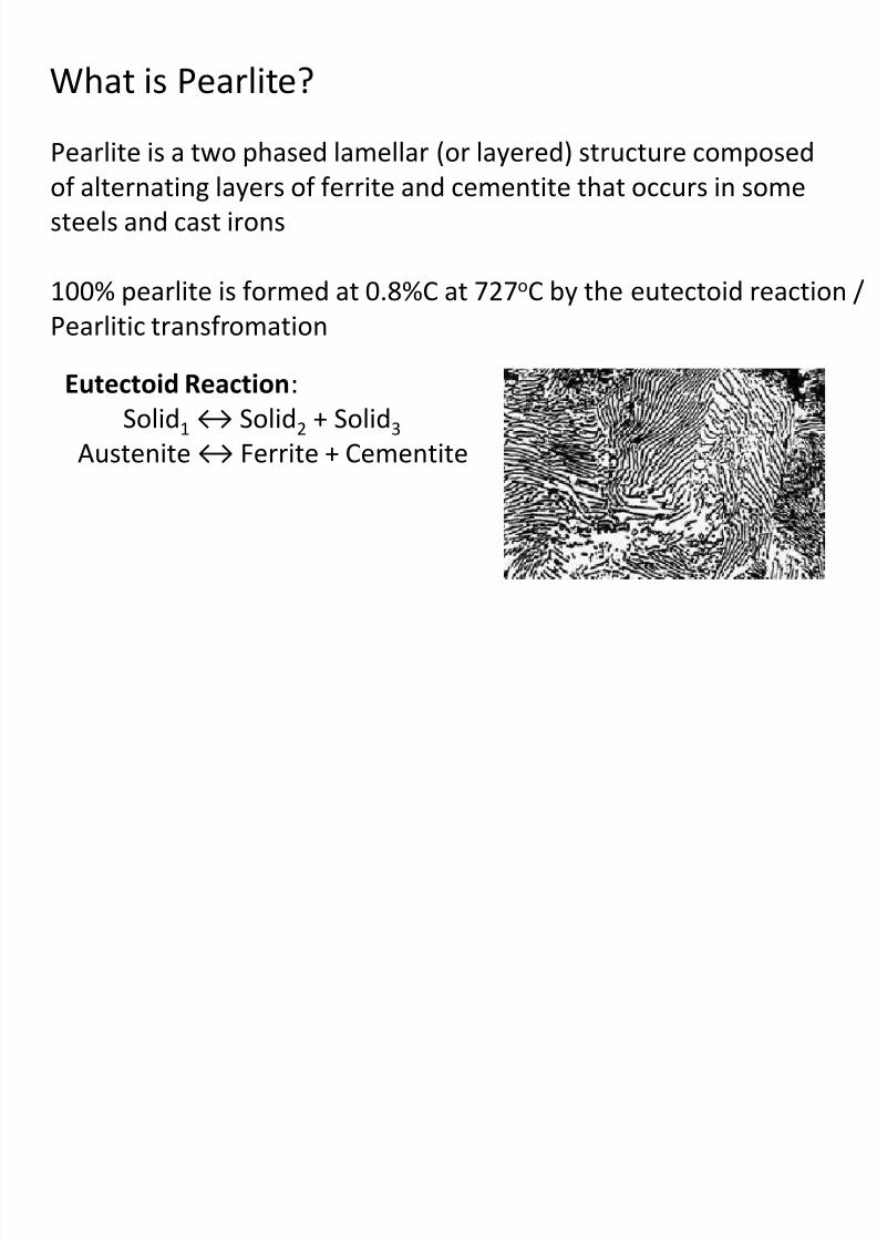
What is Pearlite?
Pearlite is a two phased lamellar (or layered) structure composed
8/10/2019 MT-201B MATERIAL SCIENCE NEW - Copy.ppt
http://slidepdf.com/reader/full/mt-201b-material-science-new-copyppt 191/295
Pearlite is a two phased lamellar (or layered) structure composed
of alternating layers of ferrite and cementite that occurs in somesteels and cast irons
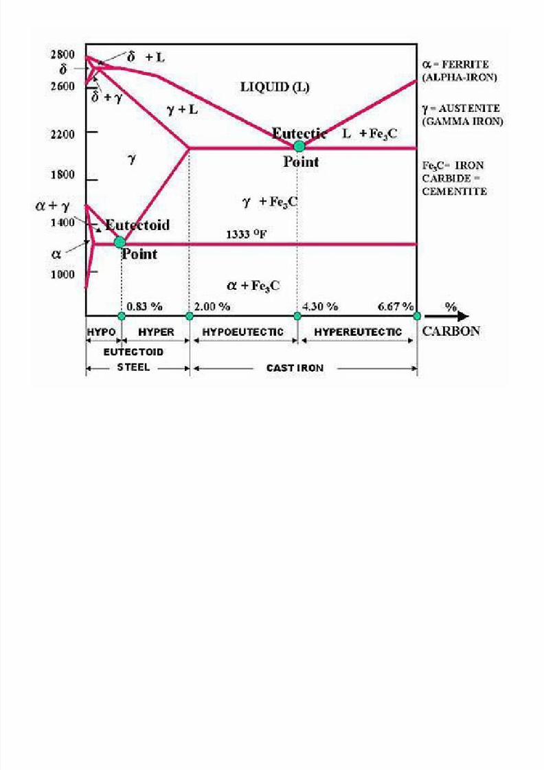
100% pearlite is formed at 0.8%C at 727oC by the eutectoid reaction /
Pearlitic transfromation
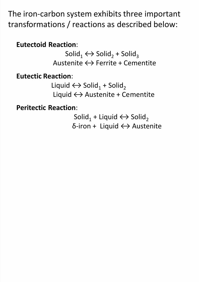
Eutectoid Reaction:
Solid1 ↔ Solid2 + Solid3
Austenite ↔ Ferrite + Cementite
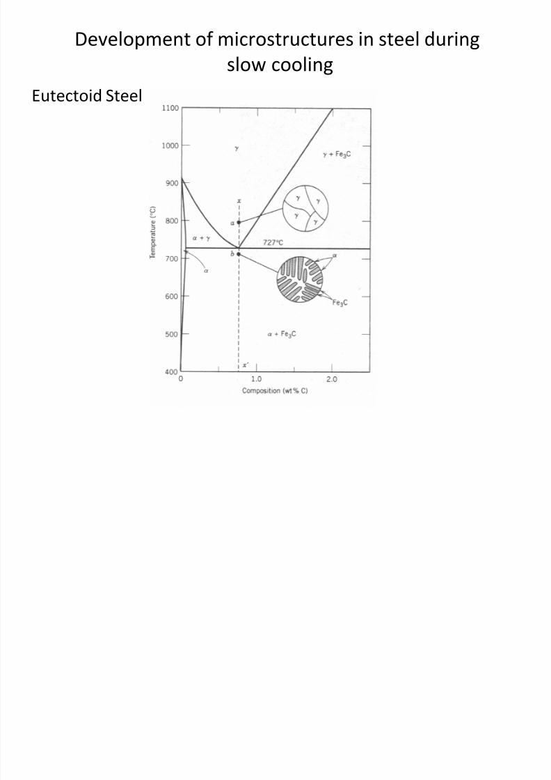
Development of microstructures in steel during
slow cooling
Eutectoid Steel
8/10/2019 MT-201B MATERIAL SCIENCE NEW - Copy.ppt
http://slidepdf.com/reader/full/mt-201b-material-science-new-copyppt 192/295
Eutectoid Steel
Hypoeutectoid Steel
8/10/2019 MT-201B MATERIAL SCIENCE NEW - Copy.ppt
http://slidepdf.com/reader/full/mt-201b-material-science-new-copyppt 193/295
Hypereutectoid Steel

8/10/2019 MT-201B MATERIAL SCIENCE NEW - Copy.ppt
http://slidepdf.com/reader/full/mt-201b-material-science-new-copyppt 194/295
Mechanical Properties
8/10/2019 MT-201B MATERIAL SCIENCE NEW - Copy.ppt
http://slidepdf.com/reader/full/mt-201b-material-science-new-copyppt 195/295
1. Hardness Test
2. Tensile Test
- Ductile and brittle fracture
3. Impact Test- Ductile-to-brittle transition
4. Fatigue Test
5. Creep Test
Hardness Test
H d i f t i l i t
8/10/2019 MT-201B MATERIAL SCIENCE NEW - Copy.ppt
http://slidepdf.com/reader/full/mt-201b-material-science-new-copyppt 196/295
Hardness is a measure of a materials resistanceto localized plastic deformation.
Types of hardness tests:
1. Brinell hardness test
2. Vickers hardness test
3. Rockwell hardness test
4. Microhardness test
Hardness tests are preformed more frequently than
any other mechanical test for several reasons:
8/10/2019 MT-201B MATERIAL SCIENCE NEW - Copy.ppt
http://slidepdf.com/reader/full/mt-201b-material-science-new-copyppt 197/295
1. They are simple and inexpensive – no special
specimen required and testing apparatus is relatively
inexpensive
2. The test is non-destructive – the specimen is
neither fractured nor excessively deformed; a small
indentation is the only deformation
3. Other mechanical properties may be estimated
from hardness data, such as tensile strength
8/10/2019 MT-201B MATERIAL SCIENCE NEW - Copy.ppt
http://slidepdf.com/reader/full/mt-201b-material-science-new-copyppt 198/295
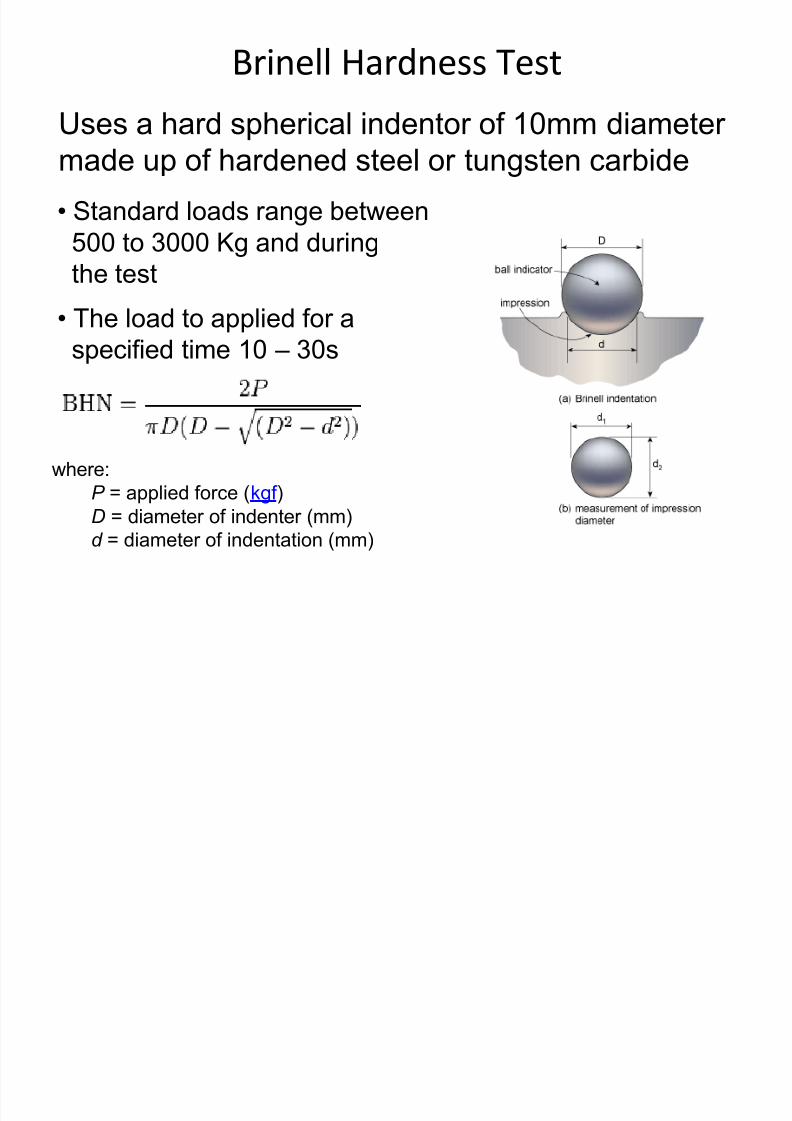
Brinell Hardness Test
Uses a hard spherical indentor of 10mm diameter
8/10/2019 MT-201B MATERIAL SCIENCE NEW - Copy.ppt
http://slidepdf.com/reader/full/mt-201b-material-science-new-copyppt 199/295
made up of hardened steel or tungsten carbide• Standard loads range between
500 to 3000 Kg and during
the test
• The load to applied for aspecified time 10 – 30s
where:
P = applied force (kgf )
D = diameter of indenter (mm)
d = diameter of indentation (mm)
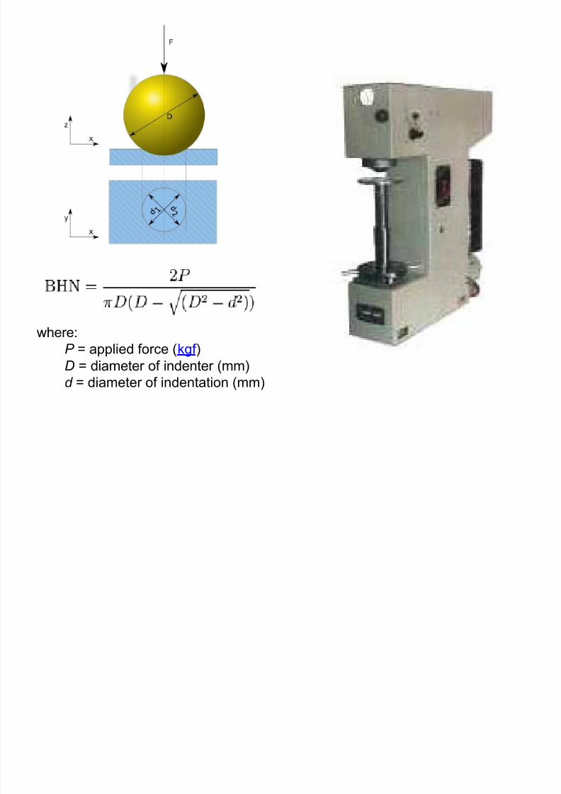
8/10/2019 MT-201B MATERIAL SCIENCE NEW - Copy.ppt
http://slidepdf.com/reader/full/mt-201b-material-science-new-copyppt 200/295
where:
P = applied force (kgf )
D = diameter of indenter (mm)
d = diameter of indentation (mm)
Advantages and Limitation of Brinell Hardness
Test
8/10/2019 MT-201B MATERIAL SCIENCE NEW - Copy.ppt
http://slidepdf.com/reader/full/mt-201b-material-science-new-copyppt 201/295
Limitations:
1. Ball is likely to deform
2. Thin materials cannot be tested
3. For some materials ridging or piling up is observed4. Test requires more time and reading are subject to
personal errors
Advantages:Useful for measuring hardness of heterogeneous
materials
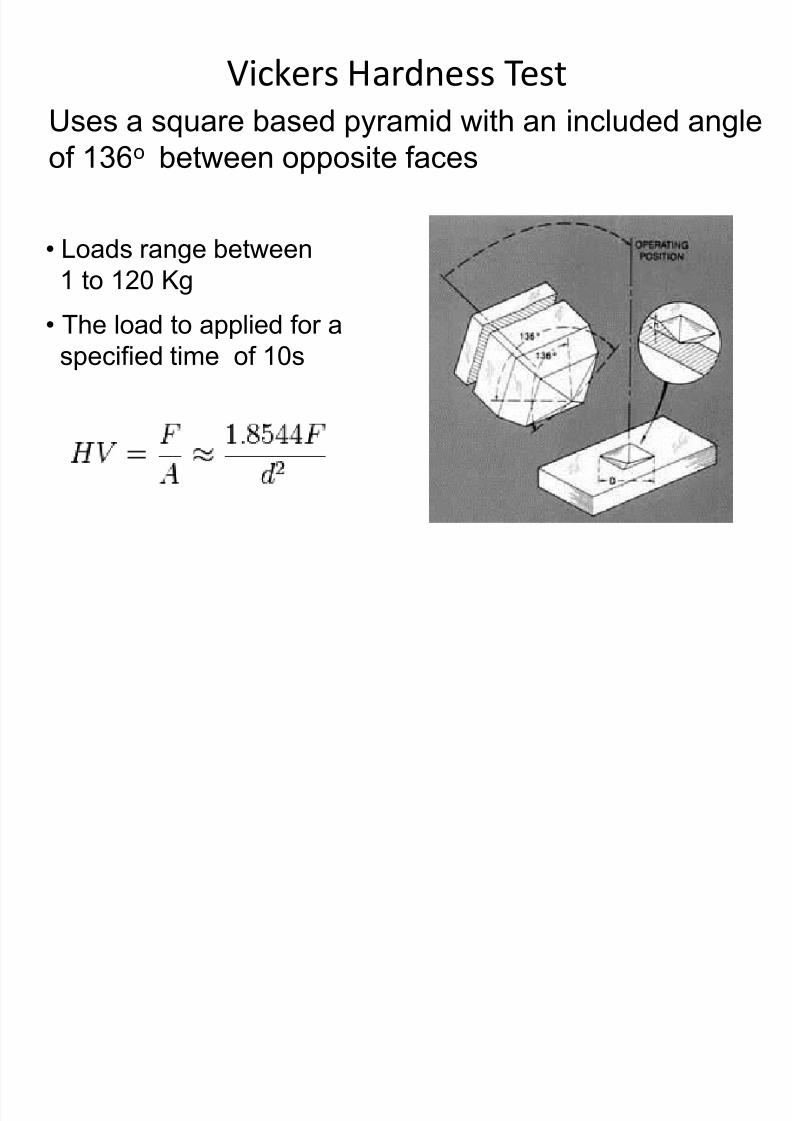
Vickers Hardness Test
Uses a square based pyramid with an included angleo
8/10/2019 MT-201B MATERIAL SCIENCE NEW - Copy.ppt
http://slidepdf.com/reader/full/mt-201b-material-science-new-copyppt 202/295
of 136o
between opposite faces
• Loads range between
1 to 120 Kg
• The load to applied for a
specified time of 10s
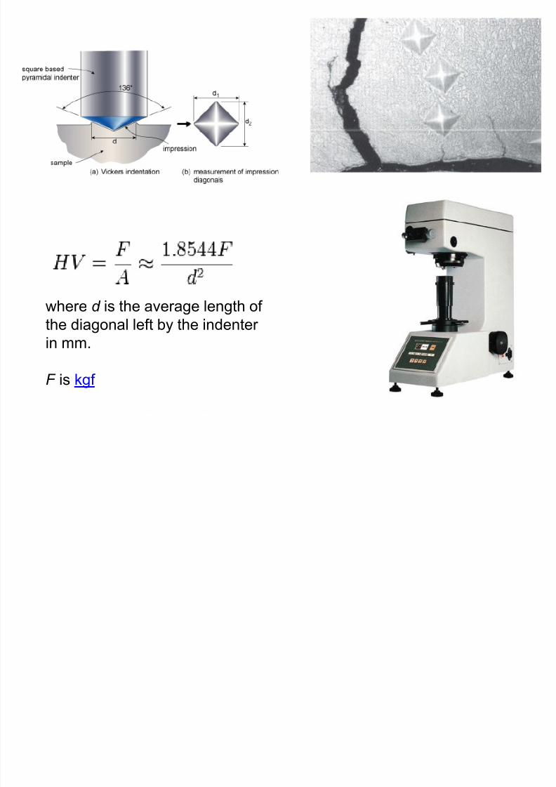
8/10/2019 MT-201B MATERIAL SCIENCE NEW - Copy.ppt
http://slidepdf.com/reader/full/mt-201b-material-science-new-copyppt 203/295
where d is the average length ofthe diagonal left by the indenter
in mm.
F is kgf
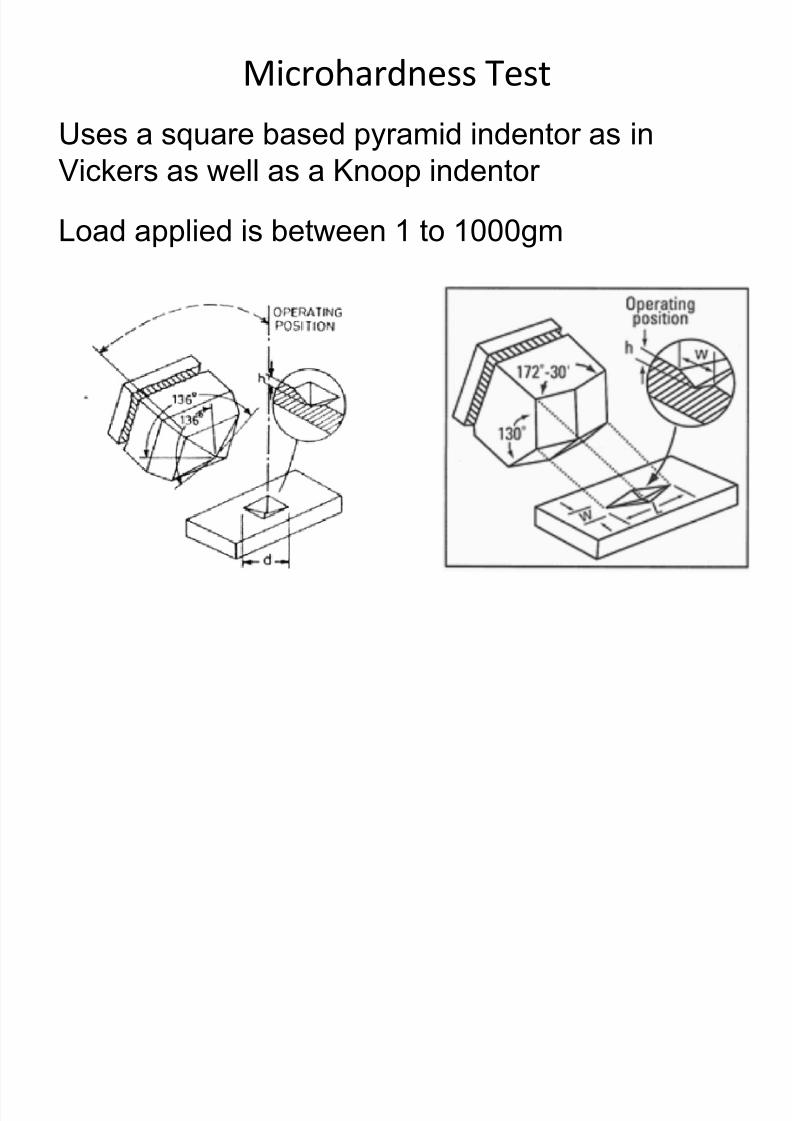
Microhardness Test
Uses a square based pyramid indentor as in
8/10/2019 MT-201B MATERIAL SCIENCE NEW - Copy.ppt
http://slidepdf.com/reader/full/mt-201b-material-science-new-copyppt 204/295
q py
Vickers as well as a Knoop indentor
Load applied is between 1 to 1000gm
8/10/2019 MT-201B MATERIAL SCIENCE NEW - Copy.ppt
http://slidepdf.com/reader/full/mt-201b-material-science-new-copyppt 205/295
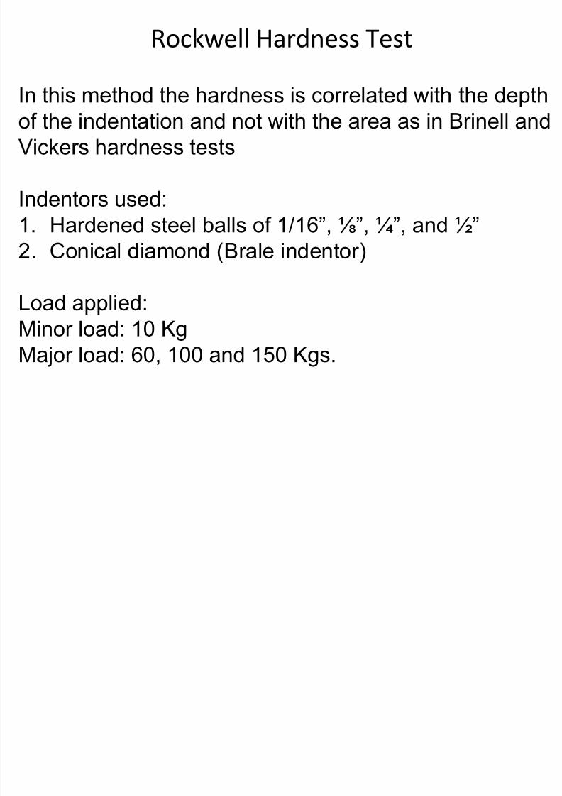
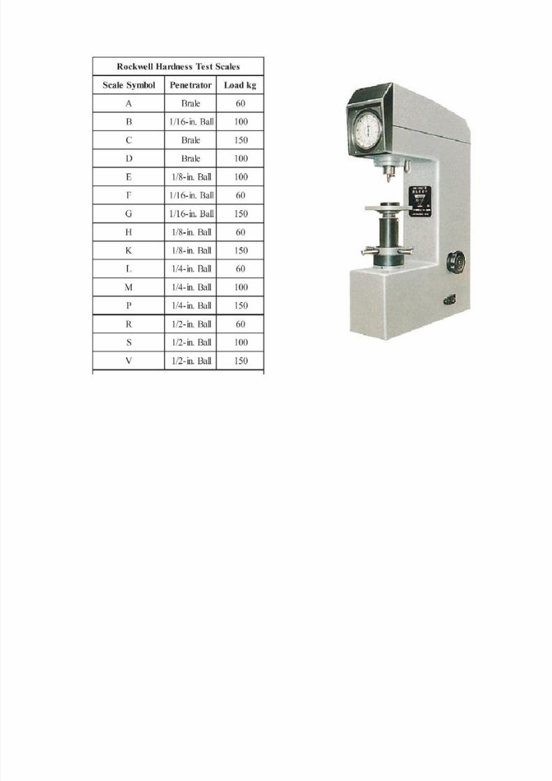
Rockwell Hardness Test
In this method the hardness is correlated with the depth
8/10/2019 MT-201B MATERIAL SCIENCE NEW - Copy.ppt
http://slidepdf.com/reader/full/mt-201b-material-science-new-copyppt 206/295
of the indentation and not with the area as in Brinell andVickers hardness tests
Indentors used:
1. Hardened steel balls of 1/16”, ⅛”, ¼”, and ½” 2. Conical diamond (Brale indentor)
Load applied:
Minor load: 10 Kg
Major load: 60, 100 and 150 Kgs.
8/10/2019 MT-201B MATERIAL SCIENCE NEW - Copy.ppt
http://slidepdf.com/reader/full/mt-201b-material-science-new-copyppt 207/295
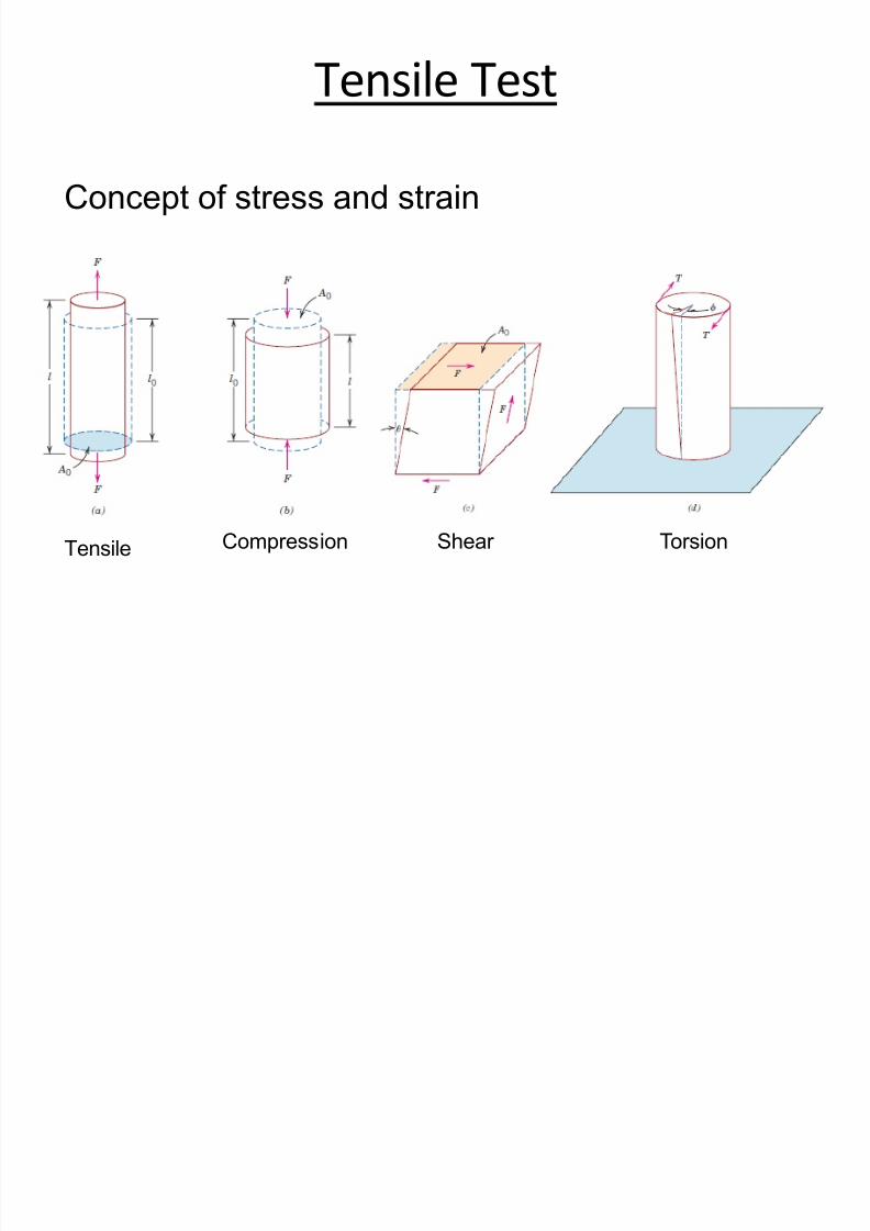
Tensile Test
8/10/2019 MT-201B MATERIAL SCIENCE NEW - Copy.ppt
http://slidepdf.com/reader/full/mt-201b-material-science-new-copyppt 208/295
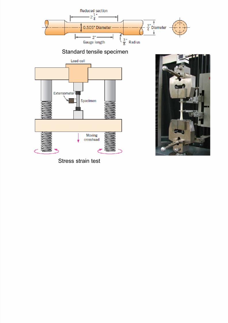
Concept of stress and strain
Tensile Compression Shear Torsion
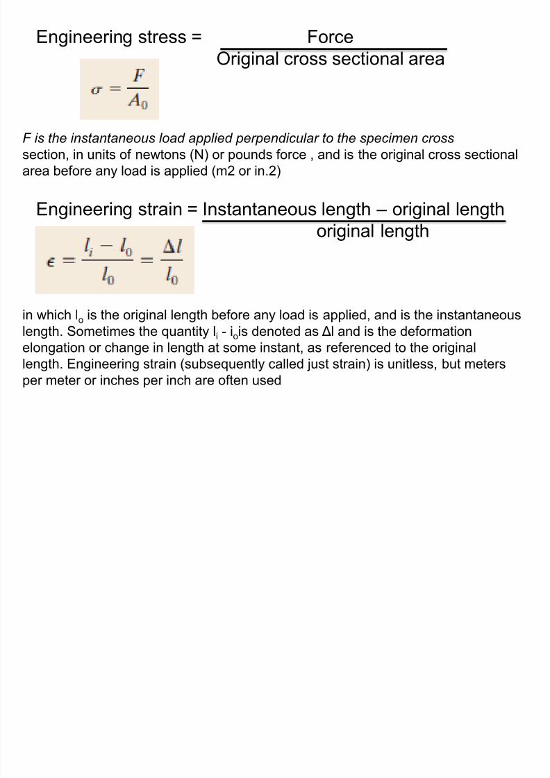
Engineering stress = Force
Original cross sectional area
8/10/2019 MT-201B MATERIAL SCIENCE NEW - Copy.ppt
http://slidepdf.com/reader/full/mt-201b-material-science-new-copyppt 209/295
F is the instantaneous load applied perpendicular to the specimen cross
section, in units of newtons (N) or pounds force , and is the original cross sectional
area before any load is applied (m2 or in.2)
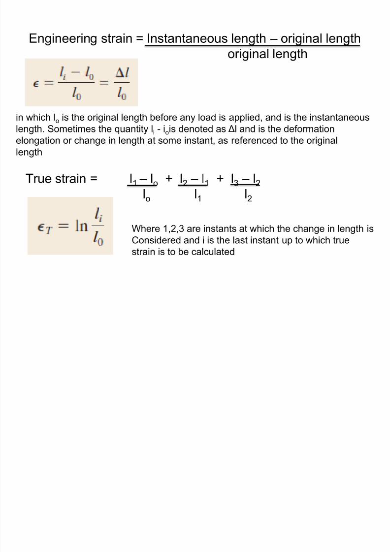
Engineering strain = Instantaneous length – original lengthoriginal length
in which lo is the original length before any load is applied, and is the instantaneouslength. Sometimes the quantity li - iois denoted as Δl and is the deformation
elongation or change in length at some instant, as referenced to the original
length. Engineering strain (subsequently called just strain) is unitless, but meters
per meter or inches per inch are often used
8/10/2019 MT-201B MATERIAL SCIENCE NEW - Copy.ppt
http://slidepdf.com/reader/full/mt-201b-material-science-new-copyppt 210/295
Standard tensile specimen
Stress strain test
8/10/2019 MT-201B MATERIAL SCIENCE NEW - Copy.ppt
http://slidepdf.com/reader/full/mt-201b-material-science-new-copyppt 211/295
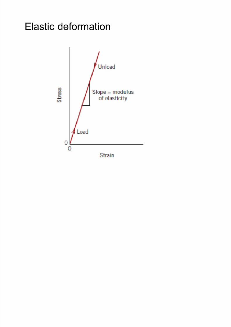
Elastic deformation
8/10/2019 MT-201B MATERIAL SCIENCE NEW - Copy.ppt
http://slidepdf.com/reader/full/mt-201b-material-science-new-copyppt 212/295
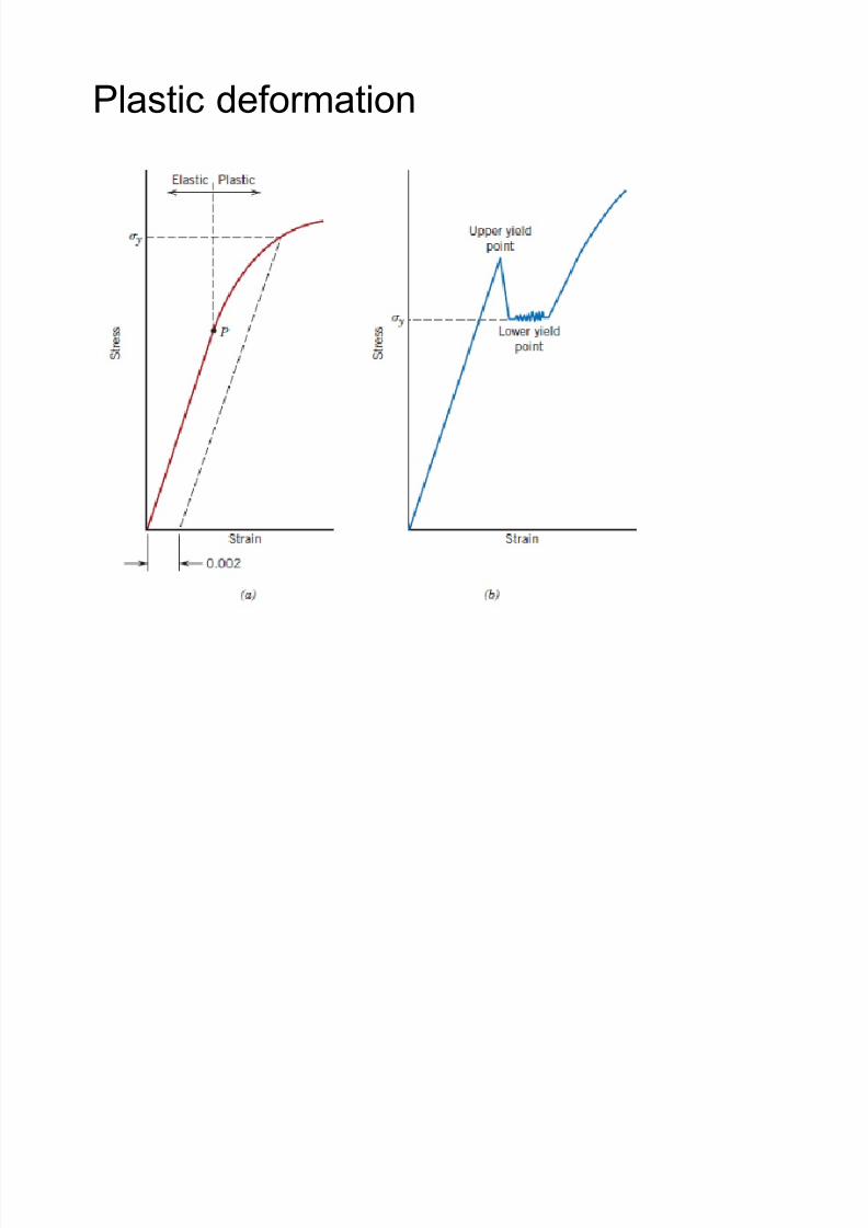
Plastic deformation
8/10/2019 MT-201B MATERIAL SCIENCE NEW - Copy.ppt
http://slidepdf.com/reader/full/mt-201b-material-science-new-copyppt 213/295
8/10/2019 MT-201B MATERIAL SCIENCE NEW - Copy.ppt
http://slidepdf.com/reader/full/mt-201b-material-science-new-copyppt 214/295
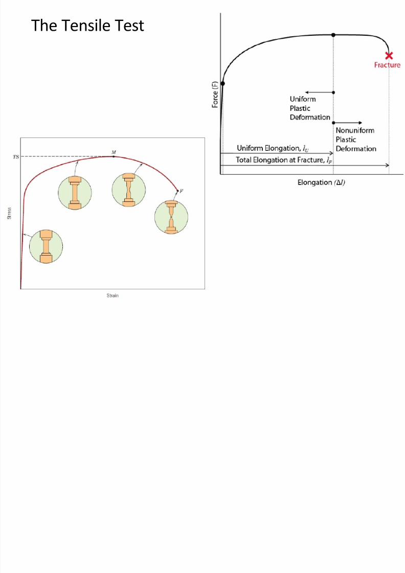
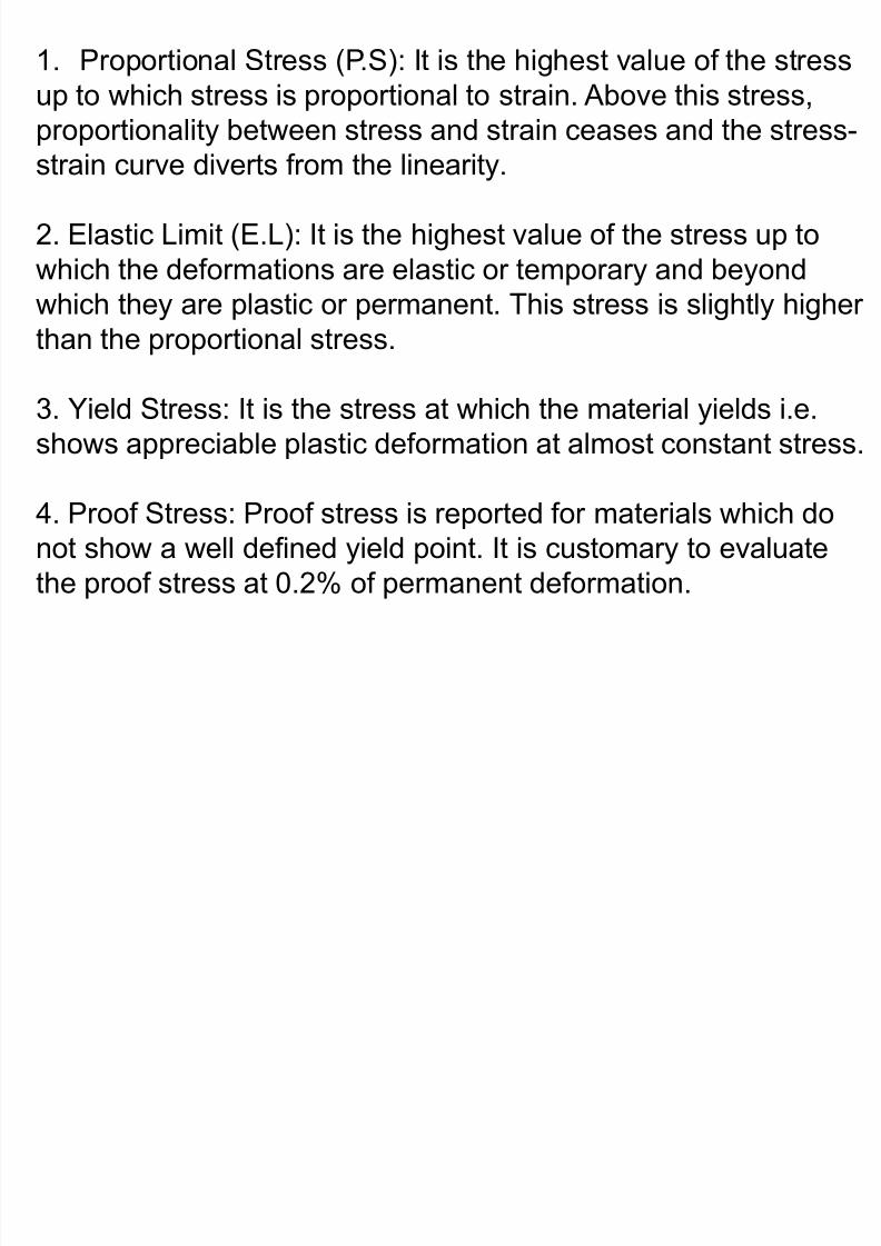
3. Ultimate Tensile Stress (U.T.S): It is the highest value of
the stress that the material can bear or sustain without
fracture.

8/10/2019 MT-201B MATERIAL SCIENCE NEW - Copy.ppt
http://slidepdf.com/reader/full/mt-201b-material-science-new-copyppt 215/295
4. Fracture stress or Breaking stress: It is the stress value
at the point of fracture or failure.
8/10/2019 MT-201B MATERIAL SCIENCE NEW - Copy.ppt
http://slidepdf.com/reader/full/mt-201b-material-science-new-copyppt 216/295
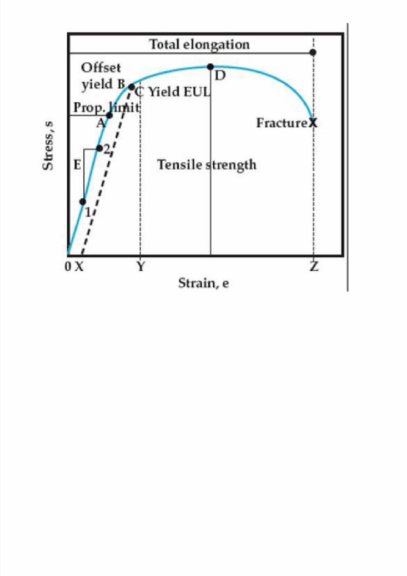
Determination of Proof Stress
8/10/2019 MT-201B MATERIAL SCIENCE NEW - Copy.ppt
http://slidepdf.com/reader/full/mt-201b-material-science-new-copyppt 217/295
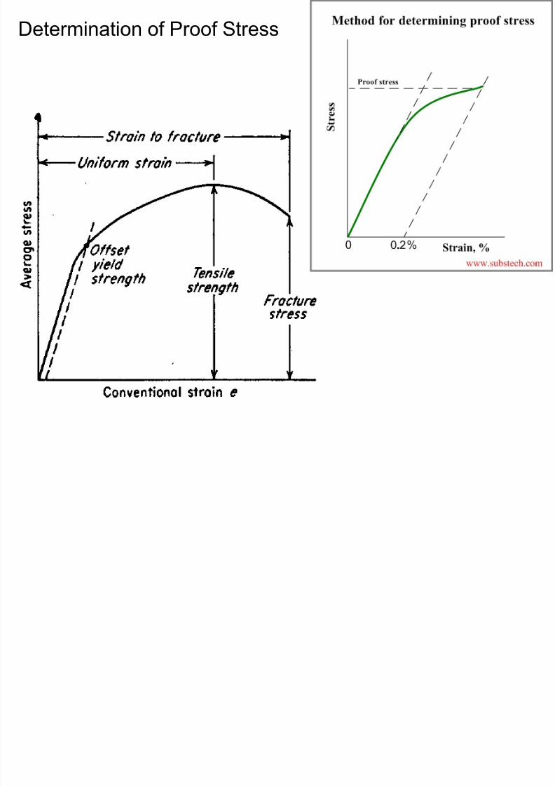
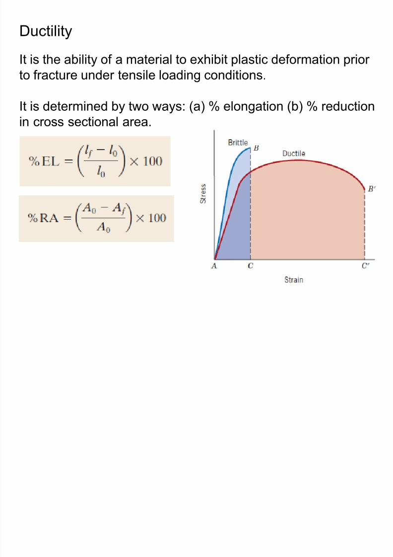
Ductility
It is the ability of a material to exhibit plastic deformation prior
to fracture under tensile loading conditions.
8/10/2019 MT-201B MATERIAL SCIENCE NEW - Copy.ppt
http://slidepdf.com/reader/full/mt-201b-material-science-new-copyppt 218/295
to actu e u de te s e oad g co d t o s
It is determined by two ways: (a) % elongation (b) % reduction
in cross sectional area.
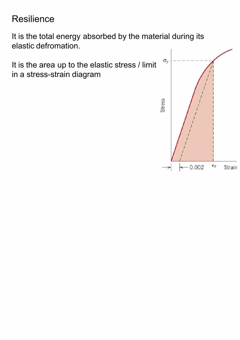
Resilience
It is the total energy absorbed by the material during its
elastic defromation.
8/10/2019 MT-201B MATERIAL SCIENCE NEW - Copy.ppt
http://slidepdf.com/reader/full/mt-201b-material-science-new-copyppt 219/295
It is the area up to the elastic stress / limit
in a stress-strain diagram
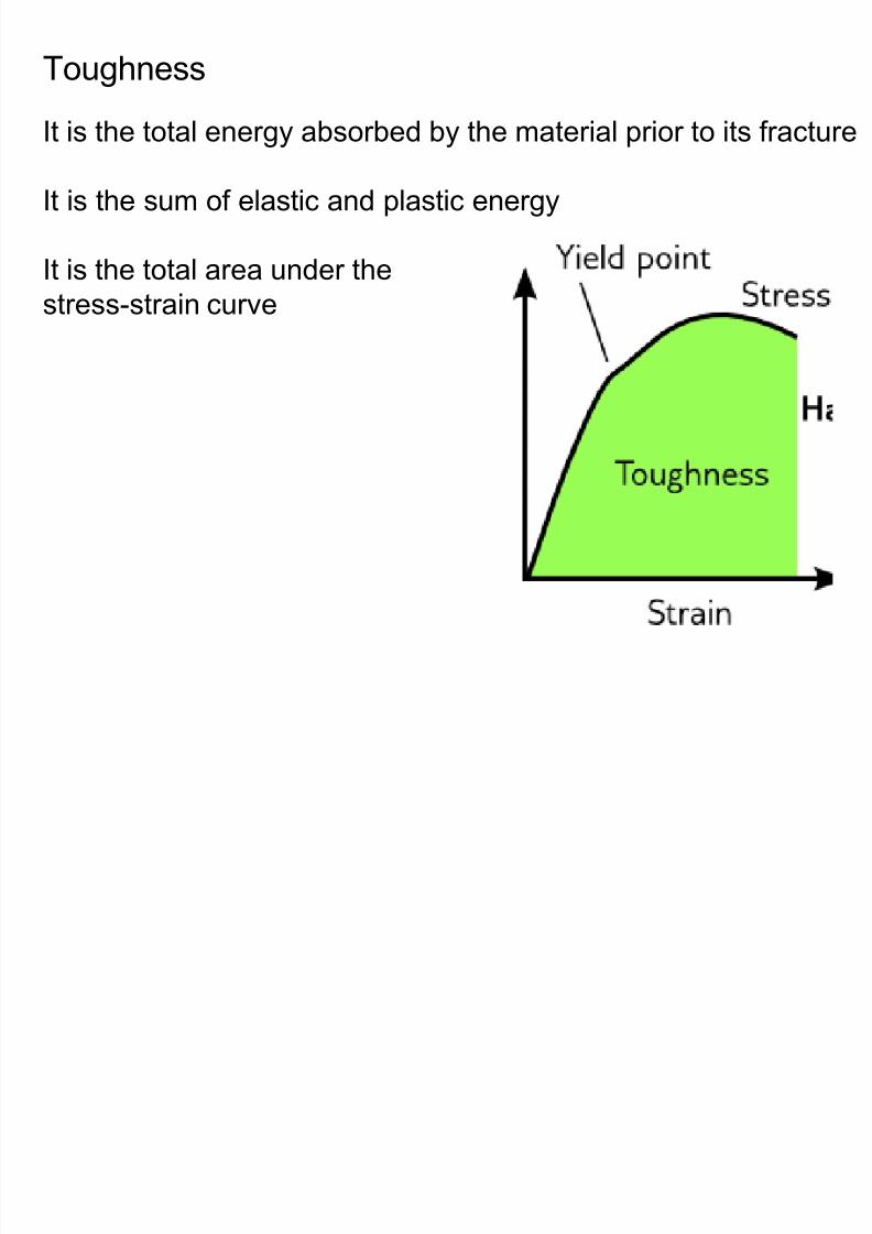
Toughness
It is the total energy absorbed by the material prior to its fracture
8/10/2019 MT-201B MATERIAL SCIENCE NEW - Copy.ppt
http://slidepdf.com/reader/full/mt-201b-material-science-new-copyppt 220/295
It is the sum of elastic and plastic energy
It is the total area under the
stress-strain curve
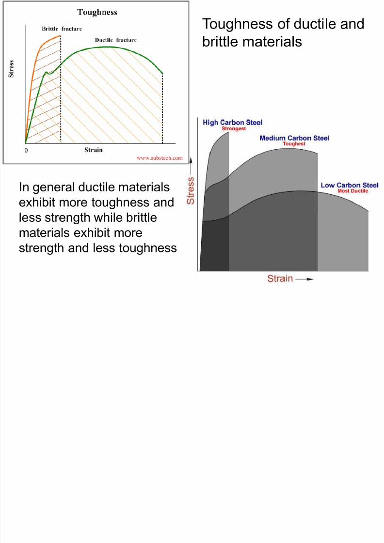
Toughness of ductile and
brittle materials
8/10/2019 MT-201B MATERIAL SCIENCE NEW - Copy.ppt
http://slidepdf.com/reader/full/mt-201b-material-science-new-copyppt 221/295
In general ductile materials
exhibit more toughness and
less strength while brittlematerials exhibit more
strength and less toughness
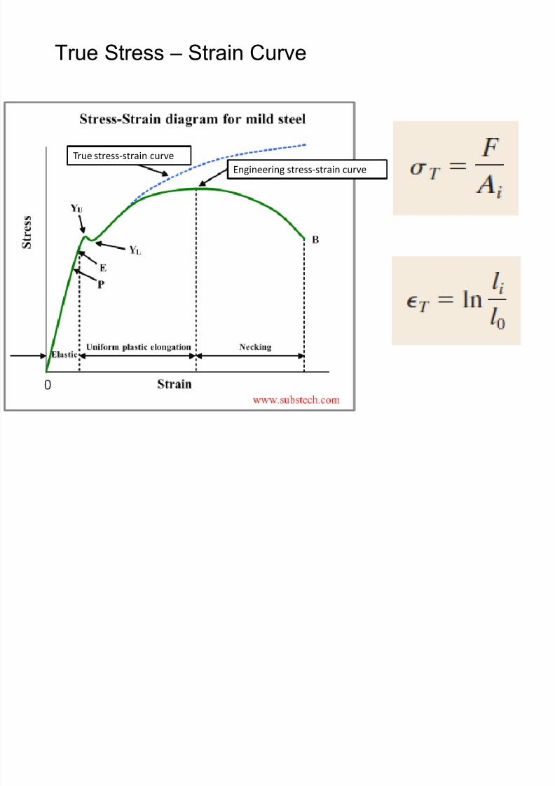
True Stress – Strain Curve
8/10/2019 MT-201B MATERIAL SCIENCE NEW - Copy.ppt
http://slidepdf.com/reader/full/mt-201b-material-science-new-copyppt 222/295
True stress-strain curve
Engineering stress-strain curve
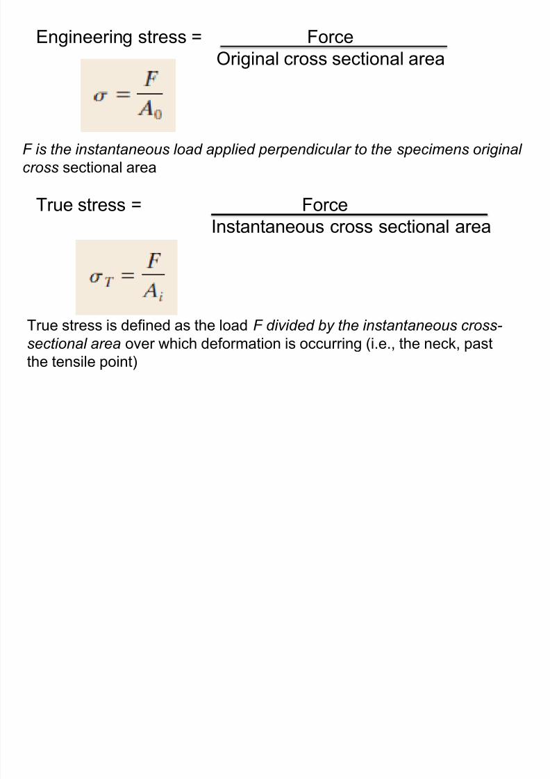
Engineering stress = Force
Original cross sectional area
8/10/2019 MT-201B MATERIAL SCIENCE NEW - Copy.ppt
http://slidepdf.com/reader/full/mt-201b-material-science-new-copyppt 223/295
F is the instantaneous load applied perpendicular to the specimens original
cross sectional area
True stress = Force
Instantaneous cross sectional area
True stress is defined as the load F divided by the instantaneous cross-
sectional area over which deformation is occurring (i.e., the neck, past
the tensile point)
8/10/2019 MT-201B MATERIAL SCIENCE NEW - Copy.ppt
http://slidepdf.com/reader/full/mt-201b-material-science-new-copyppt 224/295
Ductile and Brittle Fracture
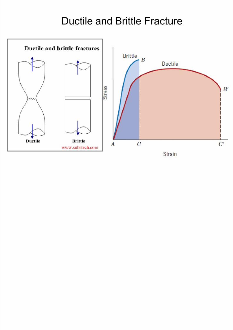
8/10/2019 MT-201B MATERIAL SCIENCE NEW - Copy.ppt
http://slidepdf.com/reader/full/mt-201b-material-science-new-copyppt 225/295
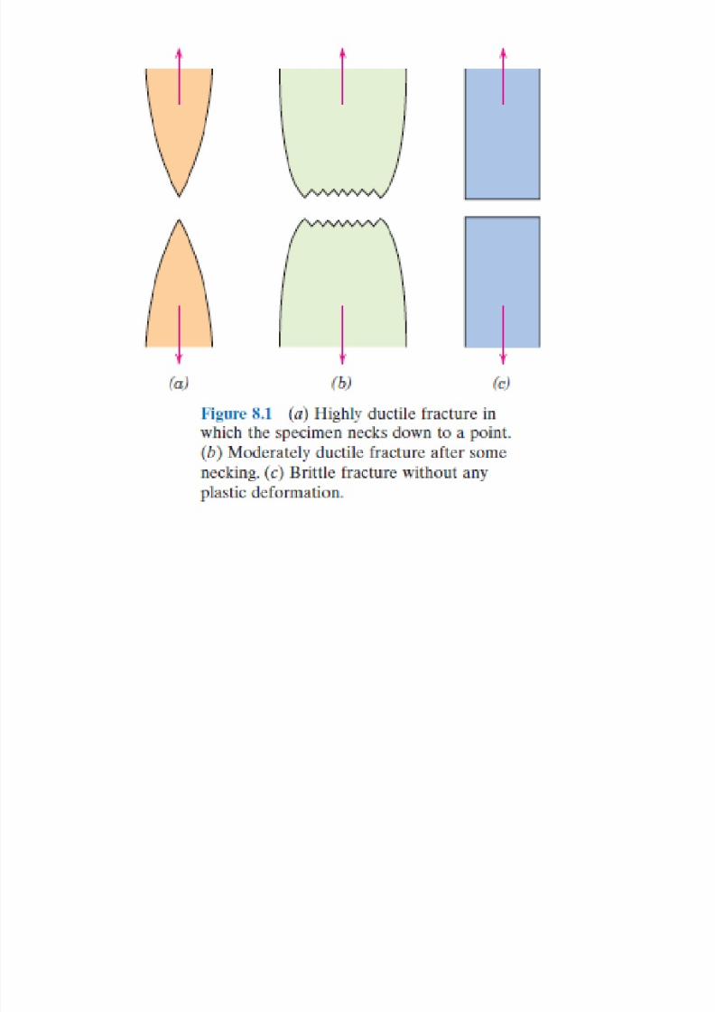
8/10/2019 MT-201B MATERIAL SCIENCE NEW - Copy.ppt
http://slidepdf.com/reader/full/mt-201b-material-science-new-copyppt 226/295
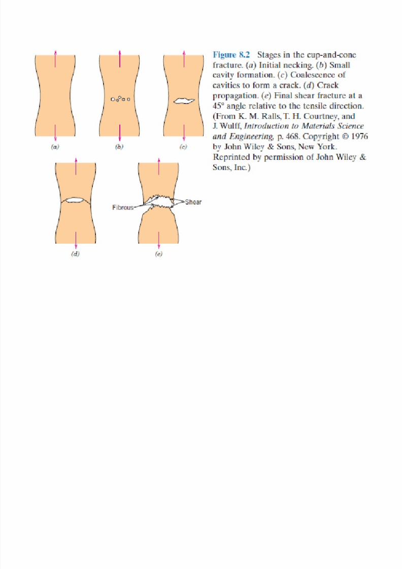
8/10/2019 MT-201B MATERIAL SCIENCE NEW - Copy.ppt
http://slidepdf.com/reader/full/mt-201b-material-science-new-copyppt 227/295
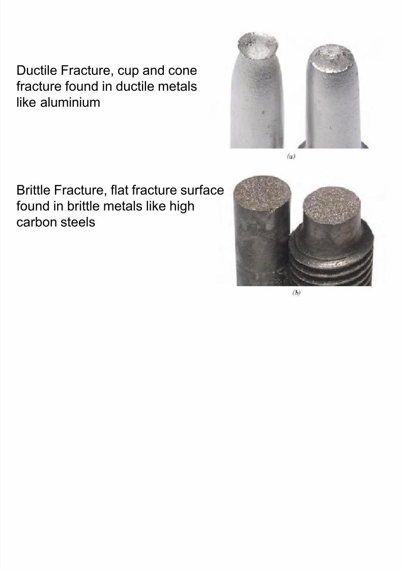
8/10/2019 MT-201B MATERIAL SCIENCE NEW - Copy.ppt
http://slidepdf.com/reader/full/mt-201b-material-science-new-copyppt 228/295
Ductile Fracture Brittle Fracture
Substantial amount of plastic
deformation prior to fracture
Takes place over a considerable
Negligible or small amount of plastic
deformation prior to fracture
Takes place instantaneously
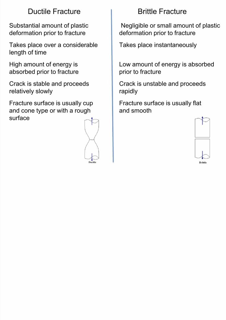
8/10/2019 MT-201B MATERIAL SCIENCE NEW - Copy.ppt
http://slidepdf.com/reader/full/mt-201b-material-science-new-copyppt 229/295
p
length of time
High amount of energy is
absorbed prior to fracture
Crack is stable and proceeds
relatively slowly
Fracture surface is usually cup
and cone type or with a rough
surface
p y
Low amount of energy is absorbed
prior to fracture
Crack is unstable and proceeds
rapidly
Fracture surface is usually flat
and smooth
Impact Test(Toughness test)
8/10/2019 MT-201B MATERIAL SCIENCE NEW - Copy.ppt
http://slidepdf.com/reader/full/mt-201b-material-science-new-copyppt 230/295
• Toughness is the ability of a material to withstand shock orimpact.
• Toughness is the total energy absorbed by a material prior
to fracture.
• Toughness is determined by the impact test.
• Toughness can also be determined by the total area under
the stress – strain diagram.
• Depending upon the standardized tests using two different
standard specimens, the Charpy and Izod impact tests
were developed and are in use.
Initial
position of
hammer
Final
position of
hammer
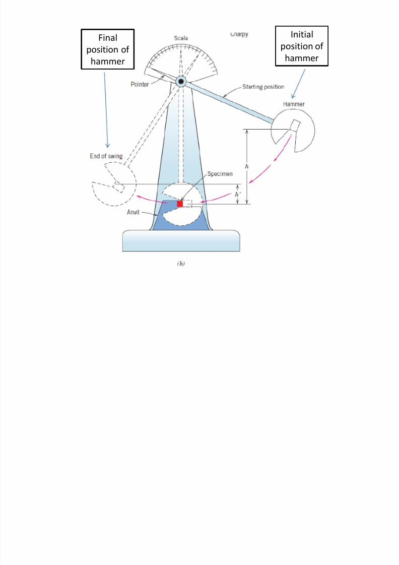
8/10/2019 MT-201B MATERIAL SCIENCE NEW - Copy.ppt
http://slidepdf.com/reader/full/mt-201b-material-science-new-copyppt 231/295
Initial energy of = Energy necessary to + Swing energy of
pendulum fracture the specimen of pendulum
mgh = toughness + mgh’
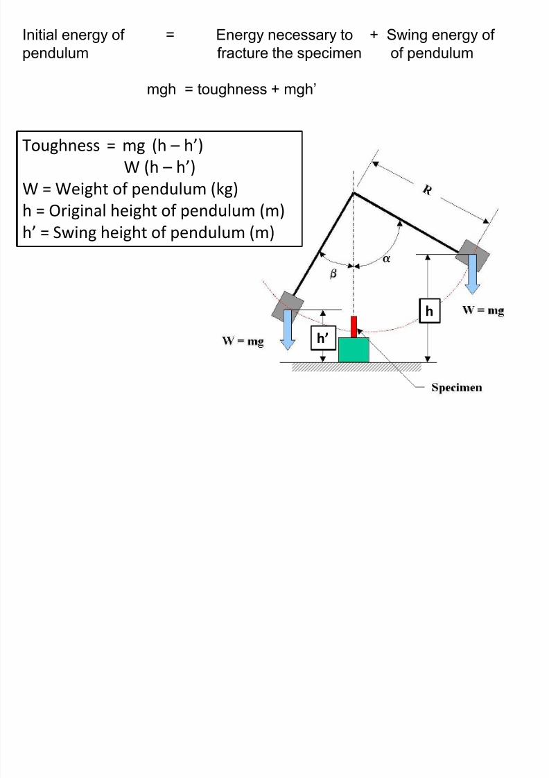
8/10/2019 MT-201B MATERIAL SCIENCE NEW - Copy.ppt
http://slidepdf.com/reader/full/mt-201b-material-science-new-copyppt 232/295
Toughness = mg (h – h’)
W (h – h’)
W = Weight of pendulum (kg)
h = Original height of pendulum (m)h’ = Swing height of pendulum (m)
h
h’
Charpy Specimen
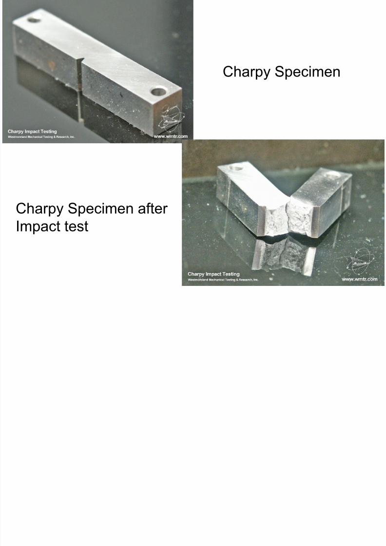
8/10/2019 MT-201B MATERIAL SCIENCE NEW - Copy.ppt
http://slidepdf.com/reader/full/mt-201b-material-science-new-copyppt 233/295
Charpy Specimen after
Impact test
Charpy specimen
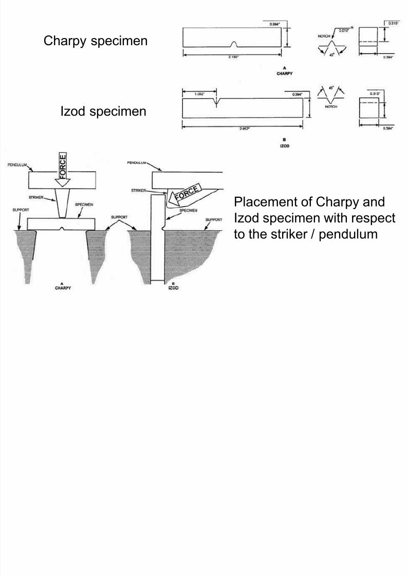
8/10/2019 MT-201B MATERIAL SCIENCE NEW - Copy.ppt
http://slidepdf.com/reader/full/mt-201b-material-science-new-copyppt 234/295
Izod specimen
Placement of Charpy and
Izod specimen with respect
to the striker / pendulum
Ductile to Brittle Transition
The transition from ductile to brittle behavior with decrease in
temperature exhibited by metals is know as the ductile to
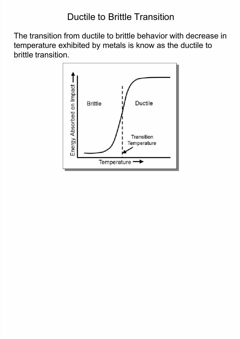
8/10/2019 MT-201B MATERIAL SCIENCE NEW - Copy.ppt
http://slidepdf.com/reader/full/mt-201b-material-science-new-copyppt 235/295
brittle transition.
• Not all metals / alloys display a ductile to brittle transition. Those
having FCC crystal structure (like aluminium and copper) remain
ductile even at extremely low temperature. However BCC and HCP
metals experience this transition.
8/10/2019 MT-201B MATERIAL SCIENCE NEW - Copy.ppt
http://slidepdf.com/reader/full/mt-201b-material-science-new-copyppt 236/295
• In plain carbon steels the transition temperature increases with
the Increase in the carbon content
• Alloying elements like Ni and Mn effectively lower the transition
temperature while phosphorus lowers the transition temperaturein steels
• Ductile to brittle transition temperature depends on crystal
structure, grain size, alloying elements, impurities, strain hardening
rate and microstructure
• Most ceramics and polymers also experience a ductile to brittle
transition.
Effect of carbon content on the ductile-to-brittle transition
temperature / temperature range in plan carbon steels
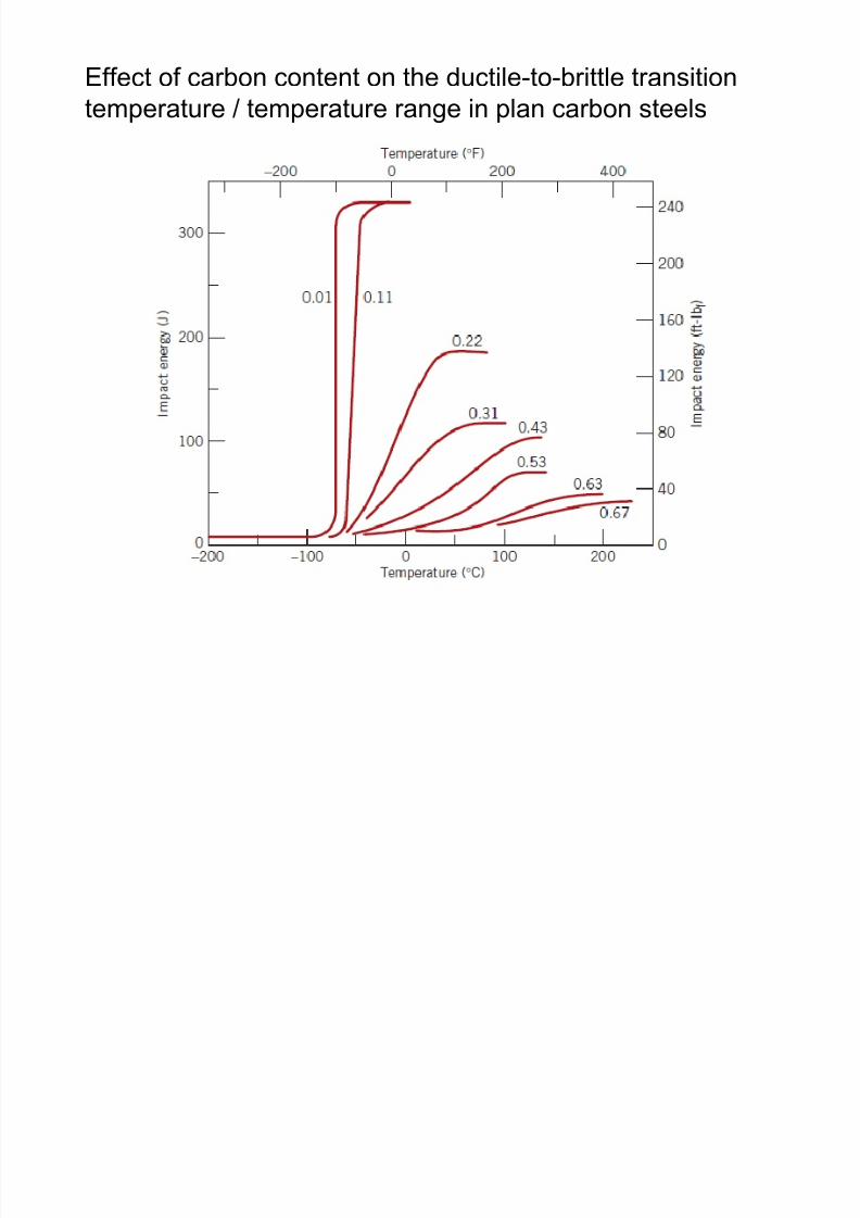
8/10/2019 MT-201B MATERIAL SCIENCE NEW - Copy.ppt
http://slidepdf.com/reader/full/mt-201b-material-science-new-copyppt 237/295
Temperatures at which impact test was carried out in oC
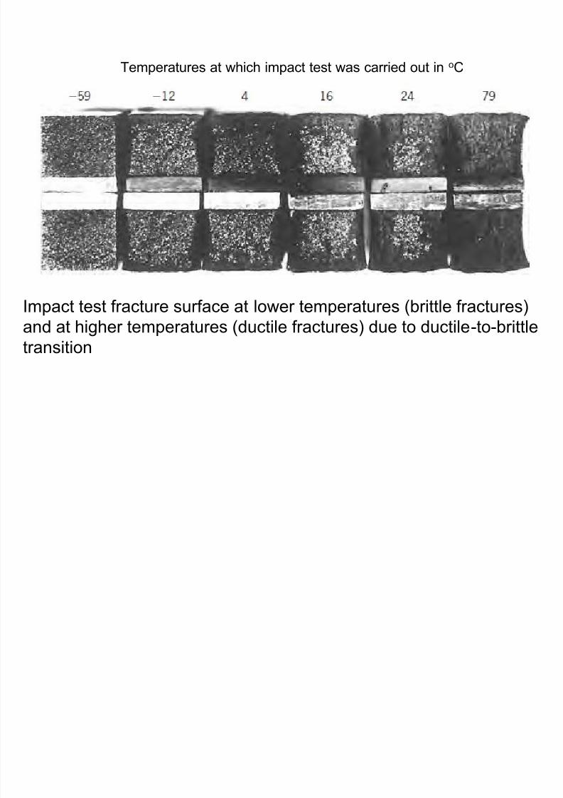
8/10/2019 MT-201B MATERIAL SCIENCE NEW - Copy.ppt
http://slidepdf.com/reader/full/mt-201b-material-science-new-copyppt 238/295
Impact test fracture surface at lower temperatures (brittle fractures)
and at higher temperatures (ductile fractures) due to ductile-to-brittletransition
Design Strategy for Toughness:
Stay Above The Ductile to Brittle Transition Temperature!
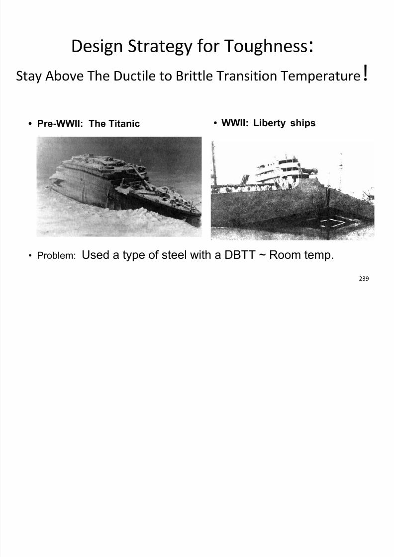
8/10/2019 MT-201B MATERIAL SCIENCE NEW - Copy.ppt
http://slidepdf.com/reader/full/mt-201b-material-science-new-copyppt 239/295
239
• Pre-WWII: The Titanic • WWII: Liberty ships
• Problem: Used a type of steel with a DBTT ~ Room temp.
Fatigue Test
Fatigue is a form of failure that occurs in components / structures
8/10/2019 MT-201B MATERIAL SCIENCE NEW - Copy.ppt
http://slidepdf.com/reader/full/mt-201b-material-science-new-copyppt 240/295
Subjected to dynamic and cyclic stresses.
Under these circumstances it is possible for failure to occur at a
stress level considerably lower than the tensile or yield strength
for a static load.
The term “fatigue” is used because this type of failure normally
occurs after a lengthy period of repeated stress or strain cycling.
It comprises of approximately 90% of all metallic failures
Alternate tensile and compressive stresses developed in a
rotating shaft leading to fatigue failure
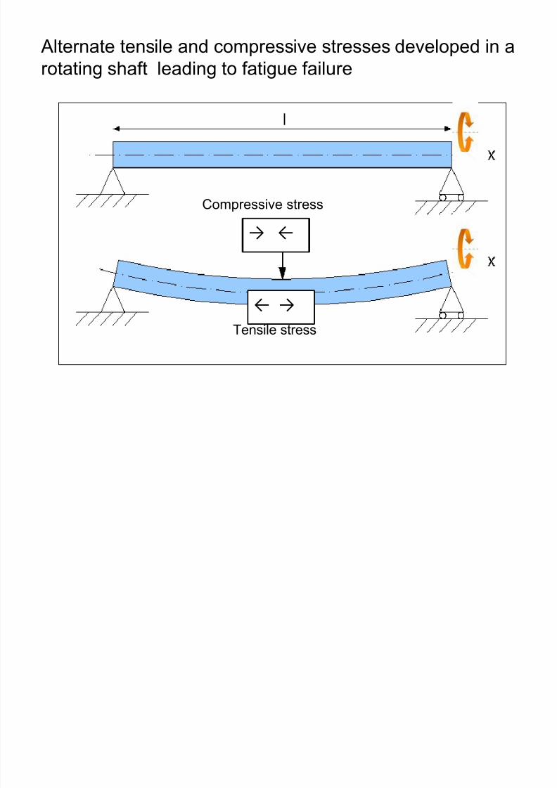
8/10/2019 MT-201B MATERIAL SCIENCE NEW - Copy.ppt
http://slidepdf.com/reader/full/mt-201b-material-science-new-copyppt 241/295
→ ←
Compressive stress
← →
Tensile stress
Variation of stress with time that accounts for fatigue failures
Reversed stress cycle, in which the
stress alternates from a maximum
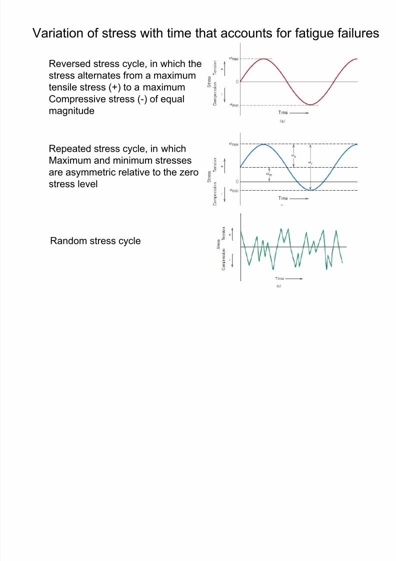
8/10/2019 MT-201B MATERIAL SCIENCE NEW - Copy.ppt
http://slidepdf.com/reader/full/mt-201b-material-science-new-copyppt 242/295
tensile stress (+) to a maximumCompressive stress (-) of equal
magnitude
Repeated stress cycle, in which
Maximum and minimum stressesare asymmetric relative to the zero
stress level
Random stress cycle
Fatigue Testing Apparatus
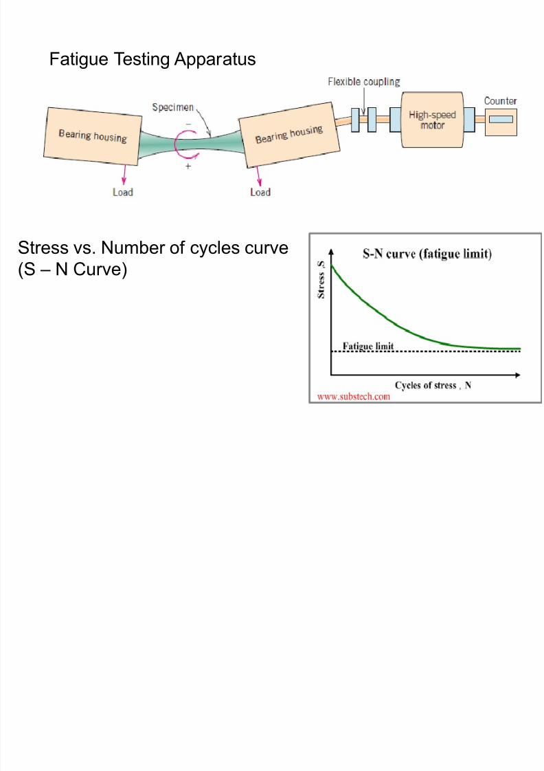
8/10/2019 MT-201B MATERIAL SCIENCE NEW - Copy.ppt
http://slidepdf.com/reader/full/mt-201b-material-science-new-copyppt 243/295
Stress vs. Number of cycles curve
(S – N Curve)
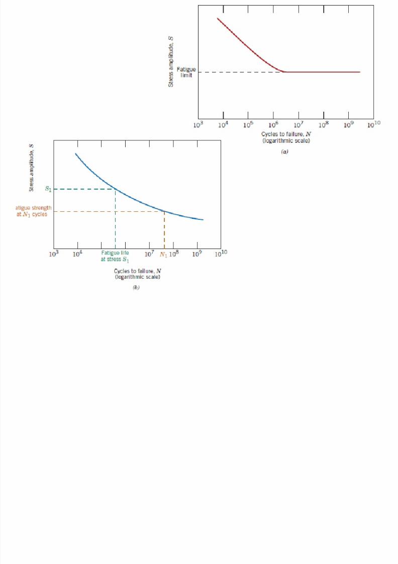
8/10/2019 MT-201B MATERIAL SCIENCE NEW - Copy.ppt
http://slidepdf.com/reader/full/mt-201b-material-science-new-copyppt 244/295
Fatigue Fracture
Fatigue failure is brittle like in nature even in normally ductile metals
i.e. associated with very little plastic deformation
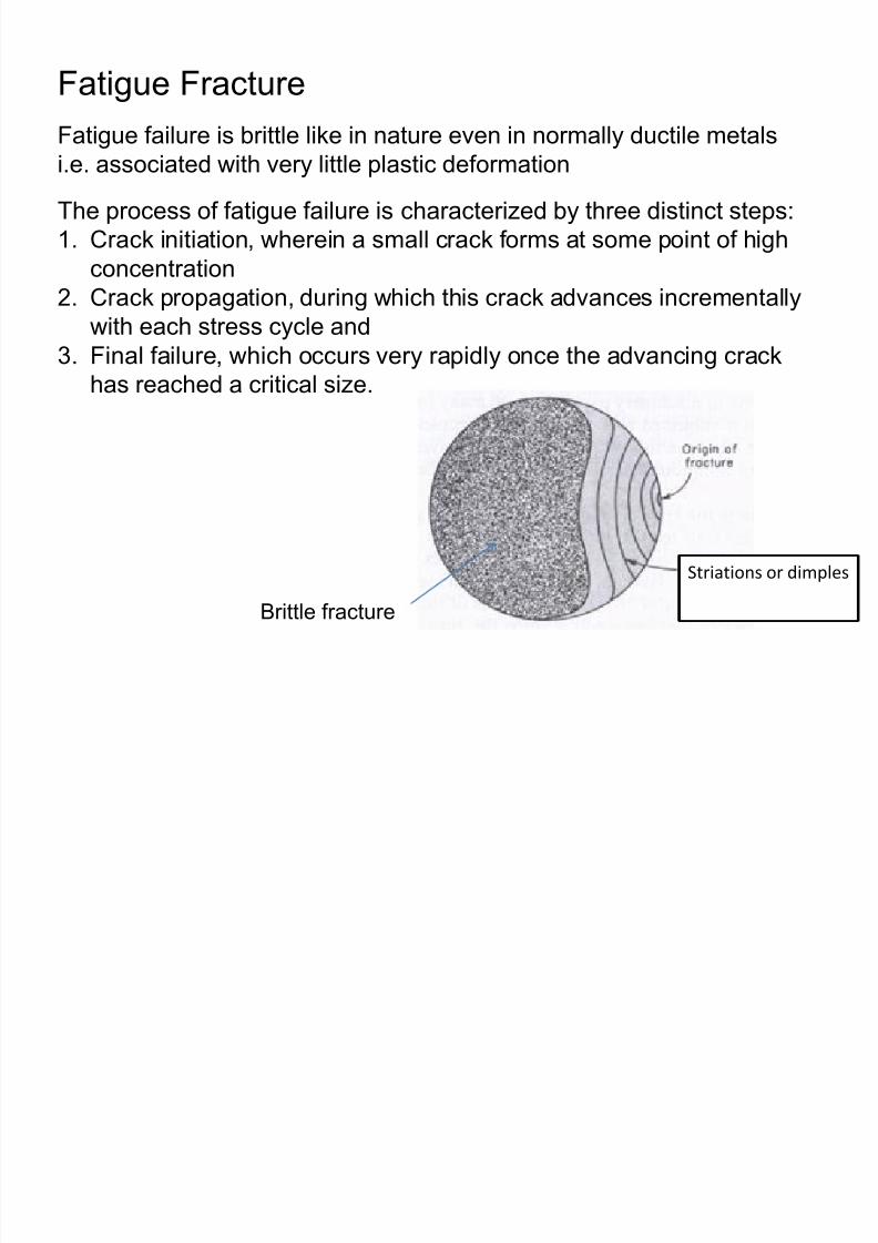
8/10/2019 MT-201B MATERIAL SCIENCE NEW - Copy.ppt
http://slidepdf.com/reader/full/mt-201b-material-science-new-copyppt 245/295
Striations or dimples
Brittle fracture
The process of fatigue failure is characterized by three distinct steps:
1. Crack initiation, wherein a small crack forms at some point of high
concentration
2. Crack propagation, during which this crack advances incrementally
with each stress cycle and
3. Final failure, which occurs very rapidly once the advancing crackhas reached a critical size.
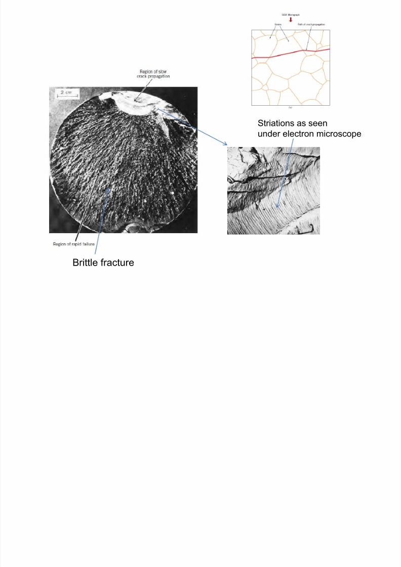
8/10/2019 MT-201B MATERIAL SCIENCE NEW - Copy.ppt
http://slidepdf.com/reader/full/mt-201b-material-science-new-copyppt 246/295
Striations as seen
under electron microscope
Brittle fracture
1. Impose a compressive surface stress
(t f k f i )
Improving Fatigue life Small, hard
particles (shot) having diamet
at high velocities onto the surf
compressive stresses to a de
diameter. The influence of sho
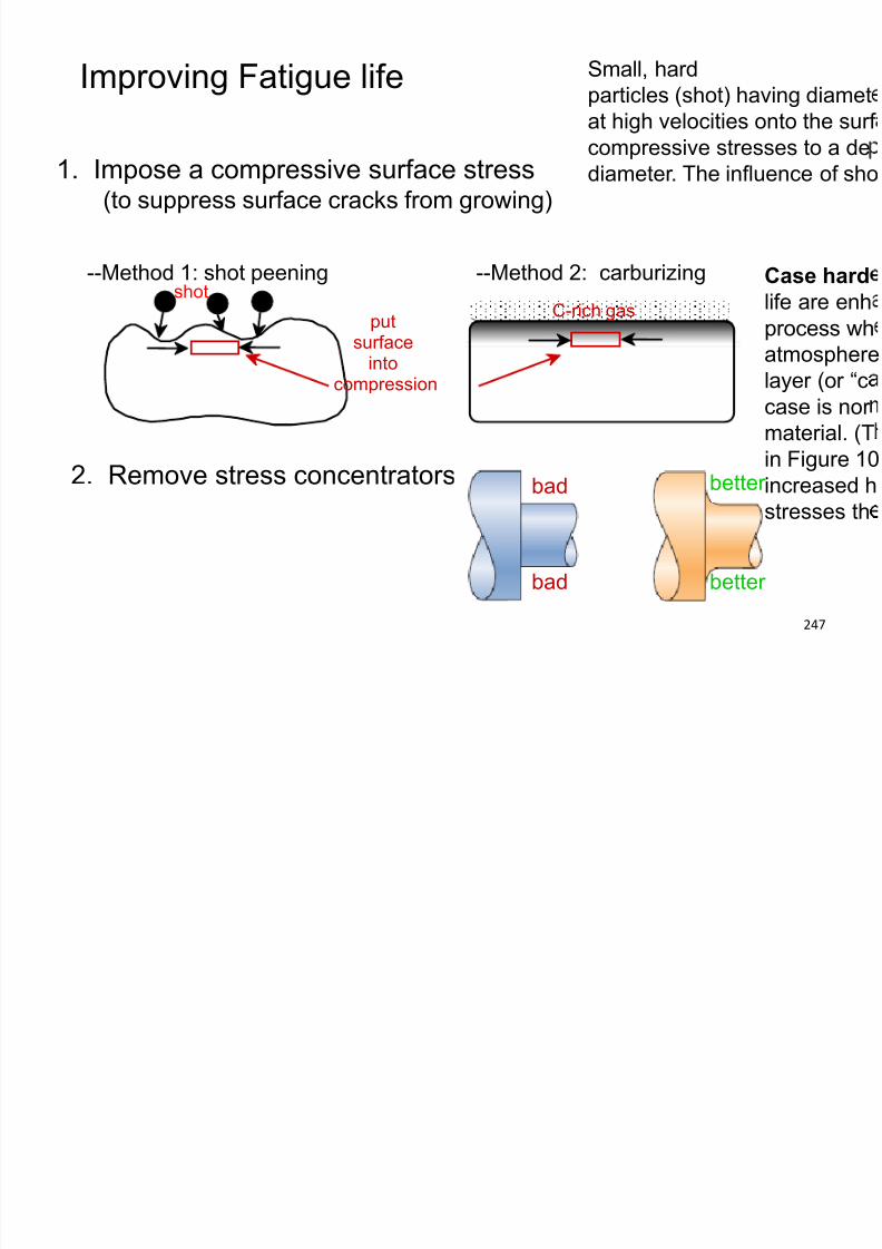
8/10/2019 MT-201B MATERIAL SCIENCE NEW - Copy.ppt
http://slidepdf.com/reader/full/mt-201b-material-science-new-copyppt 247/295
247
(to suppress surface cracks from growing)
--Method 1: shot peening
putsurface
intocompression
shot --Method 2: carburizing
C-rich gas
2. Remove stress concentrators. bad
bad
better
better
Case hard
life are enh
process wh
atmospherelayer (or “c
case is nor
material. (T
in Figure 10
increased h
stresses th
Creep Test
Creep is the slow and progressive deformation of a material
ith ti d t t t t t t i t l

8/10/2019 MT-201B MATERIAL SCIENCE NEW - Copy.ppt
http://slidepdf.com/reader/full/mt-201b-material-science-new-copyppt 248/295
with time under a constant stress at temperatures approximatelyabove 0.4 Tm (where Tm is the melting point of the metal or alloy
in degrees Kelvin)
Creep strength of a material is the highest stress that a materialcan withstand for a specified length of time without exceeding
the specified deformation at a given tempearture.
Creep is a thermally activated process and hence is a function
of temperature and time.
The Creep Test
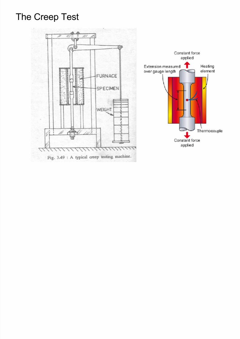
8/10/2019 MT-201B MATERIAL SCIENCE NEW - Copy.ppt
http://slidepdf.com/reader/full/mt-201b-material-science-new-copyppt 249/295
The Creep Curve
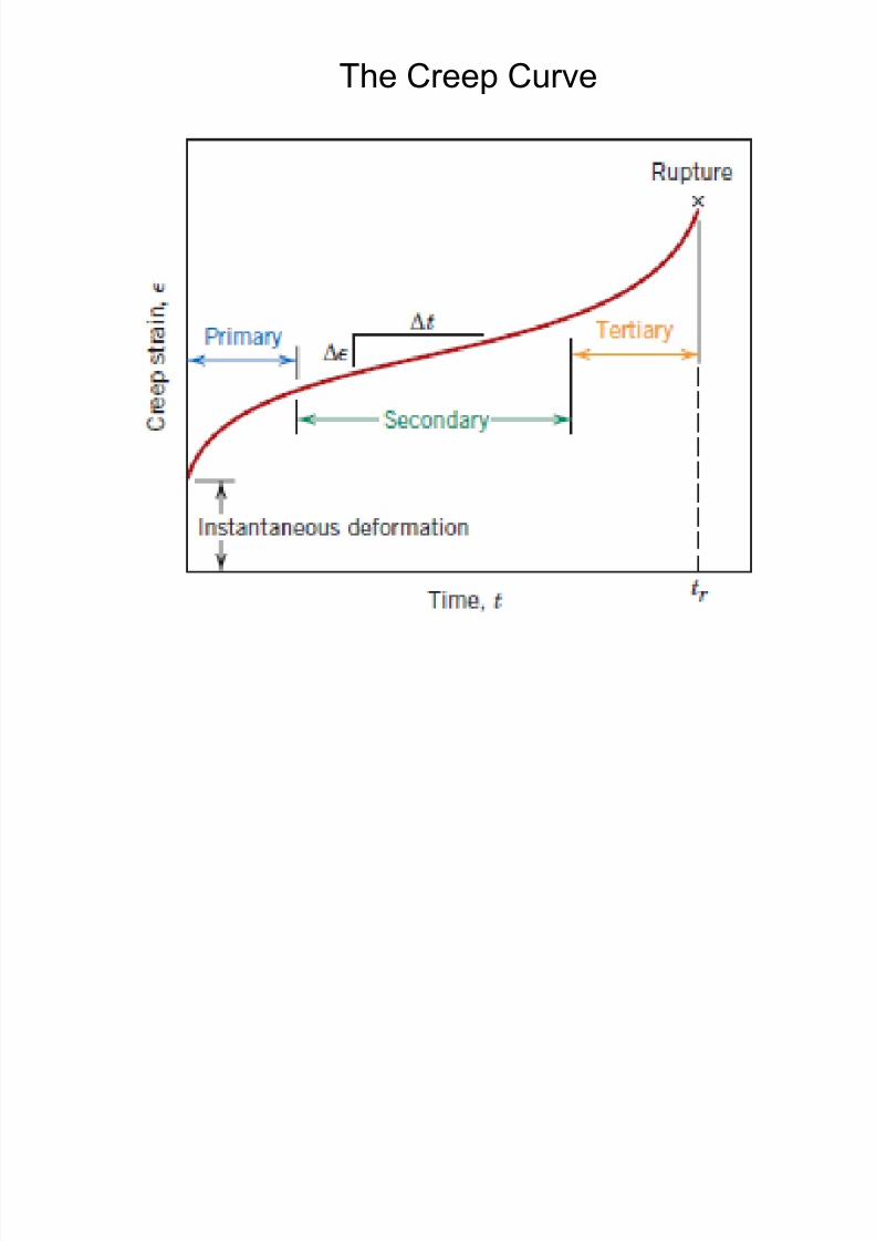
8/10/2019 MT-201B MATERIAL SCIENCE NEW - Copy.ppt
http://slidepdf.com/reader/full/mt-201b-material-science-new-copyppt 250/295
Effect of temperature on creep curves at constant stress
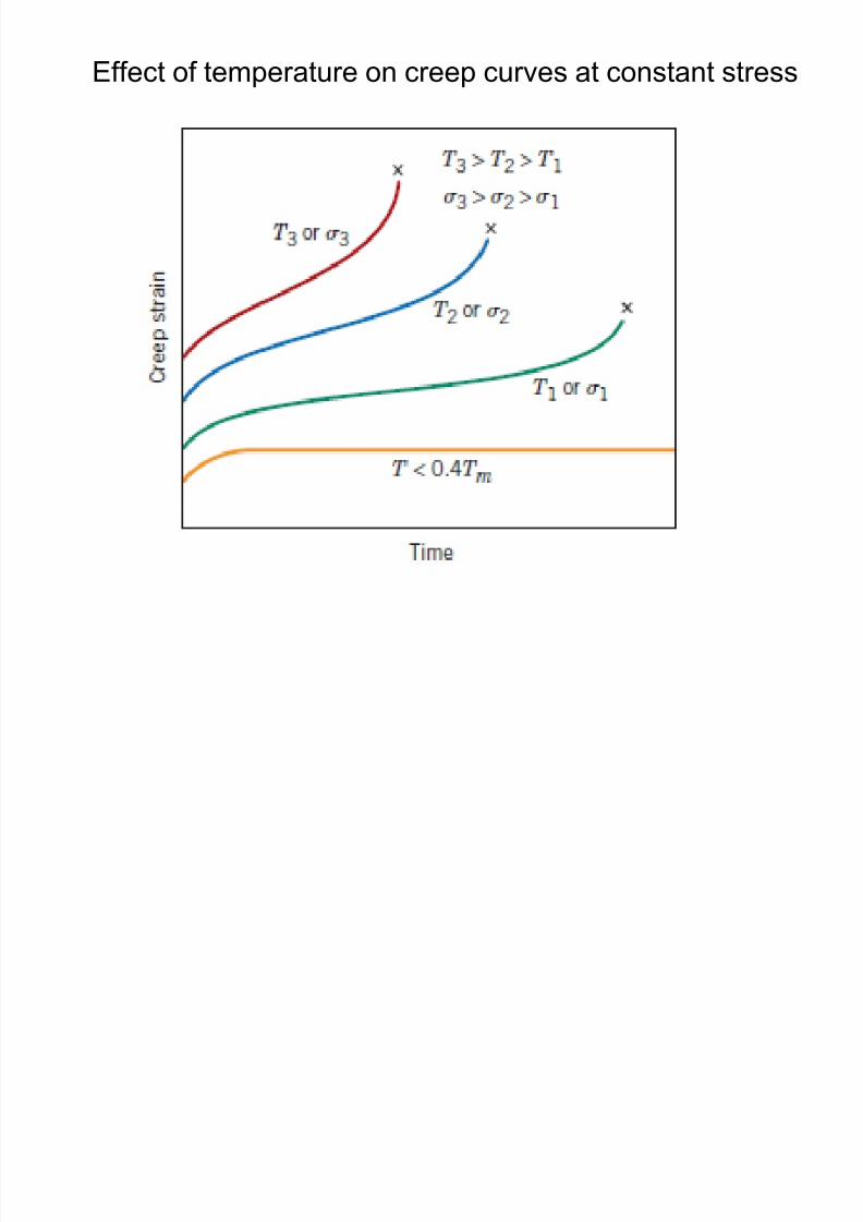
8/10/2019 MT-201B MATERIAL SCIENCE NEW - Copy.ppt
http://slidepdf.com/reader/full/mt-201b-material-science-new-copyppt 251/295
Creep Fracture
At low temperature grain boundaries are stronger than the grains and at
high temperatures grains are stronger than grain boundary.
The temperat re at hich the strength of the grain bo ndar is eq al to
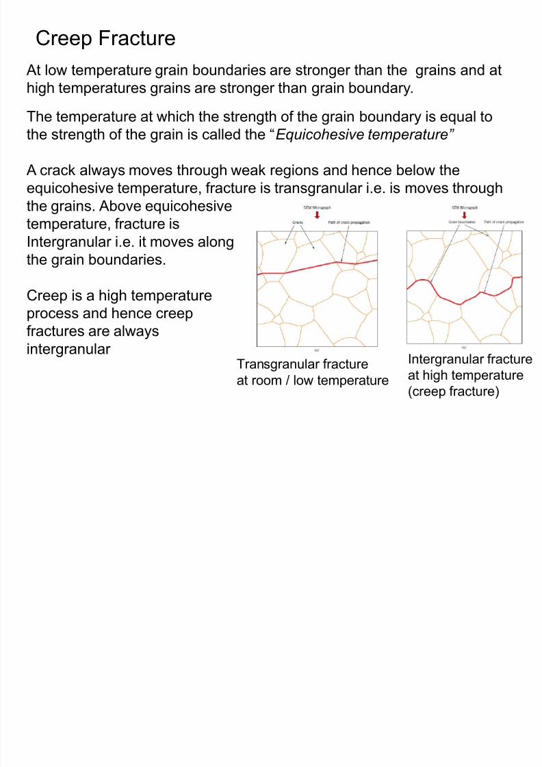
8/10/2019 MT-201B MATERIAL SCIENCE NEW - Copy.ppt
http://slidepdf.com/reader/full/mt-201b-material-science-new-copyppt 252/295
Transgranular fracture
at room / low temperature
Intergranular fracture
at high temperature
(creep fracture)
The temperature at which the strength of the grain boundary is equal tothe strength of the grain is called the “Equicohesive temperature”
A crack always moves through weak regions and hence below the
equicohesive temperature, fracture is transgranular i.e. is moves through
the grains. Above equicohesive
temperature, fracture is
Intergranular i.e. it moves along
the grain boundaries.
Creep is a high temperature
process and hence creepfractures are always
intergranular
Intergranular Creep Fracture
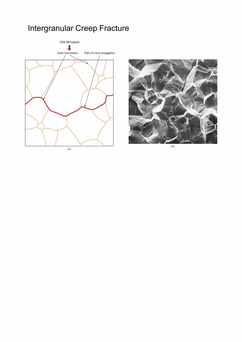
8/10/2019 MT-201B MATERIAL SCIENCE NEW - Copy.ppt
http://slidepdf.com/reader/full/mt-201b-material-science-new-copyppt 253/295
Material consideration for high temperature use
(for high creep strength)
8/10/2019 MT-201B MATERIAL SCIENCE NEW - Copy.ppt
http://slidepdf.com/reader/full/mt-201b-material-science-new-copyppt 254/295
• It should have a high melting point
• It should have coarse grained structure
• It should have high oxidation resistance
• Dispersion strengthening improves creep resistance

8/10/2019 MT-201B MATERIAL SCIENCE NEW - Copy.ppt
http://slidepdf.com/reader/full/mt-201b-material-science-new-copyppt 255/295
Heat Treatments
Eutectoid Reaction:
Solid1 ↔ Solid2 + Solid3
Equilibrium and Non-Equilibrium Cooling
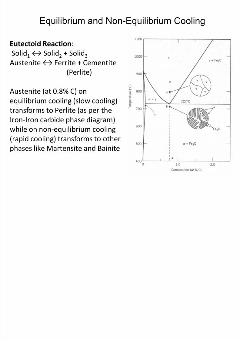
8/10/2019 MT-201B MATERIAL SCIENCE NEW - Copy.ppt
http://slidepdf.com/reader/full/mt-201b-material-science-new-copyppt 256/295
Solid1 ↔ Solid2 + Solid3
Austenite ↔ Ferrite + Cementite
(Perlite)
Austenite (at 0.8% C) on
equilibrium cooling (slow cooling)
transforms to Perlite (as per the
Iron-Iron carbide phase diagram)
while on non-equilibrium cooling
(rapid cooling) transforms to otherphases like Martensite and Bainite
Slow Cooling
Interrupted Cooling
Perlite
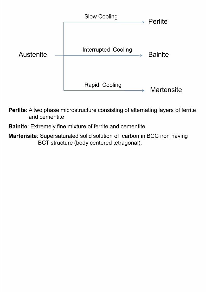
8/10/2019 MT-201B MATERIAL SCIENCE NEW - Copy.ppt
http://slidepdf.com/reader/full/mt-201b-material-science-new-copyppt 257/295
Austenite
Rapid Cooling
Interrupted CoolingBainite
Martensite
Perlite: A two phase microstructure consisting of alternating layers of ferrite
and cementiteBainite: Extremely fine mixture of ferrite and cementite
Martensite: Supersaturated solid solution of carbon in BCC iron having
BCT structure (body centered tetragonal).
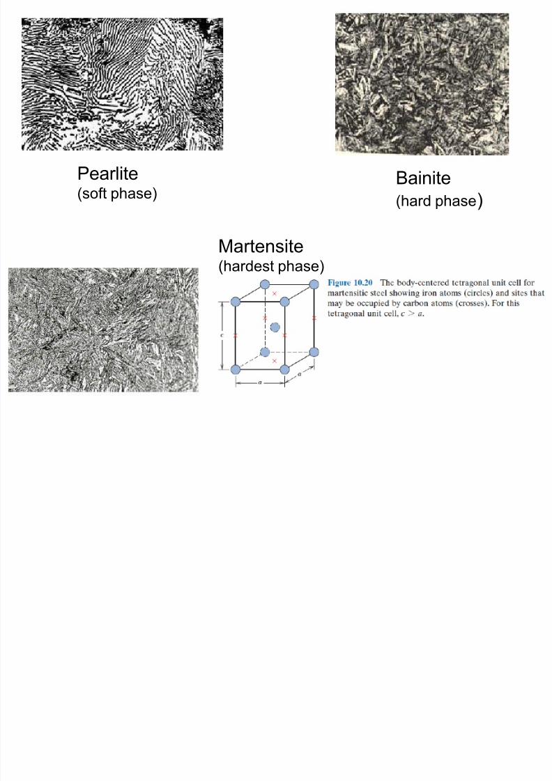
8/10/2019 MT-201B MATERIAL SCIENCE NEW - Copy.ppt
http://slidepdf.com/reader/full/mt-201b-material-science-new-copyppt 258/295
Pearlite(soft phase)
Bainite
(hard phase)
Martensite(hardest phase)
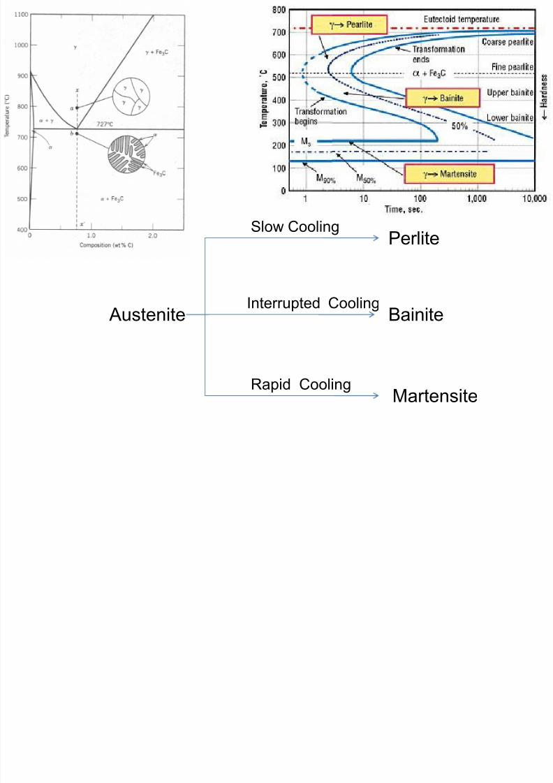
8/10/2019 MT-201B MATERIAL SCIENCE NEW - Copy.ppt
http://slidepdf.com/reader/full/mt-201b-material-science-new-copyppt 259/295
Austenite
Slow Cooling
Rapid Cooling
Interrupted Cooling
Perlite
Bainite
Martensite
Time Temperature Transformation (TTT) Diagrams
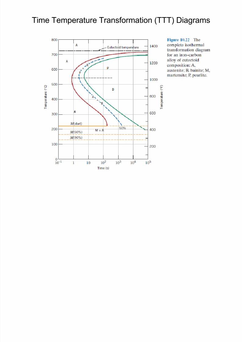
8/10/2019 MT-201B MATERIAL SCIENCE NEW - Copy.ppt
http://slidepdf.com/reader/full/mt-201b-material-science-new-copyppt 260/295
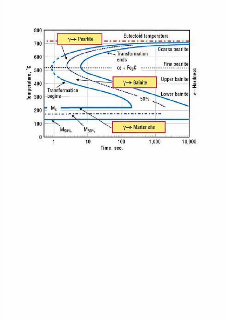
8/10/2019 MT-201B MATERIAL SCIENCE NEW - Copy.ppt
http://slidepdf.com/reader/full/mt-201b-material-science-new-copyppt 261/295
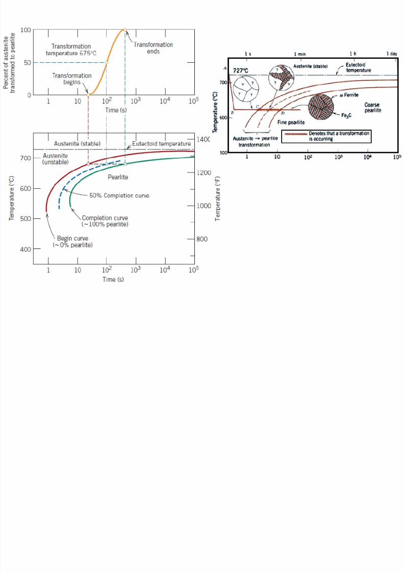
8/10/2019 MT-201B MATERIAL SCIENCE NEW - Copy.ppt
http://slidepdf.com/reader/full/mt-201b-material-science-new-copyppt 262/295
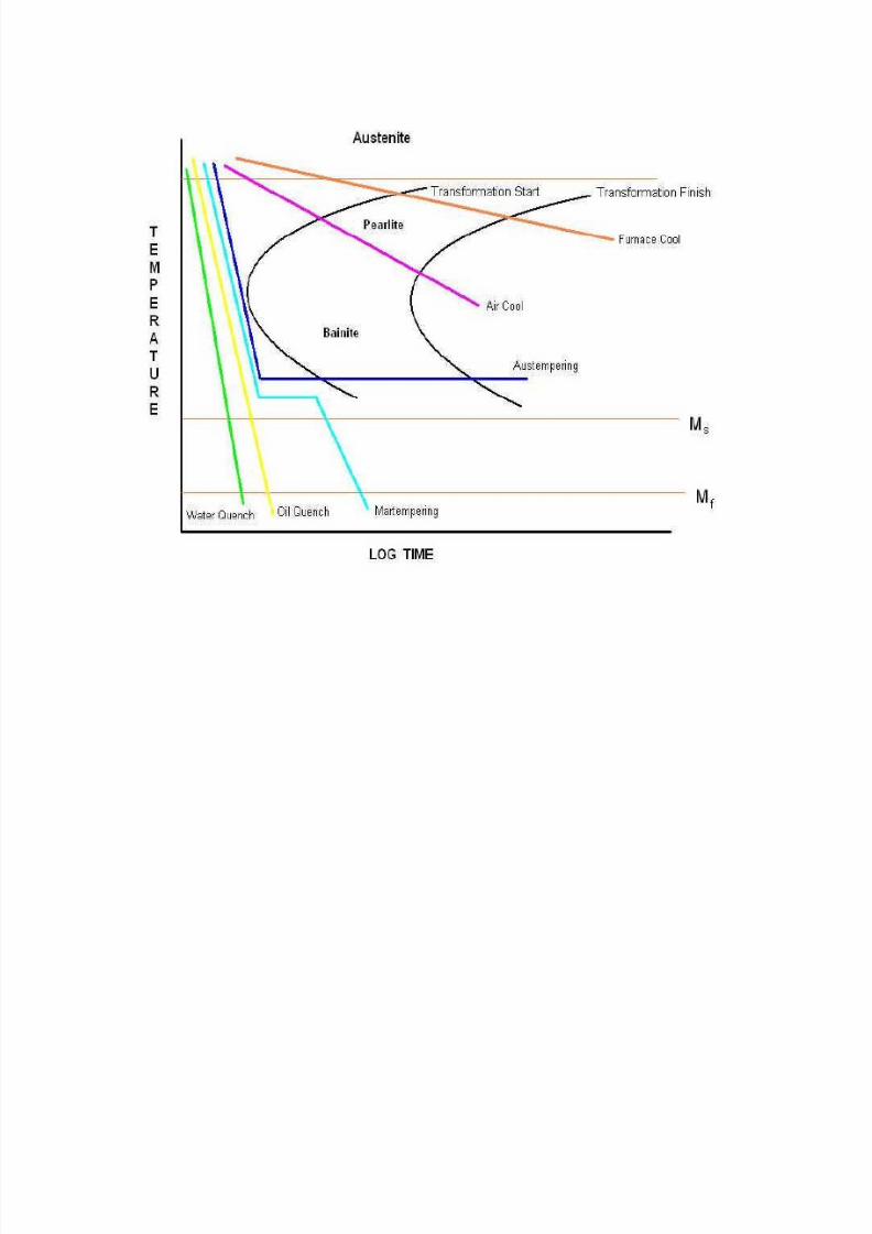
8/10/2019 MT-201B MATERIAL SCIENCE NEW - Copy.ppt
http://slidepdf.com/reader/full/mt-201b-material-science-new-copyppt 263/295
TTT curves of hypoeutectoid and hypereutectoid steels
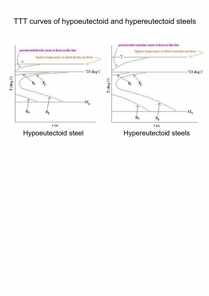
8/10/2019 MT-201B MATERIAL SCIENCE NEW - Copy.ppt
http://slidepdf.com/reader/full/mt-201b-material-science-new-copyppt 264/295
Hypoeutectoid steel Hypereutectoid steels
Continuous Cooling Transformation (TTT) Diagrams
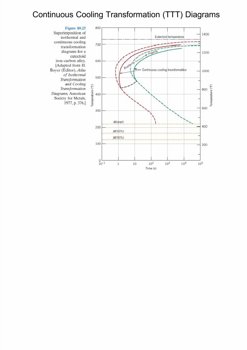
8/10/2019 MT-201B MATERIAL SCIENCE NEW - Copy.ppt
http://slidepdf.com/reader/full/mt-201b-material-science-new-copyppt 265/295
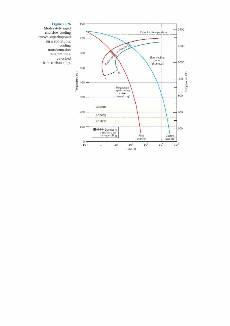
8/10/2019 MT-201B MATERIAL SCIENCE NEW - Copy.ppt
http://slidepdf.com/reader/full/mt-201b-material-science-new-copyppt 266/295
Objectives of various heat treatments:
1. To modify / adjust its mechanical, physical or chemical
properties such as hardness strength ductility electrical
8/10/2019 MT-201B MATERIAL SCIENCE NEW - Copy.ppt
http://slidepdf.com/reader/full/mt-201b-material-science-new-copyppt 267/295
properties such as hardness, strength, ductility, electrical
& magnetic properties, or corrosion resistance
2. To increase hardness, wear and abrasion resistance
3. To resoften the steel after it has been hardened by heattreatments or cold working
4. To reduce or eliminate residual stresses
5. To increase or decrease the grain size
Common Heat Treatments in Steel
8/10/2019 MT-201B MATERIAL SCIENCE NEW - Copy.ppt
http://slidepdf.com/reader/full/mt-201b-material-science-new-copyppt 268/295
1. Annealing
2. Normalizing
3. Hardening (Quenching)
4. Tempering
Annealing
Purpose of Anneling:
1 To relieve the internal stresses induced due to cold
8/10/2019 MT-201B MATERIAL SCIENCE NEW - Copy.ppt
http://slidepdf.com/reader/full/mt-201b-material-science-new-copyppt 269/295
1. To relieve the internal stresses induced due to coldworking, welding, etc.
2. To reduce hardness (i.e. to make the steel soft) and to
increase ductility
3. To increase the uniformity of phase distribution and to
make the material isotropic in respect of mechanical
properties
4. To refine the grain size5. To make the material homogeneous in respect of
chemical composition
Process of Annealing:
• The process consists of heating the steel to above A3
temperature for hypoeutectoid steels and above A1 for
hypereutectoid steels by 30-50oC holding at this
8/10/2019 MT-201B MATERIAL SCIENCE NEW - Copy.ppt
http://slidepdf.com/reader/full/mt-201b-material-science-new-copyppt 270/295
hypereutectoid steels by 30 50 C, holding at thistemperature for a definite period and slow cooling to below
A1 or room temperature usually in a furnace.
• Due to slow cooling (furnace cooling), eutectoid reaction
occurs very nearly in accordance with conditionsrepresented in the Fe-C phase diagram i.e. phase changes
follow the Fe-C phase diagram.
The Annealing (Blue region) heating temperature ranges for
hypoeutectoid and hypereutectoid steels on the Fe-C diagram
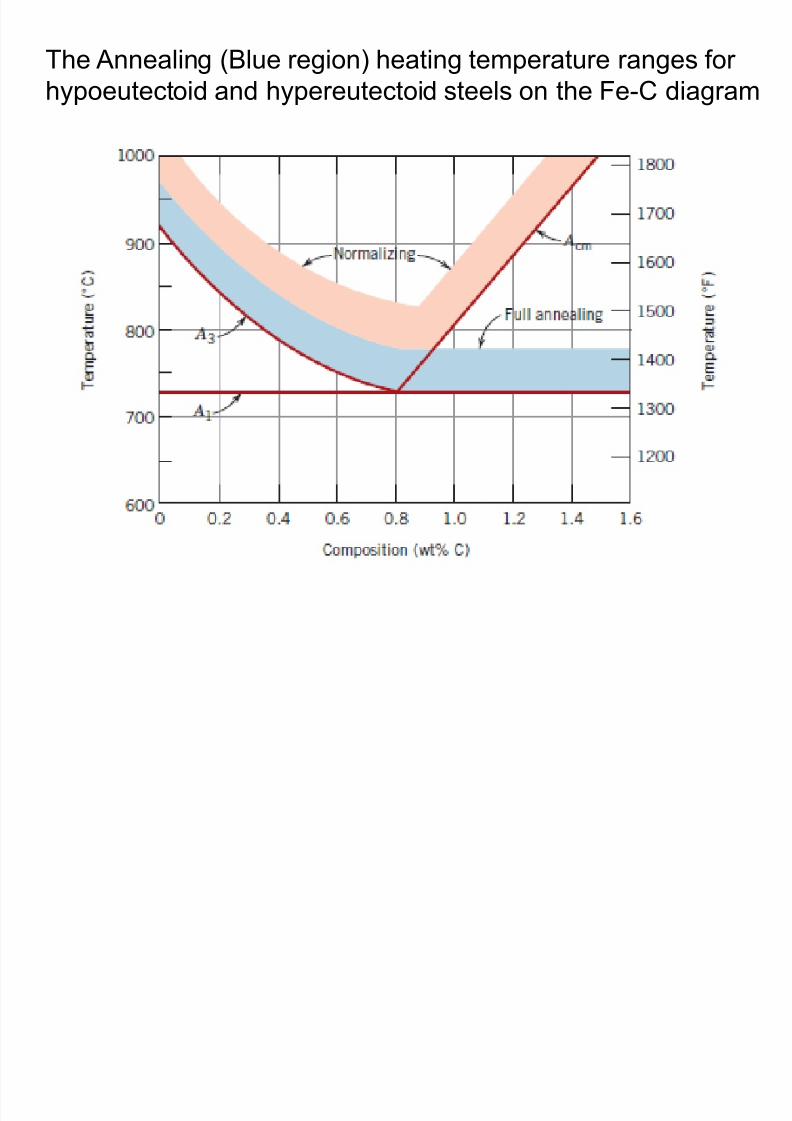
8/10/2019 MT-201B MATERIAL SCIENCE NEW - Copy.ppt
http://slidepdf.com/reader/full/mt-201b-material-science-new-copyppt 271/295
Annealing on the basis of TTT diagram
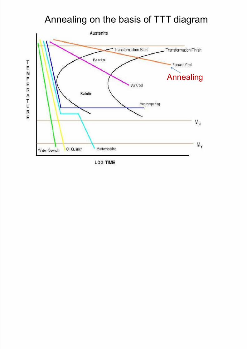
8/10/2019 MT-201B MATERIAL SCIENCE NEW - Copy.ppt
http://slidepdf.com/reader/full/mt-201b-material-science-new-copyppt 272/295
Annealing
Effect of Annealing on Cold Working
Equiaxed structure
• Cold working is the working or deformation of
a material at room temperature or below its
recrystallization temperature
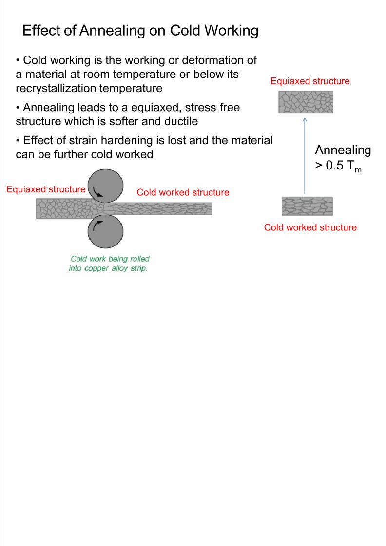
8/10/2019 MT-201B MATERIAL SCIENCE NEW - Copy.ppt
http://slidepdf.com/reader/full/mt-201b-material-science-new-copyppt 273/295
Annealing> 0.5 Tm
Cold worked structure
recrystallization temperature• Annealing leads to a equiaxed, stress free
structure which is softer and ductile
• Effect of strain hardening is lost and the material
can be further cold worked
Equiaxed structure Cold worked structure
Recovery, Recrystallization
and Grain growth occur
during Annealing
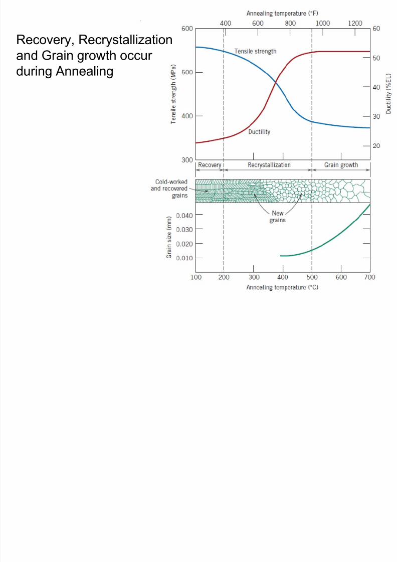
8/10/2019 MT-201B MATERIAL SCIENCE NEW - Copy.ppt
http://slidepdf.com/reader/full/mt-201b-material-science-new-copyppt 274/295
Normalising
Purpose of Annealing:
• Similar to annealing
8/10/2019 MT-201B MATERIAL SCIENCE NEW - Copy.ppt
http://slidepdf.com/reader/full/mt-201b-material-science-new-copyppt 275/295
Process of Normalizing:
• The process consists of heating the steel to above A3
temperature for hypoeutectoid steels and above Acm for
hypereutectoid steels by 30-50oC, holding at this
temperature for a definite period and slow cooling to below
A1 or room temperature usually in a furnace.
• Due to air cooling which is slightly fast as compared to
furnace cooling employed in annealing, normalised
components show slightly different structure and properties
than annealed components.
Normalising on the basis of TTT diagram
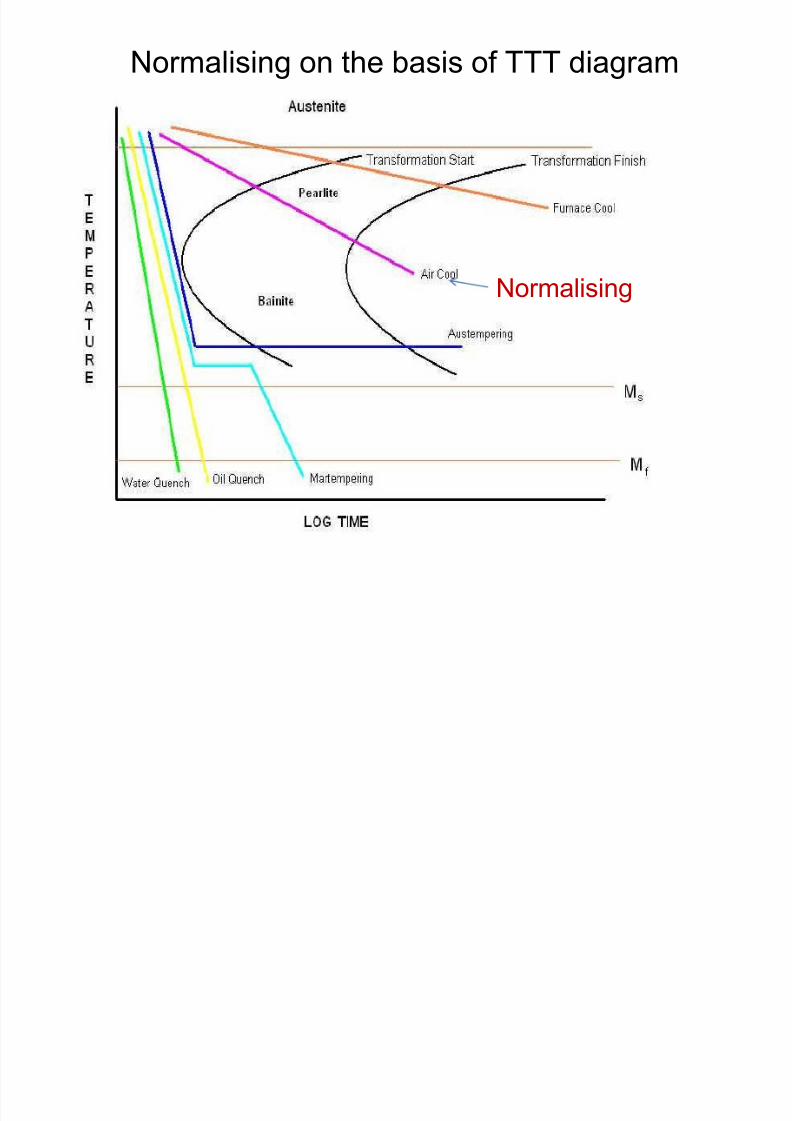
8/10/2019 MT-201B MATERIAL SCIENCE NEW - Copy.ppt
http://slidepdf.com/reader/full/mt-201b-material-science-new-copyppt 276/295
Normalising
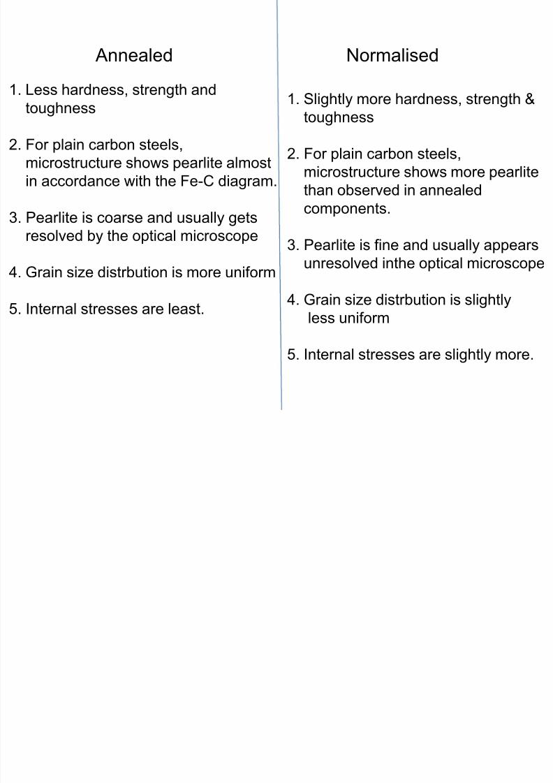
8/10/2019 MT-201B MATERIAL SCIENCE NEW - Copy.ppt
http://slidepdf.com/reader/full/mt-201b-material-science-new-copyppt 277/295
Hardening (Quenching)Purpose of Hardening:
1. To harden the steel to the maximum level by austenite to
martensite transformation.
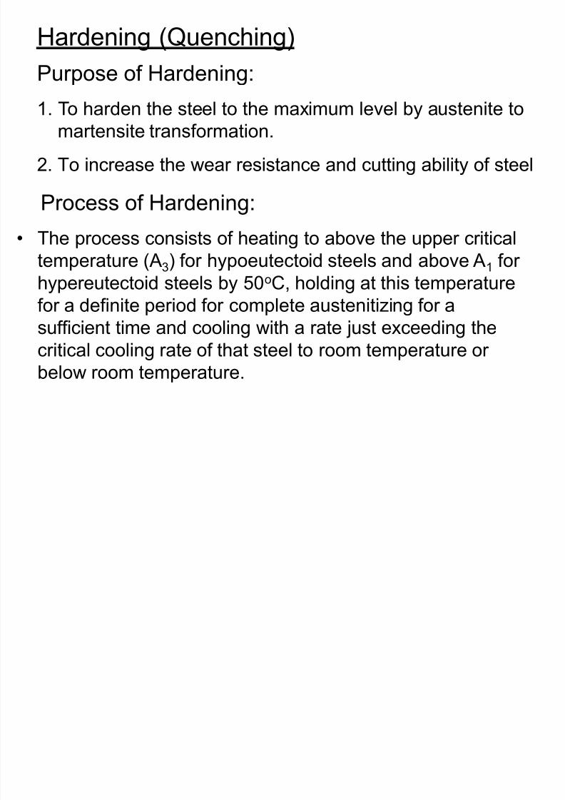
8/10/2019 MT-201B MATERIAL SCIENCE NEW - Copy.ppt
http://slidepdf.com/reader/full/mt-201b-material-science-new-copyppt 278/295
a e s e a s o a o
2. To increase the wear resistance and cutting ability of steel
Process of Hardening:
• The process consists of heating to above the upper critical
temperature (A3) for hypoeutectoid steels and above A1 for
hypereutectoid steels by 50oC, holding at this temperature
for a definite period for complete austenitizing for a
sufficient time and cooling with a rate just exceeding thecritical cooling rate of that steel to room temperature or
below room temperature.
Critical Cooling Rate (CCR)
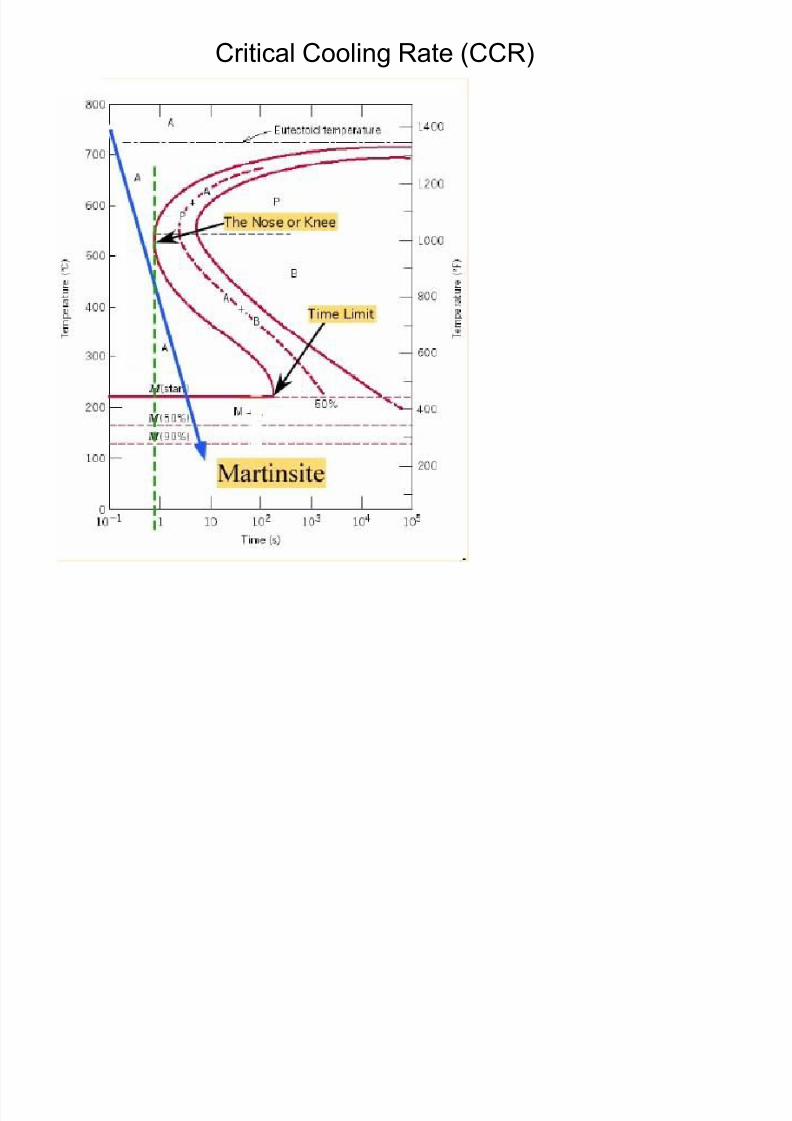
8/10/2019 MT-201B MATERIAL SCIENCE NEW - Copy.ppt
http://slidepdf.com/reader/full/mt-201b-material-science-new-copyppt 279/295
Hardening on the basis of TTT diagram
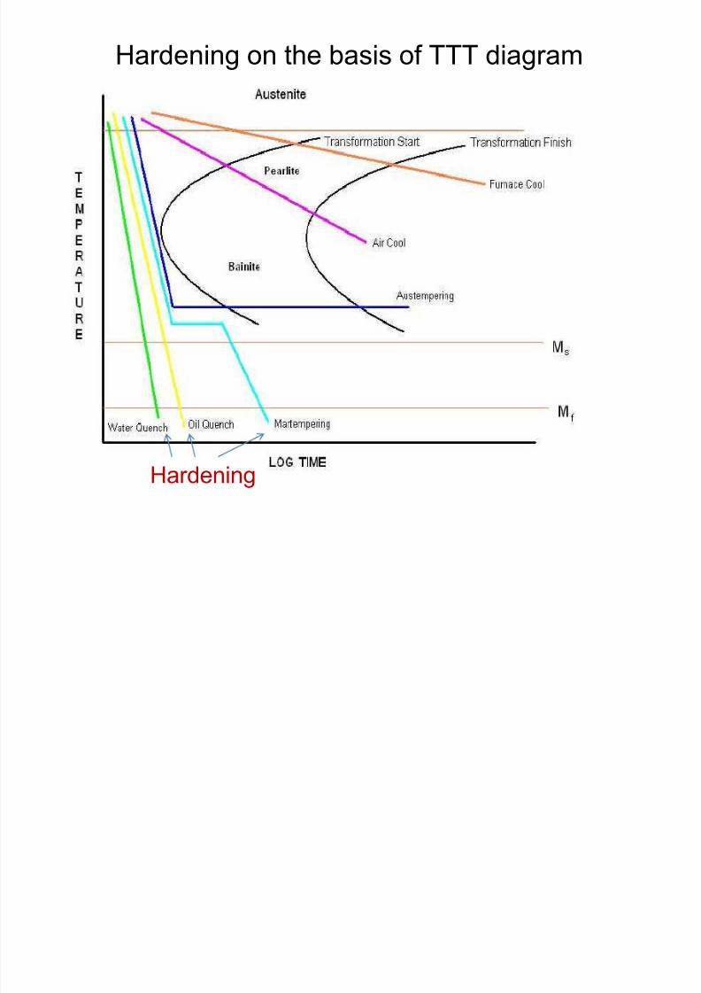
8/10/2019 MT-201B MATERIAL SCIENCE NEW - Copy.ppt
http://slidepdf.com/reader/full/mt-201b-material-science-new-copyppt 280/295
Hardening
Tempering
Purpose of Tempering:
1. To relieve the internal stresses developed due to rapid
cooling during hardening process (i e austenite to
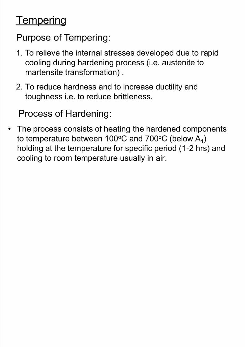
8/10/2019 MT-201B MATERIAL SCIENCE NEW - Copy.ppt
http://slidepdf.com/reader/full/mt-201b-material-science-new-copyppt 281/295
cooling during hardening process (i.e. austenite to
martensite transformation) .
2. To reduce hardness and to increase ductility and
toughness i.e. to reduce brittleness.
Process of Hardening:
• The process consists of heating the hardened components
to temperature between 100
o
C and 700
o
C (below A1)holding at the temperature for specific period (1-2 hrs) and
cooling to room temperature usually in air.
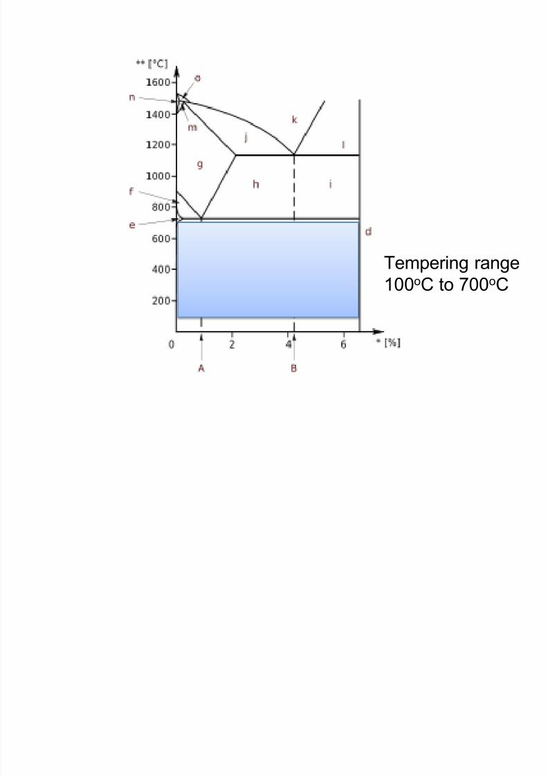
8/10/2019 MT-201B MATERIAL SCIENCE NEW - Copy.ppt
http://slidepdf.com/reader/full/mt-201b-material-science-new-copyppt 282/295
Tempering range
100oC to 700oC
Hardening and Tempering on the basis of TTT diagram
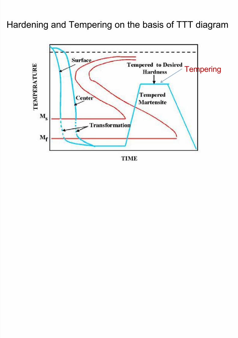
8/10/2019 MT-201B MATERIAL SCIENCE NEW - Copy.ppt
http://slidepdf.com/reader/full/mt-201b-material-science-new-copyppt 283/295
Tempering
Martempering and Austempering
Martempering
In this process the austenitized steel is cooled rapidly avoiding
the nose of the TTT curve to a temperature between the nose
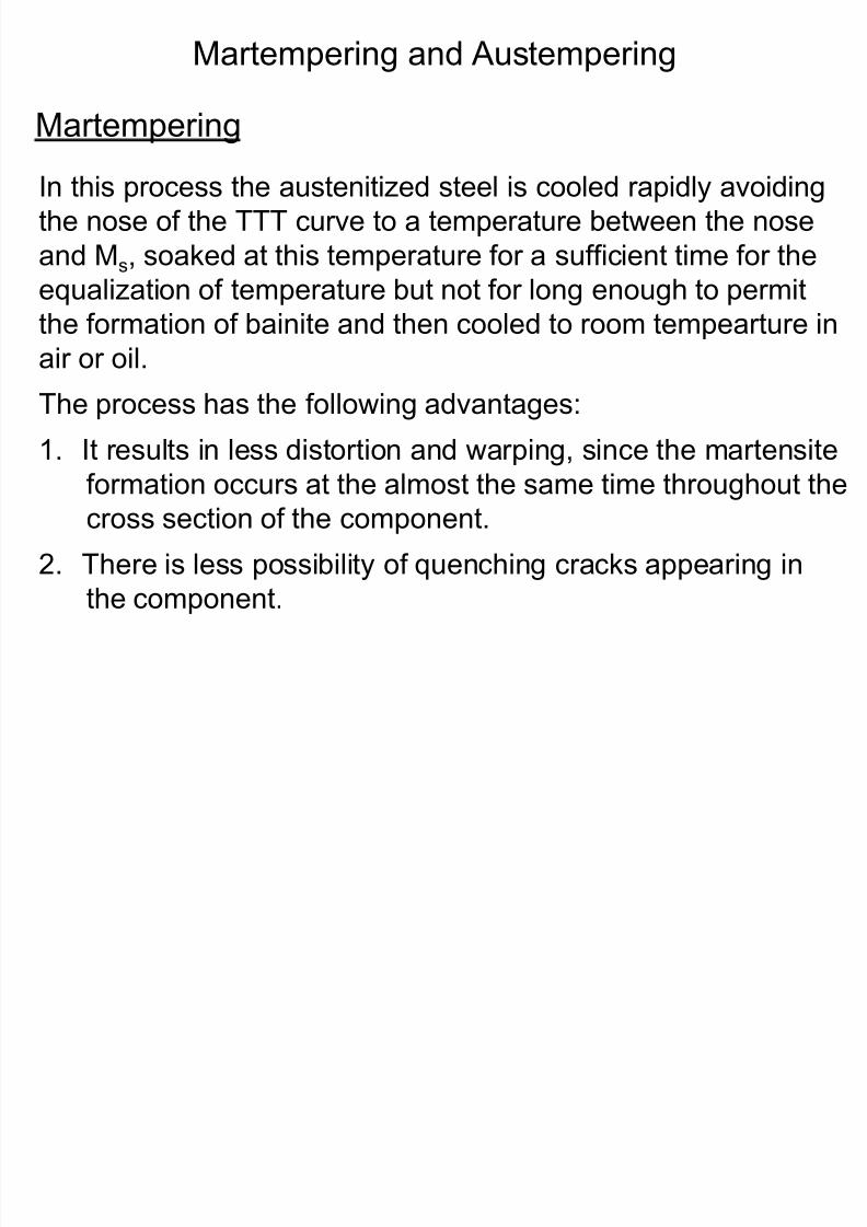
8/10/2019 MT-201B MATERIAL SCIENCE NEW - Copy.ppt
http://slidepdf.com/reader/full/mt-201b-material-science-new-copyppt 284/295
the nose of the TTT curve to a temperature between the nose
and Ms, soaked at this temperature for a sufficient time for the
equalization of temperature but not for long enough to permit
the formation of bainite and then cooled to room tempearture in
air or oil.
The process has the following advantages:
1. It results in less distortion and warping, since the martensite
formation occurs at the almost the same time throughout the
cross section of the component.
2. There is less possibility of quenching cracks appearing in
the component.
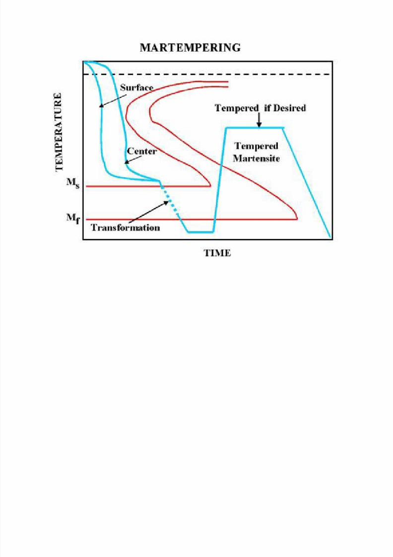
8/10/2019 MT-201B MATERIAL SCIENCE NEW - Copy.ppt
http://slidepdf.com/reader/full/mt-201b-material-science-new-copyppt 285/295
Austempering
• Austempering consists of cooling the austenitised steel with a rate
exceeding the critical cooling rate and then held at some constanttemperature between the nose of TTT curve and M temperature
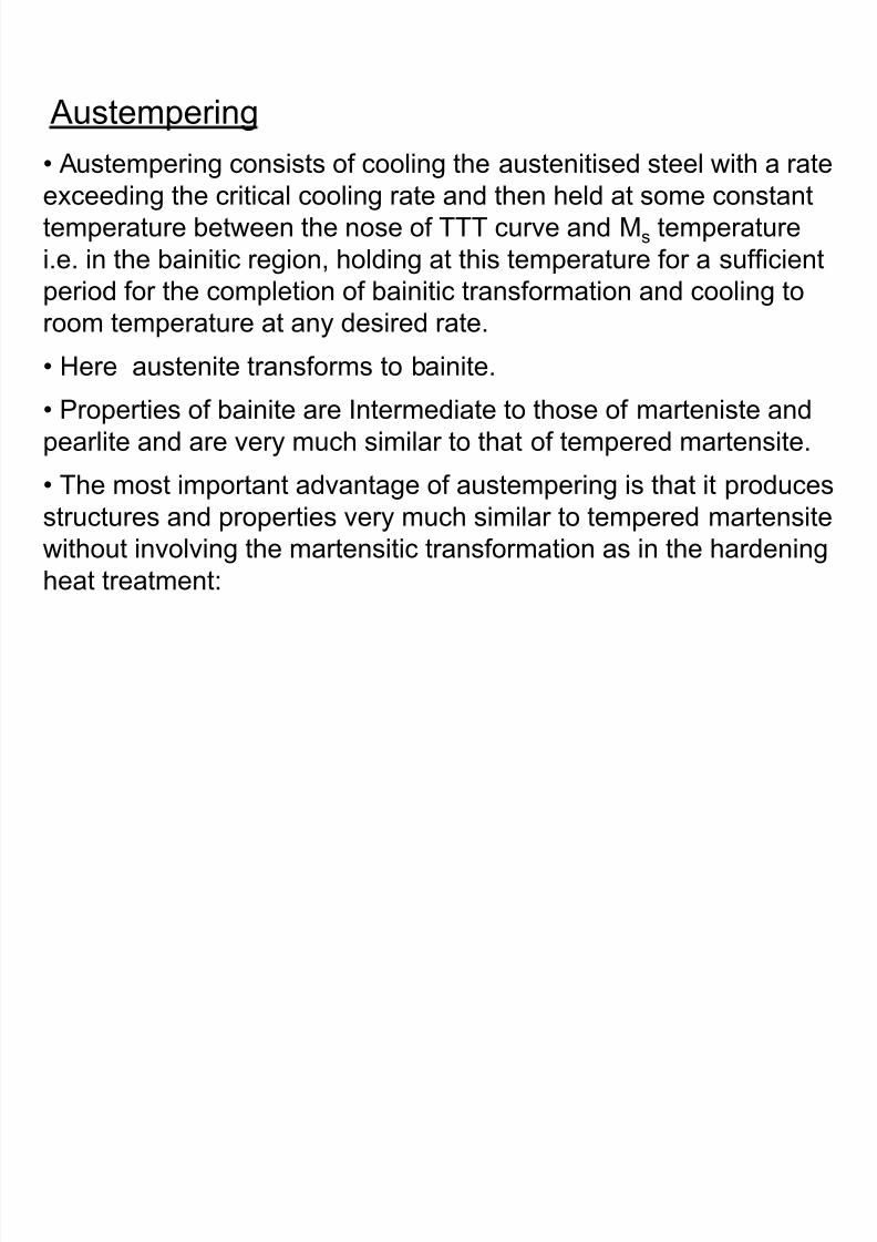
8/10/2019 MT-201B MATERIAL SCIENCE NEW - Copy.ppt
http://slidepdf.com/reader/full/mt-201b-material-science-new-copyppt 286/295
temperature between the nose of TTT curve and Ms temperature
i.e. in the bainitic region, holding at this temperature for a sufficient
period for the completion of bainitic transformation and cooling to
room temperature at any desired rate.
• Here austenite transforms to bainite.
• Properties of bainite are Intermediate to those of marteniste and
pearlite and are very much similar to that of tempered martensite.
• The most important advantage of austempering is that it produces
structures and properties very much similar to tempered martensitewithout involving the martensitic transformation as in the hardening
heat treatment:
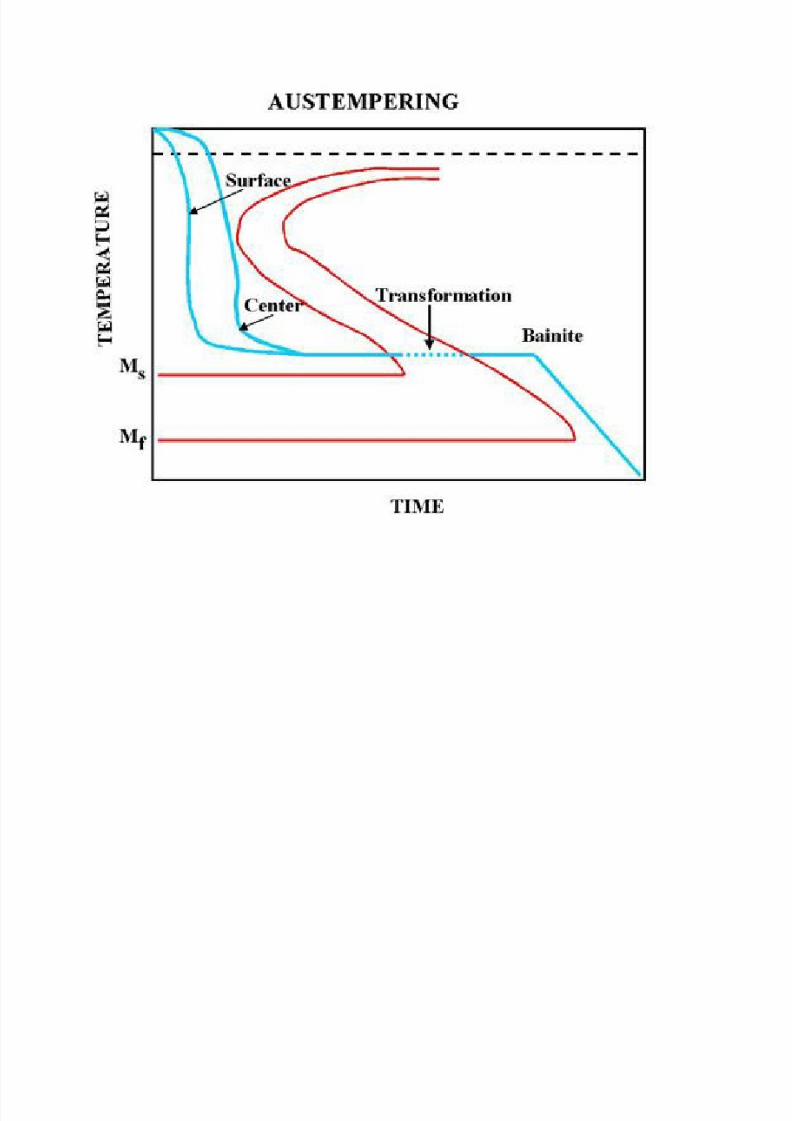
8/10/2019 MT-201B MATERIAL SCIENCE NEW - Copy.ppt
http://slidepdf.com/reader/full/mt-201b-material-science-new-copyppt 287/295
Surface Hardening• In many applications such as gears, crankshafts, etc.
a hard and wear resistant surface (case) is required
with a tough centre (core) to withstand impact loads.
• Such a requirement is difficult to achieve by using a steel of uniformcomposition
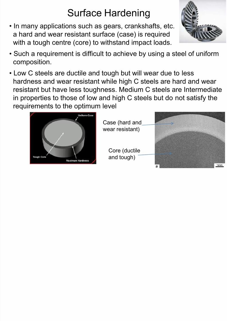
8/10/2019 MT-201B MATERIAL SCIENCE NEW - Copy.ppt
http://slidepdf.com/reader/full/mt-201b-material-science-new-copyppt 288/295
composition.
• Low C steels are ductile and tough but will wear due to less
hardness and wear resistant while high C steels are hard and wear
resistant but have less toughness. Medium C steels are Intermediatein properties to those of low and high C steels but do not satisfy the
requirements to the optimum level
Case (hard and
wear resistant)
Core (ductile
and tough)
• Such a problem can be solved by:
1. Increasing the carbon in the surface of a low C steel and
subsequently heat treating the component in a specific manner to
produce hard and wear resistant surface (case) and a tough
centre (core)
8/10/2019 MT-201B MATERIAL SCIENCE NEW - Copy.ppt
http://slidepdf.com/reader/full/mt-201b-material-science-new-copyppt 289/295
2. Introducing nitrogen in the surface of a tough steel so as to produce
hard nitrided case with no subsequent heat treatment.
3. By selectively hardening the surface only by the hardening heat
treatment
• Surface hardening treatments like those mentioned below are carried
out to selectively harden the surface
1. Carburizing2. Nitriding
3. Flame hardening
4. Induction hardening
Carburizing
• Method of increasing the carbon on the surface of a steel is know
carburizing.
• It consists of heating the steel to the austenitic region in contact witha carburizing medium holding at this temperature for a sufficient
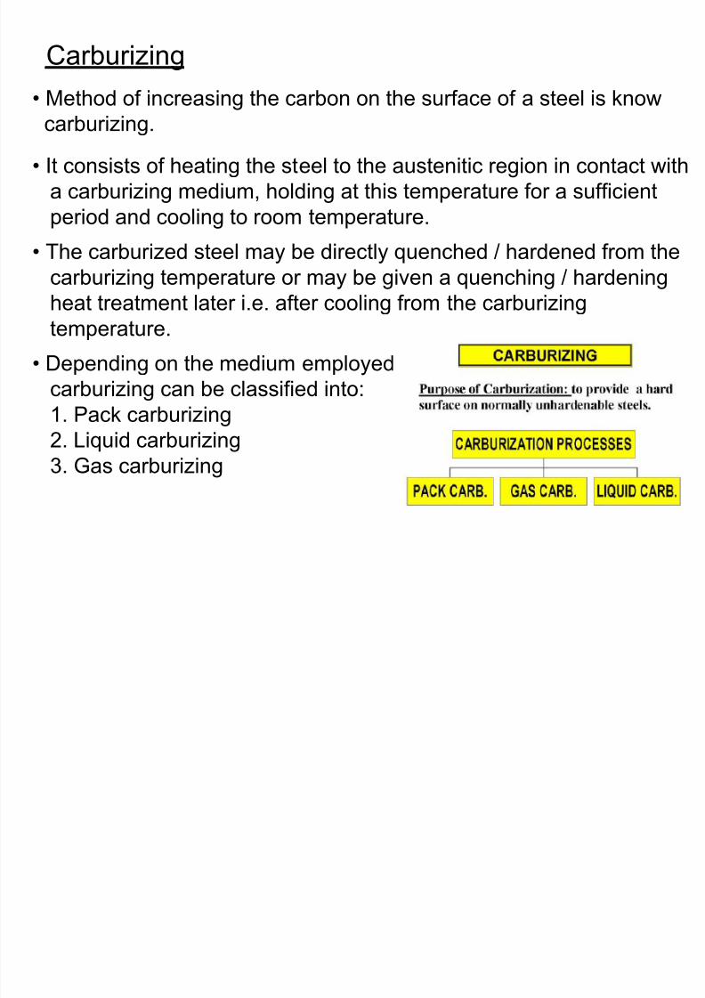
8/10/2019 MT-201B MATERIAL SCIENCE NEW - Copy.ppt
http://slidepdf.com/reader/full/mt-201b-material-science-new-copyppt 290/295
a carburizing medium, holding at this temperature for a sufficient
period and cooling to room temperature.
• The carburized steel may be directly quenched / hardened from the
carburizing temperature or may be given a quenching / hardening
heat treatment later i.e. after cooling from the carburizing
temperature.
• Depending on the medium employed
carburizing can be classified into:
1. Pack carburizing2. Liquid carburizing
3. Gas carburizing
1. Pack Carburizing
• The components to be carburized are packed with a carbonaceous
material in steel or cast iron boxes and sealed with clay.
• The usual carbonaceous material consists of charcoal and coke.
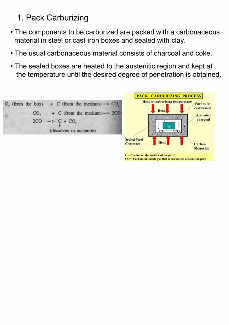
8/10/2019 MT-201B MATERIAL SCIENCE NEW - Copy.ppt
http://slidepdf.com/reader/full/mt-201b-material-science-new-copyppt 291/295
• The sealed boxes are heated to the austenitic region and kept at
the temperature until the desired degree of penetration is obtained.
2. Liquid Carburizing• In this method, carburizing is done by immersing the steel
component in a carbonaceous fused salt bath medium at a
temperature in the austenitic region.
• The bath is composed of sodium cynide, sodium carbonate andsodium chloride
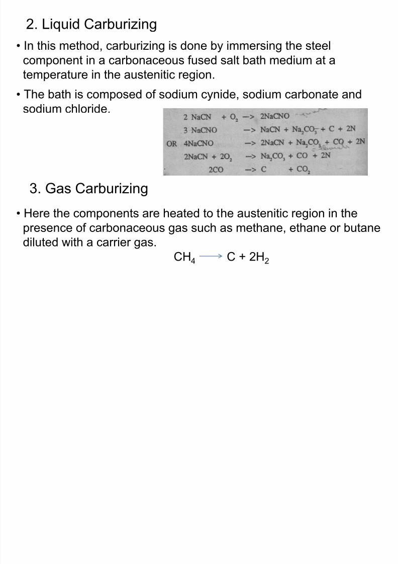
8/10/2019 MT-201B MATERIAL SCIENCE NEW - Copy.ppt
http://slidepdf.com/reader/full/mt-201b-material-science-new-copyppt 292/295
sodium chloride.
3. Gas Carburizing
• Here the components are heated to the austenitic region in the
presence of carbonaceous gas such as methane, ethane or butanediluted with a carrier gas.
CH4 C + 2H2
Nitriding
• Nitriding is accomplished by heating the steel in contact with a
source of atomic nitrogen at a temperature of about 550oC.
• The atomic nitrogen diffuses into the steel and combines with iron
and certain alloying elements present in the steel and forms
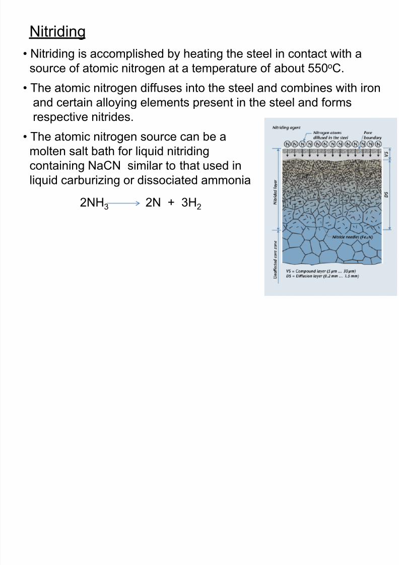
8/10/2019 MT-201B MATERIAL SCIENCE NEW - Copy.ppt
http://slidepdf.com/reader/full/mt-201b-material-science-new-copyppt 293/295
y g p
respective nitrides.
• The atomic nitrogen source can be a
molten salt bath for liquid nitriding
containing NaCN similar to that used inliquid carburizing or dissociated ammonia
2NH3 2N + 3H2
Flame Hardening
• Flame hardening is a process heating the surface layer of a
hardenable steel to its austenitic range by means of a
oxyacetylene flames followed by water spray quenching totransform austenite to martensite
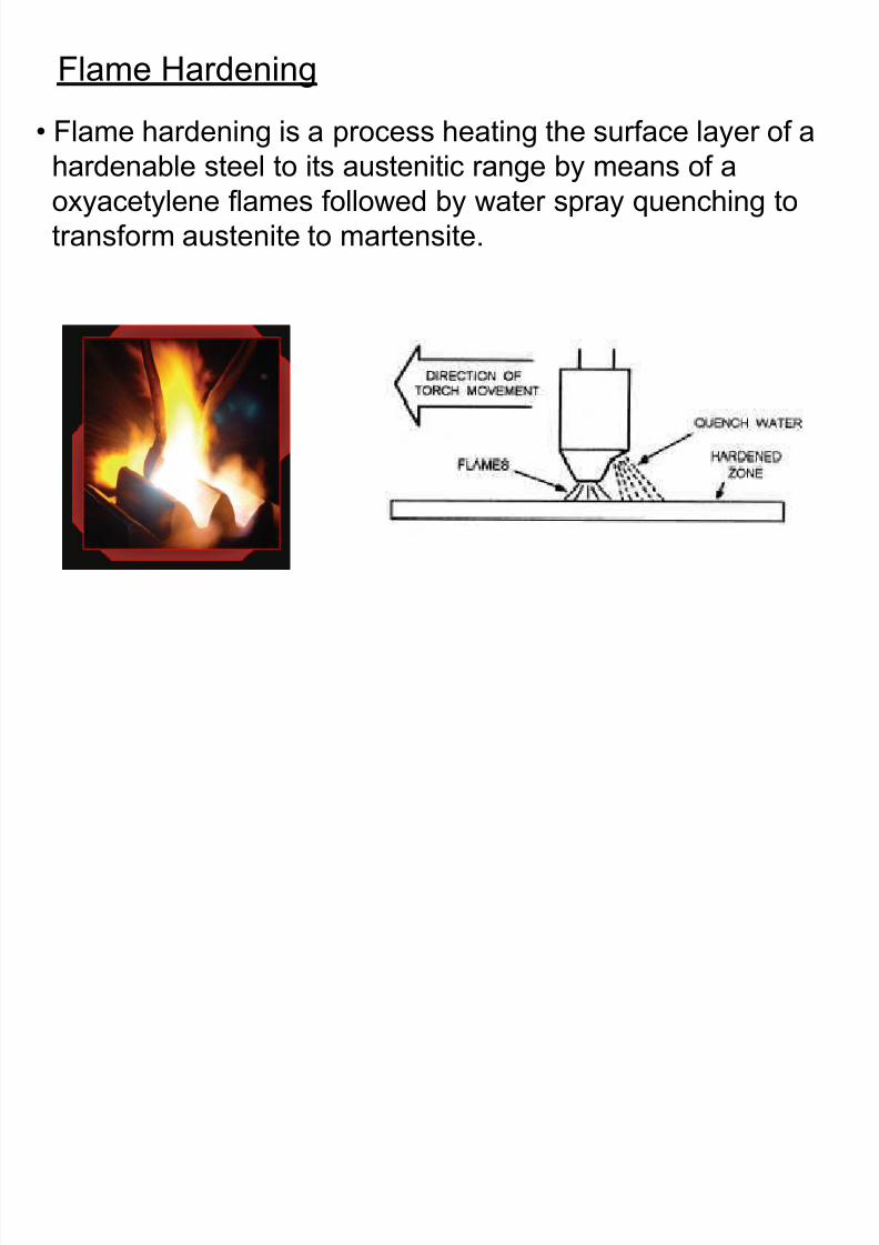
8/10/2019 MT-201B MATERIAL SCIENCE NEW - Copy.ppt
http://slidepdf.com/reader/full/mt-201b-material-science-new-copyppt 294/295
transform austenite to martensite.
Induction Hardening
• In induction hardening the surface layer of a material is heated by
induction heating by passing a high frequency current through
a induction coil.
• The high frequency alternating currents flowing through the inductor
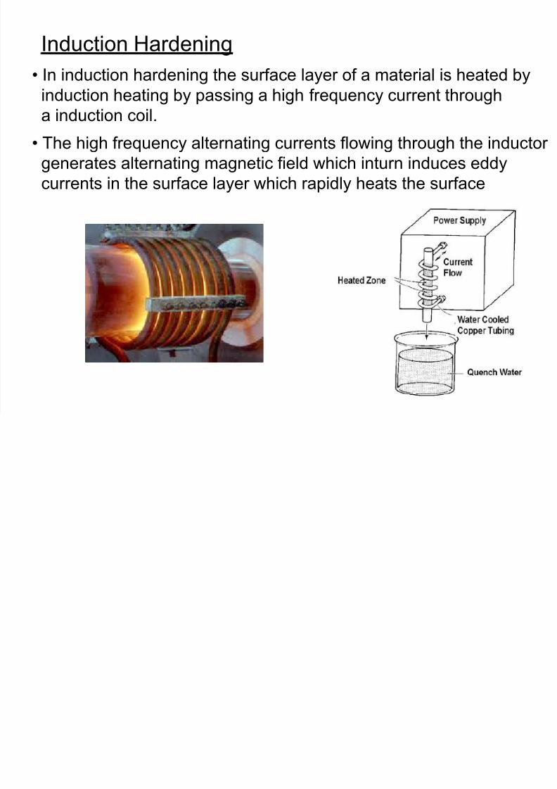
8/10/2019 MT-201B MATERIAL SCIENCE NEW - Copy.ppt
http://slidepdf.com/reader/full/mt-201b-material-science-new-copyppt 295/295
generates alternating magnetic field which inturn induces eddy
currents in the surface layer which rapidly heats the surface


![recession - Copy.ppt [Autosaved]](https://static.fdocuments.net/doc/165x107/577d2e651a28ab4e1eaeead2/recession-copyppt-autosaved.jpg)


![Amardeep jadeja copy.ppt [autosaved]](https://static.fdocuments.net/doc/165x107/54bca19e4a7959887e8b461a/amardeep-jadeja-copyppt-autosaved.jpg)