MS HYDROBASES - Poclain · 2013-04-16 · 2 08/04/2009 MS hydrobases POCLAIN HYDRAULICS Methodology...
52
T E C H N I C A L C A T A L O G MS HYDROBASES HYDRAULIC MOTORS
Transcript of MS HYDROBASES - Poclain · 2013-04-16 · 2 08/04/2009 MS hydrobases POCLAIN HYDRAULICS Methodology...

T E C H N I C A L C A T A L O G
MS HYDROBASESHYDRAULIC MOTORS

2 08/04/2009
MS hydrobases POCLAIN HYDRAULICS
Methodology :This document is intended for manufacturers of machines that incorporate Poclain Hydraulics products. It describes the technical characteristics of Poclain Hydraulics products and specifies installation conditions that will ensure optimum operation. This document includes important comments concerning safety. They are indicated in the following way:
This document also includes essential operating instructions for the product and general information. These are indicated in the following way:
The views in this document are created using metric standards. The dimensional data is given in mm and in inches (inches are between brackets and italic)
Safety comment.
Essential instructions.
General information .
Information on the model code.
Weight of component without oil.
Volume of oil.
Units.
Tightening torque.
Screws.
Information intended for Poclain-Hydraulics personnel.

08/04/2009 3
CONTENTPOCLAIN HYDRAULICS MS hydrobases
MS1
1 - M
SE11
MS0
8 - M
SE08
MS0
5 - M
SE05
MSE
03M
S02
- MSE
02MSE02 - MSE02 4
MSE03 12
MS05 - MSE05 20
MS08 - MSE08 30
MS11 - MSE11 40

4 08/04/2009
MS hydrobases POCLAIN HYDRAULICS
CHARACTERISTICS
Motor inertia = 0.01 kg.m²Noise emissions = 60 dBA
8 172 [10.5] 86 [5.2] 273 [139] 390* 409* 510*
0 213 [13.0] 107 [6.5] 339 [172] 310* 330* 410
1 235 [14.3] 118 [7.2] 374 [190] 285* 299* 372*
2 255 [15.6] 128 [7.8] 405 [206] 260* 276* 343*
0 332 [20.2] 166 [10.1] 528 [268] 200 250 275
1 364 [22.2] 182 [11.1] 579 [294] 182 228 250
2 398 [24.3] 199 [12.1] 633 [322] 165 208 230
86 [5.2] 276*
128 [7.8] 276*
85 [5.2] 330*
107 [6.5] 330*
133 [8.1] 208
199 [12.1] 208
[155]
[268]
305
528 22 [30]
18 [24]
A [172]339
18 [24]
343*
410*N
A
213 [13.0]
192
332
[11.7]
[20.2]
22 [30]
230 400[15]
260*
310*
165
12 [16]
450 [6 527]
[5 802]
450 [6 527]
400 [5 802]
9 [12]
11 [15]
12 [16]
16.5 [22]
16.5 [22]
9 [12]
11
Cam
s w
ith e
qual
lobe
sC
ams
with
une
qual
lobe
s
MS0
2M
SE02
MS0
2M
SE02
Theoretical torque
at 100 bar at 1000 PSI
Nm [lb.ft]
Max. pressure
bar [PSI]
Max.power
kW [HP]cm³/tr [cu.in/rev.]cm³/tr [cu.in/rev.]preferred
kW [HP]non-preferred
kW [HP]
First displacement
Second displacement
* See option ’’M’’ for higher speed.
Max.speed
tr/min [RPM]tr/min[RPM]
MSE02 - MSE02

08/04/2009 5
POCLAIN HYDRAULICS MS hydrobases
MS1
1 - M
SE11
MS0
8 - M
SE08
MS0
5 - M
SE05
MSE
03M
S02
- MSE
02
VALVING SYSTEMS AND HYDROBASES
Cylinder block splines(as per standard NF E22-141)
You are advised to have the installation validated by your Poclain Hydraulics application engineer before using the hydraulic unit in an application.
We must provide you with a detailed plan of the interface for any hydraulic unit use, consult your Poclain Hydraulics sales engineer.
M 0 2S 1
C
1 2
D
3 1 2
F
3 1 2
P
3 4 1 2
S
3 4 5 6
S 0 2EM
13,8 kg [30 lb] 19,9 kg [44 lb]
0,35 L [21 cu.in] 0,45 L [27 cu.in]
Dimensions for 1-displacement valving
1 2
D
3
1 21 2
D
3
1 1
1,667 2240
Y ØVØA
33,446 [1,317]
Z
3,33 [0,131][1,575]
Dimension on 2 pins
Module
ØA
YØV

6 08/04/2009
MS hydrobases POCLAIN HYDRAULICS
18,8 kg [41 lb] 24,9 kg [55 lb]
0,35 L [21 cu.in] 0,45 L [27 cu.in]
1 2
D
3
21 2
D
3
1
Dimensions for 2-displacement valving
18,8 kg [41 lb] 24,9 kg [55 lb]
0,35 L [21 cu.in] 0,45 L [27 cu.in]
1 2
D
3
E1 2
D
3
D
Dimensions for Twin-Lock™ valving
Dimensions for other valving systems

08/04/2009 7
POCLAIN HYDRAULICS MS hydrobases
MS1
1 - M
SE11
MS0
8 - M
SE08
MS0
5 - M
SE05
MSE
03M
S02
- MSE
02
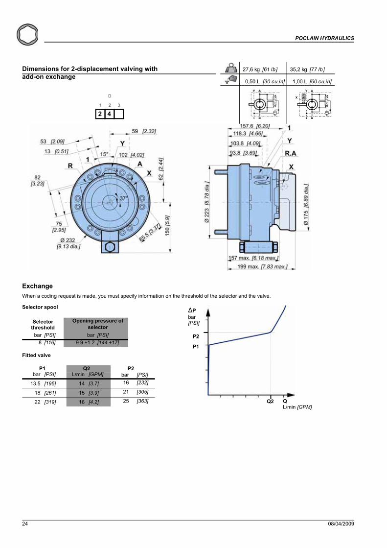
Exchange
- Selector spool
When a coding request is made, you must specify information on the threshold of the selector and the valve.
19 kg [42 lb] 25.1 kg [55 lb]
0.40 L [24 cu.in] 0.50 L [30 cu.in]
Dimensions for 1-displacement valving with built-in exchange
1 2
D
3
1 41 2
D
3
1 5
bar [PSI] bar [PSI]6 [87] 6.4±0.8 [93±11.6]
Selector threshold
Opening pressure of selector
bar [PSI] L/min [GPM] bar [PSI]
20±0.5
16±0.5
23 [334]
[348]
18±0.5 [261±7.25] 8,5±1 [2,245±0.26]
[0,977±0.13] 24[290±7.25] 3,7±0.5
P1 P2Q2
[0,898±0.13] [290]203,4±0.5[232±7.25]
Q L/min [GPM]
�Pbar [PSI]
P1
P2
Q2
- Fitted valve

8 08/04/2009
MS hydrobases POCLAIN HYDRAULICS
Chassis mountings
Take care over the immediate environment of the connections.
ØM (1) ØU S Ra V *180,25 240 0,2 12,5μm 120 N.m[7,10] [9,45] [0,008] [0,49μin] [89 lb .ft]
(1) +0,3 [+0,012]+0,2 [+0,008]
10 M12 x 2
10,9
Class
* : Min. values for torque and load to be transmitted

08/04/2009 9
POCLAIN HYDRAULICS MS hydrobases
MS1
1 - M
SE11
MS0
8 - M
SE08
MS0
5 - M
SE05
MSE
03M
S02
- MSE
02
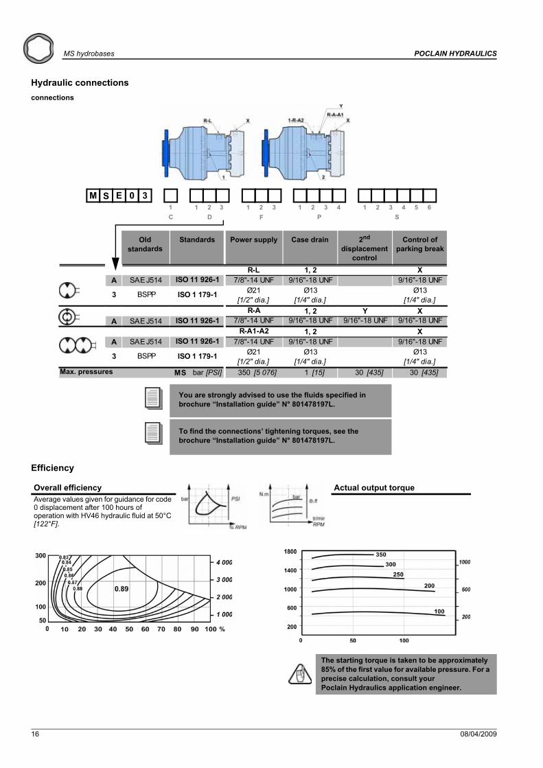
Hydraulic connections
You are strongly advised to use the fluids specified in brochure “Installation guide” N° 801478197L.
To find the connections’ tightening torques, see the brochure “Installation guide” N° 801478197L.
A SAE J514
4 NF E48 050
A SAE J514
4 NF E48 050
A SAE J514
4 NF E48 050
MS 450 [6 527]MSE 400 [5 802]
120 [1 740]
[1/4" dia.]
9/16"-18 UNF
ISO 9 974-1 M10x1
bar [PSI] 1 [15] 30 [435] 30 [435]
[1/2" dia.] [1/4" dia.] [1/4" dia.]
ISO 11 926-1 7/8"-14 UNF 9/16"-18 UNFØ21 Ø13
ISO 9 974-1
X
Ø13
M22x1.5 M14x1.5 M18x1.5
M22x1.5 M14x1.5 M14x1.5R-A1-A2 1, 2
3 BSPP ISO 1 179-1
R-AISO 11 926-1 7/8"-14 UNF
3 BSPP ISO 1 179-1 Ø21
ISO 9 974-1
R-L 1, 2ISO 11 926-1 7/8"-14 UNF
ISO 1 179-1 Ø21
X XT
Ø13
Ø13[1/4" dia.]
9/16"-18 UNF
3/4"-16 UNFØ17
Y X
9/16"-18 UNF
[3/8" dia.]M18x1.5
1, 2
3 BSPP [1/2" dia.]ISO 9 974-1 M22x1.5
[1/2" dia.]Ø13
[1/4" dia.] [1/4" dia.]
M18x1.5
M18x1.5
Ø139/16"-18 UNF 9/16"-18 UNF
0 2S
1 1 2M 0 2S E
M
1 2 3 4 5 6S
1 2 3 4PDC F
1 2 33
Standards Power supply Case drain Control of parking break
2nd displacement
control
Control of drum break
Max.pressures
Old standards

10 08/04/2009
MS hydrobases POCLAIN HYDRAULICS
Efficiency
Overall efficiency Actual output torqueAverage values given for guidance for code 0 displacement after 100 hours of operation with HV46 hydraulic fluid at 50°C [122°F].
MS02
MSE02
The starting torque is taken to be approximately 85% of the first value for available pressure. For a precise calculation, consult your Poclain Hydraulics application engineer.

08/04/2009 11
POCLAIN HYDRAULICS MS hydrobases
MS1
1 - M
SE11
MS0
8 - M
SE08
MS0
5 - M
SE05
MSE
03M
S02
- MSE
02
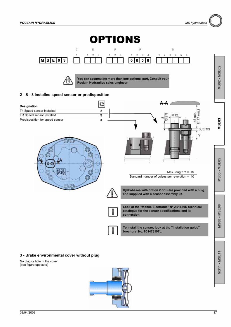
OPTIONS
2 - S - 8 Installed speed sensor or predisposition
7 - Diamond™Special treatment of the motor core which considerably increases its strength, making the motor much more tolerant to temporary instances of the operating conditions being exceeded.
H - High efficiencyReinforced piston sealing to improve volumetric efficiency.
M - High speedUnder certain conditions, an increase in the maximum speed of 30% above the values indicated in the table on page 2 is possible.
You can accumulate more than one optional part. Consult your Poclain Hydraulics sales engineer.
M 0 20 0 0 0
S 1
C
1 2
D
3 1 2
F
3 1 2
P
3 4 1 2
S
3 4 5 6
S 0 2EM
DesignationT4 Speed sensor installed 2TR Speed sensor installed SPredisposition for speed sensor 8
A-A
Max. length Y =Standard number of pulses per revolution =
Hydrobases with option 2 or S are provided with a plug and supplied with a sensor assembly kit.
Look at the "Mobile Electronic" N° A01889D technical catalogue for the sensor specifications and its connection.
To install the sensor, look at the ''Installation guide'' brochure No. 801478197L.
1940
For a precise calculation, consult your Poclain Hydraulics application engineer.
For a precise calculation, consult your Poclain Hydraulics application engineer.
12 08/04/2009
MS hydrobases POCLAIN HYDRAULICS
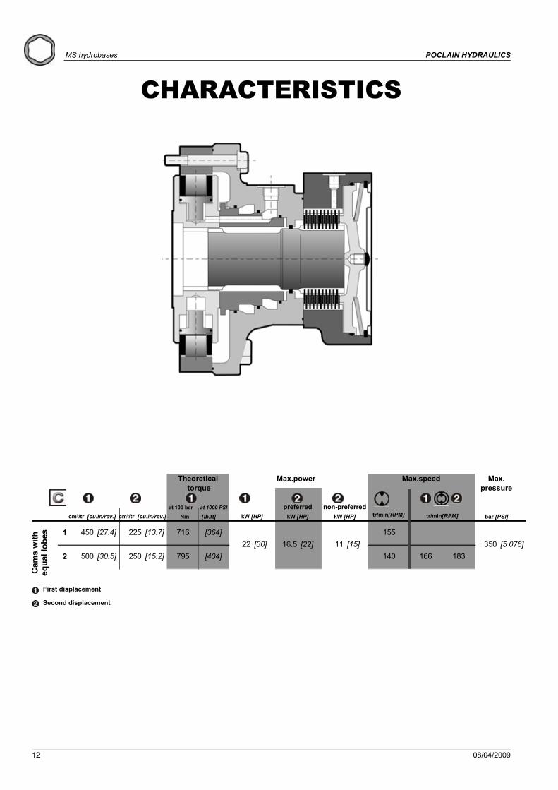
CHARACTERISTICS
1 450 [27.4] 225 [13.7] 716 [364] 155
2 500 [30.5] 250 [15.2] 795 [404] 140 166 18311 [15] 350 [5 076]22 [30] 16.5 [22]
Cam
s w
ith
equa
l lob
es
Theoretical torque
at 100 bar at 1000 PSI
Nm [lb.ft]
Max. pressure
bar [PSI]
Max.power
kW [HP]cm³/tr [cu.in/rev.]cm³/tr [cu.in/rev.]preferred
kW [HP]non-preferred
kW [HP]
Max.speed
tr/min[RPM]tr/min[RPM]
First displacement
Second displacement
MSE03

08/04/2009 13
POCLAIN HYDRAULICS MS hydrobases
MS1
1 - M
SE11
MS0
8 - M
SE08
MS0
5 - M
SE05
MSE
03M
S02
- MSE
02
VALVING SYSTEMS AND HYDROBASES
Cylinder block splines(as per standard NF E22-141)
You are advised to have the installation validated by your Poclain Hydraulics application engineer before using the hydraulic unit in an application.
We must provide you with a detailed plan of the interface for any hydraulic unit use, consult your Poclain Hydraulics sales engineer.
18,3 kg [40 lb] 24 kg [53 lb]
0,30 L [18 cu.in] 0,40 L [24 cu.in]
Dimensions for 1-displacement valving
1,667 2240
Y ØVØA
33,446 [1,317]
Z
3,33 [0,131][1,575]
Dimension on 2 pins
Module
ØA
YØV

14 08/04/2009
MS hydrobases POCLAIN HYDRAULICS
17,3 kg [38 lb] 23,0 kg [51 lb]
0,30 L [18 cu.in] 0,40 L [24 cu.in]
Dimensions for 2-displacement valving
17,3 kg [38 lb] 23,0 kg [51 lb]
0,30 L [18 cu.in] 0,40 L [24 cu.in]
Dimensions for Twin-Lock™ valving

08/04/2009 15
POCLAIN HYDRAULICS MS hydrobases
MS1
1 - M
SE11
MS0
8 - M
SE08
MS0
5 - M
SE05
MSE
03M
S02
- MSE
02
Chassis mountings
Take care over the immediate environment of the connections.
ØM (1) ØU S Ra V (*) 180,25 210 0,2 12,5μm 120 N.m[7,10] [8,27] [0,008] [0,49μin] [88,5 lb.ft]
(1) +0,3 [+0,012]+0,2 [+0,008]
2 x 5 M12 x 2
10,9
Class
* : Min. values for torque and load to be transmitted.
16 08/04/2009
MS hydrobases POCLAIN HYDRAULICS
Hydraulic connectionsconnections
Efficiency
You are strongly advised to use the fluids specified in brochure “Installation guide” N° 801478197L.
To find the connections’ tightening torques, see the brochure “Installation guide” N° 801478197L.
Overall efficiency Actual output torqueAverage values given for guidance for code 0 displacement after 100 hours of operation with HV46 hydraulic fluid at 50°C [122°F].
The starting torque is taken to be approximately 85% of the first value for available pressure. For a precise calculation, consult your Poclain Hydraulics application engineer.
A SAE J514
A SAE J514
A SAE J514
MS bar [PSI] 350 [5 076] 1 [15] 30 [435] 30 [435]
[1/2" dia.]
1, 29/16"-18 UNF9/16"-18 UNF
Ø21ISO 11 926-1 7/8"-14 UNF
R-L
3 BSPP
X
ISO 1 179-1 Ø13
X[1/4" dia.]
Ø13[1/4" dia.]
9/16"-18 UNFY
ISO 11 926-1 7/8"-14 UNF 9/16"-18 UNF 9/16"-18 UNF
3 BSPP ISO 1 179-1 Ø21[1/2" dia.]
R-A1-A2 1, 2
R-A 1, 2
XISO 11 926-1 7/8"-14 UNF 9/16"-18 UNF 9/16"-18 UNF
[1/4" dia.] [1/4" dia.]Ø13Ø13
1 1 2M 0 3S E
1 2 3 4 5 6S
1 2 3 4PDC F
1 2 33
Standards Power supply Case drain Control of parking break
2nd displacement
control
Old standards
Max. pressures
08/04/2009 17
POCLAIN HYDRAULICS MS hydrobases
MS1
1 - M
SE11
MS0
8 - M
SE08
MS0
5 - M
SE05
MSE
03M
S02
- MSE
02
OPTIONS
2 - S - 8 Installed speed sensor or predisposition
3 - Brake environmental cover without plugNo plug or hole in the cover.(see figure opposite)
You can accumulate more than one optional part. Consult your Poclain Hydraulics sales engineer.
0 0 0 01
C
1 2
D
3 1 2
F
3 1 2
P
3 4 1 2
S
3 4 5 6
S 0 3EM
DesignationT4 Speed sensor installed 2TR Speed sensor installed SPredisposition for speed sensor 8
A-A
Max. length Y =Standard number of pulses per revolution =
Hydrobases with option 2 or S are provided with a plug and supplied with a sensor assembly kit.
Look at the "Mobile Electronic" N° A01889D technical catalogue for the sensor specifications and its connection.
To install the sensor, look at the ''Installation guide'' brochure No. 801478197L.
1940

18 08/04/2009
MS hydrobases POCLAIN HYDRAULICS
7 - Diamond™Special treatment of the motor core which considerably increases its strength, making the motor much more tolerant to temporary instances of the operating conditions being exceeded.
H - High efficiencyReinforced piston sealing to improve volumetric efficiency.
For a precise calculation, consult your Poclain Hydraulics application engineer.

08/04/2009 19
POCLAIN HYDRAULICS MS hydrobases
MS1
1 - M
SE11
MS0
8 - M
SE08
MS0
5 - M
SE05
MSE
03M
S02
- MSE
02

20 08/04/2009
POCLAIN HYDRAULICS
CHARACTERISTICS
6 260 [15,9] 130 [7,9] 413 [210] 2658 376 [22,9] 188 [11,5] 598 [304] 2500 468 [28,5] 234 [14,3] 744 [378] 2401 514 [31,3] 257 [15,7] 817 [416] 2202 560 [34,2] 280 [17,1] 890 [453] 200
8 530 [32,3] 265 [16,2] 843 [429] 2000 625 [38,1] 312,5 [19,1] 994 [505] 1901 688 [42,0] 344 [21,0] 1094 [556] 1752 750 [45,7] 375 [22,9] 1193 [606] 1603 820 [50,0] 410 [25,0] 1304 [663] 145
280 [17,1]138 [8,4]234 [14,3]188 [11,5]257 [15,7]188 [11,5]280 [17,1]188 [11,5]374 [22,8]185 [11,3]313 [19,1]251 [15,3]344 [21,0]251 [15,3]374 [22,8]251 [15,3]
A 625 [38,1] 994
[36,3] 946 [481] 175[25] 15 [20]
160
160
[453]
400 [5 802]N 564 [34,4] 897 [456] 190
H 59529 [39] 19
[505]
D 560 [34,2] 890
708 [360] 220
A 468 [28,5] 744 [378] 200
[6 527]N 422 [25,7] 671 [341] 240
H 445 [27,1]
D 419 [25,6] 666 [339]
29 [39]
29 [39]
29 [39]
400
200
450
450
15 [20]
19 [25] [6 527]
[5 802]
15 [20]
15 [20]19 [25]
19 [25]
Motor inertia = 0.03 kg.m²Noise emissions = 60 dBA
* See option ’’M’’ for higher speed.
Cam
s w
ith e
qual
lobe
sC
ams
with
une
qual
lobe
s
MS0
5M
SE05
MS0
5M
SE05
Theoretical torque
at 100 bar at 1000 PSI Nm [lb.ft]
Max.speed
tr/min[RPM]
Max. pressure
bar [PSI]
Max.power
kW [HP]cm³/tr [cu.in/rev.]cm³/tr [cu.in/rev.]preferred
kW [HP]non-preferred
kW [HP]
First displacement
Second displacement
MS05 - MSE05

08/04/2009 21
POCLAIN HYDRAULICS
MS1
1 - M
SE11
MS0
8 - M
SE08
MS0
5 - M
SE05
MSE
03M
S02
- MSE
02
VALVING SYSTEMS AND HYDROBASES
Cylinder block splines(as per standard NF E22-141)
You are advised to have the installation validated by your Poclain Hydraulics application engineer before using the hydraulic unit in an application.
We must provide you with a detailed plan of the interface for any hydraulic unit use, consult your Poclain Hydraulics sales engineer.
M 0 5S 1
C
1 2
D
3 1 2
F
3 1 2
P
3 4 1 2
S
3 4 5 6
S 0 5EM
23,7 kg [52 lb] 31,7 kg [70 lb]
0,50 L [30 cu.in] 1,00 L [60 cu.in]
Dimensions for 1-displacement valving
1 2
D
3
1 31 2
D
3
1 1
1,667 2850
Y ØVØA
43,446 [1,710]
Z
3,33 [0,131][1,968]
Dimension on 2 pins
Module
ØA
YØV

22 08/04/2009
POCLAIN HYDRAULICS
27,6 kg [61 lb] 35,2 kg [77 lb]
0,50 L [30 cu.in] 1,00 L [60 cu.in]
Dimensions for 2-displacement valving
1 2
D
3
2 1
mm [in] mm [in]0 0
- 0,2 - 0,1850 0
- 0,078 - 0,0073
Ø C Ø 216[ 8,50 dia.][ 8,82dia.]
Ø 224
1 2
D
3
2 21 2
D
3
2 3
Dimensions for other valving systems

08/04/2009 23
POCLAIN HYDRAULICS
MS1
1 - M
SE11
MS0
8 - M
SE08
MS0
5 - M
SE05
MSE
03M
S02
- MSE
02
27,6 kg [61 lb] 35,2 kg [77 lb]
0,50 L [30 cu.in] 1,00 L [60 cu.in]
mm [in] mm [in]0 0
- 0,2 - 0,1850 0
- 0,078 - 0,0073
Ø C Ø 216[ 8,50 dia.][ 8,82dia.]
Ø 224
1 2
D
3
2 E1 2
D
3
2 F
Dimensions for Twin-Lock™ valving
23,7 kg [52 lb] 31,7 kg [70 lb]
0,50 L [30 cu.in] 1,00 L [60 cu.in]
Dimensions for 1-displacement valving with built-in exchange
1 2
D
3
1 41 2
D
3
1 6
24 08/04/2009
POCLAIN HYDRAULICS
ExchangeWhen a coding request is made, you must specify information on the threshold of the selector and the valve.
27,6 kg [61 lb] 35,2 kg [77 lb]
0,50 L [30 cu.in] 1,00 L [60 cu.in]
1 2
D
3
2 4
Dimensions for 2-displacement valving with add-on exchange
�Pbar[PSI]
QL/min [GPM]
P2
P1
Q2
Selector spool
Fitted valve
Selector threshold
Opening pressure of selector
bar [PSI] bar [PSI]8 [116] 9.9 ±1.2 [144 ±17]
P1 Q2 P2bar [PSI] L/min [GPM] bar [PSI]
13.5 [195] 14 [3.7] 16 [232]
18 [261] 15 [3.9] 21 [305]
22 [319] 16 [4.2] 25 [363]

08/04/2009 25
POCLAIN HYDRAULICS
MS1
1 - M
SE11
MS0
8 - M
SE08
MS0
5 - M
SE05
MSE
03M
S02
- MSE
02
Chassis mountings
Take care over the immediate environment of the connections.
See generic installation motors N°801478197L.
ØM (1) ØU S Ra V 200 265
[7,87] [10,43]216 267
[8,50] [10,51]224 265
[8,82] [10,43]200 265
[7,87] [10,43]216 267
[8,50] [10,51]224 265
[8,82] [10,43](1) +0,3 [+0,012]
+0,2 [+0,008]
210 N.m[155 lb.ft][0,008]
12,5μm[0,49μin]
10 M16 x 2
2 x 4 M16 x 2
8,8
2 x 4 M16 x 2
2 x 4 M16 x 2
MS05 / MSE05
10 M16 x 2
0,2
P
R
R
P
R
R
2 x 4 M16 x 2
Class
* : Min. values for torque and load to be transmitted.
*

26 08/04/2009
POCLAIN HYDRAULICS
Hydraulic connections
connections
You are strongly advised to use the fluids specified in brochure “Installation guide” N° 801478197L.
To find the connections’ tightening torques, see the brochure “Installation guide” N° 801478197L.
A SAE J514
8 NF E48 050
A SAE J514
4 NF E48 050
A SAE J514
4 NF E48 050
MS 450 [6 527] 450 [6 527]
MSE 400 [5 802] 400 [5 802]120 [1 740]
M14x1.5
M14x1.5
M14x1.5
Ø13
30 [435] 30 [435]bar [PSI] 1 [15]
M10x1M22x1.5ISO 9 974-1 M27x2 M16x1.5
[3/8" dia.] [1/4" dia.]
ISO 9 974-1
Ø21[1/2" dia.]
ISO 1 179-1 Ø27[3/4" dia.]
Ø17
X9/16"-18 UNFISO 11 926-1 1"1/16-12 UNF 3/4"-16 UNF
A23/4"-16 UNF
M27x2 M16x1.5 M14x1.5R-A1 1, 2
3 BSPP
Ø13 Ø13[3/4" dia.] [3/8" dia.] [1/4" dia.] [1/4" dia.]
Y XISO 11 926-1 1"1/16-12 UNF 3/4"-16 UNF 9/16"-18 UNF 9/16"-18 UNF
1, 2
3 BSPP ISO 1 179-1 Ø27 Ø17
[3/8" dia.] [1/4" dia.]ISO 6 149-1 M18x1.5 M16x1.5
3 BSPP ISO 1 179-1 Ø27 Ø17 Ø13[3/4" dia.]
3/4"-16 UNF 9/16"-18 UNFR-L 1, 2 X XT
ISO 11 926-1 1"1/16-12 UNF
ISO 9 974-1
R-A
0 5S
1 1 2M 0 5S E
M
1 2 3 4 5 6S
1 2 3 4PDC F
1 2 33
Standards Power supply Case drain Control of parking break
2nd displacement
control
Control of drum break
Old standards
Max.pressures

08/04/2009 27
POCLAIN HYDRAULICS
MS1
1 - M
SE11
MS0
8 - M
SE08
MS0
5 - M
SE05
MSE
03M
S02
- MSE
02
Efficiency
^
Overall efficiency Actual output torqueAverage values given for guidance for code 0 displacement after 100 hours of operation with HV46 hydraulic fluid at 50°C [122°F].
MS05
MSE05
The starting torque is taken to be approximately 85% of the first value for available pressure. For a precise calculation, consult your Poclain Hydraulics application engineer.

28 08/04/2009
POCLAIN HYDRAULICS
OPTIONS
2 - S - 8 Installed speed sensor or predisposition
5 - DrainageAdditional drain in the cover.
You can accumulate more than one optional part. Consult your Poclain Hydraulics sales engineer.
M 0 50 0 0 0
S 1
C
1 2
D
3 1 2
F
3 1 2
P
3 4 1 2
S
3 4 5 6
S 0 5EM
DesignationT4 Speed sensor installed 2TR Speed sensor installed SPredisposition for speed sensor 8
A-A
Max. length Y =Standard number of pulses per revolution =
Hydrobases with option 2 or S are provided with a plug and supplied with a sensor assembly kit.
Look at the "Mobile Electronic" N° A01889D technical catalogue for the sensor specifications and its connection.
To install the sensor, look at the ''Installation guide'' brochure No. 801478197L.
20.753

08/04/2009 29
POCLAIN HYDRAULICS
MS1
1 - M
SE11
MS0
8 - M
SE08
MS0
5 - M
SE05
MSE
03M
S02
- MSE
02
7 - Diamond™Special treatment of the motor core which considerably increases its strength, making the motor much more tolerant to temporary instances of the operating conditions being exceeded.
E - Reinforced sealing Reinforced seals and, for an unbraked motor, a rear reinforced plate (R02 - 8 mm thick, instead of 2 mm).
H - High efficiencyReinforced piston sealing to improve volumetric efficiency.
M - High speedUnder certain conditions, an increase in the maximum speed of 30% above the values indicated in the table on page 2 is possible.
T - Soft Shift™
M 0 5R 0 5 E
S 1
C
1 2
D
3 1 2
F
3 1 2
P
3 4 1 2
S
3 4 5 6
S 0 5EM
For a precise calculation, consult your Poclain Hydraulics application engineer.
For a precise calculation, consult your Poclain Hydraulics application engineer.
Progressive displacement change (cushioned slide-valve)
Consult your Poclain Hydraulics sales engineer.

30 08/04/2009
MS hydrobases POCLAIN HYDRAULICS
CHARACTERISTICS
Motor inertia = 0.05 kg.m²Noise emissions = 60 dBA
6 467 [28,5] 234 [14,2] 743 [378] 2108 627 [38,2] 314 [19,1] 997 [507] 2109 702 [42,8] 351 [21,4] 1116 [568] 1850 780 [47,6] 390 [23,8] 1240 [631] 1701 857 [52,3] 429 [26,1] 1363 [693] 1552 934 [57,0] 467 [28,5] 1485 [755] 1400 1 043 [63,6] 522 [31,8] 1658 [843] 1301 1 146 [69,9] 573 [34,9] 1822 [927] 1102 1 248 [76,1] 624 [38,1] 1984 [1 009] 105
390 [23,8]233 [14,2]467 [28,5]233 [14,2]467 [28,5]313 [19,1]522 [31,8]312 [19,0]624 [38,1]312 [19,0]624 [38,1]418 [25,5]
[6 527]27 [36]
27 [36] 21 [28] 400 [5 802]
D 700
41 [55]
41 [55]
[504]Q 623 [38,0] 991
21 [28] 450
[843]1658
41[42,7] 1113 [566]
[631]
[674]
450 [6 527][55] 27 [36] 21 140[28]
170
140A 780 [47,6] 1240
Q 833 [50,8] 1324
41 [55] 27 21[36] [28]
125
400
105
[5 802]D 936 [57,1] 1488 [757] 105
A 1 043 [63,6]
Cam
s w
ith e
qual
lo
bes
Cam
s w
ith u
nequ
al lo
bes
MS0
8M
SE08
MS0
8M
SE08
* See option ’’M’’ for higher speed.
Theoretical torque
at 100 bar at 1000 PSI Nm [lb.ft]
Max.speed
tr/min[RPM]
Max. pressure
bar [PSI]
Max.power
kW [HP]preferred
kW [HP]non-preferred
kW [HP]
First displacement
Second displacement
cm³/tr [cu.in/rev.]cm³/tr [cu.in/rev.]
MS08 - MSE08

08/04/2009 31
POCLAIN HYDRAULICS MS hydrobases
MS1
1 - M
SE11
MS0
8 - M
SE08
MS0
5 - M
SE05
MSE
03M
S02
- MSE
02
VALVING SYSTEMS AND HYDROBASES
Cylinder block splines(as per standard NF E22-141)
You are advised to have the installation validated by your Poclain Hydraulics application engineer before using the hydraulic unit in an application.
We must provide you with a detailed plan of the interface for any hydraulic unit use, consult your Poclain Hydraulics sales engineer.
M 0 8S 1
C
1 2
D
3 1 2
F
3 1 2
P
3 4 1 2
S
3 4 5 6
S 0 8EM
34,4 kg [76 lb] 51,8 kg [114 lb]
0,50 L [30 cu.in] 1,00 L [60 cu.in]
Dimensions for 1-displacement valving
1 2
D
3
1 21 2
D
3
1 1
2,5 2460
Y ØVØA
69,580 [2,739]
Z
4,5 [0,177][2,362]
Dimension on 2 pins
Module
ØA
YØV

32 08/04/2009
MS hydrobases POCLAIN HYDRAULICS
35 kg [77 lb]
0,50 L [30 cu.in]
1 2
D
3
1 21 2
D
3
1 1
Dimensions for one-piece valving single displacement
1 2
F
3
A 0 81 2
F
3
A 0 8
37,8 kg [83 lb] 54,7 kg [120 lb]
0,50 L [30 cu.in] 1,00 L [60 cu.in]
Dimensions for 2-displacement valving
1 2
D
3
2 21 2
D
3
2 1
Dimensions for other valving systems

08/04/2009 33
POCLAIN HYDRAULICS MS hydrobases
MS1
1 - M
SE11
MS0
8 - M
SE08
MS0
5 - M
SE05
MSE
03M
S02
- MSE
02
37,8 kg [83 lb] 54,7 kg [120 lb]
0,50 L [30 cu.in] 1,00 L [60 cu.in]
Dimensions for Twin-Lock™ valving
1 2
D
3
2 E1 2
D
3
2 D
34,4 kg [76 lb] 51,8 kg [114 lb]
0,50 L [30 cu.in] 1,00 L [60 cu.in]
1 2
D
3
1 51 2
D
3
1 4
Dimensions for 1-displacement valving with built-in exchange
1 2
F
3
R 0 81 2
F
3
R 0 8

34 08/04/2009
MS hydrobases POCLAIN HYDRAULICS
ExchangeWhen a coding request is made, you must specify information on the threshold of the selector and the valve.
Chassis mountings
Take care over the immediate environment of the connections.
See generic installation motors N°801478197L.
�Pbar[PSI]
QL/min [GPM]
P2
P1
Q2
Selector spool
Fitted valve
Selector threshold
Opening pressure of selector
bar [PSI] bar [PSI]8 [116] 9.9 ±1.2 [144 ±17]
P1 Q2 P2bar [PSI] L/min [GPM] bar [PSI]
13.5 [195] 14 [3.7] 16 [232]
18 [261] 15 [3.9] 21 [305]
22 [319] 16 [4.2] 25 [363]
ØM (1) ØU S Ra V 253 300
[9,96] [11,81]224 300
[8,82] [11,81](1) +0,3 [+0,012]
+0,2 [+0,008]
210 N.m[155 lb.ft][0,008]
12,5μm[0,49μin]
8,82 x 5
M16 x 20,2
Class
* : Min. values for torque and load to be transmitted.
Wheel motor
Shaft motor
*

08/04/2009 35
POCLAIN HYDRAULICS MS hydrobases
MS1
1 - M
SE11
MS0
8 - M
SE08
MS0
5 - M
SE05
MSE
03M
S02
- MSE
02
Hydraulic connections
connections
You are strongly advised to use the fluids specified in brochure “Installation guide” N° 801478197L.
To find the connections’ tightening torques, see the brochure “Installation guide” N° 801478197L.
A SAE J514ISO 6 162DIN 3 852ISO 6 162
BSPP4 NF E48 0505 DIN 3 8528 NF E48 050
A SAE J514ISO 6 162DIN 3 852
5 DIN 3 852
A SAE J514
5 DIN 3 852
MS 450 [6 527]
MSE 400 [5 802]
XTISO 11 926-1 1"1/16-12 UNF 3/4"-16 UNF 9/16"-18 UNF
1, 2 X
XR-A 1, 2 YM16x1.5
M16x1.5
1, 2 Y
9/16"-18 UNF1"1/16-12 UNF 3/4"-16 UNF
M16x1.5
9/16"-18 UNF
ISO 6 162ISO 9 974-1
ISO 9 974-1
M27x2ISO 9 974-1
ISO 6 162ISO 1 179-1
1
1
2
9/16"-18 UNFISO 11 926-1
ISO 9 974-1 M18x1.5 M16x1.5M27x2M22x1.5 M18x1.5
[3/8" dia.]
DN13 PN400 M18x1.5 M16x1.5
DN13 PN400Ø17
[3/8" dia.]
R-L
ISO 6 149-1 M22x1.5 M18x1.5
Ø17
ISO 6 162 ISO 9 974-1
DN13 PN400 M18x1.5 M14x1.5 M16x1.5
ISO 9 974-1 M27x2
Ø13
XM18x1.5 M14x1.5
3/4"-16 UNF 9/16"-18 UNFISO 11 926-1 1"1/16-12 UNF
3 BSPP ISO 1 179-1Ø27
R-A1-A2
Ø17 Ø13[3/4" dia.] [3/8" dia.] [1/4" dia.] [1/4" dia.]
M16x1.5
M14x1.5
M12x1.5M18x1.5 M14x1.5
ISO 9 974-1
bar [PSI] 1 [15] 30 [435] 30 [435] 120 [1 740]
0 8S
1 1 2M 0 8S E
M
1 2 3 4 5 6S
1 2 3 4PDC F
1 2 33
Standards Power supply Case drain Control of parking break
2nd displacement
control
Control of drum break
Old standards
Max.pressures

36 08/04/2009
MS hydrobases POCLAIN HYDRAULICS
Efficiency
Overall efficiency Actual output torqueAverage values given for guidance for code 0 displacement after 100 hours of operation with HV46 hydraulic fluid at 50°C [122°F].
MS08
MSE08
The starting torque is taken to be approximately 85% of the first value for available pressure. For a precise calculation, consult your Poclain Hydraulics application engineer.

08/04/2009 37
POCLAIN HYDRAULICS MS hydrobases
MS1
1 - M
SE11
MS0
8 - M
SE08
MS0
5 - M
SE05
MSE
03M
S02
- MSE
02
OPTIONS
2 - S - 8 Installed speed sensor or predisposition
You can accumulate more than one optional part. Consult your Poclain Hydraulics sales engineer.
M 0 80 0 0 0
S 1
C
1 2
D
3 1 2
F
3 1 2
P
3 4 1 2
S
3 4 5 6
S 0 8EM
DesignationT4 Speed sensor installed 2TR Speed sensor installed SPredisposition for speed sensor 8
A-A
Max. length Y =Standard number of pulses per revolution =
Hydrobases with option 2 or S are provided with a plug and supplied with a sensor assembly kit.
Look at the "Mobile Electronic" N° A01889D technical catalogue for the sensor specifications and its connection.
To install the sensor, look at the ''Installation guide'' brochure No. 801478197L.
21.160

38 08/04/2009
MS hydrobases POCLAIN HYDRAULICS
5 - DrainageFit an additional drain on the valving cover.
7 - Diamond™Special treatment of the motor core which considerably increases its strength, making the motor much more tolerant to temporary instances of the operating conditions being exceeded.
M - High speedUnder certain conditions, an increase in the maximum speed of 30% above the values indicated in the table on page 2 is possible.
T - Soft Shift™
A
[4.02]102
For a precise calculation, consult your Poclain Hydraulics application engineer.
Progressive displacement change (cushioned slide-valve)
Consult your Poclain Hydraulics sales engineer.

08/04/2009 39
POCLAIN HYDRAULICS MS hydrobases
MS1
1 - M
SE11
MS0
8 - M
SE08
MS0
5 - M
SE05
MSE
03M
S02
- MSE
02

40 08/04/2009
MS hydrobases POCLAIN HYDRAULICS
CHARACTERISTICS
Motor inertia 0.05 kg.m²
7 730 [44,5] 365 [22,3] 1 161 [590]
8 837 [51,0] 419 [25,5] 1 331 [677]
9 943 [57,5] 472 [28,8] 1 499 [762]
0 1 048 [63,9] 524 [32,0] 1 666 [847]
1 1 147 [70,0] 574 [35,0] 1 824 [927]
2 1 259 [76,8] 630 [38,4] 2 002 [1 018] 170 175
9 1 263 [77,0] 632 [38,5] 2 008 [1 021] 170 190
0 1 404 [85,6] 702 [42,8] 2 232 [1 135] 155 185
1 1 536 [93,7] 768 [46,8] 2 442 [1 242] 140 180
2 1 687 [102,9] 844 [51,4] 2 682 [1 364] 130 165
629 [38,4]
419 [25,6]
843 [51,4]
561 [34,2]
25 [34] [5 802]50 [67] 33 [44] 400120A 1 404 [85,6] [1 135]2 232
[847]1 666[63,9]A 1 048 50 [67]
50 [67]
50 [67] 25 [34]
25 450 [6 527]
400 [5 802]
450 [6 527]
200
195
190
185
180
[34]
33 [44]
33 [44]
33 [44]
25 [34]
Cam
s w
ith e
qual
lobe
sC
ams
with
une
qual
lobe
s
MS1
1M
SE11
MS1
1M
SE11
* See option ’’M’’ for higher speed.
Theoretical torque
at 100 bar at 1000 PSI Nm [lb.ft]
Max.speed
tr/min[RPM]
Max. pressure
bar [PSI]
Max.power
kW [HP]cm³/tr [cu.in/rev.]cm³/tr [cu.in/rev.]preferred
kW [HP]non-preferred
kW [HP]
First displacement
Second displacement
MS11 - MSE11

08/04/2009 41
POCLAIN HYDRAULICS MS hydrobases
MS1
1 - M
SE11
MS0
8 - M
SE08
MS0
5 - M
SE05
MSE
03M
S02
- MSE
02
VALVING SYSTEMS AND HYDROBASES
Cylinder block splines(as per standard NF E22-141)
You are advised to have the installation validated by your Poclain Hydraulics application engineer before using the hydraulic unit in an application.
We must provide you with a detailed plan of the interface for any hydraulic unit use, consult your Poclain Hydraulics sales engineer.
M 1 1S 1
C
1 2
D
3 1 2
F
3 1 2
P
3 4 1 2
S
3 4 5 6
S 1 1EM
B 76,7 [3,02]C Ø247 [9,72]D 26 [1,02]
F12
44 kg [97 lb] 67,5 kg [148,5 lb]
48,9 kg [107,6 lb] 72,4 kg [159,3 lb]
0,75 L [45 cu.in] 0,92 L [55 cu.in]
Dimensions for 1-displacement valving
1 2
D
3
1 21 2
D
3
1 1
1 1
1 2F 1 2
2,5 2875
Y ØVØA
65,169 [2,739]
Z
5 [0,197][2,953]
Dimension on 2 pins
ModuleØA
YØV

42 08/04/2009
MS hydrobases POCLAIN HYDRAULICS
44 kg [97 lb] 67,5 kg [148,5 lb]
48,9 kg [107,6 lb] 72,4 kg [159,3 lb]
0,75 L [45 cu.in] 0,92 L [55 cu.in]
Dimensions for 2-displacement valving
1 2
D
3
2 21 2
D
3
2 1
2 1
2 2F 1 2
48,9 kg [107,6 lb] 72,4 kg [159,3 lb]
0,75 L [45 cu.in] 0,92 L [55 cu.in]
Dimensions for Twin-Lock™ valving
1 2
D
3
2 E
F 1 2
Dimensions for other valving systems

08/04/2009 43
POCLAIN HYDRAULICS MS hydrobases
MS1
1 - M
SE11
MS0
8 - M
SE08
MS0
5 - M
SE05
MSE
03M
S02
- MSE
02
44 kg [97 lb] 67,5 kg [148,5 lb]
48,9 kg [107,6 lb] 72,4 kg [159,3 lb]
0,75 L [45 cu.in] 0,92 L [55 cu.in]
Dimensions for 1-displacement valving with built-in exchange
1 2
D
3
1 51 2
D
3
1 4
1 5
1 4F 1 2
44 kg [97 lb] 67,5 kg [148,5 lb]
48,9 kg [107,6 lb] 72,4 kg [159,3 lb]
0,75 L [45 cu.in] 0,92 L [55 cu.in]
Dimensions for 2-displacement valving with built-in exchange
1 2
D
3
2 51 2
D
3
2 4
1 5
1 4F 1 2
B 76,7 [3,02]C Ø247 [9,72]D 26 [1,02]
F12

44 08/04/2009
MS hydrobases POCLAIN HYDRAULICS
ExchangeWhen a coding request is made, you must specify information on the threshold of the selector and the valve.
48,9 kg [107,6 lb] 72,4 kg [159,3 lb]
0,75 L [45 cu.in] 0,92 L [55 cu.in]
Dimensions for 2-displacement valving or Twin-Lock™ valving
1 2
D
3
2 Q
F 1 2
�Pbar[PSI]
QL/min [GPM]
P2
P1
Q2
Selector spool
Fitted valve
Selector threshold
Opening pressure of selector
bar [PSI] bar [PSI]8 [116] 9.9 ±1.2 [144 ±17]
P1 Q2 P2bar [PSI] L/min [GPM] bar [PSI]
13.5 [195] 14 [3.7] 16 [232]
18 [261] 15 [3.9] 21 [305]
22 [319] 16 [4.2] 25 [363]

08/04/2009 45
POCLAIN HYDRAULICS MS hydrobases
MS1
1 - M
SE11
MS0
8 - M
SE08
MS0
5 - M
SE05
MSE
03M
S02
- MSE
02
Chassis mountings
Take care over the immediate environment of the connections.
ØM (1) ØU S Ra V 285 335
[11,22] [13,19]280 335
[11,02] [13,19](1) +0,3 [+0,012]
+0,2 [+0,008]
410 N.m[302 lb.ft][0,008]
12,5μm[0,49μin]
8,82 x 4
4 x M200,2
Class
* : Min. values for torque and load to be transmitted.
Wheel motor
Shaft motor
*

46 08/04/2009
MS hydrobases POCLAIN HYDRAULICS
Hydraulic connectionsconnections
You are strongly advised to use the fluids specified in brochure “Installation guide” N° 801478197L.
To find the connections’ tightening torques, see the brochure “Installation guide” N° 801478197L.
1 1SM
A SAE J514
ISO 6 162
DIN 3 852
ISO 6 162
BSPP
4 NF E48 050
5 DIN 3 852
ISO 6 162
SAE J514
A SAE J514
ISO 6 162
DIN 3 852
ISO 6 162
BSPP
4 NF E48 050
A SAE J514
ISO 6 162
DIN 3 852
M S 450 [6 527] 450 [6 527]
M SE 400 [5 802] 400 [5 802]
9/16"-18 UNF
M 14x1.5
M 14x1.5
XD9/16"-18 UNF
M 14x1.5
120 [1 740]
XD
9/16"-18 UNF
M 14x1.5M 16x1.5
M 14x1.5
M 14x1.5
XD
9/16"-18 UNF
30 [435]
M 16x1.5
M 16x1.5
M 16x1.5
M 16x1.5
X
3/4"-16 UNF
3/4"-16 UNF
X3/4"-16 UNF
M 16x1.5
X
3/4"-16 UNF
ISO 6 162
ISO 11 926-1
3
1ISO 6 162
1
ISO 9 974-1
R -A
1"1/16-12 UNF
ISO 6 162
M 27x2
DN13 PN400
9/16"-18 UNF
M 16x1.5
[3/8" dia.]
M 16x1.5
Ø17
[3/8" dia.]
M 16x1.5
1
ISO 11 926-1
ISO 6 162
ISO 9 974-1
ISO 9 974-1
ISO 9 974-1
3/4"-16 UNF 9/16"-18 UNF 9/16"-18 UNF
M 18x1.5
ISO 11 926-1
[1/2" dia.] [3/8" dia.] [3/8" dia.]
Ø17
[1/2" dia.]BSPP ISO 1 179-1
Ø27 Ø21
[3/4" dia.]
7 DN19 PN400
2 ISO 6 162
DN13 PN400ISO 1 179-1
3/4"-16 UNF 9/16"-18 UNF
Ø21 Ø17 Ø17
[3/8" dia.]
Ø17
1, 2
3/4"-16 UNF
DN19 PN400 M 18x1.5
ISO 9 974-1 M 27x2 M 18x1.5
Ø21
[1/2" dia.]
ISO 9 974-1 ISO 6 162
R -L 1, 2 X XT1"1/16-12 UNF
2 DN19 PN400Ø21
ISO 1 179-1 [1/2" dia.]
M 33x2 M 18x1.5 M 16x1.5
Y X
M 18x1.5 M 16x1.5 M 16x1.5
M 16x1.5
R -A 1 1, 2 Y X
ISO 11 926-1 1"1/16-12 UNF 3/4"-16 UNF 9/16"-18 UNF 9/16"-18 UNF
A 2
9/16"-18 UNF
DN13 PN400 M 18x1.5 M 16x1.5 M 16x1.5M 27x2
ISO 9 974-1M 10x1
M 14x1.5
bar [PSI] 1 [15] 30 [435] 30 [435] 120 [1 740]
3 BSPP ISO 1 179-1Ø27
[3/4" dia.]
Ø17
[3/8" dia.]
4 NF E48 050 ISO 9 974-1 M 27x2M 22x1.5
M 18x1.5 M 16x1.5 M 16x1.5M 27x2
1 1 2M 1 1S E 1 2 3 4 5 6S
1 2 3 4PDC F
1 2 33
Standards Power supply Case drain Control of parking
break
2nd displacement
control
Control of drum break
Max.pressures
Old standards
Control of parking break
Control of servicebreak
DYNA+TM

08/04/2009 47
POCLAIN HYDRAULICS MS hydrobases
MS1
1 - M
SE11
MS0
8 - M
SE08
MS0
5 - M
SE05
MSE
03M
S02
- MSE
02
Efficiency
Overall efficiency Actual output torqueAverage values given for guidance for code 0 displacement after 100 hours of operation with HV46 hydraulic fluid at 50°C [122°F].
MS11
MSE11
The starting torque is taken to be approximately 85% of the first value for available pressure. For a precise calculation, consult your Poclain Hydraulics application engineer.

48 08/04/2009
MS hydrobases POCLAIN HYDRAULICS
OPTIONS
2 - S - 8 Installed speed sensor or predisposition
7 - Diamond™Special treatment of the motor core which considerably increases its strength, making the motor much more tolerant to temporary instances of the operating conditions being exceeded.
You can accumulate more than one optional part. Consult your Poclain Hydraulics sales engineer.
M 1 10 0 0 0
S 1
C
1 2
D
3 1 2
F
3 1 2
P
3 4 1 2
S
3 4 5 6
S 1 1EM
DesignationT4 Speed sensor installed 2TR Speed sensor installed SPredisposition for speed sensor 8
A-A
Max. length Y =Standard number of pulses per revolution =
Hydrobases with option 2 or S are provided with a plug and supplied with a sensor assembly kit.
Look at the "Mobile Electronic" N° A01889D technical catalogue for the sensor specifications and its connection.
To install the sensor, look at the ''Installation guide'' brochure No. 801478197L.
20.956

08/04/2009 49
POCLAIN HYDRAULICS MS hydrobases
MS1
1 - M
SE11
MS0
8 - M
SE08
MS0
5 - M
SE05
MSE
03M
S02
- MSE
02
E - Reinforced sealing Requires reinforced seals and, for an unbraked motor, a rear reinforced plate (R08 - 8 [0.314]thick, instead of 4 [0.157]).
H - High efficiencyReinforced piston sealing to improve volumetric efficiency.
M - High speedUnder certain conditions, an increase in the maximum speed of 30% above the values indicated in the table on page 2 is possible.
T - Soft Shift™
M 1 1R 1 1 E
S 1
C
1 2
D
3 1 2
F
3 1 2
P
3 4 1 2
S
3 4 5 6
S 1 1EM
For a precise calculation, consult your Poclain Hydraulics application engineer.
For a precise calculation, consult your Poclain Hydraulics application engineer.
Progressive displacement change (cushioned slide-valve)
Consult your Poclain Hydraulics sales engineer.

50 08/04/2009
MS hydrobases POCLAIN HYDRAULICS

08/04/2009 51
POCLAIN HYDRAULICS MS hydrobases
MS1
1 - M
SE11
MS0
8 - M
SE08
MS0
5 - M
SE05
MSE
03M
S02
- MSE
02

08/04/2009
Poclain Hydraulics reserves the right to make any modifications it deems necessary to the products described in this document without prior notification.The information contained in this document must be confirmed by Poclain Hydraulics before any order is submitted.Illustrations are not binding.The Poclain Hydraulics brand is the property of Poclain Hydraulics S.A.
Thirteen subsidiaries and a worldwide network of more than 150 distributors and partners …
A15761G
A15762H
A15763J
A15764K
A15765L


![MS HYDROBASES - Poclain Hydraulics · MS hydrobases POCLAIN HYDRAULICS ... [1,317] Z [1,575] 3,33 [0,131] Dimension on 2 pins ... Standards Power supply Case drain Control of parking](https://static.fdocuments.net/doc/165x107/5aeaf1547f8b9ab24d8e1120/ms-hydrobases-poclain-hydrobases-poclain-hydraulics-1317-z-1575-333.jpg)