MORI 730BM ProgManual
340
PX-NHX_4DM-H0JPEN 2013.10.Y プログラミング説明書 PROGRAMMING MANUAL 適用機種 Applicable Model 適用制御装置 Applicable NC Unit NHX4000 NHX5000 NHX5500 NHX6300 M730BM 機械の操作、保守およびプログラミングを行う前に、必ず弊社、制御装置 メーカーおよび各付属機器メーカーの取扱説明書を熟読し、内容を十分理解 してください。 また、取扱説明書は紛失しないように大切に保管してください。 Before starting operation, maintenance, or programming, carefully read the manuals supplied by DMG MORI SEIKI, the NC unit manufacturer, and equipment manufacturers so that you fully understand the information they contain. Keep the manuals carefully so that they will not be lost.
Transcript of MORI 730BM ProgManual

プログラミング説明書PROGRAMMING MANUAL
適用機種Applicable Model
適用制御装置Applicable NC Unit
NHX4000NHX5000NHX5500NHX6300
M730BM
機械の操作、保守およびプログラミングを行う前に、必ず弊社、制御装置メーカーおよび各付属機器メーカーの取扱説明書を熟読し、内容を十分理解してください。また、取扱説明書は紛失しないように大切に保管してください。
Before starting operation, maintenance, or programming, carefully read the manuals supplied by DMG MORI SEIKI, the NC unit manufacturer, and equipment manufacturers so that you fully understand the information they contain.Keep the manuals carefully so that they will not be lost.
PX-NHX
_4DM-H0JPEN 2013.10.Y
990730
• これは、DMG 森精機株式会社が発行した正式な説明書です。
• This is an original instruction manual officially issued by DMG MORI SEIKI.
• 機械および取扱説明書の改良にともない、この説明書は予告なしで変更させて頂くことがあります。そのため、この説明書と機械との間で、多少内容の相違が生じることもありますので、あらかじめお断り申し上げます。取扱説明書の変更は、改訂版として取扱説明書番号の更新によって区別されます。
• The contents of this manual are subject to change without notice due to improvements to the machine or in order to improve the manual. Consequently, please bear in mind that there may be slight discrepancies between the contents of the manual and the actual machine. Changes to the instruction manual are made in revised editions which are distinguished from each other by updating the instruction manual number.
• 機械と取扱説明書の記載内容が異なる場合あるいは不明瞭な内容については、弊社にお問い合せ頂き、不明点を解消したうえで機械をご使用ください。不明点を残したまま機械を使用されて生じる直接、間接の損害については、弊社は責任を負いません。
• Should you discover any discrepancies between the contents of the manual and the actual machine, or if any part of the manual is unclear, please contact DMG MORI SEIKI and clarify these points before using the machine. DMG MORI SEIKI will not be liable for any damages occurring as a direct or indirect consequence of using the machine without clarifying these points.
• この取扱説明書の一部あるいは全部を複写、複製、転写することは、あらかじめ DMG 森精機株式会社の文書による同意が無い限り許されません。
• All rights reserved: reproduction of this instruction manual in any form, in whole or in part, is not permitted without the written consent of DMG MORI SEIKI.
本製品(機械およびそれに付属する設備)は、使用する国、地域の法律、規格に適合したものを製作、出荷していますので、お客様が法律、規格の異なる国、地域へ輸出、転売および移設をすることはできません。また、本製品は、外国為替および外国貿易法に基づく規制貨物に該当します。したがって、本製品を輸出する場合には、同法に基づく許可が必要となる場合があります。
The product shipped to you (the machine and accessory equipment) has been manufactured in accordance with the laws and standards that prevail in the relevant country or region. Consequently it cannot be exported, sold, or relocated, to a destination in a country with different laws or standards.The export of this product is subject to an authorization from the government of the exporting country. Check with the government agency for authorization.
Copyright © 2013 DMG MORI SEIKI CO., LTD. All rights reserved.

3
適合宣言の内容についてAbout Declaration of Conformity
< EC 適合宣言> <Declaration of EC Conformity>DMG 森精機株式会社は、欧州向けに出荷された本製品(マシニングセンタ、複合加工機)が下記の要求事項に準拠して設計、製造されていることを宣言します。
DMG MORI SEIKI declares that the machine tool shipped to Europe (machining center or multi-axis machine) is designed and manufactured in conformity with the following requirements.
1. EC 指令 1. EC directiveMachinery Directive 2006/42/EC Machinery Directive 2006/42/ECEMC Directive 2004/108/EC EMC Directive 2004/108/EC
2. EN 規格 2. EN standardsEN ISO 12100 EN ISO 12100EN 50370-1 EN 50370-1EN 50370-2 EN 50370-2EN 60204-1 EN 60204-1EN 12417 EN 12417
<機種> <Machine Model>多機種兼用の為、省略 Description of machine models is omitted because this manual
applies to multiple machine models.<製造者> <Manufacturer>DMG 森精機株式会社 DMG MORI SEIKI CO., LTD.〒 450-0002 愛知県名古屋市中村区名駅 2 丁目 35 番 16 号 2-35-16 Meieki, Nakamura-ku, Nagoya City, Aichi 450-0002,
Japan<技術ファイル等の問い合わせ先について> <Contact Address for Inquiry Regarding Technical Files>各国のお問い合わせ先は、下記ウェブサイトに 新の営業拠点を掲載しています。
For the contact addresses in or around your country, the latest information on our business sites is available on the website.
DMG 森精機ホームページ DMG MORI SEIKI websitewww.dmgmoriseiki.co.jp www.dmgmoriseiki.co.jp

4
機械についてAbout Machine
<この機械について> <Basis>この機械は、 新の技術を駆使して作られた切削用 NC 工作機械で、切削工具を使用し、ワークを加工することを意図して設計されています。この機械は、製造時点で一般的に認められた安全規則、基準ならびに仕様に適合するよう設計されています。また、自動操作、手動操作どちらにも対応しています。
This machine was designed and built using state-of-the-art technology for the purpose of machining workpieces with cutting tools. This machine complies with generally recognized safety regulations, standards and specifications at the time of manufacture. This machine is suitable for manual and automatic operation.
<使用できる工具> <Tools>この機械は一般的なミーリング、ドリル、タップ、ボーリング工具などに対応しています。研削工具および特殊工具の使用については、事前に弊社にご相談ください。
This machine is capable of using common tools such as milling cutters, drills, taps, and boring bars. Contact DMG MORI SEIKI before using grinding tools or special tools.
<加工できる素材> <Materials>この機械は金属や樹脂、プラスチックなどの加工を目的としておりますが、マグネシウム、カーボン、セラミック、木材などの加工を想定して設計されていません。これらの素材を加工する場合には、事前に弊社にご相談ください。
This machine is designed for machining metal, resin, and plastics. It was not intended for the machining of materials such as magnesium, carbon, ceramics, and wood. Contact DMG MORI SEIKI before using these materials.

5
マニュアルについてAbout this Manual
• 必要なときにすぐ参照できるように、大切に保管してください。
• Keep this manual in a clearly marked location to ensure easy access when necessary.
• 内容が不明瞭なときは、弊社サービス部門にお問い合わせください。
• Contact the DMG MORI SEIKI Service Department if any part of the manual is unclear.
• 紛失または汚損したときは、弊社サービス部門または販売店にご連絡ください。
• Contact the DMG MORI SEIKI Service Department or your distributor if this manual is lost or damaged.
• 機械の改良にともない、予告なしで変更することがあります。
• The contents of this manual are subject to change without prior notification due to improvements to the machine.
• 許可なしに複写、複製、転写することを禁止します。 • All rights reserved: reproduction of this instruction manual in any form is not permitted without the written consent of DMG MORI SEIKI.
• 本書の他にも各種マニュアルや資料が備えられています。これらのマニュアルや資料も大切に保管し、有効に活用してください。
• Various manuals and documents are supplied with the machine in addition to this manual. Keep them close to the machine to enable easy reference.
• 重要な注意事項を “ 機械を安全に使用するために ” にまとめて記載しています。本機に関するすべての作業を行う前に必ず読んでください。
• The important precautions are compiled in the “FOR SAFE MACHINE OPERATION” section. You must read this section before performing any operations relating to the machine.
• 本文中では、桁区切りおよび小数点は次の表記としています。
• The following number formatting is used in this manual:
桁区切り:“,”(コンマ) Thousand separator: “,” (comma)小数点:“.”(ピリオド) Decimal separator: “.” (period)

6
マニュアルで使用している図記号についてSignal Word Definition
8危険 8 DANGER死亡や重大な傷害となる、差し迫った危険な状態を引き起こします。
Indicates an imminently hazardous situation which, if not avoided, will result in death or serious injury.
8警告 8WARNING死亡や重大な傷害となる、潜在的に危険な状態を引き起こします。
Indicates a potentially hazardous situation which, if not avoided, could result in death or serious injury.
7注意 7 CAUTION重大には至らない傷害となる、潜在的に危険な状態、または機械の損傷のみを生じる危険な状態を引き起こします。
Indicates a potentially hazardous situation which, if not avoided, may result in minor injury or damage to the machine.
2 注記 2 NOTE
注意することがらを説明しています。 Indicates items that must be taken into consideration.
1 参照する項目を示しています。 1 Indicates items to be referred to.
5知っていると得することがらを説明しています。 5Indicates hints.
例: Example:プログラム使用例を示しています。 Indicates program-applied examples.
[ ] 危険、警告、注意に記載された注意事項を守らないと、[ ]内に表した危険および人身事故や機械の故障につながります。
[ ] Failure to observe the precautions (hazards, warnings and cautions) will lead to the hazards indicated in square brackets [ ], injuries or machine trouble.

7
はじめにINTRODUCTION
本書では、MAPPS 工具管理システムを使用したプログラム例を掲載しています。MAPPS 工具管理システムの機能を十分理解した上でご使用ください。
This manual includes the example programs using the MAPPS tool management system. Before using the MAPPS tool management system, make sure you understand the functions thoroughly.
1 MAPPS 工具管理システムの使用方法については、別冊“MAPPS 工具管理システム取扱説明書 ”
1 For details on using the MAPPS tool management system, refer to the separate volume “MAPPS TOOL MANAGEMENT SYS-TEM INSTRUCTION MANUAL”.


目次CONTENTS
機械を安全に使用するためにFOR SAFE MACHINE OPERATION
G 機能G FUNCTIONS
M 機能M FUNCTIONS
T, B, S, F 機能T, B, S, F FUNCTIONS
工具補正TOOL OFFSET
固定サイクルCANNED CYCLE
プログラム例EXAMPLE PROGRAMS
その他の機能OTHER FUNCTIONS
索引INDEX


11
目次 CONTENTS
機械を安全に使用するために
FOR SAFE MACHINE OPERATION
1 管理者および監督者へのお願い...................................................................................... 23FOR USERS AND SUPERVISORS
2 作業者への注意 ............................................................................................................... 24PRECAUTIONS FOR OPERATORS
3 火災の防止と対策 ........................................................................................................... 25FIRE PREVENTION AND COUNTERMEASURE
4 安全装置.......................................................................................................................... 28SAFETY DEVICES
5 注意銘板.......................................................................................................................... 29CAUTION LABELS5-1 安全に機械を使うための注意 .................................................................................................................... 29
Safety Precautions
5-2 電源の投入/しゃ断 ................................................................................................................................... 30Turning ON/OFF Power
5-3 ドアインタロック機能 ............................................................................................................................... 30Door Interlock Function
5-4 機械運転中の安全(1)............................................................................................................................... 32Safety During Machine Operation (1)
5-5 機械運転中の安全(2)............................................................................................................................... 33Safety During Machine Operation (2)
5-6 ツーリングと ATC....................................................................................................................................... 34Tooling and ATC
5-7 ワークのセッティングと APC(APC 仕様).............................................................................................. 34Workpiece Setting and APC (APC Specifications)
5-8 閉込め防止キー........................................................................................................................................... 35Locked-In Prevention Key
5-9 チップコンベヤ(チップコンベヤ仕様)................................................................................................... 35Chip Conveyor (Chip Conveyor Specifications)
5-10 法律上の規制............................................................................................................................................... 36Legal Obligation
6 作業環境.......................................................................................................................... 37WORKING ENVIRONMENT
7 段取り作業 ...................................................................................................................... 38SETUP OPERATION
8 機械操作.......................................................................................................................... 41MACHINE OPERATION8-1 ドアインタロック ....................................................................................................................................... 45
Door Interlock
8-2 データ .......................................................................................................................................................... 46Data
8-3 各種特別仕様............................................................................................................................................... 47Precautions when Operating Special Specification Machines
12
9 NC プログラム ............................................................................................................... 48NC PROGRAM
10 保守/点検...................................................................................................................... 49MAINTENANCE AND INSPECTION
11 機械の処分...................................................................................................................... 52DISPOSITION OF MACHINES
1 章 G 機能
CHAPTER 1 G FUNCTIONS
1 制御軸と動作方向........................................................................................................... 55AXIS CONTROL AND MOVEMENT DIRECTION1-1 制御軸の実際の動きとプログラム上での動き ......................................................................................... 56
Axis Movement in Machine and Program
2 G 機能............................................................................................................................. 57G FUNCTIONS2-1 G コード一覧表 .......................................................................................................................................... 57
G Code List
2-2 G00 早送りによる工具の移動 ................................................................................................................... 66G00 Positioning Cutting Tool at Rapid Traverse Rate
2-3 G01 切削送りによる工具の直線移動 ........................................................................................................ 67G01 Moving Cutting Tool along Straight Path at Cutting Feedrate
2-4 G02 円弧補間(時計方向)、G03 円弧補間(反時計方向)...................................................................... 68G02 Circular Interpolation (Clockwise), G03 Circular Interpolation (Counterclockwise)
2-5 G02 ヘリカル補間(時計方向)、G03 ヘリカル補間(反時計方向)....................................................... 71G02 Helical Interpolation (Clockwise), G03 Helical Interpolation (Counterclockwise)
2-6 G02 渦巻き補間/円錐補間(時計方向)、G03 渦巻き補間/円錐補間(反時計方向)(オプション) 76G02 Spiral Interpolation/Conical Interpolation (Clockwise), G03 Spiral Interpolation/Conical Interpola-tion (Counterclockwise) (Option)
渦巻き補間.............................................................................................................................................................................................................................................77Spiral Interpolation円錐補間....................................................................................................................................................................................................................................................79Conical Interpolation
2-7 G02.2 インボリュート補間(時計方向)、G03.2 インボリュート補間(反時計方向)(オプション).. 81G02.2 Involute Interpolation (Clockwise), G03.2 Involute Interpolation (Counterclockwise) (Option)
2-8 G04 プログラムの進行停止(ドウェル)................................................................................................... 83G04 Suspending Program Execution (Dwell)
2-9 G05.1 高速高精度制御 I(AI 輪郭制御 )、G05 高速高精度制御 II(高精度輪郭制御)(オプション).... 84G05.1 High-Speed High-Accuracy Control I (AI Contour Control), G05 High-Speed High-Accuracy Con-trol II (High-Precision Contour Control) (Option)
2-10 G07.1 円筒補間(オプション).................................................................................................................. 85G07.1 Cylindrical Interpolation (Option)
2-11 G08 高精度制御(先行制御)..................................................................................................................... 88G08 High-Accuracy Control (Look-Ahead Control)
2-12 SSS(Super Smooth Surface)制御(オプション)................................................................................. 89SSS (Super Smooth Surface) Control (Option)
2-13 G09 イグザクトストップ ........................................................................................................................... 90G09 Exact Stop
2-14 G10 プログラム指令によるワーク座標系変更 ......................................................................................... 93G10 Changing Work Coordinate System by Programmed Command
2-15 G15, G16 極座標指令(オプション)......................................................................................................... 95G15, G16 Polar Coordinate Command (Option)

13
2-16 G17, G18, G19 加工平面選択 ..................................................................................................................... 96G17, G18, G19 Selecting Plane for Machining
2-17 G27 原点(レファレンス点)復帰チェック ............................................................................................. 98G27 Zero (Reference Position) Return Check
2-18 G28 機械原点(レファレンス点)復帰、G30 第 2(3, 4)原点(レファレンス点)復帰 .................... 98G28 Machine Zero (Reference Position) Return, G30 Second (Third or Fourth) Zero (Reference Posi-tion) Return
2-19 G31 スキップ機能、G31.1 外部高速スキップ (オプション)............................................................... 100G31 Skip Function, G31.1 External High-Speed Skip (Option)
2-20 G40.1, G41.1, G42.1 法線方向制御(オプション).................................................................................. 102G40.1, G41.1, G42.1 Normal Direction Control (Option)
2-21 G43.4, G43.5 工具先端点制御(オプション).......................................................................................... 103G43.4, G43.5 Tool Center Point Control (Option)
G43.4 工具先端点制御(タイプ 1)の指令方法........................................................................................................................................104G43.4 Programming Using Tool Center Point Control (Type 1)G43.5 工具先端点制御(タイプ 2)の指令方法........................................................................................................................................105G43.5 Programming Using Tool Center Point Control (Type 2)
2-22 G45 ~ G48 工具位置オフセット ............................................................................................................. 105G45 to G48 Tool Position Offset
2-23 G51 スケーリング、G50 スケーリングキャンセル(オプション)....................................................... 108G51 Scaling, G50 Scaling Cancel (Option)
2-24 G51.1 プログラマブルミラーイメージ、G50.1 プログラマブルミラーイメージキャンセル.............. 112G51.1 Programmable Mirror Image, G50.1 Programmable Mirror Image Cancel
2-25 G52 ローカル座標系設定.......................................................................................................................... 114G52 Setting Local Coordinate System
2-26 G53 機械座標系選択 ................................................................................................................................. 115G53 Selecting Machine Coordinate System
2-27 G54 ~ G59 ワーク座標系選択 ................................................................................................................. 116G54 to G59 Selecting Work Coordinate System
2-28 G54.1 追加ワーク座標系選択(オプション).......................................................................................... 118G54.1 Selecting Additional Work Coordinate System (Option)
2-29 ワーク設置誤差補正(オプション)......................................................................................................... 119Work Setting Error Offset (Option)
システム変数によるワーク設置誤差量の設定............................................................................................................................................122Setting Work Setting Error with System Variablesワーク設置誤差補正モード中に指令可能な G コード.......................................................................................................................122G Codes that Can Be Specified in the Work Setting Error Offset Modeワーク設置誤差補正を指令する際に可能なモーダル G コード..............................................................................................124Modal G Codes that Allow Specification of the Work Setting Error Offset Mode
2-30 G60 一方向位置決め ................................................................................................................................. 125G60 Uni-Directional Positioning
2-31 G65, G66, G66.1, G67 マクロプログラムの使用..................................................................................... 127G65, G66, G66.1, G67 Using Macro Programs
2-32 G68 座標回転、G69 座標回転キャンセル(オプション)...................................................................... 130G68 Coordinate Rotation, G69 Coordinate Rotation Cancel (Option)
2-33 G68 3 次元座標変換、G69 3 次元座標変換キャンセル(オプション)................................................. 132G68 3D Coordinate Conversion, G69 3D Coordinate Conversion Cancel (Option)
2-34 G90 アブソリュート指令(絶対値指令)、G91 インクレメンタル指令(増分値指令)....................... 135G90 Absolute Command, G91 Incremental Command
2-35 G92.1 ワーク座標系プリセット(オプション)...................................................................................... 136G92.1 Work Coordinate System Preset (Option)
2-36 G93, G94, G95 工具の送り速度の単位設定............................................................................................. 136G93, G94, G95 Setting Feedrate Units
2-37 切削送りの速度制御 ................................................................................................................................. 137Cutting Feedrate Control

14
G09 イグザクトストップ、G61 イグザクトストップモード、G63 タッピングモード、G64 切削モード..................................................................................................................................................................................................................................................................138G09 Exact Stop, G61 Exact Stop Mode, G63 Tapping Mode, G64 Cutting ModeG62 自動コーナオーバライド.......................................................................................................................................................................................138G62 Automatic Corner Override
2-38 傾斜面加工指令(オプション)................................................................................................................ 140Tilted Working Plane Command (Option)
ロール・ピッチ・ヨーによる傾斜面加工指令............................................................................................................................................140Tilted Working Plane Command Based on Roll-Pitch-Yawオイラー角による傾斜面加工指令...........................................................................................................................................................................143Tilted Working Plane Command Based on Euler Angle傾斜面加工指令モード中に指令可能な G コード....................................................................................................................................145G Codes that Can Be Specified in the Tilted Working Plane Command Mode
2-39 G332 加工モード選択............................................................................................................................... 146G332 Cutting Mode Selection
G332 の使用方法.........................................................................................................................................................................................................................147Using G332MAPPS パラメータに加工モードを設定する方法..................................................................................................................................148Setting Cutting Mode with MAPPS Parameter
2 章 M 機能
CHAPTER 2 M FUNCTIONS
1 M 機能 .......................................................................................................................... 151M FUNCTIONS1-1 M コード一覧表 ........................................................................................................................................ 151
M Code List
1-2 マルチ M コード機能(オプション)....................................................................................................... 154Multiple M Code Function (Option)
1-3 M00 プログラムストップ、M01 オプショナルストップ ....................................................................... 155M00 Program Stop, M01 Optional Stop
1-4 M02 プログラム終了、M30 プログラム終了と頭出し ........................................................................... 156M02 Program End, M30 Program End and Rewind
1-5 M03 主軸正転、M04 主軸逆転、M05 主軸回転停止 .............................................................................. 156M03 Spindle Start (Normal), M04 Spindle Start (Reverse), M05 Spindle Stop
1-6 M06 工具交換............................................................................................................................................ 157M06 Tool Change
1-7 M08 クーラントの吐出、M09 クーラントの吐出停止 ........................................................................... 157M08 Coolant Discharge ON, M09 Coolant Discharge OFF
1-8 M19 主軸定位置停止 ................................................................................................................................ 158M19 Spindle Orientation
1-9 M20 自動電源しゃ断 ................................................................................................................................ 158M20 Automatic Power Shutoff
1-10 M33 工具収納............................................................................................................................................ 159M33 Tool Storing Cycle
1-11 M48 切削送りオーバライドキャンセル・オフ、M49 切削送りオーバライドキャンセル・オン ....... 160M48 Feedrate Override Cancel OFF, M49 Feedrate Override Cancel ON
1-12 M50 オイルホールドリル用クーラント・オン、M09 クーラント・オフ(オプション)..................... 161M50 Oil-Hole Drill Coolant Discharge ON, M09 Coolant Discharge OFF (Option)
1-13 M51 エアブロー開始、M59 エアブロー停止 .......................................................................................... 161M51 Air Blow Start, M59 Air Blow Stop
1-14 M53 センサ用エアブロー開始、M58 センサ用エアブロー停止(オプション).................................... 161M53 Sensor Air Blow Start, M58 Sensor Air Blow Stop (Option)
1-15 M70 ワークカウンタ、トータルカウンタ .............................................................................................. 162M70 Specifies Counting of Work Counter and Total Counter
15
1-16 M73, M74, M75, M76 ミラーイメージ・オン、オフ ............................................................................... 163M73, M74, M75, M76 Mirror Image ON/OFF
1-17 M80 シャワークーラント・オン、M81 シャワークーラント・オフ ..................................................... 166M80 Shower Coolant ON, M81 Shower Coolant OFF
1-18 M88 スルースピンドルクーラント・オン、M89 スルースピンドルクーラント・オフ(オプション)..... 166M88 Through-Spindle Coolant ON, M89 Through-Spindle Coolant OFF (Option)
M270 ~ M277 スルースピンドルクーラントの吐出圧力切替え(クノール仕様のみ).................................166M270 - M277Changing the Discharge Pressure of the Through-Spindle Coolant (Knoll Specifications Only)
1-19 M98/M198 サブプログラムの呼出し、M99 サブプログラム終了 .......................................................... 168M98/M198 Sub-Program Call, M99 Sub-Program End
1-20 M119 主軸(第 2)定位置停止................................................................................................................. 171M119 Spindle (Second) Orientation
1-21 M166, M167 Cs 輪郭制御(オプション)................................................................................................. 171M166, M167 Cs Contouring Control (Option)
1-22 M252 スルースピンドルエアブロー・オン、M253 スルースピンドルエアブロー・オフ(オプション) ....................................................................172M252 Through-Spindle Air Blow ON, M253 Through-Spindle Air Blow OFF (Option)
1-23 M2000 ~ M2020 マルチカウンタディスプレイ機能(オプション)..................................................... 172M2000 to M2020 Multi Counter Display Function (Option)
1-24 M2200 先読み停止 .................................................................................................................................... 174M2200 Pre-Read Stop
3 章 T, B, S, F 機能
CHAPTER 3 T, B, S, F FUNCTIONS
1 T 機能 ............................................................................................................................ 177T FUNCTION
2 B 機能............................................................................................................................ 179B FUNCTION2-1 アブソリュート/インクレメンタル指令(B 機能)............................................................................... 179
Absolute/Incremental Commands (B Function)
2-2 APC 用プログラム .................................................................................................................................... 180Programming for APC
3 S 機能............................................................................................................................ 182S FUNCTION
4 F 機能 ............................................................................................................................ 183F FUNCTION
4 章 工具補正
CHAPTER 4 TOOL OFFSET
1 工具補正........................................................................................................................ 187TOOL OFFSET1-1 工具補正量の入力 ..................................................................................................................................... 187
Inputting Tool Offset Amount‘ 工具オフセット ’ 画面での設定、変更.............................................................................................................................................................187Setting and Changing on ‘TOOL OFFSET’ ScreenG10 プログラム指令による工具補正量設定、変更...............................................................................................................................187G10 Setting and Changing Tool Offset Amount with Program Commands
1-2 工具長補正 ................................................................................................................................................ 188Tool Length Offset

16
工具の長さを補正する方法..............................................................................................................................................................................................188Methods for Setting Tool Length Offset DataG43 工具長補正、G49 工具長補正キャンセル...........................................................................................................................................190G43 Tool Length Offset, G49 Tool Length Offset Cancel
1-3 G41, G42 工具径補正、G40 工具径補正キャンセル .............................................................................. 193G41, G42 Tool Radius Offset, G40 Tool Radius Offset Cancel
工具径補正で使用する用語..............................................................................................................................................................................................196Terms for Tool Radius Offset
1-4 補正に関する一般的な注意事項 .............................................................................................................. 199General Cautions on Offset Function
切削の 終点に壁がある場合.......................................................................................................................................................................................199If Wall Lies at Endpoint of Cutting工具径補正量の変更................................................................................................................................................................................................................201Changing the Tool Radius Offset Amount工具径補正量の正負と工具中心経路.....................................................................................................................................................................201Positive (+) and Negative (−) Designation for Tool Radius Offset Amount and Tool Paths工具径補正による切込み過ぎ.......................................................................................................................................................................................202Overcut in Tool Radius Offset Mode
1-5 プログラム例 ............................................................................................................................................ 204Example Programs
5 章 固定サイクル
CHAPTER 5 CANNED CYCLE
1 穴あけ固定サイクル ..................................................................................................... 213HOLE MACHINING CANNED CYCLE1-1 穴あけ固定サイクル一覧表 ..................................................................................................................... 217
Hole Machining Canned Cycle List
1-2 G81 スポットドリリングサイクル .......................................................................................................... 219G81 Spot Drilling Cycle
1-3 ボーリングサイクル................................................................................................................................. 219Boring Cycle
G82 カウンタボーリングサイクル..........................................................................................................................................................................219G82 Counter Boring CycleG85 ボーリングサイクル...................................................................................................................................................................................................221G85 Boring CycleG86 ボーリングサイクル(ドウェル).................................................................................................................................................................221G86 Boring Cycle (Dwell)G88 ボーリングサイクル(シングルブロック停止)、G89 ボーリングサイクル(ドウェル)..............222G88 Boring Cycle (Single Block Stop), G89 Boring Cycle (Dwell)
1-4 深穴ドリリングサイクル ......................................................................................................................... 223Deep Hole Drilling Cycle
G73 高速深穴ドリリングサイクル..........................................................................................................................................................................223G73 High-Speed Deep Hole Drilling CycleG83 深穴ドリルサイクル...................................................................................................................................................................................................225G83 Deep Hole Drilling CycleM237 G83 小径深穴ドリルサイクル(オプション)..............................................................................................................................226M237 G83 Small-Diameter Deep Hole Drilling Cycle (Option)
1-5 タッピングサイクル................................................................................................................................. 228Tapping Cycle
M29 G84, M03 G84 同期式/非同期式タッピングサイクル(右ねじ)............................................................................228M29 G84, M03 G84 Synchronized/Non-Synchronized Tapping Cycle (Right-Hand Thread)M29 G74, M04 G74 同期式/非同期式逆タッピングサイクル(左ねじ).....................................................................230M29 G74, M04 G74 Synchronized/Non-Synchronized Reverse Tapping Cycle (Left-Hand Thread)M29 G84, M03 G84 同期式/非同期式ペッキングタップサイクル(右ねじ)

17
M29 G74, M04 G74 同期式/非同期式ペッキング逆タップサイクル(左ねじ)...................................................233M29 G84, M03 G84 Synchronized/Non-Synchronized Pecking Tapping Cycle (Right-Hand Thread)M29 G74, M04 G74 Synchronized/Non-Synchronized Pecking Reverse Tapping Cycle (Left-Hand Thread)M29 G84, M03 G84 同期式/非同期式深穴タップサイクル(右ねじ)M29 G74, M04 G74 同期式/非同期式深穴逆タップサイクル(左ねじ)......................................................................235M29 G84, M03 G84 Synchronized/Non-Synchronized Deep Hole Tapping Cycle (Right-Hand Thread)M29 G74, M04 G74 Synchronized/Non-Synchronized Deep Hole Reverse Tapping Cycle (Left-Hand Thread)同期式タッピングサイクルの主軸 高回転速度.....................................................................................................................................240Maximum Spindle Speed During Synchronized Tapping
1-6 高速ドリル加工、高速タップ加工........................................................................................................... 240High-Speed Drilling and High-Speed Tapping Operation
高速ドリル加工、高速タップ加工に関する注意事項.........................................................................................................................242Precautions on Executing High-speed Drilling and High-speed Tapping Operation穴あけ固定サイクルの動きとインポジション幅の有効性............................................................................................................244Validity of In-position Width in a Hole Machining Canned Cycle
1-7 G76 ファインボーリングサイクル、G87 バックボーリングサイクル.................................................. 248G76 Fine Boring Cycle, G87 Back Boring Cycle
1-8 パターンサイクル ..................................................................................................................................... 253Pattern Cycles
G300 円弧上の点(等ピッチ).......................................................................................................................................................................................254G300 Arc (Equal Intervals)G301 円弧上の点(不等ピッチ).................................................................................................................................................................................255G301 Arc (Random Intervals)G302 直線上の点(等ピッチ).......................................................................................................................................................................................256G302 Line-at-Angle (Equal Intervals)G303 直線上の点(不等ピッチ).................................................................................................................................................................................258G303 Line-at-Angle (Random Intervals)G304 四角上、格子上の点................................................................................................................................................................................................259G304 Rectangle/GridG305 千鳥格子上の点.............................................................................................................................................................................................................262G305 Staggered GridG300 ~ G305 に関する注意事項...............................................................................................................................................................................263Precautions on Using G300 to G305 CommandsG306 円内側切削(仕上げ).............................................................................................................................................................................................264G306 Circle Cutting Inside (Finishing)G307 円外側切削(仕上げ).............................................................................................................................................................................................266G307 Circle Cutting Outside (Finishing)G308 四角内側切削(仕上げ).......................................................................................................................................................................................267G308 Frame Cutting Inside (Finishing)G309 四角外側切削(仕上げ).......................................................................................................................................................................................269G309 Frame Cutting Outside (Finishing)パターンサイクルに関するアラーム.....................................................................................................................................................................272Alarms for Pattern Cycle
6 章 プログラム例
CHAPTER 6 EXAMPLE PROGRAMS
1 プログラム例 ................................................................................................................ 279EXAMPLE PROGRAMS1-1 穴あけ固定サイクル(G81, G76, G84)、サブプログラム(M98, M99)............................................... 280
Hole Machining Canned Cycle Program (G81, G76, G84) and Sub-Program (M98, M99)
1-2 真円切削(工具径補正)............................................................................................................................ 285Accurate Circle Cutting (Tool Radius Offset)

18
1-3 多数個取り ................................................................................................................................................ 288Machining Multiple Workpieces
1-4 平面加工、側面加工(G41)、穴あけ固定サイクル(G81, G73, G76)................................................. 291Facing, Side Cutting (G41), Hole Machining Canned Cycle (G81, G73, G76)
7 章 その他の機能
CHAPTER 7 OTHER FUNCTIONS
1 加工時間短縮化プログラミング ................................................................................... 301PROGRAMS TO REDUCE CYCLE TIME1-1 クイック M コード ................................................................................................................................... 301
Quick M Code主軸起動と位置決めを同時に行う...........................................................................................................................................................................302Starting-Up Spindle and Positioning SimultaneouslyATC 準備の高速化......................................................................................................................................................................................................................303Speeding-Up ATC PreparationB 軸割り出しの高速化...........................................................................................................................................................................................................304Speeding-Up B-Axis Indexing
1-2 B 軸と ATC の同時動作 ............................................................................................................................ 306Executing B-Axis and ATC Operations at Same Time
2 回転軸ワーク位置補正(オプション).......................................................................... 307WORKPIECE POSITION OFFSET FOR ROTARY AXIS (OPTION)2-1 ロータリテーブル回転中心の座標値を設定する.................................................................................... 307
Setting Coordinate Values of Rotational Center of Rotary Table
2-2 回転軸ワーク位置補正量を設定する ...................................................................................................... 308Setting Workpiece Position Offset Amount
回転軸ワーク位置補正画面での設定.....................................................................................................................................................................308Setting on Workpiece Position Offset for Rotary Axis Screenプログラム指令での設定....................................................................................................................................................................................................308Setting in Machining Program
2-3 加工プログラムで G54.2 を指令する ...................................................................................................... 308Specifying G54.2 in Machining Program
3 工具寿命管理 ................................................................................................................ 311TOOL LIFE MANAGEMENT
4 負荷監視機能 ................................................................................................................ 312LOAD MONITORING FUNCTION4-1 負荷監視機能とは..................................................................................................................................... 312
Outline of Load Monitoring Function
4-2 負荷監視機能の表示画面 ......................................................................................................................... 313Screens for Load Monitoring Function
4-3 負荷監視ロードメータ画面 ..................................................................................................................... 314Load Monitoring Load Meter Screen
4-4 負荷監視データ設定画面 ......................................................................................................................... 315Load Monitoring Data Setting Screen
4-5 警告リスト画面 ........................................................................................................................................ 317The Load Monitor Warning List Screen
負荷監視設定画面.......................................................................................................................................................................................................................318Load Monitoring Setting Screen
4-6 負荷監視用プログラムの指令方法 .......................................................................................................... 320Specifying Load Monitor Program
M86 適正加工診断......................................................................................................................................................................................................................321M86 Appropriate Cutting Diagnosis

19
M86 適応制御モード................................................................................................................................................................................................................322M86 Adaptive Control Modeカスタムマクロ U03(#1103)(オプション)............................................................................................................................................322Custom Macro U03 (#1103) (Option)プログラム例...................................................................................................................................................................................................................................323Example Program
4-7 パネル操作選択キースイッチによる設定値および操作モードのインタロック ................................... 323 Interlock Function for Set Value and Operation Mode by Operation Selection Key-Switch
4-8 アラーム、エラー表示 ............................................................................................................................. 324Alarm, Error Display
4-9 負荷監視データの入出力.......................................................................................................................... 324Load Monitoring Data Input/Output


機械を安全に使用するためにFOR SAFE MACHINE OPERATION

1 管理者および監督者へのお願い....................................................................................................... 23FOR USERS AND SUPERVISORS
2 作業者への注意..................................................................................................................................... 24PRECAUTIONS FOR OPERATORS
3 火災の防止と対策 ................................................................................................................................ 25FIRE PREVENTION AND COUNTERMEASURE
4 安全装置.................................................................................................................................................. 28SAFETY DEVICES
5 注意銘板.................................................................................................................................................. 29CAUTION LABELS
6 作業環境.................................................................................................................................................. 37WORKING ENVIRONMENT
7 段取り作業............................................................................................................................................. 38SETUP OPERATION
8 機械操作.................................................................................................................................................. 41MACHINE OPERATION
9 NC プログラム...................................................................................................................................... 48NC PROGRAM
10 保守/点検............................................................................................................................................. 49MAINTENANCE AND INSPECTION
11 機械の処分............................................................................................................................................. 52DISPOSITION OF MACHINES

23管理者および監督者へのお願い
FOR USERS AND SUPERVISORS
1 管理者および監督者へのお願いFOR USERS AND SUPERVISORS
1. 本書の内容を十分理解し、必要なときにすぐ参照できるようにしてください。
1. Understand the contents of this manual thoroughly. Store this manual close to the machine to enable easy reference whenever necessary.
2. 工作機械の知識がない人や十分な訓練を受けていない人に機械の操作、保守およびプログラミングを行わせないでください。また、十分な安全教育を受けた人以外の工場内および機械設置場所への出入りを禁止してください。事故が発生しても弊社は責任を負いません。
2. Do not allow persons who lack basic knowledge of the machine or sufficient training to perform operation, maintenance or programming of the machine. Prohibit anyone without sufficient safety training from entering the plant and vicinity of the machine. DMG MORI SEIKI is not liable for accidents.
3. 本機は五感が正常で身体に不自由のない人が使用することを想定して製造されています。実際の作業はお客様の責任のもとで行ってください。
3. This machine is manufactured for use by persons with normal senses and not-physically-challenged. Actual machine operations are the sole responsibility of the user.
4. 機械作業について、作業者に事前に、および定期的に、十分な訓練、教育を行ってください。
4. Provide operators with sufficient training and education prior to operation as well as periodically.
5. 使用目的に適合した加工条件を決定してください。 5. Determine the most appropriate settings.
6. 弊社に無断で機械を改造しないでください。無断改造によって生じた事故に対して弊社は責任を負いません。
6. Do not change or modify the machine without prior consultation with DMG MORI SEIKI. DMG MORI SEIKI is not liable for accidents.
7. 機械および作業員に必要な安全保護策をとってください。 7. Take adequate safety measures for both machine and operators.
8. 法律、規格の異なる国、地域へ本機を輸出、転売および移設できません。
8. Do not export, resell or relocate the machine to a destination with different laws or standards.
9. 万一人身事故が起こった場合、管理者または監督者は、負傷者を救助し、必要に応じ救急車を呼び、応急処置をするなどの緊急措置を行ってください。
9. If by any chance an accident occurs, managers or supervisors must rescue the injured person, then call an ambulance as necessary and take emergency measures such as first aid.
10.CE マーキング(EMC 指令)についてこの機械は重工業環境で使用されることを条件に、工作機械用の EMC 規格である EN50370-1 および EN50370-2 の基準を満たすように設計されています。軽工業、住宅環境相当で使用される場合は追加の処置が必要となります。
10.CE Marking (EMC Directive)This machine was designed and built with the conditions to be used in the industrial environment satisfying the EMC standards: EN50370-1 and EN50370-2 that are for machine tools. To use this machine in the light-industrial environment or the mixed (residential and light-industrial) environment, additional treatment is required.

作業者への注意PRECAUTIONS FOR OPERATORS24
2 作業者への注意PRECAUTIONS FOR OPERATORS
1. 本マニュアルの記載内容を十分理解して作業を行ってください。
1. Before operating or programming the machine, or performing maintenance procedures, read and understand the instruction manuals thoroughly.
2. 本機は五感が正常で身体に不自由のない人が使用することを想定して製造されています。実際の作業はお客様の責任のもとで行ってください。
2. This machine is manufactured for use by persons with normal senses and not-physically-challenged. Actual machine operations are the sole responsibility of the user.
3. 事前に作業に必要な訓練および教育を受けてください。 3. Prior to machine operation, take necessary training and education.
4. 本書に “ できる ” と書いていない限り、“ できない ” または“ してはいけない ” と考えてください。
4. Assume that something is impossible unless the manual specifically states that it can be done.
5. 酒気や薬物を帯びた状態では作業しないでください。眠気を誘発したり、集中力を低下させたりする薬を服用している場合も作業しないでください。
5. Never operate, maintain, or program the machine while under the influence of alcohol or drugs. Never operate, maintain, or program the machine while taking medicines which may induce sleep or reduce concentration.
6. 機械に巻き込まれる危険性のある指輪やネクタイなど装身具を外し、衣服(ファスナー、ボタン、ベルトなど)や頭髪を整えてください。
[巻込まれ、人身事故]
6. Take off accessories such as a ring or a tie which may be entangled by the machine, and trim clothing (fastener, button, or belt) and hair.[Entanglement/Serious injury]
7. 安全靴、保護メガネおよびヘルメットを着用してください。
7. Wear safety shoes, eye protectors and a hardhat at all times.
8. 緊急事態(事故や火災)が発生した場合、速やかに監督者に報告し、監督者の指示に従って対応してください。
8. If an emergency situation such as an accident and a fire occurs, report it immediately to the supervisor and follow the instruction of the supervisor.

25火災の防止と対策
FIRE PREVENTION AND COUNTERMEASURE
3 火災の防止と対策FIRE PREVENTION AND COUNTERMEASURE
以下の警告を守らないと、火災や機械の破損につながります。製品の欠陥による火災以外は、弊社は責任を負いません。
Failure to observe the following warnings may result in a fire or machine damage. DMG MORI SEIKI is not liable for any fire whose cause is other than a product defect.
1. クーラントを使用して加工する場合 1. When machining using coolant• 水溶性クーラントを使用してください(推奨)。 • Use water-soluble coolant (recommended).• オイルメーカーの MSDS(化学物質等安全データシー
ト)を購入元からお客様自身で入手のうえ、機械に対して化学的に影響のないクーラントを使用してください。MSDS に記載されている人体への影響や保管方法についても十分ご注意ください。
• Obtain the MSDS (MATERIAL SAFETY DATA SHEET) from the coolant manufacturer directly by yourself as the customer and use coolant without any chemical effects on the machine. Please be sure to pay careful attention to the effects on the human body and the storage method described in the MSDS.
• 自動運転を開始する前に、クーラントタンク内のクーラント量を確認し、不足している場合は補給してください。切削点に十分なクーラントが供給されないと、冷却不足により加工部分が高温になり、火災につながります。
• Before starting automatic operation, check the amount of coolant in the coolant tank, and replenish coolant if necessary. When insufficient coolant is applied to the cutting point, the machined part will heat up due to insufficient cooling, and this may result in a fire.
2. 油性クーラント(可燃性クーラント全般)を使用して加工する場合(非推奨)
2. When machining using oil-based (flammable) coolant (not recommended)
• 発火の危険性が高く、引火すると機内全体に燃え上がりますので、油性クーラントを使用しないでください。やむを得ず油性クーラントを使用する場合は、その結果生じる火災事故の被害について、お客様の責任において対処してください。
• Do not use an oil-based coolant, as it has high risk of a fire which may spread to the entire machine. If an oil-based coolant is used out of necessity, any consequent fire or accident must be dealt with as the users' responsibility.
• 常に加工状態を監視し、無人運転はしないでください。また、適切な自動消火装置などを設置して、万が一発火したときには素早く初期消火ができるようにしてください。
• Always monitor the machining process and do not carry out unmanned operation. Install appropriate automatic fire extinguishing equipment to quickly extinguish fire at an early stage.
• あらかじめ使用するクーラントの引火点を確認し、引火点の高いものを選定してください。加工中にそれらの温度を超えないように工具やワークの材質および工具の摩耗などを管理してください。また、切削箇所へ十分な量のクーラントを供給してください。
• Check the flash point of the coolant to be used in advance, and select the coolant with the highest flash point. Manage the material of the tools and workpieces, and tool wear so that the temperature during machining does not exceed these points. Supply the sufficient coolant to the cutting point.
• クーラントが機内で霧状になる加工においては、加工部分の温度異常により、クーラントが爆発的に燃焼することがあります。機内に霧状のクーラントが浮遊しないよう、クーラントの吐出方法を変更してください。または、発生した霧状のクーラントを除去する装置などを設置してください。
• When coolant becomes a mist inside the machine, it may burn explosively in abnormal temperature conditions. Change the coolant discharge method so that no coolant mist becomes suspended inside the machine, or install equipment to collect the coolant mist generated.
• ミストコレクタは防爆仕様のものを使用してください。 • Use an explosion-proof mist collector.• あらかじめ、本書に掲載しているクーラントの取扱い説
明を確認し、指示に従ってください。• Check the instructions on coolant in the manuals in
advance, and follow them.
3. クーラントを使用せずに加工する場合(ドライ加工、セミドライ加工を含む)
3. When machining without using coolant (including dry cutting and semi-dry cutting)
• 使用する工具とワークの材質を確認し、加工による発熱で火災が発生しないように管理してください。
• Check and manage the materials of the tools and workpieces to be used to prevent fire due to heat generated in the machining process.
4. 可燃性素材のワークを加工する場合 4. When machining workpieces made of flammable material• 常に加工状態を監視し、無人運転はしないでください。
また、適切な自動消火装置などを設置して、万が一発火したときには素早く初期消火ができるようにしてください。
• Always monitor the machining process and do not carry out unmanned operation. Install appropriate automatic fire extinguishing equipment to quickly extinguish fire at an early stage.
• 使用する工具および加工条件を確認し、発火温度を超えないように管理してください。
• Check and manage the tools and machining conditions to be used so that the temperature during machining does not exceed the ignition point.
• マグネシウムなど材料によっては、燃焼時に水をかけると爆発的に燃え上がるものがあります。あらかじめ、適切な消火方法や設備を確認し、速やかに消火できる位置に設置してください。
• Materials such as magnesium may burn explosively when exposed to water while burning. Check the fire-fighting methods and equipment in advance, and install the equipment at suitable locations for quickly extinguishing fire.

火災の防止と対策FIRE PREVENTION AND COUNTERMEASURE26
5. 消火装置を設置する場合 5. When installing a fire extinguisher• 消火装置として、自動消火装置の設置を推奨します。 • It is recommended to install the automatic fire
extinguishing equipment as the fire extinguisher.• 消火装置の性能、選定、保証については、消火装置メー
カーにご相談ください。• As for the capability, selection, or warranty, consult with
the manufacturer of the fire extinguisher.• 消火装置を設置する場合には、弊社にもご相談くださ
い。• When installing the fire extinguisher, consult with DMG
MORI SEIKI as well.ミストコレクタを併設する場合には、消火装置の作動と連動してミストコレクタを停止しないと、消火薬剤が排気され、消火できなくなります。
If a mist collector is also installed, the mist collector should be shut off when the fire extinguisher is activated. Other-wise, the fire extinguishing agent will be exhausted of and the fire will not be extinguished.
• 消火装置の取扱いについては、消火装置メーカーの取扱説明書を参照してください。
• For handling of the fire extinguisher, refer to the instruction manual of the fire extinguisher manufacturer.
• 消火装置メーカーの指示に従い、定期点検や適切な保守をしてください。
• Follow the instructions of the fire extinguisher manufacturer, and execute periodical inspection and appropriate maintenance.
• 消火装置が作動した場合には、消火装置メーカーの指示に従い、消火薬剤の再充填または消火装置の交換をしてください。
• After the fire extinguisher is activated, replenish the fire extinguishing agent or exchange the fire extinguisher in accordance to the instructions of the fire extinguisher manufacturer.
• 消火装置の起動準備が整うまで、機械を使用しないでください。
• Do not use the machine before the fire extinguisher is ready to be activated.
• 自動消火装置に自動・手動切替がある場合には、自動モードに設定してください。
• If the automatic fire extinguishing equipment allows switching between automatic/manual operations, set the extinguisher to automatic mode.
• 自動消火装置の消火剤は電気火災に適合したものを常備し、適切に使用してください。
• Store and properly use an extinguishing agent of the automatic fire extinguishing equipment which is applicable to an electrical fire.
6. 自動運転を開始する前に 6. Before starting automatic operation• 工具および工具ホルダ各部の締付け状況を再確認してく
ださい。締付けが不十分だとツールクランプが不十分になり、事故や発熱による火災につながります。
• Reconfirm that all parts of the tools and tool holders are securely tightened. Insufficient tightening leads to insufficient tool clamping, and may result in an accident or a fire caused by heat.
• ワークの締付け状況を再確認してください。ワークの締付けが不十分な場合、ワークがずれて工具と異常な接触が起き、発熱による火災につながります。
• Reconfirm that the workpiece is securely clamped. If a workpiece is not clamped securely, it may shift and make contact with a tool, resulting in a fire caused by heat.
• 摩耗または損傷した工具で加工しないでください。切りくずのつまりなどによって、発熱による火災につながります。
• Do not use worn or damaged tools. If worn or damaged tools are used, chips may clog them, resulting in a fire caused by heat.
• 自動運転を開始する前に、干渉や過負荷が発生しないように、使用する工具およびプログラムが正しいかを再確認してください。誤った工具やプログラムを使用すると、事故や火災につながります。特に、同じ加工を連続して繰り返すようなプログラムの場合、1 回目の加工が完了し 2 回目の繰返し加工に入る時点で、工具が正しく選択されることを確認してください。
• Before starting automatic operation, reconfirm that the tools and programs to be used are correct to prevent the interference or overload. Failure to use the correct tools and programs may result in an accident or a fire. Especially with a program in which the same pattern is executed repeatedly, confirm that the tool is selected correctly before starting the second set of repetitions after the first machining.
• ワークを加工する際、工具径や工具の突出し量がプログラムと整合していることを確認してください。
• When cutting a workpiece, confirm that the tool diameter and overhang correspond to the programs.
• こすれによる発熱を 小限に抑えるように加工条件を十分確認して、余裕を持った加工条件で加工プログラムを作成してください。プログラムによっては、発熱による火災につながります。また、ワークに適した切削工具を使用してください。
• Create a program while fully considering the safe machining conditions which can also minimize the heat generated by rubbing. Creating programs without this consideration may result in a fire or machine damage. Use cutting tools appropriate to the workpiece.
• 対話プログラム機能は、一般的な加工条件に基づいてNC プログラムを作成しますが、加工条件は 終的にお客様の責任において決定してください。対話プログラム機能によるプログラムの加工結果について、弊社は責任を負いません。
• The conversational programming function creates NC programs based on general machining conditions, but the final responsibility for determining the machining conditions rests with the user. DMG MORI SEIKI is not liable for the machining outcome of the conversational programming function.

27火災の防止と対策
FIRE PREVENTION AND COUNTERMEASURE
• 加工中および加工後に、必要に応じて切りくずを除去してください。また、切りくずが機内に堆積しないようクーラントノズルを調整してください。切りくず処理が不十分な場合、ワーク材質や加工状況によって、火災につながります。
• During and after machining, remove chips if necessary. Adjust the coolant nozzles so that the chips do not accumulate in the machine. Failure to remove chips completely may result in a fire, depending on the workpiece material and machining conditions.
• 機械の近くで、喫煙や溶接作業など火花の飛び散る作業を行わないでください。
• Do not perform smoking, welding or other works that produce sparks near the machine.
• 機械の近くに、木片、紙、布、ガスボンベなど燃えやすいものを置かないでください。また、それらを機内や堆積した切りくずの中に入れないでください。
• Keep anything flammable such as wood chip, paper, cloth and gas cylinder away from the machine. Do not put them in the machine or accumulated chips.
• 火災の危険性または防火対策の不備を発見した場合、ただちに機械を停止し、弊社サービス部門へ連絡してください。
• When risk for fire or defect in fire prevention measures are found, immediately stop the machine and contact the DMG MORI SEIKI Service Department.
• 水溶性クーラントから油性クーラントに変更する場合、弊社サービス部門へ連絡して必要な設備の追加や変更を行なってください。
• When switching from a water-soluble coolant to an oil-based coolant, contact the DMG MORI SEIKI Service Department to change or add the necessary equipment.
• 端子台やコネクタなどの接続部のゆるみやトラッキング現象で、火花が飛び発火する可能性があるので、定期的に点検してください。
• Check the connector and terminal block periodically as loosened connection at the terminal block or connector or tracking phenomenon may cause sparks and then ignition.
• 電気火災により絶縁破壊した電気配線経路部に消火用水をかけると、漏電や短絡を起こして感電することがあるので注意してください。
• Be careful when pouring water to the brokendown part of electric wiring as it may cause earth leakage or short circuits which leads to electric shock.
7. 火災が発生した場合 7. If a fire breaks out• 万一火災が発生した場合には、消火器等の使用や消火装
置の作動の有無に関わらず、機械の使用を中止し、弊社サービス部門にご連絡ください。外観に異常が見られない場合でも、内部で配線・配管等が損傷していると、機械の予期せぬ動作や破損につながります。
• If by any chance a fire occurs, stop usage of the machine and contact the DMG MORI SEIKI Service Department regardless of use of the fire extinguisher or the operation of the fire extinguishing equipment. Although there are no abnormalities in the external appearance, the wiring or piping may be damaged inside the machine and the machine may operate in an unexpected manner, causing damage to the machine.
• 管理者または監督者は、消防署に火災の届出を行ってください。
• Managers or supervisors must report the fire to the fire department.
下記の危険が生じるおそれがあるので、お客様自身で機械を改造しないでください。
Do not modify the machine as the following risks may develop.
• 配線材の変更またはユニットの追加や変更を行うと、過電流となり電気火災を引き起こすことがあります。また、配線材に非難燃性絶縁皮膜を使用している場合は、延焼の原因となることがあります。
• Change of wiring materials or addition/change of unit may cause an electrical fire due to the overcurrent. Also using a flammable insulation film for the wiring material may cause the fire spread.
• 自動消火装置の検知、報知、消火機能を無効にした状態で使用を続けると、火災発生の際に消火できないことがあります。また、ガス系自動消火装置を備えた設備の場合、加工室カバーや窓に開口部を設けると、加工室の密閉性が保てなくなるため消火能力が低下して消火できないことがあります。
• If the automatic fire extinguishing equipment is used with the detection, notification and fire extinguishing functions disabled, it may not work when the fire occurs. When the gas automatic fire extinguishing equipment is installed, an opening made in the machining chamber cover or window may deteriorate the capability of the equipment and prevent the equipment from extinguishing a fire well since the machining chamber is not sealed enough.

安全装置SAFETY DEVICES28
4 安全装置SAFETY DEVICES
作業者の身を守るために安全装置が取り付けられています。 To guard operators from danger, the machine is equipped with safety devices.
1 詳細は、機械操作説明書 1 章ご使用の前に “ 安全装置 ” 1 For details, OPERATION MANUAL Chapter 1 BEFORE START-ING MACHINE “Safety Devices”
8警告 8WARNING
1.〔非常停止〕ボタンをいつでも押せる状態で運転してくだ
さい。
1. Be ready to press the [EMERGENCY STOP] (Emergency Stop) button during machine operation.
2.〔非常停止〕ボタン付近には障害物を置かないでください。 2. Do not place any obstacle in front of an [EMERGENCY STOP] (Emergency Stop) button.
3.〔非常停止〕ボタンを押した場合でも、機械に近づく前は
すべての動作が停止していることを確認してください。
3. Even when the [EMERGENCY STOP] (Emergency Stop) button is pressed, confirm all operations have come to a complete stop before approaching moving parts.
4. 安全に関わる装置は、お客様自身で改造や取外しなどをし
ないでください。安全装置を交換したときは、機械運転前に装置が正常に機能することを確認してください。詳細については、弊社にお問い合わせください。
4. Do not modify or remove safety-related devices on your own. If the safety devices are replaced, be sure to confirm whether they work properly before starting the machine operation. Contact DMG MORI SEIKI for further information.
5. 安全装置やカバー類を取り外した状態またはそれらが機能
しない状態で機械を操作しないでください。
5. Do not operate the machine with protective covers removed or while other safety devices are in invalid status.
6. 安全装置やカバー類、ドアを過信せず、作業には十分な注
意を払ってください。本機は防爆仕様ではありません。ドアを閉めた状態でも、大型のワークなどが高速回転中に飛び出して与える衝撃やマグネシウムなどの金属加工時に発生する有害粉じんの飛散や爆発などの危険を完全に防ぐことはできません。
6. Do not put too much confidence in safety devices, protective covers and doors. This is not the explosion-proof specification machine. Recognition of the dangers involved in machining procedures is required at all times. Dangers such as the ejection of a large workpiece or harmful dust or an explosion caused by the machining of metals such as magnesium are not preventable even if the door is closed.
7. 安全装置やカバー類が破損した場合は、弊社サービス部門
にご連絡ください。
7. If protective covers or safety devices are damaged, contact the DMG MORI SEIKI Service Department.

29注意銘板
CAUTION LABELS
5 注意銘板CAUTION LABELS
8警告 8WARNING
1. 注意銘板の注意事項を守ってください。 1. Observe the information on the caution labels.
2. 注意事項は以下のとおりに分類されます。 2. Caution labels are marked according to the following warning levels.
危険:避けられない場合は、死亡や重大な傷害を間違いなくもたらす危険
DANGER:Failure to follow the instructions will result in serious injury or death.
警告:避けられない場合は、死亡や重大な傷害となる可能性が高い危険
WARNING:Failure to follow the instructions could result in serious injury or death.
注意:避けられない場合は、作業者の傷害または物的損害のみを生じる危険
CAUTION:Failure to follow the instructions could result in minor injury, or in damage to the machine.
3. 注意銘板がはがれたとき、汚れて読めなくなったとき、取
り付けてある部品を交換したときは、注意銘板を購入し、元の位置に貼ってください。
3. Purchase a replacement caution label and re-affix in original position when a label peels off, becomes blurred and cannot be read, or a part with a label attached is replaced.
4. 注意銘板の上に他のものを取り付けないでください。上か
ら他の色を塗ったりしないでください。
4. Do not fix anything on top of a caution label or paint over it.
5. 作業者が理解できる言語の注意銘板を使用してください。 5. Ensure caution labels attached to the machine are written in the native language of the operator.
6. 注意銘板の注文やお問い合わせについては、弊社サービス
部門にご連絡ください。
6. Contact the DMG MORI SEIKI Service Department on purchasing new caution labels and other inquiries.
1 据付説明書 3 章図面 “ 注意銘板 ” 1 INSTALLATION MANUAL Chapter 3 DIAGRAMS “CAUTION LABELS”
5-1 安全に機械を使うための注意Safety Precautions
このラベルの注意事項を守ってください。人身事故や機械の破損、ワークの破壊につながります。
Be sure to follow the instructions on the caution label. Failure to follow the instructions may result in serious injury, damage to the machine, and damage to workpieces.

注意銘板CAUTION LABELS30
5-2 電源の投入/しゃ断Turning ON/OFF Power
1. 以下のような場合、電源をしゃ断してください。[感電、人身事故]
1. Turn the power OFF before performing the followings.[Electric shock/Serious injury]
• 修理や清掃のために機械内部で作業するとき • Before performing any work inside the machine for maintenance and cleaning.
• 制御盤、NC ユニット内を修理するとき • Before performing any work inside the electrical cabinet and the NC unit.
• 機械から離れるとき • Before leaving the machine.
2. 必要のない限り、制御盤、NC ユニットおよび操作パネルの扉を開けないでください。ほこりや湿気が装置内に入ります。
[機械の誤作動]
2. Do not open the doors of the electrical cabinet, the NC unit, and the operation panel unless it is absolutely necessary. Dust, foreign matter, and moisture may enter to the devices.[Machine malfunction]
3. 正常に電源が供給されていないと、機械は使用できません。停電や落雷による電源のしゃ断は事故の原因になります。このような場合、すぐに機械電源スイッチをしゃ断してください。
3. The machine cannot operate correctly unless the power is properly supplied. If the power supply is momentarily cut off during machine operation due to a power failure or lightening, the machine may operate unexpectedly. In these cases, turn OFF the main power immediately.
5-3 ドアインタロック機能Door Interlock Function
機種により、ドアインタロック機能関連機器の名称が異なります。お客様の機種に合ったタイプをご確認ください。
The controls for the door interlock function are different in their names according to the specifications. Check your machine specifications and read the explanation below for the interlock function of your machine.
< A タイプ> <Type A>
〔インタロックモード〕キースイッチを〔セッティング〕にすると、ドアが開いた状態でも制限付きで機械を動かすことができるため大変危険です。通常の機械運転時は、スイッチを〔通常〕にし、キーは外して保管してください。
Note that setting the [INTERLOCK MODE] key-switch to [SETTING] to enable limited machine operations with the door open is extremely dangerous. In daily operations, set the key-switch to [NORMAL], remove the key from the switch, and store it in a safe location.

31注意銘板
CAUTION LABELS
安全および機械操作について十分な訓練を受けた人だけが、ドアインタロック機能を〔セッティング〕モードにして操作することができます。
Only persons who are trained sufficiently in safety and machine operation are permitted to switch the door interlock function to the [SETTING] mode and operate the machine.
< B タイプ> <Type B>
ドアインタロック選択キースイッチを〔解除〕にすると、ドアが開いた状態でも制限付きで機械を動かすことができるため大変危険です。通常の機械運転時は、スイッチを〔通常〕にし、キーは外して保管してください。
Note that setting the door interlock key-switch to [RELEASE] to enable limited machine operations with the door open is extremely dangerous. In daily operations, set the key-switch to [NORMAL], remove the key from the switch, and store it in a safe location.
安全および機械操作について十分な訓練を受けた人だけが、ドアインタロック機能を “ 解除 ” して操作することができます。
Only persons who are trained sufficiently in safety and machine operation are permitted to release the door interlock function and operate the machine.
1 機械操作説明書 “ ドアインタロック機能 ” 1 OPERATION MANUAL “DOOR INTERLOCK FUNCTION”
注意銘板CAUTION LABELS32
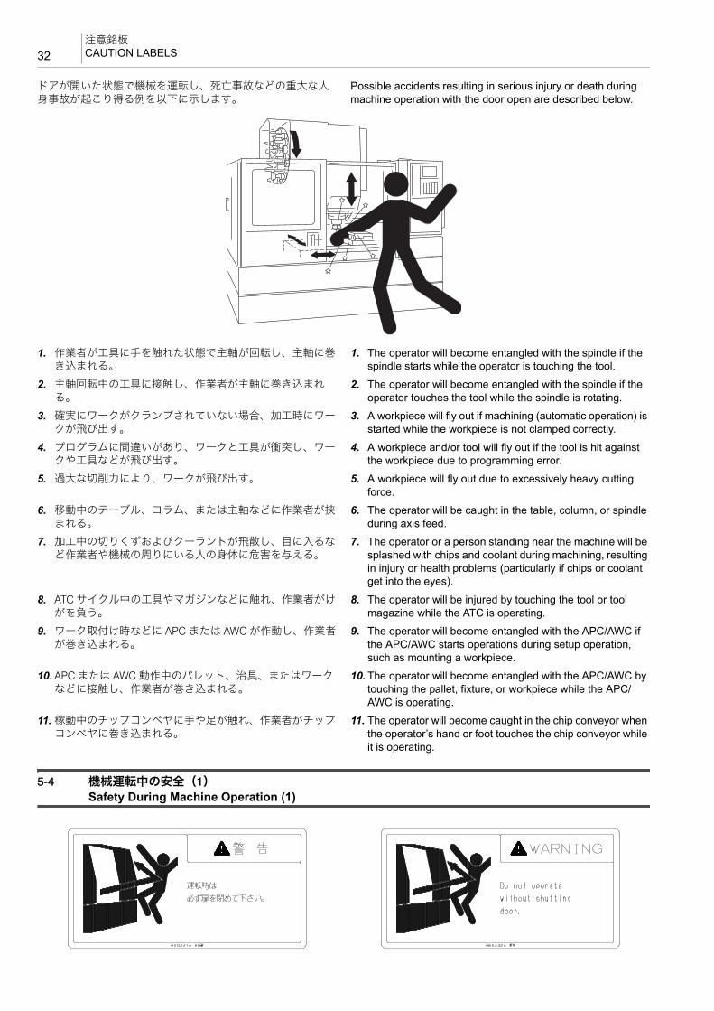
ドアが開いた状態で機械を運転し、死亡事故などの重大な人身事故が起こり得る例を以下に示します。
Possible accidents resulting in serious injury or death during machine operation with the door open are described below.
1. 作業者が工具に手を触れた状態で主軸が回転し、主軸に巻き込まれる。
1. The operator will become entangled with the spindle if the spindle starts while the operator is touching the tool.
2. 主軸回転中の工具に接触し、作業者が主軸に巻き込まれる。
2. The operator will become entangled with the spindle if the operator touches the tool while the spindle is rotating.
3. 確実にワークがクランプされていない場合、加工時にワークが飛び出す。
3. A workpiece will fly out if machining (automatic operation) is started while the workpiece is not clamped correctly.
4. プログラムに間違いがあり、ワークと工具が衝突し、ワークや工具などが飛び出す。
4. A workpiece and/or tool will fly out if the tool is hit against the workpiece due to programming error.
5. 過大な切削力により、ワークが飛び出す。 5. A workpiece will fly out due to excessively heavy cutting force.
6. 移動中のテーブル、コラム、または主軸などに作業者が挟まれる。
6. The operator will be caught in the table, column, or spindle during axis feed.
7. 加工中の切りくずおよびクーラントが飛散し、目に入るなど作業者や機械の周りにいる人の身体に危害を与える。
7. The operator or a person standing near the machine will be splashed with chips and coolant during machining, resulting in injury or health problems (particularly if chips or coolant get into the eyes).
8. ATC サイクル中の工具やマガジンなどに触れ、作業者がけがを負う。
8. The operator will be injured by touching the tool or tool magazine while the ATC is operating.
9. ワーク取付け時などに APC または AWC が作動し、作業者が巻き込まれる。
9. The operator will become entangled with the APC/AWC if the APC/AWC starts operations during setup operation, such as mounting a workpiece.
10. APC または AWC 動作中のパレット、治具、またはワークなどに接触し、作業者が巻き込まれる。
10. The operator will become entangled with the APC/AWC by touching the pallet, fixture, or workpiece while the APC/AWC is operating.
11. 稼動中のチップコンベヤに手や足が触れ、作業者がチップコンベヤに巻き込まれる。
11. The operator will become caught in the chip conveyor when the operator’s hand or foot touches the chip conveyor while it is operating.
5-4 機械運転中の安全(1)Safety During Machine Operation (1)
33注意銘板
CAUTION LABELS
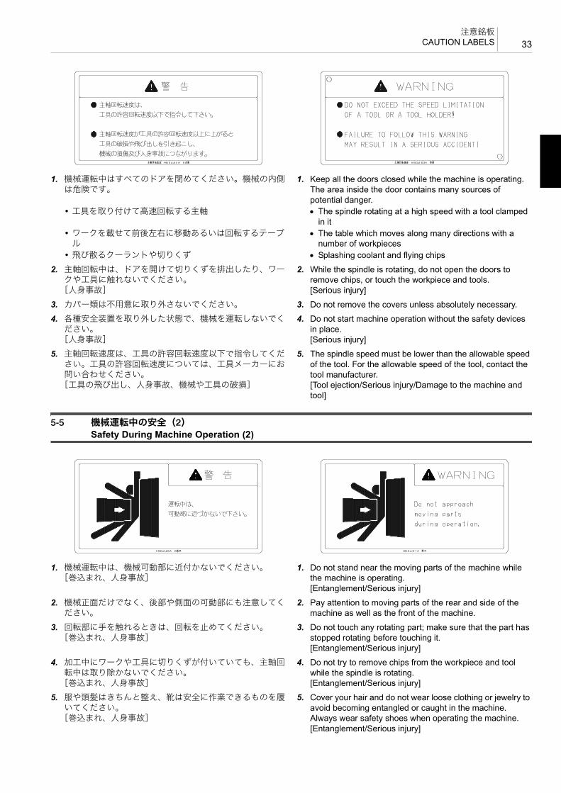
1. 機械運転中はすべてのドアを閉めてください。機械の内側は危険です。
1. Keep all the doors closed while the machine is operating. The area inside the door contains many sources of potential danger.
• 工具を取り付けて高速回転する主軸 • The spindle rotating at a high speed with a tool clamped in it
• ワークを載せて前後左右に移動あるいは回転するテーブル
• The table which moves along many directions with a number of workpieces
• 飛び散るクーラントや切りくず • Splashing coolant and flying chips
2. 主軸回転中は、ドアを開けて切りくずを排出したり、ワークや工具に触れないでください。
[人身事故]
2. While the spindle is rotating, do not open the doors to remove chips, or touch the workpiece and tools.[Serious injury]
3. カバー類は不用意に取り外さないでください。 3. Do not remove the covers unless absolutely necessary.
4. 各種安全装置を取り外した状態で、機械を運転しないでください。
[人身事故]
4. Do not start machine operation without the safety devices in place.[Serious injury]
5. 主軸回転速度は、工具の許容回転速度以下で指令してください。工具の許容回転速度については、工具メーカーにお問い合わせください。
[工具の飛び出し、人身事故、機械や工具の破損]
5. The spindle speed must be lower than the allowable speed of the tool. For the allowable speed of the tool, contact the tool manufacturer.[Tool ejection/Serious injury/Damage to the machine and tool]
5-5 機械運転中の安全(2)Safety During Machine Operation (2)
1. 機械運転中は、機械可動部に近付かないでください。[巻込まれ、人身事故]
1. Do not stand near the moving parts of the machine while the machine is operating.[Entanglement/Serious injury]
2. 機械正面だけでなく、後部や側面の可動部にも注意してください。
2. Pay attention to moving parts of the rear and side of the machine as well as the front of the machine.
3. 回転部に手を触れるときは、回転を止めてください。[巻込まれ、人身事故]
3. Do not touch any rotating part; make sure that the part has stopped rotating before touching it.[Entanglement/Serious injury]
4. 加工中にワークや工具に切りくずが付いていても、主軸回転中は取り除かないでください。
[巻込まれ、人身事故]
4. Do not try to remove chips from the workpiece and tool while the spindle is rotating.[Entanglement/Serious injury]
5. 服や頭髪はきちんと整え、靴は安全に作業できるものを履いてください。
[巻込まれ、人身事故]
5. Cover your hair and do not wear loose clothing or jewelry to avoid becoming entangled or caught in the machine. Always wear safety shoes when operating the machine.[Entanglement/Serious injury]

注意銘板CAUTION LABELS34
6. 機械可動部や操作パネルの上に、工具や測定機器などを置かないでください。
6. Do not leave any tools or instruments on the operation panel or on any moving part of the machine.
7. 機械稼動中は、機械にもたれかからないでください。特にカバー部は危険です。
7. Do not lean against the machine while it is operating. Leaning on the covers can be very dangerous.
5-6 ツーリングと ATCTooling and ATC
1. 機械運転中はマガジン内の工具に触れないでください。また、その他の可動部に近づいたり、触れたりしないでください。
[負傷、人身事故]
1. Do not try to touch the tools in the magazine while the machine is operating. Keep away from the other moving parts as well.[Injury/Serious injury]
2. ワークや工具は常に確実にクランプしてください。[ワークや工具の落下、機械や工具の破損]
2. Clamp workpieces and tools securely.[Falling of workpieces and tools/Damage to the machine and tool]
3. 切削時の切込み、送りは低い段階から始めてください。 3. Depth of cut and cutting feed must be selected from a smaller value.
4. 工具は各機種の制限範囲内のものを使用してください。[工具とワーク、治具、およびカバーとの干渉]
4. Use tools within the limit of each machine model only.[Tool interference with the workpiece, fixture, and cover]
5. マガジンに工具を取り付ける前に、主軸穴、工具テーパシャンク表面、およびマガジンポットテーパ穴をきれいなウエスでよくふき、切りくずやゴミを取り除いてください。
[機械の破損]
5. Before mounting a tool in the magazine, clean the tapered hole in the taper shank of the tool holder, and the magazine pot with a clean cloth to remove chips and dust.[Machine damage]
5-7 ワークのセッティングと APC(APC 仕様)Workpiece Setting and APC (APC Specifications)
1. ワークをセットするときは、セットアップボタンランプやラストパレットランプが消えていることを確認してください。これらのランプが点灯中は、自動的にパレットが交換されるので危険です。
1. Before fixing a workpiece, always check that the setup button lamp or the last pallet indicator is not illuminated. When the setup indicator is illuminated, the pallet is changed automatically. This can be a hazardous situation.
2. APC やパレットプール内には立ち入らないでください。保守作業のために APC やパレットプール内に立ち入るときは、機械を停止させ、電源をしゃ断してください。
[人身事故]
2. Do not enter the APC or pallet pool. When entering the APC or pallet pool, always stop the machine and disconnect the main power.[Serious injury]
3. パレットのローディング/アンローディング中は、機内に手を入れないでください。
[巻込まれ、人身事故]
3. Do not put your hand inside the machine while a pallet is being loaded or unloaded.[Entanglement/Serious injury]

35注意銘板
CAUTION LABELS
4. パレットプール仕様の機械では、段取りステーション以外のパレットには触れないでください。
[巻込まれ、人身事故]
4. With pallet pool specification machines, do not try to touch the pallet at a position other than the setup station.[Entanglement/Serious injury]
5. 段取りステーション上で治具やワークを着脱するときは、パレットが浮き上がったり、傾いたりする方向に力をかけないでください。
[パレットの落下]
5. When mounting or removing a fixture or workpiece at the setup station, do not apply force in directions that will lift or tilt the pallet.[Falling of the pallet]
5-8 閉込め防止キーLocked-In Prevention Key
閉込め防止キーは機種によりオプションとして装備されます。 The locked-in prevention key is provided as an option depending on the machine type.
< A タイプ> <Type A>
閉込め防止キー(A タイプ)を回すとドアを閉めても完全には閉まりません。機械の清掃や保守作業を行う場合、やむを得ず機内に入って作業をするときは、電源をしゃ断し、閉込め防止キーを回し、キーを抜き取って機内に持ち込んでください。
Turning the locked-in prevention key (type A) makes it impossible to fully close the door so the door cannot be closed. If it is necessary to carry out cleaning or maintenance inside the machine, turn the power OFF, turn the key, and remove it. Take the key with you when you enter the machine.
< B タイプ> <Type B>
閉込め防止キー(B タイプ)を抜き取ると、ドアを閉めても完全には閉まりません。機械の清掃や保守作業を行う場合、やむを得ず機内に入って作業をするときは、閉込め防止キーを抜き取って機内に持ち込んでください。
Removing the locked-in prevention key (type B) makes it impossible to fully close the door so the door cannot be closed. If it is necessary to carry out cleaning or maintenance inside the machine, remove the locked-in prevention key and carry it with you when you enter the machine.
5-9 チップコンベヤ(チップコンベヤ仕様)Chip Conveyor (Chip Conveyor Specifications)
1. チップコンベヤ稼動中は、手や足をチップコンベヤ内に入れないでください。
[巻込まれ、人身事故]
1. Do not attempt to reach inside the chip conveyor or put your feet in it while it is operating.[Entanglement/Serious injury]
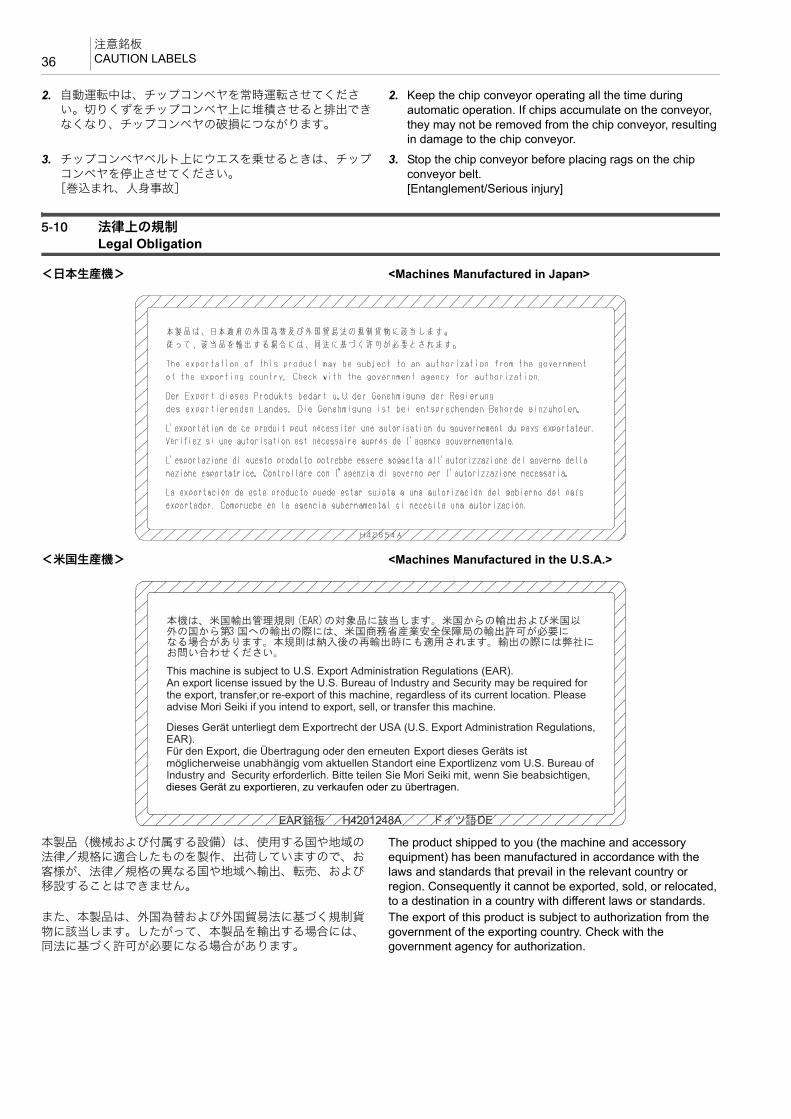
注意銘板CAUTION LABELS36
2. 自動運転中は、チップコンベヤを常時運転させてください。切りくずをチップコンベヤ上に堆積させると排出できなくなり、チップコンベヤの破損につながります。
2. Keep the chip conveyor operating all the time during automatic operation. If chips accumulate on the conveyor, they may not be removed from the chip conveyor, resulting in damage to the chip conveyor.
3. チップコンベヤベルト上にウエスを乗せるときは、チップコンベヤを停止させてください。
[巻込まれ、人身事故]
3. Stop the chip conveyor before placing rags on the chip conveyor belt.[Entanglement/Serious injury]
5-10 法律上の規制Legal Obligation
<日本生産機> <Machines Manufactured in Japan>
<米国生産機> <Machines Manufactured in the U.S.A.>
本製品(機械および付属する設備)は、使用する国や地域の法律/規格に適合したものを製作、出荷していますので、お客様が、法律/規格の異なる国や地域へ輸出、転売、および移設することはできません。
The product shipped to you (the machine and accessory equipment) has been manufactured in accordance with the laws and standards that prevail in the relevant country or region. Consequently it cannot be exported, sold, or relocated, to a destination in a country with different laws or standards.
また、本製品は、外国為替および外国貿易法に基づく規制貨物に該当します。したがって、本製品を輸出する場合には、同法に基づく許可が必要になる場合があります。
The export of this product is subject to authorization from the government of the exporting country. Check with the government agency for authorization.
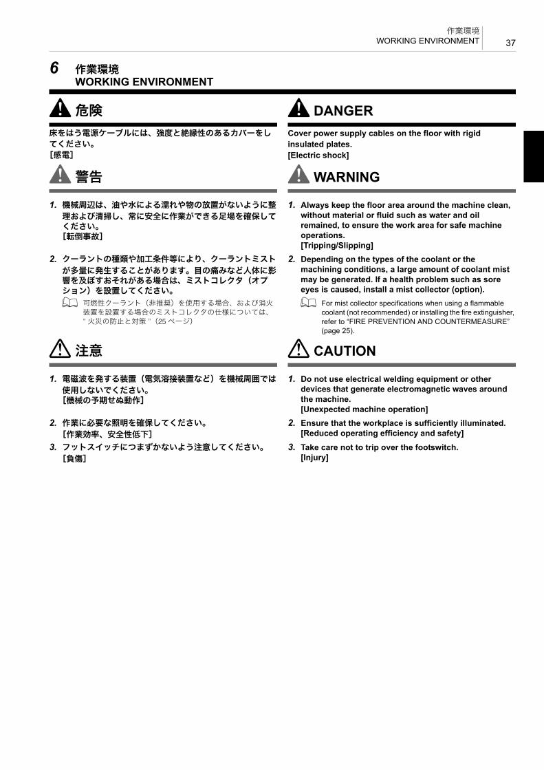
37作業環境
WORKING ENVIRONMENT
6 作業環境WORKING ENVIRONMENT
8危険 8 DANGER床をはう電源ケーブルには、強度と絶縁性のあるカバーをしてください。[感電]
Cover power supply cables on the floor with rigid insulated plates.[Electric shock]
8警告 8WARNING
1. 機械周辺は、油や水による濡れや物の放置がないように整
理および清掃し、常に安全に作業ができる足場を確保してください。
[転倒事故]
1. Always keep the floor area around the machine clean, without material or fluid such as water and oil remained, to ensure the work area for safe machine operations.[Tripping/Slipping]
2. クーラントの種類や加工条件等により、クーラントミスト
が多量に発生することがあります。目の痛みなど人体に影響を及ぼすおそれがある場合は、ミストコレクタ(オプション)を設置してください。
2. Depending on the types of the coolant or the machining conditions, a large amount of coolant mist may be generated. If a health problem such as sore eyes is caused, install a mist collector (option).
1 可燃性クーラント(非推奨)を使用する場合、および消火装置を設置する場合のミストコレクタの仕様については、“ 火災の防止と対策 ”(25 ページ)
1 For mist collector specifications when using a flammable coolant (not recommended) or installing the fire extinguisher, refer to “FIRE PREVENTION AND COUNTERMEASURE” (page 25).
7注意 7 CAUTION
1. 電磁波を発する装置(電気溶接装置など)を機械周囲では
使用しないでください。[機械の予期せぬ動作]
1. Do not use electrical welding equipment or other devices that generate electromagnetic waves around the machine.[Unexpected machine operation]
2. 作業に必要な照明を確保してください。
[作業効率、安全性低下]
2. Ensure that the workplace is sufficiently illuminated.[Reduced operating efficiency and safety]
3. フットスイッチにつまずかないよう注意してください。
[負傷]
3. Take care not to trip over the footswitch.[Injury]

段取り作業SETUP OPERATION38
7 段取り作業SETUP OPERATION
1 段取り作業時は、“ 機械操作 ”(41 ページ)も参照してください。
1 For the setup operation, also refer to “MACHINE OPERATION” (page 41).
8警告 8WARNING
1. 段取り作業中は、作業者の安全を確保するために下記の対
策を実施してください。
1. During setup, implement the following safety measures.
<自動運転を開始させたくないとき> <To prevent automatic operation start>• ハンドルモードを選択する。 • Select the handle mode.<誤って自動運転を開始させた場合を考えた安全対策> <To ensure operator safety if automatic operation is
started by mistake>• 各オーバライドスイッチ(早送り/切削送り)の設定を
低にする。• Set override switches (rapid traverse rate, cutting
feedrate) at the lowest setting.• シングルブロック機能をオンにする。 • Turn the single block function ON.• マシンロック機能をオンにする。 • Turn the machine lock function ON.• クーラントボタン 8〔オフ〕を 1 秒以上押し、クーラントオフモードにする。
• Activate the coolant OFF mode by pressing the coolant button 8 [OFF] (Off) for longer than one second.
<主軸を回転させたくないとき> <To prevent spindle rotation start>• パネル操作選択キースイッチをu〔操作不可〕にする。 • Turn the operation selection key-switch to u [OFF].• MDI 操作で “S0” を指令する。 • Enter “S0” by MDI operation.<誤って主軸を回転させた場合を考えた安全対策> <To ensure operator safety if the spindle is started by
mistake>• 主軸回転速度調整ボタンの設定を 低にする。 • Set the spindle speed setting button to the lowest
setting.
2. 主軸 高回転速度の出荷時設定は、注意銘板で確認してく
ださい。[ワーク/切削工具の飛び出しによる人身事故、機械の破損]
2. For the default setting of the spindle speed limit, check the caution label.[Serious injury by workpiece or tool ejection/Machine damage]
3. 主軸回転速度はホルダや切削工具の許容回転速度の内で
も低い回転速度以下を指令してください。[ワーク/切削工具の飛び出しによる人身事故、機械の破損]
3. Specify a spindle speed limit that is lower than the lowest of the individual permissible rotation speeds for the tool holder and cutting tool.[Serious injury by workpiece or tool ejection/Machine damage]
4. テスト加工時の切込み量や送り速度などの加工条件は生産
性を追求した条件ではなく余裕のある加工条件から始めてください。
[ワーク/切削工具の飛び出しによる人身事故、機械の破損]
4. Determine the depth of cut and cutting feedrate for test cutting with safe operation as the first priority. Do not give priority to productivity when making these determinations.[Serious injury by workpiece or tool ejection/Machine damage]
5. ワークの材質/形状/加工方法を十分検討して切削工具や
把持具を選定し、異常なくワークを加工できるか確認してください。
[ワーク/切削工具の飛び出しによる人身事故、機械の破損、加工精度の低下]
5. Select the most appropriate cutting tool and holder for the material and shape of the workpiece to be machined, as well as the cutting method, and check that the workpiece can be machined without any problems.[Serious injury by workpiece or tool ejection/Machine damage/Impaired machining accuracy]
6. 切削工具の取付け状態および主軸の回転速度を確認してか
ら主軸を回転させてください。[ワーク/切削工具の飛び出しによる人身事故、機械の破損]
6. Before starting the spindle, carefully check that the cutting tool is mounted correctly and the spindle speed is appropriate.[Serious injury by workpiece or tool ejection/Machine damage]

39段取り作業
SETUP OPERATION
7. 手締めの治具を使用するときは、締付け工具を使用した
後、治具から取り外してください。[締付け工具の飛び出しによる人身事故、機械の破損]
7. When using a manually tightened fixture, remove the clamp handle or tightening tool from the fixture after tightening.[Serious injury by tightening tool ejection/Machine damage]
8. ワークや切削工具は確実にクランプしてください。
[ワーク/切削工具の飛び出しによる人身事故、機械の破損]
8. Clamp workpieces and cutting tools securely.[Serious injury by workpiece or tool ejection/Machine damage]
9. 切削工具/ホルダ/把持具/ワークが確実に固定されてい
るか確認してください。[ワーク/切削工具の飛び出しによる人身事故、機械の破損]
9. Make sure that the cutting tool, holder, workpiece holding fixture and workpiece are all tightened securely.[Serious injury by workpiece or tool ejection/Machine damage]
10.クレーンによる作業は、クレーン運転士免許のある人が
行ってください。[事故、機械の破損]
10.Only qualified engineers are to perform hoisting work.[Accident/Machine damage]
11.ワーク/治具などの吊上げ作業を 2 人以上で行うときは、
お互いに合図しあって、注意して作業を行ってください。[事故]
11.When two or more persons are involved in the hoisting of the workpiece or fixture, clear communication and cooperation is necessary.[Accident]
12.ワーク/治具などの吊上げ時は、ワークなどの質量に耐え
るワイヤロープ、シャックル、吊上げ治具などを使用してください。
[ワーク/治具の落下]
12.When hoisting the workpiece or fixture, use only wires, shackles and jigs strong enough to support the total weight of the workpiece.[Dropped workpiece or fixture]
13.ワーク/治具などの吊上げ前に、ワークなどが確実に把持
されているか確認してください。[ワーク/治具の落下]
13.Before hoisting the workpiece or fixture, check that it is held securely.[Dropped workpiece or fixture]
14.ワーク/治具などを少し吊り上げた状態で、前後/左右の
バランスが取れているか確認してください。[ワーク/治具の落下]
14.Ensure the workpiece or fixture is well balanced in both crosswise and lengthwise directions when raised slightly from the floor.[Dropped workpiece or fixture]
15.マガジンツールアンクランプ用フットスイッチ付き機械で
は、工具取出し時は両手で工具を持ってからフットスイッチを踏んでください。
[切削工具の落下による機械の破損、人身事故]
15.When using a machine equipped with the magazine tool unclamp footswitch, ensure the tool is securely supported with both hands prior to removal, then depress the footswitch.[Machine damage caused by falling cutting tools/ Serious injury]
16.治具やワークの着脱を行うときは、パレットが浮き上がっ
たり傾いたりする方向に力をかけないでください。
16.When mounting or removing a fixture or workpiece, do not apply force in directions that will lift or tilt the pallet.
17.パレットを取り外して治具の着脱やパレット交換などを行
い、再度パレットを載せるときは、テーブルとパレットの位相(お互いの向き)を確認して正しい位置に取り付けてください。
17.When loading a pallet after mounting/removing fixtures or after a pallet change, be sure to mount the pallet in the correct position by checking the phases (relative orientation) of the table and the pallet.
7注意 7 CAUTION
1. APC または AWC 仕様では、パレット上の許容積載質量を
超えたワークを載せないでください。治具やワークを取り付けるときはバランスよく取り付けてください。
[機械の破損]
1. In the case of machines with an APC/AWC, do not place a workpiece exceeding the allowable mass on the pallet. Ensure a balanced load when mounting fixtures and workpieces.[Machine damage]
2. ホルダにエンドミルなどの工具を取り付けるときは、主軸
にホルダを入れた状態で工具を締め付けないでください。専用の締付け台にホルダを固定し、確実に工具を締め付けてください。
[機械の破損]
2. When clamping a cutting tool such as an end mill in the tool holder, do not tighten the tool in the holder while the holder is in the spindle. Always tighten the tool in the holder by using the special tool holder clamp base before mounting the holder in the spindle.[Machine damage]

段取り作業SETUP OPERATION40
3. 切削工具を主軸から手動操作で取り外すときは、切削工具
を確実に支持した後にアンクランプしてください。また機内に切削工具を落とさないよう注意してください(U 軸仕様を除く)。
[機械の破損、負傷]
3. When removing a cutting tool from the spindle manually, make sure that it is properly supported before unclamping. Also take care to ensure the cutting tool does not fall (except machines with a U-axis).[Machine damage/Injury]
4. HSK 工具ホルダを使用する場合、工具およびホルダに貫通
穴があるとき、ホルダ内部にセンタスルークーラント用パイプまたは詰栓を取り付けてください。取り付けないと、切りくずがツールクランプ部や主軸テーパ部などの構造部に侵入し、主軸およびホルダに損傷を与えます。
[機械の破損]
4. When using the HSK tool holder, if the tool and the holder have a through hole, make sure that the center-through coolant pipe or a plug is installed in the holder. If not, chips could enter the mechanical parts of the tool clamping unit or the spindle taper, damaging the spindle and the holder.[Machine damage]
5. 重量物の取付け/取外し/移動時はクレーンやリフタなど
の装置を使用してください。[負傷]
5. When handling (mounting, removing, or moving) a heavy object, use appropriate equipment such as a crane or a hoist.[Injury]

41機械操作
MACHINE OPERATION
8 機械操作MACHINE OPERATION
8危険 8 DANGER
1. 機械使用の前に電源ケーブルや電線の被覆部が損傷してい
ないことを確認してください。[感電]
1. Confirm all cables are properly insulated prior to machine operation.[Electric shock]
2. 濡れた手で操作しないでください。
[感電]
2. Do not operate with wet hands.[Electric shock]
3. 保護カバー内や回転部、可動部付近に人や障害物がないこ
とを確認してから運転を始めてください。[巻込まれ、人身事故]
3. Confirm no personnel or obstacles remain inside protective covers or close to rotating or moving parts before starting machine operation.[Entanglement/Serious injury]
8警告 8WARNING
1. 機械周辺や内部に人や障害物のないことを確認してから機
械を操作してください。機械の可動部には近づかないでください。
[機械の破損、人身事故、干渉]
1. Before operating the machine, confirm there are no personnel or obstacles around or inside the machine. Keep distance from moving parts.[Machine damage/Serious injury/Interference]
2. 各スイッチやボタン、キーは、その位置と機能をよく確認
してから、確実に操作してください。[機械の誤作動]
2. Before using a switch, button, or key, perform visual confirmation and then press or set decisively to avoid selection errors.[Machine malfunction]
3. 仕様の変更、機械の改造およびパラメータの変更が必要な
場合は、弊社にご連絡ください。[機械の性能や寿命の低下]
3. Do not change machine specifications, parameters or modify the machine without prior consultation with DMG MORI SEIKI.[Impaired machine performance/Machine service life reduction]
4. 切削条件により騒音が発生する可能性がある場合は、騒音
が大きくならないよう切削条件を変更するか、発生する騒音に応じて保護具を着用してください。
[聴覚に支障]
4. When operating noise may be produced, change cutting conditions to limit the generation of noise or ensure the operator wears protective gear to avoid injury due to excessive noise levels.[Impaired hearing]
1 機械騒音データは、“ 機械操作説明書 ” 1 For the machine noise data, refer to “OPERATION MANUAL”.
5. ドアを閉めた状態で、機械を運転してください。
[破損した工具/ワークの飛び出し、切りくず/クーラントの飛散]
5. Keep the doors closed during machine operation.[Broken tools and workpiece ejection/Chips and coolant scattered]
6. APC または AWC 仕様ではパレット上の許容積載質量を超
えたワークを載せないでください。[動作不良]
6. For machines with APC/AWC, do not place a workpiece exceeding the allowable mass on the pallet.[Mechanical error]
7. 本機は防爆仕様ではありません。ドアを閉めた状態でも、
大型のワークなどが高速回転中に飛び出して与える衝撃やマグネシウムなどの金属加工時に発生する有害粉じんの飛散や爆発などの危険を完全に防ぐことはできません。ドアやその他の保護具を過信せず、作業には十分な注意を払ってください。
7. This is not the explosion-proof specification machine. Dangers such as the ejection of a large workpiece or harmful dust or an explosion caused by the machining of metals such as magnesium are not preventable even if the door is closed. Do not rely on door and protective devices alone. Recognition of the dangers involved in machining procedures is required at all times.
8. オペレータ(全加工担当者)は、機械使用時、保護メガネ
を着用してください(メガネ着用者含む)。[粉じんが目に入るなどの事故]
8. Operators must wear safety glasses at all times, (including operators wearing prescription glasses).[Eye damage due to ejected foreign matter]
9. 手袋をして機械を使用しないでください。
[巻込まれ、人身事故(死亡)]
9. Do not wear gloves when operating the machine. [Entanglement/Serious injury (death)]
10.ワークに布やすりを当てて研削しないでください。不意に
巻き込まれます。[巻込まれ、人身事故(死亡)]
10.Do not grind workpieces with emery cloths. It may get entangled.[Entanglement/Serious injury (death)]

機械操作MACHINE OPERATION42
11.2 人以上で機械操作を行う場合は、お互いに合図しあって、
十分注意して作業してください。[事故、人身事故]
11.When the machine is operated by more than one operator, cooperation and communication between them is required at all times.[Accident/Serious injury]
12.主軸や各回転部に近づかないでください。
[巻込まれ、人身事故]
12.Keep a safe distance away from spindles or other rotating parts.[Entanglement/Serious injury]
13.チップコンベヤが稼動しているときは、手や足をチップコ
ンベヤ内に入れないでください(チップコンベヤ仕様)。[巻込まれ、人身事故]
13.Do not place hands or feet inside the chip conveyor (if installed) during operation.[Entanglement/Serious injury]
14.加工中に機内の切りくずを取り除くとき、またクーラント
の吐出方向や吐出量を調整するときは、機械を停止してから作業を行ってください。
[巻込まれ、人身事故]
14.Stop the machine before removing chips or adjusting the direction or volume of coolant supply.[Entanglement/Serious injury]
15.加工中に機械を一時停止するとき、手動操作による軸移動
は行わないでください。やむを得ずこれらの操作を行ったときは、加工を再開する前に、一時停止させたときと同じ状態に戻してください。
[機械内部の干渉]
15.Do not manually feed the axes during temporary machine stops except when absolutely necessary. Always return the axes to their original positions before restarting operations.[Component interference]
16.ワークについたバリやかえりを手作業で取るときは、ワー
クを取り外し、機外で作業を行ってください。[巻込まれ、人身事故]
16.When removing burrs on a workpiece by hand, ensure the workpiece is removed from the machine prior to performing the deburring procedure.[Entanglement/Serious injury]
17.ワーク、切削工具、ホルダ、治具が、常に確実に固定され
ているか確認してください。[ワークや切削工具の飛び出し、機械の破損、人身事故]
17.Ensure workpiece, cutting tool, holder, fixtures are tightened securely.[Workpiece or tool ejection/Machine damage/Serious injury]
18.窓から 20 cm 以上離れて作業を行ってください。この窓は
耐衝撃窓であり、工具の飛び出しなどの強い衝撃を受けたときは、窓自体が大きく変形して衝撃を緩和します。さらに強い衝撃によっては、窓が割れたり貫通したりする場合があります。
[負傷]
18.Always work at a safety margin of at least 20 cm from the window. This impact resistant window could be substantially deformed to ease the impact of an ejected tool. With further impact, the window could break or be penetrated. [Injury]
19.工程の途中のブロックをサーチして加工を再開しないでく
ださい。[機械の予期せぬ動作]
19.Never restart machining after searching for a block executed in the program.[Unexpected machine operation]
20.APCまたはAWC仕様では、APCまたはAWC操作パネルの
セットアップランプ点灯中にパレットチェンジャ内および機内に手足を入れないでください。
[巻込まれ]
20.For machines with APC/AWC, never put your hands or feet inside the pallet changer or machine while the setup indicator on the APC/AWC operation panel is illuminated.[Entanglement]
21.ワークを把持させるときおよび取り外すときは、手などを
はさまないよう注意してください。[負傷]
21.When clamping or unclamping a workpiece in the chuck, ensure hands do not become trapped.[Injury]
22.加工中にドアを開けるときは、ドアインタロック機能が通
常モードになっていることを確認してください。また、加工を再開するときは、ドアを閉めてください。
[人身事故]
22.Before opening the door during a machining operation, make sure that the door interlock function is in the normal mode. Close the door before restarting the machine operation.[Serious injury]
23.長時間無人運転を行うときや、可燃性のクーラントやワー
クを使用する前は、自動消火装置などを設置してください。
[火災]
23.Before carrying out unmanned operation over extended periods, or machining using flammable coolant or workpieces, install automatic fire extinguishing equipment.[Fire]
24.工具の長さ、直径、質量が機械の使用制限内であっても、
使用する治具や工具などの条件により、主軸を 高回転速度で回転させられないことがあります。
[無理に主軸を高速で回転させることによる工具の飛び出し、機械の破損、人身事故]
24.The spindle might not be rotated by maximum speed by conditions such as fixtures and tools used even if length, the diameter, and the mass of the tool are in the use limitations of the machine.[Tool ejection by rotating spindle at high speed forcibly/Machine damage/Serious injury]

43機械操作
MACHINE OPERATION
25.ドアインタロック関連機器の異常に気が付いた場合は、機
械の使用を中止し、弊社サービス部門にご連絡ください。[機械の破損、人身事故]
25.Stop machine operation immediately and contact the DMG MORI SEIKI Service Department following malfunction of any device related to the door interlock function.[Machine damage/Serious injury]
26.本機は、実行中のプログラムを先読みする機能を備えてお
り、自動運転の一時停止時、加工再開の処理待ち時間をなくすために先読みプログラム指令を NC 内に記憶した状態を保持します。したがって、機械の自動運転を一時停止させたときは、プログラム指令や軸の現在位置を確認してください。加工を続行しない場合などは、必要に応じ @
(リセット)キーを押し、NC 内に記憶されたプログラム指令を消去してください。特に、一時停止後にプログラム開始位置を変更した場合は、加工再開後に NC 内に記憶されたプログラム指令が働き、事故につながる可能性があります。他社製品では先読みしたプログラム情報が一時停止時に消去される場合があるため、仕様の違いに十分注意してください。
[機械の予期せぬ動作、干渉]
26.This machine is equipped with a read-ahead function for the running program, and retains the read-ahead program commands stored in the NC memory during a temporary stop of automatic operation in order to eliminate latency time when restarting. Therefore, check the program commands or present positions of the axes when stopping the machine temporarily. In cases such as when discontinuing the machining, press the @ (RESET) key to clear the program commands stored in the NC if necessary. Changing the program start position after a temporary stop in particular may cause accidents after the machining is restarted since the program commands stored in the NC are activated. Pay extra attention to the difference in the specifications in relation to other manufacturers' machines because the read-ahead program data may be cleared at temporary stops on these machines.[Unexpected machine motion/Interference]
8警告 8WARNING<主軸の回転について> <Spindle Rotation>
1. 主軸を回転させるときは、加工条件を確認してから行って
ください。[工具の飛び出し、機械の破損、人身事故]
1. Before starting the spindle, check the machining conditions.[Tool ejection/Machine damage/Serious injury]
2. 主軸が回転中は、ドアを開けないでください。
[巻込まれ、人身事故]
2. Do not open the door during spindle rotation.[Entanglement/Serious injury]
7注意 7 CAUTION
1. 機械運転中に異音や振動がある場合は、その原因を確か
め、対処してください。[機械の破損、加工精度に悪影響]
1. If abnormal noise or vibration is generated during machine operation, determine the cause and take appropriate action.[Machine damage/Impaired machining accuracy]
2. カーボンやセラミックなど、粉末状の切りくずが出るよう
な材質のワークを加工するときは、弊社サービス部門にご連絡ください。
[作業者の粉じん吸引、摺動部やベアリングの隙間への粉じんの侵入]
2. When machining a workpiece such as carbon or ceramics which generate powder particles, contact the DMG MORI SEIKI Service Department.[Inhaling powder particles, Powder particles entering slideway or gap between bearing]
3. 始業時および加工前には、主軸、各制御軸の慣らし運転を
行ってください。[機械の熱変位により加工精度に悪影響]
3. Perform spindle and controlled axis test running procedures prior to machining.[Thermal displacement adversely affecting machining accuracy]
4. 機内照明灯に不用意に触れないでください。また、電源
しゃ断後も、すぐには触れないでください。[やけど]
4. Do not touch lamps used to illuminate the interior of the machine during machine operation or immediately following power OFF.[Burns]
5. 切削工具がワークに接触しているときに、主軸の回転を停
止させないでください。[切削工具や機械の破損]
5. Do not stop spindle rotation while a cutting tool is in contact with the workpiece.[Cutting tool and machine damage]

機械操作MACHINE OPERATION44
6. ねじ切り加工中および穴加工、特にタップサイクル中に
〔非常停止〕ボタンまたは@(リセット)キーを押して停
止操作を行ったときは、ワークや切削工具の状態をよく調べてから、慎重に軸移動を行ってください。
[ワークや切削工具が衝突および干渉]
6. When the [EMERGENCY STOP] (Emergency Stop) button or the @ (RESET) key has been pressed to stop the machine during a threading operation or a hole machining operation, especially a tapping operation, carefully feed the axes after checking the condition of the workpiece and cutting tool.[Collision or interference between workpiece and cutting tool]
7. APCまたはAWC仕様では、APCまたはAWCサイクル中に
〔非常停止〕ボタンまたは@(リセット)キーを押して停
止操作を行ったときはワークや切削工具の状態をよく調べてから慎重に軸移動を行ってください。
[ワークと切削工具の衝突/干渉]
7. When the [EMERGENCY STOP] (Emergency Stop) button or the @ (RESET) key has been pressed to stop the machine while an APC/AWC cycle is in progress for the machines with APC/AWC, carefully move the axes after checking the workpiece and cutting tool for damage.[Workpiece and cutting tool collide or interfere with each other]
8. 操作パネルの下で作業したり、その下をくぐるときは、頭
を強打しないよう十分注意してください。[負傷]
8. If you have to work or crouch under the operation panel, be careful not to hit your head on it.[Injury]
9. ハードオーバトラベル機能が装備されている機械でハード
オーバトラベルを解除するとき、〔第 2 O.T. 解除〕ボタンを押すと、軸移動に関するインタロックは解除されます。絶対にハードオーバトラベルした方向には軸移動しないでください。また、安全のためハードオーバトラベル状態が解除されるまで、ハンドル送り操作〔×1〕で軸移動を行ってください。
[往復台とカバーが干渉]
9. When releasing the hard overtravel on a machine with that function, the axis movement interlock can be released by pressing the [2nd O.T. Release] button. Do not move the axis in the direction in which the hard overtravel occurred. For safety reasons, feed the axes using the handle feed [×1] until the hard overtravel status has been canceled.[Interference between carriage and covers]
10.クーラントが十分でないときは、加工直後の工具、ワー
ク、切りくずが高温になります。温度が下がるまで触れないでください。
[やけど]
10.If the coolant supply is not sufficient, tools, workpieces, and chips will reach high temperatures shortly after the production. Do not touch them until the temperature drops.[Burns]
<タッチパネル> <Touch Panel>
1. タッチパネルは傷つきやすいので、必ず指で触れて操作し
てください。タッチペンを付属している機械では、タッチペンを使用してください。
1. Use a finger to touch the panel as it can be easily scratched. Use a touch-pen if one is supplied with the machine.
2. ボールペンなど先端の固いものや鋭利なもの、また爪の先
で操作しないでください。
2. Do not touch the panel with anything with a solid tip, such as a ballpoint pen, anything sharp, or a fingernail.
3. 同時に 2 箇所以上のキーを押さないでください。
[機械の予期せぬ動作による機械の破損]
3. Do not press more than one key at the same time.[Machine damage by unexpected machine operation]
4. 市販の液晶保護フィルムは使用しないでください。
[タッチパネルの誤作動]
4. Do not use commercially available liquid crystal protective film.[Improper operation of touch panel]
5. 手袋を着用して操作しないでください。
[タッチパネルの傷つき、誤作動]
5. Do not touch the panel while wearing gloves.[Improper operation of touch panel, scratches]
6. タッチパネルの表面の汚れなどを拭き取る場合は、市販の
クリーニングクロスを使い、爪を立てずに指の腹で軽く拭いてください。
6. If the touch panel is smudged, wipe the smudging off gently with a commercially available cleaning cloth using the ball of a finger; not a fingernail.
7. アルコールを含んだクリーニング液は使用しないでくださ
い。[タッチパネルの劣化、機械の破損]
7. Do not use cleaning fluid containing alcohol.[Deterioration of touch panel/Machine damage]

45機械操作
MACHINE OPERATION
8-1 ドアインタロックDoor Interlock
8警告 8WARNING
1. 機種により、ドアインタロック機能関連機器の名称が異な
ります。お客様の機種に合ったタイプをご確認ください。
1. The controls for the door interlock function are different in their names according to the specifications. Check your machine specifications and read the explanation below for the interlock function of your machine.
< A タイプ> <Type A>機械を使用するときは、ドアインタロック機能を〔通常〕モードにしてください。ドアインタロック機能を〔セッティング〕モードにして機械を使用するときは、操作に多くの危険が存在することを認識し、十分注意してください。安全および機械操作について十分な訓練を受けた人だけが、ドアインタロック機能を〔セッティング〕モードにして操作することができます。〔セッティング〕モード状態での操作を終了した後は、ドアインタロック機能を〔通常〕モードに戻してください。
[機械の予期せぬ動作、機械の破損、人身事故]
The door interlock function must be in the [NORMAL] mode when operating the machine. If operating the machine with the door interlock switched to the [SETTING] mode, awareness of the dangers involved and particular attention given to safety during machine operation is essential. Only person who are trained sufficiently in safety and machine operation are permitted to switch the door interlock function to the [SETTING] mode and operate the machine. Following completion of the operation, ensure the door interlock is switched back to the [NORMAL] mode immediately.[Unexpected machine operation/Machine damage/Serious injury]
< B タイプ> <Type B>機械を使用するときは、ドアインタロック機能を〔通常〕モードにしてください。ドアインタロック機能を〔解除〕モードにして機械を使用するときは、操作に多くの危険が存在することを認識し、十分注意してください。安全および機械操作について十分な訓練を受けた人だけが、ドアインタロック機能を〔解除〕モードにして操作することができます。〔解除〕モード状態での操作を終了した後は、ドアインタロック機能を〔通常〕モードに戻してください。
[機械の予期せぬ動作、機械の破損、人身事故]
The door interlock function must be in the [NORMAL] mode when operating the machine. If operating the machine with the door interlock switched to the [RELEASE] mode, awareness of the dangers involved and particular attention given to safety during machine operation is essential. Only person who are trained sufficiently in safety and machine operation are permitted to switch the door interlock function to the [RELEASE] mode and operate the machine. Following completion of the operation, ensure the door interlock is switched back to the [NORMAL] mode immediately.[Unexpected machine operation/Machine damage/Serious injury]
〔インタロックモード〕キースイッチの〔通常〕〔セッティング〕
[INTERLOCK MODE] key-switch[NORMAL][SETTING]
状態表示ランプセッティングモード Status indicator SETTING MODE
INTERLOCK MODENORMAL SETTING
状態表示ランプ Status indicator
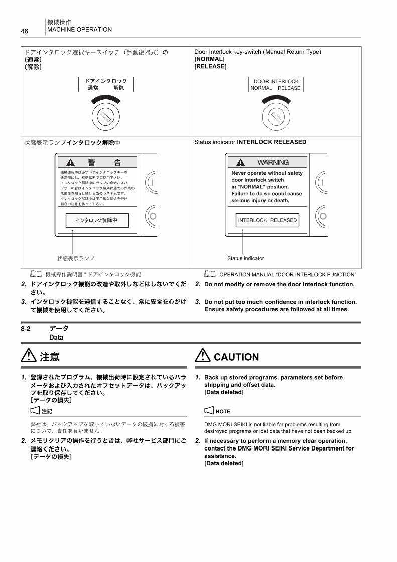
機械操作MACHINE OPERATION46
1 機械操作説明書 “ ドアインタロック機能 ” 1 OPERATION MANUAL “DOOR INTERLOCK FUNCTION”
2. ドアインタロック機能の改造や取外しなどはしないでくだ
さい。
2. Do not modify or remove the door interlock function.
3. インタロック機能を過信することなく、常に安全を心がけ
て機械を使用してください。
3. Do not put too much confidence in interlock function. Ensure safety procedures are followed at all times.
8-2 データData
7注意 7 CAUTION
1. 登録されたプログラム、機械出荷時に設定されているパラ
メータおよび入力されたオフセットデータは、バックアップを取り保存してください。
[データの損失]
1. Back up stored programs, parameters set before shipping and offset data.[Data deleted]
2 注記 2 NOTE
弊社は、バックアップを取っていないデータの破損に対する損害について、責任を負いません。
DMG MORI SEIKI is not liable for problems resulting from destroyed programs or lost data that have not been backed up.
2. メモリクリアの操作を行うときは、弊社サービス部門にご
連絡ください。[データの損失]
2. If necessary to perform a memory clear operation, contact the DMG MORI SEIKI Service Department for assistance.[Data deleted]
ドアインタロック選択キースイッチ(手動復帰式)の〔通常〕〔解除〕
Door Interlock key-switch (Manual Return Type)[NORMAL][RELEASE]
状態表示ランプインタロック解除中 Status indicator INTERLOCK RELEASED
DOOR INTERLOCKNORMAL RELEASE
状態表示ランプ Status indicator

47機械操作
MACHINE OPERATION
3. コモン変数 #147 の機内パレット番号(APC 仕様の場合)、
#148 の主軸工具番号、および #149 の MAPPS 工具管理補正番号/工具グループ番号(工具管理仕様の場合)は、NC の処理が BUSY になるとすぐには書き換えられません。つまり、データ更新の時間的な保証がありません。NC の処理が BUSY になるのはバックグラウンドでのRS-232C 入出力がほとんどですが、他の処理でも起こりえます。したがって、上記マクロ変数を使った処理を行う場合、特に重要な処理を行う場合には番号が書き換わったか確認するような処理をユーザマクロで行ってください。
[機械の破損]
3. The data stored in common variables #147 (pallet number of machine loaded pallet, if installed), #148 (spindle tool number), and #149 (MAPPS tool management offset number/tool group number, if installed) is not updated immediately if the NC is busy. This means data of these common variables are not guaranteed in the timing of data updating. The NC enters the busy state mainly caused by background input/output processing through the RS-232C interface. However, other processing could also make the NC busy. Therefore, if certain processing uses the data in the common variables above and when such processing is very important, it is necessary to check if the data in them have been updated to the latest number using a user macro.[Machine damage]
8-3 各種特別仕様Precautions when Operating Special Specification Machines
8警告 8WARNING特別仕様の機械では、その仕様に応じた使い方をしてください。
Optional specifications machines must be operated in compliance with such specifications.
<産業ロボット> <Industrial Robot Specifications>Only qualified personnel trained and approved in accordance with local regulations may operate robots. Unauthorized personnel may not operate robots under any circumstances, including teaching and inspection. Personnel assisting robot operators must be fully qualified.
1. 弊社のNC工作機械に、労働安全衛生規則第36条31号に該
当する産業用ロボットを取り付ける場合は、“ 労働安全衛生規則 ” および “ 産業用ロボットの使用等の安全基準に関する技術上の指針 ”(以下指針という)を遵守してください。(指針)
2. 産業用ロボットを取り付けるときは、安全に操作ができる
空間を確保し、適切な場所に〔非常停止〕ボタンを設置してください。(指針 3-1 配置など)
3. 人との接触事故を防止するため、産業用ロボットの稼動範
囲の外側に、囲いまたは代替品を設け、出入り口にはインタロック機能付きの安全プラグを取り付けてください。
(指針 4-1 接触防止措置)弊社では、安全柵や安全マットなどを準備しています。(オプション)
4. 作業開始前の点検で安全装置およびインタロック機能の動
作確認を行ってください。(5-1 作業開始前点検)
5. 作業に従事または共同作業をする作業者は、所定時間の学
科教育および実技教育を受けてください。(6-1 教育の内容)
<スタッカクレーン仕様> <Stacker Crane Specifications>スタッカクレーンの作業に従事するときは、労働安全法にもとづく “ 特別教育 ” が必要です。詳細は、弊社サービス部門にご連絡ください。
The stacker crane used with the machine has a capacity of less than 5 tons. Only qualified personnel may operate the stacker crane.

NC プログラムNC PROGRAM48
9 NC プログラムNC PROGRAM
8警告 8WARNING
1. 主軸の回転速度、切削時の送り速度や切込み量などの加工
条件はお客様が責任をもって決定してください。お客様で加工条件を決定しかねるときは、弊社サービス部門または切削工具メーカーにご相談ください。
[ワークの飛び出し、機械の破損、人身事故]
1. Select the appropriate spindle speed, cutting feedrate, and cutting depth. If appropriate operating conditions cannot be determined, contact the DMG MORI SEIKI Service Department or the cutting tool manufacturer.[Workpiece ejection/Machine damage/Serious injury]
2. 加工条件はワーク、切削工具および治具などの状況により
変化するため、自動プログラミングで決定される加工条件はお客様にとって 適な数値でないことがあります。
2. Note that machining conditions vary in accordance with the status of the workpiece, cutting tools, or fixture. Conditions determined by automatic programming are not necessarily the most suitable for individual user's purposes.
自動プログラミングで決定される加工条件を参考にしてお客様が責任を持って加工条件を決定してください。
[ワークの飛び出し、機械の破損、人身事故]
Determining operating conditions is the sole responsibility of the customer.[Workpiece ejection/Machine damage/Serious injury]
3. プログラムの読み違いによる入力ミス防止のため、分かり
やすく、正確なプログラムを書いてください。[機械内部の干渉、誤操作、ワークの飛び出し、機械の破損、人身事故]
3. Programmer must create an easy to read and thoroughly checked program in order to prevent the machine operator from misreading or inputting incorrect values.[Component interference/Erroneous operation/Workpiece ejection/Machine damage/Serious injury]
4. 小数点入力できるアドレスは、小数点の付け忘れがないか
確認してください。[機械内部の干渉、ワークの飛び出し、機械の破損、人身事故]
4. Always check that the decimal place is correctly entered during program input.[Component interference/Workpiece ejection/Machine damage/Serious injury]
5. 記載しているプログラム例は、すべての機械に対応してい
るわけではありません。お客様が購入された機械の能力を十分把握した上で、 適なプログラムを作成し、安全を考慮して加工を行ってください。機械の能力を十分把握せずにプログラムを作成し、加工を行うと、ワークや切削工具が飛び出すおそれがあります。
5. The programs given in this manual are not applicable to all types of machines. Programs must be written while taking the performance of the machine into consideration and be executed with due consideration given to safety. If the machine's capacity is not taken into account when writing the program, the workpiece or cutting tool may fly out during machining.
6. プログラム入力終了後は、パネル操作選択キースイッチを
i〔操作可〕またはu〔操作不可〕の位置に戻し、プロ
グラムが不用意に編集されないようにしてください。[機械の予期せぬ動作]
6. Place the operation selection key-switch in the i [ON] or u [OFF] position after completing program entry to prevent the program being accidentally updated.[Unexpected machine motion]
7注意 7 CAUTIONワークが鍛造品、鋳造品などの場合は、あらかじめワーク形状のばらつきを見込んだプログラムを作成するか、前加工で取り代を一定にしてください。[ワークの飛び出し、機械の破損、人身事故]
When machining forged or cast works, create a program that takes workpiece shape variations into consideration or perform pre-machining to determine a uniform cutting allowance.[Workpiece ejection/Machine damage/Serious injury]

49保守/点検
MAINTENANCE AND INSPECTION
10 保守/点検MAINTENANCE AND INSPECTION
8危険 8 DANGER
1. 電源をしゃ断してください。やむを得ず電源を投入した状
態で行うときは、十分に注意してください。[感電、人身事故]
1. Turn the power OFF before performing maintenance and inspection procedures. If absolutely necessary to work with the power ON, exercise extreme caution.[Electric shock/Serious injury]
2. 電気配線工事は、電気工事士に委託してください。
[感電]
2. Electrical wiring work is to be performed by qualified electrical engineers only.[Electric shock]
3. 電源が投入されていると危険を伴う保守作業時は、機械電
源スイッチを〔OFF〕の位置に回し、南京錠でロックしてください。
3. Ensure the main power switch is turned [OFF] and locked at all times when performing maintenance procedures considered dangerous if the power is ON.
1 南京錠でロックする方法については、機械操作説明書 “ 機械電源スイッチ ”
1 For locking the main power switch, refer to OPERATION MANUAL “Main Power Switch”.
4. 機内で作業を行うときは、ドアを開けた状態で行ってくだ
さい。[閉込め、負傷]
4. When working inside the machine, the door must be open.[Locked/Injury]
5. 周囲に “ 保守作業中 ” であることを明示してください。
[事故]
5. Provide clear warning that the machine is being maintained and operations cannot be performed.[Accident]
6. 制御盤、モータ、トランス、内部に電荷をおびた機器およ
び機内照明灯などの保守/点検作業を行うときは、工場側の機械用電源(ブレーカ)をしゃ断してください。機械電源のしゃ断後も通電箇所がありますので、さわらないでください。作業上必要な場合はテスタなどで通電状態を確認のうえ、作業を行ってください。やむを得ず電源を投入した状態で作業を行うときは、電気工事士に委託してください。
[感電]
6. Before performing maintenance and inspection procedures inside the electrical cabinet or on motors, transformers or machine lighting, confirm the plant side power supply (breaker) is turned OFF. Note that when the main power switch is turned OFF, parts may still contain residual electrical energy. Using a tester, confirm parts are free of residual energy prior to performing maintenance procedures. Maintenance procedures undertaken with the power turned ON must be performed by qualified electrical engineers.[Electric shock]
7. 保守・点検作業時以外は、制御盤や操作パネルのドアは開
けないでください。[ほこりや湿気の吸収、機械の破損]
7. Do not open electrical cabinet doors or the operation panel except to perform maintenance and inspection procedures.[Dust and moisture entry/Machine damage]
8. ボルトは必要以上に、強く締め付けないでください。
[機械のひずみ、ボルトの折損]
8. Do not overtighten bolts.[Machine distortion/Bolt breakage]
9. 機械を据え付けるときや移送するときは、機械に同梱され
たマニュアルや図面の記載内容を十分理解して作業を行ってください。油圧ジャッキなどを使用して機械を持ち上げるときは、転倒しないように機械のバランスに十分注意し、水平で十分な強度のある地面上で行ってください。
[機械の破損、人身事故]
9. Before installing or transferring the machine, read and make sure you understand the manuals or drawings supplied with the machine. When it is necessary to lift the machine using equipment such as a hydraulic jack, lift it up on flat ground with adequate strength, paying due attention to machine balance in order to prevent the machine from toppling over. [Machine damage/Serious injury]
1 据付説明書 1 INSTALLATION MANUAL
8警告 8WARNING
1. 部品を交換するときは、事前に弊社サービス部門にご連絡
ください。交換部品は弊社の指定品を使用してください。[機械能力低下、安全性低下]
1. Consult the DMG MORI SEIKI Service Department prior to performing replacement procedures. Use specified parts at all times.[Impaired machine performance and safety]

保守/点検MAINTENANCE AND INSPECTION50
2 注記 2 NOTE
弊社に連絡なく部品を交換して発生した事故、あるいは指定品以外の部品を交換して発生した事故に関して、弊社は責任を負いません。
DMG MORI SEIKI does not accept responsibility for accidents arising from the use of non-specified replacement parts or parts replaced without prior consultation.
2. 機械の上には登らないでください。
[落下]
2. Do not climb on top of the machine.[Falling]
3. 機内に工具やウエスなど不要な物を置かないでください。
[工具などの巻込まれ、飛散]
3. Do not leave articles such as tools and rags inside the machine.[Entanglement in tool/Ejection from machine]
4. 治具に使用しているボルトは、適切な強度を持った弊社指
定のボルトに定期的に交換してください。[ボルトの破損、ワーク/治具/切削工具の飛び出し、機械の破損、人身事故]
4. Bolts used for fixtures should be periodically replaced with the bolts specified by DMG MORI SEIKI that have appropriate strength.[Bolt breakage/Workpiece, fixture, cutting tool ejection/Machine damage/Serious injury]
5. 機械を使用するときは、ATC 単独操作時のインタロックな
どの各インタロック機能を “ 有効 ” にしてください。やむを得ず “ 無効 ” にして機械を使用するときは、操作に多くの危険が存在することを認識し、十分注意してください。“ 無効 ” 状態での操作を終了した後は、各インタロック機能を “ 有効 ” に戻してください。
[機械の予期せぬ動作、機械の破損、人身事故]
5. Interlock functions including ATC manual operating interlock must be ON when operating the machine. If necessary to operate the machine with the interlocks released, awareness of the dangers involved and particular attention given to safety during machine operation is essential. Following completion of the operation, ensure the interlocks are turned back ON immediately.[Unexpected machine operation/Machine damage/Serious injury]
6. インタロック機能の改造や取外しなどはしないでくださ
い。
6. Do not modify or remove interlock functions.
7. インタロック機能を過信しないでください。常に安全を心
がけて機械を使用してください。
7. Do not put too much confidence in interlock function. Ensure safety procedures are followed at all times.
7注意 7 CAUTION
1. ソレノイドバルブ、油圧ユニット、クーラントポンプ、
サーボモータなど高温になる箇所には電源をしゃ断した後もすぐには触れないでください。
[やけど]
1. Do not touch the hydraulic unit, coolant pump, solenoid valves and servomotors during, or immediately after operation as external surfaces reach high temperature.[Burns]
2. 切りくずや刃具に素手で触れないでください。
[負傷]
2. Do not touch chips or tool cutting edges with bare hand.[Injury]
3. 機械に付属しているキー(操作パネル/制御盤/付属機器
用など)は、お客様の責任で管理してください。
3. Management of keys supplied with the machine (operation panel, electrical cabinet, auxiliary devices) is the sole responsibility of the customer.
4. 制御盤用のキーなど、日常的に操作する必要のないキー
は、抜いた状態で保管してください。
4. Keys not used on a regular basis (electrical cabinet key) must be removed from the lock and stored in a secure location.
5. 塩素化炭化水素、アセトンあるいは同様の浸食性溶剤を使
用しないでください。[合成樹脂部品やシーリング(ワイパー)の破損]
5. Do not use chlorinated hydrocarbon, acetone, or equivalent erosive solvent. [Damage to synthetic resin parts or sealing (wiper)]
6. 切りくず/廃油/クーラントなどの産業廃棄物は自国の国
内法に基づいた処理をしてください。
6. Disposal of industrial waste such as oil, coolant, chips, and refrigerants is to be performed in strict compliance with safety and environmental protection laws as stipulated by the proper national and local authorities.

51保守/点検
MAINTENANCE AND INSPECTION
産業廃棄物処理の例
先託委物棄廃
廃油/クーラント 産業廃棄物処理の有資格者/廃油処理能力のあるガソリンスタンドや廃油業者
切りくず 産業廃棄物処理業者/金属リサイクル業者
各種冷却装置の冷媒
都道府県登録の第一種フロン類回収業者

機械の処分DISPOSITION OF MACHINES52
11 機械の処分DISPOSITION OF MACHINES
8警告 8WARNING
1. 機械を解体する前に、機械に接続されている電源ケーブル
やエアホースを外してください。
1. Before dismantling the machine, remove the power cord and air hose connected to the machine.
2. 制御盤内部や操作パネル内部などには、充電部がありま
す。作業には十分注意を払ってください。[感電]
2. There is a live part inside the electrical cabinet and the operation panel. Be sure to pay sufficient attention during the operation. [Electric shock]
3. 高圧ガス封入シリンダやエアシリンダは、内部の圧力を抜
いてから分解してください。[破裂、事故]
3. Dismantle high-pressure gas cylinders and air cylinders after eliminating pressure. [Bursting/Accident]
7注意 7 CAUTION機械の適切な処分は、機械所有者の責任です。機械を処分するにあたり、環境への配慮が強く求められます。環境保護およびリサイクルに関する自国の法律、各自治体の条例などを遵守してください。
Machine owners are responsible for appropriate machine disposal. Do not disturb the environment when you dispose the machines. Be sure to observe the laws of your country and regulations of local government concerning environmental conservation and recycling.
<液体> <Liquid>潤滑油、グリース、作動油、クーラントなどの液体は、各自治体にお問い合わせのうえ、適切に処分してください。
Contact local governments when disposing liquids such as lubricants, grease, hydraulic oil, coolants appropriately.
<電子機器> <Electronic Device>操作パネル内の電子部品、モニタ、キーボード、制御盤内の電子部品、ケーブル、測定装置(エンコーダ等)は、機器および部品がリサイクル可能か、各自治体にお問い合わせのうえ、適切に処分してください。
Appropriately dispose electrical parts in the operation panel, monitor, keyboard, electrical parts in the electrical cabinet, cable, measuring device (encoder, etc.) after having contacted the local government to check whether the devices and parts are recyclable.
<バッテリ> <Battery>バッテリや乾電池は、リサイクル可能か各自治体にお問い合わせのうえ、適切に処分してください。
Contact local governments to check whether batteries and dry-cell batteries are recyclable and appropriately dispose them.
<機械部品> <Machinery Parts>鋳物、板金、ボールねじ、ベアリング、バルブなどの機械部品はすべて、再生資源として適切に処分してください。
Appropriately dispose machine parts as recyclable resources such as casting, sheet metal, ball screw, bearing, and valve as scraps.
<ホース> <Hose>ホース類は、内部の液体を抜き取り、プラスチックごみまたは再生資源として適切に処分してください。
Appropriately dispose hoses as recyclable resources or plastic waste after having drained the liquid inside.
<冷媒> <Refrigerant>オイルクーラ、クーラント冷却装置、制御盤内クーラなど、すべての冷却装置には冷媒が使用されています。これらの装置の処分および冷媒の回収は、専門業者が行わなければなりません。機器がリサイクル可能か、各自治体にお問い合わせください。
Refrigerants are used in all cooling systems such as oil coolers, coolant cooling units, coolers in the electrical cabinet. The disposal of these cooling systems and recovery of refrigerants should be handled by professionals. Contact local governments to check whether the machines are recyclable.
<加工室内確認窓> <Machining Chamber Observation Window>加工室内確認窓は、ポリカーボネートとガラスの複合材でできています。この複合材がリサイクル可能か、各自治体にお問い合わせのうえ、適切に処分してください。
The machining chamber observation window consists of polycarbonate and tempered glass. Contact local governments to check whether the material is recyclable and appropriately dispose them.
<資料> <Document>機械に付属しているすべての資料および CD がリサイクル可能か、各自治体にお問い合わせのうえ、適切に処分してください。
Contact local governments to check whether all the related documents and CDs attached to the machine are recyclable and appropriately dispose them.
SX-MC-B012013.10.Y

1 章
1èÕ G 機能CHAPTER 1
CHAPTER 1 G FUNCTIONS

1 制御軸と動作方向 ................................................................................................................................ 55AXIS CONTROL AND MOVEMENT DIRECTION
2 G 機能...................................................................................................................................................... 57G FUNCTIONS

55制御軸と動作方向
AXIS CONTROL AND MOVEMENT DIRECTION
1 制御軸と動作方向AXIS CONTROL AND MOVEMENT DIRECTION
ここでは各制御軸とプログラムの関係について説明します。 This section describes movement along the controlled axis and its relationship with the program.
Column
Spindle Head
Table
コラム
主軸頭
テーブル

制御軸と動作方向AXIS CONTROL AND MOVEMENT DIRECTION56
1-1 制御軸の実際の動きとプログラム上での動きAxis Movement in Machine and Program
各制御軸の移動方向(+ 方向)は次の通りです。 The travel directions (+ direction) of the controlled axes are described below.
−X
+Y
−Y−Z
+Z
+X
−B+B
−X
+Y
−Y+Z
−Z
+X
+B−B
<Actual Axis Movement> <Axis Movement in Program>
Table
Spindle Side
Table
Spindle Side
<実際の動き> <プログラム上での動き>
テーブル
主軸側
テーブル
主軸側
制御軸 移動部分 実際の動き(+ 方向) プログラム上の動き(+ 方向)
X コラム主軸側から見て右(工具の回転軸からワークを見る向きに向かって右)
実際の動きと同じ。
Y 主軸頭主軸頭は主軸側から見て上(ワークから工具の回転軸を見る向きに向かって上)
実際の動きと同じ。
Z テーブル主軸側から見て奥(工具の回転軸からワークを見る向き)
“Z+_” と指令したときテーブルが止まっていて工具が動くと考えると、工具は主軸側から見て手前(ワークから工具の回転軸を見る向き)に移動。
B テーブル テーブルを上から見て時計回りテーブルが止まっていて工具が動くと考えると、工具はテーブルを上から見て反時計回りに移動。
Controlled Axis Unit Actual Axis Movement (+ Direction) Axis Movement in Program (+ Direction)
X ColumnRight when viewing from the spindle (right when viewing the workpiece from the column).
The same direction as actual movement.
Y Spindle head
Up when viewing from the spindle (up when viewing the workpiece from the column). The same direction as actual movement.
Z TableAway from the spindle (away when viewing the workpiece from the axis of rotation of the tool).
If the tool is assumed to move while the table remains stopped, the tool moves away from the column when viewing it from the spindle (away, when viewing the cutting tool rotating axis from the workpiece).
B Table Clockwise when viewing the table from the top.
If the tool is assumed to move while the table remains stopped, the tool moves counterclockwise when viewing the table from the top.

57G 機能
G FUNCTIONS
2 G 機能G FUNCTIONS
8警告 8WARNINGこの説明書に記載しているプログラムは参照用にすぎません。実際の加工は機械仕様と 適な加工条件を十分に検討し、安全に考慮して行ってください。
The programs herein are only for reference purpose. For the actual machining, study the machine specifications and optimized machining conditions sufficiently taking safety into account.
1 この章に記載していない G コードについて、あるいはさらなる詳細については、制御装置メーカー作成の取扱説明書を参照してください。
1 For the G codes not explained in this chapter or further details, refer to the instruction manual supplied by the NC unit manufac-turer.
2-1 G コード一覧表G Code List
G コードは準備機能とも呼ばれます。アドレス G とそれに続く数値により、指令されたブロックがどのような加工方法か、また、軸がどのような動きをするかを NC に準備させる機能です。
G codes are also called preparatory functions. The G codes consisting of the address G and a numerical value that follows address G define the machining method and the axis movement mode in a specified block. The NC establishes the control mode in response to the specified G code.
アドレス G に続く数値によって、そのブロックの命令がどのような意味を持つかを指示します。G コードには次の 2 種類があります。
The numerical value following address G defines the commands written in that block.
G コードは、そのコードが指令された後いつまで有効であるかによって、次の 2 種類に分けられます。
Depending on how the G codes remain valid, they are classified into the following two types:
たとえば G01, G00 はモーダルな G コード(00 グループ以外の G コード)です。
For example, G00 and G01 are both modal codes, that is, they are G codes in the group other than group 00.
2 注記 2 NOTE
1. フォーマットに従った順序で指令してください。 1. Specify the codes according to format order.2. G コードは、異なるグループであればいくつでも同一ブロックに
指令できます。2. More than one G code may be specified in the same block if their
G code groups differ from each other.3. 同一グループの G コードを同じブロックに 2 つ以上指令すると、
後で指令した G コードが有効になります。3. If more than one G code, belonging to the same group, are
specified in a block, the one specified later is valid.4. G コード一覧表にのっていない G コード、あるいは対応するオプ
ションの付いていない G コードを指令すると、画面にアラーム(P34)が表示されます。
4. If a G code not listed in the G code table or a G code for which the corresponding option is not selected is specified, an alarm message (P34) is displayed on the screen.
5. G に続く数値を指令しないでプログラムを実行すると、アラーム(P33)が発生します。
5. When a program is executed including a G code without number, an alarm (P33) occurs.
6. の記号の付いている G コードは、電源投入時あるいは @(リセット)キーを押したあと、その G コードの状態になること
を示します。
6. The NC establishes the G code modes, identified by the symbol, when the power is turned on or when the @ (RESET) key is pressed.
ただし、G17, G49, G54, G94, G97 については、@(リセット)キーを押しても、その G コードの状態にならず、各グループ内で選択されている G コードの状態になります。
Concerning G17, G49, G54, G94 and G97, however, pressing the @ (RESET) key does not establish the G code mode of them but the G code selected for each group remains valid.
種別 機能
ワンショット G コード(00グループの G コード)
指令されたブロックに限り有効
モーダル G コード(00 グループ以外の G コード)
同一グループの他の G コードが指令されるまで有効
Type Function
One-shot G code (G codes in group 00)
Valid only in the specified block.
Modal G code (G codes in groups other than group 00)
Valid until another G code in the same group is specified
G01 X_ Z_ ;X_ ;Z_ ;............................................................................ このブロックまで G01 が有効 G01 is valid up to this block.G00 X_ Z_ ;

G 機能G FUNCTIONS58
7. 同期式タッピングは G84, G74 の直前のブロックに M29 S_ と指令します。
7. For synchronized tapping, specify “M29 S_” to the block just before the block containing G84 or G74.
@:標準 ^:オプション
コード グループ 機能 区分 ぺージ
G00
01
位置決め @ 66
G01 直線補間 @ 67
G02 円弧補間/ヘリカル補間/渦巻き補間/円錐補間 時計方向@/@/^/
^
687176
G02.2 インボリュート補間時計方向 ^ 81
G03 円弧補間/ヘリカル補間/渦巻き補間/円錐補間 反時計方向@/@/^/
^
687176
G03.2 インボリュート補間反時計方向 ^ 81
G04
00
ドウェル/イグザクトストップ @ 83
G05 高速高精度制御 II(高精度輪郭制御)/ SSS 制御 ^/^8489
G05.1 高速高精度制御 I(AI 輪郭制御)/ SSS 制御 ^/^8489
G07.1 21 円筒補間 ^ 85
G08
00
高精度制御(先行制御)/ SSS 制御 @/^8889
G09 イグザクトストップ @ 90
G10 データ設定 @93
187
G11 データ設定モードキャンセル @ —
G12.121
極座標補間モード ^ —
G13.1 極座標補間キャンセルモード ^ —
G1518
極座標指令キャンセル ^ 95
G16 極座標指令 ^ 95
G17
02
XpYp 平面 Xp:X 軸またはその平行軸 @ 96
G18 ZpXp 平面 Yp:Y 軸またはその平行軸 @ 96
G19 YpZp 平面 Zp:Z 軸またはその平行軸 @ 96
G2006
インチ入力 @ —
G21 メトリック入力 @ —
G27
00
原点(レファレンス点)復帰チェック @ 98
G28 機械原点(レファレンス点)復帰 @ 98
G29 原点(レファレンス点)からの復帰 @ —
G30 第 2 /第 3、第 4 原点(レファレンス点)復帰 @/@ 98
G30.1 – G30.6 フローティングレファレンス点復帰 @ —
G31 スキップ機能 @ 100
G31.1 外部高速スキップ ^ 100
G33 01 ねじ切り ^ —
G40 07 工具径補正キャンセル @ 193
G40.1 (G150)
15 法線方向制御キャンセルモード ^ 102

59G 機能
G FUNCTIONS
G41 07 工具径補正左 @ 193
G41.1 (G151)
15 法線方向制御左側オン ^ 102
G42 07 工具径補正右 @ 193
G42.1 (G152)
15 法線方向制御右側オン ^ 102
G43
08
工具長補正 + @188190
G43.4 工具先端点制御(タイプ 1) ^ 104
G43.5 工具先端点制御(タイプ 2) ^ 105
G44 工具長補正 − @ 188
G45
00
工具位置補正 伸長 @ 105
G46 工具位置補正 縮小 @ 105
G47 工具位置補正 2 倍伸長 @ 105
G48 工具位置補正 2 倍縮小 @ 105
G49 08 工具長補正キャンセル @ 190
G50 11 スケーリングキャンセル/プログラマブルミラーイメージ(負の倍率) ^ 108
G50.1 19 プログラマブルミラーイメージキャンセル @ 112
G51 11 スケーリング/プログラマブルミラーイメージ(負の倍率) ^ 108
G51.1 19 プログラマブルミラーイメージ @ 112
G5200
ローカル座標系設定 @ 114
G53 機械座標系選択 @ 115
G5412
ワーク座標系 1 選択 @ 116
G54.1 追加ワーク座標系選択 ^ 118
G54.2 23 回転軸ワーク位置補正 ^ 308
G54.4 27 ワーク設置誤差補正 ^ 119
G55
12
ワーク座標系 2 選択 @ 118
G56 ワーク座標系 3 選択 @ 116
G57 ワーク座標系 4 選択 @ 116
G58 ワーク座標系 5 選択 @ 116
G59 ワーク座標系 6 選択 @ 116
G60 00 一方向位置決め @ 125
G61
13
イグザクトストップモード @ 138
G62 自動コーナオーバライドモード @ 139
G63 タッピングモード @ 138
G64 切削モード @ 138
G65 00 マクロ呼出し @ 127
G66
14
マクロモーダル呼出し(移動指令呼出し) @ 127
G66.1 マクロモーダル呼出し(毎ブロック呼出し) @ 127
G67 マクロモーダル呼出しキャンセル @ 127
@:標準 ^:オプション
コード グループ 機能 区分 ぺージ

G 機能G FUNCTIONS60
G68
16
座標回転/ 3 次元座標変換 ^130132
G68.2 フィーチャ座標系設定(傾斜面加工指令) ^ 140
G69 座標回転キャンセル/ 3 次元座標変換キャンセル/フィーチャ座標系設定(傾斜面加工指令)キャンセル
^130132
G73
09 穴あけ固定サイクル
高速深穴ドリリングサイクル @ 223
G74逆タッピングサイクル/ペッキング逆タップサイクル/深穴逆タップサイクル
@233235
G76 ファインボーリングサイクル @ 248
G80 穴あけ固定サイクルキャンセル @ 213
G81 スポットドリリングサイクル @ 219
G82 カウンタボーリングサイクル @ 219
G83 深穴ドリリングサイクル @ 225
G84タッピングサイクル/ペッキングタップサイクル/深穴タップサイクル
@233235
G85 ボーリングサイクル @ 221
G86 ボーリングサイクル @ 221
G87 バックボーリングサイクル @ 248
G88 ボーリングサイクル @ 222
G89 ボーリングサイクル @ 222
G9003
アブソリュート指令 @ 135
G91 インクレメンタル指令 @ 135
G9200
ワーク座標系の設定/主軸 高回転速度の設定 @ —
G92.1 ワーク座標系プリセット ^ 136
G93
05
インバースタイム送り ^ 136
G94 毎分送り @ 136
G95 毎回転送り ^ 137
G9617
周速一定制御 ^ —
G97 周速一定制御キャンセル ^ —
G9810
穴あけ固定サイクルイニシャル点レベル復帰 @ 213
G99 穴あけ固定サイクル R 点レベル復帰 @ 213
@:標準 ^:オプション
コード グループ 機能 区分 ぺージ

61G 機能
G FUNCTIONS
G300 —
パターンサイクル
円弧上の点(等ピッチ) @254263
G301 — 円弧上の点(不等ピッチ) @255263
G302 — 直線上の点(等ピッチ) @256263
G303 — 直線上の点(不等ピッチ) @258263
G304 — 四角上、格子上の点 @259263
G305 — 千鳥格子上の点 @262263
G306 — 円内側切削(仕上げ) @ 264
G307 — 円外側切削(仕上げ) @ 266
G308 — 四角内側切削(仕上げ) @ 267
G309 — 四角外側切削(仕上げ) @ 269
G313 — 負荷監視マクロプログラム呼出し @ 320
G320 — 自動心出し/自動計測のマクロ呼出し ^ —
G323 — センサ補正のマクロ呼出し ^ —
G324 — 自動工具長測定のマクロ呼出し ^ —
G325 — 自動工具折損検出のマクロ呼出し ^ —
G332 — 加工モード選択 @ 146
G370 — 基準面計測のマクロ呼出し ^ —
G388 — 工具補正データ書込み @ —
G389 — 工具補正データ読出し @ —
G400 — モーダル指令キャンセル ^ —
G412 —
真円切削サイクル
真円切削内側(CW) ^ —
G413 — 真円切削内側(CCW) ^ —
G414 — 真円切削外側(CW) ^ —
G415 — 真円切削外側(CCW) ^ —
G424 —
平面削りサイクル
四角平面削り ^ —
G425 — 四角平面単定寸 ^ —
G426 — 四角平面両定寸 ^ —
G427 —
ポケット切削サイクル
円ポケット削り ^ —
G428 — 四角ポケット削り ^ —
G429 — トラック内側 ^ —
G430 — 円外周ポケット削り ^ —
G431 — 四角外周削り ^ —
G432 — トラック外側 ^ —
G433 — 真円内側 ^ —
@:標準 ^:オプション
コード グループ 機能 区分 ぺージ

G 機能G FUNCTIONS62
G434 —
高速加工サイクル
トロコイドサイクル ^ —
G435 — 高速側面切削サイクル ^ —
G436 — Z フィード溝サイクル ^ —
G437 — コーナポケットサイクル ^ —
G438 — 四角ポケットサイクル ^ —
G439 — ヘリカル穴あけサイクル ^ —
G450 —
単形状固定サイクル
凸球面加工サイクル ^ —
G451 — 凹球面加工サイクル ^ —
G452 — 楕円外側切削サイクル ^ —
G453 — 楕円内側切削サイクル ^ —
G454 — ヘリカルねじ切りサイクル ^ —
G455 — 丸材からの角削りサイクル ^ —
G456 —面取り加工サイクル
円筒上のくぼみ面取りサイクル ^ —
G457 — 円筒上のキー溝面取りサイクル ^ —
G480 —
穴あけパターンサイクル
ボルトホールサイクル ^ —
G481 — アークサイクル ^ —
G482 — ラインアットアングルサイクル ^ —
G483 — グリッドサイクル ^ —
@:Standard ^:Option
Code Group Function Division Page
G00
01
Positioning @ 66
G01 Linear interpolation @ 67
G02 Circular interpolation/Helical interpolation/Spiral interpolation/Conical interpolation, CW (clockwise)
@/@/^/^
687176
G02.2 Involute interpolation, CW (clockwise) ^ 81
G03 Circular interpolation/Helical interpolation/Spiral interpolation/Conical interpolation, CCW (counterclockwise)
@/@/^/^
687176
G03.2 Involute interpolation, CCW (counterclockwise) ^ 81
G04
00
Dwell/Exact stop @ 83
G05 High-speed high-accuracy control II (high precision contour control)/SSS control ^/^ 84
89
G05.1 High-speed high-accuracy control I (AI contour control)/SSS control ^/^ 8489
G07.1 21 Cylindrical interpolation ^ 85
G08
00
High-accuracy control (look-ahead control)/SSS control @/^ 8889
G09 Exact stop @ 90
G10 Data setting @93
187
G11 Data setting mode cancel @ —
@:標準 ^:オプション
コード グループ 機能 区分 ぺージ

63G 機能
G FUNCTIONS
G12.121
Polar coordinate interpolation mode ^ —
G13.1 Polar coordinate interpolation cancel ^ —
G1518
Polar coordinate command cancel ^ 95
G16 Polar coordinate command ^ 95
G17
02
XpYp plane Xp: X-axis or its parallel axis @ 96
G18 ZpXp plane Yp: Y-axis or its parallel axis @ 96
G19 YpZp plane Zp: Z-axis or its parallel axis @ 96
G2006
Data input in inch system @ —
G21 Data input in metric system @ —
G27
00
Zero (reference position) return check @ 98
G28 Machine zero (reference position) return @ 98
G29 Return from zero point (reference position) @ —
G30 Second/third, fourth zero (reference position) return @/@ 98
G30.1 – G30.6 Floating reference point return @ —
G31 Skip function @ 100
G31.1 External high-speed skip ^ 100
G33 01 Thread cutting ^ —
G40 07 Tool radius offset cancel @ 193
G40.1 (G150) 15 Normal direction control cancel mode ^ 102
G41 07 Tool radius offset, left @ 193
G41.1 (G151) 15 Normal direction control ON (left side) ^ 102
G42 07 Tool radius offset, right @ 193
G42.1 (G152) 15 Normal direction control ON (right side) ^ 102
G43
08
Tool length offset, + @188190
G43.4 Tool center point control (type 1) ^ 104
G43.5 Tool center point control (type 2) ^ 105
G44 Tool length offset, − @ 188
G45
00
Tool position offset, increase @ 105
G46 Tool position offset, decrease @ 105
G47 Tool position offset, double-increase @ 105
G48 Tool position offset, double-decrease @ 105
G49 08 Tool length offset cancel @ 190
G50 11 Scaling cancel/Programmable mirror image cancel (negative magnification) ^ 108
G50.1 19 Programmable mirror image cancel @ 112
G51 11 Scaling/Programmable mirror image (negative magnification) ^ 108
G51.1 19 Programmable mirror image @ 112
G5200
Local coordinate system setting @ 114
G53 Machine coordinate system selection @ 115
@:Standard ^:Option
Code Group Function Division Page

G 機能G FUNCTIONS64
G5412
Work coordinate system 1 selection @ 116
G54.1 Additional work coordinate system selection ^ 118
G54.2 23 Workpiece position offset for rotary axis ^ 308
G54.4 27 Work setting error offset ^ 119
G55
12
Work coordinate system 2 selection @ 118
G56 Work coordinate system 3 selection @ 116
G57 Work coordinate system 4 selection @ 116
G58 Work coordinate system 5 selection @ 116
G59 Work coordinate system 6 selection @ 116
G60 00 Uni-directional approach @ 125
G61
13
Exact stop mode @ 138
G62 Automatic corner override mode @ 139
G63 Tapping mode @ 138
G64 Cutting mode @ 138
G65 00 Macro call @ 127
G66
14
Macro modal call (call after execution of axis movement commands) @ 127
G66.1 Macro modal call (call in each block) @ 127
G67 Macro modal call cancel @ 127
G68
16
Coordinate rotation/3D coordinate conversion ^130132
G68.2 Setting feature coordinate system (Tilted working plane command) ^ 140
G69 Coordinate rotation cancel/3D coordinate conversion cancel/Feature coordinate system set cancel ^
130132
G73
09 Hole machining canned cycle
High-speed deep hole drilling cycle @ 223
G74Reverse tapping cycle/Pecking reverse tapping cycle/Deep hole reverse tapping cycle
@233235
G76 Fine boring cycle @ 248
G80 Hole machining canned cycle cancel @ 213
G81 Spot drilling cycle @ 219
G82 Counter boring cycle @ 219
G83 Deep hole drilling cycle @ 225
G84 Tapping cycle/Pecking tapping cycle/Deep hole tapping cycle @
233235
G85 Boring cycle @ 221
G86 Boring cycle @ 221
G87 Back boring cycle @ 248
G88 Boring cycle @ 222
G89 Boring cycle @ 222
G9003
Absolute command @ 135
G91 Incremental command @ 135
G9200
Work coordinate system setting/Maximum spindle speed setting @ —
G92.1 Workpiece coordinate system preset ^ 136
@:Standard ^:Option
Code Group Function Division Page

65G 機能
G FUNCTIONS
G93
05
Inverse time feed ^ 136
G94 Feed per minute mode @ 136
G95 Feed per revolution mode ^ 137
G9617
Constant surface speed control ^ —
G97 Constant surface speed control cancel ^ —
G9810
Initial point level return (hole machining canned cycle) @ 213
G99 Point R level return (hole machining canned cycle) @ 213
G300 —
Pattern cycles
Arc (equal interval) @254263
G301 — Arc (random interval) @255263
G302 — Line-at-angle (equal interval) @256263
G303 — Line-at angle (random interval) @258263
G304 — Rectangle/grid @259263
G305 — Staggered grid @262263
G306 — Circle cutting inside (finishing) @ 264
G307 — Circle cutting outside (finishing) @ 266
G308 — Frame cutting inside (finishing) @ 267
G309 — Frame cutting outside (finishing) @ 269
G313 — Calling the load monitor macro program @ 320
G320 — Macro program call (automatic centering/automatic measurement) ^ —
G323 — Macro program call (sensor offset) ^ —
G324 — Macro program call (automatic tool length measurement) ^ —
G325 — Macro program call (automatic tool breakage detection) ^ —
G332 — Cutting mode selection @ 146
G370 — Macro program call (reference face measurement) ^ —
G388 — Writing tool offset data @ —
G389 — Reading tool offset data @ —
G400 — Modal command cancel ^ —
G412 —
Accurate circle cutting cycle
Accurate circle cutting, internal CW ^ —
G413 — Accurate circle cutting, internal CCW ^ —
G414 — Accurate circle cutting, external CW ^ —
G415 — Accurate circle cutting, external CCW ^ —
G424 —
Flat milling cycle
Rectangular milling cycle ^ —
G425 — Rectangular milling cycle with one-side wall ^ —
G426 — Rectangular milling cycle with two-side wall ^ —
@:Standard ^:Option
Code Group Function Division Page

G 機能G FUNCTIONS66
2-2 G00 早送りによる工具の移動G00 Positioning Cutting Tool at Rapid Traverse Rate
G00 は、早送り速度で工具を移動させる時に指令します。 By specifying the G00 command, all axis movement commands are executed at the rapid traverse rate.
G00 は、おもに次の動作をさせるときに指令します。 The G00 mode is usually used for the following operations:
1. 加工開始 1. At the start of machining:工具をワークに近づけるとき。 To move the cutting tool close to the workpiece.
2. 加工中 2. During machining:工具がワークに接触していない状態で、次の指令点に工具を移動させるとき。
To move the cutting tool, retracted from the workpiece, to the next programmed target point.
7注意 7 CAUTION加工中に早送りで工具を移動させる場合、工具経路に障害物がないことを確認してください。
When moving the cutting tool at a rapid traverse rate during machining, make sure that there are no obstacles in the tool paths.
G427 —
Pocketing cycle
Circular pocketing cycle ^ —
G428 — Rectangular pocketing cycle ^ —
G429 — Inner track machining cycle ^ —
G430 — Circular circumferential pocketing cycle ^ —
G431 — Rectangular circumferential machining ^ —
G432 — Outer track machining cycle ^ —
G433 — Inner accurate circle cutting ^ —
G434 —
High-speed machining cycle
Trochoid machining cycle ^ —
G435 — High-speed side milling cycle ^ —
G436 — Z-feed grooving cycle ^ —
G437 — Corner pocketing cycle ^ —
G438 — Rectangular pocketing cycle ^ —
G439 — Helical hole machining cycle ^ —
G450 —
Mono-shape canned cycle
Convex hemisphere cycle ^ —
G451 — Concave hemisphere cycle ^ —
G452 — External oval machining cycle ^ —
G453 — Internal oval machining cycle ^ —
G454 — Helical threading cycle ^ —
G455 — Rectangular milling cycle from round material ^ —
G456 —Chamfering cycle
Concave chamfering cycle on cylinder ^ —
G457 — Keyway chamfering cycle on cylinder ^ —
G480 —
Drilling pattern cycle
Bolt hole drilling cycle ^ —
G481 — Arc drilling cycle ^ —
G482 — Line-at-angle drilling cycle ^ —
G483 — Grid drilling cycle ^ —
@:Standard ^:Option
Code Group Function Division Page

67G 機能
G FUNCTIONS
3. 加工終了 3. At the end of machining:工具をワークから遠ざけるとき。 To move the cutting tool away from the workpiece.
7注意 7 CAUTION
1. G00 で X 軸、Y 軸および Z 軸を同時に指令して、切削工具を
移動させる場合、工具経路は必ずしも現在位置と指令点を結ぶ直線にはなりません。X 軸、Y 軸および Z 軸の早送り速度を考慮して、工具経路に障害物がないことを確認してください。
[干渉、機械の破損]
1. If X-, Y-, and Z-axes movements are specified in the same block in the G00 mode, the tool path is not always a straight line from the present position to the programmed end point. Therefore, when specifying positioning in the G00 mode, make sure that there is no obstacle in the path of positioning, which is determined according to the traverse rate of the individual axes (X, Y, Z).[Interference/Machine damage]
2. G00 指令で、たとえば X 軸移動後に Y 軸を移動させたり、Y軸移動後に X 軸を移動させると、工具はプログラムで指令した位置よりも、内側を通って移動します。つまり、一定の幅内に到達すると(インポジション)、指令終点位置まで到達していなくても、次のブロックのプログラムが実行されます。プログラム作成時は、ワークとの干渉を十分考慮してください。 インポジションチェックの有効・無効は下記パラメータ設定で切り替えることができます。 No. 1193 0:インポジションチェック無効(機械出荷時の設定) 1:インポジションチェック有効
[工具とワークの干渉]
2. If the Y-axis is moved after the X-axis, or the X-axis is moved after the Y-axis, by a G00 command for example, the tool path will be inside of the specified position. That is, if the tool reaches the specified range, the programming in the next block is executed before reaching the end position of the command (in-position). When creating programs, take interference between the tools and the workpiece into full consideration. The validity of in-position check can be switched by setting the parameter below. No. 1193 0: In-position check invalid (default setting) 1: In-position check valid [Interference between tool and workpiece]
2 注記 2 NOTE
1. 早送り速度は、操作パネルの早送りオーバライドスイッチで調整できます。
1. The rapid traverse rate is adjustable by using the rapid traverse rate override switch on the machine operation panel.
2. 自動運転中、操作パネルの送りオーバライドスイッチを “0” にすると早送りは行われず、プログラムは一時停止状態になります。
2. If the feedrate override switch is set to “0” during automatic operation, the programmed rapid traverse is not executed and the operation enters the feed hold mode.
3. G00 と同一ブロックに G50.1, G51.1 を指令すると、アドレス X, Y, Z はミラーイメージの対称軸あるいはキャンセル軸になり、値はミラーイメージの中心座標値になります。
3. If the G50.1 or G51.1 command is specified with the G00 command in the same block, addresses X, Y and/or Z specified in this block are regarded as the reference or cancel axes of the mirror image function and coordinate values of these addresses are regarded as the center of the mirror image function.
2-3 G01 切削送りによる工具の直線移動G01 Moving Cutting Tool along Straight Path at Cutting Feedrate
送り速度は、1 分間に工具を何 mm 移動させるかを F コードを使用して指令します。
The feedrate is specified with a F code by the travel distance of the cutting tool per
G00 X_ Y_ Z_ ;• G00 ...................................... 早送り移動指令 Specifies positioning at a rapid traverse rate
• X, Y, Z .................................. 終点座標値 Specifies the positioning target point
G01 X_ Y_ Z_ F_ ;• G01 ...................................... 直線切削指令 Specifies the linear interpolation mode
• X, Y, Z .................................. 終点座標 Specifies the cutting target point
• F........................................... 送り速度 Specifies the feedrate

G 機能G FUNCTIONS68
7注意 7 CAUTIONG01 指令で、たとえば切削速度が速い場合、X 軸移動後に Y軸を移動させたり、Y 軸移動後に X 軸を移動させると、前ブロックの加減速処理が完全に終了する前に次のブロックが開始されるので、コーナ部の軌跡が弧を描くことになります。つまり、コーナ部の精度を出すことができません。インポジションチェックを有効にするとコーナ部の精度を出すことができます。 インポジションチェックの有効・無効は下記パラメータ設定で切り替えることができます。 No. 1193 0:インポジションチェック無効(機械出荷時の設定) 1:インポジションチェック有効
When the cutting speed is high, if the Y-axis is moved after the X-axis or the X-axis is moved after the Y-axis, by a G01 command for example, the next block is executed before acceleration/deceleration of the previous block is completely finished and the tool paths become an arc at the corner. That is, a corner cannot be finished sharply. When the in-position check is valid, a corner is finished sharply. The validity of in-position check can be switched by setting the parameter below. No. 1193 0: In-position check invalid (default setting) 1: In-position check valid
2 注記 2 NOTE
1. 一度 G01 を指令すると、次に G00, G02 あるいは G03 などの同じグループの G コードを指令しない限り、G01 が記憶されています。
1. Once the G01 command is specified, it remains valid until another G code in the same group is specified. G00, G02, and G03 are examples of G codes which belong to the same group.
このような G コードを、モーダルな G コードといいます。 G codes which remain valid until another G code in the same group is specified are called modal G codes.
1 G コードグループについては、“G コード一覧表 ”(57 ページ)を参照してください。
1 For the G code groups, refer to “G Code List” (page 57) .
2. 送り速度は、操作パネルの送りオーバライドスイッチで指令した送り速度に対して 0 ~ 200% で調整できます。
2. The cutting feedrate is adjustable by using the feedrate override switch on the machine operation panel in the range of 0 to 200%.
3. F コードで送り速度を一度も指令しない状態では、送り速度は“0” です。したがって、プログラムを実行しても機械は動かずに、画面にアラーム(P62)が表示されます。
3. The feedrate data is “0” until an F code is specified. Before an F code is specified, the machine does not operate. In this case, an alarm message (P62) is displayed on the screen.
4. G01 と同一ブロックに G50.1, G51.1 を指令すると、アドレス X, Y, Z はミラーイメージの対称軸あるいはキャンセル軸になり、値はミラーイメージの中心座標値になります。
4. If the G50.1 or G51.1 command is specified with the G01 command in the same block, addresses X, Y and/or Z specified in this block are regarded as the reference or cancel axes of the mirror image function and coordinate values of these addresses are regarded as the center of the mirror image function.
2-4 G02 円弧補間(時計方向)、G03 円弧補間(反時計方向)G02 Circular Interpolation (Clockwise), G03 Circular Interpolation (Counterclockwise)
1. XY 平面の円弧(電源投入時) 1. Circular arc on XY plane (when the power is turned on)
2. ZX 平面の円弧 2. Circular arc on ZX plane
G03
G02
G17 G02(G03) X_ Y_ I_ J_ F_ ;G17 G02(G03) X_ Y_ R_ F_ ;
G18 G02(G03) X_ Z_ I_ K_ F_ ;G18 G02(G03) X_ Z_ R_ F_ ;

69G 機能
G FUNCTIONS
3. YZ 平面の円弧 3. Circular arc on YZ plane
1 “G17, G18, G19 加工平面選択 ”(96 ページ) 1 “G17, G18, G19 Selecting Plane for Machining” (page 96)
2 注記 2 NOTE
1. 一般的に、円弧切削は G17 の XY 平面で行いますが、ZX 平面、YZ 平面で円弧切削するときは、G18, G19 で平面を指令してください。
1. Generally, circular arc is cut in the XY plane (G17). When cutting a circular arc in the ZX or YZ plane, select the plane by specifying G18 or G19.
2. 円弧の半径 R の符号の意味は下表の通りです。円弧角 180° の場合、R は ± どちらでも指令可能です。
2. The sign (+, −) accompanying the radius R indicates as shown below. For 180°, either positive (+) or negative (−) is used.
3. 円弧の半径 R を指令する場合、以下の条件を満たす必要があります。
3. When specifying arc radius R, the value must satisfy the following condition.
4. 全円のときは、円の半径を I, J, K で指令してください。全円を Rで指令しても、始点と終点が同じ円は無数に書くことができ、円が定まらないからです。
4. When cutting a full circle, use I, J, and K to specify the radius. If circle radius is specified with R, innumerable circles that have the same start and end points can be defined.
5. I, J, K と R を同時に指令したときは R が優先され、I, J, K は無視されます。
5. When I, J, and K are specified with an R command in the same block, the R command is given priority and I, J, and K commands are ignored.
G19 G02(G03) Y_ Z_ J_ K_ F_ ;G19 G02(G03) Y_ Z_ R_ F_ ;
• G17, G18, G19..................... 円弧の平面設定 Selects the plane where a circular arc is defined.
• X, Y, Z .................................. 円弧の終点座標 Coordinate of the arc end point.
• I, J, K.................................... 円弧の始点から円弧の中心までの距離と方向
Distance and direction from the start point to the center of arc.
• R .......................................... 円弧の半径 Circular arc radius
• F........................................... 送り速度 Feedrate
R > 0 円弧角 180° 以下の円弧
R < 0 円弧角 180° 以上の円弧
R > 0 Circular arc of 180° or smaller
R < 0 Circular arc of 180° or larger
Arc when R > 0
Arc when R < 0
Center
Start Point
Center
Distance from the Arc Start Point to the Arc End Point along the chord (mm)
Arc Radius (mm)
R > 0 のときの円弧
R < 0 のときの円弧
中心点
始点
中心点
円弧の半径(mm)
円弧の始点から終点までの直線距離(mm)
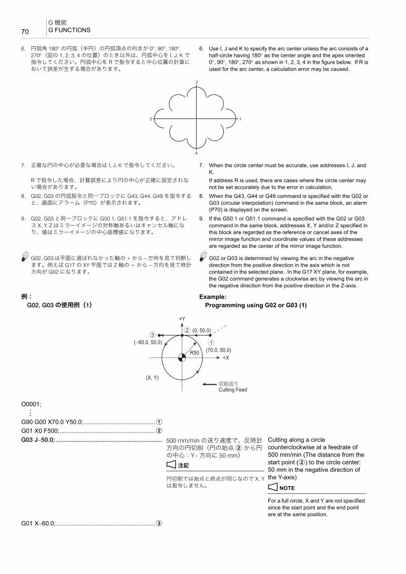
G 機能G FUNCTIONS70
6. 円弧角 180° の円弧(半円)の円弧頂点の向きが 0°, 90°, 180°, 270°(図の 1, 2, 3, 4 の位置)のとき以外は、円弧中心を I, J, K で指令してください。円弧中心を R で指令すると中心位置の計算において誤差が生ずる場合があります。
6. Use I, J and K to specify the arc center unless the arc consists of a half-circle having 180° as the center angle and the apex oriented 0°, 90°, 180°, 270° as shown in 1, 2, 3, 4 in the figure below. If R is used for the arc center, a calculation error may be caused.
7. 正確な円の中心が必要な場合は I, J, K で指令してください。 7. When the circle center must be accurate, use addresses I, J, and K.
R で指令した場合、計算誤差により円の中心が正確に設定されない場合があります。
If address R is used, there are cases where the circle center may not be set accurately due to the error in calculation.
8. G02, G03 の円弧指令と同一ブロックに G43, G44, G49 を指令すると、画面にアラーム(P70)が表示されます。
8. When the G43, G44 or G49 command is specified with the G02 or G03 (circular interpolation) command in the same block, an alarm (P70) is displayed on the screen.
9. G02, G03 と同一ブロックに G50.1, G51.1 を指令すると、アドレス X, Y, Z はミラーイメージの対称軸あるいはキャンセル軸になり、値はミラーイメージの中心座標値になります。
9. If the G50.1 or G51.1 command is specified with the G02 or G03 command in the same block, addresses X, Y and/or Z specified in this block are regarded as the reference or cancel axes of the mirror image function and coordinate values of these addresses are regarded as the center of the mirror image function.
5G02, G03 は平面に選ばれなかった軸の + から −方向を見て判断します。例えば G17 の XY 平面では Z 軸の + から − 方向を見て時計方向が G02 になります。
5G02 or G03 is determined by viewing the arc in the negative direction from the positive direction in the axis which is not contained in the selected plane. In the G17 XY plane, for example, the G02 command generates a clockwise arc by viewing the arc in the negative direction from the positive direction in the Z-axis.
例: Example:G02, G03 の使用例(1) Programming using G02 or G03 (1)
1
2
3
4
O0001;:
G90 G00 X70.0 Y50.0;..........................................aG01 X0 F500;........................................................bG03 J−50.0; .............................................................. 500 mm/min の送り速度で、反時計
方向の円切削(円の始点 b から円の中心:Y− 方向に 50 mm)
2 注記
円切削では始点と終点が同じなので X, Yは指令しません。
Cutting along a circle counterclockwise at a feedrate of 500 mm/min (The distance from the start point (b) to the circle center: 50 mm in the negative direction of the Y-axis)
2 NOTE
For a full circle, X and Y are not specified since the start point and the end point are at the same position.
G01 X−60.0;..........................................................c
32
1(70.0, 50.0)
(0, 50.0)
(−60.0, 50.0)
R50
+Y
+X
(X, Y)
Cutting Feed切削送り

71G 機能
G FUNCTIONS
例: Example:G02, G03 の使用例(2) Programming using G02 or G03 (2)
2-5 G02 ヘリカル補間(時計方向)、G03 ヘリカル補間(反時計方向)G02 Helical Interpolation (Clockwise), G03 Helical Interpolation (Counterclockwise)
1. XY 平面のヘリカル補間 1. Helical interpolation in the XY plane
2. ZX 平面のヘリカル補間 2. Helical interpolation in the ZX plane
O0001;:
G90 G01 X28.0 Y0 F500; .....................................aY20.0;....................................................................bG03 X18.0 Y30.0 I−10.0;.......................................c c に反時計方向の円弧切削(半径
10.0 mm)
5ここでは、I−10.0 の代わりに R10.0 と指令してもかまいません。
Circular cutting (counterclockwise) to c (Radius: 10.0 mm)
5It is possible to specify R10.0 instead of I−10.0 here.
G01 X−8.0;............................................................dG02 X−28.0 Y10.0 R20.0; .....................................e e に時計方向の円弧切削(半径
20.0 mm)Circular cutting (clockwise) to e (Radius: 20.0 mm)
G01 Y−10.0;..........................................................fG02 X−8.0 Y−30.0 R20.0; .....................................g g に時計方向の円弧切削(半径
20.0 mm)Circular cutting (clockwise) to g (Radius: 20.0 mm)
G01 X18.0;............................................................hG91 G03 X10.0 Y10.0 R10.0; ...............................i i に反時計方向の円弧切削(半径
10.0 mm)
5G91 のインクレメンタル指令なので、X10.0, Y10.0 は、円弧の始点から円弧の終点までの距離を表します。
Circular cutting (counterclockwise) to i (Radius: 10.0 mm)
5Since the commands are specified in the G91 incremental mode, (X10.0, Y10.0) indicates the distance from the start point to the end point of the arc.
G90 G01 Y0; .........................................................a アブソリュート指令 Absolute command
5
6
7 8
9
1
234
+Y
R20
R20
8 18
28 28
R10
R10
+X
3030
2020
1010
Cutting Feed切削送り
G17 G02(G03) X_ Y_ Z_ I_ J_ P_ F_ ;G17 G02(G03) X_ Y_ Z_ R_ F_ ;
G18 G02(G03) X_ Z_ Y_ I_ K_ P_ F_ ;G18 G02(G03) X_ Z_ Y_ R_ F_ ;
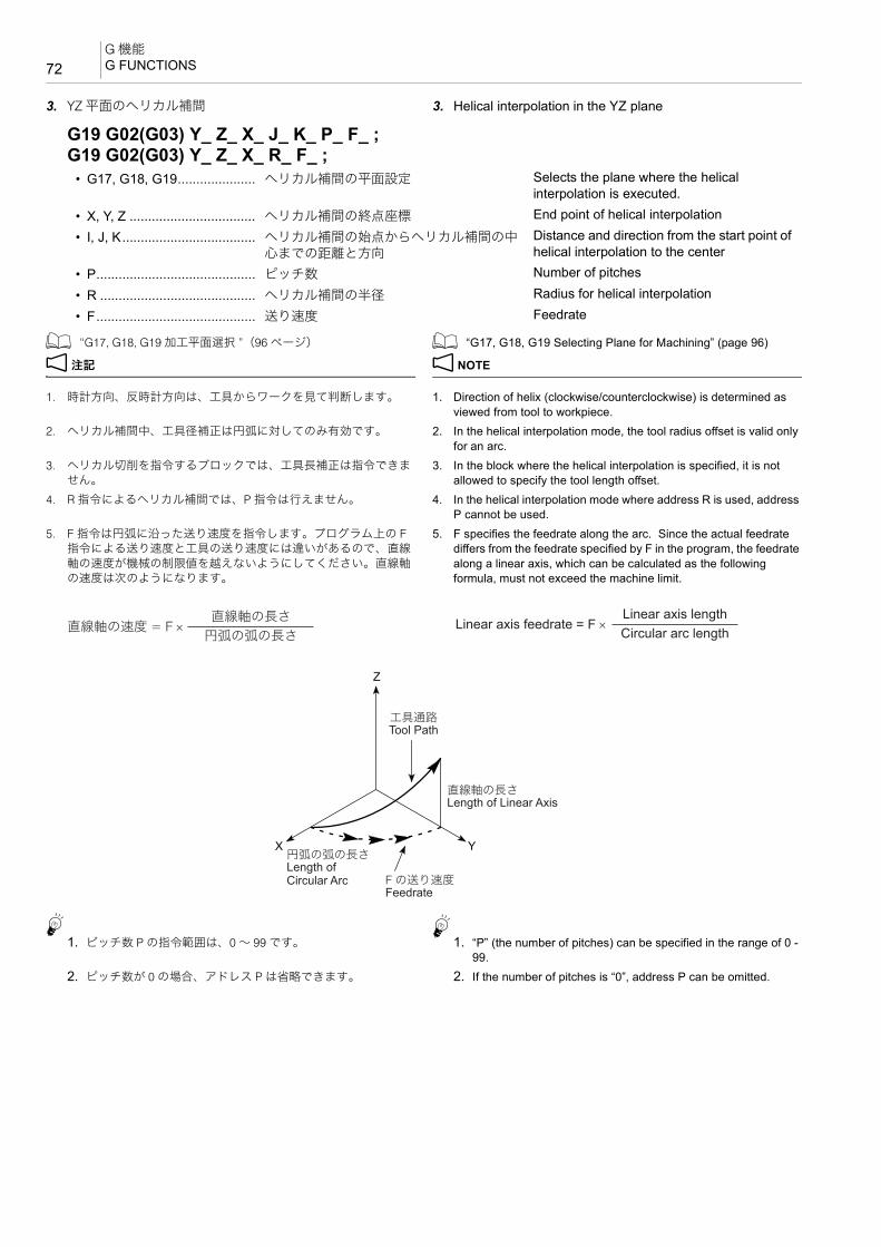
G 機能G FUNCTIONS72
5
3. YZ 平面のヘリカル補間 3. Helical interpolation in the YZ plane
1 “G17, G18, G19 加工平面選択 ”(96 ページ) 1 “G17, G18, G19 Selecting Plane for Machining” (page 96)
2 注記 2 NOTE
1. 時計方向、反時計方向は、工具からワークを見て判断します。 1. Direction of helix (clockwise/counterclockwise) is determined as viewed from tool to workpiece.
2. ヘリカル補間中、工具径補正は円弧に対してのみ有効です。 2. In the helical interpolation mode, the tool radius offset is valid only for an arc.
3. ヘリカル切削を指令するブロックでは、工具長補正は指令できません。
3. In the block where the helical interpolation is specified, it is not allowed to specify the tool length offset.
4. R 指令によるヘリカル補間では、P 指令は行えません。 4. In the helical interpolation mode where address R is used, address P cannot be used.
5. F 指令は円弧に沿った送り速度を指令します。プログラム上の F指令による送り速度と工具の送り速度には違いがあるので、直線軸の速度が機械の制限値を越えないようにしてください。直線軸の速度は次のようになります。
5. F specifies the feedrate along the arc. Since the actual feedrate differs from the feedrate specified by F in the program, the feedrate along a linear axis, which can be calculated as the following formula, must not exceed the machine limit.
1. ピッチ数 P の指令範囲は、0 ~ 99 です。5
1. “P” (the number of pitches) can be specified in the range of 0 - 99.
2. ピッチ数が 0 の場合、アドレス P は省略できます。 2. If the number of pitches is “0”, address P can be omitted.
G19 G02(G03) Y_ Z_ X_ J_ K_ P_ F_ ;G19 G02(G03) Y_ Z_ X_ R_ F_ ;
• G17, G18, G19..................... ヘリカル補間の平面設定 Selects the plane where the helical interpolation is executed.
• X, Y, Z .................................. ヘリカル補間の終点座標 End point of helical interpolation
• I, J, K.................................... ヘリカル補間の始点からヘリカル補間の中心までの距離と方向
Distance and direction from the start point of helical interpolation to the center
• P........................................... ピッチ数 Number of pitches
• R .......................................... ヘリカル補間の半径 Radius for helical interpolation
• F........................................... 送り速度 Feedrate
= F × 円弧の弧の長さ
直線軸の長さ直線軸の速度 = F ×
Circular arc lengthLinear axis length
Linear axis feedrate
Z
X Y
Feedrate
Length of Linear Axis
Tool Path
Length of Circular Arc F の送り速度
直線軸の長さ
工具通路
円弧の弧の長さ

73G 機能
G FUNCTIONS
例: Example:ヘリカル補間(G02, G03)の使用例 Programming using helical interpolation (G02/G03)
<ねじのリード角について> <Lead Angle>次の図のように三角形 abc を円筒の周囲に巻き付けるとき、斜線 ac が作る曲線をら旋といいます。ら旋に沿って三角形、四角形の断面を持つ溝を作れば、ねじになります。このねじのら旋を作る三角形 abc の ∠cab = θ をねじのリード角といいます。スムーズにねじ切り加工を行うために、c ~ h の動きは、このリード角を同じにします。リード角は次の式から求めます。
As shown in the next figure, when triangle abc is wound around a cylinder, the oblique line of the triangle forms a curve, which is called helix. If a groove having the section of triangle or square is created along the helix, it forms the tread. ∠cab = θ of triangle abc to form the helix of this tread is called the lead angle. In order to cut the tread smoothly, movements c - h above must have the same lead angle. Lead angle can be calculated as the following formula:
1) a D b 1) a D b<アプローチ円弧の半径> <Approach Arc Radius>アプローチ円弧のアプローチ半径は、次の条件を満たす必要があります。
The radius of the approach arc must satisfy the following conditions.
工具半径 < r(アプローチ半径)< 加工半径 Tool radius < r (approach arc radius) < Machining radius工具半径 15 mm と加工半径 30 mm を上記不等式に代入すると、下記の式が得られます。
By entering tool radius 15 mm and machining radius 30 mm to the inequality above, the following can be obtained.
15 < r < 30 15 < r < 30
O0001;N1;G90 G00 G54 X0 Y0;............................................aG43 Z30.0 H1 S1590 T2;M03;Z−30.0;G01 G41 X12.0 Y−18.0 D1 F80;...........................bG03 X30.0 Y0 Z−29.7 R18.0; ................................cI−30.0 Z−27.7;................................................d - gX12.0 Y18.0 Z−27.4 R18.0;...................................hG00 G40 X0 Y0;
+Y
−30 30
30
30
+X5
6
3 7
4
1
8
2
M60 × P2.0
30
φ30
+Z−Z Z0Thread Cutting Tool (Pitch 2.0 mm)
Relief: 2 mm Locus of the Cutting Tool
P2.0 のねじ切りカッタ
ぬすみは 2 mmとします。 工具の軌跡
12
6
1 2 3 4 5 6 7 8 9 10 11 12
a b
c
θ
12 3 4
50
6
78910
11
12
1 2
a b
c
3 4 5
978
1011
0
πD
θ:
L:
D:
Lead Angle (Degree)
Lead (mm)
Thread Diameter (mm)
リード角 (°)
リード (mm)
ねじの直径 (mm)

G 機能G FUNCTIONS74
r = 18 mm とします。 From this, r = 18 mm.<アプローチ円弧の始点座標> <Coordinate Values of Approach Arc Radius Start
Point>アプローチ円弧の内角が大きすぎると、アプローチに時間がかかります。
If the inside angle of the approach arc is too large, approach motion will take a time. Conversely, if it is too small, the tool may interfere with the face to be machined.
また、内角が小さすぎると、アプローチするときに加工面に接触する可能性があります。このことを考慮して、アプローチ円弧の内角を 90° にします。
Taking these into consideration, the inside angle of the approach arc is determined to be 90°.
アプローチ円弧の中心座標は、アプローチ半径と加工半径より、X12.0, Y0 になります。これより、円弧の始点 bは、X12.0, Y−18.0 になります。
The coordinate values of the center of the approach arc are calculated using the approach radius and the machining radius; X12.0, Y0. The coordinate values of the start b are then calculated as X12.0, Y−18.0.
2) b D c 2) b D c<アプローチ円弧でのリード> <Lead in Approach Arc>スムーズにねじ切り加工を行うために、リード角を合わせる必要があります。
To execute thread cutting smoothly, the lead angle within the approach arc must match the lead angle of the thread to be cut.
加工半径:ピッチ(リード)= アプローチ半径:L(リード)
Machining radius : Pitch (Lead) = Approach arc radius : L (Lead)
加工半径 30 mm、ピッチ 2 mm、アプローチ半径 18 mmより
Since “machining radius = 30 mm”, “pitch = 2 mm”, and “approach arc radius = 18 mm”,
30 : 2 = 18 : L 30 : 2 = 18 : Lしたがって、L の値は下記のようになります。 Accordingly, value L is obtained as follows:L = 1.2 mm L = 1.2 mm<アプローチ時の Z 軸移動量> <Z-Axis Movement Distance During Approach>アプローチ円弧の内角が 90° より、この円弧は 1/4 円弧になります。このため、アプローチ円弧のリード 1.2 mm の1/4 が Z 軸の移動量になります。つまり、円弧 b D c に反時計方向の円弧でアプローチするときの Z 軸の移動量は0.3 mm になります。
Since the inside angle of the approach arc is 90°, the arc is a quadrant. This means that one fourth the lead 1.2 mm in the approach arc is the movement distance of the Z-axis during approach. That is, the Z-axis moves 0.3 mm during approach motion along the approach arc b D c. The Z coordinate value at the completion of approach is therefore calculated as shown below.
Z: −30.0 + 0.3 = −29.7 Z: −30.0 + 0.3 = −29.7
3) c D d D e D f D g(全円) 3) c D d D e D f D g (full circle)< Z 軸移動量> <Z-Axis Movement Distance>全円のため、Z 軸の移動量はピッチ(リード)2.0 mm になります。
Since this movement generates a full circle, movement along the Z-axis equals the pitch (lead), 2.0 mm.
Z: −29.7 + 2.0 = −27.7 Z: −29.7 + 2.0 = −27.7
+Y
−30
30−30
30
+X5
6
3 7
4
1
2
(X12.0, Y0)
(X12.0, Y−18.0)
Coordinate Values of the Center of Approach Arc
アプローチ円弧の中心座標

75G 機能
G FUNCTIONS
4) g D h 4) g D h<逃げ円弧でのリード> <Lead in Escape Arc>アプローチ円弧でのリードと同じになるため、 The lead in the escape arc is the same as that in the
approach arc.L = 1.2 mm になります。 L = 1.2 mm<逃げ時の Z 軸移動量> <Z-Axis Movement Distance During Escape>アプローチ時の Z 軸移動量と同じになるため、逃げ円弧のリード 1.2 mm の 1/4 が Z 軸の移動量になります。つまり、円弧 g D h に反時計方向の円弧で逃げるときの Z軸の移動量は 0.3 mm になります。
The Z-axis movement distance during escape is equal to that during approach. Therefore, one fourth the lead in the escape arc 1.2 mm is the distance the Z-axis moves during escape. This Z-axis movement distance during movement along the escape arc g D h is thus obtained as 0.3 mm.
Z: −27.7 + 0.3 = −27.4 Z: −27.7 + 0.3 = −27.4<逃げ円弧の終点座標> <Coordinate Values of the End Point of Escape Arc>逃げ円弧の内角が大きすぎると、逃げるのに時間がかかります。また、内角が小さすぎると、逃げるときに加工面に接触する可能性があります。このことを考慮して、逃げ円弧の内角を 90° にします。
If the inside angle of the escape arc is too large, escape motion will take a time. Conversely, if it is too small, the tool may interfere with the face to be machined. Taking these into consideration, the inside angle of the escape arc is determined to be 90°.
逃げ円弧の中心座標は、アプローチ円弧の中心座標と同じで、X12.0, Y0 になります。これより、円弧の終点 h は、X12.0, Y18.0 になります。
The center of the escape arc is taken at the same point as the start point of the approach arc (X12.0, Y0). Therefore, the coordinate values of the end point h of the escape arc are X12.0, Y18.0.
<主軸回転速度と送り速度の求め方> <How to Calculate Spindle Speed and Feedrate><加工条件> <Cutting Conditions>
主軸回転速度 Spindle speed:
N:主軸回転速度(min−1) N: Spindle speed (min−1)V:切削速度(m/min) V: Cutting speed (m/min)D:カッタ径(mm) D: Tool diameter (mm)送り速度 Feedrate:
−30
30−30
30
+X5
6
3 7
4
8 (X12.0, Y18.0)
(X12.0, Y0)
+Y
Coordinate Values of the Center of Escape Arc
逃げ円弧の中心座標
切削速度 150 m/min
主軸 1 回転あたりのチップ送り 0.1 mm
Cutting speed 150 m/min
Feed of tip/spindle rotation 0.1 mm
N = π•D1000V
=
= 1590 (min−1)
π × 301000 × 150

G 機能G FUNCTIONS76
F1:切削線上の送り(mm/min) F1: Feedrate on the cutting line (mm/min)D1:ねじ径(mm) D1: Thread diameter (mm)D2:カッタ径(mm) D2: Tool diameter (mm)f:主軸 1 回転あたりのチップの送り(mm) f: Tip feedrate per spindle rotation (mm)Z:ねじ切りカッタのチップ数 Z: Number of tips mounted in the thread cutting tool
2 注記 2 NOTE
1. 外径ねじのときは下記の式になります。 1. For O.D. thread, use the following formula:
2. 上記で求めた値はあくまでも参考値です。工具メーカーのカタログなどを参考にして、加工条件、主軸回転速度および送り速度を求めてください。
2. The values obtained above are only for reference purpose. Determine the appropriate cutting conditions, spindle speed, and feedrate by referring to the tool manufacturers' catalogs and technical documents.
2-6 G02 渦巻き補間/円錐補間(時計方向)、G03 渦巻き補間/円錐補間(反時計方向)(オプション)G02 Spiral Interpolation/Conical Interpolation (Clockwise), G03 Spiral Interpolation/Conical Interpolation (Counterclockwise) (Option)
円弧補間の指令に加えて、回転の回数または 1 回転あたりの半径の増減量を指令すると、渦巻き補間となります。
Spiral interpolation can be specified by the circular interpolation command together with the number of rotations or the increment/decrement of the radius per rotation.
F = D1F1(D1 − D2)
=
= 80 (mm/min) 60
159 × (60 − 30)
F1 = f•Z•N= 0.1 × 1 × 1590= 159 (mm/min)
F = F1 (D1 + D2)
D1
D2
+Y
+XD1φ
φ
Workpieceワーク
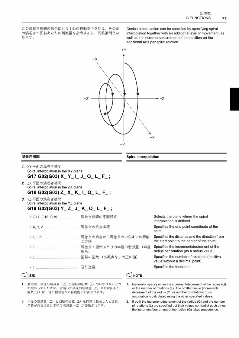
77G 機能
G FUNCTIONS
この渦巻き補間の指令にもう 1 軸の移動指令を加え、その軸の渦巻き 1 回転あたりの増減量を指令すると、円錐補間となります。
Conical interpolation can be specified by specifying spiral interpolation together with an additional axis of movement, as well as the increment/decrement of the position on the additional axis per spiral rotation.
渦巻き補間 Spiral Interpolation
1. XY 平面の渦巻き補間Spiral interpolation in the XY planeG17 G02(G03) X_ Y_ I_ J_ Q_ L_ F_ ;
2. ZX 平面の渦巻き補間Spiral interpolation in the ZX planeG18 G02(G03) Z_ X_ K_ I_ Q_ L_ F_ ;
3. YZ 平面の渦巻き補間Spiral interpolation in the YZ planeG19 G02(G03) Y_ Z_ J_ K_ Q_ L_ F_ ;
2 注記 2 NOTE
1. 通常は、半径の増減量(Q)と回転の回数(L)のいずれかひとつを指令してください。省略した半径の増減量(Q)または回転の回数(L)は、他の指令値から自動的に計算されます。
1. Generally, specify either the increment/decrement of the radius (Q) or the number of rotations (L). The omitted value (increment/ decrement of the radius (Q) or number of rotations (L) is automatically calculated using the other specified values.
2. 半径の増減量(Q)と回転の回数(L)を同時に指令したときに、矛盾がある場合は半径の増減量(Q)が優先されます。
2. If both the increment/decrement of the radius (Q) and the number of rotations (L) are specified but their values contradict each other, the increment/decrement of the radius (Q) takes precedence.
• G17, G18, G19 .................... 渦巻き補間の平面設定 Selects the plane where the spiral interpolation is defined.
• X, Y, Z ................................. 渦巻きの終点座標 Specifies the end point coordinate of the spiral.
• I, J, K ................................... 渦巻きの始点から渦巻きの中心までの距離と方向
Specifies the distance and the direction from the start point to the center of the spiral.
• Q ......................................... 渦巻き 1 回転あたりの半径の増減量 (半径指令)
Specifies the increment/decrement of the radius per rotation (as a radius value).
• L .......................................... 回転の回数 (小数点なしの正の値) Specifies the number of rotations (positive value without a decimal point).
• F .......................................... 送り速度 Specifies the feedrate.

G 機能G FUNCTIONS78
3. 回転の回数(L)は小数点なしの正の値で指令します。例えば、4周と 90° を指令したい場合には “L5” と切り上げて指令します。
3. Specify the number of rotations (L) as a positive value without a decimal point. For example, to specify four rotations plus 90°, round the value up to five and specify “L5”.
4. 指令範囲を超える値を指令すると、アラーム(P35)が発生します。
4. If a value exceeding the programmable range is specified, an alarm (P35) occurs.
5. アドレス X, Y, Z, I, J, K, Q, L, F 以外のアドレスを指令すると、アラーム(P33)が発生します。
5. If an address other than X, Y, Z, I, J, K, Q, L, and F is specified, an alarm (P33) occurs.
6. 回転平面の軸が完全に指定されていないときは、アラーム(P33)が発生します。
6. If a rotation plane axis is not specified completely, an alarm (P33) occurs.
7. 指定された増減量が、始点半径と終点半径の差分と符号が逆のときアラーム(P33)が発生します。
7. If the sign of specified increment/decrement amount is opposite from that of the difference between the start point radius and the end point radius, an alarm (P33) occurs.
8. 指定された増減量が、高さの移動方向と符号が逆のときアラーム(P33)が発生します。
8. If the sign of designated increment/decrement amount is opposite from that of the movement direction of height, an alarm (P33) occurs.
9. 同時に指令できる軸の組み合わせは仕様によります。その範囲内で、任意に組み合わせられます。
9. The axis combination that can be simultaneously specified depends on the specifications. The combination within that range is arbitrary.
10. 送り速度は、接線速度一定になります。 10. The feedrate is the constant tangential speed.11. 工具径補正(G41, G42)と組み合わせによる同時制御はできませ
ん。11. Simultaneous control combined with tool radius offset (G41, G42)
is not possible.12. 円弧平面は常に G17, G18, G19 に従います。平面と一致しない 2
つのアドレスにて指定しても G17, G18, G19 による平面の円弧制御を行います。
12. The arc plane always follows G17, G18, and G19. The plane arc control is carried out by G17, G18 and G19, even if specified by the two addresses that do not match the plane.
13. 渦巻き補間には R 指定円弧はありません。 13. There are no R-designated arcs in the spiral interpolation.14. 半径の増減量および高さの増減量から求められる終点位置が渦巻
き終点誤差より大きいとき、アラーム(P70)が発生します。14. If the end point position obtained from the increment/decrement
amounts of the radius and the height is larger than the error at the end point of the spiral, an alarm (P70) occurs.
15. 円弧補間(G02, G03)で始点半径と終点半径の差がパラメータ設定値以下のときは、自動的に渦巻き補間になります。
15. Normally the spiral interpolation is automatically enabled with the arc commands (G02, G03) when the difference between the start point radius and the end point radius is less than the parameter setting value.
16. 渦巻き補間平面以外の軸が同時に指令されたときは、渦巻きの補間に同期して他の軸も補間します。
16. When an axis other than the spiral interpolation plane is simultaneously specified, other axes are also interpolated in synchronization with the spiral interpolation.
例: Example:渦巻き補間の使用例 Programming using spiral interpolation開始点:X0.0 Y100.0 Start point: X0.0 Y100.0
<アブソリュート指令><Absolute Command>G17;G90 G02 Y20.0 J−100.0 Q−20.0 F5000;

79G 機能
G FUNCTIONS
円錐補間 Conical Interpolation
1. XY 平面の円錐補間Conical interpolation in the XY planeG17 G02(G03) X_ Y_ I_ J_ Z_ Q_ L_ K_ F_ ;
2. ZX 平面の円錐補間Conical interpolation in the ZX planeG18 G02(G03) Z_ X_ K_ I_ Y_ Q_ L_ J_ F_ ;
3. YZ 平面の円錐補間Conical interpolation in the YZ planeG19 G02(G03) Y_ Z_ J_ K_ X_ Q_ L_ I_ F_ ;
<インクレメンタル指令><Incremental Command>G17;G91 G02 Y−80.0 J−100.0 Q−20.0 F5000;
• G17, G18, G19 ....... 円錐補間の平面設定 Selects the plane where the conical interpolation is defined.
• X, Y, Z .................... 円錐の終点座標 Specifies the end point coordinate of the cone
• I, J, K ...................... a 2 つが円錐の始点から円錐の中心までの距離と方向
a Two of these specify the distance and the direction from the start point to the center of the cone.
b 残りの 1 つが渦巻き 1 回転あたりの高さの増減量
b The other one specifies the increment/ decrement of the height per spiral rotation.
XY 平面の a: I, J b: K
ZX 平面の a: K, I b: J
YZ 平面の a: J, K b: I
In the XY plane, a: I, J b: K
In the ZX plane, a: K, I b: J
In the YZ plane, a: J, K b: I
• Q ............................ 渦巻き 1 回転あたりの半径の増減量(半径指令)
Specifies the increment/decrement of the radius per rotation (as a radius value).
• L ............................. 回転の回数(小数点なしの正の値) Specifies the number of rotations (positive value without a decimal point).
• F ............................. 送り速度(直線軸を含めた接線速度) Feedrate (tangential velocity about the linear axis).

G 機能G FUNCTIONS80
2 注記 2 NOTE
1. 通常は、高さの増減量(I, J, K)、半径の増減量(Q)、または回転の回数(L)のいずれかひとつを指令してください。
1. Generally, specify the increment/decrement of the height (I, J, K), the increment/decrement of the radius (Q), or the number of rotations (L).
例: Example:XY 平面の場合、K_、Q_ または L_ のいずれかひとつを指令する。
In the XY plane, specify one of K_, Q_and L_.
省略した高さの増減量(I, J, K)、半径の増減量(Q)または回転の回数(L)は、他の指令値から自動的に計算されます。
The omitted values (among the increment/decrement of the height (I, J, K), the increment/decrement of the radius (Q), and the number of rotations (L)) are automatically calculated using the other specified values.
2. 半径の増減量(Q)と回転の回数(L)を同時に指令したときに、矛盾がある場合は半径の増減量(Q)が優先されます。
2. If both the increment/decrement of the radius (Q) and the number of rotations (L) are specified but their values contradict each other, the increment/decrement of the radius (Q) takes precedence.
3. 高さの増減量(I, J, K)と回転の回数(L)を同時に指令したときに、矛盾がある場合は高さの増減量(I, J, K)が優先されます。
3. If both the increment/decrement of the height (I, J, K) and the number of rotations (L) are specified but their values contradict each other, the increment/decrement of the height (I, J, K) takes precedence.
4. 半径の増減量(Q)と高さの増減量(I, J, K)を同時に指令したときに、矛盾がある場合は半径の増減量(Q)が優先されます。
4. If both the increment/decrement of the radius (Q) and the increment/decrement of the height (I, J, K) are specified but their values contradict each other, the increment/decrement of the radius (Q) takes precedence.
5. 回転の回数(L)は小数点なしの正の値で指令します。例えば、4周と 90° を指令したい場合には “L5” と切り上げて指令します。
5. Specify the number of rotations (L) as a positive value without a decimal point. For example, to specify four rotations plus 90°, round the value up to five and specify “L5”.
6. 指令範囲を超える値を指令すると、アラーム(P35)が発生します。
6. If a value exceeding the programmable range is specified, an alarm (P35) occurs.
7. アドレス X, Y, Z, I, J, K, Q, L, F 以外のアドレスを指令すると、アラーム(P33)が発生します。
7. If an address other than X, Y, Z, I, J, K, Q, L, and F is specified, an alarm (P33) occurs.
8. 回転平面の軸が完全に指定されていないときは、アラーム(P33)が発生します。
8. If a rotation plane axis is not specified completely, an alarm (P33) occurs.
9. 指定された増減量が、始点半径と終点半径の差分と符号が逆のときアラーム(P33)が発生します。
9. If the sign of specified increment/decrement amount is opposite from that of the difference between the start point radius and the end point radius, an alarm (P33) occurs.
10. 指定された増減量が、高さの移動方向と符号が逆のときアラーム(P33) が発生します。
10. If the sign of designated increment/decrement amount is opposite from that of the movement direction of height, an alarm (P33) occurs.
11. 同時に指令できる軸の組み合わせは仕様によります。その範囲内で、任意に組み合わせられます。
11. The axis combination that can be simultaneously specified depends on the specifications. The combination within that range is arbitrary.
12. 送り速度は、接線速度一定になります。 12. The feedrate is the constant tangential speed.13. 工具径補正(G41, G42)と組み合わせによる同時制御はできませ
ん。13. Simultaneous control combined with tool radius offset (G41, G42)
is not possible.14. 円弧平面は常に G17, G18, G19 に従います。平面と一致しない 2
つのアドレスにて指定しても G17, G18,G19 による平面の円弧制御を行います。
14. The arc plane always follows G17, G18, and G19. The plane arc control is carried out by G17, G18 and G19, even if specified by the two addresses that do not match the plane.
15. 始点半径と終点半径を変えて直線軸を同時に指令すると、円錐切削やテーパねじ切り等の加工が行えます。
15. Conical cutting, tapered thread-cutting and other such machining operations can be conducted by changing the start point and end point radius and specifying the linear axis simultaneously.
例: Example:円錐補間の使用例 Programming using conical interpolation開始点:X100.0 Y0.0 Start point: X100.0 Y0.0
<アブソリュート指令><Absolute Command>G17;G90 G02 X20.0 I−100.0 Z−80.0 Q−20.0 F5000;

81G 機能
G FUNCTIONS
2-7 G02.2 インボリュート補間(時計方向)、G03.2 インボリュート補間(反時計方向)(オプション)G02.2 Involute Interpolation (Clockwise), G03.2 Involute Interpolation (Counterclockwise) (Option)
1. XY 平面のインボリュート補間 1. Involute interpolation on XY plane
2. ZX 平面のインボリュート補間 2. Involute interpolation on ZX plane
3. YZ 平面のインボリュート補間 3. Involute interpolation on YZ plane
<インクレメンタル指令><Incremental Command>G17;G91 G02 X−80.0 I−100.0 Z−80.0 Q−20.0 F5000;
G17 G02.2(G03.2) X_ Y_ I_ J_ R_ F_ ;
G18 G02.2(G03.2) X_ Z_ I_ K_ R_ F_ ;
G19 G02.2(G03.2) Y_ Z_ J_ K_ R_ F_ ;• X, Y, Z .................................. インボリュート曲線の終点座標 End point of involute interpolation
• I, J, K ................................... インボリュート曲線の始点から基礎円の中心までの距離と方向
Distance and direction from the start point of the involute curve to the center of the base circle
• R .......................................... 基礎円の半径 Radius of the base circle
• F........................................... 送り速度 Feedrate
1
2
'1
a :
a' :
b :
Base Circle
Start point
Present position
Contact point of the tangent drawn from point a' to the base circleInvolute curve is the set of point a' which satisfies “arc ab = Line a'b”.
始点
現在位置
点 a' から基礎円に引いた接線の接点インボリュート曲線は、“弧ab=直線a'b”が成立するa'の集まりです。
基礎円
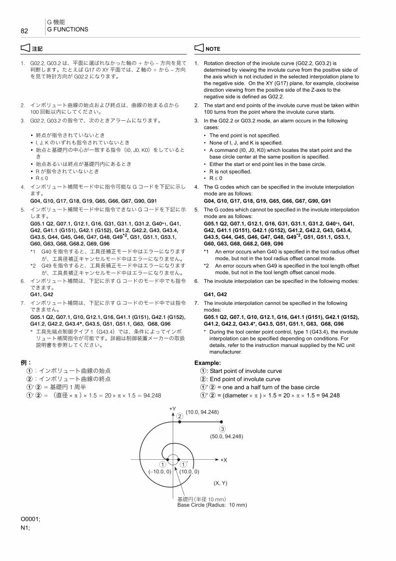
G 機能G FUNCTIONS82
2 注記 2 NOTE
1. G02.2, G03.2 は、平面に選ばれなかった軸の + から − 方向を見て判断します。たとえば G17 の XY 平面では、Z 軸の + から − 方向を見て時計方向が G02.2 になります。
1. Rotation direction of the involute curve (G02.2, G03.2) is determined by viewing the involute curve from the positive side of the axis which is not included in the selected interpolation plane to the negative side. On the XY (G17) plane, for example, clockwise direction viewing from the positive side of the Z-axis to the negative side is defined as G02.2.
2. インボリュート曲線の始点および終点は、曲線の始まる点から100 回転以内にしてください。
2. The start and end points of the involute curve must be taken within 100 turns from the point where the involute curve starts.
3. G02.2, G03.2 の指令で、次のときアラームになります。 3. In the G02.2 or G03.2 mode, an alarm occurs in the following cases:
• 終点が指令されていないとき • The end point is not specified.• I, J, K のいずれも指令されていないとき • None of I, J, and K is specified.• 始点と基礎円の中心が一致する指令(I0, J0, K0)をしていると
き• A command (I0, J0, K0) which locates the start point and the
base circle center at the same position is specified.• 始点あるいは終点が基礎円内にあるとき • Either the start or end point lies in the base circle.• R が指令されていないとき • R is not specified.• R ≤ 0 • R ≤ 0
4. インボリュート補間モード中に指令可能な G コードを下記に示します。
4. The G codes which can be specified in the involute interpolation mode are as follows:
G04, G10, G17, G18, G19, G65, G66, G67, G90, G91 G04, G10, G17, G18, G19, G65, G66, G67, G90, G915. インボリュート補間モード中に指令できない G コードを下記に示
します。5. The G codes which cannot be specified in the involute interpolation
mode are as follows:G05.1 Q2, G07.1, G12.1, G16, G31, G31.1, G31.2, G40*1, G41, G42, G41.1 (G151), G42.1 (G152), G41.2, G42.2, G43, G43.4, G43.5, G44, G45, G46, G47, G48, G49*2, G51, G51.1, G53.1, G60, G63, G68, G68.2, G69, G96
G05.1 Q2, G07.1, G12.1, G16, G31, G31.1, G31.2, G40*1, G41, G42, G41.1 (G151), G42.1 (G152), G41.2, G42.2, G43, G43.4, G43.5, G44, G45, G46, G47, G48, G49*2, G51, G51.1, G53.1, G60, G63, G68, G68.2, G69, G96
*1 G40 を指令すると、工具径補正モード中はエラーになります
が、工具径補正キャンセルモード中はエラーになりません。
*1 An error occurs when G40 is specified in the tool radius offset mode, but not in the tool radius offset cancel mode.
*2 G49 を指令すると、工具長補正モード中はエラーになります
が、工具長補正キャンセルモード中はエラーになりません。
*2 An error occurs when G49 is specified in the tool length offset mode, but not in the tool length offset cancel mode.
6. インボリュート補間は、下記に示す G コードのモード中でも指令できます。
6. The involute interpolation can be specified in the following modes:
G41, G42 G41, G427. インボリュート補間は、下記に示す G コードのモード中では指令
できません。7. The involute interpolation cannot be specified in the following
modes:G05.1 Q2, G07.1, G10, G12.1, G16, G41.1 (G151), G42.1 (G152), G41.2, G42.2, G43.4*, G43.5, G51, G51.1, G63, G68, G96
G05.1 Q2, G07.1, G10, G12.1, G16, G41.1 (G151), G42.1 (G152), G41.2, G42.2, G43.4*, G43.5, G51, G51.1, G63, G68, G96
* 工具先端点制御タイプ 1(G43.4)では、条件によってインボリュート補間指令が可能です。詳細は制御装置メーカーの取扱説明書を参照してください。
* During the tool center point control, type 1 (G43.4), the involute interpolation can be specified depending on conditions. For details, refer to the instruction manual supplied by the NC unit manufacturer.
例: Example:a:インボリュート曲線の始点 a: Start point of involute curveb:インボリュート曲線の終点 b: End point of involute curvea' b = 基礎円 1 周半 a' b = one and a half turn of the base circlea' b = (直径 × π ) × 1.5 = 20 × π × 1.5 = 94.248 a' b = (diameter × π ) × 1.5 = 20 × π × 1.5 = 94.248
O0001;N1;
(10.0, 94.248)
(50.0, 94.248)
(10.0, 0)(−10.0, 0)1 1
2
3
+Y
+X
(X, Y)
Base Circle (Radius: 10 mm)基礎円(半径 10 mm)

83G 機能
G FUNCTIONS
2-8 G04 プログラムの進行停止(ドウェル)G04 Suspending Program Execution (Dwell)
G04 を指令すると、自動運転中に指令した時間だけプログラムの進行を停止させることができます。
The G04 command is used to suspend program execution during automatic operation for the period specified in the program.
これをドウェル機能といい、溝入れ加工などで使用します。 This function is called the dwell function, and is used in operation such as the grooving operation.
溝底でドウェルを指令すると、工具の送りは止まります。その間、主軸は回転します。
If dwell is specified at the bottom of the groove, the tool stops moving. The spindle keeps rotating while the tool stays at the bottom of the groove.
工具をその位置で停止させ、主軸を 1 回転させると、溝底の精度が向上し、溝底の削残しを防ぐことができます。
By rotating the spindle one turn while locating the tool at the bottom of the groove, the groove profile accuracy is improved and uncut portion is eliminated.
2 注記 2 NOTE
1. 穴底などで G04 を指令して、プログラムの進行を停止させる場合は、プログラムの停止位置と主軸が 1 回転する程度の時間を指令してください。ワークと切削工具の接触する時間を長くすると、加工精度や切削工具の寿命に悪影響を及ぼします。
1. When suspending program execution by G04 at any places such as the hole bottom, specify the time which may allow the spindle to make one rotation. If the spindle is rotated too long while the cutting tool is in contact with the workpiece, it will shorten the tool life as well as deteriorate the machining accuracy.
2. ドウェルの指令時間は 0.001 ~ 99999.999(秒)です。 2. Programmable range of dwell period: 0.001 to 99999.999 (sec)3. G04 のドウェル機能は、指令したブロックのみ有効です。 3. The G04 command is valid only for the specified block.4. 主軸 1 回転あたりの時間(秒)は、次の式で求めます。 4. Calculate the time per spindle rotation using the following equation.
5G04 に続く P や X を省略すると、G09 のイグザクトストップと同じ指令になります。
5When neither P nor X is specified after G04, the performance becomes the same as with G09.
G90 G00 G54 X_ Y_ ;G43 Z30.0 H1 S800 T2;M03;X−10.0 Y0; ............................................................aG01 Z−5.0 F50;G02.2 X10.0 Y94.248 I10.0 J0 R10.0 F200; ....... b 200 mm/min の送り速度で b まで
インボリュート曲線を描いて切削Cutting to b along the involute curve at a feedrate of 200 mm/min
G01 X50.0; ...........................................................c:
G04 P_ ;G04 X_ ;
• G04 ...................................... ドウェル指令 Calls the dwell function.
• P........................................... プログラムの進行を停止させる時間(秒)P は小数点付きで指令します。P1.0:1 秒P1:0.001 秒
The period in which the program execution is suspended.Specify address P using a value with a decimal point.P1.0: 1 sec.P1: 0.001 sec.
• X........................................... プログラムの進行を停止させる時間(秒)X は小数点付きで指令します。X1.0:1 秒X1:0.001 秒
The period in which the program execution is suspended.Specify address X using a value with a decimal point.X1.0: 1 sec.X1: 0.001 sec.
主軸回転速度
60(秒)t(秒) =
(min−1)60 (sec)
t (sec)Spindle speed

G 機能G FUNCTIONS84
2-9 G05.1 高速高精度制御 I(AI 輪郭制御 )、G05 高速高精度制御 II(高精度輪郭制御)(オプション)G05.1 High-Speed High-Accuracy Control I (AI Contour Control), G05 High-Speed High-Accuracy Control II (High-Precision Contour Control) (Option)
高速高精度制御は、自由曲面を微小直線で近似した加工プログラムを高速かつ高精度で運転するもので、自由曲面の金型加工の高速化に効果があります。
The high-speed, high-accuracy control, to be used for running the machining program in which free-form curve is approximated with small segments at high speed and high accuracy, is effective for improving machining speeds in die/mold machining.
この高速高精度制御には、タイプ I(G05.1)とタイプ II(G05)の 2 種類があり、微小直線の近似処理能力やプログラム上の制限などに違いがあります。処理能力を微小線分長能力で比較した場合、タイプ II はタイプ I の 2 倍の能力があります。
Two types of high-speed, high-accuracy control are provided as type I (G05.1) and type II (G05). These two types differ in approximating processing performance of small segments and restrictions in programming. Comparison of the processing performance using the small segment processing length performance shows that type II provides two times higher performance than type I.
2 注記 2 NOTE
高速高精度制御は、タイプ I およびタイプ II ともにオプションです。 High-speed, high-accuracy control is optional (both type I and type II).
<高速高精度制御タイプ I> <High-speed, high-accuracy control type I>
<高速高精度制御タイプ II> <High-speed, high-accuracy control type II>
5•高速高精度制御モードをオンすると、G08 高精度制御モードが自動的にオンします。
5•When the high-speed, high-accuracy control mode is turned on, the G08 high-accuracy control mode is automatically turned on.
• 高速高精度制御モードにする前に G332 を指令すると、加工モー ドを変更することができます。
• To change the cutting mode, specify the G332 command before specifying high-speed, high-accuracy control.
2 注記 2 NOTE
1. G05.1 および G05 は単独ブロックで指令してください。 1. Specify the G05.1 or G05 command in a block without other commands.
2. @(リセット)キーを押すと、高速高精度制御モードはキャンセルされます。
2. The high-speed, high-accuracy control mode is canceled when the @ (RESET) key is pressed.
3. 工具径補正指令は、高速高精度制御 I/II モード中にオン、オフしてください。工具径補正をオンした状態で高速高精度制御 I/IIモードをオフした場合、アラーム(P34)が発生します。
3. Turn on and off the tool radius offset function in the high-speed, high-accuracy control mode. If the high-speed, high-accuracy control mode is turned off in the tool radius offset mode, an alarm (P34) occurs.
4. 高速高精度制御モードのオン、オフ時は送りが一旦減速しますので、工具がワークから離れたところでオン、オフを行ってください。
4. Since feedrate is decelerated at the point where the high-speed, high-accuracy control mode is turned on or off, turn on or off the high-speed, high-accuracy control mode at a position away from the workpiece.
5. 高速高精度制御モード中は自動運転を優先させますので、画面表示などが遅れることがあります。
5. During machining in the high-speed, high-accuracy control mode, automatic operation has priority. This means data display on the screen could be delayed from actual machining.
6. 1 ブロックの文字数やプログラムの転送速度(DNC 運転時など)によっては加工速度が低下する場合があります。
6. Machining speed may be lowered depending on the number of characters in a block and program transfer speed (in DNC operation).
7. タイプ II の高速高精度制御モードでは、マクロプログラムを実行することはできません。
7. Macro program cannot be used in the type II high-speed, high-accuracy control mode.
8. “G05.1 Q1”, “G05.1 Q0” および “G05 P10000”, “G05 P0” 指令ブロックで G、Q、または P 以外のアドレスが指令されると、アラーム(P33)が発生します。
8. If an address other than G, Q, or P is specified in the “G05.1 Q1”, “G05.1 Q0” and “G05 P10000”, “G05 P0” command blocks, an alarm (P33) occurs.
9. G05.1 および G05 指令ブロックに Q または P 指令がない場合、アラーム(P33)が発生します。
9. If address Q or P is not specified in the G05.1 or G05 command block, an alarm (P33) occurs.
10. Q および P に続くアドレスの引数には小数点を付加しないでください。
10. Do not enter a decimal point for the arguments of addresses Q and P.
G05.1 Q1; .................... 高速高精度制御モード・オン Specifies the high-speed, high-accuracy control mode ON.
G05.1 Q0; .................... 高速高精度制御モード・オフ Specifies the high-speed, high-accuracy control mode OFF.
G05 P10000;................ 高速高精度制御モード・オン Specifies the high-speed, high-accuracy control mode ON.
G05 P0;........................ 高速高精度制御モード・オフ Specifies the high-speed, high-accuracy control mode OFF.
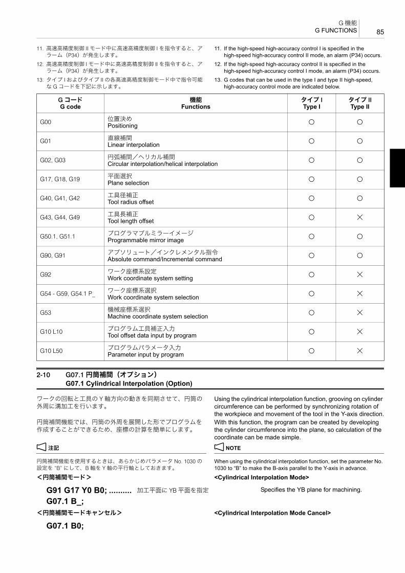
85G 機能
G FUNCTIONS
11. 高速高精度制御 II モード中に高速高精度制御 I を指令すると、アラーム(P34)が発生します。
11. If the high-speed high-accuracy control I is specified in the high-speed high-accuracy control II mode, an alarm (P34) occurs.
12. 高速高精度制御 I モード中に高速高精度制御 II を指令すると、アラーム(P34)が発生します。
12. If the high-speed high-accuracy control II is specified in the high-speed high-accuracy control I mode, an alarm (P34) occurs.
13. タイプ I およびタイプ II の各高速高精度制御モード中で指令可能な G コードを下記に示します。
13. G codes that can be used in the type I and type II high-speed, high-accuracy control mode are indicated below.
2-10 G07.1 円筒補間(オプション)G07.1 Cylindrical Interpolation (Option)
ワークの回転と工具の Y 軸方向の動きを同期させて、円筒の外周に溝加工を行います。
Using the cylindrical interpolation function, grooving on cylinder circumference can be performed by synchronizing rotation of the workpiece and movement of the tool in the Y-axis direction.
円筒補間機能では、円筒の外周を展開した形でプログラムを作成することができるため、座標の計算を簡単にします。
With this function, the program can be created by developing the cylinder circumference into the plane, so calculation of the coordinate can be made simple.
2 注記 2 NOTE
円筒補間機能を使用するときは、あらかじめパラメータ No. 1030 の設定を “B” にして、B 軸を Y 軸の平行軸としておきます。
When using the cylindrical interpolation function, set the parameter No. 1030 to “B” to make the B-axis parallel to the Y-axis in advance.
<円筒補間モード> <Cylindrical Interpolation Mode>
<円筒補間モードキャンセル> <Cylindrical Interpolation Mode Cancel>
G コードG code
機能Functions
タイプ IType I
タイプ IIType II
G00 位置決めPositioning @ @
G01 直線補間Linear interpolation @ @
G02, G03 円弧補間/ヘリカル補間Circular interpolation/helical interpolation @ @
G17, G18, G19 平面選択Plane selection @ @
G40, G41, G42 工具径補正Tool radius offset @ @
G43, G44, G49 工具長補正Tool length offset @ \
G50.1, G51.1 プログラマブルミラーイメージProgrammable mirror image @ @
G90, G91 アブソリュート/インクレメンタル指令Absolute command/Incremental command @ @
G92 ワーク座標系設定Work coordinate system setting @ \
G54 - G59, G54.1 P_ ワーク座標系選択Work coordinate system selection @ \
G53 機械座標系選択Machine coordinate system selection @ \
G10 L10 プログラム工具補正入力Tool offset data input by program @ \
G10 L50 プログラムパラメータ入力Parameter input by program @ \
G91 G17 Y0 B0; .......... 加工平面に YB 平面を指定 Specifies the YB plane for machining.
G07.1 B_;
G07.1 B0;

G 機能G FUNCTIONS86
2 注記 2 NOTE
1. G07.1 は単独ブロックで指令してください。 1. Specify the G07.1 command in a single block without other commands.
2. 円筒補間モード中、円弧の半径を I, J, K で指令することはできません。
2. In the cylindrical interpolation mode, I, J and K cannot be used to define an arc.
円弧の半径は R で指令してください。また、単位はミリになります。
Circular arc radius must be specified using R. The unit of R command is “mm”.
G02 Y_ B_ R4.0;(半径 4 mm) G02 Y_ B_ R4.0; (radius 4 mm)3. 円筒補間モード中に、円弧あるいは工具径補正を指令するとき
は、加工平面を YB 平面にしてください。3. If circular interpolation or tool radius offset is specified in the
cylindrical interpolation mode, it is necessary to specify the YB plane for machining.
4. 円筒補間モード中に工具径補正を行う場合は、円筒補間モード中に工具径補正(スタートアップとオフセットキャンセル)を指令してください。
4. To execute the tool radius offset function in the cylindrical interpolation mode, specify the tool radius offset function (start-up and offset cancel) in the cylindrical interpolation mode.
5. 工具径補正中に G07.1 を指令すると、アラーム(P485)が発生します。
5. If the G07.1 command is specified in the tool radius offset mode, an alarm (P485) occurs.
6. 工具径補正キャンセル後に軸移動指令がないまま G07.1 を指令すると、G07.1 指令ブロックの軸の位置を工具径補正キャンセル後の位置とみなして以降の動作を行います。
6. If the G07.1 command is specified without axis movement commands after canceling the tool radius offset, the position of each axis in the block with the G07.1 command is assumed to be the position after canceling the tool radius offset and the following movement is executed.
7. 円筒補間モード中に工具長補正を行うと、アラーム(P481)が発生します。
7. If the tool length offset is specified in the cylindrical interpolation mode, an alarm (P481) occurs.
8. 円筒補間を指令する前に、工具補正動作(工具長および摩耗補正量の移動)を完了してください。
8. Complete the tool offset movement (movement by the tool length offset and tool wear offset amount) before specifying the cylindrical interpolation.
9. 周速一定制御モード中に G07.1 を指令すると、アラーム(P485)が発生します。
9. If the G07.1 command is specified in the constant surface speed control mode, an alarm (P485) occurs.
10. 送り速度は、円筒展開上における接線速度をアドレス F で指令してください。
10. For the feedrate, specify the tangential speed in the cylinder development with address F.
11. 直前のブロックが、毎分送りモード(G94)または毎回転送りモード(G95)により、円筒補間モード中に直前の F 指令が有効になる/ならないが決定されます。
11. Whether the previous F command is valid or not depends on that the mode just before the G07.1 command is the feed per minute mode (G94) or the feed per revolution mode (G95).
• G07.1 指令の直前が毎分送り(G94)モードの場合 • With the feed per minute mode (G94) just before the G07.1 command
円筒補間モード中に F 指令がない場合は、直前の F 指令が有効になります。円筒補間モードキャンセル後の送り速度は、円筒補間モード開始時または円筒補間モード中に設定した 後の F指令の送り速度が有効になります。
If the F command is not specified in the cylindrical interpolation mode, the previous F command is used. As the feedrate after canceling the cylindrical interpolation mode, the last feedrate specified at the beginning of or during the cylindrical interpolation mode is valid.
• G07.1 指令の直前が毎回転送り(G95)モードの場合 • With the feed per revolution mode (G95) just before the G07.1 command
円筒補間モード中は、直前の F 指令の送り速度が有効にならないため、新たに F 指令が必要です。円筒補間モードキャンセル後の送り速度は、円筒補間モード開始前の状態に戻ります。
Since the previous F command feedrate is not valid in the cylindrical interpolation mode, a new F command must be specified. The feedrate after the cylindrical interpolation mode is canceled will return to that applied before the cylindrical interpolation mode was started.
<円筒補間モード中に F 指令がない場合> <Without F Command in Cylindrical Interpolation Mode>
:
(G91 G17 X0 Y0;) ........ 加工平面に XY 平面を指定 Specifies the XY plane for machining.
• G07.1 ................................... 円筒補間の指令 Calls the cylindrical interpolation mode.
• B........................................... ワークの半径(溝底) Specifies the radius of the workpiece (groove bottom).
直前のモードPrevious Mode
F 指令なしWithout F Command
円筒補間モードキャンセル後After Canceling Cylindrical Interpolation Mode
G94 直前の F 指令が有効Previous F command is valid
直前の F 指令が有効Previous F command is valid
G95 アラーム(P62)An alarm (P62)
G07.1 指令直前の F 指令が有効F command just before G07.1 command is valid
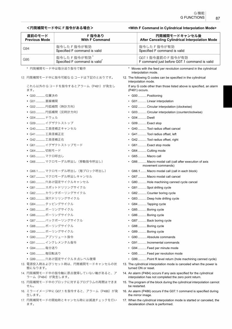
87G 機能
G FUNCTIONS
<円筒補間モード中に F 指令がある場合> <With F Command in Cylindrical Interpolation Mode>
* 円筒補間モード中は毎分送り指令で動作 * Moves with the feed per revolution command in the cylindrical interpolation mode.
12. 円筒補間モード中に指令可能な G コードは下記のとおりです。 12. The following G codes can be specified in the cylindrical interpolation mode.
これら以外の G コードを指令するとアラーム(P481)が発生します。
If any G code other than those listed above is specified, an alarm (P481) occurs.
• G00 ..................位置決め • G00 .......... Positioning
• G01 ..................直線補間 • G01 .......... Linear interpolation
• G02 ..................円弧補間(時計方向) • G02.......... Circular interpolation (clockwise)
• G03 ..................円弧補間(反時計方向) • G03.......... Circular interpolation (counterclockwise)
• G04 ..................ドウェル • G04.......... Dwell
• G09 ..................イグザクトストップ • G09 .......... Exact stop
• G40 ..................工具径補正キャンセル • G40 .......... Tool radius offset cancel
• G41 ..................工具径補正左 • G41 .......... Tool radius offset, left
• G42 ..................工具径補正右 • G42.......... Tool radius offset, right
• G61 ..................イグザクトストップモード • G61.......... Exact stop mode
• G64 ..................切削モード • G64 .......... Cutting mode
• G65 ..................マクロ呼出し • G65 .......... Macro call
• G66 ..................マクロモーダル呼出し(移動指令呼出し) • G66 .......... Macro modal call (call after execution of axis movement commands)
• G66.1 .............マクロモーダル呼出し(毎ブロック呼出し) • G66.1 ....... Macro modal call (call in each block)
• G67 ..................マクロモーダル呼出しキャンセル • G67.......... Macro modal call cancel
• G80 ..................穴あけ固定サイクルキャンセル • G80 .......... Hole machining canned cycle cancel
• G81 ..................スポットドリリングサイクル • G81 .......... Spot drilling cycle
• G82 ..................カウンタボーリングサイクル • G82 .......... Counter boring cycle
• G83 ..................深穴ドリリングサイクル • G83 .......... Deep hole drilling cycle
• G84 ..................タッピングサイクル • G84 .......... Tapping cycle
• G85 ..................ボーリングサイクル • G85 .......... Boring cycle
• G86 ..................ボーリングサイクル • G86 .......... Boring cycle
• G87 ..................バックボーリングサイクル • G87 .......... Back boring cycle
• G88 ..................ボーリングサイクル • G88 .......... Boring cycle
• G89 ..................ボーリングサイクル • G89 .......... Boring cycle
• G90 ..................アブソリュート指令 • G90.......... Absolute commands
• G91 ..................インクレメンタル指令 • G91.......... Incremental commands
• G94 ..................毎分送り • G94 .......... Feed per minute mode
• G95 ..................毎回転送り • G95 .......... Feed per revolution mode
• G99 ..................穴あけ固定サイクル R 点レベル復帰 • G99 .......... Point R level return (hole machining canned cycle)13. 電源投入時およびリセット時は、円筒補間モードキャンセルの状
態になります。13. The cylindrical interpolation mode is canceled when the power is
turned ON or reset.14. 円筒補間モード中の指令軸に原点復帰していない軸があると、ア
ラーム(P484)が発生します。14. An alarm (P484) occurs if any axis specified for the cylindrical
interpolation has not completed the zero point return.15. 円筒補間モード中のブロックに対するプログラムの再開はできま
せん。15. The program of the block during the cylindrical interpolation cannot
be restarted.16. ミラーイメージ中に G07.1 を指令すると、アラーム(P486)が発
生します。16. An alarm (P486) occurs if the G07.1 command is specified during
the mirror image.17. 円筒補間モードの開始時とキャンセル時には減速チェックを行い
ます。17. When the cylindrical interpolation mode is started or canceled, the
deceleration check is performed.
直前のモードPrevious Mode
F 指令ありWith F Command
円筒補間モードキャンセル後After Canceling Cylindrical Interpolation Mode
G94 指令した F 指令が有効Specified F command is valid
指令した F 指令が有効Specified F command is valid
G95 指令した F 指令が有効 *
Specified F command is valid*G07.1 指令直前の F 指令が有効F command just before G07.1 command is valid
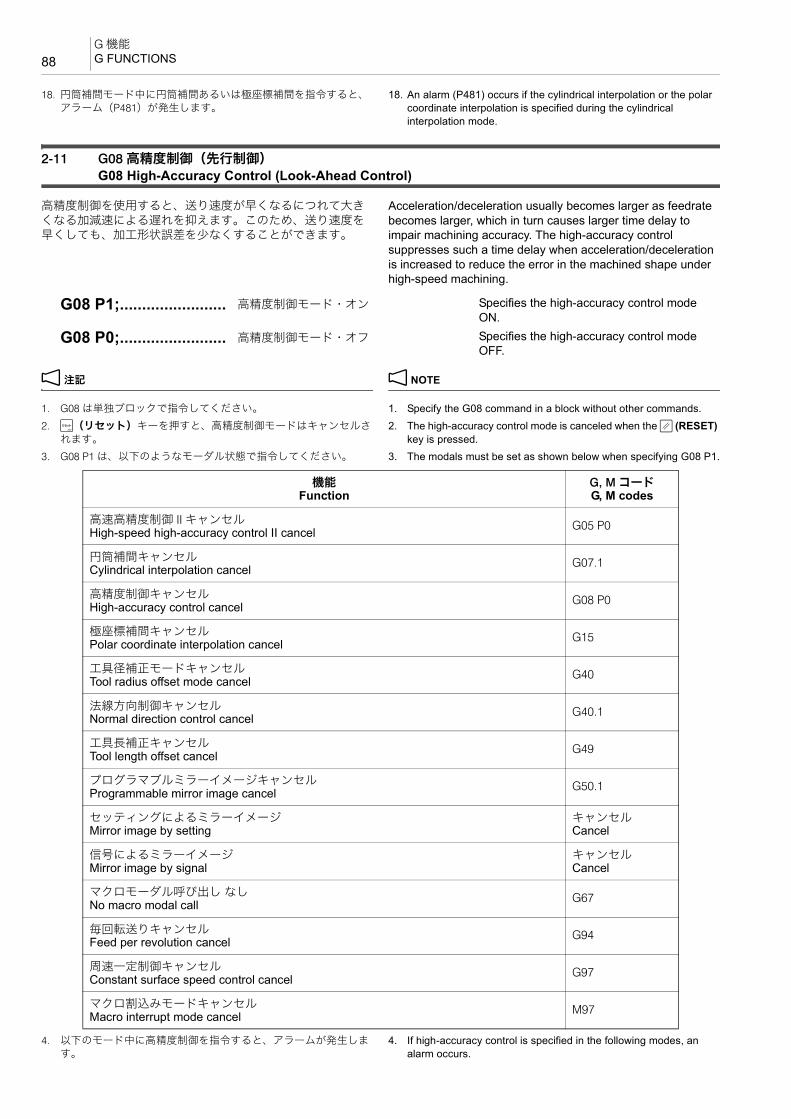
G 機能G FUNCTIONS88
18. 円筒補間モード中に円筒補間あるいは極座標補間を指令すると、アラーム(P481)が発生します。
18. An alarm (P481) occurs if the cylindrical interpolation or the polar coordinate interpolation is specified during the cylindrical interpolation mode.
2-11 G08 高精度制御(先行制御)G08 High-Accuracy Control (Look-Ahead Control)
高精度制御を使用すると、送り速度が早くなるにつれて大きくなる加減速による遅れを抑えます。このため、送り速度を早くしても、加工形状誤差を少なくすることができます。
Acceleration/deceleration usually becomes larger as feedrate becomes larger, which in turn causes larger time delay to impair machining accuracy. The high-accuracy control suppresses such a time delay when acceleration/deceleration is increased to reduce the error in the machined shape under high-speed machining.
2 注記 2 NOTE
1. G08 は単独ブロックで指令してください。 1. Specify the G08 command in a block without other commands.2. @(リセット)キーを押すと、高精度制御モードはキャンセルさ
れます。2. The high-accuracy control mode is canceled when the @ (RESET)
key is pressed.3. G08 P1 は、以下のようなモーダル状態で指令してください。 3. The modals must be set as shown below when specifying G08 P1.
4. 以下のモード中に高精度制御を指令すると、アラームが発生します。
4. If high-accuracy control is specified in the following modes, an alarm occurs.
G08 P1;........................ 高精度制御モード・オン Specifies the high-accuracy control mode ON.
G08 P0;........................ 高精度制御モード・オフ Specifies the high-accuracy control mode OFF.
機能Function
G, M コードG, M codes
高速高精度制御 II キャンセルHigh-speed high-accuracy control II cancel G05 P0
円筒補間キャンセルCylindrical interpolation cancel G07.1
高精度制御キャンセルHigh-accuracy control cancel G08 P0
極座標補間キャンセルPolar coordinate interpolation cancel G15
工具径補正モードキャンセルTool radius offset mode cancel G40
法線方向制御キャンセルNormal direction control cancel G40.1
工具長補正キャンセルTool length offset cancel G49
プログラマブルミラーイメージキャンセルProgrammable mirror image cancel G50.1
セッティングによるミラーイメージMirror image by setting
キャンセルCancel
信号によるミラーイメージMirror image by signal
キャンセルCancel
マクロモーダル呼び出し なしNo macro modal call G67
毎回転送りキャンセルFeed per revolution cancel G94
周速一定制御キャンセルConstant surface speed control cancel G97
マクロ割込みモードキャンセルMacro interrupt mode cancel M97
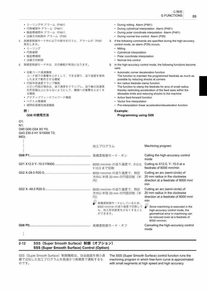
89G 機能
G FUNCTIONS
• ミーリング中 アラーム(P481) • During milling Alarm (P481)• 円筒補間中 アラーム(P481) • During cylindrical interpolation Alarm (P481)• 極座標補間中 アラーム(P481) • During polar coordinate interpolation Alarm (P481)• 法線方向制御中 アラーム(P29) • During normal line control Alarm (P29)
5. 高精度制御モード中に以下の指令を行うと、アラームが(P29)発生します。
5. If the following commands are specified during the high-accuracy control mode, an alarm (P29) occurs.
• ミーリング • Milling• 円筒補間 • Cylindrical interpolation• 極座標補間 • Polar coordinate interpolation• 法線方向制御 • Normal line control
6. 高精度制御モード中は、次の機能が有効になります。 6. In the high-accuracy control mode, the following functions become valid.
• 自動コーナ減速機能コーナ部での衝撃を小さくして、できる限り、送り速度を保持したままで動作させる機能
• Automatic corner deceleration functionThe function to maintain the programmed feedrate as much as possible by reducing shocks at corners
• 円弧半径速度クランプ機能小さい円弧の場合は、送り速度をクランプし、送り軸の加速度を許容値以上にならないようにして、機械への衝撃を小さくする機能
• Arc radius feedrate clamp functionThe function to clamp the feedrate for arcs of small radius, thereby restricting acceleration of the feed axes within the allowable limits and reducing shocks to the machine
• アクティブフィードフォワード機能 • Active feed-forward function• ベクトル精補間 • Vector fine interpolation• 補間前直線加減速機能 • Pre-interpolation linear acceleration/deceleration function
例: Example:G08 の使用方法 Programming using G08
2-12 SSS(Super Smooth Surface)制御(オプション)SSS (Super Smooth Surface) Control (Option)
SSS(Super Smooth Surface)制御機能は、自由曲面を微小直線で近似した加工プログラムを高速かつ高精度で運転するものです。
The SSS (Super Smooth Surface) control function runs the machining program in which free-form curve is approximated with small segments at high speed and high accuracy.
O1;N1;G90 G00 G54 X0 Y0;G43 Z30.0 H1 S10000 T2;M03;:
: 加工プログラム Machining program:
G08 P1;..................................................................... 高精度制御モード・オン Calling the high-accuracy control mode
G01 X12.0 Y−10.0 F8000; ........................................ 8000 mm/min の送り速度で、X12.0, Y-10.0 まで切削
Cutting to X12.0, Y−10.0 at a feedrate of 8000 mm/min
G02 X-28.0 R20.0; .................................................... 8000 mm/min の送り速度で、時計方向に半径 20 mm の円弧切削(半円)
Cutting an arc (semi-circle) of 20 mm radius in the clockwise direction at a feedrate of 8000 mm/min
G02 X−48.0 R20.0; ................................................... 8000 mm/min の送り速度で、時計方向に半径 20 mm の円弧切削(半円)
5高精度制御モードにしているため、8000 mm/min の送り速度で切削しても、加工形状誤差を少なくすることができます。
Cutting an arc (semi-circle) of 20 mm radius in the clockwise direction at a feedrate of 8000 mm/min
5Since machining is executed in the high-accuracy control mode, the geometrical error in machining can be reduced even at a feedrate of 8000 mm/min.
G08 P0;..................................................................... 高精度制御モード・オフ Canceling the high-accuracy control mode
:

G 機能G FUNCTIONS90
SSS 制御では、2 ブロック間の角度だけでなく大域的な経路情報を用いることにより、微小段差やうねりに過度に影響されない 適な速度制御を行います。結果として、切削面に傷のような跡や縞目がついたりする箇所が減少します。
With SSS control, optimum speed control is performed without excessive effects of minute stepping or waviness, using the large area of path information as well as the angle between two blocks. As a result, scratches and streaks on the cutting surface decrease.
SSS 制御の特長は以下のとおりです。 The features of the SSS control are as follows.
1. 滑らかな形状の金型を微小線分プログラムで加工する場合に有効です。
1. This function is effective when smooth shaped mold is machined using a miniature line segment program.
2. 経路に含まれる誤差の影響を受け難い速度制御を行います。
2. This function controls the speed with less effect of error included in tool paths.
3. コーナ減速が不要な箇所でも、予測した加速度が大きければ速度をクランプします。
3. Even if corner deceleration is not required, the speed is clamped if the predicted acceleration is high.
(クランプ速度は、パラメータ No. 8092 で調整することができます。)
(The clamp speed is adjustable by parameter No. 8092.)
また、本機能を使用するためには、本機能で動作する下記機能が必要です。
To use this function, the functions below that are operated by this function are required.
• 高精度制御(先行制御)(G08 P1) • High-accuracy control (look-ahead control) (G08 P1)• 高速高精度制御 I(AI 輪郭制御)(G05.1 Q1)(オプション) • High-speed, high-accuracy control I (AI contour control)
(G05.1) (option)• 高速高精度制御 II(高精度輪郭制御)(G05 P10000)(オプ
ション)• High-speed, high-accuracy control II (high-precision contour
control) (G05 P10000) (option)SSS 制御は、高精度制御(先行制御)、高速高精度制御 I(AI輪郭制御)、または高速高精度制御 II(高精度輪郭制御)のいずれかを指令すると、自動的に有効になります。
The SSS control is automatically validated when any of the high-accuracy control (look-ahead control), high-speed, high-accuracy control I (AI contour control), or high-speed, high-accuracy control II (high-precision contour control) is specified.
2 注記 2 NOTE
1. SSS 制御中は先読みを行うため、エラー発生ブロックより早い段階でアラームが発生する場合があります。
1. Since buffering is executed during the SSS control, an alarm may occur before the block containing the error is executed.
2. SSS 制御中のバッファ修正の動作は保証されません。 2. The operation of correcting buffer during the SSS control is not guaranteed.
3. SSS 制御中に自動・手動同時、及び自動ハンドル割込みを使用する場合、加工精度は保証されません。
3. If automatic/manual simultaneous or automatic handle interruptions are used during the SSS control, the machining accuracy is not guaranteed.
4. SSS 制御中に微小円弧指令を行った場合、加工に時間がかかる場合があります。
4. If a fine arc command is specified during the SSS control, it may take longer to machine.
5. グラフィックチェック中はシングルブロック運転と同様の経路となります。
5. The same path as that of single block operation is used during graphic check.
6. SSS 制御は切削送りの直線、円弧指令ブロックが速度制御の対象となります。速度制御対象外の指令ブロックでは、いったん減速して自動的に SSS 制御のオン・オフが切り替わります。
6. The line under the cutting feedrate and arc command block are subjected to the speed control in the SSS control. In the command blocks that are not subjected to the speed control, the axis movement is decelerated first and the SSS control is automatically switched ON and OFF.
7. 極座標補間、円筒補間モード中のブロックは、SSS 制御の対象外となります。
7. Blocks in the polar coordinate interpolation mode and the cylindrical interpolation mode are not subjected to the SSS control.
8. SSS 制御中は、フェアリングが無効となります。 8. The fairing is invalid during the SSS control.9. SSS 制御は、工具先端点制御および回転軸プレフィルタ機能と併
用できます。9. The SSS control can be used with the tool center point control and
the rotary tool pre-filter functions.
2-13 G09 イグザクトストップG09 Exact Stop
コーナの精度を出すために G09 を使用します。 To finish the corner sharp, the G09 Command is used.
C
A
B
Tool Path Programmed in the G01 Mode
Actual Tool Path
G01 でプログラムされた通路
実際の工具通路

91G 機能
G FUNCTIONS
5
G09 を使用して G01 の切削を行うと、移動の停止時に減速がかかるとともに、次のブロックの移動を開始するための加速が自動的にかかります。
When the G09 command is specified in the G01 mode, the axis movement is decelerated before stopping at the programmed end point and is accelerated automatically to start the axis movement specified in the next block.
2 注記 2 NOTE
G09 は切削送り(G01, G02, G03 など)に有効です。 The G09 mode is valid for cutting feed (G01, G02, G03).
1. G01 の切削送りで、ワークのコーナを鋭角なエッジにしたいときなどに使用します。
51. It is used to make the corner of the workpiece sharp in the G01
cutting feed mode.2. G01 の直線切削については、指令した位置に位置決めすると
きのインポジション幅を指令することもできます。2. For linear cutting operation in the G01 mode, it is possible to
specify the in-position width for positioning at the specified position.
1. 直線切削 1. Linear cutting
2. 円弧切削 2. Circular cutting< XY 平面> <XY Plane>
< ZX 平面> <ZX Plane>
< YZ 平面> <YZ Plane>
2 注記 2 NOTE
1. G09 はワンショット G コードなので、指令したブロックのみ有効です。
1. Since G09 is one-shot G code, it is valid only in the specified block.
1 ワンショット G コードについては、“G 機能 ”(57 ページ) 1 For the one-shot G code, refer to “G FUNCTIONS” (page 57).
2. 正確に位置決めされたかどうかをチェックする機能は、G61 にもあります。G61 が G09 と異なるのは、G61 がモーダル G コードという点です。
2. G61 also has check function for exact stop. Different from the G09 command, the G61 command is a modal G code.
3. G02(G03)の円弧切削については、インポジション幅を指令することはできません。
3. For circular arc cutting operation in the G02 or G03 mode, the in-position width cannot be specified.
4. インポジション幅の指令範囲は 1 ~ 999.999(mm)です。 4. The in-position width can be specified in the range of 1 - 999.999 (mm).
5G09 の代わりに G04 でも指令できます。G04 に続く P や X を省略すると、イグザクトストップとなります。
5G04 can be used instead of G09. When neither P nor X is specified after G04, an exact stop is performed.
G09 G01 X_ Y_ Z_ F_ ;G09 G01 X_ Y_ Z_ F_, I_ ;
G17 G09 G02(G03) X_ Y_ I_ J_ F_ ;G17 G09 G02(G03) X_ Y_ R_ F_ ;
G18 G09 G02(G03) X_ Z_ I_ K_ F_ ;G18 G09 G02(G03) X_ Z_ R_ F_ ;
G19 G09 G02(G03) Y_ Z_ J_ K_ F_ ;G19 G09 G02(G03) Y_ Z_ R_ F_ ;
• G17, G18, G19..................... 円弧の平面設定 Selects the plane where a circular arc is defined.
• G09 ...................................... 切削移動指令の終点で、正確な位置決めがされたどうかのチェック
Calls the exact stop check function, which checks if a cutting tool is correctly positioned at the programmed end point.
• G01 ...................................... 直線切削指令 Specifies the linear interpolation mode.
• G02(G03) ............................. 円弧切削指令 Specifies the circular interpolation mode.
• X, Y, Z .................................. 移動の終点座標 Coordinate values of the end point of movement.
• I, J, K.................................... 円弧の始点から円弧の中心までの距離と方向
Distance and direction from the start point of the arc to the center.
• R .......................................... 円弧の半径 Circular arc radius.
• F........................................... 送り速度 Feedrate.
• , I .......................................... インポジション幅 In-position width

G 機能G FUNCTIONS92
例: Example:イグザクトストップ(G09)の使用例 Programming using the exact stop (G09)
O0001;N1;
G00 X60.0 Y50.0; .................................................aG09 G01 X−60.0 F500; .........................................b 500 mm/min の送り速度で点 b に
工具が移動。正確に位置決めされたかどうかを、NC 側でチェック。
Moves the cutting tool to b at a feedrate of 500 mm/min. The exact positioning is checked by the NC.
Y−50.0;..................................................................c 500 mm/min の送り速度で c に工具が移動。減速せずに次の動作に移る。
2 注記
G09 はワンショット G コードなので、移動の終点で正確に位置決めされたかどうかを、NC 側でチェックしません。
Moves the cutting tool to c at a feedrate of 500 mm/min. Without deceleration, the cutting tool starts the movement specified by the next block.
2 NOTE
Since G09 is a one-shot command, it is not valid for this block. Therefore, exact positioning is not checked by the NC.
G09 X60.0; ............................................................d 500 mm/min の送り速度で d に工具が移動。正確に位置決めされたかどうかを、NC 側でチェック。
Moves the cutting tool to d at a feedrate of 500 mm/min. The exact positioning is checked by the NC.
Y50.0;....................................................................a
2
3
1
460 60
+Y
+X
5050
(60.0, 50.0)
(60.0, −50.0)
(−60.0, 50.0)
(−60.0, −50.0)
(X, Y)
Cutting Feed切削送り

93G 機能
G FUNCTIONS
2-14 G10 プログラム指令によるワーク座標系変更G10 Changing Work Coordinate System by Programmed Command
多数個取り加工などで、ワーク座標系が G54 ~ G59 の 6 つでは不足するときに、G54 ~ G59 の補正量をプログラム上で変更して使用します。
G10 is used by changing the offset amounts for G54 to G59 in a program if the number of work coordinate systems called by these six codes is not sufficient for the intended operation, for example with a multiple workpiece setup.
2 注記 2 NOTE
1. 段取り作業のときに求めた機械原点から加工原点までの距離が、G10 によって書き換えられるため、G10 でワーク座標系の原点を変更させると、それ以後は変更された座標系になります。プログラム中、ワーク座標系はそのままでその他に座標系を作成したいときは、ローカル座標系(G52)を使用します。
1. The G10 command updates the distance from the machine zero point to the workpiece zero point which is obtained during setting up. Accordingly, if the zero point of the work coordinate system is changed by using the G10 command, the commands are executed in the updated coordinate system. In a program, if a coordinate system should be established while the present work coordinate system remains as it is, use a local coordinate system (G52).
1 ローカル座標系(G52)については、“G52 ローカル座標系設定 ”(114 ページ)
1 For the local coordinate system (G52), refer to “G52 Setting Local Coordinate System” (page 114)
G90(G91) G10 L2 P_ X_ Y_ Z_ ;• G10 ...................................... ワーク座標系の補正量の外部入力指令 Specifies external input of offset amount of
work coordinate system
• L2 ......................................... ワーク座標系の補正量の入力(省略不可) Work coordinate system offset amount input (cannot be omitted)
• P........................................... ワーク座標系 G54 ~ G59 の選択P0 D G54 ~ G59 すべて共通のシフト量
(‘ 共通 ’)P1 D G54P2 D G55P3 D G56P4 D G57P5 D G58P6 D G59
Selecting work coordinate systems G54 - G59Work coordinate system shift data common to G54 to G59 (‘COMMON’)P1 D G54P2 D G55P3 D G56P4 D G57P5 D G58P6 D G59
• X, Y, Z .................................. ワーク座標系で位置決めするための座標値(加工原点)
2 注記
(G90):指令された座標値が新たな加工原点
(G91):指令された座標値が今までの加工原点に加算
1“G90 アブソリュート指令(絶対値指令)、G91 インクレメンタル指令(増分値指令)”
(135 ページ)
Coordinate values (workpiece zero point) used for positioning in a work coordinate system
2 NOTE
(G90):The specified coordinate values establish the new workpiece zero point.(G91):The specified coordinate values are added to the coordinate values of present workpiece zero point.1“G90 Absolute Command, G91 Incremental
Command” (page 135)
+Y +Y'
+X
+X'
New G54 Coordinate System Defined by G10
Original G54 Coordinate System
G10 で移動させた新しい G54 座標系
元の G54 座標系

G 機能G FUNCTIONS94
2. アドレス P を省略あるいはアドレス P に 0 ~ 6 以外を指令すると、現在選択中のワーク座標系が変更されます。ただし、オプションの追加ワーク座標系が装備されている機械では、アドレスP に 0 ~ 6 以外を指令すると、画面にアラーム(P35)が表示されます。また、G54.1 で追加ワーク座標系を設定している状態でアドレス P を省略すると、画面にアラーム(P33)が表示されます。
2. If the G10 command is executed without address P or if it is executed assigning a number other than 0 - 6 for address P, the work coordinate system presently selected is changed. However, with the machine equipped with additional work coordinate systems, designating a number other than 0 - 6 for address P causes an alarm (P35) to be displayed on the screen. If address P is omitted with an additional work coordinate system set using the G54.1 command, an alarm message (P33) is displayed.
3. G10 と同一ブロックに、G20, G21, G54 ~ G59, G90, G91 以外のG コードを指令しないでください。
3. Do not specify any G codes other than G20, G21, G54 - G59, G90 and G91 with the G10 command in the same block.
4. G10 と同一ブロックに下記の G コードを指令しないでください。下記の G コードを同一ブロックに指令すると、G10 は実行されません。
4. Do not specify the following G codes with the G10 command in the same block. If any of the G codes indicated below is specified with the G10 command in the same block, the G10 command is not executed.
• G66 ...................マクロモーダル呼出し(移動指令呼出し) • G66 ..........Macro modal call (call after execution of axis movement commands)
• G66.1 ..............マクロモーダル呼出し(毎ブロック呼出し) • G66.1 .......Macro modal call (call in each block)
• G67 ...................マクロモーダル呼出しキャンセル • G67 ..........Macro modal call cancel5. G10 を指令する前には、必ず G90 または G91 を指令してくださ
い。5. Before specifying the G10 command, specify either G90 or G91
command. G91 モードでは補正量は増分値となり、プログラムを実行するたびに累積していきますので、補正のかかり方について十分理解した上で、プログラムを作成してください。
In the G91 mode, the offset amount is interpreted as an increment and will be cumulative each time the program is executed. Understand how the offset works correctly before creating a program.
例: Example:G10 の使用例 Programming using G10下図において、a, b と e, f に G54, G55 を使用するため、プログラム中で G54, G55 のワーク座標系補正量を入力します。c, d に使用する G56, G57 は、段取り作業でワーク座標系補正量をすでに入力しています。
In the figure below, since G54 and G55 are used for a and b, and e and f respectively, the offset data of the G54 and G55 work coordinate systems are input in a program. The offset data of G56 and G57 for c and d have been input during setting up.
:
G90 G00 G54 X0 Y0;................................................ G54 のワーク座標系を選択 Selecting the G54 work coordinate system
:
G90 G10 L2 X−150.0 Y−100.0; ................................. アドレス P が省略されているため、G54 のワーク座標系の加工原点が機械原点より、X−150.0, Y−100.0 の位置に変更されます。
Changing the workpiece zero point of the work coordinate system G54 is changed from the machine zero point to (X−150.0, Y−100.0) since address P is omitted.
O0001;N1;G90 G10 L2 P1 X−400.0 Y−120.0;............................ G54 のワーク座標系に a の補正値
入力Inputs the offset data of a for G54 work coordinate system
G10 L2 P2 X−300.0 Y−120.0; ................................... G55 のワーク座標系に b の補正値入力
Inputs the offset data of b for G55 work coordinate system
G00 G54 X0 Y0;....................................................aG43 Z30.0 H1 S400 T2;M03;G55 X0 Y0; ...........................................................bG56 X0 Y0; ...........................................................c
, , 654
, , 321
+Y
+X4
+Y
+X5
+Y
+X6
+Y
+X1
+Y
+X2
+Y
+X3
G57 G54 G55
G54 G55 G56
100 100 200
120
130
+Z
+Z
350+Y
Machine Zero Point機械原点

95G 機能
G FUNCTIONS
2-15 G15, G16 極座標指令(オプション)G15, G16 Polar Coordinate Command (Option)
終点座標値を半径と角度の極座標で入力することができます。 The end point coordinate value can be input in polar coordinates (radius and angle).
1 詳細は、制御装置メーカーの取扱説明書 1 Refer to the instruction manual supplied by the NC manufacturer for details.
2 注記 2 NOTE
1. 半径、角度はアブソリュート指令(G90)、インクレメンタル指令(G91)のどちらでも指令できます。
1. Both radius and angle can be specified in either absolute or incremental command (G90, G91).
2. 極座標モードでの円弧補間やヘリカル補間(G02, G03)の半径指令は、アドレス R で指令してください。
2. In the polar coordinate mode, specify a radius for circular interpolation or helical cutting (G02, G03) with the address R.
3. 極座標モード中でも、以下の指令に伴う軸指令は極座標指令とみなされません。
3. Even in the polar coordinate mode, axes specified for the following commands are not considered as a part of the polar coordinate command.
• G04 ドウェル • G04 Dwell• G10 データ設定 • G10 Data setting• G27 原点復帰チェック • G27 Zero return check• G28 自動原点復帰 • G28 Automatic zero return• G29 原点からの復帰 • G29 Return from zero point
G57 X0 Y0; ...........................................................dG90 G10 L2 P1 X−300.0 Y−250.0;............................ G54 のワーク座標系に e の補正値
入力Inputs the offset data of e for G54 work coordinate system
G10 L2 P2 X−200.0 Y−250.0; ................................... G55 のワーク座標系に f の補正値入力
Inputs the offset data of f for G55 work coordinate system
G54 X0 Y0; ...........................................................eG55 X0 Y0; ...........................................................f
G17 (G18, G19) G90 (G91) G16;G00 X_ Y_ Z_ ;:G15;
• G17, G18, G19 .................... 極座標指令の平面選択• G17:XY 平面• G18:ZX 平面• G19:YZ 平面
Selects the plane where the polar coordinate command is applied.• G17: XY plane• G18: ZX plane• G19: YZ plane
• G90, G91 ............................. 極座標指令の中心選択• G90:ワーク座標系の原点
2 注記
G52 を使用しているときは、ローカル座標系の原点
• G91:現在位置
Selects the origin of polar coordinate command.• G90: Zero point of work coordinate system
2 NOTE
When the local coordinate system (G52) is used, the origin of the local coordinate system
• G91: Current position
• G16 ...................................... 極座標モード開始 Polar coordinate mode start
• G15 ...................................... 極座標モードキャンセル Polar coordinate mode cancel
• X, Y, Z .................................. 選択した平面の軸アドレスと指令値• G17:XY 平面
X:極座標の半径Y:極座標の角度
• G18:ZX 平面Z:極座標の半径X:極座標の角度
• G19:YZ 平面Y:極座標の半径Z:極座標の角度
Axis addresses constituting the selected plane and their values• G17: XY plane
X: Radius of polar coordinateY: Angle of polar coordinate
• G18: ZX planeZ: Radius of polar coordinateX: Angle of polar coordinate
• G19: YZ planeY: Radius of polar coordinateZ: Angle of polar coordinate

G 機能G FUNCTIONS96
• G30 第 2 /第 3、第 4 原点復帰 • G30 Second/third, fourth zero return• G31 スキップ • G31 Skip function• G51 スケーリング • G51 Scaling• G51.1 プログラマブルミラーイメージ • G51.1 Programmable mirror image• G52 ローカル座標系設定 • G52 Local coordinate system setting• G53 機械座標系の選択 • G53 Machine coordinate system selection• G68 座標回転/ 3 次元座標変換 • G68 Coordinate rotation/3D coordinate conversion• G92 ワーク座標系設定 • G92 Work coordinate system setting
2-16 G17, G18, G19 加工平面選択G17, G18, G19 Selecting Plane for Machining
円弧切削、工具径補正および座標回転を行うときに、どの平面に対してその機能が働くのかを選ぶ必要があります。一般的に G17 の XY 平面で加工しますが、ZX 平面や YZ 平面で指令しなければならないときに、G18, G19 を指令します。
To execute circular arc cutting, tool radius offset and coordinate system rotation, it is necessary to select the plane on which the called function is executed. Generally, the XY plane called by G17 is selected to execute the required functions. However, there are cases that the function must be executed on the ZX or YZ plane. To select the ZX or YZ plane, specify G18 or G19.
2 注記 2 NOTE
1. 軸の移動指令は平面選択に無関係です。 1. Axis movement commands are not affected by the selected plane.G17 G02 X_ Y_ R_ F_ ; G17 G02 X_ Y_ R_ F_ ;G01 Z_ ; XY 平面に関係なく Z 軸は移動します。 G01 Z_ ; The Z-axis moves independent of the selected plane.
2. 円弧指令(G02, G03)、工具径補正(G40 ~ G42)を指令するときに、G17 ~ G19 の適切な平面を選択しなければ、アラームが画面に表示されます。
2. When specifying a circular interpolation command (G02, G03) or tool radius offset command (G40 to G42), an alarm message is displayed on the screen if selected plane is not proper for the specified commands.
G17 .............................. XY 平面(電源投入時) XY plane (selected when power is turned on)
G18 .............................. ZX 平面 ZX plane
G19 .............................. YZ 平面 YZ plane
+Y
+X
+ZG18
G19
G17

97G 機能
G FUNCTIONS
例: Example:加工平面選択(G17, G18, G19)の使用例 Programming using the selecting plane for machining
(G17, G18, G19)下図の半球体の加工において a D c D b, a D d D b, c D d D e の半径 10 mm の 3 通りの円弧をプログラミングします。
Below shows the programming required to machine a hemisphere with three arcs of 10 mm radius (a D c D b, a D d D b, and c D d D e).
(a):XY 平面で a に工具が位置決め (a): Positions the tool at a in the XY plane.(b):XY 平面で b まで時計方向の円弧切削(半径 10.0 mm) (b): Moves the cutting tool along the arc clockwise up to b on
the XY plane. (Radius: 10.0 mm)
(c):ZX 平面で b まで反時計方向の円弧切削(半径 10.0 mm) (c): Moves the cutting tool along the arc counterclockwise up to b on the ZX plane. (Radius: 10.0 mm)
2 注記 2 NOTE
G02, G03 は Y 軸の + 側から − 方向を見て判断します。 Determine the direction (G02 or G03) by viewing the arc from Y-axis positive side to the negative side.
(d):YZ 平面で e まで反時計方向の円弧切削(半径 10.0 mm) (d): Moves the cutting tool along the arc counterclockwise up to e on the YZ plane. (Radius: 10.0 mm)
<a D c D b>(G17) G01 X10.0 Y0 Z0 F100;..........................a(a)G02 X−10.0 Y0 R10.0; ......................................b(b):
<a D d D b>G01 X10.0 Y0 Z0 F100;........................................aG18 G03 X−10.0 Z0 R10.0; ..............................b(c):
<c D d D e>G01 X0 Y−10.0 Z0 F100;......................................cG19 G03 Y10.0 Z0 R10.0; ................................e(d):
2 3
1
+Y+X
+Z
(0, −10.0, 0)
(10.0, 0, 0)
(0, 10.0, 0)5
(X0, Y0)
(0, 0, −10.0)
(−10.0, 0, 0)
4
(X, Y, Z)
3
1
−Y
10−10+X
−10
2
4
2
1+X
−10 +Z
−10
10
5
4
3
+Y
−10−Z
−10
10

G 機能G FUNCTIONS98
2 注記 2 NOTE
G02, G03 は X 軸の + 側から − 方向を見て判断します。 Determine the direction (G02 or G03) by viewing the arc from X-axis positive side negative side.
1 “G02 円弧補間(時計方向)、G03 円弧補間(反時計方向)”(68ページ)
1 “G02 Circular Interpolation (Clockwise), G03 Circular Interpola-tion (Counterclockwise)” (page 68)
2-17 G27 原点(レファレンス点)復帰チェックG27 Zero (Reference Position) Return Check
G27 の指令により、工具は指令された位置に早送りで移動します。この到達した位置が機械原点であれば、その軸の状態表示ランプ “ 原点復帰 ” が点灯します。
The G27 command positions the tool at the rapid traverse rate. If the tool reaches the machine zero point, the lamp for indicating the completion of zero return lights up.
機械原点に到達していない場合は、アラームが発生します。 If the tool has not reached the machine zero point along a specified axis, an alarm occurs.
軸移動がない場合は、現在の位置が機械原点であるかをチェックします。
If no movement occurs on the axis, it is checked whether the position is the machine zero point.
2 注記 2 NOTE
1. 原点復帰チェックで到達する位置は、補正中であれば、補正量を加味した位置です。したがって、補正量を加味した位置が機械原点に来ないと、原点復帰完了ランプは点灯しません。通常は、補正をキャンセルして G27 を指令します。
1. In an offset mode, the position to be reached in the zero return check is the position obtained by adding the offset value. Therefore, if the position with the offset value added is not the machine zero point, the lamp for indicating the completion of zero return does not light up. Normally, cancel offsets before G27 is specified.
2. マシンロックが有効の状態では、原点復帰チェックは無効です。 2. When the machine lock function is valid, the zero return check is invalid.
3. P 指令を省略した場合、機械原点復帰チェック指令となります。 3. If the P command is omitted, it is assumed that a machine zero return check command is specified.
2-18 G28 機械原点(レファレンス点)復帰、G30 第 2(3, 4)原点(レファレンス点)復帰G28 Machine Zero (Reference Position) Return, G30 Second (Third or Fourth) Zero (Reference Position) Return
G28, G30 の指令により、機械は指令された位置(中間点)に早送りで位置決めした後、自動的に機械原点あるいは第 2、第 3、第 4 原点に各軸を復帰させることができます。
The G28 or G30 command is used to automatically return the axes specified in the same block to the machine zero point or the second (third or fourth) zero point after positioning them to the specified intermediate point at a rapid traverse rate.
工具交換または APC を行うとき、あるいは工具がワーク、イケール、カバーなどと干渉するおそれがあるとき、ワークの着脱、切りくずの除去を行うときに使用します。
These commands are used when carrying out an automatic tool change or APC operation, when avoiding interference of a cutting tool with the workpiece, tooling block, or machine cover, or when changing a workpiece or removing chips.
1. 機械原点Machine zero pointG28 X_ Y_ Z_ ;
2. 第 2 原点復帰Second zero pointG30 X_ Y_ Z_ ;
G27 X_ Y_ Z_ P_ ;• G27 ...................................... 原点復帰チェック Zero return check
• X, Y, Z .................................. 機械原点の位置決め指令 Positioning to the machine zero point
• P1......................................... 機械原点復帰チェック Machine zero return check
• P2......................................... 第 2 原点復帰チェック Second zero return check
• P3......................................... 第 3 原点復帰チェック Third zero return check
• P4......................................... 第 4 原点復帰チェック Fourth zero return check

99G 機能
G FUNCTIONS
3. 第 3、第 4 原点復帰Third and fourth zero pointG30 P3(P4) X_ Y_ Z_ ;
8警告 8WARNING第 2、第 3、第 4 原点復帰位置は、機械原点からの距離をパラメータ番号 No. 2038, No. 2039, No. 2040 に入力して設定します。パラメータ番号 No. 2038 の値は変更しないでください。[人身事故、機械の破損]
The positions to be reached in the second, third and fourth zero return operation are established by setting the distance from the machine zero point in parameters No. 2038, No. 2039, and No. 2040, respectively. Do not change the setting for the parameter No. 2038.[Injuries/Machine damage]
7注意 7 CAUTION
1. G28, G30 を使用する場合は、Z 軸を機械原点あるいは第 2原点復帰させてから、X 軸、Y 軸を機械原点あるいは第 2、第 3、第 4 原点復帰させてください。
[干渉、機械の破損]
1. When using G28 or G30, return the Z-axis to the machine zero point or second zero point first and then return the X- and Y-axes to the machine zero point (or second, third, or fourth zero point).[Interference/Machine damage]
2. G28, G30を使用して現在位置から直接Z軸を機械原点ある
いは第 2、第 3、第 4 原点復帰させる場合は、“G91 G28 Z0;”, “G91 G30 Z0;” あるいは “G91 G30 P3(P4) Z0;” と指令してください。“G90_ ;” を指令すると、加工原点を経由して機械原点あるいは第 2、第 3、第 4 原点に移動するため危険です。
[干渉、機械の破損]
2. When returning the Z-axis from the present position to the machine zero point (or second, third or fourth zero point) using G28 or G30, specify any of the following commands: “G91 G28 Z0;”, “G91 G30 Z0;”, “G91 G30 P3(P4) Z0;”. If G28 or G30 is specified following G90 (“G90_ ;”), it will be dangerous since the Z-axis returns to the machine zero point (or second, third, or fourth zero point) via the workpiece zero point.[Interference/Machine damage]
3. G28, G30 で切削工具を機械原点あるいは第 2、第 3、第 4 原
点に復帰させる場合、工具経路は必ずしも現在位置と機械原点あるいは第 2、第 3、第 4 原点を結ぶ直線にはなりません。工具経路に障害物がないことを確認してください。
3. When the cutting tool returns to the machine zero point or second, third or fourth zero point using G28 or G30, the tool path is not always a straight line from the present position to the machine zero point or second, third or fourth zero point. Confirm that there is no obstacle in the path beforehand.
2 注記 2 NOTE
X, Y, Z 軸が第 2 原点復帰位置にあるとき、工具交換を行います。 The tool is changed when the X-, Y-, and Z-axes are positioned at the second zero point.
• G28 ...................................... 機械原点復帰指令 Calls the machine zero return mode.
• G30 ...................................... 第 2 原点復帰指令 Calls the second zero return mode.
• G30 P3................................. 第 3 原点復帰指令 Calls the third zero return mode.
• G30 P4................................. 第 4 原点復帰指令 Calls the fourth zero return mode.
• X, Y, Z .................................. 機械原点復帰あるいは第 2、第 3、第 4 原点復帰させる軸の指令
2 注記
X, Y, Z, に続く数値は、中間点の座標値です。
Specifies the axes to be returned to the machine zero point or, the second, third, or fourth zero point.
2 NOTE
Numeric value specified following addresses X, Y and Z indicates the coordinate value of the intermediate point.
G91 G30 Z0 M05; ..................................................... Z 軸第 2 原点復帰して、主軸の回転停止
Second zero return of Z-axis and spindle stops rotating.
G30 X0 Y0; ............................................................... X, Y 軸第 2 原点復帰 Second zero return of X- and Y-axesM06; .......................................................................... 工具交換 Tool change

G 機能G FUNCTIONS100
2-19 G31 スキップ機能、G31.1 外部高速スキップ (オプション)G31 Skip Function, G31.1 External High-Speed Skip (Option)
センサ仕様でワークの心出し、工具長測定、工具折損検出をするときなどに、G31 (G31.1) を指令します。G31 (G31.1) の指令による動きは、G01 のときと同様で直線的に移動します。G31 (G31.1) の指令の途中に外部よりスキップ信号が入力されると、残りの移動を中止して、次のブロックを実行します。
Specify G31 (G31.1) when aligning the workpiece, measuring tool length, detecting tool breakage for the machine equipped with a sensor. Movement in the G31 (G31.1) mode is linear, same as in the G01 mode. If the skip signal is input externally during sensor movement in the G31 (G31.1) mode, current movement is stopped and the program advances to the next block ignoring the remaining distance.
G31.1 は、外部機器(お客様手配)からスキップ信号を送る場合に使用します。G31.1 の機能は、G31(スキップ機能)と同じです。
Use the G31.1 command to send the skip signal from an external device (provided by customers).The G31.1 command has the same function as G31 (skip function).
5通常の加工プログラムでは指令しません。 5G31 (G31.1) cannot be specified in the ordinary machining program.
2 注記 2 NOTE
1. G31 (G31.1) はワンショット G コードなので、指令したブロックのみ有効です。
1. Since G31 (G31.1) is one-shot G code, it is valid only in the specified block.
1 ワンショット G コードについては、“G 機能 ”(57 ページ) 1 For the one-shot G code, refer to “G FUNCTIONS” (page 57).
2. G31 (G31.1) のブロックには、必ず送り速度を指令してください。送り速度を指令しない状態では、送り速度は 0 です。したがって、プログラムを実行しても機械は動かずに、画面にアラーム
(P603)が表示されます。
2. The G31 (G31.1) block must contain a feedrate command. If no feedrate command is specified with the G31 (G31.1) command, feedrate is regarded as zero. Consequently, the machine does not move even if the program is executed and an alarm message (P603) is displayed on the screen.
3. ここで指令する送り速度は、このブロックでの送り速度です。他のブロックでは無効です。
3. The feedrate specified in the G31 (G31.1) block is used to execute the axis movement commands in this block and not valid for other blocks.
4. G31 (G31.1) を指令する前に、工具径補正(G41, G42)を G40 でキャンセルしてください。工具径補正モード中に G31 (G31.1) を指令すると、画面にアラーム(P608)が表示されます。
4. Before specifying the G31 (G31.1) command, cancel the tool radius offset mode (G41, G42) by specifying the G40 command. If the G31 (G31.1) command is specified in the tool radius offset mode, an alarm message (P608) is displayed on the screen.
5. G31 (G31.1) を指令すると、送り速度は F で指令された値に固定され、操作パネルの送りオーバライドスイッチが 100%の状態になっていなくても 100%の送り速度になります。
5. If the G31 (G31.1) command is executed, feedrate is fixed to the value specified by an F command. In this state, the setting for the feedrate override dial on the operation panel is not 100%, the setting is ignored and it is assumed to be 100%.
また、ドライラン機能も無効になります。 The dry run function is invalid in the G31 (G31.1) mode.6. G31 (G31.1) の指令の途中に外部よりスキップ信号が入力されな
かった場合、移動指令完了で G31 (G31.1) の指令も完了します。6. If an external skip signal is not input during the execution of the
axis movement commands in the G31 (G31.1) block, the G31 (G31.1) mode is canceled upon completion of these axis movement commands.
7. Z 軸無視機能が有効な状態で、G31 (G31.1) のブロックに Z 軸だけが指令されている場合、あるいはマシンロック機能が有効な状態では、外部よりスキップ信号が入力されても無視され、ブロックの 後まで実行します。
7. If only a Z-axis movement command is specified in the G31 (G31.1) block while the Z-axis neglect function is valid, or when the machine lock function is valid, an external skip signal is ignored even if it is input and the commands in the G31 (G31.1) block are all executed to the end point.
8. G31 (G31.1) と同一ブロックに G40, G41, G42 指令すると、画面にアラーム(P608)が表示されます。
8. An alarm message (P608) is displayed on the screen if the G40, G41 or G42, command is specified with the G31 (G31.1) command in the same block.
9. 工具径補正モード中に G31 (G31.1) を指令すると、画面にアラーム(P608)が表示されます。
9. An alarm message (P608) is displayed on the screen if the G31 (G31.1) command is specified in the tool radius offset mode.
G31 (G31.1) X_ Y_ Z_ F_ ;
• G31 ...................................... スキップ機能・オン Skip function ON
• G31.1 ................................... 外部高速スキップ・オン External high-speed skip ON
• X, Y, Z .................................. 移動の終点座標 Coordinate values of the end point
• F........................................... 送り速度 Feedrate

101G 機能
G FUNCTIONS
例: Example:G31 の使用例 Programming using G31G31 の次のブロックがインクレメンタル指令か、アブソリュート指令かによって、次のとおり、スキップ信号の入った後の動きが異なります。
As shown below, axis movements after input of the skip signal varies according to the dimensioning mode (incremental or absolute) of the block following the G31 block.
1) インクレメンタル指令のとき 1) In Incremental ModeG31 の次のブロックは、スキップ信号によって中断された位置からインクレメンタルに動きます。
In the block following the G31 block, the axes move in the incremental mode from the point where the external skip signal is input.
下図の経路 a D b D c の動きの中で、a D b を G31で指令し、その途中の b' でスキップ信号が入った場合について説明します。
In the tool path a D b D c below, the tool behaves as follows after the skip signal input at b' during the path a D b in the G31 mode:
ブロック (a) は、スキップ信号によって、中断された b'の位置からインクレメンタルに動きます。
The block (a) is executed in the incremental mode referenced to b' where the axis movement in the previous G31 block is interrupted by a input skip signal.
2) アブソリュート指令で 1 軸指令されるとき 2) In absolute values calling movement of a single axisG31 の次のブロックでは、指令されている軸は指令された位置に移動しますが、指令されていない軸はスキップ信号の入った位置を保ちます。
In the block following the G31 block, the specified axes move to the specified position. However the unspecified axes stay at the position where the skip signal is given.
下図の経路 a D b D c の動きの中で、a D b を G31で指令し、その途中の b' でスキップ信号が入った場合について説明します。
In the path a D b D c below, the tool behaves as follows after the skip signal input at b' during the path a D b in the G31 mode:
a から b に移動中、どこでスキップ信号が入っても、cで指令された軸(X 軸)は、指令された位置に移動します。c で指令されていない軸(Y 軸)は、スキップ信号の入った位置を保ちます。
If a skip signal is input at any point in the path a D b, the axis specified at c (X-axis) moves to the specified position. The axis (Y-axis) that is not specified at c keeps the position in which the skip signal is input.
3) アブソリュート指令で 2 軸指令されるとき 3) In absolute values calling movement of two axesG31 で移動中、どこでスキップ信号が入っても、次のブロックは指令された位置に移動します。
If a skip signal is input at any point on the path specified in the G31 mode, the axes moves to the specified position in the block following the G31 block.
1
2
2
3
(−40.0, −50.0)
(−30.0, 35.0) (57.0, 35.0)
+X
+Y
1
2
2
3
(−40.0, −50.0)
(−30.0, 35.0) (57.0, 35.0)
(X, Y)
G90 G00 X−40.0 Y−50.0; ........ aG91 G31 X10.0 Y85.0 F500;... bX87.0; ...................................... c (a)
:
87.0
87.0
Programmed PathSkip signal was given here.
Actual Path
プログラムされた動きここでスキップ信号が入る
実際の動き
1
2
2
3
(−40.0, −50.0)
(−30.0, 35.0) (57.0, 35.0)
+X
+Y
(X, Y)
G90 G00 X−40.0 Y−50.0; ........ aG31 X−30.0 Y35.0 F500; ........ bX57.0; ...................................... c
:
1
2
2
3
(−40.0, −50.0)
(−30.0, 35.0) (57.0, 35.0)
X57.0
Programmed Path
Skip signal was given here.
Actual Path
プログラムされた動き
ここでスキップ信号が入る
実際の動き

G 機能G FUNCTIONS102
下図の経路 a D b D c の動きの中で、a D b を G31で指令し、その途中の点 b' でスキップ信号が入った場合について説明します。
In the path a D b D c below, the tool behaves as follows after the skip signal input at b' during the path a D b in the G31 mode:
a から b に移動中、どこでスキップ信号が入っても、cで指令された位置に移動します。
If a skip signal is input at any point in the path a D b, the axes move to the position specified at c.
2-20 G40.1, G41.1, G42.1 法線方向制御(オプション)G40.1, G41.1, G42.1 Normal Direction Control (Option)
法線方向制御では、主軸の回転に C 軸を割り当てて工具の向き(回転)を制御します。
Normal direction control allocates the C-axis to control the tool direction (rotation).
XY 平面を切削中の工具が、進行方向に対して常に垂直な方向を向くように制御されるので、ワークの輪郭を研削するときなどに指令します。
When a tool is machining on XY plane, tool rotation is controlled so that the tool is always perpendicular to the tool path. Therefore, normal direction control is used when grinding the contour of a workpiece.
なお、法線方向制御中の C 軸旋回方式により、法線方向制御 Iおよび法線方向制御 II の 2 種類があります。
The normal direction control I and II can be used according to the C-axis turn direction during normal direction control.
<法線方向制御における工具の動き> <Tool movement in normal direction control>
G41.1 または G42.1 のブロックの始点で、工具が進行方向に対して垂直になります。
The tool becomes perpendicular to the tool path at the beginning of the G41.1 or G42.1 block.
その後のブロックでは、進行方向の変化にともない、各ブロックの始点で工具がまず進行方向に対して垂直になり、その後、X 軸および Y 軸が移動します。
In the following blocks, every time the direction of the path changes, the tool first becomes perpendicular to the tool path and then the X- and Y-axes move.
1
2
2
3
(−40.0, −50.0)
(−30.0, 35.0) (57.0, 35.0)
+X
+Y
(X, Y)
G90 G00 X−40.0 Y−50.0; ......aG31 X−30.0 Y35.0 F500; ......bX57.0 Y35.0;..........................c
:
1
2
2
3
(−40.0, −50.0)
(−30.0, 35.0) (57.0, 35.0)
Programmed PathSkip signal was given here.
Actual Path
プログラムされた動き
ここでスキップ信号が入る
実際の動き
法線方向制御 I: No.1524 = 0(出荷時の設定)
工具の回転方向は、いつも180° 以下(近回り)
法線方向制御 II: No.1524 = 1
工具の回転方向は指令方向(180° 以上に回転することがあります。)
Normal direction control I: No. 1524 = 0 (default setting)
The tool always rotates 180° or less. (shortcut direction)
Normal direction control II: No. 1524 = 1
The tool rotates in the commanded direction. (The tool may rotate more than 180°.)
(X0, Y250.0)
(X200.0, Y0)
(X200.0, Y250.0)
R125
(X0, Y0)
φ20
Program pathTool center path
Arc center
プログラム経路工具中心経路
円弧中心

103G 機能
G FUNCTIONS
工具径補正モード中は、補正後の経路の進行方向に対して垂直になります。
During tool radius offset mode, the tool becomes perpendicular to the tool path created after the offset.
2 注記 2 NOTE
1. 法線方向制御モード中、下記機能を指令するとアラームが発生します。
1. If the functions below are specified in the normal direction control mode, an alarm occurs.
• 高精度制御(先行制御) アラーム(P29) • High-accuracy control (look-ahead control) Alarm (P29)• 高速高精度制御 I(AI 輪郭制御)/ II(高精度輪郭制御) アラー
ム(P29)• High-speed high-accuracy control I (AI contour control)/II
(high-precision contour control) Alarm (P29)• 円筒補間 アラーム(P486) • Cylindrical interpolation Alarm (P486)• 極座標補間 アラーム(P486) • Polar coordinate interpolation Alarm (P486)
2. シングルブロック運転の場合、法線方向制御軸は、旋回開始位置で停止します。
2. In single block operation, the normal direction control axis stops at the rotation start position.
3. 工具(C 軸)の回転速度が C 軸の 大切削送り速度を超えるような場合、C 軸の 大切削送り速度を超えないように各軸の送り速度が制限されるので、各軸の送り速度は指令された速度には達しません。
3. If the rotation speed of the tool (C-axis) exceeds the maximum cutting feedrate of the C-axis, the feedrate of other axes will be limited to keep the C-axis below the maximum cutting federate. Therefore, the federate of other axes will not reach the specified feedrate.
4. 法線方向制御モード中は、C 軸の指令は無視されます。 4. During normal direction control, any C-axis command is ignored.
5Cs 軸で法線方向制御を行うときは、あらかじめ M166 で Cs モードをオンにしてください。
5When executing normal direction control with Cs-axis, specify M166 in advance to turn on Cs mode.
1 “M166, M167 Cs 輪郭制御(オプション)”(171 ページ) 1 “M166, M167 Cs Contouring Control (Option)” (page 171)
2-21 G43.4, G43.5 工具先端点制御(オプション)G43.4, G43.5 Tool Center Point Control (Option)
工具先端点制御機能を使用すると、主軸の位置が B 軸の旋回に同期して自動的に調整され、工具先端点(下図)とワークの位置を常に一定に保ちます。例えば、ボールエンドミルを使って、刃先とワークの接触角度を一定に保ちながら加工したい場合などに有効です。特に、曲面を加工するときに便利な機能です。
If the tool center point control function is used, the spindle position is automatically adjusted in synchrony with B-axis rotation, and the position between the tool center point (as shown below) and the workpiece is always kept fixed. This function is effective, for example, when machining by using a ball end mill keeping the contact angle between the tool tip and the workpiece fixed. This function is especially convenient when machining a curved surface.
G41.1;G42.1;G40.1;
• G41.1 .................................. 法線方向制御(左)モード・オン• 工具の進行方向に向かって、工具がワー
クの左側にあるときに指令
Normal direction control (left) mode ON• Specify if the tool is on the left side of the
workpiece toward the tool advancing direction.
• G42.1 .................................. 法線方向制御(右)モード・オン• 工具の進行方向に向かって、工具がワー
クの右側にあるときに指令
Normal direction control (right) mode ON• Specify if the tool is on the right side of the
workpiece toward the tool advancing direction.
• G40.1 .................................. 法線方向制御モード・オフ• 法線方向制御モードをキャンセル
Normal direction control mode OFF• Cancels normal direction control mode.
工具先端点
プログラム指令経路
Tool Center Point
Program- Specified Path

G 機能G FUNCTIONS104
工具先端点制御のプログラムを行う座標系をプログラミング座標系と呼びます。下記パラメータの設定により、テーブルに固定された座標系をプログラミング座標系とするか、ワーク座標系をプログラミング座標系とするかを選択します。
A coordinate system used for tool center point control is called the programming coordinate system. Set the parameter below to select whether to use the coordinate system fixed in relation to the table or a workpiece coordinate system as the programming coordinate system.
• No. 7908 = 0:テーブルに固定された座標系をプログラミング座標系とする
• No. 7908 = 0: Using a coordinate system fixed in relation to the table as the programming coordinate system.
テーブル座標系は、テーブルの回転に伴い回転します。工具軸の回転に伴って回転しません。以降の X, Y, Z アドレスはテーブル座標系上で指令されたとみなされます。G43.4, G43.5 指令以前のブロックで回転軸の移動が指令された場合、G43.4, G43.5 指令時には、移動後の角度が初期値とみなされます。
The table coordinate system rotates along the table rotation. The table coordinate system does not rotate along the tool axis rotation. The subsequent X, Y, Z addresses are considered to have been specified on the table coordinate system. When a rotary axis movement is specified in a block prior to G43.4/G43.5 command, the angle generated by the rotary axis movement is regarded as an initial setting at G43.4/G43.5 command.
• No. 7908 = 1:ワーク座標系をプログラミング座標系とする • No. 7908 = 1: Using a work coordinate system as the programming coordinate system.
この場合の座標系は、テーブルの回転に伴って回転はしません。以降に X, Y, Z アドレスを指令するとテーブル(加工物)に対して直線移動が行われます。X, Y, Z には、テーブル回転後ワーク座標系から見た終点位置を指令します。
The coordinate system in this case does not rotate along the table rotation. A linear movement is carried out for the table (workpiece) when the subsequent X, Y, Z addresses are specified. The end position looking from the workpiece coordinate system after table rotation is specified to the X, Y, and Z.
工具先端点制御の指令方法は、タイプ 1 またはタイプ 2 のどちらかを選択します。
Select either type 1 or type 2 to specify tool center point control.
<タイプ 1> <Type 1>姿勢を回転軸で指令します。 Tool angle is specified by the rotary axis.<タイプ 2> <Type 2>ワーク面の姿勢ベクトル I, J, K を指令します。 Tool angle is specified by the vectors of the workpiece surface,
I, J, and K.
2 注記 2 NOTE
直行座標軸または回転軸移動指令を同一ブロックに行わない場合、単独スタートアップとなりますが、軸移動(補正量分の移動)は行いません。
When Cartesian coordinate axis movement command or rotary axis movement command is not specified in the same block, start-up without movement command is applied and no axis movement is performed (No movement for the offset amount).
G43.4 工具先端点制御(タイプ 1)の指令方法 G43.4 Programming Using Tool Center Point Control (Type 1)
2 注記 2 NOTE
1. タイプ 1 では、I, J, K に対する指令は無視されます。 1. Commands to I, J, and K are ignored during the type 1.2. G49 の代わりに、08 グループの他の G コード(G43, G44)でも
キャンセルできます。2. Instead of using G49, another G code of group 08 such as G43
and G44, can be used for cancelling.3. 直交座標軸、回転軸移動指令を G49 と同一のブロックに指令する
と、その位置でモードがキャンセルされ、その後、指令された軸移動を行います。単独キャンセルの場合は、その位置でモードのみキャンセルされ軸移動(補正量分の移動)は行いません。
3. If Cartesian coordinate axis command and rotary axis command are specified in the same block as G49, the tool center point control mode is cancelled on the position, and then the commanded axis movement is performed. If G49 is specified alone, the tool center point control mode is cancelled on the position, and yet no axis movement (movement for the offset amount) is performed.
G43.4 X_ Y_ Z_ B_ H_;G49 X_ Y_ Z_ B_;
• G43.4 ................................... 工具先端点制御(タイプ 1)機能有効 Tool center point control function (type 1) ON
• X, Y, Z .................................. 直行座標軸移動指令 Cartesian coordinate axis movement command
• B........................................... 回転軸移動指令 Rotary axis movement command
• H .......................................... 工具長補正番号 Tool length offset number
• G49 ...................................... 工具先端点制御(タイプ 1)機能無効 Tool center point control function (type 1) OFF
105G 機能
G FUNCTIONS
G43.5 工具先端点制御(タイプ 2)の指令方法 G43.5 Programming Using Tool Center Point Control (Type 2)
タイプ 2 では、テーブルに固定された座標系をプログラミング座標系とします。
In type 2, the programming coordinate system is fixed in relation to the table.
2 注記 2 NOTE
1. タイプ 2 では、回転軸の指令は行えません。指令した場合、アラーム(P33)が発生します。
1. Rotary axis movement command cannot be executed during the type 2. If command is specified, an alarm (P33) occurs.
2. タイプ 2 指令時、I, J, K のいずれかを省略した場合は、省略されたアドレスは 0 とみなします。
2. If I, J, or K is omitted when issuing the type 2 command, the omitted address is considered as “0”.
3. G49 の代わりに、08 グループの他の G コード(G43, G44)でもキャンセルできます。
3. Instead of using G49, another G code of group 08 such as G43 and G44, can be used for cancelling.
4. 直交座標軸、回転軸移動指令を G49 と同一のブロックに指令すると、その位置でモードがキャンセルされ、その後、指令された軸移動を行います。単独キャンセルの場合は、その位置でモーダルのみキャンセルされ軸移動(補正量分の移動)は行いません。
4. If Cartesian coordinate axis command and rotary axis command are specified in the same block as G49, the tool center point control mode is cancelled on the position, and then commanded axis movement is performed. If G49 is specified alone, the tool center point control mode is cancelled on the position, and yet no axis movement (movement for the offset amount) is performed.
2-22 G45 ~ G48 工具位置オフセットG45 to G48 Tool Position Offset
G45/G46 を指令すると、工具の移動距離を進行方向に伸長させたり縮小させたりすることができます。工具の移動距離を伸長させると、工具の位置はプログラムされた経路を越えたところにシフトされ、工具の移動距離を縮小させると、工具の位置はプログラムされた経路の手前にシフトします。また、G47/G48 を指令すると、2 倍伸長または 2 倍縮小させることができます。
When G45/G46 is specified, the programmed travel distance of the tool can be increased or decreased in the direction in which the tool advances. If the programmed travel distance of the tool is increased, the position of the tool is shifted forward on the programmed path; if it is decreased, the position of the tool is shifted backward on the programmed path. When G47/G48 is specified, the distance can be increased or decreased by twice the offset value.
G43.5 X_ Y_ Z_ I_ J_ K_ H_;G49 X_ Y_ Z_ B_;
• G43.5 ................................... 工具先端点制御(タイプ 2)機能有効 Tool center point control function (type 2) ON
• X, Y, Z .................................. 直行座標軸移動指令 Cartesian coordinate axis movement command
• I, J, K.................................... ワーク面の姿勢ベクトル Workpiece surface angle vector
• H .......................................... 工具長補正番号 Tool length offset number
• G49 ...................................... 工具先端点制御(タイプ 2)機能無効 Tool center point control function (type 2) OFF

G 機能G FUNCTIONS106
一度工具位置オフセットを指令すると、リセットするまで常に工具が同じ方向にシフトされるので、加工の種類によっては、工具径補正(G41/G42)を指令するよりもプログラムを作成しやすい場合があります。
Once the tool position offset is specified, the tool is always shifted to the same side. That is, programming by specifying G45 to G48 can be easier than by specifying a tool radius offset (G41/G42), depending on the machining type.
7注意 7 CAUTIONG45 ~ G48 はワンショットな G コードですが、アドレス Dにより選択された工具位置オフセット量は工具位置オフセットがリセットされるか、他の工具位置オフセット量が選択されるまで保持されます。加工が終了すると、シフトした軸を逆方向にシフトするか、原点復帰(G28)を指令してシフト量をリセットしてください。[機械の破損、工具の破損]
Although G45 to G48 are one shot G codes, the tool position offset values selected by address D are retained until the tool offset is reset or any other tool position offset value is selected. When machining is completed, reset the shift amount by shifting the shifted axis in the opposite direction or specifying a zero return (G28). [Machine damage, Tool breakage]
例:X0 の位置からⅩ 100.0 へ G46 で補正をかけた場合のシフト量リセット
Ex: Reset the shift amount when moving the tool from X0 to X100.0 with offsetting by G46.
2 注記 2 NOTE
1. 複数軸の同時移動指令に対して G45 ~ G48 を指令した場合、すべての軸に補正がかかります。
1. If G45 to G48 is specified for simultaneous multi-axis travel, the offset is applied to all the axes.
2. テーパ加工時、工具の半径分または直径分を補正しただけでは、切込み過ぎまたは切込み不足が生じます。テーパ加工時は、工具径補正(G40 ~ G42)を使用してください。
2. When the tool is offset only for the tool radius or diameter in taper cutting, overcutting or undercutting occurs. Therefore, use tool radius offset (G40 to G42) in taper cutting.
3. 工具径補正モード(G41 または G42)中に、工具位置オフセット(G45 ~ G48)を使用しないでください。
3. Do not specify a tool position offset (G45 to G48) in the tool radius offset mode (G41 or G42).
G45 X_ Y_ Z_ D_ ; ...... 工具位置オフセット伸長 Tool position offset, increase
G46 X_ Y_ Z_ D_ ; ...... 工具位置オフセット縮小 Tool position offset, decrease
G47 X_ Y_ Z_ D_ ; ...... 工具位置オフセット 2 倍伸長 Tool position offset, double-increase
G48 X_ Y_ Z_ D_ ; ...... 工具位置オフセット 2 倍縮小 Tool position offset, double-decrease
• X_ Y_ Z_ .............................. 工具の移動指令 Specifying tool movement
• D .......................................... 工具補正番号 Tool offset number
Tool Center Path Programmed Tool PathTool工具中心経路 プログラムされた経路工具
G46 X100.0 D_; (the radius of the tool is shifted backward on the programmed path)
When resetting the shift amount by returning to the original position G46 X0;
When resetting the shift amount by moving to the opposite side G45 X150.0;
G46 X100.0 D_;(半径分手前にシフト)
元の位置に戻りリセットする場合 G46 X0;
反対側に移動しリセットする場合 G45 X150.0;
X0.0 X100.0 X150.0

107G 機能
G FUNCTIONS
4. 穴あけ固定サイクルモード中に、G45 ~ G48 を指令しないでください。
4. Do not specify G45 – G48 commands in a hole machining canned cycle mode.
5. 伸長、縮小による内部演算の結果、指令方向が反転した場合は逆方向に移動します。
5. As a result of the internal arithmetic processing based on the expansion or reduction, the tool moves in the opposite direction when the command direction is reversed.
6. インクレメンタル指令(G91)で移動量 0 を指令した場合、下記のように移動します。
6. When a zero movement amount has been specified in the incremental value command (G91) mode, the result is as follows.
補正番号 D01 Offset number D01D01 に対応する補正量 1234 Offset amount corresponding to D01 1234
なお、アブソリュート指令で移動量 0 を指令した場合、即完了となり、補正量分の移動も行われません。
When a zero movement amount has been specified with an absolute value command, the operation is completed immediately and the tool does not move for the offset amount.
<工具位置オフセットの活用例> <Examples of use of tool position offset>往復加工をするとき When executing back-and-forth machining工具位置オフセットを指令すると、工具はプログラム経路に対して常に一定の方向にシフトされるので、途中で補正方向の変更を指令する必要がありません。
If a tool position offset is specified, the tool is always shifted to the specified side of the programmed path and changes of the offset direction do not need to be specified.
上図のようなワークを往復加工するとき、工具は以下のように常にプログラムされた経路の手前にシフトされます。
When executing back-and-forth machining on the workpiece in the above figure, the tool is always shifted backward on the programmed path as shown below.
NC 指令NC command G45 X0 D01; G45 X-0 D01; G46 X0 D01; G46 X-0 D01;
等価指令Equivalent command X1234; X-1234; X-1234; X1234;
G46: The tool is shifted backward on the programmed pathG46: 工具がプログラムされた経路より手前にシフトされる

G 機能G FUNCTIONS108
例: Example:
5例のように、G46 ~ G48 を使用した場合、常に同じ方向にシフトする為、加工方向が変わってもキャンセルの必要がありません。
5When G46 to G48 is used as in the example, the tool is always shifted to the same side. Therefore, even if the machining direction is changed, G46 to G48 does not need canceling.
2-23 G51 スケーリング、G50 スケーリングキャンセル(オプション)G51 Scaling, G50 Scaling Cancel (Option)
G51 を指令すると、以後スケーリングモードになります。G51 指令はスケーリング軸とその中心、倍率を指定するのみで移動はしません。
The scaling mode is validated when G51 is specified. The G51 command only specifies the scaling axis, its center and magnification, but does not move the axis.
G51 指令によりスケーリングモードになりますが、実際にスケーリングが有効になる軸はスケーリング中心が指令された軸だけです。
Though the scaling mode is validated by the G51 command, the axis actually valid for the scaling is the axis where the scaling center has been specified.
<スケーリング(形状の縮小、拡大)> <Scaling (reducing and enlarging the shape)>
G90 X100.0 Y-180.0 ;G01 G46 Y-150.0 D_ ;X0 ;Y-130.0 ;X-100.0 ;Y-110.0 ;X0 ;Y-90.0 ;X100.0 ;
X0 X100.0Y-180.0
Y-150.0
Y-130.0
Y-110.0
Y-90.0
G51 X_ Y_ Z_ P_ ;G50;
• X, Y, Z .................................. スケーリング中心の座標値 Coordinate value of the center of scaling
• P........................................... 倍率小指令単位:0.000001
指令範囲:−99999999 ~ 99999999(−99.999999 ~ 99.999999 倍)または−99.999999 ~ 99.999999どちらでも有効ですが、小数点指令は G51指令後のみ可能です。
Scaling magnificationLeast input increment: 0.000001Setting range: −99999999 to 99999999 (−99.999999 to 99.999999 times) or −99.999999 to 99.999999Both are valid, but the decimal point command is valid only after the G51 command.
+X
+Y
P4 P3
P1 P2
P'4 P'3
P'2P'1
109G 機能
G FUNCTIONS
7注意 7 CAUTION
1. G51 は単独ブロックで指令してください。スケーリング終
了後は、G50 でキャンセルしてください。
1. Specify the G51 command in a single block without other commands. After completion of the scaling, cancel the scaling mode by specifying G50.
2. G27, G28, G29、または G30 を指令するときは、G50 でス ケーリングをキャンセルしてください。
2. Before specifying G27, G28, G29, or G30, cancel the scaling mode by specifying G50.
3. G52, G53, G54.1, G54.2, G54 ~ G59、または G92 を指令
して座標系を変更する前に、G50 でスケーリングをキャンセルしてください。
3. Before changing the coordinate system by specifying G52, G53, G54.1, G54.2, G54 - G59, or G92, cancel the scaling mode by specifying G50.
<軸別スケーリング/プログラマブルミラーイメージ(負の倍率)>
<Each axis scaling/programmable mirror image (negative magnification)>
7注意 7 CAUTION
1. G51 は単独ブロックで指令してください。ミラーイメージ
終了後は、G50 でキャンセルしてください。
1. Specify G51 in a single block without other commands. Cancel the mirror image by specifying G50 after the completion of mirror image.
2. G27, G28, G29 または G30 を指令するときは、G50 でミ
ラーイメージをキャンセルしてください。
2. Before specifying G27, G28, G29, or G30, cancel the scaling mode by G50.
3. G52, G53, G54.1, G54.2, G54~G59またはG92を指令して
座標系を変更する前に、G50 で軸別スケーリング/プログ ラマブルミラーイメージをキャンセルしてください。
3. Before changing the coordinate system by specifying G52, G53, G54.1, G54.2, G54 - G59, or G92, cancel the each axis scaling mode/programmable mirror image mode by specifying G50.
2 注記 2 NOTE
1. スケーリングの中心は、そのときのアブソリュート/インクレメンタル指令に従って指定します。現在位置を中心にする場合も指令する必要があります。
1. Specify the scaling center in accordance with the then absolute/incremental mode. The scaling center must be specified also when the current position is defined as a center.
2. G51 と同一ブロックに倍率が指令されなかったときは、パラメータ No.8072 で設定された倍率を使用します。
2. When the magnification is not specified in the same block as G51, the magnification set for parameter No. 8072 is used.
3. アドレス P とアドレス I, J, K が同一ブロックに指令されると、基本 3 軸に対しては、I, J, K で指定された倍率となりますが、その他の軸に対しては、アドレス P で指定された倍率となります。
3. When address P and addresses I, J and K are specified in the same block, the magnification specified by addresses I, J and K is applied to the three basic axes and the magnification specified by address P is applied to the other axes.
4. スケーリングモード中にパラメータ No.8072 を変更しても有効にはなりません。G51 を指令したときの設定値でスケーリングします。
4. If the value of parameter No. 8072 is changed during the scaling mode, the changed value is not made valid. The scaling is performed with the value that was set when G51 was specified.
5. プログラム、パラメータともに倍率の指定がなかったときは 1 倍として計算されます。
5. When the magnification is not specified in both the program and parameter, it is calculated as 1.
6. 以下の場合はアラームが発生します。 6. In the following cases, an alarm occurs.
G51 X_ Y_ Z_ I_ J_ K_;G50_;
• X, Y, Z .................................. 対称軸およびミラーイメージ中心座標 Axis and center of symmetry
• I, J, K.................................... X, Y, Z 各軸の倍率小指令単位:0.000001
指令範囲:−99999999 ~ 99999999(−99.999999 ~ 99.999999 倍)または−99.999999 ~ 99.999999どちらでも有効ですが、小数点指令は G51指令後のみ可能です。
2 注記
1. ミラーイメージをかけたい軸には、負の倍率を指令してください。
2. 1 倍のときは、小数点を付加してください。(例:I 1.)
Scaling magnification for X-, Y- and Z-axes respectivelyLeast input increment: 0.000001Setting range: −99999999 to 99999999 (−99.999999 to 99.999999 times) or −99.999999 to 99.999999Both are valid, but the decimal point command is valid only after the G51 command.
2 NOTE
1. Specify the scaling magnification in a negative value for the axis for which mirror image is applied.
2. Enter a decimal point when the magnification is 1. (Example: I1.)

G 機能G FUNCTIONS110
• スケーリングのオプションがない場合 アラーム(P350) • When the scaling (option) is not equipped. Alarm (P350)• G51 同一ブロック倍率指令範囲の上限を超えた場合 アラーム(P35)(加工パラメータのスケーリング倍率を使用するとき、−0.000001< 倍率 <0.000001 または 99.999999 より大きい倍率あるいは −99.999999 よりも小さい倍率は 1 倍として計算されます。)
• The upper limit of the magnification specifying range is exceeded in the same block as G51. Alarm (P35) (If the machining parameter scaling magnification is used, a magnification less than 0.000001 and more than −0.000001, or more than 99.999999, or less than −99.999999 is calculated as 1.)
7. 工具径補正、工具長補正、工具位置補正の工具補正量に対しては、スケーリングはかかりません。スケーリング後の形状に対して補正の計算を行います。
7. The scaling is not applied to tool radius offset, tool length offset, and tool position offset. Offset is calculated for the shape after the scaling.
8. スケーリングは自動運転による移動指令にのみ有効です。手動による移動には無効です。
8. The scaling is valid for only the axis movement command in automatic operation. It is invalid for manual movement.
9. X, Y, Z は指令した軸にのみスケーリングが有効となり、指令のない軸にはスケーリングはかかりません。
9. For the X, Y, and Z axes, the scaling is valid for only the specified axes and is not applied to the axes not specified.
10. 円弧指令時は円弧平面を構成する 2 軸のうち 1 軸がスケーリング有効の場合、アラーム(P70)が発生します。
10. When an arc is specified and the scaling is valid for one of the two axes configuring the arc plane, an alarm (P70) occurs.
11. スケーリングモード中に M02, M03 を指令する、あるいは NC リセットを行うと、キャンセルモードになります。
11. When M02 or M03 is specified, or when NC reset is carried out during the scaling mode, the mode switches to a cancel mode.
12. スケーリング中に座標系をシフト(G92, G52 指令)すると、差分量だけスケーリング中心もシフトします。
12. When the coordinate system is sifted (G92, G52 command) during the scaling, the scaling center is also shifted by the difference amount.
13. スケーリング中に手動割込みをした場合、インクレメンタル指令に対する動作についてマニュアルアブソリュート選択は無視され、マニュアルアブソリュートオフと同じ動きになります。
13. If manual interruption is made during the scaling, manual absolute selection is ignored for the movement following an incremental value command and the operation performed is the same as that in manual absolute OFF.
14. スケーリング中に G27 を指令すると、指令完了時にはスケーリングがキャンセルされた状態になります。
14. When G27 is specified during the scaling, the scaling is cancelled at completion of the command.
15. スケーリング中に G28, G30 を指令すると、中間点でスケーリングをキャンセルして原点復帰します。中間点無視のときは、直接原点復帰します。
15. When G28 or G30 is specified during the scaling, the scaling is cancelled at the midpoint and the axis returns to the zero point. When the midpoint is to be ignored, the axis returns to the aero point directly.
16. スケーリング中に G29 を指令すると、中間点以降の移動にスケーリングがかかります。
16. When G29 is specified during the scaling, the scaling is applied to the movement after the midpoint.
17. スケーリング中に G60 を指令すると、 終位置決め点にスケーリングがかかり、クリープ量にはスケーリングがかかりません。すなわち、クリープ量はスケーリングとは無関係に一定です。
17. If G60 is specified during the scaling, the scaling is applied to the final positioning point and is not applied to the creep amount. Accordingly, the creep amount is uniform regardless of the scaling.
18. スケーリング中にワーク座標系を切換えると、新ワーク座標系と旧ワーク座標系のオフセット量の差分だけスケーリング中心がシフトされます。
18. When the workpiece coordinate system is switched during the scaling, the scaling center is shifted by the difference between the offset amounts of the new and old workpiece coordinate systems.
19. 座標回転中にスケーリングを指令すると、スケーリング中心が回転します。その回転したスケーリング中心でスケーリングが実行されます。
19. When the scaling is specified during coordinate rotation, the scaling center rotates. The scaling is executed at that rotated scaling center.
20. スケーリングモード中に G51 を指令すると、新たに中心が指令された軸もスケーリング有効軸になります。倍率は 新の G51 指令による倍率が有効になります。
20. When G51 is specified during the scaling, the axis whose center was newly specified is also made valid for the scaling. Also, the magnification under the latest G51 command is made valid.
例: Example:スケーリング(形状の縮小/拡大)の使用例 Programming using scaling (reducing and enlarging the
shape)

111G 機能
G FUNCTIONS
2 注記 2 NOTE
小設定単位 0.001 mm でプログラムを作成します。 Program is created with the least input increment of 0.001 mm.
例: Example:軸別スケーリング/プログラマブルミラーイメージ(負の倍率)の使用例
Programming using each axis scaling/programmable mirror image (negative magnification)
プログラムをメインプログラムとサブプログラムに分け、サブプログラム(O0002)で A の形状を入力しておきます。次にメインプログラム(O0001)でサブプログラム
(O0002)を呼び出して、B, C, D の形状をプログラミングします。
Separate the program in main program and sub-program, and input the shape A to the sub-program (O0002). Then, call the sub-program (O0002) in the main program (O0001) to create the program for the shape B, C, and D.
O0001;N1;G90 G00 G54 X0 Y0;G43 Z30.0 H1 S1000 T2;M03;G51 X0 Y0 P0.5; ....................................................... 加工原点(X0, Y0)を中心として、
0.5 倍のスケーリング指令Specifies scaling of 0.5-time magnification taking the workpiece zero point (X0, Y0) as the center.
X200.0 Y200.0; ....................................................aG01 Z−30.0 F500;X−200.0; ...............................................................bY−200.0; ...............................................................cX200.0; .................................................................dY200.0; .................................................................a
a, b, c, d の形状に対してスケーリングがかかるため、a', b', c', d' の形状を加工します。
As scaling is applied to the shape a, b, c, d the shape a', b', c', d' is machined.
G00 Z30.0;G50; ......................................................................... スケーリング指令キャンセル Canceling the scaling mode.:
1
4
2
3
1
4
2
3
+X
+Y
100
200
−200
−100
−200 −100 100 200
(X0, Y0)
サブプログラム(O0002)Sub-program (O0002)O0002; ..................................................................... (A の形状) (Shape A)
+X
+Y
80
6050
50 60 100
AB
DC
1
2
3
4

G 機能G FUNCTIONS112
2-24 G51.1 プログラマブルミラーイメージ、G50.1 プログラマブルミラーイメージキャンセルG51.1 Programmable Mirror Image, G50.1 Programmable Mirror Image Cancel
7注意 7 CAUTIONプログラマブルミラーイメージのオン、オフはプログラマブルミラーイメージ中心で行ってください。
Turn the programmable mirror image ON and OFF at the programmable mirror image center.
G90 G00 X60.0 Y60.0; .........................................aG01 Z−30.0 F120;X100.0; .................................................................bY80.0; ...................................................................cX60.0 Y60.0; ........................................................dG00 Z10.0;M99;
メインプログラム(O0001)Main program (O0001)O0001; ...................................................................... (A, B, C, D の形状を加工する) (Machining the shape A, B, C, and
D)N1;G90 G00 G54 X0 Y0;G43 Z30.0 H1 S400 T2;M03;M98 P2; .................................................................... サブプログラム O0002 を呼び出し、
A を加工Calls the sub-program O0002 to machine A.
G51 X50.0 Y50.0 I−1.0 J1.0;..................................... X50.0 を対称軸として、−X 方向にミラーイメージ
Applies the mirror image in the minus direction of X-axis making X50.0 as the symmetry axis.
M98 P2; .................................................................... サブプログラム O0002 を呼び出し、B を加工
Calls the sub-program O0002 to machine B.
G51 X50.0 Y50.0 I−1.0 J−1.0;................................... X50.0, Y50.0 を対称軸として、−X 方向、−Y 方向にミラーイメージ
Applies the mirror image in the minus direction of X- and Y-axes making X50.0, Y50.0 as the symmetry axis.
M98 P2; .................................................................... サブプログラム O0002 を呼び出し、C を加工
Calls the sub-program O0002 to machine C.
G51 X50.0 Y50.0 I1.0 J−1.0;..................................... Y50.0 を対称軸として、−Y 方向にミラーイメージ
Applies the mirror image in the minus direction of Y-axis making Y50.0 as the symmetry axis.
M98 P2; .................................................................... サブプログラム O0002 を呼び出し、D を加工
Calls sub-program O0002 to machine D.
G50; .......................................................................... ミラーイメージキャンセル Cancels the mirror image.:
G51.1 X_ Y_ Z_ ;• X, Y, Z .................................. 対称軸 Axis of symmetry
2 注記
指令した軸を対称軸として、ミラーイメージをかけます。
2 NOTE
The mirror image is applied taking the specified axis as the axis of symmetry.
G50.1 X_ Y_ Z_ ;• X, Y, Z ................................. ミラーイメージをキャンセルする軸 Axis for which the mirror image is canceled
2 注記
座標値は無視されるため、“X0”, “Y0”, “Z0” などと指令します。
2 NOTE
Since the coordinate value specified following address X, Y, and Z is ignored, the commands are specified as X0, Y0, or Z0.
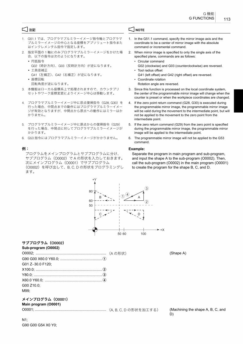
113G 機能
G FUNCTIONS
2 注記 2 NOTE
1. G51.1 では、プログラマブルミラーイメージ指令軸とプログラマブルミラーイメージの中心となる座標をアブソリュート指令またはインクレメンタル指令で指定します。
1. In the G51.1 command, specify the mirror image axis and the coordinate to be a center of mirror image with the absolute command or incremental command.
2. 指定平面の 1 軸にのみプログラマブルミラーイメージをかけた場合、以下の指令は次のようになります。
2. When mirror image is specified to only the single axis of the specified plane, commands are as follows:
• 円弧指令 • Circular commandG02(時計方向)、G03(反時計方向)が逆になります。 G02 (clockwise) and G03 (counterclockwise) are reversed.
• 工具径補正 • Tool radius offsetG41(左補正)、G42(右補正)が逆になります。 G41 (left offset) and G42 (right offset) are reversed.
• 座標回転 • Coordinate rotation回転角度が逆になります。 Rotation angle are reversed.
3. 本機能はローカル座標系上で処理されますので、カウンタプリセットやワーク座標変更によりイメージ中心は移動します。
3. Since this function is processed on the local coordinate system, the center of the programmable mirror image will change when the counter is preset or when the workpiece coordinates are changed.
4. プログラマブルミラーイメージ中に原点復帰指令(G28, G30)を行った場合、中間点までの動作にはプログラマブルミラーイメージが有効となりますが、中間点から原点への動作にはミラーはかかりません。
4. If the zero point return command (G28, G30) is executed during the programmable mirror image, the programmable mirror image will be valid during the movement to the intermediate point, but will not be applied to the movement to the zero point from the intermediate point.
5. プログラマブルミラーイメージ中に原点からの復帰指令(G29)を行った場合、中間点に対してプログラマブルミラーイメージがかかります。
5. If the zero return command (G29) from the zero point is specified during the programmable mirror image, the programmable mirror image will be applied to the intermediate point.
6. G53 指令にはプログラマブルミラーイメージがかかりません。 6. The programmable mirror image will not be applied to the G53 command.
例: Example:プログラムをメインプログラムとサブプログラムに分け、サブプログラム(O0002)で A の形状を入力しておきます。次にメインプログラム(O0001)でサブプログラム
(O0002)を呼び出して、B, C, D の形状をプログラミングします。
Separate the program in main program and sub-program, and input the shape A to the sub-program (O0002). Then, call the sub-program (O0002) in the main program (O0001) to create the program for the shape B, C, and D.
サブプログラム(O0002)Sub-program (O0002)O0002; ..................................................................... (A の形状) (Shape A)G90 G00 X60.0 Y60.0; .........................................aG01 Z−30.0 F120;X100.0; .................................................................bY80.0; ...................................................................cX60.0 Y60.0; ........................................................dG00 Z10.0;M99;
メインプログラム(O0001)Main program (O0001)O0001; ...................................................................... (A, B, C, D の形状を加工する) (Machining the shape A, B, C, and
D)N1;G90 G00 G54 X0 Y0;
+X
+Y
80
6050
50 60 100
AB
DC
1
2
3
4

G 機能G FUNCTIONS114
2-25 G52 ローカル座標系設定G52 Setting Local Coordinate System
ワーク座標系(G54 ~ G59)でのプログラムの加工原点をシフトさせて、さらに座標系を作ることができます。G52 のローカル座標系を設定しても、元のワーク座標系 G54 ~ G59には影響を与えません。
It is possible to shift the workpiece zero point of the program created in the work coordinate system (G54 - G59) to establish more number of coordinate systems. Even if the G52 local coordinate system is set, the original work coordinate system (G54 - G59) is not affected.
2 注記 2 NOTE
1. ローカル座標系は、次のときにキャンセルされます。 1. The local coordinate system is canceled by the following operations:
• “G52 X0 Y0 Z0;” と指令したとき • When “G52 X0 Y0 Z0;” is executed.• 手動で全軸の原点復帰をしたとき • When all axes are returned to the zero point manually.
2. 工具径補正モード中(G41, G42)に G52 を指令しても、工具径補正はキャンセルされません。
2. If the G52 command is specified in the tool radius offset mode (G41 or G42), the tool radius offset mode is not canceled.
G43 Z30.0 H1 S400 T2;M03;M98 P2; .................................................................... サブプログラム O0002 を呼び出し、
A を加工Calls the sub-program O0002 to machine A.
G51.1 X50.0; ............................................................. X50.0 を対称軸として、−X 方向にミラーイメージ
Applies the mirror image in the minus direction of X-axis making X50.0 as the symmetry axis.
M98 P2; .................................................................... サブプログラム O0002 を呼び出し、B を加工
Calls the sub-program O0002 to machine B.
G51.1 Y50.0; ............................................................. X50.0, Y50.0 を対称軸として、−X 方向、−Y 方向にミラーイメージ
Applies the mirror image in the minus direction of X- and Y-axes making X50.0, Y50.0 as the symmetry axis.
M98 P2; .................................................................... サブプログラム O0002 を呼び出し、C を加工
Calls the sub-program O0002 to machine C.
G50.1 X0; .................................................................. Y50.0 を対称軸として、−Y 方向にミラーイメージ
Applies the mirror image in the minus direction of Y-axis making Y50.0 as the symmetry axis.
M98 P2; .................................................................... サブプログラム O0002 を呼び出し、D を加工
Calls sub-program O0002 to machine D.
G50.1 Y0; .................................................................. ミラーイメージキャンセル Cancels the mirror image.:
G52 X_ Y_ Z_ ;• X, Y, Z .................................. ワーク座標系をシフトさせる量
その位置がローカル座標系の原点になります。
Amount to shift the work coordinate system.The position is zero point of the local coordinate system.

115G 機能
G FUNCTIONS
例: Example:ローカル座標系設定(G52)の使用例 Programming using the local coordinate system (G52)
2 注記 2 NOTE
G54 のワーク座標系に戻ります。 Work coordinate system (G54) becomes valid.
2-26 G53 機械座標系選択G53 Selecting Machine Coordinate System
機械座標系とは、X, Y, Z の機械原点を中心とした座標系をいいます。
The machine coordinate system has its origin at the machine zero point of X-, Y-, and Z-axes.
サブプログラム(O0002)Sub-program (O0002)O0002;X15.0 Y0; ..............................................................aX0 Y15.0; ..............................................................bX−15.0 Y0; ............................................................cX0 Y−15.0; ............................................................dM99;
メインプログラム(O0001)Main program (O0001)O0001;N1;G90 G00 G54 X0 Y0;G43 Z30.0 H1 S800 T2;M03;G99 G81 Z–5.0 R3.0 F100 L0;M98 P2;..................................................................... a, b, c, d のそれぞれの位置で
穴あけ加工Drills at a,b,c and d respectively.
G52 X50.0 Y−40.0;.................................................... G52 のローカル座標系で、X'Y' 座標系に移動
Establishes the local coordinate system X'-Y' by shifting the workpiece zero point.
M98 P2;..................................................................... a', b', c', d' のそれぞれの位置で穴あけ加工
Drills at a',b',c' and d' respectively.
G52 X0 Y0;................................................................ G52 のローカル座標系キャンセル Cancels the local coordinate system (G52)
G80;:
30 50 40
2
3
4
1
'2
'3
'4
'1
Y
X
X'
Y'P.C.D. 30
3040
40
P.C.D. 30
Workpiece Zero Point for G54 (X0, Y0)
Workpiece Zero Point for G52 (X'0, Y'0)
Four 10 mm Dia. Holes, Equally Spaced on 30 mm Dia. Circle.
4 等分φ10 のドリル穴G54 の加工原点 (X0, Y0)
G52 の加工原点 (X'0, Y'0)

G 機能G FUNCTIONS116
5機械座標値は、画面で表示される現在位置(機械座標)で把握できます
5The machine coordinate values can be confirmed by the present position (machine coordinate) displayed on the screen.
2 注記 2 NOTE
1. G53 はワンショット G コードなので、指令したブロックのみ有効です。
1. Since G53 is one-shot G code, it is valid only in the specified block.
1 ワンショット G コードについては、“G 機能 ”(57 ページ) 1 For the one-shot G code, refer to “G FUNCTIONS” (page 57)
2. G53 の指令を G91(インクレメンタル指令)で行うと、機械座標系ではなく、現在選択している座標系に対して、インクレメンタルで移動します。
2. If the G53 command is executed in the G91 (incremental command) mode, the coordinate values are regarded as incremental values in the presently selected coordinate system, not in the machine coordinate system.
3. G53 を指令しても、工具径補正はキャンセルされません。 3. If the G53 command is specified, the tool radius offset mode is not canceled.
2-27 G54 ~ G59 ワーク座標系選択G54 to G59 Selecting Work Coordinate System
あらかじめ、6 つのワーク座標系を設定しておき、G54 ~G59 の指令で 6 つのワーク座標系のどれかを選択することができます。
By setting six work coordinate systems beforehand, call one of them by executing the corresponding G code.
ワーク座標系の設定には、次の 2 つの方法があります。 There are two methods of setting the workpiece zero point.• 加工原点をワーク端面に設定する • Setting the workpiece zero point at the end face of the
workpiece.• 加工原点をテーブル旋回中心に設定する • Setting the workpiece zero point at the center of table
rotation.
1 加工原点の設定方法については、別冊 “ 機械操作説明書 ” 1 For details on setting the workpiece zero point, refer to the sepa-rate volume, “OPERATION MANUAL”.
2 注記 2 NOTE
1. 電源投入時は G54 が選択されます。 1. The G54 is selected when the power is turned on.2. G54 ~ G59 以上のワーク座標系が必要な場合は、G10(データ設
定)、G52(ローカル座標系設定)、または G54, G54.1(追加ワーク座標系)< オプション > を使用してください。
2. If more number of the work coordinates than G54 to G59 is required, use the G10 (data setting), G52 (setting local coordinate system), or G54, G54.1 (setting additional work coordinate system) <option>.
1 • G10 については、“G10 プログラム指令によるワーク座標系変更 ”(93 ページ)
1 • For G10, “G10 Changing Work Coordinate System by Programmed Command” (page 93)
• G52 については、“G52 ローカル座標系設定 ”(114 ページ) • For G52, “G52 Setting Local Coordinate System” (page 114)
• G54, G54.1 については “G54.1 追加ワーク座標系選択(オプション)”(118 ページ)
• For G54, G54.1, “G54.1 Selecting Additional Work Coordinate System (Option)” (page 118)
3. ワーク座標系の指令は、補正の形をとっています。 3. The work coordinate systems are defined by offsetting them from each other.
5多数個取り加工においては、各々のワークに加工原点を設定する方が、座標を簡単に求めることができます。
5It is advisable to set the workpiece zero points for individual workpieces to simplify programming when multiple workpieces are set.
G90 G53 X_ Y_ Z_ ;• G90 ...................................... アブソリュート指令 Absolute commands
• X, Y, Z .................................. 機械座標値の指令 Coordinate value in the machine coordinate system
(G90) G54(G55, G56, G57, G58, G59) X_ Y_ ;• G90 ...................................... アブソリュート指令 Absolute command
• X, Y ...................................... 選択されたワーク座標系で位置決めするための座標値
Specifies the coordinate values to position a tool in the selected work coordinate system

117G 機能
G FUNCTIONS
例: Example:加工原点をワーク端面に設定する場合 Setting workpiece zero point at the end face of
workpiece
例: Example:加工原点をテーブル旋回中心に設定する場合 Setting workpiece zero point at the center of table
rotation
O0001;N1;G90 G00 G54 X30.0 Y20.0; ..................................a 工具が a に位置決め(ワーク座標
系 G54)Positions the tool at a in the G54 work coordinate
G43 Z30.0 H1 S800 T2;............................................ Z30.0 の位置に工具が位置決め工具交換位置に 2 番グループの工具呼出し
Positions the tool at Z30.0, and calls a tool of group number 2 at the tool change position
M03; .......................................................................... 800 min−1 の回転速度で主軸正転“S800” = 主軸の回転速度
Starts the spindle in the normal direction at 800 min−1 (S800 = Spindle rotation speed)
X−30.0;..................................................................bY−20.0;..................................................................cX30.0;....................................................................dG55 X30.0 Y20.0;..................................................e 工具が e に位置決め(ワーク座標
系 G55)Positions the tool at e in the G55 work coordinate
X−30.0;..................................................................fY−20.0;..................................................................gX30.0;....................................................................h
2 1
3 4
6 5
7 8
30 30 30 30
+Y+Y
+X +X
2020
2020
Tooling Block
Workpiece Zero Point for G54 Workpiece Zero Point for G55
イケール
G54 の加工原点 G55 の加工原点
O0001;N1;G90 G00 G54 X30.0 Y20.0; ..................................a ワーク座標系 G54 で a に位置決め Positioning at a in the G54 work
coordinate system
2 1
3 4
6 5
7 8
30 30 30 30
+Y+Y
+X+X
+X
G54 G55
2020
2020
+Y
+Y
125100
+Z
+ZTooling Block
Tooling Block
イケール
イケール

G 機能G FUNCTIONS118
2 注記 2 NOTE
加工原点をテーブル旋回中心に設定するときは、以下の点に注意してください。
Pay attention to the followings to set the workpiece zero point at the center of table rotation.
1. イケールの中心とテーブル旋回中心が一致していること 1. The center of the tooling block is aligned with the center of table rotation.
2. Z 軸の座標値はテーブル旋回中心からワーク端面までの距離を考慮すること
2. Concerning the Z-axis coordinate value, take into consideration the distance from the center of table rotation to the end face of the workpiece.
2-28 G54.1 追加ワーク座標系選択(オプション)G54.1 Selecting Additional Work Coordinate System (Option)
G54 ~ G59 の 6 組のワーク座標系に加えて、さらに 48 組あるいは 300 組のワーク座標系が使用できます。
Additional 48 or 300 sets of work coordinate systems can be used in addition to the six work coordinate system set and called by G54 - G59.
2 注記 2 NOTE
1. 電源投入時は、G54 のワーク座標系が選択されます。 1. When power is turned on, the G54 work coordinate system is selected.
2. アドレス P を省略すると、画面にアラーム(P33)が表示されます。
2. An alarm message (P33) is displayed on the screen if address P is not specified.
3. アドレス P に範囲外の値を指令すると、画面にアラーム(P35)が表示されます。
3. If a value outside the allowable range is specified for address P, an alarm message (P35) is displayed on the screen.
4. G54.1 と同一ブロックにアドレス P を指令する G コードを指令しないでください。
4. A G code that requires the designation of address P must not be specified with the G54.1 command in the same block.
5. G54.1 で追加ワーク座標系を設定している状態では G52 でローカル座標系を設定することはできません。G54.1 で追加ワーク座標系を設定している状態で G52 を指令すると、画面にアラーム
(P438)が表示されます。
5. It is not allowed to set a local coordinate system by specifying the G52 command in the state an additional work coordinate system is set by the G54.1 command. An alarm message (P438) is displayed on the screen if the G52 command is specified in the state an additional work coordinate system is set by the G54.1 command.
G43 Z255.0 H1 S800 T2;.......................................... Z255.0 の位置に位置決め工具交換位置に 2 番グループの工具呼出し
Positioning at Z255.0Calling a tool of group number 2 at the tool change position
M03; .......................................................................... 800 min−1 で主軸正転 Starting the spindle in the normal direction at 800 min−1
X−30.0;..................................................................bY−20.0...................................................................cX30.0;....................................................................dG55 X30.0 Y20.0;..................................................e ワーク座標系 G55 で e に位置決め Positioning at e in the G55 work
coordinate systemX−30.0;..................................................................fY−20.0;..................................................................gX30.0;....................................................................h
G54.1 P_ X_ Y_ ;• P........................................... 使用する追加ワーク座標系
(ワーク座標系組数追加 48 組仕様)1 ~ 48 の数字から選択
(ワーク座標系組数追加 300 組仕様)1 ~ 300 の数字から選択
Additional work coordinate system to be used.(Additional 48 sets of work coordinate systems)Select a number from 1 to 48(Additional 300 sets of work coordinate systems)Select a number from 1 to 300
• X, Y ...................................... 選択された追加ワーク座標系で位置決めするための座標値
Coordinate value in the selected work coordinate system

119G 機能
G FUNCTIONS
5次の指令で、追加ワーク座標系の原点を移動させることができます。
5The origin of the additional work coordinate system can be shifted as follows:
例: Example:追加ワーク座標系設定の使用例 Programming using the additional work coordinate
system4 面イケールの 1 面にワークを 2 個取り付け、それぞれに追加ワーク座標系を設定して、加工を行います。
To machine two workpieces, mounted on one face of the tooling block, by setting the individual additional work coordinate systems.
(a):追加ワーク座標系 1 の加工原点(X0, Y0)に工具が位置決め
(a): Positions the tool at the workpiece zero point (X0, Y0) of No. 1 additional work coordinate system.
(b):追加ワーク座標系 2 の加工原点(X0, Y0)に工具が位置決め
(b): Positions the tool at the workpiece zero point (X0, Y0) of No. 2 additional work coordinate system.
2-29 ワーク設置誤差補正(オプション)Work Setting Error Offset (Option)
1 詳細は、制御装置メーカーの取扱説明書 1 Refer to the instruction manual supplied by the NC manufacturer for details.
G10 L20 P_ X_ Y_ ;• G10 L20 ............................... 追加ワーク座標系の変更 Additional work coordinate system shift
mode.
• P........................................... 原点を移動させる追加ワーク座標系(ワーク座標系組数追加 48 組仕様)1 ~ 48 の数字から選択
(ワーク座標系組数追加 300 組仕様)1 ~ 300 の数字から選択
Additional work coordinate system which the origin is to be shifted(Additional 48 sets of work coordinate systems)Select a number from 1 to 48.(Additional 300 sets of work coordinate systems)Select a number from 1 to 300.
• X, Y ...................................... (G90):機械原点から新たに設定したい加工原点までの距離指令された座標値が新たな加工原点
(G91):現在の追加ワーク座標系の原点から新たに設定したい加工原点までの距離と方向指令された座標値が今までの加工原点に加算
(G90):Distance from the machine zero point to the workpiece zero point of the additional work coordinate system to be set newly. The specified values are taken as the new offset amount.(G91):Distance and direction from the origin in the present work coordinate system to the workpiece zero point of the additional work coordinate system to be set newly. The specified values are added to the present offset amount.
O0001;N1;G90 G00 G54.1 P1 X0 Y0; ................................... (a)G43 Z30.0 H1 S500 T2;M03;:M06;
N2;G90 G00 G54.1 P2 X0 Y0; ................................... (b)G43 Z30.0 H1 S800 T3;M03;
+X+X
+Y +Y
G54.1 P1 G54.1 P2
Tooling Blockイケール

G 機能G FUNCTIONS120
1
ワーク設置誤差補正を使用すると、ワークがずれて設置された場合でも、プログラムを変更することなくプログラムどおりに加工を行うことができます。回転軸の動作をともなう機能における回転軸の位置に対しても補正が行われます。このため、工具先端点制御、傾斜面加工指令中も使用できます。
With the work setting error offset, a displaced workpiece can be machined according to the program without making modifications to the program.
あらかじめ、‘ ワーク設置誤差補正 ’ 画面またはシステム変数#26000 ~ #26077 でワーク設置誤差量を設定してください。
Set the work setting error in advance, by setting on the ‘WORK SETTING ERROR’ screen or by using system variables #26000 to #26077.
1. ‘ ワーク設置誤差補正 ’ 画面については、別冊 “ 機械操作説
明書 ”
11. For the ‘WORK SETTING ERROR’ screen, refer to the
separate volume, “OPERATION MANUAL”2. システム変数 #26000 ~ #26077 については、122 ページ
を参照してください。
2. For the system variables #26000 to #26077, refer to Page122.
2 注記 2 NOTE
1. ワーク設置誤差モード中の絶対座標表示を、ワーク座標系で表示するかワーク設置座標系で表示するかは、パラメータ No. 3106.6によって選択できます。
1. Whether absolute coordinates in the work setting error mode are to be displayed in the work coordinate system or work setting coordinate system can be chosen by setting parameter No. 3106.6.
2. システム変数 #5041 ~ #5048(各軸の現在位置)には、ワーク設置誤差補正後のワーク座標系での座標値が代入されます。
2. The coordinates in the work coordinate system are assigned to system variables #5041 to #5048.
3. 以下の指令は G54.4 と入れ子関係が成り立つように指令してください。
3. The following commands must have nesting relationships with G54.4.
• G43, G43.4, G43.5, G49(工具長補正、工具先端点制御) • G43, G43.4, G43.5, G49 (tool length offset, tool center point control)
• G68.2, G69(傾斜面加工指令) • G68.2, G69 (tilted working plane command)機能がオフの状態で G54.4 P_ を指令 → 機能をオン/オフ → G54.4 P0 の順で指令してください。
Specify “G54.4 P_when the function is OFF.” → Turn the function ON and OFF → Specify “G54.4 P0”
Workpiece
<Correct workpiece position> <Displaced workpiece>
The coordinate system and the rotary axes automatically rotate in accordance with the work setting error.
Work setting error
Coordinate system based on the displaced workpiece (work setting coordinate system)
ワーク
<正しく設置されたワーク> <ずれて設置されたワーク>
座標系と回転軸はワーク設置誤差にしたがい自動的に回転移動します。
ワーク設置時の誤差
ずれて設置されたワークを基準にした座標系
(ワーク設置座標系)
G54.4 P_ ;G54.4 P0 ;
• G54.4 P_;............................. ワーク設置誤差補正モード・オン Work setting error offset mode ON
• G54.4 P0;............................. ワーク設置誤差補正モード・オフ Work setting error offset mode OFF
• P_......................................... 使用するワーク設置誤差量の組数• P1 ~ P7 から選択します。
5ワーク設置誤差量は7組まで設定できます。
Set the number of the work setting error to be used• Select from P1 to P7.
5Up to seven sets of work setting error can be set.

121G 機能
G FUNCTIONS
例: Example:
4. ワーク設置誤差補正モード中に工具長補正または工具先端点制御を行っている場合、パラメータ No. 1210 の設定に関係なく、リセットで工具長補正または工具先端点制御はキャンセルされます。
4. When tool length offset or tool center point control is performed during the work setting error offset mode, tool length offset or tool center point control is canceled by reset operation regardless of the setting of parameter No. 1210.
5. G52 によるローカル座標系設定や G92 によるワーク座標系のシフトを行った状態でワーク設置誤差補正を行わないでください。ワーク座標系のシフトを行った後は、必ず G92.1 または各軸ワーク座標系プリセット信号機能でワーク座標系をプリセットしてから、ワーク設置誤差補正を起動してください。
5. Do not specify work setting error offset when the work coordinate system is shifted by the local coordinate system (G52) or work coordinate system change (G92). If the work coordinate system is shifted, specify G92.1 or other work coordinate system preset functions before specifying work setting error offset.
6. プログラミング座標系をテーブル座標系とする設定(パラメータNo. 7908 = 0)で、ワーク設置誤差補正モード中に工具先端点制御を行うときは、次の点に注意してください。通常、テーブル回転軸位置が “0” でない状態で工具先端点制御を起動した場合、そのときのワーク座標系がテーブルに固定されテーブル座標系となります。ワーク設置誤差補正モード中に工具先端点制御を行う場合、この仕様は無効となり、テーブル回転軸位置が “0” の状態でワーク座標系がテーブルに固定されたものとしてテーブル座標系が設定されます。
6. Note the following point when specifying tool center point control in the work setting error offset mode with the setting to use the table coordinate system as the programming coordinate system (parameter No. 7908 = 0).Generally, even the table rotation angle is not “0” degrees, the work coordinate system at the time that tool center point control started becomes the table coordinate system. However, in the work setting error mode, the work coordinate system with the table rotation angle of “0”degrees fixed to the table becomes the table coordinate system.
7. ワーク設置誤差補正モード中は、以下の機能を指令できません。 7. The following functions cannot be specified in the work setting error mode.
• 手動介入 • Manual intervention• 手動ハンドル割り込み • Handle interruption• 機械座標での位置決め(G28, G30, G53) • Positioning in the machine coordinate system (G28, G30, G53)• PMC 軸制御 • PMC axis control• 外部ミラーイメージ(信号またはセッティングによるミラーイ
メージ)• External mirror image (mirror image by signal or setting)
• プログラマブルミラーイメージ(G50.1, G51.1) • Programmable mirror image (G50.1, G51.1)• 移動前ストロークリミットチェック • Stroke check before movement• プログラム再開 • Program restart
8. ワーク設置誤差補正に関して次の不正な指令をすると、アラームが発生します。
8. If the following illegal commands are specified in the work setting error offset mode, an alarm occurs.
• ワーク設置誤差補正モード中に指令できない G コードを指令した。(アラーム No. P545)
• G codes which cannot be specified in the work setting error offset mode are specified. (Alarm No. P545)
• ワーク設置誤差補正を起動する際のモーダルに誤りがあった。(アラーム No. P545)
• The modal state is illegal for starting work setting error offset. (Alarm No. P545)
• G54.4 が単独で指令されなかった。(アラーム No. P546) • G54.4 is not specified alone in a block without other commands. (Alarm No. P546)
• G54.4 指令のブロックに P の指令がなかった。あるいは P に続く数値が範囲外だった。(アラーム No. P33)
• G54.4 is specified without address P, or the value that follows the address P is outside the specifiable range. (Alarm No. P33)
• ワーク設置誤差補正を 2 重に指令した。(アラーム No. P545) • The work setting error offset is specified twice. (Alarm No. P545)9. アドレス P を省略すると、アラーム(No.P33)が発生します。ま
た、アドレス P に “0 ~ 7” 以外を指令すると、アラーム(No. P35)が発生します。
9. If address P is omitted, an alarm (No.P33) occurs. If other than “0 to 7” is specified for address P, an alarm (No. P35) occurs.
G49; .......................................................................... 工具長補正キャンセル Tool length offset cancelG54.4 P_; .................................................................. ワーク設置誤差補正モード・オン Work setting error offset mode ONG43H_;...................................................................... 工具長補正有効 Tool length offset valid:
G49; .......................................................................... 工具長補正キャンセル Tool length offset cancelG54.4 P0;.................................................................. ワーク設置誤差補正モード・オフ Work setting error offset mode OFF

G 機能G FUNCTIONS122
システム変数によるワーク設置誤差量の設定 Setting Work Setting Error with System Variables
システム変数 #26000 ~ #26077 により、ワーク設置誤差量の読取りと書込みができます。ワーク設置誤差量は 7 組まで設定できます。各ワーク設置誤差量とそれに対応した変数番号は次のとおりです。
The work setting error can be input or output using system variables #26000 through #26077. Up to seven sets of work setting error can be set.Each work setting error and corresponding variable number is as follows.
2 注記 2 NOTE
1. 回転方向の誤差 a, b, c には、ワーク座標系を X, Y または Z 軸の周りに回転させたときの誤差を設定します。
1. The error when the work coordinate system is rotated about the X, Y, or Z-axes is set for the rotation direction error a, b, c.
2. 回転軸位置 1, 2 には、誤差を計測したときの回転軸 1, 2 の機械座標値を設定します。
2. The machine coordinate value of the rotation axis 1, 2 when the error is measured is set for rotation axis position 1, 2.
ワーク設置誤差補正モード中に指令可能な G コード G Codes that Can Be Specified in the Work Setting Error Offset Mode
ワーク設置誤差補正が有効の時、指令可能な G コードは、次のとおりです。以下の G コード以外を指令すると、アラーム(No. P545)が発生します。
The following G codes can be specified when the work setting error offset mode is ON.If G codes other than the following are specified, an alarm (No. P545) occurs.
誤差ErrorNo. 00
(COMMON)
誤差Error
No. 01
誤差ErrorNo. 02
誤差ErrorNo. 03
誤差Error
No. 04
誤差ErrorNo. 05
誤差ErrorNo. 06
誤差Error
No. 07
X 方向の誤差 Δ xX direction error Δ x #26000 #26010 #26020 #26030 #26040 #26050 #26060 #26070
Y 方向の誤差 Δ yY direction error Δ y #26001 #26011 #26021 #26031 #26041 #26051 #26061 #26071
Z 方向の誤差 Δ zZ direction error Δ z #26002 #26012 #26022 #26032 #26042 #26052 #26062 #26072
回転方向の誤差 Δ aRotation direction error Δ a – #26013 #26023 #26033 #26043 #26053 #26063 #26073
回転方向の誤差 Δ bRotation direction error Δ b – #26014 #26024 #26034 #26044 #26054 #26064 #26074
回転方向の誤差 Δ cRotation direction error Δ c – #26015 #26025 #26035 #26045 #26055 #26065 #26075
回転軸位置 1(根元軸)Rotation axis position 1 (root axis)
#26006 #26016 #26026 #26036 #26046 #26056 #26066 #26076
回転軸位置 2(ワーク軸)Rotation axis position 2 (work axis)
#26007 #26017 #26027 #26037 #26047 #26057 #26067 #26077
• G00 ...................................... 位置決め Positioning
• G01 ...................................... 直線補間 Linear interpolation
• G02, G03 ............................. 円弧補間 Circular interpolation
• G04 ...................................... ドウェル Dwell
• G05 ...................................... 高速高精度制御 II (高精度輪郭制御) High-speed high-accuracy control II (high-precision contour control)
• G05.1 ................................... 高速高精度制御 I (AI 輪郭制御) High-speed high-accuracy control I (AI contour control)
• G08 ...................................... 高精度制御 (先行制御) High-accuracy control (look-ahead control)
• G09 ...................................... イグザクトストップ Exact stop
• G10 ...................................... データ設定 Data setting
• G11 ...................................... データ設定モードキャンセル Data setting mode cancel

123G 機能
G FUNCTIONS
• G17 ...................................... 平面選択(XY) Plane selection for machining (XY plane)
• G18 ...................................... 平面選択(ZX) Plane selection for machining (ZX plane)
• G19 ...................................... 平面選択(YZ) Plane selection for machining (YZ plane)
• G20 ...................................... インチ入力 Data input in inch system
• G21 ...................................... メトリック入力 Data input in metric system
• G28 ...................................... 機械原点復帰 Zero return check
• G29 ...................................... 原点からの復帰 Return from zero point
• G30 ...................................... 第 2 /第 3、第 4 原点復帰 Second/third, fourth zero return
• G30.1 – G30.6 ..................... フローティングレファレンス点復帰 Floating reference point return
• G31 ...................................... スキップ機能 Skip function
• G40 ...................................... 工具径補正 Cutter radius offset
• G42 ...................................... 工具径補正右 Cutter radius offset, right
• G43 ...................................... 工具長補正 + Tool length offset +
• G43.4 ................................... 工具先端点制御 (タイプ 1) Tool center point control (type 1)
• G43.5 ................................... 工具先端点制御 (タイプ 2) Tool center point control (type 2)
• G44 ...................................... 工具長補正 − Tool length offset, −
• G45 ...................................... 工具位置補正 伸長 Tool position offset, increase
• G46 ...................................... 工具位置補正 縮小 Tool position offset, decrease
• G47 ...................................... 工具位置補正 2 倍伸長 Tool position offset, double-increase
• G48 ...................................... 工具位置補正 2 倍縮小 Tool position offset, double-decrease
• G49 ...................................... 工具長補正キャンセル Tool length offset mode cancel
• G50 ...................................... スケーリングキャンセル Scaling cancel
• G50.1 ................................... プログラマブルミラーイメージキャンセル Programmable mirror image cancel
• G51 ...................................... スケーリング Scaling
• G51.1 ................................... プログラマブルミラーイメージ Programmable mirror image
• G53 ...................................... 機械座標系選択 Machine coordinate system selection
• G54 – G59, G54.1................ ワーク座標系選択 Work coordinate system selection
• G54.4 ................................... ワーク設置誤差補正 Work setting error offset
• G61 ...................................... イグザクトストップモード Exact stop mode
• G64 ...................................... 切削モード Cutting mode
• G65 ...................................... マクロ呼出し Macro call
• G66, G66.1 .......................... マクロモーダル呼出し Macro modal call
• G67 ...................................... マクロモーダル呼出しキャンセル Macro modal call cancel
• G68 ...................................... 座標回転・3 次元座標変換 Coordinate rotation/3D coordinate conversion
• G68.2 ................................... 傾斜面加工指令 Tilted working plane command
• G69 ...................................... 座標回転・3 次元座標変換・傾斜面加工指令キャンセル
Coordinate rotation/3D coordinate conversion/tilted working plane command cancel
• G73, G74, G76, G80 – G89. 穴あけ固定サイクル指令 Hole machining canned cycle command
• G90 ...................................... アブソリュート指令 Absolute commands
• G91 ...................................... インクレメンタル指令 Incremental commands
• G93 ...................................... インバースタイム送り Inverse time feed
• G94 ...................................... 毎分送り指令 Feed per minute mode
• G95 ...................................... 毎回転送り Feed per revolution mode
• G98 ...................................... 穴あけ固定サイクルイニシャル点レベル復帰
Initial point level return (hole machining canned cycle)
• G99 ...................................... 穴あけ固定サイクル R 点レベル復帰 Point R level return (hole machining canned cycle)

G 機能G FUNCTIONS124
ワーク設置誤差補正を指令する際に可能なモーダル G コード
Modal G Codes that Allow Specification of the Work Setting Error Offset Mode
下記に示すモーダル G コード状態の時に、ワーク設置誤差補正を指令することが可能です。
Work setting error offset can be specified in the following modal G code state.
• G00 ...................................... 位置決め Positioning
• G01 ...................................... 直線補間 Linear interpolation
• G05 ...................................... 高速高精度制御 II (高精度輪郭制御) High-speed high-accuracy control II (high-precision contour control)
• G05.1 ................................... 高速高精度制御 I (AI 輪郭制御) High-speed high-accuracy control I (AI contour control)
• G08 ...................................... 高精度制御 (先行制御) High-accuracy control (look-ahead control)
• G13.1 ................................... 極座標補間モードキャンセル Polar coordinate interpolation mode cancel
• G15 ...................................... 極座標指令キャンセル Polar coordinate command cancel
• G17 ...................................... 平面選択(XY) Plane selection for machining (XY plane)
• G18 ...................................... 平面選択(ZX) Plane selection for machining (ZX plane)
• G19 ...................................... 平面選択(YZ) Plane selection for machining (YZ plane)
• G20 ...................................... インチ入力 Data input in inch system
• G21 ...................................... メトリック入力 Data input in metric system
• G23 ...................................... ストアードストロークチェック機能オフ Stored stroke check function OFF
• G40 ...................................... 工具径補正 Tool radius offset
• G40.1 ................................... 法線方向制御キャンセル Normal direction control cancel mode
• G49 ...................................... 工具長補正キャンセル Tool length offset mode cancel
• G50 ...................................... スケーリングキャンセル Scaling cancel
• G50.1 ................................... プログラマブルミラーイメージキャンセル Programmable mirror image cancel
• G54 – G59, G54.1................ ワーク座標系選択 Work coordinate system selection
• G54.4 ................................... ワーク設置誤差補正 Work setting error offset
• G61 ...................................... イグザクトストップモード Exact stop mode
• G64 ...................................... 切削モード Cutting mode
• G67 ...................................... マクロモーダル呼出しキャンセル Macro modal call cancel
• G69 ...................................... 座標回転・3 次元座標変換・傾斜面加工指令キャンセル
Coordinate rotation/3D coordinate conversion/tilted working plane command cancel
• G80 ...................................... 穴あけ固定サイクルキャンセル Hole machining canned cycle cancel
• G90 ...................................... アブソリュート指令 Absolute commands
• G91 ...................................... インクレメンタル指令 Incremental commands
• G93 ...................................... インバースタイム送り Inverse time feed
• G94 ...................................... 毎分送り指令 Feed per minute mode
• G95 ...................................... 毎回転送り指令 Feed per revolution mode
• G97 ...................................... 周速一定制御キャンセル Constant surface speed control cancel
• G98 ...................................... 穴あけ固定サイクルイニシャル点レベル復帰
Initial point level return (hole machining canned cycle)
• G99 ...................................... 穴あけ固定サイクル R 点レベル復帰 Point R level return (hole machining canned cycle)

125G 機能
G FUNCTIONS
2-30 G60 一方向位置決めG60 Uni-Directional Positioning
G00 の位置決め動作を常に一方向から行います。 Positioning is always Carried out from the fixed direction with this command.
2 注記 2 NOTE
1. ワンショットな G コードなので、指令したブロックのみ有効です。
1. Since G60 is one-shot G code, it is valid only in the specified block.
2. 穴あけ固定サイクル中に、Z 軸の一方向位置決めはできません。 2. Uni-directional positioning for the Z-axis is not possible during hole machining canned cycle.
3. G76, G87 の穴あけ固定サイクル中、シフト量を移動する軸の一方向位置決めは行いません。
3. Uni-directional positioning for the axis to be shifted in the canned cycle G76 or G87 is not possible.
4. パラメータで行き過ぎ量が設定されていない軸の、一方向位置決めはできません。
4. Uni-directional positioning for the axis to which overrun stroke is not set for the parameter is not possible.
5. 同一位置(移動量 0)を指令した場合、行き過ぎ量を往復し、元の位置に位置決めされます。
5. If the position where the axes are presently located is specified in the G60 block, that is if the specified axis movement distance in the G60 block is zero, the axes move by the overrun stroke and then move back by the same distance to be positioned at the previously located position.
各位置で必ず一方向位置決めを行いたいときは、必ず同一位置(移動量 0)でも指令してください。
To execute uni-directional positioning at all specified positions, it is necessary to specify a positioning command even if the target point is the presently located point (zero axis movement distance).
6. 行き過ぎ量と位置決め方向は、パラメータ No. 8209 で設定します。
6. The overrun stroke and the direction for positioning are set using parameter No.8209.
7. パラメータで設定した位置決め方向に対して、ミラーイメージは無効です。
7. The mirror image is not valid for the positioning direction which is set using a parameter.
例: Example:G60 の使用例 Programming using G60a, b, c, d の位置で穴あけ加工を行います。 Hole machining at hole positions a, b, c and d.
G60 X_ Y_ Z_ ;• X, Y, Z .................................. 早送りで位置決めさせる終点の座標値 Coordinate values of the end point at a rapid
traverse rate.
Overrun Stroke
Start Point
End PointStart Point
行き過ぎ量
始点
終点始点

G 機能G FUNCTIONS126
2 注記 2 NOTE
パラメータ No. 8209 に、X + 1.0 mm, Y + 1.0 mm の位置決め方向と行き過ぎ量を設定します。
X + 1.0 mm, Y + 1.0 mm is set with the parameter No. 8209 for the positioning direction and overrun stroke.
O0001;N1;G90 G00 G54 X50.0 Y20.0;G43 Z30.0 H1 S1000 T2;M03;G60 X30.0; ............................................................a a に +X 方向から、早送りで一方
向位置決めUni-directional positioning at a from the +X direction at a rapid traverse rate
G99 G81 Z−5.0 R3.0 F100; ..................................a a でスポットドリリングサイクル(G81)を実行
Executes the spot drilling cycle (G81) at a.
G60 X−30.0; ..........................................................b b に +X 方向から、早送りで一方向位置決め
Uni-directional positioning at b from the +X direction at a rapid traverse rate
G60 Y−20.0; ..........................................................c c に +Y 方向から、早送りで一方向位置決め
Uni-directional positioning at c from the +Y direction at a rapid traverse rate
G60 X30.0; ............................................................d d に +X 方向から、早送りで一方向位置決め
Uni-directional positioning at d from the +X direction at a rapid traverse rate
2 1
3 4
+X
+Y
30 30
2020
Overrun Stroke行き過ぎ量
1 (X30.0, Y20.0) (X50.0, Y20.0)
1.0 mm
2 (X−30.0, Y20.0) (X30.0, Y20.0)
1.0 mm
1
3
(X−30.0, Y20.0)
(X−30.0, Y−20.0)
2
1.0 mm

127G 機能
G FUNCTIONS
2-31 G65, G66, G66.1, G67 マクロプログラムの使用G65, G66, G66.1, G67 Using Macro Programs
2 注記 2 NOTE
1. G65 はワンショットなので、指令したブロックでのみ有効です。G67 の指令は G65 には関係ありません。
1. For G65, a macro program is executed only in the block where G65 is specified. The G67 command is not related to G65.
2. G66 は移動指令実行後、G67 でキャンセルするまで、マクロプログラムを実行します。
2. Macro program is executed by G66 following each axis movement command executed until it is canceled by G67.
3. G66.1 は G67 でマクロ呼出し指令をキャンセルされるまで、毎ブロック実行後、マクロプログラムを実行します。
3. If the G66.1 command is specified, macro program is executed at each block after the execution of commands in it until this mode is canceled by the G67 command.
4. G65, G66, G66.1 のブロックにおいて、G65, G66, G66.1 はすべての引数より前に指令してください。
4. In the G65, G66 and G66.1 blocks, the G65, G66 and G66.1 commands must be specified preceding any arguments.
5. G66 あるいは G66.1 と G67 のブロックは、同一プログラム内に指令してください。
5. The G66 or G66.1 block and the G67 block must be specified in the same program.
6. G66, G66.1, G67 と同一ブロックに G65 は指令できません。 6. G65 cannot be specified with G66, G66.1 or G67 in the same block.
7. マクロプログラムで使用する文字の中で、“#”,“*”,“/” などは特殊な文字なので、マクロプログラムを入出力させるときに EIA コードを使用することはできません。マクロプログラムは ISO コードで作成してください。
7. Some of the characters used in a macro program are special characters such as “#”, “*”, and “/”. Since they are not supported by the EIA code, it is not possible to use the EIA code for input/output of a macro program. Therefore, a macro program must be created in the ISO code.
8. G66.1 モード中は、各ブロックのアドレス O(プログラム番号)、アドレス N(シーケンス番号)および G コード以外はすべて実行されず、引数として扱われます。ただし、同一ブロックに複数のG コードあるいはアドレス N がある場合、以下のようになります。
8. In the G66.1 mode, all codes other than O (program number), N (sequence number), and G codes are not executed but they are treated as arguments. However, if more than one G code or address N is specified in a single block, they are processed in the following manner.
• G コード • G code
2 注記
パラメータで位置決め方向を +X 方向としているため、c から d の位置決め方向と同じになります。このため、d の位置より 1.0 mm 手前で一度停止した後、d に位置決めします。
2 NOTE
Since the positioning direction of “from +X-axis” is set for the parameter, positioning is executed in the same manner as in simple positioning from c to d. The X-axis once stops at a point 1.0 mm before d and then it is positioned to d.
G80; .......................................................................... スポットドリリングサイクル(G81)のキャンセル
Cancels the spot drilling cycle (G81).
G65(G66, G66.1) P_ L_ <引数指定> ;G65(G66, G66.1) P_ L_ <Argument assignment>;G67;
• G65 ...................................... ワンショットなマクロ呼出し指令 Calls macro call mode (one-shot)
• G66 ...................................... モーダルなマクロ呼出し指令(移動指令呼出し)
Calls macro call mode (modal command for axis movement)
• G66.1 ................................... モーダルなマクロ呼出し指令(毎ブロック呼出し)
Calls macro call mode (modal command for every block)
• G67 ...................................... モーダルなマクロ呼出し指令(G66, G66.1)キャンセル
Modal macro mode (G66, G66.1) cancel
• P........................................... 呼び出すマクロプログラム番号 Macro program number to be called
• L........................................... 繰返し呼出し回数(省略時は 1 回とみなします)
Number of macro program calls(If omitted, it is regarded as one time.)
• 引数指定 ..............................• Argument assignment
A ~ Z の引数と数字を指令 Argument (A to Z) and value
(X−30.0, Y−20.0) (X30.0, Y−20.0)
1.0 mm
3 4

G 機能G FUNCTIONS128
5
後に指令した G コードは、引数として扱われます。 The G code specified last is treated as an argument.• アドレス N • Address N
初のアドレス N 以外は、すべて引数として扱われます。 Address N, other than the first one, is all treated as an argument.
1. 繰返し呼出し回数は、 高 9999 回まで指令することができます。
51. The number of program repetition is 9999 at the maximum.
2. G, M, F, T コードなどの NC データも変数で指令できます。 2. NC data such as G, M, F and T codes can be specified with variable.
G#1, M#2, F#3, T#7 など G#1, M#2, F#3, T#7
<マクロプログラムは次のように使用します> <Using Macro Programs in the Following Cases>
(a):ワンショットなマクロ呼出し指令 (a): Calls the one-shot macro call mode.• P: 呼び出すマクロプログラム番号 • P: Macro program number to be called• X ~ Q: 引数 • X to Q: Arguments(b):マクロプログラム終了 (b): Ends the macro program.変数(#)や [ ] の条件式を組み合わせて、マクロプログラムを作成します。メインプログラムでは、引数と呼ばれる “A, B, C, ... X, Y, Z” を使用します。
The macro program is created by combining the variables “#_ ” and qualifications which are expressed in [ ], while arguments “A, B, C, ... X, Y, Z” are used in a main program.
“A = #1”,“B = #2” というように、引数と変数の組合せは決まっているので、メインプログラム中の引数に続く数値が、マクロプログラムの変数に代入されます。
Since a combination between argument and variable is fixed such as “A = #1, B = #2”, the value specified for an argument in the main program is assigned to the corresponding variable in the macro program.
2 注記 2 NOTE
上記のマクロプログラムは例であり、実際のプログラムではありません。
The macro program above is only for reference purpose and cannot be used for actual operation.
1 引数と変数の組合せについては、制御装置メーカーの取扱説明書
1 For combinations of arguments and variables, refer to the instruction manual supplied by the NC manufacture.
引数 引数
G01 および N200は、引数として扱われます。 Argument Argument
G01 and N200 are both treated as an argument.
メインプログラム(O0001)Main program (O0001)O0001;N1;G90 G00 G54 X0 Y0;G43 Z30.0 H1 S1000 T2;M03;(G98) G81 Z−10.0 R3.0 F100 L0;G65 P1000 X100.0 Y50.0 U180.0 V85.0 H1 D1 Q40.0;..............................................................................(a)G80;
マクロプログラム(O1000)Macro program (O1000)O1000;#1 = 0;:WHILE [#1 LE #4] D01;:#5 = #21*#2/#3;#6 = 1 − 2*#10;END1;M99; ......................................................................(b)
85
90
90
(X100.0, Y50.0)+X
+Y
40°
6
5
4
1
2
3

129G 機能
G FUNCTIONS
例: Example:G65, G66, G67 の使用例 Programming using G65, G66, G67<例 1> <Ex.1>4 つの穴で同じ加工を行います。まず、穴における動きのプログラムを作成します。
Performing the same machining at four holes: First, create the program for the pattern to be executed in a hole.
次に、穴あけ加工を行うメインプログラムを作成します。 Then, create the main program for hole machining at the four positions.
(a):a で “O8000” の #1 に 10.0 を代入して実行(A = #1) (a): Executes “O8000” with “10.0” assigned to the #1 variable at a. (A = #1)
(b):b で “O8000” を実行 (b): Executes “O8000” at b.(c):c で “O8000” を実行 (c): Executes “O8000” at c.(d):d で “O8000” を実行 (d): Executes “O8000” at d.(e):マクロ呼出し指令キャンセル (e): Cancels the macro call command.<例 2> <Ex.2>穴の直径が変わるプログラムを作成します。 Creating a program for the application where the holes have
different diameters.
2 注記 2 NOTE
穴における動きのプログラムは、上記 Ex.1 のマクロプログラム(O8000) を使用します。
For the pattern to be executed in a hole, the macro program (O8000) in Ex. 1 above is used.
マクロプログラム(O8000)Macro program (O8000)O8000;Z−10.0;..................................................................aG91 G01 Y#1 F100;..............................................bG02 J−#1; .............................................................cG01 Y−#1;.............................................................dG90 G00 Z10.0; ....................................................eM99;
+Y
+X
4
5
2
1
3
+Y
+X
(200, 0)3(0, 0)1
2 (100, 0)
(50, −40)4
O0001;N1;G90 G00 G54 X0 Y0;G43 Z30.0 H1 S800 T2;M03;
G66 P8000 A10.0;...............a(a)X0 Y0; X100.0; ................................b(b)X200.0; ................................c(c)X50.0 Y−40.0;......................d(d)
G65 P8000 A10.0;................ a(a)X100.0;G65 P8000 A10.0;................ b(b)X200.0;G65 P8000 A10.0;................ c(c)X50.0 Y−40.0;G65 P8000 A10.0;................ d(d)
G67; (e)
メインプログラム(O0001)Main program (O0001)O0001;N1;G90 G00 G54 X0 Y0;G43 Z30.0 H1 S800 T2;M03;G65 P8000 A10.0; ............................................a(a)X100.0;G65 P8000 A13.0; ........................................... b(b)X200.0;G65 P8000 A15.0; ............................................c(c)X50.0 Y.−40.0;G65 P8000 A16.0; ............................................d(d):
+Y
+X
(200, 0)
(0, 0)
(50, −40)
(100, 0)
φ32
φ20
φ30φ26
4
2
1
3

G 機能G FUNCTIONS130
(a):a で “O8000” の #1 に 10.0 を代入して実行(半径 10.0 mm の穴)
(a): Executes “O8000” with “10.0” assigned to the #1 variable at a. (10.0 mm radius hole)
(b):b で “O8000” の #1 に 13.0 を代入して実行(半径 13.0 mm の穴)
(b): Executes “O8000” with “13.0” assigned to the #1 variable at b. (13.0 mm radius hole)
(c):c で “O8000” の #1 に 15.0 を代入して実行(半径 15.0 mm の穴)
(c): Executes“O8000” with “15.0” assigned to the #1 variable at c. (15.0 mm radius hole)
(d):d で “O8000” の #1 に 16.0 を代入して実行(半径 16.0 mm の穴)
(d): Executes “O8000” with “16.0” assigned to the #1 variable at d. (16.0 mm radius hole)
マクロプログラム O8000 の中にある “#1” が a ~ d の “A”の値に対応します。
The #1 variable in the macro program O8000 corresponds to the value of address A at a to d.
このように、マクロプログラムを使用すると、変数の値を変えるだけで、同じような加工を短いプログラムで作成できます。
By using a variable in a macro program in this manner, similar machining can be executed with a relatively short program by simply changing the value to be assigned to the variable.
2-32 G68 座標回転、G69 座標回転キャンセル(オプション)G68 Coordinate Rotation, G69 Coordinate Rotation Cancel (Option)
この機能は、次のようなときに使用します。 Use this function in the following cases:
1) 座標値の計算が難しい形状のとき 1) For a shape difficult to calculate the coordinate values下図のように、a のプログラムを作成する場合、G68 を使用して、b を回転させます。
When programming a, first program b and rotate it using G68 as shown below:
2) 1 つの形状を回転させたようなパターンがあるとき 2) For a shape which can be defined by rotating other shape下図のように、b, c の形状のプログラムを作成する場合、G68 を使用して、a を回転させます。
After programming a, rotate it to define b and c using G68 as shown below:
< XY 平面の座標回転> <Coordinate Rotation on XY Plane>
< ZX 平面の座標回転> <Coordinate Rotation on ZX Plane>
+X
+Y 1
2
Center of Rotation Rotation Angle回転中心 回転角
+X
+Y
1
2
3
Rotation Angle
Center of Rotation
回転角
回転中心
G17 G68 X_ Y_ R_ ;
G18 G68 X_ Z_ R_ ;

131G 機能
G FUNCTIONS
< YZ 平面の座標回転> <Coordinate Rotation on YZ Plane>
1 “G17, G18, G19 加工平面選択 ”(96 ページ) 1 “G17, G18, G19 Selecting Plane for Machining” (page 96)
2 注記 2 NOTE
1. 座標回転モード中に、G17 ~ G19 の平面設定を変更すると、画面にアラーム(P111)が表示されます。
1. If the plane selected by G17 - G19 is changed in the coordinate system rotation mode, an alarm message (P111) is displayed on the screen.
2. アブソリュート指令で回転中心の座標値を指令してください。インクレメンタル指令で回転中心の座標値を指令しても、アブソリュート指令とみなします。
2. The coordinate values of the center of rotation should be specified in absolute values. Even if an incremental command is used to specify a coordinate value of the center of rotation, it is regarded as an absolute command.
3. 回転中心の座標値を省略すると、G68 の指令された点が回転中心になります。
3. If the center of rotation is omitted, the point where G68 is specified is taken as the center of rotation.
4. 回転角度のアブソリュート指令、インクレメンタル指令は、G90, G91 指令により行います。
4. The G90 and G91 commands determine whether the angle of rotation should be specified using absolute or incremental commands.
5. 回転角度の 小設定単位および指令範囲を下記に示します。 5. The minimum setting unit and programmable range of rotation angle is given below:
6. アドレス R はモーダルな情報です。一度指令すると、次に新しい回転角度を指令するまで、同じ回転角度が有効になります。ただし、G69 で座標回転をキャンセルすると、回転角度は 0 になります。
6. Address R is modal information and once specified, the specified angle of rotation remains valid until a new angle of rotation is specified next. When the coordinate system rotation mode is canceled by G69, however, the angle of rotation is reset to “0”.
7. 工具径補正、工具長補正などの補正動作は、座標回転が実行された後に行われます。
7. Offset such as tool radius offset and tool length offset is executed after the execution of the rotation.
8. プログラマブルミラーイメージと座標回転を同一ブロックに指令すると、座標回転が実行された後にプログラマブルミラーイメージが行われます。
8. If both the programmable mirror image function and the coordinate system rotation function are specified in the same block, the coordinate system rotation function is executed first and then programmable mirror image function.
9. 座標回転中に G28 による機械原点復帰を行ったとき、中間点には座標回転がかかります。
9. If zero return to the machine zero point is executed by the G28 command in the coordinate system rotation mode, the coordinate system rotation function applies to the intermediate point.
10. 座標回転はローカル座標系上で処理しているため、座標回転をかけた状態でワーク座標系の補正量を変更すると、座標回転の中心も移動します。
10. If the offset amount of the work coordinate system is changed while the coordinate system rotation function is called, the center of rotation is shifted accordingly since the coordinate system rotation function is processed based on the local coordinate system.
11. 座標回転中に操作パネルの @(リセット)キーを押すと、座標回転はキャンセルされます。
11. The coordinate system rotation function is canceled if the @ (RESET) key on the operation panel is pressed in the coordinate system rotation mode.
12. G69 は他の指令と同一ブロックに指令することができます。 12. It is allowed to specify the G69 command with other commands in the same block.
13. G69 と G02, G03 を同一ブロックに指令した場合、画面にアラーム(P70)が表示されることがあります。
13. If the G02 or G03 command is specified with the G69 command in the same block, an alarm (P70) code may be displayed on the screen.
G19 G68 Y_ Z_ R_ ;G69;
• G17, G18, G19..................... 座標回転の平面設定 Selects the planefor coordinate rotation
• G68 ...................................... 座標回転指令 Specifies the coordinate rotation
• G69 ...................................... 座標回転指令キャンセル Coordinate rotation cancel
• X, Y, Z .................................. 回転中心の座標値(アブソリュート値) Coordinate value of the center of rotation (absolute value)
• R .......................................... 回転角度
5反時計方向が + 方向です。
Angle of rotation
5The counterclockwise direction is the positive (+) direction.
小設定単位 指令範囲
0.001° −360.000° ~ 360.000°
Minimum Setting Unit Programmable Range
0.001° −360.000° to 360.000°

G 機能G FUNCTIONS132
例: Example:G68, G69 の使用例 Programming using G68, G69a b c d の形状のプログラムを作成する場合、b, c, dの座標値を計算すると手間がかかります。そこで、a b' c' d' の形状のプログラムを作成して、G68 で a b' c' d'の形状を回転させます。
When programming the shape a b c d, it will take much time to calculate the coordinate values of b, c and d. Then, the program for the shape a b' c' d' is created and the shape a b' c' d' is rotated using G68.
(a):座標回転指令 (a): Calling the coordinate rotation function回転中心 a、回転角度 30° The coordinate values of the center of rotation is point a
(X10.0, Y20.0) and the rotation angle is 30°
5回転中心に工具があるので、( )内の指令は省略できます。 5As a tool is at the rotation center, commands in ( ) can be omitted.(b) ~ (c):b' D c' D d' D a の指令 (b) to (c): Specifying the shape of a b' c' d' by defining it
in the order of b' D c' D d' D a
2 注記 2 NOTE
G68 の座標回転により、b' D c' D d' D a の指令が b D c D d D a の指令になります。
By rotating the coordinate using the G68 command, commands in these blocks are used for the program of shape b D c D d D a.
(d):座標回転指令キャンセル (d): Canceling the coordinate rotation function
2-33 G68 3 次元座標変換、G69 3 次元座標変換キャンセル(オプション)G68 3D Coordinate Conversion, G69 3D Coordinate Conversion Cancel (Option)
3 次元座標変換をかけると、ある平面上で作成したプログラムを変更しなくても、指定した点と軸を中心に座標を回転させて、別の平面上での加工ができます。
If a program on a plane is converted by the 3D coordinate conversion function, machining can be executed on the desired plane without creating another program, by rotating the coordinates around the designated point and axis.
53 次元座標変換は、2 回以上の多重指令ができます。 53D coordinate conversion can be specified twice or more.
2 注記 2 NOTE
1. 3 次元座標変換モード中の 3 次元座標変換指令は、モード中の変換との合成となります。
1. The 3D coordinate conversion command in the 3D coordinate conversion mode is combined with the conversion in the mode.
2. 3 次元座標変換モード中に 3 次元座標変換を重ねてかけた場合、重ねてかけた 3 次元座標変換はモード中の 3 次元座標変換によって作られた座標系(G68 プログラム座標系)上に作られます。
2. If the 3D coordinate conversion is overlapped during the 3D coordinate conversion mode, the overlapped 3D coordinate conversion is created on the coordinate system (G68 program coordinate system) created with the 3D coordinate conversion in the mode.
O0001;N1;G90 G00 G54 X0 Y0;G43 Z30.0 H1 S1000 T2;M03;X10.0 Y20.0;G01 Z−3.0 F200;G68 (X10.0 Y20.0) R30.0;.....................................(a)Y50.0;....................................................................(b)X30.0;G03 Y20.0 R20.0;G01 X10.0;............................................................(c)G69; ......................................................................(d)
+Y
+X10 30
20
502
1
3
4
'3
'4
'2(30.0, 50.0)
(30.0, 20.0)
(10.0, 20.0)
(10.0, 50.0)30°
R20
G68 X_ Y_ Z_ I_ J_ K_ R_ ; :
: 3 次元座標変換モード 3D coordinate conversion mode :
G69;• G68 ..................................... 3 次元座標変換モード・オン 3D coordinate conversion mode ON
• G69 ..................................... 3 次元座標変換モード・オフ 3D coordinate conversion mode OFF
• X, Y, Z ................................. 回転中心の座標値(アブソリュート値) Coordinate values of the center of rotation (absolute value)

133G 機能
G FUNCTIONS
2 注記 2 NOTE
1. G41, G42, G51.1、および穴あけ固定サイクルは、G68 ブロックより後に指令し、G69 指令の前にキャンセルしなければなりません。G68 の次のブロックは、G90 モードの移動指令を行ってください。
1. The G41, G42, G51.1, or hole machining canned cycle must be specified after the G68 block and canceled before G69. For the block next to G68, specify a movement command in the G90 mode.
例: Example:
2. 回転中心座標を省略すると、現在設定されている座標系の原点が回転中心座標となります。
2. If the rotation center coordinates are omitted, the zero point of the currently set coordinate system is the rotation center coordinates.
3. I, J, K はすべて指定してください。 3. Designate values for I, J, and K.4. アドレス I, J, K にすべて “0” を指定した場合、アラーム(P33)
が発生します。4. If “0” is set for I, J, and K respectively, an alarm (P33) occurs.
5. アドレス I, J, K を指定しなかった場合、座標回転として扱います。 5. When addresses I, J, and K are not designated, this is handled as the program coordinate rotation.
6. 3 次元座標変換モード中に指令できない G コードを指令した場合、アラーム(P921)が発生します。
6. If the G code that cannot be specified in the 3D coordinate conversion mode is specified, an alarm (P921) occurs.
7. 3 次元座標変換ができないモード中に 3 次元座標変換を指令した場合、アラーム(P922)が発生します。
7. When the 3D coordinate conversion is specified during the mode where 3D coordinate conversion cannot be carried out, an alarm (P922) occurs.
8. G68 と組み合わせることのできない G コードを G68 と同一ブロックに指令した場合、アラーム(P923)が発生します。
8. The G codes that cannot be specified together with G68 are specified in the same block as G68, an alarm (P923) occurs.
9. 回転軸に対する 3 次元座標変換指令は、アラーム(P32)が発生します。
9. If the 3D coordinate conversion command is specified for the rotary axis, an alarm (P32) occurs.
10. 3 次元座標変換モード中に指令可能な G コードは、以下のとおりです。
10. The following G codes can be specified in the 3D coordinate conversion mode.
• I, J, K................................... 回転中心軸
2 注記
回転中心軸とする軸に “1”、それ以外は "0" を指令してください。
5X 軸 DI, Y 軸 DJ, Z 軸 DK に対応しています。
The axis of the center of rotation
2 NOTE
Specify “1” for the axis to be the center of rotation and “0” for other axes.
5Address I corresponds to the X-axis, address J to the Y-axis, and address K to the Z-axis.
• R ......................................... 回転角度
2 注記
1. 回転中心軸をマイナス方向からプラス方向に見て時計方向がプラス値です。
2. 指令範囲は、−360.000 ~ 360.000 です。
3. 小指令単位は、0.001(度)です。
Rotation angle
2 NOTE
1. Plus (+) indicates the clockwise direction viewing along the axis of the center of rotation from its minus (−) direction in its plus (+) direction.
2. The programmable range is from −360.000 to 360.000.
3. The minimum command unit is 0.001 (degrees).
G68 X100.0 Y100.0 Z100.0 I0 J0 K1 R45.0;
G90 G00 X0 Y0 Z0;
G41 D01;
G40;G69;
• G00 ..................................... 位置決め Positioning
• G01 ..................................... 直線補間 Linear interpolation
• G02 ..................................... 円弧補間(時計回り) Circular interpolation (clockwise)
• G03 ..................................... 円弧補間(反時計回り) Circular interpolation (counterclockwise)
• G04 ..................................... ドウェル Dwell
• G05.1 Q1 ............................ 高速高精度制御 I(AI 輪郭制御) High-speed, high-accuracy control I (AI contour control)
• G09 ..................................... イグザクトストップ Exact stop
• G10 ..................................... データ設定 Data setting

G 機能G FUNCTIONS134
• G11 ..................................... データ設定モードキャンセル Data setting mode cancel
• G15 ..................................... 極座標指令キャンセル Polar coordinate command cancel
• G16 ..................................... 極座標指令 Polar coordinate command
• G17 ..................................... 平面選択(XY 平面) Plane selection (XY plane)
• G18 ..................................... 平面選択(ZX 平面) Plane selection (ZX plane)
• G19 ..................................... 平面選択(YZ 平面) Plane selection (YZ plane)
• G20 ..................................... インチ入力 Data input in inch system
• G21 ..................................... メトリック入力 Data input in metric system
• G27 ..................................... 原点復帰チェック Zero return check
• G28 ..................................... 機械原点復帰 Machine zero return
• G29 ..................................... 原点からの復帰 Return from zero point
• G30 ..................................... 第 2 原点復帰 Second zero return
• G30.1 – G30.6 .................... フローティングレファレンス点復帰 Floating reference point return
• G31 ..................................... スキップ機能 Skip function
• G40 ..................................... 工具径補正キャンセル Tool radius offset cancel
• G41 ..................................... 工具径補正左 Tool radius offset, left
• G42 ..................................... 工具径補正右 Too radius offset, right
• G43 ..................................... 工具長補正+ Tool length offset, +
• G44 ..................................... 工具長補正- Tool length offset, -
• G45 ..................................... 工具位置補正 伸長 Tool position offset, increase
• G46 ..................................... 工具位置補正 縮小 Tool position offset, decrease
• G47 ..................................... 工具位置補正 2 倍伸長 Tool position offset, double-increase
• G48 ..................................... 工具位置補正 2 倍縮小 Tool position offset, double-decrease
• G49 ..................................... 工具長補正キャンセル Tool length offset cancel
• G50.1 .................................. プログラマブルミラーイメージキャンセル Programmable mirror image cancel
• G51.1 .................................. プログラマブルミラーイメージ Programmable mirror image
• G53 ..................................... 機械座標系選択 The machine coordinate system selection
• G61 ..................................... イグザクトストップモード Exact stop mode
• G62 ..................................... 自動コーナオーバライドモード Automatic corner override mode
• G64 ..................................... 切削モード Cutting mode
• G65 ..................................... マクロ呼出し Macro call
• G66 ..................................... マクロモーダル呼出し(移動指令呼出し) Macro modal call (call after execution of axis movement commands)
• G66.1 .................................. マクロモーダル呼出し(毎ブロック呼出し) Macro modal call (call in each block)
• G67 ..................................... マクロモーダル呼出しキャンセル Macro modal call cancel
• G68 ..................................... 3 次元座標変換 3D coordinate conversion
• G69 ..................................... 座標回転/ 3 次元座標変換キャンセル Coordinate rotation cancel/3D coordinate conversion cancel
• G73 ..................................... 高速深穴ドリリングサイクル High-speed deep hole drilling cycle
• G74 ..................................... 逆タッピングサイクル Reverse tapping cycle
• G76 ..................................... ファインボーリングサイクル Fine boring cycle
• G80 ..................................... 穴あけ固定サイクルキャンセル Hole machining canned cycle cancel
• G81 ..................................... スポットドリリングサイクル Spot drilling cycle
• G82 ..................................... カウンタボーリングサイクル Counter boring cycle
• G83 ..................................... 深穴ドリリングサイクル Deep hole drilling cycle
• G84 ..................................... タッピングサイクル Tapping cycle
• G85 ..................................... ボーリングサイクル Boring cycle
• G86 ..................................... ボーリングサイクル Boring cycle
• G87 ..................................... バックボーリングサイクル Back boring cycle
• G88 ..................................... ボーリングサイクル Boring cycle
• G89 ..................................... ボーリングサイクル Boring cycle
• G90 ..................................... アブソリュート指令 Absolute commands

135G 機能
G FUNCTIONS
2-34 G90 アブソリュート指令(絶対値指令)、G91 インクレメンタル指令(増分値指令)G90 Absolute Command, G91 Incremental Command
5G90 または G91 を指令すると、それ以降の X, Y, Z は、すべてアブソリュート指令またはインクレメンタル指令になります。
5Once the G90 or G91 is specified, all the X, Y and Z that follow it will be executed in that mode.
例: Example:
<アブソリュート指令><Absolute Command>
<インクレメンタル指令><Incremental Command>
5( )内の指令は、直前のブロックから変化していないので省略できます。
5Since the commands given in ( ) call no axis movement, they can be omitted.
• G91 ..................................... インクレメンタル指令 Incremental commands
• G94 ..................................... 毎分送り Feed per minute mode
• G95 ..................................... 毎回転送り Feed per revolution mode
• G98 ..................................... 穴あけ固定サイクルイニシャルレベル点復帰
Initial point level return (hole machining canned cycle)
• G99 ..................................... 穴あけ固定サイクル R 点レベル復帰 Point R level return (hole machining canned cycle)
G90 X_ Y_ Z_ ;G91 X_ Y_ Z_ ;
• X, Y, Z ...................... (G90) 加工原点からの距離と方向 Distance and direction of a point from the workpiece zero point
(G91) 現在位置からの移動距離と方向 Distance and direction of travel from the current position
G90 G00 X−100.0 Y175.0 Z50.0;..........................a(X−100.0) Y−175.0 (Z50.0); ..................................bX100.0 (Y−175.0) (Z50.0); ....................................c(X100.0) Y175.0 (Z50.0); ......................................d
G90 G00 X−100.0 Y175.0 Z50.0; .........................aG91 (X0) Y−350.0 (Z0); ........................................bX200.0 (Y0) (Z0); ..................................................c(X0) Y350.0 (Z0); ..................................................d
4
1
2
3
50 +Y
+X
4
3
1
2
100100
300
175
175
500
(X0, Y0, Z0)

G 機能G FUNCTIONS136
例: Example:アブソリュート指令とインクレメンタル指令を混用。 Using both absolute and incremental commands.
2-35 G92.1 ワーク座標系プリセット(オプション)G92.1 Work Coordinate System Preset (Option)
手動介入などによりシフトされたワーク座標系を、シフト前のワーク座標系にプリセットする機能です。
This function presets a work coordinate system shifted by manual intervention to the pre-shift work coordinate system.
1 詳細は、制御装置メーカーの取扱説明書 1 Refer to the instruction manual supplied by the NC manufacturer for details.
‘ 現在位置 ’ 画面でもプリセット操作が可能です。 Presetting is also possible on the ‘CURRENT POSITION’ screen.
1 別冊 “ 機械操作説明書 ” 1 Separate volume “OPERATION MANUAL”
2 注記 2 NOTE
1. 指令していない軸はプリセットされません。 1. Axes that are not specified are not subject to the preset operation.2. G92.1 を指令する前に、工具径補正、工具長補正、および工具位
置補正をキャンセルしてください。2. Before specifying G92.1, cancel the tool radius offset, tool length
offset, and tool position offset modes.3. プログラム再開中は、ワーク座標系プリセットは実行されませ
ん。3. The work coordinate system preset function is not executed during
program restart.4. スケーリング、座標回転およびプログラマブルミラーイメージの
モード中は、G92.1 を指令しないでください。これらのモード中に G92.1 を指令すると、アラーム(P34)が発生します。
4. Do not specify G92.1 while the scaling, coordinate system rotation, and programmable image modes. If the G92.1 command is specified in these modes, an alarm (P34) occurs.
2-36 G93, G94, G95 工具の送り速度の単位設定G93, G94, G95 Setting Feedrate Units
G93, G94, G95 で工具の送り速度(アドレス F)の単位を決定します。
The units for the feedrate (address F) of tools are determined by specifying G93, G94 or G95.
< 1 分間あたりの送り量を指令する> <Specify Feedrate per Minute>
G90 G00 X10.0 Y10.0; ..........................................aX−20.0 Y20.0; .......................................................bG91 X5.0 Y−30.0;..................................................cX25.0 Y−10.0; .......................................................dG90 X20.0 Y−10.0;................................................e
2(−20.0, 20.0)
(10.0, 10.0)
120
10
−10
−20
−30 −20 −10 10 20 30+X−X
+Y
−Y
3(−15.0, −10.0)
(10.0, −20.0)4
(20.0, −10.0)5
G92.1 X0 Y0 Z0;• G92.1 .................................. ワーク座標系プリセット指令 Work coordinate system preset command
• X0, Y0, Z0 ........................... ワーク座標系をプリセットしたい軸アドレスを指令
Specifies axis addresses subject to the work coordinate system preset operation
G94;F_;

137G 機能
G FUNCTIONS
<主軸 1 回転あたりの送り量を指令する(オプション)> <Specify Feedrate per Spindle Revolution (Option)>
<インバースタイム指定モードを指令する(オプション)> <Specify inverse time mode (Option)>
1 詳細は、制御装置メーカーの取扱説明書 1 Refer to the instruction manual supplied by the NC manufacturer for details.
2 注記 2 NOTE
1. 電源投入時は G94 の毎分送りモードが選択されています。 1. When the power is turned on, G94 mode (feedrate per minute) is set.
2. G93, G94, G95 はモーダルな G コードです。 同じグループの Gコード(G93, G94, G95)が指令されるまで有効です。
2. G93, G94, and G95 are modal, and remain valid until another G code in the same group (G93, G94, G95) is specified.
3. G93 インバースタイム送りモードでは、ブロックごとに F コードを指令してください。F コードの指令がないとき、および F0 が指令されたとき、アラーム(P62)が発生します。
3. In the G93 inverse time feed mode, specify F code in each block. In the block without the address F or with F0, an alarm (P62) occurs.
2-37 切削送りの速度制御Cutting Feedrate Control
切削送り (G01, G02, G03 など ) の速度を制御する機能は、以下のとおりです。
The functions to control feedrate for cutting feed (G01, G02, G03) are shown below.
2 注記 2 NOTE
1. G09 は指令されたブロックに限り有効です。 1. G09 is valid only in the specified block.2. G61, G62, G63, G64 は、同じグループの G コードが指令されるま
で有効です。2. G61, G62, G63 and G64 remain valid until another G code in the
same group is specified.
• G94 ..................................... 毎分送り指令 Specifies the feed per minute mode
• F........................................... 工具の送り速度 (直線軸 : mm/min, 回転軸 : °/min)
Feedrate (Linear axis: mm/min, rotary axis: °/min)
G95;F_;
• G95 ..................................... 毎回転送り指令 Specifies the feed per revolution mode
• F........................................... 工具の送り速度(mm/rev) Feedrate (mm/rev)
G93;F_;
• G93 ..................................... インバースタイム送り指令 Specifies the inverse time feed mode
• F .......................................... 工具の送り速度 (1/min) Feedrate (1/min)
用途Applications
コードCode
グループGroup
機能Function
ページPage
コーナの精度を出したいときFinishing corners sharply G09 00 イグザクトストップ
Exact stop 138
コーナの精度を出したいときFinishing corners sharply G61 15 イグザクトストップモード
Exact stop mode 138
内側コーナ部をきれいに切削したいときFinishing inner corners smoothly
G62 15 自動コーナオーバライドAutomatic corner override 138
内側円弧部をきれいに切削したいときFinishing inner arcs smoothly
— —内側円弧切削速度変更Internal circular cutting feedrate change
138
タップ加工Tapping G63 15 タッピングモード
Tapping mode 138
通常の切削Usual cutting G64 15 切削モード
Cutting mode 138

G 機能G FUNCTIONS138
G09 イグザクトストップ、G61 イグザクトストップモード、G63 タッピングモード、G64 切削モード
G09 Exact Stop, G61 Exact Stop Mode, G63 Tapping Mode, G64 Cutting Mode
プログラムで工具経路 “D A D B D C D” を指令すると、切削モード(G64)やタッピングモード(G63)では工具経路は “D A D C D” となります。 一方、イグザクトストップ(G09)やイグザクトストップモード(G61)を使うと、プログラムされた工具経路と同じ “D A D B D C D” となります。
When the tool path “D A D B D C D” is specified in a program, the actual tool path is “D A D C D” in the cutting mode (G64) and the tapping mode (G63). In contrast, when exact stop (G09) or exact stop mode (G61) is used, actual tool path is same as the programmed tool path “D A D B D C D”.
< G64 切削モード> <G64 Cutting mode>切削移動指令の終点で減速せずに、次のブロックが実行されます。
The tool is not decelerated at the end point of the axis travel command, and the next block is executed.
• 一度指令されると、G61, G62, G63 が指令されるまで有効です。
• Once specified, this function is valid until G61, G62, or G63 is specified.
• 電源投入時あるいは @(リセット) キーを押すと、切削モード(G64)の状態になります。
• The cutting mode (G64) is valid when the power is turned on or when the @ (RESET) key is pressed.
< G63 タッピングモード> <G63 Tapping mode>切削移動指令の終点で減速せずに、次のブロックが実行されます。
The tool is not decelerated at the end point of the axis travel command, and the next block is executed.
• 一度指令されると、G61, G62, G64 が指令されるまで有効です。
• Once specified, this function is valid until G61, G62, or G64 is specified.
• 送り速度オーバライドおよび一時停止が無効になります。 • When G63 is specified, feedrate override and feed hold are invalid.
< G09 イグザクトストップ> <G09 Exact stop>コーナの精度を出すために、切削移動指令の終点で減速し、インポジションがチェックされた後、次のブロックが実行されます。
To finish a corner sharply, the tool is decelerated at the end point of the axis travel command, then an in-position check is performed before executing the next block.
• 直線切削(G01)や円弧切削(G02, G03)のブロック先頭に、G09 を指令します。G09 を指令したブロックに限り、イグザクトストップは有効です。
• Specify G09 at the beginning of the block before a linear cutting command (G01) or a circular cutting command (G02, G03). The exact stop function is valid only in the block in which G09 is specified.
1 “G01 切削送りによる工具の直線移動 ”(67 ページ)、“G02 円弧補間(時計方向)、G03 円弧補間(反時計方向)”
(68 ページ)、“G09 イグザクトストップ ”(90 ページ)
1 “G01 Moving Cutting Tool along Straight Path at Cutting Feedrate” (page 67),“G02 Circular Interpolation (Clockwise), G03 Circular Interpolation (Counterclockwise)” (page 68),“G09 Exact Stop” (page 90)
• 指令された位置に正確に位置決めされたかを、上記イラストの B 点で確認します。(インポジションチェック)
• At point B in the illustration above, it is checked whether the tool is positioned exactly as specified. (In-position check)
< G61 イグザクトストップモード> <G61 Exact stop mode>コーナの精度を出すために、切削移動指令の終点で減速し、インポジションがチェックされた後、次のブロックが実行されます。
To finish a corner sharply, the tool is decelerated at the end point of the axis travel command, then an in-position check is performed before executing the next block.
• 一度指令されると、G62, G63, G64 が指令されるまで有効です。
• Once specified, this function is valid until G62, G63, or G64 is specified.
• 指令された位置に正確に位置決めされたかを、上記イラストの B 点で確認します。(インポジションチェック)
• At point B in the illustration above, it is checked whether the tool is positioned exactly as specified. (In-position check)
G62 自動コーナオーバライド G62 Automatic Corner Override
工具径補正中に、工具の動きを自動的に減速して工具の負荷を軽減し、きれいに切削します。
When a tool radius offset is applied, the movement of the tool is automatically decelerated to reduce the load and finish the surface smoothly.

139G 機能
G FUNCTIONS
<内側コーナオーバライド> <Inner corner override>
G62 が指令されているとき、工具径補正された工具経路が内側コーナを形成する場合、内側コーナの交点前後で送り速度にオーバライドがかかります。
When G62 is specified, and the tool path with tool radius offset applied forms the inner corner, the feedrate is automatically overridden at both ends of the corner.
• 一度指令されると、G61, G63, G64 が指令されるまで有効です。
• Once specified, this function is valid until G61, G63, or G64 is specified.
• ドライラン、F1 桁指令にも有効です。 • This function is valid for dry runs and F1-digit feed.• 以下の場合、内側コーナオーバライドはかかりません。 • Inner corner override is invalid under the following
conditions.• コーナの前ブロックが、工具径補正のスタートアップの
ブロックのとき• When the corner is preceded by a start up block for a tool
radius offset• コーナの後ブロックに、G41 または G42 が含まれている
とき• When the corner is followed by a block including G41 or
G42<内側円弧切削速度変更> <Internal circular cutting feedrate change>
Rc: 工具中心経路半径 Rc: Radius of tool center pathRp: プログラム経路半径 Rp: Radius of programmed tool path内側にオフセットされている円弧切削のとき、指令された送り速度(F)に対して円弧切削速度を計算し、プログラム経路での速度が指令された F になるようにします。
For internally offset circular cutting, the feedrate on a programmed path is set to a specified feedrate (F) by calculating the circular cutting feedrate with respect to specified feedrate (F).
• G コードに関係なく、工具径補正モード中は有効です。 • This function is valid during the tool radius offset mode regardless of the G code.
• ドライラン、F1 桁指令にも有効です。 • This function is valid for dry runs and F1-digit feed.
Tool Center Path
Override is applied from Point a to Point b
Programmed Tool Path
工具中心経路
a 点から b 点までオーバライドがかかる
プログラム経路
Programmed Tool Path
Tool Center Path
プログラム経路
工具中心経路
円弧切削速度 Circular cutting feedrate = F × RcRp

G 機能G FUNCTIONS140
2-38 傾斜面加工指令(オプション)Tilted Working Plane Command (Option)
ワークの基準面に対して傾いた面に、穴やポケットなどの形状を加工する場合、この傾斜面に座標系を固定すると、プログラムがわかりやすくなります。この固定された座標系をフィーチャ座標系と呼びます。さらに、工具方向制御を指令すると、工具のワークに対する接触角度が常に垂直になるように制御されます。
Programming for creating holes, pockets, and other figures on a plane that is tilted with respect to the reference plane of the workpiece is easy if the commands can be specified in a coordinate system fixed to this tilted plane. This fixed coordinate system is called a feature coordinate system. If tool axis direction control is also specified, the tool to workpiece contact angle is controlled to be always vertical.
ロール・ピッチ・ヨーによる傾斜面加工指令 Tilted Working Plane Command Based on Roll-Pitch-Yaw
<アドレス Q の値と軸を回転させる順番の関係> <The Value of Address Q and the Order in which Axes Are Rotated>
機械座標系
ワーク座標系(G54)
フィーチャ座標系
Machine Coordinate System
Work Coordinate System (G54)
The Feature Coordinate System
G68.2 P1 Q_ X_. Y_. Z_. I_. J_. K_.;G53.1;G69;
• G68.2 P1.............................. フィーチャ座標系設定 The feature coordinate system set
• G53.1 ................................... 工具軸方向制御 Tool axis direction control
• G69 ...................................... フィーチャ座標系設定キャンセル The feature coordinate system set cancel
• Q .......................................... 軸を回転させる順番 Order in which axes are rotated
• X, Y, Z .................................. フィーチャ座標系の原点 Reference point of the feature coordinate system
• I ............................................ X 軸周りの回転角度(ロール角) Angle of rotation around the X-axis (roll angle)
• J ........................................... Y 軸周りの回転角度(ピッチ角) Angle of rotation around the Y-axis (pitch angle)
• K........................................... Z 軸周りの回転角度(ヨー角) Angle of rotation around the Z-axis (yaw angle)
第 1 回転軸First rotation axis
第 2 回転軸Second rotation axis
第 3 回転軸Third rotation axis
Q123 X 軸X-axis
Y 軸Y-axis
Z 軸Z-axis
Q132 X 軸X-axis
Z 軸Z-axis
Y 軸Y-axis
Q213 Y 軸Y-axis
X 軸X-axis
Z 軸Z-axis

141G 機能
G FUNCTIONS
2 注記 2 NOTE
1. アドレス X, Y, Z, I, J, K は、小数点付きで指令してください。 1. Specify addresses X, Y, Z, I, J, and K using a value with a decimal point.
2. アドレス P, Q は、小数点なしで指令してください。 2. Specify addresses P and Q using a value without a decimal point.3. アドレス Q を省略した場合、X, Y, Z 軸の順番で回転させます
(Q123 指令と同じ)。3. When address Q is omitted, the X-, Y-, and Z-axes are rotated in
this order (equivalent to Q123).4. アドレス Q に上記以外の値を指定した場合、アラーム(P954)
が発生します。4. When address Q is set to a value other than the above, an alarm
(P954) occurs.5. アドレス X, Y, Z, I, J, K を省略した場合、“0” を指令したとみなさ
れます。5. When the address X, Y, Z, I, J, or K is omitted, the omitted address
is considered as “0”.6. アドレス P, Q, X, Y, Z, I, J, K 以外を指令した場合、アラーム
(P954)が発生します。6. When the address other than P, Q, X, Y, Z, I, J, and K are specified,
an alarm (P954) occurs.
<ワーク座標系回転の考え方> <Concept of Work Coordinate System Rotation>1) X 軸周りに α° 回転させた座標系(座標系 1) 1) A workpiece coordinate system rotated by α° around the
X-axis (coordinate system 1)ワーク座標系(X, Y, Z)から、座標系 1(X’, Y’, Z’)へ変換 Convert the work coordinate system (X, Y, Z) to coordinate
system 1 (X’, Y’, Z’)
2) Y 軸周りに β° 回転させた座標系(座標系 2) 2) A workpiece coordinate system rotated by β° around the X-axis (coordinate system 2)
座標系 1(X’, Y’, Z’)から、座標系 2(X”, Y”, Z”)へ変換 Convert coordinate system 1 (X’, Y’, Z’) to coordinate system 2 (X”, Y”, Z”)
Q231 Y 軸Y-axis
Z 軸Z-axis
X 軸X-axis
Q312 Z 軸Z-axis
X 軸X-axis
Y 軸Y-axis
Q321 Z 軸Z-axis
Y 軸Y-axis
X 軸X-axis
第 1 回転軸First rotation axis
第 2 回転軸Second rotation axis
第 3 回転軸Third rotation axis

G 機能G FUNCTIONS142
5
3) Z 軸周りに γ° 回転させた座標系(フィーチャ座標系) 3) A workpiece coordinate system rotated by γ° around the Z-axis (feature coordinate system 2)
ワーク座標系 2(X”-Y”-Z”)から、フィーチャ座標系(Xc, Yc, Zc)へ変換
Convert coordinate system 2 (X”, Y”, Z”) to the feature coordinate system (Xc, Yc, Zc)
1. プラス値で指令すると反時計方向に回転し、マイナス値で指令すると時計方向に回転します。
51. Use a positive value to rotate the plane counterclockwise and a
negative value to rotate the plane clockwise.2. ‘ プログラムチェック ’ 画面の ‘ ロール・ピッチ・ヨー指令 ’
ウィンドウで、ガイダンスを見ながら各アドレスを設定することもできます。
2. The addresses can be set with a help of guidance in the ‘ROLL-PITCH-YAW COMMAND’ window on the ‘PROGRAM CHECK’ screen.
1 詳細は、別冊 “ 機械操作説明書 ” 1 For details, refer to the separate volume, “OPERATION MANUAL”.
2 注記 2 NOTE
1. G53.1 は G68.2 の次のブロック以降に指令してください。 1. G53.1 must be specified in a block after the block with G68.2.G68.2 が指令されていない状態で G53.1 を指令すると、アラーム
(P953)が発生します。An alarm (P953) occurs if G53.1 is specified without G68.2 being specified in a preceding block.
2. G53.1, G68.2. G69 は単独ブロックで指令してください。 2. Specify G53.1, G68.2, or G69 in a single block without other commands.
3. 回転軸の移動速度は以下のとおりです。 3. The feedrate of the rotary axis is as indicated below:早送りのとき: 大早送り速度 During rapid traverse: Maximum rapid traverse rate切削送りのとき:指令速度 During cutting feed: Specified speed
4. フィーチャ座標系上にさらにフィーチャ座標系を設定すると、アラームが発生します。
4. An alarm occurs if another feature coordinate system is set on a feature coordinate system.
5. フィーチャ座標系上で 3 次元座標変換を指令して新しい座標系を設定すると、アラームが発生します。
5. An alarm occurs if a new coordinate system is set on a feature coordinate system by specifying 3D coordinate conversion.
6. G28, G30, G53 などの機械座標系での位置決めは、フィーチャ座標系上の動きではなく、機械座標系上の動きになります。
6. Positioning commands in the machining coordinate system, such as G28, G30, and G53, operate in the machine coordinate system rather than in the feature coordinate system.
7. フィーチャ座標系と外部ミラーイメージを同時に使用した場合、フィーチャ座標系が先にかかり、その後外部ミラーイメージがかかります。
7. If the feature coordinate system and the external mirror image function are used in the same block, the feature coordinate system takes effect before the external mirror image function.
8. 以下の機能は、G68.2 より後に指令し、G69 指令の前にキャンセルしてください。
8. Specify the functions below after G68.2 and cancel them before G69.
• G41, G42, G40(工具径補正) • G41, G42, G40 (Tool radius offset)• G43, G49(工具長補正) • G43, G49 (Tool length offset)• G51.1, G50.1(プログラマブルミラーイメージ) • G51.1, G50.1 (Programmable mirror image)• 穴あけ固定サイクル • Hole machining canned cycle
9. G69 を円弧補間モード中または固定サイクルモード中に指令すると、アラーム(P952)が発生します。
9. When G69 is specified in the circular interpolation mode or the canned cycle mode, an alarm (P952) occurs.

143G 機能
G FUNCTIONS
例: Example:
フィーチャ座標系原点:200.0, 0, 50.0 Reference point of the feature coordinate system: 200.0, 0, 50.0
軸を回転させる順序:X 軸 DY 軸 DZ 軸 Order in which axes are rotated: X-axis D Y-axis D Z-axisX 軸周りの回転角度:30° Angle of rotation around the X-axis: 30°Y 軸周りの回転角度:0° Angle of rotation around the Y-axis: 0°Z 軸周りの回転角度:90° Angle of rotation around the Z-axis: 90°
オイラー角による傾斜面加工指令 Tilted Working Plane Command Based on Euler Angle
2 注記 2 NOTE
1. アドレス X, Y, Z, I, J, K は、小数点付きで指令してください。 1. Specify addresses X, Y, Z, I, J, and K using a value with a decimal point.
2. アドレス P, Q は、小数点なしで指令してください。 2. Specify addresses P and Q using a value without a decimal point.3. アドレス P を省略しても、“P0” を指令したとみなされます。 3. Even if the address P is omitted, it is considered that “P0” is
specified.4. アドレス X, Y, Z, I, J, K を省略した場合、“0” を指令したとみなさ
れます。4. When the address X, Y, Z, I, J, or K is omitted, the omitted address
is considered as “0”.5. アドレス P, Q, X, Y, Z, I, J, K 以外を指令した場合、アラーム
(P954)が発生します。5. When the address other than P, Q, X, Y, Z, I, J, and K are specified,
an alarm (P954) occurs.
50.0
200.0
30°
Y
X
Z
Yc Xc
Zc
フィーチャ座標系 Xc-Yc-Zc
ワーク座標系 X-Y-Z
Feature Coordinate System Xc-Yc-Zc
Work Coordinate System X-Y-Z
G68.2 P1 Q123 X200. Y0. Z50. I30. J0. K90.;
G53.1;
G68.2 P1 Q123 X200. Y0. Z50. I30. J0. K90.;G53.1;
G68.2 [P0] X_. Y_. Z_. I_. J_. K_.;G53.1;G69;
• G68.2 [P0]............................ フィーチャ座標系設定 The feature coordinate system set
• G53.1 ................................... 工具軸方向制御 Tool axis direction control
• G69 ...................................... フィーチャ座標系設定キャンセル The feature coordinate system set cancel
• X, Y, Z .................................. フィーチャ座標系の原点 Reference point of the feature coordinate system
• I, J, K.................................... フィーチャ座標系の向きを決める角度 Angles for determining the direction of the feature coordinate system

G 機能G FUNCTIONS144
5
<ワーク座標系回転の考え方> <Concept of Work Coordinate System Rotation>1. Z 軸周りに x-y 平面を回転させる角度を “I” で指令します。 1. Use address “I” to command the angle at which the x-y
plane is rotated around the Z-axis.
2. 1 でできた x’ 軸回りに y’-z 平面を回転させる角度を “J” で指令します。
2. Use address “J” to command the angle at which the y’-z plane is rotated around the x’-axis created in step 1.
3. 2 でできた z’ 軸回りに x’-y’’ 平面を回転させる角度を “K”で指令します。
3. Use address “K” to command the angle at which the x’-y’’ plane is rotated around the z’-axis created in step 2.
1. プラス値で指令すると反時計方向に回転し、マイナス値で指令すると時計方向に回転します。
51. Use a positive value to rotate the plane counterclockwise and a
negative value to rotate the plane clockwise.2. ‘ プログラムチェック ’ 画面のオイラー角指令ウィンドウで、
ガイダンスを見ながら各アドレスを設定することもできます。2. The addresses can be set with a help of guidance in the euler
angle command window on the ‘PROGRAM CHECK’ screen.
1 詳細は、別冊 “ 機械操作説明書 ” 1 For details, refer to the separate volume, “OPERATION MAN-UAL”.
2 注記 2 NOTE
1. G53.1 は G68.2 の次のブロック以降に指令してください。 1. G53.1 must be specified in a block after the block with G68.2.G68.2 が指令されていない状態で G53.1 を指令すると、アラーム
(P953)が発生します。An alarm (P953) occurs if G53.1 is specified without G68.2 being specified in a preceding block.
2. G53.1, G68.2, G69 は単独で指令してください。 2. Specify G53.1, G68.2, or G69 in a single block without other commands.
3. 回転軸の移動速度は以下のとおりです。 3. The feedrate of the rotary axis is as indicated below:早送りのとき: 大早送り速度 During rapid traverse:
Maximum rapid traverse rate切削送りのとき:指令速度 During cutting feed:
Specified speed4. フィーチャ座標系上にさらにフィーチャ座標系を設定すると、ア
ラームが発生します。4. An alarm occurs if another feature coordinate system is set on a
feature coordinate system.5. フィーチャ座標系上で 3 次元座標変換を指令して新しい座標系を
設定すると、アラームが発生します。5. An alarm occurs if a new coordinate system is set on a feature
coordinate system by specifying 3D coordinate conversion.6. G28, G30, G53 などの機械座標系での位置決めは、フィーチャ座
標系上の動きではなく、機械座標系上の動きになります。6. Positioning commands in the machining coordinate system, such
as G28, G30, and G53, operate in the machine coordinate system rather than in the feature coordinate system.
145G 機能
G FUNCTIONS
7. フィーチャ座標系と外部ミラーイメージを同時に使用した場合、フィーチャ座標系が先にかかり、その後外部ミラーイメージがかかります。
7. If the feature coordinate system and the external mirror image function are used in the same block, the feature coordinate system takes effect before the external mirror image function.
8. 以下の機能は、G68.2 より後に指令し、G69 指令の前にキャンセルしてください。
8. Specify the functions below after G68.2 and cancel them before G69.
• G41, G42, G40(工具径補正) • G41, G42, G40 (Tool radius offset)• G43, G49(工具長補正) • G43, G49 (Tool length offset)• G51.1, G50.1(プログラマブルミラーイメージ) • G51.1, G50.1 (Programmable mirror image)• 穴あけ固定サイクル • Hole machining canned cycle
9. G69 を円弧補間モード中または固定サイクルモード中に指令すると、アラーム(P952)が発生します。
9. When G69 is specified in the circular interpolation mode or the canned cycle mode, an alarm (P952) occurs.
傾斜面加工指令モード中に指令可能な G コード G Codes that Can Be Specified in the Tilted Working Plane Command Mode
これら以外の G コードを指令するとアラーム(P951)が発生します。
If G codes other than these are specified, an alarm (P951) occurs.
• G00 ..................................... 位置決め Positioning
• G01 ..................................... 直線補間 Linear interpolation
• G02 ..................................... 円弧補間/ヘリカル補間(時計回り) Circular interpolation/helical interpolation (clockwise)
• G03 ..................................... 円弧補間/ヘリカル補間(反時計回り) Circular interpolation/helical interpolation (counter clockwise)
• G04 ..................................... ドウェル Dwell
• G05 ..................................... 高速高精度制御 II(高精度輪郭制御) High-speed high-accuracy control II (high-precision contour control)
• G05.1 .................................. 高速高精度制御 I(AI 輪郭制御) High-speed high-accuracy control I (AI contour control)
• G08 ..................................... 高精度制御(先行制御) High-accuracy control (look-ahead control)
• G09 ..................................... イグザクトストップ Exact stop
• G10 ..................................... データ設定 Data setting
• G11 ..................................... データ設定モードキャンセル Data setting mode cancel
• G17 ..................................... 平面選択(XY 平面) Plane selection (XY plane)
• G18 ..................................... 平面選択(ZX 平面) Plane selection (ZX plane)
• G19 ..................................... 平面選択(YZ 平面) Plane selection (YZ plane)
• G28 ..................................... 機械原点復帰 Machine zero return
• G29 ..................................... 原点からの復帰 Return from zero point
• G30 ..................................... 第 2 /第 3、第 4 原点復帰 Second/third, forth zero return
• G30.1 – G30.6 .................... フローティングレファレンス点復帰 Floating reference point return
• G40 ..................................... 工具径補正キャンセル Tool radius offset cancel
• G41 ..................................... 工具径補正左 Tool radius offset, left
• G42 ..................................... 工具径補正右 Tool radius offset, right
• G43 ..................................... 工具長補正 Tool length offset
• G43.4 .................................. 工具先端点制御(タイプ 1) Tool center point control (type 1)
• G43.5 .................................. 工具先端点制御(タイプ 2) Tool center point control (type 2)
• G44 ..................................... 工具長補正 − Tool length offset, −
• G45 ..................................... 工具位置補正 伸長 Tool position offset, increase
• G46 ..................................... 工具位置補正 縮小 Tool position offset, decrease
• G47 ..................................... 工具位置補正 2 倍伸長 Tool position offset, double-increase
• G48 ..................................... 工具位置補正 2 倍縮小 Tool position offset, double-decrease
• G49 ..................................... 工具長補正キャンセル Tool length offset cancel
• G50 ..................................... スケーリングキャンセル Scaling cancel
• G50.1 .................................. プログラマブルミラーイメージキャンセル Programmable mirror image cancel
• G51 ..................................... スケーリング Scaling
• G51.1 .................................. プログラマブルミラーイメージ Programmable mirror image

G 機能G FUNCTIONS146
2-39 G332 加工モード選択G332 Cutting Mode Selection
高精度制御(先行制御)、高速高精度制御 I、高速高精度制御 IIを用いて加工を行う場合、加工用途に合わせて適切な加工モードを選択することができます。G332 指令のほかに、以下の 2 つの方法でも加工モードが選択できます。
When using high-accuracy control (look-ahead control), high-speed, high-accuracy control I, high-speed, high-accuracy control II for machining, the cutting mode most suitable for the machining application can be selected. Other than G332, the following two methods can be used to select the cutting mode.
1. ‘ 加工モード選択 ’ 画面で選択 1. Selecting the mode on the ‘CUTTING MODE SELECTION’ screen.
1 ‘ 加工モード選択 ’ 画面については、別冊 “ 機械操作説明書 ” 1 For details on ‘CUTTING MODE SELECTION’ screen, refer to the separate volume, “OPERATION MANUAL”.
2. MAPPS パラメータで電源投入時の加工モードを設定 2. Setting the cutting mode to be effective when the power is turned ON.
1 “MAPPS パラメータに加工モードを設定する方法 ”(148ページ)
1 “Setting Cutting Mode with MAPPS Parameter” (page 148)
1 G05, G05.1 高速高精度制御の使用法については、“G05.1 高速高精度制御 I(AI 輪郭制御 )、G05 高速高精度制御 II(高精度輪郭制御)(オプション)”(84 ページ)
1 For details about G05 and G05 high-speed high-accuracy con-trol, refer to “G05.1 High-Speed High-Accuracy Control I (AI
• G53 ..................................... 機械座標系選択 The Machine coordinate system selection
• G53.1 .................................. 工具軸方向制御 Tool axis direction control
• G61 ..................................... イグザクトストップモード Exact stop mode
• G62 ..................................... 自動コーナオーバライドモード Automatic corner override mode
• G64 ..................................... 切削モード Cutting mode
• G65 ..................................... マクロ呼出し Macro call
• G66 ..................................... マクロモーダル呼出し(移動指令呼出し) Macro modal call (call after execution of axis movement command)
• G66.1 .................................. マクロモーダル呼出し(毎ブロック呼出し) Macro modal call (call in each block)
• G67 ..................................... マクロモーダル呼出しキャンセル Macro modal call cancel
• G69 ..................................... 座標回転、3 次元座標変換、フィーチャ座標系設定(傾斜面加工指令)キャンセル
Coordinate conversion, 3D coordinate conversion, feature coordinate system set cancel
• G73 ..................................... 高速深穴ドリリングサイクル High-speed deep hole drilling cycle
• G74 ..................................... 逆タッピングサイクル Reverse tapping cycle
• G76 ..................................... ファインボーリングサイクル Fine boring cycle
• G80 ..................................... 穴あけ固定サイクルキャンセル Hole machining canned cycle cancel
• G81 ..................................... スポットドリリングサイクル Spot drilling cycle
• G82 ..................................... カウンタボーリンググサイクル Counter boring cycle
• G83 ..................................... 深穴ドリリングサイクル Deep hole drilling cycle
• G84 ..................................... タッピングサイクル Tapping cycle
• G85 ..................................... ボーリングサイクル Boring cycle
• G86 ..................................... ボーリングサイクル Boring cycle
• G87 ..................................... バックボーリングサイクル Back boring cycle
• G88 ..................................... ボーリングサイクル Boring cycle
• G89 ..................................... ボーリングサイクル Boring cycle
• G90 ..................................... アブソリュート指令 Absolute commands
• G91 ..................................... インクレメンタル指令 Incremental commands
• G93 ..................................... インバースタイム送り Inverse time feed
• G94 ..................................... 毎分送り Feed per minute mode
• G95 ..................................... 毎回転送り Feed per revolution mode
• G98 ..................................... 穴あけ固定サイクルイニシャル点レベル復帰
Initial point level return (hole machining canned cycle)
• G99 ..................................... 穴あけ固定サイクル R 点レベル復帰 Point R level return (hole machining canned cycle)

147G 機能
G FUNCTIONS
Contour Control), G05 High-Speed High-Accuracy Control II (High-Precision Contour Control) (Option)” (page 84).
1 G08 の使用法については、“G08 高精度制御(先行制御)”(88ページ)
1 For details about G08 high-accuracy control, refer to “G08 High-Accuracy Control (Look-Ahead Control)” (page 88).
5現在の加工モードは、‘ プログラムチェック ’ 画面で確認することができます。
5The present cutting mode is shown on the ‘PROGRAM CHECK’ screen.
<加工モード> <Cutting Modes>
G332 の使用方法 Using G332
2 注記 2 NOTE
1. G332 R_.; は単独ブロックで指令してください。 1. Specify “G332 R_.;” in a block without other commands.2. G332 指令は、高精度制御(先行制御)、高速高精度制御 I、高速
高精度制御 II を指令する前(オフ状態のとき)に指令してください。
2. G332 commands must be specified before specifying high-accuracy control (look-ahead control), high-speed, high-accuracy control I, high-speed, high-accuracy control II, i.e. while those controls are not in effect.
3. G332 指令を使用して加工モードを切り替えた場合、指令された加工モードは再度 G332 を指令しない限り、変更されません。時間優先モード(G332 R1.)や中間モード(G332 R2.)の設定のままにしておくと、要求される精度を満たさない場合があります。その際は精度優先モード(G332 R3.)を使用してください。
3. When the cutting mode is switched using the G332 command, the specified cutting mode will not be changed unless the G332 command is specified again. If the speed priority mode (G332 R1.) or intermediate mode (G332 R2.) is selected, the required accuracy may not be obtained. In such a case, use the accuracy priority mode (G332 R3.).
4. 荒加工、中仕上げで時間優先モード(G332 R1.)や中間モード(G332 R2.)を使用する場合、仕上げ代が少ない加工では削り過ぎになる場合があります。その際は精度優先モード(G332 R3.)を使用してください。
4. When using the speed priority mode (G332 R1.) or intermediate mode (G332 R2.) for rough or semi-finishing, an overcut may occur with the workpiece having less finishing allowance. In such a case, use the accuracy priority mode (G332 R3.).
5. 引数 R の指令には、小数点をつけてください。(例:G332 R2.) 5. Be sure to add a decimal point when specifying argument “R”. (Example: G332 R2.)
6. 引数 R に範囲外の値を指令した場合、アラームが発生します。 6. The following alarm occurs when a value out of the setting range is specified for argument “R”.
例: Example:
時間優先Time
Precedence
精度優先Precision
Precedence
R1.; 時間優先モード加工時間を 優先したモードです。荒加工など要求精度が低い場合に使用します。加工時間は 4 つのモードの中で
も短くなります。
Time priority modeMachining time prioritized, this mode is used when high precision is not required such as rough machining. Machining time is the shortest among the four modes.
R2.; 中間モード時間優先モードと精度優先モードの中間モードです。精度と時間を要求される中仕上げ加工などに使用します。
Middle modePlacing priority between machining time and precision, this mode is used when precision and speed are required such as middle finishing.
R3.;(機械出荷時設定)(Default setting)
精度優先モード加工精度を優先したモードです。加工精度や仕上げ面を要求される加工に使用します。通常加工はこのモードでの加工を推奨します。
Accuracy priority modeMachining precision prioritized, this mode is used when machining precision and refined finished surface are required. This mode is recommended for regular machining.
R4.; カスタムモード加工精度を更に優先したモードです。加工時間は 4 つのモードの中で も長くなります。
Custom modeHigher precision prioritized. Machining time is the longest among the four modes.
G332 R_.;• G332 ................................... 加工モード選択指令 Specifies the cutting mode selection
command.
• R_. ...................................... 加工モードを 1 ~ 4 より選択 Select the cutting mode from “1” to “4”.
G00 G90 G54 X0 Y0; ............................................... ワーク座標系選択 Work coordinate system selectionG43 Z100. H1 S10000 M03; .................................... 工具長補正設定 Setting tool length offset

G 機能G FUNCTIONS148
MAPPS パラメータに加工モードを設定する方法 Setting Cutting Mode with MAPPS Parameter
電源投入時の加工モードは、MAPPS パラメータ No. 1478 に設定することができます。選択する加工モードの値を設定します。
The cutting mode to be effective when the power is turned ON is set for MAPPS parameter No. 1478 by setting the following values.
2 注記 2 NOTE
MAPPS パラメータの設定を変更したときは、電源をしゃ断し、再度電源を投入してください。
When the MAPPS parameter setting is changed, turn off the power and then turn it on again.
M08; ......................................................................... クーラント・オン Coolant ONG332 R2.; ................................................................. 中間モード選択 Middle mode selectionG05 P10000; ............................................................ 高速高精度制御モード・オン High-speed, high-accuracy control
mode ONM198 P100; .............................................................. 外部サブプログラム呼出し Calling external programG05 P0; .................................................................... 高速高精度制御モード・オフ High-speed, high-accuracy control
mode OFFG332 R3.; ................................................................. 精度優先モード選択
2 注記
加工終了後に標準モード(G332. R3.)に戻します。
Accuracy priority mode selection
2 NOTE
The mode should be reset to the standard mode (G332 R3.) on completion of machining.
G91 G28 Z0 M09; .................................................... Z 軸機械原点復帰 Returning Z-axis to machine zero point
M05; ......................................................................... 主軸停止 Spindle stopM01; ......................................................................... オプショナルストップ Optional stop
MAPPS パラメータ No. 1478MAPPS Parameter No. 1478 加工モード Cutting Mode
0 前回電源を OFF したときの加工モードを保持する(標準設定)
The cutting mode when power is turned OFF last time is retained. (Default setting)
1 電源投入時 R1. モードにする。R1. mode is selected when the power is turned ON.
2 電源投入時 R2. モードにする。R2. mode is selected when the power is turned ON.
3 電源投入時 R3. モードにする。R3. mode is selected when the power is turned ON.
4 電源投入時 R4. モードにする。R4. mode is selected when the power is turned ON.
上記以外Except the above 0 と同じ Same as setting “0”.

2 章
2èÕ M 機能CHAPTER 2
CHAPTER 2 M FUNCTIONS

1 M 機能 ...................................................................................................................................................151M FUNCTIONS

151M 機能
M FUNCTIONS
1 M 機能M FUNCTIONS
M コードは補助機能とも呼ばれます。G コードの補助的役割を果たすとともにプログラムの停止、クーラントの吐出、クーラントの吐出停止などの制御を行います。
M codes are also called miscellaneous functions that control program flow, coolant discharge on/off, etc. These functions are also used as supplementary functions to those called by the G codes.
1-1 M コード一覧表M Code List
7注意 7 CAUTIONM31, M32 は保守用の M コードです。障害時以外は、絶対に使用しないでください。M31, M32 を使用するときは、弊社まで連絡してください。
M31 and M32 commands are provided for maintenance purpose and they must not be used in cases other than occurrence of fault.Before using the M31 and M32 commands, please contact DMG MORI SEIKI.
2 注記 2 NOTE
1. M コードは 1 ブロックに 1 つ指令します。 1. It is allowed to specify one M code in a block.2. ここに記載している M コードは一般的なものです。機械の仕様に
よっては、機能のないもの、機能が異なるもの、あるいはここに記載していない M コードがある場合もあります。詳細については、ラダーダイヤグラムを参照するか、弊社にお問い合わせください。
2. This chapter gives explanation on general M code functions. On some types of machine models, all of these functions may not be supported or some of the M codes may be used for different functions or not described below. For details, refer to the ladder diagram or contact DMG MORI SEIKI.
*1 装置(機能)がオプションであるため、M コードを指令して
も対応する装置(機能)がなければ機能しません。
*1 Since the device or function is optional, the Mcode does not function if the device is not equipped or function is not installed.
*2 NHX5500 および NHX6300 でのみ有効です。 *2 Valid only for NHX5500 and NHX6300.
コードCode 機能
ぺージ
Function Page
M00 プログラムストップ 155 Program stop 155
M01 オプショナルストップ 155 Optional stop 155
M02 プログラム終了 156 Program end 156
M03 主軸正転 156 Spindle start (normal) 156
M04 主軸逆転 156 Spindle start (reverse) 156
M05 主軸停止 156 Spindle stop 156
M06 工具交換(ATC サイクル開始) 157 Tool change (starts ATC cycle.) 157
M08 クーラント・オン 157 Coolant discharge ON 157
M09 クーラント・オフ 157 Coolant OFF 157
M10 B 軸クランプ(テーブル旋回軸クランプ) —B-axis clamp (clamps the rotary axis of the table.) —
M11 B 軸アンクランプ(テーブル旋回軸アンクランプ)
—B-axis unclamp (unclamps the rotary axis of the table.) —
M19 主軸定位置停止指令 158 Spindle orientation 158
M20 自動電源しゃ断 158 Automatic power shut off 158
M21 – M28*1 外部出力 — External output —
M29 同期式タッピングモード
228230233235
Synchronized tapping mode
228230233235
M30 プログラム終了と頭出し 156 Program end and rewind 156

M 機能M FUNCTIONS152
M31 軸インタロックバイパス・オン(インタロック解除)
—Axis interlock bypass ON (cancels the interlock.) —
M32 軸インタロックバイパス・オフ(M31 のキャンセル)
—Axis interlock bypass OFF (cancels the M31 function.) —
M33 工具収納 159 Tool return 159
M44*1 テーブルセンサ出(使用準備)(自動工具折 損検出時に使用)
—Table-mount sensor OUT (preparation for use) (used for automatic tool breakage detection.) —
M45*1 テーブルセンサ入(格納)(自動工具折損検 出時に使用)
—Table-mount sensor IN (storing) (used for automatic tool breakage detection.) —
M46*1 主軸センサ選択(自動心出し時に使用) —Spindle sensor selection (used for automatic centering.) —
M47*1 テーブルセンサ選択(自動工具折損検出時 に使用)
—Table-mount sensor selection (used for automatic tool breakage detection.) —
M48 オーバライドキャンセル・オフ 160 Override cancel OFF 160
M49 オーバライドキャンセル・オン 160 Override cancel ON 160
M50*1 オイルホールドリルクーラント・オン 161 Oil-hole drill coolant ON 161
M51 エアブロー・オン 161 Air blow ON 161
M53*1 センサエアブロー・オン 161 Sensor air blow ON 161
M58*1 センサエアブロー・オフ 161 Sensor air blow OFF 161
M59 エアブロー・オフ 161 Air blow OFF 161
M60 パレット交換指令 — Pallet change command —
M61 パレット交換指令 — Pallet change command —
M66 工具スキップ・オン(工具寿命管理) — Tool skip ON(tool life management) —
M67 工具管理拡張ウィンドウ指令 —Tool management expansion window command —
M70 ワークカウンタ/トータルカウンタ 162 Work counter/total counter 162
M73 Y 軸ミラーイメージ・オフ 163 Y-axis mirror image OFF 163
M74 Y 軸ミラーイメージ・オン 163 Y-axis mirror image ON 163
M75 X 軸ミラーイメージ・オフ 163 X-axis mirror image OFF 163
M76 X 軸ミラーイメージ・オン 163 X-axis mirror image ON 163
M78*1 5 軸クランプ — 5th-axis clamp —
M79*1 5 軸アンクランプ — 5th-axis unclamp —
M80*2 シャワークーラント・オン 166 Shower coolant ON 166
M81*2 シャワークーラント・オフ 166 Shower coolant OFF 166
M84 負荷監視(教示、監視)有効 320 Load monitor (teaching, monitoring) mode ON 320
M85 負荷監視(教示、監視)無効適応制御モード・オフ
320Load monitor (teaching, monitoring) mode OFFAdaptive control mode OFF
320
M86*1 適応制御モード・オン 320 Adaptive control mode ON 320
M88*1 スルースピンドルクーラント・オン 166 Through-spindle coolant ON 166
M89*1 スルースピンドルクーラント・オフ 166 Through-spindle coolant OFF 166
M96 マクロ割込みモード — Macro interrupt mode —
M97 マクロ割込みモードキャンセル — Macro interrupt mode cancel —
M98 サブプログラム呼出し 168 Sub-program call 168
コードCode 機能
ぺージ
Function Page

153M 機能
M FUNCTIONS
M99 サブプログラム終了プログラムの繰返し
168Sub-program endRepeat program 168
M101*1 工具折損検出開始 — Tool breakage detection start —
M102*1 工具折損検出動作終了チェック — Tool breakage detection cycle end check —
M103*1 工具折損判定指令 — Tool breakage judgment command —
M105*1 工具折損原点復帰 — Tool breakage zero point return —
M119 主軸(第 2)定位置停止 171 Spindle (second) orientation 171
M120 – 121*1 外部出力 — External output —
M144*1 オプティカルセンサ電源オン — Optical sensor power ON —
M145*1 オプティカルセンサ電源オフ — Optical sensor power OFF —
M148 スキップ戻し機能有効 — Skip return function valid —
M149 スキップ戻し機能無効 — Skip return function invalid —
M166*1 Cs 輪郭制御モード(Cs 輪郭制御仕様) 171Cs contouring control mode (Cs contouring control specification) 171
M167*1 Cs 輪郭制御モードキャンセル(Cs 輪郭制御仕様)
171Cs contouring control mode cancel (Cs contouring control specification) 171
M180 ミストコレクタ・オン(ミストコレクタ無しの場合は、補助出力 1 オン)
—Mist Collector ON (Auxiliary output 1 ON for the machine without a mist collector) —
M181 ミストコレクタ・オフ(ミストコレクタ無しの場合は、補助出力 1 オフ)
—Mist Collector OFF (Auxiliary output 1 OFF for the machine without a mist collector) —
M192 ATC 準備モード・オン 303 ATC preparation mode ON 303
M193 ATC 準備モード・オフ 303 ATC preparation mode OFF 303
M198 外部入出力機器内のサブプログラム呼出し 168 Sub-program call in external I/O device 168
M200 チップコンベヤ正転 — Chip conveyor start (forward direction) —
M201 チップコンベヤ停止 — Chip conveyor stop —
M226*1 セミドライ装置オン — Semi dry ON —
M227*1 セミドライ装置オフ — Semi dry OFF —
M232 オイルエア潤滑油ポンプ・オン — Oil-air lubrication pump ON —
M235 熱変位補正パラメータ読み込み —Thermal displacement compensation parameter read —
M237 小径深穴ドリルサイクル 226 Small diameter deep hole drilling cycle 226
M252*1 スルースピンドルエアブロー・オン 172 Through-spindle air blow ON 172
M253*1 スルースピンドルエアブロー・オフ 172 Through-spindle air blow OFF 172
M270 – M277*1 クーラント吐出 圧力レベル 0 ~ 7 166 Coolant discharge pressure level 0 to 7 166
M2000 – M2020*1 マルチカウンタディスプレイ機能 172 Multi counter display function 172
M2100 – M2109*1 外部出力 — External output —
M2200 先読み停止 174 Pre-read stop 174
コードCode 機能
ぺージ
Function Page

M 機能M FUNCTIONS154
1-2 マルチ M コード機能(オプション)Multiple M Code Function (Option)
マルチ M コード機能とは、1 ブロックに M コードを 大 3 つまで指令できる機能です。 複数の M コードが同時に動作するのでサイクルタイムを短縮できます。
The multiple M code function allows entry of a maximum of three M codes in a block. Cycle time can be reduced as the multiple M codes are performed simultaneously.
2 注記 2 NOTE
1. 同一ブロックに相反する M コードの指令はできません。(M03 とM04、または M08 と M09 など)
1. Reciprocating M codes cannot be specified in the same block (for example M03 and M04, or M08 and M09).
2. 同じグループの M コードは、同一ブロックには指令できません。 2. M codes belonging to a same group cannot be specified in the same block.
3. 1 ブロックに指令できる 3 個の M コードの内、第 1 の M コードはマルチ M コード以外の M コードでも指令できますが、第 2、第 3 の M コードは、マルチ M コード以外は指令できません。
3. Although the first M code among the two or three M codes specified in a block may be other than the M code allowed to be used by the multiple M code function, the second and the third M code must be the multiple M code function M codes.
4. * 装置(機能)がオプションのため、M コードを指令しても対応する装置(機能)がなければ機能しません。
4. * Since the device or function is optional, the M code does not function if the device is not equipped or function is not installed.
マルチ M コードとして使用できる M コードは次のとおりです。
Following M codes can be used as multiple M code function M codes.
<マルチ M コード> <Multiple M Code>
M コードM Code
グループGroup 機能 Function
M00 1 プログラムストップ Program stop
M01 1 オプショナルストップ Optional stop
M02 1 プログラム終了 Program end
M03 2 主軸正転 Spindle start (normal)
M04 2 主軸逆転 Spindle start (reverse)
M05 2 主軸停止 Spindle stop
M06 2 工具交換 Tool change
M10 4 B 軸クランプ B-axis clamp
M11 4 B 軸アンクランプ B-axis unclamp
M19 2 主軸定位置停止指令 Spindle orientation
M20 1 自動電源しゃ断 Automatic power shut off
M21 – M28* 3 外部出力 External output
M29 1 同期式タッピングモード Synchronized tapping mode
M30 1 プログラム終了と頭出し Program end and rewind
M31 1 軸インタロックバイパス・オン Axis interlock bypass ON
M32 1 軸インタロックバイパス・オフ Axis interlock bypass OFF
M33 2 工具収納 Tool return
M46* 1 主軸センサ選択 Spindle sensor selection
M47* 1 テーブルセンサ選択 Table-mount sensor selection
M48 1 オーバライドキャンセル・オフ Override cancel OFF
M49 1 オーバライドキャンセル・オン Override cancel ON
M60 4 パレット交換指令 Pallet change command
M61 4 パレット交換指令 Pallet change command
M66* 1 工具スキップ・オン Tool skip ON
M67 1 工具管理拡張ウィンドウ指令Tool management expansion window command
M70 3 ワークカウンタ Work counter
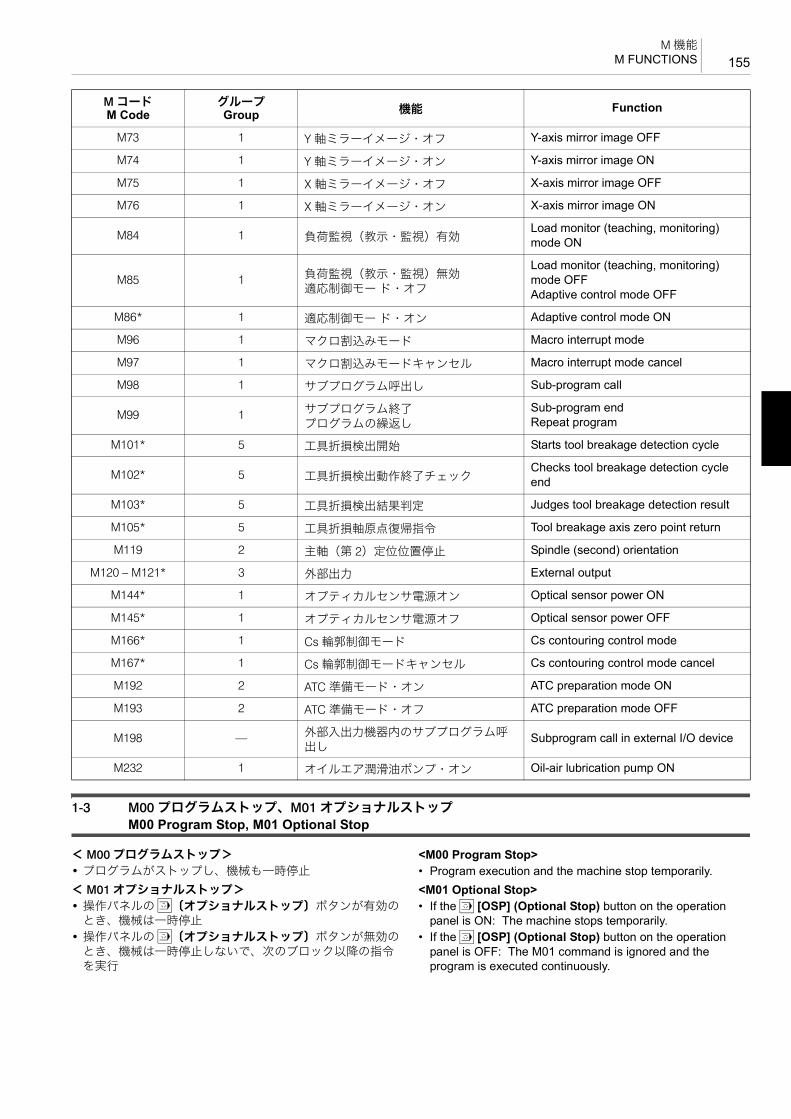
155M 機能
M FUNCTIONS
1-3 M00 プログラムストップ、M01 オプショナルストップM00 Program Stop, M01 Optional Stop
< M00 プログラムストップ> <M00 Program Stop>• プログラムがストップし、機械も一時停止 • Program execution and the machine stop temporarily.< M01 オプショナルストップ> <M01 Optional Stop>• 操作パネルの x〔オプショナルストップ〕ボタンが有効の
とき、機械は一時停止• If the x [OSP] (Optional Stop) button on the operation
panel is ON: The machine stops temporarily.• 操作パネルの x〔オプショナルストップ〕ボタンが無効の
とき、機械は一時停止しないで、次のブロック以降の指令を実行
• If the x [OSP] (Optional Stop) button on the operation panel is OFF: The M01 command is ignored and the program is executed continuously.
M73 1 Y 軸ミラーイメージ・オフ Y-axis mirror image OFF
M74 1 Y 軸ミラーイメージ・オン Y-axis mirror image ON
M75 1 X 軸ミラーイメージ・オフ X-axis mirror image OFF
M76 1 X 軸ミラーイメージ・オン X-axis mirror image ON
M84 1 負荷監視(教示・監視)有効Load monitor (teaching, monitoring) mode ON
M85 1 負荷監視(教示・監視)無効適応制御モー ド・オフ
Load monitor (teaching, monitoring) mode OFFAdaptive control mode OFF
M86* 1 適応制御モー ド・オン Adaptive control mode ON
M96 1 マクロ割込みモード Macro interrupt mode
M97 1 マクロ割込みモードキャンセル Macro interrupt mode cancel
M98 1 サブプログラム呼出し Sub-program call
M99 1 サブプログラム終了プログラムの繰返し
Sub-program endRepeat program
M101* 5 工具折損検出開始 Starts tool breakage detection cycle
M102* 5 工具折損検出動作終了チェックChecks tool breakage detection cycle end
M103* 5 工具折損検出結果判定 Judges tool breakage detection result
M105* 5 工具折損軸原点復帰指令 Tool breakage axis zero point return
M119 2 主軸(第 2)定位位置停止 Spindle (second) orientation
M120 – M121* 3 外部出力 External output
M144* 1 オプティカルセンサ電源オン Optical sensor power ON
M145* 1 オプティカルセンサ電源オフ Optical sensor power OFF
M166* 1 Cs 輪郭制御モード Cs contouring control mode
M167* 1 Cs 輪郭制御モードキャンセル Cs contouring control mode cancel
M192 2 ATC 準備モード・オン ATC preparation mode ON
M193 2 ATC 準備モード・オフ ATC preparation mode OFF
M198 — 外部入出力機器内のサブプログラム呼出し
Subprogram call in external I/O device
M232 1 オイルエア潤滑油ポンプ・オン Oil-air lubrication pump ON
M コードM Code
グループGroup 機能 Function

M 機能M FUNCTIONS156
7注意 7 CAUTIONM00, M01 で機械を一時停止させた後、手動操作で工具交換や軸移動を行わないでください。やむを得ず、これらの操作を行ったときは、加工を再開する前に、元の状態に戻してください。[干渉、機械の破損、切削工具の破損]
Do not change the cutting tools or move the axes manually while the operation is suspended by M00 or M01. If such manual operations are unavoidable, restore the tools and axes to their previous state before restarting the operation.[Interference/Machine damage/Cutting tool damage]
2 注記 2 NOTE
1. M00, M01 は単独ブロックで指令してください。 1. Specify M00 or M01 in a single block without other commands.2. 操作パネルの自動運転ボタン q〔起動〕を押すと、続きのプロ
グラムを実行します。2. The program is continuously executed when the automatic
operation button q [START] (Start) on the operation panel is pressed.
3. M00, M01 を実行すると、M03, M04 の主軸の回転指令、M08 のクーラントの吐出指令はキャンセルされます。したがって、プログラム中の M00, M01 を指令する位置には、十分注意してください。プログラムを再開するときは、始めに M03, M04、クーラントの吐出が必要なプログラムでは M08 を指令してください。
3. When M00 or M01 is executed, the spindle start codes (M03, M04) and the coolant discharge code (M08) are canceled. Therefore, pay extra attention when determining a position of M00 or M01 to be specified in the program. When restarting the program, specify M03 or M04 at the restart block, and specify M08 if coolant discharge is required.
1-4 M02 プログラム終了、M30 プログラム終了と頭出しM02 Program End, M30 Program End and Rewind
プログラムで M02 あるいは M30 を実行すると、次のようになります。
When M02 or M30 is executed,
1. 機械のすべての動作が停止します。 1. All machine operations stop.• 主軸の回転停止 • The spindle stops.• 軸移動の停止 • Axis movement stops.• クーラントの吐出停止 • Coolant discharge stops.
2. NC はリセット状態になります。 2. The NC is reset.• G コードは電源投入時の状態になります。ただし、G54
~ G59, G90, G91, G94, G95, G97 および G20, G21 は変わりません。
• In the reset state, the G codes that are valid when the power is turned on are valid. However, G54 to G59, G90, G91, G94, G95, G97, G20 or G21 modes remain unchanged.
• F コードと S コードはキャンセルされずに記憶されます。
• Both F and S codes are stored without canceled.
5M30 は M02 にリワインド機能が加わった指令です。次のワークを加工するとき、再度操作パネルの自動運転ボタン q〔起動〕を押すだけで同じプログラムを実行します。
5M30 includes the program rewind function in addition to the functions supported by M02. By using M30, the same program is executed repeatedly by simply pressing the automatic operation button q [START] (Start).
2 注記 2 NOTE
1. M02, M30 は単独ブロックで指令してください。 1. Specify M02 or M30 in a single block without other commands.2. M02, M30 を実行すると、操作パネルの自動運転ボタン q〔起
動〕のランプが消えます。2. The indicator in the automatic operation button q [START] (Start)
goes off when M02 or M30 is executed.
1-5 M03 主軸正転、M04 主軸逆転、M05 主軸回転停止M03 Spindle Start (Normal), M04 Spindle Start (Reverse), M05 Spindle Stop
7注意 7 CAUTION
1. 切削工具とワークが接触しているときに、M05 を指令し
て、主軸の回転を停止させないでください。[切削工具の破損]
1. Do not stop the spindle by specifying M05 while the cutting tool is in contact with the workpiece.[Cutting tool damage]
2. 切削工具がワークに接触する前に、M03 か M04 を指令し
て、主軸を回転させてください。(バックボーリングサイクルおよび同期式タッピングサイクル、同期式逆タッピングサイクルを除く。)
[切削工具の破損]
2. Start the spindle by executing M03 or M04 before the cutting tool comes into contact with the workpiece (except back boring cycle, synchronized tapping cycle, and synchronized reverse tapping cycle).[Cutting tool damage]

157M 機能
M FUNCTIONS
3. 高速主軸(主軸回転 10000 min−1 以上)を搭載している機
械(50 番テーパ相当機)で 10000 min−1 以上の回転速度指令を行う場合は、高速工具の設定をする必要があります。
3. When specifying the spindle speed command higher than 10000 min−1 on the machine (No. 50 taper or equivalent) equipped with high-speed spindle (10000 min−1), it is necessary to make the high-speed tool setting.
1 高速工具の設定については、別冊 “ 機械操作説明書 ” 1 For details of the high-speed tool setting, refer to the separate volume “OPERATION MANUAL”.
2 注記 2 NOTE
1. 主軸正転は、主軸後方からワークを見て、主軸が時計方向に回転、主軸逆転は主軸後方からワークを見て、主軸が反時計方向に回転することです。
1. Normal rotation: clockwise, with workpiece as viewed from the rear of the spindle. Reverse rotation: Counterclockwise
2. M03, M04 の主軸回転指令の前には、S コードによる主軸回転速度指令を行ってください。
2. Before starting the spindle rotation with M03 or M04, specify the required spindle speed using an S code.
1 S コードについては、“S 機能 ”(182 ページ) 1 For details of S code, refer to “S FUNCTION” (page 182)
1-6 M06 工具交換M06 Tool Change
M06 は、主軸の工具を交換するときや主軸に工具を取り付けるときに使用します。主軸定位置停止、ツールクランプ/アンクランプを含めた一連の交換動作(ATC)を実行します。
M06 is used to change the tool set in the spindle or set the tool to the spindle. The M06 command executes a series of tool change cycle (ATC) including spindle orientation and tool clamp/unclamp.
7注意 7 CAUTION
1. 異なる工具径の工具交換を行う場合、同径の工具交換に比
べて ATC 動作が変わります。異径間の工具交換では、ATC 動作を 2 回行います。MDI 操作で異径間の工具交換を行う場合、十分注意してください。
1. ATC operation when exchanging the tools in different diameter groups differs from that in the same diameter group. For exchanging tools in different diameter groups, the tool change operation is executed twice in the one cycle. In such case, pay sufficient care when executing ATC in the MDI mode.
2. M06 と同一ブロックで、T コードを指令しないでください。
[事故による機械の破損]
2. Do not specify “T” codes in the same block as M06. [Machine damage due to accidents]
2 注記 2 NOTE
1. 主軸回転中に M06 を指令すると、自動的に主軸定位置停止を行って、工具交換を行います。
1. If M06 is executed while the spindle is rotating, the spindle orientation is automatically executed and the tools are changed.
2. M06 を指令すると、自動的にクーラント吐出停止を行うので、M06 の前に M09 を指令する必要はありません。自動的にクーラントが吐出するように PC パラメータを設定すると、M06 の後でM08 を指令する必要はありません。
2. When M06 is specified, coolant discharge is automatically stopped; it is not necessary to specify M09 before M06. If the parameter is set so that the coolant is automatically discharged, it is not necessary to specify M08 after M06.
3. M06 は、X, Y, Z 軸ともに第 2 原点復帰位置で実行してください。 3. Execute M06 with the X-, Y-, and Z-axes positioned at the second zero point.
4. NHX5500, NHX6300 のツール 100 本、120 本、180 本、240 本、330 本マガジン仕様の場合、 終ポットには T0 が登録されています。T0 以外の工具番号を登録することもできますが、その場合、 “T0; M06;” や “M33;” を指令するとアラームが発生します。
4. For the 100-, 120-, 180-, 240-, and 330- tool magazine specifications of NHX5500 and NHX6300, T0 is registered for the last pot number (magazine position number). It is also possible to register a setting other than T0 for the last pot number (magazine position number). However, if “T0; M06;” or “M33;” is specified in this case, an alarm will occur.
1-7 M08 クーラントの吐出、M09 クーラントの吐出停止M08 Coolant Discharge ON, M09 Coolant Discharge OFF
5NHX4000 および NHX5000 では、クーラントおよびシャワークーラントが同時に吐出します。
5For NHX4000 and NHX5000, the coolant and shower coolant are discharged simultaneously.
NHX5500 および NHX6300 では、クーラントのみ吐出します。 For NHX5500 and NHX6300, only the coolant is discharged.
2 注記 2 NOTE
1. クーラントを吐出している状態で、工具交換を行わないでください。
1. Do not carry out the tool change while coolant is discharged.

M 機能M FUNCTIONS158
2. クーラントを使用して自動運転を行う場合、自動運転前に、十分な量のクーラントがクーラントタンクに入っていることを確認してください。
2. If coolant is used for automatic operation, make sure that the coolant tank has sufficient volume of coolant.
5M08と操作パネルのクーラントボタンの関係について説明します。 5Coolant discharge control using the coolant buttons on the operation panel in combination with the M08 command is explained below:
<クーラントボタン 7〔オン〕> <Coolant button 7 [ON] (On)>M08 を実行 D クーラントボタン 7〔オン〕内のランプ点灯 Dクーラント吐出
M08 executed D Indicator in the button illuminated D Coolant discharged
<クーラントボタン 8〔オフ〕> <Coolant button 8 [OFF] (Off)>クーラント吐出中にクーラントボタン 8〔オフ〕を押す D クーラントの吐出停止
Pressing the button while coolant is being supplied D Coolant discharge stopped
2 注記 2 NOTE
また、クーラントの吐出停止中に、クーラントボタン 8〔オフ〕を1 秒以上押し続けると、クーラントボタン 7〔オン〕内のランプが点滅します。この状態で M08 を実行しても、クーラントは吐出されません。再度クーラントボタン 7〔オン〕を押すと、クーラントボタン 7〔オン〕内のランプが点滅から点灯に変わります。
If the coolant button 8 [OFF] (Off) is pressed for one second or more while the coolant is not being discharged, the coolant button 7 [ON] (On) blinks. In this state, the coolant is not discharged even if M08 is executed. When the coolant button 7 [ON] (On) is pressed again, the coolant button 7 [ON] (On) stops blinking, and remains illuminated.
例: Example:M08, M09 の使用例 Programming using M08 and M09
(a):クーラントの吐出 (a): Starts coolant discharge.(b):クーラントの吐出停止 (b): Stops coolant discharge.(c):Z 軸機械原点復帰して、主軸の回転停止 (c): Stops the spindle after machine zero point return of the
Z-axis.
5通常、主軸の回転を停止する前に M09 を指令します。これは、工具に付いているクーラントを主軸の回転で振り切るためです。
5Usually, M09 is specified before stopping spindle rotation. This is to spin off coolant from the tool by the rotation of the spindle.
1-8 M19 主軸定位置停止M19 Spindle Orientation
G76, G87 を指令する場合、段取り作業において、G76, G87で使用するボーリング工具を主軸に取り付けるときに、MDI操作で M19 を使用します。
When mounting a boring bar which is used in the G76 or G87 boring cycle in the spindle, M19 is used in the MDI mode.
2 注記 2 NOTE
工具交換(M06)、穴あけ固定サイクル(G76, G87)を実行すると、主軸定位置停止を自動的に行います。プログラム中に M19 を指令する必要はありません。
Spindle orientation is automatically executed if tool change cycle (M06) or hole machining canned cycle (G76, G87) is executed. In this case, it is not necessary to specify M19 in a program.
1-9 M20 自動電源しゃ断M20 Automatic Power Shutoff
2 注記 2 NOTE
1. 操作パネルの l〔自動電源しゃ断〕ボタンは、M20 と同じ機能です。l〔自動電源しゃ断〕ボタンを押して有効(ボタン内のランプが点灯)にしておくと、プログラム中の M02 あるいは M30を実行すれば、自動的に電源がしゃ断されます。M00 あるいはM01 を実行したときに、自動的に電源がしゃ断されるかどうかは、パラメータの設定で決まります。機械納入時は、M00 あるいは M01 を実行しても電源はしゃ断されません。
1. l [APF] (Automatic Power Shutoff) button on the operation panel has the same function as M20. When the button is pressed and the automatic power shutoff function is valid (the indicator in the switch is illuminated), the power supply is automatically shut off when M02 or M30 in the program is executed. Whether the power is automatically shut off by execution of M00 or M01 is determined by the parameter setting. For the default at shipping the machine, the power is not shut off by the execution of M00 or M01.
2. M30 にはプログラムの先頭に戻る機能(リワインド機能)があるため、M20 は M30 よりも前のブロックに指令してください。
2. Specify M20 in a block preceding the M30 block because M30 has the rewind function to return to the program head.
O0001;N1;G90 G00 G54 X0 Y0;G43 Z30.0 H1 S400 T2 M08;............................... (a)M03;:M09; ..................................................................... (b)G91 G28 Z0 M05; .................................................(c)

159M 機能
M FUNCTIONS
3. 下記の動作を行っているときには、電源はしゃ断されません。動作が終了した後、M20 で電源がしゃ断されます。
3. Power is not shut off during:
• APC(AWC)サイクル中(APC(AWC)仕様) • APC (AWC) cycle (APC (AWC) specifications)• ATC サイクル中 • ATC cycle• SBC サイクル中 • SBC cycle• マガジン旋回中 • Magazine indexing• パレットプール割出し中(パレットプール仕様) • Pallet pool indexing (pallet pool specification)
After the completion of the operation above, the power is shut off.4. 自動電源しゃ断機能を使用して電源をしゃ断した後、機械電源ス
イッチの位置は〔ON〕と〔OFF〕の中間位置になっています。電源を再投入するときは、一度〔OFF〕の位置にしてから再度
〔ON〕の位置にしてください。
4. The main power switch is placed in the position between [ON] and [OFF] after the power supply is automatically shut off using the automatic power shutoff function. Place the main switch in the [OFF] position first and then place it in the [ON] position to turn on the power supply again.
例: Example:
1-10 M33 工具収納M33 Tool Storing Cycle
主軸の工具をマガジンの空ポット/クランパに収納します。 T0; M06; というプログラムを実行したときと同じ状態になります。
M33 is used to return the tool mounted in the spindle to an empty pot/clamper in the magazine, having the same effect as the program below:T0;M06;
2 注記 2 NOTE
1. M33 は単独ブロックで指令してください。 1. The M33 command must be specified in a single block.2. M33 は、各軸が工具交換位置にないと実行できません。 2. The M33 command cannot be executed unless the axes are
located at the tool change position.3. NHX5500, NHX6300 のツール 100 本、120 本、180 本、240 本、
330 本マガジン仕様の場合、 終ポットには T0 が登録されています。T0 以外の工具番号を登録することもできますが、その場合、“T0; M06;” や “M33;” を指令するとアラームが発生します。
3. For the 100-, 120-, 180-, 240-, and 330- tool magazine specifications of NHX5500 and NHX6300, T0 is registered for the last pot number (magazine position number). It is also possible to register a setting other than T0 for the last pot number (magazine position number). However, if “T0; M06;” or “M33;” is specified in this case, an alarm will occur.
O0001;N1;:
N2;:
/M20;......................................................................... M20 を実行すると、自動的に電源がしゃ断されます。“/” を入れているので、次のようになります。• ブロックデリート有効
M20 の指令を無視して、次のM30 を実行します。
• ブロックデリート無効M20 の指令を実行し、自動的に電源がしゃ断されます。
If the M20 command is executed, power supply is automatically shut off. Since the slash “/” code is entered, execution of this block is as follows:• If the block delete is activated:
M20 is ignored, and M30 command in the next block is executed.
• If the block delete button is inactivated:M20 is executed, and the power supply is automatically shut off.
M30; .......................................................................... プログラムが終了し、機械も停止NC はリセットされて、カーソルはプログラムの先頭に戻ります。
Ends the program execution and stops the machine.The NC is reset and the cursor returns to the head of the program (O0001).

M 機能M FUNCTIONS160
例: Example:M33 の使用例 Programming using M33
(a):Z 軸第 2 原点復帰して、主軸の回転停止 (a): Stops the spindle after the second zero return of the Z-axis.
(b):X, Y 軸第 2 原点復帰 (b): Second zero return of X- and Y-axes.(c):工具収納指令 (c): Specifies the tool storing cycle.
1-11 M48 切削送りオーバライドキャンセル・オフ、M49 切削送りオーバライドキャンセル・オンM48 Feedrate Override Cancel OFF, M49 Feedrate Override Cancel ON
< M49 切削送りオーバライドキャンセル・オン> <M49 Feedrate Override Cancel ON>切削送り速度が F で指令された値に固定され、操作パネルの送りオーバライドスイッチが 100% の状態になっていなくても 100% の送り速度となります。
Axis feedrate is fixed to the one programmed by the F code. Therefore, even if the feedrate override switch on the operation panel is not set 100%, it is assumed to be set 100%.
<使用例> <Example>テスト加工時にプログラム中に M48 を入れて、F の送り速度を 適な値にします。量産加工時は、プログラム中に M49 を指令して、F の送り速度を固定させます。
In a test cutting, M48 may be specified in a program so that cutting feedrates can be adjusted to the optimum one. After determining the optimum feedrates, M49 may be specified in a program so that mass production can be executed by using the fixed rates.
7注意 7 CAUTIONM49 を指令すると、F で指令された送り速度よりも早くならないことは、安全性からも良いことです。しかし、逆にワークを加工中、F で指令された送り速度が早いと感じても、送りオーバライドスイッチで、送り速度を遅くできないので注意してください。
In this mode, the actual feedrates cannot be set faster than the programmed feedrates. However, it is impossible to lower the feedrate programmed by F using the feedrate override switch during the machining even if the programmed feedrate appears to be too fast.
2 注記 2 NOTE
1. タップ加工のときは、送り速度を一定にしなければなりません。タップ加工の G コードが指令されたときは、送り速度にオーバライドが自動的にかからないようになっているので、M48, M49 を指令する必要はありません。
1. During tapping, feedrate must be kept constant. The override function is automatically ignored if the G code calling the tapping is executed. Therefore, it is not necessary to specify M48 and M49 in a program for the tapping.
2. M48, M49 は早送り速度に対しては無効です。M49 を実行している状態でも、早送り速度に対してオーバライドをかけることができます。
2. M48 and M49 are not valid for rapid traverse operation. Therefore, the rapid traverse rate override button is operative while M49 is executed.
例: Example:M48, M49 の使用例 Programming using M48, M49φ100 のフェイスミルによる平面加工を行います。 Machining the face using a 100 mm diameter face milling
cutter.
O0001;N1;:G91 G30 Z0 M05; ................................................ (a)G30 X0 Y0; .......................................................... (b)M01;M33; ......................................................................(c)M30;
80
−80
−100 100
+Y
+X
1 2
34

161M 機能
M FUNCTIONS
2 注記 2 NOTE
操作パネルの c〔ブロックデリート〕ボタンが無効になっている状態で、下記のプログラムを実行します。
The following program is executed while the c [BDT] (Block Delete) button on the operation panel is set OFF.
1-12 M50 オイルホールドリル用クーラント・オン、M09 クーラント・オフ(オプション)M50 Oil-Hole Drill Coolant Discharge ON, M09 Coolant Discharge OFF (Option)
穴の内部に確実にクーラントを供給できるので、工具の冷却および摩耗の防止、切りくずの排出に効果的です。
Since the coolant can be supplied correctly into the hole being machined, M50 effectively cools the tool, prevents the tool from being worn and discharges chips out of the hole.
2 注記 2 NOTE
1. ATC サイクル中はクーラントの吐出は停止します。 1. The discharge of coolant stops during ATC cycle.2. M08 でクーラントを吐出している状態で、M50 を指令すると、
クーラントの吐出は停止して、オイルホールドリル用クーラントが吐出します。
2. If M50 is specified while the coolant is discharged by M08, the coolant is stopped and the oil-hole drill coolant is discharged.
3. M50 でオイルホールドリル用クーラントを吐出している状態で、M08 を指令するとオイルホールドリル用クーラントの吐出は停止して、クーラントが吐出します。
3. If M08 is specified while the oil-hole drill coolant is discharged by M50, the oil-hole drill coolant is stopped and the coolant is discharged.
4. オイルホールドリルには、専用のホルダが必要です。 4. For the oil-hole drill coolant system, special tool holders are necessary.
1-13 M51 エアブロー開始、M59 エアブロー停止M51 Air Blow Start, M59 Air Blow Stop
加工中にワークの上面や溝部に溜まる切りくずを除去するときに、エアブローを使用します。
Air blow is used to blow off and discharge chips accumulated on the surface or groove of the workpiece during machining.
1-14 M53 センサ用エアブロー開始、M58 センサ用エアブロー停止(オプション)M53 Sensor Air Blow Start, M58 Sensor Air Blow Stop (Option)
テーブル側タッチセンサを使用するときに、センサの先に切りくずが付かないように、エアブローで切りくずを取り除きます。
The codes are used for removing chips from the tips of the table mounted touch sensor by blowing them away with compressed air.
O0001;N1;G90 G00 G54 X−160.0 Y−40.0;............................aG43 Z30.0 H1 S400 T2;M03;G01 Z0 F500;/M49;......................................................................... 切削送りのオーバライド無効 “/”
を入れていますが、ブロックデリートが無効になっているのでM49 は実行され、切削送りのオーバーライドは無効となり、100% の送り速度で、以降のプログラムを実行します。
Make the override for cutting feed invalid. Although the slash (/) code is entered, M49 is executed, the override for cutting feed is made invalid and the blocks thereafter are executed with 100% feedrate, because the c [BDT] (Block Delete) button on the operation panel is OFF.
X160.0 F200; ..............................................a D b 送り速度は 200 mm/min に固定されます。
The feedrate is fixed at 200 mm/min.
Y40.0 F500; ................................................b D c 送り速度は 500 mm/min に固定されます。
The feedrate is fixed at 500 mm/min.
X−160.0 F200; ............................................c D d 送り速度は 200 mm/min に固定されます。
The feedrate is fixed at 200 mm/min.
/M48;......................................................................... 切削送りのオーバライド有効この指令以降は、操作パネルの送りオーバライドスイッチが有効になります。
Makes the override for cutting feed valid.After this command, the feedrate override switch on the operation panel is valid.

M 機能M FUNCTIONS162
1-15 M70 ワークカウンタ、トータルカウンタM70 Specifies Counting of Work Counter and Total Counter
プログラムで M70 を読むと、ワークカウンタの ‘ 現在値 ’ が 1ずつ増えます。
Each time the M70 command written in a program is read, the ‘CURRENT’ value of the PC work counter increases “1”.
ワークカウンタを使用する場合、あらかじめ、繰り返したい回数を “ プリセット値 ” に設定します。
When using the work counter, set the required number of cycle repetitions for “preset value” before starting the operation.
例えば、ワークカウンタの “ プリセット値 ” に 100 を設定したとします。プログラムを実行して、M70 を 100 回実行すると、選択によりサイクルスタートインタロックあるいはブロックデリート有効のいずれかの状態になります。
Suppose “100” is set for “preset value” of the work counter. If the M70 command is executed 100 times as the program is executed repeatedly, the cycle start interlock state is established or the block delete function becomes valid according to your selection.
2 注記 2 NOTE
1. ワークカウンタの機能選択は、PC パラメータ(No. 6410.5)に設定します。
1. Set the selected work counter function at PC parameter No. 6410.5.
2. ワークカウンタは工具寿命管理やワーク個数管理を行うときに使用します。これに対して、トータルカウンタは単なる計数として使用します。
2. The work counter is used for tool life management function as well as to control the number of finished workpieces. In comparison to the work counter, the total counter is used for simply counting the number.
3. ワークカウンタが確実にカウントアップの動作を行うように、繰り返し実行するプログラムの先頭に M70 を指令してください。
3. Specify the M70 command at the start of the program which is executed repeatedly so that the execution of the program is correctly counted by the work counter.
5サイクルスタートインタロック状態およびブロックデリート有効状態の違いを下記に示します。
5How the cycle start interlock state and the block delete valid state differ from each other is explained below.
• サイクルスタートインタロック状態 • Cycle start interlocked state設定された回数分 M70 を実行すると、以降の自動運転の起動ができなくなる状態のことを意味します。
When the M70 command has been executed by the preset num-ber of times, cycle start of automatic operation is disabled.
つまり、自動運転ボタン q〔起動〕を押してもプログラムは実行されません。
In other words, the program is not executed even when the auto-matic operation button q [START] (Start) is pressed.
• ブロックデリート有効状態 • Block delete valid state設定された回数分 M70 を実行するまではブロックデリート機能が無効ですが、カウントアップが完了すると、ブロックデリート機能が有効になることを意味します。
The block delete function is invalid until the M70 command is ex-ecuted by the preset number of times. After the count-up of the counter, the block delete function becomes valid.
1 ブロックデリート機能については、別冊機械操作説明書“ プログラムに入力する記号や符号 ”
1 For details of the block delete function, refer to separate volume OPERATION MANUAL “Signs and Symbols”.
例: Example:M70 の使用例(1) Programming using M70 (1)あらかじめ、サイクルスタートインタロック状態に設定しておき、ワークカウンタの “ プリセット値 ” に “100” を設定します。
Set the work counter to establish the cycle start interlock state when it reaches the preset value and then set “100” for “preset value” of the work counter.
O1;N1;M70;.......................................................................... O1 のプログラムを実行するたび
に、加工部品数が 1 ずつカウントアップ
The count data of the number of machined workpieces increases “1” each time program O1 is executed.
G90 G00 G54 X0 Y0;:
: 加工プログラム Machining program:
G80;G91 Z0 M05;M30; .......................................................................... O1 のプログラムを 100 回実行し、
カーソルが先頭に戻った状態で機械が停止自動運転ボタン q〔起動〕を押しても、プログラムは実行されません。(ワークカウンタを使用した場合)
When the cursor has returned to the start of the program after executing program O1 100 times, the program does not start even if the automatic operation button q [START] (Start) is pressed. (When using the work counter.)
O1;M70;:
:M30;

163M 機能
M FUNCTIONS
例: Example:M70 の使用例(2) Programming using M70 (2)あらかじめ、ブロックデリート有効状態に設定しておき、ワークカウンタの “ プリセット値 ” に “100” を設定します。
Set the work counter to validate the block delete function when it reaches the preset value and then set “100” for “preset value” of the work counter.
1-16 M73, M74, M75, M76 ミラーイメージ・オン、オフM73, M74, M75, M76 Mirror Image ON/OFF
X 軸、Y 軸または、その平行軸を対称軸として対称な図形があるとき、どちらかのプログラムを作成しミラーイメージをかけるともう 1 つのプログラムが自動的に作成できます。
When there are graphics which are symmetric with each other in reference to the X- or Y-axis or an axis parallel to them, a program for one of the graphics can create the other one using the mirror image function.
< X 軸方向が対称軸> <Axis of Symmetry: X-Axis>
< Y 軸方向が対称軸> <Axis of Symmetry: Y-Axis>
O1;M70;.......................................................................... O1 のプログラムを実行するたび
に、加工部品数が 1 ずつカウントアップ
The count data of the number of machined workpieces increases “1” each time program O1 is executed.
:
: 加工プログラム Machining program:
/M99; ......................................................................... O1 のプログラムを 100 回実行するまではブロックデリート無効状態で “M99;” を実行プログラムの先頭 “O1;” に戻り、引き続きプログラムを実行します。
(ワークカウンタを使用した場合)1M99 の機能については、“M98/
M198 サブプログラムの呼出し、M99 サブプログラム終了 ”(168ページ)を参照。
100 回目でブロックデリート有効状態になり “M99;” を読み飛ばして“M30;” を実行します。
Until the program O1 is executed 100 times, the block delete function is invalid and the “M99;” block is executed.The cursor returns to block “O1;” at the head of the program and program execution continues. (When using the work counter.)1For the function of M99 code, refer
to “M98/M198 Sub-Program Call, M99 Sub-Program End” (page 168)
In the execution of the program at the 100th time, the block delete function is made valid and the “M30;” block is executed by skipping the “M99;” block.
M30;
1 − 99100
O1;M70;:
:/M99;M30;
M73;............................. Y 軸ミラーイメージ・オフ Mirror image (Y-axis) OFF
M74;............................. Y 軸ミラーイメージ・オン Mirror image (Y-axis) ON
M75;............................. X 軸ミラーイメージ・オフ Mirror image (X-axis) OFF
M76;............................. X 軸ミラーイメージ・オン Mirror image (X-axis) ON
+X
+YM74
M74
+X
+YM76
M76(Mirror Image is Applied in Y-Axis Direction.)
(Mirror Image is Applied in X-Axis Direction.)
(Y 軸方向にミラーイメージをかける)
(X 軸方向にミラーイメージをかける)

M 機能M FUNCTIONS164
7注意 7 CAUTIONM73 ~ M76 を指令する場合、対称軸上に工具を移動させてください。工具が対称軸上にない状態で M73 ~ M76 を指令すると、以降のプログラムで座標がずれます。[工具およびホルダとワークおよび治具などが干渉、機械の破損]
When specifying the M73 to M76 commands, move the cutting tool to the axis of symmetry first. If the M73 to M76 commands are specified while the cutting tool is not positioned at the axis of symmetry, the coordinate system used for executing the following program is shifted.[Interference of the cutting tool or tool holder with the workpiece or fixture/Machine damage]
例: Example:ミラーイメージの使用例 Programming using the mirror imageA ~ P の 16ヶ所で穴あけ加工を行います。 Hole machining at 16 positions (A to P).
まず、A ~ D の穴位置をサブプログラム(O0002)で作成します。
First, the sub-program (O0002) is created for the hole positions A to D.
次にメインプログラム(O0001)において、A ~ P の各穴位置で穴あけ加工を行います。
Then, the hole machining cycle is performed at A to P using the main program (O0001).
CDHG
BAEF
NMIJ
OPLK
50
15
−15
−50
−55 −20 20 55+X
+Y
サブプログラム(O0002)Sub-program (O0002)O0002;X20.0 Y15.0;X55.0;Y50.0;X20.0;M99;
+X
+YA D
メインプログラム(O0001)Main Program (O0001)O0001;:
G90 G99 G81 Z−3.0 R3.0 F80 L0;............................ スポットドリリングサイクル(G81)を指令
2 注記
L0 を指令しているので、スポットドリリングサイクルを行いません。
Specifies the spot drilling cycle (G81).
2 NOTE
Since L0 is specified, the spot drilling cycle is not carried out here.
M98 P2;..................................................................... サブプログラム(O0002)を呼び出して、A ~ D の各位置で G81 を実行
Calls the sub-program (O0002) to execute G81 at A to D.

165M 機能
M FUNCTIONS
G00 X0;..................................................................... 対称軸の Y 軸上に工具を移動 Moves the cutting tool to the symmetry axis, Y-axis.
M76;.......................................................................... X 軸のミラーイメージ有効 Calls the mirror image (X-axis) ON mode.
G81 Z−3.0 R3.0 L0; .................................................. G81 を指令 Specifies G81.M98 P2;..................................................................... サブプログラム(O0002)を呼び出
して、E ~ H の各位置で G81 を実行X 軸のミラーイメージ有効
Calls the sub-program (O0002) to execute G81 at E to H.The mirror image ON for the X-axis.
Y0;............................................................................. 対称軸の X 軸上に工具を移動 Moves the cutting tool to the symmetry axis, X-axis.
M74;.......................................................................... Y 軸のミラーイメージ有効 Calls the mirror image (Y-axis) ON mode.
G81 Z−3.0 R3.0 L0; .................................................. G81 を指令 Specifies G81.M98 P2;..................................................................... サブプログラム(O0002)を呼び出
して、I ~ L の各位置で G81 を実行X, Y 軸のミラーイメージ有効
Calls the sub-program (O0002) to execute G81 at I to L.The mirror image is ON for the X- and Y-axes.
X0;............................................................................. 対称軸の Y 軸上に工具を移動 Moves the cutting tool to the symmetry axis, Y-axis.
M75;.......................................................................... X 軸のミラーイメージ無効 Calls the mirror image (X-axis) OFF mode.
G81 Z−3.0 R3.0 L0; .................................................. G81 を指令 Specifies G81.M98 P2;..................................................................... サブプログラム(O0002)を呼び出
して、M ~ P の各位置で G81 を実行X 軸のミラーイメージ無効、Y 軸のミラーイメージ有効
Calls the sub-program (O0002) to execute G81 at M to P.The mirror image is OFF for the X-axis and ON for the Y-axis.
+X
+YA D
+X
+YE H
+X
+Y
I L

M 機能M FUNCTIONS166
1-17 M80 シャワークーラント・オン、M81 シャワークーラント・オフM80 Shower Coolant ON, M81 Shower Coolant OFF
2 注記 2 NOTE
1. M80, M81 は NHX5500 および NHX6300 でのみ使用できます。 1. The M80 and M81 commands can be used with NHX5500 or NHX6300 only.
2. シャワークーラントの吐出停止は、操作パネルのクーラントボタン 8〔オフ〕ではなく、6〔シャワー〕ボタンを押してください。
2. To stop the shower coolant, press the 6 [SHOWER] (Shower Coolant) button on the operation panel, instead of the coolant button 8 [OFF] (Off).
5M80 を実行すると、6〔シャワー〕ボタン内のランプが点灯します。
5When the M80 command is specified, the indicator in the 6 [SHOWER] (Shower Coolant) button is illuminated.
1-18 M88 スルースピンドルクーラント・オン、M89 スルースピンドルクーラント・オフ(オプション)M88 Through-Spindle Coolant ON, M89 Through-Spindle Coolant OFF (Option)
M88 を指令すると、主軸と工具の貫通穴を通してクーラントが刃先に供給されます。切りくず除去、加工点の冷却、および工具寿命の延長に効果的です。
When M88 is specified, coolant is supplied to the tool tip through the spindle and the tool through hole. It is effective for eliminating chips, cooling the machine point and lengthening the lives of the tools.
2 注記 2 NOTE
スルースピンドルクーラントの吐出停止は、操作パネルのクーラントボタン 8〔オフ〕ではなく、9〔スルースピンドル〕ボタンを押してください。
To stop the through-spindle coolant, press the 9 [THROUGH SP] (Through-spindle Coolant) button on the operation pane, instead of the coolant button 8 [OFF] (Off).
5クーラントとエアブローを切り替えることもできます。 5Coolant and air blow can be switched.
1 “M252 スルースピンドルエアブロー・オン、 M253 スルースピンドルエアブロー・オフ(オプション)”(172 ページ)
1 “M252 Through-Spindle Air Blow ON, M253 Through-Spin-dle Air Blow OFF (Option)” (page 172)
M270 ~ M277 スルースピンドルクーラントの吐出圧力切替え(クノール仕様のみ)
M270 - M277Changing the Discharge Pressure of the Through-Spindle Coolant (Knoll Specifications Only)
2 注記 2 NOTE
M270 ~ M277 は、スルースピンドルクーラント装置の I/F タイプがクノール社製に対応している場合でのみ使用できます。
M270 to M277 can only be used if the I/F type of the through-spindle coolant unit is the type made by Knoll.
スルースピンドルクーラントの吐出圧力は、以下の M コードを指令すると、8 段階に切り替えられます。
The discharge pressure of the through-spindle coolant can be changed in 8 steps by specifying the M codes below.
Y0;............................................................................. 対称軸の X 軸上に工具を移動 Moves the cutting tool to the symmetry axis, X-axis.
M73;.......................................................................... Y 軸のミラーイメージ無効後は X, Y 軸ともにミラーイメー
ジをキャンセルした状態になります。
Calls the mirror image (Y-axis) OFF mode.At the end of a program, the mirror image is off for both of the X- and Y-axes.
+X
+Y
M P
M270;........................... クーラント吐出圧力レベル 0 Coolant discharge pressure level 0
M271;........................... クーラント吐出圧力レベル 1 Coolant discharge pressure level 1
M272;........................... クーラント吐出圧力レベル 2 Coolant discharge pressure level 2
M273;........................... クーラント吐出圧力レベル 3 Coolant discharge pressure level 3

167M 機能
M FUNCTIONS
5クーラント吐出圧力切替え用の M コードと圧力切替え出力信号との関係は、以下のとおりです。
5The relationship between the M codes for changing the coolant discharge pressure and the signals for changing the pressure is indicated below.
1 I/F 仕様は、本機電気図面およびクノール社製スルースピンドルクーラント装置の取扱説明書を参照してください。
1 For I/F specifications, refer to circuit diagrams for the machine and the instruction manual for the through-spindle coolant unit provided by Knoll.
<関連 PC パラメータ> <Related PC Parameter>
M274;........................... クーラント吐出圧力レベル 4 Coolant discharge pressure level 4
M275;........................... クーラント吐出圧力レベル 5 Coolant discharge pressure level 5
M276;........................... クーラント吐出圧力レベル 6 Coolant discharge pressure level 6
M277;........................... クーラント吐出圧力レベル 7 Coolant discharge pressure level 7
M270 M271 M272 M273 M274 M275 M276 M277
圧力切替出力 0Output of Pressure Change 0 0 1 0 1 0 1 0 1
圧力切替出力 1Output of Pressure Change 1 0 0 1 1 0 0 1 1
圧力切替出力 2Output of Pressure Change 2 0 0 0 0 1 1 1 1
パラメータ番号Parameter Number
設定値Set Value
内容 Description
No. 6434.0 1 圧力切替出力の状態を記憶します。 The state of the pressure change output is memorized.
0 圧力切替出力の状態を記憶しません。 The state of the pressure change output is not memorized.
No. 6434.1 1 スルースピンドルクーラントアラーム 1を表示しません。
Through-spindle coolant alarm 1 is not displayed.
0 スルースピンドルクーラントアラーム 1を表示します。
Through-spindle coolant alarm 1 is displayed.
No. 6434.2 1 スルースピンドルクーラントアラーム 2を表示しません。
Through-spindle coolant alarm 2 is not displayed.
0 スルースピンドルクーラントアラーム 2を表示します。
Through-spindle coolant alarm 2 is displayed.
No. 6434.3 1 スルースピンドルクーラントアラーム 3を表示しません。
Through-spindle coolant alarm 3 is not displayed.
0 スルースピンドルクーラントアラーム 3を表示します。
Through-spindle coolant alarm 3 is displayed.
No.6434.4 1 スルースピンドルクーラントアラーム 4を表示しません。
Through-spindle coolant alarm 4 is not displayed.
0 スルースピンドルクーラントアラーム 4を表示します。
Through-spindle coolant alarm 4 is displayed.
No. 6434.5 1 スルースピンドルクーラントアラーム 5を表示しません。
Through-spindle coolant alarm 5 is not displayed.
0 スルースピンドルクーラントアラーム 5を表示します。
Through-spindle coolant alarm 5 is displayed.
No. 6434.6 1 スルースピンドルクーラントアラーム 6を表示しません。
Through-spindle coolant alarm 6 is not displayed.
0 スルースピンドルクーラントアラーム 6を表示します。
Through-spindle coolant alarm 6 is displayed.
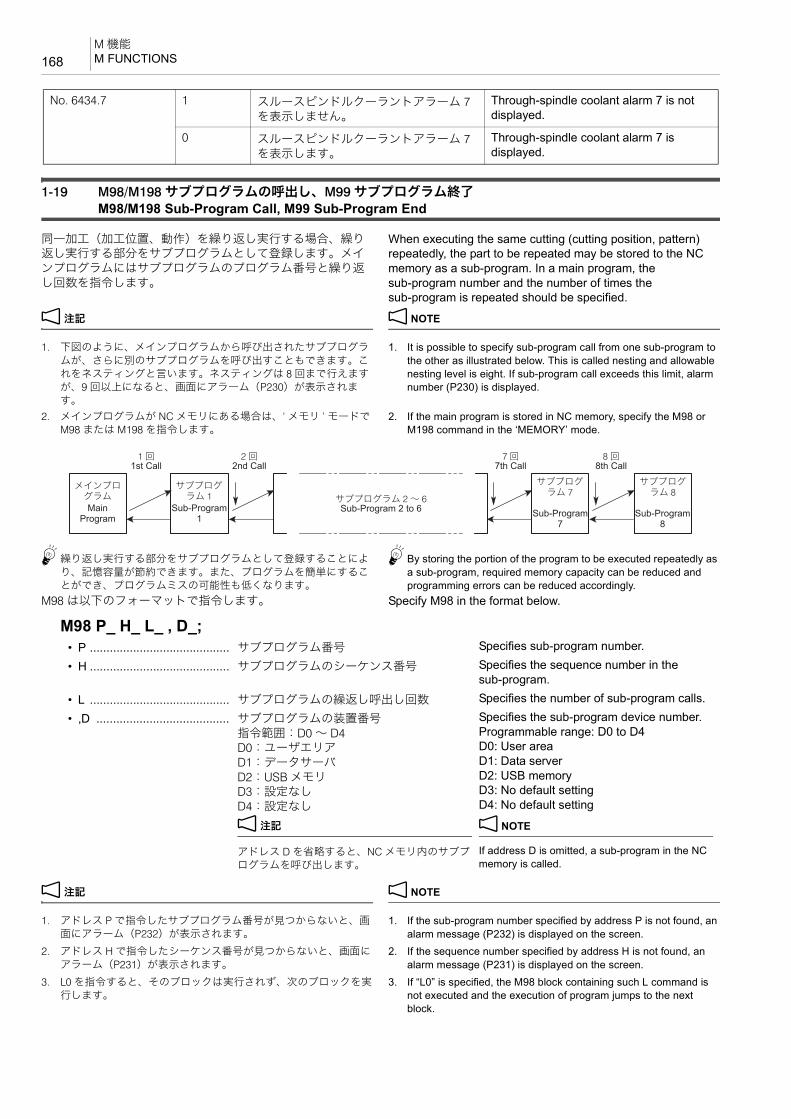
M 機能M FUNCTIONS168
1-19 M98/M198 サブプログラムの呼出し、M99 サブプログラム終了M98/M198 Sub-Program Call, M99 Sub-Program End
同一加工(加工位置、動作)を繰り返し実行する場合、繰り返し実行する部分をサブプログラムとして登録します。メインプログラムにはサブプログラムのプログラム番号と繰り返し回数を指令します。
When executing the same cutting (cutting position, pattern) repeatedly, the part to be repeated may be stored to the NC memory as a sub-program. In a main program, the sub-program number and the number of times the sub-program is repeated should be specified.
2 注記 2 NOTE
1. 下図のように、メインプログラムから呼び出されたサブプログラムが、さらに別のサブプログラムを呼び出すこともできます。これをネスティングと言います。ネスティングは 8 回まで行えますが、9 回以上になると、画面にアラーム(P230)が表示されます。
1. It is possible to specify sub-program call from one sub-program to the other as illustrated below. This is called nesting and allowable nesting level is eight. If sub-program call exceeds this limit, alarm number (P230) is displayed.
2. メインプログラムが NC メモリにある場合は、‘ メモリ ’ モードでM98 または M198 を指令します。
2. If the main program is stored in NC memory, specify the M98 or M198 command in the ‘MEMORY’ mode.
5繰り返し実行する部分をサブプログラムとして登録することにより、記憶容量が節約できます。また、プログラムを簡単にすることができ、プログラムミスの可能性も低くなります。
5By storing the portion of the program to be executed repeatedly as a sub-program, required memory capacity can be reduced and programming errors can be reduced accordingly.
M98 は以下のフォーマットで指令します。 Specify M98 in the format below.
2 注記 2 NOTE
1. アドレス P で指令したサブプログラム番号が見つからないと、画面にアラーム(P232)が表示されます。
1. If the sub-program number specified by address P is not found, an alarm message (P232) is displayed on the screen.
2. アドレス H で指令したシーケンス番号が見つからないと、画面にアラーム(P231)が表示されます。
2. If the sequence number specified by address H is not found, an alarm message (P231) is displayed on the screen.
3. L0 を指令すると、そのブロックは実行されず、次のブロックを実行します。
3. If “L0” is specified, the M98 block containing such L command is not executed and the execution of program jumps to the next block.
No. 6434.7 1 スルースピンドルクーラントアラーム 7を表示しません。
Through-spindle coolant alarm 7 is not displayed.
0 スルースピンドルクーラントアラーム 7を表示します。
Through-spindle coolant alarm 7 is displayed.
Main Program
Sub-Program 1
Sub-Program 2 to 6 Sub-Program 7
Sub-Program 8
1st Call 2nd Call 7th Call 8th Call
メインプログラム
サブプログラム 1 サブプログラム 2 ~ 6
サブプログラム 7
サブプログラム 8
1 回 2 回 7 回 8 回
M98 P_ H_ L_ , D_;• P .......................................... サブプログラム番号 Specifies sub-program number.
• H .......................................... サブプログラムのシーケンス番号 Specifies the sequence number in the sub-program.
• L .......................................... サブプログラムの繰返し呼出し回数 Specifies the number of sub-program calls.
• ,D ........................................ サブプログラムの装置番号指令範囲:D0 ~ D4D0:ユーザエリアD1:データサーバD2:USB メモリD3:設定なしD4:設定なし
2 注記
アドレス D を省略すると、NC メモリ内のサブプログラムを呼び出します。
Specifies the sub-program device number.Programmable range: D0 to D4D0: User areaD1: Data serverD2: USB memoryD3: No default settingD4: No default setting
2 NOTE
If address D is omitted, a sub-program in the NC memory is called.
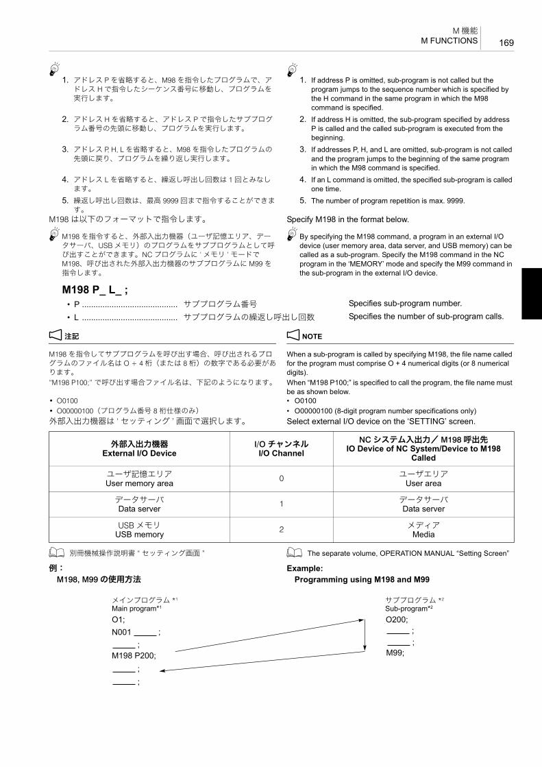
169M 機能
M FUNCTIONS
51. アドレス P を省略すると、M98 を指令したプログラムで、ア
ドレス H で指令したシーケンス番号に移動し、プログラムを実行します。
51. If address P is omitted, sub-program is not called but the
program jumps to the sequence number which is specified by the H command in the same program in which the M98 command is specified.
2. アドレス H を省略すると、アドレス P で指令したサブプログラム番号の先頭に移動し、プログラムを実行します。
2. If address H is omitted, the sub-program specified by address P is called and the called sub-program is executed from the beginning.
3. アドレス P, H, L を省略すると、M98 を指令したプログラムの先頭に戻り、プログラムを繰り返し実行します。
3. If addresses P, H, and L are omitted, sub-program is not called and the program jumps to the beginning of the same program in which the M98 command is specified.
4. アドレス L を省略すると、繰返し呼出し回数は 1 回とみなします。
4. If an L command is omitted, the specified sub-program is called one time.
5. 繰返し呼出し回数は、 高 9999 回まで指令することができます。
5. The number of program repetition is max. 9999.
M198 は以下のフォーマットで指令します。 Specify M198 in the format below.
5M198 を指令すると、外部入出力機器(ユーザ記憶エリア、データサーバ、USB メモリ)のプログラムをサブプログラムとして呼び出すことができます。NC プログラムに ‘ メモリ ’ モードでM198、呼び出された外部入出力機器のサブプログラムに M99 を指令します。
5By specifying the M198 command, a program in an external I/O device (user memory area, data server, and USB memory) can be called as a sub-program. Specify the M198 command in the NC program in the ‘MEMORY’ mode and specify the M99 command in the sub-program in the external I/O device.
2 注記 2 NOTE
M198 を指令してサブプログラムを呼び出す場合、呼び出されるプログラムのファイル名は O + 4 桁(または 8 桁)の数字である必要があります。
When a sub-program is called by specifying M198, the file name called for the program must comprise O + 4 numerical digits (or 8 numerical digits).
“M198 P100;” で呼び出す場合ファイル名は、下記のようになります。 When “M198 P100;” is specified to call the program, the file name must be as shown below.
• O0100 • O0100• O00000100(プログラム番号 8 桁仕様のみ) • O00000100 (8-digit program number specifications only)外部入出力機器は ‘ セッティング ’ 画面で選択します。 Select external I/O device on the ‘SETTING’ screen.
1 別冊機械操作説明書 “ セッティング画面 ” 1 The separate volume, OPERATION MANUAL “Setting Screen”
例: Example:M198, M99 の使用方法 Programming using M198 and M99
M198 P_ L_ ;• P .......................................... サブプログラム番号 Specifies sub-program number.
• L .......................................... サブプログラムの繰返し呼出し回数 Specifies the number of sub-program calls.
外部入出力機器External I/O Device
I/O チャンネルI/O Channel
NC システム入出力/ M198 呼出先IO Device of NC System/Device to M198
Called
ユーザ記憶エリアUser memory area 0 ユーザエリア
User area
データサーバData server 1 データサーバ
Data server
USB メモリUSB memory 2 メディア
Media
;002O;1ON001
;;
;;
M99;M198 P200;
;;
Main program*1 Sub-program*2メインプログラム *1 サブプログラム *2

M 機能M FUNCTIONS170
5
2 注記 2 NOTE
1. 1.*1 メインプログラムは、NC メモリに格納されています。 *1 The main program is stored in NC memory.*2 サブプログラムは、外部入出力機器に格納されています。 *2 The sub-program is stored in an external I/O device.
2. 制御盤内 RS232C は、M198 には対応していません。 2. The M198 command is not available with the RS232C interface in the electrical cabinet.
3. 外部入出力機器のプログラムに M198 を指令して、更に外部入出力機器のプログラムを呼び出すことはできません。
3. It is not possible to call a program in an external I/O device by specifying the M198 command in another program in the external I/O device.
4. M198 を指令して前面メディアからサブプログラムを呼び出すときは、外部メモリの認識が完了してから自動運転を実行して下さい。
4. When specifying the M198 command to call the sub-program from the front media, execute automatic operation after the external memory has been recognized completely.
M99 は以下のフォーマットで指令します。 Specify M99 in the format below.
2 注記 2 NOTE
1. アドレス P で指令したシーケンス番号が見つからないと、画面にアラーム(P231)が表示されます。
1. If the sequence number specified by address P is not found, an alarm message (P231) is displayed on the screen.
2. アドレス P を指令すると、戻り先のシーケンス番号をサーチします。このため、戻り先のシーケンス番号をサーチするのに時間がかかります。このことを考慮した上で、アドレス P を指令してください。
2. If address P is specified, the return sequence number is searched, which will take a time. Therefore, this must be taken into consideration when specifying address P.
1. アドレス P を省略すると、M98 でサブプログラムを呼び出したブロックの次のブロックに戻ります。
51. If a P command is omitted, the program flow returns to the
block that follows the one where jump to the sub-program has been made.
通常、M99 のブロックでアドレス P を指令することはありません。
Address P is not normally specified in an M99 block.
2. メインプログラムで M99 を指令すると、アドレス P で指令したシーケンス番号に戻ります。また、アドレス P を省略すると、メインプログラムの先頭に戻り、プログラムを繰り返し実行します。
2. If “M99 P_ ;” is specified in the main program: The program flow jumps to the sequence number specified by P in the main program. If a P command is omitted, the program flow jumps to the start of the main program. The main program is executed endlessly.
例: Example:M98, M99 の使用方法 Programming using M98 and M99
5M98 を M198 に置き替えても指令できます。 5The command can also be given with M198 instead of M98.
M99 P_ ;• P .......................................... 戻り先のシーケンス番号(省略可能) Specifies the sequence number in the main
program, where the program flow should return. (omissible)
;001O;1ON001 101N; ;
201N;001P 89M 200N ;N003 301N; M99;N004 ;N005 M98 P200 L2; O200;N006 102N; ;
N202 ;
N203 M99;
N011;;003O;003P 89M 210N
N013 103N; ;N014 203N; ;N015 99M 303N; P015;
1
2
3
Main program Sub-program
(Repeats twice)
メインプログラム サブプログラム
(2 回繰返し)

171M 機能
M FUNCTIONS
例: Example:M99 の使用方法 Programming using M99
5メインプログラム中で M99 を実行すると、メインプログラムの先頭に戻り、またプログラムを実行することから、暖機運転などで同じプログラムを繰り返し実行したいときに使用します。
5If the M99 command is executed in a main program, execution returns to the start block of that main program and the same main program is executed again. This programming is used for executing the same program repeatedly in such as a warm up program.
1-20 M119 主軸(第 2)定位置停止M119 Spindle (Second) Orientation
M19 指令による主軸定位置のオリエンテーション角度を基準にして、シフトさせたい角度をあらかじめシステム変数に設定しておき M119 を指令することで、任意の位置へオリエンテーションさせることができます。
Spindle orientation to any required position can be executed by setting the angle of shift relative to the orientation angle of the spindle fixed position with the M19 command in the system variables in advance, and specifying M119.
2 注記 2 NOTE
1. 定位置の初期値は、上下位置です。 1. The initial value of the fixed position is at the top and bottom.2. 定位置からのシフト角度は、システム変数 #1133 に正転方向にプ
ラス値で設定します。2. The angle of shift in relation to the fixed position is input in the
forward direction as a “plus” value for system variable #1133.
59000 = 90°、18000 = 180° となります。 59000 = 90°, 18000 = 180°
例: Example:#1133 = 9000; #1133 = 9000;M119; M119;上記プログラムを指令すると、M19 の定位置から正転方向に 90° シフトした位置へオリエンテーションします。
A program for orienting the spindle to a position shifted 90° in the forward direction from the fixed position as determined by M19 is shown above.
1-21 M166, M167 Cs 輪郭制御(オプション)M166, M167 Cs Contouring Control (Option)
主軸の回転に C 軸を割り当てて主軸を任意の角度で位置決めできるようにします。通常の主軸の状態に対して C 軸で割出し位置決めできる状態を Cs モードといいます。C 軸の位置決めが必要な加工は Cs モードで行います。
The Cs contouring control allocates the C-axis to rotation of the spindle to allow the spindle to be positioned at a desired angle. The state that allows the spindle to be indexed as the C-axis is called the Cs mode, distinguished from the normal spindle state. Machining that requires the C-axis to be indexed should be performed in the Cs mode.
< Cs モード> <Cs mode>
O1;N1;N2;:
/N7 M99; ................................................................... ブロックデリート無効時:ブロックデリートを有効にするまでの間、プログラムの先頭に戻り、何度も “N7 M99;” までのプログラムを繰り返し実行します。ブロックデリート有効時:“N7 M99;” の指令を無視して、“N8;” 以降のプログラムを実行します。
When the block delete function is invalid:The “N7 M99;” command is executed and the program flow returns to the start of the program. The program is repeated endlessly between N1 and N7 blocks until the block delete function becomes invalid.When the block delete function is valid:The “N7 M99;” command is ignored and the program is executed continuously to the following blocks.
N8;M30; .......................................................................... プログラム終了 Ends program execution
M166;........................... Cs モード Cs mode
G91 G28 C0; ............... C 軸原点復帰 C-axis zero return

M 機能M FUNCTIONS172
< C 軸の移動指令> <C-axis positioning>
< Cs モードキャンセル> <Cs mode cancel>
2 注記 2 NOTE
1. Cs モードに切り替えた時には、一度 C 軸の原点復帰を行ってください
1. After switching the mode to the Cs mode, it is necessary to execute zero return of the C-axis.
2. Cs モード中に工具交換はできません。工具交換は Cs モードをキャンセルしてから行ってください。
2. Tools cannot be changed in the Cs mode. Before changing the tools, cancel the Cs mode.
3. C 軸の角度は、下図のように設定されます。 3. C-axis angle is set as follows:+X 方向:0° +X direction: 0°+Y 方向:−90° +Y direction: −90°−X 方向:180° あるいは −180° −X direction: 180° or −180°−Y 方向:90° −Y direction: 90°
4. C 軸の回転方向は、下記のように定義されます。 4. C-axis rotation direction is defined as follows:+ 方向:主軸正転方向 Positive (+): Spindle normal rotation direction− 方向:主軸逆転方向 Negative (−): Spindle reverse rotation direction
1-22 M252 スルースピンドルエアブロー・オン、
M253 スルースピンドルエアブロー・オフ(オプション)M252 Through-Spindle Air Blow ON, M253 Through-Spindle Air Blow OFF (Option)
M252 は、工具内部に溜まっているクーラントを吐出するときや、ワークに付着したクーラントをエアーで吹き飛ばすときに使用します。また、切削ポイントに直接エアーを吐出できるので、穴あけ加工などで、切りくずを効率良く排出することもできます。
M252 is used to remove the through-spindle coolant that has accumulated inside the tool, and to blow off the coolant on the workpiece. Air can be supplied to the cutting point directly, so it is also effective for hole machining.
2 注記 2 NOTE
1. M88 でスルースピンドルクーラントを吐出している状態で、M252 を指令すると、スルースピンドルクーラントの吐出は停止して、スルースピンドルエアブローが吐出します。
1. If M252 is specified while the through-spindle coolant is supplied by M88, the through-spindle coolant is stopped and the through-spindle air blow is supplied.
2. M252 でスルースピンドルエアブローを吐出している状態で、M88 を指令すると、スルースピンドルエアブローの吐出は停止して、スルースピンドルクーラントが吐出します。
2. If M88 is specified while the through-spindle air blow is supplied by M252, the through-spindle air blow is stopped and the through-spindle coolant is supplied.
1-23 M2000 ~ M2020 マルチカウンタディスプレイ機能(オプション)M2000 to M2020 Multi Counter Display Function (Option)
プログラム中の M2000 ~ M2020 を読むごとに、マルチカウンタディスプレイ機能のカウンタが 1 ずつ増えます。あらかじめ、‘ マルチカウンタ ’ 画面で設定値を登録します。
Each time the M2000 to M2020 commands in a program are read, the count data of the multi counter display function increases “1”. Register the setting values on the ‘MULTI COUNTER’ screen.
1 設定方法は、別冊 “ 機械操作説明書 ” 1 For setting procedures, refer to the separate volume “OPERA-TION MANUAL”
C_.; ............................. 主軸の割出し角度指令 Spindle indexing angle
M167;........................... Cs モードキャンセル Cs mode cancel
+Y
−90°
90°
0°180°
+X

173M 機能
M FUNCTIONS
<指令方法> <Commands>M2000 ~ M2020 の指令は、PC パラメータ “No. 6435.1” の設定により、以下のように異なります。
M2000 to M2020 commands differ according to the setting of the PC parameter “No. 6435.1” as shown below.
2 注記 2 NOTE
1. カウンタ 1 ~ 20 は工具寿命管理やワーク個数管理を行うときに使用します。これに対して、トータルカウンタは単なる計数として使用します。
1. The counters 1 to 20 are used for tool life management function as well as to control the number of finished workpieces. Whereas, the total counter is used for simply counting the number.
2. サイクルスタートインタロック/ブロックデリート(BDT)の選択は、オペレーションパネルの “ ワークカウンタ ” で設定します。
2. Select cycle start interlock or block delete (BDT) of “work counter” on the OPERATION PANEL screen.
1 詳細は、別冊 “ 機械操作説明書 ” 1 For details, refer to the separate volume, “OPERATION MANUAL”.
3. カウンタが確実にカウントアップの動作を行うように、繰り返し実行するプログラムの先頭に M2000 ~ M2020 を指令してください。
3. Specify the M2000 to M2020 commands at the start of the program which is executed repeatedly so that the execution of the program is correctly counted by the counter.
例: Example:カウントアップの指令(PC パラメータ No. 6435.1 = 1 のとき)
Programming using count up command (when PC parameter No. 6435.1 = 1)
以下の例は、あらかじめブロックデリート有効状態に設定し、カウンタ 1 の設定値に “100” を設定した場合です。
The program is executed in the block delete function valid state, and “100” is set for the counter 1 setting value in the example below.
<No. 6435.1 = 0> 全カウンタ一斉カウントアップ All counter count up
M2000; ......................... トータルカウンタおよびカウンタ1 ~ 20 を カウントアップ
Total counter and counters 1 to 20 are counted up
<No. 6435.1 = 1> 個別カウンタカウントアップ Each counter count up
M2000; ......................... トータルカウンタをカウントアップ Total counter is counted up
M2001; .........................:
:
:
M2001 でカウンタ 1 をカウントアップ Counter 1 is counted up with M2001
M2020; ......................... M2020 でカウンタ 20 をカウントアップ Counter 20 is counted up with M2020
O0001; M2001; ......................................................................:::
O0001 のプログラムを実行するたびに、カウンタ 1 がカウントアップ加工プログラム
The counter 1 increases “1” each time program O0001 is executed. Machining program
/M99; ......................................................................... O0001 のプログラムを 100 回実行するまではブロックデリート無効状態で “M99;” を実行プログラムの先頭 “O0001;” に戻り、引き続きプログラムを実行します。1M99 の機能については “M98/
M198 サブプログラムの呼出し、M99 サブプログラム終了 ”(168ページ)を参照してください。
100 回目でブロックデリート有効状態になり “M99;” を読み飛ばして“M30;” を実行します。
Until the program O0001 is executed 100 times, the block delete function is invalid and the “M99;” block is executed.The cursor returns to “O0001;”, the start of the program and the program is executed continuously.1For the function of the M99 com-
mand, refer to “M98/M198 Sub-Program Call, M99 Sub-Pro-gram End” (page 168).
In the execution of the program at the 100th time, the block delete function is made valid and the “M30;” block is executed by skipping the “M99;” block.
O0001; M2001; :::/M99; M30;
M30;
1 - 99 100

M 機能M FUNCTIONS174
1-24 M2200 先読み停止M2200 Pre-Read Stop
NC のプログラム先読みを意図的に停止させたい場合、停止させたい場所で M2200 を指令してください。
When stopping pre-read by NC intentionally, specify M2200 where pre-read needs to be stopped.
2 注記 2 NOTE
M2200 は単独ブロックで指令してください。 Specify M2200 in a block without other commands.

3 章
3èÕ T, B, S, F 機能CHAPTER 3
CHAPTER 3 T, B, S, F FUNCTIONS

1 T 機能.....................................................................................................................................................177T FUNCTION
2 B 機能....................................................................................................................................................179B FUNCTION
3 S 機能....................................................................................................................................................182S FUNCTION
4 F 機能 ....................................................................................................................................................183F FUNCTION

177T 機能
T FUNCTION
1 T 機能T FUNCTION
T 機能は工具交換位置に工具を呼び出す機能です。アドレス Tと数字を指令すると、マガジンが旋回して、工具が工具交換位置に呼び出されます。
T function calls a specified tool to the tool change position. In response to the specification of address T, the magazine rotates to bring the specified tool to the tool change position.
アドレス T に続く数字の桁数により、呼び出される工具が以下のように異なります。
Depending on the number of digits following address T, tools to be called differ as follows.
• グループ桁数より小さい桁数の数字を指定:指定された工具グループ内で使用順位が一番高い工具が呼び出されます。
• Specifying the number smaller than the digit number of the group: the most frequently used tool in the group is called.
• グループ桁数より大きい桁数の数字を指定:指令された工具番号の工具が呼び出されます。
• Specifying the number larger than the digit number of the group: the tool of the specified number is called.
1 別冊 “MAPPS 工具管理システム取扱説明書 ” 1 Refer to the separate volume “MAPPS TOOL MANAGEMENT SYSTEM INSTRUCTION MANUAL”.
工具を呼び出すには、次の 2 つの方法があります。 A required tool is called in the following two methods.• テクニカルメモリランダム方式 • Technical memory random method• 番地固定方式 • Fixed address shorter route access method
2 注記 2 NOTE
通常、T 指令はすぐに完了し、次ブロックに進みますが、T サイクル実行中に T 指令が連続で指令されると、実行中の T サイクル完了まで、次の T 指令は受け付けられません。プログラムの待ち時間をなくすには、次の T 指令を T サイクル完了後のブロックで指令するなどしてください。
When a T command is executed, normally it is completed without any delay and the sequence moves to the next block. However, if another T command is specified in succession during execution of a tool change cycle, it is not acceptable until the current cycle is completed. To reduce a waiting time during program execution, specify the next T command in a block where the tool change cycle has been completed.
7注意 7 CAUTION
1. M06 と同一ブロックで、T コードを指令しないでください。
[事故による機械の破損]
1. Do not specify “T” codes in the same block as M06. [Machine damage due to accidents]
2. 段取り作業時などに工具を確認するとき、工具を連続して
交換しないようにしてください。ATC 工具交換を短時間に連続して行うと、ATC 用モータに過大な負荷がかかり、アラーム(EX0156)が発生することがあります。
2. When checking the tools stored in the magazine during setup, do not change tools continuously. If multiple ATC tool changes are executed consecutively in a short time, it may overload the ATC motor causing the alarm (EX0156) to be generated.
3. 工具を取り付ける場合は、工具制限を守り、工具交換時に
干渉しない配置で取り付けてください。[工具の干渉、機械の破損]
3. When mounting tools, observe the restrictions on tools thoroughly and make sure that the arrangement of tools will not cause interference at tool changes. [Tool interferences/Machine damage]
4. 大径工具の両隣ポットには工具を登録することができませ
ん。(テクニカルメモリランダム方式)
4. Tools cannot be registered to adjacent pots of large diameter tools. (Technical memory random method)
5. 同径の工具交換に比べて、異径間の工具交換では ATC 動作
が変わります。異径間の工具交換では、ATC 動作を 2 回行います。MDI操作で異径間の工具交換を行う場合、十分注意してください。(テクニカルメモリランダム方式)
5. ATC operation for changing the tools of different tool size groups differs from that for changing the tools of the same tool size group.For changing the tools belonging to different tool size groups, tool change cycle is executed twice. Pay sufficient care when executing tool change operation in the MDI mode in such cases. (Technical memory random method)
2 注記 2 NOTE
1. ATC 動作は、“ 工具選択(T 機能)” + “ 工具交換(M06)” となります。
1. The ATC operation consists of: “Tool Selection (T function)” + “Tool Change (M06)”.
つまり、T 機能は指令された工具を工具交換位置に呼び出すだけで、その後の M06 で工具を主軸内に装着します。
Note that the T function only calls the specified tool from the magazine to the tool change position. The tool is mounted in the spindle by the M06 command.
2. 使用する工具には、おもにマガジン側の制約により、長さ、直径、質量に制限があります。必ずその範囲内で使用してください。
2. The dimensions and mass of the tools used with the machine are restricted by mainly the capacity of magazine. Use the tools which are within the limits.
1 長さ、直径、質量の制限については、別冊据付説明書 “ 工具制限図 ”
1 For the dimensions and mass of the tools, refer to the separate volume, INSTALLATION MANUAL “Tool Restrictions”.

T 機能T FUNCTION178
3. NHX5500, NHX6300 のツール 100 本、120 本、180 本、240 本、330 本マガジン仕様の場合、 終ポットには T0 が登録されています。T0 以外の工具番号を登録することもできますが、その場合、“T0; M06;” や “M33;” を指令するとアラームが発生します。
3. For the 100-, 120-, 180-, 240-, and 330- tool magazine specifications of NHX5500 and NHX6300, T0 is registered for the last pot number (magazine position number). It is also possible to register a setting other than T0 for the last pot number (magazine position number). However, if “T0; M06;” or “M33;” is specified in this case, an alarm will occur.

179B 機能
B FUNCTION
2 B 機能B FUNCTION
B 機能とは、自動モードにおいて、テーブルの旋回角度をアドレス B で指令する機能です。アドレス B でテーブルの旋回角度を指令すると、B 軸がアンクランプされ、割出し動作を行ったあと、クランプされます。
The B function controls the table rotation in the automatic operation. When table rotation angle is specified with address B, the corresponding axis (B) is unclamped, indexed to the specified angular position and clamped.
2 注記 2 NOTE
任意割出し仕様の機械では、B 指令の前に B 軸アンクランプ指令(M11)、B 指令の後に B 軸クランプ指令(M10)が必要です。
With the full rotary B-axis specification, specify B-axis unclamp (M11) before B command, and specify B-axis clamp (M10) after B command.
7注意 7 CAUTIONテーブルを旋回させる場合、干渉に十分注意してください。不用意にテーブルを旋回させると、ワークやテーブルが工具(主軸)と干渉し、機械の破損につながります。
Pay sufficient care when rotating the table so that the workpiece and the fixture on the table will not cause interference. If the table is rotated carelessly, it will cause damage to the machine.
2 注記 2 NOTE
1. B 指令を行う場合、下記の条件を満たしてください。 1. The following conditions must be satisfied to execute a B-axis command.
• APC が原位置にあること • The APC is at the home position.• APC サイクル中でないこと • Not during the APC cycle• パレットがクランプされていること • The pallet is clamped.• 操作パネル側のドアが閉じていること • The operation-panel-side front door is closed.
2. B 指令は小数点入力を行ってください。小数点入力を行わないと0.001° 単位の指令になります。1° 割出し仕様の場合、1° の倍数以外を指令すると、アラーム(P20)が発生します。
2. The B-axis command must include a decimal point. A numeric value specified without a decimal point is interpreted in units of 0.001°. If a value other than a multiple of 1° is specified for the 1° indexing specification, the B-axis command becomes invalid and an alarm (P20) occurs.
3. 同一グループの G コードを同一ブロックに 2 つ以上指令した場合、後で指令した G コードが有効になります。
3. If more than one G code belonging to the same G code group is specified in the same block, the one specified last is valid.
4. B 軸は他の制御軸と同一ブロックに指令することができます。 4. B-axis can be designated with other controlled axes in the same block.
5. B 軸旋回中の一時停止、リセット、非常停止はすべて有効です。 5. While the B-axis is rotating, feed hold, reset, and emergency stop are all valid.
6. パレットがアンクランプの状態では B 軸は旋回しません。 6. The B-axis does not rotate while the pallet is unclamped.
2-1 アブソリュート/インクレメンタル指令(B 機能)Absolute/Incremental Commands (B Function)
アブソリュート指令の場合、テーブルを上から見て時計方向が +、反時計方向が − となります。
In the absolute mode, the direction the table rotates in the clockwise direction when it is viewed from the top is defined as the positive direction and its rotation in the counterclockwise direction is defined as the negative direction.
B_.; ............................. テーブルの旋回角度指令 Specifies table rotation angle.
O0001;N1;G90 G00 G54 B0; ..................................................... B 軸 0° 割出し Indexing the B-axis at 0° positionX0 Y0;G43 Z30.0 H1 S400 T2;M03;:::
B180.0; ..................................................................... B 軸 180° 割出し Indexing the B-axis at 180° position
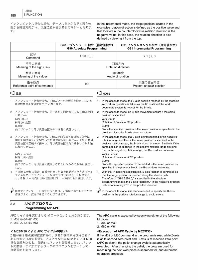
B 機能B FUNCTION180
インクレメンタル指令の場合、テーブルを上から見て現在位置から時計方向が +、現在位置から反時計方向が − となります。
In the incremental mode, the target position located in the clockwise rotation direction is defined as the positive value and that located in the counterclockwise rotation direction is the negative value. In this case, the rotation direction is also defined by viewing it from the top.
2 注記 2 NOTE
1. アブソリュート指令の場合、B 軸のワーク座標系を設定しないとB 軸機械原点復帰位置が 0° となります。
1. In the absolute mode, the B-axis position reached by the machine zero return operation is taken as the 0° position if the work coordinate system is not set for the B-axis.
2. アブソリュート指令の場合、同一点を 2 回指令しても B 軸は旋回しません。
2. In the absolute mode, no B-axis movement occurs if the same position is specified.
G90 B90.0; B 軸 90° 旋回
G90 B90.0;Rotation of B-axis to 90° position
B90.0;前のブロックと同じ旋回位置なので B 軸は旋回しない。
B90.0;Since the specified position is the same position as specified in the previous block, the B-axis does not rotate.
3. アブソリュート指令の場合、B 軸の旋回位置を負領域で指令し、同じ旋回位置を正で指令しても B 軸は旋回しません。また B 軸の旋回位置を正領域で指令し、同じ旋回位置を負で指令しても B 軸は旋回しません。
3. In the absolute mode, if a B-axis is first specified in the negative rotation range and then if the same position is specified in the positive rotation range, the B-axis does not move. Similarly, if the same position is specified in the positive rotation range first and then in the negative rotation range, the B-axis does not move.
G90 B−270.0;B 軸 −270° 旋回
G90 B−270.0;Rotation of B-axis to −270° position
B90.0;前のブロックと同じ位置に旋回することになるので B 軸は旋回しない。
B90.0;Since the specified position to be rotated is the same position as specified in the previous block, the B-axis does not rotate.
4. 1° 割出し仕様の場合、B 軸の割出し制御を自動近回り方式で行っているため、アブソリュート指令で “G90 B270.0; ” を指令すると、B 軸は + 方向に 270° 旋回せずに、− 方向に 90° 旋回します。
4. With the 1° indexing specification, B-axis rotation is controlled so that the target position is reached along the shorter path. Therefore, if “G90 B270.0;” is specified in the absolute programming mode, the B-axis rotates 90° in the negative direction instead of rotating 270° in the positive direction.
5B 軸でアブソリュート指令を行う場合、正領域で指令した方が操作性がよく、誤操作を防ぐことができます。
5In the absolute mode, it is recommended to specify the B-axis position in the positive rotation range to avoid errors.
2-2 APC 用プログラムProgramming for APC
APC サイクルを実行させる M コードは、2 とおりあります。1. M02 あるいは M302. M60 あるいは M61
The APC cycle is executed by specifying either of the following M codes:1. M02 or M302. M60 or M61
< M02/M30 による APC サイクルの実行> <Execution of APC Cycle by M02/M30>Z 軸が第 2 原点復帰位置にあり、B 軸が機械原点復帰位置にある状態で(APC 位置)、プログラム中の M02 あるいは M30指令を読み込むと、自動的にパレットを交換します。パレット交換後、次に加工するワークのプログラムをサーチして、自動運転を実行します。
If the M02 or M30 command in the program is read while Z-axis is at its second zero point and B-axis is at machine zero point (APC position), the pallet change cycle is automatically executed. After changing the pallet, the program used for machining the next workpiece is searched for, and automatic operation proceeds.
G90 アブソリュート指令(絶対値指令)G90 Absolute Programming
G91 インクレメンタル指令(増分値指令)G91 Incremental Programming
記号Command G90 (B_ ;) G91 (B_ ;)
符号の意味Meaning of the sign (+/−)
回転方向Rotation direction
数値の意味Meaning of the values
回転角度Angle of rotation
指令原点Reference point of commands B0 現在の旋回角度
Present angular position
181B 機能
B FUNCTION
<プログラム例> <Program Example>
< M60/M61 による APC サイクルの実行> <Execution of APC Cycle by M60/M61>これらの M コードを使用すると、加工中に一度パレットを払い出し、ワークを再セットした後に再度搬入して、加工を続行することができます。
If either of these commands is executed during machining, the pallet is forcibly unloaded from the machining center. After setting up the workpiece at the setup station, the pallet is loaded to the machining center and the operation proceeds automatically.
<プログラム例> <Program Example>
2 注記 2 NOTE
1. 自動(メモリ)運転中、プログラムの M60, M61 指令を読み込むと、セットアップボタンに内蔵されたランプ(セットアップランプ)の点灯を待ってパレットを交換します。
1. If the M60 or M61 command is read during automatic (memory) mode operation, the pallet change cycle is executed in response to the lighting of the indicator in the setup button.
2. MDI 運転では、セットアップボタンに内蔵されたランプ(セットアップランプ)の状態に関係なく、M60, M61 指令でパレットを交換します。
2. In the MDI mode operation, pallet change cycle is executed when the M60 or M61 command is executed independent of the status of the indicator in the setup button.
3. M60, M61 指令でのパレット交換では、パレット交換後のワークナンバーサーチは行いません。
3. In the pallet change cycle called by the M60 or M61 command, work number search is not executed after the completion of pallet change cycle.
4. 1 の倍数以外の B 指令を行うと、アラーム(P20)が発生します。 4. If B command value of other than an integer (multiple of 1°) is specified, an alarm (P20) occurs.
5. 使用中あるいは指令した座標系の B 軸のワークオフセットデータが 1 の倍数になっていないと、アラーム(P20)が発生します。
5. If B-axis work offset data of the coordinate system that is used or specified is not a multiple of “1”, an alarm (P20) occurs.
O1234;::G91G30 Z0; ............................................................... Z 軸第 2 原点復帰 Z-axis 2nd zero returnG28 B0;............................................................... B 軸原点復帰 B-axis machine zero returnM02(M30);........................................................... パレット交換、ワークナンバー
サーチPallet change, work number search
O6789; ................................................................ A パレット用加工プログラム Machining program for A pallet::
加工プログラム Machining program
M60(M61);........................................................... A パレット払い出しD ワーク再セット後、セットアップボタンを押す。
Unloading of A palletDAfter setting up at the setup station, press the setup button.
M61(M60);........................................................... A パレット搬入 Loading of A pallet::
加工プログラム Machining program
M02; .................................................................... B パレット搬入、ワークナンバーサーチ
Loading of B pallet, work number search

S 機能S FUNCTION182
3 S 機能S FUNCTION
S 機能は、主軸の回転をアドレス S で指令する機能です。 The S function is used to specify the spindle speed.
<主軸回転速度を求める式> <The formula to calculate spindle speed>
N:主軸回転速度(min−1) N: Spindle Speed (min−1)V:切削速度(m/min) V: Cutting Speed (m/min)D:工具の直径(mm) D: Tool Diameter (mm)π:円周率(3.14) π: Circumference Constant (3.14)
例: Example:S 機能の使用例 Programming using the S functionφ20 のエンドミルを使用して、切削速度 26 m/min で加工する場合の例です。まず上の式から主軸回転速度を求めます。
Here is an example for machining a workpiece at the cutting speed of 26 m/min with a 20 mm diameter end mill. First, calculate a spindle speed using the above formula.
S_ M03(M04) ;• S........................................... 主軸回転速度(min−1) Specifies the spindle speed (min−1).
• M03(M04)............................. M03 で主軸正転(M04 で主軸逆転) Specifies the spindle rotation in the normal (reverse) direction.
1000VN =
π • D
N = 3.14 × 201000 × 26 = 414(min−1)
O0001;N1;G90 G00 G54 X80.0 Y70.0;G43 Z30.0 H1 S414 T2;M03;.......................................................................... 414 min−1 の回転速度で主軸正転 Rotating the spindle in the normal
direction at 414 min−1
:
183F 機能
F FUNCTION
4 F 機能F FUNCTION
F 機能は、工具の送り速度をアドレス F で指令する機能です。G01, G02, G03 などの切削送り指令や穴あけ固定サイクルとともに指令します。
The F function is used to specify the feedrate of tools with address F. The address F is specified with the linear or circular cutting commands such as G01, G02, and G03, or the hole machining canned cycle.
1 • “G01 切削送りによる工具の直線移動 ”(67 ページ) 1 • “G01 Moving Cutting Tool along Straight Path at Cutting Feedrate” (page 67)
• “G02 円弧補間(時計方向)、G03 円弧補間(反時計方向)”(68 ページ)
• “G02 Circular Interpolation (Clockwise), G03 Circular Interpolation (Counterclockwise)” (page 68)
2 注記 2 NOTE
1. F 機能はモーダルな情報です。一度指令すると、次に新しい送り速度を指令するまで、同じ送り速度が有効です。
1. The F function is a modal function. Once a feedrate is specified, it remains valid until the next feedrate is specified.
2. プログラムで指令された送り速度は、操作パネルの送りオーバライドスイッチが 100% のときの送り速度です。
2. A cutting feedrate specified in a program is the value when the feedrate override dial on the operation panel is set at 100%.
5送り速度は操作パネルの送りオーバライドスイッチで調整できます。ただし、自動運転中で M49 を実行している場合、送り速度は固定されます。このため、送りオーバライドスイッチで送り速度を調整することはできません。
5Programmed cutting feedrate can be adjusted using the feedrate override switch on the operation panel. Note that the feedrate is fixed while the M49 command is executed in automatic mode. In this case, it is not allowed to adjust the feedrate by using the feedrate override dial.
<送り速度を求める式> <Formula to Calculate Feedrate>F = fZN F = fZNF:送り速度(mm/min) F : Feedrate (mm/min)f:1 刃あたりの送り量(mm/ 刃) f : Feed per tooth (mm/tooth)Z:工具の刃数 Z : Number of teeth (flutes)N:主軸回転速度(min−1) N : Spindle speed (min−1)例えば、2 枚刃の φ20 エンドミルを使用して、1 刃あたり0.08 mm の送り量、450 min−1 の主軸回転速度で加工する場合の送り速度を、上の式から求めます。
For example, when machining a workpiece at the feed 0.08 mm/tooth and at the spindle speed 450 min−1 with a 20 mm diameter end mill (2-flute), calculate the feedrate using the above formula.
F = 0.08 × 2 × 450 = 72 (mm/min) F = 0.08 × 2 × 450 = 72 (mm/min)<タップ加工の送り速度を求める式> <Formula to Calculate Feedrate>F = PN F = PNF:送り速度(mm/min) F : Feedrate (mm/min)P:ピッチ(mm) P : Pitch (mm)N:主軸回転速度(min−1) N : Spindle speed (min−1)< 大切削送り速度一覧表> <Maximum Cutting Feedrate Table>
F_;................................ 工具の送り速度(mm/min) Feedrate (mm/min)
機種 モードX, Y, Z 軸
mm/min
NHX4000NHX5000NHX5500
通常モード中 6000
高速高精度制御モード中
60000
Model ModeX-, Y-, Z-Axis
mm/min
NHX4000NHX5000NHX5500
During normal mode 6000
During high-speed, high-accuracy control mode
60000


4 章
4èÕ 工具補正CHAPTER 4
CHAPTER 4 TOOL OFFSET

1 工具補正................................................................................................................................................187TOOL OFFSET
187工具補正
TOOL OFFSET
1 工具補正TOOL OFFSET
プログラムで補正機能を指令すると、プログラムの内容を変更することなく、実際に使用する工具をプログラムで指令している位置に正しく行くように補います。
The offset specified in the program offsets the tool paths so that they are always generated as programmed without changing the program.
7注意 7 CAUTION
1. 工具補正量を自動運転中(シングルブロック停止中を含
む)に変更すると、次ブロックまたは複数ブロック以降の指令から有効になります。
[機械や工具の破損]
1. If the tool offset amount is changed during automatic operation (including during single block stop), it will be validated from the next block or blocks onwards.[Damage to the machine and tool]
2. MAPPS 工具管理システムでは、工具交換(M06)指令で
工具を主軸に呼び出すと、‘ 工具管理 ’ 画面に登録されている主軸工具の工具補正値が、‘ 工具オフセット ’ 画面の工具補正番号 1 に書き込まれます。MAPPS 工具管理システムの機能を十分理解した上でご使用ください。
[機械や工具の破損]
2. In the MAPPS tool management system, when calling the tool to the spindle by specifying tool change (M06), the spindle tool offset data registered in the ‘TOOL MANAGEMENT’ screen is written in the tool offset number 1 of the ‘TOOL OFFSET’ screen. Before using the MAPPS tool management system, make sure you understand the functions thoroughly. [Damage to the machine and tool]
1 MAPPS 工具管理システムの使用方法については、別冊“MAPPS 工具管理システム取扱説明書 ”
1 For details on using the MAPPS tool management system, refer to the separate volume “MAPPS TOOL MANAGEMENT SYS-TEM INSTRUCTION MANUAL”.
2 注記 2 NOTE
ここでは、基本的な工具の使用経路に関して、簡単な基礎知識が修得できるように、例題を通して注意事項とともに説明しています。基礎知識を十分に理解した上で加工を行ってください。
The explanation given here provides the fundamentals of programming through examples. Before starting actual machining, a thorough grasp of the fundamentals is required.
1 詳細については、制御装置メーカー作成の取扱説明書を参照。 1 For more details, please refer to the instruction manuals sup-plied by the NC unit manufacturer.
1-1 工具補正量の入力Inputting Tool Offset Amount
‘ 工具オフセット ’ 画面での設定、変更 Setting and Changing on ‘TOOL OFFSET’ Screen
工具補正量には、工具長補正量と工具径補正量があり、それぞれに工具形状補正量と工具摩耗補正量があります。
The tool offset includes the tool length offset and the tool radius offset: these are coupled respectively with the tool geometry offset amount and the tool wear offset amount.
5D0 を指令したときの工具径補正量および H0 を指令したときの工具長補正量は常に 0 です。また、電源投入時は、D0, H0 を指令しているのと同じ状態です。
5The tool radius offset amount with D0 specified and the tool length offset amount with H0 specified are always regarded as zero. When the power is turned on, the NC is in the same state as D0 and H0 have been specified.
G10 プログラム指令による工具補正量設定、変更 G10 Setting and Changing Tool Offset Amount with Program Commands
G90(G91) G10 L_ P_ R_ ;• G10 ...................................... 工具補正量の外部入力指令 Specifies external input of tool offset amount
• L........................................... 工具補正量の選択 Selection of tool offset amountL10: 工具長補正量の設定、変更 Sets and changes amount of tool geometry
offset for tool length (tool length offset, hereafter).
L11: 工具長摩耗補正量の設定、変更 Sets and changes amount of tool wear offset for tool length (tool length wear offset, hereafter).

工具補正TOOL OFFSET188
例: Example:G10 L12 の使用例 Programming using G10 L12
(a):工具補正番号 1 番の工具径補正量を 7.0 mm に設定 (a): Sets “7.0 mm” for the tool radius geometry offset amount of offset number 1.
(b):D1 の指令により、工具補正番号 1 番の工具径補正量7.0 mm で工具補正(G42)を実行
(b): By D1, the tool radius offset command G42 is executed using the tool radius offset amount set for the tool offset number 1 (7.0 mm).
1-2 工具長補正Tool Length Offset
工具長補正(G43, G44)を使用するとき、アドレス H で工具補正番号を指令します。 この機能を H 機能といい、各工具の長さの違いを補正して、アドレス Z で指令した位置に位置決めします。
When using the tool length offset (G43, G44), the tool offset number is specified with the address H. This function is called H function, and locates the tip of tool at the Z-axis position specified with the address Z after offsetting the differences in tool lengths.
2 注記 2 NOTE
G44 は工具長を補正するときに、補正量の符号を逆に考えます。弊社では G44 を使用せずに、G43 を使用しています。
If G44 is used for tool length offset, the sign for the tool length offset amount should be considered as opposite. DMG MORI SEIKI uses G43 without using G44.
プログラムの指令点は、工具の先端(刃先)です。Z 軸の機械原点復帰位置での刃先の位置は、工具によって異なります。各工具の Z0 までの距離を補正量として ‘ 工具オフセット ’ 画面に入力し、プログラムで G43 を指令すると、補正量を計算して、どの工具も Z 方向に同じ位置に位置決めします。
A command point of a program is a tool tip (nose). The tool nose positions differ from each other when the Z-axis is positioned at the machine zero point. If the distance to the Z0 level from the noses of the respective tools is input in the ‘TOOL OFFSET’ screen as the tool length offset data and G43 is specified, their offset amounts are calculated so that the tool noses can be positioned at the same level in the Z-axis direction.
工具の長さを補正する方法 Methods for Setting Tool Length Offset Data
工具の長さを補正する方法は、次の 2 つです。 There are two methods for setting tool offset data.• 主軸ゲージラインから工具の刃先までの距離を設定する(タイプ 1)
• To set the distance from the spindle gage line to the tool tip (type 1)
• Z 軸機械原点復帰位置での工具の刃先から加工原点までの距離を設定する(タイプ 2)
• To set the distance from the tool tip to the workpiece zero point with the Z-axis positioned at the machine zero point (type 2)
L12: 工具径補正量の設定、変更 Sets and changes amount of tool geometry offset for tool radius (tool radius offset, hereafter).
L13: 工具径摩耗補正量の設定、変更 Sets and changes amount of tool wear offset for tool radius (tool radius wear offset, hereafter).
• P........................................... 工具補正番号 Offset number
• R .......................................... 工具長補正量 Tool length offset amount
2 注記
(G90):指令された工具補正量が新たな工具補正量
(G91):指令された工具補正量が今までの工具補正量に加算
2 NOTE
(G90):The specified amount is taken as new offset amount.(G91):The specified amount is added to the present tool offset amount.
O0001;N1;G90 G10 L12 P1 R7.0;......................................... (a)G00 G54 X0 Y0;G43 Z30.0 H1 S1000 T2;:G42 G01 X50.0 Y80.0 D1 F200;.......................... (b)

189工具補正
TOOL OFFSET
<工具長補正の設定(タイプ 1)> <Setting the Tool Length Offset Data (Type 1)>タイプ 1 では、主軸ゲージラインから工具の刃先までの距離をプラス値で ‘ 工具オフセット ’ 画面に設定します。この方法で工具長補正の設定を行うと、ワークごとに各工具の工具長を再度測定する必要がありません。
With type 1, set the distance from the spindle gage line to the tool tip on the ‘TOOL OFFSET’ screen as a positive value. When this method is used for setting the tool length offset data, it is not necessary to measure the tool lengths in relation to each kind of workpiece.
A:主軸ゲージラインからテーブル上面までの距離 A: Distance from the spindle gage line to the table upper face.B:工具長さ(補正量) B: Tool length (offset data)C:移動量 C: Travel distanceD:テーブル旋回中心から基準面までの距離 D: Distance from the center of table rotation to the reference
face補正量 (B) = A − (C + D) Offset data (B) = A − (C + D)
1 A の距離は機械により異なります。詳細は、別冊据付説明書“ 機械移動量図 ”
1 Distance A is determined by the machine model. For details on this dimension, refer to “AXIS TRAVEL DIAGRAMS” in the INSTALLATION MANUAL
<工具長補正の設定(タイプ 2)> <Setting the Tool Length Offset Data (Type 2)>タイプ 2 では、Z 軸機械原点復帰位置での工具の刃先から加工原点までの距離をマイナス値で ‘ 工具オフセット ’ 画面に設定します。
With type 2, set the distance from the tool tip to the workpiece zero point, with the Z-axis returned to the machine zero point, on the ‘TOOL OFFSET’ screen as a negative value.
A
C
B
D
Type 1
Spindle Gage Line
Reference Face
Center of Table Rotation
Workpiece
Table
タイプ 1
主軸ゲージライン
基準面
テーブル旋回中心
ワーク
テーブル

工具補正TOOL OFFSET190
この方法で工具長補正の設定を行うと、ワークごとに各工具の工具長を再度測定しなければなりません。しかし、この方法は比較的簡単に工具長の設定を行えるため、1 個のワークを加工するときに、この方法を使用することもあります。
When this method is used for setting the tool length offset data, it is necessary to measure the tool lengths in relation to each kind of workpiece. However, since this method makes it simple to set the tool length offset data, it may be used when machining a single workpiece.
A:主軸ゲージラインからテーブル上面までの距離 A: Distance from the spindle gage line to the table upper faceB:工具長さ B: Tool lengthC:移動量(補正量) C: Travel distance (offset data)D : テーブル旋回中心から基準面までの距離 D: Distance from the center of table rotation to the reference
face補正量 = C Offset data = C
2 注記 2 NOTE
タイプ 2 の補正量設定値の範囲は、−999.999 ~ 999.999 です。 The setting range for the offset amount for type 2 is from −999.999 to 999.999.
タイプ 2 で補正量がこの数値を超える場合は、タイプ 1 で設定してください。
If the offset amount exceeds this value, set the amount with type 1.
5Z 軸ストロークが長い機械では、タイプ 2 を使うと −999.999 ~999.999 を超える場合があります。
5For machines with a long Z-axis stroke, the offset amount may be outside the range of −999.999 to 999.999.
G43 工具長補正、G49 工具長補正キャンセル G43 Tool Length Offset, G49 Tool Length Offset Cancel
例: Example:工具長補正の使用例(1) Programming using the tool length offset (1)下記工具を Z30.0 に位置決めするために、次のように指令します。
To execute positioning at Z30.0 level, specify:
1 番グループで呼び出された工具の工具長補正量:−300.000
Tool length offset amount of tool called from group number 1: −300.000
2 番グループで呼び出されたれた工具の工具長補正量:−270.000
Tool length offset amount of tool called from group number 2: −270.000
A
C
B
D
Spindle Gage Line
Type 2
Reference Face
Center of Table Rotation
Workpiece
Table
主軸ゲージライン
タイプ 2
基準面
テーブル旋回中心
ワーク
テーブル
G43 Z_ H_ ;G49;
• G43 ...................................... 工具長補正 Specifies the tool length offset
• G49 ...................................... 工具長補正キャンセル Tool length offset cancel
• Z........................................... Z 軸方向に位置決めする座標値 Coordinate value for positioning in the Z-axis direction
• H .......................................... 工具補正番号 Tool offset number to be used

191工具補正
TOOL OFFSET
< 1 番グループの工具> <Tool of group number 1>
−300.0(工具長補正量)+ 30.0(指令値)= −270.0 −300.0 (tool length offset amount) + 30.0 (specified position) = −270.0
1 番グループの工具は、機械原点復帰位置から Z− 方向に270.0 mm の位置に早送りで移動します。
The tool of group number 1 moves to 270.0 mm position in the −Z direction from the machine zero point of Z-axis.
< 2 番グループの工具> <Tool of group number 2>
−270.0(工具長補正量)+ 30.0(指令値)= −240.0 −270.0 (tool length offset amount) + 30.0 (specified position) = −240.0
2 番グループの工具は、機械原点復帰位置から Z− 方向に240.0 mm の位置に早送りで移動します。
The tool of group number 2 moves to 240.0 mm position in the −Z direction from the machine zero point of Z-axis.
2 注記 2 NOTE
1. 工具長補正は、G49 の他に H0 を指令してもキャンセルされます。 1. The tool length offset mode is canceled by H0 instead of specifying the G49 command.
2. 電源投入時あるいは M02, M30 実行後、工具長補正はキャンセルされます。
2. When the power is switched ON or when the M02 or M30 command has been executed, the tool length offset mode is canceled.
3. G28, G30 による自動原点(第 2、第 3、第 4 原点)復帰あるいは手動原点復帰を 実行すると、原点復帰完了時に、工具長補正はキャンセルされます。
3. If automatic (second, third, fourth) zero return using the G28 or G30 command or manual zero return is executed, the tool length offset mode is canceled on completion of zero return.
G90 G00 G43 Z30.0 H1;
−300
.0
30.0
Positioning at Z30.0
Tool of group number 1Machine Zero Point of Z-Axis
Z30.0 に位置決め
1 番グループの工具Z 軸機械原点復帰位置
G90 G00 G43 Z30.0 H1;
−270
.0
30.0
Tool of group number 2Machine Zero Point of Z-Axis
Positioning at Z30.0
2 番グループの工具Z 軸機械原点復帰位置
Z30.0 に位置決め

工具補正TOOL OFFSET192
4. H0 を指令したときの工具長補正量は、常に 0 です。また、電源投入時は、H0 を指令しているのと同じ状態です。
4. The tool length offset amount is always “0” when H0 is specified. When the power is turned on, the NC is in the same state as when H0 has been specified.
5. G43 モード中に指令した工具長補正番号は、工具長補正をキャンセルしても有効です。このため、以降のプログラムで G43 と同一ブロックに別の工具長補正番号を指令しないと、前の工具長補正番号が有効となります。
5. The tool length offset number specified in the G43 mode remains valid even after the tool length offset mode is canceled. Therefore, if no tool length offset number is specified in the next G43 block, the tool length offset number specified before is used to execute the tool length offset function.
6. G43, G44, G49 と同一ブロックに下記の G コードを指令しないでください。下記の G コードを同一ブロックに指令すると、G43, G44, G49 は実行されません。
6. Do not specify the following G codes with the G43 G44 or G49 command in the same block. If any of the G codes indicated below is specified with the G43, G44 or G49 command in the same block, the G43, G44 or G49 command is not executed.
• G04 ...................ドウェル • G04 ..........Dwell
• G10 ...................データ設定 • G10 ..........Data setting
• G11 ...................データ設定モードキャンセル • G11 ..........Data setting mode cancel
• G27 ...................原点復帰チェック • G27 ..........Zero return check
• G28 ...................自動原点復帰 • G28 ..........Automatic zero return
• G29 ...................原点からの復帰 • G29 ..........Return from zero point
• G30 ...................第 2、第 3、第 4 原点復帰 • G30 ..........Second, third, fourth zero return
• G52 ...................ローカル座標系設定 • G52 ..........Local coordinate system setting
• G53 ...................機械座標系選択 • G53 ..........Machine coordinate system selection7. G43, G44, G49 と同一ブロックに G02, G03 の円弧指令を指令する
と、画面にアラーム(P70)が表示されます。7. An alarm message (P70) is displayed on the screen if the circular
interpolation mode (G02 or G03) is specified with the G43, G44 or G49 command in the same block.
G90 G00 G54 X30.0 Y20.0;G43 Z30.0 H1 S800 T2;............................................ 工具長補正番号 1 番の補正量を使
用して、工具長補正を実行Executing the tool length offset function by using the offset amount set for tool length offset number 1
M03;:
G49; .......................................................................... 工具長補正キャンセル Canceling the tool length offset mode
:
G90 G00 G54 X30.0 Y20.0;G43 Z30.0 S1000 T3; ............................................... 工具長補正番号が指令されていな
いめ、再度、工具長補正番号 1 番の補正量を使用して、工具長補正を実行
Executing the tool length offset function by using the offset amount set for tool length offset number 1
:

193工具補正
TOOL OFFSET
例: Example:工具長補正の使用例(2) Programming using the tool length offset (2)
(a):工具補正番号 1 番の工具長補正量だけ Z 軸方向に補正して、ワーク上面 Z0 から + 側に 30 mm の位置に工具が早送りで位置決め
(a): Positions the tool at a point 30 mm away from Z0 (workpiece upper face) in the +Z direction at a rapid traverse rate; offset is made in the Z-axis direction by the tool length amount set for the tool offset number 1.
(b):工具補正番号 1 番の工具長補正量だけ Z 軸方向に補正して、ワーク上面 Z0 から + 側に 30 mm の位置に工具が早送りで位置決め
(b): Positions the tool at a point 30 mm away from Z0 (workpiece upper face) in the +Z direction at a rapid traverse rate; offset is made in the Z-axis direction by the tool length amount set for the tool offset number 1.
1-3 G41, G42 工具径補正、G40 工具径補正キャンセルG41, G42 Tool Radius Offset, G40 Tool Radius Offset Cancel
工具径補正(G41, G42)を使用するとき、アドレス D で工具補正番号を指令します。 この機能を D 機能といい、プログラムされた経路に対して、右または左に工具の半径分シフトします。 一般に、エンドミルでポケット加工をするときや、輪郭加工をするときに、工具径補正を使用して図面通りの形状に仕上げます。
When using the tool radius offset (G41, G42), the tool offset number is specified with the address D. This function is called D function. Generally, when cutting a pocket or carrying out contouring operation using an end mill, the tool radius offset function is used to finish the workpiece in the shape specified in the drawing.
たとえば、図 1 の形状を仕上げます。 For example, finish the profile in Fig. 1.プログラムを作成するときに a D b D c D d と指令します。
Specify in the program: a D b D c D d
プログラムの指令点は工具の中心なので、工具径補正を使用せずにプログラムを作成すると、図 2 のように工具は動きます。
Since the center of a cutting tool moves along the defined paths, the cutting tool moves along the paths shown in Fig. 2 if the program is created without using the tool radius offset function.
O0001;N1; (主軸に 1 番グループの工具が装
着)(A tool of group number 1 set in the spindle)
G90 G00 G54 X0 Y0;............................................aG43 Z30.0 H1 S800 T2;....................................... (a)M03;:M01;M06;
N2; (主軸に 2 番グループの工具が装着)(A tool of group number 2 set in the spindle)
G90 G00 G54 X40.0 Y0;.......................................bG43 Z30.0 H1 S1000 T3;..................................... (b)M03;:M30;
1 2
40+Y
+X
+Z−Z
Z0Workpiece Zero Point for G54G54 の加工原点

工具補正TOOL OFFSET194
ワークは工具半径分( )削過ぎが生じます。 Overcut of workpiece occurs by the radius of the cutting tool ( )
そこで、工具の半径を工具径補正量として、‘ 工具オフセット ’画面に入力します。
Input the tool radius as the tool radius offset data on the ‘TOOL OFFSET’ screen.
1 別冊機械操作説明書 “ 工具補正量の設定 ” 1 The separate volume OPERATION MANUAL, “TOOL OFFSET DATA SETTING”.
工具径補正を使用すると、図 3 のように工具の半径分外側にシフトして切削するため、図 1 の形状に仕上ります。
If the tool radius offset function is used, the tool paths are shifted outside from the programmed paths by the input offset amount as shown in Fig. 3 to finish the required shape.
このように、工具径補正を使用して、補正量だけシフトさせると、複雑な計算をして座標を求める必要がありません。
In this manner, by using the tool radius offset function, it is not necessary to obtain the coordinate values using complicated calculation to generate the tool paths to finish the workpiece to the required shape.
7注意 7 CAUTIONプログラム作成者は、刃先の経路を十分解析して G41, G42を使い分けてください。[工具のワークへのくい込み、干渉、工具の破損、加工不良]
The programmer must thoroughly understand the G41 and G42 functions as well as the tool paths to be generated. [Tool fed into or hit against the workpiece, tool damage, machine damage]
1. XY 平面の工具径補正Tool radius offset in the XY planeG17 G01(G00) G41(G42) X_ Y_ D_ F_ ;
2. ZX 平面の工具径補正Tool radius offset in the ZX planeG18 G01(G00) G41(G42) X_ Z_ D_ F_ ;
3. YZ 平面の工具径補正Tool radius offset in the YZ planeG19 G01(G00) G41(G42) Y_ Z_ D_ F_ ;
4. 工具径補正のキャンセルTool radius offset cancelG40 G01(G00) X_ Y_ Z_ I_ J_ K_ F_ ;
1
2
3 4
1
2
34
1
2
3 4
Workpiece
Fig. 1 Fig. 2 Fig. 3Tool
Workpiece Workpieceワーク
図 1 図 2 図 3工具
ワーク ワーク
• G17, G18, G19..................... 工具径補正を行う平面設定 Selects the plane where tool radius offset is executed.
• G01(G00) ............................. 工具径補正を指令する補間モードの選択G00:早送りG01:切削送り
Selects the interpolation mode in which the tool radius offset function is executed.G00: Rapid traverseG01: Cutting feed
• G41 ...................................... 工具径補正左側プログラムの進行方向に対して、左側に工具を補正します。
Calls the tool radius offset mode (offset to the left).The tool paths are generated by shifting the programmed paths to the left in reference to the tool advancing direction by the specified offset amount.

195工具補正
TOOL OFFSET
2 注記 2 NOTE
1. G40, G41, G42 と同一ブロックに下記の G コードを指令しないでください。下記の G コードを同一ブロックに指令すると、G40, G41, G42 は実行されません。
1. Do not specify the following G codes with the G40 G41 or G42 command in the same block. If any of the G codes indicated below is specified with the G40, G41 or G42 command in the same block, the G40, G41 or G42 command is not executed.
• G04 ..................ドウェル • G04.......... Dwell
• G10 ..................データ設定 • G10 .......... Data setting
• G11 ..................データ設定モードキャンセル • G11 .......... Data setting mode cancel
• G27 ..................原点復帰チェック • G27 .......... Zero return check
• G28 ..................自動原点復帰 • G28 .......... Automatic zero return
• G29 ..................原点からの復帰 • G29 .......... Return from zero point
• G30 ..................第 2 /第 3、第 4 原点復帰 • G30 .......... Second/third, fourth zero return
• G52 ..................ローカル座標系設定 • G52.......... Local coordinate system setting
• G53 ..................機械座標系選択 • G53.......... Machine coordinate system selection2. G40, G41, G42 と同一ブロックに G31, G31.1, G31.2, G31.3 を指令
すると、画面にアラーム(P608)が表示されます。2. An alarm message (P608) is displayed on the screen if the G31,
G31.1, G31.2 or G31.3 command is specified with the G40, G41 or G42 command in the same block.
3. 工具径補正モード中に G31, G31.1, G31.2, G31.3 を指令すると、画面にアラーム(P608)が表示されます。
3. An alarm message (P608) is displayed on the screen if the G31, G31.1, G31.2 or G31.3 command is specified in the tool radius offset mode.
4. G40, G41, G42 と同一ブロックに G73 ~ G89 を指令すると、画面にアラーム(P155)が表示されます。
4. An alarm message (P155) is displayed on the screen if any of the G73 to G89 commands is specified with the G40, G41 or G42 command in the same block.
5. 工具径補正モード中に G73 ~ G89 を指令すると、画面にアラーム(P155)が表示されます。
5. An alarm message (P155) is displayed on the screen if any of the G73 to G89 commands is specified in the tool radius offset mode.
• G42 ...................................... 工具径補正右側プログラムの進行方向に対して、右側に工具を補正します。
Calls the tool radius offset mode (offset to the right).The tool paths are generated by shifting the programmed paths to the right in reference to the tool advancing direction by the specified offset amount.
• G40 ...................................... 工具径補正キャンセル Cancels the tool radius offset mode.
• X, Y, Z .................................. 指令するブロックの終点座標 Specifies the coordinate values of the end point.
• I, J, K.................................... 次のブロックの素材形状の方向を仮想設定する場合に、その方向比をベクトルで指令
When making a virtual setting that represents the direction of the workpiece shape in the following block, the direction ratio for this setting is specified as a vector.
• D .......................................... 使用する工具補正番号 Offset number to be used
• F........................................... 送り速度 Specifies the feedrate in ordinary control
<G41>
Workpiece
Tool Advancing Direction
ワーク
進行方向
<G42>Workpiece
Tool Advancing Direction
進行方向
ワーク

工具補正TOOL OFFSET196
工具径補正で使用する用語 Terms for Tool Radius Offset
• スタートアップ • Start-upG41 あるいは G42 が指令される 初のブロック。スタートアップの動作が行われると、その停止位置で次のブロックの動きに対して、直角に工具の中心が工具半径だけ補正されます。
The first block in which G41 or G42 is specified. In the start-up operation, the center of the cutting tool is offset at the stopped position in right angle to the movement in the next block by its radius.
(下図は G41 の場合) (Illustration below shows the case of G41)• 補正モード • Offset mode
スタートアップが終了し、工具径補正を実行中のプログラムを補正モードといいます。
The mode in which the tool radius offset is valid, after the start-up, is called the offset mode.
• キャンセルモード • Cancel mode工具径補正を G40 でキャンセルした状態のプログラムをキャンセルモードといいます。
The state in which the tool radius offset function is canceled by executing G40 is called the cancel mode.
キャンセルモードの開始点は、直前のブロックの終点で、そのブロックに対して、直角な位置に工具の中心が移動します。
The cancel mode starts from the end point of the block that precedes the G40 block. The center of the cutting tool is positioned right angles to the tool path programmed in the preceding block.
例: Example:
G41(G42) G00 X_ Y_ ; ............................................ スタートアップ
2 注記
上図では左側補正のため、G41 となります。
Start-up
2 NOTE
G41 should be used in the illustration above because offset is made to the left.
G01 X_ Y_ F_ ;X_ Y_ ; ..................................................................... 補正モード Offset modeX_ Y_ ;X_ Y_ ;G40 G00 X_ Y_ ; ...................................................... キャンセルモード Cancel mode
Offset Mode
Offset Mode
Workpiece
Cancel Mode
Start-Up
Offset ModeOffset Mode
補正モード
補正モード
ワーク
キャンセルモード
スタートアップ
補正モード補正モード

197工具補正
TOOL OFFSET
<スタートアップ> <Start-Up>
例: Example:
2 注記 2 NOTE
1. スタートアップのブロックには、補正量(工具の半径)以上の軸移動を指令してください。
1. The start-up block must include an axis movement command; the called distance must be larger than the offset amount (radius of a tool).
2. スタートアップのブロックの移動は、直線指令(G00, G01)にしてください。G02, G03 の円弧指令を行うと、画面にアラーム
(P151)が表示され、機械が停止します。
2. The start-up must be specified in the G00 or G01 (linear motion) mode. Do not specify the start-up in the G02 or G03 mode. If the start-up is specified in such a mode, an alarm is generated, the corresponding alarm message (P151) is displayed on the screen and the machine stops operating.
3. D0 は指令しないでください。D0 を指令すると、工具径補正がキャンセルされます。
3. Do not specify “D0” in a program. Otherwise, the tool radius offset function is canceled.
<補正モード> <Offset Mode>1. 進行方向に対して、素材位置が変わらない場合 1. Behavior when the tool offset direction is not changed
工具は、プログラムの進行方向に対して、ワーク形状に接して移動します。
The tool moves along the workpiece shape with its periphery in contact with the shape.
:G00 X100.0 Y100.0; .............................................aG42 X80.0 Y50.0 D_ ; ...........................................bG01 X−45.0 F_ ; ..................................................c:
45 80
50
+X
+Y
1
23
Start-Up (This distance must be larger than the cutter radius.)
Start Point of the Next Block (X80.0, Y50.0)
This distance must be larger than the cutter radius.
スタートアップ (この移動量は、必ず工具半径より大きくしてください。)
次のブロックの始点(X80.0, Y50.0)
この距離は、必ず工具半径より大きくしてください。
:G42 G00 X100.0 Y40.0 D_ ; .................................aG01 X70.0 F200;...................................................bY65.0;....................................................................cG03 X45.0 Y90.0 R25.0;.......................................dG01 X20.0;............................................................eX_ Y_ ; ..................................................................f
b ~ f:補正モード b to f: Offset Mode
(X100.0, Y40.0)1 (X70.0, Y40.0)
6
2
3
R25.0
(X70.0, Y65.0)
(X20.0, Y90.0)5 4
(X45.0, Y90.0)

工具補正TOOL OFFSET198
2 注記 2 NOTE
1. 補正モード中に下記の指令を行わないでください。 1. In the offset mode, the following commands must not be specified.
• M コード、G04 のドウェルなど軸移動を行わないブロックを 4 ブロック以上連続して指令
• Four or more blocks not containing an axis movement command but containing an M code or G04 (dwell) command consecutively
• 先読み禁止 M コード(M00, M01, M02, M30)を指令 軸移動を行わないブロックを 4 ブロック以上連続して指令したり、先読み禁止 M コード(M00,M01,M02,M30)を指令すると、ワークを加工したとき、切込み過ぎあるいは切込み不足が生じ、加工不良につながります。また、工具に負荷がかかり、工具の破損にもつながります。
• M codes (M00, M01, M02, M30) with which buffering is not allowed If four or more blocks without axis movement are specified consecutively or if an M code with which buffering is not allowed (M00, M01, M02, M30) is specified in a program, it will cause excessive or insufficient cutting, resulting in machining failure. It will also apply an overload to a tool to be damaged.
2. 工具の半径より小さい円弧の内側あるいは工具の半径より小さい溝を加工しようとすると、切込み過ぎを防ぐため、画面にアラーム(P153)が表示されます。
2. If an attempt is made to cut the inside of an arc whose radius is smaller than the radius of the tool or to cut a groove whose width is smaller than the radius of the tool, an alarm message (P153) is displayed to avoid excessive cutting.
3. 補正モード中に、G17, G18, G19 で加工平面を切り換えないでください。
3. Do not change the machining plane using the G17, G18, or G19 command in the offset mode.
補正モード中に加工平面を切り換えると、画面にアラーム(P112)が表示されます。
If the plane is changed in the offset mode, an alarm message (P112) is displayed on the screen.
5スタートアップと補正モード中は、移動指令を 2 ブロック、移動指令が 2 ブロックなければ 大 4 ブロック先読みを行います。
5At the start-up or in the offset mode, two blocks that contain an axis movement command are buffered. If two blocks containing an axis movement command are not specified consecutively, a maximum of four blocks are buffered.
2. 進行方向に対して、素材位置が変わる場合 2. Behavior when the tool offset direction is changedプログラムの進行方向に対して、素材の位置が変化するとき、すなわち G コードが変化するとき(G41, G42)は、素材の位置が変化したブロックのつなぎ目で両素材に接します。
If the offset direction changes in a program as illustrated below, i.e., if the G code calling the tool offset changes between G41 and G42, the periphery will come into contact with the workpiece shape that is defined in the two consecutive blocks where the G code changes from G41 to G42, or vice versa.
7注意 7 CAUTION進行方向に対して素材位置が変わる場合、スタートアップのブロックと次のブロックでは、G41, G42 の切替えは行えません。
When the tool radius offset direction is changed, do not change the G code mode between G41 and G42 in the start-up and the next blocks.
<キャンセルモード> <Cancel Mode>補正モード中に、G40 を指令すると、工具径補正がキャンセルされます。
The G40 command, specified in the offset mode, cancels the tool radius offset function.
キャンセルモードの開始点は、直前のブロックの終点で、そのブロックに対して、直角な位置に工具の中心が移動します。
The cancel mode starts from the end point of the block that precedes the G40 block. The center of the cutting tool lies at right angles to the tool path programmed in the preceding block.
:G41 X70.0 Y60.0;Y40.0;....................................................................aG42 X_ Z_ ;...........................................................b
(X70.0, Y40.0)
12

199工具補正
TOOL OFFSET
例: Example:
2 注記 2 NOTE
1. 工具径補正は、G40 でキャンセルされるほかに、操作パネルの@(リセット)キーを押してもキャンセルされます。また、D0を指令してもキャンセルされます。
1. The tool radius offset function is canceled by pressing the @ (RESET) key on the operation panel in addition to the execution of the G40 command. And also, it is canceled by specifying D0.
2. キャンセルモードのブロックの移動は、直線指令(G00, G01)にしてください。G02, G03 の円弧指令を行うと、画面にアラーム
(P151)が表示され、機械が停止します。
2. The cancel block must be specified in the G00 or G01 (linear interpolation) mode. If the cancel block is specified in the G02 or G03 mode (circular interpolation), an alarm message (P151) is displayed on the screen and the machine stops operating.
3. 工具径補正終了時、“G40;” や現在位置指令などの実移動が発生しない工具径補正 キャンセル指令では、工具はキャンセルモードの開始点位置に停止したままでキャンセル動作は行われません。このような場合は、次の実移動(工具径補正と同一平面上の移動)が発生する指令においてキャンセル動作が行われます。
3. If the tool radius offset cancel command is specified with “G40;” or with positioning to the present position, where no axis movement occurs, the tool stays at the start point of the cancel mode and the cancel motion is not executed. In such a case, the cancel motion is executed when the next movement (movement on the same plane as used for the tool radius offset) is specified.
もし、“G40;” などの実移動が発生しないキャンセル指令後に移動指令がなくプログラムが終了した場合、工具径補正はまだかかったままの状態です。このような場合、@(リセット)キーで工具径補正を解除する必要があります。ただし、@(リセット)キーではキャンセル動作は行われません。
If the program ends without axis movement command after the tool radius offset cancel command, such as “G40;” and no actual movement takes place, the tool radius offset mode remains valid. In such a case, it is necessary to press the @ (RESET) key to cancel the tool radius offset mode. However, pressing the @ (RESET) key does not start the cancel motion.
工具径補正のキャンセルを行うための移動指令は、現在値と異なる位置を G00 あるいは G01 で指令して、必ず実移動が発生するようにしてください。
For the axis movement command to be specified for canceling the tool radius offset mode, it is necessary to specify the position other than the present position in the G00 or G01 mode so that the axes actually will move during the execution of the cancel command.
1-4 補正に関する一般的な注意事項General Cautions on Offset Function
切削の 終点に壁がある場合 If Wall Lies at Endpoint of Cutting
G40 のブロックに移動指令があるため、下図のような素材があると壁に接するところまで切削する必要があります。
If the workpiece wall lies in a direction independent of the direction of tool motion specified by the commands in the G40 block:
方法としては、壁の方向(素材形状)をベクトル(I, J)で指令します。I, J はインクレメンタルで指令します。
Specify the workpiece wall direction (workpiece shape) with vectors (I, J). Use incremental values for I and J commands.
ここでは、XY 平面(G17)で工具径補正を使用した場合について説明しています。ZX 平面(G18)、YZ 平面(G19)では、壁の方向(素材形状)は、ベクトル(I, K)、(J, K)で指令してください。
The following gives an explanation assuming that the tool radius offset function is used in the XY plane (G17). When executing the tool radius offset function in the ZX plane (G18) or YZ plane (G19), specify the direction of wall (workpiece shape) using vectors (I, K) or (J, K) respectively.
:(G41) X100.0 Y50.0;X60.0 Y50.0; ........................................................ aG40 G00 X40.0 Y20.0; ......................................... b:
(キャンセルモード)(Cancel mode)
(X40.0, Y20.0)
(X100.0, Y50.0)(X60.0, Y50.0) 1
2
Cancel Modeキャンセルモード
I, J
5
4
G40(100, 30)
(G42)G40 G00 X100.0 Y30.0 I−4.0 J5.0 ;+J
+I
Wall
Actual Tool Motion Commands
The workpiece is cut until the tool nose comes into contact with the wall.
壁
実際の移動指令
壁に接するところまで切削します。

工具補正TOOL OFFSET200
2 注記 2 NOTE
1. 壁の方向指示のための I, J は補正モードのあと、初めて指令するG40 と同じブロックに指令してください。
1. The I and J commands, used to define the vectors that represent the workpiece wall direction, should be specified in the G40 block that appears first after entry into the offset mode.
2. I_ J_ を指令しなければ、キャンセルモードの開始点は、直前のブロックの終点で、そのブロックに対して、直角な位置に工具の中心が移動するため、壁にくい込んでしまいます。
2. If “I_ J_” is not specified in the G40 block, the offset mode cancel point is set at the end point of the preceding block; at this end point, the center of the tool lies at right angles to the tool path generated by the commands in the preceding block. This causes an overcut on the wall.
G40 G00 X_ Y_ ; G40 G00 X_ Y_ ;
例: Example:壁の方向(素材形状)の計算方法 Calculating the wall direction (blank workpiece shape)
1) J の値は上図より 1) Value “J” is calculated as shown in the diagram above.J = 15 J = 15符号は Y 軸の + 方向ですから “J15.0” となります。 Because it is measured in the positive direction of Y, the
designation should be “J15.0”.次に I の値は Next, value “I” is calculated as:I = AC = 15 × tan30° = 8.660 I = AC = 15 × tan30° = 8.660となり、符号は X 軸の − 方向ですから “I−8.66” となります。
Because it is measured in the negative direction on the X-axis, the designation should be “I−8.66”.
2) I, J の値は壁の方向を示せばよいので、三角形の辺の比でも指令できます。
2) Since I and J commands are used to define the direction of the wall, the ratio between the sides of a triangle may be used instead of calculating actual lengths.
図のような直角三角形の各辺の長さの比は The ratio of three sides of the triangle given is known as:A : B : C = 2 : 1 : (= 1.732) A : B : C = 2 : 1 : (= 1.732)したがって “I−1.0, J1.732” となります。 Therefore, the designation should be “I−1.0 J1.732”.
• 有効• Valid
• 無効• Invalid
G42 X_ Y_ ;X_ Y_ ;
:
:
:
:
:
:
G40 G00 X_ Y_ I_ J_ ;
Offset mode補正モード
G42 X_ Y_ ;
G40 X_ Y_ ;
:
:
:
:
:
:
G40 G00 X_ Y_ I_ J_ ;
Ignored
Offset mode
Cancel mode
意味なし
補正モード
キャンセルモード
G40
(G42)
Overcut occurs.くい込みが生じます。
30°
60°C
J = 15
I 40
B
A
50 35
+X
+Z
(G40)
(G42)30°
60°
J = C
I = B
A

201工具補正
TOOL OFFSET
I, J は 1, 2 のどちらの値でも指令できます。 I and J commands may be specified in either method as described above.
工具径補正量の変更 Changing the Tool Radius Offset Amount
工具径補正量の変更は、一般的にキャンセルモードで工具が交換されたときに行います。しかし、補正モード中に工具径補正量を変更する場合、ブロックの終点における位置決めは、そのブロックで指定された工具径補正量を使用して計算されます。
The tool radius offset amount is usually changed when the cutting tool is changed in the cancel mode. If the tool radius offset amount is changed while in the tool radius offset mode, positioning at the end point of a block is made using the tool radius offset amount specified in that block.
例: Example:工具径補正量変更の使用例 Programming using the tool radius offset amount
change金型加工などにおいて、テーパ部の微調整を工具径補正量の変更で行います。
When machining a die, fine adjustment on taper can be made by changing the tool radius offset amount.
(a):工具補正番号 1 番の工具径補正量で工具径補正を実行 (a): Execute the tool radius offset using the tool radius offset amount set at the offset number 1.
(b):工具補正番号 2 番の工具径補正量で工具径補正を実行 (b): Executes the tool radius offset using the tool radius offset amount set at the offset number 2.
工具径補正量を変更することにより、テーパ部の微調整が行えます。
By changing the tool radius offset amount, adjustment is possible on the tapered portion.
工具径補正量の正負と工具中心経路 Positive (+) and Negative (−) Designation for Tool Radius Offset Amount and Tool Paths
一般に工具径補正量は、プラスになっているものとしてプログラムを作成します。
Generally, a program is created assuming that the tool radius offset amount is set in a positive value.
G01 X-40.0;G40 G00 X−10.0 Y100.0 I−8.66 J15.0;
Interchangeable with I−1.0 J1.732I−1.0 J1.732 でもよい
N6
N7
N8
Offset is Made According to the Tool Radius Offset Amount Specified in Block N6.
Offset is Made According to the Tool Radius Offset Amount Specified in Block N7.
ブロック N6 で指定されている工具径補正量から計算されます。
ブロック N7 で指定されている工具径補正量から計算されます。
G42 G01 X50.0 Y20.0 D1 F200;...........................aY40.0; ....................................................a D b (a)X0 Y60.0 D2; .........................................b D c (b)
(X50.0, Y40.0)
(X50.0, Y20.0)
+Y
+X
(X0, Y60.0)
1
2
3

工具補正TOOL OFFSET202
工具径補正量をマイナスにした場合、プログラム中の G41 とG42 をすべて入れ替えた動きをするため、ワークの外側をまわっていた工具は内側をまわり、内側をまわっていた工具は外側をまわります。
If an offset amount is set in a negative value, tool paths are generated as if G41 and G42 are entirely exchanged with each other. The paths having been generated outside the programmed profile will be generated inside the profile and those having been generated inside the programmed profile will be generated outside the profile.
プログラムで図 1 のような工具経路を指定した場合、工具径補正量をマイナスにすると、図 2 のように動きます。
If a negative value is set for the offset amount while the tool paths as shown in Fig. 1 are specified in a program, the cutting tool moves along the paths shown in Fig. 2.
逆に、プログラムで図 2 のような工具経路を指定した場合、工具径補正量をマイナスにすると、図 1 のように動きます。
Conversely, if a negative value is set for the offset amount when the tool paths shown in Fig. 2 are specified in a program, the cutting tool moves along the paths shown in Fig. 1.
工具径補正による切込み過ぎ Overcut in Tool Radius Offset Mode
1. 工具半径より小さい円弧の内側を加工する場合 1. Cutting the inside of arc whose radius is smaller than the cutter radius
指令された円弧の半径が、工具の半径より小さい場合、内側に補正すると、切込み過ぎが生じます。
If the specified arc radius is smaller than the cutter radius, offsetting inside the arc causes overcut.
そのため、その直前のブロックの終点まで移動した後、画面にアラーム(P153)が表示され、機械が停止します。
An alarm message (P153) is displayed on the screen upon completion of the commands specified in the block just before the block containing such arc command, and the machine stops.
2. 工具半径より小さい溝を加工する場合 2. Cutting a groove whose width is narrower than the cutter radius
工具中心経路が工具径補正することにより、プログラムされた経路と逆方向になる場合、切込み過ぎが生じます。
If the tool path is generated in the direction opposite to the programmed path due to offsetting, it causes overcut.
Fig. 1 Fig. 2図 1 図 2
Path of the Tool Center
Programmed Tool Path
Overcuts occur if the axes move as programmed.
Machine stops due to the alarm.
Alarm-Stop in a Single Block Stop Operation
工具中心経路
プログラムされた経路
そのまま進めば切込み過ぎが生じる
アラームが表示され、機械が停止
シングルブロック停止の場合のアラーム停止点
203工具補正
TOOL OFFSET
そのため、その直前のブロックの終点まで移動した後、画面にアラーム(P153)が表示され、機械が停止します。
An alarm message (P153) is displayed on the screen upon completion of the commands specified in the block just before the block containing such arc command, and the machine stops.
3. 工具半径より小さい段差があるプログラムで、その段差が円弧で指令されている場合
3. Cutting an arc-shaped step whose height is smaller than the cutter radius
通常どおり補正された工具中心経路では、プログラムされた経路が段差のところで逆方向になることがあります。そのような場合は、 初のベクトルは無視され、2 番目のベクトルに直線的に移動します。
The tool path to be generated in ordinary offset processing might be reversed at the stepped portion. In such a case, the first vector is ignored and the tool path is generated for a second vector that will move along a straight line.
4. X 軸、Y 軸の移動が、4 ブロック以上指令されていない、あるいは先読み禁止 M コードを指令している場合
4. Four blocks not containing X- and Y-axis movement command are specified continuously or an M code with which buffering is not allowed is specified
G17 で XY 平面を選択しているとき、工具径補正は X 軸、Y 軸に対してのみ補正します。
When the XY plane is selected, for example, the tool radius offset function is valid only for the X- and Y-axes.
2 注記 2 NOTE
1. ZX 平面では X 軸と Z 軸、YZ 平面では Y 軸と Z 軸に対してのみ補正します。
1. The tool radius offset function is valid only for the X- and Z-axes on the ZX plane, and for the Y- and Z-axes on the YZ plane.
2. 先読み禁止 M コードとは、M00, M01, M02, M30 のことを言います。
2. The M codes with which buffering is not allowed are M00, M01, M02, and M30 codes.
補正モード中に、X 軸あるいは Y 軸の移動が 4 ブロック以上ない、あるいは先読み禁止 M コードを指令しているとき、 後に位置決めしたブロックの終点で、そのブロックに対して、直角な位置に工具の中心が移動します。このため、次のように削過ぎあるいは切込み過ぎを生じることがあります。
In the offset mode, if four or more blocks not containing an axis movement command are specified continuously, or if the M code with which buffering is not allowed is specified, the center of the cutting tool moves to the position which lies on the line at the right angle to the end point of the last positioning block. Due to this, overcut or excessive infeed takes place.
Alarm-Stop in a Single Block Stop Operation
Path of the Tool Center
Programmed Tool Path
Overcut occurs if the axes move as programmed.
Machine stops due to the alarm.
シングルブロック停止の場合のアラーム停止点
工具中心経路
プログラムされた経路
そのまま進めば切込み過ぎが生じる
アラームが表示され、機械が停止
Uncut PortionArc
Tool Motion along a Straight Line
Path of the Tool Center
Programmed Tool Path
直線的に移動
削残し
円弧
工具中心経路
プログラムされた経路

工具補正TOOL OFFSET204
< X 軸、Y 軸の移動が 4 ブロック以上指令されていない> <Four blocks not containing X- and Y-axis movement command are specified continuously>
上図のように、ワークを削り過ぎます。これは直前のブロックの終点 b で、このブロックに対して、直角な位置に工具の中心が移動するためです。
Overcuts occur as illustrated above. This is because the center of the tool is positioned, when the preceding block b is executed, at the right angle to the tool path called by the commands in this block.
<先読み禁止 M コードを指令している> <M code with which buffering is not allowed is specified>
上図のように、切込み過ぎが生じます。これは直前のブロックの終点 c で、このブロックに対して、直角な位置に工具の中心が移動するためです。
Excessive infeed occurs as illustrated above. This is because the center of the tool is positioned, when the preceding block c is executed, at the right angle to the tool path called by the commands in this block.
1-5 プログラム例Example Programs
工具径補正(G40, G41, G42)を使用したプログラム例を以下に示します。 プログラムを作成するとき、必要に応じて参照してください。
An example of program where the tool radius offset function (G40, G41, G42) is used is shown below. Use this program for your reference when creating a program.
:
(G42 モード)(G42 mode)X30.0 Y35.0; ........................... a
Y55.0;...................................... b
M_ ;Z−_ ;S_ ;G04 P_ ;
4 ブロック以上 X 軸、Y 軸の移動指令がないNo X- or Y-axis movement commands in four or more blocks
X10.0;...................................... c
(X10.0, Y55.0) (X30.0, Y55.0)
(X30.0, Y35.0)
3 2
1
For overcutting
削過ぎ
:
(G42 モード)(G42 mode)X30.0 Y35.0; ........................... a
Y55.0;...................................... b
X10.0;...................................... c
M30; ........................................ 先読み禁止 M コード指令Buffering prohibited M code
:
(X10.0, Y55.0) (X30.0, Y55.0)
(X30.0 Y35.0)
3 2
1
Excessive infeed
切込み過ぎ

205工具補正
TOOL OFFSET
例: Example:G40, G41, G42 の使用例(1) Programming using G40, G41, and G42 (1)
(a):スタートアップ (a): Start-up
(b):c ~ f 補正モード (b): c to f Offset modeプログラムの指令に沿って加工 Machines the workpiece along the programmed path.
(c):キャンセルモード (c): Cancel mode
O0001;N1;G90 G00 G54 X−100.0 Y−100.0;..........................aG43 Z30.0 H1 S300 T2;M03;Z−30.0;(G17) G41 G01 X0 Y−40.0 D1 F300;...............b (a)Y250.0; ............................................................c (b)X200.0; .................................................................dG02 Y0 R125.0; ....................................................eG01 X−40.0;..........................................................fG40 G00 X−100.0 Y−100.0;.............................g (c)
(X0, Y250.0)
(X200.0, Y0)
(X200.0, Y250.0)
(X−100.0, Y−100.0)
R125
(X0, Y0)
(X0, Y−40.0)
(X−40.0, Y0) 6
1 7
5
34
2
,
φ20
• G41 ...................................... プログラムの進行方向に対して、左側に工具を補正
Offsets the tool to the left in reference to the tool advancing direction.
• D1 ........................................ 工具半径が設定されている工具補正番号 Tool offset number where the tool radius is set.
40
1
2
Start-Upスタートアップ
43
56

工具補正TOOL OFFSET206
直前のブロック f の終点で、そのブロックに対して、直角な位置に工具の中心が移動した後、X−100.0, Y−100.0 に工具が早送りで移動
Positions the tool center at a right angle to the tool path in the preceding block at the end point f. After that, positions the tool at (X−100.0, Y−100.0).
例: Example:G40, G41, G42 の使用例(2) Programming using G40, G41, and G42 (2)一般に、真円の内側を切削するときは、他の円弧(c D d)で切削開始位置点 d に近づき、真円を加工した後、再び円弧(d D e)で遠ざかります。これは、カッタがワークに食い付くのを防ぐためです。下図の真円の内径を φ40のエンドミルで切削します。
The I.D. of the circle shown below is machined using a 40 mm diameter end mill in this program. When cutting the I.D. of the circle generally, the tool approaches along an arc (c D d) to the machining start point d, and then the toll escapes from the machined circle along an arc (d D e) after the completion of the circle machining in order to avoid an overcut.
(a):スタートアップ (a): Start-up
(b):真円切削を行うために、円弧で近づく (b): The tool approaches along an arc to cut a circle.
40
7
Cancel Modeキャンセルモード
O0001;N1;G90 G00 G54 X100.0 Y100.0;..............................aG43 Z30.0 H1 S1000 T2;M03;G01 Z−_ F100;X114.142 Y114.142;..............................................bG42 Y154.142 D1; ...........................................c (a)G02 X142.426 Y142.426 R40.0;............c D d (b)I−42.426 J−42.426 ................................................(c)X154.142 Y114.142 R40.0;....................d D e (d)G40 G01 X114.142; .........................................f (e)
R60
45°
X100.0, Y100.0
r = 40
1 5
2
34
6
• G42 ...................................... プログラムの進行方向に対して、右側に工具を補正
Offsets the tool to the right in reference to the tool advancing direction.
• D1 ........................................ 工具半径が設定されている工具補正番号 Tool offset number where the tool radius is set.
1
2
3

207工具補正
TOOL OFFSET
(c):真円切削を実行(全円) (c): Cuts the circle (full circle).
(d):真円切削から円弧で遠ざかる (d): The tool escapes from a circle along the arc.(e):キャンセルモード (e): Cancel mode
< r = 40 にした理由> <Reason for Setting of r = 40>近づく円弧(c D d )と遠ざかる円弧 (d D e)は、工具径補正を使用する場合、次の条件を満たす必要があります。
Arcs for approach (c D d) and escape (d D e) must satisfy the following conditions.
工具半径 < r(円弧半径)< R(加工半径) tool radius < r (approach/escape circle radius) < R (radius of circle to be machined)
20 < r < 60 より 20 < r < 60r = 40 にします。 From the requirement above, r is determined to be “40” (r =
40).< b, c, d, e, fの座標の求め方> <Calculating the Coordinate Values of b, c, d, e and
f>
3
4
4
56
b, f X = 100.0 + 14.142 = 114.142 b, f X = 100.0 + 14.142 = 114.142Y = 100.0 + 14.142 = 114.142 Y = 100.0 + 14.142 = 114.142
c X = 114.142(b の X 軸座標値) c X = 114.142 (X coordinate value of b)Y = 114.142 + r = 114.142 + 40 = 154.142 Y = 114.142 + r = 114.142 + 40 = 154.142
d X = 100.0 + 42.426 = 142.426 d X = 100.0 + 42.426 = 142.426Y = 100.0 + 42.426 = 142.426 Y = 100.0 + 42.426 = 142.426
e X = 114.142 + r = 114.142 + 40 = 154.142 e X = 114.142 + r = 114.142 + 40 = 154.142
Y = 114.142(b の Y 軸座標値) Y = 114.142 (Y coordinate value of b)
60
60 - 40 = 20 sin 45°× 20= 14.142
sin 45°× 60= 42.426
(X 100.0, Y 100.0) cos 45°× 20= 14.142
(X 100.0, Y 100.0) cos 45°× 60= 42.426
45°1
2
4
145°
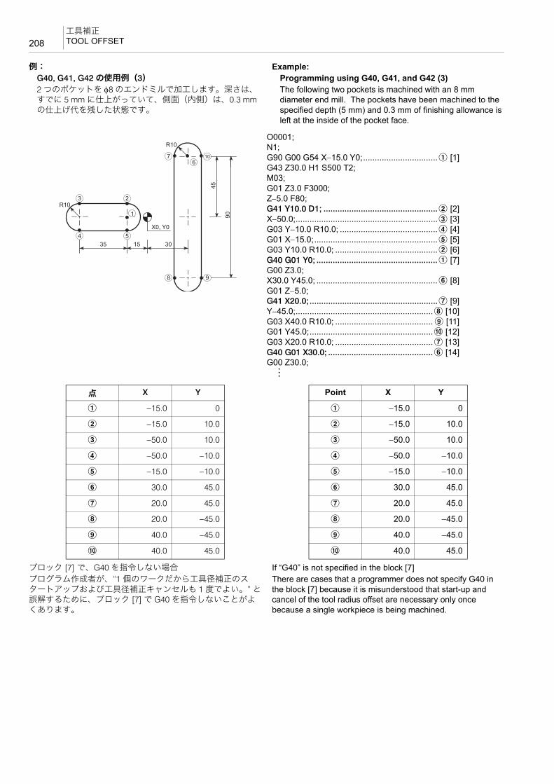
工具補正TOOL OFFSET208
例: Example:G40, G41, G42 の使用例(3) Programming using G40, G41, and G42 (3)2 つのポケットを φ8 のエンドミルで加工します。深さは、すでに 5 mm に仕上がっていて、側面(内側)は、0.3 mmの仕上げ代を残した状態です。
The following two pockets is machined with an 8 mm diameter end mill. The pockets have been machined to the specified depth (5 mm) and 0.3 mm of finishing allowance is left at the inside of the pocket face.
ブロック [7] で、G40 を指令しない場合 If “G40” is not specified in the block [7]プログラム作成者が、“1 個のワークだから工具径補正のスタートアップおよび工具径補正キャンセルも 1 度でよい。” と誤解するために、ブロック [7] で G40 を指令しないことがよくあります。
There are cases that a programmer does not specify G40 in the block [7] because it is misunderstood that start-up and cancel of the tool radius offset are necessary only once because a single workpiece is being machined.
O0001;N1;G90 G00 G54 X−15.0 Y0;................................a [1]G43 Z30.0 H1 S500 T2;M03;G01 Z3.0 F3000;Z−5.0 F80;G41 Y10.0 D1; .................................................b [2]X−50.0;.............................................................c [3]G03 Y−10.0 R10.0; ..........................................d [4]G01 X−15.0;.....................................................e [5]G03 Y10.0 R10.0; ............................................b [6]G40 G01 Y0; ....................................................a [7]G00 Z3.0;X30.0 Y45.0; ....................................................f [8]G01 Z−5.0;G41 X20.0;.......................................................g [9]Y−45.0;...........................................................h [10]G03 X40.0 R10.0; .......................................... i [11]G01 Y45.0;.....................................................j [12]G03 X20.0 R10.0; ..........................................g [13]G40 G01 X30.0; .............................................f [14]G00 Z30.0;:
R10
X0, Y0
R10
45
90
35 15 30
3 2
4 5
76
10
8 9
1
点 X Y
a −15.0 0
b −15.0 10.0
c −50.0 10.0
d −50.0 −10.0
e −15.0 −10.0
f 30.0 45.0
g 20.0 45.0
h 20.0 −45.0
i 40.0 −45.0
j 40.0 45.0
Point X Y
a −15.0 0
b −15.0 10.0
c −50.0 10.0
d −50.0 −10.0
e −15.0 −10.0
f 30.0 45.0
g 20.0 45.0
h 20.0 −45.0
i 40.0 −45.0
j 40.0 45.0

209工具補正
TOOL OFFSET
ブロック [7] で G40 を指令しないと、下図のように、b で削残しが生じます。
If G40 is not specified in the block [7], undercut occurs at b as shown in the illustration below.
実際に、ブロック [7] で G40 を指令せずに、プログラムを実行すると、下図のブロック [5] の位置で画面にアラーム
(P153)が表示され、機械が停止します。
If the program is executed without specifying G40 in block [7], operation stops after the execution of block [5] and the corresponding alarm message (P153) is displayed.
これは、上のプログラムにおいて、ブロック [6] を実行しようとしたときに、2 ブロック先読み機能により、ブロック [6]
(e D b)、ブロック [7](b D a)の両方に対して、左側に工具を補正する(7)の位置に移動しようとします。
When block [6] is going to be executed, offset is made to position (7) in the illustration because offset is made to the left side for both “point e D b” (block [6]) and “point b D a” (block [7]) due to two-block buffering function.
しかし、削過ぎが生じるので、(5)の位置で画面にアラーム(P153)が表示され、機械が停止します。
However, since this motion causes overcut, an alarm occurs at position (5) and the corresponding alarm message (P153) is displayed on the screen and machine stops.
1
2
Undercut Portion削残し
:G01 X-15.0; .....................................................e [5]G03 Y10.0 R10.0; ............................................b [6]G01 Y0;............................................................a [7]G00 Z3.0;X30.0 Y45.0; ....................................................f [8]:
1
62
(6)
(7)
(5)
5


5 章
5èÕ 固定サイクルCHAPTER 5
CHAPTER 5 CANNED CYCLE

1 穴あけ固定サイクル..........................................................................................................................213HOLE MACHINING CANNED CYCLE

213穴あけ固定サイクル
HOLE MACHINING CANNED CYCLE
1 穴あけ固定サイクルHOLE MACHINING CANNED CYCLE
穴あけ加工を行う場合、複数のブロックで加工動作を指令します。しかし、穴あけ固定サイクルを使用すると、G コードを含む 1 ブロックで指令することができ、プログラムを簡単にすることができます。
Hole machining programs are so complicated, specified in several blocks. A hole machining canned cycle, however, allows the hole machining to be programmed in one block with the appropriate G codes below:
<穴あけ固定サイクル指令一覧> <Commands for the Hole Machining Canned Cycle>
G90(G91) G98(G99) G73 – G89 X_ Y_ Z_ R_ Q_ P_ F_ L_ ;G80;
G90 アブソリュート指令 Absolute command
G91 インクレメンタル指令 Incremental command
G98 イニシャル点レベル復帰
2 注記
1. イニシャル点に戻り、次の穴あけ位置に移動します。
2. 電源投入時は、G98 のイニシャル点レベル復帰が選択されます。
3. 穴あけ固定サイクル指令中のみ有効で、他の動作に対しては無効です。
Return to initial point level
2 NOTE
1. The Z-axis returns to the initial point, and X- and Y-axes move to the next hole position.
2. When the power is turned on, G98 is selected.3. G98 is valid only for the hole machining canned cycle, but
invalid for other operations.
G99 R 点レベル復帰
2 注記
1. R 点に戻り、次の穴あけ位置に移動します。
2. 穴あけ固定サイクル指令中のみ有効で、他の動作に対しては無効です。
Return to point R level
2 NOTE
1. The Z-axis returns to the point R, and X- and Y-axes move to the next hole position.
2. G99 is valid only for the hole machining canned cycle, but invalid for other operations.
G73 – G89 穴あけ固定サイクル Hole machining canned cycle
X, Y XY 平面での穴加工の位置 Hole machining positions in XY plane
Z Z 点(穴底)の位置(G90):Z0(加工原点)からの距離と方向(G91):R 点からの距離と方向
Point Z (hole bottom)(G90):Distance and the direction from Z0 (workpiece zero point).(G91):Distance and the direction from the point R
R Z 軸切削送りの開始位置(R 点の位置)(G90):Z0(加工原点)からの距離と方向(G91):Z 軸のイニシャル点からの距離と方向
2 注記
穴あけ動作を行うブロックで指令してください。穴あけ動作を行わないブロックで指令しても、R 指令のデータは保存されません。
Point R where Z-axis feedrate changes from a rapid traverse rate to a cutting feedrate(G90):Distance and the direction from Z0 (workpiece zero point).(G91):Distance and the direction from the initial point.
2 NOTE
Specify R in the block in which the hole machining is specified. Otherwise, the data of R is not stored.
Q 1 回あたりの切込み量
2 注記
1. 穴あけ動作を行うブロックで指令してください。穴あけ動作を行わないブロックで指令しても、Q 指令のデータ
は保存されません。
2. 正の値で指令してください。
Depth of cut per cut
2 NOTE
1. Specify Q in the block in which the hole machining is specified. Otherwise, the data of Q is not stored.
2. Specify Q as a positive value.
P 穴底でのドウェル時間
2 注記
少数点指令はできません。P1000 は 1 秒のドウェルになります。
Period of dwell at the hole bottom.
2 NOTE
Decimal point must not be input for the period of dwell. P1000 corresponds to dwell for one second.

穴あけ固定サイクルHOLE MACHINING CANNED CYCLE214
F 送り速度(mm/min) Feedrate (mm/min)
S 主軸回転速度(min−1) Spindle speed (min−1)
L <繰返し回数>同じ穴が等間隔にあるとき、繰り返し回数を指令するL を使用すると、その回数だけ穴あけ固定サイクルを繰り返すので、プログラムが短縮できます。
2 注記
1. L0 を指令したブロックでは穴あけ動作は行いません。穴
あけ固定サイクルのデータだけを記憶します。
2. L 指令を省略すると、“L1” と同じになり、1 回穴あけ加工を行います。L0:穴位置へ移動後穴あけ加工は行いません。L1 ~ L9999:指令した回数だけ穴あけ固定サイクルを実行します。
3. L2 ~ L9999 を指令する場合は、インクレメンタル指令で、 初の穴位置を指令してください。アブソリュート指令で 初の穴位置を指令すると、 初の穴位置(同一穴位置)で、指令した繰返し回数分、穴あけ加工を行います。
例::G91 G99 G81 X15.0 Y10.0 Z−25.0 R−27.0 F100 L3;
<The Number of Repetitions>When machining the holes of the same dimensions arranged in equal intervals, it is possible to repeat the same hole machining canned cycle by specifying the number of repetitions following address L. The use of an address L can simplify programming.
2 NOTE
1. At the position specified in the block containing L0, hole machining cycle is not executed, but only hole machining canned cycle data is stored.
2. If L is omitted, it is designated as “L1”, and hole machining cycle is executed one time.L0: Hole machining cycle is not executed after positioning at the specified hole position.L1 - L9999: Hole machining cycle is repeated by the number of times specified by address L.
3. If “Ln” (n = 2 to 9999) is specified, specify the position of the first hole using an incremental command.If an absolute command is used to specify the position of the first hole, hole machining cycle is repeated the specified number of times at the first hole position.
Example::G91 G99 G81 X15.0 Y10.0 Z−25.0 R−27.0 F100 L3;
, I 位置決め軸(X, Y 軸)に対してのインポジション幅(mm)
2 注記
1. 高速ドリル加工または高速タップ加工を行う場合のみ指令してください。
2. インポジション幅の指令範囲は 1 ~ 999.999 mm です。
In-position width for the operation of positioning axes (X, Y) (mm).
2 NOTE
1. Specify only when high-speed drilling cycle or high-speed tapping cycle is executed.
2. The in-position width can be specified in the range of 1 – 999.999 mm.
, J Z 軸に対してのインポジション幅(mm)
2 注記
1. 高速ドリル加工または高速タップ加工を行う場合のみ指令してください。
2. インポジション幅の指令範囲は 1 ~ 999.999 mm です。
In-position width for the operation of Z-axis (mm).
2 NOTE
1. Specify only when high-speed drilling cycle or high-speed tapping cycle is executed.
2. The in-position width can be specified in the range of 1 – 999.999 mm.
10 25 40 55
45
35
25
15
+X
+Y
A
B
C
現在位置
穴加工位置
10 25 40 55
45
35
25
15
+X
+Y
A
B
C
Hole Machining Position
Present Position

215穴あけ固定サイクル
HOLE MACHINING CANNED CYCLE
8警告 8WARNING穴あけ固定サイクルを実行している途中で、〔非常停止〕ボタンまたは@(リセット)キーを押して停止操作を行った場合は、穴あけ加工モード、穴あけ加工データはクリアされます。加工を再開するときは十分注意してください。[機械の予期せぬ動作、人身事故、機械の破損]
During the execution of a hole machining canned cycle, if the operation is stopped by pressing the [EMERGENCY STOP] (Emergency Stop) button or the @ (RESET) key, the hole machining mode and the hole machining data are cleared. To restart the operation, pay sufficient care.[Unexpected machine operation, injuries, machine damage]
2 注記 2 NOTE
1. 繰返し回数は繰り返す必要があるときのみ指令してください。 1. The number of times the called hole machining canned cycle should be repeated is required only when the cycle should be executed repeatedly.
2. 穴あけ固定サイクルを指令するときは、それ以前に M03 あるいはM04 で主軸を回転させてください。(バックボーリングサイクル、同期式タッピングサイクルおよび同期式逆タッピングサイクルを除く。)
2. To call a hole machining canned cycle, the spindle should have been rotated by M03 or M04, excluding back boring cycle, synchronized tapping cycle, and synchronized reverse tapping cycle.
3. 穴あけ固定サイクルモード中は、X, Y, Z, R および付加軸のデータのいずれかがそのブロックにあれば、穴あけ動作は行われます。X, Y, Z, R および付加軸のデータのいずれも含まないブロックでは、穴あけ動作は行いません。ただし、X が指令されていても、ドウェル指令 “G04 X_ ;” の場合、穴あけ動作は行いません。
3. In the hole machining canned cycle mode, if any data of X, Y, Z, R, or additional axis is specified in a block, the called hole machining cycle is executed. In the block that does not contain any of X, Y, Z, R, or additional axis, the hole machining cycle is not executed. However, even if X is specified, the hole machining cycle is not executed if it is specified following G04 which calls the dwell.
4. 穴加工データ(Q, P, I , J)は、穴あけ動作が行われるブロック(X, Y, Z, R および付加軸のデータのいずれかを含むブロック)で指令してください。
4. Specify the hole machining data (Q, P, I, J) in the block where hole machining operation is executed. That is, the hole machining data should be in the block which contains any of X, Y, Z, R, and additional axis address.
5. 穴あけ固定サイクルの制御軸(X, Y, Z)と同一ブロックに、他の制御軸(付加軸、回転軸)を指令すると、 初に他の制御軸(付加軸、回転軸)が移動し、その後で穴あけ固定サイクルが実行されます。
5. If, in the block containing a controlled axis of hole machining canned cycle (X, Y, Z), other controlled axes (additional axis, rotary axis) are specified in the same block, other controlled axes (additional axis, rotary axis) move first and the hole machining canned cycle is executed after that.
6. 主軸の回転制御を行う穴あけ固定サイクル(G74, G84)を使用する場合、穴位置(X, Y)およびイニシャル点から R 点までの距離が短いような穴あけ加工が連続すると、穴の切削動作(Z)に入るまでに、主軸が正常な回転に達しないことがあります。このような場合には、下記のプログラムのように繰返し回数を指定しないで、G04 によるドウェルを穴あけ動作の間に挿入してください。
6. In the hole machining canned cycle (G74, G84) which controls the spindle rotation, if the cycle is executed continuously while the distance from the hole position (X, Y) and initial point to the point R is short, there may be cases where the spindle fails to reach the required speed before it starts machining the hole in Z-axis direction. If such a problem is anticipated, enter the dwell command (G04) between machining of two holes, without specifying the repeat number.
G84 X_ Y_ Z_ R_ F_ S_ ; G84 X_ Y_ Z_ R_ F_ S_ ;G04 P_ ; ドウェルを行い、穴あけ動作停止 G04 P_ ; dwell and the hole machining suspendedX_ Y_ ; X_ Y_ ;G04 P_ ; ドウェルを行い、穴あけ動作停止 G04 P_ ; dwell and the hole machining suspendedX_ Y_ ; X_ Y_ ;
G80 穴あけ固定サイクルキャンセル
2 注記
1. 穴あけ固定サイクルはモーダルなので、一度指令するとキャンセルされるまで記憶されます。穴あけ加工終了後は、G80 または 01 グループの G コード(G00, G01, G02, G03)で穴あけ固定サイクルをキャンセルしてくだ
さい。G81 X_ Y_ Z_ R_ F_ ;G00 X_ Y_ ;X, Y 軸の移動のみで、穴あけ固定サイクルは実行しない。G81 X_ Y_ Z_ R_ F_ ;X_ Y_ ;穴あけ固定サイクルを実行
2. G80 を指令すると、穴あけ固定サイクルの G コード(G73 ~ G89)だけでなく、R 点、Z 点もキャンセルされます。
Hole machining canned cycle cancel
2 NOTE
1. Since the hole machining canned cycle is modal, the canned cycle mode remains valid until it is canceled. Therefore, after completing the cycle, specify G80 or a G code of group 01 (G00, G01, G02, G03) to cancel it.G81 X_ Y_ Z_ R_ F_ ;G00 X_ Y_ ; Only X- and Y-axes are moved, the hole machining canned cycle is not executed.G81 X_ Y_ Z_ R_ F_ ;X_ Y_ ; The hole machining canned cycle is executed.
2. If G80 is specified, the R and Z points are canceled in addition to the G code (G73, G74, G76, G81 - G89) calling for the hole machining canned cycle.

穴あけ固定サイクルHOLE MACHINING CANNED CYCLE216
7. G00 ~ G03(01 グループの G コード)と穴あけ固定サイクルの指令を同一ブロックで指令すると、穴あけ固定サイクルの指令は無視されます。また、各アドレスについては、次のようになります。
(# は 0 ~ 3、[[ は穴あけ固定サイクルの G コード)
7. If any of G00 to G03 commands (G code of group 01) is specified with a G code which calls a canned cycle in the same block, the G code calling a hole machining canned cycle is ignored. Other addresses specified in the same block are executed in the following manner. (# is 0 - 3; [[ is a G code calling a canned cycle.)
8. 穴あけ固定サイクル指令と M コードが同一ブロックに指令された場合、 初の位置決めのときに M コードが送出され、位置決め終了時に完了信号(FIN)を待って、次の穴加工に移ります。繰返し回数を指令している場合は、 初の 1 回だけ M コードが送出され、それ以後は出力されません。
8. M code is specified with the G code which calls a hole machining canned cycle in the same block, the M code is output at the first positioning. After the completion of positioning, the hole machining cycle is started after checking the M code completion signal (FIN). If the number of repetitions is specified, the M code is output only in the first cycle and is not output thereafter.
9. G73 ~ G89 と同一ブロックに下記の G コードを指令しないでください。下記の G コードを同一ブロックに指令すると、G73 ~G89 は実行されません。
9. Do not specify the following G codes with a hole machining canned cycle G code (G73 to G89) in the same block. If any of the G codes indicated below is specified with a hole machining canned cycle G code (G73 to G89) in the same block, a hole machining canned cycle G code (G73 to G89) is not executed.
• G04 ...................ドウェル • G04 ..........Dwell
• G10 ...................データ設定 • G10 ..........Data setting
• G11 ...................データ設定モードキャンセル • G11 ..........Data setting mode cancel
• G52 ...................ローカル座標系設定 • G52 ..........Local coordinate system setting
• G53 ...................機械座標系選択 • G53 ..........Machine coordinate system selection
• G65 ...................マクロ呼出し • G65 ..........Macro call
• G66 ...................マクロモーダル呼出し(移動指令呼出し) • G66 ..........Macro modal call (call after execution of axis movement commands)
• G66.1 ..............マクロモーダル呼出し(毎ブロック呼出し) • G66.1 .......Macro modal call (call in each block)
• G67 ...................マクロモーダル呼出しキャンセル • G67 ..........Macro modal call cancel
• G92 ...................ワーク座標系の変更 • G92 ..........Work coordinate system change10. G73 ~ G89 と同一ブロックに G40, G41, G42 を指令すると、画面
にアラーム(P155)が表示されます。10. An alarm message (P155) is displayed on the screen if the G40,
G41 or G42 command is specified with any of the G73 to G89 commands in the same block.
11. 工具径補正モード中に G73 ~ G89 を指令すると、画面にアラーム(P155)が表示されます。
11. An alarm message (P155) is displayed on the screen if any of the G73 to G89 commands is specified in the tool radius offset mode.
12. G73 ~ G89 と同一ブロックに G50.1, G51.1 を指令すると、アドレス X, Y, Z の値はミラーイメージの中心座標値になります。
12. If the G50.1 or G51.1 command is specified with any of the G73 to G89 commands in the same block, the coordinate values of addresses X, Y and/or Z are regarded as the center of the mirror image function.
13. 穴底でドウェル指令が行えない穴あけ固定サイクル(G76, G81, G85, G87)では、パラメータ No. 1153 で穴底の加工精度を優先するか、加工速度を優先するかを設定することができます。ただし、穴底でドウェル指令が行える穴あけ固定サイクル(G73, G74, G82, G84, G86, G88, G89)では使用できません。
13. With a hole machining canned cycle (G76, G81, G85, G87) that does not allow the designation of a dwell at the hole bottom, how the hole bottom operation is performed may be set using parameter No. 1153. Using this parameter, whether priority is given to the accuracy at the hole bottom or a shorter cycle time is determined. This parameter cannot be used for a hole machining canned cycle (G73, G74, G82, G84, G86, G88, G89) that allows the designation of a dwell at the hole bottom.
• 穴底の加工精度を向上させる(穴底で減速チェックを行うタイプ) No. 1153 = 1(標準設定)
• To improve accuracy at the hole bottom (deceleration check at the bottom) No. 1153 = 1 (standard setting)
• 穴底の加工精度をさらに向上させる(穴底でインポジションチェックを行う タイプ) No. 1153 = 2
• To further improve accuracy at the hole bottom (in-position check at the bottom) No. 1153 = 2
• 加工速度を優先させる No. 1153 = 0
• To give priority to shorter cycle time.No. 1153 = 0
機械納入時は、“1” 穴底の加工精度を向上させる(穴底で減速チェックを行うタイプ)が設定されています。
Before shipping the machine, “1” (To improve accuracy at the hole bottom (deceleration check at the bottom)) is set for this parameter.
G0# G[[ X_ Y_ Z_ R_ Q_ P_ F_ L_ ;G[[ G0# X_ Y_ Z_ R_ Q_ P_ F_ L_ ;
• X, Y, Z .................................. G0# に従って、位置決めあるいは切削を行います。
Executes positioning or cutting according to the mode specified by G0#.
• R, Q, P, L.............................. 無視されます。ただし、G0# が G02 あるいは G03 の場合、R は円弧半径として扱われます。
Ignored. If G0# is G02 or G03, R is interpreted as a radius of arc.
• F........................................... 記憶されます。 Stored in memory.

217穴あけ固定サイクル
HOLE MACHINING CANNED CYCLE
1-1 穴あけ固定サイクル一覧表Hole Machining Canned Cycle List
各穴あけ固定サイクルの指令方法、代表的な使用例および注意事項をまとめています。
The operation methods called by the hole machining canned cycle G codes, typical applications and cautions are described here.
コードCode 機能 内容
ぺージPage Function Description
G73 高速深穴ドリリング 深穴ドリル加工など 223High-speed deep hole drilling
Deep hole drilling
G74 逆タッピング(左ねじ)
タップ加工(タッパを使用する)
230Reverse tapping (left-hand thread)
Tapping (tapper is used)
非同期式ペッキング逆タップサイクル(左ねじ)(パラメータ No. 1272.4 = 0)
深穴タップ加工(タッパを使用しない)
233
Non-synchronized pecking reverse tapping cycle (left-hand thread) (parameter No. 1272.4 = 0)
Deep hole tapping cycle (no tapper is used)
非同期式深穴逆タップサイクル(左ねじ)
(パラメータ No. 1272.4 = 1)
235
Non-synchronized deep hole reverse tapping cycle (left-hand thread) (parameter No. 1272.4 = 1)
M29 G74 同期式逆タッピング(左ねじ)
タップ加工(タッパを使用しない) 230
Reverse synchronized tapping (left-hand thread)
Tapping (no tapper is used)
同期式ペッキング逆タップサイクル(左ねじ)(パラメータ No. 1272.4 = 0)
深穴タップ加工(タッパを使用しない)
233
Synchronized pecking reverse tapping cycle (left-hand thread) (parameter No. 1272.4 = 0)
Deep hole tapping cycle (no tapper is used)
同期式深穴逆タップサイクル(左ねじ)(パラメータNo. 1272.4 = 1)
235
Synchronized deep hole reverse tapping cycle (left-hand thread) (parameter No. 1272.4 = 1)
G76 ファインボーリング 高精度なボーリング加工(工具を引き抜くときにシフトする。)
248Fine boring High precision boring
(Boring bar is shifted before retracting it.)
G81 スポットドリリング センタドリル加工浅い穴のドリル加工など
219Spot drilling Centering
Drilling shallow holes
G82 カウンタボーリング 座ぐり加工など 219 Counter boring Spot facing
G83 深穴ドリリング 深穴ドリル加工など 225 Deep hole drilling Deep hole drilling
M237G83
小径深穴ドリル加工<オプション>
小径深穴ドリル加工(過負荷トルク検出機能付きアーバを使用する)
226
Small-diameter deep hole drilling <Option>
Small-diameter deep hole drilling (the arbor with the overload torque detection function is used)

穴あけ固定サイクルHOLE MACHINING CANNED CYCLE218
G84 タッピング(右ねじ) タップ加工(タッパを使用する)
228Tapping (right-hand thread)
Tapping (tapper is used)
非同期式ペッキングタップサイクル(右ねじ)(パラメータ No. 1272.4 = 0)
深穴タップ加工(タッパを使用しない)
233
Non-synchronized pecking tapping cycle (right-hand thread) (parameter No. 1272.4 = 0)
Deep hole tapping cycle (no tapper is used)
非同期式深穴タップサイクル(右ねじ)(パラメータNo. 1272.4 = 1)
235
Non-synchronized deep hole tapping cycle (right-hand thread) (parameter No. 1272.4 = 1)
M29 G84 同期式タッピング(右ねじ)
タップ加工(タッパを使用しない)
228Synchronized tapping (right-hand thread)
Tapping (no tapper is used)
同期式ペッキングタップサイクル(右ねじ)
(パラメータ No. 1272.4 = 0)
深穴タップ加工(タッパを使用しない)
233
Synchronized pecking tapping cycle (right-hand thread) (parameter No. 1272.4 = 0)
Deep hole tapping cycle (no tapper is used)
同期式深穴タップサイクル(右ねじ)(パラメータ No. 1272.4 = 1)
235
Synchronized deep hole tapping cycle (right-hand thread) (parameter No. 1272.4 = 1)
G85 ボーリング リーマ加工など 221 Boring Reaming
G86 ボーリング ボーリング加工 221 Boring Boring
G87 バックボーリング 裏側からのボーリング加工(工具を入れるときと、引き抜くときにシフトする)
248
Back boring Boring from the back side (Boring bar is shifted before inserting into and removing from the workpiece.)
G88 ボーリング(シングルブロック停止)
ボーリング加工 222Boring single block stop
Boring
G89 ボーリング ボーリング加工 222 Boring Boring
コードCode 機能 内容
ぺージPage Function Description

219穴あけ固定サイクル
HOLE MACHINING CANNED CYCLE
1-2 G81 スポットドリリングサイクルG81 Spot Drilling Cycle
G81 は、センタドリルによるセンタ穴の加工や、比較的浅い穴のドリル加工などに使用します。
The G81 spot drilling cycle is used for machining a center hole by a centering drill or drilling of comparatively shallow hole.
G81(スポットドリリングサイクル)では、高速ドリル加工が行えます。
In the G81 (spot drilling cycle) mode, high-speed drilling operation is possible.
1 高速ドリル加工については、“ 高速ドリル加工、高速タップ加工 ”(240 ページ)
1 For details of the high-speed drilling operation, refer to “High-Speed Drilling and High-Speed Tapping Operation” (page 240)
1-3 ボーリングサイクルBoring Cycle
G82 カウンタボーリングサイクル G82 Counter Boring Cycle
穴底でドウェルを行うので、止まり穴加工での穴の深さの精度が向上し、穴底の面粗さが一定になります。おもに座ぐり加工を行うときに使用します。
Since dwell is carried out at the hole bottom, accuracy of hole depth in the blind hole machining and surface roughness at the hole bottom are improved as well. The G82 counter boring canned cycle is usually used for spot facing.
G98(G99) G81 X_ Y_ Z_ R_ F_ , I_, J_ ;
G99 G98
Point R
Initial PointPoint Z
Rapid Traverse
Drilling (Cutting Feed)
R 点
イニシャル点Z 点
早送り
切削送り
G98(G99) G82 X_ Y_ Z_ R_ P_ F_ , I_, J_ ;
G99 G98
Point R
Initial Point
Point Z Dwell
Rapid Traverse
Drilling (Cutting Feed)
R 点
イニシャル点
Z 点ドウェル
早送り
切削送り

穴あけ固定サイクルHOLE MACHINING CANNED CYCLE220
G82(カウンタボーリングサイクル)では、高速ドリル加工が行えます。
In the G82 (counter boring cycle) mode, high-speed drilling operation is possible.
1 高速ドリル加工については、“ 高速ドリル加工、高速タップ加工 ”(240 ページ)
1 For details of the high-speed drilling operation, refer to “High-Speed Drilling and High-Speed Tapping Operation” (page 240)
例: Example:G82 の使用例 Programming using G82
(a):イニシャル点(Z30.0)の位置に工具が位置決め (a): Positions the tool at initial point (Z30.0).(b):1000 min−1 の回転速度で主軸正転 (b): Starts the spindle in the normal direction at 1000 min−1.(c):a で G82 を実行 (c): Executes G82 at a.
(d):b で G82 を実行 (d): Executing G82 at b.(e):G82 のキャンセル (e): Cancels G82.
O0001;N1;G90 G00 G54 X50.0 Y30.0;..................................aG43 Z30.0 H1 S1000 T2;..................................... (a)M03; ..................................................................... (b)G99 G82 Z−5.0 R3.0 P100 F100; .........................(c)X−50.0;............................................................ b (d)G80; ..................................................................... (e)
Z30.0
5
Z3.0
2 1
50 5030
+X
+Y
(Point R) (Initial Point)
Movement by G82 at Points a and bDwell at Hole Bottom for 0.1 Sec
Rapid Traverse
Cutting Feed
(R 点) (イニシャル点)
早送り
切削送り
穴底でドウェル 0.1 秒点 a、点 b の G82 の動き
• Z−5.0.................................... Z 点(穴底)の位置 Z coordinate of the point Z (hole bottom)
• R3.0 ..................................... R 点の位置 Z coordinate value of the point R
• P100..................................... 穴底でのドウェル時間 0.1 秒
となり、主軸は 1 回転以上回転します。
Dwell period at hole bottom for 0.1 sec.
The spindle rotates more than one turn.
• F100..................................... 送り速度 100 mm/min Feedrate of 100 mm/min
主軸回転速度
主軸 1 回転あたりの時間(秒)60(秒)
0.06 < 0.1(秒)
=
=(min−1)spindle speed
Spindle 1 turn time (sec)60 (sec)
0.06 < 0.1 (sec)
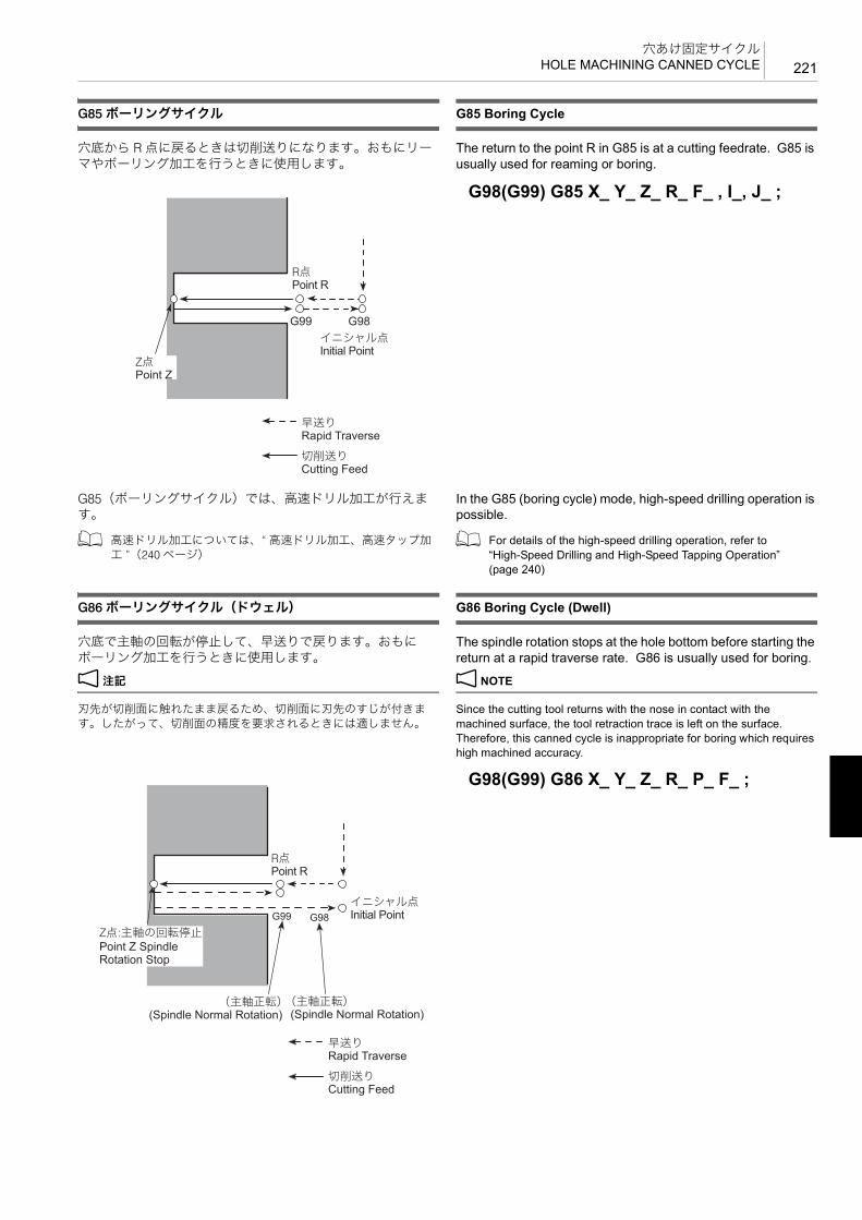
221穴あけ固定サイクル
HOLE MACHINING CANNED CYCLE
G85 ボーリングサイクル G85 Boring Cycle
穴底から R 点に戻るときは切削送りになります。おもにリーマやボーリング加工を行うときに使用します。
The return to the point R in G85 is at a cutting feedrate. G85 is usually used for reaming or boring.
G85(ボーリングサイクル)では、高速ドリル加工が行えます。
In the G85 (boring cycle) mode, high-speed drilling operation is possible.
1 高速ドリル加工については、“ 高速ドリル加工、高速タップ加工 ”(240 ページ)
1 For details of the high-speed drilling operation, refer to “High-Speed Drilling and High-Speed Tapping Operation” (page 240)
G86 ボーリングサイクル(ドウェル) G86 Boring Cycle (Dwell)
穴底で主軸の回転が停止して、早送りで戻ります。おもにボーリング加工を行うときに使用します。
The spindle rotation stops at the hole bottom before starting the return at a rapid traverse rate. G86 is usually used for boring.
2 注記 2 NOTE
刃先が切削面に触れたまま戻るため、切削面に刃先のすじが付きます。したがって、切削面の精度を要求されるときには適しません。
Since the cutting tool returns with the nose in contact with the machined surface, the tool retraction trace is left on the surface. Therefore, this canned cycle is inappropriate for boring which requires high machined accuracy.
G98(G99) G85 X_ Y_ Z_ R_ F_ , I_, J_ ;
G99 G98
Point R
Initial Point
Point Z
Rapid Traverse
Cutting Feed
R点
イニシャル点
Z点
早送り
切削送り
G98(G99) G86 X_ Y_ Z_ R_ P_ F_ ;
G99 G98
Point R
Initial Point
(Spindle Normal Rotation) (Spindle Normal Rotation)
Rapid Traverse
Cutting Feed
Point Z Spindle Rotation Stop
R点
イニシャル点
(主軸正転)(主軸正転)
早送り
切削送り
Z点:主軸の回転停止

穴あけ固定サイクルHOLE MACHINING CANNED CYCLE222
G88 ボーリングサイクル(シングルブロック停止)、G89ボーリングサイクル(ドウェル)
G88 Boring Cycle (Single Block Stop), G89 Boring Cycle (Dwell)
7注意 7 CAUTIONG88 のボーリングサイクル(手動引抜き)を行う場合、穴底で主軸の回転が停止した後、どのような手動動作も行えます。しかし、安全のため、手動動作が終わったときには、切削工具を穴から引き抜いた状態にしてください。[切削工具とワークが衝突および干渉、機械の破損]
In the boring cycle by G88, any manual operation is allowed after the spindle has stopped rotating at the bottom of the hole. However, before changing the operation mode from manual, the cutting tool must be extracted from the hole for safety.[Interference between cutting tool and workpiece/Machine damage]
<G88> <G88>ボーリング加工完了点の穴底で、ドウェルを行ってから主軸の回転が停止します。このとき、シングルブロック機能が有効な場合、一時停止します。
At the bottom of the hole where boring has been executed, the cutting tool dwells and then the spindle stops. If the single block function is valid, the machine enters the feed hold state.
自動運転スイッチ q〔起動〕を押すと、イニシャル点(G98)あるいは R 点(G99)まで早送りで戻ります。
When the q [START] (Start) switch is pressed, the cutting tool returns to the initial point level (G98) or the point R level (G99) at a rapid traverse rate.
G98(G99) G88 X_ Y_ Z_ R_ P_ F_ ;
76
3 2
6
7
1
54 ,
G99 (Spindle Normal Rotation)Spindle rotation stop after dwell*
Point Z
Rapid Traverse
Cutting Feed
Initial PointPoint R
* Feed hold if the single block function is valid.
G98 (Spindle Normal Rotation)G99(主軸正転)
ドウェル後、主軸の回転停止 *
Z 点
早送り
切削送り
イニシャル点
R 点
* シングルブロック機能が有効な場合、一時停止
G98(主軸正転)

223穴あけ固定サイクル
HOLE MACHINING CANNED CYCLE
<G89> <G89>G85(ボーリングサイクル)と同じ動きですが、穴底でドウェルを行います。ボーリング加工をするときに、穴底の精度が向上します。
Although the G89 boring cycle calls the same movement pattern as the G85 mode (boring cycle), it includes dwell at the bottom of the hole so that the accuracy of the bottom of the hole is improved.
G89(ボーリングサイクル)では、高速ドリル加工が行えます。
In the G89 (boring cycle) mode, high-speed drilling operation is possible.
1 高速ドリル加工については、“ 高速ドリル加工、高速タップ加工 ”(240 ページ)
1 For details of the high-speed drilling operation, refer to “High-Speed Drilling and High-Speed Tapping Operation” (page 240)
1-4 深穴ドリリングサイクルDeep Hole Drilling Cycle
一定の切込み量で、間けつ的にドリルを送る穴あけサイクルです。工具に無理な力をかけずに深穴をドリリングします。
The drilling cycles below, with intermittent feed, allow a deep hole to be drilled without excessive force to the drill.
G73 高速深穴ドリリングサイクル G73 High-Speed Deep Hole Drilling Cycle
ワークの材質が軟らかいときや粘性のある場合、工具に切りくずが巻きつきます。そのようなときに、切りくずを適当な長さに切る方法として使用します。
When drilling soft or viscous workpieces, chips are apt to wind around the tool. This command can be used to cut the chips in proper length.
2 注記 2 NOTE
戻り量 d は、パラメータ No. 8012 で設定します。 The return amount “d” is set for parameter No. 8012.
G98(G99) G89 X_ Y_ Z_ R_ P_ F_ , I_, J_ ;
G99 G98
Initial Point
Point R
Rapid Traverse
Drilling (Cutting Feed)
Point Z Dwell
イニシャル点
R 点
早送り
切削送り
Z 点ドウェル

穴あけ固定サイクルHOLE MACHINING CANNED CYCLE224
機械納入時は、0.100(= 0.1 mm)が設定されています。 The default setting is “0.100” (= 0.1 mm).
2 注記 2 NOTE
アドレス P は省略することができます。 Address P can be omitted.G73(高速深穴ドリリングサイクル)では、高速ドリル加工が行えます。
In the G73 (high-speed deep hole drilling cycle) mode, high-speed drilling operation is possible.
1 高速ドリル加工については、“ 高速ドリル加工、高速タップ加工 ”(240 ページ)
1 For details of the high-speed drilling operation, refer to “High-Speed Drilling and High-Speed Tapping Operation” (page 240)
G98(G99) G73 X_ Y_ Z_ Q_ R_ P_ F_ , I_ , J_ ;
d
Q Q Q
G99 G98
Initial PointPoint Z
Point R
Rapid Traverse
Cutting Feed
イニシャル点Z 点
R 点
早送り
切削送り

225穴あけ固定サイクル
HOLE MACHINING CANNED CYCLE
例: Example:G73 の使用例 Programming using G73
(a):イニシャル点(Z30.0)の位置に工具が位置決め (a): Positions the tool at the initial point (Z30.0).(b):1000 min−1 の回転速度で主軸正転 (b): Starts the spindle in the normal direction at 1000 min−1.(c):a で G73 を実行 (c): Executing G73 at a.
(d):b で G73 を実行 (d): Executing G73 at b.(e):G73 のキャンセル (e): Cancels G73.
G83 深穴ドリルサイクル G83 Deep Hole Drilling Cycle
穴が深くクーラントが届かない場合や、工具に巻き付くような切りくずが出る場合に、このサイクルを使用すると、切りくずを排出しやすくなります。
When drilling a deep hole where coolant cannot be supplied satisfactorily or drilling a workpiece which generates the chips that apt to wind around the tool, G83 can be effectively used.
2 注記 2 NOTE
クリアランス d は、パラメータ No. 8013 で設定します。 The clearance amount “d” is set for parameter No. 8013.機械納入時は、1.000(=1 mm)が設定されています。 The default setting is “1.000” (= 1 mm).
O0001;N1;G90 G00 G54 X50.0 Y30.0;..................................aG43 Z30.0 H1 S1000 T2;..................................... (a)M03; ..................................................................... (b)G99 G73 Z−17.0 Q5.0 R3.0 P100 F100; ..............(c)X−50.0;................................................................. (d)G80; ..................................................................... (e)
2 1
50 50
30
+X
+Y
17
d
5
Z30.0
Z3.0
5 5 5(Initial Point)
(Point R)Rapid Traverse
Cutting Feed
Movement by G73 at Points a and b
Dwell for 0.1 sec after each infeed
(イニシャル点)
(R 点)早送り
切削送り
点 a、点 b の G73 の動き
各切込み後でドウェル 0.1 秒
• Z−17.0.................................. Z 点(穴底)の位置 Z coordinate value of the point Z (hole bottom)
• R3.0 ..................................... R 点の位置 Z coordinate value of the point R
• Q5.0 ..................................... 1 回あたりの切込み量 5 mm Depth of cut per infeed cycle: 5 mm
• P100..................................... 各切込み後でのドウェル時間 0.1 秒 Dwell period after each infeed for 0.1 sec
• F100..................................... 送り速度 100 mm/min Feedrate: 100 mm/min
G98(G99) G83 X_ Y_ Z_ Q_ R_ P_ F_ , I_ , J_ ;
d
Q
G99 G98
Point R
Initial PointPoint Z
R 点
イニシャル点Z 点

穴あけ固定サイクルHOLE MACHINING CANNED CYCLE226
2 注記 2 NOTE
1 回あたりの切込み量 Q は、クリアランス量 d より大きい値にしてください。
Infeed depth “Q” must be larger than clearance amount "d".
G83(深穴ドリリングサイクル)では、高速ドリル加工が行えます。
In the G83 (deep hole drilling cycle) mode, high-speed drilling operation is possible.
1 高速ドリル加工については、“ 高速ドリル加工、高速タップ加工 ”(240 ページ)
1 For details of the high-speed drilling operation, refer to “High-Speed Drilling and High-Speed Tapping Operation” (page 240)
M237 G83 小径深穴ドリルサイクル(オプション) M237 G83 Small-Diameter Deep Hole Drilling Cycle (Option)
下図のように、Q の切込みを行っている際に過負荷トルク検出信号を受けたとき、および Q の切込み量に達したとき、R 点まで I で指令した送り(準早送り)で戻ります。次に、直前に加工した位置からクリアランス量 d の手前まで I で指令した送り(準早送り)で移動し、次の Q の切込みを行います。折れやすい小径ドリルの穴あけ加工に使用します。
As shown below, if overload torque detected signal is received during infeed by the programmed amount Q or when a drill is fed as much as Q, the drill is returned to the point R at the semi-rapid traverse rate specified by I. In the next infeed, the drill is moved at the semi-rapid traverse rate specified by I to the point which is away from the depth drilled by the previous operation by the clearance amount d, and then is fed by Q. It is possible to drill a small-diameter deep hole without the load exceeding the preset level to the small-diameter drill.
2 注記 2 NOTE
1. このサイクルでは、過負荷トルク検出機能付アーバを使用します。過負荷トルク検出機能付アーバはお客様での手配となります。
1. This cycle needs the use of an arbor that has the overload torque detection function. Note that the arbor with the overload torque detection function should be arranged by the user.
2. クリアランス量 d は、パラメータ No. 8084 で設定します。 2. The clearance amount “d” is set for parameter No. 8084.3. アドレス Q と R は穴あけ動作を行うブロックで指令してくださ
い。穴あけ動作を行わないブロックで指令しても、Q, R 指令のデータは保存されません。
3. Specify address Q and R in the block in which hole machining operation is specified. Otherwise, the data of Q and R are not stored.
4. アドレス Q は、正の値で指令してください。 4. Specify a positive value for address Q.5. 1 回あたりの切込み量 Q は、クリアランス量 d より大きい値にし
てください。5. Infeed depth “Q” must be larger than clearance amount “d”.
6. 指令 I を省略した場合は、下記のパラメータに設定された値を使用します。
6. If I is omitted, the values set for the parameters below are used for the semi-rapid traverse rate.
• No. 8085: • No. 8085:R 点から切削開始位置へのアプローチ時の送り速度 Feedrate for tool approach from the point R level to the cutting
start position.• No. 8086: • No. 8086:
穴底から R 点やイニシャル点への戻り時の送り速度 Feedrate for tool retraction from the hole bottom to the point R or initial point level.

227穴あけ固定サイクル
HOLE MACHINING CANNED CYCLE
7. M237 の M コードは、パラメータ No. 8083 で変更することができます。機械納入時は 237 が設定されています。このパラメータを変更する際は納入機で使用されていない M 信号番号を設定してください。
7. The M code number for this function may set for parameter No. 8083. Before shipping the M code “237” is set. When changing the setting by the parameter, use an M code number that is not used in your machine.
例: Example:M237 G83 の使用方法 Programming using M237 G
M237;G98(G99) G83 X_ Y_ Z_ Q_ R_ P_ F_I _ ;
• F........................................... 切削送り速度 (mm/min) Cutting feedrate (mm/min)
• I ............................................ 小径深穴ドリルサイクル用準早送り速度(mm/min)穴底から R 点やイニシャル点への戻り時、および R 点から切削開始位置へのアプローチ時の送り速度
Semi-rapid traverse rate to be used in the small-diameter deep hole drilling cycle (mm/min), applied to tool retraction from the hole bottom to the point R level and also to tool approach from the point R level to the cutting start position.
d
QQ Q
G98G99Initial Point
Point R
Overload Torque Detection
Point Z Dwell
Rapid Traverse
Semi-Rapid Traverse
Drilling (Cutting Feed)
イニシャル点
R 点
過負荷トルク検出
Z 点ドウェル
早送り
準早送り
切削送り
O1;N1;G90 G00 G54 X50.0 Y30.0;...................................... a a
G43 Z30.0 H1 S1000 T2;.......................................... イニシャル点(Z30.0)の位置に工具が位置決め
Positions the tool at the initial point (Z30.0).
M03; .......................................................................... 1000 min−1 の回転速度で主軸正転 Starts the spindle in the normal direction at 1000 min−1.
M237;G99 G83 Z-17.0 Q5.0 R3.0 F100 I1000; .................. a で M237 G83 を実行 Executes M237 G83 at a.
Z30.0
Z3.0
(Initial Point)
(Point R)
Rapid Traverse
Semi-Rapid Traverse
Cutting Feed
Movement by M237 G83 at Points a and b
(イニシャル点)
(R 点)
早送り
準早送り
切削送り
点 a、点 b の M237 G83 の動き

穴あけ固定サイクルHOLE MACHINING CANNED CYCLE228
1-5 タッピングサイクルTapping Cycle
M29 G84, M03 G84 同期式/非同期式タッピングサイクル(右ねじ)
M29 G84, M03 G84 Synchronized/Non-Synchronized Tapping Cycle (Right-Hand Thread)
同期式タッピングサイクルでは、主軸の回転と Z 軸の送り量が常に同期するため、右ねじを加工するときに、精度の高いタッピングが行えます。
In the synchronized tapping operation, accurate tapping operation is possible since the spindle rotation and the Z-axis feed are constantly synchronized to machine the right-hand thread.
非同期式タッピングサイクルでは、主軸の回転と Z 軸の送り量が同期しません。このため、このサイクルでは、タッパを使用します。
In the non-synchronized tapping operation, the spindle rotation and the Z-axis feed are not synchronized. Therefore, a tapper is used if tapping operation is executed in the nonsynchronized tapping mode.
• Z−17.0Z 点(穴底)の位置
• Q5.01 回あたりの切込み量 5 mm
• R3.0R 点の位置
• F100切削送り速度 100 mm/min
• I1000準早送り速度 1000 mm/min
• Z−17.0Z coordinate value of point Z (hole bottom)
• Q5.0Depth of cut per infeed cycle: 5 mm
• R3.0Z coordinate value of the point R level
• F100Feedrate: 100 mm/min
• I1000Semi-rapid traverse rate: 1000 mm/min
X−50.0;...................................................................... b で M237 G83 を実行 Executes M237 G83 at b.G80; .......................................................................... M237 G83 のキャンセル Cancels M237 G83.:
<同期式タッピングサイクル><Synchronized tapping cycle>
M29 S_ ;G98(G99) G84 X_ Y_ Z_ R_ P_ F_ (,R01) (, S_) , I_ , J_ ;
<非同期式タッピングサイクル><Non-synchronized tapping cycle>
M03 S_ ;G98(G99) G84 X_ Y_ Z_ R_ P_ F_ (,R00) , I_ , J_ ;
• P........................................... Z 点および R 点レベル復帰時のドウェル時間
Specifies dwell period at point Z or after returning to point R.
• F........................................... 送り速度(mm/min)(主軸回転速度 × ピッチ)
Specifies the feedrate (mm/min)(spindle speed × pitch).
• , R01 .................................... 同期式タッピングサイクル指令(省略可能) Specifies the synchronized tapping cycle (can be omitted).
G98G99 Initial Point
Spindle Rotation Stop
Spindle Normal Rotation
Point ZSpindle Rotation Stop (only in the synchronized
tapping cycle)
Point ZSpindle Reverse
Rotation after Dwell
Point R
Rapid Traverse
Cutting Feed
Spindle Normal Rotation after Dwell
イニシャル点
主軸の回転停止
主軸正転
Z 点主軸の回転停止 (同期式のみ)
Z 点ドウェル後、主軸逆転 R 点
早送り
切削送り
ドウェル後、主軸正転

229穴あけ固定サイクル
HOLE MACHINING CANNED CYCLE
2 注記 2 NOTE
1. “, S_” の指令は、非同期式タッピングサイクルでは指令できません。
1. “, S_” cannot be specified in the non-synchronized tapping cycle operation.
2. “, S_” の指令において、Z 点から R 点まで戻るときの主軸回転速度の値が、加工時の主軸回転速度の値より低い場合、Z 点から R点まで戻るときの主軸回転速度の値は、加工時の主軸回転速度の値になります。
2. If the spindle speed specified in “, S_” for the return from point Z to point R is lower than the spindle speed used in machining, the spindle speed specified for return is replaced with the spindle speed specified for machining.
3. “, S_” で指令した Z 点から R 点まで戻るときの主軸回転速度は、G80 あるいは G00, G01, G02, G03 でキャンセルされます。
3. The spindle speed specified in “, S_” for the return from point Z to point R is canceled by specifying the G80, G00, G01, G02, or G03.
5M29 G84 (同期式タッピングサイクル)および M03 G84(非同期式タッピングサイクル)では、高速タップ加工が行えます。
5In the M29 G84 (synchronized tapping cycle) or the M03 G84 (non-synchronized tapping cycle) mode, high-speed tapping operation is possible.
1 高速タップ加工については、“ 高速ドリル加工、高速タップ加工 ”(240 ページ)
1 For details of the high-speed tapping operation, refer to “High-Speed Drilling and High-Speed Tapping Operation” (page 240)
例: Example:M29 G84(同期式タッピングサイクル)の使用例 Programming using M29 G84 (synchronized tapping
cycle)
• , R00 .................................... 非同期式タッピングサイクル指令 Calls the non-synchronized tapping cycle.
• , S......................................... Z 点から R 点まで戻るときの主軸回転速度(min−1)
Specifies spindle speed for return from point Z to point R (min−1)
O1;N1;G90 G00 G54 X50.0 Y30.0;...................................... G54 のワーク座標系により、a に
工具が早送りで位置決めPositioning at a at a rapid traverse rate in the work coordinate system called by G54
G43 Z30.0 H1 T2; ..................................................... イニシャル点(Z30.0)の位置に工具が早送りで位置決め
2 注記
主軸の回転は停止した状態です。
Positioning at initial point (Z30.0) at a rapid traverse rate
2 NOTE
The spindle rotation is stopped.
M29 S400; ................................................................ 同期式タッピング指令 Calling the synchronized tapping cycle
G99 G84 Z-20.0 R5.0 F800 (, R01) , S1000; ................................................................................. a で同期式タッピングサイクル
(M29 G84)を実行1000 min−1 の主軸回転速度で、Z 点から R 点まで復帰
5送り速度 F= 主軸回転速度(min−1)× ピッチ
(mm)= 400 × 2 = 800(mm/min)
Executing the synchronized tapping cycle (M29 G84) at aThe spindle rotates at 1000 min−1 when the cutting tool returns from point Z to point R.
5Feedrate F=Spindle speed (min−1) × Pitch (mm)= 400 × 2 = 800 (mm/min)
X-50.0; ...................................................................... b で同期式タッピングサイクル(M29 G84)を実行
Executing the synchronized tapping cycle (M29 G84) at b
G80; .......................................................................... 同期式タッピングサイクル(M29 G84)のキャンセル
Canceling the synchronized tapping cycle (M29 G84)
:
2 1
50 50
30
+X
+Y
20
Z30.0
Z5.0
Rapid Traverse
Cutting Feed
Spindle Rotation Stops at the Hole Bottom. Movement by M29 G84 at Points a and b
Normal Rotation
Reverse Rotation
(Initial Point)
(Point R)
早送り
切削送り
穴底で主軸の回転停止点 a、点 b の M29 G84の動き
正転
逆転
(イニシャル点)
(R 点)
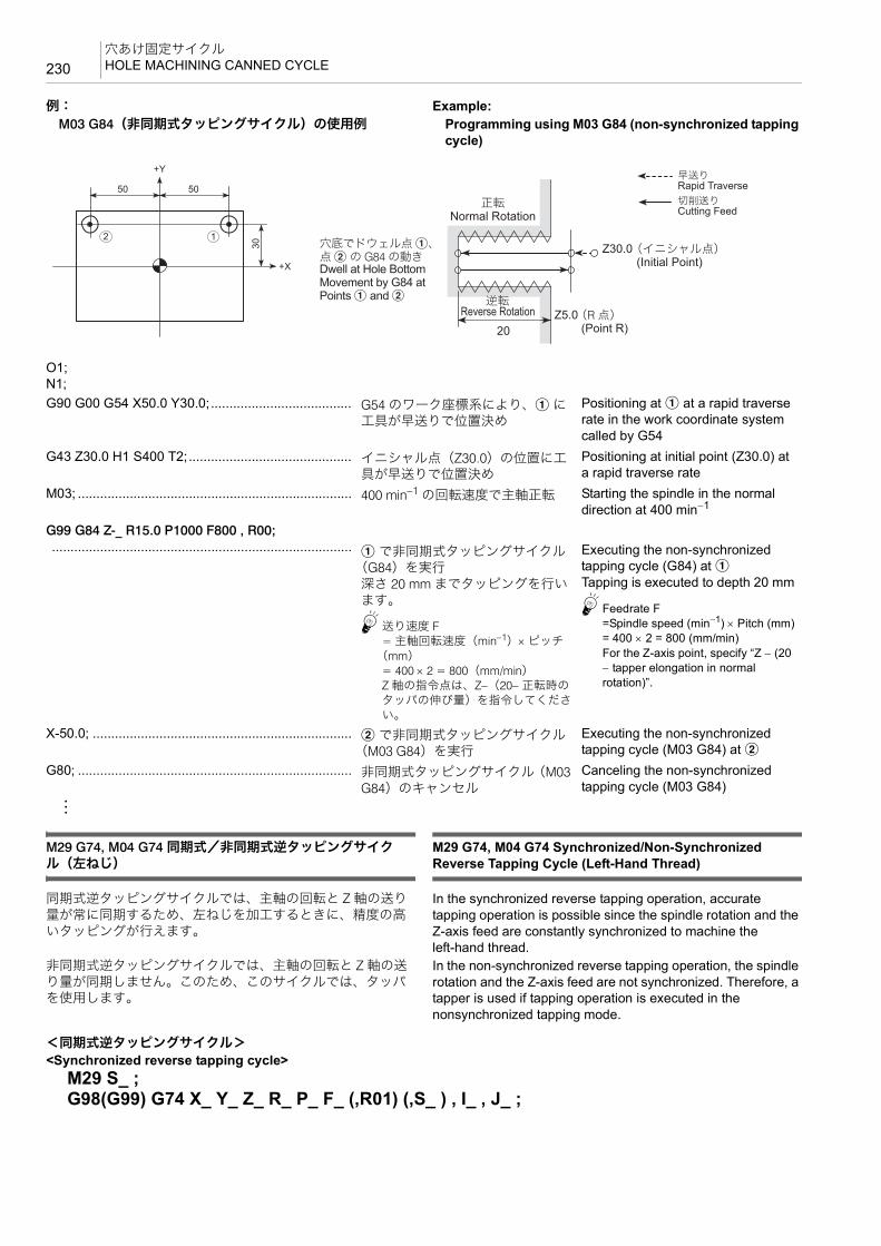
穴あけ固定サイクルHOLE MACHINING CANNED CYCLE230
例: Example:M03 G84(非同期式タッピングサイクル)の使用例 Programming using M03 G84 (non-synchronized tapping
cycle)
M29 G74, M04 G74 同期式/非同期式逆タッピングサイクル(左ねじ)
M29 G74, M04 G74 Synchronized/Non-Synchronized Reverse Tapping Cycle (Left-Hand Thread)
同期式逆タッピングサイクルでは、主軸の回転と Z 軸の送り量が常に同期するため、左ねじを加工するときに、精度の高いタッピングが行えます。
In the synchronized reverse tapping operation, accurate tapping operation is possible since the spindle rotation and the Z-axis feed are constantly synchronized to machine the left-hand thread.
非同期式逆タッピングサイクルでは、主軸の回転と Z 軸の送り量が同期しません。このため、このサイクルでは、タッパを使用します。
In the non-synchronized reverse tapping operation, the spindle rotation and the Z-axis feed are not synchronized. Therefore, a tapper is used if tapping operation is executed in the nonsynchronized tapping mode.
O1;N1;G90 G00 G54 X50.0 Y30.0;...................................... G54 のワーク座標系により、a に
工具が早送りで位置決めPositioning at a at a rapid traverse rate in the work coordinate system called by G54
G43 Z30.0 H1 S400 T2;............................................ イニシャル点(Z30.0)の位置に工具が早送りで位置決め
Positioning at initial point (Z30.0) at a rapid traverse rate
M03; .......................................................................... 400 min−1 の回転速度で主軸正転 Starting the spindle in the normal direction at 400 min−1
G99 G84 Z-_ R15.0 P1000 F800 , R00; ................................................................................. a で非同期式タッピングサイクル
(G84)を実行深さ 20 mm までタッピングを行います。
5送り速度 F= 主軸回転速度(min−1)× ピッチ
(mm)= 400 × 2 = 800(mm/min)Z 軸の指令点は、Z−(20− 正転時のタッパの伸び量)を指令してください。
Executing the non-synchronized tapping cycle (G84) at aTapping is executed to depth 20 mm
5Feedrate F=Spindle speed (min−1) × Pitch (mm)= 400 × 2 = 800 (mm/min)For the Z-axis point, specify “Z − (20 − tapper elongation in normal rotation)”.
X-50.0; ...................................................................... b で非同期式タッピングサイクル(M03 G84)を実行
Executing the non-synchronized tapping cycle (M03 G84) at b
G80; .......................................................................... 非同期式タッピングサイクル(M03 G84)のキャンセル
Canceling the non-synchronized tapping cycle (M03 G84)
:
2 1
50 50
30+X
+Y
20
Z30.0
Z5.0
Rapid Traverse
Cutting Feed
Dwell at Hole Bottom Movement by G84 at Points a and b
Normal Rotation
Reverse Rotation
(Initial Point)
(Point R)
早送り
切削送り
穴底でドウェル点 a、点 b の G84 の動き
正転
逆転
(イニシャル点)
(R 点)
<同期式逆タッピングサイクル><Synchronized reverse tapping cycle>
M29 S_ ;G98(G99) G74 X_ Y_ Z_ R_ P_ F_ (,R01) (,S_ ) , I_ , J_ ;

231穴あけ固定サイクル
HOLE MACHINING CANNED CYCLE
2 注記 2 NOTE
1. “, S_” の指令は、非同期式逆タッピングサイクルでは指令できません。
1. “, S_” cannot be specified in the non-synchronized reverse tapping cycle operation.
2. “, S_” の指令において、Z 点から R 点まで戻るときの主軸回転速度の値が、加工時の主軸回転速度の値より低い場合、Z 点から R点まで戻るときの主軸回転速度の値は、加工時の主軸回転速度の値になります。
2. If the spindle speed specified in “, S_” for the return from point Z to point R is lower than the spindle speed used in machining, the spindle speed specified for return is replaced with the spindle speed specified for machining.
3. “, S_” で指令した Z 点から R 点まで戻るときの主軸回転速度は、G80 あるいは G00, G01, G02, G03 でキャンセルされます。
3. The spindle speed specified in “, S_” for the return from point Z to point R is canceled by specifying the G80, G00, G01, G02, or G03.
5M29 G74 (同期式逆タッピングサイクル)および M04 G74(非同期式逆タッピングサイクル)では、高速タップ加工が行えます。
5In the M29 G74 (synchronized reverse tapping cycle) or the M04 G74 (non-synchronized reverse tapping cycle) mode, high-speed tapping operation is possible.
1 高速タップ加工については、“ 高速ドリル加工、高速タップ加工 ”(240 ページ)
1 For details of the high-speed tapping operation, refer to “High-Speed Drilling and High-Speed Tapping Operation” (page 240)
<非同期式逆タッピングサイクル><Non-synchronized reverse tapping cycle>
M04 S_ ;G98(G99) G74 X_ Y_ Z_ R_ P_ F_ (,R00) , I_ , J_ ;
• P........................................... Z 点および R 点レベル復帰時のドウェル時間
Specifies dwell period at point Z or after returning to point R.
• F........................................... 送り速度(mm/min)(主軸回転速度 × ピッチ)
Specifies the feedrate (mm/min)(spindle speed × pitch).
• , R01 .................................... 同期式逆タッピングサイクル指令(省略可能)
Specifies the synchronized reverse tapping cycle (can be omitted).
• , R00 .................................... 非同期式逆タッピングサイクル指令 Calls the non-synchronized reverse tapping cycle.
• , S......................................... Z 点から R 点まで戻るときの主軸回転速度(min−1)
Specifies spindle speed for return from point Z to point R (min−1)
G98G99Rapid Traverse
Cutting Feed
Initial Point
Spindle Rotation Stop(only in the synchronized tapping cycle)
Spindle Reverse Rotation
Point ZSpindle Rotation Stop
Point ZSpindle Normal
Rotation after Dwell
Point R Spindle Reverse Rotation
早送り
切削送り
イニシャル点
主軸の回転停止(同期式のみ)
主軸逆転
Z 点主軸の回転停止
Z 点ドウェル後、主軸正転 R 点 ドウェル後、主軸逆転

穴あけ固定サイクルHOLE MACHINING CANNED CYCLE232
例: Example:M29 G74(同期式逆タッピングサイクル)の使用例 Programming using M29 G74 (synchronized reverse
tapping cycle)
例: Example:M04 G74(非同期式逆タッピングサイクル)の使用例 Programming using M04 G74 (non-synchronized reverse
tapping cycle)
O1;N1;G90 G00 G54 X50.0 Y30.0;...................................... G54 のワーク座標系により、a に
工具が早送りで位置決めPositioning at a at a rapid traverse rate in the work coordinate system called by G54
G43 Z30.0 H1 T2; ..................................................... イニシャル点(Z30.0)の位置に工具が早送りで位置決め
2 注記
主軸の回転は停止した状態です。
Positioning at initial point (Z30.0) at a rapid traverse rate
2 NOTE
The spindle rotation is stopped.
M29 S400;................................................................. 同期式タッピング指令 Calling the synchronized tapping cycle
G99 G74 Z-20.0 R5.0 F800 (, R01) , S1000; ................................................................................. a で同期式逆タッピングサイクル
(M29 G74)を実行1000 min−1 の主軸回転速度で、Z 点から R 点まで復帰
5送り速度 F= 主軸回転速度(min−1)× ピッチ
(mm)= 400 × 2 = 800(mm/min)
Executing the synchronized reverse tapping cycle (M29 G74) at aThe spindle rotates at 1000 min−1 when the cutting tool returns from point Z to point R.
5Feedrate F= Spindle speed (min−1) × Pitch (mm)= 400 × 2 = 800 (mm/min)
X-50.0; ...................................................................... b で同期式逆タッピングサイクル(M29 G74)を実行
Executing the synchronized reverse tapping cycle (M29 G74) at b
G80; .......................................................................... 同期式逆タッピングサイクル(M29 G74)のキャンセル
Canceling the synchronized reverse tapping cycle (M29 G74)
:
2 1
50 50
30+X
+Y
20
Z30.0
Z5.0
Rapid Traverse
Cutting Feed
Spindle Rotation Stops at the Hole Bottom. Movement by M29 G74 at Points a and b
Reverse Rotation
Normal Rotation
(Initial Point)
(Point R)
早送り
切削送り
穴底で主軸の回転停止点 a、点 b の M29 G74の動き
逆転
正転
(イニシャル点)
(R 点)
O1;N1;G90 G00 G54 X50.0 Y30.0;...................................... G54 のワーク座標系により、a に
工具が早送りで位置決めPositioning at a at a rapid traverse rate in the work coordinate system called by G54
2 1
50 50
30
+X
+Y
20
Z30.0
Z5.0
Rapid Traverse
Cutting Feed
Dwell at Hole Bottom Movement by G74 at Points a and b
Reverse Rotation
Normal Rotation
(Initial Point)
(Point R)
早送り
切削送り
穴底でドウェル点 a、点 b の G74 の動き
逆転
正転
(イニシャル点)
(R 点)

233穴あけ固定サイクル
HOLE MACHINING CANNED CYCLE
M29 G84, M03 G84 同期式/非同期式ペッキングタップサイクル(右ねじ)M29 G74, M04 G74 同期式/非同期式ペッキング逆タップサイクル(左ねじ)
M29 G84, M03 G84 Synchronized/Non-Synchronized Pecking Tapping Cycle (Right-Hand Thread)M29 G74, M04 G74 Synchronized/Non-Synchronized Pecking Reverse Tapping Cycle (Left-Hand Thread)
パラメータ No. 1272.4 = 0 Parameter No. 1272.4 = 0ワークの材質が軟らかいときや粘い場合、工具に巻き付いた切りくずを適当な長さに切るために使用します。
When tapping mild or viscous workpieces, long chips are apt to wind around the tool. The commands above allow the chips to be cut in an appropriate length.
<右ねじ> <Right-Hand Thread>Q の切込みを正転で行った後、d だけ逆転で戻り、さらに次の Q の切込みを正転で行います。
After the infeed of a tap by “Q” with the spindle rotating in the normal direction, it returns by “d” in the reverse rotation of the spindle. Then, the next infeed is made in the normal rotation.
<左ねじ> <Left-Hand Thread>Q の切込みを逆転で行った後、d だけ正転で戻り、さらに次の Q の切込みを逆転で行います。
After the infeed of a tap by “Q” with the spindle rotating in the reverse direction, it returns by “d” in the normal rotation of the spindle, then the next infeed is repeated in the reverse rotation.
G43 Z30.0 H1 S400 T2;............................................ イニシャル点(Z30.0)の位置に工具が早送りで位置決め
Positioning at initial point (Z30.0) at a rapid traverse rate
M04; .......................................................................... 400 min−1 の回転速度で主軸逆転 Starting the spindle in the reverse direction at 400 min−1
G99 G74 Z-_ R15.0 P1000 F800 , R00; ................................................................................. a で非同期式逆タッピングサイク
ル(M04 G74)を実行深さ 20 mm まで逆タッピングを行います。
5送り速度 F= 主軸回転速度(min−1)× ピッチ
(mm)= 400 × 2 = 800(mm/min)Z 軸の指令点は、Z−(20− 逆転時のタッパの伸び量)を指令してください。
Executing the non-synchronized reverse tapping cycle (M04 G74) at aReverse tapping is executed to depth 20 mm.
5Feedrate F= Spindle speed (min−1) × Pitch (mm)= 400 × 2 = 800 (mm/min)For the Z-axis point, specify “Z − (20− tapper elongation in reverse rotation)”.
X-50.0; ...................................................................... b で非同期式逆タッピングサイクル(M04 G74)を実行
Executing the non-synchronized reverse tapping cycle (M04 G74) at b
G80; .......................................................................... 非同期式逆タッピングサイクル(M04 G74)をキャンセル
Canceling the non-synchronized reverse tapping cycle (M04 G74)
:

穴あけ固定サイクルHOLE MACHINING CANNED CYCLE234
2 注記 2 NOTE
戻り量 d は、パラメータ No. 8018 に設定してください。機械納入時、戻り量 d は設定されていません。戻り量 d がパラメータ No. 8018 に設定されていない場合、ペッキングタップサイクルは行いません。例えば、戻り量 d を 0.1 mm と設定する場合、パラメータ No. 8018 に“0.100” と入力してください。
The return amount “d” is set for parameter No. 8018.When the machine is shipped, no data is set for “d”. The pecking tapping cycle is not executed unless the return amount “d” is set for parameter No. 8018. To set “0.1 mm” for return amount “d”, for example, set “0.100” for parameter No. 8018.
1 “ 同期式タッピングサイクルの主軸 高回転速度 ”(240 ページ) 1 “Maximum Spindle Speed During Synchronized Tapping” (page 240)
<同期式ペッキングタップサイクル> <Synchronized Pecking Tapping Cycle>
<非同期式ペッキングタップサイクル> <Non-Synchronized Pecking Tapping Cycle>
<同期式ペッキング逆タップサイクル> <Synchronized Pecking Reverse Tapping Cycle>
<非同期式ペッキング逆タップサイクル> <Non-Synchronized Pecking Reverse Tapping Cycle>
<M29 G84, M03 G84> <M29 G74, M04 G74>
d
Q Q Q
G98G99 d
Q Q Q
G98G99
Rapid Traverse
Cutting Feed
Initial Point
Point R
Spindle Normal Rotation
Spindle Rotation Stop
Spindle Reverse Rotation after
Dwell
Point Z
Spindle Rotation Stop
Spindle Normal Rotation after Dwell
Spindle Reverse Rotation after Dwell
Point Z
Spindle Rotation Stop
Initial Point
Spindle Reverse Rotation
Point R
Spindle Rotation Stop
Spindle Normal Rotation after Dwell
早送り
切削送り
イニシャル点
R 点
主軸正転主軸の回転停止
ドウェル後、主軸逆転
Z 点
主軸の回転停止
ドウェル後、主軸正転
ドウェル後、主軸逆転
Z 点
主軸の回転停止
イニシャル点
主軸逆転
R 点
主軸の回転停止
ドウェル後、主軸正転
M29 S_;G98(G99) G84 X_ Y_ Z_ Q_ R_ P_ F_ S_ (,R01) (,S_), I_ ,J_;
M03 S_ ;G98(G99) G84 X_ Y_ Z_ Q_ R_ P_ F_ S_ (,R00), I_, J_;
M29 S_;G98(G99) G74 X_ Y_ Z_ Q_ R_ P_ F_ S_ (,R01) (,S_), I_ ,J_;
M04 S_ ;G98(G99) G74 X_ Y_ Z_ Q_ R_ P_ F_ S_ (,R00), I_, J_;
• P........................................... Z 点および R 点レベル復帰時のドウェル時間
Specifies dwell period at point Z or after returning to point R.
• F........................................... 送り速度(mm/min)(主軸回転速度 × ピッチ)
Specifies the feedrate (mm/min)(spindle speed × pitch)
• ,R01 ..................................... 同期式タッピングサイクル指令(省略可能) Specifies the synchronized tapping cycle (can be omitted).
• ,R00 ..................................... 非同期式タッピングサイクル指令 Calls the non-synchronized tapping cycle.
• ,S.......................................... Z 点から R 点まで戻るときの主軸回転速度(min−1)
Specifies spindle speed for return from point Z to point R (min−1)
235穴あけ固定サイクル
HOLE MACHINING CANNED CYCLE
2 注記 2 NOTE
1. アドレス Q を省略したり、Q0 を指令するとペッキングタップサイクルは行われず、通常のタッピングサイクルが行われます。
1. If Q is omitted or “Q0” is specified, a normal tapping cycle is executed, but a pecking tapping cycle is not executed.
2. “, S_” の指令は、非同期式ペッキングタップサイクルでは指令できません。
2. “, S_” cannot be specified in the non-synchronized pecking tapping cycle operation.
3. “, S_” の指令において、Z 点から R 点まで戻るときの主軸回転速度の値が、加工時の主軸回転速度の値より低い場合、Z 点から R点まで戻るときの主軸回転速度の値は、加工時の主軸回転速度の値になります。
3. If the spindle speed specified in “, S_” for the return from point Z to point R is lower than the spindle speed used in machining, the spindle speed specified for return is replaced with the spindle speed specified for machining.
4. “, S_” で指令した Z 点から R 点まで戻るときの主軸回転速度は、G80 あるいは G00, G01, G02, G03 でキャンセルされます。
4. The spindle speed specified in “, S_” for the return from point Z to point R is canceled by specifying the G80, G00, G01, G02, or G03.
5M29 G84, M03 G84(同期式/非同期式ペッキングタップサイクル)および M29 G74, M04 G74(同期式/非同期式ペッキング逆タップサイクル)では、高速タップ加工が行えます。
5In the M29 G84, M03 G84 (synchronized/non-synchronized pecking tapping cycle) or the M29 G74, M04 G74 (synchronized/ non-synchronized pecking reverse tapping cycle) mode, high-speed tapping operation is possible.
1 高速タップ加工については、“ 高速ドリル加工、高速タップ加工 ”(240 ページ)
1 For details of the high-speed tapping operation, refer to “High-Speed Drilling and High-Speed Tapping Operation” (page 240)
M29 G84, M03 G84 同期式/非同期式深穴タップサイクル(右ねじ)M29 G74, M04 G74 同期式/非同期式深穴逆タップサイクル(左ねじ)
M29 G84, M03 G84 Synchronized/Non-Synchronized Deep Hole Tapping Cycle (Right-Hand Thread)M29 G74, M04 G74 Synchronized/Non-Synchronized Deep Hole Reverse Tapping Cycle (Left-Hand Thread)
パラメータ No. 1272.4 = 1(出荷時の設定) Parameter No.1272.4 = 1 (default setting)ワークの材質が軟らかいときや粘い場合、工具に巻き付いた切りくずを適当な長さに切るために使用します。
When tapping mild or viscous workpieces, long chips are apt to wind around the tool. The commands above allow the chips to be cut in an appropriate length.
<右ねじ> <Right-Hand Thread>Q の切込みを正転で行った後、R 点まで逆転で戻ります。次に、直前に加工した位置からクリアランス量 d の手前まで正転で移動し、再度次の Q の切込みを正転で行います。
After the infeed of a tap by “Q” in the normal rotation, the tap is returned to the point R in the reverse rotation. In the next infeed, the tap is moved to the point which is above the depth tapped in the previous operation by clearance amount “d” in the normal rotation, then it is fed by “Q” in the normal rotation.
<左ねじ> <Left-Hand Thread>Q の切込みを逆転で行った後、R 点まで正転で戻ります。次に、直前に加工した位置からクリアランス量 d の手前まで逆転で移動し、再度次の Q の切込みを逆転で行います。
After the infeed of a tap by “Q” in the reverse rotation, the tap is returned to the point R in the normal rotation. In the next infeed, the tap is moved to the point which is above the depth tapped in the previous operation by clearance amount “d” in the spindle rotation, then it is fed by “Q” in the reverse rotation.

穴あけ固定サイクルHOLE MACHINING CANNED CYCLE236
2 注記 2 NOTE
戻り量 d は、パラメータ No. 8018 に設定してください。機械納入時、戻り量 d は設定されていません。戻り量 d がパラメータ No. 8018 に設定されていない場合、深穴タップサイクルは行いません。例えば、戻り量 d を 0.1 mm と設定する場合、パラメータ No. 8018 に“0.100” と入力してください。
The return amount “d” is set for parameter No. 8018. When the machine is shipped, no data is set for “d”. The deep hole tapping cycle is not executed unless the return amount “d” is set for parameter No. 8018. To set “0.1 mm” for return amount “d”, for example, set “0.100” for parameter No. 8018.
1 “ 同期式タッピングサイクルの主軸 高回転速度 ”(240 ページ) 1 “Maximum Spindle Speed During Synchronized Tapping” (page 240)
<同期式深穴タップサイクル> <Synchronized Deep Hole Tapping Cycle>
<非同期式深穴タップサイクル> <Non-Synchronized Deep Hole Tapping Cycle>
<同期式深穴逆タップサイクル> <Synchronized Deep Hole Reverse Tapping Cycle>
<非同期式深穴逆タップサイクル> <Non-Synchronized Deep Hole Reverse Tapping Cycle>
2 注記 2 NOTE
アドレス Q を省略したり、Q0 を指令すると深穴タップサイクルは行われず、通常のタッピングサイクルが行われます。
If Q is omitted or “Q0” is specified, a normal tapping cycle is executed, but a deep hole tapping cycle is not executed.
d
Q Q Q
G98G99
<M29 G84, M03 G84>
d
Q Q Q
G98G99
<M29 G74, M04 G74>
Initial Point
Point R
Spindle Rotation Stop
Spindle Rotation Stop
Spindle Normal Rotation
Spindle Normal Rotation after Dwell
Spindle Reverse Rotation after
Dwell
Rapid Traverse
Cutting Feed
Point R
Spindle Rotation Stop
Spindle Reverse Rotation
Spindle Reverse Rotation after Dwell
Spindle Normal Rotation after
Dwell
Spindle Rotation Stop
Initial Pointイニシャル点
R 点
主軸の回転停止
主軸の回転停止 主軸正転
ドウェル後、主軸正転ドウェル後、
主軸逆転
早送り
切削送り
R 点
主軸の回転停止 主軸逆転
ドウェル後、主軸逆転ドウェル後、
主軸正転
主軸の回転停止
イニシャル点
M29 S_;G98(G99) G84 X_ Y_ Z_ Q_ R_ P_ F_ (,R01);
M03 S_ ;G98(G99) G84 X_ Y_ Z_ Q_ R_ P_ F_ (,R00)
M29 S_;G98(G99) G74 X_ Y_ Z_ Q_ R_ P_ F_ (,R01);
M04 S_ ;G98(G99) G74 X_ Y_ Z_ Q_ R_ P_ F_ (,R00)
• P........................................... Z 点および R 点レベル復帰時のドウェル時間
Specifies dwell period at point Z or after returning to point R.
• F........................................... 送り速度(mm/min)(主軸回転速度 × ピッチ)
Specifies the feedrate (mm/min)(spindle speed × pitch)
• ,R01 ..................................... 同期式タッピングサイクル指令(省略可能) Specifies the synchronized tapping cycle (can be omitted).
• ,R00 ..................................... 非同期式タッピングサイクル指令 Calls the non-synchronized tapping cycle.

237穴あけ固定サイクル
HOLE MACHINING CANNED CYCLE
5M29 G84, M03 G84(同期式/非同期式深穴タップサイクル)および M29 G74, M04 G74(同期式/非同期式深穴逆タップサイクル)では、高速タップ加工が行えます。
5In the M29 G84, M03 G84 (synchronized/non-synchronized deep hole tapping cycle) or the M29 G74, M04 G74 (synchronized/ non-synchronized deep hole reverse tapping cycle) mode, high-speed tapping operation is possible.
1 高速タップ加工については、“ 高速ドリル加工、高速タップ加工 ”(240 ページ)
1 For details of the high-speed tapping operation, refer to “High-Speed Drilling and High-Speed Tapping Operation” (page 240)
< M29 G84, M03 G84, M29 G74, M04 G74 に関する注意事項>
<Cautions on Programming Using M29 G84, M03 G84, M29 G74, or M04 G74>
7注意 7 CAUTIONタッパを使用したとき、R 点に戻る動きはタッパが伸びた状態になります。R 点はタッパの伸び量より大きな値を指令してください。 [切削工具とワークが衝突および干渉、機械の破損]
For the tapping cycles, a tapper is used. The tapper is elongated when it returns from the bottom of the hole to the point R level. Therefore, the point R must be specified in a larger value than tapper elongation amount. [Collision or interference of cutting tool and workpiece/Machine damage]
2 注記 2 NOTE
1. タッピングサイクル動作中(タップ加工中)に、〔非常停止〕ボタンまたは @(リセット)キーを押して停止操作を行った場合、タップをワークから取り出さなければなりません。このとき、制御装置が手動でタップを抜くことを可能と判断すると、PLC アラーム(EX4415)が発生し、ソフトキー F6 に【タップ戻し】が表示されます。ソフトキー【タップ戻し】を押すと、アラームが
(EX4416)に変わります。この状態で手動軸送りスイッチ u〔+Z〕を押し、Z 軸が R 点まで戻ると、タップはワークから取り出されています。手動モードで軸移動を行うと、アラームメッセージおよびソフトキー【タップ戻し】が消えます。
1. If machine operation is stopped by pressing an [EMERGENCY STOP] (Emergency Stop) button or the @ (RESET) key during the execution of a tapping cycle (during tapping), it is necessary to remove a tap from the workpiece. In this case, if the NC judges that the tap can be removed manually, PLC alarm (EX4415) is displayed and the [RETRACT TAP] (F6) soft-key appears. When the [RETRACT TAP] soft-key is pressed, the alarm changes to (EX4416). In this condition, press the axis feed switch u [+Z]. When the Z-axis is moved back to point R, the tap is removed the workpiece. When the axis is moved manually, the alarm message and the [RETRACT TAP] soft-key disappear.
* ソフトキー【タップ戻し】は、タップ加工が途中停止した場合にのみ表示されます。
* The [RETRACT TAP] soft-key is displayed only when tapping operation is stopped halfway.
2. タッピングサイクル動作中に送り速度や主軸回転速度が変化すると、一定のピッチのねじが切れないため、タッピング動作中、送りオーバライドおよび主軸オーバライドは 100%に固定されます。
2. During the tapping cycle, feedrate override and spindle speed override are fixed to 100% because a fixed lead thread cannot be cut if feedrate or spindle speed is changed during tapping cycle.
3. タッピングサイクル動作中、一時停止を行っても、R 点レベルへの復帰動作が終了するまで停止しません。
3. If the w [STOP] (Stop) is pressed during tapping cycle, the cycle does not stop until the cutting tool returns to the point R level.
4. 同期式タッピングサイクルおよび同期式逆タッピングサイクルは、主軸の回転を停止させた状態で指令してください。
4. Call the synchronized tapping cycle and synchronized reverse tapping cycle in the state the spindle is stopped.
5. 同期式タッピングサイクルおよび同期式逆タッピングサイクルでは、主軸の回転と Z 軸の送り量が同期しているため、タッパを使用する必要はありません。
5. In the synchronized tapping cycle and synchronized reverse tapping cycle, it is not necessary to use a tapper since spindle rotation and Z-axis feed are synchronized.
<ドウェルの指令> <Dwell Command>G84 のタッピングサイクルおよび G74 の逆タッピングサイクルにおいて、どのようなときにドウェルを指令するのかを説明します。
The following explains necessity of the dwell in the G84 tapping cycle and the G74 reverse tapping cycle:
ドウェルDwell 指令する 指令しない To Be Specified Not Required
タップ穴の形状Tap Hole Shape
止まり穴貫通穴
Blind HoleThrough Hole

穴あけ固定サイクルHOLE MACHINING CANNED CYCLE238
<タッパを使用するときの注意事項> <Precautions on Using a Tapper>加工穴が貫通している場合は、穴底でタッパの先端部がある程度伸びても無視できます。しかし、止まり穴の場合は、下穴からさらに深く食い込もうとすると、タップの破損にもつながります。このため、止まり穴にはタッパ内部に定寸(制限)機構を組み込んだものを使用します。定寸装置を内蔵したタッパのカタログには、次の F1, F2, F3 の距離が記載されています。
When tapping a through hole, elongation of the tapper tip at the hole base can be ignored. However, in the case of a blind hole, if the tapper elongates beyond the depth of the prepared hole, the tapper is damaged. To avoid this, use a tapper with built-in depth detection device when tapping the blind hole. The following distances of F1, F2, and F3 are specified in the catalog of the tapper with built-in depth sizing device.
<止まり穴でねじの深さを正確に加工したい場合> <To Finish Tapping at Correct Depth in Blind Hole>定寸装置付きのタッパを使用して加工するときは、次のようにしてプログラムの R 点および Z 点を求めます。ただし、以下の説明は、あくまで理論値であり、ワークの材質や下穴の径により、タップの深さは変わります。
When machining a threaded hole with a tapper equipped with depth sizing device, obtain the points R and Z to be specified in a program as indicated below. Note that the values below are theoretical ones. Actual depth of tapped holes will vary depending on workpiece material and prepared holes diameter.
2 注記 2 NOTE
ここでは、右ねじで説明しています。左ねじの場合は、すべて回転方向が逆方向になりますので注意してください。
The following explanation is given assuming right-hand thread cutting. For left-hand thread cutting, pay attention to the rotation direction which is reversed from the explanation.
タッパTapper
深さ方向定寸(制限)装置内蔵型
特に制限なしBuilt-in Depth Sizing Device No Special Restriction
タッパの伸び量Tapper Extension Amount
Z 軸の送り停止点よりタッパの伸び(伸長)だけ、穴の中に引っ張り込まれます。設定された伸び量だけ伸びると、タッパ内の深さ制限装置が作動して、タップに回転を伝えなくなり、指定された深さのねじ加工が行えます。
Z 軸の送り停止点よりタッパの伸び(伸長)が作動します。タッパには 20 ~ 30 mm 程度の伸びる余裕がありますが、実際にどの程度伸びるかは判断できません。
Tapper is pulled into the hole from the feed stop point of Z-axis by the elongation. When the tapper is elongated by the set amount, the built-in depth sizing device prevents rotation from being transmitted to the tap so as to allow tapping of specified depth.
Tapper is elongated from the feed stop point of Z-axis. Although, tapper has allowance for 20 to 30 mm elongation, the actual elongation amount cannot be determined.
ドウェルDwell 指令する 指令しない To Be Specified Not Required
F1 縮み タップがワークに当たって食い付こうとしたとき、食い付きが悪い場合に必要です。
Contraction Necessary if the tap fails to be engaged with the workpiece positively at the start of tapping.
F2 伸長量 穴底での伸び量です。正転時(右ねじ)あるいは逆転時(左ねじ)の伸び量になります。
Elongation Amount
Elongation at the hole bottom. This is an elongation of a tapper in normal (right-hand thread) and reverse (left-hand thread) spindle rotation.
F3 タップが引き抜かれるときの伸長量
右ねじの場合、主軸が逆転して穴から抜けるときの逆転時の伸び量です。左ねじの場合、主軸が正転して穴から抜けるときの正転時の伸び量です。
Elongation amount when the tap is pulled out
For right-hand thread, elongation when the tapper is pulled out from the hole, rotating in the reverse direction.For left-hand thread, elongation when the tapper is pulled out from the hole, rotating in the normal direction.
F1F2F3

239穴あけ固定サイクル
HOLE MACHINING CANNED CYCLE
• R 点の位置 • Position of point R
R > F2(正転時の伸び量)+ F3(逆転時の伸び量) R > F2 (elongation amount at normal rotation) + F3 (elongation amount at reverse rotation)
• Z 点の位置 • Position of point Z
Z 点の位置を決めます。 Determine the point Z position as:Z = 図面上のタップの深さ − “F2(正転時の伸び量)” Z = “Depth of tap specified in the drawing” − “F2 (elongation
amount at normal rotation)”
例: Example:M8 × P1.25、深さ 20 mm のタップ加工を G84 で行います。 Tapping of M8 × P1.25, and 20 mm deep threaded hole in
the tapping cycle (G84).下ギリは、φ6.8 で深さ 25 mm です。 Prepared hole: 6.8 mm dia., depth 25 mm使用するタッパは、F2 = 5 mm, F3 = 7 mm とします。 Tapper to be used: F2 = 5 mm, F3 = 7 mm
(a):300 min−1 の回転速度で主軸正転 (a): Starts the spindle in the normal direction at 300 min−1.(b):G84 を実行 (b): Executes G84.
Point R
Greater Than “F2+ F3”
R点
F2+ F3より大
F2
Point ZTap Bottom
Z点タップ底
:
S300 M03; ............................................................(a)G99 G84 X_ Y_ Z−15.0 R15.0 P800 F375, R00;...(b)
Z−20.0
F2
Z−15.0
• Z−15.0.................................. Z = タップの深さ − F2(正転時の伸び量)= 20 − 5 = 15 (mm)
Z = “Depth of tap” − “F2 (elongation amount at the normal rotation)” = 20 − 5 = 15 (mm)
• R15.0 ................................... R > F2(正転時の伸び量)+ F3(逆転時の伸び量)= 5 + 7 = 12 (mm)R 点は 12 mm より大きい値が必要なので、R15.0 にします。
R > F2 (elongation amount at the normal rotation) + F3 (elongation amount at the reverse rotation) = 5 + 7 = 12 (mm)Because the value to be set for the point R must be larger than 12 mm, R15.0 is specified.
• F375..................................... F = 主軸回転速度(min−1)× ピッチ(mm)= 300 × 1.25 = 375 (mm/min)
F = Spindle speed (min−1) × pitch (mm) = 300 × 1.25 = 375 (mm/min)
• P800.....................................
ドウェル
0.8(秒)
60(秒)=
F (mm/min)
= =60 × 5375
× F2Dwell
0.8 (sec)
60 (sec)

穴あけ固定サイクルHOLE MACHINING CANNED CYCLE240
タップの深さ 20 mm を正確に加工したい場合、上のようにドウェル P を計算します。定寸装置の F2(正転時の伸び量)だけ伸びれば、Z−20 mm の深さになり、それ以上深くなりません。しかし、F2 の値まで伸びずに主軸が停止し、逆転して抜けると、浅いねじになります。そこで、F2 の値だけ伸びるようにするために、ドウェルを指令します。
To machine the thread to the depth of 20 mm correctly, calculate the dwell period, specified by P, as indicated above. When the tapper is elongated by F2 (elongation at normal rotation), set by the built-in depth sizing device, the tap reaches “Z−20” mm and further cut is not made. However, if the spindle stops before the tapper is elongated by F2 and returns in the reverse rotation, it causes the thread to be shallower than the specified depth. Accordingly, it is necessary to specify dwell for a proper period so that the tapper is elongated by F2.
同期式タッピングサイクルの主軸 高回転速度 Maximum Spindle Speed During Synchronized Tapping
同期式タッピングサイクル中の主軸 高回転速度を下記に示します。
Maximum spindle speed during synchronized tapping operation is indicated below.
ただし、主軸 高回速度を指令して実際の加工を行っても、動作の開始点と実際のワークとの距離により、主軸 高回転速度まで達しない場合があります。
Note that even if the maximum spindle speed indicated in the table is specified, actual speed may not reach the specified speed if the distance from the operation start point and the workpiece is not sufficient for the spindle to accelerate to the specified speed.
1-6 高速ドリル加工、高速タップ加工High-Speed Drilling and High-Speed Tapping Operation
高速ドリル加工、高速タップ加工とは、穴あけ固定サイクル実行中における非切削時間を短縮し、ドリルおよびタップの加工時間を短縮する加工です。
High-speed drilling and high-speed tapping operations reduce idle time during hole machining canned cycle to shorten drilling and tapping cycle time.
機種Machine Model
仕様Specifications
同期式タッピング 高回転速度(低速巻線での 高回転速度)Maximum Rotation Speed for Synchronized Tapping (Maximum
Rotational Speed with the Low-Speed Winding)
NHX4000
12000 min−1 6000 min−1 (2448 min−1)
12000 min−1
(高出力)12000 min−1
(High-output)
6000 min−1 (2066 min−1)
20000 min−1 6000 min−1 (3568 min−1)
NHX5000
12000 min−1 6000 min−1 (2448 min−1)
12000 min−1
(高出力)12000 min−1
(High-output)
6000 min−1 (2066 min−1)
20000 min−1 6000 min−1 (3568 min−1)
NHX5500
8000 min−1 4000 min−1 (2104 min−1)
8000 min−1
(高トルク)8000 min−1
(High-torque)
2500 min−1 (935 min−1)
15000 min−1 —
NHX6300
8000 min−1 2500 min−1 (935 min−1)
8000 min−1
(高トルク)8000 min−1
(High-torque)
2500 min−1 (811 min−1)
15000 min−1 —

241穴あけ固定サイクル
HOLE MACHINING CANNED CYCLE
下図の穴あけ固定サイクルにおいて、b, g, m に位置決めするときのインポジション幅を大きめに指令することにより、b, g, m への位置決め時、工具がインポジション幅だけ手前の位置から円弧状に、次の位置に向って移動します。このため、b, g, m に位置決めするための減速時間および次の位置に移動するときの加速時間あるいは移動距離が短縮されます。
In the hole machining canned cycle shown in the illustration below, by specifying a little larger in-position width for positioning at b, g, and m, a cutting tool moves to the next target point along an arc path from a point before reaching these points (b, g, m). This positioning movement reduces deceleration time at points b, g, and m, acceleration time for the positioning to the next target point, and also tool movement distance in positioning.
高速ドリル加工、高速タップ加工は、G73, G74, G81, G82, G84, G85, G89 の穴あけ固定サイクルで行えます。
High-speed drilling and high-speed tapping are possible in a hole machining canned cycle (G73, G74, G81, G82, G84, G85, and G89).
2 注記 2 NOTE
インポジション幅の指令範囲は 1 ~ 999.999 mm です。指令範囲外の値を指令すると、画面にアラーム(P35)が表示されます。
The in-position width can be specified in the range of 1 - 999.999 mm. If a value outside this range is specified, an alarm (P35) is displayed on the screen.
I:J:
I
J
Rapid Traverse
In-position Width (Z-Axis) In-position Width (Positioning Axes)
When a Little Larger In-position Width is Set
Cutting Feed
早送り
インポジション幅(Z 軸) インポジション幅(位置決め軸)
インポジション幅を大きめに指令
切削送り
G98(G99) G73(G74, G81, G82, G84, G85, G89) X_ Y_ Z_ Q_ R_ P_ F_ L_ , I_ , J_ ;

穴あけ固定サイクルHOLE MACHINING CANNED CYCLE242
高速ドリル加工、高速タップ加工に関する注意事項 Precautions on Executing High-speed Drilling and High-speed Tapping Operation
7注意 7 CAUTIONインポジション幅は、加工原点(Z0)から R 点までの距離より小さい値を指令してください。 [工具とワークの干渉、機械の破損]
For the “in-position” width, a value which is smaller than the distance from the workpiece zero point (Z0) to point R should be set. [Interference between tool and workpiece/Machine damage]
2 注記 2 NOTE
1. 穴あけ固定サイクルにおいて、繰返し回数 L を 2 回以上指令すると、指令したインポジション幅は、2 回目以降の位置決めについても有効になります。
1. If a value greater than “1” is specified for address L in a hole machining canned cycle program, the set value remains valid for the second and later positioning operation.
上記のプログラムにおいて、インポジション幅が有効になる動作は次のようになります。
With the program indicated above, the specified value is valid for the following axis movements.
:G91 (G98) G81 X40.0 Z-25.0 R-27.0 F100 , I0.2 , J0.3;:
Rapid Traverse
Movement 3
Movement 4
Movement 7
Movement 8Initial Point
Movement 6
Movement 5
Movement 1Movement 2
Point R
Cutting Feed
早送り
動作 3
動作 4
動作 7
動作 8イニシャル点
動作 6
動作 5
動作 1動作 2
R 点
切削送り
インポジション幅
, I , J
1 回目 動作 1 有効 —
動作 2 — 無効
動作 3 — 無効
動作 4 — 有効
2 回目 動作 5 有効 —
動作 6 — 無効
動作 7 — 無効
動作 8 — 有効
In-position Width
, I , J
1st path Movement 1 Valid —
Movement 2 — Invalid
Movement 3 — Invalid
Movement 4 — Valid
2nd path Movement 5 Valid —
Movement 6 — Invalid
Movement 7 — Invalid
Movement 8 — Valid

243穴あけ固定サイクル
HOLE MACHINING CANNED CYCLE
2. 下記のプログラムにおいて、指令したインポジション幅が有効になる動作は、次のようになります。
2. With the program indicated below, the specified in-position width is valid for the axis movement as indicated in the table.
2 回目のサイクルでは、1 回目のサイクルで指令した位置決め軸(X 軸)に対してのインポジション幅(, I0.2)は無効になります。(動作 5)
In the second cycle, the in-position width (, I0.2) specified for the positioning axis (X-axis) in the first cycle is invalid (movement 5).
位置決め軸(X 軸)に対してのインポジション幅を有効にする場合は、3 回目のサイクルのように、再度インポジション幅(, I0.2)を指令してください。(動作 9)
To make the in-position width valid for the positioning axis (X-axis), specify the in-position width (, I0.2) again in the program as in block [3] (movement 9).
ただし、Z 軸に対してのインポジション幅については、1 回目のサイクルで指令したインポジション幅(, J0.3)が 2 回目、3 回目のサイクルにおいても有効になります。(動作 8, 12)
Concerning the in-position width for the Z-axis, the in-position width (, J0.3) specified for the first cycle remains valid for the second cycle and the third cycle (movement 8 and 12).
3. 下記の穴あけ固定サイクルでは、高速ドリル加工は行えません。 3. High-speed drilling operation cannot be specified in the following hole machining canned cycles.
:G91 (G98) G81 X40.0 Z-25.0 R-27.0 F100 , I0.2 , J0.3; ........................................................................................................................................a
X10.0;....................................................................bX20.0 , I0.2;...........................................................c
Rapid Traverse
Movement 3
Movement 4
Movement 7
Movement 8
Movement 11
Movement 12Initial Point
Movement 10Movement 9
Movement 5
Movement 1Movement 2
Point R
Movement 6
Cutting Feed
早送り
動作 3
動作 4
動作 7
動作 8
動作 11
動作 12イニシャル点
動作 10動作 9
動作 5
動作 1動作 2
R 点
動作 6
切削送り
インポジション幅
, I , J
1 回目 動作 1 有効 —
動作 2 — 無効
動作 3 — 無効
動作 4 — 有効
2 回目 動作 5 有効 —
動作 6 — 無効
動作 7 — 無効
動作 8 — 有効
3 回目 動作 9 有効 —
動作 10 — 無効
動作 11 — 無効
動作 12 — 有効
In-position Width
, I , J
1st path Movement 1 Valid —
Movement 2 — Invalid
Movement 3 — Invalid
Movement 4 — Valid
2nd path Movement 5 Valid —
Movement 6 — Invalid
Movement 7 — Invalid
Movement 8 — Valid
3rd path Movement 9 Valid —
Movement 10 — Invalid
Movement 11 — Invalid
Movement 12 — Valid
• G76 ...................................... ファインボーリングサイクル Fine boring cycle
• G86 ...................................... ボーリングサイクル(ドウェル) Boring cycle (dwell)

穴あけ固定サイクルHOLE MACHINING CANNED CYCLE244
穴あけ固定サイクルの動きとインポジション幅の有効性 Validity of In-position Width in a Hole Machining Canned Cycle
高速ドリル加工、高速タップ加工が行える穴あけ固定サイクル(G73, G74, G81, G82, G84, G85, G89)において、どの動きに対してインポジション幅が有効になるかを説明します。
This section describes in which movements the specified in-position width is valid in hole machining canned cycles (G73, G74, G81, G82, G84, G85, G89) where high-speed drilling or high-speed tapping operation is permitted.
1. G81 スポットドリリングサイクル 1. G81 Spot drilling cycle
2. G82 カウンタボーリングサイクル 2. G82 Counter boring cycle
• G87 ...................................... バックボーリングサイクル Back boring cycle
• G88 ...................................... ボーリングサイクル(シングルブロック停止)
Boring cycle (single block stop)
G98
G99
Rapid Traverse
Point Z
Movement 4
Movement 3 Movement 2
Movement 4
Point R
Initial Point
Movement 1
Drilling (Cutting Feed)
早送り
Z 点
動作 4
動作 3 動作 2
動作 4
R 点
イニシャル点
動作 1
ドリリング(切削送り)
インポジション幅
, I , J
動作 1 有効 —
動作 2 — 無効
動作 3 — 無効
動作 4 — 有効
In-position Width
, I , J
Movement 1 Valid —
Movement 2 — Invalid
Movement 3 — Invalid
Movement 4 — Valid
G98
G99
Rapid Traverse
Point Z
Movement 5
Movement 4 (Dwell)Movement 3 Movement 2
Movement 5
Point R
Initial Point
Movement 1
Drilling (Cutting Feed)
早送り
Z 点
動作 5
動作 4(ドウェル)
動作 3 動作 2
動作 5
R 点
イニシャル点
動作 1
ドリリング(切削送り)
インポジション幅
, I , J
動作 1 有効 —
動作 2 — 無効
動作 3 — 無効
動作 4 — —
動作 5 — 有効
In-position Width
, I , J
Movement 1 Valid —
Movement 2 — Invalid
Movement 3 — Invalid
Movement 4 — —
Movement 5 — Valid

245穴あけ固定サイクル
HOLE MACHINING CANNED CYCLE
3. G85 ボーリングサイクル 3. G85 Boring cycle
4. G89 ボーリングサイクル(ドウェル) 4. G89 Boring cycle (dwell)
G98G99
Rapid Traverse
Point Z
Movement 4
Movement 3 Movement 2
Movement 5
Point R
Initial Point
Movement 1
Cutting Feed
早送り
Z 点
動作 4
動作 3 動作 2
動作 5
R 点
イニシャル点
動作 1
切削送り
インポジション幅
, I , J
動作 1 有効 —
動作 2 — 無効
動作 3 — 無効
動作 4 — 無効
動作 5 — 有効
In-position Width
, I , J
Movement 1 Valid —
Movement 2 — Invalid
Movement 3 — Invalid
Movement 4 — Invalid
Movement 5 — Valid
G98G99
Rapid Traverse
Movement 4 (Dwell)
Point Z
Movement 5
Movement 3 Movement 2
Movement 6
Point R
Initial Point
Movement 1
Cutting Feed
早送り
動作 4(ドウェル)
Z 点
動作 5
動作 3 動作 2
動作 6
R 点
イニシャル点
動作 1
切削送り
インポジション幅
, I , J
動作 1 有効 —
動作 2 — 無効
動作 3 — 無効
動作 4 — —
動作 5 — 無効
動作 6 — 有効
In-position Width
, I , J
Movement 1 Valid —
Movement 2 — Invalid
Movement 3 — Invalid
Movement 4 — —
Movement 5 — Invalid
Movement 6 — Valid

穴あけ固定サイクルHOLE MACHINING CANNED CYCLE246
5. G73 高速深穴ドリリングサイクル 5. G73 High-speed deep hole drilling cycle
G98
G99Rapid Traverse
Point Z
Movement 7 (Dwell)
Movement 3 Movement 2
Movement 4 (Dwell)
Point R Initial Point
Movement n
Movement n
Movement 5
Movement 6
Movement 8
Movement n - 1
Movement 1
Drilling (Cutting Feed)
早送り
Z 点
動作 7(ドウェル)
動作 3 動作 2
動作 4(ドウェル)
R 点 イニシャル点
動作 n
動作 n
動作 5
動作 6
動作 8
動作 n - 1
動作 1
ドリリング(切削送り)
インポジション幅
, I , J
動作 1 有効 —
動作 2 — 無効
動作 3 — 無効
動作 4 — —
動作 5 — 無効
動作 6 — 無効
動作 7 — —
動作 8 — 無効
動作 n - 1 — 無効
動作 n — 有効
In-position Width
, I , J
Movement 1 Valid —
Movement 2 — Invalid
Movement 3 — Invalid
Movement 4 — —
Movement 5 — Invalid
Movement 6 — Invalid
Movement 7 — —
Movement 8 — Invalid
Movement n - 1 — Invalid
Movement n — Valid

247穴あけ固定サイクル
HOLE MACHINING CANNED CYCLE
6. M29 G84, G84 同期式/非同期式タッピングサイクル 6. M29 G84, G84 Tapping cycle (synchronized/non-synchronized)
G98G99
Rapid Traverse
Point Z
Movement 7 (Dwell)
Movement 3 Movement 2
Movement 4 (Dwell)
Point R Initial Point
Movement 9Movement 5 (Spindle
Reverse Rotation) Movement 6Movement 8 (Spindle Normal Rotation)
Movement 1
Cutting Feed
早送り
Z 点
動作 7(ドウェル)
動作 3 動作 2
動作 4(ドウェル)
R 点 イニシャル点
動作 9動作 5(主軸逆転)
動作 6 動作 8(主軸正転)
動作 1
切削送り
インポジション幅
, I , J
動作 1 有効 —
動作 2 — 無効
動作 3 — 無効
動作 4 — —
動作 5 — —
動作 6 — 無効
動作 7 — —
動作 8 — —
動作 9 — 有効
In-position Width
, I , J
Movement 1 Valid —
Movement 2 — Invalid
Movement 3 — Invalid
Movement 4 — —
Movement 5 — —
Movement 6 — Invalid
Movement 7 — —
Movement 8 — —
Movement 9 — Valid

穴あけ固定サイクルHOLE MACHINING CANNED CYCLE248
7. M29 G74, G74 同期式/非同期式逆タッピングサイクル 7. M29 G74, G74 Reverse tapping cycle (synchronized/non-synchronized)
1-7 G76 ファインボーリングサイクル、G87 バックボーリングサイクルG76 Fine Boring Cycle, G87 Back Boring Cycle
7注意 7 CAUTIONG76 のファインボーリングサイクルと G87 のバックボーリングサイクルを使用する場合、切削工具の刃先はシフトする方向と逆の方向に取り付けてください。[切削工具とワークが衝突および干渉、機械の破損、切削工具の破損]
For the fine boring cycle by G76 and G87, mount a boring bit at the position opposite to the boring bar shift direction.[Collision and interference of cutting tool and workpiece, Machine damage, cutting tool damage]
2 注記 2 NOTE
1. シフト量 I, J, Q が適切な値でないと、切削工具を引き抜くとき、切削工具がワークと干渉するおそれがあります。
1. If shift amounts I, J, and Q are improper, the cutting tool will interfere with the workpiece when it is moved up to be extracted from the workpiece.
2. R 点レベル復帰あるいはイニシャル点レベル復帰後、アドレス I, J, Q で指令したシフト量だけ戻ります。
2. The boring bit retracts by the shift distance specified with I, J, and Q after the return to the point R or initial point level.
3. アドレス Q と R はボーリング動作を行うブロックで指令してください。
3. Specify addresses Q and R in the block in which boring is specified.
G98G99
Rapid Traverse
Point Z
Movement 7 (Dwell)
Movement 3 Movement 2Movement 4 (Dwell)
Point R Initial Point
Movement 9Movement 5 (Spindle
Normal Rotation) Movement 6Movement 8 (Spindle Reverse Rotation)
Movement 1
Cutting Feed
早送り
Z 点
動作 7(ドウェル)
動作 3 動作 2
動作 4(ドウェル)
R 点 イニシャル点
動作 9動作 5(主軸正転)
動作 6 動作 8(主軸逆転)
動作 1
切削送り
インポジション幅
, I , J
動作 1 有効 —
動作 2 — 無効
動作 3 — 無効
動作 4 — —
動作 5 — —
動作 6 — 無効
動作 7 — —
動作 8 — —
動作 9 — 有効
In-position Width
, I , J
Movement 1 Valid —
Movement 2 — Invalid
Movement 3 — Invalid
Movement 4 — —
Movement 5 — —
Movement 6 — Invalid
Movement 7 — —
Movement 8 — —
Movement 9 — Valid
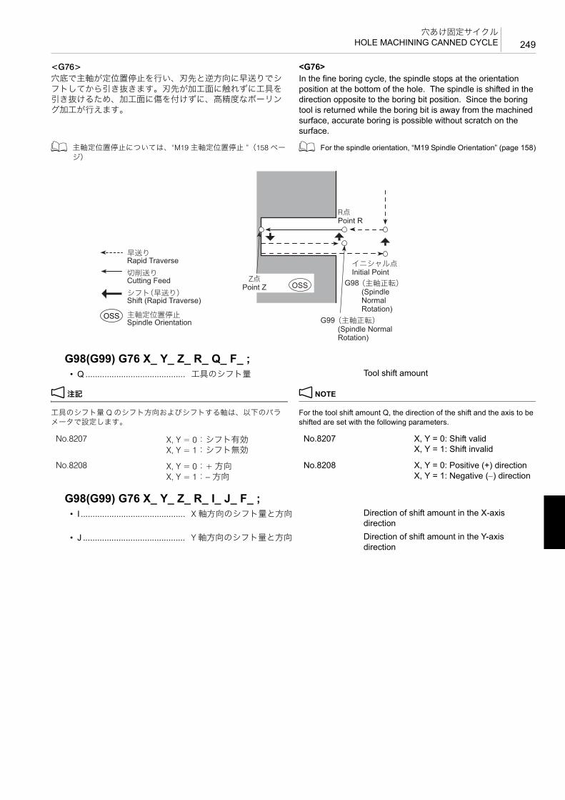
249穴あけ固定サイクル
HOLE MACHINING CANNED CYCLE
<G76> <G76>穴底で主軸が定位置停止を行い、刃先と逆方向に早送りでシフトしてから引き抜きます。刃先が加工面に触れずに工具を引き抜けるため、加工面に傷を付けずに、高精度なボーリング加工が行えます。
In the fine boring cycle, the spindle stops at the orientation position at the bottom of the hole. The spindle is shifted in the direction opposite to the boring bit position. Since the boring tool is returned while the boring bit is away from the machined surface, accurate boring is possible without scratch on the surface.
1 主軸定位置停止については、“M19 主軸定位置停止 ”(158 ページ)
1 For the spindle orientation, “M19 Spindle Orientation” (page 158)
2 注記 2 NOTE
工具のシフト量 Q のシフト方向およびシフトする軸は、以下のパラメータで設定します。
For the tool shift amount Q, the direction of the shift and the axis to be shifted are set with the following parameters.
G98(G99) G76 X_ Y_ Z_ R_ Q_ F_ ;• Q .......................................... 工具のシフト量 Tool shift amount
OSS
OSS G98
G99
Rapid Traverse
Cutting Feed
Shift (Rapid Traverse)
Spindle Orientation
Point Z
Point R
Initial Point
(Spindle Normal Rotation)
(Spindle Normal Rotation)
早送り
切削送り
シフト(早送り)
主軸定位置停止
Z点
R点
イニシャル点
(主軸正転)
(主軸正転)
No.8207 X, Y = 0:シフト有効X, Y = 1:シフト無効
No.8208 X, Y = 0:+ 方向X, Y = 1:− 方向
No.8207 X, Y = 0: Shift validX, Y = 1: Shift invalid
No.8208 X, Y = 0: Positive (+) directionX, Y = 1: Negative (−) direction
G98(G99) G76 X_ Y_ Z_ R_ I_ J_ F_ ;• I ............................................ X 軸方向のシフト量と方向 Direction of shift amount in the X-axis
direction
• J ........................................... Y 軸方向のシフト量と方向 Direction of shift amount in the Y-axis direction

穴あけ固定サイクルHOLE MACHINING CANNED CYCLE250
<主軸のシフトについて> <Spindle Shift>切削面に刃先が接した状態で、工具が上昇すると加工面に傷が付きます。主軸がシフトして上昇すれば、加工面に傷は付きません。
If the boring bar is extracted from the hole while the bit is in contact with the machined surface, the bit will leave scratch on the surface. To avoid such scratch, it is necessary to shift the spindle to move the bit away from the machined surface before extracting the boring bar.
I, J
+Y
+X
+J
-J
+I-I
Bored Hole
X and Y components of shift amount
ボーリング穴
シフト量の X, Y 成分の方向
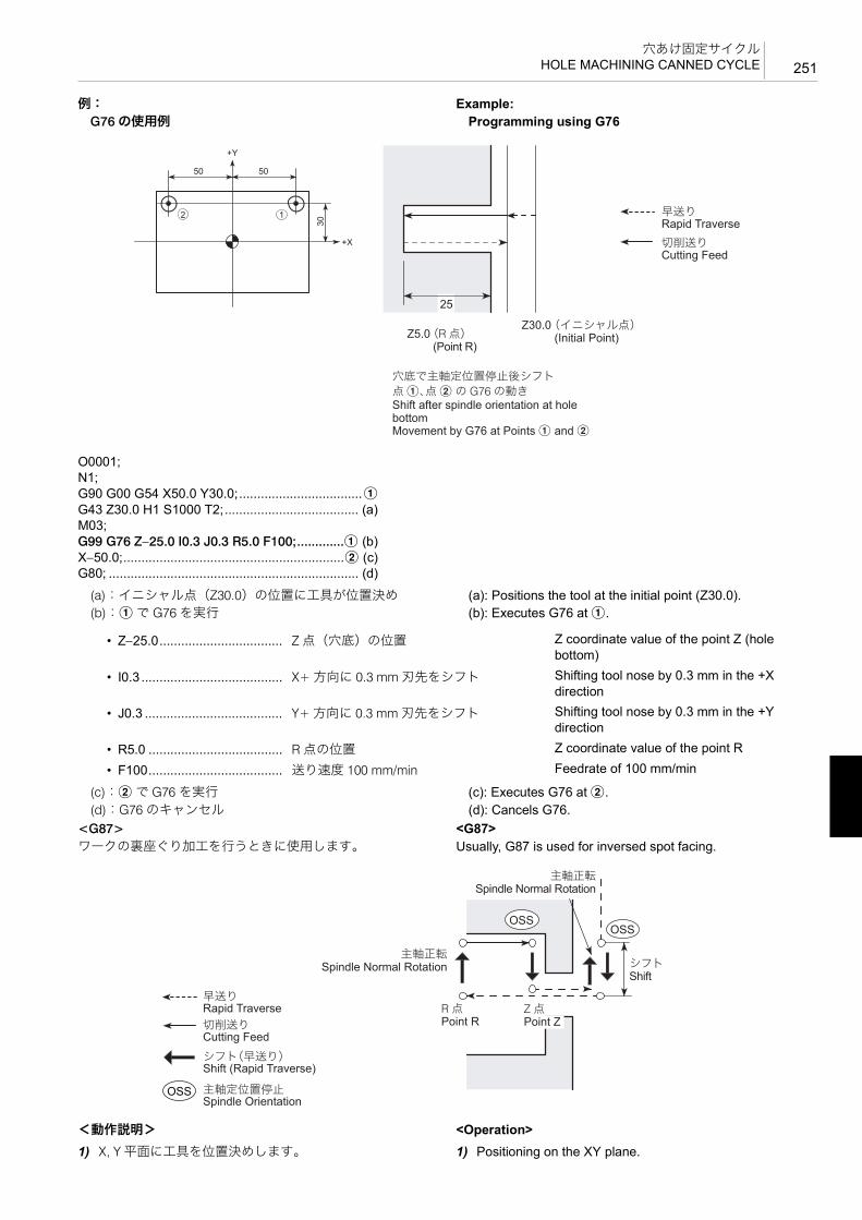
251穴あけ固定サイクル
HOLE MACHINING CANNED CYCLE
例: Example:G76 の使用例 Programming using G76
(a):イニシャル点(Z30.0)の位置に工具が位置決め (a): Positions the tool at the initial point (Z30.0).(b):a で G76 を実行 (b): Executes G76 at a.
(c):b で G76 を実行 (c): Executes G76 at b.(d):G76 のキャンセル (d): Cancels G76.
<G87> <G87>ワークの裏座ぐり加工を行うときに使用します。 Usually, G87 is used for inversed spot facing.
<動作説明> <Operation>1) X, Y 平面に工具を位置決めします。 1) Positioning on the XY plane.
O0001;N1;G90 G00 G54 X50.0 Y30.0;..................................aG43 Z30.0 H1 S1000 T2;..................................... (a)M03;G99 G76 Z−25.0 I0.3 J0.3 R5.0 F100;.............a (b)X−50.0;.............................................................b (c)G80; ..................................................................... (d)
2 1
50 50
30
+X
+Y
Z30.0
25
Z5.0
Shift after spindle orientation at hole bottomMovement by G76 at Points a and b
Rapid Traverse
Cutting Feed
(Point R)(Initial Point)
点 a、点 b の G76 の動き穴底で主軸定位置停止後シフト
早送り
切削送り
(R 点)(イニシャル点)
• Z−25.0.................................. Z 点(穴底)の位置 Z coordinate value of the point Z (hole bottom)
• I0.3 ....................................... X+ 方向に 0.3 mm 刃先をシフト Shifting tool nose by 0.3 mm in the +X direction
• J0.3 ...................................... Y+ 方向に 0.3 mm 刃先をシフト Shifting tool nose by 0.3 mm in the +Y direction
• R5.0 ..................................... R 点の位置 Z coordinate value of the point R
• F100..................................... 送り速度 100 mm/min Feedrate of 100 mm/min
OSS
OSSOSS
Rapid Traverse
Cutting Feed
Shift (Rapid Traverse)
Spindle Orientation
Spindle Normal Rotation
Shift
Point ZPoint R
Spindle Normal Rotation
早送り
切削送り
シフト(早送り)
主軸定位置停止
主軸正転
シフト
Z 点R 点
主軸正転

穴あけ固定サイクルHOLE MACHINING CANNED CYCLE252
2) 主軸定位置停止を行い、刃先と逆方向にシフトします。 2) Spindle orientation and shift in the direction opposite to the boring bit position.
3) 工具が早送りで R 点に移動します。 3) Positioning at the point R.
4) シフト量だけ戻り、主軸が正転し、Z 軸 + 方向に Z 点まで加工を行います。
4) The spindle retracts by the shift amount and starts rotating in the normal direction. Back boring is carried out in the +Z-axis direction up to the point Z.
5) 主軸定位置停止を行い、刃先と逆方向にシフトした後、穴より工具を引き抜きます。
5) Spindle orientation is performed and the cutting tool shifts in the direction opposite to the boring bit position, then the cutting tool is extracted from the hole.
2 注記 2 NOTE
G87 のバックボーリングサイクルでは、G99 の R 点復帰は指令できません。
For the back boring cycle (G87), G99 “return to point R” cannot be specified.
<主軸のシフトについて> <Spindle shift>
G98 G87 X_ Y_ Z_ R_ I_ J_ F_ ;• I ............................................ X 軸方向のシフト量と方向 Direction of shift amount in the X-axis
direction
• J ........................................... Y 軸方向のシフト量と方向 Direction of shift amount in the Y-axis direction
I, J
+Y
+X
+J
-J
+I-I
Bored Hole
X and Y components of shift amount
ボーリング穴
シフト量の X, Y 成分の方向

253穴あけ固定サイクル
HOLE MACHINING CANNED CYCLE
例: Example:G87 の使用例 Programming using G87
(a):イニシャル点(Z30.0)の位置に工具が早送りで位置決め
(a): Positions the tool at the initial point (Z30.0) at a rapid traverse rate.
主軸回転速度を 1000 min−1 に設定 Sets the spindle speed at 1000 min−1
(b):a で G87 を実行 (b): Executes G87 at a.
(c):b で G87 を実行 (c): Executes G87 at b.(d):G87 のキャンセル (d): Cancels G87.
1-8 パターンサイクルPattern Cycles
パターンサイクルとは、ある一定の法則に基づいた穴位置を加工する、あるいは円、四角切削を行うときに、プログラムをより簡単にするためのサイクルです。
A pattern cycle simplifies programming when executing a hole machining cycle at positions which can be defined by a specific pattern as well as a circle or frame cutting.
パターンサイクルを使用すると、ある一定の法則に基づいた複数の穴位置、あるいは円、四角切削を、G コードを含む 1ブロックで指令することができます。
By using a pattern cycle, hole positions arranged in a certain pattern, or circle or frame cutting can be specified by one block commands of a G code.
2 注記 2 NOTE
G300 ~ G309 および引数は、単独ブロックで指令してください。同一ブロックに他の機能が指令されると、アラームが発生します。
Specify G300 to G309 and their arguments in a block without other commands. If any other function is specified in the same block, an alarm occurs.
5G コード横の < > 内には、ページが記載されています。 5Pages are indicated in the brackets beside G codes.
• G300 <254>円弧上の点(等ピッチ) • G300 <254>Arc (equal interval)
• G301 <255>円弧上の点(不等ピッチ) • G301 <255>Arc (random interval)
• G302 <256>直線上の点(等ピッチ) • G302 <256>Line-at-angle (equal interval)
• G303 <258>直線上の点(不等ピッチ) • G303 <258>Line-at angle (random interval)
• G304 <259>四角上、格子上の点 • G304 <259>Rectangle/grid
• G305 <262>千鳥格子上の点 • G305 <262>Staggered grid
• G306 <264>円内側切削(仕上げ) • G306 <264>Circle cutting inside (finishing)
O0001;N1;G90 G00 G54 X50.0 Y30.0;..................................aG43 Z30.0 H1 S1000 T2;..................................... (a)G98 G87 Z−25.0 I4.0 R−40.0 F100;.................a (b)X−50.0;.............................................................b (c)G80; ..................................................................... (d)
2 1
50 50
30
+X
+Y
Z30.0Z−25.0Z−40.0
Rapid Traverse
Cutting Feed
Shift
(Initial Point)(Point R)
Movement by G87 at Points a and b
早送り
切削送り
シフト
(イニシャル点)(R 点)
点 a、点 b の G87 の動き
• Z−25.0.................................. Z 点の位置 Z coordinate value of the point Z
• I4.0 ....................................... X+ 方向に 4.0 mm 刃先をシフト Shifting tool nose by 4.0 mm in the +X direction
• R−40.0 ................................. R 点の位置 Z coordinate value of the point R
• F100..................................... 送り速度 100 mm/min Feedrate of 100 mm/min

穴あけ固定サイクルHOLE MACHINING CANNED CYCLE254
• G307 <266>円外側切削(仕上げ) • G307 <266>Circle cutting outside (finishing)
• G308 <267>四角内側切削(仕上げ) • G308 <267>Frame cutting inside (finishing)
• G309 <269>四角外側切削(仕上げ) • G309 <269>Frame cutting outside (finishing)
G300 円弧上の点(等ピッチ) G300 Arc (Equal Intervals)
図のように、中心点(A, B)、半径 R の円弧上で、X 軸に対して角度 C の位置を始点として、H 個の穴あけ加工をピッチ角度 Q ごとに行う場合に、定位置を指令します。
With the G300 command, hole positions arranged on an arc in equal intervals are defined.
Center of arc: (A, B)Radius of arc: R Start hole position: Angle C from the X-axis Number of equally spaced holes: H Equally spacing angle: Q
2 注記 2 NOTE
1. アドレス A, B を省略すると、中心点は現在位置になります。 1. If addresses A and B are omitted, the center of arc is defined at the present position.
2. アドレス R, H を省略しないでください。アラーム(No. 3101)が発生します。
2. Addresses R and H must not be omitted. If omitted, an alarm (No. 3101) occurs.
3. アドレス R は正の値で指令してください。R0 を指令したり、負の値を指令すると、アラーム(No. 3102)が発生します。
3. For address R, specify a positive value. If R0 is specified or a negative value is specified for address R, an alarm (No. 3102) occurs.
4. アドレス C を省略すると、X 軸と 初に穴あけ加工を行う穴位置のなす角度は 0° になります。
4. If address C is omitted, the angle of the first position from the X-axis is set to 0°.
5. アドレス Q を省略すると、穴と穴のピッチ角度は 360° になります。
5. If address Q is omitted, intervals between holes are set at 360°.
6. アドレス Q において、Q0 は指令しないでください。Q0 を指令すると、アラーム(No. 3102)が発生します。
6. When specifying address Q, do not specify Q0. If Q0 is specified, an alarm (No. 3102) occurs.
7. 穴個数 H は、1 以上の値を指令してください。0 以下の値を指令すると、アラーム(No. 3102)が発生します。
7. For address H (number of hole positions), specify a value of “1” or greater. If a value of “0” or smaller is specified, an alarm (No. 3102) occurs.
G300 A_ B_ C_ R_ Q_ H_ I1_ . . . I10_ ;• A........................................... (G90):
中心点の X 軸座標値(G90):X-coordinate of the center of arc to be defined
• B........................................... (G90):中心点の Y 軸座標値
(G90):Y-coordinate of the center of arc to be defined
• C .......................................... X 軸と 初に穴あけ加工を行う穴位置のなす角度
Specifies the angle made between the first hole machining position and the X-axis.
• R .......................................... 円弧の半径(符号なし) Specifies the radius of the arc (without a sign).
• Q .......................................... 穴と穴のピッチ角度 Pitch angle between the two adjacent holes
• H .......................................... 穴個数 Specifies the number of holes.
• I ............................................ オミット(省略)位置番号 Specifies the omit position numbers.
+X
R
Q Q
Q
C
1
2
3H
Center of Arc (A, B)中心点(A, B)

255穴あけ固定サイクル
HOLE MACHINING CANNED CYCLE
8. アドレス I は 10 個まで指令できます。 8. With address I, up to ten omission point numbers can be specified.9. アドレス I は、小数点を付けてください。ただし、小数点以下は
切り捨てられます。9. For address I, the value must include a decimal point; decimal
fraction is ignored.
例: Example:G300 の使用方法 Programming using G300円弧上に等間隔で並んだ 1 ~ 8 の位置で、スポットドリリングサイクル(G81)を行います。ただし、5 と 7 の穴加工は行いません。
To carry out spot drilling cycle (G81) at positions 1 to 8, arranged on the arc in equal intervals. At positions 5 and 7, spot drilling cycle is not carried out.
2 注記 2 NOTE
図の中で は、オミット(省略)する穴位置を表しています。 In the illustration below, indicates the positions where spot drilling cycle is omitted; not carried out.
G301 円弧上の点(不等ピッチ) G301 Arc (Random Intervals)
図のように、中心点(A, B)、半径 R の円弧上で、X 軸に対してピッチ角度 I1 ごとに J1 個の穴あけ加工、続いてピッチ角度I2 ごとに J2 個の穴あけ加工を行う場合に、穴位置を指令します。
With the G301 command, the hole positions arranged on an arc at random are defined.
Center of arc: (A, B)
O0001;N1;G90 G00 G54 X0 Y0;................................................ G54 のワーク座標系により、X0, Y0
に工具が早送りで位置決めPositioning at X0, Y0 in the work coordinate system called by G54
G43 Z30.0 H1 S1000 M03; ....................................... イニシャル点(Z30.0)の位置に工具が早送りで位置決め
Positioning at initial point (Z30.0) at a rapid traverse rate
G99 G81 Z−5.0 R3.0 F100 L0;.................................. スポットドリリングサイクル(G81)指令L0 を指令しているため、穴加工データを記憶
2 注記
• Z−5.0Z 点(穴底)の位置
• R3.0R 点の位置
• F100.送り速度 100 mm/min
Specifying the spot drilling cycle (G81)Hole machining data is stored since “L0” is specified.
2 NOTE
• Z−5.0Z coordinate value of the point Z (hole bottom)
• R3.0Z coordinate value of the point R
• F100Feedrate of 100 mm/min
G300 A80.0 B50.0 C15.0 R50.0 Q20.0 H8.0 I5.0 I7.0;........................................................................... 円弧上の点(等ピッチ)指令 Specifying the arc (equal intervals)
patternG80; .......................................................................... スポットドリリングサイクル
(G81)のキャンセルCanceling the spot drilling canned cycle mode (G81)
:
20°20°
+X
50
+Y
(80, 50)
1
2
345
6
7
8
15°
20°20°20°
20°
20°
Z3.0 Z30.0Z3.0 Z30.0
5
(X, Y)
Rapid Traverse
Cutting Feed
(Point R) (Initial Point)
Movement by G81 at Points 1 to 8
早送り
切削送り
(R 点) (イニシャル点)
1 ~ 8 の加工位置での G81 の動き

穴あけ固定サイクルHOLE MACHINING CANNED CYCLE256
Radius of arc: RNumber of holes and angular intervals from the X-axis:J1 holes in intervals of I1J2 holes in intervals of I2
2 注記 2 NOTE
1. アドレス A, B を省略すると、中心点は現在位置になります。 1. If addresses A and B are omitted, the center of arc is defined at the present position.
2. アドレス R, I, J を省略しないでください。アラーム(No. 3101)が発生します。
2. Addresses R, I, and J must not be omitted. If omitted, an alarm (No. 3101) occurs.
3. アドレス R は正の値で指令してください。R0 を指令したり、負の値を指令すると、アラーム(No. 3102)が発生します。
3. For address R, specify a positive value. If R0 is specified or a negative value is specified for address R, an alarm (No. 3102) occurs.
4. 穴個数 J は、1 以上の値を指令してください。0 以下の値を指令すると、アラーム(No. 3102)が発生します。
4. For address J (number of hole positions), specify a value of “1” or greater. If a value of “0” or smaller is specified, an alarm (No. 3102) occurs.
5. アドレス I, J は、セットで 10 個まで指令できます。 5. Concerning addresses I and J, up to ten pairs of them can be specified.
6. ピッチ角度 I が 0° で、穴個数 J が 1 以外の値を指令すると、アラーム(No. 3103)が発生します。
6. If a value other than “1” is specified for J (number of holes) with “0” specified for I (angular interval), an alarm (No. 3103) occurs.
7. アドレス J は、小数点を付けてください。ただし、小数点以下は切り捨てられます。
7. For address J, the value must include a decimal point; decimal fraction is ignored.
G302 直線上の点(等ピッチ) G302 Line-at-Angle (Equal Intervals)
図のように、基準点(A, B)、X 軸に対して角度 C の直線上に、基準点から R だけ離れた位置を始点として、H 個の穴あけ加工を間隔 Q ごとに行う場合に、穴位置を指令します。
With the G302 command, hole positions arranged on a line in equal intervals are defined.
Reference point: (A, B) Start point: R (distance from the reference point) Angle to X-axis: C
G301 A_ B_ R_ I1_ J1_ … I10_ J10_ ;• A........................................... (G90):
中心点の X 軸座標値(G90):X-coordinate of the center of arc to be defined
• B........................................... (G90):中心点の Y 軸座標値
(G90):Y-coordinate of the center of arc to be defined
• R .......................................... 円弧の半径(符号なし) Specifies the radius of the arc (without a sign).
• I ............................................ 穴と穴のピッチ角度 Pitch angle between the two adjacent holes
• J ........................................... 穴個数 Specifies the number of holes.
+X
R
1
12
J2J1
I1
I1
I2I2
I2
Center of Arc (A, B)中心点(A, B)

257穴あけ固定サイクル
HOLE MACHINING CANNED CYCLE
Number of holes: H Interval: Q
2 注記 2 NOTE
1. アドレス A, B を省略すると、基準点は現在位置になります。 1. If addresses A and B are omitted, the reference point is defined at the present position.
2. アドレス Q, H を省略しないでください。アラーム(No. 3101)が発生します。
2. Addresses Q and H must not be omitted. If omitted, an alarm (No. 3101) occurs.
3. アドレス C を省略すると、X 軸となす角度は 0° になります。 3. If address C is omitted, the angle to X-axis is 0°.4. アドレス R を省略すると、始点は基準点(A, B)になります。 4. If address R is omitted, the start point is defined on the reference
point (A, B).5. アドレス Q において、Q0 は指令しないでください。Q0 を指令す
ると、アラーム(No. 3102)が発生します。5. When specifying address Q, do not specify Q0. If Q0 is specified,
an alarm (No. 3102) occurs.6. 穴個数 H は、1 以上の値を指令してください。0 以下の値を指令
すると、アラーム(No. 3102)が発生します。6. For address H (number of hole positions), specify a value of “1” or
greater. If a value of “0” or smaller is specified, an alarm (No. 3102) occurs.
7. アドレス I は 10 個まで指令できます。 7. With address I, up to ten omission point numbers can be specified.8. アドレス I は、小数点を付けてください。ただし、小数点以下は
切り捨てられます。8. For address I, the value must include a decimal point; decimal
fraction is ignored.
例: Example:G302 の使用方法 Programming using G302直線上に等間隔で並んだ 1 ~ 5 の位置で、スポットドリリングサイクル(G81)を行います。ただし、4 の穴加工は行いません。
To carry out spot drilling cycle (G81) at positions 1 to 5, arranged on the line in equal intervals. At position 4, spot drilling cycle is not carried out.
G302 A_ B_ C_ R_ Q_ H_ I1_ … I10_ ;• A........................................... (G90):
中心点の X 軸座標値(G90):X-coordinate of the center of arc to be defined
• B........................................... (G90):中心点の Y 軸座標値
(G90):Y-coordinate of the center of arc to be defined
• C .......................................... X 軸となす角度 Specifies the angle of the line referenced to the X-axis.
• R .......................................... 基準点から始点までの距離 Specifies the distance from the reference point to the start point.
• Q .......................................... 穴と穴の間隔(ピッチ) Specifies the interval between holes (pitch).
• H .......................................... 穴個数 Specifies the number of holes.
• I ............................................ オミット(省略)位置番号 Specifies the omit position numbers.
+Y
+X
R
Q
Q
1
2
3
H
C
Q
Reference Point (A, B)基準点(A, B)

穴あけ固定サイクルHOLE MACHINING CANNED CYCLE258
2 注記 2 NOTE
図の中で は、オミット(省略)する穴位置を表しています。 In the illustration below, indicates the positions where spot drilling cycle is omitted; not carried out.
G303 直線上の点(不等ピッチ) G303 Line-at-Angle (Random Intervals)
図のように、基準点(A, B)、X 軸に対して角度 C の直線上に、間隔 I1 ごとに J1 個の穴あけ加工、続いて間隔 I2 ごとにJ2 個の穴あけ加工を行う場合に、穴位置を指令します。
With the G303 command, hole positions arranged on a line at random are defined.
Reference point: (A, B) Start point: R (distance from the reference point) Angle to X-axis: C
O0001;N1;G90 G00 G54 X0 Y0;................................................ G54 のワーク座標系により、X0, Y0
に工具が早送りで位置決めPositioning at X0, Y0 in the work coordinate system called by G54
G43 Z30.0 H1 S1000 M03; ....................................... イニシャル点(Z30.0)の位置に工具が早送りで位置決め
Positioning at initial point (Z30.0) at a rapid traverse rate
G99 G81 Z−5.0 R3.0 F100 L0;.................................. スポットドリリングサイクル(G81)指令L0 を指令しているため、穴加工データを記憶
2 注記
• Z−5.0Z 点(穴底)の位置
• R3.0R 点の位置
• F100.送り速度 100 mm/min
Specifying the spot drilling cycle (G81)Hole machining data is stored since “L0” is specified.
2 NOTE
• Z−5.0Z coordinate value of the point Z (hole bottom)
• R3.0Z coordinate value of the point R
• F100Feedrate of 100 mm/min
G302 A50.0 B30.0 C30.0 R40.0 Q20.0 H5.0 I4.0;.... 直線上の点(等ピッチ)指令 Specifying the line-at-angle (equal intervals) pattern
G80; .......................................................................... スポットドリリングサイクル(G81)のキャンセル
Canceling the spot drilling canned cycle mode (G81)
:
Z3.0 Z30.0
+Y
+X30°
(50, 30)
40
20
12
420
2020
3
5
Z3.0 Z30.0
5(X, Y)
Rapid Traverse
Cutting Feed
(Point R) (Initial Point)
Movement by G81 at Points 1 to 5
早送り
切削送り
(R 点) (イニシャル点)
1 ~ 5 の加工位置での G81 の動き

259穴あけ固定サイクル
HOLE MACHINING CANNED CYCLE
Number of holes and angular intervals: J1 holes in intervals of I1 J2 holes in intervals of I2
2 注記 2 NOTE
1. アドレス A, B を省略すると、基準点は現在位置になります。 1. If addresses A and B are omitted, the reference point is defined at the present position.
2. アドレス I, J を省略しないでください。アラーム(No. 3101)が発生します。
2. Addresses I and J must not be omitted. If omitted, an alarm (No. 3101) occurs.
3. アドレス C を省略すると、X 軸となす角度は 0° になります。 3. If address C is omitted, the angle to X-axis is 0°.4. 穴個数 J は、1 以上の値を指令してください。0 以下の値を指令
すると、アラーム(No. 3102)が発生します。4. For address J (number of hole positions), specify a value of “1” or
greater. If a value of “0” or smaller is specified, an alarm (No. 3102) occurs.
5. アドレス I, J は、セットで 10 個まで指令できます。 5. Concerning addresses I and J, up to ten pairs of them can be specified.
6. ピッチ角度 I が 0° で、穴個数 J が 1 以外の値を指令すると、アラーム(No. 3103)が発生します。
6. If a value other than “1” is specified for J (number of holes) with “0” specified for I (angular interval), an alarm (No. 3103) occurs.
7. アドレス J は、小数点を付けてください。ただし、小数点以下は切り捨てられます。
7. For address J, the value must include a decimal point; decimal fraction is ignored.
G304 四角上、格子上の点 G304 Rectangle/Grid
図のように、始点(A, B)に対して、四角あるいは格子上に穴あけ加工を行う場合に、G304 を使用して、穴位置を指令します。
With the G304 command, hole positions arranged on a rectangle or grid are defined.
Start point: A, B
G303 A_ B_ C_ I1_ J1_ … I10_ J10_ ;• A........................................... (G90):
基準点の X 軸座標値(G90):X-coordinate of the reference point to be defined
• B........................................... (G90):基準点の Y 軸座標値
(G90):Y-coordinate of the reference point to be defined
• C .......................................... X 軸となす角度 Specifies the angle of the line referenced to the X-axis.
• I ............................................ 穴と穴の間隔(ピッチ) Specifies the interval between holes (pitch).
• J ........................................... 穴個数 Specifies the number of holes.
I1
I1J1
+Y
+X
1C
1J2
I2I2
Reference Point (A, B)基準点(A, B)

穴あけ固定サイクルHOLE MACHINING CANNED CYCLE260
<四角上(W1.0)の場合> <On rectangle (W1.0)>
<格子上(W2.0)の場合> <On grid (W2.0)>
1. 四角上の点 1. Points on rectangle
2. 格子上の点 2. Points on grid
+Y
2
U
+X1
V
23
J
4I
C
R
Start Point (A, B)始点(A, B)
2
+YU
+X1
V
23
J
4I
CR
Start Point (A, B)始点(A, B)
G304 A_ B_ C_ U_ V_ I_ J_ R_ (W1.0);
G304 A_ B_ C_ U_ V_ I_ J_ R_ W2.0;• A........................................... (G90):
始点の X 軸座標値(G90):X-coordinate of the start point to be defined
• B........................................... (G90):始点の Y 軸座標値
(G90):Y-coordinate of the start point to be defined
• C .......................................... X 軸となす角度 Specifies the angle of the line referenced to the X-axis.
• U .......................................... X 軸方向の長さ Specifies the length in the X-axis direction.
• V........................................... Y 軸方向の長さ Specifies the length in the Y-axis direction.
• I ............................................ X 軸方向の穴個数 Specifies the number of holes arranged in the X-axis direction.
• J ........................................... Y 軸方向の穴個数 Specifies the number of holes arranged in the Y-axis direction.
• R .......................................... X 軸方向の直線と Y 軸方向の直線のなす角度(コーナ角度)
Specifies the angle made between the line in the X-axis direction and the line in the Y-axis direction (corner angle).
• W1.0..................................... 四角上 Specifies the rectangle pattern.
• W2.0..................................... 格子上 Specifies the grid pattern.

261穴あけ固定サイクル
HOLE MACHINING CANNED CYCLE
2 注記 2 NOTE
1. アドレス A, B を省略すると、始点は現在位置になります。 1. If addresses A and B are omitted, the start point is defined at the present position.
2. アドレス U, V, I, J を省略しないでください。アラーム(No. 3101)が発生します。
2. Addresses U, V, I, and J must not be omitted. If omitted, an alarm (No. 3101) occurs.
3. アドレス C を省略すると、X 軸となす角度は 0° になります。 3. If address C is omitted, the angle to X-axis is 0°.4. アドレス R を省略すると、X 軸方向の直線と Y 軸方向の直線のな
す角度(コーナ角度)は 90° になります。4. If address R is omitted, the angle made between the line in the
X-axis direction and the line in the Y-axis direction (corner angle) becomes 90°.
5. 四角上の点の場合、アドレス W は省略することができます。 5. When defining points on rectangle, address W can be omitted.6. アドレス U, V において、U0, V0 は指令しないでください。U0, V0
を指令すると、アラーム(No. 3102)が発生します。6. When specifying addresses U and V, do not specify U0 and V0. If
U0 and V0 are specified, an alarm (No. 3102) occurs.7. X 軸方向の穴個数 I, Y 軸方向の穴個数 J は、2 以上の値を指令して
ください。1 以下の値を指令すると、アラーム(No. 3102)が発生します。
7. For the number of holes (I in the X-axis direction and J in the Y-axis direction), a value of “2” or greater must be specified. If a value of “1” or smaller is specified for I or J, an alarm (No. 3102) occurs.
8. アドレス R は、下記の範囲で指令してください。 8. For address R, values must be specified in the following range.0 < R < 180 0 < R < 180この範囲外の値を指令すると、アラーム(No. 3102)が発生します。
If a value outside this range is specified, an alarm (No. 3102) occurs.
9. アドレス I, J は、小数点を付けてください。ただし、小数点以下は切り捨てられます。
9. For addresses I and J, the value must include a decimal point; decimal fraction is ignored.
例: Example:G304 の使用方法 Programming using G304格子上に並んだ 1 ~ 12 の位置で、スポットドリリングサイクル(G81)を行います。
To carry out the spot drilling cycle (G81) at 12 positions 1 to 12, arranged on a grid.
O0001;N1;G90 G00 G54 X0 Y0;................................................ G54 のワーク座標系により、X0, Y0
に工具が早送りで位置決めPositioning at X0, Y0 in the work coordinate system called by G54
G43 Z30.0 H1 S1000 M03; ....................................... イニシャル点(Z30.0)の位置に工具が早送りで位置決め
Positioning at initial point (Z30.0) at a rapid traverse rate
Z3.0 Z30.0
+Y
+X
(50, 30) 120
60
1 2 3 4
5678
9 10 11 12
70°
Z3.0 Z30.0
5
(X, Y) (Point R) (Initial Point)
Movement by G81 at Points 1 to 12
Rapid Traverse
Cutting Feed
(R 点) (イニシャル点)
1 ~ 12 の加工位置での G81 の動き
早送り
切削送り

穴あけ固定サイクルHOLE MACHINING CANNED CYCLE262
G305 千鳥格子上の点 G305 Staggered Grid
1. 始点に穴のある千鳥格子 1. Staggered grid with a hole at the start point
2. 始点に穴のない千鳥格子 2. Staggered grid without a hole at the start point
G99 G81 Z−5.0 R3.0 F100 K0; ................................. スポットドリリングサイクル(G81)指令K0 を指令しているため、穴加工データを記憶
2 注記
F15 フォーマット時は、K0 ではなく L0を指令してください。• Z−5.0
Z 点(穴底)の位置• R3.0
R 点の位置• F100.
送り速度 100 mm/min
Specifying the spot drilling cycle (G81)Hole machining data is stored since “K0” is specified.
2 NOTE
In the F15 format, specify “L0” instead of “K0”.• Z−5.0
Z coordinate value of the point Z (hole bottom)
• R3.0Z coordinate value of the point R
• F100Feedrate of 100 mm/min
G304 A50.0 B30.0 (C0) U120.0 V60.0 I4.0 J3.0 R70.0 W2.0; ..............................................................
格子上の点指令 Specifying the grid pattern
G80; .......................................................................... スポットドリリングサイクル(G81)のキャンセル
Canceling the spot drilling canned cycle mode (G81)
:
< W1.0 の場合><W1.0 (with hole at start point)>
< W2.0 の場合><W2.0 (without hole at start point)>
+Y
+XVY
X
U
C
+Y
+XVY C
X
U
Start Point (A, B) Start Point (A, B)始点(A, B) 始点(A, B)
G305 A_ B_ C_ X_ Y_ U_ V_ I_ J_ (W1.0);
G305 A_ B_ C_ X_ Y_ U_ V_ I_ J_ W2.0;• A........................................... (G90):
始点の X 軸座標値(G90):X-coordinate of the start point to be defined
• B........................................... (G90):始点の Y 軸座標値
(G90):Y-coordinate of the start point to be defined
• C .......................................... X 軸となす角度 Specifies the angle of the line referenced to the X-axis.
• X........................................... X 軸方向の穴と穴の間隔(ピッチ) Specifies the interval between the two adjacent holes in the X-axis direction (pitch).
• Y........................................... Y 軸方向の穴と穴の間隔(ピッチ) Specifies the interval between the two adjacent holes in the Y-axis direction (pitch).
• U .......................................... X 軸方向の千鳥ずれ量 Specifies the grid stagger distance in the X-axis direction.

263穴あけ固定サイクル
HOLE MACHINING CANNED CYCLE
2 注記 2 NOTE
1. アドレス A, B を省略すると、始点は現在位置になります。 1. If addresses A and B are omitted, the start point is defined at the present position.
2. アドレス X, Y, U, V, I, J を省略しないでください。アラーム(No. 3101)が発生します。
2. Addresses X, Y, U, V, I, and J must not be omitted. If omitted, an alarm (No. 3101) occurs.
3. アドレス C を省略すると、X 軸となす角度は 0° になります。 3. If address C is omitted, the angle to X-axis is 0°.4. 始点に穴のある千鳥格子の場合、アドレス W は省略することがで
きます。4. For the staggered grid with a hole at the start point, address W can
be omitted.5. アドレス X, Y, U, V において、X0, Y0, U0, V0 は指令しないでくだ
さい。X0, Y0, U0, V0 を指令すると、アラーム(No. 3102)が発生します。
5. When specifying addresses X, Y, U, and V, do not specify X0, Y0, U0, and V0. If X0, Y0, U0, and V0 are specified, an alarm (No. 3102) occurs.
6. X 軸方向の列数 I, Y 軸方向の列数 J は、3 以上の値を指令してください。2 以下の値を指令すると、アラーム(No. 3102)が発生します。
6. For the number of rows (I in the X-axis direction and J in the Y-axis direction), a value of “3” or greater must be specified. If a value of “2” or smaller is specified for I or J, an alarm (No. 3102) occurs.
7. アドレス X, Y, U, V において、下記の条件を満たす値を指令すると、アラーム(No. 3104)が発生します。
7. For addresses X, Y, U, and V, if the values that satisfy the following are specified, an alarm (No. 3104) occurs.
|X| ≤|U| あるいは |Y| ≤ |V| |X| ≤ |U| or |Y| ≤ |V|8. アドレス I, J は、小数点を付けてください。ただし、小数点以下
は切り捨てられます。8. For addresses I and J, the value must include a decimal point;
decimal fraction is ignored.
G300 ~ G305 に関する注意事項 Precautions on Using G300 to G305 Commands
G300 ~ G305 のパターンサイクルは、穴あけ固定サイクル(G73, G74, G76, G81 ~ G89)と組み合わせて使用します。
The pattern cycles (G300 - G305) are used in combination with the hole machining canned cycles (G73, G74, G76, G81 - G89).
指令方法は、まず穴あけ固定サイクルの G コードと穴加工データを指令します。次に、パターンサイクルの G コードと穴位置データを指令します。
In a program, a G code calling a hole machining canned cycle and the related machining data should be specified first. Following these commands, a G code defining hole position pattern (pattern cycle) and the hole position data should be specified.
• V........................................... Y 軸方向の千鳥ずれ量 Specifies the grid stagger distance in the Y-axis direction.
• I ............................................ X 軸方向の列数 Specifies the number of rows in the X-axis direction.
• J ........................................... Y 軸方向の列数 Specifies the number of rows in the Y-axis direction.
• W1.0..................................... 始点に穴あり Specifies the hole at the start point.
• W2.0..................................... 始点に穴なし Specifies without the hole at the start point.
:
(G90) G99 G81 Z−18.5 R2.0 F100 K0;..................... 穴あけ固定サイクル(G81)の指令穴加工データの記憶
2 注記
1. K0 を指令しているため、穴あけ固
定サイクルは実行されず、穴加工データの記憶のみ行います。
2. F15 フォーマット時は、K0 ではなく L0 を指令してください。
Specifying a hole machining canned cycle (G81)Storing the hole machining data
2 NOTE
1. Since “K0” is specified, the specified hole machining canned cycle is not executed and only the hole machining data is stored.
2. In the F15 format, specify “L0” instead of “K0”.
G300 A10.0 B50.0 C30.0 R80.0 Q15.0 H9.0 I5.0 I7.0;...........................................................................
パターンサイクル(G300)の指令穴位置データの指令穴位置データに従って、穴あけ固定サイクル(G81)を実行
Specifying a pattern cycle (G300)Specifying the hole position dataExecuting the hole machining canned cycle (G81) according to the specified hole position data.
G80; ..........................................................................:
穴あけ固定サイクル(G81)のキャンセル
Canceling the hole machining canned cycle (G81)

穴あけ固定サイクルHOLE MACHINING CANNED CYCLE264
2 注記 2 NOTE
1. G300 ~ G305 のパターンサイクルを使用するときは、穴あけ固定サイクルを指令するときに “K0” を指令してください。K0 を指令していない状態で穴あけ固定サイクル指令を実行すると、現在位置で穴あけ加工が行われます。
1. If a pattern cycle (G300 - G305) is used, specify “K0” in the block where a hole machining canned cycle is specified. If a hole machining canned cycle is executed without a K0 command, the specified cycle is executed at the present position.
2. G300 ~ G305 のパターンサイクルは、穴あけ固定サイクルモード中に指令してください。穴あけ固定サイクルモードでないときに、G300 ~ G305 のパターンサイクルを指令しても、位置決め動作のみ実行し、穴あけ加工は行いません。
2. A pattern cycle (G300 - G305) should be specified in a hole machining canned cycle mode. If a pattern cycle (G300 - G305) is specified in other than the hole machining canned cycle mode, hole machining is not executed although positioning is executed.
3. G300 ~ G305 のパターンサイクルを実行した後も、穴あけ固定サイクルは有効です。位置決めデータを指令すると、その位置で穴あけ加工を行います。
3. A hole machining canned cycle is valid even after the execution of a pattern cycle (G300 - G305). Therefore, if positioning data is specified, the hole machining cycle is executed at the specified position.
4. G300 ~ G305 のパターンサイクルは、指令したブロックでのみ有効です。このため、穴位置データは記憶されません。
4. A pattern cycle (G300 - G305) is valid only in the specified block. Therefore, the hole position data is not stored.
5. 各穴位置には、早送りで移動します。 5. Positioning from a defined hole position to the next is executed at a rapid traverse rate.
G306 円内側切削(仕上げ) G306 Circle Cutting Inside (Finishing)
図のように、中心点(A, B)、半径 R の円内側切削の仕上げ加工を行う場合に、G306 を指令します。
When the G306 command, finish cutting of the inside of the circle is carried out.Center of circle: (A, B)Radius: R
2 注記 2 NOTE
1. アドレス A, B を省略すると、中心点は現在位置になります。 1. If addresses A and B are omitted, the center of arc is defined at the present position.
G306 A_ B_ C_ R_ T_ D_ J_ E_ F_ ;• A........................................... (G90):
中心点の X 軸座標値(G90):X-coordinate of the center of circle to be defined
• B........................................... (G90):中心点の Y 軸座標値
(G90):Y-coordinate of the center of circle to be defined
• C .......................................... X 軸となす角度 Specifies the angle of the line referenced to the X-axis.
• R .......................................... 円の半径 Specifies the radius of circle.
• T........................................... 取り代 Specifies the cutting allowance.
• D .......................................... 工具補正番号 Specifies the tool offset number.
• J ........................................... アプローチ逃げ量 Specifies the approach relief amount.
• E........................................... アプローチ送り速度 Specifies the approach feedrate.
• F........................................... 送り速度 Specifies the cutting feedrate.
+Y
+XC
R
J
T
Center of Circle (A, B)中心点(A, B)

265穴あけ固定サイクル
HOLE MACHINING CANNED CYCLE
2. アドレス C を省略すると、X 軸となす角度は 0° になります。 2. If address C is omitted, the angle to X-axis is 0°.3. アドレス T を省略すると、取り代は 0 になります。 3. If address T is omitted, cutting allowance is 0.4. アドレス J を省略すると、アプローチ逃げ量は 5 mm になりま
す。4. If address J is omitted, approach relief amount is 5 mm.
5. アドレス E を省略すると、アプローチ送り速度はアドレス F で指令した送り速度の 5 倍になります。
5. If address E is omitted, approach feedrate is five times the feedrate specified with F.
6. アドレス F を省略すると、送り速度は NC のモーダル値になります。
6. If address F is omitted, the feedrate of modal value is used.
7. アドレス R, D を省略しないでください。アラーム(No. 3101)が発生します。
7. Addresses R and D must not be omitted. If omitted, an alarm (No. 3101) occurs.
8. 円の半径 R の符号の意味は下表の通りです。 8. Meaning of the sign of address R is indicated below.
9. アドレス R において、R0 は指令しないでください。R0 を指令すると、アラーム(No. 3102)が発生します。
9. When specifying address R, do not specify R0. If R0 is specified, an alarm (No. 3102) occurs.
10. アドレス T は、0 より小さい値を指令しないでください。アラーム(No. 3102)が発生します。
10. For address T, a value smaller than “0” must not be specified. If specified, an alarm (No. 3102) occurs.
11. アドレス J は、0 以下の値を指令しないでください。アラーム(No. 3102)が発生します。
11. For address J, a value “0” or less must not be specified. If specified, an alarm (No. 3102) occurs.
12. アドレス D は、1 より小さい値を指令しないでください。アラーム(No. 3102)が発生します。
12. For address D, a value smaller than “1” must not be specified. If specified, an alarm (No. 3102) occurs.
13. アドレス D は、工具補正組数あるいは工具補正個数以上の値を指令しないでください。アラーム(P170)が発生します。
13. For address D, a value greater than the available number of tool offset data pairs or the available number of tool offset data must not be specified. If specified, an alarm (P170) occurs.
14. アドレス D は、小数点を付けてください。ただし、小数点以下は切り捨てられます。
14. For address D, the value must include a decimal point; decimal fraction is ignored.
例: Example:G306 の使用方法 Programming using G306円の内側切削(仕上げ)を、φ20 のエンドミルで行います。 To carry out finish cutting of inside of the circle by using a
20 mm diameter end mill.
R > 0 切削方向が時計方向
R < 0 切削方向が反時計方向
R > 0 Cutting direction: Clockwise
R < 0 Cutting direction: Counterclockwise
O0001;N1;G90 G00 G54 X0 Y0;................................................ G54 のワーク座標系により、X0, Y0
に工具が早送りで位置決めPositioning at X0, Y0 in the work coordinate system called by G54
G43 Z30.0 H1 S700 M03; ......................................... Z30.0 の位置に工具が早送りで位置決め
Positioning at Z30.0 at a rapid traverse rate
Z10.0;G01 Z−10.0 F1000;G306 (A0) (B0) C45.0 R−50.0 T1.0 D1.0 (J5.0) E500.0 F200.0; .........................................................
円内側切削(仕上げ)指令
2 注記
( )内の指令は省略できます。
Specifying the circle cutting inside (finishing) pattern
2 NOTE
Commands in ( ) can be omitted.
5
6
45°
(0, 0)
50
(X, Y)

穴あけ固定サイクルHOLE MACHINING CANNED CYCLE266
G307 円外側切削(仕上げ) G307 Circle Cutting Outside (Finishing)
図のように、中心点(A, B)、半径 R の円外側切削の仕上げ加工を行う場合に、指令します。
With the G307 command, finish cutting of the outside of the circle is carried out.Center of circle: (A, B)Radius: R
2 注記 2 NOTE
1. アドレス A, B を省略すると、中心点は現在位置になります。 1. If addresses A and B are omitted, the center of arc is defined at the present position.
2. アドレス C を省略すると、X 軸となす角度は 0° になります。 2. If address C is omitted, the angle to X-axis is 0°.3. アドレス T を省略すると、取り代は 0 になります。 3. If address T is omitted, cutting allowance is 0.4. アドレス J を省略すると、アプローチ逃げ量は 5 mm になりま
す。4. If address J is omitted, approach relief amount is 5 mm.
5. アドレス E を省略すると、アプローチ送り速度はアドレス F で指令した送り速度の 5 倍になります。
5. If address E is omitted, approach feedrate is five times the feedrate specified with F.
6. アドレス F を省略すると、送り速度は NC のモーダル値になります。
6. If address F is omitted, the feedrate of modal value is used.
7. アドレス R, D, Q を省略しないでください。アラーム(No. 3101)が発生します。
7. Addresses R, D, and Q must not be omitted. If omitted, an alarm (No. 3101) occurs.
G00 Z50.0;:
G307 A_ B_ C_ R_ T_ D_ Q_ J_ E_ F_ ;• A........................................... (G90):
中心点の X 軸座標値(G90): X-coordinate of the center of circle to be defined
• B........................................... (G90):中心点の Y 軸座標値
(G90):Y-coordinate of the center of circle to be defined
• C .......................................... X 軸となす角度 Specifies the angle of the line referenced to the X-axis.
• R .......................................... 円の半径 Specifies the radius of circle.
• T........................................... 取り代 Specifies the cutting allowance.
• D .......................................... 工具補正番号 Specifies the tool offset number.
• Q .......................................... アプローチ逃げ半径 Specifies approach relief circle radius.
• J ........................................... アプローチ逃げ量 Specifies the approach relief amount.
• E........................................... アプローチ送り速度 Specifies the approach feedrate.
• F........................................... 送り速度 Specifies the cutting feedrate.
+Y
+XC
R
T
J
Q
Center of Circle (A, B)中心点(A, B)

267穴あけ固定サイクル
HOLE MACHINING CANNED CYCLE
8. 円の半径 R の符号の意味は下表の通りです。 8. Meaning of the sign of address R is indicated below.
9. アドレス R において、R0 は指令しないでください。R0 を指令すると、アラーム(No. 3102)が発生します。
9. When specifying address R, do not specify R0. If R0 is specified, an alarm (No. 3102) occurs.
10. アドレス T は、0 より小さい値を指令しないでください。アラーム(No. 3102)が発生します。
10. For address T, a value smaller than “0” must not be specified. If specified, an alarm (No. 3102) occurs.
11. アドレス J, Q は、0 以下の値を指令しないでください。アラーム(No. 3102)が発生します。
11. For addresses J and Q, a value “0” or less must not be specified. If specified, an alarm (No. 3102) occurs.
12. アドレス D は、1 より小さい値を指令しないでください。アラーム(No. 3102)が発生します。
12. For address D, a value smaller than “1” must not be specified. If specified, an alarm (No. 3102) occurs.
13. アドレス D は、工具補正組数あるいは工具補正個数以上の値を指令しないでください。アラーム(P170)が発生します。
13. For address D, a value greater than the available number of tool offset data pairs or the available number of tool offset data must not be specified. If specified, an alarm (P170) occurs.
14. アドレス D は、小数点を付けてください。ただし、小数点以下は切り捨てられます。
14. For address D, the value must include a decimal point; decimal fraction is ignored.
例: Example:
G307 の使用方法 Programming using G307円の外側切削(仕上げ)を、φ20 のエンドミルで行います。 To carry out finish cutting of outside of the circle by using a
20 mm diameter end mill.
G308 四角内側切削(仕上げ) G308 Frame Cutting Inside (Finishing)
図のように、基準点(A, B)、X 軸方向の長さ U, Y 軸方向の長さ V の四角内側切削の仕上げ加工を行う場合に、指令します。
With the G308 command, finish cutting of the inside of the frame is carried out.Reference point: (A, B)
R > 0 切削方向が時計方向
R < 0 切削方向が反時計方向
R > 0 Cutting direction: Clockwise
R < 0 Cutting direction: Counterclockwise
O0001;N1;G90 G00 G54 X100.0 Y30.0;.................................... G54 のワーク座標系により、
X100.0, Y30.0 に工具が早送りで位置決め
Positioning at X100.0, Y30.0 in the work coordinate system called by G54
G43 Z30.0 H1 S700 M03; ......................................... Z30.0 の位置に工具が早送りで位置決め
Positioning at Z30.0 at a rapid traverse rate
G00 Z−10.0;G307 (A0) (B0) C30.0 R25.0 T4.0 D1.0 Q20.0 J7.0 (E500.0) F100.0; .......................................................
円外側切削(仕上げ)指令
2 注記
( )内の指令は省略できます。
Specifying the circle cutting outside (finishing) pattern
2 NOTE
Commands in ( ) can be omitted.
G00 Z50.0;:
30°
(0, 0)
25
11
7
R20
(100, 30)
+Y
+X(X, Y)

穴あけ固定サイクルHOLE MACHINING CANNED CYCLE268
Length in the X-axis direction: ULength in the Y-axis direction: V
2 注記 2 NOTE
1. アドレス A, B を省略すると、基準点は現在位置になります。 1. If addresses A and B are omitted, the reference point is defined at the present position.
2. アドレス C を省略すると、X 軸となす角度は 0° になります。 2. If address C is omitted, the angle to X-axis is 0°.3. アドレス R を省略すると、コーナ R はアドレス D で指令した工
具補正番号の補正量になります。3. If address R is omitted, the offset amount of the tool offset number
specified by address D is used for corner rounding.4. アドレス T を省略すると、取り代は 0 になります。 4. If address T is omitted, cutting allowance is 0.5. アドレス J を省略すると、アプローチ逃げ量は 5 mm になりま
す。5. If address J is omitted, approach relief amount is 5 mm.
6. アドレス E を省略すると、アプローチ送り速度はアドレス F で指令した送り速度の 5 倍になります。
6. If address E is omitted, approach feedrate is five times the feedrate specified with F.
7. アドレス F を省略すると、送り速度は NC のモーダル値になります。
7. If address F is omitted, the feedrate of modal value is used.
8. アドレス H の符号の意味は下表の通りです。 8. Meaning of the sign of address H is indicated below.
G308 A_ B_ C_ U_ V_ R_ H_ T_ D_ Q_ J_ E_ F_ ;• A........................................... (G90):
基準点の X 軸座標値(G90):X-coordinate of the reference point to be defined
• B........................................... (G90):基準点の Y 軸座標値
(G90):Y-coordinate of the reference point to be defined
• C .......................................... X 軸となす角度 Specifies the angle of the line referenced to the X-axis.
• U .......................................... X 軸方向の長さ Specifies the length in the X-axis direction.
• V........................................... Y 軸方向の長さ Specifies the length in the Y-axis direction.
• R .......................................... コーナ R Specifies the corner rounding R.
• H .......................................... 切削開始位置および方向 Specifies the cutting start position and direction.
• T........................................... 取り代 Specifies the cutting allowance.
• D .......................................... 工具補正番号 Specifies the tool offset number.
• Q .......................................... アプローチ逃げ半径 Specifies approach relief circle radius.
• J ........................................... アプローチ逃げ量 Specifies the approach relief amount.
• E........................................... アプローチ送り速度 Specifies the approach feedrate.
• F........................................... 送り速度 Specifies the cutting feedrate.
V
+Y
+XC
T
JQ
U
RH3.0
H-3.0
H-1.0
H1.0
H-2.0 H2.0
H4.0 H-4.0
Reference Point (A, B)
基準点(A, B)
H > 0 切削方向が時計方向
H < 0 切削方向が反時計方向
H > 0 Cutting direction: Clockwise
H < 0 Cutting direction: Counterclockwise

269穴あけ固定サイクル
HOLE MACHINING CANNED CYCLE
9. アドレス H に下記以外の値を指令しないでください。 9. For address H, only the following values can be specified.±1.0, ±2.0, ±3.0, ±4.0 ±1.0, ±2.0, ±3.0, ±4.0他の値を指令すると、アラーム(No. 3103)が発生します。 If other value is specified, an alarm (No. 3103) occurs.
10. アドレス H は、小数点を付けてください。小数点を付けずに指令すると、アラーム(No. 3103)が発生します。
10. For address H, the value must include a decimal point. If not, an alarm (No. 3103) occurs.
11. アドレス U, V, H, D, Q を省略しないでください。アラーム(No. 3101)が発生します。
11. Addresses U, V, H, D, and Q must not be omitted. If omitted, an alarm (No. 3101) occurs.
12. アドレス T は、0 より小さい値を指令しないでください。アラーム(No. 3102)が発生します。
12. For address T, a value smaller than “0” must not be specified. If specified, an alarm (No. 3102) occurs.
13. アドレス U, V, J, Q は、0 以下の値を指令しないでください。アラーム(No. 3102)が発生します。
13. For addresses U, V, J, and Q, a value “0” or less must not be specified. If specified, an alarm (No. 3102) occurs.
14. アドレス D は、1 より小さい値を指令しないでください。アラーム(No. 3102)が発生します。
14. For address D, a value smaller than “1” must not be specified. If specified, an alarm (No. 3102) occurs.
15. アドレス D は、工具補正組数あるいは工具補正個数以上の値を指令しないでください。アラーム(P170)が発生します。
15. For address D, a value greater than the available number of tool offset data pairs or the available number of tool offset data must not be specified. If specified, an alarm (P170) occurs.
16. アドレス D は、小数点を付けてください。ただし、小数点以下は切り捨てられます。
16. For address D, the value must include a decimal point; decimal fraction is ignored.
例: Example:G308 の使用方法 Programming using G308四角の内側切削(仕上げ)を、φ20 のエンドミルで行います。
To carry out finish cutting of inside of the frame by using a 20 mm diameter end mill.
G309 四角外側切削(仕上げ) G309 Frame Cutting Outside (Finishing)
図のように、基準点(A, B)、X 軸方向の長さ U, Y 軸方向の長さ V の四角外側切削の仕上げ加工を行う場合に指令します。
With the G309 command, finish cutting of the outside of the frame is carried out.Reference point: (A, B)Length in the X-axis direction: U
O0001;N1;G90 G00 G54 X50.0 Y50.0;...................................... G54 のワーク座標系により、X50.0,
Y50.0 に工具が早送りで位置決めPositioning at X50.0, Y50.0 in the work coordinate system called by G54
G43 Z30.0 H1 S700 M03; ......................................... Z30.0 の位置に工具が早送りで位置決め
Positioning at Z30.0 at a rapid traverse rate
Z10.0;G01 Z−10.0 F1000;G308 (A50.0) (B50.0) (C0) U90.0 V50.0 R10.0 H−4.0 T3.0 D1.0 Q25.0 (J5.0) E200.0 F100.0;
四角内側切削(仕上げ)指令
2 注記
( )内の指令は省略できます。
Specifying the frame cutting inside (finishing) pattern
2 NOTE
Commands in ( ) can be omitted.
G00 Z50.0;:
25(50, 50)
R10
50
58
90+Y
+X
(X, Y)

穴あけ固定サイクルHOLE MACHINING CANNED CYCLE270
Length in the Y-axis direction: V
2 注記 2 NOTE
1. アドレス A, B を省略すると、基準点は(0, 0)になります。 1. If addresses A and B are omitted, the reference point is defined at (0, 0).
2. アドレス C を省略すると、X 軸となす角度は 0° になります。 2. If address C is omitted, the angle to X-axis is 0°.3. アドレス R を省略すると、コーナ R およびコーナ C は 0 になり
ます。3. If address R is omitted, corner rounding radius/chamfering size
becomes “0”.4. アドレス T を省略すると、取り代は 0 になります。 4. If address T is omitted, cutting allowance is 0.5. アドレス J を省略すると、アプローチ逃げ量は 5 mm になりま
す。5. If address J is omitted, approach relief amount is 5 mm.
6. アドレス E を省略すると、アプローチ送り速度はアドレス F で指令した送り速度の 5 倍になります。
6. If address E is omitted, approach feedrate is five times the feedrate specified with F.
7. アドレス F を省略すると、送り速度は NC のモーダル値になります。
7. If address F is omitted, the feedrate of modal value is used.
8. 円の半径 R の符号の意味は下表の通りです。 8. Meaning of the sign of address R is indicated below.
G309 A_ B_ C_ U_ V_ R_ H_ T_ D_ Q_ J_ E_ F_ ;• A........................................... (G90):
基準点の X 軸座標値(G90):X-coordinate of the reference point to be defined
• B........................................... (G90):基準点の Y 軸座標値
(G90):Y-coordinate of the reference point to be defined
• C .......................................... X 軸となす角度 Specifies the angle of the line referenced to the X-axis.
• U .......................................... X 軸方向の長さ Specifies the length in the X-axis direction.
• V........................................... Y 軸方向の長さ Specifies the length in the Y-axis direction.
• R .......................................... コーナ R(+ 指令)/コーナ C(− 指令) Specifies corner rounding (R>0)/corner chamfering (R<0).
• H .......................................... 切削開始位置および方向 Specifies the cutting start position and direction.
• T........................................... 取り代 Specifies the cutting allowance.
• D .......................................... 工具補正番号 Specifies the tool offset number.
• Q .......................................... アプローチ逃げ半径 Specifies approach relief circle radius.
• J ........................................... アプローチ逃げ量 Specifies the approach relief amount.
• E........................................... アプローチ送り速度 Specifies the approach feedrate.
• F........................................... 送り速度 Specifies the cutting feedrate.
V
+Y
+XC
T
J
Q
U
R
H3.0
H-3.0
H-1.0
H1.0
H-2.0 H2.0
H4.0 H-4.0Reference
Point (A, B)
基準点(A, B)
R > 0 コーナ R
R < 0 コーナ C
R > 0 Corner rounding
R < 0 Corner chamfering

271穴あけ固定サイクル
HOLE MACHINING CANNED CYCLE
9. アドレス H の符号の意味は下表の通りです。 9. Meaning of the sign of address H is indicated below.
10. アドレス H に下記以外の値を指令しないでください。 10. For address H, only the following values can be specified.±1.0, ±2.0, ±3.0, ±4.0 ±1.0, ±2.0, ±3.0, ±4.0他の値を指令すると、アラーム(No. 3103)が発生します。 If other value is specified, an alarm (No. 3103) occurs.
11. アドレス H は、小数点を付けてください。小数点を付けずに指令すると、アラーム(No. 3103)が発生します。
11. For address H, the value must include a decimal point. If not, an alarm (No. 3103) occurs.
12. アドレス U, V, H, D, Q を省略しないでください。アラーム(No. 3101)が発生します。
12. Addresses U, V, H, D, and Q must not be omitted. If omitted, an alarm (No. 3101) occurs.
13. アドレス T は、0 より小さい値を指令しないでください。アラーム(No. 3102)が発生します。
13. For address T, a value smaller than “0” must not be specified. If specified, an alarm (No. 3102) occurs.
14. アドレス U, V, J, Q は、0 以下の値を指令しないでください。アラーム(No. 3102)が発生します。
14. For addresses U, V, J, and Q, a value “0” or less must not be specified. If specified, an alarm (No. 3102) occurs.
15. アドレス D は、1 より小さい値を指令しないでください。アラーム(No. 3102)が発生します。
15. For address D, a value smaller than “1” must not be specified. If specified, an alarm (No. 3102) occurs.
16. アドレス D は、工具補正組数あるいは工具補正個数以上の値を指令しないでください。アラーム(P170)が発生します。
16. For address D, a value greater than the available number of tool offset data pairs or the available number of tool offset data must not be specified. If specified, an alarm (P170) occurs.
17. アドレス D は、小数点を付けてください。ただし、小数点以下は切り捨てられます。
17. For address D, the value must include a decimal point; decimal fraction is ignored.
例: Example:G309 の使用方法 Programming using G309四角の外側切削(仕上げ)を、φ20 のエンドミルで行います。
To carry out finish cutting of outside of the frame by using a 20 mm diameter end mill.
H > 0 切削方向が時計方向
H < 0 切削方向が反時計方向
H > 0 Cutting direction: Clockwise
H < 0 Cutting direction: Counterclockwise
O0001;N1;G90 G00 G54 X80.0 Y0;........................................... G54 のワーク座標系により、X80.0,
Y0 に工具が早送りで位置決めPositioning at X80.0, Y0 in the work coordinate system called by G54
G43 Z30.0 H1 S700 M03; ......................................... Z30.0 の位置に工具が早送りで位置決め
Positioning at Z30.0 at a rapid traverse rate
G00 Z10.0;G309 (A0) (B0) (C0) U50.0 V50.0 R10.0 H1.0 T1.0 D1.0 Q25.0 (J5.0) (E500.0) F100.0; .........................
四角外側切削(仕上げ)指令
2 注記
( )内の指令は省略できます。
Specifying the frame cutting outside (finishing) pattern
2 NOTE
Commands in ( ) can be omitted.
G00 Z50.0;:
(0, 0)
R10 25
(80, 0)
5
6
50
50
+Y
+X
(X, Y)

穴あけ固定サイクルHOLE MACHINING CANNED CYCLE272
パターンサイクルに関するアラーム Alarms for Pattern Cycle
• G300:円弧上の点(等ピッチ) • G300: Points on Arc (regular pitch)
• G301:円弧上の点(不等ピッチ) • G301: Points on Arc (irregular pitch)
• G302:直線上の点(等ピッチ) • G302: Points on straight line (regular pitch)
• G303:直線上の点(不等ピッチ) • G303: Points on straight line (irregular pitch)
• G304:四角上、格子上の点 • G304: Points on Rectangle/grid
マクロアラーム番号Macro Alarm No.
メッセージMessage
内容 Description
3101 ‘DATA NOT FOUND**R H’ アドレス R, H の両方の値を指令してください。
Both values of addresses R and H must be specified.
3102 ‘INPUT ERROR**R Q H’
アドレス R は、0 より大きい値を指令してください。アドレスQ は、0 以外の値を指令してください。アドレス H は、1.0 以上の値を指令してください。
For address R, a value greater than “0” must be specified. For address Q, a value other than “0” must be specified. For address H, a value “1.0” or greater must be specified.
マクロアラーム番号Macro Alarm No.
メッセージMessage
内容 Description
3101‘DATA NOT FOUND**R I1 J1’
アドレス R, I1, J1 のすべての値を指令してください。
All values of addresses R, I1, and J1 must be specified.
3102 ‘INPUT ERROR**R J’
アドレス R は、0 より大きい値を指令してください。アドレスJ は、1.0 以上の値を指令してください。
For address R, a value greater than “0” must be specified. For address J, a value “1.0” or greater must be specified.
3103‘INPUT ERROR**I1 AND J1’
アドレス I1 は、0 以外の値を指令してください。アドレス J1は、1.0 の値を指令してください。
For address I1, a value other than “0” must be specified. For address J1, a value “1.0” must be specified.
マクロアラーム番号Macro Alarm No.
メッセージMessage
内容 Description
3101 ‘DATA NOT FOUND**Q H’ アドレス Q, H の両方の値を指令してください。
Both values of addresses Q and H must be specified.
3102 ‘INPUT ERROR**Q H’
アドレス Q は、0 以外の値を指令してください。アドレス Hは、1.0 以上の値を指令してください。
For address Q, a value other than “0” must be specified. For address H, a value “1.0” or greater must be specified.
マクロアラーム番号Macro Alarm No.
メッセージMessage
内容 Description
3101‘DATA NOT FOUND**I1 J1’
アドレス I1, J1 の両方の値を指令してください。
Both values of addresses I1 and J1 must be specified.
3102 ‘INPUT ERROR**J’ アドレス J は、1.0 以上の値を指令してください。
For address J, a value “1.0” or greater must be specified.
3103‘INPUT ERROR**I1 AND J1’
アドレス I1 は、0 以外の値を指令してください。アドレス J1は、1.0 の値を指令してください。
For address I1, a value other than “0” must be specified. For address J1, a value “1.0” must be specified.
マクロアラーム番号Macro Alarm No.
メッセージMessage
内容 Description
3101‘DATA NOT FOUND**U V I J’
アドレス U, V, I, J のすべての値を指令してください。
All values of addresses U, V, I, and J must be specified.
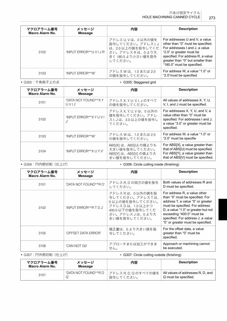
273穴あけ固定サイクル
HOLE MACHINING CANNED CYCLE
• G305:千鳥格子上の点 • G305: Staggered grid
• G306:円内側切削(仕上げ) • G306: Circle cutting inside (finishing)
• G307:円外側切削(仕上げ) • G307: Circle cutting outside (finishing)
3102 ‘INPUT ERROR**U V I J R’
アドレス U, V は、0 以外の値を指令してください。アドレス I, Jは、2.0 以上の値を指令してください。アドレス R は、0 より大きく 180.0 より小さい値を指令してください。
For addresses U and V, a value other than “0” must be specified. For addresses I and J, a value “2.0” or greater must be specified. For address R, a value greater than “0” but smaller than “180.0” must be specified.
3103 ‘INPUT ERROR**W’ アドレス W は、1.0 または 2.0の値を指令してください。
For address W, a value “1.0” or “2.0”must be specified.
マクロアラーム番号Macro Alarm No.
メッセージMessage
内容 Description
マクロアラーム番号Macro Alarm No.
メッセージMessage
内容 Description
3101‘DATA NOT FOUND**X Y U V I J’
アドレス X, Y, U, V, I, J のすべての値を指令してください。
All values of addresses X, Y, U, V, I, and J must be specified.
3102‘INPUT ERROR**X Y U V I J’
アドレス X, Y, U, V は、0 以外の値を指令してください。アドレス I, J は、3.0 以上の値を指令してください。
For addresses X, Y, U, and V, a value other than “0” must be specified. For addresses I and J, a value “3.0” or greater must be specified.
3103 ‘INPUT ERROR**W’ アドレス W は、1.0 または 2.0の値を指令してください。
For address W, a value “1.0” or “2.0” must be specifie
3104 ‘INPUT ERROR**X U Y V’
ABS[X] は、ABS[U] の値よりも大きい値を指令してください。ABS[Y] は、ABS[V] の値より大きい値を指令してください。
For ABS[X], a value greater than that of ABS[U] must be specified. For ABS[Y], a value greater than that of ABS[V] must be specified.
マクロアラーム番号Macro Alarm No.
メッセージMessage
内容 Description
3101 ‘DATA NOT FOUND**R D’ アドレス R, D の両方の値を指令してください。
Both values of addresses R and D must be specified.
3102 ‘INPUT ERROR**R T D J’
アドレス R は、0 以外の値を指令してください。アドレス T は、0 以上の値を指令してください。アドレス D は、1.0 以上かつ400.0 以下の値を指令してください。アドレス J は、0 より大きい値を指令してください。
For address R, a value other than “0” must be specified. For address T, a value “0” or greater must be specified. For address D, a value “1.0” or greater but not exceeding “400.0” must be specified. For address J, a value “0” or greater must be specified.
3105 ‘OFFSET DATA ERROR’補正量は、0 より大きい値を指令してください。
For the offset data, a value greater than “0” must be specified.
3106 ‘CAN NOT G0’ アプローチまたは加工ができません。
Approach or machining cannot be executed.
マクロアラーム番号Macro Alarm No.
メッセージMessage
内容 Description
3101‘DATA NOT FOUND**R D Q’
アドレス R, D, Q のすべての値を指令してください。
All values of addresses R, D, and Q must be specified.

穴あけ固定サイクルHOLE MACHINING CANNED CYCLE274
• G308:四角内側切削(仕上げ) • G308: Frame cutting inside (finishing)
• G309:四角外側切削(仕上げ) • G309: Frame cutting outside (finishing)
3102‘INPUT ERROR**R T D Q J’
アドレス R は、0 以外の値を指令してください。アドレス T は、0 以上の値を指令してください。アドレス D は、1.0 以上かつ400.0 以下の値を指令してください。アドレス Q,J は、0 より大きい値を指令してください。
For address R, a value other than “0” must be specified. For address T, a value “0” or greater must be specified. For address D, a value “1.0” or greater but not exceeding “400.0” must be specified. For addresses Q and J, a value greater than “0” must be specified.
3105 ‘OFFSET DATA ERROR’補正量は、0 より大きい値を指令してください。
For the offset data, a value greater than “0” must be specified.
3106 ‘CAN NOT G0’ アプローチまたは加工ができません。
Approach or machining cannot be executed.
マクロアラーム番号Macro Alarm No.
メッセージMessage
内容 Description
マクロアラーム番号Macro Alarm No.
メッセージMessage
内容 Description
3101‘DATA NOT FOUND**U V H D Q’
アドレス U, V, H, D, Q のすべての値を指令してください。
All values of addresses U, V, H, D, and Q must be specified.
3102‘INPUT ERROR**U V T D Q J’
アドレス U, V, Q, J は、0 より大きい値を指令してください。アドレス T は、0 以上の値を指令してください。アドレス D は、1.0 以上かつ 400.0 以下の値を指令してください。
For address U, V, Q, J, a value greater than “0” must be specified. For address T, a value “0” or greater must be specified. For address D, a value “1.0” or greater but not exceeding “400.0” must be specified.
3103 ‘INPUT ERROR**H’
アドレス H は、1.0, −1.0, 2.0, −2.0, 3.0, −3.0, 4.0, −4.0 のいずれかの値を指令してください。
For address H, any of the values “1.0”, “−1.0”, “2.0”, “−2.0”, “3.0”, “−3.0”, “4.0” or “−4.0” must be specified.
3105 ‘OFFSET DATA ERROR’補正量は、0 より大きい値を指令してください。
For the offset data, a value greater than “0” must be specified.
3106 ‘CAN NOT G0’ アプローチまたは加工ができません。
Approach or machining cannot be executed.
マクロアラーム番号Macro Alarm No.
メッセージMessage
内容 Description
3101‘DATA NOT FOUND**U V H D Q’
アドレス U, V, H, D, Q のすべての値を指令してください。
All values of addresses U, V, H, D, and Q must be specified.
3102‘INPUT ERROR**U V T D Q J’
アドレス U, V, Q, J は、0 より大きい値を指令してください。アドレス T は、0 以上の値を指令してください。アドレス D は、1.0 以上かつ 400.0 以下の値を指令してください。
For address U, V, Q, J, a value greater than “0” must be specified. For address T, a value “0” or greater must be specified. For address D, a value “1.0” or greater but not exceeding “400.0” must be specified.
3103 ‘INPUT ERROR**H’
アドレス H は、1.0, −1.0, 2.0, −2.0, 3.0, −3.0, 4.0, −4.0 のいずれかの値を指令してください。
For address H, any of the values “1.0”, “−1.0”, “2.0”, “−2.0”, “3.0”, “−3.0”, “4.0” or “−4.0” must be specified.
3105 ‘OFFSET DATA ERROR’補正量は、0 より大きい値を指令してください。
For the offset data, a value greater than “0” must be specified.

275穴あけ固定サイクル
HOLE MACHINING CANNED CYCLE
3106 ‘CAN NOT G0’ アプローチまたは加工ができません。
Approach or machining cannot be executed.
マクロアラーム番号Macro Alarm No.
メッセージMessage
内容 Description


6 章
6èÕ プログラム例CHAPTER 6
CHAPTER 6 EXAMPLE PROGRAMS

1 プログラム例.......................................................................................................................................279EXAMPLE PROGRAMS

279プログラム例
EXAMPLE PROGRAMS
1 プログラム例EXAMPLE PROGRAMS
同じワークを加工するにしても、非常に多くの加工方法およびプログラム方法があります。ここでは一例として、よく使用すると思われるものについて説明します。
There are a variety of machining and programming methods used when a workpieces is machined. This section describes programs which seem to be used frequently in actual machining.
これらの例を参考にお客様の加工にあった、よりよい方法を見つけ出してください。加工内容によっては、この方法や数値が適切でない場合もありますので注意してください。
Study these example programs, and then create programs which better suit your actual machining conditions. Note that the programming methods and values shown here may not apply to your specific needs.
ここでは、MAPPS 工具管理システムを使用したプログラム例を掲載しています。工具長補正番号は H1、工具径補正番号はD1 を使用しています。
Example programs in this chapter use the MAPPS tool management system. H1 is used for the tool length offset number and D1 is used for the tool radius offset number.
1 MAPPS 工具管理システムの使用方法については、別冊“MAPPS 工具管理システム取扱説明書 ”
1 For details on using the MAAPS tool management system, refer to the separate volume “MAPPS TOOL MANAGEMENT SYS-TEM INSTRUCTION MANUAL”.
8警告 8WARNING
1. お客様によって加工されるワークの材質や形状は多種多様
にわたるため、弊社ではそれらのすべてを把握することができません。したがって、ワークのクランプ方法や主軸の回転速度、切削時の送り速度、切込み量、切込み幅などの加工条件は、お客様が責任をもって決定してください。お客様でワークのクランプ方法や加工条件を決定しかねる場合は、治具メーカーや切削工具メーカーにご連絡ください。
[ワークや切削工具の飛び出し、人身事故、機械の破損、切削工具の破損]
1. Workpiece materials and shapes vary widely among machine users. DMG MORI SEIKI cannot predict the workpiece clamping method, spindle speed, feedrate, depth of cut, and width of cut, etc., that will be required in each case and it is therefore the user's responsibility to determine the appropriate settings. If you have difficulty determining these conditions, consult the fixture and tool manufacturers. [Workpiece or cutting tool ejection during machining, injuries, machine or cutting tool damage]
2. ここで記載しているプログラムは、すべての機械には対応
していません。お客様が購入された機械の能力を十分把握した上で、 適なプログラムを作成し、安全を考慮して加工を行ってください。
[ワークや切削工具が飛び出し、人身事故、機械の破損]
2. The programs given here are not applicable to all manufacturing environments. Programs must be written while taking the performance of your machine into consideration and be executed with due consideration given to safety. [Cutting tool ejection during machining, injuries, machine damage]
7注意 7 CAUTION工具補正番号は、MAPPS 工具管理システムで使用している番号を使用してください。他の工具補正番号を使用するときは、MAPPS 工具管理システムの機能を十分理解した上でご使用ください。[機械や工具の破損]
Use the tool offset number that is used in the MAPPS tool management system. If using other tool offset numbers, make sure you understand the functions thoroughly. [Damage to the machine and tool]
2 注記 2 NOTE
1. 本章では、プログラム例で繰り返し出てくるブロック(G コード、M コード)のうち、2 回目以降の説明は省略しています。
1. Among the blocks including G and/or M codes that appear repeatedly in the example programs, the first ones are explained but the explanation for the second ones and thereafter are omitted.
2. プログラム中の各 G コード、M コードの詳細については、前述の各コードの説明でご確認ください。
2. Confirm the details of the G and/or M code functions in the corresponding sections described above.

プログラム例EXAMPLE PROGRAMS280
1-1 穴あけ固定サイクル(G81, G76, G84)、サブプログラム(M98, M99)Hole Machining Canned Cycle Program (G81, G76, G84) and Sub-Program (M98, M99)
<作成手順> <Procedure>1) 加工原点を決めます。 1) Determine the workpiece zero point.
2) ワークのクランプ方法を決めます。 2) Determine the clamping method.
100
300
100(50)
0.5C1C
200
5050
5030
φ20+0.030
Prepared Hole 8.5 Dia.
Material: Cast Iron (JIS FC25)
6 - M10 × P1.5 Through-Hole
6 - M10 × P1.5 貫通下ギリ φ8.5
材質 FC25
+Y
+X
(X0, Y0)
Z0
Reference Block
Plate
Workpiece
4 Clamping Plates
Reference Block
基準ブロック
敷板
ワーク
4 - 締め板
基準ブロック

281プログラム例
EXAMPLE PROGRAMS
3) ツーリングを決めます。 3) Determine the tooling.
4) 切削条件を決めます。 4) Determine the cutting conditions.
5) プログラムを作成します。 5) Create the program.
加工順序Machining
Order工具名
Tool Name
工具グループ番号
Tool Group Number
加工箇所Portions to Be Machined
1センタドリルCenter drill
T1M10 タップ部および φ20 部センタ穴加工Centering for M10 tapping and 20 mm dia. hole
2φ8.5 ドリル8.5 mm dia. drill
T2M10 タップ下穴加工Drilling prepared hole for M10 tapping
3φ18 ドリル18 mm dia. drill
T3φ20 部荒加工Rough drilling of 20 mm dia. hole
4 φ19.5 エンドミル19.5 mm dia. end mill
T4φ20 部中仕上げ加工Semi-finishing of 20 mm dia. hole
5 φ25 面取りミル25 mm dia. chamfering mill
T5 M10 タップ部および φ20 部面取り加工Chamfering for M10 tapping holes and 20 mm dia. hole
6M10 × P1.5 タップM10 × P1.5 tap
T6タップ加工Tapping
7 φ20 ボーリング20 mm dia. boring bar
T7φ20 ボーリング仕上げ加工Finishing 20 mm dia. boring
工程Process
工具グループ番
号Tool
Group Number
(T)
工具名Tool Name
主軸回転速度Spindle Speed
(S)(min−1)
送り速度Feedrate
(F)(mm/min)
工具補正番号Offset Number
工具長補正番号Tool Length Off-
set Number(H)
工具径補正番号Tool Radius Off-
set Number(D)
N1 T1 センタドリルCenter drill
2000 150 1 —
N2 T2 φ8.5 ドリル8.5 mm dia. drill
750 150 1 —
N3 T3 φ18 ドリル18 mm dia. drill
440 90 1 —
N4 T4 φ19.5 エンドミル19.5 mm dia. end mill
400 80 1 —
N5 T5 φ25 面取りミル25 mm dia. chamfering mill
400 80 1 —
N6 T6 M10 × P1.5 タップM10 × P1.5 tap
250 375 1 —
N7 T7 φ20 ボーリング20 mm dia. boring bar
1600 150 1 —

プログラム例EXAMPLE PROGRAMS282
<メインプログラム(O0001)> <Main Program (O0001)>
O0001 (TEST PIECE); .............................................. プログラム番号、タイトル(テストピース)
Program number and title (test piece)
G00 G40 G80;........................................................... 工具径補正、穴あけ固定サイクルキャンセル
Canceling tool radius offset and hole machining canned cycle
G91 G30 Z0; ............................................................. Z 軸を第 2 原点復帰 Second zero return of Z-axisG30 X0 Y0; ............................................................... X, Y 軸を第 2 原点復帰 Second zero return of X- and Y-axesT1;............................................................................. 1 番グループの工具(センタドリ
ル)呼出しCalling a tool of group number 1 (center drill)
M01; .......................................................................... オプショナルストップ Optional stopM06; .......................................................................... 工具交換 Executing tool change cycle
N1 T2 (CENTER DRILL); .......................................... センタドリル加工2 番グループの工具(φ8.5 ドリル)呼出し
Drilling with center drillingCalling a tool of group number 2 (8.5 mm dia. drill)
G90 G00 G54 X0 Y0;................................................ ワーク座標系 G54 選択X, Y を加工原点に早送りで位置決め
Selecting work coordinate system G54Positioning of X- and Y-axes at the workpiece zero point at a rapid traverse rate
B0;............................................................................. B 軸 0° 割出し Indexing B-axis to 0° positionG43 Z50.0 H1 S2000; ............................................... 工具長補正番号 1 番の補正量だけ Z
軸方向に補正して、Z50.0 の位置に早送りで位置決め主軸回転速度 2000 min−1
Positioning at Z50.0 at a rapid traverse rate while Z-axis position is offset by offset data set for tool length offset number 1Specifying spindle speed of 2000 min−1
M03; .......................................................................... 主軸正転 Starting the spindle in the normal direction
G98(G99) G81 Z−5.0 R3.0 F150; ............................. スポットドリリングサイクル(G81)実行
Executing the spot drilling cycle (G81)
• Z−5.0.............................................................. Z 点(穴底)の位置 Z coordinate value of the point Z (hole bottom)
• R3.0 ............................................................... R 点の位置 Z coordinate value of the point R
• F150............................................................... 送り速度 150 mm/min Feedrate of 150 mm/min
M98 P2;..................................................................... サブプログラム O0002 の呼出しO0002 の穴位置でスポットドリリングサイクル(G81)を実行
Calling sub-program O0002Spot drilling cycle (G81) is executed at the positions specified in O0002.
G80 G91 G30 Z0 M05; ............................................. 穴あけ固定サイクルキャンセルZ 軸第 2 原点復帰して、主軸の回転停止
Canceling hole machining canned cycleSecond zero return of Z-axis and spindle stops rotating.
G30 X0 Y0; ............................................................... X, Y 軸第 2 原点復帰 Second zero return of X- and Y-axesM01;
(Z50.0)
(Z3.0) Initial Point
Point R Point Z (Z−5.0)
イニシャル点
R点Z点 (Z-5.0)
283プログラム例
EXAMPLE PROGRAMS
M06; .......................................................................... 主軸の 1 番グループの工具と 2 番グループの工具を交換
Tool change between a tool of group number 1 in the spindle and a tool of group number 2
N2 T3 (8.5 DRILL);.................................................... φ8.5 ドリル加工3 番グループの工具(φ18 ドリル)呼出し
Drilling with 8.5 mm dia. drillCalling a tool of group number 3 (18 mm dia. drill)
G90 G00 G54 X100.0 Y50.0;G43 Z50.0 H1 S750;M03;(G98) G81 Z−34.0 R3.0 F150 L0; ............................. スポットドリリングサイクル
(G81)実行
2 注記
L0 を指令しているため、穴あけ固定サイクルは実行されず、穴加工データの記憶のみ行います。
Executing the spot drilling cycle (G81)
2 NOTE
Since “L0” is specified, the specified hole machining canned cycle is not executed and only the hole machining data is stored.
M98 P2;G80 G91 G30 Z0 M05;G30 X0 Y0;M01;M06;
N3 T4 (18 DRILL);..................................................... φ18 ドリル加工4 番グループの工具(φ19.5 エンドミル)呼出し
Drilling with 18 mm dia. drillCalling a tool of group number 4 (19.5 mm dia. end mill)
G90 G00 G54 X0 Y0;G43 Z50.0 H1 S440;M03;(G98) G81 Z−38.0 R3.0 F90;G80 G91 G30 Z0 M05;G30 X0 Y0;M01;M06;
N4 T5 (19.5 ENDMILL); ............................................ φ19.5 エンドミル加工5 番グループの工具(φ25 面取り)呼出し
Drilling with 19.5 mm dia. end millCalling a tool of group number 5 (25 mm dia. chamfering mill)
G90 G00 G54 X0 Y0;G43 Z50.0 H1 S400;M03;(G98) G81 Z−32.0 R3.0 F80;G80 G91 G30 Z0 M05;G30 X0 Y0;M01;M06;
N5 T6 (25 MENTORI); .............................................. φ25 面取り加工6 番グループの工具(M10 × P1.5 タップ)呼出し
Chamfering with 25 mm dia. chamfering millCalling a tool of group number 6 (M10 × P1.5 tap)
G90 G00 G54 X0 Y0;G43 Z50.0 H1 S400;M03;(G98) G81 Z−11.0 R−7.0 F80; .................................. スポットドリリングサイクル
(G81)実行Executing the spot drilling cycle (G81)
• Z−11.0 ............................................................ Z 点の位置 Z coordinate value of the point Z
• R−7.0 ............................................................. R 点の位置 Z coordinate value of the point R
• F80................................................................. 送り速度 80 mm/min Feedrate of 80 mm/min

プログラム例EXAMPLE PROGRAMS284
<サブプログラム(O0002)> <Sub-Program (O0002)>
Z−5.5 R−2.0 L0; ........................................................ スポットドリリングサイクルの Z点および R 点を変更
2 注記
L0 を指令しているため、穴あけ固定サイクルは実行されず、穴加工データの記憶のみ行います。
Changing cycle point Z and R
2 NOTE
Since “L0” is specified, the specified hole machining canned cycle is not executed and only the hole machining data is stored.
• Z−5.5.............................................................. 変更した Z 点の位置 Position of the new point Z
• R−2.0 ............................................................. 変更した R 点の位置 Position of the new point RM98 P2;G80 G91 G30 Z0 M05;G30 X0 Y0;M01;M06;
N6 T7 (M10 × P1.5 TAP);.......................................... M10 × P1.5 タップ加工7 番グループの工具(φ20 ボーリング)呼出し
Tapping with M10 × P1.5 tapCalling a tool of group number 7 (20 mm dia. boring bar)
G90 G00 G54 X100.0 Y50.0;G43 Z50.0 H1;M29 S250;................................................................. 同期式タッピング指令 Specifying the synchronized tappingG98(G99) G84 Z−32.0 R10.0 F375 (,R01), S500 L0; 同期式タッピングサイクル(M29
G84)実行
2 注記
L0 を指令しているため、穴あけ固定サイクルは実行されず、穴加工データの記憶のみ行います。
Executing the synchronized tapping cycle (M29 G84)
2 NOTE
Since “L0” is specified, the specified hole machining canned cycle is not executed and only the hole machining data is stored.
M98 P2;G80 G91 G30 Z0 M05;G30 X0 Y0;M01;M06;
N7 T1 (20 BORING);................................................. φ20 ボーリング加工1 番グループの工具(センタドリル)呼出し
Boring with 20 mm dia. boring barCalling a tool of group number 1 (center drill)
G90 G00 G54 X0 Y0;................................................ ワーク座標系 G54 選択X, Y を加工原点に早送りで位置決め
Selecting work coordinate system G54Positioning of X- and Y-axes at the workpiece zero point at a rapid traverse rate
G43 Z50.0 H1 S1600;M03;
G98(G99) G76 Z−32.0 J0.5 R3.0 F150; ................... ファインボーリングサイクル(G76)実行
Executing the fine boring cycle (G76)
G80 G91 G30 Z0 M05;M30; .......................................................................... プログラム終了 Program end
O0002; ...................................................................... プログラム番号 Program NumberX100.0 Y50.0; ........................................................... 以下穴位置データ The following is hole position dataY0;Y−50.0;X−100.0;Y0;

285プログラム例
EXAMPLE PROGRAMS
1-2 真円切削(工具径補正)Accurate Circle Cutting (Tool Radius Offset)
<作成手順> <Procedure>1) 加工原点およびワークのクランプ方法を決めます。 1) Determine the workpiece zero point and the workpiece
clamping method.
2) ツーリングを決めます。 2) Determine the tooling.
Y50.0;M99; .......................................................................... サブプログラム終了
(メインプログラムに復帰)Sub-program end(Returning to main program)
2020
0
200φ100
φ90
Cutting Allowance is 5 mm
Material: Cast Iron (JIS FC25)
取り代片肉 5 mm
材質:FC25
Z0
10
110
4 Clamping Plates
Workpiece Zero Point (X0, Y0)
3 Positioning Pins
4 - 締め板
加工原点(X0, Y0)
3 - 位置決めピン
加工順序Machining
Order工具名
Tool Name
工具グループ番号
Tool Group Number
加工箇所Portions to Be Machined
—φ25 エンドミル25 mm dia. end mill
T1φ100 の穴加工100 mm dia. hole

プログラム例EXAMPLE PROGRAMS286
3) 切削条件を決めます。 3) Determine the cutting condition.
2 注記 2 NOTE
工具径補正量は、‘ 工具管理 (工具データ)’ 画面の ‘ 工具径形状 ’に 12.5 mm を設定してください。
For the tool radius offset amount, set 12.5 mm for ‘TL RAD.GEOM’ on the ‘TOOL MANAGEMENT (TOOL DATA)’ screen.
1 工具補正量の設定については、別冊 “MAPPS 工具管理システム取扱説明書 ”
1 For setting the tool radius offset amount, refer to the separate volume “MAPPS TOOL MANAGEMENT SYSTEM INSTRUCTION MANUAL”
4) プログラムを作成します。 4) Create the program.
工程Process
工具グループ番
号Tool
Group Number
(T)
工具名Tool Name
主軸回転速度Spindle Speed
(S)(min−1)
送り速度Feedrate
(F)(mm/min)
工具補正番号Offset Number
工具長補正番号Tool Length Off-
set Number(H)
工具径補正番号Tool Radius Off-
set Number(D)
N1 T1 φ25 エンドミル25 mm dia. end mill
330 66 1 1*
O0010; ...................................................................... プログラム番号 Program numberG00 G40 G80;........................................................... 工具径補正、穴あけ固定サイクル
キャンセルCanceling tool radius offset and hole machining canned cycle
G91 G30 Z0; ............................................................. Z 軸を第 2 原点復帰 Second zero return of Z-axisG30 X0 Y0; ............................................................... X, Y 軸を第 2 原点復帰 Second zero return of X- and Y-axesT1;............................................................................. 1 番グループの工具(φ25 エンドミ
ル)呼出しCalling a tool of group number 1 (25 mm dia. end mill)
M01; .......................................................................... オプショナルストップ Optional stopM06; .......................................................................... 工具交換 Executing tool change cycle
N1 (25 ENDMILL D1 = 12.5);.................................... φ25 エンドミル加工 Drilling with 25 mm dia. end millG90 G00 G54 X0 Y0;................................................ ワーク座標系 G54 選択
X, Y を加工原点に早送りで位置決めSelecting work coordinate system G54Positioning of X- and Y-axes at the workpiece zero point at a rapid traverse rate
B0;............................................................................. B 軸 0° 割出し Indexing B-axis to 0° positionG43 Z50.0 H1 S330; ................................................. 工具長補正番号 1 番の補正量だけ Z
軸方向に補正して、Z50.0 の位置に早送りで位置決め主軸回転速度 330 min−1
Positioning at Z50.0 at a rapid traverse rate while Z-axis position is offset by offset data set for tool length offset number 1Specifying spindle speed of 330 min−1
M03; .......................................................................... 主軸正転 Starting the spindle in the normal direction
Z−25.0;

287プログラム例
EXAMPLE PROGRAMS
5アプローチ半径は半径 R の 60% 位を目安として、R30.0 としています。
5Approach radius is set to R30.0 with about 60% of radius R.
G41 G01 X20.0 Y−30.0 D1 F66;...........................a 工具径補正番号 1 番の補正量だけプログラムの進行方向に対して左側に工具を補正して、X20.0, Y−30.0の位置に切削送りで移動送り速度 66 mm/min
After offsetting the tool position to the left in reference to the tool advance direction by the amount set to tool radius offset number 1, the cutting tool is moved to X20.0, Y−30.0 at a cutting feedrate.Specifying the feedrate of 66 mm/min
G03 X50.0 Y0 R30.0;............................................b X50.0, Y0 まで半径 30.0 mm の円弧切削(反時計方向)
Circular arc cutting (counterclockwise direction), radius 30.0 mm, circular arc end point coordinate X50.0, Y0
I−50.0; ...................................................................c 半径 50.0 mm の全円切削 Circle, radius 50.0 mmX20.0 Y30.0 R30.0;...............................................d X20.0, Y30.0 まで半径 30.0 mm の円
弧切削(反時計方向)Circular arc cutting (counterclockwise direction), radius 30.0 mm, circular arc end point coordinate X20.0, Y30.0
G40 G01 X0 Y0 F1000; ........................................e 工具径補正キャンセル加工原点に送り速度 1000 mm/minで移動
Canceling tool radius offsetMoving the cutting tool to the workpiece zero point at a feedrate of 1000 mm/min
G00 Z50.0 M05; ........................................................ Z50.0 まで早送りで移動して、主軸の回転停止
Positioning to Z50.0 at a rapid traverse rate and spindle stops rotating.
G91 G30 Z0; ............................................................. Z 軸第 2 原点復帰 Second zero return of Z-axisM30; .......................................................................... プログラム終了 Program end
+X
(0, 30.0)
(0, −30.0)
(20.0, 0) (50.0, 0)(0, 0)
a b
c
de

プログラム例EXAMPLE PROGRAMS288
1-3 多数個取りMachining Multiple Workpieces
“ 真円切削(工具径補正)”(285 ページ)のワークをテーブルに 4 個載せてプログラムを作成すると以下のようになります。
Place the four workpieces shown in the previous section “Accurate Circle Cutting (Tool Radius Offset)” (page 285) on the table and create the program as follows.
1) 加工原点およびクランプ方法を決めます。 1) Determine the workpiece zero point and workpiece clamping method.
2) プログラムを作成します。 2) Create the program.<メインプログラム(O0010)> <Main program (O0010)>
X0, Y0
50
20 10
Z0
Tooling Block
Clamping Plates
イケール
締め板
O0010; ................................................................ プログラム番号 Program numberG00 G40 G80; .................................................... 工具径補正、穴あけ固定サイクル
キャンセルCanceling tool radius offset and hole machining canned cycle
G90 G10 L2 P1 X_ Y_ Z_ ; ................................. ワーク座標系 G54 に X, Y, Z 軸の補正量を入力
Inputting the offset date of X-, Y-, Z-axes to define the work coordinate system G54
G10 L2 P2 X_ Y_ Z_ ; ......................................... ワーク座標系 G55 に X, Y, Z 軸の補正量を入力
Inputting the offset date of X-, Y-, Z-axes to define the work coordinate system G55
G10 L2 P3 X_ Y_ Z_ ; ......................................... ワーク座標系 G56 に X, Y, Z 軸の補正量を入力
Inputting the offset date of X-, Y-, Z-axes to define the work coordinate system G56
G10 L2 P4 X_ Y_ Z_ ; ......................................... ワーク座標系 G57 に X, Y, Z 軸の補正量を入力
Inputting the offset date of X-, Y-, Z-axes to define the work coordinate system G57
G91 G30 Z0; ....................................................... Z 軸を第 2 原点復帰 Calling second zero return of Z-axisG30 X0 Y0; ......................................................... X, Y 軸を第 2 原点復帰 Calling second zero return of X- and
Y-axesT1;....................................................................... 1 番グループの工具(φ25 エンドミ
ル)呼出しCalling a tool of group number 1 (25 mm dia. end mill)
M01; .................................................................... オプショナルストップ Optional stopM06; .................................................................... 工具交換 Executing tool change cycle

289プログラム例
EXAMPLE PROGRAMS
N1 (25 ENDMILL D1 = 12.5);.............................. φ25 エンドミル加工 Drilling with 25 mm dia. end millG90 G00 G54 X0 Y0;.......................................... ワーク座標系 G54 選択
X, Y を加工原点に早送りで位置決めSelecting work coordinate system G54Positioning of X- and Y-axes at the workpiece zero point at a rapid traverse rate
B0;....................................................................... B 軸 0° 割出し Indexing B-axis to 0°positionG43 Z50.0 H1 S330; .......................................... 工具長補正番号 1 番の補正量だけ Z
軸方向に補正して、Z50.0 の位置に早送りで位置決め主軸回転速度 330 min−1
Positioning at Z50.0 at a rapid traverse rate while Z-axis position is offset by offset data set for tool length offset number 1Specifying spindle speed of 330 mm−1
M03; .................................................................... 主軸正転 Starting the spindle in the normal direction
M98 P101;........................................................... サブプログラム O0101 の呼出し Calling sub-program O0101G55 X0 Y0; ........................................................ ワーク座標系 G55 選択
X, Y を加工原点に早送りで位置決めSelecting work coordinate system G55Positioning of X- and Y-axes at the workpiece zero point at a rapid traverse rate
(G90) B90.0; ....................................................... B 軸 90° 割出し Indexing B-axis to 90° positionM98 P101;........................................................... サブプログラム O0101 の呼出し Calling sub-program O0101G56 X0 Y0; ........................................................ ワーク座標系 G56 選択
X, Y を加工原点に早送りで位置決めSelecting work coordinate system G56Positioning of X- and Y-axes at the workpiece zero point at a rapid traverse rate
(G90) B180.0; ..................................................... B 軸 180° 割出し Indexing B-axis to 180° positionM98 P101;........................................................... サブプログラム O0101 の呼出し Calling sub-program O0101G57 X0 Y0; ........................................................ ワーク座標系 G57 選択
X, Y を加工原点に早送りで位置決めSelecting work coordinate system G57Positioning of X- and Y-axes at the workpiece zero point at a rapid traverse rate
(G90)B270.0; ...................................................... B 軸 270° 割出し Indexing B-axis to 270° positionM98 P101;........................................................... サブプログラム O0101 の呼出し Calling sub-program O0101G91 G30 Z0 M05; Z 軸第 2 原点復帰して、主軸の回転
停止Second zero return of Z-axis, spindle stops rotating
G30 X0 Y0; ......................................................... X, Y 軸第 2 原点復帰 Second zero return of X- and Y-axesG28 B0;............................................................... B 軸機械原点復帰 Machine zero return of B-axisM30; .................................................................... プログラム終了 Program end

プログラム例EXAMPLE PROGRAMS290
<サブプログラム(O0101)> <Sub-program (O0101)>
5アプローチ半径は半径 R の 60% 位を目安として、R30.0 としています。
5Approach radius is set to R30.0 with about 60% of radius R.
O0101; ................................................................ プログラム番号 Program numberG90 G00 Z−25.0;G41 G01 X20.0 Y−30.0 D1 F66;.....................a 工具径補正番号 1 番の補正量だけ
プログラムの進行方向に対して左側に工具を補正して、X20.0, Y−30.0の位置に切削送りで移動送り速度 66 mm/min
After offsetting the tool position to the left in reference to the tool advance direction by the amount set to tool radius offset number 1, the cutting tool is moved to X20.0, Y−30.0 at a cutting feedrate.Specifying the feedrate of 66 mm/min
G03 X50.0 Y0 R30.0;......................................b X50.0, Y0 まで半径 30.0 mm の円弧切削(反時計方向)
Circular arc cutting (counterclockwise direction), radius 30.0 mm, circular arc end point coordinate X50.0 Y0
I−50.0; .............................................................c 半径 50.0 mm の全円切削 Circle, radius 50.0 mmX20.0 Y30.0 R30.0;.........................................d X20.0, Y30.0 まで半径 30.0 mm の円
弧切削(反時計方向)Circular arc cutting (counterclockwise direction), radius 30.0 mm, circular arc end point coordinate X20.0 Y30.0
G40 G01 X0 Y0 F1000; .................................e 工具径補正キャンセル加工原点に送り速度 1000 mm/minで移動
Canceling tool radius offsetMoving the cutting tool to the workpiece zero point at a feedrate of 1000 mm/min
G00 Z300.0; ........................................................ Z300.0 まで早送りで移動 Moving the cutting tool to Z300.0 at a rapid traverse rate
M99; .................................................................... サブプログラム終了(メインプログラムに復帰)
Sub-program end (Returning to main program)
+X
(0, 30.0)
(0, −30.0)
(20.0, 0) (50.0, 0)(0, 0)
a b
c
de

291プログラム例
EXAMPLE PROGRAMS
1-4 平面加工、側面加工(G41)、穴あけ固定サイクル(G81, G73, G76)Facing, Side Cutting (G41), Hole Machining Canned Cycle (G81, G73, G76)
イケールにワークを 2 つ、背中合わせに取り付けます。 Mount two workpieces to the tooling block back to back.<手順> <Procedure>1) 加工原点およびワークのクランプ方法を決めます。 1) Determine the workpiece zero point and the workpiece
clamping method.
2) ツーリングを決めます。 2) Determine the tooling.
150
400
5-φ28.5
150
100
100
25 3530
0
Depth 25 mm
Material: Cast Iron (JIS FC25)
深さ 25 mm
材質:FC25
Z0
Workpiece Zero Point (X0, Y0)加工原点(X0, Y0)
加工順序Machining
Order工具名
Tool Name
工具グループ番号
Tool Group Number
加工箇所Portions to Be Machined
1 φ100 フェイスミル100 mm dia. face mill T1 平面加工(フライス加工)
Facing (Milling)

プログラム例EXAMPLE PROGRAMS292
3) 切削条件を決めます。 3) Determine the cutting conditions.
4) プログラムを作成します。 4) Create the program.<メインプログラム(O0050)> <Main program (O0050)>
2 センタドリルCenter drill T2 φ28.5 部センタ穴加工
Centering for 28.5 mm dia. hole
3 φ27 ドリル27 mm dia. drill T3 φ28.5 部荒加工
Rough drilling of 28.5 mm dia. hole
4 φ28 エンドミル28 mm dia. end mill T4 φ28.5 部中仕上げ加工
Semi-finishing of 28.5 mm dia. hole
5 φ28.5 ボーリング28.5 mm dia. boring bar T5 φ28.5 部ボーリング仕上げ加工
Finishing of 28.5 mm dia. boring
6 φ40 エンドミル40 mm dia. end mill T6 側面加工(外周加工)
Side cutting (circumferential cutting)
加工順序Machining
Order工具名
Tool Name
工具グループ番号
Tool Group Number
加工箇所Portions to Be Machined
工程Pro-cess
工具グループ番
号Tool
Group Number
(T)
工具名Tool Name
主軸回転速度Spindle Speed
(S)(min−1)
F の送り速度Feedrate
(F)(mm/min)
工具補正番号Offset Number
工具長補正番号
Tool Length Offset Num-
ber(H)
工具径補正番号
Tool RadiusOffset Num-
ber(D)
N10 T1 φ100 フェイスミル100 mm dia. face mill 330 400 1 —
N20 T2 センタドリルCenter drill 2000 150 1 —
N30 T3 φ27 ドリル27 mm dia. drill 330 70 1 —
N40 T4 φ28 エンドミル28 mm dia. end mil 330 70 1 —
N50 T5 φ28.5 ボーリング28.5 mm dia. boring bar 1000 80 1 —
N60 T6 φ40 エンドミル40 mm dia. end mil 250 50 1 1
O0050 (TEST PIECE); ........................................ プログラム番号、タイトル(テストピース)
Program number, title (test piece)
G00 G40 G80 T1; ............................................... 工具径補正、穴あけ固定サイクルキャンセル1 番グループの工具(φ100 フェイスミル)呼出し
Canceling tool radius offset and hole machining canned cycleCalling a tool of group number 1 (φ100 face mill)
G90 G10 L2 P1 X_ Y_ Z_ ; ................................. ワーク座標系 G54 に X, Y, Z 軸の補正量を入力
Inputting the offset data of X-, Y-, and Z-axes to the work coordinate system G54
G10 L2 P2 X_ Y_ Z_ ; ......................................... ワーク座標系 G55 に X, Y, Z 軸の補正量を入力
Inputting the offset data of X-, Y-, and Z-axes to the work coordinate system G55

293プログラム例
EXAMPLE PROGRAMS
M98 P51;............................................................. サブプログラム O0051 の呼出し(工具交換)
Calling sub-program O0051 (tool change)
N10 T2 (φ100 FACE MILL); ................................ φ100 フェイスミル加工2 番グループの工具(センタドリル)呼出し
Facing with 100 mm dia. face millCalling a tool of group number 2 (center drill)
G90 G54 G00 B0; ............................................... ワーク座標系 G54 選択B 軸 0° 割出し
Selecting work coordinate system G54 Indexing B-axis to 0° position
M98 P52;............................................................. サブプログラム O0052 の呼出し Calling sub-program O0052
N11;G90 G55 G00 B180.0; ........................................ ワーク座標系 G55 選択
B 軸 180° 割出しSelecting work coordinate system G55 Indexing B-axis to 180° position
M98 P52;............................................................. サブプログラム O0052 の呼出し Calling sub-program O0052M98 P51;............................................................. サブプログラム O0051 の呼出し
主軸の 1 番グループの工具と 2 番グループの工具を交換
Calling sub-program O0051Tool change between a tool of group number 1 in the spindle and a tool of group number 2
N20 T3 (CENTER DRILL);.................................. センタドリル加工3 番グループの工具(φ27 ドリル)呼出し
Drilling with center drillCalling a tool of group number 3 (27 mm dia. drill)
G90 G55 G00 B180.0; ........................................ ワーク座標系 G55 選択B 軸 180° 割出し
Selecting work coordinate system G55Indexing B-axis to 180° position
M98 P53;............................................................. サブプログラム O0053 の呼出し Calling sub-program O0053
N21G90 G54 G00 B0; ............................................... ワーク座標系 G54 選択
B 軸 0° 割出しSelecting work coordinate system G54Indexing B-axis to 0° position
M98 P53;............................................................. サブプログラム O0053 の呼出し Calling sub-program O0053M98 P51;............................................................. サブプログラム O0051 の呼出し
主軸の 2 番グループの工具と 3 番グループの工具を交換
Calling sub-program O0051Tool change between a tool of group number 2 in the spindle and a tool of group number 3
N30 T4 (27 DRILL);............................................. φ27 ドリル加工4 番グループの工具(φ28 エンドミル)呼出し
Drilling with 27 mm dia. drillCalling a tool of group number 4 (28 mm dia. end mill)
G90 G54 G00 B0; ............................................... ワーク座標系 G54 選択B 軸 0° 割出し
Selecting work coordinate system G54Indexing B-axis to 0° position
M98 P54;............................................................. サブプログラム O0054 の呼出し Calling sub-program O0054
N31G90 G55 G00 B180.0; ........................................ ワーク座標系 G55 選択
B 軸 180° 割出しSelecting work coordinate system G55Indexing B-axis to 180° position
M98 P54;............................................................. サブプログラム O0054 の呼出し Calling sub-program O0054M98 P51;............................................................. サブプログラム O0051 の呼出し
主軸の 3 番グループの工具と 4 番グループの工具を交換
Calling sub-program O0051Tool change between a tool of group number 3 in the spindle and a tool of group number 4
N40 T5 (28 ENDMILL); ....................................... φ28 エンドミル加工5 番グループの工具(φ28.5 ボーリング)呼出し
Drilling with 28 mm dia. end millCalling a tool of group number 5 (28.5 boring bar)
G90 G55 G00 B180.0; ........................................ ワーク座標系 G55 選択B 軸 180° 割出し
Selecting work coordinate system G55Indexing B-axis to 180° position
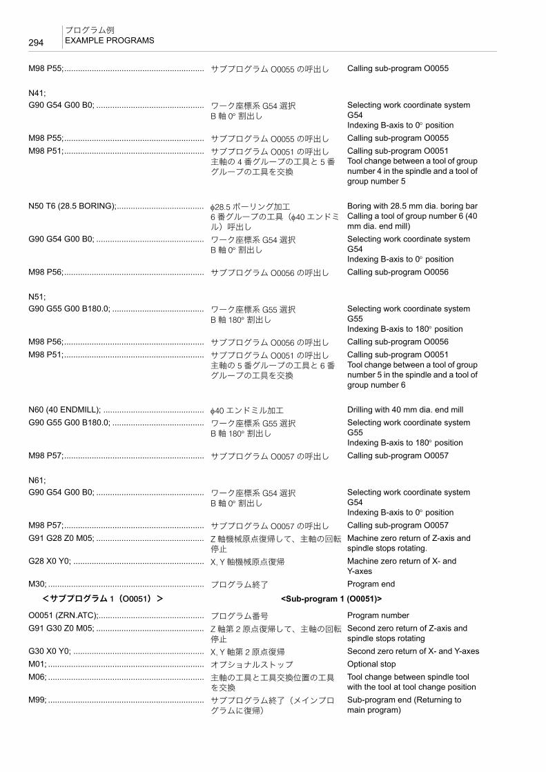
プログラム例EXAMPLE PROGRAMS294
<サブプログラム 1(O0051)> <Sub-program 1 (O0051)>
M98 P55;............................................................. サブプログラム O0055 の呼出し Calling sub-program O0055
N41;G90 G54 G00 B0; ............................................... ワーク座標系 G54 選択
B 軸 0° 割出しSelecting work coordinate system G54Indexing B-axis to 0° position
M98 P55;............................................................. サブプログラム O0055 の呼出し Calling sub-program O0055M98 P51;............................................................. サブプログラム O0051 の呼出し
主軸の 4 番グループの工具と 5 番グループの工具を交換
Calling sub-program O0051Tool change between a tool of group number 4 in the spindle and a tool of group number 5
N50 T6 (28.5 BORING);...................................... φ28.5 ボーリング加工6 番グループの工具(φ40 エンドミル)呼出し
Boring with 28.5 mm dia. boring barCalling a tool of group number 6 (40 mm dia. end mill)
G90 G54 G00 B0; ............................................... ワーク座標系 G54 選択B 軸 0° 割出し
Selecting work coordinate system G54Indexing B-axis to 0° position
M98 P56;............................................................. サブプログラム O0056 の呼出し Calling sub-program O0056
N51;G90 G55 G00 B180.0; ........................................ ワーク座標系 G55 選択
B 軸 180° 割出しSelecting work coordinate system G55Indexing B-axis to 180° position
M98 P56;............................................................. サブプログラム O0056 の呼出し Calling sub-program O0056M98 P51;............................................................. サブプログラム O0051 の呼出し
主軸の 5 番グループの工具と 6 番グループの工具を交換
Calling sub-program O0051Tool change between a tool of group number 5 in the spindle and a tool of group number 6
N60 (40 ENDMILL); ............................................ φ40 エンドミル加工 Drilling with 40 mm dia. end millG90 G55 G00 B180.0; ........................................ ワーク座標系 G55 選択
B 軸 180° 割出しSelecting work coordinate system G55Indexing B-axis to 180° position
M98 P57;............................................................. サブプログラム O0057 の呼出し Calling sub-program O0057
N61;G90 G54 G00 B0; ............................................... ワーク座標系 G54 選択
B 軸 0° 割出しSelecting work coordinate system G54Indexing B-axis to 0° position
M98 P57;............................................................. サブプログラム O0057 の呼出し Calling sub-program O0057G91 G28 Z0 M05; ............................................... Z 軸機械原点復帰して、主軸の回転
停止Machine zero return of Z-axis and spindle stops rotating.
G28 X0 Y0; ......................................................... X, Y 軸機械原点復帰 Machine zero return of X- and Y-axes
M30; .................................................................... プログラム終了 Program end
O0051 (ZRN.ATC);.............................................. プログラム番号 Program numberG91 G30 Z0 M05; ............................................... Z 軸第 2 原点復帰して、主軸の回転
停止Second zero return of Z-axis and spindle stops rotating
G30 X0 Y0; ......................................................... X, Y 軸第 2 原点復帰 Second zero return of X- and Y-axesM01; .................................................................... オプショナルストップ Optional stopM06; .................................................................... 主軸の工具と工具交換位置の工具
を交換Tool change between spindle tool with the tool at tool change position
M99; .................................................................... サブプログラム終了(メインプログラムに復帰)
Sub-program end (Returning to main program)

295プログラム例
EXAMPLE PROGRAMS
<サブプログラム 2(O0052)> <Sub-program 2 (O0052)>
<サブプログラム 3(O0053)> <Sub-program 3 (O0053)>
O0052 (100 FACE MILL SUB);G90 G00 X280.0 Y120.0;.................................... X280.0, Y120.0 に早送りで位置決め Positioning of X- and Y-axes at
X280.0, Y120.0 at a rapid traverse rate
G43 Z30.0 H1 S330; ........................................... 工具長補正番号 1 番の補正量だけ Z軸方向に補正して、Z30.0 の位置に早送りで位置決め主軸回転速度 330 min−1
Positioning at Z30.0 at a rapid traverse rate while Z-axis position is offset by offset data set for tool length offset number 1Specifying spindle speed of 330 min−1
M03; .................................................................... 主軸正転 Starting the spindle in the normal direction
Z0;G01 X−280.0 F400;............................................. X−280.0 まで 400 mm/min の送り速
度で切削Cutting up to X−280.0 at a feedrate of 400 mm/min
G00 Y40.0;.......................................................... Y40.0 まで早送りで移動 Moving the cutting tool to Y40.0 at a rapid traverse rate
G01 X280.0;........................................................ X280.0 まで 400 mm/min の送り速度で切削
Cutting up to X280.0 at a feedrate of 400 mm/min
G00 Y−40.0;........................................................ Y−40.0 まで早送りで移動 Moving the cutting tool to Y−40.0 at a rapid traverse rate
G01 X−280.0;...................................................... X−280.0 まで 400 mm/min の送り速度で切削
Cutting up to X−280.0 at a feedrate of 400 mm/min
G00 Y−120.0;...................................................... Y−120.0 まで早送りで移動 Moving the cutting tool to Y−120.0 at a rapid traverse rate
G01 X280.0;........................................................ X280.0 まで 400 mm/min の送り速度で切削
Cutting up to X280.0 at a feedrate of 400 mm/min
G00 Z200.0; ........................................................ Z200.0 まで早送りで移動 Moving the cutting tool to Z200.0 at a rapid traverse rate
M99; .................................................................... サブプログラム終了(メインプログラムに復帰)
Sub-program end (Returning to main program)
O0053 (CENTER DRILL SUB);G90 G00 X0 Y0;.................................................. X, Y を加工原点に早送りで位置決め Positioning of X- and Y-axes at the
workpiece zero point at a rapid traverse rate
G43 Z30.0 H1 S2000 M08; ................................. 工具長補正番号 1 番の補正量だけ Z軸方向に補正して、Z30.0 の位置に早送りで位置決め主軸回転速度 2000 min−1、クーラントの吐出
Positioning at Z30.0 at a rapid traverse rate while Z-axis position is offset by offset data set for tool length offset number 1Specifying spindle speed of 2000 min−1 and starting coolant supply
M03; .................................................................... 主軸正転 Starting the spindle in the normal direction
G99 G81 Z−5.0 R3.0 F150; ................................ スポットドリリングサイクル(G81)実行
Executing the spot drilling cycle (G81)
X150.0 Y100.0;Y−100.0;X−150.0;G98 Y100.0;G80; .................................................................... 穴あけ固定サイクルキャンセル Canceling hole machining canned
cycleG00 Z200.0 M09; ................................................ クーラントの吐出停止 Stopping coolant supplyM99; .................................................................... サブプログラム終了(メインプロ
グラムに復帰)Sub-program end (Returning to main program)

プログラム例EXAMPLE PROGRAMS296
<サブプログラム 4(O0054)> <Sub-program 4 (O0054)>
<サブプログラム 5(O0055)> <Sub-program 5 (O0055)>
<サブプログラム 6(O0056)> <Sub-program 6 (O0056)>
O0054 (27 DRILL SUB);G90 G00 X0 Y0;.................................................. X, Y を加工原点に早送りで位置決め Positioning of X- and Y-axes at the
workpiece zero point at a rapid traverse rate
G43 Z30.0 H1 S330 M08; ................................... 工具長補正番号 1 番の補正量だけ Z軸方向に補正して、Z30.0 の位置に早送りで位置決め主軸回転速度 330 min−1、クーラントの吐出
Positioning at Z30.0 at a rapid traverse rate while Z-axis position is offset by offset data set for tool length offset number 1Specifying spindle speed of 330 min−1 and starting coolant supply
M03; .................................................................... 主軸正転 Starting the spindle in the normal direction
G99 G73 Z−33.1 R2.0 Q3.0 F70;........................ 高速深穴ドリリングサイクル(G73)実行
Executing the high-speed deep hole drilling cycle (G73)
X150.0 Y100.0;Y−100.0;X−150.0;G98 Y100.0;G80; .................................................................... 穴あけ固定サイクルキャンセル Canceling hole machining canned
cycleG00 Z200.0 M09; ................................................ クーラントの吐出停止 Stopping coolant supplyM99; .................................................................... サブプログラム終了(メインプロ
グラムに復帰)Sub-program end (Returning to main program)
O0055 (28 ENDMILL SUB);G90 G00 X0 Y0;.................................................. X, Y を加工原点に早送りで位置決め Positioning of X- and Y-axes at the
workpiece zero point at a rapid traverse rate
G43 Z30.0 H1 S330 M08; ................................... 工具長補正番号 1 番の補正量だけ Z軸方向に補正して、Z30.0 の位置に早送りで位置決め主軸回転速度 330 min−1、クーラントの吐出
Positioning at Z30.0 at a rapid traverse rate while Z-axis position is offset by offset data set for tool length offset number 1Specifying spindle speed of 330 min−1 and starting coolant supply
M03; .................................................................... 主軸正転 Starting the spindle in the normal direction
G99 G73 Z−25.0 R2.0 Q3.0 F70;........................ 高速深穴ドリリングサイクル(G73)実行
Executing the high-speed deep hole drilling cycle (G73)
X150.0 Y100.0;Y−100.0;X−150.0;G98 Y100.0;G80; .................................................................... 穴あけ固定サイクルキャンセル Canceling hole machining canned
cycleG00 Z200.0 M09; ................................................ クーラントの吐出停止 Stopping coolant supplyM99; .................................................................... サブプログラム終了(メインプロ
グラムに復帰)Sub-program end (Returning to main program)
O0056 (28.5 BORING SUB);G90 G00 X0 Y0;.................................................. X, Y を加工原点に早送りで位置決め Positioning of X- and Y-axes at the
workpiece zero pointat a rapid traverse rate

297プログラム例
EXAMPLE PROGRAMS
<サブプログラム 7(O0057)> <Sub-program 7 (O0057)>
G43 Z30.0 H1 S1000 M08; ................................. 工具長補正番号 1 番の補正量だけ Z軸方向に補正して、Z30.0 の位置に早送りで位置決め主軸回転速度 1000 min−1、クーラントの吐出
Positioning at Z30.0 at a rapid traverse rate while Z-axis position is offset by offset data set for tool length offset number 1Specifying spindle speed of 1000 min−1 and starting coolant supply
M03; .................................................................... 主軸正転 Starting the spindle in the normal direction
G99 G76 Z−25.0 J0.5 R2.0 F80 L0;.................... ファインボーリングサイクル(G76)実行+Y 方向に逃げ量 0.5 mm
Executing the fine boring cycle (G76)Relief amount 0.5 mm in the +Y direction
X150.0 Y100.0;Y−100.0;X−150.0;G98 Y100.0;G80; .................................................................... 穴あけ固定サイクルキャンセル Canceling hole machining canned
cycleG00 Z200.0 M09; ................................................ クーラントの吐出停止 Stopping coolant supplyM99; .................................................................... サブプログラム終了(メインプロ
グラムに復帰)Sub-program end (Returning to main program)
O0057 (SUB);G90 G00 X240.0 Y250.0;.................................... X240.0, Y250.0 に早送りで位置決め Positioning of X- and Y-axes at
X240.0, Y250.0 at a rapid traverse rate
G43 Z30.0 H1 S250 M08; ................................... 工具長補正番号 1 番の補正量だけ Z軸方向に補正して、Z30.0 の位置に早送りで位置決め主軸回転速度 250 min−1、クーラントの吐出
Positioning at Z30.0 at a rapid traverse rate while Z-axis position is offset by offset data set for tool length offset number 1Specifying spindle speed of 250 min−1 and starting coolant supply
M03; .................................................................... 主軸正転 Starting the spindle in the normal direction
Z−40.0;G42 Y150.0 D1; .................................................. 工具径補正番号 1 番 Specifying the tool radius offset
number 1G01 X−200.0 F50;Y−150.0;X200.0;Y160.0;G40 G00 X240.0 Y250.0;.................................... 工具径補正キャンセル Canceling tool radius offsetZ200.0 M09;........................................................ クーラントの吐出停止 Stopping coolant supplyM99; .................................................................... サブプログラム終了(メインプロ
グラムに復帰)Sub-program end (Returning to main program)


7 章
7èÕ その他の機能CHAPTER 7
CHAPTER 7 OTHER FUNCTIONS

1 加工時間短縮化プログラミング.....................................................................................................301PROGRAMS TO REDUCE CYCLE TIME
2 回転軸ワーク位置補正(オプション)..........................................................................................307WORKPIECE POSITION OFFSET FOR ROTARY AXIS (OPTION)
3 工具寿命管理.......................................................................................................................................311TOOL LIFE MANAGEMENT
4 負荷監視機能.......................................................................................................................................312LOAD MONITORING FUNCTION
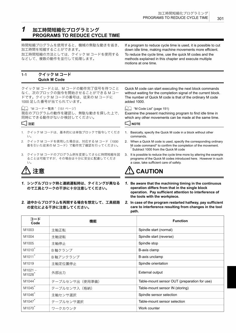
301加工時間短縮化プログラミング
PROGRAMS TO REDUCE CYCLE TIME
1 加工時間短縮化プログラミングPROGRAMS TO REDUCE CYCLE TIME
時間短縮プログラムを使用すると、機械の無駄な動きを省き、加工時間を短縮することができます。
If a program to reduce cycle time is used, it is possible to cut down idle time, making machine movements more efficient.
加工時間短縮の方法としては、クイック M コードを使用するなどして、複数の動作を並行して処理します。
To reduce the cycle time, use the quick M codes and the methods explained in this chapter and execute multiple motions at one time.
1-1 クイック M コードQuick M Code
クイック M コードとは、M コードの動作完了信号を待つことなく、次のブロックの指令を開始させることができる M コードです。クイック M コードの番号は、従来の M コードに1000 足した番号が当てられています。
Quick M code can start executing the next block commands without waiting for the completion signal of the current block. The number of Quick M code is that of the ordinary M code added 1000.
1 “M コード一覧表 ”(151 ページ) 1 “M Code List” (page 151)現在のプログラムの動作を確認し、無駄な動きを探した上で、同時にできる動作がないか検討してください。
Examine the present machining program to find idle time in which any other movements can be made at the same time.
2 注記 2 NOTE
1. クイック M コードは、基本的には単独ブロックで指令してください。
1. Basically, specify the Quick M code in a block without other commands.
2. クイック M コードを使用した場合は、対応する M コード(1000番を引いた従来の M コード)で動作完了確認を行ってください。
2. When a Quick M code is used, specify the corresponding ordinary M code command* to confirm the completion of the movement.* Subtract 1000 from the Quick M code
3. クイック M コードのプログラム例を変更してさらに時間短縮を図ることは可能ですが、その場合は十分に安全に配慮してください。
3. It is possible to reduce the cycle time more by altering the example programs of the Quick M codes introduced here. However in such a case, take sufficient care of safety.
7注意 7 CAUTION
1. シングルブロック時と連続運転時は、タイミングが異なる
ので工具とワークの干渉に十分注意してください。
1. Be aware that the machining timing in the continuous operation differs from that in the single block operation. Pay sufficient attention to interference of the tools with the workpiece.
2. 途中からプログラムを再開する場合を想定して、工具経路
の変化による干渉に注意してください。
2. In case of the program restarted halfway, pay sufficient care to interference resulting from changes in the tool path.
コードCode 機能 Function
M1003 主軸正転 Spindle start (normal)
M1004 主軸逆転 Spindle start (reverse)
M1005 主軸停止 Spindle stop
M1010* B 軸クランプ B-axis clamp
M1011* B 軸アンクランプ B-axis unclamp
M1019 主軸定位置停止 Spindle orientation
M1021 – M1028* 外部出力 External output
M1044* テーブルセンサ出(使用準備) Table-mount sensor OUT (preparation for use)
M1045* テーブルセンサ入(格納) Table-mount sensor IN (storing)
M1046* 主軸センサ選択 Spindle sensor selection
M1047* テーブルセンサ選択 Table-mount sensor selection
M1070* ワークカウンタ Work counter
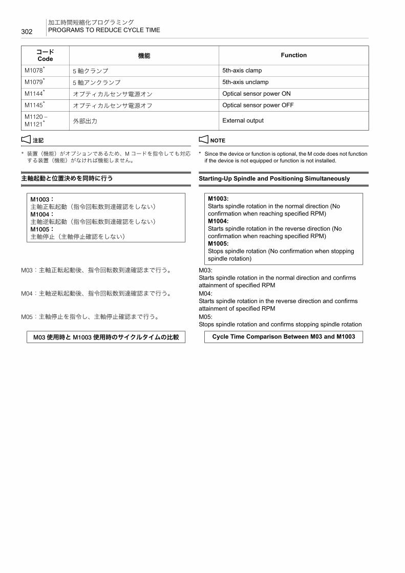
加工時間短縮化プログラミングPROGRAMS TO REDUCE CYCLE TIME302
2 注記 2 NOTE
* 装置(機能)がオプションであるため、M コードを指令しても対応する装置(機能)がなければ機能しません。
* Since the device or function is optional, the M code does not function if the device is not equipped or function is not installed.
主軸起動と位置決めを同時に行う Starting-Up Spindle and Positioning Simultaneously
M03:主軸正転起動後、指令回転数到達確認まで行う。 M03:Starts spindle rotation in the normal direction and confirms attainment of specified RPM
M04:主軸逆転起動後、指令回転数到達確認まで行う。 M04:Starts spindle rotation in the reverse direction and confirms attainment of specified RPM
M05:主軸停止を指令し、主軸停止確認まで行う。 M05:Stops spindle rotation and confirms stopping spindle rotation
M1078* 5 軸クランプ 5th-axis clamp
M1079* 5 軸アンクランプ 5th-axis unclamp
M1144* オプティカルセンサ電源オン Optical sensor power ON
M1145* オプティカルセンサ電源オフ Optical sensor power OFF
M1120 – M1121* 外部出力 External output
コードCode 機能 Function
M1003:主軸正転起動(指令回転数到達確認をしない)M1004:主軸逆転起動(指令回転数到達確認をしない)M1005:主軸停止(主軸停止確認をしない)
M1003:Starts spindle rotation in the normal direction (No confirmation when reaching specified RPM)M1004:Starts spindle rotation in the reverse direction (No confirmation when reaching specified RPM)M1005:Stops spindle rotation (No confirmation when stopping spindle rotation)
M03 使用時と M1003 使用時のサイクルタイムの比較 Cycle Time Comparison Between M03 and M1003

303加工時間短縮化プログラミング
PROGRAMS TO REDUCE CYCLE TIME
主軸を正転させ、X, Y 軸を位置決めする場合のサイクルタイムを比較します。(短縮時間の数値は参考値です。)
Here shows a comparison of the cycle times when commanding spindle rotation start in the normal direction and positioning of the X- and Y-axes. (The value of the reduced time is only for reference purpose.)
2 注記 2 NOTE
M1003 と M1004 は S 指令や軸移動と同一ブロックで指令することができます。
M1003 and M1004 can be specified in the same block of S-command and axis movement commands
ATC 準備の高速化 Speeding-Up ATC Preparation
M19:主軸定位置停止(主軸定位置停止完了を確認する)
M19:Spindle orientation (With confirmation when spindle orientation completed)
2 注記 2 NOTE
1. M1019 を指令せずに M192 を指令すると、アラームとなります。 1. Specifying M192 without specifying M1019 triggers an alarm.2. * 通常 M193 は指令しません。M06 を指令すると、ATC 準備モー
ドはオフになります。2. * Usually, the M193 command is not specified in a program since
the M192 mode is canceled when the M06 command is specified.
0.2 sec.
S10000 M03; ......................................aG00 G90 X100.0 Y100.0; ..................bG01 X-30.0 F5000; ...........................c
b a
G00 G90 X100.0 Y100.0 S10000 M1003;M03; ................................................. *G01 X-30.0 F5000; .......................... c
Reached S10000 Positioning Completed
Reduced TimeStart Cutting
Start Cutting
Positioning Completed
Confirms attainment of specified spindle speed (This M code can not be omitted)
主軸指令回転数到達確認(省略不可)
軸移動完了
S10000 到達 軸移動完了
短縮時間
切削開始
切削開始
Z 軸移動、主軸定位置停止、ATC シャッタ開の動作を同時に開始するM1019:主軸定位置停止(主軸定位置停止完了を確認しない)M192:ATC 準備モード・オン(ATC シャッタ開)(完了を確認しない)M193:*ATC 準備モード・オフ
Z-axis movement, spindle orientation and ATC shutter open can be started simultaneously.M1019:Spindle orientation (No confirmation when spindle orientation completed)M192:ATC preparation mode ON (ATC shutter open) (No confirmation when these motions are completed)M193:*ATC preparation mode OFF
サイクルタイムの比較• M19, M06 使用時• 主軸回転中に M06 使用時• M1019, M192 使用時
Cycle Time Comparison• M19, M06• M06 while spindle rotating• M1019, M192

加工時間短縮化プログラミングPROGRAMS TO REDUCE CYCLE TIME304
Z 軸移動、工具交換位置への主軸の移動、工具交換を行う場合の 3 種類のプログラムのサイクルタイムを比較します。(短縮時間の数値は参考値です。)
Here is the comparison of cycle time of the three programs in which Z-axis movement, spindle orientation and tool change are specified. (The value of the reduced time is only for reference purpose.)
B 軸割り出しの高速化 Speeding-Up B-Axis Indexing
M10:B 軸クランプ(完了を確認する)
M10:B-axis clamp (With confirmation when B-axis clamp completed)
M11:B 軸アンクランプ(完了を確認する)
M11:B-axis unclamp (With confirmation when B-axis unclamp completed)
0.1 sec.
0.8 sec.
G00 G90 Z200.0; .................................a
M19; .....................................................b
M06; .....................................................dG91 G30 X0 Y0 Z0;..............................c
G00 G90 Z200.0; .................................a
G91 G30 X0 Y0 Z0 M06;
cb
M1019; ...............................................a
M192; .................................................b
G00 G90 Z200.0; ..............................c
G91 G30 X0 Y0 Z0 M06;
ed
Z-Axis Movement Spindle Orientation Axis Movement Shutter Open Completed
Reduced Time
Tool ChangeAxis Movement
Spindle Orientation
Shutter Open Completed
Tool Change
Spindle Orientation
Shutter Open Tool Change
Positioning Completed
Z 軸移動 主軸停止 軸移動 シャッタ開完了
短縮時間
工具交換開始軸移動
主軸停止 シャッタ開完了
工具交換開始
主軸停止
シャッタ開 工具交換開始
軸移動完了
X, Y, Z 軸移動と B 軸動作を同時に行うM1010:B 軸クランプ(完了を確認しない)M1011:B 軸アンクランプ(完了を確認しない)
B-axis movements and X-, Y-, Z-axis positioning can be made simultaneously.M1010:B-axis clamp (No confirmation when B-axis clamp completed)M1011:B-axis unclamp (No confirmation when B-axis unclamp completed)
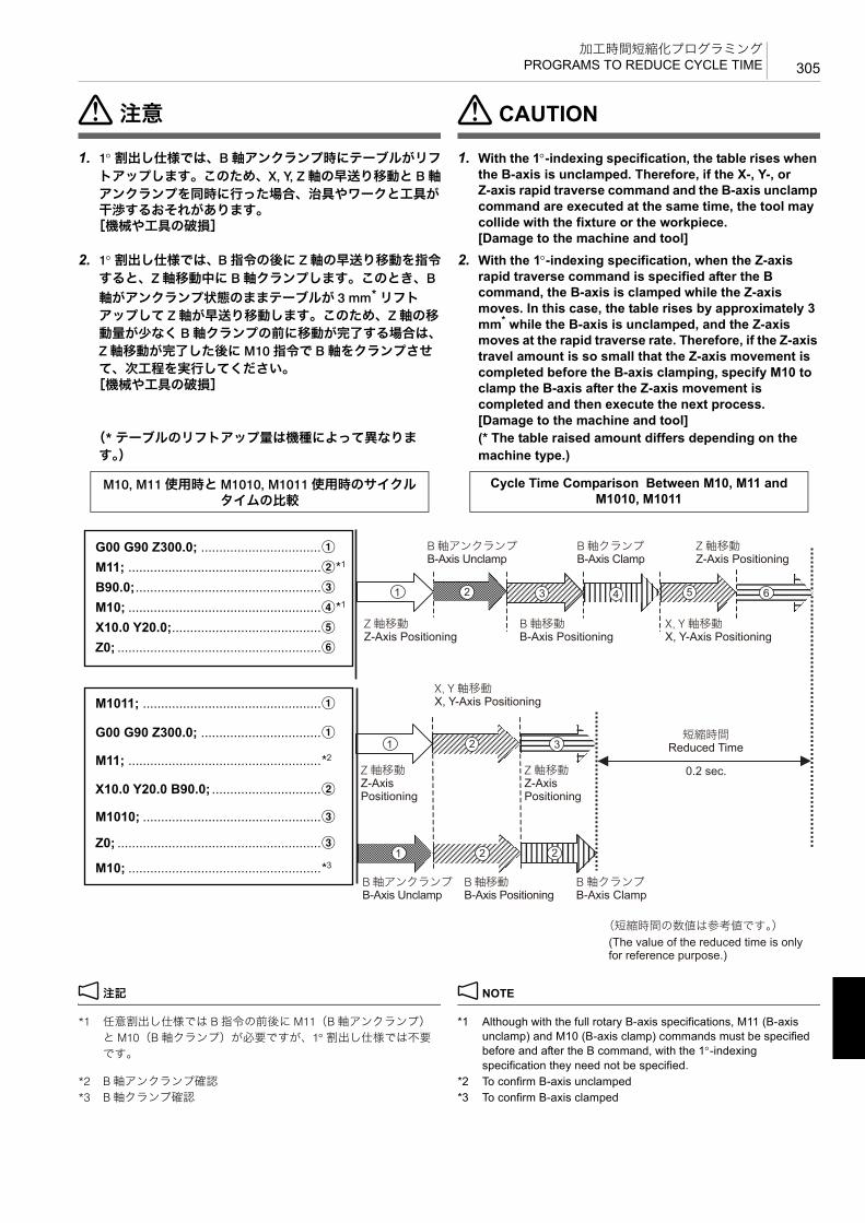
305加工時間短縮化プログラミング
PROGRAMS TO REDUCE CYCLE TIME
7注意 7 CAUTION
1. 1°割出し仕様では、B 軸アンクランプ時にテーブルがリフ
トアップします。このため、X, Y, Z 軸の早送り移動と B 軸アンクランプを同時に行った場合、治具やワークと工具が干渉するおそれがあります。
[機械や工具の破損]
1. With the 1°-indexing specification, the table rises when the B-axis is unclamped. Therefore, if the X-, Y-, or Z-axis rapid traverse command and the B-axis unclamp command are executed at the same time, the tool may collide with the fixture or the workpiece.[Damage to the machine and tool]
2. 1°割出し仕様では、B 指令の後に Z 軸の早送り移動を指令
すると、Z 軸移動中に B 軸クランプします。このとき、B軸がアンクランプ状態のままテーブルが 3 mm* リフトアップして Z 軸が早送り移動します。このため、Z 軸の移動量が少なく B 軸クランプの前に移動が完了する場合は、Z 軸移動が完了した後に M10 指令で B 軸をクランプさせて、次工程を実行してください。
[機械や工具の破損]
2. With the 1°-indexing specification, when the Z-axis rapid traverse command is specified after the B command, the B-axis is clamped while the Z-axis moves. In this case, the table rises by approximately 3 mm* while the B-axis is unclamped, and the Z-axis moves at the rapid traverse rate. Therefore, if the Z-axis travel amount is so small that the Z-axis movement is completed before the B-axis clamping, specify M10 to clamp the B-axis after the Z-axis movement is completed and then execute the next process.[Damage to the machine and tool]
(* テーブルのリフトアップ量は機種によって異なります。)
(* The table raised amount differs depending on the machine type.)
2 注記 2 NOTE
*1 任意割出し仕様では B 指令の前後に M11(B 軸アンクランプ)
と M10(B 軸クランプ)が必要ですが、1° 割出し仕様では不要
です。
*1 Although with the full rotary B-axis specifications, M11 (B-axis unclamp) and M10 (B-axis clamp) commands must be specified before and after the B command, with the 1°-indexing specification they need not be specified.
*2 B 軸アンクランプ確認 *2 To confirm B-axis unclamped*3 B 軸クランプ確認 *3 To confirm B-axis clamped
M10, M11 使用時と M1010, M1011 使用時のサイクルタイムの比較
Cycle Time Comparison Between M10, M11 and M1010, M1011
G00 G90 Z300.0; .................................a
B90.0; ...................................................cM10; .....................................................d*1
Z0; ........................................................f
Z0; ........................................................c
M10; .....................................................*3
X10.0 Y20.0 B90.0; ..............................b
M11; .....................................................*2
G00 G90 Z300.0; .................................a
M1011; .................................................a
M1010; .................................................c
X10.0 Y20.0;.........................................e
M11; .....................................................b*1
0.2 sec.
B-Axis Unclamp B-Axis Clamp Z-Axis Positioning
Z-Axis Positioning B-Axis Positioning X, Y-Axis Positioning
X, Y-Axis Positioning
Z-Axis Positioning
Z-Axis Positioning
Reduced Time
B-Axis Unclamp B-Axis Positioning B-Axis Clamp
(The value of the reduced time is only for reference purpose.)
B 軸アンクランプ B 軸クランプ Z 軸移動
Z 軸移動 B 軸移動 X, Y 軸移動
X, Y 軸移動
Z 軸移動 Z 軸移動
短縮時間
B 軸アンクランプ B 軸移動 B 軸クランプ
(短縮時間の数値は参考値です。)

加工時間短縮化プログラミングPROGRAMS TO REDUCE CYCLE TIME306
1-2 B 軸と ATC の同時動作Executing B-Axis and ATC Operations at Same Time
M06 と B 指令を 1 ブロックに指令して、一連の ATC サイクルと B 軸移動を同時に行うことができます。
By specifying the M06 command and the B command in one block, a series of ATC cycle motions can be executed while the B-axis is being indexed.
2 注記 2 NOTE
1. B 軸 1° 割出し仕様では、穴あけ固定サイクル中に M06 を指令することはできません。
1. With the 1°-indexing specification, the M06 command cannot be specified during a hole machining canned cycle.
2. 任意割出し仕様では、B 指令の前後に M11(B 軸アンクランプ)と M10(B 軸クランプ)が必要です。
2. With the full rotary B-axis specifications, the M11 (B-axis unclamp) and M10 (B-axis clamp) commands must be specified before and after the B command.
M06;............................. 工具交換指令 Specifies the tool change command.
サイクルタイムの比較• M06 と B 指令の単独使用時• M06 と B 指令の同時使用時
Cycle Time Comparison• When the M06 and B commands are specified
independently.• When the M06 and B commands are specified at the
same time.
1
1
2
2
0.4 sec.
Tool Change
(The value of the reduced time is only for reference purpose.)
B-Axis Operation Complete
Tool Change
B-Axis Operation Complete
工具交換開始
(短縮時間の数値は参考値です。)
B軸動作完了
工具交換開始
B軸動作完了

307回転軸ワーク位置補正(オプション)
WORKPIECE POSITION OFFSET FOR ROTARY AXIS (OPTION)
2 回転軸ワーク位置補正(オプション)WORKPIECE POSITION OFFSET FOR ROTARY AXIS (OPTION)
回転軸ワーク位置補正を有効にすると、ロータリテーブルの角度が変わっても、設定した回転軸ワーク位置補正量(ロータリテーブルの回転中心から加工原点までの距離)を基準にして、加工原点が自動的に補正されます。
If the workpiece position offset for rotary axis is made valid, the workpiece zero point is offset according to the set workpiece position offset amount, which is the distance between the center of rotation and the workpiece zero point, even if the angle of the rotary table is changed.
1 つの点を基準にして多面加工ができるので、複雑なワークを加工する場合に便利です。
This function is suitable for machining a complex workpiece, since multiple face machining can be executed by setting one point as a reference.
<機能の使用手順> <Procedure to Use the Function>1) ロータリテーブル回転中心の座標値を設定する
(X_ ,Y_ ,Z_)を ‘ ワークオフセット ’ 画面に設定します。(上図 a)
1) Setting the coordinate values of the rotational center of the rotary tableSet (X_,Y_,Z_) on the ‘WORK OFFSET’ screen.(position a)
2) 回転軸ワーク位置補正量を設定する1) で設定した回転中心位置から加工原点(上図 b)までの距離(回転軸ワーク位置補正量)を設定します。
2) Setting the workpiece position offset amountSet workpiece position offset amount, which is the distance between the rotational center set in step 1) and the workpiece zero point (position b).
58 個の基準回転軸ワーク位置補正量(P1 ~ P8)が設定できます。
5Eight reference workpiece position offset amounts (P1 - P8) can be set.
3) 加工プログラムで G54.2 を指令する 3) Specifying G54.2 in a machining program
2-1 ロータリテーブル回転中心の座標値を設定するSetting Coordinate Values of Rotational Center of Rotary Table
‘ ワークオフセット ’ 画面を表示させて、ロータリテーブルの回転中心の座標値(X_ ,Y_ ,Z_)を使用するワーク座標系番号に設定します。
Display the ‘WORK OFFSET’ screen to set the coordinate values of the rotational center of the rotary table (X_ ,Y_ ,Z_).
1 ロータリテーブルの回転中心については、別冊据付説明書 “ 機械移動量図 ”
1 For the rotational center of the rotary table, refer to the separate volume, INSTALLATION MANUAL, DRAWINGS “AXIS TRAVEL DIAGRAMS”.
5プログラムを理解しやすくするために、B 軸の値を設定しないことを推奨します。
5To make the programming easily understandable, B-axis should not be specified.
1
2
1
2
Y
Z(wx)
(wy)
(wz)
The rotational center of B-axisWorkpiece zero point (reference point)
From the Y-axis machine zero point
From the X-axis machine zero point From the Z-axis machine zero point
The rotational center of the B-axis
B 軸回転中心
X 軸機械原点から Z 軸機械原点から
B 軸回転中心
加工原点(基準点)
Y 軸機械原点から
機能キー o(オフセット)D ‘ ワークオフセット ’ Function selection key o (OFFSET) D ‘WORK OFFSET’

回転軸ワーク位置補正(オプション)WORKPIECE POSITION OFFSET FOR ROTARY AXIS (OPTION)308
2-2 回転軸ワーク位置補正量を設定するSetting Workpiece Position Offset Amount
‘ ワークオフセット ’ 画面に設定した、ロータリテーブルの回転中心位置の座標値(X_ ,Y_ ,Z_)から加工原点までの距離
(回転軸ワーク位置補正量)を設定します。回転軸ワーク位置補正量は、‘ 回転軸ワーク位置補正 ’ 画面に手動で、またはプログラム指令により設定します。
Set the workpiece position offset amount, which is the distance between the coordinate values of the rotational center of the rotary table (X_ ,Y_ ,Z_) set on the ‘WORK OFFSET’ screen and the workpiece zero point. Set the workpiece position offset amount manually on the ‘WORKPIECE POSITION OFFSET FOR ROTARY AXIS’ screen or specify the values in a machining program.
5プログラムを理解しやすくするために、B 軸の値を設定しないことを推奨します。
5To make the programming easily understandable, B-axis should not be specified.
回転軸ワーク位置補正画面での設定 Setting on Workpiece Position Offset for Rotary Axis Screen
プログラム指令での設定 Setting in Machining Program
G10 を指令すると、プログラム中で回転軸ワーク位置補正量が設定できます。
The workpiece position offset amount can be specified in a machining program by specifying G10.
2 注記 2 NOTE
G90 モードで実行したときは、その値そのものが設定されます。 When specified in the G90 mode, the specified value is set as the reference value.
G91 モードで実行したときは、前の値に加算した値が設定されます。 When specified in the G91 mode, the sum of the specified value and the previous value is set.
2-3 加工プログラムで G54.2 を指令するSpecifying G54.2 in Machining Program
ここでは、加工プログラム内での回転軸ワーク位置補正の指令方法について説明します。
This section describes the method for specifying the workpiece position offset for rotary axis in a machining program.
7注意 7 CAUTION回転軸を移動させる前、および回転軸ワーク位置補正の開始/終了前には、工具径補正をキャンセルしてください。G54.2モード中に工具径補正を行ったまま回転軸を移動、または回転軸ワーク位置補正をキャンセルすると、工具補正の方向の予測が困難となり、機械の予期せぬ動作へとつながります。
Before moving the rotary axes or starting/ending the rotary axis workpiece position offset, cancel the tool radius offset. Moving the rotary axes or cancelling the rotary axis workpiece position offset during the tool radius offset in the G54.2 mode causes the difficulty to predict the tool offset directions and leads to the unexpected machine motion.
5回転軸ワーク位置補正有効時にリセットした場合、設定されている補正量をキャンセルするかしないかは、下記パラメータで設定します。
5Whether the set offset amount should be canceled or not when the NC unit is reset in the workpiece position offset mode can be selected by setting the parameters below.
• リセット前のベクトルを保存:No. 1151 = 0 または、No. 1151 = 1 および No. 1210.16 = 1
• Retains the vector before reset: No. 1151 = 0 or No. 1151 = 1 and No. 1210.16 = 1
機能キー o(オフセット)D【回転軸補正】 Function selection key o (OFFSET) D [ROTARY AXIS]
G10 L21 Pn X_ Y_ Z_ B_ ;• n ........................................... 回転軸ワーク位置補正番号(1 ~ 8) Workpiece position offset number (1 - 8)
• X_ Y_ Z_ B_......................... 各軸の回転軸ワーク位置補正量 Workpiece position offset amount for each axis
G54.2 Pn; ................... 回転軸ワーク位置補正有効 Workpiece position offset for rotary axis ON
G54.2 P0; .................... 回転軸ワーク位置補正無効 Workpiece position offset for rotary axis OFF
• n ........................................... 回転軸ワーク位置補正番号(1 ~ 8) Workpiece position offset number (1 - 8)

309回転軸ワーク位置補正(オプション)
WORKPIECE POSITION OFFSET FOR ROTARY AXIS (OPTION)
• ベクトルをクリア(出荷時の設定):No. 1151 = 1 および No. 1210.16 = 0
• Cancels the vector before reset (default setting): No. 1151 = 1 and No. 1210.16 = 0
キャンセルしても、その補正量分機械が移動することはありません。
Even when the vector is canceled, the axes do not move the offset amount specified by the vector.
例: Example:回転軸ワーク位置補正の使用方法 Programming using the workpiece position offset for rotary
axis
2 注記 2 NOTE
1. G54.2 および、G54.2 指令中の回転軸ワーク位置補正に関係する回転軸の指令は、バッファリングされません。
1. Buffering is not performed for the G54.2 command and rotary axis commands related to workpiece position offset in the G54.2 mode.
2. G54.2 有効時に回転軸ワーク位置補正量を変更したときは、次の“G54.2 Pn;” が指令されてから有効になります。
2. If the workpiece position offset amount is changed while G54.2 is valid, it becomes effective after the “G54.2 Pn” command is next specified.
3. G54.2 有効時に回転軸に対して以下の指令を実行した場合、回転軸ワーク位置補正のベクトルは計算されません。
3. If the commands indicated below are specified for rotary axes while G54.2 is valid, the vector for workpiece position offset is not calculated.
• 機械座標系での指令(G53) • Commands in the machine coordinate system (G53)• ワーク座標系の変更(G54 ~ G59, G54.1, G92, G52) • Changing work coordinate systems (G54 - G59, G54.1, G92,
G52)• 原点復帰関係(G27, G28, G30, G30.1) • Zero point return and related commands (G27, G28, G30,
G30.1)4. 回転軸ワーク位置補正のベクトルが変化したことによる移動は、
そのときのグループ 01 のモーダル G コードに従いますが、G00, G01 モード以外のとき(G02, G03 など)は、一時的に G01 として移動します。
4. The motion resulting from the alteration of the vector of the workpiece position offset is performed in the group 01 G code mode at that time. However, in modes other than G00 and G01 (G02 or G03), the motion is temporarily accomplished in the G01 mode.
5. G54.2 モード中にシングルブロック停止などで自動運転を停止し、手動で回転軸を移動させたときは、回転軸ワーク位置補正のベクトルは変化しません。自動運転あるいは MDI 運転で回転軸の指令、または G54.2 を指令したときにベクトルが計算されます。
5. If a rotary axis is moved manually after stopping automatic operation, for example by making the single block function valid in the G54.2 mode, the vector of the workpiece position offset will not change. The vector is calculated when a rotary axis command or a G54.2 command is executed during automatic operation or MDI operation.
ただし、手動で回転軸を移動させた後、G91 モードで回転軸を指令したときは、手動介入量が反映された座標値を用いてベクトルが計算されます。
However, when a rotary axis command is specified in the G91 mode after moving the rotary axis manually, the vector is calculated using the coordinate values that take the amount of manual movement into account.
6. 回転軸ワーク位置補正の計算で使用する回転軸の座標値はワーク座標系での座標値を使用しますが、工具補正などの補正がかかっている場合はオフセットがかかる前の座標値を使用します。
6. The coordinate values in the work coordinate system are used for rotary axes when calculating a workpiece position offset, however, if any compensation such as tool offset is applied to the axis the coordinate values before applying the compensation are used.
7. 以下の機能は G54.2 のモード中に指令できません。 7. The commands indicated below cannot be specified during the G54.2 mode.
:
G54;G54.2 P1;.................................................................. 回転軸ワーク位置補正有効 Workpiece position offset for rotary
axis ON
G90 G00 X0 Y0 B_ S4000;....................................... B_ に応じて加工原点が補正されます。
The workpiece zero point is offset in accordance with the setting “B_”.
G43 Z30.0 H1 M03;G81 Z−20.0 R3.0 F200;G80;:
G54.2 P0; ................................................................. 回転軸ワーク位置補正無効 Workpiece position offset for rotary axis OFF
:
• G07.1 ................................... 円筒補間 Cylindrical interpolation
• G41.1(G151) ........................ 法線方向制御左側オン Normal direction control ON (left side)
• G42.1(G152) ........................ 法線方向制御右側オン Normal direction control ON (right side)
• G43.4 ................................... 工具先端点制御(タイプ 1) Tool center point control (type 1)
• G43.5 ................................... 工具先端点制御(タイプ 2) Tool center point control (type 2)
回転軸ワーク位置補正(オプション)WORKPIECE POSITION OFFSET FOR ROTARY AXIS (OPTION)310
8. 回転軸のロールオーバ機能を使う場合には、回転軸 1 回転当たりの移動量を必ず 360° としてください。
8. When using the rollover function of rotary axes, the amount of motion per rotation should always be 360°.
9. G54.2 Pn を指令する場合は、X, Y, Z 軸のすべての軸を機械原点に復帰させてください。いずれか 1 軸でも原点にない場合は、アラーム(P430)が発生します。
9. Return all the X-, Y-, and Z-axes to the machine zero points before specifying G54.2 Pn. When even any one of these axes is not at the machine zero points, an alarm (P430) occurs.
10. G54.2 モード中に同一ブロックで複数の回転軸を移動指令すると、補正量(ベクトル)が変化するため、直線軸も移動します。その場合、同時制御軸数を超えると、アラーム(P10)が発生します。
10. In the G54.2 mode, if the movement commands for two or more rotary axes are specified in the same block, the linear axis also moves as the offset amounts (vector) changes. In this case, when the maximum number of the simultaneously controllable axes is exceeded, an alarm (P10) occurs.
11. G54.2 モード中に、回転軸および直線軸(絶対値指令)の移動を同一ブロックに指令すると、直線軸の補正量が更新され、直線軸はワーク座標系で設定された位置に移動します。
11. In the G54.2 mode, if the movement commands for the rotary axis and linear axis (absolute command) are specified in the same block, the linear axis offset amount is updated and the linear axis moves to the position set by the workpiece coordinate system.
増分値を指令する場合は、以下のパラメータで設定します。 When specifying the incremental values, set the following parameters.
• G51 ...................................... スケーリング Scaling
• G51.1 ................................... プログラマブルミラーイメージ Programmable mirror image
• G68 ...................................... 座標回転/ 3 次元座標変換 Coordinate rotation/3D coordinate conversion
• No.1597 rpcNoMove = 1 ..... 現在位置から増分移動 Incremental movement from a current position
• No.1597 rpcNoMove = 0 ..... 補正量の変化値と増分値を加算した位置に移動
Movement to the position totaled the offset variation amount and the increment amount

311工具寿命管理
TOOL LIFE MANAGEMENT
3 工具寿命管理TOOL LIFE MANAGEMENT
グループに登録されたある工具が寿命に到達した場合、同じグループの予備工具を順次呼び出す機能です。
If one of the tools registered in a group has reached the end of its preset life, this function selects a spare tool in the same group.
1 別冊 “MAPPS 工具管理システム取扱説明書 ” 1 Refer to the separate volume “MAPPS TOOL MANAGEMENT SYSTEM INSTRUCTION MANUAL”.

負荷監視機能LOAD MONITORING FUNCTION312
4 負荷監視機能LOAD MONITORING FUNCTION
4-1 負荷監視機能とはOutline of Load Monitoring Function
負荷監視機能とは、加工中のモータの負荷変動を監視し、工具の異常を検出する機能です。
The load monitoring function is used to detect abnormality of a tool by monitoring the variation in motor load during cutting.
本機能には、以下に示す特徴があります。 The function includes the following features:
1. 監視グループ 1. Monitoring groups85 グループまで監視できます。 Up to 85 groups can be monitored.
2. 操作モード 2. Operation modes操作モードは、負荷監視ロードメータ画面の【教示】/
【監視】を押すと切り替わります。The operation modes can be switched by pressing the [TEACHING]/[MONITOR] soft-key on the Load Monitoring Load Meter Screen.
1 “ 負荷監視ロードメータ画面 ”(314 ページ) 1 “Load Monitoring Load Meter Screen” (page 314)• 教示モード • Teaching Mode
切削時の主軸および各送り軸の負荷基準値を検出し、警告値とアラーム値を自動的に設定します。
The function detects the reference value, and automati-cally sets the warning level and the alarm level.
• 監視モード • Monitoring Mode指定グループ区間の切削時の負荷値と、設定された同グループの警告値およびアラーム値とを比較し、設定値を超えた場合は、以下の処理を行います。
The function compares the load value detected during cutting in the specified group intervals to the preset warn-ing and alarm detection threshold level values of the same group intervals. The following processing is executed if the detected load value exceeds the preset threshold lev-el value.
警告時: Warning:スタートインタロック処理(オプションでマクロ入力信号処理)を行います。
Start interlock processing (macro input signal processing is optionally provided).
アラーム時: Alarm:機械を一時停止状態にし、主軸を停止させます。 Feed hold and spindle stop processing
3. プログラミング 3. ProgrammingG313 A_S_M_; により指定された対象軸、グループ番号にて開始し、M85 で終了します。
The axis specified by G313 A_ S_ M_; started by group number, terminated by M85.
4. データの設定 4. Data setting教示による自動設定、または MDI による設定ができます。 Automatic setting by teaching and MDI setting are possible.
5. データの入出力 5. Input/output of dataRS-232C インタフェースおよび USB メモリでデータの入出力ができます。
The data can be input/output by using RS-232C interface and USB memory.
6. 負荷監視画面 6. Load monitor screen‘ 負荷監視 ’ 画面で、切削状態での主軸または送り軸の負荷を表示します。
The load of the spindle or feed axis is displayed on the ‘LOAD MONITOR’ screen.
表示方法:バーグラフおよび数値表示 Display mode: Bar graph and numeric value
2 注記 2 NOTE
1. この負荷監視機能は負荷変動が少ない加工には適しません。 1. The function is not adequate for machining causing only slight load variation.
2. 切削速度一定制御(周速一定制御)などの加減速トルクの大きい加工は監視できません。
2. It is impossible to monitor a machining with acceleration/deceleration torque such as controlling constant surface speed (constant surface speed control).
<操作の流れ> <Operation Flow>
4 4
負荷監視設定の各数値を設定する1“ 負荷監視設定画面 ”(318 ページ)
Set each numeric value of the load monitoring setting.1“Load Monitoring Setting Screen” (page 318)
負荷監視用プログラムを作成する1“ 負荷監視用プログラムの指令方法 ”(320 ページ)
Create the program for load monitoring1“Specifying Load Monitor Program” (page 320)

313負荷監視機能
LOAD MONITORING FUNCTION
4 4
4 4
4 4
4 4
4-2 負荷監視機能の表示画面Screens for Load Monitoring Function
負荷監視機能には、次の 4 つの画面があります。 There are four screens for the load monitoring function.• 負荷監視ロードメータ画面 • Load Monitoring Load Meter Screen• 負荷監視データ設定画面 • Load Monitoring Data Setting Screen• 負荷監視警告リスト画面 • Load Monitor Warning List Screen• 負荷監視設定画面 • Load Monitoring Setting Screenこれらの画面を総称して ‘ 負荷監視 ’ 画面といいます。 ‘ プログラムチェック ’ 画面からの画面遷移は下図のとおりです。
These screens are collectively called the ‘LOAD MONITOR’ screen. Screen transition from the ‘PROGRAM CHECK’ screen is as follows.
<各画面共通ソフトキー> <Common Soft-Keys>
教示モードで負荷監視用プログラムを実行する Execute the load monitoring program in the teaching mode.
教示されたデータを確認、必要に応じてデータを変更する1“ 負荷監視データ設定画面 ”(315 ページ)
Check the data that was taught and change the data if necessary.1“Load Monitoring Data Setting Screen” (page 315)
監視モードで負荷監視用プログラムを実行する Execute the load monitoring program in the monitoring mode.
プログラム終了後、負荷監視データを確認する After finishing a program, check the load monitoring data.
‘PROGRAM CHECK’ Screen
Load Monitoring Load Meter Screen Load Monitor Warning List Screen
Load Monitoring Setting Screen
Load Monitoring Data Setting Screen
‘プログラムチェック’画面
負荷監視ロードメータ画面 負荷監視警告リスト画面
負荷監視設定画面
負荷監視データ設定画面
ソフトキー 機能 Soft-keys Function
【ロードメータ】
このソフトキーを押すと、負荷監視ロードメータ画面が表示され、このソフトキーは反転表示されます。
[LOAD METER]
On pressing this soft-key, the Load Monitoring Load Meter Screen is displayed and this soft-key is highlighted.
【データ設定】 このソフトキーを押すと、負荷監視データ設定画面が表示され、このソフトキーは反転表示されます。
[DATA SETTING]
On pressing this soft-key, the Load Monitoring Data Setting Screen is displayed and this soft-key is highlighted.
【警告リスト】 このソフトキーを押すと、警告リスト画面が表示され、このソフトキーは反転表示されます。
[WARNING LIST]
On pressing this soft-key, the Load Monitor Warning List screen is displayed and this soft-key is highlighted.

負荷監視機能LOAD MONITORING FUNCTION314
4-3 負荷監視ロードメータ画面Load Monitoring Load Meter Screen
‘ プログラムチェック ’ 画面でソフトキー【負荷監視】を押す、または、負荷監視データ設定画面/負荷監視警告リスト画面でソフトキー【ロードメータ】を押すと、この画面が表示されます。
This screen is displayed by pressing the [LOAD MONITOR] soft-key on the ‘PROGRAM CHECK’ screen, or by pressing the [LOAD METER] soft-key on the Load Monitoring Data Setting Screen/Load Monitor Warning List Screen.
この画面で、負荷の状態を棒グラフと数値で確認することができます。
The status of the load can be checked in this screen with the bar graph and numeric values.
2 注記 2 NOTE
主軸は 30 分定格を 100%, XYZ 軸は停止時の定格を 100% として表示します。
For the spindle, the load value is displayed taking the 30-min rating as 100% and for the X-, Y- and Z-axes.
また、警告またはアラームとなった工具の欄が、10 件まで黄色で表示されます。操作パネルの @(リセット)キーを押すとアラームが解除されます。黄色のハイライト表示を解除するには、ソフトキー【警告表示クリア】を押します。
In addition, the fields of up to 10 tools that have caused a warning or an alarm are displayed in yellow. The alarm state can be cleared by pressing the @ (RESET) key on the operation panel. To clear the fields displayed in yellow, press the [WARNING CLEAR] soft-key.
<表示項目と内容> <Display Items and Descriptions>
【戻り】 このソフトキーを押すと、‘ プログラムチェック ’ 画面に戻ります。
[RETURN] On pressing this soft-key, the screen returns to the ‘PROGRAM CHECK’ screen.
ソフトキー 機能 Soft-keys Function
X 10
Maximum Load ValuePresent Load Value大のロード値現在のロード値
表示項目Display Item 内容 Contents
‘ ツール No.’‘TOOL No.’
教示した、あるいは監視する工具の番号を表示します。
This item displays the number of the tool which has been taught or the tool to be monitored.
‘ サブ No.’‘SUB No.’
同一の ‘ ツール No.’ で異なる負荷を監視するためにつける番号です。
This number is assigned when load monitoring is executed for different cutting operations carried out using the tool which has the same ‘TOOL No.’.
‘ 軸 ’(軸負荷検出軸)‘AXIS’ (AX Load Detection Axis)
主軸(S)、X 軸(X)、Y 軸(Y)、Z 軸(Z)のうち、負荷検出を行う軸を表示します。
The axis selected for which the load is to be monitored among Spindle (S), X-axis (X), Y-axis (Y) and Z-axis (Z) is displayed.
‘STD’(基準値)(%)‘STD’ (Reference Value) (%)
教示操作による負荷検出値を表示します。 The load value detected in the teaching operation is displayed.
‘WRN’(警告値)(%)‘WRN’ (Warning Level) (%)
工具の摩耗を検出し、スタートインタロック処理を行うための値を表示します。
The value for detecting the tool wear and initiating Start-Interlock processing.
‘ALM’(アラーム値)(%)‘ALM’ (Alarm Level) (%)
工具の異常を検出し、一時停止、アラーム処理をするための値です。
This threshold level is used to detect the “tool chipping/breakage” alarm state; if the detected load exceeds this level, feed hold and alarm processing are executed.
‘ACP%.H’*
‘ACP%.H’*上限許容値(%)適応制御を行う範囲の上限を表示します。
Upper accept coefficient (%)The setting indicates the upper limit of the range where the adaptive control is executed.

315負荷監視機能
LOAD MONITORING FUNCTION
2 注記 2 NOTE
* 適応制御有効時のみ表示されます。 * These display items are only for the adaptive control.
<ソフトキー> <Soft-Keys>
4-4 負荷監視データ設定画面Load Monitoring Data Setting Screen
負荷監視ロードメータ画面/警告リスト画面で、ソフトキー【データ設定】を押すと、この画面が表示されます。
This screen is displayed by pressing the [DATA SETTING] soft-key on the Load Monitoring Load Meter Screen/Load Monitor Warning List Screen.
教示によって設定されたデータ(基準値、警告値、アラーム値)をこの画面で確認し、必要に応じて変更します。また、教示しないでデータを設定することもできます。
On this screen, check the data set by teaching (Reference Value, Warning level and Alarm level), and change the data if necessary. It is also possible to set the data without teaching.
また、警告またはアラームとなった工具の欄が、10 件まで黄色で表示されます。操作パネルの @(リセット)キーを押すとアラームが解除されます。黄色のハイライト表示を解除するには、ソフトキー【警告表示クリア】を押します。
In addition, the fields of up to 10 tools that have caused a warning or an alarm are displayed in yellow. The alarm state can be cleared by pressing the @ (RESET) key on the operation panel. To clear the fields displayed in yellow, press the [WARNING CLEAR] soft-key.
<表示項目と内容> <Display Items and Descriptions>
‘ACP%.L’*
‘ACP%.L’*下限許容値(%)適応制御を行う範囲の下限を表示します。
Lower accept coefficient (%)The setting indicates the lower limit of the range where the adaptive control is executed.
‘CUT%’*
‘CUT%’*適正加工診断機能で使う加工時間の計測結果
(%)を表示します。Displays the measuring result (%) of cutting time used for the appropriate cutting diagnostic function.
‘ コメント ’‘COMMENT’
工具名などを 大 8 文字まで登録できます。 A tool name or other information can be entered, using up to 8 characters.
表示項目Display Item 内容 Contents
ソフトキー 機能 Soft-keys Function
【教示】 このソフトキーを押すと、教示モードのON/OFF が切り替わります。教示モードがON のときは、このソフトキーが反転表示されます。
[TEACHING] On pressing this soft-key, the teaching mode ON/OFF status is switched. While the teaching mode is ON, this soft-key is highlighted.
【監視】 このソフトキーを押すと、監視モードのON/OFF が切り替わります。監視モードがON のときは、このソフトキーが反転表示されます。
[MONITOR] On pressing this soft-key, the monitoring mode ON/OFF status is switched. While the monitoring mode is ON, this soft-key is highlighted.
【負荷監視設定】
このソフトキーを押すと、負荷監視設定画面が表示されます。
[LOAD MONITOR SETTING]
On pressing this soft-key, the load monitoring setting screen is displayed.
【警告表示クリア】
このソフトキーを押すと、警告またはアラームとなった工具の、黄色のハイライト表示が解除されます。
[WARNING CLEAR]
On pressing this soft-key, the fields of tools that have caused a warning or an alarm displayed in yellow are cleared.
表示項目Display Item 内容 Contents
‘ ツール No.’‘TOOL No.’ 監視する工具の番号を表示します。
This item displays the number of the tool to be monitored.
‘ サブ No.’‘SUB No.’
同一の ‘ ツール No.’ で異なる負荷を監視するためにつける番号です。
This number is assigned when load monitoring is executed for different cutting operations carried out using the tool which has the same ‘TOOL No.’.
‘ 軸 ’(軸負荷検出軸)‘AXIS’ (AX Load Detection Axis)
主軸(S)、X 軸(X)、Y 軸(Y)、Z 軸(Z)の中から負荷検出を行う軸を選択します。
Select the axis for which the load is to be monitored among Spindle (S), X-axis (X), Y-axis (Y) and Z-axis (Z).

負荷監視機能LOAD MONITORING FUNCTION316
2 注記 2 NOTE
‘STD’, ‘WRN’, ‘ALM’ はモータ定格に対する割合(%)を 0 ~ 999 の範囲で決定します。値の大小関係は ‘STD’< ‘WRN’< ‘ALM’ となります。
‘STD’, ‘WRN’, and ‘ALM’ determine the percentage (%) of the rated motor load. The setting range is 0 to 999. Their magnitude relationship is ‘STD’ < ‘WRN’ < ‘ALM’
<データの設定(変更)手順> <Data setting/changing procedure>1) カーソル移動キーで、データを設定したい欄にカーソルを
移動させる。1) Move the cursor to the field for the data to be set by using
the cursor control keys.
2) 数値を入力する。 2) Input the numeric value.
3) \(入力)キーを押す。 3) Press the \ (INPUT) key.<データの削除方法> <Data deleting procedure>1) カーソル移動キーで、データを削除したい欄にカーソルを
移動させる。1) Move the cursor to the field for the data to be deleted by
using the cursor control keys.
2) ソフトキー【削除】を押す。 2) Press the [DELETE] soft-key.
3) ソフトキー【実行】を押す。 3) Press the [EXECUTE] soft-key.<ソフトキー> <Soft-Keys>
‘STD’(基準値)(%)‘STD’ (Reference Value) (%)
教示操作による負荷検出値を表示します。 The load value detected in the teaching operation is displayed.
‘WRN’(警告値)(%)‘WRN’ (WARNING Level) (%)
工具の摩耗を検出し、スタートインタロック処理を行うための値を表示します。
The value for detecting the tool wear and initiating Start-Interlock processing.
‘ALM’(アラーム値)(%)‘ALM’ (Alarm Level) (%)
工具の異常を検出し、一時停止、アラーム処理をするための値です。
This threshold level is used to detect the “tool chipping/breakage” alarm state; if the detected load exceeds this level, feed hold and alarm processing are executed.
‘ コメント ’‘COMMENT’
工具名などを 大 8 文字まで登録できます。 A tool name or other information can be entered, using up to 8 characters.
表示項目Display Item 内容 Contents
ソフトキー 機能 Soft-keys Function
【サーチ】 検索したい工具番号を入力して、このソフトキーを押すと、設定済みの工具を検索することができます。該当する工具は、データ表示部の先頭に表示されます。
[SEARCH] On pressing this soft-key after inputting the tool number to be searched for, it is possible to search for a tool that has already set. The corresponding tool is displayed at the top of the data display area.
【+**%】 ‘STD’(基準値)(%)、‘WRN’(警告値)(%)または ‘ALM’(アラーム値)(%) にカーソルを合わせて、このソフトキーを押すと、カーソル位置の工具のそれぞれの値が **%ずつ増えます。
例:• 変更前:100• ソフトキー:+10%• 変更後:110
2 注記
ソフトキーに表示される数値は、MAPPS パラメータ No. 1611 で設定します(上記の例はNo. 1611 = 10)。パラメータに “0” が設定されている場合(出荷時の設定)、ソフトキーは表示されません。
[+**%] On pressing this soft-key after placing the cursor on ‘STD’ (Reference Value) (%), ‘WRN’ (Warning Level), or ‘ALM’ (Alarm Level)(%), the corresponding value of the tool at the cursor position is increased in increments of **%.
Example:• Old Value: 100• Soft-Key: +10%• New Value: 110
2 NOTE
The value to be displayed on the soft-key is set by MAPPS parameter No. 1611 (in the above example, No. 1611 = 10). When the parameter is set to “0” (default setting), the soft-key is not displayed.

317負荷監視機能
LOAD MONITORING FUNCTION
4-5 警告リスト画面The Load Monitor Warning List Screen
負荷監視ロードメータ画面/負荷監視データ設定画面でソフトキー【警告リスト】を押すと、この画面が表示されます。
This screen is displayed by pressing the [WARNING LIST] soft-key on the Load Monitoring Load Meter Screen/Load Monitoring Data Setting Screen.
この画面には、負荷監視実行時に警告となった工具が 10 個まで表示されます。
On this screen, the list of up to 10 tools which have caused a warning during load monitoring is displayed.
2 注記 2 NOTE
負荷監視を行って、機械が停止したり、画面にアラームメッセージが出たときは、アラーム一覧表で内容を確認し、適切な処理を行ってください。
When the machine is stopped or alarm messages are displayed by executing the load monitoring function, check the details of the message by referring to “Alarm List” and take appropriate measures.
<表示項目と内容> <Display Items and Descriptions>
【−**%】 ‘STD’(基準値)(%)、‘WRN’(警告値)(%)または ‘ALM’(アラーム値)(%) にカーソルを合わせて、このソフトキーを押すと、カーソル位置の工具のそれぞれの値が **%ずつ減ります。
例:• 変更前:100• ソフトキー:−10%• 変更後:90
2 注記
ソフトキーに表示される数値は、MAPPS パラメータ No. 1611 で設定します(上記の例はNo. 1611 = 10)。“0” が設定されている場合(出荷時の設定)、ソフトキーは表示されません。
[−**%] On pressing this soft-key after placing the cursor on ‘STD’ (Reference Value) (%), ‘WRN’ (Warning Level), or ‘ALM’ (Alarm Level)(%), the corresponding value of the tool at the cursor position is decreased in increments of **%.
Example:• Old Value: 100• Soft-Key:−10%• New Value: 90
2 NOTE
The value to be displayed on the soft-key is set by MAPPS parameter No. 1611 (in the above example, No. 1611 = 10). When the parameter is set to “0” (default setting), the soft-key is not displayed.
【全削除】 このソフトキーを押すと、設定済みの負荷監視データがすべて削除されます。
[CLEAR ALL] On pressing this soft-key, all the load monitoring data are deleted.
【削除】 このソフトキーを押すと、カーソルで選択した負荷監視データを削除します。
[DELETE] On pressing this soft-key, the load monitoring data that has been selected by placing the cursor on it is deleted.
【警告表示クリア】
このソフトキーを押すと、警告またはアラームとなった工具の、黄色のハイライト表示が解除されます。
[WARNING CLEAR]
On pressing this soft-key, the fields of tools that have caused a warning or an alarm displayed in yellow are cleared.
ソフトキー 機能 Soft-keys Function
表示項目Display Item 内容 Contents
‘ 月日 ’‘DATE’ 警告になった日付を表示します。
The date when the warning has occurred is displayed.
‘ 時間 ’‘TIME’
警告になった時間を表示します。 The time when the warning has occurred is displayed.
‘O 番号 ’‘O-No.’
警告が発生したときに実行していたプログラムを一覧表示します。
The list of the presently executed programs when the warning is issued is displayed.
‘N 番号 ’‘N-No.’
警告が発生したときのシーケンス番号を表示します。
The sequence number when the warning is issued is displayed.
‘ ツール No.’‘TOOL No.’
警告が発生した工具の番号を表示します。 The number of the tool for which warning is being issued is displayed.
‘ サブ No.’‘SUB No.’
警告が発生したときのサブ番号を表示します。 The sub number when the warning is issued is displayed.
‘ 軸 ’‘AXIS’
警告が発生した工具の軸名が表示されます。 The axis name of the tool for which warning is being issued is displayed.

負荷監視機能LOAD MONITORING FUNCTION318
<ソフトキー> <Soft-Keys>
負荷監視設定画面 Load Monitoring Setting Screen
負荷監視ロードメータ画面で、ソフトキー【負荷監視設定】を押すと、この画面が表示されます。
This screen is displayed by pressing the [LOAD MONITOR SETTING] soft-key on the Load Monitoring Load Meter Screen.
この画面で、次の項目について数値を設定します。 Set numeric values for the following items on this screen.
【全削除】 このソフトキーを押すと、警告リストがすべて削除されます。また、負荷監視ロードメータ画面および負荷監視データ設定画面で警告またはアラームとなった工具の、黄色のハイライト表示が解除されます。
[CLEAR ALL] On pressing this soft-key, all the data of the warning list are deleted. On pressing this soft-key, the fields of tools that have caused a warning or an alarm displayed in yellow on the Load Monitoring Load Meter screen and the Load Monitoring Data Setting screen are also cleared.
項目と内容
標準設定Standard Setting
Items and Descriptions設定範囲
Setting Range
1. ‘ サンプリング禁止時間 ’ (×0.01 秒 )切削の立ち上がり時の過渡的な負荷変動を無視する時間。
2 注記
‘ 無負荷監視時間 ’ の設定が “0” の場合は、無負荷電流は検出されず、‘ 基準値 ’ には実負荷そのものが設定されます。
10 1. ‘SAMPLING PROHIBITION TIME’ (×0.01 sec.)The time during which the function ignores the transitional load variation before actual cutting starts
2 NOTE
If the setting for the parameter ‘NO LOAD TIME’ is “0”, the no load current is not detected and the actual load is set for the reference value (‘STD.’).
0 ~ 999
2. ‘ 無負荷監視時間 ’ (×0.01 秒 )負荷監視モードおよび教示モードを指令してから、負荷検出を行うまでの時間。0:実負荷値が “ 基準値 ” として教示されます。0 以外:実負荷値-無負荷検出区間の平均負荷が‘ 基準値 ’ として教示されます。
0 2. ‘NO LOAD TIME’ (×0.01 sec.)The time between designation of the load monitoring or teaching mode and the start of load monitoring0:The actual load value detected during teaching is set as the reference valueOther than 0: The result of following calculation is set as the reference value (‘STD.’). “(Actual load value) (Average load detected during immune period)”
0 ~ 999
3. ‘ 監視禁止時間 ’ (×0.01 秒 )‘ 負荷電流許容変化率 ’ 検出により、判定した実切削開始時の負荷変動を見逃す時間を設定します。
10 3. ‘MONIT PROHIBITION TIME’ (×0.01 sec.)Set the time during which the function ignores load variation at the start of actual cutting that is determined by the function according to the value set for ‘LOAD ACCEPT VARIABLE’.
0 ~ 999
4. ‘ アラーム値係数 ’ (%)教示モードで検出した基準値に対して、工具異常などによるアラーム値とする割合。
100 4. ‘ALARM COEFFICIENT’ (%)The load level at which alarm occurs due to tool abnormality, expressed as a percentage (%) of the reference value detected in the teaching mode.
0 ~ 200
5. ‘ 警告値係数 ’ (%)教示モードで検出した基準値に対して、工具摩耗などによる警告値とする割合。
50 5. ‘WARNING COEFFICIENT’ (%)The load level at which warning occurs due to tool wear expressed as a percentage (%) of the reference value detected in the teaching mode.
0 ~ 200

319負荷監視機能
LOAD MONITORING FUNCTION
2 注記 2 NOTE
* 仕様により機能の有効/無効が切り替わります。 * This function is on or off depending on the specifications.
<適応制御仕様有効時> <When the adaptive control is valid>
6. ‘ 平均値検出時間 ’ (×0.014 秒 )負荷電流変化率を算出するための時間。“1” の設定が “14 msec” に相当します。
3 6. ‘LOAD AVERAGE CALC. PERIOD’ (×0.014 sec.)Set the time in which the load current variation rate is calculated.Value “1” is equal to “14 msec”.
1 ~ 127
7. ‘ 負荷電流許容変化率 ’ (%)教示モードおよび監視モード中の実切削開始点の判断に使用します。負荷電流変化率が “ 負荷電流許容変化率 ” を越えてから、実切削が開始したと判断します。
10 7. ‘LOAD ACCEPT VARIABLE’ (%)The value that is used by the function to determine that the actual cutting has started in the teaching or monitor mode. The function determines that actual cutting has started when the load current variation rate exceeds the value set for this parameter.
1 ~ 100
8. ‘ アラーム判定時間 ’ (×0.01 秒 )アラーム値を越えてから、アラームとするまでの時間。
10 8. ‘ALARM DECISION TIME’ (×0.01 sec.)The time it takes to establish the alarm status after the detected load has exceeded the alarm level.
1 ~ 999
9. ‘ 警告判定時間 ’ (×0.01 秒 )警告値を越えてから、警告とするまでの時間。
10 9. ‘WARNING DECISION TIME’ (×0.01 sec.)The time it takes to establish the warning status after the detected load has exceeded the warning level.
1 ~ 999
10. ‘ サンプリング区間時間 ’ (×0.01 秒 )*
教示実行時に負荷基準を算出する区間を設定します。設定された区間の負荷の平均値を負荷基準とします。
(設定値が “0” の場合には、4 sec. または0.5 msec. となります。)
0 ~ 999
10. ‘SAMPLING SECTION TIME’ (×0.01 sec.)*When the teaching is executed, set the section to calculate the reference load. The average load value of the set section is taken as the reference load.(If the setting value is ‘0’, the reference load become 4 sec. or 0.5 msec.)
項目と内容
標準設定Standard Setting
Items and Descriptions設定範囲
Setting Range
1. ‘ 上限値許容係数 ’ (%)教示モードで検出した基準値に対して、オーバライド上限値とする割合。
20 1. ‘UPPER ACCEPT COEFFICIENT’ (%)The upper limit of the override value in percentage (%) of the reference value detected in the teaching mode.
0 ~ 200
2. ‘ 下限値許容係数 ’ (%)教示モードで検出した基準値に対して、オーバライド下限値とする割合。
20 2. ‘LOWER ACCEPT COEFFICIENT’ (%)The lower limit of the override value in percentage (%) of the reference value detected in the teaching mode.
0 ~ 200
3. ‘ 適応制御許容時間 ’ (×0.01 秒 )上限許容値、下限許容値を超えてから、適応制御を開始するまでの時間。
10 3. ‘ACCEPT DECISION TIME’ (×0.01 sec.)The time in which the adaptive control starts after the detected load has exceeded the upper or lower limit level.
1 ~ 255
4. ‘ オーバライド 大値 ’ (%)適応制御で使用する送りオーバライドの大値。
150 4. ‘OVERRIDE MAX VALUE’ (%)The maximum override value that is used for the adaptive control.0 ~ 255
5. ‘ オーバライド 小値 ’ (%)適応制御で使用する送りオーバライドの小値。
50 5. ‘OVERRIDE MIN VALUE’ (%)The minimum override value that is used for the adaptive control.0 ~ 255

負荷監視機能LOAD MONITORING FUNCTION320
2 注記 2 NOTE
1. 適応制御が有効な場合、ページ番号が表示されます。 1. If the adaptive control is valid, the page number is displayed.2. ‘ サンプリングタイプ ’、‘ 教示・監視負荷の条件 ’ は変更できませ
ん。2. The conditions of the ‘SAMPLING TYPE’ and ‘CONDITION
SELECTION OF TEACHING AND MONITOR’ cannot be changed.
<設定手順> <Setting Procedures>1) カーソル移動キーで、数値を設定したい欄にカーソルを移
動させる。1) Move the cursor to the field for the numeric value to be set
by using the cursor control keys.
2) 数値を入力する。 2) Input the numeric value.
3) \(入力)キーを押す。 3) Press the \ (INPUT) key.
4-6 負荷監視用プログラムの指令方法Specifying Load Monitor Program
<負荷監視プログラムの指令フォーマット> <Load Monitoring Program Command Format>
6. ‘ オーバライド処理時間 ’ (×0.01 秒 )適応制御で一度送りオーバライドを変化させた後、まだ許容値を超えている場合、再度送りオーバライドを変化させるまでの時間。
10 6. ‘OVERRIDE PROCESS TIME’ (×0.01 sec.)The time in which the feed rate override value is changed again if the detected load is still higher or lower than the acceptable level respectively, after the override value has been changed once during the adaptive control.
0 ~ 255
7. ‘ オーバライド変化率 ’ (%)適応制御で一度に変化させる送りオーバライドの変化率。
5 7. ‘OVERRIDE VARIABLE’ (%)The override variation rate by which the feed rate override value is changed at a time during the adaptive control.
0 ~ 100
8. ‘ サンプリングタイプ ’負荷監視を負荷トルク以外で行う場合、その内容を設定する。0: 全軸を負荷トルクで監視する。1: 主軸のみロードで監視し、その他の軸を負荷トルクで監視する。2: 全軸をロードで監視する。
2 注記
標準設定値の変更はしないでください。
0 8. ‘SAMPLING TYPE’The objective of monitoring to execute load monitoring other than load torque.0: Load torque is monitored for all axes.1: Load is monitored only for the spindle and load torque is monitored for other axes.2: Load is monitored for all axes.
2 NOTE
Do not change the standard setting.
9. ‘ 教示・監視負荷の条件 ’教示および監視時に検出する負荷に対し、切削以外による負荷変動を下記のように選択します。0: 重力軸に対し、アンバランストルクを加えた負荷の教示・監視を無効にします。1: 各軸が移動していない、および加減速中は教示の対象となります。2: 主軸の負荷に対して、速度変化による負荷を含めて教示・監視の対象とします。
0 9. ‘CONDITION SELECTION OF TEACHING AND MONITOR’For the load detected in the teaching and monitoring, select the load variation except that by cutting as follows;0: For the gravity axis, the teaching and monitoring of the load added to the unbalance torque are invalid.1: Each axis is not moving and the axis movement during acceleration/deceleration is the target of the teaching.2: The spindle load including the load by variation in the speed is the target of the teaching and monitoring.
0 ~ 7
10. ‘ 適正加工時間 ’ (%)適正加工診断に使用する目標加工時間を設定します。引数 R が −1 の場合に、本パラメータの設定が使用されます。
50 10. ‘STANDARD CUTTING TIME’ (%)Set the target cutting time to be used for appropriate cutting diagnosis.If the address R is −1, this parameter setting is valid.
0 ~ 100
G313 A_ T_ S_ M84;• A........................................... 教示あるいは監視軸の指定 Teaching or designation of the axis to be
monitored
• T........................................... 変化率検出軸の指定 Designation of variation rate detection axis

321負荷監視機能
LOAD MONITORING FUNCTION
例: Example:G313 A128. T128. S1. M84.; G313 A128. T128. S1. M84.;例では、主軸負荷の立上がり時から主軸のみの教示あるいは監視を行い、SUB-No. 1 にデータを格納します。このフォーマットは、切削ブロックの直前で指令します。
In this example, teaching/monitoring is executed for the spindle only from the rising edge of the spindle load, and the data are stored to SUB-No. 1.
指定する軸の軸定数の合計を “A” または “T” アドレスで指定します。(下表参照)
Specify the sum of axis constants for the axes to be designated with the address “A” or “T” (Refer to the table below)
<軸定数表> <Axis Constant Table>
2 注記 2 NOTE
1. “A”, “T”, “S”, “M” の後の数値には小数点入力してください。 1. A decimal point must be used in a numerical value specified following address “A”, “T”, “S”, or “M”.
2. 引数 “T” で変化率検出軸を指定できますが、‘ 負荷電流許容変化率 ’ を “0” に設定した場合、この指令は無効です。
2. It is possible to designate the axis on which the load variation rate is detected with the address “T”. This designation is, however, invalid if “0” is set for ‘LOAD ACCEPT VARIABLE’.
3. 主軸に工具がないときは教示できません。 3. Teaching is not possible if there is no tool mounted in the spindle.4. 引数 “T” は省略することができますが、省略した場合 “A” と同
じと見なされます。4. Argument T can be omitted; it is assumed that the same value as
set for address A is set for address T.教示および監視モードオフは M85 で指令します。 Specify M85 to cancel the teaching and monitor mode
2 注記 2 NOTE
切削ブロックの直後に単独ブロックで指令します。 Specify independently in a block immediately after the block including cutting commands.
5マクロ割り込みのリセットに使用するマクロ入出力変数は U03(#1103)です。
5The macro variable to reset the macro interrupt is U03 (#1103)
M86 適正加工診断 M86 Appropriate Cutting Diagnosis
あらかじめ設定された適正加工時間と、実際の加工時間とを比べて、加工が適正に行われたかを診断する機能です。例えば、加工済みのワークを取り付けて加工すると、適応制御下限値よりも負荷が下回るため、適正加工時間よりも値が大きく減少します。
This function diagnoses proper machining by comparing the configured standard cutting time with the actual cutting time. For example, when a machined workpiece is mounted and cut, the value decreases less than the standard cutting time because the load falls below the lower limit of the coefficient of adaptive control.
• S........................................... SUB 番号の指定 Designation of SUB No.
• M84 ..................................... 教示あるいは監視モードの指定 Designation of teaching or monitor mode
軸名称 軸定数
主軸 128
X 軸 1
Y 軸 2
Z 軸 4
Axis Name Axis Constant
Spindle 128
X-Axis 1
Y-axis 2
Z-axis 4
G313 A_. S_. M84.;G313 R_. (F_.) (H_.) M86;:
:
: (適応制御区間) (Adaptive control blocks)
:
:
M85;• A........................................... 監視軸の指定 Designation of monitor axis
• S........................................... SUB 番号の指定 Designation of the SUB number
• R .......................................... 適正加工時間(−1, 0 ~ 100)*1 Standard cutting time (−1, 0 - 100)*1
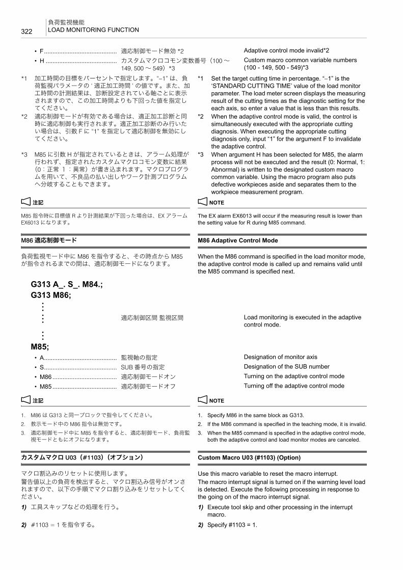
負荷監視機能LOAD MONITORING FUNCTION322
*1 加工時間の目標をパーセントで指定します。“−1” は、負荷監視パラメータの ‘ 適正加工時間 ’ の値です。また、加工時間の計測結果は、診断設定されている軸ごとに表示されますので、この加工時間よりも下回った値を指定してください。
*1 Set the target cutting time in percentage. “−1” is the ‘STANDARD CUTTING TIME’ value of the load monitor parameter. The load meter screen displays the measuring result of the cutting times as the diagnostic setting for the each axis, so enter a value that is less than this results.
*2 適応制御モードが有効である場合は、適正加工診断と同時に適応制御も実行されます。適正加工診断のみ行いたい場合は、引数 F に “1” を指定して適応制御を無効にしてください。
*2 When the adaptive control mode is valid, the control is simultaneously executed with the appropriate cutting diagnosis. When executing the appropriate cutting diagnosis only, input “1” for the argument F to invalidate the adaptive control.
*3 M85 に引数 H が指定されているときは、アラーム処理が行われず、指定されたカスタムマクロコモン変数に結果
(0:正常 1:異常)が書き込まれます。マクロプログラムを用いて、不良品の払い出しやワーク計測プログラムへ分岐することもできます。
*3 When argument H has been selected for M85, the alarm process will not be executed and the result (0: Normal, 1: Abnormal) is written to the designated custom macro common variable. Using the macro program also puts defective workpieces aside and separates them to the workpiece measurement program.
2 注記 2 NOTE
M85 指令時に目標値 R より計測結果が下回った場合は、EX アラームEX6013 になります。
The EX alarm EX6013 will occur if the measuring result is lower than the setting value for R during M85 command.
M86 適応制御モード M86 Adaptive Control Mode
負荷監視モード中に M86 を指令すると、その時点から M85が指令されるまでの間は、適応制御モードになります。
When the M86 command is specified in the load monitor mode, the adaptive control mode is called up and remains valid until the M85 command is specified next.
2 注記 2 NOTE
1. M86 は G313 と同一ブロックで指令してください。 1. Specify M86 in the same block as G313.2. 教示モード中の M86 指令は無効です。 2. If the M86 command is specified in the teaching mode, it is invalid.3. 適応制御モード中に M85 を指令すると、適応制御モード、負荷監
視モードともにオフになります。3. When the M85 command is specified in the adaptive control mode,
both the adaptive control and load monitor modes are canceled.
カスタムマクロ U03(#1103)(オプション) Custom Macro U03 (#1103) (Option)
マクロ割込みのリセットに使用します。 Use this macro variable to reset the macro interrupt.警告値以上の負荷を検出すると、マクロ割込み信号がオンされますので、以下の手順でマクロ割り込みをリセットしてください。
The macro interrupt signal is turned on if the warning level load is detected. Execute the following processing in response to the going on of the macro interrupt signal.
1) 工具スキップなどの処理を行う。 1) Execute tool skip and other processing in the interrupt macro.
2) #1103 = 1 を指令する。 2) Specify #1103 = 1.
• F........................................... 適応制御モード無効 *2 Adaptive control mode invalid*2
• H .......................................... カスタムマクロコモン変数番号(100 ~149, 500 ~ 549)*3
Custom macro common variable numbers (100 - 149, 500 - 549)*3
G313 A_. S_. M84.;G313 M86;:
: 適応制御区間 監視区間 Load monitoring is executed in the adaptive control mode.
:
M85;• A........................................... 監視軸の指定 Designation of monitor axis
• S........................................... SUB 番号の指定 Designation of the SUB number
• M86 ...................................... 適応制御モードオン Turning on the adaptive control mode
• M85 ...................................... 適応制御モードオフ Turning off the adaptive control mode
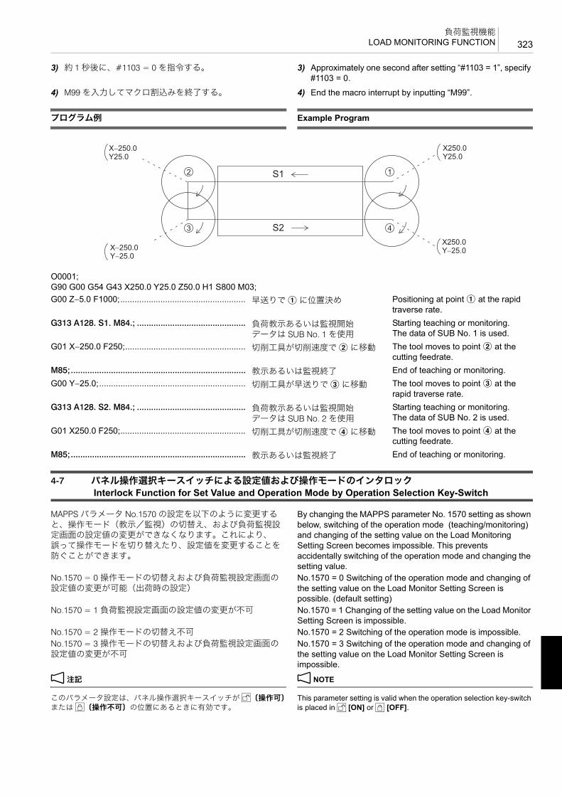
323負荷監視機能
LOAD MONITORING FUNCTION
3) 約 1 秒後に、#1103 = 0 を指令する。 3) Approximately one second after setting “#1103 = 1”, specify #1103 = 0.
4) M99 を入力してマクロ割込みを終了する。 4) End the macro interrupt by inputting “M99”.
プログラム例 Example Program
4-7 パネル操作選択キースイッチによる設定値および操作モードのインタロック Interlock Function for Set Value and Operation Mode by Operation Selection Key-Switch
MAPPS パラメータ No.1570 の設定を以下のように変更すると、操作モード(教示/監視)の切替え、および負荷監視設定画面の設定値の変更ができなくなります。これにより、誤って操作モードを切り替えたり、設定値を変更することを防ぐことができます。
By changing the MAPPS parameter No. 1570 setting as shown below, switching of the operation mode (teaching/monitoring) and changing of the setting value on the Load Monitoring Setting Screen becomes impossible. This prevents accidentally switching of the operation mode and changing the setting value.
No.1570 = 0 操作モードの切替えおよび負荷監視設定画面の設定値の変更が可能(出荷時の設定)
No.1570 = 0 Switching of the operation mode and changing of the setting value on the Load Monitor Setting Screen is possible. (default setting)
No.1570 = 1 負荷監視設定画面の設定値の変更が不可 No.1570 = 1 Changing of the setting value on the Load Monitor Setting Screen is impossible.
No.1570 = 2 操作モードの切替え不可 No.1570 = 2 Switching of the operation mode is impossible.No.1570 = 3 操作モードの切替えおよび負荷監視設定画面の設定値の変更が不可
No.1570 = 3 Switching of the operation mode and changing of the setting value on the Load Monitor Setting Screen is impossible.
2 注記 2 NOTE
このパラメータ設定は、パネル操作選択キースイッチが i〔操作可〕または u〔操作不可〕の位置にあるときに有効です。
This parameter setting is valid when the operation selection key-switch is placed in i [ON] or u [OFF].
O0001;G90 G00 G54 G43 X250.0 Y25.0 Z50.0 H1 S800 M03;G00 Z−5.0 F1000;..................................................... 早送りで a に位置決め Positioning at point a at the rapid
traverse rate.G313 A128. S1. M84.; .............................................. 負荷教示あるいは監視開始
データは SUB No. 1 を使用Starting teaching or monitoring.The data of SUB No. 1 is used.
G01 X−250.0 F250;................................................... 切削工具が切削速度で b に移動 The tool moves to point b at the cutting feedrate.
M85;.......................................................................... 教示あるいは監視終了 End of teaching or monitoring.G00 Y−25.0;.............................................................. 切削工具が早送りで c に移動 The tool moves to point c at the
rapid traverse rate.G313 A128. S2. M84.; .............................................. 負荷教示あるいは監視開始
データは SUB No. 2 を使用Starting teaching or monitoring.The data of SUB No. 2 is used.
G01 X250.0 F250;..................................................... 切削工具が切削速度で d に移動 The tool moves to point d at the cutting feedrate.
M85;.......................................................................... 教示あるいは監視終了 End of teaching or monitoring.
S1
S2
1
4
2
3
X−250.0Y25.0
X250.0Y25.0
X250.0Y−25.0X−250.0
Y−25.0

負荷監視機能LOAD MONITORING FUNCTION324
4-8 アラーム、エラー表示Alarm, Error Display
負荷監視機能に関するマクロアラームは次の通りです。 The macro alarms that relate to the load monitoring function are as follows.
2 注記 2 NOTE
PC アラームが出た場合は、e(ヘルプ)キーでメッセージの内容を確認してください。
When a PC alarm is displayed, check the message details by pressing the e (HELP) key.
4-9 負荷監視データの入出力Load Monitoring Data Input/Output
教示データの入出力は入出力画面で行います。 Teaching data Input/Output
1 入出力画面の詳細については、別冊機械操作説明書 1 For details of Input/Output screen, refer to the separate volume, “OPERATION MANUAL”
<入力手順> <Input Procedure>1) ‘ パラメータ ’ にカーソルを合わせる。 1) Place the cursor on ‘PARAM’.
2) ソフトキー【リード】を押す。 [入力データ一覧表が表示される]
2) Press the [READ] soft-key. [The input data list is displayed.]
3) 入力したいデータにカーソルを移動させる。 3) [Move the cursor to the data to be input]
4) ソフトキー【実行】を押す。 4) Press the [EXECUTE] soft-key.<出力手順> <Output Procedure>1) ‘ パラメータ ’ にカーソルを合わせる。 1) Place the cursor on ‘PARAMETER’.
2) コマンド入力行にキー入力する。 2) Make an entry in the command input line using key input.データの出力には、次の三通りがあります。 The data can be output in the following three ways.• 入力行に “LOAD” と入力し、‘ 負荷監視設定 ’ + ‘ 教示
データ ’ を出力する。• Input “LOAD” in the input line, then output ‘LOAD
MONITOR SETTING’ + ‘TEACHING DATA’.• 入力行に “ALL” と入力し、‘ パラメータ(NC, PC など)’
+ ‘ 負荷監視設定 ’ + ‘ 教示データ ’ を出力する。• Input “ALL” in the input line, then output ‘PARAMETER
(NC, PC)’ + ‘LOAD MONITOR SETTING’ + ‘TEACHING DATA’
• 何も入力しないと、‘ パラメータ(NC, PC など)’ + ‘ 負荷監視設定 ’ を出力する。
• If nothing is input, ‘PARAMETER (NC, PC)’ + ‘LOAD MONITOR SETTING’ is output.
3)【パンチ】D【実行】 3) [PUNCH] D [EXECUTE][データが出力される] [Data are output.]
マクロアラーム Macro Alarm
No. 3038: ‘LOAD MONITOR PROGRAM ERROR’(G313 のブロックで “A”“T”“S” のアドレスの指令範囲が誤っています。)
No. 3038: ‘LOAD MONITOR PROGRAM ERROR’ (In the G313 block, the address “A”, “T” or “S” designation is incorrect.)

索引
索引
ページページ
数字
3 次元座標変換(オプション)(G68) 132
3 次元座標変換キャンセル(オプション)(G69) 132
A
APC 用プログラム 180
ATC 準備の高速化 303
B
B 機能 179
B 軸アンクランプ(M11) 179
B 軸クランプ(M10) 179
B 軸と ATC の同時動作 306
B 軸割り出しの高速化 304
C
Cs 輪郭制御(オプション)(M166, M167) 171
F
F 機能 183
G
G00 早送りによる工具の移動 66
G01 切削送りによる工具の直線移動 67
G02.2 インボリュート補間(時計方向)、G03.2 インボリュート補間(反時計方向)(オプション) 81
G02 渦巻き補間/円錐補間(時計方向)、G03 渦巻き補間/円錐補間(反時計方向)(オプション) 76
G02 渦巻き補間/円錐補間(時計方向)(オプション)76
G02 円弧補間(時計方向)、G03 円弧補間(反時計方向) 68
G02 ヘリカル補間(時計方向)、G03 ヘリカル補間(反時計方向) 71
G03 渦巻き補間/円錐補間(反時計方向)(オプション) 76
G04 プログラムの進行停止(ドウェル) 83
G05.1 高速高精度制御 I(AI 輪郭制御 )、G05 高速高精度制御II(高精度輪郭制御)(オプション) 84
G05.1 高速高精度制御 I(AI 輪郭制御 )(オプション)84
G05 高速高精度制御 II(高精度輪郭制御)(オプション) 84
G07.1 円筒補間(オプション) 85
G08 高精度制御(先行制御) 88
G09 イグザクトストップ 90
G09 イグザクトストップ、G61 イグザクトストップモード、G63 タッピングモード、G64 切削モード 138
G10 プログラム指令による工具補正量設定、変更 187
G10 プログラム指令によるワーク座標系変更 93
G15, G16 極座標指令(オプション) 95
G17, G18, G19 加工平面選択 96
G27 原点(レファレンス点)復帰チェック 98
G28 機械原点(レファレンス点)復帰、G30 第 2(3, 4)原点(レファレンス点)復帰 98
G31 スキップ機能、G31.1 外部高速スキップ ( オプション) 100
G40.1, G41.1, G42.1 法線方向制御(オプション) 102
G41, G42 工具径補正、G40 工具径補正キャンセル 193
G41 平面加工、側面加工 291
G43.4, G43.5 工具先端点制御(オプション) 103
G43.4 工具先端点制御(タイプ 1)の指令方法 104
G43.5 工具先端点制御(タイプ 2)の指令方法 105
G43 工具長補正、G49 工具長補正キャンセル 190
G45 ~ G48 工具位置オフセット 105
G51 スケーリング、G50 スケーリングキャンセル(オプション) 108
G51.1 プログラマブルミラーイメージ、G50.1 プログラマブルミラーイメージキャンセル 112
G52 ローカル座標系設定 114
G53 機械座標系選択 115
G54.1 追加ワーク座標系選択(オプション) 118
G54 ~ G59 ワーク座標系選択 116
G60 一方向位置決め 125
G65, G66, G66.1, G67 マクロプログラムの使用 127
G68 3 次元座標変換、G69 3 次元座標変換キャンセル(オプション) 132
G68 座標回転、G69 座標回転キャンセル(オプション) 130
G73 高速深穴ドリリングサイクル 223
G76 ファインボーリングサイクル、G87 バックボーリングサイクル 248
G81 スポットドリリングサイクル 219
G81, G73, G76 穴あけ固定サイクル 291
G81, G76, G84 穴あけ固定サイクル 280
G82 カウンタボーリングサイクル 219
G83 深穴ドリルサイクル 225
G85 ボーリングサイクル 221
G86 ボーリングサイクル(ドウェル) 221
G88 ボーリングサイクル(シングルブロック停止)、G89ボーリングサイクル(ドウェル) 222
G90 アブソリュート指令(絶対値指令)、G91 インクレメンタル指令(増分値指令) 135
G92.1 ワーク座標系プリセット(オプション) 136
索引

索引
索引
ページページ
G93, G94, G95 工具の送り速度の単位設定 136
G300 円弧上の点(等ピッチ) 254
G300 ~ G305 に関する注意事項 263
G301 円弧上の点(不等ピッチ) 255
G302 直線上の点(等ピッチ) 256
G303 直線上の点(不等ピッチ) 258
G304 四角上、格子上の点 259
G305 千鳥格子上の点 262
G306 円内側切削(仕上げ) 264
G307 円外側切削(仕上げ) 266
G308 四角内側切削(仕上げ) 267
G309 四角外側切削(仕上げ) 269
G313 負荷監視マクロプログラム呼出し 320
G332 加工モード選択 146
G332 の使用方法 147
G62 自動コーナオーバライド 138
G 機能 57
G コード一覧表 57
M
M00 プログラムストップ、M01 オプショナルストップ155
M02 プログラム終了、M30 プログラム終了と頭出し156
M03 主軸正転、M04 主軸逆転、M05 主軸回転停止 156
M06 工具交換 157
M08 クーラントの吐出、M09 クーラントの吐出停止157
M10 B 軸クランプ 179
M11 B 軸アンクランプ 179
M19 主軸定位置停止 158
M20 自動電源しゃ断 158
M29 G74, G74 同期式/非同期式深穴逆タップサイクル(左ねじ) 235
M29 G74, M04 G74 同期式/非同期式ペッキング逆タップサイクル(左ねじ) 233
M29 G84, M03 G84 同期式/非同期式深穴タップサイクル(右ねじ) 235
M29 G84, M03 G84 同期式/非同期式ペッキングタップサイクル(右ねじ) 233
M29 G74, M04 G74 同期式/非同期式逆タッピングサイクル(左ねじ) 230
M29 G84, M03 G84 同期式/非同期式タッピングサイクル(右ねじ) 228
M33 工具収納 159
M48 切削送りオーバライドキャンセル・オフ、M49 切削送りオーバライドキャンセル・オン 160
M50 オイルホールドリル用クーラント・オン、M09 クーラン
ト・オフ(オプション) 161
M51 エアブロー開始、M59 エアブロー停止 161
M53 センサ用エアブロー開始、M58 センサ用エアブロー停止(オプション) 161
M70 ワークカウンタ、トータルカウンタ 162
M73, M74, M75, M76 ミラーイメージ・オン、オフ 163
M80 シャワークーラント・オン、M81 シャワークーラント・オフ 166
M86 適応制御モード 322
M86 適正加工診断 321
M88 スルースピンドルクーラント・オン、M89 スルースピンドルクーラント・オフ(オプション) 166
M92 負荷監視(教示、監視)有効 320
M98/M198 サブプログラムの呼出し、M99 サブプログラム終了 168
M98, M99 サブプログラム 280
M119 主軸(第 2)定位置停止 171
M166, M167 Cs 輪郭制御(オプション) 171
M237 G83 小径深穴ドリルサイクル(オプション) 226
M252 スルースピンドルエアブロー・オン(オプション) 172
M253 スルースピンドルエアブロー・オフ(オプション) 172
M270 ~ M277 スルースピンドルクーラントの吐出圧力切替え(クノール仕様のみ) 166
M2000 ~ M2020 マルチカウンタディスプレイ機能(オプション) 172
M2200 先読み停止 174
MAPPS パラメータに加工モードを設定する方法 148
M 機能 151
M コード一覧表 151
S
SSS(Super Smooth Surface)制御(オプション) 89
S 機能 182
TTCP 103
T 機能 177
あ
穴あけ固定サイクル 213
穴あけ固定サイクル(G81, G73, G76) 291
穴あけ固定サイクル(G81, G76, G84) 280
穴あけ固定サイクル一覧表 217
穴あけ固定サイクルの動きとインポジション幅の有効性 244

索引
索引
ページページ
アブソリュート指令(絶対値指令)(G90) 135
アブソリュート/インクレメンタル指令(B 機能) 179
アラーム、エラー表示 324
い
イグザクトストップモード(G61) 138
イグザクトストップ(G09) 90, 138
一方向位置決め(G60) 125
インクレメンタル指令(増分値指令)(G91) 135
インボリュート曲線 82
インボリュート補間(時計方向)(オプション)(G02.2) 81
インボリュート補間(反時計方向)(オプション)(G03.2) 81
う
渦巻き補間 77
渦巻き補間/円錐補間(時計方向)(オプション)(G02) 76
渦巻き補間/円錐補間(反時計方向)(オプション)(G03) 76
え
エアブロー開始(M51) 161
エアブロー停止(M59) 161
円外側切削(仕上げ)(G307) 266
円弧上の点(等ピッチ)(G300) 254
円弧上の点(不等ピッチ)(G301) 255
円弧補間(時計方向)(G02) 68
円弧補間(反時計方向)(G03) 68
円錐補間 79
円筒補間(オプション)(G07.1) 85
円内側切削(仕上げ)(G306) 264
お
オイラー角による傾斜面加工指令 143
オイルホールドリル用クーラント・オフ 161
オイルホールドリル用クーラント・オン(オプション)(M50) 161
オプショナルストップ(M01) 155
オフセット 187
か
回転軸ワーク位置補正(オプション) 307
回転軸ワーク位置補正画面での設定 308
回転軸ワーク位置補正量を設定する 308
カウンタボーリングサイクル(G82) 219
加工時間短縮化プログラミング 301
加工プログラムで G54.2 を指令する 308
加工平面選択(G17, G18, G19) 96
加工モード 147
カスタムモード 147
時間優先モード 147
中間モード 147
精度優先モード 147
加工モード選択(G332) 146
カスタムマクロ U03(#1103)(オプション) 322
き
機械原点復帰(G28) 98
機械座標系選択(G53) 115
極座標指令(オプション)(G15, G16) 95
く
クイック M コード 301
クーラントの吐出停止(M09) 157
クーラントの吐出(M08) 157
クーラント・オフ(オプション)(M09) 161
け
警告リスト画面 317
傾斜面加工指令(オプション) 140
傾斜面加工指令モード中に指令可能な G コード 145
原点(レファレンス点)復帰チェック(G27) 98
こ
工具位置オフセット(G45 ~ G48) 105
工具オフセット画面での設定、変更 187
工具径補正キャンセル(G40) 193
工具径補正で使用する用語 196
工具径補正による切込み過ぎ 202
工具径補正量の正負と工具中心経路 201
工具径補正量の変更 201
工具径補正(G41, G42) 193
工具交換(M06) 157
工具収納(M33) 159
工具寿命管理 311
工具先端点制御(オプション) 103
工具長補正 188

索引
索引
ページページ
工具長補正キャンセル(G49) 190
工具長補正(G43) 190
工具の送り速度の単位設定(G93, G94, G95) 136
工具の長さを補正する方法 188
工具補正 187
工具補正量の入力 187
高精度制御(先行制御)(G08) 88
高速高精度制御 II(高精度輪郭制御)(オプション)(G05) 84
高速高精度制御 I(AI 輪郭制御 )(G05.1)、高速高精度制御 II(高精度輪郭制御)(オプション)(G05) 84
高速高精度制御 I(AI 輪郭制御 )(オプション)(G05.1) 84
高速ドリル加工、高速タップ加工 240
高速ドリル加工、高速タップ加工に関する注意事項242
高速深穴ドリリングサイクル(G73) 223
さ
先読み停止(M2200) 174
座標回転キャンセル(オプション)(G69) 130
座標回転(オプション)(G68) 130
サブプログラム(M98, M99) 280
し
四角外側切削(仕上げ)(G309) 269
四角上、格子上の点(G304) 259
四角内側切削(仕上げ)(G308) 267
システム変数によるワーク設置誤差量の設定 122
自動電源しゃ断(M20) 158
シャワークーラント・オフ(M81) 166
シャワークーラント・オン(M80) 166
シャワークーラント・オン 166
主軸起動と位置決めを同時に行う 302
主軸回転停止(M05) 156
主軸逆転(M04) 156
主軸正転(M03) 156
主軸(第 2)定位置停止(M119) 171
主軸定位置停止(M19) 158
小径深穴ドリルサイクル(オプション)(M237 G83)226
す
スキップ機能(G31)、外部高速スキップ(G31.1)( オプション) 100
スケーリング 108
スケーリング(オプション)(G51) 108
スケーリングキャンセル(オプション)(G50) 108
スポットドリリングサイクル(G81) 219
スルースピンドルエアブロー・オフ(オプション)(M253) 172
スルースピンドルエアブロー・オン(オプション)(M252) 172
スルースピンドルクーラント 166
スルースピンドルクーラント・オフ(オプション)(M89) 166
スルースピンドルクーラント・オン(オプション)(M88) 166
スルースピンドルクーラントの吐出圧力切替え(クノール仕様のみ)(M270 ~ M277) 166
せ
制御軸と動作方向 55
制御軸の実際の動きとプログラム上での動き 56
切削送りオーバライドキャンセル・オフ(M48) 160
切削送りオーバライドキャンセル・オン(M49) 160
切削送りによる工具の直線移動(G01) 67
切削送りの速度制御 137
切削の 終点に壁がある場合 199
切削モード(G64) 138
センサ用エアブロー開始 161
センサ用エアブロー開始(オプション)(M53) 161
センサ用エアブロー停止(オプション)(M58) 161
た
第 2(3, 4)原点復帰(G30) 98
タッピングサイクル 228
タッピングモード(G63) 138
ち
千鳥格子上の点(G305) 262
直線上の点(等ピッチ)(G302) 256
直線上の点(不等ピッチ)(G303) 258
つ
追加ワーク座標系選択(オプション)(G54.1) 118
て
適応制御モード(M86) 322
適正加工診断(M86) 321
電源しゃ断 158

索引
索引
ページページ
と
同期式タッピングサイクルの主軸 高回転速度 240
同期式/非同期式タッピングサイクル(右ねじ)(G74) 230
同期式/非同期式タッピングサイクル(右ねじ)(G84) 228
同期式/非同期式タッピングサイクル(右ねじ)(M29 G74, M04 G74) 230
同期式/非同期式タッピングサイクル(右ねじ)(M29 G84, M03 G84) 228
同期式/非同期式深穴逆タップサイクル(左ねじ)(M29 G74, M04 G74) 235
同期式/非同期式深穴タップサイクル(右ねじ)(M29 G84, M03 G84) 235
同期式/非同期式ペッキング逆タップサイクル(左ねじ)(M29 G74, M04 G74) 233
同期式/非同期式ペッキングタップサイクル(右ねじ)(M29 G84, M03 G84) 233
は
パターンサイクル 253
パターンサイクルに関するアラーム 272
バックボーリングサイクル(G87) 248
パネル操作選択キースイッチによる設定値および操作モードのインタロック 323
早送りによる工具の移動(G00) 66
ふ
ファインボーリングサイクル(G76) 248
深穴ドリリングサイクル 223
深穴ドリルサイクル(G83) 225
負荷監視機能 312
負荷監視機能とは 312
負荷監視機能の表示画面 313
負荷監視(教示、監視)有効(M92) 320
負荷監視設定画面 318
負荷監視データ設定画面 315
負荷監視データの入出力 324
負荷監視マクロプログラム呼出し(G313) 320
負荷監視用プログラムの指令方法 320
負荷監視ロードメータ画面 314
プログラマブルミラーイメージ 112
プログラマブルミラーイメージ(G51.1) 112
プログラマブルミラーイメージキャンセル(G50.1)112
プログラム終了と頭出し(M30) 156
プログラム終了(M02) 156
プログラム指令での設定 308
プログラム指令による工具補正量設定、変更(G10)187
プログラム指令によるワーク座標系変更(G10) 93
プログラムストップ(M00) 155
プログラムの進行停止(ドウェル)(G04) 83
プログラム例 204, 279, 323
穴あけ固定サイクル(G81, G76, G84)、サブプログラム(M98, M99) 280
真円切削(工具径補正) 285
多数個取り 288
平面加工、側面加工(G41)、穴あけ固定サイクル(G81, G73, G76) 291
へ
平面加工、側面加工(G41) 291
ヘリカル補間(時計方向)(G02) 71
ヘリカル補間(反時計方向)(G03) 71
ほ
法線方向制御(オプション)(G40.1, G41.1, G42.1)102
ボーリングサイクル 219
ボーリングサイクル(シングルブロック停止)(G88)222
ボーリングサイクル(ドウェル)(G86) 221
ボーリングサイクル(ドウェル)(G89) 222
ボーリングサイクル(G85) 221
補正に関する一般的な注意事項 199
ま
マクロアラーム 324
マルチ M コード機能(オプション) 154
マルチカウンタディスプレイ機能(オプション)(M2000 ~M2020) 172
み
ミラーイメージ・オン、オフ(M73, M74, M75, M76)163
ろ
ローカル座標系設定(G52) 114
ロータリテーブル回転中心の座標値を設定する 307
ロール・ピッチ・ヨーによる傾斜面加工指令 140

索引
索引
ページページ
わ
ワークカウンタ、トータルカウンタ(M70) 162
ワーク座標系 116
ワーク座標系選択(G54 ~ G59) 116
ワーク座標系プリセット(オプション)(G92.1) 136
ワーク設置誤差補正(オプション) 119
ワーク設置誤差補正モード中に指令可能な G コード122
ワーク設置誤差補正を指令する際に可能なモーダル G コード 124

INDEX
PagePage
Numerics3D Coordinate Conversion Cancel (Option) (G69) 132
3D Coordinate Conversion (Option) (G68) 132
AAbsolute Command (G90) 135
Absolute/Incremental Commands (B Function) 179
Adaptive Control Mode (M86) 322
Air Blow Start (M51) 161
Air Blow Stop (M59) 161
Alarm, Error Display 324
Alarms for Pattern Cycle 272
Appropriate Cutting Diagnosis (M86) 321
Arc (Equal Intervals) (G300) 254
Arc (Random Intervals) (G301) 255
Automatic Power Shutoff (M20) 158
AXIS CONTROL AND MOVEMENT DIRECTION 55
Axis Movement in Machine and Program 56
BB FUNCTION 179
Back Boring Cycle (G87) 248
B-axis clamp (M10) 179
B-axis unclamp (M11) 179
Boring Cycle 219
Boring Cycle (Dwell) (G86) 221
Boring Cycle (Dwell) (G89) 222
Boring Cycle (G85) 221
Boring Cycle (Single Block Stop) (G88) 222
CCalling the load monitor macro program (G313) 320
Changing the Discharge Pressure of the Through-Spindle Coolant (Knoll Specifications Only) (M270 - M277) 166
Changing the Tool Radius Offset Amount 201
Changing Work Coordinate System by Programmed Command (G10) 93
Circle Cutting Inside (Finishing) (G306) 264
Circle Cutting Outside (Finishing) (G307) 266
Circular Interpolation (Clockwise) (G02) 68
Circular Interpolation (Counterclockwise) (G03) 68
Conical Interpolation 79
Coolant Discharge (M08) 157
Coolant Discharge Off (M09) 157
Coolant Discharge OFF (Option) (M09) 161
Coordinate Rotation (Option) (G68) 130
Coordinate Rotation Cancel (Option) (G69) 130
Counter Boring Cycle (G82) 219
Cs Contouring Control 171
Cs Contouring Control (Option) (M166, M167) 171
Custom Macro U03 (#1103) (Option) 322
Cutting Feedrate Control 137
Cutting Mode (G64) 138
Cutting Mode Selection (G332) 146
Cutting Modes 147
Cutting modesAccuracy priority mode 147Custom mode 147Middle mode 147Time priority mode 147
Cylindrical Interpolation (Option) (G07.1) 85
DDeep Hole Drilling Cycle 223
Deep Hole Drilling Cycle (G83) 225
EExact Stop (G09) 90, 138
Exact Stop Mode (G61) 138
Example Program 323
EXAMPLE PROGRAMS 279Accurate Circle Cutting (Tool Radius Offset) 285Facing, Side Cutting (G41), Hole Machining Canned Cycle (G81, G73, G76) 291Hole Machining Canned Cycle Program (G81, G76, G84) and Sub-Program (M98, M99) 280Machining Multiple Workpieces 288
Example Programs 204
Executing B-Axis and ATC Operations at Same Time 306
FF FUNCTION 183
Facing, Side Cutting (G41) 291
Feedrate Override Cancel OFF (M48) 160
Feedrate Override Cancel ON (M49) 160
Fine Boring Cycle (G76) 248
Frame Cutting Inside (Finishing) (G308) 267
Frame Cutting Outside (Finishing) (G309) 269
GG Code List 57
G Codes that Can Be Specified in the Tilted Working Plane Command Mode 145
G Codes that Can Be Specified in the Work Setting Error Offset Mode 122
INDEX

INDEX
PagePageG FUNCTIONS 57
G00 Positioning Cutting Tool at Rapid Traverse Rate 66
G01 Moving Cutting Tool along Straight Path at Cutting Feedrate 67
G02 Circular Interpolation (Clockwise), G03 Circular Interpolation (Counterclockwise) 68
G02 Helical Interpolation (Clockwise), G03 Helical Interpolation (Counterclockwise) 71
G02 Spiral Interpolation/Conical Interpolation (Clockwise), G03 Spiral Interpolation/Conical Interpolation (Counterclockwise) (Option) 76
G02 Spiral Interpolation/Conical Interpolation (Clockwise) (Option) 76
G02.2 Involute Interpolation (Clockwise), G03.2 Involute Interpolation (Counterclockwise) (Option) 81
G03 Spiral Interpolation/Conical Interpolation (Counterclockwise) (Option) 76
G04 Suspending Program Execution (Dwell) 83
G05 High-Speed High-Accuracy Control II (High-Precision Contour Control) (Option) 84
G05.1 High-Speed High-Accuracy Control I (AI Contour Control) (Option) 84
G05.1 High-Speed High-Accuracy Control I (AI Contour Control), G05 High-Speed High-Accuracy Control II (High-Precision Contour Control) (Option) 84
G07.1 Cylindrical Interpolation (Option) 85
G08 High-Accuracy Control (Look-Ahead Control) 88
G09 Exact Stop 90
G09 Exact Stop, G61 Exact Stop Mode, G63 Tapping Mode, G64 Cutting Mode 138
G10 Changing Work Coordinate System by Programmed Command 93
G10 Setting and Changing Tool Offset Amount with Program Commands 187
G15, G16 Polar Coordinate Command (Option) 95
G17, G18, G19 Selecting Plane for Machining 96
G27 Zero (Reference Position) Return Check 98
G28 Machine Zero (Reference Position) Return, G30 Second (Third or Fourth) Zero (Reference Position) Return 98
G40.1, G41.1, G42.1 Normal Direction Control (Option)102
G41 Facing, Side Cutting 291
G41, G42 Tool Radius Offset, G40 Tool Radius Offset Cancel 193
G43 Tool Length Offset, G49 Tool Length Offset Cancel190
G43.4 Programming Using Tool Center Point Control (Type 1) 104
G43.4, G43.5 Tool Center Point Control (Option) 103
G43.5 Programming Using Tool Center Point Control (Type 2) 105
G45 to G48 Tool Position Offset 105
G51 Scaling, G50 Scaling Cancel (Option) 108
G51.1 Programmable Mirror Image, G50.1 Programmable Mirror Image Cancel 112
G52 Setting Local Coordinate System 114
G53 Selecting Machine Coordinate System 115
G54 to G59 Selecting Work Coordinate System 116
G54.1 Selecting Additional Work Coordinate System (Option) 118
G60 Uni-Directional Positioning 125
G65, G66, G66.1, G67 Using Macro Programs 127
G68 3D Coordinate Conversion, G69 3D Coordinate Conversion Cancel (Option) 132
G68 Coordinate Rotation, G69 Coordinate Rotation Cancel (Option) 130
G73 High-Speed Deep Hole Drilling Cycle 223
G76 Fine Boring Cycle, G87 Back Boring Cycle 248
G81 Spot Drilling Cycle 219
G81, G73, G76 Hole Machining Canned Cycle 291
G81, G76, G84 Hole Machining Canned Cycle Program280
G82 Counter Boring Cycle 219
G83 Deep Hole Drilling Cycle 225
G85 Boring Cycle 221
G86 Boring Cycle (Dwell) 221
G88 Boring Cycle (Single Block Stop), G89 Boring Cycle (Dwell) 222
G90 Absolute Command, G91 Incremental Command135
G92.1 Work Coordinate System Preset (Option) 136
G93, G94, G95 Setting Feedrate Units 136
G300 Arc (Equal Intervals) 254
G301 Arc (Random Intervals) 255
G302 Line-at-Angle (Equal Intervals) 256
G303 Line-at-Angle (Random Intervals) 258
G304 Rectangle/Grid 259
G305 Staggered Grid 262
G306 Circle Cutting Inside (Finishing) 264
G307 Circle Cutting Outside (Finishing) 266
G308 Frame Cutting Inside (Finishing) 267
G309 Frame Cutting Outside (Finishing) 269
G31 Skip Function, G31.1 External High-Speed Skip (Option) 100
G313 Calling the load monitor macro program 320
G332 Cutting Mode Selection 146
G62 Automatic Corner Override 138
General Cautions on Offset Function 199
HHelical Interpolation (Clockwise) (G02) 71
Helical Interpolation (Counterclockwise) (G03) 71
High-Accuracy Control (Look-Ahead Control) (G08) 88

INDEX
PagePageHigh-Speed Deep Hole Drilling Cycle (G73) 223
High-Speed Drilling and High-Speed Tapping Operation240
High-Speed High-Accuracy Control I (AI Contour Control) (G05.1), High-Speed High-Accuracy Control II (High-Precision Contour Control) (Option) (G05) 84
High-Speed High-Accuracy Control I (AI Contour Control) (Option) (G05.1) 84
High-Speed High-Accuracy Control II (High-Precision Contour Control) (Option) (G05 ) 84
HOLE MACHINING CANNED CYCLE 213
Hole Machining Canned Cycle (G81, G73, G76) 291
Hole Machining Canned Cycle List 217
Hole Machining Canned Cycle Program (G81, G76, G84)280
IIf Wall Lies at Endpoint of Cutting 199
Incremental Command (G91) 135
Inputting Tool Offset Amount 187
Interlock Function for Set Value and Operation Mode by Operation Selection Key-Switch 323
involute curve 82
Involute Interpolation (Clockwise) (Option) (G02.2) 81
Involute Interpolation (Counterclockwise) (Option) (G03.2) 81
LLine-at-Angle (Equal Intervals) (G302) 256
Line-at-Angle (Random Intervals) (G303) 258
Load Monitoring (Teaching, Monitoring) Valid (M92) 320
Load Monitoring Data Input/Output 324
Load Monitoring Data Setting Screen 315
LOAD MONITORING FUNCTION 312
Load Monitoring Load Meter Screen 314
Load Monitoring Setting Screen 318
MM Code List 151
M FUNCTIONS 151
M00 Program Stop, M01 Optional Stop 155
M02 Program End, M30 Program End and Rewind 156
M03 Spindle Start (Normal), M04 Spindle Start (Reverse), M05 Spindle Stop 156
M06 Tool Change 157
M08 Coolant Discharge ON, M09 Coolant Discharge OFF157
M10 B-axis clamp 179
M11 B-axis unclamp 179
M19 Spindle Orientation 158
M20 Automatic Power Shutoff 158
M29 G74, M04 G74 Synchronized/Non-Synchronized Deep Hole Reverse Tapping Cycle (Left-Hand Thread) 235
M29 G74, M04 G74 Synchronized/Non-Synchronized Pecking Reverse Tapping Cycle (Left-Hand Thread) 233
M29 G74, M04 G74 Synchronized/Non-Synchronized Reverse Tapping Cycle (Left-Hand Thread) 230
M29 G84, M03 G84 Synchronized/Non-Synchronized Deep Hole Tapping Cycle (Right-Hand Thread) 235
M29 G84, M03 G84 Synchronized/Non-Synchronized Pecking Tapping Cycle (Right-Hand Thread) 233
M29 G84, M03 G84 Synchronized/Non-Synchronized Tapping Cycle (Right-Hand Thread) 228
M33 Tool Storing Cycle 159
M48 Feedrate Override Cancel OFF, M49 Feedrate Override Cancel ON 160
M50 Oil-Hole Drill Coolant Discharge ON, M09 Coolant Discharge OFF (Option) 161
M51 Air Blow Start, M59 Air Blow Stop 161
M53 Sensor Air Blow Start, M58 Sensor Air Blow Stop (Option) 161
M70 Specifies Counting of Work Counter and Total Counter 162
M73, M74, M75, M76 Mirror Image ON/OFF 163
M80 Shower Coolant ON, M81 Shower Coolant OFF 166
M86 Adaptive Control Mode 322
M86 Appropriate Cutting Diagnosis 321
M88 Through-Spindle Coolant ON, M89 Through-Spindle Coolant OFF (Option) 166
M92 Load Monitoring (Teaching, Monitoring) Valid 320
M98, M99 Sub-Program 280
M98/M198 Sub-Program Call, M99 Sub-Program End168
M119 Spindle (Second) Orientation 171
M166, M167 Cs Contouring Control (Option) 171
M237 G83 Small-Diameter Deep Hole Drilling Cycle (Option) 226
M252 Through-Spindle Air Blow ON 172
M252 Through-Spindle Air Blow ON, M253 Through-Spindle Air Blow OFF (Option) 172
M253 Through-Spindle Air Blow OFF (Option) 172
M270 - M277Changing the Discharge Pressure of the Through-Spindle Coolant (Knoll Specifications Only) 166
M2000 to M2020 Multi Counter Display Function (Option)172
M2200 Pre-Read Stop 174
Machine Zero (Reference Position) Return (G28) 98
macro alarms 324
Maximum Spindle Speed During Synchronized Tapping240
Methods for Setting Tool Length Offset Data 188
Mirror Image ON/OFF (M73, M74, M75, M76) 163

INDEX
PagePageModal G Codes that Allow Specification of the Work Setting Error Offset Mode 124
Moving Cutting Tool along Straight Path at Cutting Feedrate (G01) 67
Multi Counter Display Function (Option) (M2000 to M2020) 172
Multiple M Code Function (Option) 154
NNormal Direction Control (Option) (G40.1, G41.1, G42.1)102
OOil-Hole Drill Coolant Discharge (Option) 161
Oil-Hole Drill Coolant Discharge ON (Option) (M50) 161
Optional Stop (M01) 155
Outline of Load Monitoring Function 312
Overcut in Tool Radius Offset Mode 202
PPattern Cycles 253
Polar Coordinate Command (Option) (G15, G16) 95
Positioning Cutting Tool at Rapid Traverse Rate (G00) 66
Positive (+) and Negative (−) Designation for Tool Radius Offset Amount and Tool Paths 201
Power Shutoff 158
Precautions on Executing High-speed Drilling and High-speed Tapping Operation 242
Precautions on Using G300 to G305 Commands 263
Pre-Read Stop (M2200) 174
Program End (M02) 156
Program End and Rewind (M30) 156
Program Stop (M00) 155
Programmable Mirror Image 112
Programmable Mirror Image Cancel (G50.1) 112
Programmable Mirror Image (G51.1) 112
Programming for APC 180
PROGRAMS TO REDUCE CYCLE TIME 301
QQuick M Code 301
RRectangle/Grid (G304) 259
SS FUNCTION 182
Scaling 108
Scaling Cancel (Option) (G50) 108
Scaling (Option) (G51) 108
Screens for Load Monitoring Function 313
Second (Third or Fourth) Zero (Reference Position) Return (G30) 98
Selecting Additional Work Coordinate (Option) (G54.1)118
Selecting Machine Coordinate System (G53) 115
Selecting Plane for Machining (G17, G18, G19) 96
Selecting Work Coordinate System (G54 to G59) 116
Sensor Air Blow Start 161
Sensor Air Blow Start (Option) (M53) 161
Sensor Air Blow Stop (Option) (M58) 161
Setting and Changing on TOOL OFFSET Screen 187
Setting and Changing Tool Offset Amount with Program Commands (G10) 187
Setting Coordinate Values of Rotational Center of Rotary Table 307
Setting Cutting Mode with MAPPS Parameter 148
Setting Feedrate Units (G93, G94, G95) 136
Setting in Machining Program 308
Setting Local Coordinate System (G52) 114
Setting on Workpiece Position Offset for Rotary Axis Screen 308
Setting Work Setting Error with System Variables 122
Setting Workpiece Position Offset Amount 308
Shower Coolant OFF 166
Shower Coolant OFF (M81) 166
Shower Coolant ON (M80) 166
Skip Function (G31), External High-Speed Skip (G31.1) (Option) 100
Small-Diameter Deep Hole Drilling Cycle (Option) (M237 G83) 226
Specifies Counting of Work Counter and Total Counter (M70) 162
Specifying G54.2 in Machining Program 308
Specifying Load Monitor Program 320
Speeding-Up ATC Preparation 303
Speeding-Up B-Axis Indexing 304
Spindle Orientation (M19) 158
Spindle (Second) Orientation (M119) 171
Spindle Start (Normal) (M03) 156
Spindle Start (Reverse) (M04) 156
Spindle Stop (M05) 156
Spiral Interpolation 77
Spiral Interpolation/Conical Interpolation (Clockwise) (Option) (G02) 76
Spiral Interpolation/Conical Interpolation (Counterclockwise) (Option) (G03) 76
Spot Drilling Cycle (G81) 219

INDEX
PagePageSSS (Super Smooth Surface) Control (Option) 89
Staggered Grid (G305) 262
Starting-Up Spindle and Positioning Simultaneously 302
Sub-Program (M98, M99) 280
Suspending Program Execution (Dwell) (G04) 83
Synchronized/Non-Synchronized Deep Hole Reverse Tapping Cycle (Left-Hand Thread) (M29 G74, M04 G74) 235
Synchronized/Non-Synchronized Deep Hole Tapping Cycle (Right-Hand Thread) (M29 G84, M03 G84) 235
Synchronized/Non-Synchronized Pecking Reverse Tapping Cycle (Left-Hand Thread) (M29 G74, M04 G74) 233
Synchronized/Non-Synchronized Pecking Tapping Cycle (Right-Hand Thread)(M29 G84, M03 G84) 233
Synchronized/Non-Synchronized Reverse Tapping Cycle (Left-Hand Thread) (G74) 230
Synchronized/Non-Synchronized Reverse Tapping Cycle (Left-Hand Thread) (M29 G74, M04 G74) 230
Synchronized/Non-Synchronized Tapping Cycle (Right-Hand Thread) (M29 G84, M03 G84) 228
TT FUNCTION 177
Tapping Cycle 228
Tapping Mode (G63) 138
TCP 103
Terms for Tool Radius Offset 196
The Load Monitor Warning List Screen 317
Through-Spindle Air Blow OFF (Option) (M253) 172
Through-Spindle Air Blow ON 172
Through-Spindle Air Blow ON (M252) 172
Through-Spindle Coolant 166
Through-Spindle Coolant OFF (Option) (M89) 166
Through-Spindle Coolant ON (Option) (M88) 166
Tilted Working Plane Command (Option) 140
Tilted Working Plane Command Based on Euler Angle143
Tilted Working Plane Command Based on Roll-Pitch-Yaw140
Tool Change (M06) 157
Tool Length Offset 188
Tool Length Offset (G43) 190
Tool Length Offset Cancel (G49) 190
TOOL LIFE MANAGEMENT 311
TOOL OFFSET 187
Tool Position Offset (G45 to G48) 105
Tool Radius Offset (G41, G42) 193
Tool Radius Offset Cancel (G40) 193
Tool Storing Cycle (M33) 159
UUni-Directional Positioning (G60) 125
Using G332 147
VValidity of In-position Width in a Hole Machining Canned Cycle 244
WWork Coordinate System 116
Work Coordinate System Preset (Option) (G92.1) 136
Work Setting Error Offset (Option) 119
WORKPIECE POSITION OFFSET FOR ROTARY AXIS (OPTION) 307
ZZero Return Check (G27) 98


マニュアルコメント用紙
年 月 日
Comment FormDate:
本書を使いやすいものとするために、皆様からの貴重なご意見(説明不足、間違い、ご要望など)をお待ちいたしております。ご記入に際しましては、マニュアルに関することのみ具体的にご指摘くださるようお願いいたします。DMG 森精機のホームページ www.dmgmoriseiki.co.jp からもお問合わせいただけます。
To improve this manual, we invite you to make comments on any insufficient description or errors in this manual. We want to know how you think we can make this manual better. Please restrict your comments to those concerning this manual only. Comments can also be submitted using the company website at www.dmgmoriseiki.co.jp
マニュアルの名称Name of Manual
プログラミング説明書PROGRAMMING MANUAL
マニュアルの版数Number of Revisions PX-NHX_4DM-H0JPEN
お名前Name
会社名Company
部署名Department
電話番号Telephone
住所Address
章Chapter
ページPage
行Line
内容へのご指摘/ご要望Comments/Requests
DMG 森精機記入欄For DMG MORI SEIKI's Use - Do not write below this line.
記事Description
受付 No.Reception No.
受付担当印Received by


名古屋本社愛知県名古屋市中村区名駅 2 丁目 35-16(〒 450-0002) TEL.(052)587-1811 FAX.(052)587-1818
東京支社東京都港区港南 2 丁目 15-1 品川インターシティ A 棟 18 階(〒 108-6018) TEL.(03)5460-3570 FAX.(03)5460-9610
奈良第一工場奈良県大和郡山市井戸野町 362(〒 639-1104) TEL.(0743)53-1121 FAX.(0743)53-1051
奈良第二工場奈良県大和郡山市北郡山町 106(〒 639-1160) TEL.(0743)53-1125 FAX.(0743)55-0489
伊賀事業所三重県伊賀市御代 201(〒 519-1414) TEL.(0595)45-4151 FAX.(0595)45-5417
千葉事業所千葉県船橋市鈴身町 488-19(〒 274-0052) TEL.(047)410-8800 FAX.(047)410-8834
DMG 森精機セールスアンドサービス株式会社
国内 TC 32ヶ所
海外のお問い合わせ先は、下記ウェブサイトに最新の営業拠点を掲載しています。
DMG 森精機ホームページ
www.dmgmoriseiki.co.jp
サービスに関するお問合せは・・・
0120-124-280(通話無料)
0077-78-0222(通話無料)
※お手数ですが、お問合せの際には以下の項目をあらかじめご確認ください。
(例)会社名: ABC 製作所 ご担当者様: XXXXXX機種: NLX2500/700 機番: NL252XXXXXX
ご注意IP 電話、海外からなど、ご利用いただけないお客様は下記の番号におかけください。
お名前・ご連絡先をお伺い後、弊社よりお電話さしあげます。
東部サービスセンタ(千葉事業所内)
TEL: 047-410-8825(通話料お客様ご負担)
FAX: 047-410-8837E-Mail:[email protected]
西部サービスセンタ(伊賀事業所内)
TEL: 0595-45-6065(通話料お客様ご負担)
FAX: 0595-45-4156E-Mail:[email protected]
131001JP

Printed in Japan
131001EN
DMG MORI SEIKI CO., LTD.Nagoya Head Office
2-35-16 Meieki, Nakamura-ku, Nagoya City, Aichi 450-0002, Japan Phone: (81) -52-587-1811 Fax.: (81) -52-587-1818
Tokyo Branch 18th floor, Shinagawa Intercity Tower A, 2-15-1 Konan Minato-ku, Tokyo, 108-6018, Japan Phone: (81) -3-5460-3570 Fax.: (81) -3-5460-9610
Nara Campus No.1 Plant362 Idono-cho, Yamato-Koriyama City, Nara 639-1104, Japan Phone: (81) -743-53-1121 Fax.: (81) -743-53-1051
Nara Campus No.2 Plant106 Kita Koriyama-cho, Yamato-Koriyama City, Nara 639-1160, Japan Phone: (81) -743-53-1125 Fax.: (81) -743-55-0489
Iga Campus201 Midai, Iga City, Mie 519-1414, Japan Phone: (81) -595-45-4151 Fax.: (81) -595-45-5417
Chiba Campus488-19 Suzumi-cho, Funabashi City, Chiba 274-0052, Japan Phone: (81) -47-410-8800 Fax.: (81) -47-410-8834
For the contact addresses in or around your country, the latest information on our business sites is available on the website.
DMG MORI SEIKI website
www.dmgmoriseiki.co.jp