Monitoring, Maintaining, Troubleshooting User Guide
230
Subscriber Data Management Release 9.1 Monitoring, Maintaining,Troubleshooting User Guide 910-6695-001 Revision B June 2013 Copyright 2013 Tekelec. All Rights Reserved. Printed in USA. Legal Information can be accessed from the Main Menu of the optical disc or on the Tekelec Customer Support web site in the Legal Information folder of the Product Support tab.
Transcript of Monitoring, Maintaining, Troubleshooting User Guide

Subscriber Data Management
Release 9.1
Monitoring, Maintaining,Troubleshooting UserGuide
910-6695-001 Revision BJune 2013
Copyright 2013 Tekelec. All Rights Reserved. Printed in USA.Legal Information can be accessed from the Main Menu of the optical disc or on the
Tekelec Customer Support web site in the Legal Information folder of the Product Support tab.

Table of Contents
Chapter 1: Introduction.....................................................................11About this document..............................................................................................................12Scope and audience.................................................................................................................12Document organization..........................................................................................................12Documentation Admonishments..........................................................................................13Related publications...............................................................................................................14Customer Care Center............................................................................................................14Emergency Response..............................................................................................................16Locate Product Documentation on the Customer Support Site.......................................17
Chapter 2: Getting Started................................................................18Safety Warnings and Cautions..............................................................................................19Electrostatic Discharge (ESD)................................................................................................19Accessing the System..............................................................................................................19
Establish serial connection.........................................................................................19Establish Secure Shell (SSh) connection...................................................................20System login.................................................................................................................21
Chapter 3: User Interfaces.................................................................25Command Line Interface (CLI).............................................................................................26
Starting a CLI session.................................................................................................26Using the CLI...............................................................................................................27Ending a CLI Session..................................................................................................41
Web Craft Interface (WebCI).................................................................................................41Starting a WebCI Session...........................................................................................41Accessing the Web Craft Interface............................................................................41Using the WebCI.........................................................................................................42Ending a WebCI session.............................................................................................50
Bulk and Template Provisioning..........................................................................................50Preparing template files.............................................................................................50Running Command Template Loader.....................................................................51Deleting a template from the database....................................................................52Running Command File Loader...............................................................................53Running the Command Template Viewer..............................................................57
ii910-6695-001 Revision B, June 2013

Creating and Managing Users for the User Interfaces......................................................58User management using CLI.....................................................................................59User management using WebCI...............................................................................66
Creating and Managing Users for Notifications................................................................77Notification Management Using CLI.......................................................................77Notification Management Using WebCI.................................................................84
Chapter 4: Viewing and editing subscriber profiles usingWebCI................................................................................................91
Viewing/editing SIM cards, MSISDNs, IMSIs, and HLR subscriber profiles...............92Displaying the MSISDN/SIM/IMSI Provisioned in the Tekelec ngHLR...........95Modifying Displayed MSISDN.................................................................................95Make a MSISDN-IMSI Profile Association Reachable/Not Reachable...............96Assigning/unassigning a SubscriptionID to a provisioned SIM card................97Swapping SIM cards...................................................................................................98Deleting HLR subscriber............................................................................................99
Viewing/Editing HLR Service Profile...............................................................................100Provisioning a subscriber HLR service profile.....................................................100Provision Camel services for a subscriber.............................................................108Delete services for a subscriber...............................................................................110Display the Services for a Subscriber.....................................................................111
Viewing/Editing MNP-SRF Subscribers...........................................................................111Other Operations.......................................................................................................113
Viewing/Editing SIP Subscriber Profiles (Address Of Records)...................................114Viewing/Editing HSS Subscriber Profiles.........................................................................115
Displaying the Service Profile, HSS Initial Filtering Criteria and HSSService Point Trigger Data.................................................................................119
Displaying Subscriber Volatile Data......................................................................120Viewing/editing SLF Redirect host mapping...................................................................121Viewing/Editing AAA Subscriber Profiles.......................................................................122Viewing/Editing DNS ENUM Users.................................................................................126Provisioning LTE-HSS Subscriber Profiles........................................................................127Viewing/editing Subscriber (Policy) profiles...................................................................128Viewing/editing SPR subscriber quota (WebCI).............................................................130Viewing/editing SPR Pool information (WebCI)............................................................132
Chapter 5: Monitoring the system.................................................134Viewing and Managing Alarms..........................................................................................135
Active Alarm View...................................................................................................135View History Alarms................................................................................................139
iii910-6695-001 Revision B, June 2013
Viewing Logs.........................................................................................................................141Accessing log files.....................................................................................................141Accessing Log Files...................................................................................................141Configuring and Enabling/Disabling Audit Logging.........................................142Display Event Logs with WebCI.............................................................................143Accessing VLR Message Notification Logs...........................................................145Adding a header to the VLR Message Notification Logs....................................147Removing a header from the VLR Message Notification Logs..........................147VLR Message Notification Log File retention.......................................................147Accessing LTE-HSS Logs.........................................................................................147
Using traces............................................................................................................................148Accessing Traces........................................................................................................149
Viewing Information About the Activation Status of the SS7 and SIGTRANLinks..................................................................................................................................150
SS7 Configuration Window.................................................................................................150Monitoring SS7 Links and Performing a Line Test..........................................................150
Line Status..................................................................................................................151Line Test.....................................................................................................................153
CLI Operations to Monitor SS7 Activity............................................................................154Monitoring the System Through SNMP............................................................................155
Chapter 6: Maintenance...................................................................157Maintenance...........................................................................................................................158
Viewing the Disk Space Usage................................................................................158Viewing the CPU and Memory Usage...................................................................158
Chapter 7: Troubleshooting............................................................159What Is Troubleshooting?....................................................................................................160
Troubleshooting Tools..............................................................................................160Troubleshooting Using Alarms...............................................................................161Troubleshooting with System Logs........................................................................162Troubleshooting with Traces...................................................................................164Performance Monitoring..........................................................................................164Restarting Processes..................................................................................................164Stopping or starting applications, services, or slots.............................................164Remote Log In............................................................................................................169
Troubleshooting the System................................................................................................169Viewing the Software Version of the System........................................................169Viewing the System’s Host Name..........................................................................170Viewing/Modifying the Information for a Geo-Redundant System................170
iv910-6695-001 Revision B, June 2013
Viewing/Provisioning the System Shelf and Slots..............................................173Viewing/Editing SNMP Configuration................................................................175Viewing and Provisioning Services on Each Slot.................................................176Creating a Backup of the System............................................................................184Viewing State of Database in Geo-Redundant Deployment..............................196
Troubleshooting a Geo-Redundant System – Backup/Restore Procedures................198Restore constraints for geo-redundant systems...................................................198Clearing Geo-redundancy Status............................................................................201Restarting a 2-Blade System....................................................................................201Restoring a Backup on a 2-Blade System...............................................................202Restarting a system with Front-End Nodes..........................................................203Restoring a backup on a system with Front-End Nodes.....................................205Scenarios.....................................................................................................................207
View License and Log Information from the WebCI.......................................................218Set Active Subscribers Warning Threshold.......................................................................219Troubleshooting Subscriber Provisioning.........................................................................219
Viewing the Number of Active HLR Subscribers................................................219Troubleshooting congestion in SPR Received-Message Queue.....................................220
Glossary..................................................................................................................221
v910-6695-001 Revision B, June 2013
List of FiguresFigure 1: Configure SSh client (PuTTY)...........................................................................................21Figure 2: First CLI prompt.................................................................................................................27Figure 3: CLI subsystems...................................................................................................................28Figure 4: Accessing subsystems through CLI.................................................................................29Figure 5: Entities and operations available from the Hlr subsystem..........................................30Figure 6: Entering an entity in the CLI.............................................................................................31Figure 7: Displaying operations and sub-entities from a CLI entity...........................................33Figure 8: User Manager Window......................................................................................................67Figure 9: User Provisioning Window to Modify a User................................................................69Figure 10: Group Provisioning Window to Modify a Group.......................................................71Figure 11: UserAccessPrivileges provisioning window................................................................74Figure 12: Service Security Provisioning Window.........................................................................76Figure 13: ApplicationIdentity Provisioning Window to Create Applications.........................85Figure 14: HLR subscriber provisioning window..........................................................................92Figure 15: Sim information for specific SubscriptionID................................................................93Figure 16: MSISDN information for specific SubscriptionID.......................................................94Figure 17: Service Profile information for specific SubscriptionID.............................................94Figure 18: MSISDN Provisioned In The NgHLR............................................................................95Figure 19: Modifying Display flag of an MSISDN.........................................................................96Figure 20: Making an MSISDN ‘Reachable’ or ‘Not Reachable’..................................................97Figure 21: Assigning/unassigning a SIM card...............................................................................98Figure 22: SIM swap operation.........................................................................................................99Figure 23: Delete HLR Subscriber...................................................................................................100Figure 24: Camel Provisioning Screen...........................................................................................106Figure 25: Camel Data Screen..........................................................................................................106Figure 26: LCS Provisioning Screen...............................................................................................107Figure 27: LCSPrivacyExceptionList Screen..................................................................................107Figure 28: Camel and CamelCSIData provisioning.....................................................................108Figure 29: Camel O-CSI and T-CSI table provisioning................................................................110Figure 30: SIP tab for SubscriptionID.............................................................................................114Figure 31: HSS subscriber provisioning window.........................................................................116Figure 32: HssServiceProfile table displaying all service profile information.........................120Figure 33: HssSlfPublic2HssName provisioning window..........................................................121Figure 34: AAAUserId Window.....................................................................................................126Figure 35: Provisioning DNS Enum Users....................................................................................127Figure 36: Active Alarm Window...................................................................................................135Figure 37: Active Alarm Window With An Active Alarm Acknowledged..............................136
vi910-6695-001 Revision B, June 2013
Figure 38: History Alarm Window With An Active Alarm Acknowledged............................136Figure 39: Active Alarm Window With Alarm That Can Be Manually Cleared.....................138Figure 40: History Alarm Window With Cleared Alarms..........................................................139Figure 41: Alarm History Window.................................................................................................140Figure 42: Audit Manager Window...............................................................................................143Figure 43: Event Log View...............................................................................................................144Figure 44: Available Event Logs.....................................................................................................144Figure 45: Event Log Display..........................................................................................................145Figure 46: Geo Redundancy View..................................................................................................171Figure 47: Geo Redundancy Attributes Screen.............................................................................172Figure 48: Shelf View........................................................................................................................174Figure 49: Displaying Background Tasks......................................................................................175Figure 50: Displaying/editing SNMP configuration data and configuring SNMP trap
hosts...............................................................................................................................................176Figure 51: Service Management Window......................................................................................178Figure 52: RAS Server Configuration.............................................................................................179Figure 53: Service Management Screen.........................................................................................184Figure 54: Backup/Restore Window..............................................................................................186Figure 55: DatabaseBackupSchedule Provisioning Window.....................................................188Figure 56: Database Replication Monitoring (DRM)...................................................................195Figure 57: TCAP Tab From The HLR Configuration Window...................................................197Figure 58: CancelLOC Tab From The HLR Configuration Window.........................................198Figure 59: Backup source in a geo-redundant deployment........................................................199Figure 60: Restoring a backup on the Replica site of a geo-redundant deployment..............200Figure 61: Multiple Blade System with Front-End Node(s)........................................................203Figure 62: Restoring The ‘Subscribers’ Database Backup In A Geo-redundant
Deployment..................................................................................................................................208Figure 63: Final State Of The Geo-redundant Sites After Restoring The ‘Subscribers’
Database Backup.........................................................................................................................208Figure 64: Restoring A Full Backup On The Reference Site........................................................209Figure 65: Final State After Restoring A Full Backup On The Reference Site..........................210Figure 66: Restoring A Full Database Backup On The Replica Site...........................................211Figure 67: Final State After Restoring A Full Backup On The Replica Site..............................211Figure 68: Restoring Configuration Database Backup On Reference Site................................212Figure 69: Final State After Restoring A Configuration Database Backup On Reference
Site.................................................................................................................................................213Figure 70: Restoring A Configuration Database Backup On The Replica Site.........................214Figure 71: Final State After Restoring A Configuration Database Backup On The Replica
Site.................................................................................................................................................214Figure 72: Restoring A Configuration Backup From A Full Database Backup On The
Reference Site...............................................................................................................................215
vii910-6695-001 Revision B, June 2013

Figure 73: Final State After Restoring A Configuration Backup From A Full DatabaseBackup On The Reference Site...................................................................................................216
Figure 74: Restoring A Configuration Backup From A Full Database Backup On TheReplica Site...................................................................................................................................217
Figure 75: Final State After Restoring A Configuration Backup From A Full DatabaseBackup On The Replica Site.......................................................................................................218
Figure 76: License Manager window.............................................................................................218Figure 77: License Management Configuration............................................................................219
viii910-6695-001 Revision B, June 2013
List of TablesTable 1: Admonishments...................................................................................................................13Table 2: Pre-defined Users ................................................................................................................22Table 3: Pre-defined users .................................................................................................................26Table 4: Accessing subsystems through CLI...................................................................................28Table 5: CLI commands......................................................................................................................30Table 6: Supported operations .........................................................................................................35Table 7: UNIX shell commands.........................................................................................................35Table 8: CLI characters.......................................................................................................................36Table 9: HLRNumberConfig attributes............................................................................................37Table 10: Pre-defined users................................................................................................................41Table 11: Access Privileges................................................................................................................58Table 12: User table operations per user interface.........................................................................67Table 13: Access privileges operations per user interface.............................................................72Table 14: User table operations per user interface.........................................................................67Table 15: Access privileges operations per user interface.............................................................72Table 16: UserApplicationMap table................................................................................................89Table 17: UserApplicationMap table................................................................................................89Table 18: UserApplicationMap table................................................................................................89Table 19: UserApplicationMap table................................................................................................89Table 20: Subscriber services provisioned with WebCI..............................................................101Table 21: Provisioning Operations..................................................................................................117Table 22: Active Alarm Procedures................................................................................................135Table 23: Alarm Severities and Colors...........................................................................................140Table 24: Accessing Log Files..........................................................................................................141Table 25: State definitions................................................................................................................151Table 26: Alarm Symbols.................................................................................................................152Table 27: Error messages..................................................................................................................153Table 28: SNMP SET.........................................................................................................................156Table 29: Description of log fields...................................................................................................163Table 30: Operational Status Colors...............................................................................................173Table 31: Operation Status Colors..................................................................................................176Table 32: Manual Backup.................................................................................................................185Table 33: Restoring Subscriber Backup..........................................................................................207Table 34: Databases Affected by Backup Restoration on Reference Site..................................209Table 35: Restoring a Full Backup Taken on the Replica Site.....................................................210Table 36: Databases Affected by Configuration Backup on Reference Site..............................212Table 37: Databases Affected by Configuration Backup on Replica Site..................................213
ix910-6695-001 Revision B, June 2013

Table 38: Databases Affected by Backup Restoration..................................................................215Table 39: Databases Affected by Configuration Backup from Full Database Backup on
Replica Site...................................................................................................................................216
x910-6695-001 Revision B, June 2013
Chapter
1Introduction
This chapter provides general information aboutmanual organization, the scope of this manual, its
Topics:
• About this document.....12 targeted audience, how to get technical assistance,• Scope and audience.....12 and how to locate customer documentation on the
Customer Support site.• Document organization.....12• Documentation Admonishments.....13• Related publications.....14• Customer Care Center.....14• Emergency Response.....16• Locate Product Documentation on the Customer
Support Site.....17
11910-6695-001 Revision B, June 2013
About this document
This document describes the monitoring tools, maintenance procedures, troubleshooting, and provideshardware installation instructions. It also describes how to view and modify subscriber profiles fromthe WebCI.
Scope and audience
This document provides information and procedures used for the maintenance and troubleshootingof the Subscriber Data Management system.
This document is intended for use by operators that are responsible and qualified for the subject matterof this document.
Document organization
This document is organized into the following chapters:
• Introduction contains general information about this document, how to contact the Tekelec CustomerCare Center, and Locate Product Documentation on the Customer Support Site.
• Getting Started provides information about beginning to use the Subscriber Data Managementsystem.
• User Interfaces provides the procedures on how to use the user interfaces that allow the operatorto configure the system or provision subscribers.
• Viewing and editing subscriber profiles using WebCI provides information used to manage profileswithin the Subscriber Data Management system
• Monitoring the system provides information used to monitor the Subscriber Data Managementsystem for alarms and other errors.
• Maintenance provides information used to perform maintenance on the Subscriber Data Managementsystem.
• Troubleshooting provides information used to troubleshoot the Subscriber Data Management system.
About links and references
Information within the same document is linked and can be reached by clicking the hyperlink.
To follow references pointing outside of the document, use these guidelines:
General:
• Locate the referenced section in the Table of Content of the referenced document.• Locate the same section name in the referenced document.• Place the PDF files in one folder or on a disc and use the powerful Adobe PDF search functions to
locate related information in one or more documents simultaneously.
Alarms
12910-6695-001 Revision B, June 2013
IntroductionRelease 9.1 Monitoring, Maintaining,Troubleshooting User Guide

• SDM Alarms Dictionary
Product, features, concepts
• SDM Product Description
Monitoring, maintenance, or troubleshooting:
• Procedures: Monitoring, Maintenance, Troubleshooting User Guide• Entities: Monitoring, Maintenance, Troubleshooting Reference Manual
Subscriber provisioning:
• Procedures: Subscriber Provisioning User Guide• Entities: Subscriber Provisioning Reference Manual
System configuration:
• Procedures: System Configuration User Guide• Entities: System Configuration Reference Manual
User Interfaces:
• User guides
• How to use the user interface• How to set up users (permissions, groups, services)
• Reference manuals
• About user interfaces• Entities for setting up users
To determine the components of the complete documentation set delivered with the software, referto the SDM Documentation Roadmap delivered with each documentation set.
Documentation Admonishments
Admonishments are icons and text throughout this manual that alert the reader to assure personalsafety, to minimize possible service interruptions, and to warn of the potential for equipment damage.
Table 1: Admonishments
DANGER:
(This icon and text indicate the possibility of personal injury.)
WARNING:
(This icon and text indicate the possibility of equipment damage.)
13910-6695-001 Revision B, June 2013
IntroductionRelease 9.1 Monitoring, Maintaining,Troubleshooting User Guide

CAUTION:
(This icon and text indicate the possibility of service interruption.)
Related publications
For a detailed description of the available SDM documentation, refer to the SDM DocumentationRoadmap included with your SDM documentation set.
Customer Care Center
The Tekelec Customer Care Center is your initial point of contact for all product support needs. Arepresentative takes your call or email, creates a Customer Service Request (CSR) and directs yourrequests to the Tekelec Technical Assistance Center (TAC). Each CSR includes an individual trackingnumber. Together with TAC Engineers, the representative will help you resolve your request.
The Customer Care Center is available 24 hours a day, 7 days a week, 365 days a year, and is linkedto TAC Engineers around the globe.
Tekelec TAC Engineers are available to provide solutions to your technical questions and issues 7days a week, 24 hours a day. After a CSR is issued, the TAC Engineer determines the classification ofthe trouble. If a critical problem exists, emergency procedures are initiated. If the problem is not critical,normal support procedures apply. A primary Technical Engineer is assigned to work on the CSR andprovide a solution to the problem. The CSR is closed when the problem is resolved.
Tekelec Technical Assistance Centers are located around the globe in the following locations:
Tekelec - Global
Email (All Regions): [email protected]
• USA and Canada
Phone:
1-888-FOR-TKLC or 1-888-367-8552 (toll-free, within continental USA and Canada)
1-919-460-2150 (outside continental USA and Canada)
TAC Regional Support Office Hours:
8:00 a.m. through 5:00 p.m. (GMT minus 5 hours), Monday through Friday, excluding holidays• Caribbean and Latin America (CALA)
Phone:
+1-919-460-2150
TAC Regional Support Office Hours (except Brazil):
10:00 a.m. through 7:00 p.m. (GMT minus 6 hours), Monday through Friday, excluding holidays
14910-6695-001 Revision B, June 2013
IntroductionRelease 9.1 Monitoring, Maintaining,Troubleshooting User Guide

• Argentina
Phone:
0-800-555-5246 (toll-free)• Brazil
Phone:
0-800-891-4341 (toll-free)
TAC Regional Support Office Hours:
8:00 a.m. through 5:48 p.m. (GMT minus 3 hours), Monday through Friday, excluding holidays• Chile
Phone:
1230-020-555-5468• Colombia
Phone:
01-800-912-0537• Dominican Republic
Phone:
1-888-367-8552• Mexico
Phone:
001-888-367-8552• Peru
Phone:
0800-53-087• Puerto Rico
Phone:
1-888-367-8552 (1-888-FOR-TKLC)• Venezuela
Phone:
0800-176-6497
• Europe, Middle East, and Africa
Regional Office Hours:
8:30 a.m. through 5:00 p.m. (GMT), Monday through Friday, excluding holidays
• Signaling
Phone:
+44 1784 467 804 (within UK)
15910-6695-001 Revision B, June 2013
IntroductionRelease 9.1 Monitoring, Maintaining,Troubleshooting User Guide
• Software Solutions
Phone:
+33 3 89 33 54 00
• Asia
• India
Phone:
+91-124-465-5098 or +1-919-460-2150
TAC Regional Support Office Hours:
10:00 a.m. through 7:00 p.m. (GMT plus 5 1/2 hours), Monday through Saturday, excludingholidays
• Singapore
Phone:
+65 6796 2288
TAC Regional Support Office Hours:
9:00 a.m. through 6:00 p.m. (GMT plus 8 hours), Monday through Friday, excluding holidays
Emergency Response
In the event of a critical service situation, emergency response is offered by the Tekelec Customer CareCenter 24 hours a day, 7 days a week. The emergency response provides immediate coverage, automaticescalation, and other features to ensure that the critical situation is resolved as rapidly as possible.
A critical situation is defined as a problem with the installed equipment that severely affects service,traffic, or maintenance capabilities, and requires immediate corrective action. Critical situations affectservice and/or system operation resulting in one or several of these situations:
• A total system failure that results in loss of all transaction processing capability• Significant reduction in system capacity or traffic handling capability• Loss of the system’s ability to perform automatic system reconfiguration• Inability to restart a processor or the system• Corruption of system databases that requires service affecting corrective actions• Loss of access for maintenance or recovery operations• Loss of the system ability to provide any required critical or major trouble notification
Any other problem severely affecting service, capacity/traffic, billing, and maintenance capabilitiesmay be defined as critical by prior discussion and agreement with the Tekelec Customer Care Center.
16910-6695-001 Revision B, June 2013
IntroductionRelease 9.1 Monitoring, Maintaining,Troubleshooting User Guide

Locate Product Documentation on the Customer Support Site
Access to Tekelec's Customer Support site is restricted to current Tekelec customers only. This sectiondescribes how to log into the Tekelec Customer Support site and locate a document. Viewing thedocument requires Adobe Acrobat Reader, which can be downloaded at www.adobe.com.
1. Log into the Tekelec Customer Support site.
Note: If you have not registered for this new site, click the Register Here link. Have your customernumber available. The response time for registration requests is 24 to 48 hours.
2. Click the Product Support tab.3. Use the Search field to locate a document by its part number, release number, document name, or
document type. The Search field accepts both full and partial entries.4. Click a subject folder to browse through a list of related files.5. To download a file to your location, right-click the file name and select Save Target As.
17910-6695-001 Revision B, June 2013
IntroductionRelease 9.1 Monitoring, Maintaining,Troubleshooting User Guide
Chapter
2Getting Started
This chapter contains information regarding safetyprecautions, accessing the system, and logging infor the first time.
Topics:
• Safety Warnings and Cautions.....19• Electrostatic Discharge (ESD).....19• Accessing the System.....19
18910-6695-001 Revision B, June 2013

Safety Warnings and Cautions
It is important to read this section before attempting any of the hardware installation and maintenanceprocedures in this guide.
Only trained and qualified personnel should install, activate, and maintain the systems.
Warning:
• During installation, ensure the hardware being worked on is disconnected from thepower supply until it is ready to be connected to a power source.
• Always turn OFF all power supplies and unplug all power and external cables beforeopening, installing, or removing a Tekelec hardware shelf.
• Do not wear loose clothing, jewelry (including rings and chains), or other items thatmight become trapped in the chassis.
Electrostatic Discharge (ESD)
The Tekelec Subscriber Data Management system contains electrical components which can be damagedby static electricity. Electrostatic discharge (ESD) damage occurs when electronic blades or componentsare improperly handled, which can result in complete or intermittent system failures. The followingcan help avoid ESD damage:
CAUTION: To prevent accidental damage that can be caused by static discharge, alwaysuse a grounding wrist strap or other static dissipating device while handling the equipment.Connect the wrist strap to the ESD jack located at the front top right corner of the chassis.
Do not touch components on the blades. Handle the blades only by their edges, face plates or extractorlevers. When inserting or removing blades, do not touch any of the components.
Always place the blades with the component side up on an antistatic surface or in a static shieldingbag.
Accessing the System
The Operating System and Tekelec Subscriber Data Management software are installed on the systemprior to delivery. There are two ways to access the system: SSH client and serial connection.
Establish serial connection
Prerequisites:
• Terminal device with terminal emulation program• Null-modem serial cable
1. Connect one end of cable to serial console connector on faceplate of Single Board Computer.
19910-6695-001 Revision B, June 2013
Getting StartedRelease 9.1 Monitoring, Maintaining,Troubleshooting User Guide

2. Connect other end of cable to PC or other terminal device running a terminal emulation program.Or create a Telnet connection via a Terminal server.
Establish Secure Shell (SSh) connection
Prerequisites
• Configure SSh client (PuTTY) (for example, OpenSSH, Cygwin, PuttY)• Standard CAT 5 Ethernet cable
1. Connect one end of the cable to any one of the three Ethernet RJ-45 ports located on the frontfaceplate of the switch module.
2. Connect other end of cable to PC or other terminal device running a terminal emulation program.3. Start SSh client.
Configure SSh client (PuTTY)When using PuTTY as the SSh client and connecting for the first time, install and configure PuTTY.
1. Locate the SDM software CD-ROM, which includes a version of PuTTY for Windows.2. Copy the PuTTY directory to the system and run PUTTY.EXE.
20910-6695-001 Revision B, June 2013
Getting StartedRelease 9.1 Monitoring, Maintaining,Troubleshooting User Guide

Figure 1: Configure SSh client (PuTTY)
3. Enter <IP Address of the SDM> and click SSH protocol.4. Create session name.5. Click Open
System login
You can access the system by entering a valid user ID and password to the System Controller (SC).
The User Security Management feature introduces Groups, in which users are categorized followingtheir system use and to which access privileges are associated. Only the administrator has all the accessprivileges and permissions on the system.
At system installation, one default user is predefined for each of the following six predefined groups:user, operation, surveillance, admin, batch and simprov. Each default user is part of a group that hasthe same name as the user name (example: user admin is part of group admin). The password for eachuser is the user name by default. A user can be a member of only one user group. The table belowdisplays the users pre-defined at installation, their UserName and UserPasswd and the name of theGroup they are associated with.
21910-6695-001 Revision B, June 2013
Getting StartedRelease 9.1 Monitoring, Maintaining,Troubleshooting User Guide

Table 2: Pre-defined Users
Group NameDefault UserPasswdDefault UserNameUser
AdminadminadminAdministrator
SurveillancesurveilsurveilSurveillance
UseruseruserUser
BatchbatchbatchBatch
OperationoperationoperationOperation
SimprovsimprovsimprovSim provisioning
The following groups are pre-defined in the system and categorized based on their system use:
• User: users are responsible for the system configuration and the subscriber provisioning. Typicaluse is through the WebCi and the Tekelec CLI. On rare occasions, they might also need to log into the system to access the Tekelec CLI and the Command File Loader services.
• Operation: Operation regroups users responsible for the system operation and maintenance. Typicaluse is through the WebCi and the Tekelec CLI.
• Surveillance: Surveillance user are the groups involved in managing alarms produced by the system.Typical use is through an external network monitoring system (e.g., HP OpenView) and the TekelecWebCi.
• Admin: The Administrators are responsible for a set of tasks that requires super user privileges.Their typical use is through the Unix Console
• Simprov: Simprov regroups users that are in charge of provisioning SIM cards.
Only the administrator of the system, already defined in the admin user group, can add users andassociate them to one of the ten customizable groups, change its password and provision the groupsby editing the services and permissions bind to them, all through the Tekelec CLI or WebCI.
Each group may contain several users and are categorized based on their system use.
Each Group has different access privileges assigned for specific services.
To view the access privileges predefined in the system for each Group, please refer to section 8.3 UserManagement of the Reference Manual.
The admin user is for the client set up administrator to access the SDM. Only the administrator of thesystem can manage the system’s blades as well as enter the Tekelec CLI and manage all the Tekelecapplications and their services. The administrator can perform a set of tasks that requires super userprivileges. The administrator is the only one that can perform anything through the Unix Console.
Log in for the first time
1. Log in with the default username and password of a predefined group.
Note: The system administrator has superuser permissions and should always be the first personto log in to change and assign passwords.
For example, as administrator, log in as shown below and press Enter.login as: adminpassword: admin
22910-6695-001 Revision B, June 2013
Getting StartedRelease 9.1 Monitoring, Maintaining,Troubleshooting User Guide
As user, log in as shown below:login as: userpassword: user
2. At the system prompt, start a CLI session to change the password. Type cli and press Enter.[UserName@system UserName] $ cli
3. Go to the Oamp subsystem to change the password; type:> Oamp[]
4. Continue to User Management; typeOamp[]> SecurityManager[]
5. Specify the user to be modified (e.g., UserName=user2). TypeOamp[]:SecurityManager[]> User [UserName=user2]
6. Change the password by using the modify operation and entering the new password. TypeOamp[]:SecurityManager[]> User [UserName=user2]> modify . Password=Xseries4users]
The following message displays:Warning, you are about to modify this instance(s) permanently, Proceed with modify? (y/[n]):
7. Type y if you wish to continue or n to cancel.If you typed y, the following message displays:Modified:1
Command help optionsThis option displays options available for built-in commands.
Help options show the operator the operations available to perform on the system.
From the directory where the command is stored, type the command name followed by -h or -helpas shown with the commands below.
Help options are available for commands such as
• blueupdate.sh -help
• cfl -help (Command File Loader)• ctl -h (Command Template Loader)• CmdTemplateViewer -h (Command Template Viewer)
Note: The user must have access privileges to these interfaces and must have logged in successfullybefore these commands become available.
Blueupdatesh help options/opt/blue/blueupdate.sh –helpblueupdate.sh[-u] [-s] [-k] [-d] [-t dir] [-i interface] [-r release] [-f[<host:>]<filename>>] [<buildId>]
• -u: uninstall only
23910-6695-001 Revision B, June 2013
Getting StartedRelease 9.1 Monitoring, Maintaining,Troubleshooting User Guide
• -s: start software after successful installation• -k: keep current database• d: use debug load• -t: download tarball to given dir but do not install• -i: use specified interface• -r: use specified release• -f: use specified installation file
buildId is ignored if -f is specified
CFL help optionsView the different Command File Loader (CFL) options through this command:
[UserName@system UserName] $ cfl -help
CmdFileLoader options:
• [-c XmlConfigurationFileName] (default: default value)• [-cmd XmlCommand] (i.e., submitted inline)• [-d XmlCommandDirectoryName]
• [-f XmlCommandFileName]
• [-fo XmlOutputFileName] (default: console)
The –fo <XmlOutputFileName.xml> tracks the results of the provisioning request, where<XmlOutputFileName> is the path followed by the name of the XML output file in which youwish the system replies be stored (i.e., /tmp/template/Xmloutfile1.xml).
All system replies are stored in the output file (including error reply codes). Specifying the outputfile is optional and when no output file name is given, the output is sent automatically to the consoleby default.
• [-dbip] (specifies the IP address of the database).• [-ip OampMgrIpAddress]
• [-observer] (i.e., start observer; initiates notifications of changes to the database)• [-p OampManagerPort] (default: 62001)• [-reso] (produce result not encapsulated in xml and no other messages)• [-todb] (i.e., load directly in the database) This is used in bulk provisioning to load subscriber
profile information into the database without performing any validation of the xml requests.• [-trace] (traces for errors)• [-user] (user name)• [-validate] (validate input against the global schema)
24910-6695-001 Revision B, June 2013
Getting StartedRelease 9.1 Monitoring, Maintaining,Troubleshooting User Guide

Chapter
3User Interfaces
This chapter provides the procedures on how to usethe user interfaces that allow the operator toconfigure the system or provision subscribers.
Topics:
• Command Line Interface (CLI).....26• Web Craft Interface (WebCI).....41 For an overview of the Command Line Interface
(CLI), its commands, the command convention,• Bulk and Template Provisioning.....50• Creating and Managing Users for the User
Interfaces.....58navigation, and command descriptions, refer to theUser Interfaces section in the related referencemanual.• Creating and Managing Users for
Notifications.....77
25910-6695-001 Revision B, June 2013
Command Line Interface (CLI)
This section provides step-by-step instructions on how to start a CLI session, how to get around in aCLI session, and how to end a CLI session. Refer to the Command Line Interface chapter in the SDMSystem Configuration – Reference Manual for an overview of the Command Line Interface (CLI)Commands, the command convention, navigation, and command descriptions.
Starting a CLI session
At installation time, five different users are automatically added. One user for each predefined userGroup is added in the system with a default UserName and UserPasswd:
Table 3: Pre-defined users
Group NameDefault UserPasswdDefault UserNameUser
AdminAdminadminAdmin
SurveillanceSurveilsurveilSurveillance
UserUseruserUser
BatchBatchbatchBatch
OperationOperationoperationOperation
All of these users can start a CLI session, but each with limited access and permissions to specificservices. Only the administrator has access to all the services and all the permissions. To view theaccess privileges predefined in the system for each Group, refer to Creating and Managing Users for theUser Interfaces.
To start a CLI session for the first time, the user must log in, as explained in Accessing the system, withits default UserName and UserPasswd. Afterwards, they must enter the following:
[UserName@system UserName] $ cli
After starting a CLI session for the first time, and with the user having changed its own password oras per the operator’s convenience, with the administrator having changed the users’ password, theuser now accesses the system with its UserName and new password. Refer to Creating and ManagingUsers for the User Interfaces to know how to change a user’s password.
The first thing recommended for the administrator to do once he has started a CLI session, is to initiallyprovision users by creating one user name and give them different access privileges by associatingthem to groups following their system use and assigning them the access privileges desired for specificservices.
26910-6695-001 Revision B, June 2013
User InterfacesRelease 9.1 Monitoring, Maintaining,Troubleshooting User Guide
Using the CLI
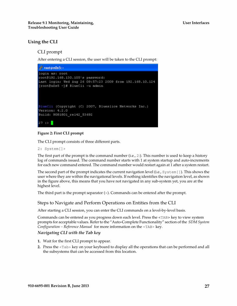
CLI promptAfter entering a CLI session, the user will be taken to the CLI prompt:
Figure 2: First CLI prompt
The CLI prompt consists of three different parts.
2: System[]>
The first part of the prompt is the command number (i.e., 2:). This number is used to keep a historylog of commands issued. The command number starts with 1 at system startup and auto-incrementsfor each new command entered. The command number would restart again at 1 after a system restart.
The second part of the prompt indicates the current navigation level (i.e., System[]). This shows theuser where they are within the navigational levels. If nothing identifies the navigation level, as shownin the figure above, this means that you have not navigated in any sub-system yet, you are at thehighest level.
The third part is the prompt separator (>). Commands can be entered after the prompt.
Steps to Navigate and Perform Operations on Entities from the CLIAfter starting a CLI session, you can enter the CLI commands on a level-by-level basis.
Commands can be entered as you progress down each level. Press the <TAB> key to view systemprompts for acceptable values. Refer to the “Auto-Complete Functionality” section of the SDM SystemConfiguration – Reference Manual for more information on the <TAB> key.Navigating CLI with the Tab key
1. Wait for the first CLI prompt to appear.2. Press the <Tab> key on your keyboard to display all the operations that can be performed and all
the subsystems that can be accessed from this location.
27910-6695-001 Revision B, June 2013
User InterfacesRelease 9.1 Monitoring, Maintaining,Troubleshooting User Guide
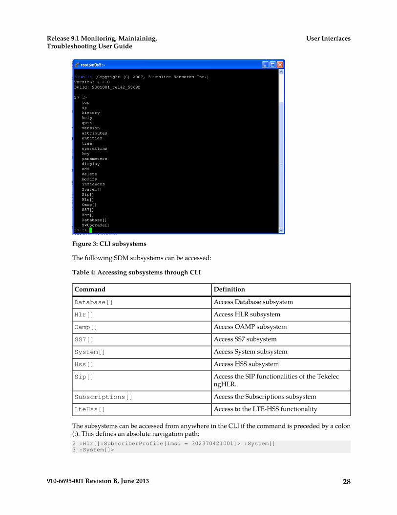
Figure 3: CLI subsystems
The following SDM subsystems can be accessed:
Table 4: Accessing subsystems through CLI
DefinitionCommand
Access Database subsystemDatabase[]
Access HLR subsystemHlr[]
Access OAMP subsystemOamp[]
Access SS7 subsystemSS7[]
Access System subsystemSystem[]
Access HSS subsystemHss[]
Access the SIP functionalities of the TekelecngHLR.
Sip[]
Access the Subscriptions subsystemSubscriptions[]
Access to the LTE-HSS functionalityLteHss[]
The subsystems can be accessed from anywhere in the CLI if the command is preceded by a colon(:). This defines an absolute navigation path:2 :Hlr[]:SubscriberProfile[Imsi = 302370421001]> :System[]3 :System[]>
28910-6695-001 Revision B, June 2013
User InterfacesRelease 9.1 Monitoring, Maintaining,Troubleshooting User Guide

3. Type the subsystem name you wish to access. For example, if you wish to perform operations onthe HLR application, you must access the HLR subsystem. Type: Hlr[]
Figure 4: Accessing subsystems through CLI
4. Press <Enter>.5. Press the <TAB> key to display the entities that can be accessed from this subsystem and the
operations that can be performed.
29910-6695-001 Revision B, June 2013
User InterfacesRelease 9.1 Monitoring, Maintaining,Troubleshooting User Guide
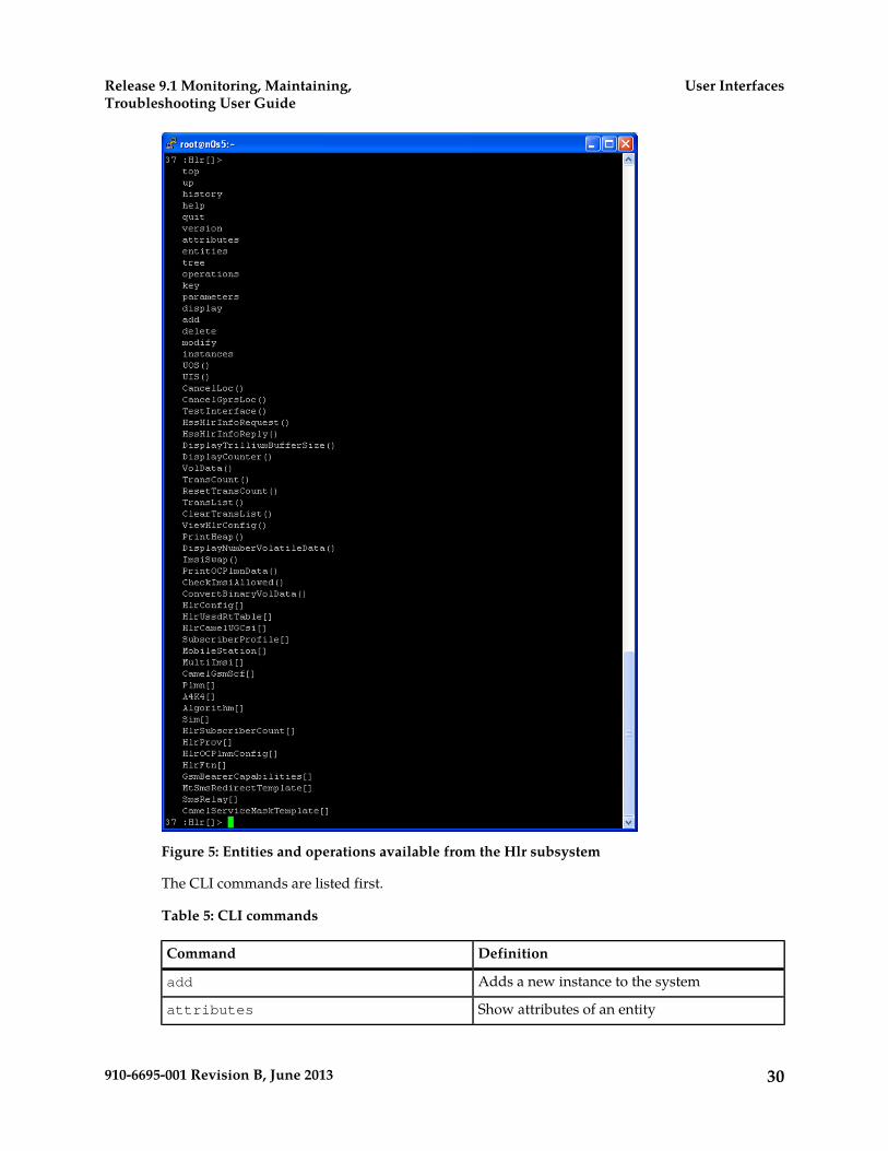
Figure 5: Entities and operations available from the Hlr subsystem
The CLI commands are listed first.
Table 5: CLI commands
DefinitionCommand
Adds a new instance to the systemadd
Show attributes of an entityattributes
30910-6695-001 Revision B, June 2013
User InterfacesRelease 9.1 Monitoring, Maintaining,Troubleshooting User Guide
DefinitionCommand
Deletes instances from the systemdelete
Display the instancesdisplay
Show sub-entitiesentities
Display help optionshelp
Lists history of commandshistory
Display all instances of an entityinstances
Show navigation key attributeskey
Make changes to instancesmodify
Show operationsoperations
Show parameters of an operationparameters
Exit the CLIquit
Go to top leveltop
View the command treetree
Go up one levelUp
Displays current version of the software load.version
The operations that can be performed on the HLR application are listed next; operations areidentified by the () at the end.
The entities that can be accessed from the HLR subsystem are listed last.
Note: Other entities can only be accessed from these high-level entities.
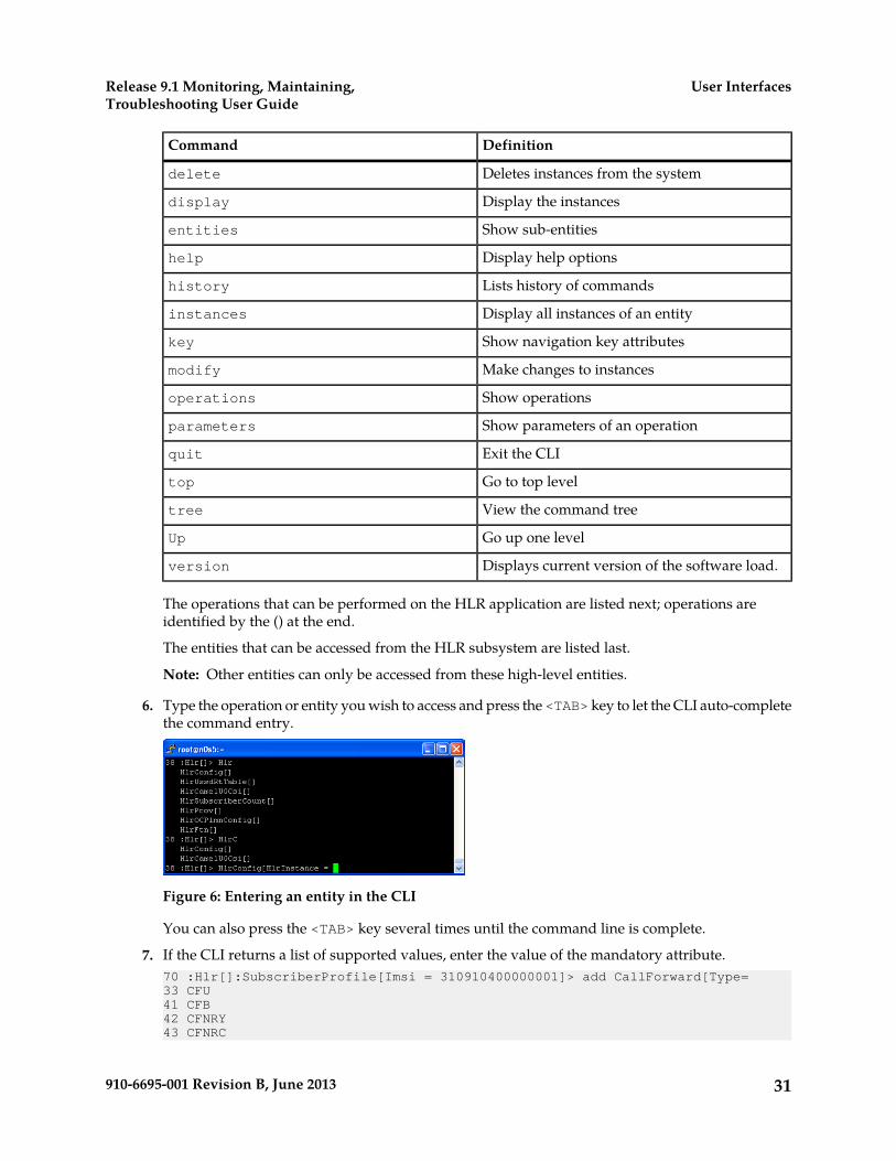
6. Type the operation or entity you wish to access and press the <TAB> key to let the CLI auto-completethe command entry.
Figure 6: Entering an entity in the CLI
You can also press the <TAB> key several times until the command line is complete.
7. If the CLI returns a list of supported values, enter the value of the mandatory attribute.70 :Hlr[]:SubscriberProfile[Imsi = 310910400000001]> add CallForward[Type=33 CFU41 CFB42 CFNRY43 CFNRC
31910-6695-001 Revision B, June 2013
User InterfacesRelease 9.1 Monitoring, Maintaining,Troubleshooting User Guide
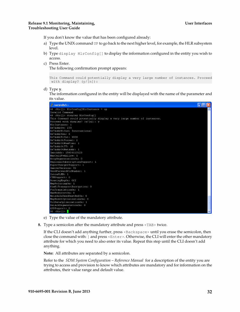
If you don't know the value that has been configured already:a) Type the UNIX command UP to go back to the next higher level, for example, the HLR subsystem
level.b) Type display HlrConfig[] to display the information configured in the entity you wish to
access.c) Press Enter.
The following confirmation prompt appears:
This Command could potentially display a very large number of instances. Proceed with display? (y/[n]):
d) Type y.The information configured in the entity will be displayed with the name of the parameter andits value.
e) Type the value of the mandatory attribute.
8. Type a semicolon after the mandatory attribute and press <TAB> twice.
If the CLI doesn’t add anything further, press <Backspace> until you erase the semicolon, thenclose the command with: ] and press <Enter>. Otherwise, the CLI will enter the other mandatoryattribute for which you need to also enter its value. Repeat this step until the CLI doesn’t addanything.
Note: All attributes are separated by a semicolon.
Refer to the SDM System Configuration – Reference Manual for a description of the entity you aretrying to access and provision to know which attributes are mandatory and for information on theattributes, their value range and default value.
32910-6695-001 Revision B, June 2013
User InterfacesRelease 9.1 Monitoring, Maintaining,Troubleshooting User Guide
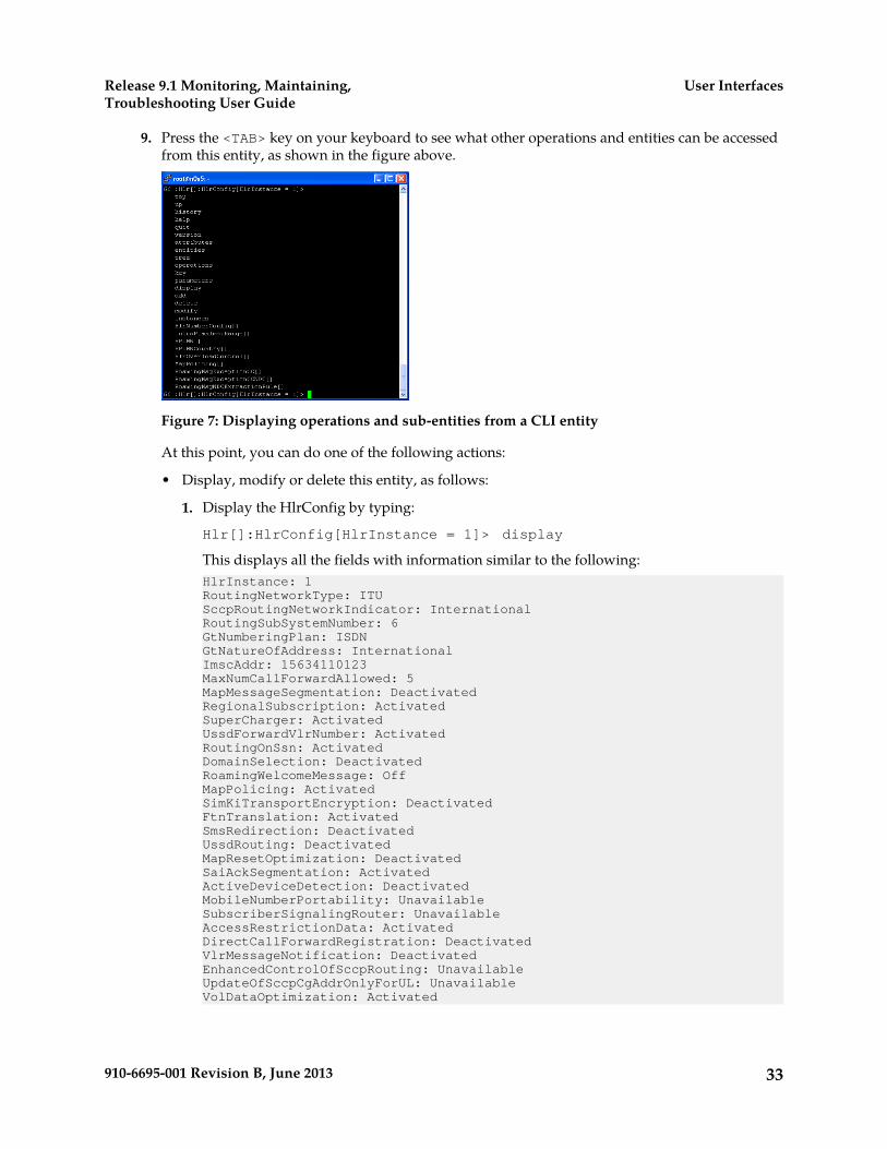
9. Press the <TAB> key on your keyboard to see what other operations and entities can be accessedfrom this entity, as shown in the figure above.
Figure 7: Displaying operations and sub-entities from a CLI entity
At this point, you can do one of the following actions:
• Display, modify or delete this entity, as follows:
1. Display the HlrConfig by typing:
Hlr[]:HlrConfig[HlrInstance = 1]> display
This displays all the fields with information similar to the following:HlrInstance: 1RoutingNetworkType: ITUSccpRoutingNetworkIndicator: InternationalRoutingSubSystemNumber: 6GtNumberingPlan: ISDNGtNatureOfAddress: InternationalImscAddr: 15634110123MaxNumCallForwardAllowed: 5MapMessageSegmentation: DeactivatedRegionalSubscription: ActivatedSuperCharger: ActivatedUssdForwardVlrNumber: ActivatedRoutingOnSsn: ActivatedDomainSelection: DeactivatedRoamingWelcomeMessage: OffMapPolicing: ActivatedSimKiTransportEncryption: DeactivatedFtnTranslation: ActivatedSmsRedirection: DeactivatedUssdRouting: DeactivatedMapResetOptimization: DeactivatedSaiAckSegmentation: ActivatedActiveDeviceDetection: DeactivatedMobileNumberPortability: UnavailableSubscriberSignalingRouter: UnavailableAccessRestrictionData: ActivatedDirectCallForwardRegistration: DeactivatedVlrMessageNotification: DeactivatedEnhancedControlOfSccpRouting: UnavailableUpdateOfSccpCgAddrOnlyForUL: UnavailableVolDataOptimization: Activated
33910-6695-001 Revision B, June 2013
User InterfacesRelease 9.1 Monitoring, Maintaining,Troubleshooting User Guide
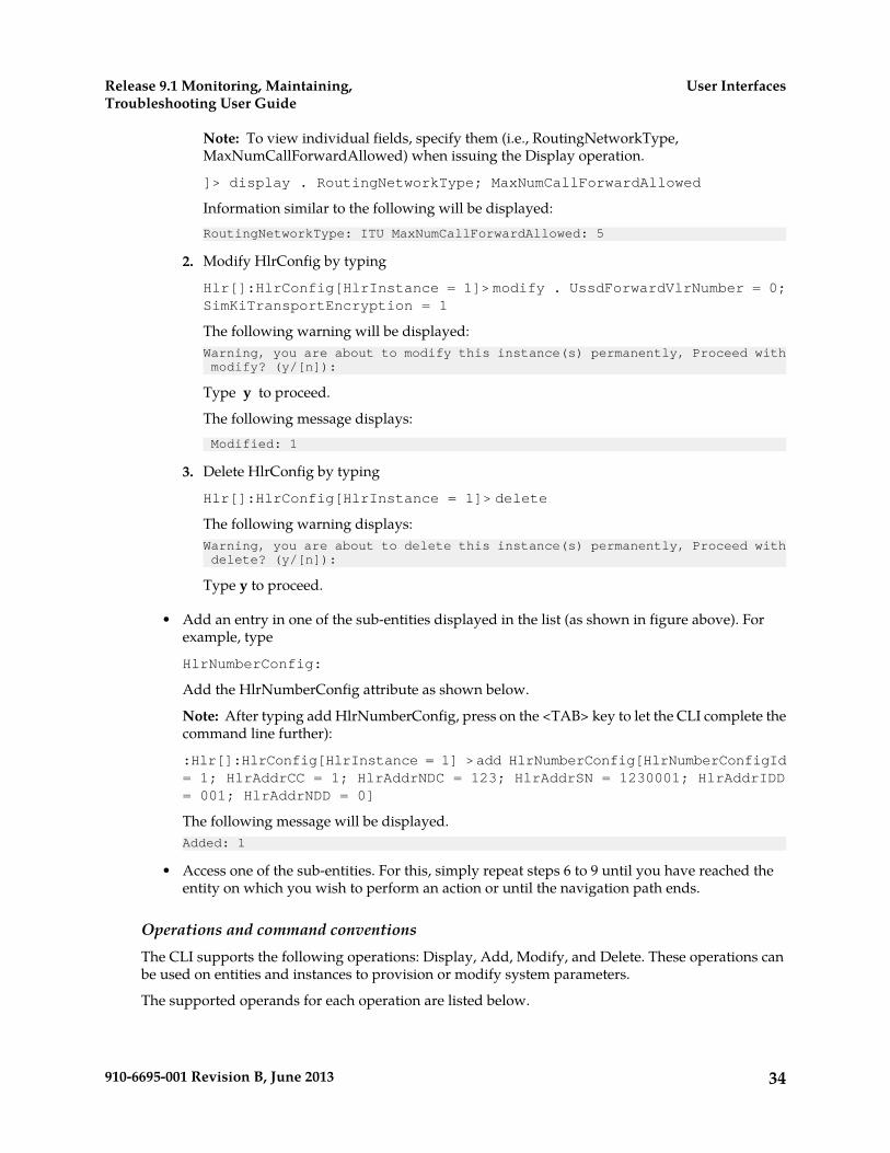
Note: To view individual fields, specify them (i.e., RoutingNetworkType,MaxNumCallForwardAllowed) when issuing the Display operation.
]> display . RoutingNetworkType; MaxNumCallForwardAllowed
Information similar to the following will be displayed:RoutingNetworkType: ITU MaxNumCallForwardAllowed: 5
2. Modify HlrConfig by typing
Hlr[]:HlrConfig[HlrInstance = 1]> modify . UssdForwardVlrNumber = 0;SimKiTransportEncryption = 1
The following warning will be displayed:Warning, you are about to modify this instance(s) permanently, Proceed with modify? (y/[n]):
Type y to proceed.
The following message displays: Modified: 1
3. Delete HlrConfig by typing
Hlr[]:HlrConfig[HlrInstance = 1]> delete
The following warning displays:Warning, you are about to delete this instance(s) permanently, Proceed with delete? (y/[n]):
Type y to proceed.
• Add an entry in one of the sub-entities displayed in the list (as shown in figure above). Forexample, type
HlrNumberConfig:
Add the HlrNumberConfig attribute as shown below.
Note: After typing add HlrNumberConfig, press on the <TAB> key to let the CLI complete thecommand line further):
:Hlr[]:HlrConfig[HlrInstance = 1] >add HlrNumberConfig[HlrNumberConfigId= 1; HlrAddrCC = 1; HlrAddrNDC = 123; HlrAddrSN = 1230001; HlrAddrIDD= 001; HlrAddrNDD = 0]
The following message will be displayed.Added: 1
• Access one of the sub-entities. For this, simply repeat steps 6 to 9 until you have reached theentity on which you wish to perform an action or until the navigation path ends.
Operations and command conventionsThe CLI supports the following operations: Display, Add, Modify, and Delete. These operations canbe used on entities and instances to provision or modify system parameters.
The supported operands for each operation are listed below.
34910-6695-001 Revision B, June 2013
User InterfacesRelease 9.1 Monitoring, Maintaining,Troubleshooting User Guide

Table 6: Supported operations
Supported OperandOperation
=, <, >, >=, <=Display
=Add
=Modify
=Delete
The following are basic UNIX shell commands to facilitate usage of the CLI:
Table 7: UNIX shell commands
DefinitionCommand
jump to home<ctrl> a
exit the CLIquit
jump to end<ctrl> e
clear screen<ctrl> l
clear typed line<ctrl> u
use up arrow to scroll up the command history
use down arrow to scroll down the commandhistory
cancels any change made by the ongoingcommand by aborting the session.*<ctrl> z
WARNING: When using the CLI, the <ctrl> z command does not send the processexecution to background, as it typically would. Since there is no need to allow to run theCLI in background, the Tekelec implementation intentionally interprets the <ctrl> zcommand as an “abort” message and suspends the ongoing command. Basically, the useof the <ctrl> z command cancels any change made by the ongoing command. In somesituations, executing this command may produce a core dump of the CLI processes.However, using the <ctrl> z command will not cause any service outage, nor will itcause data corruption. The same warning also applies for the use of the <ctrl> zcommand when using the Command File Loader (CmdFileLoader).
The following provides a description of the characters used in CLI.
35910-6695-001 Revision B, June 2013
User InterfacesRelease 9.1 Monitoring, Maintaining,Troubleshooting User Guide

Table 8: CLI characters
DefinitionSymbol
Indicates a mandatory item*
Separate multiple attributes or attribute valueswith a semicolon
;
Separate multiple items in a value list with acomma,
Specifies the current instance.
Separates different levels between entities:
Determine mandatory attributes using CLIDisplays mandatory attributes in CLI.
1. Type the command to add an entry in the entity, for example, type :Hlr[]> add MSISDN[2. Press Tab .
The CLI displays the entity attributes; the mandatory attributes are preceded by an asterisk (*).
3. Press Enter to exit the command.The CLI returns Invalid command but returns to the previous navigation level.
Provisioning an entity - HLR Number ConfigurationThis section explains how to provision an entity using the add, modify, delete, and display operations.The provisioning procedures use the HLR Number Configuration entity as an example and provisionthe HLR identities (addresses). Multiple HLR Number Configurations can be provisioned to the HLRwhere each is represented by an identifier and will be associated to IMSI ranges.
This example uses these procedures:
• Adding HLR Number Configuration• Modifying HLR Number Configuration• Deleting HLR Number Configuration• Displaying HLR Number Configuration
36910-6695-001 Revision B, June 2013
User InterfacesRelease 9.1 Monitoring, Maintaining,Troubleshooting User Guide
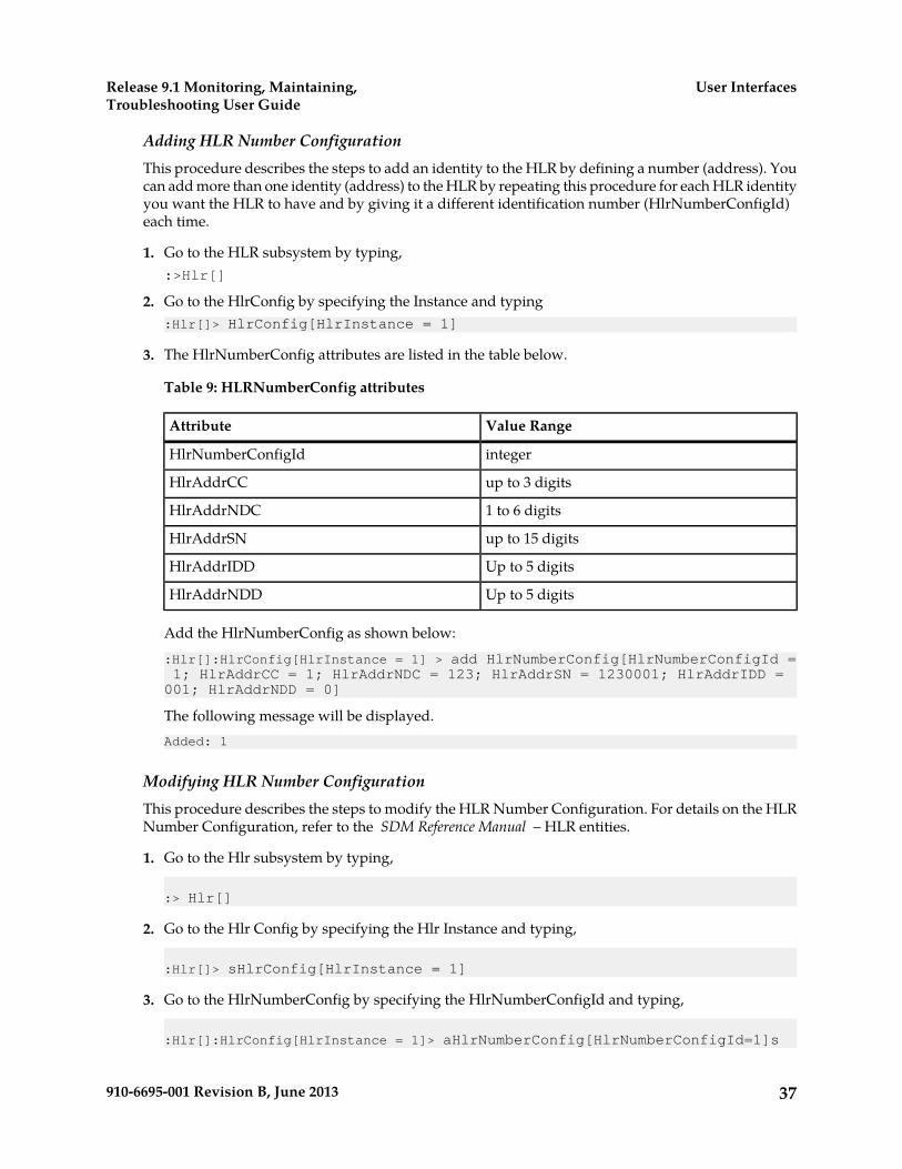
Adding HLR Number ConfigurationThis procedure describes the steps to add an identity to the HLR by defining a number (address). Youcan add more than one identity (address) to the HLR by repeating this procedure for each HLR identityyou want the HLR to have and by giving it a different identification number (HlrNumberConfigId)each time.
1. Go to the HLR subsystem by typing,:>Hlr[]
2. Go to the HlrConfig by specifying the Instance and typing:Hlr[]> HlrConfig[HlrInstance = 1]
3. The HlrNumberConfig attributes are listed in the table below.
Table 9: HLRNumberConfig attributes
Value RangeAttribute
integerHlrNumberConfigId
up to 3 digitsHlrAddrCC
1 to 6 digitsHlrAddrNDC
up to 15 digitsHlrAddrSN
Up to 5 digitsHlrAddrIDD
Up to 5 digitsHlrAddrNDD
Add the HlrNumberConfig as shown below::Hlr[]:HlrConfig[HlrInstance = 1] > add HlrNumberConfig[HlrNumberConfigId = 1; HlrAddrCC = 1; HlrAddrNDC = 123; HlrAddrSN = 1230001; HlrAddrIDD = 001; HlrAddrNDD = 0]
The following message will be displayed.Added: 1
Modifying HLR Number ConfigurationThis procedure describes the steps to modify the HLR Number Configuration. For details on the HLRNumber Configuration, refer to the SDM Reference Manual – HLR entities.
1. Go to the Hlr subsystem by typing,
:> Hlr[]
2. Go to the Hlr Config by specifying the Hlr Instance and typing,
:Hlr[]> sHlrConfig[HlrInstance = 1]
3. Go to the HlrNumberConfig by specifying the HlrNumberConfigId and typing,
:Hlr[]:HlrConfig[HlrInstance = 1]> aHlrNumberConfig[HlrNumberConfigId=1]s
37910-6695-001 Revision B, June 2013
User InterfacesRelease 9.1 Monitoring, Maintaining,Troubleshooting User Guide

4. The following attributes can be modified: HlrAddrCC, HlrAddrNDC, HlrAddrSN, HlrAddrIDD,HlrAddrNDD.a) Modify the Hlr Number Config by specifying the parameter(s) you wish to modify (i.e., in this
case, swe choose to only modify the HlrAddrCC) and providing its new value as follows:
Hlr[]:HlrConfig[HlrInstance = 1]:HlrNumberConfig[HlrNumberConfigId=1]> modify . HlrAddrCC = 31
The following warning will be displayed:
Warning, you are about to modify this instance(s) permanently, Proceed with modify? (y/[n]):
5. Type y, to proceed.
The following message will be displayed.
Modified: 1
Modifying HLR Number Configuration – Alternate Method
1. Go directly to the Hlr Number Config by specifying the HLR instance, HlrNumberConfigId, andtyping,
:> Hlr[]:HlrConfig[HlrInstance=1]:HlrNumberConfig[HlrNumberConfigId=1]
2. The following attributes can be modified: HlrAddrCC, HlrAddrNDC, HlrAddrSN, HlrAddrIDD,HlrAddrNDD.Modify the Hlr Number Config by specifying the parameter(s) you wish to modify (i.e., in thiscase, we choose to only modify the HlrAddrCC) and providing its new value as follows:
Hlr[]:HlrConfig[HlrInstance = 1]:HlrNumberConfig[HlrNumberConfigId=1]> modify . HlrAddrCC = 31
The following warning will be displayed:
Warning, you are about to modify this instance(s) permanently, Proceed with modify? (y/[n]):
3. Type y , to proceed.The following message will be displayed.
Modified: 1
Deleting HLR Number ConfigurationThis procedure describes the steps to delete a HLR identity by deleting its Number Configuration.
1. Go to the Hlr subsystem by typing,
:> Hlr[]
38910-6695-001 Revision B, June 2013
User InterfacesRelease 9.1 Monitoring, Maintaining,Troubleshooting User Guide
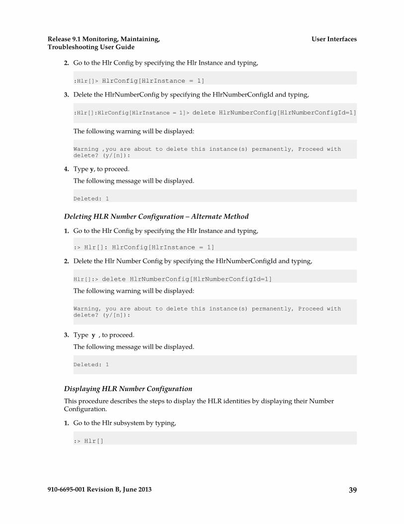
2. Go to the Hlr Config by specifying the Hlr Instance and typing,
:Hlr[]> HlrConfig[HlrInstance = 1]
3. Delete the HlrNumberConfig by specifying the HlrNumberConfigId and typing,
:Hlr[]:HlrConfig[HlrInstance = 1]> delete HlrNumberConfig[HlrNumberConfigId=1]
The following warning will be displayed:
Warning ,you are about to delete this instance(s) permanently, Proceed with delete? (y/[n]):
4. Type y, to proceed.
The following message will be displayed.
Deleted: 1
Deleting HLR Number Configuration – Alternate Method
1. Go to the Hlr Config by specifying the Hlr Instance and typing,
:> Hlr[]: HlrConfig[HlrInstance = 1]
2. Delete the Hlr Number Config by specifying the HlrNumberConfigId and typing,
Hlr[]:> delete HlrNumberConfig[HlrNumberConfigId=1]
The following warning will be displayed:
Warning, you are about to delete this instance(s) permanently, Proceed with delete? (y/[n]):
3. Type y , to proceed.
The following message will be displayed.
Deleted: 1
Displaying HLR Number ConfigurationThis procedure describes the steps to display the HLR identities by displaying their NumberConfiguration.
1. Go to the Hlr subsystem by typing,
:> Hlr[]
39910-6695-001 Revision B, June 2013
User InterfacesRelease 9.1 Monitoring, Maintaining,Troubleshooting User Guide
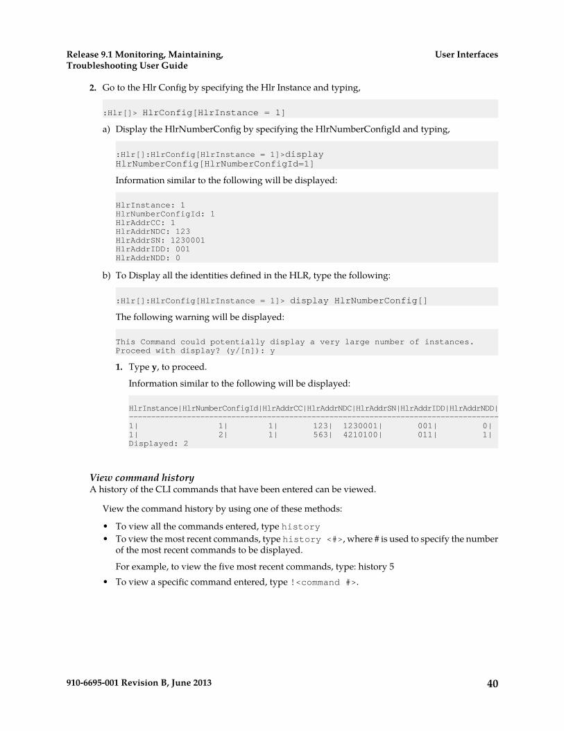
2. Go to the Hlr Config by specifying the Hlr Instance and typing,
:Hlr[]> HlrConfig[HlrInstance = 1]
a) Display the HlrNumberConfig by specifying the HlrNumberConfigId and typing,
:Hlr[]:HlrConfig[HlrInstance = 1]>display HlrNumberConfig[HlrNumberConfigId=1]
Information similar to the following will be displayed:
HlrInstance: 1HlrNumberConfigId: 1HlrAddrCC: 1HlrAddrNDC: 123HlrAddrSN: 1230001HlrAddrIDD: 001HlrAddrNDD: 0
b) To Display all the identities defined in the HLR, type the following:
:Hlr[]:HlrConfig[HlrInstance = 1]> display HlrNumberConfig[]
The following warning will be displayed:
This Command could potentially display a very large number of instances.Proceed with display? (y/[n]): y
1. Type y, to proceed.
Information similar to the following will be displayed:
HlrInstance|HlrNumberConfigId|HlrAddrCC|HlrAddrNDC|HlrAddrSN|HlrAddrIDD|HlrAddrNDD|-----------------------------------------------------------------------------------1| 1| 1| 123| 1230001| 001| 0|1| 2| 1| 563| 4210100| 011| 1|Displayed: 2
View command historyA history of the CLI commands that have been entered can be viewed.
View the command history by using one of these methods:
• To view all the commands entered, type history• To view the most recent commands, type history <#>, where # is used to specify the number
of the most recent commands to be displayed.
For example, to view the five most recent commands, type: history 5• To view a specific command entered, type !<command #>.
40910-6695-001 Revision B, June 2013
User InterfacesRelease 9.1 Monitoring, Maintaining,Troubleshooting User Guide

Ending a CLI Session
To end the CLI session type quit at the system prompt, as follows:2 :Hlr[]> quit
Note: When entering text in CLI, there is no need to enclose it in quotations. Type the text to be addedwithout quotations.
Web Craft Interface (WebCI)
The Web Craft Interface (WebCI) is a web-based application that provides a user-friendly graphicaluser interface (GUI). The WebCI is used to facilitate system configuration, troubleshooting of subscriberprofiles and alarm management.
Starting a WebCI Session
The Web Craft Interface (WebCI) supports the following versions of web browsers:
• Internet Explorer version 8 on Windows.• Mozilla Firefox version 12.0.
Accessing the Web Craft Interface
To access the Web Craft Interface (WebCI), enter the following URL in the web browser:
https://<IP Address:8443/webci
where IP Address = address of module and the default port is 8443.
e.g., https://193.10.20.100:8443/webci . The default port is 8443.
The following login window appears:
Log in to the WebCI by entering a valid username and password. Click Submit.
For the first login, the valid username and password for the following users set by default in the systemare:
Table 10: Pre-defined users
Group NameDefault UserPasswdDefault UserNameUser
adminadminadminAdmin
41910-6695-001 Revision B, June 2013
User InterfacesRelease 9.1 Monitoring, Maintaining,Troubleshooting User Guide
Group NameDefault UserPasswdDefault UserNameUser
surveillancesurveilsurveilSurveillance
useruseruserUser
batchbatchbatchBatch
operationoperationoperationOperation
SimprovsimprovsimprovSim provisioning
Each of these users have predefined access privileges, only the admin user has access to all servicesand the Read, Write and Execute permissions. To view the access privileges predefined in the systemfor each Group, please refer to Creating and Managing Users for the User Interfaces in this document.
Note: The customizable groups: usergroup1, usergroup2,…usergroup10 have no default user ordefault access privileges. The administrator, already defined in the admin group, can (if needed)provision these groups by creating a user and associating it to one of these groups and customizingthe group by setting access privileges as it wishes.
After each user starts their first session with WebCI, they must change their own password or havethe administrator change it for each user including himself, for security purposes in order to limitaccess to services for different users.
Moreover, the first thing recommended for the administrator to do once he has started a WebCI session,is to initially provision users, if not done already through CLI, by creating users and giving them ausername and password, and different access privileges by associating them to groups following theirsystem use and assigning them the access privileges desired for specific services.
From this point forward, each user can log in to the WebCI by entering their username and passwordprovisioned by the administrator in the system.
Using the WebCI
The WebCI is used to facilitate system configuration, troubleshooting of subscriber profiles and alarmmanagement.
Displaying a WebCI window
1. Locate the main menu in the left panel of the WebCI page.The main menu consists of folders next to hyperlinks labeled with the application name.
2. Click the folder or the hyperlink to display the submenu.A blank WebCI window displays.
3. Click a submenu item to display its WebCI window.
• The window displays the name of the submenu item and any applicable tables to configure.• If the submenu has its own submenu items, the WebCI window displays those items in tabs
and opens to the content of the first tab.
4. Click the hyperlink on the tab to navigate between tabs.
The figure shows the WebCI main menu with the open HLR menu item, the selected HLR Configurationsubmenu and all the tabs applicable for HLR configuration.
42910-6695-001 Revision B, June 2013
User InterfacesRelease 9.1 Monitoring, Maintaining,Troubleshooting User Guide
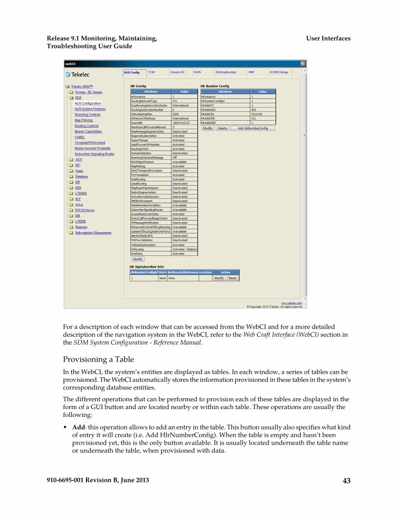
For a description of each window that can be accessed from the WebCI and for a more detaileddescription of the navigation system in the WebCI, refer to the Web Craft Interface (WebCI) section inthe SDM System Configuration - Reference Manual.
Provisioning a TableIn the WebCI, the system’s entities are displayed as tables. In each window, a series of tables can beprovisioned. The WebCI automatically stores the information provisioned in these tables in the system’scorresponding database entities.
The different operations that can be performed to provision each of these tables are displayed in theform of a GUI button and are located nearby or within each table. These operations are usually thefollowing:
• Add: this operation allows to add an entry in the table. This button usually also specifies what kindof entry it will create (i.e. Add HlrNumberConfig). When the table is empty and hasn’t beenprovisioned yet, this is the only button available. It is usually located underneath the table nameor underneath the table, when provisioned with data.
43910-6695-001 Revision B, June 2013
User InterfacesRelease 9.1 Monitoring, Maintaining,Troubleshooting User Guide

• Delete: this operation allows to delete an entry in the table. This operation only becomes availablewhen the table is provisioned. It is usually available for each entry, located in the same row as theentry for which it applies for.
• Modify: this operation allows to modify some information already provisioned for an entry in thetable. This operation only becomes available when the table is provisioned. It is usually availablefor each entry, located in the same row as the entry for which it applies for.
Some tables have a Display/Modify button. This button allows to display another table (usuallya sub-table that can only be provisioned once the main table for which it applies for is alreadyprovisioned), which is otherwise hidden. After clicking on this button, the table is displayed orsimply the title of the table with the Add button, in the case where this table is not yet provisioned.In some cases, when the sub-table is displayed, the button text changes and becomes: Hide <tablename or entry name> (e.g., Hide HPLMN Country Nodes). This button allows to hide the sub-table.
Some WebCI windows also display buttons that are not specific to a table (e.g., TCAP out of service).These buttons are located independently from any table and they allow to perform operationswhen troubleshooting the system.
Other WebCI windows display some operations in a different format, with a symbol.
For information on all the different symbols displayed in the WebCI, refer to the “Operationsavailable” section of the “Web Craft Interface (WebCI)” chapter in the SDM System Configuration– Reference Manual .
Hereunder are the procedures that describe step-by-step how to add, display, modify and deletethe AuC algorithm table from the WebCI. To provision any other table, follow the same logic asdescribed below, but apply it to the table you wish to provision.
Display a table - AuC AlgorithmThis procedure describes how to display a table in the WebCI by using the Authentication (AuC)algorithm files as an example.
1. From the main menu, click on the application folder or the hyperlink next to it, for example, clickAUC
2. Click the submenu item, for example, click Algorithm.The submenu item window displays, for example, the Algorithm window with the Algorithm tableand all the algorithm files provisioned.
Add an entry - AuC AlgorithmThe new algorithm file must be stored in the /blue/lib directory prior to running this procedureand it must have a .so file extension.
This procedure describes how to add a table entry by using the Authentication (AuC) algorithm filesas an example.
1. From the main menu, click on the application folder or the hyperlink next to it, for example, clickAUC
44910-6695-001 Revision B, June 2013
User InterfacesRelease 9.1 Monitoring, Maintaining,Troubleshooting User Guide
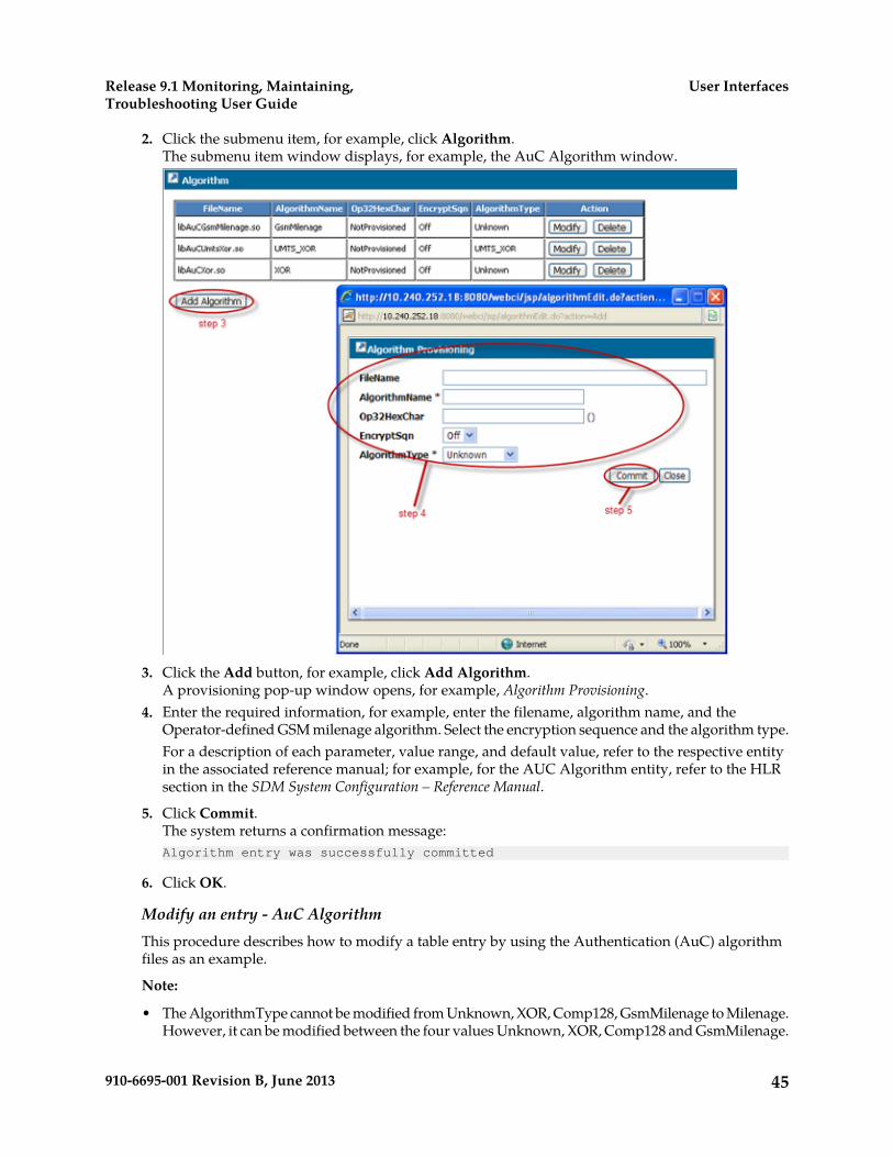
2. Click the submenu item, for example, click Algorithm.The submenu item window displays, for example, the AuC Algorithm window.
3. Click the Add button, for example, click Add Algorithm.A provisioning pop-up window opens, for example, Algorithm Provisioning.
4. Enter the required information, for example, enter the filename, algorithm name, and theOperator-defined GSM milenage algorithm. Select the encryption sequence and the algorithm type.For a description of each parameter, value range, and default value, refer to the respective entityin the associated reference manual; for example, for the AUC Algorithm entity, refer to the HLRsection in the SDM System Configuration – Reference Manual.
5. Click Commit.The system returns a confirmation message:Algorithm entry was successfully committed
6. Click OK.
Modify an entry - AuC AlgorithmThis procedure describes how to modify a table entry by using the Authentication (AuC) algorithmfiles as an example.
Note:
• The AlgorithmType cannot be modified from Unknown, XOR, Comp128, GsmMilenage to Milenage.However, it can be modified between the four values Unknown, XOR, Comp128 and GsmMilenage.
45910-6695-001 Revision B, June 2013
User InterfacesRelease 9.1 Monitoring, Maintaining,Troubleshooting User Guide

• If the AlgorithmType is created as Milenage, it cannot be modified. You would need to delete itand recreate it.
• Be careful when modifying the FileName to make sure the library is matching the AlgorithmType.
1. From the main menu, click on the application folder or the hyperlink next to it, for example, clickAUC
2. Click the submenu item, for example, click Algorithm.The submenu item window displays, for example, the Algorithm window.
3. Click the Modify button next to the algorithm to be modified.A provisioning pop-up window opens, for example, Algorithm Provisioning.
4. Modify the required information.5. Click Commit.
The system returns a confirmation message:Algorithm entry was successfully committed
6. Click OK.
Delete an entry - AuC AlgorithmThis procedure describes how to delete a table entry in the WebCI by using the Authentication (AuC)algorithm files as an example.
1. From the main menu, click on the application folder or the hyperlink next to it, for example, clickAUC
2. Click the submenu item, for example, click Algorithm.
46910-6695-001 Revision B, June 2013
User InterfacesRelease 9.1 Monitoring, Maintaining,Troubleshooting User Guide
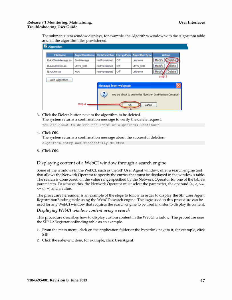
The submenu item window displays, for example, the Algorithm window with the Algorithm tableand all the algorithm files provisioned.
3. Click the Delete button next to the algorithm to be deleted.The system returns a confirmation message to verify the delete request:You are about to delete the (Name of Algorithm) Continue?
4. Click OK.The system returns a confirmation message about the successful deletion:Algorithm entry was successfully deleted
5. Click OK.
Displaying content of a WebCI window through a search engineSome of the windows in the WebCI, such as the SIP User Agent window, offer a search engine toolthat allows the Network Operator to specify the entries that must be displayed in the window’s table.The search is done based on the value range specified by the Network Operator for one of the table’sparameters. To achieve this, the Network Operator must select the parameter, the operand (>, <, >=,<= or =) and a value.
The procedure hereunder is an example of the steps to follow in order to display the SIP User AgentRegistrationBinding table using the WebCI’s search engine. The logic used in this procedure can beused for any WebCI window that requires the search engine to be used in order to display its content.Displaying WebCI window content using a searchThis procedure describes how to display custom content in the WebCI window. The procedure usesthe SIP UaRegistrationBinding table as an example.
1. From the main menu, click on the application folder or the hyperlink next to it, for example, clickSIP
2. Click the submenu item, for example, click UserAgent.
47910-6695-001 Revision B, June 2013
User InterfacesRelease 9.1 Monitoring, Maintaining,Troubleshooting User Guide
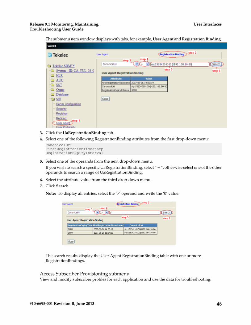
The submenu item window displays with tabs, for example, User Agent and Registration Binding.
3. Click the UaRegistrationBinding tab.4. Select one of the following RegistrationBinding attributes from the first drop-down menu:
CanonicalUriFirstRegistrationTimestampRegistrationExpiryInterval
5. Select one of the operands from the next drop-down menu.If you wish to search a specific UaRegistrationBinding, select “ = “, otherwise select one of the otheroperands to search a range of UaRegistrationBinding.
6. Select the attribute value from the third drop-down menu.7. Click Search.
Note: To display all entries, select the ‘>’ operand and write the ‘0’ value.
The search results display the User Agent RegistrationBinding table with one or moreRegistrationBindings.
Access Subscriber Provisioning submenuView and modify subscriber profiles for each application and use the data for troubleshooting.
48910-6695-001 Revision B, June 2013
User InterfacesRelease 9.1 Monitoring, Maintaining,Troubleshooting User Guide
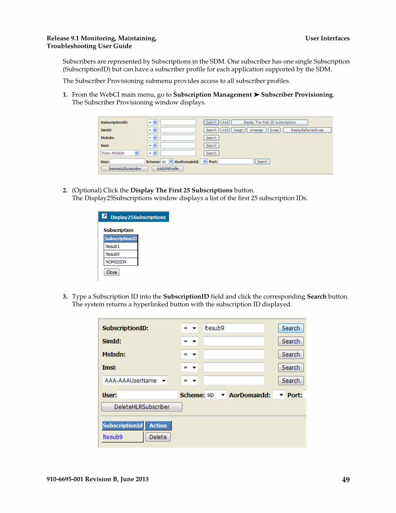
Subscribers are represented by Subscriptions in the SDM. One subscriber has one single Subscription(SubscriptionID) but can have a subscriber profile for each application supported by the SDM.
The Subscriber Provisioning submenu provides access to all subscriber profiles.
1. From the WebCI main menu, go to Subscription Management ➤ Subscriber Provisioning.The Subscriber Provisioning window displays.
2. (Optional) Click the Display The First 25 Subscriptions button.The Display25Subscriptions window displays a list of the first 25 subscription IDs.
3. Type a Subscription ID into the SubscriptionID field and click the corresponding Search button.The system returns a hyperlinked button with the subscription ID displayed.
49910-6695-001 Revision B, June 2013
User InterfacesRelease 9.1 Monitoring, Maintaining,Troubleshooting User Guide

4. Click the SubscriptionID hyperlink to go to the Subscriber Provisioning submenu.
5. Expand the application folder and click display/modify to view or edit a profile.
Ending a WebCI session
Log out of a WebCI session by clicking the logout icon ( ) located at the top right corner of thewindow.
Bulk and Template Provisioning
The Tekelec OAM&P Manager provides provisioning and configuration management. The OAM&Pmanager accepts XML commands to handle bulk (multiple) requests as well as Template Invokingfiles.
• Bulk subscriber provisioning is done by first generating a file that contains XML requests(commands). XML provisioning files can only be written and stored in the /tmp folder. Then thecommands stored in the file are processed by the command file loader tool (CmdFileLoader). Referto the SDM Subscriber Provisioning - Reference Manual for details on the XML file and Requesttypes.
• Subscriber provisioning by templates is done by generating a Template Invoking file that containsXML requests of type -Template‖, which means that are based on Templates. These Templatesmust have already been defined and loaded in the database using the Command Template Loadertool. Template files can only be written and stored in the /tmp folder. It is also possible to viewthe templates defined in the database with the Command Template Viewer tool. Refer to the SDMSubscriber Provisioning - Reference Manual for details on the XML Template Invoking file.
Preparing template files
Prior to provisioning the Subscriber Data Management system with templates and using the templatetools, all templates must be written and validated.
50910-6695-001 Revision B, June 2013
User InterfacesRelease 9.1 Monitoring, Maintaining,Troubleshooting User Guide
1. Write all template files and invoking files necessary for provisioning.
Note: Make sure to have an operation request for authentication, which is required to execute aninvoking file with the Command File Loader.
For XML file syntax and a description of what must be defined in each template, refer to the SDMSubscriber Provisioning - Reference Manual; for template examples, refer to the XML template section.
2. Open XML file(s) in an XML editor or reader of your choice to validate the basic XML syntax.Internet Explorer is a good example of an XML reader that can be used to perform the validation.The XML editor or reader will report any errors in the basic syntax. Correct any errors beforecontinuing.
3. Save the template file(s) and the corresponding invoking file(s) in the /tmp/templates/ directory,for example, /tmp/templates/Xmlfile1.xml.
The files are now ready to be uploaded with the Command Template Loader (CTL).
Running Command Template Loader
Prerequisites:
• User must belong to admin, batch, or operation group.• Template files must be completed and ready for upload. See Preparing template files.
The Command Template Loader loads templates into the system database, which allows the operatorto provision subscribers with an Invoking file that executes those templates.
1. Establish Secure Shell (SSh) connection.2. Prior to running the Command Template Loader tool, you must first write the templates you wish
to load into the system’s database and then save them in the /tmp/templates/ directory
The operator can then run the Command Template Loader (CTL) tool in order to load these templatesand the template requests that constitute them.
3. At the prompt, type
[UserName@system UserName] $ ctl -f <XmlInputFileName.xml>
where XmlInputFileName is the path followed by the name of the Invoking file that is to beexecuted, for example, /tmp/templates/Xmlfile1.xml).
4. Load the templates one at a time in this order:a) Load the Template files, which contain the Command template and all template requests.b) Load the Invoking files.
The Invoking file references the Template file and then provisions the subscribers with thespecific values provided.
The template files are now ready to be viewed or executed by the Command File Loader (CFL).
CTL help optionsDisplay the CmdTemplateLoader (CTL) help option by typing ctl –h.
These options are available to run the Command Template Loader tool:
• [-u] → username to access the database (this should be known at installation)
51910-6695-001 Revision B, June 2013
User InterfacesRelease 9.1 Monitoring, Maintaining,Troubleshooting User Guide
• [-p] → password to access the database(this should be known at installation)• [-f XmlInputFileName] → the XML input file name where the templates is stored• [-d XmlInputDirectoryName] → The directory where the <XmlInputFileName> can be found.• [-cmd XmlCommand] → (i.e. submitted inline) It allow you to directly type your XML command
instead of using a file.• [-del tp/tpr/all id/all] → other command line params ignored. allow you to delete a
template <tp> or a template request <tpr> or both <all> with the specific id.
Important: When performing the delete operation with the all option, templates and templaterequests are deleted without any warning or indication.
• [-dbip] → the ip address where the database is running• [-trace] → enables the tool traces to view traces for errors)
Deleting a template from the database
Editing a template requires the deletion of the old template from the database and the reloading ofthe new template. For example, deleting template with template id =1 that refers to a template requestwith id=100 and a template request with id=101 requires the deletion of all template requests it refersto, one at a time, by entering the following:
* CmdTemplateLoader Execution time: 0 sec
• [UserName@system UserName] $ ctl –del tpr 101
• ** TemplateRequest id[100] has been deleted
*CmdTemplateLoader Execution time: 0 sec
Deleting all the template requests referenced by a Command Template deletes the latter. As a result,the template is deleted automatically.
Note: Keep in mind that executing an Invoking file that refers to the Command Template you justdeleted will fail.
You can now load into the database the template file you have just edited by using the CommandTemplate Loader.
1. At the prompt, type
[UserName@system UserName] $ ctl –del tpr 100
** TemplateRequest id[100] has been deleted
* CmdTemplateLoader Execution time: 0 sec
2. Type
[UserName@system UserName] $ ctl –del tpr 101
Deleting all the template requests referenced by a Command Template deletes the latter. As a result,the template is deleted automatically.
Note: Executing an Invoking file that refers to a deleted Command Template will fail.
3. Reload the template. See Running Command Template Loader
52910-6695-001 Revision B, June 2013
User InterfacesRelease 9.1 Monitoring, Maintaining,Troubleshooting User Guide
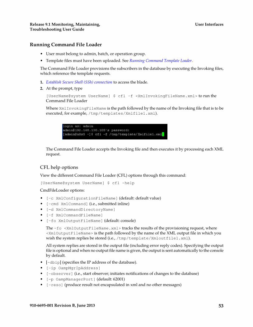
Running Command File Loader
• User must belong to admin, batch, or operation group.• Template files must have been uploaded. See Running Command Template Loader.
The Command File Loader provisions the subscribers in the database by executing the Invoking files,which reference the template requests.
1. Establish Secure Shell (SSh) connection to access the blade.2. At the prompt, type
[UserName@system UserName] $ cfl -f <XmlInvokingFileName.xml> to run theCommand File Loader
Where XmlInvokingFileName is the path followed by the name of the Invoking file that is to beexecuted, for example, /tmp/templates/Xmlfile1.xml).
The Command File Loader accepts the Invoking file and then executes it by processing each XMLrequest.
CFL help optionsView the different Command File Loader (CFL) options through this command:
[UserName@system UserName] $ cfl -help
CmdFileLoader options:
• [-c XmlConfigurationFileName] (default: default value)• [-cmd XmlCommand] (i.e., submitted inline)• [-d XmlCommandDirectoryName]
• [-f XmlCommandFileName]
• [-fo XmlOutputFileName] (default: console)
The –fo <XmlOutputFileName.xml> tracks the results of the provisioning request, where<XmlOutputFileName> is the path followed by the name of the XML output file in which youwish the system replies be stored (i.e., /tmp/template/Xmloutfile1.xml).
All system replies are stored in the output file (including error reply codes). Specifying the outputfile is optional and when no output file name is given, the output is sent automatically to the consoleby default.
• [-dbip] (specifies the IP address of the database).• [-ip OampMgrIpAddress]
• [-observer] (i.e., start observer; initiates notifications of changes to the database)• [-p OampManagerPort] (default: 62001)• [-reso] (produce result not encapsulated in xml and no other messages)
53910-6695-001 Revision B, June 2013
User InterfacesRelease 9.1 Monitoring, Maintaining,Troubleshooting User Guide
• [-todb] (i.e., load directly in the database) This is used in bulk provisioning to load subscriberprofile information into the database without performing any validation of the xml requests.
• [-trace] (traces for errors)• [-user] (user name)• [-validate] (validate input against the global schema)
Analyzing system replyTo verify the provisioning request, view the output file for any errors. Refer to the “System Repliesand Error Codes” section of the SDM Subscriber Provisioning - Reference Manual for a description ofhow to interpret the system replies and their error codes.
1. Establish Secure Shell (SSh) connection.2. Perform one of these steps:
• If you used the –fo option and saved the output file, you can view the output file by typing atthe prompt
view /tmp/template/Xmloutfile1.xml to view the templates in the database.
Note: To exit View Mode, type q
• If you didn’t use the –fo option, the output data is sent automatically to the console and is onlytemporarily displayed. Search for the error tag by typing /error
3. Then search for the error tag by typing: /errora) Look for error responses:
1. error =’0’ implies no provisioning error occurred.2. error =’code #’implies an error with code # occurred. To view the meaning of the error
code #, refer to the Database Error Notifications, HLR Error Notifications, and System ErrorNotifications in the SDM Monitoring, Troubleshooting, Maintenance - Reference Manual.
Note: When provisioning with templates, if an error occurred in one of the template requests,the system returns a general error code that simply informs that an error occurred whileprocessing XML database request (error# 7029).
b) View the actual error by typing less /blue/var/log/current.xml.
This command lists the logs recently generated. In one of the logs, you will see the xml file thatwas processed with the exact error code.
Example:
When provisioning the Invoking file with the Command File Loader, the error code 7029 isreturned to inform that an error occurred while processing XML database request.
54910-6695-001 Revision B, June 2013
User InterfacesRelease 9.1 Monitoring, Maintaining,Troubleshooting User Guide

c) Look for the log that contains in its description the template you just ran with the CommandFile Loader.
d) In the log file, another error code will indicate the problem. For a description of the error codereturned, refer to the “Error Notifications” section in the SDM Monitoring, Troubleshooting,Maintenance - Reference Manual.
4. Enter q to exit the log list and return to the prompt.
WARNING: When using the Tekelec CLI, the <ctrl> z command does not sendthe process execution to background, as it typically would. Since there is no need toallow to run the Tekelec CLI in background, the Tekelec implementation intentionallyinterprets the <ctrl> z command as an “abort” message and suspends the ongoingcommand. Basically, the use of the <ctrl> z command cancels any change madeby the ongoing command. In some situations, executing this command may producea core dump of the Tekelec CLI processes. However, using the <ctrl> z commandwill not cause any service outage, nor will it cause data corruption. The same warningalso applies for the use of the <ctrl> z command when using the Command FileLoader.
XML file syntax using Command File Loader (CFL) for HLR subscriber provisioningThe CFL uses this template (short format) to bulk-provision Tekelec ngHLR subscribers. This BulkRequest file contains insert, update, and delete requests. The requests can be provided on a single line
55910-6695-001 Revision B, June 2013
User InterfacesRelease 9.1 Monitoring, Maintaining,Troubleshooting User Guide
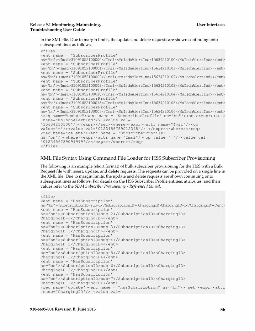
in the XML file. Due to margin limits, the update and delete requests are shown continuing ontosubsequent lines as follows.<file><ent name = "SubscriberProfile" ns="bn"><Imsi>31091052100000</Imsi><MsIsdnAlertInd>15634210100</MsIsdnAlertInd></ent><ent name = "SubscriberProfile" ns="bn"><Imsi>31091052100001</Imsi><MsIsdnAlertInd>15634210101</MsIsdnAlertInd></ent><ent name = "SubscriberProfile" ns="bn"><Imsi>31091052100002</Imsi><MsIsdnAlertInd>15634210102</MsIsdnAlertInd></ent><ent name = "SubscriberProfile" ns="bn"><Imsi>31091052100003</Imsi><MsIsdnAlertInd>15634210103</MsIsdnAlertInd></ent><ent name = "SubscriberProfile" ns="bn"><Imsi>31091052100018</Imsi><MsIsdnAlertInd>15634210104</MsIsdnAlertInd></ent><ent name = "SubscriberProfile" ns="bn"><Imsi>31091052100018</Imsi><MsIsdnAlertInd>15634210105</MsIsdnAlertInd></ent><ent name = "SubscriberProfile" ns="bn"><Imsi>31091052100006</Imsi><MsIsdnAlertInd>15634210106</MsIsdnAlertInd></ent><req name="update"><ent name = "SubscriberProfile" ns="bn"/><set><expr><attr name="MsIsdnAlertInd"/> <value val= "15634210100"/></expr></set><where><expr><attr name="Imsi"/><op value="="/><value val="0123456789012345"/> </expr></where></req><req name="delete"><ent name = "SubscriberProfile" ns="bn"/><where><expr><attr name="Imsi"/><op value="="/><value val= "0123456789099999"/></expr></where></req></file>
XML File Syntax Using Command File Loader for HSS Subscriber ProvisioningThe following is an example (short format) of bulk subscriber provisioning for the HSS with a BulkRequest file with insert, update, and delete requests. The requests can be provided on a single line inthe XML file. Due to margin limits, the update and delete requests are shown continuing ontosubsequent lines as follows. For details on the HSS Subscriber Profile entities, attributes, and theirvalues refer to the SDM Subscriber Provisioning - Reference Manual.
<file><ent name = "HssSubscription" ns="bn"><SubscriptionID>sub-1</SubscriptionID><ChargingID>ChargingID-1</ChargingID></ent><ent name = "HssSubscription" ns="bn"><SubscriptionID>sub-2</SubscriptionID><ChargingID> ChargingID-1</ChargingID></ent><ent name = "HssSubscription" ns="bn"><SubscriptionID>sub-3</SubscriptionID><ChargingID> ChargingID-1</ChargingID></ent><ent name = "HssSubscription" ns="bn"><SubscriptionID>sub-4</SubscriptionID><ChargingID> ChargingID-2</ChargingID></ent><ent name = "HssSubscription" ns="bn"><SubscriptionID>sub-5</SubscriptionID><ChargingID> ChargingID-1</ChargingID></ent><ent name = "HssSubscription" ns="bn"><SubscriptionID>sub-6</SubscriptionID><ChargingID> ChargingID-2</ChargingID></ent><ent name = "HssSubscription" ns="bn"><SubscriptionID>sub-7</SubscriptionID><ChargingID> ChargingID-1</ChargingID></ent><req name="update"><ent name = "HssSubscription" ns="bn"/><set><expr><attr name="ChargingID"/> <value val=
56910-6695-001 Revision B, June 2013
User InterfacesRelease 9.1 Monitoring, Maintaining,Troubleshooting User Guide

"ChargingID-2"/></expr></set><where><expr><attr name="SubscriptionID"/><op value="="/><value val="sub-1"/> </expr></where></req><req name="delete"><ent name = "HssSubscription" ns="bn"/><where><expr><attr name="SubscriptionID"/><op value="="/><value val= "sub-7"/></expr></where></req></file>
Running the Command Template Viewer
• User must belong to admin, batch, or operation group.• Template files must have been uploaded. See Running Command Template Loader.
The Command Template Viewer (CTV) is used to view the templates currently loaded in the database.
1. Establish Secure Shell (SSh) connection.2. Once the user is logged in the blade, in order to use the Command Template Viewer, the user must
write the following:[UserName@system UserName] $ ctv –t <tp/tpr> -id <template id>
3. At the prompt, type
[UserName@system UserName] $ ctv –t <tp/tpr> -id <template id> to view thetemplates in the database.
The Command File Loader accepts the Invoking file and then executes it by processing each XMLrequest.
CTV help optionsDisplay the help options of the Command Template Viewer by typing CmdTemplateViewer -h
57910-6695-001 Revision B, June 2013
User InterfacesRelease 9.1 Monitoring, Maintaining,Troubleshooting User Guide
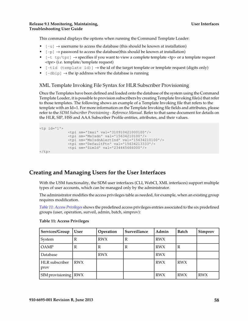
This command displays the options when running the Command Template Loader:
• [-u] → username to access the database (this should be known at installation)• [-p] → password to access the database(this should be known at installation)• [-t tp/tpr] → specifies if you want to view a complete template <tp> or a template request
<tpr> (i.e. template/template request)• [-tid (template id)] → the id of the target template or template request (digits only)• [-dbip] → the ip address where the database is running
XML Template Invoking File Syntax for HLR Subscriber ProvisioningOnce the Templates have been defined and loaded onto the database of the system using the CommandTemplate Loader, it is possible to provision subscribers by creating Template Invoking file(s) that referto those templates. The following shows an example of a Template Invoking file that refers to thetemplate with an Id=1. For more information on the Template Invoking file fields and attributes, pleaserefer to the SDM Subscriber Provisioning - Reference Manual. Refer to that same document for details onthe HLR, SIP, HSS and AAA Subscriber Profile entities, attributes, and their values.
<tp id="1"> <tpi nm="Imsi" val="310910421000100"/> <tpi nm="MsIsdn" val="15634210100"/> <tpi nm="MsIsdnAlertInd" val="15634210100"/> <tpi nm="DefaultFtn" val="15634213333"/> <tpi nm="SimId" val="234445666000"/></tp>
Creating and Managing Users for the User Interfaces
With the USM functionality, the SDM user interfaces (CLI, WebCI, XML interfaces) support multipletypes of user accounts, which can be managed only by the administrator.
The administrator modifies the access privileges table as needed, for example, when an existing grouprequires modification.
Table 11: Access Privileges shows the predefined access privileges entries associated to the six predefinedgroups (user, operation, surveil, admin, batch, simprov):
Table 11: Access Privileges
SimprovBatchAdminSurveillanceOperationUserServices/Group
RWXRRWXRSystem
RRWXRRROAMP
RWXRWXDatabase
RWXRWXRWXHLR subscriberprov
RWXRWXRWXRWXSIM provisioning
58910-6695-001 Revision B, June 2013
User InterfacesRelease 9.1 Monitoring, Maintaining,Troubleshooting User Guide
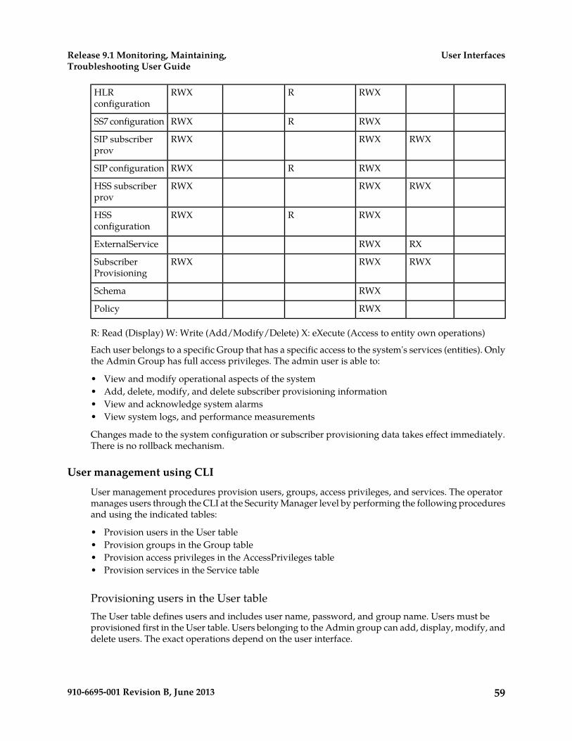
RWXRRWXHLRconfiguration
RWXRRWXSS7 configuration
RWXRWXRWXSIP subscriberprov
RWXRRWXSIP configuration
RWXRWXRWXHSS subscriberprov
RWXRRWXHSSconfiguration
RXRWXExternalService
RWXRWXRWXSubscriberProvisioning
RWXSchema
RWXPolicy
R: Read (Display) W: Write (Add/Modify/Delete) X: eXecute (Access to entity own operations)
Each user belongs to a specific Group that has a specific access to the system's services (entities). Onlythe Admin Group has full access privileges. The admin user is able to:
• View and modify operational aspects of the system• Add, delete, modify, and delete subscriber provisioning information• View and acknowledge system alarms• View system logs, and performance measurements
Changes made to the system configuration or subscriber provisioning data takes effect immediately.There is no rollback mechanism.
User management using CLI
User management procedures provision users, groups, access privileges, and services. The operatormanages users through the CLI at the Security Manager level by performing the following proceduresand using the indicated tables:
• Provision users in the User table• Provision groups in the Group table• Provision access privileges in the AccessPrivileges table• Provision services in the Service table
Provisioning users in the User tableThe User table defines users and includes user name, password, and group name. Users must beprovisioned first in the User table. Users belonging to the Admin group can add, display, modify, anddelete users. The exact operations depend on the user interface.
59910-6695-001 Revision B, June 2013
User InterfacesRelease 9.1 Monitoring, Maintaining,Troubleshooting User Guide
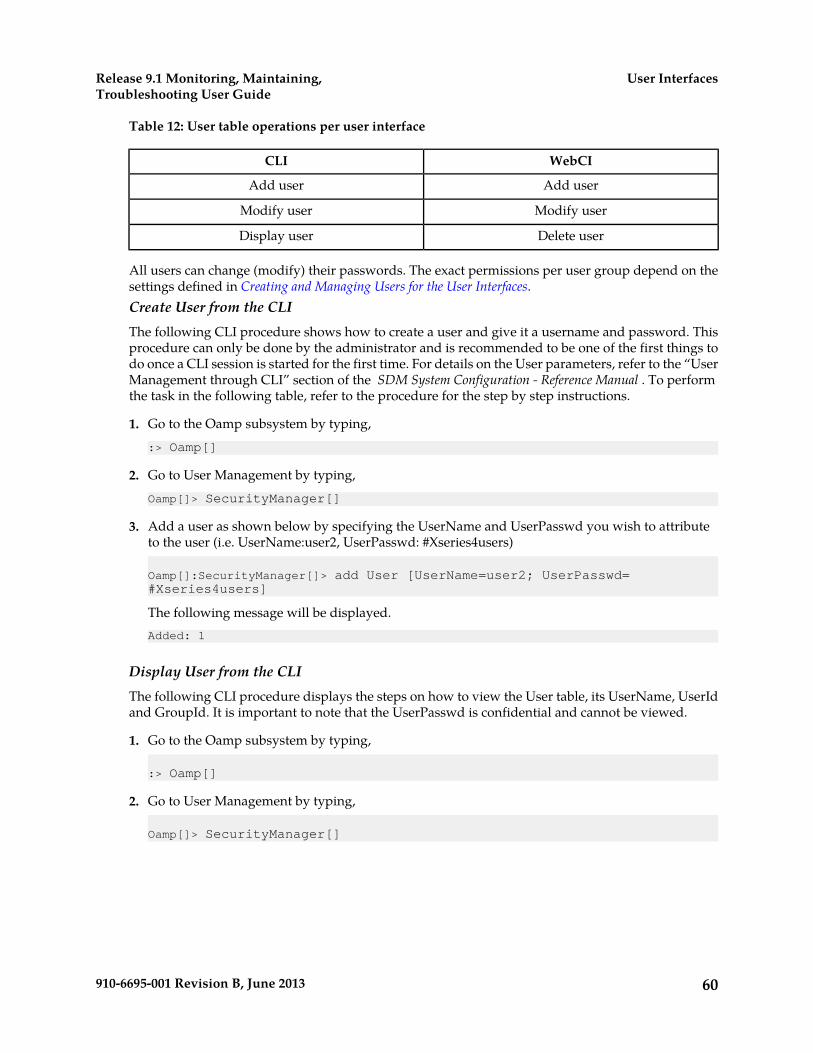
Table 12: User table operations per user interface
WebCICLI
Add userAdd user
Modify userModify user
Delete userDisplay user
All users can change (modify) their passwords. The exact permissions per user group depend on thesettings defined in Creating and Managing Users for the User Interfaces.Create User from the CLIThe following CLI procedure shows how to create a user and give it a username and password. Thisprocedure can only be done by the administrator and is recommended to be one of the first things todo once a CLI session is started for the first time. For details on the User parameters, refer to the “UserManagement through CLI” section of the SDM System Configuration - Reference Manual . To performthe task in the following table, refer to the procedure for the step by step instructions.
1. Go to the Oamp subsystem by typing,:> Oamp[]
2. Go to User Management by typing,Oamp[]> SecurityManager[]
3. Add a user as shown below by specifying the UserName and UserPasswd you wish to attributeto the user (i.e. UserName:user2, UserPasswd: #Xseries4users)
Oamp[]:SecurityManager[]> add User [UserName=user2; UserPasswd= #Xseries4users]
The following message will be displayed.Added: 1
Display User from the CLIThe following CLI procedure displays the steps on how to view the User table, its UserName, UserIdand GroupId. It is important to note that the UserPasswd is confidential and cannot be viewed.
1. Go to the Oamp subsystem by typing,
:> Oamp[]
2. Go to User Management by typing,
Oamp[]> SecurityManager[]
60910-6695-001 Revision B, June 2013
User InterfacesRelease 9.1 Monitoring, Maintaining,Troubleshooting User Guide

3. To display the entire User Table, go to User without specifying any attributes, as follows:
Oamp[]> SecurityManager[]> User[]
To display the User Table only for specific users, go to User and specify the user’s name (i.e.UserName: user):
Oamp[]> SecurityManager[]> User[UserName=user]
4. Display the User Table by typing:
Oamp[]> SecurityManager[]> User[]> displayorOamp[]> SecurityManager[]> User[UserName=user]> display
Information similar to the following will be displayed if you displayed the entire User Table:
| UserName| UserPasswd | GroupName |-----------------------|-----------------------------user | | user |operation | | operation |surveil | | surveil |admin | | admin |batch | | batch |simprov | | simprov |user2 | | user |
Displayed: 7
Information similar to the following will be displayed if you only displayed a specific user:
|UserName |UserPasswd |GroupName|------------------------------------user | | user |Displayed: 1
Modify user from the CLIEach user can modify the user password by entering a new value of the password in the User[ ] entity.
Only the system administrator can modify:
• The password of each user.• The group to which a user is associated by modifying the GroupName field.• The UpgradeMode and the PersistOS (whether to store the user information in the Operating
System)
This procedure describes how to modify any user information from the User[ ] entity. For details onUser parameters, refer to the User Management through CLI section of the SDM System Configuration -Reference Manual.
1. Go to the Oamp subsystem by typing:> Oamp[]
2. Go to User Management by typingOamp[]> SecurityManager[]
61910-6695-001 Revision B, June 2013
User InterfacesRelease 9.1 Monitoring, Maintaining,Troubleshooting User Guide

3. Specify the user for which you wish to modify information (i.e., UserName=user2). TypeOamp[]:SecurityManager[]> User [UserName=user2]
4. Modify the user specified in the previous step by executing the modify command and specifyingthe fields you wish to modify and their new values. For example, typeOamp[]:SecurityManager[]> User [UserName=user2]> modify . Password=Xseries4users]
The following message displays:Warning, you are about to modify this instance(s) permanently, Proceed with modify? (y/[n]):
5. Type y if you wish to continue or n if you wish to cancelIf you typed y, the following message displays:Modified:1
Provisioning groups in the Group tableThe Group table defines a user group based on system use and common access privileges andpermissions. Each group consists of a group name and the access granted for each service.
The Subscriber Data Management system pre-defines six groups with certain access privileges foreach service: user, operation, surveil, admin, batch, and simprov. The user group can be displayed byall users, but only the administrator can display, add, modify, or delete access privileges of each serviceassociated to the group. See also Table 11: Access Privileges.Provisioning groups from the CLIThe following CLI procedure is a generic procedure on how to provision the Group entity. Followthis logic whether you wish to add/display/modify/delete an entry in the Group[ ] entity.
1. Go to the Oamp subsystem by typing,:> Oamp[]
2. Go to User Management by typing,Oamp[]> SecurityManager[]
3. From here, you can add/display/delete/modify an entry in the Group entity. Perform one of thefollowing actions, as needed:
• To display the Group entity, perform the following:Oamp[]> SecurityManager[]> display Group[]
• To display a specific entry in the Group entity, simply specify the GroupName of the groupyou wish to display, as follows:Oamp[]> SecurityManager[]> display Group[GroupName=user]
• To add an entry, perform the following (i.e.: GroupName: usergroup1):Oamp[]> SecurityManager[]> add Group[GroupName=usergroup1]
62910-6695-001 Revision B, June 2013
User InterfacesRelease 9.1 Monitoring, Maintaining,Troubleshooting User Guide
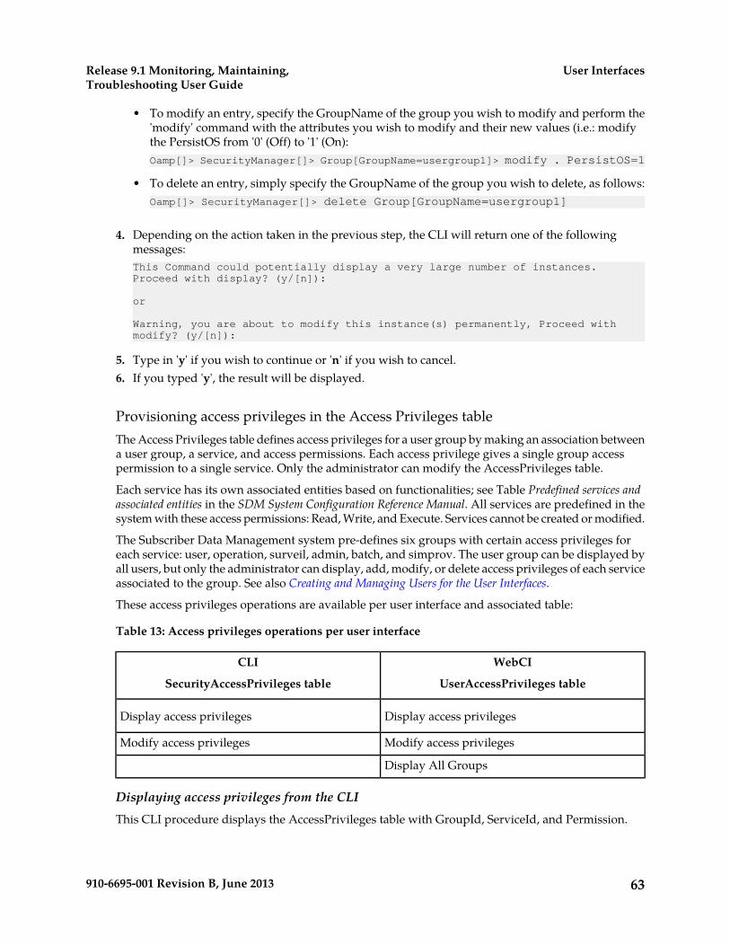
• To modify an entry, specify the GroupName of the group you wish to modify and perform the'modify' command with the attributes you wish to modify and their new values (i.e.: modifythe PersistOS from '0' (Off) to '1' (On):Oamp[]> SecurityManager[]> Group[GroupName=usergroup1]> modify . PersistOS=1
• To delete an entry, simply specify the GroupName of the group you wish to delete, as follows:Oamp[]> SecurityManager[]> delete Group[GroupName=usergroup1]
4. Depending on the action taken in the previous step, the CLI will return one of the followingmessages:This Command could potentially display a very large number of instances.Proceed with display? (y/[n]):
or
Warning, you are about to modify this instance(s) permanently, Proceed with modify? (y/[n]):
5. Type in 'y' if you wish to continue or 'n' if you wish to cancel.6. If you typed 'y', the result will be displayed.
Provisioning access privileges in the Access Privileges tableThe Access Privileges table defines access privileges for a user group by making an association betweena user group, a service, and access permissions. Each access privilege gives a single group accesspermission to a single service. Only the administrator can modify the AccessPrivileges table.
Each service has its own associated entities based on functionalities; see Table Predefined services andassociated entities in the SDM System Configuration Reference Manual. All services are predefined in thesystem with these access permissions: Read, Write, and Execute. Services cannot be created or modified.
The Subscriber Data Management system pre-defines six groups with certain access privileges foreach service: user, operation, surveil, admin, batch, and simprov. The user group can be displayed byall users, but only the administrator can display, add, modify, or delete access privileges of each serviceassociated to the group. See also Creating and Managing Users for the User Interfaces.
These access privileges operations are available per user interface and associated table:
Table 13: Access privileges operations per user interface
WebCI
UserAccessPrivileges table
CLI
SecurityAccessPrivileges table
Display access privilegesDisplay access privileges
Modify access privilegesModify access privileges
Display All Groups
Displaying access privileges from the CLIThis CLI procedure displays the AccessPrivileges table with GroupId, ServiceId, and Permission.
63910-6695-001 Revision B, June 2013
User InterfacesRelease 9.1 Monitoring, Maintaining,Troubleshooting User Guide
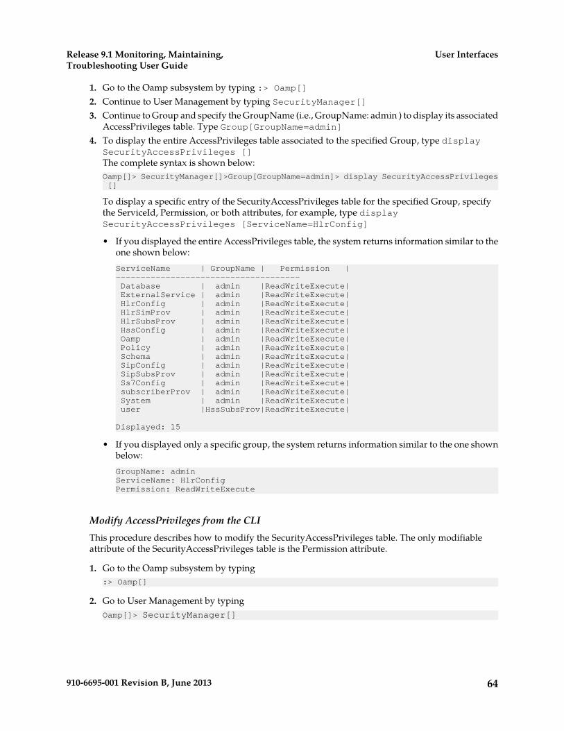
1. Go to the Oamp subsystem by typing :> Oamp[]2. Continue to User Management by typing SecurityManager[]3. Continue to Group and specify the GroupName (i.e., GroupName: admin ) to display its associated
AccessPrivileges table. Type Group[GroupName=admin]4. To display the entire AccessPrivileges table associated to the specified Group, type display
SecurityAccessPrivileges []The complete syntax is shown below:Oamp[]> SecurityManager[]>Group[GroupName=admin]> display SecurityAccessPrivileges []
To display a specific entry of the SecurityAccessPrivileges table for the specified Group, specifythe ServiceId, Permission, or both attributes, for example, type displaySecurityAccessPrivileges [ServiceName=HlrConfig]
• If you displayed the entire AccessPrivileges table, the system returns information similar to theone shown below:ServiceName | GroupName | Permission |------------------------------------- Database | admin |ReadWriteExecute| ExternalService | admin |ReadWriteExecute| HlrConfig | admin |ReadWriteExecute| HlrSimProv | admin |ReadWriteExecute| HlrSubsProv | admin |ReadWriteExecute| HssConfig | admin |ReadWriteExecute| Oamp | admin |ReadWriteExecute| Policy | admin |ReadWriteExecute| Schema | admin |ReadWriteExecute| SipConfig | admin |ReadWriteExecute| SipSubsProv | admin |ReadWriteExecute| Ss7Config | admin |ReadWriteExecute| subscriberProv | admin |ReadWriteExecute| System | admin |ReadWriteExecute| user |HssSubsProv|ReadWriteExecute|
Displayed: 15
• If you displayed only a specific group, the system returns information similar to the one shownbelow:GroupName: adminServiceName: HlrConfigPermission: ReadWriteExecute
Modify AccessPrivileges from the CLIThis procedure describes how to modify the SecurityAccessPrivileges table. The only modifiableattribute of the SecurityAccessPrivileges table is the Permission attribute.
1. Go to the Oamp subsystem by typing:> Oamp[]
2. Go to User Management by typingOamp[]> SecurityManager[]
64910-6695-001 Revision B, June 2013
User InterfacesRelease 9.1 Monitoring, Maintaining,Troubleshooting User Guide
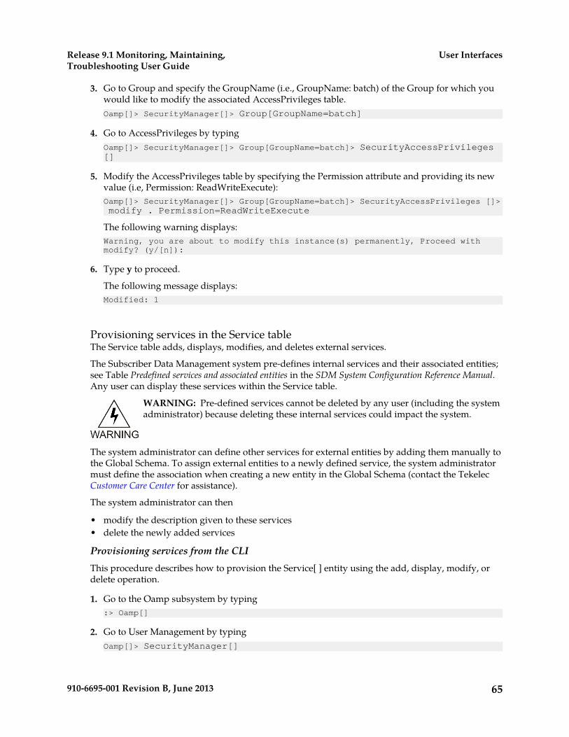
3. Go to Group and specify the GroupName (i.e., GroupName: batch) of the Group for which youwould like to modify the associated AccessPrivileges table.Oamp[]> SecurityManager[]> Group[GroupName=batch]
4. Go to AccessPrivileges by typingOamp[]> SecurityManager[]> Group[GroupName=batch]> SecurityAccessPrivileges []
5. Modify the AccessPrivileges table by specifying the Permission attribute and providing its newvalue (i.e, Permission: ReadWriteExecute):Oamp[]> SecurityManager[]> Group[GroupName=batch]> SecurityAccessPrivileges []>modify . Permission=ReadWriteExecute
The following warning displays:Warning, you are about to modify this instance(s) permanently, Proceed with modify? (y/[n]):
6. Type y to proceed.
The following message displays:Modified: 1
Provisioning services in the Service tableThe Service table adds, displays, modifies, and deletes external services.
The Subscriber Data Management system pre-defines internal services and their associated entities;see Table Predefined services and associated entities in the SDM System Configuration Reference Manual.Any user can display these services within the Service table.
WARNING: Pre-defined services cannot be deleted by any user (including the systemadministrator) because deleting these internal services could impact the system.
The system administrator can define other services for external entities by adding them manually tothe Global Schema. To assign external entities to a newly defined service, the system administratormust define the association when creating a new entity in the Global Schema (contact the TekelecCustomer Care Center for assistance).
The system administrator can then
• modify the description given to these services• delete the newly added services
Provisioning services from the CLIThis procedure describes how to provision the Service[ ] entity using the add, display, modify, ordelete operation.
1. Go to the Oamp subsystem by typing:> Oamp[]
2. Go to User Management by typingOamp[]> SecurityManager[]
65910-6695-001 Revision B, June 2013
User InterfacesRelease 9.1 Monitoring, Maintaining,Troubleshooting User Guide

3. Perform one of the following actions:
• To display the Service entity, type display:Oamp[]> SecurityManager[]> display Service[]
• To display a specific entry in the Service entity, type display and specify the ServiceName ofthe service to display:Oamp[]> SecurityManager[]> display Service[ServiceName=HlrConfig]
• To add an entry, type add and specify the ServiceName with the ExternalService value, whichregroups the ExternalServiceManager entity):Oamp[]> SecurityManager[]> add Service[ServiceName=ExternalService]
• To modify an entry, type modify and specify the ServiceName of the group to modify:Oamp[]> SecurityManager[]> Service[ServiceName=ExternalService]> modify . Description=service regrouping external services
• To delete an entry, specify the ServiceName of the service to delete:Oamp[]> SecurityManager[]> delete Service[ServiceName=ExternalService]
Warning: The pre-defined services cannot be deleted by any user (including thesystem administrator) since these are internal services and a deletion could impactthe system.
Depending on the action taken in the previous step, the CLI will return one of the followingmessages:This Command could potentially display a very large number of instances.Proceed with display? (y/[n]):
Warning, you are about to modify this instance(s) permanently, Proceed with modify? (y/[n]):
4. Type y if you wish to continue; type n if you wish to cancel.If you typed y, the result displays.
User management using WebCI
User management procedures provision users, groups, access privileges, and services. The operatormanages users through the WebCI in the User Manager by performing the following procedures andusing the indicated windows or tables:
• View all User Management information in the User Manager window• Provision users in the User table• Provision groups in the Group table• Provision access privileges in the AccessPrivileges table• Provision services in the Service table
View all User Management Information from the WebCIThis procedure describes how to display the User Manager window.
The User Manager window displays all user management information.
66910-6695-001 Revision B, June 2013
User InterfacesRelease 9.1 Monitoring, Maintaining,Troubleshooting User Guide
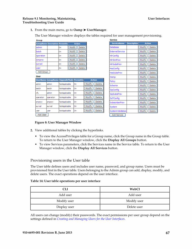
1. From the main menu, go to Oamp ➤ UserManager.
The User Manager window displays the tables required for user management provisioning.
Figure 8: User Manager Window
2. View additional tables by clicking the hyperlinks.
• To view the AccessPrivileges table for a Group name, click the Group name in the Group table.To return to the User Manager window, click the Display All Groups button.
• To view Services parameters, click the Services name in the Service table. To return to the UserManager window, click the Display All Services button.
Provisioning users in the User tableThe User table defines users and includes user name, password, and group name. Users must beprovisioned first in the User table. Users belonging to the Admin group can add, display, modify, anddelete users. The exact operations depend on the user interface.
Table 14: User table operations per user interface
WebCICLI
Add userAdd user
Modify userModify user
Delete userDisplay user
All users can change (modify) their passwords. The exact permissions per user group depend on thesettings defined in Creating and Managing Users for the User Interfaces.
67910-6695-001 Revision B, June 2013
User InterfacesRelease 9.1 Monitoring, Maintaining,Troubleshooting User Guide

Creating User from the WebCIThe following WebCI procedure shows how to create a user, give it a username and password, andassociate a group to it. This procedure can only be done by the administrator and is
recommended to be one of the first things to do once a WebCI session is started for the first time. Fordetails on the User parameters, refer to the "User Management through CLI" section of the SDMSystem Configuration - Reference Manual .
1. From the main menu, navigate to Oamp ➤ User Manager.The User Manager window displays.
2. Click the Add User button below the User table.The User Provisioning pop-up window displays.
3. Enter the information to be added (the asterisk (*) identifies a mandatory attribute).4. Click Commit.
The system returns a confirmation message User entry was successfully committed5. Click OK.
Modifying a User from the WebCIEach user can modify its own password by modifying the User[ ] entity and entering the value of thenew password desired. However, only the administrator of the system can modify the following:
• The password of each user.• The group to which a user is associated to, by modifying the GroupName field.• The UpgradeMode and the PersistOS (to store or not the user information in the Operating System)
The following WebCI procedure shows how to modify any user information from the User[ ] entity.For details on the User parameters, refer to the "User Management through CLI" section of the SDMSystem Configuration - Reference Manual. To perform the task in the following table, refer to the procedurefor the step by step instructions.
1. From the main menu, navigate to Oamp ➤ User Manager. This will display the User Managerwindow (as shown in the figure below)
2. Click the Modify button beside the User entry of the User you wish to modify.3. When the User Provisioning window appears (see figure below), enter the new value(s).
Note: The figure below is for the administrator of the system. The other users can only modify thePassword.
68910-6695-001 Revision B, June 2013
User InterfacesRelease 9.1 Monitoring, Maintaining,Troubleshooting User Guide
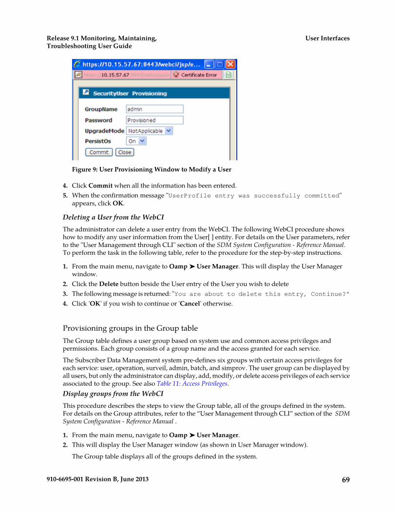
Figure 9: User Provisioning Window to Modify a User
4. Click Commit when all the information has been entered.5. When the confirmation message "UserProfile entry was successfully committed"
appears, click OK.
Deleting a User from the WebCIThe administrator can delete a user entry from the WebCI. The following WebCI procedure showshow to modify any user information from the User[ ] entity. For details on the User parameters, referto the "User Management through CLI" section of the SDM System Configuration - Reference Manual.To perform the task in the following table, refer to the procedure for the step-by-step instructions.
1. From the main menu, navigate to Oamp ➤ User Manager. This will display the User Managerwindow.
2. Click the Delete button beside the User entry of the User you wish to delete3. The following message is returned: "You are about to delete this entry, Continue?"4. Click 'OK' if you wish to continue or 'Cancel' otherwise.
Provisioning groups in the Group tableThe Group table defines a user group based on system use and common access privileges andpermissions. Each group consists of a group name and the access granted for each service.
The Subscriber Data Management system pre-defines six groups with certain access privileges foreach service: user, operation, surveil, admin, batch, and simprov. The user group can be displayed byall users, but only the administrator can display, add, modify, or delete access privileges of each serviceassociated to the group. See also Table 11: Access Privileges.Display groups from the WebCIThis procedure describes the steps to view the Group table, all of the groups defined in the system.For details on the Group attributes, refer to the “User Management through CLI” section of the SDMSystem Configuration - Reference Manual .
1. From the main menu, navigate to Oamp ➤ User Manager.2. This will display the User Manager window (as shown in User Manager window).
The Group table displays all of the groups defined in the system.
69910-6695-001 Revision B, June 2013
User InterfacesRelease 9.1 Monitoring, Maintaining,Troubleshooting User Guide
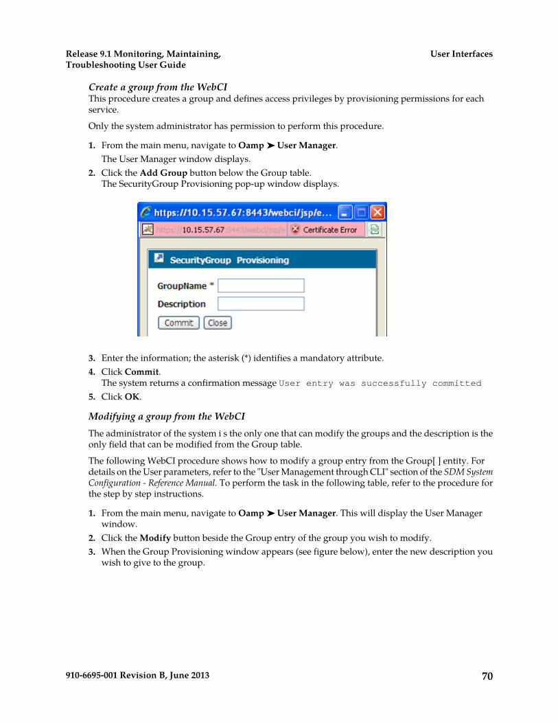
Create a group from the WebCIThis procedure creates a group and defines access privileges by provisioning permissions for eachservice.
Only the system administrator has permission to perform this procedure.
1. From the main menu, navigate to Oamp ➤ User Manager.The User Manager window displays.
2. Click the Add Group button below the Group table.The SecurityGroup Provisioning pop-up window displays.
3. Enter the information; the asterisk (*) identifies a mandatory attribute.4. Click Commit.
The system returns a confirmation message User entry was successfully committed5. Click OK.
Modifying a group from the WebCIThe administrator of the system i s the only one that can modify the groups and the description is theonly field that can be modified from the Group table.
The following WebCI procedure shows how to modify a group entry from the Group[ ] entity. Fordetails on the User parameters, refer to the "User Management through CLI" section of the SDM SystemConfiguration - Reference Manual. To perform the task in the following table, refer to the procedure forthe step by step instructions.
1. From the main menu, navigate to Oamp ➤ User Manager. This will display the User Managerwindow.
2. Click the Modify button beside the Group entry of the group you wish to modify.3. When the Group Provisioning window appears (see figure below), enter the new description you
wish to give to the group.
70910-6695-001 Revision B, June 2013
User InterfacesRelease 9.1 Monitoring, Maintaining,Troubleshooting User Guide
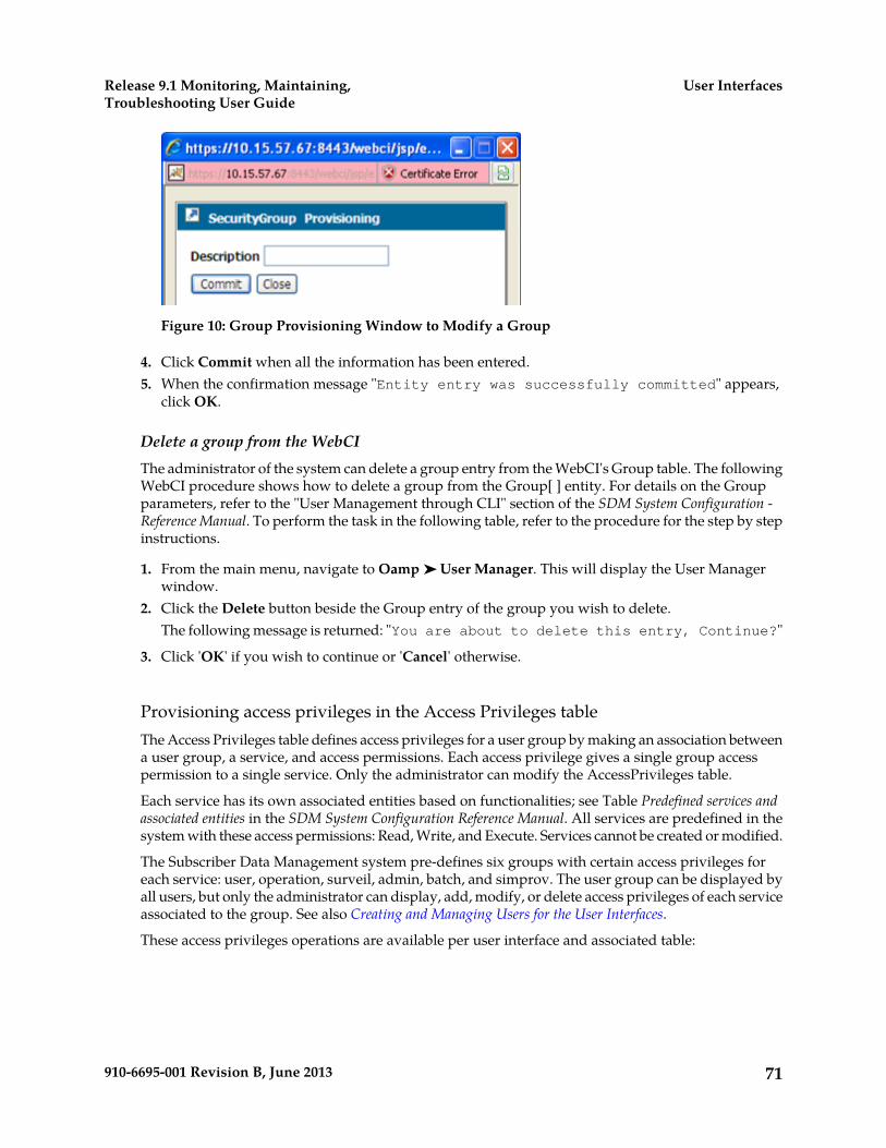
Figure 10: Group Provisioning Window to Modify a Group
4. Click Commit when all the information has been entered.5. When the confirmation message "Entity entry was successfully committed" appears,
click OK.
Delete a group from the WebCIThe administrator of the system can delete a group entry from the WebCI's Group table. The followingWebCI procedure shows how to delete a group from the Group[ ] entity. For details on the Groupparameters, refer to the "User Management through CLI" section of the SDM System Configuration -Reference Manual. To perform the task in the following table, refer to the procedure for the step by stepinstructions.
1. From the main menu, navigate to Oamp ➤ User Manager. This will display the User Managerwindow.
2. Click the Delete button beside the Group entry of the group you wish to delete.The following message is returned: "You are about to delete this entry, Continue?"
3. Click 'OK' if you wish to continue or 'Cancel' otherwise.
Provisioning access privileges in the Access Privileges tableThe Access Privileges table defines access privileges for a user group by making an association betweena user group, a service, and access permissions. Each access privilege gives a single group accesspermission to a single service. Only the administrator can modify the AccessPrivileges table.
Each service has its own associated entities based on functionalities; see Table Predefined services andassociated entities in the SDM System Configuration Reference Manual. All services are predefined in thesystem with these access permissions: Read, Write, and Execute. Services cannot be created or modified.
The Subscriber Data Management system pre-defines six groups with certain access privileges foreach service: user, operation, surveil, admin, batch, and simprov. The user group can be displayed byall users, but only the administrator can display, add, modify, or delete access privileges of each serviceassociated to the group. See also Creating and Managing Users for the User Interfaces.
These access privileges operations are available per user interface and associated table:
71910-6695-001 Revision B, June 2013
User InterfacesRelease 9.1 Monitoring, Maintaining,Troubleshooting User Guide
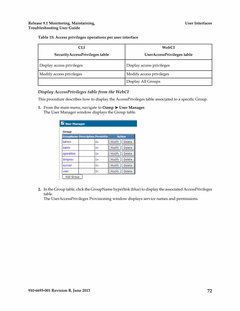
Table 15: Access privileges operations per user interface
WebCI
UserAccessPrivileges table
CLI
SecurityAccessPrivileges table
Display access privilegesDisplay access privileges
Modify access privilegesModify access privileges
Display All Groups
Display AccessPrivileges table from the WebCIThis procedure describes how to display the AccessPrivileges table associated to a specific Group.
1. From the main menu, navigate to Oamp ➤ User Manager.The User Manager window displays the Group table.
2. In the Group table, click the GroupName hyperlink (blue) to display the associated AccessPrivilegestable.The UserAccessPrivileges Provisioning window displays service names and permissions.
72910-6695-001 Revision B, June 2013
User InterfacesRelease 9.1 Monitoring, Maintaining,Troubleshooting User Guide

3. Click Display All Groups to return to the User Manager window.
Modify Access Privileges from the WebCIThis procedure describes the steps to modify the AccessPrivileges table associated to a specific Group.Only the administrator can modify the permissions assigned to specific services for each Group. Fordetails on the AccessPrivileges Management attributes, refer to the “User Management through CLI”section of the SDM System Configuration - Reference Manual .
1. From the main menu, navigate to Oamp ➤ User Manager.
This will display the User Manager window (as shown below).
2. In the Group table, click on the GroupName (written in blue) of the Group to which you wouldlike to modify the associated AccessPrivileges table.
3. When the UserAccessPrivileges Provisioning window appears, select the new permission you wantto give to that Group for each service to which you wish to modify the permission.
73910-6695-001 Revision B, June 2013
User InterfacesRelease 9.1 Monitoring, Maintaining,Troubleshooting User Guide
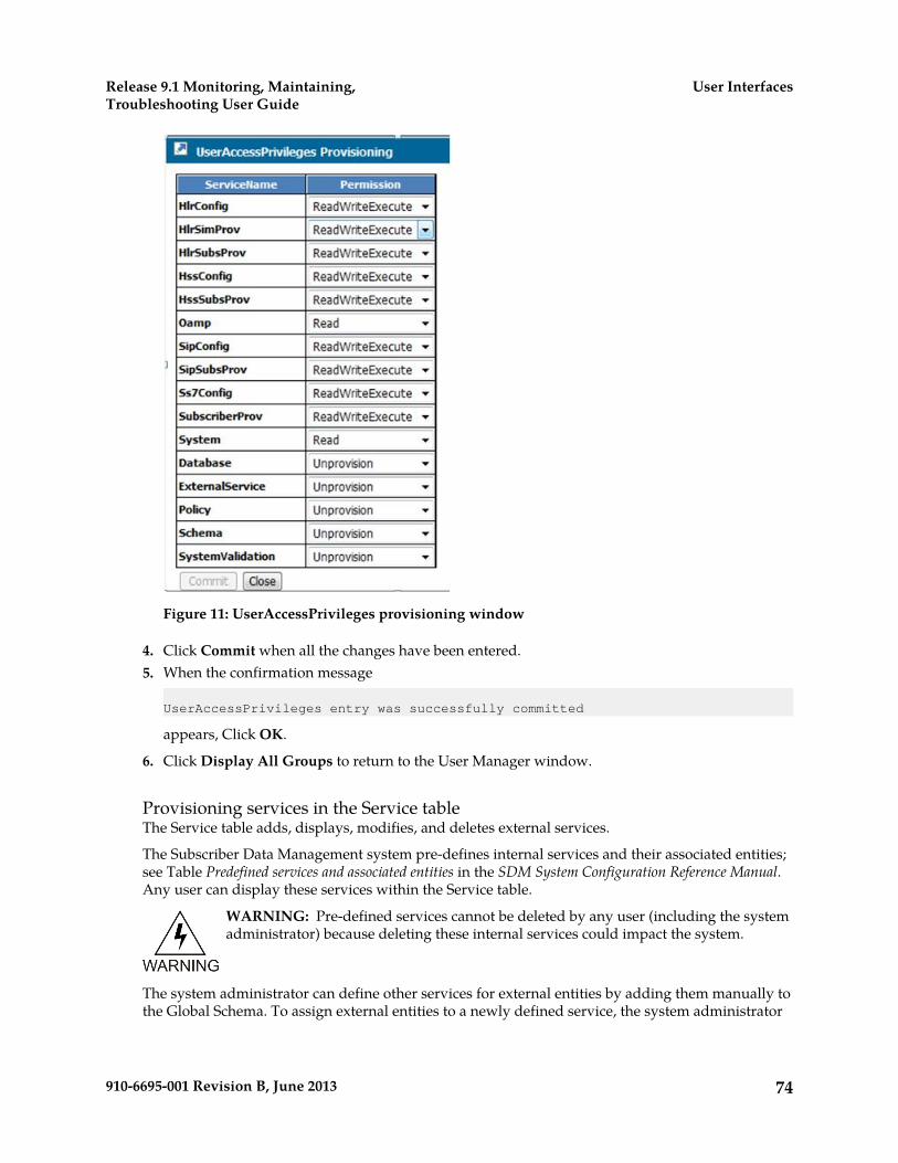
Figure 11: UserAccessPrivileges provisioning window
4. Click Commit when all the changes have been entered.5. When the confirmation message
UserAccessPrivileges entry was successfully committed
appears, Click OK.
6. Click Display All Groups to return to the User Manager window.
Provisioning services in the Service tableThe Service table adds, displays, modifies, and deletes external services.
The Subscriber Data Management system pre-defines internal services and their associated entities;see Table Predefined services and associated entities in the SDM System Configuration Reference Manual.Any user can display these services within the Service table.
WARNING: Pre-defined services cannot be deleted by any user (including the systemadministrator) because deleting these internal services could impact the system.
The system administrator can define other services for external entities by adding them manually tothe Global Schema. To assign external entities to a newly defined service, the system administrator
74910-6695-001 Revision B, June 2013
User InterfacesRelease 9.1 Monitoring, Maintaining,Troubleshooting User Guide
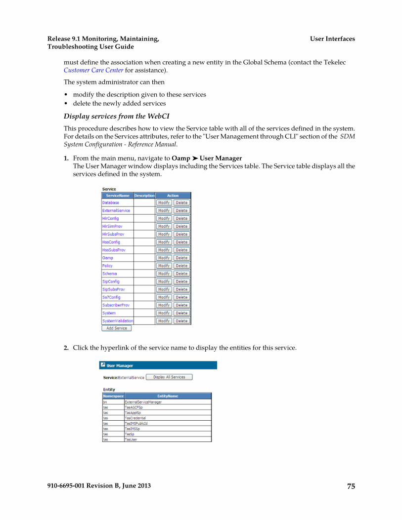
must define the association when creating a new entity in the Global Schema (contact the TekelecCustomer Care Center for assistance).
The system administrator can then
• modify the description given to these services• delete the newly added services
Display services from the WebCIThis procedure describes how to view the Service table with all of the services defined in the system.For details on the Services attributes, refer to the "User Management through CLI" section of the SDMSystem Configuration - Reference Manual.
1. From the main menu, navigate to Oamp ➤ User ManagerThe User Manager window displays including the Services table. The Service table displays all theservices defined in the system.
2. Click the hyperlink of the service name to display the entities for this service.
75910-6695-001 Revision B, June 2013
User InterfacesRelease 9.1 Monitoring, Maintaining,Troubleshooting User Guide
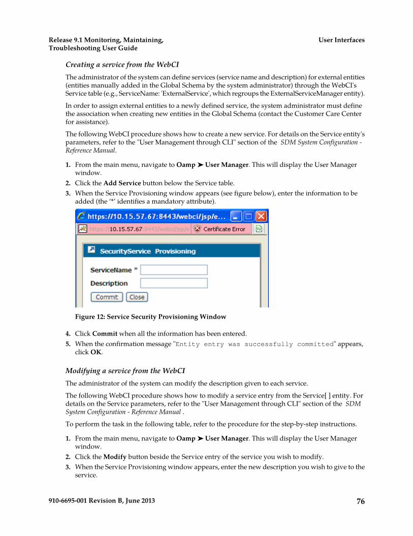
Creating a service from the WebCIThe administrator of the system can define services (service name and description) for external entities(entities manually added in the Global Schema by the system administrator) through the WebCI'sService table (e.g., ServiceName: 'ExternalService', which regroups the ExternalServiceManager entity).
In order to assign external entities to a newly defined service, the system administrator must definethe association when creating new entities in the Global Schema (contact the Customer Care Centerfor assistance).
The following WebCI procedure shows how to create a new service. For details on the Service entity'sparameters, refer to the "User Management through CLI" section of the SDM System Configuration -Reference Manual.
1. From the main menu, navigate to Oamp ➤ User Manager. This will display the User Managerwindow.
2. Click the Add Service button below the Service table.3. When the Service Provisioning window appears (see figure below), enter the information to be
added (the ‘*’ identifies a mandatory attribute).
Figure 12: Service Security Provisioning Window
4. Click Commit when all the information has been entered.5. When the confirmation message "Entity entry was successfully committed" appears,
click OK.
Modifying a service from the WebCIThe administrator of the system can modify the description given to each service.
The following WebCI procedure shows how to modify a service entry from the Service[ ] entity. Fordetails on the Service parameters, refer to the "User Management through CLI" section of the SDMSystem Configuration - Reference Manual .
To perform the task in the following table, refer to the procedure for the step-by-step instructions.
1. From the main menu, navigate to Oamp ➤ User Manager. This will display the User Managerwindow.
2. Click the Modify button beside the Service entry of the service you wish to modify.3. When the Service Provisioning window appears, enter the new description you wish to give to the
service.
76910-6695-001 Revision B, June 2013
User InterfacesRelease 9.1 Monitoring, Maintaining,Troubleshooting User Guide

4. Click Commit when all the information has been entered.5. When the confirmation message "Entity entry was successfully committed" appears,
click OK.
Deleting a service from the WebCIThe pre-defined services cannot be deleted by any user (including the administrator of the system)since these are internal services and a deletion could impact the system. However, the administratorof the system can delete services that he has added himself that regroup external entities (not pre-definedones).
The following WebCI procedure shows how to delete a service from the Service[ ] entity. For detailson the Service parameters, refer to the "User Management through CLI" section of the SDM SystemConfiguration - Reference Manual . To perform the task in the following table, refer to the procedure forthe step by step instructions.
1. From the main menu, navigate to Oamp ➤ User manager. This will display the User Managerwindow.
2. Click the Delete button beside the Service entry of the service you wish to delete.3. The following message is returned: “You are about to delete this entry, Continue?”4. Click OK if you wish to continue or Cancel, otherwise.
Creating and Managing Users for Notifications
The Notification Management functionality allows the management of users with notificationsubscription permissions for specific applications, entities and parameters.
The CLI and WebCI support multiple types of user accounts, which can only be managed by theadministrator. For an external application to be able to subscribe to notifications for specificapplications/entities/attributes, it must have a user account defined by the SDM system administratorwith a username, password and application name. The SDM system administrator must associateapplications to user accounts, by provisioning the UserApplicationMap[ ] entity. The users must firstbe defined in the User[ ] entity and the applications must also be defined with notification subscriptionpermissions for each entity/attribute as well as with notification properties. This can be provisionedin the ApplicationIdentity[ ], NotificationSubscribe[ ] and ApplicationProperty[ ] entities. Take notethat one user can have multiple applications associated to it, which allows the user to subscribenotifications for various applications.
For more details on the system's behavior, refer to the "Security Management" section of the SDMProduct Description . For more details on the entities to provision for Notification Management, referto the "Notification Security Management" section of the SDM System Configuration - Reference Manual.
Take note that changes made to the system configuration or subscriber provisioning data take effectimmediately. There is no rollback mechanism.
Notification Management Using CLI
Notification management requires the provisioning of users, their applications, and notificationsubscriptions/properties. Use these procedures:
77910-6695-001 Revision B, June 2013
User InterfacesRelease 9.1 Monitoring, Maintaining,Troubleshooting User Guide
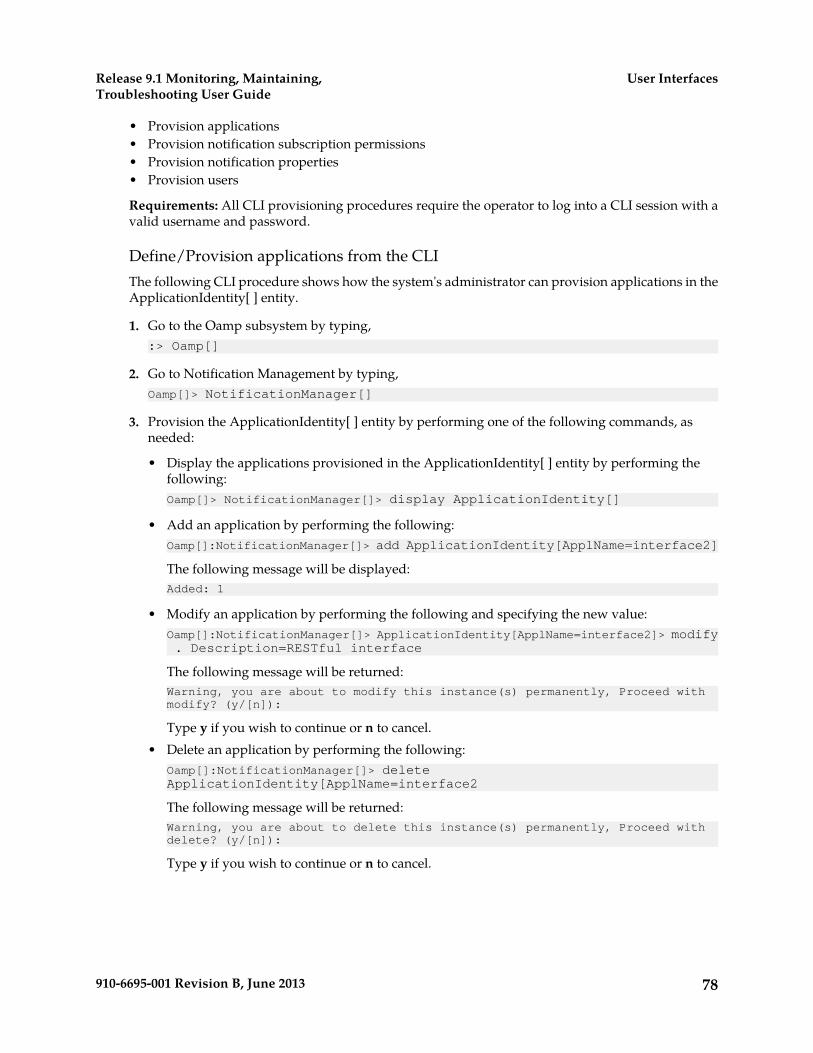
• Provision applications• Provision notification subscription permissions• Provision notification properties• Provision users
Requirements: All CLI provisioning procedures require the operator to log into a CLI session with avalid username and password.
Define/Provision applications from the CLIThe following CLI procedure shows how the system's administrator can provision applications in theApplicationIdentity[ ] entity.
1. Go to the Oamp subsystem by typing,:> Oamp[]
2. Go to Notification Management by typing,Oamp[]> NotificationManager[]
3. Provision the ApplicationIdentity[ ] entity by performing one of the following commands, asneeded:
• Display the applications provisioned in the ApplicationIdentity[ ] entity by performing thefollowing:Oamp[]> NotificationManager[]> display ApplicationIdentity[]
• Add an application by performing the following:Oamp[]:NotificationManager[]> add ApplicationIdentity[ApplName=interface2]
The following message will be displayed:Added: 1
• Modify an application by performing the following and specifying the new value:Oamp[]:NotificationManager[]> ApplicationIdentity[ApplName=interface2]> modify . Description=RESTful interface
The following message will be returned:Warning, you are about to modify this instance(s) permanently, Proceed with modify? (y/[n]):
Type y if you wish to continue or n to cancel.• Delete an application by performing the following:
Oamp[]:NotificationManager[]> delete ApplicationIdentity[ApplName=interface2
The following message will be returned:Warning, you are about to delete this instance(s) permanently, Proceed with delete? (y/[n]):
Type y if you wish to continue or n to cancel.
78910-6695-001 Revision B, June 2013
User InterfacesRelease 9.1 Monitoring, Maintaining,Troubleshooting User Guide
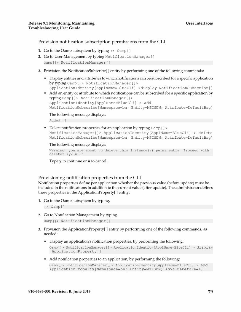
Provision notification subscription permissions from the CLI
1. Go to the Oamp subsystem by typing :> Oamp[]2. Go to User Management by typing NotificationManager[]
Oamp[]> NotificationManager[]
3. Provision the NotificationSubscribe[ ] entity by performing one of the following commands:
• Display entities and attributes to which notifications can be subscribed for a specific applicationby typing Oamp[]> NotificationManager[]>ApplicationIdentity[ApplName=BlueCli] >display NotificationSubscribe[]
• Add an entity or attribute to which notifications can be subscribed for a specific application bytyping Oamp[]> NotificationManager[]>ApplicationIdentity[ApplName=BlueCli] > addNotificationSubscribe[Namespace=bn; Entity=MSISDN; Attribute=DefaultBsg]
The following message displays:Added: 1
• Delete notification properties for an application by typing Oamp[]>NotificationManager[]> ApplicationIdentity[ApplName=BlueCli] > deleteNotificationSubscribe[Namespace=bn; Entity=MSISDN; Attribute=DefaultBsg]
The following message displays:Warning, you are about to delete this instance(s) permanently, Proceed with delete? (y/[n]):
Type y to continue or n to cancel.
Provisioning notification properties from the CLINotification properties define per application whether the previous value (before update) must beincluded in the notifications in addition to the current value (after update). The administrator definesthese properties in the ApplicationProperty[ ] entity.
1. Go to the Oamp subsystem by typing,:> Oamp[]
2. Go to Notification Management by typingOamp[]> NotificationManager[]
3. Provision the ApplicationProperty[ ] entity by performing one of the following commands, asneeded:
• Display an application's notification properties, by performing the following:Oamp[]> NotificationManager[]> ApplicationIdentity[ApplName=BlueCli] > display ApplicationProperty[]
• Add notification properties to an application, by performing the following:Oamp[]> NotificationManager[]> ApplicationIdentity[ApplName=BlueCli] > add ApplicationProperty[Namespace=bn; Entity=MSISDN; isValueBefore=1]
79910-6695-001 Revision B, June 2013
User InterfacesRelease 9.1 Monitoring, Maintaining,Troubleshooting User Guide
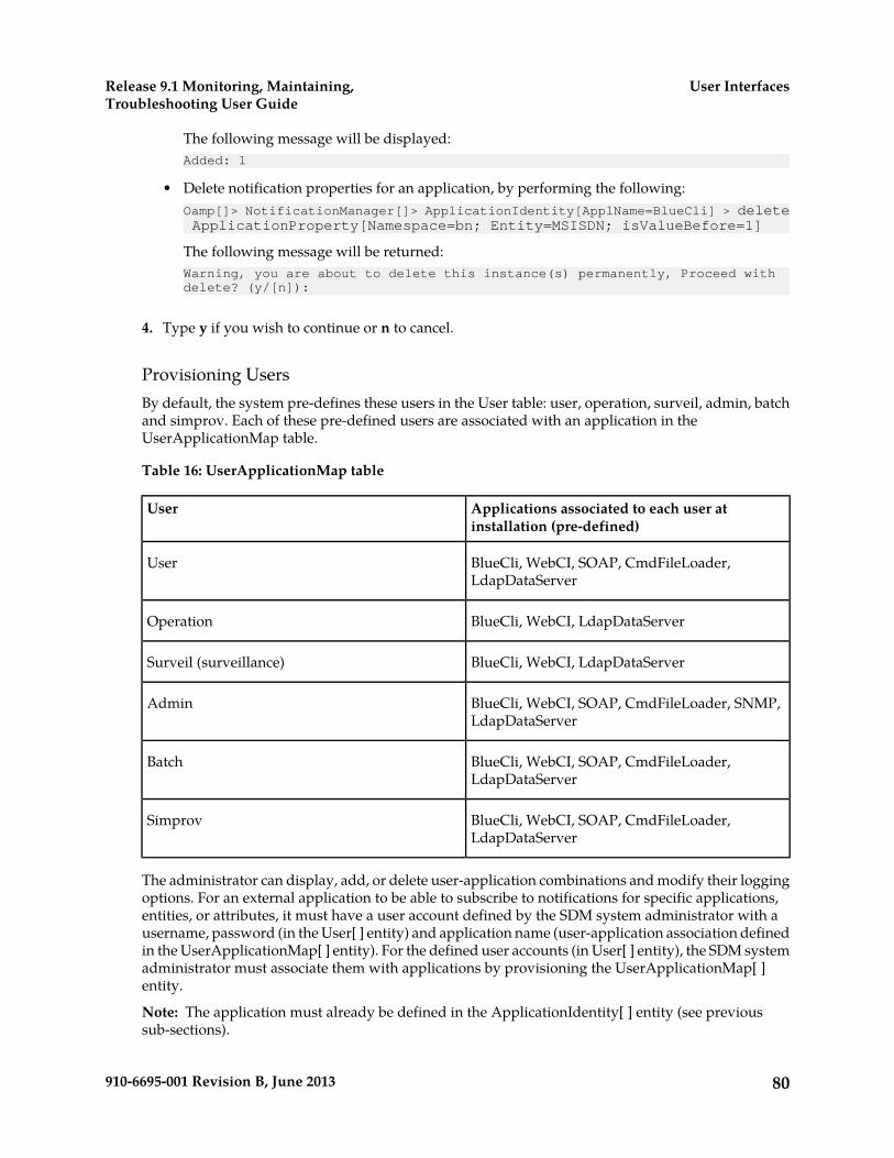
The following message will be displayed:Added: 1
• Delete notification properties for an application, by performing the following:Oamp[]> NotificationManager[]> ApplicationIdentity[ApplName=BlueCli] > delete ApplicationProperty[Namespace=bn; Entity=MSISDN; isValueBefore=1]
The following message will be returned:Warning, you are about to delete this instance(s) permanently, Proceed with delete? (y/[n]):
4. Type y if you wish to continue or n to cancel.
Provisioning UsersBy default, the system pre-defines these users in the User table: user, operation, surveil, admin, batchand simprov. Each of these pre-defined users are associated with an application in theUserApplicationMap table.
Table 16: UserApplicationMap table
Applications associated to each user atinstallation (pre-defined)
User
BlueCli, WebCI, SOAP, CmdFileLoader,LdapDataServer
User
BlueCli, WebCI, LdapDataServerOperation
BlueCli, WebCI, LdapDataServerSurveil (surveillance)
BlueCli, WebCI, SOAP, CmdFileLoader, SNMP,LdapDataServer
Admin
BlueCli, WebCI, SOAP, CmdFileLoader,LdapDataServer
Batch
BlueCli, WebCI, SOAP, CmdFileLoader,LdapDataServer
Simprov
The administrator can display, add, or delete user-application combinations and modify their loggingoptions. For an external application to be able to subscribe to notifications for specific applications,entities, or attributes, it must have a user account defined by the SDM system administrator with ausername, password (in the User[ ] entity) and application name (user-application association definedin the UserApplicationMap[ ] entity). For the defined user accounts (in User[ ] entity), the SDM systemadministrator must associate them with applications by provisioning the UserApplicationMap[ ]entity.
Note: The application must already be defined in the ApplicationIdentity[ ] entity (see previoussub-sections).
80910-6695-001 Revision B, June 2013
User InterfacesRelease 9.1 Monitoring, Maintaining,Troubleshooting User Guide
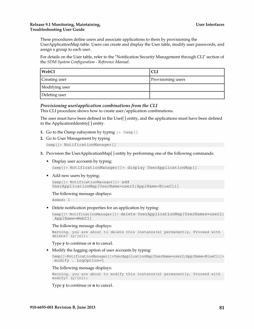
These procedures define users and associate applications to them by provisioning theUserApplicationMap table. Users can create and display the User table, modify user passwords, andassign a group to each user.
For details on the User table, refer to the "Notification Security Management through CLI" section ofthe SDM System Configuration - Reference Manual.
CLIWebCI
Provisioning usersCreating user
Modifying user
Deleting user
Provisioning user/application combinations from the CLIThis CLI procedure shows how to create user/application combinations.
The user must have been defined in the User[ ] entity, and the applications must have been definedin the ApplicationIdentity[ ] entity.
1. Go to the Oamp subsystem by typing :> Oamp[]2. Go to User Management by typing
Oamp[]> NotificationManager[]
3. Provision the UserApplicationMap[ ] entity by performing one of the following commands:
• Display user accounts by typing:Oamp[]> NotificationManager[]> display UserApplicationMap[]
• Add new users by typing:Oamp[]> NotificationManager[]> add UserApplicationMap[UserName=user2;ApplName=BlueCli]
The following message displays:Added: 1
• Delete notification properties for an application by typing:Oamp[]> NotificationManager[]> delete UserApplicationMap[UserNames=user2; ApplName=WebCI]
The following message displays:Warning, you are about to delete this instance(s) permanently, Proceed with delete? (y/[n]):
Type y to continue or n to cancel.• Modify the logging option of user accounts by typing:
Oamp[]>NotificationManager[]>UserApplicationMap[UserName=user2;ApplName=BlueCli]>modify . LogOption=1
The following message displays:Warning, you are about to modify this instance(s) permanently, Proceed with modify? (y/[n]):
Type y to continue or n to cancel.
81910-6695-001 Revision B, June 2013
User InterfacesRelease 9.1 Monitoring, Maintaining,Troubleshooting User Guide
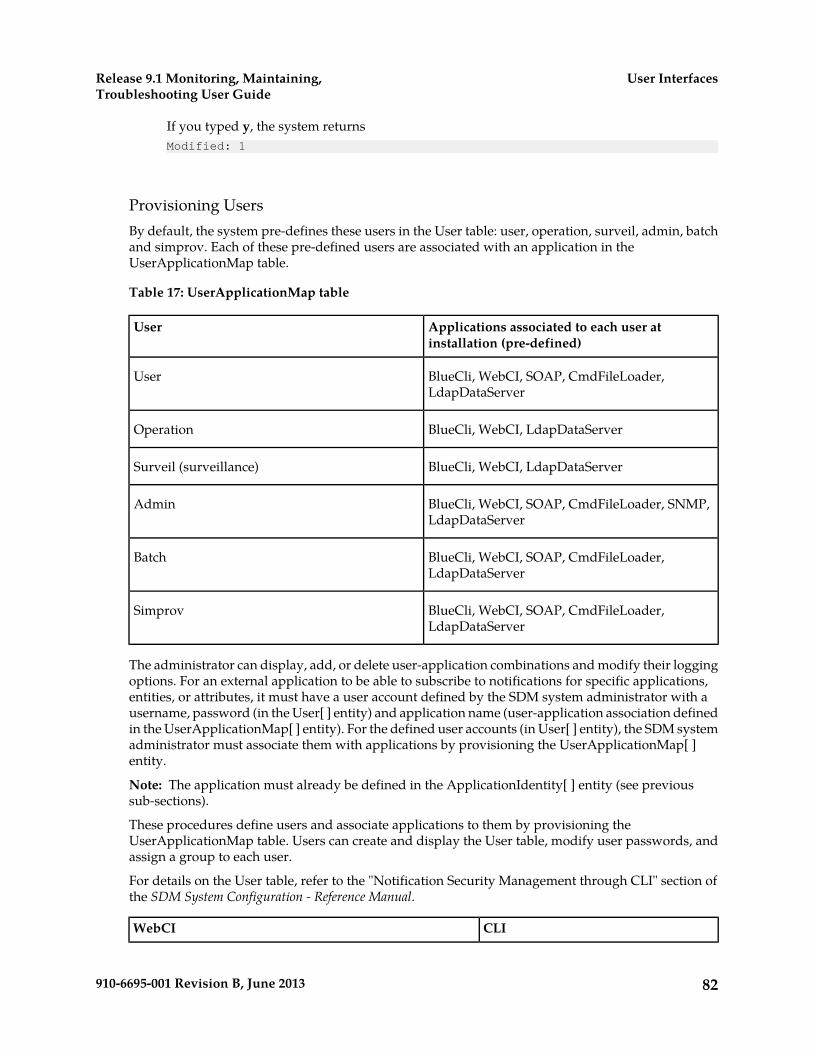
If you typed y, the system returnsModified: 1
Provisioning UsersBy default, the system pre-defines these users in the User table: user, operation, surveil, admin, batchand simprov. Each of these pre-defined users are associated with an application in theUserApplicationMap table.
Table 17: UserApplicationMap table
Applications associated to each user atinstallation (pre-defined)
User
BlueCli, WebCI, SOAP, CmdFileLoader,LdapDataServer
User
BlueCli, WebCI, LdapDataServerOperation
BlueCli, WebCI, LdapDataServerSurveil (surveillance)
BlueCli, WebCI, SOAP, CmdFileLoader, SNMP,LdapDataServer
Admin
BlueCli, WebCI, SOAP, CmdFileLoader,LdapDataServer
Batch
BlueCli, WebCI, SOAP, CmdFileLoader,LdapDataServer
Simprov
The administrator can display, add, or delete user-application combinations and modify their loggingoptions. For an external application to be able to subscribe to notifications for specific applications,entities, or attributes, it must have a user account defined by the SDM system administrator with ausername, password (in the User[ ] entity) and application name (user-application association definedin the UserApplicationMap[ ] entity). For the defined user accounts (in User[ ] entity), the SDM systemadministrator must associate them with applications by provisioning the UserApplicationMap[ ]entity.
Note: The application must already be defined in the ApplicationIdentity[ ] entity (see previoussub-sections).
These procedures define users and associate applications to them by provisioning theUserApplicationMap table. Users can create and display the User table, modify user passwords, andassign a group to each user.
For details on the User table, refer to the "Notification Security Management through CLI" section ofthe SDM System Configuration - Reference Manual.
CLIWebCI
82910-6695-001 Revision B, June 2013
User InterfacesRelease 9.1 Monitoring, Maintaining,Troubleshooting User Guide

Provisioning usersCreating user
Modifying user
Deleting user
Provisioning user/application combinations from the CLIThis CLI procedure shows how to create user/application combinations.
The user must have been defined in the User[ ] entity, and the applications must have been definedin the ApplicationIdentity[ ] entity.
1. Go to the Oamp subsystem by typing :> Oamp[]2. Go to User Management by typing
Oamp[]> NotificationManager[]
3. Provision the UserApplicationMap[ ] entity by performing one of the following commands:
• Display user accounts by typing:Oamp[]> NotificationManager[]> display UserApplicationMap[]
• Add new users by typing:Oamp[]> NotificationManager[]> add UserApplicationMap[UserName=user2;ApplName=BlueCli]
The following message displays:Added: 1
• Delete notification properties for an application by typing:Oamp[]> NotificationManager[]> delete UserApplicationMap[UserNames=user2; ApplName=WebCI]
The following message displays:Warning, you are about to delete this instance(s) permanently, Proceed with delete? (y/[n]):
Type y to continue or n to cancel.• Modify the logging option of user accounts by typing:
Oamp[]>NotificationManager[]>UserApplicationMap[UserName=user2;ApplName=BlueCli]>modify . LogOption=1
The following message displays:Warning, you are about to modify this instance(s) permanently, Proceed with modify? (y/[n]):
Type y to continue or n to cancel.
If you typed y, the system returnsModified: 1
83910-6695-001 Revision B, June 2013
User InterfacesRelease 9.1 Monitoring, Maintaining,Troubleshooting User Guide
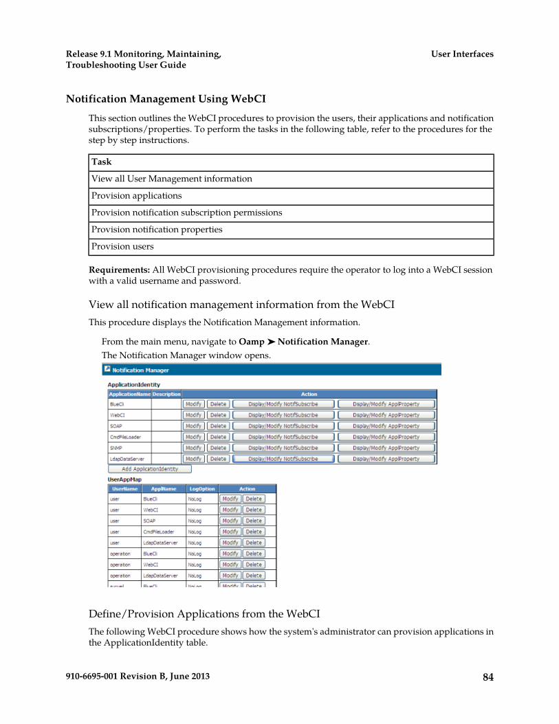
Notification Management Using WebCI
This section outlines the WebCI procedures to provision the users, their applications and notificationsubscriptions/properties. To perform the tasks in the following table, refer to the procedures for thestep by step instructions.
Task
View all User Management information
Provision applications
Provision notification subscription permissions
Provision notification properties
Provision users
Requirements: All WebCI provisioning procedures require the operator to log into a WebCI sessionwith a valid username and password.
View all notification management information from the WebCIThis procedure displays the Notification Management information.
From the main menu, navigate to Oamp ➤ Notification Manager.The Notification Manager window opens.
Define/Provision Applications from the WebCIThe following WebCI procedure shows how the system's administrator can provision applications inthe ApplicationIdentity table.
84910-6695-001 Revision B, June 2013
User InterfacesRelease 9.1 Monitoring, Maintaining,Troubleshooting User Guide

1. From the main menu, navigate to Oamp ➤ NotificationManager. This will display the NotificationManager window.
2. Click the Add ApplicationIdentity button below the ApplicationIdentity table.3. When the ApplicationIdentity Provisioning window appears (see figure below), enter the information
(ApplName) to be added.
Figure 13: ApplicationIdentity Provisioning Window to Create Applications
4. Click Commit when all the information has been entered.5. When the confirmation message “Entity entry was successfully committed” appears,
click OK.
--- end ---
Provisioning notification subscription permissions from the WebCINotification subscription permissions define per application the entities and attributes to which theuser (external application) can subscribe notifications. The administrator defines these permissions inthe NotificationSubscribe[ ] entity. This procedure describes how to provision the NotifSubscribe[ ]entity using the add or delete operation.
1. From the main menu, navigate to Oamp ➤ NotificationManager.The Notification Manager window displays.
2. Click the Display/Modify NotifSubscribe button of an application in the ApplicationIdentity table.The NotifSubscribe window with the NotifSubscribe entity opens.
3. Perform one of the following operations:
• Click Add NotifSubscribe to add notification subscription permissions (Namespace, Entity,Attribute) to the existing application.
• Click Delete to delete an entry one at a time.
4. Click Commit in the pop-up window when all the information has been entered.The system returns a confirmation message similar to Entity entry was successfullycommitted.
5. Click OK.
85910-6695-001 Revision B, June 2013
User InterfacesRelease 9.1 Monitoring, Maintaining,Troubleshooting User Guide
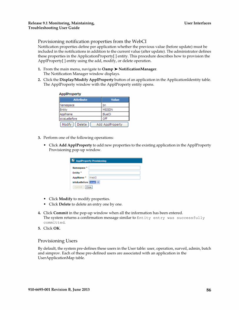
Provisioning notification properties from the WebCINotification properties define per application whether the previous value (before update) must beincluded in the notifications in addition to the current value (after update). The administrator definesthese properties in the ApplicationProperty[ ] entity. This procedure describes how to provision theApplProperty[ ] entity using the add, modify, or delete operation.
1. From the main menu, navigate to Oamp ➤ NotificationManager.The Notification Manager window displays.
2. Click the Display/Modify ApplProperty button of an application in the ApplicationIdentity table.The ApplProperty window with the ApplProperty entity opens.
3. Perform one of the following operations:
• Click Add ApplProperty to add new properties to the existing application in the ApplPropertyProvisioning pop-up window.
• Click Modify to modify properties.• Click Delete to delete an entry one by one.
4. Click Commit in the pop-up window when all the information has been entered.The system returns a confirmation message similar to Entity entry was successfullycommitted.
5. Click OK.
Provisioning UsersBy default, the system pre-defines these users in the User table: user, operation, surveil, admin, batchand simprov. Each of these pre-defined users are associated with an application in theUserApplicationMap table.
86910-6695-001 Revision B, June 2013
User InterfacesRelease 9.1 Monitoring, Maintaining,Troubleshooting User Guide
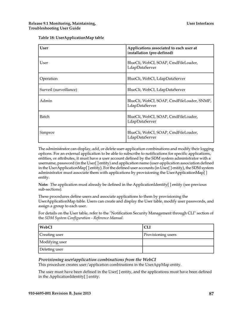
Table 18: UserApplicationMap table
Applications associated to each user atinstallation (pre-defined)
User
BlueCli, WebCI, SOAP, CmdFileLoader,LdapDataServer
User
BlueCli, WebCI, LdapDataServerOperation
BlueCli, WebCI, LdapDataServerSurveil (surveillance)
BlueCli, WebCI, SOAP, CmdFileLoader, SNMP,LdapDataServer
Admin
BlueCli, WebCI, SOAP, CmdFileLoader,LdapDataServer
Batch
BlueCli, WebCI, SOAP, CmdFileLoader,LdapDataServer
Simprov
The administrator can display, add, or delete user-application combinations and modify their loggingoptions. For an external application to be able to subscribe to notifications for specific applications,entities, or attributes, it must have a user account defined by the SDM system administrator with ausername, password (in the User[ ] entity) and application name (user-application association definedin the UserApplicationMap[ ] entity). For the defined user accounts (in User[ ] entity), the SDM systemadministrator must associate them with applications by provisioning the UserApplicationMap[ ]entity.
Note: The application must already be defined in the ApplicationIdentity[ ] entity (see previoussub-sections).
These procedures define users and associate applications to them by provisioning theUserApplicationMap table. Users can create and display the User table, modify user passwords, andassign a group to each user.
For details on the User table, refer to the "Notification Security Management through CLI" section ofthe SDM System Configuration - Reference Manual.
CLIWebCI
Provisioning usersCreating user
Modifying user
Deleting user
Provisioning user/application combinations from the WebCIThis procedure creates user/application combinations in the UserAppMap entity.
The user must have been defined in the User[ ] entity, and the applications must have been definedin the ApplicationIdentity[ ] entity.
87910-6695-001 Revision B, June 2013
User InterfacesRelease 9.1 Monitoring, Maintaining,Troubleshooting User Guide
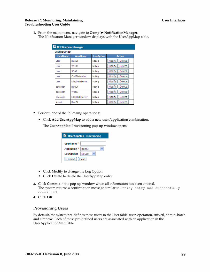
1. From the main menu, navigate to Oamp ➤ NotificationManager.The Notification Manager window displays with the UserAppMap table.
2. Perform one of the following operations:
• Click Add UserAppMap to add a new user/application combination.
The UserAppMap Provisioning pop-up window opens.
• Click Modify to change the Log Option.• Click Delete to delete the UserAppMap entry.
3. Click Commit in the pop-up window when all information has been entered.The system returns a confirmation message similar to Entity entry was successfullycommitted.
4. Click OK.
Provisioning UsersBy default, the system pre-defines these users in the User table: user, operation, surveil, admin, batchand simprov. Each of these pre-defined users are associated with an application in theUserApplicationMap table.
88910-6695-001 Revision B, June 2013
User InterfacesRelease 9.1 Monitoring, Maintaining,Troubleshooting User Guide

Table 19: UserApplicationMap table
Applications associated to each user atinstallation (pre-defined)
User
BlueCli, WebCI, SOAP, CmdFileLoader,LdapDataServer
User
BlueCli, WebCI, LdapDataServerOperation
BlueCli, WebCI, LdapDataServerSurveil (surveillance)
BlueCli, WebCI, SOAP, CmdFileLoader, SNMP,LdapDataServer
Admin
BlueCli, WebCI, SOAP, CmdFileLoader,LdapDataServer
Batch
BlueCli, WebCI, SOAP, CmdFileLoader,LdapDataServer
Simprov
The administrator can display, add, or delete user-application combinations and modify their loggingoptions. For an external application to be able to subscribe to notifications for specific applications,entities, or attributes, it must have a user account defined by the SDM system administrator with ausername, password (in the User[ ] entity) and application name (user-application association definedin the UserApplicationMap[ ] entity). For the defined user accounts (in User[ ] entity), the SDM systemadministrator must associate them with applications by provisioning the UserApplicationMap[ ]entity.
Note: The application must already be defined in the ApplicationIdentity[ ] entity (see previoussub-sections).
These procedures define users and associate applications to them by provisioning theUserApplicationMap table. Users can create and display the User table, modify user passwords, andassign a group to each user.
For details on the User table, refer to the "Notification Security Management through CLI" section ofthe SDM System Configuration - Reference Manual.
CLIWebCI
Provisioning usersCreating user
Modifying user
Deleting user
Provisioning user/application combinations from the WebCIThis procedure creates user/application combinations in the UserAppMap entity.
The user must have been defined in the User[ ] entity, and the applications must have been definedin the ApplicationIdentity[ ] entity.
89910-6695-001 Revision B, June 2013
User InterfacesRelease 9.1 Monitoring, Maintaining,Troubleshooting User Guide
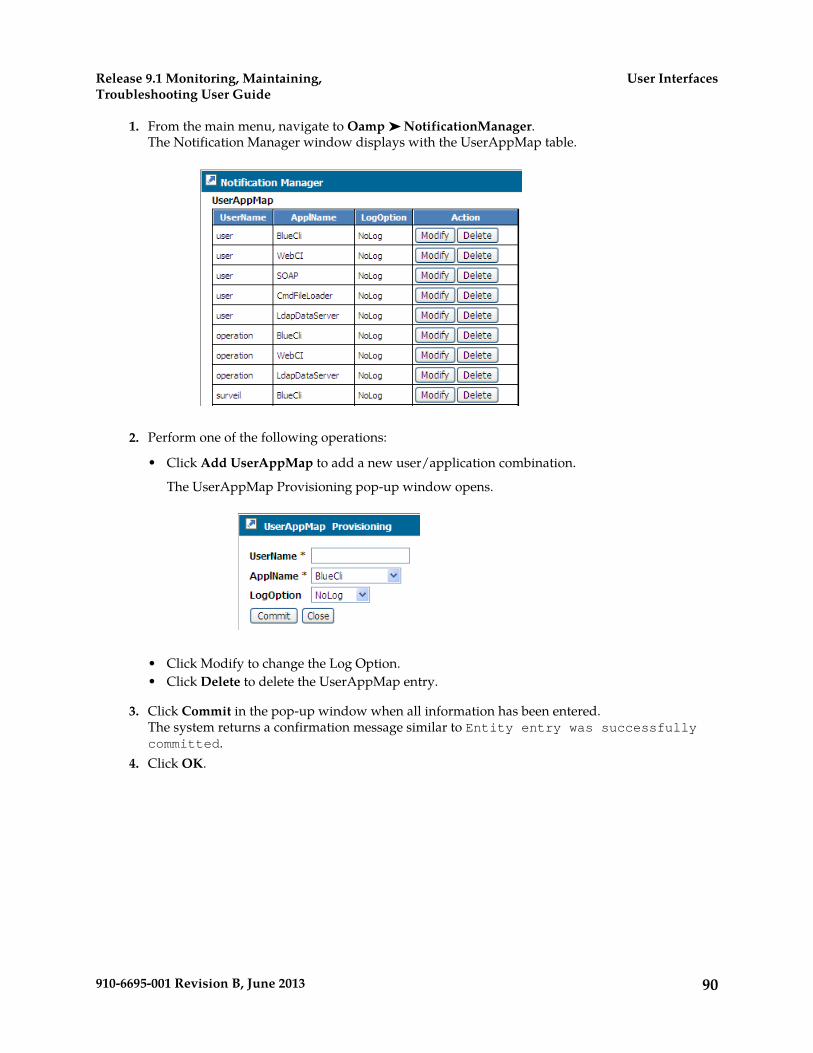
1. From the main menu, navigate to Oamp ➤ NotificationManager.The Notification Manager window displays with the UserAppMap table.
2. Perform one of the following operations:
• Click Add UserAppMap to add a new user/application combination.
The UserAppMap Provisioning pop-up window opens.
• Click Modify to change the Log Option.• Click Delete to delete the UserAppMap entry.
3. Click Commit in the pop-up window when all information has been entered.The system returns a confirmation message similar to Entity entry was successfullycommitted.
4. Click OK.
90910-6695-001 Revision B, June 2013
User InterfacesRelease 9.1 Monitoring, Maintaining,Troubleshooting User Guide

Chapter
4Viewing and editing subscriber profiles using WebCI
This chapter contains information used to manageprofiles within the Subscriber Data Managementsystem
Topics:
• Viewing/editing SIM cards, MSISDNs, IMSIs,and HLR subscriber profiles.....92
• Viewing/Editing HLR Service Profile.....100• Viewing/Editing MNP-SRF Subscribers.....111• Viewing/Editing SIP Subscriber Profiles (Address
Of Records).....114• Viewing/Editing HSS Subscriber Profiles.....115• Viewing/editing SLF Redirect host mapping....121• Viewing/Editing AAA Subscriber Profiles.....122• Viewing/Editing DNS ENUM Users.....126• Provisioning LTE-HSS Subscriber Profiles.....127• Viewing/editing Subscriber (Policy) profiles....128• Viewing/editing SPR subscriber quota
(WebCI).....130• Viewing/editing SPR Pool information
(WebCI).....132
91910-6695-001 Revision B, June 2013
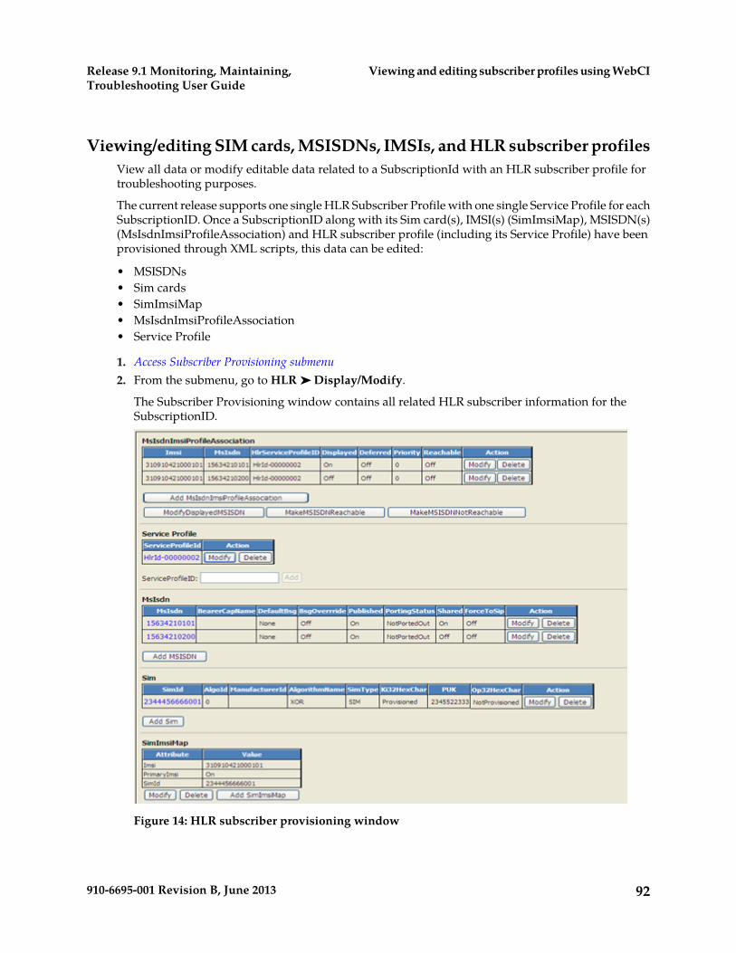
Viewing/editing SIM cards, MSISDNs, IMSIs, and HLR subscriber profilesView all data or modify editable data related to a SubscriptionId with an HLR subscriber profile fortroubleshooting purposes.
The current release supports one single HLR Subscriber Profile with one single Service Profile for eachSubscriptionID. Once a SubscriptionID along with its Sim card(s), IMSI(s) (SimImsiMap), MSISDN(s)(MsIsdnImsiProfileAssociation) and HLR subscriber profile (including its Service Profile) have beenprovisioned through XML scripts, this data can be edited:
• MSISDNs• Sim cards• SimImsiMap• MsIsdnImsiProfileAssociation• Service Profile
1. Access Subscriber Provisioning submenu2. From the submenu, go to HLR ➤ Display/Modify.
The Subscriber Provisioning window contains all related HLR subscriber information for theSubscriptionID.
Figure 14: HLR subscriber provisioning window
92910-6695-001 Revision B, June 2013
Viewing and editing subscriber profiles using WebCIRelease 9.1 Monitoring, Maintaining,Troubleshooting User Guide
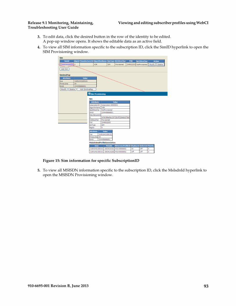
3. To edit data, click the desired button in the row of the identity to be edited.A pop-up window opens. It shows the editable data as an active field.
4. To view all SIM information specific to the subscription ID, click the SimID hyperlink to open theSIM Provisioning window.
Figure 15: Sim information for specific SubscriptionID
5. To view all MSISDN information specific to the subscription ID, click the MsIsdnId hyperlink toopen the MSISDN Provisioning window.
93910-6695-001 Revision B, June 2013
Viewing and editing subscriber profiles using WebCIRelease 9.1 Monitoring, Maintaining,Troubleshooting User Guide
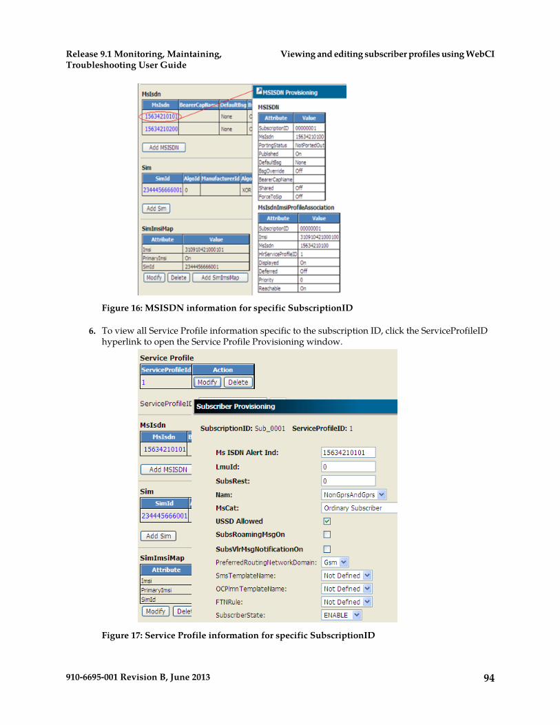
Figure 16: MSISDN information for specific SubscriptionID
6. To view all Service Profile information specific to the subscription ID, click the ServiceProfileIDhyperlink to open the Service Profile Provisioning window.
Figure 17: Service Profile information for specific SubscriptionID
94910-6695-001 Revision B, June 2013
Viewing and editing subscriber profiles using WebCIRelease 9.1 Monitoring, Maintaining,Troubleshooting User Guide
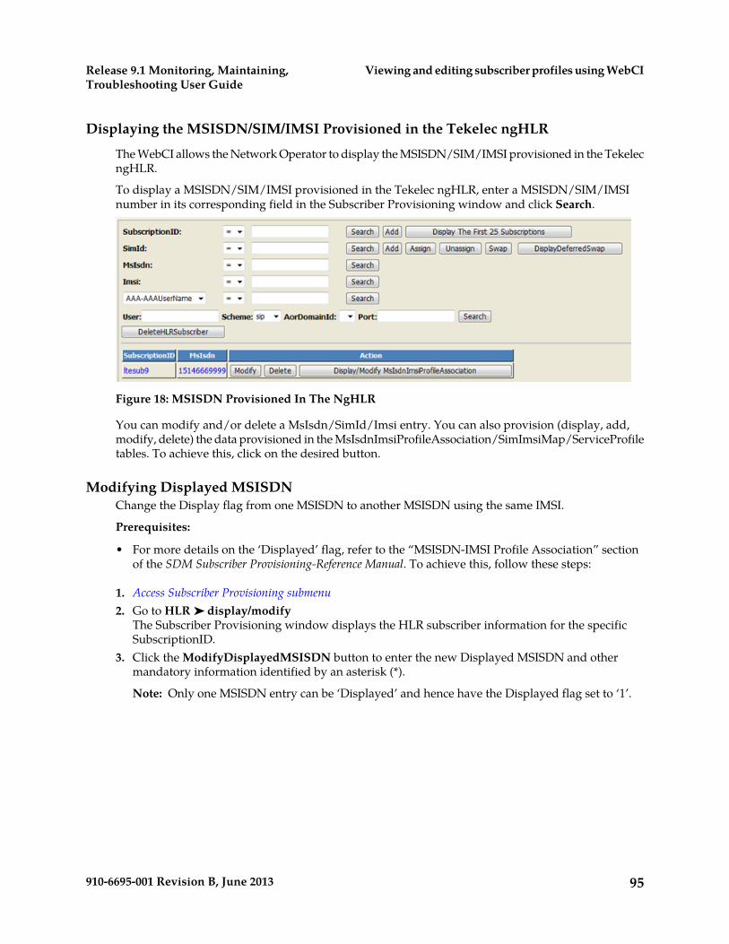
Displaying the MSISDN/SIM/IMSI Provisioned in the Tekelec ngHLR
The WebCI allows the Network Operator to display the MSISDN/SIM/IMSI provisioned in the TekelecngHLR.
To display a MSISDN/SIM/IMSI provisioned in the Tekelec ngHLR, enter a MSISDN/SIM/IMSInumber in its corresponding field in the Subscriber Provisioning window and click Search.
Figure 18: MSISDN Provisioned In The NgHLR
You can modify and/or delete a MsIsdn/SimId/Imsi entry. You can also provision (display, add,modify, delete) the data provisioned in the MsIsdnImsiProfileAssociation/SimImsiMap/ServiceProfiletables. To achieve this, click on the desired button.
Modifying Displayed MSISDNChange the Display flag from one MSISDN to another MSISDN using the same IMSI.
Prerequisites:
• For more details on the ‘Displayed’ flag, refer to the “MSISDN-IMSI Profile Association” sectionof the SDM Subscriber Provisioning-Reference Manual. To achieve this, follow these steps:
1. Access Subscriber Provisioning submenu2. Go to HLR ➤ display/modify
The Subscriber Provisioning window displays the HLR subscriber information for the specificSubscriptionID.
3. Click the ModifyDisplayedMSISDN button to enter the new Displayed MSISDN and othermandatory information identified by an asterisk (*).
Note: Only one MSISDN entry can be ‘Displayed’ and hence have the Displayed flag set to ‘1’.
95910-6695-001 Revision B, June 2013
Viewing and editing subscriber profiles using WebCIRelease 9.1 Monitoring, Maintaining,Troubleshooting User Guide

Figure 19: Modifying Display flag of an MSISDN
4. Click Commit to execute the operation.
Make a MSISDN-IMSI Profile Association Reachable/Not ReachableThis procedure configures the MSISDN/IMSI Profile Association to enable or disable an MSISDNfrom receiving calls.
Prerequisites: Access Subscriber Provisioning submenu
All mobiles/SIMs that share an MSISDN are able to make outgoing calls but only one mobile/SIMthat uses a shared MSISDN shall receive incoming calls. Therefore, each MSISDN-IMSI profileassociation must be defined as “reachable” or “not reachable” so that the Tekelec ngHLR can choosethe correct MSISDN-IMSI profile association to reach the SIM. These rules apply:
• All MSISDN-IMSI profile associations defined for one single SIM with the same MSISDN must allhave the ‘Reachable’ flag set to the same value.
• Only one SIM can be reachable among the ones that have MSISDN-IMSI associations that use thesame shared MSISDN.
• A SIM is reachable if the MSISDN ‘Published’ flag and the MSISDN-IMSI association’s ‘Reachable’flag are both set to ‘1’ (default). For an MSISDN, if one of its MSISDN-IMSI associations is notset to 1, all MSISDN-based messages will fail for this MSISDN.
• To change the reachable flag of many IMSI-MSISDN associations of the same SIM, use theMakeMsisdnNotReachable() or MakeMsisdnReachable() operations.
• The MakeMsisdnNotReachable() operation changes the ‘Reachable’ flag to ‘0’ (not reachable)for all MSISDN-IMSI associations of the MsIsdn provided.
• The MakeMsisdnReachable() operation changes the ‘Reachable’ flag to ‘1’ (reachable) for all theMSISDN-IMSI associations of the MsIsdn provided, and of the IMSIs that are part of the SimIdprovided or found by the Tekelec ngHLR (if IMSI is provided instead of SimId).
• For more details on the ‘Reachable’ flag, refer to the “MSISDN-IMSI Profile Association” sectionof the SDM Subscriber Provisioning-Reference Manual.
• When an MSISDN is defined as ‘Shared’, other mobile/SIMs within the same subscription(SubscriptionID) or belonging to different subscriptions (different SubscriptionIDs) can use thatsame MSISDN.
96910-6695-001 Revision B, June 2013
Viewing and editing subscriber profiles using WebCIRelease 9.1 Monitoring, Maintaining,Troubleshooting User Guide
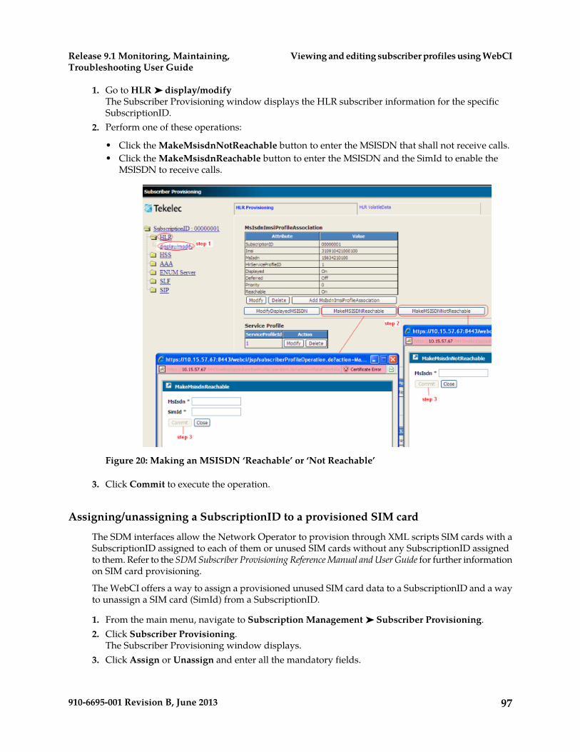
1. Go to HLR ➤ display/modifyThe Subscriber Provisioning window displays the HLR subscriber information for the specificSubscriptionID.
2. Perform one of these operations:
• Click the MakeMsisdnNotReachable button to enter the MSISDN that shall not receive calls.• Click the MakeMsisdnReachable button to enter the MSISDN and the SimId to enable the
MSISDN to receive calls.
Figure 20: Making an MSISDN ‘Reachable’ or ‘Not Reachable’
3. Click Commit to execute the operation.
Assigning/unassigning a SubscriptionID to a provisioned SIM card
The SDM interfaces allow the Network Operator to provision through XML scripts SIM cards with aSubscriptionID assigned to each of them or unused SIM cards without any SubscriptionID assignedto them. Refer to the SDM Subscriber Provisioning Reference Manual and User Guide for further informationon SIM card provisioning.
The WebCI offers a way to assign a provisioned unused SIM card data to a SubscriptionID and a wayto unassign a SIM card (SimId) from a SubscriptionID.
1. From the main menu, navigate to Subscription Management ➤ Subscriber Provisioning.2. Click Subscriber Provisioning.
The Subscriber Provisioning window displays.3. Click Assign or Unassign and enter all the mandatory fields.
97910-6695-001 Revision B, June 2013
Viewing and editing subscriber profiles using WebCIRelease 9.1 Monitoring, Maintaining,Troubleshooting User Guide

For details on each parameter and their value and meaning, refer to the AssignSIM() andUnassignSIM() operations described in the “HLR Operations” section of the SDM SubscriberProvisioning – Reference Manual.
4. Click Commit.
Figure 21: Assigning/unassigning a SIM card
Swapping SIM cards
The WebCI offers the ability for the Network Operator to easily swap SIM cards for a subscriber.
The Network Operator can change a provisioned SIM card already assigned to a SubscriptionID withan unused SIM card that has been already provisioned in the Tekelec ngHLR but that is unassignedto any SubscriptionID.
1. From the main menu, navigate to Subscription Management ➤ Subscriber Provisioning.2. Click Swap SIM and enter all the mandatory information identified by an asterisk (*).
For details on each parameter and their value and meaning, refer to the SwapSIM() operationdescribed in the “HLR Operations” section of the SDM Subscriber Provisioning – Reference Manual.
3. Click Commit to execute the operation.
98910-6695-001 Revision B, June 2013
Viewing and editing subscriber profiles using WebCIRelease 9.1 Monitoring, Maintaining,Troubleshooting User Guide
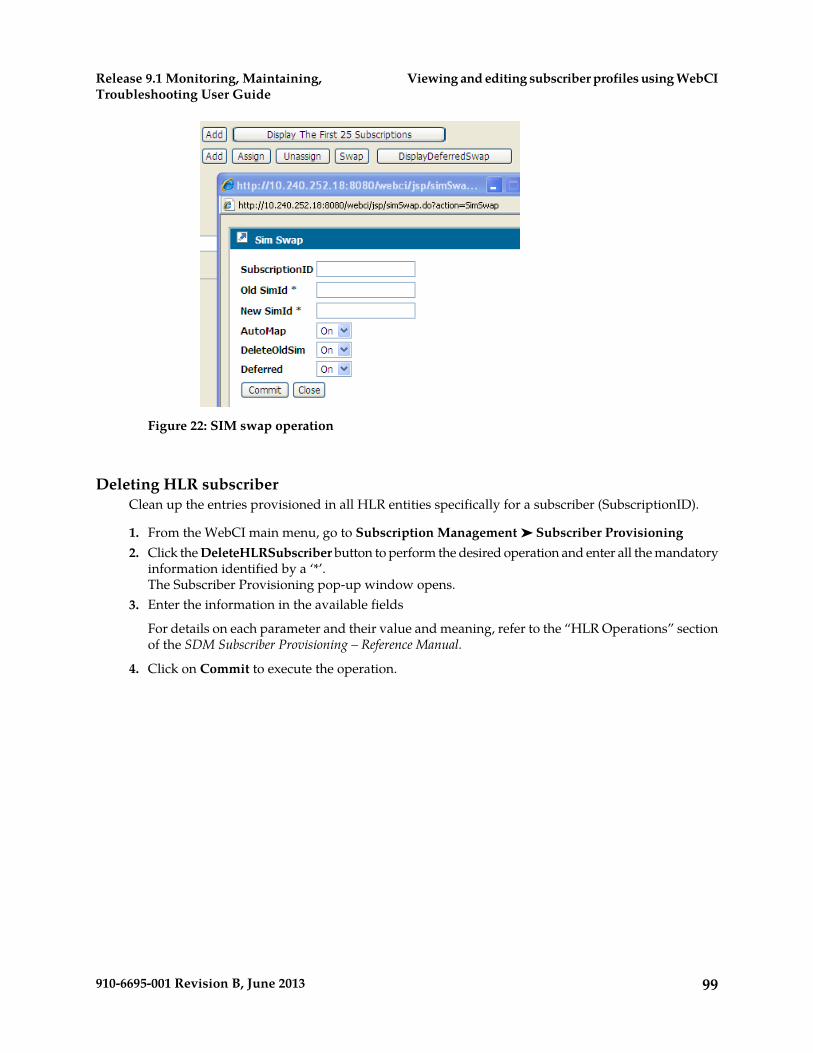
Figure 22: SIM swap operation
Deleting HLR subscriberClean up the entries provisioned in all HLR entities specifically for a subscriber (SubscriptionID).
1. From the WebCI main menu, go to Subscription Management ➤ Subscriber Provisioning2. Click the DeleteHLRSubscriber button to perform the desired operation and enter all the mandatory
information identified by a ‘*’.The Subscriber Provisioning pop-up window opens.
3. Enter the information in the available fields
For details on each parameter and their value and meaning, refer to the “HLR Operations” sectionof the SDM Subscriber Provisioning – Reference Manual.
4. Click on Commit to execute the operation.
99910-6695-001 Revision B, June 2013
Viewing and editing subscriber profiles using WebCIRelease 9.1 Monitoring, Maintaining,Troubleshooting User Guide

Figure 23: Delete HLR Subscriber
Viewing/Editing HLR Service Profile
The Service Provisioning screen provides access to provisioning windows to configure additionalbasic services and supplementary services.
The Service Provisioning screen provides access to provisioning windows that allow the networkoperator to provision HLR services profiles with the following:
• Templates/rules that must be followed for this subscriber concerning functionalities, such as:
• XML Notifications (SubsRoamingMsgOn and SubsVlrMsgNotificationOn)• MT-SMS Routing (SmsTemplateName)• Forward-To-Number (FTNRule)• Access Restriction Data• Operator Controlled Roaming Controls (OCPlmnTemplateName)• ATI Subscriber Information Level• Enable/Disable Subscriber state
• Additional basic services and supplementary services
Provisioning a subscriber HLR service profileUse this procedure to provision an HLR Service Profile for a subscriber.
The operator must have already provisioned the Viewing/editing SIM cards, MSISDNs, IMSIs, and HLRsubscriber profiles and must have created a ServiceProfileID.
Use this procedure to
• edit subscriber-specific settings, templates, and rules for ngHLR functionalities; for example,
• XML Notifications (SubsRoamingMsgOn and SubsVlrMsgNotificationOn)
100910-6695-001 Revision B, June 2013
Viewing and editing subscriber profiles using WebCIRelease 9.1 Monitoring, Maintaining,Troubleshooting User Guide

• MT-SMS Routing (SmsTemplateName)• Forward-To-Number (FTNRule)• Access Restriction Data• Operator Controlled Roaming Controls (OCPlmnTemplateName)• ATI Subscriber Information Level• Enable/Disable Subscriber state
• provision the services outlined in Table 20: Subscriber services provisioned with WebCI.
For details on these options, refer to the HLR entities in the SDM Subscriber Provisioning - ReferenceManual.
Table 20: Subscriber services provisioned with WebCI
DescriptionProvisionable itemsService
Call Forward Unconditional (CFU), Call Forwardingon Mobile Subscriber Busy (CFB), Call Forwarding
TypeCall Forward
on No Reply (CFNRY), and Call Forwarding onMobile Subscriber Not Reachable (CFNRC).
Speech, Fax, All Data Asynchronous, All DataSynchronous, Voice Group, Provision, Forward To
Basic Service Group
Number, Default Forward To Number, No ReplyCondition Timer.
Outgoing Calls (BAOC), Outgoing InternationalCalls (BOIC), Outgoing International Calls Except
Supplementary ServicesCall Barring
to the Home PLMN (BOICEXHC), Incoming Calls(BAIC), and Incoming Calls when Roaming outsidehome PLMN country (BICROAM).
Speech, Short Message Service, Fax, All DataAsynchronous, All Data Synchronous, Voice Group,Provision
Basic Service Group
Password change option, password, Number ofwrong attempts.
Subscription options
CUG Teleservice, CUG Bearer Services.Basic ServiceClosed User Group
Group Id, Index, Options, BsgList.Subscription
BsgId (Speech, Fax, All Data Asynchronous, AllData Synchronous, Voice Group), Inter CUGRestriction, Preferential Index.
Features
Calling Line Identification Presentation (CLIP),CLIP Override, Calling Line Identification
Supplementary ServicesNumber Id
Restriction (CLIR).Connected Line IdentificationPresentation (COLP), COLP Override, ConnectedLine Identification Restriction (COLR), CLIRpresentation mode
AOCC, AOCISupplementary ServicesCharge Service
101910-6695-001 Revision B, June 2013
Viewing and editing subscriber profiles using WebCIRelease 9.1 Monitoring, Maintaining,Troubleshooting User Guide

Call Wait, Call Hold, MultiParty, Call WaitActivation (BsgID).
Supplementary ServicesCall Completion
Provision states (OCsi, TCsi, VTCsi, SsCsi, DCsi,UCsi, MCsi, OSMSCsi, GPRSCsi), Csi Types, Camel
Subscriber InfoCamel
Phases and Trigger Detection Points for each CamelCSI Type.
LCSPrivacyExceptionList, SRILCSAllowedSubscriber InfoLCS
1. Access Subscriber Provisioning submenu.2. Go to HLR ➤ display/modify.
The HLR provisioning window displays.3. Locate the Service Profile table and click the Modify button of the Service Profile to be edited.
The Subscriber Provisioning window displays with its main page and the Edit Subscriber Profilemenu.
4. From the Subscriber Provision main page, provision subscriber-specific settings, templates, andrules for ngHLR functionalities.
5. From the Edit Subscriber Profile menu, click the hyperlink of the service to be modified.
Clicking a checkbox to enable a feature may provide additional parameters to provision. Changestake effect by clicking the Commit button.
Perform one or more of these steps:
• In the Call Forward Provisioning window, click a checkbox to enable or disable Call Forwardingfeatures.
102910-6695-001 Revision B, June 2013
Viewing and editing subscriber profiles using WebCIRelease 9.1 Monitoring, Maintaining,Troubleshooting User Guide
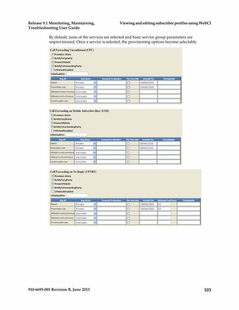
By default, none of the services are selected and basic service group parameters areunprovisioned. Once a service is selected, the provisioning options become selectable.
103910-6695-001 Revision B, June 2013
Viewing and editing subscriber profiles using WebCIRelease 9.1 Monitoring, Maintaining,Troubleshooting User Guide
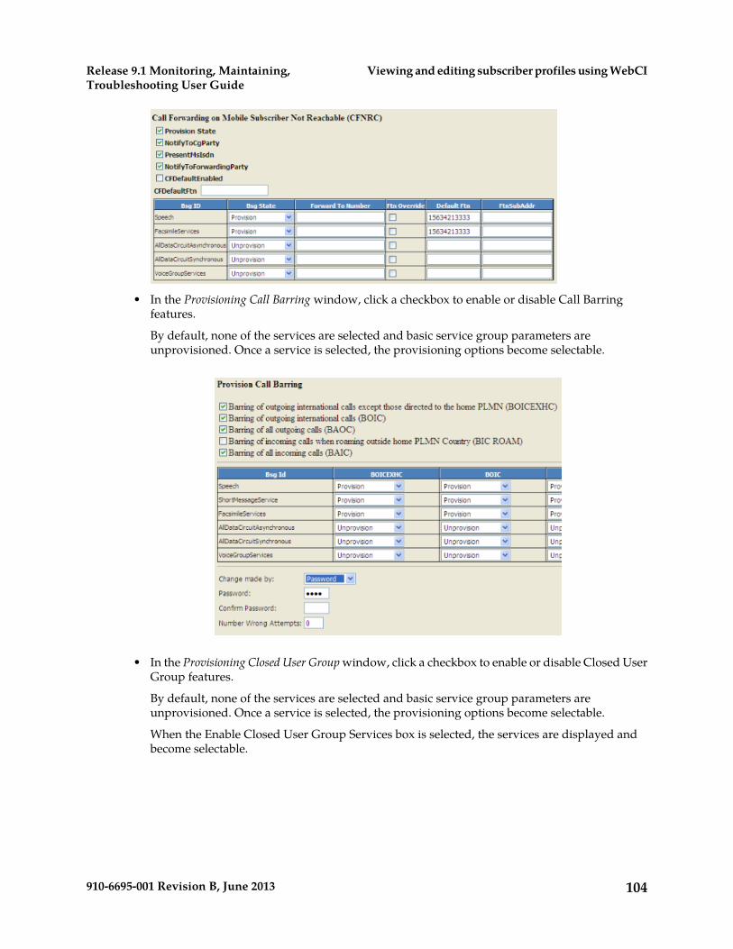
• In the Provisioning Call Barring window, click a checkbox to enable or disable Call Barringfeatures.
By default, none of the services are selected and basic service group parameters areunprovisioned. Once a service is selected, the provisioning options become selectable.
• In the Provisioning Closed User Group window, click a checkbox to enable or disable Closed UserGroup features.
By default, none of the services are selected and basic service group parameters areunprovisioned. Once a service is selected, the provisioning options become selectable.
When the Enable Closed User Group Services box is selected, the services are displayed andbecome selectable.
104910-6695-001 Revision B, June 2013
Viewing and editing subscriber profiles using WebCIRelease 9.1 Monitoring, Maintaining,Troubleshooting User Guide

• In the Provisioning Number Id Service window, click a checkbox to enable or disable Number Idfeatures.
• In the Provisioning Charge Service window, click a checkbox to enable or disable the ChargeService features.
• In the Provisioning Call Completion window, click a checkbox to enable or disable Call Completionfeatures.
105910-6695-001 Revision B, June 2013
Viewing and editing subscriber profiles using WebCIRelease 9.1 Monitoring, Maintaining,Troubleshooting User Guide
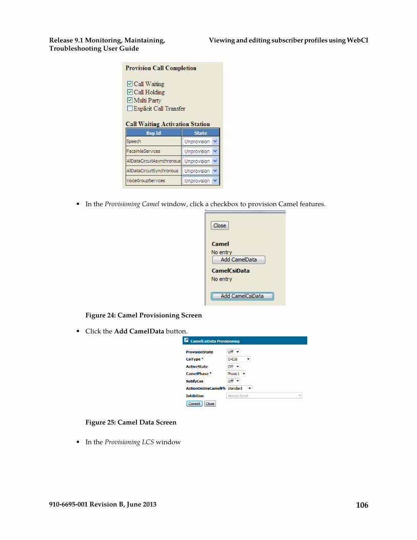
• In the Provisioning Camel window, click a checkbox to provision Camel features.
Figure 24: Camel Provisioning Screen
• Click the Add CamelData button.
Figure 25: Camel Data Screen
• In the Provisioning LCS window
106910-6695-001 Revision B, June 2013
Viewing and editing subscriber profiles using WebCIRelease 9.1 Monitoring, Maintaining,Troubleshooting User Guide
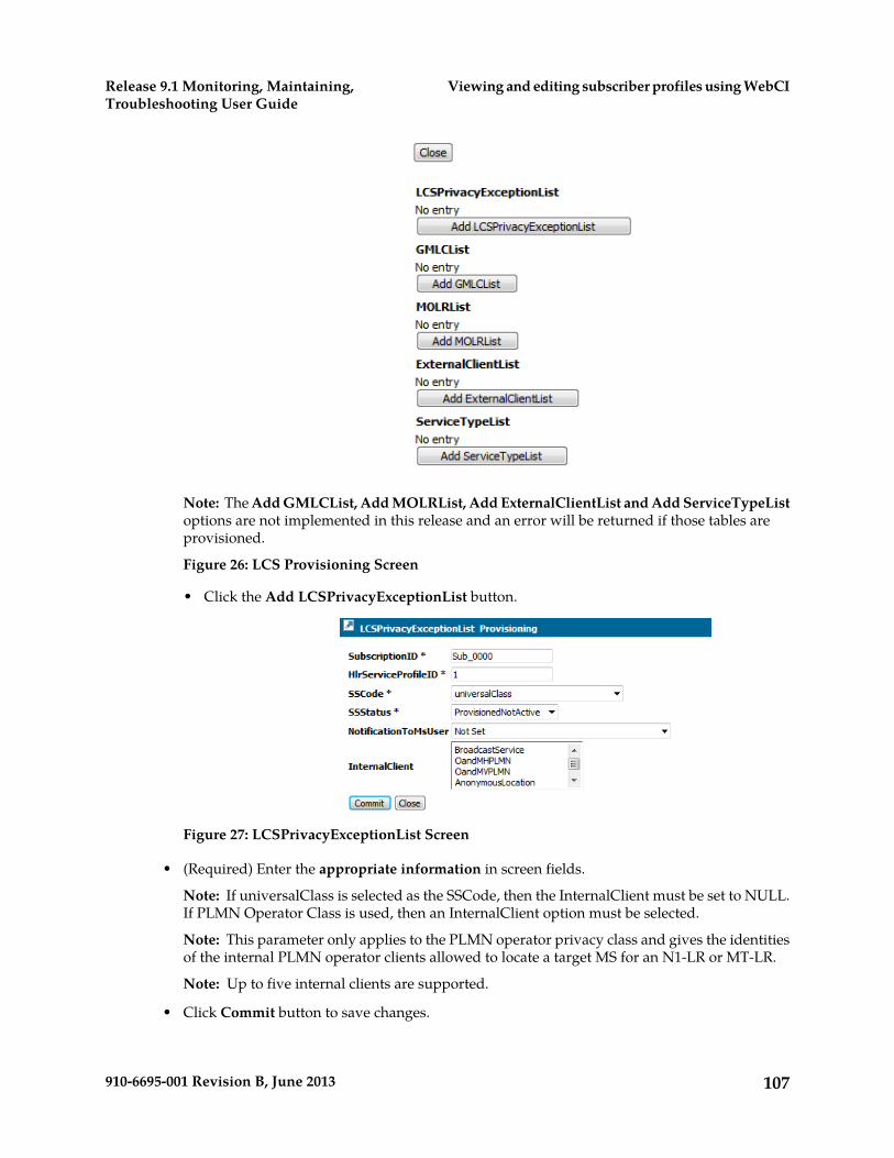
Note: The Add GMLCList, Add MOLRList, Add ExternalClientList and Add ServiceTypeListoptions are not implemented in this release and an error will be returned if those tables areprovisioned.
Figure 26: LCS Provisioning Screen
• Click the Add LCSPrivacyExceptionList button.
Figure 27: LCSPrivacyExceptionList Screen
• (Required) Enter the appropriate information in screen fields.
Note: If universalClass is selected as the SSCode, then the InternalClient must be set to NULL.If PLMN Operator Class is used, then an InternalClient option must be selected.
Note: This parameter only applies to the PLMN operator privacy class and gives the identitiesof the internal PLMN operator clients allowed to locate a target MS for an N1-LR or MT-LR.
Note: Up to five internal clients are supported.
• Click Commit button to save changes.
107910-6695-001 Revision B, June 2013
Viewing and editing subscriber profiles using WebCIRelease 9.1 Monitoring, Maintaining,Troubleshooting User Guide
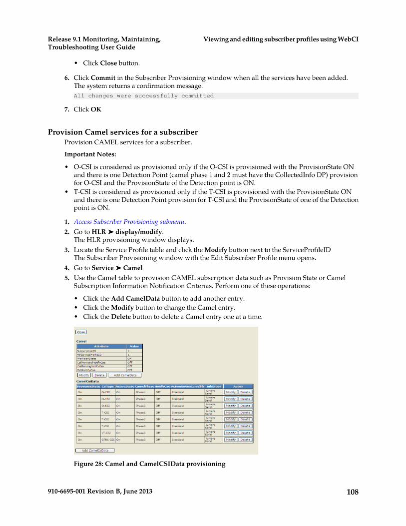
• Click Close button.
6. Click Commit in the Subscriber Provisioning window when all the services have been added.The system returns a confirmation message.All changes were successfully committed
7. Click OK
Provision Camel services for a subscriberProvision CAMEL services for a subscriber.
Important Notes:
• O-CSI is considered as provisioned only if the O-CSI is provisioned with the ProvisionState ONand there is one Detection Point (camel phase 1 and 2 must have the CollectedInfo DP) provisionfor O-CSI and the ProvisionState of the Detection point is ON.
• T-CSI is considered as provisioned only if the T-CSI is provisioned with the ProvisionState ONand there is one Detection Point provision for T-CSI and the ProvisionState of one of the Detectionpoint is ON.
1. Access Subscriber Provisioning submenu.2. Go to HLR ➤ display/modify.
The HLR provisioning window displays.3. Locate the Service Profile table and click the Modify button next to the ServiceProfileID
The Subscriber Provisioning window with the Edit Subscriber Profile menu opens.4. Go to Service ➤ Camel5. Use the Camel table to provision CAMEL subscription data such as Provision State or Camel
Subscription Information Notification Criterias. Perform one of these operations:
• Click the Add CamelData button to add another entry.• Click the Modify button to change the Camel entry.• Click the Delete button to delete a Camel entry one at a time.
Figure 28: Camel and CamelCSIData provisioning
108910-6695-001 Revision B, June 2013
Viewing and editing subscriber profiles using WebCIRelease 9.1 Monitoring, Maintaining,Troubleshooting User Guide
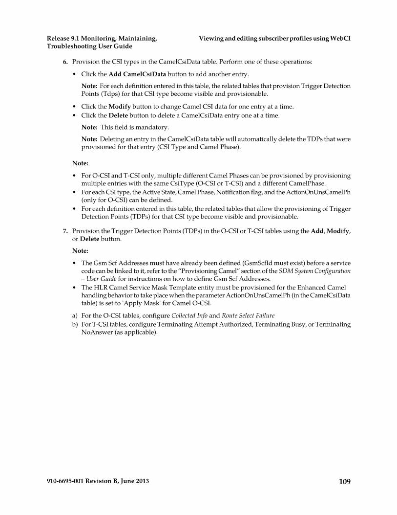
6. Provision the CSI types in the CamelCsiData table. Perform one of these operations:
• Click the Add CamelCsiData button to add another entry.
Note: For each definition entered in this table, the related tables that provision Trigger DetectionPoints (Tdps) for that CSI type become visible and provisionable.
• Click the Modify button to change Camel CSI data for one entry at a time.• Click the Delete button to delete a CamelCsiData entry one at a time.
Note: This field is mandatory.
Note: Deleting an entry in the CamelCsiData table will automatically delete the TDPs that wereprovisioned for that entry (CSI Type and Camel Phase).
Note:
• For O-CSI and T-CSI only, multiple different Camel Phases can be provisioned by provisioningmultiple entries with the same CsiType (O-CSI or T-CSI) and a different CamelPhase.
• For each CSI type, the Active State, Camel Phase, Notification flag, and the ActionOnUnsCamelPh(only for O-CSI) can be defined.
• For each definition entered in this table, the related tables that allow the provisioning of TriggerDetection Points (TDPs) for that CSI type become visible and provisionable.
7. Provision the Trigger Detection Points (TDPs) in the O-CSI or T-CSI tables using the Add, Modify,or Delete button.
Note:
• The Gsm Scf Addresses must have already been defined (GsmScfId must exist) before a servicecode can be linked to it, refer to the “Provisioning Camel” section of the SDM System Configuration– User Guide for instructions on how to define Gsm Scf Addresses.
• The HLR Camel Service Mask Template entity must be provisioned for the Enhanced Camelhandling behavior to take place when the parameter ActionOnUnsCamelPh (in the CamelCsiDatatable) is set to 'Apply Mask' for Camel O-CSI.
a) For the O-CSI tables, configure Collected Info and Route Select Failureb) For T-CSI tables, configure Terminating Attempt Authorized, Terminating Busy, or Terminating
NoAnswer (as applicable).
109910-6695-001 Revision B, June 2013
Viewing and editing subscriber profiles using WebCIRelease 9.1 Monitoring, Maintaining,Troubleshooting User Guide
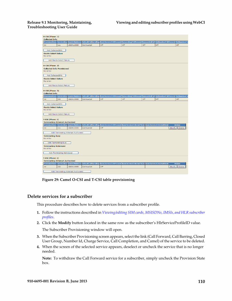
Figure 29: Camel O-CSI and T-CSI table provisioning
Delete services for a subscriber
This procedure describes how to delete services from a subscriber profile.
1. Follow the instructions described in Viewing/editing SIM cards, MSISDNs, IMSIs, and HLR subscriberprofiles.
2. Click the Modify button located in the same row as the subscriber’s HlrServiceProfileID value.
The Subscriber Provisioning window will open.
3. When the Subscriber Provisioning screen appears, select the link (Call Forward, Call Barring, ClosedUser Group, Number Id, Charge Service, Call Completion, and Camel) of the service to be deleted.
4. When the screen of the selected service appears, deselect or uncheck the service that is no longerneeded.
Note: To withdraw the Call Forward service for a subscriber, simply uncheck the Provision Statebox.
110910-6695-001 Revision B, June 2013
Viewing and editing subscriber profiles using WebCIRelease 9.1 Monitoring, Maintaining,Troubleshooting User Guide

5. Click Commit for the changes to take effect.6. When the confirmation window “
All changes were successfully committed
” appears, click OK.
Display the Services for a Subscriber
This procedure is used to display a subscriber’s profile and its provisioned services.
1. Follow the instructions described in Viewing/editing SIM cards, MSISDNs, IMSIs, and HLR subscriberprofiles
2. Click on the HlrServiceProfileID’s value.
The Subscriber Provisioning window will open.
3. Select a service tab (along the top of the window) to view details of other services (SubscriberProfile, Call Forward, Call Barring, CUG Service, Camel Service, and Other Service) assigned tothis subscriber.
Viewing/Editing MNP-SRF SubscribersThis procedure provisions MNP-SRF subscribers.
The MNP-SRF is one of the Tekelec ngHLR’s multiple functionalities. The Tekelec ngHLR supportsMobile Number Portability (MNP), which allows mobile subscribers to change their subscription fromone service provider to another without changing their mobile phone number (MSISDN). For a detaileddescription of this feature, refer to the “Support of MNP-SRF” section in the SDM Product Description.
The MNP-SRF functionality can be enabled/disabled on the Tekelec ngHLR by the Tekelec NetworkSupport Team and from the WebCI’s HLR Configuration window, its activation status can be viewedwith the MobileNumberPortabilityState parameter in the Hlr Config table. The Network Operator canactivate/deactivate the MNP feature by clicking on the Activate MNP/Deactivate MNP buttonsavailable from the HLR Configuration window’s MNP tab. Refer to the “Activating/Deactivating theMobile Network Portability (MNP)” section of the SDM System Configuration – User Guide for moredetails on the HLR Configuration window’s MNP tab. Note that this can be done even if the SSR isnot authorized yet. The activation/deactivation of the MNP can be done dynamically at any timeduring running time of the system and won’t require the restart of the HLR.
This section describes how to provision MNP-SRF subscribers. Note that deactivating the MNP willnot remove the data provisioned for the MNP subscribers.
The operator can provision the Number Portability database (NPDB) with MSISDNs, their portabilitystatus and the necessary portability information needed for the Tekelec ngHLR to be able to take oneof the following actions:
• Continue normal HLR processing• Relay query towards the recipient network• Redirect interrogating node towards the recipient network
111910-6695-001 Revision B, June 2013
Viewing and editing subscriber profiles using WebCIRelease 9.1 Monitoring, Maintaining,Troubleshooting User Guide

It is very important to note that the Tekelec NPDB is managed independently from the TekelecngHLR subscriber profiles and that the information contained in this database supersedes the onecontained in the "regular" subscriber profile, if any.
1. From the WebCI main menu, go to HLR ➤ Mobile Number Portability
The Mobile Number Portability window opens.
2. To define IMSIs that will be returned in the SRI_ack message when the Tekelec ngHLR will redirectthe interrogating node to the recipient’s network, perform these steps:a) Click the Display/Modify ImsiForRedirect button to display the ImsiForRedirect table.b) Then perform one of these operations:
• To add an IMSI for Redirect, click the Add MnpImsiForRedirect button.
The MnpImsiForRedirect Provisioning window opens.
Type the IMSI for Redirect.• To modify the IMSI for Redirect, click the Modify button.
All entries can be modified.• To delete the IMSI for Redirect, click the Delete button.
Note: If one or several MNP entries refer to the ImsiForRedirect to be deleted, the MNPentries must first be deleted, or the ImsiId value of these MNP entries must be changed toanother existent value provisioned in the ImsiForRedirect table.
Delete one entry at a time.
112910-6695-001 Revision B, June 2013
Viewing and editing subscriber profiles using WebCIRelease 9.1 Monitoring, Maintaining,Troubleshooting User Guide

3. To provision ported-out MSISDNs with the relay routing method, perform one of these operations:
• To add a new entry to the MNP table, click the Add Mnp button .
The MNP Provisioning window opens.
The Mobile Number Portability table defines MSISDNs and their portability status, routingnumber, IMSI for redirection or routing method on SRI queries.
Note: The IMSI for redirection must only be provisioned if the routing method is set to ‘Redirect’.Moreover, this operation allows you to either select an IMSI for redirection among the ones thatare already provisioned in the ImsiForRedirect table or either enter a new IMSI for redirectionvalue.
Select the routing method.• Search for the MNP table by typing a specific ImsiId or a range of MSISDN entries into the
Search field.
a) Then perform one of these operations:
• Click the Modify button to modify an entry in the Mobile Number Portability table.• Click the Delete button to delete one entry one at a time in the Mobile Number Portability
table.
Other Operations
In addition to provisioning the ImsiForRedirect and Mobile Number Portability tables with newentries, the following operations are also available:
• Delete. The following can be deleted:
One entry at a time in the Imsi For Redirect table.
Prerequisite: If one or several Mobile Number Portability entries refer to the ImsiForRedirect entryyou wish to delete, the Mobile Number Portability entries must first be deleted or at least the ImsiIdvalue of these Mobile Number Portability entries must be changed to another existent value provisionedin the Imsi For Redirect table.
One entry at a time in the Mnp table.
• Modify. Each entry in the Imsi For Redirect and Mobile Number Portability tables can be modified.
113910-6695-001 Revision B, June 2013
Viewing and editing subscriber profiles using WebCIRelease 9.1 Monitoring, Maintaining,Troubleshooting User Guide
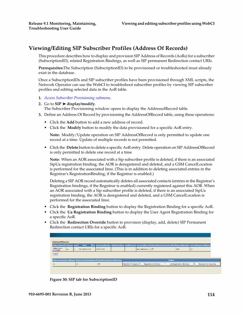
Viewing/Editing SIP Subscriber Profiles (Address Of Records)This procedure describes how to display and provision SIP Address of Records (AoRs) for a subscriber(SubscriptionID), related Registration Bindings, as well as SIP permanent Redirection contact URIs.
Prerequisites:The Subscription (SubscriptionID) to be provisioned or troubleshooted must alreadyexist in the database.
Once a SubscriptionIDs and SIP subscriber profiles have been provisioned through XML scripts, theNetwork Operator can use the WebCI to troubleshoot subscriber profiles by viewing SIP subscriberprofiles and editing selected data in the AoR table.
1. Access Subscriber Provisioning submenu.2. Go to SIP ➤ display/modify.
The Subscriber Provisioning window opens to display the AddressofRecord table.3. Define an Address Of Record by provisioning the AddressOfRecord table, using these operations:
• Click the Add button to add a new address of record.• Click the Modify button to modify the data provisioned for a specific AoR entry.
Note: Modify/Update operation on SIP AddressOfRecord is only permitted to update onerecord at a time. Update of multiple records is not permitted.
• Click the Delete button to delete a specific AoR entry. Delete operation on SIP AddressOfRecordis only permitted to delete one record at a time
Note: When an AOR associated with a Sip subscriber profile is deleted, if there is an associatedSipUa registration binding, the AOR is deregistered and deleted, and a GSM CancelLocationis performed for the associated Imsi. (This is in addition to deleting associated entries in theRegistrar's RegistrationBinding, if the Registrar is enabled.)
Deleting a SIP AOR record automatically deletes all associated contacts (entries in the Registrar’sRegistration bindings, if the Registrar is enabled) currently registered against this AOR. Whenan AOR associated with a Sip subscriber profile is deleted, if there is an associated SipUaregistration binding, the AOR is deregistered and deleted, and a GSM CancelLocation isperformed for the associated Imsi.
• Click the Registration Binding button to display the Registration Binding for a specific AoR.• Click the Ua Registration Binding button to display the User Agent Registration Binding for
a specific AoR.• Click the Redirection Override button to provision (display, add, delete) SIP Permanent
Redirection contact URIs for a specific AoR.
Figure 30: SIP tab for SubscriptionID
114910-6695-001 Revision B, June 2013
Viewing and editing subscriber profiles using WebCIRelease 9.1 Monitoring, Maintaining,Troubleshooting User Guide

Viewing/Editing HSS Subscriber Profiles
Once SubscriptionIDs and HSS subscriber profiles have been provisioned through XML scripts (referto the SDM Subscriber Provisioning Reference Manual and User Guide), the Network Operator can viewand edit, from the WebCI, some of the data provisioned for these HSS subscriber profiles. For subscriberdata, the WebCI is mainly helpful for troubleshooting purposes.
For details on HSS Subscriber Provisioning parameters, refer to the “HSS” chapter of the SDM SubscriberProvisioning - Reference Manual.
This section describes how to troubleshoot a HSS Subscriber Profile, as follows:
• Display/Delete an entire HSS Subscriber Profile• Add/Modify/Delete a Private Identity.• Modify the ChargingID the HSS Subscriber Profile refers to.• Display the Registration Status• Add/Modify/Delete a Service Profile• Add/Modify/Delete a Public Identity• Link a Public Identity to a Private Identity• Remove the link between a Public Identity and a Private Identity• Display HSS Volatile Data• Add/Modify/Delete HSS Initial Filtering Criterias• Linking(Adding) DSAI to a HSS Initial Filtering Criteria• Modify/Deleting DSAI• Add/Modify/Delete HSS Service Point Trigger• Link HSS Shared Initial Filtering Criteria• Remove Link to HSS Shared Initial Filtering Criteria
To provision a HSS Subscriber profile from the WebCI, the operator must follow these steps:
Prerequisite: It is important to note that a Subscription (SubscriptionID) and its HSS Subscriber Profilemust already be created before being able to troubleshoot it (display, edit, delete) from the WebCI.You can do this by running XML scripts that provision Subscriptions and HSS Subscriber Profiles.Refer to the SDM Subscriber Provisioning – User Guide for examples of XML scripts. Moreover, the HSSSystem Features must already be configured, refer to the “HSS System Features” section of the SDMSystem Configuration – User Guide.
1. Access Subscriber Provisioning submenu.
2. From the Subscriber Provisioning submenu, go to HSS ➤ Display/Modify.
The Subscriber Provisioning window contains all related HSS subscriber information for theSubscriptionID.
115910-6695-001 Revision B, June 2013
Viewing and editing subscriber profiles using WebCIRelease 9.1 Monitoring, Maintaining,Troubleshooting User Guide
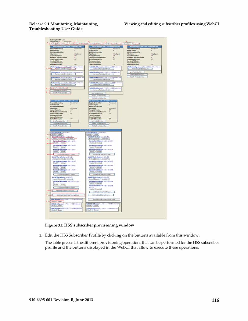
Figure 31: HSS subscriber provisioning window
3. Edit the HSS Subscriber Profile by clicking on the buttons available from this window.
The table presents the different provisioning operations that can be performed for the HSS subscriberprofile and the buttons displayed in the WebCI that allow to execute these operations.
116910-6695-001 Revision B, June 2013
Viewing and editing subscriber profiles using WebCIRelease 9.1 Monitoring, Maintaining,Troubleshooting User Guide
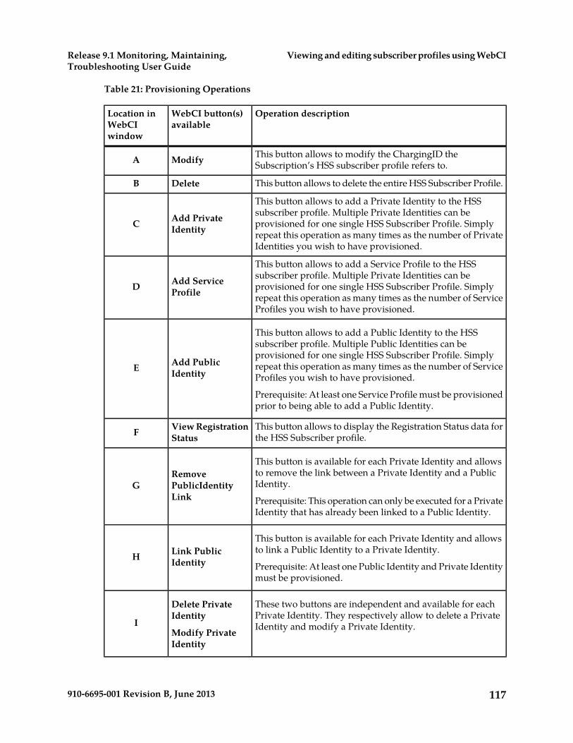
Table 21: Provisioning Operations
Operation descriptionWebCI button(s)available
Location inWebCIwindow
This button allows to modify the ChargingID theSubscription’s HSS subscriber profile refers to.ModifyA
This button allows to delete the entire HSS Subscriber Profile.DeleteB
This button allows to add a Private Identity to the HSSsubscriber profile. Multiple Private Identities can beAdd Private
IdentityC provisioned for one single HSS Subscriber Profile. Simplyrepeat this operation as many times as the number of PrivateIdentities you wish to have provisioned.
This button allows to add a Service Profile to the HSSsubscriber profile. Multiple Private Identities can beAdd Service
ProfileD provisioned for one single HSS Subscriber Profile. Simplyrepeat this operation as many times as the number of ServiceProfiles you wish to have provisioned.
This button allows to add a Public Identity to the HSSsubscriber profile. Multiple Public Identities can be
Add PublicIdentityE
provisioned for one single HSS Subscriber Profile. Simplyrepeat this operation as many times as the number of ServiceProfiles you wish to have provisioned.
Prerequisite: At least one Service Profile must be provisionedprior to being able to add a Public Identity.
This button allows to display the Registration Status data forthe HSS Subscriber profile.
View RegistrationStatusF
This button is available for each Private Identity and allowsto remove the link between a Private Identity and a PublicIdentity.
RemovePublicIdentityLink
GPrerequisite: This operation can only be executed for a PrivateIdentity that has already been linked to a Public Identity.
This button is available for each Private Identity and allowsto link a Public Identity to a Private Identity.Link Public
IdentityHPrerequisite: At least one Public Identity and Private Identitymust be provisioned.
These two buttons are independent and available for eachPrivate Identity. They respectively allow to delete a PrivateIdentity and modify a Private Identity.
Delete PrivateIdentity
Modify PrivateIdentity
I
117910-6695-001 Revision B, June 2013
Viewing and editing subscriber profiles using WebCIRelease 9.1 Monitoring, Maintaining,Troubleshooting User Guide

Operation descriptionWebCI button(s)available
Location inWebCIwindow
Prerequisite: You can only delete a Private Identity once itslinked Public Identities have been deleted (refer to theRemove PublicIdentityLink button to achieve this).
Note: Beware that deleting the last Private Identity of a HSSSubscriber Profile results in the deletion of the entire HSSSubscriber Profile itself.
These two buttons are independent and available for eachService Profile. They respectively allow to modify a ServiceProfile and delete a Service Profile.
Modify
DeleteJ
These two buttons are independent and available for eachHSS Initial Filtering Criteria. They respectively allow toModify
DeleteK modify a HSS Initial Filtering Criteria and delete a HSS Initial
Filtering Criteria.
This button is available for each HSS Initial Filtering Criteriaand allows to link a DSAI to a HSS Initial Filtering Criteria.
Link DSAIL For details on the HssIFCToDSAI entity, refer to the“Subscription Management-HSS application” section of the“HSS Entities” chapter in the SDM Subscriber Provisioning -Reference Manual.
These two buttons are independent and available for eachHSS Service Point Trigger. They respectively allow to modifyModify
DeleteM a HSS Service Point Trigger and delete a HSS Service Point
Trigger.
This button is available for each HSS Initial Filtering Criteria(iFC) and allows to add a HSS Service Point Trigger for a HSSiFC.Add HssService
PointTriggerNPrerequisite: At least one Service Profile must have alreadybeen provisioned with at least one HSS Initial FilteringCriteria.
This button is available for each HSS Service Profile andallows to add a HSS Initial Filtering Criteria (iFC) for a HSSService Profile.Add HssInitial
FilteringCriteriaOPrerequisite: At least one Service Profile must have alreadybeen provisioned.
This button is available for each HSS Service Profile andallows to link a Shared Initial Filtering Criteria (Shared iFC)for a HSS Service Profile.
Link HssSharedInitialFilteringCriteria
P
118910-6695-001 Revision B, June 2013
Viewing and editing subscriber profiles using WebCIRelease 9.1 Monitoring, Maintaining,Troubleshooting User Guide

Operation descriptionWebCI button(s)available
Location inWebCIwindow
Prerequisite:Shared iFCs must already be provisioned in thedatabase. Refer to the “Configuring Shared Initial FilteringCriterias” section of the SDM System Configuration – UserGuide for instructions on how to provision Shared iFCs.
These two buttons are independent and available for eachPublic Identity. They respectively allow to modify a PublicIdentity and delete a Public Identity.
Modify
DeleteQ
Displaying the Service Profile, HSS Initial Filtering Criteria and HSS Service PointTrigger Data
This procedure shows how to display all information related to Service Profile, HSS Initial FilteringCriteria, and HSS Service Point Trigger.
1. Access Subscriber Provisioning submenu2. Go to HSS ➤ display/modify.
The Subscriber Provisioning window and all associated information is displayed, see Figure 32:HssServiceProfile table displaying all service profile information.
119910-6695-001 Revision B, June 2013
Viewing and editing subscriber profiles using WebCIRelease 9.1 Monitoring, Maintaining,Troubleshooting User Guide

3.
Figure 32: HssServiceProfile table displaying all service profile information
Displaying Subscriber Volatile Data
Use this procedure to display subscriber volatile data from the HlrVolatileData table through theWebCI.
Note: Volatile data cannot be provisioned, it can only be displayed.
1. Access Subscriber Provisioning submenu2. Go to HLR ➤ display/modify.
The Subscriber Provisioning window opens to the HLR Provisioning tab.3. Click the HLR Volatile Data tab.
The HlrVolatileData table displays the volatile subscriber values configured in the HSS system.
120910-6695-001 Revision B, June 2013
Viewing and editing subscriber profiles using WebCIRelease 9.1 Monitoring, Maintaining,Troubleshooting User Guide
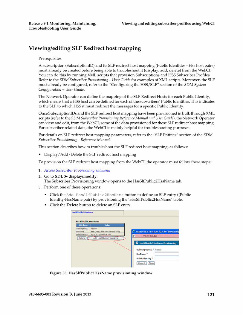
Viewing/editing SLF Redirect host mapping
Prerequisites:
A subscription (SubscriptionID) and its SLF redirect host mapping (Public Identities - Hss host pairs)must already be created before being able to troubleshoot it (display, add, delete) from the WebCI.You can do this by running XML scripts that provision Subscriptions and HSS Subscriber Profiles.Refer to the SDM Subscriber Provisioning – User Guide for examples of XML scripts. Moreover, the SLFmust already be configured, refer to the “Configuring the HSS/SLF” section of the SDM SystemConfiguration – User Guide.
The Network Operator can define the mapping of the SLF Redirect Hosts for each Public Identity,which means that a HSS host can be defined for each of the subscribers’ Public Identities. This indicatesto the SLF to which HSS it must redirect the messages for a specific Public Identity.
Once SubscriptionIDs and the SLF redirect host mapping have been provisioned in bulk through XMLscripts (refer to the SDM Subscriber Provisioning Reference Manual and User Guide), the Network Operatorcan view and edit, from the WebCI, some of the data provisioned for these SLF redirect host mapping.For subscriber related data, the WebCI is mainly helpful for troubleshooting purposes.
For details on SLF redirect host mapping parameters, refer to the “SLF Entities” section of the SDMSubscriber Provisioning - Reference Manual.
This section describes how to troubleshoot the SLF redirect host mapping, as follows:
• Display/Add/Delete the SLF redirect host mapping
To provision the SLF redirect host mapping from the WebCI, the operator must follow these steps:
1. Access Subscriber Provisioning submenu2. Go to SDL ➤ display/modify.
The Subscriber Provisioning window opens to the HssSlfPublic2HssName tab.3. Perform one of these operations:
• Click the Add HssSlfPublic2HssName button to define an SLF entry ((PublicIdentity-HssName pair) by provisioning the ‘HssSlfPublic2HssName’ table.
• Click the Delete button to delete an SLF entry.
Figure 33: HssSlfPublic2HssName provisioning window
121910-6695-001 Revision B, June 2013
Viewing and editing subscriber profiles using WebCIRelease 9.1 Monitoring, Maintaining,Troubleshooting User Guide
Viewing/Editing AAA Subscriber Profiles
Prerequisites:
1. Subscription (SubscriptionID) and its AAA Subscriber Profile must already be created2. AAA and AAA Address Allocation Policies must already be configured
Once SubscriptionIDs and AAA subscriber profiles have been provisioned through XML scripts, theNetwork Operator can use the WebCI to troubleshoot subscriber profiles by viewing AAA subscriberprofiles and editing selected data.
This section describes how to troubleshoot a AAA Subscriber Profile, as follows:
• Add/Display/Modify/Delete AAA subscriber profiles (AAAUserId)• Display User IP Address.• Add/Display/Modify/Delete AAA User Vendor Attributes• Add/Display/Modify/Delete AAA User Address Allocation Policies• Assign/Release IP Addresses• Display User Status• Display/Modify• Display Assigned IP Addresses• Disconnect User• Enable User
1. Access Subscriber Provisioning submenu2. Go to AAA ➤ display/modify.
The Subscriber Provisioning window opens to the AAAUserId tab. Each AAA user ID has its owntable.
3. Edit the AAA Subscriber Profile by clicking on the buttons available from this window.
The following presents the buttons displayed in the WebCI that allow to execute the differentprovisioning operations that can be performed to edit the AAA subscriber profile:a) Modify.
This button is available for each AAA User Id (AAA subscriber profile) provisioned and allowsto modify it.
b) Delete.
This button is available for each AAA User Id (AAA subscriber profile) provisioned and allowsto delete it.
c) Modify/Display AAAUserVendorAttribute.
This button is available for each AAA User Id (AAA subscriber profile) provisioned and allowsto display/add/modify/delete AAA User Vendor Attributes for the AAA subscriber profile.
d) Modify/Display AAAUserAddressAllocationPolicies.
This button is available for each AAA User Id (AAA subscriber profile) provisioned and allowsto display/modify/delete or to assign a AAA Address Allocation Policy to the AAA subscriberprofile.
122910-6695-001 Revision B, June 2013
Viewing and editing subscriber profiles using WebCIRelease 9.1 Monitoring, Maintaining,Troubleshooting User Guide
e) Prerequisite: A minimum of one AllocationPolicyName must already exist and have beenconfigured in the AAAAddressAllocationPolicy entity (refer to the “AAA ProvisioningConfiguring- Provisioning AAA Address Allocation Policies and IP Address Pools” of the SDMSystem Configuration – User Guide for instructions on how to add a AAAAddressAllocationPolicyentry).
f) Display UserStatus.
This button is available for each AAA User Id (AAA subscriber profile) provisioned and allowsto display a AAA subscriber’s dynamic IP Addresses information. The IP Address (es)dynamically allocated to that AAA subscriber are displayed, as well as the NAS IP Addressand the CallingStationID. With the IP Address allocation based on Calling-Station-Id attributefeature, multiple entries are allowed in this table, each with a different Calling Station ID(MSISDN in 3GPP Gi interworking).
g) Display AssignedIPAddress.
This button is available for each AAA User Id (AAA subscriber profile) provisioned and allowsto display the static IP Addresses that the AAA server has already assigned to the AAAsubscriber.
h) Disconnect User.
This button is available for each AAA User Id (AAA subscriber profile) provisioned and allowsto send a Disconnect-Request packet in order to terminate a user session on a NAS and discardall associated session context.
Note: Disconnecting a AAA user will disable it.
Note: In the case where a AAA user has IP addresses allocated to multiple MSISDNs,disconnecting the AAA user will disconnect all of the IP connections.
i) Enable User.
This button is available for each AAA User Id (AAA subscriber profile) provisioned and allowsto enable an existing AAA user that was disabled. This operation can be performed to enablea AAA user after it was disconnected using the Disconnect User operation.
j) Assign IP Address.
This button is available for each AAA User Id (AAA subscriber profile) provisioned and allowsa static IP Address to be associated to a specific Called Station (APN) or Realm. If desired, aCalling Station (MSISDN) can also be added, in order to identify the subscriber. When executingthis operation for a subscriber, the Called Station must be specified in the indicated field; therealm, on the other hand, doesn’t need to be entered, it is extracted from the AAAUserName.With this information, the AAA server associates an IP Address to the Called Station or Realmfrom the configured IP Address pools. This IP Address is said to be static and becomesunavailable for allocation by the AAA server when performing dynamic allocation of an IPAddress. For a single subscriber, a different static IP Address can be assigned for each CalledStation (APN) or Realm. Moreover, for a subscriber’s specific Calling Station (MSISDN), differentstatic IP addresses can be assigned for different Called Stations (APNs).
The following are the four cases in which a static IP address can be assigned for a AAA user:k) Case 1: The subscriber’s AAAUserName doesn’t include the realm and is defined in a format
such as aaauser1.
In this case, the operator can assign a static address to the subscriber by providing a calledstation, which is associated with an address pool. The address is selected from the pool associated
123910-6695-001 Revision B, June 2013
Viewing and editing subscriber profiles using WebCIRelease 9.1 Monitoring, Maintaining,Troubleshooting User Guide
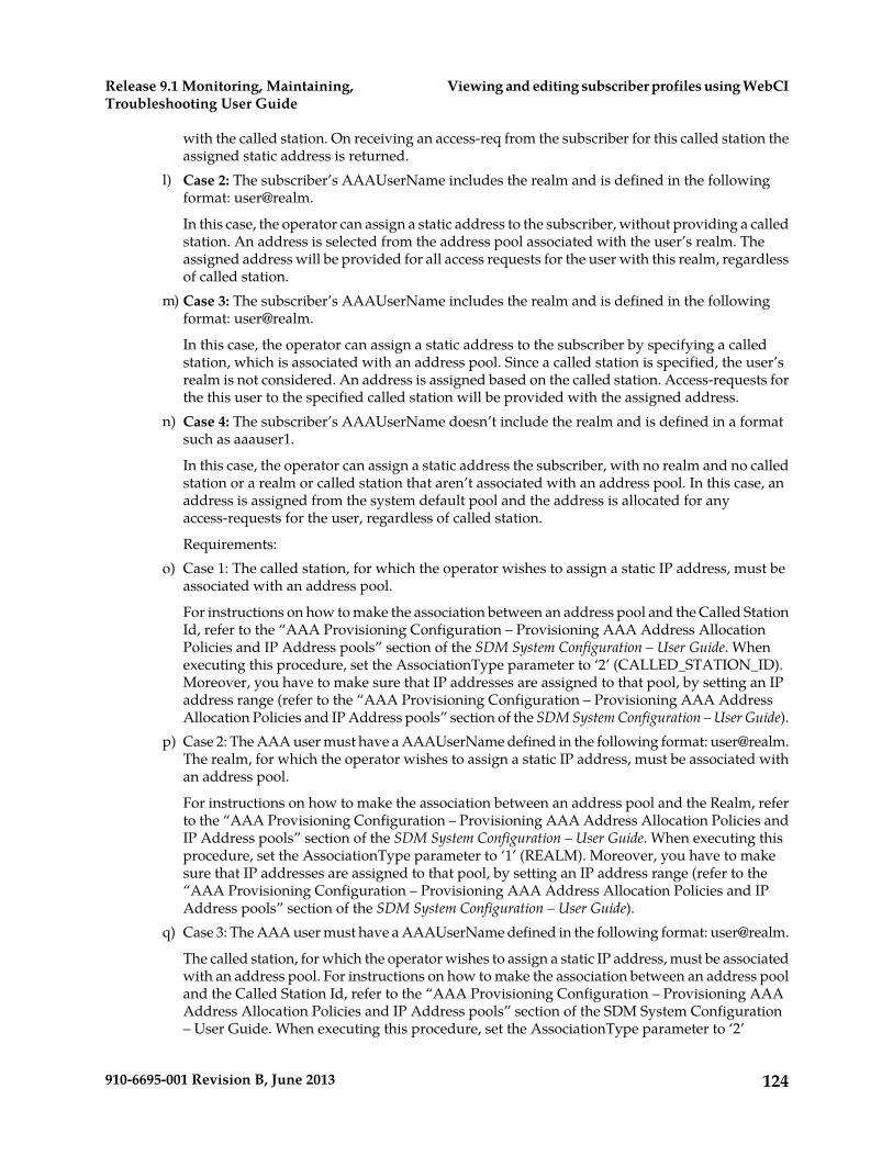
with the called station. On receiving an access-req from the subscriber for this called station theassigned static address is returned.
l) Case 2: The subscriber’s AAAUserName includes the realm and is defined in the followingformat: user@realm.
In this case, the operator can assign a static address to the subscriber, without providing a calledstation. An address is selected from the address pool associated with the user’s realm. Theassigned address will be provided for all access requests for the user with this realm, regardlessof called station.
m) Case 3: The subscriber’s AAAUserName includes the realm and is defined in the followingformat: user@realm.
In this case, the operator can assign a static address to the subscriber by specifying a calledstation, which is associated with an address pool. Since a called station is specified, the user’srealm is not considered. An address is assigned based on the called station. Access-requests forthe this user to the specified called station will be provided with the assigned address.
n) Case 4: The subscriber’s AAAUserName doesn’t include the realm and is defined in a formatsuch as aaauser1.
In this case, the operator can assign a static address the subscriber, with no realm and no calledstation or a realm or called station that aren’t associated with an address pool. In this case, anaddress is assigned from the system default pool and the address is allocated for anyaccess-requests for the user, regardless of called station.
Requirements:o) Case 1: The called station, for which the operator wishes to assign a static IP address, must be
associated with an address pool.
For instructions on how to make the association between an address pool and the Called StationId, refer to the “AAA Provisioning Configuration – Provisioning AAA Address AllocationPolicies and IP Address pools” section of the SDM System Configuration – User Guide. Whenexecuting this procedure, set the AssociationType parameter to ‘2’ (CALLED_STATION_ID).Moreover, you have to make sure that IP addresses are assigned to that pool, by setting an IPaddress range (refer to the “AAA Provisioning Configuration – Provisioning AAA AddressAllocation Policies and IP Address pools” section of the SDM System Configuration – User Guide).
p) Case 2: The AAA user must have a AAAUserName defined in the following format: [email protected] realm, for which the operator wishes to assign a static IP address, must be associated withan address pool.
For instructions on how to make the association between an address pool and the Realm, referto the “AAA Provisioning Configuration – Provisioning AAA Address Allocation Policies andIP Address pools” section of the SDM System Configuration – User Guide. When executing thisprocedure, set the AssociationType parameter to ‘1’ (REALM). Moreover, you have to makesure that IP addresses are assigned to that pool, by setting an IP address range (refer to the“AAA Provisioning Configuration – Provisioning AAA Address Allocation Policies and IPAddress pools” section of the SDM System Configuration – User Guide).
q) Case 3: The AAA user must have a AAAUserName defined in the following format: user@realm.
The called station, for which the operator wishes to assign a static IP address, must be associatedwith an address pool. For instructions on how to make the association between an address pooland the Called Station Id, refer to the “AAA Provisioning Configuration – Provisioning AAAAddress Allocation Policies and IP Address pools” section of the SDM System Configuration– User Guide. When executing this procedure, set the AssociationType parameter to ‘2’
124910-6695-001 Revision B, June 2013
Viewing and editing subscriber profiles using WebCIRelease 9.1 Monitoring, Maintaining,Troubleshooting User Guide
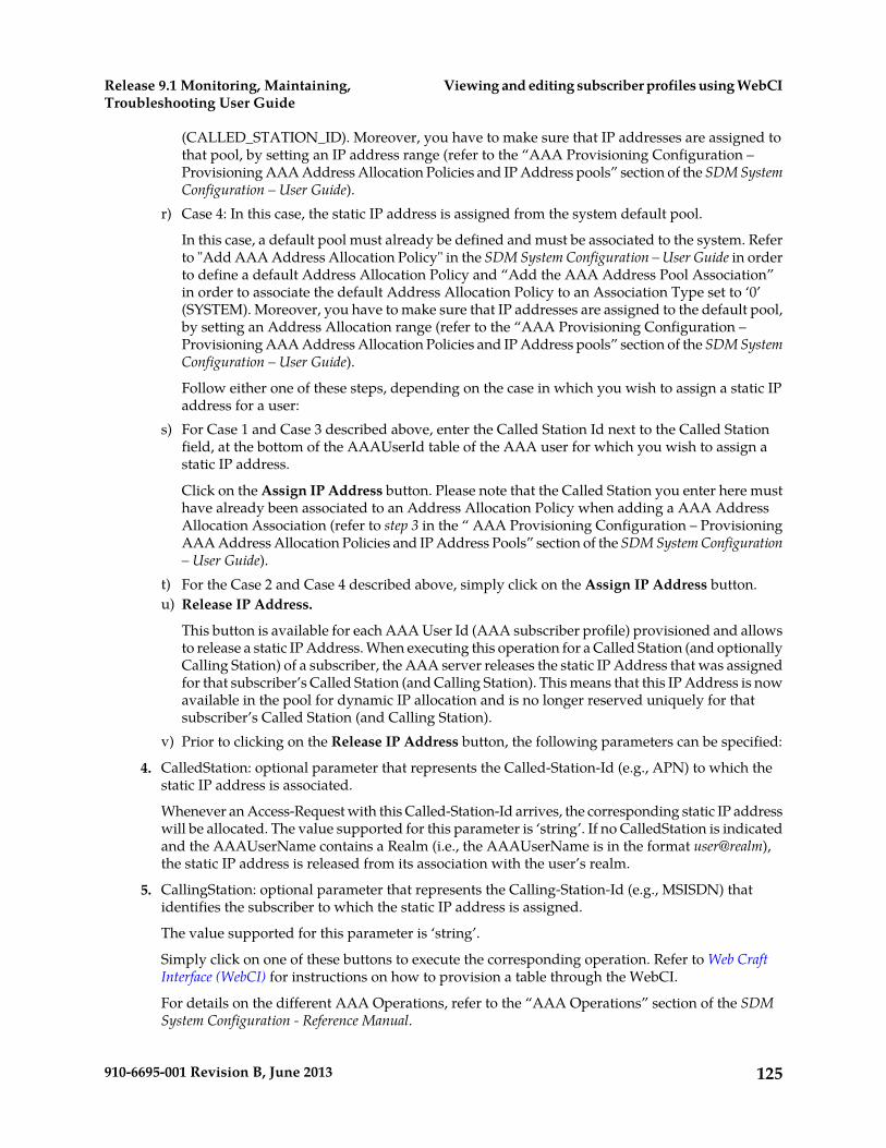
(CALLED_STATION_ID). Moreover, you have to make sure that IP addresses are assigned tothat pool, by setting an IP address range (refer to the “AAA Provisioning Configuration –Provisioning AAA Address Allocation Policies and IP Address pools” section of the SDM SystemConfiguration – User Guide).
r) Case 4: In this case, the static IP address is assigned from the system default pool.
In this case, a default pool must already be defined and must be associated to the system. Referto "Add AAA Address Allocation Policy" in the SDM System Configuration – User Guide in orderto define a default Address Allocation Policy and “Add the AAA Address Pool Association”in order to associate the default Address Allocation Policy to an Association Type set to ‘0’(SYSTEM). Moreover, you have to make sure that IP addresses are assigned to the default pool,by setting an Address Allocation range (refer to the “AAA Provisioning Configuration –Provisioning AAA Address Allocation Policies and IP Address pools” section of the SDM SystemConfiguration – User Guide).
Follow either one of these steps, depending on the case in which you wish to assign a static IPaddress for a user:
s) For Case 1 and Case 3 described above, enter the Called Station Id next to the Called Stationfield, at the bottom of the AAAUserId table of the AAA user for which you wish to assign astatic IP address.
Click on the Assign IP Address button. Please note that the Called Station you enter here musthave already been associated to an Address Allocation Policy when adding a AAA AddressAllocation Association (refer to step 3 in the “ AAA Provisioning Configuration – ProvisioningAAA Address Allocation Policies and IP Address Pools” section of the SDM System Configuration– User Guide).
t) For the Case 2 and Case 4 described above, simply click on the Assign IP Address button.u) Release IP Address.
This button is available for each AAA User Id (AAA subscriber profile) provisioned and allowsto release a static IP Address. When executing this operation for a Called Station (and optionallyCalling Station) of a subscriber, the AAA server releases the static IP Address that was assignedfor that subscriber’s Called Station (and Calling Station). This means that this IP Address is nowavailable in the pool for dynamic IP allocation and is no longer reserved uniquely for thatsubscriber’s Called Station (and Calling Station).
v) Prior to clicking on the Release IP Address button, the following parameters can be specified:
4. CalledStation: optional parameter that represents the Called-Station-Id (e.g., APN) to which thestatic IP address is associated.
Whenever an Access-Request with this Called-Station-Id arrives, the corresponding static IP addresswill be allocated. The value supported for this parameter is ‘string’. If no CalledStation is indicatedand the AAAUserName contains a Realm (i.e., the AAAUserName is in the format user@realm),the static IP address is released from its association with the user’s realm.
5. CallingStation: optional parameter that represents the Calling-Station-Id (e.g., MSISDN) thatidentifies the subscriber to which the static IP address is assigned.
The value supported for this parameter is ‘string’.
Simply click on one of these buttons to execute the corresponding operation. Refer to Web CraftInterface (WebCI) for instructions on how to provision a table through the WebCI.
For details on the different AAA Operations, refer to the “AAA Operations” section of the SDMSystem Configuration - Reference Manual.
125910-6695-001 Revision B, June 2013
Viewing and editing subscriber profiles using WebCIRelease 9.1 Monitoring, Maintaining,Troubleshooting User Guide

Figure 34: AAAUserId Window
Viewing/Editing DNS ENUM Users
This section describes how to provision DNS ENUM Users from the WebCI.
Multiple DNS Enum Users can be provisioned for one single Subscription.
1. Access Subscriber Provisioning submenu.2. Go to ENUM Server ➤ display/modify.
The Subscriber Provisioning window opens to the Enum User tab.3. Click the SubscriptionId for which you wish to provision a DNS Enum User.4. When the Subscriber Provisioning window pops up, extend the ENUM Server sub-folder and click
on display/modify.5. The DNS Enum User table will appear and allow you to view the already provisioned users or
and/or allow you to add, edit, delete entries. For details on the parameters needed to provisionENUM Users, refer to the ENUM chapter of the SDM Subscriber Provisioning - Reference Manual.
126910-6695-001 Revision B, June 2013
Viewing and editing subscriber profiles using WebCIRelease 9.1 Monitoring, Maintaining,Troubleshooting User Guide
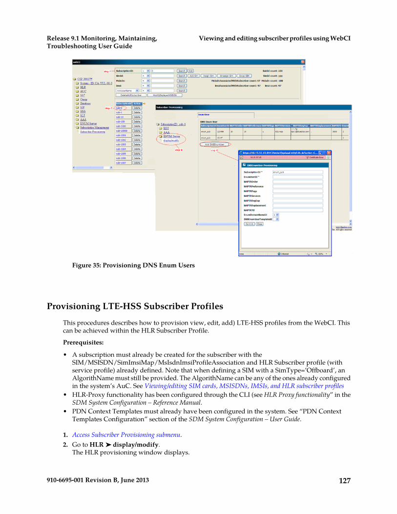
Figure 35: Provisioning DNS Enum Users
Provisioning LTE-HSS Subscriber Profiles
This procedures describes how to provision view, edit, add) LTE-HSS profiles from the WebCI. Thiscan be achieved within the HLR Subscriber Profile.
Prerequisites:
• A subscription must already be created for the subscriber with theSIM/MSISDN/SimImsiMap/MsIsdnImsiProfileAssociation and HLR Subscriber profile (withservice profile) already defined. Note that when defining a SIM with a SimType=’Offboard’, anAlgorithName must still be provided. The AlgorithName can be any of the ones already configuredin the system’s AuC. See Viewing/editing SIM cards, MSISDNs, IMSIs, and HLR subscriber profiles
• HLR-Proxy functionality has been configured through the CLI (see HLR Proxy functionality” in theSDM System Configuration – Reference Manual.
• PDN Context Templates must already have been configured in the system. See “PDN ContextTemplates Configuration” section of the SDM System Configuration – User Guide.
1. Access Subscriber Provisioning submenu.2. Go to HLR ➤ display/modify.
The HLR provisioning window displays.
127910-6695-001 Revision B, June 2013
Viewing and editing subscriber profiles using WebCIRelease 9.1 Monitoring, Maintaining,Troubleshooting User Guide
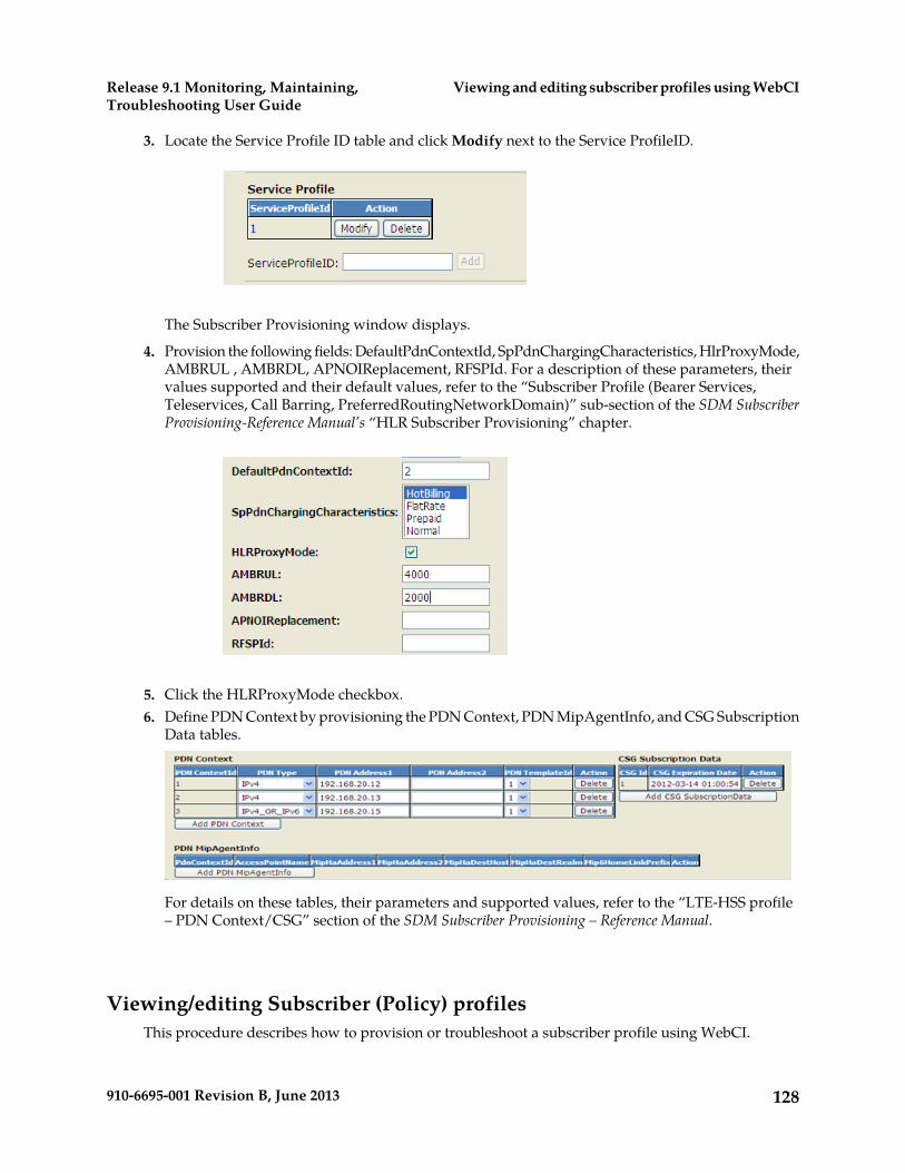
3. Locate the Service Profile ID table and click Modify next to the Service ProfileID.
The Subscriber Provisioning window displays.
4. Provision the following fields: DefaultPdnContextId, SpPdnChargingCharacteristics, HlrProxyMode,AMBRUL , AMBRDL, APNOIReplacement, RFSPId. For a description of these parameters, theirvalues supported and their default values, refer to the “Subscriber Profile (Bearer Services,Teleservices, Call Barring, PreferredRoutingNetworkDomain)” sub-section of the SDM SubscriberProvisioning-Reference Manual’s “HLR Subscriber Provisioning” chapter.
5. Click the HLRProxyMode checkbox.6. Define PDN Context by provisioning the PDN Context, PDN MipAgentInfo, and CSG Subscription
Data tables.
For details on these tables, their parameters and supported values, refer to the “LTE-HSS profile– PDN Context/CSG” section of the SDM Subscriber Provisioning – Reference Manual.
Viewing/editing Subscriber (Policy) profilesThis procedure describes how to provision or troubleshoot a subscriber profile using WebCI.
128910-6695-001 Revision B, June 2013
Viewing and editing subscriber profiles using WebCIRelease 9.1 Monitoring, Maintaining,Troubleshooting User Guide
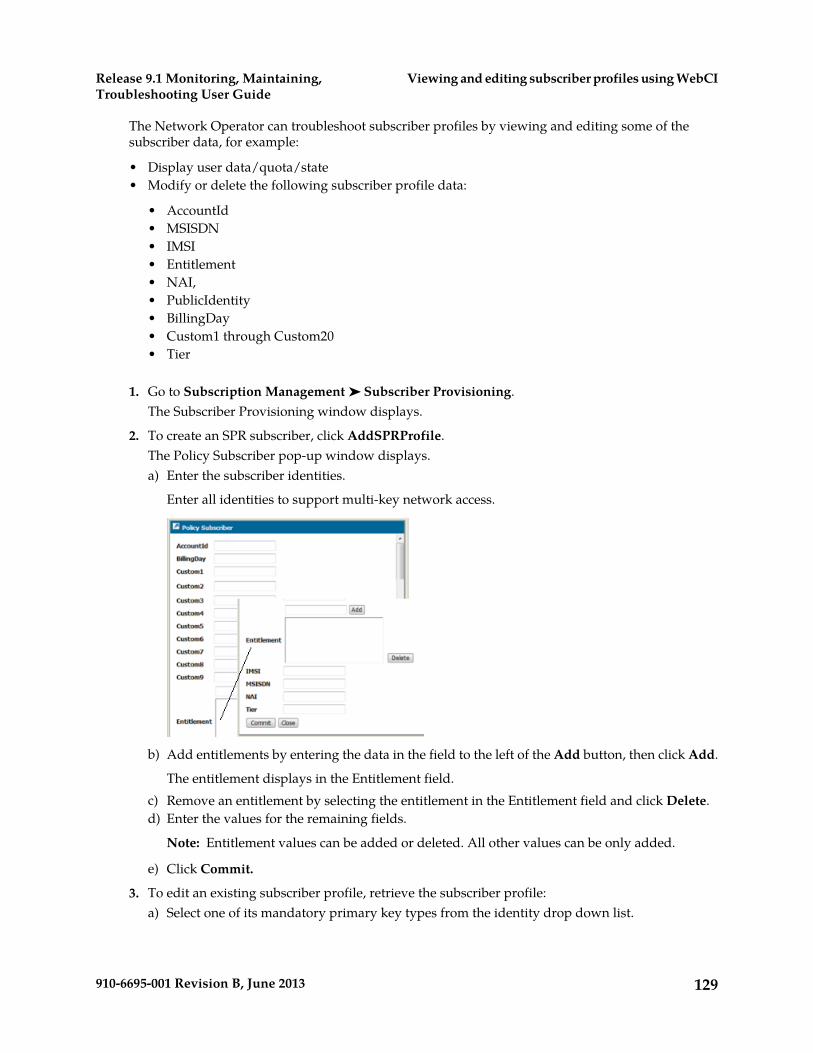
The Network Operator can troubleshoot subscriber profiles by viewing and editing some of thesubscriber data, for example:
• Display user data/quota/state• Modify or delete the following subscriber profile data:
• AccountId• MSISDN• IMSI• Entitlement• NAI,• PublicIdentity• BillingDay• Custom1 through Custom20• Tier
1. Go to Subscription Management ➤ Subscriber Provisioning.The Subscriber Provisioning window displays.
2. To create an SPR subscriber, click AddSPRProfile.The Policy Subscriber pop-up window displays.a) Enter the subscriber identities.
Enter all identities to support multi-key network access.
b) Add entitlements by entering the data in the field to the left of the Add button, then click Add.
The entitlement displays in the Entitlement field.c) Remove an entitlement by selecting the entitlement in the Entitlement field and click Delete.d) Enter the values for the remaining fields.
Note: Entitlement values can be added or deleted. All other values can be only added.
e) Click Commit.
3. To edit an existing subscriber profile, retrieve the subscriber profile:a) Select one of its mandatory primary key types from the identity drop down list.
129910-6695-001 Revision B, June 2013
Viewing and editing subscriber profiles using WebCIRelease 9.1 Monitoring, Maintaining,Troubleshooting User Guide

b) Enter the key value in the right field and click Search.The Subscriber Profile table displays the profile matching the key value as well as a Quota tableif quota is defined.
4. Perform one or more of these steps from the subscriber table:
• Click Modify to change the subscriber data available in the pop-up window, then click Commit.
Note: State data is opaque data and can be edited only through the XML interfaces and onlyas blob.
• Click Delete to delete profile data.• Click Delete Quotas to delete all quotas of a subscriber.
Note: This operation deletes all values, names, and even the database entry in the SPR volatiledata.
• Click Add Quota to add a quota to the subscriber profile.• Click DeleteFromPool to delete the subscriber from the pool.
Viewing/editing SPR subscriber quota (WebCI)This procedure describes how to provision the subscriber quota using the WebCI.
The subscriber quota represents the subscriber usage of managed resources. Use this procedure toadjust the subscriber quota to maximize resource usage.
1. Go to Subscription Management ➤ Subscriber Provisioning.The Subscriber Provisioning window displays.
2. Retrieve the existing SPR subscriber by selecting one of its mandatory primary key types from theidentity drop-down list.
130910-6695-001 Revision B, June 2013
Viewing and editing subscriber profiles using WebCIRelease 9.1 Monitoring, Maintaining,Troubleshooting User Guide
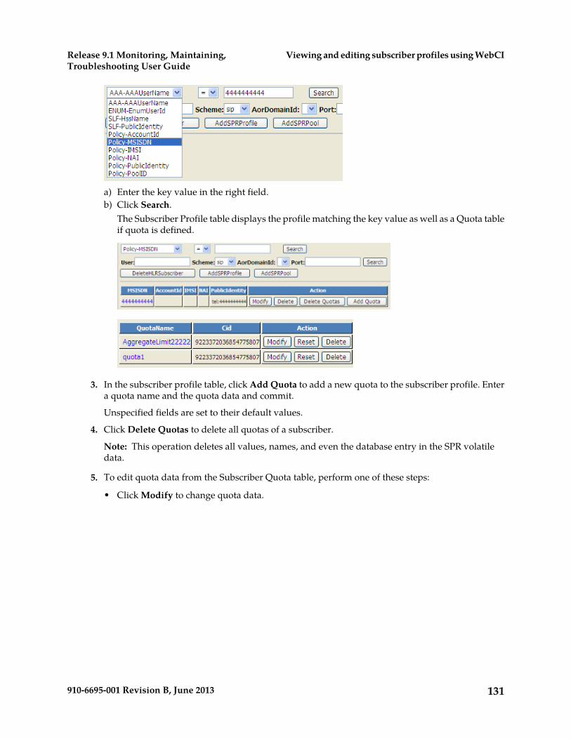
a) Enter the key value in the right field.b) Click Search.
The Subscriber Profile table displays the profile matching the key value as well as a Quota tableif quota is defined.
3. In the subscriber profile table, click Add Quota to add a new quota to the subscriber profile. Entera quota name and the quota data and commit.
Unspecified fields are set to their default values.
4. Click Delete Quotas to delete all quotas of a subscriber.
Note: This operation deletes all values, names, and even the database entry in the SPR volatiledata.
5. To edit quota data from the Subscriber Quota table, perform one of these steps:
• Click Modify to change quota data.
131910-6695-001 Revision B, June 2013
Viewing and editing subscriber profiles using WebCIRelease 9.1 Monitoring, Maintaining,Troubleshooting User Guide

Note: When editing the NextResetTime field, the timestamp format must follow this convention:[-]CCYY-MM-DDThh:mm:ss[Z|(+|-)hh:mm]
For example:
2012-05-07T00:00:00Z (UTC) or
2012-05-07T00:00:00-05:00 (UTC minus 5 hours = US Eastern Standard Time)• Click Reset to reset the quota usage to the default values assigned to the Subscriber Quota table.• Click Delete to delete a quota from the subscriber profile.
Viewing/editing SPR Pool information (WebCI)This procedure describes how to display pool information, create an SPR pool, adding a subscriberto a pool, and editing existing pool information using the WebCI.
Each subscriber can be a member of only one pool.
1. Go to Tekelec SDM ➤ Subscription Management ➤ Subscriber Provisioning.The Subscriber Provisioning window displays.
2. To create an SPR pool, click AddSPRPool and enter pool identity and pool data, then commit.3. To manipulate any pool data, retrieve the pool information by selecting Policy-PoolID from the
drop-down menu, enter the PoolD to the right, and click Search.
The Pool table displays with the actions that can be performed on the pool.
132910-6695-001 Revision B, June 2013
Viewing and editing subscriber profiles using WebCIRelease 9.1 Monitoring, Maintaining,Troubleshooting User Guide
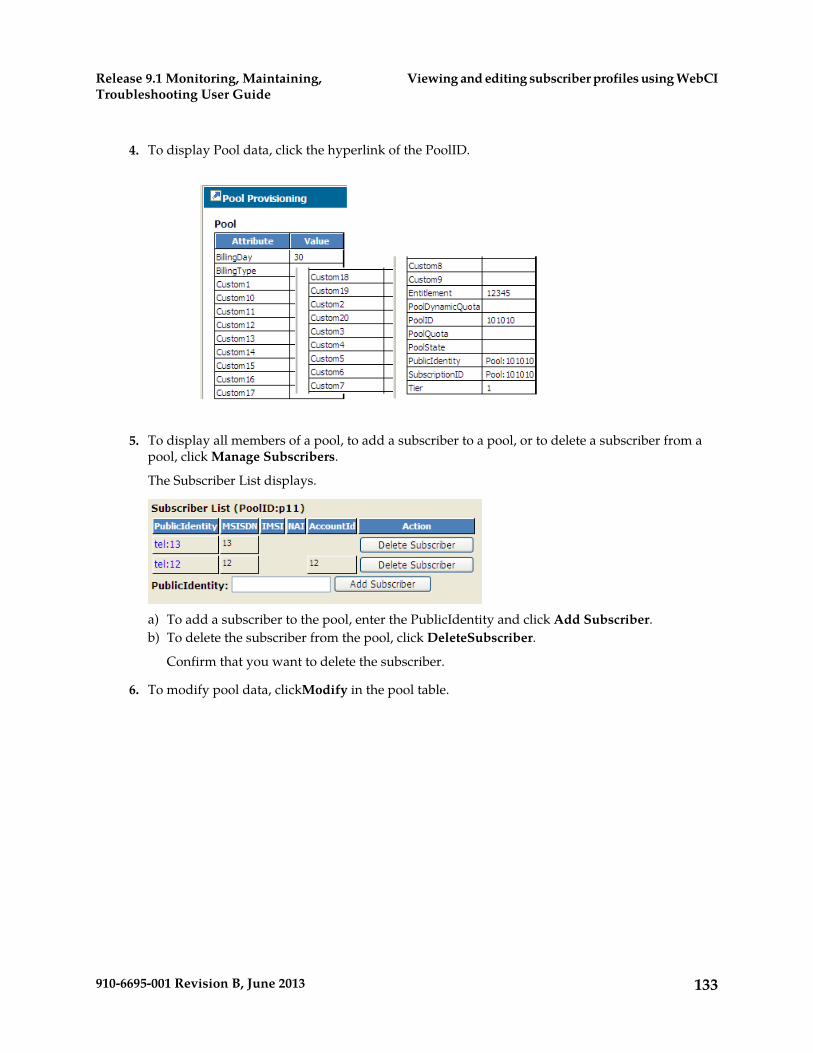
4. To display Pool data, click the hyperlink of the PoolID.
5. To display all members of a pool, to add a subscriber to a pool, or to delete a subscriber from apool, click Manage Subscribers.
The Subscriber List displays.
a) To add a subscriber to the pool, enter the PublicIdentity and click Add Subscriber.b) To delete the subscriber from the pool, click DeleteSubscriber.
Confirm that you want to delete the subscriber.
6. To modify pool data, clickModify in the pool table.
133910-6695-001 Revision B, June 2013
Viewing and editing subscriber profiles using WebCIRelease 9.1 Monitoring, Maintaining,Troubleshooting User Guide
Chapter
5Monitoring the system
This chapter contains information used to monitorthe Subscriber Data Management system for alarmsand other errors.
Topics:
• Viewing and Managing Alarms.....135• Viewing Logs.....141• Using traces.....148• Viewing Information About the Activation Status
of the SS7 and SIGTRAN Links.....150• SS7 Configuration Window.....150• Monitoring SS7 Links and Performing a Line
Test.....150• CLI Operations to Monitor SS7 Activity.....154• Monitoring the System Through SNMP.....155
134910-6695-001 Revision B, June 2013
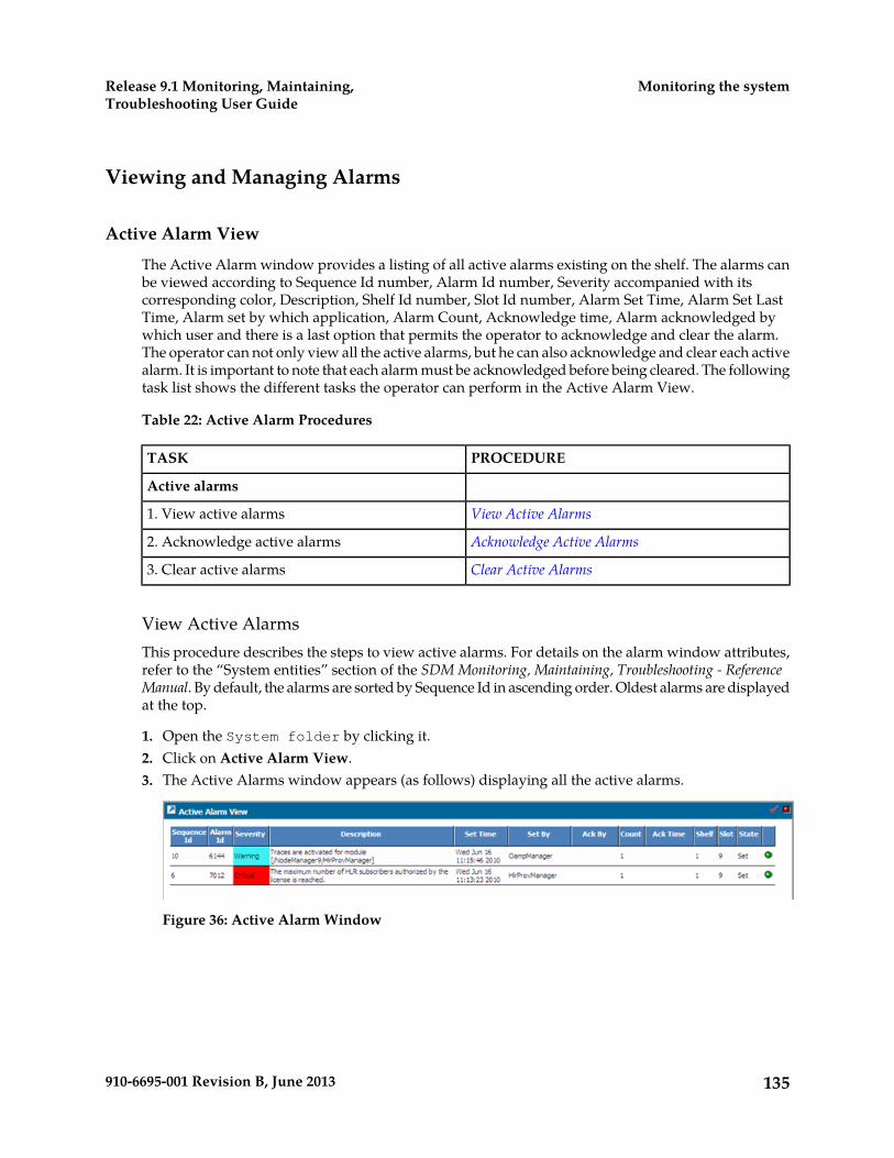
Viewing and Managing Alarms
Active Alarm View
The Active Alarm window provides a listing of all active alarms existing on the shelf. The alarms canbe viewed according to Sequence Id number, Alarm Id number, Severity accompanied with itscorresponding color, Description, Shelf Id number, Slot Id number, Alarm Set Time, Alarm Set LastTime, Alarm set by which application, Alarm Count, Acknowledge time, Alarm acknowledged bywhich user and there is a last option that permits the operator to acknowledge and clear the alarm.The operator can not only view all the active alarms, but he can also acknowledge and clear each activealarm. It is important to note that each alarm must be acknowledged before being cleared. The followingtask list shows the different tasks the operator can perform in the Active Alarm View.
Table 22: Active Alarm Procedures
PROCEDURETASK
Active alarms
View Active Alarms1. View active alarms
Acknowledge Active Alarms2. Acknowledge active alarms
Clear Active Alarms3. Clear active alarms
View Active AlarmsThis procedure describes the steps to view active alarms. For details on the alarm window attributes,refer to the “System entities” section of the SDM Monitoring, Maintaining, Troubleshooting - ReferenceManual. By default, the alarms are sorted by Sequence Id in ascending order. Oldest alarms are displayedat the top.
1. Open the System folder by clicking it.2. Click on Active Alarm View.3. The Active Alarms window appears (as follows) displaying all the active alarms.
Figure 36: Active Alarm Window
135910-6695-001 Revision B, June 2013
Monitoring the systemRelease 9.1 Monitoring, Maintaining,Troubleshooting User Guide

Acknowledge Active AlarmsThis procedure describes the steps to acknowledge active alarms. For details on the alarm windowattributes, refer to the “System entities” section of the SDM Monitoring, Maintaining, Troubleshooting -Reference Manual.
1. Open the System folder by clicking it.2. Click on Active Alarm View.3. The Active Alarms window appears as shown in Figure 36: Active Alarm Window.
You will be able to notice that by default, the alarms are all checked with a green circle in the lastcolumn.
4. To acknowledge one specific active alarm:
Click on the green circle corresponding to the active alarm you wish to acknowledge.
5. This will result in the display of the date and time in the Acknowledge Time column for the specificalarm you just acknowledged and in the display of the user that acknowledged the alarm in theAck By column.
In the example shown in the figure below, the acknowledged alarm is the Alarm Id:7012.
Figure 37: Active Alarm Window With An Active Alarm Acknowledged
6. An acknowledge notification will be recorded in the Alarm History.
More precisely, the acknowledge date and time will be registered and appear in the Acknowledgetime column and the user that acknowledged the alarm will be displayed in the Ack By column.In the example shown in the figure below, the acknowledged alarm is the Alarm Id: 7012.
Figure 38: History Alarm Window With An Active Alarm Acknowledged
136910-6695-001 Revision B, June 2013
Monitoring the systemRelease 9.1 Monitoring, Maintaining,Troubleshooting User Guide
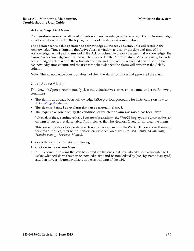
Acknowledge All AlarmsYou can also acknowledge all the alarms at once. To acknowledge all the alarms, click the Acknowledgeall action button located at the top right corner of the Active Alarm window.
The operator can use this operation to acknowledge all the active alarms. This will result in theAcknowledge Time column of the Active Alarms window to display the date and time of theacknowledgement of each alarm and in the Ack By column to display the user that acknowledged thealarm. An acknowledge notification will be recorded in the Alarm History. More precisely, for eachacknowledged active alarm, the acknowledge date and time will be registered and appear in theAcknowledge time column and the user that acknowledged the alarm will appear in the Ack Bycolumn.
Note: The acknowledge operation does not clear the alarm condition that generated the alarm.
Clear Active AlarmsThe Network Operator can manually clear individual active alarms, one at a time, under the followingconditions:
• The alarm has already been acknowledged.(See previous procedure for instructions on how toAcknowledge All Alarms)
• The alarm is defined as an alarm that can be manually cleared.• The required action to rectify the condition for which the alarm was raised has been taken
When all of these conditions have been met for an alarm, the WebCI displays a x button in the lastcolumn of the Active alarm table. This indicates that the Network Operator can clear the alarm.
This procedure describes the steps to clear an active alarm from the WebCI. For details on the alarmwindow attributes, refer to the “System entities” section of the SDM Monitoring, Maintaining,Troubleshooting - Reference Manual.
1. Open the System folder by clicking it.2. Click on Active Alarm View.3. At this point, the alarms that can be cleared are the ones that have already been acknowledged
(acknowledged alarms have an acknowledge time and acknowledged by (Ack By) name displayed)and that have a x button available in the last column of the table.
137910-6695-001 Revision B, June 2013
Monitoring the systemRelease 9.1 Monitoring, Maintaining,Troubleshooting User Guide
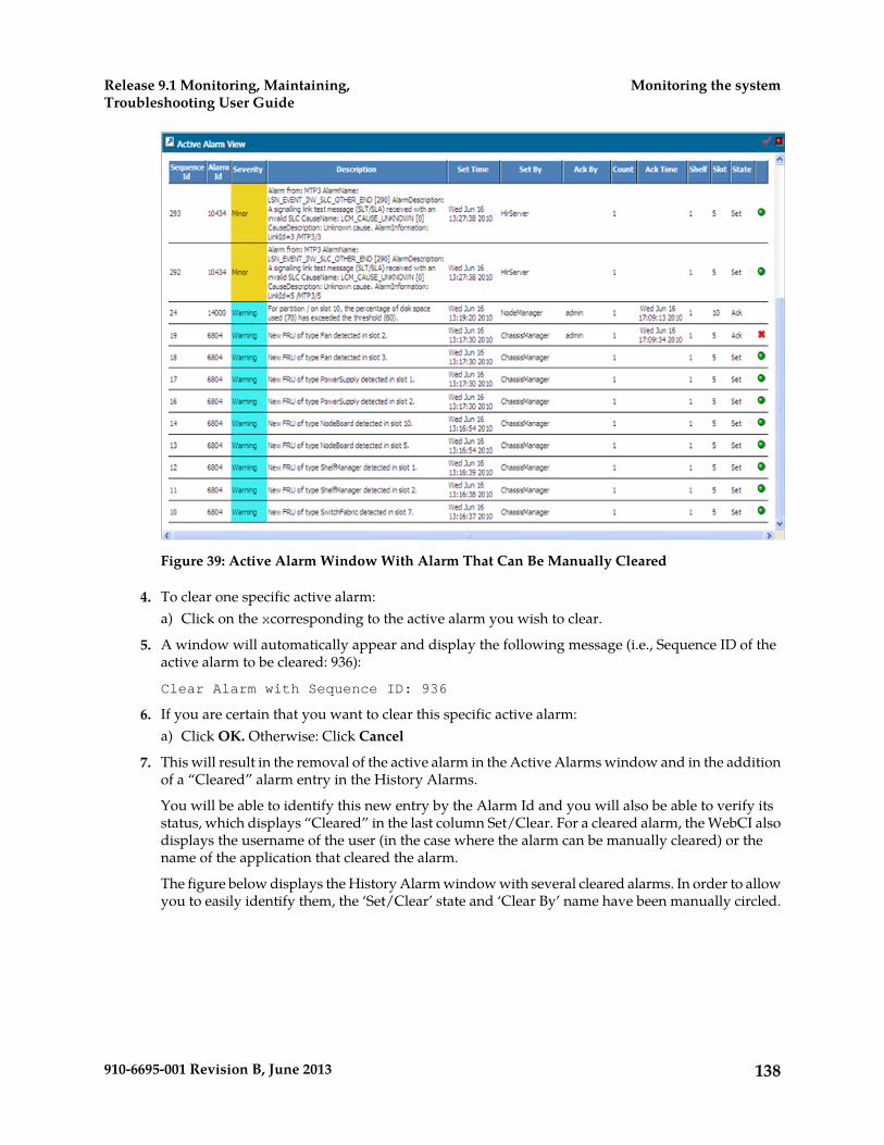
Figure 39: Active Alarm Window With Alarm That Can Be Manually Cleared
4. To clear one specific active alarm:a) Click on the xcorresponding to the active alarm you wish to clear.
5. A window will automatically appear and display the following message (i.e., Sequence ID of theactive alarm to be cleared: 936):
Clear Alarm with Sequence ID: 936
6. If you are certain that you want to clear this specific active alarm:a) Click OK. Otherwise: Click Cancel
7. This will result in the removal of the active alarm in the Active Alarms window and in the additionof a “Cleared” alarm entry in the History Alarms.
You will be able to identify this new entry by the Alarm Id and you will also be able to verify itsstatus, which displays “Cleared” in the last column Set/Clear. For a cleared alarm, the WebCI alsodisplays the username of the user (in the case where the alarm can be manually cleared) or thename of the application that cleared the alarm.
The figure below displays the History Alarm window with several cleared alarms. In order to allowyou to easily identify them, the ‘Set/Clear’ state and ‘Clear By’ name have been manually circled.
138910-6695-001 Revision B, June 2013
Monitoring the systemRelease 9.1 Monitoring, Maintaining,Troubleshooting User Guide
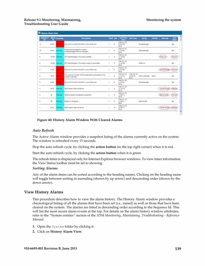
Figure 40: History Alarm Window With Cleared Alarms
Auto RefreshThe Active Alarm window provides a snapshot listing of the alarms currently active on the system.The window is refreshed every 15 seconds.
Stop the auto refresh cycle, by clicking the action button (in the top right corner) when it is red .
Start the auto refresh cycle, by clicking the action button when it is green .
The refresh timer is displayed only for Internet Explorer browser windows. To view timer information,the View Status toolbar must be set to showing.Sorting AlarmsAny of the alarm items can be sorted according to the heading names. Clicking on the heading namewill toggle between sorting in ascending (shown by up arrow) and descending order (shown by thedown arrow).
View History Alarms
This procedure describes how to view the alarm history. The History Alarm window provides achronological listing of all the alarms that have been set (i.e., raised) as well as those that have beencleared on the system. The alarms are listed in descending order according to the Sequence Id. Thiswill list the most recent alarm events at the top. For details on the alarm history window attributes,refer to the “System entities” section of the SDM Monitoring, Maintaining, Troubleshooting - ReferenceManual.
1. Open the System folder by clicking it.2. Click on History Alarm View.
139910-6695-001 Revision B, June 2013
Monitoring the systemRelease 9.1 Monitoring, Maintaining,Troubleshooting User Guide

3. The History Alarms window appears (as follows) displaying all the alarms that occurred and whenthey have been created.
Figure 41: Alarm History Window
The History Alarm window displays the 50 most recent history alarm events at a time.
To view the Previous 50 events, click on the left arrow .
To view the Next 50 events in the list, click on the right arrow .
The Active Alarm and History Alarm windows also offer another feature that helps you identifymore quickly the degree of severity of each alarm. The severity description for each alarm isaccompanied with a color. The following table presents each of the severity degree and itscorresponding color displayed.
Table 23: Alarm Severities and Colors
ColorSeverity description
TurquoiseWarning
YellowMinor
OrangeMajor
RedCritical
140910-6695-001 Revision B, June 2013
Monitoring the systemRelease 9.1 Monitoring, Maintaining,Troubleshooting User Guide
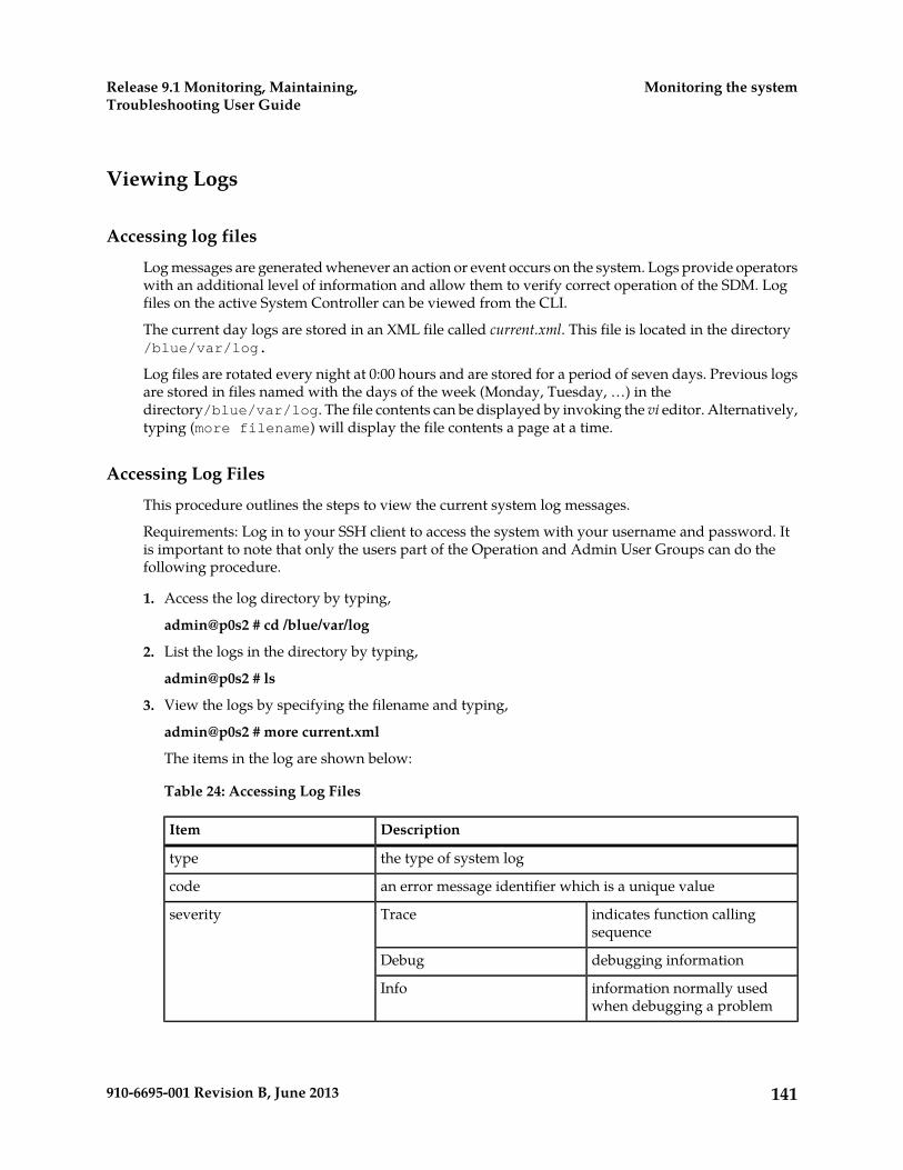
Viewing Logs
Accessing log files
Log messages are generated whenever an action or event occurs on the system. Logs provide operatorswith an additional level of information and allow them to verify correct operation of the SDM. Logfiles on the active System Controller can be viewed from the CLI.
The current day logs are stored in an XML file called current.xml. This file is located in the directory/blue/var/log.
Log files are rotated every night at 0:00 hours and are stored for a period of seven days. Previous logsare stored in files named with the days of the week (Monday, Tuesday, …) in thedirectory/blue/var/log. The file contents can be displayed by invoking the vi editor. Alternatively,typing (more filename) will display the file contents a page at a time.
Accessing Log Files
This procedure outlines the steps to view the current system log messages.
Requirements: Log in to your SSH client to access the system with your username and password. Itis important to note that only the users part of the Operation and Admin User Groups can do thefollowing procedure.
1. Access the log directory by typing,
admin@p0s2 # cd /blue/var/log
2. List the logs in the directory by typing,
admin@p0s2 # ls
3. View the logs by specifying the filename and typing,
admin@p0s2 # more current.xml
The items in the log are shown below:
Table 24: Accessing Log Files
DescriptionItem
the type of system logtype
an error message identifier which is a unique valuecode
indicates function callingsequence
Traceseverity
debugging informationDebug
information normally usedwhen debugging a problem
Info
141910-6695-001 Revision B, June 2013
Monitoring the systemRelease 9.1 Monitoring, Maintaining,Troubleshooting User Guide

DescriptionItem
non-error conditions that mayrequire special handling
Notice
warningWarning
errorError
warning alarmAlarm Warning
minor alarmAlarm Minor
major alarmAlarm Major
critical alarmAlarm Critical
Log or TraceeventType
additional information describing the log eventdescription
in GMT format (YYYY-MM-DDThh:mm:ss)timeStamp
module file namefileName
module file line numberlineNumber
log sequence number generated by client applicationSequenceNumber
slot where the event was generatedslotId
Configuring and Enabling/Disabling Audit Logging
This section describes how to configure the following Audit log files management options:
• The Audit log message format (CSV or XML)• The number of days that the old audit log files must be kept in the /export/audit directory.• The debug information request in order to request the following debug information to be included
in each audit line: slot, module, file and line. By default, this debug information is not included.
Moreover, it describes how to enable/disable the audit logging for a specific audit component. Inthe current release, only the AaaIp audit component is supported for the AAA Logging of IP addressallocation feature.
For a detailed description of the AAA Logging of IP address allocation feature, refer to the “AAAaddress allocation” section of the SDM Product Description.
In order to configure the system to enable the AAA Logging IP address feature, the audit loggingmechanism must first be enabled as follows:
1. Configure audit options (format, history, debug information) by provisioning the AuditManager[]entity.
For all the information on this entity, its CLI navigation path and attribute values, refer to the“Audit log file Management” section of the SDM Monitoring, Maintaining, Troubleshooting - ReferenceManual. For instructions on how to get around in the CLI or WebCI, refer to Command Line Interface(CLI) and Web Craft Interface (WebCI).
142910-6695-001 Revision B, June 2013
Monitoring the systemRelease 9.1 Monitoring, Maintaining,Troubleshooting User Guide

2. Enable/Disable the audit logging per audit component by provisioning the AuditInfo[] entity.
For all the information on this entity, its CLI navigation path and attribute values, refer to the“Audit log file Management” section of the SDM Monitoring, Maintaining, Troubleshooting - ReferenceManual. For instructions on how to get around in the CLI or WebCI, refer to Command Line Interface(CLI) and Web Craft Interface (WebCI).
3. Execute the StartAudit() operation.
Refer to the “Audit Log file Management” section of the SDM Monitoring, Maintaining, Troubleshooting– Reference Manual for more details on the StartAudit() operation.
Figure 42: Audit Manager Window
4. Enable/Disable the audit logging per AAA Address Allocation policy by setting theAuditLoggingEnabled parameter in the AAAAddressAllocationPolicy entity.
In order to configure the system to disable the AAA Logging IP address feature, the audit loggingmechanism must be disabled, as follows:
5. Disable the audit logging for each AAA address allocation policy, by setting theAuditLoggingEnabled parameter to ‘Disable’ in the AAAAddressAllocationPolicy entity.
Refer to the “AAA Provisioning Configuration – Provisioning AAA Address allocation Policiesand IP address pools” section of the SDM System Configuration – User Guide for instructions on howto modify the AuditLoggingEnabled parameter to the ‘Disable’ value in theAAAAddressAllocationPolicy entity. Note that by default, the AuditLoggingEnabled value is setto ‘Disable’.
6. Execute the StopAudit() operation.
Refer to the “Audit Log file Management” section of the SDM Monitoring, Maintaining, Troubleshooting– Reference Manual for more details on the StopAudit() operation.
Display Event Logs with WebCI
1. Open the System folder by clicking on it.2. Click Event Log View. The Event Log View screen displays.
143910-6695-001 Revision B, June 2013
Monitoring the systemRelease 9.1 Monitoring, Maintaining,Troubleshooting User Guide

Figure 43: Event Log View
3. Select the Event Log File from the dropdown list.
Figure 44: Available Event Logs
4. Search the Event Log File using the following criteria:
Modules
• All• Fw• HlrProv• Sm• Oamp• SipServer• HlrSvr• Ss7• NodeMgr• SipProv• Hssprov• Hss• LteProv
144910-6695-001 Revision B, June 2013
Monitoring the systemRelease 9.1 Monitoring, Maintaining,Troubleshooting User Guide
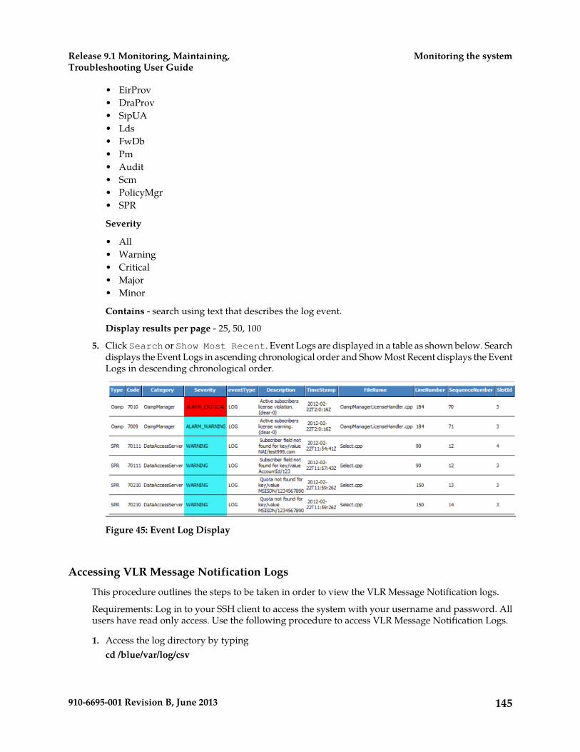
• EirProv• DraProv• SipUA• Lds• FwDb• Pm• Audit• Scm• PolicyMgr• SPR
Severity
• All• Warning• Critical• Major• Minor
Contains - search using text that describes the log event.
Display results per page - 25, 50, 100
5. Click Search or Show Most Recent. Event Logs are displayed in a table as shown below. Searchdisplays the Event Logs in ascending chronological order and Show Most Recent displays the EventLogs in descending chronological order.
Figure 45: Event Log Display
Accessing VLR Message Notification Logs
This procedure outlines the steps to be taken in order to view the VLR Message Notification logs.
Requirements: Log in to your SSH client to access the system with your username and password. Allusers have read only access. Use the following procedure to access VLR Message Notification Logs.
1. Access the log directory by typingcd /blue/var/log/csv
145910-6695-001 Revision B, June 2013
Monitoring the systemRelease 9.1 Monitoring, Maintaining,Troubleshooting User Guide
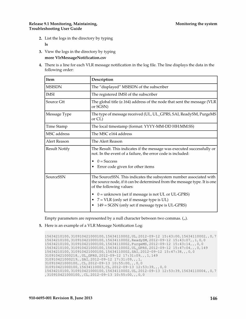
2. List the logs in the directory by typingls
3. View the logs in the directory by typingmore VlrMessageNotification.csv
4. There is a line for each VLR message notification in the log file. The line displays the data in thefollowing order:
DescriptionItem
The “displayed” MSISDN of the subscriberMSISDN
The registered IMSI of the subscriberIMSI
The global title (e.164) address of the node that sent the message (VLRor SGSN)
Source Gtt
The type of message received (UL, UL_GPRS, SAI, ReadySM, PurgeMSor CL)
Message Type
The local timestamp (format: YYYY-MM-DD HH:MM:SS)Time Stamp
The MSC e164 addressMSC address
The Alert ReasonAlert Reason
The Result. This indicates if the message was executed successfully ornot. In the event of a failure, the error code is included:
Result Notify
• 0 = Success• Error code given for other items
The SourceSSN. This indicates the subsystem number associated withthe source node, if it can be determined from the message type. It is oneof the following values:
SourceSSN
• 0 = unknown (set if message is not UL or UL-GPRS)• 7 = VLR (only set if message type is UL)• 149 = SGSN (only set if message type is UL-GPRS)
Empty parameters are represented by a null character between two commas. (,,).
5. Here is an example of a VLR Message Notification Log:
15634210100,310910421000100,15634110002,UL,2012-09-12 15:43:00,15634110002,,0,715634210100,310910421000100,15634110002,ReadySM,2012-09-12 15:43:07,,1,0,015634210100,310910421000100,15634110002,PurgeMS,2012-09-12 15:43:14,,,0,015634210100,310910421000100,15634110002,UL_GPRS,2012-09-12 15:47:04,,,0,14915634210100,310910421000100,15634110002,SAI,2012-09-12 15:47:38,,,0,0310910421000218,,UL_GPRS,2012-09-12 17:31:09,,,1,149310910421000219,,SAI,2012-09-12 17:31:09,,,1,310910421000100,,CL,2012-09-13 10:55:00,,,0,0310910421000100,15634110003,CL,2012-09-13 12:53:39,,,0,015634210100,310910421000100,15634110002,UL,2012-09-13 12:53:39,15634110004,,0,7,310910421000100,,CL,2012-09-13 10:55:00,,,0,0
146910-6695-001 Revision B, June 2013
Monitoring the systemRelease 9.1 Monitoring, Maintaining,Troubleshooting User Guide

Adding a header to the VLR Message Notification Logs
By default the VLR Message Notification Log has no header. If you wish to add a header to the VLRMessage Notification Log please contact the Tekelec Customer Care Center.
Removing a header from the VLR Message Notification Logs
By default the VLR Message Notification Log has no header. If you have added a header and wish toremove it please contact the Tekelec Customer Care Center.
VLR Message Notification Log File retention
By default the VLR Message Notification Logs are stored for 7 days in blue/var/log/csv. If youwish to change the number of days please contact the Tekelec Customer Care Center.
Accessing LTE-HSS Logs
This procedure outlines the steps to be taken in order to view the LTE-HSS logs.
Requirements: Log in to your SSH client to access the system with your username and password. Allusers have read only access. Use the following procedure to access LTE-HSS Logs.
1. Access the log directory by typingcd /blue/var/log/csv
2. List the logs in the directory by typingls
3. View the logs in the directory by typingmore lteHSSCaleaLog.csv
4. There is a line for each LTE-HSS event in the log file. The line displays the data in the followingorder:
DescriptionItem
The local timestamp (format: YYYY-MM-DDHH:MM:SS)
Time Stamp
The request type codeRequest Type Code
The host nameMME/SGSN HostName
The diameter result codeDiameter Result Code Number
The registered IMSI of the subscriberIMSI
The identification of the visited PLMNVisited PLMN ID
The alert reasonAlert Reason
The cancellation typeCancellation Type
The “displayed” MSISDN of the subscriberMSISDN
The authentication requestRequested Authentication
147910-6695-001 Revision B, June 2013
Monitoring the systemRelease 9.1 Monitoring, Maintaining,Troubleshooting User Guide

DescriptionItem
The IMEIIMEI
Empty parameters are represented by a null character between two commas. (,,). The content ofeach line in the LTE-HSS log differs based on the type of diameter message query received by theLTE-HSS.
5. Here is an example of an LTE-HSS Log:2013-04-17 13:17:20,316,mmeA.lte.blueslice.com,2001,320910421000100,05F613,15141111111,2013-04-18 16:20:34,316,mmeA.lte.blueslice.com,2001,320910421000100,05F613,15141111111,2013-04-18 17:21:55,318,mmeA.lte.blueslice.com,2001,320910421000100,05F613,EUTRAN2013-04-18 17:22:29,316,mmeA.lte.blueslice.com,2001,320910421000100,05F613,15141111111,2013-04-18 17:22:32,317,mmeA.lte.blueslice.com,,320910421000100,02013-04-18 17:24:00,321,mmeA.lte.blueslice.com,2001,320910421000100
Using traces
The system generates Traces for each system module for debugging purposes and to provideinformation on the actions that have been executed on the system and their sequence. Traces providethe Tekelec Customer Care Center and the operator with an additional level of information and allowthem to verify correct operation of the SDM.
WARNING: Traces are only useful for debugging purposes and should not be managedby the operator. Before troubleshooting, the operator must contact the Tekelec CustomerCare Center, who will help you debug by using the system traces.
Unlike all other log events in the system, traces are stored locally where they are produced. They arestored locally on the blade (under the /blue/var/trace directory) where the application concernedis running. Hence, trace files can be viewed from the blade which produced it through the CLI.
Note:
System events with the following levels are all called traces:
• Trace• Trace Error
All of the events of Trace Error level are by default always activated, which means that they can alwaysbe viewed and accessed.
However, events of Trace level are by default all deactivated. Some events of Trace level may havebeen activated by Tekelec and can only be managed (activated/deactivated) by the Tekelec CustomerCare Center during troubleshooting. In addition to activating or deactivating the necessary traces, theTekelec Customer Care Center will be able to filter some events of Trace level on a per component basisfor each process.
148910-6695-001 Revision B, June 2013
Monitoring the systemRelease 9.1 Monitoring, Maintaining,Troubleshooting User Guide
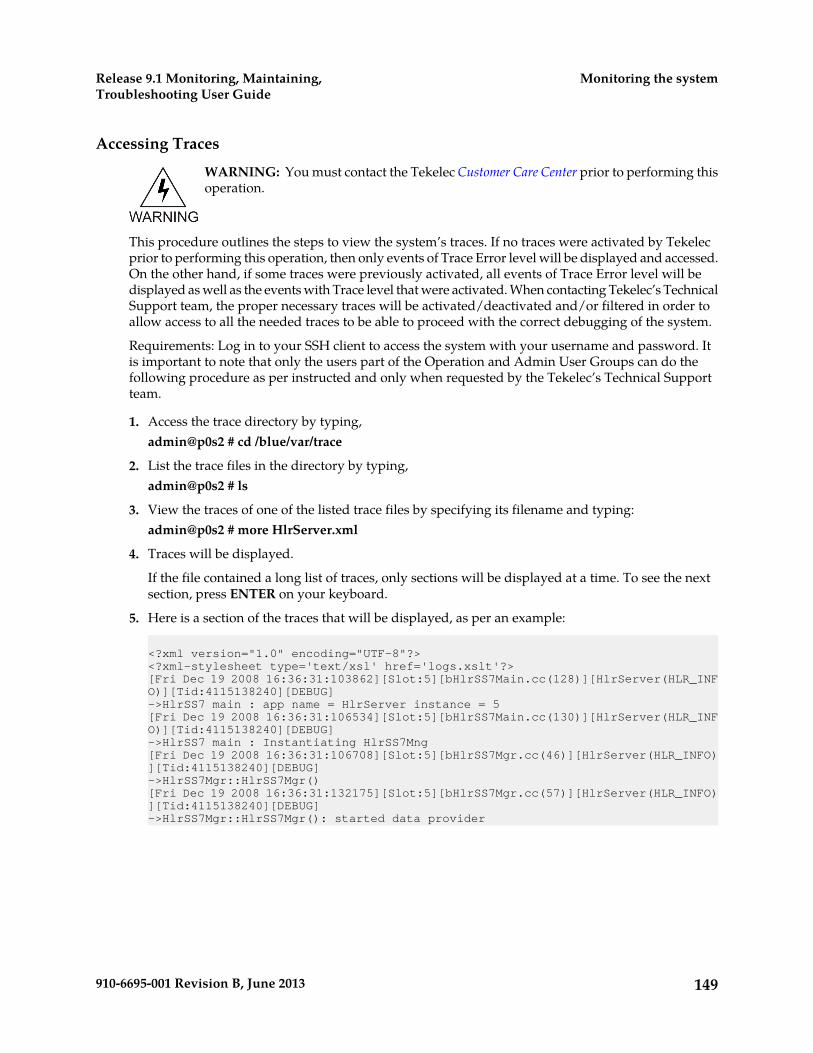
Accessing Traces
WARNING: You must contact the Tekelec Customer Care Center prior to performing thisoperation.
This procedure outlines the steps to view the system’s traces. If no traces were activated by Tekelecprior to performing this operation, then only events of Trace Error level will be displayed and accessed.On the other hand, if some traces were previously activated, all events of Trace Error level will bedisplayed as well as the events with Trace level that were activated. When contacting Tekelec’s TechnicalSupport team, the proper necessary traces will be activated/deactivated and/or filtered in order toallow access to all the needed traces to be able to proceed with the correct debugging of the system.
Requirements: Log in to your SSH client to access the system with your username and password. Itis important to note that only the users part of the Operation and Admin User Groups can do thefollowing procedure as per instructed and only when requested by the Tekelec’s Technical Supportteam.
1. Access the trace directory by typing,admin@p0s2 # cd /blue/var/trace
2. List the trace files in the directory by typing,admin@p0s2 # ls
3. View the traces of one of the listed trace files by specifying its filename and typing:admin@p0s2 # more HlrServer.xml
4. Traces will be displayed.
If the file contained a long list of traces, only sections will be displayed at a time. To see the nextsection, press ENTER on your keyboard.
5. Here is a section of the traces that will be displayed, as per an example:
<?xml version="1.0" encoding="UTF-8"?><?xml-stylesheet type='text/xsl' href='logs.xslt'?>[Fri Dec 19 2008 16:36:31:103862][Slot:5][bHlrSS7Main.cc(128)][HlrServer(HLR_INFO)][Tid:4115138240][DEBUG]->HlrSS7 main : app name = HlrServer instance = 5[Fri Dec 19 2008 16:36:31:106534][Slot:5][bHlrSS7Main.cc(130)][HlrServer(HLR_INFO)][Tid:4115138240][DEBUG]->HlrSS7 main : Instantiating HlrSS7Mng[Fri Dec 19 2008 16:36:31:106708][Slot:5][bHlrSS7Mgr.cc(46)][HlrServer(HLR_INFO)][Tid:4115138240][DEBUG]->HlrSS7Mgr::HlrSS7Mgr()[Fri Dec 19 2008 16:36:31:132175][Slot:5][bHlrSS7Mgr.cc(57)][HlrServer(HLR_INFO)][Tid:4115138240][DEBUG]->HlrSS7Mgr::HlrSS7Mgr(): started data provider
149910-6695-001 Revision B, June 2013
Monitoring the systemRelease 9.1 Monitoring, Maintaining,Troubleshooting User Guide

Viewing Information About the Activation Status of the SS7 and SIGTRANLinks
The CONFIG window is used to display the SS7 configuration information. For a description of eachof these configuration parameters, refer to the “CONFIG” section in the “SS7 entities” chapter of theSDM System Configuration Reference Manual.
Requirements: Log in to a WebCI session with a valid username and password.
1. From the main menu, navigate to SS7 > CONFIG2. This will open a SS7 configuration window (as shown in the figure below) which displays the SS7
configuration information.
SS7 Configuration Window
Monitoring SS7 Links and Performing a Line Test
To help troubleshoot SS7 physical link problems, the following sequence of events should be followedto help isolate the cause.
1. Check the line status with the iphlinestat tool.2. Test the line with the iphlinetest tool.
150910-6695-001 Revision B, June 2013
Monitoring the systemRelease 9.1 Monitoring, Maintaining,Troubleshooting User Guide
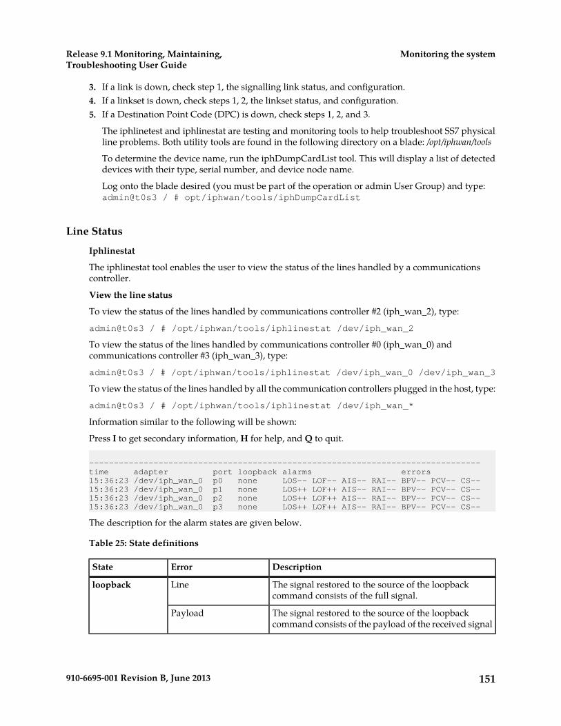
3. If a link is down, check step 1, the signalling link status, and configuration.4. If a linkset is down, check steps 1, 2, the linkset status, and configuration.5. If a Destination Point Code (DPC) is down, check steps 1, 2, and 3.
The iphlinetest and iphlinestat are testing and monitoring tools to help troubleshoot SS7 physicalline problems. Both utility tools are found in the following directory on a blade: /opt/iphwan/tools
To determine the device name, run the iphDumpCardList tool. This will display a list of detecteddevices with their type, serial number, and device node name.
Log onto the blade desired (you must be part of the operation or admin User Group) and type:admin@t0s3 / # opt/iphwan/tools/iphDumpCardList
Line Status
Iphlinestat
The iphlinestat tool enables the user to view the status of the lines handled by a communicationscontroller.
View the line status
To view the status of the lines handled by communications controller #2 (iph_wan_2), type:
admin@t0s3 / # /opt/iphwan/tools/iphlinestat /dev/iph_wan_2
To view the status of the lines handled by communications controller #0 (iph_wan_0) andcommunications controller #3 (iph_wan_3), type:
admin@t0s3 / # /opt/iphwan/tools/iphlinestat /dev/iph_wan_0 /dev/iph_wan_3
To view the status of the lines handled by all the communication controllers plugged in the host, type:
admin@t0s3 / # /opt/iphwan/tools/iphlinestat /dev/iph_wan_*
Information similar to the following will be shown:
Press I to get secondary information, H for help, and Q to quit.
-------------------------------------------------------------------------------time adapter port loopback alarms errors15:36:23 /dev/iph_wan_0 p0 none LOS-- LOF-- AIS-- RAI-- BPV-- PCV-- CS--15:36:23 /dev/iph_wan_0 p1 none LOS++ LOF++ AIS-- RAI-- BPV-- PCV-- CS--15:36:23 /dev/iph_wan_0 p2 none LOS++ LOF++ AIS-- RAI-- BPV-- PCV-- CS--15:36:23 /dev/iph_wan_0 p3 none LOS++ LOF++ AIS-- RAI-- BPV-- PCV-- CS--
The description for the alarm states are given below.
Table 25: State definitions
DescriptionErrorState
The signal restored to the source of the loopbackcommand consists of the full signal.
Lineloopback
The signal restored to the source of the loopbackcommand consists of the payload of the received signal
Payload
151910-6695-001 Revision B, June 2013
Monitoring the systemRelease 9.1 Monitoring, Maintaining,Troubleshooting User Guide

DescriptionErrorState
(with bit sequence integrity maintained) andnewly-generated ESF framing.
The port is not in loopback mode.None
Loss Of Signal. No electrical signal is detected. Verifythe line is plugged into the communications controllerand into the network interface.
LOSAlarms
Loss Of Frame. Frames are lost due to framing errors.The terminal is unable to synchronize on the DS1 signal.
LOF
Alarm Indication Signal. A signal transmitted insteadof the normal signal to maintain transmission continuity.
AIS
This signal notifies the receiving equipment that atransmission interruption occurred either on theequipment creating the AIS signal or by the receivingequipment.
Remote Alarm Indication. A signal transmitted in theoutgoing direction when a terminal detects a loss of theincoming signal.
RAI
BiPolar Violation. A BPV error event for an AMI-codedsignal is the occurrence of a pulse with the same polarityas the previous pulse.
BPVErrors
Path Code Violation. A PCV error event is a framesynchronization bit error (in D4 and E1-no CRC formats)or a CRC error in the ESF and E1-CRC formats.
PCV
Controlled Slip. A CS error results from the replicationor deletion of the payload bits of the DS1 frame. A CS
CS
may occur when there is a difference between the timingof a synchronous receiving terminal and the receivedsignal.
Each time one of the above states changes on a line (i.e., if loop back state has changed or an alarmoccurred or new errors were detected), a new line of text is displayed for that port. Alarms and errorsoccurrences are explained in the table below.
Table 26: Alarm Symbols
ErrorAlarmSymbol
No other errors of that type have occurred.No alarm of that type has occurred.- -
Other errors of that type have occurred.An alarm of that type has occurred.- +
Other errors of that type have occurred.That alarm is always present for the line.+ +
No other errors of that type have occurred.The alarm has just disappeared.+ -
The secondary information that can be obtained by pressing I, provides detailed information such as:
152910-6695-001 Revision B, June 2013
Monitoring the systemRelease 9.1 Monitoring, Maintaining,Troubleshooting User Guide
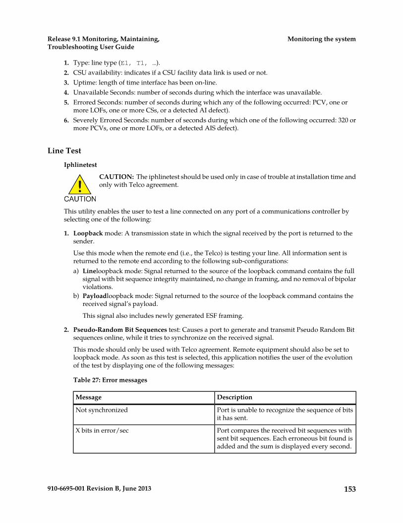
1. Type: line type (E1, T1, …).2. CSU availability: indicates if a CSU facility data link is used or not.3. Uptime: length of time interface has been on-line.4. Unavailable Seconds: number of seconds during which the interface was unavailable.5. Errored Seconds: number of seconds during which any of the following occurred: PCV, one or
more LOFs, one or more CSs, or a detected AI defect).6. Severely Errored Seconds: number of seconds during which one of the following occurred: 320 or
more PCVs, one or more LOFs, or a detected AIS defect).
Line Test
Iphlinetest
CAUTION: The iphlinetest should be used only in case of trouble at installation time andonly with Telco agreement.
This utility enables the user to test a line connected on any port of a communications controller byselecting one of the following:
1. Loopback mode: A transmission state in which the signal received by the port is returned to thesender.
Use this mode when the remote end (i.e., the Telco) is testing your line. All information sent isreturned to the remote end according to the following sub-configurations:a) Lineloopback mode: Signal returned to the source of the loopback command contains the full
signal with bit sequence integrity maintained, no change in framing, and no removal of bipolarviolations.
b) Payloadloopback mode: Signal returned to the source of the loopback command contains thereceived signal’s payload.
This signal also includes newly generated ESF framing.
2. Pseudo-Random Bit Sequences test: Causes a port to generate and transmit Pseudo Random Bitsequences online, while it tries to synchronize on the received signal.
This mode should only be used with Telco agreement. Remote equipment should also be set toloopback mode. As soon as this test is selected, this application notifies the user of the evolutionof the test by displaying one of the following messages:
Table 27: Error messages
DescriptionMessage
Port is unable to recognize the sequence of bitsit has sent.
Not synchronized
Port compares the received bit sequences withsent bit sequences. Each erroneous bit found isadded and the sum is displayed every second.
X bits in error/sec
153910-6695-001 Revision B, June 2013
Monitoring the systemRelease 9.1 Monitoring, Maintaining,Troubleshooting User Guide

DescriptionMessage
Receiving bit sequences completed; Port foundno errors when comparing sent and received bitsequences.
No error
Testing the line
To test the line plugged on port#0 (default port =0) of communications controller #2 (iph_wan_2),type:
admin@t0s3 / # /opt/iphwan/tools/iphlinetest /dev/iph_wan_2
To test the line plugged on port#1 of communication controller #0, type:
admin@t0s3 / # /opt/iphwan/tools/iphlinetest /dev/iph_wan_0 1
After tests have been completed and the application closed, the tested port is automatically restoredto its operational mode in order to handle incoming and outgoing calls.
CLI Operations to Monitor SS7 Activity
The following operations can be used to monitor SS7 activity and status on the system.
1. View Active MTP2 Sapsa) To display the active MTP2 Service Access Points, run the following operation.
Command syntax:SS7[]:MTP2[] GetActiveMTP2Saps()
2. View Active MTP3 Linksa) To display the active MTP3 Links, run the following operation.
When the state = up it indicates the link is active.b) Command syntax:c) SS7[]:MTP3[]> GetActiveLinks()
3. View Active MTP3 LinkSetsa) To display the active MTP3 Link Sets, run the following operation.b) Command syntax:c) SS7[]:MTP3[]> GetActiveLinkSets()
4. View Active MTP3 Sapsa) To display the active MTP3 Service Access Points, run the following operation.b) Command syntax:c) SS7[]:MTP3[]> GetActiveMTP3Saps()
5. View Active SCCP NSapsa) To display the active SCCP Network Service Access Points, run the following operation.b) Command syntax:c) SS7[]:SCCP[]> GetActiveSccpNSaps()
154910-6695-001 Revision B, June 2013
Monitoring the systemRelease 9.1 Monitoring, Maintaining,Troubleshooting User Guide
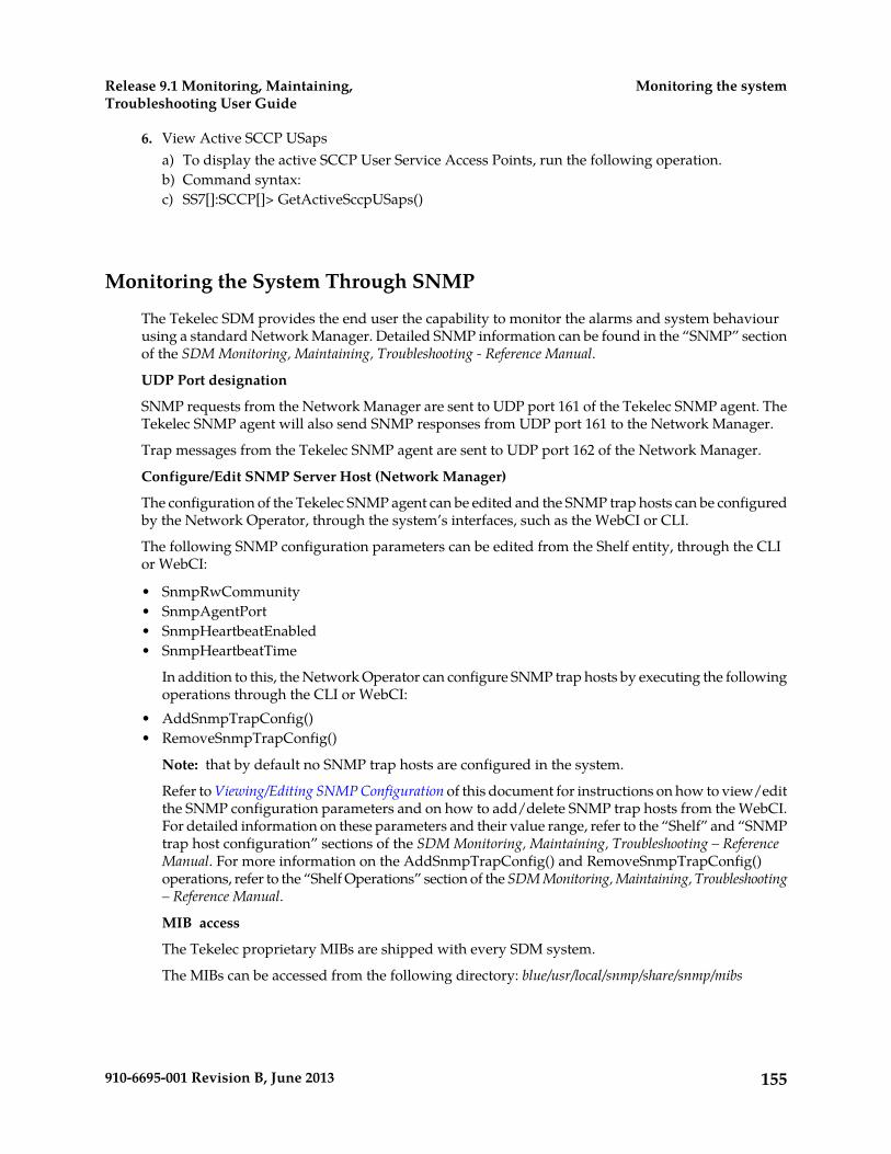
6. View Active SCCP USapsa) To display the active SCCP User Service Access Points, run the following operation.b) Command syntax:c) SS7[]:SCCP[]> GetActiveSccpUSaps()
Monitoring the System Through SNMP
The Tekelec SDM provides the end user the capability to monitor the alarms and system behaviourusing a standard Network Manager. Detailed SNMP information can be found in the “SNMP” sectionof the SDM Monitoring, Maintaining, Troubleshooting - Reference Manual.
UDP Port designation
SNMP requests from the Network Manager are sent to UDP port 161 of the Tekelec SNMP agent. TheTekelec SNMP agent will also send SNMP responses from UDP port 161 to the Network Manager.
Trap messages from the Tekelec SNMP agent are sent to UDP port 162 of the Network Manager.
Configure/Edit SNMP Server Host (Network Manager)
The configuration of the Tekelec SNMP agent can be edited and the SNMP trap hosts can be configuredby the Network Operator, through the system’s interfaces, such as the WebCI or CLI.
The following SNMP configuration parameters can be edited from the Shelf entity, through the CLIor WebCI:
• SnmpRwCommunity• SnmpAgentPort• SnmpHeartbeatEnabled• SnmpHeartbeatTime
In addition to this, the Network Operator can configure SNMP trap hosts by executing the followingoperations through the CLI or WebCI:
• AddSnmpTrapConfig()• RemoveSnmpTrapConfig()
Note: that by default no SNMP trap hosts are configured in the system.
Refer to Viewing/Editing SNMP Configuration of this document for instructions on how to view/editthe SNMP configuration parameters and on how to add/delete SNMP trap hosts from the WebCI.For detailed information on these parameters and their value range, refer to the “Shelf” and “SNMPtrap host configuration” sections of the SDM Monitoring, Maintaining, Troubleshooting – ReferenceManual. For more information on the AddSnmpTrapConfig() and RemoveSnmpTrapConfig()operations, refer to the “Shelf Operations” section of the SDM Monitoring, Maintaining, Troubleshooting– Reference Manual.
MIB access
The Tekelec proprietary MIBs are shipped with every SDM system.
The MIBs can be accessed from the following directory: blue/usr/local/snmp/share/snmp/mibs
155910-6695-001 Revision B, June 2013
Monitoring the systemRelease 9.1 Monitoring, Maintaining,Troubleshooting User Guide
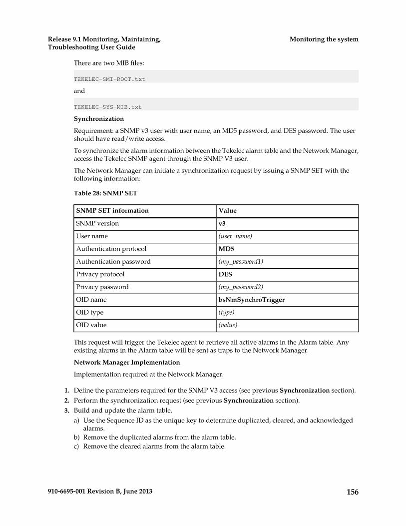
There are two MIB files:
TEKELEC-SMI-ROOT.txt
and
TEKELEC-SYS-MIB.txt
Synchronization
Requirement: a SNMP v3 user with user name, an MD5 password, and DES password. The usershould have read/write access.
To synchronize the alarm information between the Tekelec alarm table and the Network Manager,access the Tekelec SNMP agent through the SNMP V3 user.
The Network Manager can initiate a synchronization request by issuing a SNMP SET with thefollowing information:
Table 28: SNMP SET
ValueSNMP SET information
v3SNMP version
(user_name)User name
MD5Authentication protocol
(my_password1)Authentication password
DESPrivacy protocol
(my_password2)Privacy password
bsNmSynchroTriggerOID name
(type)OID type
(value)OID value
This request will trigger the Tekelec agent to retrieve all active alarms in the Alarm table. Anyexisting alarms in the Alarm table will be sent as traps to the Network Manager.
Network Manager Implementation
Implementation required at the Network Manager.
1. Define the parameters required for the SNMP V3 access (see previous Synchronization section).2. Perform the synchronization request (see previous Synchronization section).3. Build and update the alarm table.
a) Use the Sequence ID as the unique key to determine duplicated, cleared, and acknowledgedalarms.
b) Remove the duplicated alarms from the alarm table.c) Remove the cleared alarms from the alarm table.
156910-6695-001 Revision B, June 2013
Monitoring the systemRelease 9.1 Monitoring, Maintaining,Troubleshooting User Guide
Chapter
6Maintenance
The chapter contains information used to performmaintenance on the Subscriber Data Managementsystem.
Topics:
• Maintenance.....158
157910-6695-001 Revision B, June 2013
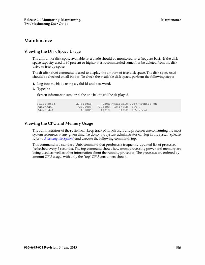
Maintenance
Viewing the Disk Space Usage
The amount of disk space available on a blade should be monitored on a frequent basis. If the diskspace capacity used is 60 percent or higher, it is recommended some files be deleted from the diskdrive to free up space.
The df (disk free) command is used to display the amount of free disk space. The disk space usedshould be checked on all blades. To check the available disk space, perform the following steps:
1. Log into the blade using a valid Id and password.2. Type: df
Screen information similar to the one below will be displayed.
Filesystem 1K-blocks Used Available Use% Mounted on/dev/hda3 72690908 7271808 62465068 11% //dev/hda1 101089 14818 81052 16% /boot
Viewing the CPU and Memory Usage
The administrators of the system can keep track of which users and processes are consuming the mostsystem resources at any given time. To do so, the system administrator can log in the system (pleaserefer to Accessing the System) and execute the following command: top.
This command is a standard Unix command that produces a frequently-updated list of processes(refreshed every 5 seconds). The top command shows how much processing power and memory arebeing used, as well as other information about the running processes. The processes are ordered byamount CPU usage, with only the "top" CPU consumers shown.
158910-6695-001 Revision B, June 2013
MaintenanceRelease 9.1 Monitoring, Maintaining,Troubleshooting User Guide
Chapter
7Troubleshooting
This chapter contains information used totroubleshoot the Subscriber Data Managementsystem.
Topics:
• What Is Troubleshooting?.....160• Troubleshooting the System.....169• Troubleshooting a Geo-Redundant System –
Backup/Restore Procedures.....198• View License and Log Information from the
WebCI.....218• Set Active Subscribers Warning Threshold.....219• Troubleshooting Subscriber Provisioning.....219• Troubleshooting congestion in SPR
Received-Message Queue.....220
159910-6695-001 Revision B, June 2013

What Is Troubleshooting?
Troubleshooting generally consists of the following:
1. Define the specific symptoms.
a. What caused the problem?
2. Determine the cause of the symptoms by using various Troubleshooting tools and techniques.3. Correct the problem.4. Once the problem has been identified, fix it by implementing a series of actions.
Before you start Troubleshooting
During troubleshooting, it may be necessary to change some files (i.e., configuration files). Oncetroubleshooting has been completed, some changes may need to be undone. The process of restoringfiles is easier to do when the files are saved before troubleshooting has started.
The operator should consider each of the following:
1. Save the network configuration.2. Save the log files.
a) Log files are kept for a period of seven days.
Logs generated by a troubleshooting session will eventually overwrite the logs that are stored.
3. Do not erase the log files unless they have been saved.4. If there are going to be several troubleshooting sessions, consider saving the logs after each
troubleshooting session (otherwise it may be overwritten by normal system activity logs).5. When the troubleshooting session is finished, remember to restore the system to the state it was in
before the troubleshooting session started.6. If necessary, restore any configuration changes, restore any files that were changed, etc.7. If special cabling was wired for troubleshooting (for example, for loopback tests), restore the cabling
to its original state.
Troubleshooting may affect system behavior
Before beginning troubleshooting, consider the following:
When it is necessary to troubleshoot on a live system, it is best to perform troubleshooting procedureswhen the traffic is low.
Troubleshooting Tools
The following section describes the tools that can be used to help troubleshoot problems on the system.
If the problem still exists after using these tools, please contact the Tekelec Customer Care Center tohelp resolve the problem.
160910-6695-001 Revision B, June 2013
TroubleshootingRelease 9.1 Monitoring, Maintaining,Troubleshooting User Guide

Troubleshooting Using Alarms
The system alarms can be used to determine the state of the system. The operator is able to:
1. View all active alarms2. View details of specific alarm(s)3. View alarm history4. Acknowledge alarms5. Clear alarms
View Active AlarmsTo view active alarms on the system, type:
System[]>display Alarm[]
View Alarm DetailsTo investigate details of a specific alarm, specify the SequenceId number and type:
System[]>display Alarm[SequenceId = 7]
Acknowledge AlarmsThe acknowledge operation can be used to acknowledge a specific alarm. Note that it does not clearthe conditions that raised the alarm. To acknowledge a specific alarm, enter the SequenceId numberand type:
System[]:Alarm[SequenceId = #]>Acknowledge()
Clear AlarmsCAUTION: the operator must be careful with this operation.
Even though this clears all the alarms from the active alarm list, the conditions that caused these alarmsstill exist but will NOT be reported when these conditions no longer prevail.
161910-6695-001 Revision B, June 2013
TroubleshootingRelease 9.1 Monitoring, Maintaining,Troubleshooting User Guide
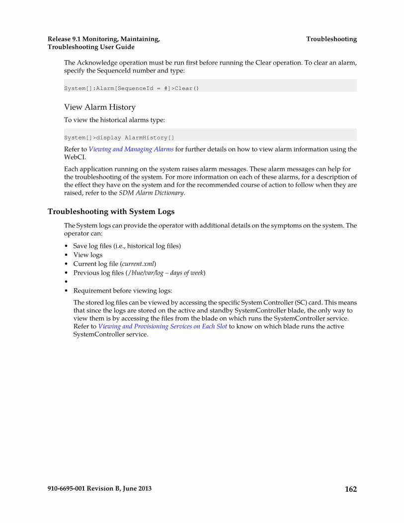
The Acknowledge operation must be run first before running the Clear operation. To clear an alarm,specify the SequenceId number and type:
System[]:Alarm[SequenceId = #]>Clear()
View Alarm HistoryTo view the historical alarms type:
System[]>display AlarmHistory[]
Refer to Viewing and Managing Alarms for further details on how to view alarm information using theWebCI.
Each application running on the system raises alarm messages. These alarm messages can help forthe troubleshooting of the system. For more information on each of these alarms, for a description ofthe effect they have on the system and for the recommended course of action to follow when they areraised, refer to the SDM Alarm Dictionary.
Troubleshooting with System Logs
The System logs can provide the operator with additional details on the symptoms on the system. Theoperator can:
• Save log files (i.e., historical log files)• View logs• Current log file (current.xml)• Previous log files (/blue/var/log – days of week)•• Requirement before viewing logs:
The stored log files can be viewed by accessing the specific System Controller (SC) card. This meansthat since the logs are stored on the active and standby SystemController blade, the only way toview them is by accessing the files from the blade on which runs the SystemController service.Refer to Viewing and Provisioning Services on Each Slot to know on which blade runs the activeSystemController service.
162910-6695-001 Revision B, June 2013
TroubleshootingRelease 9.1 Monitoring, Maintaining,Troubleshooting User Guide

Viewing System LogsTo view system log messages, go to the log directory by typing:
admin@p0s2 # cd /blue/var/logadmin@p0s2 /blue/var/log # more current.xml
Viewing Stored System LogsTo view stored log files, list the files stored in the /blue/var/log directory and type:
admin@p0s2 # cd /blue/var/logadmin@p0s2 /blue/var/log # more friday_20060616_115524
Understanding System LogsThe log messages generated provide information in the following format:
Table 29: Description of log fields
DescriptionItem
The type of system logType
An error message identifier which is a unique valueCode
module or event that generated the logCategory
indicates function calling sequenceTraceSeverity
debugging informationDebug
information normally used whendebugging a problem
Info
non-error conditions that mayrequire special handling
Notice
WarningWarning
ErrorError
warning alarmAlarm Warning
minor alarmAlarm Minor
major alarmAlarm Major
critical alarmAlarm Critical
Log or TraceeventType
additional information describing the log eventDescription
in GMT format (YYYY-MM-DDThh:mm:ss)Timestamp
module file nameFilename
163910-6695-001 Revision B, June 2013
TroubleshootingRelease 9.1 Monitoring, Maintaining,Troubleshooting User Guide

module file line numberlineNumber
log sequence number generated by client applicationSequenceNumber
chassis slot where the event was generatedslotId
Troubleshooting with Traces
The System traces can provide the operator with additional details on the symptoms of the system.Prior to using traces for troubleshooting, the Tekelec’s Customer Care Center must always be contacted.Tekelec technicians will be able to manage traces and analyse them properly to be able to debug thesystem.
Once you have contacted Tekelec’s Customer Care Center, a Tekelec Support Technician will performall or some of the following operations:
• Access/View traces. See Accessing Traces.• Save traces.• Activate/Deactivate events of Trace level.• Add/Remove Filter Component
The stored trace files can be viewed by accessing the blade on which runs the concerned application.This means that since the traces are stored locally, on the same blade on which runs the applicationthat produced it, they cannot all be viewed at once under one single location. Only the traces producedby the applications running on a specific blade can be viewed when accessing the /blue/var/tracedirectory from that blade.
Refer to Accessing Traces for step-by-step instructions on how to access traces.
Performance Monitoring
The operator can also use Performance Monitoring counts to help view system activity and monitorsystem behavior. The operator is able to:
• View current PM counts• View current PM historical
Refer to the SDM Performance Measurements document for a list of the different counters and forinstructions on how to view these counters and modify some thresholds.
Restarting Processes
In the event it may be necessary to restart the software applications (i.e., after a power failure or toreboot the system), it is recommended to Stop the services on the system and once again Start themthrough the WebCI.
Stopping or starting applications, services, or slots
Applications, services, and slots can be stopped and started from the WebCI for troubleshootingpurposes.
164910-6695-001 Revision B, June 2013
TroubleshootingRelease 9.1 Monitoring, Maintaining,Troubleshooting User Guide

Applications
To stop an application, all the system services running the application must be stopped.
These services run the SDM applications:
• The Hlr service runs the HLR and SIP applications.• The Hss service runs the HSS, SLF, AAA and DNS ENUM applications.• The LteHss service runs the LTE HSS application.
Stopping these services will also stop the other applications that run on this service.
For example, to stop the AAA application on a slot, the HSS services on that slot must be stopped.Stopping the HSS services will then also stop the remaining applications such as HSS, SLF, and DNSENUM.
After modifying the application, an application restart may be necessary.
Services
Each service can be stopped or started individually. In some situations, one single service or somespecific services may need to be stopped or started. Stopping and restarting services may be requiredin the following cases:
• If the connections are down. For example, if the SS7 connections to an HLR service are down, thatspecific HLR service must be restarted. In this case, one single service needs to be stopped and mayneed to be started again later.
• After performing a restore of the database from a backup. In this case, all the services, except theCoreSystemController, Database and DataAccess services running on the slot on which the activeDatabase service instance runs, must be stopped and then started. Each service of the slot must bestopped one at a time and then restarted again.
For a geo-redundant site where the VIP is to be modified, all the services running on a slot are stoppedand then started again automatically.
Slots
To stop or start a slot, all services running on a slot must be stopped or started. Stopping and restartinga slot may be necessary when an SBC needs to be removed. Prior to removing the SBC, all servicesrunning on its slot must be stopped. Once the replacement SBC has been installed and configured, allthe services on the slot can be started for the new SBC.
Note: When stopping slots, the front-end slots must be stopped before the back-end slots. Whenstarting slots, the front-end slots must be started before at least one back-end slot is started.
Stop a service on a slotPrerequisites:
The state of the service or all services must be at ‘Started’ prior to stop the service or all services.
1. Click the System folder.2. Click Shelf View.
The Shelf View window opens.
165910-6695-001 Revision B, June 2013
TroubleshootingRelease 9.1 Monitoring, Maintaining,Troubleshooting User Guide
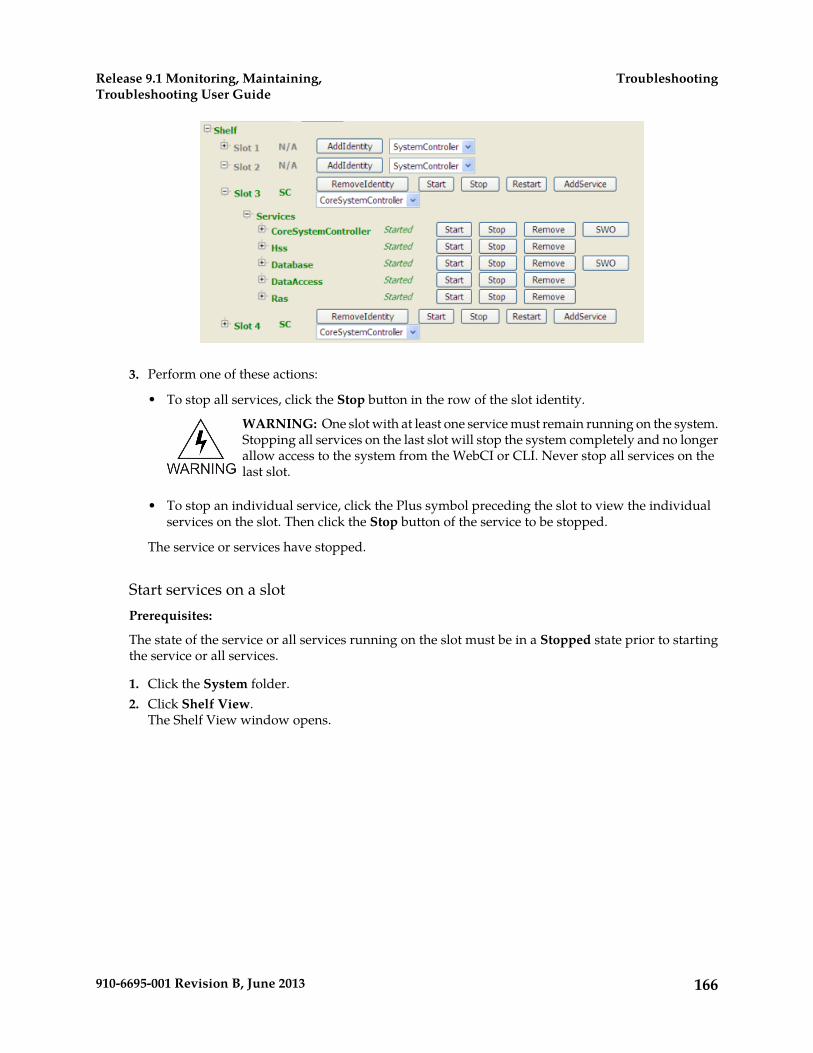
3. Perform one of these actions:
• To stop all services, click the Stop button in the row of the slot identity.
WARNING: One slot with at least one service must remain running on the system.Stopping all services on the last slot will stop the system completely and no longerallow access to the system from the WebCI or CLI. Never stop all services on thelast slot.
• To stop an individual service, click the Plus symbol preceding the slot to view the individualservices on the slot. Then click the Stop button of the service to be stopped.
The service or services have stopped.
Start services on a slotPrerequisites:
The state of the service or all services running on the slot must be in a Stopped state prior to startingthe service or all services.
1. Click the System folder.2. Click Shelf View.
The Shelf View window opens.
166910-6695-001 Revision B, June 2013
TroubleshootingRelease 9.1 Monitoring, Maintaining,Troubleshooting User Guide

3. Perform one of these actions:
• To start all services, click the Start button in the row of the slot identity.
Note: Use this option if all services on this slot need to be started. Do not attempt to start eachservice independently.
• To start an individual service, click the Plus symbol preceding the slot to view the individualservices on the slot. Then click the Start button of the service to be started.
WARNING: If a service is already running on a slot (i.e., CoreSystemController),starting the services on the slot will start the other services on the slot.
WARNING: If the Stop button was executed previously, wait 30 seconds beforeclicking the Start button.
The service or services have started.
Restart services on a slotPrerequisites:
The state of the service or all services running on the slot must be in a Started state prior to restartingthe service or all services.
1. Click the System folder.2. Click Shelf View.
The Shelf View window opens.
167910-6695-001 Revision B, June 2013
TroubleshootingRelease 9.1 Monitoring, Maintaining,Troubleshooting User Guide

3. Perform one of these actions:
• To restart all services, click the Restart button in the row of the slot identity.
Note: Use this option if all services on this blade need to be restarted. Do not attempt to restarteach service independently.
• To restart an individual service, click the Plus symbol preceding the slot to view the individualservices on the slot. Then click the Start button of the service to be restarted.
WARNING: If a service is already running on a slot (i.e., CoreSystemController),starting the services on the slot will start the other services on the slot.
WARNING: If the Stop button was executed previously, wait 30 seconds beforeclicking the Start button.
The service or services have restarted.
Start services on a System Controller bladeAfter a system start-up or a power failure it is possible to manually load data to memory on the activesystem controller blade. To do this these 2 steps must precede the steps in Start services on a blade.
Prerequisites:
The state of the service or all services running on the blade must be in a Stopped state prior to startingthe service or all services.
1. At the command line type service blue start to access the SystemController blade.2. Type perl /blue/bin/load_db_tables_in_memory.pl
localhost[username][password] to run the script. After running the script :
• Traffic can be run straight away. System capacity will not reach its full performance until allthe data is loaded into memory.
168910-6695-001 Revision B, June 2013
TroubleshootingRelease 9.1 Monitoring, Maintaining,Troubleshooting User Guide

• Wait until all the data is loaded into memory and then run traffic at peak capacity. The systemcan handle traffic at its rated capacity at this point.
Remote Log In
When terminating a remote log in session, the session window may hang occasionally. This may occurafter restarting a slot through a remote log in session.
Workaround: The session can be recovered by entering "~.".
Troubleshooting the System
Viewing the Software Version of the System
System PromptTo determine which software version is running on the Tekelec SDM system, log in to the systemcontroller card with a login name and password.
At the system prompt, type
# BlueVersion
The system will provide release information similar to the following:* Tekelec version: 3.1.00(6080100_LNX_3_1_REL)_LOAD_BUILD
The number3.1.00
is the software version number. The text6080100_LNX_3_1
indicates the load build number.
CLIFrom any navigation level within the CLI, at the system prompt :> type version to get the softwarerelease information.
WebCIIn the WebCI System Application folder, the software version is shown in the Shelf Inventory view.The software version and Load build is displayed at the bottom of the screen.
169910-6695-001 Revision B, June 2013
TroubleshootingRelease 9.1 Monitoring, Maintaining,Troubleshooting User Guide
Viewing the System’s Host Name
DefinitionThe system host name should be configured according to the following definition:xxxxxxxxxxN1sN2where xxxxxxxxxx can be any combination of characters. There is no maximum of characters but itmust start with a letter.
The name must end with two numbers separated by the letter “s” e.g., N1sN2. Both numbers mustbe ≥ 1 and each number can be a maximum of 2 digits.
Generally, the first number, N1, refers to the System ID and the second number, N2, refers to the SlotId.
Example.
TEKELEC_CA_HLR1s10TEKELEC_CA_HLR99s5
Active StatusActive Host Name
To retrieve the name of the active host on the shelf, run the following operation by typing:
:Oamp[]:OampManager[]>GetActiveOampHostName ()
Viewing/Modifying the Information for a Geo-Redundant System
The Geo-Redundant feature can be provisioned through the WebCI.
With the SDM system running in a Geo-Redundant deployment, the OAMP Virtual IP address of thepeer site and the state of the Geo-Redundant feature become important information to know.
The following procedures allow the administrator of the system, as well as users part of the AdminGroup and Operation Group, to display and modify from the WebCI the Geo-Redundant configurationdata.
The following information can be displayed:
• Enabled status of the Geo-Redundancy feature• Local/Remote Virtual IP address of the geo-redundant sites• Local Site Netmask• Local/Remote Ports of the geo-redundant sites• Activation status of the Geo-Redundancy deployment (started/stopped)
The following information can be modified:• Local/Remote Virtual IP address of the geo-redundant sites• Local Site Netmask
Display Geo Redundancy View with WebCIThis procedure describes how to display the Geo Redundancy screen using the WebCI.
170910-6695-001 Revision B, June 2013
TroubleshootingRelease 9.1 Monitoring, Maintaining,Troubleshooting User Guide
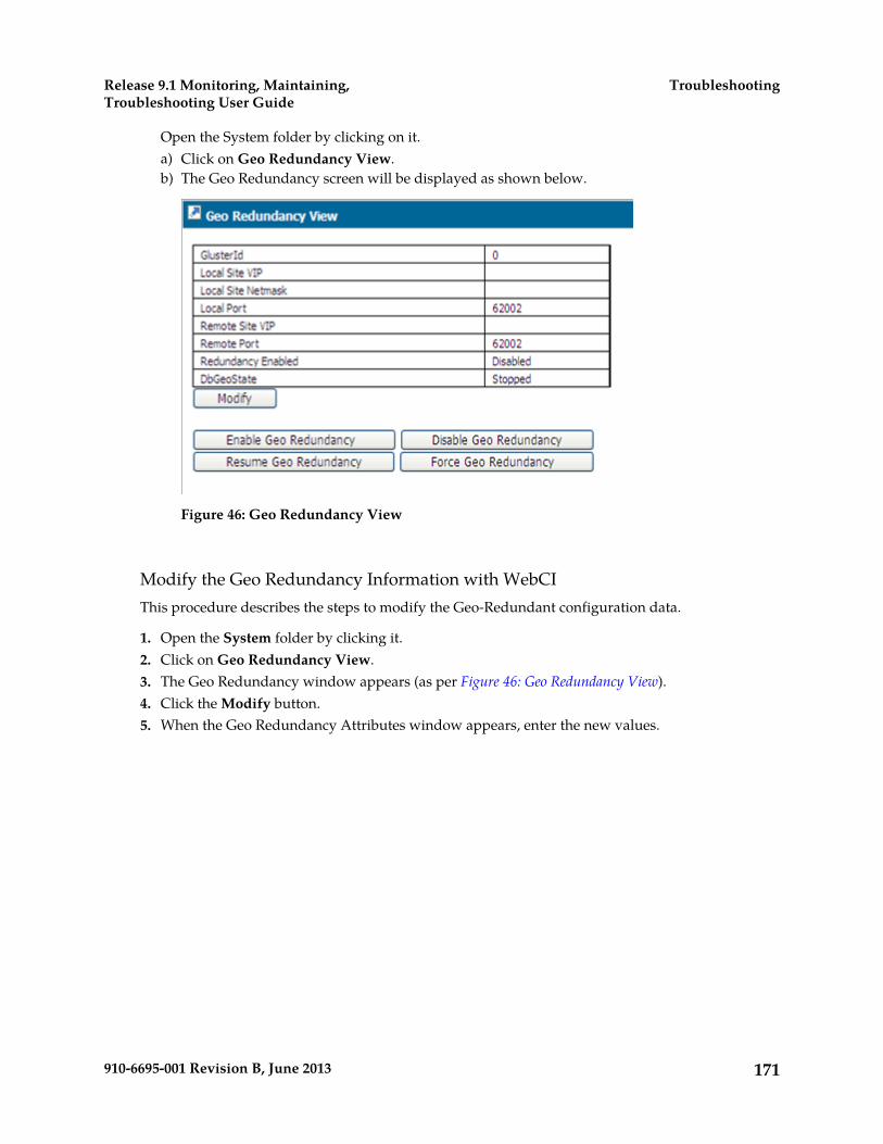
Open the System folder by clicking on it.a) Click on Geo Redundancy View.b) The Geo Redundancy screen will be displayed as shown below.
Figure 46: Geo Redundancy View
Modify the Geo Redundancy Information with WebCIThis procedure describes the steps to modify the Geo-Redundant configuration data.
1. Open the System folder by clicking it.2. Click on Geo Redundancy View.3. The Geo Redundancy window appears (as per Figure 46: Geo Redundancy View).4. Click the Modify button.5. When the Geo Redundancy Attributes window appears, enter the new values.
171910-6695-001 Revision B, June 2013
TroubleshootingRelease 9.1 Monitoring, Maintaining,Troubleshooting User Guide

Figure 47: Geo Redundancy Attributes Screen
6. Click Commit.7. When the confirmation message “Entity entry was successfully committed” appears, click OK.
The WebCI’s Geo-Redundancy View also allows to perform the following operations:a) Enable/Disable Geo Redundancyb) Resume Geo Redundancyc) Force Geo Redundancy
Enable/Disable the Geo Redundant Information with WebCIThis procedure describes the steps to enable/disable the Geo-redundant feature.
1. Open the System folder by clicking it.2. Click on Geo Redundancy View.3. The Geo Redundancy window appears (as per Figure 46: Geo Redundancy View).4. Click the Enable Geo Redundancy button if the feature is disabled and you wish to enable it.5. Click the Disable Geo Redundancy button if the feature is enabled and you wish to disable it.
WARNING: The Geo-redundancy should never be disabled on both sites (ReferenceProtected andReplica). If it is done, one of the two sites will have to be completely shut down and restarted torecover geo-redundancy. In this case, contact Tekelec’s Customer Care Center in order to restart andrecover geo-redundancy.
172910-6695-001 Revision B, June 2013
TroubleshootingRelease 9.1 Monitoring, Maintaining,Troubleshooting User Guide
Resume Geo-Redundancy with WebCIThis procedure describes the steps to resume the synchronization process when it is in an unassignedstate. Performing this operation forces the synchronization process to reenter the negotiating phasein order to identify which site has the reference database and which site has the replica database.
Requirement: The Geo-Redundancy feature must be enabled. Geo-Redundancy has not been disabledfor more than 4 hours and DbGeoState must be unassigned and enabled. Tekelec support personnelmust be contacted to resume Geo-Redundancy on a system where it was disabled for more than 4hours.
1. Open the System folder by clicking it.2. Click on Geo Redundancy View.3. The Geo Redundancy window appears (as per Figure 46: Geo Redundancy View).4. Click the Resume Geo Redundancy button.
Force the Geo Reference with WebCIThis procedure describes the steps to force the database to change from the PendingReference stateto the Reference state, after which the database changed in the case where the connection between thetwo sites was lost, either due to the physical connection or the operational state of the other site.
Requirement: The Geo-Redundancy feature must be enabled and DbGeoState must bePendingReference.
1. Open the System folder by clicking it.2. Click on Geo Redundancy View.3. The Geo Redundancy window appears (as per Figure 46: Geo Redundancy View).4. Click the Force Geo Reference button.
Viewing/Provisioning the System Shelf and Slots
This procedure describes how to display from the WebCI the configuration of the Shelf and of eachof its slots.
The Shelf View displays all the slots on the system and the services running on each one and theirstatus. It also provides in the form of buttons all the operations that might be necessary whentroubleshooting the system. Please contact Tekelec's Customer Care Center prior to executing theseoperations as they may impact the health of the system.
For further information on starting/stopping services, refer to Stopping or starting applications, services,or slots.
You will notice that the operational state of the slots is color coded as per the following legend:
Table 30: Operational Status Colors
Operational statusColor
The shelf/slot/service are up and running.Green
173910-6695-001 Revision B, June 2013
TroubleshootingRelease 9.1 Monitoring, Maintaining,Troubleshooting User Guide

Operational statusColor
The shelf/slot has some services that are notrunning.
Orange
The shelf/slot/service is not running.Red
The slot doesn’t have an identity bind to it. Noprocesses are running on that slot.
Grey
1. Open the System folder by clicking on it.2. Click on Shelf View.
a) The Shelf View screen will be displayed as shown below.
Figure 48: Shelf View
3. Click on the symbol preceding the item for which you wish to see further information.4. Click on the Display Background Task or Display Background Task History button to display
the Background tasks currently in progress or all the Background tasks that have taken place onthe system in a previous time (history of all Background tasks).
174910-6695-001 Revision B, June 2013
TroubleshootingRelease 9.1 Monitoring, Maintaining,Troubleshooting User Guide
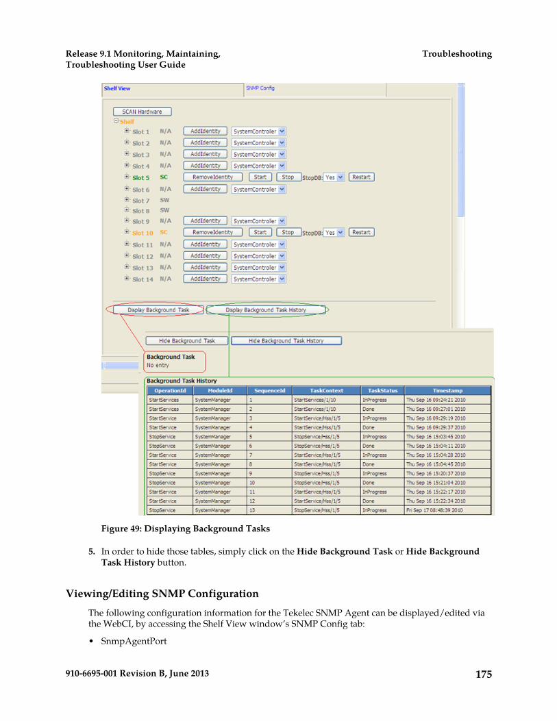
Figure 49: Displaying Background Tasks
5. In order to hide those tables, simply click on the Hide Background Task or Hide BackgroundTask History button.
Viewing/Editing SNMP Configuration
The following configuration information for the Tekelec SNMP Agent can be displayed/edited viathe WebCI, by accessing the Shelf View window’s SNMP Config tab:
• SnmpAgentPort
175910-6695-001 Revision B, June 2013
TroubleshootingRelease 9.1 Monitoring, Maintaining,Troubleshooting User Guide
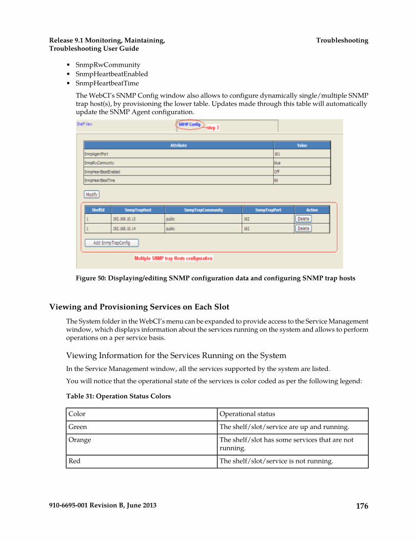
• SnmpRwCommunity• SnmpHeartbeatEnabled• SnmpHeartbeatTime
The WebCI’s SNMP Config window also allows to configure dynamically single/multiple SNMPtrap host(s), by provisioning the lower table. Updates made through this table will automaticallyupdate the SNMP Agent configuration.
Figure 50: Displaying/editing SNMP configuration data and configuring SNMP trap hosts
Viewing and Provisioning Services on Each Slot
The System folder in the WebCI’s menu can be expanded to provide access to the Service Managementwindow, which displays information about the services running on the system and allows to performoperations on a per service basis.
Viewing Information for the Services Running on the SystemIn the Service Management window, all the services supported by the system are listed.
You will notice that the operational state of the services is color coded as per the following legend:
Table 31: Operation Status Colors
Operational statusColor
The shelf/slot/service are up and running.Green
The shelf/slot has some services that are notrunning.
Orange
The shelf/slot/service is not running.Red
176910-6695-001 Revision B, June 2013
TroubleshootingRelease 9.1 Monitoring, Maintaining,Troubleshooting User Guide

The slot doesn’t have an identity bind to it. Noprocesses are running on that slot.
Grey
For each service, the following information can be displayed:
• The slot ID and state on which runs the service by clicking on the symbol preceding the slot.• Each module (process) running within the service and its status by clicking on the symbol preceding
the service:• Resource State• OpState (enabled, disabled)• Slot Id• HA Role (active, standby, unassigned)• AdminState (locked, unlocked)• The Service Option: WebServiceSecurity can be displayed by clicking on the Option button.• The Service Instance Option can be displayed by clicking on the ServiceInstanceOption button.
This displays the Service ID, Slot ID and Shelf ID on which the service runs. Moreover, for the HLRservice, you can view which protocol is used with SS7 (MTP2, SAAL, SIGTRAN).
Provisioning New Services on a SlotThe Service Management window also allows you to provision new services on a specific slot, bydisplaying the following buttons for each service:
• Add• Remove
Please contact the Tekelec Customer Care Center for assistance prior to performing these operations,which can impact traffic.
Services can be started/stopped from this window as well. Refer to the next section for more detailson these operations.
Take note that the ServiceOption button also allows to enable/disable the Web Service Security inorder to use the HTTPS protocol (port 8443) to access a secure web server or use the HTTP protocol(port 8080) to access the WebCI.
The figure hereunder displays the Service Management window and circles where to find thedifferent information described in this section as well as the operations that allow to provision newservices.
177910-6695-001 Revision B, June 2013
TroubleshootingRelease 9.1 Monitoring, Maintaining,Troubleshooting User Guide
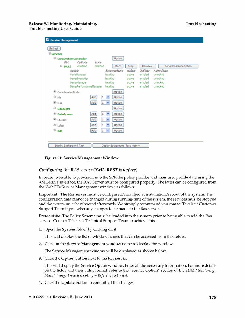
Figure 51: Service Management Window
Configuring the RAS server (XML-REST interface)In order to be able to provision into the SPR the policy profiles and their user profile data using theXML-REST interface, the RAS Server must be configured properly. The latter can be configured fromthe WebCI’s Service Management window, as follows:
Important: The Ras server must be configured/modified at installation/reboot of the system. Theconfiguration data cannot be changed during running-time of the system, the services must be stoppedand the system must be rebooted afterwards. We strongly recommend you contact Tekelec’s CustomerSupport Team if you wish any changes to be made to the Ras server.
Prerequisite: The Policy Schema must be loaded into the system prior to being able to add the Rasservice. Contact Tekelec’s Technical Support Team to achieve this.
1. Open the System folder by clicking on it.
This will display the list of window names that can be accessed from this folder.
2. Click on the Service Management window name to display the window.
The Service Management window will be displayed as shown below.
3. Click the Option button next to the Ras service.
This will display the Service Option window. Enter all the necessary information. For more detailson the fields and their value format, refer to the “Service Option” section of the SDM Monitoring,Maintaining, Troubleshooting – Reference Manual.
4. Click the Update button to commit all the changes.
178910-6695-001 Revision B, June 2013
TroubleshootingRelease 9.1 Monitoring, Maintaining,Troubleshooting User Guide

5. Click the Close button to close the window.
Figure 52: RAS Server Configuration
Stopping or starting applications, services, or slotsApplications, services, and slots can be stopped and started from the WebCI for troubleshootingpurposes.
Applications
To stop an application, all the system services running the application must be stopped.
These services run the SDM applications:
• The Hlr service runs the HLR and SIP applications.• The Hss service runs the HSS, SLF, AAA and DNS ENUM applications.• The LteHss service runs the LTE HSS application.
Stopping these services will also stop the other applications that run on this service.
179910-6695-001 Revision B, June 2013
TroubleshootingRelease 9.1 Monitoring, Maintaining,Troubleshooting User Guide
For example, to stop the AAA application on a slot, the HSS services on that slot must be stopped.Stopping the HSS services will then also stop the remaining applications such as HSS, SLF, and DNSENUM.
After modifying the application, an application restart may be necessary.
Services
Each service can be stopped or started individually. In some situations, one single service or somespecific services may need to be stopped or started. Stopping and restarting services may be requiredin the following cases:
• If the connections are down. For example, if the SS7 connections to an HLR service are down, thatspecific HLR service must be restarted. In this case, one single service needs to be stopped and mayneed to be started again later.
• After performing a restore of the database from a backup. In this case, all the services, except theCoreSystemController, Database and DataAccess services running on the slot on which the activeDatabase service instance runs, must be stopped and then started. Each service of the slot must bestopped one at a time and then restarted again.
For a geo-redundant site where the VIP is to be modified, all the services running on a slot are stoppedand then started again automatically.
Slots
To stop or start a slot, all services running on a slot must be stopped or started. Stopping and restartinga slot may be necessary when an SBC needs to be removed. Prior to removing the SBC, all servicesrunning on its slot must be stopped. Once the replacement SBC has been installed and configured, allthe services on the slot can be started for the new SBC.
Note: When stopping slots, the front-end slots must be stopped before the back-end slots. Whenstarting slots, the front-end slots must be started before at least one back-end slot is started.
Stop a service on a slotPrerequisites:
The state of the service or all services must be at ‘Started’ prior to stop the service or all services.
1. Click the System folder.2. Click Shelf View.
The Shelf View window opens.
180910-6695-001 Revision B, June 2013
TroubleshootingRelease 9.1 Monitoring, Maintaining,Troubleshooting User Guide

3. Perform one of these actions:
• To stop all services, click the Stop button in the row of the slot identity.
WARNING: One slot with at least one service must remain running on the system.Stopping all services on the last slot will stop the system completely and no longerallow access to the system from the WebCI or CLI. Never stop all services on thelast slot.
• To stop an individual service, click the Plus symbol preceding the slot to view the individualservices on the slot. Then click the Stop button of the service to be stopped.
The service or services have stopped.
Start services on a slotPrerequisites:
The state of the service or all services running on the slot must be in a Stopped state prior to startingthe service or all services.
1. Click the System folder.2. Click Shelf View.
The Shelf View window opens.
181910-6695-001 Revision B, June 2013
TroubleshootingRelease 9.1 Monitoring, Maintaining,Troubleshooting User Guide

3. Perform one of these actions:
• To start all services, click the Start button in the row of the slot identity.
Note: Use this option if all services on this slot need to be started. Do not attempt to start eachservice independently.
• To start an individual service, click the Plus symbol preceding the slot to view the individualservices on the slot. Then click the Start button of the service to be started.
WARNING: If a service is already running on a slot (i.e., CoreSystemController),starting the services on the slot will start the other services on the slot.
WARNING: If the Stop button was executed previously, wait 30 seconds beforeclicking the Start button.
The service or services have started.
Restart services on a slotPrerequisites:
The state of the service or all services running on the slot must be in a Started state prior to restartingthe service or all services.
1. Click the System folder.2. Click Shelf View.
The Shelf View window opens.
182910-6695-001 Revision B, June 2013
TroubleshootingRelease 9.1 Monitoring, Maintaining,Troubleshooting User Guide

3. Perform one of these actions:
• To restart all services, click the Restart button in the row of the slot identity.
Note: Use this option if all services on this blade need to be restarted. Do not attempt to restarteach service independently.
• To restart an individual service, click the Plus symbol preceding the slot to view the individualservices on the slot. Then click the Start button of the service to be restarted.
WARNING: If a service is already running on a slot (i.e., CoreSystemController),starting the services on the slot will start the other services on the slot.
WARNING: If the Stop button was executed previously, wait 30 seconds beforeclicking the Start button.
The service or services have restarted.
Stop/Start One Single Service on a BladeThis procedure describes the steps to stop/start a specific service on a blade using the WebCI.
Prerequisite: The state of the service you wish to stop must be ‘Started’ prior to being able to stop it.The state of the service you wish to start must be ‘Stopped’ prior to being able to start it.
WARNING: If the Stop Service button was executed previously, a delay of 30 seconds must be takeninto account before clicking on the Start Service button. The state of the service must be at ‘Stopped’prior to being able to start the service.
1. Open the System folder by clicking on it.2. Click on Service Management.
The Service Management screen will appear, as shown below.
3. Click on the symbol preceding the service you wish to stop/start.
183910-6695-001 Revision B, June 2013
TroubleshootingRelease 9.1 Monitoring, Maintaining,Troubleshooting User Guide
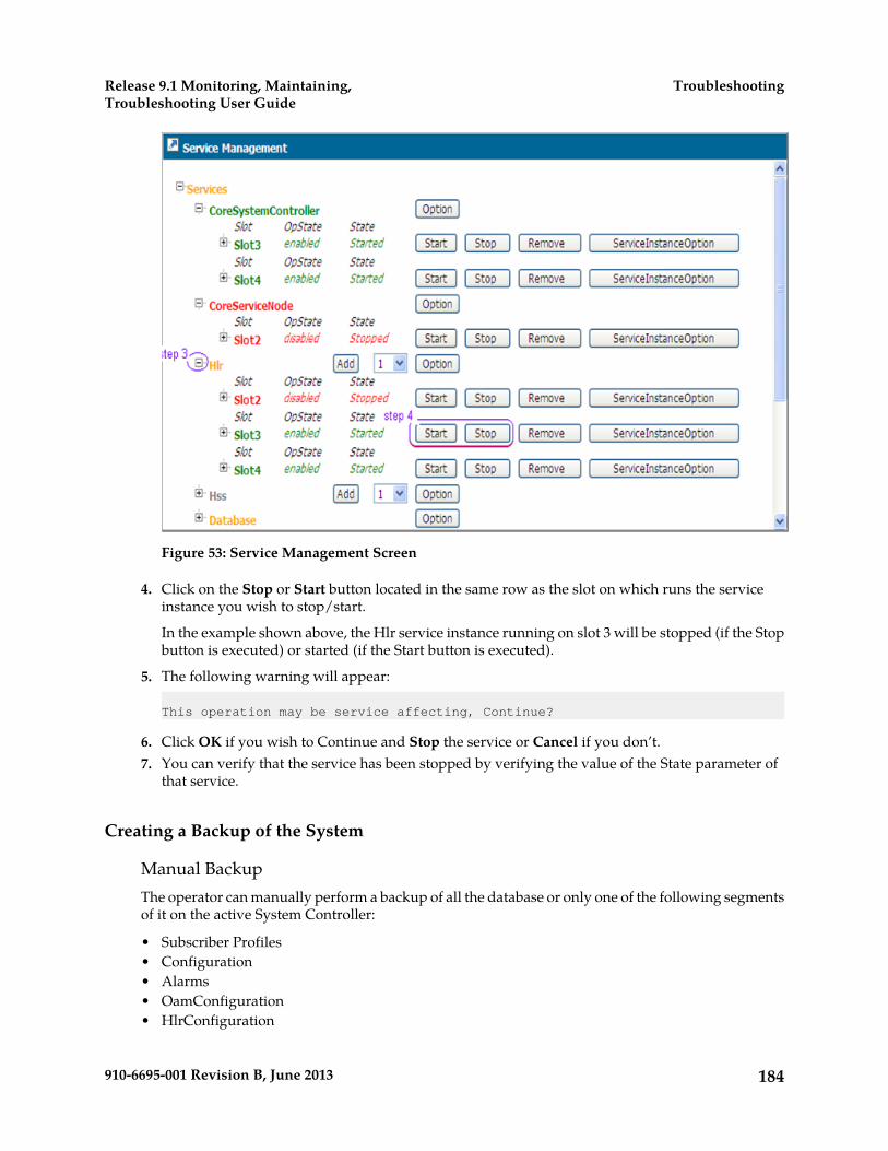
Figure 53: Service Management Screen
4. Click on the Stop or Start button located in the same row as the slot on which runs the serviceinstance you wish to stop/start.
In the example shown above, the Hlr service instance running on slot 3 will be stopped (if the Stopbutton is executed) or started (if the Start button is executed).
5. The following warning will appear:
This operation may be service affecting, Continue?
6. Click OK if you wish to Continue and Stop the service or Cancel if you don’t.7. You can verify that the service has been stopped by verifying the value of the State parameter of
that service.
Creating a Backup of the System
Manual BackupThe operator can manually perform a backup of all the database or only one of the following segmentsof it on the active System Controller:
• Subscriber Profiles• Configuration• Alarms• OamConfiguration• HlrConfiguration
184910-6695-001 Revision B, June 2013
TroubleshootingRelease 9.1 Monitoring, Maintaining,Troubleshooting User Guide
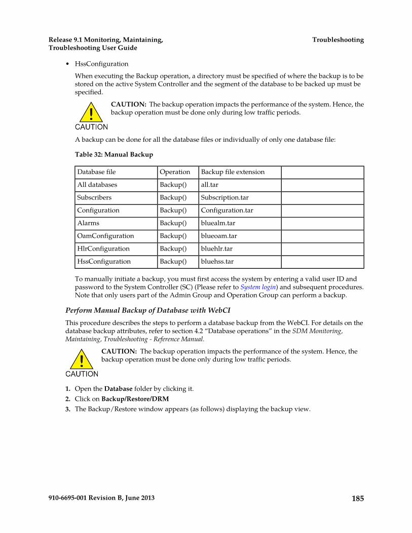
• HssConfiguration
When executing the Backup operation, a directory must be specified of where the backup is to bestored on the active System Controller and the segment of the database to be backed up must bespecified.
CAUTION: The backup operation impacts the performance of the system. Hence, thebackup operation must be done only during low traffic periods.
A backup can be done for all the database files or individually of only one database file:
Table 32: Manual Backup
Backup file extensionOperationDatabase file
all.tarBackup()All databases
Subscription.tarBackup()Subscribers
Configuration.tarBackup()Configuration
bluealm.tarBackup()Alarms
blueoam.tarBackup()OamConfiguration
bluehlr.tarBackup()HlrConfiguration
bluehss.tarBackup()HssConfiguration
To manually initiate a backup, you must first access the system by entering a valid user ID andpassword to the System Controller (SC) (Please refer to System login) and subsequent procedures.Note that only users part of the Admin Group and Operation Group can perform a backup.
Perform Manual Backup of Database with WebCIThis procedure describes the steps to perform a database backup from the WebCI. For details on thedatabase backup attributes, refer to section 4.2 “Database operations” in the SDM Monitoring,Maintaining, Troubleshooting - Reference Manual.
CAUTION: The backup operation impacts the performance of the system. Hence, thebackup operation must be done only during low traffic periods.
1. Open the Database folder by clicking it.2. Click on Backup/Restore/DRM3. The Backup/Restore window appears (as follows) displaying the backup view.
185910-6695-001 Revision B, June 2013
TroubleshootingRelease 9.1 Monitoring, Maintaining,Troubleshooting User Guide

Figure 54: Backup/Restore Window
4. In the ToDirectory box, specify the directory (i.e., /export/backup) to store the backup file.5. In the Database box, select the segment of the database you wish to do a backup of: All databases,
Subscribers, Configuration, alarms, OamConfiguration, HlrConfiguration, HssConfiguration.6. Click on Backup.
The following message will be displayed:
asynchronous event currently executing.
7. Verify the backup has been completed by clicking on System8. Click on History Alarm View9. The Backup procedure is completed when the following message appears:
Backup completed successfully
.
186910-6695-001 Revision B, June 2013
TroubleshootingRelease 9.1 Monitoring, Maintaining,Troubleshooting User Guide
Automatic BackupThe following types of backup can be performed automatically on the active System Controller:
• a backup of all the subscriber profiles and of all the configuration data
or• a backup of all the subscriber profiles
No automatic backups are executed by default, this function must be activated in order to startautomatic backups. The operator can set a DatabaseBackupSchedule through the WebCI, whichallows automatic backups to be executed at the time specified by the operator. In an automaticbackup, a maximum of 10 files are backed up. This number must be adjusted based on the size ofthe backup files.
To perform an automatic backup, a backup schedule must be defined. An automatic backup ofSubscriber Profiles will be performed every time it has been scheduled to do so. When setting theschedule of the automatic backup, the IncludeConfiguration parameter can be set optionally to ‘1’in the case where you wish the automatic backup to back up all the configuration data in additionto all the subscriber profiles. By default, the IncludeConfiguration parameter is set to ‘0’ and theautomatic backup only backs up the subscriber profiles data.
The following procedures show how to set a backup schedule and activate the automatic backupthrough the WebCI.
First, you must access the system by entering a valid user ID and password to the System Controller(SC) and then you can follow the procedures below. (Please refer to System login).
Note: Only users part of the Admin Group and Operation Group can set and activate an automaticbackup.
CAUTION: The backup operation impacts the performance of the system. Hence, thebackup operation must be done only during low traffic periods.
Add Automatic Backup of Database with WebCIThis procedure describes the steps to add an automatic database backup from the WebCI. For detailson the database backup attributes, refer to section 4.2 “Database operations” in the SDM Monitoring,Maintaining, Troubleshooting - Reference Manual.
CAUTION: The backup operation impacts the performance of the system. Hence, thebackup operation must be done only during low traffic periods.
1. Open the Database folder by clicking it.2. Click on Backup/Restore/DRM. The Backup/Restore window will appear (as shown below).3. Under DatabaseBackupSchedule, click the Add DatabaseBackupSchedule button.4. When the DatabaseBackupSchedule Provisioning window appears, enter all the information. Note
that the IncludeConfiguration parameter is optional and by default it is set to ‘0’, which means thatthe automatic backup only backs up all the subscriber profiles data.
187910-6695-001 Revision B, June 2013
TroubleshootingRelease 9.1 Monitoring, Maintaining,Troubleshooting User Guide
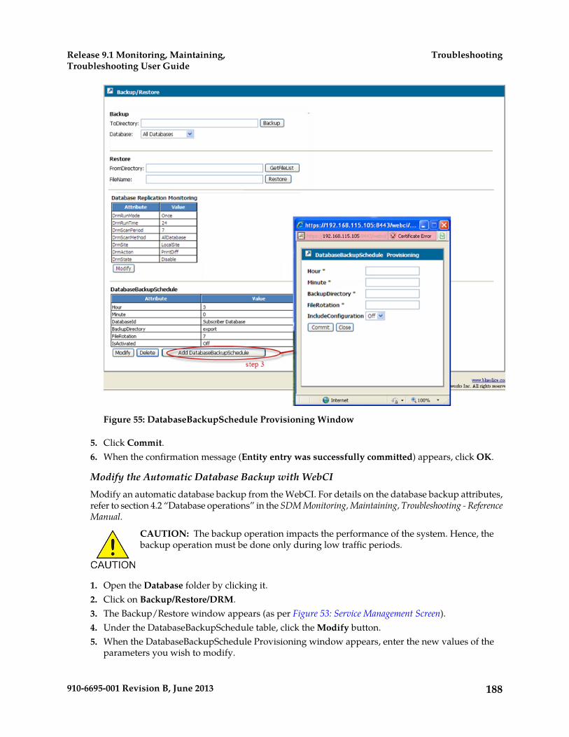
Figure 55: DatabaseBackupSchedule Provisioning Window
5. Click Commit.6. When the confirmation message (Entity entry was successfully committed) appears, click OK.
Modify the Automatic Database Backup with WebCIModify an automatic database backup from the WebCI. For details on the database backup attributes,refer to section 4.2 “Database operations” in the SDM Monitoring, Maintaining, Troubleshooting - ReferenceManual.
CAUTION: The backup operation impacts the performance of the system. Hence, thebackup operation must be done only during low traffic periods.
1. Open the Database folder by clicking it.2. Click on Backup/Restore/DRM.3. The Backup/Restore window appears (as per Figure 53: Service Management Screen).4. Under the DatabaseBackupSchedule table, click the Modify button.5. When the DatabaseBackupSchedule Provisioning window appears, enter the new values of the
parameters you wish to modify.
188910-6695-001 Revision B, June 2013
TroubleshootingRelease 9.1 Monitoring, Maintaining,Troubleshooting User Guide
6. Click Commit.7. When the confirmation message (Entity entry was successfully committed) appears, click OK.
Display the DatabaseBackupSchedule Entity with WebCIThis procedure describes the steps to display the automatic database backup information in theWebCI. For details on the database backup attributes, refer to section 4.2 “Database operations” inthe SDM Monitoring, Maintaining, Troubleshooting - Reference Manual.
CAUTION: The backup operation impacts the performance of the system. Hence, thebackup operation must be done only during low traffic periods.
1. Open the Database folder by clicking it.2. Click on Backup/Restore/DRM.3. The DatabaseBackupSchedule entity will be displayed in the Backup/Restore window (as per
Figure 53: Service Management Screen).
Activate and Disable the Automatic Backup with WebCIThis Procedure Describes The Steps To Activate And Disable The Automatic Database Backup In TheWebCI For Details On The Database Backup Attributes, Refer To Section 42 “Database Operations”In The SDM Monitoring, Maintaining, Troubleshooting - Reference Manual
CAUTION: The Backup Operation Impacts The Performance Of The System Hence, TheBackup Operation Must Be Done Only During Low Traffic Periods
1. Open the Database folder by clicking it.2. Click on Backup/Restore/DRM.3. The DatabaseBackupSchedule entity will be displayed in the Backup/Restore window (as per
Figure 53: Service Management Screen).4. Click on the Activate button to activate the automatic backup already set.
(Before activating an automatic backup, you must set it. To do so, refer to procedure 7-19 AddAutomatic Backup of Database with WebCI. By default, the automatic backup is not activated.a) If the automatic backup is activated, the attribute IsActivated will be On and the Activate button
will not exist.
In that case, there will be a Disablebutton that you can click on to deactivate the automaticbackup.
Delete the Automatic Database Backup with WebCIThis Procedure Describes The Steps To Delete An Automatic Database Backup From The WebCI ForDetails On The Database Backup Attributes, Refer To Section 4.2 “Database Operations” In The SDMMonitoring, Maintaining, Troubleshooting - Reference Manual
CAUTION: The Backup Operation Impacts The Performance Of The System Hence, TheBackup Operation Must Be Done Only During Low Traffic Periods
189910-6695-001 Revision B, June 2013
TroubleshootingRelease 9.1 Monitoring, Maintaining,Troubleshooting User Guide
1. Open the Database folder by clicking it.2. Click on Backup/Restore/DRM.3. The Backup/Restore window appears (as per Figure 53: Service Management Screen).4. Under the DatabaseBackupSchedule table, click the Delete button.5. Click Commit.6. When the delete confirmation window appears “
You are about to delete this DatabaseBackupSchedule entry, Continue?
”
7. Click OK.
Restoring the database from a backupThis procedure describes the steps to perform a database restore from the WebCI.
The database information will be restored onto the active System Controller (SC) blade.
CAUTION: When restoring the database, on the active System Controller blade, all theservices running on the system must be stopped except the active CoreSystemController,DataAccess and active Database services running on the active System Controller blade.In the case where the active CoreSystemController service instance is not running on thesame blade as the active Database service instance, you must perform a manual switchover(see Performing a manual switchover) of the CoreSystemController service. This will makesure that the active CoreSystemController and the active database are running on thesame blade, the active System Controller blade.
Note: When restoring the database on Geo-Redundant system, this operation can lead to loss ofsubscriber provisioning activity on system where the Geo-Redundancy was disabled for more than 4hours. Please refer to Resume Geo-Redundancy with WebCI for more information on Geo-Redundancymanagement.
To stop all services through WebCI, please follow these steps for each slot on the system except forthe active System Controller slot:
1. In the WebCI, click on the System Folder.2. Click on the Shelf View.3. Click on the symbol preceding the slot on which you wish to stop all services.4. Click on the symbol preceding the services which you wish to stop.5. Click the Stop button located in the same row as the Slot ID.
This will stop all the services on the slot.
For the active System Controller slot, individually stop all the services on the blade except theactive CoreSystemController service instance, the active Database service instance and theDataAccess service. Refer to Stop/Start One Single Service on a Blade.
Restoring the databaseThis procedure describes how to restore all segments of the database or only one of the followingdatabase segments from the WebCI:
• Subscribers
190910-6695-001 Revision B, June 2013
TroubleshootingRelease 9.1 Monitoring, Maintaining,Troubleshooting User Guide
• Configuration• Alarms• OamConfiguration• HlrConfiguration• HssConfiguration
The database information will be restored onto the active System Controller (SC) blade.
CAUTION: When restoring the database, all the services running on the system must bestopped except the active CoreSystemController, DataAccess and active Database servicesrunning on the active System Controller blade. If the active CoreSystemController serviceinstance is not running on the same blade as the active Database service instance, performa Resume Geo-Redundancy with WebCI of the CoreSystemController service. This will makesure the active CoreSystemController and active Database are running on the active SystemController blade.
WARNING: WARNING: When restoring the database on a Geo-Redundant system,this operation can lead to loss of subscriber provisioning activity on the system ifgeo-redundancy was disabled for more than 4 hours. Refer to Resume Geo-Redundancywith WebCI for more information on Geo-Redundancy management.
CAUTION: When restoring the database, all the services running on the system must be stoppedexcept the active CoreSystemController, DataAccess and active Database services running on theactive System Controller blade. If the active CoreSystemController service instance is not running onthe same blade as the active Database service instance, perform a Performing a manual switchover of theCoreSystemController service. This will make sure that the active CoreSystemController and activeDatabase are running on the same blade, the active System Controller blade.
1. For the active System Controller slot, individually stop all the services on the blade except theactive CoreSystemController service instance, the active Database service instance, and theDataAccess service. Use procedure Stop a service on a slot.
2. In the WebCI main menu, click Database Backup/Restore/DRM to display the Backup/Restorewindow.
191910-6695-001 Revision B, June 2013
TroubleshootingRelease 9.1 Monitoring, Maintaining,Troubleshooting User Guide
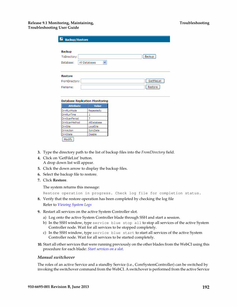
3. Type the directory path to the list of backup files into the FromDirectory field.4. Click on ‘GetFileList’ button.
A drop down list will appear.5. Click the down arrow to display the backup files.6. Select the backup file to restore.7. Click Restore.
The system returns this message:Restore operation in progress. Check log file for completion status.
8. Verify that the restore operation has been completed by checking the log fileRefer to Viewing System Logs
9. Restart all services on the active System Controller slot.a) Log onto the active System Controller blade through SSH and start a session.b) In the SSH window, type service blue stop all to stop all services of the active System
Controller node. Wait for all services to be stopped completely.c) In the SSH window, type service blue start to start all services of the active System
Controller node. Wait for all services to be started completely.
10. Start all other services that were running previously on the other blades from the WebCI using thisprocedure for each blade: Start services on a slot.
Manual switchoverThe roles of an active Service and a standby Service (i.e., CoreSystemController) can be switched byinvoking the switchover command from the WebCI. A switchover is performed from the active Service
192910-6695-001 Revision B, June 2013
TroubleshootingRelease 9.1 Monitoring, Maintaining,Troubleshooting User Guide
because only the active Service can command the standby to take over control. A manual switchovercan only be performed on the active instances of the following services:
• CoreSystemController• Database• Ldap
Manual switchovers are typically performed in the following situations:
• Verify proper switching action between active and standby and that standby will become active• Switch the roles of the blades• Upgrade current software to a new load• Shut down blades to perform hardware maintenance.
WARNING: A manual switchover cannot be performed on the service while the hardwarescan is still in progress. When the hardware scan is initiated, the system automaticallyraises an alarm (AlarmId: 6815) and eventually clears it once the hardware scan iscompleted. A manual switchover can only be performed after this alarm has beenautomatically cleared by the system.
CAUTION: A switchover is service affecting and will result in a loss of traffic. It isrecommended a switchover be done in a maintenance window when there is minimaltraffic.
Performing a manual switchoverThis procedure describes how to perform a manual switchover using the WebCI.
1. From the main menu, go to System ➤ Shelf View..2. Click the symbol preceding the slot for which you wish to display more detailed information.
This will display all the services running on that slot and their state (started/stopped).
3. Click the symbol preceding the service for which you wish to display more detailed information.
This will display all the modules running within this service and their Operational state,Administrative state, Ha Role, and Resource state.
4. Verify the HaRole of the service for which you wish to perform a switchover.
Note: A switchover can only be performed on an active instance of the services working in anactive/standby mode.
5. Click the SWO button located in the same row as the active service for which you wish to performa switchover.
6. The following warning will appear:This operation may be service affecting, Continue?
7. Click OK if you wish to Continue and perform a switchover or click Cancel.8. Verify that the switchover took place by reading the HaRole value.
Note: The standby blade will initialize first before changing into standby mode.
193910-6695-001 Revision B, June 2013
TroubleshootingRelease 9.1 Monitoring, Maintaining,Troubleshooting User Guide

Viewing/Modifying Database Replication Monitoring (DRM) ConfigurationThe Database Replication Monitoring (DRM) process (see detailed description in the “Self Healing”section of the SDM Product Description) is configured by the Tekelec Customer Care Center. The NetworkOperator can display and modify this configuration data from the Database Replication Monitoringtable (DrmConfig[] entity) through one of the User Interfaces (CLI, WebCI, SOAP, CmdFileLoader).
This section describes how to display/modify the DRM configuration data from the WebCI.
To achieve this, follow the steps described below:
Requirements: Log in to a WebCI session with a username and password. Refer to Starting a WebCISession.
1. Open the Database folder by clicking on it.2. Open the Backup/Restore/DRM window (see figure below Figure 56: Database Replication Monitoring
(DRM))3. The DRM configuration data will be displayed in the Database Replication Monitoring table.
If you wish to modify any of this data, click on the Modify button located underneath the table.This will open up the DrmConfig Provisioning window, which allows you to enter the new values.
For further instructions on how to navigate through the WebCI, refer to the "Web Craft Interface"section of the SDM Monitoring, Maintaining, Troubleshooting – Reference Manual and to Web CraftInterface (WebCI) in this document.
For details on the DrmConfig[ ] entity and its parameters, refer to the “Self Healing (DatabaseReplication Monitoring” section of the SDM System Configuration – Reference Manual.
194910-6695-001 Revision B, June 2013
TroubleshootingRelease 9.1 Monitoring, Maintaining,Troubleshooting User Guide

Figure 56: Database Replication Monitoring (DRM)
The DRM produces report files, which are saved in the active System Controller blade under thefollowing directory: /blue/var/drm.
There are three types of DRM reports:
4. The Schema Checker report, which includes any difference detected on the database structure.5. The Data Checker report, which includes all the run-time consistency replication checks.6. The Data Sync report, which includes the re-synchronized data that was different from the master
server.
The Network Operator can analyze these reports and send it to the Tekelec Customer Care Centerif anomalies are detected.
Hereunder are instructions on how to access the DRM report files from a Telnet/SSH client:
Prerequisite: Connect to the system’s active SystemController blade.
195910-6695-001 Revision B, June 2013
TroubleshootingRelease 9.1 Monitoring, Maintaining,Troubleshooting User Guide
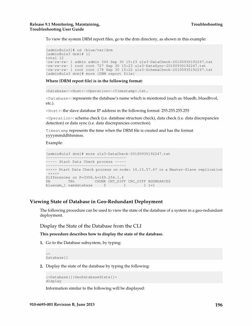
To view the system DRM report files, go to the drm directory, as shown in this example:
[admin@u1s3]# cd /blue/var/drm[admin@u1s3 drm]# lltotal 12-rw-rw-rw- 1 admin admin 344 Sep 30 15:23 u1s3-DataCheck-20100930192247.txt-rw-rw-rw- 1 root root 727 Sep 30 15:23 u1s3-DataSync-20100930192247.txt-rw-rw-rw- 1 root root 178 Sep 30 15:22 u1s3-SchemaCheck-20100930192247.txt[admin@u1s3 drm]# more {DRM report file}
Where {DRM report file} is in the following format:
<Database>-<Host>-<Operation>-<Timestamp>.txt.
<Database>: represents the database’s name which is monitored (such as: bluedb, bluedbvol,etc.).
<Host>: the slave database IP address in the following format: 255.255.255.255
<Operation>: schema check (i.e. database structure check), data check (i.e. data discrepanciesdetection) or data sync (i.e. data discrepancies correction).
Timestamp represents the time when the DRM file is created and has the formatyyyymmddhhmmss.
Example:
[admin@u1s3 drm]# more u1s3-DataCheck-20100930192247.txt----------------------------------------- Start Data Check process ----------------------------------------->>>>> Start Data Check process on node: 10.15.57.67 in a Master-Slave replication <<<<<Differences on P=3306,h=169.254.1.4DB TBL CHUNK CNT_DIFF CRC_DIFF BOUNDARIESblueoam_1 oamdatabase 0 1 1 1=1
Viewing State of Database in Geo-Redundant Deployment
The following procedure can be used to view the state of the database of a system in a geo-redundantdeployment.
Display the State of the Database from the CLIThis procedure describes how to display the state of the database.
1. Go to the Database subsystem, by typing:
:>Database[]
2. Display the state of the database by typing the following:
:>Database[]:GeoDatabaseState[]>display
Information similar to the following will be displayed:
196910-6695-001 Revision B, June 2013
TroubleshootingRelease 9.1 Monitoring, Maintaining,Troubleshooting User Guide
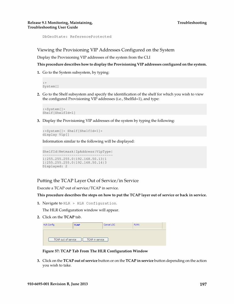
DbGeoState: ReferenceProtected
Viewing the Provisioning VIP Addresses Configured on the SystemDisplay the Provisioning VIP addresses of the system from the CLI
This procedure describes how to display the Provisioning VIP addresses configured on the system.
1. Go to the System subsystem, by typing:
:>System[]
2. Go to the Shelf subsystem and specify the identification of the shelf for which you wish to viewthe configured Provisioning VIP addresses (i.e., ShelfId=1), and type:
:>System[]>Shelf[ShelfId=1]
3. Display the Provisioning VIP addresses of the system by typing the following:
:>System[]> Shelf[ShelfId=1]>display Vip[]
Information similar to the following will be displayed:
ShelfId|Netmask|IpAddress|VipType|----------------------------------1|255.255.255.0|192.168.50.13|11|255.255.255.0|192.168.50.14|3Displayed: 2
Putting the TCAP Layer Out of Service/in ServiceExecute a TCAP out of service/TCAP in service.
This procedure describes the steps on how to put the TCAP layer out of service or back in service.
1. Navigate to HLR > HLR Configuration.
The HLR Configuration window will appear.
2. Click on the TCAP tab.
Figure 57: TCAP Tab From The HLR Configuration Window
3. Click on the TCAP out of service button or on the TCAP in service button depending on the actionyou wish to take.
197910-6695-001 Revision B, June 2013
TroubleshootingRelease 9.1 Monitoring, Maintaining,Troubleshooting User Guide

4. A warning message will pop up and ask you to confirm the action.
If you wish to go ahead with the execution of this operation, click OK, otherwise click Cancel.
Performing a Cancel Location/Cancel GPRS LocationCancel Location/Cancel GPRS Location.
This procedure describes the steps on how to perform a Cancel Location/Cancel GPRS Location inorder to force the HLR to send a MAP_CANCEL_LOCATION message to the current VLR/SGSNlocation for the specified subscriber IMSI.
1. Navigate to HLR > HLR Configuration.
The HLR Configuration window will appear.
2. Click on the CancelLOC tab to access the window shown below.
Figure 58: CancelLOC Tab From The HLR Configuration Window
3. In the white box, enter the IMSI number for which you wish the HLR to send aMAP_CANCEL_LOCATION message for.
4. A warning message will pop up and ask you to confirm the action.
If you wish to go ahead with the execution of this operation, click OK, otherwise click Cancel.
Troubleshooting a Geo-Redundant System – Backup/Restore Procedures
This section presents restore constraints for geo-redundant systems, various restore scenarios and theprocedures to execute those scenarios.
Restore constraints for geo-redundant systems
Geo-redundancy affects restore operations after a database backup.
Database selectionWhen the geo-redundancy is enabled, a database restore must be done carefully since more constraintsaffect this operation. Let’s take the following diagram as an example:
198910-6695-001 Revision B, June 2013
TroubleshootingRelease 9.1 Monitoring, Maintaining,Troubleshooting User Guide
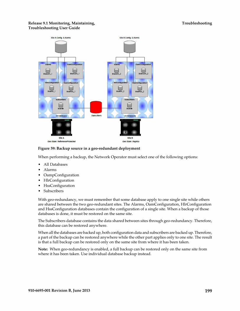
Figure 59: Backup source in a geo-redundant deployment
When performing a backup, the Network Operator must select one of the following options:
• All Databases• Alarms• OampConfiguration• HlrConfiguration• HssConfiguration• Subscribers
With geo-redundancy, we must remember that some database apply to one single site while othersare shared between the two geo-redundant sites. The Alarms, OamConfiguration, HlrConfigurationand HssConfiguration databases contain the configuration of a single site. When a backup of thosedatabases is done, it must be restored on the same site.
The Subscribers database contains the data shared between sites through geo-redundancy. Therefore,this database can be restored anywhere.
When all the databases are backed up, both configuration data and subscribers are backed up. Therefore,a part of the backup can be restored anywhere while the other part applies only to one site. The resultis that a full backup can be restored only on the same site from where it has been taken.
Note: When geo-redundancy is enabled, a full backup can be restored only on the same site fromwhere it has been taken. Use individual database backup instead.
199910-6695-001 Revision B, June 2013
TroubleshootingRelease 9.1 Monitoring, Maintaining,Troubleshooting User Guide
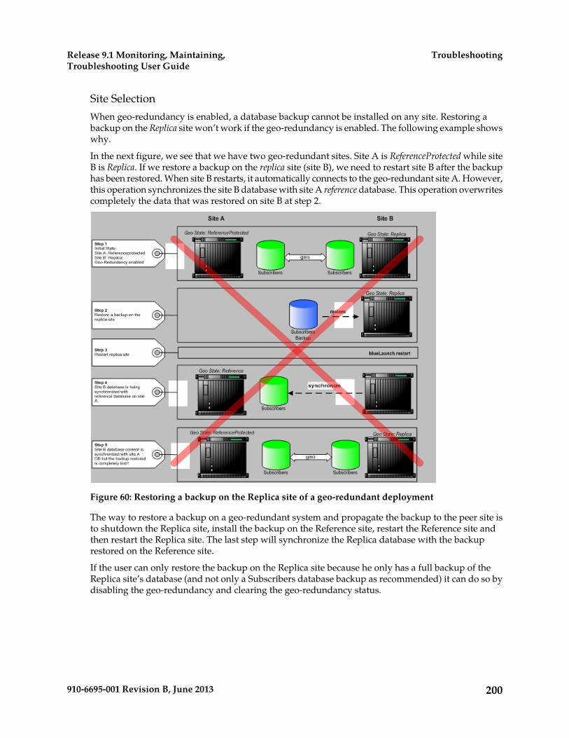
Site SelectionWhen geo-redundancy is enabled, a database backup cannot be installed on any site. Restoring abackup on the Replica site won’t work if the geo-redundancy is enabled. The following example showswhy.
In the next figure, we see that we have two geo-redundant sites. Site A is ReferenceProtected while siteB is Replica. If we restore a backup on the replica site (site B), we need to restart site B after the backuphas been restored. When site B restarts, it automatically connects to the geo-redundant site A. However,this operation synchronizes the site B database with site A reference database. This operation overwritescompletely the data that was restored on site B at step 2.
Figure 60: Restoring a backup on the Replica site of a geo-redundant deployment
The way to restore a backup on a geo-redundant system and propagate the backup to the peer site isto shutdown the Replica site, install the backup on the Reference site, restart the Reference site andthen restart the Replica site. The last step will synchronize the Replica database with the backuprestored on the Reference site.
If the user can only restore the backup on the Replica site because he only has a full backup of theReplica site’s database (and not only a Subscribers database backup as recommended) it can do so bydisabling the geo-redundancy and clearing the geo-redundancy status.
200910-6695-001 Revision B, June 2013
TroubleshootingRelease 9.1 Monitoring, Maintaining,Troubleshooting User Guide

Clearing Geo-redundancy Status
Before starting a site to force it to take the reference role (if the peer site is not started), the entry in theOamConfiguration database that indicates the location of the most recent Reference site must be cleared.Contact the Tekelec Customer Care Center to clear the geo-redundancy status.
Restarting a 2-Blade System
Target setup:
1. Stop the standby system controller (blade 2).:System[]:Shelf[ShelfId=1]:Slot[SlotId=Blade2SlotId]> StopServices()
2. Restart the blade that hosts the active system controller (blade 1).:System[]:Shelf[ShelfId=1]:Slot[SlotId=Blade1SlotId]> RestartServices()
• The connection to the WebCI/CLI will be lost while the blade is restarting.• It will be available again once the restart is completed.
3. Start the blade that hosts the standby system controller (blade 2).:System[]:Shelf[ShelfId=1]:Slot[SlotId=Blade2SlotId]> StartServices()
4. Wait for standby blade initialization to complete (blade 2).5. Display the status of ServiceInstance() running on the standby blade (blade 2) and wait for all
OpState to go to enabled state.9 :System[]:Shelf[ShelfId = 1]:Slot[SlotId = Blade2SlotId ]> display ServiceInstance[] This Command could potentially display a very large number of instances. Proceed with display? (y/[n]): y ShelfId|AdminState|ResourceState|SlotId| HaRole |OpState | IdentityId | ServiceId |ServiceState| --------------------------------------------------------------------------------------------------------------- 1| locked| healthy| 9|unassigned|disabled|SystemController|CoreSystemController| Started| 1| unlocked| healthy| 9|unassigned|disabled|SystemController| Hlr| Started| 10 :System[]:Shelf[ShelfId = 1]:Slot[SlotId = Blade2SlotId]> display ServiceInstance[] This Command could potentially display a very large number of instances. Proceed with display? (y/[n]): y ShelfId|AdminState|ResourceState|SlotId| HaRole |OpState | IdentityId | ServiceId |ServiceState| ---------------------------------------------------------------------------------------------------------------
201910-6695-001 Revision B, June 2013
TroubleshootingRelease 9.1 Monitoring, Maintaining,Troubleshooting User Guide
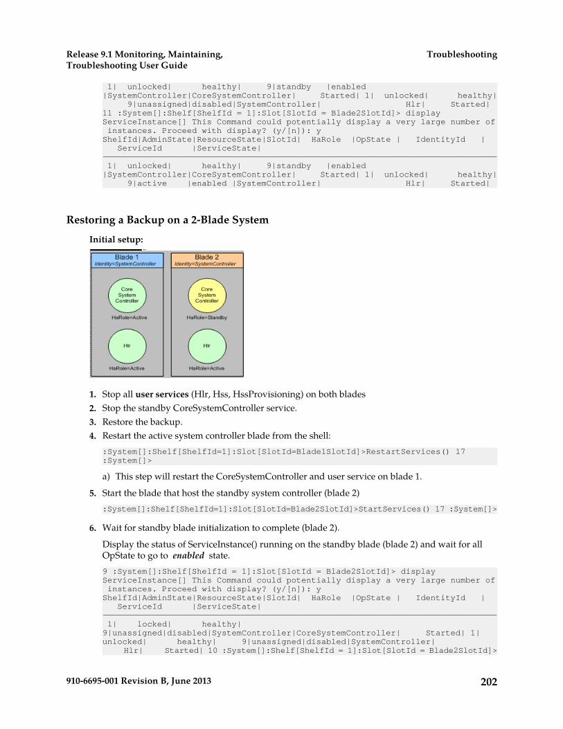
1| unlocked| healthy| 9|standby |enabled |SystemController|CoreSystemController| Started| 1| unlocked| healthy| 9|unassigned|disabled|SystemController| Hlr| Started| 11 :System[]:Shelf[ShelfId = 1]:Slot[SlotId = Blade2SlotId]> display ServiceInstance[] This Command could potentially display a very large number of instances. Proceed with display? (y/[n]): y ShelfId|AdminState|ResourceState|SlotId| HaRole |OpState | IdentityId | ServiceId |ServiceState| --------------------------------------------------------------------------------------------------------------- 1| unlocked| healthy| 9|standby |enabled |SystemController|CoreSystemController| Started| 1| unlocked| healthy| 9|active |enabled |SystemController| Hlr| Started|
Restoring a Backup on a 2-Blade System
Initial setup:
1. Stop all user services (Hlr, Hss, HssProvisioning) on both blades2. Stop the standby CoreSystemController service.3. Restore the backup.4. Restart the active system controller blade from the shell:
:System[]:Shelf[ShelfId=1]:Slot[SlotId=Blade1SlotId]>RestartServices() 17 :System[]>
a) This step will restart the CoreSystemController and user service on blade 1.
5. Start the blade that host the standby system controller (blade 2):System[]:Shelf[ShelfId=1]:Slot[SlotId=Blade2SlotId]>StartServices() 17 :System[]>
6. Wait for standby blade initialization to complete (blade 2).
Display the status of ServiceInstance() running on the standby blade (blade 2) and wait for allOpState to go to enabled state.9 :System[]:Shelf[ShelfId = 1]:Slot[SlotId = Blade2SlotId]> display ServiceInstance[] This Command could potentially display a very large number of instances. Proceed with display? (y/[n]): y ShelfId|AdminState|ResourceState|SlotId| HaRole |OpState | IdentityId | ServiceId |ServiceState| --------------------------------------------------------------------------------------------------------------- 1| locked| healthy| 9|unassigned|disabled|SystemController|CoreSystemController| Started| 1| unlocked| healthy| 9|unassigned|disabled|SystemController| Hlr| Started| 10 :System[]:Shelf[ShelfId = 1]:Slot[SlotId = Blade2SlotId]>
202910-6695-001 Revision B, June 2013
TroubleshootingRelease 9.1 Monitoring, Maintaining,Troubleshooting User Guide

display ServiceInstance[] This Command could potentially display a very large number of instances. Proceed with display? (y/[n]): y ShelfId|AdminState|ResourceState|SlotId| HaRole |OpState | IdentityId | ServiceId |ServiceState| --------------------------------------------------------------------------------------------------------------- 1| unlocked| healthy| 9|standby |enabled |SystemController|CoreSystemController| Started| 1| unlocked| healthy| 9|unassigned|disabled|SystemController| Hlr| Started| 11 :System[]:Shelf[ShelfId = 1]:Slot[SlotId = Blade2SlotId]> display ServiceInstance[] This Command could potentially display a very large number of instances. Proceed with display? (y/[n]): y ShelfId|AdminState|ResourceState|SlotId| HaRole |OpState | IdentityId | ServiceId |ServiceState| --------------------------------------------------------------------------------------------------------------- 1| unlocked| healthy| 9|standby |enabled |SystemController|CoreSystemController| Started| 1| unlocked| healthy| 9|active |enabled |SystemController| Hlr| Started|
Restarting a system with Front-End NodesUse this procedure to restart a system with more than two blades.
Target setup:
Figure 61: Multiple Blade System with Front-End Node(s)
1. Stop the front-end node blade (blade 3).:System[]:Shelf[ShelfId=1]:Slot[SlotId=Blade3SlotId]>StopServices() 17 :System[]>
2. Stop the standby system controller (blade 2).:System[]:Shelf[ShelfId=1]:Slot[SlotId=Blade2SlotId]>StopServices() 17 :System[]>
3. Restart the blade that hosts the active system controller (blade 1).:System[]:Shelf[ShelfId=1]:Slot[SlotId=Blade1SlotId]>RestartServices() 17 :System[]>
203910-6695-001 Revision B, June 2013
TroubleshootingRelease 9.1 Monitoring, Maintaining,Troubleshooting User Guide
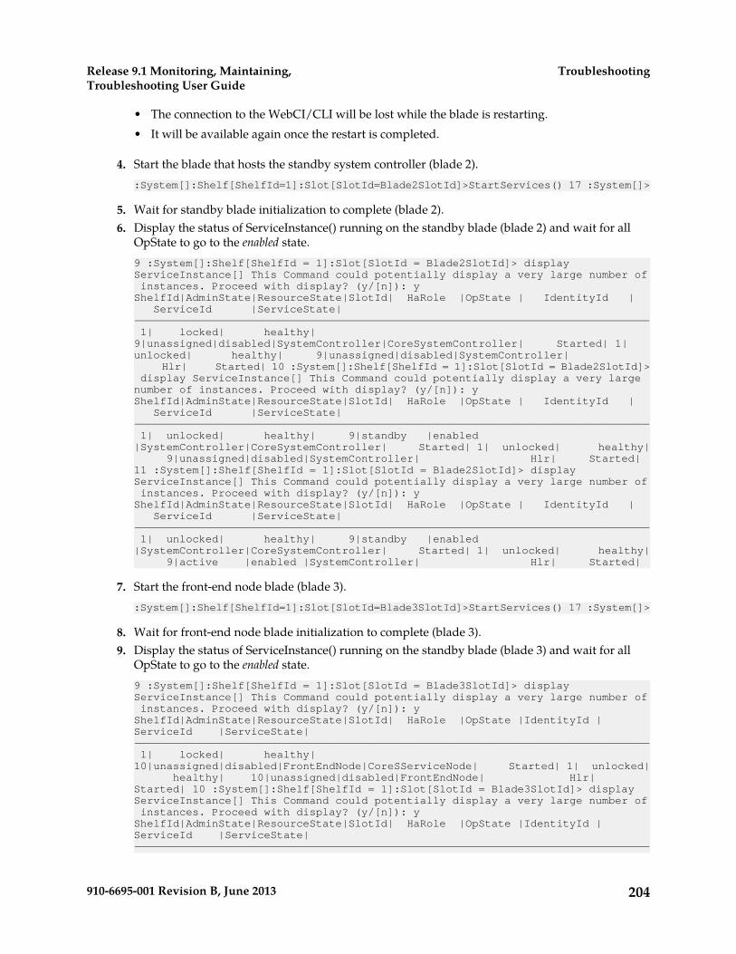
• The connection to the WebCI/CLI will be lost while the blade is restarting.• It will be available again once the restart is completed.
4. Start the blade that hosts the standby system controller (blade 2).:System[]:Shelf[ShelfId=1]:Slot[SlotId=Blade2SlotId]>StartServices() 17 :System[]>
5. Wait for standby blade initialization to complete (blade 2).6. Display the status of ServiceInstance() running on the standby blade (blade 2) and wait for all
OpState to go to the enabled state.9 :System[]:Shelf[ShelfId = 1]:Slot[SlotId = Blade2SlotId]> display ServiceInstance[] This Command could potentially display a very large number of instances. Proceed with display? (y/[n]): y ShelfId|AdminState|ResourceState|SlotId| HaRole |OpState | IdentityId | ServiceId |ServiceState| --------------------------------------------------------------------------------------------------------------- 1| locked| healthy| 9|unassigned|disabled|SystemController|CoreSystemController| Started| 1| unlocked| healthy| 9|unassigned|disabled|SystemController| Hlr| Started| 10 :System[]:Shelf[ShelfId = 1]:Slot[SlotId = Blade2SlotId]> display ServiceInstance[] This Command could potentially display a very large number of instances. Proceed with display? (y/[n]): y ShelfId|AdminState|ResourceState|SlotId| HaRole |OpState | IdentityId | ServiceId |ServiceState| --------------------------------------------------------------------------------------------------------------- 1| unlocked| healthy| 9|standby |enabled |SystemController|CoreSystemController| Started| 1| unlocked| healthy| 9|unassigned|disabled|SystemController| Hlr| Started| 11 :System[]:Shelf[ShelfId = 1]:Slot[SlotId = Blade2SlotId]> display ServiceInstance[] This Command could potentially display a very large number of instances. Proceed with display? (y/[n]): y ShelfId|AdminState|ResourceState|SlotId| HaRole |OpState | IdentityId | ServiceId |ServiceState| --------------------------------------------------------------------------------------------------------------- 1| unlocked| healthy| 9|standby |enabled |SystemController|CoreSystemController| Started| 1| unlocked| healthy| 9|active |enabled |SystemController| Hlr| Started|
7. Start the front-end node blade (blade 3).:System[]:Shelf[ShelfId=1]:Slot[SlotId=Blade3SlotId]>StartServices() 17 :System[]>
8. Wait for front-end node blade initialization to complete (blade 3).9. Display the status of ServiceInstance() running on the standby blade (blade 3) and wait for all
OpState to go to the enabled state.9 :System[]:Shelf[ShelfId = 1]:Slot[SlotId = Blade3SlotId]> display ServiceInstance[] This Command could potentially display a very large number of instances. Proceed with display? (y/[n]): y ShelfId|AdminState|ResourceState|SlotId| HaRole |OpState |IdentityId | ServiceId |ServiceState| --------------------------------------------------------------------------------------------------------------- 1| locked| healthy| 10|unassigned|disabled|FrontEndNode|CoreSServiceNode| Started| 1| unlocked| healthy| 10|unassigned|disabled|FrontEndNode| Hlr| Started| 10 :System[]:Shelf[ShelfId = 1]:Slot[SlotId = Blade3SlotId]> display ServiceInstance[] This Command could potentially display a very large number of instances. Proceed with display? (y/[n]): y ShelfId|AdminState|ResourceState|SlotId| HaRole |OpState |IdentityId | ServiceId |ServiceState| ---------------------------------------------------------------------------------------------------------------
204910-6695-001 Revision B, June 2013
TroubleshootingRelease 9.1 Monitoring, Maintaining,Troubleshooting User Guide
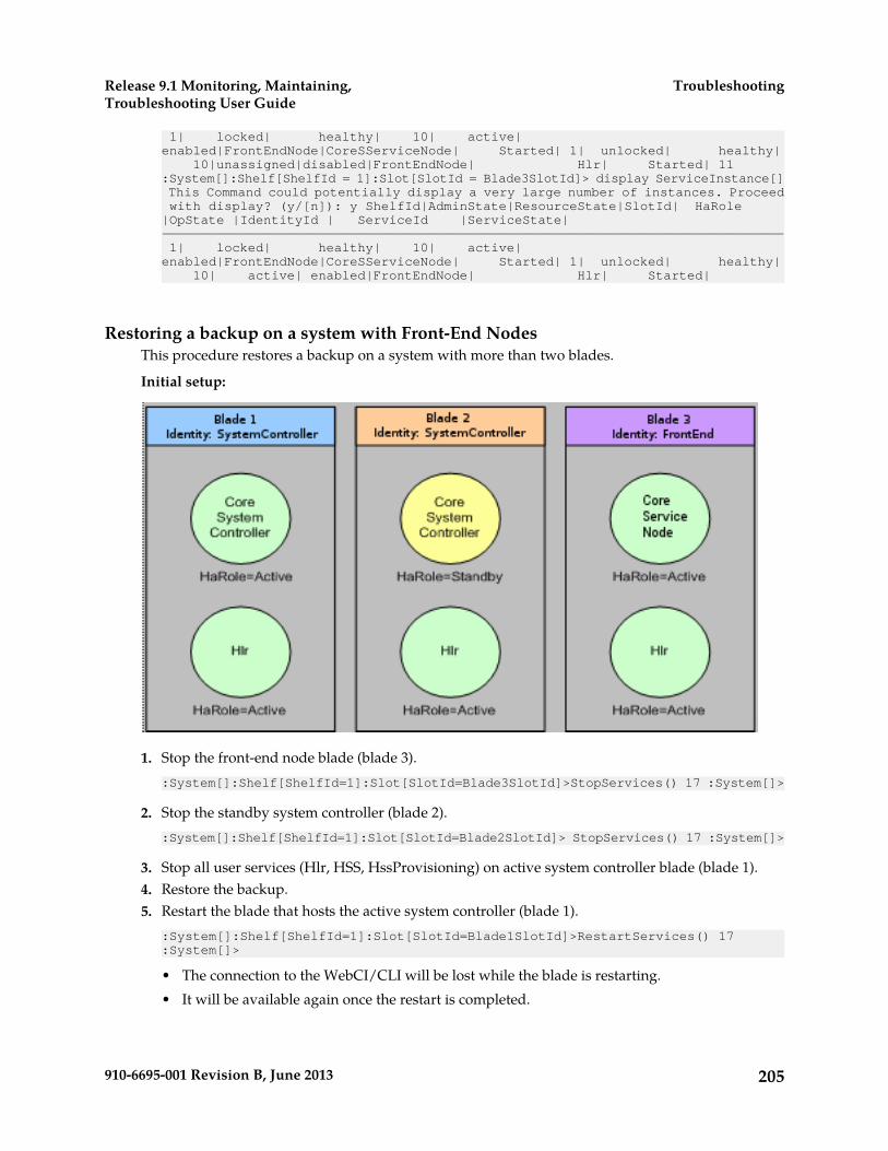
1| locked| healthy| 10| active| enabled|FrontEndNode|CoreSServiceNode| Started| 1| unlocked| healthy| 10|unassigned|disabled|FrontEndNode| Hlr| Started| 11 :System[]:Shelf[ShelfId = 1]:Slot[SlotId = Blade3SlotId]> display ServiceInstance[] This Command could potentially display a very large number of instances. Proceed with display? (y/[n]): y ShelfId|AdminState|ResourceState|SlotId| HaRole |OpState |IdentityId | ServiceId |ServiceState| --------------------------------------------------------------------------------------------------------------- 1| locked| healthy| 10| active| enabled|FrontEndNode|CoreSServiceNode| Started| 1| unlocked| healthy| 10| active| enabled|FrontEndNode| Hlr| Started|
Restoring a backup on a system with Front-End NodesThis procedure restores a backup on a system with more than two blades.
Initial setup:
1. Stop the front-end node blade (blade 3).:System[]:Shelf[ShelfId=1]:Slot[SlotId=Blade3SlotId]>StopServices() 17 :System[]>
2. Stop the standby system controller (blade 2).:System[]:Shelf[ShelfId=1]:Slot[SlotId=Blade2SlotId]> StopServices() 17 :System[]>
3. Stop all user services (Hlr, HSS, HssProvisioning) on active system controller blade (blade 1).4. Restore the backup.5. Restart the blade that hosts the active system controller (blade 1).
:System[]:Shelf[ShelfId=1]:Slot[SlotId=Blade1SlotId]>RestartServices() 17 :System[]>
• The connection to the WebCI/CLI will be lost while the blade is restarting.• It will be available again once the restart is completed.
205910-6695-001 Revision B, June 2013
TroubleshootingRelease 9.1 Monitoring, Maintaining,Troubleshooting User Guide
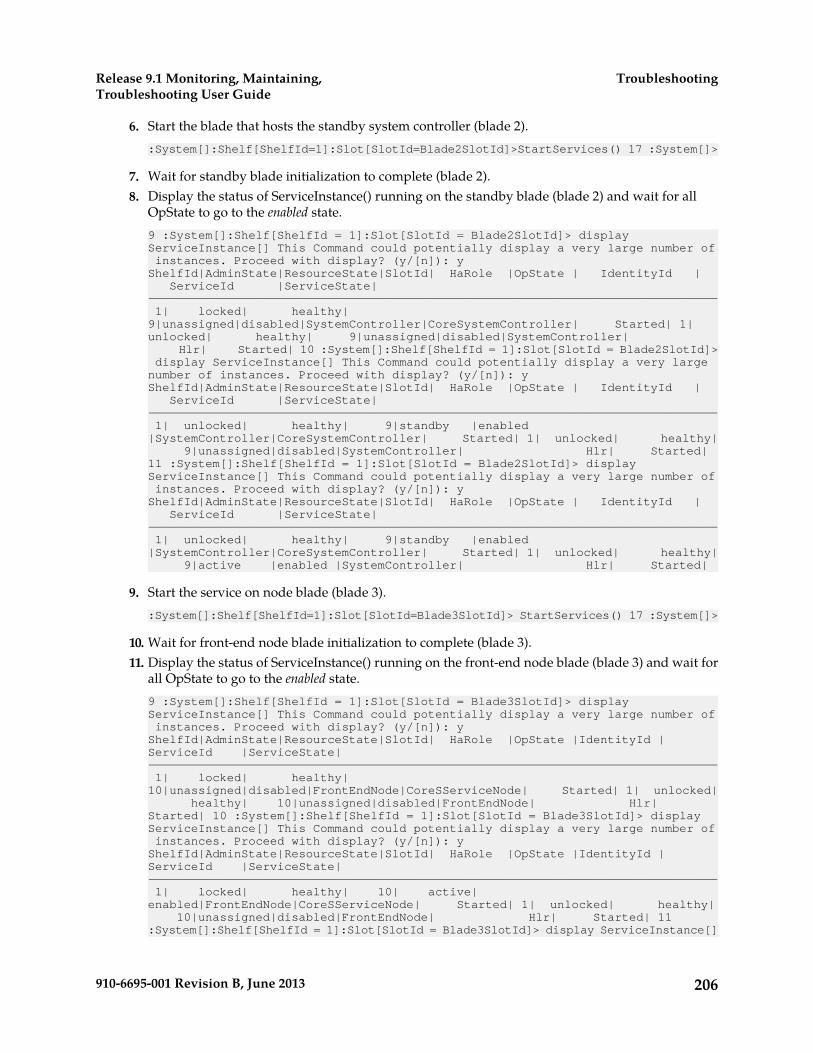
6. Start the blade that hosts the standby system controller (blade 2).:System[]:Shelf[ShelfId=1]:Slot[SlotId=Blade2SlotId]>StartServices() 17 :System[]>
7. Wait for standby blade initialization to complete (blade 2).8. Display the status of ServiceInstance() running on the standby blade (blade 2) and wait for all
OpState to go to the enabled state.9 :System[]:Shelf[ShelfId = 1]:Slot[SlotId = Blade2SlotId]> display ServiceInstance[] This Command could potentially display a very large number of instances. Proceed with display? (y/[n]): y ShelfId|AdminState|ResourceState|SlotId| HaRole |OpState | IdentityId | ServiceId |ServiceState| --------------------------------------------------------------------------------------------------------------- 1| locked| healthy| 9|unassigned|disabled|SystemController|CoreSystemController| Started| 1| unlocked| healthy| 9|unassigned|disabled|SystemController| Hlr| Started| 10 :System[]:Shelf[ShelfId = 1]:Slot[SlotId = Blade2SlotId]> display ServiceInstance[] This Command could potentially display a very large number of instances. Proceed with display? (y/[n]): y ShelfId|AdminState|ResourceState|SlotId| HaRole |OpState | IdentityId | ServiceId |ServiceState| --------------------------------------------------------------------------------------------------------------- 1| unlocked| healthy| 9|standby |enabled |SystemController|CoreSystemController| Started| 1| unlocked| healthy| 9|unassigned|disabled|SystemController| Hlr| Started| 11 :System[]:Shelf[ShelfId = 1]:Slot[SlotId = Blade2SlotId]> display ServiceInstance[] This Command could potentially display a very large number of instances. Proceed with display? (y/[n]): y ShelfId|AdminState|ResourceState|SlotId| HaRole |OpState | IdentityId | ServiceId |ServiceState| --------------------------------------------------------------------------------------------------------------- 1| unlocked| healthy| 9|standby |enabled |SystemController|CoreSystemController| Started| 1| unlocked| healthy| 9|active |enabled |SystemController| Hlr| Started|
9. Start the service on node blade (blade 3).:System[]:Shelf[ShelfId=1]:Slot[SlotId=Blade3SlotId]> StartServices() 17 :System[]>
10. Wait for front-end node blade initialization to complete (blade 3).11. Display the status of ServiceInstance() running on the front-end node blade (blade 3) and wait for
all OpState to go to the enabled state.9 :System[]:Shelf[ShelfId = 1]:Slot[SlotId = Blade3SlotId]> display ServiceInstance[] This Command could potentially display a very large number of instances. Proceed with display? (y/[n]): y ShelfId|AdminState|ResourceState|SlotId| HaRole |OpState |IdentityId | ServiceId |ServiceState| --------------------------------------------------------------------------------------------------------------- 1| locked| healthy| 10|unassigned|disabled|FrontEndNode|CoreSServiceNode| Started| 1| unlocked| healthy| 10|unassigned|disabled|FrontEndNode| Hlr| Started| 10 :System[]:Shelf[ShelfId = 1]:Slot[SlotId = Blade3SlotId]> display ServiceInstance[] This Command could potentially display a very large number of instances. Proceed with display? (y/[n]): y ShelfId|AdminState|ResourceState|SlotId| HaRole |OpState |IdentityId | ServiceId |ServiceState| --------------------------------------------------------------------------------------------------------------- 1| locked| healthy| 10| active| enabled|FrontEndNode|CoreSServiceNode| Started| 1| unlocked| healthy| 10|unassigned|disabled|FrontEndNode| Hlr| Started| 11 :System[]:Shelf[ShelfId = 1]:Slot[SlotId = Blade3SlotId]> display ServiceInstance[]
206910-6695-001 Revision B, June 2013
TroubleshootingRelease 9.1 Monitoring, Maintaining,Troubleshooting User Guide
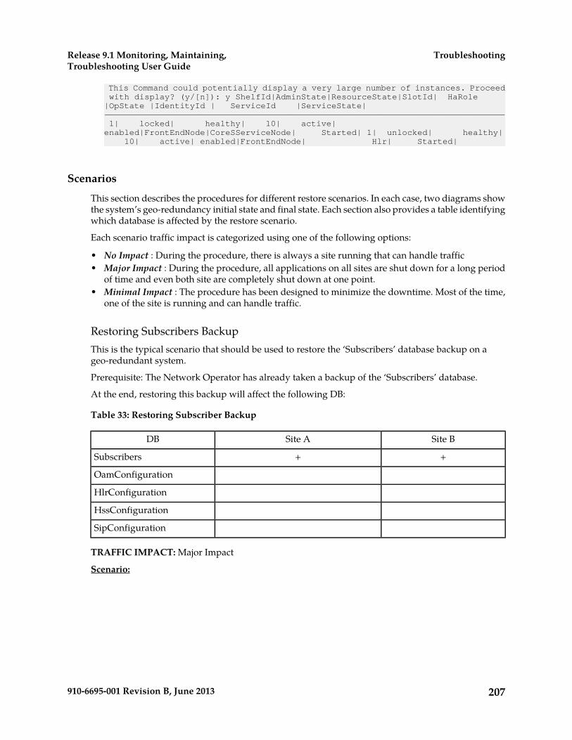
This Command could potentially display a very large number of instances. Proceed with display? (y/[n]): y ShelfId|AdminState|ResourceState|SlotId| HaRole |OpState |IdentityId | ServiceId |ServiceState| --------------------------------------------------------------------------------------------------------------- 1| locked| healthy| 10| active| enabled|FrontEndNode|CoreSServiceNode| Started| 1| unlocked| healthy| 10| active| enabled|FrontEndNode| Hlr| Started|
Scenarios
This section describes the procedures for different restore scenarios. In each case, two diagrams showthe system’s geo-redundancy initial state and final state. Each section also provides a table identifyingwhich database is affected by the restore scenario.
Each scenario traffic impact is categorized using one of the following options:
• No Impact : During the procedure, there is always a site running that can handle traffic• Major Impact : During the procedure, all applications on all sites are shut down for a long period
of time and even both site are completely shut down at one point.• Minimal Impact : The procedure has been designed to minimize the downtime. Most of the time,
one of the site is running and can handle traffic.
Restoring Subscribers BackupThis is the typical scenario that should be used to restore the ‘Subscribers’ database backup on ageo-redundant system.
Prerequisite: The Network Operator has already taken a backup of the ‘Subscribers’ database.
At the end, restoring this backup will affect the following DB:
Table 33: Restoring Subscriber Backup
Site BSite ADB
++Subscribers
OamConfiguration
HlrConfiguration
HssConfiguration
SipConfiguration
TRAFFIC IMPACT: Major Impact
Scenario:
207910-6695-001 Revision B, June 2013
TroubleshootingRelease 9.1 Monitoring, Maintaining,Troubleshooting User Guide

Figure 62: Restoring The ‘Subscribers’ Database Backup In A Geo-redundant Deployment
Procedure:
1. Disable geo-redundancy on replica site (site B) using System:DisableGeoRedundancy()operation in BlueCli.
2. Site B should go to UnassignedDisabled state and site A Reference.3. Enable geo-redundancy on replica site (site B) using System:EnableGeoRedundancy() operation
in BlueCli.4. Site B should go to UnassignedEnabled state and site A geo state should stay unchanged.5. Restore the backup on reference site (site A) using Restoring a Backup on a 2-Blade System or Restoring
a backup on a system with Front-End Nodes.6. Restart replica site (site B) using Restarting a 2-Blade System or Restarting a system with Front-End
Nodes.7. Site B should go to Replica state and site A ReferenceProtected.
Final state:
Figure 63: Final State Of The Geo-redundant Sites After Restoring The ‘Subscribers’ DatabaseBackup
208910-6695-001 Revision B, June 2013
TroubleshootingRelease 9.1 Monitoring, Maintaining,Troubleshooting User Guide

Restoring a Full Backup Taken on the Reference SiteThis is a scenario where the operator wants to restore a full backup that was taken on the reference site.A full backup can be restored only on the site it has been taken. In this case, the backup must berestored on the reference site.
At the end, restoring this backup will affect the following databases:
Table 34: Databases Affected by Backup Restoration on Reference Site
Site BSite ADB
++Subscribers
+OamConfiguration
+HlrConfiguration
+HssConfiguration
+SipConfiguration
TRAFFIC IMPACT: Major Impact
Scenario:
Figure 64: Restoring A Full Backup On The Reference Site
Procedure:
1. Disable geo-redundancy on replica site (site B) using System:DisableGeoRedundancy()operation in BlueCli.
2. Site B should go to UnassignedDisabled state and site A Reference.3. Enable geo-redundancy on replica site (site B) using System:EnableGeoRedundancy() operation
in BlueCli.4. Site B should go to UnassignedEnabled state and site A geo state should stay unchanged.
209910-6695-001 Revision B, June 2013
TroubleshootingRelease 9.1 Monitoring, Maintaining,Troubleshooting User Guide
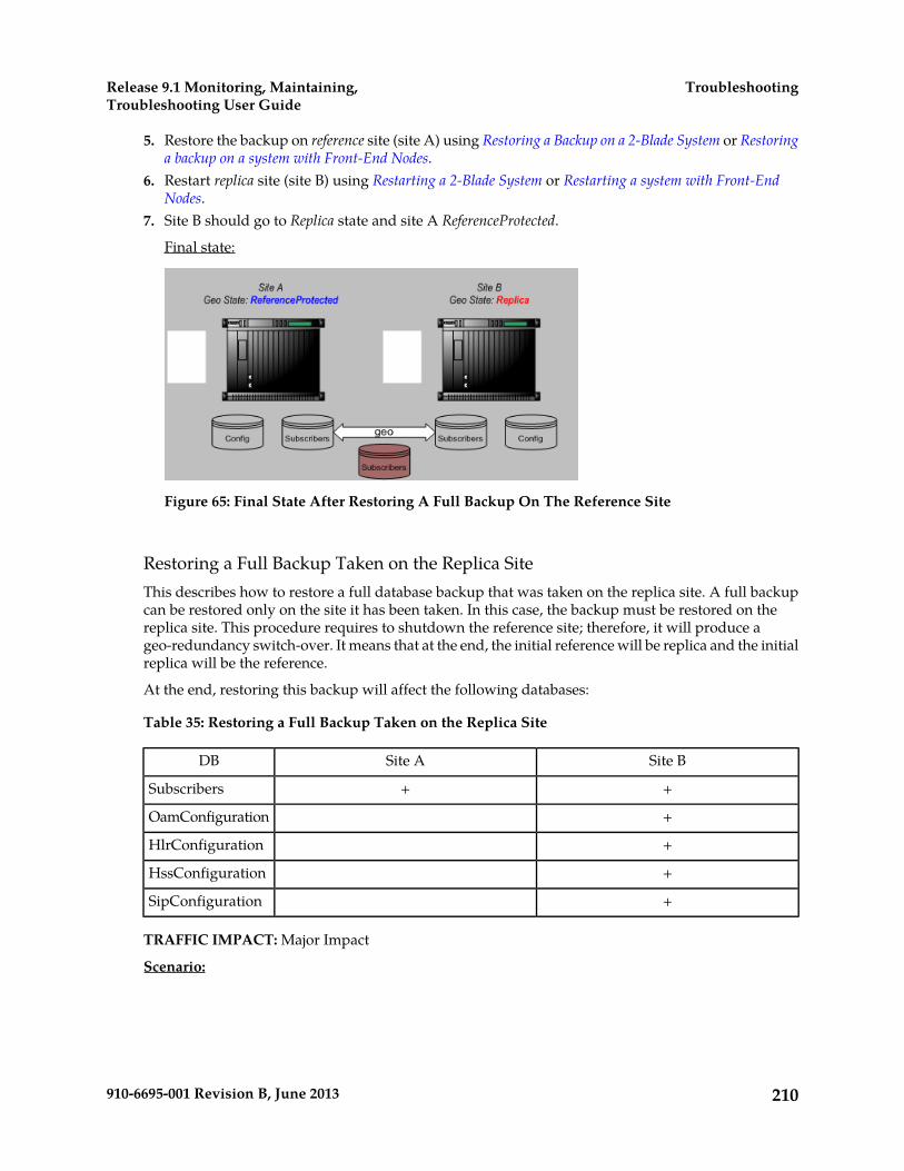
5. Restore the backup on reference site (site A) using Restoring a Backup on a 2-Blade System or Restoringa backup on a system with Front-End Nodes.
6. Restart replica site (site B) using Restarting a 2-Blade System or Restarting a system with Front-EndNodes.
7. Site B should go to Replica state and site A ReferenceProtected.
Final state:
Figure 65: Final State After Restoring A Full Backup On The Reference Site
Restoring a Full Backup Taken on the Replica SiteThis describes how to restore a full database backup that was taken on the replica site. A full backupcan be restored only on the site it has been taken. In this case, the backup must be restored on thereplica site. This procedure requires to shutdown the reference site; therefore, it will produce ageo-redundancy switch-over. It means that at the end, the initial reference will be replica and the initialreplica will be the reference.
At the end, restoring this backup will affect the following databases:
Table 35: Restoring a Full Backup Taken on the Replica Site
Site BSite ADB
++Subscribers
+OamConfiguration
+HlrConfiguration
+HssConfiguration
+SipConfiguration
TRAFFIC IMPACT: Major Impact
Scenario:
210910-6695-001 Revision B, June 2013
TroubleshootingRelease 9.1 Monitoring, Maintaining,Troubleshooting User Guide
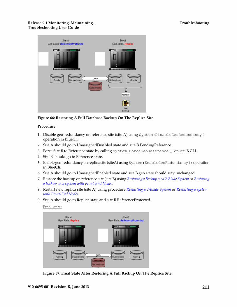
Figure 66: Restoring A Full Database Backup On The Replica Site
Procedure:
1. Disable geo-redundancy on reference site (site A) using System:DisableGeoRedundancy()operation in BlueCli.
2. Site A should go to UnassignedDisabled state and site B PendingReference.3. Force Site B to Reference state by calling System:ForceGeoReference() on site B CLI.4. Site B should go to Reference state.5. Enable geo-redundancy on replica site (siteA) using System:EnableGeoRedundancy() operation
in BlueCli.6. Site A should go to UnassignedEnabled state and site B geo state should stay unchanged.7. Restore the backup on reference site (site B) using Restoring a Backup on a 2-Blade System or Restoring
a backup on a system with Front-End Nodes.8. Restart new replica site (site A) using procedure Restarting a 2-Blade System or Restarting a system
with Front-End Nodes.9. Site A should go to Replica state and site B ReferenceProtected.
Final state:
Figure 67: Final State After Restoring A Full Backup On The Replica Site
211910-6695-001 Revision B, June 2013
TroubleshootingRelease 9.1 Monitoring, Maintaining,Troubleshooting User Guide

Restoring a Configuration Backup Taken on the Reference SiteThis describes how to restore a configuration database backup that was taken on the reference site.
A configuration backup can be restored only on the site it has been taken. In this case, the backupmust be restored on the reference site.
This scenario is not traffic impacting since the replica site can continue to run while the backup is beingrestored. After backup restore, the replica site will take the reference role since site A need to be restartedin order to apply the back upped.
At the end, restoring this backup will affect the following databases:
Table 36: Databases Affected by Configuration Backup on Reference Site
Site BSite ADB
Subscribers
+OamConfiguration
+HlrConfiguration
+HssConfiguration
+SipConfiguration
TRAFFIC IMPACT: No Impact
Scenario:
Figure 68: Restoring Configuration Database Backup On Reference Site
Procedure:
1. To prevent traffic impact, all traffic should be re-directed to site B.2. Disable geo-redundancy on reference site (site A) using System:DisableGeoRedundancy()
operation in BlueCli.3. Site A should go to UnassignedDisabled state and site B PendingReference.
212910-6695-001 Revision B, June 2013
TroubleshootingRelease 9.1 Monitoring, Maintaining,Troubleshooting User Guide
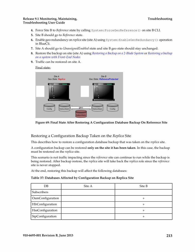
4. Force Site B to Reference state by calling System:ForceGeoReference() on site B CLI.5. Site B should go to Reference state.6. Enable geo-redundancy on replica site (site A) using System:EnableGeoRedundancy() operation
in BlueCli.7. Site A should go to UnassignedEnabled state and site B geo state should stay unchanged.8. Restore the backup on site (site A) using Restoring a Backup on a 2-Blade System or Restoring a backup
on a system with Front-End Nodes9. Traffic can be restored on site A.
Final state:
Figure 69: Final State After Restoring A Configuration Database Backup On Reference Site
Restoring a Configuration Backup Taken on the Replica SiteThis describes how to restore a configuration database backup that was taken on the replica site.
A configuration backup can be restored only on the site it has been taken. In this case, the backupmust be restored on the replica site.
This scenario is not traffic impacting since the reference site can continue to run while the backup isbeing restored. After backup restore, the replica site will take back the replica role since the referencesite is never stopped.
At the end, restoring this backup will affect the following databases:
Table 37: Databases Affected by Configuration Backup on Replica Site
Site BSite ADB
Subscribers
+OamConfiguration
+HlrConfiguration
+HssConfiguration
+SipConfiguration
213910-6695-001 Revision B, June 2013
TroubleshootingRelease 9.1 Monitoring, Maintaining,Troubleshooting User Guide

TRAFFIC IMPACT: No Impact
Scenario:
Figure 70: Restoring A Configuration Database Backup On The Replica Site
Procedure:
1. To prevent traffic impact, all traffic should be re-directed to site A.2. Disable geo-redundancy on replica site (site B) using System:DisableGeoRedundancy()
operation in BlueCli.3. Site B should go to UnassignedDisabled state and site A Reference.4. Enable geo-redundancy on replica site (site B) using System:EnableGeoRedundancy() operation
in BlueCli.5. Site B should go to UnassignedEnabled state and site A geo state should stay unchanged.6. Restore the backup on replica site (site B) using Restoring a Backup on a 2-Blade System or Restoring
a backup on a system with Front-End Nodes.7. Traffic can be restored on site B.
Final state:
Figure 71: Final State After Restoring A Configuration Database Backup On The Replica Site
214910-6695-001 Revision B, June 2013
TroubleshootingRelease 9.1 Monitoring, Maintaining,Troubleshooting User Guide
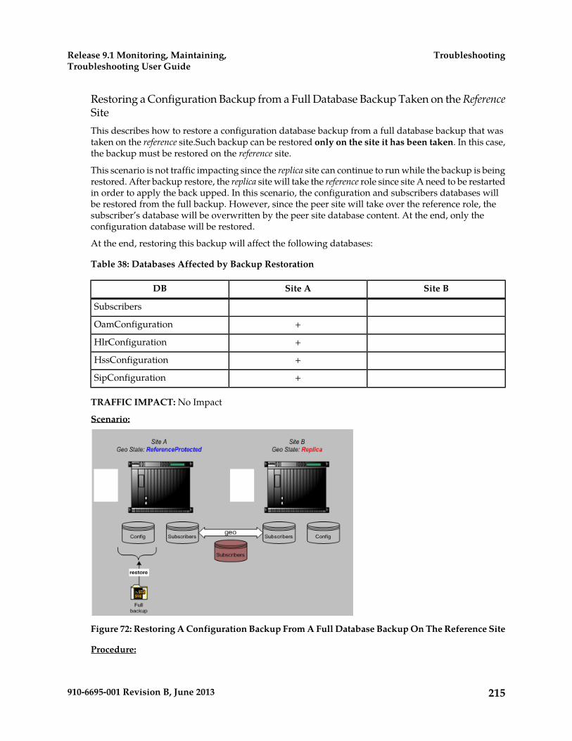
Restoring a Configuration Backup from a Full Database Backup Taken on the ReferenceSiteThis describes how to restore a configuration database backup from a full database backup that wastaken on the reference site.Such backup can be restored only on the site it has been taken. In this case,the backup must be restored on the reference site.
This scenario is not traffic impacting since the replica site can continue to run while the backup is beingrestored. After backup restore, the replica site will take the reference role since site A need to be restartedin order to apply the back upped. In this scenario, the configuration and subscribers databases willbe restored from the full backup. However, since the peer site will take over the reference role, thesubscriber’s database will be overwritten by the peer site database content. At the end, only theconfiguration database will be restored.
At the end, restoring this backup will affect the following databases:
Table 38: Databases Affected by Backup Restoration
Site BSite ADB
Subscribers
+OamConfiguration
+HlrConfiguration
+HssConfiguration
+SipConfiguration
TRAFFIC IMPACT: No Impact
Scenario:
Figure 72: Restoring A Configuration Backup From A Full Database Backup On The Reference Site
Procedure:
215910-6695-001 Revision B, June 2013
TroubleshootingRelease 9.1 Monitoring, Maintaining,Troubleshooting User Guide
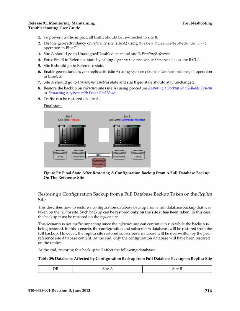
1. To prevent traffic impact, all traffic should be re-directed to site B.2. Disable geo-redundancy on reference site (site A) using System:DisableGeoRedundancy()
operation in BlueCli.3. Site A should go to UnassignedDisabled state and site B PendingReference.4. Force Site B to Reference state by calling System:ForceGeoReference() on site B CLI.5. Site B should go to Reference state.6. Enable geo-redundancy on replica site (site A) using System:EnableGeoRedundancy() operation
in BlueCli.7. Site A should go to UnassignedEnabled state and site B geo state should stay unchanged.8. Restore the backup on reference site (site A) using procedure Restoring a Backup on a 2-Blade System
or Restarting a system with Front-End Nodes.9. Traffic can be restored on site A.
Final state:
Figure 73: Final State After Restoring A Configuration Backup From A Full Database BackupOn The Reference Site
Restoring a Configuration Backup from a Full Database Backup Taken on the ReplicaSiteThis describes how to restore a configuration database backup from a full database backup that wastaken on the replica site. Such backup can be restored only on the site it has been taken. In this case,the backup must be restored on the replica site.
This scenario is not traffic impacting since the reference site can continue to run while the backup isbeing restored. In this scenario, the configuration and subscribers databases will be restored from thefull backup. However, the replica site restored subscriber’s database will be overwritten by the peerreference site database content. At the end, only the configuration database will have been restoredon the replica.
At the end, restoring this backup will affect the following databases:
Table 39: Databases Affected by Configuration Backup from Full Database Backup on Replica Site
Site BSite ADB
216910-6695-001 Revision B, June 2013
TroubleshootingRelease 9.1 Monitoring, Maintaining,Troubleshooting User Guide
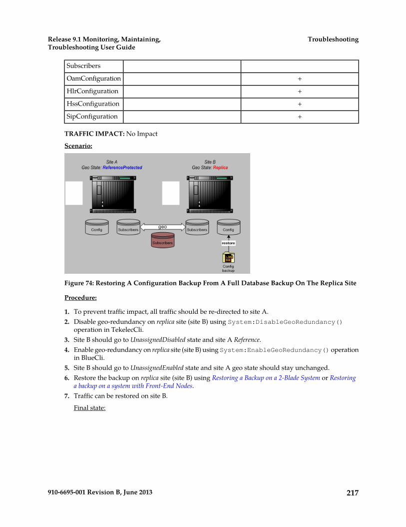
Subscribers
+OamConfiguration
+HlrConfiguration
+HssConfiguration
+SipConfiguration
TRAFFIC IMPACT: No Impact
Scenario:
Figure 74: Restoring A Configuration Backup From A Full Database Backup On The Replica Site
Procedure:
1. To prevent traffic impact, all traffic should be re-directed to site A.2. Disable geo-redundancy on replica site (site B) using System:DisableGeoRedundancy()
operation in TekelecCli.3. Site B should go to UnassignedDisabled state and site A Reference.4. Enable geo-redundancy on replica site (site B) using System:EnableGeoRedundancy() operation
in BlueCli.5. Site B should go to UnassignedEnabled state and site A geo state should stay unchanged.6. Restore the backup on replica site (site B) using Restoring a Backup on a 2-Blade System or Restoring
a backup on a system with Front-End Nodes.7. Traffic can be restored on site B.
Final state:
217910-6695-001 Revision B, June 2013
TroubleshootingRelease 9.1 Monitoring, Maintaining,Troubleshooting User Guide

Figure 75: Final State After Restoring A Configuration Backup From A Full Database BackupOn The Replica Site
View License and Log Information from the WebCI
This procedure describes the steps to view license and log information. For details on the licenseattributes, refer to the SDM Monitoring, Maintenance, Troubleshooting - Reference Manual
From the main menu, navigate to Oamp > LicenseManager.
This will display the License Manager Configuration window (as shown below).
Figure 76: License Manager window
218910-6695-001 Revision B, June 2013
TroubleshootingRelease 9.1 Monitoring, Maintaining,Troubleshooting User Guide
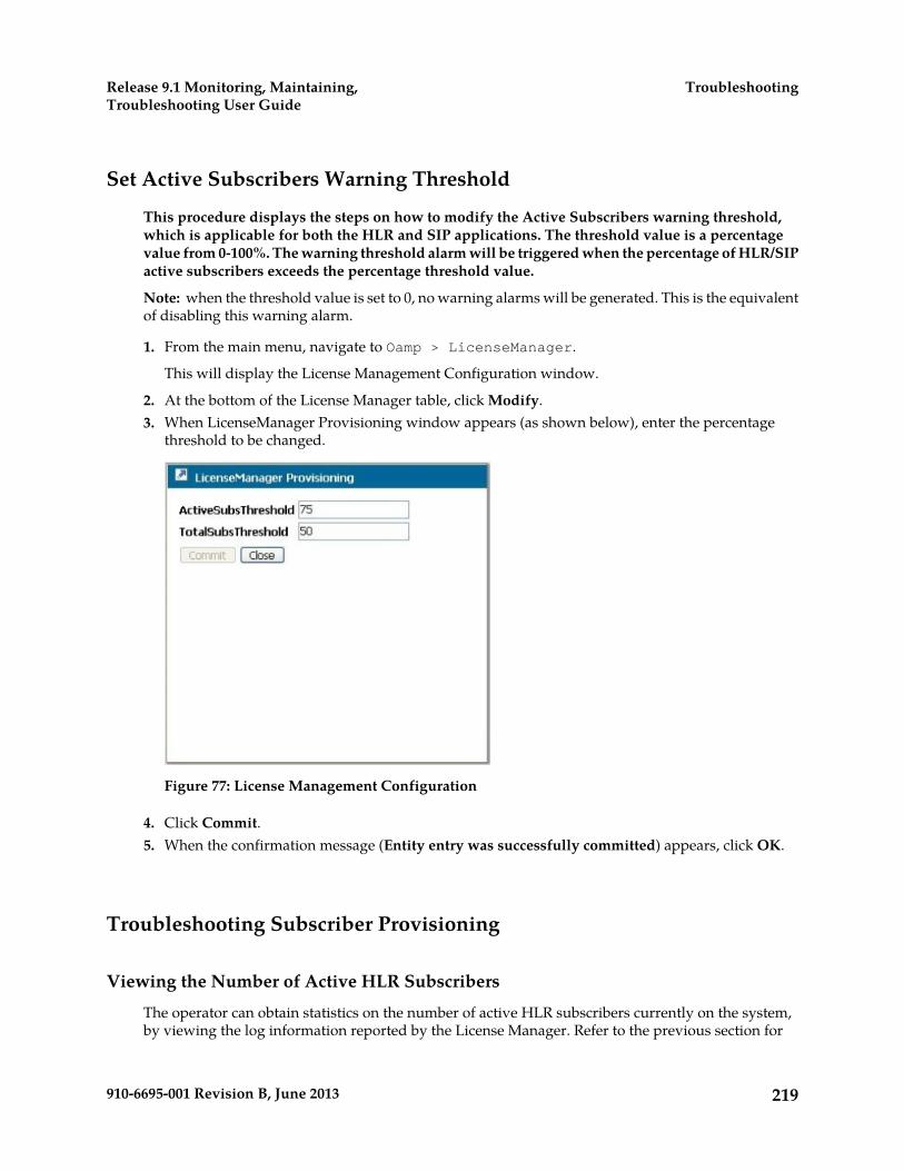
Set Active Subscribers Warning Threshold
This procedure displays the steps on how to modify the Active Subscribers warning threshold,which is applicable for both the HLR and SIP applications. The threshold value is a percentagevalue from 0-100%. The warning threshold alarm will be triggered when the percentage of HLR/SIPactive subscribers exceeds the percentage threshold value.
Note: when the threshold value is set to 0, no warning alarms will be generated. This is the equivalentof disabling this warning alarm.
1. From the main menu, navigate to Oamp > LicenseManager.
This will display the License Management Configuration window.
2. At the bottom of the License Manager table, click Modify.3. When LicenseManager Provisioning window appears (as shown below), enter the percentage
threshold to be changed.
Figure 77: License Management Configuration
4. Click Commit.5. When the confirmation message (Entity entry was successfully committed) appears, click OK.
Troubleshooting Subscriber Provisioning
Viewing the Number of Active HLR Subscribers
The operator can obtain statistics on the number of active HLR subscribers currently on the system,by viewing the log information reported by the License Manager. Refer to the previous section for
219910-6695-001 Revision B, June 2013
TroubleshootingRelease 9.1 Monitoring, Maintaining,Troubleshooting User Guide
step-by-step instructions on how to view the license log information. The License Manager generatesa license log at the beginning of each month and updates the timestamp and the number of activeHLR subscribers on a daily basis. At the end of each calendar month, there is a license log that indicatesthe total number of subscribers that were active during that month. The 12 most recent logs are keptin history.
Troubleshooting congestion in SPR Received-Message Queue
When experiencing congestion in the queue for SPR received messages, confirm that the queue-sizevalue aligns with the recommended values. Refer to the ReceivedMessagesQueueSize parameterin the HSS SPR Configuration (HssSprConfig) table (SDM System Configuration Reference Manual)
The internal receive queue is configured with the number of requests that can be received and processedby the HSS. The queue size must be calculated based on the overall TPS dimensioning for the system.Setting a queue size too small may result in congestion due to queue exhaust. Setting the queue sizetoo large may impact the ability to detect congestion. As a system grows in TPS, the initially configuredvalue may have to be updated.
220910-6695-001 Revision B, June 2013
TroubleshootingRelease 9.1 Monitoring, Maintaining,Troubleshooting User Guide

Glossary#
3rd Generation Partnership Project.The standards body for wirelesscommunications.
3GPP
A
Authentication, Authorization, andAccounting (Rx Diametercommand)
AAA
Alarm Indication SignalAIS
Access Point NameAPN
The name identifying a generalpacket radio service (GPRS) bearerservice in a GSM mobile network.See also GSM.
Authentication CenterAuC
B
Barring of All Outgoing CallsBAOC
Barring of Incoming Calls whenROAMing outside home PLMNCountry
BICROAM
Barring of Outgoing InternationalCalls
BOIC
Barring of Outgoing InternationalCalls EXcept those directed to theHome PLMN Country
BOICEXHC
C
221910-6695-001 Revision B, June 2013

C
Customized Applications forMobile networks Enhanced Logic
CAMEL
Call Forwarding on MobileSubscriber Busy
CFB
Call Forwarding on MobileSubscriber Not Reachable
CFNRC
Call Forwarding on MobileSubscriber No Reply
CFNRY
Call Forwarding UnconditionalCFU
Command-line interfaceCLI
Calling Line IdentificationPresentation
CLIP
Calling Line IdentificationRestriction
CLIR
Connected Line IdentificationPresentation
COLP
Connected Line IdentificationRestriction
COLR
Central Processing UnitCPU
Cyclic Redundancy CheckCRC
A number derived from, and storedor transmitted with, a block of datain order to detect corruption. Byrecalculating the CRC and
222910-6695-001 Revision B, June 2013
GlossaryRelease 9.1 Monitoring, Maintaining,Troubleshooting User Guide
C
comparing it to the value originallytransmitted, the receiver can detectsome types of transmission errors.
Controlled SlipCS
Channel Service UnitCSU
Comma-separated valuesCSV
The comma-separated value fileformat is a delimited data formatthat has fields separated by thecomma character and recordsseparated by newlines (a newlineis a special character or sequenceof characters signifying the end ofa line of text).
Closed User GroupCUG
D
DatabaseDB
Data bus
Domain Name SystemDNS
A system for converting Internethost and domain names into IPaddresses.
Destination Point CodeDPC
DPC refers to the scheme in SS7signaling to identify the receivingsignaling point. In the SS7 network,the point codes are numericaddresses which uniquely identifyeach signaling point. This point codecan be adjacent to the EAGLE 5 ISS,but does not have to be.
E
223910-6695-001 Revision B, June 2013
GlossaryRelease 9.1 Monitoring, Maintaining,Troubleshooting User Guide
E
TElephone NUmber MappingENUM
Electro-Static DischargeESD
Extended Super FrameESF
G
Greenwich Mean TimeGMT
General Packet Radio ServiceGPRS
A mobile data service for users ofGSM mobile phones.
Global System for MobileCommunications
GSM
Graphical User InterfaceGUI
The term given to that set of itemsand facilities which provide theuser with a graphic means formanipulating screen data ratherthan being limited to characterbased commands.
H
High AvailabilityHA
High Availability refers to a systemor component that operates on acontinuous basis by utilizingredundant connectivity, therebycircumventing unplanned outages.
Home Location RegisterHLR
Home Public Land MobileNetwork
HPLMN
224910-6695-001 Revision B, June 2013
GlossaryRelease 9.1 Monitoring, Maintaining,Troubleshooting User Guide
H
Home Subscriber ServerHSS
A central database for subscriberinformation.
I
International Mobile SubscriberIdentity
IMSI
L
The primary function of the LOCserver is to locate subscribers onGSM and IS-41 networks.
LOC
Long Term EvolutionLTE
The next-generation network beyond3G. In addition to enabling fixed tomobile migrations of Internetapplications such as Voice over IP(VoIP), video streaming, musicdownloading, mobile TV, and manyothers, LTE networks will alsoprovide the capacity to support anexplosion in demand forconnectivity from a new generationof consumer devices tailored to thosenew mobile applications.
M
Message Digest (Version 5)MD5
Management Information DatabaseMIB
Mobile Number PortabilityMNP
MNP Signaling Relay FunctionMNP-SRF
Mobile Station InternationalSubscriber Directory Number
MSISDN
225910-6695-001 Revision B, June 2013
GlossaryRelease 9.1 Monitoring, Maintaining,Troubleshooting User Guide
M
The MSISDN is the network specificsubscriber number of a mobilecommunications subscriber. This isnormally the phone number that isused to reach the subscriber.
Message Transfer Part, Level 2MTP2
Message Transfer Part, Level 3MTP3
N
Number Portability DatabaseNPDB
O
Operations – Monitoring theenvironment, detecting and
OAM&P
determining faults, and alertingadministrators.
Administration – Typically involvescollecting performance statistics,accounting data for the purpose ofbilling, capacity planning, usingusage data, and maintaining systemreliability.
Maintenance – Provides suchfunctions as upgrades, fixes, newfeature enablement, backup andrestore tasks, and monitoring mediahealth (for example, diagnostics).
Provisioning – Setting up useraccounts, devices, and services.
Operations, Administration andMaintenance Part
OAMP
Object IdentifierOID
An identifier for a managed objectin a Management Information Base(MIB) hierarchy. This can bedepicted as a tree, the levels of whichare assigned by different
226910-6695-001 Revision B, June 2013
GlossaryRelease 9.1 Monitoring, Maintaining,Troubleshooting User Guide
O
organizations. Top level MIB OIDsbelong to different standardorganizations. Vendors defineprivate branches that includemanaged objects for their ownproducts.
A data type whose specific schemais not defined as a part of the
opaque data
interface, but rather is handled asa unit and not interpreted orparsed. The values within opaquedata can only be manipulated bycalling subroutines that havespecific knowledge of thestructure/schema of the data.
P
Packet Data NetworkPDN
A digital network technology thatdivides a message into packets fortransmission.
Processing ModulePM
S
System ControllerSC
Signaling Connection Control PartSCCP
Subscriber Data ManagementSDM
Serving GPRS Support NodeSGSN
The name given to an IETF workinggroup that produced specifications
SIGTRAN
for a family of protocols that providereliable datagram service and userlayer adaptations for SS7 and ISDNcommunications protocols. The most
227910-6695-001 Revision B, June 2013
GlossaryRelease 9.1 Monitoring, Maintaining,Troubleshooting User Guide
S
significant protocol defined by theSIGTRAN group was the StreamControl Transmission Protocol(SCTP), which is used to carry PSTNsignalling over IP.
The SIGTRAN group wassignificantly influenced bytelecommunications engineers intenton using the new protocols foradapting VoIP networks to the PSTNwith special regard to signalingapplications. Recently, SCTP isfinding applications beyond itsoriginal purpose wherever reliabledatagram service is desired.
Subscriber Identity ModuleSIM
An ID card the size of a credit cardfor GSM network subscribers, andis typically referred to as a chipcard or smartcard.
Session Initiation ProtocolSIP
Simple Network ManagementProtocol.
SNMP
An industry-wide standard protocolused for network management. TheSNMP agent maintains datavariables that represent aspects ofthe network. These variables arecalled managed objects and arestored in a management informationbase (MIB). The SNMP protocolarranges managed objects intogroups.
Subscriber Profile RepositorySPR
A logical entity that may be astandalone database or integratedinto an existing subscriber databasesuch as a Home Subscriber Server(HSS). It includes information such
228910-6695-001 Revision B, June 2013
GlossaryRelease 9.1 Monitoring, Maintaining,Troubleshooting User Guide

S
as entitlements, rate plans, etc. ThePCRF and SPR functionality isprovided through an ecosystem ofpartnerships.
Send_Route_Information MessageSRI
Signaling System #7SS7
Secure ShellSSH
A protocol for secure remote loginand other network services over aninsecure network. SSH encrypts andauthenticates all EAGLE 5 ISS IPUIand MCP traffic, incoming andoutgoing (including passwords) toeffectively eliminate eavesdropping,connection hijacking, and othernetwork-level attacks.
SIP Signaling RouterSSR
Function responsible for queryinga redirection server and proxyingrequests to other SSR servers,redirect servers, SSR Service Points,and Gateways. It helps in evolvinga Flat NGN network into ahierarchical network.
T
Transaction Capabilities ApplicationPart
TCAP
Trigger Detection PointTDP
U
User Datagram ProtocolUDP
User Security ManagementUSM
229910-6695-001 Revision B, June 2013
GlossaryRelease 9.1 Monitoring, Maintaining,Troubleshooting User Guide

V
Virtual IP AddressVIP
Virtual IP is a layer-3 conceptemployed to provide HA at a hostlevel. A VIP enables two or more IPhosts to operate in an active/standbyHA manner. From the perspectiveof the IP network, these IP hostsappear as a single host.
Visitor Location RegisterVLR
A component of the switchingsubsystem, within a GSM network.The switching subsystem includesvarious databases which storeindividual subscriber data. One ofthese databases is the HLR databaseor Home Location Register; and theVLR is another.
W
Web Craft InterfaceWebCI
X
eXtensible Markup LanguageXML
A version of the StandardGeneralized Markup Language(SGML) that allows Web developersto create customized tags foradditional functionality.
230910-6695-001 Revision B, June 2013
GlossaryRelease 9.1 Monitoring, Maintaining,Troubleshooting User Guide